Embed Size (px)
Citation preview
TURBO KIT
Scion FR-S ZN6
Subaru BRZ ZC6
T518Z 10㎝2 (Internal Wastegate)
Vehicle Type Chassis Code Engine Code Transmission Model Year Scion FR-S DBA-ZN6 FA20 6MT/AT 2013 ~
Subaru BRZ DBA-ZC6 FA20 6MT/AT 2013 ~ Note : ○ Additional GReddy Oil Cooler Available (Sold Separately)
The manufacturers state that the exhaust manifold nuts should not be reused.
Please purchase new parts from the dealer prior to installation of this turbo kit.
Scion Part # SU003-02873 Subaru Part # 902370010
Installation Instructions

―1―
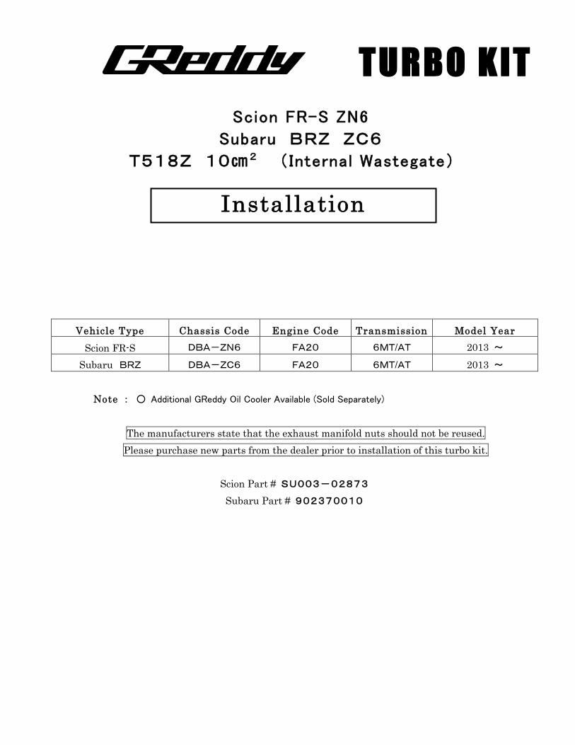
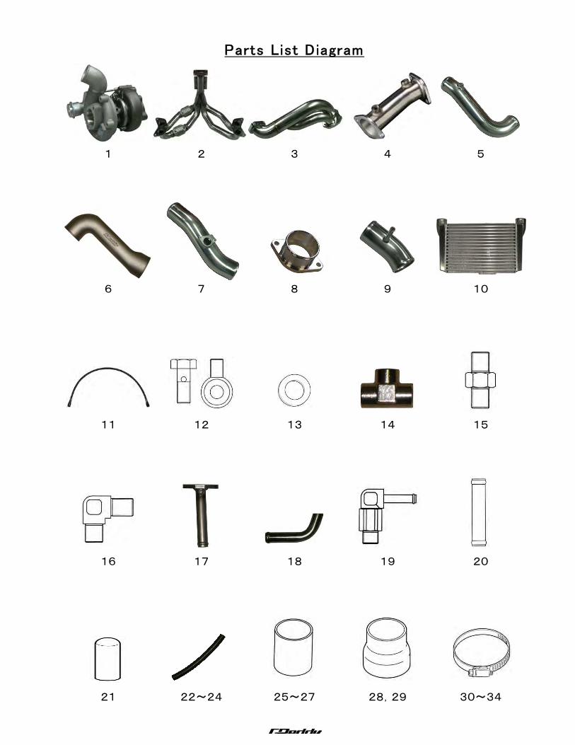
1.Parts List 1.Turbo Charger T518Z 10C㎡ P555 1
2.Exhaust Manifold (SUS 42.7φ-50.8φ) 1
3.Down Pipe (50φ-60φ) 1
4.Test Pipe 1
5.Compression Tube C-1 (Aluminum 50φ) 1
6. 〃 C-2 (Aluminum Elbow 60φ-70φ) 1
7. 〃 C-3 (Aluminum 70φ) 1
8.Intake Tube Adapter Flange (Aluminum 60φ) 1
9.Intake Tube (Aluminum 70φ) 1
10.Intercooler Type 40 E 1
11.Oil Pressure Hose SUS 600㎜ 1
12. 〃 Banjo Bolt Male Female (small) 1set
13. 〃 Copper Crush Washer 10φ (t=1.0) 2
14. 〃 Fitting 3 Way1/8PT×3 1
15. 〃 Fitting Straight 1/8PT-1/8PT 1
16. 〃 Fitting 90°1/8PT-1/8PF 1
17.Oil Return Tube with Flange 16φ 1
18.Oil Return Tube (Weld onto Oil Pan) 16φ 1
19.Free Rotation Union 1/8PT-5φ 1
20.Hose Union 12φ 1
21.Silicone Cap 15.5φ 1
22.Vacuum 5φ×150㎜ 1
23.Blow By Hose 12φ×150㎜ 1
24.Oil Return Hose 15φ×290㎜ 1
25.Silicone Hose 50φ×70㎜ 1
26. 〃 60φ×70㎜ 1
27. 〃 70φ×70㎜ 2
28.Reducer Hose 50φ-60φ 1
29. 〃 60φ-70φ 1
30.Hose Clamp 12φ Tridon #6 2
31. 〃 16φ Tridon #8 2
32. 〃 50φ Tridon #32 3
33. 〃 60φ Tridon #36 4
34. 〃 70φ Tridon #44 6
―2―
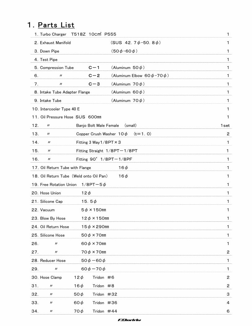
35.Gasket Turbine IN 1
36. 〃 Turbine OUT 1
37. 〃 Intake Tube Adapter Flange 1
38. 〃 Small Oil Return 1
39. 〃 Cylinder Head to Turbo Manifold (Exhaust Manifold) 2
40. 〃 Test Pipe 2
41.Heat Shield Turbine 1
42.Heat Shield Turbo Manifold 1
43.Heat Wrap 100㎜×1000㎜ 2
44.Zip Tie 150㎜ 10
45.Turbo Mounting Bracket A 1
46.Turbo Mounting Bracket B 1
47.Steel Spacer A Turbo Bracket to Pulley 1
48.Steel Spacer B Turbo Bracket to Pulley 1
49.Oil Return Hose Bracket 1
50.Test Pipe Bracket 1
51.Intercooler Bracket 1
52.Intercooler Bracket Spacer 2
53.AIRINX AY-SB 1
54.AIRINX Adapter (S70) 1
55.M4×10㎜ P0.7 Cap Bolt (Airflow Sensor) 2
56.M5×10㎜ P0.8 Stainless Cap Bolt (Exhaust Manifold Heat Shield) 4
57.M6×8㎜ P1.0 Steel Bolt Set (Turbine Heat Shield) 3
58.M6×15㎜ P1.0 Stainless B S/W ― ― (Oil Return) 2
59.M6×15㎜ P1.0 Stainless B S/W F/W ― (Intercooler Upper Bracket) 1
60.M6×30㎜ P1.0 Stainless B ― ― ― (Intercooler Lower Bracket) 2
61.M6 P1.0 Steel Flange Nut (Intercooler Lower Bracket) 2
62.M8×15㎜ P1.25 Stainless B S/W F/W ― (Intercooler) 1
63.M8×20㎜ P1.25 Stainless B S/W F/W ― (Turbine Bracket) 4
64.M8×35㎜ P1.25 Stainless B S/W F/W N (Turbine In) 1
65.M8×30㎜ P1.25 Stainless Stud B S/W ― N (Turbine In & Suction Adapter) 5
66.M8×33㎜ P1.25 Stainless Stud B S/W ― N (Turbine Out) 5
67.M10×35㎜ P1.25 Steel B S/W ― N (Down Pipe & Test Pipe) 4
68.M10×50㎜ P1.25 Steel Flange Nut (Turbine Bracket) 2
―3―
Parts List Diagram
1 2 3 4 5
6 7 8 9 10
11 12 13 14 15
16 17 18 19 20
21 22~24 25~27 28,29 30~34

―4―
35 36 37 38 39
40 41 42 43 44
45 46 47 48 49
50 51 52 53 54
55 56 57 58~67 68
―5―
2.Removing OEM Parts
Refer to the factory service manual prior to the
uninstal lation of OEM parts.
2-1 Disconnect the negative battery terminal.
2-2 Remove the under-cover, front bumper cover.
2-3 Remove the washer tank.
2-4 Remove front bumper reinforcement.
2-5 Remove the exhaust manifold.
2-6 Remove the air clear case assembly.
2-7 Remove oil pan.
2-8 Remove the oil pressure switch.
2-9 Remove engine oil pan (Sub Assembly No2).
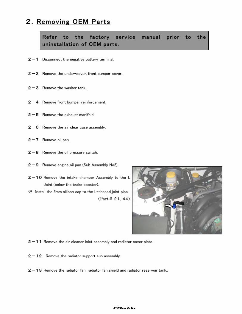
2-10 Remove the intake chamber Assembly to the L
Joint (below the brake booster).
※ Install the 5mm silicon cap to the L-shaped joint pipe.
〈Part # 21,44〉
2-11 Remove the air cleaner inlet assembly and radiator cover plate.
2-12 Remove the radiator support sub assembly.
2-13 Remove the radiator fan, radiator fan shield and radiator reservoir tank..
―6―
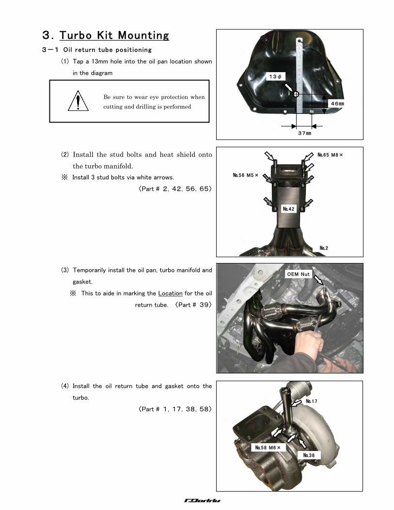
3.Turbo Kit Mounting 3-1 Oil return tube positioning
(1) Tap a 13mm hole into the oil pan location shown
in the diagram
(2) Install the stud bolts and heat shield onto the turbo manifold.
※ Install 3 stud bolts via white arrows.
〈Part # 2,42,56,65〉
(3) Temporarily install the oil pan, turbo manifold and
gasket.
※ This to aide in marking the Location for the oil
return tube. 〈Part # 39〉
(4) Install the oil return tube and gasket onto the
turbo.
〈Part # 1,17,38,58〉
OEM Nut
№58 M6×
15
№17
№38
№65 M8×
30
№56 M5×
10
№2
№42
46㎜
37㎜
13φ
Be sure to wear eye protection when cutting and drilling is performed
―7―
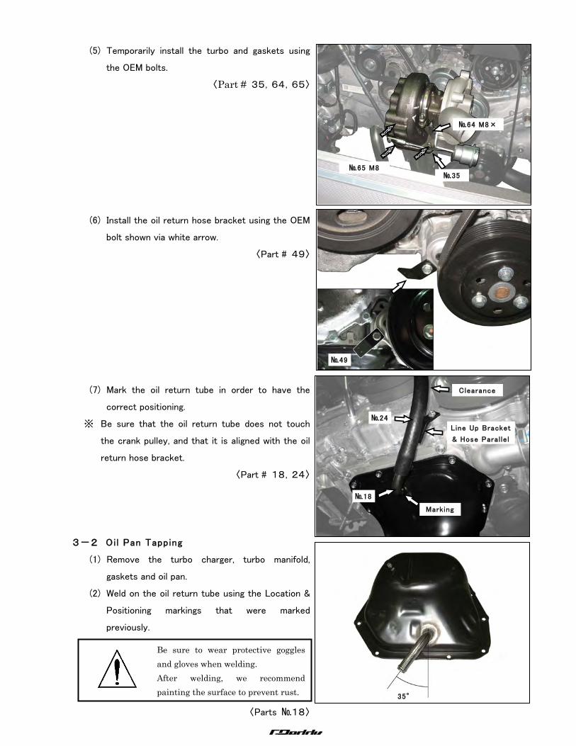
(5) Temporarily install the turbo and gaskets using
the OEM bolts.
〈Part # 35,64,65〉
(6) Install the oil return hose bracket using the OEM
bolt shown via white arrow.
〈Part # 49〉
(7) Mark the oil return tube in order to have the
correct positioning.
※ Be sure that the oil return tube does not touch
the crank pulley, and that it is aligned with the oil
return hose bracket.
〈Part # 18,24〉
3-2 Oil Pan Tapping
(1) Remove the turbo charger, turbo manifold,
gaskets and oil pan.
(2) Weld on the oil return tube using the Location &
Positioning markings that were marked
previously.
〈Parts №18〉
№65 M8
Nut
№64 M8×
35
№35
№49
Clearance
Line Up Bracket
& Hose Paral lel
№24
№18
Marking
35°
Be sure to wear protective goggles and gloves when welding. After welding, we recommend painting the surface to prevent rust.
―8―
3-3 Instal lation of Oil Pan
Install oil pan。
※ Use liquid gasket.
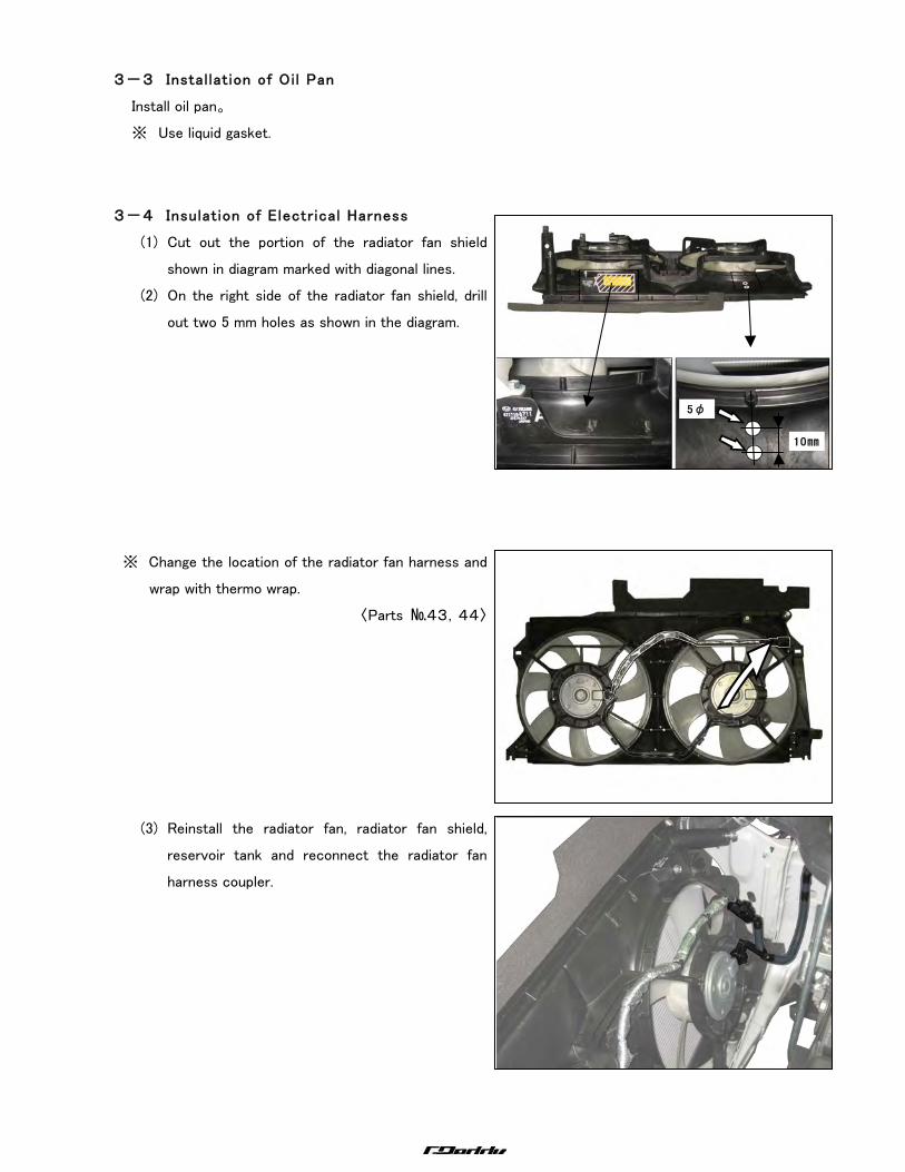
3-4 Insulation of Electrical Harness
(1) Cut out the portion of the radiator fan shield
shown in diagram marked with diagonal lines.
(2) On the right side of the radiator fan shield, drill
out two 5 mm holes as shown in the diagram.
※ Change the location of the radiator fan harness and
wrap with thermo wrap.
〈Parts №43,44〉
(3) Reinstall the radiator fan, radiator fan shield,
reservoir tank and reconnect the radiator fan
harness coupler.
5φ
10㎜
―9―
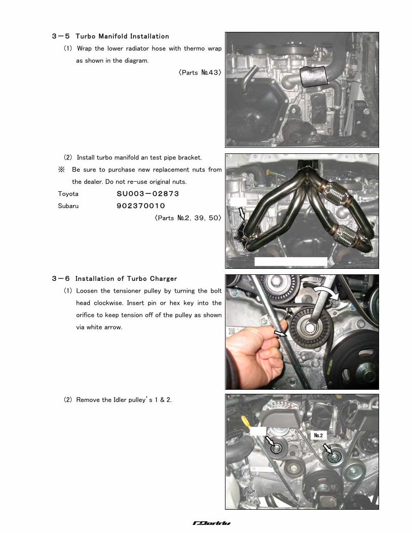
3-5 Turbo Manifold Instal lation
(1) Wrap the lower radiator hose with thermo wrap
as shown in the diagram.
〈Parts №43〉
(2) Install turbo manifold an test pipe bracket.
※ Be sure to purchase new replacement nuts from
the dealer. Do not re-use original nuts.
Toyota SU003-02873
Subaru 902370010
〈Parts №2,39,50〉
3-6 Instal lation of Turbo Charger
(1) Loosen the tensioner pulley by turning the bolt
head clockwise. Insert pin or hex key into the
orifice to keep tension off of the pulley as shown
via white arrow.
(2) Remove the Idler pulley’s 1 & 2.
№2
―10―
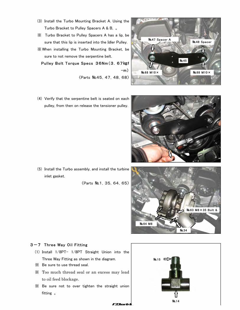
(3) Install the Turbo Mounting Bracket A. Using the
Turbo Bracket to Pulley Spacers A & B, 。
※ Turbo Bracket to Pulley Spacers A has a lip, be
sure that this lip is inserted into the Idler Pulley.
※ When installing the Turbo Mounting Bracket, be
sure to not remove the serpentine belt.
Pulley Bolt Torque Specs 36Nm(3.67㎏f
-m)
〈Parts №45,47,48,68〉
(4) Verify that the serpentine belt is seated on each
pulley, from then on release the tensioner pulley.
(5) Install the Turbo assembly, and install the turbine
inlet gasket.
〈Parts №1,35,64,65〉
3-7 Three Way Oil Fitting
(1) Install 1/8PT- 1/8PT Straight Union into the
Three Way Fitting as shown in the diagram.
※ Be sure to use thread seal.
※ Too much thread seal or an excess may lead to oil feed blockage.
※ Be sure not to over tighten the straight union
fitting 。
№64 M8
Nut
№63 M8×35 Bolt &
Nut
№34
№15
№14
№68 M10×
50
№45
№68 M10×
50
№47 Spacer A №48 Spacer
B
―11―
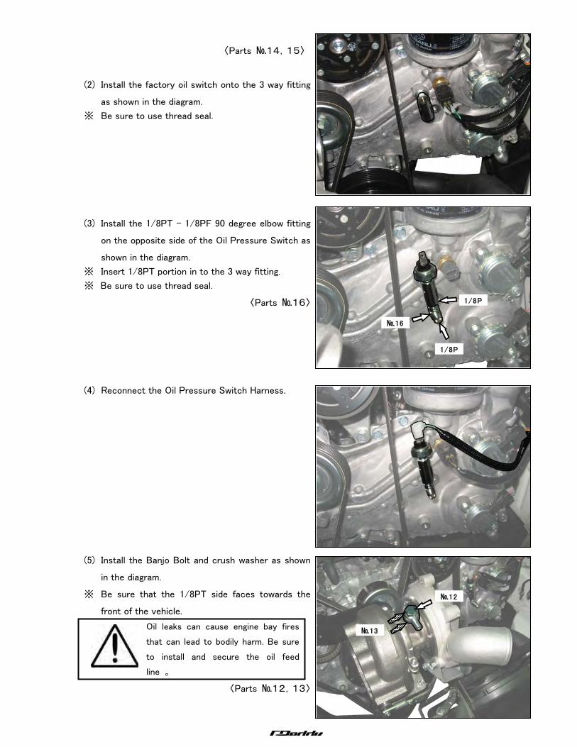
〈Parts №14,15〉
(2) Install the factory oil switch onto the 3 way fitting
as shown in the diagram.
※ Be sure to use thread seal.
(3) Install the 1/8PT - 1/8PF 90 degree elbow fitting
on the opposite side of the Oil Pressure Switch as
shown in the diagram.
※ Insert 1/8PT portion in to the 3 way fitting.
※ Be sure to use thread seal.
〈Parts №16〉
(4) Reconnect the Oil Pressure Switch Harness.
(5) Install the Banjo Bolt and crush washer as shown
in the diagram.
※ Be sure that the 1/8PT side faces towards the
front of the vehicle.
Oil leaks can cause engine bay fires
that can lead to bodily harm. Be sure
to install and secure the oil feed
line 。
〈Parts №12,13〉
№16
1/8P
F
1/8P
T
№12
№13
―12―
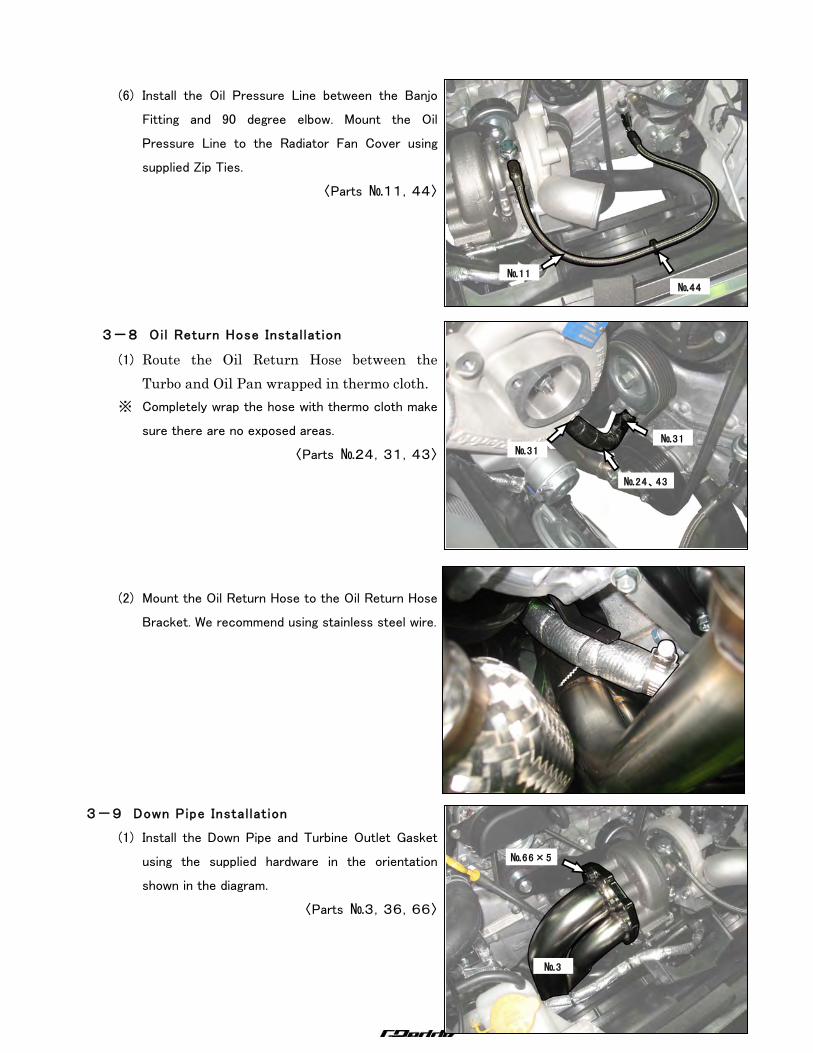
(6) Install the Oil Pressure Line between the Banjo
Fitting and 90 degree elbow. Mount the Oil
Pressure Line to the Radiator Fan Cover using
supplied Zip Ties.
〈Parts №11,44〉
3-8 Oil Return Hose Instal lation
(1) Route the Oil Return Hose between the Turbo and Oil Pan wrapped in thermo cloth.
※ Completely wrap the hose with thermo cloth make
sure there are no exposed areas.
〈Parts №24,31,43〉
(2) Mount the Oil Return Hose to the Oil Return Hose
Bracket. We recommend using stainless steel wire.
3-9 Down Pipe Instal lation
(1) Install the Down Pipe and Turbine Outlet Gasket
using the supplied hardware in the orientation
shown in the diagram.
〈Parts №3,36,66〉
№11
№44
№24、43
№31 №31
№66×5
№3
―13―
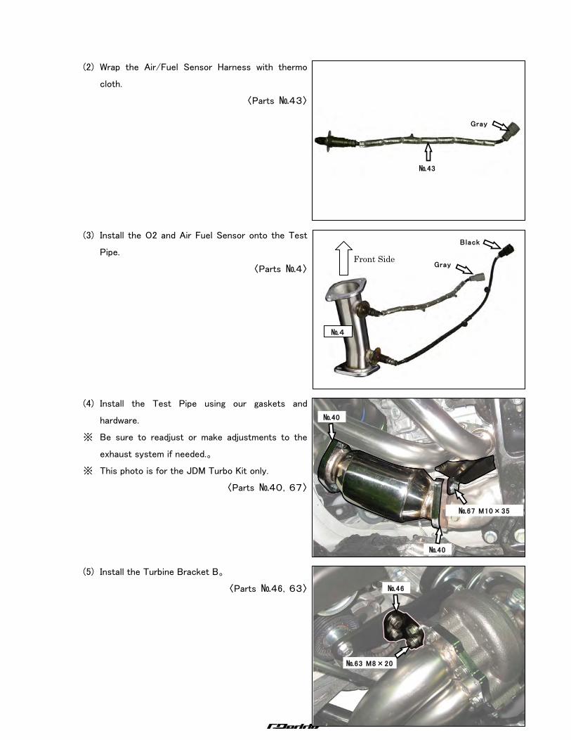
(2) Wrap the Air/Fuel Sensor Harness with thermo
cloth.
〈Parts №43〉
(3) Install the O2 and Air Fuel Sensor onto the Test
Pipe.
〈Parts №4〉
(4) Install the Test Pipe using our gaskets and
hardware.
※ Be sure to readjust or make adjustments to the
exhaust system if needed.。
※ This photo is for the JDM Turbo Kit only.
〈Parts №40,67〉
(5) Install the Turbine Bracket B。
〈Parts №46,63〉
Gray
№43
№46
№63 M8×20
№67 M10×35
№40
№40
Black
Gray
№4
Front Side
―14―
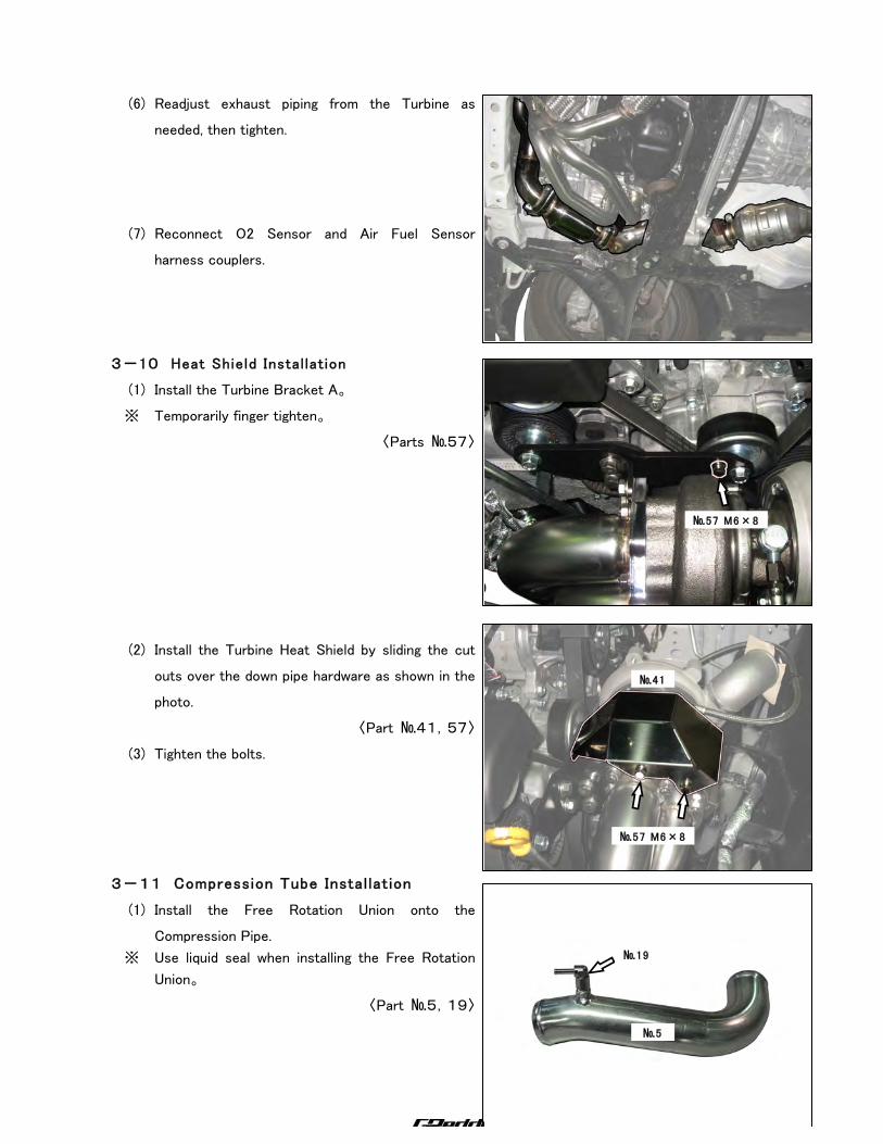
(6) Readjust exhaust piping from the Turbine as
needed, then tighten.
(7) Reconnect O2 Sensor and Air Fuel Sensor
harness couplers.
3-10 Heat Shield Instal lation
(1) Install the Turbine Bracket A。
※ Temporarily finger tighten。
〈Parts №57〉
(2) Install the Turbine Heat Shield by sliding the cut
outs over the down pipe hardware as shown in the
photo.
〈Part №41,57〉
(3) Tighten the bolts.
3-11 Compression Tube Instal lation
(1) Install the Free Rotation Union onto the
Compression Pipe.
※ Use liquid seal when installing the Free Rotation
Union。
〈Part №5,19〉
№57 M6×8
㎜
№57 M6×8
㎜
№41
№19
№5
―15―
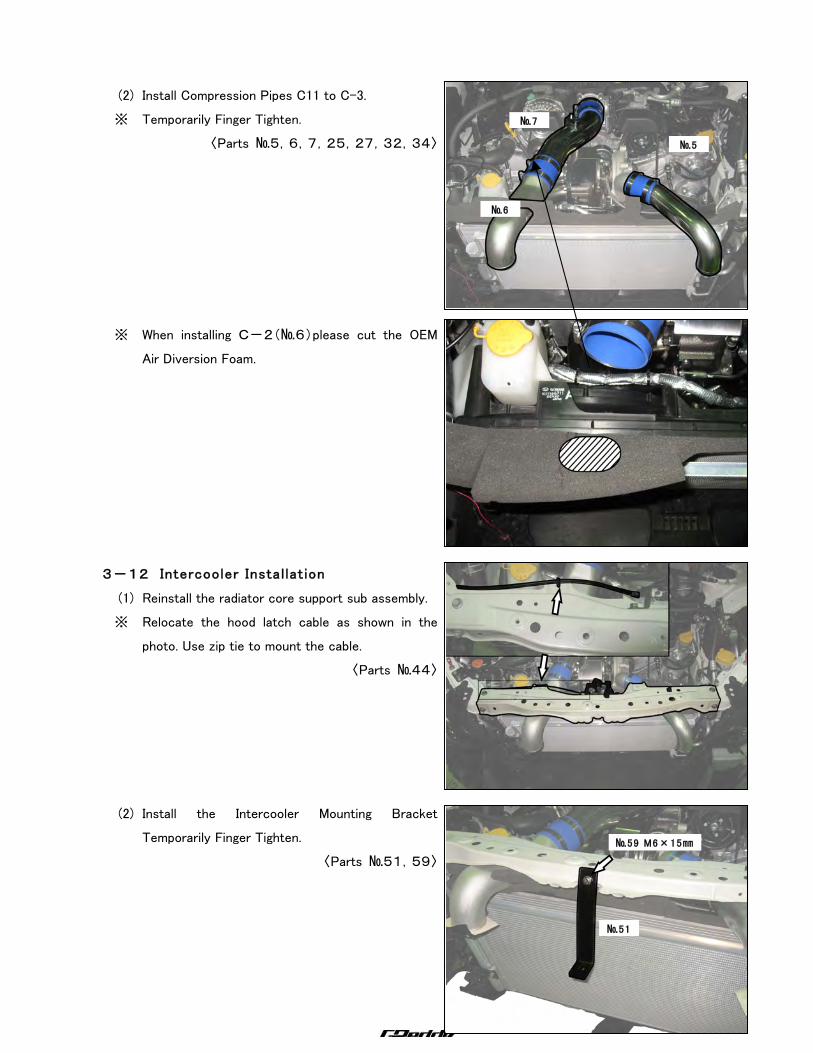
(2) Install Compression Pipes C11 to C-3.
※ Temporarily Finger Tighten.
〈Parts №5,6,7,25,27,32,34〉
※ When installing C-2(№6)please cut the OEM
Air Diversion Foam.
3-12 Intercooler Instal lation
(1) Reinstall the radiator core support sub assembly.
※ Relocate the hood latch cable as shown in the
photo. Use zip tie to mount the cable.
〈Parts №44〉
(2) Install the Intercooler Mounting Bracket
Temporarily Finger Tighten.
〈Parts №51,59〉
№5
№6
№7
№59 M6×15㎜
№51
―16―
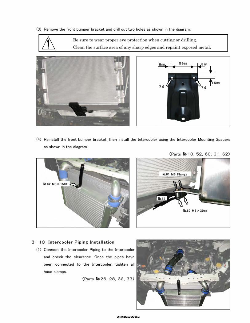
(3) Remove the front bumper bracket and drill out two holes as shown in the diagram.
(4) Reinstall the front bumper bracket, then install the Intercooler using the Intercooler Mounting Spacers
as shown in the diagram.
〈Parts №10,52,60,61,62〉
3-13 Intercooler Piping Instal lation
(1) Connect the Intercooler Piping to the Intercooler
and check the clearance. Once the pipes have
been connected to the Intercooler, tighten all
hose clamps.
〈Parts №26,28,32,33〉
15㎜
59㎜
8㎜
8㎜
7φ
7φ
№60 M6×30㎜
№61 M6 Flange
Nuts
№52
№62 M8×15㎜
Be sure to wear proper eye protection when cutting or drilling. Clean the surface area of any sharp edges and repaint exposed metal.
―17―
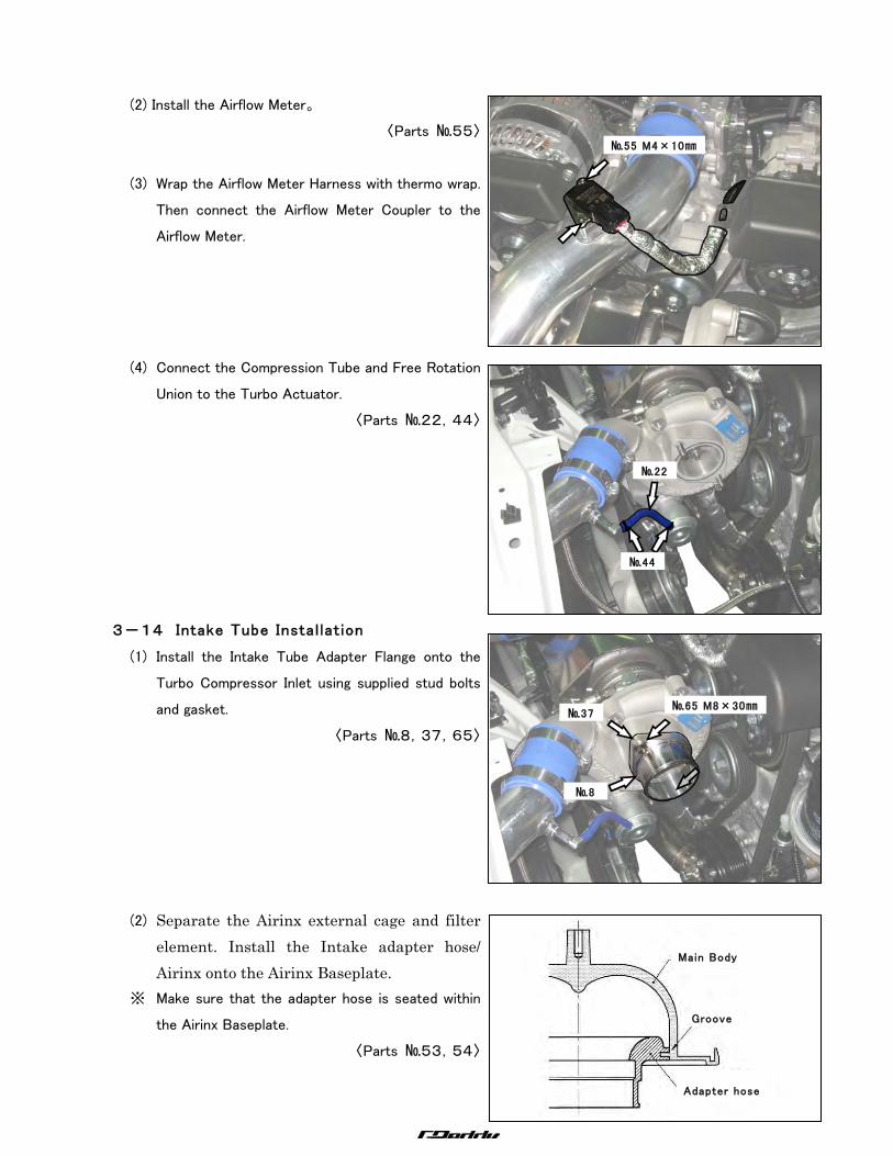
(2) Install the Airflow Meter。
〈Parts №55〉
(3) Wrap the Airflow Meter Harness with thermo wrap.
Then connect the Airflow Meter Coupler to the
Airflow Meter.
(4) Connect the Compression Tube and Free Rotation
Union to the Turbo Actuator.
〈Parts №22,44〉
3-14 Intake Tube Instal lation
(1) Install the Intake Tube Adapter Flange onto the
Turbo Compressor Inlet using supplied stud bolts
and gasket.
〈Parts №8,37,65〉
(2) Separate the Airinx external cage and filter element. Install the Intake adapter hose/ Airinx onto the Airinx Baseplate.
※ Make sure that the adapter hose is seated within
the Airinx Baseplate.
〈Parts №53,54〉
№55 M4×10㎜
№65 M8×30㎜
№8
№37
№22
№44
Main Body
Adapter hose
Groove
―18―
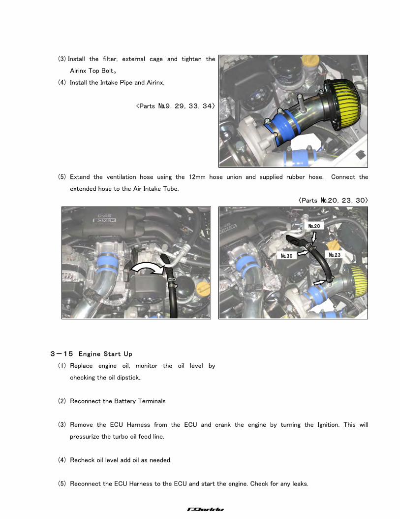
(3) Install the filter, external cage and tighten the
Airinx Top Bolt。
(4) Install the Intake Pipe and Airinx.
<Parts №9,29,33,34〉
(5) Extend the ventilation hose using the 12mm hose union and supplied rubber hose. Connect the
extended hose to the Air Intake Tube.
〈Parts №20,23,30〉
3-15 Engine Start Up
(1) Replace engine oil, monitor the oil level by
checking the oil dipstick..
(2) Reconnect the Battery Terminals
(3) Remove the ECU Harness from the ECU and crank the engine by turning the Ignition. This will
pressurize the turbo oil feed line.
(4) Recheck oil level add oil as needed.
(5) Reconnect the ECU Harness to the ECU and start the engine. Check for any leaks.
№20
№30
№23
―19―
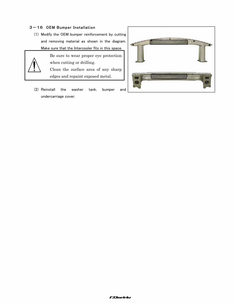
3-16 OEM Bumper Instal lation
(1) Modify the OEM bumper reinforcement by cutting
and removing material as shown in the diagram.
Make sure that the Intercooler fits in this space.
(2) Reinstall the washer tank, bumper and
undercarriage cover.
Be sure to wear proper eye protection when cutting or drilling. Clean the surface area of any sharp edges and repaint exposed metal.

―20―
4.Power Graph ○ This Turbo Kit is designed to boost up to 6 to 7.5 PSI.
※ Important This Turbo Kit is not Pre-tuned. The customer or Tuner must select a
proper fuel management system. The vehicle & fuel management system must
be re-tuned.
Spec Max Power kW(PS)/rpm Max Torque Nm(kg・m)/rpm
① Stock NA 127.5(173.4)/6770 187.9(19.2)/4780
② Turbo Kit 196.1(266.7)/7120 313.7(32.0)/3400
○ Results may vary.