Embed Size (px)
Citation preview
METRA. THE WORLD’S BEST KITS.™
© COPYRIGHT 2004-2011 METRA ELECTRONICS CORPORATION 1-800-221-0932 metraonline.com
INSTALLATION INSTRUCTIONS FOR PART FRST-2
REV.
8/1
4/20
12
INST
FRST
-2
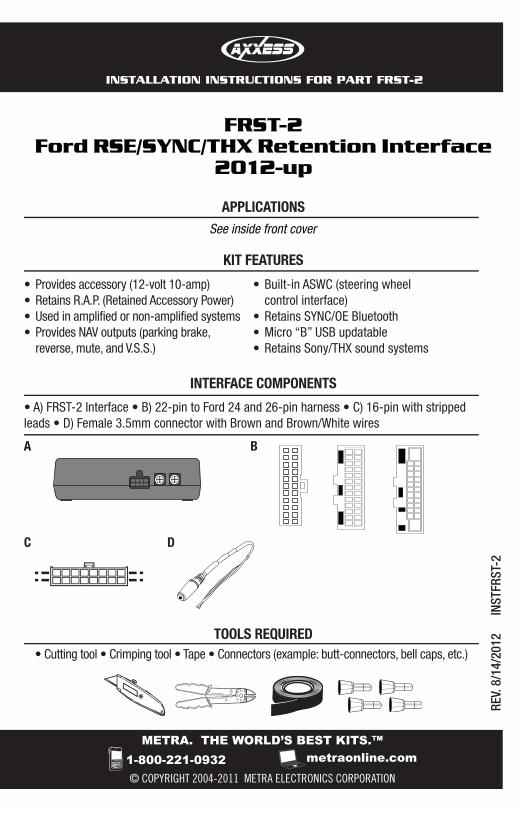
• Cutting tool • Crimping tool • Tape • Connectors (example: butt-connectors, bell caps, etc.)
IGNITIONTERM
INALS
WIRE
CUTTER
M3.5
M2.6
M3
M5
M4
ISO
62.5
1.5
TOOLS REQUIRED
FRST-2Ford RSE/SYNC/THX Retention Interface
2012-up
INTERFACE COMPONENTS
KIT FEATURES
APPLICATIONSSee inside front cover
• Provides accessory (12-volt 10-amp)• Retains R.A.P. (Retained Accessory Power)• Used in amplified or non-amplified systems • Provides NAV outputs (parking brake,
reverse, mute, and V.S.S.)
• A) FRST-2 Interface • B) 22-pin to Ford 24 and 26-pin harness • C) 16-pin with stripped leads • D) Female 3.5mm connector with Brown and Brown/White wires
A B
D
• Built-in ASWC (steering wheel control interface)
• Retains SYNC/OE Bluetooth• Micro “B” USB updatable• Retains Sony/THX sound systems
C
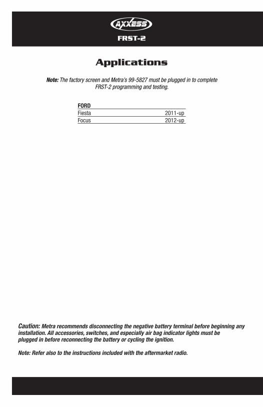
Applications
FRST-2
Caution: Metra recommends disconnecting the negative battery terminal before beginning any installation. All accessories, switches, and especially air bag indicator lights must be plugged in before reconnecting the battery or cycling the ignition.
Note: Refer also to the instructions included with the aftermarket radio.
FORDFiesta 2011-upFocus 2012-up
Note: The factory screen and Metra’s 99-5827 must be plugged in to completeFRST-2 programming and testing.
FRST-2
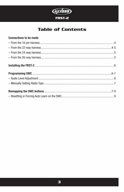
Table of Contents
Connections to be made
– From the 16-pin harness .................................................................................................. 4
– From the 22-way harness ..............................................................................................4-5
– From the 24-way harness ................................................................................................. 5
– From the 26-way harness ................................................................................................. 5
Installing the FRST-2 ......................................................................................................... 6
Programming SWC .........................................................................................................6-7
– Audio Level Adjustment .................................................................................................... 6
– Manually Setting Radio Type ............................................................................................. 7
Remapping the SWC buttons .........................................................................................7-9
– Resetting or Forcing Auto Learn on the SWC ..................................................................... 9
3
4
FRST-2
Connections to be made
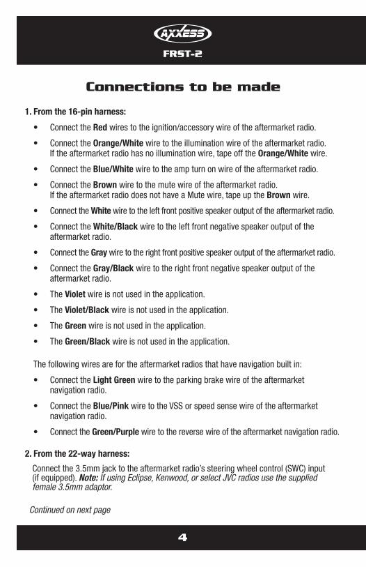
1. From the 16-pin harness:
• Connect the Red wires to the ignition/accessory wire of the aftermarket radio.
• Connect the Orange/White wire to the illumination wire of the aftermarket radio. If the aftermarket radio has no illumination wire, tape off the Orange/White wire.
• Connect the Blue/White wire to the amp turn on wire of the aftermarket radio.
• Connect the Brown wire to the mute wire of the aftermarket radio. If the aftermarket radio does not have a Mute wire, tape up the Brown wire.
• Connect the White wire to the left front positive speaker output of the aftermarket radio.
• Connect the White/Black wire to the left front negative speaker output of the aftermarket radio.
• Connect the Gray wire to the right front positive speaker output of the aftermarket radio.
• Connect the Gray/Black wire to the right front negative speaker output of the aftermarket radio.
• The Violet wire is not used in the application.
• The Violet/Black wire is not used in the application.
• The Green wire is not used in the application.
• The Green/Black wire is not used in the application.
The following wires are for the aftermarket radios that have navigation built in:
• Connect the Light Green wire to the parking brake wire of the aftermarket navigation radio.
• Connect the Blue/Pink wire to the VSS or speed sense wire of the aftermarket navigation radio.
• Connect the Green/Purple wire to the reverse wire of the aftermarket navigation radio.
2. From the 22-way harness:
Connect the 3.5mm jack to the aftermarket radio’s steering wheel control (SWC) input (if equipped). Note: If using Eclipse, Kenwood, or select JVC radios use the supplied female 3.5mm adaptor.
Continued on next page
FRST-2
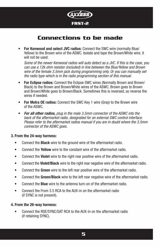
• ForKenwoodandselectJVCradios:Connect the SWC wire (normally Blue/Yellow) to the Brown wire of the ASWC. Isolate and tape the Brown/White wire, it will not be used.Some of the newer Kenwood radios will auto detect as a JVC. If this is the case, you can use a 12k ohm resistor (included) in line between the Blue/Yellow and Brown wire of the female 3.5mm jack during programming only. Or you can manually set the radio type which is in the radio programming section of this manual.
• ForEclipseradios:Connect the Eclipse SWC wires (Normally Brown and Brown/Black) to the Brown and Brown/White wires of the ASWC. Brown goes to Brown and Brown/White goes to Brown/Black. Sometimes this is reversed, so reverse the wires if needed.
• ForMetraOEradios:Connect the SWC Key 1 wire (Gray) to the Brown wire of the ASWC.
• For all other radios, plug in the male 3.5mm connector of the ASWC into the back of the aftermarket radio, designated for an external SWC control interface. Please refer to the aftermarket radios manual if you are in doubt where the 3.5mm connector of the ASWC goes.
3. From the 24-way harness:
• Connect the Black wire to the ground wire of the aftermarket radio.
• Connect the Yellow wire to the constant wire of the aftermarket radio.
• Connect the Violet wire to the right rear positive wire of the aftermarket radio.
• Connect the Violet/Black wire to the right rear negative wire of the aftermarket radio.
• Connect the Green wire to the left rear positive wire of the aftermarket radio.
• Connect the Green/Black wire to the left rear negative wire of the aftermarket radio.
• Connect the Blue wire to the antenna turn-on of the aftermarket radio.
• Connect the From 3.5 RCA to the AUX-in on the aftermarket radio (if SYNC is not present).
4. From the 26-way harness:
• Connect the RSE/SYNC/SAT RCA to the AUX-in on the aftermarket radio (if retaining SYNC).
Connections to be made
5
6
FRST-2
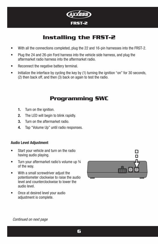
Installing the FRST-2
• With all the connections completed, plug the 22 and 16-pin harnesses into the FRST-2.
• Plug the 24 and 26-pin Ford harness into the vehicle side harness, and plug the aftermarket radio harness into the aftermarket radio.
• Reconnect the negative battery terminal.
• Initialize the interface by cycling the key by (1) turning the ignition “on” for 30 seconds, (2) then back off, and then (3) back on again to test the radio.
1. Turn on the ignition.
2. The LED will begin to blink rapidly.
3. Turn on the aftermarket radio.
4. Tap “Volume Up” until radio responses.
Audio Level Adjustment
• Start your vehicle and turn on the radio having audio playing.
• Turn your aftermarket radio’s volume up ¾ of the way.
• With a small screwdriver adjust the potentiometer clockwise to raise the audio level and counterclockwise to lower the audio level.
• Once at desired level your audio adjustment is complete.
POTENTIOMETER
Programming SWC
Continued on next page
FRST-2
7
Programming SWC
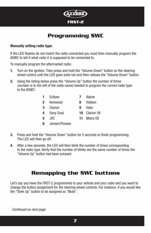
Manuallysettingradiotype:
If the LED flashes do not match the radio connected you must then manually program the ASWC to tell it what radio it is supposed to be connected to.
To manually program the aftermarket radio:
1. Turn on the ignition. Then press and hold the “Volume Down” button on the steering wheel control until the LED goes solid red and then release the “Volume Down” button.
2. Using the listing below press the “Volume Up” button the number of times (number is to the left of the radio name) needed to program the correct radio type to the ASWC:
3. Press and hold the “Volume Down” button for 5 seconds to finish programming. The LED will then go off.
4. After a few seconds, the LED will then blink the number of times corresponding to the radio type. Verify that the number of blinks are the same number of times the “Volume Up” button had been pressed.
1 Eclipse2 Kenwood3 Clarion4 Sony Dual5 JVC6 Jensen/Pioneer
7 Alpine8 Visteon9 Valor10 Clarion 5K11 Metra OE
Remapping the SWC buttons
Let’s say you have the FRST-2 programmed to your vehicle and your radio and you want to change the button assignment for the steering wheel controls. For instance, if you would like the “Seek Up” button to be assigned as “Mute”.
Continued on next page
8
Remapping the SWC buttons
FRST-2
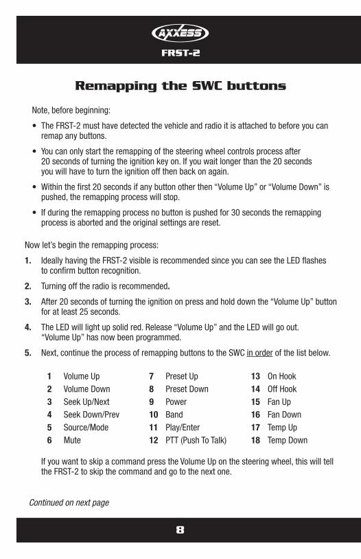
Note, before beginning:
• The FRST-2 must have detected the vehicle and radio it is attached to before you can remap any buttons.
• You can only start the remapping of the steering wheel controls process after 20 seconds of turning the ignition key on. If you wait longer than the 20 seconds you will have to turn the ignition off then back on again.
• Within the first 20 seconds if any button other then “Volume Up” or “Volume Down” is pushed, the remapping process will stop.
• If during the remapping process no button is pushed for 30 seconds the remapping process is aborted and the original settings are reset.
Now let’s begin the remapping process:
1. Ideally having the FRST-2 visible is recommended since you can see the LED flashes to confirm button recognition.
2. Turning off the radio is recommended.
3. After 20 seconds of turning the ignition on press and hold down the “Volume Up” button for at least 25 seconds.
4. The LED will light up solid red. Release “Volume Up” and the LED will go out. “Volume Up” has now been programmed.
5. Next, continue the process of remapping buttons to the SWC in order of the list below.
If you want to skip a command press the Volume Up on the steering wheel, this will tell the FRST-2 to skip the command and go to the next one.
Continued on next page
1 Volume Up2 Volume Down3 Seek Up/Next4 Seek Down/Prev5 Source/Mode6 Mute
7 Preset Up8 Preset Down9 Power10 Band11 Play/Enter12 PTT (Push To Talk)
13 On Hook14 Off Hook15 Fan Up16 Fan Down17 Temp Up18 Temp Down
Remapping the SWC buttons
FRST-2
9
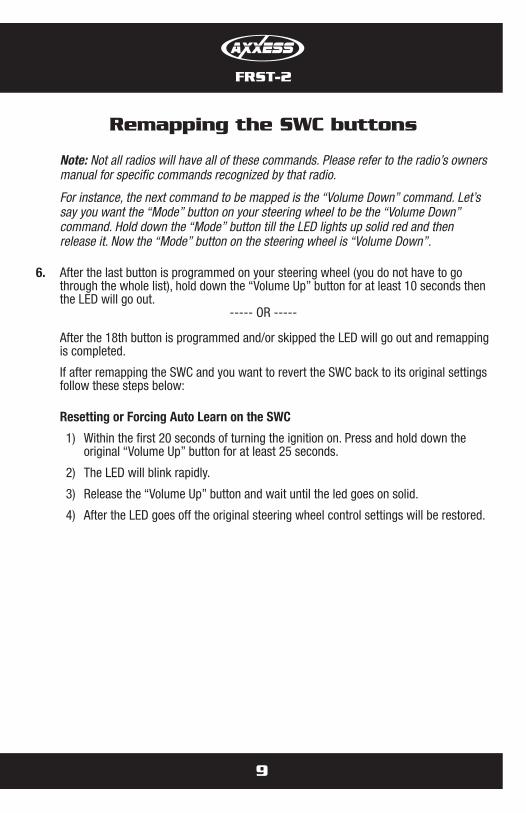
Note: Not all radios will have all of these commands. Please refer to the radio’s owners manual for specific commands recognized by that radio.
For instance, the next command to be mapped is the “Volume Down” command. Let’s say you want the “Mode” button on your steering wheel to be the “Volume Down” command. Hold down the “Mode” button till the LED lights up solid red and then release it. Now the “Mode” button on the steering wheel is “Volume Down”.
6. After the last button is programmed on your steering wheel (you do not have to go through the whole list), hold down the “Volume Up” button for at least 10 seconds then the LED will go out.
----- OR -----
After the 18th button is programmed and/or skipped the LED will go out and remapping is completed.
If after remapping the SWC and you want to revert the SWC back to its original settings follow these steps below:
Resetting or Forcing Auto Learn on the SWC
1) Within the first 20 seconds of turning the ignition on. Press and hold down the original “Volume Up” button for at least 25 seconds.
2) The LED will blink rapidly.
3) Release the “Volume Up” button and wait until the led goes on solid.
4) After the LED goes off the original steering wheel control settings will be restored.

Notes
Notes

METRA. THE WORLD’S BEST KITS.™
© COPYRIGHT 2004-2011 METRA ELECTRONICS CORPORATION 1-800-221-0932 metraonline.com
INSTALLATION INSTRUCTIONS FOR PART FRST-2
REV.
8/1
4/20
12
INST
FRST
-2
KNOWLEDGE IS POWEREnhance your installation and fabrication skills by enrolling in the most recognized and respected mobile electronics school in our industry.Log onto www.installerinstitute.com or call 800-354-6782 for more information and take steps toward a better tomorrow.
Metra recommends MECP certified technicians
IMPORTANTWARNINGThis product includes instructions for installation which must be carefully followed. The instructions are worded in such a manner to assume that the installer is capable of completing these type of electronic installations. If you are unclear as to what you are instructed to do or believe that you do not understand the instructions so as to properly and safely complete the installation you should consult a technician who does have this knowledge and understanding.
Failure to follow these instructions carefully and to install the interface as described could cause harm to the vehicle or to safety systems on the vehicle. Interference with certain safety systems could cause harm to persons as well. If you have any questions in thisregardpleasecalltheHelplineorMetraat1-800-221-0932 for assistance.
METRA. THE WORLD’S BEST KITS.™
© COPYRIGHT 2004-2011 METRA ELECTRONICS CORPORATION 1-800-221-0932 metraonline.com
INSTRUCCIONES DE INSTALACIÓN PARA LA PIEZA FRST-2
REV.
8/2
8/20
12
INST
FRST
-2
• Cortador • Pelacables • Cinta • Conectores (p. ej., conectores a tope, tapas acampanadas, etc.)
IGNITIONTERM
INALS
WIRE
CUTTER
M3.5
M2.6
M3
M5
M4
ISO
62.5
1.5
HERRAMIENTAS REQUERIDAS
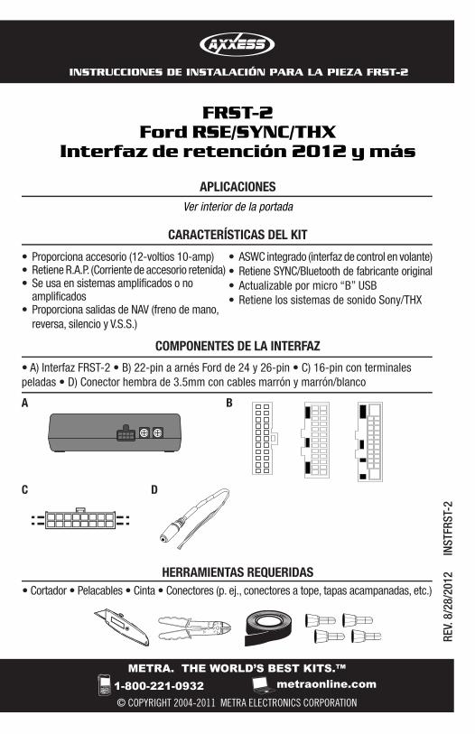
FRST-2Ford RSE/SYNC/THX
Interfaz de retención 2012 y más
COMPONENTES DE LA INTERFAZ
CARACTERÍSTICAS DEL KIT
APLICACIONESVer interior de la portada
• A) Interfaz FRST-2 • B) 22-pin a arnés Ford de 24 y 26-pin • C) 16-pin con terminales peladas • D) Conector hembra de 3.5mm con cables marrón y marrón/blanco
A B
DC
• ASWC integrado (interfaz de control en volante)• Retiene SYNC/Bluetooth de fabricante original• Actualizable por micro “B” USB• Retiene los sistemas de sonido Sony/THX
• Proporciona accesorio (12-voltios 10-amp)• Retiene R.A.P. (Corriente de accesorio retenida)• Se usa en sistemas amplificados o no
amplificados• Proporciona salidas de NAV (freno de mano,
reversa, silencio y V.S.S.)
Aplicaciones
FRST-2
PRECAUCIÓN: Metra recomienda desconectar el terminal negativo de la batería antes de comenzar cualquier instalación. Todos los accesorios, interruptores y, especialmente, las luces indicadoras de airbag deben estar enchufados antes de volver a conectar la batería o comenzar el ciclo de ignición.
Nota: Remítase a las instrucciones incluidas con el radio de postventa.
FORDFiesta 2011 y más Focus 2012 y más
Nota: La pantalla de fábrica y el Metra 99-5827 deben estar conectados para realizarla programación y pruebas de FRST-2.
FRST-2
Indice
Conexiones que se deben hacer
– Desde el arnés de 16-pin ................................................................................................. 4
– Desde el arnés de 22 vías .............................................................................................4-5
– Desde el arnés de 24 vías ................................................................................................ 5
– Desde el arnés de 26 vías ................................................................................................ 5
Instalación del FRST-2 ....................................................................................................... 6
Programación de SWC ...................................................................................................6-7
– Ajuste del nivel de audio ................................................................................................... 6
– Configuración manual del tipo de radio ............................................................................. 7
Remapeo de los botones SWC........................................................................................7-9
– Cómo restablecer o forzar el aprendizaje automático en el SWC ....................................... 9
3
4
FRST-2
Conexiones que se deben hacer
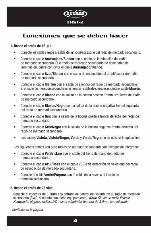
1. Desde el arnés de 16-pin:
• Conecte los cables rojos al cable de ignición/accesorio del radio de mercado secundario.
• Conecte el cable Anaranjado/Blanco con el cable de iluminación del radio de mercado secundario. Si el radio de mercado secundario no tiene cable de iluminación, cubra con cinta el cable Anaranjado/Blanco.
• Conecte el cable Azul/Blanco con el cable de encendido del amplificador del radio de mercado secundario.
• Conecte el cable Marrón con el cable de silencio del radio de mercado secundario. Si el radio de mercado secundario no tiene un cable de silencio, encinte el cable Marrón.
• Conecte el cable Blanco con la salida de la bocina positiva frontal izquierda del radio de mercado secundario.
• Conecte el cable Blanco/Negro con la salida de la bocina negativa frontal izquierda del radio de mercado secundario.
• Conecte el cable Gris con la salida de la bocina positiva frontal derecha del radio de mercado secundario.
• Conecte el cable Gris/Negro con la salida de la bocina negativa frontal derecha del radio de mercado secundario.
• Los cables Violeta, Violeta/Negro, Verde y Verde/Negro no se utilizan la aplicación.
Los siguientes cables son para radios de mercado secundario con navegación integrada:
• Conecte el cable Verde claro con el cable del freno de mano del radio de mercado secundario.
• Conecte el cable Azul/Rosa con el cable VSS o de detección de velocidad del radio de navegación de mercado secundario.
• Conecte el cable Verde/Púrpura con el cable de la reversa del radio de mercado secundario.
2. Desde el arnés de 22 vías:
Conecte el conector de 3.5mm a la entrada de control del volante de su radio de mercado secundario (SWC, si cuenta con dicho equipamiento). Nota: Si usa un radio Eclipse, Kenwood o algunos radios JVC, use el adaptador hembra de 3.5mm suministrado.
Continúa en la página
FRST-2
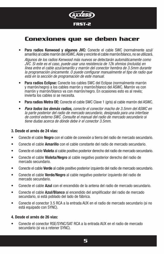
• Para radios Kenwood y algunos JVC: Conecte el cable SWC (normalmente azul/amarillo) al cable marrón del ASWC. Aísle y encinte el cable marrón/blanco, no se utilizará.
Algunos de los radios Kenwood más nuevos se detectarán automáticamente como JVC. Si este es el caso, puede usar una resistencia de 12k ohmios (incluida) en línea entre el cable azul/amarillo y marrón del conector hembra de 3.5mm durante la programación únicamente. O puede configurar manualmente el tipo de radio que está en la sección de programación de este manual.
• PararadiosEclipse:Conecte los cables SWC del Eclipse (normalmente marrón y marrón/negro) a los cables marrón y marrón/blanco del ASWC. Marrón va con marrón y marrón/blanco va con marrón/negro. En ocasiones esto es al revés; invierta los cables si se necesita.
• PararadiosMetraOE:Conecte el cable SWC Clave 1 (gris) al cable marrón del ASWC.
• Para todos los demás radios, conecte el conector macho de 3.5mm del ASWC en la parte posterior del radio de mercado secundario, designada para una interfase de control externo SWC. Consulte el manual del radio de mercado secundario si tiene dudas acerca de dónde debe ir el conector 3.5mm.
3. Desde el arnés de 24 vías:
• Conecte el cable Negro con el cable de conexión a tierra del radio de mercado secundario.
• Conecte el cable Amarillo con el cable constante del radio de mercado secundario.
• Conecte el cable Violeta al cable positivo posterior derecho del radio de mercado secundario.
• Conecte el cable Violeta/Negro al cable negativo posterior derecho del radio de mercado secundario.
• Conecte el cable Verde al cable positivo posterior izquierdo del radio de mercado secundario.
• Conecte el cable Verde/Negro al cable negativo posterior izquierdo del radio de mercado secundario.
• Conecte el cable Azul con el encendido de la antena del radio de mercado secundario.
• Conecte el cable Azul/Blanco al encendido del amplificador del radio de mercado secundario, si está poblado del lado de fábrica.
• Conecte el conector 3.5 RCA a la entrada AUX en el radio de mercado secundario (si no está equipado con SYNC).
4. Desde el arnés de 26 vías:
• Conecte el conector RSE/SYNC/SAT RCA a la entrada AUX en el radio de mercado secundario (si va a retener SYNC).
Conexiones que se deben hacer
5
6
FRST-2
Instalación del FRST-2
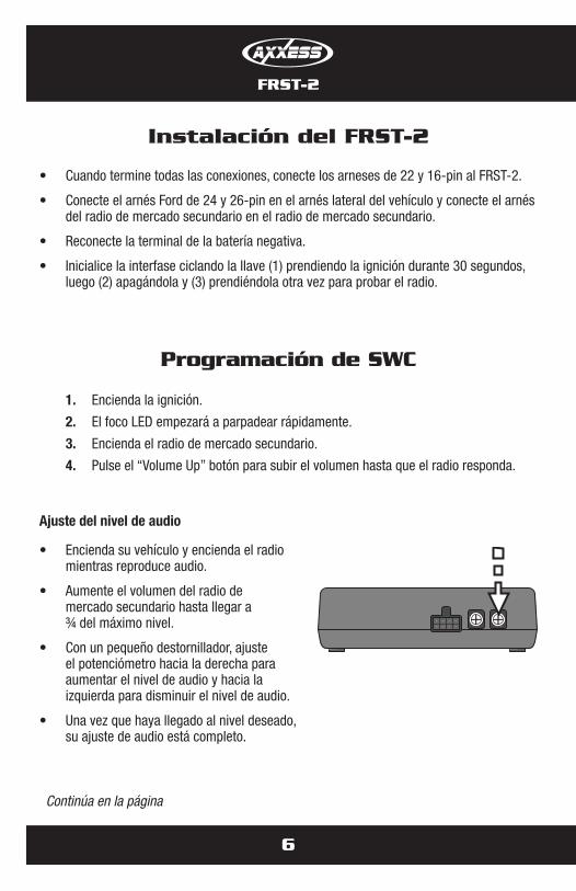
• Cuando termine todas las conexiones, conecte los arneses de 22 y 16-pin al FRST-2.
• Conecte el arnés Ford de 24 y 26-pin en el arnés lateral del vehículo y conecte el arnés del radio de mercado secundario en el radio de mercado secundario.
• Reconecte la terminal de la batería negativa.
• Inicialice la interfase ciclando la llave (1) prendiendo la ignición durante 30 segundos, luego (2) apagándola y (3) prendiéndola otra vez para probar el radio.
1. Encienda la ignición.
2. El foco LED empezará a parpadear rápidamente.
3. Encienda el radio de mercado secundario.
4. Pulse el “Volume Up” botón para subir el volumen hasta que el radio responda.
Ajuste del nivel de audio
• Encienda su vehículo y encienda el radio mientras reproduce audio.
• Aumente el volumen del radio de mercado secundario hasta llegar a ¾ del máximo nivel.
• Con un pequeño destornillador, ajuste el potenciómetro hacia la derecha para aumentar el nivel de audio y hacia la izquierda para disminuir el nivel de audio.
• Una vez que haya llegado al nivel deseado, su ajuste de audio está completo.
POTENTIOMETER
Programación de SWC
Continúa en la página
FRST-2
7
Programación de SWC
Configuración manual del tipo de radio:
Si el parpadeo del foco LED no corresponde al radio conectado, debe programar manualmente el ASWC para indicar a cuál radio se supone que debe estar conectado.
Para programar manualmente el radio de mercado secundario:
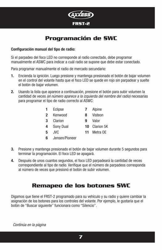
1. Encienda la ignición. Luego presione y mantenga presionado el botón de bajar volumen en el control del volante hasta que el foco LED se quede en rojo sin parpadear y suelte el botón de bajar volumen.
2. Usando la lista que aparece a continuación, presione el botón para subir volumen la cantidad de veces (el número aparece a la izquierda del nombre del radio) necesarias para programar el tipo de radio correcto al ASWC:
3. Presione y mantenga presionado el botón de bajar volumen durante 5 segundos para terminar la programación. El foco LED se apagará.
4. Después de unos cuantos segundos, el foco LED parpadeará la cantidad de veces correspondiente al tipo de radio. Verifique que el número de parpadeos corresponda al número de veces que presionó el botón de subir volumen.
1 Eclipse2 Kenwood3 Clarion4 Sony Dual5 JVC6 Jensen/Pioneer
7 Alpine8 Visteon9 Valor10 Clarion 5K11 Metra OE
Remapeo de los botones SWC
Digamos que tiene el FRST-2 programado para su vehículo y su radio y quiere cambiar la asignación de los botones para los controles del volante. Por ejemplo, le gustaría que el botón de “Buscar siguiente” funcionara como “Silencio”.
Continúa en la página
8
Remapeo de los botones SWC
FRST-2
Antes de empezar, tenga en cuenta que:
• El FRST-2 debe haber detectado el vehículo y radio conectado antes de que se puedan remapear los botones.
• Solo podrá iniciar el proceso de remapeo de los controles del volante 20 segundos después de abrir la llave de la ignición. Si espera más de 20 segundos, tendrá que apagar la ignición y volver a encenderla.
• En los primeros 20 segundos, si se presiona cualquier botón que no sea el de subir o bajar volumen, el proceso de remapeo se detendrá.
• Si durante el proceso de remapeo no se presiona ningún botón durante 30 segundos, el proceso de remapeo se aborta y se restablecen los ajustes originales.
Empecemos ahora el proceso de remapeo:
1. Idealmente se recomienda tener el FRST-2 visible, puesto que se puede ver el parpadeo del foco LED para confirmar el reconocimiento de los botones.
2. Se recomienda apagar el radio.
3. 20 segundos después de encender la ignición, presione y mantenga presionado el botón de subir volumen durante cuando menos 25 segundos.
4. El foco LED se iluminará en rojo sin parpadear. Suelte el botón de subir volumen y el foco LED se apagará. Con esto queda programado el botón de subir volumen.
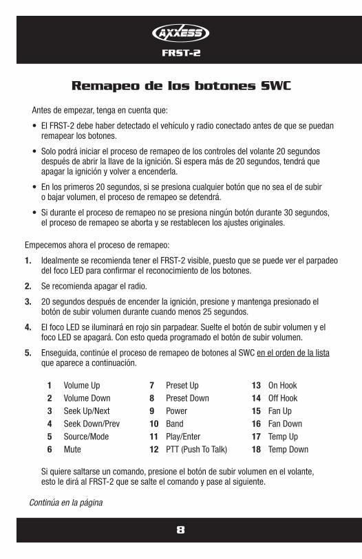
5. Enseguida, continúe el proceso de remapeo de botones al SWC en el orden de la lista que aparece a continuación.
Si quiere saltarse un comando, presione el botón de subir volumen en el volante, esto le dirá al FRST-2 que se salte el comando y pase al siguiente.
Continúa en la página
1 Volume Up2 Volume Down3 Seek Up/Next4 Seek Down/Prev5 Source/Mode6 Mute
7 Preset Up8 Preset Down9 Power10 Band11 Play/Enter12 PTT (Push To Talk)
13 On Hook14 Off Hook15 Fan Up16 Fan Down17 Temp Up18 Temp Down
Remapeo de los botones SWC
FRST-2
9
Nota: No todos los radios tienen todos estos comandos. Consulte el manual del propietario del radio para los comandos específicos reconocidos por ese radio.
Por ejemplo, el siguiente comando a mapear es el comando de bajar volumen. Digamos que usted quiere que el botón “Modo” de su volante sea el comando “Bajar volumen”. Mantenga presionado el botón “Modo” hasta que el foco LED se ilumine en rojo sin parpadear, luego suéltelo. Ahora el botón “Modo” de su volante es el botón para bajar el volumen.
6. Después de programar el último botón en su volante (no tiene que pasar por toda la lista), mantenga presionado el botón de subir volumen durante al menos 10 segundos y el foco LED se apagará.
----- O bien -----
Después de que programe o se salte el botón número 18, el foco se apagará y el remapeo habrá terminado.
Si después del remapeo del SWC usted desea revertir el SWC a su configuración original, siga estos pasos:
Cómo restablecer o forzar el aprendizaje automático en el SWC
1) En los primeros 20 segundos después de encender la ignición Presione y mantenga presionado el botón original de subir volumen durante 25 segundos, cuando menos.
2) El foco LED parpadeará rápidamente.
3) Suelte el botón de subir volumen y espere hasta que el foco LED se encienda sin parpadear.
4) Después de que el foco LED se apague, los ajustes originales del control del volante se restablecerán.

Notas

Notas
METRA. THE WORLD’S BEST KITS.™
© COPYRIGHT 2004-2011 METRA ELECTRONICS CORPORATION 1-800-221-0932 metraonline.com
INSTRUCCIONES DE INSTALACIÓN PARA LA PIEZA FRST-2
REV.
8/2
8/20
12
INST
FRST
-2
KNOWLEDGE IS POWEREnhance your installation and fabrication skills by enrolling in the most recognized and respected mobile electronics school in our industry.Log onto www.installerinstitute.com or call 800-354-6782 for more information and take steps toward a better tomorrow.
ADVERTENCIAIMPORTANTEEste producto incluye instrucciones de instalación que deben seguirse cuidadosamente. Dichas instrucciones están redactadas dando por supuesto que el instalador es capaz de completar estos tipos de instalaciones electrónicas. Si tiene dudas respecto de lo que se le indica que haga o cree que no comprende las instrucciones como para completar la instalación en forma adecuada y segura, debe consultar a un técnico que efectivamente tenga estos conocimientos y comprensión.
Sinosigueestasinstruccionesconcuidadoynoinstalalainterfaz como se describe, podría provocar daños en el vehículo o en los sistemas de seguridad del vehículo. La interferencia con determinados sistemas de seguridad también podría provocar daños a las personas. Si tiene alguna pregunta al respecto, llamealalíneadeayudaoametra,al1-800-221-0932paraobtener asistencia.
Metra recomienda técnicos con certificación del Programa de Certificación en Electrónica Móvil (Mobile Electronics Certification Program, MECP).
EL CONOCIMIENTO ES PODERMejore sus habilidades de instalación y fabricación inscribiéndose en la escuela de dispositivos electrónicos móviles más reconocida y respetada de nuestra industria. Regístrese en www.installerinstitute.com o llame al 800-354-6782 para obtener más información y avance hacia un futuro mejor.