Embed Size (px)
Citation preview
** WARNING ** WARNING ** WARNING ** WARNING **This document is intended for informational purposes only.
Users are cautioned that California Department of Transportation (Department) does not assume any liability or responsibility based on these electronic files or for any defective or incomplete copying, exerpting, scanning, faxing or downloading of the contract documents. As always, for the official paper versions of the bidders packages and non-bidder packages, including addenda write to the California Department of Transportation, Plans and Bid Documents, Room 0200, P.O. Box 942874, Sacramento, CA 94272-0001, telephone (916) 654-4490 or fax (916) 654-7028. Office hours are 7:30 a.m. to 4:15 p.m. When ordering bidder or non-bidder packages it is important that you include a telephone number and fax number, P.O. Box and street address so that you can receive addenda.
etric
Caltrans
STATE OF CALIFORNIA
DEPARTMENT OF TRANSPORTATION__________________________________________________________
NOTICE TO CONTRACTORSAND
SPECIAL PROVISIONSFOR CONSTRUCTION ON STATE HIGHWAY IN
ORANGE COUNTY AT VARIOUS LOCATIONS
DISTRICT 12, ROUTES 73, 133, 241, 261
__________________________________________________________
For Use in Connection with Standard Specifications Dated JULY 1999, Standard Plans Dated JULY 1999, and Labor Surcharge and Equipment Rental Rates.
__________________________________________________________
CONTRACT NO. 12-0E1104
12-Ora-73, 133, 241, 261-Var
Federal Aid Project
ACSTP-X059(043)E
Bids Open: September 29, 2005Dated: August 22, 2005

TABLE OF CONTENTS
NOTICE TO CONTRACTORS.............................................................................................................................................1COPY OF ENGINEER'S ESTIMATE..................................................................................................................................4SPECIAL PROVISIONS.......................................................................................................................................................7SECTION 1. SPECIFICATIONS AND PLANS..................................................................................................................7AMENDMENTS TO JULY 1999 STANDARD SPECIFICATIONS..................................................................................7SECTION 2. PROPOSAL REQUIREMENTS AND CONDITIONS................................................................................69
2-1.01 GENERAL........................................................................................................................................................692-1.015 FEDERAL LOBBYING RESTRICTIONS...................................................................................................692-1.02 DISADVANTAGED BUSINESS ENTERPRISE (DBE)................................................................................70
SECTION 3. AWARD AND EXECUTION OF CONTRACT..........................................................................................71SECTION 4. BEGINNING OF WORK, TIME OF COMPLETION AND LIQUIDATED DAMAGES.........................71SECTION 5. GENERAL....................................................................................................................................................72SECTION 5-1. MISCELLANEOUS..................................................................................................................................72
5-1.01 PLANS AND WORKING DRAWINGS.........................................................................................................725-1.011 EXAMINATION OF PLANS, SPECIFICATIONS, CONTRACT, AND SITE OF WORK.......................725-1.012 DIFFERING SITE CONDITIONS.................................................................................................................725-1.013 LINES AND GRADES..................................................................................................................................725-1.015 LABORATORY.............................................................................................................................................725-1.017 CONTRACT BONDS....................................................................................................................................725-1.019 COST REDUCTION INCENTIVE................................................................................................................735-1.02 LABOR NONDISCRIMINATION..................................................................................................................735-1.022 EXCLUSION OF RETENTION....................................................................................................................735-1.023 UNSATISFACTORY PROGRESS................................................................................................................735-1.03 INTEREST ON PAYMENTS..........................................................................................................................735-1.04 PUBLIC SAFETY............................................................................................................................................745-1.05 TESTING..........................................................................................................................................................755-1.06 REMOVAL OF ASBESTOS AND HAZARDOUS SUBSTANCES..............................................................755-1.07 (BLANK)..........................................................................................................................................................755-1.075 BUY AMERICA REQUIREMENTS.............................................................................................................755-1.08 SUBCONTRACTOR AND DBE RECORDS.................................................................................................765-1.083 DBE CERTIFICATION STATUS.................................................................................................................765-1.09 SUBCONTRACTING......................................................................................................................................765-1.10 PROMPT PROGRESS PAYMENT TO SUBCONTRACTORS....................................................................765-1.103 RECORDS......................................................................................................................................................775-1.11 PARTNERING.................................................................................................................................................775-1.114 VALUE ANALYSIS......................................................................................................................................775-1.12 DISPUTE REVIEW BOARD..........................................................................................................................785-1.13 FORCE ACCOUNT PAYMENT.....................................................................................................................885-1.14 AREAS FOR CONTRACTOR'S USE.............................................................................................................895-1.15 PAYMENTS.....................................................................................................................................................895-1.16 PROJECT INFORMATION............................................................................................................................895-1.17 SOUND CONTROL REQUIREMENTS.........................................................................................................905-1.18 INTERNET DAILY EXTRA WORK REPORT.............................................................................................90
SECTION 6. (BLANK).......................................................................................................................................................90SECTION 7. (BLANK).......................................................................................................................................................90SECTION 8. MATERIALS................................................................................................................................................90SECTION 8-1. MISCELLANEOUS..................................................................................................................................90
8-1.01 SUBSTITUTION OF NON-METRIC MATERIALS AND PRODUCTS......................................................908-1.02 PREQUALIFIED AND TESTED SIGNING AND DELINEATION MATERIALS.....................................978-1.03 STATE-FURNISHED MATERIALS............................................................................................................1038-1.04 SLAG AGGREGATE....................................................................................................................................103
SECTION 8-2. CONCRETE.............................................................................................................................................1048-2.01 PORTLAND CEMENT CONCRETE...........................................................................................................104
SECTION 8-3. WELDING...............................................................................................................................................105Contract No. 12-0E1104
1
8-3.01 WELDING......................................................................................................................................................105GENERAL...........................................................................................................................................................105WELDING QUALITY CONTROL....................................................................................................................108
SECTION 9. (BLANK).....................................................................................................................................................110SECTION 10. CONSTRUCTION DETAILS..................................................................................................................110SECTION 10-1. GENERAL.............................................................................................................................................110
10-1.01 ORDER OF WORK.....................................................................................................................................11010-1.02 WATER POLLUTION CONTROL.............................................................................................................110
RETENTION OF FUNDS...................................................................................................................................110WATER POLLUTION CONTROL PROGRAM PREPARATION, APPROVAL AND AMENDMENTS.....111COST BREAK-DOWN.......................................................................................................................................112WPCP IMPLEMENTATION..............................................................................................................................115MAINTENANCE................................................................................................................................................116REPORTING REQUIREMENTS.......................................................................................................................116PAYMENT..........................................................................................................................................................116
10-1.03 TEMPORARY MULCH..............................................................................................................................117MATERIALS.......................................................................................................................................................117APPLICATION...................................................................................................................................................117MEASUREMENT AND PAYMENT.................................................................................................................117
10-1.04 PRESERVATION OF PROPERTY.............................................................................................................11710-1.05 COOPERATION..........................................................................................................................................11810-1.06 SOLID WASTE DISPOSAL AND RECYCLING REPORT......................................................................11810-1.07 PROGRESS SCHEDULE (CRITICAL PATH METHOD).........................................................................118
DEFINITIONS.....................................................................................................................................................118GENERAL REQUIREMENTS...........................................................................................................................119COMPUTER SOFTWARE.................................................................................................................................120NETWORK DIAGRAMS, REPORTS AND DATA..........................................................................................121PRE-CONSTRUCTION SCHEDULING CONFERENCE................................................................................122BASELINE SCHEDULE....................................................................................................................................122UPDATE SCHEDULE........................................................................................................................................122TIME IMPACT ANALYSIS...............................................................................................................................123FINAL UPDATE SCHEDULE...........................................................................................................................123RETENTION.......................................................................................................................................................123PAYMENT..........................................................................................................................................................123
10-1.08 TIME-RELATED OVERHEAD..................................................................................................................12410-1.09 OBSTRUCTIONS........................................................................................................................................12610-1.10 DUST CONTROL........................................................................................................................................12710-1.11 MOBILIZATION.........................................................................................................................................12710-1.12 CONSTRUCTION AREA TRAFFIC CONTROL DEVICES....................................................................12710-1.13 CONSTRUCTION AREA SIGNS...............................................................................................................12710-1.14 MAINTAINING TRAFFIC..........................................................................................................................12810-1.15 CLOSURE REQUIREMENTS AND CONDITIONS.................................................................................130
CLOSURE SCHEDULE.....................................................................................................................................130CONTINGENCY PLAN.....................................................................................................................................130LATE REOPENING OF CLOSURES................................................................................................................130COMPENSATION..............................................................................................................................................131
10-1.16 TRAFFIC CONTROL SYSTEM FOR LANE CLOSURE..........................................................................13110-1.17 TEMPORARY CRASH CUSHION MODULE..........................................................................................13210-1.18 EXISTING HIGHWAY FACILITIES.........................................................................................................133
REMOVE METAL BEAM GUARD RAILING.................................................................................................133REMOVE ASPHALT CONCRETE DIKE.........................................................................................................133EXISTING HIGHWAY IRRIGATION FACILITIES........................................................................................133
10-1.19 CLEARING AND GRUBBING...................................................................................................................13310-1.20 EARTHWORK.............................................................................................................................................13310-1.21 AGGREGATE BASE...................................................................................................................................13410-1.22 ASPHALT CONCRETE..............................................................................................................................13410-1.23 PILING.........................................................................................................................................................134
GENERAL...........................................................................................................................................................134
Contract No. 12-0E11042
CAST-IN-DRILLED-HOLE CONCRETE PILES..............................................................................................13410-1.24 STEEL STRUCTURES................................................................................................................................145
MATERIALS.......................................................................................................................................................145ROTATIONAL CAPACITY TESTING PRIOR TO SHIPMENT TO JOB SITE.............................................145INSTALLATION TENSION TESTING AND ROTATIONAL CAPACITY TESTING AFTER ARRIVAL ON THE JOB SITE....................................................................................................................................................149SURFACE PREPARATION...............................................................................................................................150SEALING............................................................................................................................................................150
10-1.25 DELINEATORS...........................................................................................................................................15010-1.26 METAL BEAM GUARD RAILING...........................................................................................................150
ALTERNATIVE FLARED TERMINAL SYSTEM...........................................................................................150SECTION 10-2. (BLANK)...............................................................................................................................................151SECTION 10-3. SIGNALS, LIGHTING AND ELECTRICAL SYSTEMS....................................................................151
10-3.01 DESCRIPTION............................................................................................................................................15110-3.02 COST BREAK-DOWN................................................................................................................................15110-3.03 MAINTAINING EXISTING AND TEMPORARY ELECTRICAL SYSTEMS........................................15110-3.04 FOUNDATIONS..........................................................................................................................................15110-3.05 CONDUIT....................................................................................................................................................152
WARNING TAPE...............................................................................................................................................152COLORED CONCRETE BACKFILL................................................................................................................152MULTIDUCT CONDUIT...................................................................................................................................153CONDUIT AND INNERDUCT SEALING PLUGS..........................................................................................153
10-3.06 INNERDUCT...............................................................................................................................................15310-3.07 PULL BOXES..............................................................................................................................................154
COMMUNICATION PULL BOXES.................................................................................................................15410-3.08 SPLICE VAULTS........................................................................................................................................15410-3.09 CONDUCTORS AND WIRING..................................................................................................................15510-3.10 BONDING AND GROUNDING.................................................................................................................15510-3.11 SERVICE......................................................................................................................................................15510-3.12 FIBER OPTICS CABLE..............................................................................................................................155
FIBER OPTIC GLOSSARY................................................................................................................................15510-3.13 FIBER OPTIC OUTSIDE PLANT CABLE................................................................................................157
GENERAL...........................................................................................................................................................157FIBER CHARACTERISTICS.............................................................................................................................157COLOR CODING...............................................................................................................................................158CABLE CONSTRUCTION.................................................................................................................................158GENERAL CABLE PERFORMANCE SPECIFICATIONS.............................................................................159PACKAGING AND SHIPPING REQUIREMENTS.........................................................................................160
10-3.14 CABLE INSTALLATION...........................................................................................................................161SPLICING............................................................................................................................................................161
10-3.15 FIBER OPTIC SPLICE CLOSURE.............................................................................................................161SPLICE CLOSURES...........................................................................................................................................161SPLICE TRAYS..................................................................................................................................................162PASSIVE CABLE ASSEMBLIES AND COMPONENTS................................................................................163
10-3.16 LABELING..................................................................................................................................................163GENERAL...........................................................................................................................................................163
10-3.17 FIBER OPTIC CABLE TERMINATIONS.................................................................................................166GENERAL...........................................................................................................................................................166DISTRIBUTION BREAKOUT...........................................................................................................................166DISTRIBUTION INTERCONNECT PACKAGE..............................................................................................167FIBER OPTIC CABLE ASSEMBLIES AND PIGTAILS..................................................................................167
10-3.18 FIBER DISTRIBUTION UNIT...................................................................................................................16710-3.19 FAN OUT TERMINATION........................................................................................................................168
PAYMENT..........................................................................................................................................................16810-3.20 CLOSED CIRCUIT TELEVISION SYSTEM.............................................................................................168
GENERAL...........................................................................................................................................................168TYPE 334-TV CABINET....................................................................................................................................169CAMERA ASSEMBLY......................................................................................................................................169
Contract No. 12-0E11043
COMMUNICATIONS PROTOCOL..................................................................................................................173JUNCTION BOX.................................................................................................................................................176
10-3.21 HIGH MAST VIDEO POLE ASSEMBLY.................................................................................................176GENERAL...........................................................................................................................................................176SUBMITTALS....................................................................................................................................................176CORROSION RESISTANCE.............................................................................................................................176FOUNDATION...................................................................................................................................................176POLE....................................................................................................................................................................177CAMERA ASSEMBLY LOWERING DEVICE................................................................................................177TESTING.............................................................................................................................................................179
10-3.22 MULTI-CONDUCTOR CABLE.................................................................................................................179CCTV ASSEMBLY DOCUMENTATION........................................................................................................180TESTING AND DOCUMENTATION...............................................................................................................180
10-3.23 SERVICE AT TOLL PLAZA......................................................................................................................18010-3.24 EQUIPMENT AT IRVINE RANCH MAINLINE TOLL PLAZA (N/B ROUTE 133, ROUTE 241).......180
EQUIPMENT AT THE TOLL PLAZA..............................................................................................................18010-3.25 EQUIPMENT AT CATALINA VIEW TOLL PLAZA (S/B ROUTE 73, NEWPORT COAST DRIVE). 180
EQUIPMENT AT THE TOLL PLAZA..............................................................................................................18010-3.26 EQUIPMENT AT TOMATO SPRINGS MAINLINE TOLL PLAZA (N/B ROUTE 241, PORTOLA). . .181
EQUIPMENT AT THE TOLL PLAZA..............................................................................................................18110-3.27 EQUIPMENT AT WINDY RIDGE MAINLINE TOLL PLAZA (N/B ROUTE 241, WINDY RIDGE ROAD).....................................................................................................................................................................................181
EQUIPMENT AT THE TOLL PLAZA..............................................................................................................18110-3.28 EQUIPMENT AT EXISTING TRAFFIC MANAGEMENT CENTER......................................................18110-3.29 COMMUNICATION SYSTEM...................................................................................................................181
GENERAL...........................................................................................................................................................181INTERFACE TO EXISTING CLOSED CIRCUIT TELEVISION....................................................................181
10-3.30 COMMUNICATION EQUIPMENT CABINET.........................................................................................18210-3.31 SYSTEM TESTING AND DOCUMENTION............................................................................................183
FIBER OPTIC TESTING....................................................................................................................................183FACTORY TESTING.........................................................................................................................................183ARRIVAL ON SITE............................................................................................................................................183AFTER CABLE INSTALLATION.....................................................................................................................184OUTDOOR SPLICES.........................................................................................................................................184DISTRIBUTION INTERCONNECT PACKAGE TESTING AND DOCUMENTATION..............................184FIBER OPTIC SYSTEM GAIN MARGIN.........................................................................................................184ACTIVE COMPONENT TESTING...................................................................................................................184SYSTEM VERIFICATION AT COMPLETION................................................................................................184SYSTEM DOCUMENTATION..........................................................................................................................187PAYMENT..........................................................................................................................................................188
10-3.32 TRAINING...................................................................................................................................................188DESCRIPTION....................................................................................................................................................188PAYMENT..........................................................................................................................................................189
10-3.33 PAYMENT...................................................................................................................................................189SECTION 11. (BLANK)...................................................................................................................................................189SECTION 12. (BLANK)...................................................................................................................................................189SECTION 13. (BLANK)...................................................................................................................................................189SECTION 14 FEDERAL REQUIREMENTS FOR FEDERAL-AID CONSTRUCTION PROJECTS..........................190FEDERAL REQUIREMENT TRAINING SPECIAL PROVISIONS..............................................................................209
Contract No. 12-0E11044
STANDARD PLANS LIST
The Standard Plan sheets applicable to this contract include, but are not limited to those indicated below. The Revised Standard Plans (RSP) and New Standard Plans (NSP) which apply to this contract are included as individual sheets of the project plans.
A10A AbbreviationsA10B SymbolsA62A Excavation and Backfill - Miscellaneous DetailsA73A Object MarkersA73B MarkersRSP A73C Delineators, Channelizers and BarricadesA77A Metal Beam Guard Railing – Typical Wood Post With Wood BlockA77AA Metal Beam Guard Railing – Typical Steel Post With Wood BlockA77B Metal Beam Guard Railing - Standard HardwareA77C Metal Beam Guard Railing – Wood Post and Wood Block DetailsA77CA Metal Beam Guard Railing – Steel Post and Wood Block DetailsA77E Metal Beam Guard Railing – Typical LayoutsA77F Metal Beam Guard Railing – Typical Embankment Widening for End TreatmentsA77FA Metal Beam Guard Railing – Typical Line Post InstallationRSP A77G Metal Beam Guard Railing – End Treatment, Terminal Anchor Assembly (Type SFT)A77H Metal Beam Guard Railing - Anchor Cable and Anchor Plate DetailsRSP A77L Metal Beam Guard Railing and Single Faced Barrier Railing Terminal System - End
TreatmentsA87 Curbs, Dikes and DrivewaysH1 Planting and Irrigation - AbbreviationsH2 Planting and Irrigation - SymbolsT1A Temporary Crash Cushion, Sand Filled (Unidirectional)T1B Temporary Crash Cushion, Sand Filled (Bidirectional)RSP T2 Temporary Crash Cushion, Sand Filled (Shoulder Installations)RSP T10 Traffic Control System for Lane Closure On Freeways and ExpresswaysRSP T14 Traffic Control System for Ramp ClosureRS1 Roadside Signs, Typical Installation Details No. 1RS2 Roadside Signs - Wood Post, Typical Installation Details No. 2RS4 Roadside Signs, Typical Installation Details No. 4ES-1A Signal, Lighting and Electrical Systems - Symbols and AbbreviationsES-1B Signal, Lighting and Electrical Systems - Symbols and AbbreviationsES-2A Signal, Lighting and Electrical Systems - Service EquipmentES-2C Signal, Lighting and Electrical Systems - Service Equipment Notes, Type III SeriesES-2E Signal, Lighting and Electrical Systems - Service Equipment and Typical Wiring Diagram
Type III-B SeriesES-3C Signal, Lighting and Electrical Systems - Controller Cabinet DetailsES-8 Signal, Lighting and Electrical Systems - Pull Box DetailsES-13A Signal, Lighting and Electrical Systems - Splicing DetailsES-16A Closed Circuit Television Pole DetailsRSP ES-16C Closed Circuit Television - 18.2 m TO 27.4 m High Mast Pole, Foundation Details
Contract No. 12-0E11045
Federal Project with No Goals (12-01-99)
DEPARTMENT OF TRANSPORTATION_________________________
NOTICE TO CONTRACTORS_________________________
CONTRACT NO. 12-0E1104
12-Ora-73, 133, 241, 261-Var
Sealed proposals for the work shown on the plans entitled:
STATE OF CALIFORNIA; DEPARTMENT OF TRANSPORTATION; PROJECT PLANS FOR CONSTRUCTION ON STATE HIGHWAY IN ORANGE COUNTY AT VARIOUS LOCATIONS
will be received at the Department of Transportation, 3347 Michelson Drive, Suite 100, Irvine, CA 92612-1692, until 2 o'clock p.m. on September 29, 2005, at which time they will be publicly opened and read in Room C - 1116 at the same address.
Proposal forms for this work are included in a separate book entitled:
STATE OF CALIFORNIA; DEPARTMENT OF TRANSPORTATION; PROPOSAL AND CONTRACT FOR CONSTRUCTION ON STATE HIGHWAY IN ORANGE COUNTY AT VARIOUS LOCATIONS
General work description: Fiber Optics Communication System, CCTV, Maintenance Vehicle Pullouts
Bidders are urged to obtain disadvantaged business enterprise (DBE) participation on this project, although there is no specific project goal for DBE participation.
THIS PROJECT IS SUBJECT TO THE "BUY AMERICA" PROVISIONS OF THE SURFACE TRANSPORTATION ASSISTANCE ACT OF 1982 AS AMENDED BY THE INTERMODAL SURFACE
TRANSPORTATION EFFICIENCY ACT OF 1991.
Bids are required for the entire work described herein.At the time this contract is awarded, the Contractor shall possess either a Class A license or one of the following Class C
licenses: C-10.This contract is subject to state contract nondiscrimination and compliance requirements pursuant to Government Code,
Section 12990.Inquiries or questions based on alleged patent ambiguity of the plans, specifications or estimate must be communicated
as a bidder inquiry prior to bid opening. Any such inquiries or questions, submitted after bid opening, will not be treated as a bid protest.
Bidder inquiries may be made as follows:
The Department will consider bidder inquiries only when a completed "Bidder Inquiry" form is submitted. A copy of the "Bidder Inquiry" form is available at the Internet address shown below. The bidder inquiry shall include the bidder’s name and telephone number. Submit "Bidder Inquiry" forms to :
Construction Program Duty Senior3337 Michelson Dr., Ste. 380Irvine, CA 92612
Fax Number: (949) 724-2141Tel. Number: (949) 724-2159
Contract No. 12-0E11041
To expedite processing, submittal of "Bidder Inquiry" forms via Fax is preferred.To the extent feasible and at the discretion of the Department, completed "Bidder Inquiry" forms submitted for
consideration will be investigated, and responses will be posted on the Internet at:
http://www.dot.ca.gov/hq/esc/oe/project_status/bid_inq.html
The responses to bidders' inquiries, unless incorporated into formal addenda to the contract, are not a part of the contract, and are provided for the bidder’s convenience only. In some instances, the question and answer may represent a summary of the matters discussed rather than a word-for-word recitation. The availability or use of information provided in the responses to bidders' inquiries is not to be construed in any way as a waiver of the provisions of Section 2-1.03 of the Standard Specifications or any other provision of the contract, the plans, Standard Specifications or Special Provisions, nor to excuse the contractor from full compliance with those contract requirements. Bidders are cautioned that subsequent responses or contract addenda may affect or vary a response previously given.
Project plans, special provisions, and proposal forms for bidding this project can only be obtained at the Department of Transportation, Plans and Bid Documents, Room 0200, MS #26, Transportation Building, 1120 N Street, Sacramento, California 95814, FAX No. (916) 654-7028, Telephone No. (916) 654-4490. Use FAX orders to expedite orders for project plans, special provisions and proposal forms. FAX orders must include credit card charge number, card expiration date and authorizing signature. Project plans, special provisions, and proposal forms may be seen at the above Department of Transportation office and at the offices of the District Directors of Transportation at Irvine, Oakland, and the district in which the work is situated. Standard Specifications and Standard Plans are available through the State of California, Department of Transportation, Publications Unit, 1900 Royal Oaks Drive, Sacramento, CA 95815, Telephone No. (916) 445-3520.
The successful bidder shall furnish a payment bond and a performance bond.The Department of Transportation hereby notifies all bidders that it will affirmatively ensure that in any contract entered
into pursuant to this advertisement, disadvantaged business enterprises will be afforded full opportunity to submit bids in response to this invitation.
The U.S. Department of Transportation (DOT) provides a toll-free "hotline" service to report bid rigging activities. Bid rigging activities can be reported Mondays through Fridays, between 8:00 a.m. and 5:00 p.m., eastern time, Telephone No. 1-800-424-9071. Anyone with knowledge of possible bid rigging, bidder collusion, or other fraudulent activities should use the "hotline" to report these activities. The "hotline" is part of the DOT's continuing effort to identify and investigate highway construction contract fraud and abuse and is operated under the direction of the DOT Inspector General. All information will be treated confidentially and caller anonymity will be respected.
Pursuant to Section 1773 of the Labor Code, the general prevailing wage rates in the county, or counties, in which the work is to be done have been determined by the Director of the California Department of Industrial Relations. These wages are set forth in the General Prevailing Wage Rates for this project, available at the Labor Compliance Office at the offices of the District Director of Transportation for the district in which the work is situated, and available from the California Department of Industrial Relations’ internet web site at: http://www.dir.ca.gov. The Federal minimum wage rates for this project as predetermined by the United States Secretary of Labor are available through the California Department of Transportation's Electronic Project Document Distribution Site on the internet at http://hqidoc1.dot.ca.gov/. Addenda to modify the Federal minimum wage rates, if necessary, will be issued to holders of "Proposal and Contract" books. Future effective general prevailing wage rates which have been predetermined and are on file with the California Department of Industrial Relations are referenced but not printed in the general prevailing wage rates.
Contract No. 12-0E11042
If there is a difference between the minimum wage rates predetermined by the United States Secretary of Labor and the general prevailing wage rates determined by the Director of the California Department of Industrial Relations for similar classifications of labor, the Contractor and subcontractors shall pay not less than the higher wage rate. The Department will not accept lower State wage rates not specifically included in the Federal minimum wage determinations. This includes "helper" (or other classifications based on hours of experience) or any other classification not appearing in the Federal wage determinations. Where Federal wage determinations do not contain the State wage rate determination otherwise available for use by the Contractor and subcontractors, the Contractor and subcontractors shall pay not less than the Federal minimum wage rate which most closely approximates the duties of the employees in question.
DEPARTMENT OF TRANSPORTATION
Deputy Director Transportation Engineering
Dated August 22, 2005
BB
Contract No. 12-0E11043
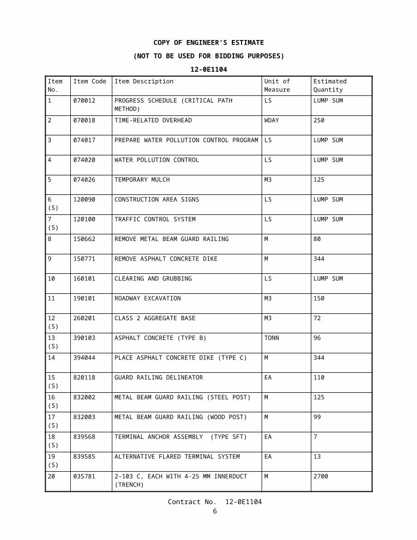
COPY OF ENGINEER'S ESTIMATE
(NOT TO BE USED FOR BIDDING PURPOSES)
12-0E1104Item No.
Item Code Item Description Unit of Measure Estimated Quantity
1 070012 PROGRESS SCHEDULE (CRITICAL PATH METHOD) LS LUMP SUM
2 070018 TIME-RELATED OVERHEAD WDAY 250
3 074017 PREPARE WATER POLLUTION CONTROL PROGRAM
LS LUMP SUM
4 074020 WATER POLLUTION CONTROL LS LUMP SUM
5 074026 TEMPORARY MULCH M3 125
6(S)
120090 CONSTRUCTION AREA SIGNS LS LUMP SUM
7(S)
120100 TRAFFIC CONTROL SYSTEM LS LUMP SUM
8 150662 REMOVE METAL BEAM GUARD RAILING M 80
9 150771 REMOVE ASPHALT CONCRETE DIKE M 344
10 160101 CLEARING AND GRUBBING LS LUMP SUM
11 190101 ROADWAY EXCAVATION M3 150
12(S)
260201 CLASS 2 AGGREGATE BASE M3 72
13(S)
390103 ASPHALT CONCRETE (TYPE B) TONN 96
14 394044 PLACE ASPHALT CONCRETE DIKE (TYPE C) M 344
15(S)
820118 GUARD RAILING DELINEATOR EA 110
16(S)
832002 METAL BEAM GUARD RAILING (STEEL POST) M 125
17(S)
832003 METAL BEAM GUARD RAILING (WOOD POST) M 99
18(S)
839568 TERMINAL ANCHOR ASSEMBLY (TYPE SFT) EA 7
19(S)
839585 ALTERNATIVE FLARED TERMINAL SYSTEM EA 13
20 035781 2-103 C, EACH WITH 4-25 MM INNERDUCT (TRENCH)
M 2700
Contract No. 12-0E11044
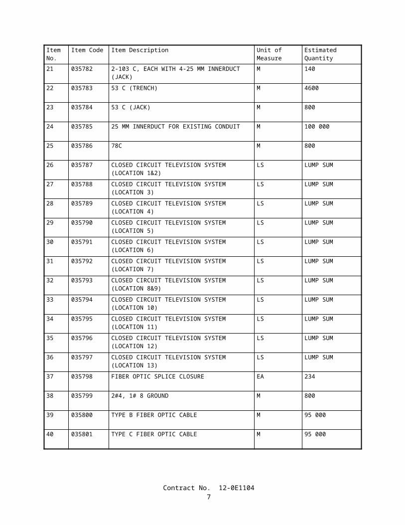
Item No.
Item Code Item Description Unit of Measure Estimated Quantity
21 035782 2-103 C, EACH WITH 4-25 MM INNERDUCT (JACK) M 140
22 035783 53 C (TRENCH) M 4600
23 035784 53 C (JACK) M 800
24 035785 25 MM INNERDUCT FOR EXISTING CONDUIT M 100 000
25 035786 78C M 800
26 035787 CLOSED CIRCUIT TELEVISION SYSTEM (LOCATION 1&2)
LS LUMP SUM
27 035788 CLOSED CIRCUIT TELEVISION SYSTEM (LOCATION 3)
LS LUMP SUM
28 035789 CLOSED CIRCUIT TELEVISION SYSTEM (LOCATION 4)
LS LUMP SUM
29 035790 CLOSED CIRCUIT TELEVISION SYSTEM (LOCATION 5)
LS LUMP SUM
30 035791 CLOSED CIRCUIT TELEVISION SYSTEM (LOCATION 6)
LS LUMP SUM
31 035792 CLOSED CIRCUIT TELEVISION SYSTEM (LOCATION 7)
LS LUMP SUM
32 035793 CLOSED CIRCUIT TELEVISION SYSTEM (LOCATION 8&9)
LS LUMP SUM
33 035794 CLOSED CIRCUIT TELEVISION SYSTEM (LOCATION 10)
LS LUMP SUM
34 035795 CLOSED CIRCUIT TELEVISION SYSTEM (LOCATION 11)
LS LUMP SUM
35 035796 CLOSED CIRCUIT TELEVISION SYSTEM (LOCATION 12)
LS LUMP SUM
36 035797 CLOSED CIRCUIT TELEVISION SYSTEM (LOCATION 13)
LS LUMP SUM
37 035798 FIBER OPTIC SPLICE CLOSURE EA 234
38 035799 2#4, 1# 8 GROUND M 800
39 035800 TYPE B FIBER OPTIC CABLE M 95 000
40 035801 TYPE C FIBER OPTIC CABLE M 95 000
Contract No. 12-0E11045
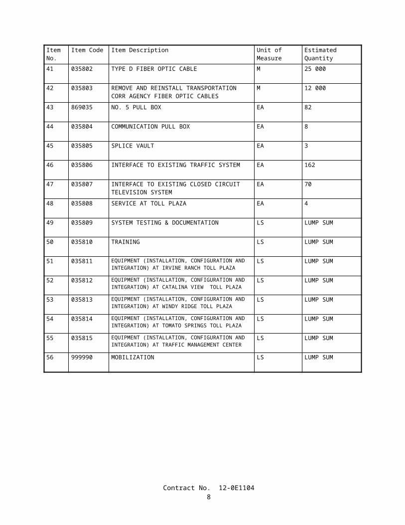
Item No.
Item Code Item Description Unit of Measure Estimated Quantity
41 035802 TYPE D FIBER OPTIC CABLE M 25 000
42 035803 REMOVE AND REINSTALL TRANSPORTATION CORR AGENCY FIBER OPTIC CABLES
M 12 000
43 869035 NO. 5 PULL BOX EA 82
44 035804 COMMUNICATION PULL BOX EA 8
45 035805 SPLICE VAULT EA 3
46 035806 INTERFACE TO EXISTING TRAFFIC SYSTEM EA 162
47 035807 INTERFACE TO EXISTING CLOSED CIRCUIT TELEVISION SYSTEM
EA 70
48 035808 SERVICE AT TOLL PLAZA EA 4
49 035809 SYSTEM TESTING & DOCUMENTATION LS LUMP SUM
50 035810 TRAINING LS LUMP SUM
51 035811 EQUIPMENT (INSTALLATION, CONFIGURATION AND INTEGRATION) AT IRVINE RANCH TOLL PLAZA
LS LUMP SUM
52 035812 EQUIPMENT (INSTALLATION, CONFIGURATION AND INTEGRATION) AT CATALINA VIEW TOLL PLAZA
LS LUMP SUM
53 035813 EQUIPMENT (INSTALLATION, CONFIGURATION AND INTEGRATION) AT WINDY RIDGE TOLL PLAZA
LS LUMP SUM
54 035814 EQUIPMENT (INSTALLATION, CONFIGURATION AND INTEGRATION) AT TOMATO SPRINGS TOLL PLAZA
LS LUMP SUM
55 035815 EQUIPMENT (INSTALLATION, CONFIGURATION AND INTEGRATION) AT TRAFFIC MANAGEMENT CENTER
LS LUMP SUM
56 999990 MOBILIZATION LS LUMP SUM
Contract No. 12-0E11046
STATE OF CALIFORNIA
DEPARTMENT OF TRANSPORTATION
_____________________________
SPECIAL PROVISIONS
Annexed to Contract No. 12-0E1104
SECTION 1. SPECIFICATIONS AND PLANS
The work embraced herein shall conform to the provisions in the Standard Specifications dated July 1999, and the Standard Plans dated July 1999, of the Department of Transportation insofar as the same may apply, and these special provisions.
In case of conflict between the Standard Specifications and these special provisions, the special provisions shall take precedence over and shall be used in lieu of the conflicting portions.
AMENDMENTS TO JULY 1999 STANDARD SPECIFICATIONS
UPDATED JANUARY 31, 2005
Amendments to the Standard Specifications set forth in these special provisions shall be considered as part of the Standard Specifications for the purposes set forth in Section 5-1.04, "Coordination and Interpretation of Plans, Standard Specifications and Special Provisions," of the Standard Specifications. Whenever either the term "Standard Specifications is amended" or the term "Standard Specifications are amended" is used in the special provisions, the text or table following the term shall be considered an amendment to the Standard Specifications. In case of conflict between such amendments and the Standard Specifications, the amendments shall take precedence over and be used in lieu of the conflicting portions.
SECTION 1: DEFINITIONS AND TERMS
Issue Date: January 31, 2005
Section 1-1.265, "Manual of Traffic Controls," of the Standard Specifications is amended to read:
1-1.265 MANUAL ON UNIFORM TRAFFIC CONTROL DEVICES• The Manual on Uniform Traffic Control Devices for Streets and Highways, 2003 Edition (MUTCD) is administered
by the Federal Highway Administration.
Section 1, "Definitions and Terms," of the Standard Specifications is amended by adding the following section:
1-1.266 MANUAL ON UNIFORM TRAFFIC CONTROL DEVICES CALIFORNIA SUPPLEMENT• The MUTCD 2003 California Supplement (MUTCD California Supplement) is issued by the Department of
Transportation to provide amendments to the MUTCD. The MUTCD and MUTCD California Supplement supersede the Department's Manual of Traffic Controls.
Contract No. 12-0E11047
SECTION 2: PROPOSAL REQUIREMENTS AND CONDITIONS
Issue Date: June 19, 2003
Section 2-1.03, "Examination of Plans, Specifications, Contract, and Site of Work," of the Standard Specifications is amended to read:
2-1.03 Examination of Plans, Specifications, Contract, and Site of Work• The bidder shall examine carefully the site of the work contemplated, the plans and specifications, and the proposal
and contract forms therefor. The submission of a bid shall be conclusive evidence that the bidder has investigated and is satisfied as to the general and local conditions to be encountered, as to the character, quality and scope of work to be performed, the quantities of materials to be furnished and as to the requirements of the proposal, plans, specifications and the contract.
• The submission of a bid shall also be conclusive evidence that the bidder is satisfied as to the character, quality and quantity of surface and subsurface materials or obstacles to be encountered insofar as this information was reasonably ascertainable from an inspection of the site and the records of exploratory work done by the Department as shown in the bid documents, as well as from the plans and specifications made a part of the contract.
• Where the Department has made investigations of site conditions including subsurface conditions in areas where work is to be performed under the contract, or in other areas, some of which may constitute possible local material sources, bidders or contractors may, upon written request, inspect the records of the Department as to those investigations subject to and upon the conditions hereinafter set forth.
• Where there has been prior construction by the Department or other public agencies within the project limits, records of the prior construction that are currently in the possession of the Department and which have been used by, or are known to, the designers and administrators of the project will be made available for inspection by bidders or contractors, upon written request, subject to the conditions hereinafter set forth. The records may include, but are not limited to, as -built drawings, design calculations, foundation and site studies, project reports and other data assembled in connection with the investigation, design, construction and maintenance of the prior projects.
• Inspection of the records of investigations and project records may be made at the office of the district in which the work is situated, or in the case of records of investigations related to structure work, at the Transportation Laboratory in Sacramento, California.
• When a log of test borings or other record of geotechnical data obtained by the Department's investigation of surface and subsurface conditions is included with the contract plans, it is furnished for the bidders' or Contractor's information and its use shall be subject to the conditions and limitations set forth in this Section 2-1.03.
• In some instances, information considered by the Department to be of possible interest to bidders or contractors has been compiled as "Materials Information." The use of the "Materials Information" shall be subject to the conditions and limitations set forth in this Section 2-1.03 and Section 6-2, "Local Materials."
• When cross sections are not included with the plans, but are available, bidders or contractors may inspect the cross sections and obtain copies for their use, at their expense.
• When cross sections are included with the contract plans, it is expressly understood and agreed that the cross sections do not constitute part of the contract, do not necessarily represent actual site conditions or show location, character, dimensions and details of work to be performed, and are included in the plans only for the convenience of bidders and their use is subject to the conditions and limitations set forth in this Section 2-1.03.
• When contour maps were used in the design of the project, the bidders may inspect those maps, and if available, they may obtain copies for their use.
• The availability or use of information described in this Section 2-1.03 is not to be construed in any way as a waiver of the provisions of the first paragraph in this Section 2-1.03 and bidders and contractors are cautioned to make independent investigations and examinations as they deem necessary to be satisfied as to conditions to be encountered in the performance of the work and, with respect to possible local material sources, the quality and quantity of material available from the property and the type and extent of processing that may be required in order to produce material conforming to the requirements of the specifications.
• The Department assumes no responsibility for conclusions or interpretations made by a bidder or contractor based on the information or data made available by the Department. The Department does not assume responsibility for representation made by its officers or agents before the execution of the contract concerning surface or subsurface conditions, unless that representation is expressly stated in the contract.
• No conclusions or interpretations made by a bidder or contractor from the information and data made available by the Department will relieve a bidder or contractor from properly fulfilling the terms of the contract.
Contract No. 12-0E11048
SECTION 5: CONTROL OF WORK
Issue Date: December 31, 2001
Section 5-1.02A, "Trench Excavation Safety Plans," of the Standard Specifications is amended to read:
5-1.02A Excavation Safety Plans• The Construction Safety Orders of the Division of Occupational Safety and Health shall apply to all excavations.
For all excavations 1.5 m or more in depth, the Contractor shall submit to the Engineer a detailed plan showing the design and details of the protective systems to be provided for worker protection from the hazard of caving ground during excavation. The detailed plan shall include any tabulated data and any design calculations used in the preparation of the plan. Excavation shall not begin until the detailed plan has been reviewed and approved by the Engineer.
• Detailed plans of protective systems for which the Construction Safety Orders require design by a registered professional engineer shall be prepared and signed by an engineer who is registered as a Civil Engineer in the State of California, and shall include the soil classification, soil properties, soil design calculations that demonstrate adequate stability of the protective system, and any other design calculations used in the preparation of the plan.
• No plan shall allow the use of a protective system less effective than that required by the Construction Safety Orders.
• If the detailed plan includes designs of protective systems developed only from the allowable configurations and slopes, or Appendices, contained in the Construction Safety Orders, the plan shall be submitted at least 5 days before the Contractor intends to begin excavation. If the detailed plan includes designs of protective systems developed from tabulated data, or designs for which design by a registered professional engineer is required, the plan shall be submitted at least 3 weeks before the Contractor intends to begin excavation.
• Attention is directed to Section 7-1.01E, "Trench Safety."
SECTION 7: LEGAL RELATIONS AND RESPONSIBILITY
Issue Date: January 31, 2005
The eighth paragraph of Section 7-1.09, "Public Safety" of the Standard Specifications is amended to read:
• Signs, lights, flags, and other warning and safety devices and their use shall conform to the requirements set forth in Part 6 of the MUTCD and of the MUTCD California Supplement. Signs or other protective devices furnished and erected by the Contractor, at the Contractor's expense, as above provided, shall not obscure the visibility of, nor conflict in intent, meaning and function of either existing signs, lights and traffic control devices or any construction area signs and traffic control devices for which furnishing of, or payment for, is provided elsewhere in the specifications. Signs furnished and erected by the Contractor, at the Contractor's expense, shall be approved by the Engineer as to size, wording and location.
The fourteenth paragraph of Section 7-1.09, "Public Safety," of the Standard Specifications is amended to read:
• The Contractor shall notify the Engineer not less than 18 days and no more than 90 days prior to the anticipated start of an operation that will change the vertical or horizontal clearance available to public traffic (including shoulders).
The sixteenth paragraph of Section 7-1.09, "Public Safety," of the Standard Specifications is amended to read:
• When vertical clearance is temporarily reduced to 4.72 m or less, low clearance warning signs shall be placed in accordance with Part 2 of the MUTCD and the MUTCD California Supplement, and as directed by the Engineer. Signs shall conform to the dimensions, color, and legend requirements of the MUTCD, the MUTCD California Supplement, and these specifications except that the signs shall have black letters and numbers on an orange retroreflective background. W12-2P signs shall be illuminated so that the signs are clearly visible.
SECTION 9: MEASUREMENT AND PAYMENT
Issue Date: November 17, 2004
Section 9-1.04, "Notice of Potential Claim," of the Standard Specifications is amended to read:
Contract No. 12-0E11049
9-1.04 NOTICE OF POTENTIAL CLAIM• It is the intention of this section that disputes between the parties arising under and by virtue of the contract be
brought to the attention of the Engineer at the earliest possible time in order that the matters may be resolved, if possible, or other appropriate action promptly taken.
• Disputes will not be considered unless the Contractor has first complied with specified notice or protest requirements, including Section 4-1.03, "Changes," Section 5-1.116, "Differing Site Conditions," Section 8-1.06, "Time of Completion," Section 8-1.07, "Liquidated Damages," and Section 8-1.10, "Utility and Non-Highway Facilities."
• For disputes arising under and by virtue of the contract, including an act or failure to act by the Engineer, the Contractor shall provide a signed written initial notice of potential claim to the Engineer within 5 days from the date the dispute first arose. The initial notice of potential claim shall provide the nature and circumstances involved in the dispute which shall remain consistent through the dispute. The initial notice of potential claim shall be submitted on Form CEM-6201A furnished by the Department and shall be certified with reference to the California False Claims Act, Government Code Sections 12650-12655. The Contractor shall assign an exclusive identification number for each dispute, determined by chronological sequencing, based on the date of the dispute.
• The exclusive identification number for each dispute shall be used on the following corresponding documents:
A. Initial notice of potential claim.B. Supplemental notice of potential claim.C. Full and final documentation of potential claim.D. Corresponding claim included in the Contractor's written statement of claims.
• The Contractor shall provide the Engineer the opportunity to examine the site of work within 5 days from the date of the initial notice of potential claim. The Contractor shall proceed with the performance of contract work unless otherwise specified or directed by the Engineer.
• Throughout the disputed work, the Contractor shall maintain records that provide a clear distinction between the incurred direct costs of disputed work and that of undisputed work. The Contractor shall allow the Engineer access to the Contractor's project records deemed necessary by the Engineer to evaluate the potential claim within 20 days of the date of the Engineer's written request.
• Within 15 days of submitting the initial notice of potential claim, the Contractor shall provide a signed supplemental notice of potential claim to the Engineer that provides the following information:
A. The complete nature and circumstances of the dispute which caused the potential claim.B. The contract provisions that provide the basis of claim.C. The estimated cost of the potential claim, including an itemized breakdown of individual costs and how the estimate
was determined.D. A time impact analysis of the project schedule that illustrates the effect on the scheduled completion date due to
schedule changes or disruptions where a request for adjustment of contract time is made.
• The information provided in items A and B above shall provide the Contractor's complete reasoning for additional compensation or adjustments.
• The supplemental notice of potential claim shall be submitted on Form CEM-6201B furnished by the Department and shall be certified with reference to the California False Claims Act, Government Code Sections 12650-12655. The Engineer will evaluate the information presented in the supplemental notice of potential claim and provide a written response to the Contractor within 20 days of its receipt. If the estimated cost or effect on the scheduled completion date changes, the Contractor shall update information in items C and D above as soon as the change is recognized and submit this information to the Engineer.
• Within 30 days of the completion of work related to the potential claim, the Contractor shall provide the full and final documentation of potential claim to the Engineer that provides the following information:
A. A detailed factual narration of events fully describing the nature and circumstances that caused the dispute, including, but not limited to, necessary dates, locations, and items of work affected by the dispute.
B. The specific provisions of the contract that support the potential claim and a statement of the reasons these provisions support and provide a basis for entitlement of the potential claim.
C. When additional monetary compensation is requested, the exact amount requested calculated in conformance with Section 9-1.03, "Force Account Payment," or Section 8-1.09, "Right of Way Delays," including an itemized breakdown of individual costs. These costs shall be segregated into the following cost categories:
Contract No. 12-0E110410
1. Labor – A listing of individuals, classifications, regular hours and overtime hours worked, dates worked, and other pertinent information related to the requested reimbursement of labor costs.
2. Materials – Invoices, purchase orders, location of materials either stored or incorporated into the work, dates materials were transported to the project or incorporated into the work, and other pertinent information related to the requested reimbursement of material costs.
3. Equipment – Listing of detailed description (make, model, and serial number), hours of use, dates of use and equipment rates. Equipment rates shall be at the applicable State rental rate as listed in the Department of Transportation publication entitled "Labor Surcharge and Equipment Rental Rates," in effect when the affected work related to the dispute was performed.
4. Other categories as specified by the Contractor or the Engineer.
D. When an adjustment of contract time is requested the following information shall be provided:
1. The specific dates for which contract time is being requested.2. The specific reasons for entitlement to a contract time adjustment.3. The specific provisions of the contract that provide the basis for the requested contract time adjustment.4. A detailed time impact analysis of the project schedule. The time impact analysis shall show the effect of
changes or disruptions on the scheduled completion date to demonstrate entitlement to a contract time adjustment.
E. The identification and copies of the Contractor's documents and the substance of oral communications that support the potential claim.
• The full and final documentation of the potential claim shall be submitted on Form CEM-6201C furnished by the Department and shall be certified with reference to the California False Claims Act, Government Code Sections 12650-12655.
• Pertinent information, references, arguments, and data to support the potential claim shall be included in the full and final documentation of potential claim. Information submitted subsequent to the full and final documentation submittal will not be considered. Information required in the full and final documentation of potential claim, as listed in items A to E above, that is not applicable to the dispute may be exempted as determined by the Engineer. No full and final documentation of potential claim will be considered that does not have the same nature and circumstances, and basis of claim as those specified on the initial and supplemental notices of potential claim.
• The Engineer will evaluate the information presented in the full and final documentation of potential claim and provide a written response to the Contractor within 30 days of its receipt unless otherwise specified. The Engineer's receipt of the full and final documentation of potential claim shall be evidenced by postal receipt or the Engineer's written receipt if delivered by hand. If the full and final documentation of potential claim is submitted by the Contractor after acceptance of the work by the Director, the Engineer need not provide a written response.
• Provisions in this section shall not apply to those claims for overhead costs and administrative disputes that occur after issuance of the proposed final estimate. Administrative disputes are disputes of administrative deductions or retentions, contract item quantities, contract item adjustments, interest payments, protests of contract change orders as provided in Section 4-1.03A, "Procedure and Protest," and protests of the weekly statement of working days as provided in Section 8-1.06, "Time of Completion." Administrative disputes that occur prior to issuance of the proposed final estimate shall follow applicable requirements of this section. Information listed in the supplemental notice and full and final documentation of potential claim that is not applicable to the administrative dispute may be exempted as determined by the Engineer.
• Unless otherwise specified in the special provisions, the Contractor may pursue the administrative claim process pursuant to Section 9-1.07B, "Final Payment and Claims," for any potential claim found by the Engineer to be without merit.
• Failure of the Contractor to conform to specified dispute procedures shall constitute a failure to pursue diligently and exhaust the administrative procedures in the contract, and is deemed as the Contractor's waiver of the potential claim and a waiver of the right to a corresponding claim for the disputed work in the administrative claim process in conformance with Section 9-1.07B, "Final Payment of Claims," and shall operate as a bar to arbitration pursuant to Section 10240.2 of the California Public Contract Code.
Section 9-1.07B, "Final Payment and Claims," of the Standard Specifications is amended to read:
9-1.07B Final Payment and Claims• After acceptance by the Director, the Engineer will make a proposed final estimate in writing of the total amount
payable to the Contractor, including an itemization of the total amount, segregated by contract item quantities, extra work and other bases for payment, and shall also show each deduction made or to be made for prior payments and amounts to be kept
Contract No. 12-0E110411
or retained under the provisions of the contract. Prior estimates and payments shall be subject to correction in the proposed final estimate. The Contractor shall submit written approval of the proposed final estimate or a written statement of claims arising under or by virtue of the contract so that the Engineer receives the written approval or statement of claims no later than close of business of the thirtieth day after receiving the proposed final estimate. If the thirtieth day falls on a Saturday, Sunday or legal holiday, then receipt of the written approval or statement of claims by the Engineer shall not be later than close of business of the next business day. The Contractor's receipt of the proposed final estimate shall be evidenced by postal receipt. The Engineer's receipt of the Contractor's written approval or statement of claims shall be evidenced by postal receipt or the Engineer's written receipt if delivered by hand.
• On the Contractor's approval, or if the Contractor files no claim within the specified period of 30 days, the Engineer will issue a final estimate in writing in conformance with the proposed final estimate submitted to the Contractor, and within 30 days thereafter the State will pay the entire sum so found to be due. That final estimate and payment thereon shall be conclusive and binding against both parties to the contract on all questions relating to the amount of work done and the compensation payable therefor, except as otherwise provided in Sections 9-1.03C, "Records," and 9-1.09, "Clerical Errors."
• If the Contractor within the specified period of 30 days files claims, the Engineer will issue a semifinal estimate in conformance with the proposed final estimate submitted to the Contractor and within 30 days thereafter the State will pay the sum found to be due. The semifinal estimate and corresponding payment shall be conclusive and binding against both parties to the contract on each question relating to the amount of work done and the compensation payable therefor, except insofar as affected by the claims filed within the time and in the manner required hereunder and except as otherwise provided in Sections 9-1.03C, "Records," and 9-1.09, "Clerical Errors."
• Except for claims for overhead costs and administrative disputes that occur after issuance of the proposed final estimate, the Contractor shall only provide the following two items of information for each claim:
A. The exclusive identification number that corresponds to the supporting full and final documentation of potential claim.
B. The final amount of requested additional compensation.
• If the final amount of requested additional compensation is different than the amount of requested compensation included in the full and final documentation of potential claim, the Contractor shall provide in the written statement of claims the reasons for the changed amount, the specific provisions of the contract which support the changed amount, and a statement of the reasons the provisions support and provide a basis for the changed amount. If the Contractor's claim fails to provide an exclusive identification number or if there is a disparity in the provided exclusive identification number, the Engineer will notify the Contractor of the omission or disparity. The Contractor shall have 15 days after receiving notification from the Engineer to correct the omission or disparity. If after the 15 days has elapsed, there is still an omission or disparity of the exclusive identification number assigned to the claim, the Engineer will assign the number. No claim will be considered that has any of the following deficiencies:
A. The claim does not have the same nature, circumstances, and basis as the corresponding full and final documentation of potential claim.
B. The claim does not have a corresponding full and final documentation of potential claim.C. The claim was not included in the written statement of claims.D. The Contractor did not comply with applicable notice or protest requirements of Sections 4-1.03, "Changes,"
5-1.116, "Differing Site Condition," 8-1.06, "Time of Completion," 8-1.07, "Liquidated Damages," 8-1.10, "Utility and Non-Highway Facilities," and 9-1.04, "Notice of Potential Claim."
• Administrative disputes that occur after issuance of the proposed final estimate shall be included in the Contractor's written statement of claims in sufficient detail to enable the Engineer to ascertain the basis and amounts of those claims.
• The Contractor shall keep full and complete records of the costs and additional time incurred for work for which a claim for additional compensation is made. The Engineer or designated claim investigators or auditors shall have access to those records and any other records as may be required by the Engineer to determine the facts or contentions involved in the claims. Failure to permit access to those records shall be sufficient cause for denying the claims.
• The written statement of claims submitted by the Contractor shall be accompanied by a notarized certificate containing the following language:
Contract No. 12-0E110412
Under the penalty of law for perjury or falsification and with specific reference to the California False Claims Act, Government Code Section 12650 et. seq., the undersigned,
.(name)
of(title)
.(company)
hereby certifies that the claim for the additional compensation and time, if any, made herein for the work on this contract is a true statement of the actual costs incurred and time sought, and is fully documented and supported under the contract between parties.
Dated
/s/
Subscribed and sworn before me this day
of .
(Notary Public)My Commission Expires
• Failure to submit the notarized certificate will be sufficient cause for denying the claim.• Claims for overhead type expenses or costs, in addition to being certified as stated above, shall be supported and
accompanied by an audit report of an independent Certified Public Accountant. Omission of a supporting audit report of an independent Certified Public Accountant shall result in denial of the claim and shall operate as a bar to arbitration, as to the claim, in conformance with the requirements in Section 10240.2 of the California Public Contract Code. Claims for overhead type expenses or costs shall be subject to audit by the State at its discretion. The costs of performing an audit examination and submitting the report shall be borne by the Contractor. The Certified Public Accountant's audit examination shall be performed in conformance with the requirements of the American Institute of Certified Public Accountants Attestation Standards. The audit examination and report shall depict the Contractor's project and company-wide financial records and shall specify the actual overall average daily rates for both field and home office overhead for the entire duration of the project, and whether the costs have been properly allocated. The rates of field and home office overhead shall exclude unallowable costs as determined in Title 48 of the Federal Acquisition Regulations, Chapter 1, Part 31. The audit examination and report shall determine if the rates of field and home office overhead are:
A. Allowable in conformance with the requirements in Title 48 of the Federal Acquisition Regulations, Chapter 1, Part 31.
B. Adequately supported by reliable documentation.C. Related solely to the project under examination.
• Costs or expenses incurred by the State in reviewing or auditing claims that are not supported by the Contractor's cost accounting or other records shall be deemed to be damages incurred by the State within the meaning of the California False Claims Act.
• If the Engineer determines that a claim requires additional analysis, the Engineer will schedule a board of review meeting. The Contractor shall meet with the review board or person and make a presentation in support of the claim. Attendance by the Contractor at the board of review meeting shall be mandatory.
• The District Director of the District that administered the contract will make the final determination of any claims which remain in dispute after completion of claim review by the Engineer or board of review meeting.
The final determination of claims will be sent to the Contractor by hand delivery or deposit in the U.S. mail. The Engineer will then make and issue the Engineer's final estimate in writing and within 30 days thereafter the State will pay the entire sum, if any, found due thereon. That final estimate shall be conclusive and binding against both parties to the contract on all questions relating to the amount of work done and the compensation payable therefor, except as otherwise provided in Sections 9-1.03C, "Records," and 9-1.09, "Clerical Errors."
Contract No. 12-0E110413
• Failure of the Contractor to conform to the specified dispute procedures shall constitute a failure to pursue diligently and exhaust the administrative procedures in the contract and shall operate as a bar to arbitration in conformance with the requirements in Section 10240.2 of the California Public Contract Code.
SECTION 12: CONSTRUCTION AREA TRAFFIC CONTROL DEVICES
Issue Date: November 2, 2004
The second paragraph of Section 12-1.01, "Description," of the Standard Specifications is amended to read:
• Attention is directed to Part 6 of the MUTCD and of the MUTCD California Supplement. Nothing in this Section 12 is to be construed as to reduce the minimum standards in these manuals.
Section 12-2.01, "Flaggers," of the Standard Specifications is amended to read:
• Flaggers while on duty and assigned to traffic control or to give warning to the public that the highway is under construction and of any dangerous conditions to be encountered as a result thereof, shall perform their duties and shall be provided with the necessary equipment in conformance with Part 6 of the MUTCD and of the MUTCD California Supplement. The equipment shall be furnished and kept clean and in good repair by the Contractor at the Contractor's expense.
The first paragraph of Section 12-3.01, "General," of the Standard Specifications is amended to read:
• In addition to the requirements in Part 6 of the MUTCD and of the MUTCD California Supplement, all devices used by the Contractor in the performance of the work shall conform to the provisions in this Section 12-3.
The first paragraph of Section 12-3.06, "Construction Area Signs," of the Standard Specifications is amended to read:
• The term "Construction Area Signs" shall include all temporary signs required for the direction of public traffic through or around the work during construction. Construction area signs are shown in or referred to in Part 6 of the MUTCD and of the MUTCD California Supplement.
The fourth paragraph of Section 12-3.06, "Construction Area Signs," of the Standard Specifications is amended to read:
• All construction area signs shall conform to the dimensions, color and legend requirements of the plans, Part 6 of the MUTCD, Part 6 of the MUTCD California Supplement, and these specifications. All sign panels shall be the product of a commercial sign manufacturer, and shall be as specified in these specifications.
The eighth paragraph of Section 12-3.06, "Construction Area Signs," of the Standard Specifications is amended to read:
• Used signs with the specified sheeting material will be considered satisfactory if they conform to the requirements for visibility and legibility and the colors conform to the requirements in Part 6 of the MUTCD and of the MUTCD California Supplement. A significant difference between day and nighttime retroreflective color will be grounds for rejecting signs.
Section 12-3.06A, "Stationary Mounted Signs," of the Standard Specifications is amended by deleting the third, fourth, fifth, and sixth paragraphs.
SECTION 19: EARTHWORK
Issue Date: December 31, 2001
The third paragraph of Section 19-1.02, "Preservation of Property," of the Standard Specifications is amended to read:
• In addition to the provisions in Sections 5-1.02, "Plans and Working Drawings," and 5-1.02A, "Excavation Safety Plans," detailed plans of the protective systems for excavations on or affecting railroad property will be reviewed for adequacy of protection provided for railroad facilities, property, and traffic. These plans shall be submitted at least 9 weeks
Contract No. 12-0E110414
before the Contractor intends to begin excavation requiring the protective systems. Approval by the Engineer of the detailed plans for the protective systems will be contingent upon the plans being satisfactory to the railroad company involved.
SECTION 42: GROOVE AND GRIND PAVEMENT
Issue Date: December 31, 2001
The last sentence of the first subparagraph of the third paragraph in Section 42-2.02, "Construction," of the Standard Specifications is amended to read:
• After grinding has been completed, the pavement shall conform to the straightedge and profile requirements specified in Section 40-1.10, "Final Finishing."
SECTION 49: PILING
Issue Date: November 2, 2004
The first paragraph in Section 49-1.03, "Determination of Length," of the Standard Specifications is amended to read:
• Foundation piles of any material shall be of such length as is required to obtain the specified penetration, and to extend into the cap or footing block as shown on the plans, or specified in the special provisions.
The fourth paragraph in Section 49-1.03, "Determination of Length," of the Standard Specifications is amended to read:
• Modification to the specified installation methods and specified pile tip elevation will not be considered at locations where tension or lateral load demands control design pile tip elevations or when the plans state that specified pile tip elevation shall not be revised.
The sixth and seventh paragraphs in Section 49-1.03, "Determination of Length," of the Standard Specifications are amended to read:
• Indicator compression pile load testing shall conform to the requirements in ASTM Designation: D 1143. The pile shall sustain the first compression test load applied which is equal to the nominal resistance in compression, as shown on the plans, with no more than 13 mm total vertical movement at the top of the pile measured relative to the top of the pile prior to the start of compression load testing.
• Indicator tension pile load testing shall conform to the requirements in ASTM Designation: D 3689. The loading apparatus described as "Load Applied to Pile by Hydraulic Jack(s) Acting at One End of Test Beam(s) Anchored to the Pile" shall not be used. The pile shall sustain the first tension test load applied which is equal to the nominal resistance in tension, as shown on the plans, with no more than 13 mm total vertical movement at the top of the pile measured relative to the top of the pile prior to the start of tension load testing.
The ninth paragraph in Section 49-1.03, "Determination of Length," of the Standard Specifications is amended to read:
• For driven piling, the Contractor shall furnish piling of sufficient length to obtain the specified tip elevation shown on the plans or specified in the special provisions. For cast-in-drilled-hole concrete piling, the Contractor shall construct piling of such length to develop the nominal resistance in compression and to obtain the specified tip elevation shown on the plans or specified in the special provisions.
The tenth paragraph in Section 49-1.03, "Determination of Length," of the Standard Specifications is deleted.
The fourth paragraph in Section 49-1.04, "Load Test Piles," of the Standard Specifications is amended to read:
• Load test piles and anchor piles which are not to be incorporated in the completed structure shall be removed in conformance with the provisions in Section 15-4.02, "Removal Methods," and the remaining holes shall be backfilled with earth or other suitable material approved by the Engineer.
The fifth paragraph in Section 49-1.04, "Load Test Piles," of the Standard Specifications is amended to read:
Contract No. 12-0E110415
• Load test anchorages in piles used as anchor piles shall conform to the following requirements:
A. High strength threaded steel rods shall conform to the provisions for bars in Section 50-1.05, "Prestressing Steel," except Type II bars shall be used.
B. High strength steel plates shall conform to the requirements in ASTM Designation: A 709/A 709M, Grade 345.C. Anchor nuts shall conform to the provisions in the second paragraph in Section 50-1.06, "Anchorages and
Distribution."
The first paragraph in Section 49-1.05, "Driving Equipment," of the Standard Specifications is amended to read:
• Driven piles shall be installed with impact hammers that are approved in writing by the Engineer. Impact hammers shall be steam, hydraulic, air or diesel hammers. Impact hammers shall develop sufficient energy to drive the piles at a penetration rate of not less than 3 mm per blow at the specified nominal resistance.
The seventh paragraph in Section 49-1.05, "Driving Equipment," of the Standard Specifications is amended to read:
• When necessary to obtain the specified penetration and when authorized by the Engineer, the Contractor may supply and operate one or more water jets and pumps, or furnish the necessary drilling apparatus and drill holes not greater than the least dimension of the pile to the proper depth and drive the piles therein. Jets shall not be used at locations where the stability of embankments or other improvements would be endangered. In addition, for steel piles, steel shells, or steel casings, when necessary to obtain the specified penetration or to prevent damage to the pile during installation, the Contractor shall provide special driving tips or heavier pile sections or take other measures as approved by the Engineer.
• The use of followers or underwater hammers for driving piles will be permitted if authorized in writing by the Engineer. When a follower or underwater hammer is used, its efficiency shall be verified by furnishing the first pile in each bent or footing sufficiently long and driving the pile without the use of a follower or underwater hammer.
The second paragraph in Section 49-1.07, "Driving," of the Standard Specifications is amended to read:
• Timber piles shall be fresh-headed and square and when permitted by the Engineer, the heads of the piles may be protected by means of heavy steel or wrought iron rings. During driving operations timber piling shall be restrained from lateral movement at intervals not to exceed 6 m over the length between the driving head and the ground surface. During driving operations, the timber pile shall be kept moving by continuous operation of the hammer. When the blow count exceeds either 2 times the blow count required in 300 mm, or 3 times the blow count required in 75 mm for the nominal resistance as shown on the plans, computed in conformance with the provisions in Section 49-1.08, "Pile Driving Acceptance Criteria," additional aids shall be used to obtain the specified penetration. These aids may include the use of water jets or drilling, where permitted, or the use of a larger hammer employing a heavy ram striking with a low velocity.
Section 49-1.08, "Bearing Value and Penetration," of the Standard Specifications is amended to read:
49-1.08 PILE DRIVING ACCEPTANCE CRITERIA• Except for piles to be load tested, driven piles shall be driven to a value of not less than the nominal resistance
shown on the plans unless otherwise specified in the special provisions or permitted in writing by the Engineer. In addition, when a pile tip elevation is specified, driven piles shall penetrate at least to the specified tip elevation, unless otherwise permitted in writing by the Engineer. Piles to be load tested shall be driven to the specified tip elevation.
• When the pile nominal resistance is omitted from the plans or the special provisions, timber piles shall be driven to a nominal resistance of 800 kN, and steel and concrete piles shall be driven to a nominal resistance of 1250 kN.
• The nominal resistance for driven piles shall be determined from the following formula in which "Ru" is the nominal resistance in kilonewtons, "Er" is the manufacturer's rating for joules of energy developed by the hammer at the observed field drop height, and "N" is the number of hammer blows in the last 300 millimeters. (maximum value to be used for N is 100):
Ru = (7 * (Er)1/2*log10 (0.83 * N)) - 550
The first paragraph in Section 49-2.03, "Requirements," of the Standard Specifications is amended to read:
Contract No. 12-0E110416
• When preservative treatment of timber piles is required by the plans or specified in the special provisions, the treatment shall conform to the provisions in Section 58, "Preservative Treatment of Lumber, Timber and Piling," and the applicable AWPA Use Category.
The first paragraph in Section 49-2.04, "Treatment of Pile Heads," of the Standard Specifications is amended to read:
A. An application of wood preservative conforming to the provisions in Section 58-1.04, "Wood Preservative for Manual Treatment," shall first be applied to the head of the pile and a protective cap shall then be built up by applying alternate layers of loosely woven fabric and hot asphalt or tar similar to membrane waterproofing, using 3 layers of asphalt or tar and 2 layers of fabric. The fabric shall measure at least 150 mm more in each direction than the diameter of the pile and shall be turned down over the pile and the edges secured by binding with 2 turns of No. 10 galvanized wire. The fabric shall be wired in advance of the application of the final layer of asphalt or tar, which shall extend down over the wiring.
B. The sawed surface shall be covered with 3 applications of a hot mixture of 60 percent creosote and 40 percent roofing pitch, or thoroughly brushcoated with 3 applications of hot creosote and covered with hot roofing pitch. A covering of 3.50-mm nominal thickness galvanized steel sheet shall be placed over the coating and bent down over the sides of each pile to shed water.
Section 49-3.01, "Description," of the Standard Specifications is amended by deleting the fifth paragraph.
The sixth and seventh paragraphs in Section 49-3.01, "Description," of the Standard Specifications are amended to read:
• Except for precast prestressed concrete piles in a corrosive environment, lifting anchors used in precast prestressed concrete piles shall be removed, and the holes filled in conformance with the provisions in Section 51-1.18A, "Ordinary Surface Finish."
• Lifting anchors used in precast prestressed concrete piles in a corrosive environment shall be removed to a depth of at least 25 mm below the surface of the concrete, and the resulting hole shall be filled with epoxy adhesive before the piles are delivered to the job site. The epoxy adhesive shall conform to the provisions in Sections 95-1, "General," and 95-2.01, "Binder (Adhesive), Epoxy Resin Base (State Specification 8040-03)."
The first and second paragraphs in Section 49-4.01, "Description," of the Standard Specifications are amended to read:
• Cast-in-place concrete piles shall consist of one of the following:
A. Steel shells driven permanently to the required nominal resistance and penetration and filled with concrete.B. Steel casings installed permanently to the required penetration and filled with concrete.C. Drilled holes filled with concrete.D. Rock sockets filled with concrete.
• The drilling of holes shall conform to the provisions in these specifications. Concrete filling for cast-in-place concrete piles is designated by compressive strength and shall have a minimum 28-day compressive strength of 25 MPa. At the option of the Contractor, the combined aggregate grading for the concrete shall be either the 25-mm maximum grading, the 12.5-mm maximum grading, or the 9.5-mm maximum grading. Concrete shall conform to the provisions in Section 90, "Portland Cement Concrete," and Section 51, "Concrete Structures." Reinforcement shall conform to the provisions in Section 52, "Reinforcement."
The fourth paragraph in Section 49-4.03, "Drilled Holes," of the Standard Specifications is amended to read:
• After placing reinforcement and prior to placing concrete in the drilled hole, if caving occurs or deteriorated foundation material accumulates on the bottom of the hole, the bottom of the drilled hole shall be cleaned. The Contractor shall verify that the bottom of the drilled hole is clean.
The first and second paragraphs in Section 49-4.04, "Steel Shells," of the Standard Specifications are amended to read:
• Steel shells shall be sufficiently watertight to exclude water during the placing of concrete. The shells may be cylindrical or tapered, step-tapered, or a combination of either, with cylindrical sections.
The first paragraph in Section 49-4.05, "Inspection," of the Standard Specifications is amended to read:
Contract No. 12-0E110417
• After being driven and prior to placing reinforcement and concrete therein, the steel shells shall be examined for collapse or reduced diameter at any point. Any shell which is improperly driven or broken or shows partial collapse to such an extent as to materially decrease its nominal resistance will be rejected. Rejected shells shall be removed and replaced, or a new shell shall be driven adjacent to the rejected shell. Rejected shells which cannot be removed shall be filled with concrete by the Contractor at the Contractor's expense. When a new shell is driven to replace a rejected shell, the Contractor, at the Contractor's expense, shall enlarge the footing as determined necessary by the Engineer.
The third paragraph in Section 49-5.01, "Description," of the Standard Specifications is amended to read:
• Steel pipe piles shall conform to the following requirements:
1. Steel pipe piles less than 360 mm in diameter shall conform to the requirements in ASTM Designation: A 252, Grade 2 or 3.
2. Steel pipe piles 360 mm and greater in diameter shall conform to the requirements in ASTM Designation: A 252, Grade 3.
3. Steel pipe piles shall be of the nominal diameter and nominal wall thickness shown on the plans or specified in the special provisions.
4. The carbon equivalency (CE) of steel for steel pipe piles, as defined in AWS D 1.1, Section XI5.1, shall not exceed 0.45.
5. The sulfur content of steel for steel pipe piles shall not exceed 0.05-percent.6. Seams in steel pipe piles shall be complete penetration welds.
The first paragraph in Section 49-6.01, "Measurement," of the Standard Specifications is amended to read:
• The length of timber, steel, and precast prestressed concrete piles, and of cast-in-place concrete piles consisting of driven shells filled with concrete, shall be the greater of the following:
A. The total length in place in the completed work, measured along the longest side, from the tip of the pile to the plane of pile cut-off.
B. The length measured along the longest side, from the tip elevation shown on the plans or the tip elevation ordered by the Engineer, to the plane of pile cut-off.
The third paragraph in Section 49-6.02, "Payment," of the Standard Specifications is amended to read:
• The contract price paid per meter for cast-in-drilled-hole concrete piling shall include full compensation for furnishing all labor, materials, tools, equipment, and incidentals, and for doing all work involved in drilling holes, disposing of material resulting from drilling holes, temporarily casing holes and removing water when necessary, furnishing and placing concrete and reinforcement, and constructing reinforced concrete extensions, complete in place, to the required penetration, as shown on the plans, as specified in these specifications and in the special provisions, and as directed by the Engineer.
The seventh paragraph in Section 49-6.02, "Payment," of the Standard Specifications is amended to read
• The contract unit price paid for drive pile shall include full compensation for furnishing all labor, materials, tools, equipment, and incidentals, and for doing all the work involved in driving timber, concrete and steel piles, driving steel shells for cast-in-place concrete piles, placing filling materials for cast-in-place concrete piles and cutting off piles, all complete in place to the required nominal resistance and penetration as shown on the plans and as specified in these specifications and the special provisions, and as directed by the Engineer.
The ninth paragraph in Section 49-6.02, "Payment," of the Standard Specifications is amended to read:
• Full compensation for all jetting, drilling, providing special driving tips or heavier sections for steel piles or shells, or other work necessary to obtain the specified penetration and nominal resistance of the piles, for predrilling holes through embankment and filling the space remaining around the pile with sand or pea gravel, for disposing of material resulting from jetting, drilling or predrilling holes, and for all excavation and backfill involved in constructing concrete extensions as shown on the plans, and as specified in these specifications and the special provisions, and as directed by the Engineer shall be
Contract No. 12-0E110418
considered as included in the contract unit price paid for drive pile or in the contract price paid per meter for cast-in-drilled-hole concrete piling, and no additional compensation will be allowed therefor.
Section 49-6.02, "Payment," of the Standard Specifications is amended by adding the following paragraphs:
Full compensation for furnishing and placing additional testing reinforcement, for load test anchorages, and for cutting off test piles, shall be considered as included in the contract price paid for piling of the type or class shown in the Engineer's Estimate, and no additional compensation will be allowed.
No additional compensation or extension of time will be made for additional foundation investigation, installation and testing of indicator piling, cutting off piling and restoring the foundation investigation and indicator pile sites, and review of request by the Engineer
SECTION 50: PRESTRESSING CONCRETE
Issue Date: November 18, 2002
Section 50-1.02, "Drawings," of the Standard Specifications is amended by adding the following paragraph after the second paragraph:
• Each working drawing submittal shall consist of plans for a single bridge or portion thereof. For multi-frame bridges, each frame shall require a separate working drawing submittal.
Section 50-1.05, "Prestressing Steel," of the Standard Specifications is amended to read:
• Prestressing steel shall be high-tensile wire conforming to the requirements in ASTM Designation: A 421, including Supplement I; high-tensile seven-wire strand conforming to the requirements in ASTM Designation: A 416; or uncoated high-strength steel bars conforming to the requirements in ASTM Designation: A 722, including all supplementary requirements. The maximum mass requirement of ASTM Designation: A 722 will not apply.
• In addition to the requirements of ASTM Designation: A 722, for deformed bars, the reduction of area shall be determined from a bar from which the deformations have been removed. The bar shall be machined no more than necessary to remove the deformations over a length of 300 mm, and reduction will be based on the area of the machined portion.
• In addition to the requirements specified herein, epoxy-coated seven-wire prestressing steel strand shall be grit impregnated and filled in conformance with the requirements in ASTM Designation: A 882/A 882M, including Supplement I, and the following:
A. The coating material shall be on the Department's list of approved coating materials for epoxy-coated strand, available from the Transportation Laboratory.
B. The film thickness of the coating after curing shall be 381 µm to 1143 µm.C. Prior to coating the strand, the Contractor shall furnish to the Transportation Laboratory a representative 230-g
sample from each batch of epoxy coating material to be used. Each sample shall be packaged in an airtight container identified with the manufacturer's name and batch number.
D. Prior to use of the epoxy-coated strand in the work, written certifications referenced in ASTM Designation: A 882/A 882M, including a representative load-elongation curve for each size and grade of strand to be used and a copy of the quality control tests performed by the manufacturer, shall be furnished to the Engineer.
E. In addition to the requirements in Section 50-1.10, "Samples for Testing," four 1.5-m long samples of coated strand and one 1.5-m long sample of uncoated strand of each size and reel shall be furnished to the Engineer for testing. These samples, as selected by the Engineer, shall be representative of the material to be used in the work.
F. Epoxy-coated strand shall be cut using an abrasive saw.G. All visible damage to coatings caused by shipping and handling, or during installation, including cut ends, shall be
repaired in conformance with the requirements in ASTM Designation: A 882/A 882M. The patching material shall be furnished by the manufacturer of the epoxy powder and shall be applied in conformance with the manufacturer's written recommendations. The patching material shall be compatible with the original epoxy coating material and shall be inert in concrete.
• All bars in any individual member shall be of the same grade, unless otherwise permitted by the Engineer.• When bars are to be extended by the use of couplers, the assembled units shall have a tensile strength of not less
than the manufacturer's minimum guaranteed ultimate tensile strength of the bars. Failure of any one sample to meet this
Contract No. 12-0E110419
requirement will be cause for rejection of the heat of bars and lot of couplers. The location of couplers in the member shall be subject to approval by the Engineer.
• Wires shall be straightened if necessary to produce equal stress in all wires or wire groups or parallel lay cables that are to be stressed simultaneously or when necessary to ensure proper positioning in the ducts.
• Where wires are to be button-headed, the buttons shall be cold formed symmetrically about the axes of the wires. The buttons shall develop the minimum guaranteed ultimate tensile strength of the wire. No cold forming process shall be used that causes indentations in the wire. Buttonheads shall not contain wide open splits, more than 2 splits per head, or splits not parallel with the axis of the wire.
• Prestressing steel shall be protected against physical damage and rust or other results of corrosion at all times from manufacture to grouting or encasing in concrete. Prestressing steel that has sustained physical damage at any time shall be rejected. The development of visible rust or other results of corrosion shall be cause for rejection, when ordered by the Engineer.
• Epoxy-coated prestressing steel strand shall be covered with an opaque polyethylene sheeting or other suitable protective material to protect the strand from exposure to sunlight, salt spray, and weather. For stacked coils, the protective covering shall be draped around the perimeter of the stack. The covering shall be adequately secured; however, it should allow for air circulation around the strand to prevent condensation under the covering. Epoxy-coated strand shall not be stored within 300 m of ocean or tidal water for more than 2 months.
• Prestressing steel shall be packaged in containers or shipping forms for the protection of the steel against physical damage and corrosion during shipping and storage. Except for epoxy-coated strand, a corrosion inhibitor which prevents rust or other results of corrosion, shall be placed in the package or form, or shall be incorporated in a corrosion inhibitor carrier type packaging material, or when permitted by the Engineer, may be applied directly to the steel. The corrosion inhibitor shall have no deleterious effect on the steel or concrete or bond strength of steel to concrete. Packaging or forms damaged from any cause shall be immediately replaced or restored to original condition.
• The shipping package or form shall be clearly marked with a statement that the package contains high-strength prestressing steel, and the type of corrosion inhibitor used, including the date packaged.
• Prestressing steel for post-tensioning which is installed in members prior to placing and curing of the concrete, and which is not epoxy-coated, shall be continuously protected against rust or other results of corrosion, until grouted, by means of a corrosion inhibitor placed in the ducts or applied to the steel in the duct. The corrosion inhibitor shall conform to the provisions specified herein.
• When steam curing is used, prestressing steel for post-tensioning shall not be installed until the steam curing is completed.
• Water used for flushing ducts shall contain either quick lime (calcium oxide) or slaked lime (calcium hydroxide) in the amount of 0.01-kg/L. Compressed air used to blow out ducts shall be oil free.
• When prestressing steel for post-tensioning is installed in the ducts after completion of concrete curing, and if stressing and grouting are completed within 10 days after the installation of the prestressing steel, rust which may form during those 10 days will not be cause for rejection of the steel. Prestressing steel installed, tensioned, and grouted in this manner, all within 10 days, will not require the use of a corrosion inhibitor in the duct following installation of the prestressing steel. Prestressing steel installed as above but not grouted within 10 days shall be subject to all the requirements in this section pertaining to corrosion protection and rejection because of rust. The requirements in this section pertaining to tensioning and grouting within 10 days shall not apply to epoxy-coated prestressing steel strand.
• Any time prestressing steel for pretensioning is placed in the stressing bed and is exposed to the elements for more than 36 hours prior to encasement in concrete, adequate measures shall be taken by the Contractor, as approved by the Engineer, to protect the steel from contamination or corrosion.
• After final fabrication of the seven-wire prestressing steel strand, no electric welding of any form shall be performed on the prestressing steel. Whenever electric welding is performed on or near members containing prestressing steel, the welding ground shall be attached directly to the steel being welded.
• Pretensioned prestressing steel shall be cut off flush with the end of the member. For epoxy-coated prestressing steel, only abrasive saws shall be used to cut the steel. The exposed ends of the prestressing steel and a 25 -mm strip of adjoining concrete shall be cleaned and painted. Cleaning shall be by wire brushing or abrasive blast cleaning to remove all dirt and residue on the metal or concrete surfaces. Immediately after cleaning, the surfaces shall be covered with one application of unthinned zinc-rich primer (organic vehicle type) conforming to the provisions in Section 91, "Paint," except that 2 applications shall be applied to surfaces which will not be covered by concrete or mortar. Aerosol cans shall not be used. The paint shall be thoroughly mixed at the time of application and shall be worked into any voids in the prestressing tendons.
The thirteenth paragraph in Section 50-1.08, "Prestressing," of the Standard Specifications is amended to read:
Contract No. 12-0E110420
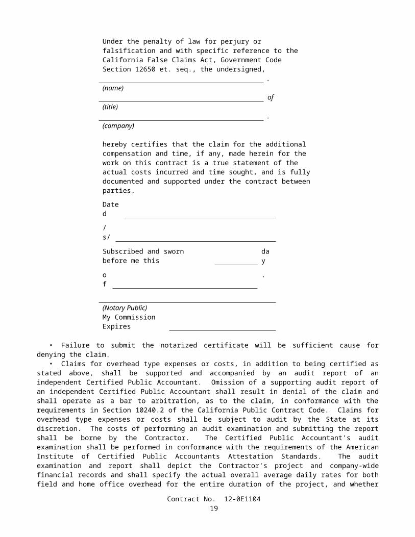
• Prestressing steel in pretensioned members shall not be cut or released until the concrete in the member has attained a compressive strength of not less than the value shown on the plans or 28 MPa, whichever is greater. In addition to these concrete strength requirements, when epoxy-coated prestressing steel strand is used, the steel shall not be cut or released until the temperature of the concrete surrounding the strand is less than 65C, and falling.
The fifth paragraph in Section 50-1.10, "Samples for Testing," of the Standard Specifications is amended to read:
• The following samples of materials and tendons, selected by the Engineer from the prestressing steel at the plant or jobsite, shall be furnished by the Contractor to the Engineer well in advance of anticipated use:
A. For wire or bars, one 2-m long sample and for strand, one 1.5-m long sample, of each size shall be furnished for each heat or reel.
B. For epoxy-coated strand, one 1.5-m long sample of uncoated strand of each size shall be furnished for each reel.C. If the prestressing tendon is a bar, one 2-m long sample shall be furnished and in addition, if couplers are to be used
with the bar, two 1.25-m long samples of bar, equipped with one coupler and fabricated to fit the coupler, shall be furnished.
The second paragraph in Section 50-1.11, "Payment," of the Standard Specifications is amended to read:
• The contract lump sum prices paid for prestressing cast-in-place concrete of the types listed in the Engineer's Estimate shall include full compensation for furnishing all labor, materials, tools, equipment, and incidentals, and for doing all work involved in furnishing, placing, and tensioning the prestressing steel in cast-in-place concrete structures, complete in place, as shown on the plans, as specified in these specifications and the special provisions, and as directed by the Engineer.
SECTION 51: CONCRETE STRUCTURES
Issue Date: January 31, 2005
The eleventh paragraph in Section 51-1.05, "Forms," of the Standard Specifications is amended to read:
• Form panels for exposed surfaces shall be furnished and placed in uniform widths of not less than 0.9 -m and in uniform lengths of not less than 1.8 m, except at the end of continuously formed surfaces where the final panel length required is less than 1.8 m. Where the width of the member formed is less than 0.9-m, the width of the panels shall be not less than the width of the member. Panels shall be arranged in symmetrical patterns conforming to the general lines of the structure. Except when otherwise provided herein or shown on the plans, panels for vertical surfaces shall be placed with the long dimension horizontal and with horizontal joints level and continuous. Form panels for curved surfaces of columns shall be continuous for a minimum of one quarter of the circumference, or 1.8 m. For walls with sloping footings which do not abut other walls, panels may be placed with the long dimension parallel to the footing. Form panels on each side of the panel joint shall be precisely aligned, by means of supports or fasteners common to both panels, to result in a continuous unbroken concrete plane surface. When prefabricated soffit panels are used, form filler panels joining prefabricated panels shall have a uniform minimum width of 0.3-m and shall produce a smooth uniform surface with consistent longitudinal joint lines between the prefabricated panels.
The first and second paragraph in Section 51-1.06A, "Falsework Design and Drawings," of the Standard Specifications are amended to read:
• The Contractor shall submit to the Engineer working drawings and design calculations for falsework proposed for use at bridges. For bridges where the height of any portion of the falsework, as measured from the ground line to the soffit of the superstructure, exceeds 4.25 m; or where any individual falsework clear span length exceeds 4.85 m; or where provision for vehicular, pedestrian, or railroad traffic through the falsework is made; the drawings shall be signed by an engineer who is registered as a Civil Engineer in the State of California. Six sets of the working drawings and 2 copies of the design calculations shall be furnished. Additional working drawings and design calculations shall be submitted to the Engineer when specified in "Railroad Relations and Insurance" of the special provisions.
• The falsework drawings shall include details of the falsework erection and removal operations showing the methods and sequences of erection and removal and the equipment to be used. The details of the falsework erection and removal operations shall demonstrate the stability of all or any portions of the falsework during all stages of the erection and removal operations.
Contract No. 12-0E110421
The seventh paragraph in Section 51-1.06A, "Falsework Design and Drawings," of the Standard Specifications is amended to read:
• In the event that several falsework plans are submitted simultaneously, or an additional plan is submitted for review before the review of a previously submitted plan has been completed, the Contractor shall designate the sequence in which the plans are to be reviewed. In such event, the time to be provided for the review of any plan in the sequence shall be not less than the review time specified above for that plan, plus 2 weeks for each plan of higher priority which is still under review. A falsework plan submittal shall consist of plans for a single bridge or portion thereof. For multi-frame bridges, each frame shall require a separate falsework plan submittal.
Section 51-1.06A, "Falsework Design and Drawings," of the Standard Specifications is amended by adding the following paragraphs:
• If structural composite lumber is proposed for use, the falsework drawings shall clearly identify the structural composite lumber members by grade (E value), species, and type. The Contractor shall provide technical data from the manufacturer showing the tabulated working stress values of the composite lumber. The Contractor shall furnish a certificate of compliance as specified in Section 6-1.07, "Certificates of Compliance," for each delivery of structural composite lumber to the project site.
• For falsework piles with a calculated loading capacity greater than 900 kN, the falsework piles shall be designed by an engineer who is registered as either a Civil Engineer or a Geotechnical Engineer in the State of California, and the calculations shall be submitted to the Engineer.
The first paragraph in Section 51-1.06A(1), "Design Loads," of the Standard Specifications is amended to read:
• The design load for falsework shall consist of the sum of dead and live vertical loads, and an assumed horizontal load. The minimum total design load for any falsework, including members that support walkways, shall be not less than 4800 N/m2 for the combined live and dead load regardless of slab thickness.
The eighth paragraph in Section 51-1.06A(1), "Design Loads," of the Standard Specifications is amended to read:
• In addition to the minimum requirements specified in this Section 51-1.06A, falsework for box girder structures with internal falsework bracing systems using flexible members capable of withstanding tensile forces only, shall be designed to include the vertical effects caused by the elongation of the flexible member and the design horizontal load combined with the dead and live loads imposed by concrete placement for the girder stems and connected bottom slabs. Falsework comprised of individual steel towers with bracing systems using flexible members capable of withstanding tensile forces only to resist overturning, shall be exempt from these additional requirements.
The third paragraph in Section 51-1.06B, "Falsework Construction," of the Standard Specifications is amended to read:
• When falsework is supported on piles, the piles shall be driven and the actual nominal resistance assessed in conformance with the provisions in Section 49, "Piling."
Section 51-1.06B, "Falsework Construction," of the Standard Specifications is amended by adding the following paragraphs:
• For falsework piles with a calculated nominal resistance greater than 1800 kN, the Contractor shall conduct dynamic monitoring of pile driving and generate field acceptance criteria based on a wave equation analysis. These analyses shall be signed by an engineer who is registered as a Civil Engineer in the State of California and submitted to the Engineer prior to completion of falsework erection.
• Prior to the placement of falsework members above the stringers, the final bracing system for the falsework shall be installed.
Section 51-1.06C, "Removing Falsework," of the Standard Specifications is amended by adding the following paragraph:
• The falsework removal operation shall be conducted in such a manner that any portion of the falsework not yet removed remains in a stable condition at all times.
Contract No. 12-0E110422
The sixth paragraph in Section 51-1.09, "Placing Concrete," of the Standard Specifications is amended to read:
• Vibrators used to consolidate concrete containing epoxy-coated bar reinforcement or epoxy-coated prestressing steel shall have a resilient covering to prevent damage to the epoxy-coating on the reinforcement or prestressing steel.
The third sentence of the fourth paragraph in Section 51-1.12D, "Sheet Packing, Preformed Pads and Board Fillers," of the Standard Specifications is amended to read:
Surfaces of expanded polystyrene against which concrete is placed shall be faced with hardboard.
Section 51-1.12F, "Sealed Joints," of the Standard Specifications is amended by adding the following paragraph:
• The opening of the joints at the time of placing shall be that shown on the plans adjusted for temperature. Care shall be taken to avoid impairment of the clearance in any manner.
The first paragraph in Section 51-1.12F, "Sealed Joints," of the Standard Specifications is amended to read:
• Where shown on the plans, joints in structures shall be sealed with joint seals, joint seal assemblies, or seismic joints in conformance with the details shown on the plans, the provisions in these specifications, and the special provisions.
The fourth paragraph in Section 51-1.12F, "Sealed Joints," of the Standard Specifications is amended to read:
• Joint seal assemblies and seismic joints shall consist of metal or metal and elastomeric assemblies which are anchored or cast into a recess in the concrete over the joint. Strip seal joint seal assemblies consist of only one joint cell. Modular unit joint seal assemblies consist of more than one joint cell.
The fifth paragraph in Section 51-1.12F, "Sealed Joints," of the Standard Specifications is amended to read:
• The Movement Rating (MR) shall be measured normal to the longitudinal axis of the joint. The type of seal to be used for the MR shown on the plans shall be as follows:
Movement Rating (MR) Seal TypeMR 15 mm Type A or Type B15 mm < MR 30 mm Type A (silicone only) or Type B30 mm < MR 50 mm Type B50 mm < MR 100 mm Joint Seal Assembly (Strip Seal)MR 100 mm Joint Seal Assembly (Modular Unit)
or Seismic Joint
The second paragraph in Section 51-1.12F(3)(b), "Type B Seal," of the Standard Specifications is amended to read:
• The preformed elastomeric joint seal shall conform to the requirements in ASTM Designation: D 2628 and the following:
A. The seal shall consist of a multi-channel, nonporous, homogeneous material furnished in a finished extruded form.B. The minimum depth of the seal, measured at the contact surface, shall be at least 95 percent of the minimum
uncompressed width of the seal as designated by the manufacturer.C. When tested in conformance with the requirements in California Test 673 for Type B seals, joint seals shall provide
a Movement Rating (MR) of not less than that shown on the plans.D. The top and bottom edges of the joint seal shall maintain continuous contact with the sides of the groove over the
entire range of joint movement.E. The seal shall be furnished full length for each joint with no more than one shop splice in any 18-m length of seal.F. The Contractor shall demonstrate the adequacy of the procedures to be used in the work before installing seals in the
joints.G. Shop splices and field splices shall have no visible offset of exterior surfaces, and shall show no evidence of bond
failure.H. At all open ends of the seal that would admit water or debris, each cell shall be filled to a depth of 80 mm with
commercial quality open cell polyurethane foam, or closed by other means subject to approval by the Engineer.
Contract No. 12-0E110423
Section 51-1.12F(3)(c), "Joint Seal Assemblies," of the Standard Specifications is amended to read:
(c) Joint Seal Assemblies and Seismic Joints• Joint seal assemblies and seismic joints shall be furnished and installed in joints in bridge decks as shown on the
plans and as specified in the special provisions.
The eighth paragraph in Section 51-1.12H(1), "Plain and Fabric Reinforced Elastomeric Bearing Pads," of the Standard Specifications is amended to read:
• The elastomer, as determined from test specimens, shall conform to the following:
TestASTM
Designation RequirementTensile strength, MPa D 412 15.5 Min.Elongation at break, percent D 412 350 Min.Compression set, 22 h at 70°C, percent
D 395 (Method B) 25 Max.
Tear strength, kN/m D 624 (Die C) 31.5 Min.Hardness (Type A) D 2240 with 2 kg. mass 55 ±5Ozone resistance 20% strain,100 h at 40°C ±2°C
D 1149 (except 100 ±20parts per 100 000 000) No cracks
Instantaneous thermal stiffening at -40°C
D 1043 Shall not exceed 4 times the stiffness measured at 23°C
Low temperature brittleness at -40°C
D 746 (Procedure B) Pass
The table in the ninth paragraph of Section 51-1.12H(1), "Plain and Fabric Reinforced Elastomeric Bearing Pads," of the Standard Specifications is amended to read:
Tensile strength, percent -15Elongation at break, percent -40; but not less than 300% total
elongation of the materialHardness, points +10
The first paragraph in Section 51-1.12H(2), "Steel Reinforced Elastomeric Bearings," of the Standard Specifications is amended to read:
• Steel reinforced elastomeric bearings shall conform to the requirements for steel-laminated elastomeric bearings in ASTM Designation: D 4014 and the following:
A. The bearings shall consist of alternating steel laminates and internal elastomer laminates with top and bottom elastomer covers. Steel laminates shall have a nominal thickness of 1.9 mm (14 gage). Internal elastomer laminates shall have a thickness of 12 mm, and top and bottom elastomer covers shall each have a thickness of 6 mm. The combined thickness of internal elastomer laminates and top and bottom elastomer covers shall be equal to the bearing pad thickness shown on the plans. The elastomer cover to the steel laminates at the sides of the bearing shall be 3 mm. If guide pins or other devices are used to control the side cover over the steel laminates, any exposed portions of the steel laminates shall be sealed by vulcanized patching. The length, width, or diameter of the bearings shall be as shown on the plans.
B. The total thickness of the bearings shall be equal to the thickness of elastomer laminates and covers plus the thickness of the steel laminates.
C. Elastomer for steel reinforced elastomeric bearings shall conform to the provisions for elastomer in Section 51-1.12H(1), "Plain and Fabric Reinforced Elastomeric Bearing Pads."
D. A Certificate of Compliance conforming to the provisions in Section 6-1.07, "Certificates of Compliance," shall be furnished to the Engineer certifying that the bearings to be furnished conform to all of the above provisions. The
Contract No. 12-0E110424
Certificate of Compliance shall be supported by a certified copy of the results of tests performed by the manufacturer on the bearings.
E. One sample bearing shall be furnished to the Engineer from each lot of bearings to be furnished for the contract. Samples shall be available at least 3 weeks in advance of intended use. The sample bearing shall be one of the following:
Bearing Pad Thicknessas Shown on the Plans Sample Bearing
50 mm Smallest complete bearing shown on the plans 50 mm * 57 ± 3 mm thick sample not less than 200 mm x 305 mm
in plan and cut by the manufacturer from the center of one of the thickest complete bearings
* The sample bearing plus remnant parts of the complete bearing shall be furnished to the Engineer.
F. A test specimen taken from the sample furnished to the Engineer will be tested in conformance with the requirements in California Test 663. Specimens tested shall show no indication of loss of bond between the elastomer and steel laminates.
The fourth paragraph in Section 51-1.14, "Waterstops," of the Standard Specifications is amended to read:
• Neoprene shall be manufactured from a vulcanized elastomeric compound containing neoprene as the sole elastomer and shall conform to the following:
TestASTM
Designation RequirementTensile strength, MPa D 412 13.8 Min.Elongation at break, percent D 412 300 Min.Compression set, 22 h at 70°C, percent
D 395 (Method B) 30 Max.
Tear strength, kN/m D 624 (Die C) 26.3 Min.Hardness (Type A) D 2240 55±5Ozone resistance 20% strain, 100 hat 38°C ±1°C
D 1149 (except 100± 20
parts per 100 000 000)
No cracks
Low temperature brittleness at -40°C
D 746 (Procedure B) Pass
Flame resistance C 542 Must not propagate flame
Oil Swell, ASTM Oil #3, 70 h at100°C, volume change, percent D 471 80 Max.Water absorption, immersed 7 daysat 70°C, change in mass, percent D 471 15 Max.
The first sentence of the fourth paragraph in Section 51-1.17, "Finish Bridge Decks," of the Standard Specifications is amended to read:
• The smoothness of completed roadway surfaces of structures, approach slabs and the adjacent 15 m of approach pavement, and the top surfaces of concrete decks which are to be covered with another material, will be tested by the Engineer with a bridge profilograph in conformance with the requirements in California Test 547 and the requirements herein.
Section 51-1.17, "Finishing Bridge Decks," of the Standard Specifications is amended by deleting the seventh, thirteenth and fourteenth paragraphs.
The fourteenth paragraph in Section 51-1.23, "Payment," of the Standard Specifications is amended by deleting "and injecting epoxy in cracks".
Contract No. 12-0E110425
SECTION 52: REINFORCEMENT
Issue Date: November 2, 2004
The first paragraph in Section 52-1.02A, "Bar Reinforcement," of the Standard Specifications is amended to read:
• Reinforcing bars shall be low-alloy steel deformed bars conforming to the requirements in ASTM Designation: A 706/A 706M, except that deformed or plain billet-steel bars conforming to the requirements in ASTM Designation: A 615/A 615M, Grade 280 or 420, may be used as reinforcement in the following 5 categories:
A. Slope and channel paving,B. Minor structures,C. Sign and signal foundations (pile and spread footing types),D. Roadside rest facilities, andE. Concrete barrier Type 50 and Type 60 series and temporary railing.
The third paragraph in Section 52-1.04, "Inspection," of the Standard Specifications is amended to read:
• A Certificate of Compliance conforming to the provisions in Section 6-1.07, "Certificates of Compliance," shall also be furnished for each shipment of epoxy-coated bar reinforcement or wire reinforcement certifying that the coated reinforcement conforms to the requirements in ASTM Designation: A 775/A 775M or A 884/A 884M respectively, and the provisions in Section 52-1.02B, "Epoxy-coated Reinforcement." The Certificate of Compliance shall include all of the certifications specified in ASTM Designation: A 775/A 775M or A 884/A 884M respectively.
Section 52-1.07 "Placing," of the Standard Specifications is amended by deleting item C of the third paragraph.
The eleventh paragraph in Section 52-1.07, "Placing," of the Standard Specifications is amended to read:
• Attention is directed to the provisions in Section 7-1.09, "Public Safety." Whenever a portion of an assemblage of bar reinforcing steel that is not encased in concrete exceeds 6 m in height, the Contractor shall submit to the Engineer for approval, in accordance with the provisions in Section 5-1.02, "Plans and Working Drawings," working drawings and design calculations for the temporary support system to be used. The working drawings and design calculations shall be signed by an engineer who is registered as a Civil Engineer in the State of California. The temporary support system shall be designed to resist all expected loads and shall be adequate to prevent collapse or overturning of the assemblage. If the installation of forms or other work requires revisions to or temporary release of any portion of the temporary support system, the working drawings shall show the support system to be used during each phase of construction. The minimum horizontal wind load to be applied to the bar reinforcing steel assemblage, or to a combined assemblage of reinforcing steel and forms, shall be the sum of the products of the wind impact area and the applicable wind pressure value for each height zone. The wind impact area is the total projected area of the cage normal to the direction of the applied wind. Wind pressure values shall be determined from the following table:
Height Zone (Meters above ground)
Wind Pressure Value (Pa)
0-9.0 9609.1-15.0 120015.1-30.0 1440Over 30 1675
Section 52-1.08 "Splicing," of the Standard Specifications is amended to read:
52-1.08 SPLICING• Splices of reinforcing bars shall consist of lap splices, service splices, or ultimate butt splices.• Splicing of reinforcing bars will not be permitted at a location designated on the plans as a "No-Splice Zone." At
the option of the Contractor, reinforcing bars may be continuous at locations where splices are shown on the plans. The location of splices, except where shown on the plans, shall be determined by the Contractor using available commercial lengths where practicable.
Contract No. 12-0E110426
• Unless otherwise shown on the plans, splices in adjacent reinforcing bars at any particular section shall be staggered. The minimum distance between staggered lap splices or mechanical lap splices shall be the same as the length required for a lap splice in the largest bar. The minimum distance between staggered butt splices shall be 600 mm, measured between the midpoints of the splices along a line which is centered between the axes of the adjacent bars.
52-1.08A Lap Splicing Requirements• Splices made by lapping shall consist of placing reinforcing bars in contact and wiring them together, maintaining
the alignment of the bars and the minimum clearances. Should the Contractor elect to use a butt welded or mechanical splice at a location not designated on the plans as requiring a service or ultimate butt splice, this splice shall conform to the testing requirements for service splice.
• Reinforcing bars shall not be spliced by lapping at locations where the concrete section is not sufficient to provide a minimum clear distance of 50 mm between the splice and the nearest adjacent bar. The clearance to the surface of the concrete specified in Section 52-1.07, "Placing," shall not be reduced.
• Reinforcing bars Nos. 43 and 57 shall not be spliced by lapping.• Where ASTM Designations: A 615/A 615M, Grade 420 or A 706/A 706M reinforcing bars are required, the length
of lap splices shall be as follows: Reinforcing bars No. 25 or smaller shall be lapped at least 45 diameters of the smaller bar joined; and reinforcing bars Nos. 29, 32, and 36 shall be lapped at least 60 diameters of the smaller bar joined, except when otherwise shown on the plans.
• Where ASTM Designation: A 615/A 615M, Grade 280 reinforcing bars are permitted, the length of lap splices shall be as follows: Reinforcing bars No. 25 or smaller shall be lapped at least 30 diameters of the smaller bar joined; and reinforcing bars Nos. 29, 32, and 36 shall be lapped at least 45 diameters of the smaller bar joined, except when otherwise shown on the plans.
• Splices in bundled bars shall conform to the following:
A In bundles of 2 bars, the length of the lap splice shall be the same as the length of a single bar lap splice.B. In bundles of 3 bars, the length of the lap splice shall be 1.2 times the length of a single bar lap splice.
• Welded wire fabric shall be lapped such that the overlap between the outermost cross wires is not less than the larger of:
A. 150 mm,B. The spacing of the cross wires plus 50 mm, orC. The numerical value of the longitudinal wire size (MW-Size Number) times 370 divided by the spacing of the
longitudinal wires in millimeters.
52-1.08B Service Splicing and Ultimate Butt Splicing Requirements• Service splices and ultimate butt splices shall be either butt welded or mechanical splices, shall be used at the
locations shown on the plans, and shall conform to the requirements of these specifications and the special provisions.
52-1.08B(1) Mechanical Splices• Mechanical splices to be used in the work shall be on the Department's current prequalified list before use. The
prequalified list can be obtained from the Department's internet site listed in the special provisions or by contacting the Transportation Laboratory directly.
• When tested in conformance with the requirements in California Test 670, the total slip shall not exceed the values listed in the following table:
Reinforcing Bar Number Total Slip (µm)13 25016 25019 25022 35025 35029 35032 45036 45043 60057 750
Contract No. 12-0E110427
• Slip requirements shall not apply to mechanical lap splices, splices that are welded, or splices that are used on hoops.
• Splicing procedures shall be in conformance with the manufacturer's recommendations, except as modified in this section. Splices shall be made using the manufacturer's standard equipment, jigs, clamps, and other required accessories.
• Splice devices shall have a clear coverage of not less than 40 mm measured from the surface of the concrete to the outside of the splice device. Stirrups, ties, and other reinforcement shall be adjusted or relocated, and additional reinforcement shall be placed, if necessary, to provide the specified clear coverage to reinforcement.
• The Contractor shall furnish the following information for each shipment of splice material in conformance with the provisions in Section 6-1.07, "Certificates of Compliance:"
A. The type or series identification of the splice material including tracking information for traceability.B. The bar grade and size number to be spliced.C. A copy of the manufacturer's product literature giving complete data on the splice material and installation
procedures.D. A statement that the splicing systems and materials used in conformance with the manufacturer's installation
procedures will develop the required tensile strengths, based on the nominal bar area, and will conform to the total slip requirements and the other requirements in these specifications.
E. A statement that the splice material conforms to the type of mechanical splice in the Department's current prequalified list.
52-1.08B(2) Butt Welded Splices• Except for resistance butt welds, butt welded splices of reinforcing bars shall be complete joint penetration butt
welds conforming to the requirements in AWS D 1.4, and these specifications.• Welders and welding procedures shall be qualified in conformance with the requirements in AWS D 1.4.• Only the joint details and dimensions as shown in Figure 3.2, "Direct Butt Joints," of AWS D 1.4, shall be used for
making complete joint penetration butt welds of bar reinforcement. Split pipe backing shall not be used.• Butt welds shall be made with multiple weld passes using a stringer bead without an appreciable weaving motion.
The maximum stringer bead width shall be 2.5 times the diameter of the electrode and slagging shall be performed between each weld pass. Weld reinforcement shall not exceed 4 mm in convexity.
• Electrodes used for welding shall meet the minimum Charpy V-notch impact requirement of 27°J at –20°C.• For welding of bars conforming to the requirements of ASTM Designation: A 615/A 615M, Grade 280 or
Grade 420, the requirements of Table 5.2, "Minimum Preheat and Interpass Temperatures," of AWS D 1.4 are superseded by the following:
The minimum preheat and interpass temperatures shall be 200°C for Grade 280 bars and 300°C for Grade 420 bars. Immediately after completing the welding, at least 150 mm of the bar on each side of the splice shall be covered by an insulated wrapping to control the rate of cooling. The insulated wrapping shall remain in place until the bar has cooled below 90°C.
• When welding different grades of reinforcing bars, the electrode shall conform to Grade 280 bar requirements and the preheat shall conform to the Grade 420 bar requirements.
• In the event that any of the specified preheat, interpass, and post weld cooling temperatures are not met, all weld and heat affected zone metal shall be removed and the splice rewelded.
• Welding shall be protected from air currents, drafts, and precipitation to prevent loss of heat or loss of arc shielding. The method of protecting the welding area from loss of heat or loss of arc shielding shall be subject to approval by the Engineer.
• Reinforcing bars shall not be direct butt spliced by thermite welding.• Procedures to be used in making welded splices in reinforcing bars, and welders employed to make splices in
reinforcing bars, shall be qualified by tests performed by the Contractor on sample splices of the type to be used, before making splices to be used in the work.
52-1.08B(3) Resistance Butt Welds• Shop produced resistance butt welds shall be produced by a fabricator who is approved by the Transportation
Laboratory. The list of approved fabricators can be obtained from the Department’s internet site or by contacting the Transportation Laboratory directly.
Contract No. 12-0E110428
• Before manufacturing hoops using resistance butt welding, the Contractor shall submit to the Engineer the manufacturer's Quality Control (QC) manual for the fabrication of hoops. As a minimum, the QC manual shall include the following:
A. The pre-production procedures for the qualification of material and equipment.B. The methods and frequencies for performing QC procedures during production.C. The calibration procedures and calibration frequency for all equipment.D. The welding procedure specification (WPS) for resistance welding.E. The method for identifying and tracking lots.
52-1.08C Service Splice and Ultimate Butt Splice Testing Requirements• The Contractor shall designate in writing a splicing Quality Control Manager (QCM). The QCM shall be
responsible directly to the Contractor for 1) the quality of all service and ultimate butt splicing including the inspection of materials and workmanship performed by the Contractor and all subcontractors; and 2) submitting, receiving, and approving all correspondence, required submittals, and reports regarding service and ultimate splicing to and from the Engineer.
• The QCM shall not be employed or compensated by any subcontractor, or by other persons or entities hired by subcontractors, who will provide other services or materials for the project. The QCM may be an employee of the Contractor.
• Testing on prequalification and production sample splices shall be performed at the Contractor's expense, at an independent qualified testing laboratory. The laboratory shall not be employed or compensated by any subcontractor, or by other persons or entities hired by subcontractors who will provide other services or materials for the project, and shall have the following:
A. Proper facilities, including a tensile testing machine capable of breaking the largest size of reinforcing bar to be tested with minimum lengths as shown in this section.
B. A device for measuring the total slip of the reinforcing bars across the splice to the nearest 25 µm, that, when placed parallel to the longitudinal axis of the bar is able to simultaneously measure movement across the splice at 2 locations 180 degrees apart.
C. Operators who have received formal training for performing the testing requirements of ASTM Designation: A 370 and California Test 670.
D. A record of annual calibration of testing equipment performed by an independent third party that has 1) standards that are traceable to the National Institute of Standards and Technology, and 2) a formal reporting procedure, including published test forms.
• The Contractor shall provide samples for quality assurance testing in conformance with the provisions in these specifications and the special provisions.
• Prequalification and production sample splices shall be 1) a minimum length of 1.5 meters for reinforcing bars No. 25 or smaller, and 2 meters for reinforcing bars No. 29 or larger, with the splice located at mid-point; and 2) suitably identified before shipment with weatherproof markings that do not interfere with the Engineer's tamper-proof markings or seals. Splices that show signs of tampering will be rejected.
• Shorter length sample splice bars may be furnished if approved in writing by the Engineer.• The Contractor shall ensure that sample splices are properly secured and transported to the testing laboratory in such
a manner that no alterations to the physical conditions occur during transportation. Sample splices shall be tested in the same condition as received. No modifications to the sample splices shall be made before testing.
• Each set or sample splice, as defined herein, shall be identified as representing either a prequalification or production test sample splice.
• For the purpose of production testing, a lot of either service splices or ultimate butt splices is defined as 1) 150, or fraction thereof, of the same type of mechanical splices used for each bar size and each bar deformation pattern that is used in the work, or 2) 150, or fraction thereof, of complete joint penetration butt welded splices or resistance butt welded splices for each bar size used in the work. If different diameters of hoop reinforcement are shown on the plans, separate lots shall be used for each different hoop diameter.
• Whenever a lot of splices is rejected, the rejected lot and subsequent lots of splices shall not be used in the work until 1) the QCM performs a complete review of the Contractor's quality control process for these splices, 2) a written report is submitted to the Engineer describing the cause of failure for the splices in this lot and provisions for preventing similar failures in future lots, and 3) the Engineer has provided the Contractor with written notification that the report is acceptable. The Engineer shall have 3 working days after receipt of the report to provide notification to the Contractor. In the event the Engineer fails to provide notification within the time allowed, and if, in the opinion of the Engineer, completion of the work is delayed or interfered with by reason of the Engineer's delay in providing notification, the Contractor will be compensated
Contract No. 12-0E110429
for any resulting loss, and an extension of time will be granted in the same manner as provided for in Section 8-1.09, "Right of Way Delays."
52-1.08C(1) Splice Prequalification Report• Before using any service splices or ultimate butt splices in the work, the Contractor shall submit a Splice
Prequalification Report. The report shall include splice material information, names of the operators who will be performing the splicing, and descriptions of the positions, locations, equipment, and procedures that will be used in the work.
• The Splice Prequalification Report shall also include certifications from the fabricator for prequalifications of operators and procedures based on sample tests performed no more than 2 years before submitting the report. Each operator shall be certified by performing 2 sample splices for each bar size of each splice type that the operator will be performing in the work. For deformation-dependent types of splice devices, each operator shall be certified by performing 2 additional samples for each bar size and deformation pattern that will be used in the work.
• Prequalification sample splices shall be tested by an independent qualified testing laboratory and shall conform to the appropriate production test criteria and slip requirements specified herein. When epoxy-coated reinforcement is required, resistance butt welded sample splices shall have the weld flash removed by the same procedure as will be used in the work, before coating and testing. The Splice Prequalification Report shall include the certified test results for all prequalification sample splices.
• The QCM shall review and approve the Splice Prequalification Report before submitting it to the Engineer for approval. The Contractor shall allow 2 weeks for the review and approval of a complete report before performing any service splicing or ultimate butt splicing in the work. In the event the Engineer fails to complete the review within the time allowed, and in the opinion of the Engineer, completion of the work is delayed or interfered with by reason of the Engineer's delay in completing the review, the Contractor will be compensated for any resulting loss, and an extension of time will be granted, in the same manner as provided for in Section 8-1.09, "Right of Way Delays."
52-1.08C(2) Service Splice Test Criteria• Service production and quality assurance sample splices shall be tensile tested in conformance with the requirements
in ASTM Designation: A 370 and California Test 670 and shall develop a minimum tensile strength of not less than 550 MPa.
52-1.08C(2)(a) Production Test Requirements for Service Splices• Production tests shall be performed by the Contractor's independent laboratory for all service splices used in the
work. A production test shall consist of testing 4 sample splices prepared for each lot of completed splices. The samples shall be prepared by the Contractor using the same splice material, position, operators, location, and equipment, and following the same procedure as used in the work.
• At least one week before testing, the Contractor shall notify the Engineer in writing of the date when and the location where the testing of the samples will be performed.
• The 4 samples from each production test shall be securely bundled together and identified with a completed sample identification card before shipment to the independent laboratory. The card will be furnished by the Engineer. Bundles of samples containing fewer than 4 samples of splices shall not be tested.
• Before performing any tensile tests on production test sample splices, one of the 4 samples shall be tested for, and shall conform to, the requirements for total slip. Should this sample not meet the total slip requirements, one retest, in which the 3 remaining samples are tested for total slip, will be allowed. Should any of the 3 remaining samples not conform to the total slip requirements, all splices in the lot represented by this production test will be rejected.
• If 3 or more sample splices from a production test conform to the provisions in this Section 52-1.08C(2),"Service Splice Test Criteria," all splices in the lot represented by this production test will be considered acceptable, provided each of the 4 samples develop a minimum tensile strength of not less than 420 MPa.
• Should only 2 sample splices from a production test conform to the provisions in this Section 52-1.08C(2), "Service Splice Test Criteria," one additional production test shall be performed on the same lot of splices. This additional production test shall consist of testing 4 samples splices that have been randomly selected by the Engineer and removed by the Contractor from the actual completed lot of splices. Should any of the 4 splices from this additional test fail to conform to these provisions, all splices in the lot represented by these production tests will be rejected.
• If only one sample splice from a production test conforms to the provisions in this Section 52-1.08C(2), "Service Splice Test Criteria," all splices in the lot represented by this production test will be rejected.
• If a production test for a lot fails, the Contractor shall repair or replace all reinforcing bars from which sample splices were removed before the Engineer selects additional splices from this lot for further testing.
52-1.08C(2)(b) Quality Assurance Test Requirements for Service Splices
Contract No. 12-0E110430
• For the first production test performed, and for at least one, randomly selected by the Engineer, of every 5 subsequent production tests, or portion thereof, the Contractor shall concurrently prepare 4 additional service quality assurance sample splices. These service quality assurance sample splices shall be prepared in the same manner as specified herein for service production sample splices.
• These 4 additional quality assurance sample splices shall be shipped to the Transportation Laboratory for quality assurance testing. The 4 sample splices shall be securely bundled together and identified by location and contract number with weatherproof markings before shipment. Bundles containing fewer than 4 samples of splices will not be tested. Sample splices not accompanied by the supporting documentation required in Section 52-1.08B(1), for mechanical splices, or in Section 52-1.08B(3), for resistance butt welds, will not be tested.
• Quality assurance testing will be performed in conformance with the requirements for service production sample splices in Section 52-1.08C(2)(a), "Production Test Requirements for Service Splices."
52-1.08C(3) Ultimate Butt Splice Test Criteria• Ultimate production and quality assurance sample splices shall be tensile tested in conformance with the
requirements described in ASTM Designation: A 370 and California Test 670.• A minimum of one control bar shall be removed from the same bar as, and adjacent to, all ultimate production, and
quality assurance sample splices. Control bars shall be 1) a minimum length of one meter for reinforcing bars No. 25 or smaller and 1.5 meters for reinforcing bars No. 29 or larger, and 2) suitably identified before shipment with weatherproof markings that do not interfere with the Engineer's tamper-proof markings or seals. The portion of adjacent bar remaining in the work shall also be identified with weatherproof markings that correspond to its adjacent control bar.
• Each sample splice and its associated control bar shall be identified and marked as a set. Each set shall be identified as representing a prequalification, production, or quality assurance sample splice.
• The portion of hoop reinforcing bar, removed to obtain a sample splice and control bar, shall be replaced using a prequalified ultimate mechanical butt splice, or the hoop shall be replaced in kind.
• Reinforcing bars, other than hoops, from which sample splices are removed, shall be repaired using ultimate mechanical butt splices conforming to the provisions in Section 52-1.08C(1), "Splice Prequalification Report," or the bars shall be replaced in kind. These bars shall be repaired or replaced such that no splices are located in any "No Splice Zone" shown on the plans.
• Ultimate production and quality assurance sample splices shall rupture in the reinforcing bar either: 1) outside of the affected zone or 2) within the affected zone, provided that the sample splice has achieved at least 95 percent of the ultimate tensile strength of the control bar associated with the sample splice. In addition, necking of the bar, as defined in California Test 670, shall be evident at rupture regardless of whether the bar breaks inside or outside the affected zone.
• The affected zone is the portion of the reinforcing bar where any properties of the bar, including the physical, metallurgical, or material characteristics, have been altered by fabrication or installation of the splice.
• The ultimate tensile strength shall be determined for all control bars by tensile testing the bars to rupture, regardless of where each sample splice ruptures. If 2 control bars are tested for one sample splice, the bar with the lower ultimate tensile strength shall be considered the control bar.
52-1.08C(3)(a) Production Test Requirements for Ultimate Butt Splices• Production tests shall be performed for all ultimate butt splices used in the work. A production test shall consist of
testing 4 sets of sample splices and control bars removed from each lot of completed splices, except when quality assurance tests are performed.
• After the splices in a lot have been completed, and the bars have been epoxy-coated when required, the QCM shall notify the Engineer in writing that the splices in this lot conform to the specifications and are ready for testing. Except for hoops, sample splices will be selected by the Engineer at the job site. Sample splices for hoops will be selected by the Engineer either at the job site or a fabrication facility.
• After notification has been received, the Engineer will randomly select the 4 sample splices to be removed from the lot and place tamper-proof markings or seals on them. The Contractor shall select the adjacent control bar for each sample splice bar, and the Engineer will place tamper-proof markings or seals on them. These ultimate production sample splices and control bars shall be removed by the Contractor, and tested by an independent qualified testing laboratory.
• At least one week before testing, the Contractor shall notify the Engineer in writing of the date when and the location where the testing of the samples will be performed.
• A sample splice or control bar from any set will be rejected if a tamper-proof marking or seal is disturbed before testing.
• The 4 sets from each production test shall be securely bundled together and identified with a completed sample identification card before shipment to the independent laboratory. The card will be furnished by the Engineer. Bundles of samples containing fewer than 4 sets of splices shall not be tested.
Contract No. 12-0E110431
• Before performing any tensile tests on production test sample splices, one of the 4 sample splices shall be tested for, and shall conform to, the requirements for total slip. Should this sample splice not meet these requirements, one retest, in which the 3 remaining sample splices are tested for total slip, will be allowed. Should any of the 3 remaining sample splices not conform to these requirements, all splices in the lot represented by this production test will be rejected.
• If 3 or more sample splices from a production test conform to the provisions in Section 52-1.08C(3), "Ultimate Butt Splice Test Criteria," all splices in the lot represented by this production test will be considered acceptable.
• Should only 2 sample splices from a production test conform to the provisions in Section 52-1.08C(3), "Ultimate Butt Splice Test Criteria," one additional production test shall be performed on the same lot of splices. Should any of the 4 sample splices from this additional test fail to conform to these provisions, all splices in the lot represented by these production tests will be rejected.
• If only one sample splice from a production test conforms to the provisions in Section 52-1.08C(3), "Ultimate Butt Splice Test Criteria," all splices in the lot represented by this production test will be rejected.
• If a production test for a lot fails, the Contractor shall repair or replace all reinforcing bars from which sample splices were removed, complete in place, before the Engineer selects additional splices from this lot for further testing.
• Production tests will not be required on repaired splices from a lot, regardless of the type of prequalified ultimate mechanical butt splice used to make the repair. However, should an additional production test be required, the Engineer may select any repaired splice for the additional production test.
52-1.08C(3)(b) Quality Assurance Test Requirements for Ultimate Butt Splices• For the first production test performed, and for at least one, randomly selected by the Engineer, of every
5 subsequent production tests, or portion thereof, the Contractor shall concurrently prepare 4 additional ultimate quality assurance sample splices along with associated control bars.
• Each time 4 additional ultimate quality assurance sample splices are prepared, 2 of these quality assurance sample splice and associated control bar sets and 2 of the production sample splice and associated control bar sets, together, shall conform to the requirements for ultimate production sample splices in Section 52-1.08C(3)(a),"Production Test Requirements for Ultimate Butt Splices."
• The 2 remaining quality assurance sample splice and associated control bar sets, along with the 2 remaining production sample splice and associated control bar sets shall be shipped to the Transportation Laboratory for quality assurance testing. The 4 sets shall be securely bundled together and identified by location and contract number with weatherproof markings before shipment. Bundles containing fewer than 4 sets will not be tested.
• Quality assurance testing will be performed in conformance with the requirements for ultimate production sample splices in Section 52-1.08C(3)(a), "Production Test Requirements for Ultimate Butt Splices."
52-1.08C(3)(c) Nondestructive Splice Tests• When the specifications allow for welded sample splices to be taken from other than the completed lot of splices, the
Contractor shall meet the following additional requirements.• Except for resistance butt welded splices, radiographic examinations shall be performed on 25 percent of all
complete joint penetration butt welded splices from a production lot. The size of a production lot will be a maximum of 150 splices. The Engineer will select the splices which will compose the production lot and also the splices within each production lot to be radiographically examined.
• All required radiographic examinations of complete joint penetration butt welded splices shall be performed by the Contractor in conformance with the requirements in AWS D 1.4 and these specifications.
• Before radiographic examination, welds shall conform to the requirements in Section 4.4, "Quality of Welds," of AWS D 1.4.
• Should more than 12 percent of the splices which have been radiographically examined in any production lot be defective, an additional 25 percent of the splices, selected by the Engineer from the same production lot, shall be radiographically examined. Should more than 12 percent of the cumulative total of splices tested from the same production lot be defective, all remaining splices in the lot shall be radiographically examined.
• Additional radiographic examinations performed due to the identification of defective splices shall be at the Contractor's expense.
• All defects shall be repaired in conformance with the requirements in AWS D 1.4.• The Contractor shall notify the Engineer in writing 48 hours before performing any radiographic examinations.• The radiographic procedure used shall conform to the requirements in AWS D1.1, AWS D1.4, and the following:
Two exposures shall be made for each complete joint penetration butt welded splice. For each of the 2 exposures, the radiation source shall be centered on each bar to be radiographed. The first exposure shall be made with the radiation source placed at zero degrees from the top of the weld and perpendicular to the weld root and identified with a station mark of "0." The second exposure shall be at 90 degrees to the "0" station mark and shall be identified with a station
Contract No. 12-0E110432
mark of "90." When obstructions prevent a 90 degree placement of the radiation source for the second exposure, and when approved in writing by the Engineer, the source may be rotated, around the centerline of the reinforcing bar, a maximum of 25 degrees.
For field produced complete joint penetration butt welds, no more than one weld shall be radiographed during one exposure. For shop produced complete joint penetration butt welds, if more than one weld is to be radiographed during one exposure, the angle between the root line of each weld and the direction to the radiation source shall be not less than 65 degrees.
Radiographs shall be made by either X-ray or gamma ray. Radiographs made by X-ray or gamma rays shall have densities of not less than 2.3 nor more than 3.5 in the area of interest. A tolerance of 0.05 in density is allowed for densitometer variations. Gamma rays shall be from the iridium 192 isotope and the emitting specimen shall not exceed 4.45 mm in the greatest diagonal dimension.
The radiographic film shall be placed perpendicular to the radiation source at all times; parallel to the root line of the weld unless source placement determines that the film must be turned; and as close to the root of the weld as possible.
The minimum source to film distance shall be maintained so as to ensure that all radiographs maintain a maximum geometric unsharpness of 0.020 at all times, regardless of the size of the reinforcing bars.
Penetrameters shall be placed on the source side of the bar and perpendicular to the radiation source at all times. One penetrameter shall be placed in the center of each bar to be radiographed, perpendicular to the weld root, and adjacent to the weld. Penetrameter images shall not appear in the weld area.
When radiography of more than one weld is being performed per exposure, each exposure shall have a minimum of one penetrameter per bar, or 3 penetrameters per exposure. When 3 penetrameters per exposure are used, one penetrameter shall be placed on each of the 2 outermost bars of the exposure, and the remaining penetrameter shall be placed on a centrally located bar.
An allowable weld buildup of 4 mm may be added to the total material thickness when determining the proper penetrameter selection. No image quality indicator equivalency will be accepted. Wire penetrameters or penetrameter blocks shall not be used.
Penetrameters shall be sufficiently shimmed using a radiographically identical material. Penetrameter image densities shall be a minimum of 2.0 and a maximum of 3.6.
Radiographic film shall be Class 1, regardless of the size of reinforcing bars.Radiographs shall be free of film artifacts and processing defects, including, but not limited to, streaks, scratches,
pressure marks or marks made for the purpose of identifying film or welding indications.Each splice shall be clearly identified on each radiograph and the radiograph identification and marking system shall
be established between the Contractor and the Engineer before radiographic inspection begins. Film shall be identified by lead numbers only; etching, flashing or writing in identifications of any type will not be permitted. Each piece of film identification information shall be legible and shall include, as a minimum, the following information: Contractor's name, date, name of nondestructive testing firm, initials of radiographer, contract number, part number and weld number. The letter "R" and repair number shall be placed directly after the weld number to designate a radiograph of a repaired weld.
Radiographic film shall be developed within a time range of one minute less to one minute more than the film manufacturer's recommended maximum development time. Sight development will not be allowed.
Processing chemistry shall be done with a consistent mixture and quality, and processing rinses and tanks shall be clean to ensure proper results. Records of all developing processes and any chemical changes to the developing processes shall be kept and furnished to the Engineer upon request. The Engineer may request, at any time, that a sheet of unexposed film be processed in the presence of the Engineer to verify processing chemical and rinse quality.
The results of all radiographic interpretations shall be recorded on a signed certification and a copy kept with the film packet.
Technique sheets prepared in conformance with the requirements in ASME Boiler and Pressure Vessels Code, Section V, Article 2 Section T-291 shall also contain the developer temperature, developing time, fixing duration and all rinse times.
52-1.08D Reporting Test Results• A Production Test Report for all testing performed on each lot shall be prepared by the independent testing
laboratory performing the testing and submitted to the QCM for review and approval. The report shall be signed by an engineer who represents the laboratory and is registered as a Civil Engineer in the State of California. The report shall include, as a minimum, the following information for each test: contract number, bridge number, lot number and location, bar size, type of splice, length of mechanical splice, length of test specimen, physical condition of test sample splice and any associated control bar, any notable defects, total measured slip, ultimate tensile strength of each splice, and for ultimate butt splices, limits of affected zone, location of visible necking area, ultimate tensile strength and 95 percent of this ultimate
Contract No. 12-0E110433
tensile strength for each control bar, and a comparison between 95 percent of the ultimate tensile strength of each control bar and the ultimate tensile strength of its associated splice.
• The QCM must review, approve, and forward each Production Test Report to the Engineer for review before the splices represented by the report are encased in concrete. The Engineer will have 3 working days to review each Production Test Report and respond in writing after a complete report has been received. Should the Contractor elect to encase any splices before receiving notification from the Engineer, it is expressly understood that the Contractor will not be relieved of the responsibility for incorporating material in the work that conforms to the requirements of the plans and specifications. Material not conforming to these requirements will be subject to rejection. Should the Contractor elect to wait to encase splices pending notification by the Engineer, and in the event the Engineer fails to complete the review and provide notification within the time allowed, and if, in the opinion of the Engineer, the work is delayed or interfered with by reason of the Engineer's delay in completing the review, the Contractor will be compensated for any resulting loss, and an extension of time will be granted, in the same manner as provided for in Section 8-1.09, "Right of Way Delays."
• Quality assurance test results for each bundle of 4 sets or 4 samples of splices will be reported in writing to the Contractor within 3 working days after receipt of the bundle by the Transportation Laboratory. In the event that more than one bundle is received on the same day, 2 additional working days shall be allowed for providing test results for each additional bundle received. A test report will be made for each bundle received. Should the Contractor elect to encase splices before receiving notification from the Engineer, it is expressly understood that the Contractor will not be relieved of the responsibility for incorporating material in the work that conforms to the requirements of the plans and specifications. Material not conforming to these requirements will be subject to rejection. Should the Contractor elect to wait to encase splices pending notification by the Engineer, and in the event the Engineer fails to complete the review within the time allowed, and in the opinion of the Engineer, completion of the work is delayed or interfered with by reason of the Engineer's delay in completing the review, the Contractor will be compensated for any resulting loss, and an extension of time will be granted, in the same manner as provided for in Section 8-1.09, "Right of Way Delays."
Section 52-1.11, "Payment," of the Standard Specifications is amended by adding the following paragraph after the seventh paragraph:
• If a portion or all of the reinforcing steel is epoxy-coated more than 480 air line kilometers from both Sacramento and Los Angeles, additional shop inspection expenses will be sustained by the State. Whereas it is and will be impracticable and extremely difficult to ascertain and determine the actual increase in these expenses, it is agreed that payment to the Contractor for furnishing the epoxy-coated reinforcement will be reduced $5000 for each epoxy-coating facility located more than 480 air line kilometers from both Sacramento and Los Angeles and an additional $3000 ($8000 total) for each epoxy-coating facility located more than 4800 air line kilometers from both Sacramento and Los Angeles.
SECTION 55: STEEL STRUCTURES
Issue Date: December 31, 2001
Section 55-3.14, "Bolted Connections," of the Standard Specifications is amended by adding the following after the ninth paragraph:
• If a torque multiplier is used in conjunction with a calibrated wrench as a method for tightening fastener assemblies to the required tension, both the multiplier and the wrench shall be calibrated together as a system. The same length input and output sockets and extensions that will be used in the work shall also be included in the calibration of the system. The manufacturer's torque multiplication ratio shall be adjusted during calibration of the system, such that when this adjusted ratio is multiplied by the actual input calibrated wrench reading, the product is a calculated output torque that is within 2 percent of the true output torque. When this system is used in the work to perform any installation tension testing, rotational capacity testing, fastener tightening, or tension verification, it shall be used, intact as calibrated.
The sixth paragraph of Section 55-4.02, "Payment," of the Standard Specifications is amended to read:
• If a portion or all of the structural steel is fabricated more than 480 air line kilometers from both Sacramento and Los Angeles, additional shop inspection expenses will be sustained by the State. Whereas it is and will be impracticable and extremely difficult to ascertain and determine the actual increase in these expenses, it is agreed that payment to the Contractor for furnishing the structural steel from each fabrication site located more than 480 air line kilometers from both Sacramento and Los Angeles will be reduced $5000 or by an amount computed at $0.044 per kilogram of structural steel fabricated, whichever is greater, or in the case of each fabrication site located more than 4800 air line kilometers from both
Contract No. 12-0E110434
Sacramento and Los Angeles, payment will be reduced $8000 or by $0.079 per kilogram of structural steel fabricated, whichever is greater.
SECTION 56: SIGNS
Issue Date: November 2, 2004
Section 56-1.01, "Description," of the Standard Specifications is amended by deleting the third paragraph.
Section 56-1.02A, "Bars, Plates and Shapes," of the Standard Specifications is amended to read:
56-1.02A Bars, Plates, Shapes, and Structural Tubing• Bars, plates, and shapes shall be structural steel conforming to the requirements in ASTM Designation:
A 36/A 36M, except, at the option of the Contractor, the light fixture mounting channel shall be continuous-slot steel channel conforming to the requirements in ASTM Designation: A 1011/A 1011M, Designation SS, Grade 33[230], or aluminum Alloy 6063-T6 extruded aluminum conforming to the requirements in ASTM Designation: B 221 or B 221M.
• Structural tubing shall be structural steel conforming to the requirements in ASTM Designation: A 500, Grade B.• Removable sign panel frames shall be constructed of structural steel conforming to the requirements in ASTM
Designation: A 36/A 36M.
Section 56-1.02B, "Sheets," of the Standard Specifications is amended to read:
56-1.02B Sheets• Sheets shall be carbon-steel sheets conforming to the requirements in ASTM Designation: A 1011/A 1011M,
Designation SS, Grade 33[230].• Ribbed sheet metal for box beam-closed truss sign structures shall be fabricated from galvanized sheet steel
conforming to the requirements in ASTM Designation: A 653/A 653M, Designation SS, Grade 33[230]. Sheet metal panels shall be G 165 coating designation in conformance with the requirements in ASTM Designation: A 653/A 653M.
Section 56-1.02F, "Steel Walkway Gratings," of the Standard Specifications is amended to read:
56-1.02F Steel Walkway Gratings• Steel walkway gratings shall be furnished and installed in conformance with the details shown on the plans and the
following provisions:
A. Gratings shall be the standard product of an established grating manufacturer.B. Material for gratings shall be structural steel conforming to the requirements in ASTM Designation: A 1011/A
1011M, Designation CS, Type B.C. For welded type gratings, each joint shall be full resistance welded under pressure, to provide a sound, completely
beaded joint.D. For mechanically locked gratings, the method of fabrication and interlocking of the members shall be approved by
the Engineer, and the fabricated grating shall be equal in strength to the welded type.E. Gratings shall be accurately fabricated and free from warps, twists, or other defects affecting their appearance or
serviceability. Ends of all rectangular panels shall be square. The tops of the bearing bars and cross members shall be in the same plane. Gratings distorted by the galvanizing process shall be straightened.
The sixth through the thirteenth paragraphs in Section 56-1.03, "Fabrication," of the Standard Specifications are amended to read:
• High-strength bolted connections, where shown on the plans, shall conform to the provisions in Section 55-3.14, "Bolted Connections," except that only fastener assemblies consisting of a high-strength bolt, nut, hardened washer, and direct tension indicator shall be used.
• High-strength fastener assemblies, and any other bolts, nuts, and washers attached to sign structures shall be zinc-coated by the mechanical deposition process.
• Nuts for high-strength bolts designated as snug-tight shall not be lubricated.• An alternating snugging and tensioning pattern for anchor bolts and high-strength bolted splices shall be used. Once
tensioned, high-strength fastener components and direct tension indicators shall not be reused.
Contract No. 12-0E110435
• For bolt diameters less than 10 mm, the diameter of the bolt hole shall be not more than 0.80-mm larger than the nominal bolt diameter. For bolt diameters greater than or equal to 10 mm, the diameter of the bolt hole shall be not more than 1.6 mm larger than the nominal bolt diameter.
• Sign structures shall be fabricated into the largest practical sections prior to galvanizing.• Ribbed sheet metal panels for box beam closed truss sign structures shall be fastened to the truss members by cap
screws or bolts as shown on the plans, or by 4.76 mm stainless steel blind rivets conforming to Industrial Fasteners Institute, Standard IFI-114, Grade 51. The outside diameter of the large flange rivet head shall be not less than 15.88 mm in diameter. Web splices in ribbed sheet metal panels may be made with similar type blind rivets of a size suitable for the thickness of material being connected.
• Spalling or chipping of concrete structures shall be repaired by the Contractor at the Contractor's expense.• Overhead sign supports shall have an aluminum identification plate permanently attached near the base, adjacent to
the traffic side on one of the vertical posts, using either stainless steel rivets or stainless steel screws. As a minimum, the information on the plate shall include the name of the manufacturer, the date of manufacture and the contract number.
The fifth paragraph of Section 56-2.02B, "Wood Posts," of the Standard Specifications is amended to read:
• Douglas fir and Hem-Fir posts shall be treated in conformance with the provisions in Section 58, "Preservative Treatment of Lumber, Timber and Piling," and in conformance with AWPA Use Category System: UC4A, Commodity Specification A. Posts shall be incised and the minimum retention of preservative shall be as specified in AWPA Standards.
SECTION 57: TIMBER STRUCTURES
Issue Date: October 12, 2004
The second paragraph of Section 57-1.02A, "Structural Timber and Lumber," of the Standard Specifications is amended to read:
• When preservative treatment of timber and lumber is required, the treatment shall conform to the provisions in Section 58, "Preservative Treatment of Lumber, Timber and Piling," and AWPA's Use Category 4B. The type of treatment to be used will be shown on the plans or specified in the special provisions.
SECTION 58: PRESERVATIVE TREATMENT OF LUMBER, TIMBER AND PILING
Issue Date: November 2, 2004
The first paragraph of Section 58-1.02, "Treatment and Retention," of the Standard Specifications is amended to read:
• Unless otherwise permitted by the Engineer or otherwise specified in the special provisions, the timber, lumber and piling shall be pressure treated after all millwork is completed. The preservatives, treatment and results of treatment shall be in conformance with AWPA Standards U1-03, "User Specification for Treated Wood," and T1-03, "Processing and Treatment." Except as provided below, treatment of lumber and timber shall conform to the specified AWPA Use Category. The type of treatment to be used shall be one of those named in the special provisions, on the plans, or elsewhere in these specifications.
The second paragraph of Section 58-1.02, "Treatment and Retention," of the Standard Specifications is deleted.
SECTION 59: PAINTING
Issue Date: December 31, 2001
Section 59-2.01, "General," of the Standard Specifications is amended by adding the following paragraphs after the first paragraph:
• Unless otherwise specified, no painting Contractors or subcontractors will be permitted to commence work without having the following current "SSPC: The Society for Protective Coatings" (formerly the Steel Structures Painting Council) certifications in good standing:
Contract No. 12-0E110436
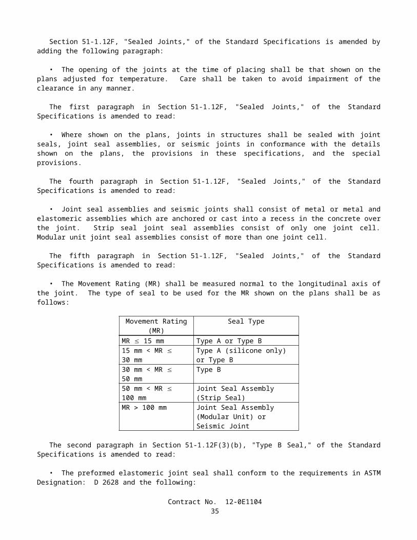
A. For cleaning and painting structural steel in the field, certification in conformance with the requirements in Qualification Procedure No. 1, "Standard Procedure For Evaluating Painting Contractors (Field Application to Complex Industrial Structures)" (SSPC-QP 1).
B. For removing paint from structural steel, certification in conformance with the requirements in Qualification Procedure No. 2, "Standard Procedure For Evaluating Painting Contractors (Field Removal of Hazardous Coatings from Complex Structures)" (SSPC-QP 2).
C. For cleaning and painting structural steel in a permanent painting facility, certification in conformance with the requirements in Qualification Procedure No. 3, "Standard Procedure For Evaluating Qualifications of Shop Painting Applicators" (SSPC-QP 3). The AISC's Sophisticated Paint Endorsement (SPE) quality program will be considered equivalent to SSPC-QP 3.
The third paragraph of Section 59-2.03, "Blast Cleaning," of the Standard Specifications is amended to read:
• Exposed steel or other metal surfaces to be blast cleaned shall be cleaned in conformance with the requirements in Surface Preparation Specification No. 6, "Commercial Blast Cleaning," of the "SSPC: The Society for Protective Coatings." Blast cleaning shall leave all surfaces with a dense, uniform, angular anchor pattern of not less than 35 µm as measured in conformance with the requirements in ASTM Designation: D 4417.
The first paragraph of Section 59-2.06, "Hand Cleaning," of the Standard Specifications is amended to read:
• Dirt, loose rust and mill scale, or paint which is not firmly bonded to the surfaces shall be removed in conformance with the requirements in Surface Preparation Specification No. 2, "Hand Tool Cleaning," of the "SSPC: The Society for Protective Coatings." Edges of old remaining paint shall be feathered.
The fourth paragraph of Section 59-2.12, "Painting," of the Standard Specifications is amended to read:
• The dry film thickness of the paint will be measured in place with a calibrated Type 2 magnetic film thickness gage in conformance with the requirements of specification SSPC-PA2 of the "SSPC: The Society for Protective Coatings."
SECTION 75: MISCELLANEOUS METAL
Issue Date: November 2, 2004
The table in the tenth paragraph of Section 75-1.02, "Miscellaneous Iron and Steel," of the Standard Specifications is amended to read:
Contract No. 12-0E110437
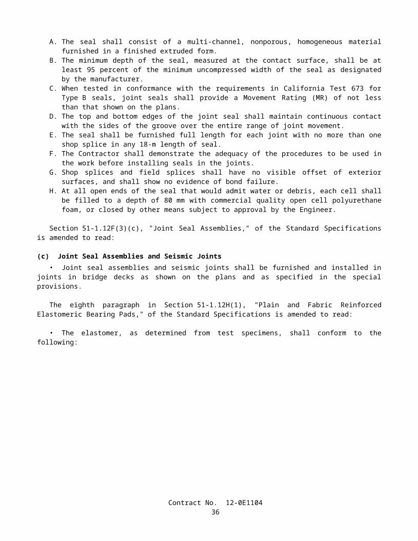
Material SpecificationSteel bars, plates and shapes
ASTM Designation: A 36/A 36M or A 575, A 576 (AISI or M Grades 1016 through 1030)
Steel fastener components for general applications:Bolts and studs ASTM Designation: A 307Headed anchor bolts ASTM Designation: A 307, Grade B, including
S1 supplementary requirementsNonheaded anchor bolts
ASTM Designation: A 307, Grade C, including S1 supplementary requirements and S1.6 of AASHTO Designation: M 314 supplementary requirementsor AASHTO Designation: M 314, Grade 36 or 55, including S1 supplementary requirements
High-strength bolts and studs, threaded rods, and nonheaded anchor bolts
ASTM Designation: A 449, Type 1
Nuts ASTM Designation: A 563, including Appendix X1*
Washers ASTM Designation: F 844Components of high-strength steel fastener assemblies for use in structural steel joints:
Bolts ASTM Designation: A 325, Type 1Tension control bolts ASTM Designation: F 1852, Type 1Nuts ASTM Designation: A 563, including
Appendix X1*Hardened washers ASTM Designation: F 436, Type 1, Circular,
including S1 supplementary requirementsDirect tension indicators
ASTM Designation: F 959, Type 325, zinc-coated
Stainless steel fasteners (Alloys 304 & 316) for general applications:Bolts, screws, studs, threaded rods, and nonheaded anchor bolts
ASTM Designation: F 593 or F 738M
Nuts ASTM Designation: F 594 or F 836MWashers ASTM Designation: A 240/A 240M and
ANSI B 18.22MCarbon-steel castings ASTM Designation: A 27/A 27M, Grade 65-35
[450-240], Class 1Malleable iron castings ASTM Designation: A 47, Grade 32510 or
A 47M, Grade 22010Gray iron castings ASTM Designation: A 48, Class 30BDuctile iron castings ASTM Designation: A 536, Grade 65-45-12Cast iron pipe Commercial qualitySteel pipe Commercial quality, welded or extrudedOther parts for general applications
Commercial quality
* Zinc-coated nuts that will be tightened beyond snug or wrench tight shall be furnished with a dyed dry lubricant conforming to Supplementary Requirement S2 in ASTM Designation: A 563.
The second paragraph in Section 75-1.03, "Miscellaneous Bridge Metal," of the Standard Specifications is amended to read:
Contract No. 12-0E110438
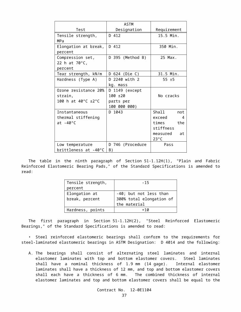
• Miscellaneous bridge metal shall consist of the following, except as further provided in Section 51-1.19, "Utility Facilities," and in the special provisions:
A. Bearing assemblies, equalizing bolts and expansion joint armor in concrete structures.B. Expansion joint armor in steel structures.C. Manhole frames and covers, frames and grates, ladder rungs, guard posts and access door assemblies.D. Deck drains, area drains, retaining wall drains, and drainage piping, except drainage items identified as "Bridge
Deck Drainage System" in the special provisions.
The table in the eighteenth paragraph of Section 75-1.03, "Miscellaneous Bridge Metal," of the Standard Specifications is amended to read:
Stud Diameter(millimeters)
Sustained TensionTest Load
(kilonewtons)29.01-33.00 137.923.01-29.00 79.621.01-23.00 64.1
* 18.01-21.00 22.215.01-18.00 18.212.01-15.00 14.29.01-12.00 9.346.00-9.00 4.23
* Maximum stud diameter permitted for mechanical expansion anchors.
The table in the nineteenth paragraph of Section 75-1.03, "Miscellaneous Bridge Metal," of the Standard Specifications is amended to read:
Stud Diameter(millimeters)
UltimateTensile Load(kilonewtons)
30.01-33.00 112.127.01-30.00 88.123.01-27.00 71.220.01-23.00 51.616.01-20.00 32.014.01-16.00 29.412.00-14.00 18.7
The table in the twenty-second paragraph of Section 75-1.03, "Miscellaneous Bridge Metal," of the Standard Specifications is amended to read:
Installation Torque Values, (newton meters)
Stud Diameter(millimeters)
Shell TypeMechanicalExpansionAnchors
Integral Stud TypeMechanicalExpansionAnchors
Resin Capsule Anchors
andCast-in-Place Inserts
29.01-33.00 — — 54023.01-29.00 — — 31521.01-23.00 — — 23518.01-21.00 110 235 20015.01-18.00 45 120 10012.01-15.00 30 65 40 9.01-12.00 15 35 246.00-9.00 5 10 —
Contract No. 12-0E110439
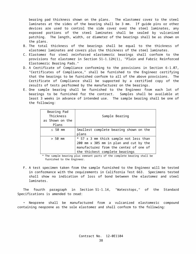
The third paragraph in Section 75-1.035, "Bridge Joint Restrainer Units," of the Standard Specifications is amended to read:
• Cables shall be 19 mm preformed, 6 x 19, wire strand core or independent wire rope core (IWRC), galvanized, and in conformance with the requirements in Federal Specification RR-W-410D, right regular lay, manufactured of improved plow steel with a minimum breaking strength of 200 kN. Two certified copies of mill test reports of each manufactured length of cable used shall be furnished to the Engineer.
The second paragraph in Section 75-1.05, "Galvanizing," of the Standard Specifications is amended to read:
At the option of the Contractor, material thinner than 3.2 mm shall be galvanized either before fabrication in conformance with the requirements of ASTM Designation: A 653/A 653M, Coating Designation Z600, or after fabrication in conformance with the requirements of ASTM Designation: A 123, except that the weight of zinc coating shall average not less than 365 g per square meter of actual surface area with no individual specimen having a coating weight of less than 305 g per square meter.
SECTION 80: FENCES
Issue Date: October 12, 2004
The second paragraph of Section 80-3.01B(2), "Treated Wood Posts and Braces," of the Standard Specifications is amended to read:
• Posts and braces to be treated shall be pressure treated in conformance with the provisions in Section 58, "Preservative Treatment of Lumber, Timber and Piling," and AWPA Use Category System: UC4A, Commodity Specification A or B.
SECTION 83: RAILINGS AND BARRIERS
Issue Date: January 31, 2005
The ninth paragraph in Section 83-1.02B, "Metal Beam Guard Railing," of the Standard Specifications is amended to read:
• The grades and species of wood posts and blocks shall be No. 1 timbers (also known as No. 1 structural) Douglas fir or No. 1 timbers Southern yellow pine. Wood posts and blocks shall be graded in conformance with the provisions in Section 57-2, "Structural Timber," of the Standard Specifications, except allowances for shrinkage after mill cutting shall in no case exceed 5 percent of the American Lumber Standards minimum sizes, at the time of installation.
The eleventh paragraph in Section 83-1.02B, "Metal Beam Guard Railing," of the Standard Specifications is amended to read:
• After fabrication, wood posts and blocks shall be pressure treated in conformance with Section 58, "Preservative Treatment of Lumber, Timber and Piling," and AWPA Use Category System: UC4A, Commodity Specification A.
The twelfth paragraph in Section 83-1.02B, "Metal Beam Guard Railing," of the Standard Specifications is amended to read:
• If copper naphthenate, ammoniacal copper arsenate, chromated copper arsenate, ammoniacal copper zinc arsenate, ammoniacal copper quat or copper azole is used to treat the wood posts and blocks, the bolt holes shall be treated as follows:
A. Before the bolts are inserted, bolt holes shall be filled with a grease, recommended by the manufacturer for corrosion protection, which will not melt or run at a temperature of 65°C.
The second paragraph in Section 83-1.02D, "Steel Bridge Railing," of the Standard Specifications is amended to read:
• Structural shapes, tubing, plates, bars, bolts, nuts, and washers shall be structural steel conforming to the provisions in Section 55-2, "Materials." Other fittings shall be commercial quality.
Contract No. 12-0E110440
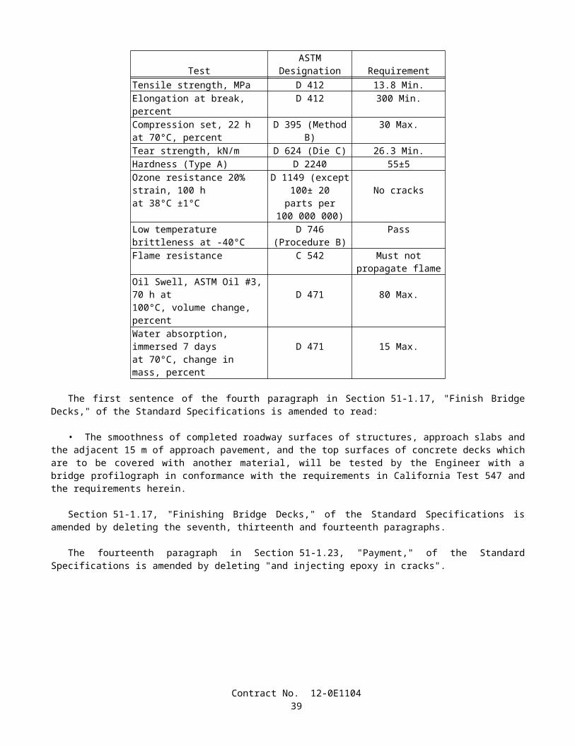
The second and third paragraphs in Section 83-1.02E, "Cable Railing," of the Standard Specifications are replaced with the following paragraph:
• Pipe for posts and braces shall be standard steel pipe or pipe that conforms to the provisions in Section 80-4.01A, "Posts and Braces."
The fourteenth paragraph in Section 83-1.02I, "Chain Link Railing," of the Standard Specifications is amended to read:
• Chain link fabric shall be either 11-gage Type I zinc coated fabric conforming to the requirements in AASHTO Designation: M 181 or 11-gage Type IV polyvinyl chloride (PVC) coated fabric conforming to the requirements in Federal Specification RR-F-191/1D.
The first paragraph in Section 83-2.02D(2), "Materials," of the Standard Specifications is amended to read:
• Type 50 and 60 series concrete barriers shall be constructed of minor concrete conforming to the provisions in Section 90-10, "Minor Concrete," except as follows:
a. The maximum size of aggregate used for extruded or slip-formed concrete barriers shall be at the option of the Contractor, but in no case shall the maximum size be larger than 37.5-mm or smaller than 9.5-mm.
b. If the 9.5-mm maximum size aggregate grading is used to construct extruded or slip-formed concrete barriers, the cementitious material content of the minor concrete shall be not less than 400 kg/m3.
The third paragraph in Section 83-2.02D(2), "Materials," of the Standard Specifications is amended to read:
• The concrete paving between the tops of the 2 walls of concrete barrier (Types 50E, 60E, 60GE, and 60SE) and the optional concrete slab at the base between the 2 walls of concrete barrier (Types 50E, 60E, 60GE, and 60SE) shall be constructed of minor concrete conforming to the provisions of Section 90-10, except that the minor concrete shall contain not less than 300 kg of cementitious material per cubic meter.
The fourth paragraph in Section 83-2.04, "Payments," of the Standard Specifications is amended to read:
• Steel plate barrier attached to concrete barrier at overhead sign foundations, electroliers, drainage structures, and other locations shown on the plans will be measured and paid for as the type of concrete barrier attached thereto.
SECTION 85: PAVEMENT MARKERS
Issue Date: May 16, 2003
The second through fifth paragraphs in Section 85-1.03, "Sampling, Tolerances and Packaging," of the Standard Specifications are amended to read:
Sampling• Twenty markers selected at random will constitute a representative sample for each lot of markers.• The lot size shall not exceed 25000 markers.
Tolerances• Three test specimens will be randomly selected from the sample for each test and tested in conformance with these
specifications. Should any one of the 3 specimens fail to conform with the requirements in these specifications, 6 additional specimens will be tested. The failure of any one of these 6 specimens shall be cause for rejection of the entire lot or shipment represented by the sample.
• The entire sample of retroreflective pavement markers will be tested for reflectance. The failure of 10 percent or more of the original sampling shall be cause for rejection.
Section 85-1.04, "Non-Reflective Pavement Markers," of the Standard Specifications is amended to read:
Contract No. 12-0E110441
85-1.04 Non-Reflective Pavement Markers• Non-reflective pavement markers (Types A and AY) shall be, at the option of the Contractor, either ceramic or
plastic conforming to these specifications.• The top surface of the marker shall be convex with a gradual change in curvature. The top, bottom and sides shall
be free of objectionable marks or discoloration that will affect adhesion or appearance. • The bottom of markers shall have areas of integrally formed protrusions or indentations, which will increase the
effective bonding surface area of adhesive. The bottom surface of the marker shall not deviate more than 1.5 mm from a flat surface. The areas of protrusion shall have faces parallel to the bottom of the marker and shall project approximately one mm from the bottom.
The second through fourth paragraphs of Section 85-1.04A, "Non-Reflective Pavement Markers (Ceramic)," of the Standard Specifications are deleted.
The table in the fifth paragraph in Section 85-1.04A, "Non-Reflective Pavement Markers (Ceramic)," of the Standard Specifications is amended to read:
Testing• Tests shall be performed in conformance with the requirements in California Test 669.
Test Test Description Requirementa Bond strength 4.8 MPa, min.b Glaze thickness 180 µm, min.c Hardness 6 Moh, min.d Luminance factor, Type A, white markers only,
glazed surface75, min.
e Yellowness index, Type A, white markers only, glazed surface
7, max.
f Color-yellow, Type AY, yellow markers only. The chromaticity coordinates shall be within a color box defined in CTM 669
Pass
g Compressive strength 6700 N, min.h Water absorption 2.0 %, max.i Artificial weathering, 500 hours exposure,
yellowness index20, max.
Section 85-1.04B, "Non-Reflective Pavement Markers (Plastic)," of the Standard Specifications is amended to read:
85-1.04B Non-Reflective Pavement Markers (Plastic)• Plastic non-reflective pavement markers Types A and AY shall be, at the option of the Contractor, either
polypropylene or acrylonitrile-butadiene-styrene (ABS) plastic type.• Plastic markers shall conform to the testing requirements specified in Section 85-1.04A, "Non-Reflective Pavement
Markers (Ceramic)," except that Tests a, b, c, and h shall not apply. The plastic markers shall not be coated with substances that interfere with the ability of the adhesive bonding to the marker.
The sixth and seventh paragraphs in Section 85-1.05, "Retroreflective Pavement Markers," of the Standard Specifications are amended to read:
Testing• Tests shall be performed in conformance with the requirements in California Test 669.
Contract No. 12-0E110442
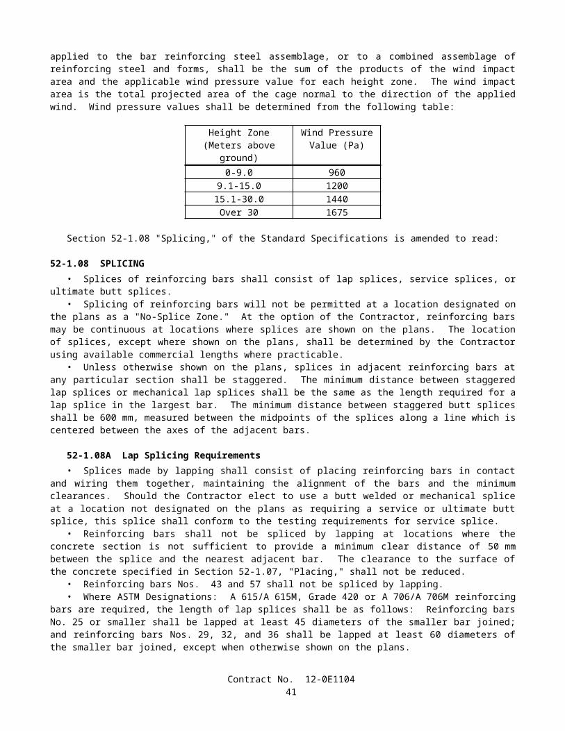
Test Description RequirementBond strengtha 3.4 MPa, min.Compressive strengthb 8900 N, min.Abrasion resistance, marker must meet the respective specific intensity minimum requirements after abrasion.
Pass
Water Soak Resistance No delamination of the body or lens system of the marker nor loss of reflectance
Specific IntensityReflectance Clear Yellow Red
0° Incidence Angle, min. 3.0 1.5 0.7520° Incidence Angle, min. 1.2 0.60 0.30After one year field evaluation 0.30 0.15 0.08
a Failure of the marker body or filler material prior to reaching 3.4 MPa shall constitute a failing bond strength test.
b Deformation of the marker of more than 3 mm at a load of less than 8900 N or delamination of the shell and the filler material of more than 3 mm regardless of the load required to break the marker shall be cause for rejection of the markers as specified in Section 85-1.03, "Sampling, Tolerances and Packaging."
• Pavement markers to be placed in pavement recesses shall conform to the above requirements for retroreflective pavement markers except that the minimum compressive strength requirement shall be 5338 N.
The eighth paragraph of Section 85-1.05, "Retroreflective Pavement Markers" of the Standard Specifications is deleted.
The eighth paragraph in Section 85-1.06, "Replacement," of the Standard Specifications is amended to read:
• Epoxy adhesive shall not be used to apply non-reflective plastic pavement markers.
SECTION 86: SIGNALS, LIGHTING AND ELECTRICAL SYSTEMS
Issue Date: January 31, 2005
The first paragraph of Section 86-2.03, "Foundations," of the Standard Specifications is amended to read:
• Except for concrete for cast-in-drilled-hole concrete pile foundations, portland cement concrete shall conform to Section 90-10, "Minor Concrete."
The fifth paragraph of Section 86-2.03, "Foundations," of the Standard Specifications is amended to read:
• Reinforced cast-in-drilled-hole concrete pile foundations for traffic signal and lighting standards shall conform to the provisions in Section 49, "Piling," with the following exceptions: 1) Material resulting from drilling holes shall be disposed of in conformance with the provisions in Section 86-2.01, "Excavating and Backfilling," and 2) Concrete filling for cast-in-drilled-hole concrete piles will not be considered as designated by compressive strength.
The seventh paragraph of Section 86-2.03, "Foundations," of the Standard Specifications is amended to read:
• Forms shall be true to line and grade. Tops of foundations for posts and standards, except special foundations, shall be finished to curb or sidewalk grade or as directed by the Engineer. Forms shall be rigid and securely braced in place. Conduit ends and anchor bolts shall be placed in proper position and to proper height, and anchor bolts shall be held in place by means of rigid top and bottom templates. The bottom template shall be made of steel. The bottom template shall provide proper spacing and alignment of the anchor bolts near their bottom embedded end. The bottom template shall be installed before placing footing concrete. Anchor bolts shall not be installed more than 1:40 from vertical.
Section 86-2.03, "Foundations," of the Standard Specifications is amended by deleting the eighth paragraph.
The twelfth paragraph of Section 86-2.03, "Foundations," of the Standard Specifications is amended to read:
Contract No. 12-0E110443
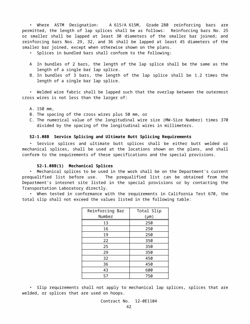
• Plumbing of the standards shall be accomplished by adjusting the leveling nuts before placing the mortar or before the foundation is finished to final grade. Shims or other similar devices shall not be used for plumbing or raking of posts, standards, or pedestals. After final adjustments of both top nuts and leveling nuts on anchorage assemblies have been made, firm contact shall exist between all bearing surfaces of the anchor bolt nuts, washers, and the base plates.
The first paragraph of Section 86-2.04, "Standards, Steel Pedestals and Posts," of the Standard Specifications is amended to read:
86-2.04 STANDARDS, STEEL PEDESTALS, AND POSTS• Standards for traffic signals and lighting, and steel pedestals for cabinets and other similar equipment, shall be
located as shown on the plans. Bolts, nuts and washers, and anchor bolts for use in signal and lighting support structures shall conform to the provisions in Section 55-2, "Materials." Except when bearing-type connections or slipbases are specified, high-strength bolted connections shall conform to the provisions in Section 55-3.14, "Bolted Connections." Welding, nondestructive testing (NDT) of welds, and acceptance and repair criteria for NDT of steel members shall conform to the requirements of AWS D1.1 and the contract special provisions.
The second paragraph of Section 86-2.04, "Standards, Steel Pedestals and Posts," of the Standard Specifications is amended to read:
• On each lighting standard except Type 1, one rectangular corrosion resistant metal identification tag shall be permanently attached above the hand hole, near the base of the standard, using stainless steel rivets. On each signal pole support, two corrosion resistant metal identification tags shall be attached, one above the hand hole near the base of the vertical standard and one on the underside of the signal mast arm near the arm plate. As a minimum, the information on each identification tag shall include the name of the manufacturer, the date of manufacture, the identification number as shown on the plans, the contract number, and a unique identification code assigned by the fabricator. This number shall be traceable to a particular contract and the welds on that component, and shall be readable after the support structure is coated and installed. The lettering shall be a minimum of 7 mm high. The information may be either depressed or raised, and shall be legible.
The fourth paragraph of Section 86-2.04, "Standards, Steel Pedestals and Posts," of the Standard Specifications is amended to read:
• Ferrous metal parts of standards, with shaft length of 4.6 m and longer, shall conform to the details shown on the plans, the provisions in Section 55-2, "Materials," except as otherwise noted, and the following requirements:
Except as otherwise specified, standards shall be fabricated from sheet steel of weldable grade having a minimum yield strength, after fabrication, of 276 MPa.
Certified test reports which verify conformance to the minimum yield strength requirements shall be submitted to the Engineer. The test reports may be the mill test reports for the as-received steel or, when the as-received steel has a lower yield strength than required, the Contractor shall provide supportive test data which provides assurance that the Contractor's method of cold forming will consistently increase the tensile properties of the steel to meet the specified minimum yield strength. The supportive test data shall include tensile properties of the steel after cold forming for specific heats and thicknesses.
When a single-ply 8-mm thick pole is specified, a 2-ply pole with equivalent section modulus may be substituted.Standards may be fabricated of full-length sheets or shorter sections. Each section shall be fabricated from not more
than 2 pieces of sheet steel. Where 2 pieces are used, the longitudinal welded seams shall be directly opposite one another. When the sections are butt-welded together, the longitudinal welded seams on adjacent sections shall be placed to form continuous straight seams from base to top of standard.
Butt-welded circumferential joints of tubular sections requiring CJP groove welds shall be made using a metal sleeve backing ring inside each joint. The sleeve shall be 3-mm nominal thickness, or thicker, and manufactured from steel having the same chemical composition as the steel in the tubular sections to be joined. When the sections to be joined have different specified minimum yield strengths, the steel in the sleeve shall have the same chemical composition as the tubular section having the higher minimum yield strength. The width of the metal sleeve shall be consistent with the type of NDT chosen and shall be a minimum width of 25 mm. The sleeve shall be centered at the joint and be in contact with the tubular section at the point of the weld at time of fit-up.
Welds shall be continuous.The weld metal at the transverse joint shall extend to the sleeve, making the sleeve an integral part of the joint.
Contract No. 12-0E110444
During fabrication, longitudinal seams on vertical tubular members of cantilevered support structures shall be centered on and along the side of the pole that the pole plate is located. Longitudinal seams on horizontal tubular members, including signal and luminaire arms, shall be within +/-45 degrees of the bottom of the arm.
The longitudinal seam welds in steel tubular sections may be made by the electric resistance welding process.Longitudinal seam welds shall have 60 percent minimum penetration, except that within 150 mm of circumferential
welds, longitudinal seam welds shall be CJP groove welds. In addition, longitudinal seam welds on lighting support structures having telescopic pole segment splices shall be CJP groove welds on the female end for a length on each end equal to the designated slip fit splice length plus 150 mm.
Exposed circumferential welds, except fillet and fatigue-resistant welds, shall be ground flush (-0, +2mm) with the base metal prior to galvanizing or painting.
Circumferential welds and base plate-to-pole welds may be repaired only one time without written permission from the Engineer.
Exposed edges of the plates that make up the base assembly shall be finished smooth and exposed corners of the plates shall be broken unless otherwise shown on the plans. Shafts shall be provided with slip-fitter shaft caps.
Flatness of surfaces of 1) base plates that are to come in contact with concrete, grout, or washers and leveling nuts; 2) plates in high-strength bolted connections; 3) plates in joints where cap screws are used to secure luminaire and signal arms; and 4) plates used for breakaway slip base assemblies shall conform to the requirements in ASTM A6.
Standards shall be straight, with a permissive variation not to exceed 25 mm measured at the midpoint of a 9-m or 11-m standard and not to exceed 20 mm measured at the midpoint of a 5-m through 6-m standard. Variation shall not exceed 25 mm at a point 4.5 m above the base plate for Type 35 and Type 36 standards.
Zinc-coated nuts used on fastener assemblies having a specified preload (obtained by specifying a prescribed tension, torque value, or degree of turn) shall be provided with a colored lubricant that is clean and dry to the touch. The color of the lubricant shall be in contrast to the zinc coating on the nut so that the presence of the lubricant is visually obvious. In addition, either the lubricant shall be insoluble in water, or fastener components shall be shipped to the job site in a sealed container.
No holes shall be made in structural members unless the holes are shown on the plans or are approved in writing by the Engineer.
Standards with an outside diameter of 300 mm or less shall be round. Standards with an outside diameter greater than 300 mm shall be round or multisided. Multisided standards shall have a minimum of 12 sides which shall be convex and shall have a minimum bend radius of 100 mm.
Mast arms for standards shall be fabricated from material as specified for standards, and shall conform to the dimensions shown on the plans.
The cast steel option for slip bases shall be fabricated from material conforming to the requirements in ASTM Designation: A 27/A 27M, Grade 70-40. Other comparable material may be used if written permission is given by the Engineer. The casting tolerances shall be in conformance with the Steel Founder's Society of America recommendations (green sand molding).
One casting from each lot of 50 castings or less shall be subject to radiographic inspection, in conformance with the requirements in ASTM Designation: E 94. The castings shall comply with the acceptance criteria severity level 3 or better for the types and categories of discontinuities in conformance with the requirements in ASTM Designations: E 186 and E 446. If the one casting fails to pass the inspection, 2 additional castings shall be radiographed. Both of these castings shall pass the inspection, or the entire lot of 50 will be rejected.
Material certifications, consisting of physical and chemical properties, and radiographic films of the castings shall be filed at the manufacturer's office. These certifications and films shall be available for inspection upon request.
High-strength bolts, nuts, and flat washers used to connect slip base plates shall conform to the requirements in ASTM Designation: A 325 or A 325M and shall be galvanized in conformance with the provisions in Section 75-1.05, "Galvanizing."
Plate washers shall be fabricated by saw cutting and drilling steel plate conforming to the requirements in AISI Designation: 1018, and be galvanized in conformance with the provisions in Section 75-1.05, "Galvanizing." Prior to galvanizing, burrs and sharp edges shall be removed and holes shall be chamfered sufficiently on each side to allow the bolt head to make full contact with the washer without tension on the bolt.
High-strength cap screws shown on the plans for attaching arms to standards shall conform to the requirements in ASTM Designation: A 325, A 325M, or A 449, and shall comply with the mechanical requirements in ASTM Designation: A 325 or A 325M after galvanizing. The cap screws shall be galvanized in conformance with the provisions in Section 75-1.05, "Galvanizing." The threads of the cap screws shall be coated with a colored lubricant that is clean and dry to the touch. The color of the lubricant shall be in contrast to the color of the zinc coating on the cap screw so that presence of the lubricant is visually obvious. In addition, either the lubricant shall be insoluble in water, or fastener components shall be shipped to the job site in a sealed container.
Contract No. 12-0E110445
Unless otherwise specified, bolted connections attaching signal or luminaire arms to poles shall be considered slip critical. Galvanized faying surfaces on plates on luminaire and signal arms and matching plate surfaces on poles shall be roughened by hand using a wire brush prior to assembly and shall conform to the requirements for Class C surface conditions for slip-critical connections in "Specification for Structural Joints Using ASTM A 325 or A 490 Bolts," a specification approved by the Research Council on Structural Connections (RCSC) of the Engineering Foundation. For faying surfaces required to be painted, the paint shall be an approved type, brand, and thickness that has been tested and approved according to the RCSC Specification as a Class B coating.
Samples of fastener components will be randomly taken from each production lot by the Engineer and submitted, along with test reports required by appropriate ASTM fastener specifications, for QA testing and evaluation. Sample sizes for each fastener component shall be as determined by the Engineer.
The seventh paragraph of Section 86-2.04, "Standards, Steel Pedestals and Posts," of the Standard Specifications is amended to read:
• To avoid interference of arm plate-to-tube welds with cap screw heads, and to ensure cap screw heads can be turned using conventional installation tools, fabricators shall make necessary adjustments to details prior to fabrication and properly locate the position of arm tubes on arm plates during fabrication.
The sixth and seventh paragraphs of 86-2.12, "Wood Poles," of the Standard Specifications are amended to read:
• After fabrication, wood poles shall be pressure treated in conformance with the provisions in Section 58, "Preservative Treatment of Lumber, Timber and Piling," and AWPA Use Category System: UC4B, Commodity Specification D.
• Wood poles, when specified in the special provisions to be painted, shall be treated with waterborne wood preservatives.
The first paragraph of Section 86-2.15, "Galvanizing," of the Standard Specifications is amended to read:
• Galvanizing shall be in conformance with the provisions in Section 75-1.05, "Galvanizing," except that cabinets may be constructed of material galvanized prior to fabrication in conformance with the requirements in ASTM Designation: A 653/653M, Coating Designation G 90, in which case all cut or damaged edges shall be painted with at least 2 applications of approved unthinned zinc-rich primer (organic vehicle type) conforming to the provisions in Section 91, "Paint." Aerosol cans shall not be used. Other types of protective coating must be approved by the Engineer prior to installation.
The first paragraph of Section 86-4.06, "Pedestrian Signal Faces" of the Standard Specifications is amended to read:
• Message symbols for pedestrian signal faces shall be white WALKING PERSON and Portland orange UPRAISED HAND conforming to the requirements in the Institute of Transportation Engineers Standards: "Pedestrian Traffic Control Signal Indications," "Manual on Uniform Traffic Control Devices," and "MUTCD California Supplement." The height of each symbol shall be not less than 250 mm and the width of each symbol shall be not less than 165 mm.
The tenth paragraph of Section 86-4.07, "Light Emitting Diode Pedestrian Signal Face 'Upraised Hand' Module" of the Standard Specifications is amended to read:
• The luminance of the "UPRAISED HAND" symbol shall be 3750 cd/m2 minimum. The color of "UPRAISED HAND" shall be Portland orange conforming to the requirements of the Institute of Transportation Engineers Standards: "Pedestrian Traffic Control Signal Indications," "Manual on Uniform Traffic Control Devices," and "MUTCD California Supplement." The height of each symbol shall be not less than 250 mm and the width of each symbol shall be not less than 165 mm.
Section 86-8.01, "Payment," of the Standard Specifications is amended by adding the following paragraph after the first paragraph:
• If a portion or all of the poles for signal, lighting and electrical systems pursuant to Standard Specification Section 86, "Signals, Lighting and Electrical Systems," is fabricated more than 480 air line kilometers from both Sacramento and Los Angeles, additional shop inspection expenses will be sustained by the State. Whereas it is and will be impracticable and extremely difficult to ascertain and determine the actual increase in such expenses, it is agreed that payment to the Contractor for furnishing such items from each fabrication site located more than 480 air line kilometers from both Sacramento and Los
Contract No. 12-0E110446
Angeles will be reduced $5000; in addition, in the case where a fabrication site is located more than 4800 air line kilometers from both Sacramento and Los Angeles, payment will be reduced an additional $3000 per each fabrication site ($8000 total per site).
SECTION 88: ENGINEERING FABRIC
Issue Date: January 15, 2002
Section 88-1.02, "Pavement Reinforcing Fabric," of the Standard Specifications is amended to read:
• Pavement reinforcing fabric shall be 100 percent polypropylene staple fiber fabric material, needle-punched, thermally bonded on one side, and conform to the following:
Specification RequirementWeight, grams per square meterASTM Designation: D 5261 140Grab tensile strength(25-mm grip), kilonewtons, min. in each directionASTM Designation: D 4632 0.45Elongation at break, percent min.ASTM Designation: D 4632 50Asphalt retention by fabric, grams per square meter. (Residual Minimum)ASTM Designation: D 6140 900Note: Weight, grab, elongation and asphalt retention are based on Minimum Average Roll Value (MARV)
SECTION 90: PORTLAND CEMENT CONCRETE
Issue Date: November 2, 2004
Section 90, "Portland Cement Concrete," of the Standard Specifications is amended to read:
SECTION 90: PORTLAND CEMENT CONCRETE90-1 GENERAL
90-1.01 DESCRIPTION• Portland cement concrete shall be composed of cementitious material, fine aggregate, coarse aggregate, admixtures
if used, and water, proportioned and mixed as specified in these specifications.• The Contractor shall determine the mix proportions for concrete in conformance with these specifications. Unless
otherwise specified, cementitious material shall be a combination of cement and mineral admixture. Cementitious material shall be either:
1. "Type IP (MS) Modified" cement; or 2. A combination of "Type II Modified" portland cement and mineral admixture; or3. A combination of Type V portland cement and mineral admixture.
• Type III portland cement shall be used only as allowed in the special provisions or with the approval of the Engineer.
• Class 1 concrete shall contain not less than 400 kg of cementitious material per cubic meter.• Class 2 concrete shall contain not less than 350 kg of cementitious material per cubic meter.• Class 3 concrete shall contain not less than 300 kg of cementitious material per cubic meter.• Class 4 concrete shall contain not less than 250 kg of cementitious material per cubic meter.• Minor concrete shall contain not less than 325 kg of cementitious material per cubic meter unless otherwise
specified in these specifications or the special provisions.• Unless otherwise designated on the plans or specified in these specifications or the special provisions, the amount of
cementitious material used per cubic meter of concrete in structures or portions of structures shall conform to the following:
Contract No. 12-0E110447
Use Cementitious Material Content(kg/m3)
Concrete designated by compressive strength:Deck slabs and slab spans of bridgesRoof sections of exposed top box culvertsOther portions of structures
400 min., 475 max.400 min., 475 max.350 min., 475 max.
Concrete not designated by compressive strength:Deck slabs and slab spans of bridgesRoof sections of exposed top box culvertsPrestressed membersSeal coursesOther portions of structures
400 min.400 min.400 min.400 min.350 min.
Concrete for precast members 350 min., 550 max.
• Whenever the 28-day compressive strength shown on the plans is greater than 25 MPa, the concrete shall be designated by compressive strength. If the plans show a 28-day compressive strength that is 28 MPa or greater, an additional 14 days will be allowed to obtain the specified strength. The 28-day compressive strengths shown on the plans that are 25 MPa or less are shown for design information only and are not a requirement for acceptance of the concrete.
• Concrete designated by compressive strength shall be proportioned such that the concrete will attain the strength shown on the plans or specified in the special provisions.
• Before using concrete for which the mix proportions have been determined by the Contractor, or in advance of revising those mix proportions, the Contractor shall submit in writing to the Engineer a copy of the mix design.
• Compliance with cementitious material content requirements will be verified in conformance with procedures described in California Test 518 for cement content. For testing purposes, mineral admixture shall be considered to be cement. Batch proportions shall be adjusted as necessary to produce concrete having the specified cementitious material content.
• If any concrete has a cementitious material, portland cement, or mineral admixture content that is less than the minimum required, the concrete shall be removed. However, if the Engineer determines that the concrete is structurally adequate, the concrete may remain in place and the Contractor shall pay to the State $0.55 for each kilogram of cementitious material, portland cement, or mineral admixture that is less than the minimum required. The Department may deduct the amount from any moneys due, or that may become due, the Contractor under the contract. The deductions will not be made unless the difference between the contents required and those actually provided exceeds the batching tolerances permitted by Section 90-5, "Proportioning." No deductions will be made based on the results of California Test 518.
• The requirements of the preceding paragraph shall not apply to minor concrete or commercial quality concrete.
90-2 MATERIALS
90-2.01 CEMENT• Unless otherwise specified, cement shall be either "Type IP (MS) Modified" cement, "Type II Modified" portland
cement or Type V portland cement.• "Type IP (MS) Modified" cement shall conform to the requirements for Type IP (MS) cement in ASTM
Designation: C 595, and shall be comprised of an intimate and uniform blend of Type II cement and not more than 35 percent by mass of mineral admixture. The type and minimum amount of mineral admixture used in the manufacture of "Type IP (MS) Modified" cement shall be in conformance with the provisions in Section 90-4.08, "Required Use of Mineral Admixtures."
• "Type II Modified" portland cement shall conform to the requirements for Type II portland cement in ASTM Designation: C 150-02a.
• In addition, "Type IP (MS) Modified" cement and "Type II Modified" portland cement shall conform to the following requirements:
A. The cement shall not contain more than 0.60-percent by mass of alkalies, calculated as the percentage of Na2O plus 0.658 times the percentage of K2O, when determined by either direct intensity flame photometry or by the atomic absorption method. The instrument and procedure used shall be qualified as to precision and accuracy in conformance with the requirements in ASTM Designation: C 114;
B. The autoclave expansion shall not exceed 0.50-percent; andC. Mortar, containing the cement to be used and Ottawa sand, when tested in conformance with California Test 527,
shall not expand in water more than 0.010 percent and shall not contract in air more than 0.048 percent, except that
Contract No. 12-0E110448
when cement is to be used for precast prestressed concrete piling, precast prestressed concrete members, or steam cured concrete products, the mortar shall not contract in air more than 0.053 percent.
• Type III and Type V portland cements shall conform to the requirements in ASTM Designation: C 150-02a and the additional requirements listed above for "Type II Modified" portland cement, except that when tested in conformance with California Test 527, mortar containing Type III portland cement shall not contract in air more than 0.075 percent.
• Cement used in the manufacture of cast-in-place concrete for exposed surfaces of like elements of a structure shall be from the same cement mill.
• Cement shall be protected from exposure to moisture until used. Sacked cement shall be piled to permit access for tally, inspection, and identification of each shipment.
• Adequate facilities shall be provided to assure that cement meeting the provisions specified in this Section 90 -2.01 shall be kept separate from other cement in order to prevent any but the specified cement from entering the work. Safe and suitable facilities for sampling cement shall be provided at the weigh hopper or in the feed line immediately in advance of the hopper, in conformance with California Test 125.
• If cement is used prior to sampling and testing as provided in Section 6-1.07, "Certificates of Compliance," and the cement is delivered directly to the site of the work, the Certificate of Compliance shall be signed by the cement manufacturer or supplier of the cement. If the cement is used in ready-mixed concrete or in precast concrete products purchased as such by the Contractor, the Certificate of Compliance shall be signed by the manufacturer of the concrete or product.
• Cement furnished without a Certificate of Compliance shall not be used in the work until the Engineer has had sufficient time to make appropriate tests and has approved the cement for use.
90-2.02 AGGREGATES• Aggregates shall be free from deleterious coatings, clay balls, roots, bark, sticks, rags, and other extraneous material.• Natural aggregates shall be thoroughly and uniformly washed before use.• The Contractor, at the Contractor's expense, shall provide safe and suitable facilities, including necessary splitting
devices for obtaining samples of aggregates, in conformance with California Test 125.• Aggregates shall be of such character that it will be possible to produce workable concrete within the limits of water
content provided in Section 90-6.06, "Amount of Water and Penetration."• Aggregates shall have not more than 10 percent loss when tested for soundness in conformance with the
requirements in California Test 214. The soundness requirement for fine aggregate will be waived, provided that the durability index, Df, of the fine aggregate is 60, or greater, when tested for durability in conformance with California Test 229.
• If the results of any one or more of the Cleanness Value, Sand Equivalent, or aggregate grading tests do not meet the requirements specified for "Operating Range" but all meet the "Contract Compliance" requirements, the placement of concrete shall be suspended at the completion of the current pour until tests or other information indicate that the next material to be used in the work will comply with the requirements specified for "Operating Range."
• If the results of either or both the Cleanness Value and coarse aggregate grading tests do not meet the requirements specified for "Contract Compliance," the concrete that is represented by the tests shall be removed. However, if the Engineer determines that the concrete is structurally adequate, the concrete may remain in place, and the Contractor shall pay to the State $4.60 per cubic meter for paving concrete and $7.20 per cubic meter for all other concrete for the concrete represented by these tests and left in place. The Department may deduct the amount from any moneys due, or that may become due, the Contractor under the contract.
• If the results of either or both the Sand Equivalent and fine aggregate grading tests do not meet the requirements specified for "Contract Compliance," the concrete which is represented by the tests shall be removed. However, if the Engineer determines that the concrete is structurally adequate, the concrete may remain in place, and the Contractor shall pay to the State $4.60 per cubic meter for paving concrete and $7.20 per cubic meter for all other concrete for the concrete represented by these tests and left in place. The Department may deduct the amount from any moneys due, or that may become due, the Contractor under the contract.
• The 2 preceding paragraphs apply individually to the "Contract Compliance" requirements for coarse aggregate and fine aggregate. When both coarse aggregate and fine aggregate do not conform to the "Contract Compliance" requirements, both paragraphs shall apply. The payments specified in those paragraphs shall be in addition to any payments made in conformance with the provisions in Section 90-1.01, "Description."
• No single Cleanness Value, Sand Equivalent or aggregate grading test shall represent more than 250 m3 of concrete or one day's pour, whichever is smaller.
• When the source of an aggregate is changed, the Contractor shall adjust the mix proportions and submit in writing to the Engineer a copy of the mix design before using the aggregates.
Contract No. 12-0E110449
90-2.02A Coarse Aggregate• Coarse aggregate shall consist of gravel, crushed gravel, crushed rock, crushed air-cooled iron blast furnace slag or
combinations thereof. Crushed air-cooled blast furnace slag shall not be used in reinforced or prestressed concrete.• Coarse aggregate shall conform to the following quality requirements:
TestsCalifornia
Test RequirementsLoss in Los Angeles Rattler (after 500 revolutions)
211 45% max.
Cleanness ValueOperating Range 227 75 min.Contract Compliance 227 71 min.
• In lieu of the above Cleanness Value requirements, a Cleanness Value "Operating Range" limit of 71, minimum, and a Cleanness Value "Contract Compliance" limit of 68, minimum, will be used to determine the acceptability of the coarse aggregate if the Contractor furnishes a Certificate of Compliance, as provided in Section 6-1.07, "Certificates of Compliance," certifying that:
1. coarse aggregate sampled at the completion of processing at the aggregate production plant had a Cleanness Value of not less than 82 when tested by California Test 227; and
2. prequalification tests performed in conformance with the requirements in California Test 549 indicated that the aggregate would develop a relative strength of not less than 95 percent and would have a relative shrinkage not greater than 105 percent, based on concrete.
90-2.02B Fine Aggregate• Fine aggregate shall consist of natural sand, manufactured sand produced from larger aggregate or a combination
thereof. Manufactured sand shall be well graded.
• Fine aggregate shall conform to the following quality requirements:
TestCalifornia
Test RequirementsOrganic Impurities 213 Satisfactorya
Mortar Strengths Relative to Ottawa Sand 515 95%, min.Sand Equivalent:
Operating Range 217 75, min.Contract Compliance 217 71, min.
a Fine aggregate developing a color darker than the reference standard color solution may be accepted if it is determined by the Engineer, from mortar strength tests, that a darker color is acceptable.
• In lieu of the above Sand Equivalent requirements, a Sand Equivalent "Operating Range" limit of 71 minimum and a Sand Equivalent "Contract Compliance" limit of 68 minimum will be used to determine the acceptability of the fine aggregate if the Contractor furnishes a Certificate of Compliance, as provided in Section 6-1.07, "Certificates of Compliance," certifying that:
1. fine aggregate sampled at the completion of processing at the aggregate production plant had a Sand Equivalent value of not less than 82 when tested by California Test 217; and
2. prequalification tests performed in conformance with California Test 549 indicated that the aggregate would develop a relative strength of not less than 95 percent and would have a relative shrinkage not greater than 105 percent, based on concrete.
90-2.03 WATER• In conventionally reinforced concrete work, the water for curing, for washing aggregates, and for mixing shall be
free from oil and shall not contain more than 1000 parts per million of chlorides as Cl, when tested in conformance with California Test 422, nor more than 1300 parts per million of sulfates as SO4, when tested in conformance with California Test 417. In prestressed concrete work, the water for curing, for washing aggregates, and for mixing shall be free from oil
Contract No. 12-0E110450
and shall not contain more than 650 parts per million of chlorides as Cl, when tested in conformance with California Test 422, nor more than 1300 parts per million of sulfates as SO4, when tested in conformance with California Test 417. In no case shall the water contain an amount of impurities that will cause either: 1) a change in the setting time of cement of more than 25 percent when tested in conformance with the requirements in ASTM Designation: C 191 or ASTM Designation: C 266 or 2) a reduction in the compressive strength of mortar at 14 days of more than 5 percent, when tested in conformance with the requirements in ASTM Designation: C 109, when compared to the results obtained with distilled water or deionized water, tested in conformance with the requirements in ASTM Designation: C 109.
• In non-reinforced concrete work, the water for curing, for washing aggregates and for mixing shall be free from oil and shall not contain more than 2000 parts per million of chlorides as Cl, when tested in conformance with California Test 422, or more than 1500 parts per million of sulfates as SO4, when tested in conformance with California Test 417.
• In addition to the above provisions, water for curing concrete shall not contain impurities in a sufficient amount to cause discoloration of the concrete or produce etching of the surface.
• Water reclaimed from mixer wash-out operations may be used in mixing concrete. The water shall not contain coloring agents or more than 300 parts per million of alkalis (Na2O + 0.658 K2O) as determined on the filtrate. The specific gravity of the water shall not exceed 1.03 and shall not vary more than ±0.010 during a day's operations.
90-2.04 ADMIXTURE MATERIALS• Admixture materials shall conform to the requirements in the following ASTM Designations:
A. Chemical Admixtures—ASTM Designation: C 494.B. Air-entraining Admixtures—ASTM Designation: C 260.C. Calcium Chloride—ASTM Designation: D 98.D. Mineral Admixtures—Coal fly ash; raw or calcined natural pozzolan as specified in ASTM Designation: C 618;
silica fume conforming to the requirements in ASTM Designation: C 1240, with reduction of mortar expansion of 80 percent, minimum, using the cement from the proposed mix design.
• Unless otherwise specified in the special provisions, mineral admixtures shall be used in conformance with the provisions in Section 90-4.08, "Required Use of Mineral Admixtures."
90-3 AGGREGATE GRADINGS
90-3.01 GENERAL• Before beginning concrete work, the Contractor shall submit in writing to the Engineer the gradation of the primary
aggregate nominal sizes that the Contractor proposes to furnish. If a primary coarse aggregate or the fine aggregate is separated into 2 or more sizes, the proposed gradation shall consist of the gradation for each individual size, and the proposed proportions of each individual size, combined mathematically to indicate one proposed gradation. The proposed gradation shall meet the grading requirements shown in the table in this section, and shall show the percentage passing each of the sieve sizes used in determining the end result.
• The Engineer may waive, in writing, the gradation requirements in this Section 90-3.01 and in Sections 90-3.02, "Coarse Aggregate Grading," 90-3.03, "Fine Aggregate Grading," and 90-3.04, "Combined Aggregate Gradings," if, in the Engineer's opinion, furnishing the gradation is not necessary for the type or amount of concrete work to be constructed.
• Gradations proposed by the Contractor shall be within the following percentage passing limits:
Primary Aggregate Nominal Size Sieve Size Limits of Proposed Gradation37.5-mm x 19-mm 25-mm 19 - 4125-mm x 4.75-mm 19-mm 52 - 8525-mm x 4.75-mm 9.5-mm 15 - 3812.5-mm x 4.75-mm 9.5-mm 40 - 78 9.5-mm x 2.36-mm 9.5-mm 50 - 85 Fine Aggregate 1.18-mm 55 - 75Fine Aggregate 600-µm 34 - 46Fine Aggregate 300-µm 16 - 29
• Should the Contractor change the source of supply, the Contractor shall submit in writing to the Engineer the new gradations before their intended use.
Contract No. 12-0E110451
90-3.02 COARSE AGGREGATE GRADING• The grading requirements for coarse aggregates are shown in the following table for each size of coarse aggregate:
Percentage Passing Primary Aggregate Nominal Sizes37.5-mm x 19-mm 25-mm x 4.75-mm 12.5-mm x 4.75-mm 9.5-mm x 2.36-mm
Operating Contract Operating Contract Operating Contract Operating ContractSieve Sizes Range Compliance Range Compliance Range Compliance Range Compliance50-mm 100 100 — — — — — —37.5-mm 88-100 85-100 100 100 — — — —25-mm x ± 18 X ± 25 88-100 86-100 — — — —19-mm 0-17 0-20 X ± 15 X ± 22 100 100 — —12.5-mm — — — — 82-100 80-100 100 1009.5-mm 0-7 0-9 X ± 15 X ± 22 X ± 15 X ± 22 X ± 15 X ± 204.75-mm — — 0-16 0-18 0-15 0-18 0-25 0-282.36-mm — — 0-6 0-7 0-6 0-7 0-6 0-7
• In the above table, the symbol X is the gradation that the Contractor proposes to furnish for the specific sieve size as provided in Section 90-3.01, "General."
• Coarse aggregate for the 37.5-mm, maximum, combined aggregate grading as provided in Section 90-3.04, "Combined Aggregate Gradings," shall be furnished in 2 or more primary aggregate nominal sizes. Each primary aggregate nominal size may be separated into 2 sizes and stored separately, provided that the combined material conforms to the grading requirements for that particular primary aggregate nominal size.
• When the 25-mm, maximum, combined aggregate grading as provided in Section 90-3.04, "Combined Aggregate Gradings," is to be used, the coarse aggregate may be separated into 2 sizes and stored separately, provided that the combined material shall conform to the grading requirements for the 25-mm x 4.75-mm primary aggregate nominal size.
90-3.03 FINE AGGREGATE GRADING• Fine aggregate shall be graded within the following limits:
Percentage PassingSieve Sizes Operating Range Contract Compliance
9.5-mm 100 1004.75-mm 95-100 93-1002.36-mm 65-95 61-991.18-mm X ± 10 X ± 13600-µm X ± 9 X ± 12300-µm X ± 6 X ± 9150-µm 2-12 1-1575-µm 0-8 0-10
• In the above table, the symbol X is the gradation that the Contractor proposes to furnish for the specific sieve size as provided in Section 90-3.01, "General."
• In addition to the above required grading analysis, the distribution of the fine aggregate sizes shall be such that the difference between the total percentage passing the 1.18-mm sieve and the total percentage passing the 600-µm sieve shall be between 10 and 40, and the difference between the percentage passing the 600-µm and 300-µm sieves shall be between 10 and 40.
• Fine aggregate may be separated into 2 or more sizes and stored separately, provided that the combined material conforms to the grading requirements specified in this Section 90-3.03.
90-3.04 COMBINED AGGREGATE GRADINGS• Combined aggregate grading limits shall be used only for the design of concrete mixes. Concrete mixes shall be
designed so that aggregates are combined in proportions that shall produce a mixture within the grading limits for combined aggregates as specified herein.
• The combined aggregate grading, except when otherwise specified in these specifications or the special provisions, shall be either the 37.5-mm, maximum grading, or the 25-mm, maximum grading, at the option of the Contractor.
Contract No. 12-0E110452
Grading Limits of Combined AggregatesPercentage Passing
Sieve Sizes 37.5-mm Max. 25-mm Max. 12.5-mm Max. 9.5-mm Max.50-mm 100 — — —37.5-mm 90-100 100 — —25-mm 50-86 90-100 — —19-mm 45-75 55-100 100 —12.5-mm — — 90-100 1009.5-mm 38-55 45-75 55-86 50 - 1004.75-mm 30-45 35-60 45-63 45 - 632.36-mm 23-38 27-45 35-49 35 - 491.18-mm 17-33 20-35 25-37 25 - 37600-µm 10-22 12-25 15-25 15 - 25300-µm 4-10 5-15 5-15 5 - 15150-µm 1-6 1-8 1-8 1 - 875-µm 0-3 0-4 0-4 0 - 4
• Changes from one grading to another shall not be made during the progress of the work unless permitted by the Engineer.
90-4 ADMIXTURES90-4.01 GENERAL
• Admixtures used in portland cement concrete shall conform to and be used in conformance with the provisions in this Section 90-4 and the special provisions. Admixtures shall be used when specified or ordered by the Engineer and may be used at the Contractor's option as provided herein.
• Chemical admixtures and air-entraining admixtures containing chlorides as Cl in excess of one percent by mass of admixture, as determined by California Test 415, shall not be used in prestressed or reinforced concrete.
• Calcium chloride shall not be used in concrete except when otherwise specified.• Mineral admixture used in concrete for exposed surfaces of like elements of a structure shall be from the same
source and of the same percentage.• Admixtures shall be uniform in properties throughout their use in the work. Should it be found that an admixture as
furnished is not uniform in properties, its use shall be discontinued.• If more than one admixture is used, the admixtures shall be compatible with each other so that the desirable effects
of all admixtures used will be realized.
90-4.02 MATERIALS• Admixture materials shall conform to the provisions in Section 90–2.04, "Admixture Materials."
90-4.03 ADMIXTURE APPROVAL• No admixture brand shall be used in the work unless it is on the Department's current list of approved brands for the
type of admixture involved.• Admixture brands will be considered for addition to the approved list if the manufacturer of the admixture submits
to the Transportation Laboratory a sample of the admixture accompanied by certified test results demonstrating that the admixture complies with the requirements in the appropriate ASTM Designation and these specifications. The sample shall be sufficient to permit performance of all required tests. Approval of admixture brands will be dependent upon a determination as to compliance with the requirements, based on the certified test results submitted, together with tests the Department may elect to perform.
• When the Contractor proposes to use an admixture of a brand and type on the current list of approved admixture brands, the Contractor shall furnish a Certificate of Compliance from the manufacturer, as provided in Section 6 -1.07, "Certificates of Compliance," certifying that the admixture furnished is the same as that previously approved. If a previously approved admixture is not accompanied by a Certificate of Compliance, the admixture shall not be used in the work until the Engineer has had sufficient time to make the appropriate tests and has approved the admixture for use. The Engineer may take samples for testing at any time, whether or not the admixture has been accompanied by a Certificate of Compliance.
• If a mineral admixture is delivered directly to the site of the work, the Certificate of Compliance shall be signed by the manufacturer or supplier of the mineral admixture. If the mineral admixture is used in ready-mix concrete or in precast
Contract No. 12-0E110453
concrete products purchased as such by the Contractor, the Certificate of Compliance shall be signed by the manufacturer of the concrete or product.
90-4.04 REQUIRED USE OF CHEMICAL ADMIXTURES AND CALCIUM CHLORIDE• When the use of a chemical admixture or calcium chloride is specified, the admixture shall be used at the dosage
specified, except that if no dosage is specified, the admixture shall be used at the dosage normally recommended by the manufacturer of the admixture.
• Calcium chloride shall be dispensed in liquid, flake, or pellet form. Calcium chloride dispensed in liquid form shall conform to the provisions for dispensing liquid admixtures in Section 90-4.10, "Proportioning and Dispensing Liquid Admixtures."
90-4.05 OPTIONAL USE OF CHEMICAL ADMIXTURES• The Contractor will be permitted to use Type A or F, water-reducing; Type B, retarding; or Type D or G,
water-reducing and retarding admixtures as described in ASTM Designation: C 494 to conserve cementitious material or to facilitate any concrete construction application subject to the following conditions:
A. When a water-reducing admixture or a water-reducing and retarding admixture is used, the cementitious material content specified or ordered may be reduced by a maximum of 5 percent by mass, except that the resultant cementitious material content shall be not less than 300 kilograms per cubic meter; and
B. When a reduction in cementitious material content is made, the dosage of admixture used shall be the dosage used in determining approval of the admixture.
• Unless otherwise specified, a Type C accelerating chemical admixture conforming to the requirements in ASTM Designation: C 494, may be used in portland cement concrete. Inclusion in the mix design submitted for approval will not be required provided that the admixture is added to counteract changing conditions that contribute to delayed setting of the portland cement concrete, and the use or change in dosage of the admixture is approved in writing by the Engineer.
90-4.06 REQUIRED USE OF AIR-ENTRAINING ADMIXTURES• When air-entrainment is specified or ordered by the Engineer, the air-entraining admixture shall be used in amounts
to produce a concrete having the specified air content as determined by California Test 504.
90-4.07 OPTIONAL USE OF AIR-ENTRAINING ADMIXTURES• When air-entrainment has not been specified or ordered by the Engineer, the Contractor will be permitted to use an
air-entraining admixture to facilitate the use of any construction procedure or equipment provided that the average air content, as determined by California Test 504, of 3 successive tests does not exceed 4 percent, and no single test value exceeds 5.5 percent. If the Contractor elects to use an air-entraining admixture in concrete for pavement, the Contractor shall so indicate at the time the Contractor designates the source of aggregate as provided in Section 40-1.015, "Cement Content."
90-4.08 REQUIRED USE OF MINERAL ADMIXTURES• Unless otherwise specified, mineral admixture shall be combined with cement to make cementitious material.• The calcium oxide content shall not exceed 10 percent when determined in conformance with the requirements in
ASTM Designation: C 114. The available alkali content (as sodium oxide equivalent) shall not exceed 1.5 percent when determined in conformance with the requirements in ASTM Designation: C 311, or the total alkali content (as sodium oxide equivalent) shall not exceed 5.0 percent when determined in conformance with the requirements in ASTM Designation: D 4326.
• The amounts of cement and mineral admixture used in cementitious material shall be sufficient to satisfy the minimum cementitious material content requirements specified in Section 90-1.01, "Description," or Section 90-4.05, "Optional Use of Chemical Admixtures," and shall conform to the following:
A. The minimum amount of cement shall not be less than 75 percent by mass of the specified minimum cementitious material content;
B. The minimum amount of mineral admixture to be combined with cement shall be determined using one of the following criteria:
1. When the calcium oxide content of a mineral admixture is equal to or less than 2 percent by mass, the amount of mineral admixture shall not be less than 15 percent by mass of the total amount of cementitious material to be used in the mix;
Contract No. 12-0E110454
2. When the calcium oxide content of a mineral admixture is greater than 2 percent, the amount of mineral admixture shall not be less than 25 percent by mass of the total amount of cementitious material to be used in the mix;
3. When a mineral admixture that conforms to the provisions for silica fume in Section 90-2.04, "Admixture Materials," is used, the amount of mineral admixture shall not be less than 10 percent by mass of the total amount of cementitious material to be used in the mix
C. The total amount of mineral admixture shall not exceed 35 percent by mass of the total amount of cementitious material to be used in the mix. Where Section 90-1.01, "Description," specifies a maximum cementitious content in kilograms per cubic meter, the total mass of cement and mineral admixture per cubic meter shall not exceed the specified maximum cementitious material content.
90-4.09 BLANK
90-4.10 PROPORTIONING AND DISPENSING LIQUID ADMIXTURES• Chemical admixtures and air-entraining admixtures shall be dispensed in liquid form. Dispensers for liquid
admixtures shall have sufficient capacity to measure at one time the prescribed quantity required for each batch of concrete. Each dispenser shall include a graduated measuring unit into which liquid admixtures are measured to within ±5 percent of the prescribed quantity for each batch. Dispensers shall be located and maintained so that the graduations can be accurately read from the point at which proportioning operations are controlled to permit a visual check of batching accuracy prior to discharge. Each measuring unit shall be clearly marked for the type and quantity of admixture.
• Each liquid admixture dispensing system shall be equipped with a sampling device consisting of a valve located in a safe and readily accessible position such that a sample of the admixture may be withdrawn slowly by the Engineer.
• If more than one liquid admixture is used in the concrete mix, each liquid admixture shall have a separate measuring unit and shall be dispensed by injecting equipment located in such a manner that the admixtures are not mixed at high concentrations and do not interfere with the effectiveness of each other. When air -entraining admixtures are used in conjunction with other liquid admixtures, the air-entraining admixture shall be the first to be incorporated into the mix.
• When automatic proportioning devices are required for concrete pavement, dispensers for liquid admixtures shall operate automatically with the batching control equipment. The dispensers shall be equipped with an automatic warning system in good operating condition that will provide a visible or audible signal at the point at which proportioning operations are controlled when the quantity of admixture measured for each batch of concrete varies from the preselected dosage by more than 5 percent, or when the entire contents of the measuring unit are not emptied from the dispenser into each batch of concrete.
• Unless liquid admixtures are added to premeasured water for the batch, their discharge into the batch shall be arranged to flow into the stream of water so that the admixtures are well dispersed throughout the batch, except that air-entraining admixtures may be dispensed directly into moist sand in the batching bins provided that adequate control of the air content of the concrete can be maintained.
• Liquid admixtures requiring dosages greater than 2.5 L/m3 shall be considered to be water when determining the total amount of free water as specified in Section 90-6.06, "Amount of Water and Penetration."
• Special admixtures, such as "high range" water reducers that may contribute to a high rate of slump loss, shall be measured and dispensed as recommended by the admixture manufacturer and as approved by the Engineer.
90-4.11 STORAGE, PROPORTIONING, AND DISPENSING OF MINERAL ADMIXTURES• Mineral admixtures shall be protected from exposure to moisture until used. Sacked material shall be piled to permit
access for tally, inspection and identification for each shipment.• Adequate facilities shall be provided to assure that mineral admixtures meeting the specified requirements are kept
separate from other mineral admixtures in order to prevent any but the specified mineral admixtures from entering the work. Safe and suitable facilities for sampling mineral admixtures shall be provided at the weigh hopper or in the feed line immediately in advance of the hopper.
• Mineral admixtures shall be incorporated into concrete using equipment conforming to the requirements for cement weigh hoppers, and charging and discharging mechanisms in ASTM Designation: C 94, in Section 90-5.03, "Proportioning," and in this Section 90-4.11.
• When concrete is completely mixed in stationary paving mixers, the mineral admixture shall be weighed in a separate weigh hopper conforming to the provisions for cement weigh hoppers and charging and discharging mechanisms in Section 90-5.03A, "Proportioning for Pavement," and the mineral admixture and cement shall be introduced simultaneously into the mixer proportionately with the aggregate. If the mineral admixture is not weighed in a separate weigh hopper, the Contractor shall provide certification that the stationary mixer is capable of mixing the cement, admixture, aggregates and water uniformly prior to discharge. Certification shall contain the following:
Contract No. 12-0E110455
A. Test results for 2 compressive strength test cylinders of concrete taken within the first one-third and 2 compressive strength test cylinders of concrete taken within the last one-third of the concrete discharged from a single batch from the stationary paving mixer. Strength tests and cylinder preparation will be in conformance with the provisions of Section 90-9, "Compressive Strength;"
B. Calculations demonstrating that the difference in the averages of 2 compressive strengths taken in the first one-third is no greater than 7.5 percent different than the averages of 2 compressive strengths taken in the last one-third of the concrete discharged from a single batch from the stationary paving mixer. Strength tests and cylinder preparation will be in conformance with the provisions of Section 90-9, "Compressive Strength;" and
C. The mixer rotation speed and time of mixing prior to discharge that are required to produce a mix that meets the requirements above.
90-5 PROPORTIONING
90-5.01 STORAGE OF AGGREGATES• Aggregates shall be stored or stockpiled in such a manner that separation of coarse and fine particles of each size
shall be avoided and also that the various sizes shall not become intermixed before proportioning.• Aggregates shall be stored or stockpiled and handled in a manner that shall prevent contamination by foreign
materials. In addition, storage of aggregates at batching or mixing facilities that are erected subsequent to the award of the contract and that furnish concrete to the project shall conform to the following:
A. Intermingling of the different sizes of aggregates shall be positively prevented. The Contractor shall take the necessary measures to prevent intermingling. The preventive measures may include, but are not necessarily limited to, physical separation of stockpiles or construction of bulkheads of adequate length and height; and
B. Contamination of aggregates by contact with the ground shall be positively prevented. The Contractor shall take the necessary measures to prevent contamination. The preventive measures shall include, but are not necessarily limited to, placing aggregates on wooden platforms or on hardened surfaces consisting of portland cement concrete, asphalt concrete, or cement treated material.
• In placing aggregates in storage or in moving the aggregates from storage to the weigh hopper of the batching plant, any method that may cause segregation, degradation, or the combining of materials of different gradings that will result in any size of aggregate at the weigh hopper failing to meet the grading requirements, shall be discontinued. Any method of handling aggregates that results in excessive breakage of particles shall be discontinued. The use of suitable devices to reduce impact of falling aggregates may be required by the Engineer.
90-5.02 PROPORTIONING DEVICES• Weighing, measuring, or metering devices used for proportioning materials shall conform to the requirements in
Section 9-1.01, "Measurement of Quantities," and this Section 90-5.02. In addition, automatic weighing systems shall comply with the requirements for automatic proportioning devices in Section 90-5.03A, "Proportioning for Pavement." Automatic devices shall be automatic to the extent that the only manual operation required for proportioning the aggregates, cement, and mineral admixture for one batch of concrete is a single operation of a switch or starter.
• Proportioning devices shall be tested at the expense of the Contractor as frequently as the Engineer may deem necessary to ensure their accuracy.
• Weighing equipment shall be insulated against vibration or movement of other operating equipment in the plant. When the plant is in operation, the mass of each batch of material shall not vary from the mass designated by the Engineer by more than the tolerances specified herein.
• Equipment for cumulative weighing of aggregate shall have a zero tolerance of ±0.5 percent of the designated total batch mass of the aggregate. For systems with individual weigh hoppers for the various sizes of aggregate, the zero tolerance shall be ±0.5 percent of the individual batch mass designated for each size of aggregate. Equipment for cumulative weighing of cement and mineral admixtures shall have a zero tolerance of ±0.5 percent of the designated total batch mass of the cement and mineral admixture. Equipment for weighing cement or mineral admixture separately shall have a zero tolerance of ±0.5 percent of their designated individual batch masses. Equipment for measuring water shall have a zero tolerance of ±0.5 percent of its designated mass or volume.
• The mass indicated for any batch of material shall not vary from the preselected scale setting by more than the following:
A. Aggregate weighed cumulatively shall be within 1.0 percent of the designated total batch mass of the aggregate. Aggregates weighed individually shall be within 1.5 percent of their respective designated batch masses; and
Contract No. 12-0E110456
B. Cement shall be within 1.0 percent of its designated batch mass. When weighed individually, mineral admixture shall be within 1.0 percent of its designated batch mass. When mineral admixture and cement are permitted to be weighed cumulatively, cement shall be weighed first to within 1.0 percent of its designated batch mass, and the total for cement and mineral admixture shall be within 1.0 percent of the sum of their designated batch masses; and
C. Water shall be within 1.5 percent of its designated mass or volume.
• Each scale graduation shall be approximately 0.001 of the total capacity of the scale. The capacity of scales for weighing cement, mineral admixture, or cement plus mineral admixture and aggregates shall not exceed that of commercially available scales having single graduations indicating a mass not exceeding the maximum permissible mass variation above, except that no scale shall be required having a capacity of less than 500 kg, with 0.5-kg graduations.
90-5.03 PROPORTIONING• Proportioning shall consist of dividing the aggregates into the specified sizes, each stored in a separate bin, and
combining them with cement, mineral admixture, and water as provided in these specifications. Aggregates shall be proportioned by mass.
• At the time of batching, aggregates shall have been dried or drained sufficiently to result in a stable moisture content such that no visible separation of water from aggregate will take place during transportation from the proportioning plant to the point of mixing. In no event shall the free moisture content of the fine aggregate at the time of batching exceed 8 percent of its saturated, surface-dry mass.
• Should separate supplies of aggregate material of the same size group, but of different moisture content or specific gravity or surface characteristics affecting workability, be available at the proportioning plant, withdrawals shall be made from one supply exclusively and the materials therein completely exhausted before starting upon another.
• Bulk "Type IP (MS) Modified" cement shall be weighed in an individual hopper and shall be kept separate from the aggregates until the ingredients are released for discharge into the mixer.
• Bulk cement and mineral admixture may be weighed in separate, individual weigh hoppers or may be weighed in the same weigh hopper and shall be kept separate from the aggregates until the ingredients are released for discharge into the mixer. If the cement and mineral admixture are weighed cumulatively, the cement shall be weighed first.
• When cement and mineral admixtures are weighed in separate weigh hoppers , the weigh systems for the proportioning of the aggregate, the cement, and the mineral admixture shall be individual and distinct from all other weigh systems. Each weigh system shall be equipped with a hopper, a lever system, and an indicator to constitute an individual and independent material weighing device. The cement and the mineral admixture shall be discharged into the mixer simultaneously with the aggregate.
• The scales and weigh hoppers for bulk weighing cement, mineral admixture, or cement plus mineral admixture shall be separate and distinct from the aggregate weighing equipment.
• For batches with a volume of one cubic meter or more, the batching equipment shall conform to one of the following combinations:
A. Separate boxes and separate scale and indicator for weighing each size of aggregate.B. Single box and scale indicator for all aggregates.C. Single box or separate boxes and automatic weighing mechanism for all aggregates.
• In order to check the accuracy of batch masses, the gross mass and tare mass of batch trucks, truck mixers, truck agitators, and non-agitating hauling equipment shall be determined when ordered by the Engineer. The equipment shall be weighed at the Contractor’s expense on scales designated by the Engineer.
90-5.03A Proportioning for Pavement• Aggregates and bulk cement, mineral admixture, and cement plus mineral admixture for use in pavement shall be
proportioned by mass by means of automatic proportioning devices of approved type conforming to these specifications.• The Contractor shall install and maintain in operating condition an electronically actuated moisture meter that will
indicate, on a readily visible scale, changes in the moisture content of the fine aggregate as it is batched within a sensitivity of 0.5 percent by mass of the fine aggregate.
• The batching of cement, mineral admixture, or cement plus mineral admixture and aggregate shall be interlocked so that a new batch cannot be started until all weigh hoppers are empty, the proportioning devices are within zero tolerance, and the discharge gates are closed. The interlock shall permit no part of the batch to be discharged until all aggregate hoppers and the cement and mineral admixture hoppers or the cement plus mineral admixture hopper are charged with masses that are within the tolerances specified in Section 90-5.02, "Proportioning Devices."
• When interlocks are required for cement and mineral admixture charging mechanisms and cement and mineral admixtures are weighed cumulatively, their charging mechanisms shall be interlocked to prevent the introduction of mineral
Contract No. 12-0E110457
admixture until the mass of cement in the cement weigh hopper is within the tolerances specified in Section 90 -5.02, "Proportioning Devices."
• The discharge gate on the cement and mineral admixture hoppers or the cement plus mineral admixture hopper shall be designed to permit regulating the flow of cement, mineral admixture, or cement plus mineral admixture into the aggregate as directed by the Engineer.
• When separate weigh boxes are used for each size of aggregate, the discharge gates shall permit regulating the flow of each size of aggregate as directed by the Engineer.
• Material discharged from the several bins shall be controlled by gates or by mechanical conveyors. The means of withdrawal from the several bins, and of discharge from the weigh box, shall be interlocked so that not more than one bin can discharge at a time, and so that the weigh box cannot be tripped until the required quantity from each of the several bins has been deposited therein. Should a separate weigh box be used for each size of aggregate, all may be operated and discharged simultaneously.
• When the discharge from the several bins is controlled by gates, each gate shall be actuated automatically so that the required mass is discharged into the weigh box, after which the gate shall automatically close and lock.
• The automatic weighing system shall be designed so that all proportions required may be set on the weighing controller at the same time.
90-6 MIXING AND TRANSPORTING
90-6.01 GENERAL• Concrete shall be mixed in mechanically operated mixers, except that when permitted by the Engineer, batches not
exceeding 0.25 m3 may be mixed by hand methods in conformance with the provisions in Section 90-6.05, "Hand-Mixing."• Equipment having components made of aluminum or magnesium alloys that would have contact with plastic
concrete during mixing, transporting, or pumping of portland cement concrete shall not be used.• Concrete shall be homogeneous and thoroughly mixed, and there shall be no lumps or evidence of undispersed
cement, mineral admixture, or cement plus mineral admixture.• Uniformity of concrete mixtures will be determined by differences in penetration as determined by California
Test 533, or slump as determined by ASTM Designation: C 143, and by variations in the proportion of coarse aggregate as determined by California Test 529.
• When the mix design specifies a penetration value, the difference in penetration, determined by comparing penetration tests on 2 samples of mixed concrete from the same batch or truck mixer load, shall not exceed 10 mm. When the mix design specifies a slump value, the difference in slump, determined by comparing slump tests on 2 samples of mixed concrete from the same batch or truck mixer load, shall not exceed the values given in the table below. Variation in the proportion of coarse aggregate will be determined by comparing the results of tests of 2 samples of mixed concrete from the same batch or truck mixer load and the difference between the 2 results shall not exceed 100 kg per cubic meter of concrete.
Average Slump Maximum Permissible DifferenceLess than 100-mm 25-mm100-mm to 150-mm 38-mmGreater than 150-mm to 225-mm 50-mm
• The Contractor, at the Contractor's expense, shall furnish samples of the freshly mixed concrete and provide satisfactory facilities for obtaining the samples.
90-6.02 MACHINE MIXING• Concrete mixers may be of the revolving drum or the revolving blade type, and the mixing drum or blades shall be
operated uniformly at the mixing speed recommended by the manufacturer. Mixers and agitators that have an accumulation of hard concrete or mortar shall not be used.
• The temperature of mixed concrete, immediately before placing, shall be not less than 10°C or more than 32°C. Aggregates and water shall be heated or cooled as necessary to produce concrete within these temperature limits. Neither aggregates nor mixing water shall be heated to exceed 65°C. If ice is used to cool the concrete, discharge of the mixer will not be permitted until all ice is melted.
• The batch shall be so charged into the mixer that some water will enter in advance of cementitious materials and aggregates. All water shall be in the drum by the end of the first one-fourth of the specified mixing time.
• Cementitious materials shall be batched and charged into the mixer by means that will not result either in loss of cementitious materials due to the effect of wind, in accumulation of cementitious materials on surfaces of conveyors or hoppers, or in other conditions that reduce or vary the required quantity of cementitious material in the concrete mixture.
Contract No. 12-0E110458
• Paving and stationary mixers shall be operated with an automatic timing device. The timing device and discharge mechanism shall be interlocked so that during normal operation no part of the batch will be discharged until the specified mixing time has elapsed.
• The total elapsed time between the intermingling of damp aggregates and all cementitious materials and the start of mixing shall not exceed 30 minutes.
• The size of batch shall not exceed the manufacturer's guaranteed capacity.• When producing concrete for pavement or base, suitable batch counters shall be installed and maintained in good
operating condition at jobsite batching plants and stationary mixers. The batch counters shall indicate the exact number of batches proportioned and mixed.
• Concrete shall be mixed and delivered to the jobsite by means of one of the following combinations of operations:
A. Mixed completely in a stationary mixer and the mixed concrete transported to the point of delivery in truck agitators or in non-agitating hauling equipment (central-mixed concrete).
B. Mixed partially in a stationary mixer, and the mixing completed in a truck mixer (shrink-mixed concrete).C. Mixed completely in a truck mixer (transit-mixed concrete).D. Mixed completely in a paving mixer.
• Agitators may be truck mixers operating at agitating speed or truck agitators. Each mixer and agitator shall have attached thereto in a prominent place a metal plate or plates on which is plainly marked the various uses for which the equipment is designed, the manufacturer's guaranteed capacity of the drum or container in terms of the volume of mixed concrete and the speed of rotation of the mixing drum or blades.
• Truck mixers shall be equipped with electrically or mechanically actuated revolution counters by which the number of revolutions of the drum or blades may readily be verified.
• When shrink-mixed concrete is furnished, concrete that has been partially mixed at a central plant shall be transferred to a truck mixer and all requirements for transit-mixed concrete shall apply. No credit in the number of revolutions at mixing speed shall be allowed for partial mixing in a central plant.
90-6.03 TRANSPORTING MIXED CONCRETE• Mixed concrete may be transported to the delivery point in truck agitators or truck mixers operating at the speed
designated by the manufacturer of the equipment as agitating speed, or in non-agitating hauling equipment, provided the consistency and workability of the mixed concrete upon discharge at the delivery point is suitable for adequate placement and consolidation in place, and provided the mixed concrete after hauling to the delivery point conforms to the provisions in Section 90-6.01, "General."
• Truck agitators shall be loaded not to exceed the manufacturer's guaranteed capacity and shall maintain the mixed concrete in a thoroughly mixed and uniform mass during hauling.
• Bodies of non-agitating hauling equipment shall be constructed so that leakage of the concrete mix, or any part thereof, will not occur at any time.
• Concrete hauled in open-top vehicles shall be protected during hauling against rain or against exposure to the sun for more than 20 minutes when the ambient temperature exceeds 24°C.
• No additional mixing water shall be incorporated into the concrete during hauling or after arrival at the delivery point, unless authorized by the Engineer. If the Engineer authorizes additional water to be incorporated into the concrete, the drum shall be revolved not less than 30 revolutions at mixing speed after the water is added and before discharge is commenced.
• The rate of discharge of mixed concrete from truck mixer-agitators shall be controlled by the speed of rotation of the drum in the discharge direction with the discharge gate fully open.
• When a truck mixer or agitator is used for transporting concrete to the delivery point, discharge shall be completed within 1.5 hours or before 250 revolutions of the drum or blades, whichever occurs first, after the introduction of the cement to the aggregates. Under conditions contributing to quick stiffening of the concrete, or when the temperature of the concrete is 30°C or above, the time allowed may be less than 1.5 hours.
• When non-agitating hauling equipment is used for transporting concrete to the delivery point, discharge shall be completed within one hour after the addition of the cement to the aggregates. Under conditions contributing to quick stiffening of the concrete, or when the temperature of the concrete is 30°C or above, the time between the introduction of cement to the aggregates and discharge shall not exceed 45 minutes.
• Each load of concrete delivered at the jobsite shall be accompanied by a weighmaster certificate showing the mix identification number, non-repeating load number, date and time at which the materials were batched, the total amount of water added to the load, and for transit-mixed concrete, the reading of the revolution counter at the time the truck mixer is charged with cement. This weighmaster certificate shall also show the actual scale masses (kilograms) for the ingredients batched. Theoretical or target batch masses shall not be used as a substitute for actual scale masses.
Contract No. 12-0E110459

• Weighmaster certificates shall be provided in printed form, or if approved by the Engineer, the data may be submitted in electronic media. Electronic media shall be presented in a tab-delimited format on a 90 mm diskette with a capacity of at least 1.4 megabytes. Captured data, for the ingredients represented by each batch shall be "line feed, carriage return" (LFCR) and "one line, separate record" with allowances for sufficient fields to satisfy the amount of data required by these specifications.
• The Contractor may furnish a weighmaster certificate accompanied by a separate certificate that lists the actual batch masses or measurements for a load of concrete provided that both certificates are imprinted with the same non-repeating load number that is unique to the contract and delivered to the jobsite with the load.
• Weighmaster certificates furnished by the Contractor shall conform to the provisions in Section 9-1.01, "Measurement of Quantities."
90-6.04 TIME OR AMOUNT OF MIXING• Mixing of concrete in paving or stationary mixers shall continue for the required mixing time after all ingredients,
except water and admixture, if added with the water, are in the mixing compartment of the mixer before any part of the batch is released. Transfer time in multiple drum mixers shall not be counted as part of the required mixing time.
• The required mixing time, in paving or stationary mixers, of concrete used for concrete structures, except minor structures, shall be not less than 90 seconds or more than 5 minutes, except that when directed by the Engineer in writing, the requirements of the following paragraph shall apply.
• The required mixing time, in paving or stationary mixers, except as provided in the preceding paragraph, shall be not less than 50 seconds or more than 5 minutes.
• The minimum required revolutions at the mixing speed for transit-mixed concrete shall not be less than that recommended by the mixer manufacturer, but in no case shall the number of revolutions be less than that required to consistently produce concrete conforming to the provisions for uniformity in Section 90-6.01, "General."
90-6.05 HAND-MIXING• Hand-mixed concrete shall be made in batches of not more than 0.25 m3 and shall be mixed on a watertight, level
platform. The proper amount of coarse aggregate shall be measured in measuring boxes and spread on the platform and the fine aggregate shall be spread on this layer, the 2 layers being not more than 0.3 meters in total depth. On this mixture shall be spread the dry cement and mineral admixture and the whole mass turned no fewer than 2 times dry; then sufficient clean water shall be added, evenly distributed, and the whole mass again turned no fewer than 3 times, not including placing in the carriers or forms.
90-6.06 AMOUNT OF WATER AND PENETRATION• The amount of water used in concrete mixes shall be regulated so that the penetration of the concrete as determined
by California Test 533 or the slump of the concrete as determined by ASTM Designation: C 143 is within the "Nominal" values shown in the following table. When the penetration or slump of the concrete is found to exceed the nominal values listed, the mixture of subsequent batches shall be adjusted to reduce the penetration or slump to a value within the nominal range shown. Batches of concrete with a penetration or slump exceeding the maximum values listed shall not be used in the work. When Type F or Type G chemical admixtures are added to the mix, the penetration requirements shall not apply and the slump shall not exceed 225 mm after the chemical admixtures are added.
Type of Work Nominal MaximumPenetration Slump Penetration Slump
(mm) (mm) (mm) (mm)Concrete Pavement 0-25 — 40 —Non-reinforced concrete facilities 0-35 — 50 —Reinforced concrete structures
Sections over 300-mm thick 0-35 — 65 —Sections 300-mm thick or less 0-50 — 75 —
Concrete placed under water — 150-200 — 225Cast-in-place concrete piles 65-90 130-180 100 200
• The amount of free water used in concrete shall not exceed 183 kg/m3, plus 20 kg for each required 100 kg of cementitious material in excess of 325 kg/m3.
• The term free water is defined as the total water in the mixture minus the water absorbed by the aggregates in reaching a saturated surface-dry condition.
Contract No. 12-0E110460

• Where there are adverse or difficult conditions that affect the placing of concrete, the above specified penetration and free water content limitations may be exceeded providing the Contractor is granted permission by the Engineer in writing to increase the cementitious material content per cubic meter of concrete. The increase in water and cementitious material shall be at a ratio not to exceed 30 kg of water per added 100 kg of cementitious material per cubic meter. The cost of additional cementitious material and water added under these conditions shall be at the Contractor’s expense and no additional compensation will be allowed therefor.
• The equipment for supplying water to the mixer shall be constructed and arranged so that the amount of water added can be measured accurately. Any method of discharging water into the mixer for a batch shall be accurate within 1.5 percent of the quantity of water required to be added to the mix for any position of the mixer. Tanks used to measure water shall be designed so that water cannot enter while water is being discharged into the mixer and discharge into the mixer shall be made rapidly in one operation without dribbling. All equipment shall be arranged so as to permit checking the amount of water delivered by discharging into measured containers.
90-7 CURING CONCRETE
90-7.01 METHODS OF CURING• Newly placed concrete shall be cured by the methods specified in this Section 90-7.01 and the special provisions.
90-7.01A Water Method• The concrete shall be kept continuously wet by the application of water for a minimum curing period of 7 days after
the concrete has been placed.• When a curing medium consisting of cotton mats, rugs, carpets, or earth or sand blankets is to be used to retain the
moisture, the entire surface of the concrete shall be kept damp by applying water with a nozzle that so atomizes the flow that a mist and not a spray is formed, until the surface of the concrete is covered with the curing medium. The moisture from the nozzle shall not be applied under pressure directly upon the concrete and shall not be allowed to accumulate on the concrete in a quantity sufficient to cause a flow or wash the surface. At the expiration of the curing period, the concrete surfaces shall be cleared of all curing mediums.
• At the option of the Contractor, a curing medium consisting of white opaque polyethylene sheeting extruded onto burlap may be used to cure concrete structures. The polyethylene sheeting shall have a minimum thickness of 100 µm, and shall be extruded onto 283.5 gram burlap.
• At the option of the Contractor, a curing medium consisting of polyethylene sheeting may be used to cure concrete columns. The polyethylene sheeting shall have a minimum thickness of 250 µm achieved in a single layer of material.
• If the Contractor chooses to use polyethylene sheeting or polyethylene sheeting on burlap as a curing medium as specified above, these mediums and any joints therein shall be secured as necessary to provide moisture retention and shall be within 75 mm of the concrete at all points along the surface being cured. When these mediums are used, the temperature of the concrete shall be monitored during curing. If the temperature of the concrete cannot be maintained below 60 C, this method of curing shall be discontinued, and one of the other curing methods allowed for the concrete shall be used.
• When concrete bridge decks and flat slabs are to be cured without the use of a curing medium, the entire surface of the bridge deck or slab shall be kept damp by the application of water with an atomizing nozzle as specified in the preceding paragraph, until the concrete has set, after which the entire surface of the concrete shall be sprinkled continuously with water for a period of not less than 7 days.
90-7.01B Curing Compound Method• Surfaces of the concrete that are exposed to the air shall be sprayed uniformly with a curing compound.• Curing compounds to be used shall be as follows:
1. Pigmented curing compound conforming to the requirements in ASTM Designation: C 309, Type 2, Class B, except the resin type shall be poly-alpha-methylstyrene.
2. Pigmented curing compound conforming to the requirements in ASTM Designation: C 309, Type 2, Class B.3. Pigmented curing compound conforming to the requirements in ASTM Designation: C 309, Type 2, Class A.4. Non-pigmented curing compound conforming to the requirements in ASTM Designation: C 309, Type 1, Class B.5. Non-pigmented curing compound conforming to the requirements in ASTM Designation: C 309, Type 1, Class A.6. Non-pigmented curing compound with fugitive dye conforming to the requirements in ASTM Designation: C 309,
Type 1-D, Class A.
• The infrared scan for the dried vehicle from curing compound (1) shall match the infrared scan on file at the Transportation Laboratory.
Contract No. 12-0E110461
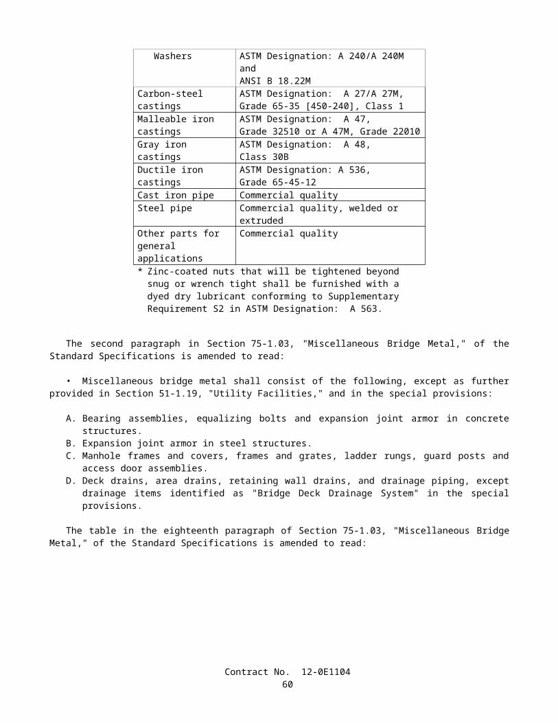
• The loss of water for each type of curing compound, when tested in conformance with the requirements in California Test 534, shall not be more than 0.15-kg/m2 in 24 hours.
• The curing compound to be used will be specified elsewhere in these specifications or in the special provisions.• When the use of curing compound is required or permitted elsewhere in these specifications or in the special
provisions and no specific kind is specified, any of the curing compounds listed above may be used.• Curing compound shall be applied at a nominal rate of 3.7 m2/L, unless otherwise specified.• At any point, the application rate shall be within ±1.2 m2/L of the nominal rate specified, and the average application
rate shall be within ±0.5 m2/L of the nominal rate specified when tested in conformance with the requirements in California Test 535. Runs, sags, thin areas, skips, or holidays in the applied curing compound shall be evidence that the application is not satisfactory.
• Curing compounds shall be applied using power operated spray equipment. The power operated spraying equipment shall be equipped with an operational pressure gage and a means of controlling the pressure. Hand spraying of small and irregular areas that are not reasonably accessible to mechanical spraying equipment, in the opinion of the Engineer, may be permitted.
• The curing compound shall be applied to the concrete following the surface finishing operation, immediately before the moisture sheen disappears from the surface, but before any drying shrinkage or craze cracks begin to appear. In the event of any drying or cracking of the surface, application of water with an atomizing nozzle as specified in Section 90-7.01A, "Water Method," shall be started immediately and shall be continued until application of the compound is resumed or started; however, the compound shall not be applied over any resulting freestanding water. Should the film of compound be damaged from any cause before the expiration of 7 days after the concrete is placed in the case of structures and 72 hours in the case of pavement, the damaged portion shall be repaired immediately with additional compound.
• At the time of use, compounds containing pigments shall be in a thoroughly mixed condition with the pigment uniformly dispersed throughout the vehicle. A paddle shall be used to loosen all settled pigment from the bottom of the container, and a power driven agitator shall be used to disperse the pigment uniformly throughout the vehicle.
• Agitation shall not introduce air or other foreign substance into the curing compound.• The manufacturer shall include in the curing compound the necessary additives for control of sagging, pigment
settling, leveling, de-emulsification, or other requisite qualities of a satisfactory working material. Pigmented curing compounds shall be manufactured so that the pigment does not settle badly, does not cake or thicken in the container, and does not become granular or curdled. Settlement of pigment shall be a thoroughly wetted, soft, mushy mass permitting the complete and easy vertical penetration of a paddle. Settled pigment shall be easily redispersed, with minimum resistance to the sideways manual motion of the paddle across the bottom of the container, to form a smooth uniform product of the proper consistency.
• Curing compounds shall remain sprayable at temperatures above 4°C and shall not be diluted or altered after manufacture.
• The curing compound shall be packaged in clean 1040-L totes, 210-L barrelsor 19-L pails shall be supplied from a suitable storage tank located at the jobsite. The containers shall comply with
"Title 49, Code of Federal Regulations, Hazardous Materials Regulations." The 1040-L totes and the 210-L barrels shall have removable lids and airtight fasteners. The 19-L pails shall be round and have standard full open head and bail. Lids with bungholes shall not be permitted. Settling or separation of solids in containers, except tanks, must be completely redispersed with low speed mixing prior to use, in conformance with these specifications and the manufacturer's recommendations. Mixing shall be accomplished either manually by use of a paddle or by use of a mixing blade driven by a drill motor, at low speed. Mixing blades shall be the type used for mixing paint. On site storage tanks shall be kept clean and free of contaminants. Each tank shall have a permanent system designed to completely redisperse settled material without introducing air or other foreign substances.
• Steel containers and lids shall be lined with a coating that will prevent destructive action by the compound or chemical agents in the air space above the compound. The coating shall not come off the container or lid as skins. Containers shall be filled in a manner that will prevent skinning. Plastic containers shall not react with the compound.
• Each container shall be labeled with the manufacturer's name, kind of curing compound, batch number, volume, date of manufacture, and volatile organic compound (VOC) content. The label shall also warn that the curing compound containing pigment shall be well stirred before use. Precautions concerning the handling and the application of curing compound shall be shown on the label of the curing compound containers in conformance with the Construction Safety Orders and General Industry Safety Orders of the State of California.
• Containers of curing compound shall be labeled to indicate that the contents fully comply with the rules and regulations concerning air pollution control in the State of California.
• When the curing compound is shipped in tanks or tank trucks, a shipping invoice shall accompany each load. The invoice shall contain the same information as that required herein for container labels.
• Curing compound will be sampled by the Engineer at the source of supply or at the jobsite or at both locations.
Contract No. 12-0E110462
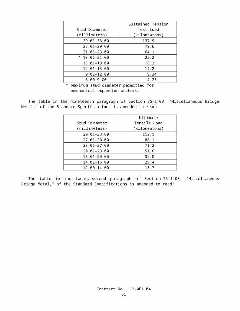
• Curing compound shall be formulated so as to maintain the specified properties for a minimum of one year. The Engineer may require additional testing before use to determine compliance with these specifications if the compound has not been used within one year or whenever the Engineer has reason to believe the compound is no longer satisfactory.
• Tests will be conducted in conformance with the latest ASTM test methods and methods in use by the Transportation Laboratory.
90-7.01C Waterproof Membrane Method• The exposed finished surfaces of concrete shall be sprayed with water, using a nozzle that so atomizes the flow that
a mist and not a spray is formed, until the concrete has set, after which the curing membrane shall be placed. The curing membrane shall remain in place for a period of not less than 72 hours.
• Sheeting material for curing concrete shall conform to the requirements in AASHTO Designation: M 171 for white reflective materials.
• The sheeting material shall be fabricated into sheets of such width as to provide a complete cover for the entire concrete surface. Joints in the sheets shall be securely cemented together in such a manner as to provide a waterproof joint. The joint seams shall have a minimum lap of 100 mm.
• The sheets shall be securely weighted down by placing a bank of earth on the edges of the sheets or by other means satisfactory to the Engineer.
• Should any portion of the sheets be broken or damaged before the expiration of 72 hours after being placed, the broken or damaged portions shall be immediately repaired with new sheets properly cemented into place.
• Sections of membrane that have lost their waterproof qualities or have been damaged to such an extent as to render them unfit for curing the concrete shall not be used.
90-7.01D Forms-In-Place Method• Formed surfaces of concrete may be cured by retaining the forms in place. The forms shall remain in place for a
minimum period of 7 days after the concrete has been placed, except that for members over 0.5-m in least dimension the forms shall remain in place for a minimum period of 5 days.
• Joints in the forms and the joints between the end of forms and concrete shall be kept moisture tight during the curing period. Cracks in the forms and cracks between the forms and the concrete shall be resealed by methods subject to the approval of the Engineer.
90-7.02 CURING PAVEMENT• The entire exposed area of the pavement, including edges, shall be cured by the waterproof membrane method, or
curing compound method using curing compound (1) or (2) as the Contractor may elect. Should the side forms be removed before the expiration of 72 hours following the start of curing, the exposed pavement edges shall also be cured. If the pavement is cured by means of the curing compound method, the sawcut and all portions of the curing compound that have been disturbed by sawing operations shall be restored by spraying with additional curing compound.
• Curing shall commence as soon as the finishing process provided in Section 40-1.10, "Final Finishing," has been completed. The method selected shall conform to the provisions in Section 90-7.01, "Methods of Curing."
• When the curing compound method is used, the compound shall be applied to the entire pavement surface by mechanical sprayers. Spraying equipment shall be of the fully atomizing type equipped with a tank agitator that provides for continual agitation of the curing compound during the time of application. The spray shall be adequately protected against wind, and the nozzles shall be so oriented or moved mechanically transversely as to result in the minimum specified rate of coverage being applied uniformly on exposed faces. Hand spraying of small and irregular areas, and areas inaccessible to mechanical spraying equipment, in the opinion of the Engineer, will be permitted. When the ambient air temperature is above 15°C, the Contractor shall fog the surface of the concrete with a fine spray of water as specified in Section 90 -7.01A, "Water Method." The surface of the pavement shall be kept moist between the hours of 10:00 a.m. and 4:30 p.m. on the day the concrete is placed. However, the fogging done after the curing compound has been applied shall not begin until the compound has set sufficiently to prevent displacement. Fogging shall be discontinued if ordered in writing by the Engineer.
90-7.03 CURING STRUCTURES• Newly placed concrete for cast-in-place structures, other than highway bridge decks, shall be cured by the water
method, the forms-in-place method, or, as permitted herein, by the curing compound method, in conformance with the provisions in Section 90-7.01, "Methods of Curing."
• The curing compound method using a pigmented curing compound may be used on concrete surfaces of construction joints, surfaces that are to be buried underground, and surfaces where only Ordinary Surface Finish is to be applied and on which a uniform color is not required and that will not be visible from a public traveled way. If the
Contract No. 12-0E110463
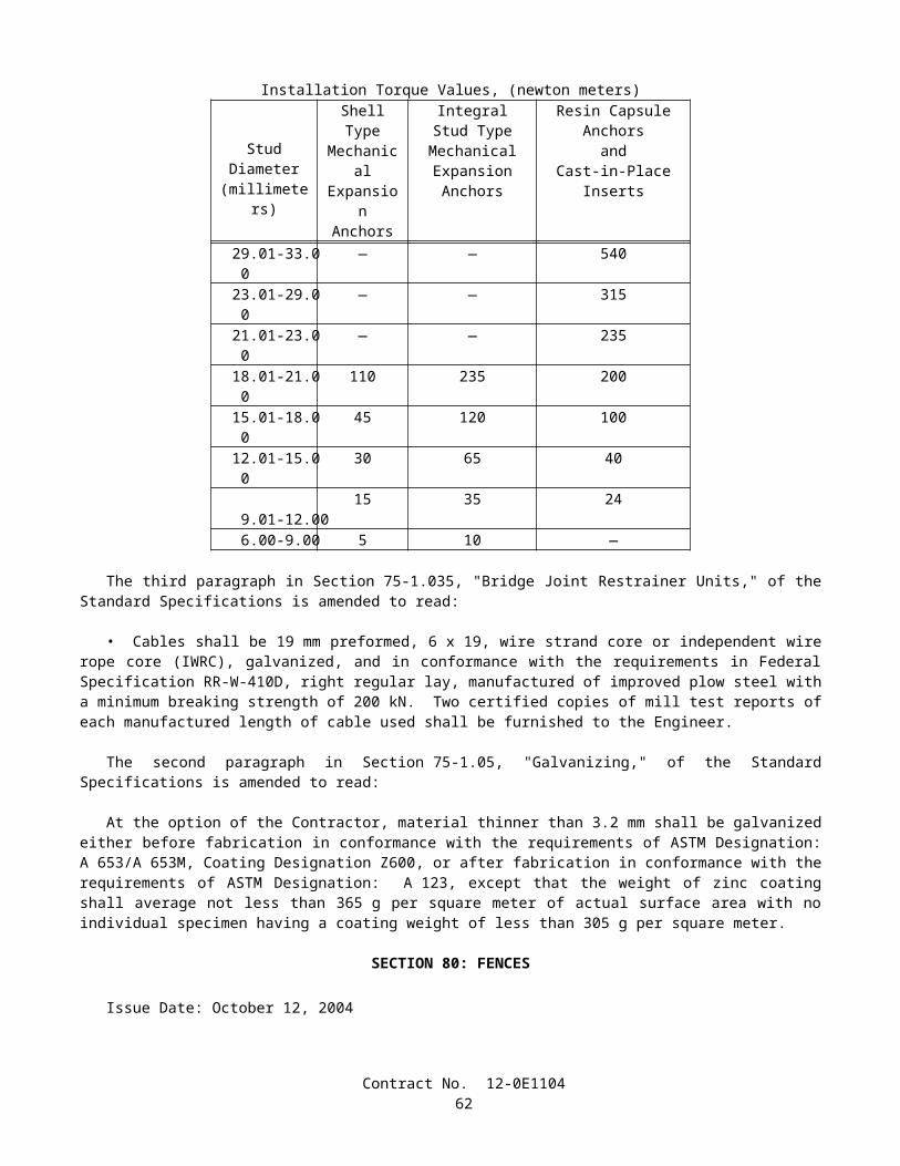
Contractor elects to use the curing compound method on the bottom slab of box girder spans, the curing compound shall be curing compound (1).
• The top surface of highway bridge decks shall be cured by both the curing compound method and the water method. The curing compound shall be curing compound (1).
• Concrete surfaces of minor structures, as defined in Section 51-1.02, "Minor Structures," shall be cured by the water method, the forms-in-place method or the curing compound method.
• When deemed necessary by the Engineer during periods of hot weather, water shall be applied to concrete surfaces being cured by the curing compound method or by the forms-in-place method, until the Engineer determines that a cooling effect is no longer required. Application of water for this purpose will be paid for as extra work as provided in Section 4-1.03D, "Extra Work."
90-7.04 CURING PRECAST CONCRETE MEMBERS• Precast concrete members shall be cured in conformance with any of the methods specified in Section 90-7.01,
"Methods of Curing." Curing shall be provided for the minimum time specified for each method or until the concrete reaches its design strength, whichever is less. Steam curing may also be used for precast members and shall conform to the following provisions:
A. After placement of the concrete, members shall be held for a minimum 4-hour presteaming period. If the ambient air temperature is below 10°C, steam shall be applied during the presteaming period to hold the air surrounding the member at a temperature between 10°C and 32°C.
B. To prevent moisture loss on exposed surfaces during the presteaming period, members shall be covered as soon as possible after casting or the exposed surfaces shall be kept wet by fog spray or wet blankets.
C. Enclosures for steam curing shall allow free circulation of steam about the member and shall be constructed to contain the live steam with a minimum moisture loss. The use of tarpaulins or similar flexible covers will be permitted, provided they are kept in good repair and secured in such a manner as to prevent the loss of steam and moisture.
D. Steam at the jets shall be at low pressure and in a saturated condition. Steam jets shall not impinge directly on the concrete, test cylinders, or forms. During application of the steam, the temperature rise within the enclosure shall not exceed 22°C per hour. The curing temperature throughout the enclosure shall not exceed 65°C and shall be maintained at a constant level for a sufficient time necessary to develop the required transfer strength. Control cylinders shall be covered to prevent moisture loss and shall be placed in a location where temperature is representative of the average temperature of the enclosure.
E. Temperature recording devices that will provide an accurate, continuous, permanent record of the curing temperature shall be provided. A minimum of one temperature recording device per 60 m of continuous bed length will be required for checking temperature.
F. Members in pretension beds shall be detensioned immediately after the termination of steam curing while the concrete and forms are still warm, or the temperature under the enclosure shall be maintained above 15°C until the stress is transferred to the concrete.
G. Curing of precast concrete will be considered completed after termination of the steam curing cycle.
90-7.05 CURING PRECAST PRESTRESSED CONCRETE PILES• Newly placed concrete for precast prestressed concrete piles shall be cured in conformance with the provisions in
Section 90-7.04, "Curing Precast Concrete Members," except that piles in a corrosive environment shall be cured as follows:
A. Piles shall be either steam cured or water cured. If water curing is used, the piles shall be kept continuously wet by the application of water in conformance with the provisions in Section 90-7.01A, "Water Method."
B. If steam curing is used, the steam curing provisions in Section 90-7.04, "Curing Precast Concrete Members," shall apply except that the piles shall be kept continuously wet for their entire length for a period of not less than 3 days, including the holding and steam curing periods.
90-7.06 CURING SLOPE PROTECTION• Concrete slope protection shall be cured in conformance with any of the methods specified in Section 90-7.01,
"Methods of Curing."• Concreted-rock slope protection shall be cured in conformance with any of the methods specified in Section
90-7.01, "Methods of Curing," or with a blanket of earth kept wet for 72 hours, or by sprinkling with a fine spray of water every 2 hours during the daytime for a period of 3 days.
Contract No. 12-0E110464
90-7.07 CURING MISCELLANEOUS CONCRETE WORK• Exposed surfaces of curbs shall be cured by pigmented curing compounds as specified in Section 90-7.01B, "Curing
Compound Method."• Concrete sidewalks, gutter depressions, island paving, curb ramps, driveways, and other miscellaneous concrete
areas shall be cured in conformance with any of the methods specified in Section 90-7.01, "Methods of Curing."• Shotcrete shall be cured for at least 72 hours by spraying with water, or by a moist earth blanket, or by any of the
methods provided in Section 90-7.01, "Methods of Curing."• Mortar and grout shall be cured by keeping the surface damp for 3 days.• After placing, the exposed surfaces of sign structure foundations, including pedestal portions, if constructed, shall be
cured for at least 72 hours by spraying with water, or by a moist earth blanket, or by any of the methods provided in Section 90-7.01, "Methods of Curing."
90-8 PROTECTING CONCRETE
90-8.01 GENERAL• In addition to the provisions in Section 7-1.16, "Contractor's Responsibility for the Work and Materials," the
Contractor shall protect concrete as provided in this Section 90-8.• Concrete shall not be placed on frozen or ice-coated ground or subgrade nor on ice-coated forms, reinforcing steel,
structural steel, conduits, precast members, or construction joints.• Under rainy conditions, placing of concrete shall be stopped before the quantity of surface water is sufficient to
damage surface mortar or cause a flow or wash of the concrete surface, unless the Contractor provides adequate protection against damage.
• Concrete that has been frozen or damaged by other causes, as determined by the Engineer, shall be removed and replaced by the Contractor at the Contractor's expense.
90-8.02 PROTECTING CONCRETE STRUCTURES• Structure concrete and shotcrete used as structure concrete shall be maintained at a temperature of not less than 7°C
for 72 hours after placing and at not less than 4°C for an additional 4 days. When required by the Engineer, the Contractor shall submit a written outline of the proposed methods for protecting the concrete.
90-8.03 PROTECTING CONCRETE PAVEMENT• Pavement concrete shall be maintained at a temperature of not less than 4°C for 72 hours. When required by the
Engineer, the Contractor shall submit a written outline of the proposed methods for protecting the concrete.• Except as provided in Section 7-1.08, "Public Convenience," the Contractor shall protect concrete pavement against
construction and other activities that abrade, scar, discolor, reduce texture depth, lower coefficient of friction, or otherwise damage the surface. Stockpiling, drifting, or excessive spillage of soil, gravel, petroleum products, and concrete or asphalt mixes on the surface of concrete pavement is prohibited unless otherwise specified in these specifications, the special provisions or permitted by the Engineer.
• When ordered by the Engineer or shown on the plans or specified in the special provisions, pavement crossings shall be constructed for the convenience of public traffic. The material and work necessary for the construction of the crossings, and their subsequent removal and disposal, will be paid for at the contract unit prices for the items of work involved and if there are no contract items for the work involved, payment for pavement crossings will be made by extra work as provided in Section 4-1.03D, "Extra Work.". Where public traffic will be required to cross over the new pavement, Type III portland cement may be used in concrete, if permitted in writing by the Engineer. The pavement may be opened to traffic as soon as the concrete has developed a modulus of rupture of 3.8 MPa. The modulus of rupture will be determined by California Test 523.
• No traffic or Contractor's equipment, except as hereinafter provided, will be permitted on the pavement before a period of 10 days has elapsed after the concrete has been placed, nor before the concrete has developed a modulus of rupture of at least 3.8 MPa. Concrete that fails to attain a modulus of rupture of 3.8 MPa within 10 days shall not be opened to traffic until directed by the Engineer.
• Equipment for sawing weakened plane joints will be permitted on the pavement as specified in Section 40-1.08B, "Weakened Plane Joints."
• When requested in writing by the Contractor, the tracks on one side of paving equipment will be permitted on the pavement after a modulus of rupture of 2.4 MPa has been attained, provided that:
A. Unit pressure exerted on the pavement by the paver shall not exceed 135 kPa;
Contract No. 12-0E110465
B. Tracks with cleats, grousers, or similar protuberances shall be modified or shall travel on planks or equivalent protective material, so that the pavement is not damaged; and
C. No part of the track shall be closer than 0.3-m from the edge of pavement.
• In case of visible cracking of, or other damage to the pavement, operation of the paving equipment on the pavement shall be immediately discontinued.
• Damage to the pavement resulting from early use of pavement by the Contractor's equipment as provided above shall be repaired by the Contractor at the Contractor's expense.
• The State will furnish the molds and machines for testing the concrete for modulus of rupture, and the Contractor, at the Contractor's expense, shall furnish the material and whatever labor the Engineer may require.
90-9 COMPRESSIVE STRENGTH
90-9.01 GENERAL• Concrete compressive strength requirements consist of a minimum strength that shall be attained before various
loads or stresses are applied to the concrete and, for concrete designated by strength, a minimum strength at the age of 28 days or at the age otherwise allowed in Section 90-1.01, "Description." The various strengths required are specified in these specifications or the special provisions or are shown on the plans.
• The compressive strength of concrete will be determined from test cylinders that have been fabricated from concrete sampled in conformance with the requirements of California Test 539. Test cylinders will be molded and initially field cured in conformance with California Test 540. Test cylinders will be cured and tested after receipt at the testing laboratory in conformance with the requirements of California Test 521. A strength test shall consist of the average strength of 2 cylinders fabricated from material taken from a single load of concrete, except that, if any cylinder should show evidence of improper sampling, molding, or testing, that cylinder shall be discarded and the strength test shall consist of the strength of the remaining cylinder.
• When concrete compressive strength is specified as a prerequisite to applying loads or stresses to a concrete structure or member, test cylinders for other than steam cured concrete will be cured in conformance with Method 1 of California Test 540. The compressive strength of concrete determined for these purposes will be evaluated on the basis of individual tests.
• When concrete is designated by 28-day compressive strength rather than by cementitious material content, the concrete strength to be used as a basis for acceptance of other than steam cured concrete will be determined from cylinders cured in conformance with Method 1 of California Test 540. If the result of a single compressive strength test at the maximum age specified or allowed is below the specified strength but is 95 percent or more of the specified strength, the Contractor shall, at the Contractor’s expense, make corrective changes, subject to approval of the Engineer, in the mix proportions or in the concrete fabrication procedures, before placing additional concrete, and shall pay to the State $14 for each in-place cubic meter of concrete represented by the deficient test. If the result of a single compressive strength test at the maximum age specified or allowed is below 95 percent of the specified strength, but is 85 percent or more of the specified strength, the Contractor shall make the corrective changes specified above, and shall pay to the State $20 for each in place cubic meter of concrete represented by the deficient test. In addition, such corrective changes shall be made when the compressive strength of concrete tested at 7 days indicates, in the judgment of the Engineer, that the concrete will not attain the required compressive strength at the maximum age specified or allowed. Concrete represented by a single test that indicates a compressive strength of less than 85 percent of the specified 28-day compressive strength will be rejected in conformance with the provisions in Section 6-1.04, "Defective Materials."
• If the test result indicates that the compressive strength at the maximum curing age specified or allowed is below the specified strength, but is 85 percent or more of the specified strength, payments to the State as required above shall be made, unless the Contractor, at the Contractor’s expense, obtains and submits evidence acceptable to the Engineer that the strength of the concrete placed in the work meets or exceeds the specified 28-day compressive strength. If the test result indicates a compressive strength at the maximum curing age specified or allowed below 85 percent, the concrete represented by that test will be rejected, unless the Contractor, at the Contractor’s expense, obtains and submits evidence acceptable to the Engineer that the strength and quality of the concrete placed in the work are acceptable. If the evidence consists of tests made on cores taken from the work, the cores shall be obtained and tested in conformance with the requirements in ASTM Designation: C 42.
• No single compressive strength test shall represent more than 250 m3.• When a precast concrete member is steam cured, the compressive strength of the concrete will be determined from
test cylinders that have been handled and stored in conformance with Method 3 of California Test 540. The compressive strength of steam cured concrete will be evaluated on the basis of individual tests representing specific portions of production. When the concrete is designated by 28-day compressive strength rather than by cementitious material content, the concrete shall be considered to be acceptable whenever its compressive strength reaches the specified 28-day compressive
Contract No. 12-0E110466
strength provided that strength is reached in not more than the maximum number of days specified or allowed after the member is cast.
• When concrete is specified by compressive strength, prequalification of materials, mix proportions, mixing equipment, and procedures proposed for use will be required prior to placement of the concrete. Prequalification shall be accomplished by the submission of acceptable certified test data or trial batch reports by the Contractor. Prequalification data shall be based on the use of materials, mix proportions, mixing equipment, procedures, and size of batch proposed for use in the work.
• Certified test data, in order to be acceptable, shall indicate that not less than 90 percent of at least 20 consecutive tests exceed the specified strength at the maximum number of cure days specified or allowed, and none of those tests are less than 95 percent of specified strength. Strength tests included in the data shall be the most recent tests made on concrete of the proposed mix design and all shall have been made within one year of the proposed use of the concrete.
• Trial batch test reports, in order to be acceptable, shall indicate that the average compressive strength of 5 consecutive concrete cylinders, taken from a single batch, at not more than 28 days (or the maximum age allowed) after molding shall be at least 4 MPa greater than the specified 28-day compressive strength, and no individual cylinder shall have a strength less than the specified strength at the maximum age specified or allowed. Data contained in the report shall be from trial batches that were produced within one year of the proposed use of specified strength concrete in the project. Whenever air-entrainment is required, the air content of trial batches shall be equal to or greater than the air content specified for the concrete without reduction due to tolerances.
• Tests shall be performed in conformance with either the appropriate California Test methods or the comparable ASTM test methods. Equipment employed in testing shall be in good condition and shall be properly calibrated. If the tests are performed during the life of the contract, the Engineer shall be notified sufficiently in advance of performing the tests in order to witness the test procedures.
• The certified test data and trial batch test reports shall include the following information:
A. Date of mixing.B. Mixing equipment and procedures used.C. The size of batch in cubic meters and the mass, type, and source of all ingredients used.D. Penetration of the concrete.E. The air content of the concrete if an air-entraining admixture is used.F. The age at time of testing and strength of all concrete cylinders tested.
• Certified test data and trial batch test reports shall be signed by an official of the firm that performed the tests.• When approved by the Engineer, concrete from trial batches may be used in the work at locations where concrete of
a lower quality is required and the concrete will be paid for as the type or class of concrete required at that location.• After materials, mix proportions, mixing equipment, and procedures for concrete have been prequalified for use,
additional prequalification by testing of trial batches will be required prior to making changes that, in the judgment of the Engineer, could result in a strength of concrete below that specified.
• The Contractor’s attention is directed to the time required to test trial batches and the Contractor shall be responsible for production of trial batches at a sufficiently early date so that the progress of the work is not delayed.
• When precast concrete members are manufactured at the plant of an established manufacturer of precast concrete members, the mix proportions of the concrete shall be determined by the Contractor, and a trial batch and prequalification of the materials, mix proportions, mixing equipment, and procedures will not be required.
90-10 MINOR CONCRETE
90-10.01 GENERAL• Concrete for minor structures, slope paving, curbs, sidewalks and other concrete work, when designated as minor
concrete on the plans, in the specifications, or in the contract item, shall conform to the provisions specified herein.• The Engineer, at the Engineer's discretion, will inspect and test the facilities, materials and methods for producing
the concrete to ensure that minor concrete of the quality suitable for use in the work is obtained.
90-10.02 MATERIALS• Minor concrete shall conform to the following requirements:
90-10.02A Cementitious Material• Cementitious material shall conform to the provisions in Section 90-1.01, "Description."
Contract No. 12-0E110467
90-10.02B Aggregate• Aggregate shall be clean and free from deleterious coatings, clay balls, roots, and other extraneous materials.• The Contractor shall submit to the Engineer for approval, a grading of the combined aggregate proposed for use in
the minor concrete. After acceptance of the grading, aggregate furnished for minor concrete shall conform to that grading, unless a change is authorized in writing by the Engineer.
• The Engineer may require the Contractor to furnish periodic test reports of the aggregate grading furnished. The maximum size of aggregate used shall be at the option of the Contractor, but in no case shall the maximum size be larger than 37.5 mm or smaller than 19 mm.
• The Engineer may waive, in writing, the gradation requirements in this Section 90-10.02B, if, in the Engineer's opinion, the furnishing of the gradation is not necessary for the type or amount of concrete work to be constructed.
90-10.02C Water• Water used for washing, mixing, and curing shall be free from oil, salts, and other impurities that would discolor or
etch the surface or have an adverse affect on the quality of the concrete.
90-10.02D Admixtures• The use of admixtures shall conform to the provisions in Section 90-4, "Admixtures."
90-10.03 PRODUCTION• Cementitious material, water, aggregate, and admixtures shall be stored, proportioned, mixed, transported, and
discharged in conformance with recognized standards of good practice that will result in concrete that is thoroughly and uniformly mixed, that is suitable for the use intended, and that conforms to requirements specified herein. Recognized standards of good practice are outlined in various industry publications such as are issued by American Concrete Institute, AASHTO, or the Department.
• The cementitious material content of minor concrete shall conform to the provisions in Section 90-1.01, "Description."
• The amount of water used shall result in a consistency of concrete conforming to the provisions in Section 90 -6.06, "Amount of Water and Penetration." Additional mixing water shall not be incorporated into the concrete during hauling or after arrival at the delivery point, unless authorized by the Engineer.
• Discharge of ready-mixed concrete from the transporting vehicle shall be made while the concrete is still plastic and before stiffening occurs. An elapsed time of 1.5 hours (one hour in non-agitating hauling equipment), or more than 250 revolutions of the drum or blades, after the introduction of the cementitious material to the aggregates, or a temperature of concrete of more than 32°C will be considered conditions contributing to the quick stiffening of concrete. The Contractor shall take whatever action is necessary to eliminate quick stiffening, except that the addition of water will not be permitted.
• The required mixing time in stationary mixers shall be not less than 50 seconds or more than 5 minutes.• The minimum required revolutions at mixing speed for transit-mixed concrete shall be not less than that
recommended by the mixer manufacturer, and shall be increased, if necessary, to produce thoroughly and uniformly mixed concrete.
• Each load of ready-mixed concrete shall be accompanied by a weighmaster certificate that shall be delivered to the Engineer at the discharge location of the concrete, unless otherwise directed by the Engineer. The weighmaster certificate shall be clearly marked with the date and time of day when the load left the batching plant and, if hauled in truck mixers or agitators, the time the mixing cycle started.
• A Certificate of Compliance conforming to the provisions in Section 6–1.07, "Certificates of Compliance," shall be furnished to the Engineer, prior to placing minor concrete from a source not previously used on the contract, stating that minor concrete to be furnished meets contract requirements, including minimum cementitious material content specified.
90-10.04 CURING MINOR CONCRETE• Curing minor concrete shall conform to the provisions in Section 90-7, "Curing Concrete."
90-10.05 PROTECTING MINOR CONCRETE• Protecting minor concrete shall conform to the provisions in Section 90-8, "Protecting Concrete," except the
concrete shall be maintained at a temperature of not less than 4°C for 72 hours after placing.
Contract No. 12-0E110468
90-10.06 MEASUREMENT AND PAYMENT• Minor concrete will be measured and paid for in conformance with the provisions specified in the various sections
of these specifications covering concrete construction when minor concrete is specified in the specifications, shown on the plans, or indicated by contract item in the Engineer's Estimate.
90-11 MEASUREMENT AND PAYMENT
90-11.01 MEASUREMENT• Portland cement concrete will be measured in conformance with the provisions specified in the various sections of
these specifications covering construction requiring concrete.• When it is provided that concrete will be measured at the mixer, the volume in cubic meters shall be computed as
the total mass of the batch in kilograms divided by the density of the concrete in kilograms per cubic meter. The total mass of the batch shall be calculated as the sum of all materials, including water, entering the batch. The density of the concrete will be determined in conformance with the requirements in California Test 518.
90-11.02 PAYMENT• Portland cement concrete will be paid for in conformance with the provisions specified in the various sections of
these specifications covering construction requiring concrete.• Full compensation for furnishing and incorporating admixtures required by these specifications or the special
provisions will be considered as included in the contract prices paid for the concrete involved and no additional compensation will be allowed therefor.
• Should the Engineer order the Contractor to incorporate any admixtures in the concrete when their use is not required by these specifications or the special provisions, furnishing the admixtures and adding them to the concrete will be paid for as extra work as provided in Section 4-1.03D, "Extra Work."
• Should the Contractor use admixtures in conformance with the provisions in Section 90-4.05, "Optional Use of Chemical Admixtures," or Section 90-4.07, "Optional Use of Air-entraining Admixtures," or should the Contractor request and obtain permission to use other admixtures for the Contractor’s benefit, the Contractor shall furnish those admixtures and incorporate them into the concrete at the Contractor’s expense and no additional compensation will be allowed therefor.
END OF AMENDMENTS
SECTION 2. PROPOSAL REQUIREMENTS AND CONDITIONS2-1.01 GENERAL
The bidder's attention is directed to the provisions in Section 2, "Proposal Requirements and Conditions," of the Standard Specifications, and these special provisions for the requirements and conditions which the bidder must observe in the preparation of the Proposal form and the submission of the bid.
The Bidder's Bond form mentioned in the last paragraph in Section 2-1.07, "Proposal Guaranty," of the Standard Specifications will be found following the signature page of the Proposal.
Submit request for substitution of an "or equal" item, and the data substantiating the request to the Department of Transportation, District 12, 3347 Michelson Drive, Suite 100, Irvine, CA 92612-1692, Attn: CTO Desk - Construction Office, so that the request is received by the Department by close of business on the fourth day, not including Saturdays, Sundays and legal holidays, following bid opening.
In conformance with Public Contract Code Section 7106, a Noncollusion Affidavit is included in the Proposal. Signing the Proposal shall also constitute signature of the Noncollusion Affidavit.
The contractor, sub recipient or subcontractor shall not discriminate on the basis of race, color, national origin, or sex in the performance of this contract. The contractor shall carry out applicable requirements of 49 CFR part 26 in the award and administration of DOT-assisted contracts. Failure by the contractor to carry out these requirements is a material breach of this contract, which may result in the termination of this contract or such other remedy as the recipient deems appropriate. Each subcontract signed by the bidder must include this assurance.
Failure of the bidder to fulfill the requirements of the Special Provisions for submittals required to be furnished after bid opening, including but not limited to DBE or DVBE submittals, or escrowed bid documents, where applicable, may subject the bidder to a determination of the bidder's responsibility in the event it is the apparent low bidder on a future public works contracts.
Contract No. 12-0E110469
2-1.015 FEDERAL LOBBYING RESTRICTIONSSection 1352, Title 31, United States Code prohibits Federal funds from being expended by the recipient or any lower
tier subrecipient of a Federal-aid contract to pay for any person for influencing or attempting to influence a Federal agency or Congress in connection with the awarding of any Federal-aid contract, the making of any Federal grant or loan, or the entering into of any cooperative agreement.
If any funds other than Federal funds have been paid for the same purposes in connection with this Federal-aid contract, the recipient shall submit an executed certification and, if required, submit a completed disclosure form as part of the bid documents.
A certification for Federal-aid contracts regarding payment of funds to lobby Congress or a Federal agency is included in the Proposal. Standard Form - LLL, "Disclosure of Lobbying Activities," with instructions for completion of the Standard Form is also included in the Proposal. Signing the Proposal shall constitute signature of the Certification.
The above-referenced certification and disclosure of lobbying activities shall be included in each subcontract and any lower-tier contracts exceeding $100,000. All disclosure forms, but not certifications, shall be forwarded from tier to tier until received by the Engineer.
The Contractor, subcontractors and any lower-tier contractors shall file a disclosure form at the end of each calendar quarter in which there occurs any event that requires disclosure or that materially affects the accuracy of the information contained in any disclosure form previously filed by the Contractor, subcontractors and any lower-tier contractors. An event that materially affects the accuracy of the information reported includes:
A. A cumulative increase of $25,000 or more in the amount paid or expected to be paid for influencing or attempting to influence a covered Federal action; or
B. A change in the person(s) or individual(s) influencing or attempting to influence a covered Federal action; or,C. A change in the officer(s), employee(s), or Member(s) contacted to influence or attempt to influence a covered
Federal action.
2-1.02 DISADVANTAGED BUSINESS ENTERPRISE (DBE)This project is subject to Part 26, Title 49, Code of Federal Regulations entitled "Participation by Disadvantaged
Business Enterprises in Department of Transportation Financial Assistance Programs." The Regulations in their entirety are incorporated herein by this reference.
It is the policy of the Department that disadvantaged business enterprises (DBEs), as defined in Part 26, Title 49 CFR, shall be encouraged to participate in the performance of contracts financed in whole or in part with Federal Funds. The Contractor should ensure that DBEs, as defined in Part 26, Title 49 CFR, have the opportunity to participate in the performance of this contract and shall take all necessary and reasonable steps, as set forth in Part 26, Title 49 CFR, for this assurance. The Contractor shall not discriminate on the basis of race, color, national origin, or sex in the award and performance of subcontracts. Failure to carry out the requirements of this paragraph shall constitute a breach of contract and may result in termination of this contract or other remedy the Department may deem appropriate.
Bidders shall be fully informed respecting the requirements of the Regulations and are urged to obtain DBE participation in this project, although there is no specific goal for DBE participation.
Bidders may use the services of the following firms to contact interested DBEs. These firms are available to assist DBEs in preparing bids for subcontracting or supplying materials.
The following firms may be contacted for projects in the following locations:
Contract No. 12-0E110470
Districts 04, 05 (except San Luis Obispo and Santa Barbara Counties),06 (except Kern County) and 10: Districts 08 and 11:
See the Department's DBE database at: Padilla & Associateshttp://www.dot.ca.gov/hq/bep/ - San Diego
2725 Congress Street, Suite 1DSan Diego, CA 92110Telephone: (619) 725-0843FAX No.: (619) 725-0854
Districts 07, 08, and 12; in San Luis Obispo and Santa Barbara Countiesin District 05; and in Kern County in District 06: Districts 01, 02, 03 and 09:
Padilla & Associates See the Department's DBE database at: - Commerce http://www.dot.ca.gov/hq/bep/
5675 East Telegraph Rd., Suite A-260Commerce, CA 90040Telephone: (323) 728-8847FAX No.: (323) 728-8867
SECTION 3. AWARD AND EXECUTION OF CONTRACTThe bidder's attention is directed to the provisions in Section 3, "Award and Execution of Contract," of the Standard
Specifications and these special provisions for the requirements and conditions concerning award and execution of contract.Bid protests are to be delivered to the following address: Department of Transportation, MS 43, Attn: Office Engineer,
1727 30th Street, Sacramento, CA 95816 or by facsimile to the Office Engineer at (916) 227-6282.The contract shall be executed by the successful bidder and shall be returned, together with the contract bonds, to the
Department so that it is received within 10 days, not including Saturdays, Sundays and legal holidays, after the bidder has received the contract for execution. Failure to do so shall be just cause for forfeiture of the proposal guaranty. The executed contract documents shall be delivered to the following address: Department of Transportation MS 43, Attn: Office Engineer, 1727 30th Street, Sacramento, CA 95816.
A "Payee Data Record" form will be included in the contract documents to be executed by the successful bidder. The purpose of the form is to facilitate the collection of taxpayer identification data. The form shall be completed and returned to the Department by the successful bidder with the executed contract and contract bonds. For the purposes of the form, payee shall be deemed to mean the successful bidder. The form is not to be completed for subcontractors or suppliers. Failure to complete and return the "Payee Data Record" form to the Department as provided herein will result in the retention of 31 percent of payments due the contractor and penalties of up to $20,000. This retention of payments for failure to complete the "Payee Data Record" form is in addition to any other retention of payments due the Contractor.
SECTION 4. BEGINNING OF WORK, TIME OF COMPLETION AND LIQUIDATED DAMAGESAttention is directed to the provisions in Section 8-1.03, "Beginning of Work," in Section 8-1.06, "Time of Completion,"
and in Section 8-1.07, "Liquidated Damages," of the Standard Specifications and these special provisions.The Contractor shall furnish the Engineer with a statement from the vendor that the order for the electrical materials
required for this contract has been received and accepted by the vendor; and the statement shall be furnished within 15 calendar days after the contract has been approved by the Attorney General, or the attorney appointed and authorized to represent the Department of Transportation. The statement shall give the date that the electrical materials will be shipped. If the Contractor has the necessary materials on hand, the Contractor will not be required to furnish the vendor's statement.
The Contractor shall begin work within 45 calendar days after the contract has been approved by the Attorney General or the attorney appointed and authorized to represent the Department of Transportation.
The work shall be diligently prosecuted to completion before the expiration of 250 WORKING DAYS beginning on the date that work begins, or beginning on the forty fifth calendar day after approval of the contract, whichever occurs first.
The Contractor shall pay to the State of California the sum of $4,700 per day, for each and every calendar day's delay in finishing the work in excess of 250 WORKING DAYS.
Contract No. 12-0E110471
The 72 hours advance notice before beginning work specified in Section 8-1.03, "Beginning of Work," of the Standard Specifications is changed to 5 days advance notice for this project.
SECTION 5. GENERAL
SECTION 5-1. MISCELLANEOUS
5-1.01 PLANS AND WORKING DRAWINGSWhen the specifications require working drawings to be submitted to the Division of Structure Design, the drawings
shall be submitted to: Division of Structure Design, Documents Unit, Mail Station 9, 1801 30th Street, Sacramento, CA 95816, Telephone 916 227-8252.
5-1.011 EXAMINATION OF PLANS, SPECIFICATIONS, CONTRACT, AND SITE OF WORKAttention is directed to "Differing Site Conditions" of these special provisions regarding physical conditions at the site
which may differ from those indicated in "Materials Information," log of test borings or other geotechnical information obtained by the Department's investigation of site conditions.
5-1.012 DIFFERING SITE CONDITIONSAttention is directed to Section 5-1.116, "Differing Site Conditions," of the Standard Specifications.During the progress of the work, if subsurface or latent conditions are encountered at the site differing materially from
those indicated in the "Materials Information," log of test borings, other geotechnical data obtained by the Department's investigation of subsurface conditions, or an examination of the conditions above ground at the site, the party discovering those conditions shall promptly notify the other party in writing of the specific differing conditions before they are disturbed and before the affected work is performed.
The Contractor will be allowed 15 days from the notification of the Engineer's determination of whether or not an adjustment of the contract is warranted, in which to file a notice of potential claim in conformance with the provisions of Section 9-1.04, "Notice of Potential Claim," of the Standard Specifications and as specified herein; otherwise the decision of the Engineer shall be deemed to have been accepted by the Contractor as correct. The notice of potential claim shall set forth in what respects the Contractor's position differs from the Engineer's determination and provide any additional information obtained by the Contractor, including but not limited to additional geotechnical data. The notice of potential claim shall be accompanied by the Contractor's certification that the following were made in preparation of the bid: a review of the contract, a review of the "Materials Information," a review of the log of test borings and other records of geotechnical data to the extent they were made available to bidders prior to the opening of bids, and an examination of the conditions above ground at the site. Supplementary information, obtained by the Contractor subsequent to the filing of the notice of potential claim, shall be submitted to the Engineer in an expeditious manner.
5-1.013 LINES AND GRADESAttention is directed to Section 5-1.07, "Lines and Grades," of the Standard Specifications.Stakes or marks will be set by the Engineer in conformance with the requirements in Chapter 12, "Construction
Surveys," of the Department's Surveys Manual.
5-1.015 LABORATORYWhen a reference is made in the specifications to the "Laboratory," the reference shall mean Division of Engineering
Services - Materials Engineering and Testing Services and Division of Engineering Services - Geotechnical Services of the Department of Transportation, or established laboratories of the various Districts of the Department, or other laboratories authorized by the Department to test materials and work involved in the contract. When a reference is made in the specifications to the "Transportation Laboratory," the reference shall mean Division of Engineering Services - Materials Engineering and Testing Services and Division of Engineering Services - Geotechnical Services, located at 5900 Folsom Boulevard, Sacramento, CA 95819, Telephone (916) 227-7000.
5-1.017 CONTRACT BONDSAttention is directed to Section 3-1.02, "Contract Bonds," of the Standard Specifications and these special provisions.The payment bond shall be in a sum not less than one hundred percent of the total amount payable by the terms of the
contract.
Contract No. 12-0E110472
5-1.019 COST REDUCTION INCENTIVEAttention is directed to Section 5-1.14, "Cost Reduction Incentive," of the Standard Specifications.Prior to preparing a written cost reduction proposal, the Contractor shall request a meeting with the Engineer to discuss
the proposal in concept. Items of discussion will also include permit issues, impact on other projects, impact on the project schedule, peer reviews, overall merit of the proposal, and review times required by the Department and other agencies.
If a cost reduction proposal submitted by the Contractor, and subsequently approved by the Engineer, provides for a reduction in contract time, 50 percent of that contract time reduction shall be credited to the State by reducing the contract working days, not including plant establishment. Attention is directed to "Beginning of Work, Time of Completion and Liquidated Damages" of these special provisions regarding the working days.
If a cost reduction proposal submitted by the Contractor, and subsequently approved by the Engineer, provides for a reduction in traffic congestion or avoids traffic congestion during construction, 60 percent of the estimated net savings in construction costs attributable to the cost reduction proposal will be paid to the Contractor. In addition to the requirements in Section 5-1.14, "Cost Reduction Incentive," of the Standard Specifications, the Contractor shall provide detailed comparisons of the traffic handling between the existing contract and the proposed change, and estimates of the traffic volumes and congestion.
5-1.02 LABOR NONDISCRIMINATIONAttention is directed to the following Notice that is required by Chapter 5 of Division 4 of Title 2, California Code of
Regulations.
NOTICE OF REQUIREMENT FOR NONDISCRIMINATION PROGRAM
(GOV. CODE, SECTION 12990)Your attention is called to the "Nondiscrimination Clause", set forth in Section 7-1.01A(4), "Labor Nondiscrimination," of the Standard Specifications, which is applicable to all nonexempt State contracts and subcontracts, and to the "Standard California Nondiscrimination Construction Contract Specifications" set forth therein. The specifications are applicable to all nonexempt State construction contracts and subcontracts of $5000 or more.
5-1.022 EXCLUSION OF RETENTIONIn conformance with 49 CFR, Part 26, Subpart B, Section 26.29 (b)(1), the retention of proceeds required by Public
Contract Code Section 10261 shall not apply. In conformance with Public Contract Code 7200 (b), in subcontracts between the Contractor and a subcontractor and in subcontracts between a subcontractor and any subcontractor thereunder, retention proceeds shall not be withheld, and the exceptions provided in Public Contract Code 7200 (c) shall not apply. At the option of the Contractor, subcontractors may be required to furnish payment and performance bonds issued by an admitted surety insurer.
The third paragraph of Section 9-1.06, "Partial Payments," of the Standard Specifications, and Section 9-1.065, "Payment of Withheld Funds," of the Standard Specifications shall not apply.
5-1.023 UNSATISFACTORY PROGRESSIf the number of working days charged to the contract exceeds 75 percent of the working days in the current time of
completion and the percent working days elapsed exceeds the percent work completed by more than 15 percentage points, the Department will withhold 10 percent of the amount due on the current monthly estimate.
The percent working days elapsed will be determined from the number of working days charged to the contract divided by the number of contract working days in the current time of completion, expressed as a percentage. The number of contract working days in the current time of completion shall consist of the original contract working days increased or decreased by time adjustment s approved by the Engineer.
The percent work completed will be determined by the Engineer from the sum of payments made to date plus the amount due on the current monthly estimate, divided by the current total estimated value of the work, expressed as a percentage.
When the percent of working days elapsed minus the percent of work completed is less than or equal to 15 percentage points, the funds withheld shall be returned to the Contractor with the next monthly progress payment.
Funds kept or withheld from payment, due to the failure of the Contractor to comply with the provisions of the contract, will not be subject to the requirements of Public Contract Code 7107 or to the payment of interest pursuant to Public Contract Code Section 10261.5.
5-1.03 INTEREST ON PAYMENTSInterest shall be payable on progress payments, payments after acceptance, final payments, extra work payments, and
claim payments as follows:
Contract No. 12-0E110473
A. Unpaid progress payments, payment after acceptance, and final payments shall begin to accrue interest 30 days after the Engineer prepares the payment estimate.
B. Unpaid extra work bills shall begin to accrue interest 30 days after preparation of the first pay estimate following receipt of a properly submitted and undisputed extra work bill. To be properly submitted, the bill must be submitted within 7 days of the performance of the extra work and in conformance with the provisions in Section 9 -1.03C, "Records," and Section 9-1.06, "Partial Payments," of the Standard Specifications. An undisputed extra work bill not submitted within 7 days of performance of the extra work will begin to accrue interest 30 days after the preparation of the second pay estimate following submittal of the bill.
C. The rate of interest payable for unpaid progress payments, payments after acceptance, final payments, and extra work payments shall be 10 percent per annum.
D. The rate of interest payable on a claim, protest or dispute ultimately allowed under this contract shall be 6 percent per annum. Interest shall begin to accrue 61 days after the Contractor submits to the Engineer information in sufficient detail to enable the Engineer to ascertain the basis and amount of said claim, protest or dispute.
The rate of interest payable on any award in arbitration shall be 6 percent per annum if allowed under the provisions of Civil Code Section 3289.
5-1.04 PUBLIC SAFETYThe Contractor shall provide for the safety of traffic and the public in conformance with the provisions in Section 7 -1.09,
"Public Safety," of the Standard Specifications and these special provisions.The Contractor shall install temporary railing (Type K) between a lane open to public traffic and an excavation, obstacle
or storage area when the following conditions exist:
A. Excavations.—The near edge of the excavation is 3.6 m or less from the edge of the lane, except:
1. Excavations covered with sheet steel or concrete covers of adequate thickness to prevent accidental entry by traffic or the public.
2. Excavations less than 0.3-m deep.3. Trenches less than 0.3-m wide for irrigation pipe or electrical conduit, or excavations less than 0.3-m in
diameter.4. Excavations parallel to the lane for the purpose of pavement widening or reconstruction.5. Excavations in side slopes, where the slope is steeper than 1:4 (vertical:horizontal).6. Excavations protected by existing barrier or railing.
B. Temporarily Unprotected Permanent Obstacles.—The work includes the installation of a fixed obstacle together with a protective system, such as a sign structure together with protective railing, and the Contractor elects to install the obstacle prior to installing the protective system; or the Contractor, for the Contractor's convenience and with permission of the Engineer, removes a portion of an existing protective railing at an obstacle and does not replace such railing complete in place during the same day.
C. Storage Areas.—Material or equipment is stored within 3.6 m of the lane and the storage is not otherwise prohibited by the provisions of the Standard Specifications and these special provisions.
The approach end of temporary railing (Type K), installed in conformance with the provisions in this section "Public Safety" and in Section 7-1.09, "Public Safety," of the Standard Specifications, shall be offset a minimum of 4.6 m from the edge of the traffic lane open to public traffic. The temporary railing shall be installed on a skew toward the edge of the traffic lane of not more than 0.3-m transversely to 3 m longitudinally with respect to the edge of the traffic lane. If the 4.6 -m minimum offset cannot be achieved, the temporary railing shall be installed on the 10 to 1 skew to obtain the maximum available offset between the approach end of the railing and the edge of the traffic lane, and an array of temporary crash cushion modules shall be installed at the approach end of the temporary railing.
Temporary railing (Type K) shall conform to the provisions in Section 12-3.08, "Temporary Railing (Type K)," of the Standard Specifications. Temporary railing (Type K), conforming to the details shown on 1999 Standard Plan T3, may be used. Temporary railing (Type K) fabricated prior to January 1, 1993, and conforming to 1988 Standard Plan B11-30 may be used, provided the fabrication date is printed on the required Certificate of Compliance.
Temporary crash cushion modules shall conform to the provisions in "Temporary Crash Cushion Module" of these special provisions.
Contract No. 12-0E110474
Except for installing, maintaining and removing traffic control devices, whenever work is performed or equipment is operated in the following work areas, the Contractor shall close the adjacent traffic lane unless otherwise provided in the Standard Specifications and these special provisions:
Approach Speed of Public Traffic (Posted Limit) (Kilometers Per Hour)
Work Areas
Over 72 (45 Miles Per Hour) Within 1.8 m of a traffic lane but not on a traffic lane56 to 72 (35 to 45 Miles Per Hour) Within 0.9-m of a traffic lane but not on a traffic lane
The lane closure provisions of this section shall not apply if the work area is protected by permanent or temporary railing or barrier.
When traffic cones or delineators are used to delineate a temporary edge of a traffic lane, the line of cones or delineators shall be considered to be the edge of the traffic lane, however, the Contractor shall not reduce the width of an existing lane to less than 3 m without written approval from the Engineer.
When work is not in progress on a trench or other excavation that required closure of an adjacent lane, the traffic cones or portable delineators used for the lane closure shall be placed off of and adjacent to the edge of the traveled way. The spacing of the cones or delineators shall be not more than the spacing used for the lane closure.
Suspended loads or equipment shall not be moved nor positioned over public traffic or pedestrians.Full compensation for conforming to the provisions in this section "Public Safety," including furnishing and installing
temporary railing (Type K) and temporary crash cushion modules, shall be considered as included in the contract prices paid for the various items of work involved and no additional compensation will be allowed therefor.
5-1.05 TESTINGTesting of materials and work shall conform to the provisions in Section 6-3, "Testing," of the Standard Specifications
and these special provisions.Whenever the provisions of Section 6-3.01, "General," of the Standard Specifications refer to tests or testing, it shall
mean tests to assure the quality and to determine the acceptability of the materials and work.The Engineer will deduct the costs for testing of materials and work found to be unacceptable, as determined by the tests
performed by the Department, and the costs for testing of material sources identified by the Contractor which are not used for the work, from moneys due or to become due to the Contractor. The amount deducted will be determined by the Engineer.
5-1.06 REMOVAL OF ASBESTOS AND HAZARDOUS SUBSTANCESWhen the presence of asbestos or hazardous substances are not shown on the plans or indicated in the specifications and
the Contractor encounters materials which the Contractor reasonably believes to be asbestos or a hazardous substance as defined in Section 25914.1 of the Health and Safety Code, and the asbestos or hazardous substance has not been rendered harmless, the Contractor may continue work in unaffected areas reasonably believed to be safe. The Contractor shall immediately cease work in the affected area and report the condition to the Engineer in writing.
In conformance with Section 25914.1 of the Health and Safety Code, removal of asbestos or hazardous substances including exploratory work to identify and determine the extent of the asbestos or hazardous substance will be performed by separate contract.
If delay of work in the area delays the current controlling operation, the delay will be considered a right of way delay and the Contractor will be compensated for the delay in conformance with the provisions in Section 8-1.09, "Right of Way Delays," of the Standard Specifications.
5-1.07 (BLANK)
5-1.075 BUY AMERICA REQUIREMENTSAttention is directed to the "Buy America" requirements of the Surface Transportation Assistance Act of 1982 (Section
165) and the Intermodal Surface Transportation Efficiency Act of 1991 (ISTEA) Sections 1041(a) and 1048(a), and the regulations adopted pursuant thereto. In conformance with the law and regulations, all manufacturing processes for steel and iron materials furnished for incorporation into the work on this project shall occur in the United States; with the exception that pig iron and processed, pelletized and reduced iron ore manufactured outside of the United States may be used in the domestic manufacturing process for such steel and iron materials. The application of coatings, such as epoxy coating, galvanizing, painting, and other coatings that protect or enhance the value of steel or iron materials shall be considered a manufacturing process subject to the "Buy America" requirements.
A Certificate of Compliance conforming to the provisions in Section 6-1.07, "Certificates of Compliance," of the Standard Specifications shall be furnished for steel and iron materials. The certificates, in addition to certifying that the
Contract No. 12-0E110475
materials comply with the specifications, shall specifically certify that all manufacturing processes for the materials occurred in the United States, except for the above exceptions.
The requirements imposed by the law and regulations do not prevent a minimal use of foreign steel and iron materials if the total combined cost of the materials used does not exceed one-tenth of one percent (0.1 percent) of the total contract cost or $2500, whichever is greater. The Contractor shall furnish the Engineer acceptable documentation of the quantity and value of the foreign steel and iron prior to incorporating the materials into the work.
5-1.08 SUBCONTRACTOR AND DBE RECORDSThe Contractor shall maintain records showing the name and business address of each first-tier subcontractor. The
records shall also show the name and business address of every DBE subcontractor, DBE vendor of materials and DBE trucking company, regardless of tier. The records shall show the date of payment and the total dollar figure paid to all of these firms. DBE prime contractors shall also show the date of work performed by their own forces along with the corresponding dollar value of the work.
Upon completion of the contract, a summary of these records shall be prepared on Form CEM-2402 (F) and certified correct by the Contractor or the Contractor's authorized representative, and shall be furnished to the Engineer. The form shall be furnished to the Engineer within 90 days from the date of contract acceptance. $10,000 will be withheld from payment until the Form CEM-2402 (F) is submitted. The amount will be returned to the Contractor when a satisfactory Form CEM-2402 (F) is submitted.
Prior to the fifteenth of each month, the Contractor shall submit documentation to the Engineer showing the amount paid to DBE trucking companies. This monthly documentation shall indicate the portion of the revenue paid to DBE trucking companies. The Contractor shall also obtain and submit documentation to the Engineer showing the amount paid by DBE trucking companies to all firms, including owner-operators, for the leasing of trucks. The DBE who leases trucks from a non-DBE is entitled to credit only for the fee or commission it receives as a result of the lease arrangement.
The Contractor shall also obtain and submit documentation to the Engineer showing the truck number, owner's name, California Highway Patrol CA number, and if applicable, the DBE certification number of the owner of the truck for all trucks used during that month. This documentation shall be submitted on Form CEM-2404 (F).
5-1.083 DBE CERTIFICATION STATUSIf a DBE subcontractor is decertified during the life of the project, the decertified subcontractor shall notify the
Contractor in writing with the date of decertification. If a subcontractor becomes a certified DBE during the life of the project, the subcontractor shall notify the Contractor in writing with the date of certification. The Contractor shall furnish the written documentation to the Engineer.
Upon completion of the contract, Form CEM-2403 (F) indicating the DBE's existing certification status shall be signed and certified correct by the Contractor. The certified form shall be furnished to the Engineer within 90 days from the date of contract acceptance.
5-1.09 SUBCONTRACTINGAttention is directed to the provisions in Section 8-1.01, "Subcontracting," of the Standard Specifications and these
special provisions.Pursuant to the provisions in Section 1777.1 of the Labor Code, the Labor Commissioner publishes and distributes a list
of contractors ineligible to perform work as a subcontractor on a public works project. This list of debarred contractors is available from the Department of Industrial Relations web site at:
http://www.dir.ca.gov/DLSE/Debar.html.
The provisions in the third paragraph of Section 8-1.01, "Subcontracting," of the Standard Specifications, that the Contractor shall perform with the Contractor's own organization contract work amounting to not less than 50 percent of the original contract price, is not changed by the Federal Aid requirement specified under "Required Contract Provisions Federal-Aid Construction Contracts" in Section 14 of these special provisions that the Contractor perform not less than 30 percent of the original contract work with the Contractor's own organization.
Each subcontract and lower tier subcontracts that may in turn be made shall include the "Required Contract Provisions Federal-Aid Construction Contracts" in Section 14 of these special provisions. Noncompliance shall be corrected. Payment for subcontracted work involved will be withheld from progress payments due, or to become due, until correction is made. Failure to comply may result in termination of the contract.
Contract No. 12-0E110476
5-1.10 PROMPT PROGRESS PAYMENT TO SUBCONTRACTORSAttention is directed to the provisions in Sections 10262 and 10262.5 of the Public Contract Code concerning prompt
payment to subcontractors.
5-1.103 RECORDSThe Contractor shall maintain cost accounting records for the contract pertaining to, and in such a manner as to provide a
clear distinction between, the following six categories of costs of work during the life of the contract:
A. Direct costs of contract item work.B. Direct costs of changes in character in conformance with Section 4-1.03C, "Changes in Character of Work," of the
Standard Specifications.C. Direct costs of extra work in conformance with Section 4-1.03D, "Extra Work," of the Standard Specifications.D. Direct costs of work not required by the contract and performed for others.E. Direct costs of work performed under a notice of potential claim in conformance with the provisions in Section
9-1.04, "Notice of Potential Claim," of the Standard Specifications.F. Indirect costs of overhead.
Cost accounting records shall include the information specified for daily extra work reports in Section 9-1.03C, "Records," of the Standard Specifications. The requirements for furnishing the Engineer completed daily extra work reports shall only apply to work paid for on a force account basis.
The cost accounting records for the contract shall be maintained separately from other contracts, during the life of the contract, and for a period of not less than 3 years after the date of acceptance of the contract. If the Contractor intends to file claims against the Department, the Contractor shall keep the cost accounting records specified above until complete resolution of all claims has been reached.
5-1.11 PARTNERINGThe State will promote the formation of a "Partnering" relationship with the Contractor in order to effectively complete
the contract to the benefit of both parties. The purpose of this relationship is to maintain a cooperative communication and to mutually resolve conflicts at the lowest responsible management level.
The Contractor may request the formation of a "Partnering" relationship by submitting a request in writing to the Engineer after approval of the contract. If the Contractor's request for "Partnering" is approved by the Engineer, scheduling of a "Partnering Workshop," selecting the "Partnering" facilitator and workshop site, and other administrative details shall be as agreed to by both parties. If agreed to by the parties, additional "Partnering Workshops" will be conducted as needed throughout the life of the contract.
The costs involved in providing the "Partnering Workshop" facilitator and workshop site will be borne equally by the State and the Contractor. The division of cost will be made by determining the cost in providing the "Partnering Workshop" facilitator and workshop site in conformance with the provisions in Section 9-1.03B, "Work Performed by Special Forces or Other Special Services," of the Standard Specifications, and paying to the Contractor one-half of that cost, except no markups will be allowed.
The establishment of a "Partnering" relationship will not change or modify the terms and conditions of the contract and will not relieve either party of the legal requirements of the contract.
5-1.114 VALUE ANALYSISThe Contractor may submit to the Engineer, in writing, a request for a "Value Analysis" workshop. The purpose for
having a workshop is to identify value enhancing opportunities and to consider modifications to the plans and specifications that will reduce either the total cost, time of construction or traffic congestion, without impairing, in any manner, the essential functions or characteristics of the project including, but not limited to, service life, economy of operation, ease of maintenance, benefits to the travelling public, desired appearance, or design and safety standards.
To maximize the potential benefits of a workshop, the request should be submitted to the Engineer early in the project after approval of the contract. If the Contractor's request for a "Value Analysis" workshop is approved by the Engineer, scheduling of a workshop, selecting the facilitator and workshop site, and other administrative details shall be determined cooperatively by the Contractor and the Engineer.
The workshop shall be conducted in conformance with the methodology described in the Department's "Value Analysis Team Guide" available at the Department's web site at:
http://www.dot.ca.gov/hq/oppd/value/
Contract No. 12-0E110477
The facilitator shall be a Certified Value Specialist (CVS) as recognized by the Society of American Value Engineers (SAVE) International, which may be contacted as follows:
Contract No. 12-0E110478
SAVE International, 60 Revere Drive, Northbrook, IL 60062Telephone 1-847-480-1730, FAX 1-847-480-9282
The Contractor may submit recommendations resulting from a "Value Analysis" workshop for approval by the Engineer as cost reduction incentive proposals in conformance with the provisions in Section 5-1.14, "Cost Reduction Incentive," of the Standard Specifications.
The costs involved in providing the "Value Analysis" facilitator and workshop site will be borne equally by the State and the Contractor. The division of cost will be made by determining the cost in providing the "Value Analysis" facilitator and workshop site in conformance with the provisions in Section 9-1.03B, "Work Performed by Special Forces or Other Special Services," of the Standard Specifications, and paying to the Contractor one-half of that cost, except no markups will be allowed.
All other costs associated with the "Value Analysis" workshop will be borne separately by the party incurring the costs, such as wages and travel expenses, and no additional compensation will be allowed therefor.
5-1.12 DISPUTE REVIEW BOARDGENERALTo assist in the resolution of disputes or potential claims arising out of the work of this project, a Dispute Review Board,
hereinafter referred to as the "DRB," shall be established by the Engineer and Contractor cooperatively upon approval of the contract. The DRB is intended to assist the contract administrative claims resolution process as specified in the provisions in Section 9-1.04, "Notice of Potential Claim," and Section 9-1.07B, "Final Payment and Claims," of the Standard Specifications and these special provisions. The DRB shall not serve as a substitute for provisions in the specifications in regard to filing potential claims. The requirements and procedures established in this section shall be a prerequisite to filing a claim, filing for arbitration, or filing for litigation prior or subsequent to project completion.
The DRB shall be utilized when dispute or potential claim resolution at the project level is unsuccessful. The DRB shall function as specified herein until the day of acceptance of the contract, at which time the work of the DRB will cease except for completion of unfinished reports. No DRB dispute meetings shall take place later than 30 days prior to acceptance of contract. After acceptance of contract, disputes or potential claims which have followed the dispute resolution processes of the Standard Specifications and these special provisions, but have not been resolved, shall be stated or restated by the Contractor, in response to the Proposed Final Estimate within the time limits provided in Section 9-1.07B, "Final Payment and Claims," of the Standard Specifications. The State will review those claims in conformance with the provisions in Section 9-1.07B of the Standard Specifications. Following the adherence to and completion of the contractual administrative claims procedure, the Contractor may file for arbitration in conformance with the provisions in Section 9-1.10, "Arbitration," of the Standard Specifications and these special provisions.
Disputes, as used in this section, shall include differences of opinion, properly noticed as provided hereinafter, between the State and Contractor on matters related to the work and other subjects considered by the State or Contractor, or by both, to be of concern to the DRB on this project, except matters relating to Contractor, subcontractor or supplier potential claims not actionable against the Department as specified in these special provisions or quantification of disputes for overhead type expenses or costs. Disputes for overhead type expenses or costs shall conform to the requirements of Section 9 -1.07B, "Final Payment and Claims," of the Standard Specifications. Whenever the term "dispute" or "disputes" is used herein, it shall be deemed to include potential claims as well as disputes.
The DRB shall serve as an advisory body to assist in the resolution of disputes between the State and the Contractor, hereinafter referred to as the "parties." The DRB shall consider disputes referred to it, and furnish written reports containing findings and recommendations pertaining to those disputes, to the parties to aid in resolution of the differences between them. DRB findings and recommendations are not binding on the parties.
SELECTION PROCESS, DISCLOSURE AND APPOINTMENTSThe DRB shall consist of one member selected by the State and approved by the Contractor, one member selected by the
Contractor and approved by the State, and a third member selected by the first 2 members and approved by both the State and the Contractor. The third member shall act as the DRB Chairperson.
DRB members shall be especially knowledgeable in the type of construction and contract documents potentially anticipated by the contract. DRB members shall discharge their responsibilities impartially as an independent body, considering the facts and circumstances related to the matters under consideration, pertinent provisions of the contract and applicable laws and regulations.
The State and the Contractor shall nominate and approve DRB members in conformance with the terms and conditions of the Dispute Review Board Agreement and these special provisions, within 45 days of the approval of the contract. Each party shall provide written notification to the other of the name of their selected DRB nominee along with the prospective member's complete written disclosure statement.
Contract No. 12-0E110479
Disclosure statements shall include a resume of the prospective member's experience and a declaration statement describing past, present, anticipated, and planned relationships, including indirect relationships through the prospective member's primary or full-time employer, to this project and with the parties involved in this construction contract, including but not limited to, relevant subcontractors or suppliers to the parties, parties' principals, or parties' counsel. DRB members shall also include a full disclosure of close professional or personal relationships with all key members of the contract. Objections to nominees must be based on a specific breech or violation of nominee responsibilities or on nominee qualifications under these provisions unless otherwise specified. The Contractor or the State may, on a one-time basis, object to the other's nominee without specifying a reason and this person will not be selected for the DRB. Another person shall then be nominated within 15 days.
The first duty of the State and Contractor selected members of the DRB shall be to select and recommend a prospective third DRB member to the parties for final selection and approval. The first 2 DRB members shall proceed with the selection of the third DRB member immediately upon receiving written notification from the State of their selection, and shall provide their recommendation simultaneously to the parties within 15 days of the notification.
The first 2 DRB members shall select a third DRB member subject to mutual approval of the parties or may mutually concur on a list of potentially acceptable third DRB members and submit the list to the parties for final selection and approval of the third member. The goal in the selection of the third member is to complement the professional experience of the first 2 members and to provide leadership for the DRB's activities.
The third prospective DRB member shall supply a full disclosure statement to the first 2 DRB members and to the parties prior to appointment.
An impasse shall be considered to have been reached if the parties are unable to approve a third member within 15 days of receipt of the recommendation of the first 2 DRB members, or if the first 2 DRB members are unable to agree upon a recommendation within their 15 day time limit. In the event of an impasse in selection of third DRB member the State and the Contractor shall each propose 3 candidates for the third DRB member position. The parties shall select the candidates proposed under this paragraph from the current list of arbitrators certified by the Public Works Contract Arbitration Committee created by Article 7.2 (commencing with Section 10245) of the State Contract Act. The first 2 DRB members shall then select one of the 6 proposed candidates in a blind draw.
No DRB member shall have prior direct involvement in this contract. No member shall have a financial interest in this contract or the parties thereto, within a period of 6 months prior to award of this contract or during the contract, except as follows:
A. Compensation for services on this DRB.B. Ownership interest in a party or parties, documented by the prospective DRB member, that has been reviewed and
determined in writing by the State to be sufficiently insignificant to render the prospective member acceptable to the State.
C. Service as a member of other Dispute Review Boards on other contracts.D. Retirement payments or pensions received from a party that are not tied to, dependent on or affected by the net
worth of the party.E. The above provisions apply to parties having a financial interest in this contract, including but not limited to
contractors, subcontractors, suppliers, consultants, and legal and business services.
The Contractor or the State may reject any of the three DRB members who fail to fully comply at all times with all required employment and financial disclosure conditions of DRB membership as described in the Dispute Review Board Agreement and as specified herein. A copy of the Dispute Review Board Agreement is included in this section.
The Contractor, the State, and the 3 members of the DRB shall complete and adhere to the Dispute Review Board Agreement in administration of this DRB within 15 days of the parties' concurrence in the selection of the third member. No DRB meeting shall take place until the Dispute Review Board Agreement has been signed by all parties. The State authorizes the Engineer to execute and administer the terms of the Agreement. The person(s) designated by the Contractor as authorized to execute contract change orders shall be authorized to execute and administer the terms of this agreement, or to delegate the authority in writing. The operation of the DRB shall be in conformance with the terms of the Dispute Review Board Agreement.
COMPENSATIONThe State and the Contractor shall bear the costs and expenses of the DRB equally. Each DRB member shall be
compensated at an agreed rate of $1,200 per day if time spent per meeting, including on-site time plus one hour of travel time, is greater than 4 hours. Each DRB member shall be compensated at an agreed rate of $700 per day if time spent per meeting, including on-site time plus one hour of travel time, is less than or equal to 4 hours. The agreed rates shall be considered full compensation for on-site time, travel expenses, transportation, lodging, time for travel and incidentals for each day, or portion thereof, that the DRB member is at an authorized DRB meeting. No additional compensation will be
Contract No. 12-0E110480
made for time spent by DRB members in review and research activities outside the official DRB meetings unless that time, (such as time spent evaluating and preparing recommendations on specific issues presented to the DRB), has been specifically agreed to in advance by the State and Contractor. Time away from the project, which has been specifically agreed to in advance by the parties, will be compensated at an agreed rate of $125 per hour. The agreed amount of $125 per hour shall include all incidentals including expenses for telephone, fax, and computer services. Members serving on more than one DRB involving the Department, regardless of the number of meetings per day, shall not be paid more than the all inclusive rate per day or rate per hour for an individual project. The State will provide, at no cost to the Contractor, administrative services such as conference facilities and secretarial services to the DRB. These special provisions and the Dispute Review Board Agreement state the provisions for compensation and expenses of the DRB. DRB members shall be compensated at the same daily and hourly rate. The Contractor shall make direct payments to each DRB member for their participation in authorized meetings and approved hourly rate charges from invoices submitted by each DRB member. The State will reimburse the Contractor for the State's share of the costs. There will be no markups applied to expenses connected with the DRB, either by the DRB members or by the Contractor when requesting payment of the State's share of DRB expenses. Regardless of the DRB recommendation, neither party shall be entitled to reimbursement of DRB costs from the other party.
REPLACEMENT OF DRB MEMBERSService of a DRB member may be terminated at any time with not less than 15 days notice as follows:
A. The State may terminate service of the State appointed member.B. The Contractor may terminate service of the Contractor appointed member.C. Upon the written recommendation of the State and Contractor appointed members for the removal of the third
member.D. Upon resignation of a member.E. The State or Contractor may terminate the service of any member who fails to fully comply with all required
employment and financial disclosure conditions of DRB membership
When a member of the DRB is replaced, the replacement member shall be appointed in the same manner as the replaced member was appointed. The appointment of a replacement DRB member will begin promptly upon determination of the need for replacement and shall be completed within 15 days. Changes in either of the DRB members chosen by the two parties will not require re-selection of the third member, unless both parties agree to such re-selection in writing. The Dispute Review Board Agreement shall be amended to reflect the change of a DRB member.
OPERATIONThe following procedure shall be used for dispute resolution:
A. If the Contractor objects to any decision, act or order of the Engineer, the Contractor shall give written notice of potential claim in conformance with the provisions in Section 9-1.04, "Notice of Potential Claim," of the Standard Specifications and these special provisions, including the provision of applicable cost documentation; or file written protests or notices in conformance with the provisions in the Standard Specifications and these special provisions.
B. The Engineer will respond, in writing, to the Contractor's written supplemental notice of potential claim within 20 days of receipt of the notice.
C. Within 15 days after receipt of the Engineer's written response, the Contractor shall, if the Contractor still objects, file a written reply with the Engineer, stating clearly and in detail the basis of the objection.
D. Following an objection to the Engineer's written response, the Contractor shall refer the dispute to the DRB if the Contractor wishes to further pursue the objection to the Engineer's decision. The Contractor shall make the referral in writing to the DRB, simultaneously copied to the State, within 21 days after receipt of the written response from the Engineer. The written dispute referral shall describe the disputed matter in individual discrete segments so that it will be clear to both parties and the DRB what discrete elements of the dispute have been resolved, and which remain unresolved, and shall include an estimate of the cost of the affected work and impacts, if any, on project completion.
E. By failing to submit the written notice of referral to the DRB, within 21 days after receipt of the Engineer's written response to the supplemental notice of potential claim, the Contractor waives future claims and arbitration on the matter in contention.
F. The Contractor and the State shall each be afforded an opportunity to be present and to be heard by the DRB, and to offer evidence. Either party furnishing written evidence or documentation to the DRB must furnish copies of such information to the other party a minimum of 15 days prior to the date the DRB is scheduled to convene the meeting for the dispute. Either party shall produce such additional evidence as the DRB may deem necessary to reach an
Contract No. 12-0E110481
understanding and a determination of the dispute. The party furnishing additional evidence shall furnish copies of such additional evidence to the other party at the same time the evidence is provided to the DRB. The DRB shall not consider evidence not furnished in conformance with the terms specified herein.
G. Upon receipt by the DRB of a written referral of a dispute, the DRB shall convene to review and consider the dispute. The dispute meeting shall be held no earlier than 30 days and no later than 60 days after receipt of the written referral unless otherwise agreed to by all parties. The DRB shall determine the time and location of the DRB dispute meeting, with due consideration for the needs and preferences of the parties while recognizing the paramount importance of a timely hearing of the dispute.
H. There shall be no participation of either party's attorneys at DRB dispute meetings. I. There shall be no participation of persons who are not directly involved in the contract or who do not have direct
knowledge of the dispute, including but not limited to consultants, except for expert testimony allowed at the discretion of the DRB and with approval prior to the dispute meeting by both parties.
J. The DRB shall furnish a report, containing findings and recommendations as described in the Dispute Review Board Agreement, in writing to both the State and the Contractor. The DRB may request clarifying information of either party within 10 days after the DRB dispute meeting. Requested information shall be submitted to the DRB within 10 days of the DRB request. The DRB shall complete its report, including minority opinion, if any, and submit it to the parties within 30 days of the DRB dispute meeting, except that time extensions may be granted at the request of the DRB with the written concurrence of both parties. The report shall include the facts and circumstances related to the matters under consideration, pertinent provisions of the contract, applicable laws and regulations, and actual costs and time incurred as shown on the Contractor's cost accounting records. The DRB shall make recommendations on the merit of the dispute and, if appropriate, recommend guidelines for determining compensation.
K. Within 30 days after receiving the DRB's report, both the State and the Contractor shall respond to the DRB in writing signifying that the dispute is either resolved or remains unresolved. Failure to provide the written response within the time specified, or a written rejection of the DRB's recommendation or response to a request for reconsideration presented in the report by either party, shall conclusively indicate that the party(s) failing to respond accepts the DRB recommendation. Immediately after responses have been received from both parties, the DRB shall provide copies of both responses to the parties simultaneously. Either party may request clarification of elements of the DRB's report from the DRB prior to responding to the report. The DRB shall consider any clarification request only if submitted within 10 days of receipt of the DRB's report, and if submitted simultaneously in writing to both the DRB and the other party. Each party may submit only one request for clarification for any individual DRB report. The DRB shall respond, in writing, to requests for clarification within 10 days of receipt of such requests.
L. The DRB's recommendations, stated in the DRB's reports, are not binding on either party. Either party may seek a reconsideration of a recommendation of the DRB. The DRB shall only grant a reconsideration based upon submission of new evidence and if the request is submitted within the 30-day time limit specified for response to the DRB's written report. Each party may submit only one request for reconsideration regarding an individual DRB recommendation.
M. If the State and the Contractor are able to resolve their dispute with the aid of the DRB's report, the State and Contractor shall promptly accept and implement the recommendations of the DRB. If the parties cannot agree on compensation within 60 days of the acceptance by both parties of the DRB's recommendation, either party may request the DRB to make a recommendation regarding compensation.
N. The State or the Contractor shall not call DRB members who served on the DRB for this contract as witnesses in arbitration proceedings which may arise from this contract, and all documents created by the DRB shall be inadmissible as evidence in subsequent arbitration proceedings, except the DRB's final written reports on each issue brought before it.
O. The State and Contractor shall jointly indemnify and hold harmless the DRB members from and against all claims, damages, losses, and expenses, including but not limited to attorney's fees, arising out of and resulting from the findings and recommendations of the DRB.
P. The DRB members shall have no claim against the State or the Contractor, or both, from claimed harm arising out of the parties' evaluations of the DRB's report.
DISPUTES INVOLVING SUBCONTRACTOR POTENTIAL CLAIMSFor purposes of this section, a "subcontractor potential claim" shall include any potential claim by a subcontractor
(including also any pass through potential claims by a lower tier subcontractor or supplier) against the Contractor that is actionable by the Contractor against the Department which arises from the work, services, or materials provided or to be provided in connection with the contract. If the Contractor determines to pursue a dispute against the Department that
Contract No. 12-0E110482
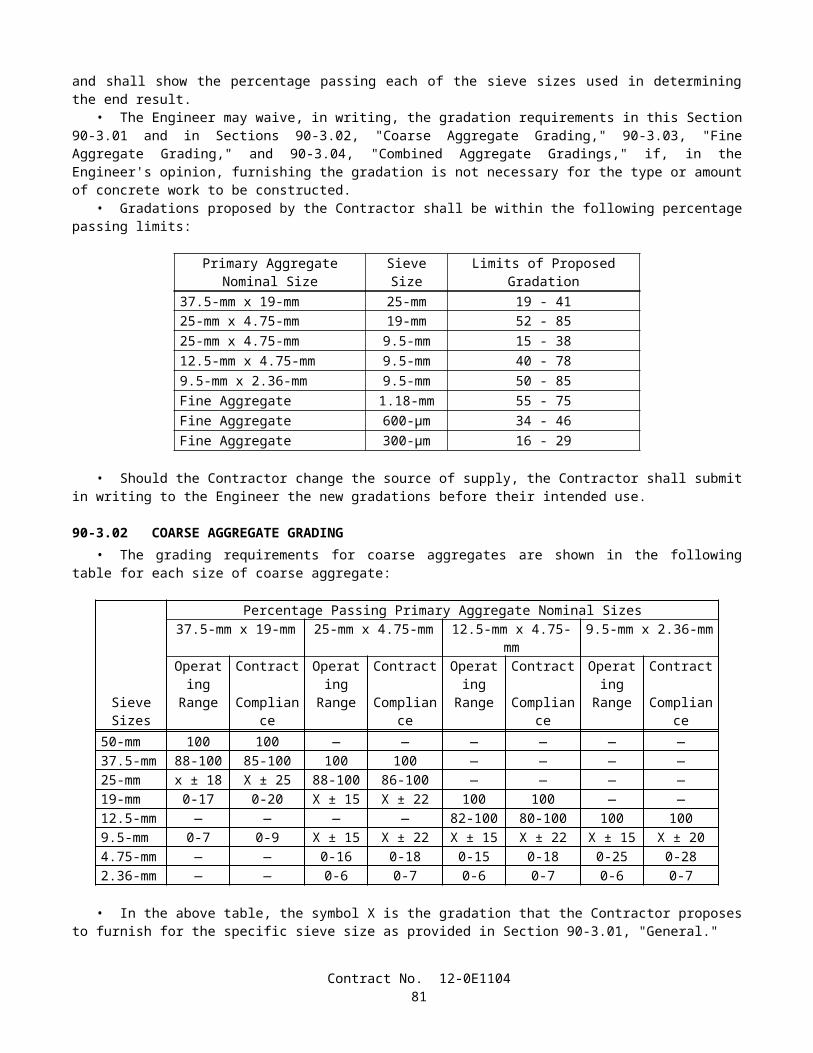
includes a subcontractor potential claim, the dispute shall be processed and resolved in conformance with these special provisions and in conformance with the following:
A. The Contractor shall identify clearly in submissions pursuant to this section, that portion of the dispute that involves a subcontractor potential claim or potential claims.
B. The Contractor shall include, as part of its submission pursuant to Step D above, a certification (False Claims Act Certification) by the subcontractor's or supplier's officer, partner, or authorized representative with authority to bind the subcontractor and with direct knowledge of the facts underlying the subcontractor potential claim. The Contractor shall submit a certification that the subcontractor potential claim is acknowledged and forwarded by the Contractor. The form for these certifications is available from the Engineer.
C. At DRB dispute meetings involving one or more subcontractor potential claims, the Contractor shall require that each subcontractor involved in the dispute have present an authorized representative with actual knowledge of the facts underlying the subcontractor potential claim to assist in presenting the subcontractor potential claim and to answer questions raised by the DRB members or the Department's representatives.
D. Failure by the Contractor to declare a subcontractor potential claim on behalf of its subcontractor (including lower tier subcontractors' and suppliers' pass through potential claims) at the time of submission of the Contractor's potential claims, as provided hereunder, shall constitute a release of the State by the Contractor of such subcontractor potential claim.
E. The Contractor shall include in all subcontracts under this contract that subcontractors and suppliers of any tier (a) agree to submit subcontractor potential claims to the Contractor in a proper form and in sufficient time to allow processing by the Contractor in conformance with the Dispute Review Board resolution specifications; (b) agree to be bound by the terms of the Dispute Review Board provisions to the extent applicable to subcontractor potential claims; (c) agree that, to the extent a subcontractor potential claim is involved, completion of all steps required under these Dispute Review Board special provisions shall be a condition precedent to pursuit by the subcontractor of other remedies permitted by law, including without limitation of a lawsuit against the Contractor; and (d) agree that the existence of a dispute resolution process for disputes involving subcontractor potential claims shall not be deemed to create any claim, right, or cause of action by any subcontractor or supplier against the Department.
Notwithstanding the foregoing, this Dispute Review Board special provision shall not apply to, and the DRB shall not have the authority to consider, subcontractor potential claims between the subcontractor(s) or supplier(s) and the Contractor that are not actionable by the Contractor against the Department.
RETENTIONFailure of the Contractor to nominate and approve DRB members in conformance with the terms and conditions of the
Dispute Review Board Agreement and these special provisions shall result in the retention of 25 percent of the estimated value of all work performed during each estimate period in which the Contractor fails to comply with the requirements of this section as determined by the Engineer. DRB retentions will be released for payment on the next monthly estimate for partial payment following the date that the Contractor has nominated and approved DRB members and no interest will be due the Contractor.
DISPUTE REVIEW BOARD AGREEMENTA copy of the "Dispute Review Board Agreement" to be executed by the Contractor, State and the 3 DRB members after
approval of the contract follows:
Contract No. 12-0E110483
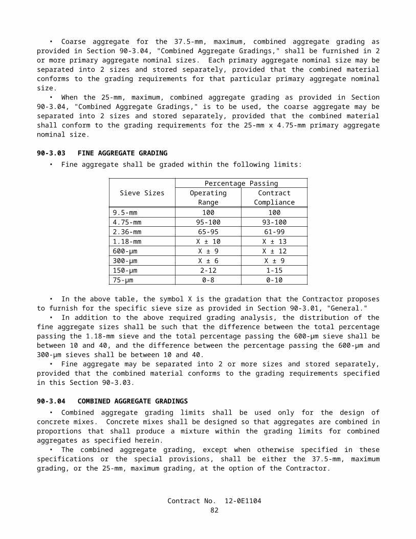
Form 6202 Rev (09/01/02)
DISPUTE REVIEW BOARD AGREEMENT
__________________________(Contract Identification)
Contract No. ___________________
THIS DISPUTE REVIEW BOARD AGREEMENT, hereinafter called "AGREEMENT", made and entered into this __________ day of _________________, _____, between the State of California, acting through the California Department of Transportation and the Director of Transportation, hereinafter called the "STATE," _________________________ ________________________ hereinafter called the "CONTRACTOR," and the Dispute Review Board, hereinafter called the "DRB" consisting of the following members:
_______________________________________________________ ,(Contractor Appointee)
_______________________________________________________ ,(State Appointee)
and ________________________________________________________(Third Person)
WITNESSETH, that
WHEREAS, the STATE and the CONTRACTOR, hereinafter called the "parties," are now engaged in the construction on the State Highway project referenced above; and
WHEREAS, the special provisions for the above referenced contract provides for the establishment and operation of the DRB to assist in resolving disputes; and
WHEREAS, the DRB is composed of three members, one selected by the STATE, one selected by the CONTRACTOR, and the third member selected by the other two members and approved by the parties;
NOW THEREFORE, in consideration of the terms, conditions, covenants, and performance contained herein, or attached and incorporated and made a part hereof, the STATE, the CONTRACTOR, and the DRB members hereto agree as follows:
SECTION I DESCRIPTION OF WORKTo assist in the resolution of disputes between the parties, the contract provides for the establishment and the operation
of the DRB. The intent of the DRB is to fairly and impartially consider disputes placed before it and provide written recommendations for resolution of these disputes to both parties. The members of this DRB shall perform the services necessary to participate in the DRB's actions as designated in Section II, Scope of Work.
SECTION II SCOPE OF WORKThe scope of work of the DRB includes, but is not limited to, the following:
A. OBJECTIVEThe principal objective of the DRB is to assist in the timely resolution of disputes between the parties arising from
performance of this contract. It is not intended for either party to default on their normal responsibility to amicably and fairly settle their differences by indiscriminately assigning them to the DRB. It is intended that the mere existence of the DRB will encourage the parties to resolve disputes without resorting to this review procedure. But when a dispute that is serious enough to warrant the DRB's review does develop, the process for prompt and efficient action will be in place.
B. PROCEDURESThe DRB shall render written reports on disputes between the parties arising from the construction contract. Prior to
consideration of a dispute, the DRB shall establish rules and regulations that will govern the conduct of its business and reporting procedures in conformance with the requirements of the contract and the terms of this AGREEMENT. DRB
Contract No. 12-0E110484
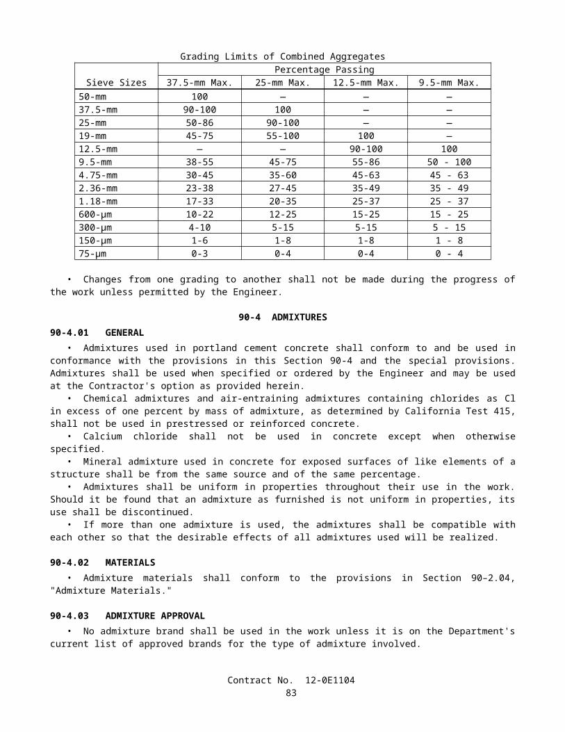
recommendations, resulting from its consideration of a dispute, shall be furnished in writing to both parties. The recommendations shall be based on facts and circumstances involved in the dispute, pertinent contract provisions, applicable laws and regulations. The recommendations shall find one responsible party in a dispute; shared or "jury" determinations shall not be rendered. The DRB shall make recommendations on the merit of the dispute, and if appropriate, recommend guidelines for determining compensation. If the parties cannot agree on compensation within 60 days of the acceptance by both parties of the DRB's recommendation, either party may request the DRB to make a recommendation regarding compensation.
The DRB shall refrain from officially giving advice or consulting services to anyone involved in the contract. The individual members shall act in a completely independent manner and while serving as members of the DRB shall have no consulting business connections with either party or its principals or attorneys or other affiliates (subcontractors, suppliers, etc.) who have a beneficial interest in the contract.
During scheduled meetings of the DRB as well as during dispute meetings, DRB members shall refrain from expressing opinions on the merits of statements on matters under dispute or potential dispute. Opinions of DRB members expressed in private sessions shall be kept strictly confidential. Individual DRB members shall not meet with, or discuss contract issues with individual parties, except as directed by the DRB Chairperson. Such discussions or meetings shall be disclosed to both parties. Other discussions regarding the project between the DRB members and the parties shall be in the presence of all three members and both parties. Individual DRB members shall not undertake independent investigations of any kind pertaining to disputes or potential disputes, except with the knowledge of both parties and as expressly directed by the DRB Chairperson.
C. CONSTRUCTION SITE VISITS, PROGRESS MEETINGS AND FIELD INSPECTIONSThe DRB members shall visit the project site and meet with representatives of the parties to keep abreast of construction
activities and to develop familiarity with the work in progress. Scheduled progress meetings shall be held at or near the project site. The DRB shall meet at least once at the start of the project, and at least once every 4 months thereafter. The frequency, exact time, and duration of additional site visits and progress meetings shall be as recommended by the DRB and approved by the parties consistent with the construction activities or matters under consideration and dispute. Each meeting shall consist of a round table discussion and a field inspection of the work being performed on the contract, if necessary. Each meeting shall be attended by representatives of both parties. The agenda shall generally be as follows:
1. Meeting opened by the DRB Chairperson.2. Remarks by the STATE's representative.3. A description by the CONTRACTOR's representative of work accomplished since the last meeting; the current
schedule status of the work; and a forecast for the coming period.4. An outline by the CONTRACTOR's representative of potential problems and a description of proposed solutions.5. An outline by the STATE's representative of the status of the work as the STATE views it.6. A brief description by the CONTRACTOR's or STATE's representative of potential claims or disputes which have
surfaced since the last meeting.7. A summary by the STATE's representative, the CONTRACTOR's representative, or the DRB of the status of past
disputes and potential claims.
The STATE's representative will prepare minutes of all progress meetings and circulate them for revision and approval by all concerned within 10 days of the meeting.
The field inspection shall cover all active segments of the work, the DRB being accompanied by both parties' representatives. The field inspection may be waived upon mutual agreement of the parties.
D. DRB CONSIDERATION AND HANDLING OF DISPUTESUpon receipt by the DRB of a written referral of a dispute, the DRB shall convene to review and consider the dispute.
The dispute meeting shall be held no earlier than 30 days and no later than 60 days after receipt of the written referral, unless otherwise agreed to by all parties. The DRB shall determine the time and location of DRB dispute meetings, with due consideration for the needs and preferences of the parties while recognizing the paramount importance of speedy resolution of issues. No dispute meetings shall take place later than 30 days prior to acceptance of contract.
Normally, dispute meetings shall be conducted at or near the project site. However, any location that would be more convenient and still provide required facilities and access to necessary documentation shall be satisfactory.
Both parties shall be given the opportunity to present their evidence at these dispute meetings. It is expressly understood that the DRB members are to act impartially and independently in the consideration of the contract provisions, applicable laws and regulations, and the facts and conditions surrounding any dispute presented by either party, and that the recommendations concerning any such dispute are advisory and nonbinding on the parties.
Contract No. 12-0E110485
The DRB may request that written documentation and arguments from both parties be sent to each DRB member, through the DRB Chairperson, for review before the dispute meeting begins. A party furnishing written documentation to the DRB shall furnish copies of such information to the other party at the same time that such information is supplied to the DRB.
DRB dispute meetings shall be informal. There shall be no testimony under oath or cross-examination. There shall be no reporting of the procedures by a shorthand reporter or by electronic means. Documents and verbal statements shall be received by the DRB in conformance with acceptance standards established by the DRB. These standards need not comply with prescribed legal laws of evidence.
The third DRB member shall act as Chairperson for dispute meetings and all other DRB activities. The parties shall have a representative at all dispute meetings. Failure to attend a duly noticed dispute meeting by either of the parties shall be conclusively considered by the DRB as indication that the non-attending party considers written submittals as their entire and complete argument. The claimant shall discuss the dispute, followed by the other party. Each party shall then be allowed one or more rebuttals until all aspects of the dispute are thoroughly covered. DRB members shall ask questions, seek clarification, and request further data from either of the parties as may be necessary to assist in making a fully informed recommendation. The DRB may request from either party documents or information that would assist the DRB in making its findings and recommendations including, but not limited to, documents used by the CONTRACTOR in preparing the bid for the project. A refusal by a party to provide information requested by the DRB may be considered by the DRB as an indication that the requested material would tend to disprove that party's position. In large or complex cases, additional dispute meetings may be necessary in order to consider all the evidence presented by both parties. All involved parties shall maintain the confidentiality of all documents and information, as provided in this AGREEMENT.
During dispute meetings, no DRB member shall express an opinion concerning the merit of any facet of the case. DRB deliberations shall be conducted in private, with interim individual views kept strictly confidential.
After dispute meetings are concluded, the DRB shall meet in private and reach a conclusion supported by 2 or more members. Private sessions of the DRB may be held at a location other than the job site or by electronic conferencing as deemed appropriate, in order to expedite the process.
The DRB's findings and recommendations, along with discussion of reasons therefor, shall then be submitted as a written report to both parties. Recommendations shall be based on the pertinent contract provisions, applicable laws and regulations, and facts and circumstances related to the dispute. The report shall be thorough in discussing the facts considered, the contract language, law or regulation viewed by the DRB as pertinent to the issues, and the DRB's interpretation and philosophy in arriving at its conclusions and recommendations. The DRB's report shall stand on its own, without attachments or appendices. The DRB Chairperson shall furnish a copy of the written recommendation report to the DRB Coordinator, Division of Construction, MS 44, P.O. Box 942874, Sacramento, CA 94274.
With prior written approval of both parties, the DRB may obtain technical services necessary to adequately review the disputes presented, including audit, geotechnical, schedule analysis and other services. The parties' technical staff may supply those services as appropriate. The cost of technical services, as agreed to by the parties, shall be borne equally by the 2 parties as specified in an approved contract change order. The CONTRACTOR will not be entitled to markups for the payments made for these services.
The DRB shall resist submittal of incremental portions of information by either party, in the interest of making a fully informed decision and recommendation.
The DRB shall make every effort to reach a unanimous decision. If this proves impossible, the dissenting member shall prepare a minority opinion, which shall be included in the DRB's report.
Although both parties should place weight upon the DRB's recommendations, they are not binding. Either party may appeal a recommendation to the DRB for reconsideration. However, reconsideration shall only be allowed when there is new evidence to present, and the DRB shall accept only one appeal from each party pertaining to an individual DRB recommendation. The DRB shall hear appeals in conformance with the terms described in the Section entitled "Dispute Review Board" in the special provisions.
E. DRB MEMBER REPLACEMENTShould the need arise to appoint a replacement DRB member, the replacement DRB member shall be appointed in the
same manner as the original DRB members were appointed. The selection of a replacement DRB member shall begin promptly upon notification of the necessity for a replacement and shall be completed within 15 days. This AGREEMENT shall be amended to indicate change in DRB membership.
SECTION III CONTRACTOR RESPONSIBILITIESThe CONTRACTOR shall furnish to each DRB member one copy of pertinent documents that are or may become
necessary for the DRB to perform their function. Pertinent documents are written notices of potential claim, responses to those notices, drawings or sketches, calculations, procedures, schedules, estimates, or other documents which are used in the
Contract No. 12-0E110486
performance of the work or in justifying or substantiating the CONTRACTOR's position. The CONTRACTOR shall also furnish a copy of such pertinent documents to the STATE, in conformance with the terms outlined in the special provisions.
Contract No. 12-0E110487
SECTION IV STATE RESPONSIBILITIESThe STATE will furnish the following services and items:
A. CONTRACT RELATED DOCUMENTSThe STATE will furnish to each DRB member one copy of Notice to Contractors and Special Provisions, Proposal and
Contract, Plans, Standard Specifications, and Standard Plans, change orders, written instructions issued by the STATE to the CONTRACTOR, or other documents pertinent to any dispute that has been referred to the DRB and necessary for the DRB to perform its function.
B. COORDINATION AND SERVICESThe STATE, through the Engineer, will, in cooperation with the CONTRACTOR, coordinate the operations of the DRB.
The Engineer will arrange or provide conference facilities at or near the project site and provide secretarial and copying services to the DRB without charge to the CONTRACTOR.
SECTION V TIME FOR BEGINNING AND COMPLETIONOnce established, the DRB shall be in operation until the day of acceptance of the contract. The DRB members shall not
begin work under the terms of this AGREEMENT until authorized in writing by the STATE.
SECTION VI PAYMENT
A. ALL INCLUSIVE RATE PAYMENTThe STATE and the CONTRACTOR shall bear the costs and expenses of the DRB equally. Each DRB member shall be
compensated at an agreed rate of $1,200 per day if time spent per meeting, including on-site time plus one hour of travel time, is greater than 4 hours. Each DRB member shall be compensated at an agreed rate of $700 per day if time spent per meeting, including on-site time plus one hour of travel time, is less than or equal to 4 hours. The agreed rates shall be considered full compensation for on-site time, travel expenses, transportation, lodging, time for travel and incidentals for each day, or portion thereof, that the DRB member is at an authorized DRB meeting. No additional compensation will be made for time spent by DRB members in review and research activities outside the official DRB meetings unless that time has been specifically agreed to in advance by the STATE and CONTRACTOR. Time away from the project that has been specifically agreed to in advance by the parties will be compensated at an agreed rate of $125 per hour. The agreed amount of $125 per hour shall include all incidentals including expenses for telephone, fax, and computer services. Members serving on more than one DRB involving the State, regardless of the number of meetings per day, shall not be paid more than the all inclusive rate per day or rate per hour for an individual project. The STATE will provide, at no cost to the CONTRACTOR, administrative services such as conference facilities and secretarial services to the DRB.
B. PAYMENTSDRB members shall be compensated at the same rate. The CONTRACTOR shall make direct payments to each DRB
member for their participation in authorized meetings and approved hourly rate charges from invoices submitted by each DRB member. The STATE will reimburse the CONTRACTOR for its share of the costs of the DRB.
The DRB members may submit invoices to the CONTRACTOR for partial payment for work performed and services rendered for their participation in authorized meetings not more often than once per month during the progress of the work. The invoices shall be in a format approved by the parties and accompanied by a general description of activities performed during that billing period. Payment for hourly fees, at the agreed rate, shall not be paid to a DRB member until the amount and extent of those fees are approved by the STATE and CONTRACTOR.
Invoices shall be accompanied by original supporting documents, which the CONTRACTOR shall include with the extra work billing when submitting for reimbursement of the STATE's share of cost from the STATE. The CONTRACTOR will be reimbursed for one-half of approved costs of the DRB. No markups will be added to the CONTRACTOR's payment.
C. INSPECTION OF COSTS RECORDSThe DRB members and the CONTRACTOR shall keep available for inspection by representatives of the STATE and the
United States, for a period of 3 years after final payment, the cost records and accounts pertaining to this AGREEMENT. If any litigation, claim, or audit arising out of, in connection with, or related to this contract is initiated before the expiration of the 3-year period, the cost records and accounts shall be retained until such litigation, claim, or audit involving the records is completed.
SECTION VII ASSIGNMENT OF TASKS OF WORKThe DRB members shall not assign the work of this AGREEMENT.
Contract No. 12-0E110488
SECTION VIII TERMINATION OF DRB MEMBERSDRB members may resign from the DRB by providing not less than 15 days written notice of the resignation to the
STATE and CONTRACTOR. DRB members may be terminated by their original appointing power or by either party, for failing to fully comply at all times with all required employment and financial disclosure conditions of DRB membership in conformance with the terms of the contract.
SECTION IX LEGAL RELATIONSThe parties hereto mutually understand and agree that the DRB member in the performance of duties on the DRB, is
acting in the capacity of an independent agent and not as an employee of either party.No party to this AGREEMENT shall bear a greater responsibility for damages or personal injury than is normally
provided by Federal or State of California Law.Notwithstanding the provisions of this contract that require the CONTRACTOR to indemnify and hold harmless the
STATE, the parties shall jointly indemnify and hold harmless the DRB members from and against all claims, damages, losses, and expenses, including but not limited to attorney's fees, arising out of and resulting from the findings and recommendations of the DRB.
SECTION X CONFIDENTIALITYThe parties hereto mutually understand and agree that all documents and records provided by the parties in reference to
issues brought before the DRB, which documents and records are marked "Confidential - for use by the DRB only," shall be kept in confidence and used only for the purpose of resolution of subject disputes, and for assisting in development of DRB findings and recommendations; that such documents and records will not be utilized or revealed to others, except to officials of the parties who are authorized to act on the subject disputes, for any purposes, during the life of the DRB. Upon termination of this AGREEMENT, said confidential documents and records, and all copies thereof, shall be returned to the parties who furnished them to the DRB. However, the parties understand that such documents shall be subsequently discoverable and admissible in court or arbitration proceedings unless a protective order has been obtained by the party seeking further confidentiality.
SECTION XI DISPUTESDisputes between the parties hereto, including disputes between the DRB members and either party or both parties,
arising out of the work or other terms of this AGREEMENT, which cannot be resolved by negotiation and mutual concurrence between the parties, or through the administrative process provided in the contract, shall be resolved by arbitration as provided in Section 9-1.10, "Arbitration," of the Standard Specifications.
SECTION XII VENUE, APPLICABLE LAW, AND PERSONAL JURISDICTIONIn the event that any party, including an individual member of the DRB, deems it necessary to institute arbitration
proceedings to enforce any right or obligation under this AGREEMENT, the parties hereto agree that such action shall be initiated in the Office of Administrative Hearings of the State of California. The parties hereto agree that all questions shall be resolved by arbitration by application of California law and that the parties to such arbitration shall have the right of appeal from such decisions to the Superior Court in conformance with the laws of the State of California. Venue for the arbitration shall be Sacramento or any other location as agreed to by the parties.
SECTION XIII FEDERAL REVIEW AND REQUIREMENTSOn Federal-Aid contracts, the Federal Highway Administration shall have the right to review the work of the DRB in
progress, except for private meetings or deliberations of the DRB.Other Federal requirements in this agreement shall only apply to Federal-Aid contracts.
Contract No. 12-0E110489
SECTION XIV CERTIFICATION OF THE CONTRACTOR, THE DRB MEMBERS, AND THE STATEIN WITNESS WHEREOF, the parties hereto have executed this AGREEMENT as of the day and year first above
written.
DRB MEMBER DRB MEMBER
By: _____________________________ By: ______________________________
Title: ____________________________ Title :_____________________________
DRB MEMBER
By :________________________________
Title :_______________________________
CONTRACTOR CALIFORNIA STATE DEPARTMENT OF TRANSPORTATION
By: _____________________________ By: _____________________________
Title: ___________________________ Title: ____________________________
5-1.13 FORCE ACCOUNT PAYMENTPayment for extra work at force account will be determined by either non-subcontracted or subcontracted force account
payment unless otherwise specified.
Non-Subcontracted Force Account Payment:When extra work to be paid for on a force account basis is performed by the Contractor, compensation will be
determined in accordance with Section 9-1.03, "Force Account Payment," of the Standard Specifications and these special provisions.
The second, third and fourth paragraphs of Section 9-1.03A, "Work Performed by Contractor," in the Standard Specifications, shall not apply.
Attention is directed to "Time-Related Overhead" of these special provisions.To the total of the direct costs for work performed on a force account basis, computed as provided in Sections
9-1.03A(1), "Labor," 9-1.03A(2), "Materials," and 9-1.03A(3), "Equipment Rental," of the Standard Specifications, there will be added the following markups:
Cost Percent MarkupLabor 28Materials 10Equipment Rental 10
The above markups shall be applied to work performed on a force account basis, regardless of whether the work revises the current contract completion date.
The above markups, together with payments made for time-related overhead pursuant to "Time-Related Overhead" of these special provisions, shall constitute full compensation for all overhead costs for work performed on a force account basis. These overhead costs shall be deemed to include all items of expense not specifically designated as cost or equipment rental in conformance with the provisions in Sections 9-1.03A(1), "Labor," 9-1.03A(2), "Materials," and 9-1.03A(3), "Equipment Rental," of the Standard Specifications. The total payment made as provided above and in the first paragraph of Section 9-1.03A, "Work Performed by Contractor," of the Standard Specifications shall be deemed to be the actual cost of the work performed on a force account basis, and shall constitute full compensation therefor.
Full compensation for overhead costs for work performed on a force account basis, and for which no adjustment is made to the quantity for time-related overhead conforming to the provisions in "Time-Related Overhead" of these special provisions, shall be considered as included in the markups specified above, and no additional compensation will be allowed therefor.
Contract No. 12-0E110490
Subcontracted Force Account Payment:When extra work to be paid for on a force account basis is performed by a subcontractor approved in conformance with
the provisions in Section 8-1.01, "Subcontracting," of the Standard Specifications, compensation will be determined in accordance with the provisions in Section 9-1.03, "Force Account Payment," of the Standard Specifications.
5-1.14 AREAS FOR CONTRACTOR'S USEAttention is directed to the provisions in Section 7-1.19, "Rights in Land and Improvements," of the Standard
Specifications and these special provisions.The highway right of way shall be used only for purposes that are necessary to perform the required work. The
Contractor shall not occupy the right of way, or allow others to occupy the right of way, for purposes which are not necessary to perform the required work.
No State-owned parcels adjacent to the right of way are available for the exclusive use of the Contractor within the contract limits. The Contractor shall secure, at the Contractor's own expense, areas required for plant sites, storage of equipment or materials, or for other purposes.
No area is available within the contract limits for the exclusive use of the Contractor. However, temporary storage of equipment and materials on State property may be arranged with the Engineer, subject to the prior demands of State maintenance forces and to other contract requirements. Use of the Contractor's work areas and other State-owned property shall be at the Contractor's own risk, and the State shall not be held liable for damage to or loss of materials or equipment located within such areas.
5-1.15 PAYMENTSAttention is directed to Sections 9-1.06, "Partial Payments," and 9-1.07, "Payment After Acceptance," of the Standard
Specifications and these special provisions.For the purpose of making partial payments pursuant to Section 9-1.06, "Partial Payments," of the Standard
Specifications, the amount set forth for the contract items of work hereinafter listed shall be deemed to be the maximum value of the contract item of work which will be recognized for progress payment purposes:
A. Clearing and Grubbing $20,000B. Prepare water pollution control program $ 3,750C. Progress Schedule (Critical Path Method) $10,000
After acceptance of the contract pursuant to the provisions in Section 7-1.17, "Acceptance of Contract," of the Standard Specifications, the amount, if any, payable for a contract item of work in excess of the maximum value for progress payment purposes hereinabove listed for the item, will be included for payment in the first estimate made after acceptance of the contract.
In determining the partial payments to be made to the Contractor, only the following listed materials will be considered for inclusion in the payment as materials furnished but not incorporated in the work:
A. Metal Beam Guard RailingB. Camera AssembliesC. Splice VaultsD. Fiber Optic CablesE. InnerductsF. Fiber Optic Conduits
5-1.16 PROJECT INFORMATIONThe information in this section has been compiled specifically for this project and is made available for bidders and
Contractors. Other information referenced in the Standard Specifications and these special provisions do not appear in this section. The information is subject to the conditions and limitations set forth in Section 2-1.03, "Examination of Plans, Specifications, Contract, and Site of Work," and Section 6-2, "Local Materials," of the Standard Specifications. Bidders and Contractors shall be responsible for knowing the procedures for obtaining information.
Cross sections are not available for this project.
Contract No. 12-0E110491
5-1.17 SOUND CONTROL REQUIREMENTSSound control shall conform to the provisions in Section 7-1.01I, "Sound Control Requirements," of the Standard
Specifications and these special provisions.The noise level from the Contractor's operations, between the hours of 9:00 p.m. and 6:00 a.m., shall not exceed 86 dBa
at a distance of 15 m. This requirement shall not relieve the Contractor from responsibility for complying with local ordinances regulating noise level.
The noise level requirement shall apply to the equipment on the job or related to the job, including but not limited to trucks, transit mixers or transient equipment that may or may not be owned by the Contractor. The use of loud sound signals shall be avoided in favor of light warnings except those required by safety laws for the protection of personnel.
Full compensation for conforming to the requirements of this section shall be considered as included in the prices paid for the various contract items of work involved and no additional compensation will be allowed therefor.
5-1.18 INTERNET DAILY EXTRA WORK REPORTWhen extra work is being paid for on a force account basis, the Contractor shall submit daily extra work reports in
conformance with the provisions in Section 9-1.03C, "Records," of the Standard Specifications and these special provisions.The Contractor shall send daily extra work reports to the Engineer using the Department's Internet extra work billing
system. The reports shall conform to the requirements in the "iCAS User's Guide" (Guide). The Guide is available from the Department, and is also found on the Internet at:
http://www.dot.ca.gov/hq/construc/ewb/EWB_INSTRUCTION.pdf
The Department will provide system accounts to the Contractor's authorized representatives when at least one of the representatives has received training. The Department will provide system training to at least one of the Contractor's authorized representatives within 30 days of the Contractor's request for training. The Department will assign an account and user identification to the Contractor's authorized representatives, and each Contractor's authorized representative shall maintain a unique password. A daily extra work report that the Contractor's authorized representative sends to the Department using the Internet extra work billing system will be considered signed by the Contractor. A daily extra work report that the Engineer approves using the Internet extra work billing system will be considered signed by the Engineer.
Daily extra work reports that include billing for materials shall be substantiated by a valid copy of a vendor's invoice in conformance to the requirements in Section 9-1.03C, "Records," of the Standard Specifications. Each materials invoice shall clearly identify the relative daily extra work report and the associated cost of the materials. In addition to postal service and parcel service and if approved by the Engineer, invoices may be sent by facsimile or as an electronic-mail attachment.
The Contractor shall maintain the Contractor's interface with the Department's Internet extra work billing system. If the Contractor is using the file transfer process to submit extra work reports, it shall conform to the file transfer format and process defined in the Guide.
SECTION 6. (BLANK)
SECTION 7. (BLANK)
SECTION 8. MATERIALS
SECTION 8-1. MISCELLANEOUS
8-1.01 SUBSTITUTION OF NON-METRIC MATERIALS AND PRODUCTSOnly materials and products conforming to the requirements of the specifications shall be incorporated in the work.
When metric materials and products are not available, and when approved by the Engineer, and at no cost to the State, materials and products in the United States Standard Measures which are of equal quality and of the required properties and characteristics for the purpose intended, may be substituted for the equivalent metric materials and products, subject to the following provisions:
A. Materials and products shown on the plans or in the special provisions as being equivalent may be substituted for the metric materials and products specified or detailed on the plans.
B. Before other non-metric materials and products will be considered for use, the Contractor shall furnish, at the Contractor's expense, evidence satisfactory to the Engineer that the materials and products proposed for use are equal to or better than the materials and products specified or detailed on the plans. The burden of proof as to the
Contract No. 12-0E110492
quality and suitability of substitutions shall be upon the Contractor and the Contractor shall furnish necessary information as required by the Engineer. The Engineer will be the sole judge as to the quality and suitability of the substituted materials and products and the Engineer's decision will be final.
C. When the Contractor elects to substitute non-metric materials and products, including materials and products shown on the plans or in the special provisions as being equivalent, the list of sources of material specified in Section 6-1.01, "Source of Supply and Quality of Materials," of the Standard Specification shall include a list of substitutions to be made and contract items involved. In addition, for a change in design or details, the Contractor shall submit plans and working drawings in conformance with the provisions in Section 5-1.02, "Plans and Working Drawings," of the Standard Specifications. The plans and working drawings shall be submitted at least 7 days before the Contractor intends to begin the work involved.
Unless otherwise specified, the following substitutions of materials and products will be allowed:
SUBSTITUTION TABLE FOR PLAIN WIRE REINFORCEMENTASTM Designation: A 82
METRIC SIZE SHOWN ON THE PLANSmm2
SIZE TO BE SUBSTITUTEDinch2 x 100
MW9 W1.4MW10 W1.6MW13 W2.0MW15 W2.3MW19 W2.9MW20 W3.1MW22 W3.5MW25 W3.9, except W3.5 in piles onlyMW26 W4.0MW30 W4.7MW32 W5.0MW35 W5.4MW40 W6.2MW45 W6.5MW50 W7.8MW55 W8.5, except W8.0 in piles onlyMW60 W9.3MW70 W10.9, except W11.0 in piles onlyMW80 W12.4MW90 W14.0MW100 W15.5
Contract No. 12-0E110493
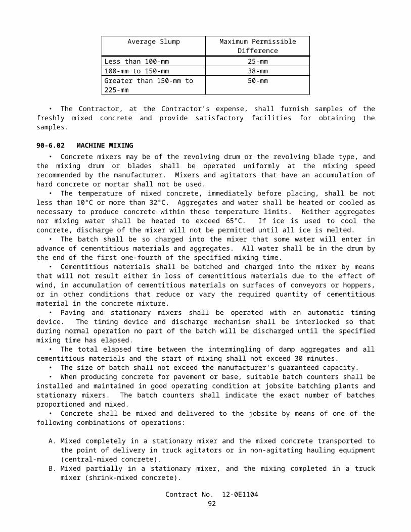
SUBSTITUTION TABLE FOR BAR REINFORCEMENTMETRIC BAR DESIGNATION
NUMBER1 SHOWN ON THE PLANSBAR DESIGNATION
NUMBER2 TO BE SUBSTITUTED10 313 416 519 622 725 829 932 1036 1143 1457 18
1Bar designation numbers approximate the number of millimeters of the nominal diameter of the bars.2Bar numbers are based on the number of eighths of an inch included in the nominal diameter of the bars.No adjustment will be required in spacing or total number of reinforcing bars due to a difference in minimum yield strength between metric and non-metric bars.
SUBSTITUTION TABLE FOR SIZES OF:(1) STEEL FASTENERS FOR GENERAL APPLICATIONS (ASTM Designation: A 307 or AASHTO Designation: M 314, Grade 36 or 55), and (2) HIGH STRENGTH STEEL FASTENERS (ASTM Designation: A 325 or A 449)
METRIC SIZE SHOWN ON THE PLANSmm
SIZE TO BE SUBSTITUTEDinch
6 or 6.35 1/48 or 7.94 5/1610 or 9.52 3/811 or 11.11 7/16
13, 12.70, or M12 1/214 or 14.29 9/16
16, 15.88, or M16 5/819, 19.05, or M20 3/422, 22.22, or M22 7/8
24, 25, 25.40, or M24 129, 28.58, or M27 1-1/832, 31.75, or M30 1-1/4
35 or 34.93 1-3/838, 38.10, or M36 1-1/2
44 or 44.45 1-3/451 or 50.80 257 or 57.15 2-1/464 or 63.50 2-1/270 or 69.85 2-3/476 or 76.20 383 or 82.55 3-1/489 or 88.90 3-1/295 or 95.25 3-3/4
102 or 101.60 4
Contract No. 12-0E110494
SUBSTITUTION TABLE FOR NOMINAL THICKNESS OF SHEET METALUNCOATED HOT AND COLD ROLLED SHEETS HOT-DIPPED ZINC COATED SHEETS
(GALVANIZED)METRIC THICKNESS
SHOWN ON THE PLANSmm
GAGE TO BE SUBSTITUTED
inch
METRIC THICKNESSSHOWN ON THE PLANS
mm
GAGE TO BE SUBSTITUTED
inch7.94 0.3125 4.270 0.16816.07 0.2391 3.891 0.15325.69 0.2242 3.510 0.13825.31 0.2092 3.132 0.12334.94 0.1943 2.753 0.10844.55 0.1793 2.372 0.09344.18 0.1644 1.994 0.07853.80 0.1495 1.803 0.07103.42 0.1345 1.613 0.06353.04 0.1196 1.461 0.05752.66 0.1046 1.311 0.05162.28 0.0897 1.158 0.04561.90 0.0747 1.006 or 1.016 0.03961.71 0.0673 0.930 0.03661.52 0.0598 0.853 0.03361.37 0.0538 0.777 0.03061.21 0.0478 0.701 0.02761.06 0.0418 0.627 0.02470.91 0.0359 0.551 0.02170.84 0.0329 0.513 0.02020.76 0.0299 0.475 0.01870.68 0.0269 -------- --------0.61 0.0239 -------- --------0.53 0.0209 -------- --------0.45 0.0179 -------- --------0.42 0.0164 -------- --------0.38 0.0149 -------- --------
Contract No. 12-0E110495
SUBSTITUTION TABLE FOR WIREMETRIC THICKNESS
SHOWN ON THE PLANSmm
WIRE THICKNESSTO BE SUBSTITUTED
inchGAGE NO.
6.20 0.244 35.72 0.225 45.26 0.207 54.88 0.192 64.50 0.177 74.11 0.162 83.76 0.148 93.43 0.135 103.05 0.120 112.69 0.106 122.34 0.092 132.03 0.080 141.83 0.072 151.57 0.062 161.37 0.054 171.22 0.048 181.04 0.041 190.89 0.035 20
SUBSTITUTION TABLE FOR PIPE PILESMETRIC SIZE
SHOWN ON THE PLANSmm x mm
SIZETO BE SUBSTITUTED
inch x inchPP 360 x 4.55 NPS 14 x 0.179PP 360 x 6.35 NPS 14 x 0.250PP 360 x 9.53 NPS 14 x 0.375PP 360 x 11.12 NPS 14 x 0.438PP 406 x 12.70 NPS 16 x 0.500
PP 460 x T NPS 18 x T"PP 508 x T NPS 20 x T"PP 559 x T NPS 22 x T"PP 610 x T NPS 24 x T"PP 660 x T NPS 26 x T"PP 711 x T NPS 28 x T"PP 762 x T NPS 30 x T"PP 813 x T NPS 32 x T"PP 864 x T NPS 34 x T"PP 914 x T NPS 36 x T"PP 965 x T NPS 38 x T"PP 1016 x T NPS 40 x T"PP 1067 x T NPS 42 x T"PP 1118 x T NPS 44 x T"PP 1219 x T NPS 48 x T"PP 1524 x T NPS 60 x T"
The thickness in millimeters (T) represents an exact conversion of the thickness in inches (T").
Contract No. 12-0E110496
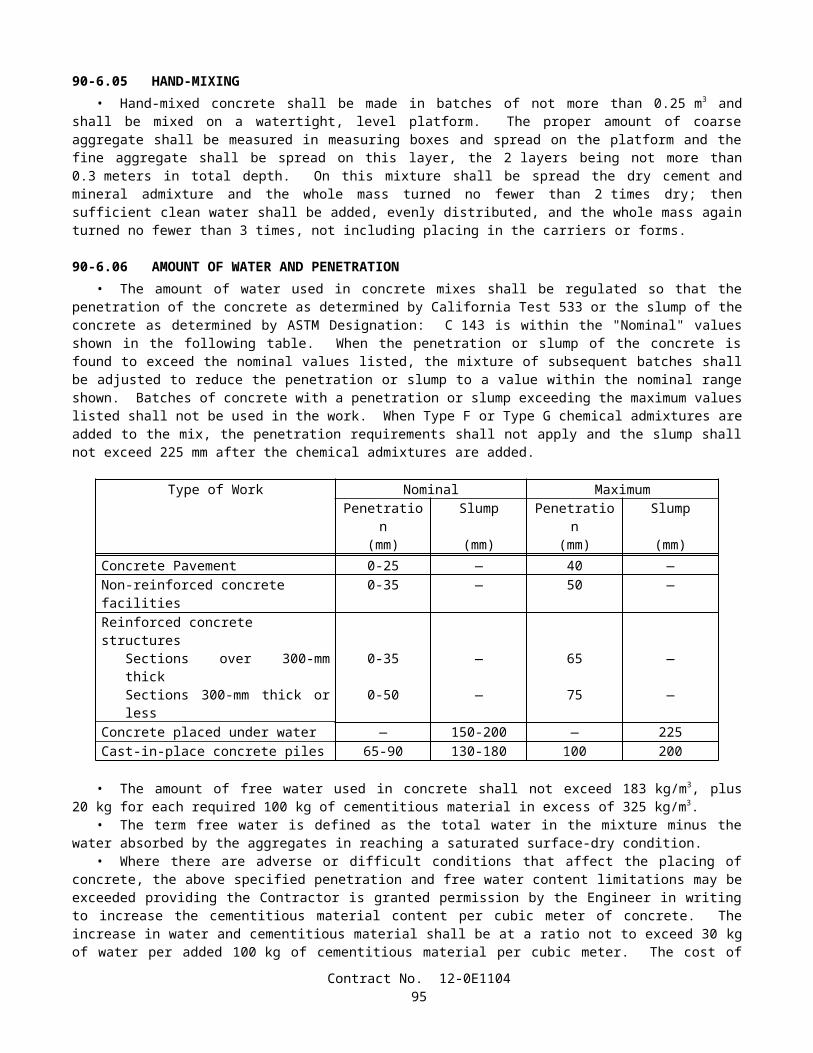
SUBSTITUTION TABLE FOR CIDH CONCRETE PILINGMETRIC SIZE
SHOWN ON THE PLANSACTUAL AUGER SIZETO BE SUBSTITUTED
inches350 mm 14400 mm 16450 mm 18600 mm 24750 mm 30900 mm 36
1.0 m 421.2 m 481.5 m 601.8 m 722.1 m 842.4 m 962.7 m 1083.0 m 1203.3 m 1323.6 m 1444.0 m 156
SUBSTITUTION TABLE FOR STRUCTURAL TIMBER AND LUMBER METRIC MINIMUM
DRESSED DRY,SHOWN ON THE PLANS
mm x mm
METRIC MINIMUM DRESSED GREEN,
SHOWN ON THE PLANSmm x mm
NOMINAL SIZE
TO BE SUBSTITUTEDinch x inch
19x89 20x90 1x438x89 40x90 2x464x89 65x90 3x489x89 90x90 4x4
140x140 143x143 6x6140x184 143x190 6x8184x184 190x190 8x8235x235 241x241 10x10286x286 292x292 12x12
Contract No. 12-0E110497
SUBSTITUTION TABLE FOR NAILS AND SPIKESMETRIC COMMON NAIL,SHOWN ON THE PLANS
Length, mmDiameter, mm
METRIC BOX NAIL,SHOWN ON THE PLANS
Length, mmDiameter, mm
METRIC SPIKE,SHOWN ON THE
PLANSLength, mm
Diameter, mm
SIZETO BE
SUBSTITUTEDPenny-weight
50.802.87
50.802.51
______ 6d
63.503.33
63.502.87
______ 8d
76.203.76
76.203.25
76.204.88
10d
82.553.76
82.553.25
82.554.88
12d
88.904.11
88.903.43
88.905.26
16d
101.604.88
101.603.76
101.605.72
20d
114.305.26
114.303.76
114.306.20
30d
127.005.72
127.004.11
127.006.68
40d
______ ______ 139.707.19
50d
______ ______ 152.407.19
60d
Contract No. 12-0E110498
SUBSTITUTION TABLE FOR IRRIGATION COMPONENTS
METRICWATER METERS, TRUCK LOADING STANDPIPES, VALVES, BACKFLOW PREVENTERS, FLOW
SENSORS, WYE STRAINERS, FILTER
ASSEMBLY UNITS, PIPE SUPPLY LINES, AND PIPE
IRRIGATION SUPPLY LINES
SHOWN ON THE PLANSDIAMETER NOMINAL
(DN) mm
NOMINAL SIZE
TO BE SUBSTITUTED
inch15 1/220 3/425 132 1-1/440 1-1/250 265 2-1/275 3100 4150 6200 8250 10300 12350 14400 16
Unless otherwise specified, substitutions of United States Standard Measures standard structural shapes corresponding to the metric designations shown on the plans and in conformance with the requirements in ASTM Designation: A 6/A 6M, Annex 2, will be allowed.
8-1.02 PREQUALIFIED AND TESTED SIGNING AND DELINEATION MATERIALSThe Department maintains the following list of Prequalified and Tested Signing and Delineation Materials. The
Engineer shall not be precluded from sampling and testing products on the list of Prequalified and Tested Signing and Delineation Materials.
The manufacturer of products on the list of Prequalified and Tested Signing and Delineation Materials shall furnish the Engineer a Certificate of Compliance in conformance with the provisions in Section 6-1.07, "Certificates of Compliance," of the Standard Specifications for each type of traffic product supplied.
For those categories of materials included on the list of Prequalified and Tested Signing and Delineation Materials, only those products shown within the listing may be used in the work. Other categories of products, not included on the list of Prequalified and Tested Signing and Delineation Materials, may be used in the work provided they conform to the requirements of the Standard Specifications.
Materials and products may be added to the list of Prequalified and Tested Signing and Delineation Materials if the manufacturer submits a New Product Information Form to the New Product Coordinator at the Transportation Laboratory. Upon a Departmental request for samples, sufficient samples shall be submitted to permit performance of required tests. Approval of materials or products will depend upon compliance with the specifications and tests the Department may elect to perform.
Contract No. 12-0E110499
PAVEMENT MARKERS, PERMANENT TYPERetroreflective With Abrasion Resistant Surface (ARS)
A. Apex, Model 921AR (100 mm x 100 mm)B. Avery Dennison, Models C88 (100 mm x 100 mm), 911 (100 mm x 100 mm) and 953 (70 mm x 114 mm)C. Ray-O-Lite, Model "AA" ARS (100 mm x 100 mm)D. 3M Series 290 (89 mm x 100 mm)E. 3M Series 290 PSA, with pressure sensitive adhesive pad (89 mm x 100 mm)
Retroreflective With Abrasion Resistant Surface (ARS)(for recessed applications only)
A. Avery Dennison, Model 948 (58 mm x 119 mm)B. Avery Dennison, Model 944SB (51 mm x 100 mm)*C. Ray-O-Lite, Model 2002 (58 mm x 117 mm)D. Ray-O-Lite, Model 2004 ARS (51 mm x 100 mm)*
*For use only in 114 mm wide (older) recessed slots
Non-Reflective, 100 mm RoundA. Apex Universal (Ceramic)B. Apex Universal, Models 929 (ABS) and 929PP (Polypropylene)C. Glowlite, Inc., (Ceramic)D. Hi-Way Safety, Inc., Models P20-2000W and 2001Y (ABS)E. Interstate Sales, "Diamond Back" (ABS) and (Polypropylene)F. Novabrite Models Cdot (White) Cdot-y (Yellow), CeramicG. Novabrite Models Pdot-w (White) Pdot-y (Yellow), PolypropyleneH. Road Creations, Model RCB4NR (Acrylic)I. Three D Traffic Works TD10000 (ABS), TD10500 (Polypropylene)
PAVEMENT MARKERS, TEMPORARY TYPETemporary Markers For Long Term Day/Night Use (6 months or less)
A. Vega Molded Products "Temporary Road Marker" (75 mm x 100 mm)
Temporary Markers For Short Term Day/Night Use (14 days or less)(For seal coat or chip seal applications, clear protective covers are required)
A. Apex Universal, Model 932B. Bunzl Extrusion, Models T.O.M., T.R.P.M., and "HH" (High Heat)C. Hi-Way Safety, Inc., Model 1280/1281D. Glowlite, Inc., Model 932
STRIPING AND PAVEMENT MARKING MATERIALPermanent Traffic Striping and Pavement Marking Tape
A. Advanced Traffic Marking, Series 300 and 400B. Brite-Line, Series 1000C. Brite-Line, "DeltaLine XRP"D. Swarco Industries, "Director 35" (For transverse application only)E. Swarco Industries, "Director 60"F. 3M, "Stamark" Series 380 and 5730G. 3M, "Stamark" Series 420 (For transverse application only)
Temporary (Removable) Striping and Pavement Marking Tape (6 months or less)A. Advanced Traffic Marking, Series 200B. Brite-Line, Series 100C. Garlock Rubber Technologies, Series 2000D. P.B. Laminations, Aztec, Grade 102E. Swarco Industries, "Director-2"F. Trelleborg Industri, R140 Series
Contract No. 12-0E1104100
G. 3M, Series 620 "CR", and Series A750H. 3M, Series A145, Removable Black Line Mask
(Black Tape: for use only on Asphalt Concrete Surfaces)I. Advanced Traffic Marking Black "Hide-A-Line"
(Black Tape: for use only on Asphalt Concrete Surfaces)J. Brite-Line "BTR" Black Removable Tape
(Black Tape: for use only on Asphalt Concrete Surfaces)K. Trelleborg Industri, RB-140
(Black Tape: for use only on Asphalt Concrete Surfaces)
Preformed Thermoplastic (Heated in place)A. Avery Dennison, "Hotape"B. Flint Trading, "Premark," "Premark 20/20 Flex," and "Premark 20/20 Flex Plus"
Ceramic Surfacing Laminate, 150 mm x 150 mmA. Highway Ceramics, Inc.
CLASS 1 DELINEATORSOne Piece Driveable Flexible Type, 1700 mm
A. Bunzl Extrusion, "Flexi-Guide Models 400 and 566"B. Carsonite, Curve-Flex CFRM-400C. Carsonite, Roadmarker CRM-375D. FlexStake, Model 654 TME. GreenLine Models HWD1-66 and CGD1-66
Special Use Type, 1700 mmA. Bunzl Extrusion, Model FG 560 (with 450 mm U-Channel base)B. Carsonite, "Survivor" (with 450 mm U-Channel base)C. Carsonite, Roadmarker CRM-375 (with 450 mm U-Channel base)D. FlexStake, Model 604E. GreenLine Models HWDU and CGD (with 450 mm U-Channel base)F. Impact Recovery Model D36, with #105 Driveable BaseG. Safe-Hit with 200 mm pavement anchor (SH248-GP1)H. Safe-Hit with 380 mm soil anchor (SH248-GP2) and with 450 mm soil anchor (SH248-GP3)
Surface Mount Type, 1200 mmA. Bent Manufacturing Company, Masterflex Model MF-180EX-48B. Carsonite, "Super Duck II"C. FlexStake, Surface Mount, Models 704 and 754 TMD. Impact Recovery Model D48, with #101 Fixed (Surface-Mount) BaseE. Three D Traffic Works "Channelflex" ID No. 522248W
CHANNELIZERSSurface Mount Type, 900 mm
A. Bent Manufacturing Company, Masterflex Models MF-360-36 (Round) and MF-180-36 (Flat)B. Bunzl Extrusion, Flexi-Guide Models FG300PE and FG300URC. Carsonite, "Super Duck" (Flat SDF-436, Round SDR-336)D. Carsonite, "Super Duck II" Model SDCF203601MB "The Channelizer"E. FlexStake, Surface Mount, Models 703 and 753 TMF. GreenLine, Model SMD-36G. Hi-Way Safety, Inc. "Channel Guide Channelizer" Model CGC36H. Impact Recovery Model D36, with #101 Fixed (Surface-Mount) BaseI. Repo, Models 300 and 400J. Safe-Hit, Guide Post, Model SH236SMAK. Three D Traffic Works "Channelflex" ID No. 522053W
Contract No. 12-0E1104101
Lane Separation SystemA. Bunzl "Flexi-Guide (FG) 300 Curb System"B. Qwick Kurb, "Klemmfix Guide System"C. Recycled Technology, Inc. "Safe-Lane System"
CONICAL DELINEATORS, 1070 mm(For 700 mm Traffic Cones, see Standard Specifications)A. Bent Manufacturing Company "T-Top"B. Plastic Safety Systems "Navigator-42"C. Radiator Specialty Company "Enforcer"D. Roadmaker Company "Stacker"E. TrafFix Devices "Grabber"F. Three D Traffic Works "Ringtop" TD7000, ID No. 742143
OBJECT MARKERSType "K", 450 mm
A. Bunzl, Model FG318PEB. Carsonite, Model SMD 615C. FlexStake, Model 701 KMD. Repo, Models 300 and 400E. Safe-Hit, Model SH718SMA
Type "K-4" / "Q" Object Markers, 600 mmA. Bent Manufacturing "Masterflex" Model MF-360-24B. Bunzl Extrusion, Model FG324PEC. Carsonite, Super Duck IID. FlexStake, Model 701KME. Repo, Models 300 and 400F. Safe-Hit, Models SH8 24SMA_WA and SH8 24GP3_WAG. The Line Connection, Model DP21-4QH. Three D Traffic Works "Q" Marker, ID No. 531702W
CONCRETE BARRIER MARKERS AND TEMPORARY RAILING (TYPE K) REFLECTORS
Impactable TypeA. ARTUK, "FB"B. Bunzl Extrusion, Models PCBM-12 and PCBM-T12C. Duraflex Corp., "Flexx 2020" and "Electriflexx"D. Hi-Way Safety, Inc., Model GMKRM100E. Plastic Safety Systems "BAM" Models OM-BARR and OM-BWARF. Sun-Lab Technology, "Safety Guide Light Model TM-5"G. Three D Traffic Works "Roadguide" 9304 Series, ID No. 903176 (One-Way), ID No. 903215 (Two-Way)
Non-Impactable TypeA. ARTUK, JD SeriesB. Plastic Safety Systems "BAM" Models OM-BITARW and OM-BITARAC. Vega Molded Products, Models GBM and JD
METAL BEAM GUARD RAIL POST MARKERS(For use to the left of traffic)A. Bunzl Extrusion, "Mini" (75 mm x 254 mm)B. Creative Building Products, "Dura-Bull, Model 11201"C. Duraflex Corp., "Railrider"
CONCRETE BARRIER DELINEATORS, 400 mm(For use to the right of traffic)A. Bunzl Extrusion, Model PCBM T-16
Contract No. 12-0E1104102
B. Safe-Hit, Model SH216RBMC. Sun-Lab Technology, "Safety Guide Light, Model TM16," (75 mm x 300 mm)D. Three D Traffic Works "Roadguide" ID No. 904364 (White), ID No. 904390 (Yellow)
CONCRETE BARRIER-MOUNTED MINI-DRUM (260 mm x 360 mm x 570 mm)A. Stinson Equipment Company "SaddleMarker"
SOUND WALL DELINEATOR(Applied vertically. Place top of 75 mm x 300 mm reflective element at 1200 mm above roadway)A. Bunzl Extrusion, PCBM S-36B. Sun-Lab Technology, "Safety Guide Light, Model SM12," (75 mm x 300 mm)
GUARD RAILING DELINEATOR(Place top of reflective element at 1200 mm above plane of roadway)
Wood Post Type, 686 mmA. Bunzl Extrusion, FG 427 and FG 527B. Carsonite, Model 427C. FlexStake, Model 102 GRD. GreenLine GRD 27E. Safe-Hit, Model SH227GRDF. Three D Traffic Works "Guardflex" TD9100 Series, ID No. 510476
Steel Post TypeA. Carsonite, Model CFGR-327 with CFGRBK300 Mounting Bracket
RETROREFLECTIVE SHEETINGChannelizers, Barrier Markers, and Delineators
A. Avery Dennison T-6500 Series (For rigid substrate devices only)B. Avery Dennison WR-6100 SeriesC. Nippon Carbide Industries, Flexible Ultralite Grade (ULG) IID. Reflexite, PC-1000 Metalized PolycarbonateE. Reflexite, AC-1000 AcrylicF. Reflexite, AP-1000 Metalized PolyesterG. Reflexite, Conformalight, AR-1000 Abrasion Resistant CoatingH. 3M, High Intensity
Traffic Cones, 330 mm SleevesA. Reflexite SB (Polyester), Vinyl or "TR" (Semi-transparent)
Traffic Cones, 100 mm and 150 mm SleevesA. Nippon Carbide Industries, Flexible Ultralite Grade (ULG) IIB. Reflexite, Vinyl, "TR" (Semi-transparent) or "Conformalight"C. 3M Series 3840
Barrels and DrumsA. Avery Dennison WR-6100B. Nippon Carbide Industries, Flexible Ultralite Grade (ULG) IIC. Reflexite, "Conformalight", "Super High Intensity" or "High Impact Drum Sheeting"D. 3M Series 3810
Barricades: Type I, Medium-Intensity (Typically Enclosed Lens, Glass-Bead Element)A. American Decal, AdcoliteB. Avery Dennison, T-1500 and T-1600 seriesC. 3M Engineer Grade, Series 3170
Contract No. 12-0E1104103
Barricades: Type II, Medium-High-Intensity (Typically Enclosed Lens, Glass-Bead Element)A. Avery Dennison, T-2500 SeriesB. Kiwalite Type IIC. Nikkalite 1800 Series
Signs: Type II, Medium-High-Intensity (Typically Enclosed Lens, Glass-Bead Element)A. Avery Dennison, T-2500 SeriesB. Kiwalite, Type IIC. Nikkalite 1800 Series
Signs: Type III, High-Intensity (Typically Encapsulated Glass-Bead Element)A. Avery Dennison, T-5500 and T-5500A SeriesB. Nippon Carbide Industries, Nikkalite Brand Ultralite Grade IIC. 3M Series 3870
Signs: Type IV, High-Intensity (Typically Unmetallized Microprismatic Element)A. Avery Dennison, T-6500 SeriesB. Nippon Carbide Industries, Crystal Grade, 94000 SeriesC. Nippon Carbide Industries, Model No. 94847 Fluorescent OrangeD. Nippon Carbide Industries, Model No. 94844 Fluorescent Yellow Green
Signs: Type VI, Elastomeric (Roll-Up) High-Intensity, without AdhesiveA. Avery Dennison, WU-6014B. Novabrite LLC, "Econobrite"C. Reflexite "Vinyl"D. Reflexite "SuperBright"E. Reflexite "Marathon"F. 3M Series RS34 Orange and RS20 Fluorescent Orange
Signs: Type VII, Super-High-Intensity (Typically Unmetallized Microprismatic Element)A. 3M LDP Series 3924 Fluorescent OrangeB. 3M LDP Series 3970
Signs: Type VIII, Super-High-Intensity (Typically Unmetallized Microprismatic Element)A. Avery Dennison, T-7500 SeriesB. Avery Dennison, T-7511 Fluorescent YellowC. Avery Dennison, T-7513 Fluorescent Yellow GreenD. Avery Dennison, W-7514 Fluorescent OrangeE. Nippon Carbide Industries, Nikkalite Crystal Grade Model 92802 WhiteF. Nippon Carbide Industries, Nikkalite Crystal Grade Model 92844 Fluorescent Yellow/GreenG. Nippon Carbide Industries, Nikkalite Crystal Grade Model 92847 Fluorescent Orange
Signs: Type IX, Very-High-Intensity (Typically Unmetallized Microprismatic Element)A. 3M VIP Series 3981 Diamond Grade Fluorescent YellowB. 3M VIP Series 3983 Diamond Grade Fluorescent Yellow/GreenC. 3M VIP Series 3990 Diamond Grade
SPECIALTY SIGNSA. Hallmark Technologies, Inc., All Sign STOP Sign (All Plastic), 750 mmB. Reflexite "Endurance" Work Zone Sign (with Semi-Rigid Plastic Substrate)
SIGN SUBSTRATEFiberglass Reinforced Plastic (FRP)
A. Fiber-BriteB. Sequentia, "Polyplate"C. Inteplast Group "InteCel" (13 mm for Post-Mounted CZ Signs, 1200 mm or less)
Contract No. 12-0E1104104
Aluminum CompositeA. Alcan Composites "Dibond Material, 2 mm" (for temporary construction signs only)B. Mitsubishi Chemical America, Alpolic 350 (for temporary construction signs only)
8-1.03 STATE-FURNISHED MATERIALSAttention is directed to Section 6-1.02, "State-Furnished Materials," of the Standard Specifications and these special
provisions.The following materials will be furnished to the Contractor:
A. Sign panels for roadside signs.B. Networking equipment and software.C. Equipment at Irvine Ranch Toll Plaza.D. Equipment at Catalina View Toll Plaza.E. Equipment at Tomato Springs Toll Plaza.F. Equipment at Windy Ridge Toll Plaza.G. Equipment at Traffic Management Center.H. Digital encoders and decoders.I. Equipment at existing hub # 1.J. Equipment at existing hub # 2.K. Equipment at existing hub # 3.
Sign panels and overlay panels will be furnished to the Contractor at the District Warehouse located at 691 South Tustin Street, Orange CA 92666.
The Contractor shall notify the District Warehouse Manager, Telephone (714) 288-4099 and the Engineer not less than 48 hours before State-furnished material is to be picked up by the Contractor. A full description of the material and the time the material will be picked up shall be provided. The number, type, and size of the sign panels, and the contract number shall also be provided to the District Warehouse Manager.
8-1.04 SLAG AGGREGATEAir-cooled iron blast furnace slag shall not be used to produce aggregate. Aggregate produced from slag resulting from
a steel-making process shall not be used for a highway construction project except for the following items:
A. Class 2 Aggregate Base.B. Asphalt Concrete (Type B).
Steel slag to be used to produce aggregate for Class 2 aggregate base shall be crushed so that 100 percent of the material will pass a 19-mm sieve and then shall be control aged for a period of at least 3 months under conditions that will maintain all portions of the stockpiled material at a moisture content in excess of 6 percent of the dry mass of the aggregate.
A supplier of steel slag aggregate shall provide separate stockpiles for controlled aging of the slag. An individual stockpile shall contain not less than 9075 tonnes nor more than 45 350 tonnes of slag. The material in each individual stockpile shall be assigned a unique lot number and each stockpile shall be identified with a permanent system of signs. The supplier shall maintain a permanent record of the dates on which stockpiles are completed and controlled aging begun, of the dates when controlled aging was completed, and of the dates tests were made and the results of these tests. Moisture tests shall be made at least once each week. No credit for aging will be given for the time period covered by tests which show a moisture content of 6 percent or less. The stockpiles and records shall be available to the Engineer during normal working hours for inspection, check testing and review.
The supplier shall notify the Transportation Laboratory, 5900 Folsom Boulevard, Sacramento, California 95819, when each stockpile is completed and controlled aging begun. No more aggregate shall be added to the stockpile unless a new aging period is initiated. A further notification shall be sent when controlled aging is completed.
The supplier shall provide a Certificate of Compliance in conformance with the provisions in Section 6-1.07, "Certificates of Compliance," of the Standard Specifications. Each stockpile or portion of a stockpile that is used in the work will be considered a lot. The Certificates of Compliance shall state that the steel slag aggregate has been aged in a stockpile for at least 3 months at a moisture content in excess of 6 percent of the dry mass of the aggregate.
Each delivery of aggregate containing steel slag for use as Class 2 aggregate base shall be accompanied by a delivery tag for each load which will identify the lot of material by stockpile number, where the slag was aged, and the date that the stockpile was completed and controlled aging begun.
Contract No. 12-0E1104105
Air-cooled iron blast furnace slag or natural aggregate may be blended in proper combinations with steel slag aggregate to produce the specified gradings, for those items for which steel slag aggregate is permitted, unless otherwise provided.
Aggregate containing slag shall meet the applicable quality requirements for the items in which the aggregate is used.The combined slag aggregate shall conform to the specified grading for the item in which it is used. The grading will be
determined by California Test 202, modified by California Test 105 when there is a difference in specific gravity of 0.2 or more between the coarse and fine portion of the aggregate or between blends of different aggregates.
No aggregate produced from slag shall be placed within 0.3-m, measured in any direction, of a non-cathodically protected pipe or structure unless the aggregate is incorporated in portland cement concrete pavement, in asphalt concrete, or in treated base.
When slag is used as aggregate in asphalt concrete, the Kc factor requirements, as determined by California Test 303, will not apply.
If steel slag aggregates are used to make asphalt concrete, there shall be no other aggregates used in the mixture, except that up to 50 percent of the material passing the 4.75-mm sieve may consist of iron blast furnace slag aggregates or natural aggregates, or a combination thereof. If iron blast furnace aggregates or natural aggregates or a combination thereof are used in the mix, each type of aggregate shall be fed to the drier at a uniform rate. The rate of feed of each type of aggregate shall be maintained within 10 percent of the amount set. Adequate means shall be provided for controlling and checking the accuracy of the feeder.
In addition to the requirements of Section 39-3.01, "Storage," of the Standard Specifications, steel slag aggregate shall be stored separately from iron blast furnace slag aggregate and each type of slag aggregate shall also be stored separately from natural aggregate.
Asphalt concrete produced from more than one of the following shall not be placed in the same layer: steel slag aggregates, iron blast furnace slag aggregates, natural aggregates or any combination thereof. Once a type of aggregate or aggregates is selected, it shall not be changed without prior approval by the Engineer.
If steel slag aggregates are used to produce asphalt concrete, and if the specific gravity of a compacted stabilometer test specimen is in excess of 2.40, the quantity of asphalt concrete to be paid for will be reduced. The stabilometer test specimen will be fabricated in conformance with the procedures in California Test 304 and the specific gravity of the specimen will be determined in conformance with Method C of California Test 308. The pay quantity of asphalt concrete will be determined by multiplying the quantity of asphalt concrete placed in the work by 2.40 and dividing the result by the specific gravity of the compacted stabilometer test specimen. Such reduction in quantity will be determined and applied as often as is necessary to ensure accurate results as determined by the Engineer.
SECTION 8-2. CONCRETE
8-2.01 PORTLAND CEMENT CONCRETEPortland cement concrete shall conform to the provisions in Section 90, "Portland Cement Concrete," of the Standard
Specifications and these special provisions.References to Section 90-2.01, "Portland Cement," of the Standard Specifications shall mean Section 90-2.01, "Cement,"
of the Standard Specifications.Mineral admixture shall be combined with cement in conformance with the provisions in Section 90-4.08, "Required Use
of Mineral Admixtures," of the Standard Specifications for the concrete materials specified in Section 56-2, "Roadside Signs," of the Standard Specifications.
The requirements of Section 90-4.08, "Required Use of Mineral Admixture," of the Standard Specifications shall not apply to Section 19-3.025C, "Soil Cement Bedding," of the Standard Specifications.
The Department maintains a list of sources of fine and coarse aggregate that have been approved for use with a reduced amount of mineral admixture in the total amount of cementitious material to be used. A source of aggregate will be considered for addition to the approved list if the producer of the aggregate submits to the Transportation Laboratory certified test results from a qualified testing laboratory that verify the aggregate complies with the requirements. Prior to starting the testing, the aggregate test shall be registered with the Department. A registration number can be obtained by calling (916) 227-7228. The registration number shall be used as the identification for the aggregate sample in correspondence with the Department. Upon request, a split of the tested sample shall be provided to the Department. Approval of aggregate will depend upon compliance with the specifications, based on the certified test results submitted, together with any replicate testing the Department may elect to perform. Approval will expire 3 years from the date the most recent registered and evaluated sample was collected from the aggregate source.
Qualified testing laboratories shall conform to the following requirements:
A. Laboratories performing ASTM Designation: C 1293 shall participate in the Cement and Concrete Reference Laboratory (CCRL) Concrete Proficiency Sample Program and shall have received a score of 3 or better on all tests of the previous 2 sets of concrete samples.
Contract No. 12-0E1104106
B. Laboratories performing ASTM Designation: C 1260 shall participate in the Cement and Concrete Reference Laboratory (CCRL) Pozzolan Proficiency Sample Program and shall have received a score of 3 or better on the shrinkage and soundness tests of the previous 2 sets of pozzolan samples.
Aggregates on the list shall conform to one of the following requirements:
A. When the aggregate is tested in conformance with the requirements in California Test 554 and ASTM Designation: C 1293, the average expansion at one year shall be less than or equal to 0.040 percent; or
B. When the aggregate is tested in conformance with the requirements in California Test 554 and ASTM Designation: C 1260, the average of the expansion at 16 days shall be less than or equal to 0.15 percent.
The amounts of cement and mineral admixture used in cementitious material shall be sufficient to satisfy the minimum cementitious material content requirements specified in Section 90-1.01, "Description," or Section 90-4.05, "Optional Use of Chemical Admixtures," of the Standard Specifications and shall conform to the following:
A. The minimum amount of cement shall not be less than 75 percent by mass of the specified minimum cementitious material content.
B. The minimum amount of mineral admixture to be combined with cement shall be determined using one of the following criteria:
1. When the calcium oxide content of a mineral admixture is equal to or less than 2 percent by mass, the amount of mineral admixture shall not be less than 15 percent by mass of the total amount of cementitious material to be used in the mix.
2. When the calcium oxide content of a mineral admixture is greater than 2 percent by mass, and any of the aggregates used are not listed on the approved list as specified in these special provisions, then the amount of mineral admixture shall not be less than 25 percent by mass of the total amount of cementitious material to be used in the mix.
3. When the calcium oxide content of a mineral admixture is greater than 2 percent by mass and the fine and coarse aggregates are listed on the approved list as specified in these special provisions, then the amount of mineral admixture shall not be less than 15 percent by mass of the total amount of cementitious material to be used in the mix.
4. When a mineral admixture that conforms to the provisions for silica fume in Section 90-2.04, "Admixture Materials," of the Standard Specifications is used, the amount of mineral admixture shall not be less than 10 percent by mass of the total amount of cementitious material to be used in the mix.
5. When a mineral admixture that conforms to the provisions for silica fume in Section 90-2.04, "Admixture Materials," of the Standard Specifications is used and the fine and coarse aggregates are listed on the approved list as specified in these special provisions, then the amount of mineral admixture shall not be less than 7 percent by mass of the total amount of cementitious material to be used in the mix.
C. The total amount of mineral admixture shall not exceed 35 percent by mass of the total amount of cementitious material to be used in the mix. Where Section 90-1.01, "Description," of the Standard Specifications specifies a maximum cementitious content in kilograms per cubic meter, the total mass of cement and mineral admixture per cubic meter shall not exceed the specified maximum cementitious material content.
SECTION 8-3. WELDING
8-3.01 WELDINGGENERALFlux core welding electrodes conforming to the requirements of AWS A5.20 E6XT-4 or E7XT-4 shall not be used to
perform welding for this project.Wherever reference is made to the following AWS welding codes in the Standard Specifications, on the plans, or in these
special provisions, the year of adoption for these codes shall be as listed:
Contract No. 12-0E1104107
AWS Code Year of AdoptionD1.1 2002D1.4 1998D1.5 2002D1.6 1999
Requirements of the AWS welding codes shall apply unless specified otherwise in the Standard Specifications, on the plans, or in these special provisions. Wherever the abbreviation AWS is used, it shall be equivalent to the abbreviations ANSI/AWS or AASHTO/AWS.
Section 6.1.1.1 of AWS D1.5 is replaced with the following:
Quality Control (QC) shall be the responsibility of the Contractor. As a minimum, the Contractor shall perform inspection and testing of each weld joint prior to welding, during welding, and after welding as specified in this section and as necessary to ensure that materials and workmanship conform to the requirements of the contract documents.
Sections 6.1.3 through 6.1.4.3 of AWS D1.1, Section 7.1.2 of AWS D1.4, and Sections 6.1.1.2 through 6.1.3.3 of AWS D1.5 are replaced with the following:
The QC Inspector shall be the duly designated person who acts for and on behalf of the Contractor for inspection, testing, and quality related matters for all welding.
Quality Assurance (QA) is the prerogative of the Engineer. The QA Inspector is the duly designated person who acts for and on behalf of the Engineer.
The QC Inspector shall be responsible for quality control acceptance or rejection of materials and workmanship, and shall be currently certified as an AWS Certified Welding Inspector (CWI) in conformance with the requirements in AWS QC1, " Standard for AWS Certification of Welding Inspectors."
The QC Inspector may be assisted by an Assistant QC Inspector provided that this individual is currently certified as an AWS Certified Associate Welding Inspector (CAWI) in conformance with the requirements in AWS QC1, "Standard for AWS Certification of Welding Inspectors." The Assistant QC Inspector may perform inspection under the direct supervision of the QC Inspector provided the Assistant is always within visible and audible range of the QC Inspector. The QC Inspector shall be responsible for signing all reports and for determining if welded materials conform to workmanship and acceptance criteria. The ratio of QC Assistants to QC Inspectors shall not exceed 5 to 1.
When the term "Inspector" is used without further qualification, it shall refer to the QC Inspector.Section 6.14.6, "Personnel Qualification," of AWS D1.1, Section 7.8, "Personnel Qualification," of AWS D1.4, and
Section 6.1.3.4, "Personnel Qualification," of AWS D1.5 are replaced with the following:
Personnel performing nondestructive testing (NDT) shall be qualified and certified in conformance with the requirements of the American Society for Nondestructive Testing (ASNT) Recommended Practice No. SNT-TC-1A and the Written Practice of the NDT firm. The Written Practice of the NDT firm shall meet or exceed the guidelines of the ASNT Recommended Practice No. SNT-TC-1A. Individuals who perform NDT, review the results, and prepare the written reports shall be either:
A. Certified NDT Level II technicians, or;B. Level III technicians who hold a current ASNT Level III certificate in that discipline and are authorized and certified
to perform the work of Level II technicians.
Section 6.5.4 of AWS D1.5 is replaced with the following:
The QC Inspector shall inspect and approve each joint preparation, assembly practice, welding technique, joint fit -up, and the performance of each welder, welding operator, and tack welder to make certain that the applicable requirements of this code and the approved Welding Procedure Specification (WPS) are met. The QC Inspector shall examine the work to make certain that it meets the requirements of Sections 3 and 6.26. The size and contour of all welds shall be measured using suitable gages. Visual inspection for cracks in welds and base metal, and for other discontinuities should be aided by strong light magnifiers, or such other devices as may be helpful. Acceptance criteria different from those specified in this code may be used when approved by the Engineer.
Section 6.6.5, "Nonspecified NDT Other than Visual," of AWS D1.1, Section 6.6.5 of AWS D1.4 and Section 6.6.5 of AWS D1.5 shall not apply.
For any welding, the Engineer may direct the Contractor to perform NDT that is in addition to the visual inspection or NDT specified in the AWS or other specified welding codes, in the Standard Specifications, or in these special provisions. Additional NDT required by the Engineer will be paid for as extra work as provided in Section 4-1.03D, "Extra Work," of the
Contract No. 12-0E1104108
Standard Specifications. Should any welding deficiencies be discovered by this additional NDT, all costs associated with the repair of the deficient area, including NDT of the weld and of the weld repair, and any delays caused by the repair, shall be at the Contractor's expense.
Repair work to correct welding deficiencies discovered by visual inspection or NDT, or by additional NDT directed or performed by the Engineer, and any associated delays or expenses caused to the Contractor by performing these repairs, shall be at the Contractor's expense.
The Engineer shall have the authority to verify the qualifications or certifications of any welder, QC Inspector, or NDT personnel to specified levels by retests or other means approved by the Engineer.
Continuous inspection shall be provided when any welding is being performed. Continuous inspection, as a minimum, shall include having a QC Inspector within such close proximity of all welders or welding operators so that inspections by the QC Inspector of each welding operation at each welding location shall not lapse for a period exceeding 30 minutes.
Inspection and approval of all joint preparations, assembly practices, joint fit-ups, welding techniques, and the performance of each welder, welding operator, and tack welder shall be documented by the QC Inspector on a daily basis for each day welding is performed. For each inspection, including fit-up, Welding Procedure Specification (WPS) verification, and final weld inspection, the QC Inspector shall confirm and document compliance with the requirements of the AWS or other specified code criteria and the requirements of these special provisions on all welded joints before welding, during welding, and after the completion of each weld.
When joint weld details that are not prequalified to the details of Section 3 of AWS D1.1 or to the details of Figure 2.4 or 2.5 of AWS D1.5 are proposed for use in the work, the joint details, their intended locations, and the proposed welding parameters and essential variables, will be approved by the Engineer. The Engineer shall have 2 weeks to complete the review of the proposed joint detail locations. In the event the Engineer fails to complete the review within the time allowed, and if, in the opinion of the Engineer, completion of the work is delayed or interfered with by reason of the Engineer's delay in completing the review, the Contractor will be compensated for any resulting loss, and an extension of time will be granted, in the same manner as provided for in Section 8-1.09, "Right of Way Delays," of the Standard Specifications. Upon approval of the proposed joint detail locations and qualification of the proposed joint details, welders and welding operators using these details shall perform a qualification test plate using the WPS variables and the joint detail to be used in production. The test plate shall have the maximum thickness to be used in production and a minimum length of 180 mm and minimum finish welded width 460 mm. The test plate shall be mechanically and radiographically tested. Mechanical and radiographic testing and acceptance criteria shall be as specified in the applicable AWS codes.
In addition to the requirements specified in the applicable code, the period of effectiveness for a welder's or welding operator's qualification shall be a maximum of 3 years for the same weld process, welding position, and weld type. If production welding will be performed without gas shielding, then qualification shall also be without gas shielding. Excluding welding of fracture critical members, a valid qualification at the beginning of work on a contract will be acceptable for the entire period of the contract, as long as the welder's or welding operator's work remains satisfactory.
The Engineer will witness all qualification tests for WPSs that were not previously approved by the Department. An approved independent third party will witness the qualification tests for welders or welding operators. The independent third party shall be a current CWI and shall not be employed by the contractor performing the welding. The Engineer shall have 2 weeks to review the qualifications and copy of the current certification of the independent third party. In the event the Engineer fails to complete the review within the time allowed, and if, in the opinion of the Engineer, completion of the work is delayed or interfered with by reason of the Engineer's delay in completing the review, the Contractor will be compensated for any resulting loss, and an extension of time will be granted, in the same manner as provided for in Section 8-1.09, "Right of Way Delays," of the Standard Specifications. The Contractor shall notify the Engineer one week prior to performing any qualification tests. Witnessing of qualification tests by the Engineer shall not constitute approval of the intended joint locations, welding parameters, or essential variables.
In addition to the requirements of AWS D1.5 Section 5.12 or 5.13, welding procedures qualification, for work welded in conformance with that code, shall conform to the following requirements:
A. Unless considered prequalified, fillet welds, including reinforcing fillet welds, shall be qualified in each position. The fillet weld soundness test shall be conducted using the essential variables of the WPS as established by the Procedure Qualification Record (PQR.)
B. For qualification of joints that do not conform to Figures 2.4 and 2.5 of AWS D1.5, two WPS qualification tests are required. The tests conforming to AWS D1.5 Section 5.13 shall be conducted using both Figure 5.1 and Figure 5.3. The test conforming to Figure 5.3 shall be conducted using the same welding electrical parameters that were established for the test conducted conforming to Figure 5.1.
C. The travel speed, current, and voltage values that are used for tests conducted per AWS D1.5 Section 5.12 or 5.13 shall be consistent for each weld joint, and shall in no case vary by more than 10 percent for travel speed, 10 percent for current, and 7 percent for voltage.
Contract No. 12-0E1104109
D. For a WPS qualified in conformance with AWS D1.5 Section 5.13, the values to be used for calculating ranges for current and voltage shall be based on the average of all weld passes made in the test. Heat input shall be calculated using the average of current and voltage of all weld passes made in the test for a WPS qualified in conformance with Section 5.12 or 5.13.
E. To qualify for unlimited material thickness, two qualification tests are required for WPSs utilized for welding material thicknesses greater than 38 mm. One test shall be conducted using 20-mm thick test plates, and one test shall be conducted using test plates with a thickness between 38 mm and 50 mm. Two maximum heat input tests may be conducted for unlimited thickness qualification.
F. Macroetch tests are required for WPS qualification tests, and acceptance shall be per AWS D1.5 Section 5.19.3.G. When a weld joint is to be made using a combination of qualified WPSs, each process shall be qualified separately.H. When a weld joint is to be made using a combination of qualified and prequalified processes, the WPS shall reflect
both processes and the limitations of essential variables, including weld bead placement, for both processes.I. Prior to preparing mechanical test specimens, the PQR welds shall be inspected by visual and radiographic tests.
Backing bar shall be 75 mm in width and shall remain in place during NDT testing. Results of the visual and radiographic tests shall comply with AWS D1.5 Section 6.26.2, excluding Section 6.26.2.2. Test plates that do not comply with both tests shall not be used.
WELDING QUALITY CONTROLWelding quality control shall conform to the requirements in the AWS or other specified welding codes, the Standard
Specifications, and these special provisions.Unless otherwise specified, welding quality control shall apply when any work is welded in conformance with the
provisions in Section 49, "Piling," Section 52, "Reinforcement," Section 55, "Steel Structures," or Section 75-1.035, "Bridge Joint Restrainer Units," of the Standard Specifications.
The welding of fracture critical members (FCMs) shall conform to the provisions specified in the Fracture Control Plan (FCP) and herein.
The Contractor shall designate in writing a welding Quality Control Manager (QCM). The QCM shall be responsible directly to the Contractor for the quality of welding, including materials and workmanship, performed by the Contractor and subcontractors.
The QCM shall be the sole individual responsible to the Contractor for submitting, receiving, reviewing, and approving all correspondence, required submittals, and reports to and from the Engineer. The QCM shall be a registered professional engineer or shall be currently certified as a CWI or a CAWI.
The QCM shall not be employed or compensated by any subcontractor, or by other persons or entities hired by subcontractors, who will provide other services or materials for the project. The QCM may be an employee of the Contractor.
Welding inspection personnel or NDT firms to be used in the work shall not be employed or compensated by any subcontractor, or by other persons or entities hired by subcontractors, who will provide other services or materials for the project, except for the following conditions:
A. The work is welded in conformance with AWS D1.5 and is performed at a permanent fabrication or manufacturing facility which is certified under the AISC Quality Certification Program, Category Cbr, Major Steel Bridges and Fracture Critical endorsement F.
B. The welding is performed on pipe pile material at a permanent pipe manufacturing facility authorized to apply the American Petroleum Institute (API) monogram for API 5L pipe.
For welding performed at such facilities, the inspection personnel or NDT firms may be employed or compensated by the facility performing the welding.
Prior to submitting the Welding Quality Control Plan (WQCP) required herein, a pre-welding meeting between the Engineer, the Contractor's QCM, and a representative from each entity performing welding or inspection for this project, shall be held to discuss the requirements for the WQCP.
The Contractor shall submit to the Engineer, in conformance with the provisions in Section 5-1.02, "Plans and Working Drawings," of the Standard Specifications, 2 copies of a separate WQCP for each subcontractor or supplier for each item of work for which welding is to be performed.
The Contractor shall allow the Engineer 2 weeks to review the WQCP submittal after a complete plan has been received. No welding shall be performed until the WQCP is approved in writing by the Engineer. In the event the Engineer fails to complete the review within the time allowed, and if, in the opinion of the Engineer, completion of the work is delayed or interfered with by reason of the Engineer's delay in completing the review, the Contractor will be compensated for any resulting loss, and an extension of time will be granted, in the same manner as provided for in Section 8-1.09, "Right of Way Delays," of the Standard Specifications.
Contract No. 12-0E1104110
An amended WQCP or any addendum to the approved WQCP shall be submitted to, and approved in writing by the Engineer, for proposed revisions to the approved WQCP. An amended WQCP or addendum will be required for revisions to the WQCP, including but not limited to a revised WPS; additional welders; changes in NDT firms, QC, or NDT personnel or procedures; or updated systems for tracking and identifying welds. The Engineer shall have 1 week to complete the review of the amended WQCP or addendum. Work affected by the proposed revisions shall not be performed until the amended WQCP or addendum has been approved. In the event the Engineer fails to complete the review within the time allowed, and if, in the opinion of the Engineer, completion of the work is delayed or interfered with by reason of the Engineer's delay in completing the review, the Contractor will be compensated for any resulting loss, and an extension of time will be granted, in the same manner as provided for in Section 8-1.09, "Right of Way Delays," of the Standard Specifications.
Information regarding the contents, format, and organization of a WQCP, is available at the Transportation Laboratory or the following website:
http://www.dot.ca.gov/hq/esc/Translab/smbresources.htm
After final approval of the WQCP, amended WQCP, or addendum, the Contractor shall submit 7 copies to the Engineer of the approved documents. A copy of the Engineer approved document shall be available at each location where welding is to be performed.
A daily production log for welding shall be kept for each day that welding is performed. The log shall clearly indicate the locations of all welding. The log shall include the welders' names, amount of welding performed, any problems or deficiencies discovered, and any testing or repair work performed, at each location. The daily report from each QC Inspector shall also be included in the log.
The following items shall be included in a Welding Report that is to be submitted to the Engineer within 10 days following the performance of any welding:
A. Reports of all visual weld inspections and NDT.B. Radiographs and radiographic reports, and other required NDT reports.C. Documentation that the Contractor has evaluated all radiographs and other nondestructive tests and corrected all
rejectable deficiencies, and all repaired welds have been reexamined by the required NDT and found acceptable.D. Daily production log.
The following information shall be clearly written on the outside of radiographic envelopes: name of the QCM, name of the nondestructive testing firm, name of the radiographer, date, contract number, complete part description, and all included weld numbers or a report number, as detailed in the WQCP. In addition, all innerleaves shall have clearly written on them the part description and all included weld numbers, as detailed in the WQCP.
Reports regarding NDT shall be signed by both the NDT technician and the person that performed the review, and then submitted directly to the QCM for review and signature prior to submittal to the Engineer. Corresponding names shall be clearly printed or typewritten next to all signatures.
The Engineer will review the Welding Report to determine if the Contractor is in conformance with the WQCP. Unless otherwise specified, the Engineer shall be allowed 10 days to review the report and respond in writing after a complete Welding Report has been received. Prior to receiving notification from the Engineer of the Contractor's conformance with the WQCP, the Contractor may encase in concrete or cover welds for which a Welding Report has been submitted. However, should the Contractor elect to encase or cover those welds prior to receiving notification from the Engineer, it is expressly understood that the Contractor shall not be relieved of the responsibility for incorporating material in the work that conforms to the requirements of the plans and specifications. Material not conforming to these requirements will be subject to rejection. Should the Contractor elect to wait to encase or cover welds pending notification by the Engineer, and in the event the Engineer fails to complete the review within the time allowed, and if, in the opinion of the Engineer, completion of the work is delayed or interfered with by reason of the Engineer's delay in completing the review, the Contractor will be compensated for any resulting loss, and an extension of time will be granted, in the same manner as provided for in Section 8-1.09, "Right of Way Delays," of the Standard Specifications.
The QC Inspector shall provide reports to the QCM on a daily basis for each day that welding is performed.Except for noncritical weld repairs, the Engineer shall be notified immediately in writing when welding problems,
deficiencies, base metal repairs, or any other type of repairs not submitted in the WQCP are discovered, and also of the proposed repair procedures to correct them. The Contractor shall allow the Engineer one week to review these procedures. No remedial work shall begin until the repair procedures are approved in writing by the Engineer. In the event the Engineer fails to complete the review within the time allowed, and if, in the opinion of the Engineer, completion of the work is delayed or interfered with by reason of the Engineer's delay in completing the review, the Contractor will be compensated for any resulting loss, and an extension of time will be granted, in the same manner as provided for in Section 8-1.09, "Right of Way Delays," of the Standard Specifications.
Contract No. 12-0E1104111
The QCM shall sign and furnish to the Engineer, a Certificate of Compliance in conformance with the provisions in Section 6-1.07, "Certificates of Compliance," of the Standard Specifications for each item of work for which welding was performed. The certificate shall state that all of the materials and workmanship incorporated in the work, and all required tests and inspections of this work, have been performed in conformance with the details shown on the plans, the Standard Specifications, and these special provisions.
SECTION 9. (BLANK)
SECTION 10. CONSTRUCTION DETAILS
SECTION 10-1. GENERAL
10-1.01 ORDER OF WORKOrder of work shall conform to the provisions in Section 5-1.05, "Order of Work," of the Standard Specifications and
these special provisions.Attention is directed to "Cooperation" of these special provisions.Closed Circuit television foundations and poles shall not be installed until the maintenance vehicle pullout construction
is complete at the same location.All electrical work shall be completed on a single route before beginning electrical work on another route.The Contractor shall bear the expense of all tolls to the Contractor’s vehicles.Only 4 Contractor's employee at one time may enter the toll plaza. The Contractor shall contact Transportation Corridor
Agencies at telephone number (949)754-3400 prior to entering the toll plaza facility outside of normal working hours, from 7 a.m. to 4 p.m. Monday through Friday.
At those locations exposed to public traffic where guard railings are to be constructed, reconstructed, or removed and replaced, the Contractor shall schedule operations so that at the end of each working day there shall be no post holes open nor shall there be any railing posts installed without the blocks and rail elements assembled and mounted thereon.
10-1.02 WATER POLLUTION CONTROLWater pollution control work shall conform to the provisions in Section 7-1.01G, "Water Pollution," of the Standard
Specifications and these special provisions.Water pollution control work shall conform to the requirements in the "Storm Water Pollution Prevention Plan (SWPPP)
and Water Pollution Control Program (WPCP) Preparation Manual" and the "Construction Site Best Management Practices (BMPs) Manual," and addenda thereto issued up to, and including, the date of advertisement of the project. These manuals are hereinafter referred to respectively as the "Preparation Manual" and the "Construction Site BMPs Manual," and collectively, as the "Manuals." Copies of the Manuals may be obtained from the Department of Transportation, Material Operations Branch, Publication Distribution Unit, 1900 Royal Oaks Drive, Sacramento, California 95815, Telephone: (916) 445-3520, and may also be obtained from the Department's Internet website at: http://www.dot.ca.gov/hq/construc/stormwater.html.
The Contractor shall know and fully comply with applicable provisions of the Manuals, and Federal, State, and local regulations and requirements that govern the Contractor's operations and storm water and non-storm water discharges from both the project site and areas of disturbance outside the project limits during construction. Attention is directed to Sections 7-1.01, "Laws to be Observed," and 7-1.12, "Indemnification and Insurance," of the Standard Specifications.
Water pollution control requirements shall apply to storm water and non-storm water discharges from areas outside the project site which are directly related to construction activities for this contract including, but not limited to, asphalt batch plants, material borrow areas, concrete plants, staging areas, storage yards and access roads. The Contractor shall comply with the Manuals for those areas and shall implement, inspect and maintain the required water pollution control practices. Installing, inspecting and maintaining water pollution control practices on areas outside the highway right of way not specifically arranged and provided for by the Department for the execution of this contract, will not be paid for.
The Contractor shall be responsible for penalties assessed or levied on the Contractor or the Department as a result of the Contractor's failure to comply with the provisions in this section "Water Pollution Control" including, but not limited to, compliance with the applicable provisions of the Manuals, and Federal, State and local regulations and requirements as set forth therein.
Penalties as used in this section shall include fines, penalties and damages, whether proposed, assessed, or levied against the Department or the Contractor, including those levied under the Federal Clean Water Act and the State Porter -Cologne Water Quality Control Act, by governmental agencies or as a result of citizen suits. Penalties shall also include payments made or costs incurred in settlement for alleged violations of the Manuals, or applicable laws, regulations, or requirements. Costs incurred could include sums spent instead of penalties, in mitigation or to remediate or correct violations.
Contract No. 12-0E1104112
RETENTION OF FUNDSNotwithstanding any other remedies authorized by law, the Department may retain money due the Contractor under the
contract, in an amount determined by the Department, up to and including the entire amount of Penalties proposed, assessed, or levied as a result of the Contractor's violation of the Manuals, or Federal or State law, regulations or requirements. Funds may be retained by the Department until final disposition has been made as to the Penalties. The Contractor shall remain liable for the full amount of Penalties until such time as they are finally resolved with the entity seeking the Penalties.
Retention of funds for failure to conform to the provisions in this section, "Water Pollution Control," shall be in addition to the other retention amounts required by the contract. The amounts retained for the Contractor's failure to conform to provisions in this section will be released for payment on the next monthly estimate for partial payment following the date when an approved WPCP has been implemented and maintained, and when water pollution has been adequately controlled, as determined by the Engineer.
When a regulatory agency identifies a failure to comply with the Manuals, or other Federal, State or local requirements, the Department may retain money due the Contractor, subject to the following:
A. The Department will give the Contractor 30 days notice of the Department's intention to retain funds from partial payments which may become due to the Contractor prior to acceptance of the contract. Retention of funds from payments made after acceptance of the contract may be made without prior notice to the Contractor.
B. No retention of additional amounts out of partial payments will be made if the amount to be retained does not exceed the amount being withheld from partial payments pursuant to Section 9-1.06, "Partial Payments," of the Standard Specifications.
C. If the Department has retained funds, and it is subsequently determined that the State is not subject to the entire amount of the Costs and Liabilities assessed or proposed in connection with the matter for which the retention was made, the Department shall be liable for interest on the amount retained for the period of the retention. The interest rate payable shall be 6 percent per annum.
During the first estimate period that the Contractor fails to conform to the provisions in this section, "Water Pollution Control," the Department may retain an amount equal to 25 percent of the estimated value of the contract work performed.
The Contractor shall notify the Engineer immediately upon request from the regulatory agencies to enter, inspect, sample, monitor, or otherwise access the project site or the Contractor's records pertaining to water pollution control work. The Contractor and the Department shall provide copies of correspondence, notices of violations, enforcement actions or proposed fines by regulatory agencies to the requesting regulatory agency.
WATER POLLUTION CONTROL PROGRAM PREPARATION, APPROVAL AND AMENDMENTSAs part of the water pollution control work, a Water Pollution Control Program (WPCP) is required for this contract.
The WPCP shall conform to the provisions in Section 7-1.01G, "Water Pollution," of the Standard Specifications, the requirements in the Manuals, and these special provisions. Upon the Engineer's approval of the WPCP, the WPCP shall be considered to fulfill the provisions in Section 7-1.01G, "Water Pollution," of the Standard Specifications for development and submittal of a Water Pollution Control Program.
No work having potential to cause water pollution, shall be performed until the WPCP has been approved by the Engineer. Approval shall not constitute a finding that the WPCP complies with applicable requirements of the Manuals and applicable Federal, State and local laws, regulations, and requirements.
The Contractor shall designate a Water Pollution Control Manager. The Water Pollution Control Manager shall be responsible for the preparation of the WPCP and required modifications or amendments, and shall be responsible for the implementation and adequate functioning of the various water pollution control practices employed. The Contractor may designate different Water Pollution Control Managers to prepare the WPCP and to implement the water pollution control practices. The Water Pollution Control Managers shall serve as the primary contact for issues related to the WPCP or its implementation. The Contractor shall assure that the Water Pollution Managers have adequate training and qualifications necessary to prepare the WPCP, implement and maintain water pollution control practices.
Within 30 working days after the approval of the contract, the Contractor shall submit 3 copies of the draft WPCP to the Engineer. The Engineer will have 10 working days to review the WPCP. If revisions are required, as determined by the Engineer, the Contractor shall revise and resubmit the WPCP within 10 working days of receipt of the Engineer's comments. The Engineer will have 5 working days to review the revisions. Upon the Engineer's approval of the WPCP, 4 approved copies of the WPCP, incorporating the required changes, shall be submitted to the Engineer. In order to allow construction activities to proceed, the Engineer may conditionally approve the WPCP while minor revisions are being completed. In the event the Engineer fails to complete the review within the time allowed, and if, in the opinion of the Engineer, completion of the work is delayed or interfered with by reason of the Engineer's delay in completing the review, the Contractor will be
Contract No. 12-0E1104113
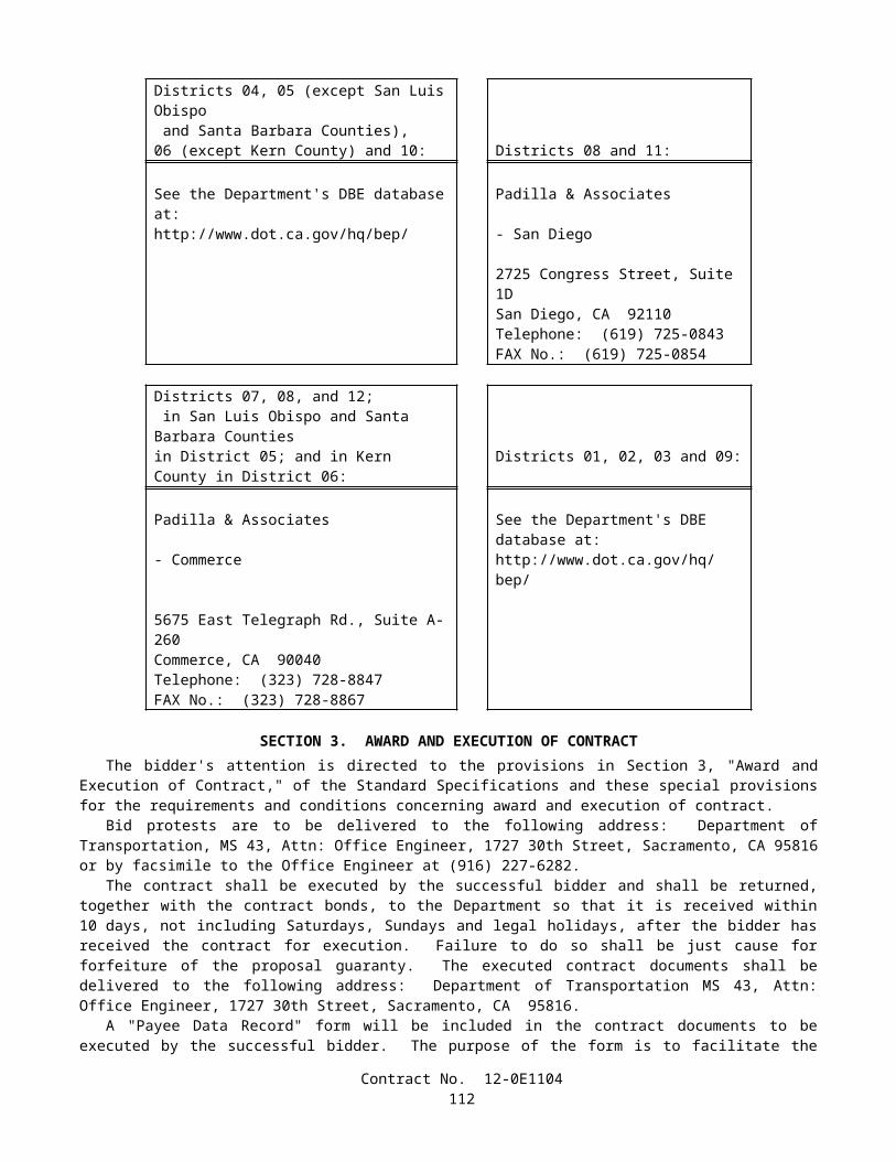
compensated for resulting losses, and an extension of time will be granted, in the same manner as provided for in Section 8-1.09, "Right of Way Delays," of the Standard Specifications.
The WPCP shall incorporate water pollution control practices in the following categories:
A. Soil stabilization.B. Sediment control.C. Wind erosion control.D. Tracking control.E. Non-storm water management.F. Waste management and materials pollution control.
The Contractor shall develop a Water Pollution Control Schedule that describes the timing of grading or other work activities that could affect water pollution. The Water Pollution Control Schedule shall be updated by the Contractor to reflect changes in the Contractor's operations that would affect the necessary implementation of water pollution control practices.
The Contractor shall complete the BMP checklists for each of the six categories presented in Section 3 of the Preparation Manual and shall incorporate the completed checklists and water pollution control practices into Sections 30.1, 30.2, and 30.3 of the WPCP. Water pollution control practices include the "Minimum Requirements" and other Contractor-selected water pollution control practices from the BMP checklists and "Project-Specific Minimum Requirements" identified in the Water Pollution Control Cost Break-Down of this section.
The WPCP shall include, but not be limited to, the items described in the Manuals and related information contained in the contract documents.
The Contractor shall prepare an amendment to the WPCP when there is a change in construction activities or operations which may affect the discharge of pollutants to surface waters, ground waters, municipal storm drain systems, or when the Contractor's activities or operations violate Federal, State or local regulations, or when directed by the Engineer. Amendments shall identify additional water pollution control practices or revised operations, including those areas or operations not identified in the initially approved WPCP. Amendments to the WPCP shall be prepared and submitted for review and approval within a time approved by the Engineer, but in no case longer than the time specified for the initial submittal and review of the WPCP.
The Contractor shall keep one copy of the approved WPCP and approved amendments at the project site. The WPCP shall be made available upon request by a representative of the Regional Water Quality Control Board, State Water Resources Control Board, United States Environmental Protection Agency, or the local storm water management agency. Requests by the public shall be directed to the Engineer.
COST BREAK-DOWNThe Contractor shall include a Water Pollution Control Cost Break-Down in the WPCP which itemizes the contract lump
sum for water pollution control work. The Contractor shall use the Water Pollution Control Cost Break-Down provided in this section as the basis for the cost break-down submitted with the WPCP. The Contractor shall use the Water Pollution Control Cost Break-Down to identify items, quantities and values for water pollution control work, excluding Temporary Water Pollution Control Practices for which there is a separate bid item. The Contractor shall be responsible for the accuracy of the quantities and values used in the cost break-down submitted with the WPCP. Partial payment for the item of water pollution control will not be made until the Water Pollution Control Cost Break-Down is approved by the Engineer.
Line items indicated in the Water Pollution Control Cost Break-Down in this section with a specified Estimated Quantity shall be considered a "Project-Specific Minimum Requirement." The Contractor shall incorporate the items with Contractor-designated quantities and values into the Water Pollution Control Cost Break-Down submitted with the WPCP.
Line items indicated in the Water Pollution Control Cost Break-Down in this section without a specified Estimated Quantity shall be considered by the Contractor for selection to meet the applicable "Minimum Requirements" as defined in the Manuals, or for other water pollution control work as identified in the BMP checklists presented in Section 3 of the Preparation Manual. In the Water Pollution Control Cost Break-Down submitted with the WPCP, the Contractor shall list only those water pollution control practices selected for the project, including quantities and values required to complete the work for those items.
The sum of the amounts for the items of work listed in the Water Pollution Control Cost Break -Down shall be equal to the contract lump sum price bid for water pollution control. Overhead and profit shall be included in each individual item listed in the cost break-down.
Contract No. 12-0E1104114
WATER POLLUTION CONTROL COST BREAK-DOWN
Contract No. 12-0E1104
ITEM ITEM DESCRIPTION UNIT ESTIMATED QUANTITY VALUE AMOUNT
SS-3 Hydraulic Mulch M2
SS-4 Hydroseeding M2
SS-5 Soil Binders M2
SS-6 Straw Mulch M2
SS-7 Geotextiles, Plastic Covers & Erosion Control Blankets/Mats M2
SS-8 Wood Mulching M2
SS-9 Earth Dikes/Drainage Swales & Lined Ditches M
SS-10 Outlet Protection/Velocity Dissipation Devices EA
SS-11 Slope Drains EA
SC-1 Silt Fence M
SC-2 Desilting Basin EA
SC-3 Sediment Trap EA
SC-4 Check Dam EA
SC-5 Fiber Rolls M
SC-6 Gravel Bag Berm M
SC-7 Street Sweeping and Vacuuming LS
SC-8 Sandbag Barrier M
SC-9 Straw Bale Barrier M
SC-10 Storm Drain Inlet Protection EA
WE-1 Wind Erosion Control LS
TC-1 Stabilized Construction Entrance/Exit EA
TC-2 Stabilized Construction Roadway EA
TC-3 Entrance/Outlet Tire Wash EA
NS-1 Water Conservation Practices LS
NS-2 Dewatering Operations EA
NS-3 Paving and Grinding Operations LS
NS-4 Temporary Stream Crossing EA
NS-5 Clear Water Diversion EA
NS-6 Illicit Connection/Illegal Discharge Detection and Reporting LS
Contract No. 12-0E1104115
ITEM ITEM DESCRIPTION UNIT ESTIMATED QUANTITY VALUE AMOUNT
NS-7 Potable Water/Irrigation LS
NS-8 Vehicle and Equipment Cleaning LS
NS-9 Vehicle and Equipment Fueling LS
NS-10 Vehicle and Equipment Maintenance LS
WM-1 Material Delivery and Storage LS
WM-2 Material Use LS
WM-3 Stockpile Management LS
WM-4 Spill Prevention and Control LS
WM-5 Solid Waste Management LS
WM-6 Hazardous Waste Management LS
WM-7 Contaminated Soil Management LS
WM-8 Concrete Waste Management LS
WM-9 Sanitary/Septic Waste Management LS
WM-10 Liquid Waste Management LS
TOTAL ____________________
Contract No. 12-0E1104116
Adjustments in the items of work and quantities listed in the approved cost break-down shall be made when required to address amendments to the WPCP, except when the adjusted items are paid for as extra work.
No adjustment in compensation will be made to the contract lump sum price paid for water pollution control due to differences between the quantities shown in the approved cost break-down and the quantities required to complete the work as shown on the approved WPCP. No adjustment in compensation will be made for ordered changes to correct WPCP work resulting from the Contractor's own operations or from the Contractor's negligence.
The approved cost break-down will be used to determine partial payments during the progress of the work and as the basis for calculating the adjustment in compensation for the item of water pollution control due to increases or decreases of quantities ordered by the Engineer. When an ordered change increases or decreases the quantities of an approved cost break-down item, the adjustment in compensation will be determined in the same manner specified for increases and decreases in the quantity of a contract item of work in conformance with the provisions in Section 4-1.03B, "Increased or Decreased Quantities," of the Standard Specifications. If an ordered change requires a new item which is not on the approved cost break-down, the adjustment in compensation will be determined in the same manner specified for extra work in conformance with Section 4-1.03D, "Extra Work," of the Standard Specifications.
If requested by the Contractor and approved by the Engineer, changes to the water pollution control practices listed in the approved cost break-down, including addition of new water pollution control practices, will be allowed. Changes shall be included in the approved amendment of the WPCP. If the requested changes result in a net cost increase to the lump sum price for water pollution control, an adjustment in compensation will be made without change to the water pollution control item. The net cost increase to the water pollution control item will be paid for as extra work as provided in Section 4 -1.03D, "Extra Work," of the Standard Specifications.
WPCP IMPLEMENTATIONUnless otherwise specified, upon approval of the WPCP, the Contractor shall be responsible throughout the duration of
the project for installing, constructing, inspecting, maintaining, removing, and disposing of the water pollution control practices specified in the WPCP and in the amendments. Unless otherwise directed by the Engineer, the Contractor's responsibility for WPCP implementation shall continue throughout any temporary suspension of work ordered in conformance with the provisions in Section 8-1.05, "Temporary Suspension of Work," of the Standard Specifications. Requirements for installation, construction, inspection, maintenance, removal, and disposal of water pollution control practices shall conform to the requirements in the Manuals and these special provisions.
If the Contractor or the Engineer identifies a deficiency in the implementation of the approved WPCP or amendments, the deficiency shall be corrected immediately. The deficiency may be corrected at a later date and time if requested by the Contractor and approved by the Engineer in writing, but shall be corrected prior to the onset of precipitation. If the Contractor fails to correct the identified deficiency by the date agreed or prior to the onset of precipitation, the project shall be in nonconformance with this section. Attention is directed to Section 5-1.01, "Authority of Engineer," of the Standard Specifications, and to "Retention of Funds" of this section for possible nonconformance penalties.
If the Contractor fails to conform to the provisions of this section, "Water Pollution Control," the Engineer may order the suspension of construction operations until the project complies with the requirements of this section.
Implementation of water pollution control practices may vary by season. The Construction Site BMPs Manual and these special provisions shall be followed for control practice selection of year-round, rainy season and non-rainy season water pollution control practices.
Year-Round Implementation RequirementsThe Contractor shall have a year-round program for implementing, inspecting and maintaining water pollution control
practices for wind erosion control, tracking control, non-storm water management, and waste management and materials pollution control.
The National Weather Service weather forecast shall be monitored and used by the Contractor on a daily basis. An alternative weather forecast proposed by the Contractor may be used if approved by the Engineer. If precipitation is predicted, the necessary water pollution control practices shall be deployed prior to the onset of the precipitation.
Disturbed soil areas shall be considered active whenever the soil disturbing activities have occurred, continue to occur or will occur during the ensuing 21 days. Nonactive areas shall be protected as prescribed in the Construction Site BMPs Manual within 14 days of cessation of soil disturbing activities or prior to the onset of precipitation, whichever occurs first.
Rainy Season Implementation RequirementsSoil stabilization and sediment control practices conforming to the requirements of these special provisions shall be
provided throughout the rainy season, defined as between October 1 and May 1.An implementation schedule of required soil stabilization and sediment control practices for disturbed soil areas shall be
completed no later than 20 days prior to the beginning of each rainy season. The implementation schedule shall identify the Contract No. 12-0E1104
117
soil stabilization and sediment control practices and the dates when the implementation will be 25 percent, 50 percent and 100 percent complete, respectively. For construction activities beginning during the rainy season, the Contractor shall implement applicable soil stabilization and sediment control practices.
Non-Rainy Season Implementation RequirementsThe non-rainy season shall be defined as days outside the defined rainy season. The Contractor's attention is directed to
the Construction Site BMPs Manual for soil stabilization and sediment control implementation requirements on disturbed soil areas during the non-rainy season. Disturbed soil areas within the project shall be protected in conformance with the requirements in the Construction Site BMPs Manual with an effective combination of soil stabilization and sediment control.
MAINTENANCETo ensure the proper implementation and functioning of water pollution control practices, the Contractor shall regularly
inspect and maintain the construction site for the water pollution control practices identified in the WPCP. The construction site shall be inspected by the Contractor as follows:
A. Prior to a forecast storm.B. After a precipitation event which causes site runoff.C. At 24 hour intervals during extended precipitation events.D. Routinely, a minimum of once every two weeks outside of the defined rainy season.E. Routinely, a minimum of once every week during the defined rainy season.
The Contractor shall use the Storm Water Quality Construction Site Inspection Checklist provided in the Preparation Manual or an alternative inspection checklist provided by the Engineer. One copy of each site inspection record shall be submitted to the Engineer within 24 hours of completing the inspection.
REPORTING REQUIREMENTSReport of Discharges, Notices or Orders
If the Contractor identifies discharges into surface waters or drainage systems in a manner causing, or potentially causing, a condition of pollution, or if the project receives a written notice or order from a regulatory agency, the Contractor shall immediately inform the Engineer. The Contractor shall submit a written report to the Engineer within 7 days of the discharge event, notice or order. The report shall include the following information:
A. The date, time, location, nature of the operation, and type of discharge, including the cause or nature of the notice or order.
B. The water pollution control practices deployed before the discharge event, or prior to receiving the notice or order.C. The date of deployment and type of water pollution control practices deployed after the discharge event, or after
receiving the notice or order, including additional measures installed or planned to reduce or prevent reoccurrence.D. An implementation and maintenance schedule for affected water pollution control practices.
Report of First-Time Non-Storm Water DischargeThe Contractor shall notify the Engineer at least 3 days in advance of first-time non-storm water discharge events. The
Contractor shall notify the Engineer of the operations causing non-storm water discharges and shall obtain field approval for first-time non-storm water discharges. Non-storm water discharges shall be monitored at first-time occurrences and routinely thereafter.
PAYMENTThe contract lump sum price paid for prepare water pollution control program shall include full compensation for
furnishing all labor, materials, tools, equipment, and incidentals for doing all the work involved in developing, preparing, obtaining approval of, revising, and amending the WPCP, as specified in the Standard Specifications and these special provisions, and as directed by the Engineer.
Attention is directed to Section 9-1.06, "Partial Payments," and Section 9-1.07, "Payment After Acceptance," of the Standard Specifications. Payments for Prepare Water Pollution Control Program will be made as follows:
A. After the WPCP has been approved by the Engineer, 75 percent of the contract item price for Prepare Water Pollution Control Program will be included in the monthly partial payment estimate.
Contract No. 12-0E1104118
B. After acceptance of the contract in conformance with the provisions in Section 7-1.17, "Acceptance of Contract," of the Standard Specifications, payment for the remaining 25 percent of the contract item price for Prepare Water Pollution Control Program will be made in conformance with the provisions in Section 9-1.07.
The contract lump sum price paid for water pollution control shall include full compensation for furnishing all labor, materials, tools, equipment, and incidentals, and for doing all the work involved in installing, constructing, maintaining, removing, and disposing of water pollution control practices, including non-storm water management, and waste management and materials pollution water pollution control practices, except those for which there is a contract item of work as specified in the Standard Specifications and these special provisions, and as directed by the Engineer.
Water pollution control practices for which there is a contract item of work will be measured and paid for as that contract item of work.
10-1.03 TEMPORARY MULCHTemporary mulch shall conform to the provisions for mulch in Section 20-4, "Highway Planting," of the Standard
Specifications and these special provisions.Temporary mulch shall consist of applying mulch at the rate specified herein to excavation and embankment slopes of
the maintenance vehicle pullouts or as directed by the Engineer. Temporary mulch shall extend to the edge of dikes and paving.
Attention is directed to "Water Pollution Control" of these special provisions.
MATERIALSMaterials shall conform to the provisions in Section 20-2, "Materials," of the Standard Specifications and the following:
MulchMulch shall be woody material consisting of chipped, shredded or ground green materials such as shrubs, tree trimmings
or clean processed wood products. Deleterious materials such as rocks, glass, plastics, metals, clods, weeds, weed seeds, coarse objects, sticks larger than the specified particle size, salts, paint, petroleum products, pesticides or other chemical residues that would be harmful to plant or animal life shall not exceed 0.1 percent of the mulch by volume. Chipping shall include shredding, grinding or any other method used to reduce mulch materials to the specified size. At least 85 percent of the mulch, by volume, shall conform to either the particle size specified for wood chips or to the particle size specified for shredded bark in Section 20-2.08, "Mulch," of the Standard Specifications. Materials shall be composted and have reached an internal temperature of 56°C for a minimum of 15 consecutive days. During the composting process the compost shall have been turned a minimum of 5 times.
Plant material that has been reduced to chips, as provided in "Clearing and Grubbing" elsewhere in these special provisions, may be substituted for mulch.
APPLICATIONTemporary mulch shall be applied as follows:
A. Mulch shall be applied at a uniform depth of 75 mm.
MEASUREMENT AND PAYMENTTemporary mulch will be measured and paid for by the cubic meter in the same manner specified for mulch in Section
20-4.09, "Measurement," and Section 20-4.10, "Payment," of the Standard Specifications.Temporary mulch placed at locations other than excavation and embankment slopes of maintenance vehicle pullouts as
directed by the Engineer, in conformance with the Contractor's Water Pollution Control Program, will not be measured and will be paid for as specified in "Water Pollution Control" of these special provisions.
10-1.04 PRESERVATION OF PROPERTYAttention is directed to Section 7-1.11, "Preservation of Property," of the Standard Specifications and these special
provisions.Existing trees, shrubs and other plants, that are not to be removed as shown on the plans or specified in these special
provisions, and are injured or damaged by reason of the Contractor's operations, shall be replaced by the Contractor. The minimum size of tree replacement shall be 600 mm box and the minimum size of shrub replacement shall be No. 15 container. Replacement ground cover plants shall be from flats and shall be planted 300 mm on center. Replacement of
Contract No. 12-0E1104119
Carpobrotus ground cover plants shall be from cuttings and shall be planted 300 mm on center. Replacement planting shall conform to the requirements in Section 20-4.07, "Replacement," of the Standard Specifications. The Contractor shall water replacement plants in conformance with the provisions in Section 20-4.06, "Watering," of the Standard Specifications.
Damaged or injured plants shall be removed and disposed of outside the highway right of way in conformance with the provisions in Section 7-l.13 of the Standard Specifications. At the option of the Contractor, removed trees and shrubs may be reduced to chips. The chipped material shall be spread within the highway right of way at locations designated by the Engineer.
Replacement planting of injured or damaged trees, shrubs and other plants shall be completed not less than 20 working days prior to acceptance of the contract. Replacement plants shall be watered as necessary to maintain the plants in a healthy condition.
10-1.05 COOPERATIONAttention is directed to Section 7-1.14, "Cooperation," and Section 8-1.10, "Utility and Non-Highway Facilities," of the
Standard Specifications and these special provisions.Daily toll plaza operations will be in progress adjacent to or within the limits of this project during progress of the work
on this contract.
10-1.06 SOLID WASTE DISPOSAL AND RECYCLING REPORTThis work shall consist of reporting disposal and recycling of construction solid waste, as specified in these special
provisions. For the purposes of this section, solid waste includes construction and demolition waste debris, but not hazardous waste.
Annually by the fifteenth day of January, the Contractor shall complete and certify Form CEM-2025, "Solid Waste Disposal and Recycling Report," which quantifies solid waste generated by the work performed and disposed of in landfills or recycled during the previous calendar year. The amount and type of solid waste disposed of or recycled shall be reported in either metric tonnes or cubic meters. The Contractor shall also complete and certify Form CEM-2025 within 5 days following contract acceptance.
Form CEM-2025, "Solid Waste Disposal and Recycling Report" can be downloaded from the following website:
http://www.dot.ca.gov/hq/construc/manual2001
If the Contractor has not submitted Form CEM-2025, by the dates specified above, the Department will withhold the amount of $10,000 for each missing or incomplete report. The moneys withheld will be released for payment on the next monthly estimate for partial payment following the date that a complete and acceptable Form CEM-2025 is submitted to the Engineer. Upon completion of all contract work and submittal of the final Form CEM-2025, remaining withheld funds associated with this section, "Solid Waste Disposal and Recycling Report," will be released for payment. Withheld funds in conformance with this section shall be in addition to other moneys withheld provided for in the contract. No interest will be due the Contractor on withheld amounts.
Full compensation for preparing and submitting Form CEM-2025, "Solid Waste Disposal and Recycling Report," shall be considered as included in the contract price for the various items of work involved and no additional compensation will be allowed therefor.
10-1.07 PROGRESS SCHEDULE (CRITICAL PATH METHOD)The Contractor shall submit to the Engineer practicable critical path method (CPM) progress schedules in conformance
with these special provisions. Whenever the term "schedule" is used in this section it shall mean CPM progress schedule.Attention is directed to "Payments" of Section 5 of these special provisions.The provisions in Section 8-1.04, "Progress Schedule," of the Standard Specifications shall not apply.
DEFINITIONSThe following definitions shall apply to this section:
A. ACTIVITY.—A task, event or other project element on a schedule that contributes to completing the project. Activities have a description, start date, finish date, duration and one or more logic ties.
B. BASELINE SCHEDULE.—The initial schedule representing the Contractor's work plan on the first working day of the project.
C. CONTRACT COMPLETION DATE.—The current extended date for completion of the contract shown on the weekly statement of working days furnished by the Engineer in conformance with the provisions in Section 8-1.06, "Time of Completion," of the Standard Specifications.
Contract No. 12-0E1104120
D. CRITICAL PATH.—The longest continuous chain of activities for the project that has the least amount of total float of all chains. In general, a delay on the critical path will extend the scheduled completion date.
E. CRITICAL PATH METHOD (CPM).—A network based planning technique using activity durations and the relationships between activities to mathematically calculate a schedule for the entire project.
F. DATA DATE.—The day after the date through which a schedule is current. Everything occurring earlier than the data date is "as-built" and everything on or after the data date is "planned."
G. EARLY COMPLETION TIME.—The difference in time between an early scheduled completion date and the contract completion date.
H. FLOAT.—The difference between the earliest and latest allowable start or finish times for an activity.I. MILESTONE.—An event activity that has zero duration and is typically used to represent the beginning or end of a
certain stage of the project.J. NARRATIVE REPORT.—A document submitted with each schedule that discusses topics related to project
progress and scheduling. K. NEAR CRITICAL PATH.—A chain of activities with total float exceeding that of the critical path but having no
more than 10 working days of total float.L. SCHEDULED COMPLETION DATE.—The planned project finish date shown on the current accepted schedule.M. STATE OWNED FLOAT ACTIVITY.—The activity documenting time saved on the critical path by actions of the
State. It is the last activity prior to the scheduled completion date.N. TIME IMPACT ANALYSIS.—A schedule and narrative report developed specifically to demonstrate what effect a
proposed change or delay has on the current scheduled completion date.O. TOTAL FLOAT.—The amount of time that an activity or chain of activities can be delayed before extending the
scheduled completion date.P. UPDATE SCHEDULE.—A current schedule developed from the baseline or subsequent schedule through regular
monthly review to incorporate as-built progress and any planned changes.
GENERAL REQUIREMENTSThe Contractor shall submit to the Engineer baseline, monthly update and final update schedules, each consistent in all
respects with the time and order of work requirements of the contract. The project work shall be executed in the sequence indicated on the current accepted schedule.
Schedules shall show the order in which the Contractor proposes to carry out the work with logical links between time-scaled work activities, and calculations made using the critical path method to determine the controlling operation or operations. The Contractor is responsible for assuring that all activity sequences are logical and that each schedule shows a coordinated plan for complete performance of the work.
The Contractor shall produce schedules using computer software and shall furnish compatible software for the Engineer's exclusive possession and use. The Contractor shall furnish network diagrams, narrative reports, tabular reports and schedule data as parts of each schedule submittal.
Schedules shall include, but not be limited to, activities that show the following that are applicable to the project:
A. Project characteristics, salient features, or interfaces, including those with outside entities, that could affect time of completion.
B. Project start date, scheduled completion date and other milestones.C. Work performed by the Contractor, subcontractors and suppliers.D. Submittal development, delivery, review and approval, including those from the Contractor, subcontractors and
suppliers.E. Procurement, delivery, installation and testing of materials, plants and equipment.F. Testing and settlement periods.G. Utility notification and relocation.H. Erection and removal of falsework and shoring.I. Major traffic stage switches.J. Finishing roadway and final cleanup.K. State-owned float as the predecessor activity to the scheduled completion date.
Schedules shall have not less than 50 and not more than 500 activities, unless otherwise authorized by the Engineer. The number of activities shall be sufficient to assure adequate planning of the project, to permit monitoring and evaluation of progress, and to do an analysis of time impacts.
Contract No. 12-0E1104121
Schedule activities shall include the following:
A. A clear and legible description.B. Start and finish dates.C. A duration of not less than one working day, except for event activities, and not more than 20 working days, unless
otherwise authorized by the Engineer.D. At least one predecessor and one successor activity, except for project start and finish milestones.E. Required constraints.F. Codes for responsibility, stage, work shifts, location and contract pay item numbers.
The Contractor may show early completion time on any schedule provided that the requirements of the contract are met. Early completion time shall be considered a resource for the exclusive use of the Contractor. The Contractor may increase early completion time by improving production, reallocating resources to be more efficient, performing sequential activities concurrently or by completing activities earlier than planned. The Contractor may also submit for approval a cost reduction incentive proposal in conformance with the provisions in Section 5-1.14, "Cost Reduction Incentive," of the Standard Specifications that will reduce time of construction.
The Contractor may show a scheduled completion date that is later than the contract completion date on an update schedule, after the baseline schedule is accepted. The Contractor shall provide an explanation for a late scheduled completion date in the narrative report that is included with the schedule.
State-owned float shall be considered a resource for the exclusive use of the State. The Engineer may accrue State-owned float by the early completion of review of any type of required submittal when it saves time on the critical path. The Contractor shall prepare a time impact analysis, when requested by the Engineer, to determine the effect of the action in conformance with the provisions in "Time Impact Analysis" specified herein. The Engineer will document State-owned float by directing the Contractor to update the State-owned float activity on the next update schedule. The Contractor shall include a log of the action on the State-owned float activity and include a discussion of the action in the narrative report. The Engineer may use State-owned float to mitigate past, present or future State delays by offsetting potential time extensions for contract change orders.
The Engineer may adjust contract working days for ordered changes that affect the scheduled completion date, in conformance with the provisions in Section 4-1.03, "Changes," of the Standard Specifications. The Contractor shall prepare a time impact analysis to determine the effect of the change in conformance with the provisions in "Time Impact Analysis" specified herein, and shall include the impacts acceptable to the Engineer in the next update schedule. Changes that do not affect the controlling operation on the critical path will not be considered as the basis for a time adjustment. Changes that do affect the controlling operation on the critical path will be considered by the Engineer in decreasing time or granting an extension of time for completion of the contract. Time extensions will only be granted if the total float is absorbed and the scheduled completion date is delayed one or more working days because of the ordered change.
The Engineer's review and acceptance of schedules shall not waive any contract requirements and shall not relieve the Contractor of any obligation thereunder or responsibility for submitting complete and accurate information. Schedules that are rejected shall be corrected by the Contractor and resubmitted to the Engineer within 5 working days of notification by the Engineer, at which time a new review period of one week will begin.
Errors or omissions on schedules shall not relieve the Contractor from finishing all work within the time limit specified for completion of the contract. If, after a schedule has been accepted by the Engineer, either the Contractor or the Engineer discover that any aspect of the schedule has an error or omission, it shall be corrected by the Contractor on the next update schedule.
COMPUTER SOFTWAREThe Contractor shall submit to the Engineer for approval a description of proposed software before delivery. The
software shall be the current version of Primavera SureTrak Project Manager for Windows, or equal, and shall be compatible with Windows NT (version 4.0) operating system. If software other than SureTrak is proposed, it shall be capable of generating files that can be imported into SureTrak.
The Contractor shall furnish schedule software and all original software instruction manuals to the Engineer with submittal of the baseline schedule. The furnished schedule software shall become the property of the State and will not be returned to the Contractor. The State will compensate the Contractor in conformance with the provisions in Section 4-1.03, "Extra Work," of the Standard Specifications for replacement of software which is damaged, lost or stolen after delivery to the Engineer.
The Contractor shall instruct the Engineer in the use of the software and provide software support until the contract is accepted. Within 20 working days of contract approval, the Contractor shall provide a commercial 8-hour training session for 2 Department employees in the use of the software at a location acceptable to the Engineer. It is recommended that the Contractor also send at least 2 employees to the same training session to facilitate development of similar knowledge and
Contract No. 12-0E1104122
skills in the use of the software. If software other than SureTrak is furnished, then the training session shall be a total of 16-hours for each Department employee.
NETWORK DIAGRAMS, REPORTS AND DATAThe Contractor shall include the following for each schedule submittal:
A. Two sets of originally plotted, time-scaled network diagrams.B. Two copies of a narrative report.C. Two copies of each of 3 sorts of the CPM software-generated tabular reports.D. One 1.44-megabyte 90 mm (3.5 inch) floppy diskette containing the schedule data.
The time-scaled network diagrams shall conform to the following:
A. Show a continuous flow of information from left to right.B. Be based on early start and early finish dates of activities.C. Clearly show the primary paths of criticality using graphical presentation.D. Be prepared on E-size sheets, 860 mm x 1120 mm (34 inch x 44 inch).E. Include a title block and a timeline on each page.
The narrative report shall be organized in the following sequence with all applicable documents included:
A. Contractor's transmittal letter.B. Work completed during the period.C. Identification of unusual conditions or restrictions regarding labor, equipment or material; including multiple shifts,
6-day work weeks, specified overtime or work at times other than regular days or hours.D. Description of the current critical path.E. Changes to the critical path and scheduled completion date since the last schedule submittal.F. Description of problem areas.G. Current and anticipated delays:
1. Cause of delay.2. Impact of delay on other activities, milestones and completion dates.3. Corrective action and schedule adjustments to correct the delay.
H. Pending items and status thereof:
1. Permits2. Change orders3. Time adjustments4. Non-compliance notices
I. Reasons for an early or late scheduled completion date in comparison to the contract completion date.
Tabular reports shall be software-generated and provide information for each activity included in the project schedule. Three different reports shall be sorted by (1) activity number, (2) early start and (3) total float. Tabular reports shall be 215 mm x 280 mm (8 1/2 inch x 11 inch) in size and shall include, as a minimum, the following applicable information:
A. Data dateB. Activity number and descriptionC. Predecessor and successor activity numbers and descriptionsD. Activity codesE. Scheduled, or actual and remaining durations (work days) for each activityF. Earliest start (calendar) dateG. Earliest finish (calendar) dateH. Actual start (calendar) dateI. Actual finish (calendar) dateJ. Latest start (calendar) dateK. Latest finish (calendar) date
Contract No. 12-0E1104123
L. Free float (work days)M. Total float (work days)N. Percentage of activity complete and remaining duration for incomplete activities.O. LagsP. Required constraints
Schedule submittals will only be considered complete when all documents and data have been provided as described above.
PRE-CONSTRUCTION SCHEDULING CONFERENCEThe Contractor shall schedule and the Engineer will conduct a pre-construction scheduling conference with the
Contractor's project manager and construction scheduler within 10 working days of the approval of the contract. At this meeting the Engineer will review the requirements of this section of the special provisions with the Contractor.
The Contractor shall submit a general time-scaled logic diagram displaying the major activities and sequence of planned operations and shall be prepared to discuss the proposed work plan and schedule methodology that comply with the requirements of these special provisions. If the Contractor proposes deviations to the construction staging of the project, then the general time-scaled logic diagram shall also display the deviations and resulting time impacts. The Contractor shall be prepared to discuss the proposal.
At this meeting, the Contractor shall additionally submit the alphanumeric coding structure and the activity identification system for labeling the work activities. To easily identify relationships, each activity description shall indicate its associated scope or location of work by including such terms as quantity of material, type of work, bridge number, station to station location, side of highway (such as left, right, northbound, southbound), lane number, shoulder, ramp name, ramp line descriptor or mainline.
The Engineer will review the logic diagram, coding structure, and activity identification system, and provide any required baseline schedule changes to the Contractor for implementation.
BASELINE SCHEDULEBeginning the week following the pre-construction scheduling conference, the Contractor shall meet with the Engineer
weekly until the baseline schedule is accepted by the Engineer to discuss schedule development and resolve schedule issues.The Contractor shall submit to the Engineer a baseline schedule within 20 working days of approval of the contract. The
Contractor shall allow 3 weeks for the Engineer's review after the baseline schedule and all support data are submitted. In addition, the baseline schedule submittal will not be considered complete until the computer software is delivered and installed for use in review of the schedule.
The baseline schedule shall include the entire scope of work and how the Contractor plans to complete all work contemplated. The baseline schedule shall show the activities that define the critical path. Multiple critical paths and near-critical paths shall be kept to a minimum. A total of not more than 50 percent of the baseline schedule activities shall be critical or near critical, unless otherwise authorized by the Engineer.
The baseline schedule shall not extend beyond the number of working days specified in these special provisions. The baseline schedule shall have a data date of the first working day of the contract and not include any completed work to date. The baseline schedule shall not attribute negative float or negative lag to any activity.
If the Contractor submits an early completion baseline schedule that shows contract completion in less than 85 percent of the working days specified in these special provisions, the baseline schedule shall be supplemented with resource allocations for every task activity and include time-scaled resource histograms. The resource allocations shall be shown to a level of detail that facilitates report generation based on labor crafts and equipment classes for the Contractor and subcontractors. The Contractor shall use average composite crews to display the labor loading of on-site construction activities. The Contractor shall optimize and level labor to reflect a reasonable plan for accomplishing the work of the contract and to assure that resources are not duplicated in concurrent activities. The time-scaled resource histograms shall show labor crafts and equipment classes to be utilized on the contract. The Engineer may review the baseline schedule activity resource allocations using Means Productivity Standards or equivalent to determine if the schedule is practicable.
UPDATE SCHEDULEThe Contractor shall submit an update schedule and meet with the Engineer to review contract progress, on or before the
first day of each month, beginning one month after the baseline schedule is accepted. The Contractor shall allow 2 weeks for the Engineer's review after the update schedule and all support data are submitted, except that the review period shall not start until the previous month's required schedule is accepted. Update schedules that are not accepted or rejected within the review period will be considered accepted by the Engineer.
The update schedule shall have a data date of the twenty-first day of the month or other date established by the Engineer. The update schedule shall show the status of work actually completed to date and the work yet to be performed as planned.
Contract No. 12-0E1104124
Actual activity start dates, percent complete and finish dates shall be shown as applicable. Durations for work that has been completed shall be shown on the update schedule as the work actually occurred, including Engineer submittal review and Contractor resubmittal times.
The Contractor may include modifications such as adding or deleting activities or changing activity constraints, durations or logic that do not (1) alter the critical path(s) or near critical path(s) or (2) extend the scheduled completion date compared to that shown on the current accepted schedule. The Contractor shall state in writing the reasons for any changes to planned work. If any proposed changes in planned work will result in (1) or (2) above, then the Contractor shall submit a time impact analysis as described herein.
TIME IMPACT ANALYSISThe Contractor shall submit a written time impact analysis (TIA) to the Engineer with each request for adjustment of
contract time, or when the Contractor or Engineer consider that an approved or anticipated change may impact the critical path or contract progress.
The TIA shall illustrate the impacts of each change or delay on the current scheduled completion date or internal milestone, as appropriate. The analysis shall use the accepted schedule that has a data date closest to and prior to the event. If the Engineer determines that the accepted schedule used does not appropriately represent the conditions prior to the event, the accepted schedule shall be updated to the day before the event being analyzed. The TIA shall include an impact schedule developed from incorporating the event into the accepted schedule by adding or deleting activities, or by changing durations or logic of existing activities. If the impact schedule shows that incorporating the event modifies the critical path and scheduled completion date of the accepted schedule, the difference between scheduled completion dates of the two schedules shall be equal to the adjustment of contract time. The Engineer may construct and utilize an appropriate project schedule or other recognized method to determine adjustments in contract time until the Contractor provides the TIA.
The Contractor shall submit a TIA in duplicate within 15 working days of receiving a written request for a TIA from the Engineer. The Contractor shall allow the Engineer 2 weeks after receipt to approve or reject the submitted TIA. All approved TIA schedule changes shall be shown on the next update schedule.
If a TIA submitted by the Contractor is rejected by the Engineer, the Contractor shall meet with the Engineer to discuss and resolve issues related to the TIA. If agreement is not reached, the Contractor will be allowed 15 days from the meeting with the Engineer to give notice in conformance with the provisions in Section 9-1.04, "Notice of Potential Claim," of the Standard Specifications. The Contractor shall only show actual as-built work, not unapproved changes related to the TIA, in subsequent update schedules. If agreement is reached at a later date, approved TIA schedule changes shall be shown on the next update schedule. The Engineer will withhold remaining payment on the schedule contract item if a TIA is requested by the Engineer and not submitted by the Contractor within 15 working days. The schedule item payment will resume on the next estimate after the requested TIA is submitted. No other contract payment will be retained regarding TIA submittals.
FINAL UPDATE SCHEDULEThe Contractor shall submit a final update, as-built schedule with actual start and finish dates for the activities, within
30 days after completion of contract work. The Contractor shall provide a written certificate with this submittal signed by the Contractor's project manager and an officer of the company stating, "To my knowledge and belief, the enclosed final update schedule reflects the actual start and finish dates of the actual activities for the project contained herein." An officer of the company may delegate in writing the authority to sign the certificate to a responsible manager.
RETENTIONThe Department will retain an amount equal to 25 percent of the estimated value of the work performed during each
estimate period in which the Contractor fails to submit an acceptable schedule conforming to the requirements of these special provisions as determined by the Engineer. Schedule retentions will be released for payment on the next monthly estimate for partial payment following the date that acceptable schedules are submitted to the Engineer or as otherwise specified herein. Upon completion of all contract work and submittal of the final update schedule and certification, any remaining retained funds associated with this section, "Progress Schedule (Critical Path Method)", will be released for payment. Retentions held in conformance with this section shall be in addition to other retentions provided for in the contract. No interest will be due the Contractor on retention amounts.
PAYMENTProgress schedule (critical path method) will be paid for at a lump sum price. The contract lump sum price paid for
progress schedule (critical path method) shall include full compensation for furnishing all labor, material, tools, equipment, and incidentals, including computer software, and for doing all the work involved in preparing, furnishing, and updating schedules, and instructing and assisting the Engineer in the use of computer software, as specified in the Standard Specifications and these special provisions, and as directed by the Engineer.
Contract No. 12-0E1104125
Payments for the progress schedule (critical path method) contract item will be made progressively as follows:
A. A total of 25 percent of the item amount or a total of 25 percent of the amount listed for progress schedule (critical path method) in "Payments" of Section 5 of these special provisions, whichever is less, will be paid upon achieving all of the following:
1. Completion of 5 percent of all contract item work.2. Acceptance of all schedules and TIAs required to the time when 5 percent of all contract item work is complete.3. Delivery of schedule software to the Engineer.4. Completion of required schedule software training.
B. A total of 50 percent of the item amount or a total of 50 percent of the amount listed for progress schedule (critical path method) in "Payments" of Section 5 of these special provisions, whichever is less, will be paid upon completion of 25 percent of all contract item work and acceptance of all schedules and TIAs required to the time when 25 percent of all contract item work is complete.
C. A total of 75 percent of the item amount or a total of 75 percent of the amount listed for progress schedule (critical path method) in "Payments" of Section 5 of these special provisions, whichever is less, will be paid upon completion of 50 percent of all contract item work and acceptance of all schedules and TIAs required to the time when 50 percent of all contract item work is complete.
D. A total of 100 percent of the item amount or a total of 100 percent of the amount listed for progress schedule (critical path method) in "Payments" of Section 5 of these special provisions, whichever is less, will be paid upon completion of all contract item work, acceptance of all schedules and TIAs required to the time when all contract item work is complete, and submittal of the certified final update schedule.
If the Contractor fails to complete any of the work or provide any of the schedules required by this section, the Engineer shall make an adjustment in compensation in conformance with the provisions in Section 4-1.03C, "Changes in Character of Work," of the Standard Specifications for the work not performed. Adjustments in compensation for schedules will not be made for any increased or decreased work ordered by the Engineer in furnishing schedules.
10-1.08 TIME-RELATED OVERHEADThe Contractor will be compensated for time-related overhead as described below and in conformance with “Force
Account Payment” of these special provisions. The Contractor will not be compensated for time-related overhead for delays to the controlling operations caused by the Engineer that occur prior to the first working day, but will be compensated for actual overhead costs incurred, as determined by an independent Certified Public Accountant audit examination and report.
Attention is directed to "Beginning of Work, Time of Completion and Liquidated Damages," "Force Account Payment," and "Progress Schedule (Critical Path Method)" of these special provisions.
The provisions in Section 9-1.08, "Adjustment of Overhead Costs," of the Standard Specifications shall not apply.Time-related overhead shall consist of those overhead costs, including field and home office overhead, that are in
proportion to the time required to complete the work. Time-related overhead shall not include costs that are not related to time, including but not limited to, mobilization, licenses, permits, and other charges incurred only once during the contract. Time-related overhead shall not apply to subcontractors of any tier, suppliers, fabricators, manufacturers, or other parties associated with the Contractor.
Field office overhead expenses include time-related costs associated with the normal and recurring operations of the construction project, and shall not include costs directly attributable to the work of the contract. Time-related costs of field office overhead include, but are not limited to, salaries, benefits, and equipment costs of project managers, general superintendents, field office managers and other field office staff assigned to the project, and rent, utilities, maintenance, security, supplies, and equipment costs of the project field office.
Home office overhead or general and administrative expenses refer to the fixed costs of operating the Contractor's business. These costs include, but are not limited to, general administration, insurance, personnel and subcontract administration, purchasing, accounting, and project engineering and estimating. Home office overhead costs shall exclude expenses specifically related to other contracts or other businesses of the Contractor, equipment coordination, material deliveries, and consultant and legal fees.
The quantity of time-related overhead associated with a reduction in contract time for cost reduction incentive proposals accepted and executed in conformance with the provisions in Section 5-1.14, "Cost Reduction Incentive," of the Standard Specifications shall be considered a construction cost attributable to the resultant estimated net savings due to the cost reduction incentive.
If the final increased quantity of time-related overhead exceeds 149 percent of the number of working days specified in the Engineer's Estimate, the Contractor shall, within 60 days of the Engineer's written request, submit to the Engineer an
Contract No. 12-0E1104126
audit examination and report performed by an independent Certified Public Accountant of the Contractor's actual overhead costs. The audit examination and report shall depict the Contractor's project and company-wide financial records and shall specify the actual overall average daily rates for both field and home office overhead for the entire duration of the project, and whether the costs have been properly allocated. The rates of field and home office overhead shall exclude unallowable costs as determined in the Federal Acquisition Regulations, 48 CFR, Chapter 1, Part 31.
Independent Certified Public Accountant's audit examinations shall be performed in conformance with the requirements of the American Institute of Certified Public Accountants Attestation Standards. Audit examinations and reports shall determine if the rates of field office overhead and home office overhead are:
A. Allowable in conformance with the requirements of the Federal Acquisition Regulations, 48 CFR, Chapter 1, Part 31.
B. Adequately supported by reliable documentation.C. Related solely to the project under examination.
Within 20 days of receipt of the Engineer's written request, the Contractor shall make its financial records available for audit by the State for the purpose of verifying the actual rate of time-related overhead specified in the audit submitted by the Contractor. The actual rate of time-related overhead specified in the audit, submitted by the Contractor, will be subject to approval by the Engineer.
If the Engineer requests the independent Certified Public Accountant audit, or if it is requested in writing by the Contractor, the contract item payment rate for time-related overhead, in excess of 149 percent of the number of working days specified in the Engineer's Estimate, will be adjusted to reflect the actual rate.
The cost of performing an independent Certified Public Accountant audit examination and submitting the report, requested by the Engineer, will be borne equally by the State and the Contractor. The division of the cost will be made by determining the cost of providing an audit examination and report in conformance with the provisions of Section 9-1.03B, "Work Performed by Special Forces or Other Special Services," of the Standard Specifications, and paying to the Contractor one-half of that cost. The cost of performing an audit examination and submitting the independent Certified Public Accountant audit report for overhead claims other than for the purpose of verifying the actual rate of time-related overhead shall be entirely borne by the Contractor. The cost of performing an audit examination and submitting the independent Certified Public Accountant audit report to verify actual overhead costs incurred prior to the first working day shall be entirely borne by the Contractor.
The quantity of time-related overhead to be paid will be measured by the working day, designated in the Engineer's Estimate as WDAY. The estimated number of working days is the number of working days, excluding days for plant establishment, as specified in "Beginning of Work, Time of Completion and Liquidated Damages" of these special provisions. The quantity of time-related overhead will be increased or decreased only as a result of suspensions or adjustments of contract time which revise the current contract completion date, and which satisfy any of the following criteria:
A. Suspensions of work ordered in conformance with the provisions in Section 8-1.05, "Temporary Suspension of Work," of the Standard Specifications, except:
1. Suspensions ordered due to weather conditions being unfavorable for the suitable prosecution of the controlling operation or operations.
2. Suspensions ordered due to the failure on the part of the Contractor to carry out orders given, or to perform the provisions of the contract.
3. Suspensions ordered due to factors beyond the control of and not caused by the State or the Contractor, for which the Contractor is granted extensions of time in conformance with the provisions of the third paragraph of Section 8-1.07, "Liquidated Damages," of the Standard Specifications.
4. Other suspensions that mutually benefit the State and the Contractor.
B. Extensions of contract time granted by the State in conformance with the provisions in the fifth paragraph in Section 8-1.07, "Liquidated Damages," of the Standard Specifications and set forth in approved contract change orders, in conformance with the provisions in Section 4-1.03, "Changes," of the Standard Specifications.
C. Reductions in contract time set forth in approved contract change orders, in conformance with the provisions in Section 4-1.03, "Changes," of the Standard Specifications.
In the event an early completion progress schedule, as defined in "Progress Schedule (Critical Path Method)" of these special provisions, is submitted by the Contractor and approved by the Engineer, the amount of time-related overhead eligible for payment will be based on the total number of working days for the project, in conformance with the provisions in
Contract No. 12-0E1104127
"Beginning of Work, Time of Completion and Liquidated Damages" of these special provisions, rather than the Contractor's early completion progress schedule.
The contract price paid per working day for time-related overhead shall include full compensation for time-related overhead, including the Contractor's share of costs of the independent Certified Public Accountant audit of overhead costs requested by the Engineer, as specified in these special provisions, and as directed by the Engineer.
The provisions in Sections 4-1.03B, "Increased or Decreased Quantities," and 4-1.03C, "Changes in Character of the Work," of the Standard Specifications shall not apply to the contract item of time-related overhead.
Full compensation for additional overhead costs involved in incentive and disincentive provisions to satisfy internal milestone or multiple calendar requirements shall be considered as included in the contract items of work involved and no additional compensation will be allowed therefor.
Full compensation for additional overhead costs incurred during days of inclement weather when the contract work is extended into additional construction seasons due to delays caused by the State shall be considered as included in the time-related overhead paid during the contract working days, and no additional compensation will be allowed therefor.
Full compensation for additional overhead costs involved in performing additional contract item work that is not a controlling operation shall be considered as included in the contract items of work involved and no additional compensation will be allowed therefor.
Full compensation for overhead, other than time-related overhead measured and paid for as specified above, and other than overhead costs included in the markups specified in "Force Account Payment" of these special provisions, shall be considered as included in the various items of work and no additional compensation will be allowed therefor.
Overhead costs incurred by subcontractors of any tier, suppliers, fabricators, manufacturers, and other parties associated with the Contractor shall be considered as included in the various items of work and as specified in Section 9 -1.03, “Force Account Payment,” of the Standard Specifications.
For the purpose of making partial payments pursuant to the provisions in Section 9-1.06, "Partial Payments," of the Standard Specifications, the number of working days to be paid for time-related overhead in each monthly partial payment will be the number of working days, specified above to be measured for payment that occurred during that monthly estimate period, including compensable suspensions and right of way delays. Working days granted by contract change order due to extra work or changes in character of the work, will be paid for upon completion of the contract. The amount earned per working day for time-related overhead shall be the lesser of the following amounts:
A. The contract item price.B. Twenty percent of the original total contract amount divided by the number of working days specified in "Beginning
of Work, Time of Completion and Liquidated Damages," of these special provisions.
After acceptance of the contract in conformance with the provisions in Section 7-1.17, "Acceptance of Contract," of the Standard Specifications, the amount of the total contract item price for time-related overhead not yet paid, will be included for payment in the first estimate made after acceptance of the contract in conformance with the provisions in Section 9-1.07, "Payment After Acceptance," of the Standard Specifications.
10-1.09 OBSTRUCTIONSAttention is directed to Section 8-1.10, "Utility and Non-Highway Facilities," and Section 15, "Existing Highway
Facilities," of the Standard Specifications and these special provisions.Attention is directed to the existence of certain underground facilities that may require special precautions be taken by
the Contractor to protect the health, safety and welfare of workers and of the public. Facilities requiring special precautions include, but are not limited to: conductors of petroleum products, oxygen, chlorine, and toxic or flammable gases; natural gas in pipelines greater than 150 mm in diameter or pipelines operating at pressures greater than 415 kPa (gage); underground electric supply system conductors or cables, with potential to ground of more than 300 V, either directly buried or in a duct or conduit which do not have concentric grounded or other effectively grounded metal shields or sheaths.
If these facilities are not located on the plans in both alignment and elevation, no work shall be performed in the vicinity of the facilities, except as provided herein for conduit to be placed under pavement, until the owner, or the owner's representative, has located the facility by potholing, probing or other means that will locate and identify the facility. Conduit to be installed under pavement in the vicinity of these facilities shall be placed by the trenching method in conformance with the provisions in "Conduit" of these special provisions. If, in the opinion of the Engineer, the Contractor's operations are delayed or interfered with by reason of the utility facilities not being located by the owner or the owner's representative, the State will compensate the Contractor for the delays to the extent provided in Section 8-1.09, "Right of Way Delays," of the Standard Specifications, and not otherwise, except as provided in Section 8-1.10, "Utility and Non-Highway Facilities," of the Standard Specifications.
The Contractor shall notify the Engineer and the appropriate regional notification center for operators of subsurface installations at least 14 working days, but not more than 14 calendar days, prior to performing any excavation or other work
Contract No. 12-0E1104128
close to any underground pipeline, conduit, duct, wire or other structure. Regional notification centers include, but are not limited to, the following:
Notification Center Telephone NumberUnderground Service Alert-Northern California (USA) 1-800-642-2444
1-800-227-2600Underground Service Alert-Southern California (USA) 1-800-422-4133
1-800-227-2600
10-1.10 DUST CONTROLDust control shall conform to the provisions in Section 10, "Dust Control," of the Standard Specifications.
10-1.11 MOBILIZATIONMobilization shall conform to the provisions in Section 11, "Mobilization," of the Standard Specifications.
10-1.12 CONSTRUCTION AREA TRAFFIC CONTROL DEVICES Flagging, signs, and all other traffic control devices furnished, installed, maintained, and removed when no longer
required shall conform to the provisions in Section 12, "Construction Area Traffic Control Devices," of the Standard Specifications and these special provisions.
Category 1 traffic control devices are defined as those devices that are small and lightweight (less than 45 kg), and have been in common use for many years. The devices shall be known to be crashworthy by crash testing, crash testing of similar devices, or years of demonstrable safe performance. Category 1 traffic control devices include traffic cones, plastic drums, portable delineators, and channelizers.
If requested by the Engineer, the Contractor shall provide written self-certification for crashworthiness of Category 1 traffic control devices. Self-certification shall be provided by the manufacturer or Contractor and shall include the following: date, Federal Aid number (if applicable), expenditure authorization, district, county, route and kilometer post of project limits; company name of certifying vendor, street address, city, state and zip code; printed name, signature and title of certifying person; and an indication of which Category 1 traffic control devices will be used on the project. The Contractor may obtain a standard form for self-certification from the Engineer.
Category 2 traffic control devices are defined as those items that are small and lightweight (less than 45 kg), that are not expected to produce significant vehicular velocity change, but may otherwise be potentially hazardous. Category 2 traffic control devices include: barricades and portable sign supports.
Category 2 devices purchased on or after October 1, 2000 shall be on the Federal Highway Administration (FHWA) Acceptable Crashworthy Category 2 Hardware for Work Zones list. This list is maintained by FHWA and can be located at the following internet address: http://safety.fhwa.dot.gov/fourthlevel/hardware/listing.cfm?code=workzone. The Department maintains a secondary list at the following internet address: http://www.dot.ca.gov/hq/traffops/signtech/signdel/pdf.htm.
Category 2 devices that have not received FHWA acceptance, and were purchased before October 1, 2000, may continue to be used until they complete their useful service life or until January 1, 2003, whichever comes first. Category 2 devices in use that have received FHWA acceptance shall be labeled with the FHWA acceptance letter number and the name of the manufacturer by the start of the project. The label shall be readable. After January 1, 2003, all Category 2 devices without a label shall not be used on the project.
If requested by the Engineer, the Contractor shall provide a written list of Category 2 devices to be used on the project at least 5 days prior to beginning any work using the devices. For each type of device, the list shall indicate the FHWA acceptance letter number and the name of the manufacturer.
Full compensation for providing self-certification for crashworthiness of Category 1 traffic control devices and for providing a list of Category 2 devices used on the project and labeling Category 2 devices as specified shall be considered as included in the prices paid for the various contract items of work requiring the use of the Category 1 or Category 2 traffic control devices and no additional compensation will be allowed therefor.
10-1.13 CONSTRUCTION AREA SIGNSConstruction area signs shall be furnished, installed, maintained, and removed when no longer required in conformance
with the provisions in Section 12, "Construction Area Traffic Control Devices," of the Standard Specifications and these special provisions.
Information on cross-referencing California sign codes with the federal (MUTCD) sign codes is available at the Department's internet site:
http://www.dot.ca.gov/hq/traffops/signtech/signdel/specs.htmContract No. 12-0E1104
129
Attention is directed to the provisions in "Prequalified and Tested Signing and Delineation Materials" of these special provisions. Type II retroreflective sheeting shall not be used on construction area sign panels.
The Contractor shall notify the appropriate regional notification center for operators of subsurface installations at least 2 working days, but not more than 14 calendar days, prior to commencing excavation for construction area sign posts. The regional notification centers include, but are not limited to, the following:
Notification Center Telephone NumberUnderground Service Alert-Northern California (USA) 1-800-642-2444
1-800-227-2600Underground Service Alert-Southern California (USA) 1-800-422-4133
1-800-227-2600
Excavations required to install construction area signs shall be performed by hand methods without the use of power equipment, except that power equipment may be used if it is determined there are no utility facilities in the area of the proposed post holes.
Sign substrates for stationary mounted construction area signs may be fabricated from fiberglass reinforced plastic as specified under "Prequalified and Tested Signing and Delineation Materials" of these special provisions.
The Contractor may be required to cover certain signs during the progress of the work. Signs that are no longer required or that convey inaccurate information to the public shall be immediately covered or removed, or the information shall be corrected. Covers for construction area signs shall be of sufficient size and density to completely block out the complete face of the signs. The retroreflective face of the covered signs shall not be visible either during the day or at night. Covers shall be fastened securely so that the signs remain covered during inclement weather. Covers shall be replaced when they no longer cover the signs properly.
10-1.14 MAINTAINING TRAFFICAttention is directed to Sections 7-1.08, "Public Convenience," 7-1.09, "Public Safety," and 12, "Construction Area
Traffic Control Devices," of the Standard Specifications and to the provisions in "Public Safety" of these special provisions and these special provisions. Nothing in these special provisions shall be construed as relieving the Contractor from the responsibilities specified in Section 7-1.09.
Lane closures shall conform to the provisions in section "Traffic Control System for Lane Closure" of these special provisions.
In addition to the provisions set forth in "Public Safety" of these special provisions, whenever work to be performed on the freeway traveled way (except the work of installing, maintaining and removing traffic control devices) is within 1.8 m of the adjacent traffic lane, the adjacent traffic lane shall be closed.
Personal vehicles of the Contractor's employees shall not be parked within the right of way.Whenever vehicles or equipment are parked on the shoulder within 1.8 m of a traffic lane, the shoulder area shall be
closed as shown on the plans.Lanes shall be closed only during the hours shown on the charts included in this section "Maintaining Traffic." Except
work required under Sections 7-1.08 and 7-1.09, work that interferes with public traffic shall be performed only during the hours shown for lane closures.
Designated legal holidays are: January 1st, the third Monday in February, the last Monday in May, July 4th, the first Monday in September, November 11th, Thanksgiving Day, the day after Thanksgiving Day and December 25th. When a designated legal holiday falls on a Sunday, the following Monday shall be a designated legal holiday. When November 11th falls on a Saturday, the preceding Friday shall be a designated legal holiday.
Minor deviations from the requirements of this section concerning hours of work which do not significantly change the cost of the work may be permitted upon the written request of the Contractor, if in the opinion of the Engineer, public traffic will be better served and the work expedited. These deviations shall not be adopted by the Contractor until the Engineer has approved the deviations in writing. All other modifications will be made by contract change order.
Contract No. 12-0E1104130
Chart No. 1 Multilane Lane Requirements
Location:1. ROUTE 73 BOTH DIRECTIONS FROM ROUTE 5 TO ROUTE 552. ROUTE 133 BOTH DIRECTIONS FROM IRVINE CENTER DRIVE TO ROUTE 2413. ROUTE 241 BOTH DIRECTIONS FROM ANTONIO PKWY TO ROUTE 914. ROUTE 261 BOTH DIRECTIONS FROM ROUTE 5 TO ROUTE 241
a.m. p.m.FROM HOUR TO HOUR 12 1 2 3 4 5 6 7 8 9 10 11 12 1 2 3 4 5 6 7 8 9 10 11 12Mondays through Thursdays A A A A A S S S S S S S A A
Fridays A A A A A S S S S S S S ASaturdays A A A A A A S S ASundays A A A A A A A S S A A
Day before designated legal holiday A A A A A S S S S S S S ADesignated legal holidays
Legend:A One lane closed in direction of travel
S Shoulder Closure allowed
No lane closure allowed
REMARKS: Closed lane(s) are mainline lanes not HOV or auxiliary lane(s). No closure sign(s) shall be exposed to public traffic more than 30 minutes before or after a closure except as
otherwise indicated in these special provisions.Shoulders may be closed when adjacent lane is closed.
Chart No. 2 Ramp Lane Requirements
Location: ALL ON/OFF RAMPS WITHIN THE FOLLOWING LIMITS:1. ROUTE 73 BOTH DIRECTIONS FROM ROUTE 5 TO ROUTE 552. ROUTE 133 BOTH DIRECTIONS FROM IRVINE CENTER DRIVE TO ROUTE 2413. ROUTE 241 BOTH DIRECTIONS FROM ANTONIO PKWY TO ROUTE 914. ROUTE 261 BOTH DIRECTIONS FROM ROUTE 5 TO ROUTE 241
a.m. p.m.FROM HOUR TO HOUR 12 1 2 3 4 5 6 7 8 9 10 11 12 1 2 3 4 5 6 7 8 9 10 11 12Mondays through Thursdays 1 R R 1 1 1 1 1 1 1 1 1 1 1
Fridays 1 R R 1 1 1 1 1 1 1 1 1 1Saturdays 1 1 R R 1 1 1 1 1Sundays 1 1 R R 1 1 1 1 1 1 1
Day before designated legal holiday 1 R R 1 1 1 1 1 1 1 1 1 1Designated legal holidays
Legend:1 A minimum of one ramp lane shall be open for use by public traffic
R Ramp may be closed
No work that interferes with public traffic will be allowed
REMARKS: No two consecutive off or on-ramps in same direction of travel shall be closed concurrently.
Contract No. 12-0E1104131
10-1.15 CLOSURE REQUIREMENTS AND CONDITIONSLane closures shall conform to the provisions in "Maintaining Traffic" of these special provisions and these special
provisions.The term closure, as used herein, is defined as the closure of a traffic lane or lanes, including ramp or connector lanes,
within a single traffic control system.
CLOSURE SCHEDULEBy noon Monday, the Contractor shall submit a written schedule of planned closures for the following week period,
defined as Friday noon through the following Friday noon.The Closure Schedule shall show the locations and times when the proposed closures are to be in effect. The Contractor
shall use the Closure Schedule request forms furnished by the Engineer. Closure Schedules submitted to the Engineer with incomplete, unintelligible or inaccurate information will be returned for correction and resubmittal. The Contractor will be notified of disapproved closures or closures that require coordination with other parties as a condition of approval.
Amendments to the Closure Schedule, including adding additional closures, shall be submitted to the Engineer, in writing, at least 3 working days in advance of a planned closure. Approval of amendments to the Closure Schedule will be at the discretion of the Engineer.
The Contractor shall confirm, in writing, all scheduled closures by no later than 8:00 a.m. 3 working days prior to the date on which the closure is to be made. Approval or denial of scheduled closures will be made no later than 4:00 p.m. 2 working days prior to the date on which the closure is to be made. Closures not confirmed or approved will not be allowed.
Confirmed closures that are cancelled due to unsuitable weather may be rescheduled at the discretion of the Engineer for the following working day.
CONTINGENCY PLANThe Contractor shall prepare a contingency plan for reopening closures to public traffic. The Contractor shall submit the
contingency plan for a given operation to the Engineer within one working day of the Engineer's request.
LATE REOPENING OF CLOSURESIf a closure is not reopened to public traffic by the specified time, work shall be suspended in conformance with the
provisions in Section 8-1.05, "Temporary Suspension of Work," of the Standard Specifications. The Contractor shall not make any further closures until the Engineer has accepted a work plan, submitted by the Contractor, that will insure that future closures will be reopened to public traffic at the specified time. The Engineer will have 2 working days to accept or reject the Contractor's proposed work plan. The Contractor will not be entitled to any compensation for the suspension of work resulting from the late reopening of closures.
COMPENSATIONThe Contractor shall notify the Engineer of any delay in the Contractor's operations due to the following conditions, and
if, in the opinion of the Engineer, the Contractor's controlling operation is delayed or interfered with by reason of those conditions, and the Contractor's loss due to that delay could not have been avoided by rescheduling the affected closure or by judicious handling of forces, equipment and plant, the delay will be considered a right of way delay within the meaning of Section 8-1.09, "Right of Way Delays," and compensation for the delay will be determined in conformance with the provisions in Section 8-1.09:
A. The Contractor's proposed Closure Schedule is denied and his planned closures are within the time frame allowed for closures in "Maintaining Traffic" of these special provisions, except that the Contractor will not be entitled to any compensation for amendments to the Closure Schedule that are not approved.
B. The Contractor is denied a confirmed closure.
Should the Engineer direct the Contractor to remove a closure prior to the time designated in the approved Closure Schedule, any delay to the Contractor's schedule due to removal of the closure will be considered a right of way delay within the meaning of Section 8-1.09, "Right of Way Delays," and compensation for the delay will be determined in conformance with the provisions in Section 8-1.09.
10-1.16 TRAFFIC CONTROL SYSTEM FOR LANE CLOSUREA traffic control system shall consist of closing traffic lanes and ramps in conformance with the details shown on the
plans, the provisions in Section 12, "Construction Area Traffic Control Devices," of the Standard Specifications, the provisions under "Maintaining Traffic" and "Construction Area Signs" of these special provisions, and these special provisions.
Contract No. 12-0E1104132
The provisions in this section will not relieve the Contractor from the responsibility to provide additional devices or take measures as may be necessary to comply with the provisions in Section 7-1.09, "Public Safety," of the Standard Specifications.
Each vehicle used to place, maintain and remove components of a traffic control system on multilane highways shall be equipped with a Type II flashing arrow sign which shall be in operation when the vehicle is being used for placing, maintaining or removing components. Vehicles equipped with Type II flashing arrow sign not involved in placing, maintaining or removing components when operated within a stationary lane closure shall only display the caution display mode. The sign shall be controllable by the operator of the vehicle while the vehicle is in motion. The flashing arrow sign shown on the plans shall not be used on vehicles which are being used to place, maintain and remove components of a traffic control system and shall be in place before a lane closure requiring its use is completed.
The traffic cones shown to be placed transversely across closed traffic lanes and shoulders on the plans entitled "Traffic Control System for Lane Closures on Freeways and Expressways" and "Traffic Control System for Lane and Complete Closures on Freeways and Expressways" shall not be placed.
If components in the traffic control system are displaced or cease to operate or function as specified, from any cause, during the progress of the work, the Contractor shall immediately repair the components to the original condition or replace the components and shall restore the components to the original location.
When lane and ramp closures are made for work periods only, at the end of each work period, components of the traffic control system, except portable delineators placed along open trenches or excavation adjacent to the traveled way, shall be removed from the traveled way and shoulder. If the Contractor so elects, the components may be stored at selected central locations designated by the Engineer within the limits of the highway right of way.
The contract lump sum price paid for traffic control system shall include full compensation for furnishing all labor, materials (including signs), tools, equipment, and incidentals, and for doing all the work involved in placing, removing, storing, maintaining, moving to new locations, replacing, and disposing of the components of the traffic control system shown on the plans, as specified in the Standard Specifications and these special provisions, and as directed by the Engineer.
The adjustment provisions in Section 4-1.03, "Changes," of the Standard Specifications shall not apply to the item of traffic control system. Adjustments in compensation for traffic control system will be made only for increased or decreased traffic control system required by changes ordered by the Engineer and will be made on the basis of the cost of the increased or decreased traffic control necessary. The adjustment will be made on a force account basis as provided in Section 9 -1.03, "Force Account Payment," of the Standard Specifications for increased work and estimated on the same basis in the case of decreased work.
10-1.17 TEMPORARY CRASH CUSHION MODULEThis work shall consist of furnishing, installing, and maintaining sand filled temporary crash cushion modules in
groupings or arrays at each location shown on the plans, as specified in these special provisions or where designated by the Engineer. The grouping or array of sand filled modules shall form a complete sand filled temporary crash cushion in conformance with the details shown on the plans and these special provisions.
Attention is directed to "Public Safety", of these special provisions.Whenever the work or the Contractor's operations establishes a fixed obstacle, the exposed fixed obstacle shall be
protected with a sand filled temporary crash cushion. The sand filled temporary crash cushion shall be in place prior to opening the lanes adjacent to the fixed obstacle to public traffic.
Sand filled temporary crash cushions shall be maintained in place at each location, including times when work is not actively in progress. Sand filled temporary crash cushions may be removed during a work period for access to the work provided that the exposed fixed obstacle is 4.6 m or more from a lane carrying public traffic and the temporary crash cushion is reset to protect the obstacle prior to the end of the work period in which the fixed obstacle was exposed. When no longer required, as determined by the Engineer, sand filled temporary crash cushions shall be removed from the site of the work.
At the Contractor's option, the modules for use in sand filled temporary crash cushions shall be either Energite III Inertial Modules, Fitch Inertial Modules or TrafFix Sand Barrels manufactured after March 31, 1997, or equal:
A. Energite III and Fitch Inertial Modules, manufactured by Energy Absorption Systems,Inc., One East Wacker Drive, Chicago, IL 60601-2076. Telephone 1-312-467-6750,FAX 1-800-770-6755
1. Distributor (North): Traffic Control Service, Inc., 8585 Thys Court, Sacramento,CA 95828. Telephone 1-800-884-8274, FAX 1-916-387-9734
2. Distributor (South): Traffic Control Service, Inc., 1881 Betmor Lane, Anaheim,CA 92805. Telephone 1-800-222-8274, FAX 1-714-937-1070
B. TrafFix Sand Barrels, manufactured by TrafFix Devices, Inc., 220 Calle Pintoresco, San
Contract No. 12-0E1104133
Clemente, CA 92672. Telephone 1-949 361-5663, FAX 1-949 361-9205
1. Distributor (North): United Rentals, Inc., 1533 Berger Drive, San Jose, CA 95112.Telephone 1-408 287-4303, FAX 1-408 287-1929
2. Distributor (South): Statewide Safety & Sign, Inc., P.O. Box 1440, Pismo Beach,CA 93448. Telephone 1-800-559-7080, FAX 1-805 929-5786
Modules contained in each temporary crash cushion shall be of the same type at each location. The color of the modules shall be the standard yellow color, as furnished by the vendor, with black lids. The modules shall exhibit good workmanship free from structural flaws and objectionable surface defects. The modules need not be new. Good used undamaged modules conforming to color and quality of the types specified herein may be utilized. If used Fitch modules requiring a seal are furnished, the top edge of the seal shall be securely fastened to the wall of the module by a continuous strip of heavy duty tape.
Modules shall be filled with sand in conformance with the manufacturer's directions, and to the sand capacity in kilograms for each module shown on the plans. Sand for filling the modules shall be clean washed concrete sand of commercial quality. At the time of placing in the modules, the sand shall contain not more than 7 percent water as determined by California Test 226.
Modules damaged due to the Contractor's operations shall be repaired immediately by the Contractor at the Contractor's expense. Modules damaged beyond repair, as determined by the Engineer, due to the Contractor's operations shall be removed and replaced by the Contractor at the Contractor's expense.
Temporary crash cushion modules shall be placed on movable pallets or frames conforming to the dimensions shown on the plans. The pallets or frames shall provide a full bearing base beneath the modules. The modules and supporting pallets or frames shall not be moved by sliding or skidding along the pavement or bridge deck.
A Type R or P marker panel shall be attached to the front of the crash cushion as shown on the plans, when the closest point of the crash cushion array is within 3.6 m of the traveled way. The marker panel, when required, shall be firmly fastened to the crash cushion with commercial quality hardware or by other methods determined by the Engineer.
At the completion of the project, temporary crash cushion modules, sand filling, pallets or frames, and marker panels shall become the property of the Contractor and shall be removed from the site of the work. Temporary crash cushion modules shall not be installed in the permanent work.
Temporary crash cushion modules placed in conformance with the provisions in "Public Safety" of these special provisions will not be measured nor paid for.
10-1.18 EXISTING HIGHWAY FACILITIESThe work performed in connection with various existing highway facilities shall conform to the provisions in Section 15,
"Existing Highway Facilities," of the Standard Specifications
REMOVE METAL BEAM GUARD RAILINGExisting metal beam guard railing, where shown on the plans to be removed, shall be removed and disposed of.Existing concrete anchors or steel foundation tubes shall be completely removed and disposed of. Full compensation for
removing concrete anchors shall be considered as included in the contract price paid per meter for remove metal beam guard railing and no separate payment will be made therefor.
Full compensation for removing cable anchor assemblies, terminal anchor assemblies or steel foundation tubes shall be considered as included in the contract price paid per meter for remove metal beam guard railing and no separate payment will be made therefor.
REMOVE ASPHALT CONCRETE DIKEExisting asphalt concrete dike, where shown on the plans to be removed, shall be removed.Prior to removing the dike, the outside edge of the asphalt concrete to remain in place shall be cut on a neat line to a
minimum depth of 50 mm.The dike shall be removed in such a manner that the surfacing which is to remain in place is not damaged.The dike shall be disposed of outside the highway right of way in conformance with the provisions in Section 7 -1.13 of
the Standard Specifications.
EXISTING HIGHWAY IRRIGATION FACILITIESExisting irrigation facilities within the limits of work shall remain in place. Irrigation facilities that are damaged by the
Contractor's operation shall be reported immediately to the Engineer.
Contract No. 12-0E1104134
Existing below ground irrigation facilities will be marked by the Engineer. Marked Irrigation facilities damaged by the Contractor's operations shall be repaired or replaced at the Contractor's expense. The replacement and repair of damaged unmarked below ground irrigation facilities will be paid for as extra work as provided in Section 4-1.03D of the Standard Specifications.
Water shall be maintained in conformance with the provisions in Section 20-5.025, "Maintain Existing Water Supply," of the Standard Specifications.
10-1.19 CLEARING AND GRUBBINGClearing and grubbing shall conform to the provisions in Section 16, "Clearing and Grubbing," of the Standard
Specifications and these special provisions.Vegetation shall be cleared and grubbed only within the excavation and embankment slope lines.At locations where there is no grading adjacent to a bridge or other structure, clearing and grubbing of vegetation shall
be limited to 1.5 m outside the physical limits of the bridge or structure.Existing vegetation outside the areas to be cleared and grubbed shall be protected from injury or damage resulting from
the Contractor's operations.Activities controlled by the Contractor, except cleanup or other required work, shall be confined within the graded areas
of the roadway.Nothing herein shall be construed as relieving the Contractor of the Contractor's responsibility for final cleanup of the
highway as provided in Section 4-1.02, "Final Cleaning Up," of the Standard Specifications.
10-1.20 EARTHWORKEarthwork shall conform to the provisions in Section 19, "Earthwork," of the Standard Specifications and these special
provisions.Surplus excavated material shall become the property of the Contractor and shall be disposed of in conformance with the
provisions in Section 7-1.13, "Disposal of Material Outside the Highway Right of Way," of the Standard Specifications.Where a portion of the existing surfacing is to be removed, the outline of the area to be removed shall be cut on a neat
line with a power-driven saw to a minimum depth of 50 mm before removing the surfacing. Full compensation for cutting the existing surfacing shall be considered as included in the contract price paid per cubic meter for roadway excavation and no additional compensation will be allowed therefor.
Reinforcement or metal attached to reinforced concrete rubble placed in embankments shall not protrude above the grading plane. Prior to placement within 0.6-m below the grading plane of embankments, reinforcement or metal shall be trimmed to no greater than 20 mm from the face of reinforced concrete rubble. Full compensation for trimming reinforcement or metal shall be considered as included in the contract prices paid per cubic meter for the types of excavation shown in the Engineer's estimate, or the contract prices paid for furnishing and placing imported borrow or embankment material, as the case may be, and no additional compensation will be allowed therefor.
10-1.21 AGGREGATE BASEAggregate base shall be Class 2 and shall conform to the provisions in Section 26, "Aggregate Bases," of the Standard
Specifications and these special provisions.The restriction that the amount of reclaimed material included in Class 2 aggregate base not exceed 50 percent of the
total volume of the aggregate used shall not apply. Aggregate for Class 2 aggregate base may include reclaimed glass. Aggregate base incorporating reclaimed glass shall not be placed at locations where surfacing will not be placed over the aggregate base.
10-1.22 ASPHALT CONCRETEAsphalt concrete shall be Type B and shall conform to the provisions in Section 39, "Asphalt Concrete," of the Standard
Specifications and these special provisions.Asphalt concrete shall be produced from commercial quality asphalt and aggregates. The spreading and compacting
provisions in Section 39-6.02, "Spreading," and Section 39-6.03, "Compacting," of the Standard Specifications will not apply.
The asphalt concrete shall conform to the following requirements:
A. Asphalt concrete shall be produced at a central mixing plant.B. Aggregate shall conform to the 19 mm, Maximum, medium grading conforming to the provisions in Section
39-2.02, "Aggregate," of the Standard Specifications.
Contract No. 12-0E1104135
C. The amount of asphalt binder to be mixed with the aggregate shall be between 4 percent and 7 percent by mass of the dry aggregate as determined by the Engineer. The fifth through eighth paragraphs in Section 39-3.03, "Proportioning," of the Standard Specifications shall not apply.
D. Compaction shall be performed with a tandem roller weighing not less than 7.2 tonnes.E. The finished surface shall meet the straightedge provisions in Section 39-6.03, "Compacting," of the Standard
Specifications.
A paint binder will not be required.Aggregate for asphalt concrete dikes shall conform to the 9.5 mm maximum grading as specified in Section 39-2.02,.
"Aggregate," of the Standard specifications.
10-1.23 PILINGGENERALPiling shall conform to the provisions in Section 49, "Piling," of the Standard Specifications, and these special
provisions.Unless otherwise specified, welding of any work performed in conformance with the provisions in Section 49, "Piling,"
of the Standard Specifications, shall be in conformance with the requirements in AWS D1.1.Attention is directed to "Welding" of these special provisions.
CAST-IN-DRILLED-HOLE CONCRETE PILESCast-in-drilled-hole concrete piling shall conform to the provisions in Section 49-4, "Cast-In-Place Concrete Piles," of
the Standard Specifications and these special provisions.The provisions of "Welding" of these special provisions shall not apply to temporary steel casings.Cast-in-drilled-hole concrete piles 600 mm in diameter or larger may be constructed by excavation and depositing
concrete under slurry.
MaterialsConcrete deposited under slurry shall have a nominal penetration equal to or greater than 90 mm. Concrete shall be
proportioned to prevent excessive bleed water and segregation.Concrete deposited under slurry shall contain not less than 400 kg of cementitious material per cubic meter.Attention is directed to "Corrosion Control for Portland Cement Concrete," of these special provisions.The combined aggregate grading used in concrete for cast-in-drilled-hole concrete piling shall be either the 25-mm
maximum grading, the 12.5-mm maximum grading, or the 9.5-mm maximum grading and shall conform to the requirements in Section 90-3 "Aggregate Gradings," of the Standard Specifications.
Found at:
http://www.dot.ca.gov/hq/esc/structurespecs/BRIDGE/99SPECS/99REF/
Mineral SlurryMineral slurry shall be mixed and thoroughly hydrated in slurry tanks, and slurry shall be sampled from the slurry tanks
and tested before placement in the drilled hole.Slurry shall be recirculated or continuously agitated in the drilled hole to maintain the specified properties.Recirculation shall include removal of drill cuttings from the slurry before discharging the slurry back into the drilled
hole. When recirculation is used, the slurry shall be sampled and tested at least every 2 hours after beginning its use until tests show that the samples taken from the slurry tank and from near the bottom of the hole have consistent specified properties. Subsequently, slurry shall be sampled at least twice per shift as long as the specified properties remain consistent.
Slurry that is not recirculated in the drilled hole shall be sampled and tested at least every 2 hours after beginning its use. The slurry shall be sampled midheight and near the bottom of the hole. Slurry shall be recirculated when tests show that the samples taken from midheight and near the bottom of the hole do not have consistent specified properties.
Slurry shall also be sampled and tested prior to final cleaning of the bottom of the hole and again just prior to placing concrete. Samples shall be taken from midheight and near the bottom of the hole. Cleaning of the bottom of the hole and placement of the concrete shall not start until tests show that the samples taken from midheight and near the bottom of the hole have consistent specified properties.
Contract No. 12-0E1104136
Mineral slurry shall be tested for conformance to the requirements shown in the following table:
MINERAL SLURRYPROPERTY REQUIREME
NTTEST
Density (kg/m3)
- before placement in the drilled hole- during drilling
- prior to final cleaning - immediately prior to placing concrete
1030* to 1110*
1030* to 1200*
Mud Weight (Density)
API 13B-1Section 1
Viscosity (seconds/liter)
bentonite
attapulgite
29 to 53
29 to 42
Marsh Funnel and Cup
API 13B-1Section 2.2
pH 8 to 10.5 Glass Electrode pH Meter or pH Paper
Sand Content(percent)
- prior to final cleaning- immediately prior to placing concrete
less than or equal to 4.0
SandAPI 13B-1Section 5
*When approved by the Engineer, slurry may be used in salt water, and the allowable densities may be increased up to 32 kg/m3.
Slurry temperature shall be at least 4 degrees Celsius when tested.
Any caked slurry on the sides or bottom of hole shall be removed before placing reinforcement. If concrete is not placed immediately after placing reinforcement, the reinforcement shall be removed and cleaned of slurry, the sides of the drilled hole cleaned of caked slurry, and the reinforcement again placed in the hole for concrete placement.
Synthetic SlurrySynthetic slurries shall be used in conformance with the manufacturer’s recommendations and these special provisions.
The following synthetic slurries may be used:
Contract No. 12-0E1104137
PRODUCT MANUFACTURERSlurryPro EXL KB Technologies Ltd.
3648 FM 1960 WestSuite 107
Houston, TX 77068(800) 525-5237
Super Mud PDS Companyc/o Champion Equipment Company
8140 East Rosecrans Ave.Paramount, CA 90723
(562) 634-8180Shore Pac GCV CETCO Drilling Products Group
1350 West Shure DriveArlington Heights, IL 60004
(847) 392-5800
Inclusion of a synthetic slurry on the above list may be obtained by meeting the Department's requirements for synthetic slurries. The requirements can be obtained from the Office of Structure Design, P.O. Box 942874, Sacramento, CA 94274-0001.
Synthetic slurries listed may not be appropriate for a given site.Synthetic slurries shall not be used in holes drilled in primarily soft or very soft cohesive soils as determined by the
Engineer.A manufacturer's representative, as approved by the Engineer, shall provide technical assistance for the use of their
product, shall be at the site prior to introduction of the synthetic slurry into a drilled hole, and shall remain at the site until released by the Engineer.
Synthetic slurries shall be sampled and tested at both mid-height and near the bottom of the drilled hole. Samples shall be taken and tested during drilling as necessary to verify the control of the properties of the slurry. Samples shall be taken and tested when drilling is complete, but prior to final cleaning of the bottom of the hole. When samples are in conformance with the requirements shown in the following tables for each slurry product, the bottom of the hole shall be cleaned and any loose or settled material removed. Samples shall be obtained and tested after final cleaning and immediately prior to placing concrete.
Contract No. 12-0E1104138
SlurryPro EXL synthetic slurries shall be tested for conformance to the requirements shown in the following table:
SLURRYPRO EXLKB Technologies Ltd.
PROPERTY REQUIREMENT
TEST
Density (kg/m3)
- during drilling
- prior to final cleaning
- just prior to placing concrete
less than or equal to 1075*
less than or equal to 1025*
Mud Weight (Density)
API 13B-1Section 1
Viscosity (seconds/liter)
- during drilling
-prior to final cleaning
- just prior to placing concrete
53 to 127
less than or equal to 74
Marsh Funnel and Cup
API 13B-1Section 2.2
pH 6 to 11.5Glass Electrode pH Meter or pH Paper
Sand Content (percent)
- prior to final cleaning
- just prior to placing concrete
less than or equal to 0.5
SandAPI 13B-1Section 5
*When approved by the Engineer, slurry may be used in salt water, and the allowable densities may be increased up to 32 kg/m3.
Slurry temperature shall be at least 4 degrees Celsius when tested.
Contract No. 12-0E1104139
Super Mud synthetic slurries shall be tested for conformance to the requirements shown in the following table:
SUPER MUD PDS Company
PROPERTY REQUIREMENT
TEST
Density (kg/m3)
- prior to final cleaning
- just prior to placing concrete
less than or equal to 1025*
Mud Weight (Density)
API 13B-1Section 1
Viscosity (seconds/liter)
- during drilling
- prior to final cleaning
- just prior to placing concrete
34 to 64
less than or equal to 64
Marsh Funnel and Cup
API 13B-1Section 2.2
pH 8 to 10.0Glass Electrode pH Meter or pH Paper
Sand Content (percent)
- prior to final cleaning
-just prior to placing concrete
less than or equal to 0.5
SandAPI 13B-1Section 5
*When approved by the Engineer, slurry may be used in salt water, and the allowable densities may be increased up to 32 kg/m3.
Slurry temperature shall be at least 4 degrees Celsius when tested.
Contract No. 12-0E1104140
Shore Pac GCV synthetic slurries shall be tested for conformance to the requirements shown in the following table:
Shore Pac GCV CETCO Drilling Products Group
PROPERTY REQUIREMENT
TEST
Density (kg/m3)
- prior to final cleaning - just prior to placing concrete
less than or equal to 1025*
Mud Weight (Density)
API 13B-1Section 1
Viscosity (seconds/liter)
- during drilling
- prior to final cleaning - just prior to placing concrete
35 to 78
less than or equal to 60
Marsh Funnel and Cup
API 13B-1Section 2.2
pH 8.0 to 11.0Glass Electrode pH Meter or pH Paper
Sand Content (percent)
- prior to final cleaning
-just prior to placing concrete
less than or equal to 0.5
SandAPI 13B-1Section 5
*When approved by the Engineer, slurry may be used in salt water, and the allowable densities may be increased up to 32 kg/m3.
Slurry temperature shall be at least 4 degrees Celsius when tested.
Contract No. 12-0E1104141
Water SlurryAt the option of the Contractor water may be used as slurry when casing is used for the entire length of the drilled hole.Water slurry shall be tested for conformance to the requirements shown in the following table:
WATER SLURRYPROPERTY REQUIREME
NTTEST
Density (kg/m3)
- prior to final cleaning - just prior to placing concrete
1017 *
Mud Weight (Density)
API 13B-1Section 1
Sand Content(percent)
- prior to final cleaning -just prior to placing concrete
less than or equal to 0.5
SandAPI 13B-1Section 5
*When approved by the Engineer, salt water slurry may be used, and the allowable densities may be increased up to 32 kg/m3.
ConstructionThe Contractor shall submit a placing plan to the Engineer for approval prior to producing the test batch for cast-in-
drilled-hole concrete piling and at least 10 working days prior to constructing piling. The plan shall include complete descriptions, details, and supporting calculations as listed below:
A. Requirements for all cast-in-drilled hole concrete piling:
1. Concrete mix design, certified test data, and trial batch reports.2. Drilling or coring methods and equipment.3. Proposed method for casing installation and removal when necessary.4. Plan view drawing of pile showing reinforcement and inspection pipes, if required.5. Methods for placing, positioning, and supporting bar reinforcement.6. Methods and equipment for accurately determining the depth of concrete and actual and theoretical volume
placed, including effects on volume of concrete when any casings are withdrawn.7. Methods and equipment for verifying that the bottom of the drilled hole is clean prior to placing concrete.8. Methods and equipment for preventing upward movement of reinforcement, including the Contractor's means
of detecting and measuring upward movement during concrete placement operations.
B. Additional requirements when concrete is placed under slurry:
1. Concrete batching, delivery, and placing systems, including time schedules and capacities therefor. Time schedules shall include the time required for each concrete placing operation at each pile.
2. Concrete placing rate calculations. When requested by the Engineer, calculations shall be based on the initial pump pressures or static head on the concrete and losses throughout the placing system, including anticipated head of slurry and concrete to be displaced.
3. Suppliers’ test reports on the physical and chemical properties of the slurry and any proposed slurry chemical additives, including Material Safety Data Sheet.
4. Slurry testing equipment and procedures.5. Methods of removal and disposal of excavation, slurry, and contaminated concrete, including removal rates.6. Methods and equipment for slurry agitating, recirculating, and cleaning.
Contract No. 12-0E1104142
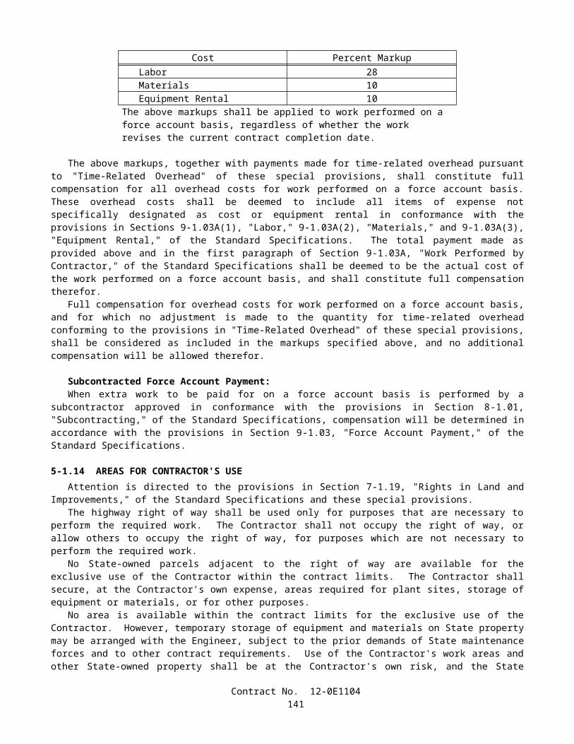
In addition to compressive strength requirements, the consistency of the concrete to be deposited under slurry shall be verified before use by producing a test batch. The test batch shall be produced and delivered to the project under conditions and in time periods similar to those expected during the placement of concrete in the piles. Concrete for the test batch shall be placed in an excavated hole or suitable container of adequate size to allow for testing as specified herein. Depositing of test batch concrete under slurry will not be required. In addition to meeting the specified nominal penetration, the test batch shall meet the following requirements:
A. For piles where the time required for each concrete placing operation, as submitted in the placing plan, will be 2 hours or less, the test batch shall demonstrate that the proposed concrete mix design achieves either a penetration of at least 50 mm or a slump of at least 125 mm after twice that time has elapsed.
B. For piles where the time required for each concrete placing operation, as submitted in the placing plan, will be more than 2 hours, the test batch shall demonstrate that the proposed concrete mix design achieves either a penetration of at least 50 mm or a slump of at least 125 mm after that time plus 2 hours has elapsed.
The time period shall begin at the start of placement. The concrete shall not be vibrated or agitated during the test period. Penetration tests shall be performed in conformance with the requirements in California Test 533. Slump tests shall be performed in conformance with the requirements in ASTM Designation: C 143. Upon completion of testing, the concrete shall be disposed of in conformance with the provisions in Section 7-1.13, "Disposal of Material Outside the Highway Right of Way," of the Standard Specifications.
The concrete deposited under slurry shall be carefully placed in a compact, monolithic mass and by a method that will prevent washing of the concrete. Concrete deposited under slurry need not be vibrated. Placing concrete shall be a continuous operation lasting not more than the time required for each concrete placing operation at each pile, as submitted in the placing plan, unless otherwise approved in writing by the Engineer. The concrete shall be placed with concrete pumps and delivery tube system of adequate number and size to complete the placing of concrete in the time specified. The delivery tube system shall consist of one of the following:
A. A tremie tube or tubes, each of which are at least 250 mm in diameter, fed by one or more concrete pumps.B. One or more concrete pump tubes, each fed by a single concrete pump.
The delivery tube system shall consist of watertight tubes with sufficient rigidity to keep the ends always in the mass of concrete placed. If only one delivery tube is utilized to place the concrete, the tube shall be placed near the center of the drilled hole. Multiple tubes shall be uniformly spaced in the hole. Internal bracing for the steel reinforcing cage shall accommodate the delivery tube system. Tremies shall not be used for piles without space for a 250-mm tube.
Spillage of concrete into the slurry during concrete placing operations shall not be allowed. Delivery tubes shall be capped with a watertight cap, or plugged above the slurry level with a good quality, tight fitting, moving plug that will expel the slurry from the tube as the tube is charged with concrete. The cap or plug shall be designed to be released as the tube is charged. The pump discharge or tremie tube shall extend to the bottom of the hole before charging the tube with concrete. After charging the delivery tube system with concrete, the flow of concrete through a tube shall be induced by slightly raising the discharge end. During concrete placement, the tip of the delivery tube shall be maintained as follows to prevent reentry of the slurry into the tube. Until at least 3 m of concrete has been placed, the tip of the delivery tube shall be within 150 mm of the bottom of the drilled hole, and then the embedment of the tip shall be maintained at least 3 m below the top surface of the concrete. Rapid raising or lowering of the delivery tube shall not be permitted. If the seal is lost or the delivery tube becomes plugged and must be removed, the tube shall be withdrawn, the tube cleaned, the tip of the tube capped to prevent entrance of the slurry, and the operation restarted by pushing the capped tube 3 m into the concrete and then reinitiating the flow of concrete.
When slurry is used, a fully operational standby concrete pump, adequate to complete the work in the time specified, shall be provided at the site during concrete placement. The slurry level shall be maintained within 300 mm of the top of the drilled hole.
A log of concrete placement for each drilled hole shall be maintained by the Contractor when concrete is deposited under slurry. The log shall show the pile location, tip elevation, dates of excavation and concrete placement, total quantity of concrete deposited, length and tip elevation of any casing, and details of any hole stabilization method and materials used. The log shall include a 215 mm x 280 mm sized graph of the concrete placed versus depth of hole filled. The graph shall be plotted continuously throughout placing of concrete. The depth of drilled hole filled shall be plotted vertically with the pile tip oriented at the bottom and the quantity of concrete shall be plotted horizontally. Readings shall be made at least at each 1.5 m of pile depth, and the time of the reading shall be indicated. The graph shall be labeled with the pile location, tip elevation, cutoff elevation, and the dates of excavation and concrete placement. The log shall be delivered to the Engineer within one working day of completion of placing concrete in the pile.
Contract No. 12-0E1104143
After placing reinforcement and prior to placing concrete in the drilled hole, if drill cuttings settle out of the slurry, the bottom of the drilled hole shall be cleaned. The Contractor shall verify that the bottom of the drilled hole is clean.
If temporary casing is used, concrete placed under slurry shall be maintained at a level at least 1.5 m above the bottom of the casing. The withdrawal of casings shall not cause contamination of the concrete with slurry.
Material resulting from using slurry shall be disposed of in conformance with the provisions in Section 7-1.13, "Disposal of Material Outside the Highway Right of Way," of the Standard Specifications.
Acceptance Testing and MitigationVertical inspection pipes for acceptance testing shall be provided in all cast-in-drilled-hole concrete piles that are
600 mm in diameter or larger, except when the holes are dry or when the holes are dewatered without the use of temporary casing to control ground water.
Inspection pipes shall be Schedule 40 polyvinyl chloride pipes with a nominal inside diameter of 50 mm. Each inspection pipe shall be capped top and bottom and shall have watertight couplers to provide a clean, dry and unobstructed 50-mm diameter clear opening from 1.0 m above the pile cutoff down to the bottom of the reinforcing cage.
Inspection pipes shall be placed around the pile, inside the outermost spiral or hoop reinforcement, and 75 mm clear of the vertical reinforcement, at a uniform spacing not exceeding 840 mm measured along the circle passing through the centers of inspection pipes. A minimum of 2 inspection pipes per pile shall be used. When the vertical reinforcement is not bundled and each bar is not more than 26 mm in diameter, inspection pipes may be placed 50 mm clear of the vertical reinforcement. The inspection pipes shall be placed to provide the maximum diameter circle that passes through the centers of the inspection pipes while maintaining the clear spacing required herein. The pipes shall be installed in straight alignment, parallel to the main reinforcement, and securely fastened in place to prevent misalignment during installation of the reinforcement and placing of concrete in the hole.
The Contractor shall log the location of the inspection pipe couplers with respect to the plane of pile cut off, and these logs shall be delivered to the Engineer upon completion of the placement of concrete in the drilled hole.
After placing concrete and before requesting acceptance tests, each inspection pipe shall be tested by the Contractor in the presence of the Engineer by passing a 48.3-mm diameter rigid cylinder 610 mm long through the complete length of pipe. If the 48.3-mm diameter rigid cylinder fails to pass any of the inspection pipes, the Contractor shall attempt to pass a 32.0-mm diameter rigid cylinder 1.375 m long through the complete length of those pipes in the presence of the Engineer. If an inspection pipe fails to pass the 32.0-mm diameter cylinder, the Contractor shall immediately fill all inspection pipes in the pile with water.
The Contractor shall replace each inspection pipe that does not pass the 32.0-mm diameter cylinder with a 50.8-mm diameter hole cored through the concrete for the entire length of the pile. Cored holes shall be located as close as possible to the inspection pipes they are replacing and shall be no more than 150 mm inside the reinforcement. Coring shall not damage the pile reinforcement. Cored holes shall be made with a double wall core barrel system utilizing a split tube type inner barrel. Coring with a solid type inner barrel will not be allowed. Coring methods and equipment shall provide intact cores for the entire length of the pile concrete. The coring operation shall be logged by an Engineering Geologist or Civil Engineer licensed in the State of California and experienced in core logging. Coring logs shall include complete descriptions of inclusions and voids encountered during coring, and shall be delivered to the Engineer upon completion. Concrete cores shall be preserved, identified with the exact location the core was recovered from within the pile, and made available for inspection by the Engineer.
Acceptance tests of the concrete will be made by the Engineer, without cost to the Contractor. Acceptance tests will evaluate the homogeneity of the placed concrete. Tests will include gamma-gamma logging. Tests may also include crosshole sonic logging and other means of inspection selected by the Engineer. The Contractor shall not conduct operations within 8.0 m of the gamma-gamma logging operations. The Contractor shall separate reinforcing steel as necessary to allow the Engineer access to the inspection pipes to perform gamma-gamma logging or other acceptance testing. After requesting acceptance tests and providing access to the piling, the Contractor shall allow 3 weeks for the Engineer to conduct these tests and make determination of acceptance if the 48.3-mm diameter cylinder passed all inspection pipes, and 4 weeks if only the 32.0-mm diameter cylinder passed all inspection pipes. Should the Engineer fail to complete these tests within the time allowance, and if in the opinion of the Engineer, the Contractor's controlling operation is delayed or interfered with by reason of the delay in inspection, the delay will be considered a right of way delay as specified in Section 8-1.09, "Right of Way Delays," of the Standard Specifications.
All inspection pipes and cored holes in a pile shall be dewatered and filled with grout after notification by the Engineer that the pile is acceptable. Placement and removal of water in the inspection pipes shall be at the Contractor’s expense. Grout shall conform to the provisions in Section 50-1.09, "Bonding and Grouting," of the Standard Specifications. The inspection pipes and holes shall be filled using grout tubes that extend to the bottom of the pipe or hole or into the grout already placed.
If acceptance testing performed by the Engineer determines that a pile does not meet the requirements of the specifications, then that pile will be rejected and all depositing of concrete under slurry or concrete placed using temporary
Contract No. 12-0E1104144
casing for the purpose of controlling groundwater shall be suspended until written changes to the methods of pile construction are approved in writing by the Engineer.
The Contractor shall submit to the Engineer for approval a mitigation plan for repair, supplementation, or replacement for each rejected cast-in-drilled-hole concrete pile, and this plan shall conform to the provisions in Section 5-1.02, "Plans and Working Drawings," of the Standard Specifications. Prior to submitting this mitigation plan, the Engineer will hold a repair feasibility meeting with the Contractor to discuss the feasibility of repairing rejected piling. The Engineer will consider the size of the defect, the location of the defect, and the design information and corrosion protection considerations for the pile. This information will be made available to the Contractor, if appropriate, for the development of the mitigation plan. If the Engineer determines that it is not feasible to repair the rejected pile, the Contractor shall not include repair as a means of mitigation and shall proceed with the submittal of a mitigation plan for replacement or supplementation of the rejected pile.
If the Engineer determines that a rejected pile does not require mitigation due to structural, geotechnical, or corrosion concerns, the Contractor may elect to 1) repair the pile per the approved mitigation plan, or 2) not repair anomalies found during acceptance testing of that pile. For such unrepaired piles, the Contractor shall pay to the State, $400 per cubic meter for the portion of the pile affected by the anomalies. The volume, in cubic meters, of the portion of the pile affected by the anomalies, shall be calculated as the area of the cross-section of the pile affected by each anomaly, in square meters, as determined by the Engineer, multiplied by the distance, in meters, from the top of each anomaly to the specified tip of the pile. If the volume calculated for one anomaly overlaps the volume calculated for additional anomalies within the pile, the calculated volume for the overlap shall only be counted once. In no case shall the amount of the payment to the State for any such pile be less than $400. The Department may deduct the amount from any moneys due, or that may become due the Contractor under the contract.
Pile mitigation plans shall include the following:
A. The designation and location of the pile addressed by the mitigation plan.B. A review of the structural, geotechnical, and corrosion design requirements of the rejected pile.C. A step by step description of the mitigation work to be performed, including drawings if necessary.D. An assessment of how the proposed mitigation work will address the structural, geotechnical, and corrosion design
requirements of the rejected pile.E. Methods for preservation or restoration of existing earthen materials.F. A list of affected facilities, if any, with methods and equipment for protection of these facilities during mitigation.G. The State assigned contract number, bridge number, full name of the structure as shown on the contract plans,
District-County-Route-Kilometer Post, and the Contractor's (and Subcontractor's if applicable) name on each sheet. H. A list of materials, with quantity estimates, and personnel, with qualifications, to be used to perform the mitigation
work.I. The seal and signature of an engineer who is licensed as a Civil Engineer by the State of California.
For rejected piles to be repaired, the Contractor shall submit a pile mitigation plan that contains the following additional information:
A. An assessment of the nature and size of the anomalies in the rejected pile.B. Provisions for access for additional pile testing if required by the Engineer.
For rejected piles to be replaced or supplemented, the Contractor shall submit a pile mitigation plan that contains the following additional information:
A. The proposed location and size of additional piling.B. Structural details and calculations for any modification to the structure to accommodate the replacement or
supplemental piling.
All provisions for cast-in-drilled-hole concrete piling shall apply to replacement piling.The Contractor shall allow the Engineer 3 weeks to review the mitigation plan after a complete submittal has been
received.Should the Engineer fail to review the complete pile mitigation submittal within the time specified, and if, in the opinion
of the Engineer, the Contractor's controlling operation is delayed or interfered with by reason of the delay in reviewing the pile mitigation plan, an extension of time commensurate with the delay in completion of the work thus caused will be granted in conformance with the provisions in Section 8-1.09, "Right of Way Delays," of the Standard Specifications.
When repairs are performed, the Contractor shall submit a mitigation report to the Engineer within 10 days of completion of the repair. This report shall state exactly what repair work was performed and quantify the success of the repairs relative to the submitted mitigation plan. The mitigation report shall be stamped and signed by an engineer that is
Contract No. 12-0E1104145
licensed as a Civil Engineer by the State of California. The mitigation report shall show the State assigned contract number, bridge number, full name of the structure as shown on the contract plans, District-County-Route-Kilometer Post, and the Contractor (and Subcontractor if applicable) name on each sheet. The Engineer will be the sole judge as to whether a mitigation proposal is acceptable, the mitigation efforts are successful, and to whether additional repairs, removal and replacement, or construction of a supplemental foundation is required.
10-1.24 STEEL STRUCTURESConstruction of steel structures shall conform to the provisions in Section 55, "Steel Structures," of the Standard
Specifications and these special provisions.Attention is directed to "Welding" in Section 8, "Materials," of these special provisions.The following substitutions of high-strength steel fasteners shall be made:
METRIC SIZE SHOWN ON THE PLANS SIZE TO BE SUBSTITUTED
ASTM Designation: A 325M(Nominal bolt diameter (mm or mm x thread
pitch))
ASTM Designation: A 325(Nominal bolt diameter (inch))
13 or 12.70, M12, M12 x 1.75 1/216 or 15.88, M16, M16 x 2 5/8
19 or 19.05, M20, M20 x 2.5 3/422 or 22.22, M22, M22 x 2.5 7/8
24, 25, or 25.40, M24, M24 x 3 129 or 28.58, M27, M24 x 3 1 1/8
32 or 31.75, M30, M30 x 3.5 1 1/438 or 38.10, M36, M36 x 4 1 1/2
MATERIALSHigh-strength fastener assemblies and other bolts attached to structural steel with nuts and washers shall be zinc-coated.
When direct tension indicators are used in these assemblies, the direct tension indicator and all components of the fastener assembly shall be zinc-coated by the mechanical deposition process.
ROTATIONAL CAPACITY TESTING PRIOR TO SHIPMENT TO JOB SITERotational capacity tests shall be performed on all lots of high-strength fastener assemblies prior to shipment of these lots
to the project site. Zinc-coated assemblies shall be tested after all fabrication, coating, and lubrication of components has been completed. One hardened washer shall be used under each nut for the tests.
The requirements of this section do not apply to high-strength cap screws or high-strength bolts used for slip base plates.Each combination of bolt production lot, nut lot, and washer lot shall be tested as an assembly.A rotational capacity lot number shall be assigned to each combination of lots tested. Each shipping unit of fastener
assemblies shall be plainly marked with the rotational capacity lot number.Two fastener assemblies from each rotational capacity lot shall be tested.The following equipment, procedure, and acceptance criteria shall be used to perform rotational capacity tests on and
determine acceptance of long bolts. Fasteners are considered to be long bolts when full nut thread engagement can be achieved when installed in a bolt tension measuring device:
A. Long Bolt Test Equipment:
1. Calibrated bolt tension measuring device with adequate tension capacity for the bolts being tested.2. Calibrated dial or digital torque wrench. Other suitable tools will be required for performing Steps 7 and 8 of
the Long Bolt Test Procedure. A torque multiplier may be required for large diameter bolts.3. Spacer washers or bushings. When spacer washers or bushings are required, they shall have the same inside
diameter and equal or larger outside diameter as the appropriate hardened washers conforming to the requirements in ASTM Designation: F436.
B Long Bolt Test Procedure:
Contract No. 12-0E1104146
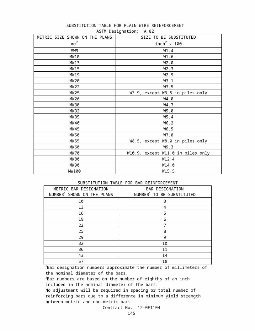
1. Measure the bolt length. The bolt length is defined as the distance from the end of the threaded portion of the shank to the underside of the bolt head.
2. Install the nut on the bolt so that 3 to 5 full threads of the bolt are located between the bearing face of the nut and the underside of the bolt head. Measure and record the thread stickout of the bolt. Thread stickout is determined by measuring the distance from the outer face of the nut to the end of the threaded portion of the shank.
3. Insert the bolt into the bolt tension measuring device and install the required number of washers, and additional spacers as needed, directly beneath the nut to produce the thread stickout measured in Step 2 of this procedure.
4. Tighten the nut using a hand wrench to a snug-tight condition. The snug tension shall not be less than the Table A value but may exceed the Table A value by a maximum of 2 kips.
Table AHigh-Strength Fastener Assembly Tension Values
to Approximate Snug-Tight ConditionBolt Diameter
(inches)Snug Tension
(kips)1/2 15/8 23/4 37/8 41 5
1 1/8 61 1/4 71 3/8 91 1/2 10
5. Match-mark the assembly by placing a heavy reference start line on the face plate of the bolt tension measuring device which aligns with 1) a mark placed on one corner of the nut, and 2) a radial line placed across the flat on the end of the bolt, or on the exposed portions of the threads of tension control bolts. Place an additional mark on the outside of the socket that overlays the mark on the nut corner such that this mark will be visible while turning the nut. Make an additional mark on the face plate, either 2/3 of a turn, one turn, or 1 1/3 turn clockwise from the heavy reference start line, depending on the bolt length being tested as shown in Table B.
Contract No. 12-0E1104147
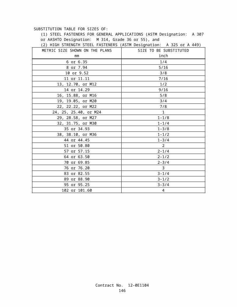
Table BRequired Nut Rotation for Rotational Capacity
Tests(a,b)
Bolt Length (measured in Step 1)
Required Rotation (turn)
4 bolt diameters or less 2/3Greater than 4 bolt
diameters but no more than 8 bolt diameters
1
Greater than 8 bolt diameters, but no more
than 12 bolt diameters(c)
1 1/3
(a) Nut rotation is relative to bolt, regardless of the element (nut or bolt) being turned. For bolts installed by 1/2 turn and less, the tolerance shall be plus or minus 30 degrees; for bolts installed by 2/3 turn and more, the tolerance shall be plus or minus 45 degrees.(b) Applicable only to connections in which all material within grip of the bolt is steel.(c) When bolt length exceeds 12 diameters, the required rotation shall be determined by actual tests in a suitable tension device simulating the actual conditions.
6. Turn the nut to achieve the applicable minimum bolt tension value listed in Table C. After reaching this tension, record the moving torque, in foot-pounds, required to turn the nut, and also record the corresponding bolt tension value in pounds. Torque shall be measured with the nut in motion. Calculate the value, T (in ft-lbs), where T=[(the measured tension in pounds) x (the bolt diameter in inches) / 48 in/ft].
Table CMinimum Tension Values for High-Strength
Fastener AssembliesBolt Diameter
(inches)Minimum Tension
(kips)1/2 125/8 193/4 287/8 391 51
1 1/8 561 1/4 711 3/8 851 1/2 103
7. Turn the nut further to increase bolt tension until the rotation listed in Table B is reached. The rotation is measured from the heavy reference line made on the face plate after the bolt was snug-tight. Record this bolt tension.
8. Loosen and remove the nut and examine the threads on both the nut and bolt.
C. Long Bolt Acceptance Criteria:
1. An assembly shall pass the following requirements to be acceptable: 1) the measured moving torque (Step 6) shall be less than or equal to the calculated value, T (Step 6), 2) the bolt tension measured in Step 7 shall be greater than or equal to the applicable turn test tension value listed in Table D, 3) the nut shall be able to be
Contract No. 12-0E1104148
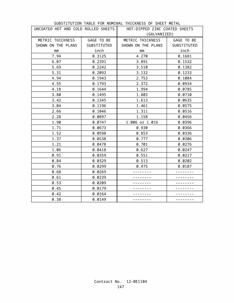
removed from the bolt without signs of thread stripping or galling after the required rotation in Step 7 has been achieved, 4) the bolt does not shear from torsion or fail during the test, and 5) the assembly does not seize before the final rotation in Step 7 is reached. Elongation of the bolt in the threaded region between the bearing face of the nut and the underside of the bolt head is expected and will not be considered a failure. Both fastener assemblies tested from one rotational capacity lot shall pass for the rotational capacity lot to be acceptable.
Table DTurn Test Tension Values
Bolt Diameter(inches)
Turn Test Tension(kips)
1/2 145/8 223/4 327/8 451 59
1 1/8 641 1/4 821 3/8 981 1/2 118
The following equipment, procedure, and acceptance criteria shall be used to perform rotational capacity tests on and determine acceptance of short bolts. Fasteners are considered to be short bolts when full nut thread engagement cannot be achieved when installed in a bolt tension measuring device:
Contract No. 12-0E1104149
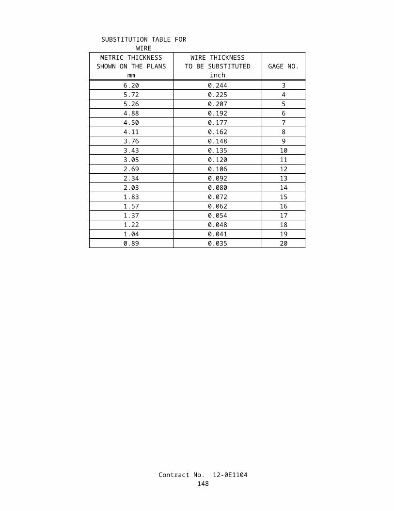
A. Short Bolt Test Equipment:
1. Calibrated dial or digital torque wrench. Other suitable tools will be required for performing Steps 7 and 8 of the Short Bolt Test Procedure. A torque multiplier may be required for large diameter bolts.
2. Spud wrench or equivalent.3. Spacer washers or bushings. When spacer washers or bushings are required, they shall have the same inside
diameter and equal or larger outside diameter as the appropriate hardened washers conforming to the requirements in ASTM Designation: F436.
4. Steel plate with a hole to install bolt. The hole size shall be 1.6 mm 1/16 inch greater than the nominal diameter of the bolt to be tested. The grip length, including any plates, washers, and additional spacers as needed, shall provide the proper number of threads within the grip, as required in Step 2 of the Short Bolt Test Procedure.
B. Short Bolt Test Procedure:
1. Measure the bolt length. The bolt length is defined as the distance from the end of the threaded portion of the shank to the underside of the bolt head.
2. Install the nut on the bolt so that 3 to 5 full threads of the bolt are located between the bearing face of the nut and the underside of the bolt head. Measure and record the thread stickout of the bolt. Thread stickout is determined by measuring the distance from the outer face of the nut to the end of the threaded portion of the shank.
3. Install the bolt into a hole on the plate and install the required number of washers and additional spacers as needed between the bearing face of the nut and the underside of the bolt head to produce the thread stickout measured in Step 2 of this procedure.
4. Tighten the nut using a hand wrench to a snug-tight condition. The snug condition shall be the full manual effort applied to the end of a 305 mm 12-inch long wrench. This applied torque shall not exceed 20 percent of the maximum allowable torque in Table E.
Table EMaximum Allowable Torque for High-Strength
Fastener AssembliesBolt Diameter
(inches)Torque(ft-lbs)
1/2 1455/8 2853/4 5007/8 8201 1220
1 1/8 15001 1/4 21301 3/8 28001 1/2 3700
5. Match-mark the assembly by placing a heavy reference start line on the steel plate or girder which aligns with 1) a mark placed on one corner of the nut and 2) a radial line placed across the flat on the end of the bolt or on the exposed portions of the threads of tension control bolts. Place an additional mark on the outside of the socket that overlays the mark on the nut corner such that this mark will be visible while turning the nut. Make 2 additional small marks on the steel plate or girder, one 1/3 of a turn and one 2/3 of a turn clockwise from the heavy reference start line on the steel plate or girder.
6. Using the torque wrench, tighten the nut to the rotation value listed in Table F. The rotation is measured from the heavy reference line described in Step 5 made after the bolt was snug-tight. A second wrench shall be used to prevent rotation of the bolt head during tightening. Measure and record the moving torque after this rotation has been reached. The torque shall be measured with the nut in motion.
Contract No. 12-0E1104150
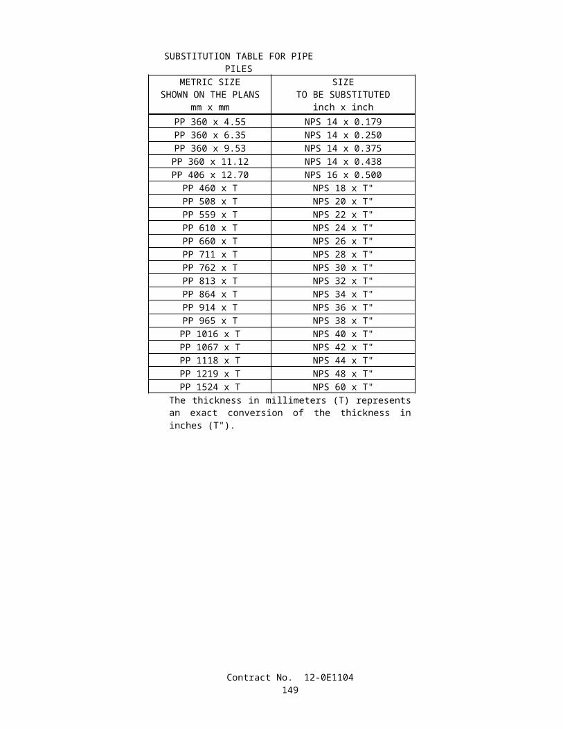
Table FNut Rotation Required for Turn-of-Nut
Installation(a,b)
Bolt Length (measured in Step 1)
Required Rotation (turn)
4 bolt diameters or less 1/3(a) Nut rotation is relative to bolt, regardless of the element (nut or bolt) being turned. For bolts installed by 1/2 turn and less, the tolerance shall be plus or minus 30 degrees.(b) Applicable only to connections in which all material within grip of the bolt is steel.
7. Tighten the nut further to the 2/3-turn mark as indicated in Table G. The rotation is measured from the heavy reference start line made on the plate or girder when the bolt was snug-tight. Verify that the radial line on the bolt end or on the exposed portions of the threads of tension control bolts is still in alignment with the start line.
Table GRequired Nut Rotation for Rotational Capacity TestBolt Length (measured
in Step 1)Required Rotation (turn)
4 bolt diameters or less 2/3
8. Loosen and remove the nut and examine the threads on both the nut and bolt.
C. Short Bolt Acceptance Criteria:
1. An assembly shall pass the following requirements to be acceptable: 1) the measured moving torque from Step 6 shall be less than or equal to the maximum allowable torque from Table E, 2) the nut shall be able to be removed from the bolt without signs of thread stripping or galling after the required rotation in Step 7 has been achieved, 3) the bolt does not shear from torsion or fail during the test, and 4) the assembly shall not seize before the final rotation in Step 7 is reached. Elongation of the bolt in the threaded region between the bearing face of the nut and the underside of the bolt head will not be considered a failure. Both fastener assemblies tested from one rotational capacity lot shall pass for the rotational capacity lot to be acceptable.
INSTALLATION TENSION TESTING AND ROTATIONAL CAPACITY TESTING AFTER ARRIVAL ON THE JOB SITEInstallation tension tests and rotational capacity tests on high-strength fastener assemblies shall be performed by the
Contractor prior to acceptance or installation and after arrival of the fastener assemblies on the project site. Installation tension tests and rotational capacity tests shall be performed at the job-site, in the presence of the Engineer, on each rotational capacity lot of fastener assemblies.
The requirements of this section do not apply to high-strength cap screws or high-strength bolts used for slip base plates.Installation tension tests shall be performed on 3 representative fastener assemblies in conformance with the provisions
in Section 8, "Installation," of the RCSC Specification. For short bolts, Section 8.2, "Pretensioned Joints," of the RCSC Specification shall be replaced by the "Pre-Installation Testing Procedures," of the "Structural Bolting Handbook," published by the Steel Structures Technology Center, Incorporated.
The rotational capacity tests shall be performed in conformance with the requirements for rotational capacity tests in "Rotational Capacity Testing Prior to Shipment to Job Site" of these special provisions.
At the Contractor's expense, additional installation tension tests, tests required to determine job inspecting torque, and rotational capacity tests shall be performed by the Contractor on each rotational capacity lot, in the presence of the Engineer, if 1) any fastener is not used within 3 months after arrival on the jobsite, 2) fasteners are improperly handled, stored, or subjected to inclement weather prior to final tightening, 3) significant changes are noted in original surface condition of threads, washers, or nut lubricant, or 4) the Contractor's required inspection is not performed within 48 hours after all fasteners in a joint have been tensioned.
Failure of a job-site installation tension test or a rotational capacity test will be cause for rejection of unused fasteners that are part of the rotational capacity lot.
Contract No. 12-0E1104151
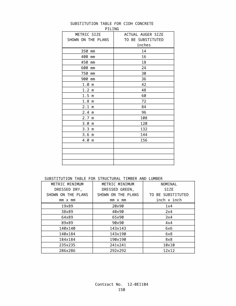
When direct tension indicators are used, installation verification tests shall be performed in conformance with Appendix Section X1.4 of ASTM Designation: F959, except that bolts shall be initially tensioned to a value 5 percent greater than the minimum required bolt tension.
SURFACE PREPARATIONFor all bolted connections, the contact surfaces and inside surfaces of bolt holes shall be cleaned and coated before
assembly in conformance with the provisions for cleaning and painting structural steel of these special provisions.
SEALINGThe perimeter around all direct tension indicator gaps shall be completely sealed with non-silicone type sealing
compound conforming to the provisions in Federal Specification TT-S-230, Type II. The sealant shall be gray in color and have a minimum thickness of 1.3 mm. If painting is required, the sealing compound shall be applied prior to painting.
When zinc-coated tension control bolts are used, the sheared end of each fastener shall be completely sealed with non-silicone type sealing compound conforming to the provisions in Federal Specification TT-S-230, Type II. The sealant shall be gray in color and shall have a minimum thickness of 1.3 mm 50 mils. The sealant shall be applied to a clean sheared surface on the same day that the splined end is sheared off.
10-1.25 DELINEATORSDelineators shall conform to the provisions in Section 82, "Markers and Delineators," of the Standard Specifications and
these special provisions. Delineators on flexible posts shall conform to the provisions in "Prequalified and Tested Signing and Delineation
Materials" of these special provisions. Flexible posts shall be made from a flexible white plastic which shall be resistant to impact, ultraviolet light, ozone, and hydrocarbons. Flexible posts shall resist stiffening with age and shall be free of burns, discoloration, contamination, and other objectionable marks or defects which affect appearance or serviceability.
Retroreflective sheeting for metal and flexible target plates shall be the retroreflective sheeting designated for channelizers, markers, and delineators conforming to the requirements in ASTM Designation: D 4956-95 and in conformance with the provisions in "Prequalified and Tested Signing and Delineation Materials" of these special provisions.
10-1.26 METAL BEAM GUARD RAILINGMetal beam guard railing shall be constructed in conformance with the provisions in Section 83-1, "Railings," of the
Standard Specifications and these special provisions.Attention is directed to "Order of Work" of these special provisions.Line posts and blocks shall be wood and steel as shown on the plans.
ALTERNATIVE FLARED TERMINAL SYSTEMAlternative flared terminal system shall be furnished and installed as shown on the plans and in conformance with these
special provisions.The allowable alternatives for a flared terminal system shall consist of one of the following or a Department approved
equal.
(1) TERMINAL SYSTEM (TYPE FLEAT) - Terminal system (Type FLEAT) shall be a Flared Energy Absorbing Terminal 350 manufactured by Road Systems, Inc., located in Big Spring, Texas, and shall include items detailed for terminal system (Type FLEAT) shown on the plans. The Flared Energy Absorbing Terminal 350 can be obtained from the distributor, Universal Industrial Sales, P.O. Box 699, Pleasant Grove, UT 84062, Telephone (801) 785–0505 or from the distributor, Gregory Highway Products, 4100 13 th Street, S.W., Canton, OH 44708, Telephone (330) 477–4800.
(2) TERMINAL SYSTEM (TYPE SRT) - Terminal system (Type SRT) shall be an SRT-350 Slotted Rail Terminal (8-post system) as manufactured by Trinity Industries, Inc., and shall include items detailed for terminal system (Type SRT) shown on the plans. The SRT-350 Slotted Rail Terminal (8-post system) can be obtained from the manufacturer, Trinity Industries, Inc., P.O. Box 99, 950 West 400S, Centerville, UT 84014, Telephone (800) 772–7976.
The Contractor shall provide the Engineer with a Certificate of Compliance from the manufacturer in conformance with the provisions in Section 6-1.07, "Certificates of Compliance," of the Standard Specifications. The Certificate of Compliance shall certify that the terminal systems furnished conform to the contract plans and specifications, conform to the prequalified design and material requirements, and were manufactured in conformance with the approved quality control program.
Contract No. 12-0E1104152
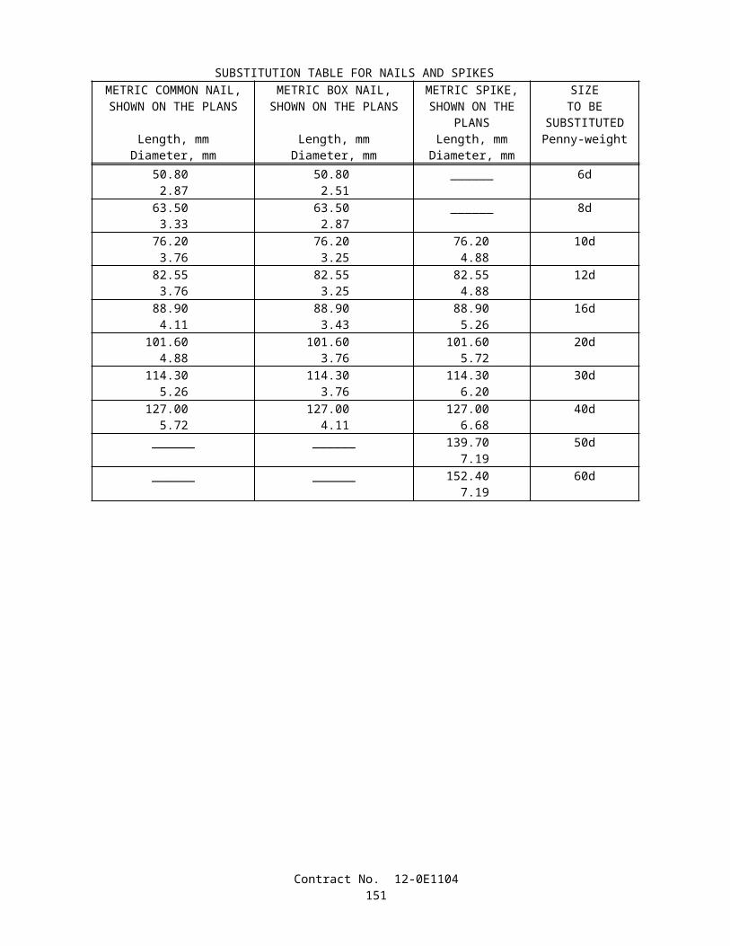
Terminal systems shall be installed in conformance with the manufacturer's installation instructions and these requirements. Each terminal system installed shall be identified by painting the type of terminal system in neat black letters and figures 60 mm high on the backside of the rail element between system posts numbers 4 and 5.
For terminal system (Type SRT), the steel foundation tubes with soil plates attached shall be, at the Contractor's option, either driven, with or without pilot holes, or placed in drilled holes. Space around the steel foundation tubes shall be backfilled with selected earth, free of rock, placed in layers approximately 100 mm thick and each layer shall be moistened and thoroughly compacted. The wood terminal posts shall be inserted into the steel foundation tubes by hand and shall not be driven. Before the wood terminal posts are inserted, the inside surfaces of the steel foundation tubes to receive the wood posts shall be coated with a grease which will not melt or run at a temperature of 65°C or less. The edges of the wood terminal posts may be slightly rounded to facilitate insertion of the post into the steel foundation tubes.
For terminal system (Type FLEAT), the soil tubes shall be, at the Contractor's option, driven with or without pilot holes, or placed in drilled holes. Space around the steel foundation tubes shall be backfilled with selected earth, free of rock, placed in layers approximately 100 mm thick and each layer shall be moistened and thoroughly compacted. Wood posts shall be inserted into the steel foundation tubes by hand. Before the wood terminal posts are inserted, the inside surfaces of the steel foundation tubes to receive the wood posts shall be coated with a grease which will not melt or run at a temperature of 65°C or less. The edges of the wood posts may be slightly rounded to facilitate insertion of the post into the steel foundation tubes.
Surplus excavated material remaining after the terminal system has been installed shall be disposed of in a uniform manner along the adjacent roadway where designated by the Engineer.
The contract unit price paid for alternative flared terminal system shall include full compensation for furnishing all labor, materials, tools, equipment, and incidentals, and for doing all the work involved in furnishing and installing alternative flared terminal system, complete in place, including excavation, backfill and disposal of surplus material, as shown on the plans, as specified in the Standard Specifications and these special provisions, and as directed by the Engineer.
SECTION 10-2. (BLANK)
SECTION 10-3. SIGNALS, LIGHTING AND ELECTRICAL SYSTEMS
10-3.01 DESCRIPTIONClosed circuit television system and communication system shall conform to the provisions in Section 86, "Signals,
Lighting and Electrical Systems," of the Standard Specifications and these special provisions.
10-3.02 COST BREAK-DOWNCost break-downs shall conform to the provisions in Section 86-1.03, "Cost Break-Down," of the Standard
Specifications and these special provisions.The Engineer shall be furnished a cost break-down for each contract lump sum item of work described in this
Section 10-3.The cost break-down shall be submitted to the Engineer for approval within 15 days after the contract has been
approved. The cost break-down shall be approved, in writing, by the Engineer before any partial payment for the items of electrical work will be made.
The cost breakdown shall include the following items in addition to those listed in the Standard Specifications:
A. Type B fiber optic cableB. Type C fiber optic cableC. Type D fiber optic cableD. Closed circuit television system
10-3.03 MAINTAINING EXISTING AND TEMPORARY ELECTRICAL SYSTEMSTraffic signal system shutdowns shall be limited to periods between the hours of 9:00 a.m. and 3:00 p.m.
10-3.04 FOUNDATIONSReinforced cast-in-drilled-hole concrete pile foundations for traffic signal and lighting standards shall conform to the
provisions in "Piling" of these special provisions.Where cast-in-drilled-hole concrete pile foundations are to be constructed in slag aggregate embankments, the diameter
of the pile shall be increased to provide a minimum of 75 mm of concrete cover over the reinforcing steel.
Contract No. 12-0E1104153
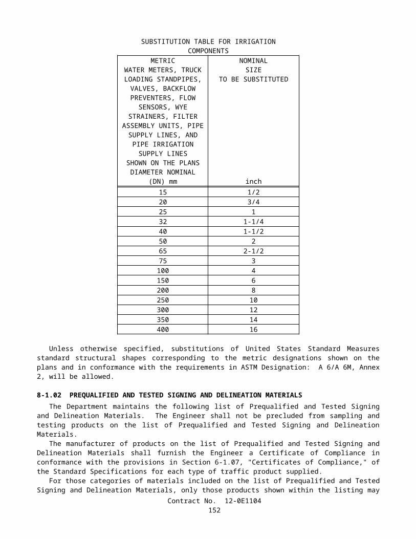
10-3.05 CONDUITConduit to be installed underground shall be Type 1 unless otherwise specified. Communication conduit to be installed
underground shall be Type 1 or Type 3 unless otherwise specified.The conduit in a foundation and between a foundation and the nearest pull box shall be Type 1.Conduit sizes shown on the plans and specified in the Standard Specifications and these special provisions are referenced
to metallic type conduit. When rigid non-metallic conduit is required or allowed, the nominal equivalent industry size shall be used as shown in the following table:
Size Designation for Metallic Type Conduit Equivalent Size for Rigid Non-metallic Conduit21 2027 2541 4053 5063 6578 75103 100
When a standard coupling cannot be used for joining Type 1 conduit, a UL listed threaded union coupling conforming to the provisions in Section 86-2.05C, "Installation," of the Standard Specifications, or a concrete-tight split coupling, or concrete-tight set screw coupling shall be used.
When Type 3 conduit is placed in a trench (not in pavement or under portland cement concrete sidewalk), after the bedding material is placed and the conduit is installed, the trench shall be backfilled with commercial quality concrete, containing not less than 250 kg of portland cement per cubic meter, to not less than 100 mm above the conduit before additional backfill material is placed.
After conductors have been installed, the ends of conduits terminating in pull boxes, service equipment enclosures, and controller cabinets shall be sealed with an approved type of sealing compound.
At those locations where conduit is required to be installed under pavement and existing underground facilities require special precautions in conformance with the provisions in "Obstructions" of these special provisions, conduit shall be placed by the "Trenching in Pavement Method" in conformance with the provisions in Section 86-2.05C, "Installation," of the Standard Specifications.
WARNING TAPEWarning tape shall be provided and placed in the trench over conduits containing F/O cable as shown on the plans. The
warning tape shall be 100 mm wide with bold printed black letters of approximately 19 mm on bright orange color background, and contain the printed warning "CAUTION BURIED FIBER OPTIC CABLE - CALTRANS (949) 724-2607," repeated at approximately 910 mm intervals.
The printed warning shall be non-erasable and shall be rated to last with the tape for a minimum of 40 years.The warning tape shall not delaminate nor shall the message smear when wet. The tape and the printed message shall be
resistant to insects and shall not degrade when exposed to alkalis, acids and other corrosive elements commonly found in soil. It shall have a minimum of 356 N tensile strength and a minimum of 700 percent elongation before breakage.
Warning tape shall be Condux International, Inc.; Allen System, Inc.; Reef Industries, Inc. or equivalent.Full compensation for furnishing and installing the warning tape shall be considered as included in the prices paid for the
various contract items of work involved and no additional compensation will be allowed therefor.
COLORED CONCRETE BACKFILLThe concrete backfill for the installation of conduits that will contain F/O cable shall be a medium to dark red color to
clearly distinguish the concrete backfill from other concrete and soil. The concrete shall be pigmented by the addition of commercial quality cement pigment to the concrete mix. The red concrete pigment shall be LM Scofield Company; Orange Chromix Colorant; Davis Colors; or equivalent. The concrete shall conform to the provisions in Section 90-10, "Minor Concrete" of the Standard Specifications.
For trenches in pavement areas, only the top 100 mm of concrete backfill will be required to be pigmented concrete. At the option of the Contractor, the full depth may have the pigment.
Full compensation for furnishing and incorporating the cement pigment to achieve the color required shall be considered as included in the prices paid for the various contract items of work involved and no additional compensation will be allowed therefor.
Contract No. 12-0E1104154
MULTIDUCT CONDUITWhere Size 103 conduit with innerduct is to be installed by trenching, a factory assembled conduit system with four
innerducts will be allowed.The conduit shall be Schedule 40 PVC. Each innerduct shall be 32 mm (I.D. nominal), manufactured from polyethylene
or PVC. Each innerduct shall be a different color and shall be consistent for the project. UL listing is not required.Polyethylene innerduct shall conform to the provisions described under "INNERDUCTS", longitudinally ribbed, with
minimum wall thickness of 2 mm.PVC innerduct shall have a wall thickness of 2.3 mm minimum.Straight segments of multiduct conduit shall be nominal 6 m lengths with a minimum 125 mm slip joint. Joints shall be
keyed to mate the enclosed innerducts and shall lock together or be provided with a seating mark to verify proper assembly. The joint shall be solvent welded or sealed with a gasket as recommended by the manufacturer. Factory manufactured end sections shall be provided.
Bends shall be rigid factory assembled sections or shall be formed from factory assembled flexible sections, designed to fit the system.
Prior to joining the last sections of the conduit run, the innerduct colors at the ends shall be verified to be consistent.
CONDUIT AND INNERDUCT SEALING PLUGSExcept as otherwise noted, all conduits and empty innerducts shall have their ends sealed with commercial preformed
plugs which prevent the passage of gas, dust and water into these conduits and their included innerducts. Sealing plugs shall be installed within each splice vault, communication pull box, cabinet, and building.
Sealing plugs shall be removable and reusable. Plugs sealing innerducts, conductor or cable shall be the split type that permits installation or removal without removing conductors or cables.
Sealing plugs that seal between the Size 103 fiber optic conduit and innerducts shall seal the conduit and all innerducts simultaneously with one self contained assembly having an adjustable resilient filler of neoprene or silicone rubber clamped between backing ends and compressed with stainless steel hardware.
Sealing plugs that seal the innerducts shall seal each innerduct individually with appropriate sizes and configuration to accommodate either empty ducts or those containing fiber optic cable. To provide suitable sealing between the varying size cables and the plugs, split neoprene or silicone adapting sleeves, used singularly or in multiples, shall be inserted within the body of the plugs.
Sealing plugs used to seal Size 103 fiber optic conduit and innerducts shall be capable of withstanding a pressure of 34.5 kPa.
A sealing plug that seals an empty conduit or innerduct shall have an eye or other type of capturing device (on the side of the plug that enters the conduit) to attach onto the pull tape, so the pull tape will be easily accessible when the plug is removed.
Full compensation for conduit and innerduct sealing plugs shall be considered as included in the prices paid for the various contract items of work involved and no additional compensation will be allowed therefor.
10-3.06 INNERDUCTFour innerducts shall be installed in each Size 103 conduit. Each fiber optic cable shall be installed in its own innerduct.Innerduct consists of an extruded flexible annealed polyethylene tubing that is installed inside electrical conduit, and
which in turn the fiber optic cable is installed. Innerduct within a conduit run shall be continuous without splices or joints.Unless otherwise shown on the plans, innerduct shall be nominal 25 mm inside diameter, with wall thickness of
2300 µm ± 76 µm, and shall meet the following requirements:Polyethylene for innerduct shall have a density of 0.955 ±0.005 g/cm3 (ASTM Standard D-1505), and shall conform to
the applicable portions of ASTM Designations: D 3485, D 3035, D 2239, and D 2447, and the applicable portions of NEMA TC7 and TC2. Tensile yield strength shall be 22,753 kPa minimum (ASTM D-638).
Walls shall be smooth, corrugated or ribbed.The polyethylene forming each innerduct shall be color coded according to the cable type that it contains as follows:
Spare - blackType B - orangeType C - yellowType D - blue
The exterior of the duct shall be marked with sequential measurement markings every meter.
Contract No. 12-0E1104155
The innerducts shall be shipped on reels marked with the manufacturer, the contract number, and the size and length of the innerduct. The product on reels shall be covered with aluminized material to protect colors from UV deterioration during shipment and storage.
Installation procedures shall conform to the procedures specified by the innerduct manufacturer.Full compensation for installing 4-25 mm innerducts into each communication conduit, including pull rope shall be
considered as included in the prices paid for the various contract items of work involved and no additional compensation will be allowed therefor.
The contract price paid per meter for 25 mm innerduct for existing conduit shall include full compensation for furnishing all labor, materials, tools, equipment, and incidentals, and for doing all the work involved in installing 25 mm innerduct into existing conduit, complete in place, including pull rope, as shown on the plans, as specified in these special provisions, and as directed by the Engineer.
10-3.07 PULL BOXESGrout shall not be placed in the bottom of pull boxes.
COMMUNICATION PULL BOXESCommunication pull boxes and covers shall have a vertical proof-load strength of 111 kN. The 111 kN load shall be
distributed through a 229-mm x 229-mm x 51-mm steel plate according to Federal Specification RR-F-621e. This load shall be placed anywhere on the box and cover for a period of one minute without causing any cracks or permanent deformations.
The communication pull boxes shall be reinforced with a galvanized Z-bar welded frame and cover similar to that shown on the plans for No. 6(T) pull boxes. Frames shall be anchored to the boxes by means of 6-mm x 57-mm long concrete anchors. Six concrete anchors shall be provided for each communication pull box, one placed in each corner and one placed near the middle of each of the longer sides.
Hold down screws shall be 9-mm hex flange cap screws of Type 316 stainless steel. The nut shall be zinc plated carbon steel and shall be made vibration resistant with a wedge ramp at the root of the thread. The nut shall be spot welded to the underside of, or fabricated with, the galvanized Z-bar pull box frame.
Steel covers shall be countersunk approximately 6 mm to accommodate the bolt head. The bolt head shall not extend more than 3 mm above the top of the cover when tightened down. A 6-mm tapped hole and brass bonding screw shall be provided.
Communication pull boxes shall have "CALTRANS COMMUNICATION" marking on the steel cover.The opening of communication pull boxes shall be as shown on the plans.Concrete placed around and under pull boxes as shown on the plans shall contain a minimum of 325 kg of portland
cement per cubic meter.Communication pull boxes shown on the plans in the shoulder are shown for general location only. Exact location shall
be outside the paved shoulder.After the installation of communication pull boxes, the steel covers shall be installed and kept bolted down during
periods when work is not actively in progress at the pull box. When placing the steel cover for the final time, the cover and the Z-bar frame shall be cleaned of all debris and securely tightened down.
10-3.08 SPLICE VAULTSSplice vaults and extensions shall conform to the Western Underground Committee Recommended Guide No. 3.6, "Non-
Concrete Enclosures," except as noted herein. Splice vaults shall have minimum inside clearances of 760 mm wide x 1500 mm long x 760 mm deep. Covers shall be in two piece torsion assisted section. Hold down bolts or cap screws and nuts shall be of brass, stainless steel or other non-corroding metal material. Cover marking shall be Caltrans communication. Enclosures, covers and extensions shall be concrete gray color. Vaults and covers may be constructed of reinforced portland cement concrete or any equivalent material which meets the specified load rating. Splice vault covers, however, must be made of steel which meets the specified load rating.
Splice vaults shall be installed as detailed and where shown on the plans. All splice vaults and covers shall have an AASHTO HS 20-44 rating. A concrete encasement ring shall be poured around the collar of the splice vault as shown on the plans. The encasement concrete shall be minor concrete as specified in Section 90-10, "Minor Concrete," of the Standard Specifications.
Splice vaults shall be drained to drainage ditches or a 305 mm rock sump shall be provided as directed by the Engineer.The contract unit price paid for splice vault shall include full compensation for furnishing all labor, materials, tools,
equipment, and incidentals, and for doing all the work involved in installing splice vault, complete in place, as shown on the plans, as specified in these special provisions, and as directed by the Engineer.
Contract No. 12-0E1104156
10-3.09 CONDUCTORS AND WIRINGSplices shall be insulated by "Method B.Splices for fiber optic cables are specified elsewhere in these special provisionsThe minimum insulation thickness, at any point, for Type USE, RHH or RHW wire shall be 1.0 mm for conductor sizes
No. 14 to No. 10, inclusive, and 1.3 mm for No. 8 to No. 2, inclusive. The minimum insulation thickness, at any point, for Type THW and TW wires shall be 0.69 mm for conductor sizes No. 14 to No. 10, inclusive, 1.02 mm for No. 8, and 1.37 mm for No. 6 to No. 2, inclusive.
10-3.10 BONDING AND GROUNDINGBonding and grounding shall conform to the provisions in Section 86-2.10, "Bonding and Grounding," of the Standard
Specifications and these special provisions.Bonding jumpers in standards with handholes and traffic pull box lid covers shall be attached by a UL listed lug using
4.5-mm diameter or larger brass or bronze bolts and shall run to the conduit or bonding wire in the adjacent pull box. The grounding jumper shall be visible after the standard has been installed and the mortar pad and cap have been placed on the foundation.
Standards without handholes shall have bonding accomplished by jumpers attached to UL listed ground clamps on each anchor bolt.
For slip base standards or slip base inserts, bonding shall be accomplished by jumpers attached to UL listed ground clamps on each anchor bolt, or a UL listed lug attached to the bottom slip base plate with a 4.5 -mm diameter or larger brass or bronze bolt.
Equipment bonding and grounding conductors are required in conduits, except when the conduits contain combinations of loop lead-in cable, fiber optic cable, or signal interconnect cable. A No. 8 minimum, bare copper wire shall run continuously in circuits, except for series lighting circuits, where No. 6 bare copper wire shall run continuously. The bonding wire size shall be increased to match the circuit breaker size in conformance with the Code, or shall be as shown on the plans. Conduits to be installed for future conductors, may omit the copper wire.
Bonding of metallic conduits in metal pull boxes shall be by means of bonding bushings and bonding jumpers connected to the bonding wire running in the conduit system.
10-3.11 SERVICEContinuous welding of exterior seams in service equipment enclosures is not required.
10-3.12 FIBER OPTICS CABLEFiber optic cable shall conform to the details shown on the plans and these special provisions.
FIBER OPTIC GLOSSARYDefinitions
The following definitions shall apply to these special provisions:
A. Active Component Link Loss Budget.—The active component link loss budget is the difference between the average transmitter launch power (in dBm) and the receiver maximum sensitivity (in dBm).
B. Backbone.—Fiber cable that provides connections between the TMC and hubs, as well as between equipment rooms or buildings, and between hubs. The term is used interchangeably with "trunk" cable.
C. Connector.—A mechanical device used to align and join two fibers together to provide a means for attaching to and decoupling from a transmitter, receiver, or another fiber (patch panel).
D. Connectorized.—The termination point of a fiber after connectors have been affixed.E. Connector Module Housing (CMH).—A patch panel used to terminate singlemode fibers with most common
connector types. It may include a jumper storage shelf and a hinged door.F. Couplers.—Devices which mate fiber optic connectors to facilitate the transition of optical light signals from one
connector into another. They are normally located within FDUs, mounted in panels. They may also be used unmounted, to join two simplex fiber runs.
G. Distribution Cable.—Fiber cable that provides connections between hubs. Drop cables are typically spliced into a distribution cable.
H. Drop Cable.—Fiber cable that provides connections between a distribution cable to a field element. Typically these run from a splice vault to a splice tray within a field cabinet. Drop cables are usually short in length (less than 20 m) and are of the same construction as outside plant cable. The term “breakout cable” is used interchangeably with drop cable.
Contract No. 12-0E1104157
I. End-to-End Loss.—The maximum permissible end-to-end system attenuation is the total loss in a given link. This loss could be the actual measured loss, or calculated using typical (or specified) values. A designer should use typical values to calculate the end-to-end loss for a proposed link. This number will determine the amount of optical power (in dB) needed to meet the System Performance Margin.
J. Fan Out Termination.—Permits the branching of fibers contained in an optical cable into individual cables and can be done at field locations; thus, allowing the cables to be connectorized or terminated per system requirements. A kit provides pull-out protection for individual bare fibers to support termination. It provides three layers of protection consisting of a Teflon inner tube, a dielectric strength member, and an outer protective PVC jacket. Fan out terminations shall not be used for more than 6 fibers. Using a patch panel would be appropriate.
K. Fiber Distribution Frame (FDF).—A rack mounted system that is usually installed in hubs or the Transportation Management Center (TMC), that may consist of a standard equipment rack, fiber routing guides, horizontal jumper troughs and Fiber Distribution Units (FDU). The FDF serves as the termination and interconnection of passive fiber optic components from cable breakout, for connection by jumpers, to the equipment.
L. Fiber Distribution Unit (FDU).—An enclosure or rack mountable unit containing both a patch panel with couplers and splice tray(s). The unit’s patch panel and splice trays may be integrated or separated by a partition.
M. F/O.—Fiber optic.N. FOIP.—Fiber optic inside plant cable.O. FOOP.—Fiber optic outside plant cable.P. FOTP.—Fiber optic test procedure(s) as defined by TIA/EIA standards.Q. Jumper.—A short cable, typically one meter or less, with connectors on each end, used to join two CMH couplers
or a CMH to active electronic components.R. Light Source.—Portable fiber optic test equipment that, when coupled with a power meter, is used to perform end-
to-end attenuation testing. It contains a stabilized light source operating at the wavelength of the system under test.S. Link.—A passive section of the system, the ends of which are connectorized. A link may include splices and
couplers. For example, a video link may be from a F/O transmitter to a video multiplexer (MUX).T. Loose Tube Cable.—Type of cable construction in which fibers are placed in buffer tubes to isolate them from
outside forces (stress). A flooding compound or material is applied to the interstitial cable core to prevent water migration and penetration. This type of cable is primarily for outdoor applications.
U. Mid-span Access Method.—Description of a procedure in which fibers from a single buffer tube are accessed and spliced to an adjoining cable without cutting the unused fibers in the buffer tube, or disturbing the remaining buffer tubes in the cable.
V. MMFO.—Multimode Fiber Optic Cable.W. Optical Time Domain Reflectometer (OTDR).—Fiber optic test equipment similar in appearance to an
oscilloscope that is used to measure the total amount of power loss in a F/O cable between two points. It provides a visual and printed display of the losses associated with system components such as fiber, splices and connectors.
X. Optical Attenuator.—An optical element that reduces the intensity of a signal passing through it.Y. Patchcord.—A term used interchangeably with "jumper".Z. Patch Panel—A precision drilled metal frame containing couplers used to mate two fiber optic connectors.AA. Pigtail.—A short optical fiber permanently attached to a source, detector, or other fiber optic device.AB. Power Meter.—Portable fiber optic test equipment that, when coupled with a light source, is used to perform end-
to-end attenuation testing. It contains a detector that is sensitive to light at the designed wavelength of the system under test. Its display indicates the amount of optical power being received at the end of the link.
AC. Riser Cable.—NEC approved cable installed in a riser (a vertical shaft in a building connecting floors).AD. Segment.—A section of F/O cable that is not connected to any active device and may or may not have splices per
the design.AE. SMFO.—Singlemode Fiber Optic Cable.AF. Splice.—The permanent joining of two fiber ends using a fusion splicer.AG. Splice Closure.—A environmentally sealed container used to organize and protect splice trays. The container
allows splitting or routing of fiber cables from multiple locations. Normally installed in a splice vault.AH. Splice Module Housing (SMH).—A unit that stores splice trays as well as pigtails and short cable lengths. The unit
allows splitting or routing of fiber cables to or from multiple locations.AI. Splice Tray.—A container used to organize and protect spliced fibers.AJ. Splice Vault.—An underground container used to house excess cable and/or splice closures.AK. System Performance Margin.—A calculation of the overall "End to End" permissible attenuation from the fiber
optic transmitter (source) to the fiber optic receiver (detector). The system performance margin should be at least 6 dB. This includes the difference between the active component link loss budget, the passive cable attenuation (total fiber loss) and the total connector/splice loss.
Contract No. 12-0E1104158
AL. Tight Buffered, Non-Breakout Cable (Tight Buffer Cable).—Type of cable construction where each glass fiber is tightly buffered (directly coated) with a protective thermoplastic coating to 900 µm (compared to 250 µm for loose tube fibers).
10-3.13 FIBER OPTIC OUTSIDE PLANT CABLEGENERALEach fiber optic outside plant cable (FOOP) for this project shall be all dielectric, gel filled or water-blocking material,
duct type, with loose buffer tube construction with a maximum outside diameter of 14 mm and shall conform to these special provisions. Cables shall contain singlemode (SM) dual-window (1310 nm and 1550 nm) fibers with the numbers described below and as shown on the plans:
Type B cable 72 SM fibersType C cable 72 SM fibersType D cable 12 SM fibers
The optical fibers shall be contained within loose buffer tubes. The loose buffer tubes shall be stranded around an all dielectric central member. Aramid yarn and/or fiberglass shall be used as a primary strength member, and a polyethylene outside jacket shall provide for overall protection.
All F/O cable of each specific type shall be from the same manufacturer, who is regularly engaged in the production of this material.
The cable shall comply with all the requirements of the United States Department of Agriculture Rural Electrification Administration specifications REA-PE-90.
The cable shall be qualified as compliant with RUS Federal Rule 7CFR1755.900.
FIBER CHARACTERISTICSEach optical fiber shall be glass and consist of a doped silica core surrounded by concentric silica cladding. All fibers in
the buffer tube shall be usable fibers, and shall be sufficiently free of surface imperfections and occlusions to meet the optical, mechanical, and environmental requirements of these specifications. The required fiber grade shall reflect the maximum individual fiber attenuation, to guarantee the required performance of each and every fiber in the cable.
The coating shall be a dual layered, UV cured acrylate. The coating shall be mechanically strippable without damaging the fiber.
The cable shall comply with the optical and mechanical requirements within an operating temperature range of -40°C to +70°C. The cable shall be tested in accordance with EIA-455-3A (FOTP-3), "Procedure to Measure Temperature Cycling Effects on Optical Fiber, Optical Cable, and Other Passive Fiber Optic Components." The change in attenuation at extreme operational temperatures (-40°C to +70°C) for singlemode fiber shall not be greater than 0.20 dB/km, with 80 percent of the measured values no greater than 0.10 dB/km. The singlemode fiber attenuation shall be measured at 1550 nm.
For all fibers the attenuation specification shall be a maximum attenuation for each fiber over the entire operating temperature range of the cable.
Singlemode fibers within the finished cable shall meet the requirements in the following table:
Contract No. 12-0E1104159
Fiber Characteristics Table
Parameters CharacteristicType Step IndexCore diameter 8.3 µm (nominal)Cladding diameter 125 µm ±1.0 µmCore to Cladding Offset ≤0.8 µmCoating Diameter 250 µm ±15 µmCladding Non-circularitydefined as: [1-(min. cladding Dia ÷Max. cladding dia.)]x100
≤2.0%
Proof/Tensile Test 345 MPa, MinAttenuation: @1310 nm ≤0.4 dB/km @1550 nm ≤0.3 dB/kmAttenuation at the Water Peak ≤2.1 dB/km @ 1383 ± 3 nmChromatic Dispersion: Zero Dispersion Wavelength 1301.5 to 1321.5 nm Zero Dispersion Slope ≤0.092 ps/(nm2*km) Maximum Dispersion: ≤3.3 ps/(nm*km) for 1285 to 1330 nm
<18 ps/(nm*km) for 1550 nmCut-Off Wavelength <1250 nmMode Field Diameter (Petermann II) 9.3 ±0.5 µm at 1310 nm
10.5 ± 1.0 µm at 1550 nm
COLOR CODINGIn buffer tubes containing multiple fibers, each fiber shall be distinguishable from others in the same tube by means of
color coding according to the following:
1. Blue (BL)2. Orange (OR)3. Green (GR)4. Brown (BR)5. Slate (SL)6. White (WT)
7. Red (RD) 8. Black (BK) 9. Yellow (YL)10. Violet (VL)11. Rose (RS)12. Aqua (AQ)
Buffer tubes containing fibers shall also be color coded with distinct and recognizable colors according to the same table listed above for fibers.
The colors shall be targeted in accordance with the Munsell color shades and shall meet EIA/TIA-598 "Color Coding of Fiber Optic Cables."
The color formulation shall be compatible with the fiber coating and the buffer tube filling compound, and be heat stable. It shall not fade or smear or be susceptible to migration and it shall not affect the transmission characteristics of the optical fibers and shall not cause fibers to stick together.
CABLE CONSTRUCTIONGeneral.-The fiber optic cable samples (3.6 m length) with part numbers shall be submitted to Resident Engineer, as
well as its original catalogue and documents from manufacturers.The fiber optic cable shall consist of but is not limited to the following components:
A. Buffer tubesB. Central memberC. Filler rodsD. StrandingE. Core and cable floodingF. Tensile strength memberG. RipcordH. Outer jacket
Contract No. 12-0E1104160
Buffer tubes.-Clearance shall be provided in the loose buffer tubes between the fibers and the inside of the tube to allow for expansion without constraining the fiber. The fibers shall be loose or suspended within the tubes. The fibers shall not adhere to the inside of the buffer tube. Each buffer tube shall contain 1, 6 or a maximum of or 12 fibers.
The loose buffer tubes shall be extruded from a material having a coefficient of friction sufficiently low to allow free movement of the fibers. The material shall be tough and abrasion resistant to provide mechanical and environmental protection of the fibers, yet designed to permit safe intentional "scoring" and breakout, without damaging or degrading the internal fibers.
Buffer tube filling compound shall be a homogeneous hydrocarbon-based gel with anti-oxidant additives and used to prevent water intrusion and migration. The filling compound shall be non-toxic and dermatologically safe to exposed skin. It shall be chemically and mechanically compatible with all cable components, non-nutritive to fungus, non-hygroscopic and electrically non-conductive. The filling compound shall be free from dirt and foreign matter and shall be readily removable with conventional nontoxic solvents.
Buffer tubes shall be stranded around a central member by a method that will prevent stress on the fibers when the cable jacket is placed under strain, such as the reverse oscillation stranding process.
Each buffer tube shall be distinguishable from other buffer tubes in the cable by the color coding specified for the fibers.
Central Member.-The central member which functions as an anti-buckling element shall be a glass reinforced plastic rod with similar expansion and contraction characteristics as the optical fibers and buffer tubes. Water swellable yarns will be pulled in with the central member. A linear overcoat of low density polyethylene shall be applied to the central member to achieve the optimum diameter to provide the proper spacing between buffer tubes during stranding.
Filler rods.-Fillers may be included in the cable to maintain the symmetry of the cable cross-section. Filler rods shall be solid medium or high density polyethylene. The diameter of filler rods shall be the same as the outer diameter of the buffer tubes.
Stranding.-Completed buffer tubes shall be stranded around the overcoated central member using stranding methods, lay lengths and positioning such that the cable shall meet mechanical, environmental and performance specifications. A polyester binding shall be applied over the stranded buffer tubes to hold them in place. Binders shall be applied with sufficient tension to secure the buffer tubes to the central member without crushing the buffer tubes. The binders shall be non-hygroscopic, non-wicking (or rendered so by the flooding compound), and dielectric with low shrinkage.
Core and Cable Flooding.-The cable core shall contain a water-blocking material or the cable core interstices shall be filled with a polyolefin based compound to prevent water ingress and migration. The water-blocking material or the flooding compound shall be homogeneous, non-hygroscopic, electrically non-conductive, and non-nutritive to fungus. The core shall be free from dirt and foreign matter and shall be readily removable with conventional nontoxic solvents. The compound shall also be nontoxic, dermatologically safe and compatible with all other cable components.
Tensile Strength Member.-Tensile strength shall be provided by high tensile strength aramid yarns and fiberglass which shall be helically stranded evenly around the cable core and shall not adhere to other cable components.
Ripcord.-The cable shall contain at least one ripcord under the jacket for easy sheath removal.
Outer jacket.-The jacket shall be free of holes, splits, and blisters and shall be medium or high density polyethylene (PE), or medium density cross-linked polyethylene with minimum nominal jacket thickness of 1000 µm ±76 µm. Jacketing material shall be applied directly over the tensile strength members and flooding compound and shall not adhere to the aramid strength material. The polyethylene shall contain carbon black to provide ultraviolet light protection and shall not promote the growth of fungus.
The jacket or sheath shall be marked with the manufacturer's name, the words "Optical Cable", the number of fibers, "SM", year of manufacture, and sequential measurement markings every meter. The actual length of the cable shall be within -0/+1 percent of the length marking. The marking shall be in a contrasting color to the cable jacket. The height of the marking shall be approximately 2.5 mm ± 0.2 mm.
GENERAL CABLE PERFORMANCE SPECIFICATIONSThe fiber optic cables shall be fully compatible and interoperable with Caltrans District 12 existing fiber optic cable
systems.
Contract No. 12-0E1104161
The Caltrans District 12 existing fiber optic cable system are Corning Cable Systems (Siecor), singlemode Altos type, part number:
012RW4-14101A20 for 12 SM fibers,072RW4-14101A20 for 72 SM fibers.
The recommendation for the other fiber optic cable manufactures are:
1. Alcatel (singlemode EZ Span All Dielectric Self Support ADSS Loose Tube Cable) or2. Lucent (singlemode DNX Dielectric Sheath LXE Lightpack Cable).
If other fiber optic cables are proposed, they shall be tested subjectively by an independent lab facility and shall comply to these special provisions. The cost of the testing of any proposed optical fiber cable shall be borne by the Contractor.
The Contractor shall submit to the Engineer the original documents for the fiber optic cable test compliance, the fiber optic manufacturer catalogue, its samples and the test results.
The F/O cable shall withstand water penetration when tested with a one meter static head or equivalent continuous pressure applied at one end of a one meter length of filled cable for one hour. No water shall leak through the open cable end. Testing shall be done in accordance with EIA-455-82 (FOTP-82), "Fluid Penetration Test for Fluid-Blocked Fiber Optic Cable."
A representative sample of cable shall be tested in accordance with EIA-455-81, "Compound Flow (Drip) Test for Filled Fiber Optic Cable". The cable shall exhibit no flow (drip or leak) at 80°C as defined in the test method.
Crush resistance of the finished F/O cables shall be 220 N/cm applied uniformly over the length of the cable without showing evidence of cracking or splitting when tested in accordance with EIA-455-41 (FOTP-41), "Compressive Loading Resistance of Fiber Optic Cables". The average increase in attenuation for the fibers shall be ≤0.10 dB at 1550 nm singlemode for a cable subjected to this load. The cable shall not exhibit any measurable increase in attenuation after removal of load. Testing shall be in accordance with EIA-455-41 (FOTP-41), except that the load shall be applied at the rate of 3 mm to 20 mm per minute and maintained for 10 minutes.
The cable shall withstand 25 cycles of mechanical flexing at a rate of 30 ±1 cycles/minute. The average increase in attenuation for the fibers shall be ≤0.20 dB at 1550 nm singlemode at the completion of the test. Outer cable jacket cracking or splitting observed under 10x magnification shall constitute failure. The test shall be conducted in accordance with EIA-455-104 (FOTP-104), "Fiber Optic Cable Cyclic Flexing Test," with the sheave diameter a maximum of 20 times the outside diameter of the cable. The cable shall be tested in accordance with Test Conditions I and II of (FOTP-104).
Impact testing shall be conducted in accordance with EIA-455-25 (FOTP-25) "Impact Testing of Fiber Optic Cables and Cable Assemblies." The cable shall withstand 20 impact cycles. The average increase in attenuation for the fibers shall be ≤0.20 dB at 1550 nm. The cable jacket shall not exhibit evidence of cracking or splitting.
The finished cable shall withstand a tensile load of 2700 N without exhibiting an average increase in attenuation of greater than 0.20 dB (singlemode). The test shall be conducted in accordance with EIA-455-33 (FOTP-33), "Fiber Optic Cable Tensile Loading and Bending Test." The load shall be applied for one-half hour in Test Condition II of the EIA-455-33 (FOTP-33) procedure.
PACKAGING AND SHIPPING REQUIREMENTSThe original documentation of manufacturer’s compliance to the required optical fiber specifications shall be provided to
the Engineer prior to ordering the material.Attention is directed to "Fiber Optic Testing," elsewhere in these special provisions.The completed cable shall be packaged for shipment on reels. The cable shall be wrapped in a weather and temperature
resistant covering. Both ends of the cable shall be sealed to prevent the ingress of moisture.Each end of the cable shall be securely fastened to the reel to prevent the cable from coming loose during transit. Four
meters of cable length on each end of the cable shall be accessible for testing.Each cable reel shall have a durable weatherproof label or tag showing the manufacturer's name, the cable type, the
actual length of cable on the reel, the Contractor's name, the contract number, and the reel number. A shipping record shall also be included in a weatherproof envelope showing the above information and also include the date of manufacture, cable characteristics (size, attenuation, bandwidth, etc.), factory test results, cable identification number and any other pertinent information.
The minimum hub diameter of the reel shall be at least thirty times the diameter of the cable. The F/O cable shall be in one continuous length per reel with no factory splices in the fiber. The minimum total length of each reel shall be 6 km (6000 meters). Each reel shall be marked to indicate the direction the reel should be rolled to prevent loosening of the cable.
Installation procedures and technical support information shall be furnished at the time of delivery.
Contract No. 12-0E1104162
10-3.14 CABLE INSTALLATIONInstallation procedures shall be in conformance with the procedures specified by the cable manufacturer for the specific
cable being installed. The Contractor shall submit the manufacturer’s recommended procedures for pulling fiber optic cable at least 20 working days prior to installing cable. Mechanical aids may be used provided that a tension measuring device, and a break away swivel are placed in tension to the end of the cable. The tension in the cable shall not exceed 2225 N or the manufacturer’s recommended pulling tension, whichever is less.
During cable installation, the bend radius shall be maintained at a minimum of twenty times the outside diameter. The cable grips for installing the fiber optic cable shall have a ball bearing swivel to prevent the cable from twisting during installation.
F/O cable shall be installed using a cable pulling lubricant recommended by the F/O cable and the innerduct manufacturer, and a pull rope conforming to the provisions described under Section 86-2.05C "conduit installation" of Standard Specification. The Contractor’s personnel shall be stationed at each splice vault and pull box through which the cable is to be pulled to lubricate and prevent kinking or other damage.
F/O cable shall be installed without splices except where specifically allowed on the plans. If splice locations are not shown on the plans, splicing shall be limited to one cable splice every 6 km. Any midspan access splice or FDU termination shall involve only those fibers being spliced as shown on the plans. Cable splices shall be located in splice closures, installed in splice vaults shown on the plans. A minimum of 20 m of slack shall be provided for each F/O cable at each splice vault. Slack shall be divided equally on each side of the F/O splice closure.
Unless shown or provided otherwise, only F/O cable shall be installed in each innerduct. Pulling a separate F/O cable into a spare duct to replace damaged fiber will not be allowed.
At the Contractor’s option, the fiber may be installed using the air blown method. If integral innerduct is used, the duct splice points or any temporary splices of innerduct used for installation must withstand a static air pressure of 758 kPa.
The fiber installation equipment must incorporate a mechanical drive unit or pusher, which feeds cable into the pressurized innerduct to provide a sufficient push force on the cable, which is coupled with the drag force created by the high-speed airflow. The unit must be equipped with controls to regulate the flow rate of compressed air entering the duct and any hydraulic or pneumatic pressure applied to the cable. It must accommodate longitudinally ribbed, or smooth wall ducts from nominal 16 mm to 51 mm inner diameter. Mid assist or cascading of equipment must be for the installation of long cable runs. The equipment must incorporate safety shutoff valves to disable the system in the event of sudden changes in pneumatic or hydraulic pressure.
The equipment must not require the use of a piston or any other air capturing device to impose a pulling force at the front end of the cable, which also significantly restricts the free flow of air through the inner duct. It must incorporate the use of a counting device to determine the speed of the cable during installation and the length of the cable installed.
SPLICINGField splices shall be done either in splice vaults or cabinets as shown on the plans. All splices in splice vaults shall be
done in splice trays, housed in splice closures. All splices in cabinets shall be done in splice trays housed in FDU’s.Unless otherwise specified, fiber splices shall be the fusion type. The mean splice loss shall not exceed 0.07 dB per
splice. The mean splice loss shall be obtained by measuring the loss through the splice in both directions and then averaging the resultant values.
All splices shall be protected with a metal reinforced thermal shrink sleeve.The individual fibers shall be looped one full turn within the splice tray to avoid micro bending. A 45 mm minimum
bend radius shall be maintained during installation and after final assembly in the optical fiber splice tray. Each bare fiber shall be individually restrained in a splice tray. The optical fibers in buffer tubes and the placement of the bare optical fibers in the splice tray shall be such that there is no discernable tensile force on the optical fiber.
The Contractor will be allowed to splice a total of 2 fibers to repair any damage done during mid-span access splicing without penalty. The Contractor will be assessed a fine of $300.00 for each additional and unplanned splice. Any single fiber may not have more than 3 unplanned splices.
If any fiber requires more than 3 unplanned splices, the entire length of F/O cable must be replaced at the Contractor’s expense (including splicing). The replacement fiber optic cable shall be identical to the original cable manufacture and shall be approved by the Engineer.
10-3.15 FIBER OPTIC SPLICE CLOSURESPLICE CLOSURESThe F/O field splices shall be enclosed in splice closures which shall be complete with splice organizer trays, brackets,
clips, cable ties, seals and sealant, as needed. The splice closure shall be suitable for a direct burial or pull box application. Manufacturer’s installation instructions shall be supplied to the Engineer prior to the installation of any splice closures.
Contract No. 12-0E1104163
Location of the splice closures shall be where a splice is required as shown on the plans, designated by the Engineer, or described in these special provisions.
The fiber optic splice closure shall consist of an outer closure, an inner closure and splice trays, and shall conform to the following special provisions.
The fiber optic splice closure shall be suitable for a temperature range of 0°C to 50°C.The size of the closure shall allow all the fibers of the largest fiber optic cable to be spliced to a second cable of the same
size, plus 12 additional pigtails. The closure shall be not more than 900 mm in length and not more than 203 mm in diameter. Two outer closures shall fit into the fiber optic splice vault and shall leave sufficient space for routing of the fiber optic communication cables, without exceeding the minimum bending radius of any cable. The closures shall be designed for butt splicing.
The splice closure shall conform to the following specifications:
A. Non-filled thermoplastic case.B. Rodent proof, water proof, re-enterable and moisture proof.C. Expandable from 2 cables per end to 8 cables per end by using adapter plates.D. Cable entry ports shall accommodate 10 mm to 25 mm diameter cables.E. Multiple grounding straps.F. Accommodate up to 8 splice trays.G. Suitable for "butt” or "through" cable entry configurations.H. Place no stress on finished splices within the splice trays.
All materials in the closures shall be nonreactive and shall not support galvanic cell action. The outer closure shall be compatible with the other closure components, the inner closure, splice trays, and cables.
The end plate shall consist of two sections and shall have capacity for two fiber optic trunk cables and 2 fiber optic branch cables.
The outer closure shall protect the splices from mechanical damage, shall provide strain relief for the cable, and shall be resistant to salt corrosion.
The outer closure shall be waterproof, re-enterable and shall be sealed with a gasket. The outer closure shall be flash-tested at 103 kPa.
The inner closure shall be of metallic construction. The inner closure shall be compatible with the outer closure and the splice trays and shall allow access to and removal of individual splice trays. The splice trays shall be compatible with the inner closure and shall be constructed of rigid plastic or metal.
Adequate splice trays shall be provided to splice all fibers of the largest fiber optic cable, plus 12 pigtails.Vinyl markers shall be used to identify each spliced fiber in the trays as described under "Fiber Optic Cable Labeling"
elsewhere in these special provisions.Each splice shall be individually mounted and mechanically protected in the splice tray.The Contractor shall install the fiber splice closure in the splice vaults where splicing is required. The fiber optic splice
closures shall be securely fastened or bolted to the side wall of the splice vault using standard hardware found in communication manholes.
The Contractor shall provide all mounting hardware required to securely mount the closures to the splice vault.The fiber splice closure shall be mounted horizontally in a manner that allows the cables to enter at the end of the
closure. Not less than 9 m of each cable shall be coiled in the vault to allow the fiber splice closure to be removed for future splicing.
The unprotected fibers exposed for splicing within the closure shall be protected from mechanical damage using the fiber support tube or tubes and shall be secured within the fiber splice closure.
Upon completion of the splices, the splice trays shall be secured to the inner closure.The Contractor shall verify the quality of each splice prior to sealing the splice closure. The splice closure shall not be
sealed until link testing is performed and is approved by the Engineer.The closure shall be sealed using a procedure recommended by the manufacturer that will provide a waterproof
environment for the splices. Encapsulant shall be injected between the inner and outer closures.Care shall be taken at the cable entry points to ensure a tight salt resistant and waterproof seal is made which will not
leak upon aging. It is acceptable to have multiple pigtails enter the fiber splice closure through one hole as long as all spaces between the cables are adequately sealed.
The fiber optic splice closure model SCN-SCAN from Seicor, or model FibrDome from 3M are recommended.
SPLICE TRAYSSplice trays must accommodate a minimum of 12 fusion splices and must allow for a minimum bend radius of 45 mm.
Individual fibers must be looped one full turn within the splice tray to allow for future splicing. No stress is to be applied on
Contract No. 12-0E1104164
the fiber when it is located in its final position. Buffer tubes must be secured near the entrance of the splice tray to reduce the chance that an inadvertent tug on the pigtail will damage the fiber. The splice tray cover may be transparent.
Splice trays in the splice closure shall conform to the following:
A. Accommodate up to 24 fusion splices.B. Place no stress on completed within the tray.C. Stackable with a snap-on hinge cover.D. Buffer tubes securable with channel straps.E. Must be able to accommodate a fusion splice with the addition of an alternative splice holder.F. Must be labeled after splicing is completed.
Only one single splice tray may be secured by a bolt through the center of the tray in the fiber termination unit. Multiple trays must be securely held in place as per the manufacturer’s recommendation.
Full compensation for splice tray shall be considered as included in the contract unit price paid for fiber optic splice closure and no separate payment will be made therefor.
PASSIVE CABLE ASSEMBLIES AND COMPONENTSThe F/O assemblies and components shall be compatible components, designed for the purpose intended, and
manufactured by a company regularly engaged in the production of material for the fiber optic industry. All components or assemblies shall be best quality, non-corroding, with a design life of at least 20 years.
The cable assemblies and components manufacturer shall be ISO9001 registered.
10-3.16 LABELINGGENERALThe Contractor shall label all fiber optic cabling in a permanent consistent manner. All tags shall be of a material
designed for long term permanent labeling of fiber optic cables and shall be marked with permanent ink on non-metal types, or embossed lettering on metal tags. Metal tags shall be constructed of stainless steel. Non-metal label materials shall be approved by the Engineer. Labels shall be affixed to the cable per the manufacturer’s recommendations and shall not be affixed in a manner which will cause damage to the fiber. Handwritten labels shall not be allowed.
Label Identification1. Labeling of CablesLabeling of the backbone, distribution and drop fiber optic cables shall conform to the following unique identification
code elements:
Contract No. 12-0E1104165
UNIQUE IDENTIFICATION CODE ELEMENTSfor Backbone, Distribution or Drop Cables
DESCRIPTION CODE NUMBER OF CHARACTERS
District District number 2Cable Type Fiber:
S: Singlemode, M: MultimodeCopper:
T: 18 AWG, U: 19 AWG,V: 20AWG, W: 22AWG, X: 24 AWG
1
Cable fiber (or copper pairs) Count Number of fibers or conductor pairs(Examples: 144 fibers; or 100 TWP)
3
Route Number Hwy. Rte (Example: 005) 3Begin Function T: TMC; H: HUB; V: Video Node;
D: Data Node; C: Cable Node; M: CCTV Camera; N: CMS;
P: Traffic Signal; Z: Ramp Meter; U: Traffic Monitoring/Count Station/Vehicle Count
Station (VDS, TOS); S: Splice Vault
1
Begin Function Number Unique ID number corresponds to BeginFunction (Example: H02 [Hub 02])
2
End Function T: TMC; H: HUB; V: Video Node; D: Data Node; C: Cable Node; M: CCTV Camera; N: CMS;
P: Traffic Signal; Z: Ramp Meter; U: Traffic Monitoring/Count Station;
S: Splice Vault
1
End Function Number Unique ID number corresponds to Begin Function (Example: H03 [Hub 03])
2
Unique Identifier XX: If two or more cables of the same count are in the same run
2
TOTAL 17
Each cable shall display one unique identification, regardless of where the cable is viewed. The begin function and end function correspond to the end points of each cable. The order of the begin and end function follow a hierarchy as listed below, where the lowest number corresponding to the begin/end function is listed first.
List of Hierarchy1 2 3 4 5 6 7 8 9 10 11
TMC HUB VideoNode(VN)
DataNode(DN)
Cable Node
CCTVCamera
CMS TrafficSignal
RampMeter
TrafficMonitoring/
CountStation
SpliceVault
This scheme will work as follows: A cable between the TMC and a HUB will always have the TMC listed as the start function and the HUB as the end function. Between a CMS and a Splice Vault, the start function will always be listed as the CMS, and so on. If a cable is connected between HUBs, for example HUB-01 and HUB-03, the lowest number, in this case HUB-01, will be listed as the start function and HUB-03 as the end function.
A. Example 1: 08S060010H02H0302This cable is located in District 8, identified as a singlemode fiber optic cable containing 60 fibers, installed along
highway Route 10, beginning in Hub 2, and ending in Hub 3, with unique ID of number 2. The implication for the unique ID is that there may be another 60 fiber optic cable between those hubs. This is an example for a backbone cable.
Contract No. 12-0E1104166
B. Example 2: 11S048008H01S04This cable is located in District 11, identified as a singlemode fiber optic cable containing 48 fibers, installed along
highway Route 8, beginning in Hub 1, and ending in Splice Vault 04. In this case, no additional digits are necessary for a unique ID. This is an example for a distribution cable.
C. Example 3: 11S006163N03S04This cable is located in District 11, identified as a singlemode fiber optic cable containing 6 fibers, installed along
highway Route 163, beginning at CMS-03, and ending in Splice Vault 04. In this case, no additional digits are necessary for a unique ID. This is an example for a drop cable.
2. Labeling of Jumpers and PigtailsLabeling of the jumpers and pigtails shall conform to the following unique identification code elements:
UNIQUE IDENTIFICATION CODE ELEMENTSfor JUMPERS (active component to FDU)
and PIGTAILS (to connector # on patch panel)
DESCRIPTION CODENUMBER OF
CHARACTERSHub Identifier Hub, TMC, VN or DN ID
Numbers or Alphanumeric or both2
From (Source) Device MU: MultiplexerFD: FDU (Fiber Distribution Unit)
RP: Repeater
2
From (Source) Device Identifier Numbers or Alphanumeric or both 2Transmitter or Receiver T or R 1To (Destination) Device MU: Multiplexer
FD: FDU (Fiber Distribution Unit)RP: Repeater
2
To (Destination) Device Identifier Numbers or Alphanumeric or both 2Connector Identifier Connector ID 2
TOTAL 13
A. Example 1: 01MU01TFD0203.This pigtail is located in Hub 1, from multiplexer 01, transmitting to FDU 02 to patch panel position (connector) 03.
B. Example 2: 02MUA1TFD0B08.This jumper is located in Hub 2, from multiplexer A1, transmitting to FDU B, to patch panel position (connector) 08.
Label Placement1. Cables--All cables shall be clearly labeled with the unique identification code element method described elsewhere
in these special provisions, at all terminations, even if no connections or splices are made, and at all splice vault entrance and exit points.
2. Cable to Cable Splices--All cable jackets entering the splice closure shall be labeled in accordance with the identification method described elsewhere in these special provisions.
3. Cable to Fiber Distribution Units--The cable jackets shall be clearly labeled at entry to the FDU in accordance with the unique identification code element method described elsewhere in these special provisions. In addition, each fiber shall be labeled with the Fiber ID and pigtails shall be labeled at the connector with the Fiber ID. The FDU shall be clearly labeled with the Cable ID on the face of the FDU. If multiple cables are connected to the FDU, each block of connectors relating to each individual cable shall be clearly identified by a single label with the Cable ID. Individual connections shall be clearly marked on the face of the FDU in the designated area with the Fiber ID.
4. Fiber--Fibers labels shall be placed next to the connectors of the individual fibers.5. Patch Panels--The cable jackets shall be clearly labeled at entry to the Patch Panel in accordance with the unique
identification code element method described elsewhere in these special provisions. In addition, each fiber shall be labeled with the Fiber ID and pigtails shall be labeled at the connector with the Fiber ID. The Patch panel shall be clearly labeled with the Cable ID on the face of the Panel. If multiple cables are connected to the Patch Panel, each block of connectors
Contract No. 12-0E1104167

relating to each individual cable shall be clearly identified by a single label with the Cable ID. Individual connections shall be clearly marked on the face of the Panel in the designated area with the Fiber ID.
6. Jumpers--Equipment to FDU jumpers shall be labeled as to the equipment type connected and shall be labeled at both ends. FDU to FDU jumpers shall be labeled at each end in accordance with the unique identification code element method described elsewhere in these special provisions.
7. Pigtails--Pigtails shall be labeled at the connector in accordance with the unique identification code element method described elsewhere in these special provisions.
8. Copper Cable Labels--All twisted-pair communications cables shall be clearly labeled in a in accordance with the unique identification code element method described elsewhere in these special provisions.
Full compensation for fiber optic cable labeling shall be considered as included in the contract unit price paid for communication cable at the location involved and no additional compensation will be allowed therefor.
10-3.17 FIBER OPTIC CABLE TERMINATIONSGENERALFiber optic outside plant (FOOP) cable entering a building shall be routed as described in these special provisions and as
shown on the plans. The cable shall continue within the conduit to the designated termination point for cable termination. All components shall be the size and type required for the specified fiber. Fiber optic cable terminations may take place in several locations such as TMCs, hubs, data nodes, cable nodes, TOS cabinets, camera sites, etc.
Cable TerminationOnce the fiber optic cable arrives within the Traffic Management Center (TMC) communications room or hub, it shall be
routed within conduit to a wall mounted fiber splice closure as shown on the plans.Fiber Optic Inside Plant (FOIP) cable shall then be spliced to the incoming cable.At the FDU, the cable jacket of the FOIP or outside plant cable, shall be removed exposing the aramid yarn, filler rods,
and buffer tubes. The exposed length of the buffer tubes shall be at least the length recommended by the FDU manufacturer which allows the tubes to be secured to the splice trays. Each buffer tube shall be secured to the splice tray in which it is to be spliced. The remainder of the tubes shall be removed to expose sufficient length of the fibers in order to properly install on the splice tray, as described in "Splicing," elsewhere in these special provisions
The cable shall then be spliced and secured with tie wraps and routed to its appropriate fiber distribution frame/unit (FDF/U) as shown on the plans.
When applicable, moisture blocking gel shall be removed from the exposed buffer tubes and fibers. The transition from the buffer tube to the bundle of jacketed fibers shall be treated by an accepted procedure for sleeve tubing, shrink tube and silicone blocking of the transition to prevent future gel leak. Manufacturer directions shall be followed to ensure that throughout the specified temperature range gel will not flow from the end of the buffer tube. The individual fibers shall be stripped and prepared for splicing.
Factory terminated pigtails shall then be spliced and placed in the splice tray.All fibers inside a fiber optic cable entering an Fiber Distribution Unit (FDU), such as at a TMC or hub, shall be
terminated and labeled. Attention is directed to "Fiber Distribution Unit" elsewhere in these special provisions.A transition shall then be made, with flexible tubing, to isolate each fiber to protect theindividual coated fibers. The final transition from bundle to individual fiber tube shall be secured with an adhesive heat
shrink sleeve. Refer to "Fan Out Termination", elsewhere in these special provisions.
DISTRIBUTION BREAKOUTThe jacketed cable shall be lashed with tie wraps to the rack prior to entering the FDU. The cable shall also be tie-
wrapped to the inside of the FDU near the point of entry. The glass fibers shall not be damaged during cutting and removal of the buffer tubes.
The jacketed area and bare fibers shall be cleaned to remove the moisture blocking gel. The transition from the buffer tube to the bundle of jacketed fibers shall be treated by an accepted procedure for sleeve tubing, shrink tube and silicone blocking of the transition to prevent future gel leak. A subsequent transition shall then be made, with flexible tubing, to isolate the fiber bundles of each buffer tube to serve as a transition from the bundle to the separation point and to protects the individual coated fibers. The last transition point (bundle to single fiber) shall consist of inserting the individual fibers into 26 AWG clear teflon tubing, to protect the fiber as it is routed toward the splice tray and to allow clear color identification of fibers for proper distribution. The final transition from bundle to individual fiber tube shall be secured with an adhesive heat shrink sleeve.
All fibers terminating in a cabinet or rack shall be properly terminated inside a FDU.
Contract No. 12-0E1104168
DISTRIBUTION INTERCONNECT PACKAGEGeneral.-Distribution involves connecting the fibers to the active electronic components. The distribution equipment
consists of FDUs with connector panels, couplers, splice trays, fiber optic pigtails and cable assemblies with connectors. The distribution interconnect package shall be assembled and tested by a company who is regularly engaged in the assembly of these packages. Attention is directed to "Fiber Optic Testing" elsewhere in these special provisions. All distribution components shall be products of the same manufacturers, who are regularly engaged in the production of these components, and the respective manufacturers shall have quality assurance programs.
FIBER OPTIC CABLE ASSEMBLIES AND PIGTAILSGeneral.-Cable assemblies (jumpers) and pigtails shall be products of the same manufacturer. The cable used for cable
assemblies (jumpers) and pigtails shall be made of fiber meeting the performance requirements of these special provisions for the F/O cable being connected.
Pigtails.-Pigtails shall be of simplex (one fiber) or duplex (two fibers) construction, in 900 m tight buffer form, surrounded by aramid for strength, with a PVC jacket with manufacturer identification information. Singlemode cable jackets shall be yellow in color. Duplex pigtails shall be of duplex round cable construction, and shall not have zipcord (siamese) construction. The two inner simplex jackets shall be color coded white and slate, respectively, to provide easy visual identification for polarity. All pigtails shall be at least one meter in length.
Jumpers.-Jumpers may be of simplex or duplex design. Duplex jumpers shall be of duplex round cable construction, and shall not have zipcord (siamese) construction. All jumpers shall be at least 2 m in length, sufficient to avoid stress and orderly routing.
The outer jacket of duplex jumpers shall be colored yellow. The two inner simplex jackets shall be color coded white and slate, respectively, to provide easy visual identification for polarity.
Connectors.-Connectors shall be of the ceramic ferrule SC type for SM. Indoor SC connector body housings shall be either nickel plated zinc or glass reinforced polymer construction. Outdoor SC connector body housing shall be glass reinforced polymer.
The associated coupler shall be of the same material as the connector housing.All F/O connectors shall be the 2.5 mm SC connector ferrule type with Zirconia Ceramic material with a PC (Physical
Contact) pre-radiused tip.The SC connector operating temperature range shall be -40oC to +70oC. Insertion loss shall not exceed 0.4 dB for
singlemode, and the return reflection loss on singlemode connectors shall be at least -55 dB. Connection durability shall be less than a 0.2 dB change per 500 mating cycles per EIA-455-21A (FOTP-21). All terminations shall provide a minimum 222 N pull out strength. Factory test results shall be documented and submitted to the Engineer prior to installing any of the connectors. Singlemode connectors shall have a yellow color on the body and/or boot that renders them easily identifiable.
Field terminations shall be limited to splicing of adjoining cable ends and/or cables to SC pigtails.
SC Couplers.-The SC Couplers shall be made of polymer construction that is consistent with the material forming the associated SC connector body. The design mechanism for mounting the couplers to the ITU connector panel may be achievable using metal clips or fasteners but shall coincide with the ITU panel punch-outs.
All coupler sleeves shall be of the cylinder split ceramic or clover leaf design.The operating temperature range for couplers shall be the same as that specified for the SC connectors.
10-3.18 FIBER DISTRIBUTION UNITThe fiber distribution unit (FDU) racks shall be EIA standard mount type as shown on the plans.The FDU shall be 482 mm rack mountable.The FDU shall not exceed 250 mm in height and 380 mm in depth.The Contractor shall furnish and install all components to terminate the incoming fiber optic communication cables.The fiber distribution unit (FDU) shall include the following:
1. A patch panel to terminate the appropriate number of singlemode fibers with SC type connector feed through couplers.
2. Splice trays.3. Storage for splice trays.4. A slide out metal drawer for the storage of spare jumpers.
Contract No. 12-0E1104169
Strain relief shall be provided for the incoming fiber optic cable. Cable accesses shall have rubber grommets or similar material to prevent the cable from coming in contact with bear metal. All fibers shall be terminated and individually identified in the FDU and on the patch panel.
The patch panel shall be hinged or have coupler plates to provide easy access and maintenance. Brackets shall be provided to spool the incoming fiber a minimum of two turns, each turn shall not be less than 300 mm, before separating out individual fibers to the splice tray.
The connector panel shall be located internal to the unit so as not expose fiber optic connections. Cable accesses shall have grommets.
FDUs shall be sized to contain sufficient connector module housings (CMHs) to handle the associated cables and their respective breakouts. In cables with smaller fiber counts, more than one cable may be assigned to an FDU but fibers from the same cable shall not be split between two FDUs. In all cases, FDUs shall be capable of housing and securing required splice trays in splice module housings (SMH).
All FDUs shall house the splice trays needed to store the "breakout to pigtail" splices.Connector module housings (CMH), and splice module housings (SMH) shall be mounted with adjustable mounting
brackets for horizontal positioning. The front covers shall be Lexan with a rear cover of metal of the same gauge and color as the remainder of the FDU rack. Panels shall have at least six coupler capacity and all panel positions shall be filled with couplers. Where panels have spare SC positions, the couplers shall have dust covers on both sides.
Coupler capacities shall usually range from 12 to 72 fibers or couplers, as indicated on the plans. Couplers shall be mounted in panels housed within the FDU. Spare panel positions within the FDU shall have blanks or panels ready for future expansion. The front and back covers of the FDU shall be retractable or removable to facilitate internal installation.
Full compensation for the fiber distribution unit and terminating fiber optic cable shall be considered as included in the contract lump sum price paid for equipment at location involved, and no additional compensation will be made therefor.
10-3.19 FAN OUT TERMINATIONA fan out termination shall be required as shown on the plans designated by the Engineer or described in these special
provisions.For fiber counts of less than 6 fibers, a fan out termination may be used to terminate the incoming fiber optic cable. The
connector return loss shall be no greater than -40 dB. The fan out termination shall consist of a splice connector and the appropriate number of fiber optic pigtails which will
be fusion spliced to the incoming fibers.The pigtail shall be contained in a housing that will provide strain relief between the incoming fiber optic cable plant
jacket, buffer tubes, fibers and pigtail jacket material.Each fiber shall be spliced to a pigtail with a factory installed and polished SC connector, as specified elsewhere in these
special provisions. The splices shall then be encapsulated in a weather proof housing. Each connector shall have a weatherproof cap to protect it from the elements. The pigtail shall be of simplex (one fiber) construction, in a 900 m tight buffer form, surrounded by Aramid yarn for strength. The buffer shall have a PVC jacket with manufacturer identification information, and a nominal outer jacket diameter of 3 mm. Singlemode simplex cable jackets shall be yellow in color. All pigtails shall be at least two meter in length.
Each pigtail shall be labeled, as specified elsewhere in these special provisions, and secured onto the cable using clear heat shrink tubing.
PAYMENTFull compensation for communication cable plant shall be considered as included in the prices paid for the various
contract items of work involved and no additional compensation will be allowed therefor.
10-3.20 CLOSED CIRCUIT TELEVISION SYSTEMGENERALThe closed circuit television (CCTV) system shall conform to Section 86, "Signals, Lighting and Electrical Systems," of
the Standard Specifications and these special provisions.The Contractor shall arrange to have a technician, qualified to work on the closed circuit television system present at the
time the equipment is turned on.Prototype, rebuilt or reconditioned equipment will not be allowed.Each CCTV system location shall consist of the following:
Type 334-TV cabinetCamera AssemblyJunction Box
Contract No. 12-0E1104170
Camera Pole Fiber Distribution Unit (FDU)Multi conductor cableAnd other material and equipment as shown on the Plans.
The FDU is specified elsewhere in these special provisions.
TYPE 334-TV CABINETType 334-TV cabinet shall consist of the following:
HousingMounting cagePower distribution assemblyThermostatically controlled fan
All necessary mounting hardware and wiring, foundation and anchor bolts and other equipment, as shown on the plans and specified in these special provisions.
The housing and the mounting cage shall conform to those of the Model 334 cabinet provisions of the "Traffic Signal Control Equipment Specifications" (TSCES) issued by the State of California, Department of Transportation, and to all addendum's thereto current at the time of project advertising. Police panel however, is not required.
Foundations for housing shall conform to the details on Standard Plan ES-3C for Model 332 and 334 Cabinets. The power distribution assembly shall consist of the following: one 30 A, 120 V minimum, single pole main breaker;
three 15 A, 120 V minimum, single pole secondary breakers; eight standard 117 V(ac) receptacles; and one duplex, 3 prong, NEMA Type 5-15R grounded utility type outlet. The power distribution assembly shall protect the equipment powered by the assembly from power transients. Over voltage protection shall be provided for the power distribution assembly and shall contain as a minimum, a surge arrestor which shall reduce the effect of power line voltage transients and be rated as follows:
Recurrent Peak Voltage 184 VEnergy Rating (Minimum) 20 JPower Dissipation, Average 0.85 WPeak Current for pulses less than 7 microseconds 1250 AStand-by Current for 60 Hz sinusoidal 1 mA or less
The thermostatically controlled fan shall provide 4.25 cubic meter per minute of ventilation. The fan shall be activated when the temperature inside the cabinet exceeds 24°C and shut off when the temperature is less than 18°C. All vents shall be filtered.
All cabinet assemblies shall be tested to demonstrate the correct function of all controls in the presence of the Engineer.Full compensation for Type 334-TV cabinets, as described in these special provisions and as shown on the plans, shall be
considered as included in the contract lump sum price paid for closed circuit television system at various locations and no additional compensation will be allowed therefor.
CAMERA ASSEMBLYThe Contractor shall supply and install the Camera Assembly consisting of the following components:
Camera with integral motorized zoom lens Environmental enclosure with sun shroudPan/tilt positioner with integral driver/receiver unit
The Camera Assembly shall have all necessary wiring, cables, and connectors. All Camera Assemblies shall be plug compatible and interchangeable such that technicians can quickly exchange Camera Assemblies in the field.
Each unit shall have a unique address, which is changeable through serial port.The complete Camera Assembly weight shall not exceed 16 kg and dimensions shall not exceed 445 mm (H) x 200 mm
(W) x 390 mm (D).
Contract No. 12-0E1104171
The Contractor shall provide four sets of documentation containing complete specifications and operation details of each of the components of the Camera Assembly. The documentation shall also include wiring diagrams showing wire colors, functions, and pin assignments for connecting these components.
The Contractor shall provide four sets of documentation for each CCTV location with complete wiring diagrams showing wire colors, functions, and pin assignments for the video, and power control cables.
CAMERA.-The Camera shall meet the following requirements:
PARAMETER SPECIFICATION
Automatic Gain Control (AGC) 0 to 16 dBImager 4.50 mm Progressive Scan CCD, interline transfer
Active pixels 758 (H) x 504 (V) (minimum)
Resolution 470 horizontal; 350 vertical
Signal to Noise Ratio (S/N) 50 dB at 100 IRE, minimum (AGC "OFF")
Gamma 0.45 to 0.50
Sensitivity(Scene) 3.0 lux @1/60 s (color day)0.2 lux @1/4 s (color day)0.3 lux @ 1/60 s (mono night)0.02 lux @ ¼ s (mono night)
Output signal Standard NTSC color video signal 1.0 V p-p at 75 Ω, unbalanced
Output connector MS Type on rear of camera Housing
Synchronization Phase-Adjust Line Lock on 60 Hz
Power consumption 9.0 W (maximum)
Maximum camera weight 0.91 kg
Maximum dimension 70 mm (H) x 70 mm (W) x 216 mm (L)
Operating voltage 120 V(ac) ±10%, 60 Hz
Operating temperature -40°C to +55°C
The Camera shall be the digital signal processing type and designed for use at low light levels and have a wide dynamic range with no blooming, cometing, haloing, and horizontal/vertical smear characteristics.
The Camera shall incorporate automatic gain control (AGC) circuitry to provide for video compensation at low light levels. Automatic light range and automatic white balance circuits shall be included to provide compensation for variations in scene brightness.
The Camera shall have auto or manual Day/Night switchover capability. The Camera shall have auto or manual integration control
MOTORIZED ZOOM LENS.-The motorized zoom lens shall be an integral part of the camera and shall meet the following requirements:
Contract No. 12-0E1104172
PARAMETER SPECIFICATION
Format 4.50 mm
Aperture range f/1.6 to f/3.7
Zoom Range 20X optical (min)10X digital (min)
Zoom & Focus Presets 60 preset positions minimum, If programmed, shall display the preset ID
Iris Motorized with manual override
Focal length range 3.6 mm to 82.8 mm
Communications EIA-232
Operating temperature -30°C to +50°C
The lens shall have three motors: one for zoom, one for focus and one for iris.Focus and iris functions shall be selectable (auto or manual).The lens shall include a neutral density spot filter and shall be designed to prevent bright light "flare" caused by indirect
sunlight outside the angle of view of the lens affecting the viewed scene.A telescopic converter or extender shall not be used to achieve required focal length range.
ENVIRONMENTAL ENCLOSURE.-The environmental enclosure shall be the outdoor type, cylindrical shaped, sealed, pressurized type, and have provisions and sufficient internal dimensions to house assembled camera, motorized zoom lens and all internal wiring.
A single sealed and weatherproof multi-pin connector shall be provided for the connection of all external video, power, and control cabling. The Contractor shall apply an approved weather -resistant spray to the inside of the connectors before engaging the connectors.
The enclosure shall be pressurized using 35 kPa dry nitrogen. The enclosure shall have a Schraeder valve for pressurizing. In addition, a pressure relief valve with a 138 kPa rating shall be provided to protect the enclosure from overcharging.
The enclosure shall include an internal thermostatically controlled heater assembly to minimize external faceplate condensation. It shall operate on a voltage range of 115 V(ac) ±10 percent power source. The maximum power consumption shall be 160 W.
The enclosure shall meet Military specification MIL-STD-810D or MIL-E-5400T, paragraph 3.2.24.4 for humidity.The enclosure shall include a sun shroud to provide protection from direct solar radiation.The operating temperature range of the enclosure shall be -30°C to +50°C.The housing shall be fabricated of aluminum tubing Type 6061-T6 and shall be finished with weather-resisting enamel.The housing shall not interfere with the widest viewing angle of the motorized zoom lens.The leakage rate with both valves closed and the housing at 69 kPa, shall be less than 6.9 kPa per year, and less than
690 Pa per month.The notation "CAUTION - PRESSURIZED" shall be printed on the rear plate of the enclosure. The letter height shall be
at least 6.4 mm.A low-pressure (LP) sensor with related circuitry shall be provided internally to send LP alarm inserted in the video
display. The LP sensor threshold shall be preset to activate LP alarm at 13.8 kPa.The housing shall be covered by a lifetime pressurization warranty.
PAN AND TILT POSITIONER WITH DRIVER/RECEIVER UNIT.-The pan/tilt positioner drive unit shall be an outdoor type, and shall be able to pan from 0 through 360 degrees continuously in the horizontal (no pan limits) mode. With the Camera Assembly attached, the tilt movement shall be from +40 degrees to –90 degrees minimum.
Operator shall be able to blank out video up to 8 privacy zones. These zones shall be programmed via EIA-232 serial communications
The pan/tilt drive unit shall be capable of supporting a maximum weight of 23.5 kg at a minimum torque output of 30 Nm at the rated voltage. The pan/tilt drive unit shall operate within a temperature range of -30°C to +50°C. The weight of the unit shall not exceed 3.0 kg, and it shall be fully load rated to operate the camera and lens under wind load conditions of 129 km/h.
Contract No. 12-0E1104173
The pan/tilt drive unit shall have the capability for instantaneous reverse motor action. In addition, it shall pan at a nominal minimum speed of 30 degrees per second, and a nominal minimum tilt speed of 10 degrees per second under no load condition.
The pan/tilt drive unit housing shall be constructed of cast aluminum with a baked enamel finish. All internal parts shall be corrosion protected. Gasket seals shall be designed for all-weather protection. The pan/tilt unit shall utilize stepper motor technology. The unit shall provide 60 (minimum) preset positions.
Mounting holes shall be located to provide for securely mounting the outdoor pan/tilt drive unit to the mounting bracket for installation on pole tops or other support structures. An adapter plate shall be utilized to mount the pan/tilt unit to a mounting plate on top of the pole.
The pan/tilt drive unit shall have the following:
Operated on input voltages of 115 V(ac) ±10% @60 Hz.Nominal power consumption less than 63 VA.Capable of providing feedback for preset positions.
Pre-wired internal feed-through for video, control and power cables from the bottom of the unit. The cable shall have sufficient length to reach NEMA Type 3R junction box through the upper handhole of CCTV pole and shall terminated in a connector equivalent to AMP 206036-3 with AMP 206070-1 back shell and AMP 66583-4 contact pins.
RECEIVER UNIT.-The receiver unit (RU) shall receive commands from a remote camera control transmitter (CCT) and decode them into outputs that are used to operate and orient a camera and pan/tilt unit, and perform the functions described below.
The RU shall provide an EIA-232 compatible serial interface (serial port) for communication with the CCT. In response to command messages to activate a function, the state of the appropriate function shall be latched until a stop command for that function is received. In the event that no stop command is received within a set period of time from the issuance of a command, that function shall be terminated. This set period of time shall be 10 seconds for pan/tilt functions and 5 seconds for zoom, iris and focus functions.
The RU shall communicate through the serial port at selectable baud rates of 1200, 2400, 4800 or 9600. Each byte shall contain 8 data bits and one stop bit. Options for parity (even/odd/none) shall also be provided.
The camera ID shall be settable from 000 to 999 decimal (0000 to 03E7 hexadecimal). The RU shall only respond to commands containing this unique Camera ID.
The RU shall be capable to set and activate a minimum of 60 camera preset positions upon receiving the appropriate function commands. The preset information shall be stored in a non-volatile memory in the RU which is capable of maintaining the settings indefinitely in the absence of power.
The RU shall have capability of superimposing 3 lines of 16 alphanumeric characters on the upper left side of the video image. The RU shall be able to activate or blank the alphanumeric display by commands through the serial port. Each character shall be between 25 and 30 TV lines high. Lines 2 and 3 shall be programmable, supporting all ASCII symbols from space (20 hexadecimal) to Z (5A hexadecimal). Line 1 shall display the word "CAMERA" and some status information generated by the RU as follows:
CHARACTER DESCRIPTION1 to 6 "CAMERA"
7 space (blank)8 to 10 Camera ID
11 space12 to 13 space, LC, LP or IM
14 space15 to 16 space or preset position number
Character 12-13 detail:
The RU shall display space (blank) unless one of the conditions below is detected, in which case the RU shall display the corresponding characters. In a case where more than one condition is detected, the characters corresponding to the highest priority condition shall be displayed (1 being highest priority and 6 being the lowest priority). The conditions are as follows:
Condition Char. Priority
Contract No. 12-0E1104174
Local LC 1 Iris Manual IM 2Low Pressure LP 3Alarm 2 A2 4Alarm 3 A3 5Alarm 4 A4 6
The RU shall be able to detect and retain in memory the above alarm/status conditions. In addition to displaying these data on the video, they shall also be sent to the CCT through the serial port. The description is as follows:
Local: This condition is activated at the CCTV site using a laptop computer.Iris Manual: This condition is activated by command through the serial port.
Characters 15-16 detail: If a preset position is active, the Camera Assembly shall display the corresponding preset position number in decimal, sector id, character generator.
COMMUNICATIONS PROTOCOLAll camera and pan & tilt functions are operated via EIA-232 serial communication. All communication bytes described
below are expressed in hexadecimal. When any other format is specified, the values shall be translated into hexadecimal.The protocol for communication from CCT to RU shall be as follows:
Byte Description1 1B
2-4 43, 54, 565 Camera ID, least-significant byte6 Camera ID, most-significant byte7 Number of command and data bytes8 COMMAND
9-X DATAX+1 CHECKSUM
Byte 1: 1B implies communication from the CCT to RU.Byte 2 through 4: ASCII code values for "CCTV."Byte 5 and 6: Camera ID. This ID will be used to communicate to a specific CCTV on a multidrop communication line.Byte 7: This number will indicate how many command/data bytes will follow.Byte 8: See Table 1 below.Byte 9 to X: See Table 1 below.Byte X plus 1: Checksum. This is a hexadecimal sum of Bytes 1 to X.
Contract No. 12-0E1104175
TABLE 1Byte 7 Byte 8 ASCII Byte 9 to
Char. Description Byte X1 Q Status Query -1 R Pan Right -1 L Pan Left -1 U Tilt Up -1 D Tilt Down -1 I Zoom In -1 O Zoom Out -1 N Focus Near -1 F Focus Far -1 J Iris Open -1 K Iris Close -1 M Iris Manual -1 m Iris Auto -1 p Pan Stop -1 t Tilt Stop -1 z Zoom Stop -1 f Focus Stop -1 i Iris Stop -Up to 33 (Decimal)
C Set Char. Display Up to 32 ASCII Char.
1 A Activate Char. Display -1 B Blank Char. Display -2 P Set Preset Position Position Number (1-10
Decimal)2 G Go to Preset Position Position Number (1-10
Decimal)2 S Set Relay Relay Number (1-6)2 s Reset Relay Relay Number (1-6)1 E Turn on Camera -1 e Turn off Camera -1 X Reset Camera -9 Y Go to coordinates Coordinate data (8
bytes)
The protocol for communication from RU to CCT shall conform to the followings:
The RU shall send a message back to CCT in response to every (valid) command received as follows:
BYTE DESCRIPTION1 09
2 to 4 43, 54, 565 Camera ID, L.S. byte6 Camera ID, M.S. byte7 0C8 COMMAND
9 to 11 STATUS 12 to 19 POSITION DATA
20 CHECKSUM
Byte 1: 09 implies communication from the RU to CCT.Byte 2 through 4: ASCII values for CCTV.Byte 5, 6: Camera ID.
Contract No. 12-0E1104176
Byte 7: This number indicates that there are 12 bytes to follow before checksum.Byte 8: This will be identical to byte 8 of the message from CCT.Byte 9-11: Status bytes. These bytes are described in the tables below. Bit 1 is the least significant bit (LSB).
Byte 9BIT FUNCTION 0 1
1 Focus Auto Manual2 Color/Mono Color Mono3 Color/Mono Auto Manual4 Integration Auto Manual5 Integration Decrease Increase6 Data Flow Control Off On7 Iris Auto Manual8 Char. Display Blank Active
Byte 10BIT FUNCTION 0 1
1 Reserved2 Local/Remote Local Remote3 Camera power Off On4 Pressure Good Low5 Alarm 2 No alarm Alarm present6 Alarm 3 No alarm Alarm present7 Alarm 4 No alarm Alarm present8 Video status Video Present No Video
No Video: The RU shall have the circuitry to detect absence and presence of video sync. signal on its video input. Absence of the video sync. signal shall indicate a no-video condition.
Byte 11: This byte will equal zero if the camera is not positioned at any of the preset positions. Otherwise this byte will contain the preset position number (1 to 10 decimal).
Byte 12-19: These bytes shall contain pan, tilt, zoom and focus position data. The values for the extreme positions are described below. The values shall range from 0000 to 0FFF (0 to 4095 decimal) and shall change linearly as the positions are varied. The extreme position data are as follows:
Byte 12 Byte 1300 00 Pan Left0F FF Pan Right
Byte 14 Byte 1500 00 Tilt Down0F FF Tilt Up
Byte 16 Byte 1700 00 Zoom Out0F FF Zoom In
Byte 18 Byte 1900 00 Focus Far0F FF Focus Near
Byte 20 is checksum. The checksum is a hexadecimal sum of all the bytes 1 to X.
Full compensation for Camera Assembly shall be considered as included in the contract lump sum price paid for closed circuit television system at various locations and no additional compensation will be allowed therefor.
Contract No. 12-0E1104177
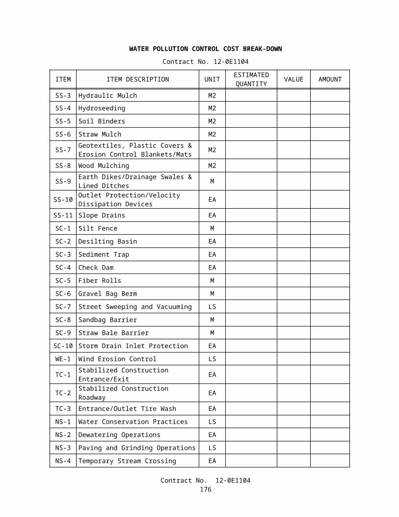
JUNCTION BOXThe Contractor shall furnish and install NEMA Type 3R junction box with hinged cover that opens sideway on the
CCTV pole as shown on the plans. The junction box shall have the minimum nominal dimensions: 406 mm (H) x 305 mm (W) x 152 mm (D) and shall be securely mounted on the pole using stainless steel straps without impeding door operation.
The junction box shall have knockout holes large enough to feed CCTV field cables with their connectors through. If the knockout holes are too small for the cables and their connectors, the Contractor shall fabricate larger holes. Grommets or linings shall be installed in these holes to protect the cables from cut.
Full compensation for junction box shall be considered as included in the contract lump sum price paid for closed circuit television system at the location involved and no additional compensation will be allowed therefor.
10-3.21 HIGH MAST VIDEO POLE ASSEMBLYThe High Mast Video Pole Assembly shall include the foundation, pole and equipment lowering device system, as
shown on the Plans, and specified in these special provisions.
GENERALInstallation of lowering device on each pole shall be made under the supervision of a trained representative of the
lowering device manufacturer at the job site. Prior to acceptance of the contract, a trained representative of the lowering device manufacturer shall demonstrate that the high mast video Pole Assembly operates properly. The demonstration shall consist of a minimum of 3 complete cycles of raising and lowering the equipment ring (complete with video apparatus) the full length of its travel, as designed, within on working day, prior to acceptance of the project.
All portion of the high mast video assembly shall have a minimum design wind velocity rating of 129 km/h.The lowering device system shall be submitted for inspection and testing. Inspection and testing shall be performed at
the project location. The lowering device system shall be demonstrated by the Contractor at his expense. Notification shall be given to the Engineer at least 7 days prior to demonstration.
After the high mast video system is in operation, the Contractor shall provide an instructional video tape (VHS), complete written instructions, and a demonstration to State maintenance personnel on the maintenance of the High Mast Video Pole Assembly, including supporting cable adjustments for the equipment ring and the procedures for the proper raising and lowering of the equipment ring.
Recommended spare parts, part lists and the operating and maintenance and service instructions, packaged with accompanying the equipment installed on the project shall be delivered to the Engineer prior to acceptance of the project.
SUBMITTALSSubmittals for the high mast video pole assemblies shall conform to the requirements in Section 86 -1.03, "Equipment
List and Drawings," of the Standard Specifications and these special provisions. Submittals shall be delivered to the Engineer prior to ordering of the high mast video assembly.
1. The Contractor shall submit descriptive data, design and installation drawings. This information shall include aiming directions for each video camera assembly, calculations and structural design, and a list of the material used for high mast video assembly. The material list shall be complete as to name of manufacturer, catalog number, size, capacity, finish, pertinent ratings, and identification symbols used on the plans or in the special provisions for each unit.
2. Each submittal shall consist of 5 copies.3. Plans and detailed drawings shall be not larger than 610 mm X 914 mm.4. Each separate item submitted shall bear a descriptive title and the State contract number.
CORROSION RESISTANCECorrosion resistance shall be provided. Methods shall include the following:
Avoidance of contact between stainless steel and carbon steel, between different types of stainless steel (including welding material), and between aluminum and ferrous materials.
Utilizing continuous welding to eliminate crevices which retain moisture.Minimizing welding of stainless steel.Use of adequate sections and suitable materials to limit stress related corrosion.
FOUNDATIONThe foundation shall conform to the requirements for cast-in-drilled hole concrete piles in Section 86-2.03,
"Foundations," of the Standard Specifications and the Plans.
Contract No. 12-0E1104178

POLEThe pole shall conform to the requirements in Section 86-2.04, "Standards, Steel Pedestals and Posts," of the Standard
Specifications, and these special provisions.The pole shall include shaft, shaft access hole with door, winch, support plate and anchor base.The shaft shall consist of sections of a round or multisided (16 sides) tapered steel tube with a uniform taper of
approximately 11.7 mm per m. Segments of multisided pole shall be convex and shall have a minimum bend radius of 102 mm. The pole shall be hot-dip galvanized after fabrication in accordance with the provisions in Section 75 -1.05, "Galvanizing," of the Standard Specifications. Steel used in fabricating the pole shall be weldable quality steel. No field welding shall be performed in the assembly of the pole.
Pole sections that slip together shall have each section permanently marked, visible from a distance of 9 m, with indexing marks to line up each section with the respective section it slips together with, and marks showing how far the sections must be slipped together.
The pole shall have a reinforced access hole to allow adequate clearance for maintaining and servicing the lowering device. Access hole reinforcement shall provide a bending strength equal to that of the pole without an opening. The access hole shall be of sufficient size to allow the removal of all installed equipment.
There shall be no electrical apparatus within the pole except for the motor, power cables, connectors and lighting bonding conductors.
The access hole shall have a door hinged to the pole. It shall open horizontally 180 degrees, and when in the open position not interfere with access to the interior of the pole.
The door shall be provided with a handle that operates a closing mechanism and incorporates a pad lock hasp type locking device. No additional hardware, including bolts, shall be used to facilitate the door to close or to secure it when closed.
The pole shall be installed with the access door towards the 334-TV cabinet.The pole shall be erected plumb. The vertical axis of the erected pole shall be within 76 mm of the theoretical vertical
axis when measured without the effect of sunlight or wind.A lightning arrestor copper cable of No. 8 AWG shall be bonded to the pole inside its base and then run in a conduit to a
6 m ground rod located within a pull box at the base of the pole.The pole shall conform to the requirements of the latest edition and interim revisions of the AASHTO "Standard
Specifications for Structural Supports for Highway Signs, Luminaires and Traffic Signals." The maximum allowable wind deflection shall not exceed 14 percent of the pole height.
An embossed aluminum plate shall be attached with rivets to the outside of each pole approximately 51 mm above the access hole. The nameplate shall indicate the name, address and telephone number of the pole manufacturer, the height of the pole, and the parameters for which the pole was designed, including wind velocity (and wind gust factors) and the maximum number of luminaires (including the weight, projected area and coefficient of drag of the luminaire used to determine it.) Luminaires shall be used for calculation purposes although video equipment (not luminaires) will actually be installed. Ten 400 W HPS high mast luminaires shall be used for calculation purposes.
CAMERA ASSEMBLY LOWERING DEVICEThe equipment lowering device shall consist of a head frame, an equipment ring and an internal power drive unit.The maximum effective projected area of the total assembly at the top of the pole, exclusive of the luminaries, shall not
exceed 0.46 m2.The maximum weight of the head frame, equipment ring and cover shall not exceed 340 kg.The head frame shall be hot rolled steel conforming to ASTM Designation: A36, and attached to the pole by means of a
steel slip fitter and secured by a minimum of 4 stainless set screws conforming to ASTM Designation: F880, Type 304. The head frame shall be hot-dip galvanized in accordance with the provisions in Section 75-1.05, "Galvanizing," of the Standard Specifications, or coated by some other method which provides equivalent corrosion resistance and is approved by the Engineer.
The head frame shall be fitted with at least 6 hoisting cable sheaves, of either galvanized or stainless steel, or aluminum, with a minimum 127 mm pith diameter. The head frame shall also be fitted with electrical power cable sheaves or rollers configured to provide a minimum bending radius as specified by the power cable manufacturer.
The hoisting cable sheaves and electrical power cable sheaves or rollers shall be fitted with suitable keepers to keep the cables in their tracks during pole erection and operation. The sheaves shall be supported by stainless steel shafts and shall be fitted with oil-impregnated sintered bronze bushings or rollers bearings.
At least 3 hoisting cables shall be supplied. The cables shall be 4.8 mm minimum diameter, 7x19 strand pre-stretched, stainless steel aircraft cable, manufactured in accordance with the Military Specification: MIL-8320B. The hoisting cables and power cable shall not rub or scrape against any portion of the system that will cause them mechanical damage.
The head frame shall be provided with a cover designed for that device and securely attached with stainless steel machine screws meeting ASTM Designation: F593, Type 304 requirements and self-locking nuts meeting the general
Contract No. 12-0E1104179
chemical requirements of ASTM Designation: F594, Type 304, or a stainless steel clamp band with a safety latch. The shape of the lowering device and cover shall be generally symmetrical about a vertical axis. The maximum weight of cover shall be 9 kg, and its maximum diameter shall be 1.07 m.
The head frame shall also include a minimum of 3 latches which support the equipment ring when the lowering device is not in operation. Latching shall be accomplished by the alternate raising and lowering of the equipment ring by the winch and hoisting assembly. When the equipment ring is raised to the top of the pole, it shall automatically latch and secure in a locked position. Automatic signaling devices shall be visible to indicate that each latch of the equipment ring is safely locked in place. Signaling devices shall be 127 mm minimum diameter.
No moving latch parts or springs shall be attached to the head frame. All moving parts of the latching mechanism shall be attached to the equipment ring and serviceable from the ground.
The equipment ring shall be fabricated of 152.4 mm x 50.8 mm gage steel channel or a member of equal strength, with the appropriate number of 50.8 mm nominal steel tube or pipe mounting arms to accommodate the number of equipment devices shown on the plans. The pipe shall conform to the requirements of ASTM Designation; A53. The ring shall be galvanized in accordance with the provisions in Section 74-1.05, "Galvanizing," of the Standard Specifications. The mounting arm shall be attached to the equipment ring in a manner which permits them to be relocated anywhere along the circumference of the ring without drilling and also allows for additional mounting arms to be symmetrically installed on the ring.
Roller-contact, spring loaded, centering arms shall be provided which shall center the equipment ring while ascending the full length of designed travel on the pole. The centering system shall be capable of keeping the ring concentric with the pole in winds up to 48 km/h. The rollers for the centering arms shall be of a water resistant, non-marking material. All axle shafts for arms and rollers shall be of stainless steel conforming to ASTM Designation: A276, Type 304. The centering system shall not allow the pole to be inadvertently wedged between the rollers and the equipment ring.
Provisions shall be made for the adjusting the equipment ring hoisting cables while in the lowered position. The Contractor shall adjust these cables to be equal length between the equipment ring and the head frame upon installation and again before completion of the contract.
A pre-wired 600 V terminal block with terminals for the camera equipment shall be installed in a NEMA Type 3R enclosure [dimension 406 mm (H) x 305 mm (W) x 152 mm (D)]. The enclosure shall be equipped with hinged door that will open sideway and a weather-proof receptacle shall be mounted on the equipment ring. When the equipment ring is lowered to ground level, the receptacle shall enable the mounted equipment to be operated and tested. The receptacle shall have a spring closed gasketed door to provide automatic weather proofing of the live terminals without tools or special effort.
A power, control, video multi-conductor cable with an appropriate locking type receptacle on its ends shall be provided (in conduit) between the 334-TV cabinet and the pole's base and another multi-conductor cable (main electrical cable) from the pole base to the CCTV assembly. The Contractor shall furnish and install appropriate "Amp-type" connectors. The former cable shall be of sufficient length to connect to the main cable via locking type connectors, when the equipment ring is in the raised position and shall be of sufficient length to reach outside through the pole's handhole to connect to the receptacle on the equipment ring to test the video camera equipment when the ring is in the lowered position.
All electrical cords shall be attached to a weather tight wiring chamber through weather tight cable connections. The main electrical cable shall be continuous and be capable of supporting its full weight when installed. The top end of the main electrical cable shall be secured through a Kellan type, strain relief grip approximately 152 mm in length, having a stainless steel endless weave and dust proof end seal.
The internal drive mechanism shall be capable of raising or lowering the equipment ring at an approximate speed of 3.4 m per minute. The winch shall be furnished with 6.4 mm minimum diameter, 7x19 strand stainless steel aircraft cable, conforming to Military Specification: MIL-8320B, of sufficient length to maintain at least one complete row of cable on the drum with the equipment ring in its fully lowered position. Winch cable shall wind uniformly and be prevented from spilling over the winch end flanges by cable guides.
The internal power drive winch unit shall include:
1. A heavy duty, totally enclosed, fan cooled, reversible universal type 120 V motor, rated at one horsepower, minimum, for continuous duty, and provide with overcurrent protection. An embossed metal plate shall be attached to the outside of the motor which states the name of the manufacturer, the horsepower, RPM, operating voltage, current, and operating conditions.
2. A torque limiter with ball or roller bearings on all rotating shafts.3. A remote control reversing switch (labeled "UP" and "DOWN") running in conduit from the base of the pole to the
Type 334-TV cabinet.4. Worm-gear driven winch. The winch shall have leak proof oil bath lubrication, steel worm reduction gears, and shall
include an integral friction drag brake to prevent spooling at the winch drum. The winch gear housing shall be provided with easily accessible removable plugs for filling, checking the proper level, or draining the winch lubricating oil with the winch in place. The winch drum shaft shall be supported at both ends. The winch drum end
Contract No. 12-0E1104180
flanges shall be sized 25 mm larger in radius than the radius of the fully wound drum. The axis of the winch drum shall be set perpendicular to the axis of the pole, and verified by the Engineer after pole installation by the Contractor using a bubble level.
5. Mounting frame.6. Weatherproof step down transformer, if necessary, of sufficient power to supply the motor and provided overcurrent
protection. The transformer when installed inside the pole, shall be removable without removing any other components.
7. Other equipment as necessary.
All internal power drive winch unit components shall be removable through the access hole as a units for repair or replacement.
TESTINGThe Contractor shall conduct tests on the operation of the lowering device by raising and lowering the equipment ring
three complete cycles. The Contractor shall set limit stops and also conduct test on the high mast CCTV system to verify proper installation and operation as per these special provisions.
Full compensation for high mast video pole assembly, including furnishing all labor, materials, tools, equipment, incidentals, and for doing all the work involved in high mast video pole assembly, complete in place, including testing, documentation, and all cable and wiring necessary to make the high mast video pole assembly functional and operational as shown on the plans, as specified in the Standard Specifications and these special provisions, and as directed by the Engineer shall be included in the contract lump sum paid for closed circuit television system at the location involved and no additional compensation will be allowed therefor.
10-3.22 MULTI-CONDUCTOR CABLEThe video/control/power cables include, one 3 pair No. 22 AWG (3PR#22), one 5 pair No. 26 AWG (5PR#26) shielded
twisted pair cables, and a flexible 75 Ω coaxial cable to connect Camera Assembly to AC power source and communication equipment.
The coaxial cable shall be Belden 8241F or equal. Appropriate connectors for interconnect cables shall be furnished and installed in accordance with manufacturer's recommended procedures.
The 3PR#22 cable shall consist of 6 tinned standard conductor (7x26) of high conductivity No. 22 AWG copper conductor with numbered PVC insulated nylon overcoat insulation. The cable outer jacket shall have 1.6 mm minimum thickness, the conductor insulation shall be a minimum 0.41 mm PVC and 0.13 mm nylon in thickness. The overall cable thickness shall not exceed 16 mm. The 3PR#22 shall be used to supply power to the camera and pan/tilt unit.
The 5PR#26 cable shall consist of 10 tinned stranded conductor (7x26) of high conductivity No. 26 AWG copper conductor with numbered PVC insulated nylon overcoat insulation. The cable outer jacket shall have a minimum thickness of 1.6 mm. The individual conductors insulation shall have a minimum of 0.41 mm PVC and 0.13 mm nylon in thickness. The overall cable thickness shall not exceed 21 mm. The 5PR#26 shall be used for camera and lens control functions.
The 3PR#22 and 5PR#26 cables shall be rated at 300 V at 90°C. The cable jacket shall be marked with the manufacturer's name and part number, the insulation type designation, voltage and temperature ratings. The cable shall have the mechanical strength to support at least 30 vertical meter of its own weight.
All 115 V(ac) carrying conductors shall be from the 3PR#22 cable. Interconnect wiring and connectors shall be supplied and installed to make the CCTV system completely operational.
Specifications of all cable assemblies, including connectors with strain relief backshells, shall be submitted to the Engineer as part of the shop drawings for review and approval.
Continuous wiring shall be installed from source to destination. No splices shall be allowed. Coaxial cables shall be installed without damaging the conductors, insulation, or jacket. The coaxial cables shall not be kinked and the manufacturer's recommended bending radius shall be maintained.
Sufficient slack shall be provided for equipment movement.Cable strain relief shall be installed.All cabling shall be secured and protected from physical damage.All interconnecting wiring and connectors shall meet all necessary standards for voltage, current, and environmental
ratings.All wiring and connectors required to connect Camera Assembly with the power source and the communication
equipment shall be provided by the Contractor.. The main connector shall be equivalent to AMP 206037-1 with AMP 206070-1 back shell and AMP 66584-4 socket
pins.A solid No. 8 AWG ground wire shall be provided between the camera assembly and the CCTV cabinet ground rod.
Contract No. 12-0E1104181
CCTV ASSEMBLY DOCUMENTATIONThe Contractor shall provide each CCTV assembly with a copy of detailed documentation, containing specifications,
parts list, operating, maintenance procedures, and wiring diagram (including but not limited to conductor color, function, connector and pin assignments).
TESTING AND DOCUMENTATIONThe Contractor shall be responsible for all testing and documentation required for approval and acceptance of the
production, installation, and operation of these materials and equipment. The following identifies the specific quality control requirements for testing and documentation:
The Contractor shall test all cables after installation with connectors attached for continuity and shorts or grounds.The Contractor shall adjust and set limit stops to the pan/tilt unit at each camera site to prevent the view of the areas
outside of the roadway system. The final settings shall be approved by the Engineer.The Contractor shall perform a local functional test at each of the CCTV locations and shall demonstrate to the
Engineer all the CCTV features.
Full compensation for CCTV testing shall be considered as included in the contract lump sum price paid for closed circuit television system at the location involved and no additional compensation will be allowed therefor.
10-3.23 SERVICE AT TOLL PLAZAService at tool plaza shall consist of installing transformer, conduits, conductors, circuit breakers, receptacles and
incidental materials and work to provide a fully functioning system as shown on the plans and as directed by the engineer.The contract unit price paid per each for service at toll plaza shall include full compensation for furnishing all labor,
materials, tools, equipment, and incidentals, and for doing all the work involved in service at toll plaza complete in place, as shown on the plans, as specified in the Standard Specifications and these special provisions, and as directed by the Engineer.
10-3.24 EQUIPMENT AT IRVINE RANCH MAINLINE TOLL PLAZA (N/B ROUTE 133, ROUTE 241)The toll plaza consists of Communication Equipment Cabinet, FDU, and other material and equipment as shown on the
plans and these specifications.
EQUIPMENT AT THE TOLL PLAZAThe following equipment shall be provided by the Contractor:
Qty Description2 Communication Equipment Cabinet2 FDU1 DB-9 Patch Panel
The communication equipment cabinet, and FDU are specified elsewhere in these special provisions.
10-3.25 EQUIPMENT AT CATALINA VIEW TOLL PLAZA (S/B ROUTE 73, NEWPORT COAST DRIVE)The toll plaza consists of Communication Equipment Cabinet, FDU, and other material and equipment as shown on the
plans and these specifications.The Communication Equipment Cabinet and FDU are specified elsewhere in these special provisions.The equipment at the toll plaza data node shall also include any ancillary or incidental items required to provide full
equipment operation at each site.
EQUIPMENT AT THE TOLL PLAZAThe following equipment shall be provided by the Contractor:
Qty Description2 Communication Equipment Cabinet2 FDU1 DB-9 Patch Panel
Contract No. 12-0E1104182
10-3.26 EQUIPMENT AT TOMATO SPRINGS MAINLINE TOLL PLAZA (N/B ROUTE 241, PORTOLA)The toll plaza consists of Communication Equipment Cabinet, FDU and other material and equipment as shown on the
plans and these specifications.The equipment at the toll plaza shall also include any ancillary or incidental items required to provide full equipment
operation at each site.
EQUIPMENT AT THE TOLL PLAZAThe following equipment shall be provided by the Contractor:
Qty Description2 Communication Equipment Cabinet2 FDU1 DB-9 Patch Panel
The communication equipment cabinet and FDU are specified elsewhere in these special provisions.
10-3.27 EQUIPMENT AT WINDY RIDGE MAINLINE TOLL PLAZA (N/B ROUTE 241, WINDY RIDGE ROAD)The toll plaza consists of Communication Equipment Cabinet, FDU and other material and equipment as shown on the
plans and these specifications.The equipment at the toll plaza shall also include any ancillary or incidental items required to provide full equipment
operation at each site.
EQUIPMENT AT THE TOLL PLAZAThe following equipment shall be provided by the Contractor:
Qty Description2 Communication Equipment Cabinet2 FDU1 DB-9 Patch Panel
The communication equipment cabinet and FDU are specified elsewhere in these special provisions.
10-3.28 EQUIPMENT AT EXISTING TRAFFIC MANAGEMENT CENTERThe following equipment shall be provided by the Contractor at the existing Traffic Management Center (TMC), located
at the Department of Transportation Building, 6681 Marine Way, Irvine, CA 92618 shall consist of the following:
Qty Description3 TMC Cabinet2 FDU3 DB-9 Patch Panel
The equipment at the TMC shall also include any ancillary or incidental items required to provide full equipment operation at each site.
10-3.29 COMMUNICATION SYSTEMGENERALThe communication system equipment shall be designed for testing, monitoring, and adjustment without service
interruption.Front access shall be provided for all routine adjustments normally required to be performed by field personnel.
INTERFACE TO EXISTING CLOSED CIRCUIT TELEVISIONThe fiber optic system shall interface to existing closed circuit television as shown on the plans. The following
equipment shall be provided at each of the existing closed circuit television locations:
FDUInterface cable
Contract No. 12-0E1104183
The FDU is specified elsewhere in these special provisions.The encoder will be State-furnished and installed by others.
10-3.30 COMMUNICATION EQUIPMENT CABINETThe communication equipment cabinets shall be installed at the TMC and at the various toll plazas and shall meet the
following parameters and features:
General:Freestanding.Front smoked plexiglass viewing door and rear vented steel door.Frame and mounting rails.Removable side panels and vented, removable roof panel.Must allow for baying of multiple cabinets.Must be supplied with 50 each M6 chrome screws and protective washers for use on the 482 mm rails.All mounting hardware shall be provided such that no drilling on the cabinet is necessary.Cable entry panel on the bottom.50 mm high plinth base.4 each leveling feet.Integrated cable trough and power strip mounting area.Equipment grounding rails and grounding straps.Cable conduits and conduit clips.Gland panel with foam rubber cable clamp for cable attachment to cabinet frame.Blanking panels with vertical hinges for blank spaces.Equipment identification strip.2 each rack mounted shelves.2 each component shelves with telescopic slides and shelf handles.Overall cabinet dimensions: 2000 mm (H) by 600 mm (W) by 650 mm (D) with no less than 40 rack units
(1780 mm) of vertical rack mounting space.Must conform to and accept installation to DIN41494 and EIA 310-C, and IEC 297-1. Must hold a protection
rating of IP20 or better.
Doors:Front door shall be of smoked acrylic glass of 3 mm thick with aluminum extruded square tubing and cast
corner piece frame assembly to provide rigidity.Rear door shall be of aluminum frame with 1 mm sheet steel with a vented portion on the bottom.Each door must have the following:
Quick release hinge mechanism which shall require no tools to operate.Two point latching mechanism for attachment to cabinet frame.Allowance for reversibility of hinging without the use of tools.A safety handle and a push-button and key lock insert for activation.Door stop mechanism on the bottom section.
Sidewalls:Cabinet must include 2 side panels.Sides shall be removable with 4 screws per side.Material shall be 0.75 mm cold rolled steel.
Frame:Frame shall be of a roll formed construction of 1.5 mm steel.All frame members shall include a repeatable hole pattern of square and round holes located on alternating
25 mm centers. Round holes shall accept self tapping screws. Square holes shall accept cage or spring nuts.Rear vertical members of frame shall allow for flush installation of 6 outlet power strips in no less than 10
locations. This space may also allow for cable runway and will include a 50 mm hole at the top and bottom of the vertical section to allow for cable passage.
Top of frame shall be constructed such that a fan package may be installed to the frame without taking any vertical rack space from the cabinet and without being mounted above the top of the cabinet.
Contract No. 12-0E1104184
Rails:Depth adjustable 482 mm rails mounted front rear and shall be made of 1.63 mm sheet steel.
Roof:Roof panel shall be ventilated with a perforation pattern of round through holes.Roof panel shall be removable via 4 screws.Roof panel shall be constructed of 0.75 mm steel.
Fans:A 6-fan tray with 4 fans shall be installed into the roof frame without reducing the storage height of 1780 mm.
Each fan shall meet the following requirements:
Operating voltage 220 V, 60/50 HzOutput power 18 W/fanNoise level 46 dB (A)Speed 2650 rpmDisplacement 160 m3
/h (unimpeded air flow)
Operating temperature -10C to +55CMaximum static pressure 0.993 MPa
Finish:Cabinet shall be electrostatically painted with deep-bath primed, textured baked enamel.Door frames, handles, and sidewall trims shall be painted in accordance with color number RAL7030 (Stone
Gray).Basic cabinet (frame, shelves, side panels, roof, bottom, and rear door) color shall be painted in accordance with
color number RAL7035 (Light Gray).
10-3.31 SYSTEM TESTING AND DOCUMENTIONFIBER OPTIC TESTING
GeneralTesting shall include the tests on elements of the passive fiber optic components: (1) at the factory, (2) after delivery to
the project site but prior to installation (3) after installation but prior to connection to any other portion of the system, and (4) during final system testing. The active components shall be tested after installation. The Contractor shall provide all personnel, equipment, instrumentation and materials necessary to perform all testing. The Engineer shall be notified two working days prior to all field tests. The notification shall include the exact location or portion of the system to be tested.
Documentation of all test results shall be provided to the Engineer within 2 working days after the test involved. Prior to arrival of the cable, the Contractor shall provide detailed test procedures for all field testing. The procedures
shall include the tests involved and how the tests are to be conducted.
FACTORY TESTINGVerification of the fiber specifications as listed in the Fiber Characteristics Table shall be supplied by the manufacturer
with the appropriate documentation. After cabling, before shipment but while on the shipping reel, 100 percent of all fibers shall be tested for attenuation. Copies of the results shall be (1) maintained on file by the manufacturer with a file identification number for a minimum of 7 years, (2) attached to the cable reel in a waterproof pouch, and (3) submitted to the Contractor and to the Engineer.
ARRIVAL ON SITEThe cable and reel shall be physically inspected on delivery and 100 percent of the fibers shall be attenuation tested to
confirm that the cable meets requirements. Test results shall be recorded, dated, compared and filed with the copy accompanying the shipping reel in a weather proof envelope. Attenuation deviations from the shipping records greater than 5 percent shall be brought to the attention of the Engineer. The cable shall not be installed until completion of this test sequence and the Engineer provides written approval. Copies of traces and test results shall be submitted to the Engineer. If the test results are unsatisfactory, the reel of F/O cable shall be considered unacceptable and all records corresponding to that reel of cable shall be marked accordingly. The unsatisfactory reels of cable shall be replaced with new reels of cable at the
Contract No. 12-0E1104185
Contractor's expense. The new reels of cable shall then be tested to demonstrate acceptability. Copies of the test results shall be submitted to the Engineer.
AFTER CABLE INSTALLATIONAfter the fiber optic cable has been pulled but before breakout and termination, 100 percent of all the fibers shall be
tested with an OTDR for attenuation. Test results shall be recorded, dated, compared and filed with the previous copies of these tests. Copies of traces and test results shall be submitted to the Engineer. If the OTDR test results are unsatisfactory, the F/O cable shall be replaced at the Contractor's expense. The new cable shall then be tested to demonstrate acceptability. Copies of the test results shall be submitted to the Engineer.
Attenuation tests shall be performed with an OTDR capable of recording and displaying anomalies of 0.02 dB as a minimum. Singlemode fibers shall be tested at 1310 nm and 1550 nm. Attenuation readings for each direction shall be recorded on the cable data sheet.
The OTDR shall have a printer capable of producing a verifying test trace with fiber identification as shown in Appendix A "Link Loss Budget Work Sheet", numerical loss values, the date and the operator's name. It shall also have a DOS based 89 mm disk recording capability that has associated software to do comparisons and reproductions on 215 mm x 279 mm paper, via a personal computer.
OUTDOOR SPLICESAt the conclusion of all outdoor splices at one location, and before they are enclosed and sealed, all splices shall be
tested with the OTDR, in both directions. Splices in singlemode segments shall be tested at 1310 nm and at 1550 nm. Individual fusion splice losses shall not exceed 0.07 dB. Measurement results shall be recorded, dated, validated by the OTDR trace printout and filed with the records of the respective cable runs. Copies of traces and test results shall be submitted to the Engineer. If the OTDR test results are unsatisfactory, the splice shall be unacceptable. The unsatisfactory splice shall be replaced at the Contractor's expense. The new splice shall then be tested to demonstrate acceptability. Copies of the test results shall be submitted to the Engineer.
DISTRIBUTION INTERCONNECT PACKAGE TESTING AND DOCUMENTATIONAll the components of the passive interconnect package (FDU), pigtails, jumpers, couplers and splice trays) shall
comprise a unit from a manufacturer who is regularly engaged in the production of the fiber optic components described.In developing the distribution interconnect package, each SC termination (pigtail or jumper) shall be tested for insertion
attenuation loss with the use of an optical power meter and source. In addition, all singlemode terminations shall be tested for return reflection loss. These values shall meet the loss requirements specified earlier and shall be recorded on a tag attached to the pigtail or jumper.
Once assembly is complete, the manufacturer shall visually verify that all tagging, including loss values, is complete. Then as a final quality control measure, the manufacturer shall do an "end to end" optical power meter/light source test from pigtail end to jumper lead end to assure continuity and overall attenuation loss values.
The final test results shall be recorded, along with previous individual component values, on a special form assigned to each FDU. The completed form shall be dated and signed by the Manufacturer's Quality Control supervisor. One copy of this form will be attached in a plastic envelope to the assembled FDU unit. Copies will be provided separately to the Contractor and to the Engineer, and shall be also be maintained on file by the manufacturer or supplier.
The assembled and completed FDU unit shall then be protectively packaged for shipment to the Contractor for installation.
FIBER OPTIC SYSTEM GAIN MARGINThe installed system gain margin shall be at least 6 dB for each and every link. If the design system gain margin is less
than 6 dB, the Engineer shall be notified and informed of the Contractor's plan to meet that requirement.
ACTIVE COMPONENT TESTINGThe transmitters and receivers shall be tested with a power meter and light source, to record the transmitter average
output power (dBm) and receiver sensitivity (dBm). These values shall be recorded in the Link Loss Budget Worksheet shown in Appendix A.
SYSTEM VERIFICATION AT COMPLETIONOTDR Testing.-Once the passive cabling system has been installed and is ready for activation, 100 percent of the fiber
links shall be tested with the OTDR for attenuation. Test results shall be recorded, dated, compared and filed with previous copies. A hard copy printout and a electronic copy of the traces and test results along with a licensed copy of the associated
Contract No. 12-0E1104186
software on a DOS based 89 mm disk shall be submitted to the Engineer. If the OTDR test results are unsatisfactory the link shall be replaced at the Contractor's expense. The new link shall then be tested to demonstrate acceptability. Copies of the test results shall be submitted to the Engineer.
Installed System Link Loss Budget.-The Link Loss Budget Worksheet shown in Appendix A shall be completed for each link in the fiber optic system, using the data gathered throughout the installation process. The completed worksheets shall be included as part of the system documentation.
The Total System Gain shall be calculated by subtracting the measured Optical Receiver Sensitivity (line 1B on The Link Loss Budget Worksheet) from the measured Optical Transmitter Average Power (line 1A), which were obtained using a power meter and source. The resulting difference shall be the maximum allowable loss between the transmitter and the receiver, within 0 percent to +10 percent of the manufacturers specified loss budget for the transmitter/receiver pair. The Total System Gain shall be recorded on line 1C.
The Fiber Losses for a link shall be calculated by multiplying the length of the fiber link (line 2A) by the normalized cable attenuation (dB/km, line 2B) at the operating wavelength. The normalized attenuation for this calculation shall be the maximum value throughout the operating temperature range of the cable. The product shall be recorded on line 2C.
The total connector losses shall be calculated by summing the individual attenuation values for each connector pair in the link, excluding the transmitter and receiver connectors. The sum shall be recorded on line 2D.
The total splice losses shall be calculated by summing the individual attenuation values for each splice in the link. The sum shall be recorded on line 2E.
The total of other losses shall be calculated by summing the individual attenuation values for each component in the link not previously addressed. The sum shall be recorded on line 2F. These items may include, but are not limited to, couplers, splitters, routers and switches.
The Total System Loss shall be recorded on line 2G of the Link Loss Budget Worksheet.The Design System Gain Margin shall be calculated by subtracting the Total System Loss (line 2G) from the Total
System Gain (line 1C). The resulting difference shall be recorded on line 3A. The Contractor's attention is directed to "F/O System Gain Margin," elsewhere in these special provisions.
Power Meter and Light Source.-At the conclusion of the final OTDR testing, 100 percent of all fibers shall be tested end to end with a power meter and light source, in accordance with EIA Optical Test Procedure 171 and in the same wavelengths specified for the OTDR tests. These tests shall be conducted in both directions. Test results shall be recorded, compared and proven to be within the design link loss budgets, and filed with the other recordings of the same links. Test results shall be submitted to the Engineer.
Test Failures.-If during any of these system verification tests, the results prove to be unsatisfactory, the F/O cable will not be accepted. The unsatisfactory segments of cable shall be replaced with a new segment of cable at the Contractor's expense. The new segment of cable shall undergo the same testing procedure to determine acceptability. Copies of the test results shall be submitted to the Engineer. The removal and replacement of a segment of cable shall be interpreted as the removal and replacement of a single contiguous length of cable connecting two splices, two connectors, or a splice and a connector. The removal of only the small section containing the failure and therefore introducing new unplanned splices, will not be allowed.
Contract No. 12-0E1104187

APPENDIX A
Link Loss Budget Worksheet
Contract No. __________
Contractor: ____________________
Approved by Caltrans: ___________
Date: ____________ Operator:_______________
Link Number: ___________ Fiber Color: ____________
Buffer Color: ___________ Cable #: ________________
Test Wavelength (Circle one): 1310 nm 1550 nm
Section 1: Total System GainMeasured Optical Transmitter Average Power: Measured Optical Receiver Sensitivity (this should be a negative value):
_________ dBm
_________ dBm
1A
1B
Subtract line 1B from 1A to obtain Total System Gain: _________ dB 1C
Section 2: Total System Loss Measured length of the link:Measured loss per km of the fiber:
_________ km _________ dB/km
2A2B
Multiply line 2A by 2B to obtain the Total Fiber Loss: _________ dB 2C
Sum of all Connector Losses in the link:Sum of all Splice Losses in the link:Sum of all Other Losses from other components (couplers, splitters, routers, switches, etc.)
_________ dB_________ dB
_________ dB
2D2E
2F
Add lines 2C, 2D, 2E and 2F to obtain Total System Loss: _________ dB 2G
Section 3: Design System Gain MarginSubtract line 2G from line 1C (This number must be at least 6 dB): _________ dB 3A
Contract No. 12-0E1104188
SYSTEM DOCUMENTATIONThe Contractor shall submit a draft copy of all documentation for review and approval prior to production of
documentation. The Engineer will review and approve or reject the draft documentation within four weeks of receipt.The Contractor shall modify the documentation if required and submit provisional documentation. The Engineer will
approve or reject the provisional documentation within three weeks of receipt. The Contractor shall arrange for re-submission in a timely manner to meet the schedule in the case that the documents are being rejected.
Draft documentation shall be submitted eight weeks prior to the start of installation. The draft documentation shall show the general approach in preparing the final manuals.
Upon approval of the draft documentation, provisional documentation shall be supplied 3 weeks prior to the start of site testing. The provisional documentation shall be of the same format as the final manuals but with temporary insertion for items which cannot be finalized until the system is completed, tested and accepted. Final documentation shall be submitted no later than 4 weeks after completion of the acceptance tests and shall incorporate all comments made during the approval stages. The Contractor shall be responsible for all delay caused by non-compliance to the specified requirements.
Final documentation shall be approved prior to its production.Ten copies of all final documents shall be delivered. The copies shall be 215 mm x 279 mm and bound in three-ring,
hard-covered binders, complete with dividers.Documentation shall consist of the following types of manuals and drawings and shall include the information described.The operations and maintenance manual shall provide all the information necessary to operate, maintain and repair the
equipment and cable to the lowest module or component level. It shall contain as a minimum the following:
Master Items IndexThe master items index section shall be the first section of the O & M manual. The section shall describe the purpose of
each manual and brief description to the directory of the manual. It shall also reference equipment manuals as required for additional and support material.
System Description and Technical DataThe system description and technical data section of the operations and maintenance manual shall contain an overall
description of the system and associated equipment and cables with illustrative block diagrams. This section shall identify all equipment and cables in the system stating the exact module and option number that are employed in the system. Technical data, specification and settings for every type of equipment or cable shall be provided. Any modification that has been done on the equipment shall be clearly described.
Theory of OperationThe manual shall contain a theory of operation section providing functional description of each element of the system,
explaining how each function is being achieved separately and how each element works together to form the complete system.
Configuration of Hardware and Software DocumentationThe operations and maintenance manual shall provide proper documentation for all configuration of hardware and
software. The configuration of hardware and software documentation shall include a clear description of the system's functionalities and specifications. Description on each configuration of hardware and software modules and programs shall be provided.
OperationsThe operations and maintenance manual shall describe how to operate the system and each particular type of equipment
and software. Equipment layout, layout of controls, displays, software operating procedures and all other information required to correctly operate the system and each functional unit shall be provided. Procedures shall also be provided for initial tune-up of the system and adjustment and checkout required to ensure that the system is functioning within the performance requirements. Warning of special procedures shall be given. The functions and setting of all parameters shall be explained.
Corrective MaintenanceThe operations and maintenance manual shall include fault diagnostic and repair procedures to permit locating and
correcting faults at the replaceable module level. Procedures shall include alignment and testing of the equipment following repair, the test equipment, tools, diagnostic software required and the test set up.
Contract No. 12-0E1104189
Preventative MaintenanceThe operations and maintenance manual shall include procedures for preventative maintenance in order to maintain the
performance parameters of the system, equipment and cables within the requirements of the specifications.
Parts ListThe operations and maintenance manual shall include a list of all replaceable parts with exact parts description and
number and a directory of recommended suppliers with correspondence address, telephone and fax numbers.
Test ResultsThe test result section of the operations and maintenance shall include a copy of the results for all the tests that have been
conducted by the Contractor.System schematic drawings shall be provided to identify the type of equipment at each location and the function of all
equipment. The drawings shall also show how the system is interconnected. A comprehensive list of cabling and wiring shall be provided to clearly identify the interconnection and labeling of all equipment both in the field , different plazas and at the TMC.
PAYMENTThe contract lump sum price paid for system testing and documentation shall include full compensation for furnishing all
labor, materials, tools, equipment, and incidentals, and for doing all the work involved in system testing and documentation, complete in place, as shown on the plans, as specified in the Standard Specifications and these special provisions, and as directed by the Engineer.
10-3.32 TRAININGDESCRIPTIONAn operation and maintenance training course shall be developed by the Contractor and presented to the Engineer. A
training area will be provided by the State at the District Office Building in Irvine, California or District Maintenance Yard in Orange, California. The Contractor may provide the training at the plant or office if it is located within reasonable travel distance (approximately one hour travel time) from the district office.
The operation and maintenance course shall provide training for technical personnel, and shall follow a training outline prepared by the Contractor. The Contractor shall provide all materials and instructors for the maintenance course. The course shall not be less than three eight-hour (excluding lunch and breaks) days in duration. No more than thirty State employees with technical backgrounds will attend this course. Each person shall receive a training manual. The remaining manuals shall be given to the Engineer for redistribution to other employees. The training manual shall be written especially for the CCTV and Communication System installed by the Contractor and shall provide complete procedures for operating, maintaining, and trouble-shooting the cable plant, camera site equipment, and equipment located at the TMC. The maintenance section of the training course shall cover preventive, routine and emergency maintenance procedures. The emergency maintenance discussion shall provide recommendations for the provisioning and use of emergency repair kits to assist maintenance crews.
The maintenance course shall also include "hands on" field training using operational equipment at one of the data and video nodes, at hubs, and at the TMC. The field training shall include the operational checkout of a camera site and shall discuss the location of and access to the various system field elements.
The information for this course shall be separated into appropriately titled sections such as:
A. System Design.B. Hardware.C. Software.D. Operation.E. Maintenance.F. Operating System.G. Equipment list and vendor.
All manuals provided for this course shall be collected at the completion of each course by the Instructor and delivered to the Engineer for later distribution to State personnel. The Contractor shall provide an evaluation sheet to be completed by the attendees. The evaluation sheets will be turned in to the Engineer and a copy will be provided to the Contractor. One copy of the manual for this course shall be delivered to the Engineer for approval at least 8 weeks prior to the scheduled class time. The Engineer will notify the Contractor of the number of State personnel who will attend. Course documentation shall be
Contract No. 12-0E1104190
delivered to the Engineer one week before the scheduled start date of the class. The operation and maintenance course shall be completed prior to the acceptance of the contract.
PAYMENTThe contract lump sum price paid for training shall include full compensation for furnishing all labor, materials, tools,
equipment, and incidentals and for doing all the work involved in training, complete in place, as specified in the Standard Specifications and these special provisions, and as directed by the Engineer.
10-3.33 PAYMENTThe contract unit price paid for interface to existing traffic system shall include full compensation for furnishing and
installing all labor, materials, tools, equipment, and incidentals, for doing all the work involved in interfacing to existing traffic system complete in place, including FDU, and interface cable as shown on the plans, as specified in the Standard Specifications and these special provisions, and as directed by the Engineer.
The contract lump sum prices paid for Irvine Ranch Toll Plaza, Catalina View Toll Plaza, Tomato Springs Toll Plaza, Windy Ridge Toll Plaza, the Traffic Management Center shall include full compensation for furnishing all labor, materials, tools, equipment, and incidentals, and for doing all the work involved installation, configuration and integration of the state furnished video encoders at the specified closed circuit television system sites as shown on the plans, as specified in the Standard Specifications and these special provisions, and as directed by the Engineer.
The contract unit price paid for interface to existing closed circuit television system shall include full compensation for furnishing and installing all labor, materials, tools, equipment, and incidentals, and for doing all the work involved in interface to existing closed circuit television system, complete in place, including FDU and interface cables as shown on the plans, as specified in the Standard Specifications and these special provisions, and as directed by the Engineer.
The contract unit price paid for communication pull box shall include full compensation for furnishing all labor, materials, tools, equipment, and incidentals, and for doing all the work involved in installing communication pull box, complete in place, as shown on the plans, as specified in these special provisions, and as directed by the Engineer.
The contract unit price paid for No. 5 pull box shall include full compensation for furnishing all labor, materials, tools, equipment, and incidentals, and for doing all the work involved in installing No. 5 pull box, complete in place, as shown on the plans, as specified in these special provisions, and as directed by the Engineer.
The contract price paid per meter for fiber optic cable Type B, C and D shall include full compensation for furnishing all labor, materials, tools, equipment, and incidentals, and for doing all the work involved in installing fiber optic cable, complete in place, as shown on the plans, as specified in the Standard Specifications and these special provisions, and as directed by the Engineer.
The contract price paid per meter for remove and reinstall transportation corridor agency fiber optic cables shall include full compensation for furnishing all labor, materials, tools, equipment, and incidentals, and for doing all the work involved in remove and reinstall fiber optic cables, complete in place, as shown on the plans, as specified in the Standard Specifications and these special provisions, and as directed by the Engineer.
SECTION 11. (BLANK)
SECTION 12. (BLANK)
SECTION 13. (BLANK)
Contract No. 12-0E1104191
SECTION 14 FEDERAL REQUIREMENTS FOR FEDERAL-AID CONSTRUCTION PROJECTSGENERAL.—The work herein proposed will be financed in whole or in part with Federal funds, and therefore all of the
statutes, rules and regulations promulgated by the Federal Government and applicable to work financed in whole or in part with Federal funds will apply to such work. The "Required Contract Provisions, Federal-Aid Construction Contracts, "Form FHWA 1273, are included in this Section 14. Whenever in said required contract provisions references are made to "SHA contracting officer," "SHA resident engineer," or "authorized representative of the SHA," such references shall be construed to mean "Engineer" as defined in Section 1-1.18 of the Standard Specifications.
PERFORMANCE OF PREVIOUS CONTRACT.—In addition to the provisions in Section II, "Nondiscrimination," and Section VII, "Subletting or Assigning the Contract," of the required contract provisions, the Contractor shall comply with the following:
The bidder shall execute the CERTIFICATION WITH REGARD TO THE PERFORMANCE OF PREVIOUS CONTRACTS OR SUBCONTRACTS SUBJECT TO THE EQUAL OPPORTUNITY CLAUSE AND THE FILING OF REQUIRED REPORTS located in the proposal. No request for subletting or assigning any portion of the contract in excess of $10,000 will be considered under the provisions of Section VII of the required contract provisions unless such request is accompanied by the CERTIFICATION referred to above, executed by the proposed subcontractor.
NON-COLLUSION PROVISION.—The provisions in this section are applicable to all contracts except contracts for Federal Aid Secondary projects.
Title 23, United States Code, Section 112, requires as a condition precedent to approval by the Federal Highway Administrator of the contract for this work that each bidder file a sworn statement executed by, or on behalf of, the person, firm, association, or corporation to whom such contract is to be awarded, certifying that such person, firm, association, or corporation has not, either directly or indirectly, entered into any agreement, participated in any collusion, or otherwise taken any action in restraint of free competitive bidding in connection with the submitted bid. A form to make the non-collusion affidavit statement required by Section 112 as a certification under penalty of perjury rather than as a sworn statement as permitted by 28, USC, Sec. 1746, is included in the proposal.
PARTICIPATION BY MINORITY BUSINESS ENTERPRISES IN SUBCONTRACTING.—Part 23, Title 49, Code of Federal Regulations applies to this Federal-aid project. Pertinent sections of said Code are incorporated in part or in its entirety within other sections of these special provisions.
Schedule B—Information for Determining Joint Venture Eligibility
(This form need not be filled in if all joint venture firms are minority owned.)
1. Name of joint venture __________________________________________________________________________2. Address of joint venture ________________________________________________________________________3. Phone number of joint venture ___________________________________________________________________4. Identify the firms which comprise the joint venture. (The MBE partner must complete Schedule A.) ___________
____________________________________________________________________________________________
a. Describe the role of the MBE firm in the joint venture. _____________________________________________________________________________________________________________________________________
b. Describe very briefly the experience and business qualifications of each non-MBE joint venturer: ____________________________________________________________________________________________________
5. Nature of the joint venture's business ___________________________________________________________________________________________________________________________________________________________
6. Provide a copy of the joint venture agreement.7. What is the claimed percentage of MBE ownership? __________________________________________________8. Ownership of joint venture: (This need not be filled in if described in the joint venture agreement, provided by
question 6.).
a. Profit and loss sharing.b. Capital contributions, including equipment.
Contract No. 12-0E1104192
c. Other applicable ownership interests.
9. Control of and participation in this contract. Identify by name, race, sex, and "firm" those individuals (and their titles) who are responsible for day-to-day management and policy decision making, including, but not limited to, those with prime responsibility for:
a. Financial decisions ________________________________________________________________________b. Management decisions, such as:
(1) Estimating ___________________________________________________________________________(2) Marketing and sales ____________________________________________________________________(3) Hiring and firing of management personnel _________________________________________________
_____________________________________________________________________________________(4) Purchasing of major items or supplies ______________________________________________________
_____________________________________________________________________________________
c. Supervision of field operations _______________________________________________________________
Note.—If, after filing this Schedule B and before the completion of the joint venture's work on the contract covered by this regulation, there is any significant change in the information submitted, the joint venture must inform the grantee, either directly or through the prime contractor if the joint venture is a subcontractor.
Affidavit"The undersigned swear that the foregoing statements are correct and include all material information necessary to
identify and explain the terms and operation of our joint venture and the intended participation by each joint venturer in the undertaking. Further, the undersigned covenant and agree to provide to grantee current, complete and accurate information regarding actual joint venture work and the payment therefor and any proposed changes in any of the joint venture arrangements and to permit the audit and examination of the books, records and files of the joint venture, or those of each joint venturer relevant to the joint venture, by authorized representatives of the grantee or the Federal funding agency. Any material misrepresentation will be grounds for terminating any contract which may be awarded and for initiating action under Federal or State laws concerning false statements."
____________________________________________________________________________Name of Firm Name of Firm
____________________________________________________________________________Signature Signature
____________________________________________________________________________Name Name
____________________________________________________________________________Title Title
____________________________________________________________________________Date Date
Contract No. 12-0E1104193
Date _______________________________________________
State of ____________________________________________
County of __________________________________________
On this ____ day of _______________, 20___, before me appeared (Name) _________________, to me personally known, who, being duly sworn, did execute the foregoing affidavit, and did state that he or she was properly authorized by (Name of firm) ________________________________ to execute the affidavit and did so as his or her free act and deed.
Notary Public __________________________________________
Commission expires _____________________________________
[Seal]
Date _______________________________________________
State of ____________________________________________
County of __________________________________________
On this ___ day of _______________, 20___, before me appeared (Name) _________________ to me personally known, who, being duly sworn, did execute the foregoing affidavit, and did state that he or she was properly authorized by (Name of firm) ___________________________ to execute the affidavit and did so as his or her free act and deed.
Notary Public __________________________________________
Commission expires _____________________________________
[Seal]
Contract No. 12-0E1104194
REQUIRED CONTRACT PROVISIONSFEDERAL-AID CONSTRUCTION CONTRACTS
I. GENERAL1. These contract provisions shall apply to all work performed on the contract by the contractor's own organization and
with the assistance of workers under the contractor's immediate superintendence and to all work performed on the contract by piecework, station work, or by subcontract.
2. Except as otherwise provided for in each section, the contractor shall insert in each subcontract all of the stipulations contained in these Required Contract Provisions, and further require their inclusion in any lower tier subcontract or purchase order that may in turn be made. The Required Contract Provisions shall not be incorporated by reference in any case. The prime contractor shall be responsible for compliance by any subcontractor or lower tier subcontractor with these Required Contract Provisions.
3. A breach of any of the stipulations contained in these Required Contract Provisions shall be sufficient grounds for termination of the contract.
4. A breach of the following clauses of the Required Contract Provisions may also be grounds for debarment as provided in 29 CFR 5.12:
Section I, paragraph 2;Section IV, paragraphs 1, 2, 3, 4, and 7;Section V, paragraphs 1 and 2a through 2g.
5. Disputes arising out of the labor standards provisions of Section IV (except paragraph 5) and Section V of these Required Contract Provisions shall not be subject to the general disputes clause of this contract. Such disputes shall be resolved in accordance with the procedures of the U.S. Department of Labor (DOL) as set forth in 29 CFR 5, 6, and 7. Disputes within the meaning of this clause include disputes between the contractor (or any of its subcontractors) and the contracting agency, the DOL, or the contractor's employees or their representatives.
6. Selection of Labor - During the performance of this contract, the contractor shall not:
a. discriminate against labor from any other State, possession, or territory of the United States (except for employment preference for Appalachian contracts, when applicable, as specified in Attachment A), or
b. employ convict labor for any purpose within the limits of the project unless it is labor performed by convicts who are on parole, supervised release, or probation.
II. NONDISCRIMINATION (Applicable to all Federal-aid construction contracts and to all related subcontracts of $10,000 or more.)
1. Equal Employment Opportunity: Equal employment opportunity (EEO) requirements not to discriminate and to take affirmative action to assure equal opportunity as set forth under laws, executive orders, rules, regulations (28 CFR 35, 29 CFR 1630, and 41 CFR 60) and orders of the Secretary of Labor as modified by the provisions prescribed herein, and imposed pursuant to 23 U.S.C. 140 shall constitute the EEO and specific affirmative action standards for the contractor's project activities under this contract. The Equal Opportunity Construction Contract Specifications set forth under 41 CFR 60-4.3 and the provisions of the American Disabilities Act of 1990 (42 U.S.C. 12101 et seq.) set forth under 28 CFR 35 and 29 CFR 1630 are incorporated by reference in this contract. In the execution of this contract, the contractor agrees to comply with the following minimum specific requirement activities of EEO:
a. The contractor will work with the State highway agency (SHA) and the Federal Government in carrying out EEO obligations and in their review of his/her activities under the contract.
b. The contractor will accept as his operating policy the following statement:
"It is the policy of this Company to assure that applicants are employed, and that employees are treated during employment, without regard to their race, religion, sex, color, national origin, age or disability. Such action
Contract No. 12-0E1104195
shall include: employment, upgrading, demotion, or transfer; recruitment or recruitment advertising; layoff or termination; rates of pay or other forms of compensation; and selection for training, including apprenticeship, preapprenticeship, and/or on-the-job training."
2. EEO Officer: The contractor will designate and make known to the SHA contracting officers an EEO Officer who will have the responsibility for and must be capable of effectively administering and promoting an active contractor program of EEO and who must be assigned adequate authority and responsibility to do so.
3. Dissemination of Policy: All members of the contractor's staff who are authorized to hire, supervise, promote, and discharge employees, or who recommend such action, or who are substantially involved in such action, will be made fully cognizant of, and will implement, the contractor's EEO policy and contractual responsibilities to provide EEO in each grade and classification of employment. To ensure that the above agreement will be met, the following actions will be taken as a minimum:
a. Periodic meetings of supervisory and personnel office employees will be conducted before the start of work and then not less often than once every six months, at which time the contractor's EEO policy and its implementation will be reviewed and explained. The meetings will be conducted by the EEO Officer.
b. All new supervisory or personnel office employees will be given a thorough indoctrination by the EEO Officer, covering all major aspects of the contractor's EEO obligations within thirty days following their reporting for duty with the contractor.
c. All personnel who are engaged in direct recruitment for the project will be instructed by the EEO Officer in the contractor's procedures for locating and hiring minority group employees.
d. Notices and posters setting forth the contractor's EEO policy will be placed in areas readily accessible to employees, applicants for employment and potential employees.
e. The contractor's EEO policy and the procedures to implement such policy will be brought to the attention of employees by means of meetings, employee handbooks, or other appropriate means.
4. Recruitment: When advertising for employees, the contractor will include in all advertisements for employees the notation: "An Equal Opportunity Employer." All such advertisements will be placed in publications having a large circulation among minority groups in the area from which the project work force would normally be derived.
a. The contractor will, unless precluded by a valid bargaining agreement, conduct systematic and direct recruitment through public and private employee referral sources likely to yield qualified minority group applicants. To meet this requirement, the contractor will identify sources of potential minority group employees, and establish with such identified sources procedures whereby minority group applicants may be referred to the contractor for employment consideration.
b. In the event the contractor has a valid bargaining agreement providing for exclusive hiring hall referrals, he is expected to observe the provisions of that agreement to the extent that the system permits the contractor's compliance with EEO contract provisions. (The DOL has held that where implementation of such agreements have the effect of discriminating against minorities or women, or obligates the contractor to do the same, such implementation violates Executive Order 11246, as amended.)
c. The contractor will encourage his present employees to refer minority group applicants for employment. Information and procedures with regard to referring minority group applicants will be discussed with employees.
5. Personnel Actions: Wages, working conditions, and employee benefits shall be established and administered, and personnel actions of every type, including hiring, upgrading, promotion, transfer, demotion, layoff, and termination, shall be taken without regard to race, color, religion, sex, national origin, age or disability. The following procedures shall be followed:
a. The contractor will conduct periodic inspections of project sites to insure that working conditions and employee facilities do not indicate discriminatory treatment of project site personnel.
Contract No. 12-0E1104196
b. The contractor will periodically evaluate the spread of wages paid within each classification to determine any evidence of discriminatory wage practices.
c. The contractor will periodically review selected personnel actions in depth to determine whether there is evidence of discrimination. Where evidence is found, the contractor will promptly take corrective action. If the review indicates that the discrimination may extend beyond the actions reviewed, such corrective action shall include all affected persons.
d. The contractor will promptly investigate all complaints of alleged discrimination made to the contractor in connection with his obligations under this contract, will attempt to resolve such complaints, and will take appropriate corrective action within a reasonable time. If the investigation indicates that the discrimination may affect persons other than the complainant, such corrective action shall include such other persons. Upon completion of each investigation, the contractor will inform every complainant of all of his avenues of appeal.
6. Training and Promotion:
a. The contractor will assist in locating, qualifying, and increasing the skills of minority group and women employees, and applicants for employment.
b. Consistent with the contractor's work force requirements and as permissible under Federal and State regulations, the contractor shall make full use of training programs, i.e., apprenticeship, and on-the-job training programs for the geographical area of contract performance. Where feasible, 25 percent of apprentices or trainees in each occupation shall be in their first year of apprenticeship or training. In the event a special provision for training is provided under this contract, this subparagraph will be superseded as indicated in the special provision.
c. The contractor will advise employees and applicants for employment of available training programs and entrance requirements for each.
d. The contractor will periodically review the training and promotion potential of minority group and women employees and will encourage eligible employees to apply for such training and promotion.
7. Unions: If the contractor relies in whole or in part upon unions as a source of employees, the contractor will use his/her best efforts to obtain the cooperation of such unions to increase opportunities for minority groups and women within the unions, and to effect referrals by such unions of minority and female employees. Actions by the contractor either directly or through a contractor's association acting as agent will include the procedures set forth below:
a. The contractor will use best efforts to develop, in cooperation with the unions, joint training programs aimed toward qualifying more minority group members and women for membership in the unions and increasing the skills of minority group employees and women so that they may qualify for higher paying employment.
b. The contractor will use best efforts to incorporate an EEO clause into each union agreement to the end that such union will be contractually bound to refer applicants without regard to their race, color, religion, sex, national origin, age or disability.
c. The contractor is to obtain information as to the referral practices and policies of the labor union except that to the extent such information is within the exclusive possession of the labor union and such labor union refuses to furnish such information to the contractor, the contractor shall so certify to the SHA and shall set forth what efforts have been made to obtain such information.
d. In the event the union is unable to provide the contractor with a reasonable flow of minority and women referrals within the time limit set forth in the collective bargaining agreement, the contractor will, through independent recruitment efforts, fill the employment vacancies without regard to race, color, religion, sex, national origin, age or disability; making full efforts to obtain qualified and/or qualifiable minority group persons and women. (The DOL has held that it shall be no excuse that the union with which the contractor has a collective bargaining agreement providing for exclusive referral failed to refer minority employees.) In the
Contract No. 12-0E1104197
event the union referral practice prevents the contractor from meeting the obligations pursuant to Executive Order 11246, as amended, and these special provisions, such contractor shall immediately notify the SHA.
8. Selection of Subcontractors, Procurement of Materials and Leasing of Equipment: The contractor shall not discriminate on the grounds of race, color, religion, sex, national origin, age or disability in the selection and retention of subcontractors, including procurement of materials and leases of equipment.
a. The contractor shall notify all potential subcontractors and suppliers of his/her EEO obligations under this contract.
b. Disadvantaged business enterprises (DBE), as defined in 49 CFR 23, shall have equal opportunity to compete for and perform subcontracts which the contractor enters into pursuant to this contract. The contractor will use his best efforts to solicit bids from and to utilize DBE subcontractors or subcontractors with meaningful minority group and female representation among their employees. Contractors shall obtain lists of DBE construction firms from SHA personnel.
c. The contractor will use his best efforts to ensure subcontractor compliance with their EEO obligations.
9. Records and Reports: The contractor shall keep such records as necessary to document compliance with the EEO requirements. Such records shall be retained for a period of three years following completion of the contract work and shall be available at reasonable times and places for inspection by authorized representatives of the SHA and the FHWA.
a. The records kept by the contractor shall document the following:
(1) The number of minority and non-minority group members and women employed in each work classification on the project;
(2) The progress and efforts being made in cooperation with unions, when applicable, to increase employment opportunities for minorities and women;
(3) The progress and efforts being made in locating, hiring, training, qualifying, and upgrading minority and female employees; and
(4) The progress and efforts being made in securing the services of DBE subcontractors or subcontractors with meaningful minority and female representation among their employees.
b. The contractors will submit an annual report to the SHA each July for the duration of the project, indicating the number of minority, women, and non-minority group employees currently engaged in each work classification required by the contract work. This information is to be reported on Form FHWA-1391. If on-the-job training is being required by special provision, the contractor will be required to collect and report training data.
III. NONSEGREGATED FACILITIES(Applicable to all Federal-aid construction contracts and to all related subcontracts of $10,000 or more.)
a. By submission of this bid, the execution of this contract or subcontract, or the consummation of this material supply agreement or purchase order, as appropriate, the bidder, Federal-aid construction contractor, subcontractor, material supplier, or vendor, as appropriate, certifies that the firm does not maintain or provide for its employees any segregated facilities at any of its establishments, and that the firm does not permit its employees to perform their services at any location, under its control, where segregated facilities are maintained. The firm agrees that a breach of this certification is a violation of the EEO provisions of this contract. The firm further certifies that no employee will be denied access to adequate facilities on the basis of sex or disability.
b. As used in this certification, the term "segregated facilities" means any waiting rooms, work areas, restrooms and washrooms, restaurants and other eating areas, time clocks, locker rooms, and other storage or dressing areas, parking lots, drinking fountains, recreation or entertainment areas, transportation, and housing facilities provided for employees which are segregated by explicit directive, or are, in fact, segregated on the basis of
Contract No. 12-0E1104198
race, color, religion, national origin, age or disability, because of habit, local custom, or otherwise. The only exception will be for the disabled when the demands for accessibility override (e.g. disabled parking).
c. The contractor agrees that it has obtained or will obtain identical certification from proposed subcontractors or material suppliers prior to award of subcontracts or consummation of material supply agreements of $10,000 or more and that it will retain such certifications in its files.
IV. PAYMENT OF PREDETERMINED MINIMUM WAGE(Applicable to all Federal-aid construction contracts exceeding $2,000 and to all related subcontracts, except for projects
located on roadways classified as local roads or rural minor collectors, which are exempt.)
1. General:
a. All mechanics and laborers employed or working upon the site of the work will be paid unconditionally and not less often than once a week and without subsequent deduction or rebate on any account [except such payroll deductions as are permitted by regulations (29 CFR 3)] issued by the Secretary of Labor under the Copeland Act (40 U.S.C. 276c) the full amounts of wages and bona fide fringe benefits (or cash equivalents thereof) due at time of payment. The payment shall be computed at wage rates not less than those contained in the wage determination of the Secretary of Labor (hereinafter "the wage determination") which is attached hereto and made a part hereof, regardless of any contractual relationship which may be alleged to exist between the contractor or its subcontractors and such laborers and mechanics. The wage determination (including any additional classifications and wage rates conformed under paragraph 2 of this Section IV and the DOL poster (WH-1321) or Form FHWA-1495) shall be posted at all times by the contractor and its subcontractors at the site of the work in a prominent and accessible place where it can be easily seen by the workers. For the purpose of this Section, contributions made or costs reasonably anticipated for bona fide fringe benefits under Section 1(b)(2) of the Davis-Bacon Act (40 U.S.C. 276a) on behalf of laborers or mechanics are considered wages paid to such laborers or mechanics, subject to the provisions of Section IV, paragraph 3b, hereof. Also, for the purpose of this Section, regular contributions made or costs incurred for more than a weekly period (but not less often than quarterly) under plans, funds, or programs, which cover the particular weekly period, are deemed to be constructively made or incurred during such weekly period. Such laborers and mechanics shall be paid the appropriate wage rate and fringe benefits on the wage determination for the classification of work actually performed, without regard to skill, except as provided in paragraphs 4 and 5 of this Section IV.
b. Laborers or mechanics performing work in more than one classification may be compensated at the rate specified for each classification for the time actually worked therein, provided, that the employer's payroll records accurately set forth the time spent in each classification in which work is performed.
c. All rulings and interpretations of the Davis-Bacon Act and related acts contained in 29 CFR 1, 3, and 5 are herein incorporated by reference in this contract.
2. Classification:
a. The SHA contracting officer shall require that any class of laborers or mechanics employed under the contract, which is not listed in the wage determination, shall be classified in conformance with the wage determination.
b. The contracting officer shall approve an additional classification, wage rate and fringe benefits only when the following criteria have been met:
(1) the work to be performed by the additional classification requested is not performed by a classification in the wage determination;
(2) the additional classification is utilized in the area by the construction industry;
(3) the proposed wage rate, including any bona fide fringe benefits, bears a reasonable relationship to the wage rates contained in the wage determination; and
(4) with respect to helpers, when such a classification prevails in the area in which the work is performed.
Contract No. 12-0E1104199
c. If the contractor or subcontractors, as appropriate, the laborers and mechanics (if known) to be employed in the additional classification or their representatives, and the contracting officer agree on the classification and wage rate (including the amount designated for fringe benefits where appropriate), a report of the action taken shall be sent by the contracting officer to the DOL, Administrator of the Wage and Hour Division, Employment Standards Administration, Washington, D.C. 20210. The Wage and Hour Administrator, or an authorized representative, will approve, modify, or disapprove every additional classification action within 30 days of receipt and so advise the contracting officer or will notify the contracting officer within the 30-day period that additional time is necessary.
d. In the event the contractor or subcontractors, as appropriate, the laborers or mechanics to be employed in the additional classification or their representatives, and the contracting officer do not agree on the proposed classification and wage rate (including the amount designated for fringe benefits, where appropriate), the contracting officer shall refer the questions, including the views of all interested parties and the recommendation of the contracting officer, to the Wage and Hour Administrator for determination. Said Administrator, or an authorized representative, will issue a determination within 30 days of receipt and so advise the contracting officer or will notify the contracting officer within the 30-day period that additional time is necessary
e. The wage rate (including fringe benefits where appropriate) determined pursuant to paragraph 2c or 2d of this Section IV shall be paid to all workers performing work in the additional classification from the first day on which work is performed in the classification.
3. Payment of Fringe Benefits:
a. Whenever the minimum wage rate prescribed in the contract for a class of laborers or mechanics includes a fringe benefit which is not expressed as an hourly rate, the contractor or subcontractors, as appropriate, shall either pay the benefit as stated in the wage determination or shall pay another bona fide fringe benefit or an hourly case equivalent thereof.
b. If the contractor or subcontractor, as appropriate, does not make payments to a trustee or other third person, he/she may consider as a part of the wages of any laborer or mechanic the amount of any costs reasonably anticipated in providing bona fide fringe benefits under a plan or program, provided, that the Secretary of Labor has found, upon the written request of the contractor, that the applicable standards of the Davis-Bacon Act have been met. The Secretary of Labor may require the contractor to set aside in a separate account assets for the meeting of obligations under the plan or program.
4. Apprentices and Trainees (Programs of the U.S. DOL) and Helpers:
a. Apprentices:
(1) Apprentices will be permitted to work at less than the predetermined rate for the work they performed when they are employed pursuant to and individually registered in a bona fide apprenticeship program registered with the DOL, Employment and Training Administration, Bureau of Apprenticeship and Training, or with a State apprenticeship agency recognized by the Bureau, or if a person is employed in his/her first 90 days of probationary employment as an apprentice in such an apprenticeship program, who is not individually registered in the program, but who has been certified by the Bureau of Apprenticeship and Training or a State apprenticeship agency (where appropriate) to be eligible for probationary employment as an apprentice.
(2) The allowable ratio of apprentices to journeyman-level employees on the job site in any craft classification shall not be greater than the ratio permitted to the contractor as to the entire work force under the registered program. Any employee listed on a payroll at an apprentice wage rate, who is not registered or otherwise employed as stated above, shall be paid not less than the applicable wage rate listed in the wage determination for the classification of work actually performed. In addition, any apprentice performing work on the job site in excess of the ratio permitted under the registered program shall be paid not less than the applicable wage rate on the wage determination for the work actually performed. Where a contractor or subcontractor is performing construction on a project in a locality other than that in which its program is
Contract No. 12-0E1104200
registered, the ratios and wage rates (expressed in percentages of the journeyman-level hourly rate) specified in the contractor's or subcontractor's registered program shall be observed.
(3) Every apprentice must be paid at not less than the rate specified in the registered program for the apprentice's level of progress, expressed as a percentage of the journeyman-level hourly rate specified in the applicable wage determination. Apprentices shall be paid fringe benefits in accordance with the provisions of the apprenticeship program. If the apprenticeship program does not specify fringe benefits, apprentices must be paid the full amount of fringe benefits listed on the wage determination for the applicable classification. If the Administrator for the Wage and Hour Division determines that a different practice prevails for the applicable apprentice classification, fringes shall be paid in accordance with that determination.
(4) In the event the Bureau of Apprenticeship and Training, or a State apprenticeship agency recognized by the Bureau, withdraws approval of an apprenticeship program, the contractor or subcontractor will no longer be permitted to utilize apprentices at less than the applicable predetermined rate for the comparable work performed by regular employees until an acceptable program is approved.
b. Trainees:
(1) Except as provided in 29 CFR 5.16, trainees will not be permitted to work at less than the predetermined rate for the work performed unless they are employed pursuant to and individually registered in a program which has received prior approval, evidenced by formal certification by the DOL, Employment and Training Administration.
(2) The ratio of trainees to journeyman-level employees on the job site shall not be greater than permitted under the plan approved by the Employment and Training Administration. Any employee listed on the payroll at a trainee rate who is not registered and participating in a training plan approved by the Employment and Training Administration shall be paid not less than the applicable wage rate on the wage determination for the classification of work actually performed. In addition, any trainee performing work on the job site in excess of the ratio permitted under the registered program shall be paid not less than the applicable wage rate on the wage determination for the work actually performed.
(3) Every trainee must be paid at not less than the rate specified in the approved program for his/her level of progress, expressed as a percentage of the journeyman-level hourly rate specified in the applicable wage determination. Trainees shall be paid fringe benefits in accordance with the provisions of the trainee program. If the trainee program does not mention fringe benefits, trainees shall be paid the full amount of fringe benefits listed on the wage determination unless the Administrator of the Wage and Hour Division determines that there is an apprenticeship program associated with the corresponding journeyman-level wage rate on the wage determination which provides for less than full fringe benefits for apprentices, in which case such trainees shall receive the same fringe benefits as apprentices.
(4) In the event the Employment and Training Administration withdraws approval of a training program, the contractor or subcontractor will no longer be permitted to utilize trainees at less than the applicable predetermined rate for the work performed until an acceptable program is approved.
c. Helpers:
Helpers will be permitted to work on a project if the helper classification is specified and defined on the applicable wage determination or is approved pursuant to the conformance procedure set forth in Section IV.2. Any worker listed on a payroll at a helper wage rate, who is not a helper under an approved definition, shall be paid not less than the applicable wage rate on the wage determination for the classification of work actually performed.
5. Apprentices and Trainees (Programs of the U.S. DOT):Apprentices and trainees working under apprenticeship and skill training programs which have been certified by the Secretary of Transportation as promoting EEO in connection with Federal-aid highway construction programs are not subject to the requirements of paragraph 4 of this Section IV. The straight time hourly wage rates for
Contract No. 12-0E1104201
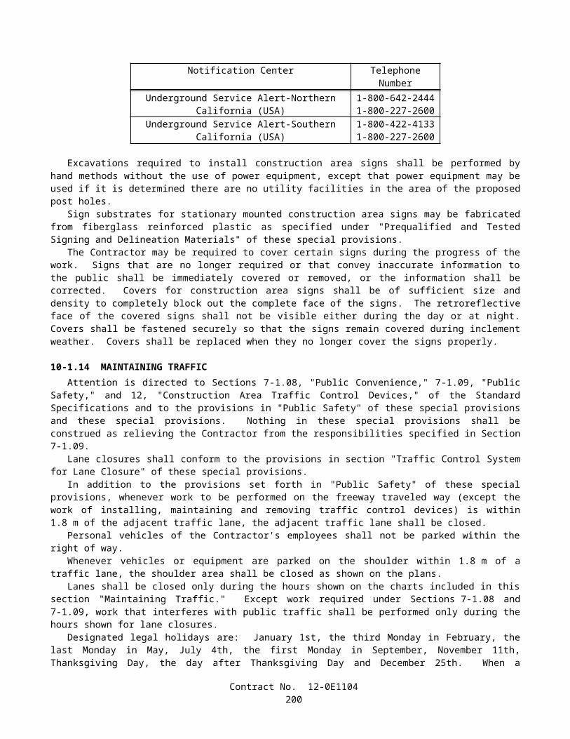
apprentices and trainees under such programs will be established by the particular programs. The ratio of apprentices and trainees to journeymen shall not be greater than permitted by the terms of the particular program.
6. Withholding:The SHA shall upon its own action or upon written request of an authorized representative of the DOL withhold, or cause to be withheld, from the contractor or subcontractor under this contract or any other Federal contract with the same prime contractor, or any other Federally-assisted contract subject to Davis-Bacon prevailing wage requirements which is held by the same prime contractor, as much of the accrued payments or advances as may be considered necessary to pay laborers and mechanics, including apprentices, trainees, and helpers, employed by the contractor or any subcontractor the full amount of wages required by the contract. In the event of failure to pay any laborer or mechanic, including any apprentice, trainee, or helper, employed or working on the site of the work, all or part of the wages required by the contract, the SHA contracting officer may, after written notice to the contractor, take such action as may be necessary to cause the suspension of any further payment, advance, or guarantee of funds until such violations have ceased.
7. Overtime Requirements:No contractor or subcontractor contracting for any part of the contract work which may require or involve the employment of laborers, mechanics, watchmen, or guards (including apprentices, trainees, and helpers described in paragraphs 4 and 5 above) shall require or permit any laborer, mechanic, watchman, or guard in any workweek in which he/she is employed on such work, to work in excess of 40 hours in such workweek unless such laborer, mechanic, watchman, or guard receives compensation at a rate not less than one-and-one-half times his/her basic rate of pay for all hours worked in excess of 40 hours in such workweek.
8. Violation:Liability for Unpaid Wages; Liquidated Damages: In the event of any violation of the clause set forth in paragraph 7 above, the contractor and any subcontractor responsible thereof shall be liable to the affected employee for his/her unpaid wages. In addition, such contractor and subcontractor shall be liable to the United States (in the case of work done under contract for the District of Columbia or a territory, to such District or to such territory) for liquidated damages. Such liquidated damages shall be computed with respect to each individual laborer, mechanic, watchman, or guard employed in violation of the clause set forth in paragraph 7, in the sum of $10 for each calendar day on which such employee was required or permitted to work in excess of the standard work week of 40 hours without payment of the overtime wages required by the clause set forth in paragraph 7.
9. Withholding for Unpaid Wages and Liquidated Damages:The SHA shall upon its own action or upon written request of any authorized representative of the DOL withhold, or cause to be withheld, from any monies payable on account of work performed by the contractor or subcontractor under any such contract or any other Federal contract with the same prime contractor, or any other Federally-assisted contract subject to the Contract Work Hours and Safety Standards Act, which is held by the same prime contractor, such sums as may be determined to be necessary to satisfy any liabilities of such contractor or subcontractor for unpaid wages and liquidated damages as provided in the clause set forth in paragraph 8 above.
V. STATEMENTS AND PAYROLLS (Applicable to all Federal-aid construction contracts exceeding $2,000 and to all related subcontracts, except for projects
located on roadways classified as local roads or rural collectors, which are exempt.)
1. Compliance with Copeland Regulations (29 CFR 3):
The contractor shall comply with the Copeland Regulations of the Secretary of Labor which are herein incorporated by reference.
2. Payrolls and Payroll Records:
a. Payrolls and basic records relating thereto shall be maintained by the contractor and each subcontractor during the course of the work and preserved for a period of 3 years from the date of completion of the contract for all laborers, mechanics, apprentices, trainees, watchmen, helpers, and guards working at the site of the work.
b. The payroll records shall contain the name, social security number, and address of each such employee; his or her correct classification; hourly rates of wages paid (including rates of contributions or costs anticipated for
Contract No. 12-0E1104202
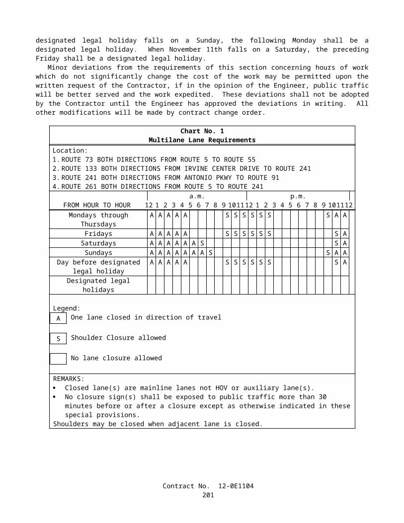
bona fide fringe benefits or cash equivalent thereof the types described in Section 1(b)(2)(B) of the Davis Bacon Act); daily and weekly number of hours worked; deductions made; and actual wages paid. In addition, for Appalachian contracts, the payroll records shall contain a notation indicating whether the employee does, or does not, normally reside in the labor area as defined in Attachment A, paragraph 1. Whenever the Secretary of Labor, pursuant to Section IV, paragraph 3b, has found that the wages of any laborer or mechanic include the amount of any costs reasonably anticipated in providing benefits under a plan or program described in Section 1(b)(2)(B) of the Davis Bacon Act, the contractor and each subcontractor shall maintain records which show that the commitment to provide such benefits is enforceable, that the plan or program is financially responsible, that the plan or program has been communicated in writing to the laborers or mechanics affected, and show the cost anticipated or the actual cost incurred in providing benefits. Contractors or subcontractors employing apprentices or trainees under approved programs shall maintain written evidence of the registration of apprentices and trainees, and ratios and wage rates prescribed in the applicable programs.
c. Each contractor and subcontractor shall furnish, each week in which any contract work is performed, to the SHA resident engineer a payroll of wages paid each of its employees (including apprentices, trainees, and helpers, described in Section IV, paragraphs 4 and 5, and watchmen and guards engaged on work during the preceding weekly payroll period). The payroll submitted shall set out accurately and completely all of the information required to be maintained under paragraph 2b of this Section V. This information may be submitted in any form desired. Optional Form WH-347 is available for this purpose and may be purchased from the Superintendent of Documents (Federal stock number 029-005-0014-1), U.S. Government Printing Office, Washington, D.C. 20402. The prime contractor is responsible for the submission of copies of payrolls by all subcontractors.
d. Each payroll submitted shall be accompanied by a "Statement of Compliance," signed by the contractor or subcontractor or his/her agent who pays or supervises the payment of the persons employed under the contract and shall certify the following:
(1) that the payroll for the payroll period contains the information required to be maintained under paragraph 2b of this Section V and that such information is correct and complete;
(2) that such laborer or mechanic (including each helper, apprentice, and trainee) employed on the contract during the payroll period has been paid the full weekly wages earned, without rebate, either directly or indirectly, and that no deductions have been made either directly or indirectly from the full wages earned, other than permissible deductions as set forth in the Regulations, 29 CFR 3;
(3) that each laborer or mechanic has been paid not less that the applicable wage rate and fringe benefits or cash equivalent for the classification of worked performed, as specified in the applicable wage determination incorporated into the contract.
e. The weekly submission of a properly executed certification set forth on the reverse side of Optional Form WH-347 shall satisfy the requirement for submission of the "Statement of Compliance" required by paragraph 2d of this Section V.
f. The falsification of any of the above certifications may subject the contractor to civil or criminal prosecution under 18 U.S.C. 1001 and 31 U.S.C. 231.
g. The contractor or subcontractor shall make the records required under paragraph 2b of this Section V available for inspection, copying, or transcription by authorized representatives of the SHA, the FHWA, or the DOL, and shall permit such representatives to interview employees during working hours on the job. If the contractor or subcontractor fails to submit the required records or to make them available, the SHA, the FHWA, the DOL, or all may, after written notice to the contractor, sponsor, applicant, or owner, take such actions as may be necessary to cause the suspension of any further payment, advance, or guarantee of funds. Furthermore, failure to submit the required records upon request or to make such records available may be grounds for debarment action pursuant to 29 CFR 5.12.
VI. RECORD OF MATERIALS, SUPPLIES, AND LABOR1. On all Federal-aid contracts on the National Highway System, except those which provide solely for the installation
of protective devices at railroad grade crossings, those which are constructed on a force account or direct labor basis, Contract No. 12-0E1104
203
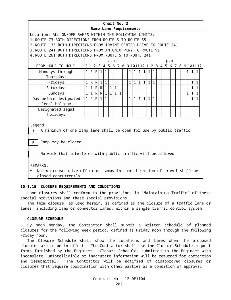
highway beautification contracts, and contracts for which the total final construction cost for roadway and bridge is less than $1,000,000 (23 CFR 635) the contractor shall:
a. Become familiar with the list of specific materials and supplies contained in Form FHWA-47, "Statement of Materials and Labor Used by Contractor of Highway Construction Involving Federal Funds," prior to the commencement of work under this contract.
b. Maintain a record of the total cost of all materials and supplies purchased for and incorporated in the work, and also of the quantities of those specific materials and supplies listed on Form FHWA-47, and in the units shown on Form FHWA-47.
c. Furnish, upon the completion of the contract, to the SHA resident engineer on Form FHWA-47 together with the data required in paragraph 1b relative to materials and supplies, a final labor summary of all contract work indicating the total hours worked and the total amount earned.
2. At the prime contractor's option, either a single report covering all contract work or separate reports for the contractor and for each subcontract shall be submitted.
VII. SUBLETTING OR ASSIGNING THE CONTRACT1. The contractor shall perform with its own organization contract work amounting to not less than 30 percent (or a
greater percentage if specified elsewhere in the contract) of the total original contract price, excluding any specialty items designated by the State. Specialty items may be performed by subcontract and the amount of any such specialty items performed may be deducted from the total original contract price before computing the amount of work required to be performed by the contractor's own organization (23 CFR 635).
a. "Its own organization" shall be construed to include only workers employed and paid directly by the prime contractor and equipment owned or rented by the prime contractor, with or without operators. Such term does not include employees or equipment of a subcontractor, assignee, or agent of the prime contractor.
b. "Specialty Items" shall be construed to be limited to work that requires highly specialized knowledge, abilities, or equipment not ordinarily available in the type of contracting organizations qualified and expected to bid on the contract as a whole and in general are to be limited to minor components of the overall contract.
2. The contract amount upon which the requirements set forth in paragraph 1 of Section VII is computed includes the cost of material and manufactured products which are to be purchased or produced by the contractor under the contract provisions.
3. The contractor shall furnish (a) a competent superintendent or supervisor who is employed by the firm, has full authority to direct performance of the work in accordance with the contract requirements, and is in charge of all construction operations (regardless of who performs the work) and (b) such other of its own organizational resources (supervision, management, and engineering services) as the SHA contracting officer determines is necessary to assure the performance of the contract.
4. No portion of the contract shall be sublet, assigned or otherwise disposed of except with the written consent of the SHA contracting officer, or authorized representative, and such consent when given shall not be construed to relieve the contractor of any responsibility for the fulfillment of the contract. Written consent will be given only after the SHA has assured that each subcontract is evidenced in writing and that it contains all pertinent provisions and requirements of the prime contract.
VIII. SAFETY - ACCIDENT PREVENTION1. In the performance of this contract the contractor shall comply with all applicable Federal, State, and local laws
governing safety, health, and sanitation (23 CFR 635). The contractor shall provide all safeguards, safety devices and protective equipment and take any other needed actions as it determines, or as the SHA contracting officer may determine, to be reasonably necessary to protect the life and health of employees on the job and the safety of the public and to protect property in connection with the performance of the work covered by the contract.
Contract No. 12-0E1104204
2. It is a condition of this contract, and shall be made a condition of each subcontract, which the contractor enters into pursuant to this contract, that the contractor and any subcontractor shall not permit any employee, in performance of the contract, to work in surroundings or under conditions which are unsanitary, hazardous or dangerous to his/her health or safety, as determined under construction safety and health standards (29 CFR 1926) promulgated by the Secretary of Labor, in accordance with Section 107 of the Contract Work Hours and Safety Standards Act (40 U.S.C. 333).
3. Pursuant to 29 CFR 1926.3, it is a condition of this contract that the Secretary of Labor or authorized representative thereof, shall have right of entry to any site of contract performance to inspect or investigate the matter of compliance with the construction safety and health standards and to carry out the duties of the Secretary under Section 107 of the Contract Work Hours and Safety Standards Act (40 U.S.C. 333).
IX. FALSE STATEMENTS CONCERNING HIGHWAY PROJECTSIn order to assure high quality and durable construction in conformity with approved plans and specifications and a high
degree of reliability on statements and representations made by engineers, contractors, suppliers, and workers on Federal-aid highway projects, it is essential that all persons concerned with the project perform their functions as carefully, thoroughly, and honestly as possible. Willful falsification, distortion, or misrepresentation with respect to any facts related to the project is a violation of Federal law. To prevent any misunderstanding regarding the seriousness of these and similar acts, the following notice shall be posted on each Federal-aid highway project (23 CFR 635) in one or more places where it is readily available to all persons concerned with the project:
Notice To All Personnel Engaged On Federal-Aid Highway Projects
18 U.S.C. 1020 READS AS FOLLOWS:
"Whoever being an officer, agent, or employee of the United States, or any State or Territory, or whoever, whether a person, association, firm, or corporation, knowingly makes any false statement, false representation, or false report as to the character, quality, quantity, or cost of the material used or to be used, or the quantity or quality of the work performed or to be performed, or the cost thereof in connection with the submission of plans, maps, specifications, contracts, or costs of construction on any highway or related project submitted for approval to the Secretary of Transportation; or
Whoever knowingly makes any false statement, false representation, false report or false claim with respect to the character, quality, quantity, or cost of any work performed or to be performed, or materials furnished or to be furnished, in connection with the construction of any highway or related project approved by the Secretary of Transportation; or
Whoever knowingly makes any false statement or false representation as to material fact in any statement, certificate, or report submitted pursuant to provisions of the Federal-aid Roads Act approved July 1, 1916, (39 Stat. 355), as amended and supplemented;
Shall be fined not more that $10,000 or imprisoned not more than 5 years or both."
X. IMPLEMENTATION OF CLEAN AIR ACT AND FEDERAL WATER POLLUTION CONTROL ACT (Applicable to all Federal-aid construction contracts and to all related subcontracts of $100,000 or more.)
By submission of this bid or the execution of this contract, or subcontract, as appropriate, the bidder, Federal-aid construction contractor, or subcontractor, as appropriate, will be deemed to have stipulated as follows:
1. That any facility that is or will be utilized in the performance of this contract, unless such contract is exempt under the Clean Air Act, as amended (42 U.S.C. 1857 et seq., as amended by Pub.L. 91-604), and under the Federal Water Pollution Control Act, as amended (33 U.S.C. 1251 et seq., as amended by Pub.L. 92-500), Executive Order 11738, and regulations in implementation thereof (40 CFR 15) is not listed, on the date of contract award, on the U.S. Environmental Protection Agency (EPA) List of Violating Facilities pursuant to 40 CFR 15.20.
2. That the firm agrees to comply and remain in compliance with all the requirements of Section 114 of the Clean Air Act and Section 308 of the Federal Water Pollution Control Act and all regulations and guidelines listed thereunder.
Contract No. 12-0E1104205
3. That the firm shall promptly notify the SHA of the receipt of any communication from the Director, Office of Federal Activities, EPA, indicating that a facility that is or will be utilized for the contract is under consideration to be listed on the EPA List of Violating Facilities.
4. That the firm agrees to include or cause to be included the requirements of paragraph 1 through 4 of this Section X in every nonexempt subcontract, and further agrees to take such action as the government may direct as a means of enforcing such requirements.
XI. CERTIFICATION REGARDING DEBARMENT, SUSPENSION, INELIGIBILITY AND VOLUNTARY EXCLUSION
1. Instructions for Certification - Primary Covered Transactions:(Applicable to all Federal-aid contracts - 49 CFR 29)
a. By signing and submitting this proposal, the prospective primary participant is providing the certification set out below.
b. The inability of a person to provide the certification set out below will not necessarily result in denial of participation in this covered transaction. The prospective participant shall submit an explanation of why it cannot provide the certification set out below. The certification or explanation will be considered in connection with the department or agency's determination whether to enter into this transaction. However, failure of the prospective primary participant to furnish a certification or an explanation shall disqualify such a person from participation in this transaction.
c. The certification in this clause is a material representation of fact upon which reliance was placed when the department or agency determined to enter into this transaction. If it is later determined that the prospective primary participant knowingly rendered an erroneous certification, in addition to other remedies available to the Federal Government, the department or agency may terminate this transaction for cause of default.
d. The prospective primary participant shall provide immediate written notice to the department or agency to whom this proposal is submitted if any time the prospective primary participant learns that its certification was erroneous when submitted or has become erroneous by reason of changed circumstances.
e. The terms "covered transaction," "debarred," "suspended," "ineligible," "lower tier covered transaction," "participant," "person," "primary covered transaction," "principal," "proposal," and "voluntarily excluded," as used in this clause, have the meanings set out in the Definitions and Coverage sections of rules implementing Executive Order 12549. You may contact the department or agency to which this proposal is submitted for assistance in obtaining a copy of those regulations.
f. The prospective primary participant agrees by submitting this proposal that, should the proposed covered transaction be entered into, it shall not knowingly enter into any lower tier covered transaction with a person who is debarred, suspended, declared ineligible, or voluntarily excluded from participation in this covered transaction, unless authorized by the department or agency entering into this transaction.
g. The prospective primary participant further agrees by submitting this proposal that it will include the clause titled "Certification Regarding Debarment, Suspension, Ineligibility and Voluntary Exclusion-Lower Tier Covered Transaction," provided by the department or agency entering into this covered transaction, without modification, in all lower tier covered transactions and in all solicitations for lower tier covered transactions.
h. A participant in a covered transaction may rely upon a certification of a prospective participant in a lower tier covered transaction that is not debarred, suspended, ineligible, or voluntarily excluded from the covered transaction, unless it knows that the certification is erroneous. A participant may decide the method and frequency by which it determines the eligibility of its principals. Each participant may, but is not required to, check the nonprocurement portion of the "Lists of Parties Excluded From Federal Procurement or Nonprocurement Programs" (Nonprocurement List) which is compiled by the General Services Administration.
i. Nothing contained in the foregoing shall be construed to require establishment of a system of records in order to render in good faith the certification required by this clause. The knowledge and information of participant is
Contract No. 12-0E1104206
not required to exceed that which is normally possessed by a prudent person in the ordinary course of business dealings.
j. Except for transactions authorized under paragraph f of these instructions, if a participant in a covered transaction knowingly enters into a lower tier covered transaction with a person who is suspended, debarred, ineligible, or voluntarily excluded from participation in this transaction, in addition to other remedies available to the Federal Government, the department or agency may terminate this transaction for cause or default.
2. Certification Regarding Debarment, Suspension, Ineligibility and Voluntary Exclusion — Primary Covered Transactions:
a. The prospective primary participant certifies to the best of its knowledge and belief, that it and its principals:
(1) Are not presently debarred, suspended, proposed for debarment, declared ineligible, or voluntarily excluded from covered transactions by any Federal department or agency;
(2) Have not within a 3-year period preceding this proposal been convicted of or had a civil judgement rendered against them for commission of fraud or a criminal offense in connection with obtaining, attempting to obtain, or performing a public (Federal, State or local) transaction or contract under a public transaction; violation of Federal or State antitrust statutes or commission of embezzlement, theft, forgery, bribery, falsification or destruction of records, making false statements, or receiving stolen property;
(3) Are not presently indicted for or otherwise criminally or civilly charged by a governmental entity (Federal, State or local) with commission of any of the offenses enumerated in paragraph 1b of this certification; and
(4) Have not within a 3-year period preceding this application/proposal had one or more public transactions (Federal, State or local) terminated for cause or default.
b. Where the prospective primary participant is unable to certify to any of the statements in this certification, such prospective participant shall attach an explanation to this proposal.
3. Instructions for Certification - Lower Tier Covered Transactions:(Applicable to all subcontracts, purchase orders and other lower tier transactions of $25,000 or more - 49 CFR 29)
a. By signing and submitting this proposal, the prospective lower tier is providing the certification set out below.
b. The certification in this clause is a material representation of fact upon which reliance was placed when this transaction was entered into. If it is later determined that the prospective lower tier participant knowingly rendered an erroneous certification, in addition to other remedies available to the Federal Government, the department or agency with which this transaction originated may pursue available remedies, including suspension and/or debarment.
c. The prospective lower tier participant shall provide immediate written notice to the person to which this proposal is submitted if at any time the prospective lower tier participant learns that its certification was erroneous by reason of changed circumstances.
d. The terms "covered transaction," "debarred," "suspended," "ineligible," "primary covered transaction," "participant," "person," "principal," "proposal," and "voluntarily excluded," as used in this clause, have the meanings set out in the Definitions and Coverage sections of rules implementing Executive Order 12549. You may contact the person to which this proposal is submitted for assistance in obtaining a copy of those regulations.
e. The prospective lower tier participant agrees by submitting this proposal that, should the proposed covered transaction be entered into, it shall not knowingly enter into any lower tier covered transaction with a person who is debarred, suspended, declared ineligible, or voluntarily excluded from participation in this covered transaction, unless authorized by the department or agency with which this transaction originated.
Contract No. 12-0E1104207
f. The prospective lower tier participant further agrees by submitting this proposal that it will include this clause titled "Certification Regarding Debarment, Suspension, Ineligibility and Voluntary Exclusion-Lower Tier Covered Transaction," without modification, in all lower tier covered transactions and in all solicitations for lower tier covered transactions.
g. A participant in a covered transaction may rely upon a certification of a prospective participant in a lower tier covered transaction that is not debarred, suspended, ineligible, or voluntarily excluded from the covered transaction, unless it knows that the certification is erroneous. A participant may decide the method and frequency by which it determines the eligibility of its principals. Each participant may, but is not required to, check the Nonprocurement List.
h. Nothing contained in the foregoing shall be construed to require establishment of a system of records in order to render in good faith the certification required by this clause. The knowledge and information of participant is not required to exceed that which is normally possessed by a prudent person in the ordinary course of business dealings.
i. Except for transactions authorized under paragraph e of these instructions, if a participant in a covered transaction knowingly enters into a lower tier covered transaction with a person who is suspended, debarred, ineligible, or voluntarily excluded from participation in this transaction, in addition to other remedies available to the Federal Government, the department or agency with which this transaction originated may pursue available remedies, including suspension and/or debarment.
4. Certification Regarding Debarment, Suspension, Ineligibility and Voluntary Exclusion — Lower Tier Covered Transactions:
a. The prospective lower tier participant certifies, by submission of this proposal, that neither it nor its principals is presently debarred, suspended, proposed for debarment, declared ineligible, or voluntarily excluded from participation in this transaction by any Federal department or agency.
b. Where the prospective lower tier participant is unable to certify to any of the statements in this certification, such prospective participant shall attach an explanation to this proposal.
XII. CERTIFICATION REGARDING USE OF CONTRACT FUNDS FOR LOBBYING (Applicable to all Federal-aid construction contracts and to all related subcontracts which exceed $100,000 - 49 CFR 20)
1. The prospective participant certifies, by signing and submitting this bid or proposal, to the best of his or her knowledge and belief, that:
a. No Federal appropriated funds have been paid or will be paid, by or on behalf of the undersigned, to any person for influencing or attempting to influence an officer or employee of any Federal agency, a Member of Congress, an officer or employee of Congress, or an employee of a Member of Congress in connection with the awarding of any Federal contract, the making of any Federal grant, the making of any Federal loan, the entering into of any cooperative agreement, and the extension, continuation, renewal, amendment, or modification of any Federal contract, grant, loan, or cooperative agreement.
b. If any funds other than Federal appropriated funds have been paid or will be paid to any person for influencing or attempting to influence an officer or employee of any Federal agency, a Member of Congress, an officer or employee of Congress, or an employee of a Member of Congress in connection with this Federal contract, grant, loan, or cooperative agreement, the undersigned shall complete and submit Standard Form-LLL, "Disclosure Form to Report Lobbying," in accordance with its instructions.
2. This certification is a material representation of fact upon which reliance was placed when this transaction was made or entered into. Submission of this certification is a prerequisite for making or entering into this transaction imposed by 31 U.S.C. 1352. Any person who fails to file the required certification shall be subject to a civil penalty of not less than $10,000 and not more than $100,000 for each such failure.
Contract No. 12-0E1104208
3. The prospective participant also agrees by submitting his or her bid or proposal that he or she shall require that the language of this certification be included in all lower tier subcontracts, which exceed $100,000 and that all such recipients shall certify and disclose accordingly.
Contract No. 12-0E1104209
FEDERAL-AID FEMALE AND MINORITY GOALSIn accordance with Section II, "Nondiscrimination," of "Required Contract Provisions Federal-aid Construction
Contracts" the following are the goals for female utilization:
Goal for Women (applies nationwide)..............(percent) 6.9
The following are goals for minority utilization:
CALIFORNIA ECONOMIC AREAGoal
(Percent)174 Redding, CA:
Non-SMSA Counties 6.8CA Lassen; CA Modoc;CA Plumas;CA Shasta; CA Siskiyou; CA Tehama.
175 Eureka, CANon-SMSA Counties 6.6
CA Del Norte; CA Humboldt; CA Trinity.
176 San Francisco-Oakland-San Jose, CA:SMSA Counties:7120 Salinas-Seaside-Monterey, CA 28.9
CA Monterey.7360 San Francisco-Oakland 25.6
CA Alameda; CA Contra Costa; CA Marin; CA San Francisco; CA San Mateo.7400 San Jose, CA 19.6
CA Santa Clara.7485 Santa Cruz, CA. 14.9
CA Santa Cruz.7500 Santa Rosa, CA 9.1
CA Sonoma.8720 Vallejo-Fairfield- Napa, CA 17.1
CA Napa; CA SolanoNon-SMSA Counties 23.2
CA Lake; CA Mendocino; CA San Benito
177 Sacramento, CA:SMSA Counties:6920 Sacramento, CA 16.1
CA Placer; CA Sacramento; CA Yolo.Non-SMSA Counties 14.3
CA Butte; CA Colusa; CA El Dorado; CA Glenn; CA Nevada; CA Sierra; CA Sutter; CA Yuba.
178 Stockton-Modesto, CA:SMSA Counties:5170 Modesto, CA 12.3
CA Stanislaus.8120 Stockton, CA 24.3
CA San Joaquin.Non-SMSA Counties 19.8
CA Alpine; CA Amador; CA Calaveras; CA Mariposa;CA Merced; CA Tuolumne.
Contract No. 12-0E1104210
Goal(Percent)
179 Fresno-Bakersfield, CASMSA Counties:0680 Bakersfield, CA 19.1
CA Kern.2840 Fresno, CA 26.1
CA Fresno.Non-SMSA Counties 23.6
CA Kings; CA Madera; CA Tulare.
180 Los Angeles, CA:SMSA Counties:0360 Anaheim-Santa Ana-Garden Grove, CA 11.9
CA Orange.4480 Los Angeles-Long Beach, CA 28.3
CA Los Angeles.6000 Oxnard-Simi Valley-Ventura, CA 21.5
CA Ventura.6780 Riverside-San Bernardino-Ontario, CA. 19.0
CA Riverside; CA San Bernardino.7480 Santa Barbara-Santa Maria-Lompoc, CA 19.7
CA Santa Barbara.Non-SMSA Counties 24.6
CA Inyo; CA Mono; CA San Luis Obispo.
181 San Diego, CA:SMSA Counties7320 San Diego, CA. 16.9
CA San Diego.Non-SMSA Counties 18.2
CA Imperial.
In addition to the reporting requirements set forth elsewhere in this contract the Contractor and subcontractors holding subcontracts, not including material suppliers, of $10,000 or more, shall submit for every month of July during which work is performed, employment data as contained under Form FHWA PR-1391 (Appendix C to 23 CFR, Part 230), and in accordance with the instructions included thereon.
Contract No. 12-0E1104211
FEDERAL REQUIREMENT TRAINING SPECIAL PROVISIONS As part of the Contractor's equal employment opportunity affirmative action program, training shall be provided as
follows:
The Contractor shall provide on-the-job training to develop full journeymen in the types of trades or job classification involved.
The goal for the number of trainees or apprentices to be trained under the requirements of this special provision will be 9.In the event the Contractor subcontracts a portion of the contract work, he shall determine how many, if any, of the
trainees or apprentices are to be trained by the subcontractor, provided however, that the Contractor shall retain the primary responsibility for meeting the training requirements imposed by this special provision. The Contractor shall also insure that this Training Special Provision is made applicable to such subcontract. Where feasible, 25 percent of trainees or apprentices in each occupation shall be in their first year of apprenticeship or training.
The number of trainees or apprentices shall be distributed among the work classifications on the basis of the Contractor's needs and the availability of journeymen in the various classifications within a reasonable area of recruitment. Prior to commencing work, the Contractor shall submit to the Department for approval the number of trainees or apprentices to be trained in each selected classification and training program to be used. Furthermore, the Contractor shall specify the starting time for training in each of the classifications. The Contractor will be credited for each trainee or apprentice employed by him on the contract work who is currently enrolled or becomes enrolled in an approved program and will be reimbursed for such trainees or apprentices as provided hereinafter.
Training and upgrading of minorities and women toward journeymen status is a primary objective of this Training Special Provision. Accordingly, the Contractor shall make every effort to enroll minority and women trainees or apprentices (e.g., by conducting systematic and direct recruitment through public and private sources likely to yield minority and women trainees or apprentices) to the extent such persons are available within a reasonable area of recruitment. The Contractor will be responsible for demonstrating the steps that he has taken in pursuance thereof, prior to a determination as to whether the Contractor is in compliance with this Training Special Provision. This training commitment is not intended, and shall not be used, to discriminate against any applicant for training, whether a member of a minority group or not.
No employee shall be employed as a trainee or apprentice in any classification in which he has successfully completed a training course leading to journeyman status or in which he has been employed as a journeyman. The Contractor should satisfy this requirement by including appropriate questions in the employee application or by other suitable means. Regardless of the method used the Contractor's records should document the findings in each case.
The minimum length and type of training for each classification will be as established in the training program selected by the Contractor and approved by both the Department and the Federal Highway Administration. The Department and the Federal Highway Administration will approve a program if it is reasonably calculated to meet the equal employment opportunity obligations of the Contractor and to qualify the average trainee or apprentice for journeyman status in the classification concerned by the end of the training period. Furthermore, apprenticeship programs registered with the U.S. Department of Labor, Bureau of Apprenticeship and Training, or with the State of California, Department of Industrial Relations, Division of Apprenticeship Standards recognized by the Bureau and training programs approved but not necessarily sponsored by the U.S. Department of Labor, Manpower Administration, Bureau of Apprenticeship and Training shall also be considered acceptable provided it is being administered in a manner consistent with the equal employment obligations of Federal-aid highway construction contracts. Approval or acceptance of a training program shall be obtained from the State prior to commencing work on the classification covered by the program. It is the intention of these provisions that training is to be provided in the construction crafts rather than clerk-typists or secretarial-type positions. Training is permissible in lower level management positions such as office engineers, estimators, timekeepers, etc., where the training is oriented toward construction applications. Training in the laborer classification may be permitted provided that significant and meaningful training is provided and approved by the division office. Some offsite training is permissible as long as the training is an integral part of an approved training program and does not comprise a significant part of the overall training.
Except as otherwise noted below, the Contractor will be reimbursed 80 cents per hour of training given an employee on this contract in accordance with an approved training program. As approved by the Engineer, reimbursement will be made for training of persons in excess of the number specified herein. This reimbursement will be made even though the Contractor receives additional training program funds from other sources, provided such other source does not specifically prohibit the Contractor from receiving other reimbursement. Reimbursement for offsite training indicated above may only be made to the Contractor where he does one or more of the following and the trainees or apprentices are concurrently employed on a Federal-aid project; contributes to the cost of the training, provides the instruction to the trainee or apprentice or pays the trainee's or apprentice's wages during the offsite training period.
No payment shall be made to the Contractor if either the failure to provide the required training, or the failure to hire the trainee or apprentice as a journeyman, is caused by the Contractor and evidences a lack of good faith on the part of the Contractor in meeting the requirements of this Training Special Provision. It is normally expected that a trainee or apprentice will begin his training on the project as soon as feasible after start of work utilizing the skill involved and remain on the
Contract No. 12-0E1104212
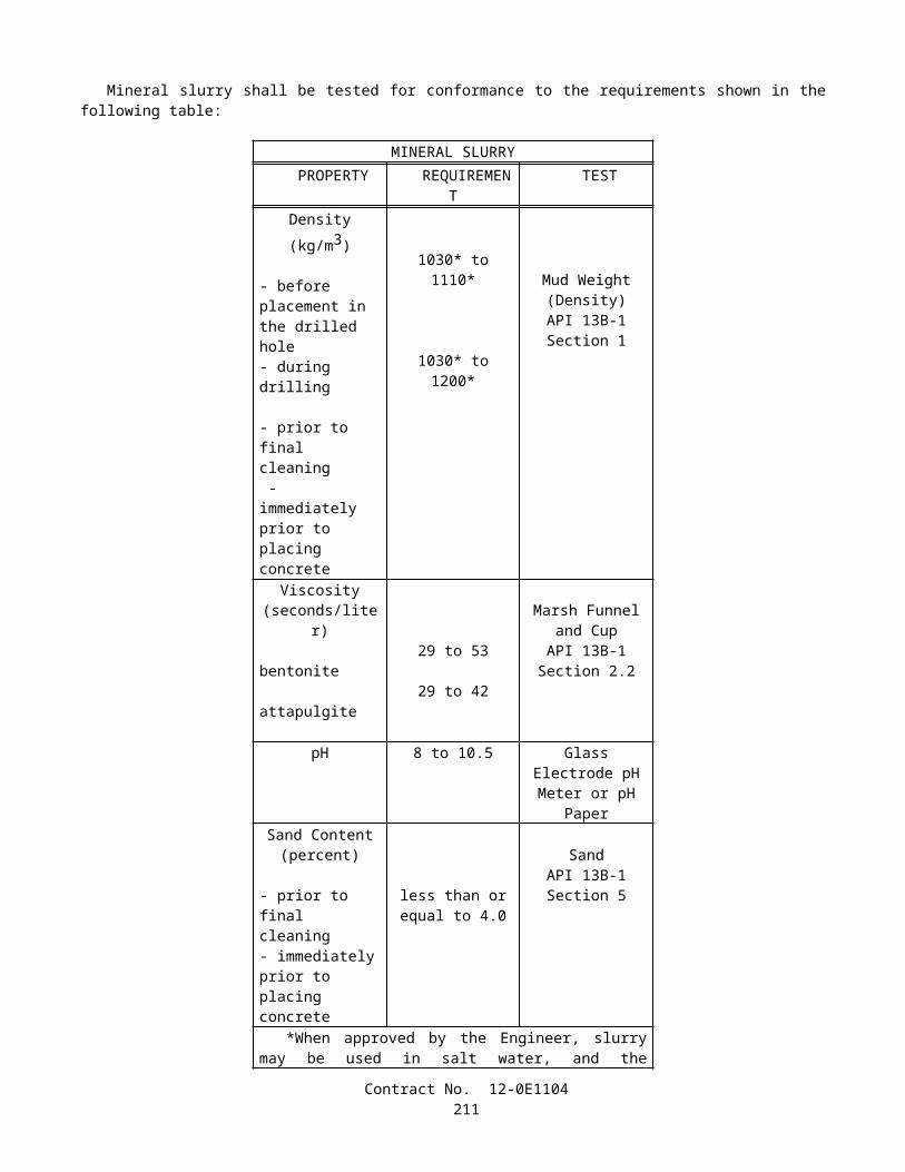
project as long as training opportunities exist in his work classification or until he has completed his training program. It is not required that all trainees or apprentices be on board for the entire length of the contract. A Contractor will have fulfilled his responsibilities under this Training Special Provision if he has provided acceptable training to the number of trainees or apprentices specified. The number trained shall be determined on the basis of the total number enrolled on the contract for a significant period.
Only trainees or apprentices registered in a program approved by the State of California's State Administrator of Apprenticeship may be employed on the project and said trainees or apprentices shall be paid the standard wage specified under the regulations of the craft or trade at which they are employed.
The Contractor shall furnish the trainee or apprentice a copy of the program he will follow in providing the training. The Contractor shall provide each trainee or apprentice with a certification showing the type and length of training satisfactorily completed.
The Contractor will provide for the maintenance of records and furnish periodic reports documenting his performance under this Training Special Provision.
Contract No. 12-0E1104213