Embed Size (px)
Citation preview
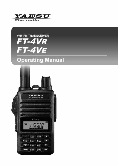
VHF FM TRANSCEIVER
Operating Manual
FT-4VRFT-4VE

Introduction ....................................................................................................................... 1About this manual ............................................................................................................ 1Quick Guide ...................................................................................................................... 2Controls & Connections .................................................................................................. 3
Transceiver ..................................................................................................................... 3Display ............................................................................................................................ 5The Keypad Functions ................................................................................................... 7
Safety Precautions (Be Sure to Read) ............................................................................ 8Preparation ...................................................................................................................... 11
Installing the Antenna .................................................................................................. 11Attaching the Belt Clip ................................................................................................. 11Installing the Battery Pack ........................................................................................... 11Removing the Battery Pack ......................................................................................... 11
Supplied Accessories and Options .............................................................................. 12Supplied Accessories .................................................................................................. 12Available Options ......................................................................................................... 12
Charging the Battery Pack ............................................................................................. 12Charging the Battery Pack using the Rapid Charger (SBH-22) ................................. 12
Operation ......................................................................................................................... 13Switching between the VFO-A and VFO-B ................................................................. 13Tuning to a Frequency ................................................................................................. 13
Changing the Frequency Step .................................................................................. 14Adjusting the squelch setting ....................................................................................... 14Transmission ................................................................................................................ 14Changing the Transmission Power Level .................................................................... 15Locking Keys and PTT switch ...................................................................................... 15Programmable key [P1]/[P2] ........................................................................................ 16
Repeater Operation ........................................................................................................ 17Communicating Via the Repeater ............................................................................... 17Tone Calling (1750 Hz) ................................................................................................. 17
Using the Memory .......................................................................................................... 18Registering to Memory Channels ................................................................................ 19Memory Recall ............................................................................................................. 19Clearing Memories ....................................................................................................... 20Recalling the Home Channels ..................................................................................... 20Changing the Home Channel Frequency .................................................................... 20Memory Channel Scanning ......................................................................................... 21Setting the Receive Operation When Scanning Stops ............................................... 21Split Memory ................................................................................................................ 22Using Memory Tag ....................................................................................................... 22Using Memory Bank ..................................................................................................... 22
Scanning Function ......................................................................................................... 22VFO Scan ..................................................................................................................... 22Programmed VFO Scan ............................................................................................... 23Weather Broadcast Channels scan (In the USA) ........................................................ 23Weather Alert Scan (In the USA) ................................................................................. 24Skip Memory Channel .................................................................................................. 24Programmable Memory scan (PMS) ........................................................................... 24Dual Receive (DW) feature .......................................................................................... 24
Convenient Functions .................................................................................................... 25VOX Operation ............................................................................................................. 25VFO Split Mode ............................................................................................................ 25Tone Squelch feature ................................................................................................... 25Digital Code Squelch (DCS) feature ............................................................................ 25New PAGER (EPCS) feature ....................................................................................... 25
Using Set Mode ............................................................................................................... 26Tables of Set Mode Operations ................................................................................... 26
Restoring to Defaults (Reset) / Setting the Preferred Operating Mode ..................... 29Specifications ................................................................................................................. 30
Contents

1
IntroductionThank you for purchasing this Yaesu product.m FT-4VR/VE is a handheld transceiver for operation in the 144 MHz Ama-
teur radio bands.m A Bridged Transless (BTL) amplifier provides One Full Watt of Audio in
spite of small size.m Two Quick Recall Keys (User Programmable) for Individual Preferencesm Lockout Capabilities for Keypad/PTT Lockout.m Emergency Operation with Alarm and HOME channel display.
r A variety of individual selective calling functions; such as tone squelch (CTCSS) and DCS functions .............................................. 28
r Large-capacity 200 memory channels ............................................. 18
r 2 home channels and 10 pairs of PMS memory channels ............... 20
r Create mnemonic tags for memory channels and PMS channel ..... 19
r Automatic power OFF (APO) feature turns the transceiver OFF after a preset time period ......................................................... 26
r The cloning feature allows the memory and configuration data from one transceiver to be transferred to another FT-4VR/VE. ......... 29
r The VOX system provides automatic transmit/receive switching based on voice .................................................................. 28We urge you to read this manual in its entirety, and also the Advance Manual (available for download on the Yaesu website), to gain a full understanding of the amazing capability of the exciting new FT-4VR/VE Transceiver.
About this manualReference icon symbols and conventions are used in this manual. Their meanings are described in the below chart.
Symbols Description
This icon indicates cautions and information that should be read.
This icon indicates notes, tips and information that should be read.
This icon indicates other pages containing relevant information.
This icon indicates FT-4VR/VE Advance Manual on the YAESU Website containing relevant information.
2
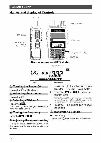
① Turning the Power ONRotate the until it clicks.② Adjusting the volumeRotate the .③ Selecting VFO-A or BPress the .The operating mode changes between the VFO-A and the VFO-B.
④ Tuning the frequencyPress the or .
⑤ Adjusting the squelch settingThe squelch level may be adjusted to mute the background noise when no signal is received.
Quick GuideNames and display of Controls
[#VFO] Key
Microphone
(Frequency up and down) Key
PWR/VOL Knob
PTT Switch
MONI/T-CALLSwitch
Function Key
S Meter / PO MeterVFO-A
Operating Frequency
Normal operation (VFO Mode)
1. Press the (Function key), then press the (MONI/T-CALL switch).
2. Press the or to adjust the squelch level.* When the squelch level is increased, the noise
is more likely to be silenced, but it may become more difficult to receive weak signals.
3. Press the (Function key) to save the setting.
⑥ Transmitting Signals z TransmittingPress the , then speak into microphone.

3
Controls & ConnectionsTransceiver
①
②
③④⑤
⑥
⑦
⑧⑨
⑪
⑫
⑬
⑭
⑮
⑩
⑦
① Strap attachment ( 11)
② Antenna Jack(SMA) ( 11)
③
PTT Switch ( 14) • Press and hold the PTT switch to transmit, and release it to receive. • In the Set mode, press the PTT switch to save the new setting and return to normal operation.
④ Microphone ( 14)
⑤
MONI/T.CALL Switch • USA/Asian versionWhile pressing and holding the MONI/T.CALL Switch, the squelch is opened temporarily. Press the Function key, then press the MONI/T.CALL Switch to adjust the squelch level.
• European versionPress the MONI/T.CALL switch to activate the T-CALL (1750 Hz).

4
⑥
Function Key ( 26)Pressing the Function key activates the “Secondary” key function.Press and hold the Function key enters the Set mode.In the Set mode, pressing the Function key defines and saves the set-ting.
⑦ Battery pack( 12)
⑧
PWR/VOL Knob • Turn this control clockwise to turn the transceiver ON and to increase the volume.
• Counter-clockwise rotation into the click-stop will turn the transceiver OFF.
⑨ Emergency KeyPress and hold it for three seconds to enable the Emergency Alarm beep functions and display the Home channel VHF frequency.
⑩ TX/BUSY Indicator LampThis indicator glows green when the squelch opens, and it glows red during transmit.
⑪ Speaker
⑫ LCD (Liquid Crystal Display)The display shows frequecny and current operating condition.
⑬ KeypadThe functions of the keypad are described in detail on page 7.
⑭ SP jackSP jack provides connection for an earphone.
⑮ MIC jackMIC jack provides connection for a microphone or clone cable.

5
Display
S Meter: Displays the received signal strengthPO Meter: Displays the transmit power level
Frequency / Memory Tag / PAGERSet Mode Item
VFO-A/BMemory Channel NumberHome Channel DisplayMemory Bank
Icon Description
Priority Memory Channel
Memory channel registered as a skip memory. 24
Repeater Shift DirectionSplit Memory (two different frequencies)
1722
: Appears when the tone encoder function. : Appears when the tone squelch function.
28
Appears when the DCS is in use. 27
The battery condition is displayed in 4 steps.
: Full battery charge : Enough battery charge : Battery is depleted. Charge battery. : (When blinking) Charge battery immediately.
13
Appears when a function key is pressed. 7
TX Power Level Indicator (LOW/MID TX Power Selected)
Tx Power Icon TX Power Meter during transmission
HIGH (5 W) (No display)
MID (2.5 W) LOWLOW (0.5 W) LOW
15

6
Icon Description
Appears when the Dual Receive (DW) function is enabled. 24
Appears when the APO (Automatic Power-Off) func-tion is enabled. 26
Appears when the bell function is enabled. 26
Appears when the lock function is enabled. 15
Appears when the Memory Bank function is en-abled. 22
Appears when the VOX (Voice Operated Transmit) function is enabled. 28

7
The Keypad Functions
Key
Primary Function (Press Key) Secondary Function
(Press F + Key)
Third Function
(Press and Hold for over one second)
VFO Memory Recall Inputting Memory Tag
Function A c t i v a t e s t h e “Secondary” key function ( ap-pears).
A c t i v a t e s t h e “Secondary ” key f u n c t i o n ( appears).
Moves the cursor to the right.
Deactivates the “Secondary” key f u n c t i o n ( appears).
Enters the Set mode.
#VFO
S w i t c h e s t h e b a n d c o n t r o l b e t w e e n V H F (VFO-A) and FM RADIO Broadcast (VFO-B).
M e m o r y O f f s e t Tuning -
P M S ( P r o g r a m Memory (Mode) Scan).
Program Scan Setting
MR
R e c a l l s t h e M e m o r y m o d e and activates the "Memory Tune" mode.
-
Numbers“*”, “+”, “-”,“/”, “@”Press and hold this key to complete the memory channel registration
D u a l R e c e i v e (DW) function
Memory wr i te mode
P1Recalls the stored P1(Programmable key) setting.
- Stores to the Home channel
Recalls the Home channel.
S t o r e s t h e P1(Programma-ble key) setting.
P2Recalls the stored P2(Programmable key) setting.
- Stores the Spl i t Memory.
R e v e r s e s t h e transmit and re-ceive frequencies w h i l e w o r k i n g through a repeater.
S t o r e s t h e P2(Programma-ble key) setting.
1 Number “1” Recalls the stored memory channel. Number “1” -
R e c a l l s t h e “ W e a t h e r ” b r o a d c a s t channel bank.
2ABC Number “2” Recalls the stored
memory channel.N u m b e r “ 2 ” , o r characters “A”, “B”, “C”, “a”, “b”, or “c”
- Act i va tes the ARTS feature.
3DEF Number “3” Recalls the stored
memory channel.N u m b e r “ 3 ” , o r characters “D”, “E”, “F”, “d”, “e”, or “f”
- -
4GHI Number “4” Recalls the stored
memory channel.N u m b e r “ 4 ” , o r characters “G”, “H”, “I”, “g”, “h”, or “i”
- -
5JKL Number “5” Recalls the stored
memory channel.N u m b e r “ 5 ” , o r characters “J”, “K”, “L”, “j”, “k”, or “l”
- -
6MNO Number “6” Recalls the stored
memory channel.N u m b e r “ 6 ” , o r characters “M”, “N”, “O”, “m”, “n”, or “o”
- K e y L o c k feature
7PQRS Number “7” Recalls the stored
memory channel.
N u m b e r “ 7 ” , o r characters “P”, “Q”, “R”, “S”, “p”, “q”, “r”, or “s”
- -
8TUV Number “8” Recalls the stored
memory channel.N u m b e r “ 8 ” , o r characters “T”, “U”, “V”, “t”, “u”, or “v”
- -
9WXYZ Number “9” Recalls the stored
memory channel.
N u m b e r “ 9 ” , o r characters “W”, “X”, “Y”, “Z”, “w” ,“x”, “y”, or “z”
DTMF autodialer setting -
0SET Number “0” Recalls the stored
memory channel.N u m b e r “ 0 ” o r space - -

8
Safety Precautions (Be Sure to Read)Be sure to read these important precautions, and use
this product safely.Yaesu is not liable for any failures or problems caused by the use or misuse of this product by the purchaser or any third party. Also, Yaesu is not liable for damages caused through the use of this product by the purchaser or any third party, except in cases where ordered to pay damages under the laws.Types and meanings of the marks
DANGER This mark indicates an imminently hazardous situation, which, if not avoided, could result in death or serious injury.
WARNING This mark indicates a potentially hazardous situation, which, if not avoided, could result in death or serious injury.
CAUTIONThis mark indicates a potentially hazardous situation, which, if not avoided, may result in minor or moderate injury or only prop-erty damage.
Types and meanings of symbolsThese symbols signify prohibited actions, which must not be done to use this prod-uct safely. For example: indicates that the product should not be disassembled.
These symbols signify required actions, which must be done to use this product safely. For example,: indicates that the power plug should be disconnected.
DANGERDo not use this product in an area where RF transmitters are prohibited, e.g., inside of a hospital, airplane, or train.This product can affect electronic or medical devices.Do not use this product while riding a bicycle or driving a car. Accidents can result.Be sure to stop the bicycle or car at a safe place before using this product.Do not perform transmission in a crowded place for the safety of persons using a medical device such as a cardiac pacemaker.The radio wave emitted from this prod-uct can cause the medical device to malfunction and result in an accident.
Do not touch any material leaking from the LCD display with bare hands.The chemical may adhere to your skin or enter your eye, and cause chemical burns. In such a case, consult the doctor immediately.Do not touch any material leaking from the battery pack with bare hands.The chemical that has stuck to your skin or entered your eye can cause chemical burns. In such a case, con-sult the doctor immediately.Do not use this product or the bat-tery charger anywhere inflammable gas is produced. A fire or explosion can occur.

9
DANGERDo not solder or short-circuit the terminals of the battery pack.A fire, leak, overheating, explosion, or ignition may result.Do not carry the battery pack together with a necklace, hairpin, or small met-al objects. A short circuit can result.
If thunder and lightening develop nearby when an external antenna is used, immediately turn this trans-ceiver OFF, and disconnect the external antenna from it.A fire, electrical shock, or damage may result.
WARNINGDo not power this transceiver with a voltage other than the specified power supply voltage.A fire, electric shock, or damage may result.Do not use the battery pack for any model other than the specified transceiver.A fire, leak, overheating, explosion, or ignition can result.Do not make very long transmis-sions.The main body of the transceiver may overheat, resulting component failure or operator burns.Do not disassemble or make any alteration to this product.An injury, electric shock, or failure may result.Keep the terminals of the battery pack clean.If terminal contacts are dirty or corrod-ed, a fire, leak, overheating, explosion, or ignition can result.Do not handle the battery pack or charger with wet hands. Do not insert or remove the power plug with wet hands.An injury, leak, fire, or failure may result.
If smoke or a strange odor is emitted from the main body, battery pack, or battery charger, immediate-ly turn the transceiver off; remove the battery pack, and remove the power plug fromthe outlet.A fire, chemical leak, overheating, component damage, ignition, or failure may result. Contact the dealer from which you purchased this product or Yaesu Amateur Customer Support.Do not use the battery pack which is externally damaged or deformed.A fire, leak, heating, explosion, or ignition can result.
Do not use any battery charger which is not specified by Yaesu.A fire or failure can result.
When transmitting, keep the trans-ceiver at least 5.0 mm (3/16 inch) away from your body.Use only the supplied antenna. Do not use modified or damaged antennas.If charging of the battery pack cannot be completed within the specified charging time, immedi-ately remove the power plug of the battery charger from the outlet.A fire, leak, overheating, explosion, or ignition can result.

10
CAUTIONDo not dangle or throw the trans-ceiver by holding its antenna.This may injure others and may also result in damage and failure of the transceiver.Do not use the transceiver in a crowded place.The antenna may strike others and result in a injury.Do not place this transceiver indi-rect sunlight or near a heater.The case may be deformed or discol-ored.
Do not place this transceiver in a humid or dusty place.A fire or failure may result.
While transmitting, keep the anten-na as far from you as possible.Long-time exposure to electromagnet-ic waves may have a negative impact on your health.Do not wipe the case using thinner and benzene etc.Use only a soft, dry cloth to wipe stains from the case.If the transceiver will not be used for an extended period, turn it OFF and remove the battery pack for safety.Do not drop, strike, or throw the transceiver.A failure or damage may result.Keep magnetic cards and video tape away from the transceiver.The data recorded on cash cards or videotapes may be erased.Charge the battery pack within the temperature range from +5 °C to +35 °C (+41 °F to +95 °F).Charging the battery pack outside this temperature range can cause leak, overheating, decrease in performance, or reduction in service life can result.When unplugging the power cord of the battery charger, be sure to hold the power plug.Pulling the power cord can damage it and cause a fire or electronic shock.
Do not use the earpiece micro-phone at an extremely high volume level.Hearing impairment can result.Keep this product out of the reach of children.Injury to the child, or damage to the transceiver may result.Install the hand strap and belt clip securely.Improper installation may cause the FT-4VR/VE to fall or drop, resulting in an injury or damage.Do not place a heavy object on the power cord of the AC adapter.The battery cord can be damaged, resulting in a fire or electric shock.Do not use the included AC adapter to charge any battery pack which is not specified for use with the AC adapter.A fire can result.Do not operate the transceiver near the TV or radio.Radio disturbance can occur in the transceiver, the TV, or the radio.Do not use any products other than the specified options and accesso-ries.Failure or miss operation may result.When the AC adapter is not in use, remove its power plug from the outlet.
Before discarding a depleted bat-tery pack, affix tape or insulating covering to its terminals.
Be sure to check with the manufac-turer of any hybrid or fuel-saving automobile regarding use of the transceiver in that car.Noise generated by an onboard elec-trical device (inverter, etc.) can disrupt the normal operation of the transceiv-er.

11
PreparationInstalling the Antenna1. Turn the antenna clockwise until it is secured.
• Do not hold or twist the upper part of the antenna when installing or removing it. To do so may break the conductors inside the antenna.
• Do not key the transmit without installing the antenna. The transmitter components may be damaged.
• When using an antenna other than the one supplied, or connecting to an external antenna, ensure that the SWR is adjusted to 1.5 or lower.
Hold the thick baseof the antenna
Attaching the Belt Clip1. Attach the belt clip on the back of transceiver
using the supplied screws (two).
• Be sure to use the supplied screws when attaching the belt clip. If any other screws are used, the belt clip cannot be secured firmly to the battery pack and the transceiver may drop off together with the battery pack; the transceiver and battery pack may fall off, causing injury, breakage and other damage.
• Use a hand strap which can withstand the weight of the transceiver. If the hand strap is not strong enough, the it may break and the transceiver may fall, causing injury, breakage and other difficulty.
Supplied Screws
Strap attachment for commerciallyavailable strap
Belt Clip
Installing the Battery Pack1. Referring to the figure at the right ①, insert the
battery pack into the seals of the battery com-partment on the back of the transceiver.
2. Push the battery pack ② in until the battery latch clicks securely.
①②
Removing the Battery Pack1. Turn the transceiver OFF. While sliding the latch
in the direction of the arrow, as shown in the illustration, slide the battery pack downward and out of the transceiver.

12
Supplied Accessories and OptionsSupplied Accessories
• Rechargeable Li-Ion Battery Pack (7.4V, 1,750mAh) SBR-28LI • AC adapter SAD-20* • Rapid Charger SBH-22 • Antenna SRA-16N • Belt Clip SHB-18
• Operating Manual (this manual) • SBR-28LI Manual
*: Depending on the transceiver version.
If any item is missing, contact the dealer from which the transceiver was purchased.
Available Options • Rechargeable Li-Ion Battery Pack (7.4V, 1,750mAh) SBR-28LI • AC adapter SAD-20* • Rapid Charger SBH-22 • VOX Earpiece Microphone SSM-512B • Antenna SRA-16N
• Speaker Microphone SSM-16B • Programming Cable SCU-35 • Clone Cable SCU-36 • Belt Clip SHB-18
*: Depending on the transceiver version.
Charging the Battery PackCharging the Battery Pack using the Rapid Charger (SBH-22)Using the supplied SAD-20 AC Adapter and the supplied Rapid Charger, it takes about 3.5 hours* to charge the SBR-28LI battery pack fully.*(Charging time may be increased, depending on the battery condition.)1. Turn the transceiver OFF to install the battery
pack.2. Referring to the figure at the right, connect the
battery charger plugs.When the battery is being charged, rapid char-ger indicator lights red.
3. When charging is completed, rapid charger cra-dle indicator will light green.
AC AdapterSAD-20
Rapid ChargerSBH-22
• The rapid charger indicator blinks red and the battery pack is not charged after a lapse of 10 or more hours, stop charging the battery pack immediately. The battery pack is presumed to be at the end of its service life, or defective. In this case, replace the battery pack with a new one.
• Charge the battery pack within the temperature range from +5 °C to +35 °C (+41 °F to +95 °F).

13
z Approximate Operating Time and Remaining Charge Level Indication
Approximate operating time for the transceiver with the fully charged lithi-um-Ion battery pack (SBR-28LI), and the indication of the remaining charge level of the battery is shown in the below table:
Frequency band Band in Use Charge Level Indication (Icon)
144 MHz band Approx. 15 hours* :Full battery charge :Enough battery charge : Battery is depleted.
Charge battery. : (When blinking) Charge battery immediately.
FM Broadcast Band Approx. 12.0 hours
*: The battery charge level calculations are based on an operating cycle of: TX:RX:Standby = 5:5:90 (TX Power 5 W, RX audio output 200 mW, Battery save 200 ms)
OperationSwitching between the VFO-A and VFO-BPress the [#VFO] key repeatedly to toggle the fre-quency control between the VFO-A and VFO-B.
To listen to the FM broadcast radio, press the [#VFO] key to change to the VFO-B. FM broadcast band may be received signals in the VFO-B mode only.
Tuning to a Frequency • Press the [] key or [] key to tune the frequency.
By pressing the function key and then press the [] key or [] key, the frequency will change in 1 MHz steps.
• The operating frequency may be entered directly from the keypad by pressing the numbered digits on the keypad in the proper sequence.
When entering a frequency using the numeric keys, it may be canceled by pressing the PTT switch.

14
Changing the Frequency StepPressing the [] key or [] key, the frequency step may be changed. Nor-mally, the factory default setting will provide a good frequency step.
Press and hold the Function key →
Press the or key→
Press the Function key
(Enters the Set mode) (Select Set Mode "37 STEP") (Confirms the setting)
1. Press the [] key or [] key to select the desired frequency step.2. Press the PTT switch to save the setting and return to normal operation.
In the default setting, the frequency step is set to “AUTO”, which automatically provides a suitable frequency step according to the frequency band.
Adjusting the squelch settingThe squelch level may be adjusted to mute the background noise when no signal is present.1. Press the function key and then press the MONI/T-CALL switch.
“LVL □”(0-15) will appear on the display.2. Press the [] key or [] key to adjust the squelch to a level at which the
background noise is muted.3. Press the function key to save the setting.
• The default setting is “LVL 2”. • When the squelch level is increased, the noise is more likely to be silenced,
however, at the higher setting it may become more difficult to receive weak signals.
Transmission1. While pressing and holding the PTT switch,
speak into the microphone.TX/BUSY indicator lights red during the trans-mission.
If the PTT switch is pressed when a frequency other than the amateur ham radio band is selected, an alarm tone (beep) will be emitted and “ERROR” appears on the LCD, disabling transmission.
Microphone
TX/BUSY Indicator
2. Release the PTT switch to return to receive mode.When receiving a signal, the TX/BUSY Indicator lights green.

15
Changing the Transmission Power Level
Press and hold the Function key →
Press the or key→
Press the Function key
(Enters the Set mode) (Select Set Mode "40 TX PWR") (Confirms the setting)
1. Press the [] or [] to select one of the following transmission power levels.
TX PO Level Icon PO meter
HIGH (5W)* (off)
MID (2.5W)
LOW (0.5W)
*: The default setting.2. Press the PTT switch to save the setting and return to the normal opera-
tion.
The transmission power level may be set separately for each frequency band.
Locking Keys and PTT switch1. Press and hold the [6] key, “LOCK” is displayed
on the LCD for one second, the “ ” icon appears on the LCD, and then the keys are locked.
• The keys and the PTT switch may be selected to be locked using Set Mode [18 LOCK]( 27). The default setting is the “LK KEY” (the keys are locked).
• The MONI/T-CALL switch, the PWR/VOL knob and the Emergency key cannot be locked.
2. Press and hold the [6] (LOCK) switch again, “UNLOCK” will be displayed on the LCD, the keys are unlocked.

16
Programmable key [P1]/[P2][P1] and [P2] keys may be used for the followings:•OneTouchRecallofapreferredsetting•OneTouchRecalloftheModesettings(1) One touch recall of the preferred status
1. To store a preferred setting, Press and hold one of the [P1] or [P2] keys.
2. To recall a stored one touch preferred status, press the associated [P1] or [P2] key.
(2) Set Mode Recall feature1. Press and hold the Function key, and then press the [] or [] key to
select the desired Set Mode item.2. When the desired Set Mode item is displayed on the screen, press
and hold one of the [P1] or [P2] keys to store the Set Mode item.3. To recall a stored one touch preferred Set Mode, press a [P1] or [P2]
key to recall the assigned Set Mode Item.
(3) Preset Functions assigned to the [P1] and [P2] keysPress the Function key, then press the [P1] or [P2] keys to recall the preset functions as listed in the table at the below. These Function key functions may not be changed.
Key FunctionFunction key + [P1] HOME channel
Function key + [P2] Reverse function

17
Repeater OperationCommunicating Via the RepeaterThe transceiver includes an ARS (Automatic Repeater Shift) function which sets the repeater operation automatically when the receiver is tuned to the repeater frequency.1. Set the downlink (output) frequency from the re-
peater.2. “ ” or “ ” lcons may automatically appear
above the frequency,
Repeater shift icon
● The reverse stateThe “reverse” state temporarily reverses the transmit and receive frequen-cies. This allows checking to find if direct communication with the other station is possible.
1. Press the Function key, and then press the [P2] key.The transmit and receive frequencies are tempo-rarily reversed (“reverse” state).In the “reverse” state, the “ ” or “ ” blinks on the LCD.
2. Press the Function key to exit from the “reverse” state. Repeater shift
Reverse state (Blinking)
• The repeater settings may be changed from the Set Mode. Set mode “30 RPT.FRQ”: Allows changing the repeater shift offset ( 28). Set mode “31 RPT.SFT”: Allows setting the repeater shift direction ( 28). Set mode “29 RPT.ARS”: Allows setting the ARS function ( 28).
Tone Calling (1750 Hz)If your transceiver is FT-4VE (European version), press and hold in the MONI/T-CALL switch to generates the 1750 Hz burst tone to access the European repeater.The transmitter will automatically be activated, and the 1750 Hz audio tone will be superimposed on the carrier. Once the repeater has been accessed, release the MONI/T-CALL switch, and use the PTT switch to activate the transmitter thereafter.If needed, the FT-4VR (USA/Asian version), may be set to access repeaters which require a 1750 Hz burst tone by setting the MONI/T-CALL switch to serve as a “Tone Call” switch instead. To change the configuration of the MONI/T-CALL switch, use Set Mode “19 M/T-CL” ( 27).
18
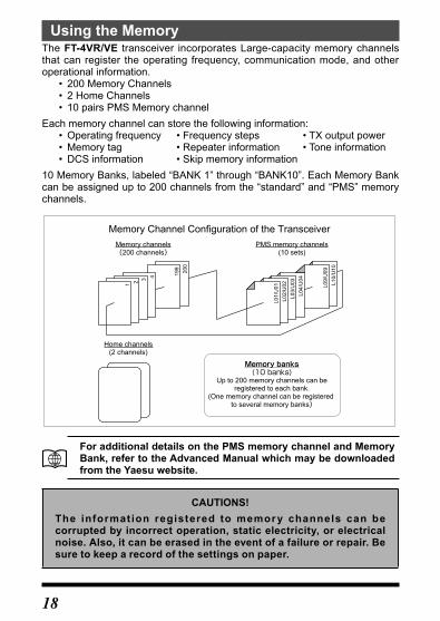
Using the MemoryThe FT-4VR/VE transceiver incorporates Large-capacity memory channels that can register the operating frequency, communication mode, and other operational information.
• 200 Memory Channels • 2 Home Channels • 10 pairs PMS Memory channel
Each memory channel can store the following information: • Operatingfrequency •Frequencysteps •TXoutputpower • Memorytag •Repeaterinformation •Toneinformation • DCSinformation •Skipmemoryinformation
10 Memory Banks, labeled “BANK 1” through “BANK10”. Each Memory Bank can be assigned up to 200 channels from the “standard” and “PMS” memory channels.
200
199
4321 L10/
U10
L09/
U09
L04/
U04
L03/
U03
L02/
U02
L01/
U01
Memory Channel Configuration of the TransceiverMemory channels(200 channels)
Home channels(2 channels)
Memory banks(10 banks)
Up to 200 memory channels can beregistered to each bank.
(One memory channel can be registered to several memory banks)
PMS memory channels(10 sets)
For additional details on the PMS memory channel and Memory Bank, refer to the Advanced Manual which may be downloaded from the Yaesu website.
CAUTIONS!The information registered to memor y channels can be corrupted by incorrect operation, static electricity, or electrical noise. Also, it can be erased in the event of a failure or repair. Be sure to keep a record of the settings on paper.
19
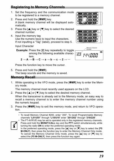
Registering to Memory Channels1. Set the frequency and the communication mode
to be registered to a memory channel.2. Press and hold the [ MR] key.
A blank memory channel will be displayed auto-matically.
3. Press the [] key or [] key to select the desired channel number.
4. Input the memory tagUse the numeric keys to input the characters.If not inputting a “Tag” (label), proceed to step 5.Input CharacterExample: Press the [2] key repeatedly to toggle
among the following available charac-ters.
2→A→B→C→a→b→c→2→···
Memory ChannelNumber
Press the function key to move the cursor.
5. Press and hold the [ MR].The beep sounds and the memory is saved.
Memory Recall1. While operating in the VFO mode, press the [ MR] key to enter the Mem-
ory mode.The memory channel most recently used appears on the LCD.
2. Pressthe[▲]or[▼]keytoselectthedesiredmemorychannel.When the transceiver is already set to the Memory mode, an easy way to recall a memory channel is to enter the memory channel number using the numeric keypad.
3. Press the [ MR] key to exit the memory mode, and return to VFO opera-tion.
• To recall Memory Channel #200, enter “200”. To recall Programmable Memory channels “L01/U01” through “L10/U10” enter “201/202” through “219/220”.
• The FT-4VR/VE may be set to operated only in the registered memory channels. Press and hold the MONI/T.CALL key and the PTT switch simultaneously, while turning the radio ON to enter the preferred operating mode.In the preferred operating mode, press the [] key or [] key to select the [F5 M-ONLY], then press the function key to enter the Memory Channel Only mode. To cancel the Memory Channel Only mode, press the [] key or [] key to select the [F5 M-ONLY], then press the function key again.

20
Clearing MemoriesPress and hold
the Function key →Press the or key
→Press the Function key
(Confirms the setting)(Enters the Set mode) (Select Set Mode "20 MEM DEL")
1. Press the [] key or [] key to select the memory channel from which the data is to be cleared.
2. Press the function key.“del OK” appears on the LCD and the memory channel is cleared.
3. Press the PTT switch to save the setting and re-turn to the normal operation.
Data on memory channel One, and the Home channel cannot be cleared.
Recalling the Home Channels1. Press the Function key, and then press the [P1]
key.“H” and the home channel frequency of the cur-rently selected band appears on the LCD.
2. Press the [#VFO] key or press the Function key, and then press the [P1] key to return to the previ-ous frequency.
Home channelindication
Changing the Home Channel Frequency1. Set the frequency and the operating mode that are to be stored as the
home channel.2. Press and hold the [ MR] key.
A blank memory channel will be displayed automatically.3. Press the [P1] key.
“HOM-IN” is displayed, the Home channel frequency is changed and the radio is returned to normal operation.

21
Memory Channel ScanningThe receiver may be set to scan memory channels:1. While operating in the VFO mode, press the [ MR] key to enter the Mem-
ory mode.2. Pressandholdthe[▲]keyor[▼]key.
Scanning starts of the memory channels begins.If the scanner halts on an incoming signal, the back light will turn ON and the decimal point between the “MHz” and “kHz” digits of the frequency display will blink.
3. Press the function key to cancel the scanning.
Setting the Receive Operation When Scanning Stops
Press and hold the Function key →
Press the or key→
Press the Function key
(Confirms the setting)(Enters the Set mode) (Select Set Mode "34 SCN.RSM")
1. Press the [▲]keyor [▼]key toselect theoperation that is tobeper-formed after the scan stops:
Display Description
BUSY(Default setting)
In BUSY mode, the scanner will halt on a signal it encounters. Scanning will resume two seconds after the other station signal ceases transmitting. In the case of constant-carrier signals like Weather Station broadcasts, the scanner will likely remain on this frequency indefinitely.
HOLDIn HOLD mode, the scanner will halt on a signal it encounters. Scanning will only resume when it is manually re-initiated.
TIMEIn TIME mode, the scanner will halt on a signal it encounters, scanning will resume after five sec-onds even if a signal is still on the frequency.
2. Press the PTT switch to save the setting and exit to normal operation.
The above Set Mode [34 SCN.RSM] operation is common for all scanning operations.
22
For additional details on the following functions, refer to the Advanced Manual which may be downloaded from the Yaesu website.
Split MemoryTwo different frequencies, one for receive and another for transmit, may be stored in one memory channel.Using Memory TagMemory name tags may be assigned to the memory channels and home channels.Using Memory BankThe transceiver allows using up to 10 memory banks to allow sorting and reg-istering the channels in convenient groups.
Scanning FunctionThe transceiver supports the following four scanning functions:
VFO ScanProgrammed ScanMemory Channel ScanProgrammable Memory Scan(PMS)Memory Bank Scan
For additional details on the Programmable Memory Scan (PMS) and Mem-ory Bank Scan, refer to the Advanced Manual which may be downloaded from the Yaesu website.
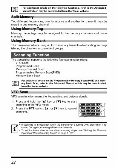
VFO ScanVFO scan function scans the frequencies, and detects signals.
1. Press and hold the [] key or [] key to start scanning in the VFO mode.
2. Press the PTTswitch, [▲]or [▼]keytocancelscanning.
• If scanning is in operation when the transceiver is turned OFF, then when it is turned ON again, scanning will resume instantly.
• To set the transceiver action when scanning stops, see “Setting the Receive Operation When Scanning Stops” on page ( 21).

23
Programmed VFO ScanThe scan condition may be selected for VFO scanning.1. Press the [#VFO] key to enter the VFO mode.2. Press and hold the [#VFO] key.3. Pressthe[▲]or [▼]key toselect thebandwidth forProgrammedVFO
scanning.
Display DescriptionBAND
(default setting) The scanner will sweep frequencies on the current operating band.
+-1MHz The scanner will sweep ±1 MHz from the operating frequency.
+-2MHz The scanner will sweep ±2 MHz from the operating frequency.
+-5MHz The scanner will sweep ±5 MHz from the operating frequency.
ALL The scanner will sweep all frequencies.
PMS-X The scanner will sweep frequencies designated by the currently se-lected PMS (Programmable Memory Scan) frequency pair.
PMS-X will appear in the [#VFO] selections after setting a PMS frequency pair. See the Advance Manual for detail.
Weather Broadcast Channels scan (In the USA)In the USA, the VHF Weather Broadcast Station Memory Channel Bank has been pre-programmed at the factory for immediate access to NOAA weather information stations.1. Press and hold the [1] key to recall the Weather Broadcast Memory Bank.2. Pressthe[▲]or[▼]keytoselect thedesiredWeatherBroadcastchan-
nel.3. To scan for additional or stronger
Weather stations, just press the PTT switch(orpressandhold the[▲]or[▼]key).When the scanner pauses on a station, press the PTT switch once to halt the scan, or press the PTT switch again to restart the scan.
CH Frequency CH Frequency1 162.550 MHz 6 162.500 MHz
2 162.400 MHz 7 162.525 MHz
3 162.475 MHz 8 161.650 MHz
4 162.425 MHz 9 161.775 MHz
5 162.450 MHz 10 163.275 MHz
4. To return to normal operation, press the [ MR] key, or press and hold the[1] key again.

24
Weather Alert Scan (In the USA)This feature allows you to check the Weather Broadcast Memory Channels for the presence of the NOAA Alert Tone while operating using VFO scan or Memory channel scan.When the Weather Alert Scan feature is engaged, the FT-4VR/VE will check the Weather Broadcast Channels for activity every five seconds while scan-ning. If you watch the display carefully, you'll observe the scanner periodically shifting to the Weather Broadcast channel, scanning the Weather channels quickly in search of the Alert Tone, after which regular scanning will resume for another five seconds.1. Press and hold the Function key to enter the Set Mode.2. Pressthe[▲]keyor[▼]keytoselectthe“46 WX ALT”. 3. Press the Function key, then press the [] key or [] key to select “ALT.
ON”.4. Press the PTT switch to save the setting and return to normal operation.5. Press and hold the [] key or [] to start scan-
ning.Scanning starts and the display will remain on the VFO frequency, but every five seconds the trans-ceiver will scan the Weather Broadcast Channels for activity.
6. Press the [ MR] key to return to normal operation.
For additional details on the following functions, refer to the Advanced Manual which may be downloaded from the Yaesu website.
Skip Memory ChannelSkip memory channels: Permits designating undesired channels to be skipped during scanning.Programmable Memory scan (PMS)This function scans only the range of frequencies between the lower and upper limits registered in a pair of PMS Programmable Memory channels. 10 sets of PMS memory channels (L01/U01 to L10/U10) are available.Dual Receive (DW) featureThe transceiver checks for signals on the frequency registered to the selected memory channel (Priority Memory Channel) once approximately every 5 sec-onds.

25
Convenient FunctionsVOX OperationThe VOX system provides automatic transmit/receive switching based on voice input. With the VOX system enabled, you do not need to press the PTT switch in order to transmit. Optional VOX earpiece microphone (SSM-512B) is also available.VFO Split ModeTwo different frequencies, one for receive and another for transmit, may be operated.Tone Squelch featureThe tone squelch opens the speaker audio only when a signal containing the specified CTCSS tone is received. By matching the tone frequency with the partner station in advance, a quiet standby is possible.Digital Code Squelch (DCS) featureDCS (Digital Coded Squelch) function allows audio to be heard only when signals containing the same DCS code are received.New PAGER (EPCS) featureThis new feature allows calling specified stations only, by using a pager code that combines two CTCSS tones. Even when the person who is called is not near the transceiver, the information is displayed on the LCD indicating that a call was received. When the call is received, the bell sounds. The transceiver is automatically placed in transmit mode (for about 2.5 seconds) when called by the other party, and notifies the other party that you are ready to communi-cate.

26
Using Set ModeThe Set Mode permits configuring the various functions according to individual operating needs and preferences.
1. Press and hold the Function key.The previously selected Set Mode item is dis-played.
2. Press the [▲]keyor [▼]key toselect thede-sired Set Mode item.
3. Press the function key, then press the [] key or [] key to change the setting.
4. Press the PTT switch to save the settings and return to normal operation.
• In step 4 above, press the Function key to save the new setting and return to Set Mode item to set the other Set Mode.
• On some setting screens, key operation is different than described in the above steps (For example, inputting the characters, etc.). Refer to the Advance manual.
For additional details, refer to the Advanced Manual which may be down-loaded from the Yaesu website
Tables of Set Mode Operations
No. Set Mode item Description
Selectable options(Options in bold are the
default settings)
1 APOSets the length of time until the transceiver turns off automatically.
OFF / 0.5 Hours – 12 Hours
2 AR BEPSets the beep option during ARTS opera-tion.
OFF / INRANG / ALWAYS
3 AR INTSets the polling interval during ARTS oper-ation.
25 SEC / 15 SEC
4 BCLOTurns the busy channel lockout function ON/OFF.
BCL.OFF / BCL.ON
5 BEEPSets the beep function on pressing the keypad, or stopping the receiver scanning.
KEY+SC / KEY / OFF
6 BELLSelects the number of CTCSS/DCS/PAG-ER/ARTS Bell ringer repetitions.
OFF / 1 T / 3 T / 5 T / 8 T / CONT
7 CWIDTurns the CW Identifier ON/OFF during ARTS operation.
TX OFF / TX ON

27
No. Set Mode item Description
Selectable options(Options in bold are the
default settings)
8 CW WRT Sets the CW ID during ARTS operation.ID= _ _ _ _ _ _ (6 characters)default: blank
9 DC VLT Displays the voltage. (Voltage)
10 DCS.COD Sets the DCS CODE RX and TX.104 DCS CODEs / OFFdefault: 023 R / 023 T
11 DT DLYSets the DTMF code transmission delay time.
50MS / 250MS / 450MS / 750MS / 1000MS
12 DT SETSelects the DTMF auto dialer memory channel and edits the DTMF code (Maxi-mum 16 digits)
d1 – d9
13 DT SPD Sets the DTMF code transmission speed. 50MS / 100MS
14 EDG.BEPTurns the Band-edge beeper ON/OFF.Whileselecting the frequencyvia the [▲]or[▼]key.
BEP.OFF / BEP. ON
15 LAMP Selects the LCD/Keypad Lamp mode.5 SEC / 10 SEC / 30 SEC / CONT / OFF
16 LED.BSY Turns the TX/BUSY indicator ON/OFF while receiving signals.
BSY ON / BSYOFF
17 LED.TXTurns the TX/BUSY indicator ON/OFF while transmitting signals.
TX ON / TXOFF
18 LOCK Configures the lock mode setting.LK KEY / LK PTT / LK P+K
19 M/T-CLSelects the function of the [MONI/T-CALL] switch.
MONI / TC1750* / TC2100 / TC1000 / TC1450(*: Eurpean / Asian Version)
20 MEM.DEL Deletes the memory channel –
21 MEM. TAG Edits the memory channel tag. –
22 PAG.ABKTurns the pager answer back Function ON/OFF
ABK.OFF / ABK. ON
23 PAG.CDR Specifies a personal code (receive). 01 – 05 – 50, 01 – 47 – 50
24 PAG.CDT Specifies a personal code (transmit). 01 – 05 – 50, 01 – 47 – 50
25 PRI.RVT Turns the Priority Revert feature ON/OFF. RVTOFF / RVT ON
26 PSWD Turns the Password feature ON/OFF. PWD.OFF / PWD. ON
27 PSWDWT Inputs the password. (4 digits)

28
No. Set Mode item Description
Selectable options(Options in bold are the
default settings)
28 RF SQL Adjusts the RF Squelch threshold level.OFF / S-1 / S-2 / S-3 / S-4 /S-5 / S-6 / S-8 / S-FULL
29 RPT.ARS Turns the ARS function on/off. ARS.ON / ARS.OFF
30 RPT.FRQ Sets the repeater shift width. OFF / 0.025MHz – 99.975MHz
31 RPT.SFT Sets the repeater shift direction. SIMPLX / +RPT / -RPT
32 RXSAVESelects the Receive mode Battery Saver interval (“sleep” ratio)
200 MS – 2 SEC / OFF
33 SCN.LMP Turns the scan lamp ON/OFF while paused. ON / OFF
34 SCN.RSM Configures the scan stop mode settings. BUSY / HOLD / TIME
35 SKIPTurns the Memory Scan “Skip” channel selection mode ON/OFF.
OFF / SKIP
36 SQL.TYPSelects the Tone Encoder and/or Decoder mode.
OFF / R-TONE / T-TONE / TSQL / REV TN / DCS / PAGER
37 STEP Sets the frequency steps.AUTO /5.0 / 6.25 / 10.0 / 12.5 / 15.0 / 20.0 / 25.0 / 50.0 / 100.0 k
38 TN FRQ Sets the TONE frequency.
OFF / 67.0 R – 100.0 R – 254.1 ROFF / 67.0 T – 100.0 T – 254.1 T
39 TOT Sets the timeout timer.OFF / 1MIN – 3MIN – 30MIN
40 TX PWR Selects Transmitter PowerHIGH (5W) / MID (2.5W) / LOW (0.5W)
41 TXSAVE Turns the Transmit Battery Saver ON/OFF. SAVOFF / SAV ON
42 VFO.SPL Turns the “VFO Split” operation ON/OFF. VSP.OFF / VSP. ON
43 VOX Turns the VOX function ON/OFF. VOXOFF/ VOX ON
44 WFM.RCVBroadband FM Radio (WFM) function En-ables/Disables.
WFM.ON / WFM.OFF
45 W/N.DEVSets the Transmit Modulation Level in the FM mode.
WIDE / NARROW
46 WX ALT Turns the Weather Alert Scan ON/OFF. ALT.OFF / ALT. ON
(*): This function displays depending on the transceiver version.

29
Restoring to Defaults (Reset) / Setting the Preferred Operating ModeThe following reset or preferred operating modes may be selected.1. Turn the transceiver OFF.2. Press and hold the MONI/T.CALL key and
the PTT switch simultaneously, while turning the transceiver ON.
3. When the LCD backlight comes on, release the MONI/T.CALL key and PTT switch.
4. Referringtothebelowtable,pressthe[▲]or[▼]keytoselectthedesiredresetsordesiredoperating modes.
5. Press the Function key momentarily to acti-vate the selected operating mode.
Display DescriptionF1:SET RST Resets the Set Mode settings to factory defaults.F2:MEM RST Clears the Memory settings to factory defaults.F3:MB. RST Clears the Memory Bank assignments.F4:ALL RST Clears the all memories and other settings to factory defaults.F5:M-ONLY Memory Mode operation only.F6:CLONE Clone Mode.
CAUTION!Resetting the transceiver (F2 MEM RST / F4 ALL RST) will clear all memories.Always make a note of the memory channel settings, etc. beforeresetting.
• To cancel this operation, turn the transceiver OFF. • Perform F4:ALL.RST to restore all of the following Set Mode items to default.
10 DCS.COD 26 PSWD 27 PSWDWT 30 RPT.FRQ 31 RPT.SFT35 SKIP 36 SQL.TYP 37 STEP 38 TN FRQ 40 TX PWR45 W/N.DEV
30
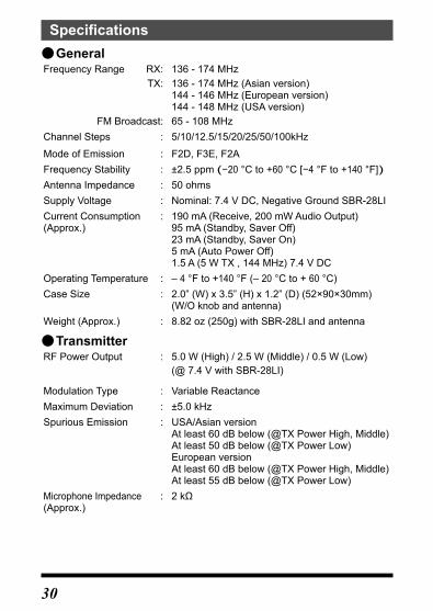
Specifications ●General
Frequency Range RX: 136 - 174 MHz TX: 136 - 174 MHz (Asian version)
144 - 146 MHz (European version)144 - 148 MHz (USA version)
FM Broadcast: 65 - 108 MHzChannel Steps : 5/10/12.5/15/20/25/50/100kHz
Mode of Emission : F2D, F3E, F2AFrequency Stability : ±2.5 ppm (−20 °C to +60°C[−4 °F to +140 °F])Antenna Impedance : 50 ohmsSupply Voltage : Nominal: 7.4 V DC, Negative Ground SBR-28LICurrent Consumption :(Approx.)
190 mA (Receive, 200 mW Audio Output)95 mA (Standby, Saver Off)23 mA (Standby, Saver On)5 mA (Auto Power Off)1.5 A (5 W TX , 144 MHz) 7.4 V DC
Operating Temperature : – 4 °F to +140 °F (– 20 °C to + 60 °C)Case Size : 2.0” (W) x 3.5” (H) x 1.2” (D) (52×90×30mm)
(W/O knob and antenna)Weight (Approx.) : 8.82 oz (250g) with SBR-28LI and antenna
●TransmitterRF Power Output : 5.0 W (High) / 2.5 W (Middle) / 0.5 W (Low)
(@ 7.4 V with SBR-28LI)
Modulation Type : Variable ReactanceMaximum Deviation : ±5.0 kHzSpurious Emission : USA/Asian version
At least 60 dB below (@TX Power High, Middle)At least 50 dB below (@TX Power Low)European versionAt least 60 dB below (@TX Power High, Middle)At least 55 dB below (@TX Power Low)
Microphone Impedance :(Approx.)
2kΩ

31
●ReceiverCircuit Type : Direct-conversionSensitivity : 0.2μVfor12dBSINAD(140-150MHz,NFM)Selectivity (-6 dB/-60 dB) : FM, NFM ±25 kHz / 12.5 kHzAF Output : 800mW(16ΩforTHD10%7.4VDC)internal
speaker800mW(16ΩforTHD10%7.4VDC)external speaker
Specifications are subject to change without notice, and are guaranteed within the 144 MHz amateur bands only. Frequency ranges will vary according to transceiver version; check with your dealer.
Symbols placed on the equipment Direct current

32
YAESU Limited WarrantyLimited Warranty is valid only in the country/region where this product was originally purchased.On-line Warranty Registration:ThankyouforbuyingYAESUproducts!Weareconfidentyournewradiowillserve your needs for many years! Please register your product at www.yae-su.com - Owner’s CornerWarranty Terms:Subject to the Limitations of the Warranty and the Warranty Procedures de-scribed below, YAESU MUSEN hereby warrants this product to be free of defects in materials and workmanship in normal use during the “Warranty Period.” (the “Limited Warranty”).Limitations of Warranty:A. YAESU MUSEN is not liable for any express warranties except the Limited
Warranty described above.B. The Limited Warranty is extended only to the original end-use purchaser or
the person receiving this product as a gift, and shall not be extended to any other person or transferee.
C. Unless a different warranty period is stated with this YAESU product, the Warranty Period is three years from the date of retail purchase by the origi-nal end-use purchaser.
D. The Limited Warranty is valid only in the country/region where this product was originally purchased.
E. During the Warranty Period, YAESU MUSEN will, at its sole option, repair or replace (using new or refurbished replacement parts) any defective parts within a reasonable period of time and free of charge.
F. The Limited Warranty does not cover shipping cost (including transporta-tion and insurance) from you to us, or any import fees, duties or taxes.
G. The Limited Warranty does not cover any impairment caused by tamper-ing, misuse, failure to follow instructions supplied with the product, unau-thorizedmodifications,ordamagetothisproductforanyreasons,suchas:accident; excess moisture; lightning; power surges; connection to improper voltage supply; damage caused by inadequate packing or shipping proce-dures;lossof,damagetoorcorruptionofstoreddata;productmodificationto enable operation in another country/purpose other than the country/purpose for which it was designed, manufactured, approved and/or autho-rized;ortherepairofproductsdamagedbythesemodifications.
H. The Limited Warranty applies only to the product as it existed at the time of the original purchase, by the original retail purchaser, and shall not pre-clude YAESU MUSEN from later making any changes in design, adding to, or otherwise improving subsequent versions of this product, or impose upon YAESU MUSEN any obligation to modify or alter this product to con-form to such changes, or improvements.
I. YAESU MUSEN assumes no responsibility for any consequential damages caused by, or arising out of, any such defect in materials or workmanship.

33
J. TO THE FULLEST EXTENT PERMITTED BY LAW, YAESU MUSEN SHALL NOT BE RESPONSIBLE FOR ANY IMPLIED WARRANTY WITH RESPECT TO THIS PRODUCT.
K. If the original retail purchaser timely complies with the Warranty Proce-dures described below, and YAESU MUSEN elects to send the purchaser a replacement product rather than repair the “original product”, then the Lim-ited Warranty shall apply to the replacement product only for the remainder of the original product Warranty Period.
L. Warranty statutes vary from state to state, or country to country, so some of the above limitations may not apply to your location.
Warranty Procedures:1.TofindtheAuthorizedYAESUServiceCenter inyourcountry/region,visit
www.yaesu.com.ContacttheYAESUServiceCenterforspecificreturnandshipping instructions, or contact an authorized YAESU dealer/distributor from whom the product was originally purchased.
2. Include proof of original purchase from an authorized YAESU dealer/dis-tributor, and ship the product, freight prepaid, to the address provided by the YAESU Service Center in your country/ region.
3. Upon receipt of this product, returned in accordance with the procedures described above, by the YAESU Authorized Service Center, all reasonable efforts will be expended by YAESU MUSEN to cause this product to con-form to itsoriginalspecifications.YAESUMUSENwill return the repairedproduct (or a replacement product) free of charge to the original purchas-er. The decision to repair or replace this product is the sole discretion of YAESU MUSEN.
Other conditions:YAESU MUSEN’S MAXIMUM LIABILITY SHALL NOT EXCEED THE ACTU-AL PURCHASE PRICE PAID FOR THE PRODUCT. IN NO EVENT SHALL YAESU MUSEN BE LIABLE FOR LOSS OF, DAMAGE TO OR CORRUP-TION OF STORED DATA, OR FOR SPECIAL, INCIDENTAL, CONSE-QUENTIAL, OR INDIRECT DAMAGES, HOW EVER CAUSED; INCLUDING WITHOUT LIMITATION TO THE REPLACEMENT OF EQUIPMENT AND PROPERTY, AND ANY COSTS OF RECOVERING, PROGRAMMING OR REPRODUCING ANY PROGRAM OR DATA STORED IN OR USED WITH THE YAESU PRODUCT.Some Countries in Europe and some States of the USA do not allow the ex-clusion or limitation of incidental or consequential damages, or a limitation on how long an implied warranty lasts, so the above limitation or exclusions may not apply.Thiswarranty provides specific rights, theremaybeother rightsavailable which may vary between countries in Europe or from state to state within the USA.This Limited Warranty is void if the label bearing the serial number has been removed or defaced.

34
1. Changes or modifications to this device that are not expressly approved by YAESU MUSEN could void the user’s authorization to operate this device.
2. This device complies with part 15 of the FCC Rules. Operation is subject to the following two conditions: (1) This device may not cause harmful interference, and (2) this device must accept any interference including received, interference that may cause undesired operation.
3. The scanning receiver in this equipment is incapable of tuning, or readily being altered, by the User to operate within the frequency bands allocated to the Domestic public Cellular Telecommunications Service in Part 22.
This device complies with Industry Canada license-exempt RSS stan-dard(s). Operation is subject to the following two conditions: (1) this device may not cause interference, and (2) this device must accept any interference, including interference that may cause undesired operation of the device.
Le présent appareil est conforme aux CNR d’Industrie Canada applica-bles aux appareils radio exempts de licence. L’exploitation est autorisée aux deux conditions suivantes : (1) l’appareil ne doit pas produire de brouillage, et (2) l’utilisateur de l’appareil doit accepter tout brouillage radioélectrique subi, même si le brouillage est susceptible d’en compro-mettre le fonctionnement.
DECLARATION BY MANUFACTURERThe Scanner receiver is not a digital scanner and is incapable of being converted or modified to a digital scanner receiver by any user.
WARNING : MODIFICATION OF THIS DEVICE TO RECEIVE CELLULAR RADIOTELEPHONE SERVICE SIGNALS IS PROHIBITED UNDER FCC RULES AND FEDERAL LAW.

35
Note

36
Note

EU Declaration of ConformityWe, Yaesu Musen Co. Ltd of Tokyo, Japan, hereby declare that this radio equipment FT-4VE is in full compliance with EU Radio Equipment Directive 2014/53/EU. The full text of the Declaration of Conformity for this product is available to view at http://www.yaesu.com/jp/red
ATTENTION – Conditions of usageThis transceiver works on frequencies that are regulated and not permitted to be used without authorisation in the EU countries shown in this table. Users of this equipment should check with their local spectrum management authority for licensing condi-tions applicable for this equipment.
AT BE BG CY CZ DEDK ES EE FI FR UKGR HR HU IE IT LTLU LV MT NL PL PTRO SK SI SE CH ISLI NO – – – –
Disposal of Electronic and Electrical EquipmentProducts with the symbol (crossed-out wheeled bin) cannot be disposed as household waste.Electronic and Electrical Equipment should be recycled at a facility capable of handling these items and their waste by-products.Please contact a local equipment supplier representative or service center for information about the waste collection sys-tem in your country.

Copyright 2018YAESU MUSEN CO., LTD.All rights reserved.No portion of this manual may bereproduced without the permission ofYAESU MUSEN CO., LTD.
YAESU MUSEN CO., LTD.Tennozu Parkside Building2-5-8 Higashi-Shinagawa, Shinagawa-ku, Tokyo140-0002 JapanYAESU USA6125 Phyllis Drive, Cypress, CA 90630, U.S.A.YAESU UKUnit 12, Sun Valley Business Park, Winnall CloseWinchester, Hampshire, SO23 0LB, U.K.
Printed in China1803M-AC-1