Embed Size (px)
Citation preview

���� ����� ��� ��� ��
FAST S.p.A.
ISO 9001:2000 - Cert.n° 0882/4 SELECTION,
INSTALLATION, USE
AND MAINTENANCE MANUAL
FTA range
Air conditioning unitsAir fl ow rate from 900 to 5000 m³/h

Contents English
General standards 4
Description of the unit 5
Description of components 5
Identification of the unit 6
Accessories 7
Compatibility of accessories 8
Nominal technical data 10
Characteristic ventilation curves 12
Pressure drops in the filters, due to dirt 20
Table showing heat exchange coil output 21
Table showing operating limits 21
Installation, use and maintenance manual 42
- General safety requirements 42
- Minimum operating spaces 43
- Handling 43
- Unit installation 43
- Installation - Connections 44
- Repositioning the internal components 46
- First start-up 46
- PTC2 control panel 46
Union base unit with accessories 47
Unit maintenance 48
Unit disposal 49
Diagnosis and fault solving 49
Wiring diagrams 50
- PTC2 connection diagram 50
- Connection diagram for the electric coils 53
- PX connection diagram 54
Size data 57
- Unit dimensions 57
- Plenum with post-heating electric coil 58
- Section of soft pocket filters 58
- Intake grille 59
- Delivery grille 59
- 2-damper mixing chamber 60
- 3-damper mixing chamber 61
- Plenum with multiple circular delivery points 62
- Closed delivery plenum 62
- 2-area damper 63
- Suction damper 63
- Silencers 64
- Section of intake fan 64
- PCT2, PX 65
�
General standards
The present manual is an
integral part of the docu-
mentation enclosed with the
machine.
It must be conserved for
future reference and must accompany
the machine throughout its working life.
The manual defines the purpose for which
the machine was built and establishes the
correct installation and use limits.
• All use, installation and maintenance
instructions of the unit are described
in this manual as well as the main
accident prevention standards.
• Read carefully and fully all informa-
tion contained in this manual before
the installation, start-up, use, main-
tenance and cleaning of the unit. Pay
particular attention to the use regu-
lations accompanied by the words
“DANGER” or “WARNING”: failure to
observe them could cause damage to
the machine and/or persons and pro-
perty.
• For irregularities not contemplated by
this manual, consult the local After
Sales Service.
• FAST S.p.A. decline any responsibility
for any damage due to the improper
use of the machine, and to a partial or
superficial reading of the information
contained in this manual.
• Installation and maintenance must be
carried out by trained and qualified
personnel, having the requirements
laid down by law 46/90 and/or DPR
380/2001 for electric/electronic and
air conditioning installations, with
consequent registration at the local
CHAMBER of COMMERCE. Otherwise
FAST S.p.A. decline all responsibility
regarding the safety of the product.
THE MANUFACTURER DECLINES ANY
RESPONS IB IL ITY FOR DAMAGE TO
PROPERTY, PERSONS OR ANIMALS CAUSED
BY THE NON-OBSERVANCE OF THE
INDICATIONS AND REGULATIONS CONTAINED
IN THIS MANUAL.
Even though a suitable risk analysis was
carried out during the design of the FTA
unit, pay ATTENTION to the pictograms on
the machine; these make it easier to read
the manual, quickly drawing the reader's
attention to risks that cannot be
avoided or sufficiently limited
with the adoption of protection
means and measures.
GENERAL DANGER SIGNS
Carefully observe all indications at the
side of the pictogram.
The non observance of the indi-
cations could cause hazardous
conditions with possible injury
to the operator and to the user
in general.
VOLTAGE DANGER SIGN
Carefully observe all indications at the
side of the pictogram.
The signs indicate components
on the unit or, in the present
manual, identify areas that could genera-
te risks of an electrical nature.
GENERAL WARNING SIGNS
Carefully observe all indications to the
side of the pictogram that limit some
actions in order to ensure greater safety
for the operator.
M A I N G U A R A N T E E CONDITIONS
• The guarantee does not include pay-
ment for damages due to incorrect
installation by the installer.
• The guarantee does not include pay-
ment for damages due to the improper
use of the unit by the user.
• The manufacture is not responsible for
injuries to the installer or user, caused
by incorrect installation or improper
use of the unit;
• The equipment must be installed in
such a manner so as to permit mainte-
nance and/or repair operations;
• The guarantee does not cover in any
case costs due to turntable ladders,
scaffolding or other similar elevating
systems that are necessary to carry
out operations under guarantee.
The guarantee is not valid if:
• the services and repairs have been
carried out by unauthorised personnel
or companies;
• the unit has been previously repaired
or modified with non-original parts;
• the unit has not been suitably maintai-
ned;
• the instructions given in this manual
have not been observed;
• unauthorised modifications have been
made.
NB:
the manufacturer reserves the right to
carry out modifications at any time dee-
med necessary to improve its product, and
is not obliged to apply the said modifica-
tions to previously manufactured machi-
nes that have already been delivered or
are being constructed.
The general conditions are in any case
subject to the general sale conditions
foreseen on the stipulation of the con-
tract.
Air conditioning units - FTA range
� � � � � � � � � � � � � � � � � � � � � � � � � � � � � � � � � � � � � � � � �
�
The air conditioning units in the FTA
range have been designed for civil,
commercial and hotel use, for small
and medium sized rooms. The units are
designed to guarantee high head levels
and can be installed either vertically
or horizontally, thereby offering
greater versatility. Thanks to this type
of unit, several rooms can be served
via a distribution plenum. The units of
this range are characterised by their
compact size, low noise levels, and the
wide choice of accessories.
STRUCTURE
The load-bearing structure is made of
galvanised steel sandwich panels with
polyurethane insulation (density 40kg/
m³), 15 mm thick. The suction and
supply panels are fitted with flanges for
connecting any air pipes or accessories
envisaged. Special brackets supplied
with the unit make it easier to fix it to
the wall.
The condensate drip tray, in galvanised
steel, has a threaded drain connection
on both sides and can be used whether
the unit is installed horizontally or
vertically.
ELECTRIC FAN UNIT
Consist ing of high performance
centrifugal fans with double intake
and forward blades. The multispeed
electric motor, for which three speeds
can be selected from the control panel
(optional), is directly connected to the
fans.
HEAT EXCHANGE COIL
In copper piping and aluminium finning
blocked by the mechanical expansion of
the pipes.
Threaded pipe couplings for the
hydraulic connections and air drain
valve are supplied. Two versions are also
available with a direct expansion coil in
copper piping with aluminium finning
blocked by the mechanical expansion of
the pipes (3 or 4 rows).
FILTERING
The air is filtered through synthetic
filters, 50mm thick, in efficiency class
G4 (in compliance with standard EN
779), positioned at the suction point.
The filters can be easily accessed for
maintenance and cleaning. For the
VRFxF accessory, the air is filtered
through soft pocket filters with a
filtering degree of F6. For higher
filtering degrees, contact our Technical/
Sales Office.
Air conditioning units - FTA range
� � � � � � � � � � � � � � � � � � � � � � � � � � � � � � � � � � � � � � � � �
Description of the unit
Description of components
�
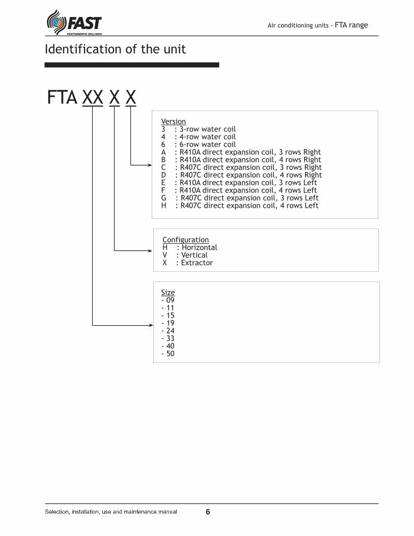
Identification of the unit
Air conditioning units - FTA range
� � � � � � � � � � � � � � � � � � � � � � � � � � � � � � � � � � � � � � � � �
FTA XX X X
Size- 09- 11- 15- 19- 24- 33- 40- 50
Version 3 : 3-row water coil4 : 4-row water coil 6 : 6-row water coil A : R410A direct expansion coil, 3 rows RightB : R410A direct expansion coil, 4 rows RightC : R407C direct expansion coil, 3 rows RightD : R407C direct expansion coil, 4 rows RightE : R410A direct expansion coil, 3 rows LeftF : R410A direct expansion coil, 4 rows LeftG : R407C direct expansion coil, 3 rows LeftH : R407C direct expansion coil, 4 rows Left
ConfigurationH : HorizontalV : Vertical X : Extractor
�
Accessories
M2SxF 2-damper mixing chamber Galvanised steel section complete with two air calibration dampers and fins in galvanised steel. Fin pitch 50mm; galvanised steel adjustment pin, 8mm, can be motor-driven.
M3SxF 3-damper mixing chamberGalvanised steel section complete with three air calibration dampers and fins in galvanised steel. Fin pitch 50mm; galvanised steel adjustment pin, 8mm, can be motor-driven.
FTFxF Section of soft pocket filters Galvanised steel section complete with soft pocket filters with a filtering degree of F6. For different filtering degrees, contact our Technical/Sales Office.
B1RxF 1-row water coil for 4-pipe systemsPositioned internally, downstream from the main coil, and made of copper piping and aluminium finning blocked by the mechanical expansion of the pipes. Threaded pipe couplings for the hydraulic connections and air drain valve are supplied.
B2RxF 2-row water coil for 4-pipe systemsPositioned internally, downstream from the main coil, and made of copper piping and aluminium finning blocked by the mechanical expansion of the pipes. Threaded pipe couplings for the hydraulic connections and air drain valve are supplied.
FTA 09 FTA 11 FTA 15 FTA 19 FTA 24 FTA 33 FTA 40 FTA 50
M2SxF M2S1F M2S1F M2S2F M2S3F M2S4F M2S4F M2S5F M2S5F
M3SxF M3S1F M3S1F M3S2F M3S3F M3S4F M3S4F M3S5F M3S5F
FTFxF FTF1F FTF1F FTF2F FTF3F FTF4F FTF4F FTF5F FTF5F
B1RxF B1R1F B1R1F B1R2F B1R3F B1R4F B1R4F B1R5F B1R5F
B2RxF B2R1F B2R1F B2R2F B2R3F B2R4F B2R4F B2R5F B2R5F
PBExF PBE1F PBE2F PBE3F PBE4F PBE5F PBE6F PBE7F PBE8F
SSLxF SSL1F SSL1F SSL2F SSL3F SSL4F SSL4F SSL5F SSL5F
S2ZxF S2Z1F S2Z1F S2Z2F S2Z3F S2Z4F S2Z4F S2Z5F S2Z5F
VRFxF VRF1F VRF2F VRF3F VRF4F VRF5F VRF6F VRF7F VRF8F
PMMxF PMM1F PMM1F PMM2F PMM3F PMM4F PMM4F PMM5F PMM5F
PMCxF PMC1F PMC1F PMC2F PMC3F PMC4F PMC4F PMC5F PMC5F
SAPxF SAP1F SAP1F SAP2F SAP3F SAP4F SAP4F SAP5F SAP5F
GMDxF GMD1F GMD1F GMD2F GMD3F GMD4F GMD4F GMD5F GMD5F
GAPxF GAP1F GAP1F GAP2F GAP3F GAP4F GAP4F GAP5F GAP5F
FPIxF FPI1F FPI1F FPI2F FPI3F FPI4F FPI4F FPI5F FPI5F
PX PX
PCT2 PCT2(*)
RG RG
TABLE SHOWING ACCESSORY COMPATIBILITY:
* ACTIV
ATIO
N W
ITH
RELAY (
NO
T S
UPPLIE
D)
PBExF Section with electric post-heating coilThe electric coil consists of armoured heaters fitted with a double safety thermostat.
SSLxF Module with silencer baffles Galvanised steel section complete with silencer baffles in rock wool covered with a polyethylene film to prevent scaling.
S2ZxF 2-area damper (70-30%)Galvanised steel damper with opposed fins for mixing the flow of external air and the flow of fresh air. Fin pitch 50mm; galvanised steel adjustment pin, 8mm, can be motor-driven.
VRFxF Fan intake section with G4 filterFan unit to be positioned at the intake point, with the accessory M3SxF, contained in a galvanised steel section fitted with flat filters with an efficiency level of G4 (EN779)
PMMxF Plenum with multiple circular delivery points
PMCxF Closed supply plenum
SAPxF Suction damperAir calibration damper with galvanised steel fins. Fin pitch 50mm; galvanised steel adjustment pin, 8mm, can be motor-driven.
GMDxF Delivery grille with adjustable finsGrille with double row of fins that can be adjusted when emitting air into the room. Can be installed directly on the equipment (removing the flanges) or on the wall.
GAPxF Suction grilleWith fins fixed at an angle of 45°; can be installed directly on the equipment (removing the flanges) or on the wall.
FPIxF Frame filter (filter already in units)
PX Selector-only control panel
PCT2 Selector/thermostat/switch control panel
RG Adjustment kit complete with electrical and power panelThe control kit allows for the control of the functions of the unit and it includes: microprocessor control with LCD room terminal. The controller with 230Vac supply and 8VA power input (without additional loads), IP30 protection class (with dedicated protections) is equipped with 2 phase-cut outputs, 10 ON/OFF outputs (relay type) under voltage (230Vac), 4 0..10V outputs, 8 digital inputs, 4 NTC inputs and 4 universal inputs.The LDC teminal visualises the state of operation of the unit and any malfunctioning, besides controlling the settings of the unit.Tthe control, based upon the retun sensor, controls the 3-way valve ON/OFF type 230Vac, 2-stages electric batteries (with a dedicated electric power board), actuators for dampers type ON/OFF 230Vac, filters pressure switches, humidity sensor.
Air conditioning units - FTA range
� � � � � � � � � � � � � � � � � � � � � � � � � � � � � � � � � � � � � � � � �
�
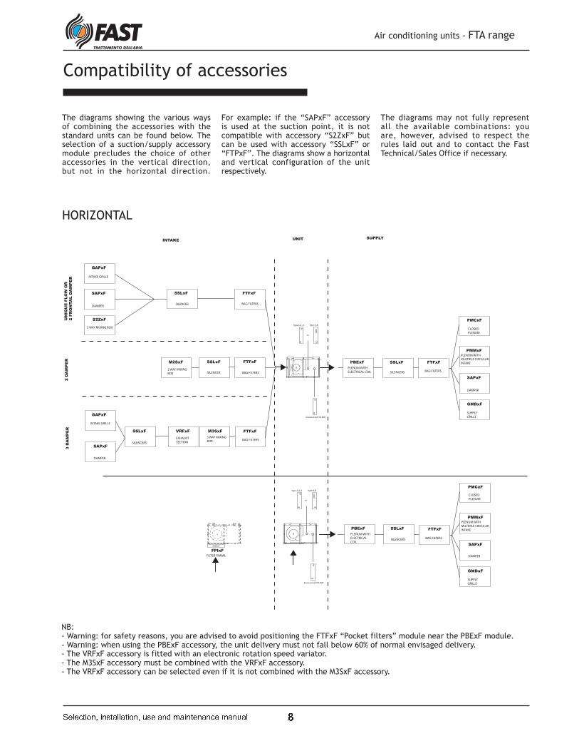
Compatibility of accessories
The diagrams showing the various ways of combining the accessories with the standard units can be found below. The selection of a suction/supply accessory module precludes the choice of other accessories in the vertical direction, but not in the horizontal direction.
For example: if the “SAPxF” accessory is used at the suction point, it is not compatible with accessory “S2ZxF” but can be used with accessory “SSLxF” or “FTPxF”. The diagrams show a horizontal and vertical configuration of the unit respectively.
The diagrams may not fully represent all the available combinations: you are, however, advised to respect the rules laid out and to contact the Fast Technical/Sales Office if necessary.
HORIZONTAL
NB:- Warning: for safety reasons, you are advised to avoid positioning the FTFxF “Pocket filters” module near the PBExF module.- Warning: when using the PBExF accessory, the unit delivery must not fall below 60% of normal envisaged delivery.- The VRFxF accessory is fitted with an electronic rotation speed variator.- The M3SxF accessory must be combined with the VRFxF accessory.- The VRFxF accessory can be selected even if it is not combined with the M3SxF accessory.
PBExF
PLENUM WITH
ELECTRICAL COIL
SSLxF
SILENCERS
PMCxF
CLOSED
PLENUM
PMMxF
PLENUM WITH
MULTIPLE CIRCULAR
INTAKE
SAPxF
DAMPER
GMDxF
SUPPLY
GRILLE
M2SxF
2 WAY MIXING
BOX
SSLxF
SILENCER
2 D
AM
PE
R
INTAKE UNIT SUPPLY
FTFxF
PBExF
PLENUM WITH
ELECTRICAL
COIL
SSLxF
SILENCERS
or
Type 3, 4 , 6 Type A, B
Accessories B1R, B2R
Accessories B1R, B2R
or
type 3, 4 , 6 type A, B
FPIxF
FILTER FRAME
FTFxF
BAG FILTERS
PMCxF
CLOSED
PLENUM
PMMxF
PLENUM WITH
MULTIPLE CIRCULAR
INTAKE
SAPxF
DAMPER
GMDxF
SUPPLY
GRILLE
FTFxF
BAG FILTERS
M3SxF
3 WAY MIXING
BOX
VRFxF
EXHAUST
SECTION
FTFxF
BAG FILTERS
SSLxF
SILENCERS
GAPxF
INTAKE GRILLE
SAPxF
DAMPER
3 D
AM
PE
R
SSLxF
SILENCER
GAPxF
INTAKE GRILLE
SAPxF
DAMPER
FTFxF
BAG FILTERS
S2ZxF
2 WAY MIXING BOX
UN
IQU
E F
LO
W O
R
2 F
RO
NTA
L D
AM
PE
R
BAG FILTERS
Air conditioning units - FTA range
� � � � � � � � � � � � � � � � � � � � � � � � � � � � � � � � � � � � � � � � �

�
VERTICAL
NB:- Warning: for safety reasons, you are advised to avoid positioning the FTFxF “Pocket filters” module near the PBExF module.- Warning: when using the PBExF accessory, the unit delivery must not fall below 60% of normal envisaged delivery.- The VRFxF accessory is fitted with an electronic rotation speed variator.- The M3SxF accessory must be combined with the VRFxF accessory.- The VRFxF accessory can be selected even if it is not combined with the M3SxF accessory.
PBExF
PLENUM WITH
ELECTRICAL
COIL
SSLxF
SILENCERS
PMCxF
CLOSED
PLENUM
PMMxF
PLENUM WITH
MULTIPLE CIRCULAR
INTAKE
SAPxF
DAMPER
GMDxF
SUPPLY
GRILLE
NOTHING
UNIT SUPPLY
PBExF
PLENUM WITH
ELECTRICAL
COIL
SSLxF
SILENCERS
PMCxF
CLOSED
PLENUM
PMMxF
PLENUM WITH
MULTIPLE CIRCULAR
INTAKE
SAPxF
DAMPER
GMDxF
SUPPLY
GRILLE
or
type 3, 4 , 6 type A, B
Accessories B1R, B2R
accessories B1R, B2R
oppure
type 3, 4 , 6 type A, B
M2SxF
2 WAY MIXING
BOX
SSLxF
SILENCERS
2 D
AM
PE
R FTFxF
BAG FILTERS
M3SxF
3 WAY MIXING
BOX
VRFxF FTFxF
BAG FILTERS
SSLxF
SILENCERS
GAPxF
INTAKE GRILLE
SAPxF
DAMPER
3 D
AM
PE
R
SSLxF
SILENCERS
GAPxF
INTAKE GRILLE
SAPxF
DAMPER
FTFxF
BAG FILTERS
S2ZxF
2 WAY MIXING BOX
FPIxF
FILTER FRAME
INTAKE
UN
IQU
E F
LO
W O
R
2 F
RO
NTA
L D
AM
PE
R
EXHAUST
SECTION
Air conditioning units - FTA range
� � � � � � � � � � � � � � � � � � � � � � � � � � � � � � � � � � � � � � � � �

�
Air conditioning units - FTA range
� � � � � � � � � � � � � � � � � � � � � � � � � � � � � � � � � � � � � � � � �
Nominal technical data
Model FTA 09 FTA 11 FTA 15 FTA 19 FTA 24 FTA 33 FTA 40 FTA 50
Nominal air flow ratem³/h 900 1100 1500 1900 2400 3300 4000 5000
l/s 250 306 417 528 667 917 1111 1389
Effective static pressure (1) Pa 140 320 270 250 185 250 245 200
Cooling capacity with 3-row coil (2)total kW 4.7 5.3 8.2 10.3 13.8 16.9 21.4 24.7
sensible kW 3.2 3.6 5.4 6.9 9.1 11.4 14.5 16.8
Cooling capacity with 4-row coil (2)total kW 4.7 5.7 8.7 12.4 17.3 21.7 27.2 31.8
sensible kW 3.5 4.2 6.2 8.3 11.2 14.3 18.0 21.3
Cooling capacity with 6-row coil (2)total kW 5.4 6.7 11.7 15.5 20.6 26.3 33.5 39.6
sensible kW 3.9 4.7 7.5 9.8 12.8 16.6 20.9 25.0
Cooling capacity with 3-row direct
expansion coil R-407C (3)
total kW 5.1 5.5 8.4 11.0 15.2 17.5 23.8 26.1
sensible kW 3.5 3.9 5.9 7.6 10.3 12.4 16.4 18.5
Cooling capacity with 4-row direct
expansion coil R-407C (3)
total kW 5.9 6.5 9.9 12.8 17.6 20.6 27.7 30.8
sensible kW 4.0 4.5 6.6 8.6 11.5 14.0 18.3 20.9
Cooling capacity with 3-row direct
expansion coil R-410A (3)
total kW 5.7 6.3 9.6 12.5 17.0 20.0 26.8 30.0
sensible kW 3.8 4.2 6.3 8.1 10.9 13.2 17.4 19.9
Cooling capacity with 4-row direct
expansion coil R-410A (3)
total kW 6.6 7.3 11.0 14.2 19.2 23.0 30.5 34.5
sensible kW 4.2 4.7 7.0 9.1 12.1 14.8 19.4 22.3
Heating capacity with 3-row coil (4) kW 11.7 13.4 19.7 25.2 33.3 41.7 53.4 62.4
Heating capacity with 4-row coil (4) kW 14.2 16.6 23.9 30.8 40.6 52.2 65.8 78.3
Heating capacity with 6-row coil (4) kW 15.7 18.5 26.6 34.2 44.3 58.0 72.6 87.5
Heating capacity with 1-row water coil for 4-pipe
system (8)kW 5.2 5.7 9.2 11.4 15.9 18.3 25.2 27.7
Heating capacity with 2-row water coil for 4-pipe
system (8)kW 8.4 9.5 14.2 17.9 24.3 29.9 38.9 44.9
Heating capacity with 3-row coil (5) kW 4.6 5.3 7.8 9.9 13.1 16.4 21.0 24.5
Heating capacity with 4-row coil (5) kW 5.5 6.4 9.3 12.1 16.0 20.6 25.9 30.8
Heating capacity with 6-row coil (5) kW 6.1 7.2 10.5 13.6 17.6 23.0 28.9 34.8
Heating capacity with 2-row water coil for 4-pipe
system (5)kW 2.2 2.4 4.0 4.9 6.9 7.9 10.9 12.0
Heating capacity with 1-row water coil for 4-pipe
system (5)kW 3.6 4.1 6.2 7.8 10.6 13.0 16.9 19.5
Electric coil capacity kW 4 6 8 10 12 16 20 24
Number of stages of electric coil no. 2 2 2 2 2 2 2 2
Electric coil power supply Volt-Ph-Hz 400-3-50 400-3-50 400-3-50 400-3-50 400-3-50 400-3-50 400-3-50 400-3-50
Fans no. 1 2 2 1 1 2 2 2
Motors no. 1 2 2 1 1 2 2 2
Total input power of fans W 357 713 713 886 874 1771 1771 2852
Input current of fans A 1.6 3.1 3.1 3.9 3.8 7.7 7.7 12.4
Fan power supply V-Ph-Hz 230-1-50 230-1-50 230-1-50 230-1-50 230-1-50 230-1-50 230-1-50 230-1-50
Poles no. 2 2 2 4 4 4 4 4
Flat filter efficiency (6) G4 G4 G4 G4 G4 G4 G4 G4
Pocket filter efficiency (6) F6 F6 F6 F6 F6 F6 F6 F6
Sound power level (7) dB(A) 63 66 67 72 74 75 76 79
Connections
Coil manifolds Ø inches 1" 1" 1" 1" 1" 1" 1" 1"
Direct expansion coil piping in Øi mm 16 16 16 16 16 16 22 22
out Øu mm 22 22 22 22 22 22 28 28
Condensate discharge Ø inches ¾ ¾ ¾ ¾ ¾ ¾ ¾ ¾
Dimensions and weight
Height mm 300 300 300 390 390 390 390 390
Width mm 700 700 1050 1050 1475 1475 2100 2100
Length mm 700 700 700 850 850 850 1000 1000
Net weight of standard unit
3-row coil kg 27 32 43 59 77 85 132 138
4-row coil kg 28 33 45 60 78 86 135 140
6-row coil kg 30 35 47 62 81 89 139 144
note (1) at nominal flow rate with 3-row coil
note (2) Temperature of incoming air 27°C d.b. 19°C w.b.; water temperature (In-Out) 7°C 12°C
note (3) Temperature of incoming air 27°C d.b. 19°C w.b.; average evap. temp. 5°C
note (4) Temperature of incoming air 10°C; water temperature (In-Out) 70°C 60°C
note (5) Temperature of incoming air 20°C; water temperature (In-Out) 45°C 40°C
note (6) in compliance with EN 779
note (7) Sound power in compliance with UNI EN ISO 9614
note (8) Temperature of incoming air 15°C; water temperature (In-Out) 70°C 60°C

� �
Air conditioning units - FTA range
� � � � � � � � � � � � � � � � � � � � � � � � � � � � � � � � � � � � � � � � �
Sizes
DESCRIPTION 09 11 15 19 24 33 40 50
Suction grille GAPxF 2 2 2 3 3 3 4 4
Supply grille with double adjustable fins GMDxF 3 3 4 4 4 4 6 6
Suction damper SAPxF 5 5 7 9 13 13 18 18
Damper for 2 opposite areas 70/30 S2ZxF 5 5 8 10 14 14 19 19
2-damper mixing chamber M2SxF 23 23 35 37 43 43 69 69
3-damper mixing chamber M3SxF 27 27 31 40 50 50 99 99
Section of soft pocket filters FTFxF 20 20 27 29 39 39 70 70
All closed supply plenum PMCxF 15 15 20 22 28 28 54 54
Fan intake section with filter VRFxF 19 22 27 36 43 55 61 62
Plenum with multiple circular delivery points PMMxF 16 16 21 23 29 29 56 56
Section of silencers SSLxF 25 25 33 37 47 47 80 80
Plenum with 2-stage post-heating electric coil PBExF 16 16 21 23 29 30 57 58
1-row post-heating water coil B1RxF 12 12 15 16 21 21 27 27
2-row post-heating water coil B2RxF 13 13 17 19 25 25 33 33
Section of flat filters with intake at base FPIxF 3 3 5 5 6 6 7 7
The weight of the accessories is expressed in kg.
Weight of the accessories
The weights of the accessories for the
FTA units are shown below.
For further information, contact the Fast
S.p.a. Technical/Sales Office.
� !
Air conditioning units - FTA range
� � � � � � � � � � � � � � � � � � � � � � � � � � � � � � � � � � � � � � � � �
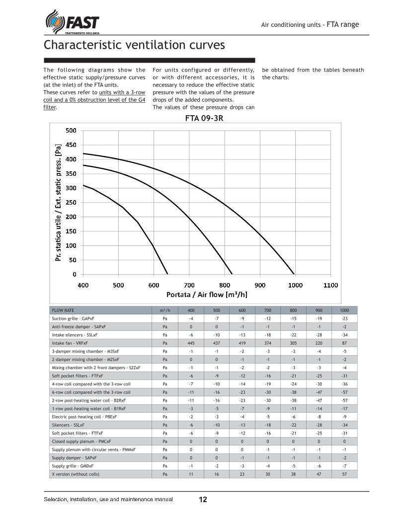
Characteristic ventilation curves
The following diagrams show the
effective static supply/pressure curves
(at the inlet) of the FTA units.
These curves refer to units with a 3-row
coil and a 0% obstruction level of the G4
filter.
For units configured or differently,
or with different accessories, it is
necessary to reduce the effective static
pressure with the values of the pressure
drops of the added components.
The values of these pressure drops can
be obtained from the tables beneath
the charts.
" # #" $ #% # #% $ #& # #& $ #$ # #'( )* + ,- ./- 0123)// .4 5 06
#$ #7 # #7 $ #& # # $ # # 8 # # 9 # # : # # ; # # 7 # # # 7 7 # #5 3 ./- 010<-
= > ? @ A @ A B C D ? E > F G H I B J KFLOW RATE m³/h 400 500 600 700 800 900 1000
Suction grille - GAPxF Pa -4 -7 -9 -12 -15 -19 -23
Anti-freeze damper - SAPxF Pa 0 0 -1 -1 -1 -1 -2
Intake silencers - SSLxF Pa -6 -10 -13 -18 -22 -28 -34
Intake fan - VRFxF Pa 445 437 419 374 305 220 87
3-damper mixing chamber - M3SxF Pa -1 -1 -2 -3 -3 -4 -5
2-damper mixing chamber - M2SxF Pa 0 0 -1 -1 -1 -1 -2
Mixing chamber with 2 front dampers - S2ZxF Pa -1 -1 -2 -2 -3 -3 -4
Soft pocket filters - FTFxF Pa -6 -9 -12 -16 -21 -25 -31
4-row coil compared with the 3-row coil Pa -7 -10 -14 -19 -24 -30 -36
6-row coil compared with the 3-row coil Pa -11 -16 -23 -30 -38 -47 -57
2-row post-heating water coil - B2RxF Pa -11 -16 -23 -30 -38 -47 -57
1-row post-heating water coil - B1RxF Pa -3 -5 -7 -9 -11 -14 -17
Electric post-heating coil - PBExF Pa -2 -3 -4 -5 -6 -8 -9
Silencers - SSLxF Pa -6 -10 -13 -18 -22 -28 -34
Soft pocket filters - FTFxF Pa -6 -9 -12 -16 -21 -25 -31
Closed supply plenum - PMCxF Pa 0 0 0 0 0 0 0
Supply plenum with circular vents - PMMxF Pa 0 0 0 -1 -1 -1 -1
Supply damper - SAPxF Pa 0 0 -1 -1 -1 -1 -2
Supply grille - GMDxF Pa -1 -2 -3 -4 -5 -6 -7
X version (without coils) Pa 11 16 23 30 38 47 57
FTA 09-3R
� L
Air conditioning units - FTA range
� � � � � � � � � � � � � � � � � � � � � � � � � � � � � � � � � � � � � � � � �
M N NM O NP N NP O NQ N NQ O NO N NRS TU V WX YZX [\]̂TZZ Y_ ` [a
NO Nb N Nb O NO N N c N N d N N e N N f N N b N N N b b N N b M N N` ^ YZX [\[gX
h i j k l k l m n o j p i q r s t m u v
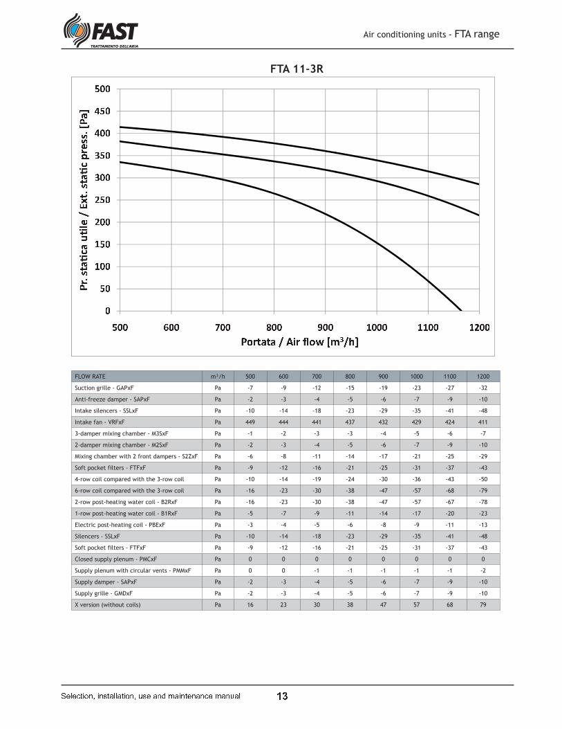
FTA 11-3R
FLOW RATE m³/h 500 600 700 800 900 1000 1100 1200
Suction grille - GAPxF Pa -7 -9 -12 -15 -19 -23 -27 -32
Anti-freeze damper - SAPxF Pa -2 -3 -4 -5 -6 -7 -9 -10
Intake silencers - SSLxF Pa -10 -14 -18 -23 -29 -35 -41 -48
Intake fan - VRFxF Pa 449 444 441 437 432 429 424 411
3-damper mixing chamber - M3SxF Pa -1 -2 -3 -3 -4 -5 -6 -7
2-damper mixing chamber - M2SxF Pa -2 -3 -4 -5 -6 -7 -9 -10
Mixing chamber with 2 front dampers - S2ZxF Pa -6 -8 -11 -14 -17 -21 -25 -29
Soft pocket filters - FTFxF Pa -9 -12 -16 -21 -25 -31 -37 -43
4-row coil compared with the 3-row coil Pa -10 -14 -19 -24 -30 -36 -43 -50
6-row coil compared with the 3-row coil Pa -16 -23 -30 -38 -47 -57 -68 -79
2-row post-heating water coil - B2RxF Pa -16 -23 -30 -38 -47 -57 -67 -78
1-row post-heating water coil - B1RxF Pa -5 -7 -9 -11 -14 -17 -20 -23
Electric post-heating coil - PBExF Pa -3 -4 -5 -6 -8 -9 -11 -13
Silencers - SSLxF Pa -10 -14 -18 -23 -29 -35 -41 -48
Soft pocket filters - FTFxF Pa -9 -12 -16 -21 -25 -31 -37 -43
Closed supply plenum - PMCxF Pa 0 0 0 0 0 0 0 0
Supply plenum with circular vents - PMMxF Pa 0 0 -1 -1 -1 -1 -1 -2
Supply damper - SAPxF Pa -2 -3 -4 -5 -6 -7 -9 -10
Supply grille - GMDxF Pa -2 -3 -4 -5 -6 -7 -9 -10
X version (without coils) Pa 16 23 30 38 47 57 68 79
� �
Air conditioning units - FTA range
� � � � � � � � � � � � � � � � � � � � � � � � � � � � � � � � � � � � � � � � �
w x xw y xz x xz y x{ x x{ y xy x x
|} ~� � �� ��� ����~�� �� � ��
xy x� x x� y xy x x � x x � x x � � x x � z x x � y x x � � x x� � ��� �����
� � � � � � � � � � � � � � � � � � � �
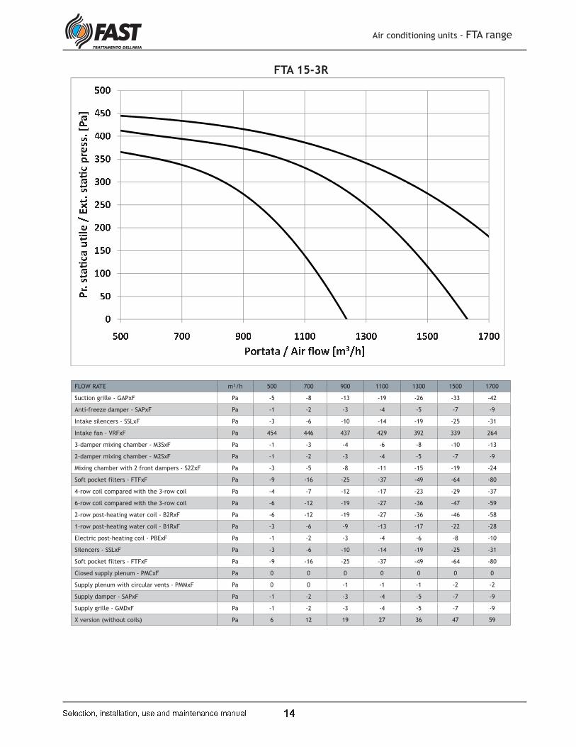
FTA 15-3R
FLOW RATE m³/h 500 700 900 1100 1300 1500 1700
Suction grille - GAPxF Pa -5 -8 -13 -19 -26 -33 -42
Anti-freeze damper - SAPxF Pa -1 -2 -3 -4 -5 -7 -9
Intake silencers - SSLxF Pa -3 -6 -10 -14 -19 -25 -31
Intake fan - VRFxF Pa 454 446 437 429 392 339 264
3-damper mixing chamber - M3SxF Pa -1 -3 -4 -6 -8 -10 -13
2-damper mixing chamber - M2SxF Pa -1 -2 -3 -4 -5 -7 -9
Mixing chamber with 2 front dampers - S2ZxF Pa -3 -5 -8 -11 -15 -19 -24
Soft pocket filters - FTFxF Pa -9 -16 -25 -37 -49 -64 -80
4-row coil compared with the 3-row coil Pa -4 -7 -12 -17 -23 -29 -37
6-row coil compared with the 3-row coil Pa -6 -12 -19 -27 -36 -47 -59
2-row post-heating water coil - B2RxF Pa -6 -12 -19 -27 -36 -46 -58
1-row post-heating water coil - B1RxF Pa -3 -6 -9 -13 -17 -22 -28
Electric post-heating coil - PBExF Pa -1 -2 -3 -4 -6 -8 -10
Silencers - SSLxF Pa -3 -6 -10 -14 -19 -25 -31
Soft pocket filters - FTFxF Pa -9 -16 -25 -37 -49 -64 -80
Closed supply plenum - PMCxF Pa 0 0 0 0 0 0 0
Supply plenum with circular vents - PMMxF Pa 0 0 -1 -1 -1 -2 -2
Supply damper - SAPxF Pa -1 -2 -3 -4 -5 -7 -9
Supply grille - GMDxF Pa -1 -2 -3 -4 -5 -7 -9
X version (without coils) Pa 6 12 19 27 36 47 59

� �
� � ¡ ¢ ¢ ¡ £ £ ¡ ¡ ¤¥ ¦§ ¨ ©ª «¬ª ®̄°¦¬¬ «± ² ³
¡ ´ ´ ¡ µ ´ ´ ¢ ´ ¶ ´ · � � ² ° «¬ª ®̧ª
¹ º » ¼ ½ ¼ ½ ¾ ¿ À » Á º Â Ã Ä Å ¾ Æ ÇFLOW RATE m³/h 700 1000 1300 1600 1900 2200
Suction grille - GAPxF Pa -5 -9 -15 -22 -30 -39
Anti-freeze damper - SAPxF Pa -1 -2 -3 -5 -6 -8
Intake silencers - SSLxF Pa -4 -7 -11 -16 -22 -28
Intake fan - VRFxF Pa 374 355 332 308 277 226
3-damper mixing chamber - M3SxF Pa -1 -2 -3 -4 -5 -7
2-damper mixing chamber - M2SxF Pa -1 -2 -3 -5 -6 -8
Mixing chamber with 2 front dampers - S2ZxF Pa -3 -5 -8 -11 -15 -20
Soft pocket filters - FTFxF Pa -16 -31 -49 -72 -98 -127
4-row coil compared with the 3-row coil Pa -4 -8 -14 -20 -27 -35
6-row coil compared with the 3-row coil Pa -7 -13 -22 -31 -43 -56
2-row post-heating water coil - B2RxF Pa -8 -15 -24 -35 -48 -62
1-row post-heating water coil - B1RxF Pa -4 -7 -11 -17 -23 -29
Electric post-heating coil - PBExF Pa -1 -2 -4 -5 -7 -9
Silencers - SSLxF Pa -4 -7 -11 -16 -22 -28
Soft pocket filters - FTFxF Pa -16 -31 -49 -72 -98 -127
Closed Supply plenum - PMCxF Pa 0 0 0 0 0 0
Supply plenum with circular vents - PMMxF Pa -1 -1 -2 -2 -3 -4
Supply damper - SAPxF Pa -1 -2 -3 -5 -6 -8
Supply grille - GMDxF Pa -1 -2 -3 -5 -6 -8
X version (without coils) Pa 7 13 22 31 43 56
Air conditioning units - FTA range
� � � � � � � � � � � � � � � � � � � � � � � � � � � � � � � � � � � � � � � � �
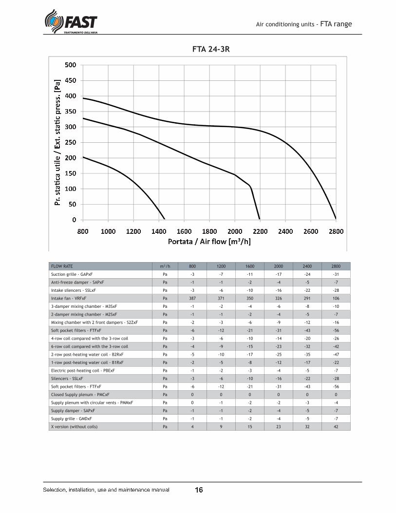
FTA 19-3R
� �
FLOW RATE m³/h 800 1200 1600 2000 2400 2800
Suction grille - GAPxF Pa -3 -7 -11 -17 -24 -31
Anti-freeze damper - SAPxF Pa -1 -1 -2 -4 -5 -7
Intake silencers - SSLxF Pa -3 -6 -10 -16 -22 -28
Intake fan - VRFxF Pa 387 371 350 326 291 106
3-damper mixing chamber - M3SxF Pa -1 -2 -4 -6 -8 -10
2-damper mixing chamber - M2SxF Pa -1 -1 -2 -4 -5 -7
Mixing chamber with 2 front dampers - S2ZxF Pa -2 -3 -6 -9 -12 -16
Soft pocket filters - FTFxF Pa -6 -12 -21 -31 -43 -56
4-row coil compared with the 3-row coil Pa -3 -6 -10 -14 -20 -26
6-row coil compared with the 3-row coil Pa -4 -9 -15 -23 -32 -42
2-row post-heating water coil - B2RxF Pa -5 -10 -17 -25 -35 -47
1-row post-heating water coil - B1RxF Pa -2 -5 -8 -12 -17 -22
Electric post-heating coil - PBExF Pa -1 -2 -3 -4 -5 -7
Silencers - SSLxF Pa -3 -6 -10 -16 -22 -28
Soft pocket filters - FTFxF Pa -6 -12 -21 -31 -43 -56
Closed Supply plenum - PMCxF Pa 0 0 0 0 0 0
Supply plenum with circular vents - PMMxF Pa 0 -1 -2 -2 -3 -4
Supply damper - SAPxF Pa -1 -1 -2 -4 -5 -7
Supply grille - GMDxF Pa -1 -1 -2 -4 -5 -7
X version (without coils) Pa 4 9 15 23 32 42
È É ÉÈ Ê ÉË É ÉË Ê ÉÌ É ÉÌ Ê ÉÊ É ÉÍÎ ÏÐ Ñ ÒÓ ÔÕÓ Ö×ØÙÏÕÕ ÔÚ Û ÖÜ
ÉÊ ÉÝ É ÉÝ Ê ÉÞ É É Ý É É É Ý È É É Ý Ì É É Ý ß É É Ý Þ É É È É É É È È É É È Ì É É È ß É É È Þ É ÉÛ Ù ÔÕÓ Ö×ÖàÓ
á â ã ä å ä å æ ç è ã é â ê ë ì í æ î ï
Air conditioning units - FTA range
� � � � � � � � � � � � � � � � � � � � � � � � � � � � � � � � � � � � � � � � �
FTA 24-3R
� �
ð ñ ñð ò ñó ñ ñó ò ñô ñ ñô ò ñõö ÷ø ù úû üýû þÿ��÷ýý ü� � þ�
ñò ñ� ñ ñ� ò ñ� ó ñ ñ � ò ñ ñ � � ñ ñ � � ñ ñ ð � ñ ñ ð ó ñ ñ ð ò ñ ñ ð � ñ ñ ð � ñ ñ ó � ñ ñ ó ó ñ ñ ó ò ñ ñ ó � ñ ñ� � üýû þÿþ�û
� � � � � � � � � � � � � � �
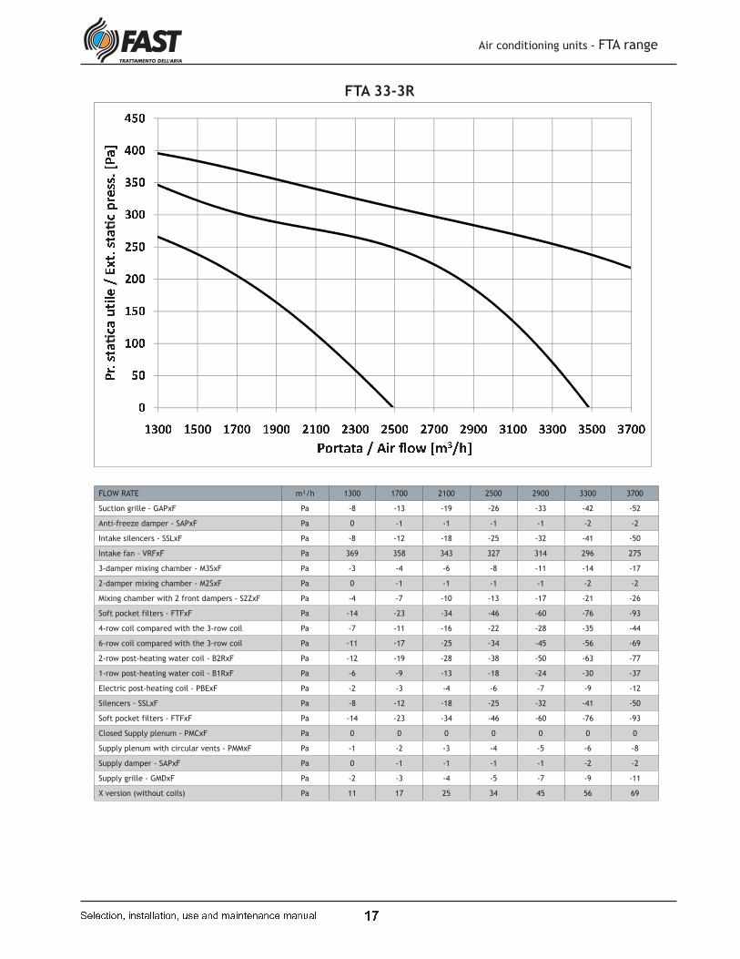
FTA 33-3R
FLOW RATE m³/h 1300 1700 2100 2500 2900 3300 3700
Suction grille - GAPxF Pa -8 -13 -19 -26 -33 -42 -52
Anti-freeze damper - SAPxF Pa 0 -1 -1 -1 -1 -2 -2
Intake silencers - SSLxF Pa -8 -12 -18 -25 -32 -41 -50
Intake fan - VRFxF Pa 369 358 343 327 314 296 275
3-damper mixing chamber - M3SxF Pa -3 -4 -6 -8 -11 -14 -17
2-damper mixing chamber - M2SxF Pa 0 -1 -1 -1 -1 -2 -2
Mixing chamber with 2 front dampers - S2ZxF Pa -4 -7 -10 -13 -17 -21 -26
Soft pocket filters - FTFxF Pa -14 -23 -34 -46 -60 -76 -93
4-row coil compared with the 3-row coil Pa -7 -11 -16 -22 -28 -35 -44
6-row coil compared with the 3-row coil Pa -11 -17 -25 -34 -45 -56 -69
2-row post-heating water coil - B2RxF Pa -12 -19 -28 -38 -50 -63 -77
1-row post-heating water coil - B1RxF Pa -6 -9 -13 -18 -24 -30 -37
Electric post-heating coil - PBExF Pa -2 -3 -4 -6 -7 -9 -12
Silencers - SSLxF Pa -8 -12 -18 -25 -32 -41 -50
Soft pocket filters - FTFxF Pa -14 -23 -34 -46 -60 -76 -93
Closed Supply plenum - PMCxF Pa 0 0 0 0 0 0 0
Supply plenum with circular vents - PMMxF Pa -1 -2 -3 -4 -5 -6 -8
Supply damper - SAPxF Pa 0 -1 -1 -1 -1 -2 -2
Supply grille - GMDxF Pa -2 -3 -4 -5 -7 -9 -11
X version (without coils) Pa 11 17 25 34 45 56 69
Air conditioning units - FTA range
� � � � � � � � � � � ! � " � � " � � � � # ! � " � $ % " � � � � � " � � � % " � # " �
& '
( ) )( * )+ ) )+ * ), ) ), * )* ) )-. /0 1 23 453 6789/55 4: ; 6<
)* )= ) )= * )= * ) ) = > * ) ( ) ) ) ( ( * ) ( * ) ) ( > * ) + ) ) ) + ( * ) + * ) ) + > * ) , ) ) ) , ( * ) , * ) ); 9 453 676?3
@ A B C D C D E F G B H A I J K L E M N
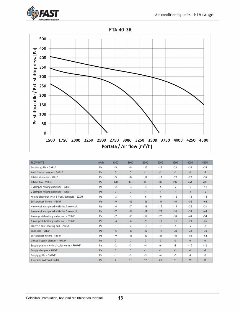
FTA 40-3R
FLOW RATE m³/h 1500 2000 2500 3000 3500 4000 4500
Suction grille - GAPxF Pa -5 -9 -13 -18 -24 -31 -38
Anti-freeze damper - SAPxF Pa 0 0 -1 -1 -1 -1 -2
Intake silencers - SSLxF Pa -5 -8 -12 -17 -22 -28 -35
Intake fan - VRFxF Pa 370 353 333 314 292 261 206
3-damper mixing chamber - M3SxF Pa -2 -3 -4 -5 -7 -9 -11
2-damper mixing chamber - M2SxF Pa 0 0 -1 -1 -1 -1 -2
Mixing chamber with 2 front dampers - S2ZxF Pa -3 -4 -6 -9 -12 -15 -18
Soft pocket filters - FTFxF Pa -9 -15 -22 -31 -41 -52 -64
4-row coil compared with the 3-row coil Pa -4 -7 -11 -15 -19 -25 -31
6-row coil compared with the 3-row coil Pa -7 -11 -17 -23 -31 -39 -48
2-row post-heating water coil - B2RxF Pa -7 -13 -19 -26 -34 -44 -54
1-row post-heating water coil - B1RxF Pa -4 -6 -9 -12 -16 -21 -26
Electric post-heating coil - PBExF Pa -1 -2 -3 -4 -5 -7 -8
Silencers - SSLxF Pa -5 -8 -12 -17 -22 -28 -35
Soft pocket filters - FTFxF Pa -9 -15 -22 -31 -41 -52 -64
Closed Supply plenum - PMCxF Pa 0 0 0 0 0 0 0
Supply plenum with circular vents - PMMxF Pa -2 -3 -4 -6 -8 -10 -12
Supply damper - SAPxF Pa 0 0 -1 -1 -1 -1 -2
Supply grille - GMDxF Pa -1 -2 -3 -4 -5 -7 -8
X version (without coils) Pa 7 11 17 23 31 39 48
Air conditioning units - FTA range
� � � � � � � � � � � ! � " � � " � � � � # ! � " � $ % " � � � � � " � � � % " � # " �
& O
� ò ñð ñ ñð ò ñó ñ ñó ò ñô ñ ñõö ÷ø ù úû üýû þÿ��÷ýý ü� � þ�
ñò ñ� ñ ñð ò ñ ñ ð � ò ñ ó ñ ñ ñ ó ð ò ñ ó ò ñ ñ ó � ò ñ ô ñ ñ ñ ô ð ò ñ ô ò ñ ñ ô � ò ñ ò ñ ñ ñ ò ð ò ñ ò ò ñ ñ� � üýû þÿþ�û
� � � � � � � � � � � � � � �
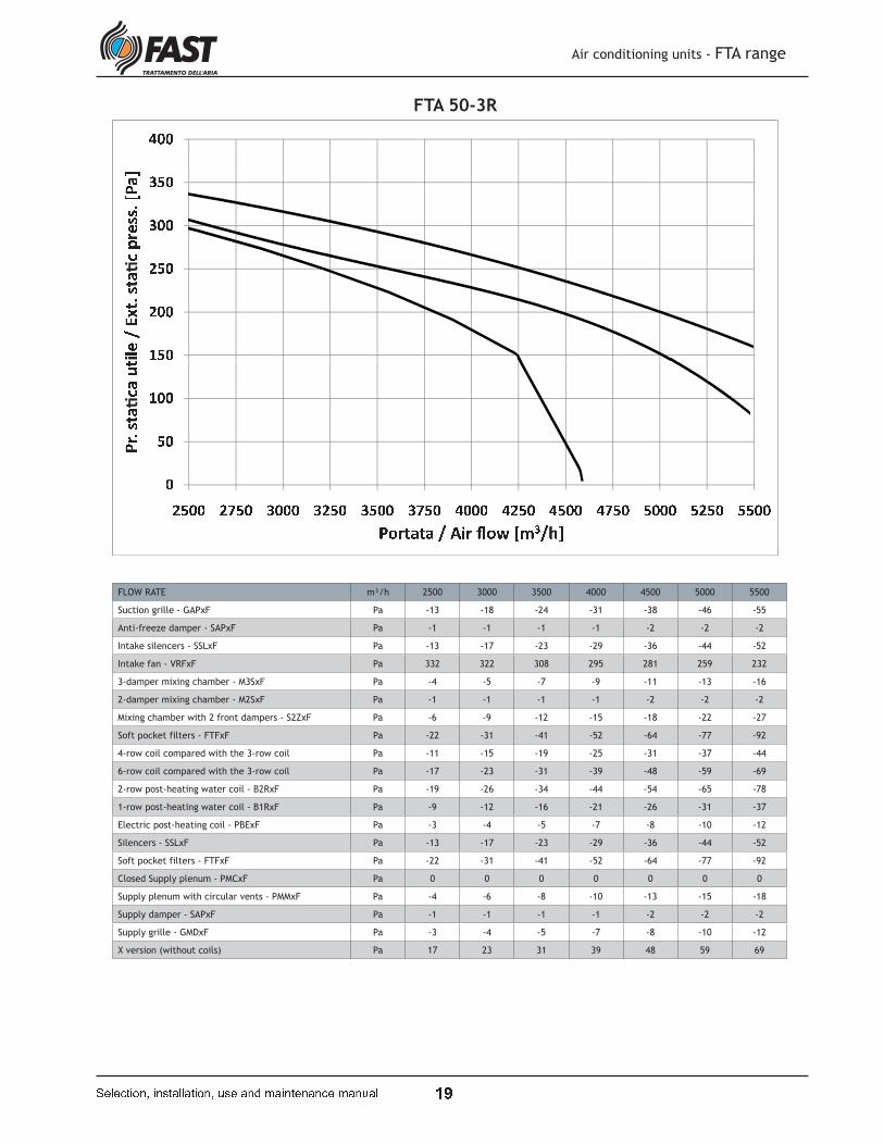
FTA 50-3R
FLOW RATE m³/h 2500 3000 3500 4000 4500 5000 5500
Suction grille - GAPxF Pa -13 -18 -24 -31 -38 -46 -55
Anti-freeze damper - SAPxF Pa -1 -1 -1 -1 -2 -2 -2
Intake silencers - SSLxF Pa -13 -17 -23 -29 -36 -44 -52
Intake fan - VRFxF Pa 332 322 308 295 281 259 232
3-damper mixing chamber - M3SxF Pa -4 -5 -7 -9 -11 -13 -16
2-damper mixing chamber - M2SxF Pa -1 -1 -1 -1 -2 -2 -2
Mixing chamber with 2 front dampers - S2ZxF Pa -6 -9 -12 -15 -18 -22 -27
Soft pocket filters - FTFxF Pa -22 -31 -41 -52 -64 -77 -92
4-row coil compared with the 3-row coil Pa -11 -15 -19 -25 -31 -37 -44
6-row coil compared with the 3-row coil Pa -17 -23 -31 -39 -48 -59 -69
2-row post-heating water coil - B2RxF Pa -19 -26 -34 -44 -54 -65 -78
1-row post-heating water coil - B1RxF Pa -9 -12 -16 -21 -26 -31 -37
Electric post-heating coil - PBExF Pa -3 -4 -5 -7 -8 -10 -12
Silencers - SSLxF Pa -13 -17 -23 -29 -36 -44 -52
Soft pocket filters - FTFxF Pa -22 -31 -41 -52 -64 -77 -92
Closed Supply plenum - PMCxF Pa 0 0 0 0 0 0 0
Supply plenum with circular vents - PMMxF Pa -4 -6 -8 -10 -13 -15 -18
Supply damper - SAPxF Pa -1 -1 -1 -1 -2 -2 -2
Supply grille - GMDxF Pa -3 -4 -5 -7 -8 -10 -12
X version (without coils) Pa 17 23 31 39 48 59 69
Air conditioning units - FTA range
� � � � � � � � � � � ! � " � � " � � � � # ! � " � $ % " � � � � � " � � � % " � # " �

P Q
PRESSURE DROP DUE TO DIRT ON THE FLAT FILTERS:
PRESSURE DROP DUE TO DIRT ON THE POCKET FILTERS:
Air conditioning units - FTA range
� � � � � � � � � � � ! � " � � " � � � � # ! � " � $ % " � � � � � " � � � % " � # " �
Pressure drops in the filters, due to dirt
The charts to determine the pressure
drops with different filter dirt levels are
shown below. From the left-hand chart
(showing the air flow rate - m³/h - on
the x co-ordinate), locate the flow rate
in question then go up until you intersect
the straight line corresponding to the
unit size. At this point, by tracing a
straight line parallel to the x co-ordinate
axis, you will intersect one of the three
curves on the right-hand chart, each
showing the degree of obstruction of the
filter, as below:
curve 1: clean filter
curve 2: filter 25% clogged
curve 3: filter 50% clogged
To determine the corresponding value of
the filter pressure drop, trace a straight
line as far as the x co-ordinate axis.
R S R RR S T RU S R RU S T RV S R RV S T RW S R RW S T RX S R RR U R R R V R R R W R R R X R R R T R R R Y R R R R S R RR S T RU S R RU S T RV S R RV S T RW S R RW S T RX S R R
R S R T R S R U R R S R U T R S R V R R S RZ [ \ ] ^ _ [ ] ^ ` a \ ^ b c d a _ c a \ ^ a e [ df ^ d _ \ c a g a h b i [ j a k f ^ d _ [ \ a ^ \l \ [ h h m \ [ ] \ c l U V W
n o p q r s
P &
Air conditioning units - FTA range
� � � � � � � � � � � ! � " � � " � � � � # ! � " � $ % " � � � � � " � � � % " � # " �
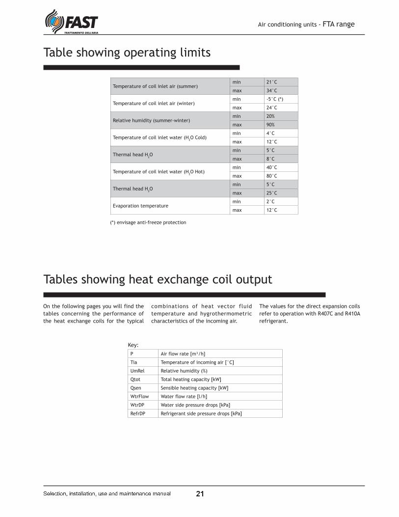
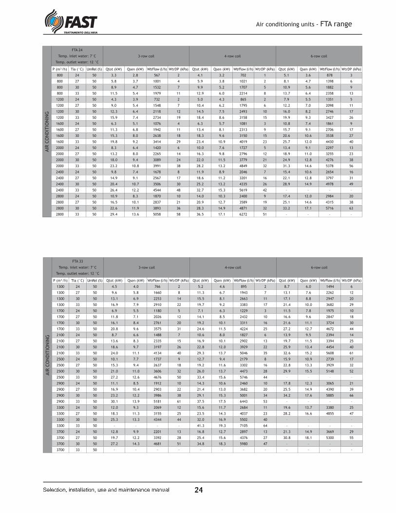
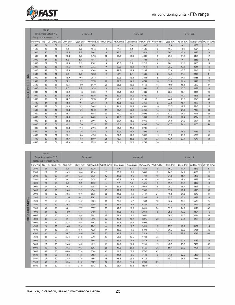
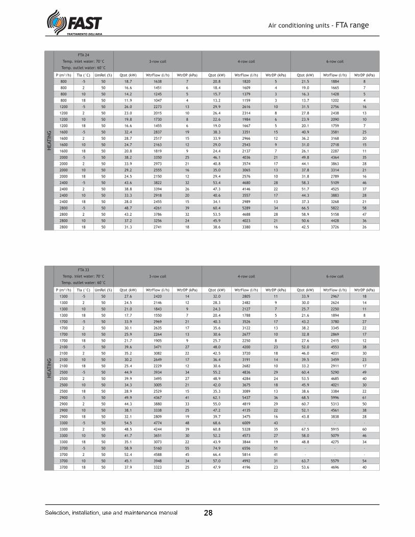
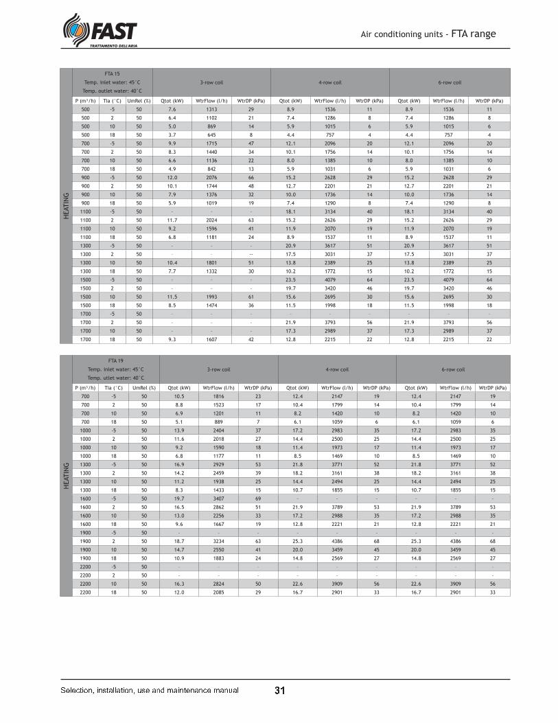
Tables showing heat exchange coil output
On the following pages you will find the
tables concerning the performance of
the heat exchange coils for the typical
combinations of heat vector fluid
temperature and hygrothermometric
characteristics of the incoming air.
The values for the direct expansion coils
refer to operation with R407C and R410A
refrigerant.
Table showing operating limits
Temperature of coil inlet air (summer)min 21°C
max 34°C
Temperature of coil inlet air (winter) min -5°C (*)
max 24°C
Relative humidity (summer-winter)min 20%
max 90%
Temperature of coil inlet water (H2O Cold)
min 4°C
max 12°C
Thermal head H2O
min 5°C
max 8°C
Temperature of coil inlet water (H2O Hot)
min 40°C
max 80°C
Thermal head H2O
min 5°C
max 25°C
Evaporation temperaturemin 2°C
max 12°C
Key:
P Air flow rate [m³/h]
Tia Temperature of incoming air [°C]
UmRel Relative humidity (%)
Qtot Total heating capacity [kW]
Qsen Sensible heating capacity [kW]
WtrFlow Water flow rate [l/h]
WtrDP Water side pressure drops [kPa]
RefrDP Refrigerant side pressure drops [kPa]
(*) envisage anti-freeze protection

P P
Air conditioning units - FTA range
� � � � � � � � � � � ! � " � � " � � � � # ! � " � $ % " � � � � � " � � � % " � # " �
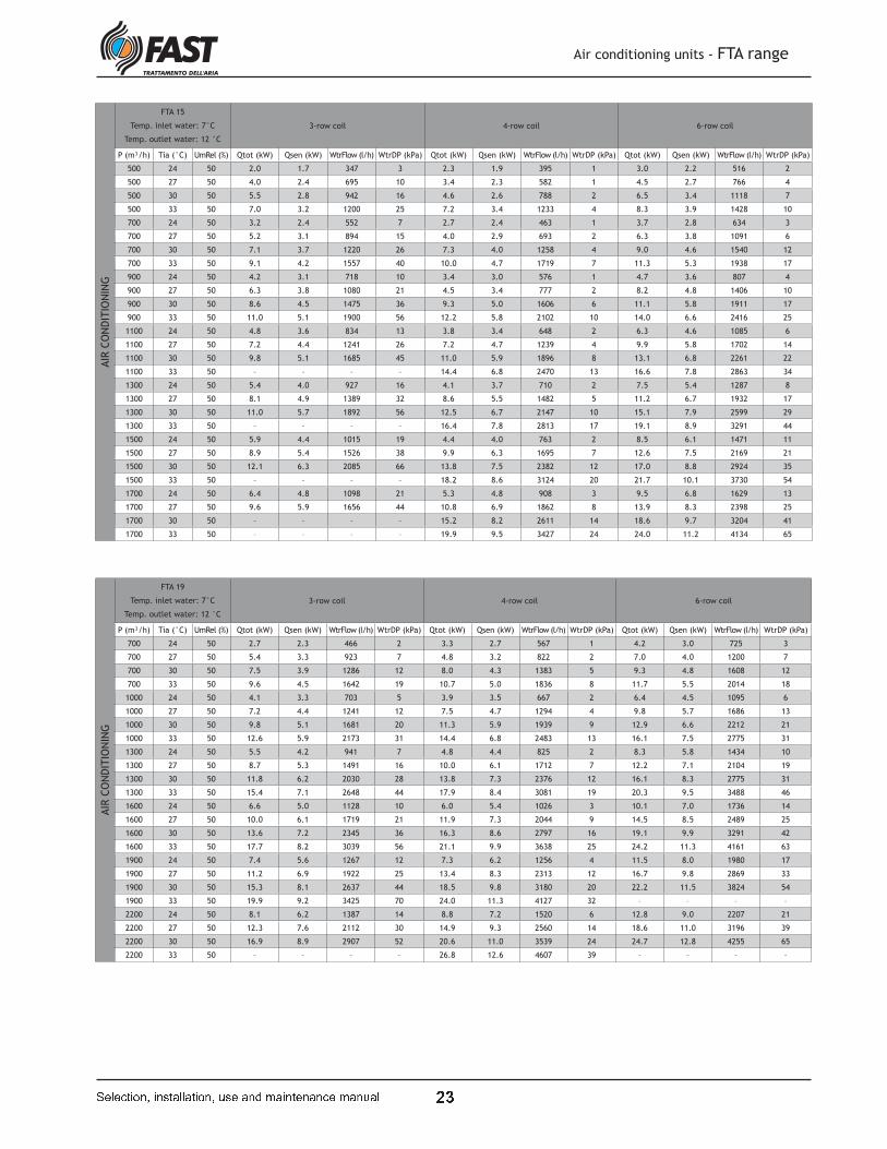
AIR
CO
ND
ITIO
NIN
GFTA 09
Temp. inlet water: 7°C
Temp. outlet water: 12 °C
3-row coil 4-row coil 6-row coil
P (m³/h) Tia (°C) UmRel (%) Qtot (kW) Qsen (kW) WtrFlow (l/h) WtrDP (kPa) Qtot (kW) Qsen (kW) WtrFlow (l/h) WtrDP (kPa) Qtot (kW) Qsen (kW) WtrFlow (l/h) WtrDP (kPa)
400 24 50 1.4 1.3 245 3 1.7 1.5 300 1 2.1 1.6 367 1
400 27 50 2.8 1.7 490 9 2.5 1.7 437 2 3.1 2.0 534 2
400 30 50 3.9 2.1 677 16 3.9 2.2 671 3 4.1 2.3 710 3
400 33 50 5.1 2.4 879 25 5.6 2.6 956 6 5.9 2.8 1022 5
500 24 50 1.8 1.6 316 4 1.9 1.7 327 1 2.4 1.9 415 1
500 27 50 3.4 2.1 589 12 2.8 2.0 487 2 3.5 2.3 607 2
500 30 50 4.7 2.5 801 21 5.0 2.7 851 5 5.4 2.9 925 4
500 33 50 6.1 2.8 1042 34 6.8 3.2 1169 8 7.4 3.5 1266 7
600 24 50 2.3 1.9 395 6 2.2 2.0 386 2 2.7 2.2 462 2
600 27 50 3.9 2.4 667 15 3.1 2.3 530 2 3.9 2.6 671 2
600 30 50 5.3 2.8 916 27 5.9 3.2 1010 7 6.5 3.5 1113 5
600 33 50 6.9 3.2 1194 43 7.8 3.7 1343 11 8.7 4.1 1497 9
700 24 50 2.7 2.1 457 8 2.5 2.2 424 2 2.9 2.5 491 2
700 27 50 4.3 2.7 739 18 4.1 2.8 713 4 4.5 3.1 779 3
700 30 50 5.9 3.1 1015 32 6.7 3.6 1157 8 7.5 4.0 1288 7
700 33 50 7.7 3.6 1320 51 8.8 4.2 1517 13 9.9 4.7 1705 11
800 24 50 3.0 2.3 512 10 2.7 2.4 457 2 3.0 2.7 521 2
800 27 50 4.7 2.9 806 21 4.8 3.2 827 5 5.4 3.5 933 4
800 30 50 6.5 3.4 1112 38 7.4 4.0 1278 10 8.5 4.5 1454 8
800 33 50 8.4 3.9 1449 60 9.8 4.7 1682 16 11.0 5.2 1893 13
900 24 50 3.2 2.5 548 11 2.8 2.6 486 2 3.4 3.1 593 2
900 27 50 5.1 3.2 872 25 5.4 3.6 930 6 6.2 4.0 1069 5
900 30 50 7.0 3.7 1203 43 8.1 4.4 1392 11 9.2 5.0 1590 10
900 33 50 9.1 4.2 1570 70 10.7 5.1 1838 18 12.1 5.7 2082 16
1000 24 50 3.5 2.8 605 13 3.0 2.7 514 2 3.7 3.3 633 2
1000 27 50 5.4 3.4 932 28 6.0 3.9 1030 7 6.9 4.4 1188 6
1000 30 50 7.5 4.0 1290 49 8.7 4.8 1498 13 10.1 5.4 1740 11
1000 33 50 – – – – 11.5 5.5 1982 21 13.2 6.2 2265 18
AIR
CO
ND
ITIO
NIN
G
FTA 11
Temp. inlet water: 7°C
Temp. outlet water: 12 °C
3-row coil 4-row coil 6-row coil
P (m³/h) Tia (°C) UmRel (%) Qtot (kW) Qsen (kW) WtrFlow (l/h) WtrDP (kPa) Qtot (kW) Qsen (kW) WtrFlow (l/h) WtrDP (kPa) Qtot (kW) Qsen (kW) WtrFlow (l/h) WtrDP (kPa)
500 24 50 1.8 1.6 316 4 1.9 1.7 327 1 2.4 1.9 415 1
500 27 50 3.4 2.1 589 12 2.8 2.0 487 2 3.5 2.3 607 2
500 30 50 4.7 2.5 801 21 5.0 2.7 851 5 5.4 2.9 925 4
500 33 50 6.1 2.8 1042 34 6.8 3.2 1169 8 7.4 3.5 1266 7
600 24 50 2.3 1.9 395 6 2.2 2.0 386 2 2.7 2.2 462 2
600 27 50 3.9 2.4 667 15 3.1 2.3 530 2 3.9 2.6 671 2
600 30 50 5.3 2.8 916 27 5.9 3.2 1010 7 6.5 3.5 1113 5
600 33 50 6.9 3.2 1194 43 7.8 3.7 1343 11 8.7 4.1 1497 9
700 24 50 2.7 2.1 457 8 2.5 2.2 424 2 2.9 2.5 491 2
700 27 50 4.3 2.7 739 18 4.1 2.8 713 4 4.5 3.1 779 3
700 30 50 5.9 3.1 1015 32 6.7 3.6 1157 8 7.5 4.0 1288 7
700 33 50 7.7 3.6 1320 51 8.8 4.2 1517 13 9.9 4.7 1705 11
800 24 50 3.0 2.3 512 10 2.7 2.4 457 2 3.0 2.7 521 2
800 27 50 4.7 2.9 806 21 4.8 3.2 827 5 5.4 3.5 933 4
800 30 50 6.5 3.4 1112 38 7.4 4.0 1278 10 8.5 4.5 1454 8
800 33 50 8.4 3.9 1449 60 9.8 4.7 1682 16 11.0 5.2 1893 13
900 24 50 3.2 2.5 548 11 2.8 2.6 486 2 3.4 3.1 593 2
900 27 50 5.1 3.2 872 25 5.4 3.6 930 6 6.2 4.0 1069 5
900 30 50 7.0 3.7 1203 43 8.1 4.4 1392 11 9.2 5.0 1590 10
900 33 50 9.1 4.2 1570 70 10.7 5.1 1838 18 12.1 5.7 2082 16
1000 24 50 3.5 2.8 605 13 3.0 2.7 514 2 3.7 3.3 633 2
1000 27 50 5.4 3.4 932 28 6.0 3.9 1030 7 6.9 4.4 1188 6
1000 30 50 7.5 4.0 1290 49 8.7 4.8 1498 13 10.1 5.4 1740 11
1000 33 50 – – – – 11.5 5.5 1982 21 13.2 6.2 2265 18
1100 24 50 3.7 2.9 640 14 3.2 2.9 550 3 3.9 3.5 668 2
1100 27 50 5.8 3.6 989 31 6.4 4.3 1109 8 7.5 4.8 1287 7
1100 30 50 8.0 4.2 1373 55 9.3 5.1 1602 15 10.9 5.8 1869 13
1100 33 50 – – – – 12.3 5.9 2123 24 14.2 6.7 2442 20
1200 24 50 3.9 3.1 674 16 3.6 3.3 624 3 4.1 3.7 702 3
1200 27 50 6.1 3.8 1044 34 7.0 4.6 1199 9 8.2 5.2 1408 8
1200 30 50 8.4 4.5 1452 61 9.9 5.4 1704 16 11.6 6.2 1989 14
1200 33 50 – – – – 13.1 6.3 2258 27 15.2 7.2 2614 23
P t
Air conditioning units - FTA range
� � � � � � � � � � � ! � " � � " � � � � # ! � " � $ % " � � � � � " � � � % " � # " �
AIR
CO
ND
ITIO
NIN
GFTA 15
Temp. inlet water: 7°C
Temp. outlet water: 12 °C
3-row coil 4-row coil 6-row coil
P (m³/h) Tia (°C) UmRel (%) Qtot (kW) Qsen (kW) WtrFlow (l/h) WtrDP (kPa) Qtot (kW) Qsen (kW) WtrFlow (l/h) WtrDP (kPa) Qtot (kW) Qsen (kW) WtrFlow (l/h) WtrDP (kPa)
500 24 50 2.0 1.7 347 3 2.3 1.9 395 1 3.0 2.2 516 2
500 27 50 4.0 2.4 695 10 3.4 2.3 582 1 4.5 2.7 766 4
500 30 50 5.5 2.8 942 16 4.6 2.6 788 2 6.5 3.4 1118 7
500 33 50 7.0 3.2 1200 25 7.2 3.4 1233 4 8.3 3.9 1428 10
700 24 50 3.2 2.4 552 7 2.7 2.4 463 1 3.7 2.8 634 3
700 27 50 5.2 3.1 894 15 4.0 2.9 693 2 6.3 3.8 1091 6
700 30 50 7.1 3.7 1220 26 7.3 4.0 1258 4 9.0 4.6 1540 12
700 33 50 9.1 4.2 1557 40 10.0 4.7 1719 7 11.3 5.3 1938 17
900 24 50 4.2 3.1 718 10 3.4 3.0 576 1 4.7 3.6 807 4
900 27 50 6.3 3.8 1080 21 4.5 3.4 777 2 8.2 4.8 1406 10
900 30 50 8.6 4.5 1475 36 9.3 5.0 1606 6 11.1 5.8 1911 17
900 33 50 11.0 5.1 1900 56 12.2 5.8 2102 10 14.0 6.6 2416 25
1100 24 50 4.8 3.6 834 13 3.8 3.4 648 2 6.3 4.6 1085 6
1100 27 50 7.2 4.4 1241 26 7.2 4.7 1239 4 9.9 5.8 1702 14
1100 30 50 9.8 5.1 1685 45 11.0 5.9 1896 8 13.1 6.8 2261 22
1100 33 50 – – – – 14.4 6.8 2470 13 16.6 7.8 2863 34
1300 24 50 5.4 4.0 927 16 4.1 3.7 710 2 7.5 5.4 1287 8
1300 27 50 8.1 4.9 1389 32 8.6 5.5 1482 5 11.2 6.7 1932 17
1300 30 50 11.0 5.7 1892 56 12.5 6.7 2147 10 15.1 7.9 2599 29
1300 33 50 – – – – 16.4 7.8 2813 17 19.1 8.9 3291 44
1500 24 50 5.9 4.4 1015 19 4.4 4.0 763 2 8.5 6.1 1471 11
1500 27 50 8.9 5.4 1526 38 9.9 6.3 1695 7 12.6 7.5 2169 21
1500 30 50 12.1 6.3 2085 66 13.8 7.5 2382 12 17.0 8.8 2924 35
1500 33 50 – – – – 18.2 8.6 3124 20 21.7 10.1 3730 54
1700 24 50 6.4 4.8 1098 21 5.3 4.8 908 3 9.5 6.8 1629 13
1700 27 50 9.6 5.9 1656 44 10.8 6.9 1862 8 13.9 8.3 2398 25
1700 30 50 – – – – 15.2 8.2 2611 14 18.6 9.7 3204 41
1700 33 50 – – – – 19.9 9.5 3427 24 24.0 11.2 4134 65
AIR
CO
ND
ITIO
NIN
G
FTA 19
Temp. inlet water: 7°C
Temp. outlet water: 12 °C
3-row coil 4-row coil 6-row coil
P (m³/h) Tia (°C) UmRel (%) Qtot (kW) Qsen (kW) WtrFlow (l/h) WtrDP (kPa) Qtot (kW) Qsen (kW) WtrFlow (l/h) WtrDP (kPa) Qtot (kW) Qsen (kW) WtrFlow (l/h) WtrDP (kPa)
700 24 50 2.7 2.3 466 2 3.3 2.7 567 1 4.2 3.0 725 3
700 27 50 5.4 3.3 923 7 4.8 3.2 822 2 7.0 4.0 1200 7
700 30 50 7.5 3.9 1286 12 8.0 4.3 1383 5 9.3 4.8 1608 12
700 33 50 9.6 4.5 1642 19 10.7 5.0 1836 8 11.7 5.5 2014 18
1000 24 50 4.1 3.3 703 5 3.9 3.5 667 2 6.4 4.5 1095 6
1000 27 50 7.2 4.4 1241 12 7.5 4.7 1294 4 9.8 5.7 1686 13
1000 30 50 9.8 5.1 1681 20 11.3 5.9 1939 9 12.9 6.6 2212 21
1000 33 50 12.6 5.9 2173 31 14.4 6.8 2483 13 16.1 7.5 2775 31
1300 24 50 5.5 4.2 941 7 4.8 4.4 825 2 8.3 5.8 1434 10
1300 27 50 8.7 5.3 1491 16 10.0 6.1 1712 7 12.2 7.1 2104 19
1300 30 50 11.8 6.2 2030 28 13.8 7.3 2376 12 16.1 8.3 2775 31
1300 33 50 15.4 7.1 2648 44 17.9 8.4 3081 19 20.3 9.5 3488 46
1600 24 50 6.6 5.0 1128 10 6.0 5.4 1026 3 10.1 7.0 1736 14
1600 27 50 10.0 6.1 1719 21 11.9 7.3 2044 9 14.5 8.5 2489 25
1600 30 50 13.6 7.2 2345 36 16.3 8.6 2797 16 19.1 9.9 3291 42
1600 33 50 17.7 8.2 3039 56 21.1 9.9 3638 25 24.2 11.3 4161 63
1900 24 50 7.4 5.6 1267 12 7.3 6.2 1256 4 11.5 8.0 1980 17
1900 27 50 11.2 6.9 1922 25 13.4 8.3 2313 12 16.7 9.8 2869 33
1900 30 50 15.3 8.1 2637 44 18.5 9.8 3180 20 22.2 11.5 3824 54
1900 33 50 19.9 9.2 3425 70 24.0 11.3 4127 32 – – – –
2200 24 50 8.1 6.2 1387 14 8.8 7.2 1520 6 12.8 9.0 2207 21
2200 27 50 12.3 7.6 2112 30 14.9 9.3 2560 14 18.6 11.0 3196 39
2200 30 50 16.9 8.9 2907 52 20.6 11.0 3539 24 24.7 12.8 4255 65
2200 33 50 – – – – 26.8 12.6 4607 39 – – – –
P u
Air conditioning units - FTA range
� � � � � � � � � � � ! � " � � " � � � � # ! � " � $ % " � � � � � " � � � % " � # " �
AIR
CO
ND
ITIO
NIN
GFTA 24
Temp. inlet water: 7°C
Temp. outlet water: 12 °C
3-row coil 4-row coil 6-row coil
P (m³/h) Tia (°C) UmRel (%) Qtot (kW) Qsen (kW) WtrFlow (l/h) WtrDP (kPa) Qtot (kW) Qsen (kW) WtrFlow (l/h) WtrDP (kPa) Qtot (kW) Qsen (kW) WtrFlow (l/h) WtrDP (kPa)
800 24 50 3.3 2.8 567 2 4.1 3.2 702 1 5.1 3.6 878 3
800 27 50 5.8 3.7 1001 4 5.9 3.8 1021 2 8.1 4.7 1398 6
800 30 50 8.9 4.7 1532 7 9.9 5.2 1707 5 10.9 5.6 1882 9
800 33 50 11.5 5.4 1979 11 12.9 6.0 2214 8 13.7 6.4 2358 13
1200 24 50 4.3 3.9 732 2 5.0 4.3 865 2 7.9 5.5 1351 5
1200 27 50 9.0 5.4 1548 7 10.4 6.2 1795 6 12.2 7.0 2098 11
1200 30 50 12.3 6.4 2118 12 14.5 7.5 2493 10 16.0 8.2 2746 17
1200 33 50 15.9 7.4 2734 19 18.4 8.6 3158 15 19.9 9.3 3427 26
1600 24 50 6.3 5.1 1076 4 6.3 5.7 1081 3 10.8 7.4 1861 9
1600 27 50 11.3 6.8 1942 11 13.4 8.1 2313 9 15.7 9.1 2706 17
1600 30 50 15.3 8.0 2638 18 18.3 9.6 3150 15 20.6 10.6 3538 27
1600 33 50 19.8 9.2 3414 29 23.4 10.9 4019 23 25.7 12.0 4430 40
2000 24 50 8.3 6.4 1420 6 10.0 7.6 1727 5 13.4 9.1 2297 13
2000 27 50 13.2 8.0 2265 14 16.3 9.8 2796 12 18.9 11.0 3255 23
2000 30 50 18.0 9.4 3089 24 22.0 11.5 3779 21 24.9 12.8 4276 38
2000 33 50 23.2 10.8 3991 38 28.2 13.2 4849 32 31.3 14.6 5378 56
2400 24 50 9.8 7.4 1678 8 11.9 8.9 2046 7 15.4 10.6 2654 16
2400 27 50 14.9 9.1 2567 17 18.6 11.2 3201 16 22.1 12.8 3797 31
2400 30 50 20.4 10.7 3506 30 25.2 13.2 4335 26 28.9 14.9 4978 49
2400 33 50 26.4 12.2 4544 48 32.7 15.3 5619 42 – – – –
2800 24 50 10.9 8.3 1870 10 14.0 10.3 2400 9 17.4 12.0 2984 20
2800 27 50 16.5 10.1 2837 21 20.9 12.7 3589 19 25.1 14.6 4315 38
2800 30 50 22.6 11.9 3893 36 28.3 14.9 4871 32 33.2 17.1 5716 63
2800 33 50 29.4 13.6 5058 58 36.5 17.1 6272 51 – – – –
AIR
CO
ND
ITIO
NIN
G
FTA 33
Temp. inlet water: 7°C
Temp. outlet water: 12 °C
3-row coil 4-row coil 6-row coil
P (m³/h) Tia (°C) UmRel (%) Qtot (kW) Qsen (kW) WtrFlow (l/h) WtrDP (kPa) Qtot (kW) Qsen (kW) WtrFlow (l/h) WtrDP (kPa) Qtot (kW) Qsen (kW) WtrFlow (l/h) WtrDP (kPa)
1300 24 50 4.5 4.0 766 2 5.2 4.6 895 2 8.7 6.0 1494 6
1300 27 50 9.6 5.8 1660 8 11.3 6.7 1943 7 13.1 7.6 2262 12
1300 30 50 13.1 6.9 2253 14 15.5 8.1 2663 11 17.1 8.8 2947 20
1300 33 50 16.9 7.9 2910 22 19.7 9.2 3383 17 21.4 10.0 3682 29
1700 24 50 6.9 5.5 1180 5 7.1 6.3 1229 3 11.5 7.8 1975 10
1700 27 50 11.8 7.1 2026 12 14.1 8.5 2432 10 16.6 9.6 2847 18
1700 30 50 16.1 8.4 2761 20 19.2 10.1 3311 16 21.6 11.1 3724 30
1700 33 50 20.8 9.6 3575 31 24.6 11.5 4224 25 27.2 12.7 4672 44
2100 24 50 8.7 6.6 1488 7 10.6 8.0 1827 6 13.9 9.5 2394 14
2100 27 50 13.6 8.3 2335 15 16.9 10.1 2902 13 19.7 11.5 3394 25
2100 30 50 18.6 9.7 3197 26 22.8 12.0 3929 22 25.9 13.4 4454 40
2100 33 50 24.0 11.1 4134 40 29.3 13.7 5046 35 32.6 15.2 5608 61
2500 24 50 10.1 7.7 1737 9 12.7 9.4 2179 8 15.9 10.9 2739 17
2500 27 50 15.3 9.4 2637 18 19.2 11.6 3302 16 22.8 13.3 3929 32
2500 30 50 21.0 11.0 3606 32 26.0 13.7 4473 28 29.9 15.5 5148 52
2500 33 50 27.2 12.6 4676 50 33.4 15.6 5746 44 – – – –
2900 24 50 11.1 8.5 1912 10 14.3 10.6 2460 10 17.8 12.3 3065 21
2900 27 50 16.9 10.4 2903 22 21.4 13.0 3682 20 25.5 14.9 4390 39
2900 30 50 23.2 12.2 3986 38 29.1 15.3 5001 34 34.2 17.6 5885 66
2900 33 50 30.1 13.9 5181 61 37.5 17.5 6443 53 – – – –
3300 24 50 12.0 9.3 2069 12 15.6 11.7 2684 11 19.6 13.7 3380 25
3300 27 50 18.3 11.3 3155 25 23.5 14.3 4037 23 28.2 16.6 4855 47
3300 30 50 25.3 13.3 4344 44 32.0 16.9 5502 40 – – – –
3300 33 50 – – – – 41.3 19.3 7105 64 – – – –
3700 24 50 12.8 9.9 2201 13 16.8 12.7 2897 13 21.3 14.9 3669 29
3700 27 50 19.7 12.2 3392 28 25.4 15.6 4376 27 30.8 18.1 5300 55
3700 30 50 27.2 14.3 4681 51 34.8 18.3 5980 47 – – – –
3700 33 50 – – – – – – – – – – – –
P v
Air conditioning units - FTA range
� � � � � � � � � � � ! � " � � " � � � � # ! � " � $ % " � � � � � " � � � % " � # " �
AIR
CO
ND
ITIO
NIN
GFTA 40
Temp. inlet water: 7°C
Temp. outlet water: 12 °C
3-row coil 4-row coil 6-row coil
P (m³/h) Tia (°C) UmRel (%) Qtot (kW) Qsen (kW) WtrFlow (l/h) WtrDP (kPa) Qtot (kW) Qsen (kW) WtrFlow (l/h) WtrDP (kPa) Qtot (kW) Qsen (kW) WtrFlow (l/h) WtrDP (kPa)
1500 24 50 5.4 4.9 924 1 6.2 5.4 1060 1 7.9 6.1 1359 3
1500 27 50 9.5 6.3 1642 3 9.2 6.5 1580 2 15.3 8.8 2624 7
1500 30 50 15.5 8.2 2661 6 17.5 9.2 3011 5 20.3 10.4 3490 11
1500 33 50 20.3 9.5 3498 10 23.3 10.9 4006 8 25.3 11.8 4345 17
2000 24 50 6.3 5.7 1087 2 7.8 7.1 1345 1 13.1 9.1 2253 5
2000 27 50 13.8 8.6 2382 5 15.8 9.8 2718 4 20.1 11.6 3463 11
2000 30 50 19.5 10.3 3362 9 23.3 12.2 4012 8 26.2 13.5 4511 18
2000 33 50 25.4 11.9 4369 14 29.7 13.9 5107 11 32.8 15.3 5640 26
2500 24 50 7.1 6.4 1220 2 8.9 8.1 1535 2 16.7 11.4 2879 8
2500 27 50 16.9 10.4 2914 7 20.3 12.3 3485 6 24.3 14.1 4188 16
2500 30 50 23.1 12.2 3978 12 27.8 14.6 4781 10 31.8 16.4 5478 25
2500 33 50 30.1 14.0 5179 20 35.8 16.8 6158 16 40.0 18.6 6873 37
3000 24 50 9.5 8.7 1638 3 9.9 9.0 1696 2 19.9 13.5 3427 11
3000 27 50 19.2 11.8 3303 9 23.8 14.4 4089 8 28.3 16.4 4866 20
3000 30 50 26.4 13.9 4546 15 32.2 17.0 5540 13 37.2 19.2 6395 33
3000 33 50 34.2 15.9 5878 25 41.6 19.5 7149 21 46.8 21.8 8049 49
3500 24 50 12.0 10.1 2063 4 13.8 12.5 2365 3 22.5 15.4 3879 14
3500 27 50 21.3 13.2 3663 11 26.6 16.2 4584 10 32.2 18.8 5543 26
3500 30 50 29.3 15.5 5040 19 36.4 19.2 6258 16 42.3 21.8 7273 41
3500 33 50 38.1 17.7 6557 30 47.0 22.0 8091 26 53.3 24.9 9176 62
4000 24 50 14.0 11.4 2409 5 17.6 14.0 3031 5 25.0 17.2 4294 16
4000 27 50 23.2 14.4 3991 12 29.4 18.0 5050 11 36.0 21.0 6194 31
4000 30 50 32.1 17.0 5518 22 40.1 21.2 6896 20 47.7 24.6 8205 51
4000 33 50 41.8 19.4 7193 35 51.8 24.3 8908 31 – – – –
4500 24 50 16.0 12.6 2745 6 20.3 15.7 3491 6 27.3 18.9 4689 19
4500 27 50 25.1 15.6 4320 14 32.0 19.6 5498 13 39.2 23.0 6736 36
4500 30 50 34.7 18.4 5969 25 43.7 23.2 7524 23 52.6 27.1 9049 61
4500 33 50 45.3 21.0 7795 40 56.6 26.6 9743 36 – – – –
AIR
CO
ND
ITIO
NIN
G
FTA 50
Temp. inlet water: 7°C
Temp. outlet water: 12 °C
3-row coil 4-row coil 6-row coil
P (m³/h) Tia (°C) UmRel (%) Qtot (kW) Qsen (kW) WtrFlow (l/h) WtrDP (kPa) Qtot (kW) Qsen (kW) WtrFlow (l/h) WtrDP (kPa) Qtot (kW) Qsen (kW) WtrFlow (l/h) WtrDP (kPa)
2500 24 50 7.1 6.4 1220 2 8.9 8.1 1535 2 16.7 11.4 2879 8
2500 27 50 16.9 10.4 2914 7 20.3 12.3 3485 6 24.3 14.1 4188 16
2500 30 50 23.1 12.2 3978 12 27.8 14.6 4781 10 31.8 16.4 5478 25
2500 33 50 30.1 14.0 5179 20 35.8 16.8 6158 16 40.0 18.6 6873 37
3000 24 50 9.5 8.7 1638 3 9.9 9.0 1696 2 19.9 13.5 3427 11
3000 27 50 19.2 11.8 3303 9 23.8 14.4 4089 8 28.3 16.4 4866 20
3000 30 50 26.4 13.9 4546 15 32.2 17.0 5540 13 37.2 19.2 6395 33
3000 33 50 34.2 15.9 5878 25 41.6 19.5 7149 21 46.8 21.8 8049 49
3500 24 50 12.0 10.1 2063 4 13.8 12.5 2365 3 22.5 15.4 3879 14
3500 27 50 21.3 13.2 3663 11 26.6 16.2 4584 10 32.2 18.8 5543 26
3500 30 50 29.3 15.5 5040 19 36.4 19.2 6258 16 42.3 21.8 7273 41
3500 33 50 38.1 17.7 6557 30 47.0 22.0 8091 26 53.3 24.9 9176 62
4000 24 50 14.0 11.4 2409 5 17.6 14.0 3031 5 25.0 17.2 4294 16
4000 27 50 23.2 14.4 3991 12 29.4 18.0 5050 11 36.0 21.0 6194 31
4000 30 50 32.1 17.0 5518 22 40.1 21.2 6896 20 47.7 24.6 8205 51
4000 33 50 41.8 19.4 7193 35 51.8 24.3 8908 31 – – – –
4500 24 50 16.0 12.6 2745 6 20.3 15.7 3491 6 27.3 18.9 4689 19
4500 27 50 25.1 15.6 4320 14 32.0 19.6 5498 13 39.2 23.0 6736 36
4500 30 50 34.7 18.4 5969 25 43.7 23.2 7524 23 52.6 27.1 9049 61
4500 33 50 45.3 21.0 7795 40 56.6 26.6 9743 36 – – – –
5000 24 50 17.4 13.7 2988 8 22.5 17.3 3879 7 29.5 20.6 5082 22
5000 27 50 26.8 16.8 4613 16 34.5 21.3 5931 15 42.5 25.0 7308 42
5000 30 50 37.2 19.7 6397 28 47.2 25.1 8126 26 56.4 29.2 9708 69
5000 33 50 48.6 22.6 8366 46 61.3 28.8 10542 42 – – – –
5500 24 50 18.4 14.6 3163 8 24.1 18.5 4138 8 31.6 22.2 5438 25
5500 27 50 28.5 17.9 4898 18 36.8 22.8 6326 17 45.7 26.9 7861 47
5500 30 50 39.6 21.0 6805 32 50.6 26.9 8703 29 – – – –
5500 33 50 51.8 24.0 8912 52 65.7 30.8 11310 47 – – – –

P w
Air conditioning units - FTA range
� � � � � � � � � � � ! � " � � " � � � � # ! � " � $ % " � � � � � " � � � % " � # " �
HEATIN
GFTA 09
Temp. inlet water: 70°C
Temp. outlet water: 60°C
3-row coil 4-row coil 6-row coil
P (m³/h) Tia (°C) UmRel (%) Qtot (kW) WtrFlow (l/h) WtrDP (kPa) Qtot (kW) WtrFlow (l/h) WtrDP (kPa) Qtot (kW) WtrFlow (l/h) WtrDP (kPa)
400 -5 50 8.4 739 16 9.7 849 5 10.3 899 3
400 2 50 7.5 655 13 8.6 750 4 9.1 795 3
400 10 50 6.4 562 10 7.3 642 3 7.8 680 2
400 18 50 5.4 473 8 6.1 538 2 6.5 571 2
500 -5 50 10.0 876 22 11.7 1025 6 12.5 1098 5
500 2 50 8.9 777 18 10.3 906 5 11.1 970 4
500 10 50 7.6 667 14 8.9 775 4 9.5 830 3
500 18 50 6.4 561 10 7.4 650 3 8.0 697 2
600 -5 50 11.4 1003 28 13.6 1192 8 14.7 1288 6
600 2 50 10.2 890 23 12.0 1054 6 13.0 1138 5
600 10 50 8.7 764 18 10.3 902 5 11.1 974 4
600 18 50 7.3 643 13 8.6 756 4 9.3 817 3
700 -5 50 12.8 1121 34 15.4 1349 10 16.8 1469 8
700 2 50 11.4 995 28 13.6 1193 8 14.8 1299 6
700 10 50 9.8 855 21 11.7 1021 6 12.7 1112 5
700 18 50 8.2 719 16 9.8 856 5 10.7 933 4
800 -5 50 14.1 1232 41 17.1 1500 12 18.8 1644 9
800 2 50 12.5 1094 33 15.1 1327 10 16.6 1454 8
800 10 50 10.7 941 25 13.0 1136 7 14.2 1245 6
800 18 50 9.0 791 19 10.9 951 5 11.9 1044 4
900 -5 50 15.3 1338 47 18.8 1644 14 20.7 1813 11
900 2 50 13.6 1189 38 16.6 1454 11 18.3 1604 9
900 10 50 11.7 1022 29 14.2 1245 9 15.7 1373 7
900 18 50 9.8 860 22 11.9 1043 6 13.1 1151 5
1000 -5 50 16.4 1438 54 20.3 1782 16 22.6 1976 13
1000 2 50 14.6 1278 43 18.0 1577 13 20.0 1748 10
1000 10 50 12.6 1099 33 15.4 1350 10 17.1 1497 8
1000 18 50 10.6 925 24 12.9 1131 7 14.3 1255 6
HEATIN
G
FTA 11
Temp. inlet water: 70°C
Temp. outlet water: 60°C
3-row coil 4-row coil 6-row coil
P (m³/h) Tia (°C) UmRel (%) Qtot (kW) WtrFlow (l/h) WtrDP (kPa) Qtot (kW) WtrFlow (l/h) WtrDP (kPa) Qtot (kW) WtrFlow (l/h) WtrDP (kPa)
500 -5 50 10.0 876 22 11.7 1025 6 12.5 1098 5
500 2 50 8.9 777 18 10.3 906 5 11.1 970 4
500 10 50 7.6 667 14 8.9 775 4 9.5 830 3
500 18 50 6.4 561 10 7.4 650 3 8.0 697 2
600 -5 50 11.4 1003 28 13.6 1192 8 14.7 1288 6
600 2 50 10.2 890 23 12.0 1054 6 13.0 1138 5
600 10 50 8.7 764 18 10.3 902 5 11.1 974 4
600 18 50 7.3 643 13 8.6 756 4 9.3 817 3
700 -5 50 12.8 1121 34 15.4 1349 10 16.8 1469 8
700 2 50 11.4 995 28 13.6 1193 8 14.8 1299 6
700 10 50 9.8 855 21 11.7 1021 6 12.7 1112 5
700 18 50 8.2 719 16 9.8 856 5 10.7 933 4
800 -5 50 14.1 1232 41 17.1 1500 12 18.8 1644 9
800 2 50 12.5 1094 33 15.1 1327 10 16.6 1454 8
800 10 50 10.7 941 25 13.0 1136 7 14.2 1245 6
800 18 50 9.0 791 19 10.9 951 5 11.9 1044 4
900 -5 50 15.3 1338 47 18.8 1644 14 20.7 1813 11
900 2 50 13.6 1189 38 16.6 1454 11 18.3 1604 9
900 10 50 11.7 1022 29 14.2 1245 9 15.7 1373 7
900 18 50 9.8 860 22 11.9 1043 6 13.1 1151 5
1000 -5 50 16.4 1438 54 20.3 1782 16 22.6 1976 13
1000 2 50 14.6 1278 43 18.0 1577 13 20.0 1748 10
1000 10 50 12.6 1099 33 15.4 1350 10 17.1 1497 8
1000 18 50 10.6 925 24 12.9 1131 7 14.3 1255 6
1100 -5 50 17.5 1535 60 21.9 1915 18 24.4 2134 15
1100 2 50 15.6 1364 49 19.4 1695 15 21.6 1888 12
1100 10 50 13.4 1173 37 16.6 1452 11 18.5 1617 9
1100 18 50 11.3 987 27 13.9 1216 8 15.5 1356 7
1200 -5 50 18.6 1627 67 23.3 2043 20 26.1 2287 17
1200 2 50 16.5 1446 54 20.7 1809 16 23.1 2024 13
1200 10 50 14.2 1244 41 17.7 1549 13 19.8 1734 10
1200 18 50 11.9 1047 30 14.8 1297 9 16.6 1453 8

P x
Air conditioning units - FTA range
� � � � � � � � � � � ! � " � � " � � � � # ! � " � $ % " � � � � � " � � � % " � # " �
HEATIN
GFTA 15
Temp. inlet water: 70°C
Temp. outlet water: 60°C
3-row coil 4-row coil 6-row coil
P (m³/h) Tia (°C) UmRel (%) Qtot (kW) WtrFlow (l/h) WtrDP (kPa) Qtot (kW) WtrFlow (l/h) WtrDP (kPa) Qtot (kW) WtrFlow (l/h) WtrDP (kPa)
500 -5 50 11.3 987 16 12.6 1104 3 13.2 1160 6
500 2 50 10.0 875 13 11.1 976 3 11.7 1026 5
500 10 50 8.6 751 10 9.5 835 2 10.0 879 4
500 18 50 7.2 632 7 8.0 701 2 8.4 740 3
700 -5 50 14.7 1288 25 16.9 1481 5 18.1 1582 11
700 2 50 13.0 1143 21 14.9 1309 4 16.0 1399 9
700 10 50 11.2 982 16 12.8 1121 3 13.7 1199 7
700 18 50 9.4 826 12 10.7 940 2 11.5 1009 5
900 -5 50 17.8 1558 36 20.9 1830 7 22.6 1982 16
900 2 50 15.8 1383 29 18.5 1619 6 20.0 1753 13
900 10 50 13.6 1189 22 15.8 1386 5 17.2 1503 10
900 18 50 11.4 1001 16 13.3 1162 3 14.4 1264 7
1100 -5 50 20.6 1806 46 24.6 2156 10 27.0 2361 22
1100 2 50 18.3 1604 37 21.8 1908 8 23.9 2089 18
1100 10 50 15.8 1379 29 18.7 1634 6 20.5 1792 13
1100 18 50 13.3 1161 21 15.6 1370 4 17.2 1507 10
1300 -5 50 23.2 2035 57 28.1 2464 12 31.1 2723 28
1300 2 50 20.6 1809 46 24.9 2181 10 27.5 2411 23
1300 10 50 17.8 1556 35 21.3 1868 7 23.6 2068 17
1300 18 50 15.0 1310 26 17.9 1566 6 19.9 1739 13
1500 -5 50 25.7 2250 69 31.5 2755 15 35.1 3070 35
1500 2 50 22.8 2000 56 27.8 2439 12 31.0 2719 28
1500 10 50 19.7 1721 42 23.9 2090 9 26.6 2332 21
1500 18 50 16.6 1450 31 20.0 1752 7 22.4 1961 16
1700 -5 50 – – – 34.6 3033 17 38.9 3403 42
1700 2 50 24.9 2181 65 30.7 2686 14 34.4 3015 34
1700 10 50 21.4 1878 50 26.3 2301 11 29.5 2587 26
1700 18 50 18.1 1581 37 22.0 1929 8 24.8 2175 19
HEATIN
G
FTA 19
Temp. inlet water: 70°C
Temp. outlet water: 60°C
3-row coil 4-row coil 6-row coil
P (m³/h) Tia (°C) UmRel (%) Qtot (kW) WtrFlow (l/h) WtrDP (kPa) Qtot (kW) WtrFlow (l/h) WtrDP (kPa) Qtot (kW) WtrFlow (l/h) WtrDP (kPa)
700 -5 50 15.6 1365 12 17.6 1545 5 18.5 1622 11
700 2 50 13.8 1210 10 15.6 1366 4 16.4 1434 9
700 10 50 11.9 1039 8 13.4 1170 3 14.0 1230 7
700 18 50 10.0 874 6 11.2 982 3 11.8 1035 5
1000 -5 50 20.6 1805 20 24.0 2106 9 25.7 2251 19
1000 2 50 18.3 1601 16 21.3 1863 7 22.7 1991 15
1000 10 50 15.7 1375 13 18.2 1596 6 19.5 1707 12
1000 18 50 13.2 1157 9 15.3 1340 4 16.4 1437 9
1300 -5 50 25.1 2197 29 29.9 2623 13 32.5 2843 29
1300 2 50 22.3 1950 23 26.5 2321 11 28.7 2516 23
1300 10 50 19.1 1676 18 22.7 1989 8 24.6 2158 18
1300 18 50 16.1 1410 13 19.1 1670 6 20.7 1816 13
1600 -5 50 29.2 2554 38 35.4 3104 18 38.9 3403 39
1600 2 50 25.9 2268 30 31.4 2748 14 34.4 3013 32
1600 10 50 22.3 1950 23 26.9 2356 11 29.5 2585 24
1600 18 50 18.7 1641 17 22.6 1977 8 24.8 2175 18
1900 -5 50 32.9 2884 47 40.6 3556 22 44.9 3936 51
1900 2 50 29.3 2562 38 36.0 3149 18 39.8 3487 41
1900 10 50 25.2 2204 29 30.8 2700 14 34.2 2992 31
1900 18 50 21.2 1855 21 25.9 2267 10 28.7 2517 23
2200 -5 50 36.4 3191 56 45.5 3983 27 50.8 4446 63
2200 2 50 32.4 2837 45 40.3 3529 22 45.0 3939 51
2200 10 50 27.9 2441 35 34.6 3026 17 38.6 3381 39
2200 18 50 23.5 2054 25 29.0 2540 12 32.5 2845 29
P '
Air conditioning units - FTA range
� � � � � � � � � � � ! � " � � " � � � � # ! � " � $ % " � � � � � " � � � % " � # " �
HEATIN
GFTA 24
Temp. inlet water: 70°C
Temp. outlet water: 60°C
3-row coil 4-row coil 6-row coil
P (m³/h) Tia (°C) UmRel (%) Qtot (kW) WtrFlow (l/h) WtrDP (kPa) Qtot (kW) WtrFlow (l/h) WtrDP (kPa) Qtot (kW) WtrFlow (l/h) WtrDP (kPa)
800 -5 50 18.7 1638 7 20.8 1820 5 21.5 1884 8
800 2 50 16.6 1451 6 18.4 1609 4 19.0 1665 7
800 10 50 14.2 1245 5 15.7 1379 3 16.3 1428 5
800 18 50 11.9 1047 4 13.2 1159 3 13.7 1202 4
1200 -5 50 26.0 2273 13 29.9 2616 10 31.5 2756 16
1200 2 50 23.0 2015 10 26.4 2314 8 27.8 2438 13
1200 10 50 19.8 1730 8 22.6 1984 6 23.9 2090 10
1200 18 50 16.6 1455 6 19.0 1667 5 20.1 1759 7
1600 -5 50 32.4 2837 19 38.3 3351 15 40.9 3581 25
1600 2 50 28.7 2517 15 33.9 2966 12 36.2 3168 20
1600 10 50 24.7 2163 12 29.0 2543 9 31.0 2718 15
1600 18 50 20.8 1819 9 24.4 2137 7 26.1 2287 11
2000 -5 50 38.2 3350 25 46.1 4036 21 49.8 4364 35
2000 2 50 33.9 2973 21 40.8 3574 17 44.1 3863 28
2000 10 50 29.2 2555 16 35.0 3065 13 37.8 3314 21
2000 18 50 24.5 2150 12 29.4 2576 10 31.8 2789 16
2400 -5 50 43.6 3822 32 53.4 4680 28 58.3 5109 46
2400 2 50 38.8 3394 26 47.3 4146 22 51.7 4525 37
2400 10 50 33.3 2918 20 40.6 3557 17 44.3 3883 28
2400 18 50 28.0 2455 15 34.1 2989 13 37.3 3268 21
2800 -5 50 48.7 4261 39 60.4 5289 34 66.5 5822 58
2800 2 50 43.2 3786 32 53.5 4688 28 58.9 5158 47
2800 10 50 37.2 3256 24 45.9 4023 21 50.6 4428 36
2800 18 50 31.3 2741 18 38.6 3380 16 42.5 3726 26
HEATIN
G
FTA 33
Temp. inlet water: 70°C
Temp. outlet water: 60°C
3-row coil 4-row coil 6-row coil
P (m³/h) Tia (°C) UmRel (%) Qtot (kW) WtrFlow (l/h) WtrDP (kPa) Qtot (kW) WtrFlow (l/h) WtrDP (kPa) Qtot (kW) WtrFlow (l/h) WtrDP (kPa)
1300 -5 50 27.6 2420 14 32.0 2805 11 33.9 2967 18
1300 2 50 24.5 2146 12 28.3 2482 9 30.0 2624 14
1300 10 50 21.0 1843 9 24.3 2127 7 25.7 2250 11
1300 18 50 17.7 1550 7 20.4 1788 5 21.6 1894 8
1700 -5 50 33.9 2969 21 40.3 3526 17 43.2 3780 27
1700 2 50 30.1 2635 17 35.6 3122 13 38.2 3345 22
1700 10 50 25.9 2264 13 30.6 2677 10 32.8 2869 17
1700 18 50 21.7 1905 9 25.7 2250 8 27.6 2415 12
2100 -5 50 39.6 3471 27 48.0 4200 23 52.0 4553 38
2100 2 50 35.2 3082 22 42.5 3720 18 46.0 4031 30
2100 10 50 30.2 2649 17 36.4 3191 14 39.5 3459 23
2100 18 50 25.4 2229 12 30.6 2682 10 33.2 2911 17
2500 -5 50 44.9 3934 34 55.2 4836 29 60.4 5290 49
2500 2 50 39.9 3495 27 48.9 4284 24 53.5 4685 40
2500 10 50 34.3 3005 21 42.0 3675 18 45.9 4021 30
2500 18 50 28.9 2529 15 35.3 3089 13 38.6 3384 22
2900 -5 50 49.9 4367 41 62.1 5437 36 68.5 5996 61
2900 2 50 44.3 3880 33 55.0 4819 29 60.7 5313 50
2900 10 50 38.1 3338 25 47.2 4135 22 52.1 4561 38
2900 18 50 32.1 2809 19 39.7 3475 16 43.8 3838 28
3300 -5 50 54.5 4774 48 68.6 6009 43 – – –
3300 2 50 48.5 4244 39 60.8 5328 35 67.5 5915 60
3300 10 50 41.7 3651 30 52.2 4573 27 58.0 5079 46
3300 18 50 35.1 3073 22 43.9 3844 19 48.8 4275 34
3700 -5 50 58.9 5160 55 74.9 6556 51 – – –
3700 2 50 52.4 4588 45 66.4 5814 41 – – –
3700 10 50 45.1 3948 34 57.0 4992 31 63.7 5579 54
3700 18 50 37.9 3323 25 47.9 4196 23 53.6 4696 40

P O
Air conditioning units - FTA range
� � � � � � � � � � � ! � " � � " � � � � # ! � " � $ % " � � � � � " � � � % " � # " �
HEATIN
GFTA 40
Temp. inlet water: 70°C
Temp. outlet water: 60°C
3-row coil 4-row coil 6-row coil
P (m³/h) Tia (°C) UmRel (%) Qtot (kW) WtrFlow (l/h) WtrDP (kPa) Qtot (kW) WtrFlow (l/h) WtrDP (kPa) Qtot (kW) WtrFlow (l/h) WtrDP (kPa)
1500 -5 50 33.5 2933 7 38.0 3328 5 39.8 3487 10
1500 2 50 29.7 2599 5 33.6 2942 4 35.2 3083 8
1500 10 50 25.5 2230 4 28.8 2521 3 30.2 2643 6
1500 18 50 21.4 1874 3 24.2 2118 3 25.4 2225 5
2000 -5 50 42.0 3679 10 48.9 4282 8 51.9 4549 16
2000 2 50 37.2 3262 8 43.2 3788 6 45.9 4024 13
2000 10 50 32.0 2800 6 37.1 3246 5 39.4 3450 10
2000 18 50 26.9 2354 5 31.1 2727 4 33.2 2904 7
2500 -5 50 49.8 4360 13 59.1 5177 11 63.5 5564 23
2500 2 50 44.2 3867 11 52.3 4582 9 56.2 4923 19
2500 10 50 37.9 3322 8 44.8 3927 7 48.2 4222 14
2500 18 50 31.9 2792 6 37.7 3299 5 40.6 3553 11
3000 -5 50 57.0 4989 17 68.8 6022 14 74.6 6535 31
3000 2 50 50.6 4427 14 60.9 5331 11 66.0 5785 25
3000 10 50 43.4 3804 10 52.2 4571 9 56.7 4963 19
3000 18 50 36.5 3198 8 43.8 3839 6 47.7 4176 14
3500 -5 50 63.7 5577 21 77.9 6823 18 85.3 7467 39
3500 2 50 56.5 4951 17 69.0 6043 14 75.5 6612 31
3500 10 50 48.6 4254 13 59.2 5182 11 64.8 5674 24
3500 18 50 40.8 3578 9 49.7 4352 8 54.5 4775 18
4000 -5 50 70.0 6130 24 86.6 7588 21 95.5 8365 48
4000 2 50 62.2 5444 20 76.7 6722 17 84.6 7410 38
4000 10 50 53.4 4680 15 65.8 5765 13 72.6 6360 29
4000 18 50 44.9 3935 11 55.3 4843 10 61.1 5352 22
4500 -5 50 76.0 6654 28 95.0 8320 25 105.4 9232 57
4500 2 50 67.5 5911 23 84.2 7372 20 93.4 8180 46
4500 10 50 58.0 5082 17 72.2 6325 15 80.2 7023 35
4500 18 50 48.8 4274 13 60.6 5312 11 67.5 5910 26
HEATIN
G
FTA 50
Temp. inlet water: 70°C
Temp. outlet water: 60°C
3-row coil 4-row coil 6-row coil
P (m³/h) Tia (°C) UmRel (%) Qtot (kW) WtrFlow (l/h) WtrDP (kPa) Qtot (kW) WtrFlow (l/h) WtrDP (kPa) Qtot (kW) WtrFlow (l/h) WtrDP (kPa)
2500 -5 50 49.8 4360 13 59.1 5177 11 63.5 5564 23
2500 2 50 44.2 3867 11 52.3 4582 9 56.2 4923 19
2500 10 50 37.9 3322 8 44.8 3927 7 48.2 4222 14
2500 18 50 31.9 2792 6 37.7 3299 5 40.6 3553 11
3000 -5 50 57.0 4989 17 68.8 6022 14 74.6 6535 31
3000 2 50 50.6 4427 14 60.9 5331 11 66.0 5785 25
3000 10 50 43.4 3804 10 52.2 4571 9 56.7 4963 19
3000 18 50 36.5 3198 8 43.8 3839 6 47.7 4176 14
3500 -5 50 63.7 5577 21 77.9 6823 18 85.3 7467 39
3500 2 50 56.5 4951 17 69.0 6043 14 75.5 6612 31
3500 10 50 48.6 4254 13 59.2 5182 11 64.8 5674 24
3500 18 50 40.8 3578 9 49.7 4352 8 54.5 4775 18
4000 -5 50 70.0 6130 24 86.6 7588 21 95.5 8365 48
4000 2 50 62.2 5444 20 76.7 6722 17 84.6 7410 38
4000 10 50 53.4 4680 15 65.8 5765 13 72.6 6360 29
4000 18 50 44.9 3935 11 55.3 4843 10 61.1 5352 22
4500 -5 50 76.0 6654 28 95.0 8320 25 105.4 9232 57
4500 2 50 67.5 5911 23 84.2 7372 20 93.4 8180 46
4500 10 50 58.0 5082 17 72.2 6325 15 80.2 7023 35
4500 18 50 48.8 4274 13 60.6 5312 11 67.5 5910 26
5000 -5 50 81.7 7153 32 103.0 9023 29 115.0 10070 66
5000 2 50 72.6 6355 26 91.3 7997 24 101.9 8925 54
5000 10 50 62.4 5465 20 78.3 6862 18 87.5 7664 41
5000 18 50 52.5 4597 15 65.8 5763 13 73.6 6450 30
5500 -5 50 87.1 7629 36 110.7 9700 33 – – –
5500 2 50 77.4 6781 29 98.2 8599 27 110.2 9648 62
5500 10 50 66.6 5832 22 84.3 7379 20 94.6 8286 47
5500 18 50 56.0 4905 16 70.8 6198 15 79.6 6974 34

t Q
Air conditioning units - FTA range
� � � � � � � � � � � ! � " � � " � � � � # ! � " � $ % " � � � � � " � � � % " � # " �
HEATIN
GFTA 09
Temp. inlet water: 45°C
Temp. outlet water: 40°C
3-row coil 4-row coil 6-row coil
P (m³/h) Tia (°C) UmRel (%) Qtot (kW) WtrFlow (l/h) WtrDP (kPa) Qtot (kW) WtrFlow (l/h) WtrDP (kPa) Qtot (kW) WtrFlow (l/h) WtrDP (kPa)
400 -5 50 5.7 984 30 6.9 1191 6 6.9 1191 6
400 2 50 4.8 825 22 5.8 997 4 5.8 997 4
400 10 50 3.7 650 15 4.5 784 3 4.5 784 3
400 18 50 2.8 480 9 3.3 579 2 3.3 579 2
500 -5 50 6.7 1167 41 8.4 1456 8 8.4 1456 8
500 2 50 5.7 979 30 7.0 1218 6 7.0 1218 6
500 10 50 4.5 771 20 5.5 957 4 5.5 957 4
500 18 50 3.3 570 12 4.1 708 3 4.1 708 3
600 -5 50 7.7 1336 52 9.9 1708 11 9.9 1708 11
600 2 50 6.5 1122 38 8.2 1429 8 8.2 1429 8
600 10 50 5.1 883 25 6.5 1123 5 6.5 1123 5
600 18 50 3.8 652 15 4.8 830 3 4.8 830 3
700 -5 50 8.6 1495 63 11.3 1951 14 11.3 1951 14
700 2 50 7.2 1255 47 9.4 1632 10 9.4 1632 10
700 10 50 5.7 989 30 7.4 1282 7 7.4 1282 7
700 18 50 4.2 730 18 5.5 946 4 5.5 946 4
800 -5 50 – – – 12.6 2184 17 12.6 2184 17
800 2 50 8.0 1381 55 10.5 1827 12 10.5 1827 12
800 10 50 6.3 1088 36 8.3 1435 8 8.3 1435 8
800 18 50 4.6 802 21 6.1 1058 5 6.1 1058 5
900 -5 50 – – – 13.9 2409 20 13.9 2409 20
900 2 50 8.7 1500 64 11.6 2016 15 11.6 2016 15
900 10 50 6.8 1182 42 9.1 1583 10 9.1 1583 10
900 18 50 5.0 871 24 6.7 1166 6 6.7 1166 6
1000 -5 50 – – – 15.2 2627 23 15.2 2627 23
1000 2 50 – – – 12.7 2198 17 12.7 2198 17
1000 10 50 7.3 1271 48 10.0 1726 11 10.0 1726 11
1000 18 50 5.4 937 28 7.3 1271 7 7.3 1271 7
HEATIN
G
FTA 11
Temp. inlet water: 45°C
Temp. outlet water: 40°C
3-row coil 4-row coil 6-row coil
P (m³/h) Tia (°C) UmRel (%) Qtot (kW) WtrFlow (l/h) WtrDP (kPa) Qtot (kW) WtrFlow (l/h) WtrDP (kPa) Qtot (kW) WtrFlow (l/h) WtrDP (kPa)
500 -5 50 6.7 1167 41 8.4 1456 8 8.4 1456 8
500 2 50 5.7 979 30 7.0 1218 6 7.0 1218 6
500 10 50 4.5 771 20 5.5 957 4 5.5 957 4
500 18 50 3.3 570 12 4.1 708 3 4.1 708 3
600 -5 50 7.7 1336 52 9.9 1708 11 9.9 1708 11
600 2 50 6.5 1122 38 8.2 1429 8 8.2 1429 8
600 10 50 5.1 883 25 6.5 1123 5 6.5 1123 5
600 18 50 3.8 652 15 4.8 830 3 4.8 830 3
700 -5 50 8.6 1495 63 11.3 1951 14 11.3 1951 14
700 2 50 7.2 1255 47 9.4 1632 10 9.4 1632 10
700 10 50 5.7 989 30 7.4 1282 7 7.4 1282 7
700 18 50 4.2 730 18 5.5 946 4 5.5 946 4
800 -5 50 – – – 12.6 2184 17 12.6 2184 17
800 2 50 8.0 1381 55 10.5 1827 12 10.5 1827 12
800 10 50 6.3 1088 36 8.3 1435 8 8.3 1435 8
800 18 50 4.6 802 21 6.1 1058 5 6.1 1058 5
900 -5 50 – – – 13.9 2409 20 13.9 2409 20
900 2 50 8.7 1500 64 11.6 2016 15 11.6 2016 15
900 10 50 6.8 1182 42 9.1 1583 10 9.1 1583 10
900 18 50 5.0 871 24 6.7 1166 6 6.7 1166 6
1000 -5 50 – – – 15.2 2627 23 15.2 2627 23
1000 2 50 – – – 12.7 2198 17 12.7 2198 17
1000 10 50 7.3 1271 48 10.0 1726 11 10.0 1726 11
1000 18 50 5.4 937 28 7.3 1271 7 7.3 1271 7
1100 -5 50 – – – 16.4 2838 27 16.4 2838 27
1100 2 50 – – – 13.7 2375 20 13.7 2375 20
1100 10 50 7.8 1356 53 10.8 1864 13 10.8 1864 13
1100 18 50 5.8 1000 31 7.9 1372 8 7.9 1372 8
1200 -5 50 – – – 17.6 3043 30 17.6 3043 30
1200 2 50 – – – 14.7 2546 22 14.7 2546 22
1200 10 50 8.3 1438 59 11.5 1998 14 11.5 1998 14
1200 18 50 6.1 1060 34 8.5 1470 8 8.5 1470 8
t &
Air conditioning units - FTA range
� � � � � � � � � � � ! � " � � " � � � � # ! � " � $ % " � � � � � " � � � % " � # " �
HEATIN
GFTA 15
Temp. inlet water: 45°C
Temp. outlet water: 40°C
3-row coil 4-row coil 6-row coil
P (m³/h) Tia (°C) UmRel (%) Qtot (kW) WtrFlow (l/h) WtrDP (kPa) Qtot (kW) WtrFlow (l/h) WtrDP (kPa) Qtot (kW) WtrFlow (l/h) WtrDP (kPa)
500 -5 50 7.6 1313 29 8.9 1536 11 8.9 1536 11
500 2 50 6.4 1102 21 7.4 1286 8 7.4 1286 8
500 10 50 5.0 869 14 5.9 1015 6 5.9 1015 6
500 18 50 3.7 645 8 4.4 757 4 4.4 757 4
700 -5 50 9.9 1715 47 12.1 2096 20 12.1 2096 20
700 2 50 8.3 1440 34 10.1 1756 14 10.1 1756 14
700 10 50 6.6 1136 22 8.0 1385 10 8.0 1385 10
700 18 50 4.9 842 13 5.9 1031 6 5.9 1031 6
900 -5 50 12.0 2076 66 15.2 2628 29 15.2 2628 29
900 2 50 10.1 1744 48 12.7 2201 21 12.7 2201 21
900 10 50 7.9 1376 32 10.0 1736 14 10.0 1736 14
900 18 50 5.9 1019 19 7.4 1290 8 7.4 1290 8
1100 -5 50 – – – 18.1 3134 40 18.1 3134 40
1100 2 50 11.7 2024 63 15.2 2626 29 15.2 2626 29
1100 10 50 9.2 1596 41 11.9 2070 19 11.9 2070 19
1100 18 50 6.8 1181 24 8.9 1537 11 8.9 1537 11
1300 -5 50 – – – 20.9 3617 51 20.9 3617 51
1300 2 50 – – -- 17.5 3031 37 17.5 3031 37
1300 10 50 10.4 1801 51 13.8 2389 25 13.8 2389 25
1300 18 50 7.7 1332 30 10.2 1772 15 10.2 1772 15
1500 -5 50 – – – 23.5 4079 64 23.5 4079 64
1500 2 50 – – – 19.7 3420 46 19.7 3420 46
1500 10 50 11.5 1993 61 15.6 2695 30 15.6 2695 30
1500 18 50 8.5 1474 36 11.5 1998 18 11.5 1998 18
1700 -5 50 – – – – – – – – –
1700 2 50 – – – 21.9 3793 56 21.9 3793 56
1700 10 50 – – – 17.3 2989 37 17.3 2989 37
1700 18 50 9.3 1607 42 12.8 2215 22 12.8 2215 22
HEATIN
G
FTA 19
Temp. inlet water: 45°C
Temp. utlet water: 40°C
3-row coil 4-row coil 6-row coil
P (m³/h) Tia (°C) UmRel (%) Qtot (kW) WtrFlow (l/h) WtrDP (kPa) Qtot (kW) WtrFlow (l/h) WtrDP (kPa) Qtot (kW) WtrFlow (l/h) WtrDP (kPa)
700 -5 50 10.5 1816 23 12.4 2147 19 12.4 2147 19
700 2 50 8.8 1523 17 10.4 1799 14 10.4 1799 14
700 10 50 6.9 1201 11 8.2 1420 10 8.2 1420 10
700 18 50 5.1 889 7 6.1 1059 6 6.1 1059 6
1000 -5 50 13.9 2404 37 17.2 2983 35 17.2 2983 35
1000 2 50 11.6 2018 27 14.4 2500 25 14.4 2500 25
1000 10 50 9.2 1590 18 11.4 1973 17 11.4 1973 17
1000 18 50 6.8 1177 11 8.5 1469 10 8.5 1469 10
1300 -5 50 16.9 2929 53 21.8 3771 52 21.8 3771 52
1300 2 50 14.2 2459 39 18.2 3161 38 18.2 3161 38
1300 10 50 11.2 1938 25 14.4 2494 25 14.4 2494 25
1300 18 50 8.3 1433 15 10.7 1855 15 10.7 1855 15
1600 -5 50 19.7 3407 69 – – – – – –
1600 2 50 16.5 2862 51 21.9 3789 53 21.9 3789 53
1600 10 50 13.0 2256 33 17.2 2988 35 17.2 2988 35
1600 18 50 9.6 1667 19 12.8 2221 21 12.8 2221 21
1900 -5 50 – – – – – – – – –
1900 2 50 18.7 3234 63 25.3 4386 68 25.3 4386 68
1900 10 50 14.7 2550 41 20.0 3459 45 20.0 3459 45
1900 18 50 10.9 1883 24 14.8 2569 27 14.8 2569 27
2200 -5 50 – – – – – – – – –
2200 2 50 – – – – – – – – –
2200 10 50 16.3 2824 50 22.6 3909 56 22.6 3909 56
2200 18 50 12.0 2085 29 16.7 2901 33 16.7 2901 33
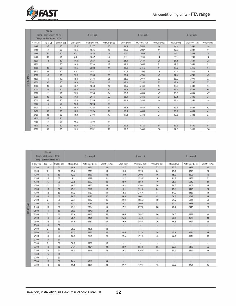
t P
Air conditioning units - FTA range
� � � � � � � � � � � ! � " � � " � � � � # ! � " � $ % " � � � � � " � � � % " � # " �
HEATIN
GFTA 24
Temp. inlet water: 45°C
Temp. outlet water: 40°C
3-row coil 4-row coil 6-row coil
P (m³/h) Tia (°C) UmRel (%) Qtot (kW) WtrFlow (l/h) WtrDP (kPa) Qtot (kW) WtrFlow (l/h) WtrDP (kPa) Qtot (kW) WtrFlow (l/h) WtrDP (kPa)
800 -5 50 12.6 2177 13 14.4 2491 14 14.4 2491 14
800 2 50 10.5 1825 10 12.0 2087 11 12.0 2087 11
800 10 50 8.3 1438 6 9.5 1649 7 9.5 1649 7
800 18 50 6.2 1067 4 7.1 1231 4 7.1 1231 4
1200 -5 50 17.5 3025 23 21.1 3649 28 21.1 3649 28
1200 2 50 14.6 2538 17 17.6 3058 21 17.6 3058 21
1200 10 50 11.5 2000 11 13.9 2415 14 13.9 2415 14
1200 18 50 8.5 1481 7 10.4 1801 8 10.4 1801 8
1600 -5 50 21.8 3780 35 27.4 4746 45 27.4 4746 45
1600 2 50 18.3 3173 25 23.0 3979 33 23.0 3979 33
1600 10 50 14.4 2501 17 18.1 3140 22 18.1 3140 22
1600 18 50 10.7 1850 10 13.5 2339 13 13.5 2339 13
2000 -5 50 25.8 4466 47 33.4 5789 64 33.4 5789 64
2000 2 50 21.6 3750 34 28.0 4854 47 28.0 4854 47
2000 10 50 17.1 2955 22 22.1 3830 31 22.1 3830 31
2000 18 50 12.6 2185 13 16.4 2851 18 16.4 2851 18
2400 -5 50 29.4 5098 59 – – – – – –
2400 2 50 24.7 4283 43 32.8 5689 62 32.8 5689 62
2400 10 50 19.5 3376 28 25.9 4489 41 25.9 4489 41
2400 18 50 14.4 2493 17 19.3 3338 24 19.3 3338 24
2800 -5 50 – – – – – – – – –
2800 2 50 27.6 4779 53 – – – – – –
2800 10 50 21.7 3767 34 29.5 5120 51 29.5 5120 51
2800 18 50 16.1 2782 20 22.0 3805 30 22.0 3805 30
HEATIN
G
FTA 33
Temp. inlet water: 45°C
Temp. outlet water: 40°C
3-row coil 4-row coil 6-row coil
P (m³/h) Tia (°C) UmRel (%) Qtot (kW) WtrFlow (l/h) WtrDP (kPa) Qtot (kW) WtrFlow (l/h) WtrDP (kPa) Qtot (kW) WtrFlow (l/h) WtrDP (kPa)
1300 -5 50 18.6 3221 26 22.7 3928 32 22.7 3928 32
1300 2 50 15.6 2703 19 19.0 3293 24 19.0 3293 24
1300 10 50 12.3 2130 13 15.0 2600 16 15.0 2600 16
1300 18 50 9.1 1577 8 11.2 1938 9 11.2 1938 9
1700 -5 50 22.8 3957 38 28.9 5012 49 28.9 5012 49
1700 2 50 19.2 3322 28 24.2 4202 36 24.2 4202 36
1700 10 50 15.1 2618 18 19.1 3315 24 19.1 3315 24
1700 18 50 11.2 1937 11 14.2 2469 14 14.2 2469 14
2100 -5 50 26.7 4629 50 34.9 6042 69 34.9 6042 69
2100 2 50 22.4 3887 36 29.2 5066 50 29.2 5066 50
2100 10 50 17.7 3064 24 23.1 3998 33 23.1 3998 33
2100 18 50 13.1 2264 14 17.2 2975 20 17.2 2975 20
2500 -5 50 30.3 5249 62 – – – – – –
2500 2 50 25.4 4410 46 34.0 5892 66 34.0 5892 66
2500 10 50 20.1 3476 30 26.8 4649 43 26.8 4649 43
2500 18 50 14.8 2567 17 19.9 3457 26 19.9 3457 26
2900 -5 50 – – – – – – – – –
2900 2 50 28.3 4898 55 – – – – – –
2900 10 50 22.3 3861 36 30.4 5273 54 30.4 5273 54
2900 18 50 16.5 2851 21 22.6 3919 32 22.6 3919 32
3300 -5 50 – – – – – – – – –
3300 2 50 30.9 5358 65 – – – – – –
3300 10 50 24.4 4224 42 33.9 5873 66 33.9 5873 66
3300 18 50 18.0 3118 25 25.2 4363 39 25.2 4363 39
3700 -5 50 – – – – – – – – –
3700 2 50 – – – – – – – – –
3700 10 50 26.4 4568 49 – – – – – –
3700 18 50 19.5 3371 28 27.7 4791 46 27.7 4791 46
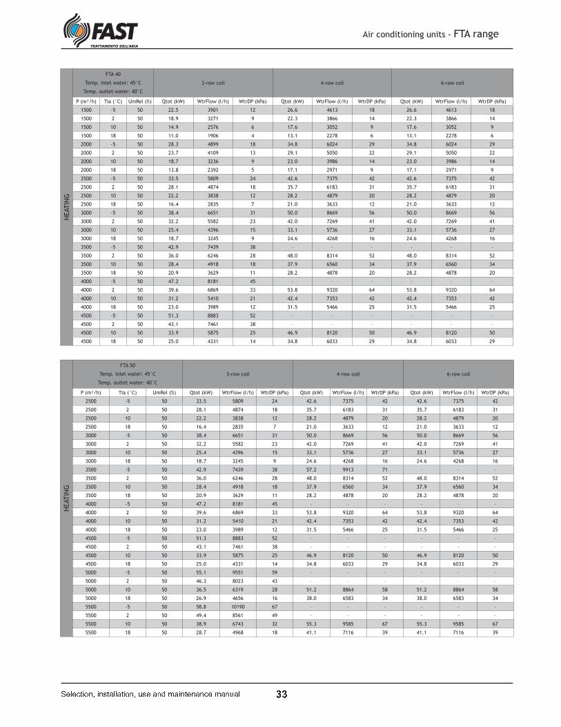
t t
Air conditioning units - FTA range
� � � � � � � � � � � ! � " � � " � � � � # ! � " � $ % " � � � � � " � � � % " � # " �
HEATIN
GFTA 40
Temp. inlet water: 45°C
Temp. outlet water: 40°C
3-row coil 4-row coil 6-row coil
P (m³/h) Tia (°C) UmRel (%) Qtot (kW) WtrFlow (l/h) WtrDP (kPa) Qtot (kW) WtrFlow (l/h) WtrDP (kPa) Qtot (kW) WtrFlow (l/h) WtrDP (kPa)
1500 -5 50 22.5 3901 12 26.6 4613 18 26.6 4613 18
1500 2 50 18.9 3271 9 22.3 3866 14 22.3 3866 14
1500 10 50 14.9 2576 6 17.6 3052 9 17.6 3052 9
1500 18 50 11.0 1906 4 13.1 2278 6 13.1 2278 6
2000 -5 50 28.3 4899 18 34.8 6024 29 34.8 6024 29
2000 2 50 23.7 4109 13 29.1 5050 22 29.1 5050 22
2000 10 50 18.7 3236 9 23.0 3986 14 23.0 3986 14
2000 18 50 13.8 2392 5 17.1 2971 9 17.1 2971 9
2500 -5 50 33.5 5809 24 42.6 7375 42 42.6 7375 42
2500 2 50 28.1 4874 18 35.7 6183 31 35.7 6183 31
2500 10 50 22.2 3838 12 28.2 4879 20 28.2 4879 20
2500 18 50 16.4 2835 7 21.0 3633 12 21.0 3633 12
3000 -5 50 38.4 6651 31 50.0 8669 56 50.0 8669 56
3000 2 50 32.2 5582 23 42.0 7269 41 42.0 7269 41
3000 10 50 25.4 4396 15 33.1 5736 27 33.1 5736 27
3000 18 50 18.7 3245 9 24.6 4268 16 24.6 4268 16
3500 -5 50 42.9 7439 38 – – – – – –
3500 2 50 36.0 6246 28 48.0 8314 52 48.0 8314 52
3500 10 50 28.4 4918 18 37.9 6560 34 37.9 6560 34
3500 18 50 20.9 3629 11 28.2 4878 20 28.2 4878 20
4000 -5 50 47.2 8181 45 – – – – – –
4000 2 50 39.6 6869 33 53.8 9320 64 53.8 9320 64
4000 10 50 31.2 5410 21 42.4 7353 42 42.4 7353 42
4000 18 50 23.0 3989 12 31.5 5466 25 31.5 5466 25
4500 -5 50 51.3 8883 52 – – – – – –
4500 2 50 43.1 7461 38 – – – – – –
4500 10 50 33.9 5875 25 46.9 8120 50 46.9 8120 50
4500 18 50 25.0 4331 14 34.8 6033 29 34.8 6033 29
HEATIN
G
FTA 50
Temp. inlet water: 45°C
Temp. outlet water: 40°C
3-row coil 4-row coil 6-row coil
P (m³/h) Tia (°C) UmRel (%) Qtot (kW) WtrFlow (l/h) WtrDP (kPa) Qtot (kW) WtrFlow (l/h) WtrDP (kPa) Qtot (kW) WtrFlow (l/h) WtrDP (kPa)
2500 -5 50 33.5 5809 24 42.6 7375 42 42.6 7375 42
2500 2 50 28.1 4874 18 35.7 6183 31 35.7 6183 31
2500 10 50 22.2 3838 12 28.2 4879 20 28.2 4879 20
2500 18 50 16.4 2835 7 21.0 3633 12 21.0 3633 12
3000 -5 50 38.4 6651 31 50.0 8669 56 50.0 8669 56
3000 2 50 32.2 5582 23 42.0 7269 41 42.0 7269 41
3000 10 50 25.4 4396 15 33.1 5736 27 33.1 5736 27
3000 18 50 18.7 3245 9 24.6 4268 16 24.6 4268 16
3500 -5 50 42.9 7439 38 57.2 9913 71 – – –
3500 2 50 36.0 6246 28 48.0 8314 52 48.0 8314 52
3500 10 50 28.4 4918 18 37.9 6560 34 37.9 6560 34
3500 18 50 20.9 3629 11 28.2 4878 20 28.2 4878 20
4000 -5 50 47.2 8181 45 – – – – – –
4000 2 50 39.6 6869 33 53.8 9320 64 53.8 9320 64
4000 10 50 31.2 5410 21 42.4 7353 42 42.4 7353 42
4000 18 50 23.0 3989 12 31.5 5466 25 31.5 5466 25
4500 -5 50 51.3 8883 52 – – – – – –
4500 2 50 43.1 7461 38 – – – – – –
4500 10 50 33.9 5875 25 46.9 8120 50 46.9 8120 50
4500 18 50 25.0 4331 14 34.8 6033 29 34.8 6033 29
5000 -5 50 55.1 9551 59 – – – – – –
5000 2 50 46.3 8023 43 – – – – – –
5000 10 50 36.5 6319 28 51.2 8864 58 51.2 8864 58
5000 18 50 26.9 4656 16 38.0 6583 34 38.0 6583 34
5500 -5 50 58.8 10190 67 – – – – – –
5500 2 50 49.4 8561 49 – – – – – –
5500 10 50 38.9 6743 32 55.3 9585 67 55.3 9585 67
5500 18 50 28.7 4968 18 41.1 7116 39 41.1 7116 39
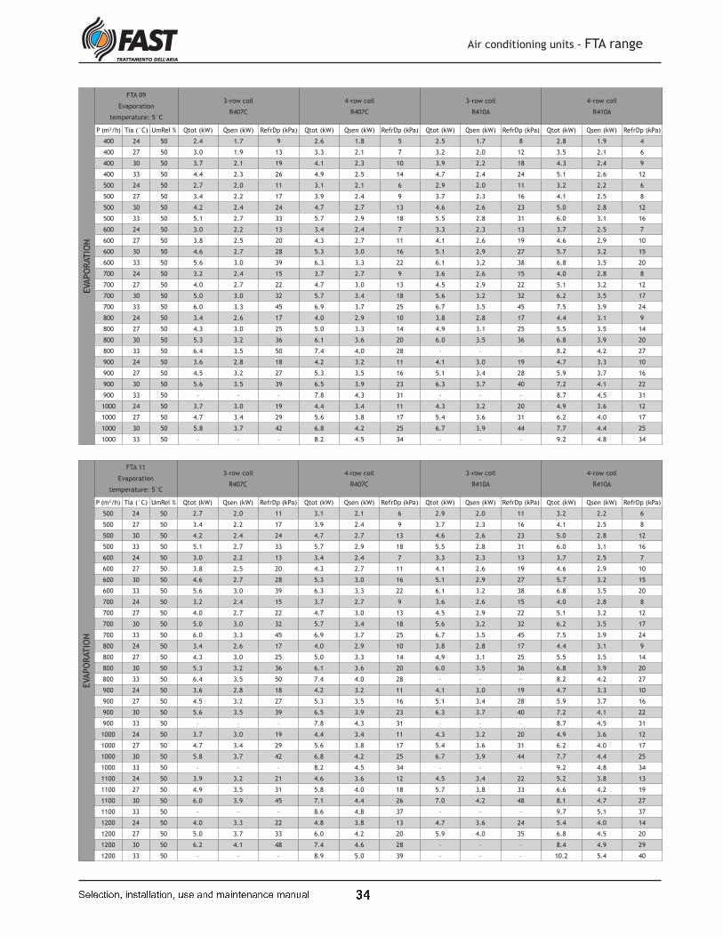
t u
Air conditioning units - FTA range
� � � � � � � � � � � ! � " � � " � � � � # ! � " � $ % " � � � � � " � � � % " � # " �
EVAPO
RATIO
NFTA 09
Evaporation
temperature: 5°C
3-row coil
R407C
4-row coil
R407C
3-row coil
R410A
4-row coil
R410A
P (m³/h) Tia (°C) UmRel % Qtot (kW) Qsen (kW) RefrDp (kPa) Qtot (kW) Qsen (kW) RefrDp (kPa) Qtot (kW) Qsen (kW) RefrDp (kPa) Qtot (kW) Qsen (kW) RefrDp (kPa)
400 24 50 2.4 1.7 9 2.6 1.8 5 2.5 1.7 8 2.8 1.9 4
400 27 50 3.0 1.9 13 3.3 2.1 7 3.2 2.0 12 3.5 2.1 6
400 30 50 3.7 2.1 19 4.1 2.3 10 3.9 2.2 18 4.3 2.4 9
400 33 50 4.4 2.3 26 4.9 2.5 14 4.7 2.4 24 5.1 2.6 12
500 24 50 2.7 2.0 11 3.1 2.1 6 2.9 2.0 11 3.2 2.2 6
500 27 50 3.4 2.2 17 3.9 2.4 9 3.7 2.3 16 4.1 2.5 8
500 30 50 4.2 2.4 24 4.7 2.7 13 4.6 2.6 23 5.0 2.8 12
500 33 50 5.1 2.7 33 5.7 2.9 18 5.5 2.8 31 6.0 3.1 16
600 24 50 3.0 2.2 13 3.4 2.4 7 3.3 2.3 13 3.7 2.5 7
600 27 50 3.8 2.5 20 4.3 2.7 11 4.1 2.6 19 4.6 2.9 10
600 30 50 4.6 2.7 28 5.3 3.0 16 5.1 2.9 27 5.7 3.2 15
600 33 50 5.6 3.0 39 6.3 3.3 22 6.1 3.2 38 6.8 3.5 20
700 24 50 3.2 2.4 15 3.7 2.7 9 3.6 2.6 15 4.0 2.8 8
700 27 50 4.0 2.7 22 4.7 3.0 13 4.5 2.9 22 5.1 3.2 12
700 30 50 5.0 3.0 32 5.7 3.4 18 5.6 3.2 32 6.2 3.5 17
700 33 50 6.0 3.3 45 6.9 3.7 25 6.7 3.5 45 7.5 3.9 24
800 24 50 3.4 2.6 17 4.0 2.9 10 3.8 2.8 17 4.4 3.1 9
800 27 50 4.3 3.0 25 5.0 3.3 14 4.9 3.1 25 5.5 3.5 14
800 30 50 5.3 3.2 36 6.1 3.6 20 6.0 3.5 36 6.8 3.9 20
800 33 50 6.4 3.5 50 7.4 4.0 28 – – – 8.2 4.2 27
900 24 50 3.6 2.8 18 4.2 3.2 11 4.1 3.0 19 4.7 3.3 10
900 27 50 4.5 3.2 27 5.3 3.5 16 5.1 3.4 28 5.9 3.7 16
900 30 50 5.6 3.5 39 6.5 3.9 23 6.3 3.7 40 7.2 4.1 22
900 33 50 – – – 7.8 4.3 31 – – – 8.7 4.5 31
1000 24 50 3.7 3.0 19 4.4 3.4 11 4.3 3.2 20 4.9 3.6 12
1000 27 50 4.7 3.4 29 5.6 3.8 17 5.4 3.6 31 6.2 4.0 17
1000 30 50 5.8 3.7 42 6.8 4.2 25 6.7 3.9 44 7.7 4.4 25
1000 33 50 – – – 8.2 4.5 34 – – – 9.2 4.8 34
EVAPO
RATIO
N
FTA 11
Evaporation
temperature: 5°C
3-row coil
R407C
4-row coil
R407C
3-row coil
R410A
4-row coil
R410A
P (m³/h) Tia (°C) UmRel % Qtot (kW) Qsen (kW) RefrDp (kPa) Qtot (kW) Qsen (kW) RefrDp (kPa) Qtot (kW) Qsen (kW) RefrDp (kPa) Qtot (kW) Qsen (kW) RefrDp (kPa)
500 24 50 2.7 2.0 11 3.1 2.1 6 2.9 2.0 11 3.2 2.2 6
500 27 50 3.4 2.2 17 3.9 2.4 9 3.7 2.3 16 4.1 2.5 8
500 30 50 4.2 2.4 24 4.7 2.7 13 4.6 2.6 23 5.0 2.8 12
500 33 50 5.1 2.7 33 5.7 2.9 18 5.5 2.8 31 6.0 3.1 16
600 24 50 3.0 2.2 13 3.4 2.4 7 3.3 2.3 13 3.7 2.5 7
600 27 50 3.8 2.5 20 4.3 2.7 11 4.1 2.6 19 4.6 2.9 10
600 30 50 4.6 2.7 28 5.3 3.0 16 5.1 2.9 27 5.7 3.2 15
600 33 50 5.6 3.0 39 6.3 3.3 22 6.1 3.2 38 6.8 3.5 20
700 24 50 3.2 2.4 15 3.7 2.7 9 3.6 2.6 15 4.0 2.8 8
700 27 50 4.0 2.7 22 4.7 3.0 13 4.5 2.9 22 5.1 3.2 12
700 30 50 5.0 3.0 32 5.7 3.4 18 5.6 3.2 32 6.2 3.5 17
700 33 50 6.0 3.3 45 6.9 3.7 25 6.7 3.5 45 7.5 3.9 24
800 24 50 3.4 2.6 17 4.0 2.9 10 3.8 2.8 17 4.4 3.1 9
800 27 50 4.3 3.0 25 5.0 3.3 14 4.9 3.1 25 5.5 3.5 14
800 30 50 5.3 3.2 36 6.1 3.6 20 6.0 3.5 36 6.8 3.9 20
800 33 50 6.4 3.5 50 7.4 4.0 28 – – – 8.2 4.2 27
900 24 50 3.6 2.8 18 4.2 3.2 11 4.1 3.0 19 4.7 3.3 10
900 27 50 4.5 3.2 27 5.3 3.5 16 5.1 3.4 28 5.9 3.7 16
900 30 50 5.6 3.5 39 6.5 3.9 23 6.3 3.7 40 7.2 4.1 22
900 33 50 – – – 7.8 4.3 31 – – – 8.7 4.5 31
1000 24 50 3.7 3.0 19 4.4 3.4 11 4.3 3.2 20 4.9 3.6 12
1000 27 50 4.7 3.4 29 5.6 3.8 17 5.4 3.6 31 6.2 4.0 17
1000 30 50 5.8 3.7 42 6.8 4.2 25 6.7 3.9 44 7.7 4.4 25
1000 33 50 – – – 8.2 4.5 34 – – – 9.2 4.8 34
1100 24 50 3.9 3.2 21 4.6 3.6 12 4.5 3.4 22 5.2 3.8 13
1100 27 50 4.9 3.5 31 5.8 4.0 18 5.7 3.8 33 6.6 4.2 19
1100 30 50 6.0 3.9 45 7.1 4.4 26 7.0 4.2 48 8.1 4.7 27
1100 33 50 – – – 8.6 4.8 37 – – – 9.7 5.1 37
1200 24 50 4.0 3.3 22 4.8 3.8 13 4.7 3.6 24 5.4 4.0 14
1200 27 50 5.0 3.7 33 6.0 4.2 20 5.9 4.0 35 6.8 4.5 20
1200 30 50 6.2 4.1 48 7.4 4.6 28 – – – 8.4 4.9 29
1200 33 50 – – – 8.9 5.0 39 – – – 10.2 5.4 40

t v
Air conditioning units - FTA range
� � � � � � � � � � � ! � " � � " � � � � # ! � " � $ % " � � � � � " � � � % " � # " �
EVAPO
RATIO
NFTA 15
Evaporation
temperature: 5°C
3-row coil
R407C
4-row coil
R407C
3-row coil
R410A
4-row coil
R410A
P (m³/h) Tia (°C) UmRel % Qtot (kW) Qsen (kW) RefrDp (kPa) Qtot (kW) Qsen (kW) RefrDp (kPa) Qtot (kW) Qsen (kW) RefrDp (kPa) Qtot (kW) Qsen (kW) RefrDp (kPa)
500 24 50 3.3 2.3 8 3.6 2.4 5 3.5 2.3 7 3.7 2.5 5
500 27 50 4.2 2.6 11 4.5 2.8 8 4.4 2.7 10 4.6 2.8 7
500 30 50 5.1 2.9 16 5.6 3.1 11 5.3 3.0 14 5.7 3.1 10
500 33 50 6.2 3.2 22 6.7 3.4 15 6.4 3.3 19 6.8 3.5 13
700 24 50 4.1 2.9 11 4.6 3.2 8 4.4 3.0 10 4.8 3.2 7
700 27 50 5.2 3.3 16 5.7 3.6 12 5.5 3.4 15 6.0 3.7 11
700 30 50 6.3 3.6 23 7.1 4.0 17 6.8 3.8 21 7.4 4.1 15
700 33 50 7.6 4.0 32 8.5 4.4 23 8.2 4.2 29 8.9 4.5 21
900 24 50 4.7 3.4 14 5.3 3.8 10 5.2 3.6 13 5.7 3.9 10
900 27 50 5.9 3.9 21 6.7 4.3 16 6.5 4.1 20 7.2 4.4 14
900 30 50 7.3 4.3 30 8.3 4.7 22 8.0 4.5 28 8.8 4.9 20
900 33 50 8.8 4.7 41 10.0 5.2 31 9.6 4.9 39 10.6 5.4 28
1100 24 50 5.2 3.9 16 6.0 4.3 13 5.8 4.1 16 6.5 4.5 12
1100 27 50 6.6 4.4 25 7.6 4.9 19 7.3 4.6 24 8.2 5.1 18
1100 30 50 8.1 4.8 35 9.3 5.4 27 9.0 5.1 35 10.0 5.7 26
1100 33 50 9.7 5.3 49 11.2 5.9 38 10.8 5.6 48 12.1 6.2 35
1300 24 50 5.6 4.3 19 6.5 4.8 15 6.3 4.6 19 7.2 5.1 14
1300 27 50 7.1 4.9 28 8.2 5.4 22 8.0 5.2 28 9.1 5.7 21
1300 30 50 8.7 5.3 40 10.1 6.0 32 9.8 5.7 41 11.1 6.3 31
1300 33 50 – – – 12.2 6.5 44 – – – 13.4 6.9 42
1500 24 50 6.0 4.7 21 7.0 5.3 17 6.8 5.0 21 7.8 5.6 16
1500 27 50 7.5 5.3 31 8.8 5.9 25 8.6 5.6 32 9.8 6.3 25
1500 30 50 9.3 5.8 45 10.9 6.5 36 10.6 6.2 46 12.1 6.9 35
1500 33 50 – – – 13.1 7.1 50 – – – – – –
1700 24 50 6.3 5.1 23 7.4 5.7 18 7.2 5.4 24 8.3 6.0 18
1700 27 50 7.9 5.7 34 9.4 6.4 28 9.1 6.1 36 10.5 6.8 28
1700 30 50 9.8 6.2 49 11.5 7.0 40 – – – 12.9 7.5 40
1700 33 50 – – – – – – – – – – – –
EVAPO
RATIO
N
FTA 19
Evaporation
temperature: 5°C
3-row coil
R407C
4-row coil
R407C
3-row coil
R410A
4-row coil
R410A
P (m³/h) Tia (°C) UmRel % Qtot (kW) Qsen (kW) RefrDp (kPa) Qtot (kW) Qsen (kW) RefrDp (kPa) Qtot (kW) Qsen (kW) RefrDp (kPa) Qtot (kW) Qsen (kW) RefrDp (kPa)
700 24 50 4.6 3.2 8 5.0 3.4 7 4.8 3.2 7 5.1 3.4 6
700 27 50 5.8 3.6 12 6.3 3.8 10 6.0 3.7 11 6.4 3.9 9
700 30 50 7.1 4.0 17 7.7 4.3 14 7.4 4.1 15 7.9 4.4 12
700 33 50 8.5 4.4 23 9.2 4.7 19 8.9 4.5 21 9.5 4.8 17
1000 24 50 5.7 4.1 12 6.4 4.4 10 6.1 4.2 11 6.7 4.5 9
1000 27 50 7.2 4.6 17 8.0 5.0 15 7.7 4.8 16 8.4 5.2 14
1000 30 50 8.8 5.1 25 9.8 5.6 22 9.5 5.3 23 10.3 5.8 19
1000 33 50 10.6 5.6 34 11.8 6.1 30 11.4 5.8 32 12.4 6.3 27
1300 24 50 6.5 4.8 15 7.5 5.3 13 7.2 5.1 14 8.0 5.5 12
1300 27 50 8.3 5.4 22 9.4 6.0 20 9.1 5.7 21 10.1 6.2 19
1300 30 50 10.2 6.0 32 11.6 6.7 29 11.2 6.3 31 12.4 7.0 27
1300 33 50 12.2 6.5 44 13.9 7.3 40 13.4 6.9 43 14.9 7.6 37
1600 24 50 7.2 5.5 18 8.4 6.1 16 8.1 5.8 18 9.1 6.4 16
1600 27 50 9.1 6.2 26 10.5 6.9 25 10.2 6.5 26 11.5 7.2 23
1600 30 50 11.2 6.8 38 13.0 7.6 35 12.5 7.2 38 14.1 8.0 34
1600 33 50 – – – – – – – – – – – –
1900 24 50 7.8 6.1 20 9.1 6.8 19 8.9 6.5 21 10.1 7.2 19
1900 27 50 9.8 6.8 30 11.5 7.6 29 11.2 7.3 31 12.7 8.1 28
1900 30 50 12.1 7.5 43 14.1 8.4 41 13.7 8.0 44 15.6 8.9 40
1900 33 50 – – – – – – – – – 18.9 9.8 56
2200 24 50 8.3 6.7 22 9.8 7.5 21 9.5 7.1 23 11.0 7.9 21
2200 27 50 10.5 7.4 33 12.3 8.4 32 12.0 7.9 35 13.8 8.9 32
2200 30 50 – – – – – – – – – – – –
2200 33 50 – – – – – – – – – – – –

t w
Air conditioning units - FTA range
� � � � � � � � � � � ! � " � � " � � � � # ! � " � $ % " � � � � � " � � � % " � # " �
EVAPO
RATIO
NFTA 24
Evaporation
temperature: 5°C
3-row coil
R407C
4-row coil
R407C
3-row coil
R410A
4-row coil
R410A
P (m³/h) Tia (°C) UmRel % Qtot (kW) Qsen (kW) RefrDp (kPa) Qtot (kW) Qsen (kW) RefrDp (kPa) Qtot (kW) Qsen (kW) RefrDp (kPa) Qtot (kW) Qsen (kW) RefrDp (kPa)
800 24 50 5.7 3.9 5 6.1 4.1 4 5.8 3.9 5 6.1 4.1 3
800 27 50 7.1 4.4 8 7.6 4.6 5 7.3 4.4 7 7.7 4.6 5
800 30 50 8.7 4.9 11 9.3 5.2 8 9.0 5.0 10 9.4 5.2 6
800 33 50 10.5 5.4 15 11.2 5.7 10 10.8 5.5 13 11.3 5.8 9
1200 24 50 7.5 5.2 8 8.2 5.6 6 7.9 5.4 8 8.5 5.7 5
1200 27 50 9.4 5.9 12 10.3 6.4 9 9.9 6.1 11 10.7 6.5 8
1200 30 50 11.5 6.6 18 12.7 7.1 13 12.2 6.8 16 13.1 7.3 11
1200 33 50 13.9 7.2 25 15.2 7.8 18 14.6 7.5 22 15.7 8.0 15
1600 24 50 8.8 6.4 11 9.9 6.9 8 9.6 6.6 11 10.5 7.1 8
1600 27 50 11.1 7.2 17 12.5 7.8 12 12.0 7.5 16 13.2 8.1 11
1600 30 50 13.7 7.9 24 15.3 8.7 18 14.8 8.3 22 16.2 9.0 16
1600 33 50 16.5 8.7 33 18.5 9.6 24 17.8 9.1 31 19.5 9.9 22
2000 24 50 9.9 7.4 14 11.3 8.1 11 10.9 7.7 13 12.2 8.4 10
2000 27 50 12.5 8.3 21 14.3 9.1 16 13.8 8.7 20 15.4 9.5 15
2000 30 50 15.4 9.1 29 17.5 10.1 22 16.9 9.6 29 18.8 10.6 21
2000 33 50 18.5 9.9 41 21.1 11.1 31 20.4 10.5 40 22.7 11.6 29
2400 24 50 10.8 8.2 16 12.5 9.1 12 12.1 8.7 16 13.7 9.5 12
2400 27 50 13.6 9.2 24 15.8 10.3 19 15.3 9.8 24 17.2 10.8 18
2400 30 50 16.8 10.2 34 19.4 11.4 27 18.8 10.8 34 21.1 12.0 25
2400 33 50 20.2 11.0 48 23.3 12.4 37 22.6 11.8 48 25.5 13.1 35
2800 24 50 11.6 9.0 18 13.5 10.1 14 13.1 9.6 18 15.0 10.6 14
2800 27 50 14.6 10.1 27 17.0 11.3 21 16.6 10.7 27 18.9 11.9 21
2800 30 50 17.9 11.1 39 20.9 12.5 31 20.3 11.9 39 23.2 13.2 30
2800 33 50 21.7 12.1 54 25.3 13.6 43 24.5 12.9 55 27.9 14.4 42
EVAPO
RATIO
N
FTA 33
Evaporation
temperature: 5°C
3-row coil
R407C
4-row coil
R407C
3-row coil
R410A
4-row coil
R410A
P (m³/h) Tia (°C) UmRel % Qtot (kW) Qsen (kW) RefrDp (kPa) Qtot (kW) Qsen (kW) RefrDp (kPa) Qtot (kW) Qsen (kW) RefrDp (kPa) Qtot (kW) Qsen (kW) RefrDp (kPa)
1300 24 50 7.8 5.5 9 8.7 6.0 7 8.3 5.7 8 9.0 6.1 6
1300 27 50 9.9 6.2 14 10.9 6.8 10 10.5 6.5 12 11.4 6.9 9
1300 30 50 12.1 6.9 19 13.4 7.5 14 12.9 7.2 18 13.9 7.7 12
1300 33 50 14.6 7.6 27 16.1 8.3 19 15.5 7.9 24 16.7 8.5 17
1700 24 50 9.1 6.6 12 10.3 7.2 9 9.9 6.9 11 10.9 7.5 8
1700 27 50 11.5 7.4 18 13.0 8.2 13 12.5 7.8 17 13.8 8.5 12
1700 30 50 14.1 8.2 25 15.9 9.1 19 15.3 8.7 24 16.9 9.4 17
1700 33 50 17.0 9.0 35 19.2 9.9 26 18.5 9.5 33 20.3 10.4 24
2100 24 50 10.2 7.6 14 11.6 8.4 11 11.2 8.0 14 12.6 8.7 10
2100 27 50 12.8 8.5 21 14.7 9.4 16 14.2 9.0 21 15.9 9.8 15
2100 30 50 15.7 9.4 31 18.0 10.4 23 17.4 9.9 30 19.5 10.9 22
2100 33 50 19.0 10.2 43 21.7 11.4 33 21.0 10.9 42 23.4 12.0 30
2500 24 50 11.0 8.5 16 12.8 9.4 13 12.4 8.9 17 14.0 9.8 12
2500 27 50 13.9 9.5 25 16.1 10.5 19 15.6 10.0 25 17.7 11.1 19
2500 30 50 17.1 10.4 35 19.8 11.7 28 19.2 11.1 36 21.7 12.3 27
2500 33 50 20.6 11.3 49 23.8 12.7 38 23.1 12.1 49 26.1 13.4 37
2900 24 50 11.7 9.2 18 13.7 10.3 15 13.3 9.8 19 15.3 10.8 14
2900 27 50 14.8 10.3 28 17.3 11.6 22 16.8 11.0 28 19.2 12.2 22
2900 30 50 18.2 11.3 40 21.3 12.7 32 20.7 12.1 41 23.6 13.5 31
2900 33 50 – – – 25.7 13.9 44 – – – 28.5 14.8 43
3300 24 50 12.4 10.0 20 14.6 11.2 16 14.2 10.6 21 16.4 11.8 16
3300 27 50 15.6 11.1 30 18.4 12.5 24 17.9 11.9 32 20.6 13.2 24
3300 30 50 19.2 12.2 44 22.6 13.8 35 22.0 13.1 45 25.4 14.6 35
3300 33 50 – – – 27.3 14.9 49 – – – – – –
3700 24 50 12.9 10.6 22 15.3 12.0 18 15.0 11.3 23 17.4 12.6 18
3700 27 50 16.3 11.9 33 19.3 13.4 27 18.9 12.7 35 21.9 14.2 27
3700 30 50 20.0 13.0 47 23.8 14.7 38 23.2 13.9 50 26.9 15.7 39
3700 33 50 – – – – – – – – – – – –
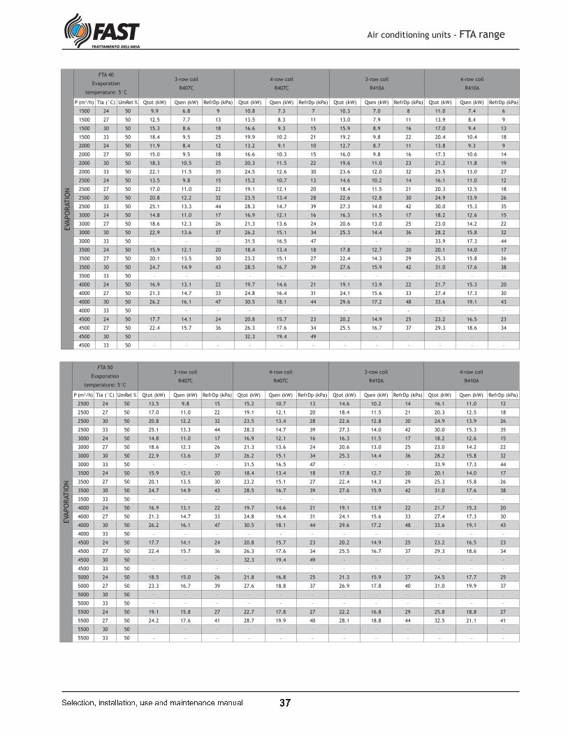
t x
Air conditioning units - FTA range
� � � � � � � � � � � ! � " � � " � � � � # ! � " � $ % " � � � � � " � � � % " � # " �
EVAPO
RATIO
NFTA 40
Evaporation
temperature: 5°C
3-row coil
R407C
4-row coil
R407C
3-row coil
R410A
4-row coil
R410A
P (m³/h) Tia (°C) UmRel % Qtot (kW) Qsen (kW) RefrDp (kPa) Qtot (kW) Qsen (kW) RefrDp (kPa) Qtot (kW) Qsen (kW) RefrDp (kPa) Qtot (kW) Qsen (kW) RefrDp (kPa)
1500 24 50 9.9 6.8 9 10.8 7.3 7 10.3 7.0 8 11.0 7.4 6
1500 27 50 12.5 7.7 13 13.5 8.3 11 13.0 7.9 11 13.9 8.4 9
1500 30 50 15.3 8.6 18 16.6 9.3 15 15.9 8.9 16 17.0 9.4 13
1500 33 50 18.4 9.5 25 19.9 10.2 21 19.2 9.8 22 20.4 10.4 18
2000 24 50 11.9 8.4 12 13.2 9.1 10 12.7 8.7 11 13.8 9.3 9
2000 27 50 15.0 9.5 18 16.6 10.3 15 16.0 9.8 16 17.3 10.6 14
2000 30 50 18.3 10.5 25 20.3 11.5 22 19.6 11.0 23 21.2 11.8 19
2000 33 50 22.1 11.5 35 24.5 12.6 30 23.6 12.0 32 25.5 13.0 27
2500 24 50 13.5 9.8 15 15.2 10.7 13 14.6 10.2 14 16.1 11.0 12
2500 27 50 17.0 11.0 22 19.1 12.1 20 18.4 11.5 21 20.3 12.5 18
2500 30 50 20.8 12.2 32 23.5 13.4 28 22.6 12.8 30 24.9 13.9 26
2500 33 50 25.1 13.3 44 28.3 14.7 39 27.3 14.0 42 30.0 15.3 35
3000 24 50 14.8 11.0 17 16.9 12.1 16 16.3 11.5 17 18.2 12.6 15
3000 27 50 18.6 12.3 26 21.3 13.6 24 20.6 13.0 25 23.0 14.2 22
3000 30 50 22.9 13.6 37 26.2 15.1 34 25.3 14.4 36 28.2 15.8 32
3000 33 50 – – – 31.5 16.5 47 – – – 33.9 17.3 44
3500 24 50 15.9 12.1 20 18.4 13.4 18 17.8 12.7 20 20.1 14.0 17
3500 27 50 20.1 13.5 30 23.2 15.1 27 22.4 14.3 29 25.3 15.8 26
3500 30 50 24.7 14.9 43 28.5 16.7 39 27.6 15.9 42 31.0 17.6 38
3500 33 50 – – – – – – – – – – – –
4000 24 50 16.9 13.1 22 19.7 14.6 21 19.1 13.9 22 21.7 15.3 20
4000 27 50 21.3 14.7 33 24.8 16.4 31 24.1 15.6 33 27.4 17.3 30
4000 30 50 26.2 16.1 47 30.5 18.1 44 29.6 17.2 48 33.6 19.1 43
4000 33 50 – – – – – – – – – – – –
4500 24 50 17.7 14.1 24 20.8 15.7 23 20.2 14.9 25 23.2 16.5 23
4500 27 50 22.4 15.7 36 26.3 17.6 34 25.5 16.7 37 29.3 18.6 34
4500 30 50 – – – 32.3 19.4 49 – – – – – –
4500 33 50 – – – – – – – – – – – –
EVAPO
RATIO
N
FTA 50
Evaporation
temperature: 5°C
3-row coil
R407C
4-row coil
R407C
3-row coil
R410A
4-row coil
R410A
P (m³/h) Tia (°C) UmRel % Qtot (kW) Qsen (kW) RefrDp (kPa) Qtot (kW) Qsen (kW) RefrDp (kPa) Qtot (kW) Qsen (kW) RefrDp (kPa) Qtot (kW) Qsen (kW) RefrDp (kPa)
2500 24 50 13.5 9.8 15 15.2 10.7 13 14.6 10.2 14 16.1 11.0 12
2500 27 50 17.0 11.0 22 19.1 12.1 20 18.4 11.5 21 20.3 12.5 18
2500 30 50 20.8 12.2 32 23.5 13.4 28 22.6 12.8 30 24.9 13.9 26
2500 33 50 25.1 13.3 44 28.3 14.7 39 27.3 14.0 42 30.0 15.3 35
3000 24 50 14.8 11.0 17 16.9 12.1 16 16.3 11.5 17 18.2 12.6 15
3000 27 50 18.6 12.3 26 21.3 13.6 24 20.6 13.0 25 23.0 14.2 22
3000 30 50 22.9 13.6 37 26.2 15.1 34 25.3 14.4 36 28.2 15.8 32
3000 33 50 – – – 31.5 16.5 47 – – – 33.9 17.3 44
3500 24 50 15.9 12.1 20 18.4 13.4 18 17.8 12.7 20 20.1 14.0 17
3500 27 50 20.1 13.5 30 23.2 15.1 27 22.4 14.3 29 25.3 15.8 26
3500 30 50 24.7 14.9 43 28.5 16.7 39 27.6 15.9 42 31.0 17.6 38
3500 33 50 – – – – – – – – – – – –
4000 24 50 16.9 13.1 22 19.7 14.6 21 19.1 13.9 22 21.7 15.3 20
4000 27 50 21.3 14.7 33 24.8 16.4 31 24.1 15.6 33 27.4 17.3 30
4000 30 50 26.2 16.1 47 30.5 18.1 44 29.6 17.2 48 33.6 19.1 43
4000 33 50 – – – – – – – – – – – –
4500 24 50 17.7 14.1 24 20.8 15.7 23 20.2 14.9 25 23.2 16.5 23
4500 27 50 22.4 15.7 36 26.3 17.6 34 25.5 16.7 37 29.3 18.6 34
4500 30 50 – – – 32.3 19.4 49 – – – – – –
4500 33 50 – – – – – – – – – – – –
5000 24 50 18.5 15.0 26 21.8 16.8 25 21.3 15.9 27 24.5 17.7 25
5000 27 50 23.3 16.7 39 27.6 18.8 37 26.9 17.8 40 31.0 19.9 37
5000 30 50 – – – – – – – – – – – –
5000 33 50 – – – – – – – – – – – –
5500 24 50 19.1 15.8 27 22.7 17.8 27 22.2 16.8 29 25.8 18.8 27
5500 27 50 24.2 17.6 41 28.7 19.9 40 28.1 18.8 44 32.5 21.1 41
5500 30 50 – – – – – – – – – – – –
5500 33 50 – – – – – – – – – – – –
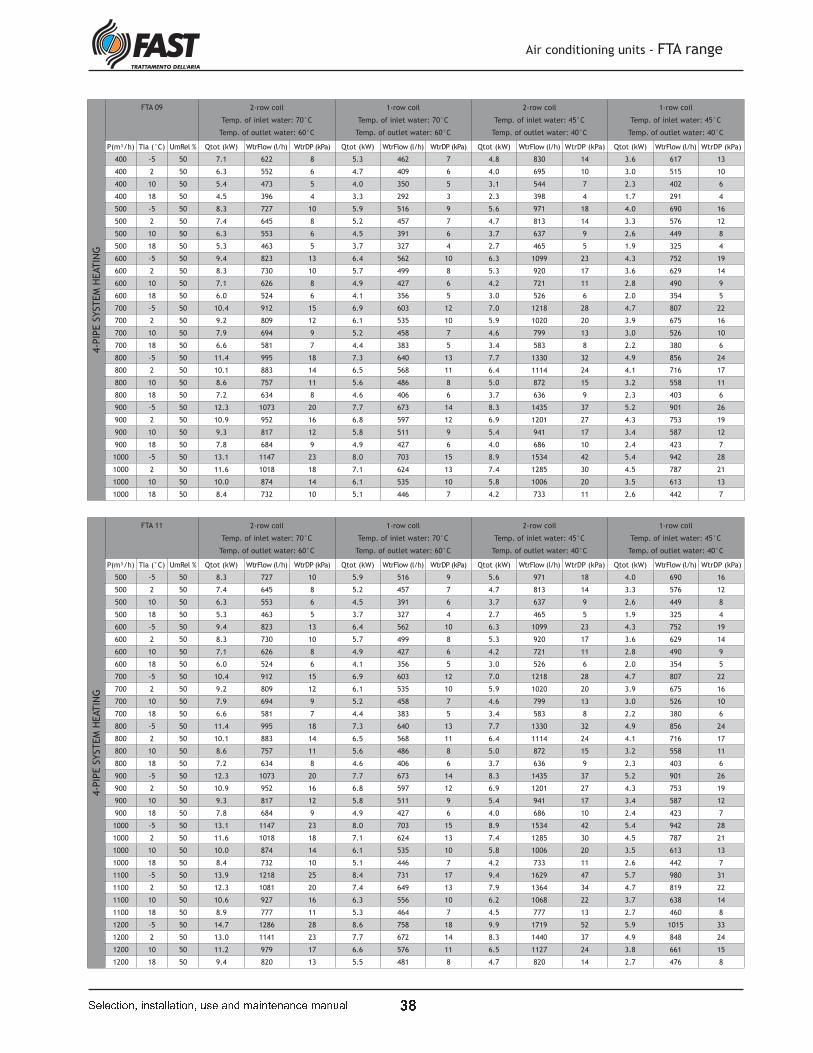
t '
Air conditioning units - FTA range
� � � � � � � � � � � ! � " � � " � � � � # ! � " � $ % " � � � � � " � � � % " � # " �
4-P
IPE S
YSTEM
HEATIN
GFTA 09 2-row coil
Temp. of inlet water: 70°C
Temp. of outlet water: 60°C
1-row coil
Temp. of inlet water: 70°C
Temp. of outlet water: 60°C
2-row coil
Temp. of inlet water: 45°C
Temp. of outlet water: 40°C
1-row coil
Temp. of inlet water: 45°C
Temp. of outlet water: 40°C
P(m³/h) Tia (°C) UmRel % Qtot (kW) WtrFlow (l/h) WtrDP (kPa) Qtot (kW) WtrFlow (l/h) WtrDP (kPa) Qtot (kW) WtrFlow (l/h) WtrDP (kPa) Qtot (kW) WtrFlow (l/h) WtrDP (kPa)
400 -5 50 7.1 622 8 5.3 462 7 4.8 830 14 3.6 617 13
400 2 50 6.3 552 6 4.7 409 6 4.0 695 10 3.0 515 10
400 10 50 5.4 473 5 4.0 350 5 3.1 544 7 2.3 402 6
400 18 50 4.5 396 4 3.3 292 3 2.3 398 4 1.7 291 4
500 -5 50 8.3 727 10 5.9 516 9 5.6 971 18 4.0 690 16
500 2 50 7.4 645 8 5.2 457 7 4.7 813 14 3.3 576 12
500 10 50 6.3 553 6 4.5 391 6 3.7 637 9 2.6 449 8
500 18 50 5.3 463 5 3.7 327 4 2.7 465 5 1.9 325 4
600 -5 50 9.4 823 13 6.4 562 10 6.3 1099 23 4.3 752 19
600 2 50 8.3 730 10 5.7 499 8 5.3 920 17 3.6 629 14
600 10 50 7.1 626 8 4.9 427 6 4.2 721 11 2.8 490 9
600 18 50 6.0 524 6 4.1 356 5 3.0 526 6 2.0 354 5
700 -5 50 10.4 912 15 6.9 603 12 7.0 1218 28 4.7 807 22
700 2 50 9.2 809 12 6.1 535 10 5.9 1020 20 3.9 675 16
700 10 50 7.9 694 9 5.2 458 7 4.6 799 13 3.0 526 10
700 18 50 6.6 581 7 4.4 383 5 3.4 583 8 2.2 380 6
800 -5 50 11.4 995 18 7.3 640 13 7.7 1330 32 4.9 856 24
800 2 50 10.1 883 14 6.5 568 11 6.4 1114 24 4.1 716 17
800 10 50 8.6 757 11 5.6 486 8 5.0 872 15 3.2 558 11
800 18 50 7.2 634 8 4.6 406 6 3.7 636 9 2.3 403 6
900 -5 50 12.3 1073 20 7.7 673 14 8.3 1435 37 5.2 901 26
900 2 50 10.9 952 16 6.8 597 12 6.9 1201 27 4.3 753 19
900 10 50 9.3 817 12 5.8 511 9 5.4 941 17 3.4 587 12
900 18 50 7.8 684 9 4.9 427 6 4.0 686 10 2.4 423 7
1000 -5 50 13.1 1147 23 8.0 703 15 8.9 1534 42 5.4 942 28
1000 2 50 11.6 1018 18 7.1 624 13 7.4 1285 30 4.5 787 21
1000 10 50 10.0 874 14 6.1 535 10 5.8 1006 20 3.5 613 13
1000 18 50 8.4 732 10 5.1 446 7 4.2 733 11 2.6 442 7
4-P
IPE S
YSTEM
HEATIN
G
FTA 11 2-row coil
Temp. of inlet water: 70°C
Temp. of outlet water: 60°C
1-row coil
Temp. of inlet water: 70°C
Temp. of outlet water: 60°C
2-row coil
Temp. of inlet water: 45°C
Temp. of outlet water: 40°C
1-row coil
Temp. of inlet water: 45°C
Temp. of outlet water: 40°C
P(m³/h) Tia (°C) UmRel % Qtot (kW) WtrFlow (l/h) WtrDP (kPa) Qtot (kW) WtrFlow (l/h) WtrDP (kPa) Qtot (kW) WtrFlow (l/h) WtrDP (kPa) Qtot (kW) WtrFlow (l/h) WtrDP (kPa)
500 -5 50 8.3 727 10 5.9 516 9 5.6 971 18 4.0 690 16
500 2 50 7.4 645 8 5.2 457 7 4.7 813 14 3.3 576 12
500 10 50 6.3 553 6 4.5 391 6 3.7 637 9 2.6 449 8
500 18 50 5.3 463 5 3.7 327 4 2.7 465 5 1.9 325 4
600 -5 50 9.4 823 13 6.4 562 10 6.3 1099 23 4.3 752 19
600 2 50 8.3 730 10 5.7 499 8 5.3 920 17 3.6 629 14
600 10 50 7.1 626 8 4.9 427 6 4.2 721 11 2.8 490 9
600 18 50 6.0 524 6 4.1 356 5 3.0 526 6 2.0 354 5
700 -5 50 10.4 912 15 6.9 603 12 7.0 1218 28 4.7 807 22
700 2 50 9.2 809 12 6.1 535 10 5.9 1020 20 3.9 675 16
700 10 50 7.9 694 9 5.2 458 7 4.6 799 13 3.0 526 10
700 18 50 6.6 581 7 4.4 383 5 3.4 583 8 2.2 380 6
800 -5 50 11.4 995 18 7.3 640 13 7.7 1330 32 4.9 856 24
800 2 50 10.1 883 14 6.5 568 11 6.4 1114 24 4.1 716 17
800 10 50 8.6 757 11 5.6 486 8 5.0 872 15 3.2 558 11
800 18 50 7.2 634 8 4.6 406 6 3.7 636 9 2.3 403 6
900 -5 50 12.3 1073 20 7.7 673 14 8.3 1435 37 5.2 901 26
900 2 50 10.9 952 16 6.8 597 12 6.9 1201 27 4.3 753 19
900 10 50 9.3 817 12 5.8 511 9 5.4 941 17 3.4 587 12
900 18 50 7.8 684 9 4.9 427 6 4.0 686 10 2.4 423 7
1000 -5 50 13.1 1147 23 8.0 703 15 8.9 1534 42 5.4 942 28
1000 2 50 11.6 1018 18 7.1 624 13 7.4 1285 30 4.5 787 21
1000 10 50 10.0 874 14 6.1 535 10 5.8 1006 20 3.5 613 13
1000 18 50 8.4 732 10 5.1 446 7 4.2 733 11 2.6 442 7
1100 -5 50 13.9 1218 25 8.4 731 17 9.4 1629 47 5.7 980 31
1100 2 50 12.3 1081 20 7.4 649 13 7.9 1364 34 4.7 819 22
1100 10 50 10.6 927 16 6.3 556 10 6.2 1068 22 3.7 638 14
1100 18 50 8.9 777 11 5.3 464 7 4.5 777 13 2.7 460 8
1200 -5 50 14.7 1286 28 8.6 758 18 9.9 1719 52 5.9 1015 33
1200 2 50 13.0 1141 23 7.7 672 14 8.3 1440 37 4.9 848 24
1200 10 50 11.2 979 17 6.6 576 11 6.5 1127 24 3.8 661 15
1200 18 50 9.4 820 13 5.5 481 8 4.7 820 14 2.7 476 8
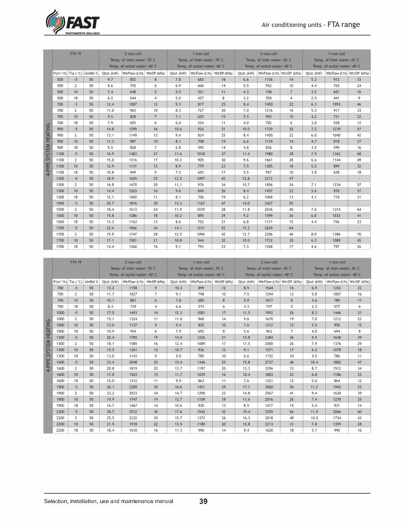
t O
Air conditioning units - FTA range
� � � � � � � � � � � ! � " � � " � � � � # ! � " � $ % " � � � � � " � � � % " � # " �
4-P
IPE S
YSTEM
HEATIN
GFTA 15 2-row coil
Temp. of inlet water: 70°C
Temp. of outlet water: 60°C
1-row coil
Temp. of inlet water: 70°C
Temp. of outlet water: 60°C
2-row coil
Temp. of inlet water: 45°C
Temp. of outlet water: 40°C
1-row coil
Temp. of inlet water: 45°C
Temp. of outlet water: 40°C
P(m³/h) Tia (°C) UmRel % Qtot (kW) WtrFlow (l/h) WtrDP (kPa) Qtot (kW) WtrFlow (l/h) WtrDP (kPa) Qtot (kW) WtrFlow (l/h) WtrDP (kPa) Qtot (kW) WtrFlow (l/h) WtrDP (kPa)
500 -5 50 9.7 852 8 7.8 683 18 6.6 1136 14 5.3 912 33
500 2 50 8.6 755 6 6.9 606 14 5.5 952 10 4.4 765 24
500 10 50 7.4 648 5 5.9 521 11 4.3 748 7 3.5 601 16
500 18 50 6.2 544 4 5.0 437 8 3.2 550 4 2.5 441 9
700 -5 50 12.4 1087 12 9.3 817 25 8.4 1450 22 6.3 1093 46
700 2 50 11.0 965 10 8.3 727 20 7.0 1216 16 5.3 917 33
700 10 50 9.5 828 7 7.1 625 15 5.5 955 10 4.2 721 22
700 18 50 7.9 695 6 6.0 524 11 4.0 702 6 3.0 528 12
900 -5 50 14.8 1295 16 10.6 926 31 10.0 1729 30 7.2 1239 57
900 2 50 13.1 1149 13 9.4 824 25 8.4 1450 22 6.0 1040 42
900 10 50 11.3 987 10 8.1 708 19 6.6 1139 14 4.7 818 27
900 18 50 9.5 828 7 6.8 595 14 4.8 836 8 3.5 599 16
1100 -5 50 16.9 1483 21 11.6 1018 37 11.4 1980 38 7.9 1362 68
1100 2 50 15.0 1316 17 10.3 905 30 9.6 1661 28 6.6 1144 49
1100 10 50 12.9 1131 13 8.9 779 23 7.5 1305 18 5.2 899 32
1100 18 50 10.8 949 9 7.5 655 17 5.5 957 10 3.8 658 18
1300 -5 50 18.9 1655 25 12.5 1097 42 12.8 2212 47 – – –
1300 2 50 16.8 1470 20 11.1 976 34 10.7 1856 34 7.1 1234 57
1300 10 50 14.4 1263 16 9.6 840 26 8.4 1457 22 5.6 970 37
1300 18 50 12.1 1060 11 8.1 706 19 6.2 1068 13 4.1 710 21
1500 -5 50 20.7 1816 30 13.3 1167 47 14.0 2427 55 – – –
1500 2 50 18.4 1613 24 11.9 1039 38 11.8 2036 40 7.6 1314 64
1500 10 50 15.8 1386 18 10.2 895 29 9.2 1599 26 6.0 1033 41
1500 18 50 13.3 1163 13 8.6 752 21 6.8 1171 15 4.4 756 23
1700 -5 50 22.4 1966 34 14.1 1231 52 15.2 2629 64 – – –
1700 2 50 19.9 1747 28 12.5 1096 42 12.7 2206 46 8.0 1386 70
1700 10 50 17.1 1501 21 10.8 944 32 10.0 1732 30 6.3 1089 45
1700 18 50 14.4 1260 16 9.1 793 23 7.3 1268 17 4.6 797 26
4-P
IPE S
YSTEM
HEATIN
G
FTA 19 2-row coil
Temp. of inlet water: 70°C
Temp. of outlet water: 60°C
1-row coil
Temp. of inlet water: 70°C
Temp. of outlet water: 60°C
2-row coil
Temp. of inlet water: 45°C
Temp. of outlet water: 40°C
1-row coil
Temp. of inlet water: 45°C
Temp. of outlet water: 40°C
P(m³/h) Tia (°C) UmRel % Qtot (kW) WtrFlow (l/h) WtrDP (kPa) Qtot (kW) WtrFlow (l/h) WtrDP (kPa) Qtot (kW) WtrFlow (l/h) WtrDP (kPa) Qtot (kW) WtrFlow (l/h) WtrDP (kPa)
700 -5 50 13.2 1158 9 10.3 899 12 8.9 1544 16 6.9 1202 22
700 2 50 11.7 1027 7 9.1 798 10 7.5 1294 12 5.8 1007 16
700 10 50 10.1 881 6 7.8 685 8 5.9 1017 8 4.6 789 11
700 18 50 8.4 739 4 6.6 574 6 4.3 747 5 3.3 577 6
1000 -5 50 17.0 1493 14 12.3 1081 17 11.5 1992 26 8.3 1446 31
1000 2 50 15.1 1324 11 11.0 960 14 9.6 1670 19 7.0 1212 23
1000 10 50 13.0 1137 9 9.4 825 10 7.6 1312 12 5.5 950 15
1000 18 50 10.9 954 6 7.9 692 8 5.6 963 7 4.0 694 8
1300 -5 50 20.4 1785 19 14.0 1226 21 13.8 2384 36 9.5 1640 39
1300 2 50 18.1 1585 16 12.4 1089 17 11.5 2000 26 7.9 1376 29
1300 10 50 15.5 1361 12 10.7 936 13 9.1 1571 17 6.2 1078 18
1300 18 50 13.0 1143 9 9.0 785 10 6.6 1152 10 4.5 786 11
1600 -5 50 23.4 2048 25 15.4 1346 25 15.8 2737 46 10.4 1802 47
1600 2 50 20.8 1819 20 13.7 1197 20 13.3 2296 33 8.7 1512 34
1600 10 50 17.8 1563 15 11.7 1029 16 10.4 1803 22 6.8 1186 22
1600 18 50 15.0 1312 11 9.9 863 11 7.6 1321 12 5.0 864 12
1900 -5 50 26.1 2289 30 16.6 1451 29 17.7 3060 56 11.2 1942 53
1900 2 50 23.2 2033 24 14.7 1290 23 14.8 2567 41 9.4 1630 39
1900 10 50 19.9 1747 19 12.7 1109 18 11.6 2016 26 7.4 1278 25
1900 18 50 16.7 1467 14 10.6 930 13 8.5 1477 15 5.4 931 14
2200 -5 50 28.7 2512 36 17.6 1542 32 19.4 3359 66 11.9 2066 60
2200 2 50 25.5 2232 29 15.7 1372 26 16.3 2818 48 10.0 1734 43
2200 10 50 21.9 1918 22 13.5 1180 20 12.8 2213 31 7.8 1359 28
2200 18 50 18.4 1610 16 11.3 990 14 9.4 1620 18 5.7 990 16

u Q
Air conditioning units - FTA range
� � � � � � � � � � � ! � " � � " � � � � # ! � " � $ % " � � � � � " � � � % " � # " �
4-P
IPE S
YSTEM
HEATIN
G
FTA 24 2-row coil
Temp. of inlet water: 70°C
Temp. of outlet water: 60°C
1-row coil
Temp. of inlet water: 70°C
Temp. of outlet water: 60°C
2-row coil
Temp. of inlet water: 45°C
Temp. of outlet water: 40°C
1-row coil
Temp. of inlet water: 45°C
Temp. of outlet water: 40°C
P(m³/h) Tia (°C) UmRel % Qtot (kW) WtrFlow (l/h) WtrDP (kPa) Qtot (kW) WtrFlow (l/h) WtrDP (kPa) Qtot (kW) WtrFlow (l/h) WtrDP (kPa) Qtot (kW) WtrFlow (l/h) WtrDP (kPa)
800 -5 50 16.3 1428 10 13.3 1161 11 11.0 1902 18 8.9 1550 20
800 2 50 14.5 1266 8 11.8 1030 9 9.2 1595 13 7.5 1299 15
800 10 50 12.4 1087 6 10.1 884 7 7.2 1256 9 5.9 1020 10
800 18 50 10.4 913 5 8.5 742 5 5.3 927 5 4.3 748 6
1200 -5 50 22.0 1926 17 16.6 1453 16 14.8 2568 31 11.2 1942 30
1200 2 50 19.5 1709 14 14.7 1290 13 12.4 2155 22 9.4 1629 22
1200 10 50 16.8 1468 10 12.7 1109 10 9.8 1697 15 7.4 1279 14
1200 18 50 14.1 1234 8 10.6 930 7 7.2 1251 9 5.4 936 8
1600 -5 50 26.9 2358 24 19.2 1679 21 18.2 3147 44 13.0 2246 39
1600 2 50 23.9 2094 19 17.0 1493 17 15.3 2643 32 10.9 1885 29
1600 10 50 20.5 1800 15 14.7 1283 13 12.0 2080 21 8.5 1480 19
1600 18 50 17.3 1513 11 12.3 1077 10 8.8 1532 12 6.2 1083 11
2000 -5 50 31.3 2744 32 21.3 1866 26 21.2 3665 58 14.4 2498 48
2000 2 50 27.8 2438 25 19.0 1660 21 17.8 3078 42 12.1 2097 35
2000 10 50 23.9 2097 19 16.3 1427 16 14.0 2423 28 9.5 1646 22
2000 18 50 20.1 1763 14 13.7 1198 12 10.3 1784 16 6.9 1204 13
2400 -5 50 35.3 3096 39 23.1 2026 30 – – – 15.7 2712 56
2400 2 50 31.4 2752 32 20.6 1803 24 20.1 3476 53 13.1 2278 40
2400 10 50 27.0 2367 24 17.7 1551 19 15.8 2736 34 10.3 1789 26
2400 18 50 22.7 1991 18 14.9 1302 14 11.6 2013 20 7.5 1307 15
2800 -5 50 39.1 3421 47 24.7 2166 34 – – – 16.7 2901 63
2800 2 50 34.7 3043 38 22.0 1928 28 22.2 3843 63 14.1 2437 46
2800 10 50 29.9 2618 29 18.9 1659 21 17.5 3025 41 11.0 1914 29
2800 18 50 25.1 2202 21 15.9 1393 15 12.8 2225 24 8.1 1398 17
4-P
IPE S
YSTEM
HEATIN
G
FTA 33 2-row coil
Temp. of inlet water: 70°C
Temp. of outlet water: 60°C
1-row coil
Temp. of inlet water: 70°C
Temp. of outlet water: 60°C
2-row coil
Temp. of inlet water: 45°C
Temp. of outlet water: 40°C
1-row coil
Temp. of inlet water: 45°C
Temp. of outlet water: 40°C
P(m³/h) Tia (°C) UmRel % Qtot (kW) WtrFlow (l/h) WtrDP (kPa) Qtot (kW) WtrFlow (l/h) WtrDP (kPa) Qtot (kW) WtrFlow (l/h) WtrDP (kPa) Qtot (kW) WtrFlow (l/h) WtrDP (kPa)
1300 -5 50 23.3 2039 19 17.3 1514 18 15.7 2720 34 11.7 2024 33
1300 2 50 20.7 1810 15 15.4 1345 14 13.2 2283 25 9.8 1698 24
1300 10 50 17.8 1555 11 13.2 1156 11 10.4 1797 16 7.7 1333 15
1300 18 50 14.9 1307 8 11.1 970 8 7.6 1325 10 5.6 976 9
1700 -5 50 28.1 2458 26 19.7 1729 23 18.9 3282 48 13.4 2313 42
1700 2 50 24.9 2183 21 17.6 1537 18 15.9 2756 35 11.2 1942 30
1700 10 50 21.4 1877 16 15.1 1321 14 12.5 2169 23 8.8 1524 20
1700 18 50 18.0 1578 12 12.7 1109 10 9.2 1597 13 6.4 1115 11
2100 -5 50 32.4 2835 33 21.8 1908 27 21.9 3787 62 14.7 2554 50
2100 2 50 28.8 2519 27 19.4 1697 22 18.4 3181 45 12.4 2145 36
2100 10 50 24.7 2166 21 16.7 1460 17 14.5 2504 29 9.7 1684 23
2100 18 50 20.8 1822 15 14.0 1226 12 10.6 1843 17 7.1 1231 13
2500 -5 50 36.3 3179 41 23.6 2063 31 – – – 15.9 2762 57
2500 2 50 32.3 2827 33 21.0 1835 25 20.6 3570 55 13.4 2319 42
2500 10 50 27.8 2432 25 18.0 1579 19 16.2 2810 36 10.5 1822 27
2500 18 50 23.3 2045 19 15.1 1326 14 11.9 2068 21 7.7 1331 15
2900 -5 50 40.0 3499 49 25.1 2199 35 – – – 17.0 2945 65
2900 2 50 35.5 3112 40 22.3 1957 28 22.7 3931 66 14.3 2474 47
2900 10 50 30.6 2678 30 19.2 1684 22 17.9 3095 43 11.2 1943 30
2900 18 50 25.7 2252 22 16.1 1414 16 13.1 2276 25 8.2 1419 17
3300 -5 50 43.4 3798 57 26.5 2321 39 – – – – – –
3300 2 50 38.6 3379 46 23.6 2066 31 – – – 15.1 2612 52
3300 10 50 33.2 2908 35 20.3 1778 24 19.4 3360 50 11.8 2052 33
3300 18 50 27.9 2446 26 17.1 1494 17 14.3 2471 29 8.6 1498 19
3700 -5 50 46.6 4080 65 27.8 2432 42 – – – – – –
3700 2 50 41.4 3630 52 24.7 2166 34 – – – 15.8 2738 57
3700 10 50 35.7 3125 40 21.3 1864 26 20.8 3612 57 12.4 2150 36
3700 18 50 30.0 2628 29 17.9 1566 19 15.3 2655 32 9.1 1570 21
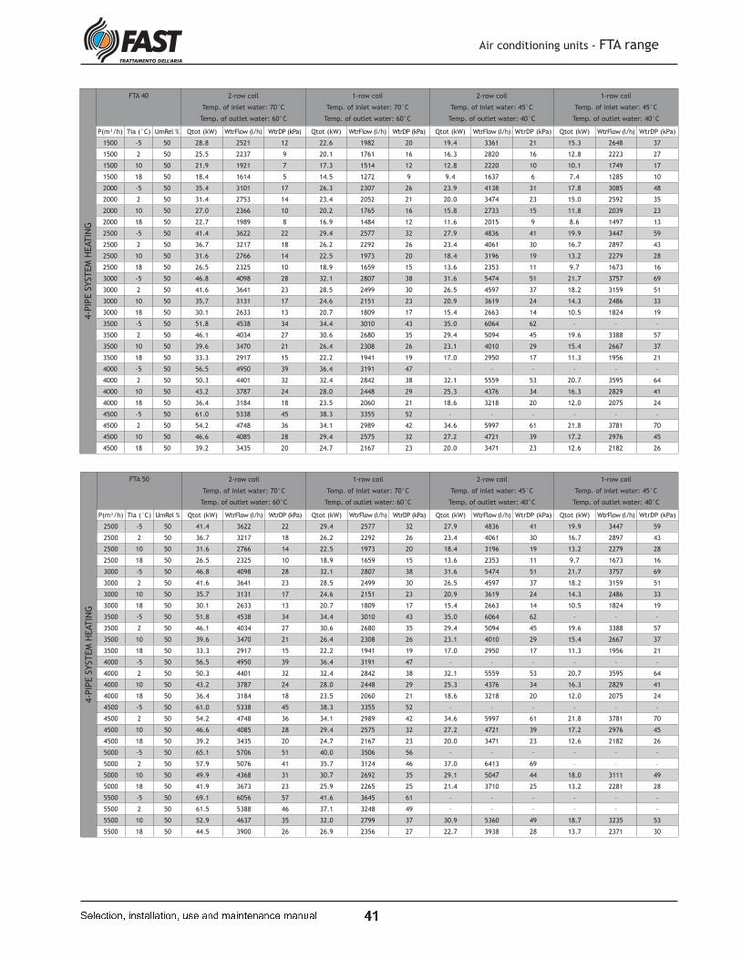
u &
Air conditioning units - FTA range
� � � � � � � � � � � ! � " � � " � � � � # ! � " � $ % " � � � � � " � � � % " � # " �
4-P
IPE S
YSTEM
HEATIN
GFTA 40 2-row coil
Temp. of inlet water: 70°C
Temp. of outlet water: 60°C
1-row coil
Temp. of inlet water: 70°C
Temp. of outlet water: 60°C
2-row coil
Temp. of inlet water: 45°C
Temp. of outlet water: 40°C
1-row coil
Temp. of inlet water: 45°C
Temp. of outlet water: 40°C
P(m³/h) Tia (°C) UmRel % Qtot (kW) WtrFlow (l/h) WtrDP (kPa) Qtot (kW) WtrFlow (l/h) WtrDP (kPa) Qtot (kW) WtrFlow (l/h) WtrDP (kPa) Qtot (kW) WtrFlow (l/h) WtrDP (kPa)
1500 -5 50 28.8 2521 12 22.6 1982 20 19.4 3361 21 15.3 2648 37
1500 2 50 25.5 2237 9 20.1 1761 16 16.3 2820 16 12.8 2223 27
1500 10 50 21.9 1921 7 17.3 1514 12 12.8 2220 10 10.1 1749 17
1500 18 50 18.4 1614 5 14.5 1272 9 9.4 1637 6 7.4 1285 10
2000 -5 50 35.4 3101 17 26.3 2307 26 23.9 4138 31 17.8 3085 48
2000 2 50 31.4 2753 14 23.4 2052 21 20.0 3474 23 15.0 2592 35
2000 10 50 27.0 2366 10 20.2 1765 16 15.8 2733 15 11.8 2039 23
2000 18 50 22.7 1989 8 16.9 1484 12 11.6 2015 9 8.6 1497 13
2500 -5 50 41.4 3622 22 29.4 2577 32 27.9 4836 41 19.9 3447 59
2500 2 50 36.7 3217 18 26.2 2292 26 23.4 4061 30 16.7 2897 43
2500 10 50 31.6 2766 14 22.5 1973 20 18.4 3196 19 13.2 2279 28
2500 18 50 26.5 2325 10 18.9 1659 15 13.6 2353 11 9.7 1673 16
3000 -5 50 46.8 4098 28 32.1 2807 38 31.6 5474 51 21.7 3757 69
3000 2 50 41.6 3641 23 28.5 2499 30 26.5 4597 37 18.2 3159 51
3000 10 50 35.7 3131 17 24.6 2151 23 20.9 3619 24 14.3 2486 33
3000 18 50 30.1 2633 13 20.7 1809 17 15.4 2663 14 10.5 1824 19
3500 -5 50 51.8 4538 34 34.4 3010 43 35.0 6064 62 – – –
3500 2 50 46.1 4034 27 30.6 2680 35 29.4 5094 45 19.6 3388 57
3500 10 50 39.6 3470 21 26.4 2308 26 23.1 4010 29 15.4 2667 37
3500 18 50 33.3 2917 15 22.2 1941 19 17.0 2950 17 11.3 1956 21
4000 -5 50 56.5 4950 39 36.4 3191 47 – – – – – –
4000 2 50 50.3 4401 32 32.4 2842 38 32.1 5559 53 20.7 3595 64
4000 10 50 43.2 3787 24 28.0 2448 29 25.3 4376 34 16.3 2829 41
4000 18 50 36.4 3184 18 23.5 2060 21 18.6 3218 20 12.0 2075 24
4500 -5 50 61.0 5338 45 38.3 3355 52 – – – – – –
4500 2 50 54.2 4748 36 34.1 2989 42 34.6 5997 61 21.8 3781 70
4500 10 50 46.6 4085 28 29.4 2575 32 27.2 4721 39 17.2 2976 45
4500 18 50 39.2 3435 20 24.7 2167 23 20.0 3471 23 12.6 2182 26
4-P
IPE S
YSTEM
HEATIN
G
FTA 50 2-row coil
Temp. of inlet water: 70°C
Temp. of outlet water: 60°C
1-row coil
Temp. of inlet water: 70°C
Temp. of outlet water: 60°C
2-row coil
Temp. of inlet water: 45°C
Temp. of outlet water: 40°C
1-row coil
Temp. of inlet water: 45°C
Temp. of outlet water: 40°C
P(m³/h) Tia (°C) UmRel % Qtot (kW) WtrFlow (l/h) WtrDP (kPa) Qtot (kW) WtrFlow (l/h) WtrDP (kPa) Qtot (kW) WtrFlow (l/h) WtrDP (kPa) Qtot (kW) WtrFlow (l/h) WtrDP (kPa)
2500 -5 50 41.4 3622 22 29.4 2577 32 27.9 4836 41 19.9 3447 59
2500 2 50 36.7 3217 18 26.2 2292 26 23.4 4061 30 16.7 2897 43
2500 10 50 31.6 2766 14 22.5 1973 20 18.4 3196 19 13.2 2279 28
2500 18 50 26.5 2325 10 18.9 1659 15 13.6 2353 11 9.7 1673 16
3000 -5 50 46.8 4098 28 32.1 2807 38 31.6 5474 51 21.7 3757 69
3000 2 50 41.6 3641 23 28.5 2499 30 26.5 4597 37 18.2 3159 51
3000 10 50 35.7 3131 17 24.6 2151 23 20.9 3619 24 14.3 2486 33
3000 18 50 30.1 2633 13 20.7 1809 17 15.4 2663 14 10.5 1824 19
3500 -5 50 51.8 4538 34 34.4 3010 43 35.0 6064 62 – – –
3500 2 50 46.1 4034 27 30.6 2680 35 29.4 5094 45 19.6 3388 57
3500 10 50 39.6 3470 21 26.4 2308 26 23.1 4010 29 15.4 2667 37
3500 18 50 33.3 2917 15 22.2 1941 19 17.0 2950 17 11.3 1956 21
4000 -5 50 56.5 4950 39 36.4 3191 47 – – – – – –
4000 2 50 50.3 4401 32 32.4 2842 38 32.1 5559 53 20.7 3595 64
4000 10 50 43.2 3787 24 28.0 2448 29 25.3 4376 34 16.3 2829 41
4000 18 50 36.4 3184 18 23.5 2060 21 18.6 3218 20 12.0 2075 24
4500 -5 50 61.0 5338 45 38.3 3355 52 – – – – – –
4500 2 50 54.2 4748 36 34.1 2989 42 34.6 5997 61 21.8 3781 70
4500 10 50 46.6 4085 28 29.4 2575 32 27.2 4721 39 17.2 2976 45
4500 18 50 39.2 3435 20 24.7 2167 23 20.0 3471 23 12.6 2182 26
5000 -5 50 65.1 5706 51 40.0 3506 56 – – – – – –
5000 2 50 57.9 5076 41 35.7 3124 46 37.0 6413 69 – – –
5000 10 50 49.9 4368 31 30.7 2692 35 29.1 5047 44 18.0 3111 49
5000 18 50 41.9 3673 23 25.9 2265 25 21.4 3710 25 13.2 2281 28
5500 -5 50 69.1 6056 57 41.6 3645 61 – – – – – –
5500 2 50 61.5 5388 46 37.1 3248 49 – – – – – –
5500 10 50 52.9 4637 35 32.0 2799 37 30.9 5360 49 18.7 3235 53
5500 18 50 44.5 3900 26 26.9 2356 27 22.7 3938 28 13.7 2371 30

u P
Air conditioning units - FTA range
� � � � � � � � � � � ! � " � � " � � � � # ! � " � $ % " � � � � � " � � � % " � # " �
INSTALLATION, USE AND MAINTENANCE MANUAL
WARNING!
The units of the FTA range are
designed for the public and
service sectors: any other use
(in highly corrosive environments, in the
presence of potentially explosive sur-
roundings, etc.) is not permitted.
Installation and maintenanceBefore installation, make sure that the
unit has not been damaged during tran-
sportation: the use of a damaged machi-
ne may be hazardous.
Installation and supplementary main-
tenance must be carried out by trained
personnel in accordance with the present
laws.
The unit must not be used as recovery of
equipment or spare parts. Any other use
other than that indicated in the present
manual may be hazardous and is therefo-
re prohibited.
Before starting any maintenance or cle-
aning operations, make sure the units is
disconnected from the power supply and
that it cannot be reconnected without
the knowledge of the maintenance engi-
neer.
During maintenance and cleaning, take
care of possible scalding from heating
coils.
Before starting the unit, make sure that
the electrical parts have been connected
to the building's earth system.
During installation, maintenance and
cleaning, Personal Protective Equipment
(PPE) must be worn and the correct tools
used.
Access to the unitAccess to the unit once it has been instal-
led must only be permitted to qualifi ed
operators and technicians. The operator
is a person who has been authorised by
the owner of the machine to carry out
operations on the said machine (accor-
ding to the indications given in this ma-
nual). The technician is a person autho-
rised by FAST, or subordinate under their
own responsibility by a FAST distributor,
to carry out operations on the machine.
The owner of the machine is the legal
representative of the company, entity or
individual owner of the system in which
the FAST machine is installed. These per-
sons are responsible for the observance
of all safety standards indicated in this
manual and the existing law. As these
units are usually installed in suspended
ceilings,
it is important to ensure the lower panel-
ling can be accessed in order to inspect
the fi lters and fans.
Residual risksThe installation, start-up, shutdown and
maintenance of the machine must be car-
ried out in accordance with that stipu-
lated in the technical documentation of
the product and in such a manner that
no hazardous situations are generated.
The machine has been designed so as to
reduce to a minimum the risks for the sa-
fety of those persons interacting with it.
During the design phase, it was not tech-
nically possible to completely eliminate
the risk causes. Therefore it is imperative
to refer to the following instructions.
General safety requirements
CONSIDERED PART RESIDUAL RISK METHOD PRECAUTION
Inside the unit: fi nned heat
exchanger coilsmall cuts contact
avoid contact, use protective
gloves
Electric heating coil burns, injuries contact avoid contact
Inside the unit: metal parts
and electrical cables
intoxication, electrocution,
severe burns
insulation defect of the power
supply cables upstream of the
unit's electric panel; live metal
parts
suitable electrical protection of
the power supply line; maximum
care when earthing the metal
parts
Outside the unit: area
around the unitserious burns
fi re due to short circuit or
overheating of the power supply
line upstream of the unit's elec-
tric panel
cable section and power supply
line safety system conforming
with existing laws

u t
All the necessary operating spaces
must be checked before beginning the
installation:
• the positioning of the canalisation of
the intake and expulsion air;
• the passage of the electrical power sup-
ply cables;
• the correct maintenance and cleaning
operations.
In particular:
• there must be a space of at least 200
mm in correspondence with the conden-
sate discharge point, for the drain-trap
(more detailed instructions can be found
on the label attached to the discharge
point itself);
• a space of at least 400 mm is required in
correspondence with the water coil col-
lectors, to install the valve;
• for routine maintenance operations (vi-
sual inspections, fi lter replacement and
cleaning), there must be a space of at
least 1000 mm.
PACKAGING
The air conditioning units of the FTA ran-
ge are supplied on pallets and packaged
in cardboard boxes.
ON-SITE STORAGE
The units of the FTA range must be stored
under cover.
TRANSPORT
Transportation must be carried out with
the following precautions:
• the load must be well blocked on the
lorry;
• the load must be suitably protected.
CHECKS UPON RECEIPT
Upon receipt of the unit, an initial visual
check must be made for any damage re-
sulting from transportation. If damage is
discovered, this must be highlighted on
the accompanying travel document.
The essential indications for the correct
installation of the equipment are given
below.
The fi ne details of all the operations de-
pend on the specifi c requirements howe-
ver, and are therefore left to the instal-
ler's experience.
The unit is supplied complete with sup-
port brackets for wall or ceiling assembly.
The brackets can be assembled with the
bend pointing inwards or outwards.
For other types of assembly, the indica-
tions below should be modifi ed according
to the specifi c on-site requirements.
In any case, you are advised to fi x the
brackets to the ceiling fi rst of all (using
wall plugs or threaded tie-rods), then fi x
the units to the brackets.
In the case of vertical installation, the
screws for fi xing the unit to the brackets
will rest in the shorter part of the slots.
To fi x the unit to the wall, proceed as fol-
lows:
- mark the four holes for the wall plugs;
- prepare the fi xing means (wall plugs or
tie-rods);
- fi x the brackets to the wall or ceiling,
using nuts, washers and locknuts;
- attach the unit to the brackets, using
the 4 side screws;
- in the case of horizontal installation,
before tightening the screws, nuts and
locknuts check the condensate is correct-
ly discharged.
Finally, you are advised to apply a slight
inclination towards the discharge point,
to aid the fl ow.
Air conditioning units - FTA range
� � � � � � � � � � � ! � " � � " � � � � # ! � " � $ % " � � � � � " � � � % " � # " �
Minimum operating spaces
Handling
Unit installation
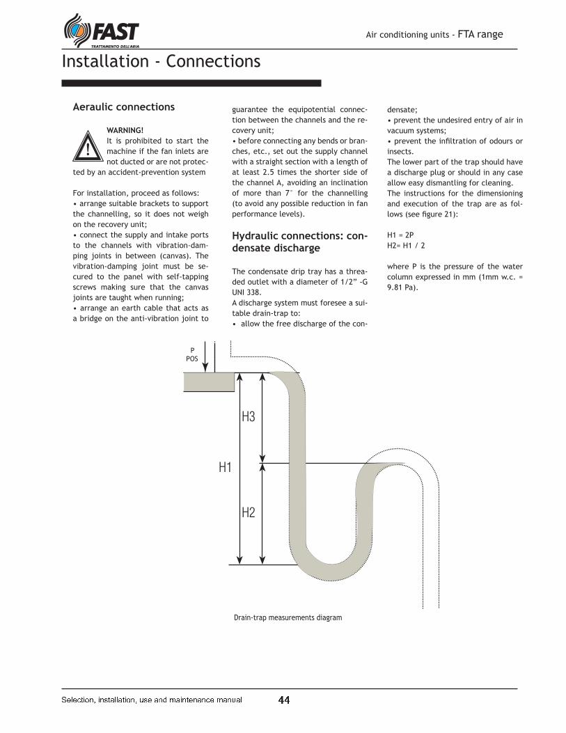
u u
Air conditioning units - FTA range
� � � � � � � � � � � ! � " � � " � � � � # ! � " � $ % " � � � � � " � � � % " � # " �
Installation - Connections
Aeraulic connections
WARNING!
It is prohibited to start the
machine if the fan inlets are
not ducted or are not protec-
ted by an accident-prevention system
For installation, proceed as follows:
• arrange suitable brackets to support
the channelling, so it does not weigh
on the recovery unit;
• connect the supply and intake ports
to the channels with vibration-dam-
ping joints in between (canvas). The
vibration-damping joint must be se-
cured to the panel with self-tapping
screws making sure that the canvas
joints are taught when running;
• arrange an earth cable that acts as
a bridge on the anti-vibration joint to
guarantee the equipotential connec-
tion between the channels and the re-
covery unit;
• before connecting any bends or bran-
ches, etc., set out the supply channel
with a straight section with a length of
at least 2.5 times the shorter side of
the channel A, avoiding an inclination
of more than 7° for the channelling
(to avoid any possible reduction in fan
performance levels).
Hydraulic connections: con-densate discharge
The condensate drip tray has a threa-
ded outlet with a diameter of 1/2” -G
UNI 338.
A discharge system must foresee a sui-
table drain-trap to:
• allow the free discharge of the con-
densate;
• prevent the undesired entry of air in
vacuum systems;
• prevent the infi ltration of odours or
insects.
The lower part of the trap should have
a discharge plug or should in any case
allow easy dismantling for cleaning.
The instructions for the dimensioning
and execution of the trap are as fol-
lows (see fi gure 21):
H1 = 2P
H2= H1 / 2
where P is the pressure of the water
column expressed in mm (1mm w.c. =
9.81 Pa).
Drain-trap measurements diagram
P
POS
u v
Water coil connection
All water coil manifolds have threaded
male connectors for the entrance and
exit of water.
For correct installation follow the simple
indications below:
• anti-freeze devices should be present
in the event of adverse weather condi-
tions;
• the course of the piping must be such
so as not to create obstacles in the event
the coil must be removed and so as not to
compromise inspection and maintenance
of the unit and possible accessories;
• when screwing together the manifolds
and hydraulic circuit, avoid stresses that
could damage the coil manifolds;
• provide a stop valve to isolate the coil
from the rest of the circuit in the even it
must be disconnected from the hydraulic
circuit;
• fi rmly clamp the pipes outside the unit,
to prevent them weighing on the coil;
• for the connection of water feed pipes,
follow the indications on the "WATER IN-
LET" and "WATER OUTLET" plate on the
outside panelling ;
• fi t an air bleed valve on the highest sec-
tion of the circuit and a water discharge
valve on the lowest section of the circuit;
• once the connections have been made,
position the external rubber seal fl ush
with the panelling to avoid air
seepage.
WARNING!
To avoid burns during the heating fun-
ction, the piping must be carefully insu-
lated with suitable material as far as the
panelling.
Connection of the direct ex-pansion coils
The coils are supplied with connections
hermetically sealed and pressurised with
inert gas.
For correct installation follow the simple
indications below:
• the course of the piping must be
such so as not to create obstacles if the
coil needs to be removed, and not to
compromise the inspection and mainte-
nance of the unit and any accessories;
• arrange suitable brackets to support
the piping so as to avoid that their weight
overloads the recovery unit;
• once the connections have been made,
position the external rubber seal fl ush
with the panelling to avoid air seepage;
• the performance of the coil declared
in the present manual could undergo
changes in the event that the connection
pipes to a condensing only unit cause ex-
cessive pressure drops of the refrigerant.
WARNING!
To avoid burns, the piping must be suita-
bly insulated with suitable material up to
the panelling.
Electrical connec-tions: earth system
WARNING!
The electrical connections and wiring
must be carried out by qualifi ed person-
nel in accordance with the
present laws.
WARNING!
Each electrical appliance must be con-
nected to the earth of the system.
Use the connectors with the earth symbol
to connect the earth of the unit and pos-
sible accessories to the earth of the bu-
ilding.
Mains power supply connection
WARNING!
Make sure that the characteristics of the
mains power supply are compatible with
the electrical characteristics indicated
on the machine's rating plate.
Electrical connec-tions: electric coils
WARNING!Make sure that the characteristics of the
mains power supply are compatible with
the electrical characteristics indicated
on the part's rating plates.
Carry out the following instructions for
the connection of the electric coil:
• prepare suitable protection upstream,
with a residual current circuit breaker
with overcurrent protection;
• always connect a safety thermostat
to guarantee the disconnection of the
electric coil power supply in the event of
overheating;
• the safety thermostat must be in se-
ries with the regulating thermostat (not
supplied);
• the power supply of the coil must be
slaved to the function of the fans;
• always connect the earth wire of the
electric heating coil to the terminal insi-
de the electric box.
The wiring diagrams are supplied along
with the machine.
Electrical connections: elec-tric motors
The correct connection of the electric
motors is made on the control boards
assembled inside the unit (for FTA sizes
09-11-15), or on the Archimedean screw
of one of the fans (for FTA units 19-24-
33-40-50).
For units with two motors, the power
supply and earth cables are on one con-
trol board for each fan.
Air conditioning units - FTA range
� � � � � � � � � � � ! � " � � " � � � � # ! � " � $ % " � � � � � " � � � % " � # " �
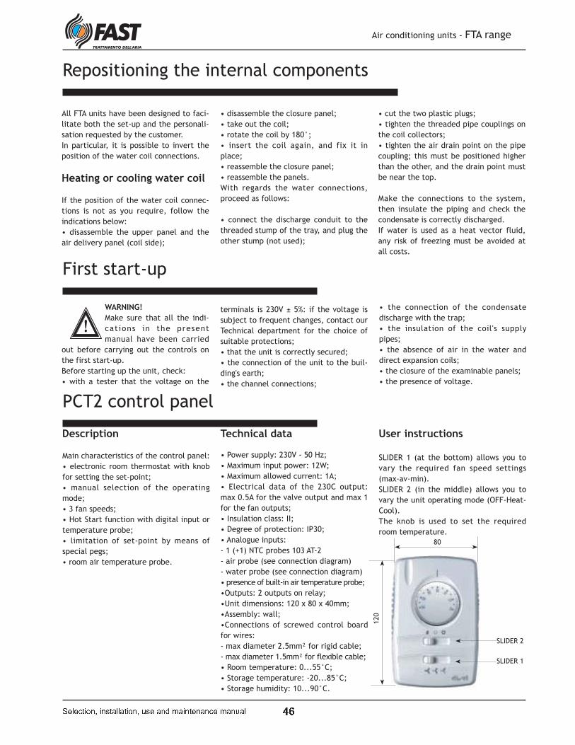
u w
Repositioning the internal components
Air conditioning units - FTA range
� � � � � � � � � � � ! � " � � " � � � � # ! � " � $ % " � � � � � " � � � % " � # " �
All FTA units have been designed to faci-
litate both the set-up and the personali-
sation requested by the customer.
In particular, it is possible to invert the
position of the water coil connections.
Heating or cooling water coil
If the position of the water coil connec-
tions is not as you require, follow the
indications below:
• disassemble the upper panel and the
air delivery panel (coil side);
First start-up
WARNING!
Make sure that all the indi-
cations in the present
manual have been carried
out before carrying out the controls on
the first start-up.
Before starting up the unit, check:
• with a tester that the voltage on the
PCT2 control panel
Description
Main characteristics of the control panel:
• electronic room thermostat with knob
for setting the set-point;
• manual selection of the operating
mode;
• 3 fan speeds;
• Hot Start function with digital input or
temperature probe;
• limitation of set-point by means of
special pegs;
• room air temperature probe.
Technical data
• Power supply: 230V - 50 Hz;
• Maximum input power: 12W;
• Maximum allowed current: 1A;
• Electrical data of the 230C output:
max 0.5A for the valve output and max 1
for the fan outputs;
• Insulation class: II;
• Degree of protection: IP30;
• Analogue inputs:
- 1 (+1) NTC probes 103 AT-2
- air probe (see connection diagram)
- water probe (see connection diagram)
• presence of built-in air temperature probe;
•Outputs: 2 outputs on relay;
•Unit dimensions: 120 x 80 x 40mm;
•Assembly: wall;
•Connections of screwed control board
for wires:
- max diameter 2.5mm² for rigid cable;
- max diameter 1.5mm² for flexible cable;
• Room temperature: 0...55°C;
• Storage temperature: -20...85°C;
• Storage humidity: 10...90°C.
User instructions
SLIDER 1 (at the bottom) allows you to
vary the required fan speed settings
(max-av-min).
SLIDER 2 (in the middle) allows you to
vary the unit operating mode (OFF-Heat-
Cool).
The knob is used to set the required
room temperature.
80
SLIDER 1
SLIDER 2
120
• disassemble the closure panel;
• take out the coil;
• rotate the coil by 180°;
• insert the coil again, and fix it in
place;
• reassemble the closure panel;
• reassemble the panels.
With regards the water connections,
proceed as follows:
• connect the discharge conduit to the
threaded stump of the tray, and plug the
other stump (not used);
• cut the two plastic plugs;
• tighten the threaded pipe couplings on
the coil collectors;
• tighten the air drain point on the pipe
coupling; this must be positioned higher
than the other, and the drain point must
be near the top.
Make the connections to the system,
then insulate the piping and check the
condensate is correctly discharged.
If water is used as a heat vector fluid,
any risk of freezing must be avoided at
all costs.
terminals is 230V ± 5%: if the voltage is
subject to frequent changes, contact our
Technical department for the choice of
suitable protections;
• that the unit is correctly secured;
• the connection of the unit to the buil-
ding's earth;
• the channel connections;
• the connection of the condensate
discharge with the trap;
• the insulation of the coil's supply
pipes;
• the absence of air in the water and
direct expansion coils;
• the closure of the examinable panels;
• the presence of voltage.

u x
Air conditioning units - FTA range
� � � � � � � � � � � ! � " � � " � � � � # ! � " � $ % " � � � � � " � � � % " � # " �
Union base unit with accessories
All base units are designed to provide
easy confi guration and customization
through modular accessories to meet fully
the needs of the customer.To ensure this,
have been developed of how to merge
standard to simplify the connection
between the base unit and accessories
or even across multiple accessories
and the unit itself. It comes complete
with all the accessories provided, a kit
assembly composed of screws and fl at
sealing adhesive to be applied on the
walls in contact in order to prevent air
leakage between one or more modules.
The mounting of accessories may be
executed either when the machine to
the ground (in the case where this is a
new installation) of that machine already
installed.
We will hereafter consider the case of
union of units on the ground:
1a) remove the inspection panel on the
bottom of the accessory in order to allow
access to the inside of the assembly
accessory - base unit or accessory -
accessory.
2a) apply the self-adhesive gasket,
supplied with, on the edges of the
accessory that will be connected in order
to prevent air leakage during operation.
3a) to bring the two modules and
screwing together the brackets (top,
bottom and sides) of the two modules
using the screws metric supplied.
4a) close the panel inspection accessory.
In the case in which the base unit is
already installed and it should proceed
with the installation of an accessory
in a second moment, it can act in the
following way:
1b) remove the inspection panel on the
bottom of the accessory in order to allow
access to the inside of the assembly
accessory - base unit or accessory -
accessory.
2b) apply the self-adhesive gasket,
supplied with, on the edges of the
accessory that will be connected in order
to prevent air leakage during operation.
3b) remove the bracket on the inside of
the upper long side of the accessory and
reinstall it from the outside of the same
side: fi xing is fi xing the screws from the
inside. Bring the two modules together
and screw the brackets top and sides of
the two modules using the metric screws
supplied.
4b) close the inspection of the accessory
panel and secure the lower bracket from
the outside.
1a
2a
1b
3b
Il metodo esposto si riferisce a tutte le tipologie di accessori anche se lo schema raffigura
il montaggio di un silenziatore SSL
3a
2b
u '
WARNING!
Use suitable personal protective equi-
pment (PPE) during maintenance ope-
rations
WARNING!
Before accessing the unit
for maintenance or clea-
ning operations, make sure the unit is
disconnected from the power supply,
that the supply can not be switched
on again without the maintenance
engineer's knowledge and that the
heat exchange coils are off.
WARNING!
Take particular care when
working close to finned
coils because the fins are particularly
sharp.
WARNING!
After finishing the main-
tenance operations, make
sure that the panelling is correctly
closed by means of fixing screws.
The units of the FTA range have been
designed to require less maintenance,
and to make each operation easier.
Below are some simple instructions
for correct maintenance of the unit.
The maintenance program must in
any case be carried out by a qualified
technician.
Routine maintenanceRoutine maintenance consists of sim-
ple operations that should be carried
out monthly, as follows:
- check the tightness of the fans fi xing
screws to the panels;
- check that the machine's power sup-
ply cable has not undergone any al-
terations that could compromise its
insulation;
- make sure that the screws that fi x
the wires to the electrical components
inside the electric panel are tight so
as to guarantee an electrical connec-
tion; the same also goes for the earth
connections.
Maintenance of the filters (if present)The cleaning of the filters is funda-
mental in order to maintain a high
qualitative standard of air in the
room. The synthetic filters fitted to
the FTA unit can be regenerated using
compressed air or by washing them
in cold water. To disassemble the fil-
ters, observe the following indica-
tions (see the figure below):
• remove the inspection panel with
knobs;
• remove the filters;
• clean the filters;
• reassemble all the components in
the reverse order.
Fan maintenance
It is essential to check and clean the
fans, to maintain the low noise level
of the unit. Check annually:
- the clean state of the impeller;
- the noise level of the bearings.
Coil maintenance
It is essential to check and clean the
coils, to maintain the high standard
of quality and renewal of fresh air in
the room.
Check annually:
- the clean state of the finned unit.
Unit maintenance
FTA
FLAT
FILTER
665 x 265
FLAT
FILTER
1015 x 265
FLAT
FILTER
1440 x 355
FLAT
FILTER
2065 x 355
09 1
11 1
15 1
19 1
24 1
33 1
40 1
50 1
FTA
FILTER
287 x 592
09 1
11 1
15 1
19 1
24 2
33 2
40 3
50 3
Dimensional table of filters used in the FTA units
Air conditioning units - FTA range
� � � � � � � � � � � ! � " � � " � � � � # ! � " � $ % " � � � � � " � � � % " � # " �
u O
Unit disposal
The components of the FTA range have
been designed to guarantee continual ope-
rations. The duration of some main parts
depends on the maintenance to which it
has undergone.
At the end of their useful life, the FTA
range units must be disposed of in accor-
dance with the current laws in force.
If the unit is to be disposed of, the opera-
tion must be carried out by speciali-
sed personnel.
The main materials that make up the
units of the FTA range are:
• galvanised steel (panels, fans, con-
densate drip tray);
• aluminium sheet or aluminium
alloy (coil fins, grilles, electric motor
frame);
• copper (coil pipes, winding of the
electric motors);
• polyurethane foam (sandwich panels
insulation).
PROBLEM CAUSE REMEDY
1. INSUFFICIENT
AIR FLOW RATE
1. Blocked filters - Clean the filters
2. Blocked coils - Clean the coils
3. NO AIR FLOW
RATE
1. Power supply off - Check the presence of power
2. Electric motor burnt out - Replace the electric motor
4. ABNORMAL
NOISE
1. Excessive flow rate - Reduce the flow rate
2. Fan bearings worn or defective - Replace bearings
3. Foreign bodies on the fans' impellers - Clean the impellers
4. MOISTURE
CARRYOVER
1. Drain-trap blocked - Clean drain-trap
2. No drain-trap or incorrectly made - Correctly prepare a drain-trap as
indicated in this manual
5. REQUIRED
TEMPERATURE NOT
ACHIEVED
1. Temperature of the inlet air on coil out-
side the envisaged limits - Check the water temperature
2. Air in the water coils - Bleed the coils
3. Insufficient water flow rate in the water
coils - Increase the water flow rate
4. Insufficient coil inlet water temperature - Check the water temperature
5. Dirty coil unit surface - Clean the surface of the pack
Diagnosis and fault solving
Air conditioning units - FTA range
� � � � � � � � � � � ! � " � � " � � � � # ! � " � $ % " � � � � � " � � � % " � # " �
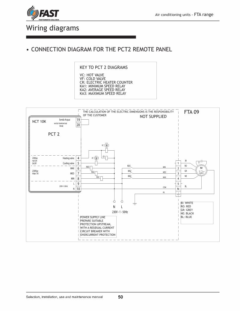
v Q
Air conditioning units - FTA range
� � � � � � � � � � � ! � " � � " � � � � # ! � " � $ % " � � � � � " � � � % " � # " �
Wiring diagrams
KEY TO PCT 2 DIAGRAMS
VC: HOT VALVE VF: COLD VALVE CR: ELECTRIC HEATER COUNTER KA1: MINIMUM SPEED RELAY KA2: AVERAGE SPEED RELAY KA3: MAXIMUM SPEED RELAY
• CONNECTION DIAGRAM FOR THE PCT2 REMOTE PANEL
M
1
230V-1-50Hz
ON/OFF
Heating valve
Sonda Acqua
Cooling valve
N
L
MAX
MED
PROBE
WATER TEMPERATURE
COM
PE
MIN
MAX
MED230Vacmax 1A
max 0,5A
MIN
230Vac
230V - 1 - 50Hz
VC
KA2
KA3
KA1
KA1
KA3
KA2
VFCR
C1
4
5
6
7
8
10
19
20
9
LN
5
1
2
3
4
N
BI
RO
NE
BL
GR
FTA 09THE CALCULATION OF THE ELECTRIC DIMENSIONS IS THE RESPONSIBILITY
OF THE CUSTOMER NOT SUPPLIED
POWER SUPPLY LINE
PREPARE SUITABLE
PROTECTION UPSTREAM,
WITH A RESIDUAL CURRENT
CIRCUIT BREAKER WITH
OVERCURRENT PROTECTION
BI: WHITE
RO: RED
GR: GREY
NE: BLACK
BL: BLUE
NCT 10K
PCT 2
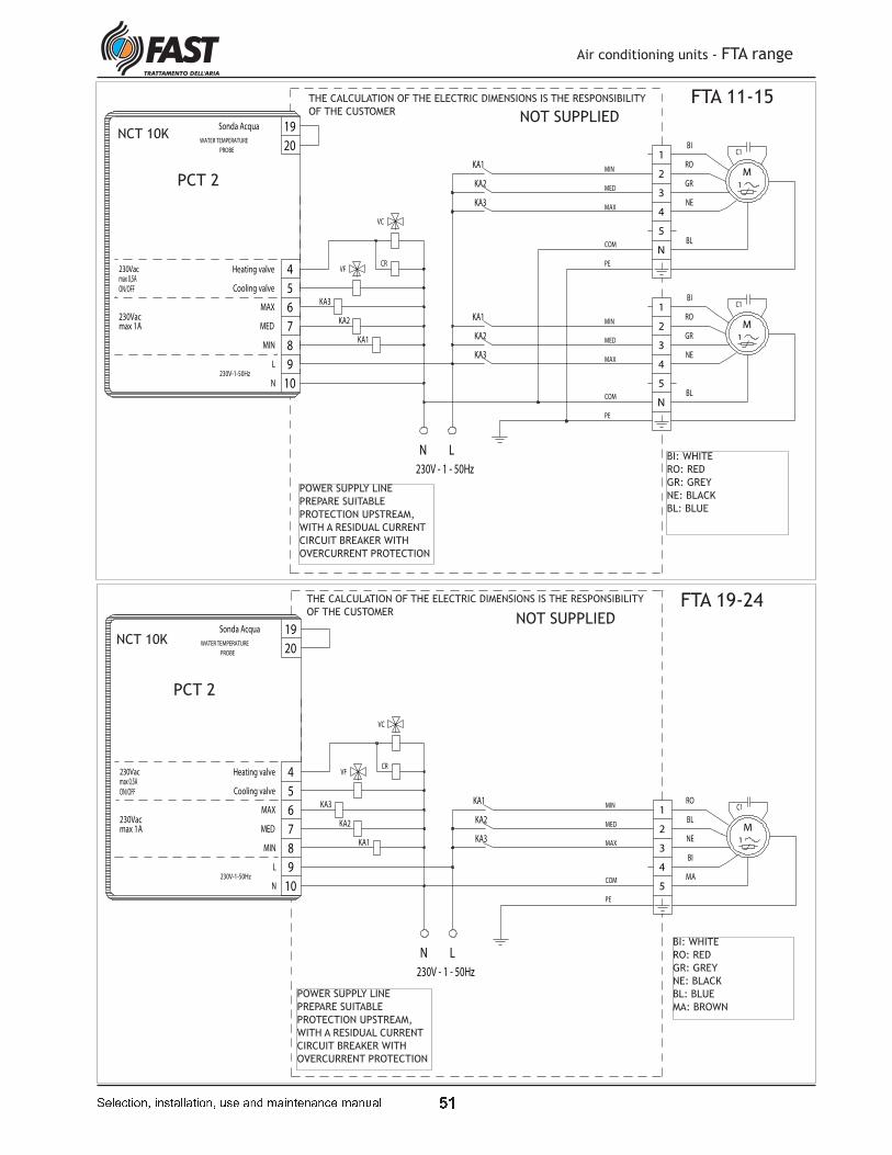
v &
Air conditioning units - FTA range
� � � � � � � � � � � ! � " � � " � � � � # ! � " � $ % " � � � � � " � � � % " � # " �
M
1
M
1
MIN
MAX
MED
230Vacmax 1A
max 0,5A
MIN
230V-1-50Hz
ON/OFF
COM
PE
MIN
MAX
MED
230Vac
230V - 1 - 50Hz
PE
COM
PROBE
WATER TEMPERATURE
MED
MAX
L
N
Cooling valve
Heating valve
Sonda Acqua
KA1
KA3
KA2
VC
KA2
KA3
KA1
KA1
KA3
KA2
VFCR
C1
C1
8
10
19
20
9
LN
7
6
5
4
5
1
2
3
4
N
BI
RO
NE
BL
GR
5
1
2
3
4
N
BI
RO
NE
BL
GR
FTA 11-15THE CALCULATION OF THE ELECTRIC DIMENSIONS IS THE RESPONSIBILITY
OF THE CUSTOMER NOT SUPPLIED
BI: WHITE
RO: RED
GR: GREY
NE: BLACK
BL: BLUE
POWER SUPPLY LINE
PREPARE SUITABLE
PROTECTION UPSTREAM,
WITH A RESIDUAL CURRENT
CIRCUIT BREAKER WITH
OVERCURRENT PROTECTION
PCT 2
NCT 10K
M
1
COM
PE
ON/OFF
230V-1-50Hz
MED
MAX
MIN
PROBE
WATER TEMPERATURE
MED
MAX
L
N
Cooling valve
Heating valve
Sonda Acqua
230V - 1 - 50Hz
230Vacmax 1A
max 0,5A
MIN
230Vac
C1
CRVF
KA2
KA3
KA1
KA2
KA3
KA1
VC
MA
BL
NE
RO
BI
1
2
3
4
5
4
5
6
7
8
10
19
20
9
LN
THE CALCULATION OF THE ELECTRIC DIMENSIONS IS THE RESPONSIBILITY
OF THE CUSTOMERNOT SUPPLIED
FTA 19-24
POWER SUPPLY LINE
PREPARE SUITABLE
PROTECTION UPSTREAM,
WITH A RESIDUAL CURRENT
CIRCUIT BREAKER WITH
OVERCURRENT PROTECTION
BI: WHITE
RO: RED
GR: GREY
NE: BLACK
BL: BLUE
MA: BROWN
PCT 2
NCT 10K

y z
Air conditioning units - FTA range
{ | } | ~ � � � � � � � � � � } } � � � � � � � � | � � � � � � � � | � � � ~ | � � � � � }
M
1
M
1
PE
COM
MIN
MAX
MED
COM
PE
MED
MAX
MIN
ON/OFF
230V-1-50Hz
230V - 1 - 50Hz
PROBE
WATER TEMPERATURE
MED
MAX
L
N
Cooling valve
Heating valve
Sonda Acqua
230Vac
MIN
max 0,5A
max 1A230Vac
C1
KA1
KA3
KA2
C1
CRVF
KA2
KA3
KA1
KA2
KA3
KA1
VC
MA
BL
NE
RO
BI8
1
2
3
4
5
10
BI
RO
NE
BL
MA
1
2
3
4
5
4
5
6
7
N L
9
20
19
THE CALCULATION OF THE ELECTRIC DIMENSIONS IS THE RESPONSIBILITY
OF THE CUSTOMER
FTA 33-40
BI: WHITE
RO: RED
GR: GREY
NE: BLACK
BL: BLUE
MA: BROWN
NOT SUPPLIED
POWER SUPPLY LINE
PREPARE SUITABLE
PROTECTION UPSTREAM,
WITH A RESIDUAL CURRENT
CIRCUIT BREAKER WITH
OVERCURRENT PROTECTION
PCT 2
NCT 10K
M
1
M
1
PE
COM
MIN
MAX
MED
COM
PE
MINMED
MAX
230VacMIN
max 1A
max 0,5AON/OFF
230V-1-50Hz
230V - 1 - 50Hz
PROBE
WATER TEMPERATURE
MED
MAX
L
N
Cooling valve
Heating valve
Sonda Acqua
230Vac
C1
KA1
KA3
KA2
VC
KA1
KA3
CRVF
KA2
KA3
KA1 KA2
C1
MA
BL
NE
RO
BI
8
6
19
20
10
9
LN
1
2
3
4
5
4
5
6
7
MA
BL
NE
RO
BI
6
1
2
3
4
5
NCT 10K
PCT 2
THE CALCULATION OF THE ELECTRIC DIMENSIONS IS THE RESPONSIBILITY
OF THE CUSTOMER NOT SUPPLIED
BI: WHITE
RO: RED
GR: GREY
NE: BLACK
BL: BLUE
MA: BROWN
POWER SUPPLY LINE
PREPARE SUITABLE
PROTECTION UPSTREAM,
WITH A RESIDUAL CURRENT
CIRCUIT BREAKER WITH
OVERCURRENT PROTECTION
FTA 50

y �
KEY:
CR: ELECTRIC HEATER COUNTERRE: ELECTRIC HEATERSTS: AUTOMATIC THERMOSTATTSM: MANUAL THERMOSTAT
Air conditioning units - FTA range
{ | } | ~ � � � � � � � � � � } } � � � � � � � � | � � � � � � � � | � � � ~ | � � � � � }
TMIN
230Vacmax 0,5A
NOT SUPPLIEDNON FORNITA
max 1A230Vac
Sonda Acqua
Heating valve
Cooling valve
N
L
MAX
MED
PROBE
WATER TEMPERATURE
230V-1-50Hz
ON/OFF
Sonda Acqua
Heating valve
Cooling valve
N
L
MAX
MED
PROBE
WATER TEMPERATURE
230V-1-50Hz
ON/OFF
230Vacmax 1A
max 0,5A230Vac
MIN
BRIDGEPONTE
6
5
7
9
20
19
10
8
7
6
5
4 4
8
10
H2
O19
20
9
WITH WATER PROBE WITHOUT WATER PROBE
PCT 2 PCT 2
NCT 10K NCT 10K
ΘΘ
C° 001C° 09
40
0V
- 3
- 5
0H
z4
00
V -
3 -
50
Hz
NON FORNITI
TSMTS
RE
CR
A2 A1
RE
CR
A2 A1
W1
V1
U1
1N
W2
V2
U2
2
N
4
POWER SUPPLY LINE
PREPARE SUITABLE
PROTECTION UPSTREAM,
WITH A RESIDUAL CURRENT
CIRCUIT BREAKER WITH
OVERCURRENT PROTECTION
FSS 210
FSS 210
• CONNECTION DIAGRAM FOR THE ELECTRIC COILS

y �
• CONNECTION DIAGRAM FOR THE PX REMOTE PANEL
M
1
4 3 2 1
cd
MAX
MIN
PE
230V - 1 - 50Hz
MED
COM
C1
L
N
5
1
2
3
4
N
BI
RO
NE
BL
GR
Air conditioning units - FTA range
{ | } | ~ � � � � � � � � � � } } � � � � � � � � | � � � � � � � � | � � � ~ | � � � � � }
POWER SUPPLY LINE
PREPARE SUITABLE
PROTECTION UPSTREAM,
WITH A RESIDUAL CURRENT
CIRCUIT BREAKER WITH
OVERCURRENT PROTECTION
FTA 09
PXBI: WHITE
RO: RED
GR: GREY
NE: BLACK
BL: BLUE
M
1
M
1
1234
230V - 1 - 50Hz
cd
MIN
MAX
MED
COM
PE
MIN
MAX
MED
PE
COM
KA3
KA1
KA2
KA1
KA3
KA2
KA2
KA3
KA1
C1
C1
N
L
GR
5
1
2
3
4
N
BI
RO
NE
BL
GR
5
1
2
3
4
N
BI
RO
NE
BLPX
POWER SUPPLY LINE
PREPARE SUITABLE
PROTECTION UPSTREAM,
WITH A RESIDUAL CURRENT
CIRCUIT BREAKER WITH
OVERCURRENT PROTECTION
FTA 11-15 BI: WHITE
RO: RED
GR: GREY
NE: BLACK
BL: BLUE
THE CALCULATION OF THE ELECTRIC DIMENSIONS IS THE RESPONSIBILITY OF THE CUSTOMER
NOT SUPPLIED
THE CALCULATION OF THE ELECTRIC DIMENSIONS IS THE RESPONSIBILITY OF THE CUSTOMER

� �
Air conditioning units - FTA range
� � � � � � � � � � � � � � � � � � � � � � � � � � � � � � � � � � � � � � � � � � � � � �
M
1MAX
MIN
PE
COM
4 3 2 1
cd
230V - 1 - 50Hz
MED
C1
MA
BL
NE
RO
BI
1
2
3
4
5
L
N
FTA 19-24
POWER SUPPLY LINE
PREPARE SUITABLE
PROTECTION UPSTREAM,
WITH A RESIDUAL CURRENT
CIRCUIT BREAKER WITH
OVERCURRENT PROTECTION
BI: WHITE
RO: RED
GR: GREY
NE: BLACK
BL: BLUE
MA: BROWN
PX
NOT SUPPLIED
THE CALCULATION OF THE ELECTRIC DIMENSIONS IS THE RESPONSIBILITY OF THE CUSTOMER
M
1
M
1
MIN
MAX
MED
COM
PE
MIN
MAX
MED
d c
230V - 1 - 50Hz
PE
COM
4 3 2 1
C1
C1KA1
KA3
KA2
KA2
KA3
KA1
KA2
KA1
KA3
MA
BL
NE
RO
BI
5
4
3
2
1
MA
1
2
3
BL
NE
4
5
RO
BI
N
L
FTA 33-40 BI: WHITE
RO: RED
GR: GREY
NE: BLACK
BL: BLUE
MA: BROWN
PX
POWER SUPPLY LINE
PREPARE SUITABLE
PROTECTION UPSTREAM,
WITH A RESIDUAL CURRENT
CIRCUIT BREAKER WITH
OVERCURRENT PROTECTION
NOT SUPPLIED
THE CALCULATION OF THE ELECTRIC DIMENSIONS IS THE RESPONSIBILITY OF THE CUSTOMER
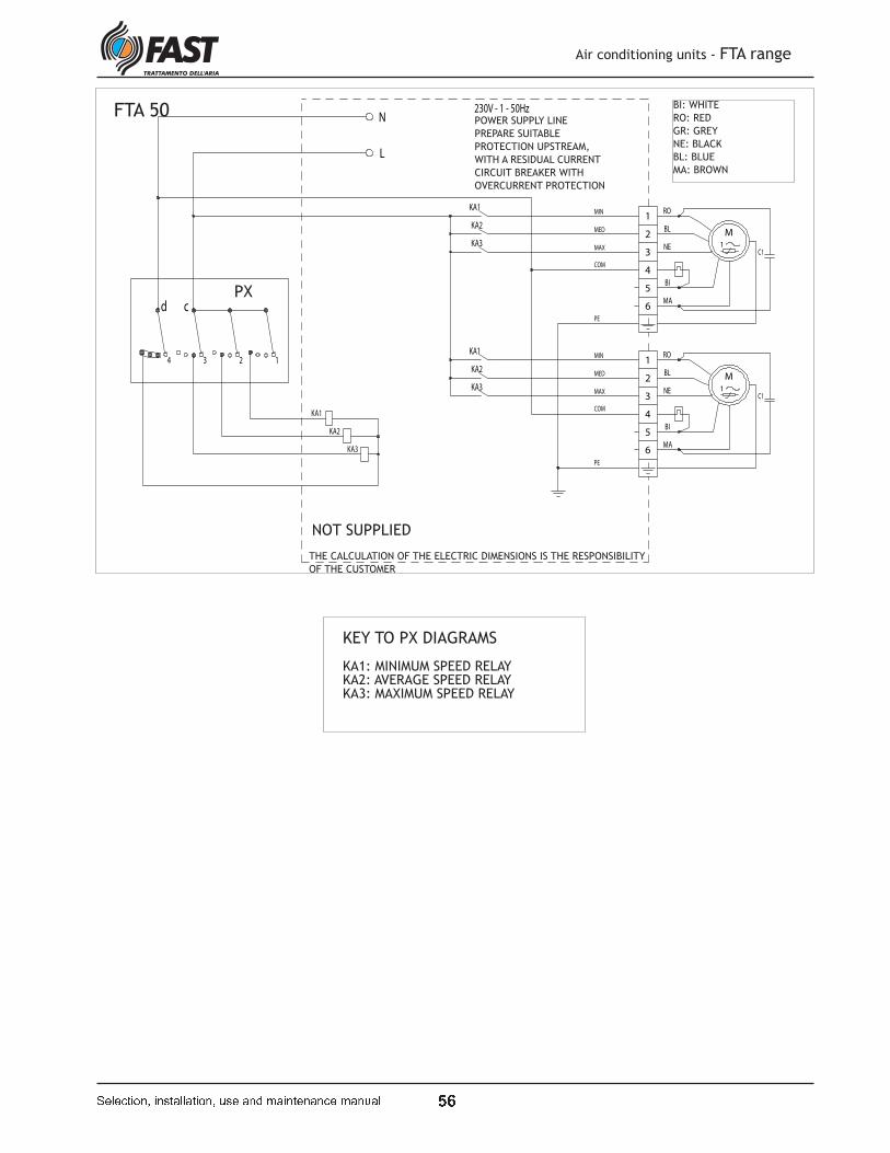
� �
M
1
M
1
1234
COM
PE
230V - 1 - 50Hz
cd
MIN
MAX
MED
COM
PE
MIN
MAX
MED
KA3
KA1
KA2
KA1
KA3
KA2
KA2
KA3
KA1
C1
C1
L
N
MA
BL
NE
RO
BI
6
1
2
3
4
5
MA
BL
NE
RO
BI
6
1
2
3
4
5
Air conditioning units - FTA range
� � � � � � � � � � � � � � � � � � � � � � � � � � � � � � � � � � � � � � � � � � � � � �
PX
FTA 50POWER SUPPLY LINE
PREPARE SUITABLE
PROTECTION UPSTREAM,
WITH A RESIDUAL CURRENT
CIRCUIT BREAKER WITH
OVERCURRENT PROTECTION
BI: WHITE
RO: RED
GR: GREY
NE: BLACK
BL: BLUE
MA: BROWN
NOT SUPPLIED
THE CALCULATION OF THE ELECTRIC DIMENSIONS IS THE RESPONSIBILITY
OF THE CUSTOMER
KEY TO PX DIAGRAMS
KA1: MINIMUM SPEED RELAY KA2: AVERAGE SPEED RELAY KA3: MAXIMUM SPEED RELAY

� �
Size data
Unit dimensions (mm)
A
B
C
Mod. A B C D
FTA 09 - FTA 11 700 300 700 82
FTA 15 700 300 1050 82
FTA 19 850 390 1050 82
FTA 24 - FTA 33 850 390 1475 82
FTA 40 - FTA 50 1000 390 2100 82
D
Mod. A B C D E G N. Ventilator
FTA 09 700 840 300 732 655 70 1
FTA 11 700 840 300 732 655 70 2
FTA 15 1050 840 300 1082 655 70 2
FTA 19 1050 1090 390 1082 905 70 1
FTA 24 1475 1090 390 1507 905 70 1
FTA 33 1475 1090 390 1507 905 70 2
FTA 40 2099 1090 390 2131 905 70 2
FTA 50 2099 1090 390 2131 905 70 2
A
36,5°
C
B
D
GE
G
Air conditioning units - FTA range
� � � � � � � � � � � � � � � � � � � � � � � � � � � � � � � � � � � � � � � � � � � � � �
Orizzontal version
Vertical version
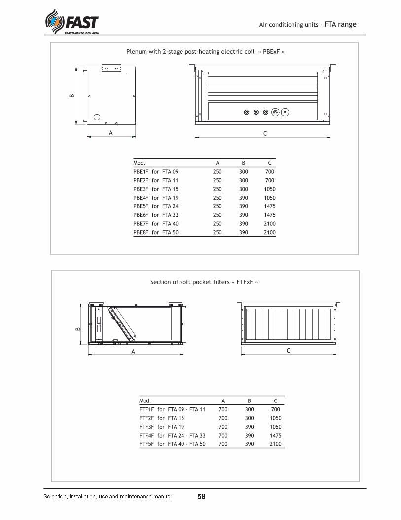
� �
Plenum with 2-stage post-heating electric coil « PBExF »
Mod. A B C
PBE1F for FTA 09 250 300 700
PBE2F for FTA 11 250 300 700
PBE3F for FTA 15 250 300 1050
PBE4F for FTA 19 250 390 1050
PBE5F for FTA 24 250 390 1475
PBE6F for FTA 33 250 390 1475
PBE7F for FTA 40 250 390 2100
PBE8F for FTA 50 250 390 2100
A
B
C
Section of soft pocket filters « FTFxF »
Mod. A B C
FTF1F for FTA 09 - FTA 11 700 300 700
FTF2F for FTA 15 700 300 1050
FTF3F for FTA 19 700 390 1050
FTF4F for FTA 24 - FTA 33 700 390 1475
FTF5F for FTA 40 - FTA 50 700 390 2100
A
B
C
Air conditioning units - FTA range
� � � � � � � � � � � � � � � � � � � � � � � � � � � � � � � � � � � � � � � � � � � � � �

� �
Supply grille « GMDxF »
A
B
CD
E
Mod. A B C D E
GMD1F for FTA 09 - FTA 11 700 640 300 240 45
GMD2F for FTA 15 1050 990 300 240 45
GMD3F for FTA 19 1050 990 390 330 45
GMD4F for FTA 24 - FTA 33 1475 1415 390 330 45
GMD5F for FTA 40 - FTA 50 2100 2040 390 330 45
Mod. A B C D E
GAP1F for FTA 09 - FTA 11 700 640 293 240 48
GAP2F for FTA 15 1050 990 300 240 45
GAP3F for FTA 19 1050 990 390 330 45
GAP4F for FTA 24 - FTA 33 1475 1415 390 330 45
GAP5F for FTA 40 - FTA 50 2100 2040 390 330 45
Intake grille « GAPxF »
A
B
C D
E
Air conditioning units - FTA range
� � � � � � � � � � � � � � � � � � � � � � � � � � � � � � � � � � � � � � � � � � � � � �
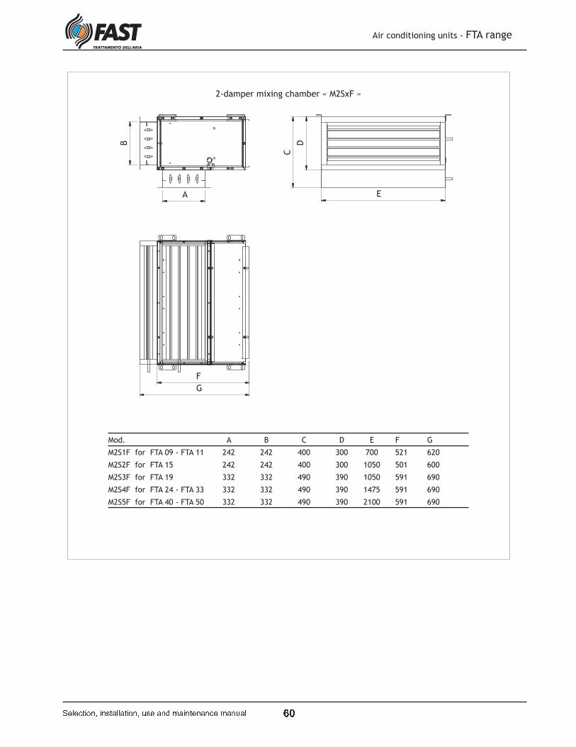
� �
2-damper mixing chamber « M2SxF »
Mod. A B C D E F G
M2S1F for FTA 09 - FTA 11 242 242 400 300 700 521 620
M2S2F for FTA 15 242 242 400 300 1050 501 600
M2S3F for FTA 19 332 332 490 390 1050 591 690
M2S4F for FTA 24 - FTA 33 332 332 490 390 1475 591 690
M2S5F for FTA 40 - FTA 50 332 332 490 390 2100 591 690
G
E
F
A
D
C
B
Air conditioning units - FTA range
� � � � � � � � � � � � � � � � � � � � � � � � � � � � � � � � � � � � � � � � � � � � � �

� �
3-damper mixing chamber « M3SxF »
AB
C D
E
Mod. A B C D E
M3S1F for FTA 09 - FTA 11 700 400 300 200 700
M3S2F for FTA 15 700 400 300 200 1050
M3S3F for FTA 19 850 500 390 300 1050
M3S4F for FTA 24 - FTA 33 1142 770 390 300 2100
M3S5F for FTA 40 - FTA 50 1142 770 390 300 2100
Air conditioning units - FTA range
� � � � � � � � � � � � � � � � � � � � � � � � � � � � � � � � � � � � � � � � � � � � � �
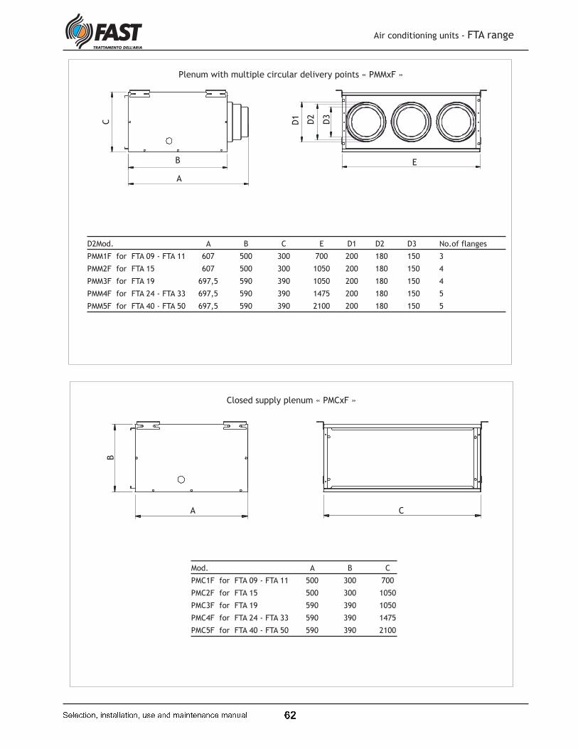
�
Plenum with multiple circular delivery points « PMMxF »
D2Mod. A B C E D1 D2 D3 No.of flanges
PMM1F for FTA 09 - FTA 11 607 500 300 700 200 180 150 3
PMM2F for FTA 15 607 500 300 1050 200 180 150 4
PMM3F for FTA 19 697,5 590 390 1050 200 180 150 4
PMM4F for FTA 24 - FTA 33 697,5 590 390 1475 200 180 150 5
PMM5F for FTA 40 - FTA 50 697,5 590 390 2100 200 180 150 5
A
B
C
E
D2
D3
D1
Closed supply plenum « PMCxF »
Mod. A B C
PMC1F for FTA 09 - FTA 11 500 300 700
PMC2F for FTA 15 500 300 1050
PMC3F for FTA 19 590 390 1050
PMC4F for FTA 24 - FTA 33 590 390 1475
PMC5F for FTA 40 - FTA 50 590 390 2100
A
B
C
Air conditioning units - FTA range
� � � � � � � � � � � � � � � � � � � � � � � � � � � � � � � � � � � � � � � � � � � � � �
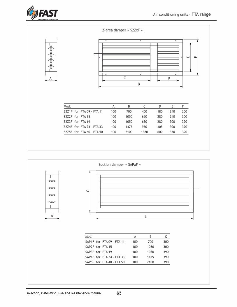
� ¡
Suction damper « SAPxF »
A B
C
Mod. A B C
SAP1F for FTA 09 - FTA 11 100 700 300
SAP2F for FTA 15 100 1050 300
SAP3F for FTA 19 100 1050 390
SAP4F for FTA 24 - FTA 33 100 1475 390
SAP5F for FTA 40 - FTA 50 100 2100 390
2-area damper « S2ZxF »
Mod. A B C D E F
S2Z1F for FTA 09 - FTA 11 100 700 400 180 240 300
S2Z2F for FTA 15 100 1050 650 280 240 300
S2Z3F for FTA 19 100 1050 650 280 300 390
S2Z4F for FTA 24 - FTA 33 100 1475 950 405 300 390
S2Z5F for FTA 40 - FTA 50 100 2100 1380 600 330 390
A
B
C D
E F
Air conditioning units - FTA range
� � � � � � � � � � � � � � � � � � � � � � � � � � � � � � � � � � � � � � � � � � � � � �
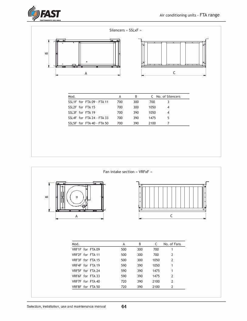
� ¢
Silencers « SSLxF »
Mod. A B C No. of Silencers
SSL1F for FTA 09 - FTA 11 700 300 700 3
SSL2F for FTA 15 700 300 1050 4
SSL3F for FTA 19 700 390 1050 4
SSL4F for FTA 24 - FTA 33 700 390 1475 5
SSL5F for FTA 40 - FTA 50 700 390 2100 7
A
B
C
Fan intake section « VRFxF »
A
B
C
Mod. A B C No. of Fans
VRF1F for FTA 09 500 300 700 1
VRF2F for FTA 11 500 300 700 2
VRF3F for FTA 15 500 300 1050 2
VRF4F for FTA 19 590 390 1050 1
VRF5F for FTA 24 590 390 1475 1
VRF6F for FTA 33 590 390 1475 2
VRF7F for FTA 40 720 390 2100 2
VRF8F for FTA 50 720 390 2100 2
Air conditioning units - FTA range
� � � � � � � � � � � � � � � � � � � � � � � � � � � � � � � � � � � � � � � � � � � � � �
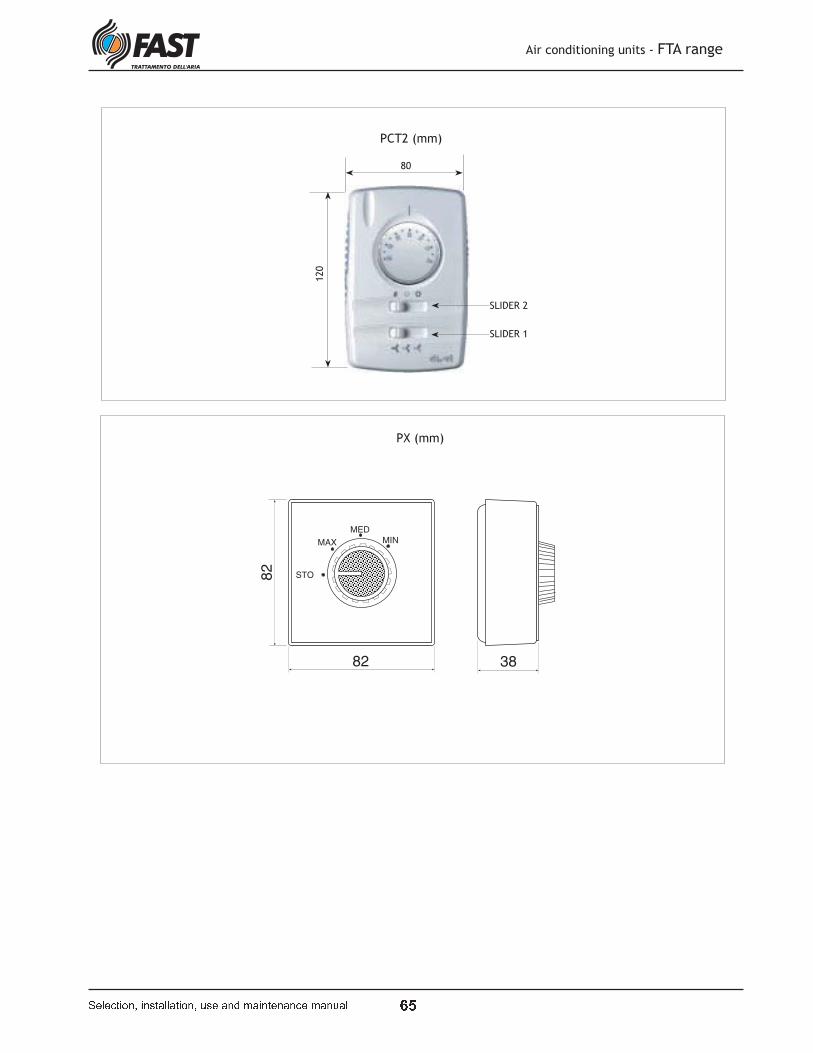
� �
PCT2 (mm)
Air conditioning units - FTA range
� � � � � � � � � � � � � � � � � � � � � � � � � � � � � � � � � � � � � � � � � � � � � �
SLIDER 1
SLIDER 2
STO
MAX
MED
MIN
82
82 38
PX (mm)
120
80


The technical data given in this booklet are not binding. FAST S.p.A. reserves the right to introduce at any time whatever modifications are deemed necessary for product improvement.
£ ¤ ¥ ¦ ¤ § ¨ © ª ¥ « ¬ ® ¥ © ¬ ¯ ° ¯ § ¬ ¨ ¤ ¨ ¬ © ±
FAST S.p.A. AIR TREATMENT35044 Montagnana (PD) - ItalyVia Luppia Alberi, 170Tel. (+39) 0429 806311 - Fax 0429 806340E-mail: [email protected]://www.fastaer.com
²³́µ ¶³́·² ¸·́ ¶¹º» ¼²³