Embed Size (px)
DESCRIPTION
thermal
Citation preview
Chapter 15 Flow Over Bodies: Drag and Lift
Flow over Flat Plates
15-43C The fluid viscosity is responsible for the development of the velocity boundary layer. For the idealized inviscid fluids (fluids with zero viscosity), there will be no velocity boundary layer.
15-44C The friction coefficient represents the resistance to fluid flow over a flat plate. It is proportional to the drag force acting on the plate. The drag coefficient for a flat surface is equivalent to the mean friction coefficient.
15-45C The friction coefficient will change with position in laminar flow over a flat plate (it will decrease along the plate in the flow direction).
15-46C The average friction coefficient in flow over a flat plate is determined by integrating the local friction coefficient over the entire plate, and then dividing it by the length of the plate. Or, it can be determined experimentally by measuring the drag force, and dividing it by the dynamic pressure.
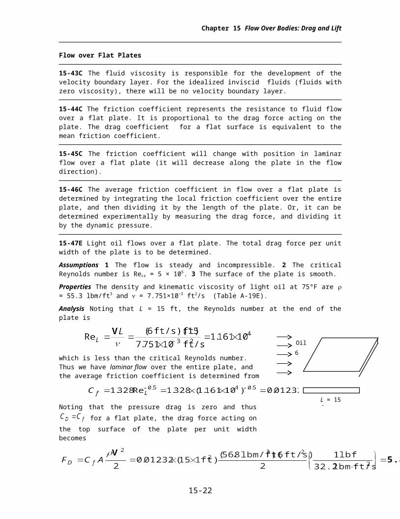
15-47E Light oil flows over a flat plate. The total drag force per unit width of the plate is to be determined.
Assumptions 1 The flow is steady and incompressible. 2 The critical Reynolds number is Recr = 5 × 10⁵. 3 The surface of the plate is smooth.
Properties The density and kinematic viscosity of light oil at 75°F are = 55.3 lbm/ft3 and = 7.751×10⁻³
ft2/s (Table A-19E).
Analysis Noting that L = 15 ft, the Reynolds number at the end of the plate is
which is less than the critical Reynolds number. Thus we have laminar flow over the entire plate, and the average friction coefficient is determined from
Noting that the pressure drag is zero and thus for a flat plate, the drag force acting on the top surface of the plate per unit width becomes
The total drag force acting on the entire plate can be determined by multiplying the value obtained above by the width of the plate.
Discussion The force per unit width corresponds to the weight of a mass of 5.87 lbm. Therefore, a person who applies an equal and opposite force to the plate to keep it from moving will feel like he or she is using as much force as is necessary to hold a 5.87 lbm mass from dropping.
15-22
6 ft/s
Oil
L = 15 ft
Chapter 15 Flow Over Bodies: Drag and Lift
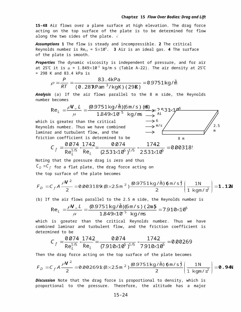
15-48 Air flows over a plane surface at high elevation. The drag force acting on the top surface of the plate is to be determined for flow along the two sides of the plate.
Assumptions 1 The flow is steady and incompressible. 2 The critical Reynolds number is Recr = 5105. 3 Air is an ideal gas. 4 The surface of the plate is smooth.
Properties The dynamic viscosity is independent of pressure, and for air at 25C it is = 1.84910-5
kg/ms (Table A-22). The air density at 25C = 298 K and 83.4 kPa is
Analysis (a) If the air flows parallel to the 8 m side, the Reynolds number becomes
which is greater than the critical Reynolds number. Thus we have combined laminar and turbulent flow, and the friction coefficient is determined to be
Noting that the pressure drag is zero and thus for a flat plate, the drag force acting on the top surface of the plate becomes
(b) If the air flows parallel to the 2.5 m side, the Reynolds number is
which is greater than the critical Reynolds number. Thus we have combined laminar and turbulent flow, and the friction coefficient is determined to be
Then the drag force acting on the top surface of the plate becomes
Discussion Note that the drag force is proportional to density, which is proportional to the pressure. Therefore, the altitude has a major influence on the drag force acting on a surface. Commercial airplanes take advantage of this phenomenon and cruise at high altitudes where the air density is much lower to save fuel.
15-23
Air
6 m/s
8 m
2.5 m
Chapter 15 Flow Over Bodies: Drag and Lift
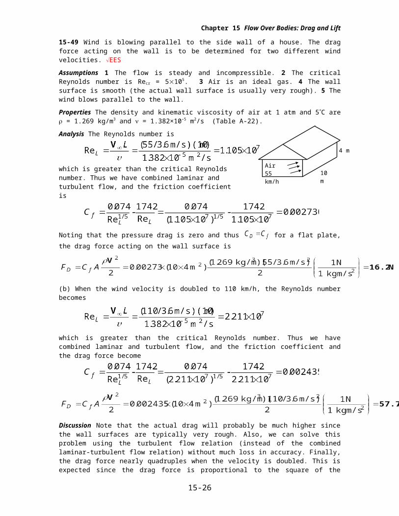
15-49 Wind is blowing parallel to the side wall of a house. The drag force acting on the wall is to be determined for two different wind velocities. EES
Assumptions 1 The flow is steady and incompressible. 2 The critical Reynolds number is Recr = 5105. 3 Air is an ideal gas. 4 The wall surface is smooth (the actual wall surface is usually very rough). 5 The wind blows parallel to the wall.
Properties The density and kinematic viscosity of air at 1 atm and 5C are = 1.269 kg/m3 and = 1.382×10⁻⁵ m2/s (Table A-22).
Analysis The Reynolds number is
which is greater than the critical Reynolds number. Thus we have combined laminar and turbulent flow, and the friction coefficient is
Noting that the pressure drag is zero and thus for a flat plate, the drag force acting on the wall surface is
(b) When the wind velocity is doubled to 110 km/h, the Reynolds number becomes
which is greater than the critical Reynolds number. Thus we have combined laminar and turbulent flow, and the friction coefficient and the drag force become
Discussion Note that the actual drag will probably be much higher since the wall surfaces are typically very rough. Also, we can solve this problem using the turbulent flow relation (instead of the combined laminar-turbulent flow relation) without much loss in accuracy. Finally, the drag force nearly quadruples when the velocity is doubled. This is expected since the drag force is proportional to the square of the velocity, and the effect of velocity on the friction coefficient is small.
15-24
10 m
4 m
Air55 km/h
Chapter 15 Flow Over Bodies: Drag and Lift
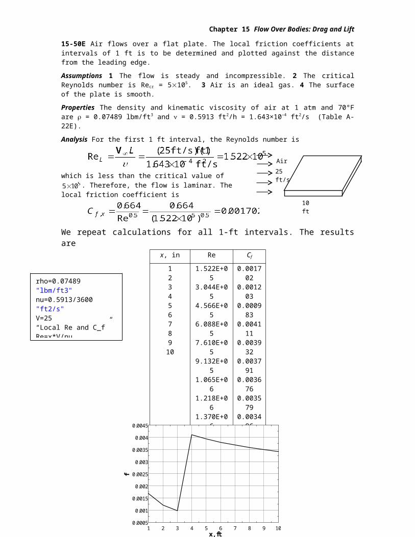
15-50E Air flows over a flat plate. The local friction coefficients at intervals of 1 ft is to be determined and plotted against the distance from the leading edge.
Assumptions 1 The flow is steady and incompressible. 2 The critical Reynolds number is Recr = 5105. 3 Air is an ideal gas. 4 The surface of the plate is smooth.
Properties The density and kinematic viscosity of air at 1 atm and 70°F are = 0.07489 lbm/ft3 and = 0.5913 ft2/h = 1.643×10⁻⁴ ft2/s (Table A-22E).
Analysis For the first 1 ft interval, the Reynolds number is
which is less than the critical value of . Therefore, the flow is laminar. The local friction coefficient is
We repeat calculations for all 1-ft intervals. The results are x, in Re Cf
12345678910
1.522E+053.044E+054.566E+056.088E+057.610E+059.132E+051.065E+061.218E+061.370E+061.522E+06
0.0017020.0012030.0009830.0041110.0039320.0037910.0036760.0035790.0034960.003423
Discussion Note that the Reynolds number exceeds the critical value for x > 3 ft, and thus the flow is
turbulent over most of the plate. For x > 3 ft, we used for friction
coefficient. Note that Cf decreases with Re in both laminar and turbulent flows.
15-25
25 ft/s
Air
10 ft
rho=0.07489 "lbm/ft3"nu=0.5913/3600 "ft2/s"V=25 “Local Re and C_f”Re=x*V/nu"f=0.664/Re^0.5"f=0.059/Re^0.2
1 2 3 4 5 6 7 8 9 100.0005
0.001
0.0015
0.002
0.0025
0.003
0.0035
0.004
0.0045
x, ft
f
Chapter 15 Flow Over Bodies: Drag and Lift
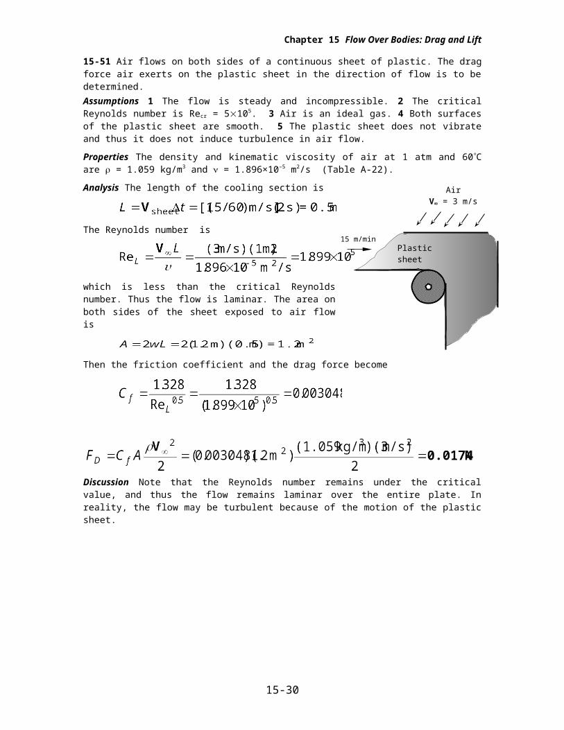
15-51 Air flows on both sides of a continuous sheet of plastic. The drag force air exerts on the plastic sheet in the direction of flow is to be determined.Assumptions 1 The flow is steady and incompressible. 2 The critical Reynolds number is Recr = 5105. 3 Air is an ideal gas. 4 Both surfaces of the plastic sheet are smooth. 5 The plastic sheet does not vibrate and thus it does not induce turbulence in air flow.
Properties The density and kinematic viscosity of air at 1 atm and 60C are = 1.059 kg/m3 and = 1.896×10⁻⁵ m2/s (Table A-22).
Analysis The length of the cooling section is
The Reynolds number is
which is less than the critical Reynolds number. Thus the flow is laminar. The area on both sides of the sheet exposed to air flow is
Then the friction coefficient and the drag force become
Discussion Note that the Reynolds number remains under the critical value, and thus the flow remains laminar over the entire plate. In reality, the flow may be turbulent because of the motion of the plastic sheet.
15-26
Plastic sheet
AirV = 3 m/s
15 m/min
Chapter 15 Flow Over Bodies: Drag and Lift
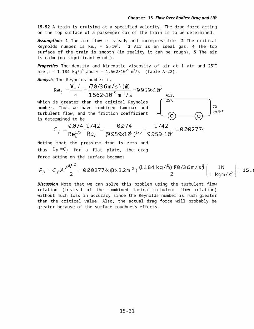
15-52 A train is cruising at a specified velocity. The drag force acting on the top surface of a passenger car of the train is to be determined.
Assumptions 1 The air flow is steady and incompressible. 2 The critical Reynolds number is Recr = 5105. 3 Air is an ideal gas. 4 The top surface of the train is smooth (in reality it can be rough). 5 The air is calm (no significant winds).
Properties The density and kinematic viscosity of air at 1 atm and 25C are = 1.184 kg/m3 and = 1.562×10⁻⁵ m2/s (Table A-22).
Analysis The Reynolds number is
which is greater than the critical Reynolds number. Thus we have combined laminar and turbulent flow, and the friction coefficient is determined to be
Noting that the pressure drag is zero and thus for a flat plate, the drag force acting on the surface becomes
Discussion Note that we can solve this problem using the turbulent flow relation (instead of the combined laminar-turbulent flow relation) without much loss in accuracy since the Reynolds number is much greater than the critical value. Also, the actual drag force will probably be greater because of the surface roughness effects.
15-27
70 km/h
Air, 25C
Chapter 15 Flow Over Bodies: Drag and Lift
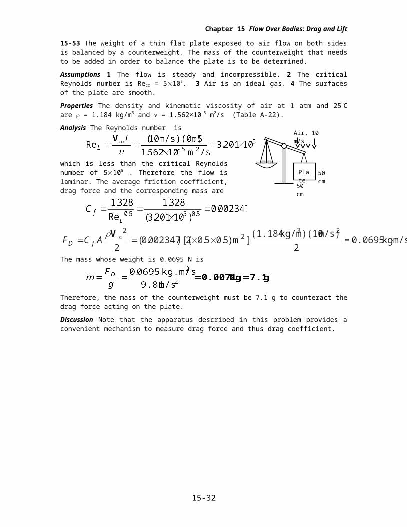
15-53 The weight of a thin flat plate exposed to air flow on both sides is balanced by a counterweight. The mass of the counterweight that needs to be added in order to balance the plate is to be determined.
Assumptions 1 The flow is steady and incompressible. 2 The critical Reynolds number is Recr = 5105. 3 Air is an ideal gas. 4 The surfaces of the plate are smooth.
Properties The density and kinematic viscosity of air at 1 atm and 25C are = 1.184 kg/m3 and = 1.562×10⁻⁵ m2/s (Table A-22).
Analysis The Reynolds number is
which is less than the critical Reynolds number of 5105 . Therefore the flow is laminar. The average friction coefficient, drag force and the corresponding mass are
The mass whose weight is 0.0695 N is
Therefore, the mass of the counterweight must be 7.1 g to counteract the drag force acting on the plate.
Discussion Note that the apparatus described in this problem provides a convenient mechanism to measure drag force and thus drag coefficient.
15-28
Air, 10 m/s
50 cm
50 cm
Plate
Chapter 15 Flow Over Bodies: Drag and Lift
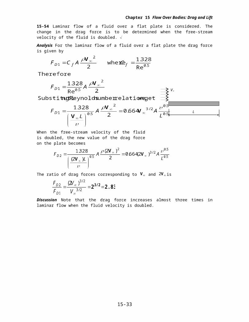
15-54 Laminar flow of a fluid over a flat plate is considered. The change in the drag force is to be determined when the free-stream velocity of the fluid is doubled.
Analysis For the laminar flow of a fluid over a flat plate the drag force is given by
When the free-stream velocity of the fluid is doubled, the new value of the drag force on the plate becomes
The ratio of drag forces corresponding to V and 2V is
Discussion Note that the drag force increases almost three times in laminar flow when the fluid velocity is doubled.
15-29
V
L
Chapter 15 Flow Over Bodies: Drag and Lift
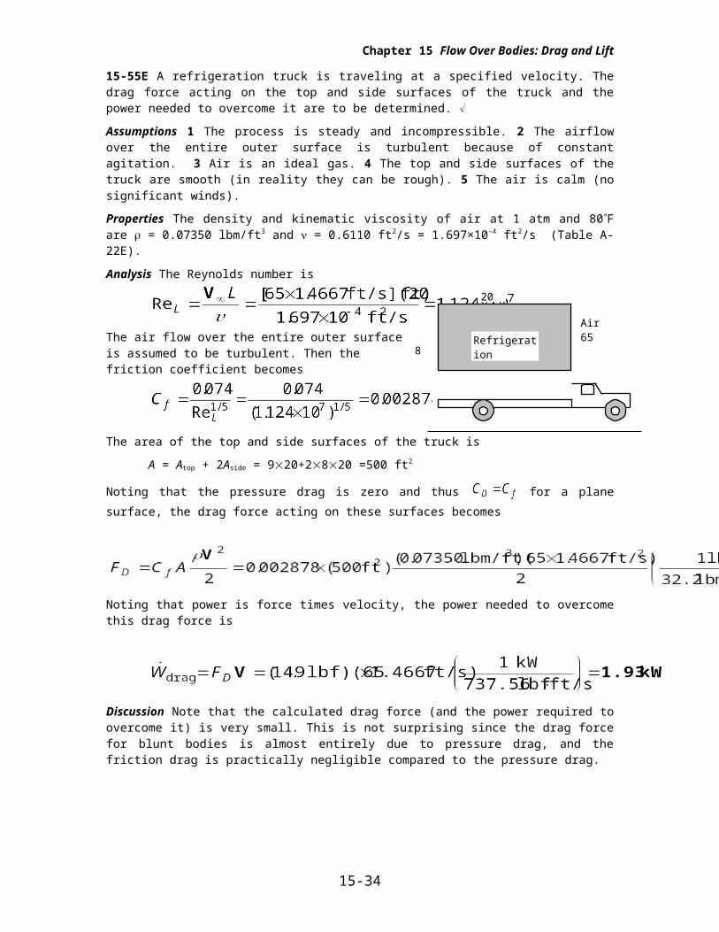
15-55E A refrigeration truck is traveling at a specified velocity. The drag force acting on the top and side surfaces of the truck and the power needed to overcome it are to be determined.
Assumptions 1 The process is steady and incompressible. 2 The airflow over the entire outer surface is turbulent because of constant agitation. 3 Air is an ideal gas. 4 The top and side surfaces of the truck are smooth (in reality they can be rough). 5 The air is calm (no significant winds).
Properties The density and kinematic viscosity of air at 1 atm and 80 F are = 0.07350 lbm/ft3 and = 0.6110 ft2/s = 1.697×10⁻⁴ ft2/s (Table A-22E).
Analysis The Reynolds number is
The air flow over the entire outer surface is assumed to be turbulent. Then the friction coefficient becomes
The area of the top and side surfaces of the truck is
A = Atop + 2Aside = 920+2820 =500 ft2
Noting that the pressure drag is zero and thus for a plane surface, the drag force acting on these surfaces becomes
Noting that power is force times velocity, the power needed to overcome this drag force is
Discussion Note that the calculated drag force (and the power required to overcome it) is very small. This is not surprising since the drag force for blunt bodies is almost entirely due to pressure drag, and the friction drag is practically negligible compared to the pressure drag.
15-30
20 ft
8 ftRefrigerationtruck
Air65 mph
Chapter 15 Flow Over Bodies: Drag and Lift
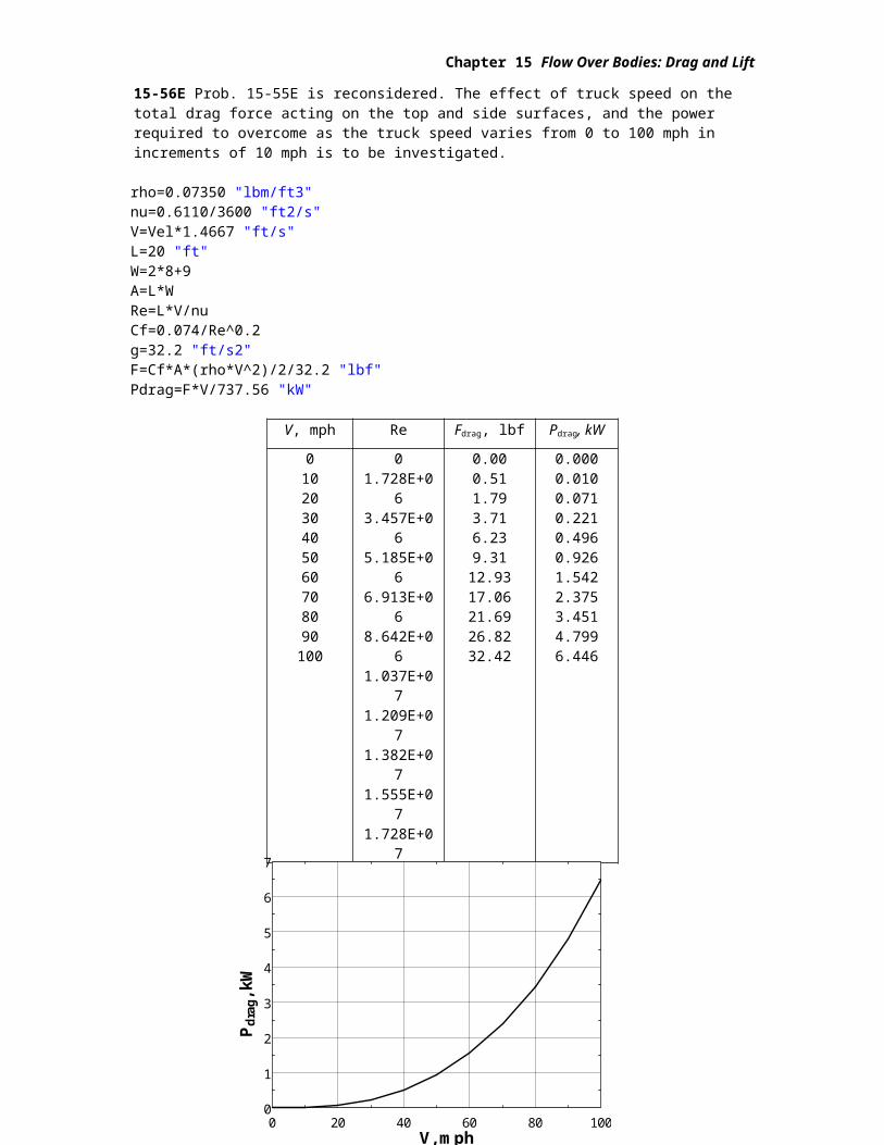
15-56E Prob. 15-55E is reconsidered. The effect of truck speed on the total drag force acting on the top and side surfaces, and the power required to overcome as the truck speed varies from 0 to 100 mph in increments of 10 mph is to be investigated.
rho=0.07350 "lbm/ft3"nu=0.6110/3600 "ft2/s"V=Vel*1.4667 "ft/s"L=20 "ft"W=2*8+9A=L*WRe=L*V/nuCf=0.074/Re^0.2g=32.2 "ft/s2"F=Cf*A*(rho*V^2)/2/32.2 "lbf"Pdrag=F*V/737.56 "kW"
V, mph Re Fdrag, lbf Pdrag, kW
0102030405060708090100
01.728E+063.457E+065.185E+066.913E+068.642E+061.037E+071.209E+071.382E+071.555E+071.728E+07
0.000.511.793.716.239.3112.9317.0621.6926.8232.42
0.0000.0100.0710.2210.4960.9261.5422.3753.4514.7996.446
15-31
0 20 40 60 80 1000
1
2
3
4
5
6
7
V, mph
Pd
rag, k
W
Chapter 15 Flow Over Bodies: Drag and Lift
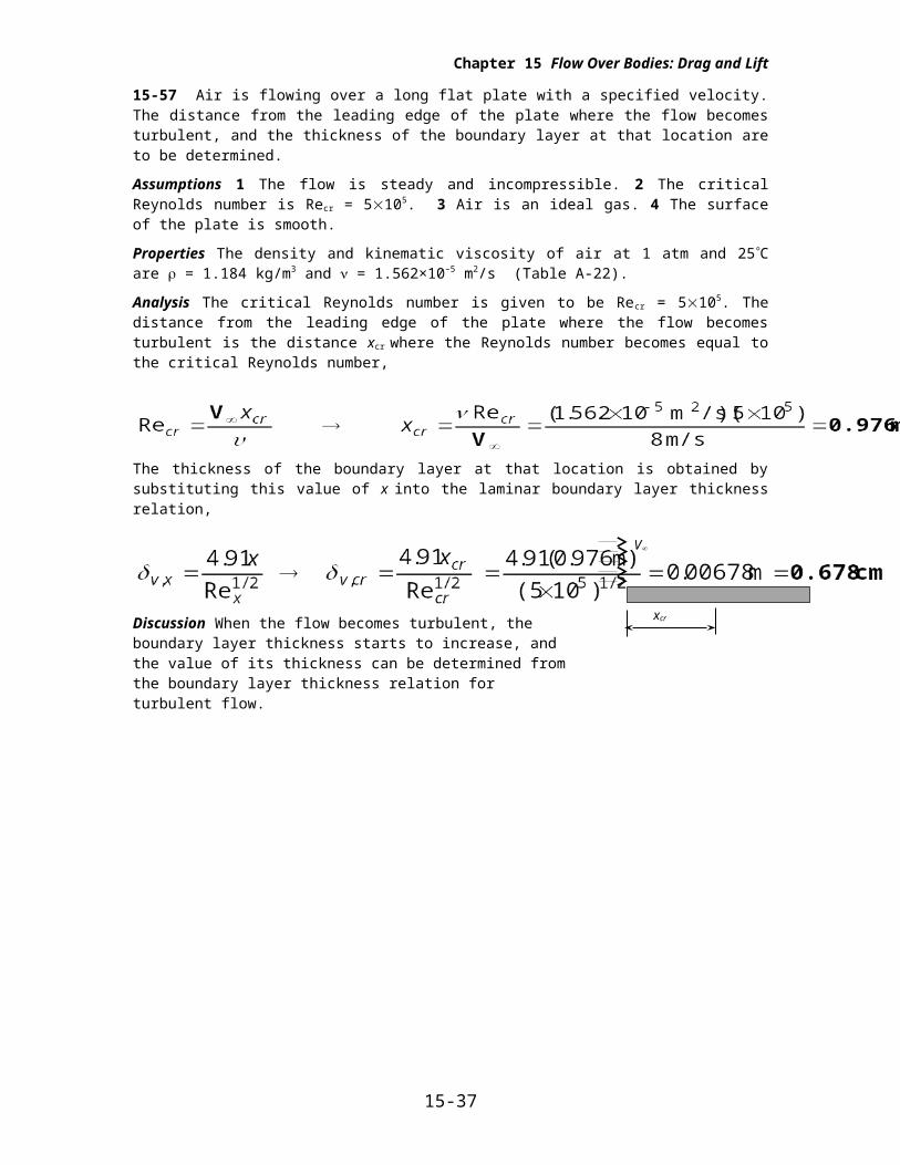
15-57 Air is flowing over a long flat plate with a specified velocity. The distance from the leading edge of the plate where the flow becomes turbulent, and the thickness of the boundary layer at that location are to be determined.
Assumptions 1 The flow is steady and incompressible. 2 The critical Reynolds number is Recr = 5105. 3 Air is an ideal gas. 4 The surface of the plate is smooth.
Properties The density and kinematic viscosity of air at 1 atm and 25C are = 1.184 kg/m3 and = 1.562×10⁻⁵ m2/s (Table A-22).
Analysis The critical Reynolds number is given to be Recr = 5105. The distance from the leading edge of the plate where the flow becomes turbulent is the distance xcr where the Reynolds number becomes equal to the critical Reynolds number,
The thickness of the boundary layer at that location is obtained by substituting this value of x into the laminar boundary layer thickness relation,
Discussion When the flow becomes turbulent, the boundary layer thickness starts to increase, and the value of its thickness can be determined from the boundary layer thickness relation for turbulent flow.
15-32
V
xcr
Chapter 15 Flow Over Bodies: Drag and Lift
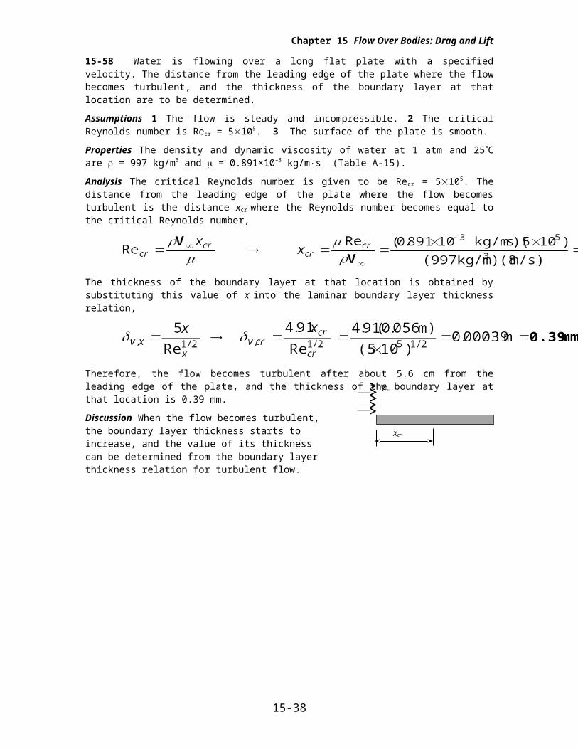
15-58 Water is flowing over a long flat plate with a specified velocity. The distance from the leading edge of the plate where the flow becomes turbulent, and the thickness of the boundary layer at that location are to be determined.
Assumptions 1 The flow is steady and incompressible. 2 The critical Reynolds number is Recr = 5105. 3 The surface of the plate is smooth.
Properties The density and dynamic viscosity of water at 1 atm and 25 C are = 997 kg/m3 and = 0.891×10⁻³ kg/ms (Table A-15).
Analysis The critical Reynolds number is given to be Recr = 5105. The distance from the leading edge of the plate where the flow becomes turbulent is the distance xcr where the Reynolds number becomes equal to the critical Reynolds number,
The thickness of the boundary layer at that location is obtained by substituting this value of x into the laminar boundary layer thickness relation,
Therefore, the flow becomes turbulent after about 5.6 cm from the leading edge of the plate, and the thickness of the boundary layer at that location is 0.39 mm.
Discussion When the flow becomes turbulent, the boundary layer thickness starts to increase, and the value of its thickness can be determined from the boundary layer thickness relation for turbulent flow.
15-33
V
xcr
Chapter 15 Flow Over Bodies: Drag and Lift
Flow across Cylinders and Spheres
15-59C Turbulence moves the fluid separation point further back on the rear of the body, reducing the size of the wake, and thus the magnitude of the pressure drag (which is the dominant mode of drag). As a result, the drag coefficient suddenly drops. In general, turbulence increases the drag coefficient for flat surfaces, but the drag coefficient usually remains constant at high Reynolds numbers when the flow is turbulent.
15-60C Friction drag is due to the shear stress at the surface whereas the pressure drag is due to the pressure differential between the front and back sides of the body when a wake is formed in the rear.
15-61C Flow separation in flow over a cylinder is delayed in turbulent flow because of the extra mixing due to random fluctuations and the transverse motion.
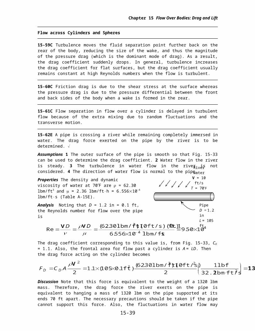
15-62E A pipe is crossing a river while remaining completely immersed in water. The drag force exerted on the pipe by the river is to be determined.
Assumptions 1 The outer surface of the pipe is smooth so that Fig. 15-33 can be used to determine the drag coefficient. 2 Water flow in the river is steady. 3 The turbulence in water flow in the river is not considered. 4 The direction of water flow is normal to the pipe.
Properties The density and dynamic viscosity of water at 70F are = 62.30 lbm/ft3 and = 2.36 lbm/fth = 6.55610-4 lbm/fts (Table A-15E).
Analysis Noting that D = 1.2 in = 0.1 ft, the Reynolds number for flow over the pipe is
The drag coefficient corresponding to this value is, from Fig. 15-33, CD = 1.1. Also, the frontal area for flow past a cylinder is A = LD. Then the drag force acting on the cylinder becomes
Discussion Note that this force is equivalent to the weight of a 1320 lbm mass. Therefore, the drag force the river exerts on the pipe is equivalent to hanging a mass of 1320 lbm on the pipe supported at its ends 70 ft apart. The necessary precautions should be taken if the pipe cannot support this force. Also, the fluctuations in water flow may reduce the drag coefficients by inducing turbulence and delaying flow separation.
15-34
River waterV = 10 ft/sT = 70F
Pipe D = 1.2 inL = 105 ft
Chapter 15 Flow Over Bodies: Drag and Lift
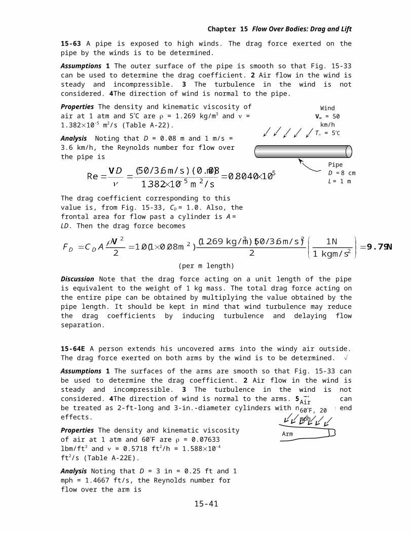
15-63 A pipe is exposed to high winds. The drag force exerted on the pipe by the winds is to be determined.
Assumptions 1 The outer surface of the pipe is smooth so that Fig. 15-33 can be used to determine the drag coefficient. 2 Air flow in the wind is steady and incompressible. 3 The turbulence in the wind is not considered. 4The direction of wind is normal to the pipe.
Properties The density and kinematic viscosity of air at 1 atm and 5C are = 1.269 kg/m3 and = 1.38210-5 m2/s (Table A-22).
Analysis Noting that D = 0.08 m and 1 m/s = 3.6 km/h, the Reynolds number for flow over the pipe is
The drag coefficient corresponding to this value is, from Fig. 15-33, CD = 1.0. Also, the frontal area for flow past a cylinder is A = LD. Then the drag force becomes
(per m length)
Discussion Note that the drag force acting on a unit length of the pipe is equivalent to the weight of 1 kg mass. The total drag force acting on the entire pipe can be obtained by multiplying the value obtained by the pipe length. It should be kept in mind that wind turbulence may reduce the drag coefficients by inducing turbulence and delaying flow separation.
15-64E A person extends his uncovered arms into the windy air outside. The drag force exerted on both arms by the wind is to be determined.
Assumptions 1 The surfaces of the arms are smooth so that Fig. 15-33 can be used to determine the drag coefficient. 2 Air flow in the wind is steady and incompressible. 3 The turbulence in the wind is not considered. 4The direction of wind is normal to the arms. 5 The arms can be treated as 2-ft-long and 3-in.-diameter cylinders with negligible end effects.
Properties The density and kinematic viscosity of air at 1 atm and 60F are = 0.07633 lbm/ft3 and = 0.5718 ft2/h = 1.58810-4 ft2/s (Table A-22E).
Analysis Noting that D = 3 in = 0.25 ft and 1 mph = 1.4667 ft/s, the Reynolds number for flow over the arm is
The drag coefficient corresponding to this value is, from Fig. 15-33, CD = 1.0. Also, the frontal area for flow past a cylinder is A = LD. Then the total drag force acting on both arms becomes
Discussion Note that this force is equivalent to the weight of 1 lbm mass. Therefore, the drag force the wind exerts on the arms of this person is equivalent to hanging 0.5 lbm of mass on each arm. Also, it should be kept in mind that the wind turbulence and the surface roughness may affect the calculated result significantly.
15-65 Wind is blowing across the wire of a transmission line. The drag force exerted on the wire by the wind is to be determined.
15-35
WindV = 50 km/h
T = 5C
Pipe D = 8 cmL = 1 m
Air60F, 20 mph
Arm
Chapter 15 Flow Over Bodies: Drag and Lift
Assumptions 1 The wire surfaces are smooth so that Fig. 15-33 can be used to determine the drag coefficient. 2 Air flow in the wind is steady and incompressible. 3 The turbulence in the wind is not considered. 4The direction of wind is normal to the wire.
Properties The density and kinematic viscosity of air at 1 atm and 15 C are = 1.225 kg/m3 and = 1.47010-5 m2/s (Table A-22).
Analysis Noting that D = 0.006 m and 1 m/s = 3.6 km/h, the Reynolds number for the flow is
The drag coefficient corresponding to this value is, from Fig. 15-33, CD = 1.0. Also, the frontal area for flow past a cylinder is A = LD. Then the drag force becomes
Therefore, the drag force acting on the wire is 54.4 N, which is equivalent to the weight of about 5.4 kg mass hanging on the wire.
Discussion It should be kept in mind that wind turbulence may reduce the drag coefficients by inducing turbulence and delaying flow separation.
15-36
WindV = 40 km/h
T = 15C
Transmission wire,D = 0.6 cmL = 120 m
Chapter 15 Flow Over Bodies: Drag and Lift
15-66 A spherical hail is falling freely in the atmosphere. The terminal velocity of the hail in air is to be determined.
Assumptions 1 The surface of the hail is smooth so that Fig. 15-33 can be used to determine the drag coefficient. 2 The variation of the air properties with altitude is negligible. 3 The buoyancy force applied by air to hail is negligible since air << hail (besides, the uncertainty in the density of hail is greater than the density of air). 4 Air flow over the hail is steady and incompressible when terminal velocity is established. 5 The atmosphere is calm (no winds or drafts).
Properties The density and kinematic viscosity of air at 1 atm and 5C are = 1.269 kg/m3 and = 1.38210-5 m2/s (Table A-22). The density of hail is given to be 910 kg/m3.
Analysis The terminal velocity of a free falling object is reached when the drag force equals the weight of the solid object less the buoyancy force applied by the fluid, which is negligible in this case,
where
and A = D2/4 is the frontal area. Substituting and simplifying,
Solving for V and substituting,
(1)
The drag coefficient CD is to be determined from Fig. 15-33, but it requires the Reynolds number which cannot be calculated since we do not know velocity. Therefore, the solution requires a trial-error approach. First we express the Reynolds number as
(2)
Now we choose a velocity in m/s, calculate the Re from Eq. (2), read the corresponding CD from Fig. 15-33, and calculate V from Eq. (1). Repeat calculations until the assumed velocity matches the calculated velocity. With this approach the terminal velocity is determined to be
V = 13.7 m/s
The corresponding Re and CD values are Re = 7930 and CD = 0.40. Therefore, the velocity of hail will remain constant when it reaches the terminal velocity of 13.7 m/s = 49 km/h.
Discussion The simple analysis above gives us a reasonable value for the terminal velocity. A more accurate answer can be obtained by a more detailed (and complex) analysis by considering the variation of air properties with altitude, and by considering the uncertainty in the drag coefficient (a hail is not necessarily spherical and smooth).
15-37
AirT = 5C
HailD = 0.3 cm
D
Chapter 15 Flow Over Bodies: Drag and Lift
15-67 A spherical dust particle is suspended in the air at a fixed point as a result of an updraft air motion. The magnitude of the updraft velocity is to be determined using Stokes law.
Assumptions 1 The Reynolds number is low (at the order of 1) so that Stokes law is applicable (to be verified). 2 The updraft is steady and incompressible. 3 The buoyancy force applied by air to the dust particle is negligible since air << dust (besides, the uncertainty in the density of dust is greater than the density of air). (We will solve the problem without utilizing this assumption for generality).
Properties The density of dust is given to be s = 2.1 g/cm3 = 2100 kg/m3. The density and dynamic viscosity of air at 1 atm and 25C are f = 1.184 kg/m3 and = 1.84910-5 kg/ms (Table A-22).
Analysis The terminal velocity of a free falling object is reached (or the suspension of an object in a flow stream is established) when the drag force equals the weight of the solid object less the buoyancy force applied by the surrounding fluid,
where (Stoke’s law),
Here V = D3/6 is the volume of the sphere. Substituting,
Solving for the velocity V and substituting the numerical values, the updraft velocity is determined to be
The Reynolds number in this case is
which is in the order of 1. Therefore, the creeping flow idealization and thus Stokes law is applicable, and the value calculated is valid.
Discussion Flow separation starts at about Re = 10. Therefore, Stokes law can be used for Reynolds numbers upto this value, but this should be done with care.
15-38
0.1 mm V
AirDust
Chapter 15 Flow Over Bodies: Drag and Lift
15-68 Dust particles that are unsettled during high winds rise to a specified height, and start falling back when things calm down. The time it takes for the dust particles to fall back to the ground and their velocity are to be determined using Stokes law.
Assumptions 1 The Reynolds number is low (at the order of 1) so that Stokes law is applicable (to be verified). 2 The atmosphere is calm during fall back (no winds or drafts). 3 The initial transient period during which the dust particle accelerates to its terminal velocity is negligible. 4 The buoyancy force applied by air to the dust particle is negligible since air << dust (besides, the uncertainty in the density of dust is greater than the density of air). (We will solve this problem without utilizing this assumption for generality).
Properties The density of dust is given to be s = 1.8 g/cm3 = 1800 kg/m3. The density and dynamic viscosity of air at 1 atm and 15C are f = 1.225 kg/m3 and = 1.80210-5 kg/ms (Table A-22).
Analysis The terminal velocity of a free falling object is reached when the drag force equals the weight of the solid object less the buoyancy force applied by the surrounding fluid,
where (Stoke’s law),
Here V = D3/6 is the volume of the sphere. Substituting,
Solving for the velocity V and substituting the numerical values, the terminal velocity is determined to be
Then the time it takes for the dust particle to travel 350 m at this velocity becomes
The Reynolds number is
which is in the order of 1. Therefore, the creeping flow idealization and thus Stokes law is applicable.
Discussion Note that the dust particle reaches a terminal velocity of 0.136 m/s, and it takes about an hour to fall back to the ground. The presence of drafts in air may significantly increase the settling time.
15-39
0.05 mmV
Dust
Chapter 15 Flow Over Bodies: Drag and Lift
15-69 A cylindrical log suspended by a crane is subjected to normal winds. The angular displacement of the log and the tension on the cable are to be determined.
Assumptions 1 The surfaces of the log are smooth so that Fig. 15-33 can be used to determine the drag coefficient (not a realistic assumption). 2 Air flow in the wind is steady and incompressible. 3 The turbulence in the wind is not considered. 4The direction of wind is normal to the log, which always remains horizontal. 5 The end effects of the log are negligible. 6 The weight of the cable and the drag acting on it are negligible. 7 Air is an ideal gas.
Properties The dynamic viscosity of air at 5C (independent of pressure) is = 1.75410-5 kg/ms (Table A-22). Then the density and kinematic viscosity of air are calculated to be
Analysis Noting that D = 0.2 m and 1 m/s = 3.6 km/h, the Reynolds number is
The drag coefficient corresponding to this value is, from Fig. 15-33, CD = 1.2. Also, the frontal area for flow past a cylinder is A = LD. Then the total drag force acting on the log becomes
The weight of the log is
Then the resultant force acting on the log and the angle it makes with the horizontal become
Drawing a free body diagram of the log and doing a force balance will show that the magnitude of the tension on the cable must be equal to the resultant force acting on the log. Therefore, the tension on the cable is 318 N and the cable makes 84 with the horizontal.
Discussion Note that the wind in this case has rotated the cable by 6 from its vertical position, and increased the tension action on it somewhat. At very high wind speeds, the increase in the cable tension can be very significant, and wind loading must always be considered in bodies exposed to high winds.
15-40
80 km/h
2 m
0.2 m
Chapter 15 Flow Over Bodies: Drag and Lift
15-70 A ping-pong ball is suspended in air by an upward air jet. The velocity of the air jet is to be determined, and the phenomenon that the ball returns to the center of the air jet after a disturbance is to be explained.
Assumptions 1 The surface of the ping-pong ball is smooth so that Fig. 15-33 can be used to determine the drag coefficient. 2 Air flow over the ball is steady and incompressible.
Properties The density and kinematic viscosity of air at 1 atm and 25C are = 1.184 kg/m3 and = 1.56210-5 m2/s (Table A-22).
Analysis The terminal velocity of a free falling object is reached when the drag force equals the weight of the solid object less the buoyancy force applied by the fluid,
where
Here A = D2/4 is the frontal area and V = D3/6 is the volume of the sphere. Also,
Substituting and solving for V,
(1)
The drag coefficient CD is to be determined from Fig. 15-33, but it requires the Reynolds number which cannot be calculated since we do not know velocity. Therefore, the solution requires a trial-error approach. First we express the Reynolds number as
(2)
Now we choose a velocity in m/s, calculate the Re from Eq. (2), read the corresponding CD from Fig. 15-33, and calculate V from Eq. (1). Repeat calculations until the assumed velocity matches the calculated velocity. With this approach the velocity of the fluid jet is determined to be
V = 9.3 m/s
The corresponding Re and CD values are Re = 22,600 and CD = 0.43. Therefore, the ping-pong ball will remain suspended in the air jet when the air velocity reaches 9.3 m/s = 33.5 km/h.
Discussion 1 If the ball is pushed to the side by a finger, the ball will come back to the center of the jet (instead of falling off) due to the Bernoulli effect. In the core of the jet the velocity is higher, and thus the pressure is lower relative to a location away from the jet.
2 Note that this simple apparatus can be used to determine the drag coefficients of certain object by simply measuring the air velocity, which is easy to do.
3 This problem can also be solved roughly by taking CD = 0.5 from Table 15-3 for a sphere in laminar flow, and then verifying that the flow is laminar.
15-41
Air jet
Ball2.6 g