Embed Size (px)
Citation preview

Fuel Cell Basics
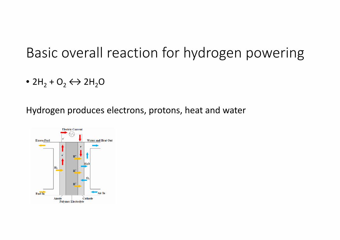
Basic overall reaction for hydrogen powering
• 2H2 + O2 ↔ 2H2O
Hydrogen produces electrons, protons, heat and water
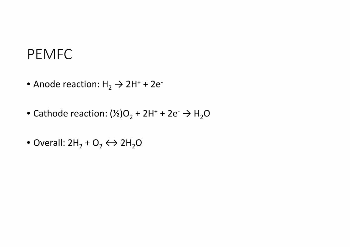
PEMFC
• Anode reaction: H2 → 2H+ + 2e‐
• Cathode reaction: (½)O2 + 2H+ + 2e‐ → H2O
• Overall: 2H2 + O2 ↔ 2H2O
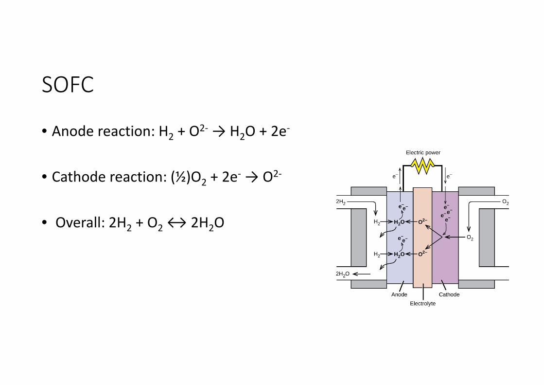
SOFC
• Anode reaction: H2 + O2‐ → H2O + 2e‐
• Cathode reaction: (½)O2 + 2e‐ → O2‐
• Overall: 2H2 + O2 ↔ 2H2O
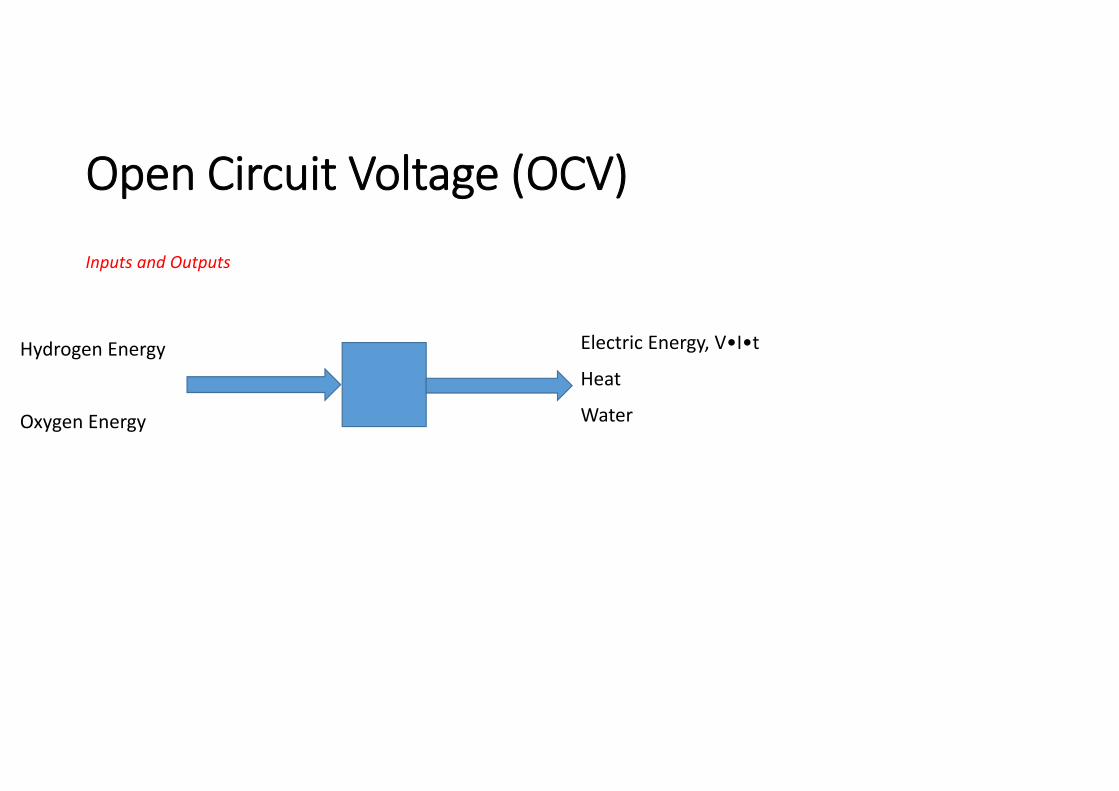
Open Circuit Voltage (OCV)
Inputs and Outputs
Hydrogen Energy
Oxygen Energy
Electric Energy, V•I•t
Heat
Water
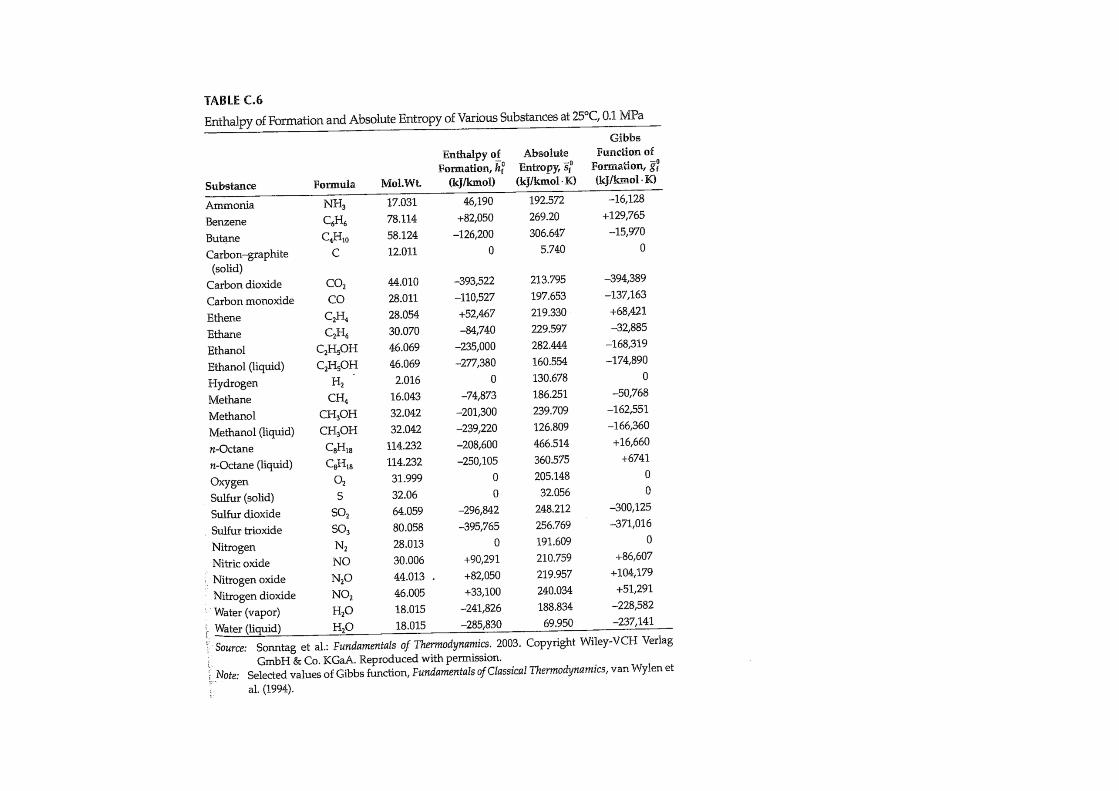
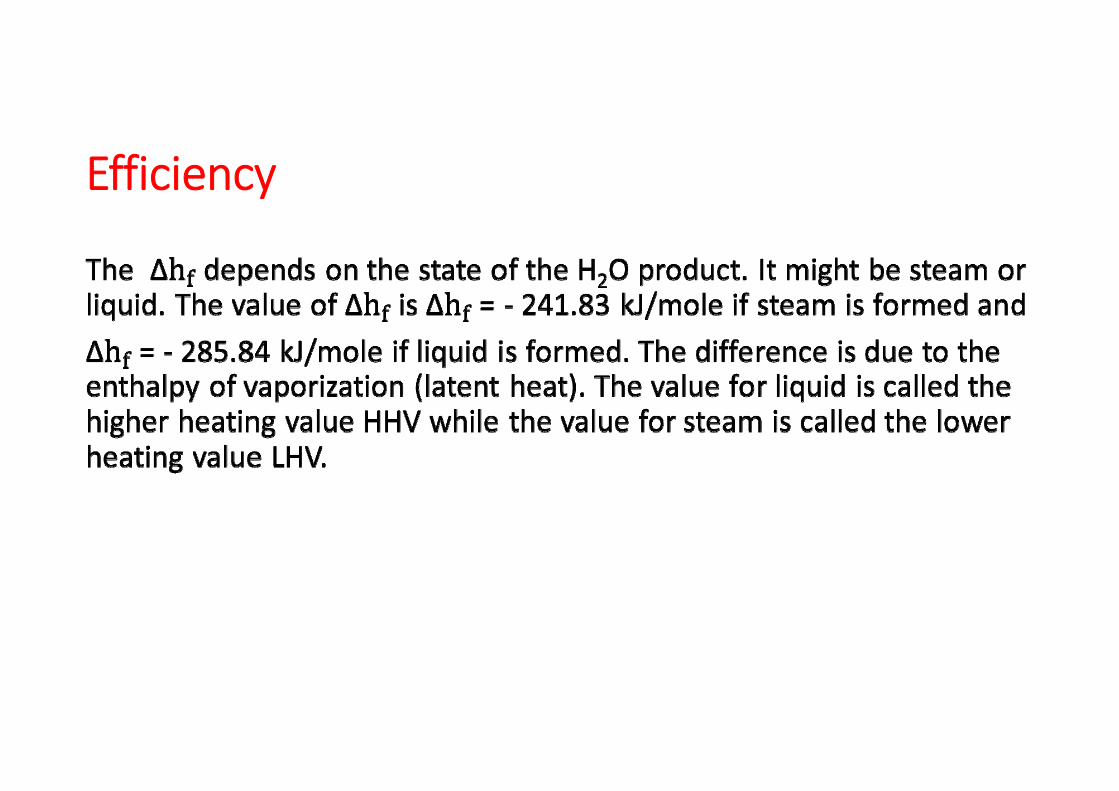
Enthalpy of formation
Enthalpy of formation of the product in a chemical reaction is the difference in enthalpy of the product and sum of enthalpy of all reactants
Enthalpy of formation Reference state is 25 C and 0.1 MPa. At this state the
enthalpy of the reactants is zero.The enthalpy of the product at the reference state is then
given by the net heat transfer and this is termed the enthalpy of formation of the product
Enthalpy of formation
The enthalpy of formation can be determined by experiments but commonly statistical thermodynamics is used to determine it for various compounds. Table is
provided.
= Hp= QCV
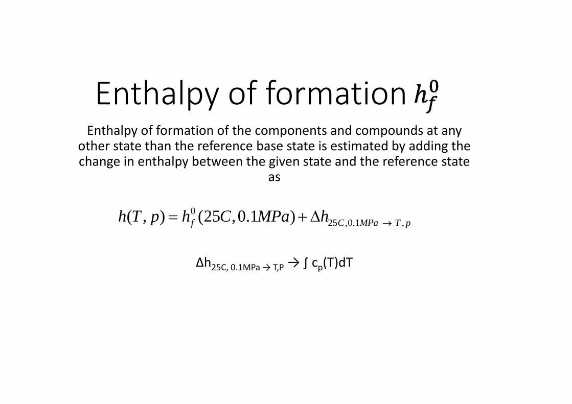
Enthalpy of formation Enthalpy of formation of the components and compounds at any
other state than the reference base state is estimated by adding the change in enthalpy between the given state and the reference state
as
∆h25C, 0.1MPa → T,P → ∫ cp(T)dT
025 ,0.1 , ( , ) (25 ,0.1 )f C MPa T ph T p h C MPa h
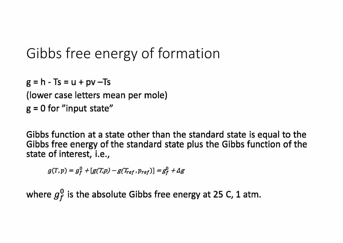
Gibbs free energy of formation
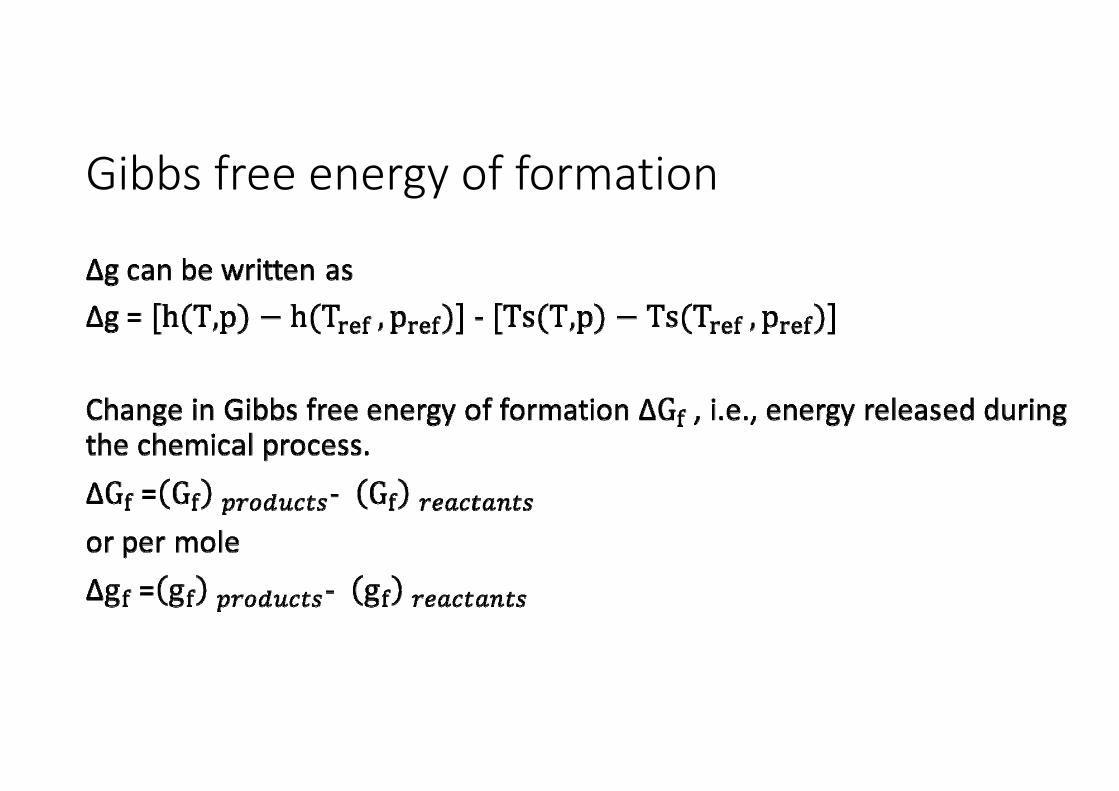
Gibbs free energy of formation
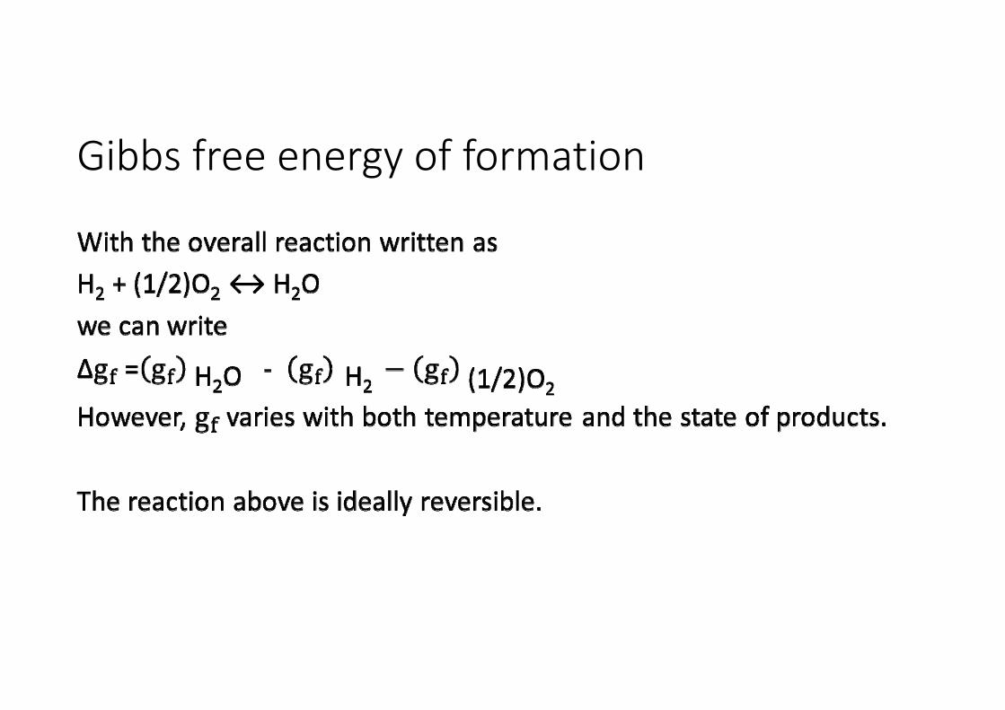
Gibbs free energy of formation
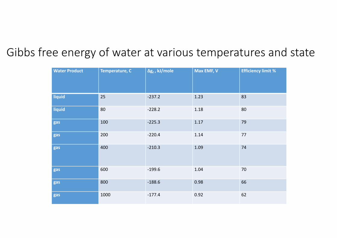
Gibbs free energy of water at various temperatures and stateWater Product Temperature, C Δgf , kJ/mole Max EMF, V Efficiency limit %
liquid 25 ‐237.2 1.23 83
liquid 80 ‐228.2 1.18 80
gas 100 ‐225.3 1.17 79
gas 200 ‐220.4 1.14 77
gas 400 ‐210.3 1.09 74
gas 600 ‐199.6 1.04 70
gas 800 ‐188.6 0.98 66
gas 1000 ‐177.4 0.92 62
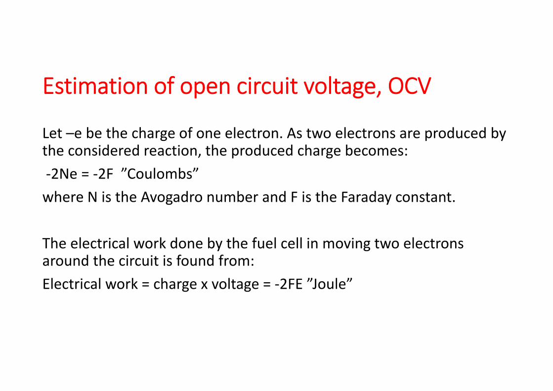
Estimation of open circuit voltage, OCV
Let –e be the charge of one electron. As two electrons are produced by the considered reaction, the produced charge becomes:‐2Ne = ‐2F ”Coulombs”where N is the Avogadro number and F is the Faraday constant.
The electrical work done by the fuel cell in moving two electrons around the circuit is found from:Electrical work = charge x voltage = ‐2FE ”Joule”
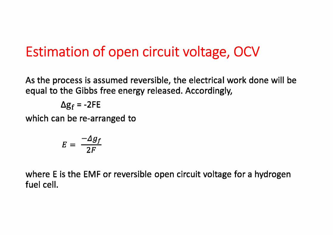
Estimation of open circuit voltage, OCV
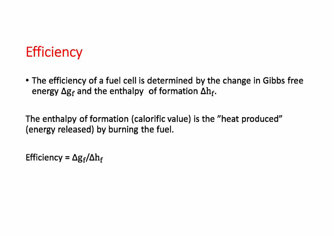
Efficiency
Efficiency

Influence of Pressure on Gibbs Energy and Reversible Voltage
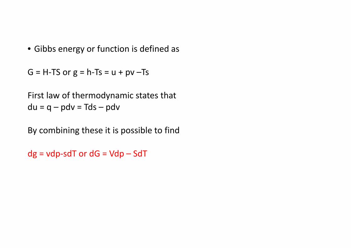
• Gibbs energy or function is defined as
G = H‐TS or g = h‐Ts = u + pv –Ts
First law of thermodynamic states thatdu = q – pdv = Tds – pdv
By combining these it is possible to find
dg = vdp‐sdT or dG = Vdp – SdT
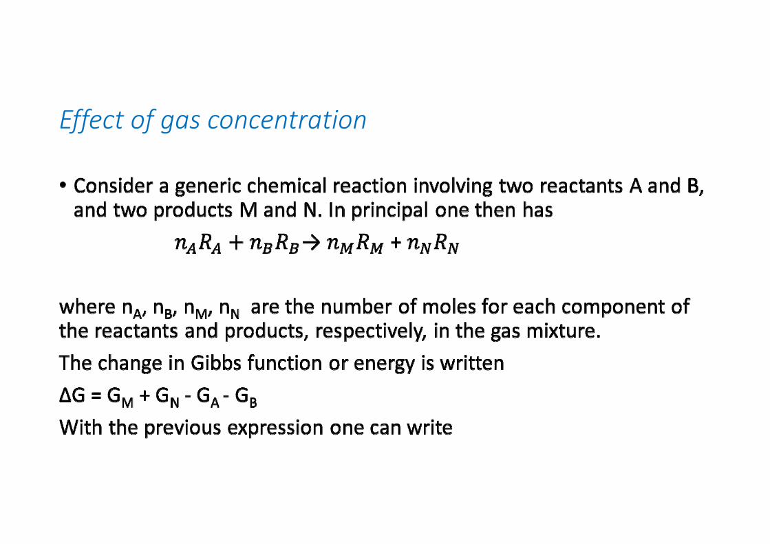
Effect of gas concentration
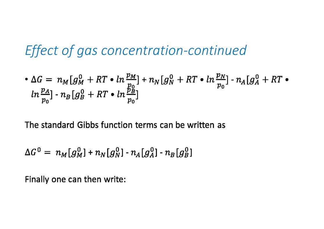
Effect of gas concentration‐continued
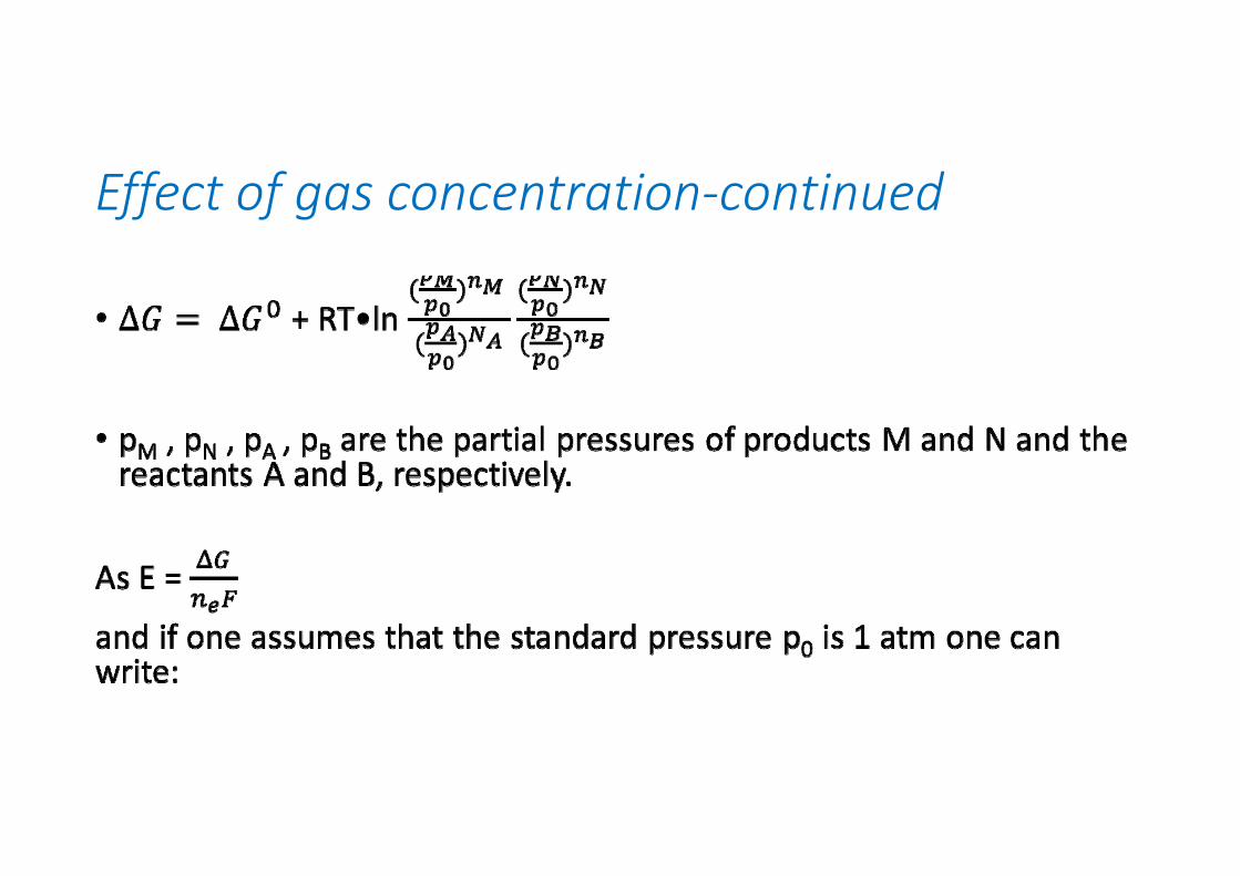
Effect of gas concentration‐continued
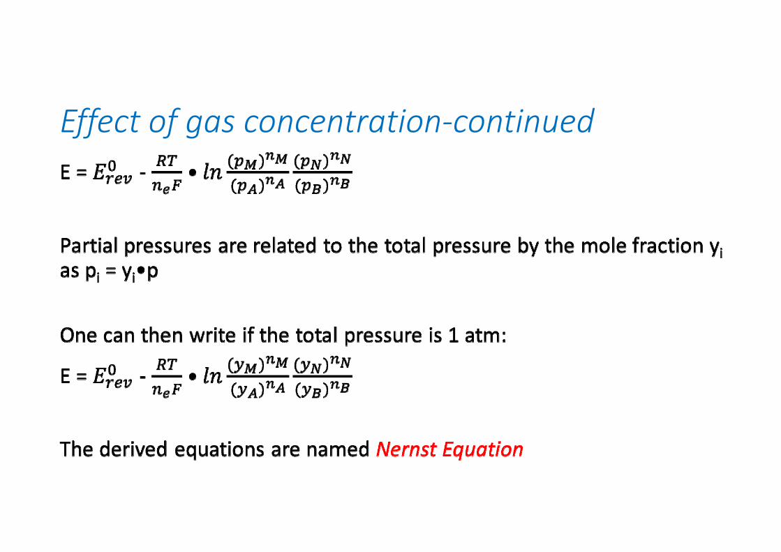
Effect of gas concentration‐continued
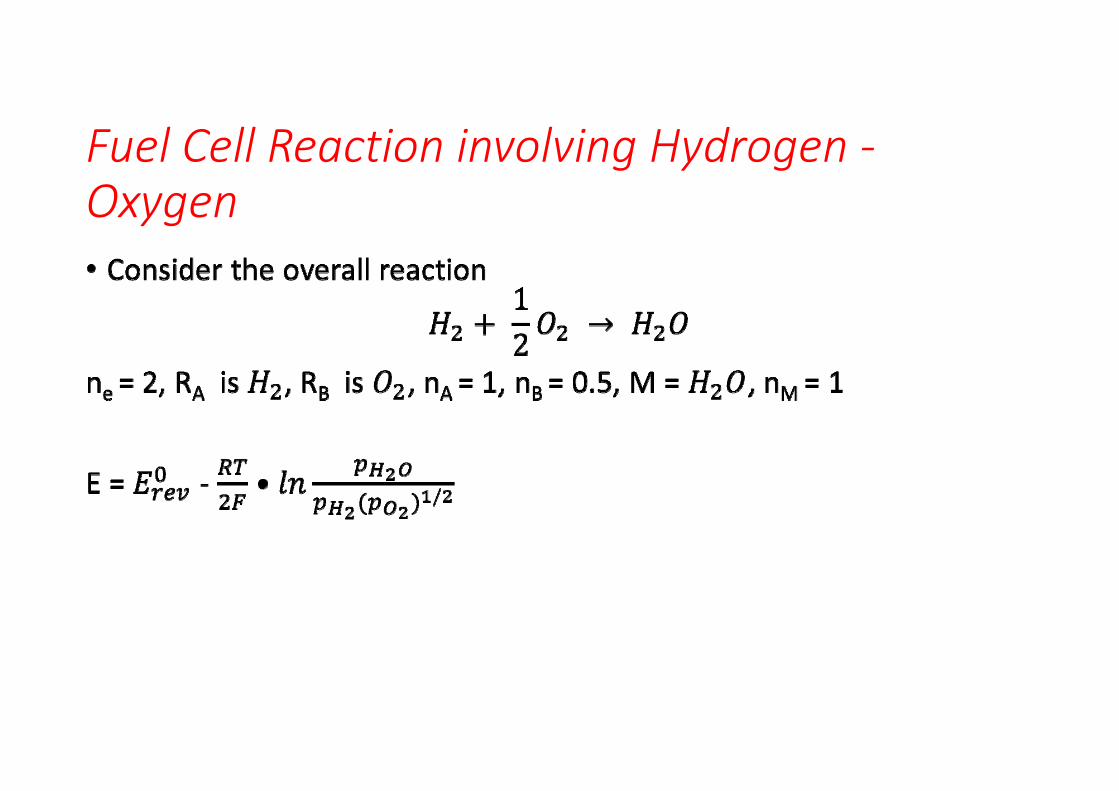
Fuel Cell Reaction involving Hydrogen ‐Oxygen
EMF values
Depends on temperature
Low temperature (40 C): EMF ≈ 1.2 V
High temperature (800 C): EMF ≈ 1 V
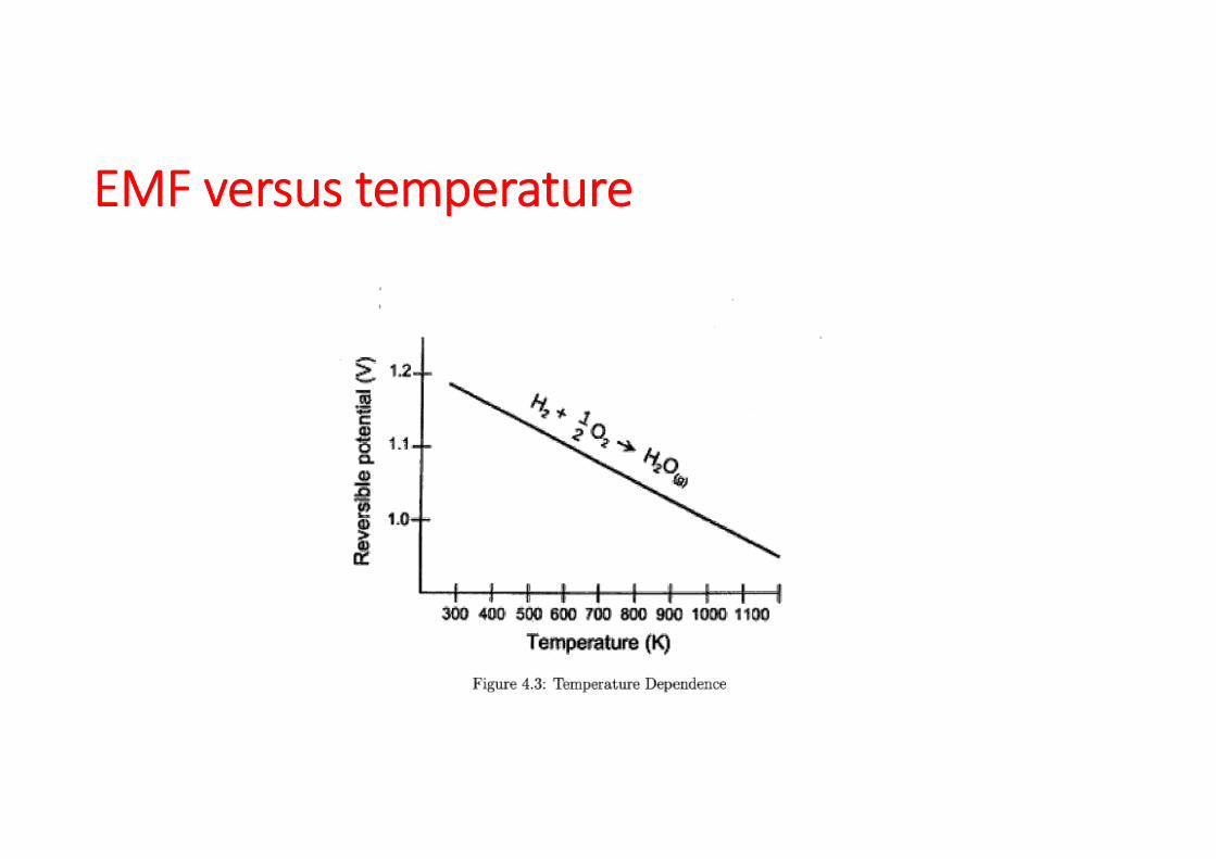
EMF versus temperature
Operational losses
FC‐Ireversibilities, Voltage losses
• Activation loss• Ohmic loss• Concentration loss• Cross‐over and short circuit losses
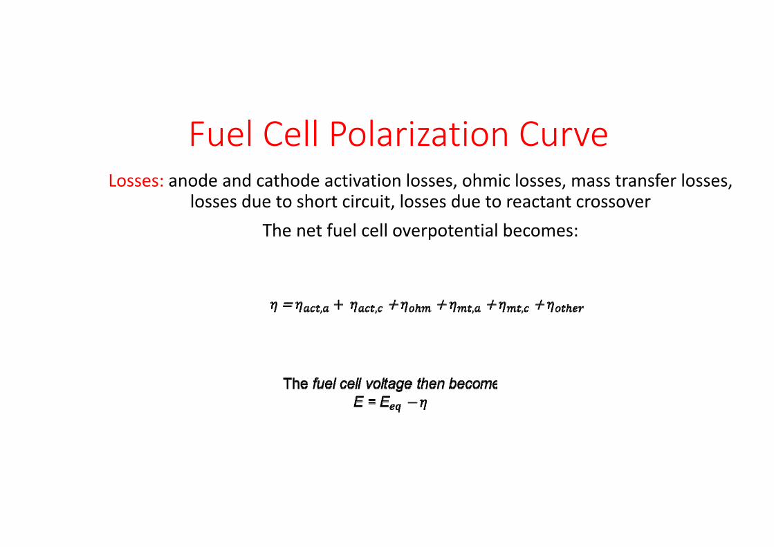
Fuel Cell Polarization CurveLosses: anode and cathode activation losses, ohmic losses, mass transfer losses,
losses due to short circuit, losses due to reactant crossoverThe net fuel cell overpotential becomes:
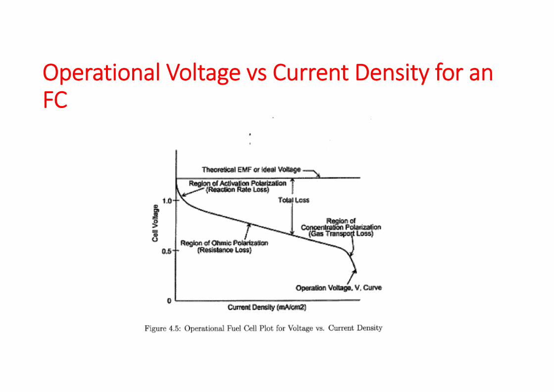
Operational Voltage vs Current Density for an FC
Voltage losses
• Activation losses ”over potential”• Fuel crossover/internal current losses• Ohmic losses• Mass transport/concentration losses
Activation losses
• The activation losses are non‐linear with current. Typically the activation losses introduce a sharp initial drop in the cell open circuit EMF with increasing current load. The losses are different at each electrode (the anode and cathode) because the double layer configuration is different. These losses are directly related to the energy barrier (resistances) for oxidation and reduction at the electrodes.
Activation losses
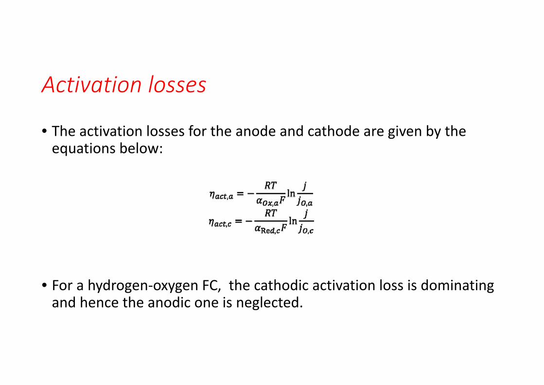
• The activation losses for the anode and cathode are given by the equations below:
• For a hydrogen‐oxygen FC, the cathodic activation loss is dominating and hence the anodic one is neglected.
Activation loss
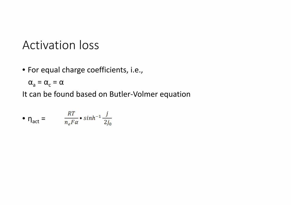
• For equal charge coefficients, i.e.,αa = αc = α
It can be found based on Butler‐Volmer equation
• ηact =
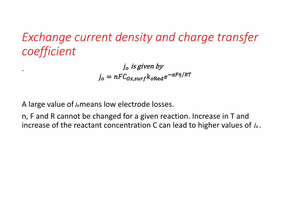
Exchange current density and charge transfer coefficient.
A large value of means low electrode losses.n, F and R cannot be changed for a given reaction. Increase in T and increase of the reactant concentration C can lead to higher values of .
Minimizing activation losses
• High operational temperature, i0 goes up• Catalytic presencea) Rough catalysts mean more contact area, b) increase operational pressure, c) selection of catalytic material, Ni, Pt used commonly otherwise Pd better.
Ohmic losses
These occur due to resistance to the flow of electrons in the interconnect, anode and cathodeDirectly proportional to the currentMajor loss in both low and high temperature fuel cells
Ohmic losses
Mass transport/concentration losses
For low and high temperature fuel cellsParticularly at high current densitiesLoss of high concentration of either fuel (at anode) or oxygen (at cathode)Fuel or oxygen is used faster than supplied
Mass transport loss
• The balance between the rate of transport of species and the rate of consumption at the interface determines the maximum current.The key transport processes are convection, diffusion and migration.
Migrationmeans transport of ionic species toward or away from the electrode due to the effect of an electric field. A high electric field gives high migration rate.Diffusionmeans transport of reactant or product species because of a concentration gradient.Convectionmeans transport of reactant or product species by bulk fluid motion driven by natural or applied mechanical forces.
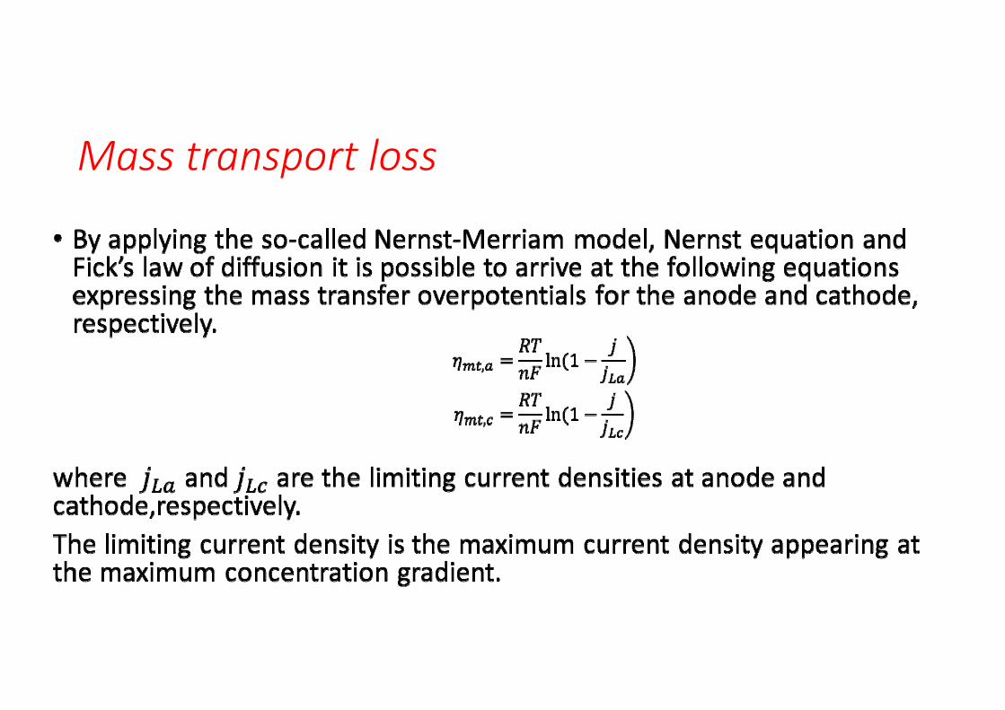
Mass transport loss
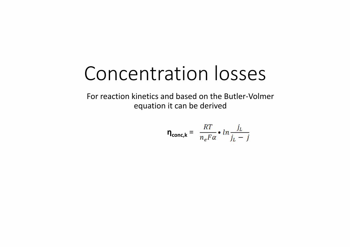
Concentration lossesFor reaction kinetics and based on the Butler‐Volmer
equation it can be derived
ηconc,k =
Concentration losses
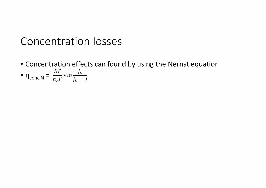
• Concentration effects can found by using the Nernst equation• ηconc,N =
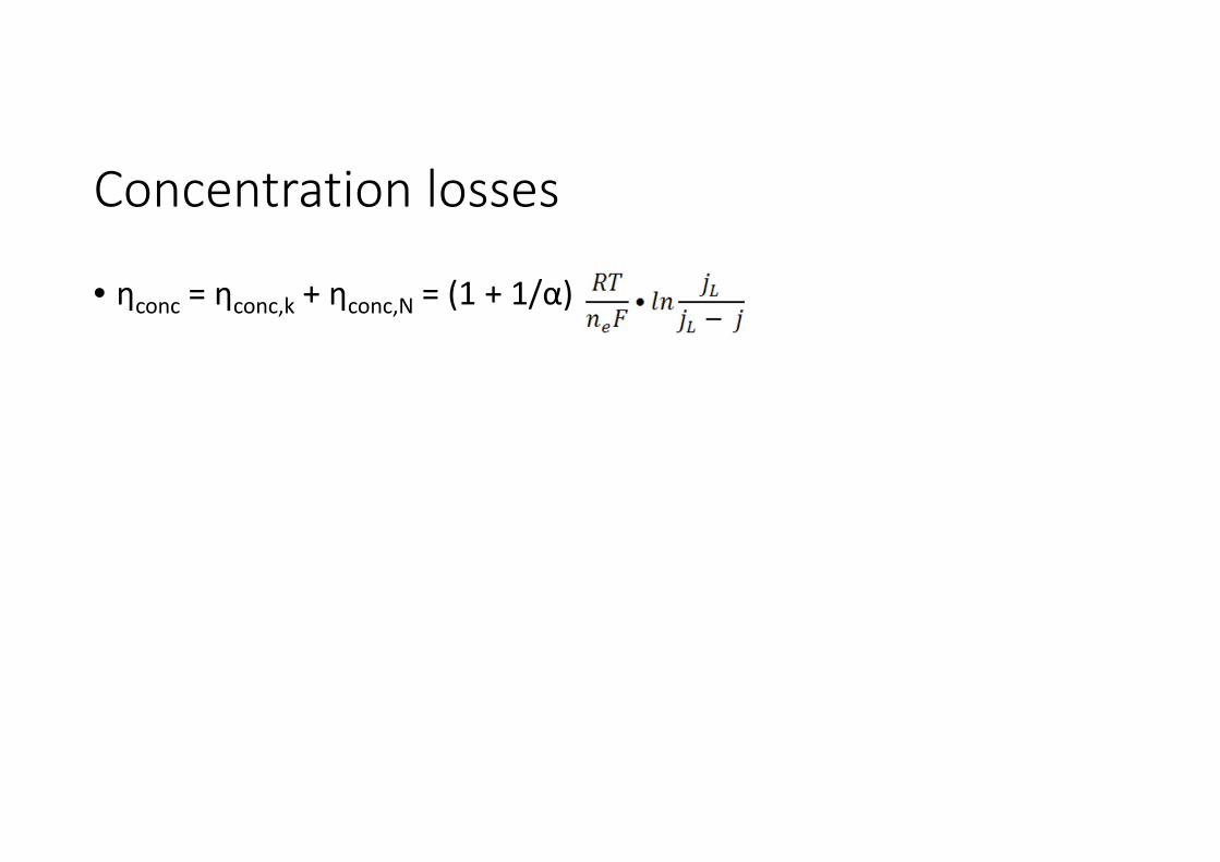
Concentration losses
• ηconc = ηconc,k + ηconc,N = (1 + 1/α)
Reactant crossover and internal currents
• The electrolyte of a fuel cell mainly conducts ions but it is not completely insulated from electrons. It will be able to support a small amount of electron conduction. This electron conduction in the electrolyte or internal current creates a net loss of current to external load. Also some reactants will diffuse from one electrode to another through the electrolyte where reactions occur without external electron transfer.
Fuel cross‐over/internal current loss
Losses throughout the electrolyte
a) Fuel is leaking through the electrodeb) Electrons are leaking through the electrode
Fuel leakage most severe but has a significant effect only at low temperature
jL• jL is the maximum current density or limiting current density. At this all reactant gas has been consumed and the output cell voltage is zero.
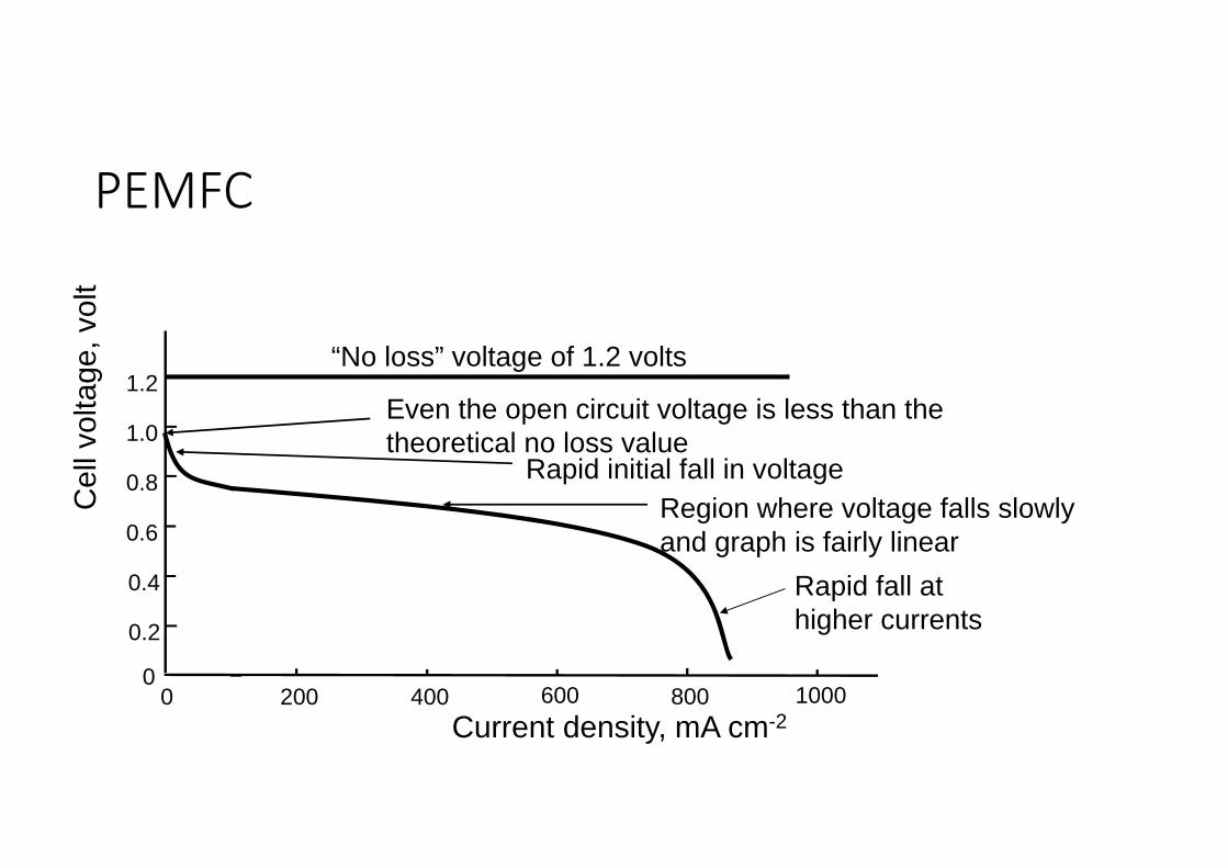
PEMFC
Cel
l vol
tage
, vol
t
Current density, mA cm-2
“No loss” voltage of 1.2 volts
00 400200 800600 1000
0.2
0.6
0.4
0.8
1.0
1.2Even the open circuit voltage is less than the theoretical no loss value
Rapid fall at higher currents
Rapid initial fall in voltageRegion where voltage falls slowly and graph is fairly linear
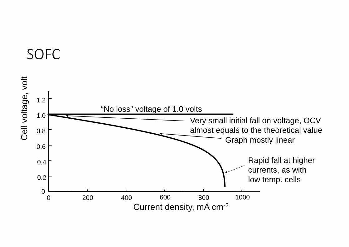
SOFC
Cel
l vol
tage
, vol
t
Current density, mA cm-2
“No loss” voltage of 1.0 volts
00 400200 800600 1000
0.2
0.6
0.4
0.8
1.0
1.2
Very small initial fall on voltage, OCV almost equals to the theoretical value
Rapid fall at higher currents, as with low temp. cells
Graph mostly linear
Butler Volmer equation
• A key issue in the physical understanding, modeling and simulation of fuel cells is to determine the current generated by a cell. The most common method is to apply the so‐called Butler‐Volmer equation which relates the current density to the activation overpotential at each electrode/electrolyte interface. It reads:
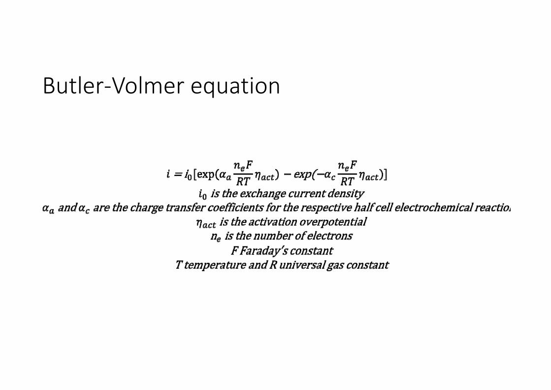
Butler‐Volmer equation
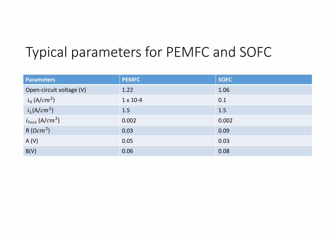
Typical parameters for PEMFC and SOFC
Parameters PEMFC SOFC
Open‐circuit voltage (V) 1.22 1.06
1 x 10‐4 0.1
1.5 1.5
0.002 0.002
0.03 0.09
A (V) 0.05 0.03
B(V) 0.06 0.08
Oxygen‐Hydrogen‐Water Flow Rates
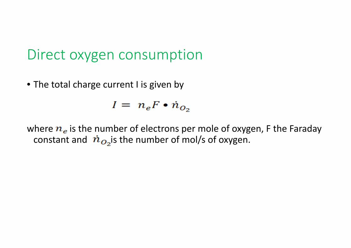
Direct oxygen consumption
• The total charge current I is given by
where is the number of electrons per mole of oxygen, F the Faraday constant and is the number of mol/s of oxygen.
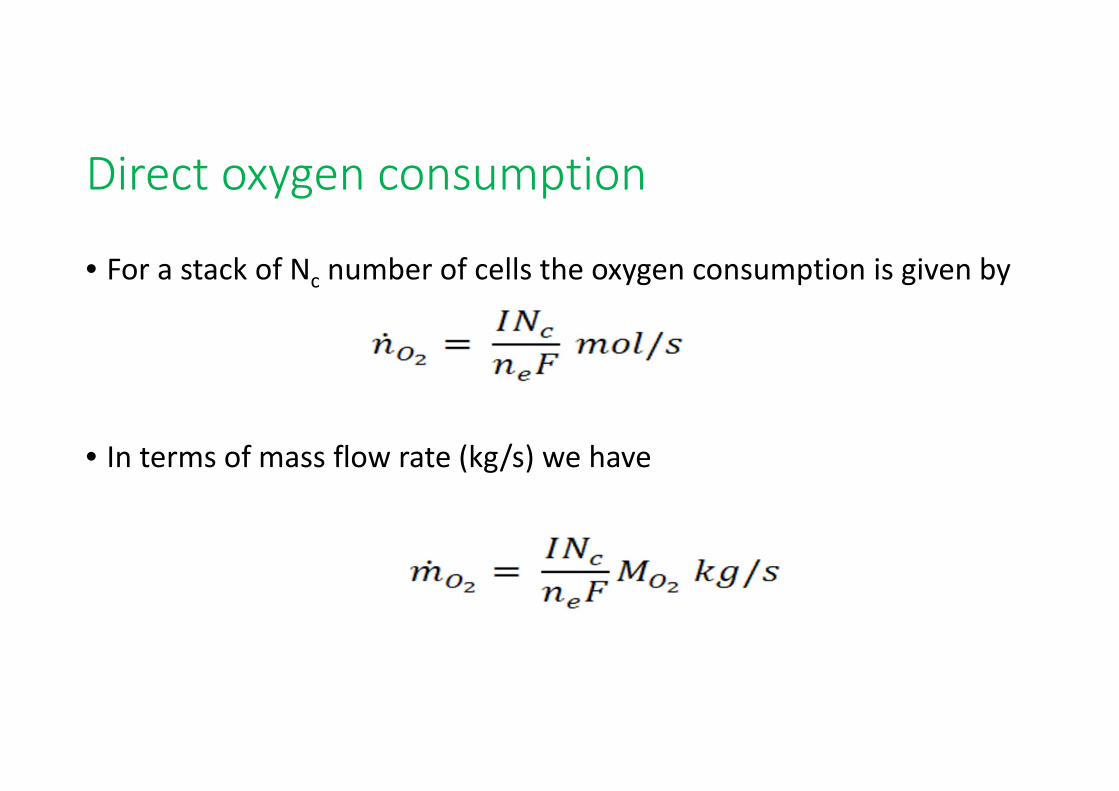
Direct oxygen consumption
• For a stack of Nc number of cells the oxygen consumption is given by
• In terms of mass flow rate (kg/s) we have
Direct oxygen consumption
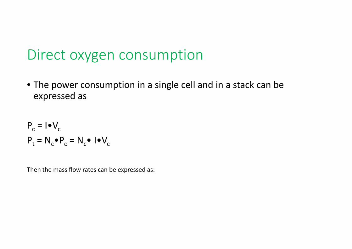
• The power consumption in a single cell and in a stack can be expressed as
Pc = I•VcPt = Nc•Pc = Nc• I•Vc
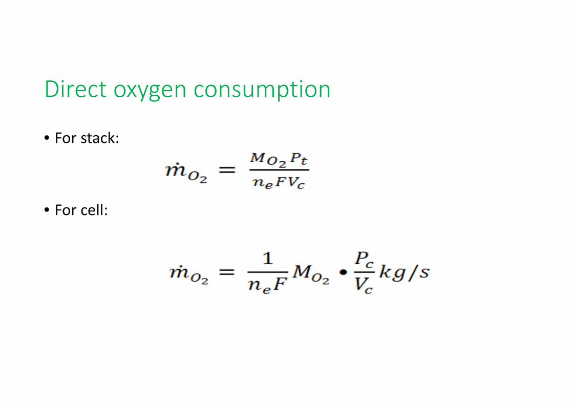
Then the mass flow rates can be expressed as:
Direct oxygen consumption
• For stack:
• For cell:
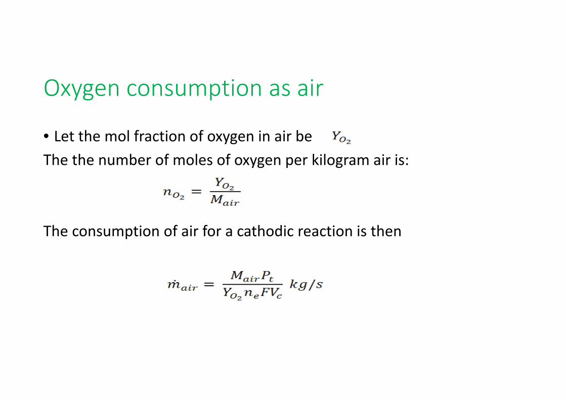
Oxygen consumption as air
• Let the mol fraction of oxygen in air beThe the number of moles of oxygen per kilogram air is:
The consumption of air for a cathodic reaction is then
Oxygen consumption as air
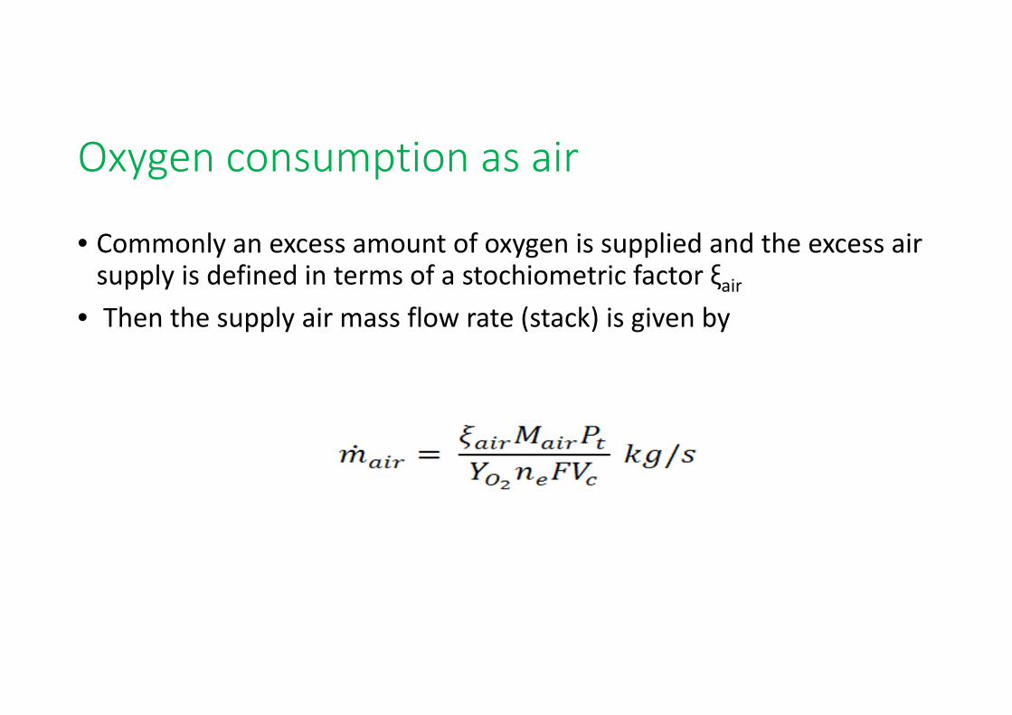
• Commonly an excess amount of oxygen is supplied and the excess air supply is defined in terms of a stochiometric factor ξair
• Then the supply air mass flow rate (stack) is given by
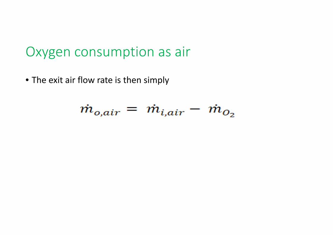
Oxygen consumption as air
• The exit air flow rate is then simply
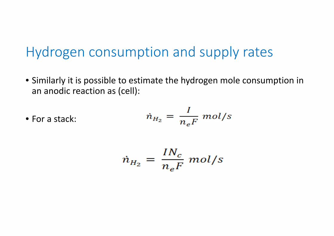
Hydrogen consumption and supply rates
• Similarly it is possible to estimate the hydrogen mole consumption in an anodic reaction as (cell):
• For a stack:
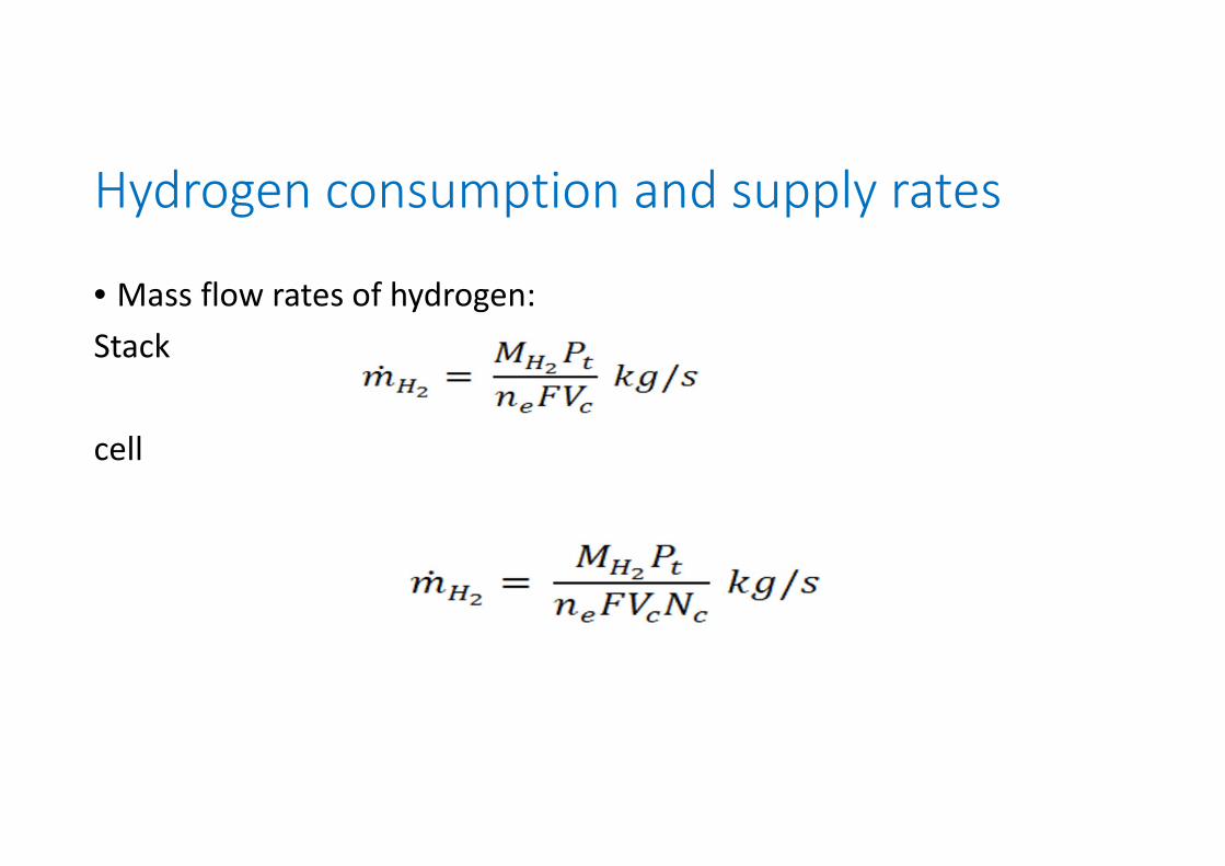
Hydrogen consumption and supply rates
• Mass flow rates of hydrogen:Stack
cell
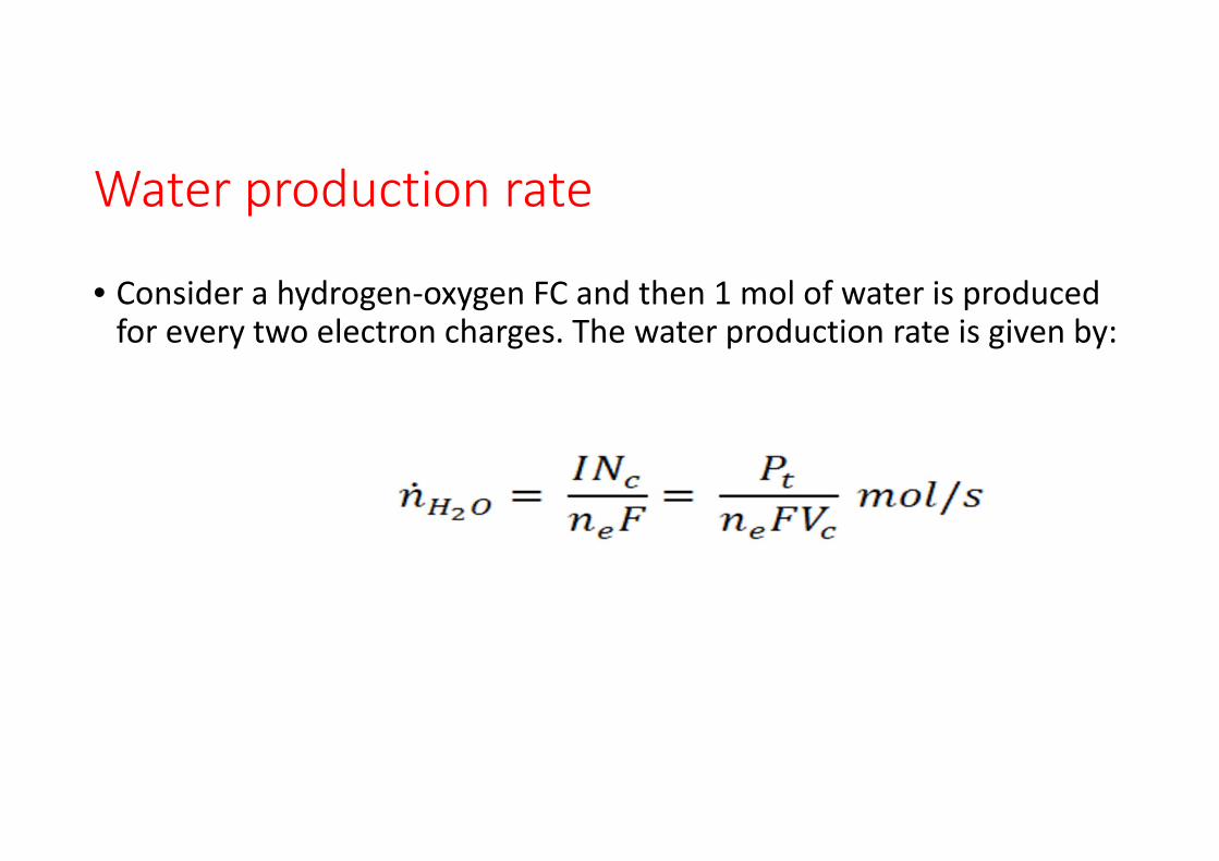
Water production rate
• Consider a hydrogen‐oxygen FC and then 1 mol of water is produced for every two electron charges. The water production rate is given by:
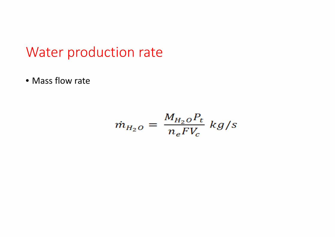
Water production rate
• Mass flow rate
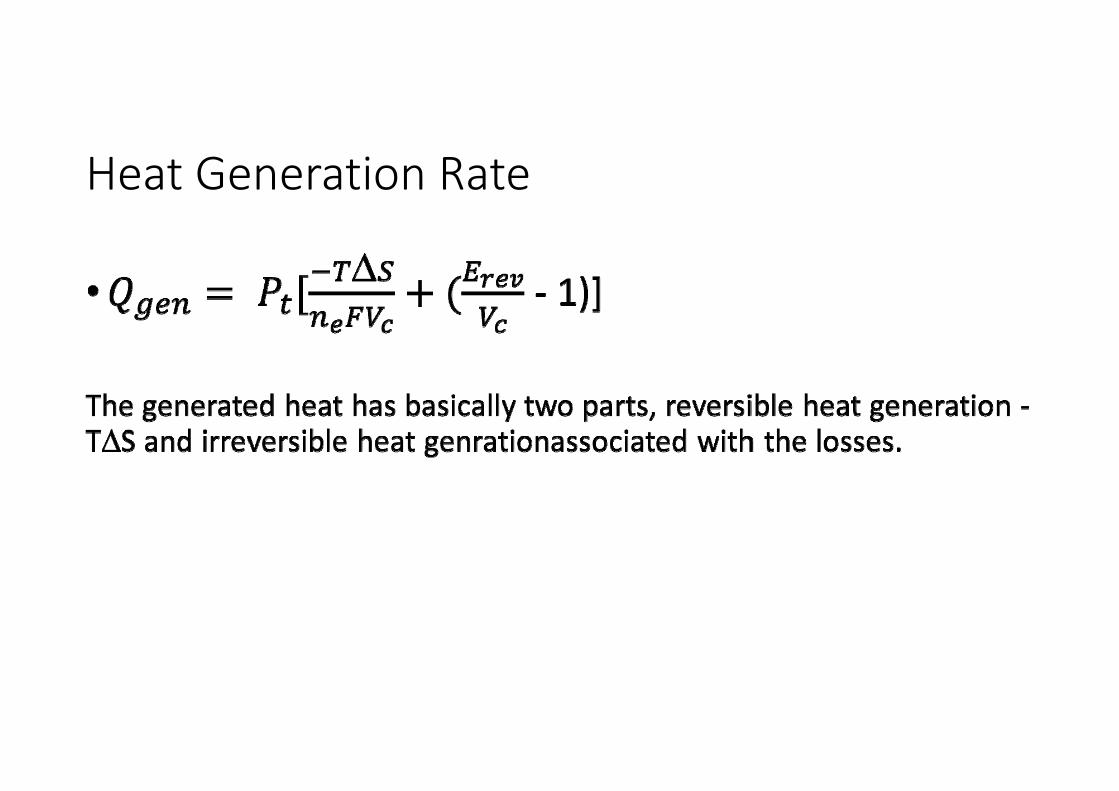
Heat Generation Rate