Embed Size (px)
Citation preview
Electrochemical Energy Conversion
Fuel Cells and Electrochemical Energy Storage Anthony F. Sammells Eltron Research, Inc., 710 E. Ogden Avenue, Naperville, IL 60540
The inhrrmt feature 111 de\.ices for electrurhemical enerhy conversion lien in t h ~ . ilict thl~t c.hct~~ical energy i~ runverred directlv to electricitv with the absence of anv movine Darts or - Carnot efficiency limitations, as is the case with conventional electrical energy generators. As a consequence, fuel cells and rechargeable batteries provide a high efficiency route for the respective generation and convenient storage of electrical energy. Present fossil fueled generating plants typically op- erate with overall efficiencies of 2035%. This compares to the burning via electrochemical oxidation in a fuel cell, of hy- drocarbon derived fuels for which overall efficiencies between 50% and close to theoretical can, in principle, be envi- sioned.
When we consider the increasing demands placed upon the earth's limited resources as a consequence of an expanding population and dwindling fossil reserves, there is a clear ne- cessity to identify and develop new technologies for the more efficient eeneration and usaee of enerev. I t can be ex~ected - - -" that a clearer understanding of electrochemical processes will lead to the more ranid and inevitahlv wider accevtance of such devices to realize this goal. Apart from the rather obvious near term social and economic incentives for makina greater use
even more imperative in the future. This is the slow buillup of COz in the atmosphere, (1,2) which appears to he occurring presently as a result of the increasing consumption of fossil fuels in relatively inefficient power plants and internal com- bustion engines. Such a build up of COz in the atmosphere could result in an increase in the earth's average temperature because of the "greenhouse effect" where the longer wave- length radiation reflected from the earth hecomes absorbed by COz. A partial melting of existing ice caps could result. This could have disasterous effects on present coastal communities because of the resultant rise in sea level which could be an- ticipated, together with a potentially dramatic change in the earth's climate patterns.
To gain an appreciation for the efficiency gains that can be realized from electrochemical energy convertors let us first consider the chemlcal reaction, 2Hz + Oz - 2Hz0, where hydrogen is burned in the presence of oxygen to form water. If the energy resulting from this reaction were used to power an internal combustion engine operating an electrical gener- ator, overall efficiencies for the conversion of this chemical energy to electricity of about 30% might be expected. If we were to perform this same reaction electrochemically in a fuel cell at two metallic electrodes separated by an electrolyte, then the overall reaction could be separated into two partialor half reactions. Hydrogen would become oxidized at the anode via the half reaction
whereas oxygen would become reduced at a cathode via the reaction
O2 + 4Hf + 4e - 2Hz0
Here the overall chemical reaction has become separated into two components via an external wire (for electron transfer)
which connects the anode (where oxidation occurs) and the cathode (where reduction occurs). The free energy change occurring from this overall reaction can he efficiently ex- tracted via the electric current which flows in the wire, which can then. of course. be used directlv to verform useful work. " . The overall efficiency for such a process would be 70-80%. In fuel cells, therefore, chemical enerev is s~ontaneously con- ... . verred ru elecrricity by I he doi~urion of elertro~is at an unodr h i m ,in uxidi.ul~lr material and the arreptance oielectruns via a reducible species a t a cathode povided the overall re- action has a negative AG.
Although the principle of the fuel cell was first experi- mentally demonstrated as early as 1839 (31, it has only been in the last several vears that thev have shown the notentid for reduction to practical devices. The most dramatic demon- stration of this was the HdOq fuel cell used on the Anollo - - moon flights, which operated continuously for 440 hours, eenerated 292 Kw-hr of electrical enerw and. incidentallv 100 i of water. This fuel cell used an aqueous KOH electrolyte, specially prepared porous nickel electrodes, and operated at around 200°C. Major emphasis today is, however, directed toward fuel cells for terrestrial avvlications. Such fnel cells are classified according to the nature of their electrolyte and include mainly the phosphoric acid, molten carbonate and solid oxide systems (4). -
Although i t is well recognized that the electrochemical ki- netics for the reduction of oxygen at a fnel cell cathode are, in general, more rapid in alkaline than with acid electrolytes (thereby leading to lower "overpotential" energy losses) a t a given temperature, the presence of COX in atmospheric oxygen will in the former electrolvte lead to a build uv of carbonate both within the electrolytditself and the electrke pores. This will result in limiting the useful life of the cell. Since oxygen derived from the air is the preferred (cheapest) reducible svecies in such fuel cells, this has dictated an emohasis on fuel cells with acid electrolytes.
Types of Fuel Cells The phosphoric acid fuel cell is the most highly developed
fuel cell today with a 4.8 megawatt unit installed in New York City (5). This fuel cell operates at 180°C and uses highly dis- ptricd pliitirnun on or;iphitizt.d c.whon us the rlectrodei. In - diviih~al wlls opvmte n t currtwr drnsirirs 1r;il m h cni >ill
;I cell \d ta rc 1,irr.7> V. Rc:irarch is t~rl..rnrlv hrinr directed - " toward minimizing the amount of platinum required to ade- auatelv catalvze the s~ontaneous electrochemical reaction. .'dso, n<:w ~:lrctrulytt~s..i~~ h ;I> triil~itmnnrthanc sull'~mir arid ;ire t)eing rescarrhcd hemuae rd'thcir higher ikmicconductivitv and thepossibility of improved electrode kinetics, both df which would lead to lower internal cell enerav losses and. therefore, higher energy conversion efficiencies. This phos- phoric acid fuel cell can be o~era ted onlv in the absence of carbon monoxide a t the fuel electrode (anode) since its pres- ence will result in a poisoning of the platinum and a conse- quent rapid deteriorkion in cell performance.
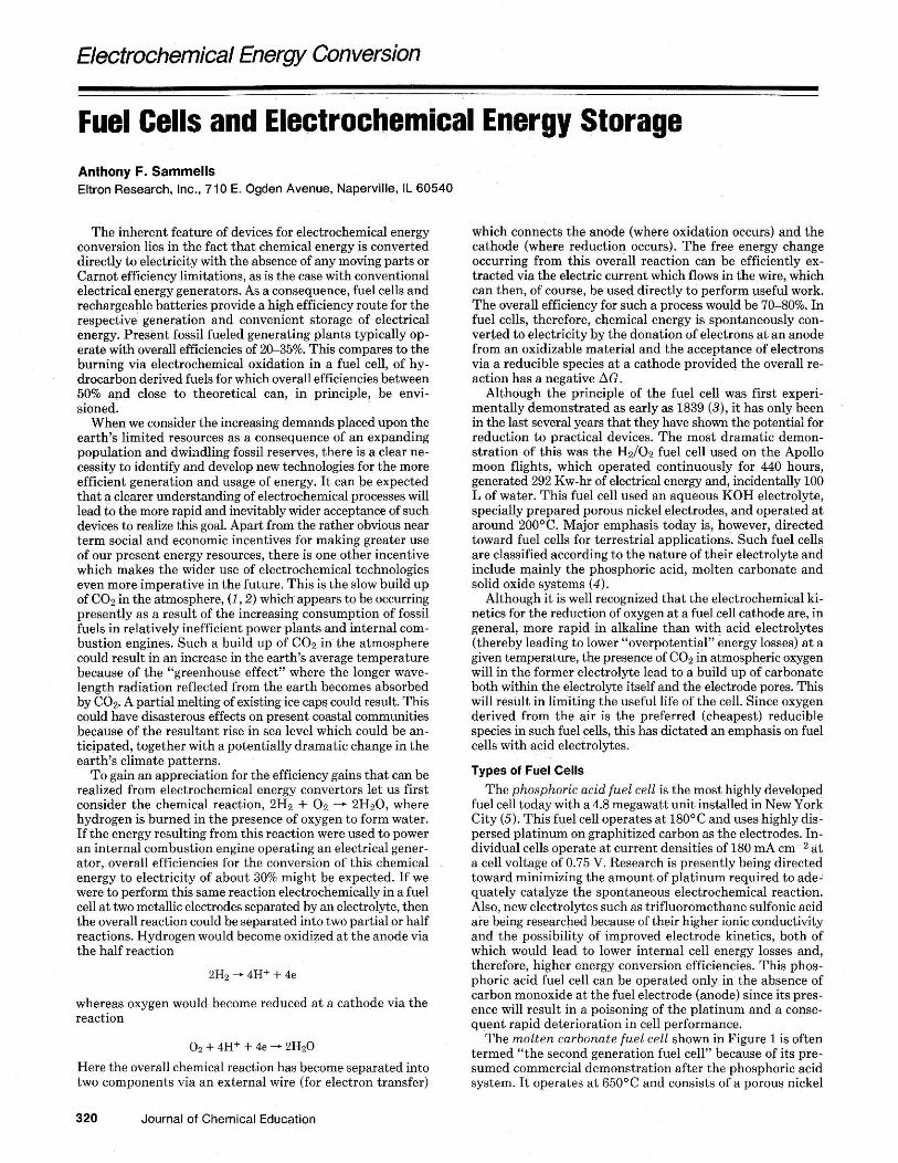
The molten carbonate fuel cell shown in Figure 1 is often termed "the second generation fuel cell" because of its pre- sumed commercial demonstration after the phosphoric acid system. I t operates at 650°C and consists of a porous nickel
320 Journal of Chemical Education
"I"
1
,ON mNn"t,m &m ElTlTkO* I " I " L I I 0 I
Figure 1. Schematic diagram of molten carbonate fuel cell.
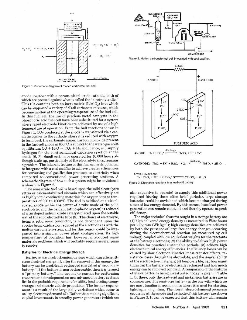
anode together with a porous nickel oxide cathode, hoth of which are pressed against what is called the "electrolyte tile." This tile contains hoth an inert matrix (LiAlOd into which can he sunnorted a varietv of alkali carbonate mixtures, which ~~~ ~~ . . become molten at the operating temperature of the fuel cell. In this fuel cell the use of precious metal catalysts in the phosphoric acid fuel cell have been substituted for a system where rapid electrode kinetics are achieved by use of a high temperature of operation. From the half reactions shown in Figure 1. C07 wroduced at the anode is transferred via a cat- & t i c burnerto the cathode where it is reduced with oxygen to form hack the carbonate anion. Carbon monoxide present in the fuel cell anode at 650°C is subject to the water-gas shift equilibrium CO + Hz0 e COz + Hz and, hence, will supply hydrogen for the electrochemical oxidation reaction at the anode (6 , 7). Small cells have operated for 40,000 hours al- though scale up, particularly of the electrolyte tiles, remains a problem. The inherent feature of this fuel cell is its potential to integrate with a coal gasifier to achieve greater efficiencies for converting coal gasification products to electricity when compared to- conventional power generating stations. A schematic diagram of how such a system might be envisioned is shown in ~ k u r e 2.
The solid ox;de fuel cell is based upon the solid electrolytes yttria or calcia-stabilized zirconia which can effectively act as highly ionic conducting materials for oxygen ions at tem- oeratures of 900 to 1000°C. The fuel is oxidized at a nickel- eoated anode within the center of a tube made of the solid electrolvte. and the oxidant (atmospheric oxygen) is reduced . . HI d t i n rIup<.(l indi11111 oxide ca1a1y.1 p l x d upcm the ou~side I i I I e l r r h 6 I . The cheiie 811 e!errrulglr. heing a solid ionic conductor, is not dependent upon the swecies being oxidized or reduced at the electrodes as with the molten carbbnate system, and for this reason could be inte- grated into a simpler power plant configuration. Its high temperature of operation has, however, introduced many materials problems which will probably require several years to resolve.
Batteries for Electrical Energy Storage Batteries are electrochemical devices which can efficiently
store electrical energy. If, after the removal of this energy, the hattery can he electrically recharged i t is called a "secondary hattery." If the battery is non-rechargeable, then it is termed a "primary battery." The two majorreasons for performing research and development on new advanced hattery systems lies in the nrobable reauirement for utilitv load leveling enerm -- storage and electric vehicle propulsion. The former require- ment is a result of the large dailv variations which occur in utility electricity demand 6). ath her than making significant capital investments in standby power generators (which are
rpi -A"
COMPRESSOR
Figure 2 Molten carbonate fuel cell ~ntegrated with coal gasifier
ANODE CATHODE
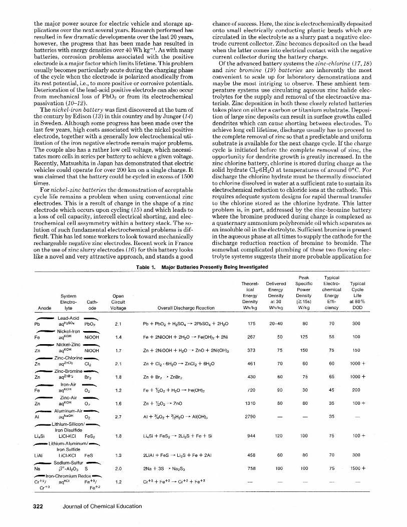
I SULFURIC ACID I discharge
ANODE: Ph + HSO; PhSOa + H' + 2e
discharp CATHODE: PhO, + 3H' + HSO; + 2 e - D PbSO, + 2H,O
Overall Reaction: Ph + PhO, + 2H' + 2HSO; zz=zzzE 2PbS0, + 2H,O
Figure 3. Discharge reactions in a lead-acid battery.
also expensive to operate) to supply this additional power required (during these often brief periods), large storage batteries could be envisioned which hecame charged during times of low energy demand. By this means, base load power generation can remain constant and thereby operate a t peak efficiencv.
The major technical features sought in a storage battery are (1) high delivered enerev densitv as measured in Watt hours per kiogram (Wh kg-:)"; high ehergy densities are achieved by both the presence of large free energy changes occurring during the electrochemical reaction (as measured by cell voltage) coupled with low equivalent weights for the reactants at the hattery electrodes; (2) the ability to deliver high power densities for practical sustainable periods; (3) achieve high electrochemical energy efficiencies. Inefficiency losses can be caused by slow electrode kinetics, mass transfer effects, re- sistance losses through the electrolyte, and the unavailability of the electroactive materials; (4) long cycle life, i.e., how many times can the hatterv be electricallv recharged and how much
1. o f these, only the lea>-acid a i d nickel-iion Gatteries are in common use. The lead-acid battery is the one with which we are most familiar in automobiles where it is used for starting, lightinr, and ignition. The overall electrochemical wrocesses <,,.t I I I ~ : I I ~ .I! I h(. :111ml<. . ~ n d W I htnlc. d t h i . I M I I ~ I Y :lr(, shown i n Fi,w~.e ;:. I t ~ d n I ~ z expr.ted th.~t thi< Iuttery will remain
Volume 60 Number 4 April 1983 321
the major power source for electric vehicle and storage ap- plications over the next several years. Research performed has resulted in few dramatic developments over the last 20 years, however, the progress that has been made has resulted in batteries with energy densities over 40 Wh kg-'. As with many batteries, corrosion problems associated with the positive electrode is a major factor which limits lifetime. This problem usually becomes particularly acute during the charging phase of the cycle when the electrode is polarized anodically from
passivation (10-12). The nichel-iron battery was first discovered at the turn of
the centurv bv Edison (13) in this countrv and bv Juneer (14) . in wede en. ~ i t h o u g h some progress hasbeen made over the last few vears, high costs associated with the nickel ~osit ive electrode, together with a generally low electrochem&al uti- lization of the iron negative electrode remain major problems. The couple also has a rather low cell voltage, which necessi- tates more cells in series Der hatterv to achieve a riven voltare.
was claimed that the battery could be cycled in excess ofi500 times.
For nickel-z~nc batteries the demonstration of acceptable cycle life remains a problem when using conventional zinc electrodes. This is a result of change in the shape of a zinc electrode which occurs upon cycling (15) and which leads to a loss of cell capacity, intercell electrical shorting, and elec- trochemical cell assymmetry within a battery stack. The so- lution of such fundamental electrochemical problems is dif- ficult. This has led some workers to look toward mechanically rechargeable negative zinc electrodes. Recent work in France on the use of zinc slurry electrodes (16) for this battery looks like a novel and very attractive approach, and stands a good
chance of success. Here, the zinc is electrochemically deposited onto small electrically conducting plastic beads which are circulated in the electrolyte as a slurry past a negative elec- trode current collector. Zinc becomes deposited on the head when the latter comes into electrical contact with the negative current collector during the battery charge.
Of the advanced battery systems the zinc-chlorine (1 7,181 and zinc bromine (19) batteries are inherently the most convenient to scale up for laboratory demonstrations and maybe the most intriging to observe. These ambient tem- perature systems use circulating aqueous zinc halide elec- trolytes for the supply and removal of the electroactive ma- terials. Zinc deposition in both these closely related batteries takes place on either a carbon or titanium substrate. Deposi- tion of large zinc deposits can result in surface growths called dendrites which can cause shorting between electrodes. To achieve long cell lifetime, discharge usually has to proceed to the complete removal of zinc so that a predictable and uniform substrate is available for the next charge cycle. If the charge cycle is initiated before the complete removal of zinc, the o ~ ~ o r t u n i t v for dendrite growth is ereatlv increased. In the "
z& chlorine battery, chlorine is stored during charge as the solid hvdrate C1~6H90 at tem~eratures of around ODC. For
electrochemical reduction to chloride ions at the cathode. This requires adequate system designs for rapid thermal transfer to the chlorine stored as the chlorine hydrate. This latter problem is, in part, addressed by the zinc-bromine battery where the bromine produced during charge is complexed as a quaternary ammonium polybromide oil which separates as an insoluble oil in the electrolyte. Sufficient bromine is present in the aqueous phase a t all times to supply the cathode for the discharge reduction reaction of bromine to bromide. The somewhat complicated plumbing of these two flowing elec- trolyte systems suggests their more probable application for
Theoret- Delivered ical Energy
System Open Energy Density Eiectro- Cath- Circuit Density at 30
Anode lyte ode Voltage Overall Discharge Reaction Wh/kg Whlkg
Table 1. Major Batteries Presently Being Investigated
-
Lead-Acid - Pb aqHsSo' PbOn
Nickel-Iron - Fe aqKoH NiOOH
Nickei-Zinc - Zn aqKoH NiOOH
Zinc-Chlorine- Z" aqz"='2 CI,
Zinc-Bromine- Zn aqZ"8's Br2 - I - A -4 Fe aqKoH O2
Zinc-Air - zn aqKOH 0 2
Aluminum-Air- Ai aqNaOH 0 2
-Lithium-Silicon/-, lron Oisulfide
LilSi LiCI-KC1 FeS2 - Lithium-Aluminum/-, lron Sulfide
Li A1 LEI-KC1 FeS
Sodlum-Sulfur - N= ~ - A I ~ O S s
2LiAl + FeS - Li2S + Fe + 2Ai
2Na + 3 s - Na2S3
Crt3 + Fe+2 - Crt2 + Fei3
Peak Typical Specific Electro- Typical Power chemical Cycle Density Energy Life (215s) Effi- a t80% Wlkg ciency 000
322 Journal of Chemical Education
bulk energy storage rather than for electric vehicles. Redox batteries comuletelv avoid electrode morphological
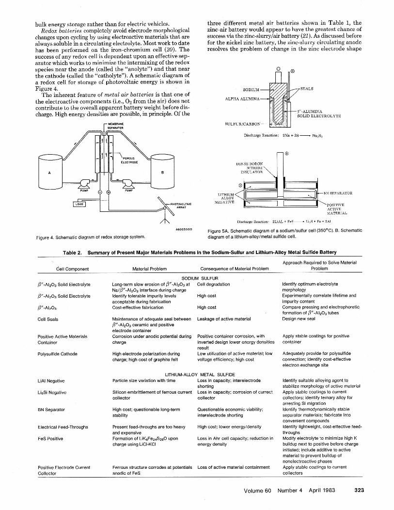
changes upon cycling by using electroactive materials that are always soluble in a circulating electrolyte. Most work to date has been performed on the iron-chromium cell (20). The success of any redox cell is dependent upon an effective sep- arator which works to minimize the intermixing of the redox species near the anode (called the "anolyte") and that near the cathode (called the "catholyte"). A schematic diagram of a redox cell for storage of photovoltaic energy is shown in Figure 4.
The inherent feature of metal air batteries is that one of the electroactive comuonents (i.e.. Oo from the air) does not
three different metal air batteries shown in Table 1, the zinc-air battery would appear to have the greatest chance of success via the zinc-slurrylair battery (21). As discussed before for the nickel zinc battery, the zinc-slurry circulating anode resolves the problem of change in the zinc electrode shape
SODIUM
ALPHA ALUMINA
SOLID ELECTROLYTE
SULFURICARBON
cuntril~ute t t r the u\wal, npp : i n 111 barrcry w i g h t heiore dis- rh;arge. High encrky den+ities arr po-:~lh, in prinrilk. Of t h e
Discharge Reaction: 2Na + 33- Na,S,
A 480030810
Figure 4. Schematic diagram of redox storage system.
LITHIUM BN SEPARATOR ALLOY
NEDATIVE POSITIVE ACTIVE MATERIAL
Discharge Rsrctmn: 21rAL+ FeS-LI,S + Fe + 241
Figure 5A. Schematic diagram of a sodiumlsuifur cell (350°C). 8. Schematic diagram of a iithium-ailoylmetal sulfide cell.
Table 2. Summary of Present Major Materials Problems in the Sodlum-Sulfur and Lithium-Allov Metal Sulfide Batterv
Cell Comoonent
P-Ai203 Solid Electrolyte
P-A1,O3 Solid Electrolyte
p-Ai2O3
Cell Seais
Positive Active Materiais Container
POlySUifide Cathode
LiAi Negative
LisSi Negative
EN Separator
Electrical Feed-Throughs
FeS Positive
Positive Electrode Current Collector
Material Problem Consequence of Material Problem
SODIUM SULFUR Long-term slow erosion of fl"-Ai2O3 at Cell degradation NalP-A1203 interface during charge identify tolerable impurity levels High cost acceptable during fabrication Cost-effective fabrication High cost
Maintenance of adequate seai between Leakage of active materiai p -A l soS ceramic and positive electrode container Corrosion under anodic potential during Positive container corrosion, with charge inverted design lower energy densities
resuit High electrode polarization during LOW utilization of active material: low charge: high cost of graphite felt voltage efficiency; high cost
LITHIUM-ALLOY METAL SULFIDE Particle size variation with time Loss in capacity: ~ntereiectrode
shorting Silicon embrittiement of ferrous current Loss in capaclty: corrosion of currecl collector collector
High cost: questionable long-term Questionable economic viability; stability interelectrode shorting
Present feed-thraughs are too heavy High cost: iower energyidensity and expensive Formation of LiKeFe2&~O upon LOSS in Ahr cell capacity; reduction in charge using LiCi-KCi energy density
Ferrous structure corrades at potentials Loss of active materiai containment anodic of FeS
Approach Required to Solve Material Probiem
identify optimum electrolyte morphology Exper8mentaliy correlate lifetime and impurity content Compare pressing and electrophoretic formation of ~ - A I , o ~ tubes D e w n new seai
Apply stabie coatings f a positive container
Adequately provide far polysuifide connection: identify cost-effective electron exchange site
Identify suitable alloying agent to stabilize mor~hoio(lv of active materiai
arresting Si migration identify thermodynamically stable separator materials: fabricate into convenient compounds identify lightweight, cost-effective feed- through$ Modify electrolyte to minimize high K buildup next to positive before charge initiated; include additive to active materiai to prevent buildup of noneiectroactive phases Apply stable coatings to current ~o i i ec to r~
Volume GO Number 4 April 1983 323

associated with conventional solid zinc electrodes. Also, the
&-reduction) is not necessary as is with, for example, the iron air battery, since formation of the zinc slurry occurs in a sep- arate charging cell. The negative electrode of the alumi- num-air battery is mechanically recharged (22) and although it has an attractive theoretical energy density, has yet to prove itself a viahle candidate for electric vehicles.
Both the high temperature lithium alloylmetal sulfide and sodium-sulfur batteries have demonstrated in the laboratory the potential for achieving the necessary energy and power densities for electric vehicle propulsion. Also, because of their low projected costs, they appear compatible for hulk energy storage. The high temperature of operation for these cells is dictated by the melting point of the LiC1-KC1 molten salt electrolvte in the Li-allovlmetal sulfide cell and bv the meltine point o; the sodium pol&dfide reactant at the cathode of thz sodium sulfur cell. These cells tvoicallv onerate at 450 and . . . . 350°C, respectively.
Both cells are shown in Fiaure 5A & B. Both lithium-alu- minum (23) and lithium-silicon (24) negative electrodes have been studied to date for the lithium alloy cell. The unique feature of the sodium sulfur cell is the application of the so- dium ion conducting solid electrolyte /f" Ale03, which acts to separate the highly reactive molten sodium anode from the molten sodium polysulfide cathode. Because of the high temperature of operation for both of these systems, research greatly emphasizes materials corrosion problems. Major materials research endeavors with these svstems are sum- marized in Table 2.
Recently, photoelectrochemical (PEC) cells (25-27) have been shown compatihle for energy storage. They will he dis- cussed in subsequent papers.
Electrochemical energy conversion and storage research and
development represents an exciting and challenging research area for the future, because of the obvious benefits that will result from successful progress in this area and the inherent multidisciplinary nature i f such work.
Such electrochemical technology can be expected to mature toward the end of this centurv and make a maior imoact in the next. Applications can be expected in primary energy gener- ation (fuel cells). enerw manaaement load leveling (batteries).
324 Journal of Chemical Education