Embed Size (px)
Citation preview

Fuel Cycle Approaches
for Waste Burden Minimisation
in Japan
K. Nishihara
Japan Atomic Energy Agency
Technical Meeting on Advanced Fuel Cycles to Improve the Sustainability of Nuclear Power through the Minimisation of High Level Waste, VIC M0E05, Vienna, 17-19 October 2017

Content
1. Scenario study for Level 1, 2 and 4 in case of phase-out
in Japan
2. R&D for ADS
Reference: K. Nishihara, et. al, “Comparative Study of Plutonium and Minor Actinide Transmutation Scenario,” Proceedings of 21st International Conference & Exhibition; Nuclear Fuel Cycle for a Low-Carbon Future (GLOBAL 2015) , p.388 - 395, 2015/09
LWR Repository Pu, MA, FP
(SF)
- After the Fukushima-accident,
visions of long-term utilization
becomes unclear in Japan.
- If current LWRs will not be
replaced after their closure,
Pu remains as legacy in
spent fuel (SF) from LWR.
- This study focuses on
transmutation of Pu and
minor actinide (MA) in SF
that will be produced from the
existing LWRs in Japan.
Reference scenario
0
10
20
30
40
50
60
1960 1980 2000 2020 2040 2060G
en
era
tio
n c
ap
acity o
f LW
R (
GW
e)
A.D.
REF
2055
Phase-out
Direct disposal of LWR-SF
Phase-out from NPP 1. Scenario study:

Once-through (OT-)
Transmutation
LWR Repository MA, FP
(SF)
Transmuter = Thermal neutron reactors
L-MOX, light water reactor (LWR) with MOX
L-ROX, LWR with rock-like oxide (ROX)
G-ROX, gas reactor with ROX
Reproce
ssing
Transmu
ter
Pu
Pu, MA, FP
Pu is transmuted only once.
ROX: PuO2 in yittria stabilized zirconia (YSZ)
Chemically stable like natural rock,
and hardly soluble to acid and alkali
(Glass)
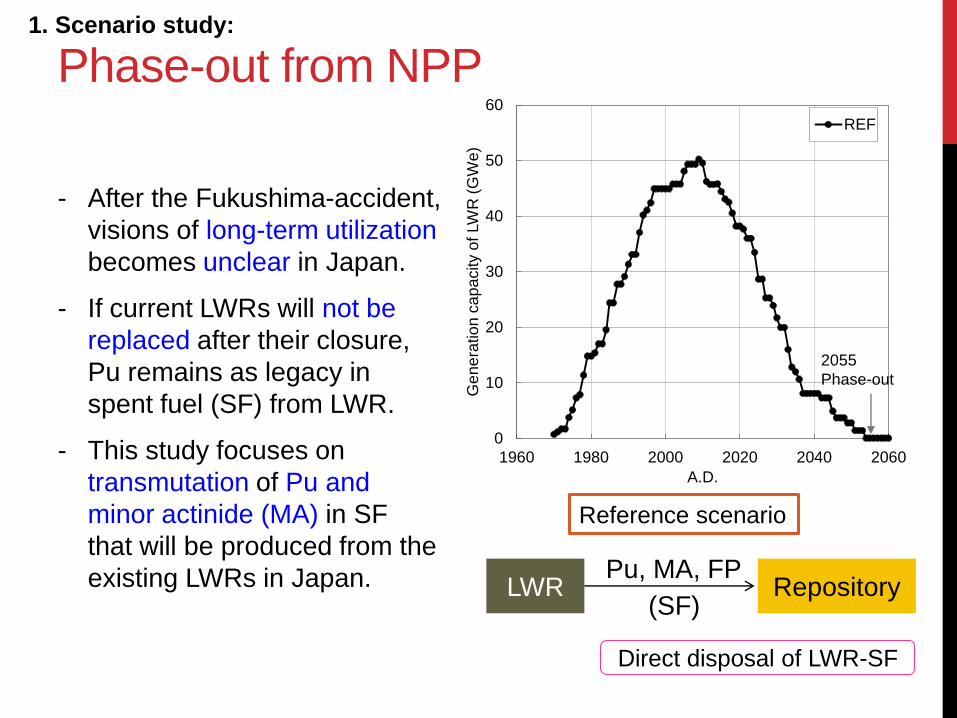
Multiple (M-)
Transmutation
LWR Repository FP
(SF)
Transmuter = Fast neutron reactors
FR, sodium-cooled fast reactor
ADS, accelerator-driven system
MSFR, molten-salt fast reactor
Transmu
ter
Pu, MA Pu, MA, FP
TRU is transmuted in many times.
Reproce
ssing
FP
Pu, MA
Only FP is
disposed of. Reprocessing
with partitioning

Purpose and
Estimated amounts
1. Scale of transmuters
Thermal output, number of plants, schedule
2. Inventory of Pu and MA
Time evolution, residual amount after closing transmuters
3. Repository
Area, potential toxicity
Many transmutation technology are proposed from many research
groups.
Each of them insists its superiority to direct disposal based on each
assumptions and analysis.
This study attempts to provide estimations for each based on
common assumptions and analysis.

Method: NMB code
(Nuclear Material Balance Code)
Amount of 26 actinides (Th-Cm, T1/2> several days) in spent fuels is calculated with an accuracy comparable to the ORIGEN code.
LWR, CANDU, gas-cooled reactor, several sodium-cooled FRs, ADS and MSFR are available. Each reactor can be coupled with appropriate fuel such as UO2, MOX, ROX, Pu-nitride (PuN), MA-nitride (MAN) and molten-salt fuel.
Fission products are estimated by dividing them into several groups (iodine, rare gas, technetium and platinum group metals, strontium, cesium and others)
Number of waste packages and repository size are determined by temperature analysis considering repository layout.
Potential radio-toxicity that is defined as dose by direct ingestion is also estimated.
Backup
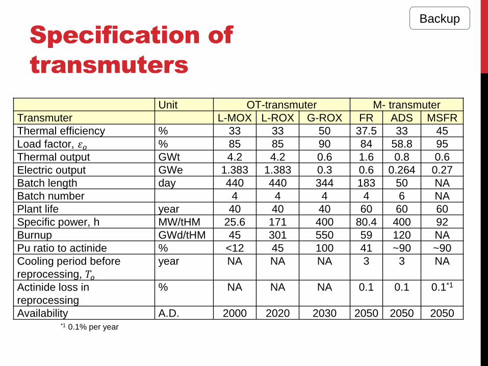
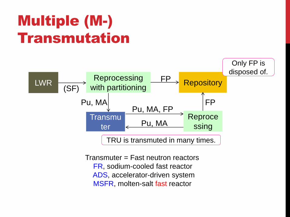
Specification of
transmuters
*1 0.1% per year
Unit OT-transmuter M- transmuter
Transmuter L-MOX L-ROX G-ROX FR ADS MSFR
Thermal efficiency % 33 33 50 37.5 33 45
Load factor, 𝜀𝑜 % 85 85 90 84 58.8 95
Thermal output GWt 4.2 4.2 0.6 1.6 0.8 0.6
Electric output GWe 1.383 1.383 0.3 0.6 0.264 0.27
Batch length day 440 440 344 183 50 NA
Batch number 4 4 4 4 6 NA
Plant life year 40 40 40 60 60 60
Specific power, h MW/tHM 25.6 171 400 80.4 400 92
Burnup GWd/tHM 45 301 550 59 120 NA
Pu ratio to actinide % <12 45 100 41 ~90 ~90
Cooling period before
reprocessing, 𝑇𝑜
year NA NA NA 3 3 NA
Actinide loss in
reprocessing
% NA NA NA 0.1 0.1 0.1*1
Availability A.D. 2000 2020 2030 2050 2050 2050
Backup

Common assumptions
• LWR construction: Ohma, full-MOX BWR in
2014 is the last.
• Rokkasho reprocessing is gradually started
from 2015. Separation of MA becomes
possible from 2025.
• L-MOX fuel can be loaded to all LWRs with limit
of 30% except Ohma that is full-MOX reactor.
Backup
Result: OT-transmutation
Scale of transmuters
0
2
4
6
8
10
12
2000 2020 2040 2060 2080 2100
Ge
ne
ratio
n c
ap
acity o
f O
T-T
ran
sm
ute
rs
(GW
e)
A.D.
L-MOX (Total)
L-MOX (full loading)
L-ROX (Total)
L-ROX (full loading)
G-ROX (Total)
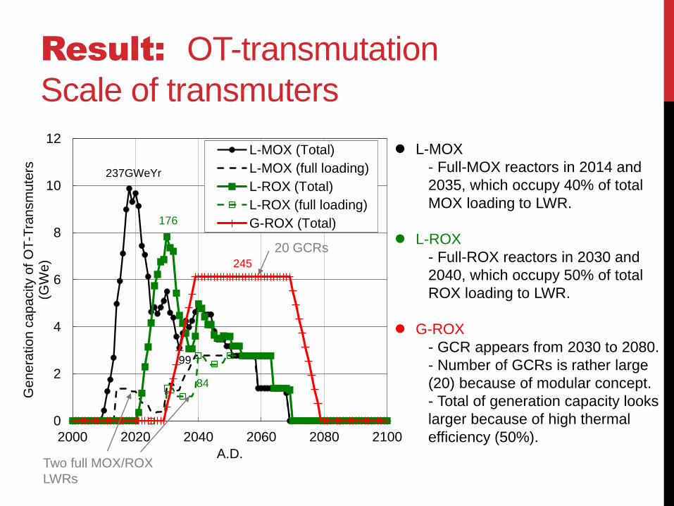
237GWeYr
176
84
99
245
Two full MOX/ROX
LWRs
L-MOX
- Full-MOX reactors in 2014 and
2035, which occupy 40% of total
MOX loading to LWR.
L-ROX
- Full-ROX reactors in 2030 and
2040, which occupy 50% of total
ROX loading to LWR.
G-ROX
- GCR appears from 2030 to 2080.
- Number of GCRs is rather large
(20) because of modular concept.
- Total of generation capacity looks
larger because of high thermal
efficiency (50%).
20 GCRs

Result: OT-transmutation
Actinide inventory
0
50
100
150
200
250
300
350
400
450
500
2000 2020 2040 2060 2080 2100
TR
U in
ve
nto
ry (
t)
A.D.
REF
L-MOX
L-ROX
G-ROX
0
50
100
150
200
250
2000 2020 2040 2060 2080 2100
Fis
sile
Pu
in
ve
nto
ry (
t)
A.D.
REF
L-MOX
L-ROX
G-ROX
MA+Pu Fiss. Pu
-37
%
-24
%
-39
%
-72
%
-55
%
-79
%
Total amount in REF reaches 430t.
L-MOX is inferior to others.
Total amount in REF reaches 210t.
G-ROX performs best.
L-ROX contains small amount of 238U
due to safety issue, which produces 239Pu.
430t 210t
0
1
2
3
4
5
6
7
2000 2100 2200 2300 2400
Ge
ne
ratio
n c
ap
acity o
f tr
an
sm
ute
r (G
We)
A.D.
FR
ADS
MSFR
Result: M-transmutation
Scale of transmuters
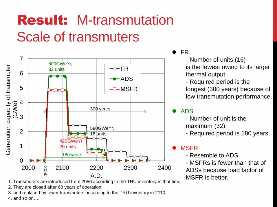
580GWeYr,
16 units
420GWeYr
26 units
500GWeYr,
32 units
180 years
300 years
FR
- Number of units (16)
is the fewest owing to its larger
thermal output.
- Required period is the
longest (300 years) because of
low transmutation performance.
ADS
- Number of unit is the
maximum (32).
- Required period is 180 years.
MSFR
- Resemble to ADS.
- MSFRs is fewer than that of
ADSs because load factor of
MSFR is better.
←2
05
0
1. Transmuters are introduced from 2050 according to the TRU inventory in that time.
2. They are closed after 60 years of operation,
3. and replaced by fewer transmuters according to the TRU inventory in 2110,
4. and so on….
0
50
100
150
200
250
2000 2100 2200 2300 2400F
issile
Pu
in
ve
nto
ry (
t)A.D.
REF
FR
ADS
MSFR
Result: M-transmutation
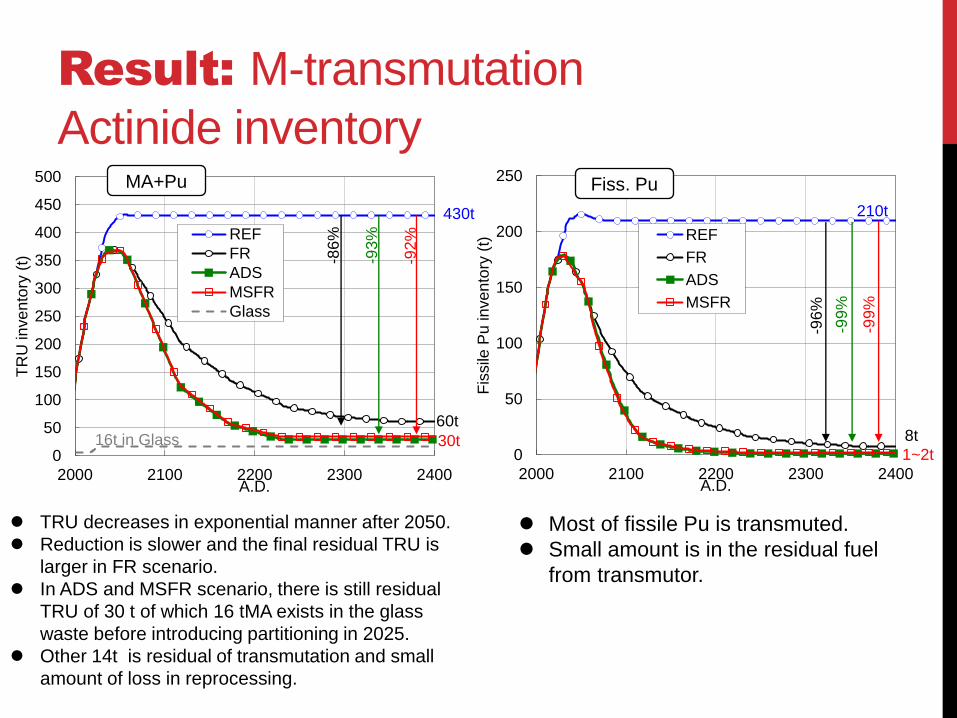
Actinide inventory Fiss. Pu
-99
%
-96
%
-99
%
TRU decreases in exponential manner after 2050.
Reduction is slower and the final residual TRU is
larger in FR scenario.
In ADS and MSFR scenario, there is still residual
TRU of 30 t of which 16 tMA exists in the glass
waste before introducing partitioning in 2025.
Other 14t is residual of transmutation and small
amount of loss in reprocessing.
Most of fissile Pu is transmuted.
Small amount is in the residual fuel
from transmutor.
210t
1~2t
8t
0
50
100
150
200
250
300
350
400
450
500
2000 2100 2200 2300 2400
TR
U in
ve
nto
ry (
t)
A.D.
REF
FR
ADS
MSFR
Glass
MA+Pu
-93
%
-86
%
-92
%
430t
30t
60t
16t in Glass

Repository size
0
1
2
3
4
5
RE
F
L-M
OX
L-R
OX
G-R
OX
FR
AD
S
MS
FR
Tota
l re
pository
are
a (
km
2)
ROX
SF
ROX
SF
MOX
SF
MOX
SF
UO2
SF
Glass
PT waste
OT-Transmutation M-Transmutation
-80
%
OT-transmutation
- Area is same to REF.
- Decay heat from MOX- and ROX-
spent fuel avoids dens disposal,
although glass waste occupies about
half of original UO2 spent fuel.
M-transmutation
- Area is reduced by 80%.
- Glass before introducing partitioning
technology (in 2025) occupies 0.5km2.
Potential radio-toxicity
(Dose assuming direct ingestion)
1E+8
1E+9
1E+10
1E+11
1E+12
1E+13
1E
+2
1E
+3
1E
+4
1E
+5
1E
+6
Inta
ke d
ose (
Sv)
Time (year)
ADS
MSFRFR
natU
L-MOXL-ROXG-ROX
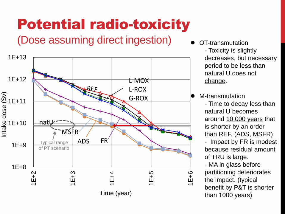
OT-transmutation
- Toxicity is slightly
decreases, but necessary
period to be less than
natural U does not
change.
M-transmutation
- Time to decay less than
natural U becomes
around 10,000 years that
is shorter by an order
than REF. (ADS, MSFR)
- Impact by FR is modest
because residual amount
of TRU is large.
- MA in glass before
partitioning deteriorates
the impact. (typical
benefit by P&T is shorter
than 1000 years)
Typical range
of PT scenario
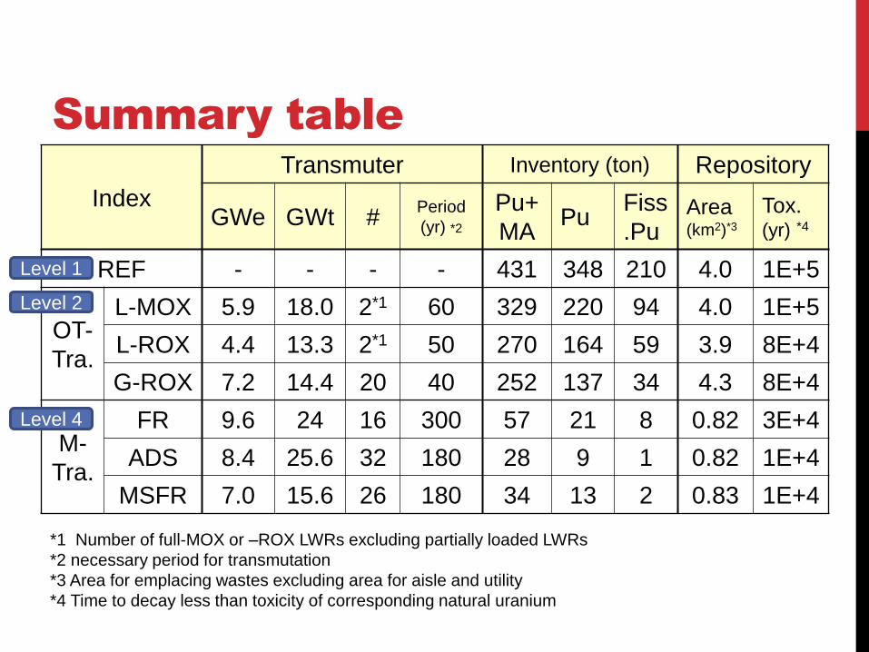
Summary table
Index
Transmuter Inventory (ton) Repository
GWe GWt # Period
(yr) *2
Pu+
MA Pu
Fiss
.Pu Area (km2)*3
Tox. (yr) *4
REF - - - - 431 348 210 4.0 1E+5
OT-
Tra.
L-MOX 5.9 18.0 2*1 60 329 220 94 4.0 1E+5
L-ROX 4.4 13.3 2*1 50 270 164 59 3.9 8E+4
G-ROX 7.2 14.4 20 40 252 137 34 4.3 8E+4
M-
Tra.
FR 9.6 24 16 300 57 21 8 0.82 3E+4
ADS 8.4 25.6 32 180 28 9 1 0.82 1E+4
MSFR 7.0 15.6 26 180 34 13 2 0.83 1E+4
*1 Number of full-MOX or –ROX LWRs excluding partially loaded LWRs
*2 necessary period for transmutation
*3 Area for emplacing wastes excluding area for aisle and utility
*4 Time to decay less than toxicity of corresponding natural uranium
Level 1
Level 2
Level 4
Conclusion of scenario study
• As a whole, advanced technology performs better,
but necessary transmuters is more.
• Development of efficient Pu burner with multiple
transmutation is needed in case of phase-out.
• Advantage and disadvantage of the technologies
depends on many aspect: economics, technological
readiness, inherent safety, impact on repository,
non-proliferation and so on. The present
comparison using common assumptions and
methodology provides base of the future discussion
in these aspect.

18
2. R&D for ADS:
Technical Issues of ADS in JAEA
• R&D of SC-LINAC • Reliability assessment
based on experience in J-PARC accelerator
•Design study on reactor vessel, beam duct, quake-proof structure, etc.
•Fabrication, irradiation and reprocessing tests
•Experiments in critical assemblies and analyses
Reactor component
MA fuel
•Pb-Bi technology (chemical control, pumps, sensors…) in cold loop
•Material verification (irradiation corrosion, erosion, strain)
•Spallation Target, Material
•Operation of Pb-Bi system
•Reactor Physics •Control of Subcritical System
Accelerator
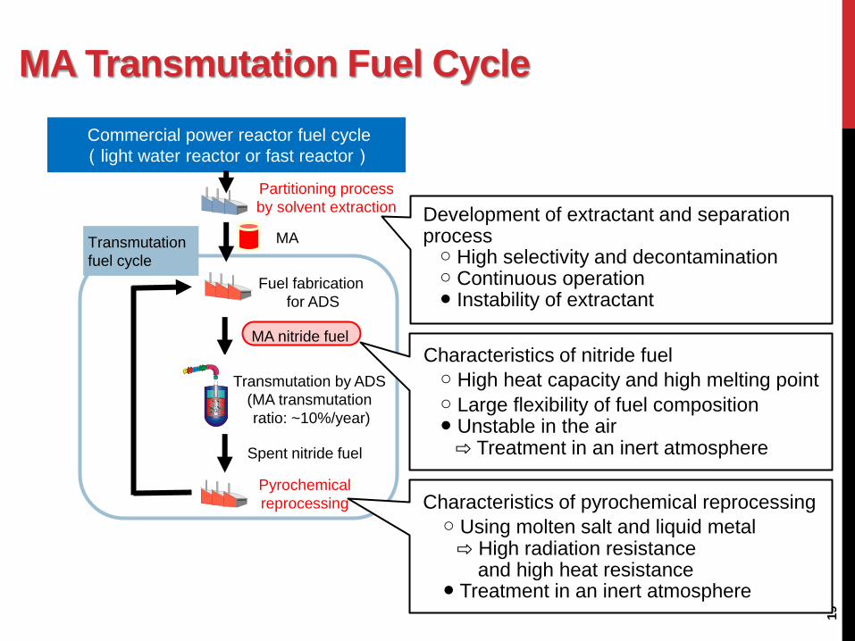
MA Transmutation Fuel Cycle
19
MA nitride fuel
Spent nitride fuel
Transmutation
fuel cycle
Commercial power reactor fuel cycle
(light water reactor or fast reactor)
Partitioning process
by solvent extraction
Transmutation by ADS
(MA transmutation
ratio: ~10%/year)
Fuel fabrication
for ADS
Pyrochemical
reprocessing
MA
Characteristics of nitride fuel
○ High heat capacity and high melting point
○ Large flexibility of fuel composition ● Unstable in the air
⇨ Treatment in an inert atmosphere
Characteristics of pyrochemical reprocessing
○ Using molten salt and liquid metal ⇨ High radiation resistance and high heat resistance ● Treatment in an inert atmosphere
Development of extractant and separation process ○ High selectivity and decontamination ○ Continuous operation ● Instability of extractant

R&D Activities in JAEA :
MA Separation Process from HLW
20
- Very high Distribution ratio (D) for An(III) and RE at high HNO3 concentration
- Very low D of An(III) at low HNO3 concentration
- Soluble in n-dodecane, CHON extractant
- High extraction capacity
Np, Pu
FP, U(VI)
Am, Cm, RE
High-level liquid waste(HNO3:1-3M)
An(IV) Strip
An(III) Strip
An(III),An(IV) Extraction
Conceptual flow of the process
Counter-current continuous extraction tests
using mixer-settler units were performed
with simulated HLLW containing 12 fission
product elements and Am and Np tracers.
C
C
O
O
O
C
CH2
NN
C12H25
H25C12
H2
C12H25
H25C12 C
C
O
O
O
C
CH2
NN
C12H25
H25C12
H2
C12H25
H25C12
TDdDGA (Dodecyl-DGA)
N,N,N’N’-tetradodecyldiglycolamide
Am extraction : > 99.99 %
Np extraction : 91 %
Sr, Pd, Zr were separated from An.
Optimization of the process for genuine HLLW hot test are conducted.

R&D Activities in JAEA :
MA Nitride Fuel Fabrication & Performance
21
Almost completed
- Preparation of homogenous
mixture of inert matrix (ZrN)
and TRU nitrides
- Stability evaluation of ZrN-
TRU nitride solid solution
against hydrolysis &
evaporation
-Physical property
measurements
To be studied/developed
- Fabrication process
considering high heat
density of the fuel
- Enrichment of 15N
- Fuel behavior analyses code
- Irradiation tests
Nitridation-distillation combined method
窒化法
Fuel rod
PartitioningProcess
Pyrochemicaltreatment
Nitride fuel pellet
Inert matrix nitride
fuel powder material
MA nitride TRU nitride Inert matrix(ZrN)
MA containing
aqueous solution
Recovered TRU
(TRU-Cd alloy)
via oxideCarbothermic
reduction
Fuel assembly
HLW from commercial power reactor cycle
(Zr,Pu)N pellet sample
for irradiation test at
JMTR
(Zr,Pu,Am)N
disk sample
3mmf、95mg
Powder metallurgy
AnCdx+1/2N2=AnN+xCd↑
AnO2+2C+1/2N2=AnN+2CO↑
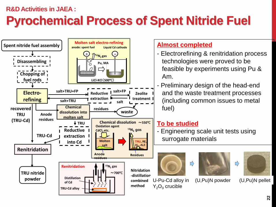
R&D Activities in JAEA :
Pyrochemical Process of Spent Nitride Fuel
22
Spent nitride fuel assembly
TRU nitride powder
Reductive extraction
into Cd
Chemical dissolution into
molten salt
Zeolite treatment
recovered TRU
(TRU-Cd)
Anode residues
residues waste
Chopping of fuel rods
Renitridation
Electro-refining
Disassembling
TRU-Cd
TRU
Reductive extraction
salt+TRU+FP
salt+TRU
Anode
residues
Oxidation agent CdCl2 etc.
Molten salt
Residues
Chemical dissolution
15N2 gas
TRU、RE、 AL、ALE
LiCl-KCl(500℃)
15N2 gas
Pu, MA
Liquid Cd cathode anode: spent fuel
Molten salt electro-refining
~700℃
TRU-Cd alloy
15N2 gas
Distillation of Cd
Nitridation-distillation combined method
Renitridation
~550℃
salt+FP
salt
Almost completed
- Electrorefining & renitridation process
technologies were proved to be
feasible by experiments using Pu &
Am.
- Preliminary design of the head-end
and the waste treatment processes
(including common issues to metal
fuel)
To be studied
- Engineering scale unit tests using
surrogate materials
Cd cathode U and Pu Recovered (U,Pu)Npowder Nitride pelletU-Pu-Cd alloy in
Y2O3 crucible
(U,Pu)N powder (U,Pu)N pellet

TRL
K. Ikeda et al. / Progress in Nuclear Energy 74 (2014) 242-263
TRL of ADS reactor and Double Strata fuel cycle in Japan
• The nuclear technology for the ADS
is assessed to be at TRL 2 to 3
(Proof of critical function).
• The next step is development of
individual technology in engineering
scale.

backup

Someday, Phase out
will come …
0
20,000
40,000
60,000
80,000
100,000
2000 2100 2200 2300 2400 2500 2600 2700 2800
TRU
in t
he
wo
rld
(t)
A.D.
Open cycle
Transition
to FR
NOT YET closed. Huge inventory in core….
Sustainable
FR Phase-out
OK, it’s
closed!
Backup

Result: OT-transmutation
Transmutation ratio
FF: fresh fuel, SF: spent fuel
0%
20%
40%
60%
80%
100%
FF SF FF SF BOC EOC
L-MOX L-ROX G-ROX
Co
mp
ositio
n o
f P
u a
nd
MA
Pu (Fissile) Pu (Fertile) MA
-85% -77%
-50%
-27%
-54% -56%
Pu+MA
- L-MOX is inferior
Pu fissile
- G-ROX performs best.
- L-ROX contains small
amount of 238U due to safety
issue, which produces 239Pu.
Backup

R&D Activities in JAEA :
Request for High Reliable Accelerator
27
LANSCE
+KEKB
J-PARC
Number of beam trips per year (7,200 hours)
We are comparing the trip rate estimated
from data of existing accelerators and the
maximum acceptable trips to keep the
integrity of the ADS components.
Short beam trip (<10s) can meet the
cliteria.
Longer beam trip should be decreased by:
Reducing the frequency and
Reducing the beam trip duration
Beam trip duration
0-10s 10s – 5min. >5min.
Acceptable trip rate
Estimation from experiences
Be
am
trip
rate
(tim
es/y
ear)

28
R&D Activities in JAEA :
R&D Activities for Superconducting LINAC
Photograph of J-PARC LINAC
100
150
200
250
300
350
400
450
500
80
85
90
95
100
27 28 29 30 32 33 34 Total
Statics [ Run #27 (Nov. 2009) -- #34 (Jun. 2010)]
Run Hours
Availability (%)R
un H
ours
Ava
ilability (%
)
Run #
Nov. Dec. Jan. Feb. Apr. May. Jun. 2010
100
150
200
250
300
350
400
450
500
80
85
90
95
100
27 28 29 30 32 33 34 Total
Statics [ Run #27 (Nov. 2009) -- #34 (Jun. 2010)]
Run Hours
Availability (%)R
un H
ours
Ava
ilability (%
)
Run #
Nov. Dec. Jan. Feb. Apr. May. Jun. 2010
Prototype of cryomodule , which was designed to
accept 927MHz RF wave, was made and tested.
Two cavity excitation was successfully performed at the
design field of 10MV/m, repetition rate of 25Hz and
pulse length of 1ms.
Information on J-PARC LINAC (181MeV at present,
400MeV in the future) will be included for the
accelerator design study.
The LINAC had been operated stably for injection to the
following 3 GeV synchrotron since October, 2007.
Superconducting cavity
Cryomodule

29
R&D Activities in JAEA :
Spallation Target and Beam Window
Beam window will be used in following
severe conditions:
external pressure by LBE
heat generation by the proton beam
creep deformation at high temperature
corrosion in LBE
irradiation damage by neutrons and
protons
Design condition
Proton beam:1.5 GeV-20 mA(30 MW)
LBE velocity : < 2m/s
Maximum beam window temperature :
< 500ºC
R&D issues : Material
corrosion in LBE, thermal-
hydraulic of LBE, material
irradiation effect
(2700)
1890
3390
1000
6450
1030
1390
9050
5250
1800
2000
ビーム導入管
ビーム保護管
内 筒
13700
(285)
4610φ
(2700)
1890
3390
1000
6450
1030
1390
9050
5250
1800
2000
ビーム導入管
ビーム保護管
内 筒
13700
(285)
4610φ
Core barrelCore region
Reflector
Support structure
Coolant flow
Beam windowBeam ductProton beam
Target region
Beam duct support
Partition wall
Flow control nozzle
(2700)
1890
3390
1000
6450
1030
1390
9050
5250
1800
2000
ビーム導入管
ビーム保護管
内 筒
13700
(285)
4610φ
(2700)
1890
3390
1000
6450
1030
1390
9050
5250
1800
2000
ビーム導入管
ビーム保護管
内 筒
13700
(285)
4610φ
Core barrelCore region
Reflector
Support structure
Coolant flow
Beam windowBeam ductProton beam
Target region
Beam duct support
Partition wall
Flow control nozzle
30MW proton beam with 1.5GeV causes
heat deposition of 15.7MW.
30
R&D Activities in JAEA :
Thermal Hydraulics Study of LBE (1/2)
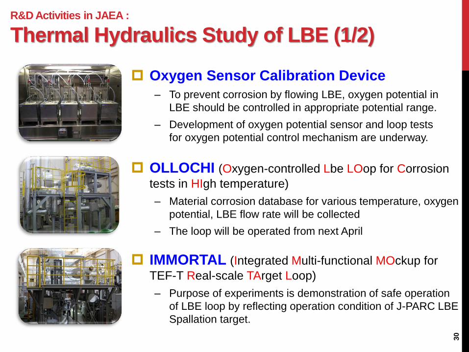
Oxygen Sensor Calibration Device
– To prevent corrosion by flowing LBE, oxygen potential in
LBE should be controlled in appropriate potential range.
– Development of oxygen potential sensor and loop tests
for oxygen potential control mechanism are underway.
OLLOCHI (Oxygen-controlled Lbe LOop for Corrosion
tests in HIgh temperature)
– Material corrosion database for various temperature, oxygen
potential, LBE flow rate will be collected
– The loop will be operated from next April
IMMORTAL (Integrated Multi-functional MOckup for
TEF-T Real-scale TArget Loop)
– Purpose of experiments is demonstration of safe operation
of LBE loop by reflecting operation condition of J-PARC LBE
Spallation target.

31
R&D Activities in JAEA :
Thermal Hydraulics Study of LBE (2/2)
JLBL-4 instantaneous
3D flow structure
instantaneous
3D flow structure
Measurement result by UDM at a centerline
and inclined direction
Measurement result by advanced measurement
system “Vector-UVP”
The flow velocity measurement by UDM (Ultrasonic Doppler Method) is being
developed by using JAEA LBE loop-2 (JLBL-2).
– The distribution of the flow velocity was measured at 150 ºC by use of the UDM,
which is useful for visualization of the liquid LBE flow.
An advanced measurement system “Vector-UVP” was developed and
successfully applied to the actual LBE flow in JLBL-4 for two-dimensional
velocity vector measurement.
JLBL-2
32
R&D Activities in JAEA :
Mock-up Experiment for Beam Window
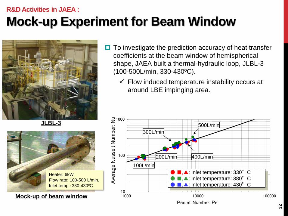
JLBL-3
Mock-up of beam window
100L/min
10
100
1000
1000 10000 100000
Peclet Number: Pe
Avera
ge N
usse
lt N
um
ber:
Nu
●,■,▲: Inlet temperature: 330°C
●,■,▲: Inlet temperature: 380°C
●,■,▲: Inlet temperature: 430°C
100L/min
200L/min
300L/min
400L/min
500L/min
Heater: 6kW
Flow rate: 100-500 L/min.
Inlet temp.:330-430ºC
To investigate the prediction accuracy of heat transfer
coefficients at the beam window of hemispherical
shape, JAEA built a thermal-hydraulic loop, JLBL-3
(100-500L/min, 330-430ºC).
Flow induced temperature instability occurs at
around LBE impinging area.

R&D Activities in JAEA :
Material Irradiation in LBE : MEGAPIE
33
Beam window
after experiment
Cutting plan of beam window
and test peace for PIE
MEGAPIE International Experiment
MEGAPIE (MEGAwatt Pilot Experiment) is an
international collaborating experiment to
demonstrate the feasibility of a high-power liquid
metal target carried out at the spallation neutron
source SINQ at PSI.
The target, filled with 920 kg liquid LBE, worked
successfully from August to December 2006 with
maximum power of 1.35 mA x 580 MeV.
PIE of irradiated beam window have been
performed in various institutes.
Target
Upper shield
Heat exchanger
Main EMP pump
Bypass EMP pump
Main guide tube
Bypass flow guideDouble wall container cooled by D2O
Beam window
LBE flow
R&D Activities in JAEA :
Allowable Maximum k-eff for ADS
34
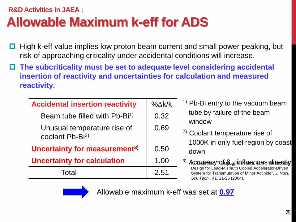
Accidental insertion reactivity %k/k
Beam tube filled with Pb-Bi1) 0.32
Unusual temperature rise of
coolant Pb-Bi2)
0.69
Uncertainty for measurement3) 0.50
Uncertainty for calculation 1.00
Total 2.51
1) Pb-Bi entry to the vacuum beam
tube by failure of the beam
window
2) Coolant temperature rise of
1000K in only fuel region by coast
down
3) Accuracy of βeff influences directly
Allowable maximum k-eff was set at 0.97
High k-eff value implies low proton beam current and small power peaking, but
risk of approaching criticality under accidental conditions will increase.
The subcriticality must be set to adequate level considering accidental
insertion of reactivity and uncertainties for calculation and measured
reactivity.
K. Tsujimoto, T.Sasa, K.Nishihara, et. al, “Neutronics
Design for Lead-Mismuth Cooled Accelerator-Driven
System for Transmutation of Minor Actinide”, J. Nucl.
Sci. Tech., 41, 21-26 (2004).

35
R&D Activities in JAEA :
Neutronics Design of ADS
0.93
0.94
0.95
0.96
0.97
0.98
0.99
1
1.01
BOC EOC
k-e
ff, E
ND
F
JAEA EB6
CIEMAT EB6
KIT EB7
EB6
EB7
0.93
0.94
0.95
0.96
0.97
0.98
0.99
1
1.01
BOC EOC
k-e
ff, JE
FF
JAEAJEFF3.0
CIEMATJEFF3.0
CIEMATJEFF3.1
KITJEFF3.1
JF3.1
JF3.0
0.93
0.94
0.95
0.96
0.97
0.98
0.99
1
1.01
BOC EOC
k-e
ff, JE
ND
L
JAEA J3.3
JAEA J3.2
JAEA J4.0
J4.0
J3.2, J3.3
JAEA proposed the comparison of reactor physics parameters calculated by
different nuclear data as a benchmark exercise of IAEA-CRP.
About 2% discrepancies in k-eff were found among the different nuclear
data. (k-eff disperses from 0.98 to 1.0 at BOC and 0.93 to 0.96 at EOC.)
JENDL ENDF JEFF
Calculated results for IAEC-CRP benchmark proposed by JAEA (Burnup calculation for the first
burnup cycle of 600 EFPD with 800MWth ADS)
R&D Activities in JAEA :
R&D for Reactor Physics of ADS
36
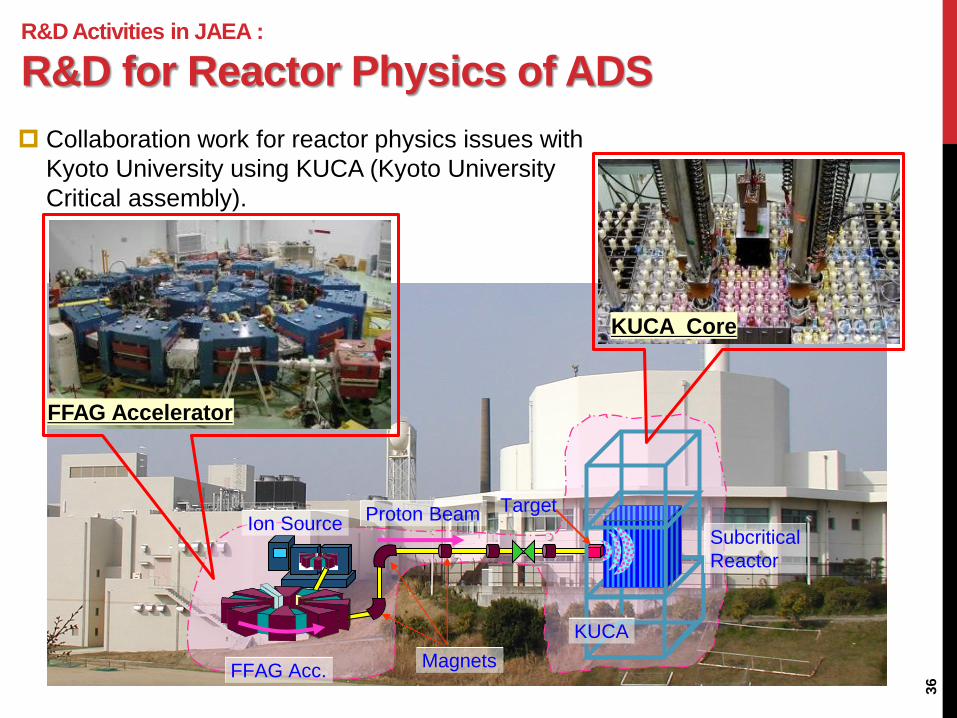
Ion Source
FFAG Acc.
Target Proton Beam
KUCA
Subcritical
Reactor
Magnets
FFAG Accelerator
KUCA Core
Collaboration work for reactor physics issues with
Kyoto University using KUCA (Kyoto University
Critical assembly).

R&D Activities in JAEA (Future Plan) :
Transmutation Experimental Facility (TEF)
37
Phase-I construction of J-PARC
was completed.
Phase-I facilities were in service
until March 2011. Although there
were significant damages by the
earthquake, the operation was
restarted in Dec. 2011.
The Transmutation Experimental
Facility (TEF) is the main project in
Phase-2 of J-PARC, however, it is
still waiting for the approval of the
Government.
TEF consists of
Transmutation Physics
Experimental Facility (TEF-P)
ADS Target Test Facility (TEF-T)
Jan. 28, 2008
50 GeV
Synchrotron
LINAC
Neutrino
Site for Transmutation
Experimental Facility
Material and Life
Science Facility
Hadron Facility
3 GeV Ring
Control Bldg.
Jan. 28, 2008
50 GeV
Synchrotron
LINAC
Neutrino
Site for Transmutation
Experimental Facility
Site for Transmutation
Experimental Facility
Material and Life
Science Facility
Hadron Facility
3 GeV Ring
Control Bldg.

R&D Activities in JAEA (Future Plan) :
Image View of TEF
38
ADS Target Test Facility:TEF-T
Critical Assembly
Pb-Bi Target
Transmutation Physics
Experimental Facility: TEF-P
Purpose: To investigate physics properties of
subcritical reactor with low power, and to
accumulate operation experiences of ADS.
Licensing: Nuclear reactor: (Critical assembly)
Proton beam: 400MeV-10W
Thermal power: <500W
Purpose: To research and develop a spallation
target and related materials with high-
power proton beam.
Licensing: Particle accelerator
Proton beam: 400MeV-250kW
Target: Lead-Bismuth Eutectic (LBE, Pb-Bi)
Proton Beam
Multi-purpose
Irradiation Area
R&D Activities in JAEA (Future Plan) :
ADS Target Test Facility (TEF-T)
39
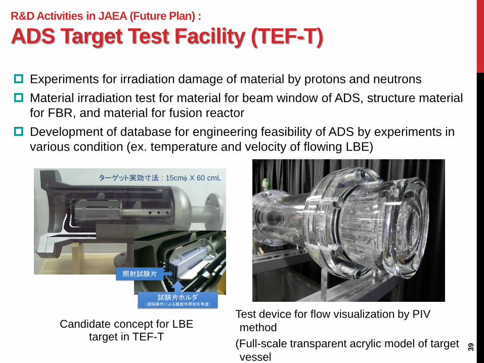
Candidate concept for LBE target in TEF-T
Test device for flow visualization by PIV
method
(Full-scale transparent acrylic model of target
vessel
ターゲット実効寸法 : 15cmf X 60 cmL
照射試験片
試験片ホルダ(遠隔操作による複数年照射を考慮)
Experiments for irradiation damage of material by protons and neutrons
Material irradiation test for material for beam window of ADS, structure material
for FBR, and material for fusion reactor
Development of database for engineering feasibility of ADS by experiments in
various condition (ex. temperature and velocity of flowing LBE)
R&D Activities in JAEA (Future Plan) :
Transmutation Physics Experimental Facility (TEF-P)
40
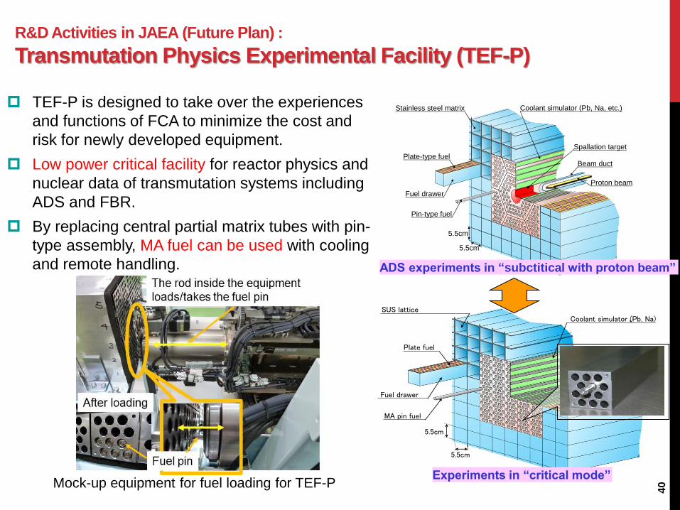
TEF-P is designed to take over the experiences
and functions of FCA to minimize the cost and
risk for newly developed equipment.
Low power critical facility for reactor physics and
nuclear data of transmutation systems including
ADS and FBR.
By replacing central partial matrix tubes with pin-
type assembly, MA fuel can be used with cooling
and remote handling.
Mock-up equipment for fuel loading for TEF-P
Coolant simulator (Pb, Na)、
Plate fuel
Fuel drawer
MA pin fuel
SUS lattice
5.5cm
5.5cm
5.5cm
Coolant simulator (Pb, Na, etc.)Stainless steel matrix
Plate-type fuel
Fuel drawer
Pin-type fuel
5.5cm
Proton beam
Beam duct
Spallation target
Experiments in “critical mode”
ADS experiments in “subctitical with proton beam”
R&D Activities in JAEA (Future Plan) :
FCA (Fast Critical Assembly) at JAEA
41
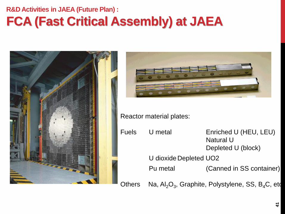
Reactor material plates:
Fuels U metal Enriched U (HEU, LEU)
Natural U
Depleted U (block)
U dioxide Depleted UO2
Pu metal (Canned in SS container)
Others Na, Al2O3, Graphite, Polystylene, SS, B4C, etc.

R&D Activities in JAEA :
MA Transmutation Fuel
42
MA is contained as a principal component in the fuel
Uranium-free fuel to avoid TRU formation
Diluent material to adjust the power density is contained in place of U
⇒ U-free Nitride fuel is considered as the first candidate
Hard neutron spectrum
Good thermal properties (high Tm, high thermal conductivity )
Large mutual solubility among TRU (Np,Pu,Am,Cm)
Feasibility of processing
• Highly enriched 15N is used to avoid 14C formation.
• Inert gas atmosphere is necessary for handling
• Maturity levels of fabrication & irradiation are low
Typical composition of the fuel:
Zr0.70Pu0.09MA0.21N (solid solution)
ZrN: diluent material
Pu : to mitigate the burn-up reactivity swing
Fuel type TRL
Metals 4-5
Oxide
homogeneous 4-5
Oxide
heterogeneous 4
Nitrides 3
Dispersion fuels 3-4
Maturity level for MA containing
fuels judged by OECD/NEA(2014)