Embed Size (px)
Citation preview

GT-Suite Users International ConferenceFrankfurt a.M., October 20th 2008Frankfurt a.M., October 20 2008
Fuel injection and combustion integrated Fuel injection and combustion integrated simulation for a marine dieselsimulation for a marine diesel engineenginegg
F. Millo,F. Millo, E. PautassoE. Pautasso, , S. ZancanaroS. Zancanaro (Politecnico di Torino, Italy)(Politecnico di Torino, Italy)
D. Delneri (D. Delneri (Wärtsilä S.p.A, Italy)

Presentation OverviewPresentation Overview
•• IntroductionIntroduction
•• Experimental setExperimental set--upup
•• Analysis of the injector modelAnalysis of the injector modely jy j
•• Analysis of the engine modelAnalysis of the engine model
•• Integrated analysis of the injection model with the Integrated analysis of the injection model with the engine modelengine model
•• ConclusionsConclusions

IntroductionIntroductionIn a previous study on a marine diesel engine* a DoE analysis
•• IntroductionIntroduction
•• Experimental Experimental setset--upup
In a previous study on a marine diesel engine a DoE analysiswas carried out in order to evaluate the effects on fuelconsumption and NOx emissions of different combination ofcompression ratio, injection timing, injector nozzle holes size
•• Analysis of the Analysis of the Injector modelInjector model
•• Analysis of the Analysis of the
and number.
yyEngine modelEngine model
•• Integrated Integrated analysis of the analysis of the i j ti d li j ti d linjection model injection model with the with the W6L26B2 W6L26B2 engine modelengine model
•• ConclusionsConclusions
* GT-User Conference 2006 ; SAE paper 2007-01-0670

IntroductionIntroductionSince the previous work demonstrated the good potential of the
•• IntroductionIntroduction
•• Experimental Experimental setset--upup
Since the previous work demonstrated the good potential of thesimulation tool as far as the combustion process wasconcerned, a further investigation was carried out, in order toevaluate the impact on fuel consumption and emissions of
•• Analysis of the Analysis of the Injector modelInjector model
•• Analysis of the Analysis of the
different injection cam profiles, by means of an integrated fuelinjection and combustion simulation.
yyEngine modelEngine model
•• Integrated Integrated analysis of the analysis of the i j ti d li j ti d linjection model injection model with the with the W6L26B2 W6L26B2 engine modelengine model
•• ConclusionsConclusions

Experimental setExperimental set--upupMAIN ENGINE FEATURES : Wärtsilä W6L26B2
Type Diesel, 4 stroke, 6 cylinders in line
•• IntroductionIntroduction
•• Experimental Experimental setset--upup
Bore/Stroke 260 / 320 mmDisplacement 101 dm3
Compression Ratio 16 : 1
•• Analysis of the Analysis of the Injector modelInjector model
•• Analysis of the Analysis of the Propeller curve
Compression Ratio 16 : 1Maximum Power 340 kW/cyl at 1000 rpm
Maximum BMEP 24.3 bar
yyEngine modelEngine model
•• Integrated Integrated analysis of the analysis of the i j ti d li j ti d l
# Engine speed [rpm]
BMEP [bar]
Load [%]
Air System Single Stage Turbocharger with Fixed Geometry Turbine
d Aft l
injection model injection model with the with the W6L26B2 W6L26B2 engine modelengine model
1 1000 24.0 1002 947 21.5 85
3 906 19.9 75and Aftercooler
Valves 4 valves/cylinderCombustion chamber Quiescent
•• ConclusionsConclusions 4 794 15.2 50
5 629 9.5 25
Experimental setExperimental set--upup
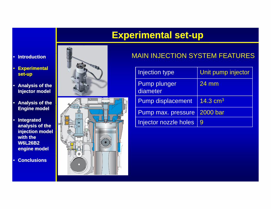
MAIN INJECTION SYSTEM FEATURES
Injection type Unit pump injector
MAIN INJECTION SYSTEM FEATURES•• IntroductionIntroduction
•• Experimental Experimental setset--upup
Pump plunger diameter
24 mm
Pump displacement 14.3 cm3
•• Analysis of the Analysis of the Injector modelInjector model
•• Analysis of the Analysis of the
Pump max. pressure 2000 barInjector nozzle holes 9
yyEngine modelEngine model
•• Integrated Integrated analysis of the analysis of the i j ti d li j ti d linjection model injection model with the with the W6L26B2 W6L26B2 engine modelengine model
•• ConclusionsConclusions

Injector componentsInjector components
MDV l
CPV valve
MDV valve•• IntroductionIntroduction
•• Experimental Experimental setset--upup
•• Analysis of the Analysis of the Injector modelInjector model
•• Analysis of the Analysis of the
Pump
yyEngine modelEngine model
•• Integrated Integrated analysis of the analysis of the i j ti d li j ti d l
Injector
injection model injection model with the with the W6L26B2 W6L26B2 engine modelengine model
•• ConclusionsConclusions

Injector modelInjector model
CPV & MDV Valves Injection Line•• IntroductionIntroduction
•• Experimental Experimental setset--upup
Pump Injector
•• Analysis of the Analysis of the Injector modelInjector model
•• Analysis of the Analysis of the Pump InjectoryyEngine modelEngine model
•• Integrated Integrated analysis of the analysis of the i j ti d li j ti d linjection model injection model with the with the W6L26B2 W6L26B2 engine modelengine model
•• ConclusionsConclusions

Injector modelInjector modelImposed in- Imposed discharge Injector model
•• IntroductionIntroduction
•• Experimental Experimental setset--upup
cylinder pressureg
nozzle coefficient
•• Analysis of the Analysis of the Injector modelInjector model
•• Analysis of the Analysis of the yyEngine modelEngine model
•• Integrated Integrated analysis of the analysis of the i j ti d li j ti d l
Injection Injection velocityinjection model injection model
with the with the W6L26B2 W6L26B2 engine modelengine model
pressure Needle lift
•• ConclusionsConclusions

Injector model refinementInjector model refinement
The comparison between simulated and experimental data was•• IntroductionIntroduction
•• Experimental Experimental setset--upup
The comparison between simulated and experimental data wasnot satisfactory at the beginning, with injection pressuredifferences of over 200 bar and unacceptable differences inneedle lift duration that required further model refinements
•• Analysis of the Analysis of the Injector modelInjector model
•• Analysis of the Analysis of the
needle lift duration that required further model refinements.
yyEngine modelEngine model
•• Integrated Integrated analysis of the analysis of the i j ti d li j ti d l
Δp
injection model injection model with the with the W6L26B2 W6L26B2 engine modelengine model
•• ConclusionsConclusions

Injector model refinementInjector model refinement
The first step was to adjust the injection duration in order to fit•• IntroductionIntroduction
•• Experimental Experimental setset--upup
The first step was to adjust the injection duration in order to fitthe experimental needle lift, varying the duration of the initialand closing transient phases of the pump delivery, byadjusting the pre-stroke and the spill port opening
•• Analysis of the Analysis of the Injector modelInjector model
•• Analysis of the Analysis of the
j g p p p p gparameters.
yyEngine modelEngine model
•• Integrated Integrated analysis of the analysis of the i j ti d li j ti d linjection model injection model with the with the W6L26B2 W6L26B2 engine modelengine model
•• ConclusionsConclusions
Needle lift adjustment

Injector model refinementInjector model refinementThen, the difference in the injection pressure was then
•• IntroductionIntroduction
•• Experimental Experimental setset--upup
, j pattributed to an overestimate of the pump internal leakage.
By reducing the leakage between pump plunger and cylinderthe pressure rate a satisfactory agreement with the
•• Analysis of the Analysis of the Injector modelInjector model
•• Analysis of the Analysis of the
the pressure rate a satisfactory agreement with theexperimental data was obtained.
QPumpyy
Engine modelEngine model
•• Integrated Integrated analysis of the analysis of the i j ti d li j ti d l
Pump plunger
injection model injection model with the with the W6L26B2 W6L26B2 engine modelengine model
•• ConclusionsConclusions
Injection pressure profile

Moreover the pressure trend in the injection line after the
Injector model refinementInjector model refinement
•• IntroductionIntroduction
•• Experimental Experimental setset--upup
Moreover, the pressure trend in the injection line after theinjection phase was not properly captured.
•• Analysis of the Analysis of the Injector modelInjector model
•• Analysis of the Analysis of the yyEngine modelEngine model
•• Integrated Integrated analysis of the analysis of the i j ti d li j ti d linjection model injection model with the with the W6L26B2 W6L26B2 engine modelengine model Pressure decrease
•• ConclusionsConclusions

Injector modelInjector modelThis behaviour was caused by a too slow closure of the Control
•• IntroductionIntroduction
•• Experimental Experimental setset--upup
yPressure Valve (CPV) after the pump delivery phase that causedan excessive pressure drop in the injection line. Anoverestimation of the damping coefficient between the MDV and
•• Analysis of the Analysis of the Injector modelInjector model
•• Analysis of the Analysis of the
CPV valve in the injector model can cause this delayed closure;a more fast valve closure and a more limited pressure drop in theline was the obtained by reducing the damping coefficient.yy
Engine modelEngine model
•• Integrated Integrated analysis of the analysis of the i j ti d li j ti d l
Baseline damping coefficientCPV displacement
injection model injection model with the with the W6L26B2 W6L26B2 engine modelengine model
Reduced damping coefficient
•• ConclusionsConclusions
Valve closure

Injector model refinementInjector model refinement
A di ti f th l l i th•• IntroductionIntroduction
•• Experimental Experimental setset--upup
A proper prediction of the pressure level in theinjection line was then achieved
•• Analysis of the Analysis of the Injector modelInjector model
•• Analysis of the Analysis of the yyEngine modelEngine model
•• Integrated Integrated analysis of the analysis of the i j ti d li j ti d linjection model injection model with the with the W6L26B2 W6L26B2 engine modelengine model
•• ConclusionsConclusions
Injection pressure profile

Injector modelInjector modelComparison between experimental and
•• IntroductionIntroduction
•• Experimental Experimental setset--upup
Comparison between experimental and simulated data for the needle lift and injection
pressure profile•• Analysis of the Analysis of the
Injector modelInjector model
•• Analysis of the Analysis of the
Load 100%
yyEngine modelEngine model
•• Integrated Integrated analysis of the analysis of the i j ti d li j ti d linjection model injection model with the with the W6L26B2 W6L26B2 engine modelengine model
•• ConclusionsConclusions

Injector modelInjector modelComparison between experimental and
•• IntroductionIntroduction
•• Experimental Experimental setset--upup
Comparison between experimental and simulated data for the needle lift and injection
pressure profile•• Analysis of the Analysis of the
Injector modelInjector model
•• Analysis of the Analysis of the
Load 85%
yyEngine modelEngine model
•• Integrated Integrated analysis of the analysis of the i j ti d li j ti d linjection model injection model with the with the W6L26B2 W6L26B2 engine modelengine model
•• ConclusionsConclusions

Injector modelInjector modelComparison between experimental and
•• IntroductionIntroduction
•• Experimental Experimental setset--upup
Comparison between experimental and simulated data for the needle lift and injection
pressure profile•• Analysis of the Analysis of the
Injector modelInjector model
•• Analysis of the Analysis of the
Load 75%
yyEngine modelEngine model
•• Integrated Integrated analysis of the analysis of the i j ti d li j ti d linjection model injection model with the with the W6L26B2 W6L26B2 engine modelengine model
•• ConclusionsConclusions

Injector modelInjector modelComparison between experimental andComparison between experimental and
simulated data for the needle lift and injection pressure profile
•• IntroductionIntroduction
•• Experimental Experimental setset--upup
•• Analysis of the Analysis of the Injector modelInjector model
•• Analysis of the Analysis of the
Load 50%
yyEngine modelEngine model
•• Integrated Integrated analysis of the analysis of the i j ti d li j ti d linjection model injection model with the with the W6L26B2 W6L26B2 engine modelengine model
•• ConclusionsConclusions

Engine modelEngine model
The engine modelavailable before thei t t d l i
•• IntroductionIntroduction
•• Experimental Experimental setset--upup
integrated analysis wasbased on the use of animposed injected massand injection pressure
•• Analysis of the Analysis of the Injector modelInjector model
•• Analysis of the Analysis of the and injection pressureprofile (obtained fromexperiments), with apredictive DI-Jet model
yyEngine modelEngine model
•• Integrated Integrated analysis of the analysis of the i j ti d li j ti d l predictive DI-Jet model
for combustion andemissions prediction.
injection model injection model with the with the W6L26B2 W6L26B2 engine modelengine model
•• ConclusionsConclusions

Engine modelEngine modelEngine modelImposed injection
fImposed injectedtotal fuel mass•• IntroductionIntroduction
•• Experimental Experimental setset--upup
pressure from exp. total fuel mass
•• Analysis of the Analysis of the Injector modelInjector model
•• Analysis of the Analysis of the yyEngine modelEngine model
•• Integrated Integrated analysis of the analysis of the i j ti d li j ti d l Mass flow rate
Cd calculated
Heat release rate In-cylinder pressureinjection model injection model with the with the W6L26B2 W6L26B2 engine modelengine model
y p
•• ConclusionsConclusions

Engine modelEngine modelComparison between experimental and simulated data
(engine “stand alone” model)•• IntroductionIntroduction
•• Experimental Experimental setset--upup
•• Analysis of the Analysis of the Injector modelInjector model
•• Analysis of the Analysis of the yyEngine modelEngine model
•• Integrated Integrated analysis of the analysis of the i j ti d li j ti d linjection model injection model with the with the W6L26B2 W6L26B2 engine modelengine model
•• ConclusionsConclusions

Integrated analysisIntegrated analysis
In a integrated simulation the injection pressure profile isprovided by the detailed injection model, while the in-cylinderpressure profile is calculated by the code.
•• IntroductionIntroduction
•• Experimental Experimental setset--upup
In this way, it is possible to predict the effects of injectionsystem geometry variations (e.g. the cam profile or the
•• Analysis of the Analysis of the Injector modelInjector model
•• Analysis of the Analysis of the nozzle hole diameter), avoiding the need for any simplifiedhypothesis.
M if th i j ti d l i l lib t d it i
yyEngine modelEngine model
•• Integrated Integrated analysis of the analysis of the i j ti d li j ti d l Moreover, if the injection model is properly calibrated, it is
possible to obtain the pressure profile in parts of the injectionsystem, where positioning a real pressure sensor would bevery difficult or even impossible
injection model injection model with the with the W6L26B2 W6L26B2 engine modelengine model
very difficult or even impossible.•• ConclusionsConclusions

Integrated analysisIntegrated analysis
P fil i t f th•• IntroductionIntroduction
•• Experimental Experimental setset--upup
Effects of injection system geometry variations
Pressure profile in parts of the injection system
where no exp. meas. are availble
PRESSURE
PRESSURE PROFILE IN THE NOZZLE SAC
PRESSURE PROFILE WITH
PRESSURE PROFILE WITH SLOW CAM
•• Analysis of the Analysis of the Injector modelInjector model
•• Analysis of the Analysis of the PRESSURE PROFILE IN
THE NOZZLE HOLDER (SENSOR
STANDARD CAM
SLOW CAMyyEngine modelEngine model
•• Integrated Integrated analysis of the analysis of the i j ti d li j ti d l (SENSOR
POSITION)injection model injection model with the with the W6L26B2 W6L26B2 engine modelengine model
•• ConclusionsConclusions

W26 Injector modelW26 Engine model
Integrated analysisIntegrated analysis
W26 Injector modelW26 Engine model•• IntroductionIntroduction
•• Experimental Experimental setset--upup
•• Analysis of the Analysis of the Injector modelInjector model
•• Analysis of the Analysis of the yyEngine modelEngine model
•• Integrated Integrated analysis of the analysis of the i j ti d li j ti d linjection model injection model with the with the W6L26B2 W6L26B2 engine modelengine model
•• ConclusionsConclusions

Integrated analysisIntegrated analysisImposed discharge Integrated model
•• IntroductionIntroduction
•• Experimental Experimental setset--upup
nozzle coefficient
•• Analysis of the Analysis of the Injector modelInjector model
•• Analysis of the Analysis of the yyEngine modelEngine model
•• Integrated Integrated analysis of the analysis of the i j ti d li j ti d l
Heat release rate In-cylinder pressureInjection pressureinjection model injection model with the with the W6L26B2 W6L26B2 engine modelengine model
•• ConclusionsConclusions

Integrated analysis Integrated analysis –– model validationmodel validationComparison between experimental and simulated datap p
(integrated simulation)•• IntroductionIntroduction
•• Experimental Experimental setset--upup
•• Analysis of the Analysis of the Injector modelInjector model
•• Analysis of the Analysis of the yyEngine modelEngine model
•• Integrated Integrated analysis of the analysis of the i j ti d li j ti d linjection model injection model with the with the W6L26B2 W6L26B2 engine modelengine model
•• ConclusionsConclusions

Integrated analysis Integrated analysis –– model validationmodel validation
•• IntroductionIntroduction
•• Experimental Experimental setset--upup
•• Analysis of the Analysis of the Injector modelInjector model
•• Analysis of the Analysis of the
Stand alone engine model Integrated simulation
yyEngine modelEngine model
•• Integrated Integrated analysis of the analysis of the i j ti d li j ti d linjection model injection model with the with the W6L26B2 W6L26B2 engine modelengine model
•• ConclusionsConclusions

Comparison between experimental and simulated data for
Integrated analysis Integrated analysis –– model validationmodel validationComparison between experimental and simulated data for
different engine operating points
In-cylinder pressure profile Heat release rate
•• IntroductionIntroduction
•• Experimental Experimental setset--upup
In-cylinder pressure profile Heat release rate•• Analysis of the Analysis of the
Injector modelInjector model
•• Analysis of the Analysis of the yyEngine modelEngine model
•• Integrated Integrated analysis of the analysis of the i j ti d li j ti d linjection model injection model with the with the W6L26B2 W6L26B2 engine modelengine model
Load 100%
•• ConclusionsConclusions

Comparison between experimental and simulated data for
Integrated analysis Integrated analysis –– model validationmodel validation
In-cylinder pressure profile Heat release rate
Comparison between experimental and simulated data for different engine operating points•• IntroductionIntroduction
•• Experimental Experimental setset--upup
In-cylinder pressure profile Heat release rate•• Analysis of the Analysis of the
Injector modelInjector model
•• Analysis of the Analysis of the yyEngine modelEngine model
•• Integrated Integrated analysis of the analysis of the i j ti d li j ti d linjection model injection model with the with the W6L26B2 W6L26B2 engine modelengine model
Load 85%
•• ConclusionsConclusions

Comparison between experimental and simulated data for
Integrated analysis Integrated analysis –– model validationmodel validation
In-cylinder pressure profile Heat release rate
Comparison between experimental and simulated data for different engine operating points•• IntroductionIntroduction
•• Experimental Experimental setset--upup
In-cylinder pressure profile Heat release rate•• Analysis of the Analysis of the
Injector modelInjector model
•• Analysis of the Analysis of the yyEngine modelEngine model
•• Integrated Integrated analysis of the analysis of the i j ti d li j ti d linjection model injection model with the with the W6L26B2 W6L26B2 engine modelengine model
Load 75%
•• ConclusionsConclusions

Comparison between experimental and simulated data for
Integrated analysis Integrated analysis –– model validationmodel validation
In-cylinder pressure profile Heat release rate
Comparison between experimental and simulated data for different engine operating points•• IntroductionIntroduction
•• Experimental Experimental setset--upup
In-cylinder pressure profile Heat release rate•• Analysis of the Analysis of the
Injector modelInjector model
•• Analysis of the Analysis of the yyEngine modelEngine model
•• Integrated Integrated analysis of the analysis of the i j ti d li j ti d linjection model injection model with the with the W6L26B2 W6L26B2 engine modelengine model
Load 50%
•• ConclusionsConclusions

Comparison between experimental and simulated data for
Integrated analysis Integrated analysis –– model validationmodel validationComparison between experimental and simulated data for
NOx emissions at different operating points•• IntroductionIntroduction
•• Experimental Experimental setset--upup
•• Analysis of the Analysis of the Injector modelInjector model
•• Analysis of the Analysis of the yyEngine modelEngine model
•• Integrated Integrated analysis of the analysis of the i j ti d li j ti d l
200 ppm
injection model injection model with the with the W6L26B2 W6L26B2 engine modelengine model
•• ConclusionsConclusions

Integrated analysisIntegrated analysis
Once validated, the integrated model was then used to predictthe effects produced by different injection system geometryconfigurations.
•• IntroductionIntroduction
•• Experimental Experimental setset--upup configurations.
Afterwards, experimental tests were carried out in order tocheck the reliability of the model predictions.
•• Analysis of the Analysis of the Injector modelInjector model
•• Analysis of the Analysis of the
Config. Inj. Cam SOI Inj. hole diameter
[‐] [‐] [° bTDC] [‐]
yyEngine modelEngine model
•• Integrated Integrated analysis of the analysis of the i j ti d li j ti d l 1 Standard +2 deg adv Baseline
2 Slow Baseline Baseline
injection model injection model with the with the W6L26B2 W6L26B2 engine modelengine model
3 Slow +2 deg adv ‐15 % (area)•• ConclusionsConclusions

Integrated analysisIntegrated analysisComparison between different cam profilesComparison between different cam profiles
•• IntroductionIntroduction
•• Experimental Experimental setset--upup Standard inj. cam Slow inj. cam
•• Analysis of the Analysis of the Injector modelInjector model
•• Analysis of the Analysis of the yyEngine modelEngine model
•• Integrated Integrated analysis of the analysis of the i j ti d li j ti d linjection model injection model with the with the W6L26B2 W6L26B2 engine modelengine model
•• ConclusionsConclusions
Configuration 1 Configuration 2 & 3

Integrated analysisIntegrated analysisComparison between experimental and simulated data forComparison between experimental and simulated data for
different injection system configurations @950 rpm (load = 85%)
•• IntroductionIntroduction
•• Experimental Experimental setset--upup
I j ti•• Analysis of the Analysis of the
Injector modelInjector model
•• Analysis of the Analysis of the
Injection pressure
yyEngine modelEngine model
•• Integrated Integrated analysis of the analysis of the i j ti d li j ti d linjection model injection model with the with the W6L26B2 W6L26B2 engine modelengine model
•• ConclusionsConclusions
Configuration 1 Configuration 2

Integrated analysisIntegrated analysisComparison between experimental and simulated data forComparison between experimental and simulated data for
different injection system configurations @950 rpm (load = 85%)
•• IntroductionIntroduction
•• Experimental Experimental setset--upup
Injected fuel mass Maximum injection pressure•• Analysis of the Analysis of the Injector modelInjector model
•• Analysis of the Analysis of the yyEngine modelEngine model
•• Integrated Integrated analysis of the analysis of the i j ti d li j ti d linjection model injection model with the with the W6L26B2 W6L26B2 engine modelengine model
•• ConclusionsConclusions

Integrated analysisIntegrated analysisComparison between experimental and simulated data forComparison between experimental and simulated data for
different injection system configurations @950 rpm (load = 85%)
•• IntroductionIntroduction
•• Experimental Experimental setset--upup
In-cylinder maximum pressure Brake specific NOx•• Analysis of the Analysis of the Injector modelInjector model
•• Analysis of the Analysis of the yyEngine modelEngine model
•• Integrated Integrated analysis of the analysis of the i j ti d li j ti d linjection model injection model with the with the W6L26B2 W6L26B2 engine modelengine model
•• ConclusionsConclusions

ConclusionsConclusions
•• AA goodgood correlationcorrelation betweenbetween experimentalexperimental datadata andandsimulationsimulation resultsresults bothboth forfor thethe injectioninjection systemsystem modelmodel andandforfor thethe engineengine modelmodel couldcould bebe achievedachieved
•• IntroductionIntroduction
•• Experimental Experimental setset--upup gg
•• TheThe simplicitysimplicity ofof integratingintegrating differentdifferent modelsmodels (i(i..ee.. engineengineandand fuelfuel injectioninjection modelsmodels inin anan single,single, fullyfully
•• Analysis of the Analysis of the Injector modelInjector model
•• Analysis of the Analysis of the comprehensivecomprehensive modelmodel allowedallowed anan easyeasy assemblyassembly andandintegrationintegration afterafter preliminarypreliminary validationsvalidations carriedcarried outout forfor thethesinglesingle partsparts
yyEngine modelEngine model
•• Integrated Integrated analysis of the analysis of the i j ti d li j ti d l
•• AnAn integratedintegrated simulationsimulation withwith aa detaileddetailed engineengine modelmodel andandaa detaileddetailed injectioninjection modelmodel provedproved toto bebe extremelyextremely helpfulhelpfulff thth ti i titi i ti ff thth h lh l ii ff
injection model injection model with the with the W6L26B2 W6L26B2 engine modelengine model
forfor thethe optimizationoptimization ofof thethe wholewhole engineengine performanceperformance•• ConclusionsConclusions

GT-Suite Users International ConferenceFrankfurt a.M., October 20th 2008Frankfurt a.M., October 20 2008
Fuel injection and combustion integrated Fuel injection and combustion integrated simulation for a marine dieselsimulation for a marine diesel engineenginegg
F. Millo,F. Millo, E. PautassoE. Pautasso, , S. ZancanaroS. Zancanaro (Politecnico di Torino, Italy)(Politecnico di Torino, Italy)
D. Delneri (D. Delneri (Wärtsilä S.p.A, Italy)