Embed Size (px)
Citation preview
1
Fuel-oils from co-pyrolysis of scrap tyres with coal and a bituminous waste.
Influence of oven configuration
Beatriz Acevedo, Carmen Barriocanal* Instituto Nacional del Carbón, INCAR-CSIC, Apartado 73, 33080 Oviedo. Spain
*Corresponding author. Tel: +34 985 11 90 90; Fax:+34 985 29 76 62; e.mail address: [email protected] ABSTRACT Two wastes from the tyre recycling industry -the fibres used as reinforcing material and
tyre crumbs- were pyrolyzed in two ovens of different configuration. Blends with a low
rank coal and a bituminous waste were also prepared to modify the composition of the
oils obtained from the pyrolysis of the tyre wastes. Elemental analysis, calorific value,
Fourier transform infrared spectroscopy (FTIR) and gas chromatography were used to
determine the oil composition. A comparative study taking into account the
configurations of the ovens and the raw materials was carried out. The oils produced
in the rotary oven were found to be more aromatic and to have lower oxygen contents.
Depending on the type of oven and the material used in the co-pyrolysis process it is
possible to obtain a fuel-oil with a specific heating value and sulphur content. It is also
possible to obtain oil with more than 20% limonene and 20% BTX (benzene, toluene,
xylene). The amount of aliphatics can be increased by including a coal in the pyrolysis
process and the amount of aromatics can be increased by co-pyrolysis with a
bituminous waste.
Keywords: Pyrolysis oil, Scrap Tyres, Reinforcing Fibre, Coal, GC-MS, FTIR
2
1. Introduction
End-of-Life Tyres (ELTs) is an increasing economic and environmental problem
closely related with a rapid developing modern society. More than 3.3 million tons of
used tyres are generated in the European Union each year. While 2.7 millions tons are
considered to be ELTs the rest are reused, exported or retreaded [1]. European
legislation on waste tyres has become more stringent since the year 2000 and, as a
consequence, the amount of waste tyres has declined while the valorization of the
material has been favoured either due to the greater number of uses for tyre crumbs or
to the increasing use of this material in the production of energy [2].
Pyrolysis can be considered as an optimal and environmentally friendly method
for thermo-chemical conversion of wastes such as tyres. Three products are derived
from pyrolysis: gas with a high calorific value, pirolytic oil that can be used as fuel or as
a source of benzene, toluene, xylene (BTX) or limonene and char that can be used as
fuel, activated carbon or carbon black [2-7].
Scrap tyres are converted in tyre recycling plants into tyre crumbs, reinforcing
fibre and steel. Styrene butadiene (SBR), polybutadiene (BR), nitrile (NiR) and
chloroprene rubbers together with natural rubber (NR) are the main constituents of tyre
crumbs [5, 7-9]. Their chemical structure with aromatic and aliphatic constituents plays
an important role in determining the composition of the oils derived from tyre crumbs.
The reinforcing fibre is usually recovered as a heterogeneous fluff made up of
polymeric fibres that contain a certain amount of rubber [3, 10,11]. Until now little effort
has been devoted to finding a procedure for recycling this fluff.
The co-processing of tyre crumbs with coal has been studied as a way to
improve coal liquefaction [8, 11-13]. But to our knowledge the co-pyrolysis of waste
tyres with coal or with a bituminous waste has not been reported.
It has been well established [14] that the structural units of a coal increase in
size with coal rank. Coal pyrolysis can be considered as a depolymerization reaction
during which the weak bonds such as methylene and oxymethylene bridges are
3
broken, resulting in tars that contain structures representative of the parent coals [15].
Tars from low-rank coals contain low-molecular weight compounds such as phenol,
alkyl phenols and saturated aliphatics [16,17].
The configuration of the oven can give rise to differences in the composition of
the pyrolysis oils [18,19].
Taking into account that the pyrolysis of a low-rank coal produces mainly
aliphatic compounds, co-pyrolysis with tyre wastes can modify the composition of the
oils so that it has a higher aliphatic/ aromatic ratio. On the other hand, if the objective is
to increase the percentage of aromatic compounds co-pyrolysis with a bituminous
waste is the best option.
The objective of the present research work was to study the co-pyrolysis of
waste tyres with a low rank coal and a bituminous waste in two ovens of different
configuration to try to optimize the composition of the pyrolysis oils as a function of the
oven configuration and the raw material used.
2. Experimental
2.1. Materials
The raw materials used for the pyrolysis experiments were tyre crumbs (TC)
and fluff/fibres (RF) obtained as a waste during the grinding and shredding of scrap
tyres obtained from the processing of car and truck tyres. For the co-pyrolysis test, a
low rank coal used in blast furnaces for pulverized coal injection and a bituminous
waste (BW) obtained from the benzol distillation column of a by-product section of a
coking plant were employed.
RF is a very heterogeneous material composed of fluff, cord with tyre adhered
to it and finely grounded crumbs of tyre [3, 11]. The tyre crumbs with a particle size
lower than 3 mm were used as received.
Proximate analyses were performed following the ISO562 e ISO1171, Standard
procedures for volatile matter and ash contents, respectively. The elemental analysis
was performed using a LECO CHN-2000 instrument for C, H y N (ASTM D-5773), a
4
LECO S-144 DR instrument(ASTM D-5016) for sulphur and a LECO VTF-900 device
for direct oxygen determination.
2.2. Pyrolysis in a fixed bed (FB) and a rotary oven (RO)
The pyrolysis experiments in the two ovens were carried out with the following
samples: the two tyre wastes (RF and TC), their blends with the coal 1:1, and the
RF/BW 1:1 blend. In the fixed bed oven samples of 6-8 g were introduced into a quartz
reactor that was heated in a horizontal electrically-heated oven at 5 °C/min to a final
temperature of 850 °C. During the pyrolysis, the liquid products were collected using
an ice-cooled trap. The char and liquid product yields were calculated relative to the
starting material, while the gas yield was calculated by difference.
Around 40 g of sample was introduced into the quartz reactor of the rotary oven
and heated to 850 °C at a rate of 5 °C/min. A cold trap (OT) and a column filled with
amberlite resin (AMB) allowed the recovery of the condensable products. The product
yields were calculated, as in the case of the FB oven. A diagram showing the
configuration of both ovens has been published previously [11].
For the pyrolysis experiments the coal and the bituminous waste were ground to
a size lower than 1.18 mm while RF and TC were used, as received.
2.3. Characterization of the pyrolysis oils obtained in the two ovens
The elemental analysis of the pyrolysis oils was determined as in section 2.1.
The calorific value was measured in a IKA - Calorimeter C4000 adiabatic,
Analysentechnik Heitersheim apparatus.
Fourier transform infrared spectroscopy (FTIR) spectra were recorded on a
Nicolet Magna-IR560 spectrometer equipped with a DTGS detector. The sample was
deposited as a thin film between the NaCl windows and subjected to 64 scans at a
resolution of 4 cm-1 in the 400 cm-1 to 4000 cm-1 range to obtain the spectra. Selected
indices obtained from the FTIR data, using the integrated area (A) of different
absorption bands were employed for the semiquantitative analyses (Table 1). The
5
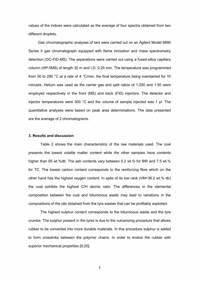
values of the indices were calculated as the average of four spectra obtained from two
different droplets.
Gas chromatographic analyses of tars were carried out on an Agilent Model 6890
Series II gas chromatograph equipped with flame ionization and mass spectrometry
detection (GC-FID-MS). The separations were carried out using a fused-silica capillary
column (HP-5MS) of length 30 m and I.D. 0.25 mm. The temperature was programmed
from 50 to 295 °C at a rate of 4 °C/min, the final temperature being maintained for 10
minutes. Helium was used as the carrier gas and split ratios of 1:200 and 1:50 were
employed respectively in the front (MS) and back (FID) injectors. The detector and
injector temperatures were 300 °C and the volume of sample injected was 1 µl. The
quantitative analyses were based on peak area determinations. The data presented
are the average of 2 chromatograms.
3. Results and discussion
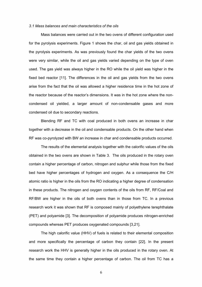
Table 2 shows the main characteristics of the raw materials used. The coal
presents the lowest volatile matter content while the other samples have contents
higher than 65 wt.%db. The ash contents vary between 0.2 wt.% for BW and 7.5 wt.%
for TC. The lowest carbon content corresponds to the reinforcing fibre which on the
other hand has the highest oxygen content. In spite of its low rank (VM=36.2 wt.% db)
the coal exhibits the highest C/H atomic ratio. The differences in the elemental
composition between the coal and bituminous waste may lead to variations in the
compositions of the oils obtained from the tyre wastes that can be profitably exploited.
The highest sulphur content corresponds to the bituminous waste and the tyre
crumbs. The sulphur present in the tyres is due to the vulcanizing procedure that allows
rubber to be converted into more durable materials. In this procedure sulphur is added
to form crosslinks between the polymer chains. In order to endow the rubber with
superior mechanical properties [9,20].
6
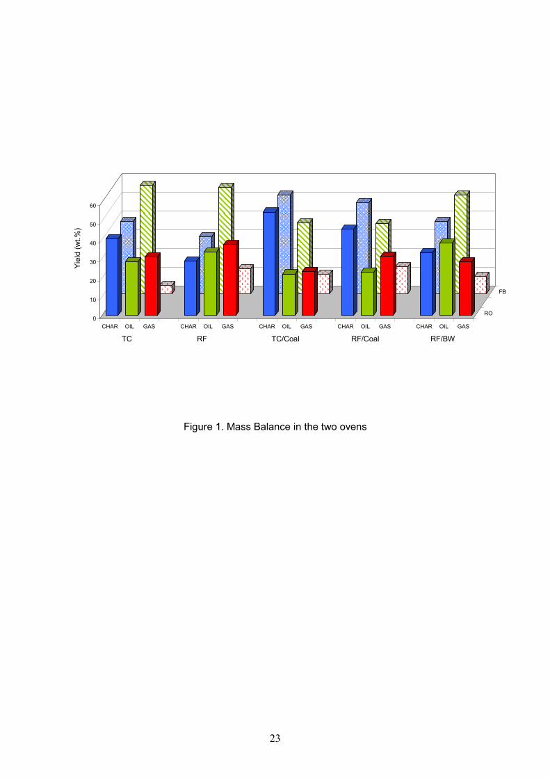
3.1 Mass balances and main characteristics of the oils
Mass balances were carried out in the two ovens of different configuration used
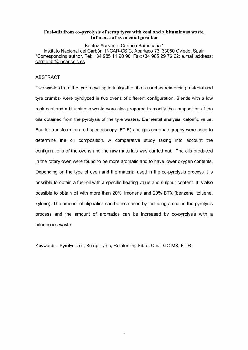
for the pyrolysis experiments. Figure 1 shows the char, oil and gas yields obtained in
the pyrolysis experiments. As was previously found the char yields of the two ovens
were very similar, while the oil and gas yields varied depending on the type of oven
used. The gas yield was always higher in the RO while the oil yield was higher in the
fixed bed reactor [11]. The differences in the oil and gas yields from the two ovens
arise from the fact that the oil was allowed a higher residence time in the hot zone of
the reactor because of the reactor’s dimensions. It was in the hot zone where the non-
condensed oil yielded, a larger amount of non-condensable gases and more
condensed oil due to secondary reactions.
Blending RF and TC with coal produced in both ovens an increase in char
together with a decrease in the oil and condensable products. On the other hand when
RF was co-pyrolyzed with BW an increase in char and condensable products occurred.
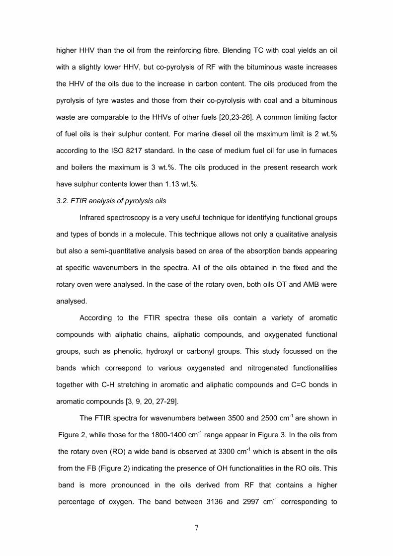
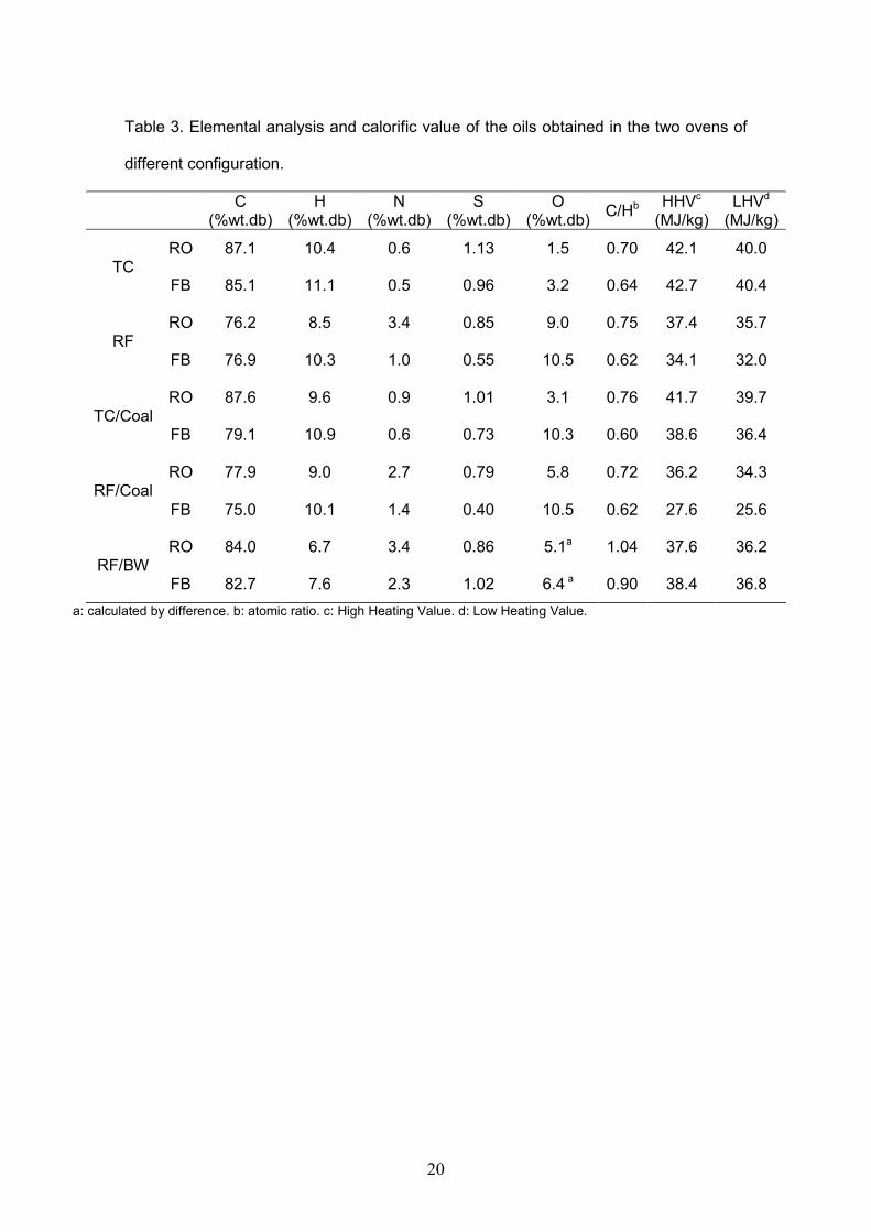
The results of the elemental analysis together with the calorific values of the oils
obtained in the two ovens are shown in Table 3. The oils produced in the rotary oven
contain a higher percentage of carbon, nitrogen and sulphur while those from the fixed
bed have higher percentages of hydrogen and oxygen. As a consequence the C/H
atomic ratio is higher in the oils from the RO indicating a higher degree of condensation
in these products. The nitrogen and oxygen contents of the oils from RF, RF/Coal and
RF/BW are higher in the oils of both ovens than in those from TC. In a previous
research work it was shown that RF is composed mainly of polyethylene terephthalate
(PET) and polyamide [3]. The decomposition of polyamide produces nitrogen-enriched
compounds whereas PET produces oxygenated compounds [3,21].
The high calorific value (HHV) of fuels is related to their elemental composition
and more specifically the percentage of carbon they contain [22]. In the present
research work the HHV is generally higher in the oils produced in the rotary oven. At
the same time they contain a higher percentage of carbon. The oil from TC has a
7
higher HHV than the oil from the reinforcing fibre. Blending TC with coal yields an oil
with a slightly lower HHV, but co-pyrolysis of RF with the bituminous waste increases
the HHV of the oils due to the increase in carbon content. The oils produced from the
pyrolysis of tyre wastes and those from their co-pyrolysis with coal and a bituminous
waste are comparable to the HHVs of other fuels [20,23-26]. A common limiting factor
of fuel oils is their sulphur content. For marine diesel oil the maximum limit is 2 wt.%
according to the ISO 8217 standard. In the case of medium fuel oil for use in furnaces
and boilers the maximum is 3 wt.%. The oils produced in the present research work
have sulphur contents lower than 1.13 wt.%.
3.2. FTIR analysis of pyrolysis oils
Infrared spectroscopy is a very useful technique for identifying functional groups
and types of bonds in a molecule. This technique allows not only a qualitative analysis
but also a semi-quantitative analysis based on area of the absorption bands appearing
at specific wavenumbers in the spectra. All of the oils obtained in the fixed and the
rotary oven were analysed. In the case of the rotary oven, both oils OT and AMB were
analysed.
According to the FTIR spectra these oils contain a variety of aromatic
compounds with aliphatic chains, aliphatic compounds, and oxygenated functional
groups, such as phenolic, hydroxyl or carbonyl groups. This study focussed on the
bands which correspond to various oxygenated and nitrogenated functionalities
together with C-H stretching in aromatic and aliphatic compounds and C=C bonds in
aromatic compounds [3, 9, 20, 27-29].
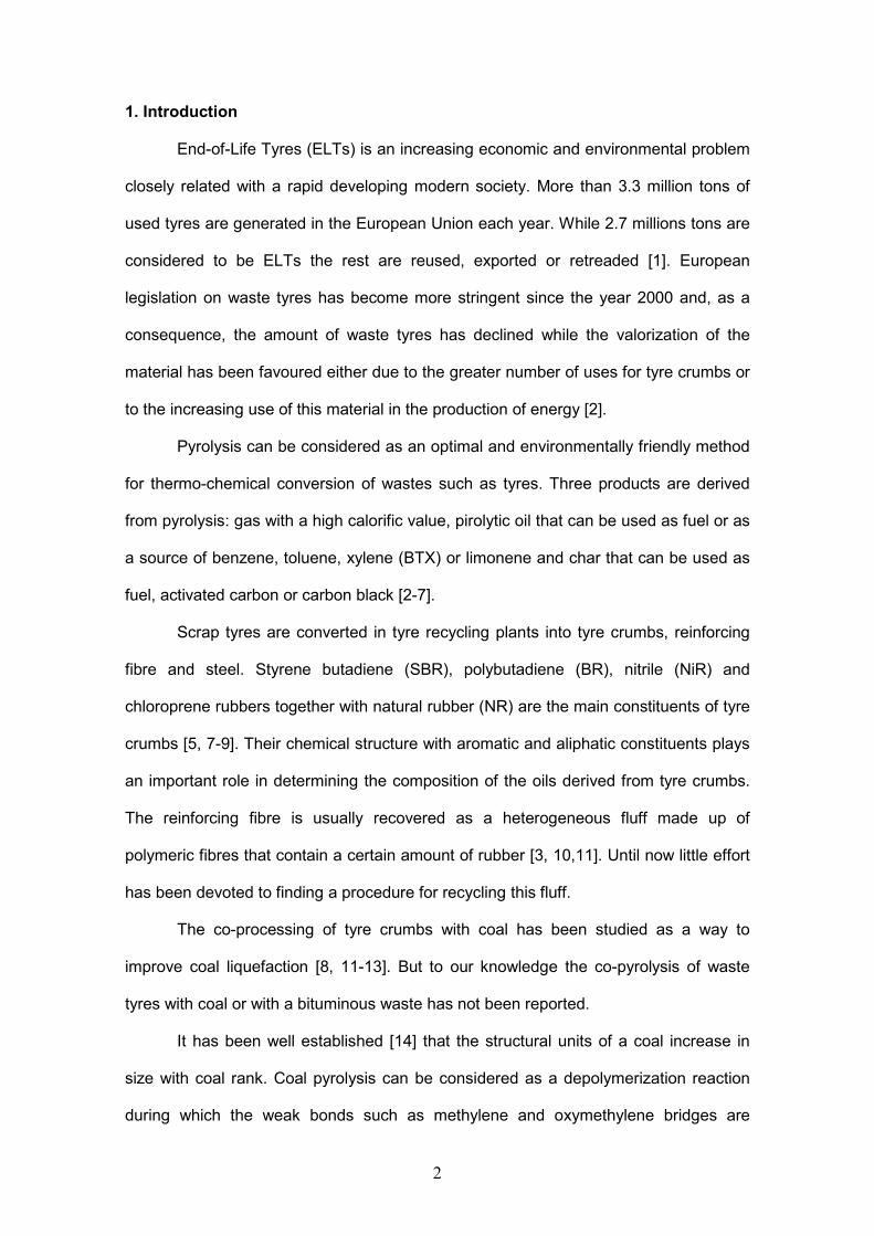
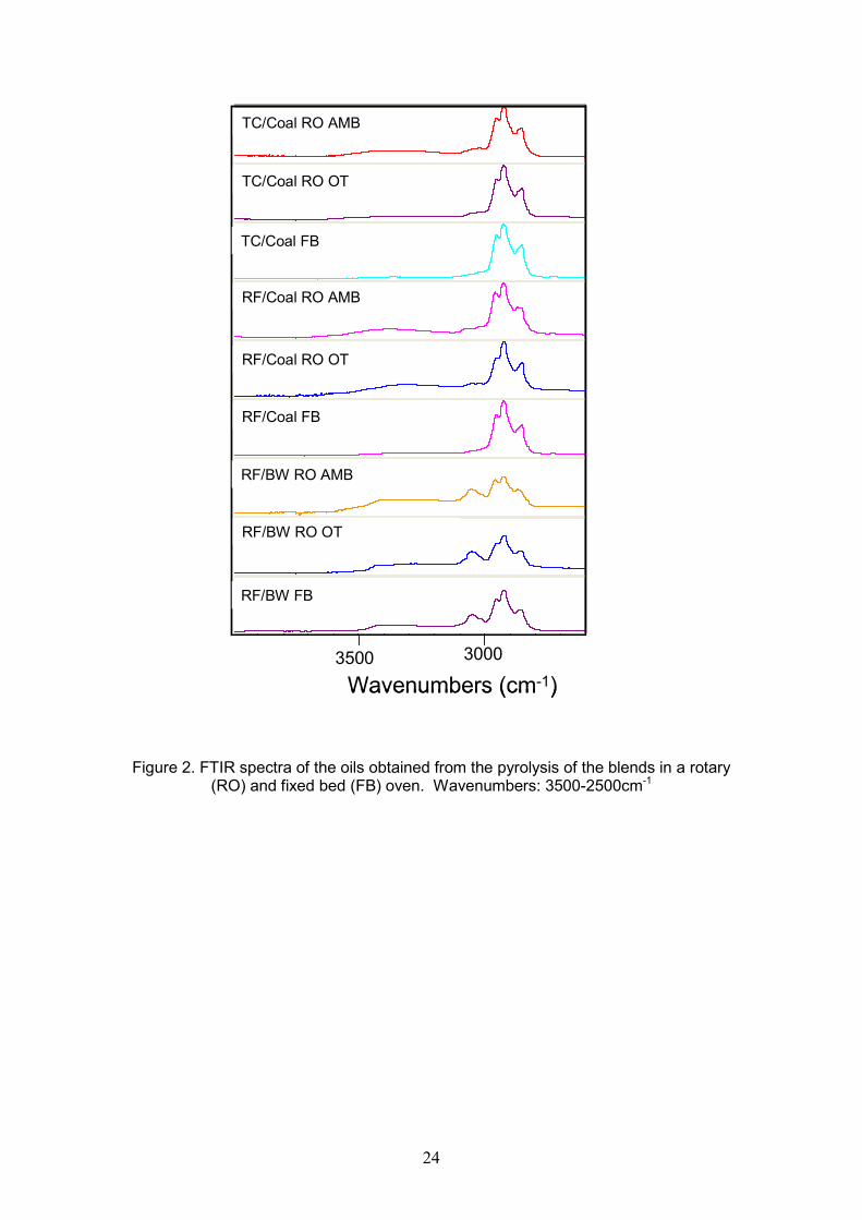
The FTIR spectra for wavenumbers between 3500 and 2500 cm-1 are shown in
Figure 2, while those for the 1800-1400 cm-1 range appear in Figure 3. In the oils from
the rotary oven (RO) a wide band is observed at 3300 cm-1 which is absent in the oils
from the FB (Figure 2) indicating the presence of OH functionalities in the RO oils. This
band is more pronounced in the oils derived from RF that contains a higher
percentage of oxygen. The band between 3136 and 2997 cm-1 corresponding to
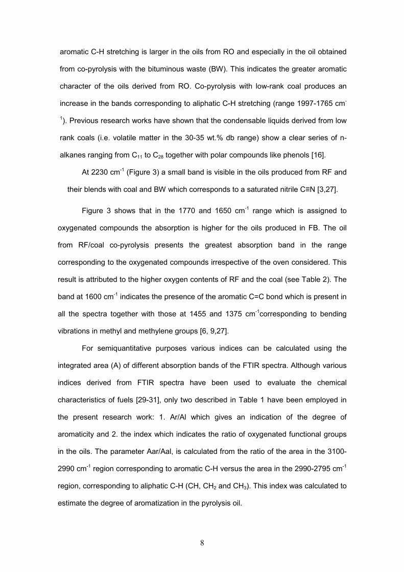
8
aromatic C-H stretching is larger in the oils from RO and especially in the oil obtained
from co-pyrolysis with the bituminous waste (BW). This indicates the greater aromatic
character of the oils derived from RO. Co-pyrolysis with low-rank coal produces an
increase in the bands corresponding to aliphatic C-H stretching (range 1997-1765 cm-
1). Previous research works have shown that the condensable liquids derived from low
rank coals (i.e. volatile matter in the 30-35 wt.% db range) show a clear series of n-
alkanes ranging from C11 to C28 together with polar compounds like phenols [16].
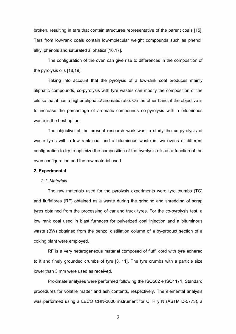
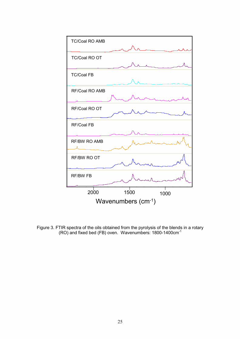
At 2230 cm-1 (Figure 3) a small band is visible in the oils produced from RF and
their blends with coal and BW which corresponds to a saturated nitrile C≡N [3,27].
Figure 3 shows that in the 1770 and 1650 cm-1 range which is assigned to
oxygenated compounds the absorption is higher for the oils produced in FB. The oil
from RF/coal co-pyrolysis presents the greatest absorption band in the range
corresponding to the oxygenated compounds irrespective of the oven considered. This
result is attributed to the higher oxygen contents of RF and the coal (see Table 2). The
band at 1600 cm-1 indicates the presence of the aromatic C=C bond which is present in
all the spectra together with those at 1455 and 1375 cm-1corresponding to bending
vibrations in methyl and methylene groups [6, 9,27].
For semiquantitative purposes various indices can be calculated using the
integrated area (A) of different absorption bands of the FTIR spectra. Although various
indices derived from FTIR spectra have been used to evaluate the chemical
characteristics of fuels [29-31], only two described in Table 1 have been employed in
the present research work: 1. Ar/Al which gives an indication of the degree of
aromaticity and 2. the index which indicates the ratio of oxygenated functional groups
in the oils. The parameter Aar/Aal, is calculated from the ratio of the area in the 3100-
2990 cm-1 region corresponding to aromatic C-H versus the area in the 2990-2795 cm-1
region, corresponding to aliphatic C-H (CH, CH2 and CH3). This index was calculated to
estimate the degree of aromatization in the pyrolysis oil.

9
As the reaction time increases, the methylene groups decrease because of the
removal of methylene cross-links in the macromolecular structure and to some extent
due to the decomposition of the aliphatic side chains. This results in the formation of
terminal CH3 groups and aromatic C-H bonds with ring closure reactions, all of which
leads to the growth of aromatic clusters.
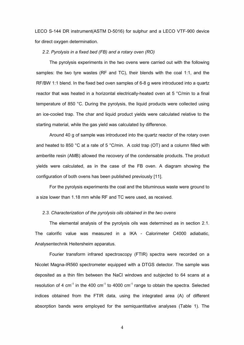
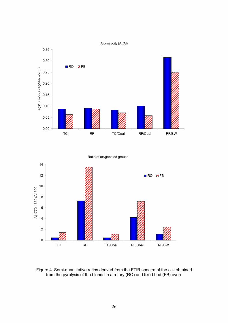
Figure 4 shows the values of the indices for the oils produced in the two
furnaces of different configuration. It is clear in all cases that the aromaticity of the oils
from RO is higher than that of the oils produced in the fixed bed reactor. This is in
accordance with their higher C/H atomic ratio (Table 3). Special attention should be
paid to the aromaticity of the oils produced from co-pyrolysis with BW. In a previous
paper [32] the composition of two bituminous wastes similar to the one used here were
studied and the aromaticity indices obtained there were 0.69 and 0.55 indicating the
highly aromatic character of the wastes. The aromaticity values in this study for the oil
derived from the co-pyrolysis of RF/BW were 0.32 and 0.25 in the rotary oven and the
fixed bed respectively. Therefore co-pyrolysis with BW produces an increase in the
aromatic character of the pyrolysis oils. The presence of compounds with oxygenated
functionalities can be studied using the index calculated as the ratio of the area in the
1770-1650 cm-1 range versus the area of the band at 1600 cm-1 which corresponds to
the stretching of the C=C bond in aromatic compounds. The oxygenated compounds
are more abundant in the oils generated in the fixed bed. This result is in agreement
with the higher oxygen content of the oils from the fixed bed furnace (Table 3). The
reason for the higher oxygen content is to be found in the configuration of the oven.
While in FB the oils are collected as they are produced, in RO the oils are allowed to
undergo secondary reactions with the consequent decrease in the more reactive
compounds and increase in aromatic compounds.
In the case of the two wastes, the aromatic compounds present in the oil
originate from the decomposition of the polymers that constitute the rubber and fibres.
A general mechanism for the aromatization of alkene compounds and the formation of
10
aromatics with the increase in the amount of permanent light gases has been proposed
by some authors [23,24,33,34].
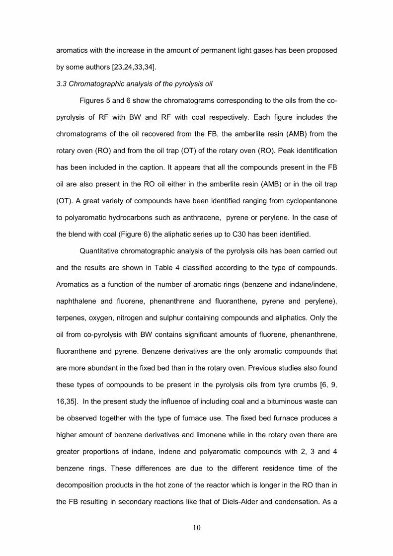
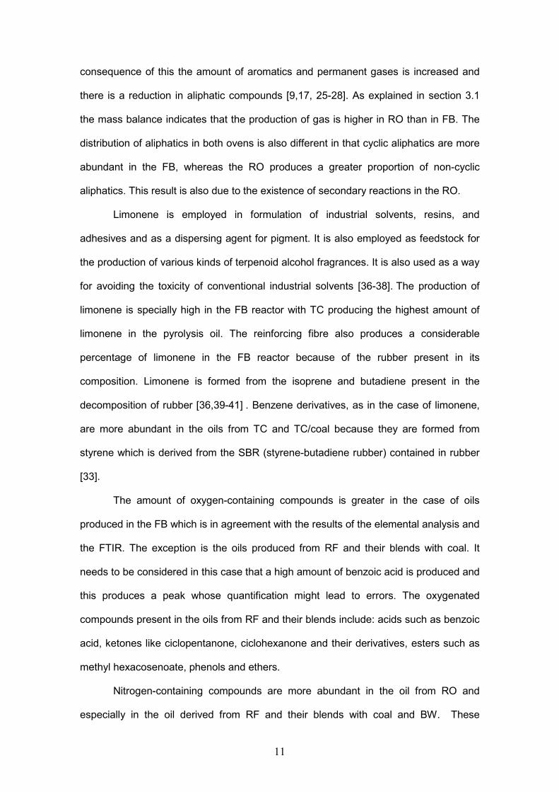
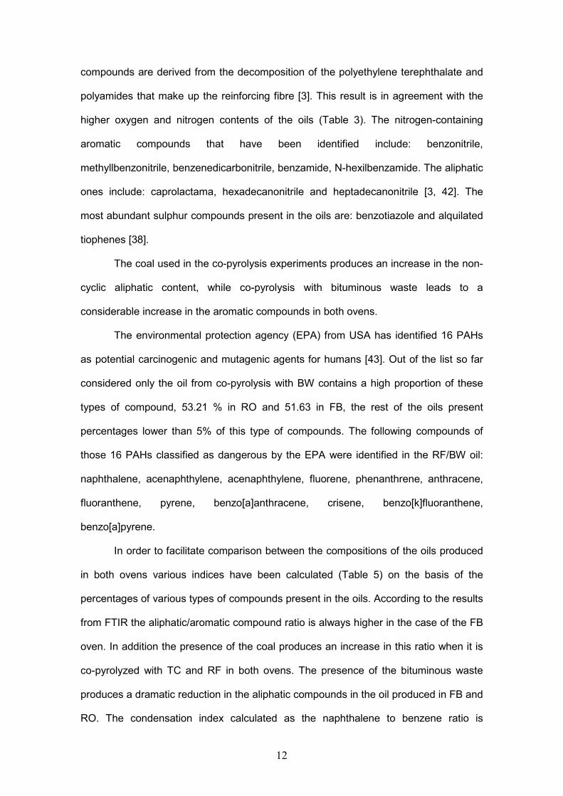
3.3 Chromatographic analysis of the pyrolysis oil
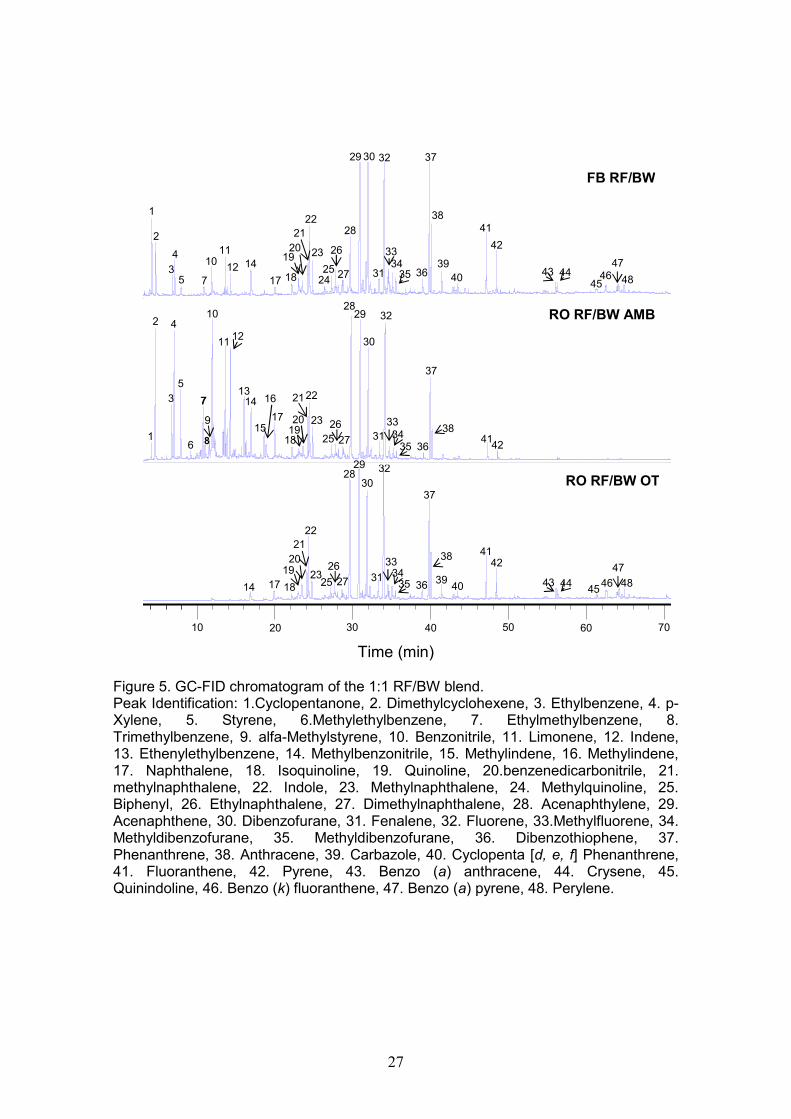
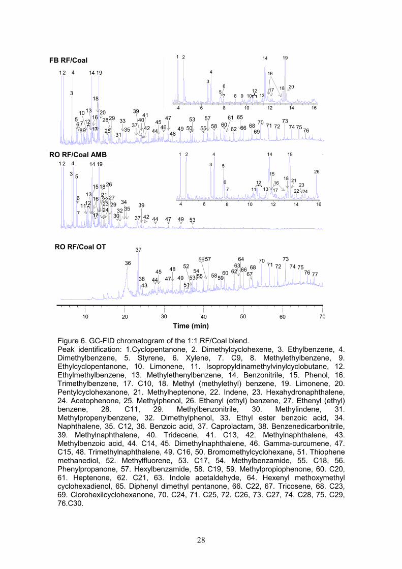
Figures 5 and 6 show the chromatograms corresponding to the oils from the co-
pyrolysis of RF with BW and RF with coal respectively. Each figure includes the
chromatograms of the oil recovered from the FB, the amberlite resin (AMB) from the
rotary oven (RO) and from the oil trap (OT) of the rotary oven (RO). Peak identification
has been included in the caption. It appears that all the compounds present in the FB
oil are also present in the RO oil either in the amberlite resin (AMB) or in the oil trap
(OT). A great variety of compounds have been identified ranging from cyclopentanone
to polyaromatic hydrocarbons such as anthracene, pyrene or perylene. In the case of
the blend with coal (Figure 6) the aliphatic series up to C30 has been identified.
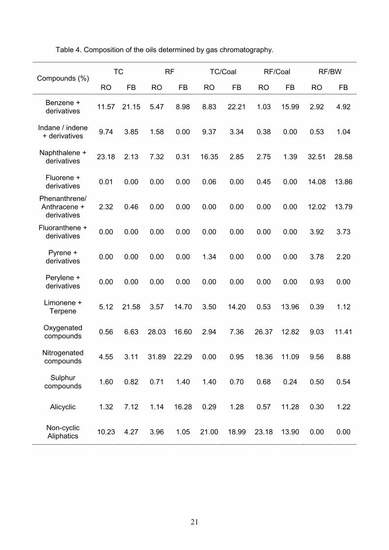
Quantitative chromatographic analysis of the pyrolysis oils has been carried out
and the results are shown in Table 4 classified according to the type of compounds.
Aromatics as a function of the number of aromatic rings (benzene and indane/indene,
naphthalene and fluorene, phenanthrene and fluoranthene, pyrene and perylene),
terpenes, oxygen, nitrogen and sulphur containing compounds and aliphatics. Only the
oil from co-pyrolysis with BW contains significant amounts of fluorene, phenanthrene,
fluoranthene and pyrene. Benzene derivatives are the only aromatic compounds that
are more abundant in the fixed bed than in the rotary oven. Previous studies also found
these types of compounds to be present in the pyrolysis oils from tyre crumbs [6, 9,
16,35]. In the present study the influence of including coal and a bituminous waste can
be observed together with the type of furnace use. The fixed bed furnace produces a
higher amount of benzene derivatives and limonene while in the rotary oven there are
greater proportions of indane, indene and polyaromatic compounds with 2, 3 and 4
benzene rings. These differences are due to the different residence time of the
decomposition products in the hot zone of the reactor which is longer in the RO than in
the FB resulting in secondary reactions like that of Diels-Alder and condensation. As a
11
consequence of this the amount of aromatics and permanent gases is increased and
there is a reduction in aliphatic compounds [9,17, 25-28]. As explained in section 3.1
the mass balance indicates that the production of gas is higher in RO than in FB. The
distribution of aliphatics in both ovens is also different in that cyclic aliphatics are more
abundant in the FB, whereas the RO produces a greater proportion of non-cyclic
aliphatics. This result is also due to the existence of secondary reactions in the RO.
Limonene is employed in formulation of industrial solvents, resins, and
adhesives and as a dispersing agent for pigment. It is also employed as feedstock for
the production of various kinds of terpenoid alcohol fragrances. It is also used as a way
for avoiding the toxicity of conventional industrial solvents [36-38]. The production of
limonene is specially high in the FB reactor with TC producing the highest amount of
limonene in the pyrolysis oil. The reinforcing fibre also produces a considerable
percentage of limonene in the FB reactor because of the rubber present in its
composition. Limonene is formed from the isoprene and butadiene present in the
decomposition of rubber [36,39-41] . Benzene derivatives, as in the case of limonene,
are more abundant in the oils from TC and TC/coal because they are formed from
styrene which is derived from the SBR (styrene-butadiene rubber) contained in rubber
[33].
The amount of oxygen-containing compounds is greater in the case of oils
produced in the FB which is in agreement with the results of the elemental analysis and
the FTIR. The exception is the oils produced from RF and their blends with coal. It
needs to be considered in this case that a high amount of benzoic acid is produced and
this produces a peak whose quantification might lead to errors. The oxygenated
compounds present in the oils from RF and their blends include: acids such as benzoic
acid, ketones like ciclopentanone, ciclohexanone and their derivatives, esters such as
methyl hexacosenoate, phenols and ethers.
Nitrogen-containing compounds are more abundant in the oil from RO and
especially in the oil derived from RF and their blends with coal and BW. These
12
compounds are derived from the decomposition of the polyethylene terephthalate and
polyamides that make up the reinforcing fibre [3]. This result is in agreement with the
higher oxygen and nitrogen contents of the oils (Table 3). The nitrogen-containing
aromatic compounds that have been identified include: benzonitrile,
methyllbenzonitrile, benzenedicarbonitrile, benzamide, N-hexilbenzamide. The aliphatic
ones include: caprolactama, hexadecanonitrile and heptadecanonitrile [3, 42]. The
most abundant sulphur compounds present in the oils are: benzotiazole and alquilated
tiophenes [38].
The coal used in the co-pyrolysis experiments produces an increase in the non-
cyclic aliphatic content, while co-pyrolysis with bituminous waste leads to a
considerable increase in the aromatic compounds in both ovens.
The environmental protection agency (EPA) from USA has identified 16 PAHs
as potential carcinogenic and mutagenic agents for humans [43]. Out of the list so far
considered only the oil from co-pyrolysis with BW contains a high proportion of these
types of compound, 53.21 % in RO and 51.63 in FB, the rest of the oils present
percentages lower than 5% of this type of compounds. The following compounds of
those 16 PAHs classified as dangerous by the EPA were identified in the RF/BW oil:
naphthalene, acenaphthylene, acenaphthylene, fluorene, phenanthrene, anthracene,
fluoranthene, pyrene, benzo[a]anthracene, crisene, benzo[k]fluoranthene,
benzo[a]pyrene.
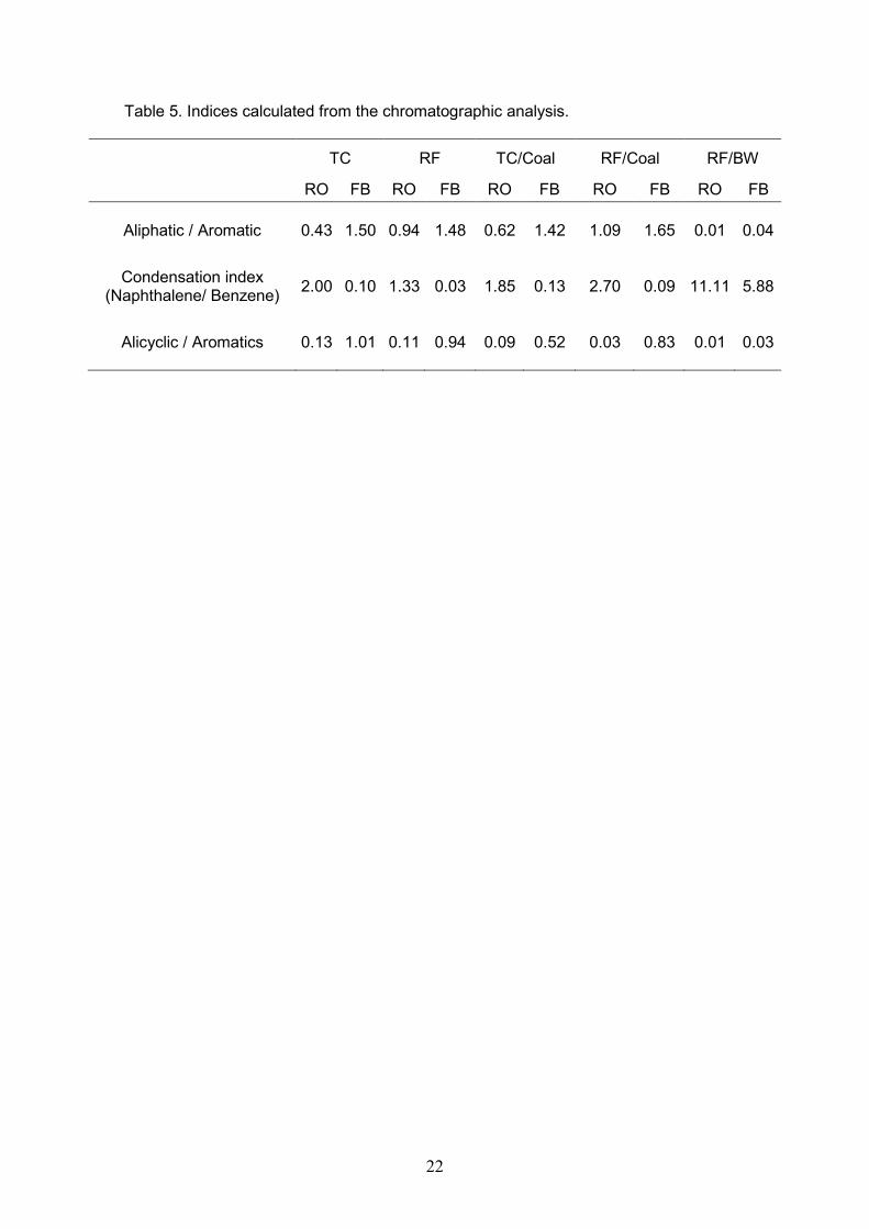
In order to facilitate comparison between the compositions of the oils produced
in both ovens various indices have been calculated (Table 5) on the basis of the
percentages of various types of compounds present in the oils. According to the results
from FTIR the aliphatic/aromatic compound ratio is always higher in the case of the FB
oven. In addition the presence of the coal produces an increase in this ratio when it is
co-pyrolyzed with TC and RF in both ovens. The presence of the bituminous waste
produces a dramatic reduction in the aliphatic compounds in the oil produced in FB and
RO. The condensation index calculated as the naphthalene to benzene ratio is
13
consistently higher in the oils from RO in agreement with the C/H ratio and aromaticity
index from FTIR analysis. The alicyclic/aromatics ratio is also consistently higher in the
FB oils as one would expect in view of the more drastic pyrolysis conditions of RO.
4. Conclusions
The mass balance of the carbonizations depends on the type of furnace used.
The amount of oils was lower in the rotary oven because here secondary reactions
occurred (condensation and Diels-Alder) which diminished the percentage of oils and
thereby increased the amount of gas. In addition the higher residence time of the
volatile products gave rise to a decrease in the more reactive compounds. As a
consequence of this the oil produced in the RO from the two tyre wastes and their
blends with coal and bituminous waste was more aromatic and had a higher C/H ratio
and lower oxygen content. In contrast the oil from the fixed bed furnace presented a
higher aliphatic/aromatic compound ratio, BTX and an abundance of limonene.
Tyre crumbs produced a greater amount of limonene and BTX, whereas the
reinforcing fibre produced a larger amount of oxygenated and nitrogenated compounds
such as ketones, acids, nitriles and amides. Blending with coal and with a bituminous
waste increased the percentage of linear aliphatics and produced even more aromatic
oil respectively. The bituminous waste caused a drastic reduction in the aliphatic
compounds in the oil produced in both ovens.
Ackowledgements
The research leading to these results has received funding from the Spanish MICINN
project reference CTM2009-10227. BA. thanks the Government of the Principado de
Asturias for the award of a predoctoral grant with funding from PCTI-Asturias.
14
References
[1] European Tyre & Rubber Manufacturing Association,
<http://www.etrma.org/uploads/Modules/Documentsmanager/brochure-elt-2011-
final.pdf>, 11/03/2013.
[2] Antoniou N, Zabaniotou A. Features of an efficient and environmentally attractive
used tyres pyrolysis with energy and material recovery. Renew. Sust. Energ. Rev.
2013;20: 539-558.
[3] Fernández AM, Barriocanal C, Alvarez R. Pyrolysis of a waste from the grinding of
scrap tyres. J. Hazard. Mater. 2012;203– 204:236– 243.
[4] ÖnenÇ S, Brebu M, Vasile C, Yanik J. Copyrolysis of scrap tires with oily wastes. J.
Anal. Appl. Pyrolysis 2012; 94:184-189.
[5] Murillo R, Aylón E, Navarro MV, Callén MS, Aranda A, Mastral AM. The
application of thermal processes to valorise waste tyre. Fuel Process. Technol.
2006;87: 143-147.
[6] Kyari M, Cunliffe A, Williams PT. Characterization of oils, gases and char in relation
to the pyrolysis of different brands of scrap automotive tires. Energy Fuels
2005;19:1165-1173.
[7] Amari T, Themelis NJ, Wernick IK. Resource recovery from used rubber tires.
Resour. Policy 1999;25:179-188.
[8] Mastral AM, Murillo R, Perez-Surio MJ, Callén MS. Coal Hydrocoprocessing with
Tires and tire components. Energy Fuels 1996;10:941-947.
[9] Williams PT, Besler S, Taylor DT. The pyrolysis of scrap automotive tyres. Fuel
1990;69:1474-1482.
[10] Parres F, Crespo-Amorós JE, Nadal-Gisbert A. Characterization of fibers
obtained from shredded tires. J. Appl. Polym. Sci. 2009;113:2136-2142.
[11] Acevedo B, Barriocanal C, Álvarez R. Pyrolysis of blends of coal and tyre
wastes in a fixed bed reactor and a rotary oven. Fuel 2013;113:817-825.
15
[12] Callén M, Hall S, Mastral AM, García T, Ross A, Bartle KD. PAH presence in
oils and tars from coal-tyre coprocessing. Fuel Process. Technol. 2000; 62:53-63.
[13] Mastral AM, Callén S, García T, Navarro MV. Aromatization of oils from coal-
tyre cothermolysis II. PAH content study as a function of the process variables. Fuel
Process Technol. 2000;68:45-55.
[14] van Krevelen DW. Coal. Typology- Chemistry – Physics- Constitution. Elsevier,
Amsterdam, 1981.
[15] Solomon PR, Fletcher TH, Pugmire RJ. Progress in coal pyrolysis. Fuel 1993;
72:587-597.
[16] Casal MD, Díez MA, Alvarez R, Barriocanal C. Primary tar from different coking
coal ranks. Int. J. Coal Geol. 2008;76:237–242.
[17] Snape CE, Ladner WR, Bartlet KD. Fate of aliphatic groups in low-rank coals
during extraction and pyrolysis processes. Fuel 1985; 64:1394-1400.
[18] Martínez JD, Puy N, Murillo R, García T, Navarro MV, Mastral AM. Waste tyre
pyrolysis–A review. Renew. Sust. Energ. Rev. 2013;23:179–213.
[19] Meier D, Faix O. State of the art of applied fase pyrolysis of lignocellulosic
materials –a review. Bioresourc. Technol. 68 (1999) 71–77.
[20] Januszewicz K, Klein M, Klugmann-radziemska E. Gaseous products from
scrap tires pyrolisis, Ecol. Chem. Eng. S. 2012;19: 451- 460.
[21] Ohtani H, Nagaya T, Sugimura Y, Tsuge S. Studies on thermal degradation of
aliphatic polyamides by pyrolysis-glass capillary gas chromatograpy. J. Anal. Appl.
Pyrol. 1982;4:117-131.
[22] Channiwala SA, Parikh PP. A unified correlation for estimating HHV of solid,
liquid and gaseous fuels. Fuel 2002; 81:051-1063.
[23] Laresgoiti MF, Caballero BM, De Marco I, Torres A, Cabrero MA, Chomón MJ.
Characterization of the liquid products obtained in tyre pyrolysis. J. Anal. Appl.
Pyrol. 2004;71:917–34.
16
[24] Cunliffe AM, Williams PT. Composition of oils derived from the batch pyrolysis
of tyres. J. Anal. Appl. Pyrol. 1998;44:131–52.
[25] López FA, Centeno TA, Alguacil FJ, Lobato B, Urien A. The GRAUTHERMIC-
Tyres process for the reclycing of granulated scrap tyres. J. Anal. Appl. Pyrol.
2013;103:207-215.
[26] Banar M, Akyildiz V, Özkan A, Çokaygil Z, Onay Ö. Characterization of
pyrolytic oil obtained from pyrolysis of TDF (Tire Derived Fuel). Energ. Convers.
Manag. 2012;62:22-30.
[27] Smith B. Infrared Spectral Interpretation: A Systematic Approach, CRC Press,
Boca Raton, 1998.
[28] Petersen HI, Rosenberg P, Nytoft HP. Oxygen groups in coals and alginite-rich
kerogen revisited. Int. J. Coal Geol. 2008;74:93–113.
[29] Chen Y, Mastalerz M, Schimmelmann A. Characterization of chemical
functional groups in macerals across different coal ranks via micro-FTIR
spectroscopy. Int. J. Coal Geol. 2012;104: 22–33.
[30] Ibarra JV, Muñoz E, Moliner R. FTIR study of the evolution of coal structure
during the coalification process. Org. Geochem. 1996;24:725-735.
[31] Iglesias MJ, Jiménez A, Laggoun-Defarge F, Suarez-Ruiz I. FTIR Study of Pure
Vitrains and Associated Coals. Energy Fuels 1995;9:458-466.
[32] Fernández AM, Barriocanal C, Díez MA, Alvarez R. Evaluation of bituminous
wastes as coal fluidity enhancers. Fuel 2012;101: 45-52.
[33] Kwon E, Castaldi MJ. Fundamental understanding of the thermal degradation
mechanisms of waste tires and their air pollutant generation in a N2 Atmosphere.
Environ. Sci. Technol. 2009;43 5996–6002.
[34] Kwon E, Castaldi MJ. Investigation of mechanisms of polycyclic aromatic
hydrocarbons (PAHs) initiated from the thermal degradation of styrene butadiene
rubber (SBR) in N2 atmosphere. Environ. Sci. Technol. 2008; 42:2175–2180.
17
[35] Cao Q, Jin L, Bao W, Lv Y. Investigations into the characteristics of oils
produced from co-pyrolysis of biomass and tire. Fuel Processing Technology
2009;90:337-342.
[36] Pakdel H, Roy C, Aubln H, Jean G , Coulombe S. Formation of dl-limonene in
used tire vacuum pyrolysis oils. Environ. Sci. Technol. 1991;25:1646-1649.
[37] Roy C, Darmstadt H, Benallal B, Amen-Chen C. Characterization of naphtha
and carbon black obtained by vacuum pyrolysis of polyisoprene rubber. Fuel
Process Technol. 1997;50: 87-103.
[38] Williams PT, Bottrill RP. Sulfur-polycyclic aromatic hydrocarbons in tyre
pyrolysis oil. Fuel 1995;74:736-742.
[39] Unapumnuk K, Lu M, Keener T. C. Carbon distribution from the pirólisis of tire-
derived fuels. Ind. Eng.Chem.Res. 2006;45:8757-8764.
[40] Mastral AM, Murillo R, Callén MS, García T, Snape CE. Influence of process
variables on oils from tire pirólisis and hydropyrolysis in a swept fixed bed reactor.
Energy Fuels 2000; 14:739-744.
[41] Stanciulescu M, Ikura M. Limonene ethers from tire pyrolysis oil Part 1: Batch
experiments. J. Anal. Appl. Pyrolysis 2006;75:217–225.
[42] Mirmiran S, Pakdel H, Roy C. Characterization of used tire vacuum pyrolysis oil:
Nitrogenous compounds from the naphtha fraction. J.Anal. Appl.Pyrol. 1995;22:
205-215.
[43] Heidi K, Peter G. Characterization of EPA’s 16 priority pollutant polycyclic
aromatic hydrocarbons (PAHs) in tank bottom solids and associated contaminated
soils at oil exploration and production sites in Texas. Reg. Toxicol. Pharmacol.
2007;47:288-295.

18
Table 1. Indices derived from the FTIR spectra.
Semi-quantitative index Band region (cm-1)
Aromaticity (Ar/Al) CHar stretching / CHal stretching (3136-2997) / (2997-
2765)
Ratio of oxygenated groups
Oxygenated groups / C=C stretching (1770-1650) / 1600

19
Table 2. Proximate and elemental analysis of the raw materials used.
TC RF Coal BW
VMa (wt.% dbb) 65.5 72.9d 36.2 68.2 d
Ash(wt.% db) 7.5 4.6 d 6.4 0.2 d
C (wt.% db) 78.5 68.2 78.6 86.7
H (wt.% db) 7.0 6.7 4.5 5.1
N (wt.% db) 1.3 1.1 2.0 4.4
S (wt.% db) 2.13 1.03 0.51 2.39
O (wt.% db) 3.9 18.6 8.2 2.3
C/Hc 0.93 0.85 1.46 1.39 a: volatile matter, b: dry basis, c: atomic ratio, d: from thermogravimetric analysis.
20
Table 3. Elemental analysis and calorific value of the oils obtained in the two ovens of
different configuration.
C (%wt.db)
H (%wt.db)
N (%wt.db)
S (%wt.db)
O (%wt.db)
C/Hb HHVc
(MJ/kg) LHVd
(MJ/kg)
TC RO 87.1 10.4 0.6 1.13 1.5 0.70 42.1 40.0
FB 85.1 11.1 0.5 0.96 3.2 0.64 42.7 40.4
RF RO 76.2 8.5 3.4 0.85 9.0 0.75 37.4 35.7
FB 76.9 10.3 1.0 0.55 10.5 0.62 34.1 32.0
TC/Coal RO 87.6 9.6 0.9 1.01 3.1 0.76 41.7 39.7
FB 79.1 10.9 0.6 0.73 10.3 0.60 38.6 36.4
RF/Coal RO 77.9 9.0 2.7 0.79 5.8 0.72 36.2 34.3
FB 75.0 10.1 1.4 0.40 10.5 0.62 27.6 25.6
RF/BW RO 84.0 6.7 3.4 0.86 5.1a 1.04 37.6 36.2
FB 82.7 7.6 2.3 1.02 6.4 a 0.90 38.4 36.8
a: calculated by difference. b: atomic ratio. c: High Heating Value. d: Low Heating Value.
21
Table 4. Composition of the oils determined by gas chromatography.
Compounds (%) TC RF TC/Coal RF/Coal RF/BW
RO FB RO FB RO FB RO FB RO FB
Benzene + derivatives
11.57 21.15 5.47 8.98 8.83 22.21 1.03 15.99 2.92 4.92
Indane / indene + derivatives
9.74 3.85 1.58 0.00 9.37 3.34 0.38 0.00 0.53 1.04
Naphthalene + derivatives
23.18 2.13 7.32 0.31 16.35 2.85 2.75 1.39 32.51 28.58
Fluorene + derivatives
0.01 0.00 0.00 0.00 0.06 0.00 0.45 0.00 14.08 13.86
Phenanthrene/ Anthracene +
derivatives 2.32 0.46 0.00 0.00 0.00 0.00 0.00 0.00 12.02 13.79
Fluoranthene + derivatives
0.00 0.00 0.00 0.00 0.00 0.00 0.00 0.00 3.92 3.73
Pyrene + derivatives
0.00 0.00 0.00 0.00 1.34 0.00 0.00 0.00 3.78 2.20
Perylene + derivatives
0.00 0.00 0.00 0.00 0.00 0.00 0.00 0.00 0.93 0.00
Limonene + Terpene
5.12 21.58 3.57 14.70 3.50 14.20 0.53 13.96 0.39 1.12
Oxygenated compounds
0.56 6.63 28.03 16.60 2.94 7.36 26.37 12.82 9.03 11.41
Nitrogenated compounds
4.55 3.11 31.89 22.29 0.00 0.95 18.36 11.09 9.56 8.88
Sulphur compounds
1.60 0.82 0.71 1.40 1.40 0.70 0.68 0.24 0.50 0.54
Alicyclic 1.32 7.12 1.14 16.28 0.29 1.28 0.57 11.28 0.30 1.22
Non-cyclic Aliphatics
10.23 4.27 3.96 1.05 21.00 18.99 23.18 13.90 0.00 0.00
22
Table 5. Indices calculated from the chromatographic analysis.
TC RF TC/Coal RF/Coal RF/BW
RO FB RO FB RO FB RO FB RO FB
Aliphatic / Aromatic 0.43 1.50 0.94 1.48 0.62 1.42 1.09 1.65 0.01 0.04
Condensation index (Naphthalene/ Benzene)
2.00 0.10 1.33 0.03 1.85 0.13 2.70 0.09 11.11 5.88
Alicyclic / Aromatics 0.13 1.01 0.11 0.94 0.09 0.52 0.03 0.83 0.01 0.03
23
Figure 1. Mass Balance in the two ovens
0
10
20
30
40
50
60
CHAR OIL GAS CHAR OIL GAS CHAR OIL GAS CHAR OIL GAS CHAR OIL GAS
RO
FB
TC RF TC/Coal RF/Coal RF/BW
Yie
ld(w
t.%
)
24
Figure 2. FTIR spectra of the oils obtained from the pyrolysis of the blends in a rotary (RO) and fixed bed (FB) oven. Wavenumbers: 3500-2500cm-1
*TYGUAamb1309-b
0.2
0.4
Abs
*Ty3GuaAlqCjBrz850-c
0.0
0.5A
bs
*Ty3GuaGK850-b
-0.0 0.2
0.4
Abs
*Tx3GuaAmb850-a
0.0
0.5
Abs
*Tx3GuaAlqCj850-a
0.1
0.2
Abs
*Tx3GuaGK850-a
0.0
0.5
Abs
*HR TX3 BREA AMB b
0.00
0.05
Abs
*HR TX3 BREA ALQ BZ+CJ c
-0.0
0.4
Abs
*Tx3BreaGK850-c
0.2
Abs
1500 2000 2500 3000 3500
Wavenumbers (cm-1)3500 3000 2500 2000 1500
Wavenumbers (cm-1)
TC/Coal RO AMB
TC/Coal RO OT
TC/Coal FB
RF/Coal RO AMB
RF/Coal RO OT
RF/Coal FB
RF/BW RO AMB
RF/BW RO OT
RF/BW FB
25
Figure 3. FTIR spectra of the oils obtained from the pyrolysis of the blends in a rotary (RO) and fixed bed (FB) oven. Wavenumbers: 1800-1400cm-1
2500 1000 1500 2000 2500 3000
Wavenumbers (cm-1)3000 2000 1500 1000
Wavenumbers (cm-1)
TC/Coal RO AMB
TC/Coal RO OT
TC/Coal FB
RF/Coal RO AMB
RF/Coal RO OT
RF/Coal FB
RF/BW RO AMB
RF/BW RO OT
RF/BW FB
26
Figure 4. Semi-quantitative ratios derived from the FTIR spectra of the oils obtained from the pyrolysis of the blends in a rotary (RO) and fixed bed (FB) oven.
Ratio of oxygenated groups
0
2
4
6
8
10
12
14
TC RF TC/Coal RF/Coal RF/BW
A(1
77
0-1
650
)/A
160
0
RO FB
Aromaticity (Ar/Al)
0.00
0.05
0.10
0.15
0.20
0.25
0.30
0.35
TC RF TC/Coal RF/Coal RF/BW
A(3
13
6-2
99
7)/
A(2
99
7-2
76
5) RO FB
27
Time (min) Figure 5. GC-FID chromatogram of the 1:1 RF/BW blend. Peak Identification: 1.Cyclopentanone, 2. Dimethylcyclohexene, 3. Ethylbenzene, 4. p-Xylene, 5. Styrene, 6.Methylethylbenzene, 7. Ethylmethylbenzene, 8. Trimethylbenzene, 9. alfa-Methylstyrene, 10. Benzonitrile, 11. Limonene, 12. Indene, 13. Ethenylethylbenzene, 14. Methylbenzonitrile, 15. Methylindene, 16. Methylindene, 17. Naphthalene, 18. Isoquinoline, 19. Quinoline, 20.benzenedicarbonitrile, 21. methylnaphthalene, 22. Indole, 23. Methylnaphthalene, 24. Methylquinoline, 25. Biphenyl, 26. Ethylnaphthalene, 27. Dimethylnaphthalene, 28. Acenaphthylene, 29. Acenaphthene, 30. Dibenzofurane, 31. Fenalene, 32. Fluorene, 33.Methylfluorene, 34. Methyldibenzofurane, 35. Methyldibenzofurane, 36. Dibenzothiophene, 37. Phenanthrene, 38. Anthracene, 39. Carbazole, 40. Cyclopenta [d, e, f] Phenanthrene, 41. Fluoranthene, 42. Pyrene, 43. Benzo (a) anthracene, 44. Crysene, 45. Quinindoline, 46. Benzo (k) fluoranthene, 47. Benzo (a) pyrene, 48. Perylene.
min10 20 30 40 50 60
pA
0
50
100
150
200
250
300
350
400
FID1 B, (D:\BEATRIZ\CROMAT~1\850\GK850~1\TX3BALQC.D)
min10 20 30 40 50 60
pA
0
100
200
300
400
500
600
FID1 B, (D:\BEATRIZ\CROMAT~1\850\HR850~1\TX3BAMB1.D)
min10 20 30 40 50 60
pA
0
100
200
300
400
500
FID1 B, (D:\BEATRIZ\CROMAT~1\850\HR850~1\TXBCJBZ2.D)
10 20 30 40 50 60 70
FB RF/BW
RO RF/BW AMB
RO RF/BW OT
1
1
2
2
3
3
4
4
5
5
6
7
7
8
7
9
10
10 11
12 11
12
13 14
14
14
15
16
17
17
17
18
18
18
19 20 21
22
23
20
21 22
23
20 21
22
23 19
19
24 25
25
26
26
27
28
30 29 32
31
33
35 34
36
37
38
39
27
28
30
29 32
31 33
35 34
36
37
38
25
26
27
28 30
32
31
33
35 34
36
37
38
39 40
40
41
41
42
42
41 42
43 44
43 44 45
46 47
48
46
47
48 45
29
28
Figure 6. GC-FID chromatogram of the 1:1 RF/Coal blend. Peak identification: 1.Cyclopentanone, 2. Dimethylcyclohexene, 3. Ethylbenzene, 4. Dimethylbenzene, 5. Styrene, 6. Xylene, 7. C9, 8. Methylethylbenzene, 9. Ethylcyclopentanone, 10. Limonene, 11. Isopropyldinamethylvinylcyclobutane, 12. Ethylmethylbenzene, 13. Methylethenylbenzene, 14. Benzonitrile, 15. Phenol, 16. Trimethylbenzene, 17. C10, 18. Methyl (methylethyl) benzene, 19. Limonene, 20. Pentylcyclohexanone, 21. Methylheptenone, 22. Indene, 23. Hexahydronaphthalene, 24. Acetophenone, 25. Methylphenol, 26. Ethenyl (ethyl) benzene, 27. Ethenyl (ethyl) benzene, 28. C11, 29. Methylbenzonitrile, 30. Methylindene, 31. Methylpropenylbenzene, 32. Dimethylphenol, 33. Ethyl ester benzoic acid, 34. Naphthalene, 35. C12, 36. Benzoic acid, 37. Caprolactam, 38. Benzenedicarbonitrile, 39. Methylnaphthalene, 40. Tridecene, 41. C13, 42. Methylnaphthalene, 43. Methylbenzoic acid, 44. C14, 45. Dimethylnaphthalene, 46. Gamma-curcumene, 47. C15, 48. Trimethylnaphthalene, 49. C16, 50. Bromomethylcyclohexane, 51. Thiophene methanediol, 52. Methylfluorene, 53. C17, 54. Methylbenzamide, 55. C18, 56. Phenylpropanone, 57. Hexylbenzamide, 58. C19, 59. Methylpropiophenone, 60. C20, 61. Heptenone, 62. C21, 63. Indole acetaldehyde, 64. Hexenyl methoxymethyl cyclohexadienol, 65. Diphenyl dimethyl pentanone, 66. C22, 67. Tricosene, 68. C23, 69. Clorohexilcyclohexanone, 70. C24, 71. C25, 72. C26, 73. C27, 74. C28, 75. C29, 76.C30.
min10 20 30 40 50 60
pA
0
50
100
150
200
250
300
350
400
450
min10 20 30 40 50 60
pA
20
30
40
50
60
70
80
90
10 20 30 40 50 60 70
Time (min)
1 2
3
4
6
7
5
12 11
13
14 19
17
16
15 18
21 22 23 24
26
27 29
32 30
34 35
36
37
37
38
39
42 44 47 49 53
43 44
45 47
48
49
52
53 51
54 55
57
58
56
59 60 62
64
66 63 68
67
70 71 72
73 74 75
76 77
min10 20 30 40 50 60
pA
20
40
60
80
100
120
140
160
180
1 2
3
4 14 19
5 6 7
8 9
10
12
13 16
17
18
20
25
28 29
31
33
35 37
40
39 41
42 44 46
45 47
48 49 50
53
55
57
58 60 62
61
66
65
68 69
70 71 72
73 74 75
76
FB RF/Coal
RO RF/Coal AMB
RO RF/Coal OT
min4 6 8 10 12 14 16
pA
0
100
200
300
400
6 8 10 12 14 16 4
1 2
3
4
5
6
7
12
11 13
14
15
19
21 18
17
16
22 23
24
26
min4 6 8 10 12 14 16
pA
50
100
150
200
250
4 6 8 10 12 14 16
2
3
5
4
1
6
7 8 9 10 13
14 19
20 18 12
16
17