Embed Size (px)
Citation preview

Fuel Processing Technology 159 (2017) 128–144
Contents lists available at ScienceDirect
Fuel Processing Technology
j ourna l homepage: www.e lsev ie r .com/ locate / fuproc
Review
Chemical equilibrium analysis of hydrogen production from shale gasusing sorption enhanced chemical looping steam reforming
Zainab Ibrahim S G Adiya ⁎, Valerie Dupont, Tariq MahmudSchool of Chemical and Process Engineering (SCAPE), The University of Leeds, Leeds LS2 9JT, UK
⁎ Corresponding author.E-mail addresses: [email protected] (Z.I. S G Adiy
http://dx.doi.org/10.1016/j.fuproc.2017.01.0260378-3820/© 2017 Published by Elsevier B.V.
a b s t r a c t
a r t i c l e i n f oArticle history:Received 21 July 2016Received in revised form 14 January 2017Accepted 16 January 2017Available online xxxx
Detailed chemical equilibrium analysis based onminimisation of Gibbs Energy is conducted to illustrate the ben-efits of integrating sorption enhancement (SE) and chemical looping (CL) togetherwith the conventional catalyt-ic steam reforming (C-SR) process for hydrogen production from a typical shale gas feedstock. CaO(S) was chosenas the CO2 sorbent and Ni/NiO is the oxygen transfer material (OTM) doubling as steam reforming catalyst. Up to49% and 52% rise in H2 yield and purity respectively were achieved with SE-CLSR with a lower enthalpy changecompared to C-SR at S:C 3 and 800 K. A minimum energy of 159 kJ was required to produce 1 mol of H2 at S:C 3and 800 K in C-SR process, this significantly dropped to 34 kJ/mol of produced H2 in the CaO(S)/NiO system atsame operating condition without regeneration of the sorbent, when the energy of regenerating the sorbent at1170Kwas included, the enthalpy rose to 92 kJ/mol H2, i.e., significantly lower than the Ca-free system. The pres-ence of inert bedmaterials in the reactor bed such as catalyst support or degraded CO2 sorbent introduced a verysubstantial heating burden to bring thesematerials from reforming temperature to sorbent regeneration temper-ature or to Ni oxidation temperature. The choice of S:C ratio in conditions of excess steam represents a compro-mise between the higher H2 yield and purity and lower risk of coking, balanced by the increased enthalpy cost ofraising excess steam.
© 2017 Published by Elsevier B.V.
Keywords:Shale gasSteam reformingChemical loopingSorption enhancement
Contents
1. Introduction . . . . . . . . . . . . . . . . . . . . . . . . . . . . . . . . . . . . . . . . . . . . . . . . . . . . . . . . . . . . . . 1292. Process description . . . . . . . . . . . . . . . . . . . . . . . . . . . . . . . . . . . . . . . . . . . . . . . . . . . . . . . . . . . 1303. Methodology of the thermodynamic equilibrium calculation . . . . . . . . . . . . . . . . . . . . . . . . . . . . . . . . . . . . . . . . 1324. Results and discussion . . . . . . . . . . . . . . . . . . . . . . . . . . . . . . . . . . . . . . . . . . . . . . . . . . . . . . . . . 133
4.1. Effect of temperature and presence of C2-C3 feedstock on both C-SR and SE-SR processes . . . . . . . . . . . . . . . . . . . . . . . . 1344.2. Effect of steam to carbon ratio on steam reforming processes . . . . . . . . . . . . . . . . . . . . . . . . . . . . . . . . . . . . . 1344.3. Sorption enhancement with CaO sorbent (SE-SR) . . . . . . . . . . . . . . . . . . . . . . . . . . . . . . . . . . . . . . . . . . 1354.4. Chemical looping with NiO coupled with steam reforming (CL-SR) of shale gas . . . . . . . . . . . . . . . . . . . . . . . . . . . . 1364.5. Sorption enhanced chemical looping steam reforming . . . . . . . . . . . . . . . . . . . . . . . . . . . . . . . . . . . . . . . . 138
4.5.1. H2 yield, H2 purity and selectivity to carbonate . . . . . . . . . . . . . . . . . . . . . . . . . . . . . . . . . . . . . . . 1384.5.2. Enthalpy balance of SE-CLSR . . . . . . . . . . . . . . . . . . . . . . . . . . . . . . . . . . . . . . . . . . . . . . . 1384.5.3. Effect of inert materials on enthalpy balance of the cyclic processes . . . . . . . . . . . . . . . . . . . . . . . . . . . . . . 140
4.6. Carbon product . . . . . . . . . . . . . . . . . . . . . . . . . . . . . . . . . . . . . . . . . . . . . . . . . . . . . . . . . 1404.7. Effect of pressure on C-SR and SE-CLSR . . . . . . . . . . . . . . . . . . . . . . . . . . . . . . . . . . . . . . . . . . . . . . . 142
5. Conclusion and final remarks . . . . . . . . . . . . . . . . . . . . . . . . . . . . . . . . . . . . . . . . . . . . . . . . . . . . . . 142Acknowledgments . . . . . . . . . . . . . . . . . . . . . . . . . . . . . . . . . . . . . . . . . . . . . . . . . . . . . . . . . . . . . . 142Appendix A. Supplementary data . . . . . . . . . . . . . . . . . . . . . . . . . . . . . . . . . . . . . . . . . . . . . . . . . . . . . . 142References . . . . . . . . . . . . . . . . . . . . . . . . . . . . . . . . . . . . . . . . . . . . . . . . . . . . . . . . . . . . . . . . . 142
a), [email protected] (V. Dupont).

Table 1Composition of shale gas used for stimulations [63].
Species Shale gas (moles)
CH4 79.4C2H6 16.1C3H8 4.0CO2 0.1N2 0.4Total 100
129Z.I. S G Adiya et al. / Fuel Processing Technology 159 (2017) 128–144
1. Introduction
Hydrogen is at present of enormous value in the production ofsynthetic fertilizers via ammonia manufacture, as well as an essentialreagent in petroleum refinery operations [1,2]. Ammonia is the back-bone of the fertilizer industry and is generated in industrial processesby reaction between hydrogen and nitrogen at medium temperatureand high pressure. Although the use of high pressure in the industrialH2 production process is detrimental to the equilibrium feedstockconversion and thus of the H2 yield per mol of feedstock, it permitsthe utilization of more compact and thus less capital intensive plants.Ammonia production individually represents the largest H2 consump-tion, with 50% of all the hydrogen produced in the globe [1–3]. Rapidgrowth in world population is generating increased demand for foodand providing a continued need for agricultural chemicals, especiallyfertilizers [4]. World-wide ammonia capacity is anticipated to rise 16%(over/in comparison to 2013), reaching 245Mt NH3 in 2018 [5]. Hydro-gen production, management and recovery within petroleum refineriesis also increasing particularly in the production of low-sulphur and die-sel fuels using hydrotreating and hydrocracking processes [6,7]. Perhapshydrogen is the most significant utility in a modern petroleum refinery[8]. As more severe product specifications come into effect, a classic re-finery is either ‘bottlenecked’ due to lack of hydrogen or will be in thefuture [9]. The increasing stringent requirements on refinery productsquality have effect on hydrogen production and demand. Hydrogen atrefineries is provided in part by catalytic reforming (main product:cracked fractions, by-product: hydrogen), the remainder being suppliedon site or off site by steam reforming (main product: hydrogen, by-product: CO or CO2), and, to a much smaller extent partial oxidationand autothermal reforming are used [6,9]. Steam reforming can alsoform the first step in Fischer Tropsch processes, which convert naturalgas to gasoline-like liquid fuel [10] via ‘GTL’ technology. Feedstocks forsteam reforming at refineries vary from gases (natural gas ‘NG’, butalso, associated gases, flare gas) to naphtha [11,12]. A boom in shalegas production [13] and unconventional gas resources in the world(e.g. hydrates) foresees that gas will remain the main feedstock ofsteam reforming in the near term, in contrast to naphtha, which is de-clining due to high availability of natural gas [13,14]. ‘Shale gas is a nat-ural gas found within shale formations’ [15] (a form of sedimentaryrock). The recent development in oil and gas extraction e.g. drillingand fracking have made shale gas production economically viable. In2013, the Annual Energy Outlook projected that the U.S (world largestproducer of shale gas) natural gas production will increase an estimateof 44% over the next 30 years. Enormous amount of this projected in-crease is expected from shale gas extraction. Shale gas is also expectedto grow from 7.8 million MMcF (million cubic feet) extracted in 2011,to 16.7 million MMcf in 2040. In future, shale gas production in theU.S is anticipated to rise, whereas all other extraction method are likelyto remain steady or decline [15,16]. Furthermore, many developedcountries have extensive natural gas distribution networks which canact as energy storage and transport facilities with lower losses thantheir electricity grids, which positions gas as an attractive energy carrier(e.g. UK). The use Natural Gas (NG) fuelled vehicles and NG power sta-tions is also increasing in the world. Gas feedstock compositions arecharacterised by significant content in hydrocarbons with carbon num-ber 2 to 6, in addition to themain componentmethane, as well as great-ly varying contents in N2, CO2, H2S according to their source [12].Despite having reached technological maturity, steam reforming isone of themost energy consuming processes in hydrocarbon processingand ammonia production via its heating requirement, with additionaldisadvantages such as greenhouse gas andother air pollutants emission,high operational and maintenance cost [17].
Researchers are focusing onfinding alternative energy efficient tech-nologies that can mitigate the economic and environmental impacts ofthe forecasted large increases in hydrogen demand. Sorption enhance-ment (i.e. process with in situ CO2 capture on a solid sorbent) which
shifts favourably the chemical equilibria of H2-producing reactions,and chemical looping (i.e. oxygen for oxidative heat is provided by asolid transfer material undergoing redox cycles at medium tempera-tures), have both drawn attention as promising modifications to theconventional steam reforming process. This is because of their potentialfor significant energy savings and lower environmental impactsbrought about by process intensification features and milder reactiveconditions [18]. Addition of ‘high temperature’ (as opposed to ‘flue tem-perature’) solid CO2 sorbent in the reformer that captures CO2, shifts theequilibriumof the steam reforming andwater gas shift reaction towardsmaximum hydrogen yield and purity, as well as increasing feedstockconversion [19,20]. Moreover, CO2 chemisorption is highly exothermic,providing energy directly inside the reformer. Lyon and Cole [21] pro-posed the coupling of sorption enhancement and chemical looping to-gether for endothermic reactions such as steam reforming, the processfirst termed ‘unmixed’ reforming, was later termed ‘sorption enhancedchemical looping’ steam reforming (SE-CLSR). The process has beenstudied and analysed using variety of fuels, such as methane [18] andwaste cooking oil [22], for hydrogen production using both the inter-connected fluidised bed and the fixed bed reactors configurations,which both have their advantages and drawbacks. However, studieson the thermodynamic analysis and process simulation, which are rele-vant to both types of configurations are limited. Researchers havefocused mainly on either the sorption enhanced process [23,24] or thechemical looping process [25] separately. Coupling of sorption en-hanced water gas shift and chemical looping with partial oxidationhas also been investigated [18]. Moreover, to date, the processes thatuse typical/actual gas composition containing higher hydrocarbonsand inert have not been investigated.
Global warming is presently one of the major concern in the world[26]. The conventional steam reforming (C-SR) process is one of leadingcauses of global warming; by increasing the CO2 (the primary green-house gas bringing about global warming) concentration in the atmo-sphere. For every 4 mol of H2 produced by complete steam methanereforming process for example, a mole of CO2 is generated. In additionto tons of CO2 generated and release into the atmosphere by furnaceflue gas. SE-CLSR process aimed to overcome this by capturing the CO2
during the steam reforming process [18,22,27] and eliminating the useof furnace flue gas at steady state operation.
Sorbent degration is a major concern and drawback on sorption en-hanced processes. Tomake things worse degradation cannot be studiedvia equilibrium thermodynamics. Researchers worlwide work towardsunderstanding the reasons behind sorbents' loss of CO2 capacity withrepeated cycling and increasing the durability of Ca based CO2 sorbent[20,28].
In this study, a detailed thermodynamic equilibrium analysis of H2
production from Marcellus shale gas (see composition in Table 1)using SE-CLSR with CaO(S) sorbent and NiO as both catalyst and oxygentransfer material (OTM), was conducted. The gas represents a typicalcomposition of natural gas, containing roughly up to 80% of methanewith roughly 20% higher hydrocarbons (NC3), CO2 and inert gas [29],representing a mixture rich in ethane and propane. This compositioncan also be representative of typical composition of natural gases fromNigeria [30] and the North Sea [31], by containing up to 80% methane[31]. The effect of different input parameters such as temperature,

130 Z.I. S G Adiya et al. / Fuel Processing Technology 159 (2017) 128–144
pressure, and molar steam-to-carbon ratio were investigated on themain process outputs of hydrogen yield, purity, feedstock and steamconversion, and carbon formation. The purpose of the study is to dem-onstrate the effect of coupling SE and CL in C-SR process aswell as iden-tify optimum operating conditions of the studied processes using arealistic feedstock. Sorption enhanced reduction of the Nickel oxygencarrier catalyst is also report in the present study for the first time.
(a) C-SR
(c) CL-SR step 1
(d) SECL-SR step 1
(a) SE-SR st
Fig. 1. Schematic description of (a) C-SR, (b) SE-SR steps 1 & 2, (c) CL-SR steps 1 & 2 and (d) SE-Cusing energy from the exothermic oxidation and gas turbine). Units in grey colour are not coveflames in furnace are commensurate to heat input from relevant combustible flow (fresh fuel
2. Process description
Steam methane reforming (SMR) is the most established and com-monly used process to produce hydrogen on a large scale [32]. Approx-imately, 90% of the world's overall hydrogen production is by SMR offossils fuels [3,32,33]. Fig. 1a depicts a simplified schematic representa-tion of the conventional SMR process henceforth termed ‘C-SR’.
(c) CL-SR step 2
(d) SECL-SR step 2
(b) SE-SR step 2ep 1
LSR steps 1 & 2 processes. CaCO3(S) regeneration occurs during step 2 (highlighted in black,red in our calculation. Blacked out valve symbols (if any) represent closed to flow. Size ofvs. separation unit tail gas).

131Z.I. S G Adiya et al. / Fuel Processing Technology 159 (2017) 128–144
The process (C-SR), consists of mainly two basic steps followed byseparation. In the first stage; water (in the form of high-temperaturesteam) reacts with feedstock (mainly natural gas) to generate syngas(CO, CO2, H2O, H2) in the presence of nickel oxide catalyst at an elevatedtemperature (almost 800–950 °C) andmediumpressure (at 20–35 atm)[34,35]. In the second stage, thewater gas shift (WGS) reaction runs at alower temperature (almost 200–400 °C) [36,37]. Although the latter re-action is exothermic, the overall energy demand of the process is signif-icantly endothermic, requiring part of the natural gas to be burnt in thereformer furnace. Separation of the H2 from the syngas leaving theWGSreactor (mostly unreacted CH4, CO, H2O, and CO2) is carried out in thefinal stage. Numerous techniques can be used to undertake separation.Three of themost common techniques used are; pressure swing absorp-tion (PSA), membranes, cryogenics [38,39]. Chemical absorption for ex-ample CO2 scrubbing using methyldiethanolamine (MDEA) andmonoethanolamine (MEA) are also used for separation [40]. However,the separation step is not covered in the present thermodynamic analy-sis. Fig. 1a represents the most common configuration in industrial H2
production where a PSA unit performs the H2 separation and the tailgas from the PSA is recycled to the furnace and contributes to meetthe reformers heating load.
The purpose of sorption enhanced steam reforming (SE-SR) is toenhance H2 yield in the conventional steam reforming (C-SR) process[41]. In 1868, H2 production from hydrocarbon in the presence ofCaO(s) sorbent reportedly took place [18]. A patent for hydrogenproduction using SE-SR process was issued as early as 1933 [18,42]. Asmentioned earlier, the C-SR process route has at least three basicsteps; SMR process, WGS and finally the separation/purification step.The logic behind SE-SR process is to perform all those three steps(SMR, WGS and CO2 capture) simultaneously in a single reactor vesselin the presence of a solid CO2 sorbent. The role of CO2 sorbent can beperformed cheaply by the abundant calciumoxide or calciumhydroxide[18], but there are other suitable CO2 sorbents such as hydrotalcites (e.g.Mg6Al2(OH)16(CO)3 × 4H2O/K2CO3) and Li-based sorbents (e.g.Li4SiO4). The process is usually configured either using two packedbed reactors operated in cyclic reforming/calcining mode achievedwith alternating feed flows, or two fluidised bed reactors with circulat-ing bed materials moving between the reformer (fuel reactor) and thecalciner (air reactor). In both cases, the calcination conditions performthe regeneration of the CO2 sorbent. Although, it is feasible to performreforming and calcination semi-batch wise in a single reactor vessel,resulting in intermittent H2 production, a continuous operating processusing at least two reactor vessels seems to be more attractive [18]. TheCO2 produced during steam reforming is captured by the sorbent,which once nearly-saturatedwith CO2, is regenerated in situ by temper-ature or pressure swing adsorption principle. For a Ca-based sorbent, asthe CO2 is been captured CaCO3(S), the equilibrium of the H2-producingreactions is shifted towards the right, increasing hydrogen generation atfairly lower/medium temperatures (723–873 K) compared to the con-ventional (C-SR) process (1073–1300 K) [18,20,43,44]. Fig. 1b depictsa schematic of the two-step SE-SR process in a packed bed configura-tion, where step 1 is the H2 producing step and step 2 the CO2 sorbentregeneration step. The sorbents play a significant role in the SE-SR pro-cess. It is vital for the sorbent to have some certain basic characteristicssuch as; high selectivity and adsorption ability at operating temperatureand pressure, good and steady adsorption capability of CO2 after repeat-ed adsorption and desorption cycles, and good mechanical strength ofadsorbent particles after cyclic exposure to high pressure streams [45,46]. Themost commonly used CO2 sorbent is CaO [18], which is reducedwith CO2 in an exothermic reaction forming CaCO3(S) [20]. The carbon-ated sorbent can be regenerated in order to be useable again by calcina-tion [18,20].
The advantages of SE-SR over C-SR process are; potential to use alower operating temperature, reduction of purification steps and extentof the reduction, minimisation of reactor size and decrease in the quan-tity of steam to beused as opposed to C-SR [45,46]. Brun-Tsekhovoi et al.
[47] revealed that the SE-SR process is able to reduce the overall energyrequired by the system with a potential of saving up to 20–25% asopposed to the C-SR process. In addition to these benefits, the SE-SRprocess has the advantage of increasing feed conversion, producinghigh purity hydrogen with a minimum CO2, proficient CO2 capturefrom the product as CaCO3(S), and potential to generate pure CO2 duringthe sorbent calcination step that is suitable for subsequent use orsequestration [45,46,48]. These advantages are illustrated in Fig. 1b incontrast to Fig. 1a by the absence of WGS stage, a smaller PSA unit,and no large demand of fresh natural gas in the furnace. In the pastfew years, various SE-SR pilot plants with capacity of 2–20 MW werebuilt in Sweden, Australia, and Germany [49–51]. However, all of theplants used wood chips or woods pellets as fuel for syngas productionand the process was demonstrated during gasification [49]. Presently,numerous research groups, both at research institutes and universitylevels, are investigating the performance of the SE-SR process [41]using various/diverse fuel and feedstocks ranging from methane [24]to propane [23], including hydroxyacetone [52], acetic acid [53], andurea [20].
The chemical looping steam reforming (CL-SR) is a special casewhich combines chemical looping combustion (CLC) and steamreforming. Ametal oxide is used as an intermediate to transport oxygenfrom air to fuel in order to provide heat of oxidation to the endothermicH2 production process. This necessitates keeping the air to fuel ratio lowto avoid the fuel from been oxidised completely to H2O and CO2 [18].Fig. 1c depicts a schematic of the CL-SR process, step 1 representingthe OTM reduction combined with H2 production, and step 2 corre-sponding to the oxidation of the OTM.
The process gas is fed into the reactor where both reduction of OTMand steam reforming occur simultaneously. A fraction of the feedstock isexpected to be used as reductant in the metal oxide reduction to pro-duce H2O and CO2 but the remainder would then reform to CO/CO2
and H2 by the catalytically active reduced metal. The second step in-volves oxidation of the OTM back to its initial state. A best choice ofOTM for CL-SR is nickel, as it not only an excellent steam reforming cat-alyst when reduced by hydrocarbon flow (or NH3, or H2) [54] but isreadily oxidised (mainly to NiO) using air, thus an ideal OTM for theCL-SR process. However, the heats of reactions are dependent on oxy-gen carrier and fuel type [55,56]. The large scale application of CLCand CL-SR is still reliant upon the obtainability of appropriate oxygencarriers. Themost commonly studied OTMs are oxides of nickel, copper,iron and manganese. Nickel has been the most used oxygen carrier andconsidered as state of the art [57,58] because of its high reactivity, neg-ligible volatility, and thermal steadinesswhich are favourable factors forelevated temperature and high gas turbine CLC [55,56,59,60]. Neverthe-less, nickel in particulate form is toxic upon inhalation, and has a ther-modynamic constraint of 99–99.5% fuel conversion, conditional ontemperature and pressure [58]. Advantages of the CL-SR process overconventional steam reforming are illustrated in Fig. 1c in comparisonto Fig. 1a, where the overall surplus energy contained in the syngasand lack of external heating demand in the reformer would in theorypermit operating a combustor/gas turbine/electrical generator system.As a result single ‘squat’ reformer units would be possible that wouldmade the whole plant economical at smaller scales.
The combination of sorption enhancement and CL-SR in one singleprocess and is called sorption enhanced chemical looping steamreforming (SE-CLSR). Thematerial bed then consists of amixture of par-ticles comprising of solid oxygen carrier and CO2 sorbent. The reformingreactor normally operates at a low/medium temperature, partially re-ducing the fuel with the oxygen provided by oxygen carrier and steamreforming most of the fuel, and at the same time any CO2 producedduring the process is captured by the CO2 sorbent, causing sorptionenhanced steam reforming. The overall reaction in the reduction/reforming reactor is thermos-neutral [18,61] owing to the strongly exo-thermic carbonation reaction. The SE-CLSR process could in principle beself-sufficient with regard to energy because the required heat for the

132 Z.I. S G Adiya et al. / Fuel Processing Technology 159 (2017) 128–144
endothermic steam reforming and reduction reactions could be provid-ed by the exothermic sorbent carbonation reaction, while the heat fromre-oxidation of the OTM is utilised for sorbent regeneration [19] in aseparate time step. Hence, this could mean near complete eliminationof dependency on flue gas use to provide reformer heat at steady stateoperation. However, full benefits of the process are discussed in detaillater. Fig. 1d depicts the SE-CLSR process, with step 1 consisting of thecombined OTM reduction, H2 production under gas and steam flowwith in situ CO2 capture by the sorbent, and step 2 carrying out thecoupled OTM oxidation under air flow and CO2 sorbent calcination. Itis suggested that a smaller scale separation process be used, owing tothe fact that nearly pure H2 can be generated in step 1 of the processunder well chosen operating conditions. Another capital cost reducingaspect is that instead of needing to use an assembly of many long thinreformer tubes exposed to harsh combustion environments, the re-former could be a single reactor making little use of external heat (e.g.for startup only). The benefits of intensifying the C-SR process byusing SE-CLSR technology are pointed out in Fig. 1d in comparison toFig. 1a, where the furnace and WGS reactor are no longer required,the energy content of the separation gases is used to run (as an exam-ple) a combustor/gas turbine-generator, the ‘squat’ reformer aspectand the reduced separation stage all permit economical downsizingand potentially co-generation.
3. Methodology of the thermodynamic equilibrium calculation
The CEA (Chemical Equilibrium andApplications ) software byNASA[62] was used to perform the thermodynamic equilibrium calculationsof the gas-water-solid (Ca-based CO2 sorbent/Ni-OTM) system of fourdifferent processes as illustrated in Fig. 1 using a model compositionof shale gas as the hydrocarbon feedstock. First, conventional steamreforming (C-SR), then sorption enhanced steam reforming (SE-SR),followed by chemical looping steam reforming (CL-SR) and finally,sorption enhanced chemical looping steam reforming (SE-CLSR) havebeen simulated. The program uses a solution procedure based on theminimisation of the Gibbs energy function of a feed mixture consistingof hydrocarbon gas, water and solids (Ca-sorbent/Ni-OTM) to calculatethe mole fractions of the equilibriummixture of products. The CEA cal-culations were conducted at isothermal and isobaric conditions giventhe endothermicity of themain reaction of steam reforming, permittingchanges in volume of the system and representing a reactor mostly ne-cessitating external heat. However, the energy balance of the combinedprocesseswill showexothermic balance in some cases, whereby the iso-thermal conditions would have represented a cooled reactor. Includedin the program outputswere specific enthalpy, internal energy, entropyand molar masses of the initial and equilibrium mixtures.
The species considered at equilibrium in the gas-water system inaddition to all the gaseous reactants (CH4, C2H6, C3H8, N2, CO2 andH2O) were: H2, CO, C(S), and NH3 when simulating the C-SR process.In addition, Ca containing solid species CaO(S) and Ca(OH)2(s) wereincluded in the reactant mixtures of the sorption enhanced processes(SE-SR and SE-CLSR), with CaCO3(s) as additional product, whileNiO(S) was included in the reactant mixture of the chemical loopingprocesses (CL-SR and SE-CLSR), with Ni(S) as additional product spe-cies. Other related species such as CH2, CH3, CH2OH, C2H4, C2H5, andCH3COOH to mention few, were also included in the equilibrium cal-culations but their molar fractions were b5 × 10−6 and considerednegligible.
The thermodynamic properties (specific heats, enthalpies, entro-pies) for the initial feed mixture and the equilibrium mixture ofproducts were obtained from NASA [62] and the NIST (National Insti-tute of Standards and Technology) database. The Aspen Plussoftware's RGibbs model reactor with ideal as well as Peng-Robinsonthermodynamic properties were also used for the verification of re-sults. The selected feedstockmodel compositionwas based on valuesfound in the literature [63]. A shale gas containing roughly up to 80%
of methanewith a significant quantity of higher hydrocarbons (NC1),CO2 and inert gas was simulated, representing a mixture rich in eth-ane and propane. Conditions at equilibrium were provided on thebasis of moles of each hydrocarbon gas input (CH4, C2H6, C3H8), themolar steam-to-carbon ratio (S:C), the molar calcium-to-carbonratio (Ca:C), and the molar nickel oxide-to-carbon ratio (NiO:C), aswell as system pressure and temperature. The four S:C equilibriumconditions of 0, 1, 2, and 3 were calculated in the study, where ‘C’represents ‘hydrocarbon’ moles of carbon in the gas feed, and S themoles of water feed, as steam. Their choice is justified as follows:S:C of 0 represents the thermal decomposition of the gas. S:C of 1 isthe stoichiometric S:C ratio for complete conversion of CnH2n feed-stock to CO and H2, hence it represents the minimum S:C ratio ofpractical operation for H2 generation. S:C of 2 is the condition of stoi-chiometry for complete conversion of CnH2n to CO2 and H2 forma-tion, while S:C 3 is the condition of excess steam typically used inindustrial steam methane reforming, aimed at H2 production ratherthan syngas generation [20]. The excess steam also increases theyield and purity of H2 via Le Chatelier's principle, and in practice in-hibits carbon deposition on the catalyst as well as consumes alreadyformed carbon deposits, if any, via steam gasification.
The authors applied their own post processing procedures allowingthe calculations of reactants conversions andmolar yields of products. Acarbon balance was used to facilitate the calculation of the equilibriumtotal moles produced for the initial mixture chosen (‘Neq’) and deriveproducts yields and reactants conversions ‘Xi’ using Eqs. (1.1)–(7).Presentation and discussion of results was based on the followingdefinitions:
Neq ¼∑i;in
αinCi;in
∑j;eq
α jyCj;eqð1:1Þ
where nC represents number of moles of carbon species represented bythe subscript indices i in the initial ‘in’mixture, and j in the equilibrium‘eq’ mixtures. α is the number of carbon atoms in the relevant carbonspecies. yC,j,eq are the equilibriummol fraction of carbon containing spe-cies j. Henceforth, molar amounts nj,eq obey the equation:
nj;eq ¼ yj;eq � Neq ð1:2Þ
where y stands for molar fraction of a particular species in the relevantmixture. Reactants gas and steam conversions (percent or fraction)were defined based on Eqs. (2)-(3)
Xgas %ð Þ ¼ 100�∑i;in
αinCi;in−∑i;in
αinCi;eq
∑i;in
αinCi;inð2Þ
XH20 ¼ nH2O;in−nH2O;eq
nH2O;inð3Þ
where n is the number of moles of the relevant species (e.g. ‘H2O’ is thesum ofmoles of water) in the relevant conditions (e.g. ‘in’ or ‘eq’). In Eq.(2) subscript i is relevant only to the hydrocarbon species present in thefeed mixture.
Two definitions of H2 yield were used: onmass basis, expressed as %mass of fuel feed (Eq. (4)), and on an absolute molar basis (Eq. (5))
H2 yield wt:%ð Þ ¼100� 2:02
g of H2
mol of H2
� �� nH2;eq
MWgasg of gas
mol of gas
� �� ngas in
ð4Þ
H2 yield mole basisð Þ ¼ yH2;eq � Neq ð5Þ
133Z.I. S G Adiya et al. / Fuel Processing Technology 159 (2017) 128–144
And H2 purity was defined using Eq. (6).
H2 purity dry basisð Þ ¼ nH2;eq
∑nj;eq� 100 ð6Þ
A Ca:C ratio of 1 was used in the SE processes, representing the stoi-chiometry of the calcium oxide and calcium hydroxide carbonation re-actions. The regeneration temperature of 1170 K (~900 °C) wasselected to represent temperatures used in practice for decarbonation(calcination) of calcium carbonate in mixtures that may havesiginificant CO2 content [20,64]. Calculations were made based on thefollowing outputs, where TR is the reaction temperature:
Carbon products selectivity to CaCO3:
SC to CaCO3 ¼ nCaCO3;eq
TnC;eq� 100 ð7Þ
The enthalpy balances were performed by summing up the ‘reac-tants’ terms to the ‘reaction’ terms according to the relevant step inthe process covered. ‘Reactants’ term is the enthalpy change of bringingindividual reactants from ambient temperature (25 °C) and in their nat-ural phase to a given reaction temperature and potentially new phase(e.g. liquid water to water vapour). A ‘Reaction’ term is the enthalpychange of conversion to products isothermally at the given reactiontemperature for the process step considered. Thermal efficiency of theprocess is assessed via the ‘ΔH ratio’ factor. ‘ΔH ratio’ is the ratio ofthe total enthalpy change of generating 1 mol of H2 via the equilibriumsteam reforming process under consideration (e.g. C-SR, SE-SR, etc.) tothat of generating 1mol of H2 via thermalwater splitting. Total enthalpychange assumes reactants in their natural state at 298 K (25 °C) andending with products at reaction temperature. ΔH ratios below thevalue of 1 showcase a H2 production process that is thermodynamicallyadvantageous towater splitting. Furthermore, a negativeΔH ratio is ob-tained for an overall exothermic H2 production process. Two scenarioswere considered in the processes that featured solids: ‘A’ is used for atotal energy balance which does not account for the energy of regener-ation of the CO2 sorbent while ‘B’ includes the sorbent regeneration en-ergy. The enthalpy termswith the index ‘1’ apply to step 1 of the processconsidered (fuel and steam feed), and ‘2’ to step 2 (air feed). These ter-minologies are used in the figures legends and their relevant equationsare provided in the supplementary data section.
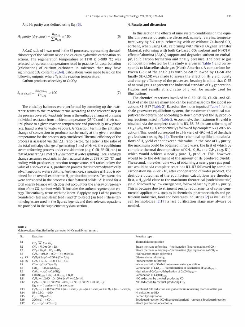
Table 2Main reactions identified in the gas-water-Ni-Ca equilibrium system.
No. Reaction
R1 CH4 →Heat
C þ 2H2
R2 CH4+H2O⇆CO+3H2
R3 CH4+2H2O⇆CO2+4H2
R4 CnHm+nH2O→nCO+(n+0.5m)H2
e.g. R5 C2H6+2H2O→2CO+(2+3)H2
e.g. R6 C3H8+3H2O→3CO+(3+4)H2
R7 CO+H2O⇆CO2+H2
R8 CaO(s)+CO2⇆CaCO3(s)
R9 CaO(s)+H2O⇆Ca(OH)2R10 Ca(OH)2(s)+CO2→CaCO3(s)+H2OR11 CnHm+(n)NiO →(n)CO+(n)Ni+(0.5m)H2
R12 CnHm+(2n+0.5m)NiO →nCO2+(2n+0.5m)Ni+(0.5m)H2OE.g. n = 1 and m = 4 for methane
R13 CnHm+(n+0.25m)NiO+(n−0.25m)H2O→(n+0.25m)Ni+nCO2+(n+0.25mR14 Ni+0.5O2 →NiOR15 C(S)+2H2→CH4
R16 2CO⇆C(S)+CO2
R17 C(S)+H2O⇆CO+H2
4. Results and discussion
In this section the effects of nine system conditions on the equi-librium process outputs are discussed, namely: varying tempera-ture, varying S:C ratio, reforming with or without Ca-based CO2
sorbent, when using CaO, reforming with Nickel Oxygen TransferMaterial, reforming with both Ca-based CO2 sorbent and Ni-OTM,effect of alumina (Al2O3) support and degraded sorbent on enthal-py, solid carbon formation and finally pressure. The precise gascomposition selected for this study is given in Table 1 and corre-sponds to Marcellus shale gas (North America). A comparison be-tween C-SR of the shale gas with SE-SR followed by CL-SR andfinally SE-CLSR was made to assess the effect on H2 yield, purityand energy efficiency of the processes, bearing in mind that C-SRof natural gas is at present the industrial standard of H2 generation.Figures and results at S:C ratio of 3 will be mainly used forillustrations.
The chemical reactions involved in C-SR, SE-SR, CL-SR- and SE-CLSR of shale gas are many and can be summarised by the global re-actions R1–R17 (Table 2). Based on themolar inputs of Table 1 for theshale gas/water equilibrium system, the maximum theoretical out-puts can be determined according to stoichiometry of the H2 produc-ing reactions listed in Table 2. Accordingly, the maximum H2 yield isobtained via the complete reactions R3, R5, R6 (steam reforming ofCH4, C2H6 and C3H8 respectively) followed by complete R7 (WGS re-action). This would correspond to a H2 yield of 49.0 wt.% of the shalegas feedstock using Eq. (4). Therefore chemical equilibrium calcula-tions of H2 yield cannot exceed this value. In the case of H2 purity,the maximum could be obtained in two ways, the first of which bycomplete thermal decomposition of CH4, C2H6 and C3H8 (e.g. R1),which would achieve a nearly pure H2 product. This, however,would be to the detriment of the amount of H2 produced (yield).The second, more desirable way of obtaining a nearly pure gas prod-uct would be via complete reactions R3–R7 followed by completecarbonation via R8 or R10, after condensation of water product. Thedesirable outcomes of the equilibrium calculations are thereforefirst, a H2 yield close to the maximum theoretical (stoichiometric)yield, followed by low energy cost, followed last by high H2 purity.This is because due to stringent purity requirements of some com-mercial applications, such as in chemicals, pharmaceuticals and pe-troleum industries, food and beverages industries [2] as well as fuelcell technologies [2,17] a last purification stage may always beneeded.
Reaction type
Thermal decomposition
Steam methane reforming→/methanation (hydrogenation) of CO ←Steam methane reforming→/methanation (hydrogenation) of CO2 ←Hydrocarbon steam reformingEthane steam reformingPropane steam reformingWater gas shift (CO-shift)→/reverse water gas shift ←Carbonation of CaO(S) →/decarbonation or calcination of CaCO3(S) ←Hydration of CaO(S)→/dehydration of Ca(OH)2(S) ←Carbonation of Ca(OH)2(S)NiO reduction by the fuel, producing CONiO reduction by the fuel, producing CO2
)H2 Combined NiO reduction and global steam reforming reaction of the gasNi oxidation to NiOCarbon hydrogenationBoudouard reaction (CO disproportionation) →/reverse Boudouard reaction←Steam gasification of carbon→

134 Z.I. S G Adiya et al. / Fuel Processing Technology 159 (2017) 128–144
4.1. Effect of temperature and presence of C2-C3 feedstock on both C-SR andSE-SR processes
H2 yield and purity plots between 500 and 1200 K at S:C ratios of1, 2, 3, 4, 5 and 6 are displayed in Fig. 2(a and b), respectively. Theseprofiles illustrate a comparative analysis of C-SR and SE-SR of shalegas. In the absence of water (S:C= 0, not shown in Fig. 2), the gas re-quired in excess of 900 K to undergo thermal decomposition and tobegin converting significantly to H2. For S:C of 1, 2, and 3, H2 yieldand purity increased steeply as temperature increased for both theprocesses. For C-SR, this was caused by conditions shifting frombeing favourable to methanation (main products CH4 and CO2
below 900 K) and other solid carbon forming reactions at a low tem-perature, to promoting steammethane reforming (main products H2
and CO2). This occurred up to roughly 1100 K, where H2 yield and pu-rity declined and a gentle dwindling in both hydrogen yield and pu-rity was seen with further temperature increase, independent of theS:C ratio, and caused by reverse water gas shift. In the case featuringin situ CO2 sorption (SE-SR), the H2 yield and purity profiles withtemperature showed a much sharper rise with a wider range of pla-teau of maximum H2 yield and purity with temperature, exhibitingthe sorption enhancement effects; this is discussed in more detailin Section 4.3. In the low temperature range (b720 K), the presenceof C2 and C3 species in the reactant gas increases CH4 yield signifi-cantly resulting from the cracking of those species and methanationas further confirmed by the negative CH4 conversion from 500 to720 K for C-SR process and from 500 to 540 K for SE-SR process(not shown). The latter resulted from the exothermicity of methana-tion, favoured at low temperature. Sorption enhancement results inreducing the equilibrium concentration of CH4 in favour of the pro-cess at a higher temperature, thus the higher yield and purity thanthe conventional processs. Modelling the conditions S:C = 3 withAspen Plus V8.8 (reactor option RGibbs, properties method PengRobinson) resulted in an excellent agreement with the results de-rived from CEA. However, for the SE-SR process a slight difference(decreased in H2 purity and selectivity of carbon to calcium carbon-ate) was observed at 1000 K, which might result from the differencein thermodynamic properties of the programmes (ideal in CEA, non-ideal in Aspen Plus). Nonetheless this is relatively insignificant sinceCa-sorption enhancement wanes at such high temperature. Similarthermodynamic studies were also conducted with or without Ca sor-bent (C-SR and SE-SR process) using several fuels including methane[24], propane [23], hydroxyacetone [52], acetic acid [53], and urea[20]. These results showed a similar trend to those of shale gas(this paper) with regards to H2 yield and purity and the effect ofS:C ratio to be discussed later.
Fig. 2. (a) H2 yield vs temperature (b) H2 purity vs temperature at 1 bar, Ca:C 1 and vari
4.2. Effect of steam to carbon ratio on steam reforming processes
For the C-SR process, H2 yield and purity behaviour with respect toS:C ratio follows Le Chatelier”'s principle, whereby an increase in thewater reactant concentration in the system moves the equilibrium to-wards higher water conversion, thus causing higher H2 yield and purity(Fig. 2). However, operating at a large S:C ratio requires higher reactorvolume, as well as high operational expenditure for raising steam [20,23,53]. The effect of S:C ratio levels off at higher values (above S:C 4and 700–1200 K approximately) [65] as depicted in Fig. 2. The slight in-crease in the temperature range of 500–700 K in both H2 yield and pu-rity (above S:C 4) is reasonably insignificant, as industrial steamreforming plant operate around 1073–1273 K roughly [36,37]. Further-more, using higher S:C ratio is known to cause catalyst and sorbent de-activation because of pore blocking [66,67]. Thus, S:C ratio of 3 typicallyused in industrial steammethane reformingwill be focus on in the pres-ence studies [20]. The curves of H2 yield and purity against temperaturefor the varied S:C ratio demonstrate the benefits of operating with highS:C ratio. For example, at 800 K, with the C-SR process case at S:C ratio of1, the equilibrium H2 yield is 13.2 wt.% of fuel with 56.0% purity, but itbecomes 24.3 wt.% of fuel with 65.4% purity at S:C ratio of 3. This isequivalent to 84% and 17% rises in H2 yield and H2 purity, respectively.The higher the S:C ratio, the closer the H2 yield gets to the theoretical(stoichiometric) maximum of 49.0 wt.%, as well as increasing H2 purity.The use of high S:C ratio also prevents carbon product (potentialdeposition on the catalyst) through reaction (R17), however equilibri-um carbon is discussed separately in Section 4.6.
Fig. 3(a) depicts the impact of S:C ratio through the value of the ΔHratio for the C-SR process (2nd y axis). Recall that the furthest ΔH ratiobelow 1, the more thermally efficient the process is. The profiles inFig. 3(a) indicate that the ΔH ratio of C-SR penetrated the b1 viabilityarea at similar temperatures of 670 K for S:C ratio of 1, 2, and 3. ForS:C ratio of 0 the process was viable at roughly 600 K, representing aprocesswhereH2 is only aminor product, this is confirmed by the grow-ing energy costs of operating at increasing S:C ratio, e.g. minimum ΔHratio of 0.41 was obtained at stoichiometric S:C ratio of 1 and 800 K,but minimum ΔH ratio became 0.51 at the same temperature at S:Cratio of 3.
The energy balance for molar inputs of shale gas composition inTable 1 is further analysed with the help of Fig. 3 (b) which depicts in-dividual enthalpy terms profiles against temperature. The scalesshown on the y axis of Fig. 3 (b) in kJ are not particularly significant be-cause they depend on themolar inputs chosen for the system, howeverwhat is significant is the relative positions of each enthalpy termprofilesin thefigure. The total enthalpy change of the process, and consequentlythe ΔH ratio, is seen to be dominated by the enthalpy change terms of
ed S:C ratio (note: the straight line in H2 yield represent the theoretical maximum).

Fig. 3. (a) Effect of S:C ratio onH2 yield andΔH ratio vs reaction temperature at 1 bar, without Ca in the system and S:C 0–3 and Table 1 inputs, (b) enthalpy terms vs. temperature for S:C 3and Table 1 inputs at 1 bar without Ca, (c) selectivity of carbon to calcium carbonate vs temperature at 1 bar, Ca:C 1, and S:C 0–3.
135Z.I. S G Adiya et al. / Fuel Processing Technology 159 (2017) 128–144
bringing the gas and water reactants to reaction temperature, and inparticular that of the water reactant, as opposed to the change in reac-tion enthalpy. At S:C 1 the total enthalpy change of the process at800 K and 1070 K were 129 and 118 kJ per mol of H2 produced, respec-tively, which further increased to 150 and 130 kJ/mol H2 at S:C 2, and159 and 145 kJ/mol H2 at S:C 3, indicating the increased energy penaltyof operating at higher S:C ratios.
4.3. Sorption enhancement with CaO sorbent (SE-SR)
Several benefits of in situ CO2 sorption are identifiable in the temper-ature zone of the highest CaCO3(s) yield (500–990 K) on the gas watersystem at equilbrium. Firstly, H2 yield increased, bringing it closer totheoretical maximum as depicted by Fig. 2(a). The effects of the CaO(s)
sorbent on the H2 yield in the low temperature range was broughtabout by the shift in equilibrium favouring the two H2 generating reac-tions (water gas shift and steam reforming), caused by removal of theCO2 from the syngas product (see diagram Fig. 1(b)). This would haveincreased bothH2 yield and purity simultanously as seen in Fig. 2. For in-stance, the H2 purity increased from 65.4% without Ca sorbent in thesystem to 98.0% with CaO(s) sorbent, at S:C ratio of 3 and temperatureof 800 K. This is equivalent to 50.0% rise in purity between the two pro-cesses at a steam reforming temperature on the low side, ie. mild for thesolid materials, thus preventing sintering. The latter was accompaniedby significant CO and CO2 reductions with dry mole fractions below0.01 at 800 K and 0.1 at 1070 K. H2 yield and efficiency of CO2 captureis favoured in the low temperature range not only due to thermal de-composition of the sorbent at higher temperatures but also becausethe equilibrium vapour pressure of CO2 over CaO(S) is low at lowtemperatures [18,19]. Effectively the SE-SR process extends by roughly110–200 K (depending on S:C ratio in use) the conditions resultingin higher H2 yield, shifted towards lower temperature, as depicted byFig. 2(a).
Two regions of temperature were observed in the trends of the pro-cess, that result from the sudden drops of Ca(OH)2(s) and CaCO3(s) prod-uct yield to zero. This was expected because at temperatures higher
than 700 K, thermal decomposition of Ca(OH)2(s) occurs, while that ofCaCO3(s) happens at temperatures higher than 1000 K (Fig. 3(c)).
In addition, the presence of CaO(s) lowered the energy demand of H2
generation from the gas-water system. This can be seen in the ΔH ratiofarther from 1 for the systemwith CaO compared to the systemwithoutCaO, as shown in Fig. 4(a), due to the lower total change in enthalpy ob-tained with CaO (Fig. 4b).
Another benefit is reduced energy demand, as shown by the ΔHratio notably below that of the sorbent-free system, even whenaccounting for regeneration of the CaCO3(s) back to CaO(s) through a de-carbonation step conducted at 1170 K, as represented by case ‘B’ (Fig. 4).Sorbent carbonation was reduced at S:C ratio of 0 and 1 due to low car-bonate produced. Thus, the effect of sorption enhancement is not prop-erly active at those conditions. For S:C of 2 and 3 the SE-SR process wasoverallmoderately endothermicwithout sorbent regeneration (case A),but became overall significantly endothermic when accounting for theregeneration step of the sorbent (case B). Regeneration enthalpy changedropped to zero above 1000 K for all the S:C ratios considered due tothermal decomposition of CaCO3(s), and as a result, theΔH ratio vs. tem-perature profiles of the C-SR and SE-SR processes (with andwithout re-generation)mergedwith each other, making the later equivalent to thetypical C-SR process. The heating cost of the gas was the same for thefour S:C ratios (0, 1, 2, and 3) as their molar input remained unchanged.The enthalpy change of raising steam increasedwith S:C ratio as expect-ed. The energy of heating up the water further confirms the growingcost of operating at a high S:C ratio. The enthalpies of evaporatingwater and superheating steam at the reaction temperature still domi-nated the energy balance of the process with sorption enhancementas well. The reaction enthalpy is the backbone of the major differenceseen between the two processes (C-SR and SE-SR), illustrated in theΔH ratios as depicted by Fig. 4(c). This no doubt can be accredited tothe carbonation process which is strongly exothermic.
To illustrate the energy savings brought about by in situ CO2 sorptionusing CaO(s) sorbent, the case of S:C ratio of 3 is used. Theminimum en-ergy required to bring the system at equilibrium, starting from feedma-terials of the gas and liquid water at 298 K, was 159 kJ per mol ofproduced H2 at 800 K without CaO(s) in the system. This decreased to

Fig. 4. (a)ΔH ratio vs temperature at 1 bar, Ca:C 1, and S:C 3 (b) total enthalpy terms vs. temperature at 1 bar, Ca:C 1, and S:C 3 (c) enthalpy terms vs. temperature at 1 bar, Ca:C 1, and S:C 3(note: A and B mean without regeneration and with regeneration respectively while the number 1 and 2 denotes reaction process relevant to step 1 and step 2 respectively).
136 Z.I. S G Adiya et al. / Fuel Processing Technology 159 (2017) 128–144
59 kJ/mol H2 with CaO(s) without regeneration of the CaCO3(s) (i.e. al-most isenthalpic). When including the enthalpy of CaCO3(s) regenera-tion back to CaO(s) performed at 1170 K, the total enthalpy changerose to 114 kJ per mol of produced H2 at 800 K respectively, i.e. signifi-cantly lower than the sorbent-free system. It is noteworthy that the H2
producing step (step 1) would be physically separate from the sorbentregeneration step (step 2), and thus during the H2 production, nearautothermal conditionswould be reached in step 1 of the SE-SR process.
Accounting for Ca(OH)2(s) and CaCO3(S) as possible products ofCaO(s) conversion had different effects on process outputs dependingon the S:C ratio and temperature. In situ CO2 capture by CaO(S) (R8)and hydration reaction of CaO to produce Ca(OH)2(s) (R9) are active atlow to intermediate temperatures (b700 K) and the latter competeswith both steam reforming and water gas shift reactions for waterusage. At temperature of maximum H2 yield, 800 K approximately, re-moval of water by CaO was insignificant because thermal decomposi-tion of Ca(OH)2(s) occured at around the same temperature. HenceCaO(s) was permitted to transform to CaCO3(s) producing the desiredsorption enhancement.
4.4. Chemical looping with NiO coupled with steam reforming (CL-SR) ofshale gas
Fig. 5 summarises the outputs of steam reforming of shale gas whencoupledwith chemical looping (CL-SR) usingNiO as the oxygen transfermaterial. For the purpose of comparison of processes, the outputs of C-SR are also included in the figure. The process was investigated by firstvarying the NiO:C ratio while maintaining S:C of 3 in Fig. 5 (a and b),then followed by changing the S:C between 0 and 3 while maintainingNiO:C 1.0 constant, as depicted in Fig. 5 (c and d).
In the CL-SR process, complete conversion of the gas and good selec-tivity towards the desired products was achieved. NiO reduction with
the fuel is thermodynamically possible at temperatures as low as400 K, as indicated by negative water conversion below 400 K. Increas-ing the NiO:C ratio decreases monotonically the H2 yield and purity(Fig. 5a). The decrease in H2 yield can be attributed to CL-processesusing part of the fuel according to either R11 (co products CO and H2)or R12 (co-products CO2 and H2O) to meet the energy demand ofsteam reforming, a role that is normally played by the gas fired furnacein the C-SR process (see Fig. 1a). H2 purity also decreases with growingNiO:C ratio. This can be explained by concurrent CO2 generation via theNiO reduction reaction (R12).
One significant benefit of coupling C-SRwith chemical looping is thereduced energy demand of the overall H2 production. This is evidencedby the ΔH ratio notably below that of the NiO-free system (Fig. 6).The reduced energy demand can be attributed to the stronglyexothermic nickel oxidation process (one of the major difference be-tween the CL-SR and C-SR process) as shown in Fig. 6(b). The ΔHratio of the CL-SR process (steps 1&2) was fairly endothermic at low/medium temperature (700–850 K) but slightly decreases at higher tem-peratures (850–1200 K) with increase in operating temperature. Theoverall energy demand of the process decrease with increase in NiO:Cratio, making the process almost autothermal at the highest NiO:Cratio (1.0). However, even at the lowest NiO:C ratio energy demand ofthe CL-SR proces was still siginificantly lower than that of the conven-tional process (see table SD4 in the supplementary data for ΔH totaland ΔH ratio values with varying NiO:C ratios). As expected, the ΔHratio increasedwith increasing S:C (0–3) due to the accrued cost of rais-ing the excess steam, as explained earlier (figure not shown). This con-firmed that the CL-SR process was also dominated by the cost of raisingexcess steam(S:C ratio in use). The energy demandof thewhole processwas dominated in the order of contributions of the following enthalpyterms: sum heating up reactants N sum reactions 1 & 2 as depicted inFig. 6(b and c). The energy demand of heating up the reactants was in

Fig. 5. (a) H2 yield vs temperature at 1 bar, S:C 3 and varied NiO:C (0.5–1.0) (b) H2 purity vs temperature at 1 bar, S:C 3 and varied NiO:C (0.5–1.0) (c) H2 yield vs temperature at 1 bar,NiO:C of 1.0 and varied S:C (0–3) (d) H2 purity vs temperature at 1 bar, NiO:C of 1.0 and varied S:C (0–3) (note: NiO:C 0.0 denote C-SR process and the straight line in H2 yield representsthe theoretical maximum).
Fig. 6. (a) ΔH ratio of CL-SR vs. temperature at 1 bar, S:C 3 and NiO:C 0.0–1.0 (b) reaction enthalpy terms and (c) sensible enthalpy terms (gases: 298 K → T(K) under stage 1, solid:T(K) → 1100 K under stage 2) vs. temperature at 1 bar, S:C 3 and NiO:C 1.0 (note: the numbers 1 and 2 denote reaction processes stages 1 (reductive & reforming under fuel andsteam feed) and 2 (oxidative under air feed) respectively). Temperature T(K) refers to reforming temperature. (Oxidation temperature is assumed to be 1100 K in all CL-SR cases).
137Z.I. S G Adiya et al. / Fuel Processing Technology 159 (2017) 128–144

Fig. 7. (a) H2 yield vs temperaturewith CaO(s) sorbent at 1 bar, Ca:C 1, NiO:C 1.0 and S:C 2 and 3(b) H2 purity vs temperaturewith CaO(s) sorbent at 1 bar, Ca:C 1, NiO:C 1.0 and S:C 2 and 3(note: the straight line in H2 yield represent the theoretical maximum).
138 Z.I. S G Adiya et al. / Fuel Processing Technology 159 (2017) 128–144
the order H2O N air N shale gas. The cost of heating up the gas was rela-tively insiginificant compared to those of raising steam from liquidwater feed and preheating air.
4.5. Sorption enhanced chemical looping steam reforming
4.5.1. H2 yield, H2 purity and selectivity to carbonateThe effect of temperature onH2 yield and purity is illustrated in Fig. 7
for the three processes (C-SR, SE-SR and SE-CLSR) in the particular caseof Ni:C 1.0 and the two S:C of 2 and 3. Note that in the chemical loopingprocesses CL-SR and SE-CLSR, some feedstock is consumed for NiO re-duction according to R11 and R12, while for C-SR and SE-SR the fuel isfully available for the steam reforming process. The figure clearly por-trays the significance of coupling sorption enhancement and chemicallooping in steam reforming with both the superior H2 yield ca. 700–850 K and H2 purity ca. 700–1000 K obtained for SE-CLSR compared tothe C-SR process (i.e. region of maximum CO2 capture/efficient carbon-ation reaction). The presence of the CO2 sorbent shifts the thermody-namic equilibria of both the steam reforming and the water gas shiftreaction (R2 and R7) towards higher conversion to CO, then to CO2,followed by capture of the CO2 on the sorbent, with the carbon productbecoming almost exclusively solid calcium carbonate. Subsequently, thepresence of thenickel basedOTM in SE-CLSR led to even greater H2 yield(in region of effective carbonation) than C-SR, although part of the fuelwas used for reduction. This is because the reduction of fuel by NiO(R12) produces total oxidation products CO2 and H2O, with the formerbeing captured by the sorbent, and the latter increasing the water con-centration of the system, effectively achieving a double or synergetic en-hancement effect. The effect of coupling between C-SR and SE-SR on theH2 purity in the low/medium temperature zone is explained by the effi-ciency of CO2 capture by the Ca sorbent. At high temperatures (roughlyabove 1000 K), the efficiency of CO2 capture declined rapidly anddropped to zero, hence the SE-SR process reverted back to C-SR, as con-ditions favoured CaCO3 decomposition [18,19]. Regarding H2 purity inthe high temperature zone (above 1000 K), the inferiority of SE-CLSRprocess compared to C-SR and SE-SR was due to the additional CO2
Table 3Equilibrium outputs comparing C-SR and SE-CLSR at 800 K Ca:C 1, NiO:C 1.0 and S:C of 2and 3.
S:Cratio
Conditions H2 yield (wt.%of available fuel)
H2 purity(%)
Selectivity of C toCacO3(s) (%)
2 Without Ca 19.0 59.2 n/a2 With CaO & NiO 35.0 98.5 96.13 Without Ca 24.3 65.4 n/a3 With CaO & NiO 36.1 99.5 99.0
present at equilibrium resulting from the NiO reduction, while C-SRand SE-SR performed equally due to decomposition of the CaCO3(S).On the other hand, the inferiority of the process (SE-CLSR) comparedto SE-SR with regards to H2 yield was due to the fact that part of fuelwas used for NiO reduction while the fuel was completely availablefor steam reforming in the case of SE-SR process [68].
Therefore the optimal operating temperatures for both SE-SR andSE-CLSR at atmospheric pressurewere around 700–850 K approximate-ly, as illustrated in Fig. 7.
In practice, when using packed bed configuration used with alter-nating feed flows, it is envisaged that at least two packed bed reactorswould be used in parallel, one undergoing the reductive stage with insitu CO2 capture while the other is in oxidative stage with sorbent re-generation (and potentially carbon burn off), as shown in Fig. 1(d).Table 3 compares the equilibrium outputs of C-SR and SE-CLSR processusing CaO as the CO2 sorbents at 800 K.
Fig. 8 depicts the selectivity of carbon products to CaCO3(S) as a func-tion of temperature for the SE-SR and the SE-CLSR processes. SE-CLSRoffers higher selectivity to the carbonate product for a wider range oftemperature over SE-SRwith CaO. This is because the reduction processincreased thewater concentration in the system, in favour of CO2 forma-tion, hence allowing the maximum sorption. At temperatures above1000 K the efficiency of the CO2 capture declined because of thefavoured carbonate decomposition [18,19].
4.5.2. Enthalpy balance of SE-CLSRSignificantly reduced energy demand was seen in the SE-CLSR
process as despicted in Fig. 9, notably below those of both the C-SR
Fig. 8. Selectivity of carbon to calcium carbonate vs temperature at 1 bar, Ca:C 1, NiO:C 1.0and S:C 2 and 3 with CaO(S) sorbent.

Fig. 9.ΔH ratio and enthalpy terms vs. reforming temperature for SE-CLSR at 1 bar, Ca:C 1, NiO:C 1.0 and S:C 3 (a)ΔH ratio vs reforming temperature (b) total enthalpy terms vs. reformingtemperature (c) sensible enthalpy terms vs. reforming temperature (note:A andBmeanwithout andwith CaCO3(S) regeneration to CaO(S) at 1170K, respectively,while the numbers 1 and2 denote reaction process stages 1 (reductive/reforming) and 2 (oxidative/regenerating) respectively at 1170 K).
139Z.I. S G Adiya et al. / Fuel Processing Technology 159 (2017) 128–144
and SE-SR process, even when accounting for complete regeneration ofthe CaCO3(s) back to CaO(s) via a decarbonation step conducted at1170 K. The ΔH ratio without regeneration was slightly endothermic(overall authothermal process) at low/medium temperature range(700–900 K) for S:C 2 but moderately endothermic (almostautothermal process) at S:C 3 with CaO(s) sorbent. When the enthalpyof regenerating the CaO(S) sorbent at 1170Kwas included, theΔH ratiosbecame significantly endothermic (positive) but remained significantlylower than the C-SR process, thus more energetically favourable. Theheating demand of the gas and air was the same for the S:C 2 and 3 astheir molar input remained unchanged. On the other hand, the heatingdemand of water increasedwith increase in S:C ratio (discussed earlier)i.e. S:C 2 b S:C 3. Although steam reforming andNiO reduction are endo-thermic processes, the total reaction enthalpy of the two-step cyclicprocess (stage 1 + stage 2) was overall exothermic, with the exother-micity decreasing with increase in stage 1 reaction temperature. Wechose to showhow this excess energy could be used by including a com-bustor/gas turbine/generator system in Fig. 1(d), as it is the most flexi-ble way to utilise the enthalpy of combustible as well as non-combustible streams via by-passing the combustor. The overall exother-micity resulted from the strongly exothermic Ni oxidation process, asshown in Fig. 9. BothNi oxidation and carbonation reactions have signif-icantly lowered the energy demand of the hydrogen production. TheΔH ratio of the two processes (C-SR and SE-CLSR) did not mergewhen decarbonation process stopped (at roughly 1000 K) like the SE-SR process, this effect can be explained by the activity of chemicallooping and nodoubt can be accredited to the strongly exothermic nick-el oxidation. The total energy cost of the process was, again, dominatedbywater enthalpy change followed by the reaction enthalpy (Fig. 9(c)).
The results of the chemical looping processes (CL-SR and SE-CLSR)were further verified by the authors with Aspen plus ‘RGibbs’ reactormodelling andwere in good agreement to those of CEA. Previous studieswere conducted on CL-SR process by [25] and SE-CLSR process by [18,19,65,69]. The results are in good agreement to those of the presentstudy with regards to H2 yield and purity, selectivity of carbon to calci-um carbonates (SE-CLSR process only) as well as reduced energy re-quirement of the processes when compared to the conventional
process. Optimum operating conditions for SE-CLSR also happen to bein the same range to those reported in the present study 700–850 K,1–4 bar pressure, S:C 3 and Ca:C 0.8–1 [19]. Zhu and Fan, 2015 [69]analysed the influence of Ca:M ratio, M(fuel):M ratio and Ni:M ratioon SE-CLSR process using equilibrium calculations, they foundCa:M = 1, M(fuel):M of 0.2 and Ni:M of 0.8 were optimum operatingcondition. Their conclusion (production of high purity hydrogen in thelower operating temperature range compared to CL-SR process) is ingood agreementwith the present study. Fan and Zhu, 2015 [70] investi-gated the performance of a novel polygeneration system driven bymethane aimed at producing high-purity H2 through chemical loopingcombustion thermally coupled with CaO sorption enhanced methanesteam reforming (they termed it CLC-SEMSR) combined with powergeneration through combined cycle. They stimulated the process usingAspen Plus exiting functions and build in functions. They found thatthe novel polygeneration system can achieve higher exergy efficiencyof 83.1% compared to 68.7% in the C-SR process. Their conclusion thatpolygeneration systems for H2 production and power generation sim-plifies the overall process with a more reasonable utilization of fuel, inaddition to CLC-SEMSR process potential to produce higher H2 yieldand purity with reduced energy consumption for CO2 separation is ingood agreement with the present study. However, all of the thermody-namic studies (on SE-CLSR process) focussed pure methane as fuel inprevious literature and most of the previous studies such as [69,70]used fluidised bed reactor (air and fuel reactor separate). Researchersalso investigated the performance of Ca-supported sorbent on the SE-CLSR process. For example, Fernandez et al. [71], modelled the SE-CLSR process using a Ni based (9% on Al2O3 support) OTM/catalystand a Ca/Cu sorbent with pure methane feedstock. They investigatedthe effect of catalyst/sorbent ratio, space velocity, S:C ratio, temperatureand pressure. They found the optimum operating condition in the tem-perature range of 923–1023K, at low-mediumpressures (5–15bar) andhigh S:C ratio of 3–6. The differences in the optimum operating condi-tion with the present study could be attributed to differences in operat-ing conditions,model used for stimulation andmost likely differences inCO2 sorbent used in addition to the fact that temperatures lower than873 K were not investigated. Martínez et al. [72] performed a detailed

Table 4Equilibrium outputs at 800 K (ΔH total and ΔH ratio at 1 bar, Ca:C 1, NiO:C 1.0, and S:C 2and 3. A and B mean without sorbent regeneration and with sorbent regenerationrespectively).
Conditions ΔH total (kJ/mol H2) ΔH ratio
C-SR S:C 2 150 0.49SE-CLSR S:C 2 With CaO A 12 0.04SE-CLSR S:C 2 With CaO B 71 0.23C-SR S:C 3 159 0.51SE-CLSR S:C 3 With CaO A 34 0.11SE-CLSR S:C 3 With CaO B 92 0.30
140 Z.I. S G Adiya et al. / Fuel Processing Technology 159 (2017) 128–144
and complete process design of a H2 generation plant using natural gasas feedstock, Ni based OTM/catalyst and a novel Ca/Cu CO2 sorbent aswell. Their findings, compact design and the use of cheaper materialscompared to C-SR process is in good agreement with the presentstudy (Table 4).
4.5.3. Effect of inert materials on enthalpy balance of the cyclic processesThe presence of inert solid materials in the reactor bed does not af-
fect the equilibrium materials balances (i.e. H2 yield and purity are thesame with inert materials compared to without inert materials), asthey do not affect the gas phase equilibrium reactions. However, inertmaterials would require heating or cooling as required during the cyclesof the CL processes. There are two types of inert materials that may bepresent at any time in the reactor: the oxygen transfer catalyst support,and the degraded CO2 sorbentmaterial. During cyclic operation, the bedmaterials require heating from reaction temperature to regenerationtemperature (SE-SR with regeneration, and SE-CLSR) or to oxidationtemperature (CL-SR), and the active part of the sorbent undergoes de-carbonation during regeneration. In the SE-CLSR process, Ni oxidationand decarbonation reactions occur together at sorbent regenerationtemperature, 1170 K. In the following section, the individual effects ofcatalyst support and of degraded sorbent on the total enthalpy changeof the cyclic processes are discussed.
4.5.3.1. Oxygen transfer catalyst support. In practice, oxygen transfer ma-terials as well as solid phase catalysts are structured so that a significantpart of the material does not participate in the reactions (or it does in aminimal way), but imparts desirable properties to the reactor bed, e.g.morphological (high surface area), mechanical (strength) and thermal(phase stability), so they act as ‘support’ to the chemically active com-ponent [56]. Thus NiO is not used on its own in the reactor, but as partof NiO on a support. To represent this effect on the enthalpy balance,an 18 wt.% NiO on α-Al2O3 support (typical commercial steamreforming catalyst) [73] was simulated for the CL-SR and the SE-CLSRprocesses (Fig. 10). This introduced α-Al2O3 (corundum) as an addi-tional ‘inert reactant’ in the molar ratio of Al2O3: NiO of 3.34, and thecases are described as either ‘with support’ or ‘without support’. Typi-cally it was found that a cyclic process with support in proportions of
Fig. 10. SE-CLSR: process 2 at 1170 K, active Ca:C= 1, CL-SR: process 2 at 1100 K, S:C= 3,NiO:C = 1, “no support”: NiO 100 wt.%, “with support”: 18 wt.% NiO/Al2O3, “activesorbent”: 100% CaO, “degraded sorbent”: 10% active CaO and 90% inert CaO.
Al2O3: NiO of 3.34 saw its ΔH ratio increase by about 0.2 compared tothe same process without support, although the gap between the tworeduced as reforming temperature increased. For instance, at thereforming temperature of 800 K, CL-SR without support had a ΔHratio of 0.33 compared to 0.54 with support. For the SE-CLSR, at 800 K,ΔH ratio was 0.30 without support but 0.45 with support. By compari-son C-SR at 800 K had a ΔH ratio of 0.51. Here the CL-SR appears at dis-advantage compared to the conventional process for reformingtemperatures below 840 K, which was caused by the assumption thatthe nickel oxidation step was carried out at 1100 K. When reducingthe oxidation temperature to 1050 K, which is sufficient to completelyoxidise carbon black deposits on an 18 wt.% NiO/α-Al2O3 catalyst [74],the ΔH ratios of the CL-SR with support and the C-SR processes werethe same at a reforming temperature of 800 K.
This implies that heat recuperation from the solids and gases fromthe regeneration step, not represented here, could play a crucial rolein making the CL-SR viable when using a highly supported catalyst.The incentive is thus to minimise the amount of support required forthe bed materials to maintain the right properties.
4.5.3.2. Degraded CO2 sorbent. Similarly, another potential additional en-ergy cost can be brought about by the deactivation of the CO2 sorbent.Over many cycles, natural Ca-based sorbents typically stabilise to ca.8–10% of their ‘fresh’ CO2 capacity [75]. Sorbent materials such as lime-stone would then contain 90–92 wt.% of inert sorbent. The latter wouldalso present a sensible enthalpy burden when bringing the bed mate-rials to regeneration temperature (here assumed 1170 K). The effectof degraded sorbent in the bed was represented by introducing in thereactants mix the equivalent of 90 wt.% of the total molar calcium inthe feed as inert CaO. The Ca:C ratio of 1 quoted in the figures refers tothe active CaO.
The ΔH ratios of the SE processes (SE-SR and SE-CLSR with and w/osupport) were seen to also increase by around 0.2 at 800 K for the caseswith degraded sorbent compared to the active sorbent, with anarrowing gap as the reforming temperature approached the regenera-tion temperature of 1170 K. Note that above 880 K, the sorption en-hancement gradually disappeared as a result of decarbonation of thesorbent. This meant that, typically for reforming temperatures above800 K, the SE-SR with 90% degraded sorbent and the SE-CLSR with sup-port and 90% degraded sorbent both became less energetically viablethan the conventional C-SR process. For the SE-CLSR process with sup-port and 90% degraded sorbent to become more energetically viablethan the C-SR process, reforming temperatures would have to reach720 K, which is the equilibrium lower limit for sorption enhancementas per Figs. 7 and 8. This would imply the use of a very active steamreforming catalyst. At lower temperatures, energetics would befavourable but selectivity to hydrogen product would drop (loweryield and lower purity).
With regards to environmental aspects; SE-CLSR process could be aneffective and eco-friendly way of generating H2 if the challenges associ-ated with the energy costs of heating the bedmaterials to regeneration/oxidation temperature were to be addressed. The overall GWP of a C-SRplant is 11,888 g CO2 equivalent/kg of H2 from which Hydrogen plantoperation only account for 78.8% (8895 g CO2 equivalent/kg of H2)[76]. SE-CLSR would also have to address the issues of life cycle analysisbrought about by the use, operation lifetime and recyclability of theOTM catalyst and sorbent materials. As the majority of the world's hy-drogen is generated through steam reforming of fossil fuels, there willbe no elimination of greenhouse gases till CO2 is sequestered at thesource [77].
4.6. Carbon product
Generally, operating at a high S:C ratio inhibits solid carbon forma-tion, as gasification reactions are promoted. This is one of the reasonssteam reforming plants aim to operate with some excess of steam.

Fig. 11. Carbon yield at 1 bar and S:C 0 and 1, (a) Ca free and Ca sorbent systems, (b) Ca free and CL-SR system at NiO:C 1.0.
141Z.I. S G Adiya et al. / Fuel Processing Technology 159 (2017) 128–144
Solid carbon in the equilibriumproducts not only deactivates catalyst bycovering its active sites but also reduces H2 yield and purity because itrepresents carbon that does not react with steam to generate H2. Solidcarbon product is completely prevented at equilibrium conditions ofS:C 2 and 3 in all the processes via steam gasification of carbon (R17)[78]. As shown in Fig. 11, solid carbon product mainly occurs at S:C be-tween 0 and 1, with the quantity of carbon product depending on theprocess in use. As expected, enormous carbon was generated at S:Cratio of 0 in both the Ca free and CaO(s) sorbent system. No doubt thisresulted from the absence of steam reactant in the system whichlowered the amount of CO2 product to be generated and thus to beadsorbed. Hence, the process behaves like C-SR, consequently the out-puts of the SE-SR and C-SR processes at S:C 0 merge with each other.For S:C 1 in the Ca-free and CaO(s) sorbent system, solid carbon equilib-rium product was siginificantly low (nearly zero) in the low tempera-ture range (500–650 K) but rose in the region of maximum H2 yield
Fig. 12. Effect of pressure at NiO:C 1.0 and S:C 3 (a) H2 yield vs temperature with CaO sorbent (bvs temperature with CaO sorbent.
before exhibiting a gentle dwindling that approches zero at higher tem-peratures (1000−1200 K). The sub stoichiometric conditions (limitedwater in the system) again are the reason behind this observation. Asdepicted in Fig. 11(b), solid carbon product is significantly low in theCL-SR system compared to C-SR system at same operating conditions.This stems from the fact that water can be a product in the NiO reduc-tion process (R12), thus, favours suppression of equilibrium solid car-bon. At S:C 1 in the CL-SR system, solid carbon formation declinesgradually and approches 0 significantly owing to the increase in waterconcentration in the system as mentioned previously. This furtherportrayed the positve impacts of operating at super-stoichiometric S:Cratio. In the SE-CLSR process, formation of solid carbon was completelyeliminated not only at S:C ratio of 2 and 3 but also at S:C ratio 0 and 1 aswell. This no doubt is attributed to effectively achieving sorption en-hancement of the NiO reduction reaction, which is identifed here forthe first time, and the sorption enhanced steam reforming reaction.
) H2 purity vs temperature with CaO sorbent (c) selectivity of carbon to calcium carbonate

142 Z.I. S G Adiya et al. / Fuel Processing Technology 159 (2017) 128–144
4.7. Effect of pressure on C-SR and SE-CLSR
Although steam reforming is affected by pressure negatively in ac-cordance with Le Chatelier's principle due to volumetric increase, it ishighly desirable to operate under elevated pressures in industrial plants,which enables higher throughputs, flows over large piping distances,sorption processes, and reduces reactors and gas storage volumes. Theeffect of pressure on steam reforming is investigated at S:C ratio of 3 be-cause it is the condition of excess steam typically used in industrialsteam reforming [20] aimed at hydrogen generation rather than syngasgeneration. Equilibrium conditions of 1 bar, 5 bars, 20 bars, 30 bars and40 bars were calculated. Their choice was justified as follow: 1 bar rep-resents atmospheric pressure and typically used for the lab-scale exper-imental work and derivation of kinetic rates, and a pressure rangebetween 20 and 40 bar represents typical pressure values used in com-mercial steam reforming operations [79].
The effect of pressure on both the Ca-free system and that with a Casorbent in the system follows Le Chatelier's principle. When the pres-sure was increased to above atmospheric pressure, the H2 reactionsequilibrium shifted to H2 consumption to a very large extent to counter-act product volume expansion, resulting in low H2 yield and purity asdepicted in Fig. 12. H2 yields of the C-SR and SE-CLSR processes de-creased with increase in operating pressure. However, above 900 K,H2 purity of the SE-CLSR process slightly increased with pressure. Thisoccurred as partial pressure of CO2 favoured the carbonation reactionleading to higher H2 purity [80].
In order to increase the partial pressure of CO2 in the stripping gasthe temperature of the adsorption step will always be lower than thatof the desorption step. Furthermore, low/medium temperatures limitthe maximum partial pressure of CO2 that can be recuperated fromthe sorbent. Similarly, it is desirable that regeneration of sorbent (CO2
desorption) be conducted at as lower total pressure as possible, to in-crease the quantity of CO2 desorbed [43,65,81]. Thus, thermal swing issuggested for desorption of the sorbent, as per our assumption ofregenerating at 1170 K. Steam is a good carrier gas for CO2 since it canbe easily condensed out of the CO2 stream before being prepared for se-questration, with potential tominimise the steamusage. Thus, advanta-geous to the whole system performance [81].
5. Conclusion and final remarks
Using ideal materials properties, represented by an oxygen transfermaterial little diluted by inert support, and by fully active CO2 sorbent,sorption enhanced chemical looping steam reforming can have consid-erable advantages compared to conventional steam reforming for H2
production because of the substantial increase in H2 yield and purity,as well as significant drop in temperature of the maximum H2 yieldwith effective capture of CO2 under well-chosen operational conditions.The opportunity of operating the Ca sorbent system at a low tempera-ture could in turn decrease the need to operate at the higher pressureend, thus thermodynamically favouring the H2 producing reactions. Inthe ideal bed materials conditions, near full sorption enhancement(over 95% efficiency of CO2 capture) was observed about 700–900 Kand atmospheric pressure, this nearly eliminated the need for furtherpurification steps (CO shift, PSA) aswell as expected tominimise the en-ergy cost of operating the system. The energetic cost of shale gasreforming with and without Ca in the system is dominated by the en-thalpy change of heating up the liquid water at 298 K and phase trans-formation to superheated steamat the reaction temperature, dependingon S:C ratio in use. The choice of S:C ratio in conditions of excess steamrepresents a compromise between the higher H2 yield and purity andlow risk of solid carbon formation balanced by the increased energy de-mand of raising excess steam. The greater the S:C ratio of choice, thegreater the enthalpy change of raising the steam will be, and viceversa. Addition of NiO to steam reforming systemwill decrease the ther-mal energy requirement of the process. Synergetic enhancement effects
(favourable equilibrium shifts) are observed by the generation of steamfrom the NiO reduction step, which in turn promotes the steam con-suming H2 production and CO2 generating reactions while CO2 is cap-tured, allowing for safe operation (non carbon generating, high H2
yield) at lower temperatures and lower S:C ratios than the conventionalprocess with excess heat.
Atmospheric pressure and S:C ratio of 3 are found to be optimum foreach of the studied processes. Temperature range between 1000 and1010 K is best for the C-SR process, while 870 to 1000 K temperaturesare optimum for CL-SR process. On the other hand the range 700 to850 K are most beneficial for the SE-SR and SE-CLSR processes. Up to49% and 52% rise in H2 yield and purity respectively were achievedwith SE-CLSR compared to C-SR at S:C 3 and 800 K. The enthalpy ofbringing the system to equilibrium also decreased significantly in thesystem. A minimum energy of 159 kJ is required to produce 1 mol ofH2 at S:C 3 and 800 K in C-SR process, this significantly drops to34 kJ/mol of produced H2 in the CaO(S)/NiO system at same operatingcondition without regeneration of the sorbent, but when the energy ofregenerating the sorbent at 1170 K was included, the enthalpy rose to92 kJ/mol H2. This is still significantly lower than the Ca-free system.
Presence of inert bed materials in the reactor bed such as catalystsupport or degraded CO2 sorbent introduce a very substantial heatingburden to bring these materials from reforming temperature to sorbentregeneration temperature or to Ni oxidation temperature, if different.Motivation for future research in the SE-CLSR process ought to focuson these two issues in order to maintain the theoretical advantages ofSE-CLSR over the conventional steam reforming process.
Acknowledgments
The PetroleumTechnologyDevelopment Fund (Nigeria) is gratefullyacknowledged for the scholarship of Zainab Ibrahim S. G. Adiya, and wealso thank the UKCCSRC EPSRC consortium (EP/K000446/1) for call 2grant ‘Novel Materials and Reforming Process Route for the Productionof Ready-Separated CO2/N2/H2 from Natural Gas Feedstocks’.
Appendix A. Supplementary data
Supplementary data to this article can be found online at http://dx.doi.org/10.1016/j.fuproc.2017.01.026.
References
[1] D.P. Harrison, Z. Peng, Low-carbon monoxide hydrogen by sorption enhanced reac-tion, Int. J. Chem. React. Eng. 1 (2003) 1542–6580.
[2] R. Ramachandran, R.K. Menon, An overview of industrial uses of hydrogen, Int. J.Hydrog. Energy 23 (1998) 593–598.
[3] F.-X. Chiron, G.S. Patience, S. Rifflart, Hydrogen production through chemicallooping using NiO/NiAl2O4 as oxygen carrier, Chem. Eng. Sci. 66 (2011) 6324–6330.
[4] Anon, Ammonia global market to 2020 - food security concerns driving demand forammonia-based fertilizers, Research and Markets, http://www.prnewswire.com/news-releases/ammonia-global-market-to-2020—food-security-concerns-driving-demand-for-ammonia-based-fertilizers-216913621.html 2014 (accessed 09.03.15).
[5] P. Heffer, M. Prud'homme, Fertiliser Outlook 2013–2018, International Fertilizer In-dustry Association (IFA), 2014 (http://www.fertilizer.org, (accessed 18.06.16)).
[6] J.G. Speight, The Chemistry and Technology of Petroleum, Fifth ed., Taylor andFrancis Group LLC, Boca Raton, c2007.
[7] J.L. Borges, F.L.P. Pessoa, E.M. Queiroz, Hydrogen source diagram: a procedure forminimization of hydrogen demand in petroleum refineries, Ind. Eng. Chem. Res.51 (2012) 12877–12885.
[8] L.C. Castañeda, J.A.D. Muñoz, J. Ancheyta, Comparison of approaches to determinehydrogen consumption during catalytic hydrotreating of oil fractions, Fuel 90(2011) 3593–3601.
[9] Z. Rabiei, Hydrogen management in refinieries, Pet. Coal 54 (4) (2012) 357–368.[10] L. Pérez-Moreno, J. Soler, J. Herguido, M. Menéndez, Stable hydrogen production by
methane steam reforming in a two zone fluidized bed reactor: experimental assess-ment, J. Power Sources 243 (2013) 233–241.
[11] H. Shu-Ren, Hydrocarbon steam reforming process: feedstock and catalysts for hy-drogen production in China, Int. J. Hydrog. Energy 23 (1998) 315–319.
[12] E. Turpeinen, R. Raudaskoski, E. Pongrácz, R.L. Keiski, Thermodynamic analysis ofconversion of alternative hydrocarbon-based feedstocks to hydrogen, Int. J. Hydrog.Energy 33 (2008) 6635–6643.

143Z.I. S G Adiya et al. / Fuel Processing Technology 159 (2017) 128–144
[13] S.L. Peng, Banking on U.S. shale gas boom, Asia petrochemical firms switchto LPG, http://www.reuters.com/article/2014/2008/2021/us-asia-lpg-idUSKBN2010GL2012AD20140821 2014 (accessed 01.10.14).
[14] F. Beyer, J. Brightling, P. Fernell, C. Foster, Steam reforming-50 years of developmentsand the challenges for the next 50 years, http://www.uhde-ftp.de/cgi-bin/byteserver.pl/archive/upload/uhde_publications_pdf_en_53.00.pdf 2005 (accessed 18.06.16).
[15] Anon, Shale gas production in the United States from 1999 to 2015 (in trillion cubicfeet), http://www.statista.com/statistics/183740/shale-gas-production-in-the-unit-ed-states-since-181999/ 2015 (accessed 23.05.15).
[16] PPI Energy, Chemicals Team, The effects of shale gas production on natural gasprices, http://www.bls.gov/opub/btn/volume-2/the-effects-of-shale-gas-produc-tion-on-natural-gas-prices.htm 2013 (accessed 29.11.13).
[17] R.V. Kumar, R.K. lyon, J.A. Cole, Unmixed Reforming: A Novel Autothermal CyclicSteam Reforming Process, Springer, US, 2002.
[18] M. Ryden, P. Ramos, H2 production with CO2 capture by sorption enhanced chemi-cal-looping reforming using NiO as oxygen carrier and CaO as CO2 sorbent, Fuel Pro-cess. Technol. 96 (2012) 27–36.
[19] A. Antzara, E. Heracleous, D.B. Bukur, A.A. Lemonidou, Thermodynamic analysis ofhydrogen production via chemical looping steam methane reforming coupledwith in situ CO2 capture, Int. J. Greenhouse Gas Control 32 (2015) 115–128.
[20] V. Dupont, M.V. Twigg, A.N. Rollinson, J.M. Jones, Thermodynamics of hydrogen pro-duction from urea by steam reformingwith andwithout in situ carbon dioxide sorp-tion, Int. J. Hydrog. Energy 38 (2013) 10260–10269.
[21] R.K. Lyon, J.A. Cole, Unmixed combustion: an alternative to fire, Combust. Flame 121(2000) 249–261.
[22] P. Pimenidou, G. Rickett, V. Dupont, M.V. Twigg, High purity H2 by sorption-en-hanced chemical looping reforming of waste cooking oil in a packed bed reactor,Bioresour. Technol. 101 (2010) 9279–9286.
[23] X. Wang, N. Wang, L. Wang, Hydrogen production by sorption enhanced steamreforming of propane: a thermodynamic investigation, Int. J. Hydrog. Energy 36(2011) 466–472.
[24] D.M. Anderson, P.A. Kottke, A.G. Fedorov, Thermodynamic analysis of hydrogen pro-duction via sorption-enhanced steam methane reforming in a new class of variablevolume batch-membrane reactor, Int. J. Hydrog. Energy 39 (2014) 17985–17997.
[25] M.V. Kathe, A. Empfield, J. Na, E. Blair, L.-S. Fan, Hydrogen production from naturalgas using an iron-based chemical looping technology: thermodynamic simulationsand process system analysis, Appl. Energy 165 (2016) 183–201.
[26] A. Hafizi, M.R. Rahimpour, S. Hassanajili, Hydrogen production via chemical loopingsteam methane reforming process: effect of cerium and calcium promoters on theperformance of Fe2O3/Al2O3 oxygen carrier, Appl. Energy 165 (2016) 685–694.
[27] A. Hafizi, M.R. Rahimpour, S. Hassanajili, High purity hydrogen production via sorp-tion enhanced chemical looping reforming: application of 22Fe2O3/MgAl2O4 and22Fe2O3/Al2O3 as oxygen carriers and cerium promoted CaO as CO2 sorbent, Appl.Energy 169 (2016) 629–641.
[28] G. Grasa, B. González, M. Alonso, J.C. Abanades, Comparison of CaO-based syntheticCO2 sorbents under realistic calcination conditions, Energy Fuel 21 (2007)3560–3562.
[29] S. Mokhatab, W.A. Poe, Handbook of Natural Gas Transmission and Processing, sec-ond ed. Gulf Professional Publishing, USA, 2012.
[30] J.A. Sonibare, F.A. Akeredolu, A theoretical prediction of non-methane gaseous emis-sions from natural gas combustion, Energ Policy 32 (2004) 1653–1665.
[31] M.W.H. Peebles, Natural Gas Fundamentals, Shell International Gas Limited, London,1992.
[32] J.R. Rostrup-Nielsen, J. Sehested, J.K. Nørskov, Hydrogen and synthesis gas by steam-and C02 reforming, Adv. Catal. 47 (2000) 65–137.
[33] A.P. Simpson, A.E. Lutz, Exergy analysis of hydrogen production via steam methanereforming, Int. J. Hydrog. Energy 32 (2007) 4811–4820.
[34] M.A. Rosen, Thermodynamic investigation of hydrogen production by steam-meth-ane reforming, Int. J. Hydrog. Energy 16 (1991) 207–217.
[35] R.C. Pasel, A. Samsun, R. Tschauder, D. Peters, Stolten, A novel reactor type forautothermal reforming of diesel fuel and kerosene, Appl. Energy 150 (2015)176–184.
[36] A.M. Adris, B.B. Pruden, C.J. Lim, J.R. Grace, On the reported attempts to radically im-prove the performance of the steam methane reforming reactor, Can. J. Chem. Eng.74 (1996) 177–186.
[37] J.R. Fernández, J.C. Abanades, R. Murillo, G. Grasa, Conceptual design of a hydrogenproduction process from natural gas with CO2 capture using a Ca–Cu chemicalloop, Int. J. Greenhouse Gas Control 6 (2012) 126–141.
[38] N. Patel, B. Baade, V. Khurana, Creating Value through Refinery Hydrogen Manage-ment, Asian Refinery Technology Conference Singapore, 2006.
[39] G. Lee, J. Yu, S.V. Golikeri, B. Klein,Market conditions encourage refiners to recover by-product gases, http://www.ogj.com/articles/print/volume-111/issue-110/processing/market-conditions-encourage-refiners-to-recover.html 2013 (accessed 10.12.13).
[40] Ö. Yildirim, A.A. Kiss, N. Hüser, K. Leßmann, E.Y. Kenig, Reactive absorption in chem-ical process industry: a review on current activities, Chem. Eng. J. 213 (2012)371–391.
[41] S.O. Storset, A. Brunsvold, K. Jordal, O. Langorge, R. Anantharaman, D. Berstad, M.Ditaranto, J. Bakkan, R. Blom, T. Peters, K.A. Hoff, P.P. Henrisksen, M.L. Fontaine,Technology Survey and Assessment for Piloting of CO2 Capture Technologies, SINTEFEnergy Reserch, Gas Technology, 2013.
[42] R. Williams, Hydrogen production, http://www.google.com/patents/US19382021933 (accessed 12.06.15).
[43] J.R. Hufton, S. Mayorga, S. Siricar, Sorption enhanced reaction process for hydrogenproduction, AICHE J. 45 (1999) 248–256.
[44] E. Ochoa-Fernandez, G. Haugen, T. Zhao, M. Ronning, I. Aartun, B. Borresen, E. Rytter,M. Ronnekleiv, D. Chen, Process design simulation of H2 production by sorption
enhanced steam methane reforming: evaluation of potential CO2 acceptors, GreenChem. 9 (2007) 654–662.
[45] R. Chaubey, S. Sahu, O.O. James, S. Maity, A review on development of industrial pro-cesses and emerging techniques for production of hydrogen from renewable andsustainable sources, Renew. Sust. Energ. Rev. 23 (2013) 443–462.
[46] A.L. García-Lario, G.S. Grasa, R. Murillo, Performance of a combined CaO-based sor-bent and catalyst on H2 production, via sorption enhanced methane steamreforming, Chem. Eng. J. 264 (2015) 697–705.
[47] A. Brun-tsekhovoi, A. Zadorin, Y.R. Katsobashvili, S. Kourdyumov, The process of cat-alytic steam-reforming of hydrocarbons in the presence of carbon dioxide acceptor,Hydrogen Energy Progress VII, Proceedings of the 7th World Hydrogen Energy Con-ference 1988, pp. 25–29.
[48] R. Wess, F. Nores-Pondal, M. Laborde, P. Giunta, Single stage H2 production, purifica-tion and heat supply by means of Sorption-enhanced Steam Reforming of Glycerol.A thermodynamic analysis, Chem. Eng. Sci. 134 (2015) 86–95.
[49] C. Pfeifer, T. Prolly, B. Puchnerz, H. Hofbauer, H2-rich syngas from renewable sourcesby dual fluidized bed steam gasication of solid biomass, The 12th International Con-ference on Fluidization - New Horizons in Fluidization Engineering May 13–17,2007, p. 2007.
[50] N.B. Rasmussen, Technologies relevant for gasification and methanation in Den-mark: detailed analysis of bio-SNG technologies and other RE-gases, http://www.dgc.eu/sites/default/files/filarkiv/documents/R1207_gasification_methanisation.pdf2012 (accessed 10.05.16).
[51] D. Schweitzer, M. Beirow, A. Gredinger, N. Armbrust, G. Waizmann, H. Dieter, G.Scheffknecht, Pilot-scale demonstration of oxy-SER steam gasification: productionof syngas with pre-combustion CO2 capture, Energy Procedia 86 (2016) 56–68.
[52] P. Fu, W. Yi, Z. Li, Y. Li, J. Wang, X. Bai, Comparative analysis on sorption enhancedsteam reforming and conventional steam reforming of hydroxyacetone for hydro-gen production: thermodynamic modeling, Int. J. Hydrog. Energy 38 (2013)11893–11901.
[53] R.M. Zin, A. Lea-Langton, V. Dupont, M.V. Twigg, High hydrogen yield and purityfrom palm empty fruit bunch and pine pyrolysis oils, Int. J. Hydrog. Energy 37(2012) 10627–10638.
[54] D.E. Ridler, M.V. Twigg, Catalyst handbook, in: M.V. Twigg (Ed.), Steam Reformin,Manson Publishing, London 1996, pp. 225–280.
[55] M.M. Hossain, H.I. de Lasa, Chemical-looping combustion (CLC) for inherentseparations—a review, Chem. Eng. Sci. 63 (2008) 4433–4451.
[56] J. Adanez, A. Abad, F. Garcia-Labiano, P. Gayan, L.F.d. Diego, Progress in Chemical-Looping Combustion and Reforming technologies, Prog. Energy Combust. 38(2012) 215–282.
[57] C. Linderholm, T. Mattisson, A. Lyngfelt, Long-term integrity testing of spraydriedparticles in a 10-kW chemical-looping combustor using natural gas as fuel, Fuel88 (2009) 2083–2096.
[58] M. Källén, M. Rydén, A. Lyngfelt, T. Mattisson, Chemical-looping combustion usingcombined iron/manganese/silicon oxygen carriers, Appl. Energy 157 (2015)330–337.
[59] T. Mattisson, A. Järdnäs, A. Lyngfelt, Reactivity of some metal oxides supported onalumina with alternating methane and oxygens application for chemical-loopingcombustion, Energy Fuel 17 (2003) 643–651.
[60] J. Adánez, L.F. de Diego, F. García-Labiano, P. Gayán, A. Abad, Selection of oxygen car-riers for chemical-looping combustion, Energy Fuel 18 (2004) 371–377.
[61] A. Lyngfelt, B. Leckner, T. Mattisson, A fluidized-bed combustion process with inher-ent CO2 separation; application of chemical-looping combustion, Chem. Eng. Sci. 56(2001) 3101–3113.
[62] B.J. Mcbride, S. Gordon, M. Reno, Coefficients of calculating thermodynamics andtransport properties of individual species, NASA report TM-4513, http://ntrs.nasa.gov/archive/nasa/casi.ntrs.nasa.gov/19940013151.pdf 1993 (accessed 20.02.14).
[63] K. Bullin, P. Krouskop, Composition variety complicates processing plans for USshale gas, www.digitalrefining.com/article/1000568 2008 (accessed 05.05.14).
[64] N. MacDowell, N. Florin, A. Buchard, J. Hallett, A. Galindo, G. Jackson, C.S. Adjiman,C.K. Williams, N. Shah, P. Fennell, An overview of CO2 capture technologies, Energ.Environ. Sci. 3 (2010) 1645–1669.
[65] A. Antzara, E. Heracleous, D.B. Bukur, A.A. Lemonidou, Thermodynamic analysis ofhydrogen production via chemical looping steam methane reforming coupledwith in situ CO2 capture, Energy Procedia 63 (2014) 6576–6589.
[66] Z. Martunus, A.D. Helwani, J. Wiheeb, M.R. Kim, Othman, Improved carbon dioxidecapture using metal reinforced hydrotalcite under wet conditions, Int. J. GreenhouseGas Control 7 (2012) 127–136.
[67] J.M. Silva, M.A. Soria, L.M. Madeira, Thermodynamic analysis of Glycerol SteamReforming for hydrogen production with in situ hydrogen and carbon dioxide sep-aration, J. Power Sources 273 (2015) 423–430.
[68] L. Silvester, A. Antzara, G. Boskovic, E. Heracleous, A.A. Lemonidou, D.B. Bukur, NiOsupported on Al2O3 and ZrO2 oxygen carriers for chemical looping steam methanereforming, Int. J. Hydrog. Energy 40 (2015) 7490–7501.
[69] L. Zhu, J. Fan, Thermodynamic analysis of H2 production from CaO sorption-en-hanced methane steam reforming thermally coupled with chemical looping com-bustion as a novel technology, Int. J. Energy Res. 39 (2015) 356–369.
[70] J. Fan, L. Zhu, Performance analysis of a feasible technology for power and high-pu-rity hydrogen production driven by methane fuel, Appl. Therm. Eng. 75 (2015)103–114.
[71] J.R. Fernandez, J.C. Abanades, G. Grasa, Modeling of sorption enhanced steam meth-ane reforming—part II: simulation within a novel Ca/Cu chemical loop process forhydrogen production, Chem. Eng. Sci. 84 (2012) 12–20.
[72] I. Martínez, M.C. Romano, J.R. Fernández, P. Chiesa, R. Murillo, J.C. Abanades, Processdesign of a hydrogen production plant from natural gas with CO2 capture based on anovel Ca/Cu chemical loop, Appl. Energy 114 (2014) 192–208.

144 Z.I. S G Adiya et al. / Fuel Processing Technology 159 (2017) 128–144
[73] M.A. El-Bousiffi, D.J. Gunn, A dynamic study of steam-methane reforming, Int. J. HeatMass Transf. 50 (2007) 723–733.
[74] F. Cheng, V. Dupont, M.V. Twigg, Temperature-programmed reduction of nickelsteam reforming catalyst with glucose, Appl. Catal. A Gen. 527 (2016) 1–8.
[75] P. Fennell, B. Anthony (Eds.), Calcium and Chemical Looping Technology for PowerGeneration and Carbon Dioxide (CO2) Capture, Elsevier, 2015.
[76] P.L. Spath, M.K. Mann, Life Cycle Assessment of Hydrogen Production via Natu-ral Gas Steam Reforming, NREL/TP-570-27637, National Renewable EnergyLaboratory, US, 2001 (http://pordlabs.ucsd.edu/sgille/mae124_s106/27637.pdf, (18.11.16)).
[77] W.C. Lattin, V.P. Utgikar, Transition to hydrogen economy in the United States: a2006 status report, Int. J. Hydrog. Energy 32 (2007) 3230–3237.
[78] D.R. Goodman, Catalyst handbook, in: M.V. Twigg (Ed.), Handling and Using Cata-lysts in the Plant, Manson Publishing Limited, London 1996, pp. 140–188.
[79] J.R.R. Nielsen, J. Sehested, J.K. Norskov, Adv. Catal. 47 (2002) 65–139.[80] D.P. Harrison, Sorption-enhanced hydrogen production: a review, Ind. Eng. Chem.
Res. 47 (2008) 6486–6501.[81] P.D. Cobden, G.D. Elzingaa, S. Booneveld, J.W. Dijkstra, D. Jansen, R.W. van den Brink,
Sorption-enhanced steam-methane reforming: CaO–CaCO3 capture technology, En-ergy Procedia 1 (2009) 733–739.