Embed Size (px)
Citation preview
Version 6.1 as at 22 Apr 13
1
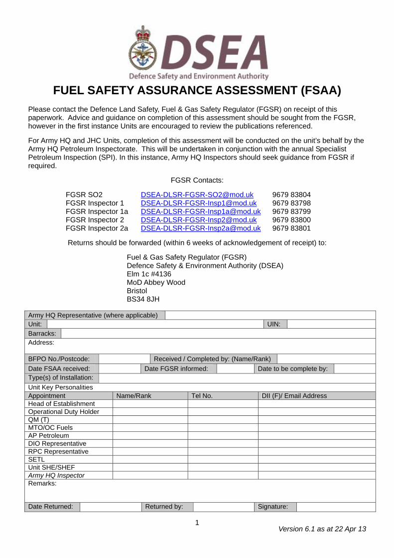
FUEL SAFETY ASSURANCE ASSESSMENT (FSAA) Please contact the Defence Land Safety, Fuel & Gas Safety Regulator (FGSR) on receipt of this paperwork. Advice and guidance on completion of this assessment should be sought from the FGSR, however in the first instance Units are encouraged to review the publications referenced. For Army HQ and JHC Units, completion of this assessment will be conducted on the unit’s behalf by the Army HQ Petroleum Inspectorate. This will be undertaken in conjunction with the annual Specialist Petroleum Inspection (SPI). In this instance, Army HQ Inspectors should seek guidance from FGSR if required.
FGSR Contacts:
FGSR SO2 [email protected] 9679 83804 FGSR Inspector 1 [email protected] 9679 83798 FGSR Inspector 1a [email protected] 9679 83799 FGSR Inspector 2 [email protected] 9679 83800 FGSR Inspector 2a [email protected] 9679 83801
Returns should be forwarded (within 6 weeks of acknowledgement of receipt) to:
Fuel & Gas Safety Regulator (FGSR) Defence Safety & Environment Authority (DSEA) Elm 1c #4136 MoD Abbey Wood Bristol BS34 8JH
Army HQ Representative (where applicable) Unit: UIN: Barracks: Address: BFPO No./Postcode: Received / Completed by: (Name/Rank) Date FSAA received: Date FGSR informed: Date to be complete by: Type(s) of Installation: Unit Key Personalities Appointment Name/Rank Tel No. DII (F)/ Email Address Head of Establishment Operational Duty Holder QM (T) MTO/OC Fuels AP Petroleum DIO Representative RPC Representative SETL Unit SHE/SHEF Army HQ Inspector Remarks: Date Returned: Returned by: Signature:
Version 6.1 as at 22 Apr 13
2
Introduction
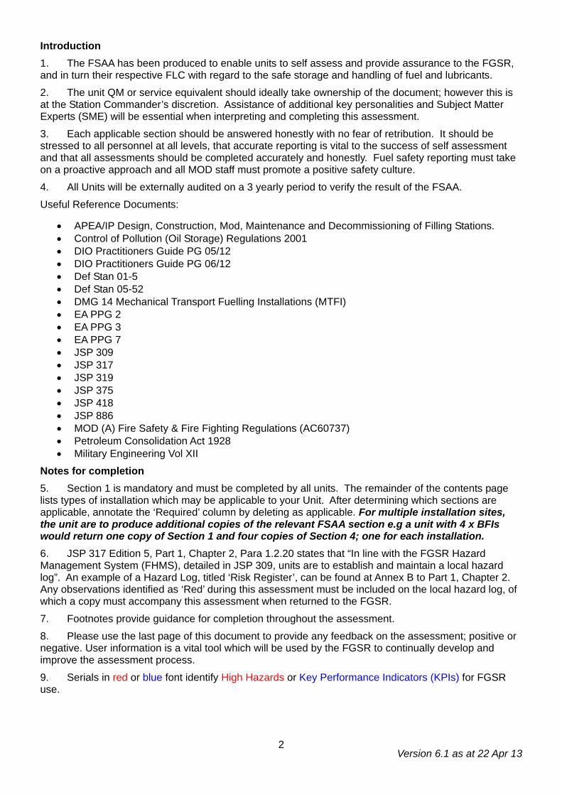
1. The FSAA has been produced to enable units to self assess and provide assurance to the FGSR, and in turn their respective FLC with regard to the safe storage and handling of fuel and lubricants.
2. The unit QM or service equivalent should ideally take ownership of the document; however this is at the Station Commander’s discretion. Assistance of additional key personalities and Subject Matter Experts (SME) will be essential when interpreting and completing this assessment.
3. Each applicable section should be answered honestly with no fear of retribution. It should be stressed to all personnel at all levels, that accurate reporting is vital to the success of self assessment and that all assessments should be completed accurately and honestly. Fuel safety reporting must take on a proactive approach and all MOD staff must promote a positive safety culture.
4. All Units will be externally audited on a 3 yearly period to verify the result of the FSAA.
Useful Reference Documents:
• APEA/IP Design, Construction, Mod, Maintenance and Decommissioning of Filling Stations. • Control of Pollution (Oil Storage) Regulations 2001 • DIO Practitioners Guide PG 05/12 • DIO Practitioners Guide PG 06/12 • Def Stan 01-5 • Def Stan 05-52 • DMG 14 Mechanical Transport Fuelling Installations (MTFI) • EA PPG 2 • EA PPG 3 • EA PPG 7 • JSP 309 • JSP 317 • JSP 319 • JSP 375 • JSP 418 • JSP 886 • MOD (A) Fire Safety & Fire Fighting Regulations (AC60737) • Petroleum Consolidation Act 1928 • Military Engineering Vol XII
Notes for completion
5. Section 1 is mandatory and must be completed by all units. The remainder of the contents page lists types of installation which may be applicable to your Unit. After determining which sections are applicable, annotate the ‘Required’ column by deleting as applicable. For multiple installation sites, the unit are to produce additional copies of the relevant FSAA section e.g a unit with 4 x BFIs would return one copy of Section 1 and four copies of Section 4; one for each installation.
6. JSP 317 Edition 5, Part 1, Chapter 2, Para 1.2.20 states that “In line with the FGSR Hazard Management System (FHMS), detailed in JSP 309, units are to establish and maintain a local hazard log”. An example of a Hazard Log, titled ‘Risk Register’, can be found at Annex B to Part 1, Chapter 2. Any observations identified as ‘Red’ during this assessment must be included on the local hazard log, of which a copy must accompany this assessment when returned to the FGSR.
7. Footnotes provide guidance for completion throughout the assessment.
8. Please use the last page of this document to provide any feedback on the assessment; positive or negative. User information is a vital tool which will be used by the FGSR to continually develop and improve the assessment process.
9. Serials in red or blue font identify High Hazards or Key Performance Indicators (KPIs) for FGSR use.
Version 6.1 as at 22 Apr 13
3
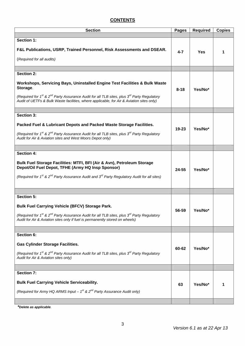
CONTENTS
Section Pages Required Copies Section 1: F&L Publications, USRP, Trained Personnel, Risk Assessments and DSEAR. (Required for all audits)
4-7 Yes 1
Section 2: Workshops, Servicing Bays, Uninstalled Engine Test Facilities & Bulk Waste Storage. (Required for 1st & 2nd Party Assurance Audit for all TLB sites, plus 3rd Party Regulatory Audit of UETFs & Bulk Waste facilities, where applicable, for Air & Aviation sites only)
8-18 Yes/No*
Section 3: Packed Fuel & Lubricant Depots and Packed Waste Storage Facilities. (Required for 1st & 2nd Party Assurance Audit for all TLB sites, plus 3rd Party Regulatory Audit for Air & Aviation sites and West Moors Depot only)
19-23 Yes/No*
Section 4: Bulk Fuel Storage Facilities: MTFI, BFI (Air & Avn), Petroleum Storage Depot/Oil Fuel Depot, TFHE (Army HQ Insp Sponsor) (Required for 1st & 2nd Party Assurance Audit and 3rd Party Regulatory Audit for all sites)
24-55 Yes/No*
Section 5: Bulk Fuel Carrying Vehicle (BFCV) Storage Park. (Required for 1st & 2nd Party Assurance Audit for all TLB sites, plus 3rd Party Regulatory Audit for Air & Aviation sites only if fuel is permanently stored on wheels)
56-59 Yes/No*
Section 6: Gas Cylinder Storage Facilities. (Required for 1st & 2nd Party Assurance Audit for all TLB sites, plus 3rd Party Regulatory Audit for Air & Aviation sites only)
60-62 Yes/No*
Section 7: Bulk Fuel Carrying Vehicle Serviceability. (Required for Army HQ ARMS Input – 1st & 2nd Party Assurance Audit only)
63 Yes/No* 1
*Delete as applicable.
Version 6.1 as at 22 Apr 13
4
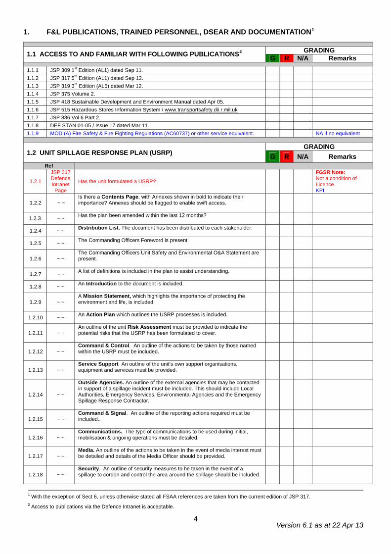
1. F&L PUBLICATIONS, TRAINED PERSONNEL, DSEAR AND DOCUMENTATION1
GRADING 1.1 ACCESS TO AND FAMILIAR WITH FOLLOWING PUBLICATIONS2 G R N/A Remarks
1.1.1 JSP 309 1st Edition (AL1) dated Sep 11. 1.1.2 JSP 317 5th Edition (AL1) dated Sep 12. 1.1.3 JSP 319 3rd Edition (AL5) dated Mar 12. 1.1.4 JSP 375 Volume 2. 1.1.5 JSP 418 Sustainable Development and Environment Manual dated Apr 05. 1.1.6 JSP 515 Hazardous Stores Information System / www.transportsafety.dii.r.mil.uk 1.1.7 JSP 886 Vol 6 Part 2. 1.1.8 DEF STAN 01-05 / Issue 17 dated Mar 11. 1.1.9 MOD (A) Fire Safety & Fire Fighting Regulations (AC60737) or other service equivalent. NA if no equivalent
GRADING 1.2 UNIT SPILLAGE RESPONSE PLAN (USRP) G R N/A Remarks
Ref
1.2.1
JSP 317 Defence Intranet Page
Has the unit formulated a USRP? FGSR Note: Not a condition of Licence. KPI
1.2.2 ~ ~ Is there a Contents Page, with Annexes shown in bold to indicate their importance? Annexes should be flagged to enable swift access.
1.2.3 ~ ~ Has the plan been amended within the last 12 months?
1.2.4 ~ ~ Distribution List. The document has been distributed to each stakeholder.
1.2.5 ~ ~ The Commanding Officers Foreword is present.
1.2.6 ~ ~ The Commanding Officers Unit Safety and Environmental O&A Statement are present.
1.2.7 ~ ~ A list of definitions is included in the plan to assist understanding.
1.2.8 ~ ~ An Introduction to the document is included.
1.2.9 ~ ~ A Mission Statement, which highlights the importance of protecting the environment and life, is included.
1.2.10 ~ ~ An Action Plan which outlines the USRP processes is included.
1.2.11 ~ ~ An outline of the unit Risk Assessment must be provided to indicate the potential risks that the USRP has been formulated to cover.
1.2.12 ~ ~ Command & Control. An outline of the actions to be taken by those named within the USRP must be included.
1.2.13 ~ ~ Service Support An outline of the unit’s own support organisations, equipment and services must be provided.
1.2.14 ~ ~
Outside Agencies. An outline of the external agencies that may be contacted in support of a spillage incident must be included. This should include Local Authorities, Emergency Services, Environmental Agencies and the Emergency Spillage Response Contractor.
1.2.15 ~ ~ Command & Signal. An outline of the reporting actions required must be included..
1.2.16 ~ ~ Communications. The type of communications to be used during initial, mobilisation & ongoing operations must be detailed.
1.2.17 ~ ~ Media. An outline of the actions to be taken in the event of media interest must be detailed and details of the Media Officer should be provided.
1.2.18 ~ ~ Security. An outline of security measures to be taken in the event of a spillage to cordon and control the area around the spillage should be included.
1 With the exception of Sect 6, unless otherwise stated all FSAA references are taken from the current edition of JSP 317. 2 Access to publications via the Defence Intranet is acceptable.
Version 6.1 as at 22 Apr 13
5
Ref G R N/A Remarks
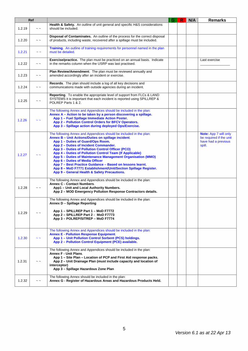
1.2.19 ~ ~ Health & Safety. An outline of unit general and specific H&S considerations should be included.
1.2.20 ~ ~ Disposal of Contaminates. An outline of the process for the correct disposal of products, including waste, recovered after a spillage must be included.
1.2.21 ~ ~ Training. An outline of training requirements for personnel named in the plan must be detailed.
1.2.22 ~ ~ Exercise/practice. The plan must be practiced on an annual basis. Indicate in the remarks column when the USRP was last practised.
Last exercise ________________
1.2.23 ~ ~ Plan Review/Amendment. The plan must be reviewed annually and amended accordingly after an incident or exercise.
1.2.24 ~ ~ Records. The plan should include a log of all key decisions and communications made with outside agencies during an incident.
1.2.25 ~ ~ Reporting. To enable the appropriate level of support from FLCs & LAND SYSTEMS it is important that each incident is reported using SPILLREP & POLREP Parts 1 & 2.
1.2.26 ~ ~
The following Annex and Appendices should be included in the plan: Annex A – Action to be taken by a person discovering a spillage. App 1 – Fuel Spillage Immediate Action Poster. App 2 – Pollution Control Orders for BFCV Operators. App 3 – Spillage action during deployed Ops/Exercise.
1.2.27 ~ ~
The following Annex and Appendices should be included in the plan: Annex B – Unit Actions/Duties on spillage incident. App 1 – Duties of Guard/Ops Room. App 2 – Duties of Incident Commander. App 3 – Duties of Pollution Control Officer (PCO) App 4 – Duties of Pollution Control Team (If Applicable) App 5 – Duties of Maintenance Management Organisation (MMO) App 6 – Duties of Media Officer App 7 – Best Practice Guidance – Based on lessons learnt. App 8 – MoD F7771 Establishment/Unit/Section Spillage Register. App 9 – General Health & Safety Precautions.
Note: App 7 will only be required if the unit have had a previous spill.
1.2.28 ~ ~
The following Annex and Appendices should be included in the plan: Annex C - Contact Numbers. App1 – Unit and Local Authority Numbers. App 2 – MOD Emergency Pollution Response Contractors details.
1.2.29 ~ ~
The following Annex and Appendices should be included in the plan: Annex D – Spillage Reporting App 1 – SPILLREP Part 1 – MoD F7772 App 2 – SPILLREP Part 2 - MoD F7773 App 3 – POLREP/SITREP – MoD F7774
1.2.30 ~ ~
The following Annex and Appendices should be included in the plan: Annex E - Pollution Response Equipment. App 1 – Unit Pollution Control Sorbent (PCS) holdings. App 2 – Pollution Control Equipment (PCE) available.
1.2.31 ~ ~
The following Annex and Appendices should be included in the plan: Annex F - Unit Plans. App 1 – Site Plan – Location of PCP and First Aid response packs. App 2 – Unit Drainage Plan (must include capacity and location of interceptor) App 3 – Spillage Hazardous Zone Plan
1.2.32 ~ ~ The following Annex should be included in the plan: Annex G - Register of Hazardous Areas and Hazardous Products Held.
Version 6.1 as at 22 Apr 13
6
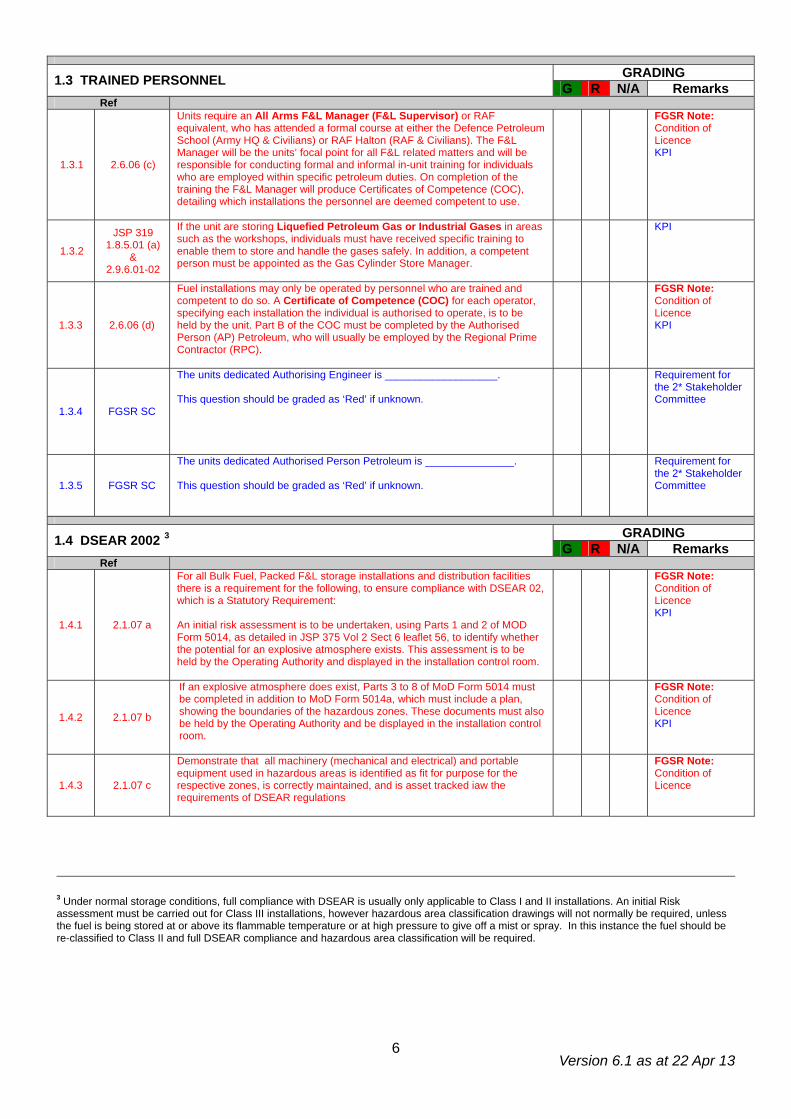
GRADING 1.3 TRAINED PERSONNEL G R N/A Remarks Ref
1.3.1 2.6.06 (c)
Units require an All Arms F&L Manager (F&L Supervisor) or RAF equivalent, who has attended a formal course at either the Defence Petroleum School (Army HQ & Civilians) or RAF Halton (RAF & Civilians). The F&L Manager will be the units’ focal point for all F&L related matters and will be responsible for conducting formal and informal in-unit training for individuals who are employed within specific petroleum duties. On completion of the training the F&L Manager will produce Certificates of Competence (COC), detailing which installations the personnel are deemed competent to use.
FGSR Note: Condition of Licence KPI
1.3.2
JSP 319 1.8.5.01 (a)
& 2.9.6.01-02
If the unit are storing Liquefied Petroleum Gas or Industrial Gases in areas such as the workshops, individuals must have received specific training to enable them to store and handle the gases safely. In addition, a competent person must be appointed as the Gas Cylinder Store Manager.
KPI
1.3.3 2.6.06 (d)
Fuel installations may only be operated by personnel who are trained and competent to do so. A Certificate of Competence (COC) for each operator, specifying each installation the individual is authorised to operate, is to be held by the unit. Part B of the COC must be completed by the Authorised Person (AP) Petroleum, who will usually be employed by the Regional Prime Contractor (RPC).
FGSR Note: Condition of Licence KPI
1.3.4
FGSR SC
The units dedicated Authorising Engineer is ___________________. This question should be graded as ‘Red’ if unknown.
Requirement for the 2* Stakeholder Committee
1.3.5
FGSR SC
The units dedicated Authorised Person Petroleum is _______________. This question should be graded as ‘Red’ if unknown.
Requirement for the 2* Stakeholder Committee
GRADING 1.4 DSEAR 2002 3 G R N/A Remarks Ref
1.4.1 2.1.07 a
For all Bulk Fuel, Packed F&L storage installations and distribution facilities there is a requirement for the following, to ensure compliance with DSEAR 02, which is a Statutory Requirement: An initial risk assessment is to be undertaken, using Parts 1 and 2 of MOD Form 5014, as detailed in JSP 375 Vol 2 Sect 6 leaflet 56, to identify whether the potential for an explosive atmosphere exists. This assessment is to be held by the Operating Authority and displayed in the installation control room.
FGSR Note: Condition of Licence KPI
1.4.2 2.1.07 b
If an explosive atmosphere does exist, Parts 3 to 8 of MoD Form 5014 must be completed in addition to MoD Form 5014a, which must include a plan, showing the boundaries of the hazardous zones. These documents must also be held by the Operating Authority and be displayed in the installation control room.
FGSR Note: Condition of Licence KPI
1.4.3 2.1.07 c
Demonstrate that all machinery (mechanical and electrical) and portable equipment used in hazardous areas is identified as fit for purpose for the respective zones, is correctly maintained, and is asset tracked iaw the requirements of DSEAR regulations
FGSR Note: Condition of Licence
3 Under normal storage conditions, full compliance with DSEAR is usually only applicable to Class I and II installations. An initial Risk assessment must be carried out for Class III installations, however hazardous area classification drawings will not normally be required, unless the fuel is being stored at or above its flammable temperature or at high pressure to give off a mist or spray. In this instance the fuel should be re-classified to Class II and full DSEAR compliance and hazardous area classification will be required.
Version 6.1 as at 22 Apr 13
7
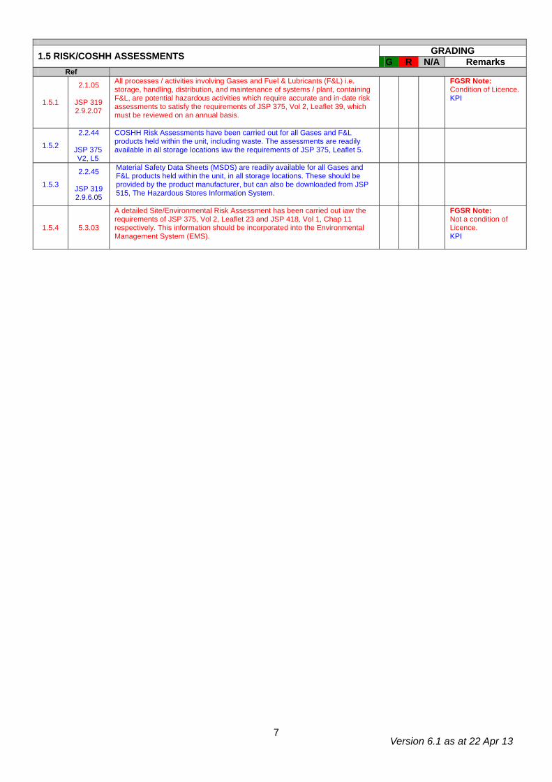
GRADING 1.5 RISK/COSHH ASSESSMENTS G R N/A Remarks Ref
1.5.1
2.1.05
JSP 319 2.9.2.07
All processes / activities involving Gases and Fuel & Lubricants (F&L) i.e. storage, handling, distribution, and maintenance of systems / plant, containing F&L, are potential hazardous activities which require accurate and in-date risk assessments to satisfy the requirements of JSP 375, Vol 2, Leaflet 39, which must be reviewed on an annual basis.
FGSR Note: Condition of Licence. KPI
1.5.2
2.2.44
JSP 375 V2, L5
COSHH Risk Assessments have been carried out for all Gases and F&L products held within the unit, including waste. The assessments are readily available in all storage locations iaw the requirements of JSP 375, Leaflet 5.
1.5.3
2.2.45
JSP 319 2.9.6.05
Material Safety Data Sheets (MSDS) are readily available for all Gases and F&L products held within the unit, in all storage locations. These should be provided by the product manufacturer, but can also be downloaded from JSP 515, The Hazardous Stores Information System.
1.5.4 5.3.03
A detailed Site/Environmental Risk Assessment has been carried out iaw the requirements of JSP 375, Vol 2, Leaflet 23 and JSP 418, Vol 1, Chap 11 respectively. This information should be incorporated into the Environmental Management System (EMS).
FGSR Note: Not a condition of Licence. KPI
Version 6.1 as at 22 Apr 13
8
2. WORKSHOP AND SERVICING BAYS
APPLICABLE TO SECTION 2
2.1 DESIGN Ref
2.1.1 1.1.07 Note: In countries outside of the UK JSP 317 standards will apply unless the host nation regulations are more stringent. This does not apply to Germany where local standards in compliance with SOFA are to be adhered to.
Information only
WORKSHOPS
GRADING 2.1.1 FIRE, HEALTH & SAFETY G R N/A Remarks Ref
2.1.1.1 2.2.48 e-h
Combat of F&L Health Hazards. Washing & changing facilities provided at the place of work. Barrier and After Work Cream provided. Provision of Eyewash & First Aid.
2.1.1.2 2.2.49 Appropriate PPE is provided for all employees and is worn at all times when undertaking petroleum duties.
2.1.1.3 2.5.06 & 2.5.07
A comprehensive fire plan is to be provided for all locations storing and handling petroleum products. It should include details of :
• Fire detection and alarm systems • Water and other chemical fire fighting agents • Fire fighting equipment • Emergency shut down procedures • Emergency evacuation procedures & assembly points • Staff fire training • Duties of persons nominated in the plan • Arrangements for testing and updating the plan
FGSR Note: Example Fire Plan provided on JSP 317 website.
2.1.1.4 2.5.09
The extent of the hazardous area is to be clearly indicated with the use of notices stating “Petroleum Spirit. Highly Flammable- No Smoking –No Naked Lights” (Overseas dual language signs), as follows:
2.1.1.5 2.5.10
Fire Safety Notices & Fire Action Notices must be displayed in order to comply with the Health and Safety (Safety Signs and Signals) Regulations 1996. Locations and quantities should relate to the local risks and be the result of a risk assessment.
2.1.1.6 2.5.11 Smoking or Smoking materials are not permitted in the hazardous area. Personnel are to deposit any smoking materials in a safe designated contraband area before entering a hazardous zone or likely hazardous area.
2.1.1.7 2.7.65 Where drums or other large containers are required to be moved by hand, cradles or trolleys are to be provided to minimise product spillage and injury to personnel.
2.1.1.8 2.7.69 a Storage Cabinets must be Fire Resistant and designed to BS 476 specification. (NSN F3 7125-99-700-4418).
2.1.1.9 2.7.69 b The cabinet should be sited in a designated area, at least 3m from working area but preferably 5m and not below any openings or exits.
2.1.1.10 2.7.74 Figure 2.7.7
The following HWS must be displayed on all F&L cabinets:
GRADING 2.1.2 ENVIRONMENTAL PROTECTION G R N/A Remarks Ref
2.1.2.1 2.5.13 b Spillages to be mopped up immediately using approved absorbent material which must be removed from the area for safe disposal.
2.1.2.2 5.9.12.g (2)
Spillage Immediate Action Posters are to be prominently displayed at all Pollution Control Points and locations were F&L is stored.
FGSR Note: Para 5 of example USRP.
Version 6.1 as at 22 Apr 13
9
GRADING 2.1.3 OPERATING PROCEDURES G R N/A Remarks Ref
2.1.3.1 1.4.16 Container Markings. All container markings are to be legible and correct. 2.1.3.2 2.5.13 f Oxidisers or Acids. Are not to be stored with flammable liquids. 2.1.3.3 2.5.24 c Housekeeping. No general rubbish, all contaminates removed from the
area including rags after use.
2.1.3.4 2.7.53
Large Drums. Containers with a capacity of no greater than 200 Ltrs and intended for use n the same day or shift may be stored temporarily outside a building providing the container is properly closed and labelled and the building wall is a fire wall.
2.1.3.5 2.7.55 Unused Containers. To be returned to the storage area at the end of the working day or shift.
2.1.3.6 2.7.60 Empty Containers. All empty container closures to be closed.
2.1.3.7 2.7.69 Working Stock. Up to 50 Ltrs of class 3.1 or 3.2 & 250 Ltrs of Class 3.3 Unclassified, can be stored in the workplace providing serials 2.1.1.8 – 2.1.1.10 are complied with.
2.1.3.8 2.7.73 b Each locker is to display an up to date contents list which is to be annotated with the batch number and re-test dates of all products held.
2.1.3.9 2.7.73 c Life expired products which are unidentifiable due to degradation of labels are to be quarantined and segregated from ‘In use’ stock pending disposal or investigation.
2.1.3.10 2.12.11 User Units. Officers in charge are responsible for ensuring the quality and integrity of all F&L products held in their unit.
SERVICING BAY
GRADING 2.2.1 FIRE, HEALTH & SAFETY G R N/A Remarks Ref
2.2.1.1 2.2.48 e-h Combat of F&L Health Hazards. Washing & changing facilities provided at the place of work. Barrier and After Work Cream provided. Provision of Eyewash & First Aid.
2.2.1.2 2.2.48 i Appropriate PPE is provided for all operators.
2.2.1.3 2.5.06 & 2.5.07
A comprehensive fire plan is to be provided for all locations storing and handling petroleum products. It should include details of :
• Fire detection and alarm systems • Water and other chemical fire fighting agents • Fire fighting equipment • Emergency shut down procedures • Emergency evacuation procedures & assembly points • Staff fire training • Duties of persons nominated in the plan
Arrangements for testing and updating the plan
FGSR Note: Example Fire Plan provided on JSP 317 website.
2.2.1.4 2.5.09
The extent of the hazardous area is to be clearly indicated with the use of notices stating “Petroleum Spirit. Highly Flammable- No Smoking –No Naked Lights” (Overseas dual language signs), as follows:
2.2.1.5 2.5.10
Fire Safety Notices & Fire Action Notices must be displayed in order to comply with the Health and Safety (Safety Signs and Signals) Regulations 1996. Locations and quantities should relate to the local risks and be the result of a risk assessment.
2.2.1.6 2.5.11
Smoking or Smoking materials are not permitted in the hazardous area. Personnel are to deposit any smoking materials in a safe designated contraband area before entering a hazardous zone or likely hazardous area.
2.2.1.7 2.7.65 Where drums or other large containers are required to be moved by hand, cradles or trolleys are to be provided to minimise product spillage and injury to personnel.
2.2.1.8 2.7.69 a Storage Cabinet. Fire resistant. BS 476. (NSN F3 7125-99-700-4418). 2.2.1.9 2.7.69 b The cabinet should be sited in a designated area, at least 3m from working
area but preferably 5m and not below any openings or exits.
2.2.1.10 2.7.74 Figure 2.7.7
The following HWS must be displayed on all F&L cabinets:
Version 6.1 as at 22 Apr 13
10
GRADING 2.2.2 ENVIRONMENTAL PROTECTION G R N/A Remarks Ref
2.2.2.1 2.5.13 b Spillages to be mopped up immediately using approved absorbent material which must be removed from the area for safe disposal.
2.2.2.2 5.9.12.g (2)
Spillage Immediate Action Posters are to be prominently displayed at all Pollution Control Points and locations were F&L is stored.
FGSR Note: Para 5 of example USRP.
GRADING 2.2.3 OPERATING PROCEDURES G R N/A Remarks Ref
2.2.3.1 1.4.16 Container Markings. All container markings are to be legible and correct.
2.2.3.2 2.5.13 f Oxidisers or Acids. Are not to be stored with flammable liquids.
2.2.3.3 2.5.24 c Housekeeping. A good housekeeping standard is to be maintained. Rubbish and refuse of any kind is to be removed.
2.2.3.4 2.7.53
Large Drums. Containers with a capacity of no greater than 200 Ltrs and intended for use n the same day or shift may be stored temporarily outside a building providing the container is properly closed and labelled and the building wall is a fire wall.
2.2.3.5 2.7.55 Unused Containers. To be returned to the storage area at the end of the working day or shift.
2.2.3.6 2.7.60 Empty Containers. All empty container closures to be closed.
2.2.3.7 2.7.69 Working Stock. Up to 50 Ltrs of class 3.1 or 3.2 & 250 Ltrs of Class 3.3 Unclassified, can be stored in the workplace providing serials 2.2.1.8 – 2.1.1.10 are complied with.
2.2.3.8 2.7.73 b Each locker is to display an up to date contents list which is to be annotated with the batch number and re-test dates of all products held.
2.2.3.9 2.7.73 c Life expired products which are unidentifiable due to degradation of labels are to be quarantined and segregated from ‘In use’ stock pending disposal or investigation.
2.2.3.10 2.12.11 User Units. Officers in charge are responsible for ensuring the quality and integrity of all F&L products held in their unit.
GRADING 2.3.1 BULK FUEL CARRYING VEHICLE SERVICING BAY Note: These additional questions are only applicable to units with purpose built BFCV Servicing Bays. G R N/A Remarks
Ref
2.3.1.1 D&MG 13, Para 3.4
Internal Walls. Are to be provided with imperforate 1 hour rated fire walls, with no internal access doors.
2.3.1.2 As above Ventilation. If supplied from a common plant room all ductwork should be provided with fire dampers at the point of duct penetration to the bay
2.3.1.3 As above Earthing Points. Recessed earthing points (with a resistance of 10 ohms or less) each side of the bay every 5m.
2.3.1.4 As above Electrical Equipment. Zone 1 in accordance with BS 5345 throughout the entire servicing bay.
2.3.1.5 2.7.39 Lightning Protection. To be installed in compliance with BS 6651.
2.3.1.6 2.7.44
Hazard Warning Signs(HWS). The following HWS must be displayed on all approaches to the facility:
Version 6.1 as at 22 Apr 13
11
OIL PUMP ROOM
GRADING 2.4.1 DESIGN G R N/A Remarks Ref
2.4.1.1 2.7.31
Containment. A 75 mm retention sill should surround the store or the floor should be recessed to this depth, sloping towards a sump with sufficient capacity to contain 110% of the largest container stored. An alternative method would be to surround the store with a 150 mm retaining sill without the provision of a sump, provided containment of the largest container is achieved.
GRADING 2.4.2 FIRE, HEALTH & SAFETY G R N/A Remarks Ref
2.4.2.1 2.5.10
Fire Safety Notices & Fire Action Notices must be displayed in order to comply with the Health and Safety (Safety Signs and Signals) Regulations 1996. Locations and quantities should relate to the local risks and be the result of a risk assessment.
2.4.2.2 2.5.11
Smoking or Smoking materials are not permitted in the hazardous area. Personnel are to deposit any smoking materials in a safe designated contraband area before entering a hazardous zone or likely hazardous area.
2.4.2.3 2.7.65
Where drums or other large containers are required to be moved by hand, cradles or trolleys are to be provided to minimise product spillage and injury to personnel.
2.4.2.4 2.7.66 The storage and handling of petroleum products is to be forbidden within 15m of any source of ignition.
2.4.2.5 2.7.76
A Hazard Warning Sign stating “Petroleum Mixture. Unauthorised Persons Prohibited Beyond This Point. No Smoking –No Naked Lights” must be displayed at the Oil Pump Room entrance.
GRADING 2.4.3 ENVIRONMENTAL PROTECTION G R N/A Remarks Ref
2.4.3.1 2.5.13 b Spillages to be mopped up immediately using approved absorbent material which must be removed from the area for safe disposal.
2.4.3.2 5.9.12.g (2) Spillage Immediate Action Posters are to be prominently displayed at all Pollution Control Points and locations were F&L is stored.
GRADING 2.4.4 OPERATING PROCEDURES G R N/A Remarks Ref
2.4.4.1 2.5.24 c Housekeeping. A good housekeeping standard is to be maintained. Rubbish and refuse of any kind is to be removed.
2.4.4.2 2.7.53
Large Drums. Containers with a capacity of no greater than 200 Ltrs and intended for use on the same day or shift may be stored temporarily outside a pump room providing they are properly closed and labelled and the building wall is a fire wall.
2.4.4.3 2.7.75 Packed Products. Packed products for use in the pump room are to be stored in approved locations outside of the facility.
Version 6.1 as at 22 Apr 13
12
BULK WASTE INSTALLATION
3.4.09 Waste F&L has the same impact on the environment as serviceable F&L. Therefore Bulk Waste Storage shall comply with principles laid down at JSP 317, Part 2, Chapter 7. Information Only
GRADING 2.5.1 DESIGN G R N/A Remarks Ref
2.5.1.1 2.8.07 b
Above Ground Storage Tanks- Secondary Containment The bund wall must be capable of retaining 110% of the largest container within the bund or 25% of the aggregate of multiple containers, whichever is greater.
2.5.1.2 2.8.14
Above Ground Storage Tanks- Secondary Containment The bund wall must: • Be impervious to liquid • Not normally be higher than 1.5m high. • Be fitted with crash protection if susceptible to impact damage e.g
adjacent to a vehicle manoeuvring area.
2.5.1.3 2.8.15
Above Ground Storage Tanks- Secondary Containment The bund wall must not be constructed too close to the tank to prevent jetting; a phenomenon caused when the primary container fails and F&L is propelled at force over the bund wall
2.5.1.4 2.8.18
Above Ground Storage Tanks - Secondary Containment The bund base and walls must not be penetrated by any valve, pipe or other opening which is used for draining the bund. Where a tank fill pipe or draw off pipe must pass through the bund base or wall, the hole must be carefully sealed to prevent oil escaping.
2.5.1.5 2.8.19
Above Ground Storage Tanks - Secondary Containment Rainwater which collects in the sump must be removed on a regular basis to ensure the bund capacity is maintained. This water be disposed of appropriately to ensure no pollution occurs.
2.5.1.6 2.8.20 Inspection of Bunds - Bunds should be regularly inspected for signs of damage and checked for water by the operator on a weekly basis.
2.5.1.7 2.8.21 Above Ground Storage Tanks - Secondary Containment If oil or a mixture of oil and water is found in the bund it must be disposed of in accordance with current Hazardous Waste Regulations.
2.5.1.8 2.8.75
Above Ground Storage Tanks - Small Tank Minimum Separation Distances. A small tank is considered to be a tank with a diameter of less than 10m. The minimum separation distances from site boundaries, fixed sources of ignition, buildings and process areas for single small tanks are as follows:
Tank Capacity (m³) Separation (m) Less than or equal to 1 1* Greater than 1 and less than or equal to 5 4 Greater than 5 and less than or equal to 33 6 Greater than 33 and less than or equal to 100 8
*In this instance the tank must be sited at least 2m from doors, plain glazed windows, other openings or means of escape. In addition they must not be below any openings from an upper floor, regardless of vertical distance.
2.5.1.9
Oil Storage Regs 01
3 (3)
Above Ground Storage Tanks- Secondary Containment Valves should be as resistant to unauthorised interference and vandalism as far as is feasibly possible, with lockable or removable hand wheels.
2.5.1.10 OSR 01 Reg 3(3)
Above Ground Storage Tank- Secondary Containment s All tank vent pipes, valves, filters, sight gauges and any other ancillary equipment with the exception of the fill pipe, draw off pipe or pump if the fuel has a flashpoint of less than 32ºc, must be positioned within the bund wall.
2.5.1.11 OSR 01 Reg 3(3)
Above Ground Storage Tanks Valves should be marked to indicate whether they are open or closed, kept locked when not in use and fitted with a blanking cap or plug.
2.5.1.12 OSR 01
Guidance Para 38
Above Ground Storage Tanks The connection point is to be located inside bund wall or be located in a position which allows for containment.
2.5.1.13 PPG 2 Para 8b
Above Ground Storage Tanks If the filling operation is controlled from a place where it not reasonably practicable to see the tank or its vent pipe, the tank must be fitted with an automatic overfill protection device, which may include an alarm sounding device.
Version 6.1 as at 22 Apr 13
13
Ref G R N/A Remarks
2.5.1.14 2.8.22 a-e
Above Ground Storage Tanks -Sight Glasses The use of sight glasses should be limited to the storage of Class II & III fuel tanks with a maximum capacity of 3500 Ltrs. If sight glasses are fitted they shall:
• Be located in the secondary containment. • Be properly supported so that they cannot come loose. • Be fitted with a valve that automatically closes when the sight glass
is not in use.
Have valves fitted which are kept closed when not in use and only opened when taking contents readings.
2.5.1.15 2.10.01 The Road Tanker Delivery Stand should be located in a safe, well ventilated position in the open and should offer a clear, unobstructed forward escape route.
2.5.1.16 2.10.02 a
The Road Tanker Delivery Stand – Attended. Prior to a bulk receipt at attended installations, the delivery driver must be presented with notices detailing safe delivery/receipt and emergency procedures. The driver is to read and sign the relevant notices to confirm they understand the procedures before commencing delivery.
2.5.1.17 2.10.02 i
The Road Tanker Delivery Stand – Unattended. Where supervision for tanker delivery is not provided, a notice shall be prominently displayed at the delivery point detailing safe delivery and USRP emergency procedures. Additionally, the road tanker driver should be specifically trained in dealing with an emergency at the delivery stand.
2.5.1.18 2.10.03 The Road Tanker Delivery Stand should be a minimum of 15m x 5m. If this isn’t practicable, signage and barriers are to be used to restrict vehicle and personnel access during transfer operations.
2.5.1.19 2.10.04
The Road Tanker Delivery Stand should be substantially level to ensure full extraction during deliveries. If the delivery stand is in close proximity to an above ground storage tank, adequate protection against impact damage is to be provided.
2.5.1.20 2.10.05 The Road Tanker Delivery Stand must be impermeable to hydrocarbons and be capable of withstanding the axle weight of a fully laden delivery tanker.
GRADING 2.5.2 FIRE, HEALTH & SAFETY G R N/A Remarks Ref
2.5.2.1 2.5.01 & 2.5.29
The quantity and location of all fire fighting equipment, which is determined by the Unit Fire Officer, must reflect what is stated in the Fire Safety Risk Assessment (FSRA).
2.5.2.2 2.5.06 & 2.5.07
A comprehensive fire plan is to be provided for all locations storing and handling petroleum products. It should include details of :
• Fire detection and alarm systems • Water and other chemical fire fighting agents • Fire fighting equipment • Emergency shut down procedures • Emergency evacuation procedures & assembly points • Staff fire training • Duties of persons nominated in the plan • Arrangements for testing and updating the plan
FGSR Note: Example Fire Plan provided on JSP 317 website.
2.5.2.3 2.5.10
Fire Safety Notices & Fire Action Notices must be displayed in order to comply with the Health and Safety (Safety Signs and Signals) Regulations 1996. Locations and quantities should relate to the local risks and be the result of a risk assessment.
2.5.2.4 2.5.11
Smoking or Smoking materials are not permitted in the hazardous area. Personnel are to deposit any smoking materials in a safe designated contraband area before entering a hazardous zone or likely hazardous area.
2.5.2.5 2.11.17 Fig 2.11.1
The following Hazard Warning Sign stating “Petroleum Mixture, Highly Flammable, No Smoking or Naked Flames, No Mobile Phones, No Parking” must be displayed on all approaches to the facility:

Version 6.1 as at 22 Apr 13
14
Ref G R N/A Remarks
2.5.2.6 2.5.17
Grass and Vegetation is to be cut back to a minimum of 15m. Isolated deciduous trees are permitted but conifers must be removed. Grass cutting and removal of vegetation must be carried out iaw the MoD Safety Rules and Procedures for Work on Petroleum installations.
GRADING 2.5.3 ENVIRONMENTAL PROTECTION G R N/A Remarks Ref
2.5.3.1 2.5.13 b Spillages to be mopped up immediately using approved absorbent material which must be removed from the area for safe disposal.
2.5.3.2 5.9.12.g (2)
Spillage Immediate Action Posters are to be prominently displayed at all Pollution Control Points and locations were F&L is stored.
FGSR Note: Para 5 of example USRP.
2.5.3.3 2.10.10
The following ‘Disconnect the Hose’ sign must be displayed at tanker Receipt/Issue points. The sign must be visible from the vehicle cab when the dispensing hose is connected to the installation:
2.5.3.4 5.3.16 h A Pollution Control Point (PCP) is to be established at the installation. The PCP must be clearly identifiable, stocked appropriately and be maintained on a regular basis.
GRADING 2.5.4 OPERATING PROCEDURES G R N/A Remarks Ref
2.5.4.1 1.4.17
Segregation. Different types of waste are to be stored separately to avoid the risk of fire, explosion or toxic vapour. Waste products should be collected and mixed into one of the following groupings as detailed in JSP 317, Part 3, Chapter 4, Annex A: • Mineral Oils • Fuel • Glycol’s, Glycol Ethers (AL’s)
The Bulk Waste Tank should be labelled with the specific group heading, prefixed by the word ‘Waste’ and followed by the word ‘Only’, e.g:
2.5.4.2 2.5.24 (e) Only authorised equipment, plant, vehicles or locomotives may enter the hazardous area.
2.5.4.3 2.8.88
Security. When not in use, all manhole covers, dip hatch covers, outlet points and dipsticks are to be locked. Keys are to be held in safe custody under local arrangements. This requirement may be waivered by the Fuels Officer in Charge if the dipsticks and sampling hatches are located inside a secure building.
2.5.4.4 3.1.20 A high standard of cleanliness is to be maintained at the installation. Rubbish of any kind must not be allowed to accumulate, and the growth of vegetation is to be controlled so as not to present a fire hazard.
Version 6.1 as at 22 Apr 13
15
UETF
GRADING 2.6.1 MAINTENANCE G R N/A Remarks Ref
2.6.1.1
DIO Practitioner
Guide PG 06/12
Inspection of the Fuel Infrastructure and Flammable Goods Facilities (Previously known as Task 249) : An Inspection of the Fuel Infrastructure and Flammable Goods Facilities was carried out on _____________. A Certificate of Fitness for Continued Use was Issued for a period of _____ months . If the facility was considered ‘Not Fit For Continued Use’ or the unit were given a specified timeframe to rectify observations in the ‘Table of Defects’, which has lapsed without rectification, grade this question as Red and answer the following ‘Action Plan’ question.
*If this question is graded Red, answer the following Action Plan question.
KPI
2.6.1.2 As above.
Inspection of the Fuel Infrastructure and Flammable Goods Facilities Action Plan (If applicable): An Action Plan has been produced and funding has been allocated to rectify the specific observations detailed in the ‘Table of defects’ which warranted the ‘Not Fit for Continued Use’ grading.
If green, send copy with completed report
2.6.1.3 DIO
Practitioners Guide 05/12
Electrical Systems Test (Annual): The Installations Electrical System was tested iaw the requirements of PG 05/12 on ____________ and was graded as ‘Satisfactory’. An ‘Unsatisfactory’ grade should be awarded ‘Red’ for this question.
*If this question is graded Red, answer the following Electrical Test Action Plan question.
2.6.1.4 As above.
Electrical Systems Test Action Plan (If applicable): An Action Plan has been produced and funding has been allocated to rectify the specific observations which resulted in the ‘Unsatisfactory’ Electrical Test grading.
If green, send copy with completed report
2.6.1.5 JSP 317 Para 3.1.08 c
Lightning Protection (If applicable) BS 6651 is to be consulted to determine whether the installation is in an area susceptible to lightning. If protection is required the requirements of BS 6651 are to be incorporated into the installations design.
2.6.1.6 DIO PG 06/12 Annex B
Level 1 Assessment (Underground Single Skinned Steel Tanks (USSST)): Level 1 Assessments were conducted on __________ and the cumulative scores were______________________________.
A tank is deemed to be a high risk if the cumulative score exceeds +6.
2.6.1.7
DIO PG 06/12 Annex B
D&MG 14 Chap 15.2
Table 1
Level 2 Testing, Tank Tightness Tests of USSST: The Installation was constructed in________. The last Level 2 Testing was undertaken on the installations storage tanks on ________. The next Tank Tightness Tests are due on _______________________.
USSST shall undergo Level 2 testing in years 20, 25, 30 and every 2 years thereafter as a minimum and more frequently if the level 1 assessment deems it necessary.
GRADING 2.6.2 DESIGN G R N/A Remarks Ref
2.6.2.1 2.5.01 Does the installation design and layout provide means of escape for employees and means of access for the fire brigade in the event of a fire? Answer Green for ‘Yes’ and Red for ‘No’.
2.6.2.2 2.5.14 Overhead Power Cables are not permitted to cross the installations Hazardous Area.
2.6.2.3 2.8.07 b
Above Ground Storage Tanks- Secondary Containment The bund wall must be capable of retaining 110% of the largest container within the bund or 25% of the aggregate of multiple containers, whichever is greater.
2.6.2.4 2.8.11-12
Compliant Integrally Bunded Storage Tank. Defined as ‘An above ground storage tank which has an integral secondary containment system, capable of containing 110% of the primary containers brimful capacity. If this storage media is employed, an additional bund will not be required however the tank must be sited on an impermeable surface and be isolated from the surface water drainage system.
Version 6.1 as at 22 Apr 13
16
Ref G R N/A Remarks
2.6.2.5
APEA Design, Con, Mod,
Maint & Decom of
Filling Stations Para 11.6
Tank Contents Measurement Method. All tanks or compartments should be provided with a means of ascertaining the quantity of fuel stored. This may be by use of a dipstick or by some means of tank contents gauge. Indicate which method is used in the remarks column.
Manual Dip* Auto Tank Gauge* *Delete as applicable
2.6.2.6 2.8.14
Above Ground Storage Tanks- Secondary Containment The bund wall must: • Be impervious to liquid • Not normally be higher than 1.5m high. • Be fitted with crash protection if susceptible to impact damage
e.g adjacent to a vehicle manoeuvring area.
2.6.2.7 2.8.15
Above Ground Storage Tanks- Secondary Containment The bund wall must not be constructed too close to the tank to prevent jetting; a phenomenon caused when the primary container fails and F&L is propelled at force over the bund wall.
2.6.2.8 2.8.18
Above Ground Storage Tanks - Secondary Containment The bund base and walls must not be penetrated by any valve, pipe or other opening which is used for draining the bund. Where a tank fill pipe or draw off pipe must pass through the bund base or wall, the hole must be carefully sealed to prevent oil escaping.
2.6.2.9 2.8.19
Above Ground Storage Tanks - Secondary Containment Rainwater which collects in the sump must be removed on a regular basis to ensure the bund capacity is maintained. This water be disposed of appropriately to ensure no pollution occurs.
2.6.2.10 2.8.20 Inspection of Bunds - Bunds should be regularly inspected for signs of damage and checked for water by the operator on a weekly basis.
2.6.2.11 2.8.21 Above Ground Storage Tanks - Secondary Containment If oil or a mixture of oil and water is found in the bund it must be disposed of in accordance with current Hazardous Waste Regulations.
2.6.2.12 Oil Storage Regs 3 (3)
Above Ground Storage Tanks- Secondary Containment Valves should be as resistant to unauthorised interference and vandalism as far as is feasibly possible, with lockable or removable hand wheels.
2.6.2.13 OSR 01 Reg 3(3)
Above Ground Storage Tank- Secondary Containment s All tank vent pipes, valves, filters, sight gauges and any other ancillary equipment with the exception of the fill pipe, draw off pipe or pump if the fuel has a flashpoint of less than 32ºc, must be positioned within the bund wall.
2.6.2.14
OSR 01 Reg 3(3)
Above Ground Storage Tanks Valves should be marked to indicate whether they are open or closed, kept locked when not in use and fitted with a blanking cap or plug.
2.6.2.15 OSR 01
Guidance Para 38
Above Ground Storage Tank- The connection point is to be located inside bund wall or be located in a position which allows for containment.
2.6.2.16 2.8.22 a-e
Above Ground Storage Tank- - Sight Glasses The use of sight glasses should be limited to the storage of Class II & III fuel tanks with a maximum capacity of 3500 Ltrs. If sight glasses are fitted they shall:
• Be located in the secondary containment. • Be properly supported so that they cannot come loose. • Be fitted with a valve that automatically closes when the sight
glass is not in use.
Have valves fitted which are kept closed when not in use and only opened when taking contents readings.
2.6.2.17 2.8.75
Above Ground Storage Tank- - Small Tank Minimum Separation Distances. A small tank is considered to be a tank with a diameter of less than 10m. The minimum separation distances from site boundaries, fixed sources of ignition, buildings and process areas for single small tanks are as follows:
Tank Capacity (m³) Separation (m) Less than or equal to 1 1* Greater than 1 and less than or equal to 5 4 Greater than 5 and less than or equal to 33 6 Greater than 33 and less than or equal to 100 8
*In this instance the tank must be sited at least 2m from doors, plain glazed windows, other openings or means of escape. In addition they must not be below openings from an upper floor, regardless of vertical distance.
Version 6.1 as at 22 Apr 13
17
Ref G R N/A Remarks
2.6.2.18 PPG 2 Para 8b
Above Ground Storage Tanks If the filling operation is controlled from a place where it not reasonably practicable to see the tank or its vent pipe, the tank must be fitted with an automatic overfill protection device, which may include an alarm sounding device.
2.6.2.19 D&MG 14, 9.3 b
The main switchgear shall be located in a non-hazardous area and incorporate the main isolation switch and the means of isolation. The main isolation switch must be labelled “Mains Isolating Switch” in the host nation language and English.
2.6.2.20 D&MG 14 9.3 g
Electrical supplies to Wet Stock Management and Leak Detection Systems, if fitted, must be fed by individual dedicated circuits. Miniature circuit breakers feeding such circuits are to be clearly labelled “Do not switch off” in the host nation language and English.
2.6.2.21 D&MG 14 9.5 r
A permanent label is to be fitted at all earthing and bonding connection points stating “Safety Electrical connection – Do not remove” in the host nation language and English.
2.6.2.22 D&MG 14 13.2 h
At unattended installations a notice stating the name, address and phone number of the person to be contacted in an emergency is to be displayed.
2.6.2.23 2.10.01 The Road Tanker Delivery Stand should be located in a safe, well ventilated position in the open and should offer a clear, unobstructed forward escape route.
2.6.2.24 2.10.02 a
The Road Tanker Delivery Stand – Attended. Prior to a bulk receipt at attended installations, the delivery driver must be presented with notices detailing safe delivery/receipt and emergency procedures. The driver is to read and sign the relevant notices to confirm they understand the procedures before commencing delivery.
2.6.2.25 2.10.02 i
The Road Tanker Delivery Stand – Unattended. Where supervision for tanker delivery is not provided, a notice shall be prominently displayed at the delivery point detailing safe delivery and USRP emergency procedures. Additionally, the road tanker driver should be specifically trained in dealing with an emergency at the delivery stand.
2.6.2.26 2.10.03 The Road Tanker Delivery Stand should be a minimum of 15m x 5m. If this isn’t practicable, signage and barriers are to be used to restrict vehicle and personnel access during transfer operations.
2.6.2.27 2.10.04
The Road Tanker Delivery Stand should be substantially level to ensure full extraction during deliveries. If the delivery stand is in close proximity to an above ground storage tank, adequate protection against impact damage is to be provided.
2.6.2.28 2.10.05 The Road Tanker Delivery Stand must be impermeable to hydrocarbons and be capable of withstanding the axle weight of a fully laden delivery tanker.
2.6.2.29 3.1.14
The installation should have an effective means of both raising the alarm and giving warning in case of fire. It should be audible to all those likely to be effected by the fire. There must be access to a phone with in reasonable distance, which is to be clearly signposted.
GRADING 2.6.3 FIRE, HEALTH & SAFETY G R N/A Remarks Ref
2.6.3.1 1.4.26 Above ground storage tanks are to be marked with the correct NATO Product and Grade Identification markings. These markings must be visible from all directions.
2.6.3.2 1.4.27 Above ground Class I tanks shall be marked with ‘Highly Flammable, No Smoking, No Naked Lights’.
2.6.3.3 1.4.28 Above ground Class II tanks shall be marked ‘Flammable Liquid, No Smoking, No Naked Lights’.
2.6.3.4 2.2.48 e-h
Washing & changing facilities are to be provided for personnel at the place of work. In addition, the following items must also be provided:
• Barrier Cream and After Work Cream. • Eyewash (In Date). • Emergency First Aid Kit.
Version 6.1 as at 22 Apr 13
18
Ref G R N/A Remarks 2.6.3.5 2.2.48 i Appropriate Personal Protective Equipments (PPE) and Respiratory
Protective Equipment (RPE) is provided and used by all operators.
2.6.3.6 2.5.01 & 2.5.29
The quantity and location of all fire fighting equipment, which is determined by the Unit Fire Officer, must reflect what is stated in the Fire Safety Risk Assessment (FSRA).
2.6.3.7 2.5.06 & 2.5.07
A comprehensive fire plan is to be provided for all locations storing and handling petroleum products. It should include details of :
• Fire detection and alarm systems • Water and other chemical fire fighting agents • Fire fighting equipment • Emergency shut down procedures • Emergency evacuation procedures & assembly points • Staff fire training • Duties of persons nominated in the plan
Arrangements for testing and updating the plan
FGSR Note: Example Fire Plan provided on JSP 317 website.
2.6.3.8 2.5.10
Fire Safety Notices & Fire Action Notices must be displayed in order to comply with the Health and Safety (Safety Signs and Signals) Regulations 1996. Locations and quantities should relate to the local risks and be the result of a risk assessment.
2.6.3.9 2.5.11
Smoking or Smoking materials are not permitted in the hazardous area. Personnel are to deposit any smoking materials in a safe designated contraband area before entering a hazardous zone or likely hazardous area.
2.6.3.10 2.5.17
Grass and Vegetation is to be cut back to a minimum of 15m. Isolated deciduous trees are permitted but conifers must be removed. Grass cutting and removal of vegetation must be carried out iaw the MoD Safety Rules and Procedures for Work on Petroleum installations.
2.6.3.11 3.1.15 Fig 3.1.1
The following Hazard Warning Sign must be displayed on all approaches to the facility to clearly indicate the extent of the hazard. The sign must be produced in the local language and English:
GRADING 2.6.4 ENVIRONMENTAL PROTECTION G R N/A Remarks Ref
2.6.4.1 2.10.10
The following ‘Disconnect the Hose’ sign must be displayed at tanker Receipt/Issue points. The sign must be visible from the vehicle cab when the dispensing hose is connected to the installation:
2.6.4.2 2.5.13 b Spillages to be mopped up immediately using approved absorbent material which must be removed from the area for safe disposal.
2.6.4.3 5.3.16 h A Pollution Control Point (PCP) is to be established at the installation. The PCP must be clearly identifiable, stocked appropriately and be maintained on a regular basis.
2.6.4.4 5.9.12.g (2) Spillage Immediate Action Posters are to be prominently displayed at all Pollution Control Points and locations were F&L is stored.
FGSR Note: Para 5 of example USRP.
GRADING 2.6.5 OPERATING PROCEDURES G R N/A Remarks Ref
2.6.5.1 2.5.24 (e) Only authorised equipment, plant, vehicles or locomotives may enter the hazardous area.
2.6.5.2 2.8.88
Security. When not in use, all manhole covers, dip hatch covers, outlet points and dipsticks are to be locked. Keys are to be held in safe custody under local arrangements. This requirement may be waivered by the Fuels Officer in Charge if the dipsticks and sampling hatches are located inside a secure building.
2.6.5.3 3.1.20
A high standard of cleanliness is to be maintained at the installation. Rubbish of any kind must not be allowed to accumulate, and the growth of vegetation is to be controlled so as not to present a fire hazard.
Version 6.1 as at 22 Apr 13
19
3. PACKED FUEL AND LUBRICANT STORAGE FACILITIES
APPLICABLE TO SECT 3
1.1.07 Outside of UK. In countries outside of the UK JSP 317 standards will apply unless the host nation regulations are more stringent. This does not apply to Germany where local standards in compliance with SOFA are to be adhered to. Information Only
OPERATING AUTHORITY: ___________________________________________
PACKED F&L STORAGE FACILITY
GRADING 3.1.1 DESIGN G R N/A Remarks Ref
3.1.1.1 2.5.24 d Security. Installations should be protected by security fences unless inherently secure, as within a secure area.
3.1.1.2 2.7.14 &
Table 2.7.3
Minimum Separation Distances. Packed stocks in open-air compounds need to have sufficient separation distances from potential sources of ignition, boundaries, public roads, railway lines and occupied buildings. The following distances, determined by quantity of F&L products stored, should be imposed:
Quantity Stored (Ltrs) Minimum Separation Distance (m) < 1000 2 1001- 100,000 4 > 100,000 7.5
In addition the maximum stack size should not exceed 300,000 Ltrs. If this quantity is stored the minimum separation distance between stacks is to be 4 m.
3.1.1.3 2.7.16
Fire Walls. If employed no separation distance between products is required. Wall must be as high as container stack, be a min of 2m high and located within 3m of stack. Provided these conditions are met, the fire wall may form part of the bund wall, building wall or boundary wall.
3.1.1.4 2.7.29
Re-Packing Room. A separate room is required for repackaging of damaged containers, which can also act as a quarantine and transit area. This room does not have to be part of the storage facility, however in an open compound a segregated area with drip trays must be provided.
3.1.1.5 2.7.30 Acid. If stored physical segregation, or preferably, a dedicated storage room is required. In addition, an Eyewash Station and Emergency Drench Shower must also be provided in an area adjacent to the store.
3.1.1.6 2.7.31
Containment within buildings. If stored inside a 75 mm retention sill should surround the store. If this can’t be achieved, the floor should be recessed to this depth, sloping towards a sump with sufficient capacity to contain 110% of the largest container stored. An alternative, acceptable method could be achieved with the provision of 150 mm retaining sill, which surrounds the entire facility. In this instance a sump would not be required.
3.1.1.7 2.7.32 Aqueous Products. If aqueous dangerous goods e.g AL 39 or marine pollutants are stored, the area must be bunded or so arranged to prevent any spillage from entering the drainage system.
3.1.1.8 2.7.34
Bunds. Bunds of open air compounds are to be of sufficient capacity to contain 110% of the largest container stored. A means of removing accumulated water from the bund is required and the contaminated water must be disposed of as hazardous waste.
3.1.1.9 2.7.34 Access Ramp. Access ramps to either closed or open-air storage facilities are to have a maximum slope of 1 in 15.
3.1.1.10 2.7.35
Fire Protection. F&L Stores and Buildings should be constructed using non-combustible materials. They should be fitted with a Lightweight roof to act as an explosive relief conduit or alternatively have relief panels fitted to one or more exterior walls, provided they vent to a safe place.
3.1.1.11 2.7.36
Means of Escape. The distance of travel to a means of escape is not to exceed more than 9 m in one direction. If a means of escape is provided in more than one direction the maximum travel distance between exits is limited to 18 m. Emergency exits should be obvious and gangways are to be a minimum of 1.5 m in width. Exits are to open outwards and are to be immediately operable using a single action device which doesn’t require a key.
3.1.1.12 2.7.37 Electrical Equipment. The electrical equipment designated is to be Zone 2, Ex N. The most onerous temperature class is to be determined by the product range to be stored. BS EN 60079-01-2006 refers.
Version 6.1 as at 22 Apr 13
20
Ref G R N/A Remarks
3.1.1.13 2.7.38 Lighting. Is to be installed to provide an average luminance of 200 Lux at 0.8m above ground level.
3.1.1.14 2.7.39 Lightning Protection. A lightning protection system compliant with BS 6651 is to be installed.
3.1.1.15 2.7.42
Ventilation. Ventilation openings are to have a total area equivalent to 1-3% of the total external wall area. For small buildings the simplest method of ensuring adequate ventilation is to have fixed, permanent openings, such as air bricks or louvers installed in the external walls at high and low levels.
3.1.1.16 2.7.44 Fig 2.7.6
Hazard Warning Signs(HWS). The following HWS stating “Petroleum Spirit, Highly Flammable, No Smoking, No Naked Lights” must be displayed on all approaches to the facility:
GRADING 3.1.2 FIRE, HEALTH & SAFETY G R N/A Remarks Ref
3.1.2.1 MOD(A)
FF&FS Sec 3 Ch 2 P 5
Other Stores. Facility to be used exclusively for the storage of F&L.
3.1.2.2
MOD(A)FF&FS Sec 3, Ch 2, P 35
d
Glazing. All windows within the building, if applicable, are to be fitted with fire resistant glazing. (Highly Flammable products only – Flashpoint of 32ºc or below).
3.1.2.3 2.2.46 e-h
Washing & changing facilities are to be provided for personnel at the place of work. In addition, the following items must also be provided:
• Barrier Cream and After Work Cream. • Eyewash (In Date). • Emergency First Aid Kit.
3.1.2.4 2.2.46 i Appropriate Personal Protective Equipments (PPE) and Respiratory Protective Equipment (RPE) is provided and used by all operators.
3.1.2.5 2.5.01 & 2.5.29
The quantity and location of all fire fighting equipment, which is determined by the Unit Fire Officer, must reflect what is stated in the Fire Safety Risk Assessment (FSRA).
3.1.2.6 2.5.06 & 2.5.07
A comprehensive fire plan is to be provided for all locations storing and handling petroleum products. It should include details of :
• Fire detection and alarm systems • Water and other chemical fire fighting agents • Fire fighting equipment • Emergency shut down procedures • Emergency evacuation procedures & assembly points • Staff fire training • Duties of persons nominated in the plan • Arrangements for testing and updating the plan
FGSR Note: Example Fire Plan provided on JSP 317 website.
3.1.2.7 2.5.10
Fire Safety Notices & Fire Action Notices must be displayed in order to comply with the Health and Safety (Safety Signs and Signals) Regulations 1996. Locations and quantities should relate to the local risks and be the result of a risk assessment.
3.1.2.8 2.5.11
Smoking or Smoking materials are not permitted in the hazardous area. Personnel are to deposit any smoking materials in a safe designated contraband area before entering a hazardous zone or likely hazardous area.
3.1.2.9 2.5.17
Grass and Vegetation is to be cut back to a minimum of 15m. Isolated deciduous trees are permitted but conifers must be removed. Grass cutting and removal of vegetation must be carried out iaw the MoD Safety Rules and Procedures for Work on Petroleum installations.
3.1.2.10 2.7.40
The installation should have an effective means of both raising the alarm and giving warning in case of fire. It should be audible to all those likely to be effected by the fire. There must be access to a phone with in reasonable distance, which is to be clearly signposted.
Version 6.1 as at 22 Apr 13
21
GRADING 3.1.3 ENVIRONMENTAL PROTECTION G R N/A Remarks Ref
3.1.3.1 2.5.13 b Spillages to be mopped up immediately using approved absorbent material which must be removed from the area for safe disposal.
3.1.3.2 2.7.57
Leaking Containers. The storage area should be inspected regularly for evidence of leaking containers. If found, leakers should be decanted into sound containers specifically designed for the storage of F&L.
3.1.3.3 5.3.16 h A Pollution Control Point (PCP) is to be established at the installation. The PCP must be clearly identifiable, stocked appropriately and be maintained on a regular basis.
3.1.3.4 5.9.12 g (2) Spillage Immediate Action Posters are to be prominently displayed at all Pollution Control Points and locations were F&L is stored.
FGSR Note: Para 5 of example USRP.
GRADING 3.1.4 OPERATING PROCEDURES G R N/A Remarks Ref
3.1.4.1 1.4.16 Container Markings. Product information must be marked on each container and the labels must be legible.
3.1.4.2 2.5.24 c Housekeeping. No general rubbish and all contaminates, including rags, are to be removed from the area after use.
3.1.4.3 2.5.24 e Only authorised equipment, plant, vehicles or locomotives may enter the hazardous area.
3.1.4.4 2.7.33 Gas bottles, including medical gases, whether full or empty are to be stored separately from packed F&L stock.
3.1.4.5 2.7.56 Leak Detection. Containers are to be stacked in such a manner that leaks can be easily detected.
3.1.4.6 2.7.59 a (1)
25 Ltr Drums (Indoors). Preferably stored in F&L Schaefer Pallets. If no pallets available drums should be stacked upright with each tier inset half a drum. Where the design of the drum makes this method impractical they may be stored directly on top of each other to a maximum of 5 tiers high.
3.1.4.7 2.7.59 a (2)
25 Ltr Drums (Outdoors). Preferably stored in F&L Schaefer Pallets. If unavailable belly stack drums in rows of 2, butt to butt, up to a maximum of 5 tiers high. Filler caps to face outward and be just below the level of the liquid. A 2 m wide lane is to be left between each double row.
3.1.4.8 2.7.59 b 205 Ltrs Drums. Belly stacked as above in rows of 2. Usually 1 tier high, however if real estate is restricted this can be extended to 3 tiers. Drums must be stored on hard, dry standings.
3.1.4.9 2.7.59 c Jerricans. Preferably stored in F&L Schaefer Pallets up to 4 tiers high if real estate permits. If stored on uneven ground jerricans are to be belly stacked up to a maximum of 10 tiers high.
3.1.4.10 2.7.59 d
Greases. Grease in individual tins or kegs should be stacked upright not more than 5 Tiers high and be inset by half a tin diameter at each tier. Wherever possible, grease should be stored under cover.
3.1.4.11 2.7.59 e Cartons. Preferably stored in F&L Schaefer Pallets. Stacked under cover where possible up to 6 tiers high. If no pallets available kept off the ground using metal or brick dunnage.
3.1.4.12 2.7.59 f
Palletised Containers. . Palletised Stack height is limited to the MHE available. Larger lanes should be left to allow MHE to manoeuvre, however the minimum recommended safety distances must never be reduced.
3.1.4.13 2.7.60 Empty Containers. Closures to be closed, bungs replaced and screwed tight.
3.1.4.14 2.7.65 Cradles or Trolleys. To be provided when movement of large drums is to be undertaken by hand.
3.1.4.15 2.12.64 Segregation. Packed F&L should be segregated by product type, UN Classification, Batch Number, Fill and Re-test dates and each location is to be labelled accordingly
3.1.4.16 2.12.10 a&b
Fit For Issue. The quality and integrity of the packed F&L is to be maintained at all times. All stock held should be fit for purpose and should have sufficient life left to allow for consumption by the user before a retest is due.
3.1.4.17 3.1.26
Unit Filled Cans. In exceptional circumstances Unit Commanders may authorise an Officer or NCO to fill jerricans from an MTFI. In this instance all previous labels must be removed from the cans prior to filling and a Unit Filled Identification Label must be fitted. Unit Filled cans are to be used within 3 months of fill date.
Version 6.1 as at 22 Apr 13
22
PACKED WASTE COMPOUND
3.4.09 An uncontrolled release of waste F&L would have the same impact on the environment as serviceable F&L. Therefore packed waste storage shall comply with principles laid down at JSP 317, Part 2, Chapter 7.
Information Only
GRADING 3.2.1 DESIGN G R N/A Remarks Ref
3.2.1.1 2.5.24 d Security. Installations should be protected by security fences unless inherently secure, as within a secure area.
3.2.1.2 2.7.14 &
Table 2.7.3
Minimum Separation Distances. Packed stocks in open-air compounds need to have sufficient separation distances from potential sources of ignition, boundaries, public roads, railway lines and occupied buildings. The following distances, determined by quantity of F&L products stored, should be imposed:
Quantity Stored (Ltrs) Minimum Separation Distance (m) < 1000 2 1001- 100,000 4 > 100,000 7.5
In addition the maximum stack size should not exceed 300,000 Ltrs. If this quantity is stored the minimum separation distance between stacks is to be 4 m.
3.2.1.3 2.7.32 Aqueous Products. If aqueous dangerous goods e.g AL 39 or marine pollutants are stored, the area must be bunded or so arranged to prevent any spillage from entering the drainage system.
3.2.1.4 2.7.34
Bunds. Bunds of open air compounds are to be of sufficient capacity to contain 110% of the largest container stored. A means of removing accumulated water from the bund is required and the contaminated water must be disposed of as hazardous waste.
3.2.1.5 2.7.34 Access Ramp. Access ramps to either closed or open-air storage facilities are to have a maximum slope of 1 in 15.
3.2.1.6 2.11.17 Fig 2.11.1
The following Hazard Warning Sign stating “Petroleum Mixture, Highly Flammable, No Smoking or Naked Flames, No Mobile Phones, No Parking” must be displayed on all approaches to the facility:
GRADING 3.2.2 FIRE, HEALTH & SAFETY G R N/A Remarks Ref
3.2.2.1
MOD(A) FF&FS
Sec 3 Ch 2 Para 5
Other Stores. Facility to be used exclusively for F&L.
3.2.2.2 2.2.48 e-h
Washing & changing facilities are to be provided for personnel at the place of work. In addition, the following items must also be provided:
• Barrier Cream and After Work Cream. • Eyewash (In Date). • Emergency First Aid Kit.
3.2.2.3 2.2.48 i Appropriate Personal Protective Equipments (PPE) and Respiratory Protective Equipment (RPE) is provided and used by all operators.
3.2.2.4 2.5.01 & 2.5.29
The quantity and location of all fire fighting equipment, which is determined by the Unit Fire Officer, must reflect what is stated in the Fire Safety Risk Assessment (FSRA).
3.2.2.5 2.5.06 & 2.5.07
A comprehensive fire plan is to be provided for all locations storing and handling petroleum products. It should include details of :
• Fire detection and alarm systems • Water and other chemical fire fighting agents • Fire fighting equipment • Emergency shut down procedures • Emergency evacuation procedures & assembly points • Staff fire training • Duties of persons nominated in the plan • Arrangements for testing and updating the plan
FGSR Note: Example Fire Plan provided on JSP 317 website.

Version 6.1 as at 22 Apr 13
23
Ref G R N/A Remarks
3.2.2.6 2.5.10
Fire Safety Notices & Fire Action Notices must be displayed in order to comply with the Health and Safety (Safety Signs and Signals) Regulations 1996. Locations and quantities should relate to the local risks and be the result of a risk assessment.
3.2.2.7 2.5.11
Smoking or Smoking materials are not permitted in the hazardous area. Personnel are to deposit any smoking materials in a safe designated contraband area before entering a hazardous zone or likely hazardous area.
3.2.2.8 2.5.17
Grass and Vegetation is to be cut back to a minimum of 15m. Isolated deciduous trees are permitted but conifers must be removed. Grass cutting and removal of vegetation must be carried out iaw the MoD Safety Rules and Procedures for Work on Petroleum installations.
3.2.2.9 2.5.24 c Housekeeping. No general rubbish and all contaminates, including rags, are to be removed from the area after use.
3.2.2.10 2.5.24 e Only authorised equipment, plant, vehicles or locomotives may enter the hazardous area.
3.2.2.11 2.7.33 Gas bottles, including medical gases, whether full or empty are to be stored separately from packed waste F&L.
3.2.2.12 2.7.40
The installation should have an effective means of both raising the alarm and giving warning in case of fire. It should be audible to all those likely to be effected by the fire. There must be access to a phone with in reasonable distance, which is to be clearly signposted.
GRADING 3.2.3 ENVIRONMENTAL PROTECTION G R N/A Remarks Ref
3.2.3.1 2.5.13 b Spillages to be mopped up immediately using approved absorbent material which must be removed from the area for safe disposal.
3.2.3.2 5.3.16 h A Pollution Control Point (PCP) is to be established at the installation. The PCP must be clearly identifiable, stocked appropriately and be maintained on a regular basis.
3.2.3.3 5.9.12.g (2)
Spillage Immediate Action Posters are to be prominently displayed at all Pollution Control Points and locations were F&L is stored.
FGSR Note: Para 5 of example USRP.
GRADING 3.2.4 OPERATING PROCEDURES G R N/A Remarks Ref
3.2.4.1 1.3.17
Segregation. Different types of waste are to be stored separately to avoid the risk of fire, explosion or toxic vapour. Waste products should be collected and mixed into one of the following groupings as detailed in JSP 317, Part 3, Chapter 4, Annex A:
• Mineral Oils • Fuel • Glycol’s, Glycol Ethers (AL’s)
Waste drums should be labelled with the specific group heading, prefixed by the word ‘Waste’ and followed by the word ‘Only’, e.g:
3.2.4.2 2.7.56 Leak Detection. Containers are to be stacked in such a manner that leaks can be easily detected.
3.2.4.3 2.7.57 Leaking Containers. The storage area should be inspected regularly for evidence of leaking containers. If found, leakers should be decanted into sound containers specifically designed for the storage of F&L.
3.2.4.4 2.7.60 Empty Containers. Closures to be closed, bungs replaced and screwed tight.
3.2.4.5 2.7.65 Cradles or Trolleys. To be provided when movement of large drums is to be undertaken by hand.
Version 6.1 as at 22 Apr 13
24
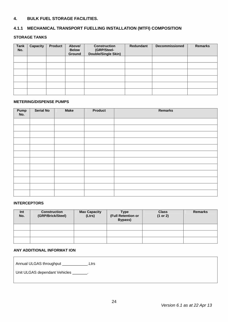
4. BULK FUEL STORAGE FACILITIES. 4.1.1 MECHANICAL TRANSPORT FUELLING INSTALLATION (MTFI) COMPOSITION STORAGE TANKS
Tank No.
Capacity Product Above/ Below
Ground
Construction (GRP/Steel-
Double/Single Skin)
Redundant
Decommissioned
Remarks
METERING/DISPENSE PUMPS
Pump No.
Serial No Make Product Remarks
INTERCEPTORS
Int No.
Construction (GRP/Brick/Steel)
Max Capacity (Ltrs)
Type (Full Retention or
Bypass)
Class (1 or 2)
Remarks
ANY ADDITIONAL INFORMAT ION Annual ULGAS throughput .Ltrs Unit ULGAS dependant Vehicles .
Version 6.1 as at 22 Apr 13
25
MTFI
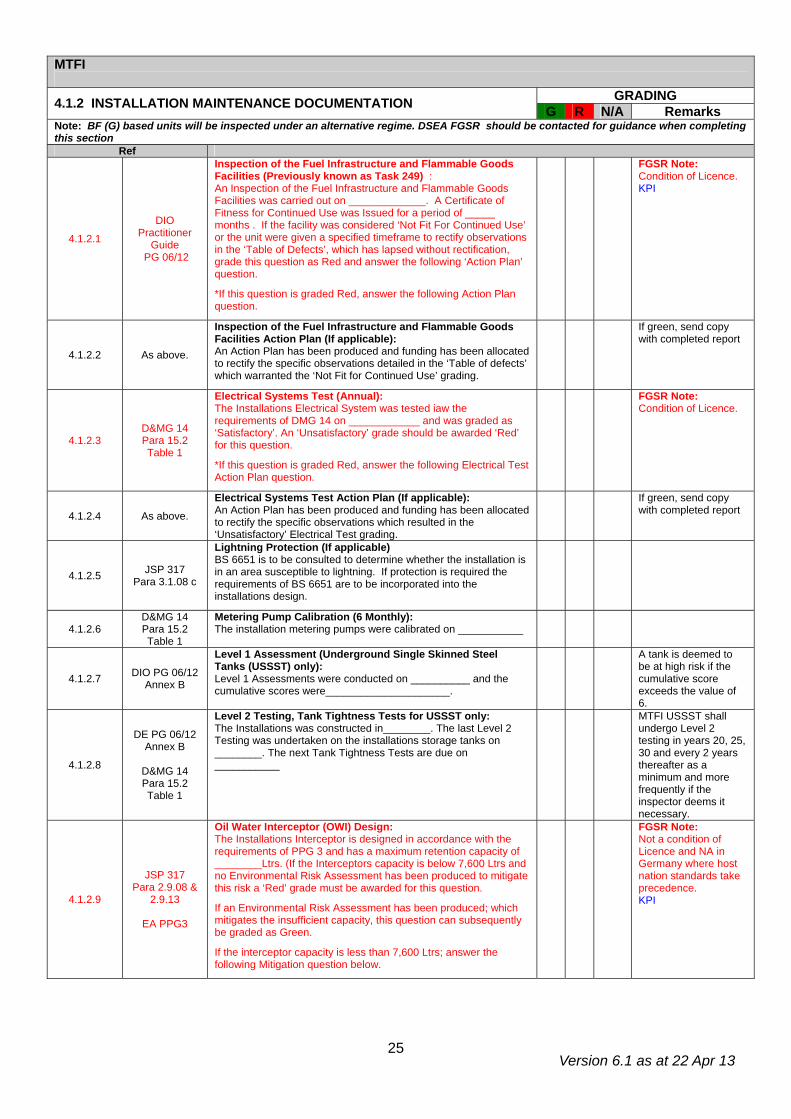
GRADING 4.1.2 INSTALLATION MAINTENANCE DOCUMENTATION G R N/A Remarks Note: BF (G) based units will be inspected under an alternative regime. DSEA FGSR should be contacted for guidance when completing this section
Ref
4.1.2.1
DIO Practitioner
Guide PG 06/12
Inspection of the Fuel Infrastructure and Flammable Goods Facilities (Previously known as Task 249) : An Inspection of the Fuel Infrastructure and Flammable Goods Facilities was carried out on _____________. A Certificate of Fitness for Continued Use was Issued for a period of _____ months . If the facility was considered ‘Not Fit For Continued Use’ or the unit were given a specified timeframe to rectify observations in the ‘Table of Defects’, which has lapsed without rectification, grade this question as Red and answer the following ‘Action Plan’ question.
*If this question is graded Red, answer the following Action Plan question.
FGSR Note: Condition of Licence. KPI
4.1.2.2 As above.
Inspection of the Fuel Infrastructure and Flammable Goods Facilities Action Plan (If applicable): An Action Plan has been produced and funding has been allocated to rectify the specific observations detailed in the ‘Table of defects’ which warranted the ‘Not Fit for Continued Use’ grading.
If green, send copy with completed report
4.1.2.3 D&MG 14 Para 15.2 Table 1
Electrical Systems Test (Annual): The Installations Electrical System was tested iaw the requirements of DMG 14 on ____________ and was graded as ‘Satisfactory’. An ‘Unsatisfactory’ grade should be awarded ‘Red’ for this question.
*If this question is graded Red, answer the following Electrical Test Action Plan question.
FGSR Note: Condition of Licence.
4.1.2.4 As above.
Electrical Systems Test Action Plan (If applicable): An Action Plan has been produced and funding has been allocated to rectify the specific observations which resulted in the ‘Unsatisfactory’ Electrical Test grading.
If green, send copy with completed report
4.1.2.5 JSP 317 Para 3.1.08 c
Lightning Protection (If applicable) BS 6651 is to be consulted to determine whether the installation is in an area susceptible to lightning. If protection is required the requirements of BS 6651 are to be incorporated into the installations design.
4.1.2.6 D&MG 14 Para 15.2 Table 1
Metering Pump Calibration (6 Monthly): The installation metering pumps were calibrated on ___________
4.1.2.7 DIO PG 06/12 Annex B
Level 1 Assessment (Underground Single Skinned Steel Tanks (USSST) only): Level 1 Assessments were conducted on __________ and the cumulative scores were_____________________.
A tank is deemed to be at high risk if the cumulative score exceeds the value of 6.
4.1.2.8
DE PG 06/12 Annex B
D&MG 14 Para 15.2 Table 1
Level 2 Testing, Tank Tightness Tests for USSST only: The Installations was constructed in________. The last Level 2 Testing was undertaken on the installations storage tanks on ________. The next Tank Tightness Tests are due on ___________
MTFI USSST shall undergo Level 2 testing in years 20, 25, 30 and every 2 years thereafter as a minimum and more frequently if the inspector deems it necessary.
4.1.2.9
JSP 317 Para 2.9.08 &
2.9.13
EA PPG3
Oil Water Interceptor (OWI) Design: The Installations Interceptor is designed in accordance with the requirements of PPG 3 and has a maximum retention capacity of ________Ltrs. (If the Interceptors capacity is below 7,600 Ltrs and no Environmental Risk Assessment has been produced to mitigate this risk a ‘Red’ grade must be awarded for this question.
If an Environmental Risk Assessment has been produced; which mitigates the insufficient capacity, this question can subsequently be graded as Green.
If the interceptor capacity is less than 7,600 Ltrs; answer the following Mitigation question below.
FGSR Note: Not a condition of Licence and NA in Germany where host nation standards take precedence. KPI
Version 6.1 as at 22 Apr 13
26
Ref G R N/A Remarks
4.1.2.10
JSP 317 5.3.01-5.3.05
OWI Mitigation - Pollution ERA: A Pollution ERA, which has been updated within the previous 12 months, has been produced to mitigate the increased risk created by the insufficient capacity.
If the Pollution ERA mitigates the insufficient capacity by demonstrating a work around solution, subsequent assessments can be assessed as Green.
FGSR Note: Not a condition of Licence and NA in Germany where host nation standards take precedence.
4.1.2.11
JSP 317 2.9.17a-d
DMG 14
Para 15.2 Table 1
OWI Maintenance: These assets are maintained under Project Aquatrine by Aquatrine Service Providers. As a minimum, every 6 months or iaw manufacturers’ instructions, OWIs should be physically inspected to:
• Confirm the quantity of accumulated F&L and silt and remove as necessary.
• Confirm that all electrical equipment is functioning correctly i.e Alarms.
• Inspect the Condition of any coalescing devices and replace if necessary.
The last inspection of the Interceptor was conducted by ___________ on ___________. If this date exceeds 6 months or the date of the last inspection can not be ascertained award a ‘Red’ grade for this question.
FGSR Note: Not a condition of Licence. In addition the Aquatrine contract only includes mainland UK units. In all other instances host nation standards will apply. KPI
GRADING 4.1.3 DESIGN G R N/A Remarks Ref
4.1.3.1 FGSR Notice
2011/01
If the installation dispenses Petroleum (IP Class 1)and the following criteria is met, a Stage 1b vapour recovery system must be fitted:
• Throughput is greater than 100,000 Ltrs per year. • The installation is in England or Wales
Installations in the Highlands and Islands of Scotland do not require vapour recovery.
4.1.3.2 1.2.16 An in-date Defence Safety & Environment Authority (DSEA) ‘Certificate for Continued Operation’ must be displayed at the installation control point.
4.1.3.3 1.4.34 All Metering pumps/dispensers shall be marked with the NATO product and grade identification markings.
4.1.3.4 2.5.01 Does the installation layout provide adequate escape routes for personnel and means of access for fire brigades in the event of fire?
4.1.3.5 2.5.14 Overhead Power Cables must not cross the Petroleum Hazardous Area.
4.1.3.6 2.8.07 b
Above Ground Storage Tanks- Secondary Containment The bund wall must be capable of retaining 110% of the largest container within the bund or 25% of the aggregate of multiple containers, whichever is greater.
FGSR Note: Not a condition of Licence.
4.1.3.7 2.8.14
Above Ground Storage Tanks- Secondary Containment The bund wall must: • Be impervious to liquid • Not normally be higher than 1.5m high. • Be fitted with crash protection if susceptible to impact damage
e.g adjacent to a vehicle manoeuvring area.
FGSR Note: Not a condition of Licence.
4.1.3.8 2.8.15
Above Ground Storage Tanks- Secondary Containment The bund wall must not be constructed too close to the tank to prevent jetting; a phenomenon caused when the primary container fails and F&L is propelled at force over the bund wall.
4.1.3.9 2.8.18
Above Ground Storage Tanks - Secondary Containment The bund base and walls must not be penetrated by any valve, pipe or other opening which is used for draining the bund. Where a tank fill pipe or draw off pipe must pass through the bund base or wall, the hole must be carefully sealed to prevent oil escaping.
FGSR Note: Not a condition of Licence.
4.1.3.10 2.8.19
Above Ground Storage Tanks - Secondary Containment Rainwater which collects in the sump must be removed on a regular basis to ensure the bund capacity is maintained. This water be disposed of appropriately to ensure no pollution occurs.
Version 6.1 as at 22 Apr 13
27
Ref G R N/A Remarks 4.1.3.11 2.8.20 Inspection of Bunds - Bunds should be regularly inspected for signs of
damage and checked for water by the operator on a weekly basis.
4.1.3.12 2.8.21 Above Ground Storage Tanks - Secondary Containment If oil or a mixture of oil and water is found in the bund it must be disposed of in accordance with current Hazardous Waste Regulations.
4.1.3.13 Oil Storage Regs 3 (3)
Above Ground Storage Tanks- Secondary Containment Valves should be as resistant to unauthorised interference and vandalism as far as is feasibly possible, with lockable or removable hand wheels.
4.1.3.14 OSR 01 Reg 3(3)
Above Ground Storage Tank- Secondary Containment s All tank vent pipes, valves, filters, sight gauges and any other ancillary equipment with the exception of the fill pipe, draw off pipe or pump if the fuel has a flashpoint of less than 32ºc, must be positioned within the bund wall.
4.1.3.15
OSR 01 Reg 3(3)
Above Ground Storage Tanks Valves should be marked to indicate whether they are open or closed, kept locked when not in use and fitted with a blanking cap or plug.
4.1.3.16 OSR 01
Guidance Para 38
The connection point is to be located inside bund wall or be located in a position which allows for containment.
4.1.3.17 2.8.22 a-e
Sight Glasses The use of sight glasses should be limited to the storage of Class II & III fuel tanks with a maximum capacity of 3500 Ltrs. If sight glasses are fitted they shall:
• Be located in the secondary containment. • Be properly supported so that they cannot come loose. • Be fitted with a valve that automatically closes when the sight glass
is not in use.
Have valves fitted which are kept closed when not in use and only opened when taking contents readings.
4.1.3.18 2.8.75
Small Tank Minimum Separation Distances. A small tank is considered to be a tank with a diameter of less than 10m. The minimum separation distances from site boundaries, fixed sources of ignition, buildings and process areas for single small tanks are as follows:
Tank Capacity (m³) Separation (m) Less than or equal to 1 1* Greater than 1 and less than or equal to 5 4 Greater than 5 and less than or equal to 33 6 Greater than 33 and less than or equal to 100 8
*In this instance the tank must be sited at least 2m from doors, plain glazed windows, other openings or means of escape. In addition they must not be below openings from an upper floor, regardless of vertical distance.
4.1.3.19 2.9.08-09
The installation must be protected by an independent Forecourt Separator/Oil Water Interceptor (OWI). Under no circumstances should waste water from washing, cleaning or fire fighting activities be discharged through a forecourt separator as the detergents will cause emulsification and render the device useless.
FGSR Note: Host nation standards take precedence in Germany.
4.1.3.20 2.9.15
The OWI must be fitted with a high-level alarm & automatic shut off valve.
FGSR Note: Host nation standards take precedence in Germany
4.1.3.21 2.10.01
The Road Tanker Delivery Stand should be located in a safe, well ventilated position in the open and should offer a clear, unobstructed forward escape route.
FGSR Note: Condition of Licence
4.1.3.22 2.10.02 a
The Road Tanker Delivery Stand – Attended. Prior to a bulk receipt at attended installations, the delivery driver must be presented with notices detailing safe delivery/receipt and emergency procedures. The driver is to read and sign the relevant notices to confirm they understand the procedures before commencing delivery.
4.1.3.23 2.10.02 h
The minimum recommended distance of a Road Tanker Delivery Stand from occupied buildings, the site boundary or a fixed source of ignition is 10m or the distance calculated on the DSEAR RA; whichever is greater. This does not apply to Bulk Waste, UETF, FFO and Domestic Heating Tanks.
FGSR Note: Condition of Licence
4.1.3.24 2.10.03
The Road Tanker Delivery Stand should be a minimum of 15m x 5m. If this isn’t practicable, signage and barriers are to be used to restrict vehicle and personnel access during transfer operations.
FGSR Note: Not a condition of Licence.
Version 6.1 as at 22 Apr 13
28
Ref G R N/A Remarks
4.1.3.25 2.10.04 The Road Tanker Delivery Stand should be substantially level to ensure full extraction during deliveries.
FGSR Note: Not a condition of Licence.
4.1.3.26 2.10.05
The Road Tanker Delivery Stand must be impermeable to hydrocarbons and be capable of withstanding the axle weight of a fully laden delivery tanker.
FGSR Note: Not a condition of Licence.
4.1.3.27 2.10.11
The Road Tanker Delivery Stand. Delivery stand gradients and perimeter drains shall be designed to accept a discharge rate of 16 litres per second for a period of 7 minutes over a 2m wide section of catchment channel, without overflowing.
FGSR Note: Not a condition of Licence and NA in Germany where host nation standards take precedence.
4.1.3.28 APEA Para 13.3.1
Vehicle Filling Area. Areas that are liable to contamination, such as the vehicle filling area, should be impermeable to all hydrocarbons and should not allow seepage through or below the surface. Areas such as these should always be protected at the perimeter by a suitable means of restraint such as kerbing, drainage channels or walling, to prevent the flow of contaminants towards permeable surfaces.
FGSR Note: Not a condition of Licence.
4.1.3.29 2.10.10
The following ‘Disconnect the Hose’ sign must be displayed at tanker Receipt/Issue points. The sign must be visible from the vehicle cab when the dispensing hose is connected to the installation:
4.1.3.30 3.1.14
The installation should have an effective means of both raising the alarm and giving warning in case of fire. It should be audible to all those likely to be effected by the fire. There must be access to a phone with in reasonable distance, which is to be clearly signposted.
4.1.3.31 APEA Para 4.4.5
Vent pipes for underground storage tanks must be a minimum of 4 m above ground level (5m for non-emission control systems). The vent discharge point on an emissions control system should not be within 3 m of opening windows in any direction or any other opening to a building. In addition, vent pipes should not be located within 2 m of the installation boundary (3 m for non-emission control systems).
4.1.3.32 3.1.15 (a)
If a vapour recovery system is fitted a sign stating “Connect vapour line before off-loading ” must be displayed at each vapour return hose connection point.
4.1.3.33 3.1.15 (b)
If a vapour recovery system is fitted a sign stating “Warning, this tank is manifolded. Isolate tank vent pipe before commencing any work” must be displayed at each tank connected to a common vapour collection point.
4.1.3.34 3.1.15 Fig 3.1.1
The following Hazard Warning Sign stating “Petroleum Spirit, Highly Flammable, No Smoking or Naked Flames, No Mobile Phones, Switch Off Engine” must be displayed on all approaches to the facility in the local language and English:
4.1.3.35 3.1.15 (c)
The following minimised sign stating “Petroleum Spirit, Highly Flammable, No Smoking or Naked Flames, No Mobile Phones, Switch Off Engine” must be displayed at each metering pump/dispenser, the control point and offset filling point (If applicable) in the local language and English:

Version 6.1 as at 22 Apr 13
29
Ref G R N/A Remarks
4.1.3.36 3.1.15 (d)
If any of the storage tanks have contained leaded petrol a label reading “This tank has contained leaded petroleum spirit. It must not be entered unless the prescribed regulations are complied with.” must be displayed at the opening of the tank.
4.1.3.37 D&MG 14 Para 4.2 a
The centre lines of any tank openings or offset filling points are not to be within 4 m from roads, occupied buildings or the installation boundary. Where a building is a domestic premises or premises housing vulnerable populations, e.g. schools, hospitals, an increased separation distance of up to 12 m is recommended.
4.1.3.38 D&MG 14 Para 4.2 b
Pipe work from tanks to offset filling points is to be routed below ground and in such a manner that access can be achieved after installation.
4.1.3.39 D&MG 14 Para 4.4
Metering pumps should be located in the open air where they can be adequately ventilated. The centre lines of the dispensing pumps must be a minimum of 9m from living accommodation, 6m from other occupied buildings, including the control room and must not be within 4m of access roads or the installation boundary or any access roads.
4.1.3.40 D&MG 14 13.2 h
At unattended installations the name and contact number of the person to be contacted in an emergency should be displayed in an area adjacent to the emergency telephone.
4.1.3.41 APEA Para 9.6.8
All unattended self service (USS) sites must have the nozzle trigger latching mechanisms removed or disarmed. In addition the dispensing area(s) and position(s) of any emergency equipment should have adequate illumination.
4.1.3.42 D&MG 14 Para 4.6
The Control Point at attended Installations should be located where the operator can provide supervision over fuelling activities. The view must not be obstructed by other buildings, structures or by a road tanker positioned for a fuel delivery.
4.1.3.43 D&MG 14 Para 4.7
Interceptor vent pipes must extend to a minimum of 2.4 m above ground level and must not be within 3 m of access roads or building apertures.
FGSR Note: Vent pipes in Germany must be Stadt approved.
4.1.3.44 D&MG 14 Para 6.1 c
All Tank vent pipes should be identified by their associated tank number.
4.1.3.45 D&MG 14 Para 6.1 c
All fill/receipt points should be identified with the number, fuel type and capacity of the associated tank.
4.1.3.46 APEA Para 11.6
Tank Contents Measurement Method. All tanks or compartments should be provided with a means of ascertaining the quantity of fuel stored. This may be by use of a dipstick or by some means of tank contents gauge. Indicate which method is used in the remarks column.
Manual Dip* Auto Tank Gauge* *Delete as applicable
4.1.3.47 D&MG 14 Para 6.4 d
The storage tanks are fitted with overfill prevention devices or the unit have adopted a suitable operating procedure to prevent overfilling.
4.1.3.48 D&MG 14 Para 6.7 a
For petrol installations the tank vent pipe is to be fitted above ground with a flame arrestor, designed to BS 7244.
4.1.3.49 D&MG 14 9.3 b
The mains electric incoming switch must be labelled “MAINS ISOLATING SWITCH”.
4.1.3.50 D&MG 14 9.3 g
Supplies to AFDS, Wet Stock Management (WSM) systems and leak detection systems must be fed by individual dedicated circuits. Miniature circuit breakers feeding such circuits are to be clearly labelled. “DO NOT SWITCH OFF”.
4.1.3.51 D&MG 14 9.3 h
The emergency switch to disconnect all pumps/dispensers and their associated equipment from the installation should be clearly identified with a sign stating “FUEL PUMPS SWITCH OFF HERE”.
4.1.3.52 D&MG 14 9.5 r
A permanent label is to be fitted at all earthing and bonding connection points stating “SAFETY ELECTRICAL CONNECTION – DO NOT REMOVE”
4.1.3.53 DMG 14 Para 11 b
If a canopy is fitted the minimum height from the ground to the underside of the lowest part of the canopy is to be 5.3m.
FGSR Note: The max height sign may be less than 5.3m however the actual height of the canopy should be an additional 1m.
Version 6.1 as at 22 Apr 13
30
GRADING 4.1.4 FIRE, HEALTH & SAFETY G R N/A Remarks Ref
4.1.4.1 1.4.26 Above ground storage tanks are to be marked with the correct NATO Product and Grade Identification markings. These markings must be visible from all directions.
4.1.4.2 1.4.27 Above ground Class I tanks shall be marked with ‘Highly Flammable, No Smoking, No Naked Lights’.
4.1.4.3 1.4.28 Above ground Class II tanks shall be marked ‘Flammable Liquid, No Smoking, No Naked Lights’.
4.1.4.4 2.2.48 e-h
Washing & changing facilities are to be provided for personnel at the place of work. In addition, the following items must also be provided:
• Barrier Cream and After Work Cream. • Eyewash (In Date). • Emergency First Aid Kit.
4.1.4.5 2.2.48 i Appropriate Personal Protective Equipments (PPE) and Respiratory Protective Equipment (RPE) is provided and used by all operators.
4.1.4.6 2.5.06 & 2.5.07
A comprehensive fire plan is to be provided for all locations storing and handling petroleum products. It should include details of :
• Fire detection and alarm systems • Water and other chemical fire fighting agents • Fire fighting equipment • Emergency shut down procedures • Emergency evacuation procedures & assembly points • Staff fire training • Duties of persons nominated in the plan • Arrangements for testing and updating the plan
FGSR Note: Example Fire Plan provided on JSP 317 website.
4.1.4.7 2.5.08 (b)
If the installation is unmanned i.e. it has a Ground Fuel Management System (GFMS), a telephone must be provided. If the installation is manned the attendant must know the location of the nearest telephone.
4.1.4.8 2.5.10
Fire Safety Notices & Fire Action Notices must be displayed in order to comply with the Health and Safety (Safety Signs and Signals) Regulations 1996. Locations and quantities should relate to the local risks and be the result of a risk assessment.
4.1.4.9 2.5.11
Smoking or Smoking materials are not permitted in the hazardous area. Personnel are to deposit any smoking materials in a safe designated contraband area before entering a hazardous zone or likely hazardous area.
4.1.4.10 3.1.20 A high standard of cleanliness is to be maintained at the installation. Rubbish of any kind must not be allowed to accumulate, and the growth of vegetation is to be controlled so as not to present a fire hazard.
4.1.4.11 2.5.17
Grass and Vegetation is to be cut back to a minimum of 15m. Isolated deciduous trees are permitted but conifers must be removed. Grass cutting and removal of vegetation must be carried out iaw the MoD Safety Rules and Procedures for Work on Petroleum installations.
4.1.4.12 2.5.28 Table 2.5.1
The quantity and location of Fire Fighting apparatus will be determined by the Unit Fire Officer, however as a minimum requirement 2 x 9 Ltr Foam extinguishers should be provided for the first four dispense pumps. An additional extinguisher will be required for each additional two pumps.
4 = 2 10 = 5 5 = 2 11 = 5 6 = 3 12 = 6 7 = 3 13 = 6 8 = 4 14 = 7 9 = 4 15 = 7
GRADING 4.1.5 ENVIRONMENTAL PROTECTION G R N/A Remarks Ref
4.1.5.1 2.5.13 b Spillages to be mopped up immediately using approved absorbent material which must be removed from the area for safe disposal.
4.1.5.2 3.1.28
A Pollution Control Point (PCP) should be established close to the MTFI. In addition to the Pollution Control Sorbents (PCS) which are held within the PCP, the following additional items should also be held:
• Dustpan and Brush. • Stiff Broom. • Heavy duty plastic sacks and ties.
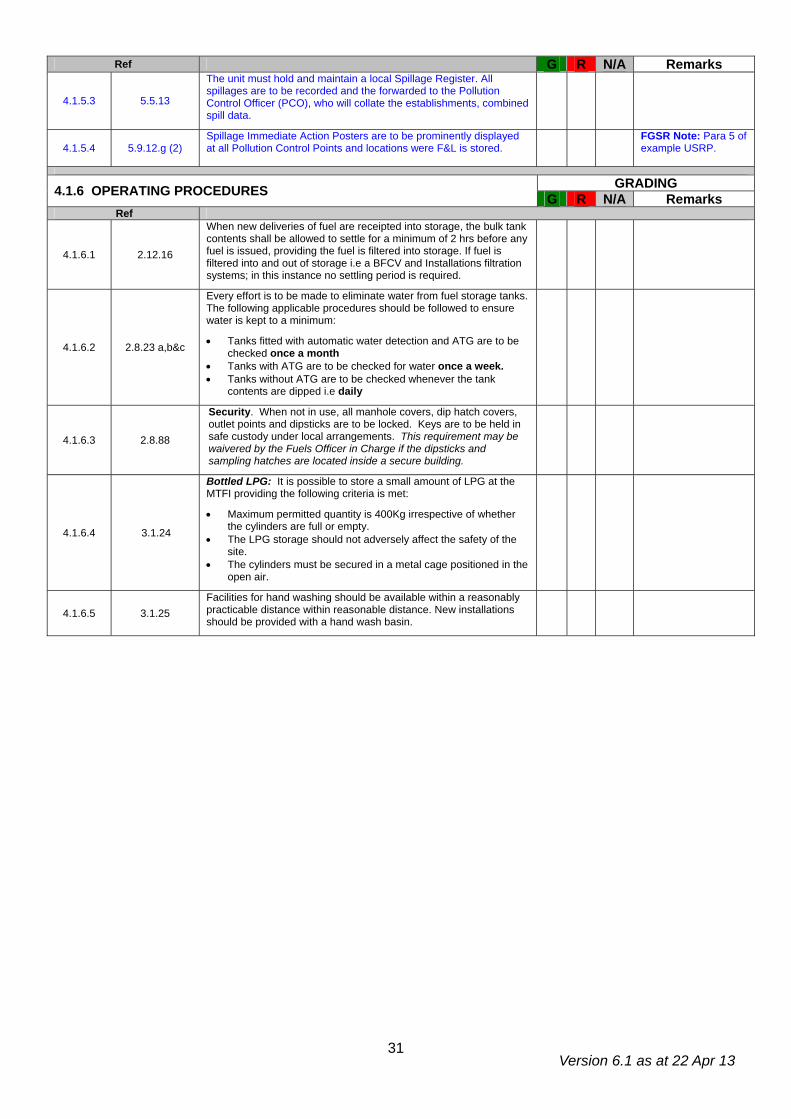
Version 6.1 as at 22 Apr 13
31
Ref G R N/A Remarks
4.1.5.3 5.5.13
The unit must hold and maintain a local Spillage Register. All spillages are to be recorded and the forwarded to the Pollution Control Officer (PCO), who will collate the establishments, combined spill data.
4.1.5.4 5.9.12.g (2) Spillage Immediate Action Posters are to be prominently displayed at all Pollution Control Points and locations were F&L is stored.
FGSR Note: Para 5 of example USRP.
GRADING 4.1.6 OPERATING PROCEDURES G R N/A Remarks Ref
4.1.6.1 2.12.16
When new deliveries of fuel are receipted into storage, the bulk tank contents shall be allowed to settle for a minimum of 2 hrs before any fuel is issued, providing the fuel is filtered into storage. If fuel is filtered into and out of storage i.e a BFCV and Installations filtration systems; in this instance no settling period is required.
4.1.6.2 2.8.23 a,b&c
Every effort is to be made to eliminate water from fuel storage tanks. The following applicable procedures should be followed to ensure water is kept to a minimum:
• Tanks fitted with automatic water detection and ATG are to be checked once a month
• Tanks with ATG are to be checked for water once a week. • Tanks without ATG are to be checked whenever the tank
contents are dipped i.e daily
4.1.6.3 2.8.88
Security. When not in use, all manhole covers, dip hatch covers, outlet points and dipsticks are to be locked. Keys are to be held in safe custody under local arrangements. This requirement may be waivered by the Fuels Officer in Charge if the dipsticks and sampling hatches are located inside a secure building.
4.1.6.4 3.1.24
Bottled LPG: It is possible to store a small amount of LPG at the MTFI providing the following criteria is met:
• Maximum permitted quantity is 400Kg irrespective of whether the cylinders are full or empty.
• The LPG storage should not adversely affect the safety of the site.
• The cylinders must be secured in a metal cage positioned in the open air.
4.1.6.5 3.1.25 Facilities for hand washing should be available within a reasonably practicable distance within reasonable distance. New installations should be provided with a hand wash basin.
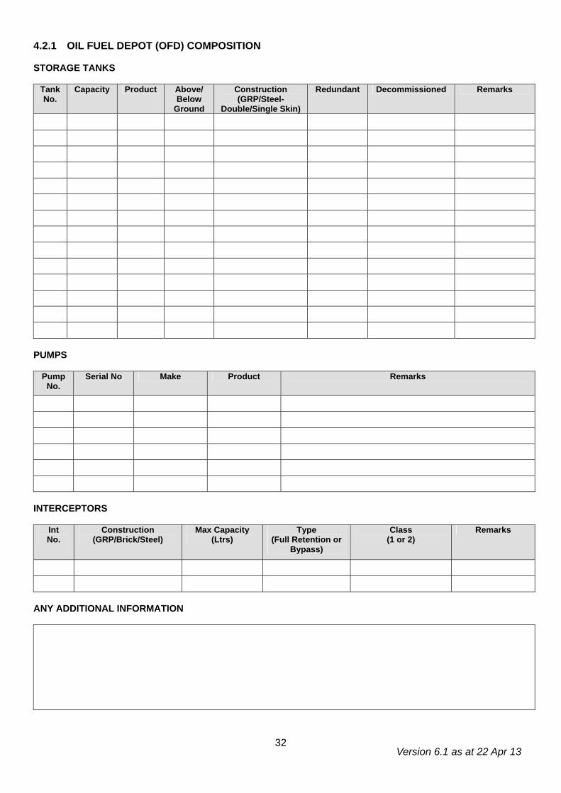
Version 6.1 as at 22 Apr 13
32
4.2.1 OIL FUEL DEPOT (OFD) COMPOSITION STORAGE TANKS
Tank No.
Capacity Product Above/ Below
Ground
Construction (GRP/Steel-
Double/Single Skin)
Redundant Decommissioned Remarks
PUMPS
Pump No.
Serial No Make Product Remarks
INTERCEPTORS
Int No.
Construction (GRP/Brick/Steel)
Max Capacity (Ltrs)
Type (Full Retention or
Bypass)
Class (1 or 2)
Remarks
ANY ADDITIONAL INFORMATION
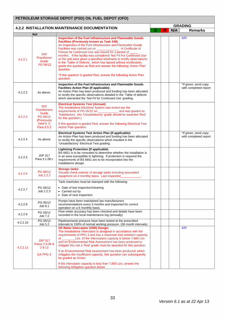
Version 6.1 as at 22 Apr 13
33
PETROLEUM STORAGE DEPOT (PSD) OIL FUEL DEPOT (OFD)
GRADING 4.2.2 INSTALLATION MAINTENANCE DOCUMENTATION G R N/A Remarks Ref
4.2.2.1
DIO Practitioner
Guide PG 06/12
Inspection of the Fuel Infrastructure and Flammable Goods Facilities (Previously known as Task 249) : An Inspection of the Fuel Infrastructure and Flammable Goods Facilities was carried out on _____________. A Certificate of Fitness for Continued Use was Issued for a period of _____ months . If the facility was considered ‘Not Fit For Continued Use’ or the unit were given a specified timeframe to rectify observations in the ‘Table of Defects’, which has lapsed without rectification, grade this question as Red and answer the following ‘Action Plan’ question.
*If this question is graded Red, answer the following Action Plan question.
KPI
4.2.2.2 As above.
Inspection of the Fuel Infrastructure and Flammable Goods Facilities Action Plan (If applicable): An Action Plan has been produced and funding has been allocated to rectify the specific observations detailed in the ‘Table of defects’ which warranted the ‘Not Fit for Continued Use’ grading.
*If green, send copy with completed report
4.2.2.3
DIO Practitioners
Guide PG 05/12
(Previously DWFS 7) Para 6.5.3
Electrical Systems Test (Annual): The Installations Electrical System was tested iaw the requirements of PG 05/12 on ____________ and was graded as ‘Satisfactory’. (An ‘Unsatisfactory’ grade should be awarded ‘Red’ for this question.)
If this question is graded Red, answer the following Electrical Test Action Plan question.
4.2.2.4 As above
Electrical Systems Test Action Plan (If applicable): An Action Plan has been produced and funding has been allocated to rectify the specific observations which resulted in the ‘Unsatisfactory’ Electrical Test grading.
*If green, send copy with completed report
4.2.2.5 JSP 317 Para 3.1.08 c
Lightning Protection (If applicable) BS 6651 is to be consulted to determine whether the installation is in an area susceptible to lightning. If protection is required the requirements of BS 6651 are to be incorporated into the installations design.
4.2.2.6 PG 05/12 Job 2.2.2
Storage tanks: Visually check exterior of storage tanks including associated equipment on 3 monthly basis. Last inspected____________.
4.2.2.7 PG 05/12 Job 2.2.3
Tank manholes must be stamped with the following:
• Date of last inspection/cleaning • Carried out by • Date of next inspection
4.2.2.8 PG 05/12 Job 8.1
Pumps have been maintained iaw manufacturers recommendations every 3 months and inspected for correct operation on a 6 monthly basis.
4.2.2.9 PG 05/12 Job 7.2
Flow meter accuracy has been checked and details have been recorded in the local maintenance log (annually)
4.2.2.10 PG 05/12 Job 5.2
Pipelines/work pressure have been tested at the prescribed intervals to 150% of normal working pressure. (36 month intervals)
4.2.2.11
JSP 317 Paras 2.9.08 &
2.9.13
EA PPG 3
Oil Water Interceptor (OWI) Design: The Installations Interceptor is designed in accordance with the requirements of PPG 3 and has a maximum fuel retention capacity of ________Ltrs. (If the Interceptors capacity is below 7,600 Ltrs and no Environmental Risk Assessment has been produced to mitigate this risk a ‘Red’ grade must be awarded for this question.
If an Environmental Risk Assessment has been produced; which mitigates the insufficient capacity, this question can subsequently be graded as Green.
If the interceptor capacity is less than 7,600 Ltrs; answer the following Mitigation question below
KPI
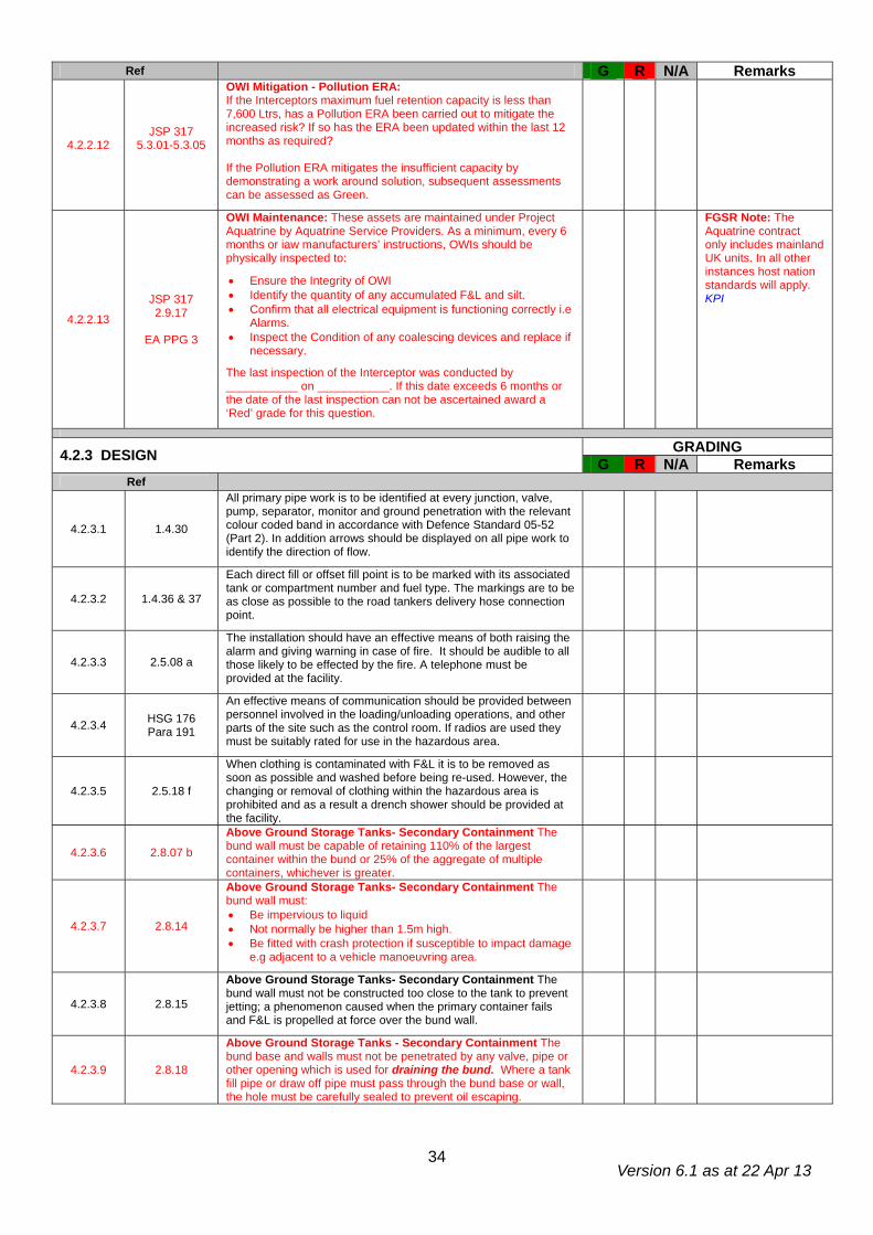
Version 6.1 as at 22 Apr 13
34
Ref G R N/A Remarks
4.2.2.12 JSP 317
5.3.01-5.3.05
OWI Mitigation - Pollution ERA: If the Interceptors maximum fuel retention capacity is less than 7,600 Ltrs, has a Pollution ERA been carried out to mitigate the increased risk? If so has the ERA been updated within the last 12 months as required? If the Pollution ERA mitigates the insufficient capacity by demonstrating a work around solution, subsequent assessments can be assessed as Green.
4.2.2.13 JSP 317 2.9.17
EA PPG 3
OWI Maintenance: These assets are maintained under Project Aquatrine by Aquatrine Service Providers. As a minimum, every 6 months or iaw manufacturers’ instructions, OWIs should be physically inspected to:
• Ensure the Integrity of OWI • Identify the quantity of any accumulated F&L and silt. • Confirm that all electrical equipment is functioning correctly i.e
Alarms. • Inspect the Condition of any coalescing devices and replace if
necessary.
The last inspection of the Interceptor was conducted by ___________ on ___________. If this date exceeds 6 months or the date of the last inspection can not be ascertained award a ‘Red’ grade for this question.
FGSR Note: The Aquatrine contract only includes mainland UK units. In all other instances host nation standards will apply. KPI
GRADING 4.2.3 DESIGN G R N/A Remarks Ref
4.2.3.1 1.4.30
All primary pipe work is to be identified at every junction, valve, pump, separator, monitor and ground penetration with the relevant colour coded band in accordance with Defence Standard 05-52 (Part 2). In addition arrows should be displayed on all pipe work to identify the direction of flow.
4.2.3.2 1.4.36 & 37
Each direct fill or offset fill point is to be marked with its associated tank or compartment number and fuel type. The markings are to be as close as possible to the road tankers delivery hose connection point.
4.2.3.3 2.5.08 a
The installation should have an effective means of both raising the alarm and giving warning in case of fire. It should be audible to all those likely to be effected by the fire. A telephone must be provided at the facility.
4.2.3.4 HSG 176 Para 191
An effective means of communication should be provided between personnel involved in the loading/unloading operations, and other parts of the site such as the control room. If radios are used they must be suitably rated for use in the hazardous area.
4.2.3.5 2.5.18 f
When clothing is contaminated with F&L it is to be removed as soon as possible and washed before being re-used. However, the changing or removal of clothing within the hazardous area is prohibited and as a result a drench shower should be provided at the facility.
4.2.3.6 2.8.07 b
Above Ground Storage Tanks- Secondary Containment The bund wall must be capable of retaining 110% of the largest container within the bund or 25% of the aggregate of multiple containers, whichever is greater.
4.2.3.7 2.8.14
Above Ground Storage Tanks- Secondary Containment The bund wall must: • Be impervious to liquid • Not normally be higher than 1.5m high. • Be fitted with crash protection if susceptible to impact damage
e.g adjacent to a vehicle manoeuvring area.
4.2.3.8 2.8.15
Above Ground Storage Tanks- Secondary Containment The bund wall must not be constructed too close to the tank to prevent jetting; a phenomenon caused when the primary container fails and F&L is propelled at force over the bund wall.
4.2.3.9 2.8.18
Above Ground Storage Tanks - Secondary Containment The bund base and walls must not be penetrated by any valve, pipe or other opening which is used for draining the bund. Where a tank fill pipe or draw off pipe must pass through the bund base or wall, the hole must be carefully sealed to prevent oil escaping.
Version 6.1 as at 22 Apr 13
35
Ref G R N/A Remarks
4.2.3.10 2.8.19
Above Ground Storage Tanks - Secondary Containment Rainwater which collects in the sump must be removed on a regular basis to ensure the bund capacity is maintained. This water be disposed of appropriately to ensure no pollution occurs.
4.2.3.11 2.8.20 Inspection of Bunds - Bunds should be regularly inspected for signs of damage and checked for water by the operator on a weekly basis.
4.2.3.12 HSG 176 Para 104
Pumps are potential ignition sources and should be located outside the bund, on an impervious base, preferably in the open air. The minimum recommended safety distance from buildings, boundaries and sources of ignition is 7.5m for a large standard pump, however this can be reduced to 3m if the pumps capacity is <100m3/ hr.
4.2.3.13 HSG 176 Para 151
The bund should not be used for the storage of flammable liquid containers, gas cylinders (full or empty) or other hazardous substances.
4.2.3.14 2.8.21 Above Ground Storage Tanks - Secondary Containment If oil or a mixture of oil and water is found in the bund it must be disposed of in accordance with current Hazardous Waste Regulations.
4.2.3.15 Oil
Storage Regs 3 (3)
Above Ground Storage Tanks- Secondary Containment Valves should be as resistant to unauthorised interference and vandalism as far as is feasibly possible, with lockable or removable hand wheels.
4.2.3.16 OSR 01 Reg 3(3)
Above Ground Storage Tank- Secondary Containment All tank vent pipes, valves, filters, sight gauges and any other ancillary equipment with the exception of the fill pipe, draw off pipe or pump if the fuel has a flashpoint of less than 32ºc, must be positioned within the bund wall.
4.2.3.17
OSR 01 Reg 3(3)
Above Ground Storage Tanks Valves should be marked to indicate whether they are open or closed, kept locked when not in use and fitted with a blanking cap or plug.
4.2.3.18 2.8.75
Above Ground Storage Tanks - Separation distances for ‘small’ tanks. A small tank is considered to be a tank with a diameter of less than 10m. The minimum separation distances from site boundaries, fixed sources of ignition, buildings and process areas for single small tanks are as follows:
Tank Capacity (m³) Separation (m) Less than or equal to 1 1* Greater than 1 and less than or equal to 5 4 Greater than 5 and less than or equal to 33 6 Greater than 33 and less than or equal to 100 8 Greater than 100 and less than or equal to 250 10 Greater than 250 15
*In this instance the tank must be sited at least 2m from doors, plain glazed windows, other openings or means of escape. In addition they must not be below any openings from an upper floor, regardless of vertical distance.
4.2.3.19 2.8.78
Above Ground Storage Tanks - Separation distances for groups of ‘small’ tanks . For the purpose of determining the safe separation distances from site boundaries, buildings, process areas and fixed sources of ignition a group of small tanks may be regarded as one tank. The minimum distances for such tanks are as follows:
Tank Capacity (m³) Separation (m) Less than or equal to 3 1* Greater than 3 and less than or equal to 15 4 Greater than 15 and less than or equal to 100 6 Greater than 100 and less than or equal to 300 8 Greater than 300 and less than or equal to 750 10 Greater than 750 and less than or equal to 8000 15
*In this instance the tank must be sited at least 2m from doors, plain glazed windows, other openings or means of escape. In addition they must not be below any openings from an upper floor, regardless of vertical distance.
4.2.3.20 2.8.58 Electrical installations must be designed, installed and maintained in accordance with the current construction standards and comply with the hazardous area in which they are located.
4.2.3.21 2.8.59 All metal parts of the installation should be bonded together and earthed to prevent the accumulation of electrostatic charge.
Version 6.1 as at 22 Apr 13
36
Ref G R N/A Remarks
4.2.3.22 2.8.65
A schematic diagram showing the installation layout and valve numbering is to be mounted and displayed in a prominent position in the pump house or other suitable location at the installation.
4.2.3.23 2.8.65 All installation valves are to be numbered using a disc no smaller than 100 mm in diameter. All valves must correspond exactly with the information provided on the schematic.
4.2.3.24 2.8.88 Security. When not in use, all manhole covers, dip hatch covers, outlet points and dipsticks are to be locked. Keys are to be held in safe custody under local arrangements.
4.2.3.25 2.8.89 To prevent trespassing or tampering storage areas are to be enclosed by a substantial fence of at least 1.8m high, constructed of welded mesh or chain link.
4.2.3.26 2.9.06 The installation has an integral Full Retention Separator/Oil Water Interceptor (OWI) which offers sufficient environmental protection to the surrounding area.
4.2.3.27 2.9.15 The OWI must be fitted with a high-level alarm & automatic shut off valve.
4.2.3.28 2.10.01 The Road Tanker Delivery Stand should be located in a safe, well ventilated position in the open and should offer a clear, unobstructed forward escape route.
4.2.3.29 2.10.02 a
The Road Tanker Delivery Stand – Attended. Prior to a bulk receipt at attended installations, the delivery driver must be presented with notices detailing safe delivery/receipt and emergency procedures. The driver is to read and sign the relevant notices to confirm they understand the procedures before commencing delivery.
4.2.3.30 2.10.02 h
The minimum recommended distance of a Road Tanker Delivery Stand from occupied buildings, the site boundary or a fixed source of ignition is 10m or the distance calculated on the DSEAR RA; whichever is greater. This does not apply to Bulk Waste, UETF, FFO and Domestic Heating Tanks.
4.2.3.31 2.10.03
The Road Tanker Delivery Stand should be a minimum of 15m x 5m. If this isn’t practicable, signage and barriers are to be used to restrict vehicle and personnel access during transfer operations.
4.2.3.32 2.10.04 The Road Tanker Delivery Stand should be substantially level to ensure full extraction during deliveries.
4.2.3.33 2.10.05 The Road Tanker Delivery Stand must be impermeable to hydrocarbons and be capable of withstanding the axle weight of a fully laden delivery tanker.
4.2.3.34 2.10.10
The following ‘Disconnect the Hose’ sign must be displayed at tanker Receipt/Issue points. The sign must be visible from the vehicle cab when the dispensing hose is connected to the installation:
4.2.3.35 2.10.13
In addition to the Road Tanker Delivery Stand, traffic areas should also be impermeable to hydrocarbons and be capable of holding any spilled residue until such time as the drainage system can accept and convey the spillage to the OWI.
4.2.3.36 2.10.14
Roadways shall be laid out to provide easy access to and from all parts of the installation. A one-way traffic system should be adopted whenever possible, particularly in areas where vehicles are loaded and unloaded.
4.2.3.37 2.10.15
Roads shall be designed to enable all-weather access to tanks for fire-fighting purposes. Where 2-way traffic is encountered the width of the road shall be sufficient to allow 2 vehicles to pass. Single-track roads shall be provided with lay-byes. Curvatures, contours, bearing strengths, junctions and clearance heights shall accommodate the largest vehicles, including emergency vehicles, likely to use the roads.
Version 6.1 as at 22 Apr 13
37
Ref G R N/A Remarks
4.2.3.38 2.10.16
Working areas associated with storage tanks, including loading and unloading points, should be adequately lit when in use. An average luminance of at least 50 lux is recommended at ground level, on stairs at access platforms etc. It may be necessary to increase this to 100 lux where perception of detail is required, for example to read level gauges.
4.2.3.39 2.10.17
Bonding. Bulk fuel dispense and receipt points shall be provided with a bonding cable. The bonding cable shall be connected to the fixed earth network, which in turn will be connected to the dispense/ receipt pipeline.
4.2.3.40 3.1.15 Fig 3.1.1
The following Hazard Warning Sign must be displayed on all approaches to the facility in the local language and English:
4.2.3.41 3.1.20 A high standard of cleanliness is to be maintained at the installation. Rubbish of any kind must not be allowed to accumulate, and the growth of vegetation is to be controlled so as not to present a fire hazard.
GRADING 4.2.4 FIRE, HEALTH & SAFETY G R N/A Remarks Ref
4.2.4.1 1.4.26 Above ground storage tanks are to be marked with the correct NATO Product and Grade Identification markings. These markings must be visible from all directions.
4.2.4.2 1.4.27 Class I tanks shall be marked with ‘Highly Flammable, No Smoking, No Naked Lights’.
4.2.4.3 1.4.28 Class II tanks shall be marked ‘Flammable Liquid, No Smoking, No Naked Lights’.
4.2.4.4 2.2.48 e-h
Washing & changing facilities are to be provided for personnel at the place of work. In addition, the following items must also be provided:
• Barrier Cream and After Work Cream. • Eyewash (In Date). • Emergency First Aid Kit.
4.2.4.5 2.2.48 i Appropriate Personal Protective Equipments (PPE) and Respiratory Protective Equipment (RPE) is provided and used by all operators.
4.2.4.6 2.5.01 & 2.5.29
The quantity and location of all fire fighting equipment, which is determined by the Unit Fire Officer, must reflect what is stated in the Fire Safety Risk Assessment (FSRA).
4.2.4.7 2.5.06 & 2.5.07
A comprehensive fire plan is to be provided for all locations storing and handling petroleum products. It should include details of :
• Fire detection and alarm systems • Water and other chemical fire fighting agents • Fire fighting equipment • Emergency shut down procedures • Emergency evacuation procedures & assembly points • Staff fire training • Duties of persons nominated in the plan • Arrangements for testing and updating the plan
FGSR Note: Example Fire Plan provided on JSP 317 website.
4.2.4.8 2.5.10
Fire Safety Notices & Fire Action Notices must be displayed in order to comply with the Health and Safety (Safety Signs and Signals) Regulations 1996. Locations and quantities should relate to the local risks and be the result of a risk assessment.
4.2.4.9 2.5.11
Smoking or Smoking materials are not permitted in the hazardous area. Personnel are to deposit any smoking materials in a safe designated contraband area before entering a hazardous zone or likely hazardous area.
Version 6.1 as at 22 Apr 13
38
Ref G R N/A Remarks
4.2.4.10 HSG 176 Para 151
Combustible material such as vegetation, litter or rubbish should not be allowed to accumulate in the bund as this will increase the risk of fire.
4.2.4.11 2.5.17
Grass and Vegetation is to be cut back to a minimum of 15m. Isolated deciduous trees are permitted but conifers must be removed. Grass cutting and removal of vegetation must be carried out iaw the MoD Safety Rules and Procedures for Work on Petroleum installations.
GRADING 4.2.5 ENVIRONMENTAL PROTECTION G R N/A Remarks Ref
4.2.5.1 2.5.13 b Spillages to be mopped up immediately using approved absorbent material which must be removed from the area for safe disposal.
4.2.5.2 5.3.16 h A Pollution Control Point (PCP) is to be established at the installation. The PCP must be clearly identifiable, stocked appropriately and be maintained on a regular basis.
4.2.5.3 5.5.13
The unit must hold and maintain a local Spillage Register. All spillages are to be recorded and the forwarded to the Pollution Control Officer (PCO), who will collate the establishments, combined spill data.
4.2.5.4 5.9.12.g (2) Spillage Immediate Action Posters are to be prominently displayed at all Pollution Control Points and locations were F&L is stored.
FGSR Note: Para 5 of example USRP.
GRADING 4.2.6 OPERATING PROCEDURES G R N/A Remarks Ref
4.2.6.1 2.8.23
Elimination of Water from Storage Tanks.
The presence of water in storage tanks can give rise to microbiological contamination, and the leaching out of additives. Every effort is to be made to eliminate water in storage tanks. To ensure that water in fuel tanks is kept to a minimum, the following procedures are to be applied:
• Tanks fitted with automatic water detection and an integrated water removal systems, or automatic tank gauges (ATG), compliant with STANAG 7011, are to be checked for water once a month.
• Tanks fitted with an ATG, compliant with STANAG 7011, are to be checked for water once a week. Where the tank has not issued or received fuel during the previous week, or where local conditions preclude weekly water checks from being conducted, the frequency of checks may be extended to a period not exceeding one month.
• Tanks which are not fitted with an ATG are to be checked for water whenever the tank contents are dipped. If water is detected in a tank that is not fitted with an automatic water detection system which incorporates an integrated water removal system, a works service request is to be raised for its immediate removal. The results of all water checks are to be recorded and stock adjustments made in accordance with JSP 886.
4.2.6.2 2.12.07
The following basic Quality Control measures are instigated at the installation:
• Documentation is checked prior to receipt of any fuel to confirm correct product and grade is being delivered.
• A sample is to be taken from the tanker prior to commencing receipt operations. Sample must be clear and free from suspended matter and water.
• Observe proper maintenance procedures for all facilities. Ensure the correct use and placement of filtration equipment.
Version 6.1 as at 22 Apr 13
39
Ref G R N/A Remarks
4.2.6.3 2.12.15
Before any product is transferred into storage the following actions must be taken:
• All storage tanks to be used must be suitable for the product and if empty, certified clean. If they contain product it must be of the same grade, free from contamination and within specification and retest date
• All filters, connections and associated pipe work must be checked to ensure cleanliness, correct connection and operation. All hatches are to be secured to avoid the ingress of water and other contaminants.
4.2.6.4 2.12.16
When new deliveries of fuel are receipted into storage, the bulk tank contents shall be allowed to settle for a minimum of 2 hrs before any fuel is issued, providing the fuel is filtered into storage. If fuel is filtered into and out of storage i.e a BFCV and Installations filtration systems; in this instance no settling period is required.
4.2.6.5 JSP 886 Vol
6 Sec 2 Page 114
Frequency of Dips
Daily. All In Use bulk fuel storage tanks and Bulk Fuel carrying Vehicles (BFCV), are to be dipped daily. This can be carried out by ATG (if accurate to +/- 1mm and +/- 0.5oC) or manually and, whenever possible before issues of the day.
Weekly. The dip, water check and temperature measurement (temperature is not required for BFCVs) of all bulk storage tanks, and BFCVs, including those where no fuel movement has taken place, is to be carried out once a week under the supervision of an authorised officer, normally Fridays.
Last Working Day of the Month. Dips are to be carried out on the last working day of the month, following the procedures at Paragraph 3b above and under the supervision of an authorised officer (OC Supply at RAF Units).
4.2.6.6 3.1.10
Turnover of Stocks Stocks are always to be issued on the principle of using oldest stock first. The age of stock is to be assessed by the length of time it has been in storage in the installation. Where an installation has two or more tanks, the tanks are to be filled and emptied in rotation.
Version 6.1 as at 22 Apr 13
40
4.3.1 AVIATION BULK FUEL INSTALLATIONS (BFI) COMPOSITION STORAGE TANKS
Tank No.
Capacity Product Above/ Below
Ground
Construction (GRP/Steel-
Double/Single Skin)
Redundant Decommissioned Remarks
METERING/DISPENSE PUMPS
Pump No.
Serial No. Make Product Remarks
FILTER WATER SEPARATORS
Coalescer Elements Differential Pressure Gauge FWS No.
Serial No. Make Date installed Calibrated Last Inspected
Date Pressure Relief Valve
Tested to 110% Remarks
INTERCEPTORS
Int No.
Construction (GRP/Brick/Steel)
Max Capacity (Ltrs)
Type (Full Retention or Bypass)
Class (1 or 2)
Remarks
Version 6.1 as at 22 Apr 13
41
AVIATION BULK FUEL INSTALLATION
GRADING 4.3.2 INSTALLATION MAINTENANCE DOCUMENTATION G R N/A Remarks Note: BF(G) based units will be inspected under an alternative regime. DSEA FGSR should be contacted for guidance when completing this section.
Ref
4.3.2.1
DIO Practitioner
Guide PG 06/12 (Previously PG 01/09)
Inspection of the Fuel Infrastructure and Flammable Goods Facilities (Previously known as Task 249) : An Inspection of the Fuel Infrastructure and Flammable Goods Facilities was carried out on _____________. A Certificate of Fitness for Continued Use was Issued for a period of _____ months . If the facility was considered ‘Not Fit For Continued Use’ or the unit were given a specified timeframe to rectify observations in the ‘Table of Defects’, which has lapsed without rectification, grade this question as Red and answer the following ‘Action Plan’ question.
*If this question is graded Red, answer the following Action Plan question.
FGSR Note: Condition of Licence. KPI
4.3.2.2 As above.
Inspection of the Fuel Infrastructure and Flammable Goods Facilities Action Plan (If applicable): An Action Plan has been produced and funding has been allocated to rectify all observations highlighted in the Inspection of the Fuel Infrastructure and Flammable Goods Facilities, Table of defects
4.3.2.3
DIO Practitioners
Guide PG 05/12
(Previously DWFS 7) Para 6.5.3
Electrical Systems Test (Annual): The Installations Electrical System was tested iaw the requirements of PG 05/12 on ____________ and was graded as ‘Satisfactory’. (An ‘Unsatisfactory’ grade should be awarded ‘Red’ for this question.)
If this question is graded Red, answer the following Electrical Test Action Plan question.
FGSR Note: Condition of Licence
4.3.2.4 As above.
Electrical Systems Test Action Plan (If applicable): An Action Plan has been produced and funding has been allocated to rectify the specific observations which resulted in the ‘Unsatisfactory’ Electrical Test grading.
4.3.2.5
JSP 317 Paras 2.9.08
& 2.9.13
EA PPG 3
Oil Water Interceptor (OWI) Design: The Installations Interceptor is designed in accordance with the requirements of PPG 3 and has a maximum fuel retention capacity of ________Ltrs. (If the Interceptors capacity is below 7,600 Ltrs and no Environmental Risk Assessment has been produced to mitigate this risk a ‘Red’ grade must be awarded for this question.
If an Environmental Risk Assessment has been produced; which mitigates the insufficient capacity, this question can subsequently be graded as Green.
If the interceptor capacity is less than 7,600 Ltrs; answer the following Mitigation question below
FGSR Note: Not a condition of Licence and NA in Germany where host nation standards take precedence. KPI
4.3.2.6 JSP 317 5.3.01-5.3.05
OWI Mitigation - Pollution ERA: If the Interceptors maximum fuel retention capacity is less than 7,600 Ltrs, has a Pollution ERA been carried out to mitigate the increased risk? If so has the ERA been updated within the last 12 months as required? If the Pollution ERA mitigates the insufficient capacity by demonstrating a work around solution, subsequent assessments can be assessed as Green.
FGSR Note: Not a condition of Licence and NA in Germany where host nation standards take precedence.
4.3.2.7 JSP 317 2.9.17
EA PPG 3
OWI Maintenance: These assets are maintained under Project Aquatrine by Aquatrine Service Providers. As a minimum, every 6 months or iaw manufacturers’ instructions, OWIs should be physically inspected to:
• Ensure the Integrity of OWI • Identify the quantity of any accumulated F&L and silt. • Confirm that all electrical equipment is functioning correctly i.e Alarms. • Inspect the Condition of any coalescing devices and replace if
necessary.
The last inspection of the Interceptor was conducted by ___________ on ___________. If this date exceeds 6 months or the date of the last inspection can not be ascertained award a ‘Red’ grade for this question.
FGSR Note: Not a condition of Licence. In addition the Aquatrine contract only includes mainland UK units. In all other instances host nation standards will apply. KPI
4.3.2.8 PG 05/12 Job 2.2.2
Storage tanks: Visually check exterior of storage tanks including associated equipment on 3 monthly basis. Last inspected____________.
Version 6.1 as at 22 Apr 13
42
Ref G R N/A Remarks
4.3.2.9 PG 05/12 Job 3.3
Storage Tank Contents Gauge: Inspect external tank equipment gauges every 12 months. Last inspected_______
4.3.2.10 PG 05/12 Job 2.2.3
Tank manholes must be stamped with the following: • Date of last inspection/cleaning • Carried out by • Date of next inspection
4.3.2.11 PG 05/12 Job 8.2
FWS maintenance: a) Monitoring the pressure differential across the unit. (3m) b) Inspect unit for leaks, mechanical damage and corrosion. (6m) c) Ensuring correct operation of unit. (6m) d) Test automatic water drains (where fitted) in accordance with manufacturers approved original test procedure. (6m) Note: Details of inspections and tests undertaken should be recorded in the maintenance register, together with dates of cartridge replacement – which should also be stencilled on the outside of the unit.
4.3.2.12 JSP 317 Para 2.8.107
FWS Coalescer Element Replacement*: a) Elements installed* ________________. b) Next change due @ 15 psi dp or _______________.
*Must not exceed 36
months
4.3.2.13 PG 05/12 Job 9.1
Rubber hoses have been maintained as follows: • Visual Inspection for damage (3m) • Pressure tested (6m) • Electrical continuity tested (6m))
4.3.2.14 PG 05/12 Job 8.1
Pumps have been maintained iaw manufacturers recommendations every 3 months and inspected for correct operation on a 6 monthly basis.
4.3.2.15 2.10.09 All meters associated with the storage media are to be in good working order and calibrated.
4.3.2.16 PG 05/12 Job 7.2
Flow meter accuracy has been checked and details have been recorded in the local maintenance log (annually)
4.3.2.17 PG 05/12 Job 7.3
Differential pressure gauges have been checked and details have been recorded in the local maintenance log (6m)
4.3.2.18 PG 05/12 Job 5.2
Pipelines/work pressure have been tested at the prescribed intervals to 150% of normal working pressure. (36m)
GRADING 4.3.3 DESIGN G R N/A Remarks Ref*
4.3.3.1 1.4.30
All primary pipe work is to be identified at every junction, valve, pump, separator, monitor and ground penetration with the relevant colour coded band in accordance with Defence Standard 05-52 (Part 2). In addition arrows should be displayed on all pipe work to identify the direction of flow.
4.3.3.2 1.4.36 & 37 Each direct fill or offset fill point is to be marked with its associated tank or compartment number and fuel type. The markings are to be as close as possible to the road tankers delivery hose connection point.
4.3.3.3 2.5.08 a A telephone must be provided at the installation.
4.3.3.4 HSG 176 Para 191
An effective means of communication should be provided between personnel involved in the loading/unloading operations, and other parts of the site such as the control room. If radios are used they must be suitably rated for use in the hazardous area.
4.3.3.5 2.5.18 f
When clothing is contaminated with F&L it is to be removed as soon as possible and washed before being re-used. However, the changing or removal of clothing within the hazardous area is prohibited and as a result a drench shower should be provided at the facility.
4.3.3.6 2.8.07 b Above Ground Storage Tanks- Secondary Containment The bund wall must be capable of retaining 110% of the largest container within the bund or 25% of the aggregate of multiple containers, whichever is greater.
FGSR Note: Not a condition of Licence.
4.3.3.7 2.8.14
Above Ground Storage Tanks- Secondary Containment The bund wall must: • Be impervious to liquid • Not normally be higher than 1.5m high. • Be fitted with crash protection if susceptible to impact damage e.g
adjacent to a vehicle manoeuvring area.
FGSR Note: Not a condition of Licence.

Version 6.1 as at 22 Apr 13
43
Ref G R N/A Remarks
4.3.3.8 2.8.15
Above Ground Storage Tanks- Secondary Containment The bund wall must not be constructed too close to the tank to prevent jetting; a phenomenon caused when the primary container fails and F&L is propelled at force over the bund wall.
4.3.3.9 2.8.18
Above Ground Storage Tanks - Secondary Containment The bund base and walls must not be penetrated by any valve, pipe or other opening which is used for draining the bund. Where a tank fill pipe or draw off pipe must pass through the bund base or wall, the hole must be carefully sealed to prevent oil escaping.
FGSR Note: Not a condition of Licence.
4.3.3.10 2.8.19
Above Ground Storage Tanks - Secondary Containment Rainwater which collects in the sump must be removed on a regular basis to ensure the bund capacity is maintained. This water be disposed of appropriately to ensure no pollution occurs.
4.3.3.11 2.8.20 Inspection of Bunds - Bunds should be regularly inspected for signs of damage and checked for water by the operator on a weekly basis.
4.3.3.12 HSG 176 Para 104
Pumps are potential ignition sources and should be located outside the bund, on an impervious base, preferably in the open air. The minimum recommended safety distance from buildings, boundaries and sources of ignition is 7.5m for a large standard pump, however this can be reduced to 3m if the pumps capacity is <100m3/ hr.
4.3.3.13 HSG 176 Para 151
The bund should not be used for the storage of flammable liquid containers, gas cylinders (full or empty) or other hazardous substances.
4.3.3.14 2.8.21 Above Ground Storage Tanks - Secondary Containment If oil or a mixture of oil and water is found in the bund it must be disposed of in accordance with current Hazardous Waste Regulations.
4.3.3.15 Oil Storage Regs 3 (3)
Above Ground Storage Tanks- Secondary Containment Valves should be as resistant to unauthorised interference and vandalism as far as is feasibly possible, with lockable or removable hand wheels.
4.3.3.16 OSR 01 Reg 3(3)
Above Ground Storage Tank- Secondary Containment All tank vent pipes, valves, filters, sight gauges and any other ancillary equipment with the exception of the fill pipe, draw off pipe or pump if the fuel has a flashpoint of less than 32ºc, must be positioned within the bund wall.
4.3.3.17
OSR 01 Reg 3(3)
Above Ground Storage Tanks Valves should be marked to indicate whether they are open or closed, kept locked when not in use and fitted with a blanking cap or plug.
4.3.3.18 2.8.75
Above Ground Storage Tanks - Separation distances for ‘small’ tanks. A small tank is considered to be a tank with a diameter of less than 10m. The minimum separation distances from site boundaries, fixed sources of ignition, buildings and process areas for single small tanks are as follows:
Tank Capacity (m³) Separation (m) Less than or equal to 1 1* Greater than 1 and less than or equal to 5 4 Greater than 5 and less than or equal to 33 6 Greater than 33 and less than or equal to 100 8 Greater than 100 and less than or equal to 250 10 Greater than 250 15
*In this instance the tank must be sited at least 2m from doors, plain glazed windows, other openings or means of escape. In addition they must not be below any openings from an upper floor, regardless of vertical distance.
4.3.3.19 2.8.78
Above Ground Storage Tanks - Separation distances for groups of ‘small’ tanks . For the purpose of determining the safe separation distances from site boundaries, buildings, process areas and fixed sources of ignition a group of small tanks may be regarded as one tank. The minimum distances for such tanks are as follows:
Tank Capacity (m³) Separation (m) Less than or equal to 3 1* Greater than 3 and less than or equal to 15 4 Greater than 15 and less than or equal to 100 6 Greater than 100 and less than or equal to 300 8 Greater than 300 and less than or equal to 750 10 Greater than 750 and less than or equal to 8000 15
*In this instance the tank must be sited at least 2m from doors, plain glazed windows, other openings or means of escape. In addition they must not be below any openings from an upper floor, regardless of vertical distance.
Version 6.1 as at 22 Apr 13
44
Ref G R N/A Remarks
4.3.3.20 2.8.58 Electrical installations must be designed, installed and maintained in accordance with the current construction standards and comply with the hazardous area in which they are located.
4.3.3.21 2.8.59 All metal parts of the installation should be bonded together and earthed to prevent the accumulation of electrostatic charge.
4.3.3.22 2.8.65 A schematic diagram showing the installation layout and valve numbering is to be mounted and displayed in a prominent position in the pump house or other suitable location at the installation.
4.3.3.23 2.8.65 All installation valves are to be numbered using a disc no smaller than 100 mm in diameter. All valves must correspond exactly with the information provided on the schematic.
4.3.3.24 2.8.88 Security. When not in use, all manhole covers, dip hatch covers, outlet points and dipsticks are to be locked. Keys are to be held in safe custody under local arrangements.
4.3.3.25 2.8.89 To prevent trespassing or tampering storage areas are to be enclosed by a substantial fence of at least 1.8m high, constructed of welded mesh or chain link.
4.3.3.26 2.9.06
The installation has an integral Full Retention Separator/Oil Water Interceptor (OWI), which offers sufficient environmental protection to the surrounding area.
FGSR Note: Host nation standards take precedence in Germany.
4.3.3.27 2.9.15 The OWI must be fitted with a high-level alarm & automatic shut off valve.
FGSR Note: As above.
4.3.3.28 2.10.01 The Road Tanker Delivery Stand should be located in a safe, well ventilated position in the open and should offer a clear, unobstructed forward escape route.
FGSR Note: Condition of Licence.
4.3.3.29 2.10.02 a
The Road Tanker Delivery Stand – Attended. Prior to a bulk receipt at attended installations, the delivery driver must be presented with notices detailing safe delivery/receipt and emergency procedures. The driver is to read and sign the relevant notices to confirm they understand the procedures before commencing delivery.
4.3.3.30 2.10.02 h
The minimum recommended distance of a Road Tanker Delivery Stand from occupied buildings, the site boundary or a fixed source of ignition is 10m or the distance calculated on the DSEAR RA; whichever is greater. This does not apply to Bulk Waste, UETF, FFO and Domestic Heating Tanks.
FGSR Note: Condition of Licence.
4.3.3.31 2.10.03 The Road Tanker Delivery Stand should be a minimum of 15m x 5m. If this isn’t practicable, signage and barriers are to be used to restrict vehicle and personnel access during transfer operations.
FGSR Note: Not a condition of Licence.
4.3.3.32 2.10.04 The Road Tanker Delivery Stand should be substantially level to ensure full extraction during deliveries.
FGSR Note: Not a condition of Licence.
4.3.3.33 2.10.05 The Road Tanker Delivery Stand must be impermeable to hydrocarbons and be capable of withstanding the axle weight of a fully laden delivery tanker.
FGSR Note: Not a condition of Licence.
4.3.3.34 2.10.10
The following ‘Disconnect the Hose’ sign must be displayed at tanker Receipt/Issue points. The sign must be visible from the vehicle cab when the dispensing hose is connected to the installation:
4.3.3.35 2.10.13
In addition to the Road Tanker Delivery Stand, traffic areas should also be impermeable to hydrocarbons and be capable of holding any spilt residue until such time as the drainage system can accept and convey the spillage to the OWI.
FGSR Note: Not a condition of Licence.
4.3.3.36 2.10.14 Roadways shall be laid out to provide easy access to and from all parts of the installation. A one-way traffic system should be adopted whenever possible, particularly in areas where vehicles are loaded and unloaded.
4.3.3.37 2.10.15
Roads shall be designed to enable all-weather access to tanks for fire-fighting purposes. Where 2-way traffic is encountered the width of the road shall be sufficient to allow 2 vehicles to pass. Single-track roads shall be provided with lay-byes. Curvatures, contours, bearing strengths, junctions and clearance heights shall accommodate the largest vehicles, including emergency vehicles, likely to use the roads.
4.3.3.38 2.10.16
Working areas associated with storage tanks, including loading and unloading points, should be adequately lit when in use. An average luminance of at least 50 lux is recommended at ground level, on stairs at access platforms etc. It may be necessary to increase this to 100 lux where perception of detail is required, for example to read level gauges.
Version 6.1 as at 22 Apr 13
45
Ref G R N/A Remarks
4.3.3.39 2.10.17 Bonding. Bulk fuel dispense and receipt points shall be provided with a bonding cable. The bonding cable shall be connected to the fixed earth network, which in turn will be connected to the dispense/ receipt pipeline.
4.3.3.40 3.1.15 Fig 3.1.1
The following Hazard Warning Sign must be displayed on all approaches to the facility in the local language and English:
4.3.3.41 3.1.20 A high standard of cleanliness is to be maintained at the installation. Rubbish of any kind must not be allowed to accumulate, and the growth of vegetation is to be controlled so as not to present a fire hazard.
GRADING 4.3.4 FIRE, HEALTH & SAFETY G R N/A Remarks Ref
4.3.4.1 1.4.26 Above ground storage tanks are to be marked with the correct NATO Product and Grade Identification markings. These markings must be visible from all directions.
4.3.4.2 1.4.27 Class I tanks shall be marked with ‘Highly Flammable, No Smoking, No Naked Lights’.
4.3.4.3 1.4.28 Class II tanks shall be marked ‘Flammable Liquid, No Smoking, No Naked Lights’.
4.3.4.4 2.2.48 e-h
Washing & changing facilities are to be provided for personnel at the place of work. In addition, the following items must also be provided:
• Barrier Cream and After Work Cream. • Eyewash (In Date). • Emergency First Aid Kit.
4.3.4.5 2.2.48 i Appropriate Personal Protective Equipments (PPE) and Respiratory Protective Equipment (RPE) is provided and used by all operators.
4.3.4.6 2.5.01 & 2.5.29
The quantity and location of all fire fighting equipment, which is determined by the Unit Fire Officer, must reflect what is stated in the Fire Safety Risk Assessment (FSRA).
4.3.4.7 2.5.06 & 2.5.07
A comprehensive fire plan is to be provided for all locations storing and handling petroleum products. It should include details of :
• Fire detection and alarm systems • Water and other chemical fire fighting agents • Fire fighting equipment • Emergency shut down procedures • Emergency evacuation procedures & assembly points • Staff fire training • Duties of persons nominated in the plan • Arrangements for testing and updating the plan
FGSR Note: Example Fire Plan provided on JSP 317 website.
4.3.4.8 2.5.10
Fire Safety Notices & Fire Action Notices must be displayed in order to comply with the Health and Safety (Safety Signs and Signals) Regulations 1996. Locations and quantities should relate to the local risks and be the result of a risk assessment.
4.3.4.9 2.5.11
Smoking or Smoking materials are not permitted in the hazardous area. Personnel are to deposit any smoking materials in a safe designated contraband area before entering a hazardous zone or likely hazardous area.
4.3.4.10 HSG 176 Para 151
Combustible material such as vegetation, litter or rubbish should not be allowed to accumulate in the bund as this will increase the risk of fire.
4.3.4.11 2.5.17
Grass and Vegetation is to be cut back to a minimum of 15m. Isolated deciduous trees are permitted but conifers must be removed. Grass cutting and removal of vegetation must be carried out iaw the MoD Safety Rules and Procedures for Work on Petroleum installations.
Version 6.1 as at 22 Apr 13
46
GRADING 4.3.5 ENVIRONMENTAL PROTECTION G R N/A Remarks Ref
4.3.5.1 2.5.13 b Spillages to be mopped up immediately using approved absorbent material which must be removed from the area for safe disposal.
4.3.5.2 5.3.16 h A Pollution Control Point (PCP) is to be established at the installation. The PCP must be clearly identifiable, stocked appropriately and be maintained on a regular basis.
4.3.5.3 5.5.13 The unit must hold and maintain a local Spillage Register. All spillages are to be recorded and the forwarded to the Pollution Control Officer (PCO), who will collate the establishments, combined spill data.
4.3.5.4 5.9.12.g (2)
Spillage Immediate Action Posters are to be prominently displayed at all Pollution Control Points and locations were F&L is stored.
FGSR Note: Para 5 of example USRP.
GRADING 4.3.6 OPERATING PROCEDURES G R N/A Remarks Note: Operating procedures will be assessed on both documentary evidence and a set of verbal responses to the auditor.
AVIATION RECEIPT PROCEDURES Ref
4.3.6.1 2.8.104 Brass or copper alloy fittings are not permitted to be installed on an Aviation Installation.
4.3.6.2
2.12.17 2.12.23 2.12.29 2.12.32 2.12.33
What grades of fuel are receipted into the installation and by what method? If F35 is receipted and blended on site answer the relevant blending questions. View the receipt point noting the general condition and cleanliness of the area, the correct fitment of blanking caps and the location of spill and fire equipment.
F18, F34, F35, F44 Pipeline or BFCV
4.3.6.3 2.12.15
Before any product is transferred into storage the following actions must be taken
• All storage tanks to be used must be suitable for the product and if empty, certified clean. If they contain product it must be of the same grade, free from contamination and within specification and retest date
• All filters, connections and associated pipe work must be checked to ensure cleanliness, correct connection and operation. All hatches are to be secured to avoid the ingress of water and other contaminants.
• There is sufficient ullage within the storage tank to accept the delivered volume.
4.3.6.4 2.12.16
When new deliveries of fuel are receipted into storage, the bulk tank contents shall be allowed to settle for a minimum of 2 hrs before any fuel is issued, providing the fuel is filtered into storage. If fuel is filtered into and out of storage i.e a BFCV and Installations filtration systems; in this instance no settling period is required.
4.3.6.5 2.12 Annex A
A sample must be taken at time of receipt.
4.3.6.6
2.12 Annex I Annex H Annex L Annex C Annex J
Ascertain which tests are being conducted. As a minimum these should be:
• Appearance • Density • Conductivity (Not F-44) • FSII (Not F-35) • Test for free water
Results for these tests should be compared to those of the release certificate of the fuel being delivered.
Are records being kept of test data? If so where are these held and how are they logged?
Version 6.1 as at 22 Apr 13
47
Ref G R N/A Remarks
4.3.6.7 2.12 Annex A
What equipment is held to accomplish the testing conducted at 4.3.6.5?
As a minimum these should be; • 4.5 itre Glass Jar and Carrier • A suitable Hydrometer for the product being delivered, test jar and
thermometer (Check calibration status of the hydrometer and thermometer) OR a handheld densitometer (Check calibration of the densitometer)
• Conductivity Meter (Check calibration) • For receipts of F-34 and F-44 then a FSII refractometer kit is required • In date Shell Water Detection Capsules
Can the operator demonstrate how to use the equipment?
Is the equipment stored in good order, i.e. clean/tidy order, thermometers in an upright position etc?
4.3.6.8 2.12.56
If F-35 is receipted, is it to be delivered to aircraft as F-35 or is blending required to convert it to F-34? If F-35 is to be blended when and where does this is to occur (State in remarks column):
• Between receipt point and storage • Between storage and intermediate storage • Directly into the refuelling vehicle • Directly into the aircraft
4.3.6.9 2.12.56 Has the installation operator received sufficient training to enable him to use the blending apparatus?
4.3.6.10 2.12.56 Has the blending apparatus been calibrated?
4.3.6.11 2.12.56 Is there a mechanism for checking that the correct level of additives is being blended?
4.3.6.12 2.12.56 Is the blending additive stored in a suitable location and segregated from other products?
AVIATION STORAGE PROCEDURES Ref G R N/A Remarks
4.3.6.13 2.8.30
The storage media should be appropriate for the product being stored and be in a satisfactory condition. This includes the condition of the tank, appropriate marking of the tank. All blanking caps are to be in place when not in use.
4.3.6.14 2.12 Annex A
What equipment is held to accomplish the testing of bulk stock?
As a minimum these should be; • Any Level Bottom Sampler (ALBTMS) • 4.5 litre Glass Jar and Carrier • A suitable Hydrometer for the product, test jar and thermometer
(Check calibration status of the hydrometer and thermometer) OR a handheld densitometer (Check calibration of the densitometer)
• Conductivity Meter (Check calibration) • For receipts of F-34 and F-44 then a FSII refractometer kit is required • In date Shell Water Detection Capsules Ask the operator to demonstrate/talk through how to use the equipment
Is the equipment stored in good order, i.e. clean/tidy order, thermometers in an upright position etc.
4.3.6.15 3.3.20
Control boards are to be maintained in F&L Sections to ensure that information regarding the state of each bulk aviation fuel storage tank is readily available. The following information as a minimum should be recorded:
• Tank number. • Grade of fuel. • Tank capacity. • Stock. • Ullage. • Tanks into which bulk receipts are to be accepted. • Tanks from which issues are to be made. • Date of next tank clean. • Date of last update. • Density of fuel @ 15°c (density reading taken from BFI after a
receipt).
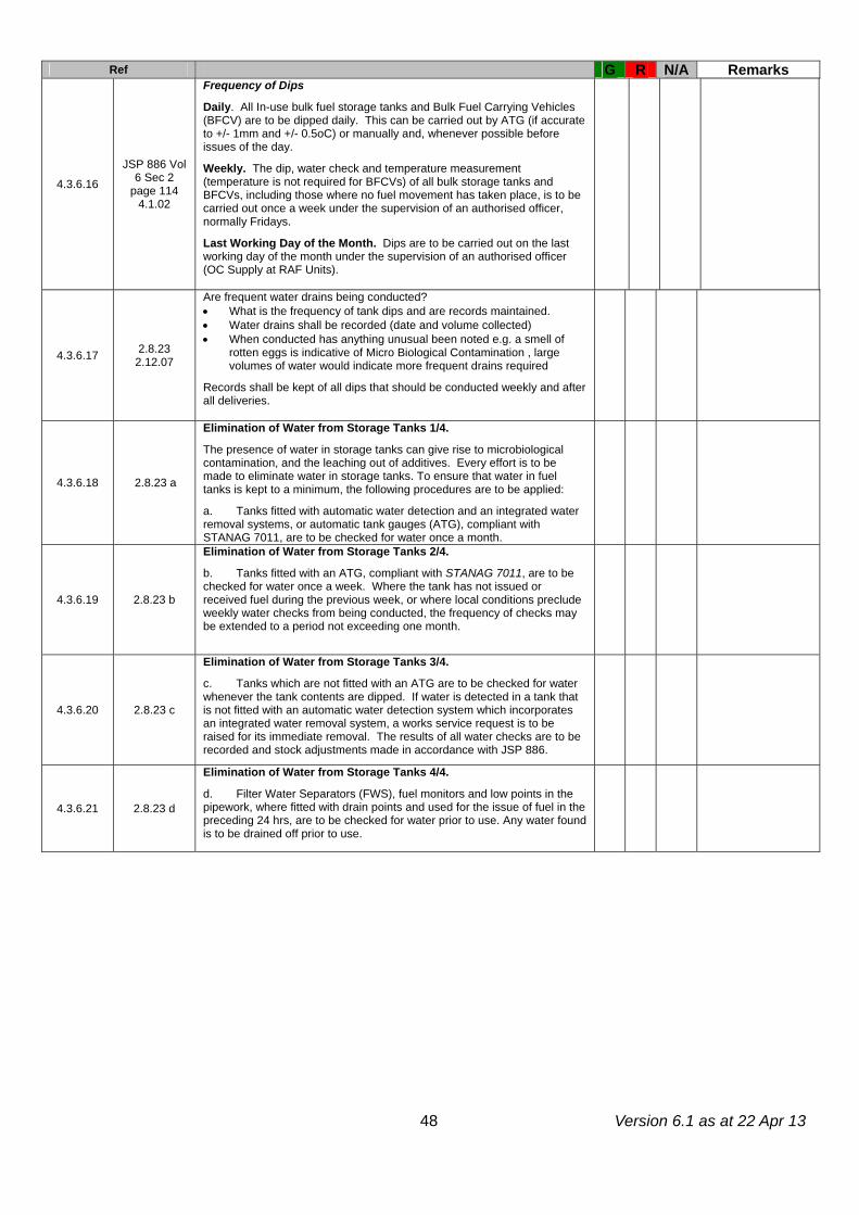
Version 6.1 as at 22 Apr 13
48
Ref G R N/A Remarks
4.3.6.16 JSP 886 Vol
6 Sec 2 page 114
4.1.02
Frequency of Dips Daily. All In-use bulk fuel storage tanks and Bulk Fuel Carrying Vehicles (BFCV) are to be dipped daily. This can be carried out by ATG (if accurate to +/- 1mm and +/- 0.5oC) or manually and, whenever possible before issues of the day.
Weekly. The dip, water check and temperature measurement (temperature is not required for BFCVs) of all bulk storage tanks and BFCVs, including those where no fuel movement has taken place, is to be carried out once a week under the supervision of an authorised officer, normally Fridays. Last Working Day of the Month. Dips are to be carried out on the last working day of the month under the supervision of an authorised officer (OC Supply at RAF Units).
4.3.6.17 2.8.23 2.12.07
Are frequent water drains being conducted? • What is the frequency of tank dips and are records maintained. • Water drains shall be recorded (date and volume collected) • When conducted has anything unusual been noted e.g. a smell of
rotten eggs is indicative of Micro Biological Contamination , large volumes of water would indicate more frequent drains required
Records shall be kept of all dips that should be conducted weekly and after all deliveries.
4.3.6.18 2.8.23 a
Elimination of Water from Storage Tanks 1/4. The presence of water in storage tanks can give rise to microbiological contamination, and the leaching out of additives. Every effort is to be made to eliminate water in storage tanks. To ensure that water in fuel tanks is kept to a minimum, the following procedures are to be applied:
a. Tanks fitted with automatic water detection and an integrated water removal systems, or automatic tank gauges (ATG), compliant with STANAG 7011, are to be checked for water once a month.
4.3.6.19 2.8.23 b
Elimination of Water from Storage Tanks 2/4.
b. Tanks fitted with an ATG, compliant with STANAG 7011, are to be checked for water once a week. Where the tank has not issued or received fuel during the previous week, or where local conditions preclude weekly water checks from being conducted, the frequency of checks may be extended to a period not exceeding one month.
4.3.6.20 2.8.23 c
Elimination of Water from Storage Tanks 3/4. c. Tanks which are not fitted with an ATG are to be checked for water whenever the tank contents are dipped. If water is detected in a tank that is not fitted with an automatic water detection system which incorporates an integrated water removal system, a works service request is to be raised for its immediate removal. The results of all water checks are to be recorded and stock adjustments made in accordance with JSP 886.
4.3.6.21 2.8.23 d
Elimination of Water from Storage Tanks 4/4. d. Filter Water Separators (FWS), fuel monitors and low points in the pipework, where fitted with drain points and used for the issue of fuel in the preceding 24 hrs, are to be checked for water prior to use. Any water found is to be drained off prior to use.
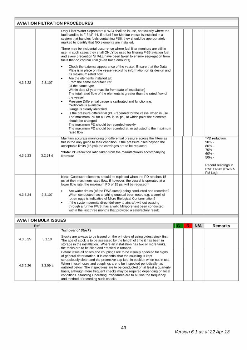
Version 6.1 as at 22 Apr 13
49
AVIATION FILTRATION PROCEDURES
4.3.6.22 2.8.107
Only Filter Water Separators (FWS) shall be in use, particularly where the fuel handled is F-34/F-44. If a fuel filter Monitor vessel is installed in a system that handles fuels containing FSII, they should be appropriately marked to identify that NO elements are installed.
There may be incidental occurrence where fuel filter monitors are still in use. In such cases they shall ONLY be used for filtering F-35 aviation fuel and every precaution SHALL have been taken to ensure segregation from fuels that do contain FSII (even trace amounts).
• Check the external appearance of the vessel. Ensure that the Data Plate is in place on the vessel recording information on its design and its maximum rated flow.
• Are the elements installed all: From the same manufacturer Of the same type Within date (3 year max life from date of installation) The total rated flow of the elements is greater than the rated flow of the vessel
• Pressure Differential gauge is calibrated and functioning. Certificate is available Gauge is clearly identified
• Is the pressure differential (PD) recorded for the vessel when in use The maximum PD for a FWS is 15 psi, at which point the elements should be changed The maximum PD should be recorded weekly The maximum PD should be recorded at, or adjusted to the maximum rated flow
4.3.6.23 3.2.51 d
Maintain accurate monitoring of differential pressure across the filters as this is the only guide to their condition. If the pressure rises beyond the acceptable limits (15 psi) the cartridges are to be replaced.
*Note: PD reduction ratio taken from the manufacturers accompanying literature.
*PD reduction: 90% - 80% - 70% - 60% - 50% - Record readings in RAF F6816 (FWS & FM Log)
4.3.6.24 2.8.107
Note: Coalescer elements should be replaced when the PD reaches 15 psi at their maximum rated flow. If however, the vessel is operated at a lower flow rate, the maximum PD of 15 psi will be reduced.*
• Are water drains (of the FWS sump) being conducted and recorded? When conducted has anything unusual been noted e.g. a smell of rotten eggs is indicative of Micro Biological Contamination?
• If the system permits direct delivery to aircraft without passing through a further FWS, has a valid Millipore test been conducted within the last three months that provided a satisfactory result.
AVIATION BULK ISSUES Ref G R N/A Remarks
4.3.6.25 3.1.10
Turnover of Stocks Stocks are always to be issued on the principle of using oldest stock first. The age of stock is to be assessed by the length of time it has been in storage in the installation. Where an installation has two or more tanks, the tanks are to be filled and emptied in rotation.
4.3.6.26 3.3.09 a
Before issue all hoses and couplings are to be visually checked for signs of general deterioration. It is essential that the coupling is kept scrupulously clean and the protective cap kept in position when not in use. When in use hoses and couplings are to be inspected periodically, as outlined below. The inspections are to be conducted on at least a quarterly basis, although more frequent checks may be required depending on local conditions. Standing Operating Procedures are to outline the frequency and method of recording such checks.
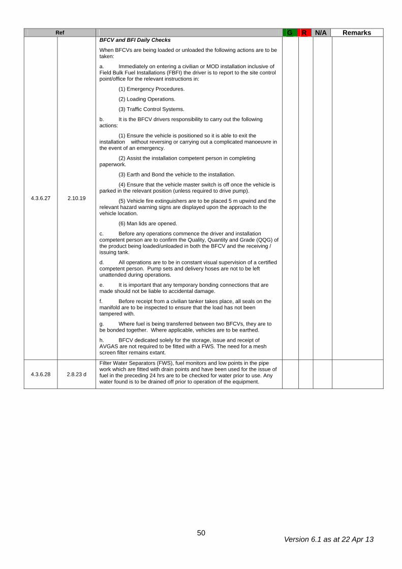
Version 6.1 as at 22 Apr 13
50
Ref G R N/A Remarks
4.3.6.27 2.10.19
BFCV and BFI Daily Checks
When BFCVs are being loaded or unloaded the following actions are to be taken:
a. Immediately on entering a civilian or MOD installation inclusive of Field Bulk Fuel Installations (FBFI) the driver is to report to the site control point/office for the relevant instructions in:
(1) Emergency Procedures.
(2) Loading Operations.
(3) Traffic Control Systems.
b. It is the BFCV drivers responsibility to carry out the following actions:
(1) Ensure the vehicle is positioned so it is able to exit the installation without reversing or carrying out a complicated manoeuvre in the event of an emergency.
(2) Assist the installation competent person in completing paperwork.
(3) Earth and Bond the vehicle to the installation.
(4) Ensure that the vehicle master switch is off once the vehicle is parked in the relevant position (unless required to drive pump).
(5) Vehicle fire extinguishers are to be placed 5 m upwind and the relevant hazard warning signs are displayed upon the approach to the vehicle location.
(6) Man lids are opened.
c. Before any operations commence the driver and installation competent person are to confirm the Quality, Quantity and Grade (QQG) of the product being loaded/unloaded in both the BFCV and the receiving / issuing tank.
d. All operations are to be in constant visual supervision of a certified competent person. Pump sets and delivery hoses are not to be left unattended during operations.
e. It is important that any temporary bonding connections that are made should not be liable to accidental damage.
f. Before receipt from a civilian tanker takes place, all seals on the manifold are to be inspected to ensure that the load has not been tampered with.
g. Where fuel is being transferred between two BFCVs, they are to be bonded together. Where applicable, vehicles are to be earthed.
h. BFCV dedicated solely for the storage, issue and receipt of AVGAS are not required to be fitted with a FWS. The need for a mesh screen filter remains extant.
4.3.6.28 2.8.23 d
Filter Water Separators (FWS), fuel monitors and low points in the pipe work which are fitted with drain points and have been used for the issue of fuel in the preceding 24 hrs are to be checked for water prior to use. Any water found is to be drained off prior to operation of the equipment.

Version 6.1 as at 22 Apr 13
51
OPERATION OF AVIATION BULK FUEL CARRYING & HYDRANT REFUELLING VEHICLES Ref G R N/A Remarks
4.3.6.29
2.12.83 2.12.85 2.12.89 2.12.91 2.12.94
Are the following first parade/pre delivery checks being conducted on aviation fuel:
• Appearance • Density • Water Detection
At the following intervals:
• The start of each day • After 180 minutes (3 hours) if no aircraft have been refuelled
following the start of day check • After bulking of the BFCV (a minimum of 10 minutes shall be
allowed for the fuel to settle post loading before a sample is taken) • At change of shift/driver • Every 10 days if the vehicle is currently out of use
A sample shall be drawn from the tank drain and examined for;
• Appearance (Clear and Bright and free from particulate matter) Test for free water (Shell Water Detection test)
4.3.6.30 2.12.83-84
Issue of Aviation Fuel from BFCVs
It is recommended that all bulk fuel carrying vehicles be kept as full as is practical at all times and carrier tanks should be filled to 90% of their capacity at the end of the operating period / day to minimise the amount of water formed thereby reducing the risk of microbiological contamination and also depletion of the Fuel System Icing Inhibitor (FSII) in the fuel.
Samples are to be taken from the sump of the carrier tank. Contamination tests are to be carried out:
a. Each time the vehicle receives fuel from any source, and after a minimum settling time of 10 minutes. b. Where a fuelling vehicle has been out of use for a period of 10 days the contamination test is carried out on the 11th day and is repeated at ten day intervals during the period for which the vehicle is not in use.
4.3.6.31 2.8.107
Only Filter Water Separators (FWS) shall be in use, particularly where the fuel handled is F-34/F-44. If a fuel filter Monitor vessel is installed in a system that handles fuels containing FSII, they should be appropriately marked to identify that NO elements are installed. There may be incidental occurrence where fuel filter monitors are still in use. In such cases they shall ONLY be used for filtering F-35 aviation fuel and every precaution SHALL have been taken to ensure segregation from fuels that do contain FSII (even trace amounts). • Check the external appearance of the vessel. Ensure that the Data
Plate is in place on the vessel recording information on its design and its maximum rated flow.
• Are the elements installed all: From the same manufacturer Of the same type Within date (3 year max life from date of installation) The total rated flow of the elements is greater than the rated flow of the vessel
• Pressure Differential gauge is calibrated and functioning. Certificate is available Gauge is clearly identified
• Is the pressure differential (PD) recorded for the vessel when in use The maximum PD for a FWS is 15 psi, at which point the elements should be changed The maximum PD should be recorded weekly The maximum PD should be recorded at, or adjusted to the maximum rated flow

Version 6.1 as at 22 Apr 13
52
Ref G R N/A Remarks
4.3.6.32 3.2.51 d
Maintain accurate monitoring of differential pressure across the filters as this is the only guide to their condition. If the pressure rises beyond the acceptable limits (15 psi) the cartridges are to be replaced. *Note: PD reduction ratio taken from the manufacturers accompanying literature.
*PD reduction ratio: 90% - 80% - 70% - 60% - 50% - Record readings on MoD F7765.
4.3.6.33 2.8.107
Note: Coalescer elements should be replaced when the PD reaches 15 psi at their maximum rated flow. If however, the vessel is operated at a lower flow rate, the maximum PD of 15 psi will be reduced.*
• Are water drains (of the FWS sump) being conducted and recorded When conducted has anything unusual been noted e.g. a smell of rotten eggs is indicative of Micro Biological Contamination.
• If the system permits direct delivery to aircraft without passing through a further FWS, has a valid Millipore test been conducted within the last three months that provided a satisfactory result.
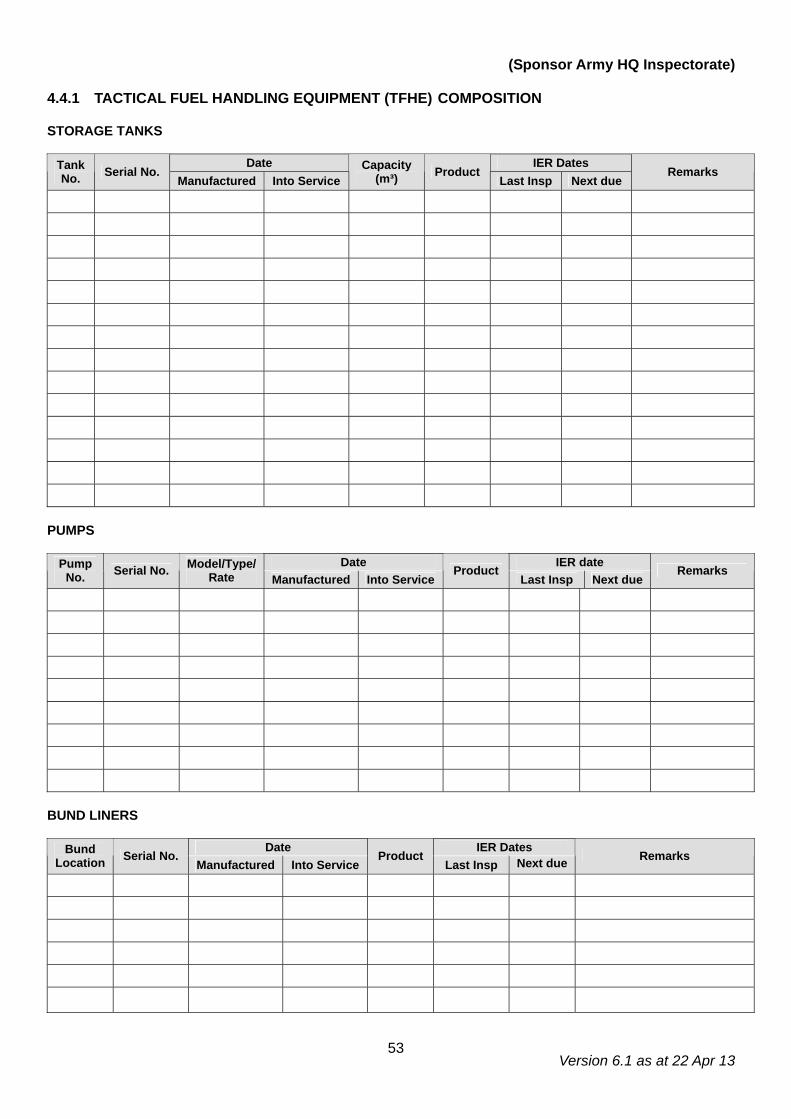
Version 6.1 as at 22 Apr 13
53
(Sponsor Army HQ Inspectorate)
4.4.1 TACTICAL FUEL HANDLING EQUIPMENT (TFHE) COMPOSITION
STORAGE TANKS
Date IER Dates Tank No. Serial No.
Manufactured Into Service Capacity
(m³) Product Last Insp Next due
Remarks
PUMPS
Date IER date Pump No. Serial No. Model/Type/
Rate Manufactured Into Service Product
Last Insp Next due Remarks
BUND LINERS
Date IER Dates Bund
Location Serial No. Manufactured Into Service
Product Last Insp Next due Remarks
Version 6.1 as at 22 Apr 13
54
TACTICAL FUEL HANDLING EQUIPMENT (TFHE) (Sponsor Army HQ Inspectorate) Note: All Deployed Bulk Fuel Installations (DBFIs) regardless of size are to meet the requirements of this section. The definition of a DBFI is referenced to Military Engineering Volume XII. Where the rapid nature of deployment and recovery during operations within a Military Works Area preclude a full planning cycle, it may not be pertinent to consider all stated aspects herein, but for all instances of training and as soon as possible on operations, all aspects of the FSAA (in respect of DBFI’s) should be considered. Users of DBFI’s should not limit their references to JSP 317 alone and should demonstrate a thorough understanding and application of those other regulatory/ legislative instruments which are provided for various products or activities undertaken, or concluded within the confines of a DBFI (Container filling, aviation refuelling, BFCV operations, packed stock storage etc)
Note: SOPs and TOPs may not be referenced and as a result these observations will not be regulated by the FGSR. In this instance the reference column will state ‘SOP’ or ‘TOP’.
GRADING 4.4.2 INSTALLATION DOCUMENTATION G R N/A Remarks Ref
4.4.2.1 TOP Person in charge (PinC) has been nominated? 4.4.2.2 4.1.12 a Recce Report has been produced and is available. 4.4.2.3 4.2.11 Earth Testing and Electrical Continuity checks completed and recorded? 4.4.2.4 4.2.15 Pneumatic Leak Testing completed and recorded? 4.4.2.5 4.2.20 Hydraulic Leak Testing completed and recorded? 4.4.2.6 4.2.23 Testing and Commissioning Certificate issued?
4.4.2.7 4.2.32 Following construction, the Operating Authority should receive a formal handover from RE personnel. A completed handover certificate should be available at the installation.
4.4.2.8 4.1.5 f (4) iii Safe System of Work is adhered to? 4.4.2.9 Issue vouchers for stores and lists for all equipment on site.
4.4.2.10 Plant Docs and tank record books available. 4.4.2.11 Instructions on operations of any unfamiliar components. 4.4.2.12
SOP
Drawing recording site layout and valve setting chart. 4.4.2.13 TOP Permitting system in place and controlled by AP (Pet)?
GRADING 4.4.3 DESIGN G R N/A Remarks Ref*
4.4.3.1 4.2.3 The installation has been designed, constructed and approved iaw the requirements of JSP 317 and Mil Eng Vol XII.
4.4.3.2 4.1.12
Personnel responsible for the siting of DBFI’s are to consider the following:
• Siting boards should take place when possible. Where this is not possible, a recce is to produce a Formal Recce Report in its place.
• Should allow for the dispersion of vapours • The release of contaminated water etc (bund water etc is to be treated
as contaminated waste) • Vehicular access from MSR’s • Dispersion of stocks • Separation and safety distances from other areas such as: • Ammunition >50 m (ATO to advise) • Antenna Farms - Advice from Technical Authority • Accommodation & sleeping areas >45m (Fire Advisor (FA) to advise) • Occupied buildings and possible sources of ignition - Advice from FA:
• Class I & II products min >15m • Class III product min >10m
• Flight-paths - Advice from SATCO
4.4.3.3 4.1.12 i Camouflage, Concealment and Deception (CCD) If camouflage nets are used they must be a minimum of 1m above bund walls to allow for dispersion of vapour.
4.4.3.4 Mil Eng XII Para 1724
FWS located as close to dispense points as possible.
4.4.3.5 4.1.12 j
Bunds constructed in accordance with Mil Eng Vol XII and making provision for:
• Bund floor free of sharp objects and max slope of 1:60 towards the dispensing end.
• Bund floor provided with sump. • Bund wall to be continuous and capable of containing 110% of the
largest tank they contain. • No more than 2 x 136m³ TFC’s per bund • Where possible bunds are to be separated from one another Bunds shall be constructed of non flammable material
Version 6.1 as at 22 Apr 13
55
G R N/A Remarks
4.4.3.6 4.1.12 f
Traffic Circuits must be adequate to allow the passage of delivery/receipt vehicles as well as allowing for unhindered passage of fire fighting vehicles. Access and egress to the site must be controlled and where necessary, physical protection measures may be required to protect exposed pipework/equipment from vehicle damage.
GRADING 4.4.4 FIRE, HEALTH & SAFETY G R N/A Remarks Ref
4.4.4.1 2.2.48 e-h
Washing & changing facilities are to be provided for personnel at the place of work. In addition, the following items must also be provided:
• Barrier Cream and After Work Cream. • Eyewash (In Date). • Emergency First Aid Kit.
4.4.4.2 2.2.48 i Appropriate Personal Protective Equipments (PPE) and Respiratory Protective Equipment (RPE) is provided and used by all operators.
4.4.4.3 2.5.11
Smoking or Smoking materials are not permitted in the hazardous area. Personnel are to deposit any smoking materials in a safe designated contraband area before entering a hazardous zone or likely hazardous area.
4.4.4.4 4.1.12 e
Following consultation with the Defence Fire Service (DFS), Landowners and possibly the local Fire Brigade the appropriate scale of Fire Fighting Equipment is provided at the facility and is positioned to afford the maximum protection for the entire installation.
4.4.4.5 4.1.12 g
The following Hazard Warning Signs stating ‘Petroleum Spirit, Highly Flammable, No Smoking, No Naked Lights’ must be displayed on all approaches to the facility in local language and English:
4.4.4.6 4.1.12 g All sites boundaries must display the correct ‘Ex’ warning sign.
GRADING 4.4.5 ENVIRONMENTAL PROTECTION G R N/A Remarks Ref
4.4.5.1 2.5.13 b Spillages to be mopped up immediately using approved absorbent material which must be removed from the area for safe disposal.
4.4.5.2 5.3.16 h Sufficient Pollution Control Points (PCP) are established at the installation. The PCPs must be clearly identifiable, stocked appropriately and be maintained on a regular basis.
4.4.5.3 4.1.12 d Bund Water. All water which accumulates in the bund is to be classed as contaminated waste and consideration should be given to placement of interceptors if required and waste water removal by contractor.
GRADING 4.4.6 STANDARD OPERATING PROCEDURES G R N/A Remarks Ref
4.4.6.1 SOP Issue vouchers for stores and lists available for all equipment on site. 4.4.6.2 SOP Fire Practice conducted and recorded, prior to in-load of product? 4.4.6.3 SOP Rehearsal of the USRP conducted and recorded prior to in-load of
product?
4.4.6.4 SOP No unauthorised personnel. Where personnel require access but are not in receipt of a COC for the installation, are arrangements in place to provide adequate and constant supervision?
4.4.6.5 SOP Training delivered and competence assessed and recorded for all operations and procedures conducted on the installation?
4.4.6.6 SOP Safety Brief for visitors (including all drivers)? 4.4.6.7 SOP Question visiting drivers on emergency procedures. 4.4.6.8 SOP Provision of valves to permit commissioning, decommissioning and repair
of the installation?
4.4.6.9 SOP Bunding or drip trays for all pumps, manifolds, FWS and sand and stone traps?
4.4.6.10 SOP Adequate ullage provided to accept emergency transfer from tanks containing products of the same grade?
4.4.6.11 SOP Tanks not to be filled above 100% of their max working capacity? 4.4.6.12 SOP Water drained off daily. Use of water finding paste? 4.4.6.13 SOP Daily visual inspections of all TFC and pipelines?
Version 6.1 as at 22 Apr 13
56
5. BULK FUEL CARRYING VEHICLE (BFCV) STORAGE PARK BFCV STORAGE PARK
1.1.07 Outside of UK. In countries outside of the UK JSP 317 standards will apply unless the host nation regulations are more stringent. This does not apply to Germany where local standards in compliance with SOFA are to be adhered to.
Interceptor Capacity ___________________m³
GRADING 5.1 DESIGN
G R N/A Remarks Ref
5.1.1 2.11.07
The hard standing is to be of sufficient size to accommodate all establishment BFCVs. In addition there must also be sufficient area for manoeuvring and an additional area dedicated for transiting or visiting unit BFCVs. Calculations for determining the area should be 2.25 x the floor plan area of each vehicle e.g 9 Tonne MM Unit Support Tanker (UST): 2.55m x 9.16m x 2.25 = 52.56 m².
5.1.2 2.11.08 The hard standing surface must be constructed of concrete or another material that is impervious to hydrocarbons.
5.1.3 2.11.09
In all instances there is to be a safety distance around the hard standing, extending outwards 10m in all directions. No facilities, vehicle parking areas or buildings, including control rooms, are permitted within this safety distance.
5.1.4 2.11.10
A 45m Safety distance applies to living accommodation & public highways. The Siting Board can give dispensation to reduce the distance from a public highway to a min of 10m, however the distance from living accommodation must not be reduced.
5.1.5 2.11.11 Drainage The ground must be sloped towards catchment drain/drains.
5.1.6 2.9.12 c If the interceptor capacity is less than the largest, single, vehicle compartment, answer the following Mitigation question below.
KPI
5.1.7 5.3.01-5.3.05
OWI Mitigation_ Pollution ERA: If the Interceptor has been identified as below the required capacity, has a suitable Pollution ERA been carried out, recorded, and is it annually reviewed to mitigate the increased risk?
If the Pollution ERA mitigates the insufficient capacity by demonstrating a work around solution, subsequent assessments can be assessed as Green
.
5.1.8 2.9.17 a-d
OWI Maintenance: OWIs are assets which are maintained under Project Aquatrine by Aquatrine Service Providers. As a minimum, every 6 months or iaw manufacturers’ instructions OWIs should be inspected to confirm:
• Integrity of OWI. • Quantity of accumulated F&L and silt. • Correct operation of electrical equipment (alarms) • Condition of coalescing devices – replace as necessary.
The last inspection of the Interceptor was conducted by ___________ on ___________. If this date exceeds 6 months or the date of the last inspection can not be ascertained award a ‘Red’ grade.
FGSR Note: The Aquatrine contract only includes mainland UK units. In all other instances host nation standards will apply. KPI
5.1.9 2.11.13 Illumination. Overhead lighting is to be a minimum 20 Lux iaw JSP 315.
5.1.10 2.11.14
The BFCV Park is to be surrounded and secured by a 1.8m High chain link fence. The perimeter fence should be positioned no less than 10m from the edge of the BFCV hard standing if it forms part of the camp perimeter and no less than 2m if not.
5.1.11 2.11.14
Entrance/exit gates must open outwards and must not be self-locking. Securing mechanisms must be operable utilizing a single action device, without resorting to the use of a key. Gates must be capable of being bolted or held open.
Version 6.1 as at 22 Apr 13
57
Ref G R N/A Remarks
5.1.12 2.11.15
An emergency deluge shower is to be installed and sited at or as close the park entrance as possible. Where this is not possible, alternative arrangements should be made after producing a risk assessment.
Award a red grade for this serial if no RA is produced.
5.1.13 2.11.18
Traffic Flow. Under normal circumstances a one-way traffic system incorporating an exit and access gate is to be approved, based upon a risk assessment and the number of BFCVs operated. Where this requirement is deemed unnecessary it may still be necessary to impose restrictions on the outcome of a risk assessment such as:
a. If the distance to travel to exit the park exceeds 24m a personnel emergency exit should to be included in the design.
b. If only one exit is used the width of the park entrance and approach road may need to be increased to allow two-way traffic flow.
c. Appropriate traffic flow indication markings to be incorporated within and around the park.
d. Design must allow parked vehicles to be driven forward to the nearest/safest exit without the need to manoeuvre/reverse, in the event of an emergency.
5.1.14 2.11.19
Earthing/Bonding. Bulk Transfer areas are to be equipped with fixed earth points. Fixed earth points are not required outside of this area. BFCVs stored/parked in the facility are to utilise fitted CES items.
5.1.15 2.11.33
Transfers must only to take place in a designated area of the BFCV Park. The transfer area is to be marked and a safety distance of 15m is to be established around the two BFCVs from any other vehicle.
5.1.16 2.11
Annex A & B
Safety Distances BFCV Parking. Area provided in accordance with JSP 317- 2.25m for each vehicle, 1m between UBRE/UST & 2m between Support Tankers (all variants). 3m between groups of 9 UBRE & 5m between groups of 9 Support Tankers
GRADING 5.2 FIRE, HEALTH & SAFETY G R N/A Remarks Ref
5.2.1 2.11.16 Communications. Does the unit have an effective means of both raising the alarm & giving warning in case of fire?
5.2.2 2.11.17 Fig 2.11.1
The following Hazard Warning Sign stating ‘Petroleum Mixture, Highly Flammable, No Smoking/Naked flames, No mobile phones, No parking’ is to be displayed on all approaches to the facility in the local language and English:
5.2.3 2.11.20
Hazardous Area. The hazardous area extends to 10m beyond the physical boundaries of the BFCV Park. The following items/activities are not permitted within this distance:
• Smoking or naked flames. • Studded footwear. • Tracked vehicles. • Mobile or portable phones unless ATEX certified. • Consumption of food. • The removal of contaminated clothing. Hearing Aids, unless they have been certified as intrinsically safe. If they are certified the user must be briefed not to change or expose the batteries in the hazardous area.
5.2.4 2.11.21-22
Security/Access. Access to the facility is to be restricted to authorised, trained, duty personnel. When unoccupied BFCV Park gates are to be locked and keys must be held in safe custody. Access to the keys should be restricted to authorised personnel only. Any visitors who have not received a mandatory safety brief before entering the facility must be supervised by a competent person at all times.
Version 6.1 as at 22 Apr 13
58
Ref G R N/A Remarks
5.2.5 2.11.23 Contraband. There must be a system in place to deposit contraband and any smoking materials prior to entering the hazardous area.
5.2.6 2.11.31 Vehicle Repairs. Hot or electrical BFCV repairs are not permitted within the BFCV Park.
5.2.7 2.11.32
Contaminated Clothing. (Class I & II products). Contaminated clothing is to be drenched in water (Deluge shower) and removed outside the hazardous area to guard against electro-static discharge.
5.2.8 2.11.34 Ammunition. The storage or carriage of ammunition is prohibited inside the hazardous area.
5.2.9 2.11.36 Fire Precautions. Is a Comprehensive Fire Plan provided for the BFCV park?
FGSR Note: Example Fire Plan provided on JSP 317 website.
5.2.10 2.5.29
Fire Fighting Apparatus. Min 2 x 90 litre for first 12 vehicles and one for each additional 12 or part thereof. Extinguishers are to be sited not less than 15m from any BFCV in an easily accessible position.
5.2.11 2.5.10 & 26
Fire Safety Notices & Fire Action Notices must be displayed in order to comply with the Health and Safety (Safety Signs and Signals) Regulations 1996. Locations and quantities should relate to the local risks and be the result of a risk assessment.
5.2.12 2.11.37
First Aid & Eye Wash. Provisions for emergency first aid treatment are to be made, in conjunction with appropriately trained and qualified personnel. First Aid points (including eye wash facilities) are to be established and locations are to be clearly identified/signposted.
5.2.13 2.11.38 Toilets, washing and changing facility. To be provided within 50m of BFCV Park entrance. Adequate supplies of pre-work barrier and after work cream to be provided at this facility.
5.2.14 2. 11.39 a-c
Personal Protective Equipment (PPE). HoE is to ensure employees are informed, instructed and trained in the following areas:
• The risks PPE is designed to protect against and limitations. • The correct use of PPE and its purpose. • Actions required by personnel to avoid exposure to hazards.
5.2.15 2.11.40
PPE HoE is to provide employees with adequate PPE and must take all reasonable steps to ensure it is being used correctly and is inspected iaw the requirements JSP 375.
5.2.16 2.11.41
PPE HoE must provide suitable storage for the PPE to :
• Protect it from the hazard for which it was provided and any other hazard that may damage it or cause it to be hazardous.
• Ensure it is stored in a clean, hygienic location.
5.2.17 2.11.42
PPE Employees are responsible for ensuring that they:
• Make full and proper use of their PPE. • Make sure it is stored in the designated area when not in
use. • Report any damaged PPE to their CoC immediately.
5.2.18 2.11.50
Emergency Action Point (EAP). An EAP is to be established as close to the park entrance as possible, but at least 15m from the closest parked BFCV. The list is not exhaustive but as a minimum the EAP should include the following:
• Hazard Warning Signs. • Pollution Control Point. • Fire Extinguisher • Notice Board, suitably weatherproofed, displaying the
following: • Site specific Comprehensive Fire Plan. • Pollution Control Plan. • DSEAR RA. • COSHH RAs & relevant Safety Data Sheets.
Version 6.1 as at 22 Apr 13
59
Ref G R N/A Remarks
5.2.19 2.11.48
Instructions in Writing. When vehicles contain product within the storage tank or they are classed as nominally empty, Instructions in Writing must be displayed at all times. Where vehicles have been gas freed, Instructions in Writing must either be removed or placed in a securely closed container marked “Not relating to dangerous goods carried”.
5.2.20 2.11.49
Instructions in Writing (cont). Where it is necessary to de-couple articulated BFCVs, the Instructions in Writing must be removed from the vehicle cab and be securely attached to the trailer unit in a weatherproof enclosure. Kemlar plates attached to the front of the trailer to assist emergency services.
GRADING 5.3 ENVIRONMENTAL PROTECTION G R N/A Remarks Ref
5.3.1 2.11.12
User units have a responsibility to ensure that the Aquatrine Service Provider (ASP) maintains, services and routinely inspects/cleans the facilities interceptor. The unit Site Estate Team Leader (SETL) is usually the Aquatrine Liaison Representative (ALR) and they should be contacted in the first instance if the unit feel the ASP are failing to fulfil this requirement.
5.3.2 2.11.12 Units are to contact their Regional Prime Contractor (RPC), DIO and the SETL if a significant spillage occurs at the facility or when they suspect that the interceptor is full and requires emptying.
5.3.3 2.5.13 b Spillages to be mopped up immediately using approved absorbent material which must be removed from the area for safe disposal.
5.3.4 Part 5, Chap 2
A Pollution Control Plan is to be provided for the BFCV Park iaw JSP 317, Part 5, Chap 2. A copy of the plan is to be included in the Unit Spillage Response Plan (USRP).
5.3.5 2.11.44
Pollution Control Point (PCP). 1x PCP is to be provided for the first 8 x BFCVs and one additional PCP for the next 8 x BFCVs of parts thereof. Each PCP should contain the following:
• Contents, instruction leaflet and Pollution Control Plan. • 100 Ltrs of loose absorbent. • 20 Flat pads. • 4 Oil seal/tube pads. • 2 x Stiff brooms. • 2 x Shovels. • 2 x large drip trays. • 6 x disposable polythene sacks and ties.
BFCVs PCPs 8 1 9-16 2 17-24 3 25-32 4
5.3.6 5.9.12.g (2) Spillage Immediate Action Posters are to be prominently displayed at all Pollution Control Points and locations were F&L is stored.
FGSR Note: Para 5 of example USRP.
GRADING 5.4 OPERATING PROCEDURES G R N/A Remarks Ref
5.4.1 2.11.24
Vegetation within the hazardous area is to be maintained and should not present a fire hazard. Isolated deciduous trees may be left in situ, providing overhanging foliage is cut back. Coniferous trees are not permitted within the hazardous area.
5.4.2 2.11.26 Housekeeping. Waste, contaminated pollution control sorbents and any other material used for cleaning purposes must be removed from the hazardous area immediately after use.
5.4.3 2.11.27 Skips/Bins. Skips, bins or other containers, used for the storage of contaminated materials, are not to be sited within the hazardous area.
5.4.4 2.11.28 Parking. Vehicles must be guided into parking bays and must not overhang the edge of the hard standing.
Version 6.1 as at 22 Apr 13
60
6. GAS CYLINDER STORAGE FACILITIES 4 (Sponsor Mr Gary Bennett FGSR Gas) GAS CYLINDER STORAGE FACILITIES
GRADING 6.1 MANAGEMENT CONTROL G R N/A Remarks
Ref 6.1.1 2.9.6.06 Are “Weekly Inspections” carried out? Records kept? 6.1.2 2.9.6.05 Are “Receipt and Issue Checks” carried out?
6.1.3 2.9.6.02 Is there management control of the access keys to all gas cylinder stores? Is there a list of authorised persons who may require access to a store? Is this list up-to date?
6.1.4 2.9.6.03 Is there an Emergency Plan of the gas cylinder store and its contents? Is this available to the emergency services?
6.1.5 JSP 375, V2, L34
Has an Area Hazard Register been produced and is it maintained? Are the duties of the Area Custodian for the site enforced?
6.1.6 1.7.3 Are all accidents, incidents and dangerous occurrences associated with gases and their containers reported? Is a log kept? Is action taken to prevent a re-occurrence?
6.1.7 2.9.6.01 (i)
Controlled (F) gases. Is there a record of Controlled (F) gases held and of l Controlled (F) gas leakages?
GRADING 6.2 SITING G R N/A Remarks Ref
6.2.1 2.9.3.03 All new installations, or substantial changes to a site, are subject to a Siting Board.
6.2.2 2.9.3.05 The use of an external store, at ground level, is the preferred option.
6.2.3 2.9.3.44 Ventilation. Thorough ventilation by “clean” air required. Is the store located in an area where it may receive contaminated air e.g. aircraft jet efflux, or where there is substantial interference in the air flow from obstructions?
6.2.4 2.9.3.06 -15
Adjoining sites. Is there a hazard from near-by sites – fuels, explosives, combustible products, etc.? Consider flows from a spillage. Is the gas cylinder store a hazard to other sites? Have these risk(s) been assessed? Is there communication between the site owners? Have the relevant minimum safety distances been enforced?
6.2.5 2.9.3.12-15
Is there a hazard from other infrastructure e.g. electrical installations, power cables (above and below ground), thermal radiation, and electromagnetic radiation?
6.2.6 2.9.3.18 Is the site located close to access routes for personnel or vehicles?
GRADING 6.3 DESIGN G R N/A Remarks
Ref
6.3.1 2.9.3.16 Is the site of an adequate size for the quantity and type of cylinders being stored?
6.3.2 2.9.3.17 Is the compound secure? Fenced/permanent walls at least 1.8m in height. Secure access gates.
6.3.3 2.9.3.18-21
Is access adequate for 1) personnel, and 2) delivery and emergency vehicles? Are emergency escape routes identified and clear?
6.3.4 2.9.3.21 Do access doors open outwards and have the correct security locks? 6.3.5 2.9.3.29 Are the component parts of the storage area manufactured from non-
combustible materials?
6.3.6 2.9.3.39 Lighting. Adequate lighting shall be provided to allow safe working activities in poor light conditions and to assist in the identification of cylinder types. Lighting is to be suitably protected. Not an ignition source.
6.3.7 2.9.3.30-32
Floor. The floor should be constructed of concrete or other non-combustible material. Is there adequate drainage? Note that any drainage should not allow spills of liquefied or dense gases to enter confined spaces. Consider the flow of liquids and gases away from the site.
6.3.8 2.9.4.09 Fire Protection. Where the store forms part of a building, it should be separated by a firewall with at least 60 minutes fire-resistance. (2m high minimum / same height as tallest cylinder)
4 Unless otherwise stated all references for Sect 6 are extracted from JSP 319.
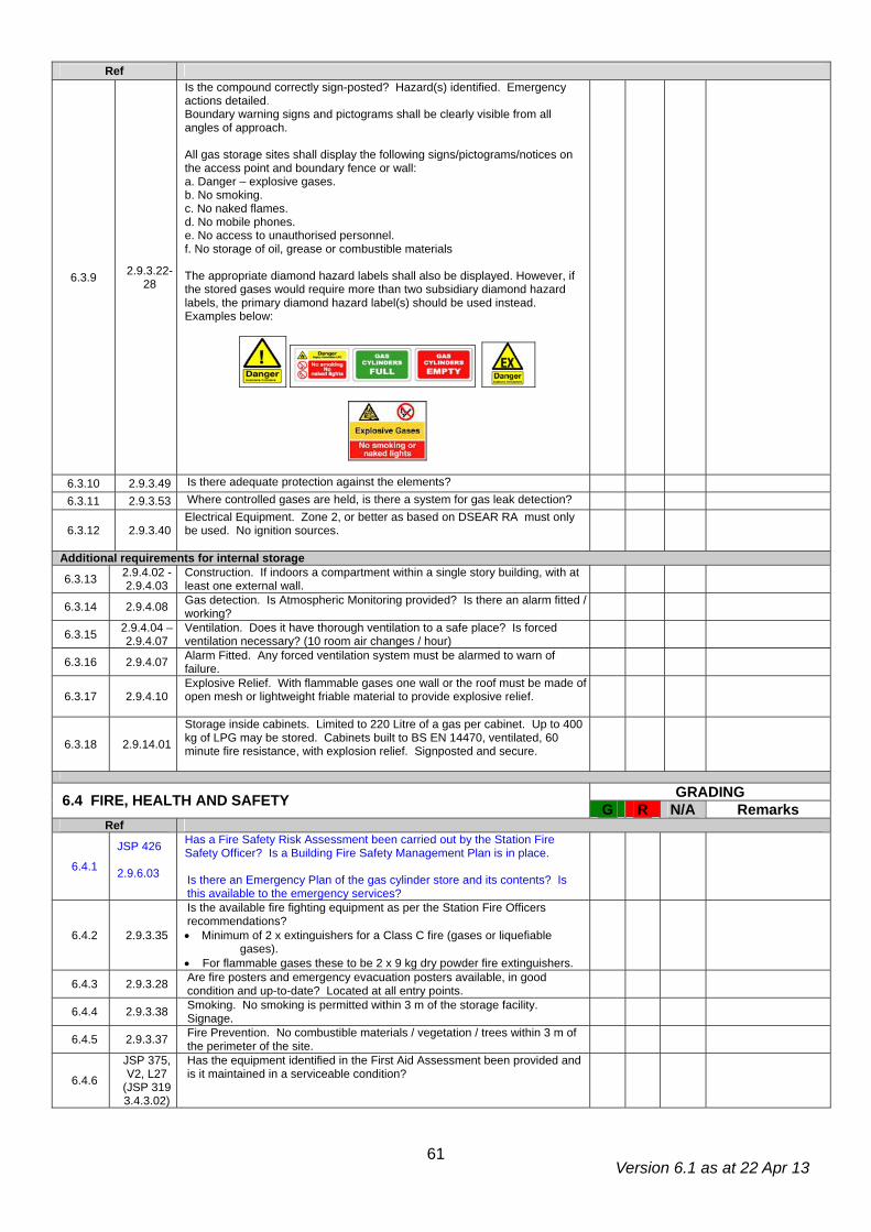
Version 6.1 as at 22 Apr 13
61
Ref
6.3.9 2.9.3.22-28
Is the compound correctly sign-posted? Hazard(s) identified. Emergency actions detailed. Boundary warning signs and pictograms shall be clearly visible from all angles of approach. All gas storage sites shall display the following signs/pictograms/notices on the access point and boundary fence or wall: a. Danger – explosive gases. b. No smoking. c. No naked flames. d. No mobile phones. e. No access to unauthorised personnel. f. No storage of oil, grease or combustible materials The appropriate diamond hazard labels shall also be displayed. However, if the stored gases would require more than two subsidiary diamond hazard labels, the primary diamond hazard label(s) should be used instead. Examples below:
6.3.10 2.9.3.49 Is there adequate protection against the elements? 6.3.11 2.9.3.53 Where controlled gases are held, is there a system for gas leak detection?
6.3.12 2.9.3.40 Electrical Equipment. Zone 2, or better as based on DSEAR RA must only be used. No ignition sources.
Additional requirements for internal storage
6.3.13 2.9.4.02 - 2.9.4.03
Construction. If indoors a compartment within a single story building, with at least one external wall.
6.3.14 2.9.4.08 Gas detection. Is Atmospheric Monitoring provided? Is there an alarm fitted / working?
6.3.15 2.9.4.04 – 2.9.4.07
Ventilation. Does it have thorough ventilation to a safe place? Is forced ventilation necessary? (10 room air changes / hour)
6.3.16 2.9.4.07 Alarm Fitted. Any forced ventilation system must be alarmed to warn of failure.
6.3.17 2.9.4.10 Explosive Relief. With flammable gases one wall or the roof must be made of open mesh or lightweight friable material to provide explosive relief.
6.3.18 2.9.14.01
Storage inside cabinets. Limited to 220 Litre of a gas per cabinet. Up to 400 kg of LPG may be stored. Cabinets built to BS EN 14470, ventilated, 60 minute fire resistance, with explosion relief. Signposted and secure.
GRADING 6.4 FIRE, HEALTH AND SAFETY G R N/A Remarks Ref
6.4.1
JSP 426 2.9.6.03
Has a Fire Safety Risk Assessment been carried out by the Station Fire Safety Officer? Is a Building Fire Safety Management Plan is in place. Is there an Emergency Plan of the gas cylinder store and its contents? Is this available to the emergency services?
6.4.2 2.9.3.35
Is the available fire fighting equipment as per the Station Fire Officers recommendations? • Minimum of 2 x extinguishers for a Class C fire (gases or liquefiable
gases). • For flammable gases these to be 2 x 9 kg dry powder fire extinguishers.
6.4.3 2.9.3.28 Are fire posters and emergency evacuation posters available, in good condition and up-to-date? Located at all entry points.
6.4.4 2.9.3.38 Smoking. No smoking is permitted within 3 m of the storage facility. Signage.
6.4.5 2.9.3.37 Fire Prevention. No combustible materials / vegetation / trees within 3 m of the perimeter of the site.
6.4.6
JSP 375, V2, L27
(JSP 319 3.4.3.02)
Has the equipment identified in the First Aid Assessment been provided and is it maintained in a serviceable condition?
Version 6.1 as at 22 Apr 13
62
Ref
6.4.7
JSP 375, V2, L27
(JSP 319 3.4.3.02)
Are First Aid equipment locations and the First Aiders clearly identified? Is signage adequate and correct?
6.4.8 2.9.3.17 Is access restricted to authorised personnel. Are these personnel competent to access the gas cylinder store.
6.4.9 1.8.3.01 Have all personnel received adequate training, including product awareness and manual handling.
6.4.10 2.7.2.04 Is there a range of manual handling equipment available – e.g. cylinder trolleys? Are they of the correct size and type?
6.4.11 2.7.5.01 2.9.5.18
Mechanical handling aids. . If Fork Lift Trucks are employed are they suitablefor use in this environment?
6.4.12 2.7.5.02 If cylinders are moved manually, do the operators “churn” correctly?
6.4.13 1.9.3.03
Emergency Procedures. Does the facility have comprehensive Written Emergency Procedures and are they displayed? • Spills • Leaks • Fire • Action in the event of an emergency at a nearby facility Question installation operator on actions to be taken.
6.4.14 2.2.2.01 & JSP 375, V2, L13
PPE. Personal protective equipment, e.g. safety footwear, gloves and eye/face protection. Has a risk assessment been carried out? Do all personnel have their own suitable PPE? Is it in good condition? Is it stored correctly, maintained and inspected?
GRADING 6.5 STORE ORGANISATION G R N/A Remarks Ref
6.5.1 2.9.5.01 Are all cylinders stored against a formal plan?
6.5.2 2.9.5.02 -15
Is there appropriate segregation? Are these segregated areas signposted? • Full and empty cylinders separated. • Hazard groups (flammable/oxidising/inert/toxic etc.) separated. • LPG cylinders separated. • Unserviceable cylinders separated. • Medical cylinders separated. (In separate storage facility) Note: Nominally empty cylinders to be treated as full for zoning and separation distance calculations.
6.5.3 2.9.5.16 Is there sufficient room to allow safe movement of personnel and any mechanical aids? Minimum isle size 0.6 m.
6.5.4 2.7.4.01 2.9.5.10 2.9.5.12
Cylinders are secured and are (normally) stored in the upright position in specially designed pallets if provided?
6.5.5 2.9.8.04 On all cylinders (including nominally empty cylinders) the valve is to be closed. The valve outlet is to be protected.
6.5.6 2.9.5.15 Cylinders are not to be stacked unless specifically designed for this purpose. 6.5.7 2.9.6.08 Only gas cylinders and their accessories are stored in a gas cylinder store.
The store is not used as a lay-apart store.
6.5.8 2.9.6.07 Only the minimum quantity of cylinders necessary are being stored. Nominally empty, unwanted or unserviceable cylinders are returned promptly.
6.5.9 2.9.6.16 Gas cylinder stocks are rotated and are kept within their expiry dates.
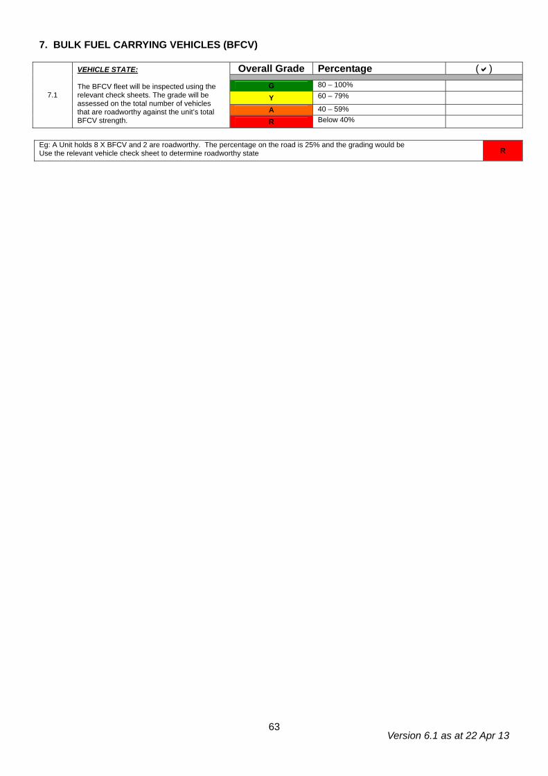
Version 6.1 as at 22 Apr 13
63
7. BULK FUEL CARRYING VEHICLES (BFCV)
Overall Grade Percentage ( )
G 80 – 100%
Y 60 – 79%
A 40 – 59%
7.1
VEHICLE STATE: The BFCV fleet will be inspected using the relevant check sheets. The grade will be assessed on the total number of vehicles that are roadworthy against the unit’s total BFCV strength. R Below 40%
Eg: A Unit holds 8 X BFCV and 2 are roadworthy. The percentage on the road is 25% and the grading would be Use the relevant vehicle check sheet to determine roadworthy state R

Version 6.1 as at 22 Apr 13
64
Feedback The FGSR are committed to continual development of the Assurance Assessment. Please use the box below to submit any comments, good or bad, and any suggestions or recommendations you may have and we will endeavour to continually improve the fuel safety assurance process.
Comments: