Embed Size (px)
Citation preview
# FGE2
SCIENCESCIENCESCIENCECreativeCreative
& Research
PO BOX 557 New Albany, IN. 47151 USA
Copyright 2002 - 2004 Creative Science & Research
Cover pg 1
33 lb33 lb
33 lb 33 lb
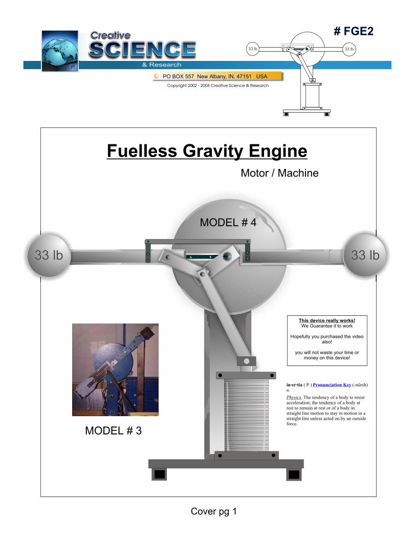
Fuelless Gravity EngineMotor / Machine
MODEL # 4
MODEL # 3
This device really works!We Guarantee it to work
Hopefully you purchased the video also!
you will not waste your time or money on this device!
in·er·tia ( P ) (-nûrsh)n.
Physics. The tendency of a body to resist acceleration; the tendency of a body at rest to remain at rest or of a body in straight line motion to stay in motion in a straight line unless acted on by an outside force.
Pronunciation Key
# FGE2
SCIENCESCIENCESCIENCECreativeCreative
& Research
PO BOX 557 New Albany, IN. 47151 USA
Copyright 2002 - 2004 Creative Science & Research
33 lb 33 lb
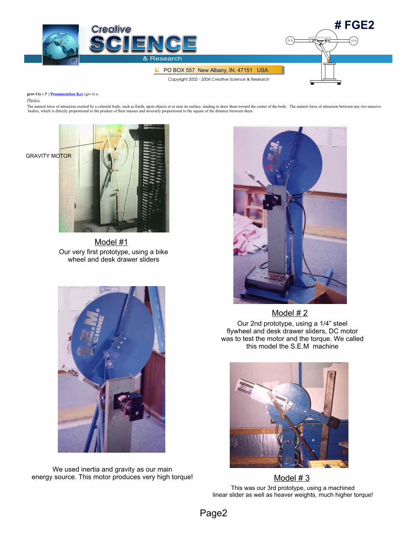
Model #1
Model # 2
Model # 3
Our very first prototype, using a bikewheel and desk drawer sliders
We used inertia and gravity as our mainenergy source. This motor produces very high torque!
Our 2nd prototype, using a 1/4” steelflywheel and desk drawer sliders, DC motor
was to test the motor and the torque. We called this model the S.E.M machine
This was our 3rd prototype, using a machinedlinear slider as well as heaver weights, much higher torque!
GRAVITY MOTOR
grav·i·ty ( P ) (grv-t) n.
Physics.
The natural force of attraction exerted by a celestial body, such as Earth, upon objects at or near its surface, tending to draw them toward the center of the body. The natural force of attraction between any two massive bodies, which is directly proportional to the product of their masses and inversely proportional to the square of the distance between them.
Pronunciation Key
Page2
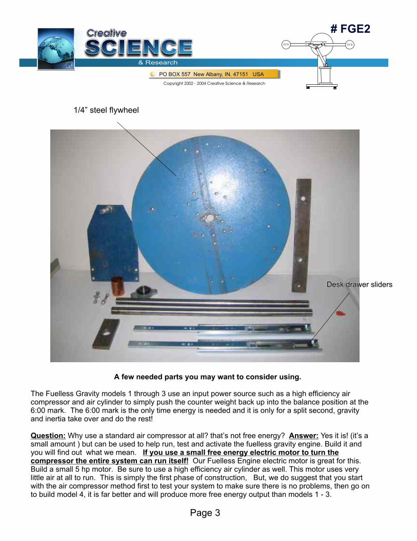
A few needed parts you may want to consider using.
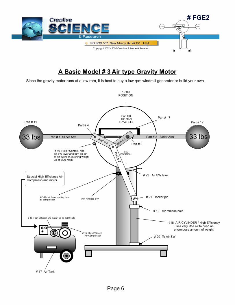
The Fuelless Gravity models 1 through 3 use an input power source such as a high efficiency air compressor and air cylinder to simply push the counter weight back up into the balance position at the 6:00 mark. The 6:00 mark is the only time energy is needed and it is only for a split second, gravity and inertia take over and do the rest!
Question: Why use a standard air compressor at all? that’s not free energy? Answer: Yes it is! (it’s a small amount ) but can be used to help run, test and activate the fuelless gravity engine. Build it and you will find out what we mean. If you use a small free energy electric motor to turn the compressor the entire system can run itself! Our Fuelless Engine electric motor is great for this. Build a small 5 hp motor. Be sure to use a high efficiency air cylinder as well. This motor uses very little air at all to run. This is simply the first phase of construction, But, we do suggest that you start with the air compressor method first to test your system to make sure there is no problems, then go on to build model 4, it is far better and will produce more free energy output than models 1 - 3.
Page 3
1/4” steel flywheel
Desk drawer slidersDesk drawer sliders
# FGE2
SCIENCESCIENCESCIENCECreativeCreative
& Research
PO BOX 557 New Albany, IN. 47151 USA
Copyright 2002 - 2004 Creative Science & Research
33 lb 33 lb
# FGE2
SCIENCESCIENCESCIENCECreativeCreative
& Research
PO BOX 557 New Albany, IN. 47151 USA
Copyright 2002 - 2004 Creative Science & Research
33 lb 33 lb
Page 4
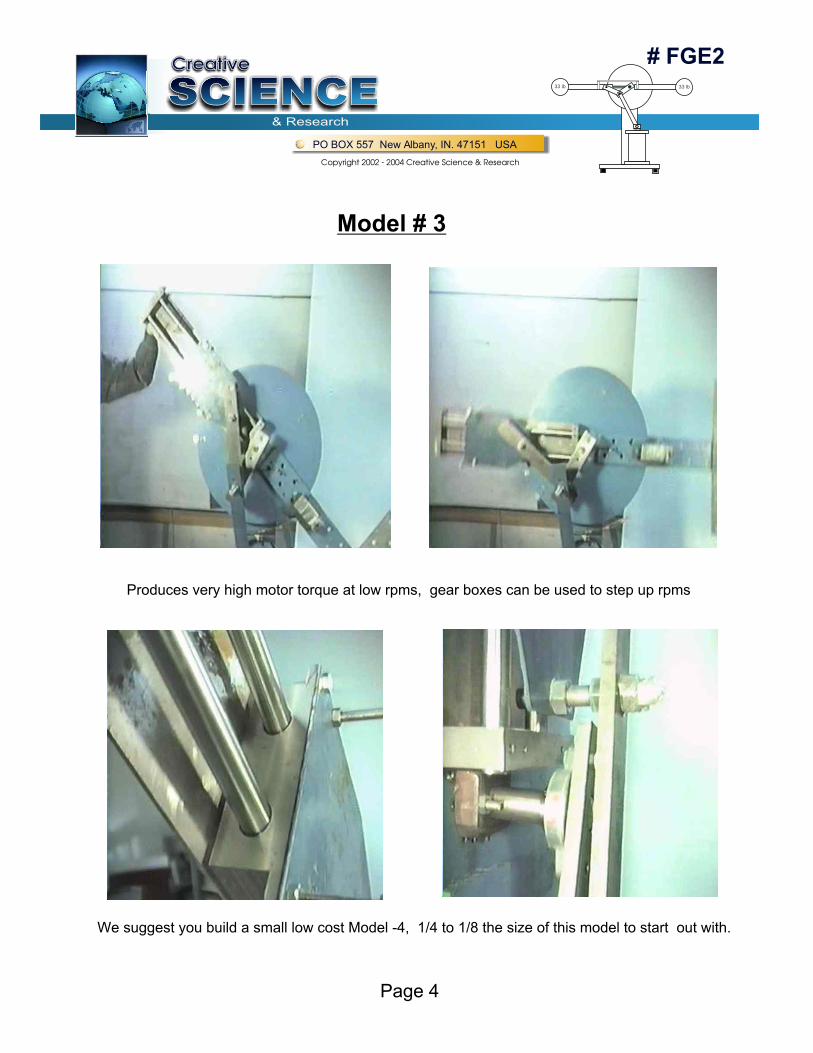
Model # 3
Produces very high motor torque at low rpms, gear boxes can be used to step up rpms
We suggest you build a small low cost Model -4, 1/4 to 1/8 the size of this model to start out with.
# FGE2
SCIENCESCIENCESCIENCECreativeCreative
& Research
PO BOX 557 New Albany, IN. 47151 USA
Copyright 2002 - 2004 Creative Science & Research
33 lb 33 lb
Page 5
The FGE2 Fuelless Gravity Engine is an amazing new idea created by Rick H. & David Waggoner of Creative Science & Research. It is unlike any other gravity motor we have ever seen before The FGE2 Gravity Engine or ( Motor ) can be designed to run itself very easily!The FGE2 Gravity Engine is basically a gravity, inertia driven motor which gets it’s torque power from leverage as well as speed. The slider arms and the 33 lb weights for example, are off balanced in the 11:00 mark position, the longer the arm and weight is from the center shaft point, the higher the torque pounds, which can be calculated into horsepower as well. The rpms are adjustable from 1 to 600 rpms. The speed can be adjusted by adjusting the input energy of the power source at the 6:00 mark.
Example: if you build the air model # 3, the more air pressure you add the more speed you gain, but efficiency is lost using the air compressor compared to using a High Voltage solenoid to move the arm weight up at the 6:00 position. In our Model # 4, the higher the voltage driven into the solenoid coil, the higher the rpms will be as well as the efficiency of the motor.
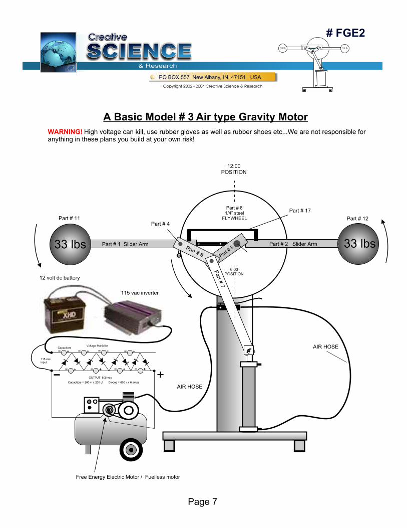
The solenoid is of a special design, it uses Neodymium disk magnets (# N40 or #N38 ) as the plunger rod, thus the solenoid coil acts as a Generator as well as a linear motor plunger! The back EMF from the coil should be more than what was put into the coil to run it. The back emf can be collected and stored back into the 12 volt battery. A 12 v marine type battery is used to run a 115 volt AC inverter x 175 watts or less. The inverter is used to power a voltage multiplier circuit using diodes and special capacitors! ( See our step up voltage plans ) The multiplier steps up the voltage as high as 2000 vdc x 3 amps, the coil will only use 10 to 40 milliamps.
Just imagine, the FGE2 could then be hooked up to a 10 kW x 120 v x 60 Hz generator, some of that energy could be used to run the engine itself as well as other household appliances. A 10 kW x 120 vac generator which is rated at about 500 rpms can be purchased at www.graingers.com
The idea is to use very little energy at the 6:00 position of the slider arm and weight to produce more energy coming out than what is coming into the system. If we build a Gravity motor to run at about 10 hp and compare that to a commercially built 10 hp electric motor, the gravity motor would win in efficiency over the commercial 10 hp motor, in that the commercial 10 hp motor would fire at about 6 to 8 times to get the rotor to rotate at 10 hp, but our gravity engine only fires 1 time to push the weight back up into a perfect balance position which is from the 6:00 position to the 12:00 position and our gravity motor uses a free energy solenoid to do it!
If you purchased our #362 Fuelless Engine plans then you will see that you can use the magnetic coil air design as well as the homemade copper pipe SW motor commutator method to switch the power on to the solenoid at the 6:00 position and turn it off at the 5:00 position,
# FGE2
SCIENCESCIENCESCIENCECreativeCreative
& Research
PO BOX 557 New Albany, IN. 47151 USA
Copyright 2002 - 2004 Creative Science & Research
33 lb 33 lb
Page 6
Part # 11
12:00POSITION
6:00POSITION
Part # 4
# 22 Air SW lever
# 17 Air Tank
# 9 Air hose SW # 14 to air hose coming fromair compressor
# 16 High Efficient DC motor, 90 to 1000 volts
# 15 High Efficient Air Compressor
Special High Efficiency Air Compresso and motor.
# 10 Roller Contact, hitsair SW lever and turn on airto air cylinder, pushing weightup at 6:00 mark.
# 19 Air release hole
# 20 To Air SW
#18 AIR CYLINDER / High Efficiencyuses very little air to push an enormouse amount of weight!
# 21 Rocker pin
Part #
7
Part # 6 Part # 5
Part # 3
Part # 17
Part # 1 Slider Arm Part # 2 Slider Arm
Part # 12
Part # 81/4” steel
FLYWHEEL
33 lbs 33 lbs
A Basic Model # 3 Air type Gravity Motor
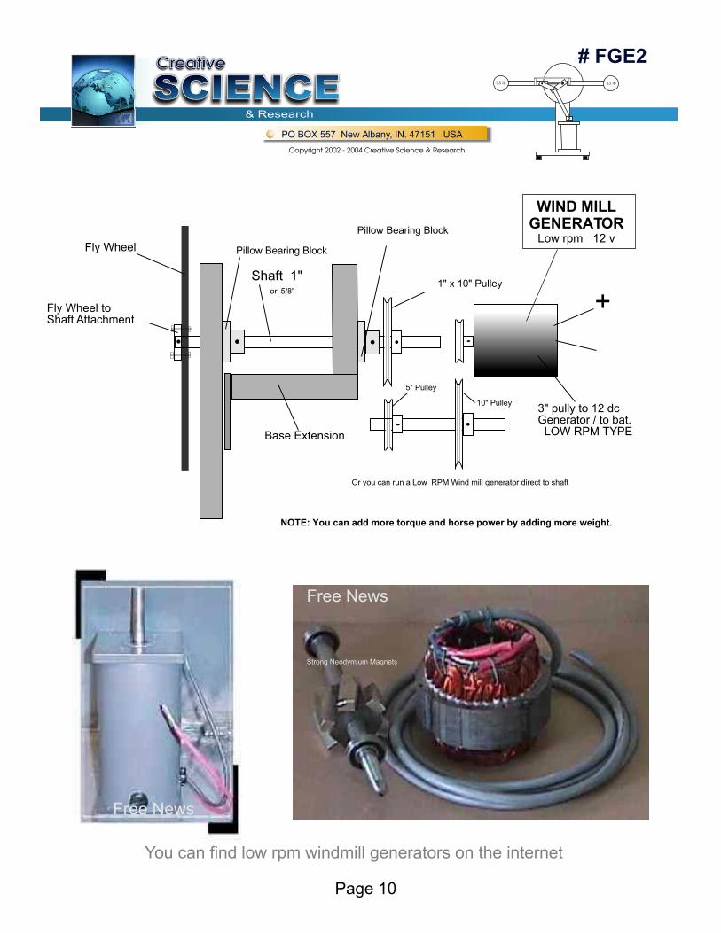
Since the gravity motor runs at a low rpm, it is best to buy a low rpm windmill generator or build your own.
# FGE2
SCIENCESCIENCESCIENCECreativeCreative
& Research
PO BOX 557 New Albany, IN. 47151 USA
Copyright 2002 - 2004 Creative Science & Research
33 lb 33 lb
Page 7
Part # 11
12 volt dc battery
115 vac inverter
12:00POSITION
6:00POSITION
Part # 4
Free Energy Electric Motor / Fuelless motor
AIR HOSE
AIR HOSE
Part #
7
Part # 6 Part # 5
Part # 17
Part # 1 Slider Arm Part # 2 Slider Arm
Part # 12
Part # 81/4” steel
FLYWHEEL
33 lbs 33 lbs
A Basic Model # 3 Air type Gravity Motor
CapacitorsVoltage Multiplier
OUTPUT 805 vdc
Capacitors = 360 v x 200 uf Diodes = 600 v x 6 amps
115 vacinput
+ + + +
+ + + +
+
WARNING! High voltage can kill, use rubber gloves as well as rubber shoes etc...We are not responsible for anything in these plans you build at your own risk!
LINEAR ACTUATORS®
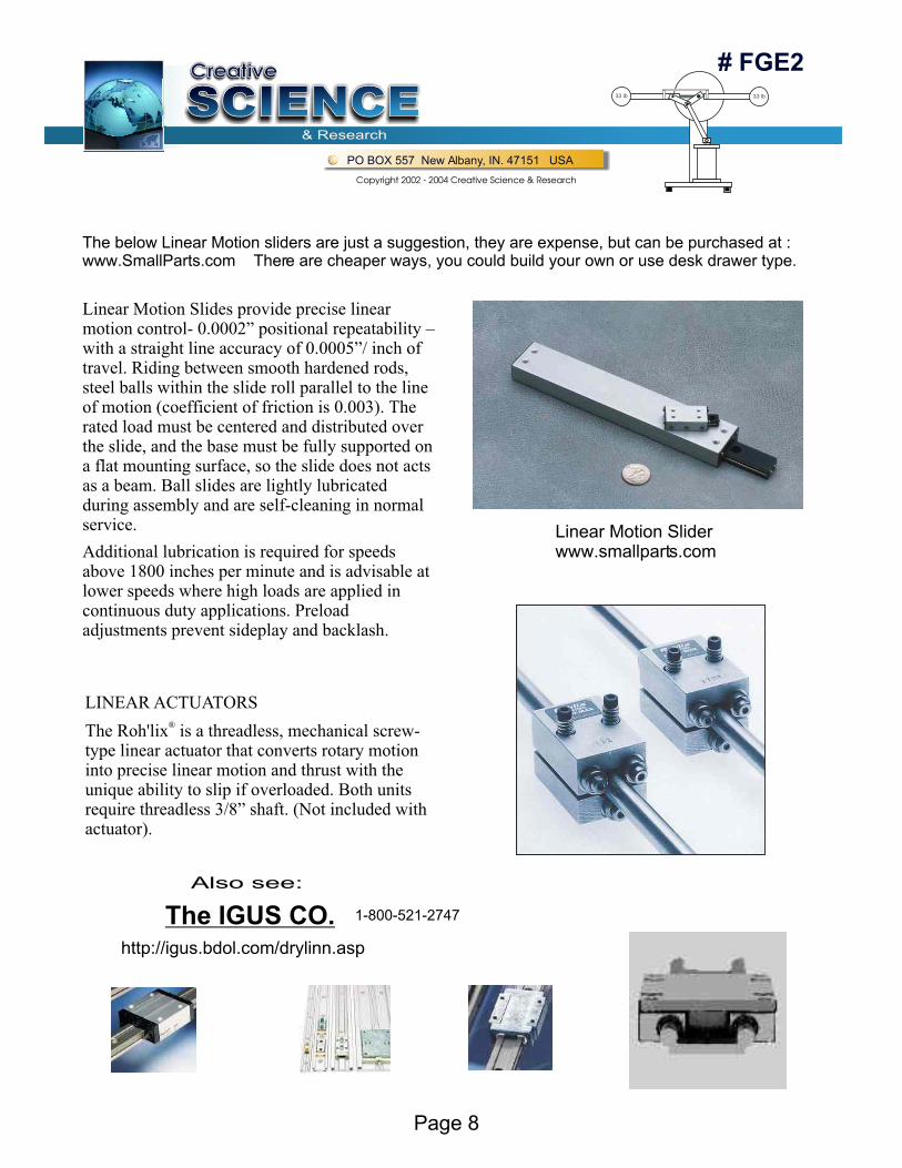
The Roh'lix is a threadless, mechanical screw-type linear actuator that converts rotary motion into precise linear motion and thrust with the unique ability to slip if overloaded. Both units require threadless 3/8” shaft. (Not included with actuator).
Linear Motion Slides provide precise linear motion control- 0.0002” positional repeatability – with a straight line accuracy of 0.0005”/ inch of travel. Riding between smooth hardened rods, steel balls within the slide roll parallel to the line of motion (coefficient of friction is 0.003). The rated load must be centered and distributed over the slide, and the base must be fully supported on a flat mounting surface, so the slide does not acts as a beam. Ball slides are lightly lubricated during assembly and are self-cleaning in normal service.
Additional lubrication is required for speeds above 1800 inches per minute and is advisable at lower speeds where high loads are applied in continuous duty applications. Preload adjustments prevent sideplay and backlash.
# FGE2
SCIENCESCIENCESCIENCECreativeCreative
& Research
PO BOX 557 New Albany, IN. 47151 USA
Copyright 2002 - 2004 Creative Science & Research
33 lb 33 lb
Page 8
Linear Motion Sliderwww.smallparts.com
The below Linear Motion sliders are just a suggestion, they are expense, but can be purchased at :www.SmallParts.com There are cheaper ways, you could build your own or use desk drawer type.
http://igus.bdol.com/drylinn.asp
The IGUS CO.
Also see:
1-800-521-2747
# FGE2
SCIENCESCIENCESCIENCECreativeCreative
& Research
PO BOX 557 New Albany, IN. 47151 USA
Copyright 2002 - 2004 Creative Science & Research
33 lb 33 lb
Page 9
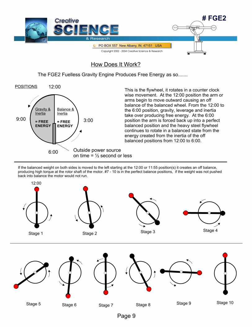
How Does It Work?
The FGE2 Fuelless Gravity Engine Produces Free Energy as so.......
12:00
12:00
POSITIONS
Gravity &Inertia
= FREEENERGY
Balance &Inertia
= FREEENERGY
3:00
Outside power sourceon time = ½ second or less
6:00
9:00
This is the flywheel, it rotates in a counter clock wise movement. At the 12:00 position the arm or arms begin to move outward causing an off balance of the balanced wheel. From the 12:00 to the 6:00 position, gravity, leverage and inertia take over producing free energy. At the 6:00 position the arm is forced back up into a perfect balanced position and the heavy steel flywheel continues to rotate in a balanced state from the energy created from the inertia of the off balanced positions from 12:00 to 6:00.
Stage 1 Stage 2 Stage 3 Stage 4
Stage 5 Stage 6 Stage 7 Stage 8 Stage 9 Stage 10
If the balanced weight on both sides is moved to the left starting at the 12:00 or 11:55 position(s) it creates an off balance, producing high torque at the rotor shaft of the motor. #7 - 10 is in the perfect balance positions, if the weight was not pushed back into balance the motor would not run.
# FGE2
SCIENCESCIENCESCIENCECreativeCreative
& Research
PO BOX 557 New Albany, IN. 47151 USA
Copyright 2002 - 2004 Creative Science & Research
33 lb 33 lb
Page 10
Shaft 1" or 5/8"
Pillow Bearing Block
Pillow Bearing Block
1" x 10" Pulley
Base Extension
5" Pulley
Or you can run a Low RPM Wind mill generator direct to shaft
10" Pulley3" pully to 12 dc Generator / to bat. LOW RPM TYPE
Fly Wheel
Fly Wheel toShaft Attachment
NOTE: You can add more torque and horse power by adding more weight.
+
Free News
Strong Neodymium Magnets
Free News
You can find low rpm windmill generators on the internet
WIND MILL GENERATOR
Low rpm 12 v
# FGE2
SCIENCESCIENCESCIENCECreativeCreative
& Research
PO BOX 557 New Albany, IN. 47151 USA
Copyright 2002 - 2004 Creative Science & Research
33 lb 33 lb
Page 11
WARNING PLEASE READ!
These plans are for your eyes only! You can not show anyone else these plans with out our written permission. You can not copy resell or give away these plans or any other set of plans you may have purchased from us as well as our videos. You can not manufacture this device or any of our other devices without our written permission.
You are allowed and can build different size models and use for them for your own use only.
You Build at your own risk, these plans involve the use of dangerous products as well as high voltage devices, always wear rubber gloves to protect yourself against electrical shock, one mistake and you are dead! So please be very careful!
You can never build any of our free energy devices and show them to any part of the media or newspaper media in anyway or you will be sued as well as all other legal action taken. Our free energy devices must be built by individuals like you, this is the plan we have chosen to take and will slowly introduce free energy devices to the world! Free energy devices must be slowly introduced to the world! If you do not take our advice and you try to get away with manufacturing our devices, not only will we find you and take legal action but Big Brother will take action as well! ( Who ever Big Brother realy is )? Who ever they are, they have agents who take care of these things and much differently than we would do. Believe me, we have tried to manufacture them ourselves and found out the hard way!
IN THE 1994 AT&T 1-800 BUSINESS YELLOW PAGES BOOK A manufacturing company tried to sell free energy electric motors and generators! Wow! That takes guts! They had a large ad on one of the yellow book pages, (we still have a copy of that page ) they were quickly shut down and never heard from ever again. We tried many times to find them and contact them but all the phone numbers that were in there ad were disconnected! So who is doing this? Who is suppressing the manufacturing of free energy devices, IT’S BEST THAT YOU DID NOT KNOW!....................
The Fuelless Gravity Engine
How It Works: This engine uses gravity, balance, weight, leverage and inertia as it's main Free Energy Source. The weight is shifted to the left to off balance the fly wheel. this happens between the 12:00 and the 6:00 positions. from the 6:00, 3:00 to the 12:00 positions inertia takes over there is no resistance other than what comes from the air and shaft hook ups. Part #6 is the Push arm from the drawings it may look like it will hit something but it wont, it rotates with the fly wheel and completely misses parts # 7 & 5. When arm roller switch reaches the 6:00 Position it hits #22 releasing a surge of air pressure to #18 the Air cylinder. The air cylinder uses very little air to push a large amount of weight.
Of course you can use much more weight than what we are showing in our drawings! Using more weight and longer slide arms will cause the engine to have more horse power. but in doing so you will have to redesign your slide arms to take that much weight. Plus the more weight and speed you have the more the whole motor will try and move around, there is a lot of force potential here! you'll have to bolt the bottom base to the floor and secure the right side to a wall, Take it from experience your engine will tip over and hurt some one.
Remember that much weight and speed is very powerful and can kill you, be careful. The speed ( Rpm's) can be adjusted up or down by simply regulating your air pressure on your compressor tank. Note: Make sure you use a high efficient electric motor for your air compressor , a 1 phase or 3 phase if you got 3 phase, or use a high efficient motor rated at 220 volt ac. the main thing you want to accomplish is to bring down your amperage as low as you can. Or better yet as we mentioned before, use our small 5 hp Fuelless Engine motor.
Also use a low Rpm High CFM Compressor, This will allow you to use a low horse power and low amperage electric motor to run the air compressor
NOTE: When slide extension arm is in the 6:00 Position and roller switch activates air switch you must have enough air pressure to push the arm up fast before it leaves the 6:00 position . and when it's in the 3:00 position it must be let down fast. ( the air must escape the air cylinder quickly. ) if extension arm does not come down quickly it will cause arm to prematurely come out before the 12:00 Position and offset the balance and cause the engine to slow down and be less efficient. The use of springs may need to be used.
This engine is designed to provide Free Electricity for your Home.
You have many choices on how to build and run this engine/ motor,
#1 You can Make it run itself. By using a DC wind mill low rpm generator to charge a 12 volt DC deep cycle battery to run a 175 watt DC to AC 115 vac Inverter. The inverter is then used to power a homemade capacitor diode voltage multiplier to step the voltage up to the proper voltages used to run one of our Fuelless Engine motors ( Free Energy Electric Motors ) see our plans #362rc cost is $40 and can be downloaded or mailed. Shipping cost if mailed is $5.95, to send by e-mail download is only $3.95 for office service charges. You don't have to be a machinist to build this engine, you can let a machine shop make some of the parts for you or just make it the best way you can, it may be a little less efficient but it should still work well.
# FGE2
SCIENCESCIENCESCIENCECreativeCreative
& Research
PO BOX 557 New Albany, IN. 47151 USA
Copyright 2002 - 2004 Creative Science & Research
33 lb 33 lb
Page 12
Suppliers List
PARTS LIST
Grainger's Louisville,KY. 502-499-0001 Small Parts Inc. FL. 1-800-423-9009
Bearings Inc. Louisville, KY. 502-637-1444Neil-Lavielle Steel Division KY. 502-456-2444
Alternative Energy Inc. 1-800-777-6609ZAPP POWER Inc. 1-800-682- 2677
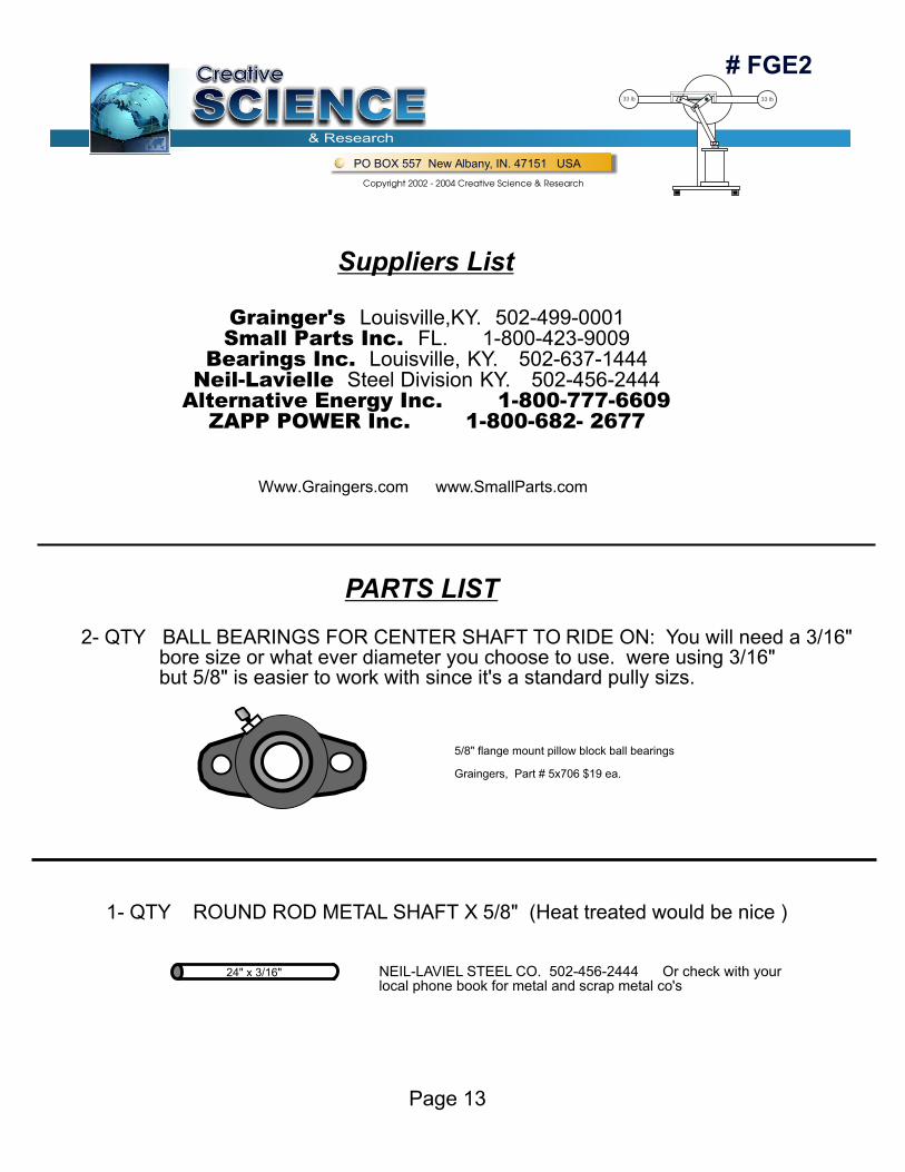
2- QTY BALL BEARINGS FOR CENTER SHAFT TO RIDE ON: You will need a 3/16" bore size or what ever diameter you choose to use. were using 3/16" but 5/8" is easier to work with since it's a standard pully sizs.
1- QTY ROUND ROD METAL SHAFT X 5/8" (Heat treated would be nice )
24" x 3/16" NEIL-LAVIEL STEEL CO. 502-456-2444 Or check with yourlocal phone book for metal and scrap metal co's
5/8" flange mount pillow block ball bearings
Graingers, Part # 5x706 $19 ea.
# FGE2
SCIENCESCIENCESCIENCECreativeCreative
& Research
PO BOX 557 New Albany, IN. 47151 USA
Copyright 2002 - 2004 Creative Science & Research
33 lb 33 lb
Page 13
Www.Graingers.com www.SmallParts.com
SIDE VIEW
Front ViewAttached
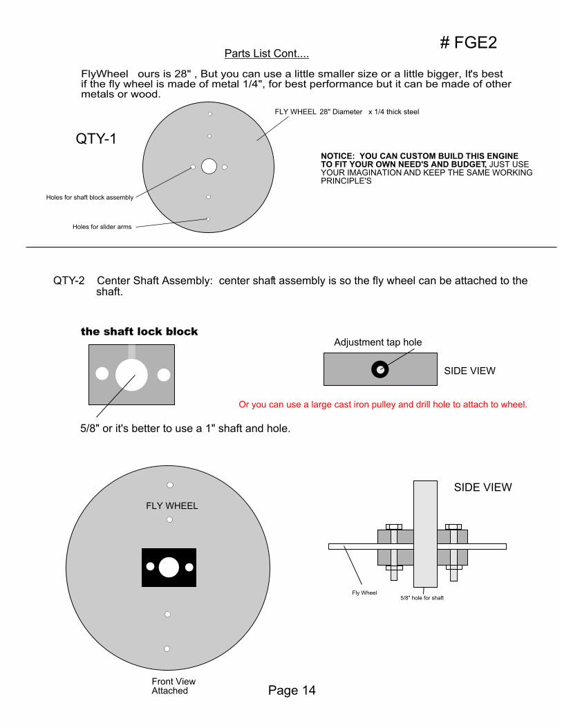
Parts List Cont....
FlyWheel ours is 28" , But you can use a little smaller size or a little bigger, It's best if the fly wheel is made of metal 1/4", for best performance but it can be made of other metals or wood.
FLY WHEEL 28" Diameter x 1/4 thick steel
NOTICE: YOU CAN CUSTOM BUILD THIS ENGINETO FIT YOUR OWN NEED'S AND BUDGET, JUST USEYOUR IMAGINATION AND KEEP THE SAME WORKINGPRINCIPLE'S
QTY-2 Center Shaft Assembly: center shaft assembly is so the fly wheel can be attached to the shaft.
5/8" or it's better to use a 1" shaft and hole.
the shaft lock block
5/8" hole for shaftFly Wheel
SIDE VIEW
Adjustment tap hole
QTY-1
# FGE2
Holes for shaft block assembly
Holes for slider arms
FLY WHEEL
Page 14
Or you can use a large cast iron pulley and drill hole to attach to wheel.
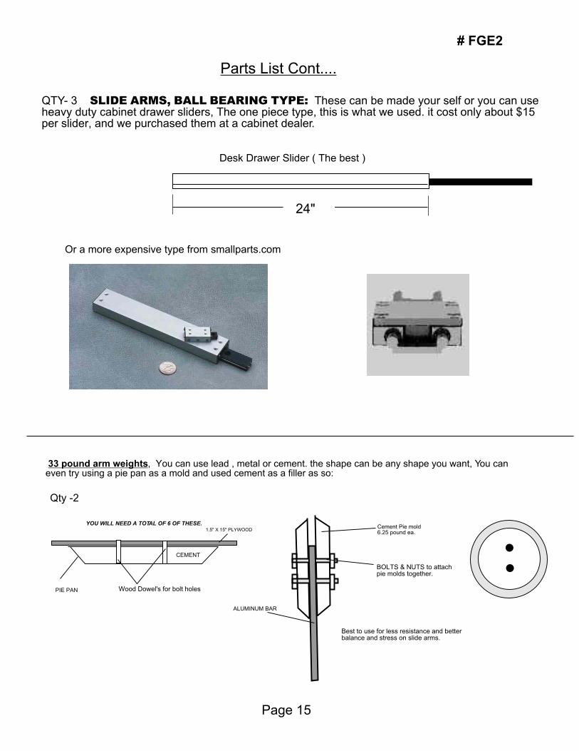
Parts List Cont....
QTY- 3 SLIDE ARMS, BALL BEARING TYPE: These can be made your self or you can use heavy duty cabinet drawer sliders, The one piece type, this is what we used. it cost only about $15 per slider, and we purchased them at a cabinet dealer.
24"
33 pound arm weights, You can use lead , metal or cement. the shape can be any shape you want, You can even try using a pie pan as a mold and used cement as a filler as so:
Wood Dowel's for bolt holes
YOU WILL NEED A TOTAL OF 6 OF THESE.
PIE PAN
CEMENT
1.5" X 15" PLYWOOD
ALUMINUM BAR
Best to use for less resistance and better balance and stress on slide arms.
Cement Pie mold6.25 pound ea.
BOLTS & NUTS to attachpie molds together.
Desk Drawer Slider ( The best )
Or a more expensive type from smallparts.com
Qty -2
Page 15
# FGE2
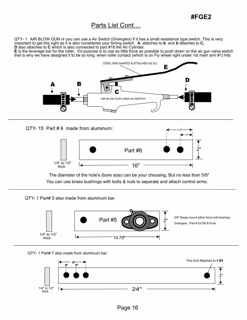
Parts List Cont....
QTY- 1 AIR BLOW GUN or you can use a Air Switch (Graingers) if it has a small resistance type switch. This is very important to get this right as it is also considered your timing switch. A attaches to b and b attaches to C,D also attaches to C which is also connected to part #18 the Air Cylinder.E is the leverage bar for the roller, it's purpose is to use as little force as possible to push down on the air gun valve switch that is why we have designed it to be so long. when roller contact (which is on Fly wheel right under 1st main arm #1) hits
STEEL BAR SHAPED & ATTACHED AS SO:
AIR BLOW GUN USED AS SWITCH
A B
E
C
D
QTY- 15 Part # 6 made from aluminum:
The diameter of the hole's (bore size) can be your choosing, But no less than 5/8"
You can use brass bushings with bolts & nuts to separate and attach control arms.
QTY- 1 Part# 5 also made from aluminum bar.
QTY- 1 Part# 7 also made from aluminum bar.
16"
Part #6
Part #5
1/4" to 1/2" thick
1/4" to 1/2" thick
1/4" to 1/2" thick
2"
2"
10.75"
24"
2"
4.75"
1"
5/8" flange mount pillow block ball bearings
Graingers, Part # 5x706 $19 ea.
This End Attaches to # 214"
2" 3"
Page 16
#FGE2
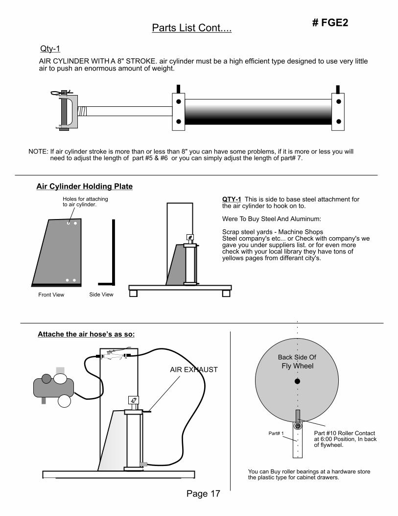
Parts List Cont....
AIR CYLINDER WITH A 8" STROKE. air cylinder must be a high efficient type designed to use very little air to push an enormous amount of weight.
NOTE: If air cylinder stroke is more than or less than 8" you can have some problems, if it is more or less you will need to adjust the length of part #5 & #6 or you can simply adjust the length of part# 7.
Front View
Holes for attachingto air cylinder.
Side View
QTY-1 This is side to base steel attachment for the air cylinder to hook on to.
Were To Buy Steel And Aluminum:
Scrap steel yards - Machine ShopsSteel company's etc... or Check with company's we gave you under suppliers list. or for even more check with your local library they have tons of yellows pages from differant city's.
AIR EXHAUST
Part# 1
Fly Wheel
Part #10 Roller Contactat 6:00 Position, In backof flywheel.
You can Buy roller bearings at a hardware storethe plastic type for cabinet drawers.
Back Side Of
Qty-1
Air Cylinder Holding Plate
Attache the air hose’s as so:
Page 17
# FGE2
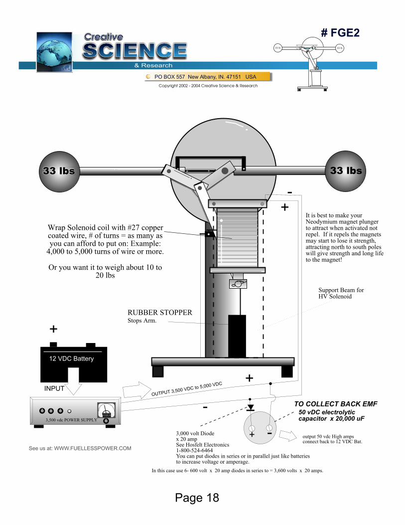
50 vDC electrolyticcapacitor x 20,000 uF
TO COLLECT BACK EMF
33 lbs 33 lbs
Support Beam forHV Solenoid
It is best to make your Neodymium magnet plungerto attract when activated not repel. If it repels the magnetsmay start to lose it strength,attracting north to south poleswill give strength and long lifeto the magnet!
+
+
+
-
-
-
Wrap Solenoid coil with #27 copper coated wire, # of turns = as many as you can afford to put on: Example:
4,000 to 5,000 turns of wire or more.
Or you want it to weigh about 10 to 20 lbs
RUBBER STOPPERStops Arm.
See us at: WWW.FUELLESSPOWER.COM
3,500 vdc POWER SUPPLY
+
12 VDC Battery
INPUTOUTPUT 3,500 VDC to 5,000 VDC
3,000 volt Diodex 20 ampSee Hosfelt Electronics1-800-524-6464You can put diodes in series or in parallel just like batteriesto increase voltage or amperage.
In this case use 6- 600 volt x 20 amp diodes in series to = 3,600 volts x 20 amps.
output 50 vdc High ampsconnect back to 12 VDC Bat.
# FGE2
SCIENCESCIENCESCIENCECreativeCreative
& Research
PO BOX 557 New Albany, IN. 47151 USA
Copyright 2002 - 2004 Creative Science & Research
33 lb 33 lb
Page 18
# FGE2
SCIENCESCIENCESCIENCECreativeCreative
& Research
PO BOX 557 New Albany, IN. 47151 USA
Copyright 2002 - 2004 Creative Science & Research
33 lb 33 lb
Page 19
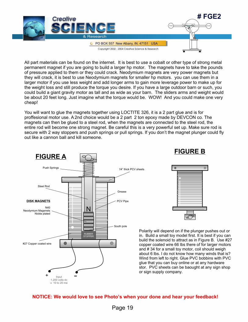
RUBBERSTOPPER
N
South pole
Input1,200 volts dcx 10 to 20 ma
Grease
Steel Rod
Push Springs
#27 Copper coated wire
!/4” thick PCV sheets
PCV Pipe
N40Neodymium Magenets
Nickle plated
+
All part materials can be found on the internet. It is best to use a cobalt or other type of strong metal permanent magnet if you are going to build a larger hp motor. The magnets have to take the pounds of pressure applied to them or they could crack. Neodymium magnets are very power magnets but they will crack, it is best to use Neodymium magnets for smaller hp motors. you can use them in a larger motor if you use less weight and add longer arms to gain more leverage power to make up for the weight loss and still produce the torque you desire. If you have a large outdoor barn or such, you could build a giant gravity motor as tall and as wide as your barn. The sliders arms and weight would be about 20 feet long. Just imagine what the torque would be. WOW! And you could make one very cheap!
You will want to glue the magnets together using LOCTITE 326, it is a 2 part glue and is for proffesional motor use. A 2nd choice would be a 2 part 2 ton epoxy made by DEVCON co. The magnets can then be glued to a steel rod, when the magnets are connected to the steel rod, the entire rod will become one strong magnet. Be careful this is a very powerful set up. Make sure rod is secure with 2 way stoppers and push springs or pull springs. If you don’t the magnet plunger could fly out like a cannon ball and kill someone.
DISK MAGNETS
Polarity will depend on if the plunger pushes out or in. Build a small toy model first. It is best if you can build the solenoid to attract as in Figure B. Use #27 copper coated wire 66 lbs there of for larger motors and # 34 for a small toy motor, coil should weigh about 6 lbs. I do not know how many winds that is?Wind from left to right. Glue PVC bobbins with PVC glue that you can buy online or at any hardware stor. PVC sheets can be baought at any sign shop or sign supply company.
FIGURE AFIGURE B
NOTICE: We would love to see Photo’s when your done and hear your feedback!
# FGE2
SCIENCESCIENCESCIENCECreativeCreative
& Research
PO BOX 557 New Albany, IN. 47151 USA
Copyright 2002 - 2004 Creative Science & Research
33 lb 33 lb
Page 20