Embed Size (px)
Citation preview
User Guide - English
Fujitsu battery unit
S26361-F5541-E414/-L414
May 2016

Copyright and Trademarks
Copyright © 2016 Fujitsu LIMITED.
All rights reserved.
Delivery subject to availability; right of technical modifications reserved.
All hardware and software names used are trademarks of their respective manufacturers.
– The contents of this manual may be revised without prior notice.
– Fujitsu assumes no liability for damages to third party copyrights or other rights arising from
the use of any information in this manual.
– No part of this manual may be reproduced in any form without the prior written permission
of Fujitsu.
Microsoft, Windows, Windows Server, and Hyper V are trademarks or registered trademarks of
Microsoft Corporation in the USA and other countries.
Intel and Xeon are trademarks or registered trademarks of Intel Corporation or its subsidiaries
in the USA and other countries.
FJBU User Guide 3
Before reading this manual
For your safety
This manual contains important information for safely and correctly using this
product.
Carefully read the manual before using this product. Pay particular attention to
the accompanying manual "Safety Notes and Regulations" and ensure these
safety notes are understood before using the product. Keep this manual and the
manual "Safety Notes and Regulations" in a safe place for easy reference while
using this product.
Radio interference
This product is a "Class A" ITE (Information Technology Equipment). In a
domestic environment this product may cause radio interference, in which case
the user may be required to take appropriate measures. VCCI-A
Aluminum electrolytic capacitors
The aluminum electrolytic capacitors used in the product's printed circuit board
assemblies and in the mouse and keyboard are limited-life components. Use of
these components beyond their operating life may result in electrolyte leakage or
depletion, potentially causing emission of foul odor or smoke. As a guideline, in a
normal office environment (25°C) operating life is not expected to be reached
within the maintenance support period (5 years).
However, operating life may be reached more quickly if, for example, the
product is used in a hot environment. The customer shall bear the cost of
replacing replaceable components which have exceeded their operating life.
Note that these are only guidelines, and do not constitute a guarantee of
trouble-free operation during the maintenance support period.
High safety use
This product has been designed and manufactured to be used in commercial
and/or industrial areas as a server.
When used as visual display workplace, it must not be placed in the direct field of
view to avoid incommoding reflections (applies only to TX server systems).The
device has not been designed or manufactured for uses which demand an
extremely high level of safety and carry a direct and serious risk of life or body if
such safety cannot be assured.

FJBU User Guide 4
These uses include control of nuclear reactions in nuclear power plants,
automatic airplane flight control, air traffic control, traffic control in mass transport
systems, medical devices for life support, and missile guidance control in
weapons systems (hereafter, "high safety use"). Customers should not use this
product for high safety use unless measures are in place for ensuring the level of
safety demanded of such use. Please consult the sales staff of Fujitsu if
intending to use this product for high safety use.
Measures against momentary voltage drop
This product may be affected by a momentary voltage drop in the power supply
caused by lightning. To prevent a momentary voltage drop, use of an AC
uninterruptible power supply is recommended.
(This notice follows the guidelines of Voltage Dip Immunity of Personal
Computer issued by JEITA, the Japan Electronics and Information Technology
Industries Association.)
Technology controlled by the Foreign Exchange and Foreign Trade
Control Law of Japan
Documents produced by Fujitsu may contain technology controlled by the
Foreign Exchange and Foreign Trade Control Law of Japan. Documents which
contain such technology should not be exported from Japan or transferred to
non-residents of Japan without first obtaining authorization in accordance with
the above law.
Harmonic Current Standards
This product conforms to harmonic current standard JIS C 61000-3-2.
FJBU User Guide 5
Contents
Fujitsu battery unit ....................................................................................... 1
1 Introduction ............................................................................................ 6
1.1 Documentation ..................................................................................... 6
2 Overview.................................................................................................. 7
2.1 Function overview ............................................................................... 7
2.2 Specification ......................................................................................... 8
2.3 Appearance ........................................................................................... 9
2.4 LED display ......................................................................................... 9
2.5 FJBU management software ............................................................ 10
2.6 Integration with ServerView ............................................................ 12
3 Trouble shooting ................................................................................... 14
3.1 FJBU alarm LED display ................................................................. 14
3.2 GEL of server (Maintenance lamp) .................................................. 14
3.3 OS application log .............................................................................. 15
3.4 TRAP .................................................................................................. 16
3.5 FJBU management software trouble shooting ............................... 16
4 FJBU management software ............................................................... 18
4.1 Screen image of FJBU management software ................................ 18
4.2 Example of SVOM screen ................................................................. 19
4.3 IPMI command specification ............................................................ 21

FJBU User Guide 6
1 Introduction This manual will familiarize you with FJBU that is designed for server battery
backup when power fail happened.
This manual informs you on the following topics:
● Chapter 2
This chapter gives an overview of the FJBU hardware.
● Chapter 3
This chapter gives a trouble shooting information.
● Chapter 4
This chapter gives a management software information.
1.1 Documentation
PRIMERGY manuals are available in PDF format on the ServerView Suite
DVD 2. The ServerView Suite DVD 2 is supplied with your server. If you no
longer have the ServerView Suite DVDs, you can obtain the relevant current
versions using the order number U15000-C289 (the order number for the
Japanese market: please refer to the configurator of the server
http://primeserver.fujitsu.com/primergy/system.html.
The PDF files of the manuals can also be downloaded free of charge from the
Internet. The overview page showing the online documentation available on the
Internet can be found using the URL (for EMEA market):
http://manuals.ts.fujitsu.com.
The PRIMERGY server documentation can be accessed using the Industry
standard servers navigation option. For the Japanese market please use the
URL: http://primeserver.fujitsu.com/primergy/manual.html.

FJBU User Guide 7
2 Overview The server can be equipped:
- With a standard power supply unit(permanently built-in)
The power supply unit adjusts automatically to any mains voltage in the
range of 100 V-240 V.
- Or one hot-plug FJBU(slide-in units)
The Fujitsu battery unit (FJBU) behaves as a modular UPS in server.
When power fail happened, server could operate by FJBU battery for a while.
For graceful shutdown, user should install management software and configure
shutdown timing.
2.1 Function overview
In this section, function and technical data of Fujitsu battery unit (hereafter, "FJBU") are provided. FJBU is battery unit for PRIMERGY.
FJBU behaves as a modular UPS in following server. When power fail happened,
server could operate by FJBU battery for a while. FJBU supports hot plugging, and can be replaced during operation. You can download the management software (FJBU management software) for following OS. FJBU management software supports shutdown configuration and management of FJBU status. Support server: TX1330 M1/RX1330 M1 Support OS: Windows Server 2012 R2, Windows Server 2012, Windows Server 2008 R2 SP1, Windows Server 2008 SP2 FJBU management software is not available in Red Hat Enterprise Linux environment. Please use the IPMI function at Linux environment.

FJBU User Guide 8
2.2 Specification
Table 1: FJBU specification
Item Specification
Product name Fujitsu Battery Unit
Parts number S26361-F5541-E414/-L414
Maximum watege 280W
Backup duration Max. 4minute(280W)
Charge duration 4 hours to 90%,5 hours to 100%
Battery spec. Nickel Metal-Hydrite battery
Battery Life time 5 years
Input/Output voltage 12V DC
Dimention [mm](W x D x H) 57×358×39
Weight 1.2kg
Backup duration of FJBU depend on following table.
Table 2: Backup duration and power consumption
Server power consumption(W) Backup Duration
280 4minute
250 4minute30seconds
200 5 minute 40 seconds
150 7 minute 37 seconds
100 11 minute 30 seconds
50 23 minute 10 seconds
FJBU User Guide 9
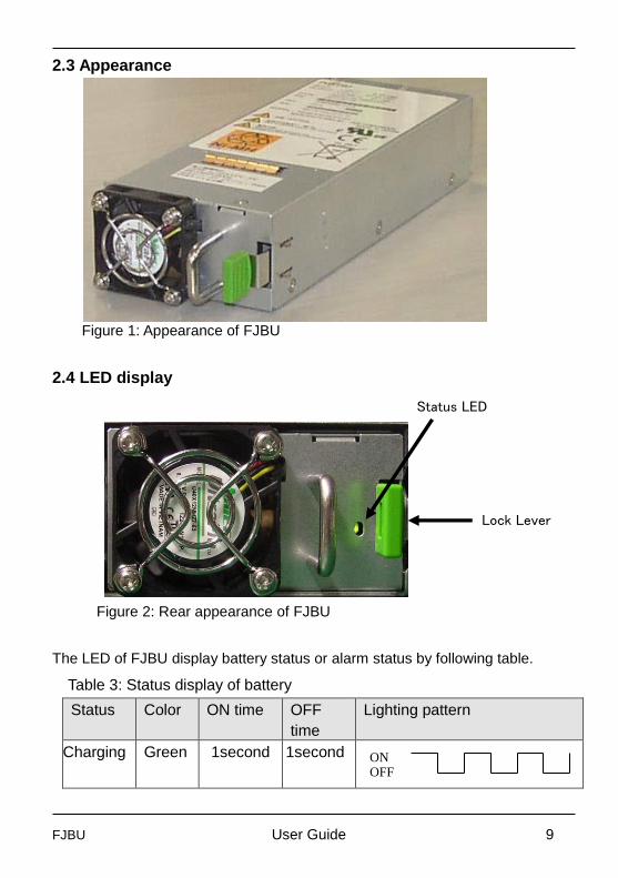
2.3 Appearance
Figure 1: Appearance of FJBU
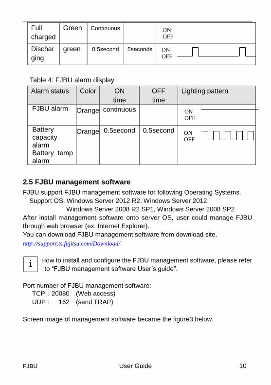
2.4 LED display
Figure 2: Rear appearance of FJBU
The LED of FJBU display battery status or alarm status by following table.
Table 3: Status display of battery
Status Color ON time OFF
time
Lighting pattern
Charging Green 1second 1second
ON OFF
Status LED
Lock Lever
FJBU User Guide 10
Full
charged
Green Continuous
Dischar
ging
green 0.5second 5seconds
Table 4: FJBU alarm display
Alarm status Color ON
time
OFF
time
Lighting pattern
FJBU alarm Orange continuous
Battery capacity alarm Battery temp alarm
Orange 0.5second 0.5second
2.5 FJBU management software
FJBU support FJBU management software for following Operating Systems.
Support OS: Windows Server 2012 R2, Windows Server 2012,
Windows Server 2008 R2 SP1, Windows Server 2008 SP2
After install management software onto server OS, user could manage FJBU
through web browser (ex. Internet Explorer).
You can download FJBU management software from download site.
http://support.ts.fujitsu.com/Download/
How to install and configure the FJBU management software, please refer
to “FJBU management software User’s guide”.
Port number of FJBU management software:
TCP:20080 (Web access)
UDP: 162 (send TRAP)
Screen image of management software became the figure3 below.
ON OFF
ON OFF
ON OFF
ON OFF
i

FJBU User Guide 11
Figure 3: example of FJBU management software screen
Table 5: function overview of management software
Status display Display normal or fault status of FJBU, and
status of charge and event log.
SNMP trap SNMP trap of FJBU error/fault. (notify to SVOM
through SNMP)
Direct management Management software is installed in server OS,
and user could manage FJBU through SVOM
console. (User could manage FJBU through
FJBU management software without SVOM
console.)
Remote
management
Through SVOM function, user could manage
FJBU from remote.
Shutdown Graceful shutdown
Configure shutdown timing
FJBU User Guide 12
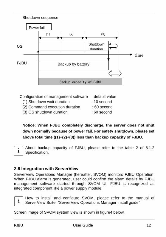
Shutdown sequence
OS
FJBU
Configuration of management software default value
(1) Shutdown wait duration : 10 second
(2) Command execution duration : 60 second
(3) OS shutdown duration : 60 second
Notice: When FJBU completely discharge, the server does not shut
down normally because of power fail. For safety shutdown, please set
above total time ((1)+(2)+(3)) less than backup capacity of FJBU.
About backup capacity of FJBU, please refer to the table 2 of 6.1.2 Specification.
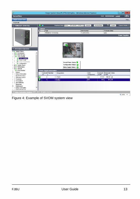
2.6 Integration with ServerView
ServerView Operations Manager (hereafter, SVOM) monitors FJBU Operation. When FJBU alarm is generated, user could confirm the alarm details by FJBU management software started through SVOM UI. FJBU is recognized as integrated component like a power supply module.
How to install and configure SVOM, please refer to the manual of ServerView Suite. “ServerView Operations Manager install guide”
Screen image of SVOM system view is shown in figure4 below.
Power fail
time
(2)
Shutdown
duration
(3) (1)
Backup by battery
Backup capacity of FJBU
i
i
FJBU User Guide 13
Figure 4: Example of SVOM system view
FJBU User Guide 14
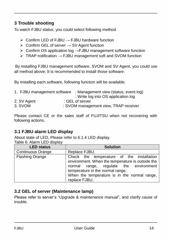
3 Trouble shooting
To watch FJBU status, you could select following method.
Confirm LED of FJBU → FJBU hardware function
Confirm GEL of server → SV Agent function
Confirm OS application log →FJBU management software function
TRAP notification → FJBU management soft and SVOM function
By installing FJBU management software, SVOM and SV Agent, you could use
all method above. It is recommended to install those software.
By installing each software, following function will be available.
1. FJBU management software : Management view (status, event log)
: Write log into OS application log 2. SV Agent : GEL of server 3. SVOM : SVOM management view, TRAP receiver
Please contact CE or the sales staff of FUJITSU when not recovering with following actions.
3.1 FJBU alarm LED display
About state of LED, Please refer to 6.1.4 LED display. Table 6: Alarm LED display
LED status Solution
Continuous Orange Replace FJBU.
Flashing Orange Check the temperature of the installation environment. When the temperature is outside the normal range, regulate the environment temperature in the normal range. When the temperature is in the normal range, replace FJBU.
3.2 GEL of server (Maintenance lamp)
Please refer to server’s “Upgrade & maintenance manual”, and clarify cause of trouble.

FJBU User Guide 15
3.3 OS application log
FJBU management software writes FJBU information/warning/error message to Windows application log. The error messages of Windows application log and solutions are shown below. Source: FJBUService
Table 7: OS application log list
Message ID Solution
Communication error 1 Check mounting of FJBU. Insert FJBU Correctly in the slot.
Recovered from a communication error
2 The action is unnecessary.
Battery error (DC/DC converter temperature alarm)
4 Replace FJBU.
Battery error (DC/DC converter voltage alarm)
Battery error (Charge path (FET) defects)
Battery error (Discharge path (FET) defects)
Battery error (Thermistor defects)
Battery error (Charge circuit defects)
Battery error (DC 12V over voltage alarm or DC 12V low voltage alarm)
Battery error (FAN defects)
Battery error (Trickle charge defects)
Battery error (EEPROM access defects)
Battery error (Overcurrent alarm in discharging (SW))
Battery error (Overcurrent alarm in charging (SW))
Battery warning (Battery capacity alarm)
3 Check the temperature of the installation environment. When the temperature is outside the normal range, regulate the environment temperature in the normal range. When the temperature is in the normal range, replace FJBU.
Battery warning (Low battery voltage alarm)
Battery warning (Battery temperature alarm)
Battery warning (Impedance alarm)

FJBU User Guide 16
3.4 TRAP
Table 8: TRAP message list
Message Importance
Number
Solution
Communication with the Internal Battery Unit of server %s lost. Information URL: %s.
Minor 2001 Check mounting of FJBU. Insert FJBU Correctly in the slot.
Communication with the Internal Battery Unit of server %s established again. Information URL: %s.
Info. 2002 The action is unnecessary.
The Internal Battery Unit has detected an major problem of server %s(detail: %s). Information URL: %s.
Major 2004 Replace FJBU.
The Internal Battery Unit has detected an minor problem of server %s(detail: %s). Information URL: %s.
Minor 2003 Check the temperature of the installation environment. When the temperature is outside the normal range, regulate the environment temperature in the normal range. When the temperature is in the normal range, replace FJBU.
3.5 FJBU management software trouble shooting
Table 9: FJBU management software trouble shooting
Problem Solution
“Communication error” is written in the event log.
Check mounting of FJBU. Insert FJBU Correctly in the PSU slot. When FJBU is pulled out as hot plug, “Communication error” is written in the event log.
“Recovered from a communication error” is written in the event log.
The action is unnecessary. When FJBU is pulled out as hot plug, “Recovered from a communication error” is written in the event log.
FJBU management software is not normally displayed through remote SVOM.
Restart FJBUService.
Status and Battery capacity is Restart FJBUService.
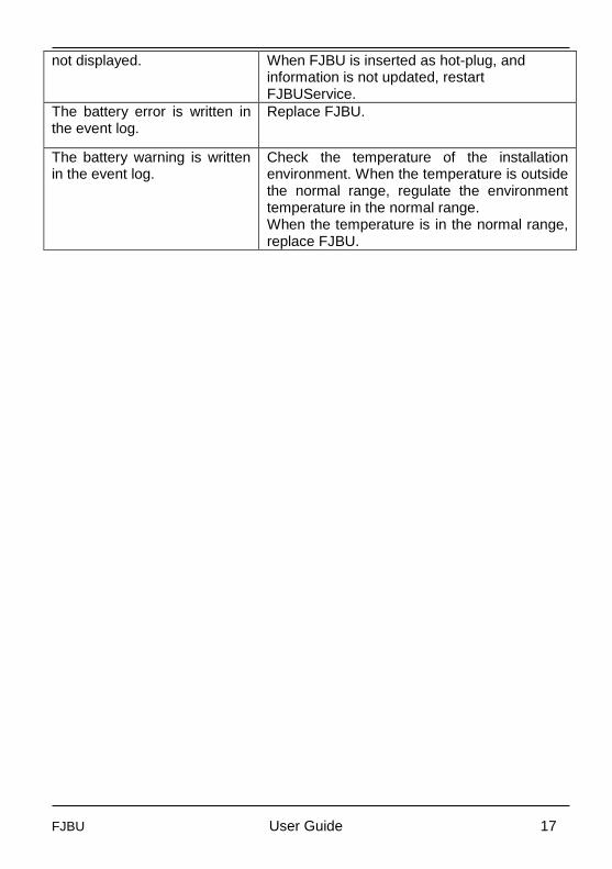
FJBU User Guide 17
not displayed. When FJBU is inserted as hot-plug, and information is not updated, restart FJBUService.
The battery error is written in the event log.
Replace FJBU.
The battery warning is written in the event log.
Check the temperature of the installation environment. When the temperature is outside the normal range, regulate the environment temperature in the normal range. When the temperature is in the normal range, replace FJBU.
FJBU User Guide 18
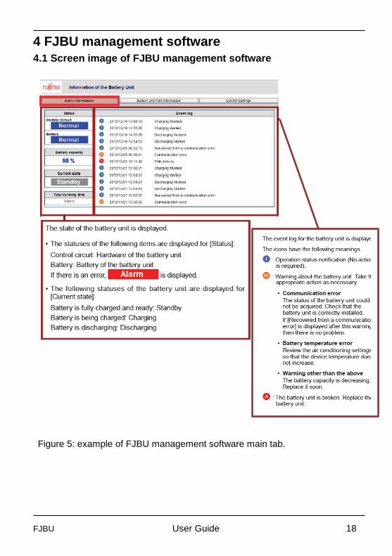
4 FJBU management software
4.1 Screen image of FJBU management software
Figure 5: example of FJBU management software main tab.
FJBU User Guide 19
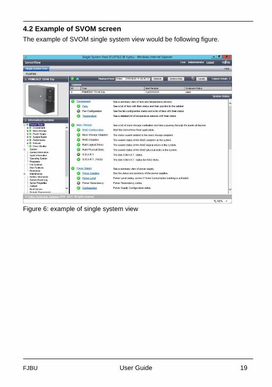
4.2 Example of SVOM screen
The example of SVOM single system view would be following figure.
Figure 6: example of single system view
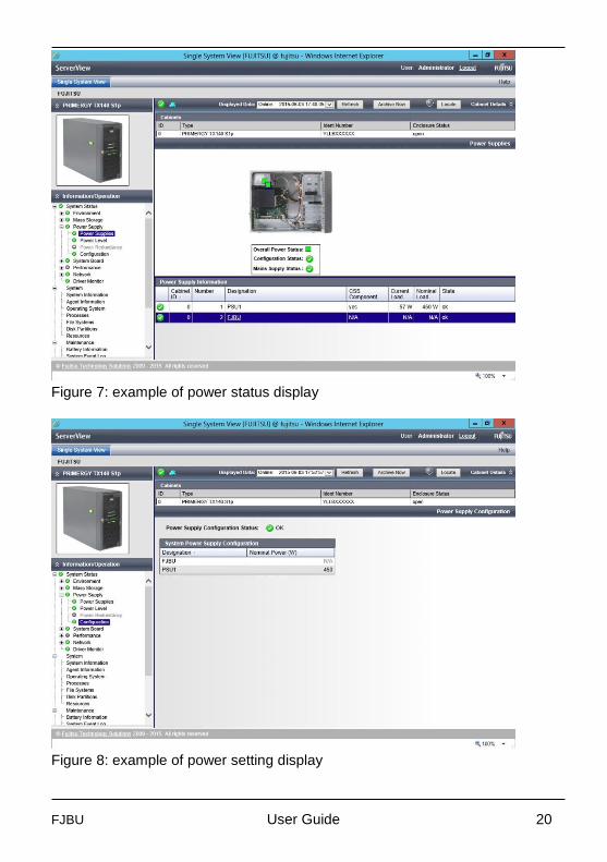
FJBU User Guide 20
Figure 7: example of power status display
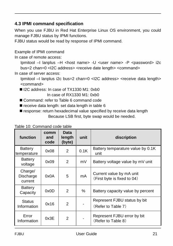
Figure 8: example of power setting display
FJBU User Guide 21
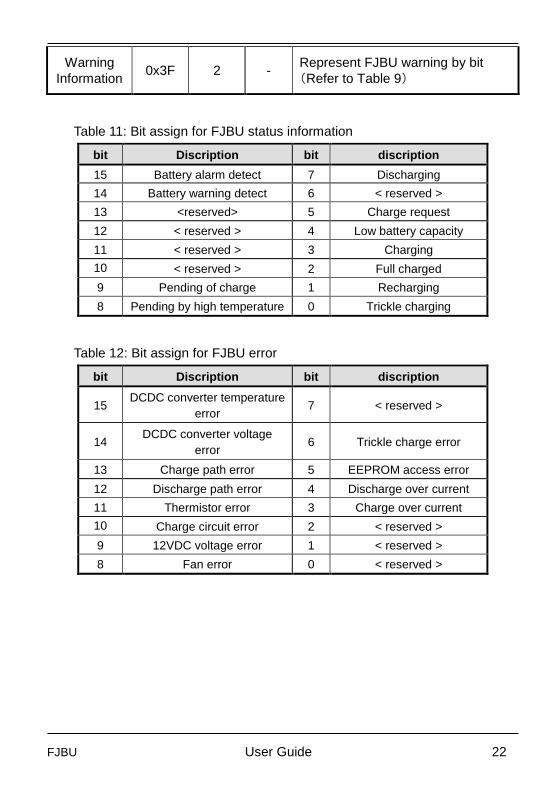
4.3 IPMI command specification
When you use FJBU in Red Hat Enterprise Linux OS environment, you could
manage FJBU status by IPMI functions.
FJBU status would be read by response of IPMI command.
Example of IPMI command
In case of remote access:
Ipmitool –I lanplus –H <host name> -U <user name> -P <password> i2c
bus=2 chan=0 <I2C address> <receive date length> <command>
In case of server access:
Ipmitool –I lanplus i2c bus=2 chan=0 <I2C address> <receive data length>
<command>
I2C address: In case of TX1330 M1: 0xb0
In case of RX1330 M1: 0xb0
Command: refer to Table 6 command code
receive data length: set data length in table 6
response: return hexadecimal value specified by receive data length
Because LSB first, byte swap would be needed.
Table 10: Command code table
function
command
code
Data length (byte)
unit discription
Battery
temperature 0x08 2 0.1K
Battery temparature value by 0.1K
unit
Battery
voltage 0x09 2 mV Battery voltage value by mV unit
Charge/
Discharge
current
0x0A 5 mA Current value by mA unit
(First byte is fixed to 04)
Battery
Capacity
0x0D 2 % Battery capacity value by percent
Status
Information 0x16 2 -
Represent FJBU status by bit
(Refer to Table 7)
Error
Information 0x3E 2 -
Represent FJBU error by bit
(Refer to Table 8)
FJBU User Guide 22
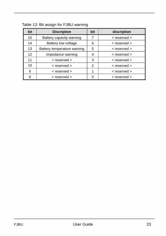
Warning
Information 0x3F 2 -
Represent FJBU warning by bit
(Refer to Table 9)
Table 11: Bit assign for FJBU status information
bit Discription bit discription
15 Battery alarm detect 7 Discharging
14 Battery warning detect 6 < reserved >
13 <reserved> 5 Charge request
12 < reserved > 4 Low battery capacity
11 < reserved > 3 Charging
10
9
< reserved > 2 Full charged
9 Pending of charge 1 Recharging
8 Pending by high temperature 0 Trickle charging
Table 12: Bit assign for FJBU error
bit Discription bit discription
15 DCDC converter temperature
error 7 < reserved >
14 DCDC converter voltage
error 6 Trickle charge error
13 Charge path error 5 EEPROM access error
12 Discharge path error 4 Discharge over current
11 Thermistor error 3 Charge over current
10
9
Charge circuit error 2 < reserved >
9 12VDC voltage error 1 < reserved >
8 Fan error 0 < reserved >
FJBU User Guide 23
Table 13: Bit assign for FJBU warning
bit Discription bit discription
15 Battery capacity warning 7 < reserved >
14 Battery low voltage 6 < reserved >
13 Battery temperature warning 5 < reserved >
12 Impedance warning 4 < reserved >
11 < reserved > 3 < reserved >
10
9
< reserved > 2 < reserved >
9 < reserved > 1 < reserved >
8 < reserved > 0 < reserved >


![ホワイトペーパー - Fujitsu...ホワイトペーパー - Fujitsu ... ディスク []](https://img.pdfslide.net/doc/110x75/5f69c50e8cd17923e37b26af/fffffff-fujitsu-fffffff-fujitsu-f.jpg)