Embed Size (px)
Citation preview
FUJITSU Cloud Service K5
IaaS Service Portal User Guide
Version 3.0
FUJITSU LIMITED
i
Preface
Purpose of This Document
This guide describes the operating procedures of the IaaS Service Portal for
the services provided by FUJITSU Cloud Service K5.
You are recommended to also refer to the following related manuals.
- IaaS Features Handbook
- IaaS API References
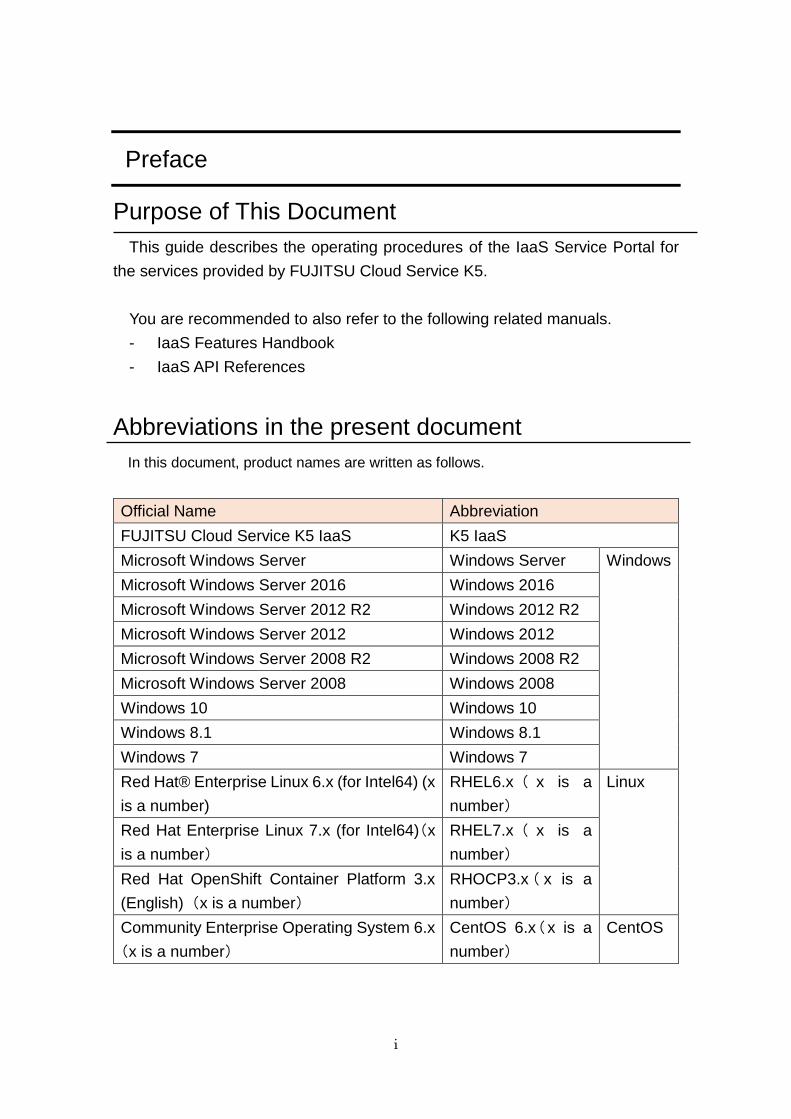
Abbreviations in the present document
In this document, product names are written as follows.
Official Name Abbreviation
FUJITSU Cloud Service K5 IaaS K5 IaaS
Microsoft Windows Server Windows Server Windows
Microsoft Windows Server 2016 Windows 2016
Microsoft Windows Server 2012 R2 Windows 2012 R2
Microsoft Windows Server 2012 Windows 2012
Microsoft Windows Server 2008 R2 Windows 2008 R2
Microsoft Windows Server 2008 Windows 2008
Windows 10 Windows 10
Windows 8.1 Windows 8.1
Windows 7 Windows 7
Red Hat® Enterprise Linux 6.x (for Intel64) (x
is a number)
RHEL6.x ( x is a
number)
Linux
Red Hat Enterprise Linux 7.x (for Intel64)(x
is a number)
RHEL7.x ( x is a
number)
Red Hat OpenShift Container Platform 3.x
(English) (x is a number)
RHOCP3.x ( x is a
number)
Community Enterprise Operating System 6.x
(x is a number)
CentOS 6.x(x is a
number)
CentOS
ii
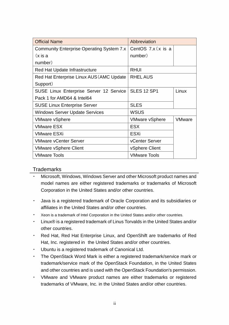
Official Name Abbreviation
Community Enterprise Operating System 7.x
(x is a
number)
CentOS 7.x(x is a
number)
Red Hat Update Infrastructure RHUI
Red Hat Enterprise Linux AUS(AMC Update
Support)
RHEL AUS
SUSE Linux Enterprise Server 12 Service
Pack 1 for AMD64 & Intel64
SLES 12 SP1 Linux
SUSE Linux Enterprise Server SLES
Windows Server Update Services WSUS
VMware vSphere VMware vSphere VMware
VMware ESX ESX
VMware ESXi ESXi
VMware vCenter Server vCenter Server
VMware vSphere Client vSphere Client
VMware Tools VMware Tools
Trademarks
・ Microsoft, Windows, Windows Server and other Microsoft product names and
model names are either registered trademarks or trademarks of Microsoft
Corporation in the United States and/or other countries.
・ Java is a registered trademark of Oracle Corporation and its subsidiaries or
affiliates in the United States and/or other countries.
・ Xeon is a trademark of Intel Corporation in the United States and/or other countries.
・ Linux® is a registered trademark of Linus Torvalds in the United States and/or
other countries.
・ Red Hat, Red Hat Enterprise Linux, and OpenShift are trademarks of Red
Hat, Inc. registered in the United States and/or other countries.
・ Ubuntu is a registered trademark of Canonical Ltd.
・ The OpenStack Word Mark is either a registered trademark/service mark or
trademark/service mark of the OpenStack Foundation, in the United States
and other countries and is used with the OpenStack Foundation's permission.
・ VMware and VMware product names are either trademarks or registered
trademarks of VMware, Inc. in the United States and/or other countries.
iii
・ SAP and SAP logos, SAP R/3, mySAP.com, mySAP Business Suite, and
other SAP products are either trademarks or registered trademarks of SAP
AG in Germany and/or other countries.
・ Akamai and Akamai Intelligent Platform are either trademarks or registered
trademarks of Akamai Technologies, Inc.
・ Novell is a registered trademark of Novell Inc. in the United States and/or
other countries; SUSE and SUSE logos are either trademarks or registered
trademarks of SUSE LLC in the United States and/or other countries.
・ Other company names and product names mentioned in this manual are
trademarks or registered trademarks of their respective companies.
In addition, the company name and product name described in this document are
trademarks or registered trademarks of each company.
Compliance with Export Control Regulations
When exporting this document or providing it to a third party, check the export
control laws and regulations of your country and the U.S. and take necessary
procedures.
Notices
- The content of this manual is subject to change without notice.
- The content of this manual shall not be reproduced without express written
permission from FUJITSU LIMITED.
- FUJITSU LIMITED shall bear no responsibility for any claims of violation of
a third party's patent or other rights arising from the use of the data described
in this document.
iv
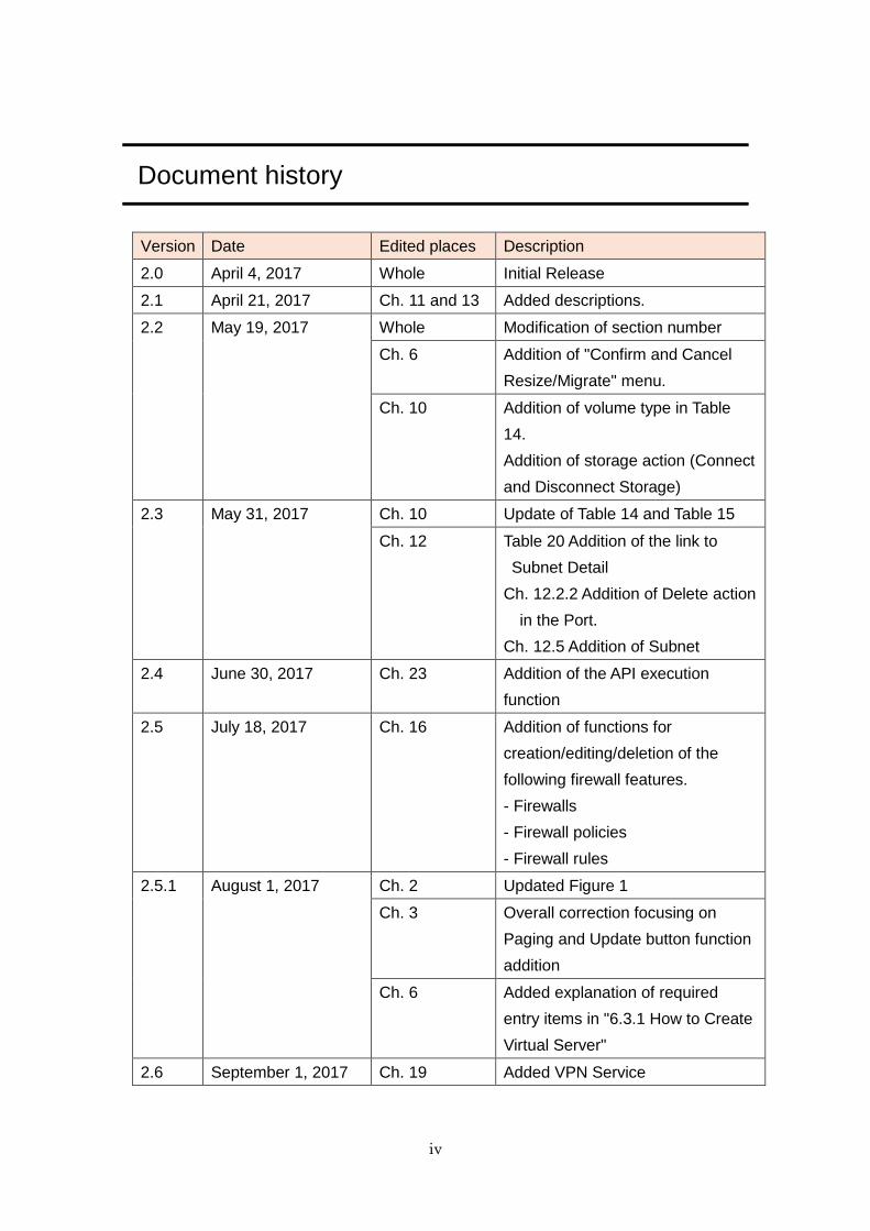
Document history
Version Date Edited places Description
2.0 April 4, 2017 Whole Initial Release
2.1 April 21, 2017 Ch. 11 and 13 Added descriptions.
2.2 May 19, 2017 Whole Modification of section number
Ch. 6 Addition of "Confirm and Cancel
Resize/Migrate" menu.
Ch. 10 Addition of volume type in Table
14.
Addition of storage action (Connect
and Disconnect Storage)
2.3 May 31, 2017 Ch. 10 Update of Table 14 and Table 15
Ch. 12 Table 20 Addition of the link to
Subnet Detail
Ch. 12.2.2 Addition of Delete action
in the Port.
Ch. 12.5 Addition of Subnet
2.4 June 30, 2017 Ch. 23 Addition of the API execution
function
2.5 July 18, 2017 Ch. 16 Addition of functions for
creation/editing/deletion of the
following firewall features.
- Firewalls
- Firewall policies
- Firewall rules
2.5.1 August 1, 2017 Ch. 2 Updated Figure 1
Ch. 3 Overall correction focusing on
Paging and Update button function
addition
Ch. 6 Added explanation of required
entry items in "6.3.1 How to Create
Virtual Server"
2.6 September 1, 2017 Ch. 19 Added VPN Service
v
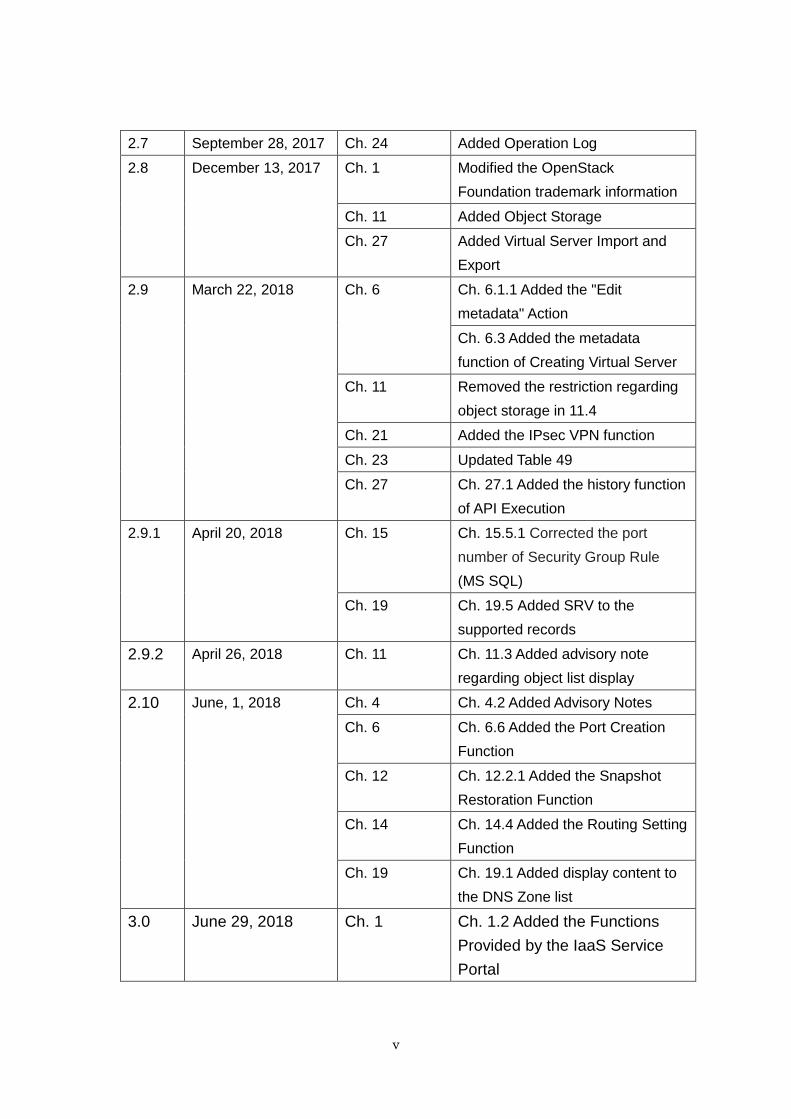
2.7 September 28, 2017 Ch. 24 Added Operation Log
2.8 December 13, 2017 Ch. 1 Modified the OpenStack
Foundation trademark information
Ch. 11 Added Object Storage
Ch. 27 Added Virtual Server Import and
Export
2.9 March 22, 2018 Ch. 6
Ch. 6.1.1 Added the "Edit
metadata" Action
Ch. 6.3 Added the metadata
function of Creating Virtual Server
Ch. 11 Removed the restriction regarding
object storage in 11.4
Ch. 21 Added the IPsec VPN function
Ch. 23 Updated Table 49
Ch. 27
Ch. 27.1 Added the history function
of API Execution
2.9.1 April 20, 2018 Ch. 15 Ch. 15.5.1 Corrected the port
number of Security Group Rule
(MS SQL)
Ch. 19 Ch. 19.5 Added SRV to the
supported records
2.9.2 April 26, 2018 Ch. 11 Ch. 11.3 Added advisory note
regarding object list display
2.10 June, 1, 2018 Ch. 4 Ch. 4.2 Added Advisory Notes
Ch. 6 Ch. 6.6 Added the Port Creation
Function
Ch. 12 Ch. 12.2.1 Added the Snapshot
Restoration Function
Ch. 14 Ch. 14.4 Added the Routing Setting
Function
Ch. 19 Ch. 19.1 Added display content to
the DNS Zone list
3.0 June 29, 2018 Ch. 1 Ch. 1.2 Added the Functions
Provided by the IaaS Service
Portal
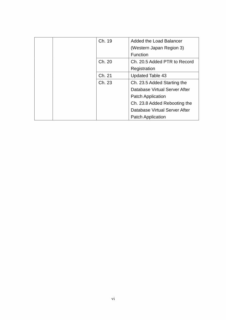
vi
Ch. 19 Added the Load Balancer
(Western Japan Region 3)
Function
Ch. 20 Ch. 20.5 Added PTR to Record
Registration
Ch. 21 Updated Table 43
Ch. 23 Ch. 23.5 Added Starting the
Database Virtual Server After
Patch Application
Ch. 23.8 Added Rebooting the
Database Virtual Server After
Patch Application
vii
Contents
Preface .................................................................................................................................... i
Document history ................................................................................................................. iv
Chapter 1 Introduction ......................................................................................................... 1
1.1 IaaS Service Portal Overview ................................................................................... 1
1.1.1 IaaS Service Portal ......................................................................................... 1
1.1.2 Recommended Environment .......................................................................... 1
1.2 Functions Provided by the IaaS Service Portal ....................................................... 2
Chapter 2 Overall Structure ................................................................................................ 5
2.1 GUI Structure ............................................................................................................ 5
Chapter 3 Common Operations ........................................................................................... 6
3.1 Description .................................................................................................................. 6
3.1.1 System Area Common Operations ................................................................. 6
3.1.2 Display Area Common Operations ................................................................. 7
Chapter 4 Login .................................................................................................................... 8
4.1 How to Login .............................................................................................................. 8
4.2 Advisory Notes ........................................................................................................... 9
Chapter 5 Top ...................................................................................................................... 10
5.1 Alarm ........................................................................................................................ 10
5.1.1 Select Alarm ................................................................................................... 11
5.1.2 Alarm History ................................................................................................. 11
5.1.3 Graph ............................................................................................................. 12
5.2 Service Usage ........................................................................................................... 12
5.2.1 Select Graph of Service Usage ..................................................................... 13
5.2.2 Graph ............................................................................................................. 13
5.2.3 Ranking .......................................................................................................... 14
5.3 Resource Usage ........................................................................................................ 15
Chapter 6 Virtual Server .................................................................................................... 16
6.1 Virtual Servers List ................................................................................................. 16
6.1.1 Action ............................................................................................................. 17
6.2 Virtual Server Details .............................................................................................. 19
6.2.1 Action ............................................................................................................. 21
6.3 Create Virtual Server .............................................................................................. 22
viii
6.3.1 How to Create Virtual Server ....................................................................... 22
6.4 Edit Virtual Server................................................................................................... 26
6.4.1 How to Edit Virtual Server ........................................................................... 26
6.5 Resize Virtual Server ............................................................................................... 27
6.5.1 How to Resize Virtual Server ....................................................................... 27
6.6 Port Creation ............................................................................................................ 28
6.6.1 How to Create a Port .................................................................................... 28
Chapter 7 Key Pair ............................................................................................................. 31
7.1 Key Pair List ............................................................................................................ 31
7.2 Key Pair Creation ...................................................................................................... 31
7.2.1 How to Create a Key Pair ............................................................................... 31
7.3 Key Pair Import .......................................................................................................... 32
7.3.1 How to import the key pair .............................................................................. 32
7.4 Key Pair Details ......................................................................................................... 34
7.5 Key Pair Deletion ..................................................................................................... 35
7.5.1 How to delete a key pair ................................................................................. 35
Chapter 8 Image .................................................................................................................. 36
8.1 Image List ................................................................................................................. 36
8.1.1 Action ............................................................................................................. 37
8.2 Image Details ........................................................................................................... 38
Chapter 9 Schedule ............................................................................................................. 39
9.1 Schedule List ............................................................................................................ 39
9.2 Create Schedule ....................................................................................................... 39
9.2.1 How to Create Schedule................................................................................ 39
9.3 Schedule Details ........................................................................................................ 43
9.4 Schedule Deletion ..................................................................................................... 44
9.4.1 How to delete Schedule ................................................................................. 44
Chapter 10 Storage ............................................................................................................. 45
10.1 Storage List .............................................................................................................. 45
10.1.1 Action ............................................................................................................. 46
10.2 Storage Details ......................................................................................................... 47
10.3 Create Storage .......................................................................................................... 49
10.3.1 How to Create Storage .................................................................................. 49
10.4 Edit Storage .............................................................................................................. 50
10.4.1 How to Edit Storage ...................................................................................... 50
10.5 Disconnect Storage ................................................................................................... 50
ix
10.6 Connect Storage ....................................................................................................... 50
10.7 Create Snapshot ....................................................................................................... 50
10.7.1 How to Create Snapshot ............................................................................... 50
Chapter 11 Object Storage ................................................................................................. 51
11.1 Function Overview ................................................................................................... 51
11.2 Usage Methods of Object Storage ........................................................................... 52
11.2.1 Create a Container ........................................................................................ 52
11.2.2 Create an Object ............................................................................................ 56
11.2.3 Download an Object ...................................................................................... 61
11.2.4 Import a VM Image ....................................................................................... 61
11.3 Advisory Notes ......................................................................................................... 62
Chapter 12 Snapshot .......................................................................................................... 63
12.1 Snapshot List Screen ............................................................................................... 63
12.1.1 Action ............................................................................................................. 64
12.2 Snapshot Details Screen .......................................................................................... 64
12.2.1 Restore a Snapshot ....................................................................................... 65
12.3 Edit Snapshot Screen .............................................................................................. 66
12.4 Advisory Notes ......................................................................................................... 66
Chapter 13 Virtual Network .............................................................................................. 67
13.1 Virtual Network List ................................................................................................ 67
13.1.1 Action ............................................................................................................. 68
13.2 Virtual Network Details .......................................................................................... 68
13.2.1 Action for Subnet........................................................................................... 70
13.2.2 Action for Port ............................................................................................... 70
13.3 Create Virtual Network ........................................................................................... 70
13.3.1 How to Create Virtual Network ................................................................... 70
13.4 Edit Virtual Network ............................................................................................... 74
13.4.1 How to Edit Virtual Network ....................................................................... 74
13.5 Add Subnet ............................................................................................................... 74
Chapter 14 Virtual Router ................................................................................................. 75
14.1 Virtual router list ..................................................................................................... 75
14.1.1 Action ............................................................................................................. 76
14.2 Virtual Router Overview ......................................................................................... 76
14.2.1 Action ............................................................................................................. 77
14.3 Virtual Router Creation ........................................................................................... 78
14.3.1 How to create a virtual router ...................................................................... 78
x
14.4 Edit a Virtual Router ............................................................................................... 78
14.4.1 How to edit a virtual router ......................................................................... 78
14.5 Add interface ............................................................................................................ 79
Chapter 15 Security Group ................................................................................................ 80
15.1 Security Group List .................................................................................................. 80
15.1.1 About Operation ............................................................................................ 80
15.2 Security Group Creation .......................................................................................... 81
15.2.1 How to create a security group..................................................................... 81
15.3 Security Group Details ............................................................................................ 82
15.4 Manage Security Group Rules ................................................................................ 83
15.4.1 How to Transfer to the Rule Management Screen...................................... 84
15.5 Addition of Security Group Rules ........................................................................... 85
15.5.1 How to Add Security Group Rules ............................................................... 85
15.6 Export Security Group Rules .................................................................................. 87
15.6.1 How to Export Rules ..................................................................................... 87
15.7 Import Security Group Rules .................................................................................. 87
15.7.1 How to Import Rules ..................................................................................... 87
15.8 Deletion of Security Group Rules ........................................................................... 88
15.8.1 How to Delete Rules ...................................................................................... 88
15.9 Editing a Security Group ......................................................................................... 89
15.9.1 How to Edit a Security Group ...................................................................... 89
15.10 Deletion of Security Group ............................................................................... 90
15.10.1 How to Delete a Security Group .................................................................. 90
Chapter 16 Global IP .......................................................................................................... 91
16.1 Global IP List ........................................................................................................... 91
16.1.1 Action ............................................................................................................. 91
16.2 Reserved Global IP ................................................................................................... 91
16.3 Allocate Global IP .................................................................................................... 92
16.4 Deallocate Global IP ................................................................................................ 93
16.5 Release Global IP ..................................................................................................... 93
Chapter 17 Firewall ............................................................................................................ 94
17.1 Function Overview ................................................................................................... 94
17.2 Firewall List Screen ................................................................................................. 95
17.3 Firewall Creation Procedure ................................................................................... 96
17.3.1 Firewall Rule Sorting Operation .................................................................. 98
17.4 Advisory Notes ....................................................................................................... 100
xi
Chapter 18 Load Balancer................................................................................................ 101
18.1 Load Balancer List ................................................................................................. 101
18.1.1 Action ........................................................................................................... 101
18.2 Load Balancer Details ........................................................................................... 102
18.3 Create Load Balancer ............................................................................................ 105
18.3.1 How to Create Load Balancer .................................................................... 105
18.4 Add Subnet ............................................................................................................. 107
18.4.1 How to Add Subnet ..................................................................................... 107
18.5 Delete Subnet ......................................................................................................... 108
18.5.1 How to Delete Subnet ................................................................................. 108
18.6 Add Listener ........................................................................................................... 108
18.6.1 How to Add Listener ................................................................................... 108
18.7 Delete Listener ....................................................................................................... 108
18.8 Add Virtual Server ................................................................................................. 108
18.8.1 How to Add Virtual Server ......................................................................... 108
18.9 Delete Virtual Server ............................................................................................. 108
18.9.1 How to Delete Virtual Server ..................................................................... 109
18.10 Create Session Persistence Policy ................................................................. 109
18.11 Create SorryServer Policy .............................................................................. 109
18.11.1 How to Create SorryServer policy.............................................................. 109
18.12 Create/Delete Policy ....................................................................................... 109
18.13 Set Health Check Information ........................................................................ 110
18.14 Set Security Group .......................................................................................... 110
18.15 Set Cipher Suite ............................................................................................... 110
Chapter 19 Load Balancer (Western Japan Region 3) .................................................... 111
19.1 Function Overview .................................................................................................. 111
19.2 Method of Using Load Balancers ........................................................................... 112
19.2.1 Create a Load Balancer ............................................................................... 113
19.2.2 Load Balancing Settings .............................................................................. 114
19.2.3 Confirmation after Creation ....................................................................... 121
19.3 Points to Note ......................................................................................................... 123
Chapter 20 DNS ................................................................................................................ 124
20.1 DNS Zone List ........................................................................................................ 124
20.1.1 About Operation .......................................................................................... 125
20.2 DNS Zone Registration .......................................................................................... 125
20.2.1 How to Register DNS Zone ......................................................................... 125
xii
20.3 Record List .............................................................................................................. 127
20.3.1 About Operation .......................................................................................... 128
20.4 Record Details ........................................................................................................ 128
20.5 Record Registration ............................................................................................... 130
20.5.1 How to register records ............................................................................... 130
20.6 Editing Records ...................................................................................................... 137
20.6.1 How to edit records ..................................................................................... 137
20.7 Record Deletion ...................................................................................................... 138
20.7.1 How to delete records .................................................................................. 138
20.8 DNS Zone Deletion ................................................................................................. 138
20.8.1 How to delete DNS zone ............................................................................. 138
Chapter 21 VPN Service (SSL-VPN) ............................................................................... 140
21.1 Function Overview ................................................................................................. 140
21.2 Usage Method of SSL-VPN Connections .............................................................. 140
21.3 Advisory Notes ....................................................................................................... 146
Chapter 22 VPN Service (IPsec VPN) ............................................................................. 147
22.1 Function Overview ................................................................................................. 147
22.2 Usage Method of IPsec VPN Connections ............................................................ 148
22.3 How to Delete IKE and IPsec Policies .................................................................. 156
22.4 Advisory Notes ....................................................................................................... 158
Chapter 23 Database Virtual Server ............................................................................... 159
23.1 Database Virtual Server List ................................................................................ 159
23.1.1 About Operation .......................................................................................... 161
23.2 Database Virtual Server Creation ........................................................................ 162
23.2.1 How to create database virtual server ....................................................... 162
23.3 Database Virtual Server Details ........................................................................... 166
23.4 Database Virtual Server Startup .......................................................................... 171
23.4.1 How to start up Database Virtual Server.................................................. 171
23.5 Starting the Database Virtual Server after Patch Application .......................... 172
23.5.1 How to start the database virtual server after patch application ........... 172
23.6 Database Virtual Server Stop ............................................................................... 173
23.6.1 How to stop database virtual server .......................................................... 173
23.7 Database Virtual Server Reboot ........................................................................... 173
23.7.1 How to reboot the database virtual server ................................................ 174
23.8 Rebooting the Database Virtual Server after Patch Application........................ 175
23.8.1 How to reboot the database virtual server after patch application ......... 175
xiii
23.9 Database Virtual Server Deletion ......................................................................... 176
23.9.1 How to delete the database virtual server ................................................ 176
23.10 DB Parameter Group Details......................................................................... 177
23.10.1 How to Check DB Parameter Group .......................................................... 177
23.11 Database Log List ........................................................................................... 178
23.11.1 How to see log .............................................................................................. 178
23.12 Database Log Details...................................................................................... 179
Chapter 24 Stack............................................................................................................... 180
24.1 Stack List ................................................................................................................ 180
24.2 Stack Details .......................................................................................................... 181
24.3 Create Stack ........................................................................................................... 182
24.3.1 How to Create Stack ................................................................................... 182
24.4 Edit Stack ............................................................................................................... 183
Chapter 25 Monitoring ..................................................................................................... 184
25.1 Monitoring Target Resource List .......................................................................... 184
25.1.1 How to display target resource list ............................................................ 184
25.2 Resource Audit Information .................................................................................. 186
25.3 Graph ...................................................................................................................... 187
25.3.1 How to change the displayed content of the graph ................................... 187
25.3.2 Graph Operation ......................................................................................... 188
Chapter 26 Alarm .............................................................................................................. 189
26.1 Alarm List ............................................................................................................... 189
26.1.1 About Operations ........................................................................................ 190
26.2 Alarm Creation ....................................................................................................... 190
26.2.1 How to create an alarm .............................................................................. 190
26.3 Alarm Details ......................................................................................................... 204
26.4 Action setting ......................................................................................................... 208
26.4.1 How to set an alarm .................................................................................... 208
26.5 History of Alarm ..................................................................................................... 212
26.5.1 How to display the history of alarm .......................................................... 212
26.6 Alarm Deletion ....................................................................................................... 215
26.6.1 How to delete an alarm ............................................................................... 215
Chapter 27 Operation Log ................................................................................................ 216
27.1 Function Overview ................................................................................................. 216
27.2 Usage Method of Operation Logs .......................................................................... 218
27.3 Advisory Notes ....................................................................................................... 219
xiv
Chapter 28 API Execution ................................................................................................ 220
28.1 Function Overview ................................................................................................. 220
28.2 Usage Example ....................................................................................................... 220
28.2.1 Information Necessary for API Execution ................................................. 220
28.2.2 Endpoint List ............................................................................................... 221
28.2.3 Example of Virtual Server List Acquisition .............................................. 223
28.2.4 Example of Virtual Server Creation .......................................................... 225
Chapter 29 VM Import and Export ................................................................................. 229
29.1 Function Overview ................................................................................................. 229
29.2 Usage Example ....................................................................................................... 230
29.2.1 VM Import ................................................................................................... 230
29.2.2 VM Export ................................................................................................... 233
29.3 Advisory Notes ....................................................................................................... 235
1
Chapter 1 Introduction
1.1 IaaS Service Portal Overview
1.1.1 IaaS Service Portal
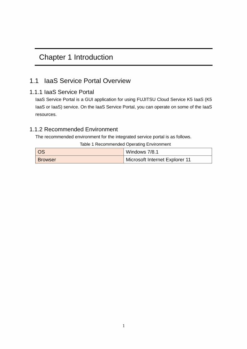
IaaS Service Portal is a GUI application for using FUJITSU Cloud Service K5 IaaS (K5
IaaS or IaaS) service. On the IaaS Service Portal, you can operate on some of the IaaS
resources.
1.1.2 Recommended Environment
The recommended environment for the integrated service portal is as follows.
Table 1 Recommended Operating Environment
OS Windows 7/8.1
Browser Microsoft Internet Explorer 11
2
1.2 Functions Provided by the IaaS Service Portal
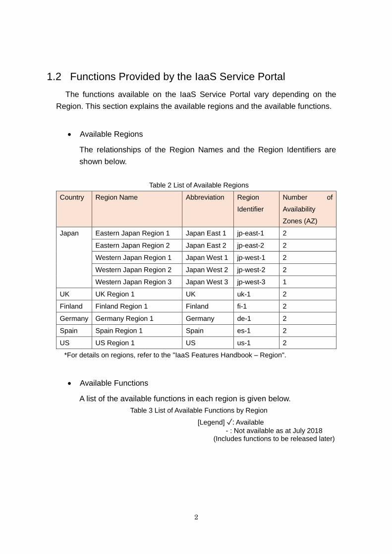
The functions available on the IaaS Service Portal vary depending on the
Region. This section explains the available regions and the available functions.
Available Regions
The relationships of the Region Names and the Region Identifiers are
shown below.
Table 2 List of Available Regions
Country Region Name Abbreviation Region
Identifier
Number of
Availability
Zones (AZ)
Japan Eastern Japan Region 1 Japan East 1 jp-east-1 2
Eastern Japan Region 2 Japan East 2 jp-east-2 2
Western Japan Region 1 Japan West 1 jp-west-1 2
Western Japan Region 2 Japan West 2 jp-west-2 2
Western Japan Region 3 Japan West 3 jp-west-3 1
UK UK Region 1 UK uk-1 2
Finland Finland Region 1 Finland fi-1 2
Germany Germany Region 1 Germany de-1 2
Spain Spain Region 1 Spain es-1 2
US US Region 1 US us-1 2
*For details on regions, refer to the "IaaS Features Handbook – Region".
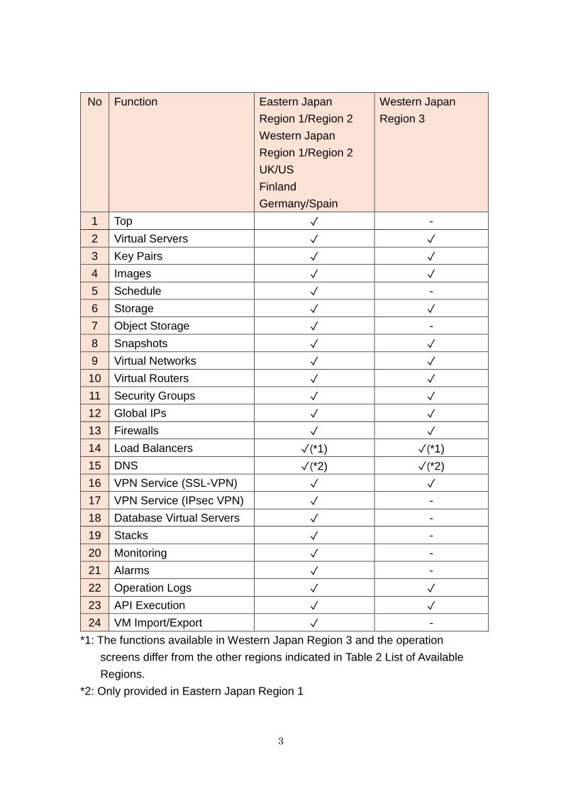
Available Functions
A list of the available functions in each region is given below.
Table 3 List of Available Functions by Region
[Legend] ✓: Available
- : Not available as at July 2018 (Includes functions to be released later)
3
No Function Eastern Japan
Region 1/Region 2
Western Japan
Region 1/Region 2
UK/US
Finland
Germany/Spain
Western Japan
Region 3
1 Top ✓ -
2 Virtual Servers ✓ ✓
3 Key Pairs ✓ ✓
4 Images ✓ ✓
5 Schedule ✓ -
6 Storage ✓ ✓
7 Object Storage ✓ -
8 Snapshots ✓ ✓
9 Virtual Networks ✓ ✓
10 Virtual Routers ✓ ✓
11 Security Groups ✓ ✓
12 Global IPs ✓ ✓
13 Firewalls ✓ ✓
14 Load Balancers ✓(*1) ✓(*1)
15 DNS ✓(*2) ✓(*2)
16 VPN Service (SSL-VPN) ✓ ✓
17 VPN Service (IPsec VPN) ✓ -
18 Database Virtual Servers ✓ -
19 Stacks ✓ -
20 Monitoring ✓ -
21 Alarms ✓ -
22 Operation Logs ✓ ✓
23 API Execution ✓ ✓
24 VM Import/Export ✓ -
*1: The functions available in Western Japan Region 3 and the operation
screens differ from the other regions indicated in Table 2 List of Available
Regions.
*2: Only provided in Eastern Japan Region 1
4
Points to Note
As there is only one AZ in Western Japan Region 3, AZ information is
not displayed on the screen.
Even though functions may be common between regions, depending
on the region the layouts of screens differ slightly. Unless otherwise
noted, the screens shown in this guide are those of Eastern Japan
Region 1.
5
Chapter 2 Overall Structure
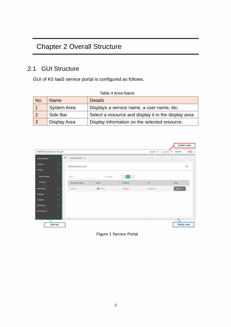
2.1 GUI Structure
GUI of K5 IaaS service portal is configured as follows.
Table 4 Area Name
No. Name Details
1 System Area Displays a service name, a user name, etc.
2 Side Bar Select a resource and display it in the display area.
3 Display Area Display information on the selected resource.
Figure 1 Service Portal
6
Chapter 3 Common Operations
3.1 Description
This section explains the common operations of the IaaS Service Portal window.
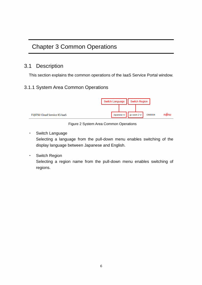
3.1.1 System Area Common Operations
Figure 2 System Area Common Operations
・ Switch Language
Selecting a language from the pull-down menu enables switching of the
display language between Japanese and English.
・ Switch Region
Selecting a region name from the pull-down menu enables switching of
regions.
7
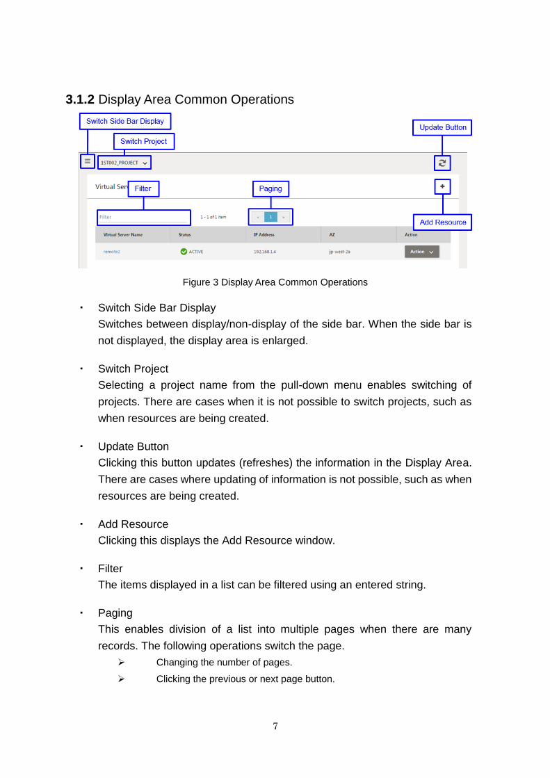
3.1.2 Display Area Common Operations
Figure 3 Display Area Common Operations
・ Switch Side Bar Display
Switches between display/non-display of the side bar. When the side bar is
not displayed, the display area is enlarged.
・ Switch Project
Selecting a project name from the pull-down menu enables switching of
projects. There are cases when it is not possible to switch projects, such as
when resources are being created.
・ Update Button
Clicking this button updates (refreshes) the information in the Display Area.
There are cases where updating of information is not possible, such as when
resources are being created.
・ Add Resource
Clicking this displays the Add Resource window.
・ Filter
The items displayed in a list can be filtered using an entered string.
・ Paging
This enables division of a list into multiple pages when there are many
records. The following operations switch the page.
Changing the number of pages.
Clicking the previous or next page button.
8
Chapter 4 Login
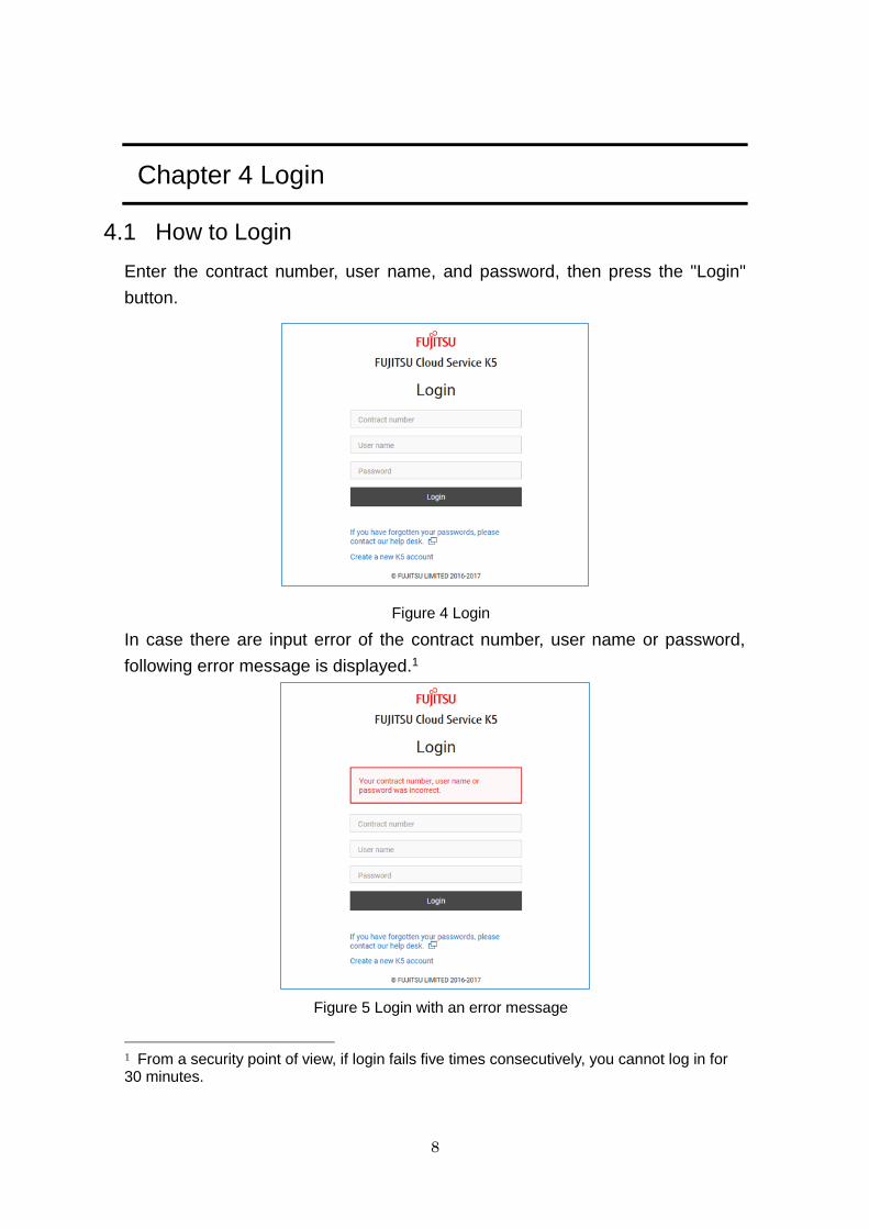
4.1 How to Login
Enter the contract number, user name, and password, then press the "Login"
button.
Figure 4 Login
In case there are input error of the contract number, user name or password,
following error message is displayed.1
Figure 5 Login with an error message
1 From a security point of view, if login fails five times consecutively, you cannot log in for 30 minutes.
9
4.2 Advisory Notes
When an authentication error occurs during login, the browser's cache may
be the cause. Take corrective action following the procedure below.
1. Delete the cache of IE 11.
From the Tool Bar, select "Tools" > "Internet Options" > "General Tab",
and "Delete" in the "Browsing history".
Check "Cookies and website data", and press "Delete".
2. Close all IE 11 windows.
3. Start IE 11 again and log in.
10
Chapter 5 Top
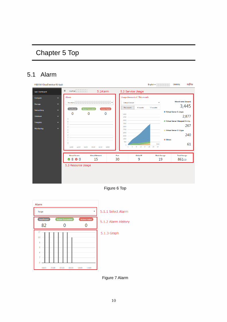
5.1 Alarm
Figure 6 Top
Figure 7 Alarm

11
5.1.1 Select Alarm
Select an alarm whose graph you want to display from alarm list.
Figure 8 Select Alarm
5.1.2 Alarm History
Table 5 Items of Alarm
No Item Name Description
1 Insufficient Number of alarms with insufficient condition
settings
2 Action Succeeded Number of successful alarms
3 Action Failed Number of failed alarms
Figure 9 Result of Alarm Collection
Most of data that are highly likely to be conditional settings as meaningless
alarms are distributed to Insufficient.
12
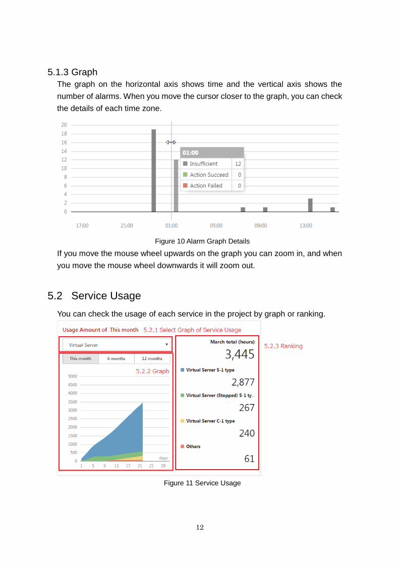
5.1.3 Graph
The graph on the horizontal axis shows time and the vertical axis shows the
number of alarms. When you move the cursor closer to the graph, you can check
the details of each time zone.
Figure 10 Alarm Graph Details
If you move the mouse wheel upwards on the graph you can zoom in, and when
you move the mouse wheel downwards it will zoom out.
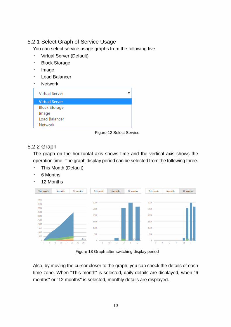
5.2 Service Usage
You can check the usage of each service in the project by graph or ranking.
Figure 11 Service Usage
13
5.2.1 Select Graph of Service Usage
You can select service usage graphs from the following five.
・ Virtual Server (Default)
・ Block Storage
・ Image
・ Load Balancer
・ Network
Figure 12 Select Service
5.2.2 Graph
The graph on the horizontal axis shows time and the vertical axis shows the
operation time. The graph display period can be selected from the following three.
・ This Month (Default)
・ 6 Months
・ 12 Months
Figure 13 Graph after switching display period
Also, by moving the cursor closer to the graph, you can check the details of each
time zone. When "This month" is selected, daily details are displayed, when "6
months" or "12 months" is selected, monthly details are displayed.
14
Figure 14 Service Usage Graph Details (This Month)
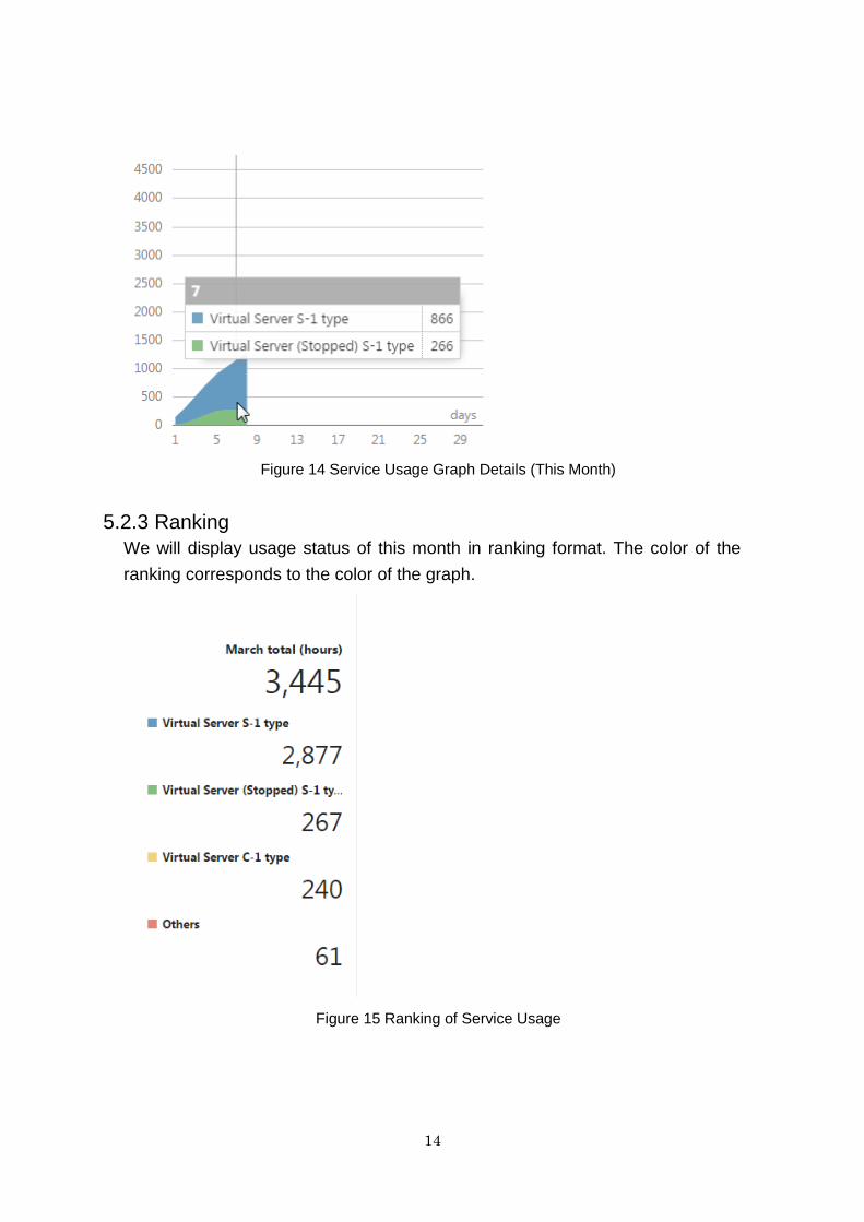
5.2.3 Ranking
We will display usage status of this month in ranking format. The color of the
ranking corresponds to the color of the graph.
Figure 15 Ranking of Service Usage
15
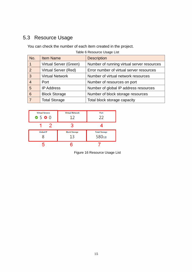
5.3 Resource Usage
You can check the number of each item created in the project.
Table 6 Resource Usage List
No. Item Name Description
1 Virtual Server (Green) Number of running virtual server resources
2 Virtual Server (Red) Error number of virtual server resources
3 Virtual Network Number of virtual network resources
4 Port Number of resources on port
5 IP Address Number of global IP address resources
6 Block Storage Number of block storage resources
7 Total Storage Total block storage capacity
Figure 16 Resource Usage List
16
Chapter 6 Virtual Server
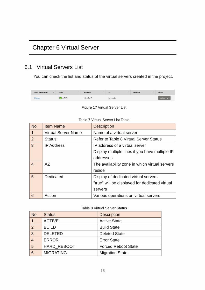
6.1 Virtual Servers List
You can check the list and status of the virtual servers created in the project.
Figure 17 Virtual Server List
Table 7 Virtual Server List Table
No. Item Name Description
1 Virtual Server Name Name of a virtual server
2 Status Refer to Table 8 Virtual Server Status
3 IP Address IP address of a virtual server
Display multiple lines if you have multiple IP
addresses
4 AZ The availability zone in which virtual servers
reside
5 Dedicated Display of dedicated virtual servers
"true" will be displayed for dedicated virtual
servers
6 Action Various operations on virtual servers
Table 8 Virtual Server Status
No. Status Description
1 ACTIVE Active State
2 BUILD Build State
3 DELETED Deleted State
4 ERROR Error State
5 HARD_REBOOT Forced Reboot State
6 MIGRATING Migration State
17
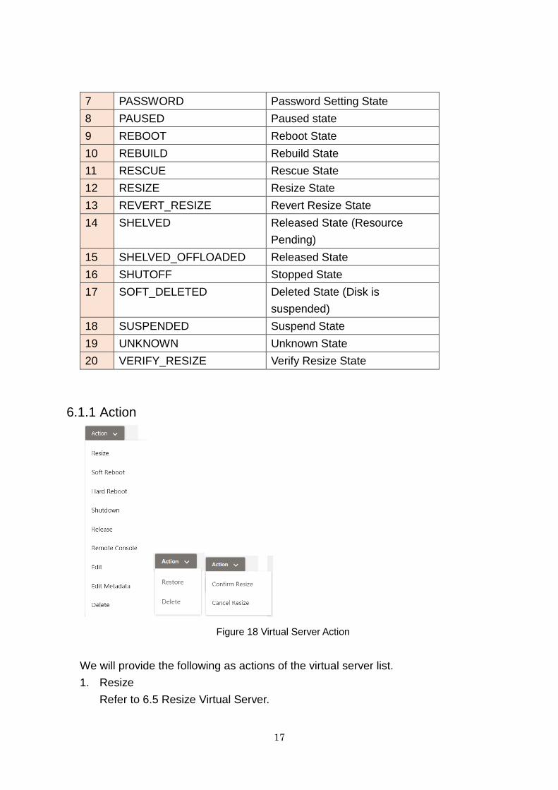
7 PASSWORD Password Setting State
8 PAUSED Paused state
9 REBOOT Reboot State
10 REBUILD Rebuild State
11 RESCUE Rescue State
12 RESIZE Resize State
13 REVERT_RESIZE Revert Resize State
14 SHELVED Released State (Resource
Pending)
15 SHELVED_OFFLOADED Released State
16 SHUTOFF Stopped State
17 SOFT_DELETED Deleted State (Disk is
suspended)
18 SUSPENDED Suspend State
19 UNKNOWN Unknown State
20 VERIFY_RESIZE Verify Resize State
6.1.1 Action
Figure 18 Virtual Server Action
We will provide the following as actions of the virtual server list.
1. Resize
Refer to 6.5 Resize Virtual Server.
18
2. Soft Reboot
Restart a virtual server.
3. Hard Reboot
Turn off an instance, then back on
4. Shutdown
Shutdown a virtual server.
5. Release
Release a virtual server.
6. Remote Console
Open Remote Console.
Some browsers are blocked by pop-ups. In that case please allow pop-ups.
7. Edit
Refer to 6.4 Edit Virtual Server.
8. Edit Metadata
Edit (Add/Display/Update/Delete) metadata of a virtual server.
9. Delete
Delete a virtual server.
10. Start-up
Start a virtual server.
11. Restore
Restore a virtual server.
12. Confirm Resize/Migration
Execute to resize/migrate a virtual server.
13. Cancel Resize/Migration
Cancel to resize/migrate a virtual server.
19
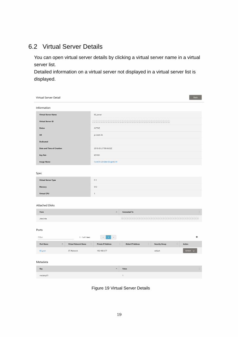
6.2 Virtual Server Details
You can open virtual server details by clicking a virtual server name in a virtual
server list.
Detailed information on a virtual server not displayed in a virtual server list is
displayed.
Figure 19 Virtual Server Details

20
Table 9 Virtual Server Details
No. Classification Item Name Description
1 Information Virtual Server Name Name of a virtual server
2 Virtual Server ID Unique value
3 Status Status of a virtual server
4 AZ Availability Zone
5 Dedicated Display of dedicated
virtual servers
"true" will be displayed
for dedicated virtual
servers
6 Key Pair Key Pair
7 Image Name Image Name
8 Date and Time of
Creation
Date and Time of
Creation
9 Spec Virtual Server Type Specification of a virtual
server
10 Memory Memory Size
11 Virtual CPU Number of CPUs
12 Connected Disk Access Point Connection Block
Storage
13 Connection Destination Connection Destination
Volume
14 Port Port Name Port Name
15 Virtual Network Name Virtual Network Name
16 Private IP Address Private IP Address
17 Global IP Address Displayed when a global
IP address is set.
18 Security Group Security Group Name
19 Action Various operations on
ports
20 Metadata Key Key set for virtual server
metadata
21 Value Value set for virtual
server metadata
21
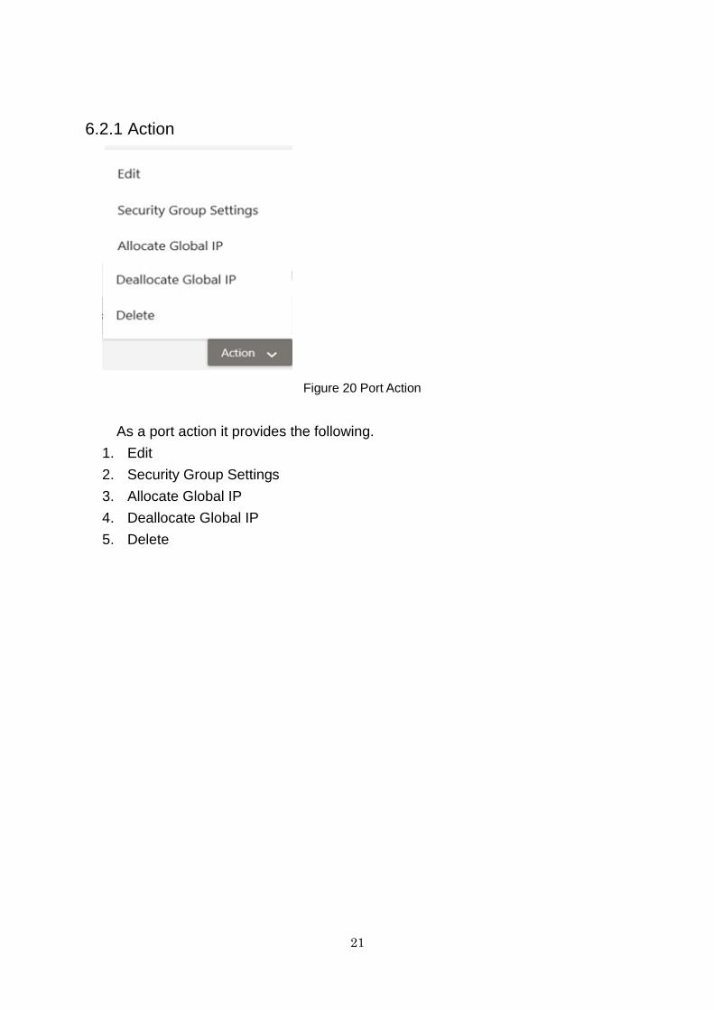
6.2.1 Action
Figure 20 Port Action
As a port action it provides the following.
1. Edit
2. Security Group Settings
3. Allocate Global IP
4. Deallocate Global IP
5. Delete
22
6.3 Create Virtual Server
This is the GUI when creating a new virtual server. Click Create icon of Virtual
Server List.
6.3.1 How to Create Virtual Server
When creating a Virtual Server, it is necessary to create a virtual network in advance.
1. Click an icon of Virtual Server list
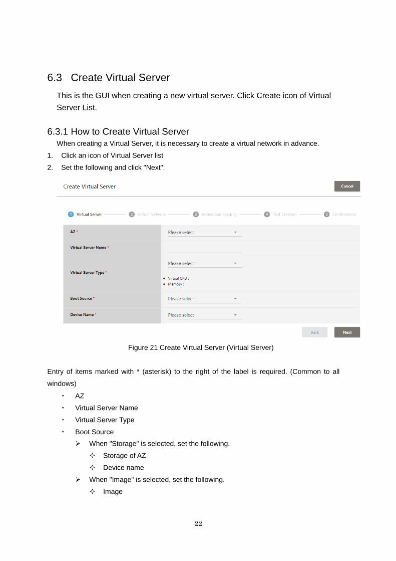
2. Set the following and click "Next".
Figure 21 Create Virtual Server (Virtual Server)
Entry of items marked with * (asterisk) to the right of the label is required. (Common to all
windows)
・ AZ
・ Virtual Server Name
・ Virtual Server Type
・ Boot Source
When "Storage" is selected, set the following.
Storage of AZ
Device name
When "Image" is selected, set the following.
Image
23
Device Size
Device Name
When "Snapshot" is selected, set the following.
Storage Snapshot
Device Name
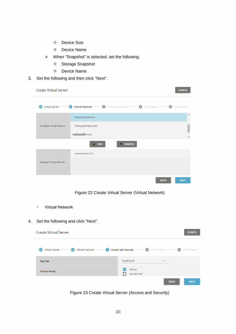
3. Set the following and then click "Next".
Figure 22 Create Virtual Server (Virtual Network)
・ Virtual Network
4. Set the following and click "Next".
Figure 23 Create Virtual Server (Access and Security)
24
・ Key Pair
・ Security Group
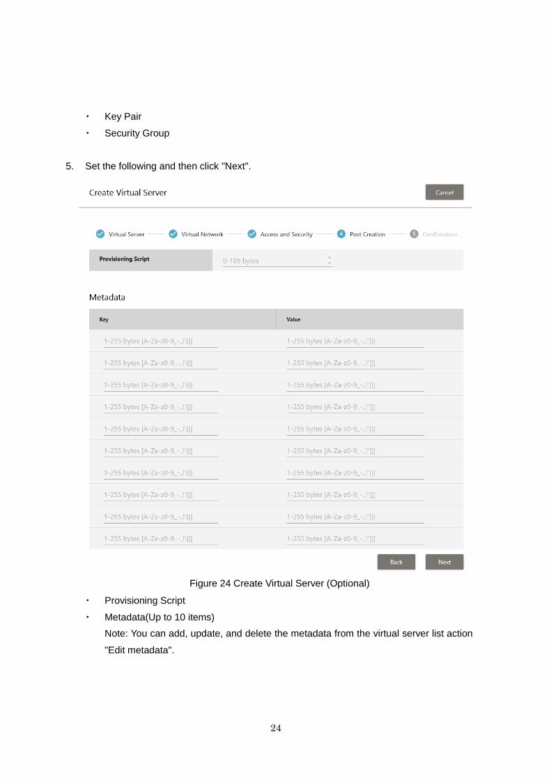
5. Set the following and then click "Next".
Figure 24 Create Virtual Server (Optional)
・ Provisioning Script
・ Metadata(Up to 10 items)
Note: You can add, update, and delete the metadata from the virtual server list action
"Edit metadata".

25
6. Confirm the settings so far on the confirmation window. If there are no problems, click
"Create".
Please return to the virtual server list and make sure that the state of the created virtual
server is "BUILD". It will become available when the status is changed to "Active".
Figure 25 Create Virtual Server (Confirmation)
26
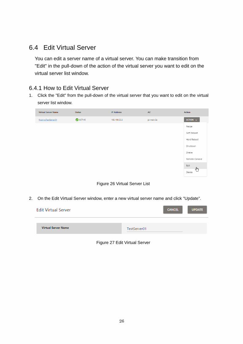
6.4 Edit Virtual Server
You can edit a server name of a virtual server. You can make transition from
"Edit" in the pull-down of the action of the virtual server you want to edit on the
virtual server list window.
6.4.1 How to Edit Virtual Server
1. Click the "Edit" from the pull-down of the virtual server that you want to edit on the virtual
server list window.
Figure 26 Virtual Server List
2. On the Edit Virtual Server window, enter a new virtual server name and click "Update".
Figure 27 Edit Virtual Server
27
6.5 Resize Virtual Server
You can change the specifications (number of virtual CPUs etc.) of a Virtual
Server. You can make transition from "Resize" of the action pull down of the
virtual server you want to change on the virtual server list window.
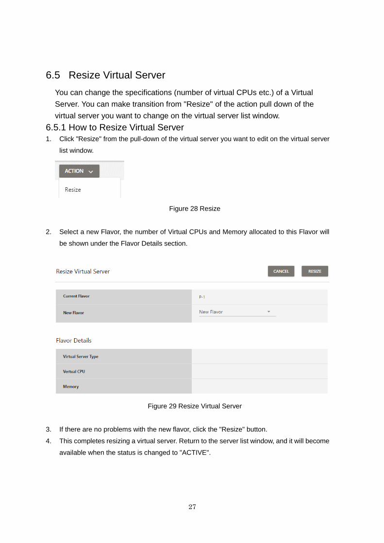
6.5.1 How to Resize Virtual Server
1. Click "Resize" from the pull-down of the virtual server you want to edit on the virtual server
list window.
Figure 28 Resize
2. Select a new Flavor, the number of Virtual CPUs and Memory allocated to this Flavor will
be shown under the Flavor Details section.
Figure 29 Resize Virtual Server
3. If there are no problems with the new flavor, click the "Resize" button.
4. This completes resizing a virtual server. Return to the server list window, and it will become
available when the status is changed to "ACTIVE".
28
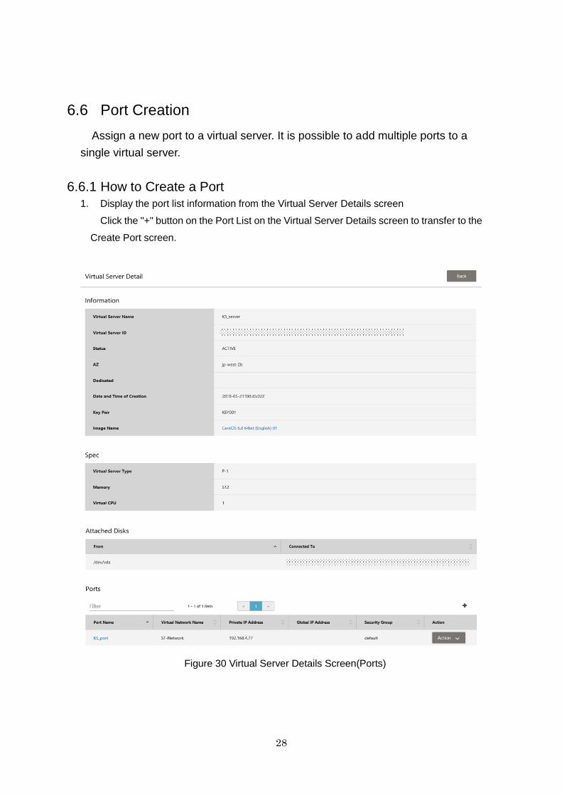
6.6 Port Creation
Assign a new port to a virtual server. It is possible to add multiple ports to a
single virtual server.
6.6.1 How to Create a Port
1. Display the port list information from the Virtual Server Details screen
Click the "+" button on the Port List on the Virtual Server Details screen to transfer to the
Create Port screen.
Figure 30 Virtual Server Details Screen(Ports)
29
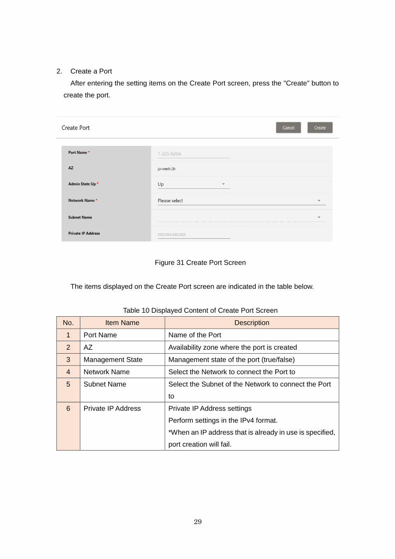
2. Create a Port
After entering the setting items on the Create Port screen, press the "Create" button to
create the port.
Figure 31 Create Port Screen
The items displayed on the Create Port screen are indicated in the table below.
Table 10 Displayed Content of Create Port Screen
No. Item Name Description
1 Port Name Name of the Port
2 AZ Availability zone where the port is created
3 Management State Management state of the port (true/false)
4 Network Name Select the Network to connect the Port to
5 Subnet Name Select the Subnet of the Network to connect the Port
to
6 Private IP Address Private IP Address settings
Perform settings in the IPv4 format.
*When an IP address that is already in use is specified,
port creation will fail.
30
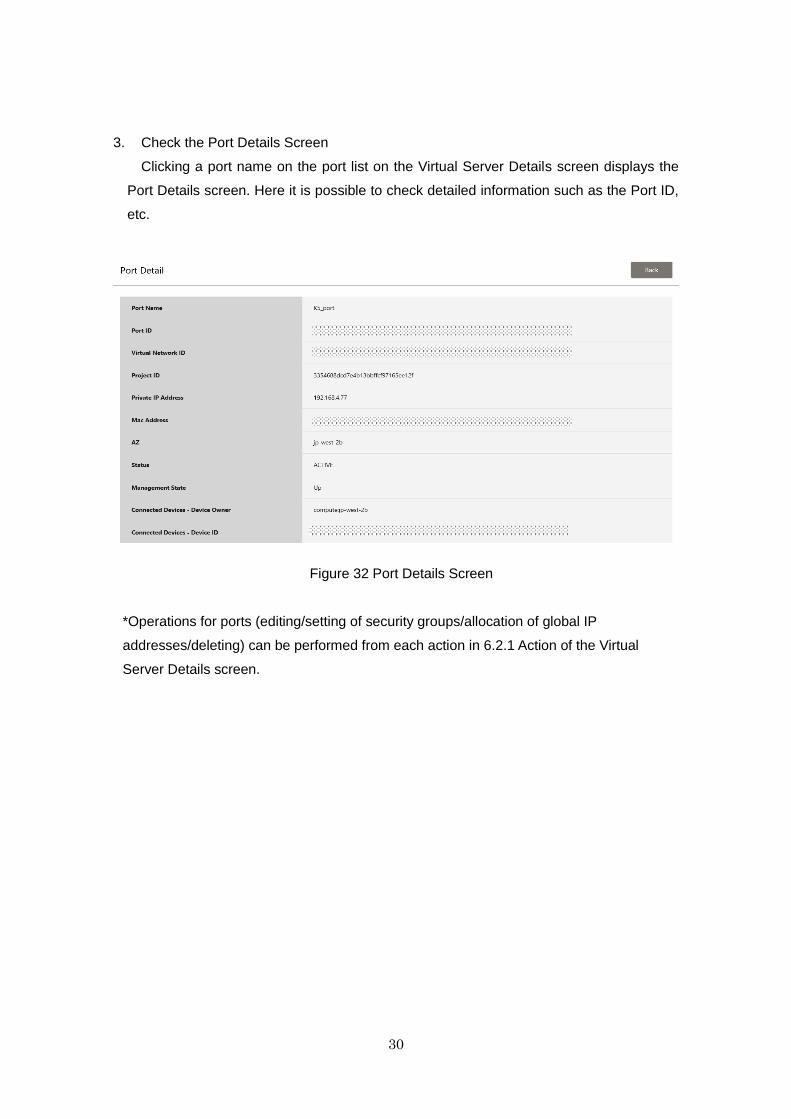
3. Check the Port Details Screen
Clicking a port name on the port list on the Virtual Server Details screen displays the
Port Details screen. Here it is possible to check detailed information such as the Port ID,
etc.
Figure 32 Port Details Screen
*Operations for ports (editing/setting of security groups/allocation of global IP
addresses/deleting) can be performed from each action in 6.2.1 Action of the Virtual
Server Details screen.
31
Chapter 7 Key Pair
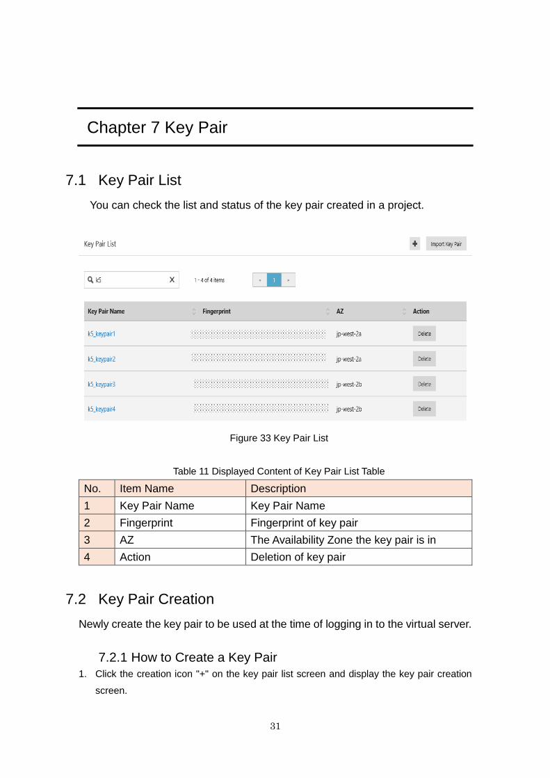
7.1 Key Pair List
You can check the list and status of the key pair created in a project.
Figure 33 Key Pair List
Table 11 Displayed Content of Key Pair List Table
No. Item Name Description
1 Key Pair Name Key Pair Name
2 Fingerprint Fingerprint of key pair
3 AZ The Availability Zone the key pair is in
4 Action Deletion of key pair
7.2 Key Pair Creation
Newly create the key pair to be used at the time of logging in to the virtual server.
7.2.1 How to Create a Key Pair
1. Click the creation icon "+" on the key pair list screen and display the key pair creation
screen.
32
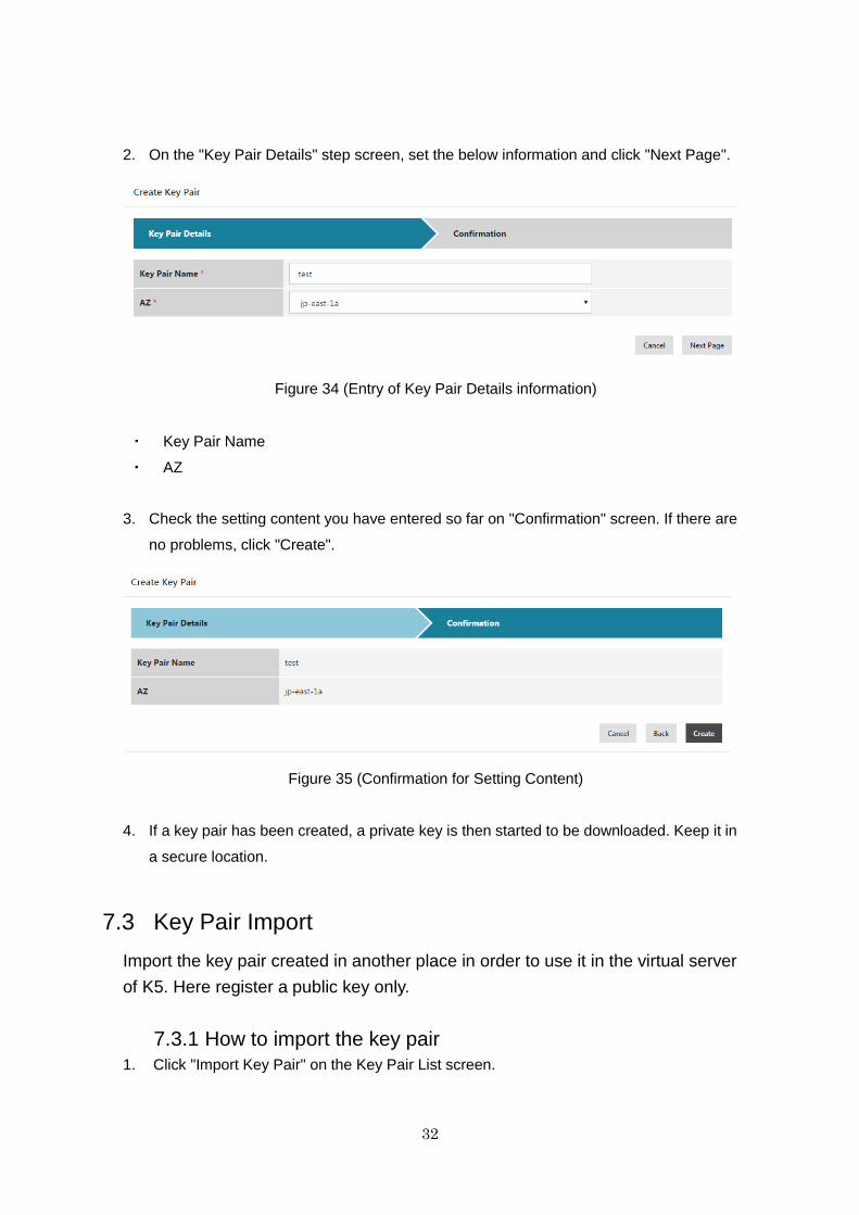
2. On the "Key Pair Details" step screen, set the below information and click "Next Page".
Figure 34 (Entry of Key Pair Details information)
・ Key Pair Name
・ AZ
3. Check the setting content you have entered so far on "Confirmation" screen. If there are
no problems, click "Create".
Figure 35 (Confirmation for Setting Content)
4. If a key pair has been created, a private key is then started to be downloaded. Keep it in
a secure location.
7.3 Key Pair Import
Import the key pair created in another place in order to use it in the virtual server
of K5. Here register a public key only.
7.3.1 How to import the key pair
1. Click "Import Key Pair" on the Key Pair List screen.
33
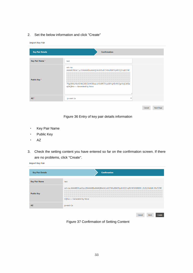
2. Set the below information and click "Create"
Figure 36 Entry of key pair details information
・ Key Pair Name
・ Public Key
・ AZ
3. Check the setting content you have entered so far on the confirmation screen. If there
are no problems, click "Create".
Figure 37 Confirmation of Setting Content
34
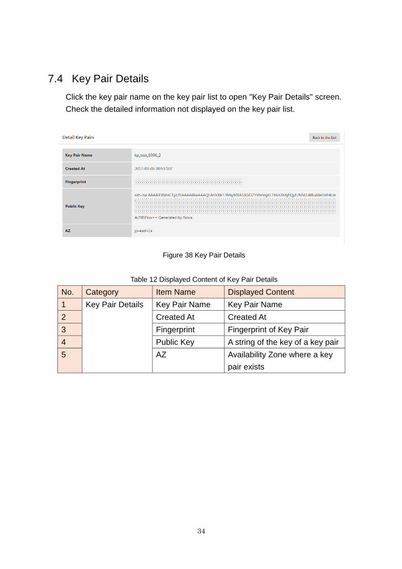
7.4 Key Pair Details
Click the key pair name on the key pair list to open "Key Pair Details" screen.
Check the detailed information not displayed on the key pair list.
Figure 38 Key Pair Details
Table 12 Displayed Content of Key Pair Details
No. Category Item Name Displayed Content
1 Key Pair Details Key Pair Name Key Pair Name
2 Created At Created At
3 Fingerprint Fingerprint of Key Pair
4 Public Key A string of the key of a key pair
5 AZ Availability Zone where a key
pair exists
35
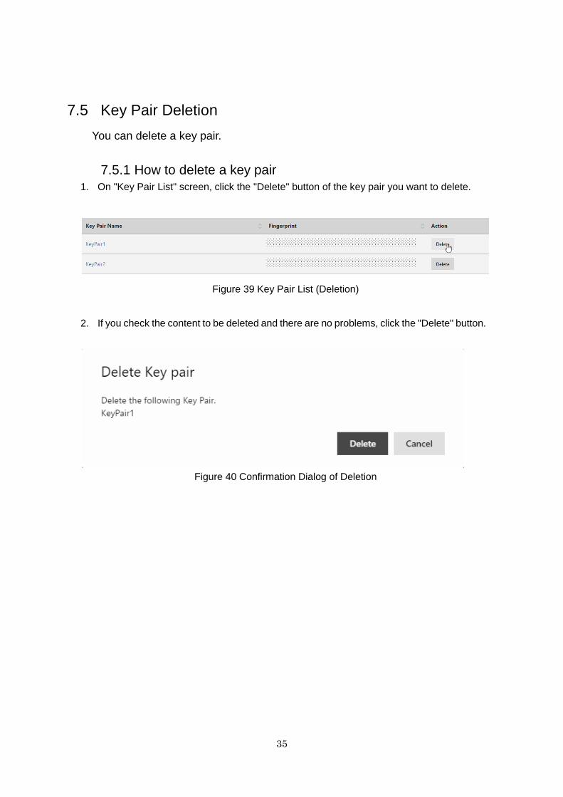
7.5 Key Pair Deletion
You can delete a key pair.
7.5.1 How to delete a key pair
1. On "Key Pair List" screen, click the "Delete" button of the key pair you want to delete.
Figure 39 Key Pair List (Deletion)
2. If you check the content to be deleted and there are no problems, click the "Delete" button.
Figure 40 Confirmation Dialog of Deletion
36
Chapter 8 Image
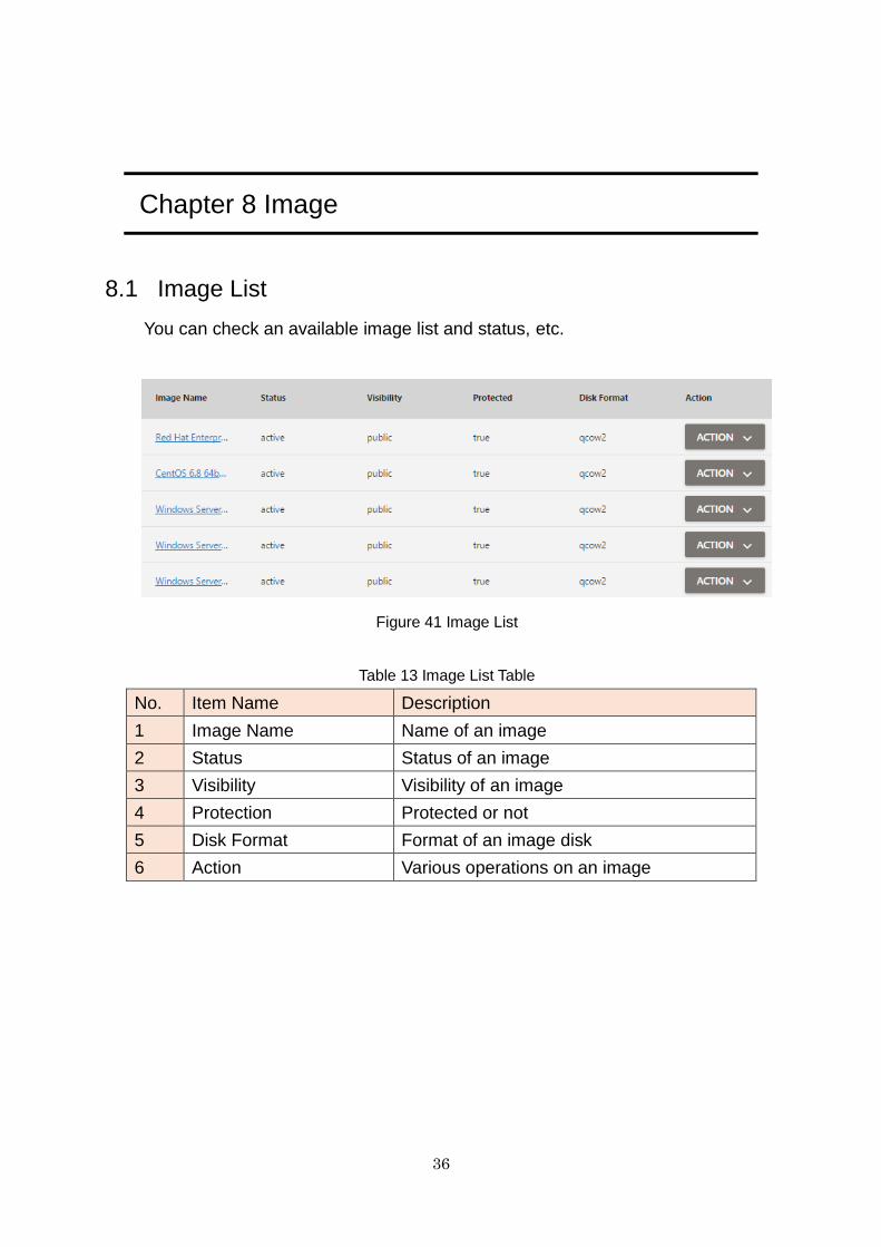
8.1 Image List
You can check an available image list and status, etc.
Figure 41 Image List
Table 13 Image List Table
No. Item Name Description
1 Image Name Name of an image
2 Status Status of an image
3 Visibility Visibility of an image
4 Protection Protected or not
5 Disk Format Format of an image disk
6 Action Various operations on an image
37
8.1.1 Action
Figure 42 Images Action
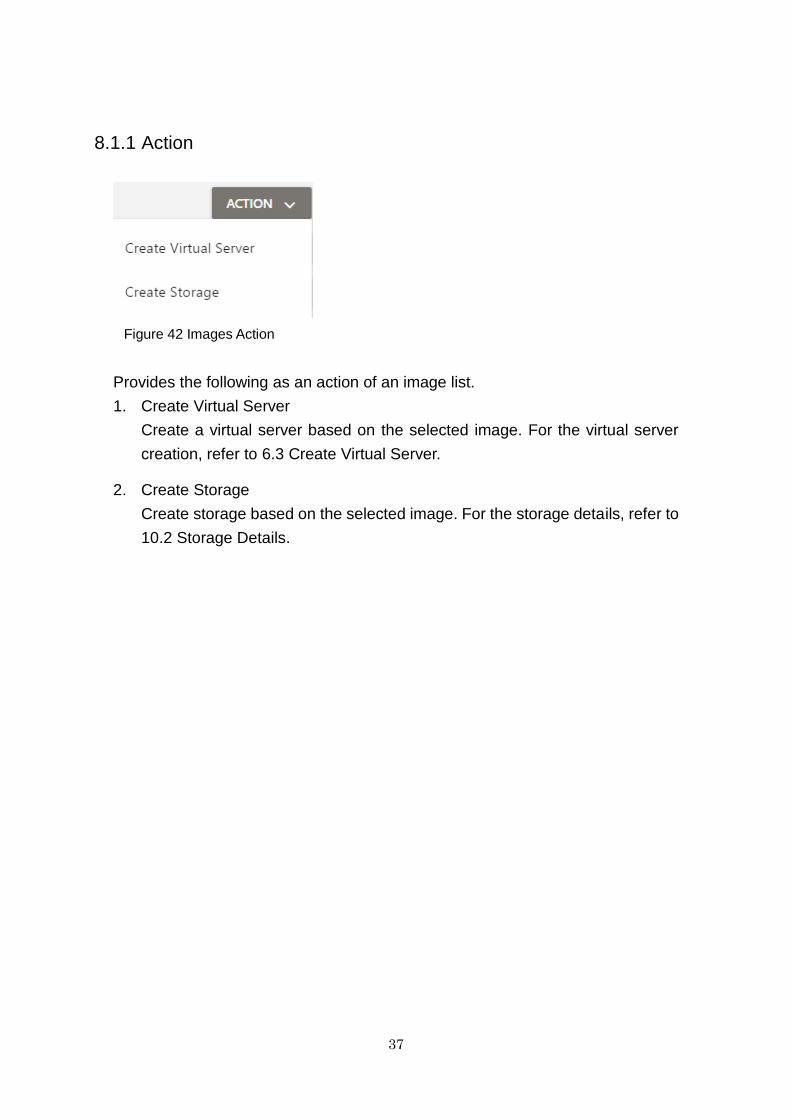
Provides the following as an action of an image list.
1. Create Virtual Server
Create a virtual server based on the selected image. For the virtual server
creation, refer to 6.3 Create Virtual Server.
2. Create Storage
Create storage based on the selected image. For the storage details, refer to
10.2 Storage Details.
38
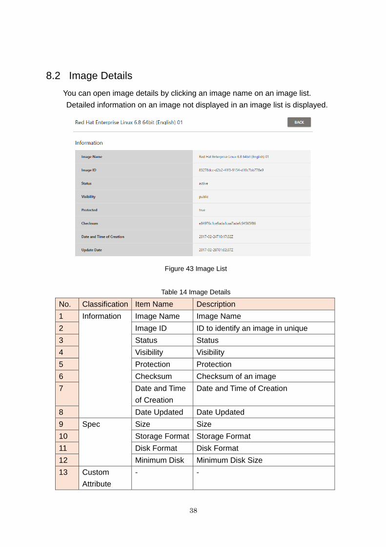
8.2 Image Details
You can open image details by clicking an image name on an image list.
Detailed information on an image not displayed in an image list is displayed.
Figure 43 Image List
Table 14 Image Details
No. Classification Item Name Description
1 Information Image Name Image Name
2 Image ID ID to identify an image in unique
3 Status Status
4 Visibility Visibility
5 Protection Protection
6 Checksum Checksum of an image
7 Date and Time
of Creation
Date and Time of Creation
8 Date Updated Date Updated
9 Spec Size Size
10 Storage Format Storage Format
11 Disk Format Disk Format
12 Minimum Disk Minimum Disk Size
13 Custom
Attribute
- -
39
Chapter 9 Schedule
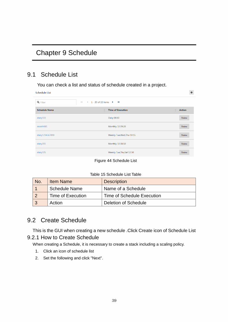
9.1 Schedule List
You can check a list and status of schedule created in a project.
Figure 44 Schedule List
Table 15 Schedule List Table
No. Item Name Description
1 Schedule Name Name of a Schedule
2 Time of Execution Time of Schedule Execution
3 Action Deletion of Schedule
9.2 Create Schedule
This is the GUI when creating a new schedule .Click Create icon of Schedule List
9.2.1 How to Create Schedule
When creating a Schedule, it is necessary to create a stack including a scaling policy.
1. Click an icon of schedule list
2. Set the following and click "Next".
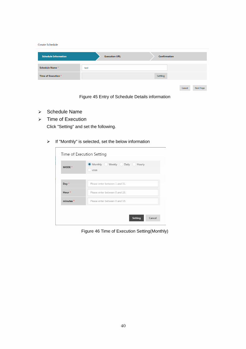
40
Figure 45 Entry of Schedule Details information
Schedule Name
Time of Execution
Click "Setting" and set the following.
If "Monthly" is selected, set the below information
Figure 46 Time of Execution Setting(Monthly)
41
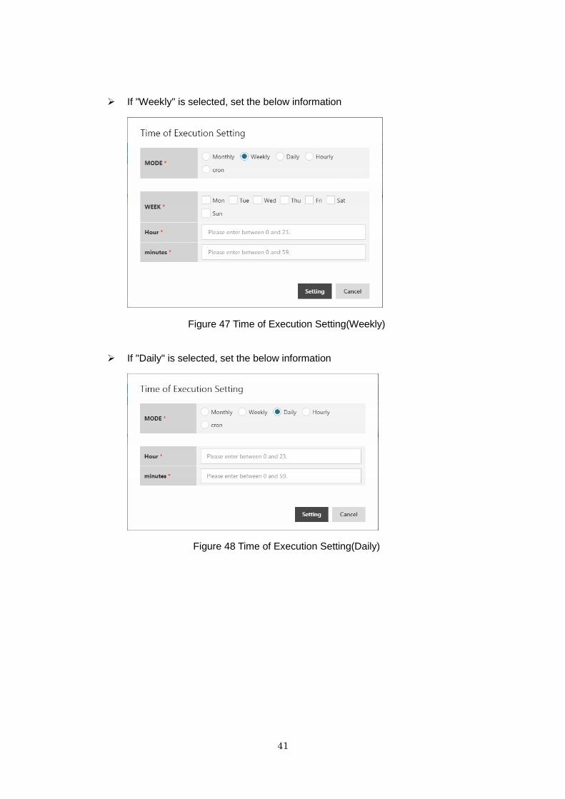
If "Weekly" is selected, set the below information
Figure 47 Time of Execution Setting(Weekly)
If "Daily" is selected, set the below information
Figure 48 Time of Execution Setting(Daily)
42
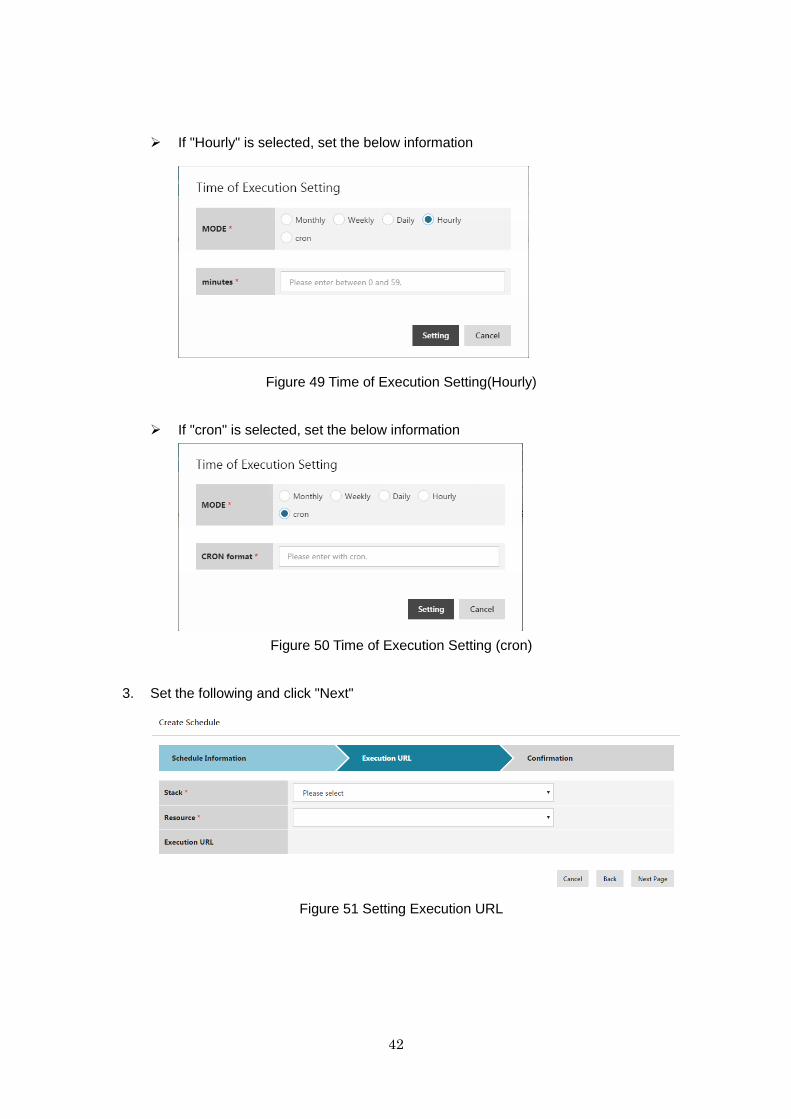
If "Hourly" is selected, set the below information
Figure 49 Time of Execution Setting(Hourly)
If "cron" is selected, set the below information
Figure 50 Time of Execution Setting (cron)
3. Set the following and click "Next"
Figure 51 Setting Execution URL
43
・ Stack
・ Resource
・ Execution URL
Execution URL is automatically set from "Stack" and "Resource".
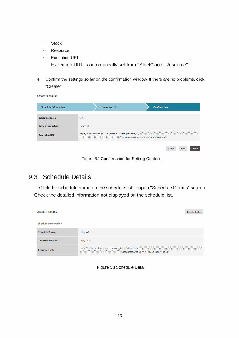
4. Confirm the settings so far on the confirmation window. If there are no problems, click
"Create"
Figure 52 Confirmation for Setting Content
9.3 Schedule Details
Click the schedule name on the schedule list to open "Schedule Details" screen.
Check the detailed information not displayed on the schedule list.
Figure 53 Schedule Detail
44
Table 16 Displayed Content of Schedule Details
No. Category Item Name Displayed Content
1 Schedule Details Schedule Name Schedule Name
2 Time of Execution Time of Schedule
Execution
3 Execution URL Execution URL
9.4 Schedule Deletion
You can delete a schedule.
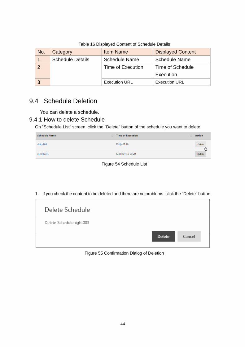
9.4.1 How to delete Schedule
On "Schedule List" screen, click the "Delete" button of the schedule you want to delete
Figure 54 Schedule List
1. If you check the content to be deleted and there are no problems, click the "Delete" button.
Figure 55 Confirmation Dialog of Deletion
45
Chapter 10 Storage
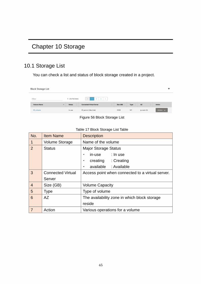
10.1 Storage List
You can check a list and status of block storage created in a project.
Figure 56 Block Storage List
Table 17 Block Storage List Table
No. Item Name Description
1 Volume Storage Name of the volume
2 Status Major Storage Status
・ in-use : In use
・ creating : Creating
・ available : Available
3 Connected Virtual
Server
Access point when connected to a virtual server.
4 Size (GB) Volume Capacity
5 Type Type of volume
6 AZ The availability zone in which block storage
reside
7 Action Various operations for a volume
46
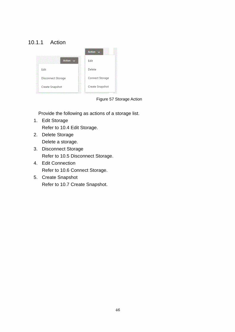
10.1.1 Action
Figure 57 Storage Action
Provide the following as actions of a storage list.
1. Edit Storage
Refer to 10.4 Edit Storage.
2. Delete Storage
Delete a storage.
3. Disconnect Storage
Refer to 10.5 Disconnect Storage.
4. Edit Connection
Refer to 10.6 Connect Storage.
5. Create Snapshot
Refer to 10.7 Create Snapshot.
47
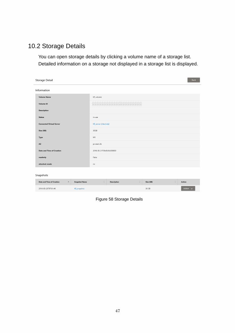
10.2 Storage Details
You can open storage details by clicking a volume name of a storage list.
Detailed information on a storage not displayed in a storage list is displayed.
Figure 58 Storage Details
48
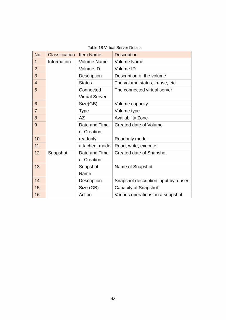
Table 18 Virtual Server Details
No. Classification Item Name Description
1 Information
Volume Name Volume Name
2 Volume ID Volume ID
3 Description Description of the volume
4 Status The volume status, in-use, etc.
5 Connected
Virtual Server
The connected virtual server
6 Size(GB) Volume capacity
7 Type Volume type
8 AZ Availability Zone
9 Date and Time
of Creation
Created date of Volume
10 readonly Readonly mode
11 attached_mode Read, write, execute
12 Snapshot Date and Time
of Creation
Created date of Snapshot
13 Snapshot
Name
Name of Snapshot
14 Description Snapshot description input by a user
15 Size (GB) Capacity of Snapshot
16 Action Various operations on a snapshot
49
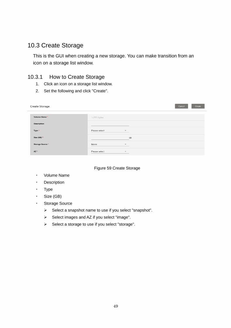
10.3 Create Storage
This is the GUI when creating a new storage. You can make transition from an
icon on a storage list window.
10.3.1 How to Create Storage
1. Click an icon on a storage list window.
2. Set the following and click "Create".
Figure 59 Create Storage
・ Volume Name
・ Description
・ Type
・ Size (GB)
・ Storage Source
Select a snapshot name to use if you select "snapshot".
Select images and AZ if you select "image".
Select a storage to use if you select "storage".
50
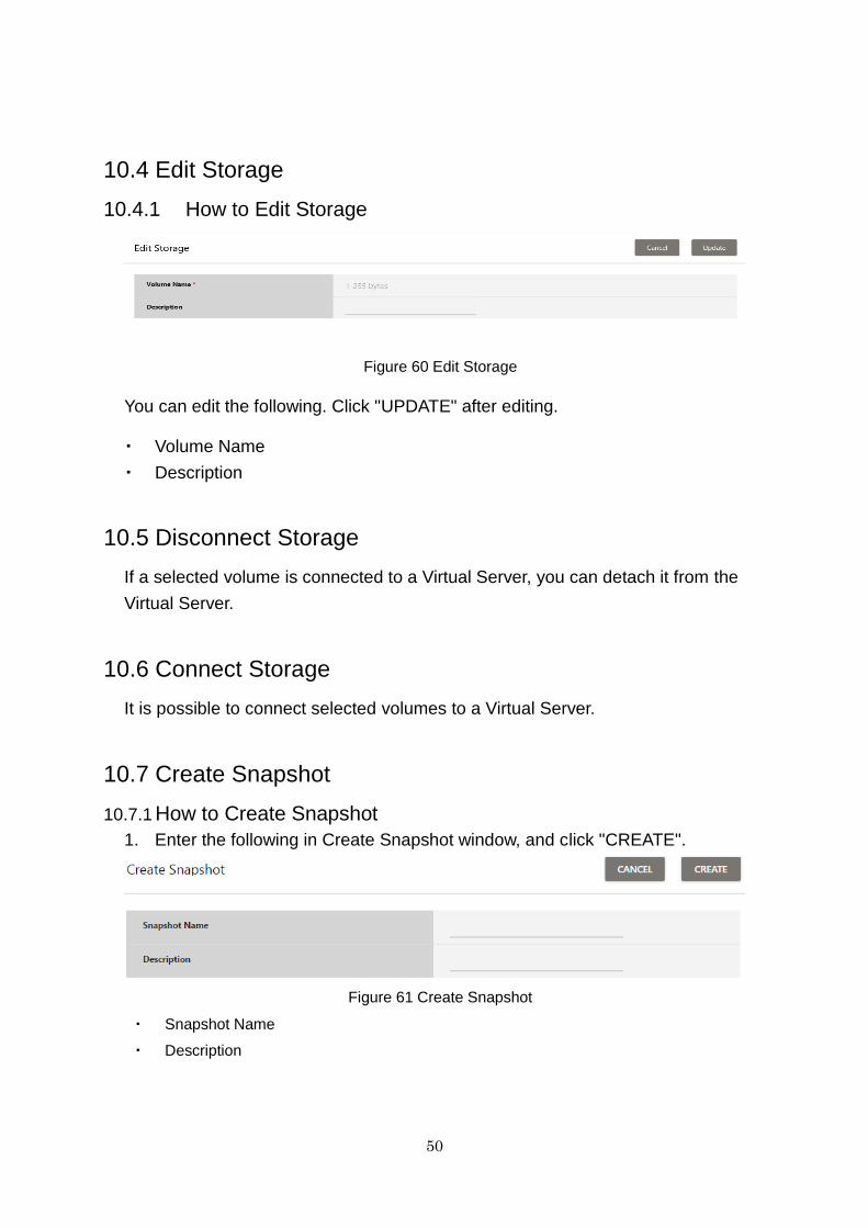
10.4 Edit Storage
10.4.1 How to Edit Storage
Figure 60 Edit Storage
You can edit the following. Click "UPDATE" after editing.
・ Volume Name
・ Description
10.5 Disconnect Storage
If a selected volume is connected to a Virtual Server, you can detach it from the
Virtual Server.
10.6 Connect Storage
It is possible to connect selected volumes to a Virtual Server.
10.7 Create Snapshot
10.7.1 How to Create Snapshot
1. Enter the following in Create Snapshot window, and click "CREATE".
Figure 61 Create Snapshot
・ Snapshot Name
・ Description
51
Chapter 11 Object Storage
11.1 Function Overview
This function provides the functionality for object storage on the IaaS Service
Portal. It enables use of online storage in which data can be stored and
retrieved on an object (their content and metadata) basis.
The functions provided are as follows:
・ Containers
Display of lists and details of containers
Creation, editing, and deletion of containers
Setting of access policies (ACL) for containers *1
Creation and deletion of container metadata
・ Objects
Display of lists and details of objects
Creation and deletion of objects
Re-upload of objects and editing of metadata
Download of objects and VM(Virtual Server) import
*1 The setting of access policies (ACL) for containers is a function that
enables the setting of container read privileges (X-Container-Read)
and write privileges (X-Container-Read). Using these settings it is
possible control access to containers by the following:
- Projects/users
- Referer headers included in HTTP requests
52
11.2 Usage Methods of Object Storage
This chapter explains the following usage methods:
・ Create a container
・ Create an object
・ Download an object
・ Import a VM image
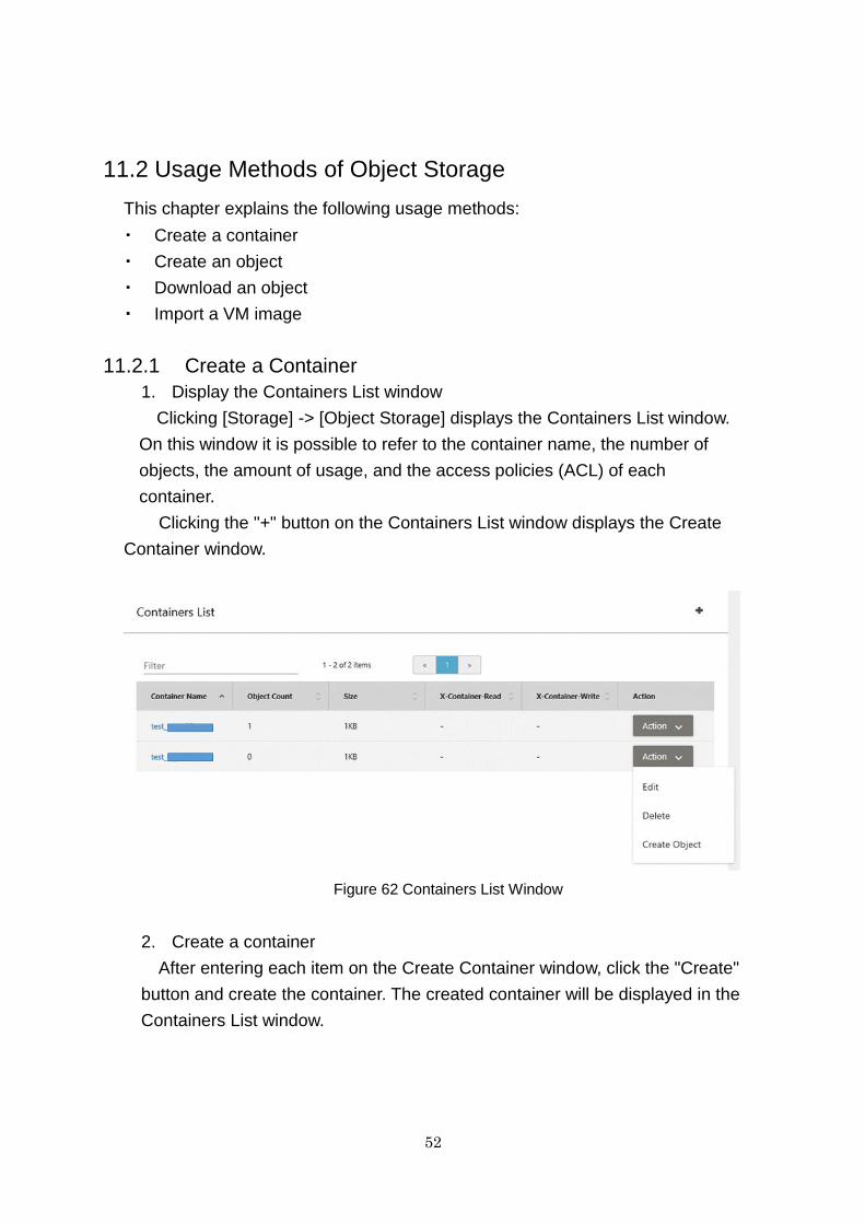
11.2.1 Create a Container
1. Display the Containers List window
Clicking [Storage] -> [Object Storage] displays the Containers List window.
On this window it is possible to refer to the container name, the number of
objects, the amount of usage, and the access policies (ACL) of each
container.
Clicking the "+" button on the Containers List window displays the Create
Container window.
Figure 62 Containers List Window
2. Create a container
After entering each item on the Create Container window, click the "Create"
button and create the container. The created container will be displayed in the
Containers List window.

53
Figure 63 Create Container Window
The setting items listed below are those required when creating a
container.
Table 19 Entry Items for Container Creation
No. Item* Description
1 Container Name The name of the container
2 X-Container-Read The access policy (ACL) settings for read
privileges
3 X-Container-Write The access policy (ACL) settings for write
privileges
4 X-Versions-Location The name of the container for versioning
management
5 Container Metadata The key and value to set for the container
metadata
X-Container-Meta-
Access-Control-Allow-
Origin
"*" : Initial value
Note: If this value is changed uploading and
downloading of files from the portal is not
possible.
X-Container-Meta-
Access-Control-Max-Age
"3628800" : Initial value
*For details on each item, refer to the "API Reference - Foundation Service".

54
3. Check the Container Detail window
The detailed information of a container can be referred to by clicking the
container name on the Containers List window. The Container Detail window
displays objects, container information, and container metadata.
Figure 64 Container Detail Window
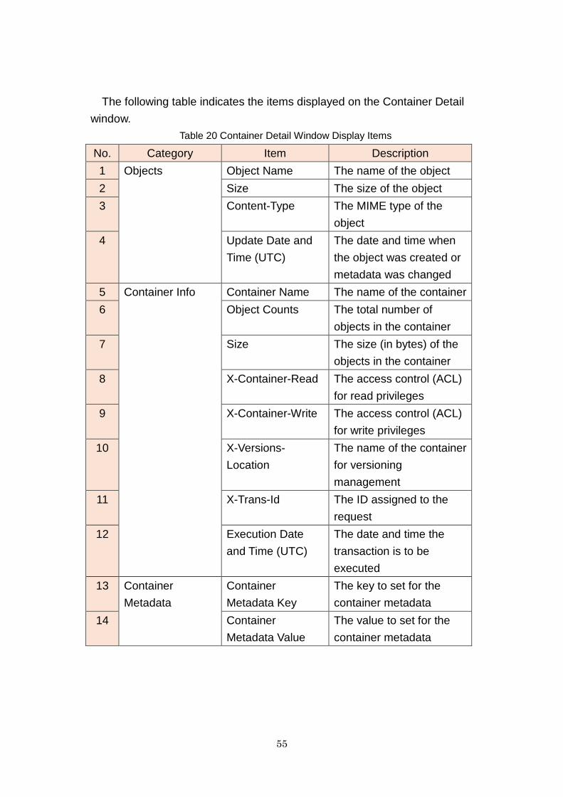
55
The following table indicates the items displayed on the Container Detail
window.
Table 20 Container Detail Window Display Items
No. Category Item Description
1 Objects Object Name The name of the object
2 Size The size of the object
3 Content-Type The MIME type of the
object
4 Update Date and
Time (UTC)
The date and time when
the object was created or
metadata was changed
5 Container Info Container Name The name of the container
6 Object Counts The total number of
objects in the container
7 Size The size (in bytes) of the
objects in the container
8 X-Container-Read The access control (ACL)
for read privileges
9 X-Container-Write The access control (ACL)
for write privileges
10 X-Versions-
Location
The name of the container
for versioning
management
11 X-Trans-Id The ID assigned to the
request
12 Execution Date
and Time (UTC)
The date and time the
transaction is to be
executed
13 Container
Metadata
Container
Metadata Key
The key to set for the
container metadata
14 Container
Metadata Value
The value to set for the
container metadata

56
11.2.2 Create an Object
1. Display the object list information from the Container Detail window
The object list information can be referred to from the Container Detail
window. The object name, size, Content-Type, and Update Date and Time
(UTC) are displayed in the object list information.
Clicking the "+" button on the Container Detail window displays the Create
Object window.
Figure 65 Container Detail Window (Object Section)
Another method for transferring to the Create Object window is to click
"Create Object" in the Action menu on the Containers List window.
57
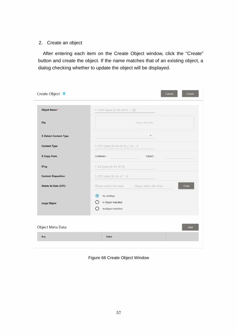
2. Create an object
After entering each item on the Create Object window, click the "Create"
button and create the object. If the name matches that of an existing object, a
dialog checking whether to update the object will be displayed.
Figure 66 Create Object Window
58
The following table indicates the items displayed on the Create Object
window.
Table 21 Create Object Window Display Items
No. Item* Description
1 Object Name The name of the object
2 File The file to register
The maximum file size is 1 GB.
*When registering a file larger than 1 GB, the
setting for a large object is necessary.
*Please split files by yourself.
3 X-Detect-Content-
Type
Automatic and manual setting of the MIME
type of the object
4 Content-Type The MIME type setting of the object
5 X-Copy-From
Container
The name of the container of the source object
6 X-Copy-From Object The name of the source object
7 ETag The setting for the MD5 check sum value of
the object
8 Content-Disposition The setting for the behavior of the browser
9 Delete At Date (UTC) Specification of the time and date for deletion
of the object, in UTC format
10
Large Object
The setting regarding large objects
There are the following three methods
No settings The setting when not handling as a large
object
X-Object-Manifest The setting for dynamic large objects
Sets the container name/object name.
multipart-manifest The setting for static large objects
Sets using JSON format.
11 Object Metadata The key and value to set for the object
metadata
*For details on each item, refer to the "API Reference - Foundation Service".
59
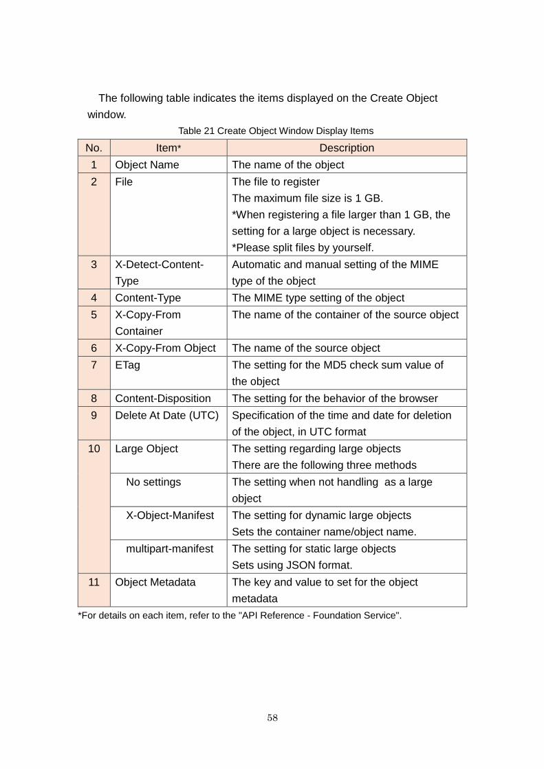
3. Check the Object Detail window
Clicking the object name in the Object List on the Container Detail window
displays the Object Detail window. You can refer to detailed information such
as object metadata, etc.
Figure 67 Object Detail Window

60
The following table indicates the items displayed on the Object Detail
window.
Table 22 Object Detail Window Display Items
No. Item Description
1 Object Name The name of the object
2 Content-Length The size of the object
3 Content-Type The MIME type of the object
4 Update Date The date and time when the object was
created or metadata was changed
5 ETag The MD5 check sum value of the object/
"A character string consisting of the ETag of
each segment of the manifest combined with
the value of the MD5 check sum" (for manifest
objects)
6 Content-Encoding The Content-Encoding meta data value
7 Content-Disposition The setting value for the behavior of the
browser
8 Delete At Date (UTC) The scheduled time and date for deletion of the
object
9 X-Object-Manifest The setting for dynamic large objects (the
container name and the prefix name of the split
object)
10 X-Static-Large-Object If the object is the manifest object of a static
large object, "True" will be returned
11 X-Trans-Id The ID assigned to the request
12 Transaction Date The date and time the transaction is to be
executed
13 URL The URL of the download target object
14 Object Metadata Key The key to set for the object metadata
15 Object Metadata
Value
The value to set for the object metadata
61
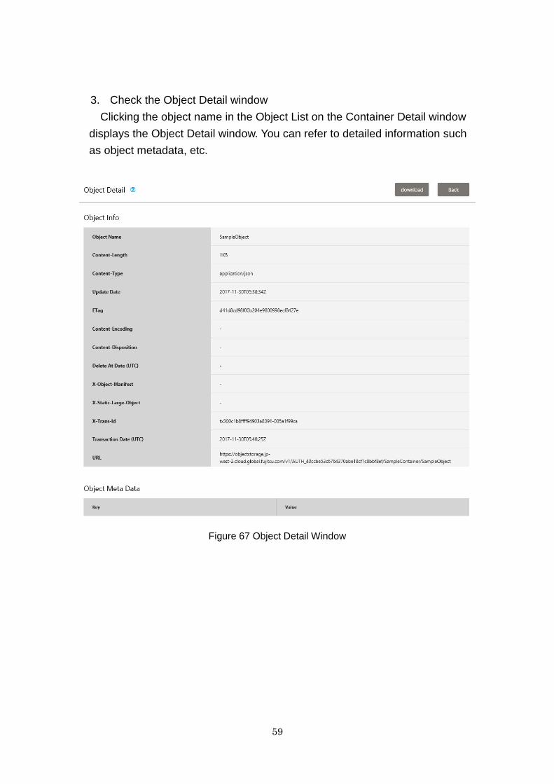
11.2.3 Download an Object
There are the following two methods for downloading an object.
Clicking the "Download" button on the Object Detail window
Selecting from the Action menu of the object list on the Container Detail
window
Figure 68 Object Action Menu on the Container Detail Window
Advisory Notes
・ It is necessary to configure the following setting in IE 11:
Click [Tools] > [Internet options] > [Security] > [Custom level], and then
select "Enable" for [Access data sources across domains].
Uploading and downloading of files may take approximately 90 minutes per
GB depending on the time of day, the amount of data, and the distance to the
target region the data is being transferred to.
Note: By viewing [F12 developer tools] > [Network] in IE 11, it is possible to
confirm the processing status of each API issued from the portal.
11.2.4 Import a VM Image
It is possible to select VM Import from the Action menu on the Container
Detail window to import a virtual server image to the K5 service. Selecting "VM
Import" on the Action menu transfers you to the VM Import window. For details
on VM import, refer to 29.2.1 VM Import.
62
11.3 Advisory Notes
With the container deletion function, it is only possible to perform "Delete"
from the Action menu on the Container List window when the number of
objects in a container is "0".
Regarding the access policy (ACL) settings, as setting permission for
referrer makes reading possible without authentication using a token, it
is not recommended as it lowers the security level. For details, refer to
the "API Reference - Foundation Service".
When you want to register split objects as a single object, perform
settings for a large object. This integrates split objects, enabling batch
download as a single object and VM import.
The maximum number of objects that can be displayed on the Container
Detail window is 10,000. If it is necessary to obtain a list of objects when
the maximum has been exceeded, obtain the list using an API.
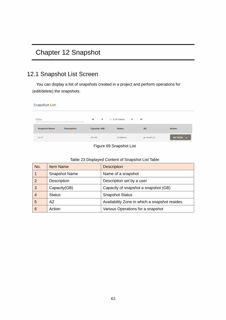
63
Chapter 12 Snapshot
12.1 Snapshot List Screen
You can display a list of snapshots created in a project and perform operations for
(edit/delete) the snapshots.
Figure 69 Snapshot List
Table 23 Displayed Content of Snapshot List Table
No. Item Name Description
1 Snapshot Name Name of a snapshot
2 Description Description set by a user
3 Capacity(GB) Capacity of snapshot a snapshot (GB)
4 Status Snapshot Status
5 AZ Availability Zone in which a snapshot resides.
6 Action Various Operations for a snapshot
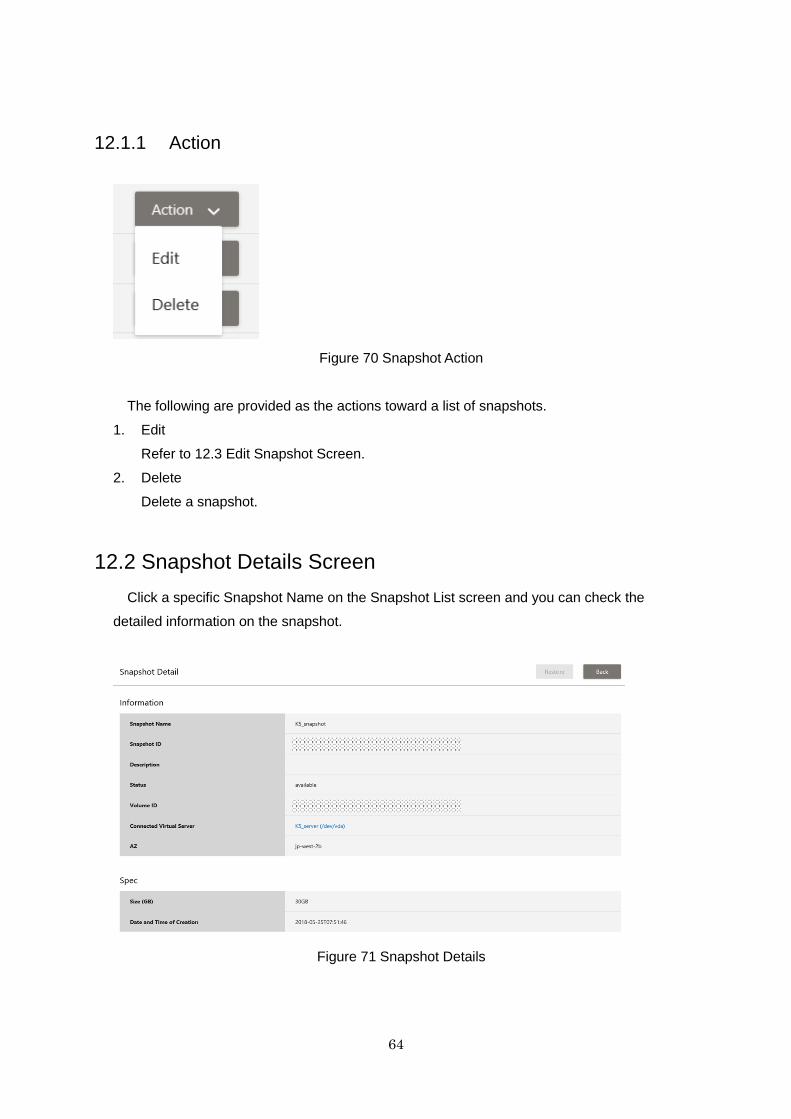
64
12.1.1 Action
Figure 70 Snapshot Action
The following are provided as the actions toward a list of snapshots.
1. Edit
Refer to 12.3 Edit Snapshot Screen.
2. Delete
Delete a snapshot.
12.2 Snapshot Details Screen
Click a specific Snapshot Name on the Snapshot List screen and you can check the
detailed information on the snapshot.
Figure 71 Snapshot Details
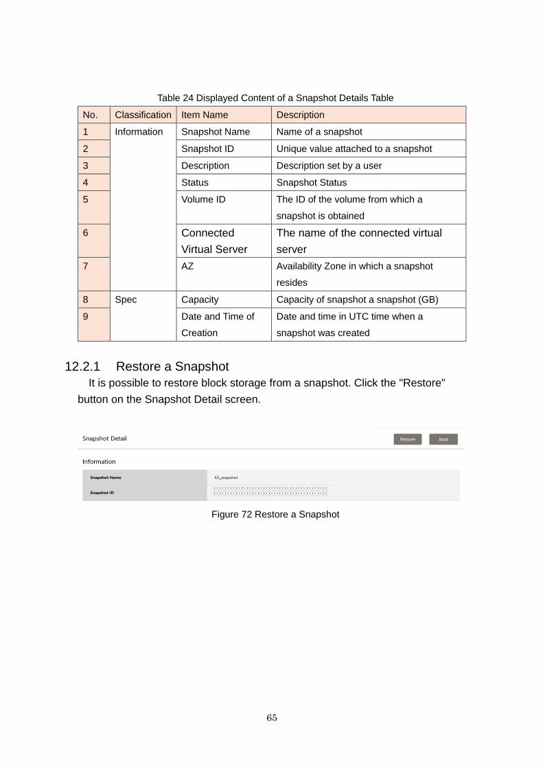
65
Table 24 Displayed Content of a Snapshot Details Table
No. Classification Item Name Description
1 Information Snapshot Name Name of a snapshot
2 Snapshot ID Unique value attached to a snapshot
3 Description Description set by a user
4 Status Snapshot Status
5 Volume ID The ID of the volume from which a
snapshot is obtained
6 Connected
Virtual Server
The name of the connected virtual
server
7 AZ Availability Zone in which a snapshot
resides
8 Spec Capacity Capacity of snapshot a snapshot (GB)
9 Date and Time of
Creation
Date and time in UTC time when a
snapshot was created
12.2.1 Restore a Snapshot
It is possible to restore block storage from a snapshot. Click the "Restore"
button on the Snapshot Detail screen.
Figure 72 Restore a Snapshot
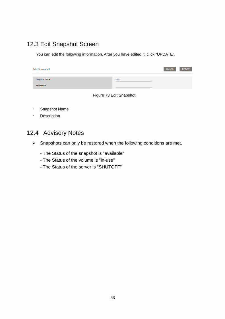
66
12.3 Edit Snapshot Screen
You can edit the following information. After you have edited it, click "UPDATE".
Figure 73 Edit Snapshot
・ Snapshot Name
・ Description
12.4 Advisory Notes
Snapshots can only be restored when the following conditions are met.
- The Status of the snapshot is "available"
- The Status of the volume is "in-use"
- The Status of the server is "SHUTOFF"
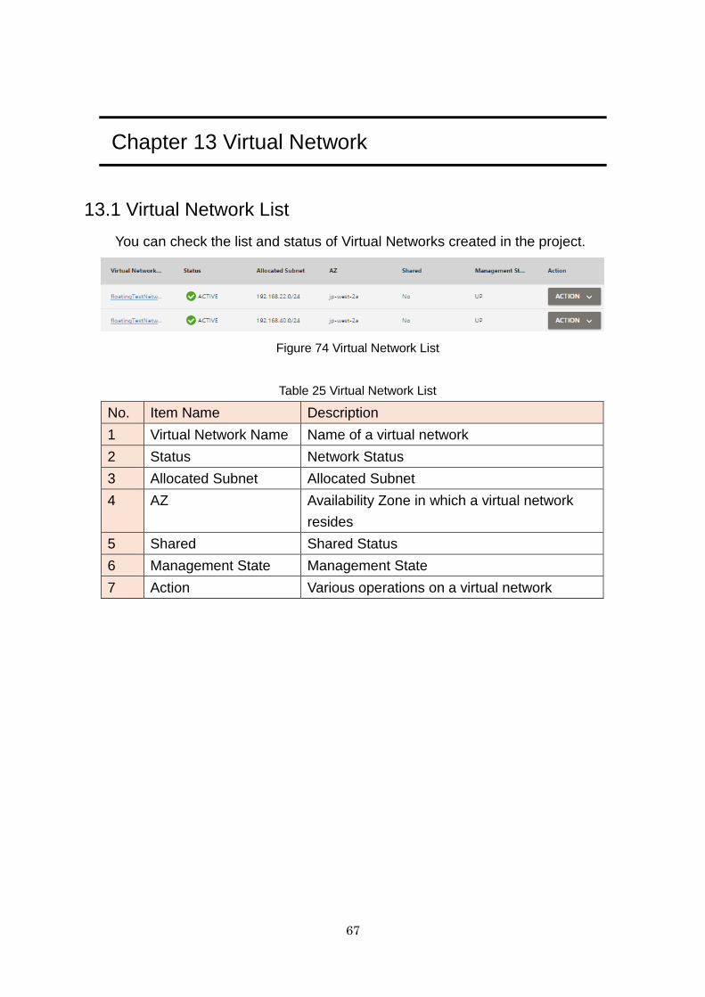
67
Chapter 13 Virtual Network
13.1 Virtual Network List
You can check the list and status of Virtual Networks created in the project.
Figure 74 Virtual Network List
Table 25 Virtual Network List
No. Item Name Description
1 Virtual Network Name Name of a virtual network
2 Status Network Status
3 Allocated Subnet Allocated Subnet
4 AZ Availability Zone in which a virtual network
resides
5 Shared Shared Status
6 Management State Management State
7 Action Various operations on a virtual network
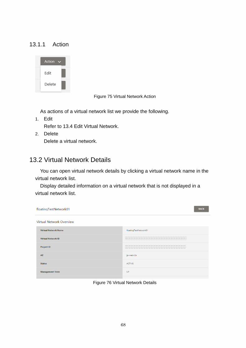
68
13.1.1 Action
Figure 75 Virtual Network Action
As actions of a virtual network list we provide the following.
1. Edit
Refer to 13.4 Edit Virtual Network.
2. Delete
Delete a virtual network.
13.2 Virtual Network Details
You can open virtual network details by clicking a virtual network name in the
virtual network list.
Display detailed information on a virtual network that is not displayed in a
virtual network list.
Figure 76 Virtual Network Details
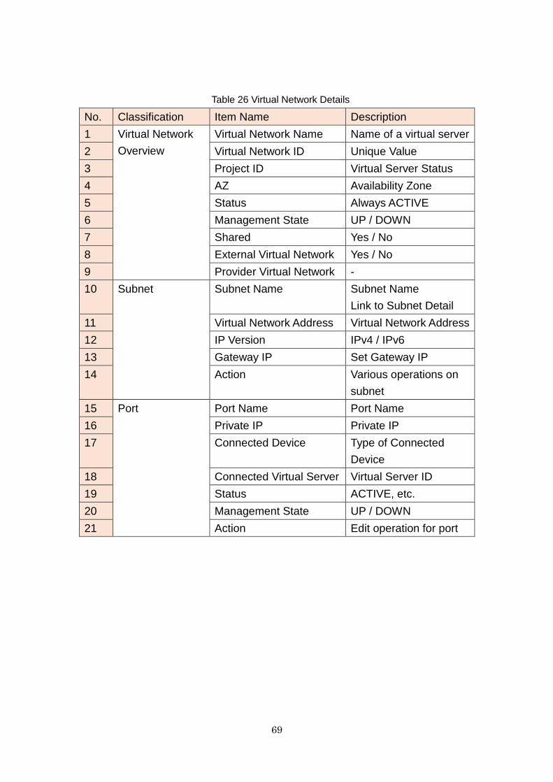
69
Table 26 Virtual Network Details
No. Classification Item Name Description
1 Virtual Network
Overview
Virtual Network Name Name of a virtual server
2 Virtual Network ID Unique Value
3 Project ID Virtual Server Status
4 AZ Availability Zone
5 Status Always ACTIVE
6 Management State UP / DOWN
7 Shared Yes / No
8 External Virtual Network Yes / No
9 Provider Virtual Network -
10 Subnet Subnet Name Subnet Name
Link to Subnet Detail
11 Virtual Network Address Virtual Network Address
12 IP Version IPv4 / IPv6
13 Gateway IP Set Gateway IP
14 Action Various operations on
subnet
15 Port Port Name Port Name
16 Private IP Private IP
17 Connected Device Type of Connected
Device
18 Connected Virtual Server Virtual Server ID
19 Status ACTIVE, etc.
20 Management State UP / DOWN
21 Action Edit operation for port
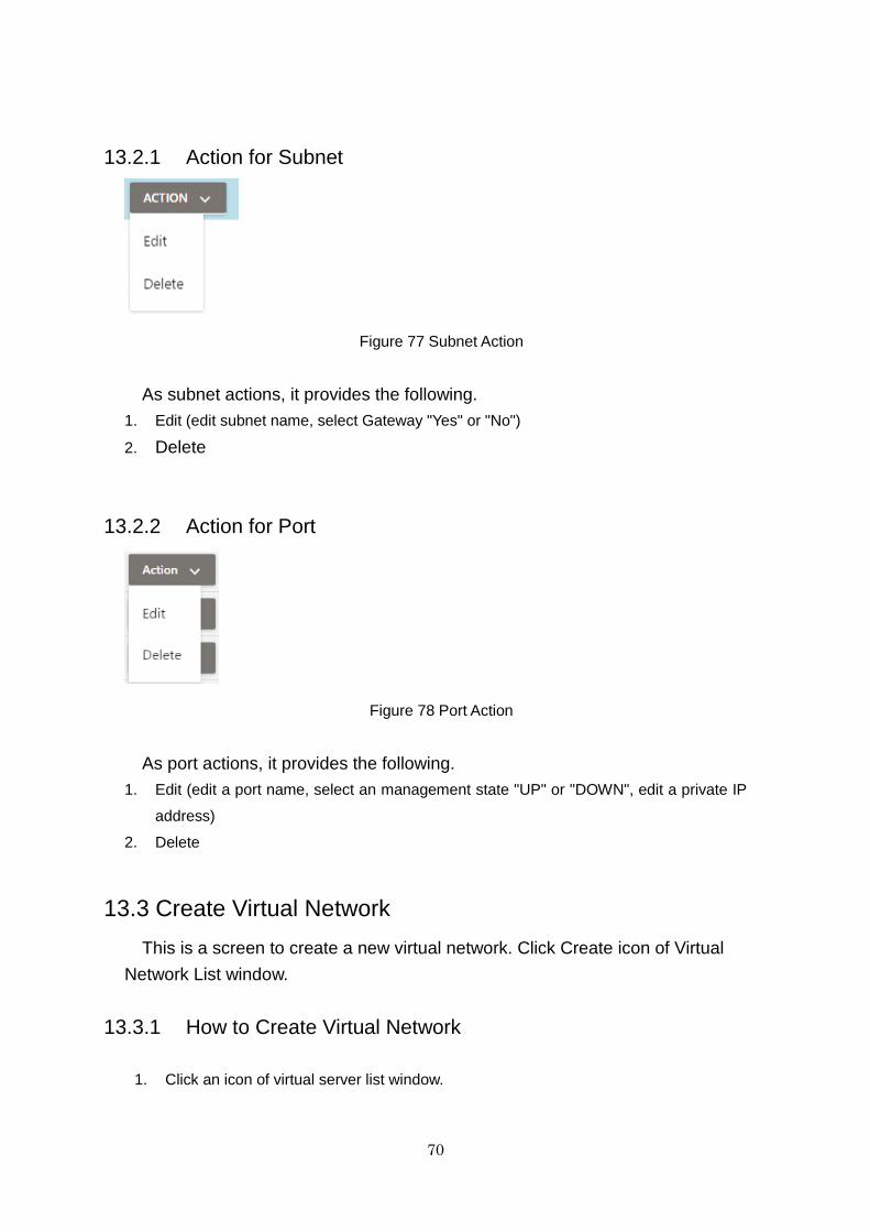
70
13.2.1 Action for Subnet
Figure 77 Subnet Action
As subnet actions, it provides the following.
1. Edit (edit subnet name, select Gateway "Yes" or "No")
2. Delete
13.2.2 Action for Port
Figure 78 Port Action
As port actions, it provides the following.
1. Edit (edit a port name, select an management state "UP" or "DOWN", edit a private IP
address)
2. Delete
13.3 Create Virtual Network
This is a screen to create a new virtual network. Click Create icon of Virtual
Network List window.
13.3.1 How to Create Virtual Network
1. Click an icon of virtual server list window.
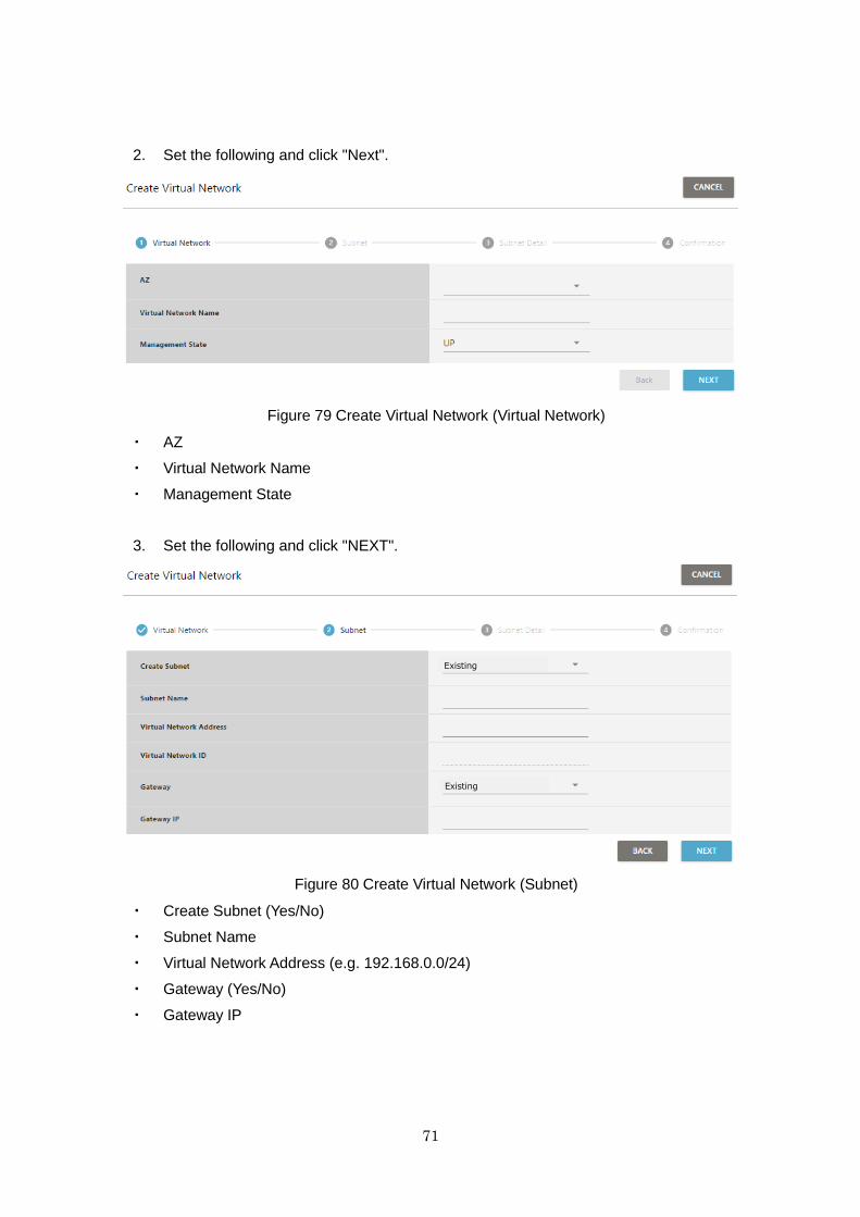
71
2. Set the following and click "Next".
Figure 79 Create Virtual Network (Virtual Network)
・ AZ
・ Virtual Network Name
・ Management State
3. Set the following and click "NEXT".
Figure 80 Create Virtual Network (Subnet)
・ Create Subnet (Yes/No)
・ Subnet Name
・ Virtual Network Address (e.g. 192.168.0.0/24)
・ Gateway (Yes/No)
・ Gateway IP
Existing
Existing

72
4. Set the following and click "Create".
Figure 81 Create Virtual Network (Subnet Details)
・ DHCP (Enable/Disable)
・ IP Address Allocation Pool
Click "Add" to assign multiple address ranges.
・ DNS Server
Click "Add" to set multiple DNS servers.
・ Adding a Routing Setting
Click "Add" to set multiple routes.
5. Confirm the settings so far on the confirmation window. If there are no problems, click
"CREATE".
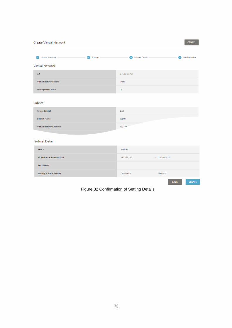
73
Figure 82 Confirmation of Setting Details

74
13.4 Edit Virtual Network
13.4.1 How to Edit Virtual Network
You can edit the following. After editing, click "UPDATE".
Figure 83 Edit Virtual Network
・ Virtual Network Name
・ Management State (UP/ DOWN)
13.5 Add Subnet
In case user does not create subnet in the timing of "Create Virtual Network"
operation, it is possible to add subnet from Virtual Network Detail Window.
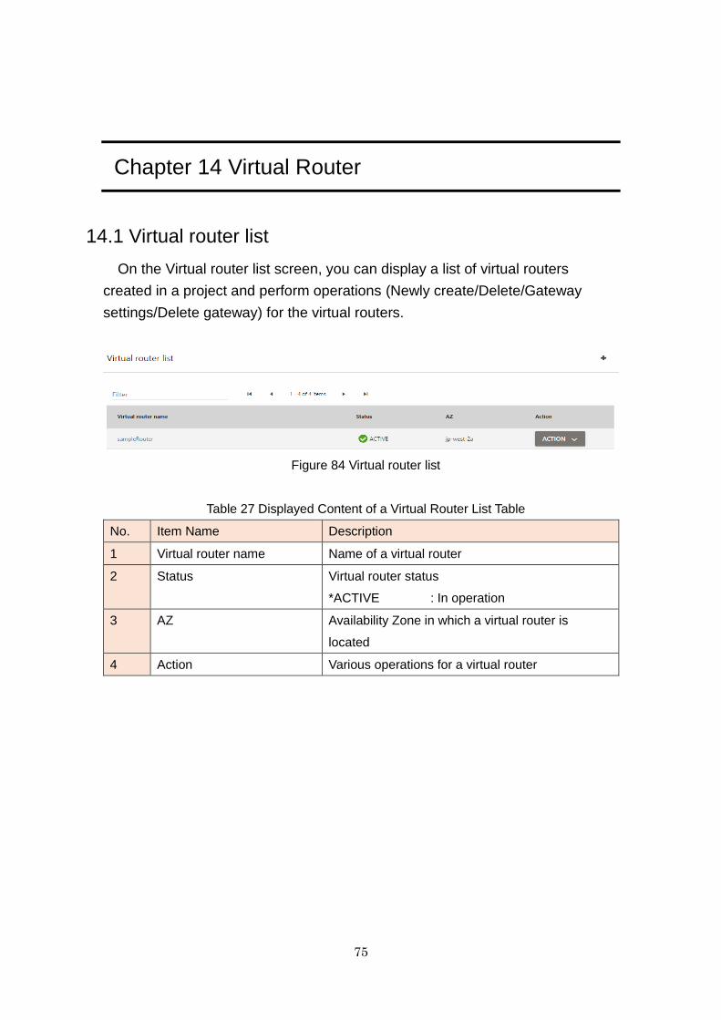
75
Chapter 14 Virtual Router
14.1 Virtual router list
On the Virtual router list screen, you can display a list of virtual routers
created in a project and perform operations (Newly create/Delete/Gateway
settings/Delete gateway) for the virtual routers.
Figure 84 Virtual router list
Table 27 Displayed Content of a Virtual Router List Table
No. Item Name Description
1 Virtual router name Name of a virtual router
2 Status Virtual router status
*ACTIVE : In operation
3 AZ Availability Zone in which a virtual router is
located
4 Action Various operations for a virtual router
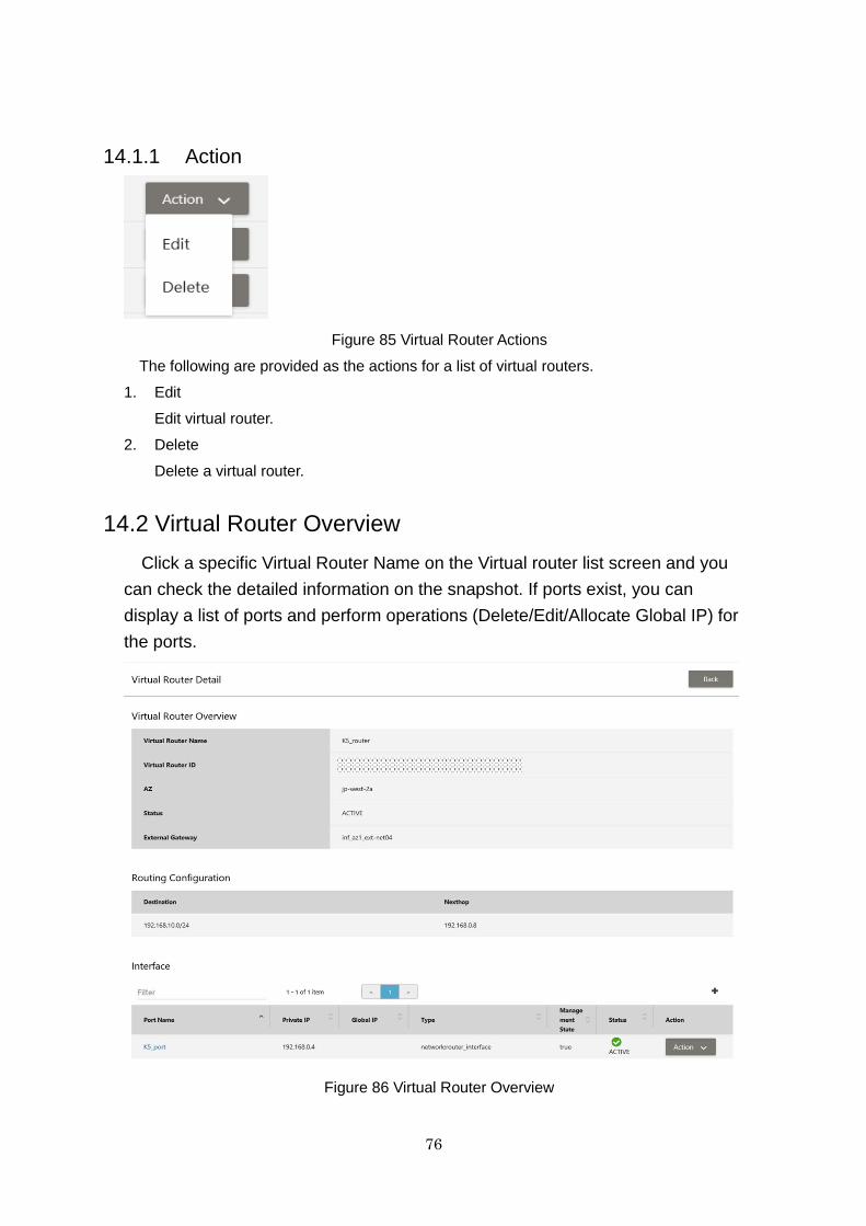
76
14.1.1 Action
Figure 85 Virtual Router Actions
The following are provided as the actions for a list of virtual routers.
1. Edit
Edit virtual router.
2. Delete
Delete a virtual router.
14.2 Virtual Router Overview
Click a specific Virtual Router Name on the Virtual router list screen and you
can check the detailed information on the snapshot. If ports exist, you can
display a list of ports and perform operations (Delete/Edit/Allocate Global IP) for
the ports.
Figure 86 Virtual Router Overview
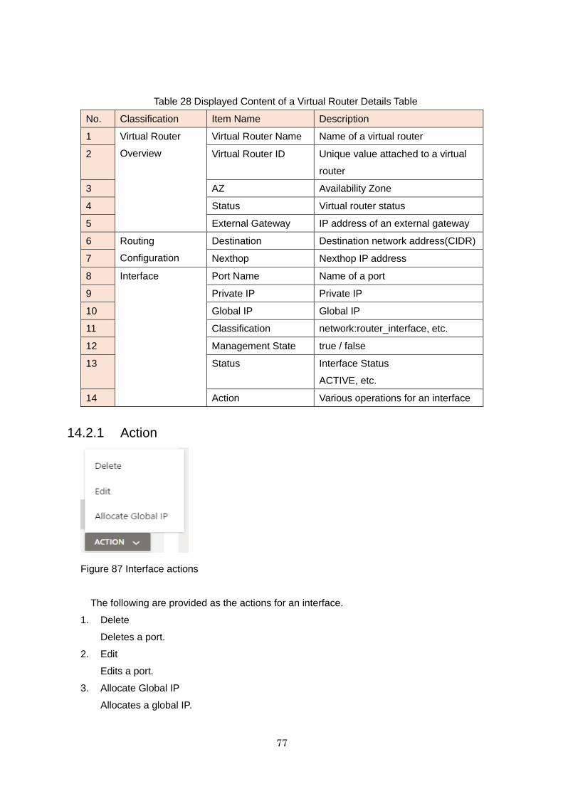
77
Table 28 Displayed Content of a Virtual Router Details Table
No. Classification Item Name Description
1 Virtual Router
Overview
Virtual Router Name Name of a virtual router
2 Virtual Router ID Unique value attached to a virtual
router
3 AZ Availability Zone
4 Status Virtual router status
5 External Gateway IP address of an external gateway
6 Routing
Configuration
Destination Destination network address(CIDR)
7 Nexthop Nexthop IP address
8 Interface Port Name Name of a port
9 Private IP Private IP
10 Global IP Global IP
11 Classification network:router_interface, etc.
12 Management State true / false
13 Status Interface Status
ACTIVE, etc.
14 Action Various operations for an interface
14.2.1 Action
Figure 87 Interface actions
The following are provided as the actions for an interface.
1. Delete
Deletes a port.
2. Edit
Edits a port.
3. Allocate Global IP
Allocates a global IP.
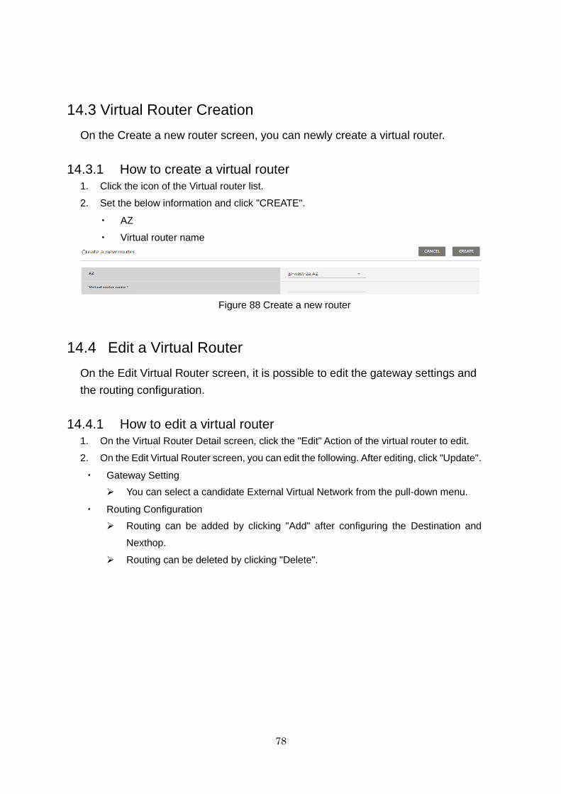
78
14.3 Virtual Router Creation
On the Create a new router screen, you can newly create a virtual router.
14.3.1 How to create a virtual router
1. Click the icon of the Virtual router list.
2. Set the below information and click "CREATE".
・ AZ
・ Virtual router name
Figure 88 Create a new router
14.4 Edit a Virtual Router
On the Edit Virtual Router screen, it is possible to edit the gateway settings and
the routing configuration.
14.4.1 How to edit a virtual router
1. On the Virtual Router Detail screen, click the "Edit" Action of the virtual router to edit.
2. On the Edit Virtual Router screen, you can edit the following. After editing, click "Update".
・ Gateway Setting
You can select a candidate External Virtual Network from the pull-down menu.
・ Routing Configuration
Routing can be added by clicking "Add" after configuring the Destination and
Nexthop.
Routing can be deleted by clicking "Delete".
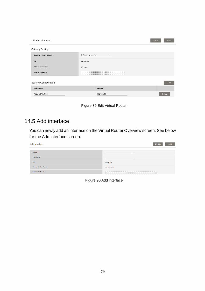
79
Figure 89 Edit Virtual Router
14.5 Add interface
You can newly add an interface on the Virtual Router Overview screen. See below
for the Add interface screen.
Figure 90 Add interface
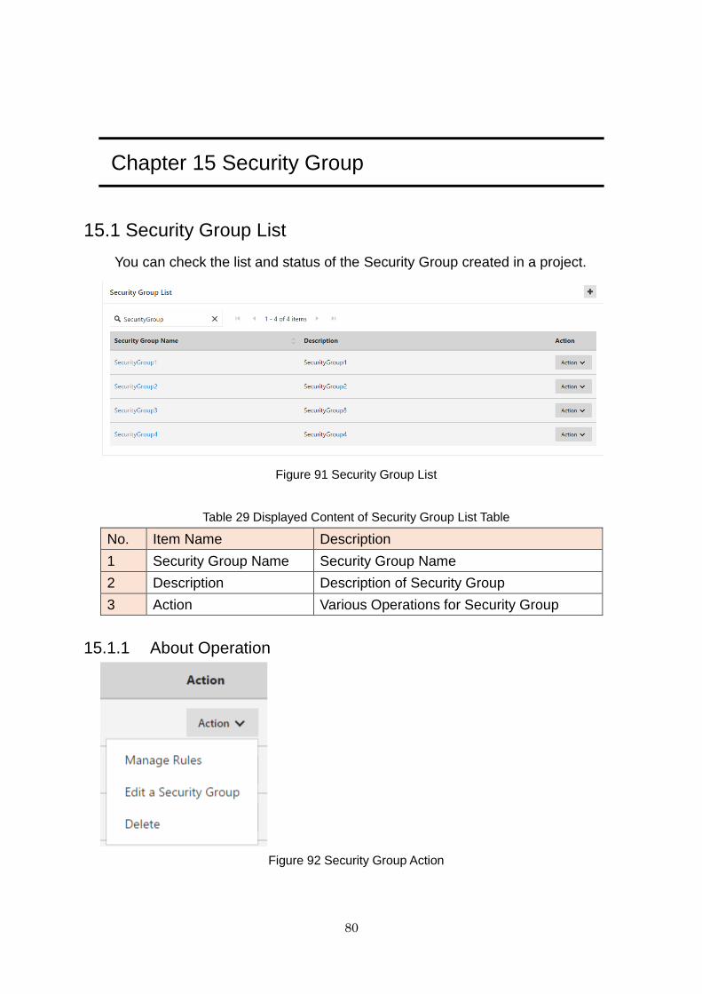
80
Chapter 15 Security Group
15.1 Security Group List
You can check the list and status of the Security Group created in a project.
Figure 91 Security Group List
Table 29 Displayed Content of Security Group List Table
No. Item Name Description
1 Security Group Name Security Group Name
2 Description Description of Security Group
3 Action Various Operations for Security Group
15.1.1 About Operation
Figure 92 Security Group Action
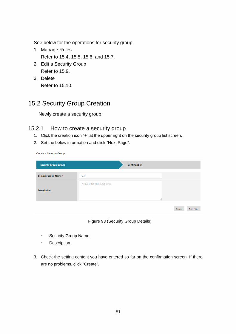
81
See below for the operations for security group.
1. Manage Rules
Refer to 15.4, 15.5, 15.6, and 15.7.
2. Edit a Security Group
Refer to 15.9.
3. Delete
Refer to 15.10.
15.2 Security Group Creation
Newly create a security group.
15.2.1 How to create a security group
1. Click the creation icon "+" at the upper right on the security group list screen.
2. Set the below information and click "Next Page".
Figure 93 (Security Group Details)
・ Security Group Name
・ Description
3. Check the setting content you have entered so far on the confirmation screen. If there
are no problems, click "Create".
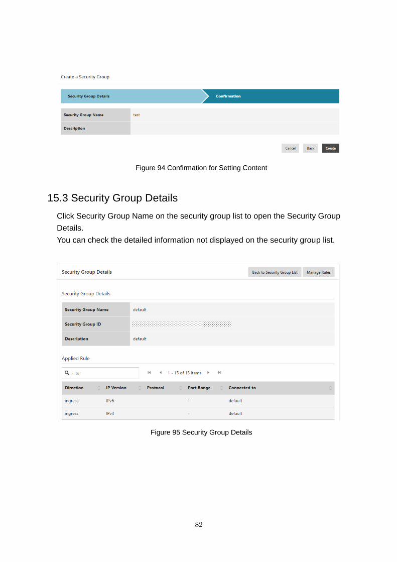
82
Figure 94 Confirmation for Setting Content
15.3 Security Group Details
Click Security Group Name on the security group list to open the Security Group
Details.
You can check the detailed information not displayed on the security group list.
Figure 95 Security Group Details
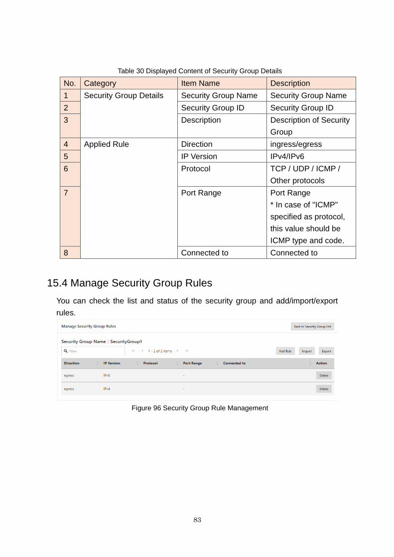
83
Table 30 Displayed Content of Security Group Details
No. Category Item Name Description
1 Security Group Details Security Group Name Security Group Name
2 Security Group ID Security Group ID
3 Description Description of Security
Group
4 Applied Rule Direction ingress/egress
5 IP Version IPv4/IPv6
6 Protocol TCP / UDP / ICMP /
Other protocols
7 Port Range Port Range
* In case of "ICMP"
specified as protocol,
this value should be
ICMP type and code.
8 Connected to Connected to
15.4 Manage Security Group Rules
You can check the list and status of the security group and add/import/export
rules.
Figure 96 Security Group Rule Management
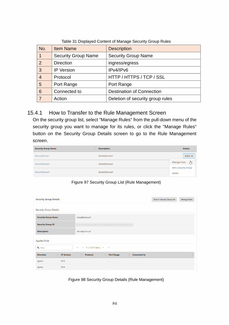
84
Table 31 Displayed Content of Manage Security Group Rules
No. Item Name Description
1 Security Group Name Security Group Name
2 Direction ingress/egress
3 IP Version IPv4/IPv6
4 Protocol HTTP / HTTPS / TCP / SSL
5 Port Range Port Range
6 Connected to Destination of Connection
7 Action Deletion of security group rules
15.4.1 How to Transfer to the Rule Management Screen
On the security group list, select "Manage Rules" from the pull-down menu of the
security group you want to manage for its rules, or click the "Manage Rules"
button on the Security Group Details screen to go to the Rule Management
screen.
Figure 97 Security Group List (Rule Management)
Figure 98 Security Group Details (Rule Management)
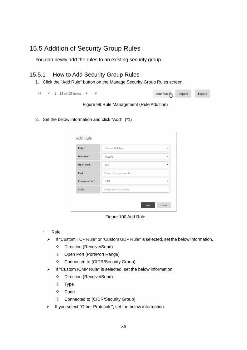
85
15.5 Addition of Security Group Rules
You can newly add the rules to an existing security group.
15.5.1 How to Add Security Group Rules
1. Click the "Add Rule" button on the Manage Security Group Rules screen.
Figure 99 Rule Management (Rule Addition)
2. Set the below information and click "Add". (*1)
Figure 100 Add Rule
・ Rule
If "Custom TCP Rule" or "Custom UDP Rule" is selected, set the below information.
Direction (Receive/Send)
Open Port (Port/Port Range)
Connected to (CIDR/Security Group)
If "Custom ICMP Rule" is selected, set the below information.
Direction (Receive/Send)
Type
Code
Connected to (CIDR/Security Group)
If you select "Other Protocols", set the below information.
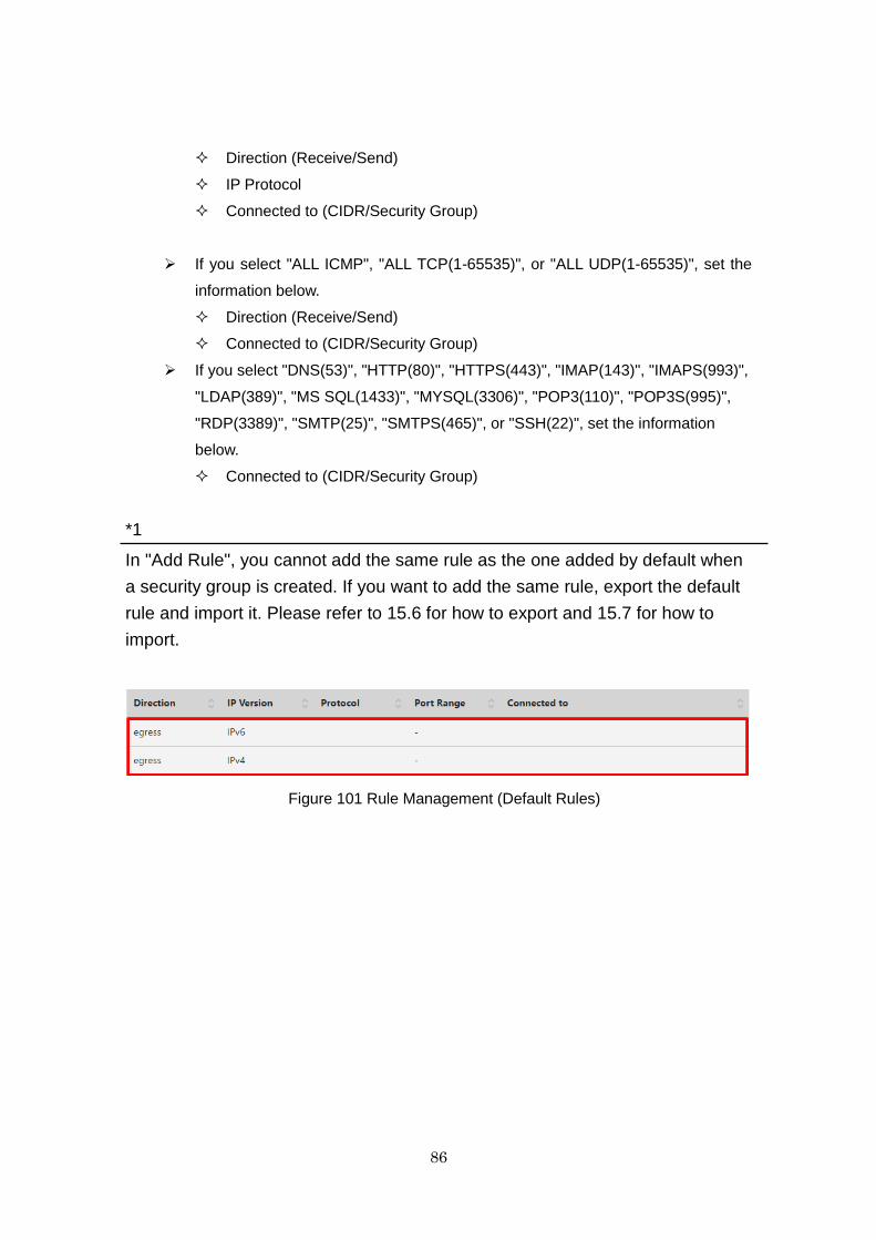
86
Direction (Receive/Send)
IP Protocol
Connected to (CIDR/Security Group)
If you select "ALL ICMP", "ALL TCP(1-65535)", or "ALL UDP(1-65535)", set the
information below.
Direction (Receive/Send)
Connected to (CIDR/Security Group)
If you select "DNS(53)", "HTTP(80)", "HTTPS(443)", "IMAP(143)", "IMAPS(993)",
"LDAP(389)", "MS SQL(1433)", "MYSQL(3306)", "POP3(110)", "POP3S(995)",
"RDP(3389)", "SMTP(25)", "SMTPS(465)", or "SSH(22)", set the information
below.
Connected to (CIDR/Security Group)
*1
In "Add Rule", you cannot add the same rule as the one added by default when
a security group is created. If you want to add the same rule, export the default
rule and import it. Please refer to 15.6 for how to export and 15.7 for how to
import.
Figure 101 Rule Management (Default Rules)
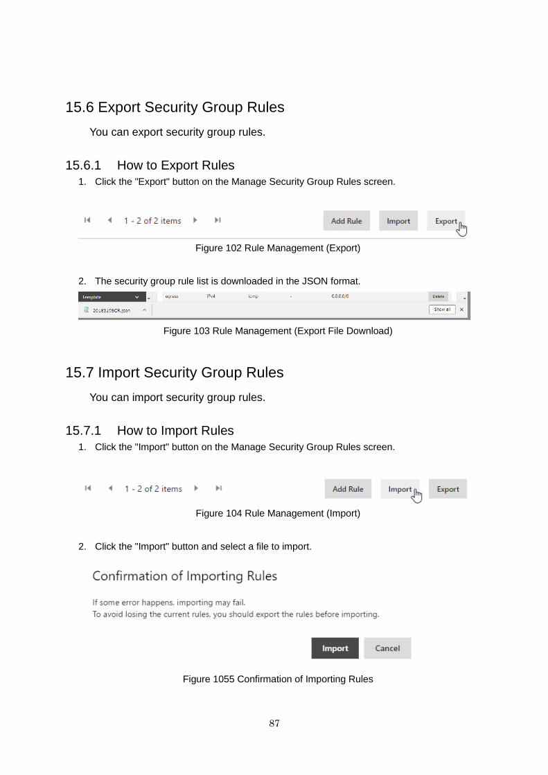
87
15.6 Export Security Group Rules
You can export security group rules.
15.6.1 How to Export Rules
1. Click the "Export" button on the Manage Security Group Rules screen.
Figure 102 Rule Management (Export)
2. The security group rule list is downloaded in the JSON format.
Figure 103 Rule Management (Export File Download)
15.7 Import Security Group Rules
You can import security group rules.
15.7.1 How to Import Rules
1. Click the "Import" button on the Manage Security Group Rules screen.
Figure 104 Rule Management (Import)
2. Click the "Import" button and select a file to import.
Figure 1055 Confirmation of Importing Rules
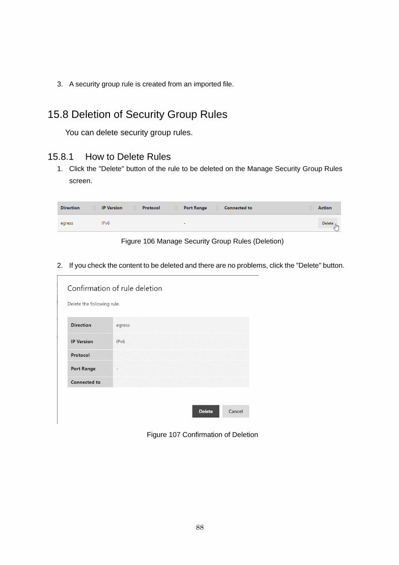
88
3. A security group rule is created from an imported file.
15.8 Deletion of Security Group Rules
You can delete security group rules.
15.8.1 How to Delete Rules
1. Click the "Delete" button of the rule to be deleted on the Manage Security Group Rules
screen.
Figure 106 Manage Security Group Rules (Deletion)
2. If you check the content to be deleted and there are no problems, click the "Delete" button.
Figure 107 Confirmation of Deletion
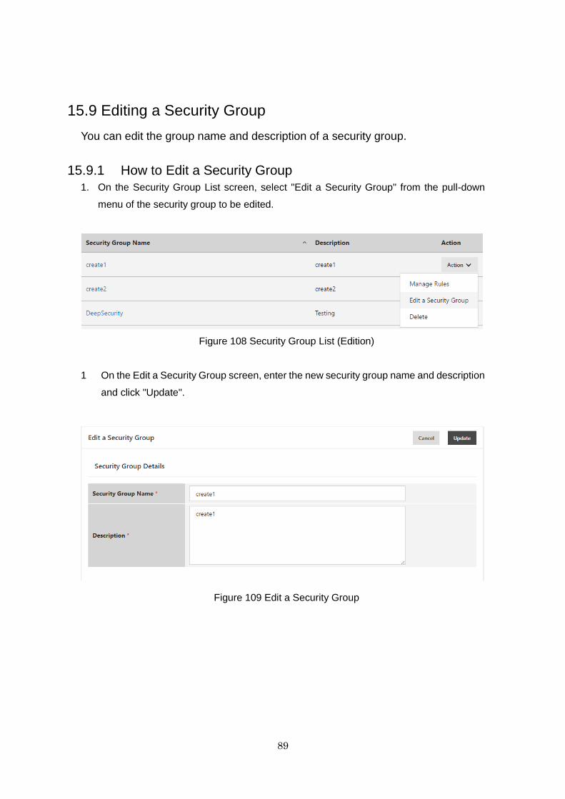
89
15.9 Editing a Security Group
You can edit the group name and description of a security group.
15.9.1 How to Edit a Security Group
1. On the Security Group List screen, select "Edit a Security Group" from the pull-down
menu of the security group to be edited.
Figure 108 Security Group List (Edition)
1 On the Edit a Security Group screen, enter the new security group name and description
and click "Update".
Figure 109 Edit a Security Group
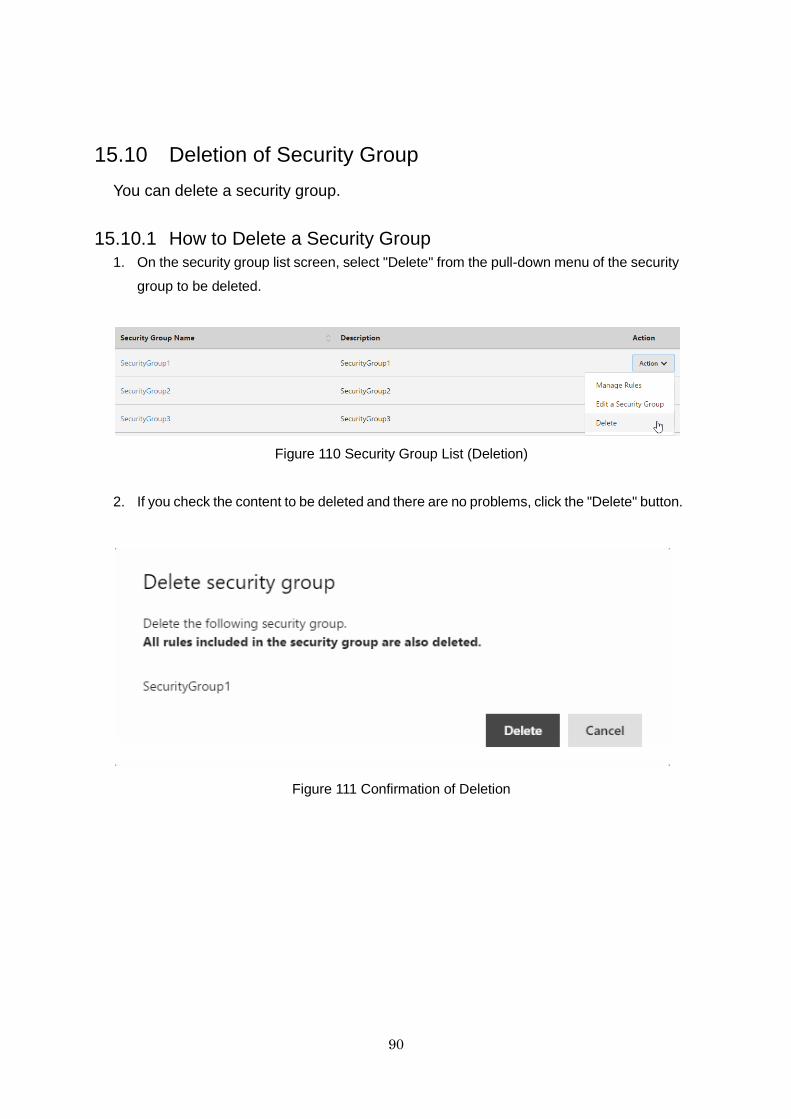
90
15.10 Deletion of Security Group
You can delete a security group.
15.10.1 How to Delete a Security Group
1. On the security group list screen, select "Delete" from the pull-down menu of the security
group to be deleted.
Figure 110 Security Group List (Deletion)
2. If you check the content to be deleted and there are no problems, click the "Delete" button.
Figure 111 Confirmation of Deletion
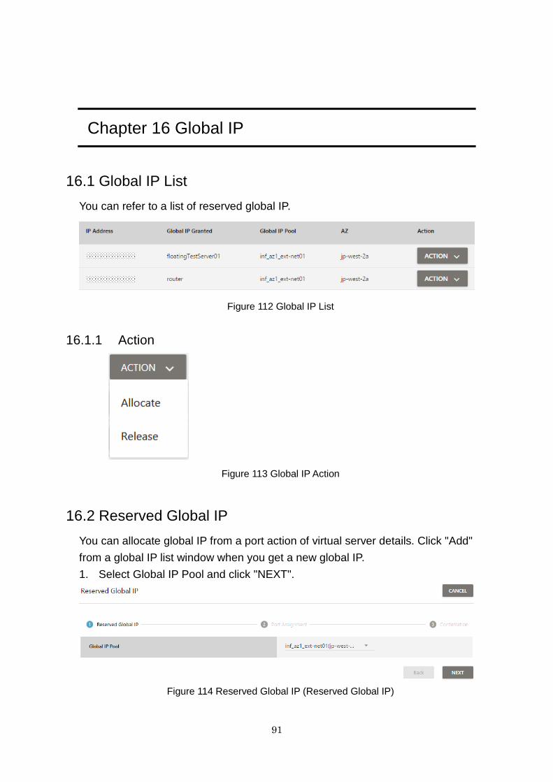
91
Chapter 16 Global IP
16.1 Global IP List
You can refer to a list of reserved global IP.
Figure 112 Global IP List
16.1.1 Action
Figure 113 Global IP Action
16.2 Reserved Global IP
You can allocate global IP from a port action of virtual server details. Click "Add"
from a global IP list window when you get a new global IP.
1. Select Global IP Pool and click "NEXT".
Figure 114 Reserved Global IP (Reserved Global IP)
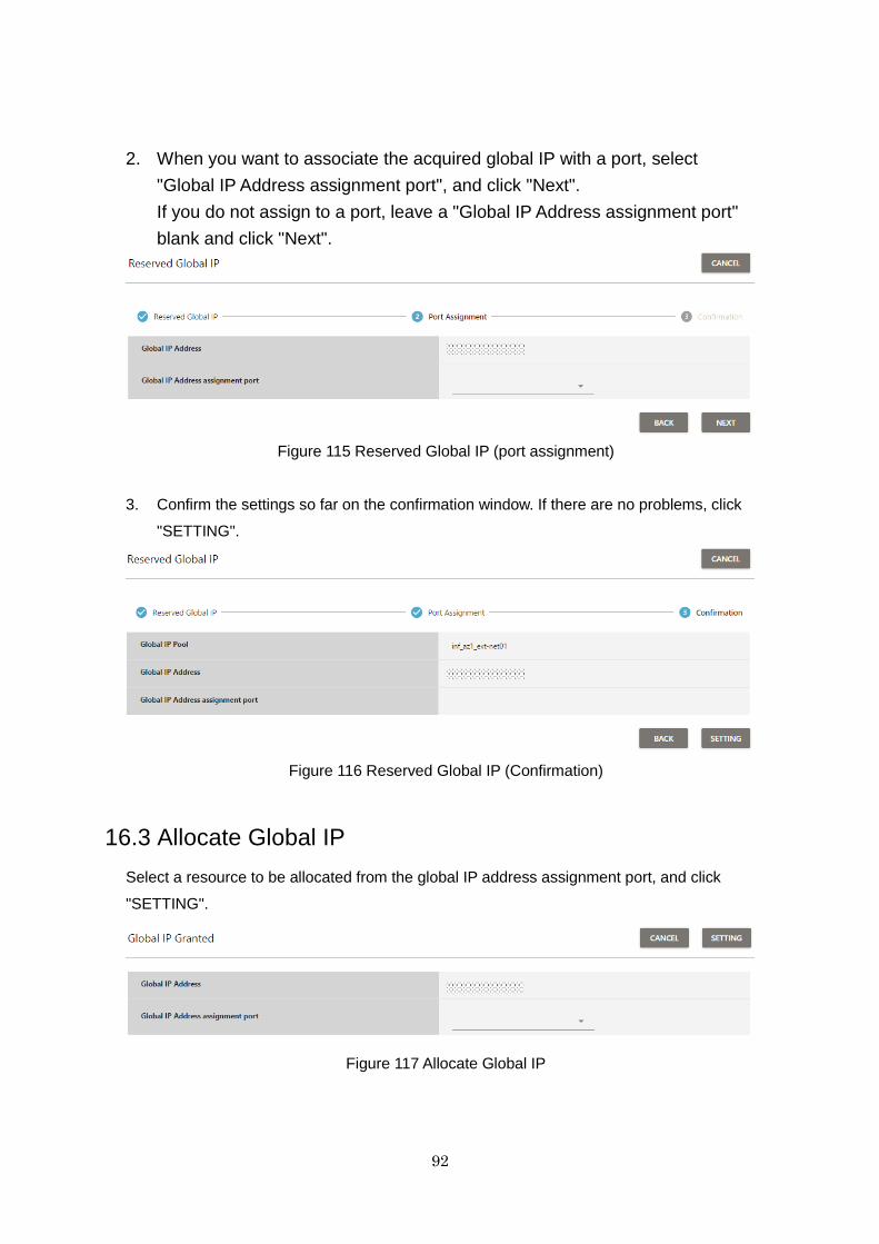
92
2. When you want to associate the acquired global IP with a port, select
"Global IP Address assignment port", and click "Next".
If you do not assign to a port, leave a "Global IP Address assignment port"
blank and click "Next".
Figure 115 Reserved Global IP (port assignment)
3. Confirm the settings so far on the confirmation window. If there are no problems, click
"SETTING".
Figure 116 Reserved Global IP (Confirmation)
16.3 Allocate Global IP
Select a resource to be allocated from the global IP address assignment port, and click
"SETTING".
Figure 117 Allocate Global IP
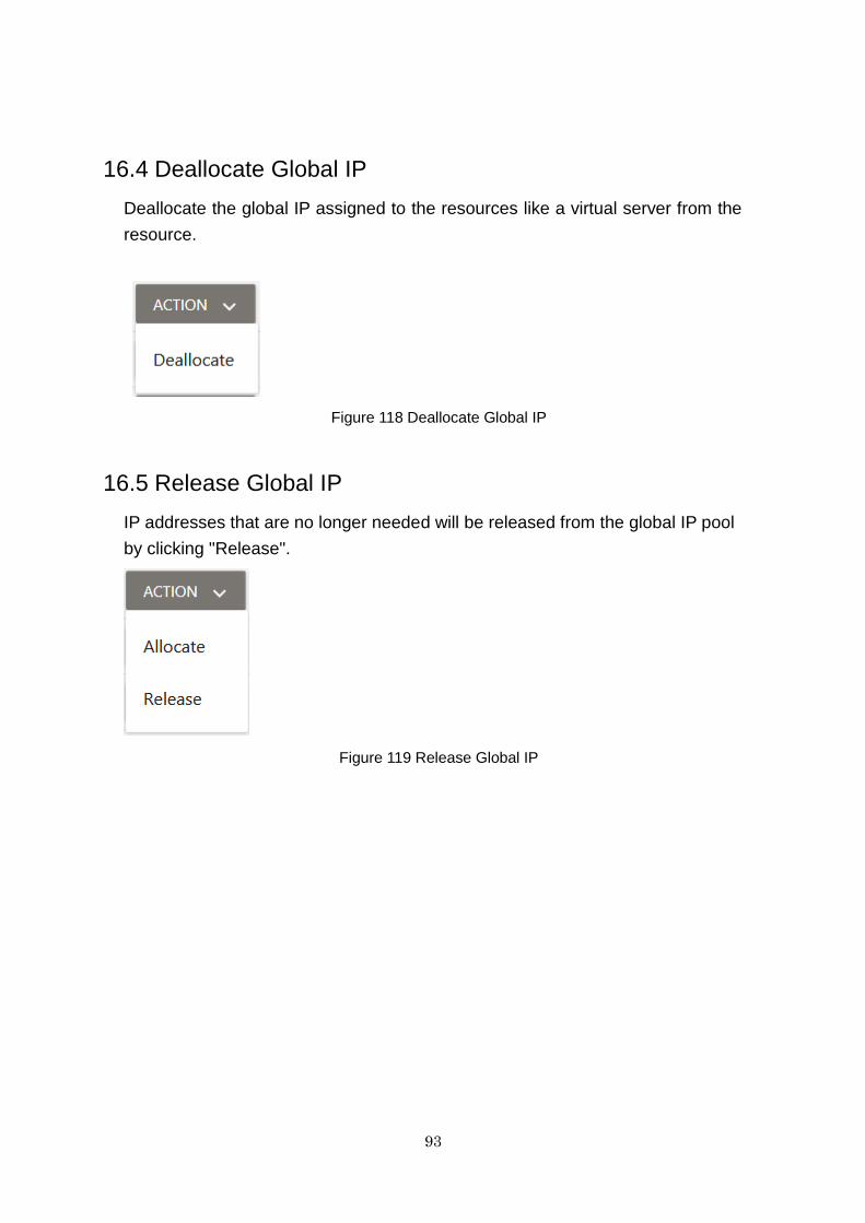
93
16.4 Deallocate Global IP
Deallocate the global IP assigned to the resources like a virtual server from the
resource.
Figure 118 Deallocate Global IP
16.5 Release Global IP
IP addresses that are no longer needed will be released from the global IP pool
by clicking "Release".
Figure 119 Release Global IP
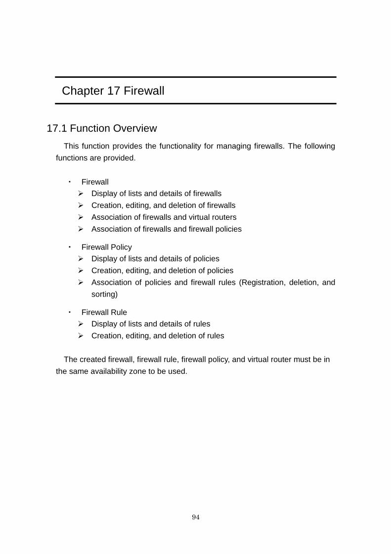
94
Chapter 17 Firewall
17.1 Function Overview
This function provides the functionality for managing firewalls. The following
functions are provided.
・ Firewall
Display of lists and details of firewalls
Creation, editing, and deletion of firewalls
Association of firewalls and virtual routers
Association of firewalls and firewall policies
・ Firewall Policy
Display of lists and details of policies
Creation, editing, and deletion of policies
Association of policies and firewall rules (Registration, deletion, and
sorting)
・ Firewall Rule
Display of lists and details of rules
Creation, editing, and deletion of rules
The created firewall, firewall rule, firewall policy, and virtual router must be in
the same availability zone to be used.
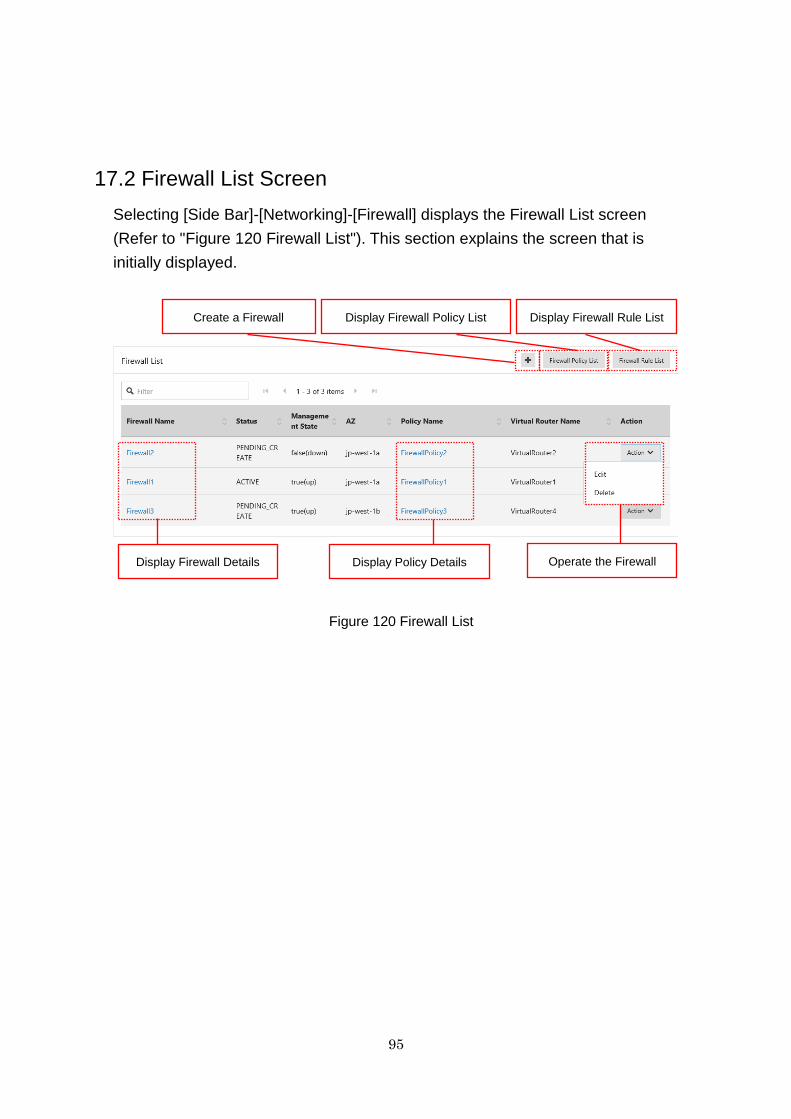
95
17.2 Firewall List Screen
Selecting [Side Bar]-[Networking]-[Firewall] displays the Firewall List screen
(Refer to "Figure 120 Firewall List"). This section explains the screen that is
initially displayed.
Figure 120 Firewall List
Create a Firewall
Display Firewall Details
Display Policy Details
Display Firewall Rule List
Operate the Firewall
Display Firewall Policy List
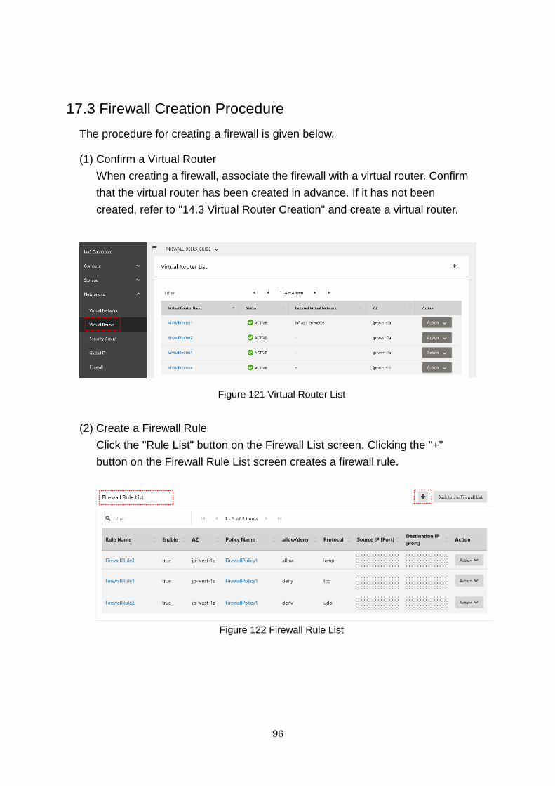
96
17.3 Firewall Creation Procedure
The procedure for creating a firewall is given below.
(1) Confirm a Virtual Router
When creating a firewall, associate the firewall with a virtual router. Confirm
that the virtual router has been created in advance. If it has not been
created, refer to "14.3 Virtual Router Creation" and create a virtual router.
Figure 121 Virtual Router List
(2) Create a Firewall Rule
Click the "Rule List" button on the Firewall List screen. Clicking the "+"
button on the Firewall Rule List screen creates a firewall rule.
Figure 122 Firewall Rule List
z
z
z
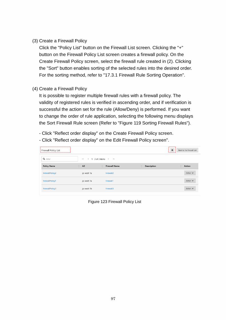
97
(3) Create a Firewall Policy
Click the "Policy List" button on the Firewall List screen. Clicking the "+"
button on the Firewall Policy List screen creates a firewall policy. On the
Create Firewall Policy screen, select the firewall rule created in (2). Clicking
the "Sort" button enables sorting of the selected rules into the desired order.
For the sorting method, refer to "17.3.1 Firewall Rule Sorting Operation".
(4) Create a Firewall Policy
It is possible to register multiple firewall rules with a firewall policy. The
validity of registered rules is verified in ascending order, and if verification is
successful the action set for the rule (Allow/Deny) is performed. If you want
to change the order of rule application, selecting the following menu displays
the Sort Firewall Rule screen (Refer to "Figure 119 Sorting Firewall Rules").
- Click "Reflect order display" on the Create Firewall Policy screen.
- Click "Reflect order display" on the Edit Firewall Policy screen".
Figure 123 Firewall Policy List
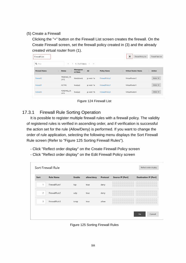
98
(5) Create a Firewall
Clicking the "+" button on the Firewall List screen creates the firewall. On the
Create Firewall screen, set the firewall policy created in (3) and the already
created virtual router from (1).
Figure 124 Firewall List
17.3.1 Firewall Rule Sorting Operation
It is possible to register multiple firewall rules with a firewall policy. The validity
of registered rules is verified in ascending order, and if verification is successful
the action set for the rule (Allow/Deny) is performed. If you want to change the
order of rule application, selecting the following menu displays the Sort Firewall
Rule screen (Refer to "Figure 125 Sorting Firewall Rules").
- Click "Reflect order display" on the Create Firewall Policy screen
- Click "Reflect order display" on the Edit Firewall Policy screen
Figure 125 Sorting Firewall Rules
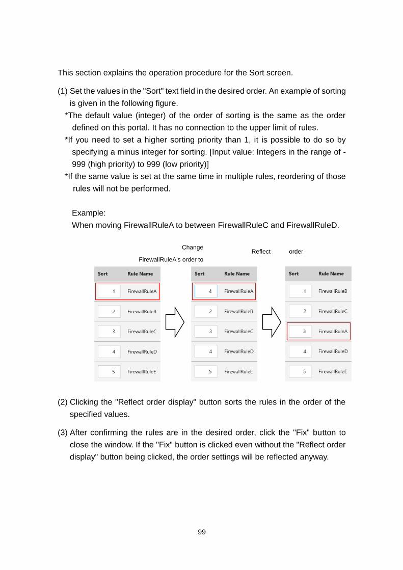
99
This section explains the operation procedure for the Sort screen.
(1) Set the values in the "Sort" text field in the desired order. An example of sorting
is given in the following figure.
*The default value (integer) of the order of sorting is the same as the order
defined on this portal. It has no connection to the upper limit of rules.
*If you need to set a higher sorting priority than 1, it is possible to do so by
specifying a minus integer for sorting. [Input value: Integers in the range of -
999 (high priority) to 999 (low priority)]
*If the same value is set at the same time in multiple rules, reordering of those
rules will not be performed.
Example:
When moving FirewallRuleA to between FirewallRuleC and FirewallRuleD.
(2) Clicking the "Reflect order display" button sorts the rules in the order of the
specified values.
(3) After confirming the rules are in the desired order, click the "Fix" button to
close the window. If the "Fix" button is clicked even without the "Reflect order
display" button being clicked, the order settings will be reflected anyway.
Change
FirewallRuleA's order to
Reflect order
100
17.4 Advisory Notes
This section explains the advisory notes for each function.
・ Indication of "Source IP [Port]" and "Destination IP [Port]" on the Firewall Rule
List
If an IP address and port number are not set, "(any)" will be displayed in the
"Source IP [Port]" and "Destination IP [Port]" fields. If the source or
destination port is set, "[the_port_number]" or
"[the_range_of_port_numbers]" will be displayed.
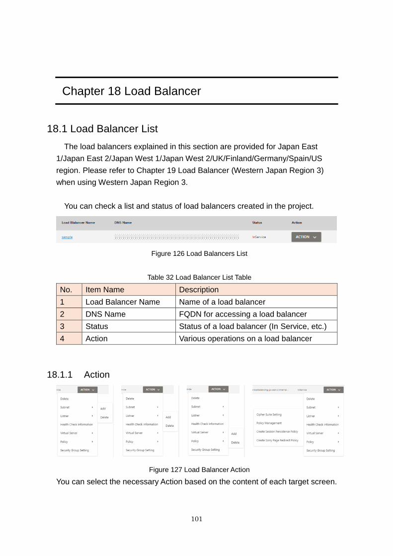
101
Chapter 18 Load Balancer
18.1 Load Balancer List
The load balancers explained in this section are provided for Japan East
1/Japan East 2/Japan West 1/Japan West 2/UK/Finland/Germany/Spain/US
region. Please refer to Chapter 19 Load Balancer (Western Japan Region 3)
when using Western Japan Region 3.
You can check a list and status of load balancers created in the project.
Figure 126 Load Balancers List
Table 32 Load Balancer List Table
No. Item Name Description
1 Load Balancer Name Name of a load balancer
2 DNS Name FQDN for accessing a load balancer
3 Status Status of a load balancer (In Service, etc.)
4 Action Various operations on a load balancer
18.1.1 Action
Figure 127 Load Balancer Action
You can select the necessary Action based on the content of each target screen.
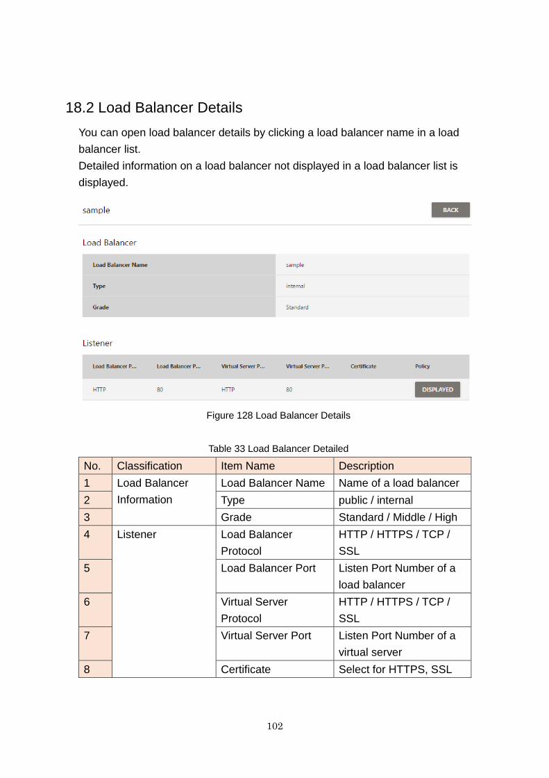
102
18.2 Load Balancer Details
You can open load balancer details by clicking a load balancer name in a load
balancer list.
Detailed information on a load balancer not displayed in a load balancer list is
displayed.
Figure 128 Load Balancer Details
Table 33 Load Balancer Detailed
No. Classification Item Name Description
1 Load Balancer
Information
Load Balancer Name Name of a load balancer
2 Type public / internal
3 Grade Standard / Middle / High
4 Listener Load Balancer
Protocol
HTTP / HTTPS / TCP /
SSL
5 Load Balancer Port Listen Port Number of a
load balancer
6 Virtual Server
Protocol
HTTP / HTTPS / TCP /
SSL
7 Virtual Server Port Listen Port Number of a
virtual server
8 Certificate Select for HTTPS, SSL
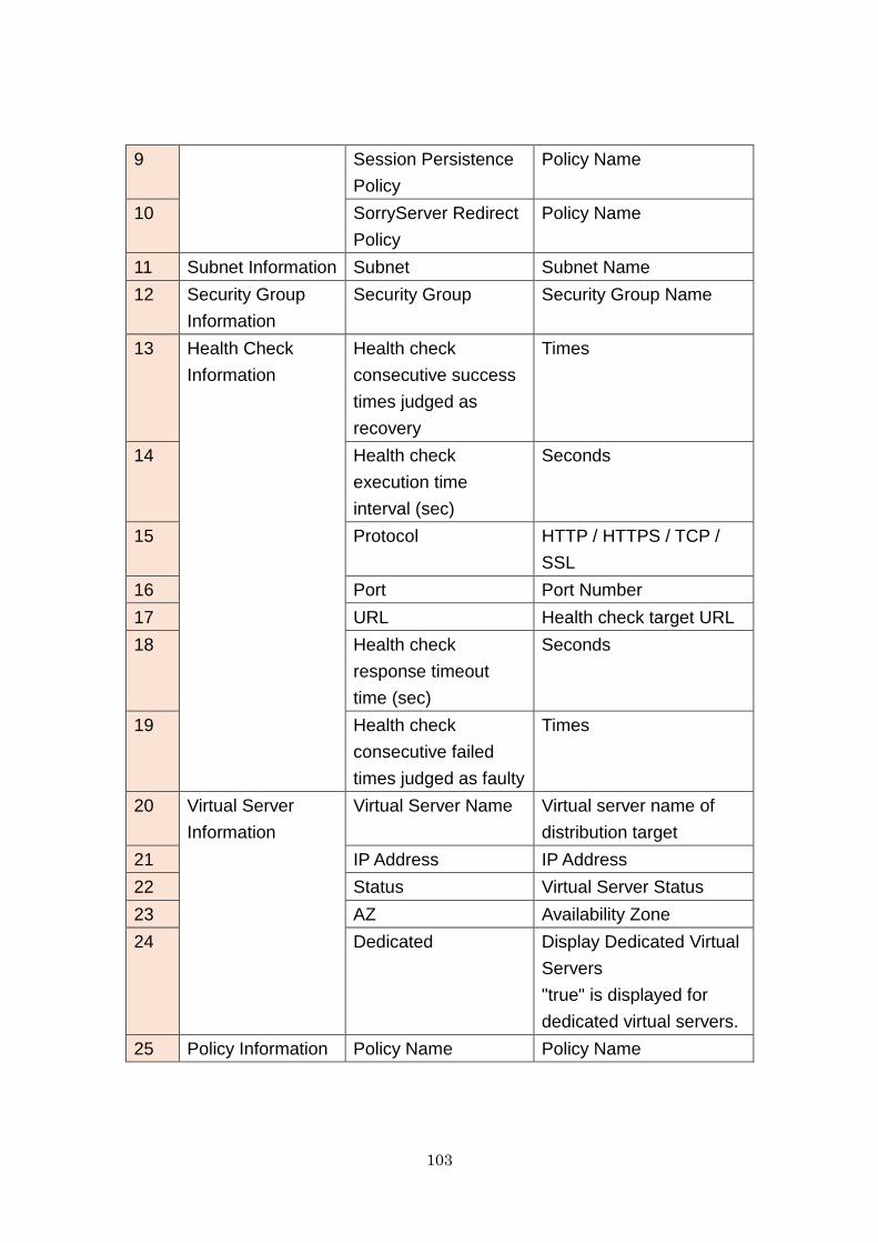
103
9 Session Persistence
Policy
Policy Name
10 SorryServer Redirect
Policy
Policy Name
11 Subnet Information Subnet Subnet Name
12 Security Group
Information
Security Group Security Group Name
13 Health Check
Information
Health check
consecutive success
times judged as
recovery
Times
14 Health check
execution time
interval (sec)
Seconds
15 Protocol HTTP / HTTPS / TCP /
SSL
16 Port Port Number
17 URL Health check target URL
18 Health check
response timeout
time (sec)
Seconds
19 Health check
consecutive failed
times judged as faulty
Times
20 Virtual Server
Information
Virtual Server Name Virtual server name of
distribution target
21 IP Address IP Address
22 Status Virtual Server Status
23 AZ Availability Zone
24 Dedicated Display Dedicated Virtual
Servers
"true" is displayed for
dedicated virtual servers.
25 Policy Information Policy Name Policy Name
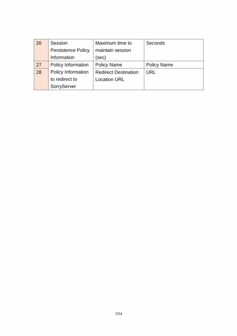
104
26 Session
Persistence Policy
Information
Maximum time to
maintain session
(sec)
Seconds
27 Policy Information
Policy Information
to redirect to
SorryServer
Policy Name Policy Name
28 Redirect Destination
Location URL
URL
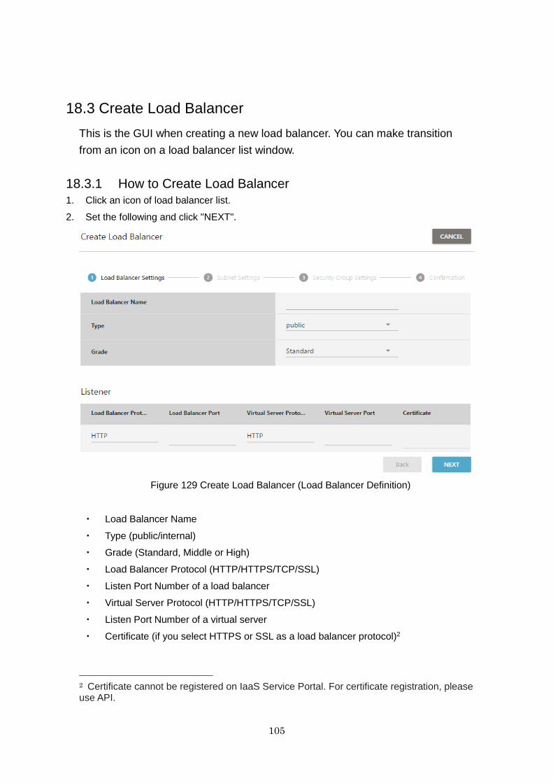
105
18.3 Create Load Balancer
This is the GUI when creating a new load balancer. You can make transition
from an icon on a load balancer list window.
18.3.1 How to Create Load Balancer
1. Click an icon of load balancer list.
2. Set the following and click "NEXT".
Figure 129 Create Load Balancer (Load Balancer Definition)
・ Load Balancer Name
・ Type (public/internal)
・ Grade (Standard, Middle or High)
・ Load Balancer Protocol (HTTP/HTTPS/TCP/SSL)
・ Listen Port Number of a load balancer
・ Virtual Server Protocol (HTTP/HTTPS/TCP/SSL)
・ Listen Port Number of a virtual server
・ Certificate (if you select HTTPS or SSL as a load balancer protocol)2
2 Certificate cannot be registered on IaaS Service Portal. For certificate registration, please use API.
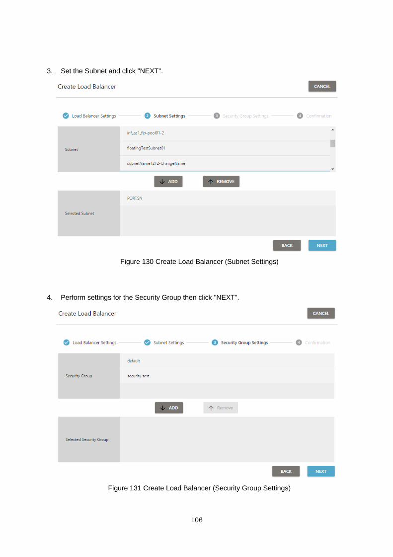
106
3. Set the Subnet and click "NEXT".
Figure 130 Create Load Balancer (Subnet Settings)
4. Perform settings for the Security Group then click "NEXT".
Figure 131 Create Load Balancer (Security Group Settings)
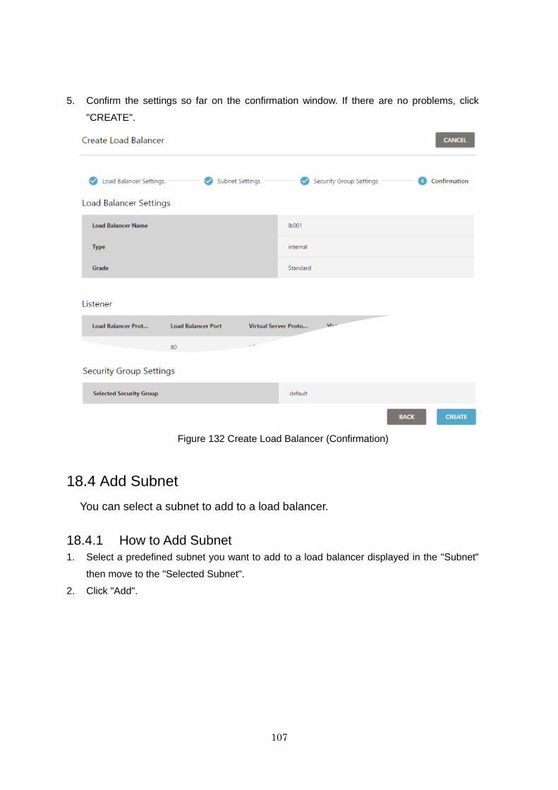
107
5. Confirm the settings so far on the confirmation window. If there are no problems, click
"CREATE".
Figure 132 Create Load Balancer (Confirmation)
18.4 Add Subnet
You can select a subnet to add to a load balancer.
18.4.1 How to Add Subnet
1. Select a predefined subnet you want to add to a load balancer displayed in the "Subnet"
then move to the "Selected Subnet".
2. Click "Add".
108
18.5 Delete Subnet
You can select a subnet to remove from a load balancer.
18.5.1 How to Delete Subnet
1. Select the deletion target from the subnet displayed in the list and click "Delete".
18.6 Add Listener
You can select a listener to add to a load balancer.
18.6.1 How to Add Listener
It is possible to select the listener to add to a load balancer. The method for adding
a listener is indicated below.
1. In "Load Balancer Protocol", select a protocol accepted by a load balancer. (HTTP/HTTPS/
TCP/SSL).
2. Enter a port number acceptable for a load balancer in "Load Balancer Port".
3. Select a protocol to communicate from a load balancer to a virtual server in "Virtual Server
Protocol". (HTTP/HTTPS/TCP/SSL)
4. Enter a port number acceptable for a virtual server in "Virtual server port".
5. Select a credential if you select "HTTPS" or "SSL" in "Load Balancer Protocol".
6. Click "Add".
18.7 Delete Listener
You can delete listeners of load balancers from the displayed list screen.
18.8 Add Virtual Server
You can select a virtual server to which a load balancer distributes requests.
18.8.1 How to Add Virtual Server
1. From a virtual server list, select a server you want to add to a load balancer.
2. Click "Add".
18.9 Delete Virtual Server
109
You can delete a virtual server to which a load balancer distributes requests.
Just out of the load balancer distribution target, the virtual server itself will
remain.
18.9.1 How to Delete Virtual Server
1. From a virtual server list, select a server you want to delete from a load balancer.
2. Click "Delete".
18.10 Create Session Persistence Policy
You can create a session persistence policy for a load balancer.
1. Set the following items and click "Create".
・ Policy Name
・ Maximum time to maintain session (sec)
18.11 Create SorryServer Policy
You can create a policy to redirect to SorryServer when there is no destination
for a load balancer to distribute.
18.11.1 How to Create SorryServer policy
1. Set the following items and click "Create".
・ Policy Name
Redirect Destination Location URL
18.12 Create/Delete Policy
For a load balancer, you can set a session persistence policy created and a
SorryServer policy to set.
1. Set the following items and click "Set".
・ Load Balancer Port
・ Session Persistence Policy to set
・ SorryServer Policy to set
* The values of Session persistence policy and SorryServer policy are displayed by
selecting a policy.
110
18.13 Set Health Check Information
You can set health check information of a virtual server by a load balancer.
The items that can be set are as follows:
・ Health check consecutive success times judged as recovery
・ Health check execution time interval (sec)
・ Protocol (HTTP/HTTPS/TCP/SSL)
・ Port
・ URL
・ Health check response timeout time (sec)
・ Health check consecutive failed times judged as faulty
18.14 Set Security Group
You can set a security group on a load balancer.
1. Select a predefined security group you want to add to a load balancer displayed in "Security
Group", then move to "Security Group Settings", and click "Set".
18.15 Set Cipher Suite
You can set cipher suites on a load balancer. The method for setting is given
below.
1. Select "Add" or an action of the created cipher suite.
2. Select a cipher suite name and a cipher suite to use in the cipher suite add (edit) dialog.
3. Click "Set".

111
Chapter 19 Load Balancer (Western Japan Region 3)
19.1 Function Overview
This section explains the load balancer function that provides the load
distribution function. By using load balancers, it is possible to distribute the load
among multiple virtual servers when requests are received from the network.
This prevents specific virtual servers from having excessively high loads, and
enables continued provision of smooth speed.
However, the load balancers explained in this section, and the operation
screens displayed are those of the function provided in Western Japan Region
3. Please refer to Chapter 18 Load Balancer since the provided functions differ
from those of the regions other than Western Japan Region 3.
The provided functions are as follows:
・ Create Load Balancer
By creating load balancers and entering the load distribution settings as
shown in the Creation screens, it becomes possible to use load
balancers.
・ Refer to Load Balancer (List / Details )
It is possible to check the statuses of create load balancers on the List
screen, and to check their detailed information.
・ Delete Load Balancer
It is possible to delete created load balancers using the Action menu on
the List screen.
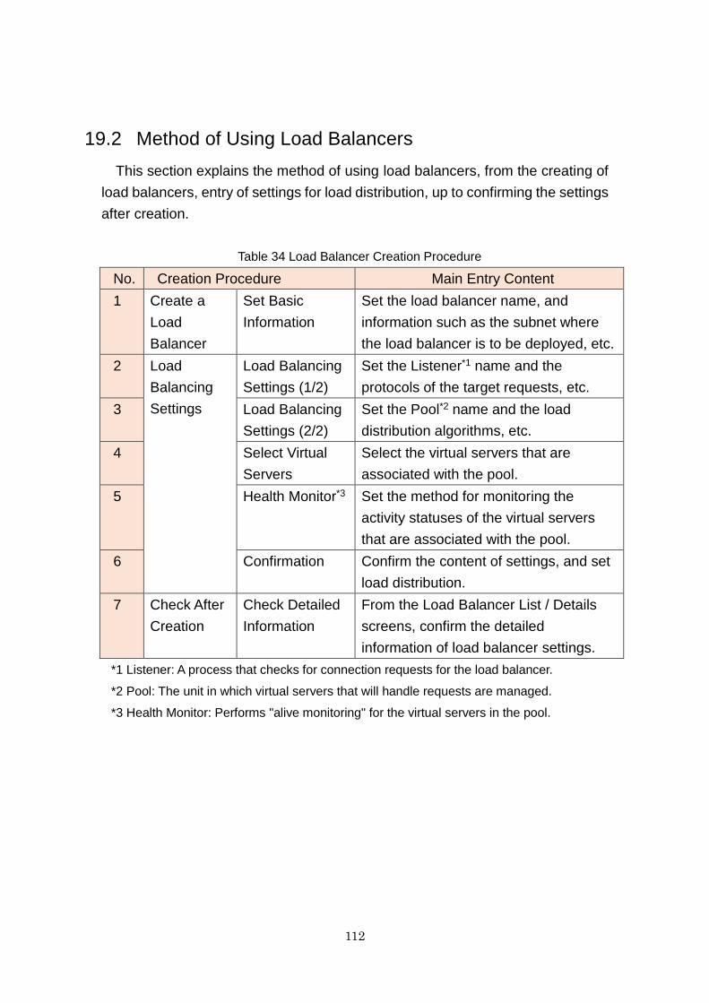
112
19.2 Method of Using Load Balancers
This section explains the method of using load balancers, from the creating of
load balancers, entry of settings for load distribution, up to confirming the settings
after creation.
Table 34 Load Balancer Creation Procedure
No. Creation Procedure Main Entry Content
1 Create a
Load
Balancer
Set Basic
Information
Set the load balancer name, and
information such as the subnet where
the load balancer is to be deployed, etc.
2 Load
Balancing
Settings
Load Balancing
Settings (1/2)
Set the Listener*1 name and the
protocols of the target requests, etc.
3 Load Balancing
Settings (2/2)
Set the Pool*2 name and the load
distribution algorithms, etc.
4 Select Virtual
Servers
Select the virtual servers that are
associated with the pool.
5 Health Monitor*3 Set the method for monitoring the
activity statuses of the virtual servers
that are associated with the pool.
6 Confirmation Confirm the content of settings, and set
load distribution.
7 Check After
Creation
Check Detailed
Information
From the Load Balancer List / Details
screens, confirm the detailed
information of load balancer settings.
*1 Listener: A process that checks for connection requests for the load balancer.
*2 Pool: The unit in which virtual servers that will handle requests are managed.
*3 Health Monitor: Performs "alive monitoring" for the virtual servers in the pool.
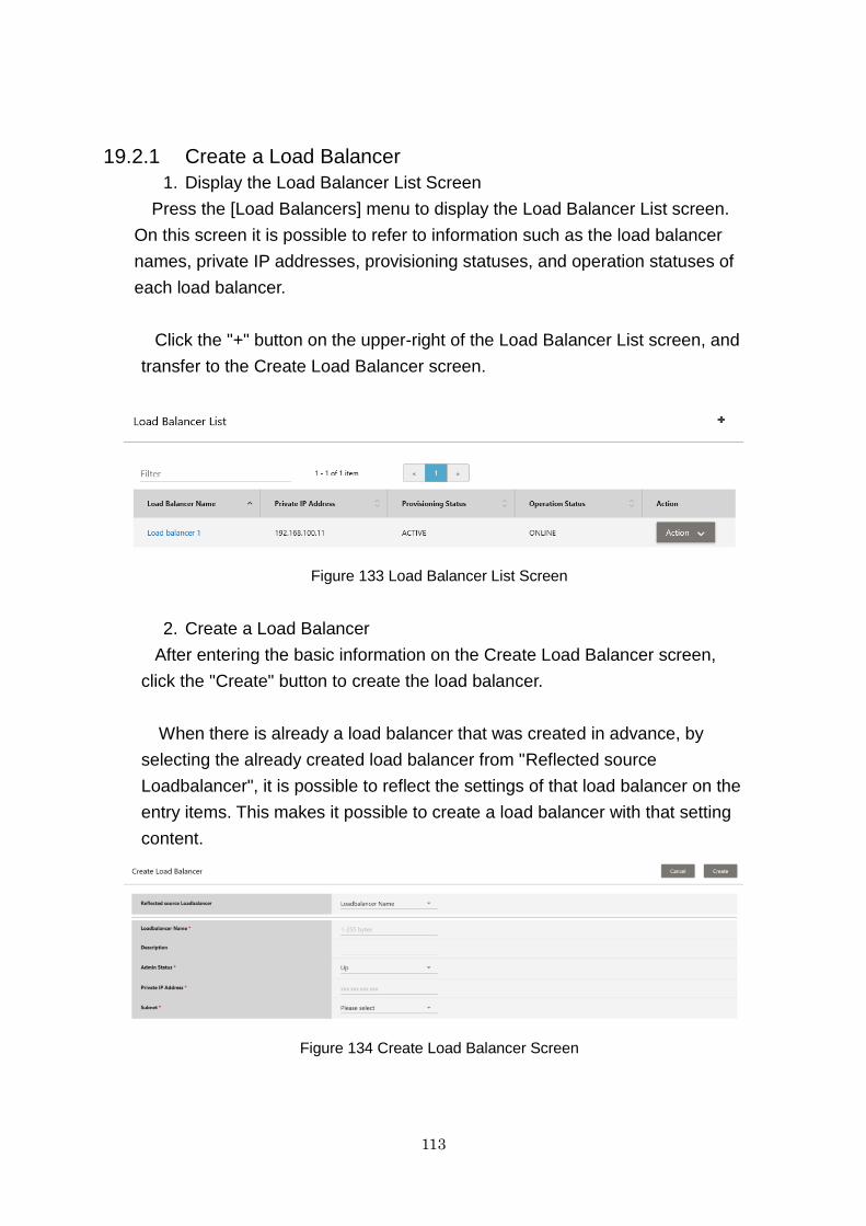
113
19.2.1 Create a Load Balancer
1. Display the Load Balancer List Screen
Press the [Load Balancers] menu to display the Load Balancer List screen.
On this screen it is possible to refer to information such as the load balancer
names, private IP addresses, provisioning statuses, and operation statuses of
each load balancer.
Click the "+" button on the upper-right of the Load Balancer List screen, and
transfer to the Create Load Balancer screen.
Figure 133 Load Balancer List Screen
2. Create a Load Balancer
After entering the basic information on the Create Load Balancer screen,
click the "Create" button to create the load balancer.
When there is already a load balancer that was created in advance, by
selecting the already created load balancer from "Reflected source
Loadbalancer", it is possible to reflect the settings of that load balancer on the
entry items. This makes it possible to create a load balancer with that setting
content.
Figure 134 Create Load Balancer Screen
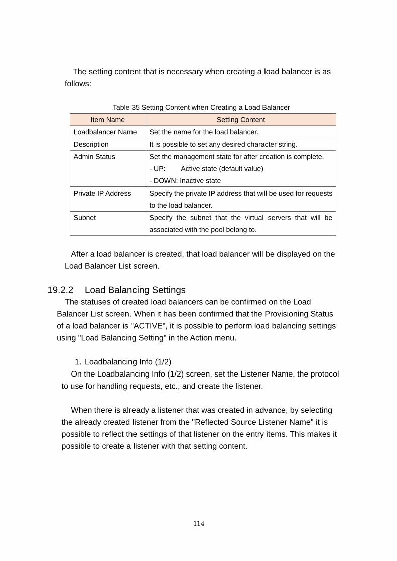
114
The setting content that is necessary when creating a load balancer is as
follows:
Table 35 Setting Content when Creating a Load Balancer
Item Name Setting Content
Loadbalancer Name Set the name for the load balancer.
Description It is possible to set any desired character string.
Admin Status Set the management state for after creation is complete.
- UP: Active state (default value)
- DOWN: Inactive state
Private IP Address Specify the private IP address that will be used for requests
to the load balancer.
Subnet Specify the subnet that the virtual servers that will be
associated with the pool belong to.
After a load balancer is created, that load balancer will be displayed on the
Load Balancer List screen.
19.2.2 Load Balancing Settings
The statuses of created load balancers can be confirmed on the Load
Balancer List screen. When it has been confirmed that the Provisioning Status
of a load balancer is "ACTIVE", it is possible to perform load balancing settings
using "Load Balancing Setting" in the Action menu.
1. Loadbalancing Info (1/2)
On the Loadbalancing Info (1/2) screen, set the Listener Name, the protocol
to use for handling requests, etc., and create the listener.
When there is already a listener that was created in advance, by selecting
the already created listener from the "Reflected Source Listener Name" it is
possible to reflect the settings of that listener on the entry items. This makes it
possible to create a listener with that setting content.

115
Figure 135 Loadbalancing Info (1/2) Screen
The items to set are as follows:
Table 36 Setting Content of the Load Balancing Info (1/2) Screen
Item Name Setting Content
Listener Name Set the name for the listener.
Description It is possible to set any desired character string.
Admin Status Set the management state for after creation is complete.
- UP: Active state (default value)
- DOWN: Inactive state
Protocol Specify the communication protocols for the Front End and Back End
sides. The following four combinations of [Front End Protocol]-[Back
End Protocol] can be specified.
[Setting Values] HTTP-HTTP, HTTPS-HTTP, HTTPS-HTTPS, TCP-
TCP
Frontend Port Specify the port number that will be used for requests to the load
balancer.
Specifiable range of port numbers: 1 - 65535
Max Connections The maximum number of connections that the listener will process.
Specifiable values: 1 - 32768
SSL Certificate
URL
When using HTTPS communication, set the URL of the server
certificate.
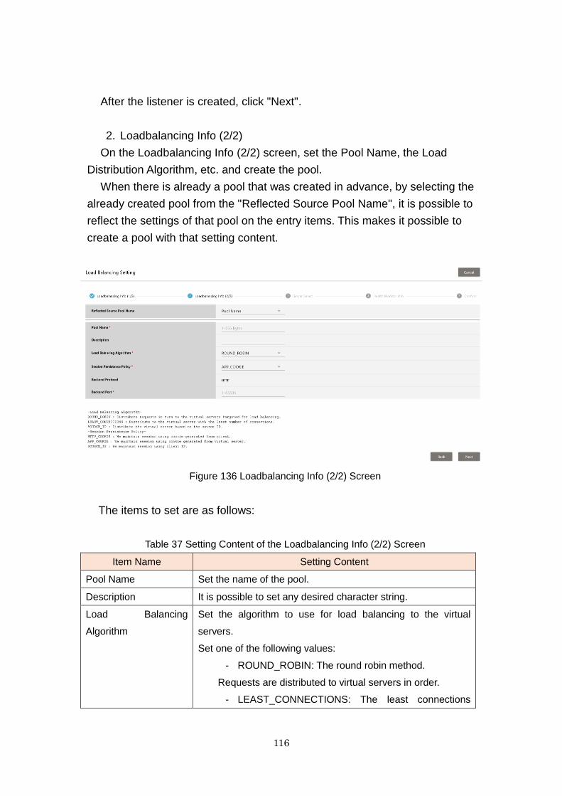
116
After the listener is created, click "Next".
2. Loadbalancing Info (2/2)
On the Loadbalancing Info (2/2) screen, set the Pool Name, the Load
Distribution Algorithm, etc. and create the pool.
When there is already a pool that was created in advance, by selecting the
already created pool from the "Reflected Source Pool Name", it is possible to
reflect the settings of that pool on the entry items. This makes it possible to
create a pool with that setting content.
Figure 136 Loadbalancing Info (2/2) Screen
The items to set are as follows:
Table 37 Setting Content of the Loadbalancing Info (2/2) Screen
Item Name Setting Content
Pool Name Set the name of the pool.
Description It is possible to set any desired character string.
Load Balancing
Algorithm
Set the algorithm to use for load balancing to the virtual
servers.
Set one of the following values:
- ROUND_ROBIN: The round robin method.
Requests are distributed to virtual servers in order.
- LEAST_CONNECTIONS: The least connections
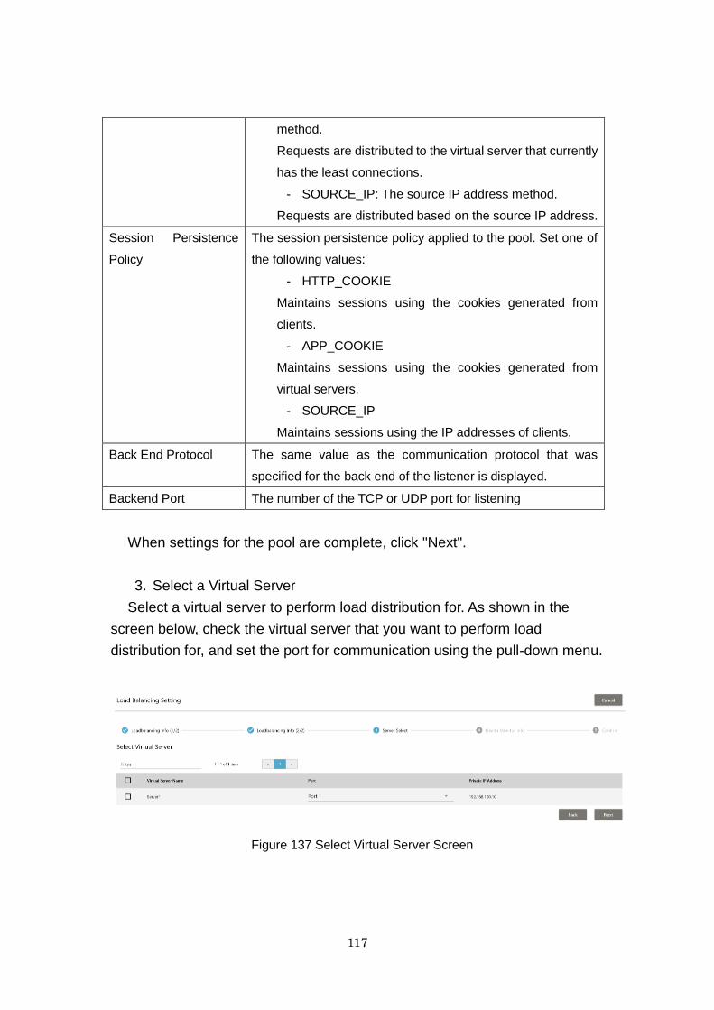
117
method.
Requests are distributed to the virtual server that currently
has the least connections.
- SOURCE_IP: The source IP address method.
Requests are distributed based on the source IP address.
Session Persistence
Policy
The session persistence policy applied to the pool. Set one of
the following values:
- HTTP_COOKIE
Maintains sessions using the cookies generated from
clients.
- APP_COOKIE
Maintains sessions using the cookies generated from
virtual servers.
- SOURCE_IP
Maintains sessions using the IP addresses of clients.
Back End Protocol The same value as the communication protocol that was
specified for the back end of the listener is displayed.
Backend Port The number of the TCP or UDP port for listening
When settings for the pool are complete, click "Next".
3. Select a Virtual Server
Select a virtual server to perform load distribution for. As shown in the
screen below, check the virtual server that you want to perform load
distribution for, and set the port for communication using the pull-down menu.
Figure 137 Select Virtual Server Screen
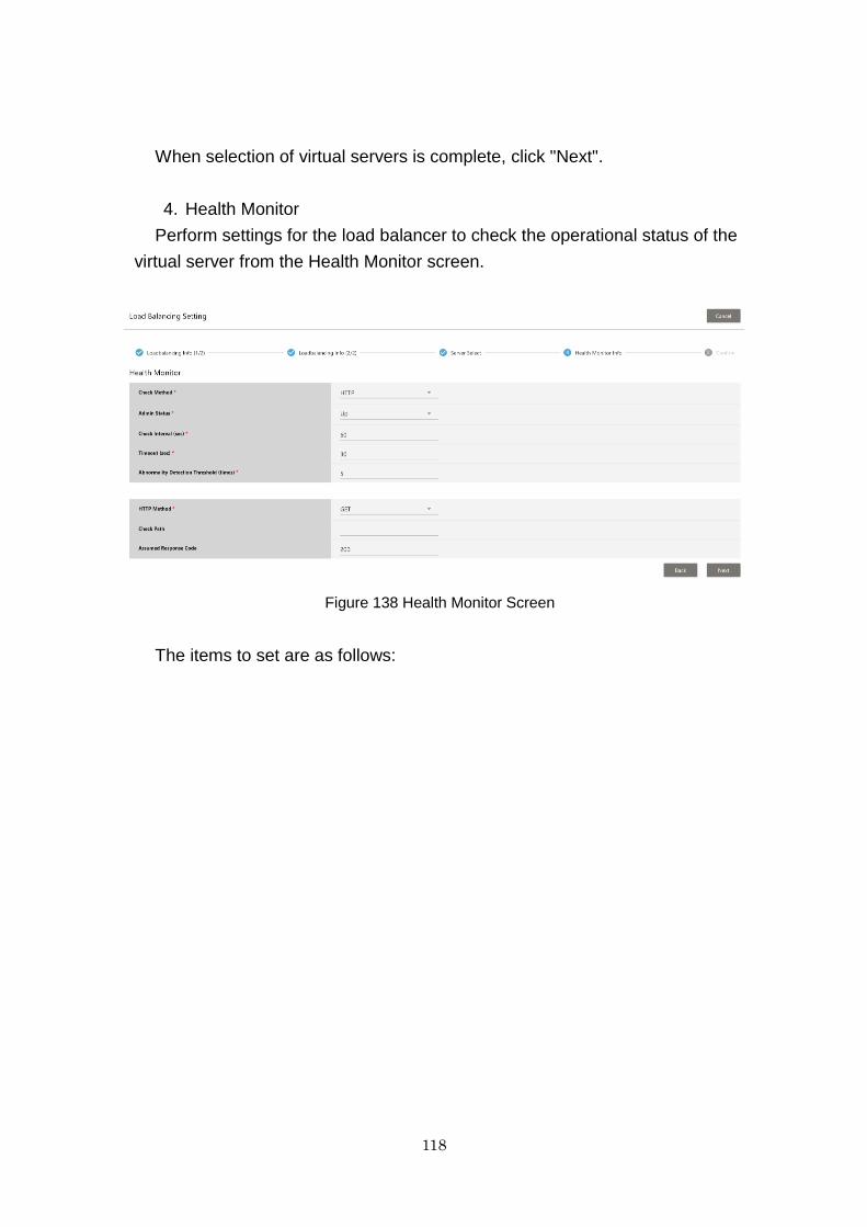
118
When selection of virtual servers is complete, click "Next".
4. Health Monitor
Perform settings for the load balancer to check the operational status of the
virtual server from the Health Monitor screen.
Figure 138 Health Monitor Screen
The items to set are as follows:
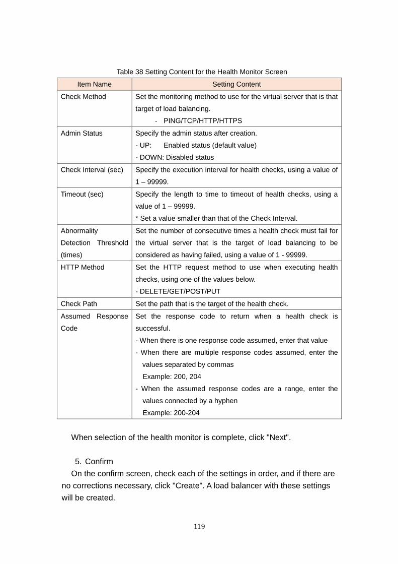
119
Table 38 Setting Content for the Health Monitor Screen
Item Name Setting Content
Check Method Set the monitoring method to use for the virtual server that is that
target of load balancing.
- PING/TCP/HTTP/HTTPS
Admin Status Specify the admin status after creation.
- UP: Enabled status (default value)
- DOWN: Disabled status
Check Interval (sec) Specify the execution interval for health checks, using a value of
1 – 99999.
Timeout (sec) Specify the length to time to timeout of health checks, using a
value of 1 – 99999.
* Set a value smaller than that of the Check Interval.
Abnormality
Detection Threshold
(times)
Set the number of consecutive times a health check must fail for
the virtual server that is the target of load balancing to be
considered as having failed, using a value of 1 - 99999.
HTTP Method Set the HTTP request method to use when executing health
checks, using one of the values below.
- DELETE/GET/POST/PUT
Check Path Set the path that is the target of the health check.
Assumed Response
Code
Set the response code to return when a health check is
successful.
- When there is one response code assumed, enter that value
- When there are multiple response codes assumed, enter the
values separated by commas
Example: 200, 204
- When the assumed response codes are a range, enter the
values connected by a hyphen
Example: 200-204
When selection of the health monitor is complete, click "Next".
5. Confirm
On the confirm screen, check each of the settings in order, and if there are
no corrections necessary, click "Create". A load balancer with these settings
will be created.
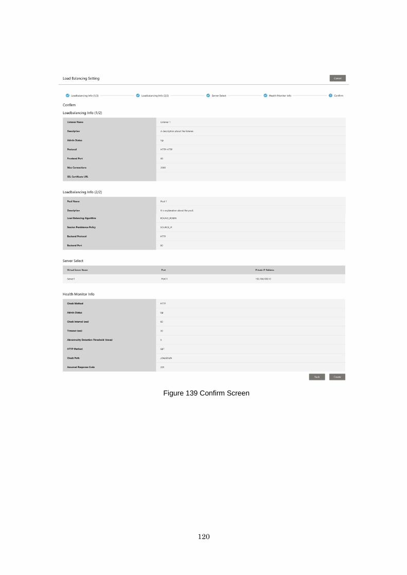
120
Figure 139 Confirm Screen

121
19.2.3 Confirmation after Creation
After creating a load balancer, it is possible to confirm it from the Load
Balancer List screen. When the created load balancer is displayed, clicking the
link of the load balancer name displays the content that was set when it was
created.
Figure 140 Load Balancer List Screen
Figure 141 Load Balancer Detail Screen
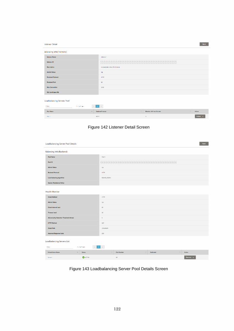
122
Figure 142 Listener Detail Screen
Figure 143 Loadbalancing Server Pool Details Screen

123
19.3 Points to Note
When editing each setting, it is necessary to do so using the API, or delete
the load balancer and create a new one.
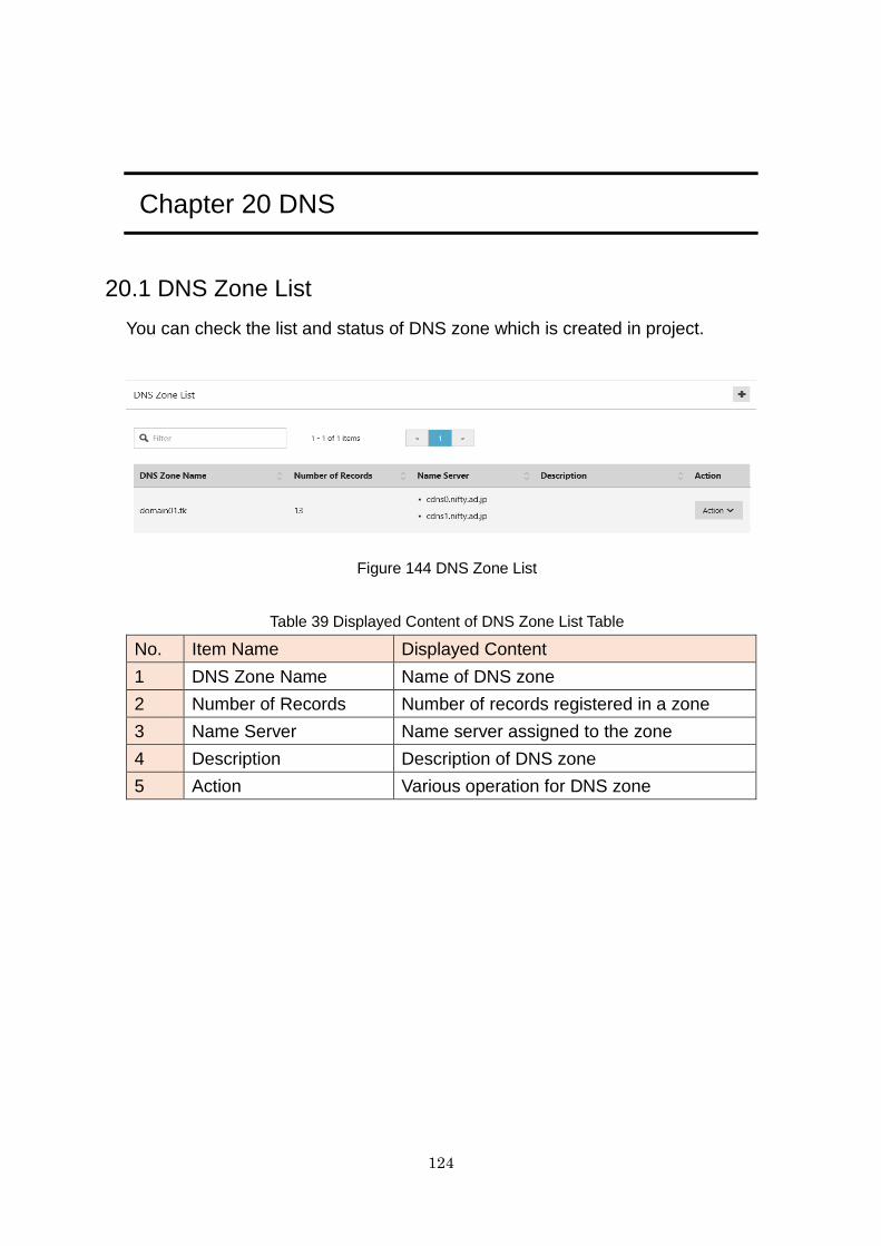
124
Chapter 20 DNS
20.1 DNS Zone List
You can check the list and status of DNS zone which is created in project.
Figure 144 DNS Zone List
Table 39 Displayed Content of DNS Zone List Table
No. Item Name Displayed Content
1 DNS Zone Name Name of DNS zone
2 Number of Records Number of records registered in a zone
3 Name Server Name server assigned to the zone
4 Description Description of DNS zone
5 Action Various operation for DNS zone
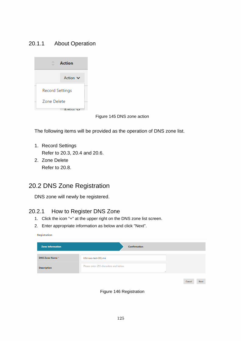
125
20.1.1 About Operation
Figure 145 DNS zone action
The following items will be provided as the operation of DNS zone list.
1. Record Settings
Refer to 20.3, 20.4 and 20.6.
2. Zone Delete
Refer to 20.8.
20.2 DNS Zone Registration
DNS zone will newly be registered.
20.2.1 How to Register DNS Zone
1. Click the icon "+" at the upper right on the DNS zone list screen.
2. Enter appropriate information as below and click "Next".
Figure 146 Registration
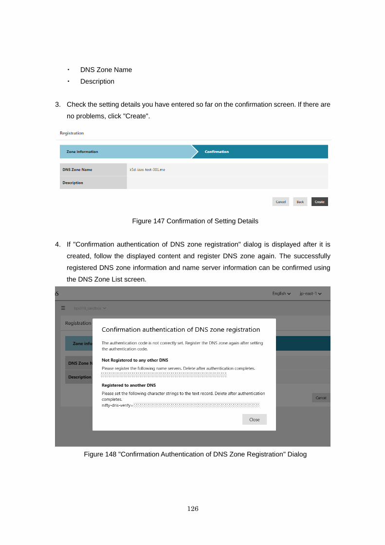
126
・ DNS Zone Name
・ Description
3. Check the setting details you have entered so far on the confirmation screen. If there are
no problems, click "Create".
Figure 147 Confirmation of Setting Details
4. If "Confirmation authentication of DNS zone registration" dialog is displayed after it is
created, follow the displayed content and register DNS zone again. The successfully
registered DNS zone information and name server information can be confirmed using
the DNS Zone List screen.
Figure 148 "Confirmation Authentication of DNS Zone Registration" Dialog
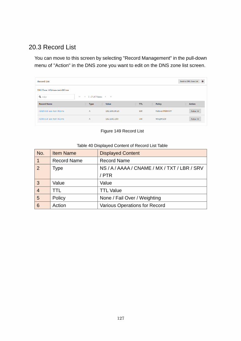
127
20.3 Record List
You can move to this screen by selecting "Record Management" in the pull-down
menu of "Action" in the DNS zone you want to edit on the DNS zone list screen.
Figure 149 Record List
Table 40 Displayed Content of Record List Table
No. Item Name Displayed Content
1 Record Name Record Name
2 Type NS / A / AAAA / CNAME / MX / TXT / LBR / SRV
/ PTR
3 Value Value
4 TTL TTL Value
5 Policy None / Fail Over / Weighting
6 Action Various Operations for Record
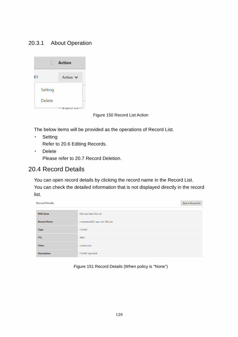
128
20.3.1 About Operation
Figure 150 Record List Action
The below items will be provided as the operations of Record List.
・ Setting
Refer to 20.6 Editing Records.
・ Delete
Please refer to 20.7 Record Deletion.
20.4 Record Details
You can open record details by clicking the record name in the Record List.
You can check the detailed information that is not displayed directly in the record
list.
Figure 151 Record Details (When policy is "None")
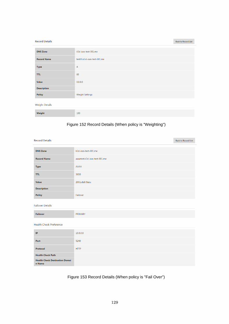
129
Figure 152 Record Details (When policy is "Weighting")
Figure 153 Record Details (When policy is "Fail Over")
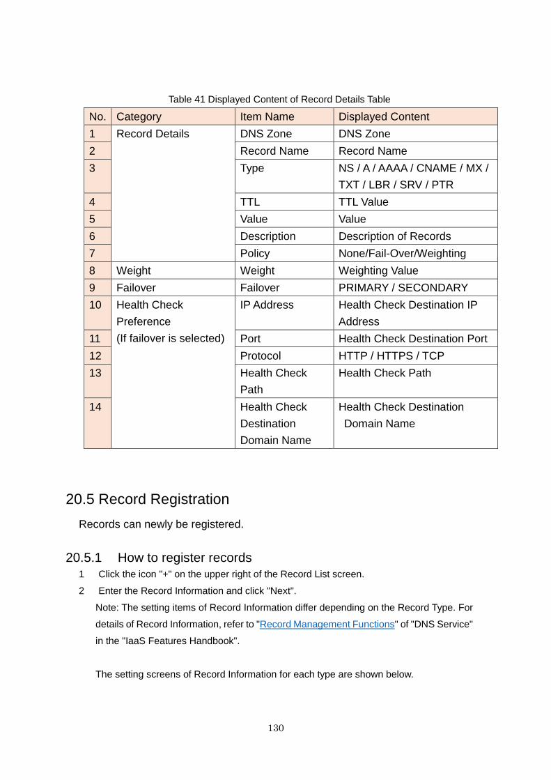
130
Table 41 Displayed Content of Record Details Table
No. Category Item Name Displayed Content
1 Record Details DNS Zone DNS Zone
2 Record Name Record Name
3 Type NS / A / AAAA / CNAME / MX /
TXT / LBR / SRV / PTR
4 TTL TTL Value
5 Value Value
6 Description Description of Records
7 Policy None/Fail-Over/Weighting
8 Weight Weight Weighting Value
9 Failover Failover PRIMARY / SECONDARY
10 Health Check
Preference
(If failover is selected)
IP Address Health Check Destination IP
Address
11 Port Health Check Destination Port
12 Protocol HTTP / HTTPS / TCP
13 Health Check
Path
Health Check Path
14 Health Check
Destination
Domain Name
Health Check Destination
Domain Name
20.5 Record Registration
Records can newly be registered.
20.5.1 How to register records
1 Click the icon "+" on the upper right of the Record List screen.
2 Enter the Record Information and click "Next".
Note: The setting items of Record Information differ depending on the Record Type. For
details of Record Information, refer to "Record Management Functions" of "DNS Service"
in the "IaaS Features Handbook".
The setting screens of Record Information for each type are shown below.
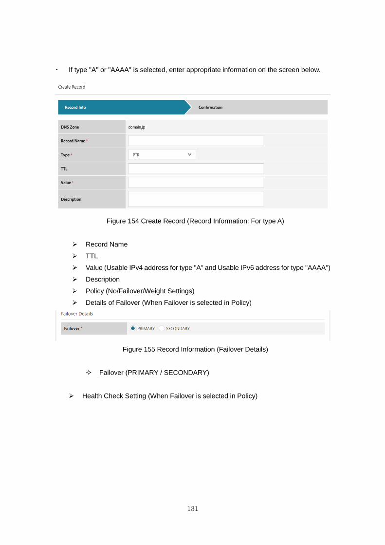
131
・ If type "A" or "AAAA" is selected, enter appropriate information on the screen below.
Figure 154 Create Record (Record Information: For type A)
Record Name
TTL
Value (Usable IPv4 address for type "A" and Usable IPv6 address for type "AAAA")
Description
Policy (No/Failover/Weight Settings)
Details of Failover (When Failover is selected in Policy)
Figure 155 Record Information (Failover Details)
Failover (PRIMARY / SECONDARY)
Health Check Setting (When Failover is selected in Policy)
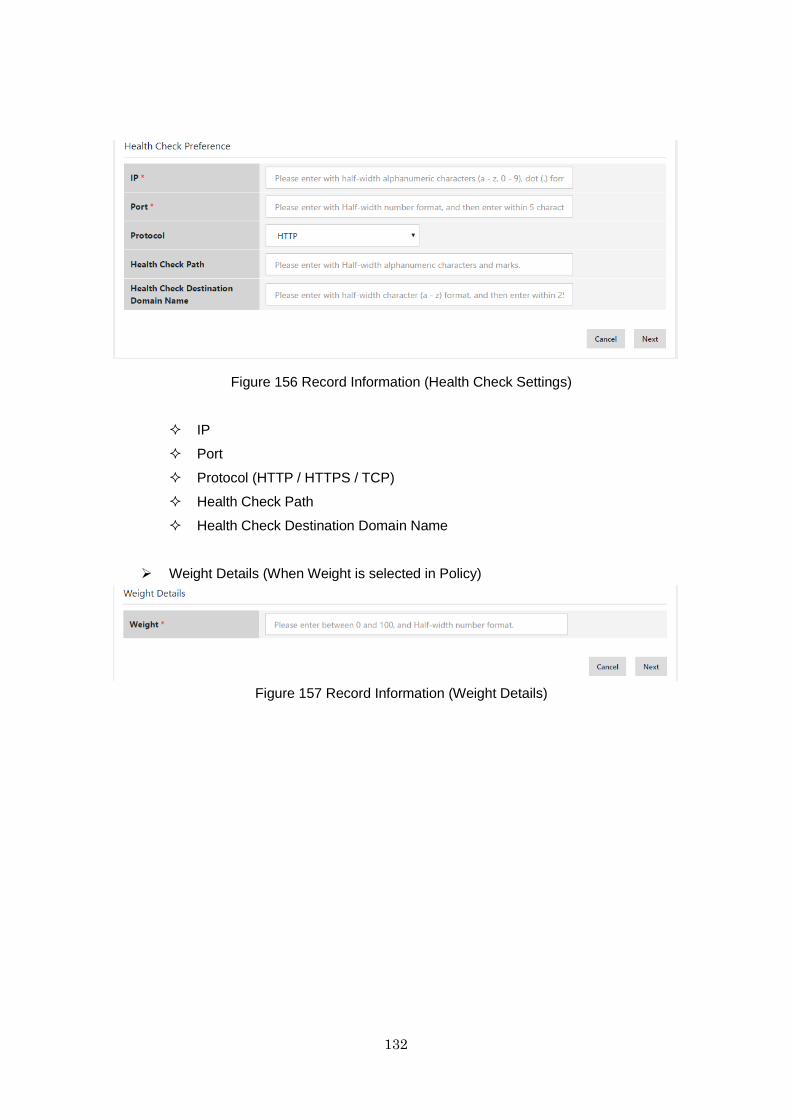
132
Figure 156 Record Information (Health Check Settings)
IP
Port
Protocol (HTTP / HTTPS / TCP)
Health Check Path
Health Check Destination Domain Name
Weight Details (When Weight is selected in Policy)
Figure 157 Record Information (Weight Details)
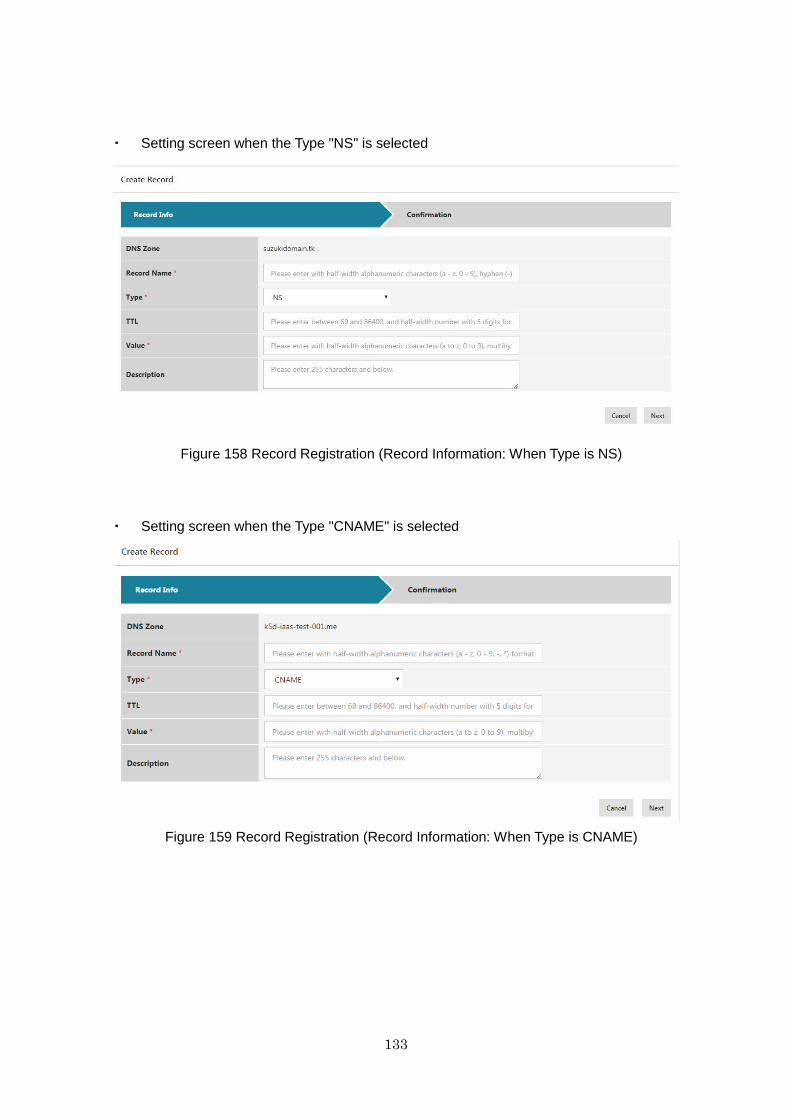
133
・ Setting screen when the Type "NS" is selected
Figure 158 Record Registration (Record Information: When Type is NS)
・ Setting screen when the Type "CNAME" is selected
Figure 159 Record Registration (Record Information: When Type is CNAME)

134
・ Setting screen when the Type "MX" is selected
Figure 160 Record Registration (Record Information: When Type is MX)
・ Setting screen when the Type "TXT" is selected
Figure 161 Record Registration (Record Information: When Type is TXT)
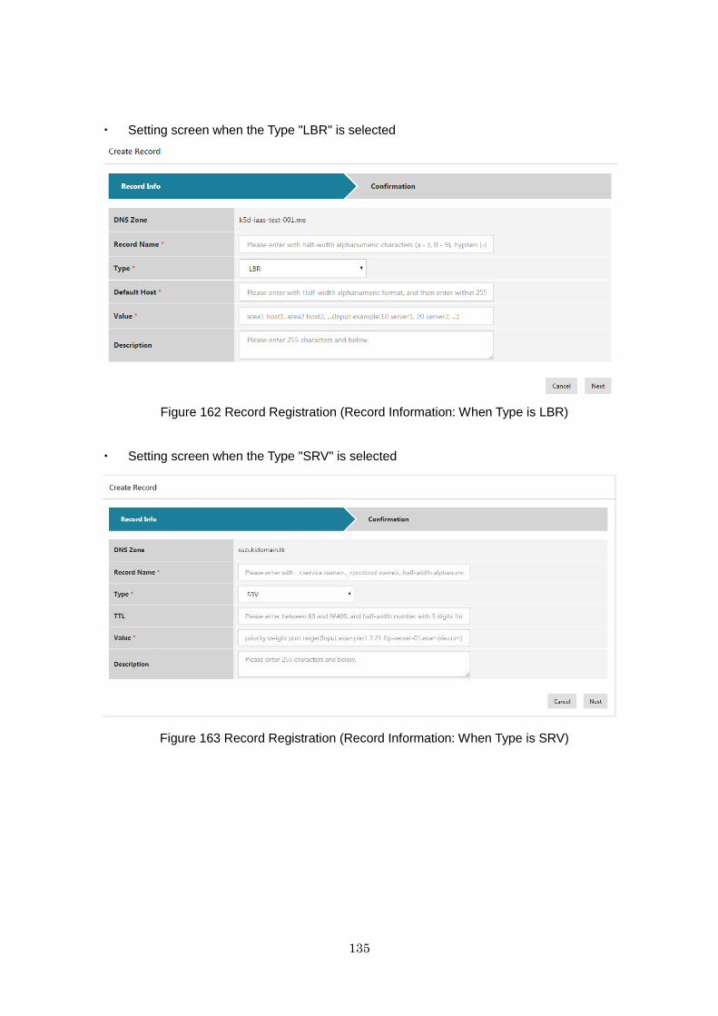
135
・ Setting screen when the Type "LBR" is selected
Figure 162 Record Registration (Record Information: When Type is LBR)
・ Setting screen when the Type "SRV" is selected
Figure 163 Record Registration (Record Information: When Type is SRV)
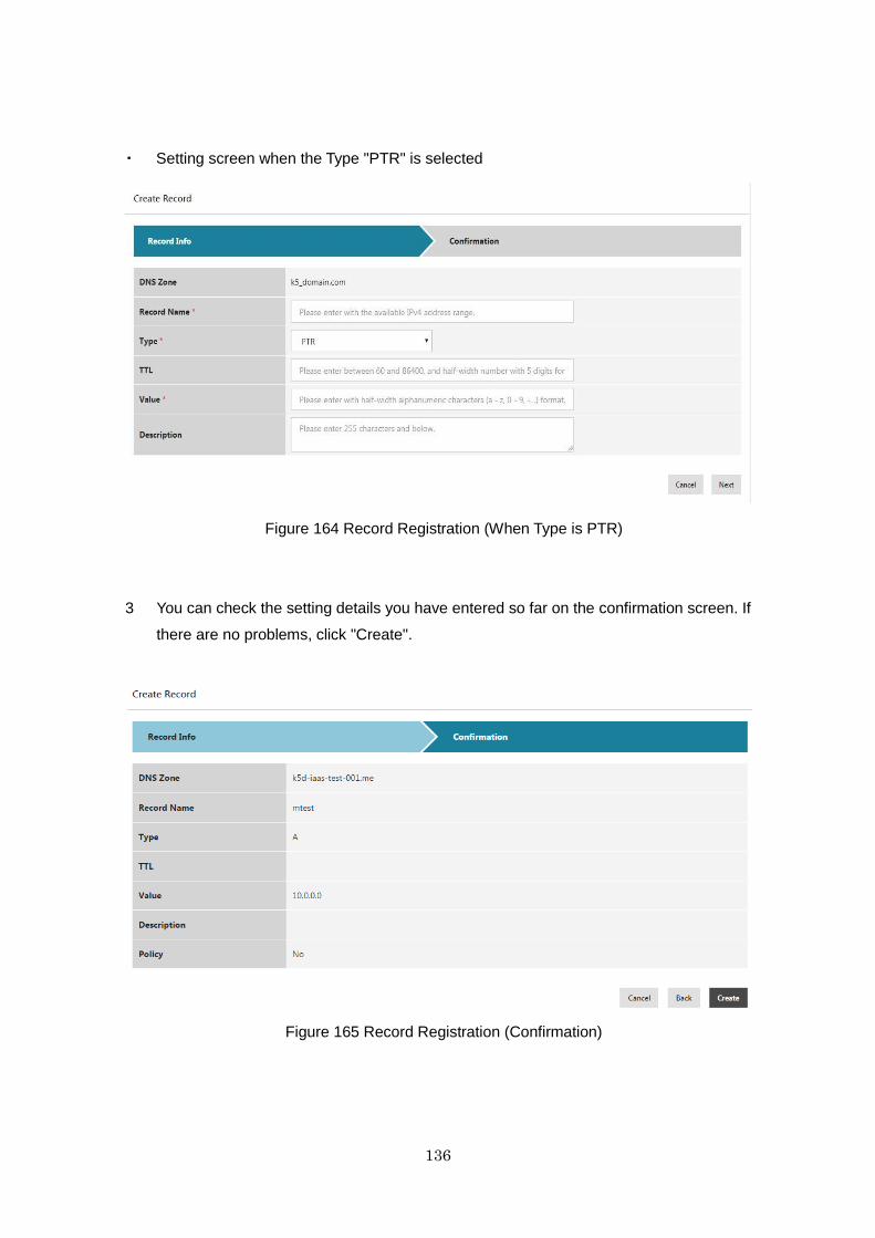
136
・ Setting screen when the Type "PTR" is selected
Figure 164 Record Registration (When Type is PTR)
3 You can check the setting details you have entered so far on the confirmation screen. If
there are no problems, click "Create".
Figure 165 Record Registration (Confirmation)
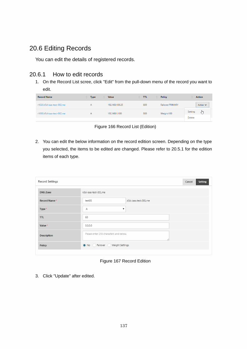
137
20.6 Editing Records
You can edit the details of registered records.
20.6.1 How to edit records
1. On the Record List scree, click "Edit" from the pull-down menu of the record you want to
edit.
Figure 166 Record List (Edition)
2. You can edit the below information on the record edition screen. Depending on the type
you selected, the items to be edited are changed. Please refer to 20.5.1 for the edition
items of each type.
Figure 167 Record Edition
3. Click "Update" after edited.
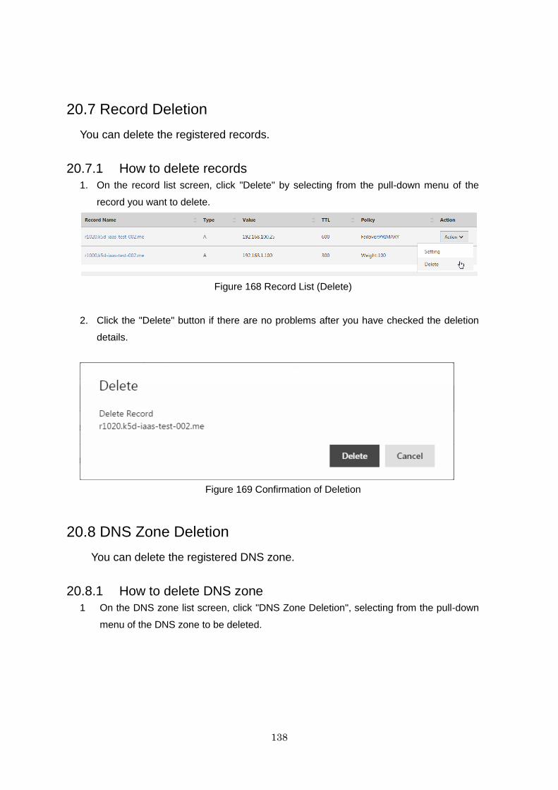
138
20.7 Record Deletion
You can delete the registered records.
20.7.1 How to delete records
1. On the record list screen, click "Delete" by selecting from the pull-down menu of the
record you want to delete.
Figure 168 Record List (Delete)
2. Click the "Delete" button if there are no problems after you have checked the deletion
details.
Figure 169 Confirmation of Deletion
20.8 DNS Zone Deletion
You can delete the registered DNS zone.
20.8.1 How to delete DNS zone
1 On the DNS zone list screen, click "DNS Zone Deletion", selecting from the pull-down
menu of the DNS zone to be deleted.
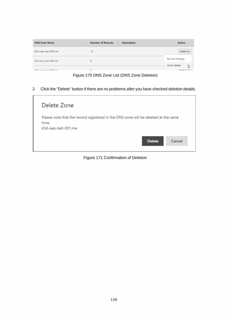
139
Figure 170 DNS Zone List (DNS Zone Deletion)
2 Click the "Delete" button if there are no problems after you have checked deletion details.
Figure 171 Confirmation of Deletion
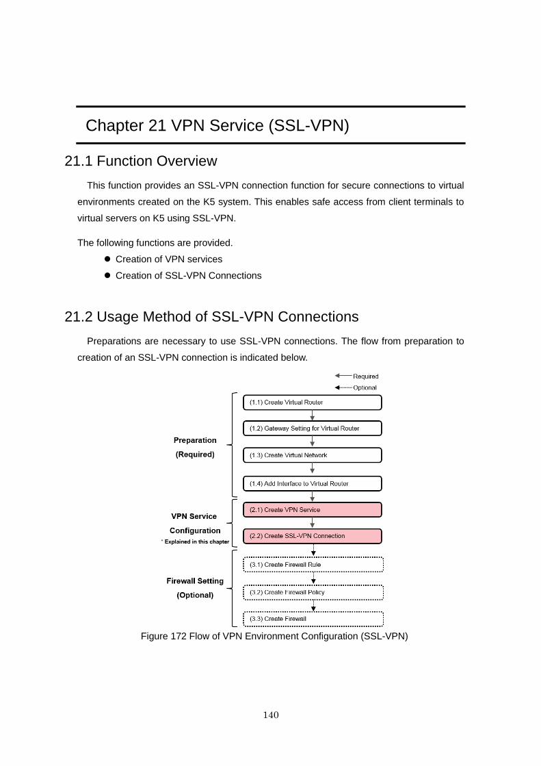
140
Chapter 21 VPN Service (SSL-VPN)
21.1 Function Overview
This function provides an SSL-VPN connection function for secure connections to virtual
environments created on the K5 system. This enables safe access from client terminals to
virtual servers on K5 using SSL-VPN.
The following functions are provided.
Creation of VPN services
Creation of SSL-VPN Connections
21.2 Usage Method of SSL-VPN Connections
Preparations are necessary to use SSL-VPN connections. The flow from preparation to
creation of an SSL-VPN connection is indicated below.
Figure 172 Flow of VPN Environment Configuration (SSL-VPN)
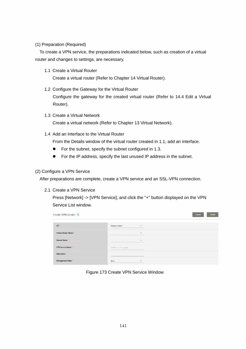
141
(1) Preparation (Required)
To create a VPN service, the preparations indicated below, such as creation of a virtual
router and changes to settings, are necessary.
1.1 Create a Virtual Router
Create a virtual router (Refer to Chapter 14 Virtual Router).
1.2 Configure the Gateway for the Virtual Router
Configure the gateway for the created virtual router (Refer to 14.4 Edit a Virtual
Router).
1.3 Create a Virtual Network
Create a virtual network (Refer to Chapter 13 Virtual Network).
1.4 Add an Interface to the Virtual Router
From the Details window of the virtual router created in 1.1, add an interface.
For the subnet, specify the subnet configured in 1.3.
For the IP address, specify the last unused IP address in the subnet.
(2) Configure a VPN Service
After preparations are complete, create a VPN service and an SSL-VPN connection.
2.1 Create a VPN Service
Press [Network] -> [VPN Service], and click the "+" button displayed on the VPN
Service List window.
Figure 173 Create VPN Service Window
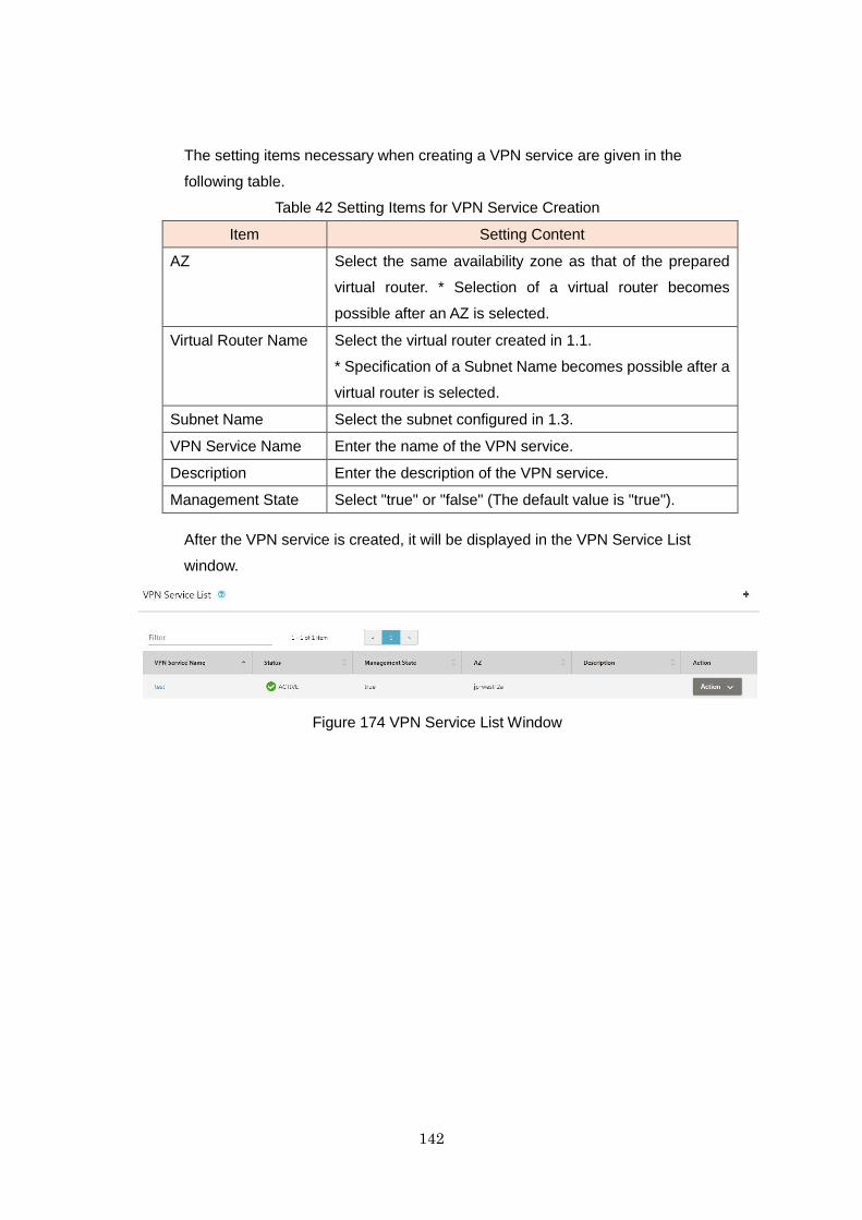
142
The setting items necessary when creating a VPN service are given in the
following table.
Table 42 Setting Items for VPN Service Creation
Item Setting Content
AZ Select the same availability zone as that of the prepared
virtual router. * Selection of a virtual router becomes
possible after an AZ is selected.
Virtual Router Name Select the virtual router created in 1.1.
* Specification of a Subnet Name becomes possible after a
virtual router is selected.
Subnet Name Select the subnet configured in 1.3.
VPN Service Name Enter the name of the VPN service.
Description Enter the description of the VPN service.
Management State Select "true" or "false" (The default value is "true").
After the VPN service is created, it will be displayed in the VPN Service List
window.
Figure 174 VPN Service List Window
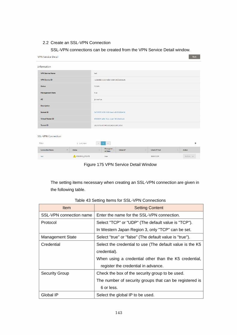
143
2.2 Create an SSL-VPN Connection
SSL-VPN connections can be created from the VPN Service Detail window.
Figure 175 VPN Service Detail Window
The setting items necessary when creating an SSL-VPN connection are given in
the following table.
Table 43 Setting Items for SSL-VPN Connections
Item Setting Content
SSL-VPN connection name Enter the name for the SSL-VPN connection.
Protocol Select "TCP" or "UDP" (The default value is "TCP").
In Western Japan Region 3, only "TCP" can be set.
Management State Select "true" or "false" (The default value is "true").
Credential Select the credential to use (The default value is the K5
credential).
When using a credential other than the K5 credential,
register the credential in advance.
Security Group Check the box of the security group to be used.
The number of security groups that can be registered is
6 or less.
Global IP Select the global IP to be used.
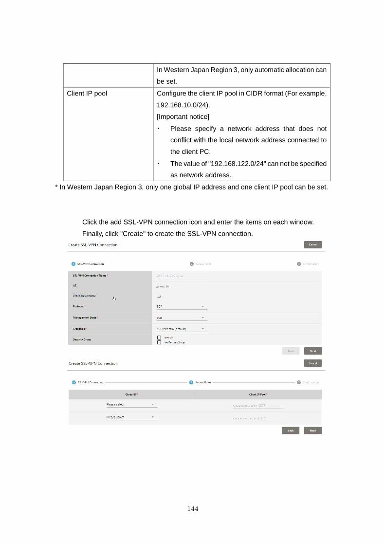
144
In Western Japan Region 3, only automatic allocation can
be set.
Client IP pool Configure the client IP pool in CIDR format (For example,
192.168.10.0/24).
[Important notice]
・ Please specify a network address that does not
conflict with the local network address connected to
the client PC.
・ The value of "192.168.122.0/24" can not be specified
as network address.
* In Western Japan Region 3, only one global IP address and one client IP pool can be set.
Click the add SSL-VPN connection icon and enter the items on each window.
Finally, click "Create" to create the SSL-VPN connection.
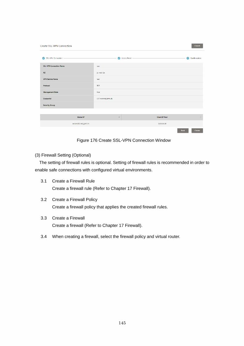
145
Figure 176 Create SSL-VPN Connection Window
(3) Firewall Setting (Optional)
The setting of firewall rules is optional. Setting of firewall rules is recommended in order to
enable safe connections with configured virtual environments.
3.1 Create a Firewall Rule
Create a firewall rule (Refer to Chapter 17 Firewall).
3.2 Create a Firewall Policy
Create a firewall policy that applies the created firewall rules.
3.3 Create a Firewall
Create a firewall (Refer to Chapter 17 Firewall).
3.4 When creating a firewall, select the firewall policy and virtual router.
146
21.3 Advisory Notes
・ When creating an SSL-VPN connection, if using a credential other than the
K5 credential, register that credential with the API in advance (Refer to the
K5 IaaS Features Handbook and the K5 IaaS API Reference - Management
Administration).
・ After creating an SSL-VPN connection, connect to the target virtual server
using an OpenVPN client, etc. For the installation method for an OpenVPN
client, refer to the "K5 IaaS Features Handbook".
147
Chapter 22 VPN Service (IPsec VPN)
22.1 Function Overview
This function provides an IPsec VPN connection function for secure
connections to virtual environments created on the K5 system. This enables
access from client terminals to virtual servers on K5, and access between virtual
servers to be performed more safely.
The following functions are provided.
Display of lists and details of IPsec VPN connections
Creation, editing, and deletion of IPsec VPN connections*
Creation of IKE policies
Creation of IPsec policies
*For creation of IPsec VPN connections, refer to "IPsec VPN Connection
Patterns" in the "IaaS Design and configuration Guide (Design
Pattern/Implementation Samples)".
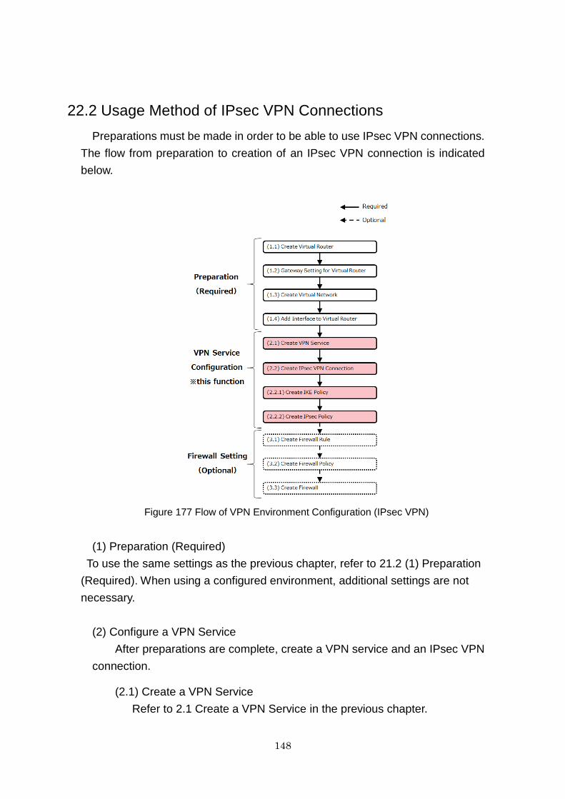
148
22.2 Usage Method of IPsec VPN Connections
Preparations must be made in order to be able to use IPsec VPN connections.
The flow from preparation to creation of an IPsec VPN connection is indicated
below.
Figure 177 Flow of VPN Environment Configuration (IPsec VPN)
(1) Preparation (Required)
To use the same settings as the previous chapter, refer to 21.2 (1) Preparation
(Required). When using a configured environment, additional settings are not
necessary.
(2) Configure a VPN Service
After preparations are complete, create a VPN service and an IPsec VPN
connection.
(2.1) Create a VPN Service
Refer to 2.1 Create a VPN Service in the previous chapter.
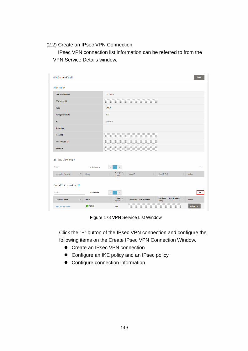
149
(2.2) Create an IPsec VPN Connection
IPsec VPN connection list information can be referred to from the
VPN Service Details window.
Figure 178 VPN Service List Window
Click the "+" button of the IPsec VPN connection and configure the
following items on the Create IPsec VPN Connection Window.
Create an IPsec VPN connection
Configure an IKE policy and an IPsec policy
Configure connection information
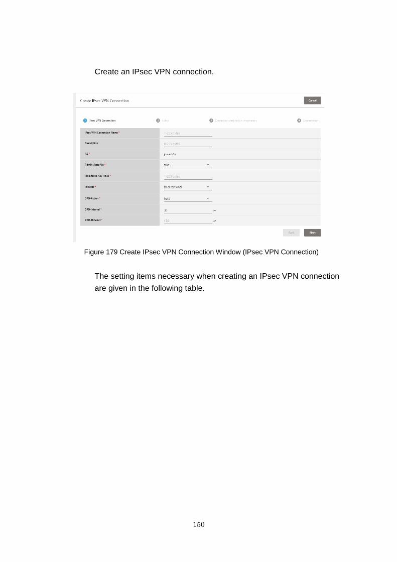
150
Create an IPsec VPN connection.
Figure 179 Create IPsec VPN Connection Window (IPsec VPN Connection)
The setting items necessary when creating an IPsec VPN connection
are given in the following table.
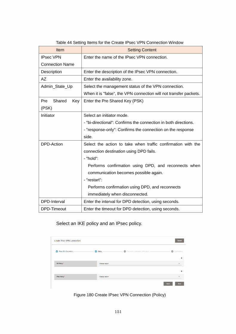
151
Table 44 Setting Items for the Create IPsec VPN Connection Window
Item Setting Content
IPsec VPN
Connection Name
Enter the name of the IPsec VPN connection.
Description Enter the description of the IPsec VPN connection.
AZ Enter the availability zone.
Admin_State_Up Select the management status of the VPN connection.
When it is "false", the VPN connection will not transfer packets.
Pre Shared Key
(PSK)
Enter the Pre Shared Key (PSK)
Initiator Select an initiator mode.
- "bi-directional": Confirms the connection in both directions.
- "response-only": Confirms the connection on the response
side.
DPD-Action Select the action to take when traffic confirmation with the
connection destination using DPD fails.
- "hold":
Performs confirmation using DPD, and reconnects when
communication becomes possible again.
- "restart":
Performs confirmation using DPD, and reconnects
immediately when disconnected.
DPD-Interval Enter the interval for DPD detection, using seconds.
DPD-Timeout Enter the timeout for DPD detection, using seconds.
Select an IKE policy and an IPsec policy.
Figure 180 Create IPsec VPN Connection (Policy)
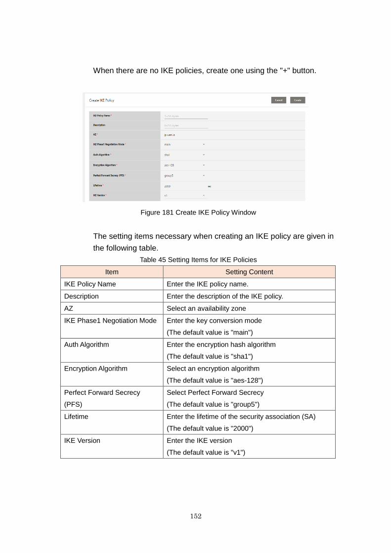
152
When there are no IKE policies, create one using the "+" button.
Figure 181 Create IKE Policy Window
The setting items necessary when creating an IKE policy are given in
the following table.
Table 45 Setting Items for IKE Policies
Item Setting Content
IKE Policy Name Enter the IKE policy name.
Description Enter the description of the IKE policy.
AZ Select an availability zone
IKE Phase1 Negotiation Mode Enter the key conversion mode
(The default value is "main")
Auth Algorithm Enter the encryption hash algorithm
(The default value is "sha1")
Encryption Algorithm Select an encryption algorithm
(The default value is "aes-128")
Perfect Forward Secrecy
(PFS)
Select Perfect Forward Secrecy
(The default value is "group5")
Lifetime Enter the lifetime of the security association (SA)
(The default value is "2000")
IKE Version Enter the IKE version
(The default value is "v1")

153
When there are no IPsec policies, create one using the "+" button.
Figure 182 Create IPsec Policy
The setting items necessary when creating an IPsec policy are given
in the following table.
Table 46 Setting Items for IPsec Policies
Item Setting Content
IPsec Policy Name Enter the IPsec policy name
Description Enter the description of the IPsec policy
AZ Select an availability zone
Transform Protocol Enter the transformation protocol being used
(The default value is "esp")
Auth Algorithm Enter the encryption algorithm
(The default value is "sha1")
Encapsulation Mode Select an encapsulation mode
(The default value is "tunnel")
Encryption Algorithm Select an encryption algorithm
(The default value is "aes-128")
Perfect Forward Secrecy (PFS) Enter the Perfect Forward Secrecy
(The default value is "group5")
Lifetime Enter the lifetime of the security association (SA)
(The default value is "3600")
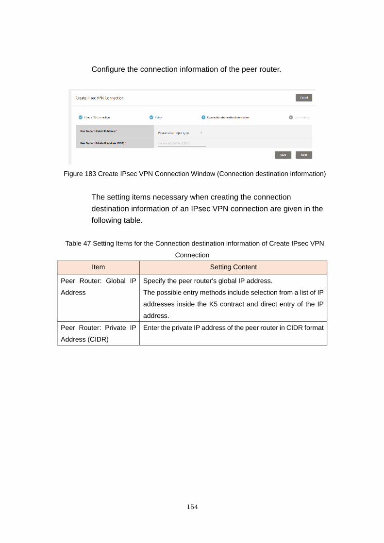
154
Configure the connection information of the peer router.
Figure 183 Create IPsec VPN Connection Window (Connection destination information)
The setting items necessary when creating the connection
destination information of an IPsec VPN connection are given in the
following table.
Table 47 Setting Items for the Connection destination information of Create IPsec VPN
Connection
Item Setting Content
Peer Router: Global IP
Address
Specify the peer router's global IP address.
The possible entry methods include selection from a list of IP
addresses inside the K5 contract and direct entry of the IP
address.
Peer Router: Private IP
Address (CIDR)
Enter the private IP address of the peer router in CIDR format
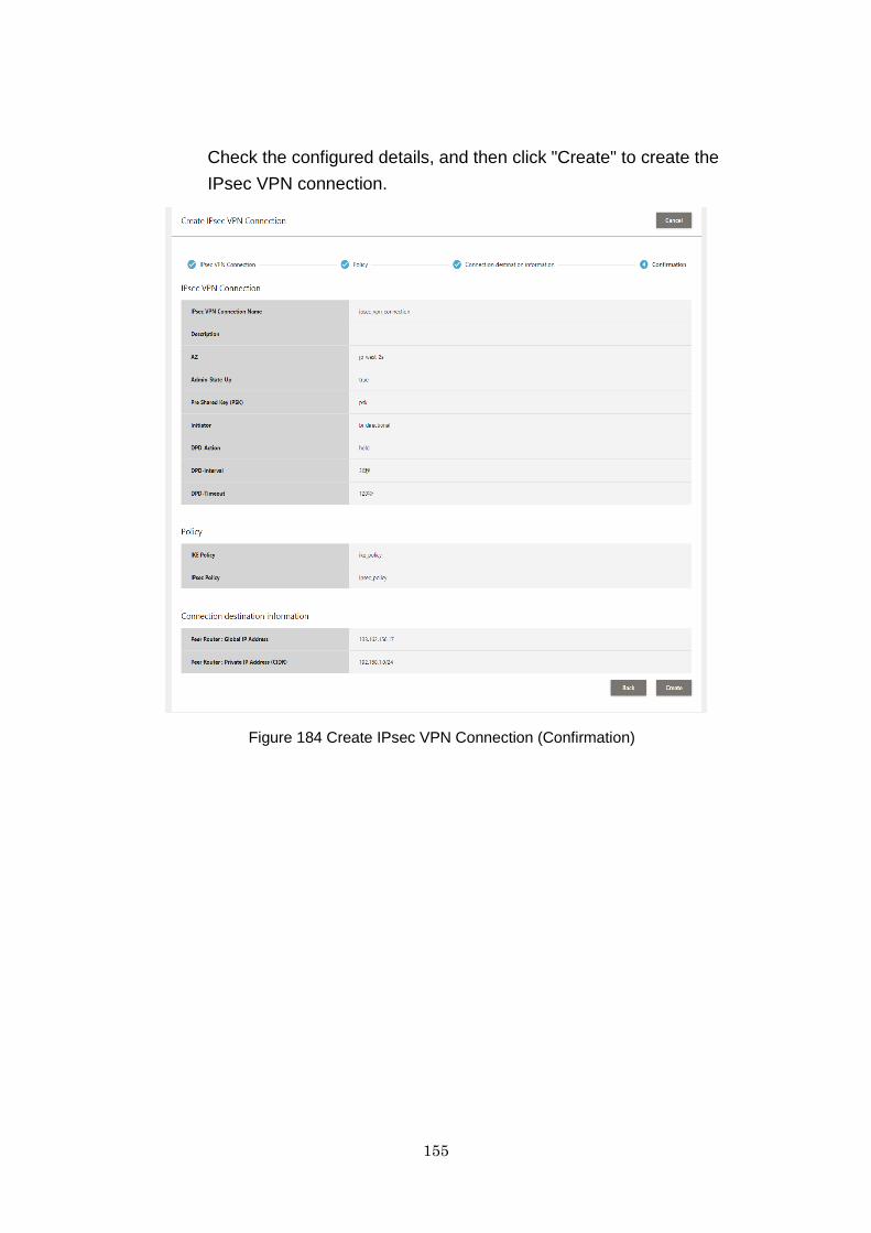
155
Check the configured details, and then click "Create" to create the
IPsec VPN connection.
Figure 184 Create IPsec VPN Connection (Confirmation)

156
22.3 How to Delete IKE and IPsec Policies
Created IKE policies and IPsec policies cannot be deleted from the VPN
Service window. To delete them, do so from the API Execution window or by
executing an API.
This section explains the deletion method using the API Execution window.
(1) Obtain Policy List Information
Set the following values on the API Execution window, press the Execute
API button, and the policy list information will be displayed in the response
display section.
- HTTP Method: "GET"
- Endpoint: "networking"
- URI: "/v2.0/vpn/ikepolicies" For an IKE policy
"/v2.0/vpn/ipsecpolicies" For an IPsec policy
Figure 185 Obtain Policy List Information (For an IPsec policy)
(2) Check the Policy ID of the Policy to Delete
The policy ID of the policy to delete can be checked using the policy name
in the response display section of the policy list information.
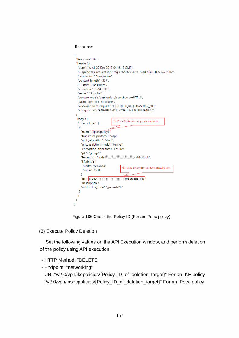
157
Figure 186 Check the Policy ID (For an IPsec policy)
(3) Execute Policy Deletion
Set the following values on the API Execution window, and perform deletion
of the policy using API execution.
- HTTP Method: "DELETE"
- Endpoint: "networking"
- URI:"/v2.0/vpn/ikepolicies/{Policy_ID_of_deletion_target}" For an IKE policy
"/v2.0/vpn/ipsecpolicies/{Policy_ID_of_deletion_target}" For an IPsec policy
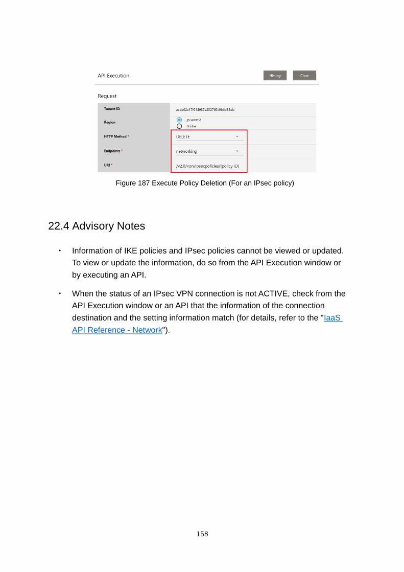
158
Figure 187 Execute Policy Deletion (For an IPsec policy)
22.4 Advisory Notes
・ Information of IKE policies and IPsec policies cannot be viewed or updated.
To view or update the information, do so from the API Execution window or
by executing an API.
・ When the status of an IPsec VPN connection is not ACTIVE, check from the
API Execution window or an API that the information of the connection
destination and the setting information match (for details, refer to the "IaaS
API Reference - Network").
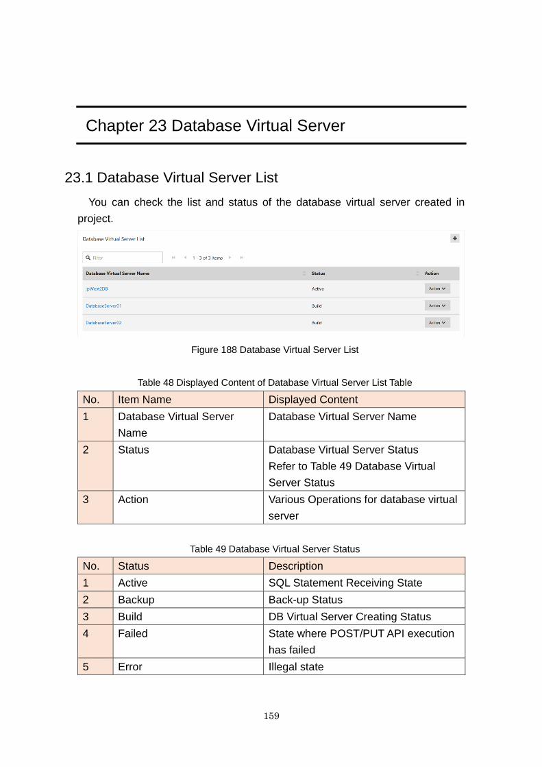
159
Chapter 23 Database Virtual Server
23.1 Database Virtual Server List
You can check the list and status of the database virtual server created in
project.
Figure 188 Database Virtual Server List
Table 48 Displayed Content of Database Virtual Server List Table
No. Item Name Displayed Content
1 Database Virtual Server
Name
Database Virtual Server Name
2 Status Database Virtual Server Status
Refer to Table 49 Database Virtual
Server Status
3 Action Various Operations for database virtual
server
Table 49 Database Virtual Server Status
No. Status Description
1 Active SQL Statement Receiving State
2 Backup Back-up Status
3 Build DB Virtual Server Creating Status
4 Failed State where POST/PUT API execution
has failed
5 Error Illegal state
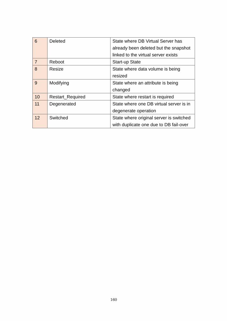
160
6 Deleted State where DB Virtual Server has
already been deleted but the snapshot
linked to the virtual server exists
7 Reboot Start-up State
8 Resize State where data volume is being
resized
9 Modifying State where an attribute is being
changed
10 Restart_Required State where restart is required
11 Degenerated State where one DB virtual server is in
degenerate operation
12 Switched State where original server is switched
with duplicate one due to DB fail-over
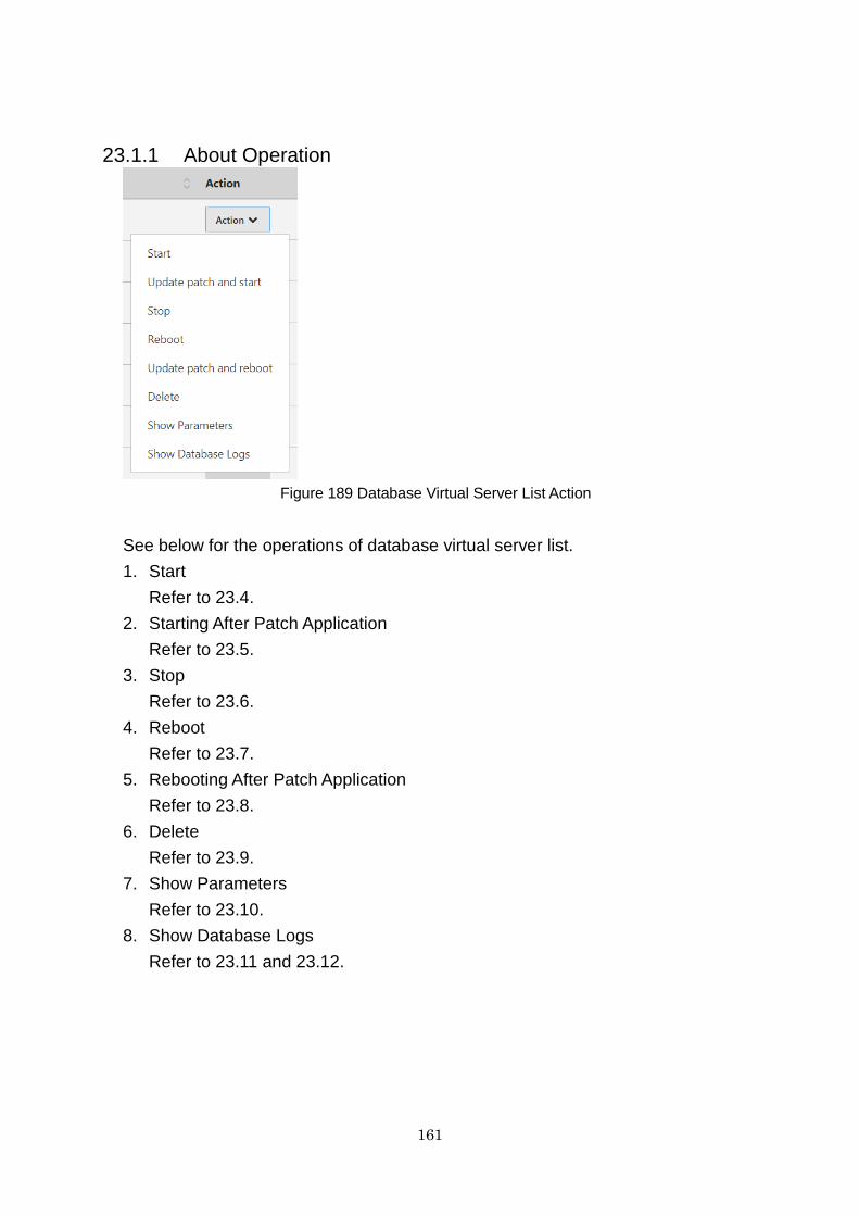
161
23.1.1 About Operation
Figure 189 Database Virtual Server List Action
See below for the operations of database virtual server list.
1. Start
Refer to 23.4.
2. Starting After Patch Application
Refer to 23.5.
3. Stop
Refer to 23.6.
4. Reboot
Refer to 23.7.
5. Rebooting After Patch Application
Refer to 23.8.
6. Delete
Refer to 23.9.
7. Show Parameters
Refer to 23.10.
8. Show Database Logs
Refer to 23.11 and 23.12.
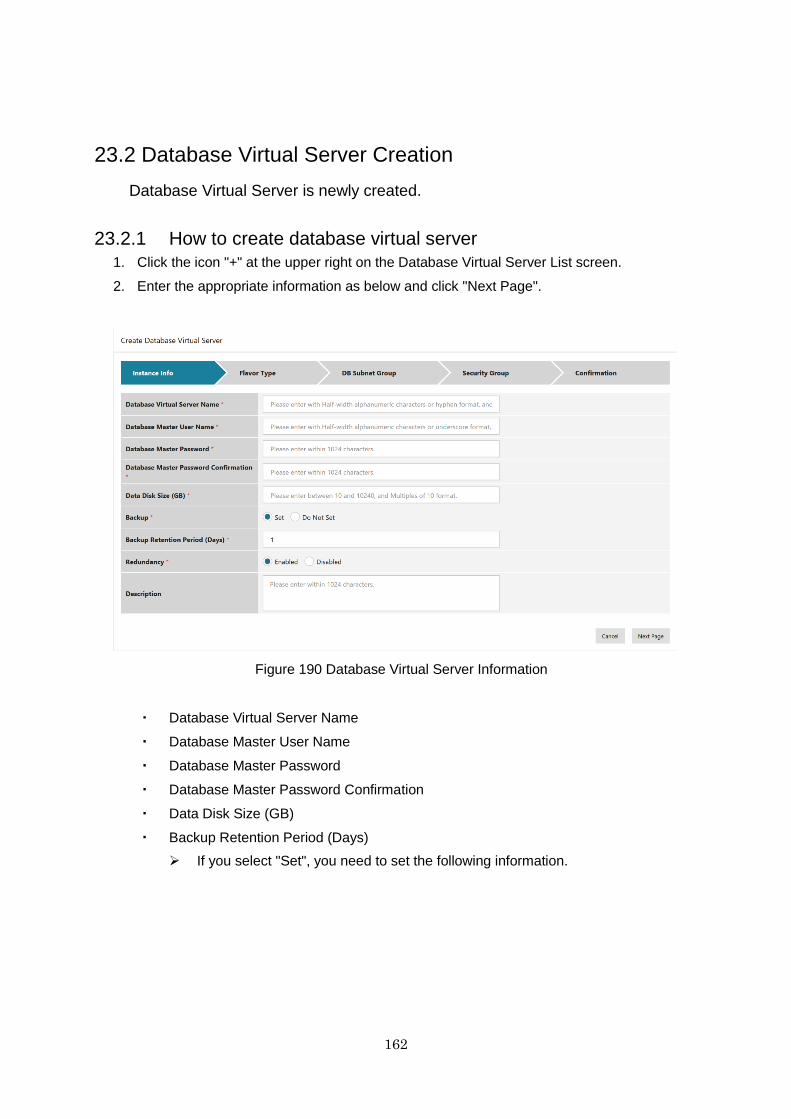
162
23.2 Database Virtual Server Creation
Database Virtual Server is newly created.
23.2.1 How to create database virtual server
1. Click the icon "+" at the upper right on the Database Virtual Server List screen.
2. Enter the appropriate information as below and click "Next Page".
Figure 190 Database Virtual Server Information
・ Database Virtual Server Name
・ Database Master User Name
・ Database Master Password
・ Database Master Password Confirmation
・ Data Disk Size (GB)
・ Backup Retention Period (Days)
If you select "Set", you need to set the following information.
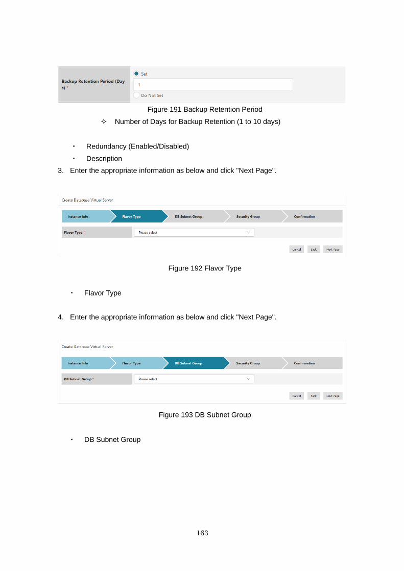
163
Figure 191 Backup Retention Period
Number of Days for Backup Retention (1 to 10 days)
・ Redundancy (Enabled/Disabled)
・ Description
3. Enter the appropriate information as below and click "Next Page".
Figure 192 Flavor Type
・ Flavor Type
4. Enter the appropriate information as below and click "Next Page".
Figure 193 DB Subnet Group
・ DB Subnet Group
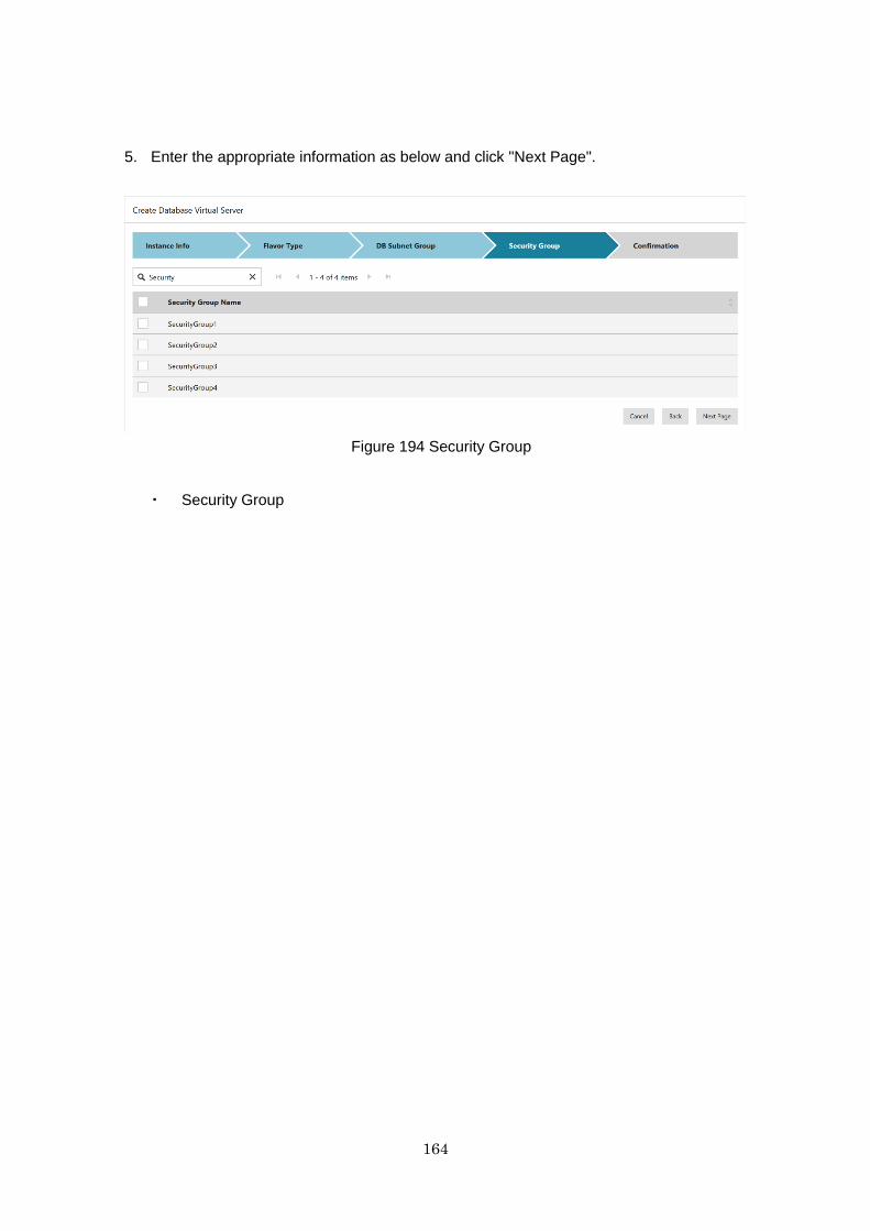
164
5. Enter the appropriate information as below and click "Next Page".
Figure 194 Security Group
・ Security Group
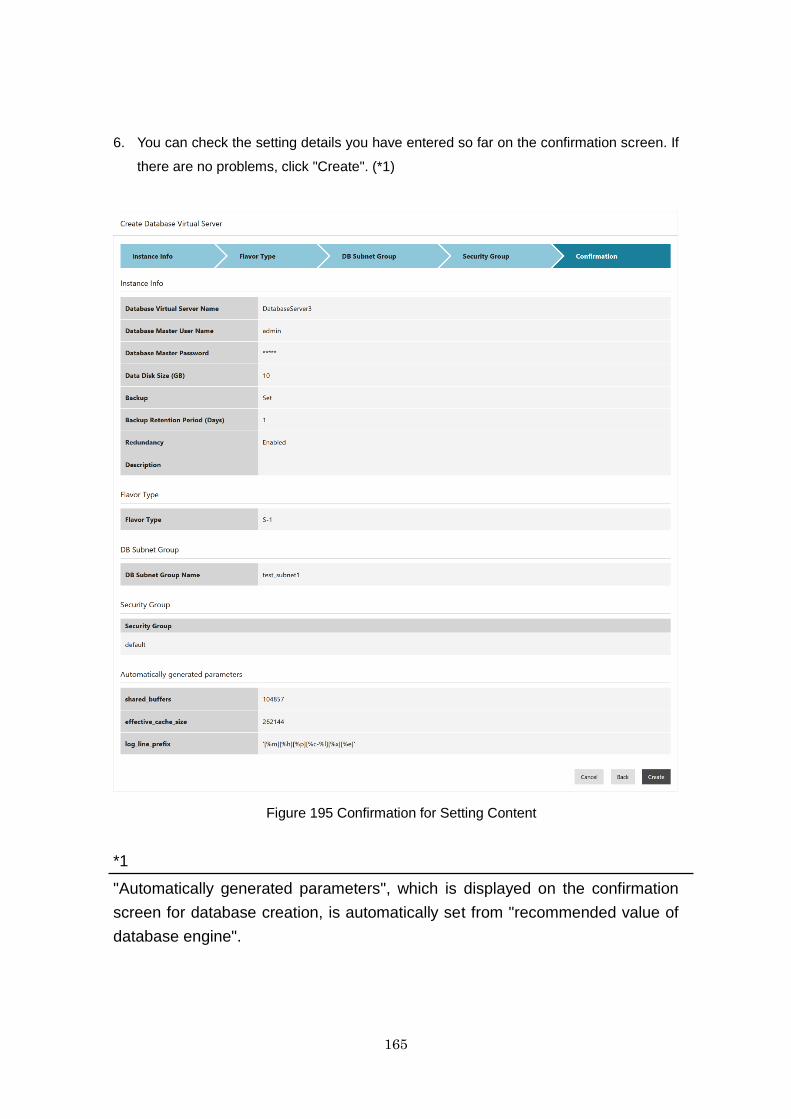
165
6. You can check the setting details you have entered so far on the confirmation screen. If
there are no problems, click "Create". (*1)
Figure 195 Confirmation for Setting Content
*1
"Automatically generated parameters", which is displayed on the confirmation
screen for database creation, is automatically set from "recommended value of
database engine".
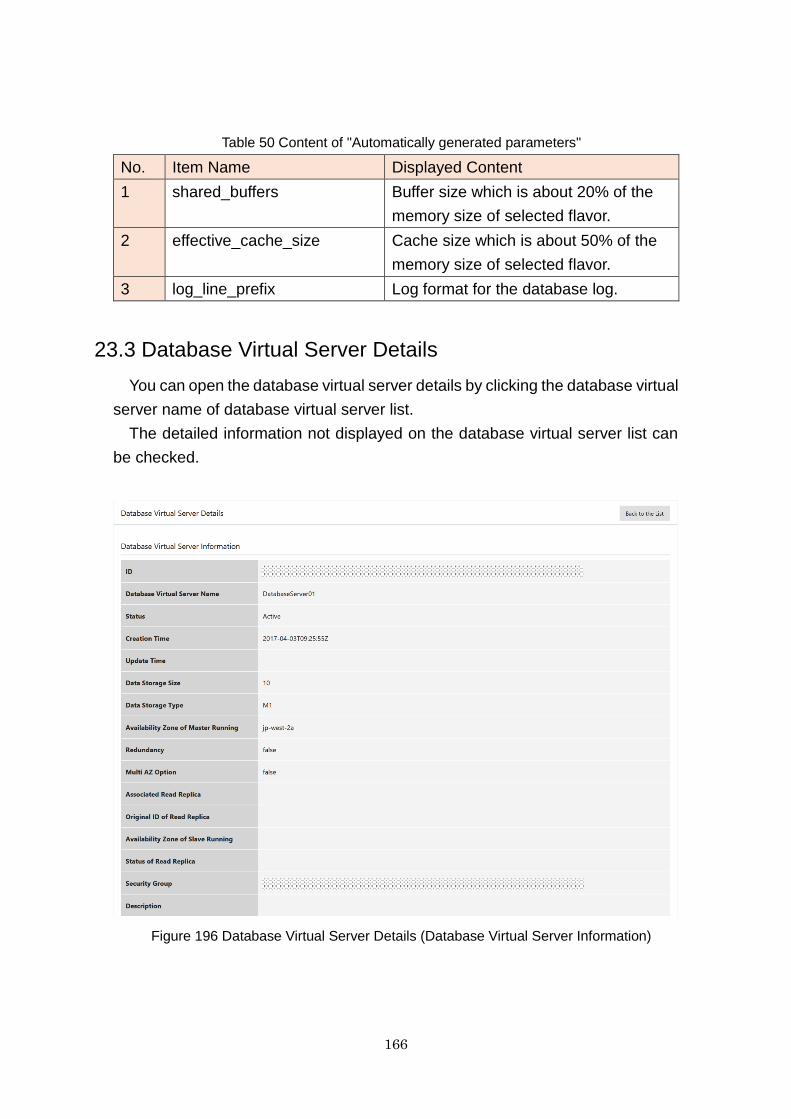
166
Table 50 Content of "Automatically generated parameters"
No. Item Name Displayed Content
1 shared_buffers Buffer size which is about 20% of the
memory size of selected flavor.
2 effective_cache_size Cache size which is about 50% of the
memory size of selected flavor.
3 log_line_prefix Log format for the database log.
23.3 Database Virtual Server Details
You can open the database virtual server details by clicking the database virtual
server name of database virtual server list.
The detailed information not displayed on the database virtual server list can
be checked.
Figure 196 Database Virtual Server Details (Database Virtual Server Information)
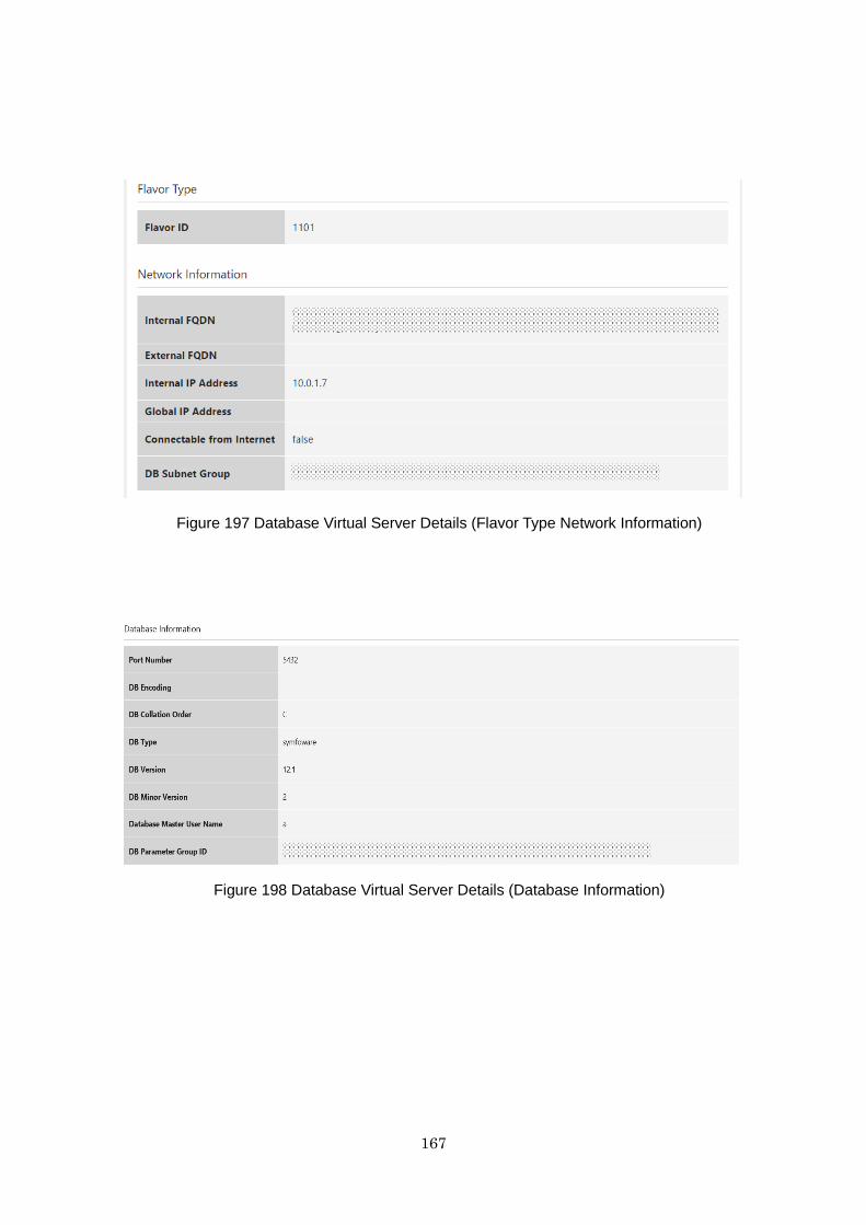
167
Figure 197 Database Virtual Server Details (Flavor Type Network Information)
Figure 198 Database Virtual Server Details (Database Information)

168
Figure 199 Database Virtual Server Details (Database Operation Information)
Figure 200 Database Virtual Server Details (Parameters to be changed at the time of next
reboot)
Table 51 Displayed Content of Database Virtual Server Details
No. Category Item Name Displayed Content
1 Database Virtual
Server Details
ID Database Virtual Server
ID
2 Database Virtual
Server Name
Database Virtual Server
Name
3 Status Database Virtual Server
Status.Refer to Table 49
Database Virtual Server
Status
4 Creation Time Created Date and Time

169
5 Update Time Update Date and Time
6 Data Storage Size Data Storage Size
7 Data Storage Type Data Storage Type
8 Availability Zone of
Master Running
Availability Zone where
the main server is
starting up
9 Redundancy true / false
10 Multi AZ Option true / false
11 Associated Read
Replica
Linked Read Replica
12 Original ID of Read
Replica
Replication Source
Database Virtual Server
ID
13 Availability Zone of
Slave Running
Availability Zone where
duplicate server is
starting up
14 Status of Read Replica Status of Read Replica
15 Security Group Security Group
16 Description Description
17 Flavor Type Flavor ID Flavor ID
18 Network
Information
Internal FQDN Internal FQDN
19 External FQDN External FQDN
20 Internal IP Address IP Address
21 Global IP Address Global IP Address
22 Connectable from
Internet
true / false
23 DB Subnet Group Subnet Group
24 Database
Information
Port Number Port Number
25 DB Encoding Database Encoding
26 DB Collation Order Checking Flow
27 DB Type Type
28 DB Version Version
29 DB Minor Version Minor Version
30 Database Master User
Name
Database Management
User Name
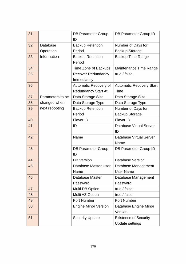
170
31 DB Parameter Group
ID
DB Parameter Group ID
32 Database
Operation
Information
Backup Retention
Period
Number of Days for
Backup Storage
33 Backup Retention
Period
Backup Time Range
34 Time Zone of Backups Maintenance Time Range
35 Recover Redundancy
Immediately
true / false
36 Automatic Recovery of
Redundancy Start At
Automatic Recovery Start
Time
37 Parameters to be
changed when
next rebooting
Data Storage Size Data Storage Size
38 Data Storage Type Data Storage Type
39 Backup Retention
Period
Number of Days for
Backup Storage
40 Flavor ID Flavor ID
41 ID Database Virtual Server
ID
42 Name Database Virtual Server
Name
43 DB Parameter Group
ID
DB Parameter Group ID
44 DB Version Database Version
45 Database Master User
Name
Database Management
User Name
46 Database Master
Password
Database Management
Password
47 Multi DB Option true / false
48 Multi AZ Option true / false
49 Port Number Port Number
50 Engine Minor Version Database Engine Minor
Version
51 Security Update Existence of Security
Update settings
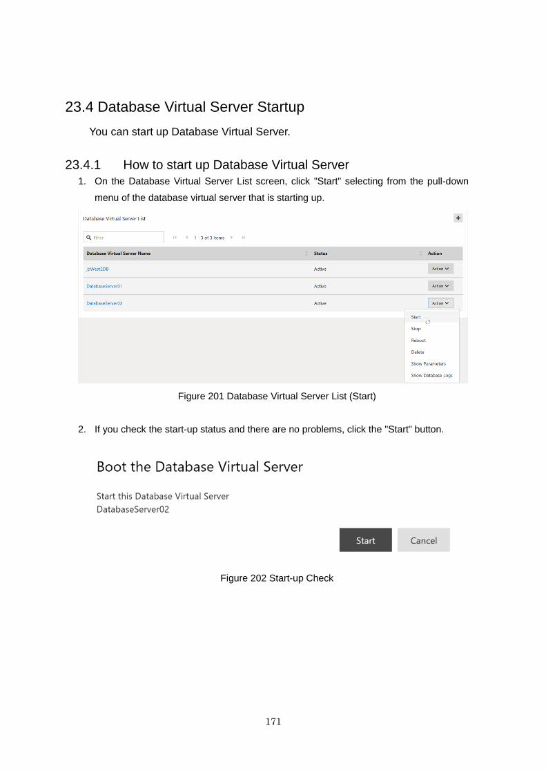
171
23.4 Database Virtual Server Startup
You can start up Database Virtual Server.
23.4.1 How to start up Database Virtual Server
1. On the Database Virtual Server List screen, click "Start" selecting from the pull-down
menu of the database virtual server that is starting up.
Figure 201 Database Virtual Server List (Start)
2. If you check the start-up status and there are no problems, click the "Start" button.
Figure 202 Start-up Check
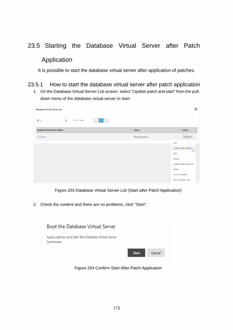
172
23.5 Starting the Database Virtual Server after Patch
Application
It is possible to start the database virtual server after application of patches.
23.5.1 How to start the database virtual server after patch application
1. On the Database Virtual Server List screen, select "Update patch and start" from the pull-
down menu of the database virtual server to start.
Figure 203 Database Virtual Server List (Start after Patch Application)
2. Check the content and there are no problems, click "Start".
Figure 204 Confirm Start After Patch Application
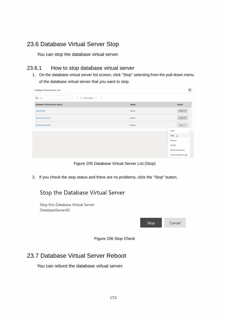
173
23.6 Database Virtual Server Stop
You can stop the database virtual server.
23.6.1 How to stop database virtual server
1. On the database virtual server list screen, click "Stop" selecting from the pull-down menu
of the database virtual server that you want to stop.
Figure 205 Database Virtual Server List (Stop)
2. If you check the stop status and there are no problems, click the "Stop" button.
Figure 206 Stop Check
23.7 Database Virtual Server Reboot
You can reboot the database virtual server.

174
23.7.1 How to reboot the database virtual server
1. On the database virtual server list screen, click "Reboot" selecting from the pull-down
menu of the database virtual server that you want to reboot.
Figure 207 Database Virtual Server List (Reboot)
2. If you check reboot status and there are no problems, click the "Reboot" button.
Figure 208 Reboot Check
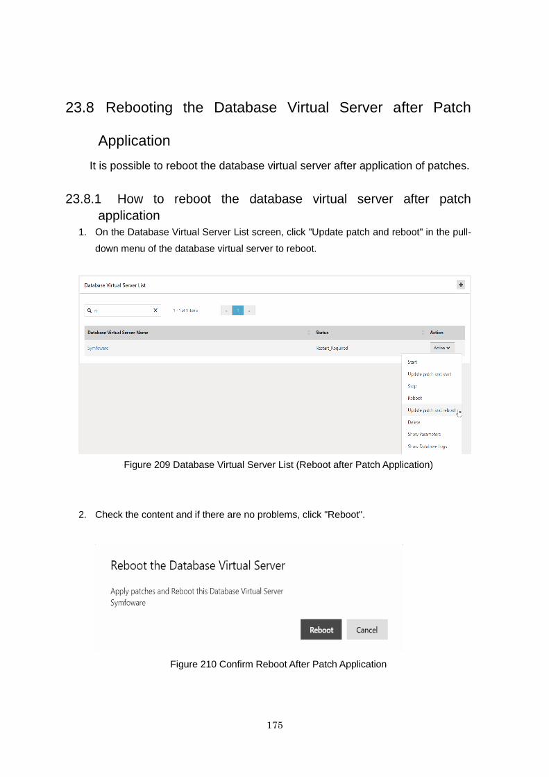
175
23.8 Rebooting the Database Virtual Server after Patch
Application
It is possible to reboot the database virtual server after application of patches.
23.8.1 How to reboot the database virtual server after patch
application
1. On the Database Virtual Server List screen, click "Update patch and reboot" in the pull-
down menu of the database virtual server to reboot.
Figure 209 Database Virtual Server List (Reboot after Patch Application)
2. Check the content and if there are no problems, click "Reboot".
Figure 210 Confirm Reboot After Patch Application
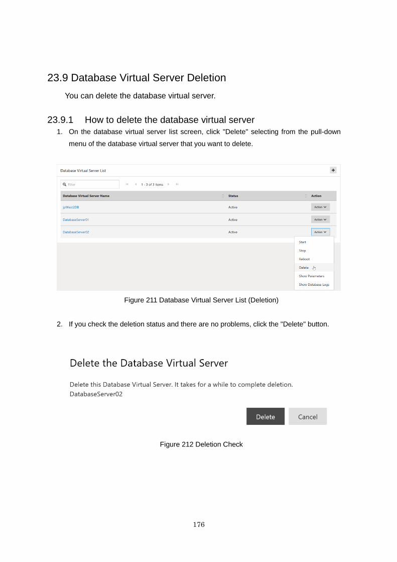
176
23.9 Database Virtual Server Deletion
You can delete the database virtual server.
23.9.1 How to delete the database virtual server
1. On the database virtual server list screen, click "Delete" selecting from the pull-down
menu of the database virtual server that you want to delete.
Figure 211 Database Virtual Server List (Deletion)
2. If you check the deletion status and there are no problems, click the "Delete" button.
Figure 212 Deletion Check
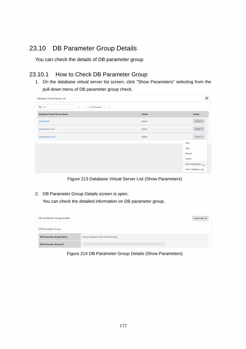
177
23.10 DB Parameter Group Details
You can check the details of DB parameter group.
23.10.1 How to Check DB Parameter Group
1. On the database virtual server list screen, click "Show Parameters" selecting from the
pull-down menu of DB parameter group check.
Figure 213 Database Virtual Server List (Show Parameters)
2. DB Parameter Group Details screen is open.
You can check the detailed information on DB parameter group.
Figure 214 DB Parameter Group Details (Show Parameters)
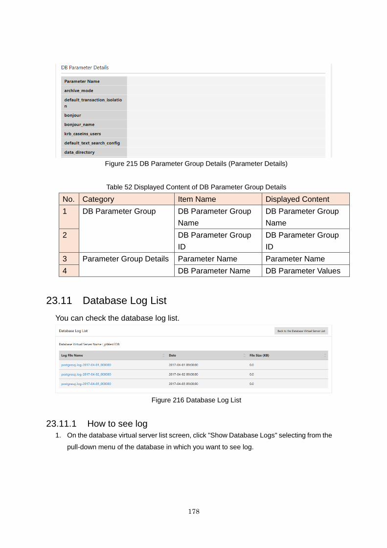
178
Figure 215 DB Parameter Group Details (Parameter Details)
Table 52 Displayed Content of DB Parameter Group Details
No. Category Item Name Displayed Content
1 DB Parameter Group DB Parameter Group
Name
DB Parameter Group
Name
2 DB Parameter Group
ID
DB Parameter Group
ID
3 Parameter Group Details Parameter Name Parameter Name
4 DB Parameter Name DB Parameter Values
23.11 Database Log List
You can check the database log list.
Figure 216 Database Log List
23.11.1 How to see log
1. On the database virtual server list screen, click "Show Database Logs" selecting from the
pull-down menu of the database in which you want to see log.
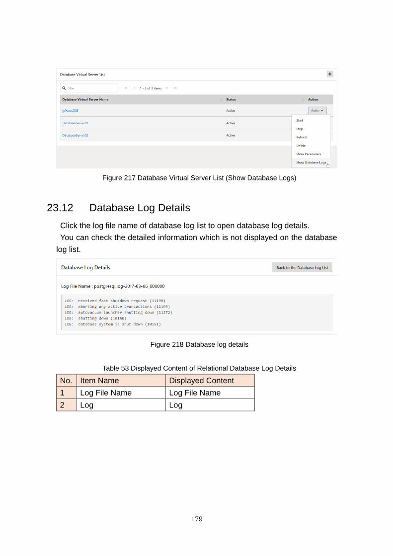
179
Figure 217 Database Virtual Server List (Show Database Logs)
23.12 Database Log Details
Click the log file name of database log list to open database log details.
You can check the detailed information which is not displayed on the database
log list.
Figure 218 Database log details
Table 53 Displayed Content of Relational Database Log Details
No. Item Name Displayed Content
1 Log File Name Log File Name
2 Log Log
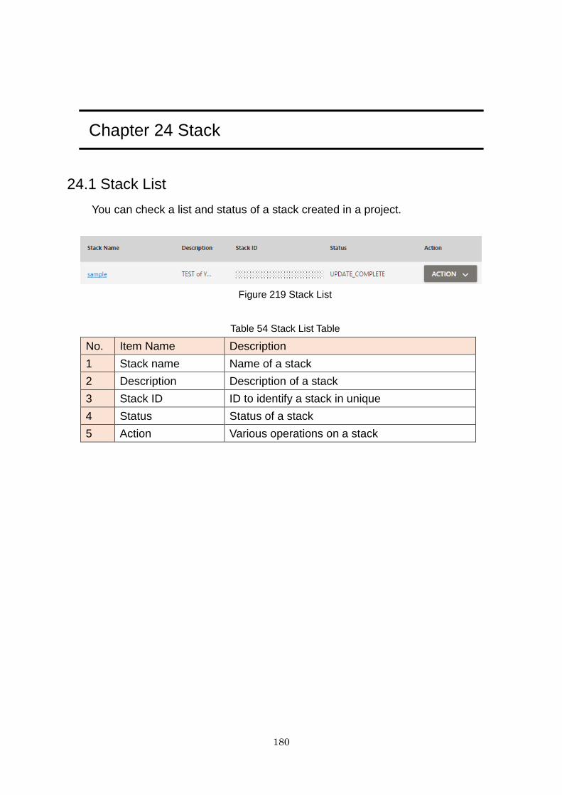
180
Chapter 24 Stack
24.1 Stack List
You can check a list and status of a stack created in a project.
Figure 219 Stack List
Table 54 Stack List Table
No. Item Name Description
1 Stack name Name of a stack
2 Description Description of a stack
3 Stack ID ID to identify a stack in unique
4 Status Status of a stack
5 Action Various operations on a stack
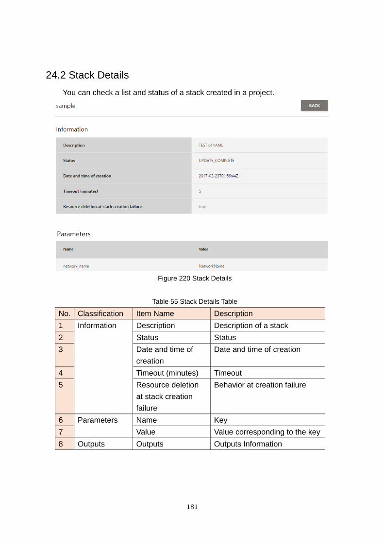
181
24.2 Stack Details
You can check a list and status of a stack created in a project.
Figure 220 Stack Details
Table 55 Stack Details Table
No. Classification Item Name Description
1 Information Description Description of a stack
2 Status Status
3 Date and time of
creation
Date and time of creation
4 Timeout (minutes) Timeout
5 Resource deletion
at stack creation
failure
Behavior at creation failure
6 Parameters Name Key
7 Value Value corresponding to the key
8 Outputs Outputs Outputs Information
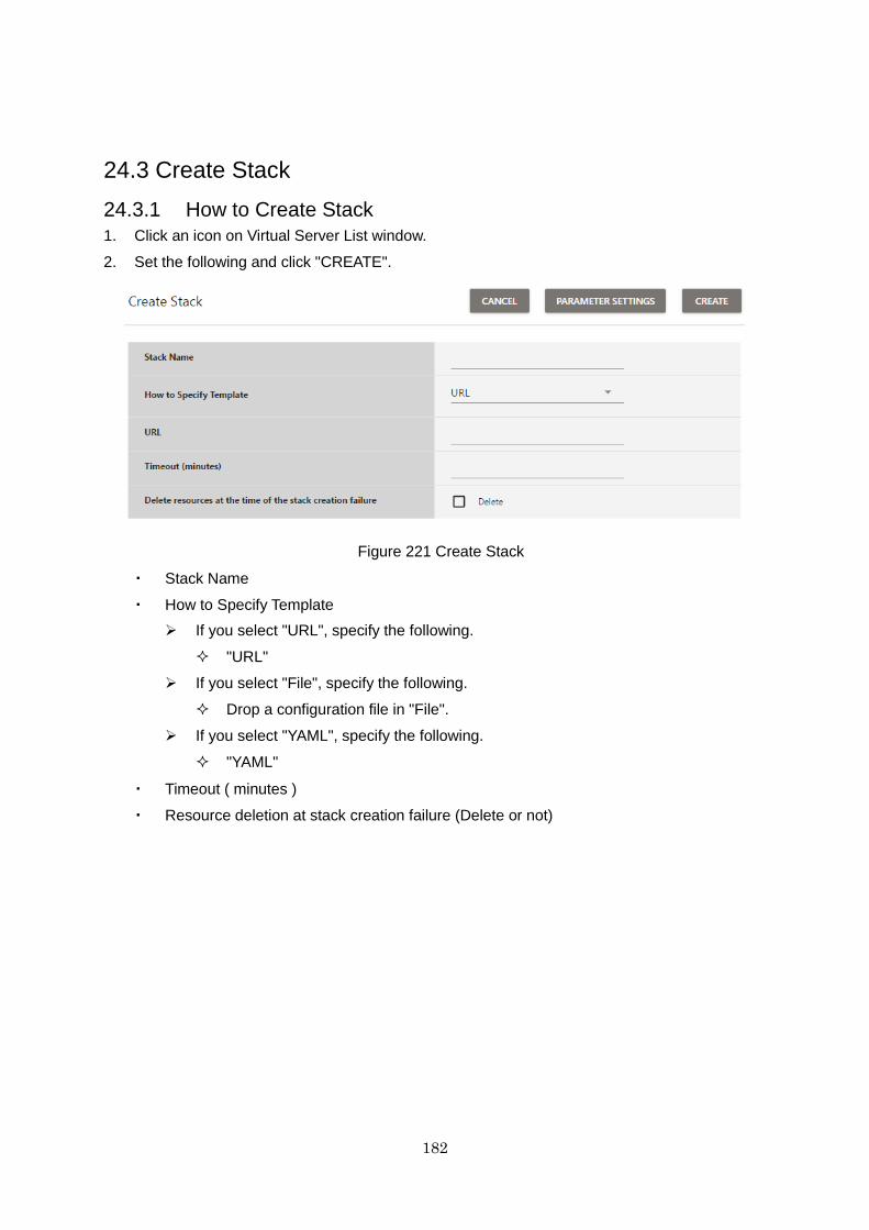
182
24.3 Create Stack
24.3.1 How to Create Stack
1. Click an icon on Virtual Server List window.
2. Set the following and click "CREATE".
Figure 221 Create Stack
・ Stack Name
・ How to Specify Template
If you select "URL", specify the following.
"URL"
If you select "File", specify the following.
Drop a configuration file in "File".
If you select "YAML", specify the following.
"YAML"
・ Timeout ( minutes )
・ Resource deletion at stack creation failure (Delete or not)
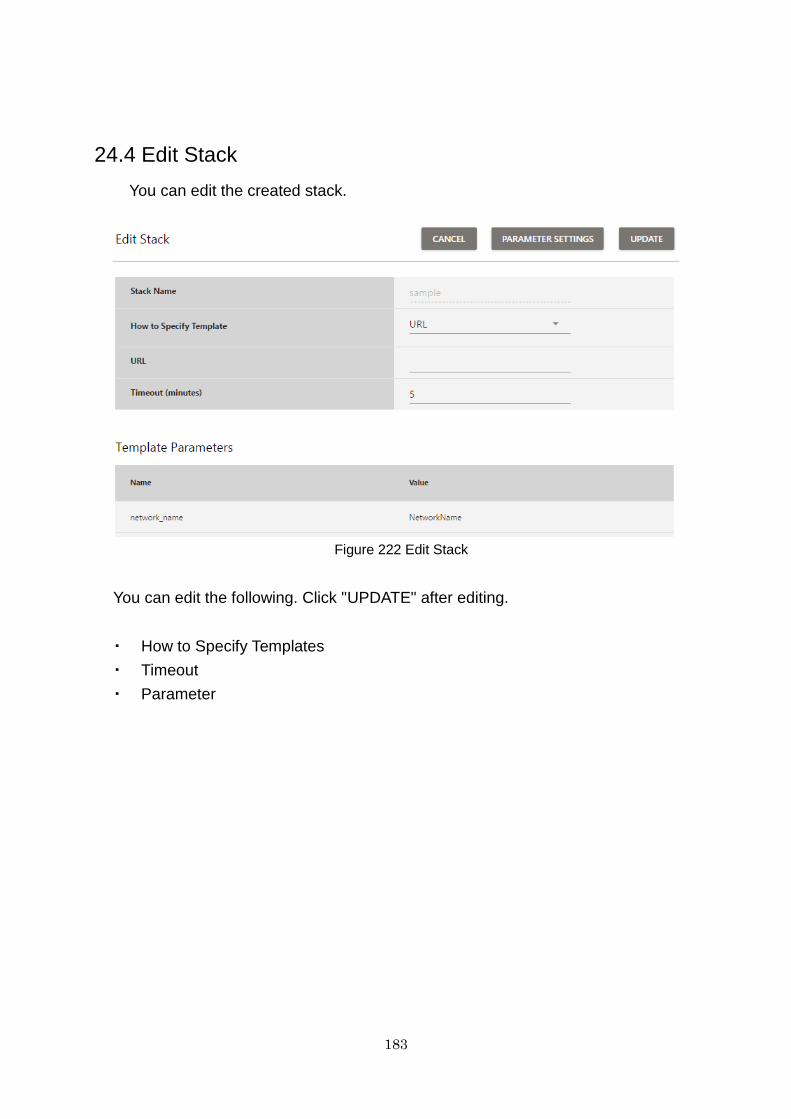
183
24.4 Edit Stack
You can edit the created stack.
Figure 222 Edit Stack
You can edit the following. Click "UPDATE" after editing.
・ How to Specify Templates
・ Timeout
・ Parameter
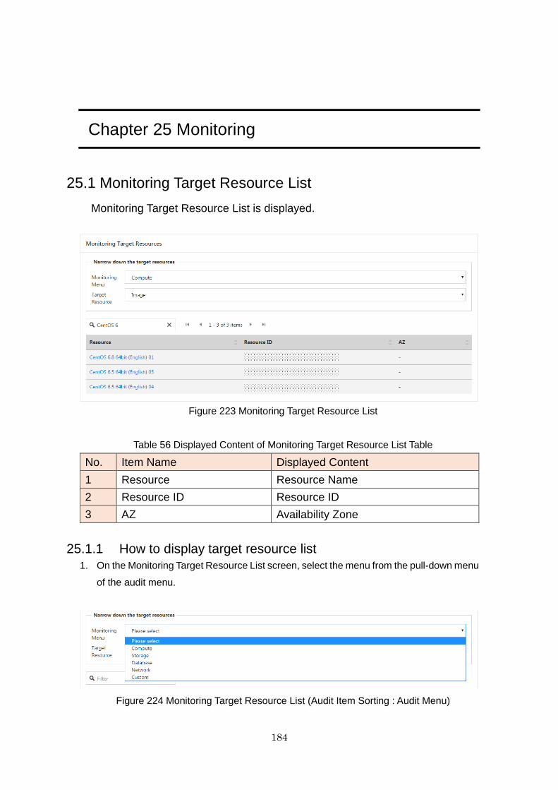
184
Chapter 25 Monitoring
25.1 Monitoring Target Resource List
Monitoring Target Resource List is displayed.
Figure 223 Monitoring Target Resource List
Table 56 Displayed Content of Monitoring Target Resource List Table
No. Item Name Displayed Content
1 Resource Resource Name
2 Resource ID Resource ID
3 AZ Availability Zone
25.1.1 How to display target resource list
1. On the Monitoring Target Resource List screen, select the menu from the pull-down menu
of the audit menu.
Figure 224 Monitoring Target Resource List (Audit Item Sorting : Audit Menu)
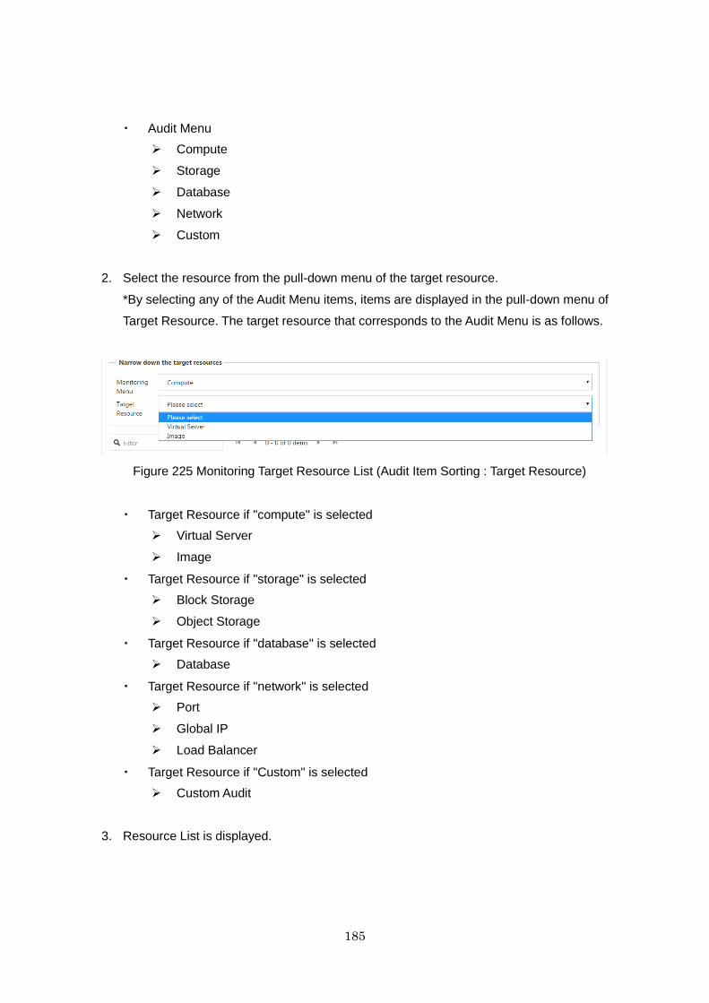
185
・ Audit Menu
Compute
Storage
Database
Network
Custom
2. Select the resource from the pull-down menu of the target resource.
*By selecting any of the Audit Menu items, items are displayed in the pull-down menu of
Target Resource. The target resource that corresponds to the Audit Menu is as follows.
Figure 225 Monitoring Target Resource List (Audit Item Sorting : Target Resource)
・ Target Resource if "compute" is selected
Virtual Server
Image
・ Target Resource if "storage" is selected
Block Storage
Object Storage
・ Target Resource if "database" is selected
Database
・ Target Resource if "network" is selected
Port
Global IP
Load Balancer
・ Target Resource if "Custom" is selected
Custom Audit
3. Resource List is displayed.
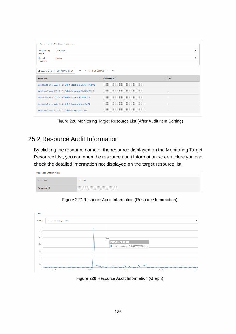
186
Figure 226 Monitoring Target Resource List (After Audit Item Sorting)
25.2 Resource Audit Information
By clicking the resource name of the resource displayed on the Monitoring Target
Resource List, you can open the resource audit information screen. Here you can
check the detailed information not displayed on the target resource list.
Figure 227 Resource Audit Information (Resource Information)
Figure 228 Resource Audit Information (Graph)
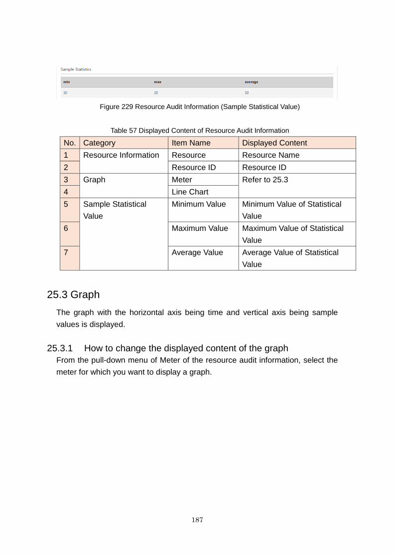
187
Figure 229 Resource Audit Information (Sample Statistical Value)
Table 57 Displayed Content of Resource Audit Information
No. Category Item Name Displayed Content
1 Resource Information Resource Resource Name
2 Resource ID Resource ID
3 Graph Meter Refer to 25.3
4 Line Chart
5 Sample Statistical
Value
Minimum Value Minimum Value of Statistical
Value
6 Maximum Value Maximum Value of Statistical
Value
7 Average Value Average Value of Statistical
Value
25.3 Graph
The graph with the horizontal axis being time and vertical axis being sample
values is displayed.
25.3.1 How to change the displayed content of the graph
From the pull-down menu of Meter of the resource audit information, select the
meter for which you want to display a graph.
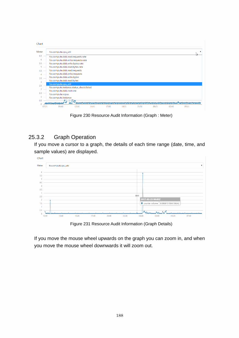
188
Figure 230 Resource Audit Information (Graph : Meter)
25.3.2 Graph Operation
If you move a cursor to a graph, the details of each time range (date, time, and
sample values) are displayed.
Figure 231 Resource Audit Information (Graph Details)
If you move the mouse wheel upwards on the graph you can zoom in, and when
you move the mouse wheel downwards it will zoom out.
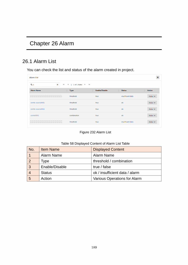
189
Chapter 26 Alarm
26.1 Alarm List
You can check the list and status of the alarm created in project.
Figure 232 Alarm List
Table 58 Displayed Content of Alarm List Table
No. Item Name Displayed Content
1 Alarm Name Alarm Name
2 Type threshold / combination
3 Enable/Disable true / false
4 Status ok / insufficient data / alarm
5 Action Various Operations for Alarm
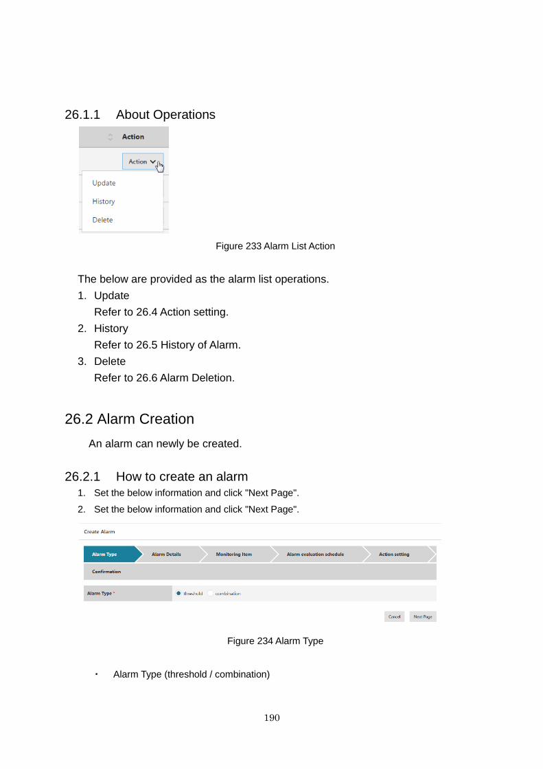
190
26.1.1 About Operations
Figure 233 Alarm List Action
The below are provided as the alarm list operations.
1. Update
Refer to 26.4 Action setting.
2. History
Refer to 26.5 History of Alarm.
3. Delete
Refer to 26.6 Alarm Deletion.
26.2 Alarm Creation
An alarm can newly be created.
26.2.1 How to create an alarm
1. Set the below information and click "Next Page".
2. Set the below information and click "Next Page".
Figure 234 Alarm Type
・ Alarm Type (threshold / combination)
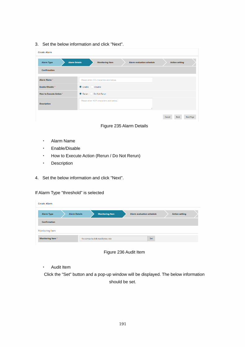
191
3. Set the below information and click "Next".
Figure 235 Alarm Details
・ Alarm Name
・ Enable/Disable
・ How to Execute Action (Rerun / Do Not Rerun)
・ Description
4. Set the below information and click "Next".
If Alarm Type "threshold" is selected
Figure 236 Audit Item
・ Audit Item
Click the "Set" button and a pop-up window will be displayed. The below information
should be set.
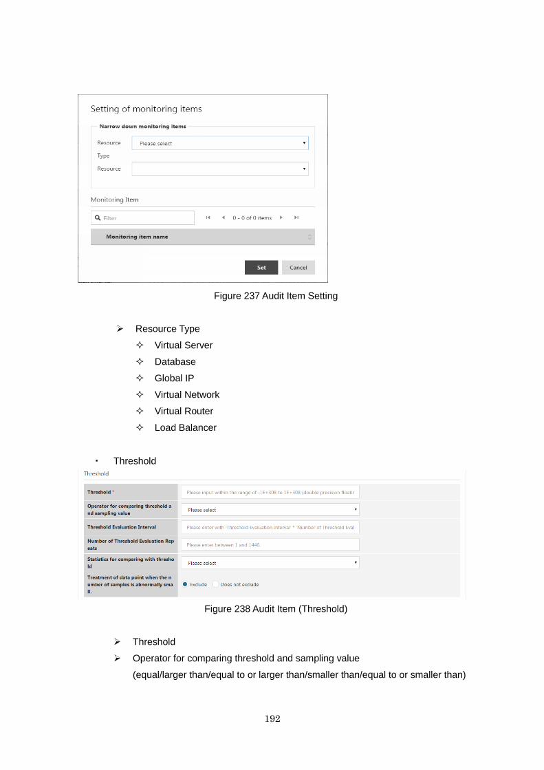
192
Figure 237 Audit Item Setting
Resource Type
Virtual Server
Database
Global IP
Virtual Network
Virtual Router
Load Balancer
・ Threshold
Figure 238 Audit Item (Threshold)
Threshold
Operator for comparing threshold and sampling value
(equal/larger than/equal to or larger than/smaller than/equal to or smaller than)
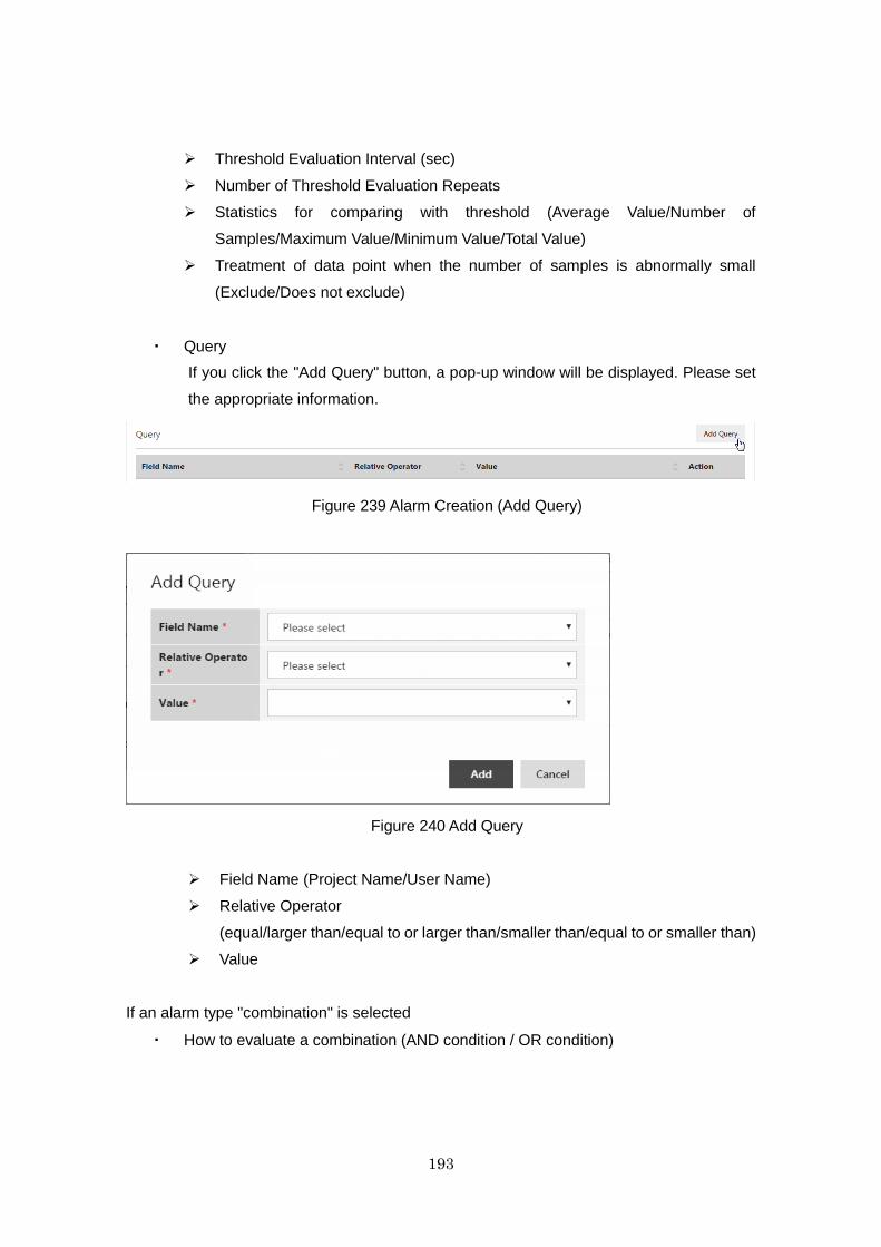
193
Threshold Evaluation Interval (sec)
Number of Threshold Evaluation Repeats
Statistics for comparing with threshold (Average Value/Number of
Samples/Maximum Value/Minimum Value/Total Value)
Treatment of data point when the number of samples is abnormally small
(Exclude/Does not exclude)
・ Query
If you click the "Add Query" button, a pop-up window will be displayed. Please set
the appropriate information.
Figure 239 Alarm Creation (Add Query)
Figure 240 Add Query
Field Name (Project Name/User Name)
Relative Operator
(equal/larger than/equal to or larger than/smaller than/equal to or smaller than)
Value
If an alarm type "combination" is selected
・ How to evaluate a combination (AND condition / OR condition)
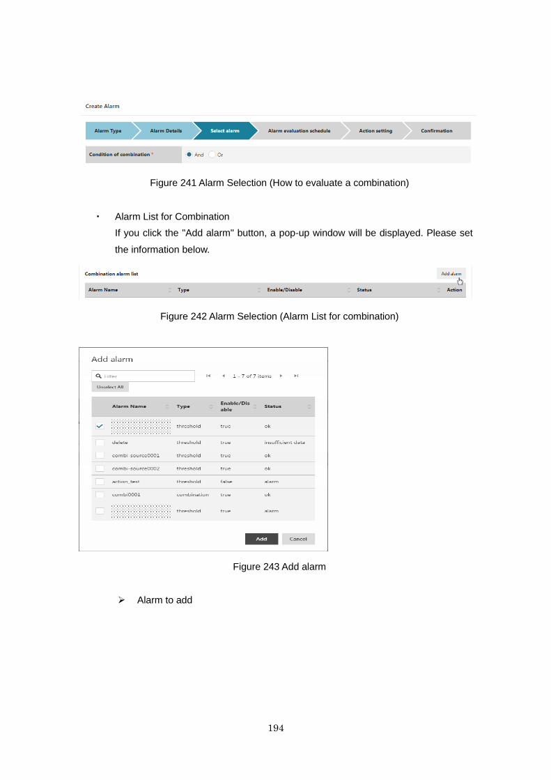
194
Figure 241 Alarm Selection (How to evaluate a combination)
・ Alarm List for Combination
If you click the "Add alarm" button, a pop-up window will be displayed. Please set
the information below.
Figure 242 Alarm Selection (Alarm List for combination)
Figure 243 Add alarm
Alarm to add
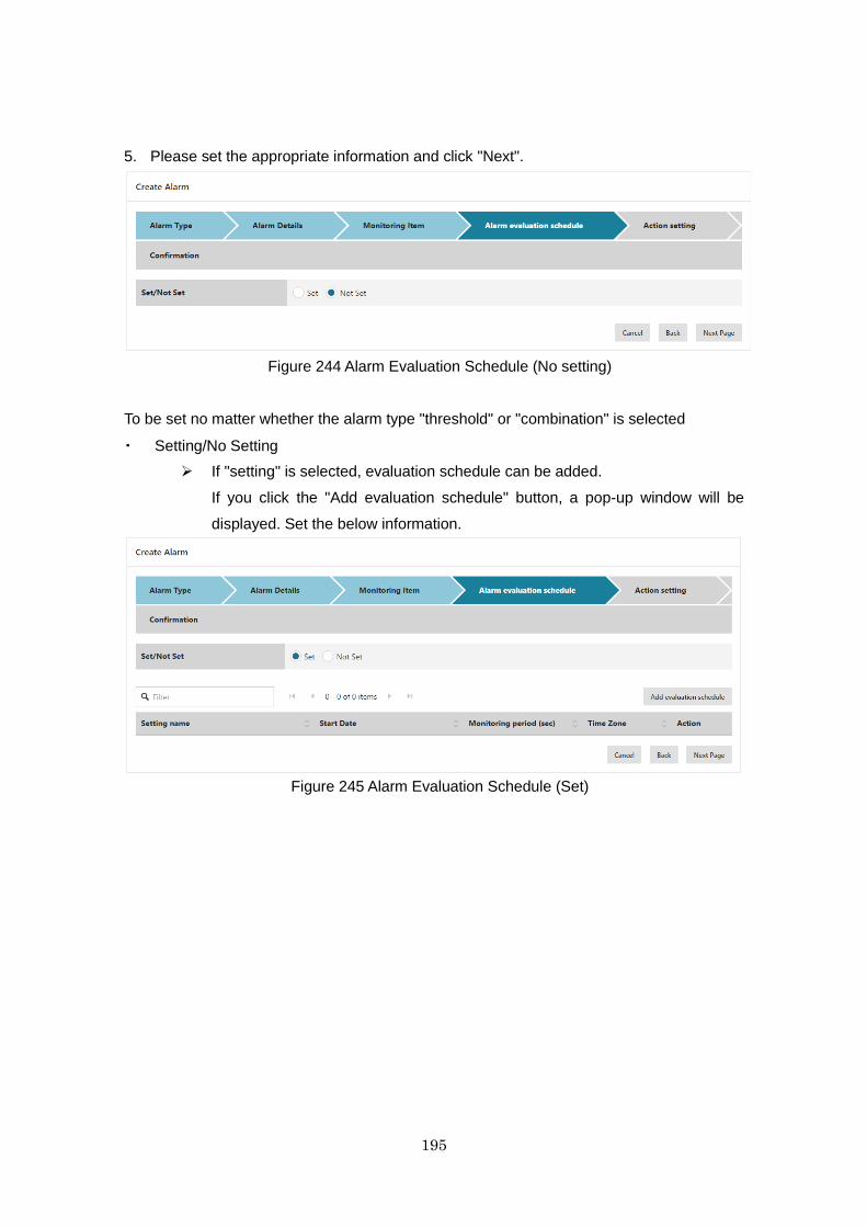
195
5. Please set the appropriate information and click "Next".
Figure 244 Alarm Evaluation Schedule (No setting)
To be set no matter whether the alarm type "threshold" or "combination" is selected
・ Setting/No Setting
If "setting" is selected, evaluation schedule can be added.
If you click the "Add evaluation schedule" button, a pop-up window will be
displayed. Set the below information.
Figure 245 Alarm Evaluation Schedule (Set)
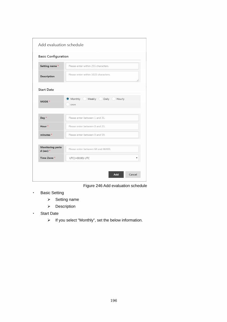
196
Figure 246 Add evaluation schedule
・ Basic Setting
Setting name
Description
・ Start Date
If you select "Monthly", set the below information.
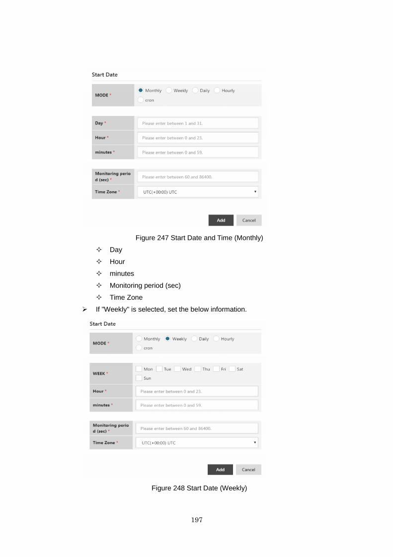
197
Figure 247 Start Date and Time (Monthly)
Day
Hour
minutes
Monitoring period (sec)
Time Zone
If "Weekly" is selected, set the below information.
Figure 248 Start Date (Weekly)
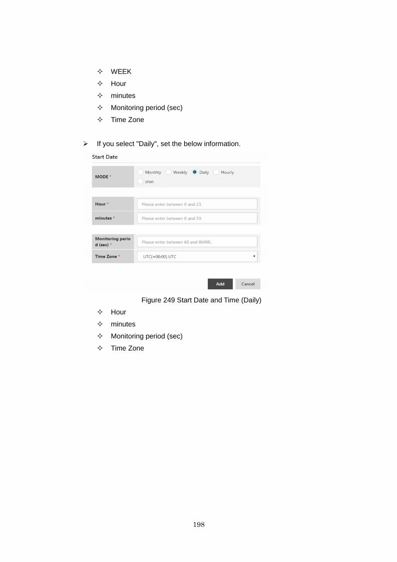
198
WEEK
Hour
minutes
Monitoring period (sec)
Time Zone
If you select "Daily", set the below information.
Figure 249 Start Date and Time (Daily)
Hour
minutes
Monitoring period (sec)
Time Zone
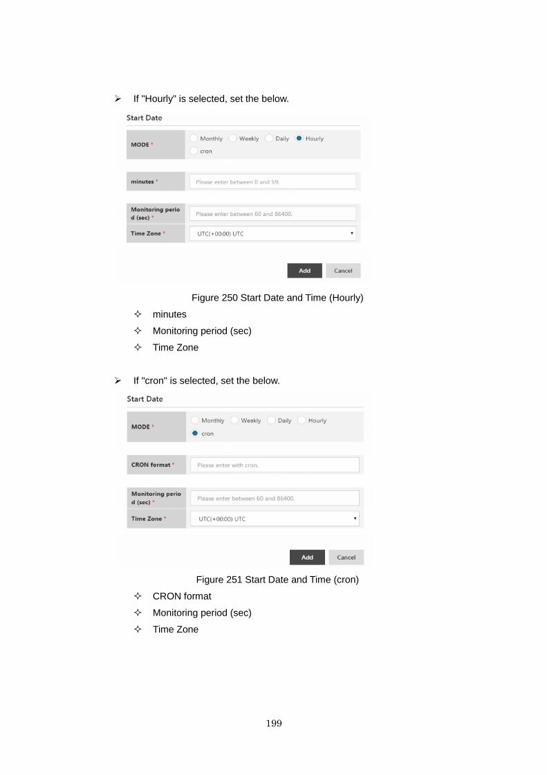
199
If "Hourly" is selected, set the below.
Figure 250 Start Date and Time (Hourly)
minutes
Monitoring period (sec)
Time Zone
If "cron" is selected, set the below.
Figure 251 Start Date and Time (cron)
CRON format
Monitoring period (sec)
Time Zone
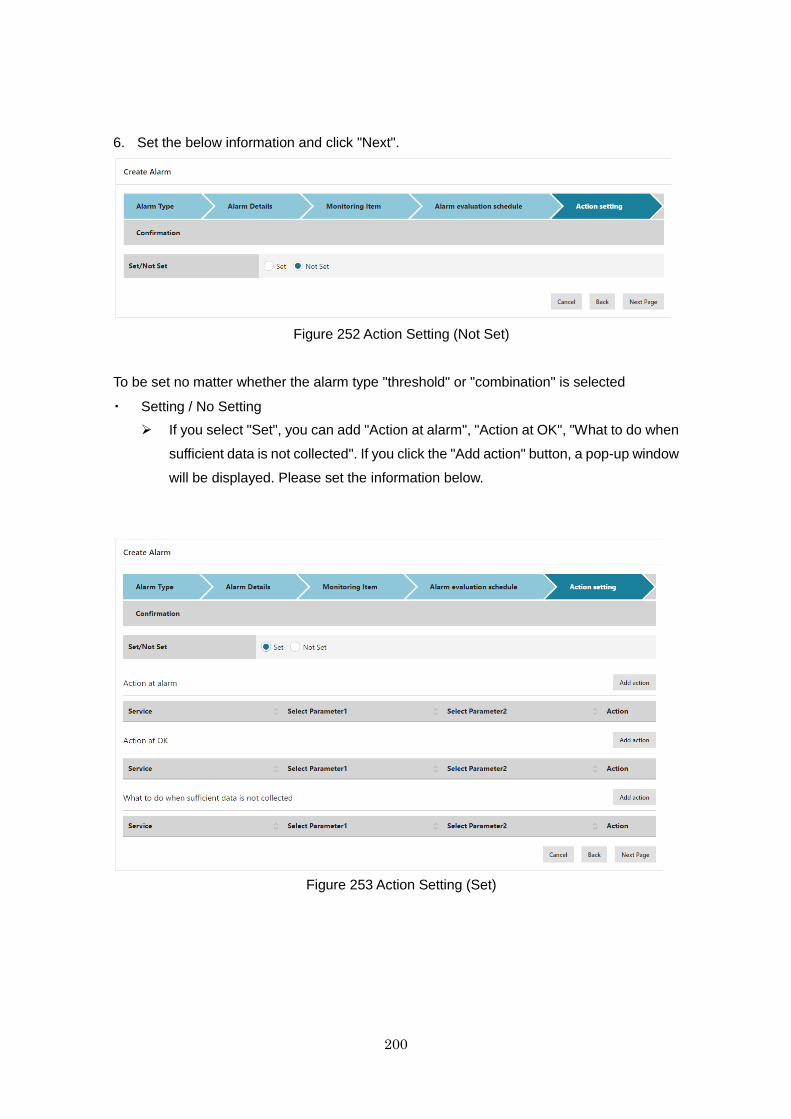
200
6. Set the below information and click "Next".
Figure 252 Action Setting (Not Set)
To be set no matter whether the alarm type "threshold" or "combination" is selected
・ Setting / No Setting
If you select "Set", you can add "Action at alarm", "Action at OK", "What to do when
sufficient data is not collected". If you click the "Add action" button, a pop-up window
will be displayed. Please set the information below.
Figure 253 Action Setting (Set)
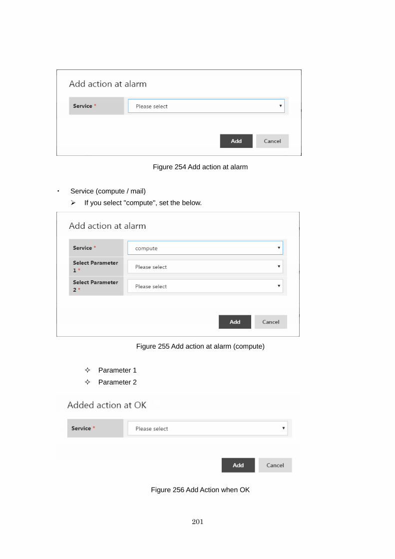
201
Figure 254 Add action at alarm
・ Service (compute / mail)
If you select "compute", set the below.
Figure 255 Add action at alarm (compute)
Parameter 1
Parameter 2
Figure 256 Add Action when OK
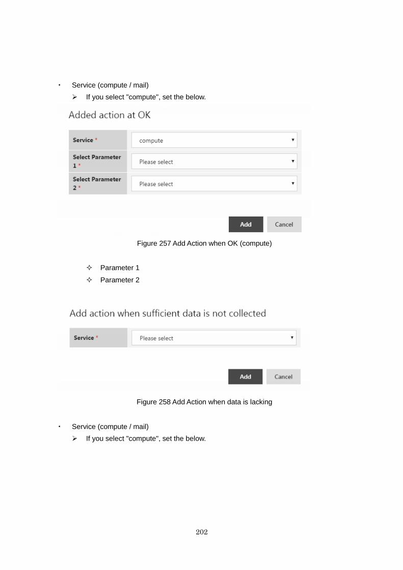
202
・ Service (compute / mail)
If you select "compute", set the below.
Figure 257 Add Action when OK (compute)
Parameter 1
Parameter 2
Figure 258 Add Action when data is lacking
・ Service (compute / mail)
If you select "compute", set the below.
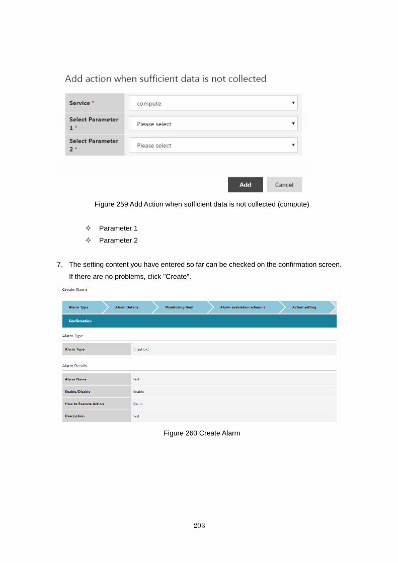
203
Figure 259 Add Action when sufficient data is not collected (compute)
Parameter 1
Parameter 2
7. The setting content you have entered so far can be checked on the confirmation screen.
If there are no problems, click "Create".
Figure 260 Create Alarm
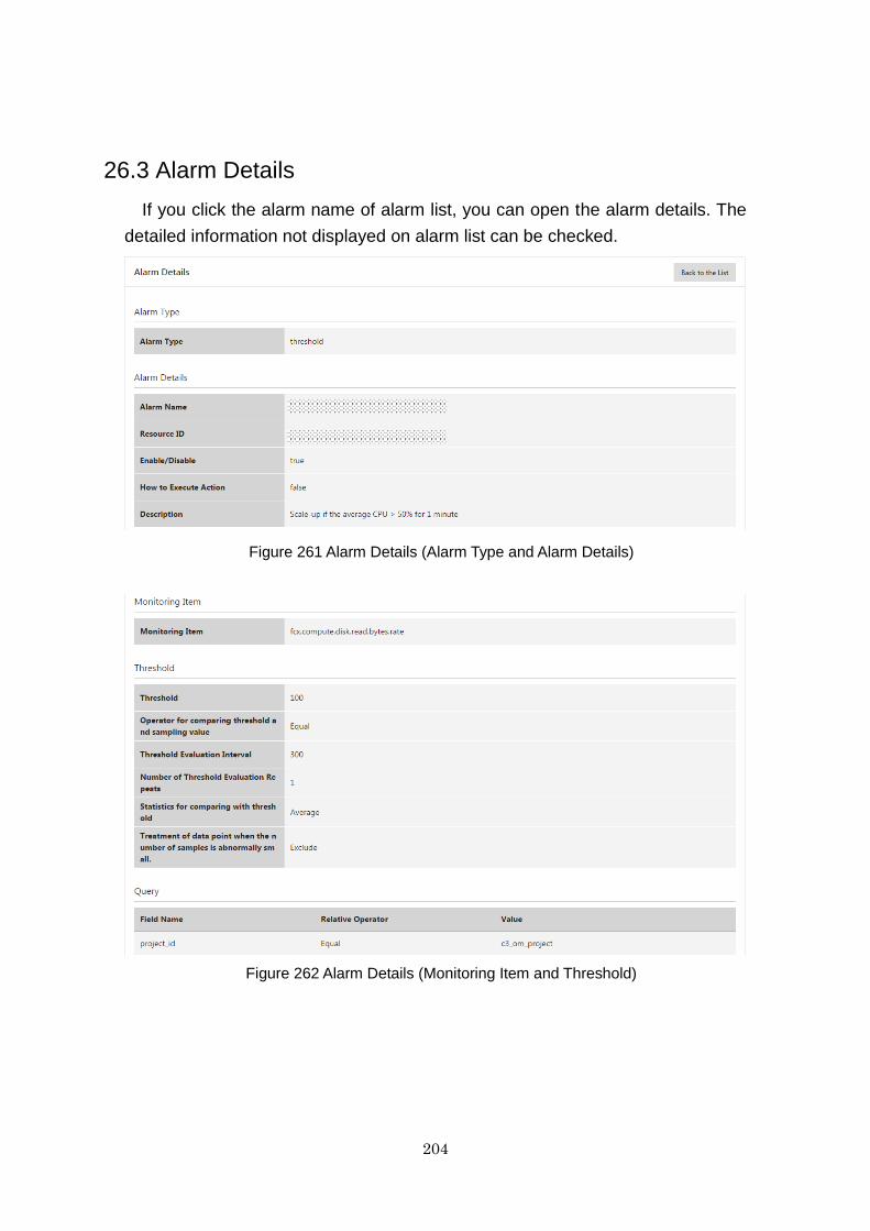
204
26.3 Alarm Details
If you click the alarm name of alarm list, you can open the alarm details. The
detailed information not displayed on alarm list can be checked.
Figure 261 Alarm Details (Alarm Type and Alarm Details)
Figure 262 Alarm Details (Monitoring Item and Threshold)
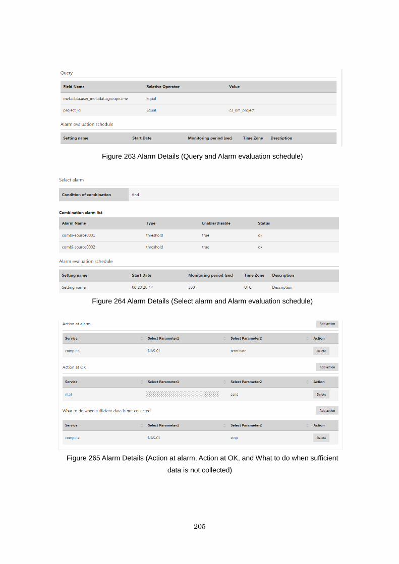
205
Figure 263 Alarm Details (Query and Alarm evaluation schedule)
Figure 264 Alarm Details (Select alarm and Alarm evaluation schedule)
Figure 265 Alarm Details (Action at alarm, Action at OK, and What to do when sufficient
data is not collected)
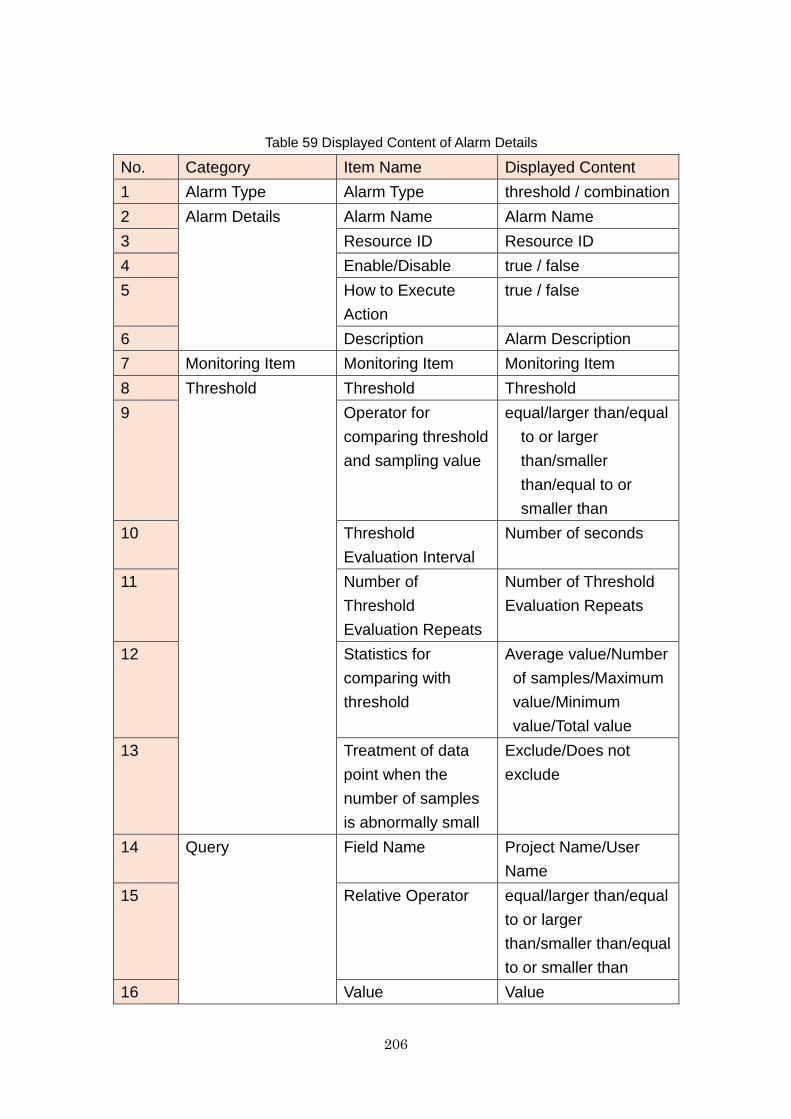
206
Table 59 Displayed Content of Alarm Details
No. Category Item Name Displayed Content
1 Alarm Type Alarm Type threshold / combination
2 Alarm Details Alarm Name Alarm Name
3 Resource ID Resource ID
4 Enable/Disable true / false
5 How to Execute
Action
true / false
6 Description Alarm Description
7 Monitoring Item Monitoring Item Monitoring Item
8 Threshold Threshold Threshold
9 Operator for
comparing threshold
and sampling value
equal/larger than/equal
to or larger
than/smaller
than/equal to or
smaller than
10 Threshold
Evaluation Interval
Number of seconds
11 Number of
Threshold
Evaluation Repeats
Number of Threshold
Evaluation Repeats
12 Statistics for
comparing with
threshold
Average value/Number
of samples/Maximum
value/Minimum
value/Total value
13 Treatment of data
point when the
number of samples
is abnormally small
Exclude/Does not
exclude
14 Query Field Name Project Name/User
Name
15 Relative Operator equal/larger than/equal
to or larger
than/smaller than/equal
to or smaller than
16 Value Value

207
17 Select alarm Condition of
combination
AND condition / OR
condition
18 Alarm Name Names of alarm to be
evaluated in the
combination
19 Alarm Type Type of each alarm:
threshold / combination
20 Enable / Disable True / false
21 Status The latest status of
each alarm:
ok / insufficient data /
alarm
22 Alarm evaluation
schedule
Setting name Setting name
23 Start Date Start Date
24 Monitoring period
(sec)
Number of seconds
25 Time Zone Time Zone
26 Description Description of Alarm
evaluation schedule
27 Action at alarm Service compute / mail
28 Parameter 1 Parameter 1
29 Parameter 2 Parameter 2
30 Action at OK Service compute / mail
31 Parameter 1 Parameter 1
32 Parameter 2 Parameter 2
33 What to do when
sufficient data is not
collected
Service compute / mail
34 Parameter 1 Parameter 1
35 Parameter 2 Parameter 2
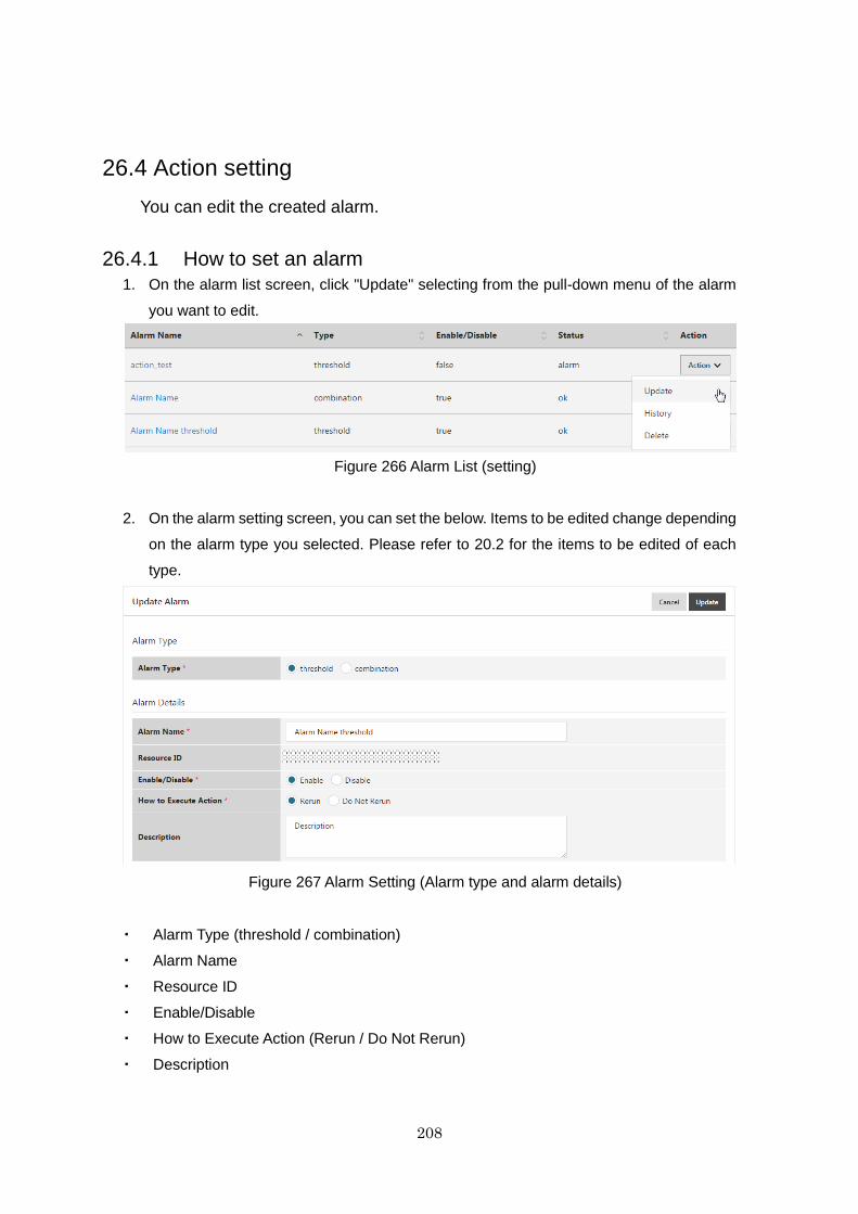
208
26.4 Action setting
You can edit the created alarm.
26.4.1 How to set an alarm
1. On the alarm list screen, click "Update" selecting from the pull-down menu of the alarm
you want to edit.
Figure 266 Alarm List (setting)
2. On the alarm setting screen, you can set the below. Items to be edited change depending
on the alarm type you selected. Please refer to 20.2 for the items to be edited of each
type.
Figure 267 Alarm Setting (Alarm type and alarm details)
・ Alarm Type (threshold / combination)
・ Alarm Name
・ Resource ID
・ Enable/Disable
・ How to Execute Action (Rerun / Do Not Rerun)
・ Description
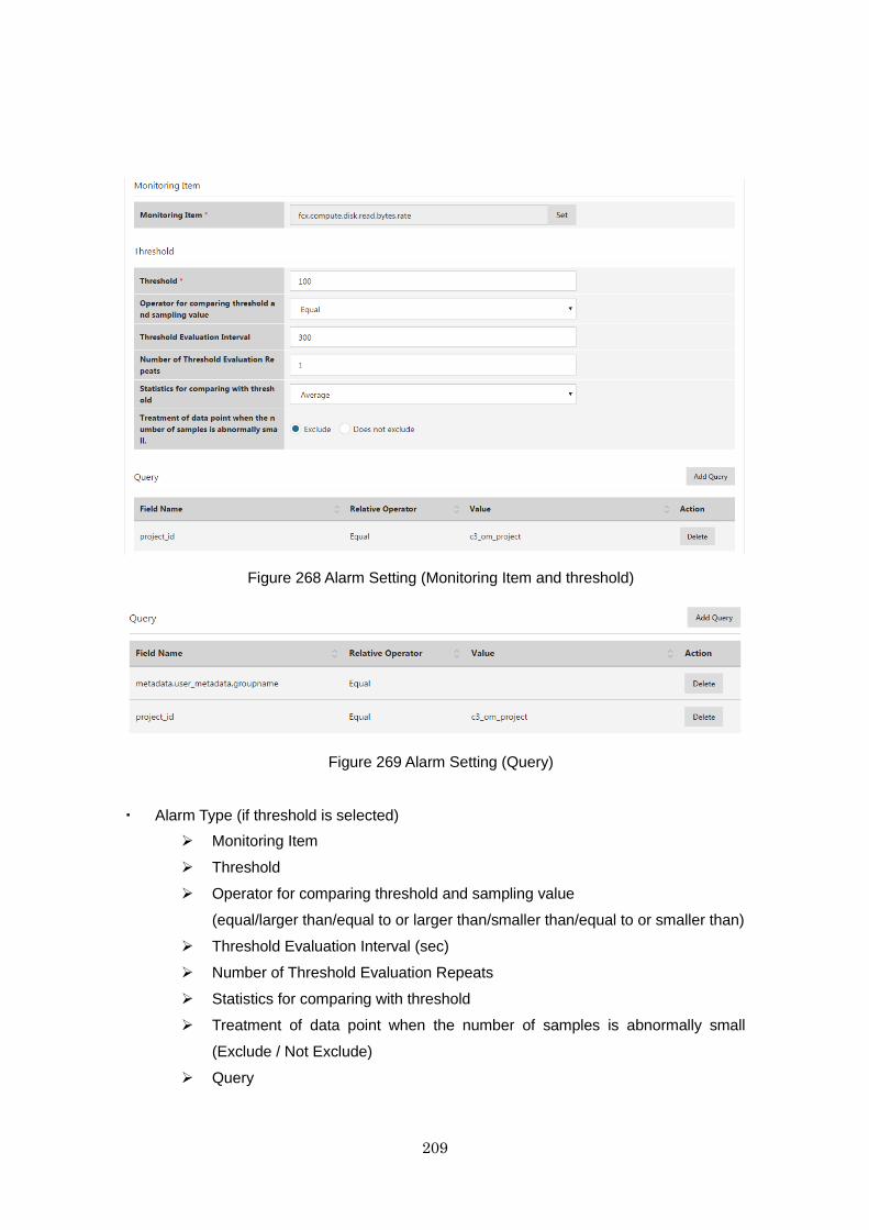
209
Figure 268 Alarm Setting (Monitoring Item and threshold)
Figure 269 Alarm Setting (Query)
・ Alarm Type (if threshold is selected)
Monitoring Item
Threshold
Operator for comparing threshold and sampling value
(equal/larger than/equal to or larger than/smaller than/equal to or smaller than)
Threshold Evaluation Interval (sec)
Number of Threshold Evaluation Repeats
Statistics for comparing with threshold
Treatment of data point when the number of samples is abnormally small
(Exclude / Not Exclude)
Query
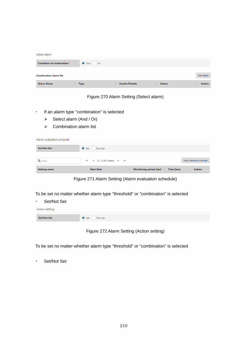
210
Figure 270 Alarm Setting (Select alarm)
・ If an alarm type "combination" is selected
Select alarm (And / Or)
Combination alarm list
Figure 271 Alarm Setting (Alarm evaluation schedule)
To be set no matter whether alarm type "threshold" or "combination" is selected
・ Set/Not Set
Figure 272 Alarm Setting (Action setting)
To be set no matter whether alarm type "threshold" or "combination" is selected
・ Set/Not Set
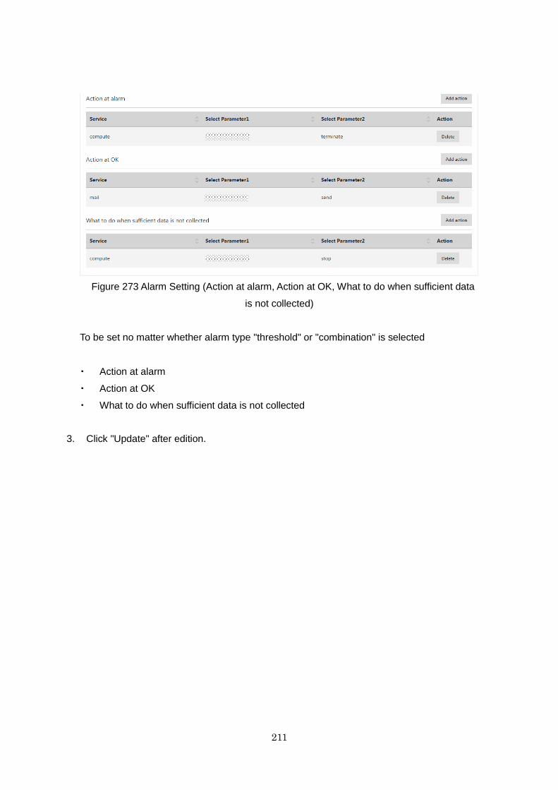
211
Figure 273 Alarm Setting (Action at alarm, Action at OK, What to do when sufficient data
is not collected)
To be set no matter whether alarm type "threshold" or "combination" is selected
・ Action at alarm
・ Action at OK
・ What to do when sufficient data is not collected
3. Click "Update" after edition.
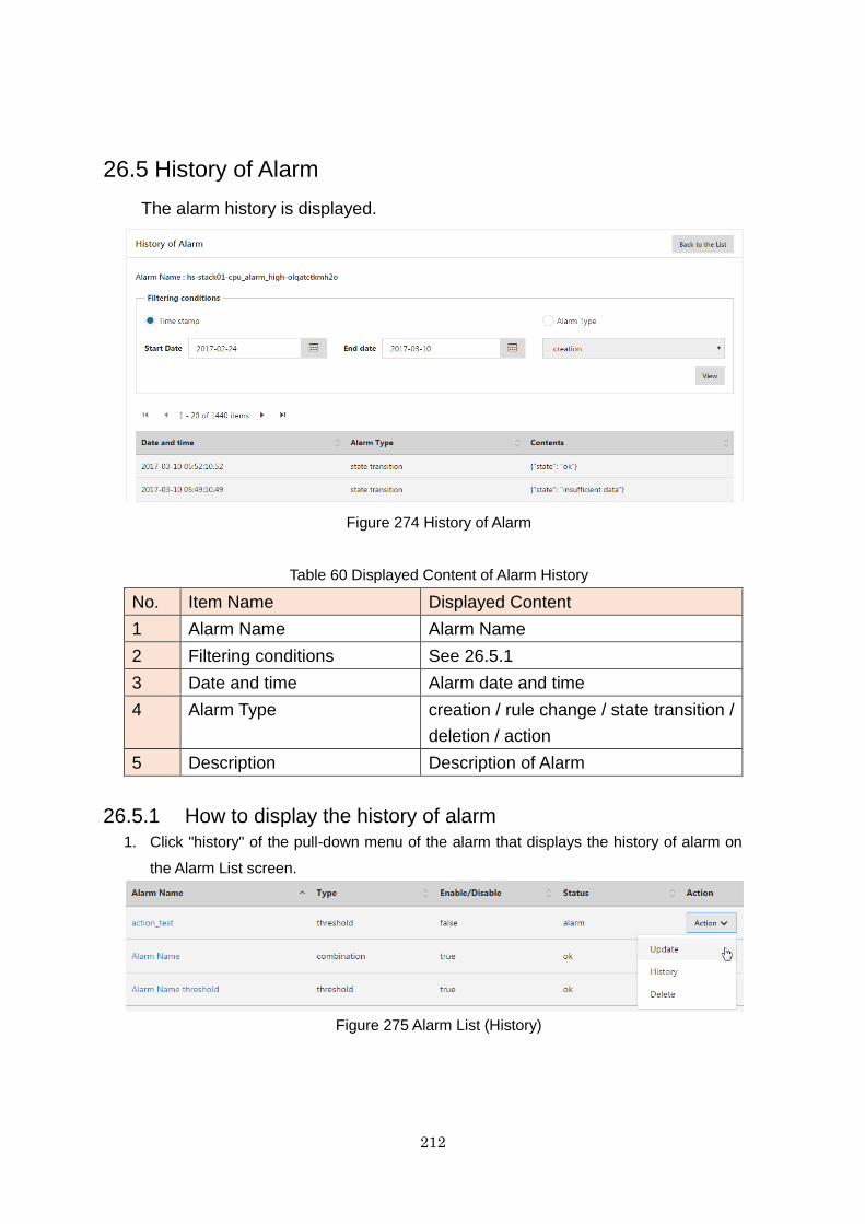
212
26.5 History of Alarm
The alarm history is displayed.
Figure 274 History of Alarm
Table 60 Displayed Content of Alarm History
No. Item Name Displayed Content
1 Alarm Name Alarm Name
2 Filtering conditions See 26.5.1
3 Date and time Alarm date and time
4 Alarm Type creation / rule change / state transition /
deletion / action
5 Description Description of Alarm
26.5.1 How to display the history of alarm
1. Click "history" of the pull-down menu of the alarm that displays the history of alarm on
the Alarm List screen.
Figure 275 Alarm List (History)
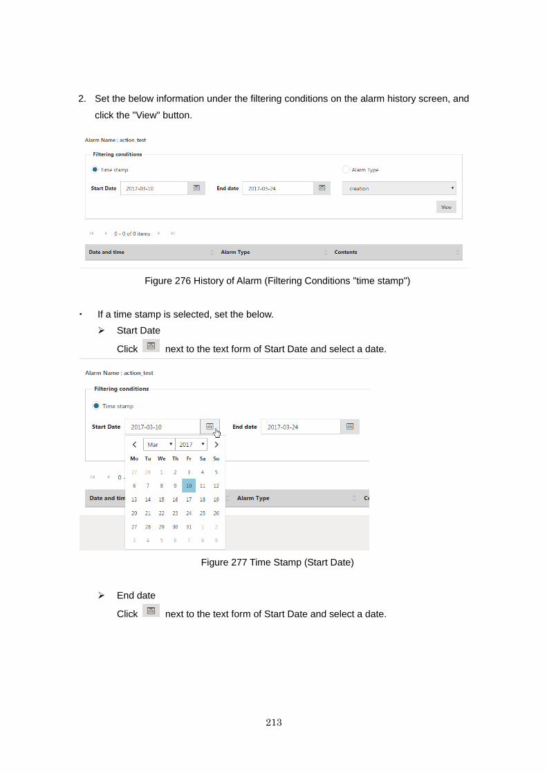
213
2. Set the below information under the filtering conditions on the alarm history screen, and
click the "View" button.
Figure 276 History of Alarm (Filtering Conditions "time stamp")
・ If a time stamp is selected, set the below.
Start Date
Click next to the text form of Start Date and select a date.
Figure 277 Time Stamp (Start Date)
End date
Click next to the text form of Start Date and select a date.
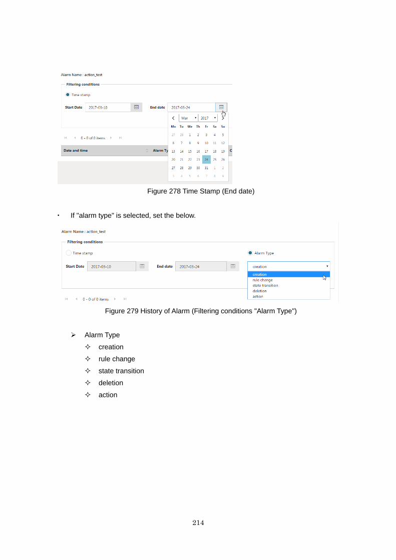
214
Figure 278 Time Stamp (End date)
・ If "alarm type" is selected, set the below.
Figure 279 History of Alarm (Filtering conditions "Alarm Type")
Alarm Type
creation
rule change
state transition
deletion
action
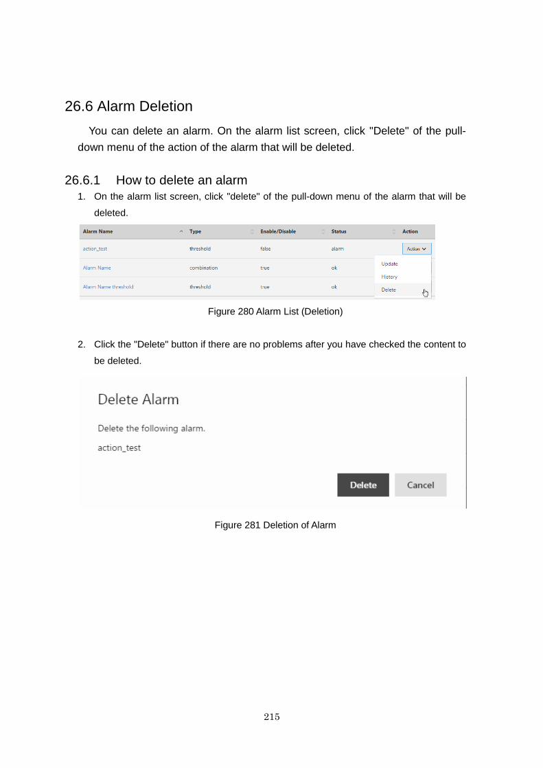
215
26.6 Alarm Deletion
You can delete an alarm. On the alarm list screen, click "Delete" of the pull-
down menu of the action of the alarm that will be deleted.
26.6.1 How to delete an alarm
1. On the alarm list screen, click "delete" of the pull-down menu of the alarm that will be
deleted.
Figure 280 Alarm List (Deletion)
2. Click the "Delete" button if there are no problems after you have checked the content to
be deleted.
Figure 281 Deletion of Alarm

216
Chapter 27 Operation Log
27.1 Function Overview
This function provides the functionality for checking the history of operations
performed on the IaaS service portal. The history of operations performed in the
last three days can be referred to.
The following functions are provided.
・ List Display of Operation Logs
Search function
Select a period from the last three days to filter the displayed operation
log. The displayed items are those listed in Table 61. Clicking a displayed
request ID displays the details of the relevant operation log.
- Specifiable range of date and time to search: The last three days
- Amount of operation logs displayable at once: One day's worth
- Date and time specification format: UTC time
Export function
The list information of displayed operation logs can be output in csv
format.
- File format: csv
・ Detailed Display of Operation Logs
Clicking a specific request ID in the list of the operation log displays the
detailed information indicated in Table 61. This enables checking of API
request parameters and response bodies.
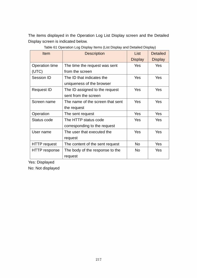
217
The items displayed in the Operation Log List Display screen and the Detailed
Display screen is indicated below.
Table 61 Operation Log Display Items (List Display and Detailed Display)
Item Description List
Display
Detailed
Display
Operation time
(UTC)
The time the request was sent
from the screen
Yes Yes
Session ID The ID that indicates the
uniqueness of the browser
Yes Yes
Request ID The ID assigned to the request
sent from the screen
Yes Yes
Screen name The name of the screen that sent
the request
Yes Yes
Operation The sent request Yes Yes
Status code The HTTP status code
corresponding to the request
Yes Yes
User name The user that executed the
request
Yes Yes
HTTP request The content of the sent request No Yes
HTTP response The body of the response to the
request
No Yes
Yes: Displayed
No: Not displayed
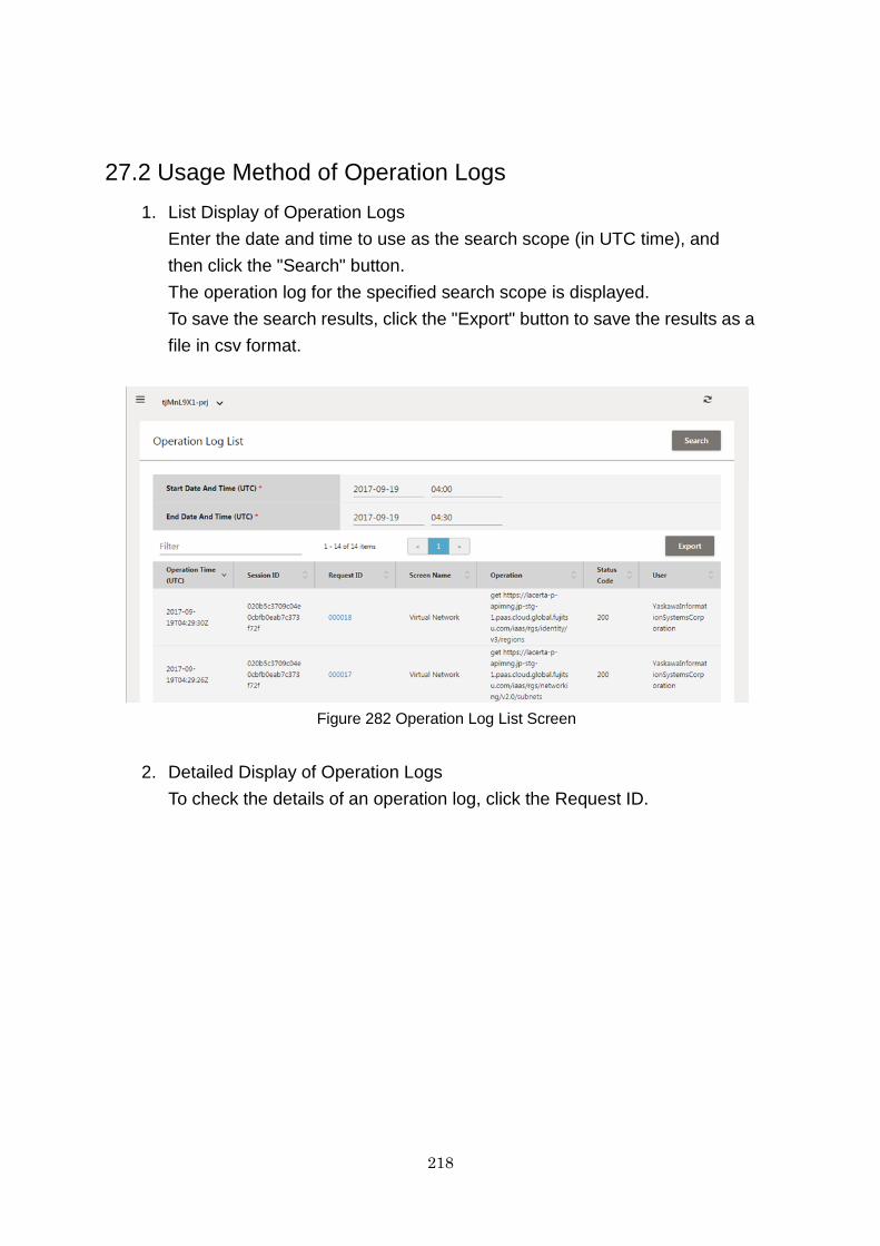
218
27.2 Usage Method of Operation Logs
1. List Display of Operation Logs
Enter the date and time to use as the search scope (in UTC time), and
then click the "Search" button.
The operation log for the specified search scope is displayed.
To save the search results, click the "Export" button to save the results as a
file in csv format.
Figure 282 Operation Log List Screen
2. Detailed Display of Operation Logs
To check the details of an operation log, click the Request ID.
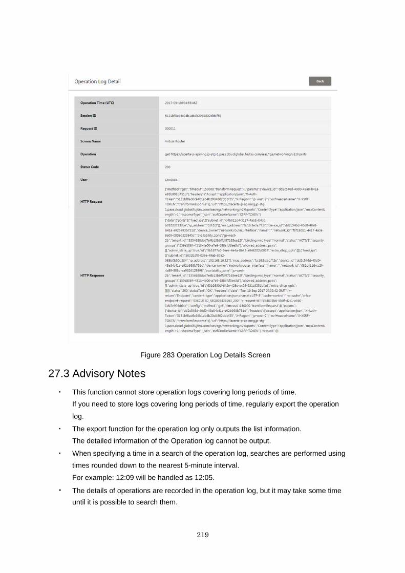
219
Figure 283 Operation Log Details Screen
27.3 Advisory Notes
・ This function cannot store operation logs covering long periods of time.
If you need to store logs covering long periods of time, regularly export the operation
log.
・ The export function for the operation log only outputs the list information.
The detailed information of the Operation log cannot be output.
・ When specifying a time in a search of the operation log, searches are performed using
times rounded down to the nearest 5-minute interval.
For example: 12:09 will be handled as 12:05.
・ The details of operations are recorded in the operation log, but it may take some time
until it is possible to search them.
220
Chapter 28 API Execution
28.1 Function Overview
This function is for executing APIs from the IaaS Service Portal and displaying
the response results on the portal. It can be used when executing functions not
provided by the IaaS Service Portal, or when there is no environment for
executing APIs using the command line. In addition, up to 10 executed APIs are
saved in the history function3.
Note: This function is not guaranteed to work with all APIs. If it does not work
correctly, please use the API.
Refer to the following URL for the "API Reference".
https://k5-doc.jp-east-1.paas.cloud.global.fujitsu.com/doc/en/iaas/document/list/doclist_iaas.html
28.2 Usage Example
This chapter explains examples of the following two methods that can be
executed using APIs. For other methods, use them after referring to the "API
Reference".
・ GET method: An example of virtual server list acquisition is explained.
・ POST method: An example of virtual server creation is explained.
28.2.1 Information Necessary for API Execution
The following information is necessary on the API execution window. The example explains
the methods for confirming and setting this information.
3 The history is deleted when the project or region is changed.
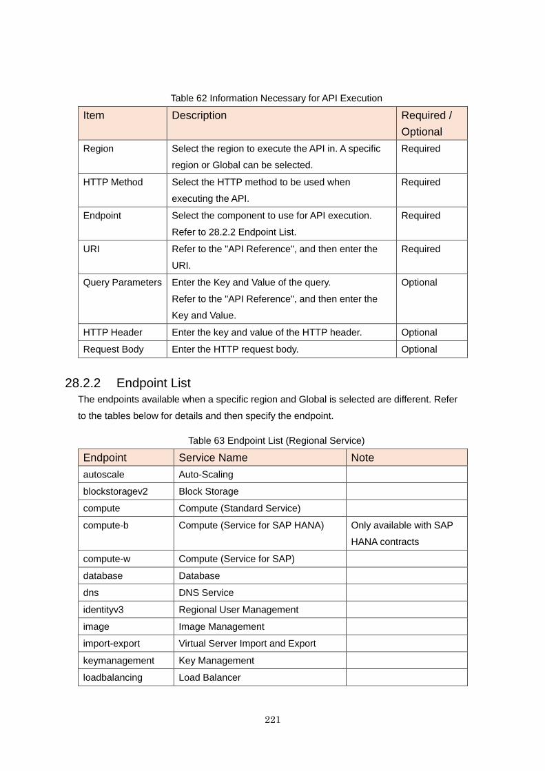
221
Table 62 Information Necessary for API Execution
Item Description Required /
Optional
Region Select the region to execute the API in. A specific
region or Global can be selected.
Required
HTTP Method Select the HTTP method to be used when
executing the API.
Required
Endpoint Select the component to use for API execution.
Refer to 28.2.2 Endpoint List.
Required
URI Refer to the "API Reference", and then enter the
URI.
Required
Query Parameters Enter the Key and Value of the query.
Refer to the "API Reference", and then enter the
Key and Value.
Optional
HTTP Header Enter the key and value of the HTTP header. Optional
Request Body Enter the HTTP request body. Optional
28.2.2 Endpoint List
The endpoints available when a specific region and Global is selected are different. Refer
to the tables below for details and then specify the endpoint.
Table 63 Endpoint List (Regional Service)
Endpoint Service Name Note
autoscale Auto-Scaling
blockstoragev2 Block Storage
compute Compute (Standard Service)
compute-b Compute (Service for SAP HANA) Only available with SAP
HANA contracts
compute-w Compute (Service for SAP)
database Database
dns DNS Service
identityv3 Regional User Management
image Image Management
import-export Virtual Server Import and Export
keymanagement Key Management
loadbalancing Load Balancer
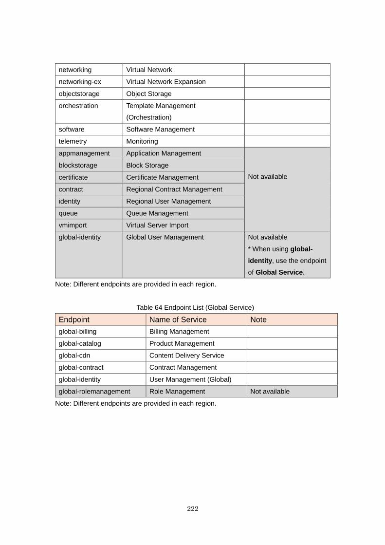
222
networking Virtual Network
networking-ex Virtual Network Expansion
objectstorage Object Storage
orchestration Template Management
(Orchestration)
software Software Management
telemetry Monitoring
appmanagement Application Management
Not available
blockstorage Block Storage
certificate Certificate Management
contract Regional Contract Management
identity Regional User Management
queue Queue Management
vmimport Virtual Server Import
global-identity Global User Management Not available
* When using global-
identity, use the endpoint
of Global Service.
Note: Different endpoints are provided in each region.
Table 64 Endpoint List (Global Service)
Endpoint Name of Service Note
global-billing Billing Management
global-catalog Product Management
global-cdn Content Delivery Service
global-contract Contract Management
global-identity User Management (Global)
global-rolemanagement Role Management Not available
Note: Different endpoints are provided in each region.
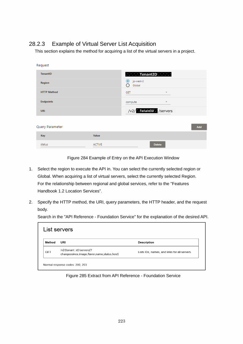
223
28.2.3 Example of Virtual Server List Acquisition
This section explains the method for acquiring a list of the virtual servers in a project.
Figure 284 Example of Entry on the API Execution Window
1. Select the region to execute the API in. You can select the currently selected region or
Global. When acquiring a list of virtual servers, select the currently selected Region.
For the relationship between regional and global services, refer to the "Features
Handbook 1.2 Location Services".
2. Specify the HTTP method, the URI, query parameters, the HTTP header, and the request
body.
Search in the "API Reference - Foundation Service" for the explanation of the desired API.
Figure 285 Extract from API Reference - Foundation Service
TenantID
/v2/ /serversTenantID
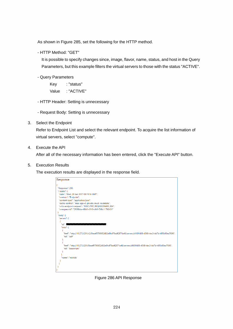
224
As shown in Figure 285, set the following for the HTTP method.
- HTTP Method: "GET"
It is possible to specify changes since, image, flavor, name, status, and host in the Query
Parameters, but this example filters the virtual servers to those with the status "ACTIVE".
- Query Parameters
Key : "status"
Value : "ACTIVE"
- HTTP Header: Setting is unnecessary
- Request Body: Setting is unnecessary
3. Select the Endpoint
Refer to Endpoint List and select the relevant endpoint. To acquire the list information of
virtual servers, select "compute".
4. Execute the API
After all of the necessary information has been entered, click the "Execute API" button.
5. Execution Results
The execution results are displayed in the response field.
Figure 286 API Response
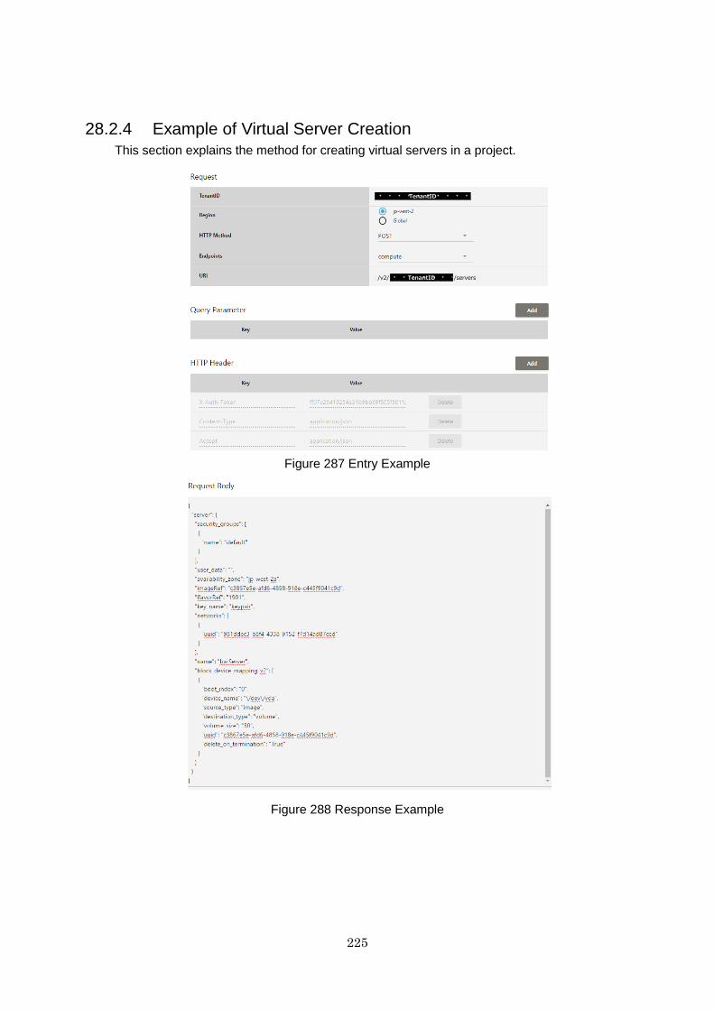
225
28.2.4 Example of Virtual Server Creation
This section explains the method for creating virtual servers in a project.
Figure 287 Entry Example
Figure 288 Response Example
TenantID
/v2/ /serversTenantID
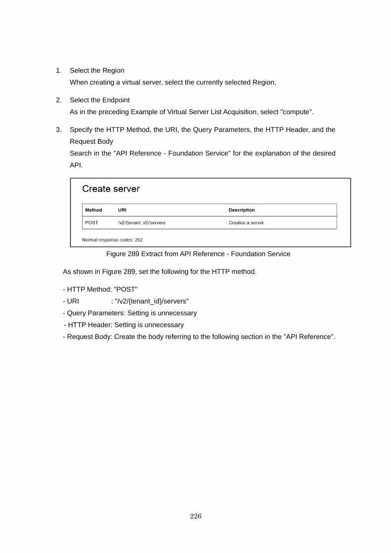
226
1. Select the Region
When creating a virtual server, select the currently selected Region.
2. Select the Endpoint
As in the preceding Example of Virtual Server List Acquisition, select "compute".
3. Specify the HTTP Method, the URI, the Query Parameters, the HTTP Header, and the
Request Body
Search in the "API Reference - Foundation Service" for the explanation of the desired
API.
Figure 289 Extract from API Reference - Foundation Service
As shown in Figure 289, set the following for the HTTP method.
- HTTP Method: "POST"
- URI : "/v2/{tenant_id}/servers"
- Query Parameters: Setting is unnecessary
- HTTP Header: Setting is unnecessary
- Request Body: Create the body referring to the following section in the "API Reference".

227
Figure 290 Extract from API Reference - Foundation Service
Figure 291 Example of Request Body Creation
Remainder
omitted
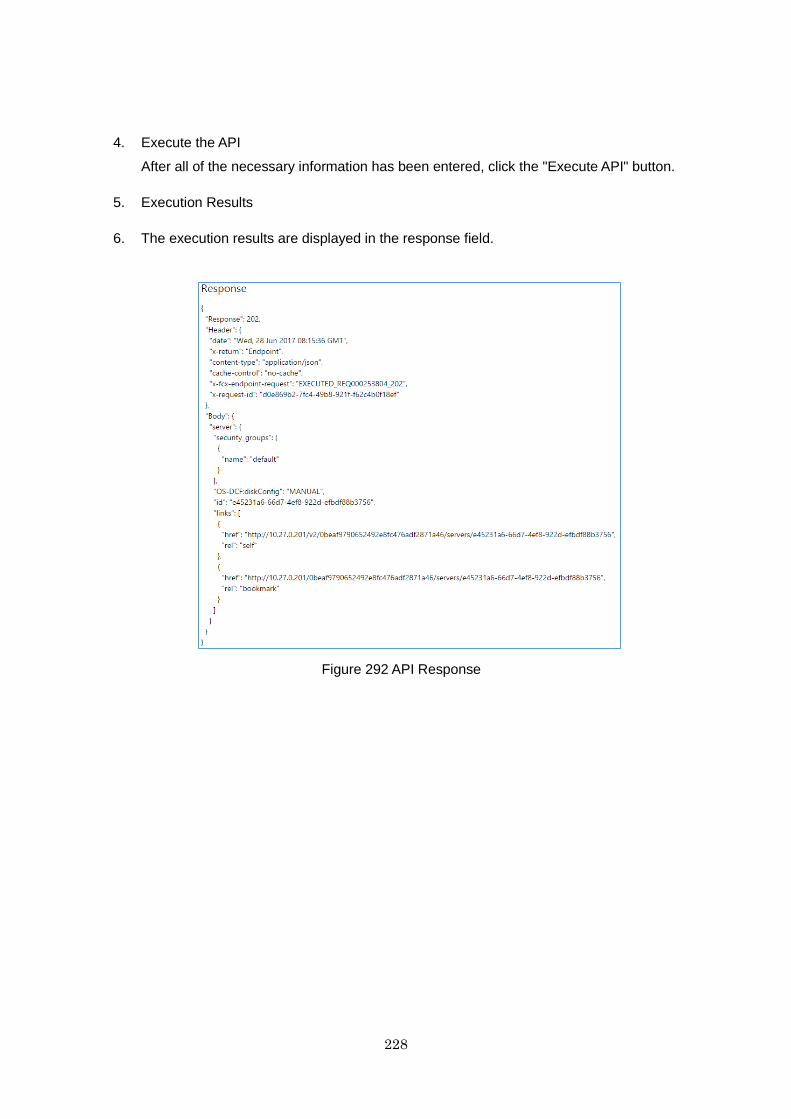
228
4. Execute the API
After all of the necessary information has been entered, click the "Execute API" button.
5. Execution Results
6. The execution results are displayed in the response field.
Figure 292 API Response
229
Chapter 29 VM Import and Export
29.1 Function Overview
This function provides the functions (VM import and export) for importing and
exporting virtual server images (vmdk format) that are stored on object storage
to and from the K5 service. For details on the environment settings necessary for
VM import and export, refer to "Virtual Server Import" and "Virtual Server Export"
in the "IaaS Features Handbook".
The OSs supported by VM import and export are as follows:
VM import and export only support the following OSs:
Windows Server 2008 R2 SE
Windows Server 2008 R2 EE
Windows Server 2012 SE
Windows Server 2012 R2 SE
Red Hat Enterprise Linux 6
Red Hat Enterprise Linux 7
CentOS
Ubuntu
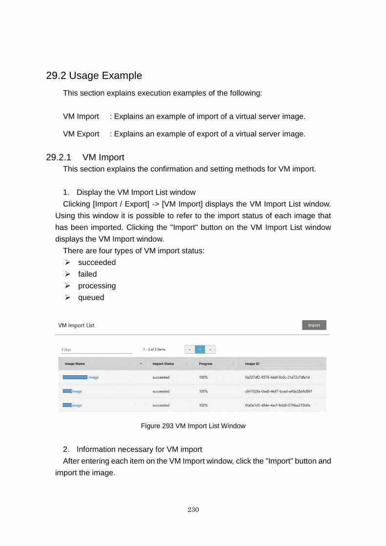
230
29.2 Usage Example
This section explains execution examples of the following:
VM Import : Explains an example of import of a virtual server image.
VM Export : Explains an example of export of a virtual server image.
29.2.1 VM Import
This section explains the confirmation and setting methods for VM import.
1. Display the VM Import List window
Clicking [Import / Export] -> [VM Import] displays the VM Import List window.
Using this window it is possible to refer to the import status of each image that
has been imported. Clicking the "Import" button on the VM Import List window
displays the VM Import window.
There are four types of VM import status:
succeeded
failed
processing
queued
Figure 293 VM Import List Window
2. Information necessary for VM import
After entering each item on the VM Import window, click the "Import" button and
import the image.

231
Figure 294 VM Import Window
The following table indicates the items necessary for VM import.
Table 65 VM Import Window Display Items
No. Item Description Required/
Optional
1 Image Name Enter the image name. Required
2 Container
Name
Select the name of the container to import.
*When there are no containers, transfer to the
Create Container window using the text link, and
then create a container. Refer to 11.2.1 Create a
Container.
Required
3 Object Name Select the name of the object to import.
*When there are no objects, transfer to the
Create Object window using the text link, and
then create an object.
Refer to 11.2.2 Create an Object.
Required
4 OS Type Select the OS type.
* Specify an OS type that matches that of the
OS to be imported.
Required
5 Check Sum
(SHA1)
Enter the value of the check sum. Optional
6 Min Disk Enter the minimum disk value. Optional
7 Min RAM Enter the minimum RAM value. Optional
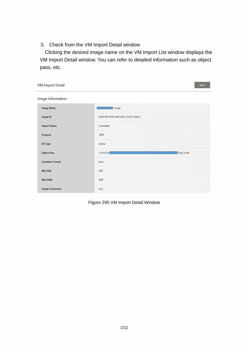
232
3. Check from the VM Import Detail window
Clicking the desired image name on the VM Import List window displays the
VM Import Detail window. You can refer to detailed information such as object
pass, etc.
Figure 295 VM Import Detail Window
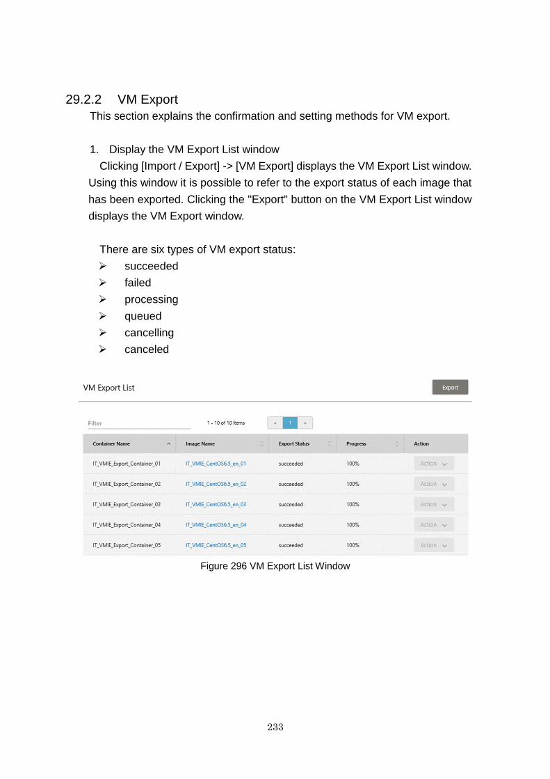
233
29.2.2 VM Export
This section explains the confirmation and setting methods for VM export.
1. Display the VM Export List window
Clicking [Import / Export] -> [VM Export] displays the VM Export List window.
Using this window it is possible to refer to the export status of each image that
has been exported. Clicking the "Export" button on the VM Export List window
displays the VM Export window.
There are six types of VM export status:
succeeded
failed
processing
queued
cancelling
canceled
Figure 296 VM Export List Window
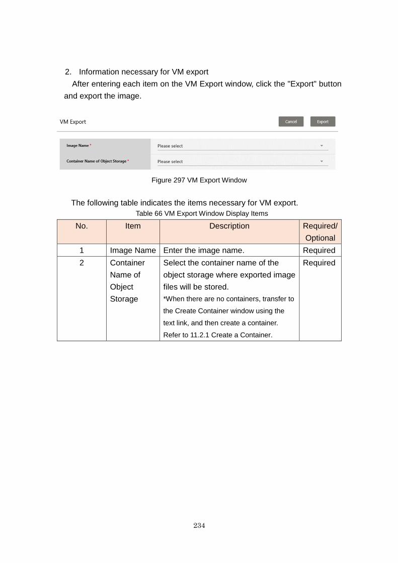
234
2. Information necessary for VM export
After entering each item on the VM Export window, click the "Export" button
and export the image.
Figure 297 VM Export Window
The following table indicates the items necessary for VM export.
Table 66 VM Export Window Display Items
No. Item Description Required/
Optional
1 Image Name Enter the image name. Required
2 Container
Name of
Object
Storage
Select the container name of the
object storage where exported image
files will be stored.
*When there are no containers, transfer to
the Create Container window using the
text link, and then create a container.
Refer to 11.2.1 Create a Container.
Required
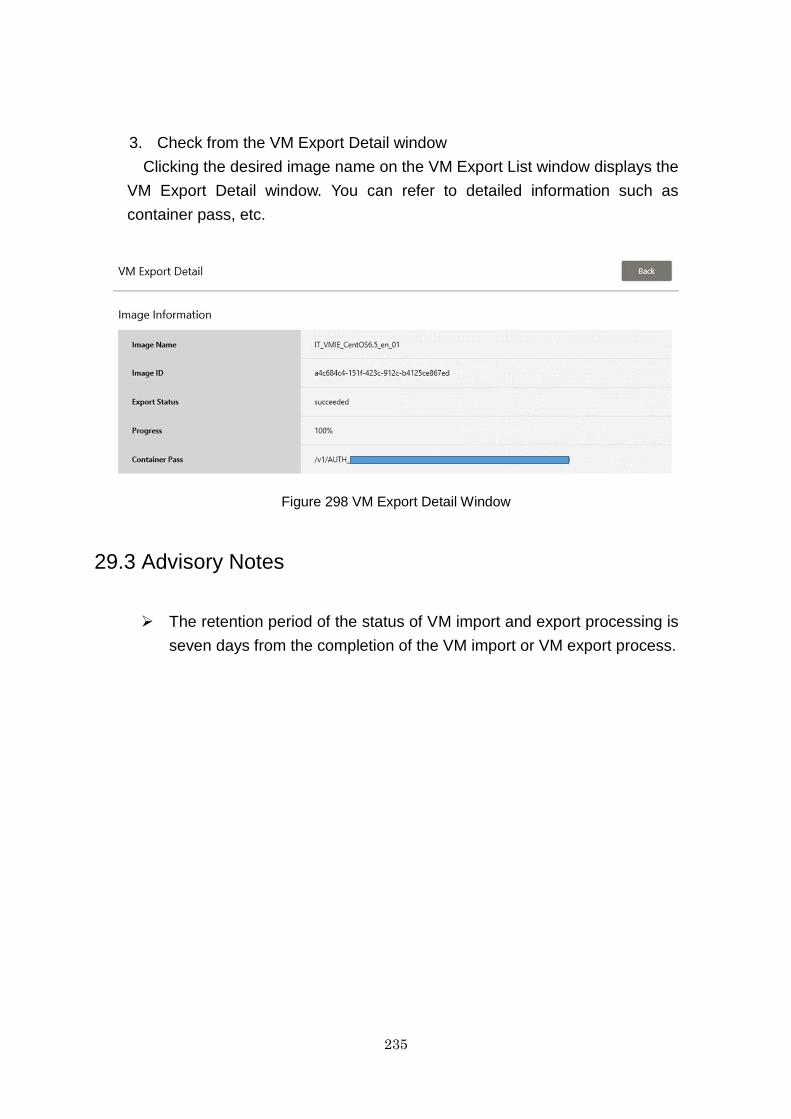
235
3. Check from the VM Export Detail window
Clicking the desired image name on the VM Export List window displays the
VM Export Detail window. You can refer to detailed information such as
container pass, etc.
Figure 298 VM Export Detail Window
29.3 Advisory Notes
The retention period of the status of VM import and export processing is
seven days from the completion of the VM import or VM export process.
236
FUJITSU Cloud Service K5
IaaS Service Portal User Guide
All Rights Reserved, Copyright FUJITSU LIMITED
- The content of this manual is subject to change without any prior notice.
- No part of this manual may be reproduced in any form whatsoever without the
written permission of FUJITSU LIMITED.