Embed Size (px)
Citation preview

C o p y r i g h t
Fujitsu LifeBook®
N3430 Notebook
User’s Guide
N3430-02.book Page 1 Tuesday, May 16, 2006 10:48 AM

C o p y r i g h t
N3430-02.book Page 2 Tuesday, May 16, 2006 10:48 AM
C o p y r i g h t
Copyright and Trademark Information
Fujitsu Computer Systems Corporation has made every effort to ensure the accuracy and completeness of this document. However, as ongoing development efforts are continually improving the capabilities of our products, we cannot guarantee the accuracy of the contents of this document. We disclaim liability for errors, omissions, or future changes. The absence of a product or service name, slogan, or logo does not constitute a waiver of any trademark or other intellectual property rights relating to that name, slogan, or logo owned by Fujitsu Computer Systems Corporation, its parent, subsidiaries, and affiliated companies.
Fujitsu, the Fujitsu logo, and LifeBook are registered trade-marks of Fujitsu Limited.
MS, MS-DOS, and Windows are either registered trademarks or trademarks of Microsoft Corporation in the United States and/or other countries.
HyperMemory™ is a trademark of ATI Technologies, Inc.
The ExpressCard word mark and logo are owned by the Personal Computer Memory Card International Association (PCMCIA) and any use of such marks by Fujitsu Computer Systems Corporation is under license.
PCMCIA is a trademark of the Personal Computer Memory Card International Association.
Roxio is a trademark of Roxio, a division of Sonic Solutions.
Intel, Centrino, and Pentium are trademarks or registered trademarks of Intel Corporation or its subsidiaries in the United States and other countries.
Adobe, Acrobat, and Acrobat Reader are either registered trade-marks or trademarks of Adobe Systems Incorporated in the United States and/or other countries.
Google is a trademark of Google, Incorporated.
Dolby Headphone is manufactured under license from Dolby Laboratories. Dolby, Pro Logic, and the double-D symbol are trademarks of Dolby Laboratories.
Quicken® is a registered trademark of Intuit, Inc., or one of its subsidiaries, in the United States and other countries.
PowerProducer, PowerDVD, MakeDVD, and PowerDirector are trademarks of CyberLink Corp.
Norton Internet Security is a trademark of Symantec Corpora-tion in the United States and other countries.
All other trademarks mentioned herein are the property of their respective owners.
This product incorporates copyright protection technology that is protected by method claims of certain U.S. patents and other intellectual property rights owned by Macrovision Corporation and other rights owners. Use of this copyright protection tech-nology must be authorized by Macrovision Corporation, and is intended for home and other limited viewing uses only unless otherwise authorized by Macrovision Corporation. Reverse engineering or disassembly is prohibited.
© Copyright 2006 Fujitsu Computer Systems Corporation. All rights reserved. No part of this publication may be copied, reproduced, translated, stored or transmitted in any electronic form without the written consent of Fujitsu Computer Systems Corporation.
B6FH-9991-01EN-00
Warning
Handling the cord on this product will expose you to lead, a chemical known to the State of California to cause birth defects or other reproductive harm.
Wash hands after handling.
DECLARATION OF CONFORMITYaccording to FCC Part 15
Responsible Party Name: Fujitsu Computer Systems Corporation
Address: 1250 E. Arques Avenue, M/S 122Sunnyvale, CA 94085
Telephone: (408) 746-6000
Declares that product: Model Configurations: LifeBook N3430 notebook comply with Part 15 of the FCC Rules.
This device complies with Part 15 of the FCC rules. Operations are subject to the following two conditions:(1) This device may not cause harmful interference, (2) This device must accept any interference received, including interference that may cause undesired operation.
N3430-02.book Page 3 Tuesday, May 16, 2006 10:48 AM

L i f e B o o k N 3 4 0 0 S e r i e s N o t e b o o k
IMPORTANT SAFETY INSTRUCTIONS
■ This product requires an AC adapter to operate. Use only a UL Listed I.T.E. AC Adapter with an output rat-ing of 19V DC, and a current of 3.37A.
■ AC adapter output polarity:
■ When using your notebook equipment, basic safety precautions should always be followed to reduce the risk of fire, electric shock and injury to persons, including the following:
■ Do not use this product near water for example, near a bathtub, washbowl, kitchen sink or laundry tub, in a wet basement or near a swimming pool.
■ Avoid using the modem during an electrical storm. There may be a remote risk of electric shock from lightning.
■ Do not use the modem to report a gas leak in the vicinity of the leak.
■ Use only the power cord and batteries indicated in this manual. Do not dispose of batteries in a fire. They may explode. Check with local codes for possible special disposal instructions.
■ To reduce the risk of fire, use only No. 26 AWG or larger UL Listed or CSA Certified Telecommunication Line Cord
■ For TV tuner use: To protect from overvoltages and transients on the Cable Distribution System, make sure that the outer shield of the coaxial cable is con-nected to earth (grounded) at the building premise as close to the point of cable entrance as practicable, as required per NEC Article 820.93, ANSI/NFPA 70: 2005. If you have questions about your CATV installa-tion, contact your service provider.
SAVE THESE INSTRUCTIONS
For Authorized Repair Technicians Only
System Disposal
+
Danger of explosion if Lithium (clock) bat-tery is incorrectly replaced. Replace only with the same or equivalent type recom-mended by the manufacturer. Dispose of used batteries according to the manufac-turer’s instruction.
For continued protection against risk of fire, replace only with the same type and rating fuse.
Hg LAMP(S) INSIDE THIS PRODUCT CONTAIN MERCURY AND MUST BE RECYCLED OR DISPOSED OF ACCORDING TO LOCAL, STATE, ORFEDERAL LAWS.
N3430-02.book Page 4 Tuesday, May 16, 2006 10:48 AM

T a b l e o f C o n t e n t s
Fujitsu LifeBook® N3430 notebook
Table of Contents
1PREFACE
PrefaceAbout This Guide . . . . . . . . . . . . . . . . . . . . . . . . . 3Fujitsu Contact Information . . . . . . . . . . . . . . . . . 3Warranty . . . . . . . . . . . . . . . . . . . . . . . . . . . . . . . 3
2GETTING TO KNOWYOUR LIFEBOOK NOTEBOOK
OverviewUnpacking . . . . . . . . . . . . . . . . . . . . . . . . . . . . . . 7
Locating the Controls/ConnectorsTop and Front Components . . . . . . . . . . . . . . . . . 8Left-Side Panel Components . . . . . . . . . . . . . . . . 9Right-Side Panel Components . . . . . . . . . . . . . . 10Back/Top Panel Components . . . . . . . . . . . . . . . 11Bottom Components . . . . . . . . . . . . . . . . . . . . . 12
Status Indicator PanelBattery Charging Indicator . . . . . . . . . . . . . . . . . 13Battery Level Indicator . . . . . . . . . . . . . . . . . . . . 13Hard Disk/CD Access Indicator. . . . . . . . . . . . . . 13EMail Notification Indicator . . . . . . . . . . . . . . . . 13NumLk Indicator . . . . . . . . . . . . . . . . . . . . . . . . 13CapsLock Indicator. . . . . . . . . . . . . . . . . . . . . . . 14ScrLk Indicator . . . . . . . . . . . . . . . . . . . . . . . . . . 14
KeyboardUsing the Keyboard . . . . . . . . . . . . . . . . . . . . . . 15Numeric Keypad. . . . . . . . . . . . . . . . . . . . . . . . . 15Windows Keys . . . . . . . . . . . . . . . . . . . . . . . . . . 15Cursor Keys . . . . . . . . . . . . . . . . . . . . . . . . . . . . 15Function Keys. . . . . . . . . . . . . . . . . . . . . . . . . . . 15
Volume ControlControlling the Volume . . . . . . . . . . . . . . . . . . . 17
Application/Media Player PanelMode Button . . . . . . . . . . . . . . . . . . . . . . . . . . . 18Application Launch/Media Player Buttons . . . . . 18Configuring the Application Panel . . . . . . . . . . . 18Using the Media Player . . . . . . . . . . . . . . . . . . . 19Desktop Control Panel . . . . . . . . . . . . . . . . . . . . 20
Touchpad Pointing DeviceClicking . . . . . . . . . . . . . . . . . . . . . . . . . . . . . . . 21Double-Clicking . . . . . . . . . . . . . . . . . . . . . . . . . 21Dragging . . . . . . . . . . . . . . . . . . . . . . . . . . . . . . 22Scrolling. . . . . . . . . . . . . . . . . . . . . . . . . . . . . . . 22Touchpad Control Adjustment . . . . . . . . . . . . . . 22
3GETTING STARTED
Power SourcesConnecting the Power Adapters . . . . . . . . . . . . 25
Display PanelOpening the Display Panel. . . . . . . . . . . . . . . . . 26Adjusting Display Panel Brightness. . . . . . . . . . . 26Closing the Display Panel . . . . . . . . . . . . . . . . . . 26
Starting Your LifeBookPower On . . . . . . . . . . . . . . . . . . . . . . . . . . . . . 27BIOS Setup Utility . . . . . . . . . . . . . . . . . . . . . . . 27Booting the System the First time. . . . . . . . . . . . 28Getting Started . . . . . . . . . . . . . . . . . . . . . . . . . 28Windows Product Activation . . . . . . . . . . . . . . . 28Registering Your LifeBook notebook . . . . . . . . . 28Installing Click Me! and FDU . . . . . . . . . . . . . . 28
Power ManagementPower/Suspend/Resume Button . . . . . . . . . . . . 29Suspend Mode. . . . . . . . . . . . . . . . . . . . . . . . . . 29Hibernation (Save-to-Disk) Feature . . . . . . . . . . 29Display Timeout. . . . . . . . . . . . . . . . . . . . . . . . . 30Hard Disk Timeout. . . . . . . . . . . . . . . . . . . . . . . 30Windows Power Management. . . . . . . . . . . . . . 30Restarting the System . . . . . . . . . . . . . . . . . . . . 30Power Off . . . . . . . . . . . . . . . . . . . . . . . . . . . . . 30
N3430-02.book Page 1 Tuesday, May 16, 2006 10:48 AM
L i f e B o o k N 3 4 0 0 S e r i e s N o t e b o o k
4USER-INSTALLABLE DEVICES AND MEDIA
Lithium ion BatteryRecharging the Batteries. . . . . . . . . . . . . . . . . . . 33Replacing the Battery . . . . . . . . . . . . . . . . . . . . . 34
Optical DriveLoading Media on Your Drive . . . . . . . . . . . . . . 35Removing Media . . . . . . . . . . . . . . . . . . . . . . . . 36Using the Media Player Software . . . . . . . . . . . . 36Using Dolby™ Headphone. . . . . . . . . . . . . . . . . 37Using Optical Drive on Battery Power . . . . . . . . 37
Memory Stick/SD/xD Card SlotInserting Memory Stick/SD/xD Cards. . . . . . . . . 38Removing A Memory Stick/SD/XD Card . . . . . . 39
Memory Upgrade ModuleInstalling a Memory Module . . . . . . . . . . . . . . . 40Removing a Memory Upgrade Module . . . . . . . 41Checking the Memory Capacity . . . . . . . . . . . . . 41
PC Cards/ExpressCards™Inserting/Removing PC Cards . . . . . . . . . . . . . . 42Inserting/Removing ExpressCards . . . . . . . . . . . 43
Device PortsModem (RJ-11) Telephone Port . . . . . . . . . . . . . 44Internal LAN (RJ-45) Port . . . . . . . . . . . . . . . . . . 44IEEE 1394 Port . . . . . . . . . . . . . . . . . . . . . . . . . . 44Universal Serial Bus Ports . . . . . . . . . . . . . . . . . . 45Microphone Jack . . . . . . . . . . . . . . . . . . . . . . . . 45Headphone/SPDIF Jack . . . . . . . . . . . . . . . . . . . 45S-Video Out Port . . . . . . . . . . . . . . . . . . . . . . . . 45External Video Port . . . . . . . . . . . . . . . . . . . . . . 45
5USING THE INTEGRATED WIRELESS LAN
Before Using the Wireless LANWireless LAN Modes Using this Device . . . . . . . 50Deactivating the WLAN Device . . . . . . . . . . . . . 51Activating the WLAN Device . . . . . . . . . . . . . . . 51
Configuration of the WLAN DeviceFlow of Operations . . . . . . . . . . . . . . . . . . . . . . 52Configuration Using Intel PROSet Utility . . . . . . 52Connection to the Network . . . . . . . . . . . . . . . . 53
Troubleshooting the WLANTroubleshooting. . . . . . . . . . . . . . . . . . . . . . . . . 56
Wireless LAN GlossaryGlossary. . . . . . . . . . . . . . . . . . . . . . . . . . . . . . . 57
IP address informationAbout IP Addresses . . . . . . . . . . . . . . . . . . . . . . 59
WLAN SpecificationsSpecifications . . . . . . . . . . . . . . . . . . . . . . . . . . . 60
6TROUBLESHOOTING
TroubleshootingIdentifying the Problem . . . . . . . . . . . . . . . . . . . 63Specific Problems . . . . . . . . . . . . . . . . . . . . . . . . 63Troubleshooting Table . . . . . . . . . . . . . . . . . . . . 64Power On Self Test Messages . . . . . . . . . . . . . . 71Emergency Optical Drive Tray Release . . . . . . . . 72Modem Result Codes. . . . . . . . . . . . . . . . . . . . . 72Restoring Pre-installed Software . . . . . . . . . . . . 73Restoring the Factory Image . . . . . . . . . . . . . . . 73Automatically Downloading Driver Updates. . . . . . . . . . . . . . . . . . . . . . . . . . 74
7CARING FOR YOUR LIFEBOOK NOTEBOOK
Care and MaintenanceCaring for your LifeBook Notebook . . . . . . . . . . 77Batteries. . . . . . . . . . . . . . . . . . . . . . . . . . . . . . . 78Media Care . . . . . . . . . . . . . . . . . . . . . . . . . . . . 78Media Cards . . . . . . . . . . . . . . . . . . . . . . . . . . . 79
N3430-02.book Page 2 Tuesday, May 16, 2006 10:48 AM
T a b l e o f C o n t e n t s
8SYSTEM SPECIFICATIONS
SpecificationsConfiguration Label . . . . . . . . . . . . . . . . . . . . . . 83Microprocessor. . . . . . . . . . . . . . . . . . . . . . . . . . 83Memory. . . . . . . . . . . . . . . . . . . . . . . . . . . . . . . 83Chipset . . . . . . . . . . . . . . . . . . . . . . . . . . . . . . . 83Video . . . . . . . . . . . . . . . . . . . . . . . . . . . . . . . . . 83Integrated Pointing Device . . . . . . . . . . . . . . . . . 83Audio. . . . . . . . . . . . . . . . . . . . . . . . . . . . . . . . . 83Mass Storage Device Options. . . . . . . . . . . . . . . 83Communications . . . . . . . . . . . . . . . . . . . . . . . . 84LifeBook Application Panel . . . . . . . . . . . . . . . . . 84Theft Prevention Lock Slot . . . . . . . . . . . . . . . . . 84Device Ports . . . . . . . . . . . . . . . . . . . . . . . . . . . . 84Keyboard . . . . . . . . . . . . . . . . . . . . . . . . . . . . . . 84Power . . . . . . . . . . . . . . . . . . . . . . . . . . . . . . . . 84Dimensions and Weight . . . . . . . . . . . . . . . . . . . 84Environmental Requirements . . . . . . . . . . . . . . . 84Pre-Installed Software . . . . . . . . . . . . . . . . . . . . 85Regulatory Information . . . . . . . . . . . . . . . . . . . 87
9GLOSSARYGlossary . . . . . . . . . . . . . . . . . . . . . . . . . . . . . . . 91
INDEXIndex . . . . . . . . . . . . . . . . . . . . . . . . . . . . . . . . . 97
N3430-02.book Page 3 Tuesday, May 16, 2006 10:48 AM

L i f e B o o k N 3 4 0 0 S e r i e s N o t e b o o k
N3430-02.book Page 4 Tuesday, May 16, 2006 10:48 AM

1
1Preface
N3430-02.book Page 1 Tuesday, May 16, 2006 10:48 AM

2
L i f e B o o k N 3 4 0 0 S e r i e s N o t e b o o k
N3430-02.book Page 2 Tuesday, May 16, 2006 10:48 AM
3
P r e f a c e
Preface
ABOUT THIS GUIDEThe LifeBook® N3400 notebook from Fujitsu features the Intel® Core™ Duo processor and an integrated Intel GMA950 graphics chipset with up to 224 MB of shared memory. This combination delivers the resources to tackle photo editing, computer gaming, and general business applications. A large and bright 15.4-inch Color-Enhanced Crystal View Wide XGA display adds to the computing experience, bringing applications to life wherever you are, and allowing you to watch movies with brilliant colors and true wide screen aspect.
This manual explains how to operate your LifeBook notebook’s hardware and built-in system software.
Your LifeBook notebook comes with Microsoft® Windows® XP Home, Microsoft® Windows® XP Profes-sional, or Microsoft® Windows® XP Media Center Edition 2005 pre-installed.
Conventions Used in the GuideKeyboard keys appear in brackets. Example: [Fn], [F1], [ESC], [ENTER] and [CTRL].
Pages with additional information about a specific topic are cross-referenced within the text. Example: (See page xx.)
On screen buttons or menu items appear in boldExample: Click OK to restart your notebook computer.
FUJITSU CONTACT INFORMATIONService and SupportYou can contact Fujitsu Service and Support in the following ways:
■ Toll free: 1-800-8Fujitsu (1-800-838-5487)■ Fax: 408-764-2724 ■ E-mail: [email protected]/computers ■ Web site:
http://www.computers.us.fujitsu.com/support
Before you place the call, you should have the following information ready so that the customer support representative can provide you with the fastest possible solution:
■ Product name■ Product configuration number■ Product serial number■ Purchase date■ Conditions under which the problem occurred■ Any error messages that have occurred■ Hardware configuration■ Type of device connected, if any
Fujitsu OnlineYou can go directly to the online Fujitsu product catalog for your LifeBook notebook by clicking on the Fujitsu Weblinks -> LifeBook Accessories web site link, located in the Windows Start menu.
You can also reach Fujitsu Service and Support on-line by clicking on the Fujitsu Weblinks -> Service and Support Web site link, located in the Service and Support Software folder of the Windows Start menu.
WARRANTYYour LifeBook notebook is backed by an International Limited Warranty. Check the service kit that came with your LifeBook notebook for warranty terms and condi-tions.
The information icon highlights information that will enhance your understanding of the subject material.
The caution icon highlights information that is important to the safe operation of your computer, or to the integrity of your files. Please read all caution information carefully.
The warning icon highlights information that can be hazardous to either you, your LifeBook notebook, or your files. Please read all warning information carefully.
You must have an active internet connec-tion to use the online URL links.
N3430-02.book Page 3 Tuesday, May 16, 2006 10:48 AM

4
L i f e B o o k N 3 4 0 0 S e r i e s N o t e b o o k – S e c t i o n O n e
N3430-02.book Page 4 Tuesday, May 16, 2006 10:48 AM

5
2Getting to KnowYour Computer
N3430-02.book Page 5 Tuesday, May 16, 2006 10:48 AM

6
L i f e B o o k N 3 4 0 0 S e r i e s N o t e b o o k – S e c t i o n T w o
N3430-02.book Page 6 Tuesday, May 16, 2006 10:48 AM

7
O v e r v i e w
Figure 2-1. LifeBook N3400 series notebook
OverviewThis section describes the components of your LifeBook notebook. We strongly recommend that you read it before using your notebook – even if you are already familiar with notebook computers.
UNPACKINGWhen you receive your LifeBook notebook, unpack it carefully, and compare the parts you have received with the items listed below.
For a pre-configured model you should have:
■ LifeBook N3400 series notebook (Figure 2-1)
■ Lithium ion battery, pre-installed
■ AC adapter with AC power cord (Figure 2-2)
■ Phone/Modem (RJ-11) telephone cable
■ Drivers and Applications CD
■ System Recovery and Utility Disc
■ Getting Started Guide
■ User’s Guide (this document)
■ International Limited Warranty Brochure
Depending upon the configuration of your notebook, you may have also received one of the following items:
■ Application CDs for third-party software
■ Additional battery
■ Remote control package, including remote control, infrared remote control receiver, and infrared control cable
Once you have checked and confirmed that your Life-Book notebook is complete, read through the following pages to learn about all of your notebook’s components.
Figure 2-2. Typical AC Adapter
Detailed specifications about your LifeBook notebook can be found in the chapter entitled “Specifications” on page 83.
N3430-02.book Page 7 Tuesday, May 16, 2006 10:48 AM
8
L i f e B o o k N 3 4 0 0 S e r i e s N o t e b o o k – S e c t i o n T w o
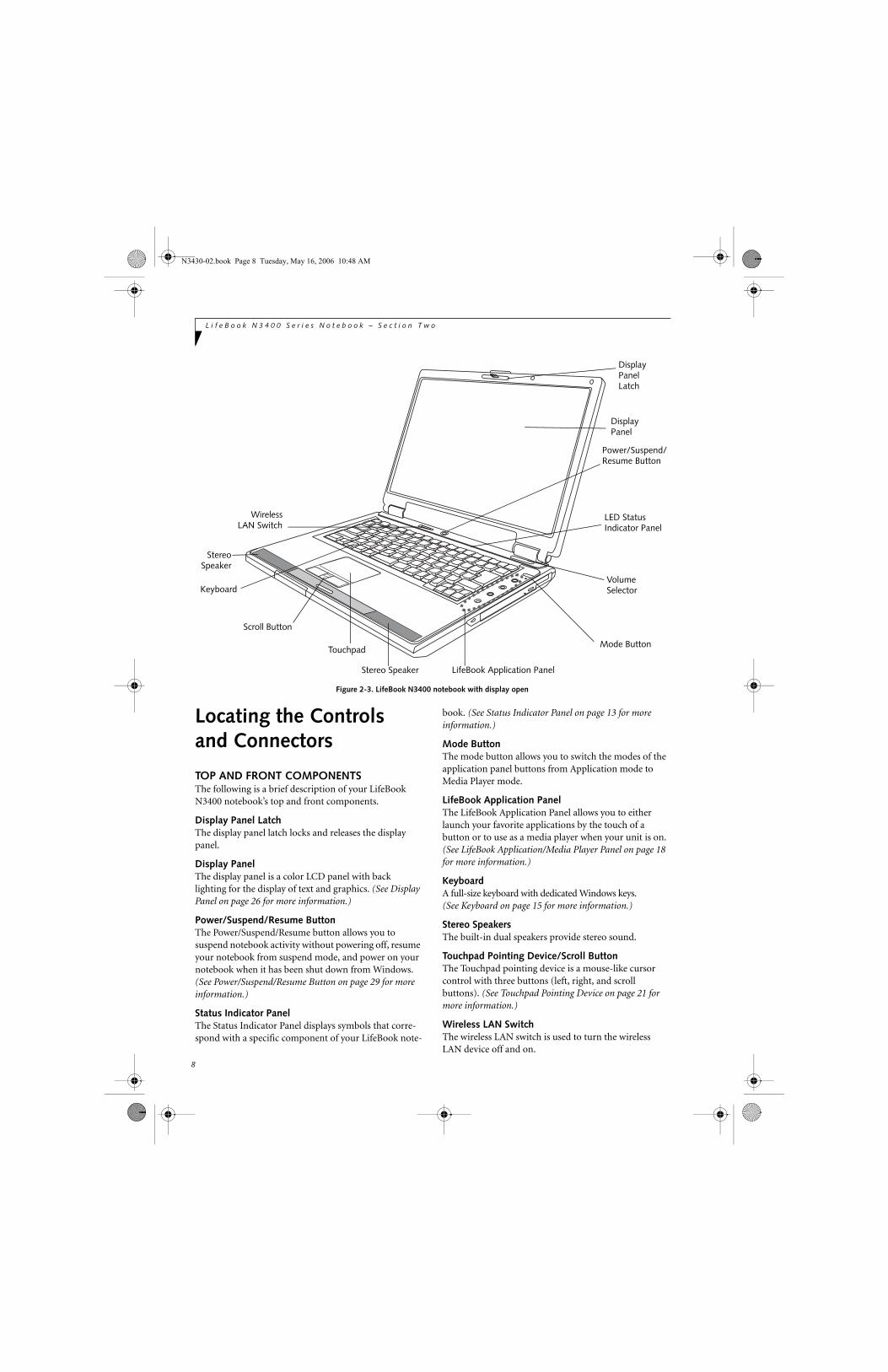
Figure 2-3. LifeBook N3400 notebook with display open
Locating the Controlsand Connectors
TOP AND FRONT COMPONENTSThe following is a brief description of your LifeBook N3400 notebook’s top and front components.
Display Panel LatchThe display panel latch locks and releases the display panel.
Display PanelThe display panel is a color LCD panel with back lighting for the display of text and graphics. (See Display Panel on page 26 for more information.)
Power/Suspend/Resume ButtonThe Power/Suspend/Resume button allows you to suspend notebook activity without powering off, resume your notebook from suspend mode, and power on your notebook when it has been shut down from Windows. (See Power/Suspend/Resume Button on page 29 for more information.)
Status Indicator PanelThe Status Indicator Panel displays symbols that corre-spond with a specific component of your LifeBook note-
book. (See Status Indicator Panel on page 13 for more information.)
Mode ButtonThe mode button allows you to switch the modes of the application panel buttons from Application mode to Media Player mode.
LifeBook Application PanelThe LifeBook Application Panel allows you to either launch your favorite applications by the touch of a button or to use as a media player when your unit is on. (See LifeBook Application/Media Player Panel on page 18 for more information.)
KeyboardA full-size keyboard with dedicated Windows keys. (See Keyboard on page 15 for more information.)
Stereo SpeakersThe built-in dual speakers provide stereo sound.
Touchpad Pointing Device/Scroll ButtonThe Touchpad pointing device is a mouse-like cursor control with three buttons (left, right, and scroll buttons). (See Touchpad Pointing Device on page 21 for more information.)
Wireless LAN SwitchThe wireless LAN switch is used to turn the wireless LAN device off and on.
DisplayPanelLatch
Display
Keyboard
LED Status
Touchpad
Scroll Button
Panel
Stereo Speaker
Indicator Panel
Power/Suspend/Resume Button
WirelessLAN Switch
Stereo
Mode Button
LifeBook Application Panel
VolumeSelector
Speaker
N3430-02.book Page 8 Tuesday, May 16, 2006 10:48 AM

9
L o c a t i n g t h e C o n t r o l s a n d C o n n e c t o r s
Figure 2-4. LifeBook N3400 notebook left-side panel
LEFT-SIDE PANEL COMPONENTSThe following is a brief description of your LifeBook N3400 notebook’s left-side components.
Microphone JackThe microphone jack allows you to connect an external mono microphone. (See Microphone Jack on page 45 for more information.)
Headphone/SPDIF JackThe headphone/SPDIF audio jack allows you to connect headphones or SPDIF devices, such as MiniDisc recorders. (See Headphone/SPDIF Jack on page 45 for more information.)
ExpressCardTM SlotThe ExpressCard Slot allows you to insert an Express-Card. (See PC Cards/ExpressCards™ on page 42 for more information.)
PC Card SlotThe PC Card Slot allows you to insert a Type I or Type II PC Card. (See PC Cards/ExpressCards™ on page 42 for more information.)
USB 2.0 PortThe USB port allows you to connect Universal Serial Bus 2.0 or USB 1.1 devices. Note that there are three addi-tional USB 2.0 ports on the rear of the system. (See Universal Serial Bus Ports on page 45 for more informa-tion.)
Memory Stick/SD/xD Card SlotThe Memory Stick/SD/xD-Picture Card slot allows you to insert a flash memory card for data storage. This archi-tecture allows you to transfer data from a variety of different digital devices. (See Inserting Memory Stick/SD/xD Cards on page 38 for more information.)
IEEE 1394 (4-pin) PortThe 1394 port is used to connect between your LifeBook notebook and a peripheral such as a digital video camera.(See IEEE 1394 Port on page 44 for more informa-tion.)
PC Card SlotUSB Port
Headphone/SPDIF Jack
1394 Jack
Memory Stick/SD/xD Card Slot Eject Buttons
ExpressCardTM SlotMicrophone Jack
N3430-02.book Page 9 Tuesday, May 16, 2006 10:48 AM
10
L i f e B o o k N 3 4 0 0 S e r i e s N o t e b o o k – S e c t i o n T w o
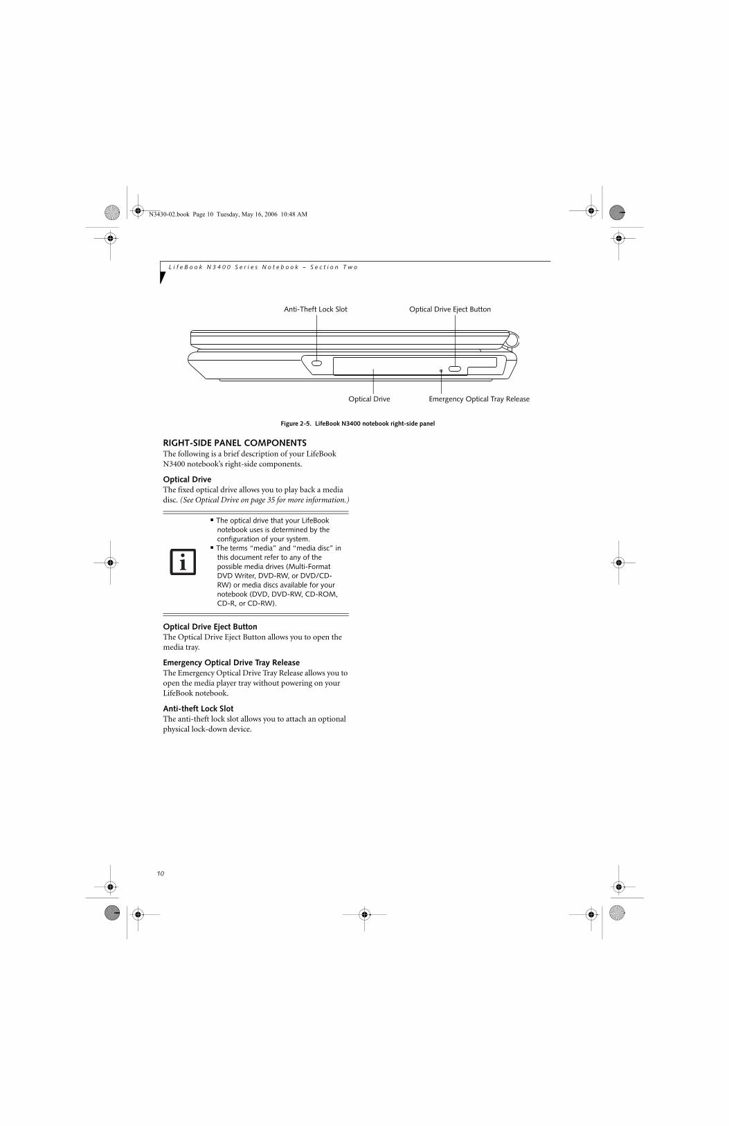
Figure 2-5. LifeBook N3400 notebook right-side panel
RIGHT-SIDE PANEL COMPONENTSThe following is a brief description of your LifeBook N3400 notebook’s right-side components.
Optical DriveThe fixed optical drive allows you to play back a media disc. (See Optical Drive on page 35 for more information.)
Optical Drive Eject ButtonThe Optical Drive Eject Button allows you to open the media tray.
Emergency Optical Drive Tray ReleaseThe Emergency Optical Drive Tray Release allows you to open the media player tray without powering on your LifeBook notebook.
Anti-theft Lock SlotThe anti-theft lock slot allows you to attach an optional physical lock-down device.
Anti-Theft Lock Slot
Optical Drive
Optical Drive Eject Button
Emergency Optical Tray Release
■ The optical drive that your LifeBook notebook uses is determined by the configuration of your system.
■ The terms “media” and “media disc” in this document refer to any of the possible media drives (Multi-Format DVD Writer, DVD-RW, or DVD/CD-RW) or media discs available for your notebook (DVD, DVD-RW, CD-ROM, CD-R, or CD-RW).
N3430-02.book Page 10 Tuesday, May 16, 2006 10:48 AM
11
L o c a t i n g t h e C o n t r o l s a n d C o n n e c t o r s
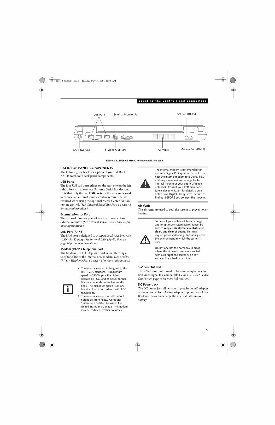
Figure 2-6. LifeBook N3400 notebook back/top panel
BACK/TOP PANEL COMPONENTSThe following is a brief description of your LifeBook N3400 notebook’s back panel components.
USB PortsThe four USB 2.0 ports (three on the rear, one on the left side) allow you to connect Universal Serial Bus devices. Note that only the two USB ports on the left can be used to connect an infrared remote control receiver that is required when using the optional Media Center Edition remote control. (See Universal Serial Bus Ports on page 45 for more information.)
External Monitor PortThe external monitor port allows you to connect an external monitor. (See External Video Port on page 45 for more information.)
LAN Port (RJ-45)The LAN port is designed to accept a Local Area Network (LAN) RJ-45 plug. (See Internal LAN (RJ-45) Port on page 44 for more information.)
Modem (RJ-11) Telephone PortThe Modem (RJ-11) telephone port is for attaching a telephone line to the internal 56K modem. (See Modem (RJ-11) Telephone Port on page 44 for more information.)
Air VentsThe air vents are used to cool the system to prevent over-heating.
S-Video Out Port The S-Video output is used to transmit a higher resolu-tion video signal to a compatible TV or VCR.(See S-Video Out Port on page 45 for more information.)
DC Power JackThe DC power jack allows you to plug in the AC adapter or the optional Auto/Airline adapter to power your Life-Book notebook and charge the internal Lithium ion battery.
IR REMOTE
LAN Port (RJ-45)USB Ports External Monitor Port
S-Video Out Port Modem Port (RJ-11)DC Power Jack Air Vents
■ The internal modem is designed to the ITU-T V.90 standard. Its maximum speed of 53000bps is the highest allowed by FCC, and its actual connec-tion rate depends on the line condi-tions. The maximum speed is 33600 bps at upload in accordance with FCC regulations.
■ The internal modems on all LifeBook notebooks from Fujitsu Computer Systems are certified for use in the United States and Canada. The modem may be certified in other countries.
The internal modem is not intended for use with Digital PBX systems. Do not con-nect the internal modem to a Digital PBX as it may cause serious damage to the internal modem or your entire LifeBook notebook. Consult your PBX manufac-turer’s documentation for details. Some hotels have Digital PBX systems. Be sure to find out BEFORE you connect the modem.
To protect your notebook from damage and to optimize system performance, be sure to keep all air all vents unobstructed, clean, and clear of debris. This may require periodic cleaning, depending upon the environment in which the system is used.
Do not operate the notebook in areas where the air vents can be obstructed, such as in tight enclosures or on soft surfaces like a bed or cushion.
N3430-02.book Page 11 Tuesday, May 16, 2006 10:48 AM

12
L i f e B o o k N 3 4 0 0 S e r i e s N o t e b o o k – S e c t i o n T w o
Figure 2-7. LifeBook N3400 notebook bottom panel
BOTTOM COMPONENTSThe following is a brief description of your LifeBook N3400 notebook’s bottom panel components.
Main Unit and Configuration LabelThe configuration label shows the model number and other information about your LifeBook notebook. In addition, the configuration portion of the label has the serial number and manufacturer information that you will need to give your support representative. It identi-fies the exact version of various components of your LifeBook notebook. (See Configuration Label on page 83 for more information.)
Lithium ion Battery BayThe battery bay contains the internal Lithium ion battery. It can be opened for the removal of the battery when stored over a long period of time or for swapping a discharged battery with a charged Lithium ion battery. (See Lithium ion Battery on page 33 for more informa-tion.)
Memory Compartment CoverYour LifeBook notebook comes with high speed DDR2 533 MHz SO-DIMM memory. The memory upgrade compartment allows you to expand the system memory capacity of your LifeBook notebook, thus improving overall performance. (See Memory Upgrade Module on page 45 for more information.)
Lithium ionBattery Bay
Main Unit andConfiguration
Label (location
Certificate ofAuthenticity Label
(location may vary)
Battery latches
may vary)
MemoryCompartment
N3430-02.book Page 12 Tuesday, May 16, 2006 10:48 AM

13
S t a t u s I n d i c a t o r P a n e l
Figure 2-8 Status Indicator Panel
Status Indicator PanelThe Status Indicator displays symbols that correspond with a specific component of your LifeBook notebook. These symbols (when visible) tell you how each of those components is operating. (Figure 2-8). When you turn off the system, all indicators will go off, except when the battery is being charged.
BATTERY CHARGING INDICATORWhen the AC adapter is connected to your system, this indicator shows the status of the battery charging, as follows:
■ Green, solid: The battery is either fully charged or the AC adapter is connected and there is no battery pack installed.
■ Orange, solid: The battery pack is charging.■ Orange, blinking: Charging is suspended due to exces-
sively high or low battery temperature. ■ Off: No AC adapter is connected.
BATTERY LEVEL INDICATORThe Battery Level indicator displays the charge level of the battery pack, as follows:■ Green, solid: Battery is between 51% and 100%
charged.■ Orange, solid: Battery is between 13% and 50%
charged.■ Red, solid: Battery is between 0% and 12% charged.■ Red, blinking: There is a problem with the battery.■ Off: There is no battery installed.
HARD DISK/CD ACCESS INDICATORThe Hard Disk/CD access indicator lights when the hard disk or optical drive is being accessed.
EMAIL NOTIFICATION INDICATORThe Email notification indicator blinks when Email is received. (This function assumes the application button is set for Email notification.) For additional informa-tion, see “Configuring the Application Panel” on page 18.
NUMLK INDICATORThe NumLk indicator lights when the keyboard is in NumLk mode (during which you can use the keyboard as a ten-digit numeric keypad). To turn on or off, toggle the [NumLk] key on your keyboard.
BatteryLevel
NumLk
CapsLk
ScrLkHard Disk/CD Access
BatteryCharging
EMailNotification
If the AC adapter is not connected or the battery pack is not fully charged when the computer is switched to standby mode, the indicator will blink. The LED blinks at the rate of one second on/five seconds off.
■ Batteries subjected to shocks, vibration or extreme temperatures can be perma-nently damaged.
■ A shorted battery is damaged and must be replaced.
N3430-02.book Page 13 Tuesday, May 16, 2006 10:48 AM

14
L i f e B o o k N 3 4 0 0 S e r i e s N o t e b o o k – S e c t i o n T w o
CAPSLOCK INDICATORThe CapsLock indicator lights when your keyboard is set to type in all capital letters. To turn on or off, toggle the [CapsLk] key on your keyboard.
SCRLK INDICATORThe ScrLk indicator lights when the active window is locked to prevent the user from scrolling up or down. To turn on or off, press the [ScrLk] key while pressing the [Fn] key.
N3430-02.book Page 14 Tuesday, May 16, 2006 10:48 AM

15
K e y b o a r d
Figure 2-9. Keyboard
Keyboard
USING THE KEYBOARDYour LifeBook notebook has an integral 86-key keyboard. The keys perform all the standard functions of a 101-key keyboard, including the Windows keys and other special function keys. This section describes the following keys.
■ Numeric keypad
■ Cursor keys
■ Function keys
■ Windows keys
NUMERIC KEYPADCertain keys on the keyboard perform dual functions as both standard character keys and numeric keypad keys. NumLk can be activated by pressing the [NumLk] keys. Turning off the NumLk feature is done the same way. Once this feature is activated you can enter numerals 0 through 9, perform addition ( + ), subtraction ( - ),multiplication ( * ), or division ( / ), and enter decimal points ( . ) using the keys designated as ten-key function keys. The keys in the numeric keypad are marked on the front edge of the key to indicate their secondary functions.
WINDOWS KEYSYour LifeBook notebook has two Windows keys, consisting of one Start key and one Application key. The Start key displays the Start menu. This button functions the same as your on-screen Start menu button. The Application key functions the same as your right mouse button and displays shortcut menus for the selected item. (Refer to your Windows documentation for addi-tional information regarding the Windows keys.)
CURSOR KEYSThe cursor keys are the four arrow keys on the keyboard which allow you to move the cursor up, down, left and right in applications. In programs such as Windows Explorer, it moves the “focus” (selects the next item up, down, left, or right).
FUNCTION KEYSYour LifeBook notebook has 12 function keys, F1 through F12. The functions assigned to these keys differ for each application. You should refer to your software documentation to find out how these keys are used.
The [Fn] key provides extended functions for theLifeBook notebook and is always used in conjunction with another key.
■ [Fn+F3]: Pressing [F3] while holding [Fn] will toggle the Audio Mute on and off.
Fn Key Start Key
Function Keys
Numeric Keypad Cursor KeysApplication Key(outlined with thick black line)
N3430-02.book Page 15 Tuesday, May 16, 2006 10:48 AM

16
L i f e B o o k N 3 4 0 0 S e r i e s N o t e b o o k – S e c t i o n T w o
■ [Fn+F4]: Pressing [F4] while holding down [Fn] allows you to toggle between an internal mouse (touchpad) and an external mouse (USB-type).
■ [Fn+F5]: Pressing [F5] while holding [Fn] allows you to toggle between video compensation and no compensation. (Video compensation controls spacing on the display. When it is enabled, displays with less than 1024 x 768 or 800 x 600 pixel resolution will still cover the entire screen.)
■ [Fn+F6]: Pressing [F6] repeatedly while holding [Fn] will lower the brightness of your display.
■ [Fn+F7]: Pressing [F7] repeatedly while holding [Fn] will increase the brightness of the display.
■ [Fn+F10]: Pressing [F10] while holding [Fn] allows you to change your selection of where to send your display video. Each time you press the combination of keys you will step to the next choice. The choices, in order, are: built-in display panel only, both built-in display panel and external monitor or external moni-tor only.
■ [Fn+F11]: Pressing [F11] while holding down [Fn] allows you to toggle S-Video Output off and on.
N3430-02.book Page 16 Tuesday, May 16, 2006 10:48 AM

17
V o l u m e C o n t r o l
Volume ControlYour LifeBook notebook has multiple volume controls which interact with each other.
CONTROLLING THE VOLUMEThe volume can be controlled in several different ways:
■ Volume can be set using the Volume button, which is located below the right hinge of the display. To lower the volume, press the left side of the button; to increase the volume, press the right side of the button.
■ Volume can be set from within the Volume Control on the Taskbar.
■ Volume can be controlled by many volume controls that are set within individual applications.
■ Certain external audio devices you might connect to your system may have hardware volume controls.
Each source discussed above puts an upper limit on the volume level that must then be followed by the other sources.
We recommend that you experiment with the various volume controls to discover the optimal sound level.
Any software that contains audio files will also contain a volume control of its own. If you install an external audio device that has an independent volume control, the hardware volume control and the software volume control will interact with each other. It should be noted that if you set your software volume to Off, you will override the external volume control setting.
N3430-02.book Page 17 Tuesday, May 16, 2006 10:48 AM

18
L i f e B o o k N 3 4 0 0 S e r i e s N o t e b o o k – S e c t i o n T w o
Figure 2-10. LifeBook Application Launcher Buttons
LifeBook Application/Media Player PanelA unique feature of your LifeBook notebook is the Life-Book Application Panel. The LifeBook Application Panel makes your LifeBook notebook more than just another computer. This panel allows you to launch applications with the touch of one button or to operate the optical drive as an independent audio media player; each of the buttons serves a dual purpose.
The Application/Media Player panel is located to the right of the keyboard.
Your LifeBook notebook is pre-installed with software utilities that let you operate and configure your Life-Book Application Panel. These utilities are found under [Start] -> Control Panel -> Application Panel.
The panel consists of the following elements:
MODE BUTTONLocated at the top of the button array, the mode button allows you to select the function of the panel either as an Application Launcher or a media player.
When you press the Mode button, the indicator light will change. If Application mode is selected, the “app” indicator will be lit; if Media mode is selected, the “player” button will be lit.
APPLICATION LAUNCH/MEDIA PLAYER BUTTONSWhen Application mode is active, pressing any of the four application buttons (A, B, Internet, or Mail) will launch a user-defined application. When Media mode is selected, the buttons operate the media player.
CONFIGURING THE APPLICATION PANEL When you start your system, the LifeBook Application Panel is automatically activated. As an application launcher, the LifeBook Application Panel is very flexible, giving you a variety of options. To set up the panel to best suit your needs, the Application Panel Setup utility will quickly and easily help you make the most of this valuable feature.
Mode Button
A Button
B Button
Internet Button
EMail Button
M o d e
player app
A
B
www
App Mode IndicatorMedia Player Mode Indicator
Fast Backward Button
Fast Forward Button
Stop/Eject Button
Play/Pause Button
■ The LifeBook Application Panel uses the date and time settings of your LifeBook notebook. If the date and time are incorrect, you can adjust the settings in the Windows Control Panel.
■ The media player that your LifeBook notebook uses is determined by the configuration of your system.
N3430-02.book Page 18 Tuesday, May 16, 2006 10:48 AM

19
L i f e B o o k A p p l i c a t i o n / M e d i a P l a y e r
To configure your LifeBook Application Panel with the Application Panel Setup utility:1. Click on [Start] -> Control Panel. (Note that
depending upon the View you are using, you may need to click Settings before clicking Control Panel).
3. Double-click on Application Panel. The Application Panel Setup utility will appear.
The utility window has tabs that correspond to the application buttons on the application panel. When you receive your notebook, these buttons are pre-configured to launch specific programs. (See Specifications on page 83 for more information).
To change an application associated with one of the buttons, click on the tab for the button you would like to reconfigure. Click on the Browse button. Scroll down to the application you want to associate with the buttons, click on the application you wish to launch with this button, and then click Open. Click OK, and the button will now launch the new application.
One of the buttons (labeled “www”) may be preconfig-ured to launch your default Internet browser. In order to reconfigure it to launch a different program, follow these easy steps:
1. Click on the Internet tab of the application panel utility. Click on the down-arrow in the Specify the button action: field. Select Start Other Program from the dropdown list.
2. Click on the Browse button.
3. Scroll down the list of applications, and click on the application you wish to launch with this button. Click on Open.
4. Click OK.
The button will now launch the new application. If you want to return to launching your default Internet browser with this button, you need only click on “Default Internet Browser” from the dropdown list. Be aware that you will erase the settings for the other appli-cation. If you wish to go back to launching the other application from this button, you will need to recon-figure it as described above.
The E-mail tab can be modified in the same manner as the Internet tab.
At the bottom of each application setup page are two selectable options. The first will enable/disable the
button when your LifeBook notebook is in Standby mode, and the second will enable/disable the button when your LifeBook notebook is in the pseudo-off state. You can enable/disable either or both of these functions simply by clicking on the option.
When you have finished with Application Panel utility, click on OK, and the new settings will take effect. You can reconfigure your LifeBook Application Panel as often as you like.
USING THE MEDIA PLAYER The media player allows you to use your LifeBook note-book’s optical drive as an audio media player.
There is no configuration required for media player operation. The buttons are pre-configured to work like a normal media player. When the selector switch is in the bottom position, the buttons will operate as follows:
■ Stop/Eject: This is the first button below the Mode button. Press it once to stop an audio CD that is play-ing. Press it twice to eject the audio CD.
■ Play/Pause: This is the second button below the Mode button. Press this button to start playing an audio CD starting at Track 1. While the audio CD is playing, press it to pause. Press it again to continue.
■ Fast Backward: This is the third button below the Mode button. Press this button once to skip one track back.
■ Fast Forward: This is the bottom button. Press this button once to skip forward one track.
The tabs in Application Panel Setup may not be in the same order as the buttons on your LifeBook notebook. Please select the tab you wish to change carefully.
■ If you shut down from Windows while the media player is playing an audio CD, it will stop.
■ You cannot go into Suspend Mode or Hibernation (Save-to-Disk) Mode while the media player is playing a CD.
■ The media player will only play when the system is powered on.
■ If you press the play button and nothing happens, you either have the Selector switch locked, there is no audio CD in the media player drive, you have a CD other than an audio CD in the drive, or system is not powered on.
■ Because of the Windows CD auto-inser-tion function, audio CDs will start play-ing immediately after they are inserted if your LifeBook notebook is on. This will not happen if you are using the media player in Suspend or Pseudo-off modes.
N3430-02.book Page 19 Tuesday, May 16, 2006 10:48 AM

20
L i f e B o o k N 3 4 0 0 S e r i e s N o t e b o o k – S e c t i o n T w o
DESKTOP CONTROL PANELYour LifeBook notebook includes a desktop control panel for your notebook’s desktop that you can use at any time. You may use this panel to operate the media player when you have the Selector switch in the Application position or Lock mode.
To use the desktop control panel:1. Click on Start.
2. Click on Programs.
3. Click on Lifebook Application Panel.
4. Click on CD Player.
The desktop control panel will appear in the upper corner of your screen. To close the panel:1. Click on the “x” button.
To minimize the panel:2. Click on the “-” button.
You can select from four appearances for your desktop control panel. Simply double-click on the track display area of the panel, and a menu will appear which will allow you to select from a pull down menu. On the same pop-up are two other options: “Always on top” and “Continuous Play”. If you click on “Always on top” the desktop controls will always be seen on your screen, no matter what other application you are running. If you click on “Continuous Play”, your media player will automatically start over at the beginning of the CD in the drive as soon as it finishes the last track.
You can move the desktop control panel to anywhere on your desktop. Drag it by clicking on the track number display, holding it down, and dragging the control panel. When you place it where you would like, release the mouse button.
Deactivating and Activating theLifeBook Application PanelTo deactivate the LifeBook Application Panel, follow these easy steps:
1. Click on Start.
2. Click on Programs.
3. Click on LifeBook Application Panel.
4. Click on Stop Application Panel.
To reactivate, follow the same procedure, except for
step 4. Click on Start Application Panel instead.
Application Panel Setup■ If you insert an audio CD which has both audio and
data tracks into the media player drive, the media player may fail to play the first audio track.
■ The Volume Up, Volume Down and Mute controls for the media player desktop control panel adjusts the volume of the CD audio line only. It does not adjust your LifeBook notebook’s master software volume control.
■ The media player desktop control panel is designed to be displayed in High Color (16-bit) or in True Color (24-bit or more). If you have your LifeBook note-book’s display set for 256 colors or less Media Player will display in a “basic” mode.
■ If you have your display set to 256 colors, the basic display will appear no matter which one you select. You will need to set your display colors to more than 256 in order to select other display appearances.
■ When you close the media player’s desktop control panel, it will stop the audio media player. Simply press the Play button if you would like to continue listening, and the media player will restart at track 1. The Selector switch must be in the media player position.
Every time you start Windows, the Life-Book Application Panel is activated, even if you deactivated it before you shut down.
N3430-02.book Page 20 Tuesday, May 16, 2006 10:48 AM

21
T o u c h p a d P o i n t i n g D e v i c e
Figure 2-11. Touchpad pointing device
Touchpad Pointing DeviceThe Touchpad pointing device comes built into your LifeBook notebook. It is used to control the movement of the pointer to select items on your display panel. The Touchpad is composed of a cursor control, a left and right button, and a scrolling button. The cursor control works the same way a mouse does, and moves the cursor around the display. It only requires light pressure with the tip of your finger. The left and right buttons function the same as mouse buttons. The actual functionality of the buttons may vary depending on the application that is being used. The scrolling button allows you to navi-gate quickly through pages, without having to use the scroll bars. (Figure 2-11)
CLICKINGClicking means pushing and releasing a button. To left-click, move the cursor to the item you wishto select, press the left button once, and then immedi-ately release it. To right-click, move the mouse cursor to the item you wish to select, press the right button once, and then immediately release it. You can also perform the clicking operation by tapping lightly on the Touchpad once. (Figure 2-12)
Figure 2-12. Clicking
DOUBLE-CLICKINGDouble-clicking means pushing and releasing the left button twice in rapid succession. This procedure does not function with the right button. To double-click, move the cursor to the item you wish to select, pressthe left button twice, and then immediately release it. You can also perform the double-click operation by tapping lightly on the Touchpad twice. (Figure 2-13)
Figure 2-13. Double-clicking
Touchpad
Left Button
Scroll Button
Right Button
N3430-02.book Page 21 Tuesday, May 16, 2006 10:48 AM

22
L i f e B o o k N 3 4 0 0 S e r i e s N o t e b o o k – S e c t i o n T w o
DRAGGINGDragging means pressing and holding the left button, while moving the cursor. To drag, move the cursor tothe item you wish to move. Press and hold the left button while moving the item to its new location and then release it. Dragging can also be done using the Touchpad. First, tap the Touchpad twice over the item you wish to move making sure to leave your finger on the pad after the final tap. Next, move the object to its new location by moving your finger across the Touchpad, and then releasing your finger. (Figure 2-14)
Figure 2-14. Dragging
SCROLLINGUsing the Scrolling button allows you to navigate through a document quickly without using the window’s scroll bars. This is particularly useful when you are navigating through on-line pages. To use the Scrolling button, press the crescent shape at the top or bottom of the button to scroll up or down a page. When you have reached the desired section of the page, release the button. (Figure 2-15)
Figure 2-15. Scrolling
TOUCHPAD CONTROL ADJUSTMENTIf you need to change or adjust any of the touchpad control functions, you can customize them from the Mouse properties dialog box in the Control Panel. Click on Start, select Settings > Control Panel, then double-click Mouse.
■ If the interval between clicks is too long, the double-click will not be executed.
■ Parameters for the Touchpad can be adjusted from the Mouse Properties dialog box located in the Windows Control Panel.
N3430-02.book Page 22 Tuesday, May 16, 2006 10:48 AM

23
3Getting Started
N3430-02.book Page 23 Tuesday, May 16, 2006 10:48 AM

24
L i f e B o o k N 3 4 0 0 S e r i e s N o t e b o o k – S e c t i o n T h r e e
N3430-02.book Page 24 Tuesday, May 16, 2006 10:48 AM
25
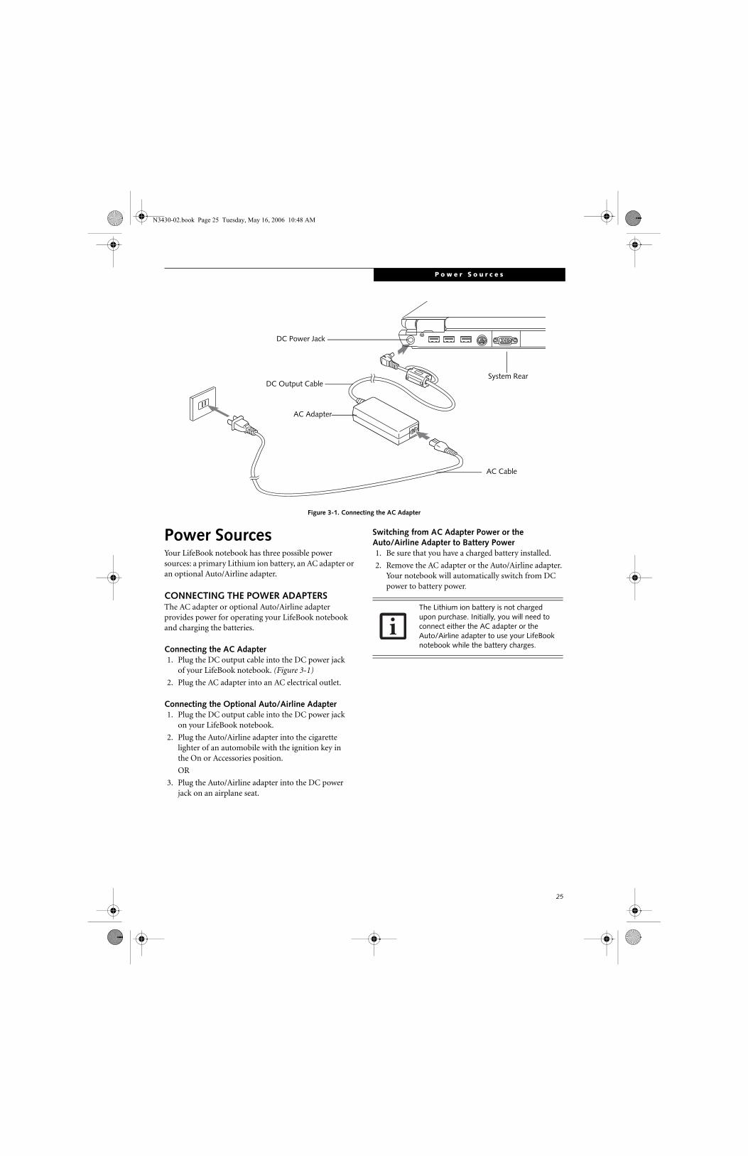
P o w e r S o u r c e s
Figure 3-1. Connecting the AC Adapter
Power SourcesYour LifeBook notebook has three possible power sources: a primary Lithium ion battery, an AC adapter or an optional Auto/Airline adapter.
CONNECTING THE POWER ADAPTERSThe AC adapter or optional Auto/Airline adapter provides power for operating your LifeBook notebook and charging the batteries.
Connecting the AC Adapter1. Plug the DC output cable into the DC power jack
of your LifeBook notebook. (Figure 3-1)
2. Plug the AC adapter into an AC electrical outlet.
Connecting the Optional Auto/Airline Adapter1. Plug the DC output cable into the DC power jack
on your LifeBook notebook.
2. Plug the Auto/Airline adapter into the cigarette lighter of an automobile with the ignition key inthe On or Accessories position.
OR
3. Plug the Auto/Airline adapter into the DC power jack on an airplane seat.
Switching from AC Adapter Power or theAuto/Airline Adapter to Battery Power1. Be sure that you have a charged battery installed.
2. Remove the AC adapter or the Auto/Airline adapter. Your notebook will automatically switch from DC power to battery power.
AC Cable
AC Adapter
DC Power Jack
DC Output CableSystem Rear
The Lithium ion battery is not charged upon purchase. Initially, you will need to connect either the AC adapter or the Auto/Airline adapter to use your LifeBook notebook while the battery charges.
N3430-02.book Page 25 Tuesday, May 16, 2006 10:48 AM
26
L i f e B o o k N 3 4 0 0 S e r i e s N o t e b o o k – S e c t i o n T h r e e
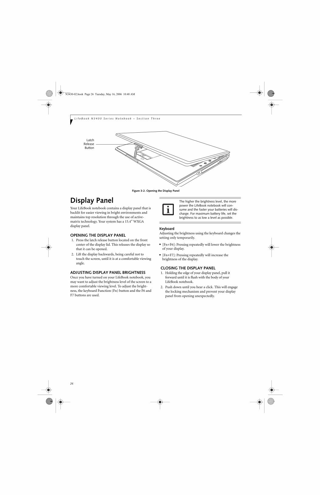
Figure 3-2. Opening the Display Panel
Display PanelYour LifeBook notebook contains a display panel that is backlit for easier viewing in bright environments and maintains top resolution through the use of active-matrix technology. Your system has a 15.4” WXGA display panel.
OPENING THE DISPLAY PANEL1. Press the latch release button located on the front
center of the display lid. This releases the display so that it can be opened.
2. Lift the display backwards, being careful not to touch the screen, until it is at a comfortable viewing angle.
ADJUSTING DISPLAY PANEL BRIGHTNESSOnce you have turned on your LifeBook notebook, you may want to adjust the brightness level of the screen to a more comfortable viewing level. To adjust the bright-ness, the keyboard Function (Fn) button and the F6 and F7 buttons are used.
KeyboardAdjusting the brightness using the keyboard changes the setting only temporarily.
■ [Fn+F6]: Pressing repeatedly will lower the brightness of your display.
■ [Fn+F7]: Pressing repeatedly will increase the brightness of the display.
CLOSING THE DISPLAY PANEL1. Holding the edge of your display panel, pull it
forward until it is flush with the body of your LifeBook notebook.
2. Push down until you hear a click. This will engage the locking mechanism and prevent your display panel from opening unexpectedly.
LatchReleaseButton
The higher the brightness level, the more power the LifeBook notebook will con-sume and the faster your batteries will dis-charge. For maximum battery life, set the brightness to as low a level as possible.
N3430-02.book Page 26 Tuesday, May 16, 2006 10:48 AM
27
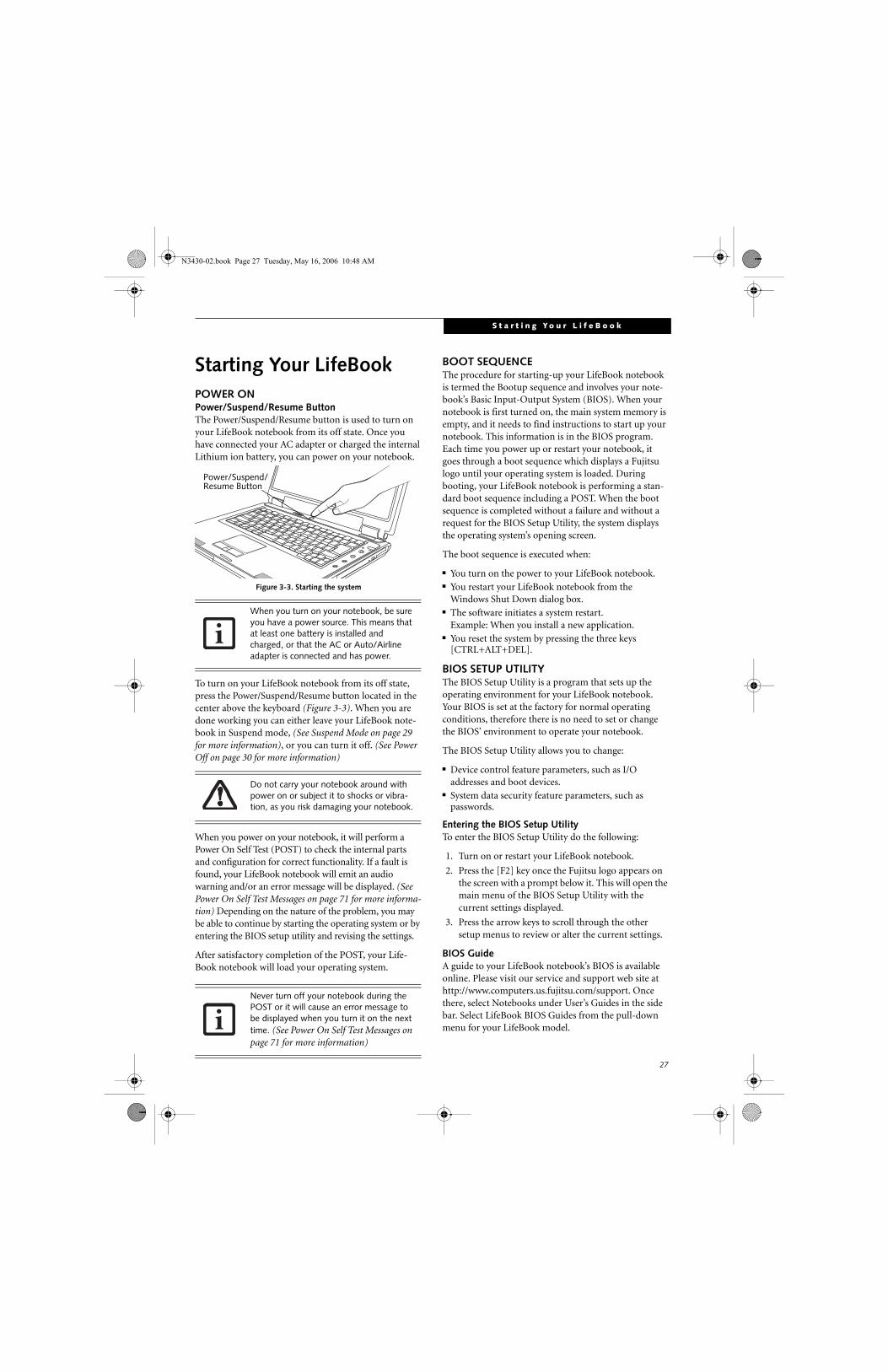
S t a r t i n g Y o u r L i f e B o o k
Starting Your LifeBookPOWER ONPower/Suspend/Resume ButtonThe Power/Suspend/Resume button is used to turn on your LifeBook notebook from its off state. Once you have connected your AC adapter or charged the internal Lithium ion battery, you can power on your notebook.
Figure 3-3. Starting the system
To turn on your LifeBook notebook from its off state, press the Power/Suspend/Resume button located in the center above the keyboard (Figure 3-3). When you are done working you can either leave your LifeBook note-book in Suspend mode, (See Suspend Mode on page 29 for more information), or you can turn it off. (See Power Off on page 30 for more information)
When you power on your notebook, it will perform a Power On Self Test (POST) to check the internal parts and configuration for correct functionality. If a fault is found, your LifeBook notebook will emit an audio warning and/or an error message will be displayed. (See Power On Self Test Messages on page 71 for more informa-tion) Depending on the nature of the problem, you may be able to continue by starting the operating system or by entering the BIOS setup utility and revising the settings.
After satisfactory completion of the POST, your Life-Book notebook will load your operating system.
BOOT SEQUENCEThe procedure for starting-up your LifeBook notebook is termed the Bootup sequence and involves your note-book’s Basic Input-Output System (BIOS). When your notebook is first turned on, the main system memory is empty, and it needs to find instructions to start up your notebook. This information is in the BIOS program. Each time you power up or restart your notebook, it goes through a boot sequence which displays a Fujitsu logo until your operating system is loaded. During booting, your LifeBook notebook is performing a stan-dard boot sequence including a POST. When the boot sequence is completed without a failure and without a request for the BIOS Setup Utility, the system displays the operating system’s opening screen.
The boot sequence is executed when:
■ You turn on the power to your LifeBook notebook.■ You restart your LifeBook notebook from the
Windows Shut Down dialog box.■ The software initiates a system restart.
Example: When you install a new application.■ You reset the system by pressing the three keys
[CTRL+ALT+DEL].
BIOS SETUP UTILITYThe BIOS Setup Utility is a program that sets up the operating environment for your LifeBook notebook. Your BIOS is set at the factory for normal operating conditions, therefore there is no need to set or change the BIOS’ environment to operate your notebook.
The BIOS Setup Utility allows you to change:
■ Device control feature parameters, such as I/O addresses and boot devices.
■ System data security feature parameters, such as passwords.
Entering the BIOS Setup UtilityTo enter the BIOS Setup Utility do the following:
1. Turn on or restart your LifeBook notebook.
2. Press the [F2] key once the Fujitsu logo appears on the screen with a prompt below it. This will open the main menu of the BIOS Setup Utility with the current settings displayed.
3. Press the arrow keys to scroll through the other setup menus to review or alter the current settings.
BIOS GuideA guide to your LifeBook notebook’s BIOS is available online. Please visit our service and support web site at http://www.computers.us.fujitsu.com/support. Once there, select Notebooks under User’s Guides in the side bar. Select LifeBook BIOS Guides from the pull-down menu for your LifeBook model.
When you turn on your notebook, be sure you have a power source. This means that at least one battery is installed and charged, or that the AC or Auto/Airline adapter is connected and has power.
Do not carry your notebook around with power on or subject it to shocks or vibra-tion, as you risk damaging your notebook.
Never turn off your notebook during the POST or it will cause an error message to be displayed when you turn it on the next time. (See Power On Self Test Messages on page 71 for more information)
Power/Suspend/Resume Button
N3430-02.book Page 27 Tuesday, May 16, 2006 10:48 AM

28
L i f e B o o k N 3 4 0 0 S e r i e s N o t e b o o k – S e c t i o n T h r e e
BOOTING THE SYSTEM THE FIRST TIMEWe strongly recommend that you not attach any external devices or put a DVD/CD in your drive until you have gone through the initial power-on sequence.
When you turn on your LifeBook notebook for the first time, it will display a Fujitsu logo on the screen. If you do nothing the system will load the operating system, and then the Windows Welcome will begin.
Designed to accommodate the needs of many users, in many countries, Windows needs to be configured the first time you use it. Windows has two parts:
■ Getting Started: You have the opportunity to review the Windows License Agreement, enter custom infor-mation for your system, and set up your modem so that your notebook will be prepared to dial out.
■ Registration: Easy online registration for Windows with Microsoft.
GETTING STARTEDRead the instructions on the screens carefully and fill in the information as directed. You will be asked to read the Windows End User License Agreement. When you finish, you must accept or reject the terms of the agreement.
You will then be asked for such items as the language you wish to use, the country in which you live, your first and last name, and about how you dial out from where you will be using your notebook. For the modem settings, enter your current location information where you will be using your notebook. If you are not connected to a phone line and plan to register at a later time, you may click the Skip button.
Once you have set up your LifeBook notebook to dial out, Windows will make a free telephone call to test the settings. If the call is unsuccessful, you will be returned to the phone settings page where you may try to fix
them. If you are unable to fix the settings please contact Fujitsu Service and Support. (See Fujitsu Contact Infor-mation on page 3 for more information) If you would simply like to move on, and register at a later time, you may click the Skip button.
Windows RegistrationIf your connection is successful, you will receive an acknowledgement from Microsoft that your registration was successful.
WINDOWS PRODUCT ACTIVATIONIf your system has Windows XP as an operating system, it has already been pre-installed and pre-activated when you receive the system.
In the event you need to re-install Windows XP (e.g., after making significant configuration changes), it may be necessary to reactivate the operating system. To do so, use the following information.
■ After re-installing Windows XP, you have thirty days to activate it. Product activation ensures that you are the authorized owner of the operating system.
■ Until you activate the product, when you turn on your system you will be prompted that activation is required. Follow the on-screen directions to activate your operating system. The product only needs to be activated once, unless significant hardware changes are made to your system.
■ Note that Product Activation and Registration are not the same thing. Registration is optional, whereas Product Activation is a required procedure.
REGISTERING YOUR LIFEBOOK NOTEBOOK
How do I register my LifeBook notebook?To register your LifeBook notebook, visit our Web site at: http://www.computers.us.fujitsu.com/support.
INSTALLING CLICK ME! AND FDU
Installing ClickMe!The first time you boot up your system, you will see an icon called Click Me! in the Start folder. When you click the icon, your system will automatically build the icon tray in the bottom right of the screen. These icons provide links to utilities that you will frequently access.
Installing Fujitsu Driver Update Utility In the system tray, right-click on the Fujitsu Driver Update Utility (FDU) icon and follow the on-screen instructions to update your drivers. (See Automatically Downloading Driver Updates on page 74 for more infor-mation)
If your data security settings require it, you may be asked for a password before the BIOS main menu will appear.
You may click Cancel at any time within this process to shut down Windows. You may restart this process at any time in the future, but you must complete it in order to use your computer.
If you reject the terms of the License Agreement you will be returned to the beginning of the Windows Welcome Pro-cess, even if you shut your notebook down and start it up again.
Before installing ClickMe!, be sure the wireless LAN switch is set to the On position.
N3430-02.book Page 28 Tuesday, May 16, 2006 10:48 AM

29
P o w e r M a n a g e m e n t
Power ManagementYour LifeBook notebook has many features for conserving battery power. Some of these features are automatic and need no user intervention, such as those for the internal modem. However, others depend on the parameters you set to best suit your operating condi-tions, such as those for the display brightness. Internal power management for your LifeBook notebook may be controlled from settings made in your operating system or pre-bundled power management application.
Besides the options available for conserving battery power, there are also some things that you can do to prevent your battery from running down as quickly.For example, you can create an appropriate power saving profile, put your LifeBook notebook into Suspend mode when it is not performing an operation, and you can limit the use of high power devices. As with all mobile battery-powered computers, there is a trade-off betweenperformance and power savings.
POWER/SUSPEND/RESUME BUTTONWhen your LifeBook notebook is active, the Power/Suspend/Resume button can be used to manually put your LifeBook notebook into Suspend mode. Push the Power/Suspend/Resume button when your LifeBook notebook is active, but not actively accessing anything, and immediately release the button. You will hear two short beeps and your system will enter Suspend mode.
If your LifeBook notebook is suspended, pushing the Power/Suspend/Resume button will return your Life-Book notebook to active operation.
SUSPEND MODESuspend mode saves the contents of your LifeBook note-book’s system memory during periods of inactivity by maintaining power to critical parts. This mode will turn off the CPU, the display, the hard drive, and all of the other internal components except those necessary to maintain system memory and allow for restarting. Your LifeBook notebook can be put in Suspend mode by:
■ Pressing the Power/Suspend/Resume button when your system is turned on.
■ Selecting Standby from the Windows Shut Down menu.■ Timing out from lack of activity (if the power profile
has been set up accordingly).■ Allowing the battery to reach the Dead Battery
Warning condition.
Your notebook’s system memory typically stores the files on which you are working, open applications informa-tion, and any other data required to support the opera-tions in progress. When you resume operation from Suspend mode, your notebook will return to the point
where it left off. You must use the Power/Suspend/Resume button to resume operation, and there must be an adequate power source available, or your notebook will not resume.
HIBERNATION (SAVE-TO-DISK) FEATUREThe Hibernation (Save-to-Disk) feature saves the contents of your LifeBook notebook’s system memory to the hard drive as a part of the Suspend/Resume mode. You can enable or disable this feature.
Enable or Disable the Hibernation FeatureHibernation is the default setting for Windows XP. To disable or enable the Hibernation feature, follow these steps:
1. From the Start menu, select Control Panel.
2. From the Control Panel, double-click the Power Options icon.
3. Select the Hibernate tab. Select or deselect the box to enable or disable this feature.
Using the Hibernation Feature1. From the Start menu, select Control Panel.
2. From the Control Panel, select Power Options.
3. Select the Advanced tab. Select Hibernate from the pull down menu for Power buttons. (Note that Hibernate will only appear as an option if it has been enabled in the Hibernate tab).
If you are running your LifeBook notebook on battery power, be aware that the bat-tery continues to discharge while your LifeBook notebook is in Suspend mode, though not as fast as when fully opera-tional.
The Suspend or Hibernation (Save-to-Disk) mode should not be used with cer-tain PC Cards. Check your PC Card docu-mentation for more information.
N3430-02.book Page 29 Tuesday, May 16, 2006 10:48 AM

30
L i f e B o o k N 3 4 0 0 S e r i e s N o t e b o o k – S e c t i o n T h r e e
DISPLAY TIMEOUT The Video Timeout is one of the power management parameters. This feature saves power by turning off the display if there is no keyboard or pointer activity for the user selected timeout period. Any keyboard or pointer activity will cause the display to restart automatically. This feature is independent of the Power/Suspend/Resume button and can be enabled and disabled in Windows.
HARD DISK TIMEOUTThe Hard Disk Timeout is another one of the power management parameters. This feature saves power by turning off the hard drive if there is no hard drive activity for the user selected timeout period. Any attempt to access the hard drive will cause it to restart automatically. This feature is independent of the Power/Suspend/Resume button and can be enabled and disabled in Windows.
WINDOWS POWER MANAGEMENT The Power Options icon in the Windows Control Panel allows you to configure some of the power management settings. For example, you can use the Power Manage-ment to set the timeout values for turning off the display and hard disks whether you are running the notebook on battery power or one of the adapters. (See Pre-Installed Software on page 85 for more information)
RESTARTING THE SYSTEMIf your system is on and you need to restart it, be sure that you use the following procedure.
1. Click the Start button, and then click Shut Down.
2. Select the Restart option from within the Windows Shut Down dialog box.
3. Click OK to restart your LifeBook notebook. Your
notebook will shut down and then reboot.
POWER OFFBefore turning off the power by choosing Shut Down from Windows, check that the Hard Drive, optical drive, PC Card and Floppy Disk Drive Access indicators are all Off. (See figure 2-8 on page 13) If you turn off the power while accessing a disk or PC Card there is a risk of data loss. To ensure that your LifeBook notebook shuts down without error, use the Windows shut down procedure.
Using the correct procedure to shut down from Windows, allows your LifeBook notebook to complete its operations and turn off power in the proper sequence to avoid errors. The proper sequence is:
1. Click the Start button, and then click Shut Down.
2. Select the Shut Down option from within the Windows Shut Down dialog box.
3. Click OK to shut down your LifeBook notebook.
If you are going to store your LifeBook notebook for a month or more, see the Care and Maintenance section of this manual.
■ If your notebook is actively accessing information when you enter the Suspend or Hibernation (Save-to-Disk) modes changes to open files are not lost. The files are left open and memory is kept active during Suspend mode or the memory is transferred to the internal hard drive during Hibernation (Save-to-Disk) mode.
■ When PC Cards or external devices are in use, Save-to-Disk mode cannot return to the exact state prior to suspension, because all of the peripheral devices are re-initialized when the system restarts.
■ The main advantage of using Hiberna-tion is that power is not required to maintain your data. This is important if you will be leaving your notebook in a suspended state for a prolonged period of time. The drawback of using Hiberna-tion mode is that it lengthens the power down and power up sequences and resets peripheral devices.
Turning off your LifeBook notebook without exiting Windows or turning on your notebook within 10 seconds of the notebook being shut off may cause an error when you start the next time.
Never turn your LifeBook notebook off while an application is running. Be sure to close all files, exit all applications, and shut down your operating system prior to turn-ing off the power. If files are open when you turn the power off, you will lose any changes that have not been saved, and may cause disk errors.
N3430-02.book Page 30 Tuesday, May 16, 2006 10:48 AM

31
4User-Installable Devices and Media
N3430-02.book Page 31 Tuesday, May 16, 2006 10:48 AM

32
L i f e B o o k N 3 4 0 0 S e r i e s N o t e b o o k – S e c t i o n F o u r
N3430-02.book Page 32 Tuesday, May 16, 2006 10:48 AM

33
L i t h i u m i o n B a t t e r y
Lithium ion BatteryYour LifeBook notebook has a Lithium ion battery that provides power for operating your notebook when no external power source is available. The battery is durable and long lasting, but should not be exposed to extreme temperatures, high voltages, chemicals or other hazards.
The Lithium ion battery operating time may become shorter if it is used under the following conditions:
■ The operating temperature range of the Lithium ion battery is 5°C to 30°C. If the battery is used outside these temperature ranges, charging efficiency will be greatly reduced and the likelihood of battery deterio-ration will greatly increase. The Battery Charging indi-cator on the Status Indicator Panel will flash orange when you try to charge a battery that is outside its operating temperature range. (See Battery Charging Indicator on page 13 for more information)
■ When using a high current device such as a modem, DVD, or hard drive, using the AC adapter will conserve your battery life.
RECHARGING THE BATTERIESIf you want to know the charge condition of the primary Lithium ion battery, check the Battery Level indicator located on the Status Indicator panel (See Battery Level Indicator on page 13 for more information). The indicator changes as the battery level changes.
The Lithium ion battery is recharged internally using the AC adapter or Auto/Airline adapter. To recharge the battery, make sure the battery is installed in your note-book and connect the AC or Auto/Airline adapter.
It is not necessary to discharge the battery completely before recharging. Charge times will be much longer if your notebook is in use while the battery is charging. If you want to charge the battery more quickly, put your notebook into Suspend mode, or turn it off while the adapter is charging the battery. (See Power Management on page 29 for more information on Suspend mode and shutdown procedure)
Low Battery StateWhen the battery is running low, a low battery notifica-tion message will appear. If you do not respond to the low battery message, the batteries will continue to discharge until they are too low to operate. When this happens, your LifeBook notebook will go into Suspend mode. There is no guarantee that your data will be saved once the notebook reaches this point.
■ Actual battery life will vary based on screen brightness, applications, fea-tures, power management settings, bat-tery condition and other customer preferences. Media player drive or hard drive usage may also have a significant impact on battery life. The battery charging capacity is reduced as the bat-tery ages. If your battery is running low quickly, you should replace it with a new one.
■ Do not leave a faulty battery in your LifeBook notebook. It may damage your AC adapter, optional Auto/Airline adapter, or your LifeBook notebook itself. It may also prevent operation of your notebook by draining all available current into the bad battery.
■ Under federal, state, or local law, it may be illegal to dispose of batteries by put-ting them in the trash. Please take care of our environment and dispose of bat-teries properly. Check with your local government authority for details regard-ing recycling or disposing of old batter-ies. If you cannot find this information elsewhere, contact your support repre-sentative at 1-800-8Fujitsu (1-800-838-5487).
Make sure that the Battery Charging indicator and the percentage charge is indicated by the Battery Level icon on the Status Indicator Panel.
Using heavy current devices such as a modem or frequent media player accesses may prevent charging completely.
■ Once the low battery notification message appears, you need to either plug in an AC power adapter or Auto/Airline adapter, or save all your active data, power down your system, and install a charged battery as soon as possible.
■ When you are in Suspend mode there must always be at least one power source active. If you remove all power sources while your LifeBook notebook is in Suspend mode, any data that has not been saved to the hard drive will be lost.
N3430-02.book Page 33 Tuesday, May 16, 2006 10:48 AM

34
L i f e B o o k N 3 4 0 0 S e r i e s N o t e b o o k – S e c t i o n F o u r
Once your LifeBook notebook battery goes dead, you will be unable to resume operation until you provide a source of power either from an adapter or a charged battery. Once you have provided power, you will need to press the Power/Suspend/Resume button to resume operation. If your battery dies, your data will be lost if a power source is not provided promptly. Once you provide power, you can continue to use your LifeBook notebook while an adapter is charging the battery.
Damaged BatteriesThe Battery Level indicator displays the operating level available in that battery. (See “Battery Level Indicator” on page 13). If this icon is red and blinking, it means that the battery is damaged and must be replaced so it does not damage any other parts of your notebook.
REPLACING THE BATTERY With the purchase of an additional battery, you can have a fully charged spare to swap with one that is not charged. (Figure 4-1)
1. Have a charged battery ready to install.
2. Shut down your LifeBook notebook and disconnectthe AC adapter.
3. Press the battery release latches while lifting the battery.
4. Remove the battery from the bay.
5. Insert the new battery into the bay. The pins will automatically align with the connector.
6. Press the battery down until the battery release latches snap into place.
7. Plug in the AC adapter and turn the power on.
Figure 4-1. Replacing the Battery
If the Lithium ion battery connector is not fully seated, you may not be able to use your LifeBook notebook or charge your battery.
BatteryRelease Latches
N3430-02.book Page 34 Tuesday, May 16, 2006 10:48 AM

35
O p t i c a l D r i v e
Figure 4-2. Optical Drive
Optical DriveYour system may have a DVD/CD-RW combo drive or a Dual-Layer Multi-Format DVD drive. These are known as “optical drives”. A variety of media is available to use with your system, depending upon the optical drive in your system.
DVD-R and DVD-RW discs hold up to 4.7 GB of data (DVD-R discs used with the Multi-Format Dual-Layer DVD writer hold up to 8.5 GB of data.). A DVD-R disc can only be written to once; DVD-RW discs can be written to over and over. DVD-R and DVD-RW discs can be played on most standard DVD players.
CD-R and CD-RW discs hold up to 640 MB of data. A CD-R disc can only be written to once; CD-RW discs can be written to over and over.
Depending upon the configuration of your notebook, you may have one of the following optical drives:
■ DVD/CD-RW combo: A DVD/CD-RW combo drive allows you to access movie, software, data, or audio DVD/CDs, and to write data onto recordable CD-R and CD-RW discs.
■ Dual-Layer Multi-Format DVD Writer: This drive allows you to access movies, software, and audio DVD/CDs as well as to read and write to CD-R, CD-RW, DVD-R, DVD+R, DVD-RW, DVD+RW, and DVD RAM discs. The dual-layer architecture allows you to record up to 8.5 GB of data on DVD+R discs.
LOADING MEDIA ON YOUR DRIVETo load a disc into your optical drive:
1. Push and release the eject button on the front of the optical drive to open the holder tray. The tray will come out of the LifeBook notebook a short distance.
2. Gently pull the tray out until a media disc can easily be placed in the tray.
Media Holder Tray
Optical Drive Eject Button
Install your media player software before first using the optical drive. Refer to the applicable readme file on the Driver Applications CD-ROM.
■ Do not operate your optical drive unless your LifeBook notebook is sitting on a flat surface. Using a drive when the system is not level may damage the drive or prevent proper operation.
■ Prolonged use of the optical drive, such as watching a DVD movie, will substan-tially reduce your battery life if no other power source is attached.
■ You should regularly check the Fujitsu web site at: http://www.computers.us.fujitsu.com/support for current updated drivers.
■ All LifeBook DVD players are set to play DVD titles with region code number 1 which is specified for the North Amer-ican market. The region number is a regional restriction code defined by the DVD Forum acting on Hollywood requirements. Different region codes are recorded on video DVD titles for publication in different areas of the world. If the regional code of the DVD player does not match the codes on the titles, then playback is impossible.
■ You can change the region code on the DVD player using the Properties menu of the DVD software. Note, however, that you can only change the region code up to four times. After the fourth change, the last code entered becomes permanent, and cannot be changed.
N3430-02.book Page 35 Tuesday, May 16, 2006 10:48 AM

36
L i f e B o o k N 3 4 0 0 S e r i e s N o t e b o o k – S e c t i o n F o u r
3. Place the media into the tray, label side up, with the hole in the center of the disc. Snap the disc onto the raised circle in the center of the tray.
4. Gently push the holder tray back in until you hear a click. (Figure 4-3)
Figure 4-3. Loading/Ejecting Media
REMOVING MEDIA1. Push and release the eject button on the front of the
optical drive. This will stop the drive and the holder tray will come out of the LifeBook notebook a short distance.
2. Gently pull the tray out until the disc can easily be removed from the tray.
3. Carefully remove the media disc from the holder tray.
4. Gently push the holder tray back in until you hear a click.
USING THE MEDIA PLAYER SOFTWARE
Starting a DVD Movie1. Insert the DVD movie into your optical drive. If the
CD AutoRun feature activates, skip Step 2.
2. The first time you insert a movie into the DVD/CD-RW tray, you will be prompted to select what you want the system to do when discs are inserted (e.g., start automatically or wait for a prompt). Until you make a selection, you will receive the same prompt whenever you insert a disc.
3. Click OK to close the About DVD Player Performance dialog box and the movie will begin.
Opening the Media Player Control PanelWith most DVD-ROMs, you have the option of altering how the movie should play and what you wish to view. You can do this by using the media player control panel and the mouse.
1. Right-click on the movie screen to open a dropdown menu for options.
2. Select View, then Player for all the controls available. This will open the control panel into the bottom of the screen.
Using the Media Player Control PanelThe media player software allows you to watch the movie much like a VCR player. You have the option to pause, rewind, fast-forward and stop the movie at any point.
1. To Pause the movie, click the on-screen button.
2. To Rewind the movie, click the button to rewind to a specific portion of the movie, or the button to return to the opening screen.
There may be a protective sheet in the tray from when it was shipped; please make sure it is removed before operating the drive.
If you have disabled the Auto Insert Notification Function, you will have to start the drive from your desktop, since your LifeBook notebook will not automatically recognize that media has been loaded.
(a) (b)
(c) (d)
■ The program used when playing DVDs on your LifeBook notebook is deter-mined by your operating system (Microsoft Windows XP Professional, Windows XP Home, or Windows XP Media Center Edition). If your system is running Windows XP Professional or Windows XP Home editions, the DVD player is PowerDVD, which can be selected from the Start -> Programs list. If your system is running Windows XP Media Center Edition, you should select Play DVD in MediaCenter from the Start -> Programs list.
■ Depending upon its configuration, your system may not have the media player software pre-installed. If it is not installed, reference the documentation that accompanies the media application.
N3430-02.book Page 36 Tuesday, May 16, 2006 10:48 AM

37
O p t i c a l D r i v e
3. To Fast-forward the movie, click the button to forward to a specific portion of the movie, or the button to jump to the ending credits.
4. To Stop the movie, click the button.
Exiting the Media Player1. Click the located in the upper right corner of the
title bar. This will open a media player dialog box.
2. Click Yes to stop and exit the movie, or No to close the media player dialog box and return to the movie.
USING DOLBY™ HEADPHONEThe Dolby Headphone utility lets you enjoy multi-channel sound sources, such as DVD movies, with real-istic virtual surround sound using conventional stereo headphones. The Dolby Headphone is a utility that is available in the PowerDVD application.
Dolby Headphone is a signal processing system that enables your stereo headphones to realistically emulate the sound of a multi-speaker playback system.
To use the Dolby Headphone feature, perform the following steps:
1. Double click PowerDVD icon on your desktop. (If it does not appear on your desktop, select it from the Start -> Programs list.)
2. On the toolbar that appears, click the Properties button (the fourth button from the left, with the image of a wrench).
3. On the Properties window, select the Dolby Head-phone tab.
4. To enable Dolby Headphone, check the Enable Dolby Headphone box. To change the type of surround sound, select one of the radio buttons listed under Room Filter Setting.
5. Click OK. The Dolby Headphone feature will now be enabled until you disable it by unchecking Enable Dolby Headphone.
USING OPTICAL DRIVE ON BATTERY POWERSince optical drives consume a lot of power, your overall battery life will be significantly shorter when operating the drive continuously (such as watching a DVD movie) than during standard operation. Many movie run-times are longer than your LifeBook notebook can support on a single charged battery. If you are watching a DVD movie on battery power you may need to swap in an additional, charged battery or attach AC power during the movie to view it in its entirety.
To Watch a Movie on Battery Power:1. Have an additional full-charged battery or your AC
adapter ready for use.
2. Start watching your DVD movie.
3. When the low battery warning occurs, immediately stop the movie and exit the media player.
4. Power down your LifeBook notebook and replace the discharged battery with an additional fully-charged battery. If you do not have an additional battery, you should attach AC power as soon as you see the low battery warning.
5. Resume your notebook operation by pressing the Suspend button again. This is not required if you attached AC power without entering suspend mode.
6. Restart your optical drive, locate and skip to the chapter of the movie you were last watching.
7. Continue watching your DVD movie.
■ Media discs which do not have the Dolby Surround 5:1 symbol will not support Dolby Headphone.
■ After making changes to the Dolby Headphone feature and clicking OK, wait at least ten seconds before making another change in order to allow the system to stabilize.
An additional fully-charged battery is recommended if you will be watching DVD movies on battery power. If you don’t have an additional battery, you may purchase one either online at http://www.computers.us.fujitsu.com or by calling 1-877-372-3473.
If you do not stop the optical drive quickly and the LifeBook notebook attempts to auto-suspend (critical battery low state) the notebook will shut down improperly. If this occurs, you will need to perform a hard reset and follow any instructions presented before the system will reboot.
Some shorter DVD movies may not require you to swap batteries or attach AC power to complete them; however, it is best to be prepared since actual battery life while operating the media player cannot be guaranteed.
N3430-02.book Page 37 Tuesday, May 16, 2006 10:48 AM

38
L i f e B o o k N 3 4 0 0 S e r i e s N o t e b o o k – S e c t i o n F o u r
Figure 4-4. Inserting a Memory Stick/SD Card
Memory Stick/Secure Digital/xD Card SlotYour LifeBook notebook supports the following memory cards, on which you can store and transfer data to and from a variety of digital devices. These cards use flash memory architecture, which means they don’t need a power source to retain data.
■ SD Memory Card
■ Memory Stick Media
■ Memory Stick Select Media
■ Memory Stick Duo Media
■ Memory Stick PRO Media
■ xD Picture Cards
Memory Stick is a flash memory technology developed by Sony Electronics. Memory Stick allows you to record, transfer and share digital content, such as digital pictures, movies, music, voice, and computer data and applications.
Secure Digital (SD) Cards are very similar to Memory Sticks, but they are shorter. Like the Memory Stick, SD Cards allow portable storage among a variety of devices, such as cell phones, GPS systems, digital cameras, and
PDAs. SD Cards transfer data quickly, with low battery consumption. Like the memory stick, it uses flash memory architecture.
xD Cards work the same as Memory Sticks and SD Cards, but they are much smaller than either one. xD Cards are primarily used to store and transfer images with devices such as cell phones.
Figure 4-5. Memory Stick, Secure Digital, and xD Cards
INSERTING MEMORY STICK/SD/XD CARDSMemory Sticks, SD Cards, and xD Cards are inserted in the Memory Stick/SD/xD Card slot (Figure 4-4). To insert a Memory Stick, SD Card or xD Card, follow these steps:
1. See your Memory Stick, SD Card, or xD Card manual for instructions on the insertion of your card. Some cards may require that your notebook is off while inserting them.
Memory Stick
Memory Stick/SD Card Slot
Note: A Memory Stick is used for purposes ofIllustration.
• Some of the media in the above list may have more features than others.
• Memory Stick PRO’s high-speed data rate when using a parallel interface is not supported.
• An adapter is required for Memory Stick Duo.
• Copyright Protection Technology can-not be used.
• MultiMedia Cards (MMC) and Secure MMC are not supported.
■ Inserting or removing a Memory Stick, SD Card, or xD Card during your note-book’s shutdown or bootup process may damage the card and/or your notebook.
■ Do not insert a card into a slot if there is water or any other substance on the card as you may permanently damage the card, your notebook, or both.
N3430-02.book Page 38 Tuesday, May 16, 2006 10:48 AM

39
M e m o r y S t i c k / S D C a r d
2. Make sure there is no card currently in the slot. If there is, see Removing a Memory Stick/SD/xD Card.
3. Insert your card into the slot with the product label facing up.
4. Push the card firmly into the slot until it is seated in the connector.
REMOVING A MEMORY STICK/SD/XD CARDTo remove a Memory Stick, SD Card, or xD Card, follow these easy steps:
Push the Memory Stick, SD Card, or xD Card in until it unlatches. It will then eject from the slot for removal.
See your card manual for specific instructions on the removal of your card. Some cards may require your LifeBook notebook to be in Suspend Mode or Off while removing them.
N3430-02.book Page 39 Tuesday, May 16, 2006 10:48 AM

40
L i f e B o o k N 3 4 0 0 S e r i e s N o t e b o o k – S e c t i o n F o u r
Memory Upgrade ModuleYour LifeBook notebook comes with on-board high speed Synchronous Dynamic RAM (SDRAM, PC2-4200, DDR2, 533 MHz) factory installed (the amount of on-board memory depends upon the configuration of your system). To increase your LifeBook notebook’s memory capacity, you may install a larger and/or additional memory upgrade module, with a maximum of 2 GB. The memory upgrade must be a dual-in-line (DIMM) SDRAM module. To ensure 100% compatibility, purchase the SDRAM module only from the Fujitsu web store at: http://www.computers.us.fujitsu.com.
INSTALLING A MEMORY MODULETo install a memory upgrade module follow these steps:
1. Turn off power to your LifeBook notebook and remove any power adapter (AC or auto/airline).
2. Turn the notebook bottom side up, and remove the screws of the memory upgrade module compart-ment. (Figure 4-6)
3. Remove the cover.
Figure 4-6. Opening the Memory Upgrade Compartment
5. Remove the new memory upgrade module from the
static guarded sleeve.
6. Align the memory upgrade module with the component side up. Align the connector edge of the memory upgrade module with the connector slot in the compartment.
7. Insert the memory upgrade module at a 45° angle. Press the connector edge of the module firmly down and into the connector until it lodges under the retaining clip. You will hear a click when it is prop-erly in place. (Figure 4-7)
■ Do not remove any screws from the memory upgrade module compartment except the ones specifically shown in the directions for installing and removing the memory upgrade module.
■ The memory upgrade module can be severely damaged by electrostatic dis-charge (ESD). To minimize risk to the module, observe the following precau-tions:
■ Before handling a memory module, touch a grounded metal object to discharge static electricity built up in your body.
■ When installing or removing a memory module, hold it by the edge so as not to touch any contacts or chips. Be careful not to touch any internal computer terminals or components; the oil from your fingers could cause a short to the components.
■ Be sure to power down your system before adding or removing memory modules. Even if the system is in hibernate or standby states, data could be lost or the memory could be damaged if power is still available to the system.
Fujitsu highly recommends that only memory modules purchased from Fujitsu or recommended by Fujitsu be installed. The installation of incompatible memory modules can cause numerous problems which could result in loss of data.
■ Turn off power and remove any tele-phone line connections before perform-ing the memory upgrade.
■ If the computer has been used recently, it may be hot. Make sure the system has cooled off completely before changing memory.
If you have only one memory module installed in your system, it must be installed in slot 1. Slot 1 is the slot closest to the edge of the system. Installing a memory module only in slot 2 could result in data loss.
N3430-02.book Page 40 Tuesday, May 16, 2006 10:48 AM

41
M e m o r y U p g r a d e M o d u l e
Figure 4-7. Installing a Memory Module
8. Replace the cover. (Figure 4-6)
9. Replace the screws.
REMOVING A MEMORY UPGRADE MODULE1. Perform steps 1 through 4 of Installing a Memory
Upgrade Module.
2. Pull the clips sideways away from each side of the memory upgrade module at the same time.
3. While holding the clips out, remove the module from the slot by lifting it up and pulling towards the rear of your notebook.
4. Store the memory upgrade module in a static guarded sleeve.
5. Replace the cover.
CHECKING THE COMPUTER RECOGNITIONOF NEW MEMORY CAPACITYOnce you have changed the system memory capacityby either adding or removing a memory upgrade module, be sure to check that your LifeBook notebook has recognized the change.
You can check the memory capacity by looking at the Main menu of the BIOS setup:
1. Turn on the power to your LifeBook notebook using the Power/Suspend/Resume button.
2. Allow the system to start booting and press the F2 key once the Fujitsu logo appears on the screen with a prompt below it. This will open the main menu of the BIOS setup with the current settings displayed. (See BIOS Setup Utility on page 27 for more informa-tion).
The system memory information is located in the lower right portion of the window, as detected by your Life-Book notebook during the Power On Self Test (POST). The chart below shows the possible displays that can be shown on the screen.
The memory upgrade module is not something you routinely remove from your notebook. Once it is installed, you should leave it in place unless you want to change system memory capacity.
After changing your memory module con-figuration, you must complete the Reset-ting the Hibernation (Save-to-Disk) Parameters procedure in order for the Hibernation (Save-to-Disk) mode to oper-ate properly on your LifeBook notebook. (See Hibernation (Save-to-Disk) Feature on page 29 for more information)
Slot 2Slot 1
If the total memory displayed is incorrect, check that your memory upgrade module is properly installed. (If the module is prop-erly installed and the capacity is still not correctly recognized, see the Trouble-shooting section starting on page 63)
Memory Displayed
Slot 1
512 MB512 MB
1 GB
Slot 2
512 MB1 GB1 GB
Total Memory
1.0 GB1.5 GB2 GB
N3430-02.book Page 41 Tuesday, May 16, 2006 10:48 AM

42
L i f e B o o k N 3 4 0 0 S e r i e s N o t e b o o k – S e c t i o n F o u r
Figure 4-8. PC Card/ExpressCard Slots
PC Cards/ExpressCards™Your LifeBook notebook supports Type I and Type II PC
Cards and ExpressCardsTM, which can perform a variety of functions depending on which type of card you insert. You can insert one or two cards at a time, depending on its type. PC Cards should be inserted in the bottom slot, and ExpressCards in the top slot. Note that although ExpressCards are available in two widths, only one card can be inserted in the ExpressCard slot at a time.
Some available PC/ExpressCards:
■ Wireless wide area network (WAN) cards■ Local area network (LAN) cards (Type II)■ IDE solid-state disk cards (Type II)■ SCSI cards (Type II)■ Other PC Cards that conform to PCMCIA 2.1 or
CardBus standards
For further information, refer to the instructions supplied with your card(s).
Figure 4-9. Inserting/Removing PC Cards
INSERTING PC CARDSPC Cards are inserted in the PC Card slot (the lower of the two slots). To insert a PC Card, follow these steps:
1. See your PC Card manual for instructions on the insertion of your card. Some cards may require that your notebook is off while inserting them.
2. Make sure there is no PC Card currently in the slot. If there is, see Removing PC Cards.
3. If the eject button is extended, press it until it clicks.
4. Insert the card into the slot with the label facing up.
5. Push the card firmly into the slot until it is seated in the connector.
REMOVING PC CARDSSee your PC Card manual for specific instructions on removing your card. Some cards may require your note-book to be in Suspend Mode or Off during removal.
2. Unlock the card from the slot by pressing the eject button associated with the slot in which the card is located. When pressed, the button will pop out.
3. Firmly press the button again until it is flush with the notebook. This will eject the card slightly out of the slot allowing you to remove the card.
ExpressCard Slot
PC Card Slot
ExpressCard Eject Button
PC Card Eject Button
■ Inserting or removing a PC Card during your LifeBook notebook’s shutdown or bootup process may damage the card and/or your LifeBook notebook.
■ Do not insert a PC Card into a slot if there is water or any other substance on the card as you may permanently damage the card, your LifeBook note-book, or both.
PC Card Slot (bottom slot only)
PC Card
You may be required to log on as an Administrator or member of the Adminis-trator’s Group to complete this procedure. If the computer is connected to a network, network policy settings may also prevent you from completing this procedure.
■ Windows has a shutdown procedure for PC Cards that must be followed before removing a card. (Review your operating system manual for the correct proce-dure.) It is good practice to remove devices using the Unplug or Eject Hard-ware icon in the system tray.
■ If the dialog box states that the device cannot be removed, you must save all of your open files, close any open applica-tions and shut down your notebook.
If the PC Card has an external connector and cable, do not pull the cable when removing the card.
N3430-02.book Page 42 Tuesday, May 16, 2006 10:48 AM
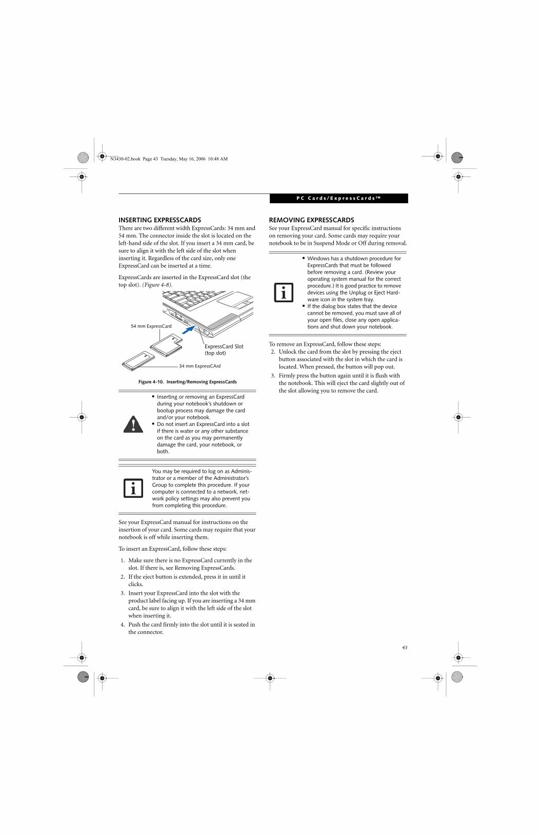
43
P C C a r d s / E x p r e s s C a r d s ™
INSERTING EXPRESSCARDSThere are two different width ExpressCards: 34 mm and 54 mm. The connector inside the slot is located on the left-hand side of the slot. If you insert a 34 mm card, be sure to align it with the left side of the slot when inserting it. Regardless of the card size, only one ExpressCard can be inserted at a time.
ExpressCards are inserted in the ExpressCard slot (the top slot). (Figure 4-8).
Figure 4-10. Inserting/Removing ExpressCards
See your ExpressCard manual for instructions on the insertion of your card. Some cards may require that your notebook is off while inserting them.
To insert an ExpressCard, follow these steps:
1. Make sure there is no ExpressCard currently in the slot. If there is, see Removing ExpressCards.
2. If the eject button is extended, press it in until it clicks.
3. Insert your ExpressCard into the slot with the product label facing up. If you are inserting a 34 mm card, be sure to align it with the left side of the slot when inserting it.
4. Push the card firmly into the slot until it is seated in the connector.
REMOVING EXPRESSCARDSSee your ExpressCard manual for specific instructions on removing your card. Some cards may require your notebook to be in Suspend Mode or Off during removal.
To remove an ExpressCard, follow these steps:2. Unlock the card from the slot by pressing the eject
button associated with the slot in which the card is located. When pressed, the button will pop out.
3. Firmly press the button again until it is flush with the notebook. This will eject the card slightly out of the slot allowing you to remove the card.
■ Inserting or removing an ExpressCard during your notebook’s shutdown or bootup process may damage the card and/or your notebook.
■ Do not insert an ExpressCard into a slot if there is water or any other substance on the card as you may permanently damage the card, your notebook, or both.
You may be required to log on as Adminis-trator or a member of the Administrator’s Group to complete this procedure. If your computer is connected to a network, net-work policy settings may also prevent you from completing this procedure.
54 mm ExpressCard
34 mm ExpressCArd
ExpressCard Slot (top slot)
■ Windows has a shutdown procedure for ExpressCards that must be followed before removing a card. (Review your operating system manual for the correct procedure.) It is good practice to remove devices using the Unplug or Eject Hard-ware icon in the system tray.
■ If the dialog box states that the device cannot be removed, you must save all of your open files, close any open applica-tions and shut down your notebook.
N3430-02.book Page 43 Tuesday, May 16, 2006 10:48 AM
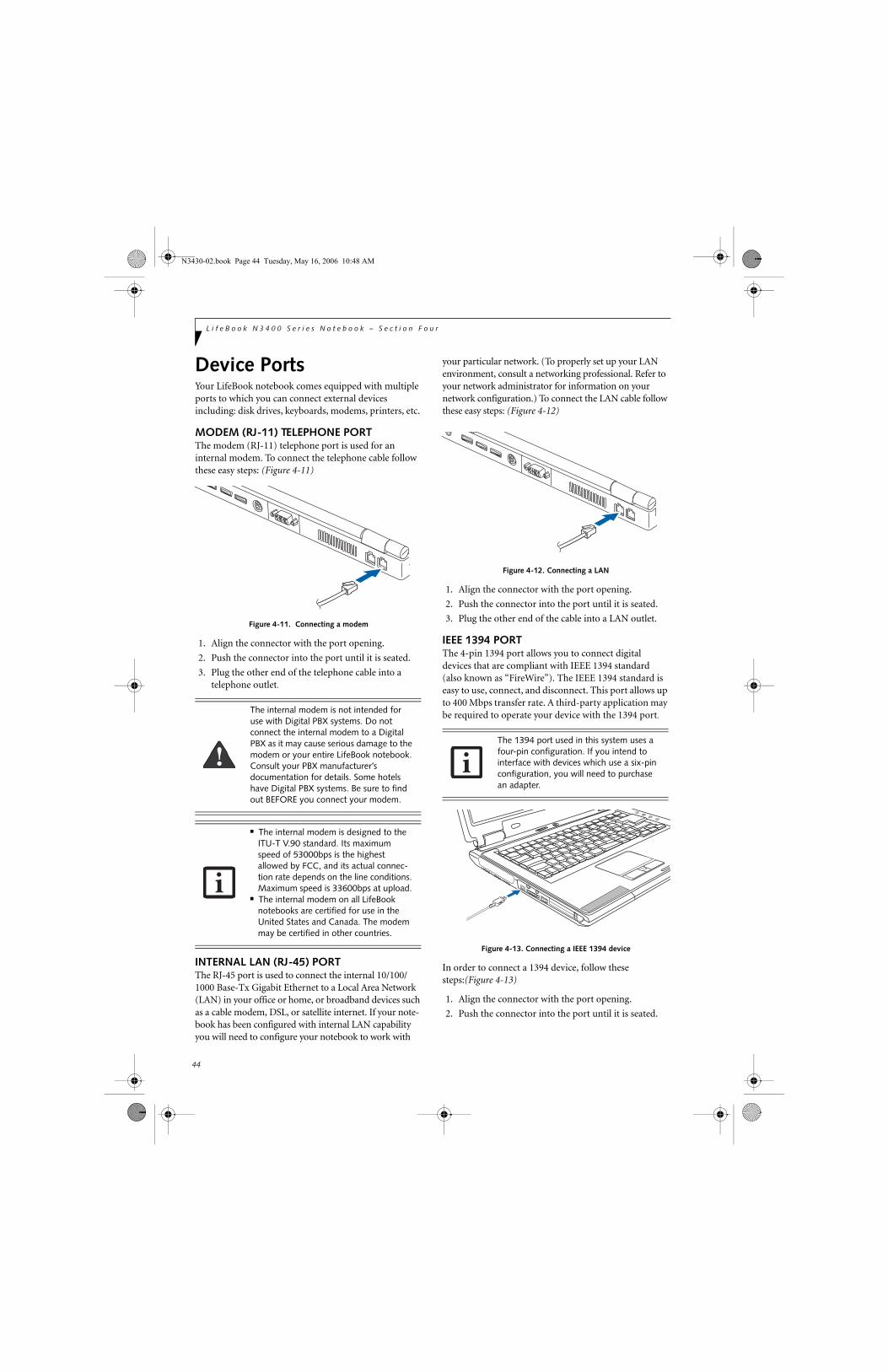
44
L i f e B o o k N 3 4 0 0 S e r i e s N o t e b o o k – S e c t i o n F o u r
Device PortsYour LifeBook notebook comes equipped with multiple ports to which you can connect external devices including: disk drives, keyboards, modems, printers, etc.
MODEM (RJ-11) TELEPHONE PORTThe modem (RJ-11) telephone port is used for an internal modem. To connect the telephone cable follow these easy steps: (Figure 4-11)
Figure 4-11. Connecting a modem
1. Align the connector with the port opening.
2. Push the connector into the port until it is seated.
3. Plug the other end of the telephone cable into atelephone outlet.
INTERNAL LAN (RJ-45) PORT The RJ-45 port is used to connect the internal 10/100/1000 Base-Tx Gigabit Ethernet to a Local Area Network (LAN) in your office or home, or broadband devices such as a cable modem, DSL, or satellite internet. If your note-book has been configured with internal LAN capability you will need to configure your notebook to work with
your particular network. (To properly set up your LAN environment, consult a networking professional. Refer to your network administrator for information on your network configuration.) To connect the LAN cable follow these easy steps: (Figure 4-12)
Figure 4-12. Connecting a LAN
1. Align the connector with the port opening.
2. Push the connector into the port until it is seated.
3. Plug the other end of the cable into a LAN outlet.
IEEE 1394 PORTThe 4-pin 1394 port allows you to connect digital devices that are compliant with IEEE 1394 standard (also known as “FireWire”). The IEEE 1394 standard is easy to use, connect, and disconnect. This port allows up to 400 Mbps transfer rate. A third-party application may be required to operate your device with the 1394 port.
Figure 4-13. Connecting a IEEE 1394 device
In order to connect a 1394 device, follow these steps:(Figure 4-13)
1. Align the connector with the port opening.
2. Push the connector into the port until it is seated.
The internal modem is not intended for use with Digital PBX systems. Do not connect the internal modem to a Digital PBX as it may cause serious damage to the modem or your entire LifeBook notebook. Consult your PBX manufacturer’s documentation for details. Some hotels have Digital PBX systems. Be sure to find out BEFORE you connect your modem.
■ The internal modem is designed to the ITU-T V.90 standard. Its maximum speed of 53000bps is the highest allowed by FCC, and its actual connec-tion rate depends on the line conditions. Maximum speed is 33600bps at upload.
■ The internal modem on all LifeBook notebooks are certified for use in the United States and Canada. The modem may be certified in other countries.
The 1394 port used in this system uses a four-pin configuration. If you intend to interface with devices which use a six-pin configuration, you will need to purchase an adapter.
N3430-02.book Page 44 Tuesday, May 16, 2006 10:48 AM
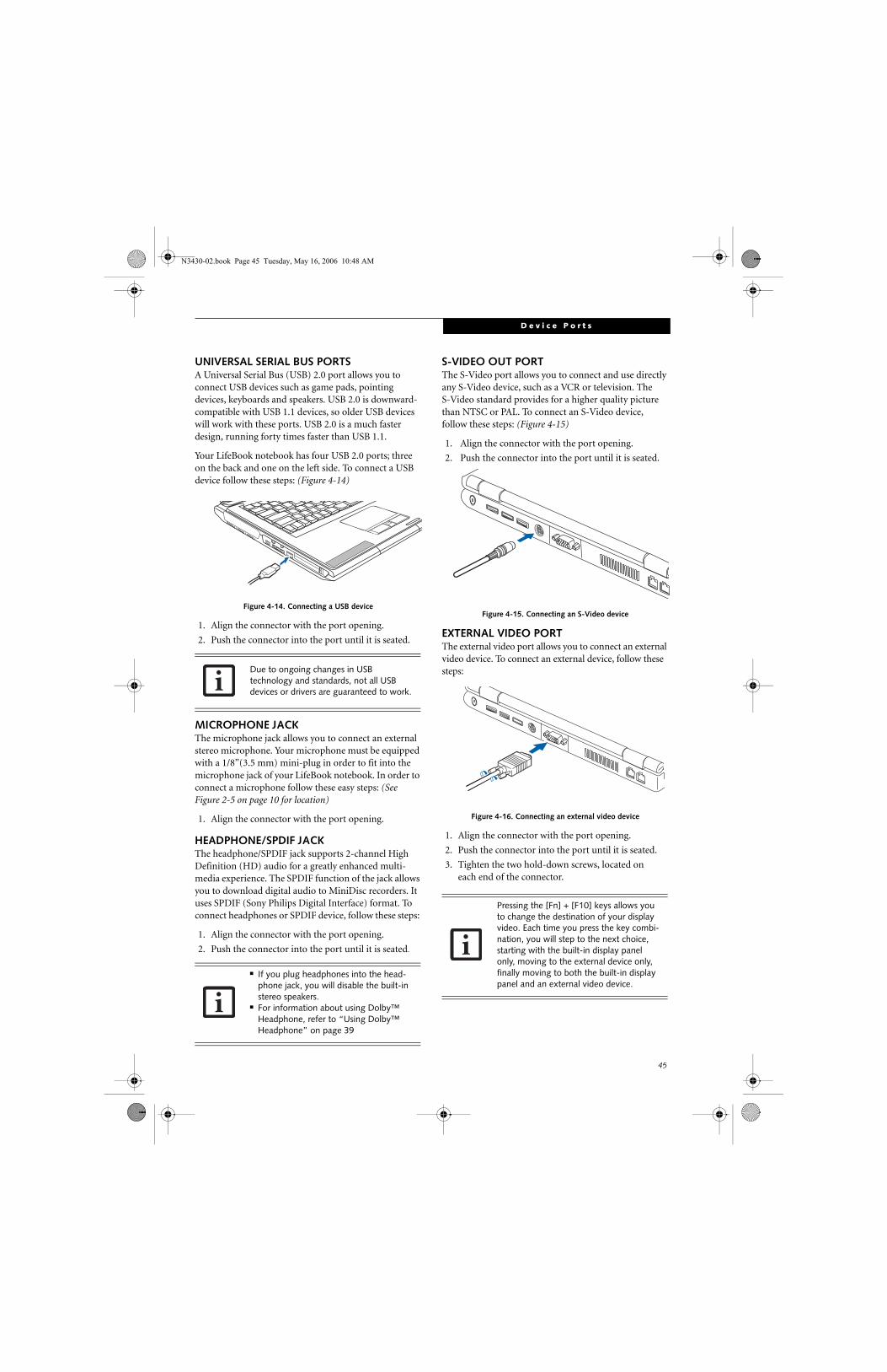
45
D e v i c e P o r t s
UNIVERSAL SERIAL BUS PORTSA Universal Serial Bus (USB) 2.0 port allows you to connect USB devices such as game pads, pointing devices, keyboards and speakers. USB 2.0 is downward- compatible with USB 1.1 devices, so older USB devices will work with these ports. USB 2.0 is a much faster design, running forty times faster than USB 1.1.
Your LifeBook notebook has four USB 2.0 ports; three on the back and one on the left side. To connect a USB device follow these steps: (Figure 4-14)
Figure 4-14. Connecting a USB device
1. Align the connector with the port opening.
2. Push the connector into the port until it is seated.
MICROPHONE JACKThe microphone jack allows you to connect an external stereo microphone. Your microphone must be equipped with a 1/8”(3.5 mm) mini-plug in order to fit into the microphone jack of your LifeBook notebook. In order to connect a microphone follow these easy steps: (See Figure 2-5 on page 10 for location)
1. Align the connector with the port opening.
HEADPHONE/SPDIF JACKThe headphone/SPDIF jack supports 2-channel High Definition (HD) audio for a greatly enhanced multi-media experience. The SPDIF function of the jack allows you to download digital audio to MiniDisc recorders. It uses SPDIF (Sony Philips Digital Interface) format. To connect headphones or SPDIF device, follow these steps:
1. Align the connector with the port opening.
2. Push the connector into the port until it is seated.
S-VIDEO OUT PORT The S-Video port allows you to connect and use directly any S-Video device, such as a VCR or television. The S-Video standard provides for a higher quality picture than NTSC or PAL. To connect an S-Video device, follow these steps: (Figure 4-15)
1. Align the connector with the port opening.
2. Push the connector into the port until it is seated.
Figure 4-15. Connecting an S-Video device
EXTERNAL VIDEO PORTThe external video port allows you to connect an external video device. To connect an external device, follow these steps:
Figure 4-16. Connecting an external video device
1. Align the connector with the port opening.
2. Push the connector into the port until it is seated.
3. Tighten the two hold-down screws, located oneach end of the connector.
Due to ongoing changes in USB technology and standards, not all USB devices or drivers are guaranteed to work.
■ If you plug headphones into the head-phone jack, you will disable the built-in stereo speakers.
■ For information about using Dolby™
Headphone, refer to “Using Dolby™ Headphone” on page 39
Pressing the [Fn] + [F10] keys allows you to change the destination of your display video. Each time you press the key combi-nation, you will step to the next choice, starting with the built-in display panel only, moving to the external device only, finally moving to both the built-in display panel and an external video device.
N3430-02.book Page 45 Tuesday, May 16, 2006 10:48 AM

46
L i f e B o o k N 3 4 0 0 S e r i e s N o t e b o o k – S e c t i o n F o u r
N3430-02.book Page 46 Tuesday, May 16, 2006 10:48 AM
47
5Using the Integrated Wireless LAN
N3430-02.book Page 47 Tuesday, May 16, 2006 10:48 AM

48
L i f e B o o k N 3 4 0 0 S e r i e s N o t e b o o k – S e c t i o n F i v e
N3430-02.book Page 48 Tuesday, May 16, 2006 10:48 AM

49
W I r e l e s s L A N U s e r ’ s G u i d e
FCC REGULATORY INFORMATION
Please note the following regulatory information related to the wireless LAN device.
Regulatory Notes and Statements
Wireless LAN, Health and Authorization for use
Radio frequency electromagnetic energy is emitted from Wire-less LAN devices. The energy levels of these emissions, however, are far much less than the electromagnetic energy emissions from wireless devices such as mobile phones. Wireless LAN devices are safe for use by consumers because they operate within the guidelines found in radio frequency safety standards and recommendations. The use of Wireless LAN devices may be restricted in some situations or environments, such as:
■ On board an airplane, or■ In an explosive environment, or■ In situations where the interference risk to other devices or
services is perceived or identified as harmful.
In cases in which the policy regarding use of Wireless LAN devices in specific environments is not clear (e.g., airports, hospitals, chemical/oil/gas industrial plants, private buildings), obtain authorization to use these devices prior to operating the equipment.
Regulatory Information/Disclaimers
Installation and use of this Wireless LAN device must be in strict accordance with the instructions included in the user documentation provided with the product. Any changes or modifications made to this device that are not expressly approved by the manufacturer may void the user’s authority to operate the equipment. The manufacturer is not responsible for any radio or television interference caused by unauthorized modification of this device, or the substitution or attachment of connecting cables and equipment other than those specified by the manufacturer. It is the responsibility of the user to correct any interference caused by such unauthorized modification, substitution or attachment. The manufacturer and its autho-rized resellers or distributors will assume no liability for any damage or violation of government regulations arising from failure to comply with these guidelines.
This device must not be co-located or operating in conjunction with any other antenna or transmitter.
For IEEE 802.11a Wireless LAN: This device is for operation within 5.15-5.25 GHz frequency range, is restricted to indoor environments, and the antenna of the device must be integral.
Federal Communications Commission statement
This device complies with Part 15 of FCC Rules.
Operation is subject to the following two conditions: (1) This device may not cause interference, and, (2) This device must accept any interference, including interference that may cause undesired operation of this device.
FCC Interference Statement
This equipment has been tested and found to comply with the limits for a Class B digital device, pursuant to Part 15 of the FCC Rules. These limits are designed to provide reasonable protection against harmful interference in a residential installa-tion. This equipment generates, uses, and can radiate radio frequency energy. If not installed and used in accordance with the instructions, it may cause harmful interference to radio communications. However, there is no guarantee that interfer-ence will not occur in a particular installation.
If this equipment does cause harmful interference to radio or television reception, which can be determined by turning the equipment off and on, the user is encouraged to try and correct the interference by one or more of the following measures:
1. Reorient or relocate the receiving antenna.
2. Increase the distance between the equipment and the receiver.
3. Connect the equipment to an outlet on a circuit different from the one the receiver is connected to.
4. Consult the dealer or an experienced radio/TV technician for help.
FCC Radio Frequency Exposure statement
This Wireless LAN radio device has been evaluated under FCC Bulletin OET 65C and found compliant with the requirements as set forth in CFR 47 Sections 2.1091, 2.1093, and 15.247 (b) (4) addressing RF Exposure from radio frequency devices. The radiated output power of this Wireless LAN device is far below the FCC radio frequency exposure limits.
Export restrictions
This product or software contains encryption code which may not be exported or transferred from the US or Canada without an approved US Department of Commerce export license. This device complies with Part 15 of FCC Rules., as well as ICES 003 B / NMB 003 B. Operation is subject to the following two conditions: (1) this device may not cause harmful interference, and (2) this device must accept any interference received, including interference that may cause undesirable operation. Modifications not expressly authorized by Fujitsu Computer Systems Corporation may invalidate the user's right to operate this equipment.
Canadian Notice
The device for the 5150-5250 MHz band is only for indoor usage to reduce the potential for harmful interference to co-channel mobile satellite systems.
The maximum antenna gain of 6 dBi permitted (for devices in the 5250-5350 MHz and 5470-5725 MHz bands) to comply with the e.i.r.p. limit.
In addition, users are cautioned to take note that high power radars are allocated as primary users (meaning they have priority) of 5250-5350 MHz and 5650-5850 MHz and these radars could cause interference and/or damage to LE-LAN devices.
N3430-02.book Page 49 Tuesday, May 16, 2006 10:48 AM

50
L i f e B o o k N 3 4 0 0 S e r i e s N o t e b o o k - S e c t i o n F i v e
Before Using the Wireless LAN
This manual describes the procedures required to prop-erly set up and configure the integrated Wireless LAN Mini-PCI device (referred to as "WLAN device" in the rest of the manual). Before using the WLAN device, read this manual carefully to ensure it's correct operation. Keep this manual in a safe place for future reference.
Wireless LAN Device Covered by this Document
This document is applicable to systems containing the Intel PRO/Wireless 3945ABG Network Connections (802.11a+b/g)
Characteristics of the WLAN Device■ The WLAN device is a Mini-PCI card attached to the
main board of the mobile computer.
■ The WLAN device operates in license-free RF bands, eliminating the need to procure an FCC operating license. The WLAN operates in the 2.4GHz Industrial, Scientific, and Medical (ISM) RF band and the lower, middle, and upper bands of the 5GHz Unlicensed National Information Infrastructure (UNII) bands.
■ The Intel PRO/Wireless 3945ABG WLAN device is capable of three operating modes, IEEE802.11a, IEEE802.11b and IEEE802.11g.
■ The WLAN device is Wi-Fi certified and operates at the maximum data transfer rate of 54 Mbps in IEEE802.11a or IEEE802.11g mode and 11 Mbps in IEEE802.11b mode.
■ The WLAN device supports the following encryption methods - WEP, TKIP, CKIP, and AES encryption.
■ The Wireless LAN device is compliant with the follow-ing standards: WPA, WPA2, CCX1.0, CCX2.0, and CCX3.0.
WIRELESS LAN MODES USING THIS DEVICE
Ad Hoc Mode
(See Figure 5-1) "Ad Hoc Mode" refers to a wireless network architecture where wireless network connec-tivity between multiple computers is established without a central wireless network device, typically known as Access Point(s). Connectivity is accomplished using only client devices in a peer-to-peer fashion. That is why Ad Hoc networks are also known as peer-to-peer networks. Ad Hoc networks are an easy and inexpensive method for establishing network connectivity between multiple computers.
Ad Hoc mode requires that the SSID, network authenti-cation, and encryption key settings are identically configured on all computers in the Ad Hoc network.
Access Point (Infrastructure) Mode
(See Figure 5-2) Infrastructure mode refers to a wireless network architecture in which devices communicate with wireless or wired network devices by communi-cating through an Access Point. In infrastructure mode, wireless devices can communicate with each other or with a wired network. Corporate wireless networks operate in infrastructure mode because they require access to the WLAN in order to access services, devices, and computers (e.g., file servers, printers, databases).
Figure 5-1. Ad Hoc Mode Network
N3430-02.book Page 50 Tuesday, May 16, 2006 10:48 AM

51
W I r e l e s s L A N U s e r ’ s G u i d e
How to Handle This Device
The WLAN device comes pre-installed in your mobile computer. Under normal circumstances, it should not be necessary for you to remove or re-install it. The Oper-ating System that your mobile computer comes with has been pre-configured to support the WLAN device.
■ The Intel PRO/Wireless 3945ABG WLAN device sup-ports IEEE802.11a, IEEE802.11b and IEEE802.11g.
■ The WLAN device operates in the 2.4GHz ISM band and the 5 GHz lower, middle, and upper UNII bands.
■ Microwave ovens may interfere with the operation of WLAN devices since they operate in the same 2.4GHz frequency range as IEEE802.11b/g devices. Interfer-ence by microwaves does not occur with IEEE802.11a radio which operates in the 5 GHz RF band.
■ Wireless devices that transmit in the 2.4GHz fre-quency range may interfere with the operation of WLAN devices in IEEE802.11b/g modes. Symptoms of interference include reduced throughput, intermittent disconnects, and large amounts of frame errors. It is HIGHLY recommended that these interfering devices be powered off to ensure the proper operation of the WLAN device.
DEACTIVATING THE WLAN DEVICEDeactivation of the WLAN device may be desired in certain circumstances (to extend battery life) or where certain environments require it (i.e. hospitals, clinics, airplanes, etc.). Fujitsu mobile computers employ two methods with which to deactivate the WLAN device, 1) the Wireless On/Off Switch, and, 2) in Windows using the Intel PROSet for Wireless utility.
Deactivation using the Wireless On/Off Switch
The WLAN device can be deactivated quickly and effi-ciently by toggling the Wireless On/Off Switch to the Off position. (Figure 5-3)
The Wireless On/Off switch has no effect on non-Wire-less LAN models.
Figure 5-3. Wireless LAN On/Off Switch
Deactivation using Intel PROSet for Wireless Utility
The WLAN device can also be deactivated in Windows using the Intel PROSet for Wireless utility. The proce-dure to accomplish this:
1. Click [Start]-> [All Programs].
2. Select Intel ProSet Wireless, then click on Intel ProSet Wireless from the menu that appears. The Intel ProSet Wireless utility will be displayed.
3. At the bottom left corner of the window, select Wireless Off from the dropdown list.
ACTIVATING THE WLAN DEVICEActivation of the WLAN device can be accomplished using the same methods as the deactivation process
■ Using the Wireless On/Off Switch
■ In Windows using the Intel PROSet for Wireless utility
Before using the wireless LAN device, you must first install ClickMe! to ensure that the correct software for your device is installed. (See Installing Click Me! and FDU on page 28 for more information)
OFF ON
Figure 5-2. Access Point (Infrastructure) Mode Network
ADSL modem,cable modem,or similar
InternetWired LAN
Access Point*
Wireless LAN
*An optional hub for a wiredLAN may be required dependingupon the type of access point used.
N3430-02.book Page 51 Tuesday, May 16, 2006 10:48 AM

52
L i f e B o o k N 3 4 0 0 S e r i e s N o t e b o o k - S e c t i o n F i v e
Configuration of the WLAN Device
The WLAN device can be configured to establish wire-less network connectivity using the Intel PROSet for Wireless utility. The Intel PROSet for Wireless utility allows for multiple profile setup and supports automatic profile switching. Support for most industry standard security solutions is contained in this software.
FLOW OF OPERATIONS1. Activate the WLAN Device (See Activating the
WLAN Device on page 51 for more information).
2. Configure the Wireless Network parameters (See Configuration Using Intel PROSet for Wireless Utility, below).
■ Enter the network name (SSID)
■ Choose the appropriate WLAN architecture (Ad Hoc or Infrastructure)
■ Choose Authentication method: Open, Shared, WPA-Enterprise, WPA2-Enterprise, WPA-Personal, or WPA2-Personal.
■ If using static WEP keys, enter static WEP key and choose key index.
3. Configure network settings
■ TCP/IP settings
■ Workgroup or Domain settings.
CONFIGURATION USING INTEL PROSET FOR WIRELESS UTILITYThis section explains the procedure to properly configure the WLAN device using the Intel PROSet for Wireless utility. Pre-defined parameters will be required for this procedure. Please consult with your network administrator for these parameters:
Network Name - Also known as the SSID
Network Key (WEP) - Required if using static WEP keys.
Authentication Type - Open, Shared, WPA, WPA-PSK
Procedure
1. Activate the WLAN device using either the Wireless On/Off Switch or the Intel PROSet for Wireless utility.
2. Click the [Start] button first and then [All Pro-grams].
3. Click the icon [Intel PROSet Wireless] to execute the Intel PROSet for Wireless utility.
4. Click the [Add] button. The General Settings dialog displays.
5. Enter a profile name in the Profile Name field.
6. Enter the network SSID, in the Network Name (SSID) field.
7. Click Infrastructure or Ad Hoc for the operating mode.
8. Click [Advanced].
9. The Mandatory Access Point option is only used if Infrastructure mode is selected. Use this option to connect to a specific access point. Enter the MAC address for the access point. Click OK to save the setting and return to the General Settings page.
10. Click [Next].
11. If you wish to enable Cisco Compatible Extensions, click Cisco Options and check the “Enable Cisco Compatible Extensions” box.
12. To enable LEAP support, check the 802.1x option and choose LEAP from the pull down list.
13. Click [OK].
14. Click Next.
15. Select Open, Shared, WPA-Enterprise, WPA2-Enterprise, WPA-Personal, or WPA2-Personal in the Network Authentication options.
16. Select either None, WEP, CKIP, or TKIP for the data encryption.
17. If WEP is selected, select either 64 or 128-bit for the Encryption Level.
18. Select the appropriate key index for your WLAN. The key index must be identical to the WEP key index used by the Access Point.
19. Enter the WEP key if required. If your network does not employ a 802.1x/EAP security mechanism, please skip to step 24.
20. Click the Enable 802.1x checkbox to enable the 802.1x security option. Please contact your network administrator if configuration of this setting is required.
21. Select the appropriate Authentication Type. Please contact your network administrator if configura-tion of this setting is required.
22. After selecting authentication type, enter the name, domain, and password of the user you have created on the authentication server. The user name and password do not have to be the same as name and password of your current Windows user login.
N3430-02.book Page 52 Tuesday, May 16, 2006 10:48 AM

53
W I r e l e s s L A N U s e r ’ s G u i d e
23. Click [OK] to save the settings.
24. From the Intel ProSet Wireless page, click the new profile name shown in the Profile List. Use the up and down arrows to position the priority of the new profile in the priority list.
25. Click the Connect button to connect to the net-work.
Click [Close] if you want to close the Intel(R) PROSet for Wireless window.
CONNECTION TO THE NETWORKThis section explains connection to the network.
If there is an administrator of the network, contact the network administrator for data settings.
Setting the network
Perform the “Setting TCP/IP” and “Confirming the computer and work group names” operations required for network connection.
Setting TCP/IP
1. Click the [Start] button first and then [Control Panel].
2. If the Control Panel is in Category view, switch to Classic view by clicking “Switch to Classic View” under Control Panel the left frame. (If you are already in Classic view, “Switch to Category View” will be displayed.)
3. Double-click [Network Connections]. A list of cur-rently installed networks will be displayed.
4. Right-click [Wireless Network Connection] in the list, and then click [Properties] in the menu dis-played. The [Wireless Network Connection Proper-ties] window will be displayed.
5. Click the [General] tab if it is not already selected.
6. Click [Internet Protocol (TCP/IP] and then click [Properties]. The [Internet Protocol (TCP/IP) Properties] window will be displayed.
7. Set the IP address as follows:
■ For ad hoc connection: Select [Use the following IP address:] and then enter data for [IP address] and [Subnet mask]. See page 59 for IP address setting.
■ For access point (infrastructure) connection: If your network uses DHCP, select [Obtain an IP address automatically] and [Obtain DNS server
address automatically]. If your network uses static IP addresses, consult with your network adminis-trator for the correct IP address settings.
8. Click the [OK] button. Processing will return to the [Wireless Network Connection Properties] window.
9. Click the [OK] button.
10. Close the [Network Connection] window.
Following this operation, confirm the names of the computer and the workgroup as follows.
Confirming the computer and work group names
1. Click the [Start] button, then [Control Panel].
2. If the Control Panel is in Category view, switch to Classic view by clicking “Switch to Classic View” under Control Panel the left frame. (If you are already in Classic view, “Switch to Category View” will be displayed.)
3. Double-click the [System] icon. The [System Prop-erties] window will be displayed.
4. Click the [Computer Name] tab.
5. Confirm the settings of [Full computer name:] and [Workgroup:].
a. The setting of [Full computer name:] denotes the name for identifying the computer. Any name can be assigned for each personal computer.
Enter the desired name in less than 15 ASCII character code format. Identifiability can be enhanced by entering the model number, the user name, and other factors.
b. [Workgroup name] is the group name of the network. Enter the desired name in less than 15 ASCII character code format.
For ad hoc connection: Assign the same network name to all personal computers existing on the network.
For access point (infrastructure) connection: Assign the name of the work group to be accessed.
To change the setting of the IP address, you need to be logged in from Windows as an administrator.
To modify the computer name and/or the work group name, you need to be logged in from Windows as an administrator.
To change the name, click [Change], then proceed in accordance with the instruction messages displayed on the screen.
N3430-02.book Page 53 Tuesday, May 16, 2006 10:48 AM

54
L i f e B o o k N 3 4 0 0 S e r i e s N o t e b o o k - S e c t i o n F i v e
6. Click the [OK] button. If a message is displayed that requests you to restart the personal computer, click [Yes] to restart the computer.
Setting the sharing function
Set the sharing function to make file and/or printer sharing with other network-connected personal computers valid.
This operation is not required unless the sharing func-tion is to be used.
The folder and printer for which the sharing function has been set will be usable from any personal computer present on the network.
Setting the Microsoft network-sharing service
1. Click the [Start] button first and then [Control Panel].
2. If the Control Panel is in Category view, switch to Classic view by clicking “Switch to Classic View” under Control Panel the left frame. (If you are already in Classic view, “Switch to Category View” will be displayed.)
3. Double-click [Network Connections]. A list of cur-rently installed networks will be displayed.
4. Right-click [Wireless Network Connection] in the list, and then click [Properties] in the menu dis-played. The [Wireless Network Connection Prop-erties] window will be displayed.
5. If [File and Printer Sharing for Microsoft Net-works] is displayed, proceed to step 6. If [File and Printer Sharing for Microsoft Networks] is not dis-played, skip to step 7.
6. Make sure that the [File and Printer Sharing for Microsoft Networks] check box is checked, and then click the [OK] button. Skip to “Setting file-sharing function”.
7. Click [Install]. The [Select Network Component Type] window will be displayed.
8. Click [Service], then click the [Add] button. The [Select Network Service] window will be displayed.
9. Click [File and Printer Sharing for Microsoft Net-works] and then click the [OK] button. Processing will return to the [Wireless Network Connection Properties] window, and [File and Printer Sharing for Microsoft Networks] will be added to the list.
10. Click the [Close] button.
Setting the file-sharing function
The procedure for setting the file-sharing function follows, with the “work” folder in drive C: as an example.
1. Click the [Start] button, then [My Computer].
2. Double-click [Local disk (C:)].
3. Right-click the “work” folder (or whichever folder you want to share), and then click [Sharing and Security...] in the menu displayed. The [Folder Name Properties] window will be displayed.
4. Click [Sharing] if it isn’t already selected.
5. Click the link stating “If you understand the secu-rity risks, but want to share files without running the wizard, click here”.
6. Click “Just enable file sharing” and click [OK].
7. Check the [Share this folder on the network] box.
8. Click the [OK] button. The folder will be set as a sharable folder, and the display of the icon for the “work.” folder will change.
Setting the printer-sharing function
1. Click the [Start] button first and then [Printers and FAX]. A list of connected printers will be displayed.
2. Right-click the printer for which the sharing func-tion is to be set, and then click [Sharing] in the menu displayed. The property window correspond-ing to the selected printer will be displayed.
To share a file and/or the connected printer, you need to be logged in as an administrator.
Setting the file-sharing function for the file which has been used to execute Network Setup Wizard is suggested on the screen. For the wireless LAN, however, since security is guaranteed by entry of the network name (SSID) and the network key, the steps to be taken to set the file-sharing function easily without using Network Setup Wizard are given below.
To specify the corresponding folder as a read-only folder, select the [Read only] checkbox under the General tab.
Setting the printer-sharing function when Network Setup Wizard has been executed is suggested on the screen. For the wireless LAN, however, since security is guaranteed by entry of the network name (SSID) and the network key, the steps to be taken to set the printer-sharing function without using Network Setup Wizard are laid down below.
N3430-02.book Page 54 Tuesday, May 16, 2006 10:48 AM

55
W I r e l e s s L A N U s e r ’ s G u i d e
3. Click the [Sharing] tab.
4. Click [Share this printer].
5. Enter the sharing printer name in [Share name].
6. Click the [OK] button.
Confirming connection
After you have finished the network setup operations, access the folder whose sharing has been set for other personal computers. Also, confirm the status of the radio waves in case of trouble such as a network connection failure.
Connecting your personal computer to another personal computer
1. Click [Start] first and then [My Computer]. The [My Computer] window will be displayed in the left frame.
2. Click [My Network Places] in the “Other Places” list. The window [My Network Places] will be dis-played.
3. Click [View workgroup computers] under Network Tasks in the left frame.
4. Double-click the personal computer to which your personal computer is to be connected. The folder that was specified in “Setting the file-sharing func-tion” on page 54 will be displayed.
5. Double-click the folder to be accessed.
Confirming the status of the radio
1. Right-click the Intel PRO Wireless icon in the lower right corner of the screen.
2. Click [Open Intel PROSet for Wireless]. The Intel PROSet for Wireless window opens.
3. Contained within the General tab and the Details section (accessed by pressing the [Details] button), you will find the current operating status of the radio. (When the radio is turned off or the com-puter is not yet connected, some of the conditions will not be displayed.)
■ Profile NameThe current configuration profile is displayed.
■ Network Name (SSID)Displays the Network Name (SSID) currently used by the radio.
■ IP AddressThe IP address of the current profile.
■ Signal QualityDisplays a message stating the current quality of the signal.
■ Signal StrengthDisplays a graphic representation of the current signal strength.
Additionally, in the lower section of the display, you will see a variety of different measurements related to the WLAN. For additional information about the items, click on the “Help?” button:
■ Adapter MAC Address
■ Band
■ Supported Data Rates
■ Radio Frequency
■ Channel Number
■ Network Authentication
■ Data Encryption
■ 802.1x Authentication Type
■ 802.1x Authentication Protocol
■ CCX Version
■ CCX TPC
■ CCX Power Levels
■ Access Point MAC Address
■ Mandatory Access Point
In the case of access point (infrastructure) connection, enter the necessary data for the access point before confirming connection. Refer to the manual of the access point for the access point setup procedure.
N3430-02.book Page 55 Tuesday, May 16, 2006 10:48 AM
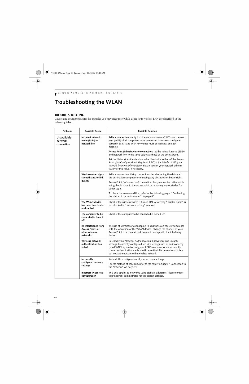
56
L i f e B o o k N 3 4 0 0 S e r i e s N o t e b o o k - S e c t i o n F i v e
Troubleshooting the WLAN
TROUBLESHOOTINGCauses and countermeasures for troubles you may encounter while using your wireless LAN are described in the following table.
Problem Possible Cause Possible Solution
Unavailable network connection
Incorrect network name (SSID) or network key
Ad hoc connection: verify that the network names (SSID’s) and network keys (WEP) of all computers to be connected have been configured correctly. SSID’s and WEP key values must be identical on each machine.
Access Point (Infrastructure) connection: set the network name (SSID) and network key to the same values as those of the access point.
Set the Network Authentication value identically to that of the Access Point (See Configuration Using Intel PROSet for Wireless Utility on page 52 for more information). Please consult your network adminis-trator for this value, if necessary.
Weak received signal strength and/or link quality
Ad hoc connection: Retry connection after shortening the distance to the destination computer or removing any obstacles for better sight.
Access Point (Infrastructure) connection: Retry connection after short-ening the distance to the access point or removing any obstacles for better sight.
To check the wave condition, refer to the following page: “Confirming the status of the radio waves” on page 55.
The WLAN device has been deactivated or disabled
Check if the wireless switch is turned ON. Also verify “Disable Radio” is not checked in “Network setting” window.
The computer to be connected is turned off
Check if the computer to be connected is turned ON.
RF interference from Access Points or other wireless networks
The use of identical or overlapping RF channels can cause interference with the operation of the WLAN device. Change the channel of your Access Point to a channel that does not overlap with the interfering device.
Wireless network authentication has failed
Re-check your Network Authentication, Encryption, and Security settings. Incorrectly configured security settings such as an incorrectly typed WEP key, a mis-configured LEAP username, or an incorrectly chosen authentication method will cause the LAN device to associate but not authenticate to the wireless network.
Incorrectly configured network settings
Recheck the configuration of your network settings.
For the method of checking, refer to the following page:·“Connection to the Network” on page 53.
Incorrect IP address configuration
This only applies to networks using static IP addresses. Please contact your network administrator for the correct settings.
N3430-02.book Page 56 Tuesday, May 16, 2006 10:48 AM

57
W I r e l e s s L A N U s e r ’ s G u i d e
Wireless LAN Glossary
GLOSSARY
Access point
Wireless network device used to bridge wireless and wired network traffic.
Ad Hoc Mode
Ad Hoc Mode refers to a wireless network architecture where wireless network connectivity between multiple computers is established without a central wireless network device, typically known as Access Points. Connectivity is accomplished using only client devices in a peer-to-peer fashion. For details, refer to “Ad hoc connection” on page 50.
Channel
Range of narrow-band frequencies used by the WLAN device to transmit data. IEEE802.11b/g - 11 channels, 22 MHz wide channels.
DHCP (Dynamic Host Configuration Protocol)
A protocol that provides a means to dynamically allocate IP addresses to computers on a local area network.
DNS (Domain Name System)
A data query service that provides a mechanism with which to translate host names into Internet addresses.
IEEE802.11a
Wireless LAN standard that supports a maximum data rate of 54 Mbps. 802.11a devices operate in the 5 GHz lower and middle UNII bands.
IEEE802.11b
Wireless LAN standard that supports a maximum data rate of 11 Mbps. 802.11b devices operate in the 2.4 GHz ISM band.
IEEE802.11g
Wireless LAN standard that supports a maximum data rate of 54 Mbps. 802.11g devices operate in the 2.4 GHz ISM band.
IP address
The logical 32-bit host address defined by the Internet Protocol that uniquely identifies a computer on a network. The IP address is usually expressed in dotted decimal notation.
LAN (Local Area Network)
A LAN or Local Area Network is a computer network (or data communications network) which is confined to a limited geographical area.
MAC address (Media Access Control Address)
A MAC address (also called an Ethernet address or IEEE MAC address) is the 48-bit address (typically written as twelve hexadecimal digits, 0 through 9 and A through F, or as six hexadecimal numbers separated by periods or colons, e.g., 0080002012ef, 0:80:0:2:20:ef) which identify uniquely a computer that has an Ethernet interface.
MTU (Maximum Transmission Unit)
The maximum size of data which can be transmitted at one time in networks including the Internet. In an envi-ronment whose maximum size of data is too large to correctly receive data, normal communications can be restored by setting the size of MTU to a smaller value.
Network key
Data that is used for encrypting data in data communi-cation. The personal computer uses the same network key both for data encryption and decryption, therefore, it is necessary to set the same network key as the other side of communication.
Network name (SSID: Service Set Identifier)
When a wireless LAN network is configured, grouping is performed to avoid interference or data theft. This grouping is performed with “Network name (SSID)”. In order to improve security, the network key is set allowing no communication unless “Network name (SSID)” coincides with the network key.
Open system authentication
Null authentication method specified in the 802.11 stan-dard that performs no authentication checks on a wire-less client before allowing it to associate.
PPPoE (Point to Point Protocol over Ethernet)
A method of allowing the authentication protocol adopted in telephone line connection (PPP) to be used over an Ethernet.
Protocol
A procedure or rule of delivering data among computers. Ordered data communication is allowed by making all conditions required for communication including the method of data transmission/reception and action upon communication errors into procedures.
Shared key authentication
802.11 network authentication method in which the AP sends the client device a challenge text packet that the client must then encrypt with the correct WEP key and return to the AP. If the client has the wrong key or no key, authentication will fail and the client will not be allowed to associate with the AP. Shared key authentica-
N3430-02.book Page 57 Tuesday, May 16, 2006 10:48 AM

58
L i f e B o o k N 3 4 0 0 S e r i e s N o t e b o o k - S e c t i o n F i v e
tion is not considered secure, because a hacker who detects both the clear-text challenge and the same chal-lenge encrypted with a WEP key can decipher the key.
SSID (Service Set Identifier)
Service Set Identifier, a 32-character unique identifier attached to the header of packets sent over a WLAN that acts as a password when a mobile device tries to connect to the BSS. The SSID differentiates one WLAN from another, so all access points and all devices attempting to connect to a specific WLAN must use the same SSID. A device will not be permitted to join the BSS unless it can provide the unique SSID. Because the SSID is broadcast in plain text, it does not supply any security to the network.
Subnet mask
TCP-IP network is controlled by being divided into multiple smaller networks (subnets). IP address consists of the subnet address and the address of each computer. Subnet mask defines how many bits of IP address comprise the subnet address. The same value shall be set among computers communicating with each other.
TCP/IP (Transmission Control Protocol/Internet Protocol)
A standard protocol of the Internet.
Wi-Fi
Wi-Fi (Wireless Fidelity) is a set of standards for wireless local area networks (WLAN) based on the IEEE 802.11 specifications. Certified products can use the official Wi-Fi logo, which indicates that the product is interoperable with any other product also showing that logo.
N3430-02.book Page 58 Tuesday, May 16, 2006 10:48 AM
59
W I r e l e s s L A N U s e r ’ s G u i d e
IP address information
ABOUT IP ADDRESSES
If IP address is unknown, set IP address as follows:
If you have an access point (DHCP server) on the network, set the IP address as follows:
[Obtain an IP address automatically]
If the IP address is already assigned to the computer in the network, ask the network administrator to check the IP address to be set for the computer.
If no access point is found in the network:
An IP address is expressed with four values in the range between 1 and 255.
Set the each computer as follows: The value in paren-theses is a subnet mask.
<Example>
Computer A: 192.168.100.2 (255.255.255.0)
Computer B: 192.168.100.3 (255.255.255.0)
Computer C: 192.168.100.4 (255.255.255.0)
:
:
Computer X: 192.168.100.254 (255.255.255.0)
IP addressing is much more complicated than can be briefly explained in this document. You are advised to consult with your network administrator for additional information.
A DHCP server is a server that automatically assigns IP addresses to computers or other devices in the network. There is no DHCP server for the AdHoc network.
N3430-02.book Page 59 Tuesday, May 16, 2006 10:48 AM

60
L i f e B o o k N 3 4 0 0 S e r i e s N o t e b o o k - S e c t i o n F i v e
WLAN Specifications
SPECIFICATIONS
* “Wi-Fi based” indicates that the interconnectivity test of the organization which guarantees the interconnectivity of wireless LAN (Wi-Fi Alliance) has been passed.
** The communication ranges shown above will increase or decrease depending on factors such as number of walls, reflective material, or interference from external RF sources.
*** Encryption with network key (WEP) is performed using the above number of bits, however, users can set 40 bits/104 bits after subtracting the fixed length of 24 bits.
**** Depending on practical environments, the allowable number of computers to be connected may be decreased.
Item Specification
Type of network The Intel PRO/Wireless 3945ABG Network Connections WLAN device conforms to IEEE 802.11a and 802.11b/g (Wi-Fi based)*.
Transfer rate (Automatic switching) 54 Mbps maximum data rate
Active frequency 802.11b/g: 2400~2473 MHz 802.11a: 4900 ~ 5850 MHz
Number of channels 802.11a: 8 independent channels802.11b/g: 11 channels, 3 non-overlapping channels
Typical operating distances** 802.11a: 40 ft. (12 m) @ 54 Mbps; 300 ft. (91 m) @ 6 Mbps802.11b: 100 ft. (30 m) @ 11 Mbps; 300 ft. (91 m) @ 1 Mbps802.11g: 100 ft. (30 m) @ 54 Mbps; 300 ft. (91 m) @ 1 Mbps
Security Encryption Types - WEP, TKIP, AES***WPA 1.0 compliant
Encryption Key lengths Supported: 64 bits and 128 bits802.1x/EAP
Maximum recommended number of computers to be connected over wireless LAN (during ad hoc connection)
10 units or less ****
N3430-02.book Page 60 Tuesday, May 16, 2006 10:48 AM

61
6Troubleshooting
N3430-02.book Page 61 Tuesday, May 16, 2006 10:48 AM

62
L i f e B o o k N 3 4 0 0 S e r i e s N o t e b o o k – S e c t i o n S i x
N3430-02.book Page 62 Tuesday, May 16, 2006 10:48 AM
63
T r o u b l e s h o o t i n g
TroubleshootingThere may be occasions when you encounter simple setup or operating problems that you can solve on the spot, or problems with peripheral devices that can be solved by replacing the device. The information in this section helps you isolate and resolve some of these straightforward issues and identify failures that require service.
IDENTIFYING THE PROBLEMIf you encounter a problem, go through the following procedure before pursuing complex troubleshooting:
1. Turn off your LifeBook notebook.
2. Make sure the AC adapter is plugged into your Life-Book notebook and to an active AC power source.
3. Make sure that any card inserted in the PC Card slot is seated properly. You can also remove the card from the slot, thus eliminating it as a possible cause of failure.
4. Make sure that any devices connected to the external connectors are plugged in properly. You can also disconnect such devices, thus eliminating them as possible causes of failure.
5. Turn on your LifeBook notebook. Make sure it has been off at least 10 seconds before you turn it on.
6. Go through the boot sequence.
7. If the problem has not been resolved, refer to the Troubleshooting Table that follows for more detailed troubleshooting information.
8. If you have tried the solutions suggested in the Trou-bleshooting Table without success, contact your support representative:
Toll free: 1-800-8Fujitsu (1-800-838-5487) Fax: 408-764-2724 E-mail: [email protected]/computers Web site: http://www.computers.us.fujitsu.com/support.
Before you place the call, you should have the following information ready so that the customer support represen-tative can provide you with the fastest possible solution:
■ Product name■ Product configuration number■ Product serial number■ Purchase date■ Conditions under which the problem occurred■ Any error messages that have occurred■ Hardware configuration■ Type of device connected, if any
See the Configuration Label on the bottom of yourLifeBook notebook for configuration and serial numbers. (See Figure 2-7 on page 12 for location)
SPECIFIC PROBLEMS
Using the Troubleshooting TableWhen you have problems with your LifeBook notebook, try to find the symptoms under the Problem column of the troubleshooting table for the feature giving you diffi-culty. You will find a description of common causes for that symptom under the column Possible Cause and what, if anything, you can do to correct the condition under Possible Solutions. All possible causes or solutions may not apply to your LifeBook notebook.
■ If you keep notes about what you have tried, your support representative may be able to help you more quickly by giving additional suggestions over the phone.
■ Do not return a failed LifeBook note-book to your supplier until you have talked to a support representative.
N3430-02.book Page 63 Tuesday, May 16, 2006 10:48 AM

64
L i f e B o o k N 3 4 0 0 S e r i e s N o t e b o o k – S e c t i o n S i x
TROUBLESHOOTING TABLEProblem PageAudio Problems . . . . . . . . . . . . . . . . . . . . . . . . . . page 64Optical Drive Problems . . . . . . . . . . . . . . . . . . . . page 64Hard Drive Problems . . . . . . . . . . . . . . . . . . . . . . page 65Keyboard or Mouse Problems. . . . . . . . . . . . . . . page 65Memory Problems . . . . . . . . . . . . . . . . . . . . . . . . page 66Modem Problems . . . . . . . . . . . . . . . . . . . . . . . . . page 66
Problem PageUSB Device Problems . . . . . . . . . . . . . . . . . . . . . page 66PC Card Problems . . . . . . . . . . . . . . . . . . . . . . . . page 66Power Failures . . . . . . . . . . . . . . . . . . . . . . . . . . . page 66Shutdown and Startup Problems . . . . . . . . . . . . page 68Video Problems . . . . . . . . . . . . . . . . . . . . . . . . . . page 69Miscellaneous Problems . . . . . . . . . . . . . . . . . . . page 70
Problem Possible Cause Possible Solutions
Audio Problems
There is no sound coming from the built-in speakers.
The software volume control is set too low.
Adjust the sound volume control settings in your software, operating system and applications.
Headphones are plugged into your LifeBook notebook.
Plugging in headphones disables the built-in speakers, remove the headphones.
BIOS audio settings are incorrect. Set the BIOS setup utility to the default values within the Multimedia Device Configuration menu. (See BIOS Setup Utility on page 27 for more information)
Software driver is not configured correctly.
Refer to your application and operating system documentation for help.
Optical Drive Problems
LifeBook notebook fails to recognize media discs.
The disc is not pushed down onto raised center circle of the drive.
Open media player tray and re-install the media disc properly.
Media player tray is not latched shut.
Push on the front of the media player tray until it latches.
Setup utility is set to something other than media player or Auto for Secondary Master Controller.
Revise BIOS settings for the Secondary Master Controller. (See BIOS Setup Utility on page 27 for more information)
Wrong drive designator was used for media player in the application.
Verify the drive designator used by the application is the same as the one used by the operating system. When the operating system is booted from a media player, drive designators are automatically adjusted.
Windows Media Player auto insert notification function is disabled.
Start the media player from the desktop or applica-tion software or re-enable the Windows media player auto insert notification function.
Media disc is dirty or defective. Wipe the disc with a non-abrasive CD cleaning cloth and reinsert. It if still will not work try another media disc in the drive.
The Media Player Access indicator on the Status Indicator Panel blinks at regular intervals when no disc is in the tray or the media drive is not installed.
The Windows media player auto insert notification function is active and is checking to see if a media disc is ready to run.
This is normal.
The notebook fails to Auto-Play a DVD movie.
The media player software has not been installed.
Locate and install the DVD-ROM Applications CD.
N3430-02.book Page 64 Tuesday, May 16, 2006 10:48 AM

65
T r o u b l e s h o o t i n g
The media player will not play international DVD titles
The region code for the DVD does not match that of the media player.
All Fujitsu notebook DVD players are set to play DVD titles with region code number 1, which is specified for the North American market. The region number is a regional restriction code defined by the DVD Forum acting on the requirements of Hollywood. Different region codes are recorded on video DVD titles for publication in different areas of the world. If the regional code of the DVD player does not match the regional codes on the titles, then playback is impossible.
NOTE: You can change the region code on the DVD player using the Properties menu of the DVD soft-ware. Note, however, that you can only change the region code up to four times. After the fourth change, the last region code entered becomes permanent, and cannot be changed.
Hard Drive Problems
You cannot access your hard drive.
The setup utility is incorrectly set for your internal (Primary Master) or optional second hard drive (Primary Slave).
Revise BIOS settings to set both Primary Masterand Primary Slave correctly. (See BIOS Setup Utility on page 27 for more information)
The wrong drive designator was used by an application when a bootable CD-ROM was used to start the LifeBook notebook.
Verify drive designator used by application is inuse by the operating system. When the operating system is booted from a CD, drive designationsare automatically adjusted.
Security is set so your OS cannot be started without a password.
Verify your password and security settings.
Keyboard or Mouse Problems
The built-in keyboard does not seem to work.
The LifeBook notebook has gone into Suspend mode.
Push the Power/Suspend/Resume button.
Your application has locked out your keyboard.
Try to use your integrated pointing device to restart your system. If this fails, turn your LifeBook note-book off press the Power/Suspend/Resume button for 10 seconds or more, and then turn it back on.
You have installed an external keyboard or mouse, and it does not seem to work.
Your external device is not properly installed.
Re-install your device. (See Device Ports on page 44 for more information)
Your operating system software is not set up with the correct software driver for that device.
Check your device and operating system docu-mentation and activate the proper driver.
You have connected an external keyboard or a mouse and it seems to be locking up the system.
Your operating system software is not set up with the correct software driver for that device.
Check your device and operating systemdocumentation and activate the proper driver.
Your system has crashed. Try to restart your LifeBook notebook. If this fails, turn your LifeBook notebook off press the Power/Suspend/Resume button for 10 seconds or more, and then turn it back on.
Problem Possible Cause Possible Solutions
N3430-02.book Page 65 Tuesday, May 16, 2006 10:48 AM
66
L i f e B o o k N 3 4 0 0 S e r i e s N o t e b o o k – S e c t i o n S i x
Memory Problems
Your Main menu of the BIOS setup utility does not show the correct amount of installed memory.
Your memory upgrade module is not properly installed.
Remove and re-install your memory upgrade module. (See Memory Upgrade Module on page 40 for more information)
You have a memory failure. Check for Power On Self Test (POST) messages. (See Power On Self Test Messages on page 71 for more information)
Modem Problems
Messages about modem operation.
Messages about modem opera-tion are generated by whichever modem application is in use.
See your application software documentation for additional information.
USB or IR Device Problems
You have installed a USB or IR device. Your Life-Book notebook does not recognize the device, or the device does not seem to work properly.
The device is not properly installed.
Remove and re-install the device. (See Device Ports on page 44 for more information)
The device may have been installed while an application was running, so your LifeBook is not aware of its installation.
Close the application and restart your LifeBook notebook.
Your software may not have the correct software driver active.
See your software documentation and activate the correct driver.
PC Card Problems
PC Card does not work or locks up the system.
The card is not properly installed. Remove and re-install the card. (See PC Cards/ExpressCards™ on page 42 for more information)
The card may have been installed while an application was running, so your system is not aware of it.
Close the application and restart your LifeBook notebook.
Your software may not have the correct software driver active.
See your software documentation and activate the correct driver.
The card may have been “removed” using the Unplug or Eject Hardware utility.
If Unplug or Eject Hardware utility has been used to remove the card, the system will not recognize it, even if it is still in the slot. Remove the card and reinstall it. If that isn’t successful, reboot the system.
Power Failures
You turn on your LifeBook notebook and nothing seems to happen.
The installed primary battery is completely discharged, there is no optional second battery installed or there is no power adapter (AC or Auto/Airline) installed.
Check the Status Indicator Panel to determine the presence and condition of the batteries. (See Status Indicator Panel on page 13 for more information) Install a charged battery or a power adapter.
The primary battery is installed but is faulty.
Use the Status Indicator panel to verify the presence and condition of the batteries. (See Status Indicator Panel on page 13 for more information) If a battery is indicating a short, remove that battery and operate from another power source or replace that battery.
Problem Possible Cause Possible Solutions
N3430-02.book Page 66 Tuesday, May 16, 2006 10:48 AM
67
T r o u b l e s h o o t i n g
You turn on your LifeBook notebook and nothing seems to happen.(continued)
The battery is low. Check the Status Indicator Panel to verify the pres-ence and condition of the battery. (See Status Indi-cator Panel on page 13 for more information) Use an AC adapter to operate until a battery is charged or install a charged battery.
The power adapter (AC or auto/airline) is not plugged in properly.
Verify that your adapter is connected correctly. (See Power Sources on page 25 for more information)
The power adapter (AC or auto/airline) has no power from the AC outlet, airplane seat jack, or the car’s cigarette lighter.
Move the AC cord to a different outlet, check for a line switch or tripped circuit breaker for the AC outlet. If you are using an auto/airline adapter in a car make sure the ignition switch is in the On or Accessories position.
The power adapter (AC or auto/airline) is faulty.
Try a different power adapter or install a charged optional second battery.
Your LifeBook note-book turns off all by itself.
You have a battery failure. Verify the condition of the batteries using the Status Indicator Panel, and replace or remove any batteries that are shorted. (See Status Indicator Panel on page 13 for more information)
The power management parame-ters are set for auto timeouts which are too short for your oper-ating needs.
Press any button on the keyboard, or move the mouse to restore operation. If that fails, push the Power/Suspend/Resume button. Check your power management settings, or close your applications and go to the Power Options menu of the setup utility to adjust the timeout values to suit your needs.
You are operating on battery power and ignored a low battery alarm until the battery is at dead battery state and the system has entered Dead Battery mode.
Install a power adapter or a charged battery, then push the Power/Suspend/Resume button. (See Power Sources on page 25 for more information)
Your power adapter has failed or lost its power source.
Make sure the adapter is plugged in and the outlet has power.
Your LifeBook note-book will not work on battery alone.
The installed battery is dead. Replace the battery with a charged one or install a power adapter.
No battery is installed. Install a charged battery.
The battery is improperly installed.
Verify that the battery is properly connected by re-installing it.
Your installed battery is faulty. Verify the condition of the battery using the Status Indicator panel and replace or remove any battery that is shorted. (See Status Indicator Panel on page 13 for more information)
Problem Possible Cause Possible Solutions
N3430-02.book Page 67 Tuesday, May 16, 2006 10:48 AM

68
L i f e B o o k N 3 4 0 0 S e r i e s N o t e b o o k – S e c t i o n S i x
The battery seems to discharge too quickly.
You are running an application that uses a great deal of power due to frequent hard drive or media player drive access, use of a modem card or a LAN PC card.
Use both the primary battery and/or use a power adapter for this application when at all possible.
The power savings features may be disabled.
Check the power management and/or setup utility settings in the Power Options menu and adjust according to your operating needs.
The brightness is turned all the way up.
Turn down the brightness adjustment. The higher the brightness the more power your display uses.
The battery is very old. Replace the battery.
The battery has been exposed to high temperatures.
Replace the battery.
The battery is too hot or too cold. Restore the LifeBook to normal operating tempera-ture. The Battery Charging icon on the indicator panel will flash when the battery is outside operating range.
The Mode light is on constantly. Turn off the Mode light by turning system power off, then pressing the Power/Suspend/Resume button for four or more seconds.
Shutdown and Startup Problems
The Power/Suspend/Resume button does not work.
The Power/Suspend/Resume button is disabled from the Advanced submenu of the Power menu of the setup utility.
Enable the button from the setup utility.
You did not hold the button in long enough.
Hold the button longer. This may need to be a few seconds if your application is preventing the CPU from checking for button pushes.
There may be a conflict with the application software.
Close all applications and try the button again.
The system powers up and displays power-on information, but fails to load the operating system.
The boot sequence settings of the setup utility are not compatible with your configuration.
Set the operating source by pressing the [ESC] key while the Fujitsu logo is on screen or use the [F2] key and enter the setup utility and adjust the source settings from the Boot menu. (See BIOS Setup Utility on page 27 for more information)
You have a secured system requiring a password to load your operating system.
Make sure you have the right password. Enter the setup utility and verify the Security settings and modify them as accordingly. (See BIOS Setup Utility on page 27 for more information)
Internal hard drive was not detected.
Use the BIOS setup utility or IDE Settings submenu, located within the Main menu, to try to auto detect the internal hard drive.
An error message is displayed during the LifeBook notebook (boot) sequence.
Power On Self Test (POST) has detected a problem.
See Power On Self Test (POST) messages to deter-mine the meaning of the problem. Not all messages are errors; some are status indicators. (See Power On Self Test Messages on page 71 for more information)
Problem Possible Cause Possible Solutions
N3430-02.book Page 68 Tuesday, May 16, 2006 10:48 AM

69
T r o u b l e s h o o t i n g
Your LifeBook note-book appears to change setup parameters when you start it.
BIOS setup changes were not saved when you made them and exited the BIOS setup utility returning it to previous settings.
Make sure you select Save Changes And Exit when exiting the BIOS setup utility.
The BIOS CMOS hold-up battery has failed.
Contact your support representative for repairs. This is not a user serviceable part but has a normal life of 3 to 5 years.
Video Problems
Display is blank when you turn on the system.
Something is pushing on the Closed Cover switch.
Clear the Closed Cover switch. (See Figure 2-3 on page 8 for location)
The LifeBook notebook is set for an external monitor only.
Pressing [F10] while holding down the [Fn] key allows you to change the destination of your display video. Each time you press the combination of keys you will step to the next choice. The choices, in order, are: built-in display only, external monitor only, both built-in display and external monitor.
The angle and brightness settings of the display are not adequate for the lighting conditions.
Move the display and the brightness control until you have adequate visibility.
The power management timeouts may be set for very short intervals and you failed to notice the display come on and go off again.
Press any button on the keyboard, or move the mouse to restore operation. If that fails, push the Power/Suspend/Resume button. (The display may be shut off by Standby mode, Auto Suspend or Video Timeout)
When the ATI Driver CD is first installed, you receive a Microsoft message informing you that the ATI driver is not compatible with your operating system.
The warning does not apply to your LifeBook; the driver has been thoroughly tested and its installation will not jeopardize the performance of your system.
If this message appears on your screen, click the Continue Anyway or Yes buttons to proceed.
The LifeBook notebook turned on with a series of beeps and your built-in display is blank.
Power On Self Test (POST) has detected a failure which does not allow the display to operate.
Contact your support representative.
The display goes blank by itself after you have been using it.
The LifeBook notebook has gone into Video timeout, Standby mode, Suspend mode or Hiber-nation (Save-to-Disk) mode because you have not used it for a period of time.
Press any button on the keyboard, or move the mouse to restore operation. If that fails, push the Power/Suspend/Resume button. Check your power manage-ment settings, or close your applications and go to the Power Savings menu of the setup utility to adjust the timeout values to suit your operation needs. (See BIOS Setup Utility on page 27 for more information)
Something is pushing on the Closed Cover switch.
Check the Closed Cover switch. (See Figure 2-3 on page 8 for location)
The power management timeouts may be set for very short intervals and you failed to notice the display come on and go off again.
Press a keyboard button or move the mouse to restore operation. If that fails, push the Power/Suspend/Resume button. (The display may be shut off by Standby Mode, Auto Suspend or Video Timeout)
Problem Possible Cause Possible Solutions
N3430-02.book Page 69 Tuesday, May 16, 2006 10:48 AM

70
L i f e B o o k N 3 4 0 0 S e r i e s N o t e b o o k – S e c t i o n S i x
The built-in display does not close.
A foreign object, such as a paper clip, is stuck between the display and the keyboard.
Remove all foreign objects from the keyboard.
The built-in display has bright or dark spots.
If the spots are very tiny and few in number, this is normal for a large LCD display.
This is normal; do nothing.
If the spots are numerous or large enough to interfere with your operation needs.
Display is faulty; contact your support representative.
The application display uses only a portion of your screen and is surrounded by a dark frame.
You are running an application that does not support 800 x 600/1024 x 768 pixel resolution display and display compression is enabled.
Display compression gives a clearer but smaller display for applications that do not support 800 x 600 /1024 x 768 pixel resolution. You can fill the screen but have less resolution by changing your display compression setting, (See the Video Features submenu, located within the Advance menu of the BIOS. (See BIOS Setup Utility on page 27 for more information)
The Display is dark when on battery power.
The BatteryAid default is set on low brightness to conserve power.
Press [Fn] + [F7] to increase brightness or double-click on BatteryAid gauge and adjust Power Control under battery settings.
You have connected an external video device and it does not display any information.
Your BIOS setup is not set to enable your external device.
Toggle the video destination by pressing [Fn] and [F10] together, or check your BIOS setup and enable your external video device. (See Video Features submenu, located within the Advance Menu of the BIOS. (See BIOS Setup Utility on page 27 for more information)
Your external video device is not properly installed.
Reinstall your device. (See External Video Port on page 45 for more information)
Your operating system software is not set up with the correct soft-ware driver for that device.
Check your device and operating systemdocumentation and activate the proper driver.
You have connected an external monitor and it does not come on.
Your external monitor is not compatible with your LifeBook notebook.
See your monitor documentation and the External Monitor Support portions of the Specifications section.
Miscellaneous Problems
An error message is displayed on the screen during the operation ofan application.
Application software often has its own set of error message displays.
See your application manual and help displays screens for more information. Not all messages are errors some may simply be status.
Problem Possible Cause Possible Solutions
N3430-02.book Page 70 Tuesday, May 16, 2006 10:48 AM

71
T r o u b l e s h o o t i n g
POWER ON SELF TEST MESSAGESThe following is an alphabetic list of error-and-status messages that BIOS and/or your operating system can generate and an explanation of each message. Error messages are marked with an *. The most common errors are marked with a #. If an error message is displayed, write it down and check your operating system documentation both on screen and in the manual. If you can find no reference to the message and its meaning is not clear, contact your support represen-tative for assistance.
nnnn Cache SRAM Passed Where nnnn is the amount of system cache in kilobytes successfully tested by the Power On Self Test. (This can only appear if you have an SRAM PC Card installed.)
*Diskette drive A error or Diskette drive B error Drive A: or B: is present but fails the BIOS Power On Self Test diskette tests. Check to see that the drive is defined with the proper diskette type in the Setup Utility, (See BIOS Setup Utility on page 27 for more information) and that the diskette drive is installed correctly. If the disk drive is properly defined and installed, avoid using it and contact your support representative.
*Extended RAM Failed at offset: nnnn Extended memory not working or not configured prop-erly. If you have an installed memory upgrade module, verify that the module is properly installed. If it is prop-erly installed, you may want to check your Windows Setup to be sure it is not using unavailable memory until you can contact your support representative.
nnnn Extended RAM Passed Where nnnn is the amount of memory in kilobytes successfully tested.
*Failing Bits: nnnn The hex number nnnnThis is a map of the bits at the memory address (in System, Extended, or Shadow memory) which failed the memory test. Each 1 (one) in the map indicates a failed bit. This is a serious fault that may cause you to lose data if you continue. Contact your support representative.
*Fixed Disk x Failure or Fixed Disk Controller Failure (where x = 1-4) The fixed disk is not working or not configured properly. This may mean that the hard drive type identified in your setup utility does not agree with the type detected by the Power On Self Test. Run the setup utility to check for the hard drive type settings and correct them if necessary. If the settings are OK and the message appears when you restart the system, there may be a serious fault which might cause you to lose data if you continue. Contact your support representative.
*Incorrect Drive A type – run SETUP Type of floppy drive A: not correctly identified in Setup. This means that the floppy disk drive type identified in your setup utility does not agree with the type detected by the Power On Self Test. Run the setup utility to correct the inconsistency.
*Incorrect Drive B type – run SETUPType of floppy drive B: not correctly identified in Setup. This means that the floppy disk drive type identified in your setup utility does not agree with the type detected by the Power On Self Test. Run the setup utility to correct the inconsistency.
*Invalid NVRAM media typeProblem with NVRAM access. In the unlikely case that you see this message you may have some display prob-lems. You can continue operating but should contact your support representative for more information.
*Keyboard controller error The keyboard controller test failed. You may have to replace your keyboard or keyboard controller but may be able to use an external keyboard until then. Contact your support representative.
*Keyboard error Keyboard not working. You may have to replace your keyboard or keyboard controller but may be able to use an external keyboard until then. Contact your support representative.
*Keyboard error nn BIOS discovered a stuck key and displays the scan code for the stuck key. You may have to replace your keyboard but may be able to use an external keyboard until then. Contact your support representative.
*Monitor type does not match CMOS – Run SETUPMonitor type not correctly identified in Setup. This error probably means your BIOS is corrupted, run the setup utility and set all settings to the default conditions. If you still get this error, contact your support representative.
#*Operating system not found Operating system cannot be located on either drive A: or drive C: Enter the setup utility and see if both the fixed disk, and drive A: are properly identified and that the boot sequence is set correctly. Unless you have changed your installation greatly, the operating system should be on drive C:. If the setup utility is correctly set, your hard drive may be corrupted and your system may have to be re-installed from your back up media.
N3430-02.book Page 71 Tuesday, May 16, 2006 10:48 AM
72
L i f e B o o k N 3 4 0 0 S e r i e s N o t e b o o k – S e c t i o n S i x
*Parity Check 1 nnnn Parity error found in the system bus. BIOS tries to locate the address and display it on the screen. If it cannot locate the address, it displays ????. This could potentially destroy data. Contact a support representative.
*Parity Check 2 nnnn Parity error found in the I/O bus. BIOS attempts to locate the address and display it on the screen. If it cannot locate the address, it displays ????. This is a potentially data-destroying failure. Contact yoursupport representative.
#*Press <F1> to resume, <F2> to SETUP Displayed after any recoverable error message. Pressthe [F1] key to continue the boot process or the [F2]key to enter Setup and change any settings.
#*Previous boot incomplete – Default configuration used Previous Power On Self Test did not complete success-fully. The Power On Self Test will load default values and offer to run Setup. If the previous failure was caused by incorrect values and they are not corrected, the next boot will likely fail also. If using the default settings does not allow you to complete a successful boot sequence, you should turn off the power with the Power/Suspend/Resume button and contact your support representative.
*Real time clock error Real-time clock fails BIOS test. May require board repair. Contact your support representative.
*Shadow RAM Failed at offset: nnnn Shadow RAM failed at offset nnnn of the 64k block at which the error was detected. You are risking data corrup-tion if you continue. Contact your support representative.
nnnn Shadow RAM Passed Where nnnn is the amount of shadow RAM in kilobytes successfully tested.
*System battery is dead – Replace and run SETUP The BIOS CMOS RAM memory battery is dead. This is part of your BIOS and is a board-mounted battery which requires a support representative to change. You can continue operating but you will have to use setup utility default values or reconfigure your setup utility every time you turn off your LifeBook notebook. This battery has an expected life of 2 to 3 years.
System BIOS shadowed System BIOS copied to shadow RAM.
*System CMOS checksum bad – run SETUP BIOS CMOS RAM has been corrupted or modified incorrectly, perhaps by an application program that changes data stored in BIOS memory. Run Setup and reconfigure the system.
*System RAM Failed at offset: nnnn System memory failed at offset nnnn of in the 64k block at which the error was detected. This means that there is a fault in your built-in memory. If you continue to operate, you risk corrupting your data. Contact your support representative for repairs.
nnnn System RAM PassedWhere nnnn is the amount of system memory inkilobytes successfully tested.
*System timer error The timer test failed. The main clock that operates the computer is faulty. Requires repair of system board. Contact your support representative for repairs.
UMB upper limit segment address: nnnn Displays the address of the upper limit of Upper Memory Blocks, indicating released segments of the BIOS memory which may be reclaimed by a virtual memory manager.
Video BIOS shadowed Video BIOS successfully copied to shadow RAM.
EMERGENCY OPTICAL DRIVE TRAY RELEASEIf for some reason the eject button fails, you can open the optical drive tray with a paper clip or similar tool inserted into the eject hole in the far right side of the front of the tray. Straighten one side of a paper clip and push it gently into the hole. The tray will pop out.
MODEM RESULT CODESThe operating system and application software that is factory installed detects the modem characteristics and provides the necessary command strings to operate the modem. The internal modem operation is controlled by generic AT commands from the operating system and application software. The standard long form result codes may, in some cases, be displayed on your screen to keep you informed of the actions of your modem. The operating system and application software may suppress display of the result codes.
Examples of result codes are:
■ OK■ NO CARRIER■ NO DIALTONE■ CONNECT 53000 (Connection complete at 53 Kbps.)■ ERROR■ FAX■ RING (This means an incoming call.)■ BUSY■ NO ANSWER
When using the internal modem with applications that are not factory installed refer to the application docu-mentation.
N3430-02.book Page 72 Tuesday, May 16, 2006 10:48 AM

73
T r o u b l e s h o o t i n g
RESTORING PRE-INSTALLED SOFTWAREThe Recovery and Utility Disc contains sets of device drivers and Fujitsu utilities (in specific directories) that are unique to your notebook configuration for use as documented below.
Re-Installing Individual Drivers and Applications The Drivers and Applications CD can be used to selec-tively re-install drivers and/or applications that may have
been un-installed or corrupted.
To re-install drivers and/or applications:
1. Boot up the system and insert the DAR CD after Windows has started. A Fujitsu Installer screen is displayed after the CD is inserted.
2. After reading the License Agreement, click [I agree].
3. A window will appear containing a list of applica-tions, drivers, and utilities that you can install from the Drivers and Applications CD.
4. In the list, check off all the components you want to install. If you want to install all components, click [Select All]. Clicking [Select All] will select all of the blue-coded components; you must select grey and green components separately.
5. Once you have selected the components you wish to install, click [Install Selected Subsystems]; the components will be installed.
6. After the components are installed, click [OK], then [Yes] when asked if you want to reboot the system.
RESTORING THE FACTORY IMAGEThe Recovery and Utility Disc that came with your system contains two utilities:
■ The Recovery utility allows you to restore the original contents of the C: drive.
■ The Hard Disk Data Delete utility on this disc is used to delete all data on your hard disk and prevent it from being reused. Do not use the Hard Disk Data Delete utility unless you are absolutely certain that you want to erase your entire hard disk, including all partitions.
BOOT Priority ChangeBefore restoring an image, you must first verify that your system is set up to boot from the DVD drive. To verify/change the boot-up priority (rather than booting-up from the hard drive or an external floppy disk drive), perform the following steps:
1. Start your system and press the [F2] key when the Fujitsu logo appears. You will enter the BIOS Setup Utility.
2. Using the arrow keys, go to the Boot menu.
3. Arrow down to the Boot Device Priority submenu. Press [Enter].
4. If “Optical Media Drive” or “CD-ROM Drive” is not at the top of the list, arrow down to the drive in the list, and press the space bar (or the + key) to move it to the top of the list. (The system attempts to boot from the devices in the order in which they are listed.). Note that the BIOS for some systems will indicate “CD-ROM Drive”, even when a DVD drive is connected.
5. If you have an external DVD drive connected, proceed to step 6; otherwise, proceed to step 7.
6. If you have an external DVD drive connected:
• Select the Advance menu in the BIOS window.
• Scroll down to the USB Features submenu and press the Enter key to open it.
If you have access to the internet, visit the Fujitsu Support web site at http://www.computers.us.fujitsu.com/support to check for the most current information, drivers and hints on how to perform recovery and system updates. (See Automatically Downloading Driver Updates on page 74 for more information)
There may be certain free third-party applications pre-installed on your system that are not on the DAR CD. The latest versions of the applications can be downloaded from the third-party’s website.
The components listed are color-coded in terms of their install status. Blue indicates that the component can be installed. Green indicates that the component needs to be installed separately. Grey indicates a component that is already installed; grey items can be reinstalled, but prior to installation you will receive a reminder that the component is already installed.
• The use of this disc requires that you have a device capable of reading DVDs attached to your system. If you do not have a built-in DVD drive, you will need to attach an external drive. For more information on available external devices, visit our Web site at: http://www.computers.us.fujitsu.com.
• This disc can only be used with the system with which it was purchased.
N3430-02.book Page 73 Tuesday, May 16, 2006 10:48 AM

74
L i f e B o o k N 3 4 0 0 S e r i e s N o t e b o o k – S e c t i o n S i x
• If Legacy USB Support is disabled, press the space bar to enable it.
• Scroll down to SCSI SubClass Support and press the space bar to enable it.
7. Press [F10], then click on [Yes] to exit the BIOS Setup Utility and return to the boot process.
After you have changed the boot priority, you can restore a backup image when you are booting up.
Procedure
1. Turn on the power to your system.
2. Ensure that you have a device that can read DVDs either installed in your system or attached exter-nally to it.
3. Insert the Recovery and Utility Disc into the drive tray.
4. Reboot your system.
5. After the system reboots, follow the instructions that appear to either restore your system image or erase all data from your hard disk.
AUTOMATICALLY DOWNLOADING DRIVER UPDATESYour system has a convenient tool called the Fujitsu Driver Update (FDU) utility. With FDU, you can choose to automatically or manually go to the Fujitsu site to check for new updates for your system.
The FDU icon should appear in the system tray at the bottom right of your screen (roll the cursor over the
icons to find the correct one). If the FDU icon does not appear in the system tray, it can be started by going to [Start] -> All Programs, and clicking on Fujitsu Driver Update; this will create the icon automatically.
To invoke the FDU menu, right-click on the FDU icon. The menu contains the following items:
■ Check for updates nowAllows for manual driver update search. The first time it is used, you are prompted to agree to a user agreement. After clicking on the icon, the FDU auto-matically connects with the Fujitsu site to check for updates and downloads them. While downloading, the icon has a red bar through it, indicating that it cannot be used while the download is in process. When the update is complete, a message appears informing you of the fact.
■ Enable Automatic Update NotificationsAutomatically searches for new updates on a regular basis (approximately every 3 days).
■ Show update historyBrings up a screen that displays a history of updates that have been made via the FDU.
■ About Fujitsu Driver UpdateDisplays the FDU version number and copyright information
■ Fujitsu Driver Update ReadmeDisplays the FDU readme.
N3430-02.book Page 74 Tuesday, May 16, 2006 10:48 AM

75
7Care and Maintenance
N3430-02.book Page 75 Tuesday, May 16, 2006 10:48 AM

76
L i f e B o o k N 3 4 0 0 S e r i e s N o t e b o o k – S e c t i o n S e v e n
N3430-02.book Page 76 Tuesday, May 16, 2006 10:48 AM

77
C a r e a n d M a i n t e n a n c e
Care and MaintenanceIf you use your LifeBook notebook carefully, you will increase its life and reliability. This section provides
some tips for looking after your notebook.
CARING FOR YOUR LIFEBOOK NOTEBOOK■ Your LifeBook notebook is a durable but sensitive
electronic device. Treat it with respect and care.
■ Transport the notebook it in a suitable carrying case.
■ To protect your notebook from damage and to opti-mize system performance, be sure to keep all air all vents unobstructed, clean, and clear of debris. This may require periodic cleaning, depending upon the environment in which the system is used.
■ Do not operate the notebook in areas where the air vents can be obstructed, such as in tight enclosures or on soft surfaces like a bed or cushion.
■ Do not attempt to service the computer yourself. Always follow installation instructions closely.
■ Keep it away from food and beverages.
■ If you accidentally spill liquid on your notebook:
1. Turn it off.
2. Position it so that the liquid can run out.
3. Let it dry out for 24 hours, or longer if needed.
4. If your LifeBook notebook will not boot up after it has dried out, call your support representative.
■ Do not use your notebook in a wet environment (near a bathtub, swimming pool).
■ Always use the AC adapter and batteries that are approved for your notebook.
■ Avoid exposure to sand, dust and other environmental hazards.
■ Do not expose your LifeBook notebook to direct sun-light for long periods of time as temperatures above 140° F (60° C) may damage your notebook.
■ Keep the covers closed on the connectors and slots when they are not in use.
■ Do not put heavy or sharp objects on the computer.
■ If you carry your notebook in a carrying case, make sure that there are no objects pressing on the lid.
■ Never position your notebook such that the media player drive is supporting the weight of the notebook.
■ Do not touch the screen with any sharp objects.
Cleaning your Fujitsu notebook■ Always disconnect the power by pulling the plug, not
the cord.)
■ Clean your LifeBook notebook with a damp, lint-free cloth. Do not use abrasives or solvents.
■ Use a soft cloth such as a lens cleaning cloth to remove dust from the screen. Never use glass cleaners.
Storing your Fujitsu notebook■ If storing your LifeBook notebook for a month or
longer, turn your notebook off, fully charge the bat-tery, then remove and store all Lithium ion batteries.
■ Store your notebook and batteries separately. If you store your notebook with a battery installed, the bat-tery will discharge, and battery life will be reduced. In addition, a faulty battery might damage the notebook.
■ Store the notebook in a cool, dry place. Temperatures should remain between 13ºF and 140ºF (-25ºC -60ºC).
Traveling with your Fujitsu notebook■ Do not transport your notebook while it is turned on.
■ Don’t check the computer as baggage; carry it aboard.
■ Avoid putting your notebook through a metal detec-tor. Have the notebook hand-inspected by security personnel. You can put your notebook through a prop-erly tuned X-ray machine. To avoid problems, place your notebook close to the entrance of the machine and remove it as soon as possible or have your notebook
■ The system contains components that can be severely damaged by electro-static discharge (ESD). To minimize risk to the components, observe the following precautions:■ Before docking or undocking your
LifeBook notebook (when using a port replicator), it is a good practice to always touch a grounded metal object to discharge static electricity built up in your body.
■ Be sure to power down your system before adding or removing system components. Even if the system is in hibernate or standby states, data could be lost or memory could be damaged if power is still available to the system.
■ When installing or removing a memory module, hold it by the edge so as not to touch any contacts or chips. Be careful not to touch any internal computer terminals or components; the oil from your fingers could cause a short to the compo-nents.
■ Electrical equipment may be hazardous if misused. Operations of this product or similar products, must always be super-vised by an adult. Do not allow children access to the interior of any electrical products and do not permit them to handle any cables.
N3430-02.book Page 77 Tuesday, May 16, 2006 10:48 AM
78
L i f e B o o k N 3 4 0 0 S e r i e s N o t e b o o k – S e c t i o n S e v e n
hand-inspected by security personnel. Security officials may require you to turn your notebook on. Make sure you have a charged battery on hand.
■ When traveling with the hard drive removed, wrap the drive in a non-conducting materials (cloth or paper). If you have the drive checked by hand, be ready to install the drive if needed. Never put your hard drive through a metal detector. Have your hard drive hand-inspected by security personnel. You can however, put your hard drive through a properly tuned X-ray machine.
■ Take the necessary plug adapters if you're traveling overseas. Check the following diagram to determine which plug adapter you'll need or ask your travel agent.
Figure 7-1. International Outlet Types
BATTERIESCaring for your Batteries■ Always handle batteries carefully.
■ Do not short-circuit the battery terminals (that is, do not touch both terminals with a metal object). Do not carry loose batteries in a pocket or purse where they may mix with coins, keys, or other metal objects. Doing so may cause an explosion or fire.
■ Do not drop, puncture, disassemble, mutilate or incin-erate the battery.
■ Recharge batteries only as described in this manual and only in ventilated areas.
■ Do not leave batteries in hot locations for more than a day or two. Intense heat can shorten battery life.
■ Do not leave a battery in storage for longer than 6 months without recharging it.
Increasing Battery Life■ Power your LifeBook notebook with the AC or
optional auto/airline adapter whenever possible.
■ If your LifeBook notebook is running on battery power all day, connect it to the AC adapter overnight to recharge the battery.
■ Keep brightness to the lowest level comfortable.
■ Set the power management for maximum battery life.
■ Put your LifeBook notebook in Suspend mode when it is turned on and you are not actually using it.
■ Limit your media drive access.
■ Disable the media player auto insert notification function.
■ Always use fully charged batteries.
■ Eject PCMCIA cards or ExpressCards when not in use.
MEDIA CARECaring for your Media (DVD/CD/CD-R/DVD+/-R/DVD+/-RW)Media discs are precision devices and will function reli-ably if given reasonable care.
■ Always store your media disc in its case when it is not in use.
■ Always handle discs by the edges and avoid touching the surface.
■ Avoid storing any media discs in extreme tempera-tures.
■ Do not bend media discs or set heavy objects on them.
■ Do not spill liquids on media discs.
■ Do not scratch media discs.
■ Do not put a label on media discs.
■ Do not get dust on media discs.
■ Never write on the label surface with a ballpoint pen or pencil. Always use a felt pen.
■ If a media disc is subjected to a sudden change in tem-perature, cold to warm condensation may form on the surface. Wipe the moisture off with a clean, soft, lint free cloth and let it dry at room temperature. DO NOT use a hair dryer or heater to dry media discs.
■ If a disc is dirty, use only a DVD/CD cleaner or wipe it with a clean, soft, lint free cloth starting from the inner edge and wiping to the outer edge.
Caring for your Media DriveYour media player drive is durable but you must treat it with care. Please pay attention to the following points:
■ The drive rotates the compact disc at a very high speed. Do not carry it around or subject it to shock or vibration with the power on.
Outlet Type Location
United States, Canada, parts of Latin America, Japan, Korea, Mexico, Taiwan, the Philippines
Russia and Commonwealth of Independent States (CIS), most of Europe, parts of Latin America, the Middle East, parts of Africa, Hong Kong, India, most of South Asia
United Kingdom, Ireland, Malaysia, Singapore, parts of Africa
China, Australia, New Zealand
N3430-02.book Page 78 Tuesday, May 16, 2006 10:48 AM
79
C a r e a n d M a i n t e n a n c e
■ Avoid using or storing the drive where it will be exposed to extreme temperatures.
■ Avoid using or storing the drive where it is damp or dusty.
■ Avoid using or storing the drive near magnets or devices that generate strong magnetic fields.
■ Avoid using or storing the drive where it will be subjected to shock or vibration.
■ Do not disassemble or dismantle the media player drive.
MEDIA CARDSCaring for your Media Cards Media cards (including PC Cards, ExpressCards, Memory Sticks and SD Cards) are durable, but you must treat them with care. The documentation supplied with your card will provide specific information, but you should pay attention to the following points:
■ To keep out dust and dirt, store cards in their protec-tive sleeves when they’re not installed in the notebook.
■ Avoid prolonged exposure to direct sunlight orexcessive heat.
■ Keep the cards dry.
■ Do not flex or bend the cards, and do not place heavy objects on top of them.
■ Do not force cards into the slot.
■ Avoid dropping cards, or subjecting them to excessive vibration.
N3430-02.book Page 79 Tuesday, May 16, 2006 10:48 AM

80
L i f e B o o k N 3 4 0 0 S e r i e s N o t e b o o k – S e c t i o n S e v e n
N3430-02.book Page 80 Tuesday, May 16, 2006 10:48 AM

81
8Specifications
N3430-02.book Page 81 Tuesday, May 16, 2006 10:48 AM

82
L i f e B o o k N 3 4 0 0 S e r i e s N o t e b o o k – S e c t i o n E i g h t
N3430-02.book Page 82 Tuesday, May 16, 2006 10:48 AM

83
S p e c i f i c a t i o n s
SpecificationsThis section provides the hardware, software, and envi-ronmental specifications for your LifeBook notebook. Specifications of particular configurations will vary.
CONFIGURATION LABELYour LifeBook notebook contains a configuration label located on the bottom of your LifeBook notebook. (See figure 2-7 on page 12 for location) This label contains information about the options you’ve chosen for your LifeBook notebook. Following is a typical label and information on how to read your configuration label.
Figure 8-1. Configuration Label
MICROPROCESSORIntel® Core™ Duo processor* (To determine your processor model, refer to the configuration label on the bottom of your system).
667 MHz Front Side Bus (FSB)
Cache Memory2 MB L2 on-die
MEMORYSystem MemoryThe amount of installed memory depends upon your system configuration. Memory modules are on-board dual-channel Synchronous Dynamic RAM (SDRAM, PC2-4200, DDR-2, 533 MHz)*, with one open DIMM slot for expansion up to 2 GB SDRAM, via DIMM modules. Note that 2 DIMMs are required in order to support dual-channel memory. (Reference the table on page 41 for a list of memory configurations.)
CHIPSETIntel 945GM / Intel 82801GBM
VIDEOBuilt-in 15.4” Color-Enhanced Crystal View WXGA flat-panel TFT active matrix LCD wide screen display with simultaneous display capability. Brightness: 300 nitsContrast ratio: 400:1 (Min) - 500:1 (Typ)
Video Color and Resolution■ Internal: 1280 x 800 pixel resolution, 16M colors.■ External: 1600 x 1200 pixel resolution, 16M colors.■ Simultaneous Video: 1200 x 800 pixel resolution
* The memory size and processor speed can be found in the BIOS Info section. (Reference information on page 27)
Video RAMIntegrated Intel® GMA950 graphics chipset with up to 224 MB of shared graphics
INTEGRATED POINTING DEVICETouch pad pointing device with scrolling button.
AUDIO■ Realtek ALC262, HD Audio compliant■ Stereo headphone jack, 3.5 mm■ Stereo microphone jack, 3.5 mm mini-jack■ Two built-in stereo speakers, 28 mm diameter
MASS STORAGE DEVICE OPTIONSHard Drive■ 80 GB fixed hard drive, Ultra DMA 100, P-ATA, 4200
rpm, or,■ 100 GB fixed hard drive, Ultra DMA 100, P-ATA, 4200
rpm■ 120 GB fixed hard drive, Ultra DMA 100, P-ATA, 4200
rpm
Media Player Drive(One of the following devices, depending upon the configuration of your system).
■ Dual-Layer Multi-Format DVD Writer: (Note that on the configuration label, this device is referred to as “DL S-MULTI”).Modular 8x DVD-R, 4x DVD-RW, 8x DVD+R, 2.4x DVD+R DL, 2x DVD-R DL, 4x DVD+RW, 5x DVD-RAM, 8x DVD-ROM, 24x CD-R, 10x CD-RW, 24x CD-ROM
■ DVD/CD-RW Combo Drive: 24x CD-R, 10x CD-RW, 24x CD-ROM, 8x DVD-ROM
FPC06xxxx
N3430, 15.4WXGA, INTEL T2300, XPH, DL S-MULTI, 512M, 80G, MDM/LAN, WLAN
No: Part No: DC7xxxxxxxxxxxxx
Operating Hard Device
Configuration ID Part Number
ProcessorModel Screen Size/ Memory CommunicationsDrive SystemType
N3430-02.book Page 83 Tuesday, May 16, 2006 10:48 AM

84
L i f e B o o k N 3 4 0 0 S e r i e s N o t e b o o k – S e c t i o n E i g h t
Flash Media SlotMemory Stick/Memory Stick PRO, shared with Secure Digital (SD) and xD-Picture Card slot
PCMCIA Slots■ PC Card Slot, Type I or Type II CardBus■ ExpressCard™ Slot with PCI Express and USB 2.0
interface; support for 32 mm and 54 mm format
COMMUNICATIONS■ Modem: Internal multinational V.90 standard 56K*
fax/modem (ITU V.90, 56K data, 14.4K fax.) ■ LAN: 10/1000 Base-Tx Ethernet■ Intel PRO/Wireless 3945ABG Network Connections
(802.11a+b/g)
LIFEBOOK APPLICATION PANELApplication Launcher and Audio CD Player. The Appli-cation Launcher is pre-set with the following defaults assigned to each button:
THEFT PREVENTION LOCK SLOTLock slot for use with physical restraining security systems.
DEVICE PORTS■ PC Card slot for one Type I or Type II card: PCMCIA
Standard 2.1 with CardBus support■ ExpressCard slot for one ExpressCard■ One slot for a Memory Stick, SD, or xD-Picture card■ One 15-pin D-SUB connector for VGA external device ■ Four connectors for USB 2.0 (Universal Serial Bus)
input/output devices.■ One modular modem (RJ-11) connector.■ One modular Ethernet (RJ-45) jack■ One IEEE 1394 jack (4-pin type)■ One mono microphone jack. ■ One headphone jack. ■ One S-Video out port
KEYBOARDBuilt-in keyboard with all functions of 101 key PS/2 compatible keyboards.■ Total number of keys: 86 ■ Twelve function keys: F1 through F12■ Feature extension key: Fn■ Two Windows keys: one Start key and one
application key ■ Key pitch: 19 mm
■ Key stroke: 3 mm ■ Built-in touchpad with scroll button■ Built-in Palm Rest
External Keyboard and Mouse SupportUSB-compatible
POWERBatteriesOne 4-cell Lithium ion Battery, rechargeable, 14.4 V, 2000 mAh, 28.8 Wh, or,
Optional high-capacity 8-cell Lithium ion Battery, rechargeable, 14.4 V, 4800 mAh, 69.1 Wh
AC AdapterAutosensing 100-240 V AC, 64 W, supplying 19 VDC, 3.37A to the LifeBook notebook, including AC cable.
Power ManagementConforms to ACPI (Advanced Configuration and Power Interface).
DIMENSIONS AND WEIGHTOverall Dimensions 14.25” (w) x 10.51” (d) x 1.57/1.61” (h) (362 x 267 x 39.9/40.9 mm)
Weight Approximately 7.28 lbs. (3.2 kg), including battery, and DVD drive
ENVIRONMENTAL REQUIREMENTSTemperatureOperating: 5° to 35° C (41° to 95° F).Non-operating: –10° to 60° C (14° to 140° F).
HumidityOperating: 20% to 85%, relative, non-condensing.Non-operating; 8% to 85%, relative, non-condensing.
AltitudeOperating: 10,000 feet (3,048 m) maximum
* Actual speeds over U.S. telephone lines vary and are less than 56 Kbps due to the current FCC regulations and line conditions. The internal modems on all LifeBook notebooks are only quali-fied for use with telephone systems inside the United States and Canada and may not operate in other countries.
Application A: Notepad
Application B: Calculator
Internet: Internet Explorer or default browser
Mail: Outlook Express
N3430-02.book Page 84 Tuesday, May 16, 2006 10:48 AM

85
S p e c i f i c a t i o n s
PRE-INSTALLED SOFTWAREYour LifeBook Series notebook comes with pre-installed software for playing audio and video files of various formats. In addition there is file transfer software, virus protection software, and Power Management software.
■ TutorialsAll operating systems and most application software have tutorials built-into them upon installation. We highly recommend that you step through the tutorial before you use an application.
■ ManualsIncluded with your notebook you will find manuals for your installed operating system and other pre-installed software. Any manuals that are not included, are avail-able online through the help system of the software. We recommend that you review these manuals for general information on the use of these applications.
■ Adobe Acrobat ReaderThe Adobe Acrobat Reader allows you to view, navigate, and print PDF files from across all of the major computing platforms.
■ Norton Internet Security™ from SymantecYour system is pre-installed with a free 90-day trial version of Symantec’s Norton Internet Security™. Norton Internet Security is designed to protect your notebook from computer viruses. It assists in protection of the data currently on your hard disk from contamina-tion or destruction. The trial version is activated upon acceptance of software license agreement. After 90 days, you must purchase a subscription from Symantec to download the latest definitions. (See online help or manual for more information on how and when to run this program)
■ CyberLink PowerDVDPowerDVD from CyberLink is a versatile DVD player software application. PowerDVD provides high-quality video and audio playback on your system.
■ Cyberlink PowerDirector Express, PowerProducer, and MakeDVD
(Available only with systems with Dual-Layer Multi-Format DVD Writer.) The CyberLink suite of applica-tions allows you to edit videos, burn CDs, add creative features to your media, and create slideshows. Power-Producer allows you to turn movies and photos into stunning DVDs, in any format, including dual layer discs.
■ Operating System OptionsDepending upon your system, one of the following operating system configurations will be installed:
Microsoft Windows XP Media Center Edition 2005With Microsoft Office 60-day trial (Student/Teacher Edition)
Microsoft Windows XP Media Center Edition 2005
With Microsoft Office Small Business Edition (SBE)
Microsoft Windows XP Home With Microsoft Works 8.0 and Microsoft Office 60-day trial (Student/Teacher Edition).
Microsoft Windows XP HomeWith Microsoft Office Small Business Edition (SBE)
Microsoft Windows XP Professional With Microsoft Works 8.0 and Microsoft Office 60-day trial (Small Business Edition).
Microsoft Windows XP ProfessionalWith Microsoft Office Small Business Edition (SBE)
■ Microsoft Small Business Edition (SBE)(Optional, as noted above) Microsoft Office Small Busi-ness Edition is easy-to-use software to help you manage business opportunities more effectively, create marketing materials, manage e-mail, and share informa-tion. Microsoft SBE includes Microsoft Word, Excel, Outlook, and Publisher.
■ Microsoft Works 8.0 (Optional, as noted above) Microsoft Works 8.0 is a soft-ware suite containing the basic tools to write letters and reports, track family and friends with address books, manage home finances, and create a home inventory.
■ Microsoft Internet ExplorerInternet Explorer is installed as default Internet browser.
■ Quicken 2006 New User EditionQuicken 2006 New User Edition by Intuit is a personal money management program. It has features such as portfolio management, account registries, online banking and bill paying features. This version is for new users who are using Quicken software for the first time. Full version upgrade information is available online.
■ Fujitsu HotKeyFujitsu HotKey allows you to control the display bright-ness of your notebook in order to maximize battery life.
■ Fujitsu Driver Update UtilityYour notebook contains a handy utility called Fujitsu Driver Update (FDU) pre-installed. With FDU, you can choose to automatically or manually go to the Fujitsu site to check for new updates for your system. For more information about FDU, see “Automatically Down-loading Driver Updates” on page 74.
■ Google ToolbarThe Google Toolbar allows you to search the Internet quickly, block pop-ups, and perform a variety of other tasks to make your Internet experience easier and more pleasant.
■ Roxio DigitalMedia SERoxio DigitalMedia SE from Sonic Solutions is a versa-tile program to burn CDs and DVDs using the LifeBook.
N3430-02.book Page 85 Tuesday, May 16, 2006 10:48 AM

86
L i f e B o o k N 3 4 0 0 S e r i e s N o t e b o o k – S e c t i o n E i g h t
N3430-02.book Page 86 Tuesday, May 16, 2006 10:48 AM

87
R e g u l a t o r y I n f o r m a t i o n
Regulatory InformationNOTICEChanges or modifications not expressly approved by Fujitsu could void this user’s authority to operate the equipment.
FCC NOTICESNotice to Users of Radios and TelevisionThese limits are designed to provide reasonable protec-tion against harmful interference in a residential instal-lation. This equipment generates, uses, and can radiate radio frequency energy and, if not installed and used in accordance with the instructions, may cause harmful interference to radio communications. However, there is no guarantee that interference will not occur in a partic-ular installation. If this equipment does cause harmful interference to radio or television reception, which can be determined by turning the equipment off and on, the user is encouraged to try to correct the interference by one or more of the following measures:
• Reorient or relocate the receiving antenna.• Increase the separation between the equipment and
receiver.• Connect the equipment into an outlet that is on a
different circuit than the receiver.• Consult the dealer or an experienced radio/TV
technician for help.Shielded interconnect cables must be employed with this equipment to ensure compliance with the pertinent RF emission limits governing this device.
Notice to Users of the US Telephone NetworkThis equipment (Agere Systems, Inc. Modem D40) complies with Part 68 of the FCC rules, and the require-ments adopted by ACTA. On the bottom of this equip-ment is a label that contains, among other information, the FCC registration number and ringer equivalence number (REN) for this equipment; or a product identi-fier in the format US:AAAEQ##TXXXX. If requested, this information or number must be provided to the telephone company.
This equipment is designed to be connected to the tele-phone network or premises wiring using a standard jack type USOC RJ11C. A plug and jack used to connect this equipment to the premises wiring and telephone network must comply with the applicable FCC Part 68 rules and requirements adopted by the ACTA. A compliant telephone cord and modular plug is provided with this product. It is designed to be connected to a compatible modular jack that is also compliant.
The ringer equivalent number (REN) of this equipment is 0.1B. The REN is used to determine the number of devices that may be connected to a telephone line.
Excessive RENs on a telephone may result in the devices not ringing in response to an incoming call. In most but not all areas, the sum of RENs should not exceed five (5.0). To be certain of the number of devices that may be connected to a line, as determined by the total RENs, contact the local telephone company. For products approved after July 23, 2001, the REN for this product is part of the product identifier that has the format US:AAAEQ##TXXXX. The digits represented by ## are the REN without a decimal point (e.g., 00 is a REN of 0.0). For earlier products, the REN is separately shown on the label.
If this equipment causes harm to the telephone network, the telephone company will notify you in advance that temporary discontinuance of service may be required. But if advance notice isn’t practical, the telephone company will notify the customer as soon as possible. Also, you will be advised of your right to file a complaint with the FCC if you believe it is necessary.
The telephone company may make changes in its facili-ties, equipment, operations or procedures that could affect the operation of the equipment. If this happens, the telephone company will provide advance notice in order for you to make necessary modifications to main-tain uninterrupted service.
If trouble is experienced with this equipment, for repair or warranty information, please refer to the manual or contact Fujitsu Computer Systems, Customer Service. If the equipment is causing harm to the telephone network, the telephone company may request that you disconnect the equipment until the problem is resolved.
The equipment cannot be used on public coin service provided by the telephone company. Connection to party line service is subject to state tariffs. (Contact the state public utility commission, public service commis-sion or corporation commission for information).
If your home has specially wired alarm equipment connected to the telephone line, ensure the installation of this computer does not disable your alarm equip-ment. If you have any questions about what will disable alarm equipment, consult your telephone company or a qualified installer.
The Telephone Consumer Protection Act of 1991 makes it unlawful for any person to use a computer or other electronic device to send any message via a telephone fax machine unless such message clearly contains in a margin at the top or bottom of each transmitted page or on the first page of the transmission, the date and time it is sent, and an identification of the business or other entity, or other individual sending the message and the telephone number of the sending machine or such business, other entity, or individual.
N3430-02.book Page 87 Tuesday, May 16, 2006 10:48 AM

88
L i f e B o o k N 3 4 0 0 S e r i e s N o t e b o o k
DOC (INDUSTRY CANADA) NOTICESNotice to Users of Radios and TelevisionThis Class B digital apparatus meets all requirements of Canadian Interference-Causing Equipment Regulations.
CET appareil numérique de la class B respecte toutes les exigence du Réglement sur le matérial brouilleur du Canada.
Notice to Users of the Canadian Telephone Network NOTICE: This equipment (Agere Systems, Inc. Modem D40) meets the applicable Industry Canada Terminal Equipment Technical Specifications. This is confirmed by the registration number. The abbreviation, IC, before the registration number signifies that registration was performed based on a Declaration of Conformity indi-cating that Industry Canada technical specifications were met. It does not imply that Industry Canada approved the equipment.
Before connecting this equipment to a telephone line the user should ensure that it is permissible to connect this equipment to the local telecommunication facilities. The user should be aware that compliance with the certifica-tion standards does not prevent service degradation in some situations.
Repairs to telecommunication equipment should be made by a Canadian authorized maintenance facility. Any repairs or alterations not expressly approved by Fujitsu or any equipment failures may give the telecom-munication company cause to request the user to disconnect the equipment from the telephone line.
NOTICE: The Ringer Equivalence Number (REN) for this terminal equipment is 0.1B. The REN assigned to each terminal equipment provides an indication of the maximum number of terminals allowed to be connected to a telephone interface. The termination on an interface may consist of any combination of devices subject only to the requirement that the sum of the Ringer Equiva-
lence Numbers of all the devices does not exceed five.
Avis Aux Utilisateurs Du Réseau Téléphonique CanadienAVIS: Le présent matériel (Agere Systems, Inc. Modem D40) est conforme aux spécifications techniques d’Industrie Canada applicables au matériel terminal. Cette conformité est confirmée par le numéro d’enregis-trement. Le sigle IC, placé devant le numéro d’enregis-trement, signifie que l’enregistrement s’est effectué conformément à une déclaration de conformité et indique que les spécifications techniques d’Industrie Canada ont été respectées. Il n’implique pas qu’Industrie Canada a approuvé le matériel.
Avant de connecter cet équipement à une ligne télépho-nique, l’utilisateur doit vérifier s’il est permis de connecter cet équipement aux installations de télécom-munications locales. L’utilisateur est averti que même la conformité aux normes de certification ne peut dans certains cas empêcher la dégradation du service.
Les réparations de l’équipement de télécommunications doivent être effectuées par un service de maintenance agréé au Canada. Toute réparation ou modification, qui n’est pas expressément approuvée par Fujitsu, ou toute défaillance de l’équipement peut entraîner la compagnie de télécommunications à exiger que l’utilisateur décon-necte l’équipement de la ligne téléphonique.
AVIS: L’indice d’équivalence de la sonnerie (IES) du présent matériel est de 0.1B. L’IES assigné à chaque dispositif terminal indique le nombre maximal de terminaux qui peuvent être raccordés à une interface téléphonique. La terminaison d’une interface peut consister en une combinaison quelconque de dispositifs, à la seule condition que la somme d’indices d’équiva-
lence de la sonnerie de tous les dispositifs n’excède pas 5.
For safety, users should ensure that the electrical ground of the power utility, the telephone lines and the metallic water pipes are connected together. Users should NOT attempt to make such connections themselves but should contact the appropriate electric inspection authority or electrician. This may be particularly important in rural areas.
Pour assurer la sécurité, les utilisateurs doivent vérifier que la prise de terre du ser-vice d’électricité, les lignes télphoniques et les conduites d’eau métalliques sont con-nectées ensemble. Les utilisateurs NE doivent PAS tenter d’établir ces connex-ions eux-mêmes, mais doivent contacter les services d’inspection d’installations électriques appropriés ou un électricien. Ceci peut être particulièrement important en régions rurales.
N3430-02.book Page 88 Tuesday, May 16, 2006 10:48 AM

89
9Glossary
N3430-02.book Page 89 Tuesday, May 16, 2006 10:48 AM

90
L i f e B o o k N 3 4 0 0 S e r i e s N o t e b o o k – S e c t i o n N i n e
N3430-02.book Page 90 Tuesday, May 16, 2006 10:48 AM

91
G l o s s a r y
Glossary802.11b802.11b is a wireless communications architecture that allows data transfer at up to 11 Mbps. 802.11b operates at the 2.4 GHz frequency.
802.11g802.11g is a wireless communications architecture that allows data transfer at up to 54 Mbps, nearly five times the speed of the IEEE 802.11b standard. 802.11g is back-ward-compatible with IEEE 802.11b, and operates at the same 2.4 GHz frequency.
AC AdapterA device which converts the AC voltage from a wall outlet to the DC voltage needed to power your LifeBook notebook.
ACPIA power management specification that allows the oper-ating system to determine the amount of power given to each connected device.
Active-Matrix DisplayA type of technology for making flat-panel displays which has a transistor or similar device for every pixel on the screen.
ADSLAsymmetric Digital Subscriber Line
Technology for transporting high bit-rate services over ordinary phone lines.
AGPAccelerated Graphics Port. High-performance, compo-nent-level interconnect that enhances 3D graphical display.
APMAdvanced Power Management.
Auto/Airline AdapterA device which converts the DC voltage from an auto-mobile cigarette lighter or aircraft DC power outlet to the DC voltage needed to power your LifeBook note-book.
BIOSBasic Input-Output System. A program and set of default parameters stored in ROM which tests and operates your LifeBook notebook when you turn it on until it loads your installed operating system from disk. Information from the BIOS is transferred to the installed operating system to provide it with information on the configuration and status of the hardware.
BitAn abbreviation for binary digit. A single piece of information which is either a one (1) or a zero (0).
bpsAn abbreviation for bits per second. Used to describe data transfer rates.
BootTo start-up a computer and load its operating system from disc, ROM or other storage media into RAM.
BusAn electrical circuit which passes data between the CPU and the sub-assemblies inside your LifeBook notebook.
Byte8 bits of parallel binary information.
Cache MemoryA block of memory built into the micro-processor which is much faster to access than your system RAM and used in specially structured ways to make your overall data handling time faster.
CardBusA faster, 32-bit version of the PC Card interface which offers performance similar to 32-bit PCI architecture.
CD-RCompact disc - read. A CD-R disc allows you to record to it once, then play it repeatedly. CD-Rs typically contain about 640 MB of data.
CD-ROMCompact disc read only memory. This is a form of digital data storage which is read optically with a laser rather than a magnetic head. A typical CD-ROM can contain about 640 MB of data and is not subject to heads crashing into the surface and destroying the data when there is a failure nor to wear from reading.
CD-RWCompact disc - read/write. A CD-RW disc allows you to record to it multiple times, then play it repeatedly. CD-RWs typically contain about 640 MB of data.
CMOS RAMComplementary metal oxide semiconductor random access memory. This is a technology for manufacturing random access memory which requires very low levels of power to operate.
CommandAn instruction which you give your operating system. Example: run a particular application or format a floppy disk.
ConfigurationThe combination of hardware and software that makes up your system and how it is allocated for use.
CRTCathode Ray Tube. A display device which uses a beam of electronic particles striking a luminescent screen. It produces a visual image by varying the position and intensity of the beam.
N3430-02.book Page 91 Tuesday, May 16, 2006 10:48 AM

92
L i f e B o o k N 3 4 0 0 S e r i e s N o t e b o o k – S e c t i o n N i n e
DataThe information a system stores and processes.
DCDirect current. A voltage or current that does not fluctuate periodically with time.
DDRDouble Data Rate. A memory module design that allows data transfer between memory and processor at a rate that is double the bus rate. Faster transfer enhances application and multimedia performance. DDR modules are typically used in high performance PCs.
Default ValueA pre programmed value to be used if you fail to set your own.
DIMMDual-in-line memory module.
diskA spinning platter of magnetic data storage media. If the platter is very stiff it is a hard drive, if it is highly flexible it is a floppy disk, if it is a floppy disk in a hard housing with a shutter it is commonly called a diskette.
Disk DriveThe hardware which spins the disk and has the heads and control circuitry for reading and writing the data on the disk.
DisketteA floppy disk in a hard housing with a shutter.
DMADirect Memory Access. Special circuitry for memory to memory data transfers which don’t require CPU action.
DMIDesktop Management Interface. A standard that provides PC management applications with a common method of locally or remotely querying and configuring PC computer systems, hardware and software compo-nents, and peripherals.
DOSDisk Operating System (MS-DOS is a Microsoft Disk Operating System).
DriverA computer program which converts application and operating system commands to external devices into the exact form required by a specific brand and model of device in order to produce the desired results from that particular equipment.
DVDDigital Video Disc. A type of CD-ROM that holds up to 4.7 GB of data, enough for a full-length movie. DVDs are backward-compatible with CD-ROMs, so that DVD players can play old CD-ROMs, video CDs, and new DVD-ROMs.
DVD-RDigital Video Disc - Readable. DVD-R discs can be written to only once, then read. DVD-R discs hold up to 4.7 GB of data.
DVD-RWDVD Read-Write. DVD-RW allows you to edit home movies. DVD-RW discs are designed to be compatible with existing players and drives. Discs are recordable over 1,000 times, and hold up to 4.7 GB of data.
ECPExtended Capability Port. A set of standards for high speed data communication and interconnection between electronic devices.
ESDElectro-Static Discharge. The sudden discharge of elec-tricity from a static charge which has built-up slowly. Example: the shock you get from a doorknob on a dry day or the sparks you get from brushing hair on a dry day.
ExpressCardThe ExpressCard is a new technology from the PCMCIA group that is a smaller, faster card solution. There are two different width ExpressCards: 34 mm and 54 mm, both of which use the same size connector. The Express-Card design is much faster than typical PC cards, and can transfer data at a theoretical 250 Mbps in both direc-tions as compared to the PC card speed of 132 Mbps.
Extended MemoryAll memory more than the 640 KB recognized by MS-DOS as system memory.
FCCFederal Communication Commission.
Floppy DiskA spinning platter of magnetic data storage media which is highly flexible.
GBGigabyte.
Hard driveA spinning platter of magnetic data storage media where the platter is very stiff.
HexadecimalA decimal notation for the value of a 4 bit binary number. (0-9, A, B, C, D, E, F) Example: 2F in hexa-decimal = 00101111 in binary = 47 in decimal.
I/OInput/Output. Data entering and leaving your LifeBook notebook in electronic form.
I/O PortThe connector and associated control circuits for data entering and leaving your LifeBook notebook in elec-tronic form.
N3430-02.book Page 92 Tuesday, May 16, 2006 10:48 AM
93
G l o s s a r y
IDEIntelligent Drive Electronics. A type of control interface for a hard drive which is inside the hard drive unit.
IEEE 1394A fast external bus that allows transfer rates of up to 400 Mbps.
IRQInterrupt Request. An acronym for the hardware signal to the CPU that an external event has occurred which needs to be processed.
KB Kilobyte.
LANLocal Area Network. An interconnection of computers and peripherals within a single limited geographic location which can pass programs and data amongst themselves.
LCDLiquid Crystal Display. A type of display which makes images by controlling the orientation of crystals in a crystalline liquid.
Lithium ion BatteryA type of rechargeable battery which has a high power-time life for its size and is not subject to the memory effect as Nickel Cadmium batteries.
MBMegabyte.
Megahertz1,000,000 cycles per second.
MemoryA repository for data and applications which is readily accessible to your LifeBook notebook CPU.
Memory StickMemory Stick is a flash memory technology developed by Sony Electronics. Memory Stick allows you to record, transfer and share digital content, such as still and moving images, music, voice, and computer data and applications.
Memory Stick PROMemory Stick PRO is an advancement over the Memory Stick, offering much greater capacity and transfer speed. The 1 GB Memory Stick PRO can hold up to six hours of MPEG4 movies, or 20 minutes of DVD-quality MPEG2 movies.
MHzMegahertz.
MIDIMusical Instrument Digital Interface. A standard communication protocol for exchange of information
between computers and sound producers such as synthesizers.
ModemA contraction for MOdulator-DEModulator. The equipment which connects a computer or other data terminal to a communication line.
MonauralA system using one channel to process sound from all sources.
MPU-401A standard for MIDI interfaces and connectors.
NTSCNational TV Standards Commission. The standard for TV broadcast and reception for the USA.
Operating SystemA group of control programs that convert application commands, including driver programs, into the exact form required by a specific brand and model of micro-processor in order to produce the desired results from that particular equipment.
PartitionA block of space on a hard drive which is set aside and made to appear to the operating system as if it were a separate disk, and addressed by the operating system accordingly.
PCMCIAPCMCIA is a trademark of the Personal Computer Memory Card International Association. The Personal Computer Memory Card International Association is an organization that sets standards for add-in cards for personal computers.
Peripheral DeviceA piece of equipment which performs a specific function associated with but not integral to a computer.Examples: a printer, a modem, a CD-ROM.
Pitch (keyboard)The distance between the centers of the letter keys of a keyboard.
PixelThe smallest element of a display, a dot of color on your display screen. The more pixels per area the clearer your image will appear.
POSTPower On Self Test. A program which is part of the BIOS which checks the configuration and operating condition of your hardware whenever power is applied to your LifeBook notebook. Status and error messages may be displayed before the operating system is loaded. If the self test detects failures that are so serious that operation can not continue, the operating system will not be loaded.
N3430-02.book Page 93 Tuesday, May 16, 2006 10:48 AM
94
L i f e B o o k N 3 4 0 0 S e r i e s N o t e b o o k – S e c t i o n N i n e
PPPoEPoint to Point Protocol over Ethernet.
A protocol for Ethernet, using a Point-to-Point Protocol (PPP), which is used for connection on the phone line.
ProgramAn integrated set of coded commands to your computers telling your hardware what to do and how and when to do it.
RAMRandom Access Memory. A hardware component of your LifeBook notebook that holds binary information (both program and data) as long as it has the proper power applied to it.
RAM ModuleA printed circuit card with memory and associated circuitry which allows the user to add additional memory to the computer without special tools.
ResetThe act of reloading the operating system. A reset erases all information stored in RAM.
RestartSee Reset.
ResumeTo proceed after interruption. In your LifeBook note-book this refers to returning to active operation after having been in one of the suspension states.
ROMRead Only Memory. A form of memory in which infor-mation is stored by physically altering the material. Data stored in this way can not be changed by your LifeBook notebook and does not require power to maintain it.
SDSee Secure Digital.
SDRAMSynchronous Dynamic Random Access Memory.
Secure DigitalA Secure Digital (SD) card is a small memory card that allows portable storage among a variety of devices, such as cell phones, GPS systems, digital cameras, and PDAs. SD cards transfer data quickly, with low battery consumption. Like the memory stick, it uses flash memory architecture. This means that a power source is not required to retain data.
Serial PortA connection to another device through which data is transferred one bit at a time on a single wire with any other wires only for control of the device not for transfer of data.
SPDIFSony Philips Digital Interface Format. The optical digital audio format that allows you to download digital audio onto a MiniDisc recorder or connect to your sound system to play MP3 files with high fidelity sound.
SRAMStatic random access memory. A specific technology of making RAM which does not require periodic data refreshing.
SSIDService Set Identifier
Specifies which network you are joining. Some systems allow you to specify any SSID as an option so you can join any network.
Status IndicatorA display which reports the condition of some portion of your hardware. On your LifeBook notebook this is an LCD screen just above the keyboard.
Stereo (audio)A system using two channels to process sound from two different sources.
Stroke (keyboard)The amount of travel of a key when it is pressed from resting to fully depressed.
SuspendTo make inoperative for a period of time. Your LifeBook notebook uses various suspension states to reduce power consumption and prolong the charge of your battery.
SVGASuper VGA. Standard that provides 800x600 pixel resolution and a palette of 16M colors.
S-VideoSuper Video. A component video system for driving a TV or computer monitor.
System ClockAn oscillator of fixed precise frequency which synchronizes the operation of the system and is counted to provide time of day and date.
TFTThin Film Transistor – A technology for flat display panels which uses a thin film matrix of transistors to control each pixel of the display screen individually.
ULUnderwriters Laboratories – An independent organiza-tion that tests and certifies the electrical safety of devices.
UMAUnified Memory Architecture. A computer architecture that uses graphics chips on the motherboard that use part of the main memory for video memory.
N3430-02.book Page 94 Tuesday, May 16, 2006 10:48 AM

95
G l o s s a r y
USBUniversal Serial Bus. The USB 2.0 specification is a peripheral bus standard for connecting external devices at up to 480 Mbps. Some features of the standard include support for up to 127 concurrent USB devices, dynamic insertion and removal of devices, and self-iden-tifying peripheral configuration for true plug-and-play functionality. USB 1.0 connects external devices at up to 11 Mbps. USB 2.0 is backward-compatible with USB 1.0 devices to allow you to connect older devices to the ports.
VGAVideo Graphics Array. A video display standard originally introduced by IBM with the PS/2 series of personal computers. Provides resolutions of 720 x 400.
VRAMVideo Random Access Memory. A memory dedicated to video display data and control.
WEPWired Equivalent Privacy
WEP is an encryption algorithm that is part of the 802.1x standard. WEP works by encrypting data while being transmitted over radio waves.
Wi-Fi Compatible
Wi-Fi (Wireless Fidelity) Identifies that the product has passed the interoperability test, supplied by the WECA (Wireless Ethernet Compatibility Alliance), which guar-antees the interoperability of wireless IEEE 802.11 LAN products. For more information on the Wi-Fi standard, go to the WECA website at: www.wirelessethernet.com.
WFMWired for Management is Intel’s broad-based initiative to reduce the total cost of ownership (TCO) of business computing without sacrificing power and flexibility.
Write ProtectPrevent alteration of the binary state of all bits in a storage media. Example: all information on a device such as a floppy diskette; a block of space in a storage media such as a partition of a hard drive; a file or direc-tory of floppy diskette or hard drive.
XGAExtended graphics array. Standard that provides resolutions of 640x480 or 1024x764, supporting 64k colors.
N3430-02.book Page 95 Tuesday, May 16, 2006 10:48 AM

96
L i f e B o o k N 3 4 0 0 S e r i e s N o t e b o o k – S e c t i o n N i n e
N3430-02.book Page 96 Tuesday, May 16, 2006 10:48 AM

97
I n d e x
Index
AAC
adapter . . . . . . . . . . . . . . . . . . . . . . . . . . . . . . . . . . . 25plug adapters . . . . . . . . . . . . . . . . . . . . . . . . . . . . . . 78
Adobe Acrobat Reader . . . . . . . . . . . . . . . . . . . . . . . . 85
Air Vents . . . . . . . . . . . . . . . . . . . . . . . . . . . . . . . . . . . 11
Anti-theft Lock Slot . . . . . . . . . . . . . . . . . . . . . . . . . . . 10
Application Launch/ Media Player Buttons . . . . . . . 18
Application Panel, Configuring . . . . . . . . . . . . . . . . . 18
Auto/Airline Adapter . . . . . . . . . . . . . . . . . . . . . . . . . 25
BBattery
alarm . . . . . . . . . . . . . . . . . . . . . . . . . . . . . . . . . . . . 33care . . . . . . . . . . . . . . . . . . . . . . . . . . . . . . . . . . . . . . 78charging indicator . . . . . . . . . . . . . . . . . . . . . . . . . . 13conserving power . . . . . . . . . . . . . . . . . . . . . . . . . . 29dead . . . . . . . . . . . . . . . . . . . . . . . . . . . . . . . . . . . . . 67faulty . . . . . . . . . . . . . . . . . . . . . . . . . . . . . . . . . . . . . 67increasing life . . . . . . . . . . . . . . . . . . . . . . . . . . . . . . 78level indicators . . . . . . . . . . . . . . . . . . . . . . . . . . . . . 13lithium ion battery . . . . . . . . . . . . . . . . . . . . . . . . . 33low . . . . . . . . . . . . . . . . . . . . . . . . . . . . . . . . . . . . . . 33problems . . . . . . . . . . . . . . . . . . . . . . . . . . . . . . 67, 68recharging . . . . . . . . . . . . . . . . . . . . . . . . . . . . . . . . 33replacing . . . . . . . . . . . . . . . . . . . . . . . . . . . . . . . . . . 34shorted . . . . . . . . . . . . . . . . . . . . . . . . . . . . . . . . . . . 34suspend mode . . . . . . . . . . . . . . . . . . . . . . . . . . . . . 33
BIOSGuide . . . . . . . . . . . . . . . . . . . . . . . . . . . . . . . . . . . . 27setup utility . . . . . . . . . . . . . . . . . . . . . . . . . . . . . . . 27
Boot Sequence . . . . . . . . . . . . . . . . . . . . . . . . . . . . . . . 27
Booting the System the First time . . . . . . . . . . . . . . . 28
Built-in Speakers . . . . . . . . . . . . . . . . . . . . . . . . . . . . . 64
CCapsLock Indicator . . . . . . . . . . . . . . . . . . . . . . . . . . . 14
Click Me! . . . . . . . . . . . . . . . . . . . . . . . . . . . . . . . . . . . 28
Clicking . . . . . . . . . . . . . . . . . . . . . . . . . . . . . . . . . . . . 21
Configuration Label . . . . . . . . . . . . . . . . . . . . . . . . . . 83
Conventions Used in the Guide . . . . . . . . . . . . . . . . . . 3
Cursor . . . . . . . . . . . . . . . . . . . . . . . . . . . . . . . . . . . . . . 21
Cursor Keys . . . . . . . . . . . . . . . . . . . . . . . . . . . . . . . . . 15
DDC Output Cable . . . . . . . . . . . . . . . . . . . . . . . . . . . . .25
DIMM . . . . . . . . . . . . . . . . . . . . . . . . . . . . . . . . . . . . . .40
display . . . . . . . . . . . . . . . . . . . . . . . . . . . . . . . . . . . . . .69
Display Panel . . . . . . . . . . . . . . . . . . . . . . . . . . . . . . .8, 69adjusting . . . . . . . . . . . . . . . . . . . . . . . . . . . . . . . . . .26brightness . . . . . . . . . . . . . . . . . . . . . . . . . . . . . . . . .26closing . . . . . . . . . . . . . . . . . . . . . . . . . . . . . . . . . . . .26opening . . . . . . . . . . . . . . . . . . . . . . . . . . . . . . . . . . .26
Display Panel Latch . . . . . . . . . . . . . . . . . . . . . . . . . . . .8
Display Timeout . . . . . . . . . . . . . . . . . . . . . . . . . . . . . .30
Dolby Headphone . . . . . . . . . . . . . . . . . . . . . . . . . . . . .37
Double-Clicking . . . . . . . . . . . . . . . . . . . . . . . . . . . . . .21
Dragging . . . . . . . . . . . . . . . . . . . . . . . . . . . . . . . . . . . .22
Driver Updates, Automatically Downloading . . . . . .74
DVD/CD-RW combo . . . . . . . . . . . . . . . . . . . . . . . . . .35
EEMail Notification Indicator . . . . . . . . . . . . . . . . . . . .13
Error Messages . . . . . . . . . . . . . . . . . . . . . . . . . . . . . . .71
ExpressCards . . . . . . . . . . . . . . . . . . . . . . . . . . . . . . . . .42
External Monitor Port . . . . . . . . . . . . . . . . . . . . . .11, 45
FFDU . . . . . . . . . . . . . . . . . . . . . . . . . . . . . . . . . . . . . . . .74
Flexible Bay . . . . . . . . . . . . . . . . . . . . . . . . . . . . . . . . . .35
Fujitsu Contact Information . . . . . . . . . . . . . . . . . . . . .3
Fujitsu Driver Update Utility . . . . . . . . . . . . . . . . .74, 85
Function KeyF10 . . . . . . . . . . . . . . . . . . . . . . . . . . . . . . . . . . . . . . .16F3 . . . . . . . . . . . . . . . . . . . . . . . . . . . . . . . . . . . . . . . .15F4 . . . . . . . . . . . . . . . . . . . . . . . . . . . . . . . . . . . . . . . .16F5 . . . . . . . . . . . . . . . . . . . . . . . . . . . . . . . . . . . . . . . .16F6 . . . . . . . . . . . . . . . . . . . . . . . . . . . . . . . . . . . . . . . .16F7 . . . . . . . . . . . . . . . . . . . . . . . . . . . . . . . . . . . . . . . .16FN . . . . . . . . . . . . . . . . . . . . . . . . . . . . . . . . . . . . . . .15
GGoogle Toolbar . . . . . . . . . . . . . . . . . . . . . . . . . . . . . . .85
N3430-02.book Page 97 Tuesday, May 16, 2006 10:48 AM

98
L i f e B o o k N 3 4 0 0 S e r i e s N o t e b o o k
HHard Disk Drive . . . . . . . . . . . . . . . . . . . . . . . . . . . . . 65
Hard Disk Timeout . . . . . . . . . . . . . . . . . . . . . . . . . . . 30
Hard Disk/CD Access Indicator . . . . . . . . . . . . . . . . . 13
Headphone Jack . . . . . . . . . . . . . . . . . . . . . . . . . . . . . 45
Hibernation (Save-to-Disk) Mode . . . . . . . . . . . . . . 29
IIEEE 1394 Port . . . . . . . . . . . . . . . . . . . . . . . . . . . . . . 10
Infrared Port . . . . . . . . . . . . . . . . . . . . . . . . . . . . . . . . 10
Internal LAN Jack . . . . . . . . . . . . . . . . . . . . . . . . . . . . 44
KKeyboard . . . . . . . . . . . . . . . . . . . . . . . . . . . . . . 8, 15, 65
cursor keys . . . . . . . . . . . . . . . . . . . . . . . . . . . . . . . . 15function keys . . . . . . . . . . . . . . . . . . . . . . . . . . . . . . 15numeric keypad . . . . . . . . . . . . . . . . . . . . . . . . . . . . 15windows keys . . . . . . . . . . . . . . . . . . . . . . . . . . . . . . 15
LLAN Jack (RJ-45) . . . . . . . . . . . . . . . . . . . . . . . . . . . . 11
LifeBook Application Panel . . . . . . . . . . . . . . . 8, 18, 20
Lithium ion Battery Bay . . . . . . . . . . . . . . . . . . . . . . . 12
MMedia Player
care . . . . . . . . . . . . . . . . . . . . . . . . . . . . . . . . . . . . . . 78Control Panel . . . . . . . . . . . . . . . . . . . . . . . . . . . . . 36control panel . . . . . . . . . . . . . . . . . . . . . . . . . . . . . . 36software . . . . . . . . . . . . . . . . . . . . . . . . . . . . . . . . . . 36tray release . . . . . . . . . . . . . . . . . . . . . . . . . . . . . . . . 72using . . . . . . . . . . . . . . . . . . . . . . . . . . . . . . . . . . . . . 19
Memorycapacity . . . . . . . . . . . . . . . . . . . . . . . . . . . . . . . . . . 41compartment . . . . . . . . . . . . . . . . . . . . . . . . . . . 12, 40extended . . . . . . . . . . . . . . . . . . . . . . . . . . . . . . . . . . 41installing . . . . . . . . . . . . . . . . . . . . . . . . . . . . . . . . . . 40removing . . . . . . . . . . . . . . . . . . . . . . . . . . . . . . . . . 41system . . . . . . . . . . . . . . . . . . . . . . . . . . . . . . . . . . . . 41
Memory Stick/SD/xD Card Slot . . . . . . . . . . . . . . . . . 9
Memory Upgrade Module . . . . . . . . . . . . . . . . . . . . . 66
Microphone Jack . . . . . . . . . . . . . . . . . . . . . . . . . . . 9, 45
Microsoft Internet Explorer . . . . . . . . . . . . . . . . . . . . 85
Microsoft Works 7.0 . . . . . . . . . . . . . . . . . . . . . . . . . . 85
Mode Button . . . . . . . . . . . . . . . . . . . . . . . . . . . . . . 8, 18
Mode Indicatorturning on and off . . . . . . . . . . . . . . . . . . . . . . . . . . 18
Modem (RJ-11) Telephone Jack . . . . . . . . . . . . . .11, 44
Modem Result Codes . . . . . . . . . . . . . . . . . . . . . . . . . .72
Modular Multi-Format DVD Writer . . . . . . . . . . . . .35
Mouse . . . . . . . . . . . . . . . . . . . . . . . . . . . . . . . . . . . . . .65
NNorton Internet Security . . . . . . . . . . . . . . . . . . . . . . .85
Numeric Keypad . . . . . . . . . . . . . . . . . . . . . . . . . . . . . .15
NumLk Indicator . . . . . . . . . . . . . . . . . . . . . . . . . . . . .13
OOptical Drive . . . . . . . . . . . . . . . . . . . . . . . . . . . . . . . . .10
Emergency Tray Release . . . . . . . . . . . . . . . . . . . . . .10loading . . . . . . . . . . . . . . . . . . . . . . . . . . . . . . . . . . . .35removing media . . . . . . . . . . . . . . . . . . . . . . . . . . . .36using . . . . . . . . . . . . . . . . . . . . . . . . . . . . . . . . . . . . . .37
PPC Cards . . . . . . . . . . . . . . . . . . . . . . . . . . . . . . . . . . . .66
care . . . . . . . . . . . . . . . . . . . . . . . . . . . . . . . . . . . . . . .79removing . . . . . . . . . . . . . . . . . . . . . . . . . . . . . . .42, 43slots . . . . . . . . . . . . . . . . . . . . . . . . . . . . . . . . . . . . . . .9
PowerAC adapter . . . . . . . . . . . . . . . . . . . . . . . . . . . . . . . .25Auto/Airline adapter . . . . . . . . . . . . . . . . . . . . . . . .25failure . . . . . . . . . . . . . . . . . . . . . . . . . . . . . . . . . .66, 67off . . . . . . . . . . . . . . . . . . . . . . . . . . . . . . . . . . . . . . . .30sources . . . . . . . . . . . . . . . . . . . . . . . . . . . . . . . . . . . .25
Power Management . . . . . . . . . . . . . . . . . . . . . . . .29, 30
Power/Suspend/Resume Button . . . . . . . . . . . 8, 27, 29
PowerDVD . . . . . . . . . . . . . . . . . . . . . . . . . . . . . . . . . .85
Pre-Installed Software . . . . . . . . . . . . . . . . . . . . . . . . .85manuals . . . . . . . . . . . . . . . . . . . . . . . . . . . . . . . . . . .85
QQuicken 2006 New User Edition . . . . . . . . . . . . . . . . .85
RRecovery and Utility Disc . . . . . . . . . . . . . . . . . . . . . . .73
Registration . . . . . . . . . . . . . . . . . . . . . . . . . . . . . . . . . .28
Re-Installing Individual Drivers and Applications . .73
Restarting . . . . . . . . . . . . . . . . . . . . . . . . . . . . . . . . . . . .30
Restoring the Factory Image . . . . . . . . . . . . . . . . . . . .73
Restoring Your Pre-installed Software . . . . . . . . . . . .73
RJ-11 . . . . . . . . . . . . . . . . . . . . . . . . . . . . . . . . . . . . . . .44
RJ-45 . . . . . . . . . . . . . . . . . . . . . . . . . . . . . . . . . . . . . . .44
N3430-02.book Page 98 Tuesday, May 16, 2006 10:48 AM

99
I n d e x
SSave-to-Disk Mode . . . . . . . . . . . . . . . . . . . . . . . . . . . 29
ScrLk Indicator . . . . . . . . . . . . . . . . . . . . . . . . . . . . . . 14
SD . . . . . . . . . . . . . . . . . . . . . . . . . . . . . . . . . . . . . . . . . 38
SD Cardinserting . . . . . . . . . . . . . . . . . . . . . . . . . . . . . . . . . . 38removing . . . . . . . . . . . . . . . . . . . . . . . . . . . . . . 38, 39
SDRAM . . . . . . . . . . . . . . . . . . . . . . . . . . . . . . . . . 40, 83
Shut Down . . . . . . . . . . . . . . . . . . . . . . . . . . . . . . . . . . 30
Specifications . . . . . . . . . . . . . . . . . . . . . . . . . . . . . . . . 83
Status Indicator Panel . . . . . . . . . . . . . . . . . . . . . . . . . 13
Status LCD Panel . . . . . . . . . . . . . . . . . . . . . . . . . . . . . . 8
Stereo Speakers . . . . . . . . . . . . . . . . . . . . . . . . . . . . . . . 8
Storing . . . . . . . . . . . . . . . . . . . . . . . . . . . . . . . . . . . . . 77
Suspend Mode . . . . . . . . . . . . . . . . . . . . . . . . . . . . . . . 29
Suspend/Resume Button . . . . . . . . . . . . . . . . . . . . . . 68
S-Video Out Port . . . . . . . . . . . . . . . . . . . . . . . . . 11, 45
TTouchpad . . . . . . . . . . . . . . . . . . . . . . . . . . . . . . . . . 8, 21
buttons . . . . . . . . . . . . . . . . . . . . . . . . . . . . . . . . . . . 21controls . . . . . . . . . . . . . . . . . . . . . . . . . . . . . . . . . . 22
Traveling . . . . . . . . . . . . . . . . . . . . . . . . . . . . . . . . . . . 77
Troubleshooting . . . . . . . . . . . . . . . . . . . . . . . . . . . . . 63
UUSB Ports . . . . . . . . . . . . . . . . . . . . . . . . . . . . . . 9, 11, 45
VVolume Control . . . . . . . . . . . . . . . . . . . . . . . . . . . . . .17
WWarranty Information . . . . . . . . . . . . . . . . . . . . . . . . . .3
Windows keys . . . . . . . . . . . . . . . . . . . . . . . . . . . . . . . .15Application key . . . . . . . . . . . . . . . . . . . . . . . . . . . . .15Start keys . . . . . . . . . . . . . . . . . . . . . . . . . . . . . . . . . .15
Windows Product Activation . . . . . . . . . . . . . . . . . . .28
Wireless LANBefore Using the Wireless LAN . . . . . . . . . . . . . . . .50IP address information . . . . . . . . . . . . . . . . . . . . . . .59Specifications . . . . . . . . . . . . . . . . . . . . . . . . . . . . . .60Troubleshooting . . . . . . . . . . . . . . . . . . . . . . . . . . . .56Wireless LAN Glossary . . . . . . . . . . . . . . . . . . . . . . .57
XxD Card
inserting . . . . . . . . . . . . . . . . . . . . . . . . . . . . . . . . . . .38removing . . . . . . . . . . . . . . . . . . . . . . . . . . . . . . . . . .38
N3430-02.book Page 99 Tuesday, May 16, 2006 10:48 AM

100
L i f e B o o k N 3 4 0 0 S e r i e s N o t e b o o k
N3430-02.book Page 100 Tuesday, May 16, 2006 10:48 AM

101
I n d e x
N3430-02.book Page 101 Tuesday, May 16, 2006 10:48 AM

102
L i f e B o o k N 3 4 0 0 S e r i e s N o t e b o o k
N3430-02.book Page 102 Tuesday, May 16, 2006 10:48 AM

103
I n d e x
N3430-02.book Page 103 Tuesday, May 16, 2006 10:48 AM

104
L i f e B o o k N 3 4 0 0 S e r i e s N o t e b o o k
N3430-02.book Page 104 Tuesday, May 16, 2006 10:48 AM