Embed Size (px)
DESCRIPTION
Full Containment LNG Storage Tank
Citation preview
23rd World Gas Conference, Amsterdam 2006
DEVELOPMENT OF THE WORLD’S LARGEST ABOVE-GROUND
FULL CONTAINMENT LNG STORAGE TANK
Young-myung Yang
Ji-hoon Kim, Heung-seok Seo, Kangwon Lee, Ihn-soo Yoon
Korea Gas Corporation Korea

ABSTRACT
Korea Gas Corporation (KOGAS) has developed the world’s largest above-ground full containment LNG storage tank with a gross capacity of 200,000m3. The main objective of the development of the large capacity LNG storage tank is to reduce the construction cost and the boil-off gas and use the tank building site more effectively.
The large tank was designed for the KOGAS’ Tongyoung and Pyeongtaek LNG Receiving
Terminals. The design work was done through numerous structural, thermal and seismic analyses. The tank consists of 9% nickel steel inner tank, pre-stressed concrete outer tank, suspended ceiling deck, secondary bottom and corner protection system, and bottom heating system. The design boil-off rate (BOR) used in the design is 0.05% in volume per day. The inner tank has a diameter of 84m and the thickness of shell insulation is 1200mm. The 9% nickel steel plates with a thickness of 32.9mm were used for the first course of inner shell. The design was used for the construction of new tanks in the Tongyoung and Pyeongtaek LNG Receiving Terminals.
This paper introduces the basic design concept and features of the large capacity 9% nickel
full containment LNG storage tank developed by KOGAS.

TABLE OF CONTENTS
Abstract
1. Introduction
2. Description of LNG Storage Tank
- Specification of Developed Tank
3. Design of Inner Tank
- Basic Design Data
- Static Design
- Seismic Design
- Hoop Loadings
- Resistance to Overturning
- Shell Compression
- Seismic Sloshing
- Secondary Bottom
- Corner Protection System
- Suspended Deck
- Roof Sheeting
- Roof Fittings
- Thermal Design
4. Design of Outer Tank
- Description of the Concrete Structure
- Design Criteria
- Loadings Considered in Design
- Static Analysis
- Non-linear Analysis
- Dynamic Analysis
5. Conclusions
References
List of Figures
DEVELOPMENT OF THE WORLD’S LARGEST ABOVE-GROUND FULL CONTAINMENT LNG STORAGE TANK
1. INTRODUCTION Since the first introduction of liquefied natural gas (LNG) in Korea in 1986, the Korean LNG industry grew up very fast. The consumption of natural gas in domestic and industrial use has been also dramatically increased. Although the rate of increase is slowing down from 2000, it is expected that the increasing trend will continue as the growth of the Korean economy. In order to meet the growing needs of natural gas, Korea Gas Corporation (KOGAS) had to build a lot of LNG storage tanks around the nation. KOGAS, the world’s largest LNG importer, now has 36 LNG storage tanks with the total storage capacity of 4,600,000m3 in operation and 12 storage tanks under construction at three LNG receiving terminals. KOGAS had depended on foreign countries for the design technology of LNG receiving terminal and LNG storage tanks. In 1997, KOGAS decided to develop the LNG terminal and tank technologies at the R&D Centre. At first, KOGAS developed the key technologies and materials related to LNG storage tanks and constructed a pilot LNG storage tank having a gross capacity of 1,300m3 by employing the KOGAS’ in-house membrane and insulation system. With a successful completion of the pilot LNG storage tank, KOGAS had developed both full containment and membrane containment type LNG storage tanks with a gross capacity of 150,000m3 and applied the design to the construction of 11 LNG storage tanks at the Tongyoung and Pyeongtaek LNG receiving terminals. In 2005, KOGAS developed the largest above-ground full containment LNG storage tank in the world which has a gross capacity of 200,000m3. The main objective of the development of the large capacity LNG storage tank is to reduce the construction cost and to use the construction site more effectively. This paper introduces the basic design concept and features of the large capacity 9% nickel full containment LNG storage tank developed by KOGAS. 2. DESCRIPTION OF LNG STORAGE TANK According to BS7777, LNG tanks are classified in three different types. Single containment tank is either a single tank or a tank comprising an inner tank and outer container designed and constructed so that only the inner tank is required to meet the low temperature ductility requirements for storage of the product. A double containment tank is a tank designed and constructed so that both the inner tank and the outer tank are capable of independently containing the refrigerated liquid stored. And full containment tank (Figure 1) is described as a double tank designed and constructed so that both the inner tank and the outer tank are capable of independently containing the refrigerated liquid stored. The difference between the double containment and full containment is that the outer tank of a full containment tank is intended to be capable of both containing the refrigerated liquid and of controlled venting of the vapour resulting from product leakage after a credible event. Among these three types of LNG tanks, the full containment type is regarded as the most advanced type. The tanks are also classified by the elevations from the ground level: above-ground type, in-ground type and under-ground type. The large tank developed by KOGAS is an above-ground, full containment type which consists of inner and outer tank. The inner tank is manufactured with 9% nickel steel and the outer tank is composed of reinforced concrete and pre-stressed concrete. The 9% nickel steel is widely used as a material for the inner tank since it has the strength and toughness enough for the cryogenic uses. The inner tank also has a function of preventing the LNG from leakage. Meanwhile, the concrete outer tank is designed to resist all the external loads including seismic load. Insulating materials are placed between the inner and outer tank to preserve the stored LNG.

Figure 1: Full containment LNG storage tank
• Specifications of the 200,000m 3 LNG storage tank The technical specifications of the tank were determined on the basis of the KOGAS’ ITB (invitation to bid) as follows:
- type of tank : above-ground, full containment - inner tank : 9% nickel steel - outer tank : pre-stressed concrete - roof : concrete dome with suspended ceiling deck - secondary barrier : 9% nickel steel corner protection system up to 5m high from the
tank bottom then polyurethane foam(PUF) coating - type of base : brine heating system(BHS) - seismic requirements : SSE 0.2g, OBE 0.1g - gross capacity : 200,000 m3 - design pressure : 29 kPa - design boil-off rate : 0.05 vol%/day
The tank is of an above-ground, 9% nickel steel full containment type with a pre-stressed concrete outer tank and a corner protection system of 9% nickel steel as a secondary barrier. The base of the tank has a bottom heating system (BHS) using ethylene glycol as brine fluid. The roof has a suspended ceiling deck and a steel lined concrete dome. First of all, different hydraulic calculations and process simulations from ship to tanks were carried out for determining the maximum elevation of the tank top. With the results of the calculations and simulations and the technical requirements above, the size of the tank to be developed was determined. Figure 2 shows the sectional view of the LNG storage tank of 200,000m3.
- diameter of inner tank : 84.0 m - design liquid level : 36.22 m - maximum operating level : 35.92 m - height of inner tank : 37.61 m - thickness of shell insulation : 1200 mm - diameter of outer tank : 86.4 m - height of outer tank : 52.4 m

Figure 2: Sectional view of the 200,000m3 full containment LNG storage tank The LNG is stored in the 9% nickel steel inner tank. The steel liner installed on the inside surface of the outer concrete tank provides the gas tightness. The boil-off rate is determined by the insulation system.
In case of an LNG leakage, liquid may impact on the outer tank. Accordingly, the liquid tightness must be guaranteed by the corner protection system as well as the polyurethane foam coating installed on the inside surface of the concrete wall. The concrete outer tank protects the inner tank in case of emergency come from the outside. The bottom heating system is installed in order to avoid frost heave. The roof liner consisting of a 5mm thick steel membrane stiffened with rafters in radial and tangential directions acts as formwork for the concrete sphere. The steel structure is fabricated on the bottom slab and lifted by air pressure to its final position. Rafters and roof liner plates are connected with a steel compression ring anchored in the concrete roof ring-beam by welding. 3. DESIGN OF INNER TANK The principal design codes applied to the design of the inner tank are API 620 and NFPA 59A. Figure 3 shows a general procedure for the design of 9% nickel steel inner tank and the basic design data applied in the design are as follows; • Basic Design Data
- type of tank : 9% nickel steel full containment - gross capacity : 200,000 m3 - design pressure : 29 kPa - design temperature : -170oC - specific gravity of LNG : 0.48 - design boil-off rate : 0.05 vol%/day - design vacuum : -0.5 kPa

- diameter of inner tank : 84.0 m - height of inner tank : 37.61 m - maximum liquid feed rate : 11,000 m3/hr - number of shell courses : 10 - seismic loads
horizontal SSE : 0.2g horizontal OBE : 0.1g vertical seismic response : 2/3 of horizontal values
Figure 3: General design procedure for 9%nickel inner tank • Static Design The inner tank is sized to contain 200,000m3 of LNG at a specific gravity of 0.48 in cold condition. An additional dead space for the in-tank pump NPSH of 2.0m has been given at the bottom of the inner tank and the allowance for seismic slosh plus free board has been made above the design liquid level to determine the height of the inner tank. The thickness of 9% nickel steel plates of the inner tank shell is designed:
- for the full head of LNG corresponding to the design liquid level; and - for a partial hydrostatic test load corresponding to 1.25 times the full head of LNG.
Shell Thickness Annular Plate Stiffener Ring
Diameter of Inner Tank
Shell Height
Shell Courses
Static Calculation
Seismic Shell Hoop Tension Shell Thickness Moment on Base
Stress & Stability Check Sliding Force
Dynamic Calculation
Shell Thickness Annular Plate Stiffener Ring Bottom Plate
BOR Calculation Results Annular Space
Insulation Properties
Design Condition
Shell Insulation Bottom Insulation
Material Selection
Blanket Material and Thickness
Calculation of Inner Tank Movement
Material Selection
Arrangement of Insulation
Choose Material
Calculation of Seismic Test Load
Working Volume NPSH
Plate Dimension Allowable Stress
Filling Height
Design Condition
Calculation of Total Weight on Insulation
Calculation of Perlite Pressure

The operating vapour pressure is equalized on both sides of the tank shell since the inner tank has an open top. • Seismic Design The inner tank is designed as an unanchored and unstrained tank to resist the OBE and SSE level design accelerations given in basic design data. • Hoop Loadings The hoop forces on the inner tank shell are a combination of the static pressure due to the product liquid, the impulsive pressure due to the action of the impulsive component of the liquid, the convective pressure due to the action of the convective component of the liquid, and the vertical (or barrelling) pressure caused by the vertical component of the seismic loading. • Resistance to Overturning The calculation of the resistance to overturning caused by contained liquid action on the annular plate and the width and thickness of the annular plate are based on the requirements of API 620 Appendix L paragraph L4.1 and L4.2. • Shell Compression The shell compression is calculated using the procedure in API 620 Appendix L Section L.5.1 for unanchored tanks. The maximum allowable shell compression is in accordance with API 620 L5.3. • Seismic Sloshing The seismic slosh height is calculated using the formula from API 620 L.8. An addition for shell run up is made in accordance with the requirement of API 620 paragraph L.8.1. • Secondary Bottom If the secondary bottom is located at the top of the base insulation, it will be almost at the same temperature as the inner tank bottom in service. In the event of an inner bottom leak, no thermal shock to the secondary bottom will be given. If the secondary bottom is located at the middle of the base insulation, it will be at a higher temperature than the inner tank bottom in service. Leakage from the inner tank bottom will give a local thermal shock to the secondary bottom. More severe considerations than the code requirements for allowable stress and joint factors must be taken in this circumstance. • Corner Protection System In case of a leakage from the inner tank, LNG may accumulate in the annular space between the inner and outer tanks and cool the wall/bottom corner. In order to prevent the LNG from cracking of the lower concrete wall section, a liquid tight protection system thermally isolated with cellular glass insulation and shielded with 9% nickel steel plates will be provided as shown on Figure 4. The design will be carried out using finite element analysis taking into account pressure loads and thermal stresses/movements. The outer tank shall be capable of containing the full inner tank contents. Minor and major leak cases shall be checked by finite element analyses and combined with the maximum pressure in the analyses.

Figure 4: Insulation and corner protection system
• Suspended Deck The suspended deck is designed to resist the loadings of self weight, insulation weight, differential vapour pressure, construction traffic and seismic loadings. The design code applied in the design is British Standard Code of Practice CP 118. An aluminium suspended deck with concentric ring stiffeners is used and the thickness of the deck plate is 5mm. The deck plate is thermally isolated by glass fibre blankets of 6 layers (see Figure 5 for the top corner arrangement).
Figure 5: Top corner arrangement
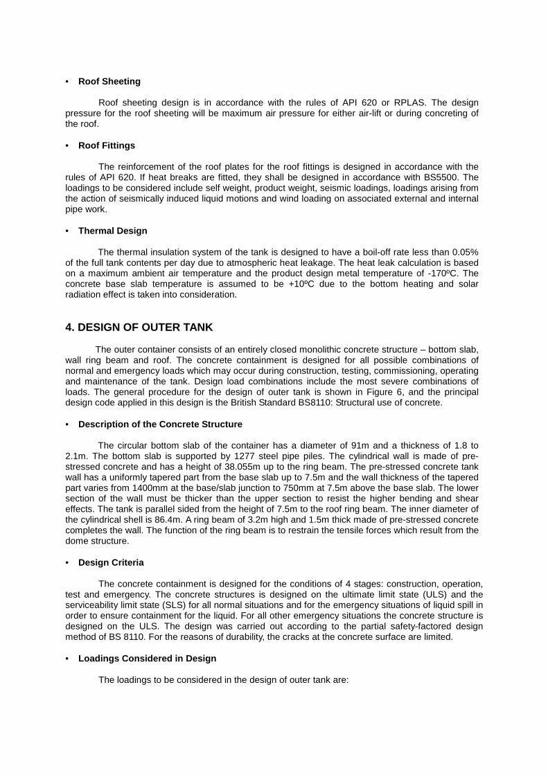
• Roof Sheeting Roof sheeting design is in accordance with the rules of API 620 or RPLAS. The design pressure for the roof sheeting will be maximum air pressure for either air-lift or during concreting of the roof. • Roof Fittings The reinforcement of the roof plates for the roof fittings is designed in accordance with the rules of API 620. If heat breaks are fitted, they shall be designed in accordance with BS5500. The loadings to be considered include self weight, product weight, seismic loadings, loadings arising from the action of seismically induced liquid motions and wind loading on associated external and internal pipe work. • Thermal Design The thermal insulation system of the tank is designed to have a boil-off rate less than 0.05% of the full tank contents per day due to atmospheric heat leakage. The heat leak calculation is based on a maximum ambient air temperature and the product design metal temperature of -170ºC. The concrete base slab temperature is assumed to be +10ºC due to the bottom heating and solar radiation effect is taken into consideration. 4. DESIGN OF OUTER TANK The outer container consists of an entirely closed monolithic concrete structure – bottom slab, wall ring beam and roof. The concrete containment is designed for all possible combinations of normal and emergency loads which may occur during construction, testing, commissioning, operating and maintenance of the tank. Design load combinations include the most severe combinations of loads. The general procedure for the design of outer tank is shown in Figure 6, and the principal design code applied in this design is the British Standard BS8110: Structural use of concrete. • Description of the Concrete Structure The circular bottom slab of the container has a diameter of 91m and a thickness of 1.8 to 2.1m. The bottom slab is supported by 1277 steel pipe piles. The cylindrical wall is made of pre-stressed concrete and has a height of 38.055m up to the ring beam. The pre-stressed concrete tank wall has a uniformly tapered part from the base slab up to 7.5m and the wall thickness of the tapered part varies from 1400mm at the base/slab junction to 750mm at 7.5m above the base slab. The lower section of the wall must be thicker than the upper section to resist the higher bending and shear effects. The tank is parallel sided from the height of 7.5m to the roof ring beam. The inner diameter of the cylindrical shell is 86.4m. A ring beam of 3.2m high and 1.5m thick made of pre-stressed concrete completes the wall. The function of the ring beam is to restrain the tensile forces which result from the dome structure. • Design Criteria The concrete containment is designed for the conditions of 4 stages: construction, operation, test and emergency. The concrete structures is designed on the ultimate limit state (ULS) and the serviceability limit state (SLS) for all normal situations and for the emergency situations of liquid spill in order to ensure containment for the liquid. For all other emergency situations the concrete structure is designed on the ULS. The design was carried out according to the partial safety-factored design method of BS 8110. For the reasons of durability, the cracks at the concrete surface are limited. • Loadings Considered in Design
The loadings to be considered in the design of outer tank are:
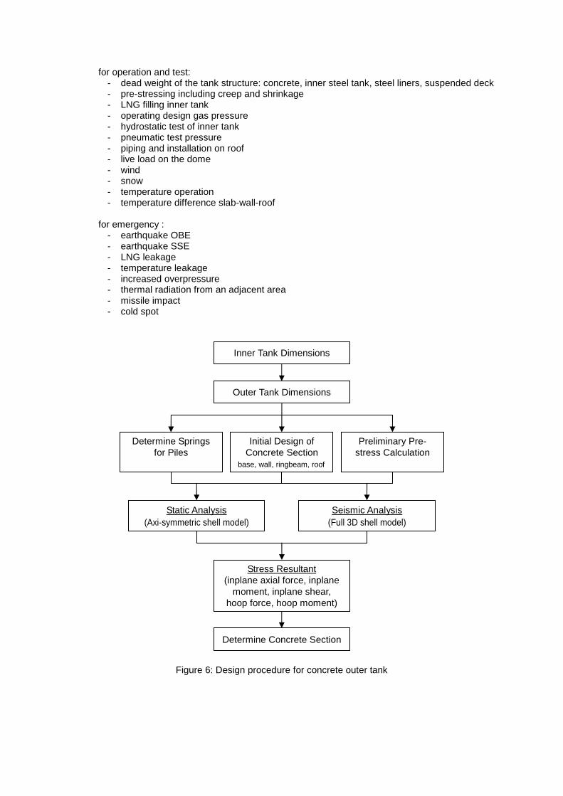
for operation and test: - dead weight of the tank structure: concrete, inner steel tank, steel liners, suspended deck - pre-stressing including creep and shrinkage - LNG filling inner tank - operating design gas pressure - hydrostatic test of inner tank - pneumatic test pressure - piping and installation on roof - live load on the dome - wind - snow - temperature operation - temperature difference slab-wall-roof
for emergency :
- earthquake OBE - earthquake SSE - LNG leakage - temperature leakage - increased overpressure - thermal radiation from an adjacent area - missile impact - cold spot
Figure 6: Design procedure for concrete outer tank
Inner Tank Dimensions
Outer Tank Dimensions
Determine Concrete Section
Determine Springs for Piles
Initial Design of Concrete Section
base, wall, ringbeam, roof
Preliminary Pre-stress Calculation
Static Analysis (Axi-symmetric shell model)
Seismic Analysis (Full 3D shell model)
Stress Resultant (inplane axial force, inplane
moment, inplane shear, hoop force, hoop moment)

• Static Analysis For the static analysis of linear sectional forces, the main concrete tank structure is modelled using a semi-finite element computer program for axis-symmetric systems. The model comprises the bottom slab, the wall, the roof ring beam and roof. Spring elements were used to model the pile foundation in order to take into account the interaction between the tank structure and the sub-soil. • Nonlinear Analysis In emergency cases in which the concrete is exposed to extreme temperatures due to heat radiation, non-linear effects of the concrete behaviour caused by the reduced stiffness due to crack formation is taken into account. The linear analysis, where the individual single load cases can be superposed, a non-linear analysis must be carried out for load combinations determined previously. For non-linear calculations the reinforcement is an input data. • Dynamic Analysis
The seismic calculations for OBE and SSE were done in two stages:
- tank structure : modal analysis of an axis-symmetric model using acceleration response spectra as excitation input. The whole system is required to remain in the elastic limit, no physical or geometrical nonlinearities shall occur.
- roof : additional modal analysis of a 3 dimensional finite element model (roof) using response spectra as excitation input.
Figure 7 shows an example of full seismic analysis model including the outer tank, internal structures and liquid. Figure 8 shows a seismic analysis result obtained on the model of Figure 7.
Figure 7: Full model for 3D seismic analysis Figure 8: Seismic analysis result
5. CONCLUSIONS Over the past 20 years, the LNG market in Korea has grown remarkably. In order to meet the natural gas demand, KOGAS has built many LNG storage tanks and a nation-wide gas transmission network and developed new techniques for LNG receiving terminal and LNG storage tanks. The KOGAS’ development project of the 200,000m3 above-ground 9% nickel steel full containment LNG storage tank was successfully completed in 2005 and the design was used for the construction of new tanks in the Tongyoung and Pyeongtaek Receiving Terminals. As compared to the KOGAS’ 150,000m3 tanks currently built, the 200,000m3 tank is expected to reduce the construction cost by 12% and the tank building site by 33%. The latter is very important for KOGAS in light of having difficulty with LNG terminal site. In addition, the large tank can reduce the boil-off rate by approximately 15%.

REFERENCES 1. Korean Government Report (2004). 7th Long-term Natural Gas Demand and Supply Plan”, Ministry of Commerce, Industry and Energy. 2. Hong, Seongho, and Lee, Kangwon (2004). A Study on the Localization of Design Technologies for LNG Storage Tanks. 14th International Conference & Exhibition on Liquefied Natural Gas, Doha, Qatar. 3. Nishizaki, T., et al. (2001). Largest aboveground PC LNG Storage Tank in the World, incorporating the latest technology-construction cost reduction and shortening of work period by employing new construction methods. Proc., 13th International Conference & Exhibition on Liquefied Natural Gas, IGU. IIR. GTI, PS6 4.1-11 4. Recommendations for the Design and Construction of Refrigerated Liquefied Gas Storage Tanks (1986). FEMUA. 5. Timishenko, S.D. and Woinowsky-Krieger, S. (1970). Theory of Plates and Shells, 2nd edition, McGraw-Hill 6. Goto, S., Kamiya, A. and Tajima, M. (2001). LNG Technological Progress in Japan-Three Decades of Evolution. Proc., 13th International Conference & Exhibition on Liquefied Natural Gas.” IGU/IIR/GTI, PO 23.5-9. 7. British Standard (BS) 7777: Flat-Bottomed Vertical, Cylindrical Storage Tanks for Low Temperature Service. 8. British Standard (BS) 8110: Structure Use of Concrete. 9. American Petroleum Institute (API) 620 : Recommended Rules for Design and Construction of Large, Welded Low Pressure Storage Tanks. 10. American Concrete Institute (ACI) 318-99: Building Code Requirements for Structural Concrete and Commentary.

List of Figures
Figure 1: Full containment LNG storage tank
Figure 2: Sectional view of the 200,000m3 full containment LNG storage tank
Figure 3: General design procedure for 9% nickel inner tank
Figure 4: Insulation and corner protection system
Figure 5: Top corner arrangement
Figure 6: Design procedure for concrete outer tank
Figure 7: Full model for 3D seismic analysis
Figure 8: Seismic analysis result