Embed Size (px)
Citation preview

Full Lotus floats are sold without struts, spreaders, and other installation hardware. This document contains construction drawings and photos of an installation for the Avid Flyer / Kitfox family, which also fits other aircraft with similar attachment points on the fuselage.
You can calculate the appropriate lengths of float struts and spreaders for your own plane, using a spreadsheet which is posted at http://rolf.nossum.net/ln-yti/ along with the latest version of this document and other info.
These drawings are made available free of charge, for anyone to use as they see fit. No claim is expressed or implied about their suitability for any particular installation.
Don't hesitate to contact me with your comments, questions or suggestions.
Many happy landings to all!
September 2004Rolf Nossum <[email protected]>
LN-YTI
Full Lotus Installation
Rev Jan 8, 2005
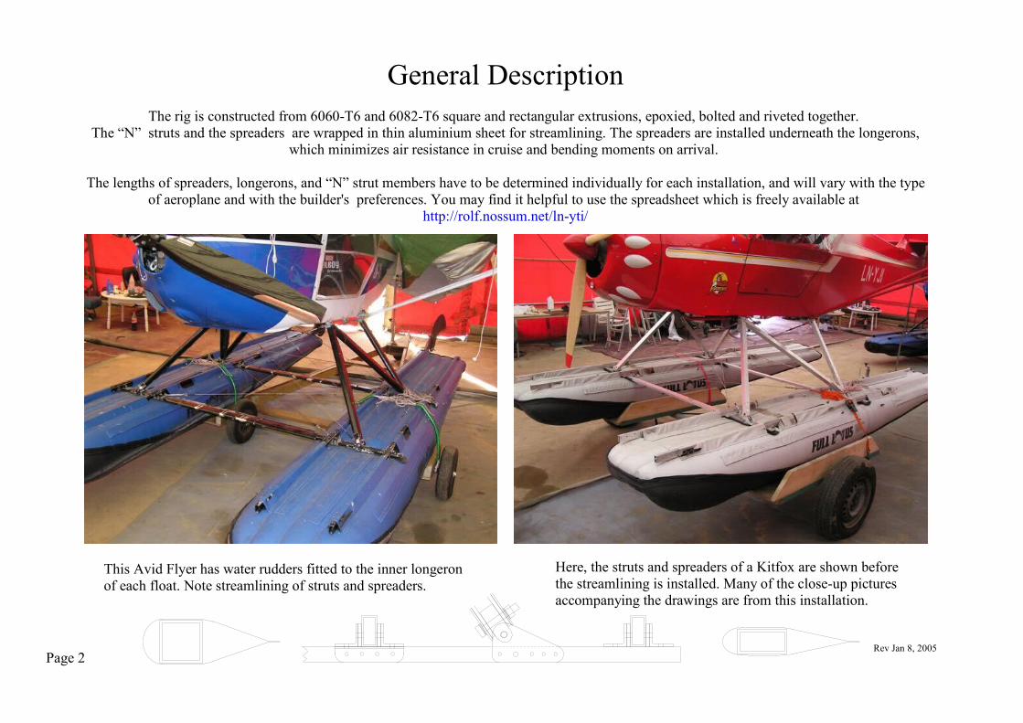
General DescriptionThe rig is constructed from 6060-T6 and 6082-T6 square and rectangular extrusions, epoxied, bolted and riveted together.
The “N” struts and the spreaders are wrapped in thin aluminium sheet for streamlining. The spreaders are installed underneath the longerons, which minimizes air resistance in cruise and bending moments on arrival.
The lengths of spreaders, longerons, and “N” strut members have to be determined individually for each installation, and will vary with the type of aeroplane and with the builder's preferences. You may find it helpful to use the spreadsheet which is freely available at
http://rolf.nossum.net/ln-yti/
This Avid Flyer has water rudders fitted to the inner longeron of each float. Note streamlining of struts and spreaders.
Here, the struts and spreaders of a Kitfox are shown before the streamlining is installed. Many of the close-up pictures accompanying the drawings are from this installation.
Page 2Rev Jan 8, 2005

Contents Page Rev
Full Lotus Installation 1 Jan 8, 2005
General Description 2 Jan 8, 2005
Contents / Parts List 3 Jan 8, 2005
Materials List 4 Oct 18, 2004
Preparations 5 Oct 15, 2004
Drawings 7 Oct 15, 2004
Parts List # req
L 4 Longeron 8 Oct 15, 2004
LD 16 Longeron Doubler 9 Oct 15, 2004
LBI 8 Longeron Bracket, Inner 10 Oct 15, 2004
LBO 8 Longeron Bracket, Outer 11 Oct 15, 2004
S 2 Spreader 12 Oct 18, 2004
SDF, SDR 2+2 Spreader Doubler, Front and Rear 13 Oct 15, 2004
SBI 8 Spreader Bracket, Inner 14 Oct 15, 2004
SBU 8 Spreader Bracket, U-joint 15 Oct 30, 2004
SC 4 Spreader Cushion 16 Oct 15, 2004
UJL 4 Universal Joint, Lower 17 Oct 15, 2004
UJU 4 Universal Joint, Upper 18 Oct 15, 2004
NF, NR 2+2 “N” Strut, Front and Rear Legs 19 Oct 15, 2004
NM 2 “N” Strut, Middle Leg 20 Oct 15, 2004
NDFR 16 “N” Strut Doubler, Front and Rear Legs 21 Oct 15, 2004
NDM 8 “N” Strut Doubler, Middle Leg 22 Oct 15, 2004
NWF, NWM, NWR, SW 2+2+2+2 “N” Strut and Spreader Streamlining Wraps 23 Dec 2, 2004
Assembly Notes 24-26 Oct 18, 2004
Caveat 27 Oct 15, 2004
Page 3 Rev Jan 8, 2005

Aluminium Alloy / Size Required For
Dimensions are in 6060-T6 rectangular tubing 20 x 40 x 2 See page 5 L,Smillimeters 6060-T6 square tubing 34 x 34 x 2 See page 5 NF,NM,NRunless otherwise noted. 6060-T6 bar 20 x 3 1800mm SDF,SDR
6060-T6 bar 30 x 5 9500mm LD, NDFR, NDM6060-T6 or 6082-T6 bar 50 x 6 750mm SBU6060-T6 angle 30 x 30 x 3 1800mm LBI, LBO, SBI6060-T6 or 6082-T6 bar 20 x 40 450mm UJL, UJU5052 sheet 0,5mm thick 1 x 2 m SW, NWF, NWM, NWR
BoltsDIN933 A4-80 M6-20 20 LBI/SBI, LBO/S
Stainless steel washers DIN931 A4-80 M6-35 4 LBI/SBI(regular and large) and DIN931 A4-80 M6-55 8 LBI/L, LBO/LA4-80 nylock nuts are DIN931 A4-80 M6-90 4 SBU/Salso required for these bolts. DIN931 A4-80 M8-60 4 NR/UJU, NF/UJL
DIN931 A4-80 M8-70 4 NR/UJL, NF/UJUDIN931 A4-80 M8-80 4 SBU/UJL
Sundry ItemsStainless steel pop rivets 4mm dia. in lengths up to 10mm; Stainless steel cable 3mm dia. for 3 cross braces; Stainless steel cable thimbles and bushings; Nicopress sleeves;Stainless steel tangs and shackles for cross brace attachments.6ea. 6mm stainless steel turnbuckles; 4ea. nylon belaying cleats;Aluminium pop rivets 3mm dia. in lengths up to 4mm;Epoxy glue; Acetone; Rubber sheet or bicycle inner tube.
Page 4
Materials List
Rev Oct 18, 2004

Page 5
Preparations
Rev Oct 15, 2004
The first order of business is to decide the geometry of your float rig. This will depend on the CG of your aeroplane at max gross weight, and on the incidence of your wing chord relative to the fuselage. Experience shows that the CG should be a small distance, say 100mm, ahead of the float step, and that the average wing chord should be a small angle, say 4 degrees, above the incidence of the float step. This section gives advice about how to achieve these goals. The following guidelines depend on a spreadsheet which is freely available at http://rolf.nossum.net/ln-yti/ . You may wish to download the spreadsheet and refer to it and to the sketch on the next page as you proceed. You must decide the following dimensions before you can start construction:
A) the length of the longerons,B) the distance between float centerlines,C) the distance between spreader centerlines,D) and the lengths of each of the three members of the ”N” struts.
A) The longerons should be slightly longer than the pockets running lengthwise on top of the floats. If you plan to install water rudders (which is highly recommended), then let the inner longerons protrude a short distance from the end of the float, providing convenient attachment points for the rudders.
B) The distance between float centerlines should be wide enough to provide lateral stability during displacement taxi and mooring, but narrow enough to give your ailerons some authority during step taxi. The two installations that are featured in the accompanying drawings measure 1650mm and 1700mm, respectively, between their float centerlines, which is ample for this size of aeroplane.
C) Measure the distances, forward and across, between pairs of attachment points at the belly of the fuselage. Note that the width of your fuselage may be slightly different at the front and rear attachment points. Decide how high above the top of the floats you want the belly of the fuselage to be (the two installations featured in the accompanying drawings have heights of 530mm and 575mm, respectively). Now, with the wings level and the plane in cruising attitude, drop a bob line from your CG at max gross weight. The step of the float, and the rear spreader, are located 100mm behind that line. This gives you the horizontal distance between the rear attachment points at the fuselage belly and the rear spreader. Decide a position for the front spreader some distance ahead of the front attachment points at the belly of the fuselage, so that the front member of the “N” strut will slant forward. This facilitates fine-tuning the rig later on.
D) Determine the angle between the average wing chord and the line between forward and rear attachment points on one side of the fuselage belly, subtract that from 4 degrees, and calculate the tangent of the result. Input the numbers arrived at in steps A)-D) into the spreadsheet, and it will calculate the corresponding lengths of the three “N” strut members for you.

Angle4o-v
Anglev
CG
Fron
t Spr
eade
r
Fron
t Atta
chm
ent P
oint
Floa
t Ste
p =
Rea
r Spr
eade
r
Rea
r Atta
chm
ent P
oint
Preparationscfr. previous page
Page 6 Rev Oct 15, 2004
100mm

Page 7
Full Lotus Installation DrawingsThese drawings are in the public domain. No claim is expressed or implied about
their suitability for any particular installation. Refer to http://rolf.nossum.net/ln-yti/ for the latest version and other info.
Rev Oct 15, 2004

L - LongeronRev Oct 15, 2004
FULL LOTUS INSTALLATIONThese drawings are in the public domain. No claim is expressed or implied about
their suitability for any particular installation. Refer to http://rolf.nossum.net/ln-yti/ for the latest version and other info.
Page 8
Make 4 ea. from 20x40x2 6060-T6 rectangular tubing.
Spreader Centerline
Side view
The length of the longerons and the position of the spreaders is unique to each installation.Refer to page 5, “Preparations”.
Top view
Close-up side view of Longeron at spreader position.
Ø = 6mm
Spreader Centerline
15m
m
40m
m
L
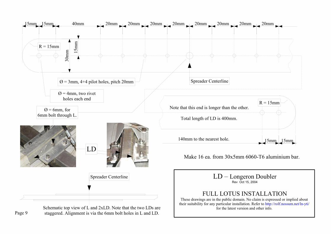
LD – Longeron DoublerRev Oct 15, 2004
FULL LOTUS INSTALLATIONThese drawings are in the public domain. No claim is expressed or implied about
their suitability for any particular installation. Refer to http://rolf.nossum.net/ln-yti/ for the latest version and other info.
Page 9
Make 16 ea. from 30x5mm 6060-T6 aluminium bar.
Total length of LD is 400mm.
15mm
Ø = 6mm, for6mm bolt through L.
15mm 40mm 20mm 20mm
15mm15mm
Note that this end is longer than the other.
20mm 20mm 20mm 20mm 20mm
140mm to the nearest hole.
20mm
15m
m
30m
m
Ø = 3mm, 4+4 pilot holes, pitch 20mm
Ø = 4mm, two rivetholes each end
LD
Spreader Centerline
Schematic top view of L and 2xLD. Note that the two LDs are staggered. Alignment is via the 6mm bolt holes in L and LD.
Spreader Centerline
R = 15mm
R = 15mm
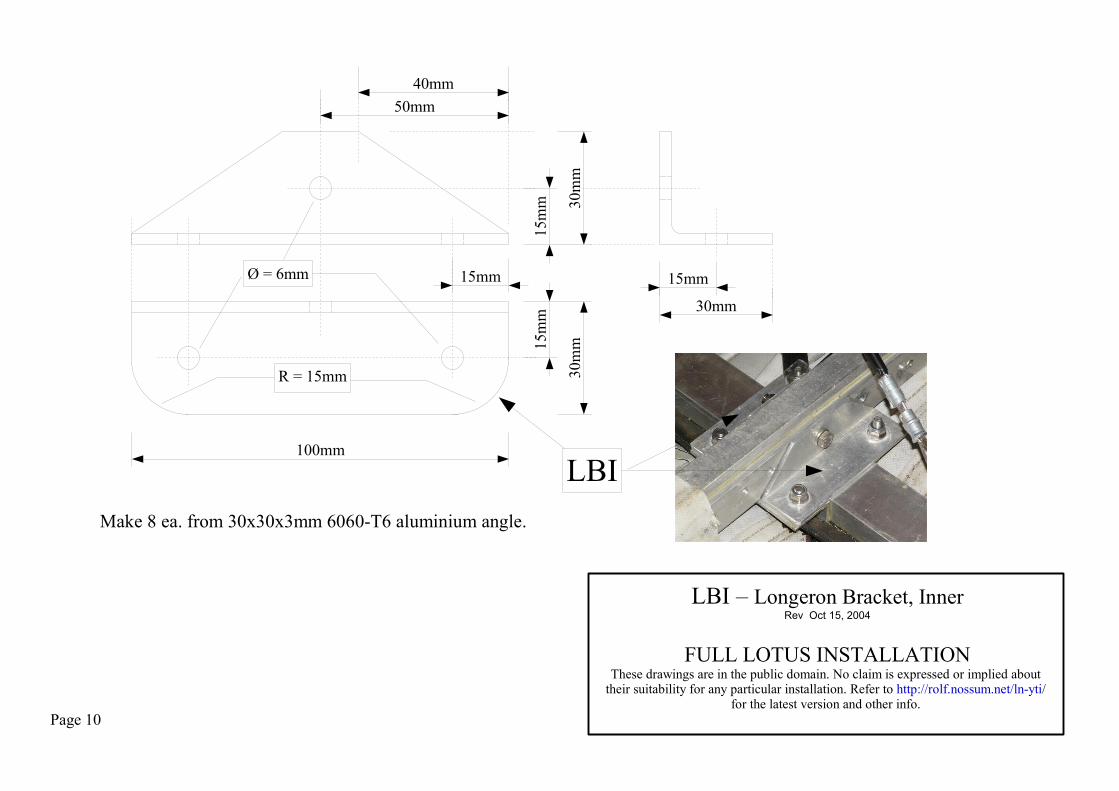
LBI – Longeron Bracket, InnerRev Oct 15, 2004
FULL LOTUS INSTALLATIONThese drawings are in the public domain. No claim is expressed or implied about
their suitability for any particular installation. Refer to http://rolf.nossum.net/ln-yti/ for the latest version and other info.
Page 10
Make 8 ea. from 30x30x3mm 6060-T6 aluminium angle.
Ø = 6mm
30m
m30
mm
15mm
100mm
15mm
30mm
40mm50mm
15m
m15
mm
R = 15mm
LBI
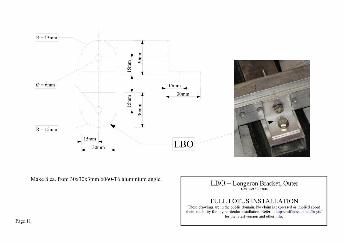
LBO – Longeron Bracket, OuterRev Oct 15, 2004
FULL LOTUS INSTALLATIONThese drawings are in the public domain. No claim is expressed or implied about
their suitability for any particular installation. Refer to http://rolf.nossum.net/ln-yti/ for the latest version and other info.
Page 11
Make 8 ea. from 30x30x3mm 6060-T6 aluminium angle.
Ø = 6mm
30m
m
15mm
30mm
15m
m
30m
m15m
m
15mm
30mm
R = 15mm
R = 15mm
LBO

S - SpreaderRev Oct 18, 2004
FULL LOTUS INSTALLATIONThese drawings are in the public domain. No claim is expressed or implied about
their suitability for any particular installation. Refer to http://rolf.nossum.net/ln-yti/ for the latest version and other info.
Page 12
Make 2 ea. from 20x40x2 6060-T6 rectangular tubing.
Float Centerline Float Centerline
233mm 233mmThe distance between float centerlines is unique to each installation.
Top view
Front view
Refer to page 5, “Preparations”.
S
178mm178mm
Float Centerline
Schematic view of spreader end, with brackets:

SDF – Spreader Doubler, FrontSDR – Spreader Doubler, Rear
Rev Oct 15, 2004
FULL LOTUS INSTALLATIONThese drawings are in the public domain. No claim is expressed or implied about
their suitability for any particular installation. Refer to http://rolf.nossum.net/ln-yti/ for the latest version and other info. Page 13
Make 2 ea. SDF and 2 ea. SDR from 20x3mm 6060-T6 aluminium bar.
50mm 50mm50mm
10m
m
20m
m
Ø = 4mm rivet holes, pitch 50mm,running the entire length of SDF and SDR.
R = 10mm
10mm 10mm
SDF and SDR are identical except for their lengths: Total length of SDF is 570mm and total length of SDR is 320mm.
SDR
SDF
Schematic top view of Spreader with SDF and SDR.
Middle of Spreader.

SBI – Spreader Bracket, InnerRev Oct 15, 2004
FULL LOTUS INSTALLATIONThese drawings are in the public domain. No claim is expressed or implied about
their suitability for any particular installation. Refer to http://rolf.nossum.net/ln-yti/ for the latest version and other info.
Page 14
Make 8 ea. from 30x30x3mm 6060-T6 aluminium angle.
SBI
15mm 15mm15mm20mm 20mm 20mm 15mm
10m
m
15m
m
90mm
30m
m
20m
m
Ø = 6mm
Ø = 4mm
R = 15mm
R = 10mm
SBISchematic side and front views of SBI/LBI assembly.

SBU – Spreader Bracket, U-jointRev Oct 30, 2004
FULL LOTUS INSTALLATIONThese drawings are in the public domain. No claim is expressed or implied about
their suitability for any particular installation. Refer to http://rolf.nossum.net/ln-yti/ for the latest version and other info.
Page 15
90mm
30mm
Ø = 8mm
Ø = 6mm
Ø = 4mm
50m
m35
mm
10m
m
10mm
Float Centerline
R = 15mm
15mm
50mm65mm
80mm
R = 10mm
R = 10mm
Attach cross brace here.Make 8 ea. from 6x50mm 6060-T6 or 6082-T6 aluminium bar.
Schematic front view of SBU+UJL assembly (rear spreader).

SC – Spreader CushionRev Oct 15, 2004
FULL LOTUS INSTALLATIONThese drawings are in the public domain. No claim is expressed or implied about
their suitability for any particular installation. Refer to http://rolf.nossum.net/ln-yti/ for the latest version and other info.
Page 16
Cut 4 ea. from rubber sheet or bicycle inner tube.
500mm
60m
m
SC

UJL – Universal Joint, LowerRev Oct 15, 2004
FULL LOTUS INSTALLATIONThese drawings are in the public domain. No claim is expressed or implied about
their suitability for any particular installation. Refer to http://rolf.nossum.net/ln-yti/ for the latest version and other info.
Page 17
Ø = 8mm
R = 20mm
10m
m
30m
m50m
m
40mm
20m
m
20mm
R = 10mm
Make 4 ea. from 20 x 40 mm 6082-T6 aluminium bar.
UJL
NDM
NDFR
10mm
20mm

UJU – Universal Joint, UpperRev Oct 15, 2004
FULL LOTUS INSTALLATIONThese drawings are in the public domain. No claim is expressed or implied about
their suitability for any particular installation. Refer to http://rolf.nossum.net/ln-yti/ for the latest version and other info.
Page 18
40mm
20m
m
20mm
Ø=8mm
R = 20mm
20m
m
20mm
45m
m55m
m
R = 10mm
Make 4 ea. from 20 x 40 mm 6082-T6 aluminium bar.
Ø = 1/4” = 6.35mm(adapt to airframe)
NDM
UJU
NDFR
10mm
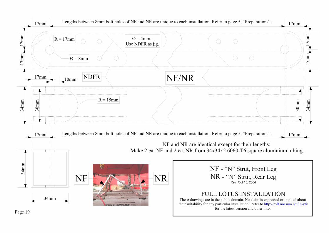
NF - “N” Strut, Front LegNR - “N” Strut, Rear Leg
Rev Oct 15, 2004
FULL LOTUS INSTALLATIONThese drawings are in the public domain. No claim is expressed or implied about their suitability for any particular installation. Refer to http://rolf.nossum.net/ln-yti/
for the latest version and other info. Page 19
Ø = 8mm
R = 17mm
NF and NR are identical except for their lengths: Make 2 ea. NF and 2 ea. NR from 34x34x2 6060-T6 square aluminium tubing.
17mm17
mm
17m
m
17m
m17
mm
17mmLengths between 8mm bolt holes of NF and NR are unique to each installation. Refer to page 5, “Preparations”.34
mm
30m
m R = 15mm
34m
m
30m
m
17mm 17mmLengths between 8mm bolt holes of NF and NR are unique to each installation. Refer to page 5, “Preparations”.
10mm17mm
34m
m
Ø = 4mm. Use NDFR as jig.
NF NR
34mm
NF/NRNDFR

NM - “N” Strut, Middle LegRev Oct 15, 2004
FULL LOTUS INSTALLATIONThese drawings are in the public domain. No claim is expressed or implied about their suitability for any particular installation. Refer to http://rolf.nossum.net/ln-yti/
for the latest version and other info.
Page 20
Make 2 ea. from 34x34x2 6060-T6 square aluminium tubing.
12m
m22
mm
34m
m
Ø = 4mm. Use NDM as jig.
22mm20mm
Length of NM (nominally between the 8mm bolt holes in NDM at each end of NM) is unique to each installation. Refer to page 5, “Preparations”.
Length of NM (nominally between the 8mm bolt holes in NDM at each end of NM) is unique to each installation. Refer to page 5, “Preparations”.
22mm
34m
m
12m
m
NM
34mm
20mm NDM NM

Make 16 ea. from 5x30mm 6060-T6 or 6082-T6 aluminium bar:
NDFR - “N” Strut Doubler, Front and Rear LegsRev Oct 15, 2004
FULL LOTUS INSTALLATIONThese drawings are in the public domain. No claim is expressed or implied about their suitability for any particular installation. Refer to http://rolf.nossum.net/ln-yti/
for the latest version and other info.
NDFR
No rivet in this area. Improved rivet pattern avoids
interference with NDM.
NDFR installs on the inside of the front and rear legs,cfr. NF and NR drawings. 2 required at each end, top and bottom, of each leg.
Page 21
30mm
60m
m 45m
m15
mm
Ø = 8mm
Ø = 4mm
R = 15mm65
mm
75m
m95
mm
15mm
R = 8mm
60m
m 45m
m15
mm
Ø = 8mm
Ø = 4mm
R = 15mm
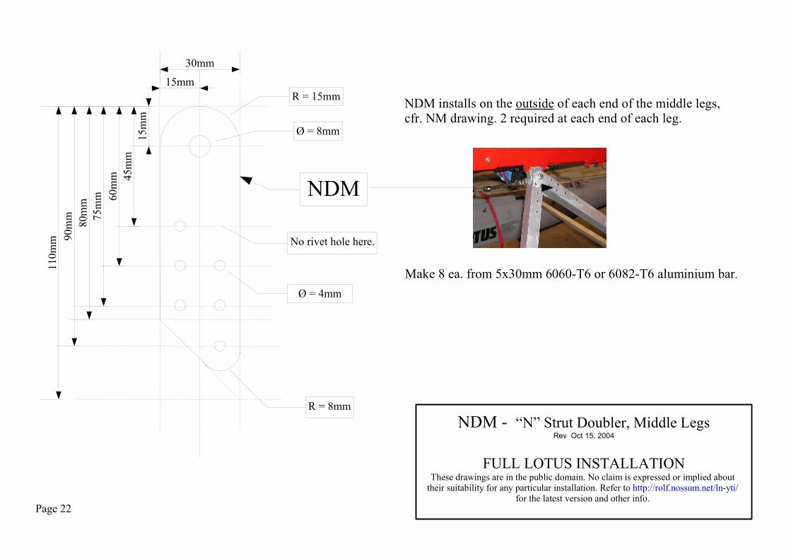
NDM - “N” Strut Doubler, Middle LegsRev Oct 15, 2004
FULL LOTUS INSTALLATIONThese drawings are in the public domain. No claim is expressed or implied about
their suitability for any particular installation. Refer to http://rolf.nossum.net/ln-yti/ for the latest version and other info.
NDM
No rivet hole here.
NDM installs on the outside of each end of the middle legs,cfr. NM drawing. 2 required at each end of each leg.
75m
m
Make 8 ea. from 5x30mm 6060-T6 or 6082-T6 aluminium bar.
Page 22
90m
m11
0mm
80m
m
30mm
15mm
R = 8mm
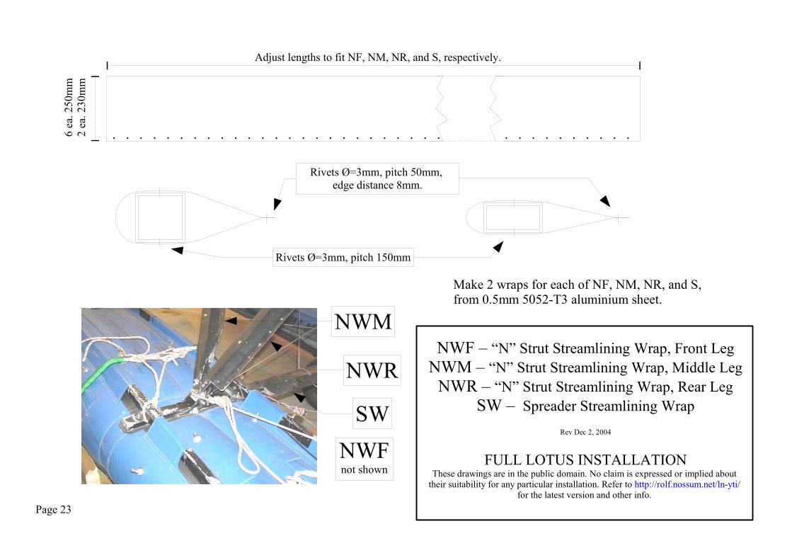
NWF – “N” Strut Streamlining Wrap, Front LegNWM – “N” Strut Streamlining Wrap, Middle Leg
NWR – “N” Strut Streamlining Wrap, Rear LegSW – Spreader Streamlining Wrap
Rev Dec 2, 2004
FULL LOTUS INSTALLATIONThese drawings are in the public domain. No claim is expressed or implied about
their suitability for any particular installation. Refer to http://rolf.nossum.net/ln-yti/ for the latest version and other info.
Page 23
Make 2 wraps for each of NF, NM, NR, and S, from 0.5mm 5052-T3 aluminium sheet.
Adjust lengths to fit NF, NM, NR, and S, respectively.6
ea. 2
50m
m2
ea. 2
30m
m
Rivets Ø=3mm, pitch 50mm, edge distance 8mm.
NWM
NWR
SWNWFnot shown
Rivets Ø=3mm, pitch 150mm
Page 24
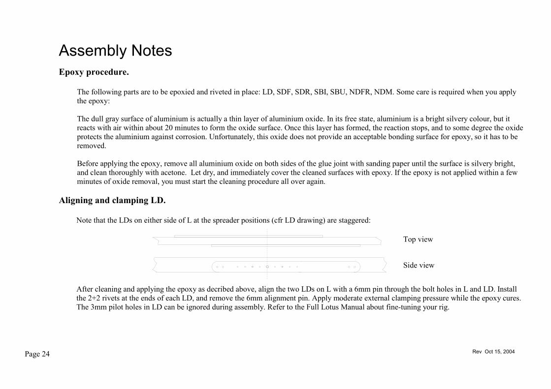
Assembly Notes
Rev Oct 15, 2004
Epoxy procedure.
The following parts are to be epoxied and riveted in place: LD, SDF, SDR, SBI, SBU, NDFR, NDM. Some care is required when you apply the epoxy:
The dull gray surface of aluminium is actually a thin layer of aluminium oxide. In its free state, aluminium is a bright silvery colour, but it reacts with air within about 20 minutes to form the oxide surface. Once this layer has formed, the reaction stops, and to some degree the oxide protects the aluminium against corrosion. Unfortunately, this oxide does not provide an acceptable bonding surface for epoxy, so it has to be removed.
Before applying the epoxy, remove all aluminium oxide on both sides of the glue joint with sanding paper until the surface is silvery bright, and clean thoroughly with acetone. Let dry, and immediately cover the cleaned surfaces with epoxy. If the epoxy is not applied within a few minutes of oxide removal, you must start the cleaning procedure all over again.
Aligning and clamping LD.
Note that the LDs on either side of L at the spreader positions (cfr LD drawing) are staggered:
After cleaning and applying the epoxy as decribed above, align the two LDs on L with a 6mm pin through the bolt holes in L and LD. Install the 2+2 rivets at the ends of each LD, and remove the 6mm alignment pin. Apply moderate external clamping pressure while the epoxy cures. The 3mm pilot holes in LD can be ignored during assembly. Refer to the Full Lotus Manual about fine-tuning your rig.
Side view
Top view

Page 25
Assembly Notes, cont.
Rev Oct 15, 2004
Cleats.
Belaying cleats made of nylon weigh next to nothing. Install them at the front and rear ends of the outer longerons.
Alignment of SBU.
Make sure the 8mm hole in SBU is aligned on the float centerline. On the 12.5 ft Full Lotus floats that are featured in the photos, the longeron pockets are 356mm apart. If your floats are different, then it will be necessary to change the length of S and the positions of SBI and LBO.
178mm178mm
Float Centerline

Page 26
Assembly Notes, cont.
Rev Oct 18, 2004
Attaching the vertical cross braces.
Connect the turnbuckles at the top of the vertical cross braces to the airframe as shown here. Do not connect them to the transverse M8 bolts through UJU (despite what you may have seen in other photos).
Connect the lower ends of the vertical cross braces to the M6 bolts through SBU. Avoid connecting them to any of the M8 bolts though UJL, as this would subject S to an unacceptable bending moment.
Attaching the horizontal cross brace.
The horizontal cross brace is attached to the LBI/SBI assemblies with DIN931A4-80 M6-35 bolts. At one end, the fork of the turnbuckle grips LBI+SBI, at the other end a stainless steel shackle is used. A cable bushing or a flat stainless steel tang would be acceptable in lieu of the shackle, preferably on the underside of SBI.
Here.
Not here.
Here.
Not here.

Page 27
Caveat.
Be sure to get some dual instruction before attempting to fly a seaplane as PIC.
Have fun, and fly safely!
Assembly Notes 7Assembly Notes 7
Rev Oct 15, 2004