Embed Size (px)
Citation preview

Enhanced energy conversion performance of Philippine photovoltaic panels through tilt angle adjustments: A mechatronics approachFidel Diaz, Jerrold Ngo, Maximillian Pascual, Albert Planes, and Alvin Chua*
Mechatronics Research LaboratoryMechanical Engineering DepartmentDe La Salle University, Manila, Philippines
ARTICLE
This study focuses on improving the energy conversion performance of photovoltaic panels in the Philippines with monthly and quarterly tilt angle adjustments. The study employs a mechatronic approach to verify the performance of PV systems. A mathematical
model is used to estimate the daily extraterrestrial radiation received by a unit area in order to generate the optimal PV tilt angles in the Philippines. The simulation results proves that it is worth changing the tilt angle of a PV panel facing true south on a monthly and quarterly basis in order to achieve significant irradiance gains over panels fixed at the computed optimal year tilt. Experimental results show that energy gains of up to 10% over a year period could be achieved using this technique.
KEYWORDS
Solar energy, extraterrestrial irradiation, energy gains, photovoltaic panels, mechatronics
INTRODUCTION
The adaption of solar energy in the Philippines is slowly becoming a reality. Solar technology is considered to be clean and abundant hence its desirability. It is this situation that has spurred the Philippine government and the private sector to invest in the technology. Investment is manifest in the construction of power plants and implementation rural electrification projects with photovoltaic (PV) arrays as the power generator. However, the continuous improvement in the performance of PV arrays is still the subject of different studies.
Fixed photovoltaic panels are widely used in most commercial applications. It is therefore important to find the right angle to maximize the harnessing of solar energy. In the previous studies, it was concluded that in the northern hemisphere, the optimum orientation is south facing and the optimum tilt angle depends only on the latitude. No definite value is given researchers for the optimum tilt angle. For example, Heywood (Heywood, 1971) concluded that βopt = ϕ − 10º, Lunde (Lunde,1980) and Garge (Garge, 1982) suggested βopt = ϕ ± 15º where φ is latitude of the location and where plus and minus signs are used in winter and summer, respectively. Theoretical models for βopt were suggested by Lewis (Lewis, 1987), who considered two different models for βopt while El-Kassaby (El-Kassaby, 1988) and Hassab (El-Kassaby and Hassab, 1994) introduced an analytical equation to
Vol. 7 | No. 1 | 2014 Philippine Science Letters 7
*Corresponding authorEmail Address: [email protected]: May 9, 2013 Revised: October 3, 2013Accepted: October 4, 2013Published: January 25, 2014Editor-in-charge and Reviewer: Danilo B. Romero
get the daily optimum angle at any latitude. They also concluded that the optimum tilt angle for any period could be obtained by integrating the analytical equation over the required period. Skeiker (Skeiker, 2009) presented an analytical procedure which required the least number of parameters to determine βopt for any chosen day, latitude in either hemisphere but was only able to apply the model to Syria. In the studies reviewed, there is a lack of experimental setup to validate the simulation results.
This study extends the previous studies done by applying the mathematical equations to the Philippine geographical location and experimentally verifying the energy conversion gains through a mechatronic setup consisting of mechanically adjustable 20W PV panels, electronic sensors and a data acquisition software. Optimal quarterly and monthly tilt angles will be computed and used for two panels while one panel will be oriented at the computed optimal year tilt.
MATERIALS AND METHODS
Mathematical Equations to Generate the Optimal Tilt Angles
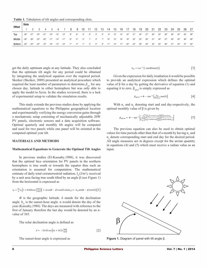
In previous studies (El-Kassaby,1988), it was discovered that the optimal face orientation for PV panels in the northern hemisphere is true south or towards the equator thus such an orientation is assumed for computation. The mathematical estimate of daily total extraterrestrial radiation, Id (J/m2), received by a unit area facing true south tilted by an angle β (see Figure 1) from the horizontal is expressed as
[1]
Ф is the geographic latitude. δ stands for the declination angle. hss is the sunset-hour angle. n would denote the day of the year (Kassaby,1988). The days are measured with reference to the first of January therefore the last day would be denoted by an n-value of 365.
The solar declination angle is defined as
[2]
The sunset-hour angle is expressed as
[3]
Given the expression for daily irradiation it would be possible to provide an analytical expression which defines the optimal value of β for a day by getting the derivative of equation (1) and equating it to zero. βopt,d is simply expressed as
[4]
With n1 and n2 denoting start and end day respectively, the optimal monthly value of β is given by
The previous equation can also be used to obtain optimal values for time periods other than that of a month by having n1 and n2 denote corresponding start and end day for the desired period. All angle measures are in degrees except for the arctan quantity in equations (4) and (5) which must receive a radian value as an input.
8 Philippine Science Letters Vol. 7 | No. 1 | 2014
[5]
Figure 1 Diagram of panel with tilt angle β
Figure 2 Mechatronic Setup Block Diagram
Figure 3 Solar Panels in the study
Figure 1. Diagram of panel with tilt angle β.
Table 1. Tabulation of tilt angles and corresponding slots.
OffsetSlots
1 2 3 4 5 6 7 8 9 10 11 12 13 14 15 16 17 18 19 20 21 22 23 24 25 26 27
Top -30° -27° -24° -21° -18° -15° -12° -9° -6° -3° 0° 3° 6° 9° 12° 15° 18° 21° 24° 27° 30° 33° 36° 39° 42° 45° 48°
Middle -29° -26° -23° -20° -17° -14° -11° -8° -5° -2° 1° 4° 7° 10° 13° 16° 19° 22° 25° 28° 31° 34° 37° 40° 43° 46° 49°
Bottom -28° -25° -22° -19° -16° -13° -10° -7° -4° -1° 2° 5° 8° 11° 14° 17° 20° 23° 26° 29° 32° 35° 38° 41° 44° 47° 50°
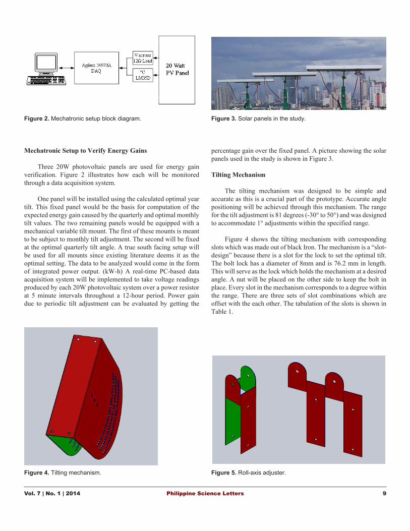
Mechatronic Setup to Verify Energy Gains
Three 20W photovoltaic panels are used for energy gain verification. Figure 2 illustrates how each will be monitored through a data acquisition system.
One panel will be installed using the calculated optimal year tilt. This fixed panel would be the basis for computation of the expected energy gain caused by the quarterly and optimal monthly tilt values. The two remaining panels would be equipped with a mechanical variable tilt mount. The first of these mounts is meant to be subject to monthly tilt adjustment. The second will be fixed at the optimal quarterly tilt angle. A true south facing setup will be used for all mounts since existing literature deems it as the optimal setting. The data to be analyzed would come in the form of integrated power output. (kW-h) A real-time PC-based data acquisition system will be implemented to take voltage readings produced by each 20W photovoltaic system over a power resistor at 5 minute intervals throughout a 12-hour period. Power gain due to periodic tilt adjustment can be evaluated by getting the
percentage gain over the fixed panel. A picture showing the solar panels used in the study is shown in Figure 3.
Tilting Mechanism
The tilting mechanism was designed to be simple and accurate as this is a crucial part of the prototype. Accurate angle positioning will be achieved through this mechanism. The range for the tilt adjustment is 81 degrees (-30° to 50°) and was designed to accommodate 1° adjustments within the specified range.
Figure 4 shows the tilting mechanism with corresponding
slots which was made out of black Iron. The mechanism is a “slot-design” because there is a slot for the lock to set the optimal tilt. The bolt lock has a diameter of 8mm and is 76.2 mm in length. This will serve as the lock which holds the mechanism at a desired angle. A nut will be placed on the other side to keep the bolt in place. Every slot in the mechanism corresponds to a degree within the range. There are three sets of slot combinations which are offset with the each other. The tabulation of the slots is shown in Table 1.
Vol. 7 | No. 1 | 2014 Philippine Science Letters 9
Figure 1 Diagram of panel with tilt angle β
Figure 2 Mechatronic Setup Block Diagram
Figure 3 Solar Panels in the study
Figure 2. Mechatronic setup block diagram.
Figure 1 Diagram of panel with tilt angle β
Figure 2 Mechatronic Setup Block Diagram
Figure 3 Solar Panels in the study
Figure 3. Solar panels in the study.
Figure 4 Tilting Mechanism
Table 1 Tabulation of Tilt Angles and Corresponding Slots
Figure 5 Roll-axis Adjuster
Figure 4. Tilting mechanism.
Figure 4 Tilting Mechanism
Table 1 Tabulation of Tilt Angles and Corresponding Slots
Figure 5 Roll-axis Adjuster
Figure 5. Roll-axis adjuster.
Roll-axis adjuster
The ground is not always perfectly horizontal. The design of the PV mount should have the ability to compensate for the horizontal adjustments. Figure 5 shows the roll-axis adjuster that will allow for the roll angle to be 0°. This part also connects the tip of the base-pole and the tilting mechanism. The material used was also black iron.
Low-cost electronic pyranometer
Verification of daily optimal tilt by means of manual incremental tilting has proven impossible due to fast changing cloud conditions during the wet season. Since the process is quite slow, sudden change in cloud cover would cause a sudden change in voltage readout over the load and would likely lead to an erroneous maximum. Thus what follows is a description of a system that automates the process through a low-cost electronic pyranometer (see Figure 6).
The electromechanical component of the mechanized pyranometer tilting system is a stepper motor. A model KH42HM2B05B made by Japan Servo Co. Ltd. was selected. The motor has a 1.8 degree step and has sufficient torque to rotate the relatively light photodiode that would be attached to a plastic disc. A plastic disc was chosen over an arm design due to its greater balance when undergoing a rotating motion. The motor is set to operate in half-step mode in order to approximate a 1 degree tilt increment. A 50.4 degree angular displacement is scanned by the system. The motor, motor controller and MCU are housed in a black plastic casing in order to minimize reflected radiation. The system is intended to be mounted to enable southward tilting with little or no roll -axis displacement. Also, the device in its inactive state should have the photodiode perfectly leveled so as to ensure accurate global radiation readings. To enable such leveling, screw pegs were incorporated. Figure 7 shows the actual low-cost electronic pyranometer. A stepper motor driver was purchased to drive the motor. It can divide a single step into half, four, eight and sixteen micro-steps. It receives commands
10 Philippine Science Letters Vol. 7 | No. 1 | 2014
Figure 6 Low Cost Electronic Pyranometer
Figure 7 Actual Low Cost Electronic Pyranometer
Figure 8 %Gain vs. Geographical Latitude
Figure 7. Actual low-cost electronic pyranometer.
Figure 6 Low Cost Electronic Pyranometer
Figure 7 Actual Low Cost Electronic Pyranometer
Figure 8 %Gain vs. Geographical Latitude
Figure 9 Optimal Monthly Tilt Angle vs. Geographical Latitude
Figure 10 Plot of % Gain over panel oriented at computed year tilt vs.
Figure 9. Optimal monthly tilt angle versus geopgraphical latitude.
Figure 8. Percent gain versus geographical latitude.
Figure 6 Low Cost Electronic Pyranometer
Figure 7 Actual Low Cost Electronic Pyranometer
Figure 8 %Gain vs. Geographical Latitude
Figure 6. Low-cost electronic pyranometer.
via parallel interface and is active-low in setting. It has a 4-bit parallel input. Such inputs are: step, halfstep, reverse rotation and free-wheeling brake.
RESULTS AND DISCUSSION
Simulation Results Using the Mathematical Equations
A program is used to conduct operational iterations of equations (4) and (5) discussed previously in order to generate β values for all days of the year with Philippine latitudes (4°-21° N) as the input latitude value. Iterations would also be done in order to obtain monthly, quarterly, and year β values using the same latitude inputs as those used for daily β values. The program used for computation is Matlab. Equation (1) is used to estimate extraterrestrial irradiation received by a unit extraterrestrial area with a specific tilt angle in a day. With this equation total irradiation for an entire year can be calculated for a year-round fixed tilt, monthly tilt adjustment, quarterly tilt adjustment, and
daily tilt adjustment. Values obtained are to be evaluated in terms of percentage irradiation gain achieved over a panel oriented using the calculated optimal year tilt. Computed gains are tabulated for all Philippine latitudes. A graph of percentage gain plotted versus adjustment frequency (i.e. how often panels would receive a change in tilt angle in a year) for all latitudes is also produced.
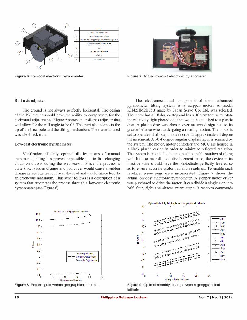
Figure 8 indicates gains over a panel using computed year tilt range from 10.2% to 10.4% for daily adjustments; 10% to 10.1% for monthly adjustments and 8.4-8.5% for quarterly adjustment depending on geographical latitude. From the same figure it can be deduced that more northern latitudes achieve higher gains.
Figure 9 shows optimal monthly tilt plotted against different Philippine latitudes. Monthly tilt adjustment is a convenient means of achieving gains over a fixed panel setup that come close to the gains achieved by doing daily tilt adjustment. The defined periods are intuitive and the adjustment frequency is not overly cumbersome.
Vol. 7 | No. 1 | 2014 Philippine Science Letters 11
Figure 9 Optimal Monthly Tilt Angle vs. Geographical Latitude
Figure 10 Plot of % Gain over panel oriented at computed year tilt vs.
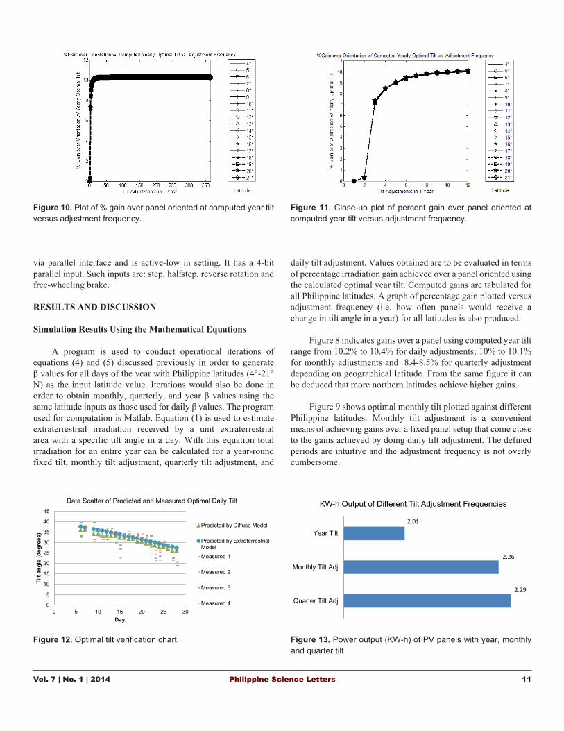
Figure 10. Plot of % gain over panel oriented at computed year tilt versus adjustment frequency.
Figure 12 Optimal Tilt Verification Chart
05
1015202530354045
0 5 10 15 20 25 30
Tilt
Angl
e (d
eg)
Day
Data Scatter of Predicted and Measured Optimal Daily Tilt
Predicted by Diffuse Model
Predicted by ExtraterrestrialModel
Measured 1
Measured 2
Measured 3
Measured 4
Figure 11 Close-up plot of % Gain over panel oriented at computed year tilt vs. Adjustment Frequency
Figure 11. Close-up plot of percent gain over panel oriented at computed year tilt versus adjustment frequency.
Figure 12 Optimal Tilt Verification Chart
0
5
10
15
20
25
30
35
40
45
0 5 10 15 20 25 30
Tilt
angl
e (d
egre
es)
Day
Data Scatter of Predicted and Measured Optimal Daily Tilt
Predicted by Diffuse Model
Predicted by ExtraterrestrialModelMeasured 1
Measured 2
Measured 3
Measured 4
Figure 11 Close-up plot of % Gain over panel oriented at computed year tilt vs. Adjustment Frequency
Figure 12. Optimal tilt verification chart.
Figure 13 Power Output (KW-h) of PV Panels with Year, Monthly and Quarter Tilt
2.29
2.26
2.01
Quarter Tilt Adj
Monthly Tilt Adj
Year Tilt
KW-h Output of Different Tilt Adjustment Frequencies
Figure 13. Power output (KW-h) of PV panels with year, monthly and quarter tilt.
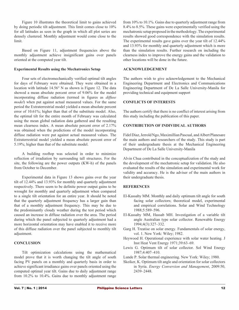
Figure 10 illustrates the theoretical limit to gains achieved by doing periodic tilt adjustment. This limit comes close to 10% for all latitudes as seen in the graph in which all plot series are densely clustered. Monthly adjustment would come close to the limit.
Based on Figure 11, adjustment frequencies above the monthly adjustment achieve insignificant gains over panels oriented at the computed year tilt.
Experimental Results using the Mechatronics Setup
Four sets of electromechanically verified optimal tilt angles for days of February were obtained. They were obtained in a location with latitude 14.56° N as shown is Figure 12. The data showed a mean absolute percent error of 9.06% for the model incorporating diffuse radiation (termed in figures as diffuse model) when put against actual measured values. For the same period the Extraterrestrial model yielded a mean absolute percent error of 10.61%; higher than that of the substitute model. Also, the optimal tilt for the entire month of February was calculated using the mean global radiation data gathered and the resulting mean clearness index. A mean absolute percent error of 2.17% was obtained when the predictions of the model incorporating diffuse radiation were put against actual measured values. The Extraterrestrial model yielded a mean absolute percent error of 5.19%; higher than that of the substitute model.
A building rooftop was selected in order to minimize reflection of irradiation by surrounding tall structures. For the site, the following are the power outputs (KW-h) of the panels from October to December.
Experimental data in Figure 13 shows gains over the year tilt of 12.44% and 13.93% for monthly and quarterly adjustment respectively. There seem to be definite power output gains to be wrought for monthly and quarterly adjustment when compared to a single tilt orientation for an entire year. It should be noted that the quarterly adjustment frequency has a larger gain than that of a monthly adjustment frequency. This may be due to the predominantly cloudy weather during the test period which caused an increase in diffuse radiation over the area. The period during which the panel subjected to quarterly adjustment had a more horizontal orientation may have enabled it to receive more of this diffuse radiation over the panel subjected to monthly tilt adjustment.
CONCLUSION
Tilt optimization calculations using the mathematical model prove that it is worth changing the tilt angle of south facing PV panels on a monthly and quarterly basis in order to achieve significant irradiance gains over panels oriented using the computed optimal year tilt. Gains due to daily adjustment range from 10.2% to 10.4%. Gains due to monthly adjustment range
from 10% to 10.1%. Gains due to quarterly adjustment range from 8.4% to 8.5%. These gains were experimentally verified using the mechatronic setup proposed in the methodology. The experimental results showed good correspondence with the simulation results. The experimental results gave gains over the year tilt of 12.44% and 13.93% for monthly and quarterly adjustment which is more than the simulation results. Further research on including the clearness index to improve the energy gains and the validation to other locations will be done in the future.
ACKNOWLEDGEMENT
The authors wish to give acknowledgement to the Mechanical Engineering Department and Electronics and Communications Engineering Department of De La Salle University-Manila for providing technical and equipment support
CONFLICTS OF INTERESTS
The authors certify that there is no conflict of interest arising from this study including the publication of this paper.
CONTRIBUTION OF INDIVIDUAL AUTHORS
Fidel Diaz, Jerrold Ngo, Maximillian Pascual, and Albert Planesare the main authors and researchers of the study. This study is part of their undergraduate thesis at the Mechanical Engineering Department of De La Salle University-Manila
Alvin Chua contributed in the conceptualization of the study and the development of the mechatronic setup for validation. He also evaluated the results of the simulation and experimental work for validity and accuracy. He is the adviser of the main authors in their undergraduate thesis.
REFERENCES
El-Kassaby MM. Monthly and daily optimum tilt angle for south facing solar collectors; theoretical model, experimental and empirical correlations. Solar and Wind Technology 1988;5:589–596.
El-Kassaby MM, Hassab MH. Investigation of a variable tilt angle Australian type solar collector. Renewable Energy 1994;4(3):327–332.
Garg H. Treatise on solar energy. Fundamentals of solar energy, vol. 1. New York: Wiley; 1982.
Heywood H. Operational experience with solar water heating. J Inst Heat Vent Energy 1971;39:63–69.
Lewis G. Optimum tilt of solar collector. Sol Wind Energy 1987;4:407–410.
Lunde P. Solar thermal engineering. New York: Wiley; 1980.Skeiker, K. Optimum tilt angle and orientation for solar collectors
in Syria. Energy Conversion and Management, 2009:50, 2439–2448.
Vol. 7 | No. 1 | 2014 Philippine Science Letters 12


![Balisacan & Pernia 2002-The Rural Road to Poverty Reduction [Philippine Experience]-147.Full](https://img.pdfslide.net/doc/110x75/55cf9bcf550346d033a77733/balisacan-pernia-2002-the-rural-road-to-poverty-reduction-philippine-experience-147full.jpg)