Embed Size (px)
Citation preview
DOT/FAA/AR-98/52
Office of Aviation ResearchWashington, D.C. 20591
Full-Scale Test Evaluation ofAircraft Fuel Fire BurnthroughResistance Improvements
Timothy R. Marker
January 1999
Final Report
This document is available to the U.S. publicthrough the National Technical InformationService (NTIS), Springfield, Virginia 22161.
U.S. Department of TransportationFederal Aviation Administration
NOTICE
This document is disseminated under the sponsorship of the U.S.Department of Transportation in the interest of information exchange. TheUnited States Government assumes no liability for the contents or usethereof. The United States Government does not endorse products ormanufacturers. Trade or manufacturer's names appear herein solelybecause they are considered essential to the objective of this report.
This report is available at the Federal Aviation Administration WilliamJ. Hughes Technical Center’s Full-Text Technical Reports page:www.tc.faa.gov/its/act141/reportpage.html in Adobe Acrobat portabledocument format (PDF).

Technical Report Documentation Page
1. Report No.
DOT/FAA/AR-98/52
2. Government Accession No. 3. Recipient's Catalog No.
4. Title and Subtitle
FULL-SCALE TEST EVALUATION OF AIRCRAFT FUEL FIRE
5. Report Date
January 1999
BURNTHROUGH RESISTANCE IMPROVEMENTS 6. Performing Organization Code
7. Author(s)
Timothy R. Marker
8. Performing Organization Report No.
9. Performing Organization Name and Address
Fire Safety Section AAR-422Federal Aviation Administration
10. Work Unit No. (TRAIS)
William J. Hughes Technical CenterAtlantic City International Airport, NJ 08405
11. Contract or Grant No.
12. Sponsoring Agency Name and Address
U.S. Department of TransportationFederal Aviation Administration
13. Type of Report and Period Covered
Final Report
Office of Aviation ResearchWashington, DC 20591
14. Sponsoring Agency Code
ANM-11215. Supplementary Notes
16. Abstract
This report summarizes the research and full-scale tests undertaken by the Federal Aviation Administration (FAA) to evaluatethe fuselage burnthrough resistance of transport category aircraft that are exposed to large postcrash fuel fires. Twenty-eightfull-scale tests were conducted in a reusable fuselage test rig to determine the effectiveness of thermal-acoustical insulationimprovements in preventing or delaying fuselage burnthrough. The testing showed that the method of attaching the insulation tothe fuselage structure had a critical effect on the effectiveness of the insulation material. In addition, the composition of theinsulation bagging material, normally a thermoplastic film, was also shown to be an important factor. A number of fiberglassinsulation modifications and new insulation materials were shown to be effective in varying degrees. For example, a heat-treated, oxidized polyacrylonitrile fiber (OPF) encased in a polyimide bagging material prevented burnthrough for over 8minutes. When contrasted with current insulation materials, which were shown to fail in as little as 2 minutes, effective firebarriers such as the OPF insulation offer the potential of saving lives during a postcrash fire accident in which the fuselageremains intact.
17. Key Words
Postcrash, Burnthrough, Insulation batting,Heat-treated oxidized polyacrylonitrile fiber (OPF),Metallized polyvinyl fluoride film, Polyimide film, Rigidpolyimide foam
18. Distribution Statement
This document is available to the public through the NationalTechnical Information Service (NTIS), Springfield, Virginia22161.
19. Security Classif. (of this report)
Unclassified
20. Security Classif. (of this page)
Unclassified
21. No. of Pages
42
22. Price
Form DOT F1700.7 (8-72) Reproduction of completed page authorized
iii
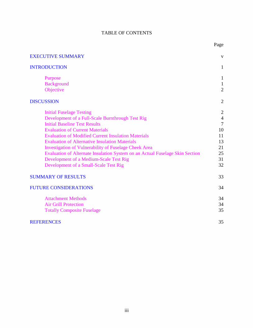
TABLE OF CONTENTS
Page
EXECUTIVE SUMMARY v
INTRODUCTION 1
Purpose 1Background 1Objective 2
DISCUSSION 2
Initial Fuselage Testing 2Development of a Full-Scale Burnthrough Test Rig 4Initial Baseline Test Results 7Evaluation of Current Materials 10Evaluation of Modified Current Insulation Materials 11Evaluation of Alternative Insulation Materials 13Investigation of Vulnerability of Fuselage Cheek Area 21Evaluation of Alternate Insulation System on an Actual Fuselage Skin Section 25Development of a Medium-Scale Test Rig 31Development of a Small-Scale Test Rig 32
SUMMARY OF RESULTS 33
FUTURE CONSIDERATIONS 34
Attachment Methods 34Air Grill Protection 34Totally Composite Fuselage 35
REFERENCES 35
iv
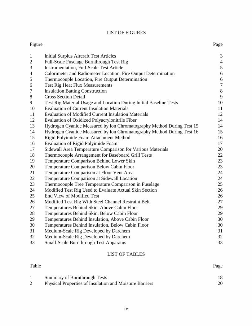
LIST OF FIGURES
Figure Page
1 Initial Surplus Aircraft Test Articles 32 Full-Scale Fuselage Burnthrough Test Rig 43 Instrumentation, Full-Scale Test Article 54 Calorimeter and Radiometer Location, Fire Output Determination 65 Thermocouple Location, Fire Output Determination 66 Test Rig Heat Flux Measurements 77 Insulation Batting Construction 88 Cross Section Detail 99 Test Rig Material Usage and Location During Initial Baseline Tests 1010 Evaluation of Current Insulation Materials 1111 Evaluation of Modified Current Insulation Materials 1212 Evaluation of Oxidized Polyacrylonitrile Fiber 1413 Hydrogen Cyanide Measured by Ion Chromatography Method During Test 15 1414 Hydrogen Cyanide Measured by Ion Chromatography Method During Test 16 1515 Rigid Polyimide Foam Attachment Method 1616 Evaluation of Rigid Polyimide Foam 1717 Sidewall Area Temperature Comparison for Various Materials 2018 Thermocouple Arrangement for Baseboard Grill Tests 2219 Temperature Comparison Behind Lower Skin 2320 Temperature Comparison Below Cabin Floor 2321 Temperature Comparison at Floor Vent Area 2422 Temperature Comparison at Sidewall Location 2423 Thermocouple Tree Temperature Comparison in Fuselage 2524 Modified Test Rig Used to Evaluate Actual Skin Section 2625 End View of Modified Test 2626 Modified Test Rig With Steel Channel Restraint Belt 2727 Temperatures Behind Skin, Above Cabin Floor 2928 Temperatures Behind Skin, Below Cabin Floor 2929 Temperatures Behind Insulation, Above Cabin Floor 3030 Temperatures Behind Insulation, Below Cabin Floor 3031 Medium-Scale Rig Developed by Darchem 3132 Medium-Scale Rig Developed by Darchem 3233 Small-Scale Burnthrough Test Apparatus 33
LIST OF TABLES
Table Page
1 Summary of Burnthrough Tests 182 Physical Properties of Insulation and Moisture Barriers 20
v/vi
EXECUTIVE SUMMARY
Fuselage burnthrough refers to the penetration of an external postcrash fuel fire into an aircraftcabin. The time to burnthrough is critical because, in survivable aircraft accidents, the hazards ofburning cabin materials ignited by burnthrough from an external fuel fire may incapacitatepassengers before they are able to escape. There are typically three barriers that a fuel fire mustpenetrate in order to burnthrough to the cabin interior: the aluminum skin, the thermal-acousticalinsulation, and the interior sidewall and floor panel combination. The burnthrough resistance ofaluminum skin is well known, lasting between 30 to 60 seconds, depending on the thickness.Thermal-acoustical insulation, typically comprised of fiberglass batting encased in a polyvinylfluoride (PVF) moisture barrier, can offer an additional 1 to 2 minutes protection if the materialis not physically dislodged from the fuselage structure. Honeycomb sandwich panels used in thesidewall and floor areas of transport aircraft offer a substantial barrier to fire; however, full-scaletesting has shown that a large fire can penetrate through other openings such as the seamsbetween sidewall panels, window reveals, and baseboard air return grills.
The research described in this report consisted primarily of full-scale fire tests in a reusablefuselage test rig to determine the effectiveness of thermal-acoustical insulation improvements inpreventing or delaying fuselage burnthrough. Twenty-eight full-scale tests were conducted onmodified fiberglass batting or replacement insulation materials. The testing showed that themethod of attaching the insulation to the fuselage structure had a critical effect on theeffectiveness of the insulation material. In addition, the composition of the insulation baggingmaterial, normally a thermoplastic film, was also shown to be an important factor. A number ofbarrier materials used in conjunction with the current insulation systems were shown to beeffective in varying degrees, including the use of a ceramic fiber layer. Several new materialsand combinations tested also showed vast improvements in burnthrough resistance over existingmaterials. For example, a heat-treated, oxidized polyacrylonitrile fiber (OPF) encased in apolyimide bagging material prevented burnthrough for over 8 minutes. When contrasted withcurrent insulation blankets, which were shown to fail in as little as 2 minutes, effective firebarriers offer the potential of saving lives during a postcrash fire accident in which the fuselageremains intact.
1
INTRODUCTION
PURPOSE.
The purpose of this report is to describe the research and full-scale tests undertaken to evaluatethe burnthrough resistance of a transport category aircraft fuselage and to determine theeffectiveness of various improvements aimed at extending the resistance of a fuselage during apostcrash fuel fire scenario.
BACKGROUND.
In a majority of survivable accidents where there is a fire, ignition of the interior of the aircraft iscaused by burning jet fuel external to the aircraft as a result of fuel tank damage during impact.One important factor to occupant survivability is the integrity of the fuselage during an accident.In an aircraft accident the fuselage can remain intact or it may rupture during the crash oremergency exits may be opened, allowing the external fuel fire flames to contact the cabinmaterials. Based on past accidents, experimental studies, and fuselage design, it is apparent thatthe fuselage rupturing or opening represents the worst case condition in a crash and providesmore significant opportunity for fire to enter the cabin. [1] Past Federal Aviation Administration(FAA) regulatory actions governing interior material flammability were based on full-scale testsemploying a fuel fire adjacent to a fuselage opening in an otherwise intact fuselage. Thisscenario, in which the cabin materials were directly exposed to the intense thermal radiationemitted by the fuel fire, represented a severe but survivable fire condition and was used todevelop improved standards. However, in some crash accidents, the fuselage remainedcompletely intact and fire penetrated into the passenger cabin as a result of a burnthrough of thefuselage shell. [2] Five transport accidents involving burnthrough have occurred in the last 20years, in which fire penetration of the fuselage was a primary focus of the accident investigation:Los Angeles 1972, Malaga 1982, Calgary 1984, Manchester 1985, and Anchorage 1987.
During an accident involving a Continental DC-10 at Los Angeles in 1978, a large fuel fireburned for 2 to 3 minutes before it was extinguished by the Crash Fire Rescue personnel. Duringthis interval, the fuel fire did not penetrate to ignite the cabin furnishings, although there wassome evidence of heat and flame damage at panel seams and along seat back cushions. It wasclear from this accident that wide-body transports (B-747, DC-10, and L-1011) could resistburnthrough for several minutes because the fuselage walls of these aircraft are constructed ofthicker aluminum skin and heavy structural elements, along with thick thermal-acousticalinsulation and honeycomb sidewall panels. In the DC-10 accident in Malaga, Spain in 1982, theaircraft overran the runway after an aborted takeoff, coming to rest in a field just off the airport.The right wing was torn off and a large fuel fire encompassed the aft end of the fuselage. Thefire entered the aft cabin through tears in the fuselage and burnthrough of the skin. Evacuationwas hampered by traumatized passengers and debris in the aisles. There were 51 fatalities of the393 occupants.
It was believed that in narrow-body aircraft (B-727, B-737, and MD-80) burnthrough may occurmuch more quickly because of aluminum sidewall panels in some aircraft, thinner thermal-acoustical insulation, and in many cases, a thinner aluminum skin. [3] However, in the B-737
2
accident at Calgary in 1984, a fire resulted when the left engine failed and ignited the fuelreleased by the nearby damaged fuel tank. The fire was immediate and intensified as the aircraftwas brought to rest almost 2 minutes later. The 119 passengers and crewmembers were able toevacuate in an estimated 2-3 minutes, although portions of the cabin quickly filled with smokewhen the exits were opened. The same could not be said of the B-737 accident in Manchester in1985, which had a similar fire scenario as the Calgary accident. During this accident, a B-737was approaching takeoff when it experienced an uncontained engine failure, propelling pieces ofthe engine into the wing and subsequently rupturing the wing fuel access door area. The takeoffwas aborted. As the airplane decelerated, leaking fuel ignited and burned, erupting into a largeground fire after the plane came to rest. Although the fire fighting response was practicallyimmediate, 55 occupants perished from the effects of the fire. In this accident, it was believedthat the external fire very rapidly burned through the lower fuselage skin and quickly ignited thecabin furnishings by gaining entry through the baseboard return air grills. [4] During an accidentinvolving a B-727 at Anchorage in 1987, a large fuel fire developed on the ground adjacent to theaircraft when it was accidentally towed into a loading walkway causing a massive fuel spillagedue to a punctured fuel tank. Although a large section of the fuselage skin melted away duringthe ensuing fire, it did not spread into the cabin, indicating that, in some cases, the fuselage couldact as an effective fire barrier. One key difference between the Manchester accident and both theCalgary and Anchorage accidents was the presence of the wind blowing flames against thefuselage, which could have aided the rapid fire penetration.
OBJECTIVE.
Although fire can penetrate into the passenger compartment by a variety of paths including thewindows, the sidewall (above the cabin floor), cheek area (below the cabin floor), cabin floor,and baseboard return air grills, there is no set pattern based on past accidents or experimental testdata to indicate which areas are the most vulnerable. Testing has been performed on theindividual components (aluminum skin, windows, thermal-acoustical insulation, and interiorsidewall panels) but has not been done on the complete fuselage shell system in which firepenetration paths and burnthrough times could be observed. For this reason, the objective of thistest program was to conduct full-scale fuselage fire tests to determine these mechanisms and thelikely timeframe for burnthrough. The program was undertaken in two phases. First, a series oftests were conducted on surplus aircraft fuselages. The data from these tests were then used todevelop a full-scale burnthrough test rig which was used to conduct a series of tests to quantifyburnthrough rates and potential improvements.
DISCUSSION
INITIAL FUSELAGE TESTING.
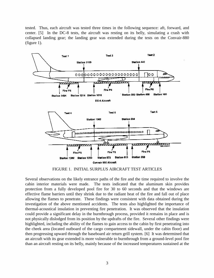
To better understand and quantify the fuselage burnthrough problem, the FAA conducted a seriesof full-scale tests by subjecting surplus aircraft (DC-8 and Convair 880) fuselages to 400-square-feet jet fuel fires. The fuel fires were set adjacent to intact fuselage sections instrumented withthermocouples, heat flux transducers, and cameras to determine penetration locations, firepaths,and important event times. During the tests, each aircraft was divided into three sections byinstalling exterior barriers and internal partitions to confine the fire within the section being
3
tested. Thus, each aircraft was tested three times in the following sequence: aft, forward, andcenter. [5] In the DC-8 tests, the aircraft was resting on its belly, simulating a crash withcollapsed landing gear; the landing gear was extended during the tests on the Convair-880(figure 1).
FIGURE 1. INITIAL SURPLUS AIRCRAFT TEST ARTICLES
Several observations on the likely entrance paths of the fire and the time required to involve thecabin interior materials were made. The tests indicated that the aluminum skin providesprotection from a fully developed pool fire for 30 to 60 seconds and that the windows areeffective flame barriers until they shrink due to the radiant heat of the fire and fall out of placeallowing the flames to penetrate. These findings were consistent with data obtained during theinvestigation of the above mentioned accidents. The tests also highlighted the importance ofthermal-acoustical insulation in preventing fire penetration. It was observed that the insulationcould provide a significant delay in the burnthrough process, provided it remains in place and isnot physically dislodged from its position by the updrafts of the fire. Several other findings werehighlighted, including the ability of the flames to gain access to the cabin by first penetrating intothe cheek area (located outboard of the cargo compartment sidewall, under the cabin floor) andthen progressing upward through the baseboard air return grill system. [6] It was determined thatan aircraft with its gear extended is more vulnerable to burnthrough from a ground-level pool firethan an aircraft resting on its belly, mainly because of the increased temperatures sustained at the
4
upper flame area of the fire. The information obtained during this test project was used as a basisfor the development of a full-scale burnthrough test rig.
DEVELOPMENT OF A FULL-SCALE BURNTHROUGH TEST RIG.
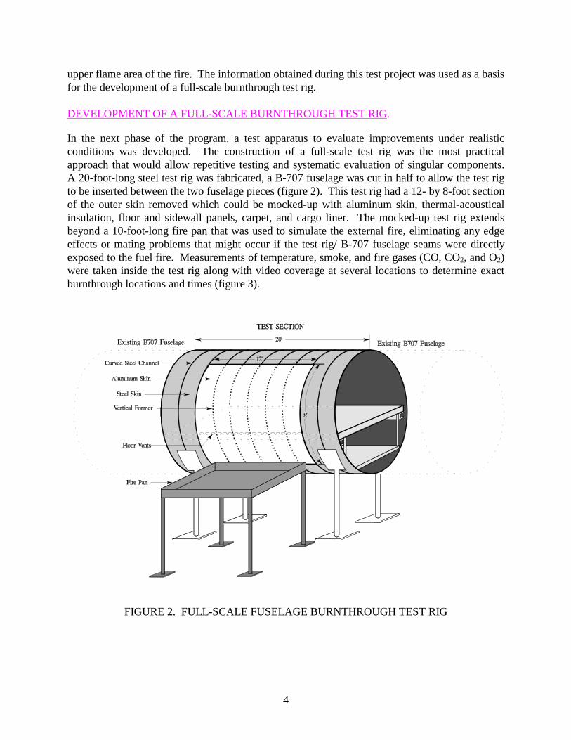
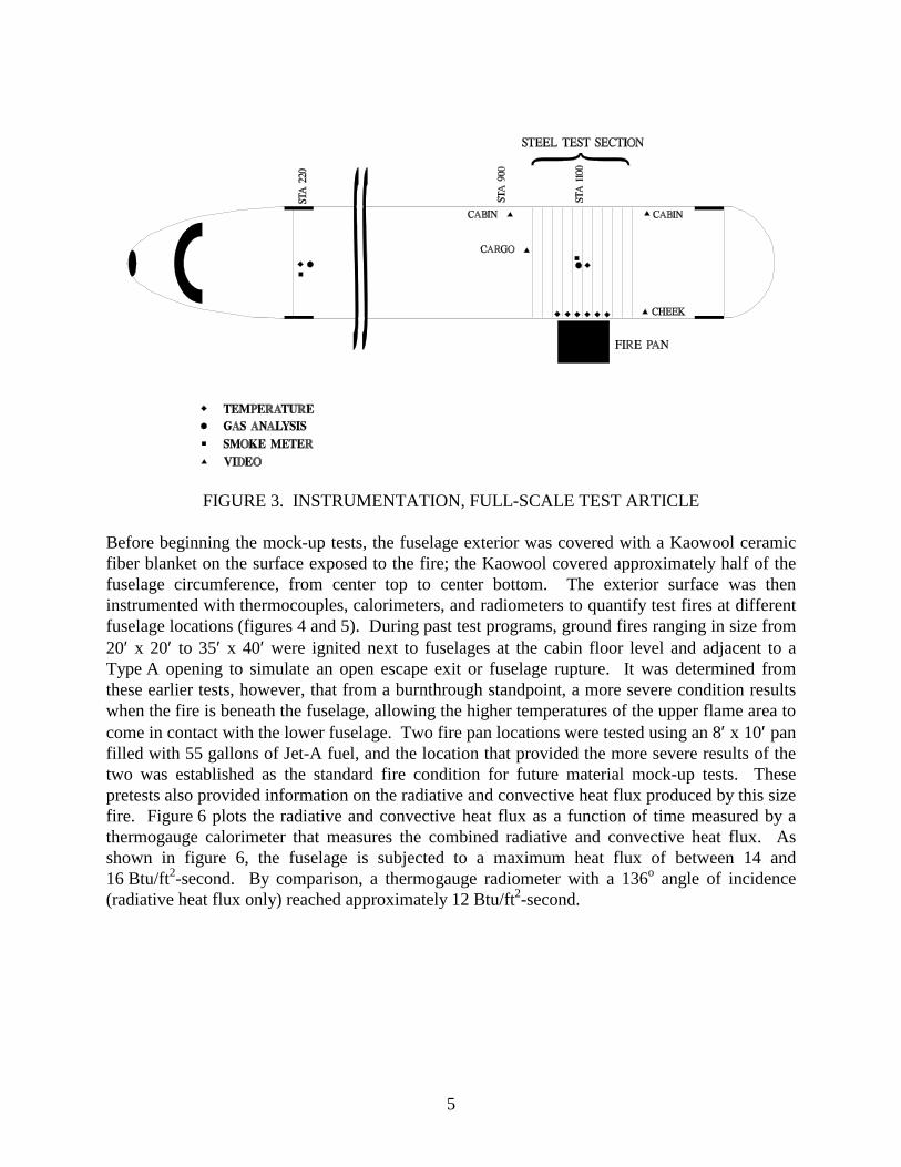
In the next phase of the program, a test apparatus to evaluate improvements under realisticconditions was developed. The construction of a full-scale test rig was the most practicalapproach that would allow repetitive testing and systematic evaluation of singular components.A 20-foot-long steel test rig was fabricated, a B-707 fuselage was cut in half to allow the test rigto be inserted between the two fuselage pieces (figure 2). This test rig had a 12- by 8-foot sectionof the outer skin removed which could be mocked-up with aluminum skin, thermal-acousticalinsulation, floor and sidewall panels, carpet, and cargo liner. The mocked-up test rig extendsbeyond a 10-foot-long fire pan that was used to simulate the external fire, eliminating any edgeeffects or mating problems that might occur if the test rig/ B-707 fuselage seams were directlyexposed to the fuel fire. Measurements of temperature, smoke, and fire gases (CO, CO2, and O2)were taken inside the test rig along with video coverage at several locations to determine exactburnthrough locations and times (figure 3).
FIGURE 2. FULL-SCALE FUSELAGE BURNTHROUGH TEST RIG
5
FIGURE 3. INSTRUMENTATION, FULL-SCALE TEST ARTICLE
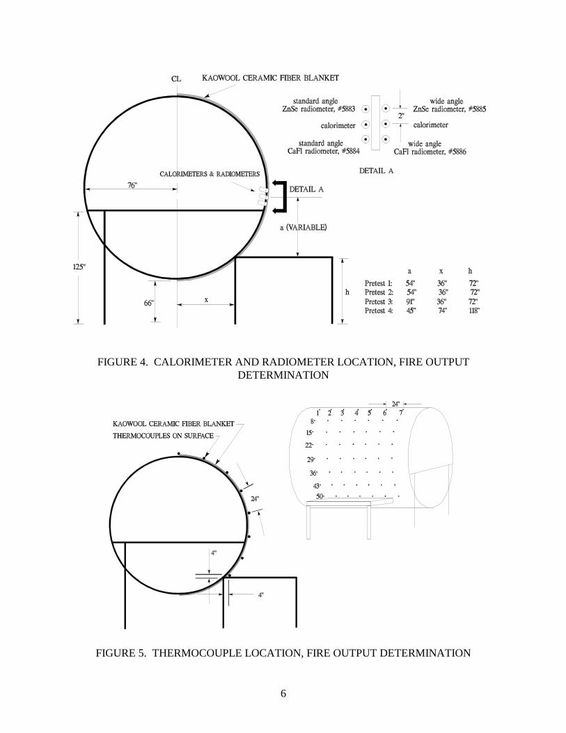
Before beginning the mock-up tests, the fuselage exterior was covered with a Kaowool ceramicfiber blanket on the surface exposed to the fire; the Kaowool covered approximately half of thefuselage circumference, from center top to center bottom. The exterior surface was theninstrumented with thermocouples, calorimeters, and radiometers to quantify test fires at differentfuselage locations (figures 4 and 5). During past test programs, ground fires ranging in size from20′ x 20′ to 35′ x 40′ were ignited next to fuselages at the cabin floor level and adjacent to aType A opening to simulate an open escape exit or fuselage rupture. It was determined fromthese earlier tests, however, that from a burnthrough standpoint, a more severe condition resultswhen the fire is beneath the fuselage, allowing the higher temperatures of the upper flame area tocome in contact with the lower fuselage. Two fire pan locations were tested using an 8′ x 10′ panfilled with 55 gallons of Jet-A fuel, and the location that provided the more severe results of thetwo was established as the standard fire condition for future material mock-up tests. Thesepretests also provided information on the radiative and convective heat flux produced by this sizefire. Figure 6 plots the radiative and convective heat flux as a function of time measured by athermogauge calorimeter that measures the combined radiative and convective heat flux. Asshown in figure 6, the fuselage is subjected to a maximum heat flux of between 14 and16 Btu/ft2-second. By comparison, a thermogauge radiometer with a 136o angle of incidence(radiative heat flux only) reached approximately 12 Btu/ft2-second.
6
FIGURE 4. CALORIMETER AND RADIOMETER LOCATION, FIRE OUTPUTDETERMINATION
FIGURE 5. THERMOCOUPLE LOCATION, FIRE OUTPUT DETERMINATION

7
FIGURE 6. TEST RIG HEAT FLUX MEASUREMENTS
INITIAL BASELINE TEST RESULTS.
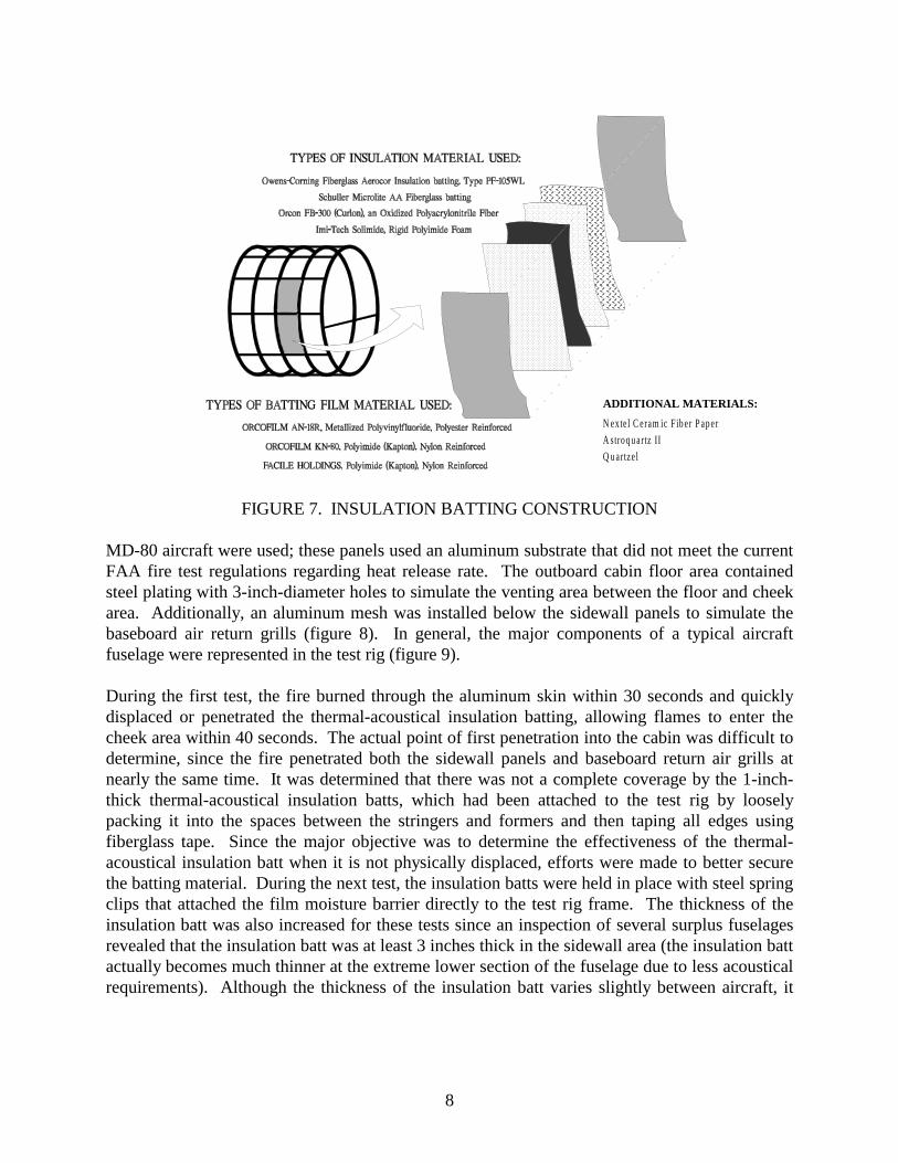
To evaluate potential improvements in materials and systems for better resistance to fuel firepenetrations, a baseline test arrangement was established using in-service materials. Analuminum skin section measuring 8 feet high by 12 feet wide was installed where the originalsteel skin of the test rig was removed. It consisted of two sheets of 0.063-inch-thick Alclad 2024T3 aluminum heliarc welded together. The aluminum panel extended from the lower fuselagequadrant up to the window level and was mounted to the test rig stringers and ribs using steelrivets to reduce the potential for separation during testing. The remaining area of the test rig wascovered with 22-gauge sheet metal. The first several tests used custom-made insulation battingconsisting of Owens-Corning Aerocor fiberglass insulation encapsulated in Orcon brand heatshrinkable metallized polyvinyl fluoride (PVF) film (also known as Tedlar), type AN-18R. Theinsulation batting was sized to fit in the spaces outlined by the vertical formers and the horizontalstringers of the test rig (figure 7). The insulation batts spanned the entire area of the aluminumskin, 8 by 12 feet. In the test rig cargo compartment, 0.013-inch-thick Conolite BMS 8-2Afiberglass liners were installed in both the ceiling and sidewall areas facing the fire and held inplace by steel strips of channel screwed into the steel frame of the test rig. An M.C. Gill“Gillfab” 4017 honeycomb floor panel measuring 4 by 12 feet was installed in the test rig cabinfloor area and covered with FAA-approved aircraft quality wool/nylon carpet. The remainingtest rig cabin floor area consisted of corrugated sheet steel. Interior sidewall panels from an
Radiative Versus Tota l Heat Flux
-2
0
2
4
6
8
10
12
14
16
18
0 60 120 180
Time (Seconds)
Btu
/ft2 -s
econ
dCa lorimeter 5293 Ca lorimeter 5290 Rad iometer ZnSe W/ A Rad iometer ZnSe Rad iometer CaF2 W/ A Rad iometer CaF2
8
FIGURE 7. INSULATION BATTING CONSTRUCTION
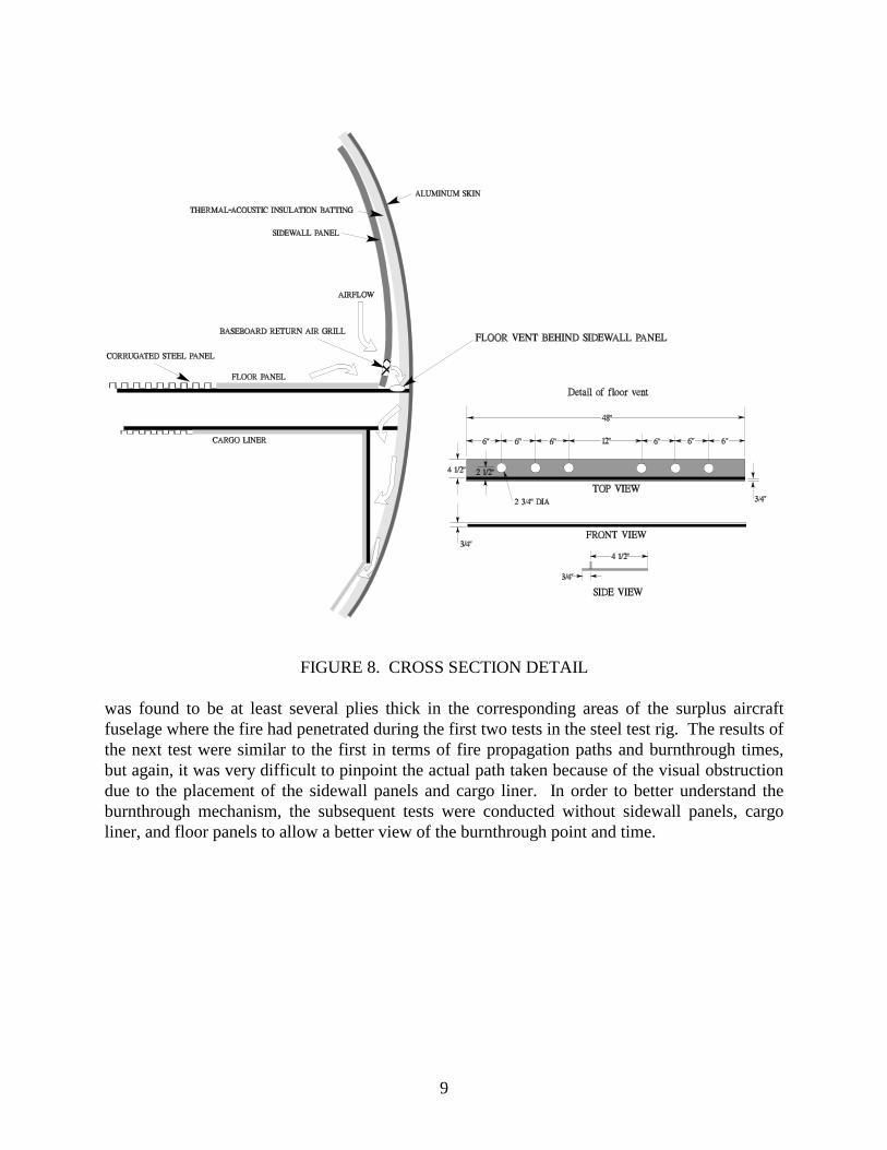
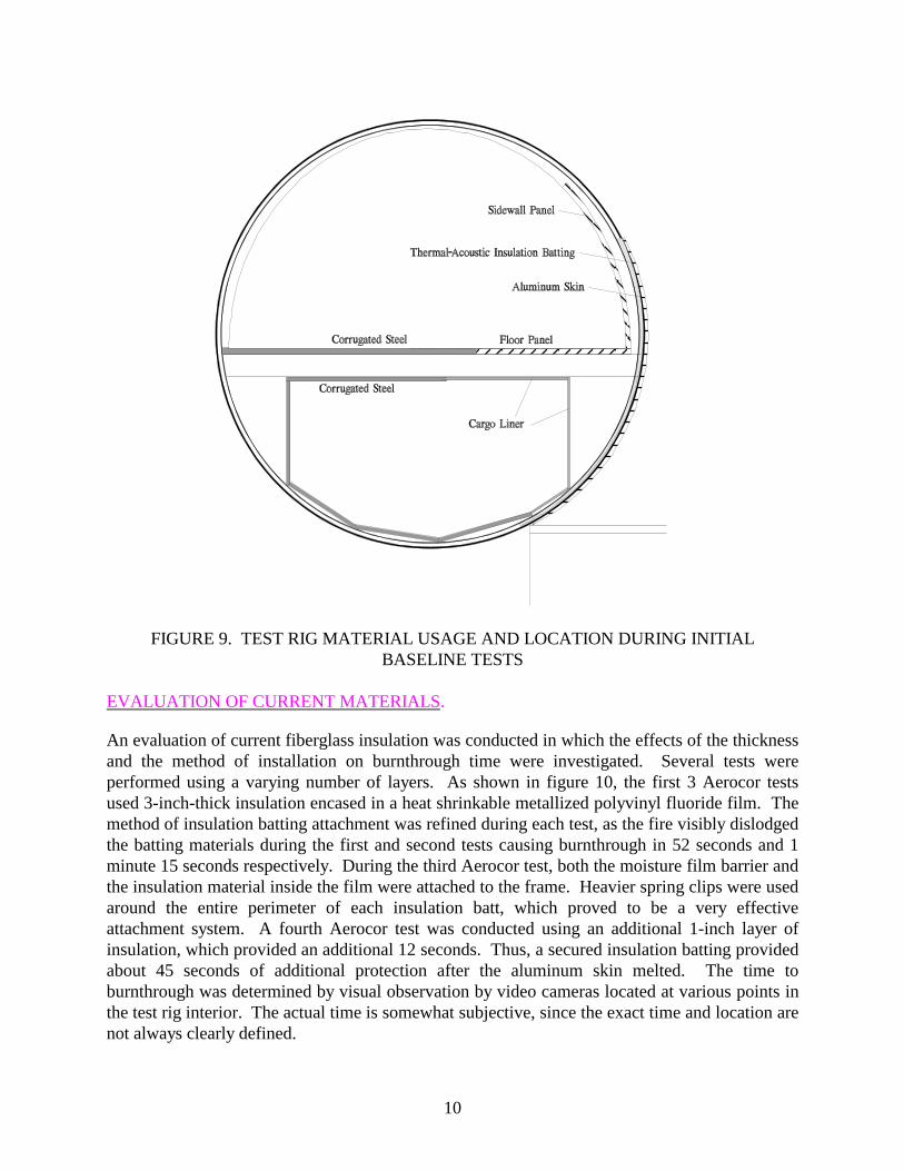
MD-80 aircraft were used; these panels used an aluminum substrate that did not meet the currentFAA fire test regulations regarding heat release rate. The outboard cabin floor area containedsteel plating with 3-inch-diameter holes to simulate the venting area between the floor and cheekarea. Additionally, an aluminum mesh was installed below the sidewall panels to simulate thebaseboard air return grills (figure 8). In general, the major components of a typical aircraftfuselage were represented in the test rig (figure 9).
During the first test, the fire burned through the aluminum skin within 30 seconds and quicklydisplaced or penetrated the thermal-acoustical insulation batting, allowing flames to enter thecheek area within 40 seconds. The actual point of first penetration into the cabin was difficult todetermine, since the fire penetrated both the sidewall panels and baseboard return air grills atnearly the same time. It was determined that there was not a complete coverage by the 1-inch-thick thermal-acoustical insulation batts, which had been attached to the test rig by looselypacking it into the spaces between the stringers and formers and then taping all edges usingfiberglass tape. Since the major objective was to determine the effectiveness of the thermal-acoustical insulation batt when it is not physically displaced, efforts were made to better securethe batting material. During the next test, the insulation batts were held in place with steel springclips that attached the film moisture barrier directly to the test rig frame. The thickness of theinsulation batt was also increased for these tests since an inspection of several surplus fuselagesrevealed that the insulation batt was at least 3 inches thick in the sidewall area (the insulation battactually becomes much thinner at the extreme lower section of the fuselage due to less acousticalrequirements). Although the thickness of the insulation batt varies slightly between aircraft, it
ADDITIONAL MATERIALS:
N exte l C eram ic Fiber P aper
A stroquartz II
Q uartze l
9
FIGURE 8. CROSS SECTION DETAIL
was found to be at least several plies thick in the corresponding areas of the surplus aircraftfuselage where the fire had penetrated during the first two tests in the steel test rig. The results ofthe next test were similar to the first in terms of fire propagation paths and burnthrough times,but again, it was very difficult to pinpoint the actual path taken because of the visual obstructiondue to the placement of the sidewall panels and cargo liner. In order to better understand theburnthrough mechanism, the subsequent tests were conducted without sidewall panels, cargoliner, and floor panels to allow a better view of the burnthrough point and time.
10
FIGURE 9. TEST RIG MATERIAL USAGE AND LOCATION DURING INITIALBASELINE TESTS
EVALUATION OF CURRENT MATERIALS.
An evaluation of current fiberglass insulation was conducted in which the effects of the thicknessand the method of installation on burnthrough time were investigated. Several tests wereperformed using a varying number of layers. As shown in figure 10, the first 3 Aerocor testsused 3-inch-thick insulation encased in a heat shrinkable metallized polyvinyl fluoride film. Themethod of insulation batting attachment was refined during each test, as the fire visibly dislodgedthe batting materials during the first and second tests causing burnthrough in 52 seconds and 1minute 15 seconds respectively. During the third Aerocor test, both the moisture film barrier andthe insulation material inside the film were attached to the frame. Heavier spring clips were usedaround the entire perimeter of each insulation batt, which proved to be a very effectiveattachment system. A fourth Aerocor test was conducted using an additional 1-inch layer ofinsulation, which provided an additional 12 seconds. Thus, a secured insulation batting providedabout 45 seconds of additional protection after the aluminum skin melted. The time toburnthrough was determined by visual observation by video cameras located at various points inthe test rig interior. The actual time is somewhat subjective, since the exact time and location arenot always clearly defined.

11
FIGURE 10. EVALUATION OF CURRENT INSULATION MATERIALS
Since the Aerocor is a somewhat older material, additional tests were conducted using MicroliteAA insulation, which is currently used on most transport category aircraft. As shown, there wasonly a marginal increase in the burnthrough resistance offered by the 3-inch Microlite material(1 minute 32 seconds versus 1 minute 24 seconds using 3-inch-thick Aerocor). The test rigburnthrough times compared favorably with past tests using surplus aircraft where flamepenetration was observed in approximately 2 minutes 30 seconds. [6] Assuming that thesidewall panels, flooring, and cargo liner in the surplus aircraft likely provided an additionalminute of protection, it was concluded that the mock-up tests were a reasonable representation ofactual crash fire conditions.
With a realistic and repeatable test condition and the burnthrough resistance of current materialsdefined, improvements in burnthrough resistance were evaluated. Considering the thermal-acoustical insulation system only, there are two possible areas for improvement (1) modificationor enhancement of existing insulation materials or (2) replacement of the current fiberglassinsulation with a more fire-resistant type.
EVALUATION OF MODIFIED CURRENT INSULATION MATERIALS.
The previous burnthrough evaluation of existing materials showed that with the metallizedpolyvinyl fluoride film, fire propagated rapidly from the outboard face of the insulation batt tothe inboard face. Polyimide (Kapton), a candidate replacement film, with low flammability and
12
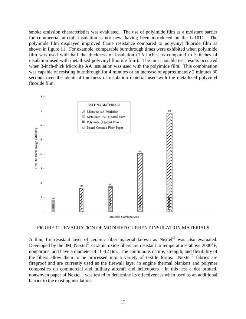
smoke emission characteristics was evaluated. The use of polyimide film as a moisture barrierfor commercial aircraft insulation is not new, having been introduced on the L-1011. Thepolyimide film displayed improved flame resistance compared to polyvinyl fluoride film asshown in figure 11. For example, comparable burnthrough times were exhibited when polyimidefilm was used with half the thickness of insulation (1.5 inches as compared to 3 inches ofinsulation used with metallized polyvinyl fluoride film). The most notable test results occurredwhen 3-inch-thick Microlite AA insulation was used with the polyimide film. This combinationwas capable of resisting burnthrough for 4 minutes or an increase of approximately 2 minutes 30seconds over the identical thickness of insulation material used with the metallized polyvinylfluoride film.
FIGURE 11. EVALUATION OF MODIFIED CURRENT INSULATION MATERIALS
A thin, fire-resistant layer of ceramic fiber material known as Nextel was also evaluated.Developed by the 3M, Nextel ceramic oxide fibers are resistant to temperatures above 2000°F,nonporous, and have a diameter of 10-12 µm. The continuous nature, strength, and flexibility ofthe fibers allow them to be processed into a variety of textile forms. Nextel fabrics arefireproof and are currently used as the firewall layer in engine thermal blankets and polymercomposites on commercial and military aircraft and helicopters. In this test a dot printed,nonwoven paper of Nextel was tested to determine its effectiveness when used as an additionalbarrier to the existing insulation.
13
During the test, a layer of the Nextel was placed inside each of the insulation batts and bothwere then encapsulated in the standard metallized polyvinyl fluoride moisture barrier film. TheNextel was installed on the outboard face of the insulation batts (within the film) to form aflame propagation barrier between the external flames and the interior of the fuselage. Theinsulation batts and Nextel fiber mat were clamped in place around the perimeter; thus theclamping also held the Nextel in place. This arrangement was very effective, preventingburnthrough for nearly 7 minutes. Although there were visible flames on the backface of theinsulation batts after approximately 4 minutes, it was difficult to determine if fuel fire penetrationhad occurred or if the polyvinyl fluoride film was burning due to the elevated temperatures. Aposttest inspection showed that the majority of the Nextel had remained in place with theexception of one area approximately 20 inches by 20 inches which had been penetrated.
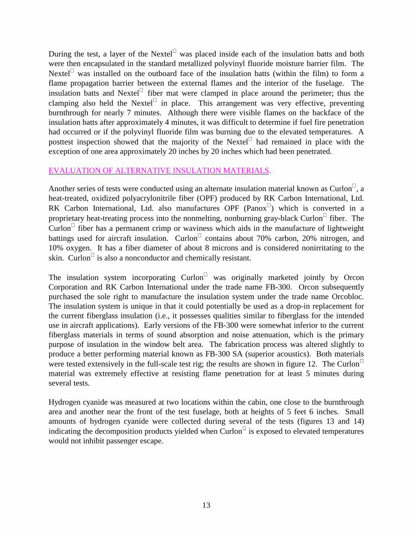
EVALUATION OF ALTERNATIVE INSULATION MATERIALS.
Another series of tests were conducted using an alternate insulation material known as Curlon, aheat-treated, oxidized polyacrylonitrile fiber (OPF) produced by RK Carbon International, Ltd.RK Carbon International, Ltd. also manufactures OPF (Panox) which is converted in aproprietary heat-treating process into the nonmelting, nonburning gray-black Curlon fiber. TheCurlon fiber has a permanent crimp or waviness which aids in the manufacture of lightweightbattings used for aircraft insulation. Curlon contains about 70% carbon, 20% nitrogen, and10% oxygen. It has a fiber diameter of about 8 microns and is considered nonirritating to theskin. Curlon is also a nonconductor and chemically resistant.
The insulation system incorporating Curlon was originally marketed jointly by OrconCorporation and RK Carbon International under the trade name FB-300. Orcon subsequentlypurchased the sole right to manufacture the insulation system under the trade name Orcobloc.The insulation system is unique in that it could potentially be used as a drop-in replacement forthe current fiberglass insulation (i.e., it possesses qualities similar to fiberglass for the intendeduse in aircraft applications). Early versions of the FB-300 were somewhat inferior to the currentfiberglass materials in terms of sound absorption and noise attenuation, which is the primarypurpose of insulation in the window belt area. The fabrication process was altered slightly toproduce a better performing material known as FB-300 SA (superior acoustics). Both materialswere tested extensively in the full-scale test rig; the results are shown in figure 12. The Curlon
material was extremely effective at resisting flame penetration for at least 5 minutes duringseveral tests.
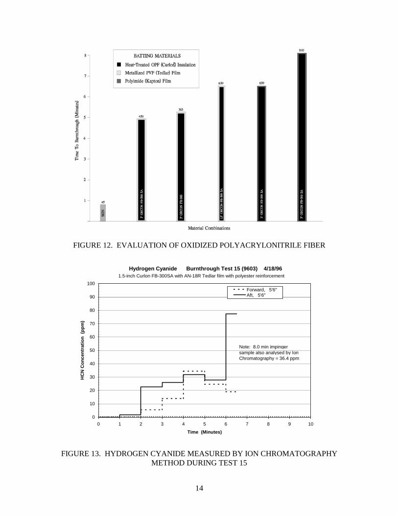
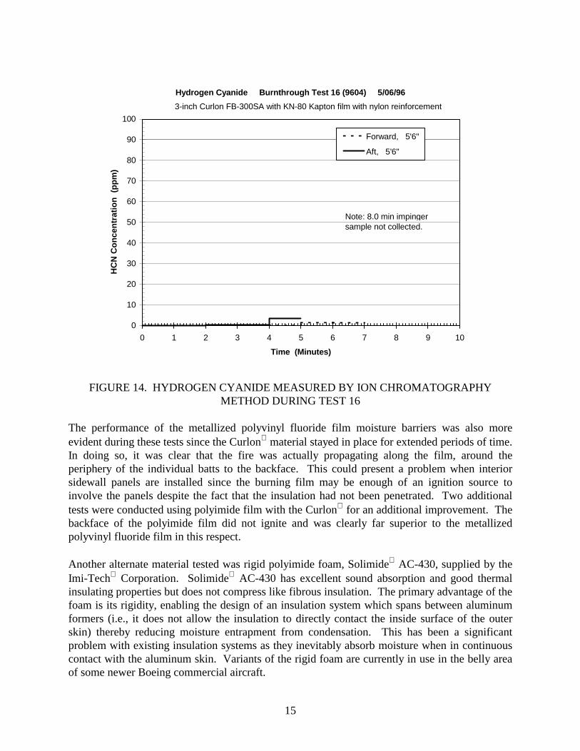
Hydrogen cyanide was measured at two locations within the cabin, one close to the burnthrougharea and another near the front of the test fuselage, both at heights of 5 feet 6 inches. Smallamounts of hydrogen cyanide were collected during several of the tests (figures 13 and 14)indicating the decomposition products yielded when Curlon is exposed to elevated temperatureswould not inhibit passenger escape.
14
FIGURE 12. EVALUATION OF OXIDIZED POLYACRYLONITRILE FIBER
Hydrogen Cyanide Burnthrough Test 15 (9603) 4/18/96
0
10
20
30
40
50
60
70
80
90
100
0 1 2 3 4 5 6 7 8 9 10
Time (Minutes)
HC
N C
once
ntra
tion
(pp
m)
Forward, 5'6"Aft, 5'6"
1.5-inch Curlon FB-300SA with AN-18R Tedlar film with polyester reinforcement
Note: 8.0 min impinger sample also analysed by Ion Chromatography = 36.4 ppm
FIGURE 13. HYDROGEN CYANIDE MEASURED BY ION CHROMATOGRAPHYMETHOD DURING TEST 15
15
Hydrogen Cyanide Burnthrough Test 16 (9604) 5/06/96
0
10
20
30
40
50
60
70
80
90
100
0 1 2 3 4 5 6 7 8 9 10
Time (Minutes)
HC
N C
once
ntra
tion
(pp
m)
Forward, 5'6"
Aft, 5'6"
3-inch Curlon FB-300SA with KN-80 Kapton film with nylon reinforcement
Note: 8.0 min impinger sample not collected.
FIGURE 14. HYDROGEN CYANIDE MEASURED BY ION CHROMATOGRAPHYMETHOD DURING TEST 16
The performance of the metallized polyvinyl fluoride film moisture barriers was also moreevident during these tests since the Curlon material stayed in place for extended periods of time.In doing so, it was clear that the fire was actually propagating along the film, around theperiphery of the individual batts to the backface. This could present a problem when interiorsidewall panels are installed since the burning film may be enough of an ignition source toinvolve the panels despite the fact that the insulation had not been penetrated. Two additionaltests were conducted using polyimide film with the Curlon for an additional improvement. Thebackface of the polyimide film did not ignite and was clearly far superior to the metallizedpolyvinyl fluoride film in this respect.
Another alternate material tested was rigid polyimide foam, Solimide AC-430, supplied by theImi-Tech Corporation. Solimide AC-430 has excellent sound absorption and good thermalinsulating properties but does not compress like fibrous insulation. The primary advantage of thefoam is its rigidity, enabling the design of an insulation system which spans between aluminumformers (i.e., it does not allow the insulation to directly contact the inside surface of the outerskin) thereby reducing moisture entrapment from condensation. This has been a significantproblem with existing insulation systems as they inevitably absorb moisture when in continuouscontact with the aluminum skin. Variants of the rigid foam are currently in use in the belly areaof some newer Boeing commercial aircraft.

16
Before the full-scale tests, the test rig was modified to hold the rigid foam, since it did not requireclips to hold the batting material in place. Three steel T-sections with cross sections 2 incheswide by 4.5 inches high were installed along each of the vertical curved steel channels as shownin figure 15(a). The insulation batts were held in place by rigid foam cap strips that snapped inplace over the top of the steel T-section at the edge of each insulation batt. No moisture barrierfilm was used.
FIGURE 15. RIGID POLYIMIDE FOAM ATTACHMENT METHOD
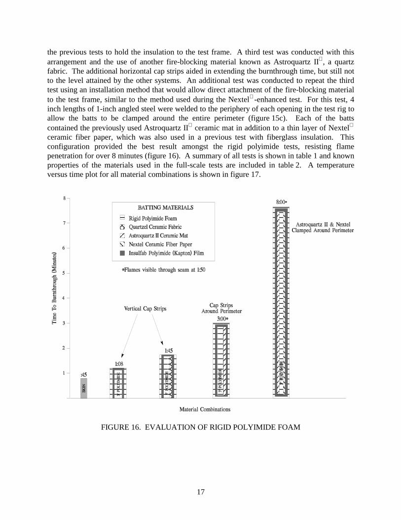
During the first test, the insulation batts were 3-inch-thick Solimide rigid foam heat sealed in abag of Insulfab-reinforced polyimide film, supplied by Facile Holdings, Inc. For this insulationsystem, burnthrough occurred at 1 minute 8 seconds, approximately 20 seconds less thanfiberglass batting. In an effort to extend the burnthrough time, a second test was run in whichQuartzel, a vitreous silica wool barrier, was placed in the insulation batts, not unlike the earlierfiberglass-enhanced tests with Nextel. The Quartzel improved the burnthrough resistance ofthe rigid foam material, but the system was less effective than the system with the Nextel-enhanced fiberglass system and the Curlon. The weakness appeared to be at the horizontalseam location where the individual batts matted together. The absence of an attachment systemalong the top and bottom edges of each batt allowed flames to propagate to the inboard face earlyin the test. After reviewing the video coverage, it was confirmed that the system was, in fact,failing at the top and bottom seams rather than because of burnthrough of the material. To rectifythe problem, horizontal cap strips were used in addition to the vertical cap strips already used in
17
the previous tests to hold the insulation to the test frame. A third test was conducted with thisarrangement and the use of another fire-blocking material known as Astroquartz II, a quartzfabric. The additional horizontal cap strips aided in extending the burnthrough time, but still notto the level attained by the other systems. An additional test was conducted to repeat the thirdtest using an installation method that would allow direct attachment of the fire-blocking materialto the test frame, similar to the method used during the Nextel-enhanced test. For this test, 4inch lengths of 1-inch angled steel were welded to the periphery of each opening in the test rig toallow the batts to be clamped around the entire perimeter (figure 15c). Each of the battscontained the previously used Astroquartz II ceramic mat in addition to a thin layer of Nextel
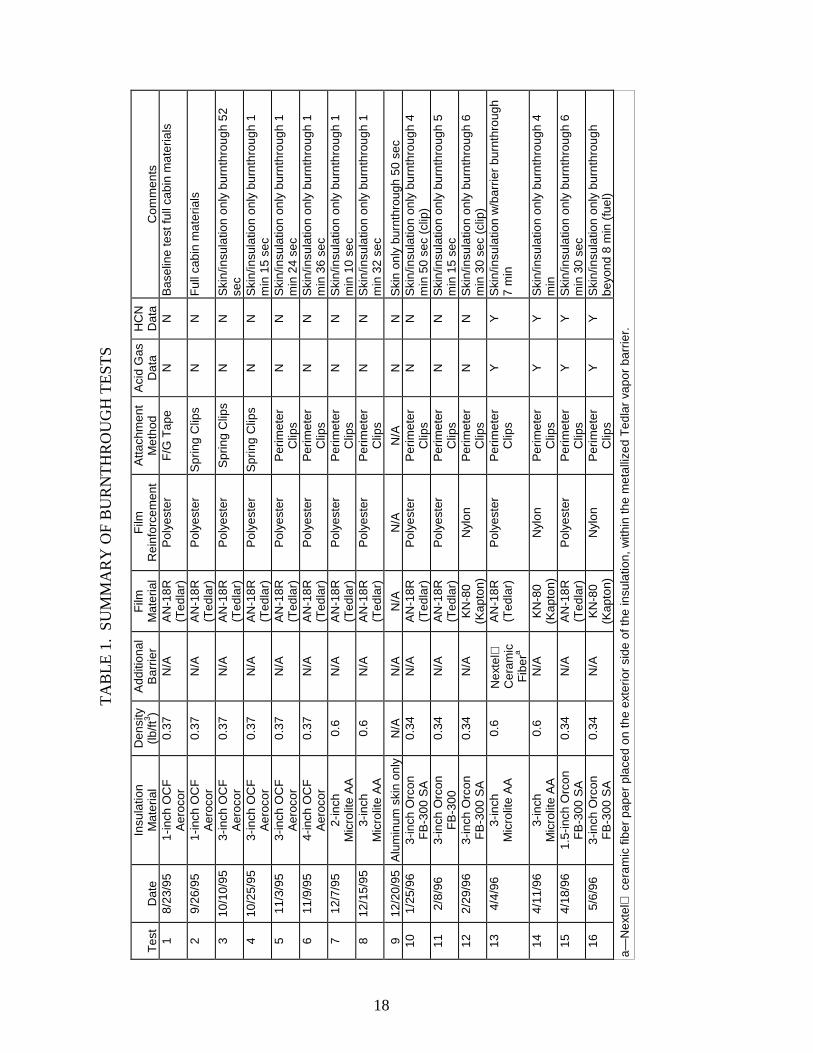
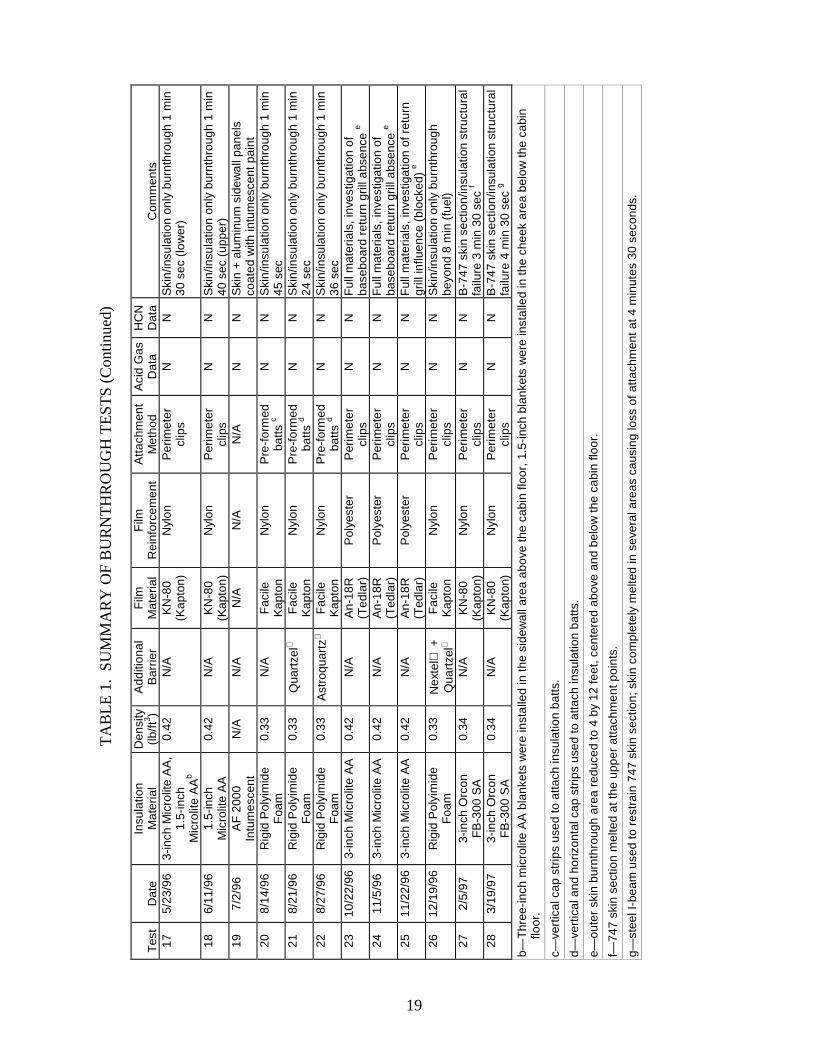
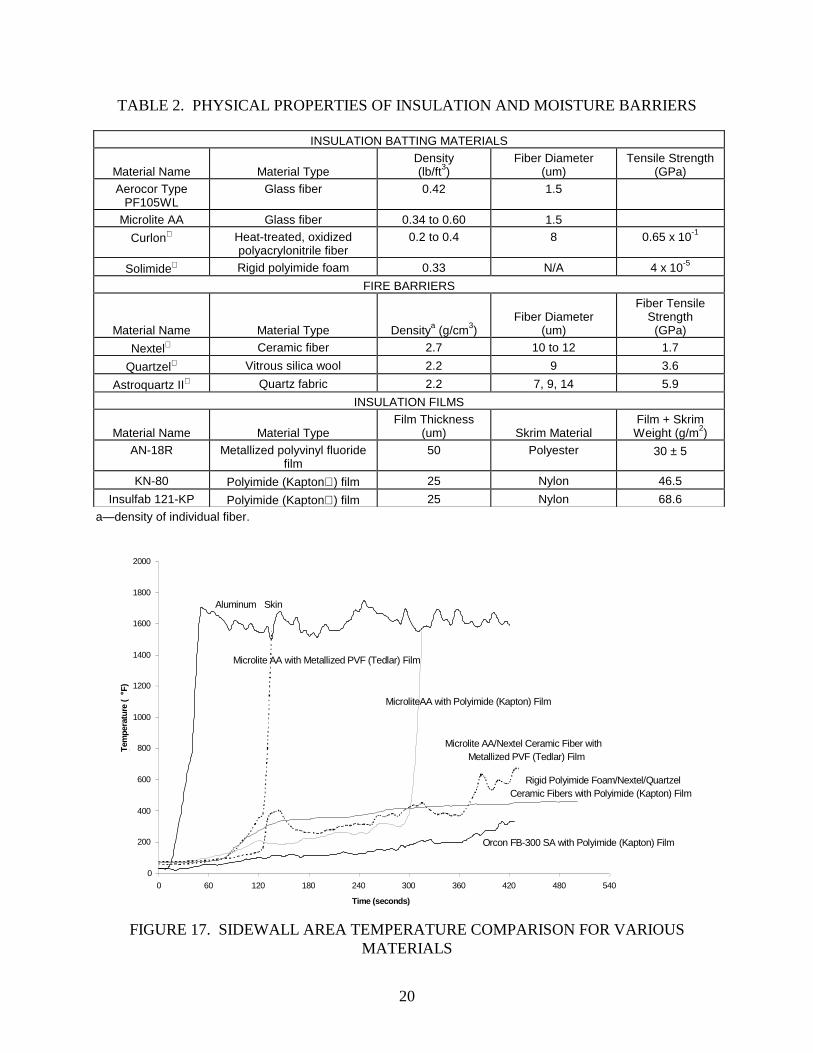
ceramic fiber paper, which was also used in a previous test with fiberglass insulation. Thisconfiguration provided the best result amongst the rigid polyimide tests, resisting flamepenetration for over 8 minutes (figure 16). A summary of all tests is shown in table 1 and knownproperties of the materials used in the full-scale tests are included in table 2. A temperatureversus time plot for all material combinations is shown in figure 17.
FIGURE 16. EVALUATION OF RIGID POLYIMIDE FOAM
TA
BLE
1.
SU
MM
AR
Y O
F B
UR
NT
HR
OU
GH
TE
ST
S
Tes
tD
ate
Insu
latio
nM
ater
ial
Den
sity
(lb/ft
3 )A
dditi
onal
Bar
rier
Film
Mat
eria
lF
ilmR
einf
orce
men
tA
ttach
men
tM
etho
dA
cid
Gas
Dat
aH
CN
Dat
aC
omm
ents
18/
23/9
51-
inch
OC
FA
eroc
or0.
37N
/AA
N-1
8R(T
edla
r)P
olye
ster
F/G
Tap
eN
NB
asel
ine
test
full
cabi
n m
ater
ials
29/
26/9
51-
inch
OC
FA
eroc
or0.
37N
/AA
N-1
8R(T
edla
r)P
olye
ster
Spr
ing
Clip
sN
NF
ull c
abin
mat
eria
ls
310
/10/
953-
inch
OC
FA
eroc
or0.
37N
/AA
N-1
8R(T
edla
r)P
olye
ster
Spr
ing
Clip
sN
NS
kin/
insu
latio
n on
ly b
urnt
hrou
gh 5
2se
c4
10/2
5/95
3-in
ch O
CF
Aer
ocor
0.37
N/A
AN
-18R
(Ted
lar)
Pol
yest
erS
prin
g C
lips
NN
Ski
n/in
sula
tion
only
bur
nthr
ough
1m
in 1
5 se
c5
11/3
/95
3-in
ch O
CF
Aer
ocor
0.37
N/A
AN
-18R
(Ted
lar)
Pol
yest
erP
erim
eter
Clip
sN
NS
kin/
insu
latio
n on
ly b
urnt
hrou
gh 1
min
24
sec
611
/9/9
54-
inch
OC
FA
eroc
or0.
37N
/AA
N-1
8R(T
edla
r)P
olye
ster
Per
imet
erC
lips
NN
Ski
n/in
sula
tion
only
bur
nthr
ough
1m
in 3
6 se
c7
12/7
/95
2-in
chM
icro
lite
AA
0.6
N/A
AN
-18R
(Ted
lar)
Pol
yest
erP
erim
eter
Clip
sN
NS
kin/
insu
latio
n on
ly b
urnt
hrou
gh 1
min
10
sec
812
/15/
953-
inch
Mic
rolit
e A
A0.
6N
/AA
N-1
8R(T
edla
r)P
olye
ster
Per
imet
erC
lips
NN
Ski
n/in
sula
tion
only
bur
nthr
ough
1m
in 3
2 se
c
912
/20/
95A
lum
inum
ski
n on
lyN
/AN
/AN
/AN
/AN
/AN
NS
kin
only
bur
nthr
ough
50
sec
101/
25/9
63-
inch
Orc
onF
B-3
00 S
A0.
34N
/AA
N-1
8R(T
edla
r)P
olye
ster
Per
imet
erC
lips
NN
Ski
n/in
sula
tion
only
bur
nthr
ough
4m
in 5
0 se
c (c
lip)
112/
8/96
3-in
ch O
rcon
FB
-300
0.34
N/A
AN
-18R
(Ted
lar)
Pol
yest
erP
erim
eter
Clip
sN
NS
kin/
insu
latio
n on
ly b
urnt
hrou
gh 5
min
15
sec
122/
29/9
63-
inch
Orc
onF
B-3
00 S
A0.
34N
/AK
N-8
0(K
apto
n)N
ylon
Per
imet
erC
lips
NN
Ski
n/in
sula
tion
only
bur
nthr
ough
6m
in 3
0 se
c (c
lip)
134/
4/96
3-in
chM
icro
lite
AA
0.6
Nex
tel
Cer
amic
Fib
era
AN
-18R
(Ted
lar)
Pol
yest
erP
erim
eter
Clip
sY
YS
kin/
insu
latio
n w
/bar
rier
burn
thro
ugh
7 m
in
144/
11/9
63-
inch
Mic
rolit
e A
A0.
6N
/AK
N-8
0(K
apto
n)N
ylon
Per
imet
erC
lips
YY
Ski
n/in
sula
tion
only
bur
nthr
ough
4m
in15
4/18
/96
1.5-
inch
Orc
onF
B-3
00 S
A0.
34N
/AA
N-1
8R(T
edla
r)P
olye
ster
Per
imet
erC
lips
YY
Ski
n/in
sula
tion
only
bur
nthr
ough
6m
in 3
0 se
c16
5/6/
963-
inch
Orc
onF
B-3
00 S
A0.
34N
/AK
N-8
0(K
apto
n)N
ylon
Per
imet
erC
lips
YY
Ski
n/in
sula
tion
only
bur
nthr
ough
beyo
nd 8
min
(fu
el)
a—N
exte
l c
eram
ic fi
ber
pape
r pl
aced
on
the
exte
rior
side
of t
he in
sula
tion,
with
in th
e m
etal
lized
Ted
lar
vapo
r ba
rrie
r.
18
TA
BLE
1.
SU
MM
AR
Y O
F B
UR
NT
HR
OU
GH
TE
ST
S (
Con
tinue
d)
Tes
tD
ate
Insu
latio
nM
ater
ial
Den
sity
(lb/ft
3 )A
dditi
onal
Bar
rier
Film
Mat
eria
lF
ilmR
einf
orce
men
tA
ttach
men
tM
etho
dA
cid
Gas
Dat
aH
CN
Dat
aC
omm
ents
175/
23/9
63-
inch
Mic
rolit
e A
A,
1.5-
inch
Mic
rolit
e A
Ab
0.42
N/A
KN
-80
(Kap
ton)
Nyl
onP
erim
eter
clip
sN
NS
kin/
insu
latio
n on
ly b
urnt
hrou
gh 1
min
30 s
ec (
low
er)
186/
11/9
61.
5-in
chM
icro
lite
AA
0.42
N/A
KN
-80
(Kap
ton)
Nyl
onP
erim
eter
clip
sN
NS
kin/
insu
latio
n on
ly b
urnt
hrou
gh 1
min
40 s
ec (
uppe
r)19
7/2/
96A
F 2
000
Intu
mes
cent
N/A
N/A
N/A
N/A
N/A
NN
Ski
n +
alu
min
um s
idew
all p
anel
sco
ated
with
intu
mes
cent
pai
nt20
8/14
/96
Rig
id P
olyi
mid
eF
oam
0.33
N/A
Fac
ileK
apto
nN
ylon
Pre
-for
med
batts
cN
NS
kin/
insu
latio
n on
ly b
urnt
hrou
gh 1
min
45 s
ec21
8/21
/96
Rig
id P
olyi
mid
eF
oam
0.33
Qua
rtze
lF
acile
Kap
ton
Nyl
onP
re-f
orm
edba
tts d
NN
Ski
n/in
sula
tion
only
bur
nthr
ough
1 m
in24
sec
228/
27/9
6R
igid
Pol
yim
ide
Foa
m0.
33A
stro
quar
tz
Fac
ileK
apto
nN
ylon
Pre
-for
med
batts
dN
NS
kin/
insu
latio
n on
ly b
urnt
hrou
gh 1
min
36 s
ec23
10/2
2/96
3-in
ch M
icro
lite
AA
0.42
N/A
An-
18R
(Ted
lar)
Pol
yest
erP
erim
eter
clip
sN
NF
ull m
ater
ials
, inv
estig
atio
n of
base
boar
d re
turn
gril
l abs
ence
e
2411
/5/9
63-
inch
Mic
rolit
e A
A0.
42N
/AA
n-18
R(T
edla
r)P
olye
ster
Per
imet
ercl
ips
NN
Ful
l mat
eria
ls, i
nves
tigat
ion
ofba
sebo
ard
retu
rn g
rill a
bsen
ce e
2511
/22/
963-
inch
Mic
rolit
e A
A0.
42N
/AA
n-18
R(T
edla
r)P
olye
ster
Per
imet
ercl
ips
NN
Ful
l mat
eria
ls, i
nves
tigat
ion
of r
etur
ngr
ill in
fluen
ce (
bloc
ked)
e
2612
/19/
96R
igid
Pol
yim
ide
Foa
m0.
33N
exte
l +
Qua
rtze
lF
acile
Kap
ton
Nyl
onP
erim
eter
clip
sN
NS
kin/
insu
latio
n on
ly b
urnt
hrou
ghbe
yond
8 m
in (
fuel
)27
2/5/
973-
inch
Orc
onF
B-3
00 S
A0.
34N
/AK
N-8
0(K
apto
n)N
ylon
Per
imet
ercl
ips
NN
B-7
47 s
kin
sect
ion/
insu
latio
n st
ruct
ural
failu
re 3
min
30
sec
f
283/
19/9
73-
inch
Orc
onF
B-3
00 S
A0.
34N
/AK
N-8
0(K
apto
n)N
ylon
Per
imet
ercl
ips
NN
B-7
47 s
kin
sect
ion/
insu
latio
n st
ruct
ural
failu
re 4
min
30
sec
g
b—T
hree
-inch
mic
rolit
e A
A b
lank
ets
wer
e in
stal
led
in th
e si
dew
all a
rea
abov
e th
e ca
bin
floor
, 1.5
-inch
bla
nket
s w
ere
inst
alle
d in
the
chee
k ar
ea b
elow
the
cabi
nflo
or.
c—ve
rtic
al c
ap s
trip
s us
ed to
atta
ch in
sula
tion
batts
.
d—ve
rtic
al a
nd h
oriz
onta
l cap
str
ips
used
to a
ttach
insu
latio
n ba
tts.
e—ou
ter
skin
bur
nthr
ough
are
a re
duce
d to
4 b
y 12
feet
, cen
tere
d ab
ove
and
belo
w th
e ca
bin
floor
.
f—74
7 sk
in s
ectio
n m
elte
d at
the
uppe
r at
tach
men
t poi
nts.
g—st
eel I
-bea
m u
sed
to r
estr
ain
747
skin
sec
tion;
ski
n co
mpl
etel
y m
elte
d in
sev
eral
are
as c
ausi
ng lo
ss o
f atta
chm
ent a
t 4 m
inut
es 3
0 se
cond
s.
19
20
TABLE 2. PHYSICAL PROPERTIES OF INSULATION AND MOISTURE BARRIERS
INSULATION BATTING MATERIALS
Material Name Material TypeDensity(lb/ft3)
Fiber Diameter(um)
Tensile Strength(GPa)
Aerocor TypePF105WL
Glass fiber 0.42 1.5
Microlite AA Glass fiber 0.34 to 0.60 1.5
Curlon Heat-treated, oxidizedpolyacrylonitrile fiber
0.2 to 0.4 8 0.65 x 10⁻¹
Solimide Rigid polyimide foam 0.33 N/A 4 x 10⁻⁵
FIRE BARRIERS
Material Name Material Type Densitya (g/cm3)Fiber Diameter
(um)
Fiber TensileStrength
(GPa)
Nextel Ceramic fiber 2.7 10 to 12 1.7
Quartzel Vitrous silica wool 2.2 9 3.6
Astroquartz II Quartz fabric 2.2 7, 9, 14 5.9
INSULATION FILMS
Material Name Material TypeFilm Thickness
(um) Skrim MaterialFilm + Skrim
Weight (g/m2)AN-18R Metallized polyvinyl fluoride
film50 Polyester 30 ± 5
KN-80 Polyimide (Kapton) film 25 Nylon 46.5
Insulfab 121-KP Polyimide (Kapton) film 25 Nylon 68.6
a—density of individual fiber.
0
200
400
600
800
1000
1200
1400
1600
1800
2000
0 60 120 180 240 300 360 420 480 540
Time (seconds)
Tem
pera
ture
(° F
)(
Aluminum Skin
Microlite AA with Metallized PVF (Tedlar) Film
MicroliteAA with Polyimide (Kapton) Film
Microlite AA/Nextel Ceramic Fiber withMetallized PVF (Tedlar) Film
Rigid Polyimide Foam/Nextel/QuartzelCeramic Fibers with Polyimide (Kapton) Film
Orcon FB-300 SA with Polyimide (Kapton) Film
FIGURE 17. SIDEWALL AREA TEMPERATURE COMPARISON FOR VARIOUSMATERIALS

21
INVESTIGATION OF VULNERABILITY OF FUSELAGE CHEEK AREA.
During the initial tests using surplus aircraft, the likely areas of burnthrough were investigated.The test results indicated the cheek area below the floor line usually provided the earliestpenetration of an external fire into the fuselage. Most of the vulnerability of this area was due tothe location of sidewall panel-mounted return air grills used to channel cabin air through flooropenings behind the sidewall panel down to the outflow valve located in the fuselage belly.These baseboard grills provide direct openings for fire propagation, and the problem iscompounded by the fact that there are no interior sidewall panels located beneath the cabin floormaking the fiberglass insulation batting in this area more susceptible to breakdown. Thecombined insulation weakness and direct flame accessibility renders the entire cheek area proneto early burnthrough. In order to more fully understand the ability of fire to penetrate this area, abrief series of blocked and unblocked air return grill tests were run to determine the degree offlame penetration in this area.
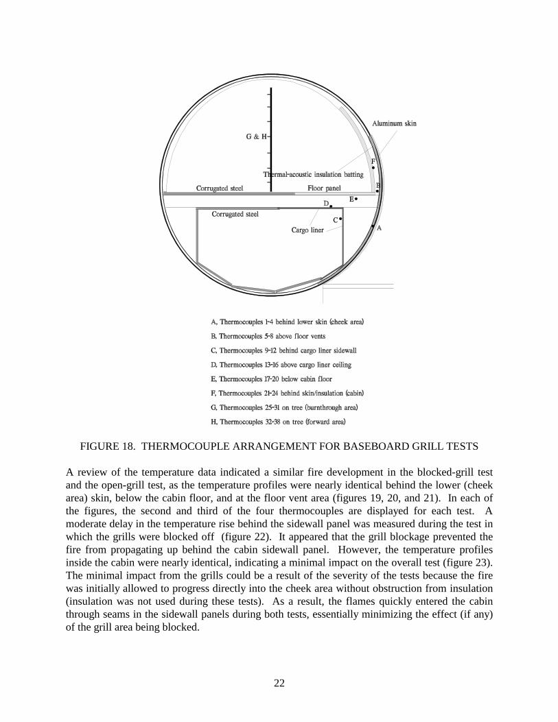
An initial baseline test was conducted in which the test rig was configured with a 4- by 12-footburnthrough area, roughly half of the area used for most previous tests. Since the investigationfocused on the cheek area only, there was no need to involve more materials than required. The4-foot-high burnthrough area was centered above and below the cabin floor and riveted in placesimilar to previous tests. Insulation bags of Microlite AA with metallized polyvinyl fluoride filmwere installed in the cabin sidewall, above the floor only. For test purposes, there was noinsulation below the floor, since it was assumed that the batts would be displaced during anactual fire. In addition to the sidewall insulation, interior sidewall panels were installed alongwith an M.C. Gill Gillfab 4017 honeycomb floor panel measuring 4 by 12 feet and covered withFAA-approved aircraft quality wool/nylon carpet and cargo liner in the lower compartment.Thermocouples were located in the following areas: behind the skin, inside floor openingsbehind the sidewall panel, behind the cargo liner (sidewall), above the cargo liner (ceiling),below the cabin floor, and behind the cabin sidewall panel (figure 18). In each of these locations,a thermocouple was placed in the area between the vertical formers; a total of four thermocoupleswere used in each area. Temperatures were also monitored at two tree locations inside the cabin,one near the burnthrough area and another in the forward fuselage.
Because there was no insulation below the cabin floor, flames were visible inside the cabin in 20seconds during the initial test and quickly propagating through the floor vent holes behind thesidewall panels. A problem with the attachment of the insulation and sidewall panels led toextinguishing the external fuel fire early. A subsequent test used proper attachment methods anda more realistic mounting of the sidewall panels. During the open-grill test, the baseboard airreturn grill area normally located in the base of the sidewall panel was left completely open toproduce a test condition offering the least resistance to flame penetration. Flames were evidentin the cabin in approximately 45 seconds and flames had completely engulfed the cabin materialsafter 1 minute 30 seconds. The test was terminated at 2 minutes 30 seconds. During a follow-uptest, the baseboard air return grill area was blocked off with sheet metal, but the cabin flooropenings behind the sidewall panels were left open. After fuel pan ignition, flames were visiblein the cabin after 1 minute. The interior materials were completely involved after approximately2 minutes, approximately 30 seconds later than during the previous test.
22
FIGURE 18. THERMOCOUPLE ARRANGEMENT FOR BASEBOARD GRILL TESTS
A review of the temperature data indicated a similar fire development in the blocked-grill testand the open-grill test, as the temperature profiles were nearly identical behind the lower (cheekarea) skin, below the cabin floor, and at the floor vent area (figures 19, 20, and 21). In each ofthe figures, the second and third of the four thermocouples are displayed for each test. Amoderate delay in the temperature rise behind the sidewall panel was measured during the test inwhich the grills were blocked off (figure 22). It appeared that the grill blockage prevented thefire from propagating up behind the cabin sidewall panel. However, the temperature profilesinside the cabin were nearly identical, indicating a minimal impact on the overall test (figure 23).The minimal impact from the grills could be a result of the severity of the tests because the firewas initially allowed to progress directly into the cheek area without obstruction from insulation(insulation was not used during these tests). As a result, the flames quickly entered the cabinthrough seams in the sidewall panels during both tests, essentially minimizing the effect (if any)of the grill area being blocked.
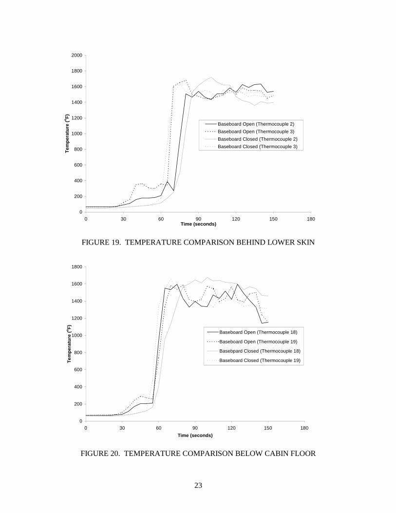
23
0
200
400
600
800
1000
1200
1400
1600
1800
2000
0 30 60 90 120 150 180Time (seconds)
Tem
pera
ture
(oF
)
Baseboard Open (Thermocouple 2)
Baseboard Open (Thermocouple 3)
Baseboard Closed (Thermocouple 2)
Baseboard Closed (Thermocouple 3)
FIGURE 19. TEMPERATURE COMPARISON BEHIND LOWER SKIN
0
200
400
600
800
1000
1200
1400
1600
1800
0 30 60 90 120 150 180
Time (seconds)
Tem
pera
ture
(oF
)
Baseboard Open (Thermocouple 18)
Baseboard Open (Thermocouple 19)
Basebpard Closed (Thermocouple 18)
Baseboard Closed (Thermocouple 19)
FIGURE 20. TEMPERATURE COMPARISON BELOW CABIN FLOOR

24
0
200
400
600
800
1000
1200
1400
1600
1800
2000
0 30 60 90 120 150 180Time (seconds)
Tem
pera
ture
(oF
)
Baseboard Open (Thermocouple 6)
Baseboard Open (Thermocouple 7)
Baseboard Closed (Thermocouple 6)
Baseboard Closed (Thermocouple 7)
FIGURE 21. TEMPERATURE COMPARISON AT FLOOR VENT AREA
0
200
400
600
800
1000
1200
1400
1600
1800
0 30 60 90 120 150 180
Time (seconds)
Tem
pera
ture
(oF
)
Baseboard Open (Thermocouple 22)
Basebpard Open (Thermocouple 23)
Basebpard Closed (Thermocouple 22)
Baseboard Closed (Thermocouple 23)
FIGURE 22. TEMPERATURE COMPARISON AT SIDEWALL LOCATION

25
0
50
100
150
200
250
300
350
400
450
0 30 60 90 120 150 180
Time (seconds)
Tem
pera
ture
(oF
)Thermocouple Tree 4' (Baseboard Open)
Thermocouple Tree 5' (Baseboard Open)
Thermocouple Tree 4' (Baseboard Closed)
Thermocouple Tree 5' (Baseboard Closed)
FIGURE 23. THERMOCOUPLE TREE TEMPERATURE COMPARISON IN FUSELAGE
EVALUATION OF ALTERNATE INSULATION SYSTEM ON AN ACTUAL FUSELAGESKIN SECTION.
A final series of tests were run to determine the effectiveness of the heat-treated OPF whenmounted in an actual aircraft fuselage section. Until this point, all material evaluations had takenplace using the steel channel test rig. This had raised concern over the validity of the resultssince steel has a melting point in the area of 2600oF, which is well above the 1850oF temperatureof the fuel fire flames. During most of the tests, the materials were attached directly to the testrig, which eliminated the possibility of burnthrough due to structural failure. In an actual aircraftfire, aluminum fuselage materials will melt at approximately 1100oF and lose their structuralintegrity at even lower temperatures. If an external fuel fire was large enough, a significantportion of the fuselage could fail, causing the insulation materials to be pulled out into the fire. Ifthis were to occur, the burnthrough resistance of the materials would be considerably lessimportant.
The heat-treated OPF was chosen for these tests since it could be considered a drop-in (direct)replacement for the current insulation systems, and it exhibited favorable burnthrough resistancequalities during full-scale tests. In order to evaluate the material under realistic conditions, thesteel test rig was modified considerably. First, large sections of 5 of the 11 curved-steel channelswere removed from the area that faced the fuel fire to provide an opening. This area was thenreinforced from the inside and also around the perimeter to prevent collapse of the structure(figure 24). Next, steel mounting pads were attached at six points around the periphery of theopening in order to accept an actual fuselage section (figures 24 and 25).

26
FIGURE 24. MODIFIED TEST RIG USED TO EVALUATE ACTUAL SKIN SECTION
FIGURE 25. END VIEW OF MODIFIED TEST
27
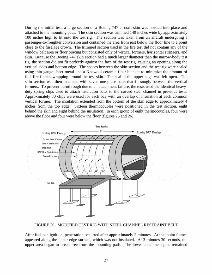
During the initial test, a large section of a Boeing 747 aircraft skin was hoisted into place andattached to the mounting pads. The skin section was trimmed 140 inches wide by approximately100 inches high to fit onto the test rig. The section was taken from an aircraft undergoing apassenger-to-freighter conversion and contained the area from just below the floor line to a pointclose to the fuselage crown. The trimmed section used in the fire test did not contain any of thewindow belt area or floor bracing but consisted only of vertical formers, horizontal stringers, andskin. Because the Boeing 747 skin section had a much larger diameter than the narrow-body testrig, the section did not fit perfectly against the face of the test rig, causing an opening along thevertical sides and bottom edge. The spaces between the skin section and the test rig were sealedusing thin-gauge sheet metal and a Kaowool ceramic fiber blanket to minimize the amount offuel fire flames wrapping around the test skin. The seal at the upper edge was left open. Theskin section was then insulated with seven one-piece batts that fit snugly between the verticalformers. To prevent burnthrough due to an attachment failure, the tests used the identical heavy-duty spring clips used to attach insulation batts to the curved steel channel in previous tests.Approximately 30 clips were used for each bay with an overlap of insulation at each commonvertical former. The insulation extended from the bottom of the skin edge to approximately 4inches from the top edge. Sixteen thermocouples were positioned in the test section, eightbehind the skin and eight behind the insulation. In each group of eight thermocouples, four wereabove the floor and four were below the floor (figures 25 and 26).
FIGURE 26. MODIFIED TEST RIG WITH STEEL CHANNEL RESTRAINT BELT
After fuel pan ignition, penetration occurred after approximately 2 minutes. At this point flamesappeared along the upper edge surface, which was not insulated. At 3 minutes 30 seconds, theupper area began to break free from the mounting pads. The lower attachment pins remained

28
intact during the entire test. For the next 30 seconds, the entire skin section slowly rotatedoutward into the fuel pan, allowing ever-greater flame penetration into the test fuselage. By 4minutes, flames had completely engulfed the backside of the skin section, which was nearlyhorizontal at this point. The fuel fire flames were extinguished at 4 minutes 30 seconds. Asubsequent investigation of the test section revealed that a large portion of the outer skin hadbeen consumed by the fire, and a discernible horizontal failure line was observed near the upperedge of the skin, which had caused the rotation into the fire. The insulation remained nearlyintact, as it was held in place by the remaining stringers and steel spring clips.
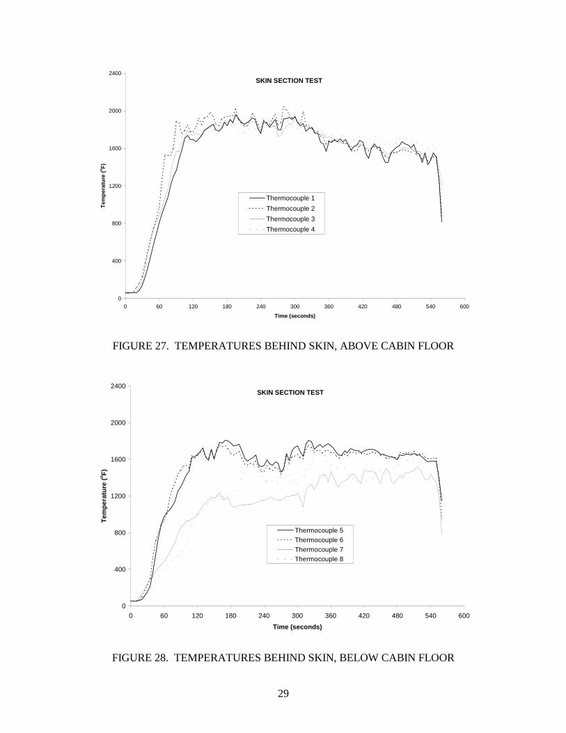
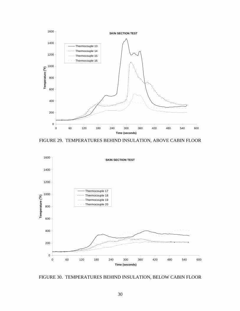
A second test was conducted in which the upper attachment points were fortified with a steelchannel belt used to hold the skin section in place if the three mounting-pad attachments failed(figure 26). This also created a more realistic test condition, since an actual continuous fuselageskin would not likely fail along a horizontal line near the upper fire impingement area, asconfirmed by the previous tests using the surplus fuselage sections. After fuel pan ignition, thetest progressed normally until 1 minute 30 seconds when flames were again noticed at the upperedge surface, which was not insulated on the uppermost 4 inches. At approximately 3 minutes,there was a noticeable separation between the upper three mounting pins and the test rig, but theskin section was restrained from further movement by the steel channel belt. At approximately 4minutes 15 seconds, the upper section of the two center insulation batts began to pulsate and giveway to the fire. By 4 minutes 30 seconds, large flames were penetrating near the seam of thecenter insulation batts, but the batts remained attached along the seam at a lower location. Allother insulation batts remained in place, preventing flame penetration in other areas. This patterncontinued until the pan fire was extinguished at 9 minutes. The temperature data shown infigures 27 and 28 indicate that the fuselage skin was penetrated in approximately 60 seconds bythe fuel fire. Maximum flame temperatures were 2000 and 1800oF above and below the cabinfloor, respectively. In spite of the high flame temperatures, the inboard temperatures of the heat-treated OPF batting never exceeded 500 and 400oF above and below the cabin floor (figures 29and 30) while it remained in place. Figure 29 shows a rapid temperature rise over a 2-minuteperiod approximately 4 minutes after the test began due to the opening of a seam betweenadjacent batts in the upper section. A subsequent inspection revealed that not only was the skinlargely consumed, but the vertical formers had been depleted in the center area as well. Thecenter insulation batts were actually suspended between adjacent batts and stringers and held inplace by the aid of the spring clips only. Inspection of the insulation material following bothtests showed that the materials remained intact, confirming initial observations of flamepenetration occurring along the seams. If properly restrained, the tests demonstrated thatimproved insulation blankets can be effective burnthrough barriers when installed in actualaluminum fuselage structures. The results were consistent with the findings in the reusable steel-framed test rig. Again, the importance of securely fastening the insulation blanket and protectingthe seams was evidenced.
29
SKIN SECTION TEST
0
400
800
1200
1600
2000
2400
0 60 120 180 240 300 360 420 480 540 600
Time (seconds)
Tem
pera
ture
(oF
)
Thermocouple 1
Thermocouple 2
Thermocouple 3
Thermocouple 4
FIGURE 27. TEMPERATURES BEHIND SKIN, ABOVE CABIN FLOOR
SKIN SECTION TEST
0
400
800
1200
1600
2000
2400
0 60 120 180 240 300 360 420 480 540 600
Time (seconds)
Tem
pera
ture
(oF
)
Thermocouple 5Thermocouple 6Thermocouple 7Thermocouple 8
FIGURE 28. TEMPERATURES BEHIND SKIN, BELOW CABIN FLOOR
30
SKIN SECTION TEST
0
200
400
600
800
1000
1200
1400
1600
0 60 120 180 240 300 360 420 480 540 600
Time (seconds)
Tem
pera
ture
(oF
)Thermocouple 13
Thermocouple 14
Thermocouple 15
Thermocouple 16
FIGURE 29. TEMPERATURES BEHIND INSULATION, ABOVE CABIN FLOOR
SKIN SECTION TEST
0
200
400
600
800
1000
1200
1400
1600
0 60 120 180 240 300 360 420 480 540 600
Time (seconds)
Tem
pera
ture
(oF
)
Thermocouple 17
Thermocouple 18
Thermocouple 19
Thermocouple 20
FIGURE 30. TEMPERATURES BEHIND INSULATION, BELOW CABIN FLOOR
31
DEVELOPMENT OF A MEDIUM-SCALE TEST RIG.
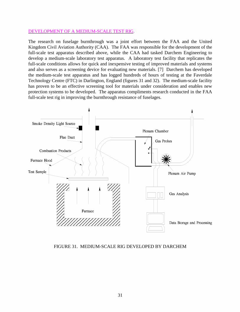
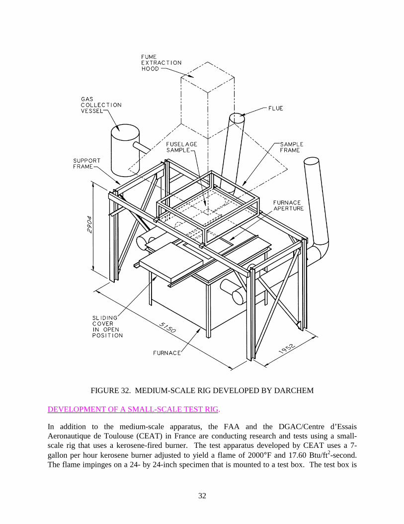
The research on fuselage burnthrough was a joint effort between the FAA and the UnitedKingdom Civil Aviation Authority (CAA). The FAA was responsible for the development of thefull-scale test apparatus described above, while the CAA had tasked Darchem Engineering todevelop a medium-scale laboratory test apparatus. A laboratory test facility that replicates thefull-scale conditions allows for quick and inexpensive testing of improved materials and systemsand also serves as a screening device for evaluating new materials. [7] Darchem has developedthe medium-scale test apparatus and has logged hundreds of hours of testing at the FaverdaleTechnology Centre (FTC) in Darlington, England (figures 31 and 32). The medium-scale facilityhas proven to be an effective screening tool for materials under consideration and enables newprotection systems to be developed. The apparatus compliments research conducted in the FAAfull-scale test rig in improving the burnthrough resistance of fuselages.
FIGURE 31. MEDIUM-SCALE RIG DEVELOPED BY DARCHEM
32
FIGURE 32. MEDIUM-SCALE RIG DEVELOPED BY DARCHEM
DEVELOPMENT OF A SMALL-SCALE TEST RIG.
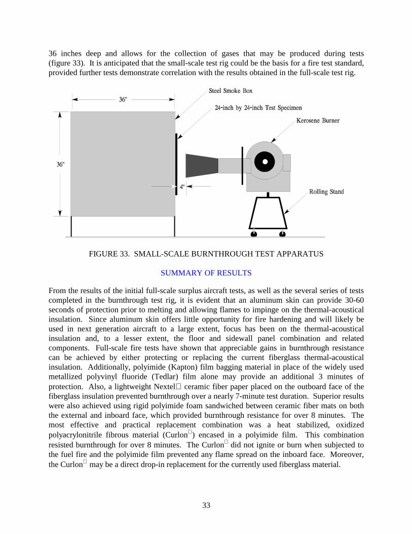
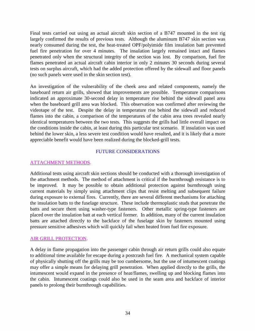
In addition to the medium-scale apparatus, the FAA and the DGAC/Centre d’EssaisAeronautique de Toulouse (CEAT) in France are conducting research and tests using a small-scale rig that uses a kerosene-fired burner. The test apparatus developed by CEAT uses a 7-gallon per hour kerosene burner adjusted to yield a flame of 2000°F and 17.60 Btu/ft2-second.The flame impinges on a 24- by 24-inch specimen that is mounted to a test box. The test box is
33
36 inches deep and allows for the collection of gases that may be produced during tests(figure 33). It is anticipated that the small-scale test rig could be the basis for a fire test standard,provided further tests demonstrate correlation with the results obtained in the full-scale test rig.
FIGURE 33. SMALL-SCALE BURNTHROUGH TEST APPARATUS
SUMMARY OF RESULTS
From the results of the initial full-scale surplus aircraft tests, as well as the several series of testscompleted in the burnthrough test rig, it is evident that an aluminum skin can provide 30-60seconds of protection prior to melting and allowing flames to impinge on the thermal-acousticalinsulation. Since aluminum skin offers little opportunity for fire hardening and will likely beused in next generation aircraft to a large extent, focus has been on the thermal-acousticalinsulation and, to a lesser extent, the floor and sidewall panel combination and relatedcomponents. Full-scale fire tests have shown that appreciable gains in burnthrough resistancecan be achieved by either protecting or replacing the current fiberglass thermal-acousticalinsulation. Additionally, polyimide (Kapton) film bagging material in place of the widely usedmetallized polyvinyl fluoride (Tedlar) film alone may provide an additional 3 minutes ofprotection. Also, a lightweight Nextel ceramic fiber paper placed on the outboard face of thefiberglass insulation prevented burnthrough over a nearly 7-minute test duration. Superior resultswere also achieved using rigid polyimide foam sandwiched between ceramic fiber mats on boththe external and inboard face, which provided burnthrough resistance for over 8 minutes. Themost effective and practical replacement combination was a heat stabilized, oxidizedpolyacrylonitrile fibrous material (Curlon) encased in a polyimide film. This combinationresisted burnthrough for over 8 minutes. The Curlon did not ignite or burn when subjected tothe fuel fire and the polyimide film prevented any flame spread on the inboard face. Moreover,the Curlon may be a direct drop-in replacement for the currently used fiberglass material.
34
Final tests carried out using an actual aircraft skin section of a B747 mounted in the test riglargely confirmed the results of previous tests. Although the aluminum B747 skin section wasnearly consumed during the test, the heat-treated OPF/polyimide film insulation batt preventedfuel fire penetration for over 4 minutes. The insulation largely remained intact and flamespenetrated only when the structural integrity of the section was lost. By comparison, fuel fireflames penetrated an actual aircraft cabin interior in only 2 minutes 30 seconds during severaltests on surplus aircraft, which had the added protection offered by the sidewall and floor panels(no such panels were used in the skin section test).
An investigation of the vulnerability of the cheek area and related components, namely thebaseboard return air grills, showed that improvements are possible. Temperature comparisonsindicated an approximate 30-second delay in temperature rise behind the sidewall panel areawhen the baseboard grill area was blocked. This observation was confirmed after reviewing thevideotape of the test. Despite the delay in temperature rise behind the sidewall and reducedflames into the cabin, a comparison of the temperatures of the cabin area trees revealed nearlyidentical temperatures between the two tests. This suggests the grills had little overall impact onthe conditions inside the cabin, at least during this particular test scenario. If insulation was usedbehind the lower skin, a less severe test condition would have resulted, and it is likely that a moreappreciable benefit would have been realized during the blocked-grill tests.
FUTURE CONSIDERATIONS
ATTACHMENT METHODS.
Additional tests using aircraft skin sections should be conducted with a thorough investigation ofthe attachment methods. The method of attachment is critical if the burnthrough resistance is tobe improved. It may be possible to obtain additional protection against burnthrough usingcurrent materials by simply using attachment clips that resist melting and subsequent failureduring exposure to external fires. Currently, there are several different mechanisms for attachingthe insulation batts to the fuselage structure. These include thermoplastic studs that penetrate thebatts and secure them using washer-type fasteners. Other metallic spring-type fasteners areplaced over the insulation batt at each vertical former. In addition, many of the current insulationbatts are attached directly to the backface of the fuselage skin by fasteners mounted usingpressure sensitive adhesives which will quickly fail when heated from fuel fire exposure.
AIR GRILL PROTECTION.
A delay in flame propagation into the passenger cabin through air return grills could also equateto additional time available for escape during a postcrash fuel fire. A mechanical system capableof physically shutting off the grills may be too cumbersome, but the use of intumescent coatingsmay offer a simple means for delaying grill penetration. When applied directly to the grills, theintumescent would expand in the presence of heat/flames, swelling up and blocking flames intothe cabin. Intumescent coatings could also be used in the seam area and backface of interiorpanels to prolong their burnthrough capabilities.
35/36
TOTALLY COMPOSITE FUSELAGE.
Another issue that should be considered is the burnthrough resistance of a composite skinfuselage. The use of composites in transport category aircraft has grown steadily due to theirhigh strength and low weight. The fuselage skin of the High-Speed Civil Transport (HSCT) willlikely be constructed of a composite material which requires an assessment of its performancewhen exposed to a large fuel fire. From a burnthrough standpoint, a composite fuselage wouldlikely offer greater burnthrough protection than aluminum. However, there is concern over thepotential toxic and combustible gases released during flame exposure, which could accumulate inthe cabin and present a hazard to escaping occupants. Whether or not this is a real concern couldbe determined in the full-scale test rig by replacing the aluminum skin with composite structureand measuring the resultant gases within the cabin.
REFERENCES
1. Sarkos, C.P., 1988, “Development of Improved Fire Safety Standards Adopted by theFederal Aviation Administration,” AGARD-CPP-467-5, Propulsion and Energetics Panel73rd Symposium on Aircraft Fire Safety, Sintra, Portugal, May 22-26, 1989.
2. Sarkos, C.P., Webster, H., Geyer, G., Do, D., Wright, J., Collins, J., and Hampton, L.,1990, “Full-Scale Fuselage Burnthrough Tests,” The European Cabin Safety Conference,Gatwick International Airport, Sussex, United Kingdom, September 18-21, 1990.
3. Sarkos, C.P. and Hill, R.G., 1988, “Characteristics of Transport Aircraft Fires Measuredby Full-Scale Tests,” AGARD-CPP-467-11, Propulsion and Energetics Panel 73rdSymposium on Aircraft Fire Safety, Sintra, Portugal, May 22-26, 1989.
4. “Report on the Accident to Boeing 737-236 Series 1 G-BGJL at Manchester InternationalAirport on 22 August 1985.” Air Accidents Investigation Branch (1988). AircraftAccident Report 8/88, London: Her Majesty’s Stationary Office.
5. Webster, H., Geyer, G., Do, D., Wright, J., Collins, J., and Hampton, L., “Full-Scale AirTransport Category Fuselage Burnthrough Tests,” Federal Aviation AdministrationTechnical Note DOT/FAA/CT-TN89/65, February 1990.
6. Webster, H., “Fuselage Burnthrough from Large Exterior Fuel Fires,” Federal AviationAdministration Final Report DOT/FAA/CT-90/10, July 1994.
7. Dodd, D.C., Hall, C.T.M., Pollard, J., and Snell, M.A., 1994, “Burnthrough Resistance ofFuselages: Initial Findings,” CAA Paper 94002,0 Civil Aviation Authority, London.