Embed Size (px)
Citation preview
www.advenergymat.de
FULL PAPER
1700157 (1 of 12) © 2017 WILEY-VCH Verlag GmbH & Co. KGaA, Weinheim
Fully Biodegradable Microsupercapacitor for Power Storage in Transient Electronics
Geumbee Lee, Seung-Kyun Kang, Sang Min Won, Philipp Gutruf, Yu Ra Jeong, Jahyun Koo, Sang-Soo Lee, John A. Rogers,* and Jeong Sook Ha*
DOI: 10.1002/aenm.201700157
active and passive materials are impor-tant in this context. Here, the hardware dissolves completely into ground water or biofluids after stable operation for a controlled duration. Applications include not only “green” electronics, but also tem-porary biomedical implants, secure data systems, and environmental monitors.[5–7] Previous demonstrations of such classes of devices, often viewed as a subset of broader type of technology known as tran-sient electronics, include simple compo-nents such as metal-oxide-semiconductor field effect transistors (MOSFETs), diodes, inductors, and capacitors; integrated logic circuits such as NAND, NOR, and inverter circuits; energy harvesters; primary bat-teries; and various medical sensors.[5–11] Among those transient devices in a rapidly expanding area of interest in the materials and device communities, a key, unsolved challenge is in power supply.
Recent reports describe biodegradable batteries and supercapacitor, as an energy-storage option. The first, by Yin et al.,[10] reports water-activated primary batteries based on biodegradable metal foils. These nonrechargeable bat-teries have low output voltages (0.4 V for a single cell) and large dimensions (3 × 2 × 1.3 cm3) for arrays of cells. The second, by Fu et al.,[11] involves a rechargeable, flexible device with output voltage of 2.8 V, but where the electrode materials, current col-lectors, and substrate dissolve in water within a few seconds/minutes. The third, by Wang et al.,[12] reports on an edible
In this work, the authors report materials, fabrication strategies, and applica-tions of biodegradable microsupercapacitors (MSCs) built using water-soluble (i.e., physically transient) metal (W, Fe, and Mo) electrodes, a biopolymer, hydrogel electrolyte (agarose gel), and a biodegradable poly(lactic-co-glycolic acid) substrate, encapsulated with polyanhydride. During repetitive charge/discharge cycles, the electrochemical performance of these unusual MSCs is dramatically enhanced, following from the role of pseudocapacitance that originates from metal-oxide coatings generated by electrochemical corrosion at the interface between the water-soluble metal electrode and the hydrogel electrolyte. Systematic studies reveal the dissolution kinetics/behaviors of each individual component of the MSCs, as well as those of the integrated devices. An encapsulation strategy that involves control over the thickness, chemistry, and molecular weight of the constituent materials provides a versatile means to engineer desired functional lifetimes. Demonstration experiments illustrate potential applications of these biodegradable MSCs as transient sources of power in the operation of light-emitting diodes and as charging capacitors in integrated circuits for wireless power harvesting.
G. Lee, Prof. S.-S. Lee, Prof. J. S. HaKU-KIST Graduate School of Converging Science and TechnologyKorea University145 Anam-ro, Seongbuk-gu, Seoul 02841, Republic of KoreaE-mail: [email protected]. S.-K. Kang, S. M. Won, Dr. P. Gutruf, Dr. J. Koo, Prof. J. A. RogersDepartment of Materials Science and EngineeringFrederick Seitz Materials Research LaboratoryUniversity of Illinois at Urbana-ChampaignUrbana, IL 61801, USAE-mail: [email protected]. P. Gutruf, Prof. J. A. RogersDepartment of Materials Science and EngineeringNorthwestern UniversityEvanston, IL 60208, USA
Microsupercapacitors
Y. R. Jeong, Prof. J. S. HaDepartment of Chemical and Biological EngineeringKorea University145 Anam-ro, Seongbuk-gu, Seoul 02841, Republic of KoreaProf. S.-S. LeePhoto-Electronic Hybrids Research CenterKorea Institute of Science and TechnologySeoul 136-791, Republic of KoreaProf. J. A. RogersDepartments of Biomedical Engineering, Chemistry, Mechanical Engineering, Electrical Engineering and Computer Science, and Neurological SurgeryCenter for Bio-Integrated Electronics, and Simpson Querrey Institute for Nano/biotechnologyNorthwestern UniversityEvanston, IL 60208, USA
1. Introduction
The development of electronic devices for sustainable genera-tion and storage of energy is critically important for environ-mentally responsible technologies.[1,2] In spite of significant recent advances in this area, comparatively little consideration has been given to the pollution introduced by associated waste streams and the toxic and harmful effects on the human body.[3,4] Emerging device technologies based on bio/ecoresorbable
Adv. Energy Mater. 2017, 7, 1700157
www.advenergymat.dewww.advancedsciencenews.com
© 2017 WILEY-VCH Verlag GmbH & Co. KGaA, Weinheim1700157 (2 of 12)
supercapacitor that utilizes soft, food-based materials. The structure involves a relatively thick electrode film (≈120 µm) and a stack-type structure. The requirement for edibility places constraints on materials choices, some of which do not apply to devices simply constructed to resorb in the body, as those introduced here. The disadvantages of these options limit their practical use.
Electrochemical capacitors, often known as supercapaci-tors, can store electrical energy and deliver this energy to active devices at proper rates, thereby providing high power densities. A such, these devices are well suited to provide back-up energy, for example, to eliminate adverse consequences of unexpected interruptions in power supply,[13] or to supply pulsed power for communication devices,[14] or to stabilize the output voltage of a battery,[15] etc. They can also play key roles in integrated circuits as passive components.[16]
This work introduces materials and fabrication strategies for fully biodegradable microsupercapacitors (MSCs) with high electrochemical performances. Here, water-soluble transition-metal (tungsten (W), iron (Fe), and molybdenum (Mo)) thin films,[17–19] which are both biocompatible and biodegradable, serve as the electrode materials as well as current collectors. Ion salts (Na+ and Cl−) in an agarose gel, a type of biopolymer, func-tion as the electrolyte.[20] Conventional supercapacitors store energy electrostatically by forming an electrical double layer at the interface between the electrode surface and the electrolyte. The charge-storage mechanism of this electrical double layer capacitor (EDLC) is based on the adsorption of ions in the elec-trolyte onto the electrode surface, with opposite polarity, during charging. Enhancements in performance can be achieved with carbon-based nanomaterials such as graphene[21,22] or carbon nanotubes,[23,24] whose large specific surface areas increase the number density of adsorbed ions[25,26] and whose porous struc-tures facilitate effective diffusion of ions into the electrodes.[27,28]
In the supercapacitors described here, continuous growth of a metal-oxide film results from electrochemical corrosion of thin metal electrodes formed by sputtering or electron-beam (e-beam) evaporation, as a result of contact with the water-containing hydrogel electrolyte during repeated cycles of charge/discharge. These phenomena lead to additional redox reactions, and thereby, improved performance compared to that of the conventional EDLCs, as a result of pseudoca-pacitance.[29–32] In addition, these planar, solid-state MSCs, when formed on flexible films of the biodegradable polymer poly(lactic-co-glycolic acid) (PLGA), can be integrated with other active devices, in a manner that offers mechanical stability under bending, folding, and rolling deformations.
MSCs with Mo interdigitated electrodes and a complete set of degradable components offer areal capacitances of 1.6 mF cm−2, energy density of 0.14 µW h cm−2, and power density of 1.0 mW cm−2. These values are comparable to those of nontransient supercapacitors. The output voltages and capac-itances of the MSCs can be controlled by connecting arrays in series or parallel configurations. The devices offer stable performance under immersion in phosphate-buffered saline (PBS) for a well-defined period of time, and dissolve completely afterward.
Systematic investigations of the materials, fabrication strate-gies, and their applications reveal all of the essential details and
operating mechanisms of these systems. Here, we introduce a new class of technology based on an unusual device architec-ture and unconventional materials. Therefore, this class of fully biodegradable supercapacitor represents an important advance in fully bio/ecodegradable, high performance energy-storage for power supply.
2. Results and Discussion
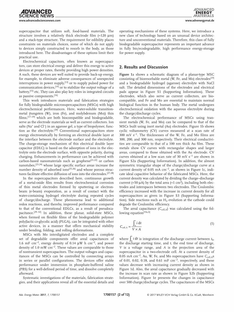
Figure 1a shows a schematic diagram of a planar-type MSC consisting of bioresorbable metal (W, Fe, and Mo) electrodes[19] and a biodegradable hydrogel (agarose) electrolyte with NaCl salt. The detailed dimensions of the electrodes and electrical pads appear in Figure S1 (Supporting Information). These electrodes, which also serve as current collectors, are bio-compatible, and Fe and Mo are essential to maintain normal biological function in the human body. The metal undergoes electrochemical oxidation with the aqueous electrolyte during the charge/discharge cycles.
The electrochemical performance of MSCs using tran-sient metals (W, Fe, and Mo) can be compared to that of the MSCs built using inert metal (Au) electrodes. Figure 1b shows cyclic voltammetry (CV) curves measured at a scan rate of 300 mV s−1. The thicknesses of the W, Fe, and Mo films are 300, 200, and 300 nm, respectively. Their electrical conductivi-ties are comparable to that of a 100 nm thick Au film. These metals show CV curves with rectangular shapes and larger areas, compared to those obtained with the Au electrode. CV curves obtained at a low scan rate of 30 mV s−1 are shown in Figure S2a (Supporting Information). In addition, the almost symmetric triangular shape of the charge/discharge curve at a current density of 0.05 mA cm−2, as shown in Figure 1c, indi-cate ideal capacitive behavior of the fabricated MSCs. Here, the current density was calculated by dividing the charge–discharge current (≈50 µA) by the total area (≈1 cm2), including both elec-trodes and interspaces between two electrodes. The Coulombic efficiency increased with the increase in current density for all supercapacitors as given in Figure S3 (Supporting Informa-tion). Side reactions such as H2 evolution at the cathode could degrade the Coulombic efficiency.
The areal capacitance (Ccell,A) was calculated using the fol-lowing equation[33a,b]
∫=
×
dcell,A
0Ci t
V At
t
(1)
where ∫ d0i t
t
t
is integration of the discharge current between t0, the discharge starting time, and t, the end time of discharge, V is a voltage range, and A is the projection area of the supercapacitor in a two-electrode cell. At a current density of 0.05 mA cm−2, Au, W, Fe, and Mo supercapacitors have Ccell,As of 0.01, 0.02, 0.18, and 0.61 mF cm−2, respectively, and these values decrease with increasing current density as shown in Figure 1d. Also, the areal capacitance gradually decreased with the increase in scan rate as shown in Figure S2b (Supporting Information). Figure 1e presents the changes in capacitance over 500 charge/discharge cycles. The capacitances of the MSCs
Adv. Energy Mater. 2017, 7, 1700157
www.advenergymat.dewww.advancedsciencenews.com
© 2017 WILEY-VCH Verlag GmbH & Co. KGaA, Weinheim1700157 (3 of 12)
with Fe and Mo electrodes increase three fold, while that of the MSCs with the W and Au electrodes remain unchanged after 500 cycles. All MSCs show symmetric charge/discharge curves over the entire range of cycles. Most conventional supercapaci-tors exhibit decreasing or unchanged capacitance after repeated charge/discharge cycles. The former effects can follow from pulverization or loss of electrical contact between the active material and the current collector,[34] or because of the degrada-tion of the metal oxides or conducting polymers used as elec-trode materials.[35,36] By contrast, MSCs based on biodegradable metal electrodes exhibit a sharp increase in the capacitance after several cycles. Previous observations of increased capaci-tance with cycling were attributed to an activation process asso-ciated with improvement in the surface wetting of the electrode by the liquid or gel electrolyte.[37]
For the bioresorbable electrodes used in this study, anodic reactions at the interface between the hydrogel electrolyte and the metal surface, under a continuously applied cur-rent, might increase the capacitance, even without the inten-tional addition of a coated metal-oxide layer for generating a pseudocapacitance.[29–32]
Figure 1f displays the changes in impedance with frequency, obtained from one of the electrochemical impedance spectrum (EIS) tests (Nyquist plots). The plots for Au and W are almost parallel to the imaginary axis, corresponding to capacitive behavior. By contrast, Fe and Mo show straight line responses at an angle of 45° with respect to the real axis in the low-frequency region, after charge/discharge cycles. This behavior relates to ion diffusion between the electrolyte and the electrode mate-rials.[38] Here, the internal resistance corresponds to an equiva-lent series resistance (ESR) corresponding to the resistances of
the electrode materials and the electrolyte, the contact resist-ance between them, the interfacial resistance at the active materials and the current collector, and the diffusion resistance of the ions.[39] After 500 cycles of charge/discharge, the ESR values for MSCs with Au and W electrodes remain unchanged while values for those with Fe and Mo electrodes increase from 112 and 111 Ω to 192 and 237 Ω, respectively, likely correlated to the different changes in capacitance shown in Figure 1e. The invariance of ESR with cycling suggests that Faradaic reac-tions do not occur on the electrode surfaces. Increases in ESR follow from Faradaic reactions corresponding to corrosion of the positive electrode and/or oxidation of the electrolyte.[40] The increase in ESR observed in Figure 1f likely originates from surface oxidation of the anode under the continuously applied current. The formation of such oxide layers would increase the electrical resistance as well as the capacitance.
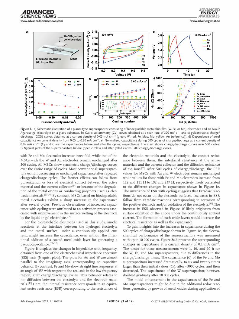
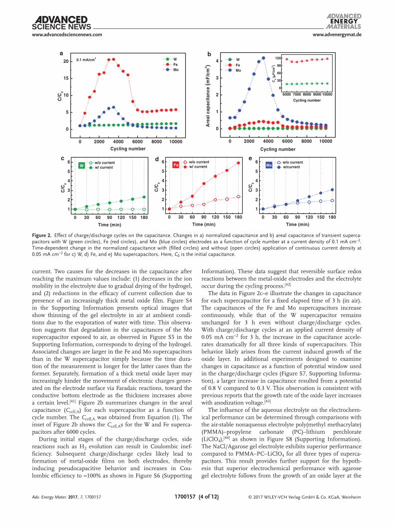
To gain insights into the increases in capacitance during the 500 cycles of charge/discharge shown in Figure 1e, the electro-chemical performance of the supercapacitors was measured with up to 10 000 cycles. Figure 2a,b presents the corresponding changes in capacitance at a current density of 0.1 mA cm−2. The times for these measurements were 1, 10, and 60 h for the W, Fe, and Mo supercapacitors, due to differences in the charge/discharge times. The capacitance (C) of the Fe and Mo supercapacitors increased dramatically, to six and twenty times larger than their initial values (C0), after ≈3000 cycles, and then decreased. The capacitance of the W supercapacitor, however, doubled gradually after 10 000 cycles.
The initial enhancement in the capacitances of the Fe and Mo supercapacitors might be due to the additional redox reac-tions generated by growth of metal oxides during application of
Adv. Energy Mater. 2017, 7, 1700157
Figure 1. a) Schematic illustration of a planar-type supercapacitor consisting of biodegradable metal thin-film (W, Fe, or Mo) electrodes and an NaCl/Agarose gel electrolyte on a glass substrate. b) Cyclic voltammetry (CV) curves obtained at a scan rate of 300 mV s−1, and c) galvanostatic charge/discharge (GCD) curves obtained at a current density of 0.05 mA cm−2 (green: W; red: Fe; blue: Mo; yellow: Au (reference)). d) Dependence of areal capacitance on current density from 0.05 to 0.20 mA cm−2. e) Normalized capacitance during 500 cycles of charge/discharge at a current density of 0.05 mA cm−2 (C0 and C are the capacitances before and after the cycles, respectively). The inset shows charge/discharge curves near 500 cycles. f) Nyquist plots of the supercapacitors before (open circles) and after (filled circles) 500 charge/discharge cycles.
www.advenergymat.dewww.advancedsciencenews.com
© 2017 WILEY-VCH Verlag GmbH & Co. KGaA, Weinheim1700157 (4 of 12)
current. Two causes for the decreases in the capacitance after reaching the maximum values include: (1) decreases in the ion mobility in the electrolyte due to gradual drying of the hydrogel, and (2) reductions in the efficacy of current collection due to presence of an increasingly thick metal oxide film. Figure S4 in the Supporting Information presents optical images that show thinning of the gel electrolyte in air at ambient condi-tions due to the evaporation of water with time. This observa-tion suggests that degradation in the capacitances of the Mo supercapacitor exposed to air, as observed in Figure S5 in the Supporting Information, corresponds to drying of the hydrogel. Associated changes are larger in the Fe and Mo supercapacitors than in the W supercapacitor simply because the time dura-tion of the measurement is longer for the latter cases than the former. Separately, formation of a thick metal oxide layer may increasingly hinder the movement of electronic charges gener-ated on the electrode surface via Faradaic reactions, toward the conductive bottom electrode as the thickness increases above a certain level.[41] Figure 2b summarizes changes in the areal capacitance (Ccell,A) for each supercapacitor as a function of cycle number. The Ccell,A was obtained from Equation (1). The inset of Figure 2b shows the Ccell,As for the W and Fe superca-pacitors after 6000 cycles.
During initial stages of the charge/discharge cycles, side reactions such as H2 evolution can result in Coulombic inef-ficiency. Subsequent charge/discharge cycles likely lead to formation of metal-oxide films on both electrodes, thereby inducing pseudocapacitive behavior and increases in Cou-lombic efficiency to ≈100% as shown in Figure S6 (Supporting
Information). These data suggest that reversible surface redox reactions between the metal-oxide electrodes and the electrolyte occur during the cycling process.[42]
The data in Figure 2c–e illustrate the changes in capacitance for each supercapacitor for a fixed elapsed time of 3 h (in air). The capacitances of the Fe and Mo supercapacitors increase continuously, while that of the W supercapacitor remains unchanged for 3 h even without charge/discharge cycles. With charge/discharge cycles at an applied current density of 0.05 mA cm−2 for 3 h, the increase in the capacitance accele-rates dramatically for all three kinds of supercapacitors. This behavior likely arises from the current induced growth of the oxide layer. In additional experiments designed to examine changes in capacitance as a function of potential window used in the charge/discharge cycles (Figure S7, Supporting Informa-tion), a larger increase in capacitance resulted from a potential of 0.8 V compared to 0.3 V. This observation is consistent with previous reports that the growth rate of the oxide layer increases with anodization voltage.[43]
The influence of the aqueous electrolyte on the electrochem-ical performance can be determined through comparisons with the air-stable nonaqueous electrolyte poly(methyl methacrylate) (PMMA)–propylene carbonate (PC)–lithium perchlorate (LiClO4),[44] as shown in Figure S8 (Supporting Information). The NaCl/Agarose gel electrolyte exhibits superior performance compared to PMMA–PC–LiClO4 for all three types of superca-pacitors. This result provides further support for the hypoth-esis that superior electrochemical performance with agarose gel electrolyte follows from the growth of an oxide layer at the
Adv. Energy Mater. 2017, 7, 1700157
a b
0 30 60 90 120 150 180
1
2
3
4
5
6
C/C
0
Time (min)
w/o current w/ current
0 30 60 90 120 150 180
1
2
3
4
5
6C
/C0
Time (min)
w/o current w/ current
0 30 60 90 120 150 180
1
2
3
4
5
6
C/C
0
Time (min)
w/o current w/current
c d e
0 2000 4000 6000 8000 10000
0
1
2
3
4
6000 7000 8000 9000 10000
0
30
60
90
120
Cce
ll (µF
)
Cycling number
Are
al c
apac
itan
ce (m
F/c
m2 )
Cycling number
W Fe Mo
CA ( µ
F/c
m2 )
0 2000 4000 6000 8000 10000
0
5
10
15
20C
/C0
Cycling number
W Fe Mo
0.1 mA/cm2
W Fe Mo
Figure 2. Effect of charge/discharge cycles on the capacitance. Changes in a) normalized capacitance and b) areal capacitance of transient superca-pacitors with W (green circles), Fe (red circles), and Mo (blue circles) electrodes as a function of cycle number at a current density of 0.1 mA cm−2. Time-dependent change in the normalized capacitance with (filled circles) and without (open circles) application of continuous current density at 0.05 mA cm−2 for c) W, d) Fe, and e) Mo supercapacitors. Here, C0 is the initial capacitance.
www.advenergymat.dewww.advancedsciencenews.com
© 2017 WILEY-VCH Verlag GmbH & Co. KGaA, Weinheim1700157 (5 of 12)
interface between the metal electrodes and the contacting electrolyte. In addition, the agarose, which is known to be a biodegrad-able polymer, can form a submicron porous network by hydrogen bonding in its back-bone so that water can fill these pores effec-tively.[20] Thus, the use of the NaCl/Agarose gel electrolyte can induce electrochemical corrosion of the metal anodes by providing moisture, and ensuring biocompatibility for use in implanted devices.[45]
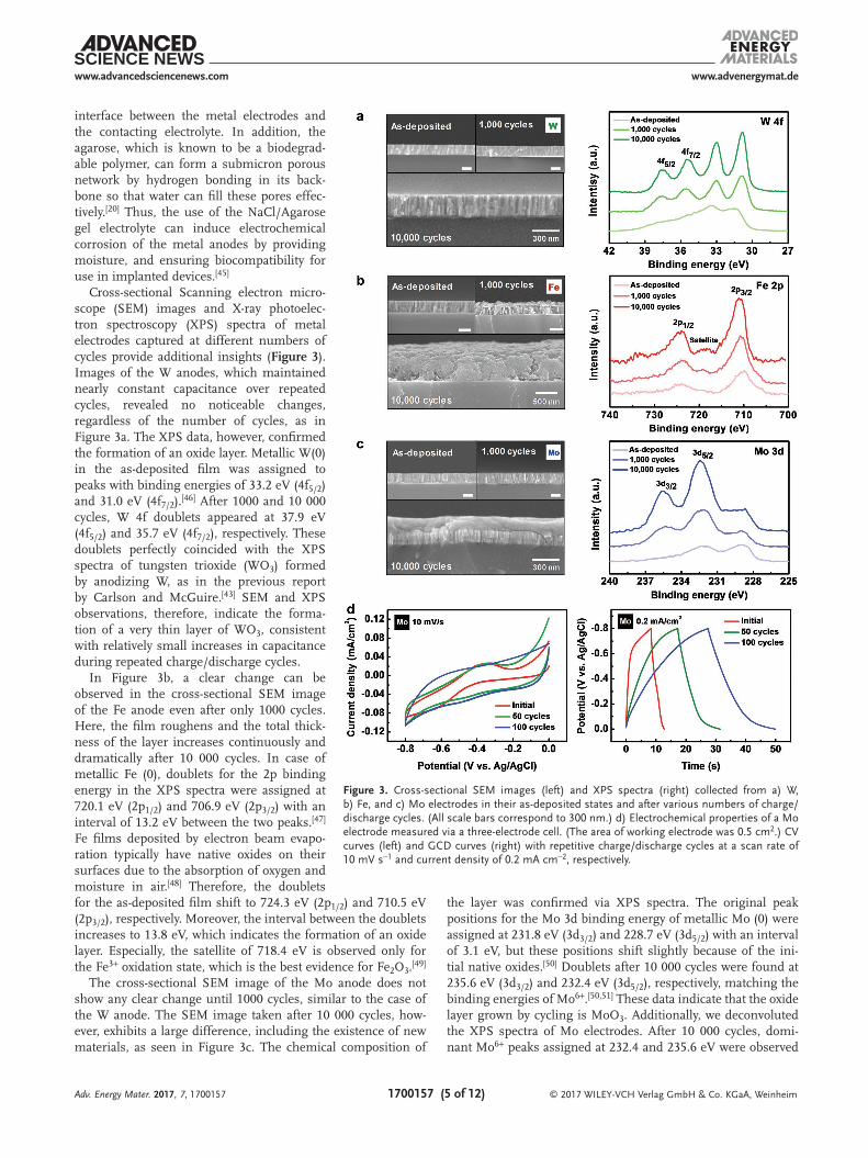
Cross-sectional Scanning electron micro-scope (SEM) images and X-ray photoelec-tron spectroscopy (XPS) spectra of metal electrodes captured at different numbers of cycles provide additional insights (Figure 3). Images of the W anodes, which maintained nearly constant capacitance over repeated cycles, revealed no noticeable changes, regardless of the number of cycles, as in Figure 3a. The XPS data, however, confirmed the formation of an oxide layer. Metallic W(0) in the as-deposited film was assigned to peaks with binding energies of 33.2 eV (4f5/2) and 31.0 eV (4f7/2).[46] After 1000 and 10 000 cycles, W 4f doublets appeared at 37.9 eV (4f5/2) and 35.7 eV (4f7/2), respectively. These doublets perfectly coincided with the XPS spectra of tungsten trioxide (WO3) formed by anodizing W, as in the previous report by Carlson and McGuire.[43] SEM and XPS observations, therefore, indicate the forma-tion of a very thin layer of WO3, consistent with relatively small increases in capacitance during repeated charge/discharge cycles.
In Figure 3b, a clear change can be observed in the cross-sectional SEM image of the Fe anode even after only 1000 cycles. Here, the film roughens and the total thick-ness of the layer increases continuously and dramatically after 10 000 cycles. In case of metallic Fe (0), doublets for the 2p binding energy in the XPS spectra were assigned at 720.1 eV (2p1/2) and 706.9 eV (2p3/2) with an interval of 13.2 eV between the two peaks.[47] Fe films deposited by electron beam evapo-ration typically have native oxides on their surfaces due to the absorption of oxygen and moisture in air.[48] Therefore, the doublets for the as-deposited film shift to 724.3 eV (2p1/2) and 710.5 eV (2p3/2), respectively. Moreover, the interval between the doublets increases to 13.8 eV, which indicates the formation of an oxide layer. Especially, the satellite of 718.4 eV is observed only for the Fe3+ oxidation state, which is the best evidence for Fe2O3.[49]
The cross-sectional SEM image of the Mo anode does not show any clear change until 1000 cycles, similar to the case of the W anode. The SEM image taken after 10 000 cycles, how-ever, exhibits a large difference, including the existence of new materials, as seen in Figure 3c. The chemical composition of
the layer was confirmed via XPS spectra. The original peak positions for the Mo 3d binding energy of metallic Mo (0) were assigned at 231.8 eV (3d3/2) and 228.7 eV (3d5/2) with an interval of 3.1 eV, but these positions shift slightly because of the ini-tial native oxides.[50] Doublets after 10 000 cycles were found at 235.6 eV (3d3/2) and 232.4 eV (3d5/2), respectively, matching the binding energies of Mo6+.[50,51] These data indicate that the oxide layer grown by cycling is MoO3. Additionally, we deconvoluted the XPS spectra of Mo electrodes. After 10 000 cycles, domi-nant Mo6+ peaks assigned at 232.4 and 235.6 eV were observed
Adv. Energy Mater. 2017, 7, 1700157
Figure 3. Cross-sectional SEM images (left) and XPS spectra (right) collected from a) W, b) Fe, and c) Mo electrodes in their as-deposited states and after various numbers of charge/discharge cycles. (All scale bars correspond to 300 nm.) d) Electrochemical properties of a Mo electrode measured via a three-electrode cell. (The area of working electrode was 0.5 cm2.) CV curves (left) and GCD curves (right) with repetitive charge/discharge cycles at a scan rate of 10 mV s−1 and current density of 0.2 mA cm−2, respectively.

www.advenergymat.dewww.advancedsciencenews.com
© 2017 WILEY-VCH Verlag GmbH & Co. KGaA, Weinheim1700157 (6 of 12)
among mixed oxidation states of Mo, as shown in Figure S9 in the Supporting Information, consistent with the result without deconvolution. O 1s spectra show the development of surface oxides, as in Figure S10 (Supporting Information). After 10 000 cycles, intense peaks occur at 530.6, 530.1, and 531.0 eV in W, Fe, and Mo surfaces, respectively. These peaks correspond to the lattice oxygen (O2−) in metal oxides.[52a–d] XRD analysis shown in Figure S11 in the Supporting Information, does not clearly reveal the crystallinity of the oxides, except for the case of Fe. Here, major peaks at 38.4° (400) and 45.0° (332) indi-cate the formation of β-Fe2O3.[53a,b] The SEM and XPS findings conclusively demonstrate the formation of oxides. The optical images of the electrode surface of each supercapacitor after 1000 charge/discharge cycles are in Figure S12 (Supporting Information). Noticeable differences are observed in the images of the Fe and Mo electrodes.
The redox reaction between the transition metal oxides and ions in the electrolyte can enhance the capacitance above that of EDLCs with simple adsorption/desorption as the charge-storage mechanism.[21–24] Recent publications report pseudo-capacitors that use intentionally deposited transition metal oxides (e.g., RuO2·nH2O, MnO2, and Nb2O5, etc.) on the cur-rent collector, as electrode materials.[29–32] Similarly, recent reports have also investigated the pseudocapacitive behavior of WO3, Fe2O3, and MoO3 in aqueous electrolyte.[41,54,55a,b] The pseudocapacitive materials typically display the electrochemical signature (e.g., cyclic voltammogram and charge–discharge curves) observed in capacitive carbon based materials[56,57]: (i) In a cyclic voltammetry, the shape of curves is almost rec-tangular. (ii) In a galvanostatic charge–discharge, the shape is sloping and additional symmetric triangular line indicates ideal capacitive behavior. (iii) In an AC impedance experiment, the Nyquist plot shows a vertical line with a phase angle of 90° or less. Here, in order to confirm the pseudocapacitive behavior associated with the oxide layer, we representatively conducted three-electrode measurements with a 300 nm thick Mo thin film in 0.35 m NaCl solution of pH 6.3 (Figure 3d), where the Mo film with area of 0.5 cm2, a Pt wire, and a Ag/AgCl elec-trode were served as a working electrode, counter electrode, and reference electrode, respectively. In neutral media, cyclic voltammetry curves of as-deposited Mo film at a low scan rate have the broad peaks, which is associated with oxidation of the underlying molybdenum metal itself (left of Figure 3d).[55a] This phase transformation on the metal surface results in con-stant potential region in galvanostatic charge/discharge curves (right of Figure 3d).[56] However, thicker oxide layer formed on the metal surface by repetitive charge/discharge cycles led to almost rectangular shape of the CV curves and charge– discharge curves without potential plateau (Figure 3d). It is very similar with electrochemical behavior of capacitive carbon based electrodes and the same electrochemical features were observed in other researches investigating the electrochemical properties of MoO3 as a pseudocapacitive electrode in three-electrode system.[58,59] So, we can conclude that the MoO3 layer formed on the Mo surface has a pseudocapacitive behavior based on these experimental results and the previous reports from other groups.
Our results indicate that biodegradable metals in superca-pacitors with hydrogel electrolytes can incorporate metal oxide
layers on the electrode surfaces, which might lead to dramati-cally enhanced capacitance owing to the redox reaction between the transition metal oxide (WO3, Fe2O3, or MoO3) and the Na+ ions in the NaCl/Agarose gel electrolyte.[54,55a,b,60] The existing data do not provide insights into the effects of Cl− compared to other anions on the electrochemical performance. Previous studies suggest that the performance might depend on the type of anions.[55b] This topic will be the subject of future investiga-tions. For use in biodegradable or environmentally degradable applications, the dissolution kinetics of the metal thin films and that serve as the electrodes are important. Each bioresorbable metal (W, Fe, and Mo) can dissolve by hydrolysis in the form of an oxide (WOx, FeOx, or MoOx) or hydroxide according to[61–63]
W 4H O WO 8H 6e2 42+ → + +− + −
Mo 4H O MoO 8H 6e2 42+ → + +− + −
4Fe 3O 10H O 4Fe OH 4H2 2 4( )+ + → +− +
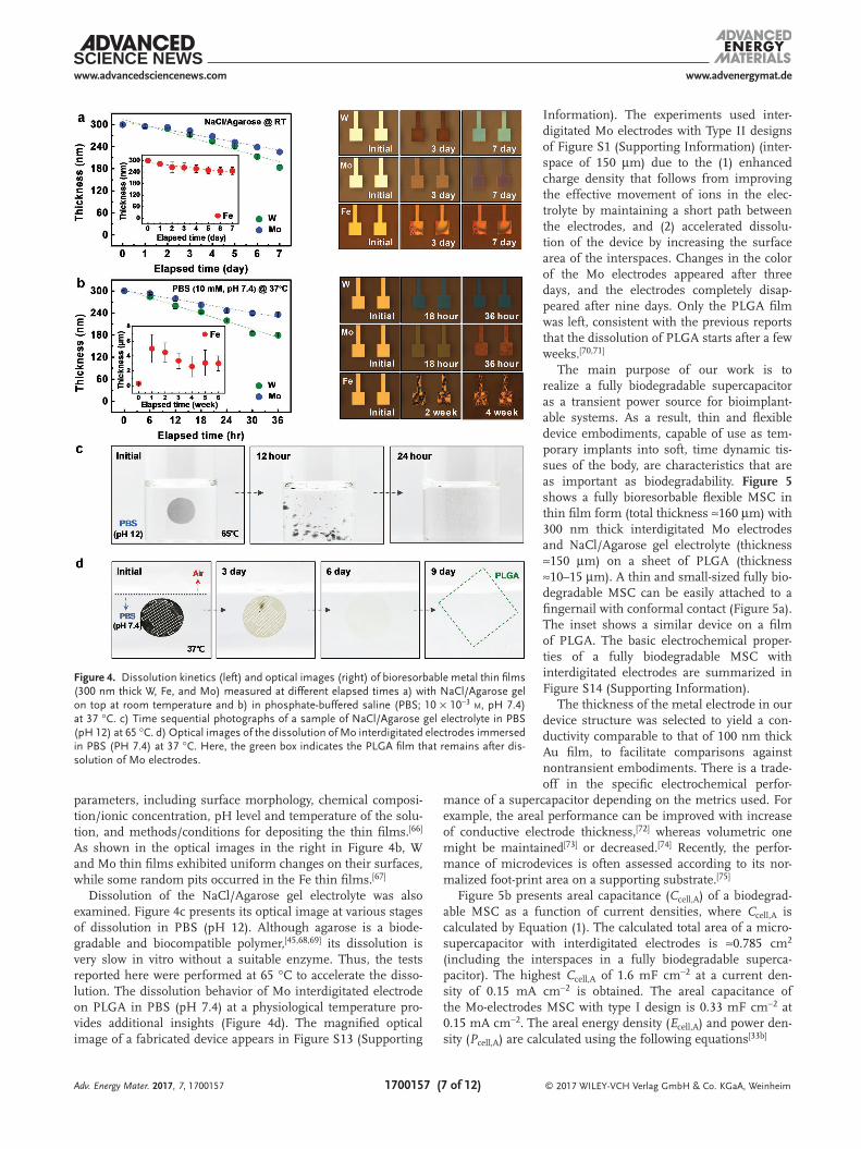
Figure 4a,b presents the dissolution kinetics and a corre-sponding series of microscope images of films exposed to the gel electrolyte with NaCl salt and deionized (DI) water, and dipped in PBS (10 × 10−3 m, pH 7.4), respectively. Since the elec-trodes of the planar-type supercapacitors (two electrodes placed on the same plane) are in contact with the gel electrolyte film, changes in their thicknesses as a function of elapsed time occur for the NaCl/Agarose gel electrolyte at room temperature (left graph in Figure 4a). We performed linear fitting of changes in initial thickness of the metal thin film over time. The dis-solution rates for each metal were extracted from this linear fit-ting.[19] The dissolution rates of W and Mo thin films are ≈0.02 and 0.01 µm d−1, respectively, and that of Fe is 0.007 µm d−1. Products of hydrolysis may diffuse into the gel in the form of ions by the mechanisms mentioned above. The surface mor-phologies of the W and Mo thin films in contact with the gel electrolyte remained smooth, consistent with spatially uniform corrosion during dissolution. By contrast, the Fe thin film exhibited a speckled surface in the optical micrographs (right images in Figure 4a). The surface colors change with time, due to changes in interference effects associated with the evolving thicknesses of the grown oxide layers and/or differences in morphology due to micropores formed during dissolution.[64]
The thicknesses of the W and Mo thin films in PBS (10 × 10−3 m, pH 7.4), measured every 6 h at body temperature (37 °C) decreased gradually with time, with dissolution rates of 0.09 and 0.05 µm d−1, respectively (left graph in Figure 4b). The thickness of the Fe thin film increased dramatically to more than 10 times the initial value in the first week (inset of Figure 4b), consistent with behavior observed in in-vivo tests of Fe foils as substrates in degradable medical implants,[65] and in studies of the dissolution kinetics of Fe thin films for electrical interconnects.[19] In previous studies of 50 µm thick foils of W, Fe, and Mo, the dissolution rates were 0.15, 0.08, and 0.02 µm d−1, respectively.[9] The changes in the thicknesses of W, Fe, and Mo thin films immersed in Hank’s solution (pH 7.4) at 37 °C were 0.5, 0.17, and 0.017 µm d−1, respectively.[19] The wide range of dissolution rates follows from sensitivity to many
Adv. Energy Mater. 2017, 7, 1700157
www.advenergymat.dewww.advancedsciencenews.com
© 2017 WILEY-VCH Verlag GmbH & Co. KGaA, Weinheim1700157 (7 of 12)
parameters, including surface morphology, chemical composi-tion/ionic concentration, pH level and temperature of the solu-tion, and methods/conditions for depositing the thin films.[66] As shown in the optical images in the right in Figure 4b, W and Mo thin films exhibited uniform changes on their surfaces, while some random pits occurred in the Fe thin films.[67]
Dissolution of the NaCl/Agarose gel electrolyte was also examined. Figure 4c presents its optical image at various stages of dissolution in PBS (pH 12). Although agarose is a biode-gradable and biocompatible polymer,[45,68,69] its dissolution is very slow in vitro without a suitable enzyme. Thus, the tests reported here were performed at 65 °C to accelerate the disso-lution. The dissolution behavior of Mo interdigitated electrode on PLGA in PBS (pH 7.4) at a physiological temperature pro-vides additional insights (Figure 4d). The magnified optical image of a fabricated device appears in Figure S13 (Supporting
Information). The experiments used inter-digitated Mo electrodes with Type II designs of Figure S1 (Supporting Information) (inter-space of 150 µm) due to the (1) enhanced charge density that follows from improving the effective movement of ions in the elec-trolyte by maintaining a short path between the electrodes, and (2) accelerated dissolu-tion of the device by increasing the surface area of the interspaces. Changes in the color of the Mo electrodes appeared after three days, and the electrodes completely disap-peared after nine days. Only the PLGA film was left, consistent with the previous reports that the dissolution of PLGA starts after a few weeks.[70,71]
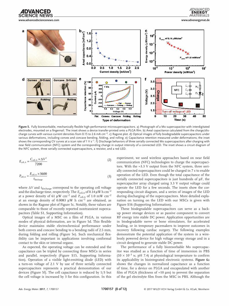
The main purpose of our work is to realize a fully biodegradable supercapacitor as a transient power source for bioimplant-able systems. As a result, thin and flexible device embodiments, capable of use as tem-porary implants into soft, time dynamic tis-sues of the body, are characteristics that are as important as biodegradability. Figure 5 shows a fully bioresorbable flexible MSC in thin film form (total thickness ≈160 µm) with 300 nm thick interdigitated Mo electrodes and NaCl/Agarose gel electrolyte (thickness ≈150 µm) on a sheet of PLGA (thickness ≈10–15 µm). A thin and small-sized fully bio-degradable MSC can be easily attached to a fingernail with conformal contact (Figure 5a). The inset shows a similar device on a film of PLGA. The basic electrochemical proper-ties of a fully biodegradable MSC with interdigitated electrodes are summarized in Figure S14 (Supporting Information).
The thickness of the metal electrode in our device structure was selected to yield a con-ductivity comparable to that of 100 nm thick Au film, to facilitate comparisons against nontransient embodiments. There is a trade-off in the specific electrochemical perfor-
mance of a supercapacitor depending on the metrics used. For example, the areal performance can be improved with increase of conductive electrode thickness,[72] whereas volumetric one might be maintained[73] or decreased.[74] Recently, the perfor-mance of microdevices is often assessed according to its nor-malized foot-print area on a supporting substrate.[75]
Figure 5b presents areal capacitance (Ccell,A) of a biodegrad-able MSC as a function of current densities, where Ccell,A is calculated by Equation (1). The calculated total area of a micro-supercapacitor with interdigitated electrodes is ≈0.785 cm2 (including the interspaces in a fully biodegradable superca-pacitor). The highest Ccell,A of 1.6 mF cm−2 at a current den-sity of 0.15 mA cm−2 is obtained. The areal capacitance of the Mo-electrodes MSC with type I design is 0.33 mF cm−2 at 0.15 mA cm−2. The areal energy density (Ecell,A) and power den-sity (Pcell,A) are calculated using the following equations[33b]
Adv. Energy Mater. 2017, 7, 1700157
Figure 4. Dissolution kinetics (left) and optical images (right) of bioresorbable metal thin films (300 nm thick W, Fe, and Mo) measured at different elapsed times a) with NaCl/Agarose gel on top at room temperature and b) in phosphate-buffered saline (PBS; 10 × 10−3 m, pH 7.4) at 37 °C. c) Time sequential photographs of a sample of NaCl/Agarose gel electrolyte in PBS (pH 12) at 65 °C. d) Optical images of the dissolution of Mo interdigitated electrodes immersed in PBS (PH 7.4) at 37 °C. Here, the green box indicates the PLGA film that remains after dis-solution of Mo electrodes.
www.advenergymat.dewww.advancedsciencenews.com
© 2017 WILEY-VCH Verlag GmbH & Co. KGaA, Weinheim1700157 (8 of 12)
7200cell,A
cell,A2
= × ∆E
C V
(2)
3600cell,A
cell,A
discharge
= ×P
E
t (3)
where ΔV and tdischarge correspond to the operating cell voltage and the discharge time, respectively. The Ecell,A of 0.14 µW h cm−2 at a power density of 61 µW cm−2 and Pcell,A of 1.0 mW cm−2 at an energy density of 0.0083 µW h cm−2 are obtained, as shown in the Ragone plot of Figure 5c. Notably, these values are comparable to those of recently reported nontransient superca-pacitors (Table S1, Supporting Information).
Optical images of a MSC on a film of PLGA, in various modes of physical deformation, are in Figure 5d. This flexible device maintains stable electrochemical performance under both convex and concave bending to a bending radii of 2.5 mm, during folding and rolling (Figure 5e). Such mechanical flex-ibility can be important in applications involving conformal contact to the skin or internal organs.
As expected, the operating voltage can be extended and the capacitance can be tripled by connecting three MSCs in series and parallel, respectively (Figure S15, Supporting Informa-tion). Operation of a visible light-emitting diode (LED) with a turn-on voltage of 2.1 V by use of three serially connected supercapacitors represents a practical demonstration of our devices (Figure 5f). The cell capacitance is reduced by 1/3 but the cell voltage is increased by 3 for this configuration. In this
experiment, we used wireless approaches based on near field communication (NFC) technologies to charge the supercapaci-tors. With the ≈3.3 V output from the NFC system, three seri-ally connected supercapacitors could be charged in 7 s to enable operation of the LED. Even though the total capacitance of the serially connected supercapacitors is just hundreds of µF, the supercapacitor array charged using 3.3 V output voltage could operate the LED for a few seconds. The insets show the cor-responding circuit diagram, and a series of images of the LED during discharging of the supercapacitors. More detailed expla-nation on turning on the LED with our MSCs is given with Figure S16 (Supporting Information).
These biodegradable supercapacitors can serve as a back-up power storage devices or as passive component to convert RF energy into stable DC power. Application opportunities are in biodegradable nerve or bone stimulators, for accelerated healing, or in temporary pacemakers to improve outcomes in recovery following cardiac surgery. The following examples demonstrate the potential application of the system in a wire-lessly powered device for high voltage energy storage and in a circuit designed to generate stable DC power.
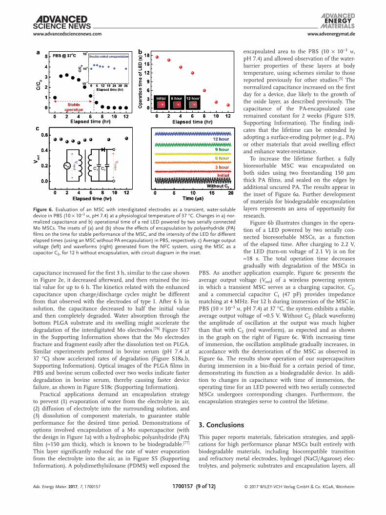
The performance of a fully bioresorbable Mo supercapac-itor was studied as a function of time of immersion in PBS (10 × 10−3 m, pH 7.4) at physiological temperature to confirm its applicability in biointegrated electronic systems. Figure 6a shows the changes in normalized capacitance as a function of time, for a device on PLGA and encapsulated with another film of PLGA (thickness of ≈10 µm) to prevent the separation of the gel electrolyte film from the MSC in PBS. Although the
Adv. Energy Mater. 2017, 7, 1700157
Figure 5. Fully bioresorbable, mechanically flexible high-performance microsupercapacitors. a) Photograph of a Mo supercapacitor with interdigitated electrodes, mounted on a fingernail. The inset shows a device transfer-printed onto a PLGA film. b) Areal capacitance calculated from the charge/dis-charge curves with various current densities from 0.15 to 2.6 mA cm−2. c) Ragone plot. d) Optical images of fully biodegradable supercapacitors under various deformations, including convex and concave bending, folding, and rolling. e) Capacitance retention measured under deformations; the inset shows the corresponding CV curves at a scan rate of 1 V s−1. f) Discharge behaviors of three serially connected Mo supercapacitors after charging with near field communication (NFC) system and the corresponding change in output intensity of a connected LED. The inset shows a circuit diagram of the NFC system, three serially connected supercapacitors, a resistor, and a red LED.
www.advenergymat.dewww.advancedsciencenews.com
© 2017 WILEY-VCH Verlag GmbH & Co. KGaA, Weinheim1700157 (9 of 12)
capacitance increased for the first 3 h, similar to the case shown in Figure 2e, it decreased afterward, and then retained the ini-tial value for up to 6 h. The kinetics related with the enhanced capacitance upon charge/discharge cycles might be different from that observed with the electrodes of type I. After 6 h in solution, the capacitance decreased to half the initial value and then completely degraded. Water absorption through the bottom PLGA substrate and its swelling might accelerate the degradation of the interdigitated Mo electrodes.[76] Figure S17 in the Supporting Information shows that the Mo electrodes fracture and fragment easily after the dissolution test on PLGA. Similar experiments performed in bovine serum (pH 7.4 at 37 °C) show accelerated rates of degradation (Figure S18a,b, Supporting Information). Optical images of the PLGA films in PBS and bovine serum collected over two weeks indicate faster degradation in bovine serum, thereby causing faster device failure, as shown in Figure S18c (Supporting Information).
Practical applications demand an encapsulation strategy to prevent (1) evaporation of water from the electrolyte in air, (2) diffusion of electrolyte into the surrounding solution, and (3) dissolution of component materials, to guarantee stable performance for the desired time period. Demonstrations of options involved encapsulation of a Mo supercapacitor (with the design in Figure 1a) with a hydrophobic polyanhydride (PA) film (≈150 µm thick), which is known to be biodegradable.[77] This layer significantly reduced the rate of water evaporation from the electrolyte into the air, as in Figure S5 (Supporting Information). A polydimethylsiloxane (PDMS) well exposed the
encapsulated area to the PBS (10 × 10−3 m, pH 7.4) and allowed observation of the water-barrier properties of these layers at body temperature, using schemes similar to those reported previously for other studies.[5] The normalized capacitance increased on the first day for a device, due likely to the growth of the oxide layer, as described previously. The capacitance of the PA-encapsulated case remained constant for 2 weeks (Figure S19, Supporting Information). The finding indi-cates that the lifetime can be extended by adopting a surface-eroding polymer (e.g., PA) or other materials that avoid swelling effect and enhance water-resistance.
To increase the lifetime further, a fully bioresorbable MSC was encapsulated on both sides using two freestanding 150 µm thick PA films, and sealed on the edges by additional uncured PA. The results appear in the inset of Figure 6a. Further development of materials for biodegradable encapsulation layers represents an area of opportunity for research.
Figure 6b illustrates changes in the opera-tion of a LED powered by two serially con-nected bioresorbable MSCs, as a function of the elapsed time. After charging to 2.2 V, the LED (turn-on voltage of 2.1 V) is on for ≈18 s. The total operation time decreases gradually with degradation of the MSCs in
PBS. As another application example, Figure 6c presents the average output voltage (Vout) of a wireless powering system in which a transient MSC serves as a charging capacitor, C2, and a commercial capacitor C1 (47 pF) provides impedance matching at 4 MHz. For 12 h during immersion of the MSC in PBS (10 × 10−3 m, pH 7.4) at 37 °C, the system exhibits a stable, average output voltage of ≈0.5 V. Without C2 (black waveform) the amplitude of oscillation at the output was much higher than that with C2 (red waveform), as expected and as shown in the graph on the right of Figure 6c. With increasing time of immersion, the oscillation amplitude gradually increases, in accordance with the deterioration of the MSC as observed in Figure 6a. The results show operation of our supercapacitors during immersion in a bio-fluid for a certain period of time, demonstrating its function as a biodegradable device. In addi-tion to changes in capacitance with time of immersion, the operating time for an LED powered with two serially connected MSCs undergoes corresponding changes. Furthermore, the encapsulation strategies serve to control the lifetime.
3. Conclusions
This paper reports materials, fabrication strategies, and appli-cations for high performance planar MSCs built entirely with biodegradable materials, including biocompatible transition and refractory metal electrodes, hydrogel (NaCl/Agarose) elec-trolytes, and polymeric substrates and encapsulation layers, all
Adv. Energy Mater. 2017, 7, 1700157
Figure 6. Evaluation of an MSC with interdigitated electrodes as a transient, water-soluble device in PBS (10 × 10−3 m, pH 7.4) at a physiological temperature of 37 °C. Changes in a) nor-malized capacitance and b) operational time of a red LED powered by two serially connected Mo MSCs. The insets of (a) and (b) show the effects of encapsulation by polyanhydride (PA) films on the time for stable performance of the MSC, and the intensity of the LED for different elapsed times (using an MSC without PA encapsulation) in PBS, respectively. c) Average output voltage (left) and waveforms (right) generated from the NFC system, using the MSC as a capacitor C2, for 12 h without encapsulation, with circuit diagram in the inset.
www.advenergymat.dewww.advancedsciencenews.com
© 2017 WILEY-VCH Verlag GmbH & Co. KGaA, Weinheim1700157 (10 of 12)
in simple designs that do not require the separate addition of pseudocapacitive oxide layers. Instead, electrochemical oxida-tion of the metal electrodes in contact with the water-containing agarose gel electrolyte follows naturally from repeated cycles of charge/discharge, thereby enhancing the performance via pseudocapacitance.
Studies of dissolution kinetics reveal that these biodegrad-able MSCs retain their performance for well-defined times of immersion in PBS at physiological temperatures, as a dem-onstration of their potential use as a power supply system for temporary electronic implants. As specific examples of use, series connected MSCs offer voltages and power levels suitable for operating a LED and for serving as storage capacitors in wireless power-transmission networks. Biodegradable encapsu-lating films can be used to tune the lifetimes of these devices MSC over a wide range.
The results are of interest as first demonstrations of fully biodegradable MSCs, with potential for applications in environ-mentally friendly electronics for internet of things, resorbable biomedical devices for human healthcare and others areas that cannot be addressed using conventional technologies.
4. Experimental SectionFabrication of Patterned Electrodes for Transient MSCs: A
photolithography technique patterned planar-type electrodes. The process used negative photoresist (PR; AZ nLOF 2070, MicroChem) spin-coated on a glass substrate at 4000 rpm for 30 s, and cured on a hot plate at 110 °C for 90 s. The PR-coated glass substrate was exposed to ultraviolet (UV) light through a photomask with a 150 µm interspaced electrode design (Type 1 in Figure S1, Supporting Information). Next, the sample was baked for 2 min for crosslinking the UV-exposed PR. Immersion in a developer (AZ 917 MIF, MicroChem) removed the PR that was not exposed to the UV. Magnetron sputtering (AJA Orion 3 sputter system, N. Scituat) formed W and Mo thin films (300 nm) at a power of 150 W in pure Ar gas under the pressure of 3 mTorr. Thin films of Fe (200 nm) were deposited by e-beam evaporation (AJA Orion 8 evaporation system, N. Scituat) at a rate of 0.1 nm s−1. Thin (10 nm) Cr layers deposited by sputtering or e-beam evaporation served to improve the adhesion to the glass substrate. A final step involved immersion in acetone to remove the remaining PR, leaving the patterned electrodes on glass.
Preparation of the NaCl/Agarose Gel Electrolyte: Synthesis of the NaCl/Agarose gel electrolyte involved addition of 2.13 g of NaCl (Sigma-Aldrich) to 100 mL of DI water followed by stirring at room temperature. After dissolving the NaCl, 1 g (1%, w/v) of agarose powder (Sigma-Aldrich) was added to NaCl solution (0.35 m). Mixing vigorously and heating at 120 °C yielded a clear solution. After 20 min, pouring the solution onto a glass plate at room temperature yielded a solid gel. After cooling, this gel electrolyte was cut to a suitable size (1 cm × 1 cm) and detached from the glass plate.
Transfer Printing of Transient MSC onto the Biodegradable Polymer: First, PMMA (MicroChem) was spin-casted on a silicon (Si) wafer as a sacrificial layer. Then, a solution of diluted polyimide (D-PI; bottom D-PI; Sigma-Aldrich) consisting of PI and 1-methyl-2-pyrrolidinone (Sigma-Aldrich) in a weight ratio of 2:1, was coated onto the PMMA-coated Si wafer. On this temporary substrate, interdigitated electrodes with spacings of 150 µm were patterned using a lift-off resist (LOR; LOR 20B, MicroChem) and a photoresist (PR; AZ 5214E, MicroChem) via photolithography (Type II in Figure S1 in the Supporting Information). To achieve fully biodegradable MSCs, only the Mo thin film was deposited by magnetron sputtering (without an adhesion layer of Cr).
After metal deposition, another D-PI layer (top D-PI) was spin-coated and some regions were patterned with PR (AZ 4620, MicroChem) to etch the polymer layer (PMMA, bottom and top D-PI). Reactive ion etching (RIE; March RIE) using O2 gas removed polymer through the patterned opening sites and the Mo metal thin film was protected by the coated PR layer. Then, the sample was immersed in acetone overnight to remove the PMMA layer. In this way, the metal electrodes could be released from the Si wafer and retrieved using a PDMS stamp via transfer-printing. Next, the exposed bottom layer of D-PI was removed by O2 gas via RIE, and then the device was transferred onto the PLGA film. The fabrication was completed by etching the top D-PI layer. Detailed schematic illustrations and explanations of this fabrication process are reported by Hwang et al.[73]
Dissolution tests of Biodegradable Metal Thin Films: The dissolution kinetics of 300 nm thick square patterns of W, Fe, and Mo formed by sputter deposition and e-beam evaporation on glass were evaluated. To prevent delamination during the test, a 10 nm thick layer of Cr served as an adhesion promoter. A slab of NaCl/Agarose gel electrolyte was placed on top of thin metal films patterned on a glass substrate to evaluate dissolution kinetics of the biodegradable metals in gel electrolyte at room temperature. Separately, a similar substrate without gel electrolyte was immersed in 20 mL of PBS (10 × 10−3 m, pH 7.4) at body temperature (37 °C) to evaluate dissolution kinetics of the biodegradable metals in PBS. The samples were retrieved from the solution, and the gel electrolyte films were removed to measure the thickness of the metal patterns using a profilometer. After measuring the thickness, new gel electrolyte films and new PBS were used to eliminate the effects of the aged electrolyte and PBS on the dissolution kinetics of the metal films. Each measurement was performed on 15 different metal-film patterns and the error bars were estimated from the multiple patterns.
Morphology and Chemical Composition of Metal Thin-Film Surface: SEM (Hitachi S4700, Hitachi high-technologies corporation) images obtained under an applied voltage of 10 kV and working distance of 6 mm in a high-resolution mode revealed cross-sectional morphologies of the metal thin films in their as-deposited state and after undergoing repeated charge/discharge cycles. To collect the cross-sectional SEM images of the oxide grown metal electrodes after the cyclic test, samples were prepared by mechanical cleaving after scribing the back surface using a glass cutter with a diamond tip. XPS (X-TOOL, ULVAC-PHI) determined the oxidation state of the oxide layer formed on the metal electrode surface after repeated charge/discharge cycles. The dissolution kinetics associated with contact to the hydrogel film and immersion in PBS (10 × 10−3 m, pH 7.4) were estimated by measuring the thicknesses of the metal thin-film by surface profilometry (Dektak 3030, Sloan Technology Co) at regular time intervals. At these same times, the surface morphologies of the films were examined using an optical microscope (Ultraplan FS100, Mitutoyo Corporation).
Electrochemical Measurements: The electrochemical performance of the supercapacitors was evaluated by cyclic voltammetry, galvanostatic charge/discharge, and electrochemical impedance, using an electrochemical analyzer (Short VMP3, Bio-Logic). The EIS was obtained with an amplitude of 10 mV over a frequency range from 1 MHz to 100 mHz.
Supporting InformationSupporting Information is available from the Wiley Online Library or from the author.
AcknowledgementsG.L. and S.-K.K. contributed equally to this work. This work was supported by the National Research Foundation of Korea (NRF) grant funded by the Korean government (MEST) (Grant No. NRF-2016R1A2A1A05004935).
Adv. Energy Mater. 2017, 7, 1700157
www.advenergymat.dewww.advancedsciencenews.com
© 2017 WILEY-VCH Verlag GmbH & Co. KGaA, Weinheim1700157 (11 of 12)Adv. Energy Mater. 2017, 7, 1700157
The authors also thank the KU-KIST graduate school program of Korea University.
Conflict of InterestThe authors declare no conflict of interest.
Keywordsbiodegradable metals, biodegradable materials, flexible energy storage devices, microsupercapacitors, transient electronics
Received: January 16, 2017Revised: March 11, 2017
Published online: May 23, 2017
[1] D. Larcher, J.-M. Tarascon, Nat. Chem. 2015, 7, 19.[2] H. Wang, J.-D. Park, Z. J. Ren, Environ. Sci. Technol. 2015, 49, 3267.[3] S.-R. Lim, J. M. Schoenung, J. Hazard. Mater. 2010, 177, 251.[4] D. Lisbana, T. Snee, Process Saf. Environ. Prot. 2011, 89, 434.[5] S.-W. Hwang, H. Tao, D.-H. Kim, H. Cheng, J.-K. Song, E. Rill,
M. A. Brenckle, B. Panilaitis, S. M. Won, Y.-S. Kim, Y. M. Song, K. J. Yu, A. Ameen, R. Li, Y. Su, M. Yang, D. L. Kaplan, M. R. Zakin, M. J. Slepian, Y. Huang, F. G. Omenetto, J. A. Rogers, Science 2012, 337, 1640.
[6] S.-K. Kang, R. K. J. Murphy, S.-W. Hwang, S. M. Lee, D. V. Harburg, N. A. Krueger, J. Shin, P. Gamble, H. Cheng, S. Yu, Z. Liu, J. G. McCall, M. Stephen, H. Ying, J. Kim, G. Park, R. C. Webb, C. H. Lee, S. Chung, D. S. Wie, A. D. Gujar, B. Vemulapalli, A. H. Kim, K.-M. Lee, J. Cheng, Y. Huang, S. H. Lee, P. V. Braun, W. Z. Ray, J. A. Rogers, Nature 2016, 530, 71.
[7] K. J. Yu, D. Kuzum, S.-W. Hwang, B. H. Kim, H. Juul, N. H. Kim, S. M. Won, K. Chiang, M. Trumpis, A. G. Richardson, H. Cheng, H. Fang, M. Thompson, H. Bink, D. Talos, K. J. Seo, H. N. Lee, S.-K. Kang, J.-H. Kim, J. Y. Lee, Y. Huang, F. E. Jensen, M. A. Dichter, T. H. Lucas, J. Viventi, B. Litt, J. A Rogers, Nat. Mater. 2016, 15, 782.
[8] S.-W. Hwang, X. Huang, J.-H. Seo, J.-K. Song, S. Kim, S. Hage-Ail, H. -J. Chung, H. Tao, F. G Omenetto, Z. Ma, J. A Rogers, Adv. Mater. 2013, 25, 3526.
[9] S.-K. Kang, S.-W. Hwang, S. Yu, J.-H. Seo, E. A. Corbin, J. Shin, D. S. Wie, R. Bashir, Z. Ma, J. A. Rogers, Adv. Funct. Mater. 2015, 25, 1789.
[10] L. Yin, X. Huang, H. Xu, Y. Zhang, J. Lam, J. Cheng, J. A. Rogers, Adv. Mater. 2014, 26, 3879.
[11] K. Fu, Z. Liu, Y. Yao, Z. Wang, B. Zhao, W. Luo, J. Dai, S. D. Lacey, Li. Zhou, F. Shen, M. Kim, L. Swafford, L. Sengupta, L. Hu, Nano Lett. 2015, 15, 4664.
[12] X. Wang, W. Xu, P. Chatterjee, C. Lv, J. Popovich, Z. Song, L. Dai, M. Y. S. Kalani, S. E. Haydel, H. Jiang, Adv. Mater. Technol. 2016, 1, 1600059.
[13] M. Mastragostino, C. Arbizzani, F. Soavi, J. Power Sources 2001, 97–98, 812.
[14] R. A. Huggins, Solid State Ionics 2000, 134, 179.[15] R. A. Dougal, S. Liu, R. E. White, IEEE Trans. Compon., Packag.,
Manuf. Technol. 2002, 25, 120.[16] X. Zhao, B. M. Sánchez, P. J. Dobson, P. S. Grant, Nanoscale 2011,
3, 839.[17] M. Peuster, C. Fink, C. V. Schnakenburg, Biomaterials 2003, 24,
4057.
[18] S. Zhu, N. Huang, L. Xu, Y. Zhang, H. Liu, H. Sun, Y. Leng, Mater. Sci. Eng. C 2009, 29, 1589.
[19] L. Yin, H. Cheng, S. Mao, R. Haasch, Y. Liu, X. Xie, S.-W. Hwang, H. Jain, S.-K. Kang, Y. Su, R. Li, Y. Huang, J. A. Rogers, Adv. Funct. Mater. 2014, 24, 645.
[20] W. G. Moon, G.-P. Kim, M. Lee, H. D. Song, J. Yi, ACS Appl. Mater. Interfaces 2015, 7, 3503.
[21] W.-Y. Tsai, R. Lin, S. Murali, L. L. Shang, J. K. McDonough, R. S. Ruoff, P.-L. Taberna, Y. Gogotsi, P. Simon, Nano Energy 2013, 2, 403.
[22] J. Yan, Q. Wang, T. Wei, L. Jiang, M. Zhang, X. Jing, Z. Fan, ACS Nano 2015, 8, 4720.
[23] X. Xiao, T. Li, Z. Peng, H. Jin, Q. Zhong, Q. Hu, B. Yao, Q. Luo, C. Zhang, Li. Gong, J. Chen, Y. Gogotsi, J. Zhou, Nano Energy 2014, 6, 1.
[24] D. Kim, G. Lee, D. Kim, J. Yun, S.-S. Lee, J. S. Ha, Nanoscale 2016, 8, 15611.
[25] C. Zheng, X. Zhou, H. Cao, G. Wang, Z. Liu, J. Power Sources 2015, 258, 290.
[26] Y. Li, Z. Li, P. K. Shen, Adv. Mater. 2013, 25, 2474.[27] T. Kim, G. Jung, S. Yoo, K. S. Suh, R. S. Ruoff, ACS Nano 2013, 7,
6899.[28] H. Jiang, P. S. Lee, C. Li, Energy Environ. Sci. 2013, 6, 41.[29] J. P. Zheng, P. J. Cygan, T. R. Jow, J. Electrochem. Soc. 1995, 142,
2699.[30] C.-Y. Le, A. M. Bond, Langmuir 2010, 26, 16155.[31] T. Brousse, M. Toupin, R. Dugas, L. Athouël, O. Crosnier,
D. Bélanger, J. Electrochem. Soc. 2006, 153, A2171.[32] V. Augustyn, J. Come, M. A. Lowe, J. W. Kim, P.-L. Taberna,
S. H. Tolbert, H. D. Abruna, P. Simon, B. Dunn, Nat. Mater. 2013, 12, 518.
[33] a) A. Tolosa, B. Krüner, S. Fleischmann, N. Jäckel, M. Zeiger, M. Aslan, I. Grobelsek, V. Presser, J. Mater. Chem. A 2016, 4, 16003; b) D. Yu, K. Goh, H. Wang, L. Wei, W. Jiang, Q. Zhang, L. Dai, Y. Chen, Nat. Nanotechnol. 2014, 9, 555.
[34] J. Yan, Z. Fan, W. Sun, G. Ning, T. Wei, Q. Zhang, R. Zhang, L. Zhi, F. Wei, Adv. Funct. Mater. 2012, 22, 2632.
[35] G. Hu, C. Tang, C. Li, H. Li, Y. Wang, H. Gong, J. Electrochem. Soc. 2011, 158, A695.
[36] S. R. Sivakkumar, W. J. Kim, J.-A. Choi, D. R. MacFarlane, M. Forsyth, D.-W. Kim, J. Power Sources 2007, 171, 1062.
[37] C.-T. Hsieh, H. Teng, Carbon 2002, 40, 667.[38] R. B. Rakhi, N. A. Alhebshi, D. H. Anjum, H. N. Alshareef, J. Mater.
Chem. A 2014, 2, 16190.[39] A. G. Pandolfo, A. F. Hollenkamp, J. Power Sources 2006, 157, 11.[40] P. L. Taberna, P. Simon, J. F. Fauvarque, J. Electrochem. Soc. 2003,
150, A292.[41] P. Yang, P. Sun, L. Du, Z. Liang, W. Xie, X. Cai, L. Huang, S. Tan,
W. Mai, J. Phys. Chem. C 2015, 119, 16483.[42] W. Li, S. Wang, L. Xin, M. Wu, X. Lou, J. Mater. Chem. A 2016, 4,
7700.[43] T. A. Carlson, G. E. McGuire, J. Electron Spectrosc. Relat. Phenom.
1972, 1, 161.[44] G. Lee, D. Kim, D. Kim, S. Oh, J. Yun, J. Kim, S.-S. Lee, J. S. Ha,
Energy Environ. Sci. 2015, 8, 1764.[45] S. Fernández-Cossío, A. León-Mateos, F. G. Samperdro,
M. T. C. Oreja, Plast. Reconstr. Surg. 2007, 120, 1161.[46] E. A. Kneer, C. Raghunath, S. Raghavan, J. S. Jeon, J. Electrochem.
Soc. 1996, 143, 4095.[47] P. C. J. Graat, M. A. J. Somers, Appl. Surf. Sci. 1996, 100, 36.[48] G. Bhargava, I. Gouzman, C. M. Chun, T. A. Ramanarayanan,
S. L. Bernasek, Appl. Surf. Sci. 2007, 253, 4322.[49] T. Yamashita, P. Hayes, Appl. Surf. Sci. 2008, 254, 2441.[50] F. Werfel, E. Minni, J. Phys. C: Solid State Phys. 1983, 16, 6091.
www.advenergymat.dewww.advancedsciencenews.com
© 2017 WILEY-VCH Verlag GmbH & Co. KGaA, Weinheim1700157 (12 of 12)Adv. Energy Mater. 2017, 7, 1700157
[51] M. T. Greiner, L. Chai, M. G. Heler, W.-M. Tang, Z.-H. Lu, Adv. Funct. Mater. 2013, 23, 215.
[52] a) A. P. Shpak, A. M. Korduban, M. M. Medvedskij, V. O. Kandyba, J. Electron Spectrosc. Relat. Phenom. 2007, 156, 172; b) S. Suzuki, K. Yanagihara, K. Hirokawa, Surf. Interface Anal. 2000, 30, 372; c) G. Bhargava, I. Gouzman, C. M. Chun, T. A. Ramanarayanan, S. L. Bernasek, Appl. Surf. Sci. 2007, 253, 4322; d) I. A. Okonkwo, J. Doff, A. Baron-Wiechec, G. Jones, E. V. Koroleva, P. Skeldon, G. E. Thompson, Thin Solid Films 2012, 520, 6318.
[53] a) S. Sakurai, A. Namai, K. Hashimoto, S.-i. Ohkoshi, J. Am. Chem. Soc. 2009, 131, 18299; b) G. Carraro, A. Gasparotto, C. Maccato, E. Bontempi, F. Bilo, D. Peeters, C. Sada, D. Barreca, CrystEngComm 2014, 16, 8710.
[54] A. Abdi, M. Trari, Electrochim. Acta 2013, 111, 869.[55] a) V. S. Saji, C.-W. Lee, ChemSusChem 2012, 5, 1146. b) V. S. Saji,
C.-W. Lee, J. Electrochem. Soc. 2013, 160, H54.[56] V. Augustyn, P. Simon, B. Dunn, Energy Environ. Sci. 2014, 7,
1597.[57] T. Brousse, D. Blanger, J. W. Long, J. Electrochem. Soc. 2015, 162,
A5185.[58] J. Chang, M. Jin, F. Yao, T. H. Kim, V. T. Le, H. Yue, F. Gunes, B. Li,
A. Ghosh, S. Xie, Y. H. Lee, Adv. Funct. Mater. 2013, 23, 5074.[59] X. Xiao, T. Ding, L. Yuan, Y. Shen, Q. Zhong, X. Zhang, Y. Cao,
B. Hu, T. Zhai, L. Gong, J. Chen, Y. Tong, J. Zhou, Z. L. Wang, Adv. Energy Mater. 2012, 2, 1328.
[60] C. Ng, Y. H. Ng, A. Iwase, R. Amal, Phys. Chem. Chem. Phys. 2011, 13, 13421.
[61] M. Anik, K. O. Asare, J. Electrochem. Soc. 2002, 149, B224.[62] A. Stefànsson, Environ. Sci. Technol. 2007, 41, 6117.[63] W. A. Badawy, F. M. Al-Kharafi, Electrochim. Acta 1998, 44, 693.
[64] S. V. Gils, P. Mast, E. Stijns, H. Terryn, Surf. Coat. Technol. 2004, 185, 303.
[65] P. P. Mueller, S. Arnold, M. Badar, D. Bormann, F.-W. Bach, A. Drynda, A. M. Lindenberg, H. Hauser, M. Peuster, J. Biomed. Mater. Res. A 2012, 100A, 2881.
[66] S.-W. Hwang, G. Park, C. Edwards, E. A. Corbin, S.-K. Kang, H. Cheng, J.-K. Song, J.-H. Kim, S. Yu, J. Ng, J. E. Lee, J. Kim, C. Yee, B. Bhaduri, Y. Su, F. G. Omennetto, Y. Huang, R. Bashir, L. Goddard, G. Popescu, K.-M. Lee, J. A. Rogers, ACS Nano 2014, 8, 5843.
[67] H. Wang, J. Xie, K. P. Yan, M. Duan, Y. Zuo, Corros. Sci. 2009, 51, 181.
[68] A. K. S. Chandel, C. U. Kumar, S. K. Jewrajka, ACS Appl. Mater. Inter-faces 2016, 8, 3182.
[69] L.-M. Zhang, C.-X. Wu, J.-Y. Huang, X.-H. Peng, P. Chen, S.-Q. Tang, Carbohydr. Polym. 2012, 88, 1445.
[70] X. S. Wu, N. Wang, J. Biomater. Sci., Polym. Ed. 2001, 12, 21.[71] H. K. Makadia, S. J. Siegel, Polymers 2011, 3, 1377.[72] S. W. Lee, J. Kim, S. Chen, P. T. Hammond, Y. Shao-Horn, ACS Nano
2010, 4, 3889.[73] G. Lee, D. Kim, J. Yun, Y. Ko, J. Cho, J. S. Ha, Nanoscale 2014, 6,
9655.[74] J. Chmiola, C. Largeot, P.-L. Taberna, P. Simon, Y. Gogotsi, Science
2010, 328, 480.[75] N. A. Kyeremateng, T. Brousse, D. Pech, Nat. Nanotechnol. 2017,
12, 7.[76] S.-W. Hwang, J.-K. Song, X. Huang, H. Cheng, S.-K. Kang,
B. H. Kim, J.-H. Kim, S. Yu, Y. Huang, J. A. Rogers, Adv. Mater. 2014, 26, 3905.
[77] S.-K. Kang, J. A. Rogers, unpublished.