Embed Size (px)
Citation preview
DESA INTERNATIONAL P/N 55392 2701 INDUSTRIAL DRIVE REV B P.O. BOX 90024 1/00 BOWLING GREEN, KY 42102-9004 www.desatech.com
SAVE THIS BOOK This book is valuable. In addition to instructing you on how to install and maintain your appliance, it also contains information that will enable you to obtain replacement parts or optional accessory items when needed. Keep it with your other important papers.
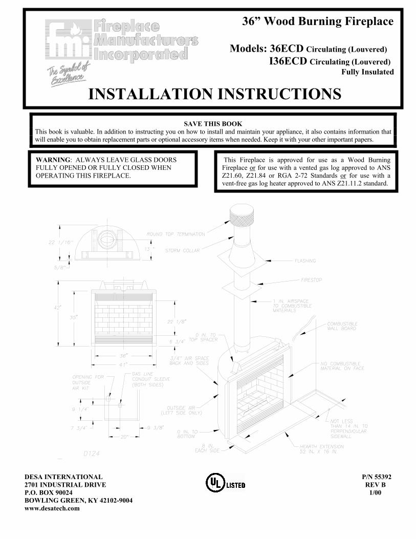
This Fireplace is approved for use as a Wood Burning Fireplace or for use with a vented gas log approved to ANS Z21.60, Z21.84 or RGA 2-72 Standards or for use with a vent-free gas log heater approved to ANS Z21.11.2 standard.
WARNING: ALWAYS LEAVE GLASS DOORS FULLY OPENED OR FULLY CLOSED WHEN OPERATING THIS FIREPLACE.
36” Wood Burning Fireplace Models: 36ECD Circulating (Louvered) I36ECD Circulating (Louvered) Fully Insulated
INSTALLATION INSTRUCTIONS
1
INSTALLATION INSTRUCTIONS INTRODUCTION ♦ Before beginning the installation of your fireplace, read
these instructions through completely. ♦ These FMI components and fireplace are safe when
installed according to this Installation Manual. Unless you use FMI components, which has been designed and tested for the fireplace system, you may cause a fire hazard.
♦ The FMI warranty will be voided by and FMI disclaims any responsibility for the following actions:
a) Modification of the fireplace, components, doors, blower, fans, air inlet system and damper control.
b) Use of any component part not manufactured or approved by FMI in combination with a FMI fireplace system.
PROPER INSTALLATION is the most important step in ensuring safe and continuous operation of the fireplace. Consult the local building codes as to the particular requirements concerned with the installation of all factory built fireplaces. Although grounding may not be required by code the manufacturer recommends it. This fireplace is not intended to be used as a substitute for a furnace to heat and entire home. Use for supplementary heating only.
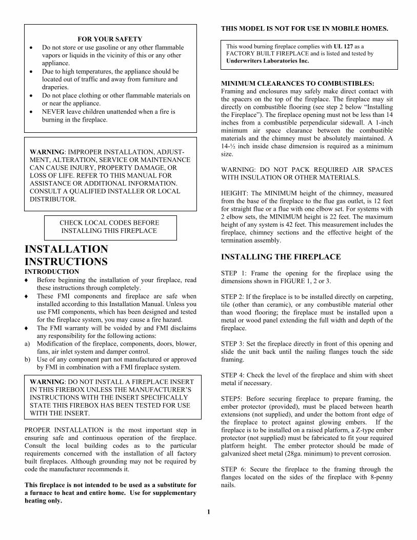
THIS MODEL IS NOT FOR USE IN MOBILE HOMES. MINIMUM CLEARANCES TO COMBUSTIBLES: Framing and enclosures may safely make direct contact with the spacers on the top of the fireplace. The fireplace may sit directly on combustible flooring (see step 2 below “Installing the Fireplace”). The fireplace opening must not be less than 14 inches from a combustible perpendicular sidewall. A 1-inch minimum air space clearance between the combustible materials and the chimney must be absolutely maintained. A 14-½ inch inside chase dimension is required as a minimum size. WARNING: DO NOT PACK REQUIRED AIR SPACES WITH INSULATION OR OTHER MATERIALS. HEIGHT: The MINIMUM height of the chimney, measured from the base of the fireplace to the flue gas outlet, is 12 feet for straight flue or a flue with one elbow set. For systems with 2 elbow sets, the MINIMUM height is 22 feet. The maximum height of any system is 42 feet. This measurement includes the fireplace, chimney sections and the effective height of the termination assembly. INSTALLING THE FIREPLACE STEP 1: Frame the opening for the fireplace using the dimensions shown in FIGURE 1, 2 or 3. STEP 2: If the fireplace is to be installed directly on carpeting, tile (other than ceramic), or any combustible material other than wood flooring; the fireplace must be installed upon a metal or wood panel extending the full width and depth of the fireplace. STEP 3: Set the fireplace directly in front of this opening and slide the unit back until the nailing flanges touch the side framing. STEP 4: Check the level of the fireplace and shim with sheet metal if necessary. STEP5: Before securing fireplace to prepare framing, the ember protector (provided), must be placed between hearth extensions (not supplied), and under the bottom front edge of the fireplace to protect against glowing embers. If the fireplace is to be installed on a raised platform, a Z-type ember protector (not supplied) must be fabricated to fit your required platform height. The ember protector should be made of galvanized sheet metal (28ga. minimum) to prevent corrosion. STEP 6: Secure the fireplace to the framing through the flanges located on the sides of the fireplace with 8-penny nails.
This wood burning fireplace complies with UL 127 as a FACTORY BUILT FIREPLACE and is listed and tested by Underwriters Laboratories Inc.
FOR YOUR SAFETY • Do not store or use gasoline or any other flammable
vapors or liquids in the vicinity of this or any other appliance.
• Due to high temperatures, the appliance should be located out of traffic and away from furniture and draperies.
• Do not place clothing or other flammable materials on or near the appliance.
• NEVER leave children unattended when a fire is burning in the fireplace.
WARNING: IMPROPER INSTALLATION, ADJUST- MENT, ALTERATION, SERVICE OR MAINTENANCE CAN CAUSE INJURY, PROPERTY DAMAGE, OR LOSS OF LIFE. REFER TO THIS MANUAL FOR ASSISTANCE OR ADDITIONAL INFORMATION. CONSULT A QUALIFIED INSTALLER OR LOCAL DISTRIBUTOR.
CHECK LOCAL CODES BEFORE INSTALLING THIS FIREPLACE
WARNING: DO NOT INSTALL A FIREPLACE INSERT IN THIS FIREBOX UNLESS THE MANUFACTURER’S INSTRUCTIONS WITH THE INSERT SPECIFICALLY STATE THIS FIREBOX HAS BEEN TESTED FOR USE WITH THE INSERT.
2
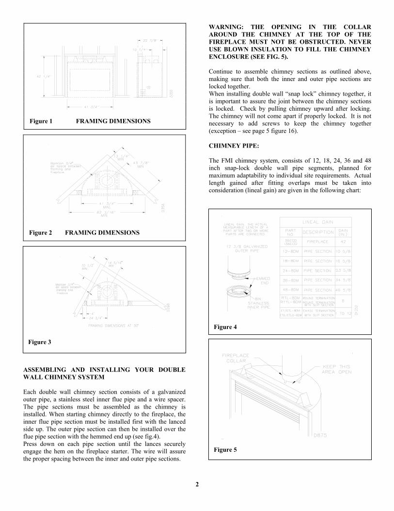
ASSEMBLING AND INSTALLING YOUR DOUBLE WALL CHIMNEY SYSTEM Each double wall chimney section consists of a galvanized outer pipe, a stainless steel inner flue pipe and a wire spacer. The pipe sections must be assembled as the chimney is installed. When starting chimney directly to the fireplace, the inner flue pipe section must be installed first with the lanced side up. The outer pipe section can then be installed over the flue pipe section with the hemmed end up (see fig.4). Press down on each pipe section until the lances securely engage the hem on the fireplace starter. The wire will assure the proper spacing between the inner and outer pipe sections.
WARNING: THE OPENING IN THE COLLAR AROUND THE CHIMNEY AT THE TOP OF THE FIREPLACE MUST NOT BE OBSTRUCTED. NEVER USE BLOWN INSULATION TO FILL THE CHIMNEY ENCLOSURE (SEE FIG. 5). Continue to assemble chimney sections as outlined above, making sure that both the inner and outer pipe sections are locked together. When installing double wall “snap lock” chimney together, it is important to assure the joint between the chimney sections is locked. Check by pulling chimney upward after locking. The chimney will not come apart if properly locked. It is not necessary to add screws to keep the chimney together (exception – see page 5 figure 16). CHIMNEY PIPE: The FMI chimney system, consists of 12, 18, 24, 36 and 48 inch snap-lock double wall pipe segments, planned for maximum adaptability to individual site requirements. Actual length gained after fitting overlaps must be taken into consideration (lineal gain) are given in the following chart:
Figure 1 FRAMING DIMENSIONS
Figure 2 FRAMING DIMENSIONS
Figure 3
Figure 4
Figure 5
3
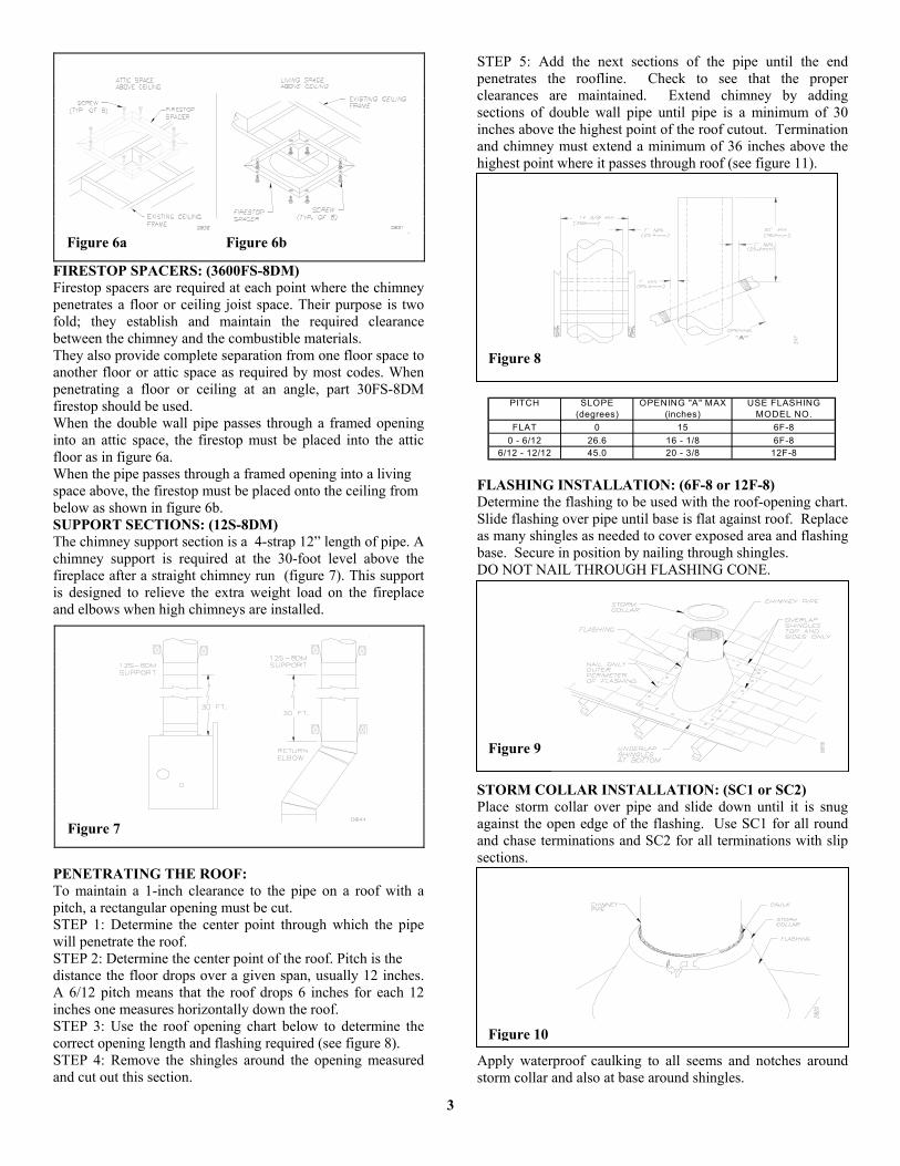
FIRESTOP SPACERS: (3600FS-8DM) Firestop spacers are required at each point where the chimney penetrates a floor or ceiling joist space. Their purpose is two fold; they establish and maintain the required clearance between the chimney and the combustible materials. They also provide complete separation from one floor space to another floor or attic space as required by most codes. When penetrating a floor or ceiling at an angle, part 30FS-8DM firestop should be used. When the double wall pipe passes through a framed opening into an attic space, the firestop must be placed into the attic floor as in figure 6a. When the pipe passes through a framed opening into a living space above, the firestop must be placed onto the ceiling from below as shown in figure 6b. SUPPORT SECTIONS: (12S-8DM) The chimney support section is a 4-strap 12” length of pipe. A chimney support is required at the 30-foot level above the fireplace after a straight chimney run (figure 7). This support is designed to relieve the extra weight load on the fireplace and elbows when high chimneys are installed.
PENETRATING THE ROOF: To maintain a 1-inch clearance to the pipe on a roof with a pitch, a rectangular opening must be cut. STEP 1: Determine the center point through which the pipe will penetrate the roof. STEP 2: Determine the center point of the roof. Pitch is the distance the floor drops over a given span, usually 12 inches. A 6/12 pitch means that the roof drops 6 inches for each 12 inches one measures horizontally down the roof. STEP 3: Use the roof opening chart below to determine the correct opening length and flashing required (see figure 8). STEP 4: Remove the shingles around the opening measured and cut out this section.
STEP 5: Add the next sections of the pipe until the end penetrates the roofline. Check to see that the proper clearances are maintained. Extend chimney by adding sections of double wall pipe until pipe is a minimum of 30 inches above the highest point of the roof cutout. Termination and chimney must extend a minimum of 36 inches above the highest point where it passes through roof (see figure 11). FLASHING INSTALLATION: (6F-8 or 12F-8) Determine the flashing to be used with the roof-opening chart. Slide flashing over pipe until base is flat against roof. Replace as many shingles as needed to cover exposed area and flashing base. Secure in position by nailing through shingles. DO NOT NAIL THROUGH FLASHING CONE. STORM COLLAR INSTALLATION: (SC1 or SC2) Place storm collar over pipe and slide down until it is snug against the open edge of the flashing. Use SC1 for all round and chase terminations and SC2 for all terminations with slip sections. Apply waterproof caulking to all seems and notches around storm collar and also at base around shingles.
Figure 6a Figure 6b
Figure 7
Figure 8
PITCH SLOPE OPENING "A" MAX USE FLASHING(degrees) (inches) MODEL NO.
FLAT 0 15 6F-80 - 6/12 26.6 16 - 1/8 6F-8
6/12 - 12/12 45.0 20 - 3/8 12F-8
Figure 9
Figure 10
4
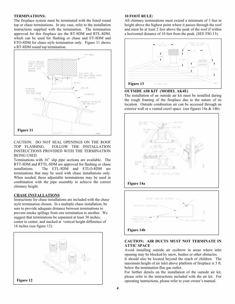
TERMINATIONS: The fireplace system must be terminated with the listed round top or chase terminations. In any case, refer to the installation instructions supplied with the termination. The termination approved for this fireplace are the RT-8DM and RTL-8DM, which can be used for flashing or chase and ET-8DM and ETO-8DM for chase style termination only. Figure 11 shows a RT-8DM round top termination.
CAUTION: DO NOT SEAL OPENINGS ON THE ROOF TOP FLASHING. FOLLOW THE INSTALLATION INSTRUCTIONS PROVIDED WITH THE TERMINATION BEING USED. Terminations with 16” slip pipe sections are available. The RTT-8DM and RTTL-8DM are approved for flashing or chase installations. The ETL-8DM and ETLO-8DM are terminations that may be used with chase installations only. When needed, these adjustable terminations may be used in combination with the pipe assembly to achieve the correct chimney height. CHASE INSTALLATIONS Instructions for chase installations are included with the chase style termination chosen. In a multiple chase installation, be sure to provide adequate distance between terminations to prevent smoke spillage from one termination to another. We suggest that terminations be separated at least 30 inches, center to center, and stacked at vertical height difference of 18 inches (see figure 12).
10 FOOT RULE: All chimney terminations must extend a minimum of 3 feet in height above the highest point where it passes through the roof and must be at least 2 feet above the peak of the roof if within a horizontal distance of 10 feet from the peak. (SEE FIG 13).
OUTSIDE AIR KIT (MODEL AK4E) The installation of an outside air kit must be installed during the rough framing of the fireplace due to the nature of its location. Outside combustion air can be accessed through an exterior wall or a vented crawl space (see figures 14a & 14b). CAUTION: AIR DUCTS MUST NOT TERMINATE IN ATTIC SPACE Avoid installing outside air eyebrow in areas where inlet opening may be blocked by snow, bushes or other obstacles. It should also be located beyond the reach of children. The maximum height of air inlet above platform of fireplace is 3 ft. below the termination flue gas outlet. For further details on the installation of the outside air kit, please refer to the instructions included with the air kit. For operating instructions, please refer to your owner’s manual.
Figure 11
Figure 13
Figure 14a
Figure 12
Figure 14b

5
INSTRUCTIONS WHEN OFFSET OF CHIMNEY IS NEEDED TO INSTALL ELBOWS 1. To achieve desired offset, you may install combinations
of 12”, 18”, 24”, 36” and 48” length of double wall pipe (SEE SINGLE OFFSET CHART & FIGURE 16 & 17).
2. Chimney weight above offset rests on return elbow.
Strops must be securely nailed to rafters or joists (SEE FIGURE 15 DETAILS A & B).
3. Maximum length of pipe between supports (return elbow
or 12S-8DM) is 6’ of angled run. Maximum of two (2) 6’ angled run sections per chimney system (SEE FIGE 17).
Figure 17 TYPICAL OFFSET INSTALLATION
Figure 15
OFFSET RISEA B 48" 36" 24" 18" 12"
4 - 3/8 16 -3/89 - 3/4 25 - 1/2 1
12 - 3/4 30 - 3/4 115 34 - 3/4 118 40 1 1
21 - 1/4 46 - 1/4 123 - 3/4 49 - 1/4 1 127 - 3/4 56 - 3/4 1
30 60 - 3/4 1 133 66 1 136 71 1 1
38 - 1/4 75 241 - 1/4 80 - 1/4 1 1 1
45 86 - 3/4 246 - 3/4 89 - 1/2 1 1 1
51 97 1 153 - 1/4 101 2 156 - 1/4 106 - 1/4 259 - 1/4 111 - 1/2 1 1 161 - 3/4 115 - 1/2 2 164 - 3/4 120 - 3/4 2 168 - 1/4 127 1 2
70 130 2 1 174 - 1/4 137 - 1/2 1 2 176 - 3/4 141 - 1/2 1 2 179 - 3/4 146 - 3/4 4
CHIMNEY LENGTH
All joints between offset Shall be secured with two Screws, only on the outer Pipe, and shall not penetrate The inner stainless. Figure 16

6
GAS LINE INSTALLATION GAS LINE HOOK UP SHOULD BE DONE BY YOUR SUPPLIER OR A QUALIFIED SERVICE PERSON. NOTE: BEFORE YOU PROCEED, MAKE SURE YOUR GAS SUPPLY IS TURNED OFF. A gas line may be installed for the purpose of installing a decorative gas appliance available through your local distributor. Use only a ½ - inch black iron pipe and appropriate fittings. When installing a gas line, a shut-off valve designed for installation outside the appliance is recommended. STEP 1: To install, remove the knockout indentation on the refractory, (or firebrick), wall located approximately 2 inches above the refractory hearth floor. The knockout indentation must be firmly tapped with any solid object until it is released. Remove fragmented portions of refractory (see figure 18).
STEP 2: Remove gas line cover plate on rear of fireplace and pull out insulation from gas line conduit sleeve. Save insulation for reuse. STEP 3: Run a ½ inch black iron gas line into the fireplace through the rear at 11 – ¼ inches from the floor and through gas line conduit sleeve (if using a raised platform, add height). Provide sufficient gas line into fireplace chamber for fitting connection (see figure 19). NOTE: Secure incoming gas line to wood framing to provide rigidity for threaded end.
STEP 4: Repack insulation around gas line and into sleeve opening. Seal any gaps between gas line and refractory knockout hole with refractory cement or commercial furnace cement. Install the decorative gas appliance or cap-off gas line if desired.
The gas pipe is intended for connection to a decorative gas appliance (vented gas log). If you wish to install an unvented gas log set, ONLY UNVENTED GAS LOG SETS WHICH HAVE BEEN FOUND TO COMPLY WITH THE STANDARD FOR UNVENTED ROOM HEATERS, ANS Z21.11.2, ARE TO BE INSTALLED IN THIS FIREPLACE. NOTE: An FMI hood must be installed when using an unvented gas log set (see accessories on page 9). If you install a decorative gas appliance (vented gas log), the decorative gas appliance must comply with the Standard for Decorative Gas Appliances for Installation in solid fuel burning Fireplaces, ANS Z21.60-1996, Z21.84 or RGA 2-72, and shall also be installed in accordance with the National Fuel Gas code, ANS Z223.1-1996. LOUVER REPLACEMENT: To remove louvers unscrew the two philip screws on each side as shown in figure 20.
Figure 19
Figure 18
CAUTION: All gas piping and connections must be tested for leaks after the installation is completed. After ensuring that the gas valve is on, apply a soap and water solution to all connections and joints. Bubbles forming show a leak. Correct all leaks at once. DO NOT USE AN OPEN FLAME FOR LEAK TESTING AND DO NOT OPERATE ANY APPLIANCE IF A LEAK IS DETECTED.
WARNING: DO NOT OPERATE AN UNVENTED GAS LOG SET IN THIS FIREPLACE WITH THE CHIMNEY REMOVED.
WARNING: WHEN USING A DECORATIVE APPLIANCE, THE DAMPER MUST BE REMOVED OR PERMANENTLY LOCKED IN THE FULLY OPEN POSITION.
Figure 20
7
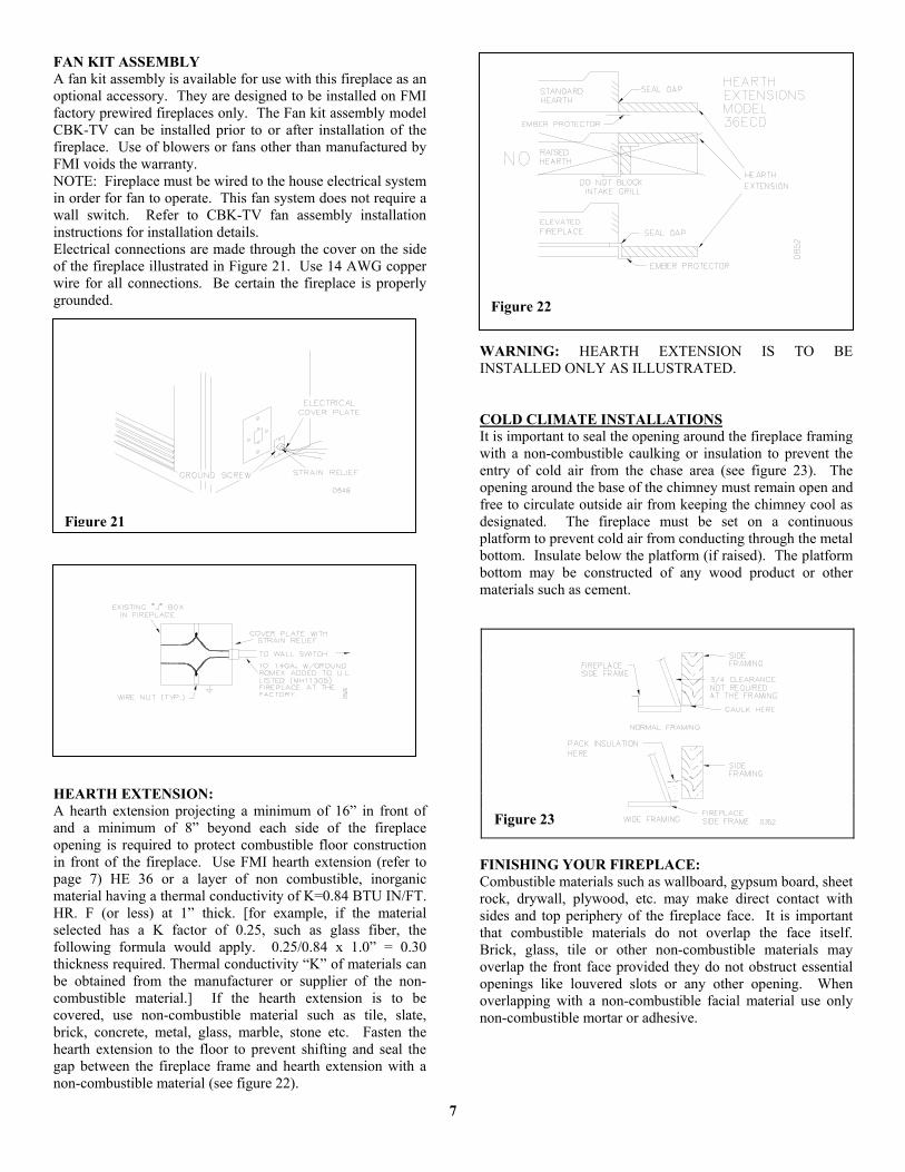
FAN KIT ASSEMBLY A fan kit assembly is available for use with this fireplace as an optional accessory. They are designed to be installed on FMI factory prewired fireplaces only. The Fan kit assembly model CBK-TV can be installed prior to or after installation of the fireplace. Use of blowers or fans other than manufactured by FMI voids the warranty. NOTE: Fireplace must be wired to the house electrical system in order for fan to operate. This fan system does not require a wall switch. Refer to CBK-TV fan assembly installation instructions for installation details. Electrical connections are made through the cover on the side of the fireplace illustrated in Figure 21. Use 14 AWG copper wire for all connections. Be certain the fireplace is properly grounded. HEARTH EXTENSION: A hearth extension projecting a minimum of 16” in front of and a minimum of 8” beyond each side of the fireplace opening is required to protect combustible floor construction in front of the fireplace. Use FMI hearth extension (refer to page 7) HE 36 or a layer of non combustible, inorganic material having a thermal conductivity of K=0.84 BTU IN/FT. HR. F (or less) at 1” thick. [for example, if the material selected has a K factor of 0.25, such as glass fiber, the following formula would apply. 0.25/0.84 x 1.0” = 0.30 thickness required. Thermal conductivity “K” of materials can be obtained from the manufacturer or supplier of the non-combustible material.] If the hearth extension is to be covered, use non-combustible material such as tile, slate, brick, concrete, metal, glass, marble, stone etc. Fasten the hearth extension to the floor to prevent shifting and seal the gap between the fireplace frame and hearth extension with a non-combustible material (see figure 22).
WARNING: HEARTH EXTENSION IS TO BE INSTALLED ONLY AS ILLUSTRATED. COLD CLIMATE INSTALLATIONS It is important to seal the opening around the fireplace framing with a non-combustible caulking or insulation to prevent the entry of cold air from the chase area (see figure 23). The opening around the base of the chimney must remain open and free to circulate outside air from keeping the chimney cool as designated. The fireplace must be set on a continuous platform to prevent cold air from conducting through the metal bottom. Insulate below the platform (if raised). The platform bottom may be constructed of any wood product or other materials such as cement.
FINISHING YOUR FIREPLACE: Combustible materials such as wallboard, gypsum board, sheet rock, drywall, plywood, etc. may make direct contact with sides and top periphery of the fireplace face. It is important that combustible materials do not overlap the face itself. Brick, glass, tile or other non-combustible materials may overlap the front face provided they do not obstruct essential openings like louvered slots or any other opening. When overlapping with a non-combustible facial material use only non-combustible mortar or adhesive.
Figure 23
Figure 22
Figure 21
8
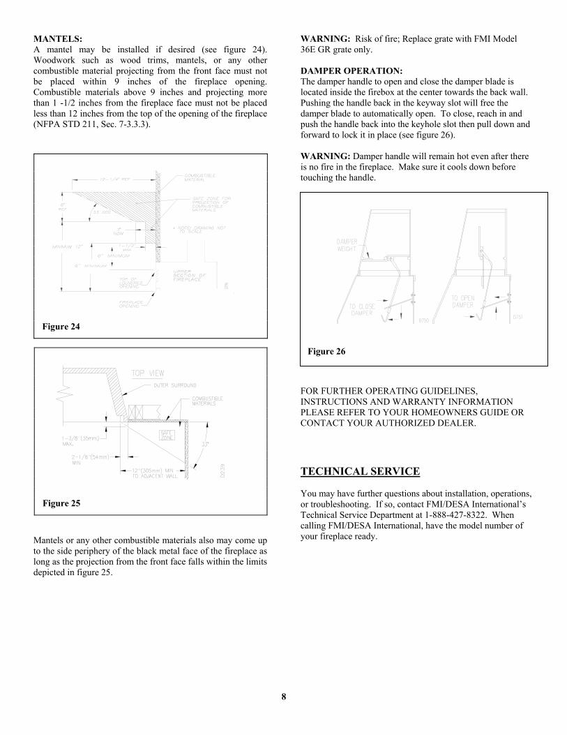
MANTELS: A mantel may be installed if desired (see figure 24). Woodwork such as wood trims, mantels, or any other combustible material projecting from the front face must not be placed within 9 inches of the fireplace opening. Combustible materials above 9 inches and projecting more than 1 -1/2 inches from the fireplace face must not be placed less than 12 inches from the top of the opening of the fireplace (NFPA STD 211, Sec. 7-3.3.3).
Mantels or any other combustible materials also may come up to the side periphery of the black metal face of the fireplace as long as the projection from the front face falls within the limits depicted in figure 25.
WARNING: Risk of fire; Replace grate with FMI Model 36E GR grate only. DAMPER OPERATION: The damper handle to open and close the damper blade is located inside the firebox at the center towards the back wall. Pushing the handle back in the keyway slot will free the damper blade to automatically open. To close, reach in and push the handle back into the keyhole slot then pull down and forward to lock it in place (see figure 26). WARNING: Damper handle will remain hot even after there is no fire in the fireplace. Make sure it cools down before touching the handle. FOR FURTHER OPERATING GUIDELINES, INSTRUCTIONS AND WARRANTY INFORMATION PLEASE REFER TO YOUR HOMEOWNERS GUIDE OR CONTACT YOUR AUTHORIZED DEALER. TECHNICAL SERVICE You may have further questions about installation, operations, or troubleshooting. If so, contact FMI/DESA International’s Technical Service Department at 1-888-427-8322. When calling FMI/DESA International, have the model number of your fireplace ready.
Figure 24
Figure 25
Figure 26

9
REPLACEM ENT PARTS
ACCESSORY PARTS