Embed Size (px)
Citation preview

s
Contents, Foreword
Input/output blocks
Communication blocks
Logic blocks
Service-/diagnostic blocks
SIMOLINK blocks
Closed-loop control blocks
Index
Function Blocks
FM 458-1 DP
Manual
Edition 12.2004
Siemens Aktiengesellschaft
This Manual contains notices which you should observe to ensure your own personal safety, as well as to protect the product and connected equipment. These notices are highlighted in the Manual by a warning triangle and are marked as follows according to the level of danger:
!
DANGER indicates an imminently hazardous situation which, if not avoided, will result in death or serious injury.
!
WARNING indicates a potentially hazardous situation which, if not avoided, could result in death or serious injury.
!
CAUTION used with the safety alert symbol indicates a potentially hazardous situation which, if not avoided, may result in minor or moderate injury.
CAUTION used without safety alert symbol indicates a potentially hazardous situation which, if not avoided, may result in property damage.
NOTICE used without the safety alert symbol indicates a potential situation which, if not avoided, may result in an undesireable result or state.
Note the following:
This device and its components may only be used for the applications described in the catalog or the technical description, and only in connection with devices or components from other manufacturers which have been approved or recommended by Siemens.
SIMATIC and SIMADYN D are registered trademarks of Siemens AG.
Third parties using for their own purposes any other names in this document which refer to trademarks might infringe upon the rights of the trademark owners.
Safety guidelines
Correct usage
Trademarks
Copyright SIEMENS AG 2004 All rights reserved Disclaimer of liability The reproduction, transmission or use of this document or its contents is not permitted without express written authority. Offenders will be liable for damages. All rights, including rights created by patent grant or registration of a utility model or design, are reserved. Siemens AG A&D Frauenauracher Straße 80 91056 Erlangen
We have checked the contents of this manual for agreement with the hardware and software described. Since deviations cannot be precluded entirely, we cannot guarantee full agreement. However, the data in this manual are reviewed regularly and any necessary corrections included in subsequent editions. Suggestions for improvement are welcomed.
Siemens AG 2004 Technical data subject to change.

Function Blocks - FM 458-1 DP ii Edition 12.2004
Editions FM 458-1 DP
Manual
Function Blocks
Edition 12.2004
NOTE Please note that the current edition of this documentation contains different editions of the individual chapters. The following overview tells you when a chapter was revised the last time.
Chapter Edition Foreword Edition 12.2004
1 Input/output blocks Edition 12.2004
2 Communication blocks Edition 12.2004
3 Logic blocks Edition 03.2003
4 Service-/diagnostic blocks Edition 03.2003
5 SIMOLINK drive coupling Edition 12.2004
6 Closed-loop control blocks Edition 12.2003
Overview (chapter editions)

Function Blocks - FM 458-1 DP iii Edition 12.2004
Foreword This Manual explains the principle use and functions of the STEP 7 automation software with the main focus on the appropriate technological and drive control components T400, FM 458-1 DP, SIMADYN D, SIMATIC TDC or D7-SYS.
TDC: Technology and Drives Control
This Manual addresses programmers and commissioning engineers. General knowhow regarding automation technology is required in order to understand the contents of the Manual
This Manual is valid for SIMATIC D7-SYS Version 6.2.
If you have questions relating to the use of the products described in the Manual, which cannot be answered here, then please contact your local Siemens office. You can also call the Hotline:
• Tel.: +49 (180) 5050-222
• Fax: +49 (180) 5050-223
• e-mail: [email protected]
Appropriate training courses are available in order to make it easier to get to know the SIMADYN D automation system. Please contact the central Training Center in D-Erlangen (I&S IS INA TC):
• Tel.: +49 (9131) 7-27689, -27972
• Fax: +49 (9131) 7-28172
• Internet: www.siemens.de/sibrain
• Intranet: http://info-tc.erlm.siemens.de/
NOTE This user part of the Manual does not include any detailed information/instructions with individual descriptions, but is only intended to provide a basic procedure. More detailed information on the dialog boxes in the software and how they are handled is provided in the appropriate online help.
Purpose of this Manual
Basic knowledge required
Validity of the Manual
Additional support
Training Center

Foreword
iv Function Blocks - FM 458-1 DP Edition 12.2004
This manual is part of the overall documentation for the technological and drive control components T400, FM 458, SIMADYN D, SIMATIC TDC and SIMATIC D7-SYS:
Title Content System and communications configuring D7-SYS
The first project in a few steps This Section provides an extremely simple entry into the methodology when assembling and programming the SIMATIC TDC/SIMADYN D control system. It is especially conceived for first-time users of a control system. System software This Section provides basic know-how about the structure of the operating system and an application program of a CPU. It should be used to obtain an overview of the programming methodology, and basis for configuring user programs. Communications configuring This section provides you with basic know-how about the communication possibilities and how you configure links to the communication partners. Changeover from STRUC V4.x to D7-SYS Essential features are included in this section, which have changed over STRUC V4.x with the introduction of SIMATIC D7-SYS.
STEP 7 option packages for D7-SYS
Basis software This section explains the essential use and the functions of the STEP 7 automation software. For first users, it provides an overview on configuring, programming and commissioning a station. When working with the basis software, you can access the online help which provides you with support when it comes to detailed questions on using the software. CFC The CFC language (Continuous Function Chart) allows you to graphically interconnect blocks. When working with the particular software, you can also use the online help which can answer detailed questions regarding the use of the editors/compiler. SFC Configuring sequence controls using SFC (Sequential Function Chart) of SIMATIC S7. In the SFC editor, you generate a sequence chart using graphic resources. The SFC elements of the chart are then positioned according to specific rules.
Hardware The complete hardware spectrum is described as reference in this Manuals.
Function blocks These Reference Manuals provide you with an overview of selected function blocks for the associated technological and drive control components T400, FM 458-1 DP, SIMADYN D and SIMATIC TDC.
Information overview

Foreword
Function Blocks - FM 458-1 DP v Edition 12.2004
As first time user, we recommend that this Manual is used as follows:
• Please read the first section on using the software in order to get to know some of the terminology and basic procedure.
• Then use the particular sections of the Manual if you wish to carry-out certain processing steps (e.g. loading programs).
If you have already executed a small project, and have gained some experience, then you can read individual sections of the Manual in order to get up to speed about a specific subject.
Can be accessed globally at any time of the day:
World-wide (Nürnberg) Technical Support Local time: 0:00 to 24:00 / 365 days Phone: +49 (180) 5050-222 Fax: +49 (180) 5050-223 E-Mail: [email protected] GMT: +1:00
Europe / Africa (Nürnberg) Authorization Local time: Mo.-Fr. 8:00 to 17:00 Phone: +49 (180) 5050-222 Fax: +49 (180) 5050-223 E-Mail: [email protected] GMT: +1:00
United States (Johnson City) Technical Support and Authorization Local time: Mo.-Fr. 8:00 to 17:00 Phone: +1 (423) 262 2522 Fax: +1 (423) 262 2289 E-Mail: [email protected] GMT: -5:00
Asia / Australia (Peking) Technical Support and Authorization Local time: Mo.-Fr. 8:00 to 17:00 Phone: +86 10 64 75 75 75 Fax: +86 10 64 74 74 74 E-Mail: [email protected]: +8:00
Technical Support and Authorization speak generally German and English.
Guide
A&D Technical Support

Function Blocks - FM 458-1 DP vii Edition 12.2004
Contents
Foreword ........................................................................................................................................ iii
1 Input/output blocks................................................................................................................ 1-1 1.1 SBM Rotary encoder block ....................................................................................... 1-2
2 Communication blocks.......................................................................................................... 2-1 2.1 Central coupling blocks............................................................................................. 2-1 2.1.1 @CSL2F PROFIBUS FMS coupling central block ................................................... 2-1 2.1.2 @CSL2L PROFIBUS FDL central block................................................................... 2-1 2.1.3 @CSPRO Central block PROFIBUS DP coupling ................................................... 2-1 2.1.4 @PRODP Central block PROFIBUS DP coupling ................................................... 2-2 2.2 Kopplung PROFIBUS DP ......................................................................................... 2-3 2.2.1 DPDIAG Diagnostics overview, PROFIBUS DP....................................................... 2-3 2.2.2 DPSLDG Slave diagnostics, PROFIBUS DP ........................................................... 2-6 2.2.3 DPEVT Alarm information, PROFIBUS DP .............................................................. 2-9 2.2.4 DPPEVT Process alarm information, PROFIBUS DP Symbol............................... 2-12 2.3 FM 458-specific coupling ........................................................................................ 2-15 2.3.1 @CPB P-bus, central coupling block...................................................................... 2-15 2.3.2 S7RD_P Reading data from a SIMATIC-CPU (P Bus) .......................................... 2-16 2.3.3 S7WR_P Sending data to a SIMATIC-CPU (P Bus) .............................................. 2-18 2.3.4 BRCV Block-oriented data reception via an S7 coupling ....................................... 2-20 2.3.5 S7STAT S7 CPU operating state ........................................................................... 2-23 2.3.6 S7RD, S7RD_B, S7RD_I, S7RD_D Read from the peripheral area of the S7-
CPU......................................................................................................................... 2-25 2.3.7 S7WR, S7WR_B, S7WR_I, S7WR_D Write into the peripheral area of the S7-
CPU......................................................................................................................... 2-27 2.4 Parameterizing SIMADYN D................................................................................... 2-29 2.4.1 @FMPAR Parameter processing on FM 458-1 DP modules................................. 2-29 2.4.2 CBCONF COMBOARD configuration..................................................................... 2-32 2.4.3 CBRFAW Receiving warnings from a COMBOARD .............................................. 2-36 2.4.4 PNAME Parameter names ..................................................................................... 2-38 2.4.5 PSTAT Change enable for parameters .................................................................. 2-40
3 Logic blocks ........................................................................................................................... 3-1 3.1 SAV_TR Save FB for NOV_RAM............................................................................. 3-1 3.2 PAS7 Initiate process interrupt at the S7-CPU......................................................... 3-3

Contents
viii Function Blocks - FM 458-1 DP Edition 12.2004
4 Service-/diagnostic blocks .................................................................................................... 4-1 4.1 FMLED Control FM 458-1 DP diagnostics LED ....................................................... 4-1
5 SIMOLINK drive coupling ...................................................................................................... 5-1 5.1 @SL SIMOLINK central block .................................................................................. 5-1 5.2 SLAV, SLAVE_R SIMOLINK receive block for one actual value.............................. 5-9 5.3 SLD SIMOLINK delta evaluation.............................................................................5-11 5.4 SLDIS SIMOLINK dispatcher..................................................................................5-12 5.5 SLSV, SLSV_R SIMOLINK send block for one setpoint ........................................5-13 5.6 SLSV2, SLSV2R SIMOLINK send block for 2 setpoints.........................................5-15 5.7 SLSVAV SIMOLINK send and receive block for one slave ....................................5-17
6 Closed-loop control blocks ................................................................................................... 6-1 6.1.1 INT_M Modulo integrator for axis cycle correct integration ...................................... 6-1
Index .............................................................................................................................................. I-1

Function Blocks - FM 458-1 DP 1-1 Edition 12.2004
1 Input/output blocks Assignment of the input/output blocks to processor- and peripheral devices.
Blocks Modules PM5 PM6 T400 IT41 IT42 EA12 EB11 FM
458 EXM 438
EXM 448*)
ITSL*)
SBM x x
*) with SBM2 Module

Input/output blocks
1-2 Function Blocks - FM 458-1 DP Edition 12.2004
1.1 SBM Rotary encoder block
SBM
hardware address ―GV AD YPI DI ―position in increments encoder type ― I TYP RPI DI ―max. increments/revolution
baud rate ― I BDR Y R ―normalized speed resolution ― I EXP U I ― revolutions
alarm- or normal FP ―BO DM QF BO ―group error message rated speed ―R RS YF DW ―error detection
The SBM function block is used to realize the following tasks:
• Initialize the rotary encoder, which is connected at the SBM2 module
• Determine the position and speed from the encoder data
• Error handling when communication errors develop between the encoder and SBM2 module
During the initialization phase of the system, the initialization I/O are read and the appropriate mode set at the SBM2 module. The following settings are made for the EQN1325 encoder:
• The encoder power supply is set to 5 V
• Number of revolutions to 4096
• Signal periods per revolution 8192
After the mode has been set, the zero position is determined, and the starting values for the position and the speed output at the connections.
In the standard mode, the block can assume four different statuses:
• NRM The values read-out from the SBM2 module (position and speed) are displayed at the block connections. If an error is detected, the block goes into the ERR error condition.
• ERR The following errors can occur in operation:
• Encoder is defective or is not connected
• Encoder was disconnected
• Data transfer error for serial communications between the encoder and SBM2 module
• SBM2 module not available
In the first three cases, the block goes into the "INI“ initialization status and in the latter case into the "OFF" status.
Symbol
Brief description
Mode of operation
Input/output blocks
Function Blocks - FM 458-1 DP 1-3 Edition 12.2004
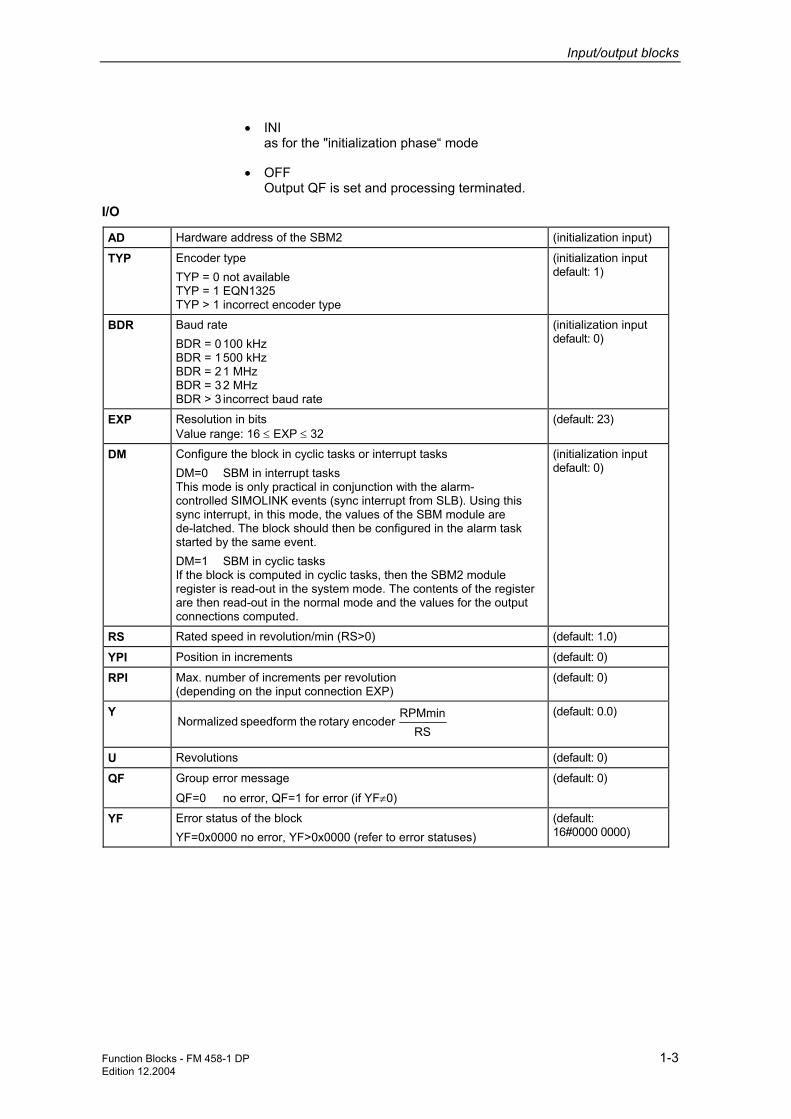
• INI as for the "initialization phase“ mode
• OFF Output QF is set and processing terminated.
AD Hardware address of the SBM2 (initialization input)
TYP Encoder type TYP = 0 not available TYP = 1 EQN1325 TYP > 1 incorrect encoder type
(initialization input default: 1)
BDR Baud rate BDR = 0 100 kHz BDR = 1 500 kHz BDR = 2 1 MHz BDR = 3 2 MHz BDR > 3 incorrect baud rate
(initialization input default: 0)
EXP Resolution in bits Value range: 16 ≤ EXP ≤ 32
(default: 23)
DM Configure the block in cyclic tasks or interrupt tasks DM=0 SBM in interrupt tasks This mode is only practical in conjunction with the alarm- controlled SIMOLINK events (sync interrupt from SLB). Using this sync interrupt, in this mode, the values of the SBM module are de-latched. The block should then be configured in the alarm task started by the same event. DM=1 SBM in cyclic tasks If the block is computed in cyclic tasks, then the SBM2 module register is read-out in the system mode. The contents of the register are then read-out in the normal mode and the values for the output connections computed.
(initialization input default: 0)
RS Rated speed in revolution/min (RS>0) (default: 1.0)
YPI Position in increments (default: 0)
RPI Max. number of increments per revolution (depending on the input connection EXP)
(default: 0)
Y
RSRPMmin
encoderrotary the speedform Normalized (default: 0.0)
U Revolutions (default: 0)
QF Group error message
QF=0 no error, QF=1 for error (if YF≠0)
(default: 0)
YF Error status of the block YF=0x0000 no error, YF>0x0000 (refer to error statuses)
(default: 16#0000 0000)
I/O

Input/output blocks
1-4 Function Blocks - FM 458-1 DP Edition 12.2004
Value Significance Nibble 1
0x0001 Initialization mode
0x0002 No SBM2 module available
0x0004 SBM2 module is processed from another SBM
0x0008 Encoder defective/not available
Nibble 2
0x0010 Unknown carrier or illegal module code
0x0020 Incorrect hardware address
0x0040 Encoder fault/error → Check the hardware (encoder, cable etc.)
0x0080 No voltage or short-circuit
Nibble 3
0x0100 No data transfer from or to the encoder → check the hardware (encoder, cable etc.)
0x0200 Erroneous data transfer from or to the encoder → check the hardware (encoder, cable etc.)
0x0400 Invalid mode parameterized
0x0800 Invalid encoder parameterized
Nibble 4
0x1000 Invalid speed normalization parameterized
0x2000 Invalid baud rate parameterized
0x4000 Sampling time too high; speed computation not possible →Sampling time: ≤ 4.0 ms
0x8000 Error for the request to save
Nibble 5
0x10000 Invalid resolution parameterized
0x20000 Function block is not configured in the alarm task
0x40000 Not defined: Reserve → Default: 0
0x80000 Not defined: Reserve → Default: 0
Nibble 6-8 Not defined: Reserve → Default: 0
Computation time [µs] FM 458-1 DP 13,2
Can be inserted online No
Can be configured in Interrupt tasks Cyclic tasks
Executed in Initialization mode Normal mode
Special features Can only be used with an EQN 1325 encoder
Error statuses
Configuringdata

Function Blocks - FM 458-1 DP 2-1 Edition 12.2004
2 Communication blocks
2.1 Central coupling blocks
NOTE Additional information on this group of function blocks, e.g. symbol, mode of operation, I/O and technical data are provided in the online help for the particular block.
2.1.1 @CSL2F PROFIBUS FMS coupling central block
• the function block initializes and monitors the PROFIBUS FMS coupling (CS7 and SS5 module).
• the function block may only be configured in the sampling interval 32 ms <= TA <= 256 ms and only in the communications FP "Transmit". Otherwise, an entry is made in the communications error field.
2.1.2 @CSL2L PROFIBUS FDL central block
• the function block initializes and monitors the PROFIBUS FDL coupling (CS7 and SS5 module).
• the function block may only be configured in the sampling interval 32 ms <= TA <= 256 ms and only configured in the communications FP "transmit". Otherwise an entry will be made in the communications error field.
2.1.3 @CSPRO Central block PROFIBUS DP coupling
• the function block initializes and monitors the PROFIBUS DP coupling (EXM 448/EXM 448-1).
• the function block may only be configured in the sampling interval 32 ms <= TA <= 256 ms . Otherwise an entry is made in the communications error field.
Brief description
Brief description
Brief description

Communication blocks
2-2 Function Blocks - FM 458-1 DP Edition 12.2004
2.1.4 @PRODP Central block PROFIBUS DP coupling
• the function block initializes and monitors the PROFIBUS DP coupling at connector X03 on FM 458-1 DP.
• the function block may only be configured in the sampling interval 32 ms <= TA <= 256 ms . Otherwise an entry is made in the communications error field.
Brief description
Communication blocks
Function Blocks - FM 458-1 DP 2-3 Edition 12.2004
2.2 Kopplung PROFIBUS DP
2.2.1 DPDIAG Diagnostics overview, PROFIBUS DP
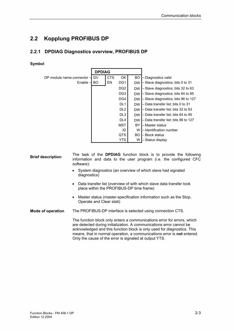
DPDIAG
DP module name.connector ―GV CTS OK BO ―Diagnostics valid Enable ―BO EN DG1 DW ―Slave diagnostics; bits 0 to 31
DG2 DW ―Slave diagnostics; bits 32 to 63 DG3 DW ―Slave diagnostics; bits 64 to 95 DG4 DW ―Slave diagnostics; bits 96 to 127 DL1 DW ―Data transfer list; bits 0 to 31 DL2 DW ―Data transfer list; bits 32 to 63 DL3 DW ―Data transfer list; bits 64 to 95 DL4 DW ―Data transfer list; bits 96 to 127 MST BY ―Master status ID W ―Identification number QTS BO ―Block status YTS W ―Status display
The task of the DPDIAG function block is to provide the following information and data to the user program (i.e. the configured CFC software): • System diagnostics (an overview of which slave had signaled
diagnostics)
• Data transfer list (overview of with which slave data transfer took place within the PROFIBUS-DP time frame)
• Master status (master-specification information such as the Stop, Operate and Clear stati)
The PROFIBUS-DP interface is selected using connection CTS.
The function block only enters a communications error for errors, which are detected during initialization. A communications error cannot be acknowledged and this function block is only used for diagnostics. This means, that in normal operation, a communications error is not entered. Only the cause of the error is signaled at output YTS.
Symbol
Brief description
Mode of operation

Communication blocks
2-4 Function Blocks - FM 458-1 DP Edition 12.2004
CTS Module name.connector of the Profibus-DP interface (Initialization connection)
EN Block enable The block is not processed if EN=0; output OK=0 and YTS=1; the last value is kept at the other outputs
(Default: 1)
OK Diagnostics data valid (Default: 0) DG1 Overview of which slave signaled diagnostics data. This output is
bit-coded. Every bit is assigned to a slave with its Profibus address. Bit 3 of the 32 bit is, for example, assigned to the slave with Profibus address 3.
Comment: The bits 0 up to and including 2 are always 0 as the associated addresses (0 to 2) should be reserved for the DP master, for a PG and an OP. For a more detailed description, refer to the user manual "FM 458-1 DP", chapter "Configuring", section "PROFIBUS DP coupling".
(Default: 0)
DG2 Overview of which slave had signaled diagnostics data. This output is bit-coded. Every bit is assigned to a slave with its Profibus address. The bit 0 of the 32-bit word is, for example, assigned to the slave with Profibus address 32. For a more detailed description, refer to the user manual "FM 458-1 DP", chapter "Configuring", section "PROFIBUS DP coupling".
(Default: 0)
DG3 Overview of which slave had signaled diagnostics data. This output is bit-coded. Every bit is assigned to a slave with its Profibus address. The bit 0 of the 32-bit word is, for example, assigned to the slave with Profibus address 64. For a more detailed description, refer to the user manual "FM 458-1 DP", chapter "Configuring", section "PROFIBUS DP coupling".
(Default: 0)
DG4 Overview of which slave had signaled diagnostics data. This output is bit-coded. Every bit is assigned to a slave with its Profibus address. The bit 0 of the 32-bit word is, for example, assigned to the slave with Profibus address 96. For a more detailed description, refer to the user manual "FM 458-1 DP", chapter "Configuring", section "PROFIBUS DP coupling".
(Default: 0)
DL1 Overview of with which slave data transfer took place. This output is bit-coded. Every bit is assigned to a slave with its Profibus address. For example, bit 3 of the 32-bit word is assigned to the slave with Profibus address 3. For a more detailed description, refer to the user manual "FM 458-1 DP", chapter "Configuring", section "PROFIBUS DP coupling".
(Default: 0)
I/O

Communication blocks
Function Blocks - FM 458-1 DP 2-5 Edition 12.2004
DL2 Overview of with which slave data transfer took place. This output is bit-coded. Every bit is assigned to a slave with its Profibus address. For example, bit 0 of the 32-bit word is assigned to the slave with Profibus address 32. For a more detailed description, refer to the user manual "FM 458-1 DP", chapter "Configuring", section "PROFIBUS DP coupling".
(Default: 0)
DL3 Overview of with which slave data transfer took place. This output is bit-coded. Every bit is assigned to a slave with its Profibus address. For example, bit 0 of the 32-bit word is assigned to the slave with Profibus address 64. For a more detailed description, refer to the user manual "FM 458-1 DP", chapter "Configuring", section "PROFIBUS DP coupling".
(Default: 0)
DL4 Overview of with which slave data transfer took place. This output is bit-coded. Every bit is assigned to a slave with its Profibus address. For example, bit 0 of the 32-bit word is assigned to the slave with Profibus address 96. For a more detailed description, refer to the user manual "FM 458-1 DP", chapter "Configuring", section "PROFIBUS DP coupling".
(Default: 0)
MST Status of the DP master: Stop (0x40 ), Clear (0x80) or Operate (0xC0)
(Default: 0)
ID Master identification number: (0x8037 for EXM448 as Profibus interface, 0x80EB when using X3 of the FM458-1)
(Default: 0)
QTS Block output QTS is used to display whether the block is operating error-free (QTS = 1) or was de-activated after a communications error message was entered (QTS = 0).
(Default: 0)
YTS Detailed status display: • YTS=0 o.k.
• YTS=1 Block processing inhibited (EN=0) For additional values at YTS, refer to: D7-SYS Online Help "Help events". (Press the F1 button in the CFC and call the topic "Help on events" under "CFC for D7-SYS".)
(Default: 0)
Computation time [µs] FM458-1 DP 42,7 Can be inserted online No Can be configured in Cyclic tasks Executed in Initialization mode
Normal mode Special features This function block may only be configured
once for each PROFIBUS communications module.
Configuring data

Communication blocks
2-6 Function Blocks - FM 458-1 DP Edition 12.2004
2.2.2 DPSLDG Slave diagnostics, PROFIBUS DP
DPSLDG
DP module name. connector ―GV CTS OK BO ―Diagnostics valid Slave address ― I SLA ST1 BY ―Status 1, standard diagnostics
Number of device-related diagnostic bytes
― I LEN ST2 BY ―Status 2, standard diagnostics
Enable ―BO EN ST3 BY ―Status 3, standard diagnostics MPA BY ―Master Profibus address ID W ―Slave identification number D01 DW ―Diagnostic bytes v, w, x u. y 1) D59 DW ―Diagnostic bytes v, w, x u. y 1) QTS BO ―Block status YTS W ―Status display
1) normally invisible
The DPSLDG function block provides diagnostics data from a DP slave to the user program. This diagnostics data correspond, with the exception of the maximum possible length, to EN 50170. According to this Standard, the diagnostics data can be a maximum of 244 bytes long. The function block supports a maximum of 240 bytes
On the EXM448, there are restrictions regarding the quantity of diagnostics data. Only diagnostics data (Standard diagnostics data) is supplied which the function block DIAPRO supplies.
The consistency of the outputs is not ensured. When new diagnostics data is received, some of the outputs can have "New" information and some can still have "old" information.
The PROFIBUS-DP interface is selected using connection CTS.
The function block only enters a communications error for errors, which are detected during initialization. A communications error cannot be acknowledged and the function block DPSLDG is only used for diagnostics. This means, that in normal operation, a communications error is not entered. Only the cause of the error is signaled at output YTS.
Symbol
Brief description
Note
Mode of operation

Communication blocks
Function Blocks - FM 458-1 DP 2-7 Edition 12.2004
CTS DP module name, connector of the Profibus DP interface (Initialization connection) SLA Diagnostics data required from the slave with the appropriate
station number (3 to 123) (Initialization connection) (Default: 3)
LEN Number of the device-related diagnostic bytes; this means the diagnostics bytes which extend beyond the Standard diagnostics. Here, a maximum value of 234 may be set. Whether device-related diagnostics data is available and, if yes, which significance they have, should be taken from the user documentation of the relevant DP slave.
(Initialization connection) (Default: 0, i.e. only Standard diagnostics, not device-related diagnostic bytes)
EN Block enable. If EN=0, the block is not processed; output OK=0 and YTS=1, the last value remains at the other outputs.
(Default: 1)
OK Diagnostics data valid (Default: 0) ST1 Status 1 of the diagnostics according to the Standard (byte 1).
For a more detailed description, refer to the user manual "FM 458-1 DP", chapter "Configuring", section "PROFIBUS DP coupling".
(Default: 0)
ST2 Status 2 of the diagnostics according to the Standard (byte 2). For a more detailed description, refer to the user manual "FM 458-1 DP", chapter "Configuring", section "PROFIBUS DP coupling".
(Default: 0)
ST3 Status 3 of the diagnostics according to the Standard (byte 3). For a more detailed description, refer to the user manual "FM 458-1 DP", chapter "Configuring", section "PROFIBUS DP coupling".
(Default: 0)
MPA Master Profibus address (byte 4 of the diagnostics according to the Standard)
ID Identification number of the slave (bytes 5 and 6 of the diagnosics according to the Standard)
D01 to D59
Device-related diagnostic bytes; 4 bytes are combined in one 32-bit word. Bytes 7, 8, 9 and 10 of the diagnostics telegram can be found in D01. For a more detailed description, refer to the user manual "FM 458-1 DP", chapter "Configuring", section "PROFIBUS DP coupling".
When data is entered at LEN, this has an influence on the update of the outputs. For LEN=0, these outputs are not updated. For LEN=234, D01 up to and including D59 are updated. Comment: Bytes 1 to 6 of a diagnostics telegram for PROFIBUS DP corresponds to the Standard Diagnostics; bytes from 7 onwards depend on the particular slave (referred to the particular device).
(Default: 0)
QTS Block output QTS is used to display whether the block is operating error-free (QTS = 1) or was de-activated after a communications error message was entered (QTS = 0).
(Default: 0)
I/O

Communication blocks
2-8 Function Blocks - FM 458-1 DP Edition 12.2004
YTS Detailed status display:
• YTS=0 o.k.
• YTS=1 Block processing inhibited (EN=0)
• YTS=2 An initialization connection (SLA er LEN) was changed in cyclic opertion; this change only becomes effective the next time that the FM458-1 starts
• YTS=3 The block has already been configured once for the slave addressed via SLA
• YTS=4 The slave, with the address specified at SLA, has not been configured in the PROFIBUS network.
For additional values at YTS, refer to: D7-SYS Online Help "Help events". (Press the F1 button in the CFC and call the topic "Help on events" uncer "CFC for D7-SYS".)
(Default: 0)
Computation time [µs] FM458-1 DP 29 Can be inserted online No Can be configured in Cyclic tasks Executed in Initialization mode
Normal mode Special features The function block may only be configured
once for each slave.
Configuring data

Communication blocks
Function Blocks - FM 458-1 DP 2-9 Edition 12.2004
2.2.3 DPEVT Alarm information, PROFIBUS DP
DPEVT
Expanded info ―BO EXT OB I ―Appropriate S7 alarm OB STA I ―Station SLO I ―Slot SUB I ―Sub-module SBN I ―Sub-network YO1 DW ―Diagnostic bytes 0, 1, 2 and 3 YO2 DW ―Diagnostic bytes 4, 5, 6 and 7 YO3 DW ―Diagnosebytes 8, 9, 10 and 11 YO4 DW ―Diagnostic bytes 12, 13, 14 and 15 YO5 DW ―Diagnostic bytes 16, 17, 18 and 19 YO6 DW ―Diagnostic bytes ... 1) YO21 DW ―Diagnostic bytes ... 1) QTS BO ―Block status YTS W ―Status display
1) normally invisible
The DPEVT function block (DP event) provides more detailed information about a Profibus-DP process or diagnostics alarm. The information/data, provided at the outputs, correspond to the information/data which a SIMATIC S7 module also has when processing the appropriate alarm OBs (e.g. OB40, OB55 etc.).
When an alarm event is output, all of the values at the outputs are updated.
When the appropriate alarm occurs, the alarm task configured for this purpose, is started, Within the alarm task, DPEVT reads-out the alarm information. A new alarm of the same time is only detected again after the alarm task has been completed.
When a communications error occurs, the cause is also output at output YTS and the QTS output is set to "0".
Symbol
Brief description
Mode of operation

Communication blocks
2-10 Function Blocks - FM 458-1 DP Edition 12.2004
EXT For EXT=0, only the data/information at outputs Y01 to Y05 is updated. For EXT=1, in addition, the information/data at outputs Y06 to Y21 is updated.
(Default: 0)
OB The number of the appropriate SIMATIC S7 organizational block (OB) is displayed at this output. In an error-free state, values 40, 55, 56, 57, 82, 83 and 86 are possible here. The actual value depends on the process alarm configured in the HWConfig for the particular alarm task.
(Default: 0)
STA Station address of the slave which had initiated the alarm. Values of between 1 and 126 are valid values for this address.
(Default: 0)
SLO Slot of the module which initiated the alarm. Values of between 1 and 244 are valid values for the slot data.
(Default: 0)
SUB Sub-module of the module which initiated the alarm. Values of between 1 and 31 are valid values for the sub-module data. A value of 0 means no sub-module.
(Default: 0)
SBN Sub-network to which the module, which initiated the alarm, is connected. Values of between 1 and 255 are valid values for the sub-network data. The number for the sub-network can be taken from the properties dialog box in NetPro or HY-Config.
(Default: 0)
YO1 The first 4 bytes with information about the last alarm event are available at this output. The actual significance corresponds to the first byte of the local data of the appropriate S7-OB. As a whole, the local data comprise 20 bytes; the structuring of the local data can be taken from the help for the appropriate OB.
(Default: 0)
YO2 The second 4 bytes with information about the last alarm event are available at this output.
(Default: 0)
YO3 The third 4 bytes with information about the last alarm event are available at this output.
(Default: 0)
YO4 The fourth 4 bytes with information about the last alarm event are available at this output.
(Default: 0)
YO5 The fifth 4 bytes with information about the last alarm event are available at this output.
(Default: 0)
Y06 to Y21
You can obtain additional information/data about the alarm, which goes beyond the local data of the S7-OBs, at these outputs. The information/data correspond to that which you would obtain if you would have called the SFB54 "RALRM" within the appropriate S7-OBs. The outputs are only updated if EXT=1 is set to 1. Normally, these outputs are switched so that they are invisible, and, when required, must be first made visible in the CFC, under the tab "I/O".
(Default: 0)
QTS Block output QTS is used to display whether the block is operating error-free (QTS = 1) or was de-activated after a communications error message was entered (QTS = 0).
(Default: 0)
YTS Detailed status display for additional values at YTS, refer to: D7-SYS Online Help "Help events". (Press the F1 button in the CFC and call the topic "Help on events" uncer "CFC for D7-SYS".)
(Default: 0)
I/O

Communication blocks
Function Blocks - FM 458-1 DP 2-11 Edition 12.2004
Computation time [µs] FM458-1 DP 23,6 Can be inserted online No Can be configured in Alarm tasks Executed in Initialization mode
Normal mode Special features The DPEVT may only be configured in an
alarm task for which one of the following alarm causes is configured in HW-Config:
• Process alarm 1 (OB40)
• DPV1 status alarm (OB55)
• DPV1 update alarm (OB56)
• DPV1 manufacturer-specific alarm (OB57)
• Diagnostics alarm (OB82)
• Withdraw/insert alarm (OB83)
• Failure, subrack alarm (OB86) If this is not the case, DPEVT signals an appropriate communications error and stops processing.
Configuring data

Communication blocks
2-12 Function Blocks - FM 458-1 DP Edition 12.2004
2.2.4 DPPEVT Process alarm information, PROFIBUS DP Symbol
DPPEVT
STA I ―Station SLO I ―Slot SUB I ―Sub-module SBN I ―Sub-network EVC BY ―Event classes and IDs IOF BY ―IO flag IN BO ―Input module OUT BO ―Output module MDL W ―Logical address PAD DW ―OB40_POINT_ADDR YYR I ―Year YMO I ―Month YDA I ―Day YHR I ―Hour YMI I ―Minute YSE I ―Seconds QTS BO ―Block state YTS W ―Status display
The DPPEV (DP process event) provides more detailed information about the Profibus DP process alarm (OB40 alarm). Contrary to the DPEVT, only selected information/data is available, but then, in a conditioned form.
When an alarm event is output, all of the values at the outputs are updated.
For a communications error, the cause is additionally output at YTS and the QTS output is set to "0".
Symbol
Brief description
Mode of operation

Communication blocks
Function Blocks - FM 458-1 DP 2-13 Edition 12.2004
STA Station address of the slave which had initiated the alarm. Values of between 1 to 126 are valid values for this address.
(Default: 0)
SLO Slot of the module which initiated the alarm. Values of between 1 and 244 are valid values for the slot data.
(Default: 0)
SUB Sub-module of the module which initiated the alarm. Values of between 1 and 31 are valid values for the sub-module data. A value of 0 means no sub-module.
(Default: 0)
SBN Sub-network to which the module, which initiated the alarm, is connected. Values of between 1 and 255 are valid values for the sub-network data. The number for the sub-network can be taken from the properties dialog box in NetPro or HW-Config.
(Default: 0)
EVC This output corresponds to the local data variables OB40_EV_CLASS of the OB40 for a SIMATIC-S7. A value of B#16#11(11 hexadecimal) means that the alarm is active.
(Default: 0)
IOF This output corresponds to the local data variables OB40_IO_FLAG of the OB40 for a SIMATIC-S7. The significance is as follows:
B#16#54 (54 hexadecimal) Input module
B#16#55 (55 hexadecimal) Output module The (present) possible information is available, in a conditioned form, at outputs IN and OUT.
(Default: 0)
IN IN=1 Input module has initiated an alarm IN=0 The alarm was not initiated from an input module
(Default: 0)
OUT OUT=1 Output module had initiated an alarm OUT=0 The alarm was not initiated from an output module
(Default: 0)
MDL This value outputs the logical basis address of the module. The value corresponds to the local data variables OB40_MDL_ADDR of the OB40 for a SIMATIC-S7.
(Default: 0)
PAD This value supplies additional information about the cause of the process alarm. The value corresponds to the local data variables OB40_POINT_ADDR of the OB40 for a SIMATIC-S7. Additional information about this is provided in the SIMATIC documentation.
(Default: 0)
YYR Year (specifies in which year the alarm was initiated)
(Default: 0)
YMO Month (specifies in which month the alarm was initiated)
(Default: 0)
YDA Day (specifies on which day the alarm was initiated)
(Default: 0)
YHR Hour (specifies at which hour the alarm was initiated)
(Default: 0)
YMI Minute (specifies at which minute the alarm was initiated)
(Default: 0)
YSE Second (specifies at which second the alarm was initiated)
(Default: 0)
QTS Block output QTS is used to display whether the block is operating error-free (QTS = 1) or was de-activated after a communications error message was entered (QTS = 0).
(Default: 0)
I/O

Communication blocks
2-14 Function Blocks - FM 458-1 DP Edition 12.2004
YTS Detailed status display; for additional values at YTS, refer to: D7-SYS Online Help "Help events". (Press the F1 button in the CFC and call the topic "Help on events" uncer "CFC for D7-SYS".)
(Default: 0)
Computation time [µs] FM458-1 DP 23,6 Can be inserted online No Can be configured in Alarm tasks Executed in Initialization mode
Normal mode Special features The DPPEV may only be configured in an
alarm task for which the following alarm cause is configured in HW-Config
• Process alarm 1 (OB40) If this is not the case, DPPEV signals an appropriate communications error and stops processing. A new alarm of the same time is only again detected after the alarm task has been completed.
Configuring data

Communication blocks
Function Blocks - FM 458-1 DP 2-15 Edition 12.2004
2.3 FM 458-specific coupling
2.3.1 @CPB P-bus, central coupling block
@CPB
CPU-module-name.PBUS ―GV CTS CDM BO ―coupling status QTS BO ―block status
The central block for the P-bus coupling can only run with an FM 458 application module.
• This function block is responsible for initializing and monitoring the P bus coupling.
• The function block can only be configured once for each application module FM 458, as there is only one P-bus coupling for each FM 458. If a function block is configured a multiple number of times, this is detected when initializing, and results in an entry in the communications error field.
• The block may only be configured in the sampling interval 32 ms <= TA <= 256 ms. Otherwise, an entry is made in the communications error field.
When initializing the function block, general preparations are made to enable the coupling. The coupling is only enabled after the standard mode has been run-through (executed) several times.
After the coupling has been enabled, the central block monitors that senders and receivers are correctly registered. Further, if required, it re-organizes and updates the block output CDM at each processing cycle.
The function block cannot be used to initialize another P-bus coupling or monitor this. It can only initialize its own P-bus coupling on which CPU is configured. An entry is made in the communications error field if another module name is specified at the CTS input (other than its own).
The CDM block output provides information about the coupling status. The connection is a 1, if the coupling is enabled for general send/receive operation. The CDM block output is 0, as long as the coupling is still being initialized, or is being re-initialized (after a temporary fault).
Symbol
Brief description
Mode of operation

Communication blocks
2-16 Function Blocks - FM 458-1 DP Edition 12.2004
CTS The configured name of its own CPU is specified at this initialization input.
CDM Specifies the coupling status (faulted = 0, not faulted = 1).
(default: 0)
QTS Operating status of the function block There is an irreparable fault for QTS = 0, for QTS = 1, the function block operates error-free.
(default: 0)
Computation time [µs] FM 458-1 DP 16,5
Available online no
Can be configured in Cyclic tasks
Executed in Normal mode Initialization mode
Special features -
2.3.2 S7RD_P Reading data from a SIMATIC-CPU (P Bus)
S7RD_P
Offs in 128By-PBus-Buffer ― I OFF PTR DW ―PtrBuffer Transmitdata Number bytes to be read ― I LEN QF BO ―Error-Status Block
Enable ―BO EN YF W ―StatusInfo Block
This block can only be used for the SIMATIC application module FM 458-1 DP. A SIMATIC-CPU can transfer up to 128 bytes to the FM 458-1 DP in its output area of the P bus. Block S7RD_P reads this data from the P-Bus and provides it, via its pointer interface, to the read blocks (DRD…, CPY_Y) for further processing in the CFC configured software.
This block operates similar to the telegram block CRV_P. A maximum of 128 bytes can be accessed via the pointer interface. These bytes are sent from the SIMATIC-CPU to the FM 458-1 DP via the P bus. Data can be read using the read blocks (DRD…) or the copy block (CPY_P).
This block only communicates with a SIMATIC-CPU. This means that the required byte or word swap operations are automatically made (depending on the data type of the connected read/write blocks). The entry, which is normally required at the SW-connection of the read/write block, is not evaluated and is therefore not required.
I/O
Configuringdata
Symbol
Brief description
Mode of operation

Communication blocks
Function Blocks - FM 458-1 DP 2-17 Edition 12.2004
The computation time essentially depends on the amount of data transferred. A base computation time of approx. 10 µs as well as approx. 1 µs/byte can be assumed as nominal value.
The following blocks can be connected to this block (pointer input): DRD, DRD_8, DRD_8D, DRD_8I, DRD_BY, DRD_D, DRD_I, CPY_P
Default:
OFF Offs in 128By-PBus-Buffer Offset of the value to be sent within the 128 byte memory relative to the start of the buffer; max. offset: Buffer length - length of the data type
0
LEN Number bytes to be read Number of bytes which are read by the SIMATIC-CPU via the P bus. Max. number: 128 bytes
0
EN Enable For EN=1 at each call, the data sent from the SIMATIC-CPU (max. 128 bytes) is read.
1
PTR PtrBuffer Transmitdata Pointer to the telegram data buffer; to connect with the same connection type of other pointer-based communication blocks. The CFC connection can be changed online. The connection also includes monitoring information to ensure correct configuring.
16#00000000
QF Error status block QF=1: There is an error; for details, refer to YF
0.0
YF StatusInfo Block §§ as for the DRD block!
16#0000
Computation time [µs] FM 458-1 DP 10,0 + 1 for each byte Can be inserted online Yes Can be configured in Interrupt tasks
Cyclic tasks Executed in Initialization mode
Normal mode Special features The block must be configured in the same
sampling time as the blocks, connected via the pointer interface(CFC connection via connections PTR). This can only be used for the FM 458-1 DP! Several S7RD_P blocks can be configured. Although this is not a typical application, it can make sense if, for example, the 128 byte area should be read in several blocks or if data is required in different sampling times.
Associated blocks
I/O
Configuring data

Communication blocks
2-18 Function Blocks - FM 458-1 DP Edition 12.2004
2.3.3 S7WR_P Sending data to a SIMATIC-CPU (P Bus)
S7WR_P
Offs in 128By-PBus-Buffer ― I OFF PTR DW ―PtrBuffer Transmitdata Number bytes to be write ― I LEN QF BO ―Error-Status Block Number bytes to be write ―BO EN YF W ―StatusInfo Block
This block can only be used for the SIMATIC application module FM 458-1 DP. An FM 458-1 DP can send up to 128 bytes to the SIMATIC-CPU via the P-Bus. The block S7WR_P sends data which were previously loaded with write blocks via the pointer interface.
This block operates similar to the telegram block CTV_P. A maximum of 128 bytes can be transferred via this pointer interface and via the P bus to the SIMATIC CPU. This data is previously loaded into the telegram buffer using write blocks DWR… of the copy block CPY_Y.
This block only communicates with a SIMATIC-CPU. This means that the required byte or word swap operations are automatically made (depending on the data type of the connected read/write blocks). The entry, which is normally required at the SW-connection of the read/write block, is not evaluated and is therefore not required.
The computation time essentially depends on the amount of data transferred. A base computation time of approx. 5 µs as well as approx. 0.7 µs/byte can be assumed as nominal value.
The following blocks can be connected to this block (pointer input): DWR, DWR_8, DWR_8D, DWR_8I, DWD_BY, DWR_D, DWR_I, CPY_P
Default:
OFF Offs in 128By-PBus-Buffer Offset of the value to be sent within the 128 byte memory relative to the start of the buffer; max. offset: Buffer length - length of the data type
0
LEN Number of bytes to be written Number of bytes which are to be sent to the SIMATIC CPU via the P bus. Max. number: 128 bytes
0
EN Enable For EN=1, at each call, the telegram buffer (max. 128 bytes) is sent to the SIMATIC-CPU.
1
PTR PtrBuffer Transmitdata Pointer to the telegram/data buffer; to connect with the same connection type of other pointer-based communication blocks. The CFC connection can be changed online. The connection also includes monitoring information to ensure correct configuring.
16#00000000
Symbol
Brief description
Mode of operation
Associated blocks
I/O

Communication blocks
Function Blocks - FM 458-1 DP 2-19 Edition 12.2004
QF Error status block QF=1: There is an error; for details, refer to YF
0.0
YF StatusInfo Block §§ as for the DRD block!
16#0000
Computation time [µs] FM 458-1 DP 5,0 + 0.7 for each byte Can be inserted online Yes Can be configured in Interrupt tasks
Cyclic tasks Executed in Initialization mode
Normal mode Special features The block must be configured in the same
sampling time as the blocks, connected via the pointer interface (CFC connection via connections PTR). This can only be used for the FM 458-1 DP! Several S7WR_P blocks can be configured. Although this is not a typical application, it can make sense if, for example, the 128 byte area should be written in several blocks or if data is required in different sampling times.
Configuring data

Communication blocks
2-20 Function Blocks - FM 458-1 DP Edition 12.2004
2.3.4 BRCV Block-oriented data reception via an S7 coupling
BRCV
Establish ready to receive ―BO ENR PTR DW ―Receive data is ready Addressing parameters ID ―W ID NDR BO ―Status parameter NDR
Addressing parameters R_ID ―DW RID LEN DI ―Length of data received before Maximum length, receive data ―DI RLN CTR DI ―Number of receive operations
ERR BO ―Status parameter ERROR STA W ―Status, fault display QTS BO ―Block status YTS W ―Status display
The function block allows block-oriented data reception via a configured S7 coupling.
The BRCV block receives data from a "remote" partner. The "remote" partner is an SFB/FB, type BSEND (SFB/FB 12) on a SIMATIC S7-400 CPU.
After each data segment which has been received, an acknowledgement is sent to the partner SFB/FB and the LEN parameter is updated.
The block is ready to receive when a "1" is connected to the control input ENR. A running task can be interrupted with ENR=0.
The maximum length of the receive area is specified by the data at input RLN. The length of the data block received is displayed at output LEN.
ENR Control parameter The block is ready to receive with ENR = 1
Default: 0
ID Addressing parameter Reference to the local connection description (this is specified as a result of the STEP7 configured connection)
Initialization input, Default: 0
RID The value at input RID specifies the association with the send SFB/FB. The value at the input must match the R_ID parameter for SFB/FB on the send side. This allows several SFB/FB pairs to communicate via the same logical coupling. The block pairs of a logical coupling, defined using RID or R_ID must be unique for this coupling.
Initialization input, Default: 0
RLN The maximum length of the received data is defined here. Only values of between 0 and 65535 may be configured.
Initialization input, Default: 0
PTR The receive data, to be evaluated by the blocks for direct communication, is made available here (e.g. types DRD, DRD_I, etc.).
Default: 0
Symbol
Brief description
Mode of operation
I/O

Communication blocks
Function Blocks - FM 458-1 DP 2-21 Edition 12.2004
NDR Status parameter NDR 0: Task was still not started (ENR input)or is still running 1: Task was successfully completed
Default: 0
LEN Length of the previously received data in bytes Default: 0 CTR This output counts the total number of successfully complete data
receive cycles since the last change from STOP to RUN.
Default: 0
ERR An error is output at block output ERR. The detailed information about the type of the error is available at output STA. This output corresponds to the ERROR output of an SFB/FB 13 of an S7-CPU.
Default: 0
STA Detailed status display This output corresponds to the STATUS output of an SFB/FB 13 of an S7-CPU. ERR = 0:
• STA=00H No alarm, no fault
• STA=11H Non-synchronous data is received, output LEN indicates the number of pieces of data previously received in bytes.
ERR = 1:
• STA=01H Communication problems (e.g. the coupling description to the ID not loaded, coupling has still not been established from the partner or the coupling was interrupted)
• STA=04H Error regarding the data length The data block sent is longer than the receive range set using input RLN.
• STA=05H Reset request received, incomplete transfer
• STA=12H R_ID already exists in the coupling
• STA=14H too little working memory
Default: 0
QTS Block output QTS indicates whether the block is operating (QTS = 1) or became inactive after a communications error message was entered (QTS = 0).
Default: 0
YTS Detailed status display
• YTS=0 O.K. (ready)
• YTS=1 The block is in the DISABLED state, i.e. ENR=0
• YTS=2 The initialization connection is changed, the change only becomes effective at the next STOP RUN transition; the FB operates with the values at ID, RID and RLN set when running-up
For other values at YTS, in addition, a communications error is entered in the diagnostics buffer and the block is no longer processed (QTS=0)
Default: 0

Communication blocks
2-22 Function Blocks - FM 458-1 DP Edition 12.2004
Computation time [µs] FM458-1 DP 5,7 Can be inserted online No Can be configured in Alarm tasks
Cyclic tasks Executed in Initialization mode
Normal mode Special features -
Configuring data

Communication blocks
Function Blocks - FM 458-1 DP 2-23 Edition 12.2004
2.3.5 S7STAT S7 CPU operating state
S7STAT
RUN BO ―S7-CPU in RUN STP BO ―S7-CPU in STOP HLD BO ―S7-CPU in HOLD ACT W ―actual operating state OLD W ―previous operating state
The actual and previous S7-CPU operating states are displayed at the outputs.
The actual and previous operating state of the S7-CPU is determined and displayed at connectors ACT for the actual and OLD for the previous operating state. Output RUN is set to TRUE if the S7-CPU is either in the RUN or RUN-R state.
Output value to ACT or OLD
Operating state RUN STP HLD
0x0010 Stop 0 1 0 0x0020 Cold start 0 0 0 0x0040 New start 0 0 0 0x0080 Re-start 0 0 0 0x0100 RUN 1 0 0 0x0200 RUN-R 1 0 0 0x0400 Hold 0 0 1
NOTE All other values are used for extended diagnostics.
RUN S7-CPU in RUN (Default: 0) STP S7-CPU in STOP (Default: 0) HLD S7-CPU in HOLD (Default: 0) ACT Actual operating state of the S7-CPU (Default: 0x8000) OLD Previous operating state of the S7-CPU (Default: 0x8000)
Please refer to the help for STEP7 for a more detailed description of the operating states.
Symbol
Brief description
Mode of operation
I/O

Communication blocks
2-24 Function Blocks - FM 458-1 DP Edition 12.2004
Commutation time [µs] FM458-1 DP Can be inserted online yes Can be configured in Alarm tasks
Cyclic tasks Executed in Normal mode Special features -
Configuring data

Communication blocks
Function Blocks - FM 458-1 DP 2-25 Edition 12.2004
2.3.6 S7RD, S7RD_B, S7RD_I, S7RD_D Read from the peripheral area of the S7-CPU
S7RD
Offset ―I OFF Y R ―Output Enable ―BO EN QF BO ―error output
The function blocks, read from the peripheral area of the S7-CPU, can only run with an FM 458 application module.
The S7RD, S7RD_B, S7RD_I, S7RD_D blocks only differ by the data type at the output, which must correspond with the parameters to be read:
• S7RD: REAL
• S7RD_B: BOOL
• S7RD_I: INT
• S7RD_D: DINT
With this block, data can be read into the assigned net data area of the SIMATIC S7-CPU, (periphery output) assigned to the FM 458 application module. This PE area is 128 bytes.
If the enable signal is set, the appropriate value is read from the PA area and made available at output Y.
The offset determines at which location in the PA area, the value is retrieved.
Depending on the block- or data type, the offset is specified as follows:
• for REAL data type in 4-byte steps (data length) value range of the offset: 0 . . . 31
• for BOOL data type in 1-byte steps (data length). value range of the offset: 0 . . . 127
• for INT data type in 2-byte steps (data length). value range of the offset: 0 . . . 63
• for DINT data type in 4-byte steps (data length). value range of the offset: 0 . . . 31
Output QF has the value 1, if an invalid offset was selected, or the block is not configured on the FM 458.
Symbol
Brief description
Mode of operation

Communication blocks
2-26 Function Blocks - FM 458-1 DP Edition 12.2004
OFF Offset (default: 0)
EN Enable (default: 0)
Y Output (default: 0.0)
QF Error output (default: 0)
Computation time [µs] FM 458-1 DP 3,3
Available online yes
Can be configured in Interrupt tasks Cyclic tasks
Executed in Normal mode Initialization mode
Special features -
I/O
Configuringdata

Communication blocks
Function Blocks - FM 458-1 DP 2-27 Edition 12.2004
2.3.7 S7WR, S7WR_B, S7WR_I, S7WR_D Write into the peripheral area of the S7-CPU
S7WR
Input ―R X QF BO ―Error output Offset ― I OFF
Enable ―BO EN
The function blocks, write the peripheral area (I/O) of the S7-CPU can only run with one FM 458 application module.
The S7WR, S7WR_B, S7WR_I, S7WR_D blocks differ by the data type at the input, which must correspond with the parameters to be written:
• S7WR: REAL
• S7WR_B: BOOL
• S7WR_I: INT
• S7WR_D: DINT
Using this block, data can be written into the net (useful) data area of the SIMATIC S7-CPU, assigned to the FM 458 application module (periphery input). This PE area is 128 bytes. If the enable signal is set, the input value is accepted via the input and entered in the PE area.
The offset determines at which position in the PE area, the input value is saved. Depending on the block- or data type, the offset is specified as follows:
• for REAL data type in 4 byte steps (data length). value range of the offset: 0 . . . 31
• for BOOL data type in 1 byte steps (data length). value range of the offset: 0 . . . 127
• for INT data type in 2 byte steps (data length). value range of the offset: 0 . . . 63
• for DINT data type in 4 byte steps (data length). value range of the offset: 0 . . . 31
Output QF has the value 1, if an invalid offset was selected, or the block is not configured on the FM 458 application module.
X Input (default: 0.0)
OFF Offset (default: 0)
EN Enable (default: 0)
QF Error output (default: 0)
Symbol
Brief description
Mode of operation
I/O

Communication blocks
2-28 Function Blocks - FM 458-1 DP Edition 12.2004
Computation time [µs] FM 458-1 DP 3,3
Available online yes
Can be configured in Interrupt tasks Cyclic tasks
Executed in Normal mode Initialization mode
Special features -
Configuringdata

Communication blocks
Function Blocks - FM 458-1 DP 2-29 Edition 12.2004
2.4 Parameterizing SIMADYN D
2.4.1 @FMPAR Parameter processing on FM 458-1 DP modules
@FMPAR
EXM448 module name. connector ―GV CTS CS BO ―COMBOARD status Parameter language selection ― I PLA QTS BO ―Block status
Parameter type float to Comboard ―BO CF YT1 W ―Status 1.COMBOARD parameter channelParameter change enable ―BO PEN YT2 W ―Status 2.COMBOARD parameter channel
BASEBOARD-Function ―BO BBF
The FB @FMPAR can only be configured on a FM 458-1 DP module.
FB @FMPAR monitors the COMBOARD (communications submodule of the SIMOVERT MASTER DRIVES, e.g. CBP for PROFIBUS DP) and processes the parameter tasks which are defined for it.
Several @FMPAR central blocks for various COMBOARDs can be configured on a FM 458-1 DP module.
It should be configured in a slow sampling time (approx. 100 ms). The maximum permissible sampling time is 200 ms (as a result of the monitoring using adjacent modules).
The existence and correction functioning of the COMBOARD is automatically identified and is displayed at output CS.
Only one COMBOARD may be configured using FB @FMPAR.
Parameter processing:
Parameters are configured in the comment at each I/O. If the comment starts with "@TP_", then this I/O is designated as parameter. Every parameter can be allocated a parameter name (FB-PNAME). Further, a setting parameter can also be allocated a minimum and a maximum (FB-PLIM).
The block handles the following tasks:
• Checks the module code of the COMBOARD
• Monitors the COMBOARD (lifebit counter)
• Transfers the configuration data to the COMBOARD
• Processes the parameter channels
• In standard operation, processes the parameter tasks (in the sampling time cycle).
Symbol
Brief description
Mode of operation
Communication blocks
2-30 Function Blocks - FM 458-1 DP Edition 12.2004
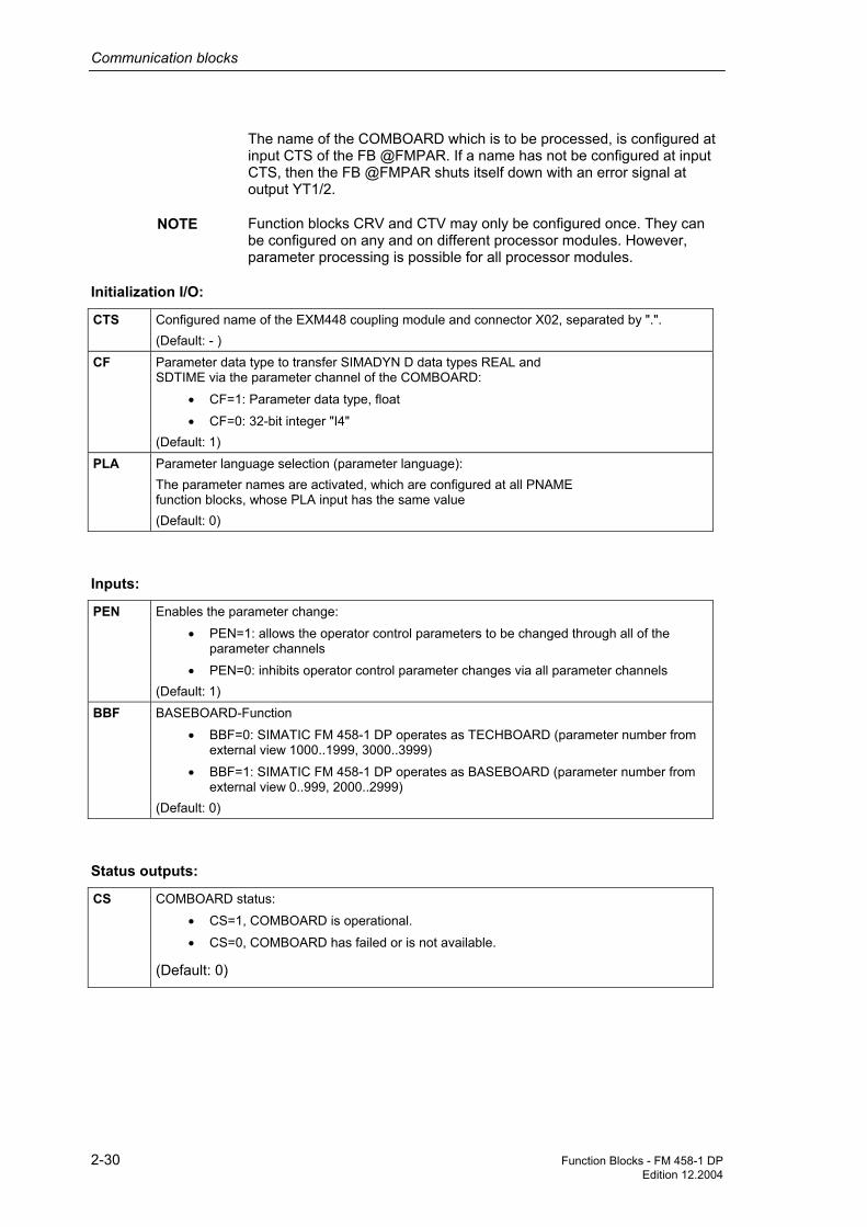
The name of the COMBOARD which is to be processed, is configured at input CTS of the FB @FMPAR. If a name has not be configured at input CTS, then the FB @FMPAR shuts itself down with an error signal at output YT1/2.
Function blocks CRV and CTV may only be configured once. They can be configured on any and on different processor modules. However, parameter processing is possible for all processor modules.
CTS Configured name of the EXM448 coupling module and connector X02, separated by ".". (Default: - )
CF Parameter data type to transfer SIMADYN D data types REAL and SDTIME via the parameter channel of the COMBOARD:
• CF=1: Parameter data type, float
• CF=0: 32-bit integer "I4" (Default: 1)
PLA Parameter language selection (parameter language): The parameter names are activated, which are configured at all PNAME function blocks, whose PLA input has the same value (Default: 0)
PEN Enables the parameter change:
• PEN=1: allows the operator control parameters to be changed through all of the parameter channels
• PEN=0: inhibits operator control parameter changes via all parameter channels (Default: 1)
BBF BASEBOARD-Function
• BBF=0: SIMATIC FM 458-1 DP operates as TECHBOARD (parameter number from external view 1000..1999, 3000..3999)
• BBF=1: SIMATIC FM 458-1 DP operates as BASEBOARD (parameter number from external view 0..999, 2000..2999)
(Default: 0)
CS COMBOARD status:
• CS=1, COMBOARD is operational.
• CS=0, COMBOARD has failed or is not available.
(Default: 0)
NOTE
Initialization I/O:
Inputs:
Status outputs:

Communication blocks
Function Blocks - FM 458-1 DP 2-31 Edition 12.2004
QTS Block status:
• QTS=1: Block is operational and is operating error-free.
• QTS=0: Block is shutdown due to a fault with an error output at YT1/2
(Default: 0)
YT1 • YT1=0: OK status
• Initialization mode: status of the block initialization
• Standard mode: Status of the 1st parameter channel from COMBOARD For additional values, refer to: D7-SYS online help "Help on Events". (press the F1 key in the CFC and call-up the topic "Help on events" under "CFC for D7-SYS".) (Default: 0)
YT2 • YT2=0: OK status
• Intialization module: Status of the block initialization
• Standard mode: Status of the 2nd parameter channel of COMBOARD For additional values, refer to: D7-SYS online help "Help on events". (press key F1 in the CFC and call-up the topic "Help on events" under "CFC for D7-SYS".) (Default: 0)
Computation time [µs] FM 458-1 DP 3,3 Can be inserted online -- Can be configured in Cyclic tasks Executed in Initialization mode
Normal mode Special features • 10<=sampling time<=200 ms
• Block may not be switched-in or switched-out per task group.
Diagnose outputs:
Configuringdata

Communication blocks
2-32 Function Blocks - FM 458-1 DP Edition 12.2004
2.4.2 CBCONF COMBOARD configuration
CBCONF name of the module to the right ―GV CTR QTS BO ―block status
new configuration command ―BO SET YTS W ―status display station address ― I MAA D01 W ―COMBOARD diagnosis 01
COMBOARD parameter 01 ― I P01 D02 W ―COMBOARD diagnosis 02 COMBOARD parameter 02 ― I P02 D03 W ―COMBOARD diagnosis 03 COMBOARD parameter 03 ― I P03 D04 W ―COMBOARD diagnosis 04 COMBOARD parameter 04 ― I P04 D05 W ―COMBOARD diagnosis 05 COMBOARD parameter 05 ― I P05 D06 W ―COMBOARD diagnosis 06 COMBOARD parameter 06 ― I P06 D07 W ―COMBOARD diagnosis 07 COMBOARD parameter 07 ― I P07 D08 W ―COMBOARD diagnosis 08 COMBOARD parameter 08 ― I P08 D09 W ―COMBOARD diagnosis 09 COMBOARD parameter 09 ― I P09 D10 W ―COMBOARD diagnosis 10 COMBOARD parameter 10 ― I P10 D11 W ―COMBOARD diagnosis 11 COMBOARD parameter 11 ― I P11 D12 W ―COMBOARD diagnosis 12 COMBOARD parameter 12 ― I P12 D13 W ―COMBOARD diagnosis 13 COMBOARD parameter 13 ― I P13 D14 W ―COMBOARD diagnosis 14 COMBOARD parameter 14 ― I P14 D15 W ―COMBOARD diagnosis 15 COMBOARD parameter 15 ― I P15 D16 W ―COMBOARD diagnosis 16 COMBOARD parameter 16 ― I P16 D17 W ―COMBOARD diagnosis 17 COMBOARD parameter 17 ― I P17 D18 W ―COMBOARD diagnosis 18 COMBOARD parameter 18 ― I P18 D19 W ―COMBOARD diagnosis 19 COMBOARD parameter 19 ― I P19 D20 W ―COMBOARD diagnosis 20 COMBOARD parameter 20 ― I P20 D21 W ―COMBOARD diagnosis 21 COMBOARD parameter 21 ― I P21 D22 W ―COMBOARD diagnosis 22 COMBOARD parameter 22 ― I P22 D23 W ―COMBOARD diagnosis 23 COMBOARD parameter 23 ― I P23 D24 W ―COMBOARD diagnosis 24 COMBOARD parameter 24 ― I P24 D25 W ―COMBOARD diagnosis 25 COMBOARD parameter 25 ― I P25 D26 W ―COMBOARD diagnosis 26 COMBOARD parameter 26 ― I P26 D27 W ―COMBOARD diagnosis 27 COMBOARD parameter 27 ― I P27 D28 W ―COMBOARD diagnosis 28 COMBOARD parameter 28 ― I P28
FB CBCONF can be configured on the following modules:
• FM458 modules
• T400 technology module
The function block CBCONF may only be configured once on a FM458 module per COMBOARD. It is configured on the FM458 module on which the function block @FMPAR was configured for the appropriate COMBOARD.
Symbol
Brief description
Configuring on a FM458 module

Communication blocks
Function Blocks - FM 458-1 DP 2-33 Edition 12.2004
The block saves the configured configuration data in the admin. area of the COMBOARD. It executes this once after run-up and user-controlled in the RUN mode. In the RUN mode, it outputs diagnostics data from the COMBOARD at its outputs.
New configuration data can be transferred online to COMBOARD with a positive edge at input SET.
CTR Configured name of the "righthand" adjacent module (initialization connection). The following data can be entered:
• CTR = 0 if an adjacent module was not configured
• CTR=<module name> or
• CTR=<module name>.<connector> if an adjacent board is configured. (default value: - )
SET The configuration data is transferred online to the COMBOARD with a rising edge at this input. (Default value: 0)
MAA The station number should be assigned depending on the particular protocol (e.g. USS: 0..30, PROFIBUS DP: 3..125). (Default value: 0)
P01...P28 Max. 28 additional COMBOARD-specific configuration parameters. (Default value: 0)
QTS Block status:
• QTS = 1: Block is operational.
• QTS = 0: The block is disabled with an error output at YTS
(Default value: 0)
YTS Status display, possible values
• - 0: OK status
• - 7CB3: T400 operates as TECHBOARD and a BASEBOARD is available Additional values, refer to: D7-SYS Online Help "Help on events" (press key F1 in the CFC and call-up the topic "Help on events" under "CFC for SIMADYN D".) (Default value: 0)
D01...D28 Max. 28 words of diagnostics data of the COMBOARD (Default value: 0)
Mode of operation
I/O

Communication blocks
2-34 Function Blocks - FM 458-1 DP Edition 12.2004
The "CB-Param" and "SCB-Param" columns establish the assignment to the COMBOARD User Manuals.
Input CB-Param new/old
CB1: DP
CBP: DP
CBP2: DP
CBP2: USS
CB2: CAN
MAA P918 Bus address Bus address Bus address Bus address Bus address
P01 P711/ P696
(not used) Diagnostic selection
Diagnostic selection
- PKW task
P02 P712/ P697
PPO-Typ PPO-Typ PPO-Typ - PZD receive
P03 P713/ P698
(END) (END) Protocol selection: 0: Profibus-DP 2: USS
PZD send
P04 P714/ P699
SIMATIC OP writes in: 0: EEPROM 1. RAM
- PZD send length
P05 P715/ P700
Slave to slave data transfer failed: 0: Error 1: Warning
- PZD send rate
P06 P716/ P701
(END) - PZD receive Broadcast
P07 P717/ P702
- PZD receive Multicast
P08 P718/ P703
Baud rate 6 = 9,6 kBaud 7 = 19,2 kBaud 8 = 38,4 kBaud
PZD receiver cross
P09 P719/ P704
PKW: 0:no, 127:yes, 3:one word, 4:one D word
PKW task Broadcast
P10 P720/ P705
PZD: No. of words
Baud rate
P11 P706.1 (END) CAN layer
P12 P706.2 Bus timing
P13 P706.3 (END)
P14 P706.4
...
P28
Significance of the configuring input for several COMBOARDs

Communication blocks
Function Blocks - FM 458-1 DP 2-35 Edition 12.2004
Input SCB- Param
SCB2: USS-Slave
SCB2: Peer
SCB1: CAN
MAA P683.2 Bus address (not used)
P01 P682 SCB1/SCB2-protocol selection: 0:CAN, 1:USS 4-wire, 2:USS-2-wire, 3:Peer
P02 P685.2 PKW: 0:no, 127:yes, 3:one word, 4:one D word
(not used)
P03 P686.2 Process data: No. of words
(not used)
P04 P684.2 Baud rate
P05 P687.2 Telegram failure time
P06 (END) (END)
P07
P08
P09
P10
P11
P12
P13
P14
...
P28
Refer to the COMBOARD User Manuals
Computation time [µs] FM458-1 DP 3,3 Can be inserted online -- Can be configured in Cyclic tasks Executed in Initialization mode
Normal mode Special features • The block can only be configured once for
each communications submodule.
• Additional block required on the CPU modules: @FMPAR
Significance of the diagnostic outputs
Configuringdata

Communication blocks
2-36 Function Blocks - FM 458-1 DP Edition 12.2004
2.4.3 CBRFAW Receiving warnings from a COMBOARD
CBRFAW EXM448 module name, connector ―GV CTS CW W ―COMBOARD alarms 96 - 81
QTS BO ―Module status YTS W ―Status, COMBOARD alarm
channel
• The block can only be configured on a FM458 module.
• This block receives warnings A81 to A96 of a COMBOARD (communications submodule of SIMOVERT MASTER DRIVES, e.g. CBP2 for PROFIBUS DP).
• Input CTS of the CBRFAW function block is used to define from which COMBOARD the warnings are to be received.
• Function block CBRFAW may only be configured on a FM458 module of each COMBOARD. It is configured on the FM458 module, on which a @FMPAR function block was also configured for the appropriate COMBOARD.
Initialization inputs:
CTS Configured name of the EXM448/EXM448-2 module and connector X01 or X02, separated by ".". (Default: - )
Outputs:
CW Outputs COMBOARD warnings A81 to A96 (Default: 0)
QTS Block status:
• QTS=1: Block is being processed and is operating error-free.
• QTS=0: Block is shut down due to a fault with error output at YTS.
(Default: 0)
YTS Status of the COMBOARD warning channel: YTS=0: OK condition For additional values, refer to: D7-SYS online help "Help on events". (press the F1 key in the CFC and call-up the topic "Help on events" under "CFC for SIMADYN D".) (Default: 0)
Symbol
Brief description
I/O

Communication blocks
Function Blocks - FM 458-1 DP 2-37 Edition 12.2004
Computation time [µs] FM458-1 DP 3,3 Can be inserted online -- Can be configured in Cyclic tasks Executed in Initialization mode
Normal mode Special features • The block can only be configured once for
each communications submodule.
• Additionally required block: @FMPAR
Configuringdata
Communication blocks
2-38 Function Blocks - FM 458-1 DP Edition 12.2004
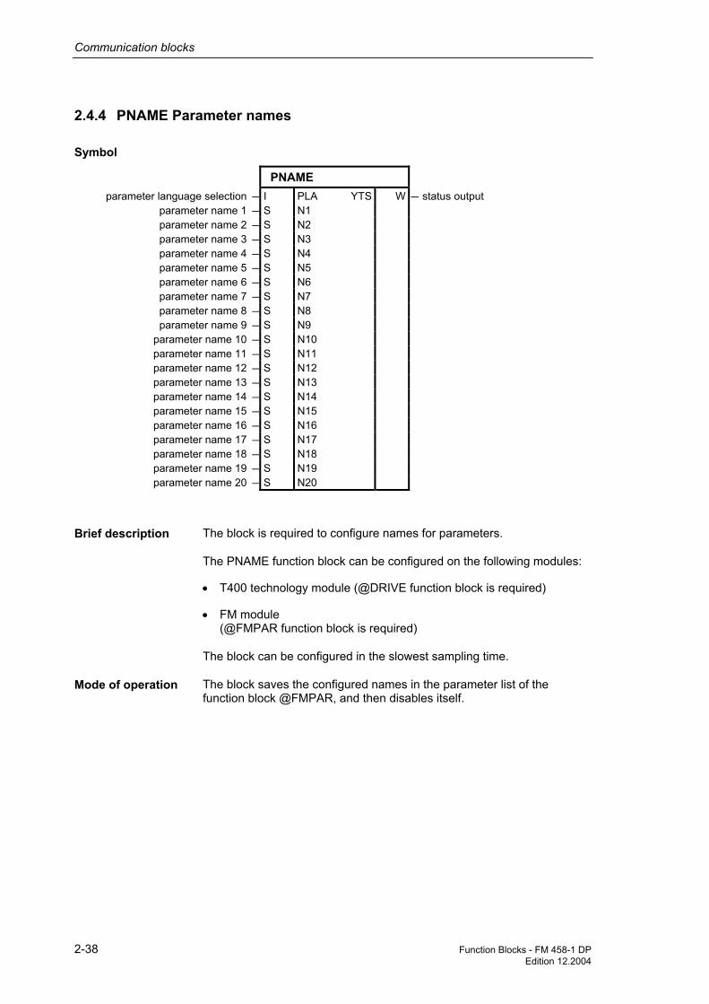
2.4.4 PNAME Parameter names
PNAME
parameter language selection ― I PLA YTS W ―status output parameter name 1 ―S N1 parameter name 2 ―S N2 parameter name 3 ―S N3 parameter name 4 ―S N4 parameter name 5 ―S N5 parameter name 6 ―S N6 parameter name 7 ―S N7 parameter name 8 ―S N8 parameter name 9 ―S N9
parameter name 10 ―S N10 parameter name 11 ―S N11 parameter name 12 ―S N12 parameter name 13 ―S N13 parameter name 14 ―S N14 parameter name 15 ―S N15 parameter name 16 ―S N16 parameter name 17 ―S N17 parameter name 18 ―S N18 parameter name 19 ―S N19 parameter name 20 ―S N20
The block is required to configure names for parameters.
The PNAME function block can be configured on the following modules:
• T400 technology module (@DRIVE function block is required)
• FM module (@FMPAR function block is required)
The block can be configured in the slowest sampling time.
The block saves the configured names in the parameter list of the function block @FMPAR, and then disables itself.
Symbol
Brief description
Mode of operation

Communication blocks
Function Blocks - FM 458-1 DP 2-39 Edition 12.2004
PLA Parameter language selection (parameter langage): The configured parameter names are exactly activated when the data coincides with the PLA input at the @FMPAR block. (Initialization input) (Default value: 0)
Nnn The parameter number and the parameter name, separated by a colon are specified at the Nnn inputs. Example: "H123: parameter name". The parameter number must always consists of a letter (H or L) and three digits. The parameter name should be a maximum of 16 characters long; longer names will be cut-off and shorter names, filled with blanks. . (Initialization input) (Default value: Empty string)
YTS Status display, possible values - 0: OK status (all of the names are activated). Alarms: - 1: The names are not activated, as another language is set at function block @FMPAR - 2: For at least one parameter number, there is no parameter (the name is ignored) Additional values, refer to: D7-SYS Online Help "Help on events" (press key F1 in the CFC and call-up the topic "Help on events" under "CFC for SIMADYN D") (Default value: 0)
Computation time [µs] FM 458-1 DP 3,3
Can be inserted online --
Can be configured in Cyclic tasks
Executed in Initialization mode Normal mode
Special features • additionally required block on the FM modules: @FMPAR
I/O
Configuringdata

Communication blocks
2-40 Function Blocks - FM 458-1 DP Edition 12.2004
2.4.5 PSTAT Change enable for parameters
PSTAT
Password ― I PSW WLV W ―Access level Level 1 ― I PW1 WST W ―Device status Level 2 ― I PW2 YTS W ―Status display Level 3 ― I PW3 Level 4 ― I PW4 Level 5 ― I PW5 Level 6 ― I PW6 Level 7 ― I PW7 Level 8 ― I PW8
Device status ― I STE
Using the function block, the following can be realized
• a current device status can be configured,
• the access level can be defined by entering a password,
• the device status and the access level is used to define whether a parameter may be changed.
The statuses and access level, in which a parameter is to be inhibited or enabled, are defined using the PLIM function block.
Function block PSTAT may only be configured once in each FM module.
PSW Current password: If password PSW does not coincide with the PWi values, then this corresponds to access level 0: this does not permit any change. If password PSW coincides with a value of PWi, then this corresponds to access level i and all lower access levels. In access level 8, there are no access authorizations as a result of the access level (all other access restrictuions, e.g. using the device status, are retained). (Default: 0)
PWi Appropriate password for access level i (password i): (Default: 0)
STE Actual "device status": There are 16 statuses. Permissible entry range: 1 to 16 (Default: 1)
Symbol
Brief description
I/O

Communication blocks
Function Blocks - FM 458-1 DP 2-41 Edition 12.2004
WLV Actual access stage i (word level): The access stage i, determined by the entry at input PSW, is output as binary value. For access stage n, bit n is set to 1 and all of the other 15 bits, are set to 0. e.g. for access level = 7, WLVcorresponds to 2#0000000001000000. (Default: 2#0000000000000000)
WST Device status (word state): The actual device status STE is output as a binary value. For the current device status ST=n, bit n is set to 1 and all of the other 15 bits are set to 0. e.g. for STE=7, WST corresponds to 2#000000001000000. (Default: 2#0000000000000001)
YTS Status display:
• 7C72: Function block is configured several times
• 7CA9: no @FMPAR function block configured
• 7CC3: one or several incorrect entries were made at input PWi
• 7CC4: illegal entry at input STE (Default: 0) For additional values, refer to: D7-SYS online help "Help on events". (press key F1 in the CFC and call-up the topic "Help on events" under "CFC for SIMADYN D".)
Computation time [µs] FM 458-1 DP 3,3
Can be inserted online --
Can be configured in Alarm-Tasks Cyclic tasks
Executed in Initialization mode Normal mode
Special features • Function block may only be configured once per FM module
• Function block additionally required on the FM modules: @FMPAR and PLIM
Configuringdata

Function Blocks - FM 458-1 DP 3-1Edition 03.2003
3 Logic blocks
3.1 SAV_TR Save FB for NOV_RAM
SAV_TR input variable ―R X Y R ―output variable
mode of operation ―BO M QF BO ―no available memory
A REAL type quantity is saved in the NOV-RAM of a technology module.
The function block is a read/write memory for a REAL value. It is onlyactive, if a 0 at output QF indicates that the memory space in theNOVRAM is available. The function block operating mode is selected atinput M:
• The quantity to be saved is entered at input X. It is transferred tooutput Y.
• Further, input quantity X is entered in the NOV-RAM of the module. Inthis case, a value, already contained in the NOV-RAM is overwritten.
• The last input quantity, saved in the write operating mode, is outputat Y.
• The NOV-RAM is deleted from the operating system each time theconfigured software changes (even when the system is configured forthe first time), i.e. zeros are written into it. If the NOV-RAM is thenread, without having previously written a value into the NOV RAM,then the initialization value of the NOV RAM (zero) is output at Y.
In the INIT operating mode of the function block, memory is madeavailable to accept a REAL value. Output QF is set to 1 if this is not (nolonger) possible. The function block is then inactive in the RUN operatingmode.
X Input quantity (default: 0.0)M Operating mode (default: 0)Y Output quantity (default: 0.0)QF No free memory (default: 0)
Symbol
Brief descriptionMode of operation
Write operatingmode (M = 1)
Read operatingmode (M = 0)
INIT Operatingmode
I/O

Logic blocks
3-2 Function Blocks - FM 458-1 DPEdition 03.2003
Computation time [µs] FM 458-1 DP 0,6Can be inserted online --Can be configured in Interrupt tasks
Cyclic tasksExecuted in Initialization mode
Normal modeSpecial features -
Configuringdata
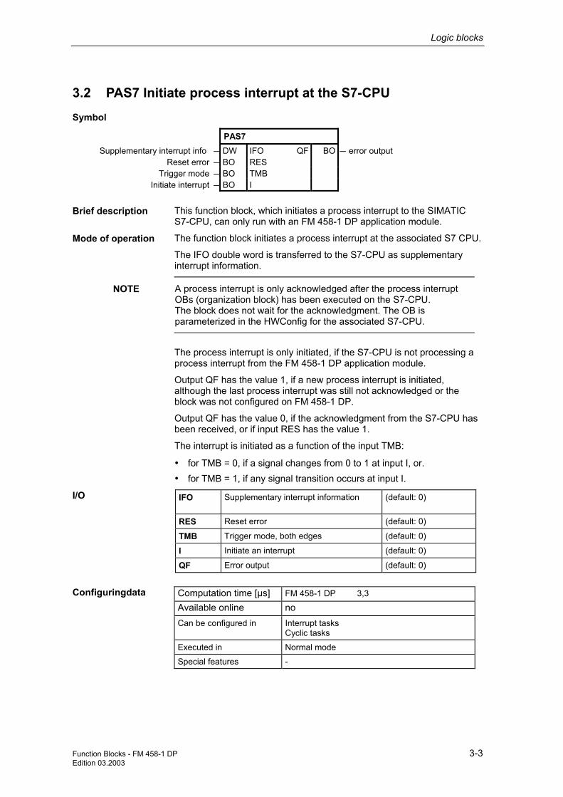
Logic blocks
Function Blocks - FM 458-1 DP 3-3Edition 03.2003
3.2 PAS7 Initiate process interrupt at the S7-CPU
PAS7 Supplementary interrupt info ―DW IFO QF BO ―error output
Reset error ―BO RESTrigger mode ―BO TMB
Initiate interrupt ―BO I
This function block, which initiates a process interrupt to the SIMATICS7-CPU, can only run with an FM 458-1 DP application module.
The function block initiates a process interrupt at the associated S7 CPU.
The IFO double word is transferred to the S7-CPU as supplementaryinterrupt information.
NOTE A process interrupt is only acknowledged after the process interruptOBs (organization block) has been executed on the S7-CPU.The block does not wait for the acknowledgment. The OB isparameterized in the HWConfig for the associated S7-CPU.
The process interrupt is only initiated, if the S7-CPU is not processing aprocess interrupt from the FM 458-1 DP application module.
Output QF has the value 1, if a new process interrupt is initiated,although the last process interrupt was still not acknowledged or theblock was not configured on FM 458-1 DP.
Output QF has the value 0, if the acknowledgment from the S7-CPU hasbeen received, or if input RES has the value 1.
The interrupt is initiated as a function of the input TMB:
• for TMB = 0, if a signal changes from 0 to 1 at input I, or.• for TMB = 1, if any signal transition occurs at input I.
IFO Supplementary interrupt information (default: 0)
RES Reset error (default: 0)
TMB Trigger mode, both edges (default: 0)
I Initiate an interrupt (default: 0)
QF Error output (default: 0)
Computation time [µs] FM 458-1 DP 3,3Available online noCan be configured in Interrupt tasks
Cyclic tasksExecuted in Normal modeSpecial features -
Symbol
Brief description
Mode of operation
I/O
Configuringdata

Function Blocks - FM 458-1 DP 4-1Edition 03.2003
4 Service-/diagnostic blocks
4.1 FMLED Control FM 458-1 DP diagnostics LED
FMLEDLED (user error) ―I AWF QF BO ―error output
LED (online monitoring) ―I ONLLED (communications error) ―I COM
LED (sampling time overflow) ―I CYC
The function block, which controls the FM 458-1 DP diagnostic LEDs,can only run with an FM 458-1 DP application module.
The LEDs of the FM 458-1 DP application module can be controlledusing this block.
The LED display is canceled for a value of 0 at the appropriate input; fora value of 1, it is set and for a value of -1, its status is retained,unchanged. The value of -1 is required, as this block has been configureda multiple number of times.
Output QF has the value 1, if the inputs have invalid values, or if theblock is not configured on the FM 458-1 DP application module.
AWF LED for user error (default: -1)ONL LED for online monitoring (default: -1)COM LED for communications error (default: -1)CYC LED for sampling time overflow (default: -1)QF Error output (default: 0)
Computation time [µs] FM 458-1 DP 1,0
Available online yes
Can be configured in Interrupt tasksCyclic tasks
Executed in Normal modeInitialization mode
Special features -
Symbol
Brief description
Mode of operation
I/O
Configuringdata

Function Blocks - FM 458-1 DP 5-1 Edition 12.2004
5 SIMOLINK drive coupling
5.1 @SL SIMOLINK central block
@SL
Hardware address SLB ―GV TAD YF I ―Error status of the block Operating mode ― I MOD NCP I ―No. of nodes
Node address ― I ASL NCY DI ―No. of cycles Send power ― I POW NOR DI ―No. of overruns
Filling-up the telegram gaps ―BO FIL NTO DI ― No. of timeouts Use PCI Copy ―BO DM NCR DI ―No. of CRC errors Max. blocksize ― I NSL NDM DI ―No. of the defective module
Enable the drive interface ―BO EN CO1 DI ―No. of waiting cycles CO2 DI ―No. of CO1 overruns QF BO ―Group error bit
The @SL central block allows the initialization and monitoring of communications with an SLB module.
An SLB module is a system hardware component, which can be an ITSL-, an EXM 448-1 module or an optional SLB (SIMOLINK Board) of the ITSL module.
The @SL central block may only be configured in a cyclic task and once per SIMOLINK ring.
The following parameters must be set for an SLB module:
• Hardware address SLB (TAD)
• Operating mode (MOD)
• Node address (ASL), only relevant when operating mode 0 is selected
• Send power (POW) for the SLB module
1. The @SL central block executes the following steps while the system is being initialized: − Checks the validity of the value ranges at the input connections
− Checks whether additional @SL central blocks have been configured at the same hardware address (input TAD)
− Initializes the SLB module corresponding to the data at the initialization connections
Symbol
Brief description
Mode of operation

SIMOLINK drive coupling
5-2 Function Blocks - FM 458-1 DP Edition 12.2004
− Sends an initialization sequence (SIMOLINK) and monitors the starting sequence
2. The @SL central block executes, in the standard mode ("RUN“ operating status) of the system, the following operating steps: − Monitors communications of the SIMOLINK drive interface
− Outputs fault messages when communication faults occur at the outputs
− Outputs information about the drive coupling
− New values for the node address (ASL) and send power (POW) are only transferred after the SIMOLINK drive coupling restarts.
An SLB module can be initialized and can operate in 6 different operating modes.
When configuring, the different time characteristics of the SIMOLINK blocks for the selected operating modes at input MOD.
0 Slave mode The SLB module operates as slave. The SIMOLINK blocks in the CFC chart must be configured in an interrupt task Ix (x=1 . . . 8). Timing: an interrupt is initiated each time a SYNC telegram is received, and therefore starts execution of interrupt task Ix. The received values are read and the values to be sent are written into the write buffer of the SLB module.
SIMOLINK cycleProcessing time of theSIMOLINK blocks
Processing time of theSIMOLINK blocks
SIMOLINK cycleProcessing time of theSIMOLINK blocks
Interrupt task Ix
SYNC telegram SYNC telegramSYNC telegram
1 Asynchronous mode
The SLB module operates as master. The SIMOLINK blocks in the CFC chart must be configured in a cyclic task Tx (x=1 . . . 5). Timing: The blocks are executed each time cyclic task Tx starts. The SIMOLINK telegrams are sent after the last SIMOLINK block has been calculated.
Processing time of theSIMOLINK blocks
SIMOLINK cycle SIMOLINK cycle
Cyclic task Tx
Processing time of theSIMOLINK blocks
Operating mode

SIMOLINK drive coupling
Function Blocks - FM 458-1 DP 5-3 Edition 12.2004
2 Timer mode The SLB module operates as master. The SIMOLINK blocks in the CFC chart must be configured in an interrupt task Ix (x=1 . . . 8). Timing: A timer of the ITSL/EXM 448-1 module initiates, corresponding to the equivalent sampling time, an interrupt, and therefore execution of interrupt task Ix. The SIMOLINK telegrams are sent after the last SIMOLINK block has been calculated.
SIMOLINK cycle SIMOLINK cycle
Timer interrupt
Interrupt task Ix
Timer interrupt
Processing time of theSIMOLINK blocks
Processing time of theSIMOLINK blocks
3 Automatic mode
The SLB module operates as master. The SIMOLINK blocks in the CFC chart must be configured in an interrupt task Ix (x=1 . . . 8). Timing: Each SYNC telegram which is received, initiates an interrupt, and therefore execution of the interrupt task Ix. The SIMOLINK bus cycle is automatically re-initiated each time a SYNC telegram is received. SIMOLINK telegrams are sent and received in parallel with the signal processing (internal calculations).
NOP
Interrupt task
SYNC telegram SYNC telegram
Processing time of theSIMOLINK blocks
Processing time of theSIMOLINK blocks
Processing time of theSIMOLINK blocks
SIMOLINK cycle SIMOLINK cycle SIMOLINK cycle
4 External mode
The SLB module operates as master. The SIMOLINK blocks in the CFC chart must be configured in an interrupt task Ix (x=1 . . . 8). Timing: The bask clock cycle T0 from the system initiates that telegrams are sent, and therefore the start of the SIMOLINK cycle. A subsequently received SYNC telegram initiates an interrupt and therefore execution of interrupt task Ix. The signal processing (internal calculations) are realized after the SIMOLINK telegram has been sent and received.
Interrupt task Ix
Basic clock cycle T0
SYNC telegramT0 interrupt T0 interrupt SYNC telegram
SIMOLINK cycle SIMOLINK cycle
Processing time of theSIMOLINK blocks
Processing time of theSIMOLINK blocks
5 External cyclic mode
The SLB module operates as master. The SIMOLINK blocks in the CFC chart must be configured in a cyclic task T1=T0. Timing: The basic clock cycle T0 initiates that telegrams are sent (starts the SIMOLINK cycle) and the SIMOLINK blocks are processed in T1=T0. The signals are processed (internal calculation) at the same time as sending and receiving SIMOLINK telegrams. T0 interrupt T0 interrupt T0 interrupt
Cyclic task T1 = T0
SIMOLINK cycle SIMOLINK cycle SIMOLINK cycleProcessing time of theSIMOLINK blocks
Processing time of theSIMOLINK blocks
Processing time of theSIMOLINK blocks

SIMOLINK drive coupling
5-4 Function Blocks - FM 458-1 DP Edition 12.2004
10 Cyclic-automatic-mode 10 The cyclic-automatic-mode 10 offers the advantage to place the function block configuration in cyklic tasks, in opposed to mode 3.
NOP
cyclic Task Tx
SYNC Telegram SYNC Telegram
cycle cyclecycleProcessing time of theSIMOLINK blocks
Processing time of theSIMOLINK blocks
Processing time of theSIMOLINK blocks
NOTE It is necessary to set interrupt task sources for operating modes 0, 2, 3, 4 and 10, in order to initiate the configured interrupt tasks. The settings must be made in the HWConfig in the properties window under the "Interrupt tasks" tab. They are dependent on the configured hardware components.
Interrupt source to be set for the interrupt task Ix of the SIMOLINK blocks, if:
Operating mode
first SLB module at slot 1
first SLB module at slot 2
second SLB module at slot 1
second SLB module at slot 2
0 LE bus interrupt 1 LE bus interrupt 3 LE bus interrupt 2 LE bus interrupt 4
2 LE bus interrupt 5 LE bus interrupt 6 LE bus interrupt 7 LE bus interrupt 8
3 LE bus interrupt 1 LE bus interrupt 3 LE bus interrupt 2 LE bus interrupt 4
4 LE bus interrupt 1 LE bus interrupt 3 LE bus interrupt 2 LE bus interrupt 4
NOTE The first SLB module can be an EXM 448-1- or an ITSL module without optional SLB. The settings for the second SLB module are only relevant for an ITSL module with optional SLB.
interrupt task settings

SIMOLINK drive coupling
Function Blocks - FM 458-1 DP 5-5 Edition 12.2004
TAD Hardware address SLB (name of the SLB module), which can be configured in HWConfig.
MOD Operating mode Sets the required operating mode (initialization connection)
(default: 0)
ASL Node address Address of the slave (1 . . . 200) in the SIMOLINK ring (this is only relevant, if operating mode 0 was selected at MOD) (initialization connection)
(default: 0)
POW Send power Send power of the SLB module (if a lower send power is used, the aging processing of the fiber-optic cables is slowed down and errors in the medium can be more easily identified at start-up). Value range: 1 . . . 3 (small, medium large); (initialization connection)
(default: 3)
FIL Filling-up the telegram gaps For FIL=1, if there is a gap between two bus cycles, then this is filled-up with NOP telegrams. Note: if the sampling time T0 is synchronized, then filling-up only operates correctly if the equivalent sampling time is precisely set to the value of the cycle time that is used for synchronization. (initialization connection)
(default: 0)
DM Use PCI Copy 1 = Data with PCI Copy read 0 = Data normal read
(default: 0)
NSL max. blocksize Max. blocksize for a PCI Copy block
(default: 15)
EN Bus enable Start/stop of the SLB module for telegram data transfer EN=0 no telegrams are sent EN=1 telegrams are sent corresponding to the selected operating mode
(default: 1)
YF Error status of the block YF=0 No error, YF > 0 refer to coded error output
(default: 0)
NCP Number of nodes Number of nodes in the SIMOLINK ring (including SL master)
(default: 0)
NCY Number of cycles Number of SIMOLINK cycles which have been executed or the number of SIMOLINK telegrams
(default: 0)
NOR Number of overruns The number of statuses, where the configured function blocks have not be able to provide the data or retrieve the data up to the start of the next SIMOLINK cycle. The data remains consistent, even for errors such as these and the SIMOLINK cycle is started with old data. In order to resolve this problem, the interrupt tasks, in which the SIMOLINK blocks were configured, must be relieved.
(default: 0)
NTO No. of timeouts on the SIMOLINK ring A timeout means that a telegram has failed (not been received).
(default: 0)
NCR Number of CRC errors in the SIMOLINK ring A node sends a telegram with a CRC error.
(default: 0)
I/O

SIMOLINK drive coupling
5-6 Function Blocks - FM 458-1 DP Edition 12.2004
NDM Number of the defective module and/or node that detected the fault in the line.
(default: 0)
CO1 No. of waiting cycles The number of the processor cycles specifies while the values by PCI Copy are being waited for.
(default: 0)
CO2 No. of CO1 Overruns (default: 0)
QF Group error bit QF=0 No error, QF=1 for error (if YF≠0)
(default: 0)

SIMOLINK drive coupling
Function Blocks - FM 458-1 DP 5-7 Edition 12.2004
Error statuses which occur for the appropriate block are output in a coded form at outputs YF of the SIMOLINK blocks. Only the last error event is displayed.
Value Significance 2 TAD input is incorrectly connected
3 SLB module not inserted or hardware defective
4 SLB module is already being used by another central block @SL
5 Memory problem
6 Central block @SL not configured
7 No SIMOLINK block available
8 Memory register was not set-up
9 Software does not support the hardware combination
10 Block must be configured in an interrupt task
11 Block must be configured in a cyclic task
12 Block must be configured in a cyclic task with TX=T0
13 Equivalent sampling time must be equal to T0
14 Interrupt source for the alarm task is incorrect
15 Blocks must be configured in the same sampling time
16 Operating mode is (still) not supported
17 Node address at input ASL is too high
18 No send- and receive blocks available Note: However, if send and receive blocks are configured, then the fault messages at these blocks should be carefully observed!
19 Maximum number of SIMOLINK telegrams (max. 1021 net telegrams) exceeded → increase SIMOLINK cycle time or configure fewer SIMOLINK blocks
20 Slave address too high
21 Channel number too high
22 Slave attempts to write to the incorrect address
23 Cross-data transfer is only possible in one direction per slave (sending or receiving)
30 Physical data transfer along the SIMOLINK ring is faulted → increase the send power at one of the partial segments, or the fiber-optic cable medium or connector is defective
31 CRC error (check sum error)
32 Timeout error in the SIMOLINK ring
33 Only for MOD=0: signaled SIMOLINK cycle time (in the special telegram from the SL master) does not correspond to the configured equivalent sampling time
coded error output

SIMOLINK drive coupling
5-8 Function Blocks - FM 458-1 DP Edition 12.2004
Computation time [µs] FM 458-1 DP 69,3
Can be inserted online No
Can be configured in Cyclic task
Executed in Initialization mode Normal mode
Special features -
Configuringdata

SIMOLINK drive coupling
Function Blocks - FM 458-1 DP 5-9 Edition 12.2004
5.2 SLAV, SLAVE_R SIMOLINK receive block for one actual value
SLAV
Hardware address SLB ―GV TAD YA0 DI ―Actual value from slave 0 Address of the first slave ― I FSL YA1 DI ―Actual value from slave 1
Number of slaves ― I NSL YA2 DI ―Actual value from slave 2 Channel number for the actual value ― I CSV YA3 DI ―Actual value from slave 3
Enable cross-data transfer ―BO QV YA4 DI ―Actual value from slave 4 YA5 DI ―Actual value from slave 5 YA6 DI ―Actual value from slave 6 YA7 DI ―Actual value from slave 7 SEQ I ―Sequence number YF I ―Block error status QF BO ―Group error bit
A max. of 8 actual values can be transferred from max. 8 slaves using the SLAV receive block. Each slave can only receive one actual value, and for all of the slaves, only the same channel number is addressed.
The SLAVE and SLAVE_R function blocks are functionally identical. The only difference is the data type of the actual value connections YA0 to YA7: SLAVE: DINT SLAVE_R: REAL
1. The SLAV function block executes the following steps while the system is being initialized − Checks the task assignment,
− Initializes the task list of the SLB module corresponding to the data configured at the inputs
2. In the normal system mode ("RUN“ operating status), the SLAV function block executes the following steps: − Checks that the inputs are within the permissible value range
− Reads-out the actual values to be received from the receive buffer of the SLB module#
Symbol
Brief description
Mode of operation

SIMOLINK drive coupling
5-10 Function Blocks - FM 458-1 DP Edition 12.2004
I
TAD SLB hardware address (name of the SLB module), which can be configured in HWConfig
FSL Address of the first slave from which the actual value YA0 should be received, value range 1 . . . 200 (initialization connection)
(default: 1)
NSL No. of slaves, from which actual values are to be received, value range 1. . . 8 (initialization connection)
(default: 1)
CSV Channel number on which the actual value is received, value range 0 . . . 7 (initialization connection)
(default: 0)
QV Enable cross-data transfer This is used, if data is to be sent to a slave in the same cycle which is physically located in front in the SIMOLINK ring (e.g. from slave 4 to slave 1).
(default: 0)
YA0 to YA7
Actual value YA from slaves 1 to 8 A maximum of 8 actual values can be received.
(default: 0)
SEQ Sequence number Number of the block in the SIMOLINK block sequence The value supplies info as to whether the block was correctly initialized.
(default: 0)
YF Error status of the block YF=0 no error, YF > 0 refer to coded error output @SL
(default: 0)
QF Group error bit QF=0 no error, QF=1 for error (if YF≠0)
(default: 0)
Computation time [µs] FM 458-1 DP 34,7
Can be inserted online No
Can be configured in Interrupt tasks Cyclic tasks
Executed in Initialization mode Normal mode
Special features -
I/O
Configuringdata

SIMOLINK drive coupling
Function Blocks - FM 458-1 DP 5-11 Edition 12.2004
5.3 SLD SIMOLINK delta evaluation
SLD
Hardware address SLB ―GV TAD DAT DI ―Delta time DMX DI ―Delta time, max. DMN DI ―Delta time, min. SEQ I ―Sequence number YF I ―Block error status QF BO ―Group error bit
A sampling time failure can be detected using function block SLD. The counter status is interrogated at each SYNC interrupt (this is generated at the end of every telegram cycle). The block can calculate and output the difference to the old (previous) value.
The blocks reads the interrogated value of the counter and generates the difference to the value which was saved in the old (previous) cycle. This value is output at DT. The minimum and maximum values of DT are kept for monitoring purposes.
TAD SLB hardware address (name of the SLB module), which can be configured in HWConfig
DT Delta time Difference to the last SIMOLINK cycle duration
(default: 0)
DMX Delta time, max. Maximum value of DT
(default: 0)
DMN Delta time, min. Minimum value of DT
(default: 0)
SEQ Sequence number Number of the block in the SIMOLINK block sequence This value provides information as to whether the block was correctly initialized.
(default: 0)
YF Error status of the block YF=0 no error, YF > 0 refer to coded error output @SL
(default: 0)
QF Group error bit QF=0 no error, QF=1 for error (if YF≠0)
(default: 0)
Computation time [µs] FM 458-1 DP 19,8
Can be inserted online No
Can be configured in Interrupt tasks Cyclic tasks
Executed in Initialization mode Normal mode
Special features -
Symbol
Brief description
Mode of operation
I/O
Configuringdata

SIMOLINK drive coupling
5-12 Function Blocks - FM 458-1 DP Edition 12.2004
5.4 SLDIS SIMOLINK dispatcher
SLDIS
Hardware address SLB ―GV TAD SEQ I ―Sequence number Number of slaves ― I NSL YF I ―Block error status
Number of channels ― I NCN QF BO ―Group error bit Enable cross-data transfer ―BO QV
A dispatcher mode is prepared in-line with the SIMOLINK specifications (as for MASTERDRIVES drive converters) using the SLDIS function block.
The block registers the telegrams for all NSL slaves and all NCN channels.
TAD Hardware address SLB (name of the SLB module), which can be configured in HWConfig
NSL Number of all of the slaves in the SIMOLINK ring (initialization connection)
(default: 1)
NCN Number of all of the channels (initialization connection)
(default: 1)
QV Enable cross-data transfer This is used, if data are to be sent to a slave in the same cycle, which is located physically in front in the SIMOLINK ring (e.g. from slave 4 to slave 1).
(default: 0)
SEQ Sequence number Number of the block in the SIMOLINK block sequence This value provides information as to whether the block was correctly initialized.
(default: 0)
YF Error status of the block YF=0 no error, YF > 0 refer to coded error output @SL
(default: 0)
QF Group error bit QF=0 no error, QF=1 for error (if YF≠0)
(default: 0)
Computation time [µs] FM 458-1 DP 14,7
Can be inserted online No
Can be configured in Interrupt tasks Cyclic tasks
Executed in Initialization mode Normal mode
Special features -
Symbol
Brief description
Mode of operation
I/O
Configuringdata

SIMOLINK drive coupling
Function Blocks - FM 458-1 DP 5-13 Edition 12.2004
5.5 SLSV, SLSV_R SIMOLINK send block for one setpoint
SLSV
Hardware addresse SLB ―GV TAD SEQ I ―Sequence numbedr Address of the first slave ― I FSL YF I ―Block error status
Number of slaves ― I NSL QF BO ―Group error bit Channel number for the setpoint ― I CSV
Setpoint at slave 0 ―DI XS0 Setpoint at slave 1 ―DI XS1 Setpoint at slave 2 ―DI XS2 Setpoint at slave 3 ―DI XS3 Setpoint at slave 4 ―DI XS4 Setpoint at slave 5 ―DI XS5 Setpoint at slave 6 ―DI XS6 Setpoint at slave 7 ―DI XS7
A maximum of 8 setpoints can be transferred to a maximum of 8 slaves using the SLSV send block. Only one setpoint can be sent to each slave, and for all of the slaves, only the same channel number can be addressed.
The SLSV and SLSV_R function blocks are functionally identical. The only difference is the data type of the setpoint connections XS0 to XS7: SLSV: DINT SLSV_R: REAL
1. The SLSV send block executes the following steps while the system is being initialized: − Checks the task assignment
− Initializes the task-list of the SLB module corresponding to the data configured at the inputs
2. In the normal system mode ("RUN" mode), the SLSV send block executes the following: − Calculates the setpoints
− Checks that the inputs are within the permissible value ranges
− Enters the setpoints to be sent into the write buffer of the SLB module
Symbol
Brief description
Mode of operation

SIMOLINK drive coupling
5-14 Function Blocks - FM 458-1 DP Edition 12.2004
TAD Hardware address SLB (name of the SLB module), which can be configured in HWConfig
FSL Address of the first slave to which setpoint XS0 should be sent, value range 1 . . . 200 (initialization connection)
(default: 1)
NSL Number of slaves to which the setpoint should be sent, value range 1. . . 8 (initialization connection)
(default: 1)
CSV Number of the channel on which the setpoint is sent, value range 0 . . . 7 (initialization connection)
(default: 0)
XS0 to XS7
Setpoint XS for slaves 1 to 8, A maximum of 8 setpoints can be sent.
(default: 0)
SEQ Sequence number Number of the blocks in the SIMOLINK block sequence This value provides information as to whether the block was correctly initialized.
(default: 0)
YF Error status of the block YF=0 no error, YF > refer to coded error output @SL
(default: 0)
QF Group error bit QF=0 no error, QF=1 for error (if YF≠0)
(default: 0)
Computation time [µs] FM 458-1 DP 34,7
Can be inserted online No
Can be configured in Interrupt tasks Cyclic tasks
Executed in Initialization mode Normal mode
Special features -
I/O
Configuringdata

SIMOLINK drive coupling
Function Blocks - FM 458-1 DP 5-15 Edition 12.2004
5.6 SLSV2, SLSV2R SIMOLINK send block for 2 setpoints
SLSV2
Hardware addresse SLB ―GV FSL SEQ I ―Sequence number Address of the first slave ― I NSL YF I ―Block group error status
No. of slaves ― I ACL QF BO ― Group error bit Axix cycle length ―DI CTV
Channel number for setpoint 2 ― I CSV Channel number for the setpoint ― I XSA
Common setpoint of the main angle ―DI XO0 Setpoint offset for slave 0 ―DI XO1 Setpoint offset for slave 1 ―DI XO2 Setpoint offset for slave 2 ―DI XO3 Setpoint offset for slave 3 ―DI XO4 Setpoint offset for slave 4 ―DI XO5 Setpoint offset for slave 5 ―DI XO5 Setpoint offset for slave 6 ―DI XO6 Setpoint offset for slave 7 ―DI XO7
2 setpoints can be sent to each slave using the SLSV2 send block. In this case, the block can handle a maximum of 8 slaves. The first setpoint is transferred to all of the 8 slaves.
This functionality can be used to implement a virtual shaft, especially if the time and the position/angular setpoint must be transferred to the slaves.
The SLSV2 and SLSV2R function blocks are functionally identical. The only difference is the data type of the setpoint connections XO0 to XO7: SLSV2: DINT SLSV2R: REAL
1. The SLSV2 send block executes the following steps while the system is being initialized: − Checks the task assignment
− Initializes the task list of the SLB module corresponding to the data configured at the inputs
2. In the normal system mode ("RUN" mode), the SLSV2 send block executes the following steps: − Calculates the setpoints
− Checks that the inputs are within the permissible value ranges
− Enters the setpoints to be sent into the write buffer of the SLB module
Symbol
Brief description
Mode of operation

SIMOLINK drive coupling
5-16 Function Blocks - FM 458-1 DP Edition 12.2004
TAD Hardware address SLB (name of the SLB module), which can be configured in HWConfig
FSL Address of the first slave to which setpoint XO0 should be set, value range 1 . . . 200 (initialization connection)
(default: 1)
NSL Number of slaves to which the setpoint should be sent, value range 1. . . 8 (initialization connection)
(default: 1)
ACL Axis cycle length Upper integrator limit value
(default: 0)
CTV Channel number for setpoint 2, value range 0 . . . 7 (initialization connection)
(default: 0)
CSV Number of the channel on which the setpoint is sent, Value range 0 . . . 7 (initialization connection)
(default: 0)
XSA Common setpoint XS of the main angle/position for all NSL slaves (default: 0)
XO0 to XO7
Setpoint offset XO for slaves 1 to 8, A maximum of 8 setpoint offsets can be sent.
(default: 0)
SEQ Sequence number Number of the block in the SIMOLINK block sequence This value provides information as to whether the block was correctly initialized.
(default: 0)
YF Error status of the block YF=0 no error, YF > 0 refer to coded error output @SL
(default: 0)
QF Group error bit QF=0 no error, QF=1 for error (if YF≠0)
(default: 0)
Computation time [µs] FM 458-1 DP 39,6
Can be inserted online No
Can be configured in Interrupt tasks Cyclic tasks
Executed in Initialization mode Normal mode
Special features -
I/O
Configuringdata

SIMOLINK drive coupling
Function Blocks - FM 458-1 DP 5-17 Edition 12.2004
5.7 SLSVAV SIMOLINK send and receive block for one slave
Hardware addresse SLBaddresse of the slave
Number of send channelsNumber of receive channels
setpoint at channel 0setpoint at channel 1setpoint at channel 2setpoint at channel 3setpoint at channel 4setpoint at channel 5setpoint at channel 6setpoint at channel 7
GVIIIDIDIDIDIDIDIDIDI
TADASLNSVNAVXS0XS1XS2XS3XS4XS5XS6XS7
SLSVAV
YA0YA1YA2YA3YA4YA5YA6YA7SEQ
YFQF
DIDIDIDIDIDIDIDI
II
BO
Actual value from slave 0Actual value from slave 1Actual value from slave 2Actual value from slave 3Actual value from slave 4Actual value from slave 5Actual value from slave 6Actual value from slave 7Sequence numberBlock error statusGroup error bit
A maximum of
• 8 setpoints and
• 8 actual values
can be transfered to and from one slave. The number of addressed channels for the setpoints and the actual values is configured at the inputs.
1. The SLSVAV send and receive block executes the following steps while the system is being initialized: • Checks the task assignment
• Initializes the task-list of the SLB module corresponding to the data configured at the inputs
2. In the normal system mode ("RUN" mode), the SLSVAV send and receive block executes the following: • Checks that the inputs are within the permissible value range
• Enters the setpoints to be sent into the write buffer of the SLB module
• Reads-out the actual values to be received from the receive buffer of the SLB module
Symbol
Brief description
Mode of operation

SIMOLINK drive coupling
5-18 Function Blocks - FM 458-1 DP Edition 12.2004
TAD Hardware address SLB (name of the SLB module), which can be configured in HWConfig
ASL Address of the slave for dataexchange, value range 1 . . . 200 (initialization connection)
(default: 1)
NSV Number of channels for the setpoint to be sent, value range 0. . . 8 (initialization connection)
(default: 0)
NAV Number of channels for the actual values to be received, value range 0 . . . 8 (initialization connection)
(default: 0)
XS0 to XS7
Setpoint XS for channel 0 to 7, A maximum of 8 setpoints can be sent.
(default: 0)
YS0 to YS7
Actual values YS from channel 0 to 7, A maximum of 8 actual values can be received.
(default: 0)
SEQ Sequence number Number of the blocks in the SIMOLINK block sequence This value provides information as to whether the block was correctly initialized.
(default: 0)
YF Error status of the block YF=0 no error, YF > 0
(default: 0)
QF Group error bit QF=0 no error, QF=1 for error (if YF≠0)
(default: 0)
Computation time [µs] FM458 / PM6 34,7 Can be inserted online no Can be configured in Interrupt tasks
Cyclic tasks Executed in Initialization mode
Normal mode Special features -
I/O
Configuringdata

Function Blocks - FM 458-1 DP 6-1 Edition 12.2003
6 Closed-loop control blocks
6.1.1 INT_M Modulo integrator for axis cycle correct integration
INT_M
Modulo value ―DI MOD Y DI ―Output Input ―DI X QP BO ―Positive oberflow
Numerator, ratio ―DI NM QN BO ―Negative overflow Denominator, ratio ―DI DN YF W ―Block error status
Setting value ―DI SV Reset ―BO R
Set ―BO S Hold ―BO H
the virtual master block INT_M is used to generate position reference values in angular synchronism.
The block sums the input values X, weighted with ratio NM and DN.
If the sum of the modulo value MOD exceeds or falls below 0, the modulo value is subtracted or added, and an overflow bit QP or QN is set for the duration of the sampling time.
MOD Modulo value, value range 1 . . . 230 (default: 0)
X Input quantity of the integrator e.g. velocity (ramp-function generator output)
(default: 0)
NM Numerator value for the ratio (gearbox factor) NM ∗ X may not exceed 231, value range: – 230 to + 230
(default: 1)
DN Denominator value for the ratio (gearbox factor), value range: – 230 to + 230
(default: 1)
SV Setting value Is the value which is set to the output Y with S=1.
(default: 0)
R Reset R=1 → Y=0
(default: 0)
S Setting Bit to set the output value Y to the setting value SV S=1 → Y=SV (initial offset)
(default: 0)
H Hold Holds the instantaneous value at output Y H=1 → Y=Yold
(default: 0)
Symbol
Brief description
Mode of operation
I/O

Closed-loop control blocks
6-2 Function Blocks - FM 458-1 DP Edition 12.2003
Y Output quantity of the integrator R=S=H=0 → Y=Yold+X∗NM/DN
(default: 0)
QP Positive overflow QP=1 → Y + X ≥ MOD (Y=Y-MOD)
(default: 0)
QN Negative overflow QN=1 → Y+X < 0 (Y=Y+MOD)
(default: 0)
YF Error status of the block YF=0 no error, YF > 0 coded error output
(default: 0)
The error status is output in a coded form at output YF of the modulo integrator INT_M. The last error event is always displayed.
Value Significance 1 MOD > 230 or < 1
4 Division overflow, positive
8 Division overflow, negative
16 Overflow, rest positive
32 Overflow, rest negative
Computation time [µs] FM 458-1 DP 19,8
Can be inserted online Yes
Can be configured in Interrupt tasks Cyclic tasks
Executed in Initialization mode Normal mode
Special features -
Coded error output
Configuringdata
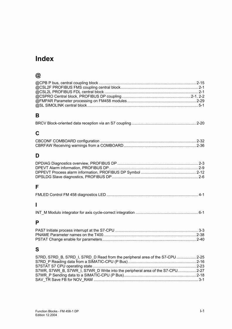
Function Blocks - FM 458-1 DP I-1 Edition 12.2004
Index
@ @CPB P bus, central coupling block .......................................................................................... 2-15 @CSL2F PROFIBUS FMS coupling central block........................................................................ 2-1 @CSL2L PROFIBUS FDL central block ....................................................................................... 2-1 @CSPRO Central block, PROFIBUS DP coupling................................................................2-1, 2-2 @FMPAR Parameter processing on FM458 modules................................................................ 2-29 @SL SIMOLINK central block....................................................................................................... 5-1
B BRCV Block-oriented data reception via an S7 coupling............................................................ 2-20
C CBCONF COMBOARD configuration ......................................................................................... 2-32 CBRFAW Receiving warnings from a COMBOARD................................................................... 2-36
D DPDIAG Diagnostics overview, PROFIBUS DP ........................................................................... 2-3 DPEVT Alarm information, PROFIBUS DP................................................................................... 2-9 DPPEVT Process alarm information, PROFIBUS DP Symbol ................................................... 2-12 DPSLDG Slave diagnostics, PROFIBUS DP................................................................................ 2-6
F FMLED Control FM 458 diagnostics LED ..................................................................................... 4-1
I INT_M Modulo integrator for axis cycle-correct integration .......................................................... 6-1
P PAS7 Initiate process interrupt at the S7-CPU ............................................................................. 3-3 PNAME Parameter names on the T400...................................................................................... 2-38 PSTAT Change enable for parameters....................................................................................... 2-40
S S7RD, S7RD_B, S7RD_I, S7RD_D Read from the peripheral area of the S7-CPU .................. 2-25 S7RD_P Reading data from a SIMATIC-CPU (P Bus) ............................................................... 2-16 S7STAT S7 CPU operating state................................................................................................ 2-23 S7WR, S7WR_B, S7WR_I, S7WR_D Write into the peripheral area of the S7-CPU................. 2-27 S7WR_P Sending data to a SIMATIC-CPU (P Bus)................................................................... 2-18 SAV_TR Save FB for NOV_RAM ................................................................................................. 3-1

Index
I-2 Function Blocks - FM 458-1 DP Edition 12.2004
SBM Rotary encoder block............................................................................................................1-2 SLAV, SLAVE_R SIMOLINK receive block for one actual value ..................................................5-9 SLD SIMOLINK delta evaluation .................................................................................................5-11 SLDIS SIMOLINK dispatcher ......................................................................................................5-12 SLSV, SLSV_R SIMOLINK send block for one setpoint .............................................................5-13 SLSV2, SLSV2R SIMOLINK send block for 2 setpoints .............................................................5-15 SLSVAV SIMOLINK send and receive block for one slave.........................................................5-17


![Libraries and function blocks - Phoenix Contact · 6.10.200 ControlTechnology Function blocks for control applications. [Control technology - PCW_6_ControlTechnology_2_20190522.msi]](https://img.pdfslide.net/doc/110x75/5fea45063554747a1506ea55/libraries-and-function-blocks-phoenix-contact-610200-controltechnology-function.jpg)