Embed Size (px)
Citation preview

Function – InstallationElectronic Speed Governor
D E
2(0)

1
Electronic Speed GovernorFunction – Installation – Fault-tracing
This booklet only covers the ACB225, ACB275 andACD175-24 actuators and the ESD5500E control unit.
Genset applications:
Note. If the GAC system is to be used for a genset application, please contactHügli Tech Ltd. (Switzerland) for application assistance.
– telephone: INT +41-62 9165030– telefax: INT +41-62 9165035– e-mail: [email protected]
Contents
Safety precautions ......................................................................... 2General information ....................................................................... 5General description ........................................................................ 7Function ......................................................................................... 8Installation ...................................................................................... 11Electromagnetic compatibility ........................................................ 12Setting and Adjusting ..................................................................... 13Running ......................................................................................... 15Fault-tracing ................................................................................... 17
2
As a general rule all service operations must becarried out with the engine stopped. Some work,e.g. certain adjustments, require the engine to berunning. Approaching an engine which is runningis a safety risk. Remember that loose clothes orlong hair can fasten in rotating parts and causesevere personal injuries. If working in proximity ofan engine which is operating, careless move-ments or a dropped tool can result in personal in-jury. Take care to avoid contact with hot surfaces(exhaust pipes, Turbocharger (TC), air intakepipe, start element etc.) and hot liquids in linesand hoses on an engine which is running or whichhas just been stopped. Reinstall all protectiveparts removed during service operations beforestarting the engine.
Check that the warning or information decals onthe engine are always clearly visible. Replace de-cals that have been damaged or painted over.
Never start the engine without installing the aircleaner (ACL). The rotating compressor in theTurbo can cause serious personal injury. Foreignobjects entering the intake ducts can also causemechanical damage.
Never use start spray or similar to start the en-gine. The start spray may cause an explosion inthe inlet manifold. Danger of personal injury.
Avoid opening the coolant filler cap when the en-gine is hot. Steam or hot coolant can spray out assystem pressure is lost. Open the filler cap slowlyand release coolant system pressure, if the fillercap or a drain cock/venting cock must be opened,or if a plug or engine coolant line must be re-moved on a hot engine. It is difficult to anticipatein which direction steam or hot coolant can sprayout.
Hot oil can cause burns. Avoid skin contact withhot oil. Ensure that the lubrication system is notunder pressure before commencing work on it.Never start or operate the engine with the oil fillercap removed, otherwise oil could be ejected.
Stop the engine and close the sea cock beforecarrying out operations on the engine cooling sys-tem.
IntroductionThis Service Manual contains technical specifications,installation instructions and wiring diagrams for theElectronic Speed Governor.
If you do not understand or are uncertain about any op-eration or information in this Manual, please contactyour Volvo Penta dealer for assistance.
Read the “Safety Precautions” and the “General In-formation” carefully before starting work.
Important!In this book and on the engine you will find the followingspecial warning symbols.
WARNING! Possible danger of personal injury,damage to property or mechanical malfunction ifthe instructions are not followed.
IMPORTANT! Used to attract attention to whatcan cause injury, malfunction, or damage toproperty.
NOTE! Used to attract attention to important informa-tion for the simplification of work processes orhandling.
To provide a general understanding of the risks andprecautions to which attention should always begiven we have made the following list.
Plan work in advance to ensure that there is suffi-cient space to remove components without dan-ger of injury or damage. Plan the engine compart-ment (and other compartments such as the bat-tery compartment) so that all service points areaccessible. Take precautions so that you do notcome into contact with rotating components, hotsurfaces or sharp edges when servicing or in-specting the engine. Ensure that all equipment(pump or compressor drives for example) areequipped with suitable safety guards.
Immobilize the engine by turning off the powersupply to the engine at the main switches so it isimpossible to start, and lock them in the OFF po-sition before starting work. Set up a warning no-tice at the engine control point or helm.
Safety Precautions
3
Only start the engine in a well-ventilated area. Ifoperating the engine in a closed area ensure thatthere is exhaust ventilation leading out of thework area to remove exhaust gases and crank-case ventilation emissions.
Always use protective goggles where there is adanger of pieces of metal, sparks from grinding,acid or other chemicals being thrown into youreyes. Your eyes are very sensitive, injury canlead to loss of sight!
Avoid skin contact with oil. Long-term or repeatedcontact with oil can remove the natural oils fromyour skin. The result can be irritation, dry skin, ec-zema and other skin problems.Used oil is more dangerous to health than new oil.Use protective gloves and avoid oil-soakedclothes and rags.Wash regularly, especially before meals. Use thecorrect barrier cream to prevent dry skin and tomake cleaning your skin easier.
Most chemicals used in products (engine andtransmission oils, glycol, petrol and diesel oil) andworkshop chemicals (solvents and paints) arehazardous to health Read the instructions on theproduct packaging carefully! Always follow safetyinstructions (using breathing apparatus, protectivegoggles and gloves for example). Ensure that oth-er personnel are not unwittingly exposed to haz-ardous substances (by breathing them in for ex-ample). Ensure that ventilation is good. Handleused and excess chemicals according to instruc-tions.
Be extremely careful when tracing leaks in thefuel system and testing fuel injection nozzles. Useprotective goggles! The jet ejected from a fuel in-jection nozzle is under very high pressure. It canpenetrate body tissue and cause serious injuryThere is a danger of blood poisoning.
WARNING! Delivery pipes must not be bent,twisted or subjected to other stress. Replacedamaged delivery pipes.
All fuels and many chemicals are inflammable.Ensure that a naked flame or sparks cannot ignitefuel or chemicals. Combined with air in certain ra-tios, petrol, some solvents and hydrogen frombatteries are easily inflammable and explosive.
Smoking is prohibited! Ensure that ventilation isgood and that the necessary safety precautionshave been taken before carrying out welding orgrinding work. Always have a fire extinguisher tohand in the workplace.
Store oil and fuel-soaked rags and fuel and oil fil-ters safely. In certain conditions oil-soaked ragscan spontaneously ignite. Used fuel and oil filtersare environmentally dangerous waste and mustbe deposited at an approved site for destructiontogether with used lubricating oil, contaminatedfuel, paint remnants, solvent, degreasing agentsand waste from washing parts.
Ensure that the battery compartment is construct-ed according to applicable safety regulations.Never allow a naked flame or electric sparks nearthe batteries. Never smoke in proximity to the bat-teries. The batteries give off hydrogen gas duringcharging which when mixed with air can form anexplosive gas - oxyhydrogen. This gas is easilyignited and highly volatile. Incorrect connection ofthe battery can cause a spark which is sufficientto cause an explosion with resulting damage. Donot disturb battery connections when starting theengine (spark risk) and do not lean over batteries.
Never mix up the positive and negative batteryterminals when installing. Incorrect installationcan result in serious damage to electrical equip-ment. Refer to wiring diagrams.
Always use protective goggles when charging andhandling batteries. The battery electrolyte con-tains extremely corrosive sulfuric acid. If thisshould come in contact with the skin, immediatelywash with soap and plenty of water. If battery acidcomes in contact with the eyes, immediately flushwith plenty of water and obtain medical assist-ance without delay.
Turn the engine off and switch off power at themain switches before carrying out work on theelectrical system.
Clutch adjustments, where a clutch is fitted, mustbe carried out with the engine turned off.
Use the lifting eyes mounted on the engine/re-verse gear when lifting the drive unit. Alwayscheck that the lifting equipment used is in goodcondition and has the load capacity to lift the en-gine (engine weight including reverse gear andany extra equipment installed).
4
To ensure safe handling and to avoid damagingengine components on top of the engine, use alifting beam to raise the engine. All chains and ca-bles should run parallel to each other and as per-pendicular as possible in relation to the top of theengine.
If extra equipment is installed on the engine alter-ing its center of gravity, a special lifting device isrequired to achieve the correct balance for safehandling.
Never carry out work on an engine suspended ona hoist.
Never handle heavy components alone, evenwhere secure lifting equipment such as securedblocks are being used. Even where lifting equip-ment is being used it is best to carry out the workwith two people; one to operate the lifting equip-ment and the other to ensure that componentsare not trapped and damaged when being lifted.
When working on-board ensure that there is suffi-cient space to remove components without dan-ger of injury or damage.
WARNING! The components in the electrical sys-tem and in the fuel system on Volvo Penta prod-ucts are designed and manufactured to minimizethe risk of fire and explosion.
The engine must not be run in areas where thereare explosive materials.
Always use fuels recommended by Volvo Penta.Refer to the Instruction Book. The use of lowerquality fuels can damage the engine. On a dieselengine poor quality fuel can cause the control rodto seize and the engine to overrev with the result-ing risk of damage to the engine and personal in-jury. Poor fuel quality can also lead to highermaintenance costs.
Observe the following rules when cleaning withhigh-pressure water jets. Never direct the waterjet at seals, rubber hoses or electrical compo-nents. Never use a high pressure jet when wash-ing the engine.
5
Certificated enginesFor service and repair of an engine certificated forany area where exhaust emissions are regulated bylaw, the following is important:
Certification means that an engine type is inspected andapproved by the authorities. The engine manufacturerguarantees that all engines manufactured of that typecorrespond to the certified engine.
This places special requirements on maintenanceand service as follows:
The maintenance and service intervals recommend-ed by Volvo Penta must be observed.
Only genuine Volvo Penta replacement parts may beused.
The service of injection pumps and injectors or pumpsettings must always be carried out by an authorizedVolvo Penta workshop.
The engine must not be modified in any way exceptwith accessories and service kits approved by VolvoPenta.
No modifications to the exhaust pipes and air supplyducts for the engine may be undertaken.
Seals may only be broken by authorized personnel.
Otherwise the general instructions contained in the In-struction Manual concerning operation, service andmaintenance must be followed.
IMPORTANT! Late or inadequate maintenance/
service or the use of spare parts other than genu-ine Volvo Penta original spare parts will invalidateAB Volvo Penta’s responsibility for the enginespecification being in accordance with the certifi-cated variant.
Volvo Penta accepts no responsibility or liabilityfor any damage or costs arising due to the above.
General InformationGeneralThis Manual is primarily intended for use by expert pro-fessionals. Persons using this book are assumed tohave a basic knowledge and be able to carry out relatedmechanical and electrical work.
The mechanic is responsible for ensuring that installa-tion is carried out correctly, that only approved materialsand equipment is used, that function tests are carriedout after installation, and that the installation meets allapplicable regulations.
Volvo Penta is continuously developing their products.We therefore reserve the right to make changes. All theinformation contained in this book is based on productdata available at the time of going to print. Any impor-tant modifications to the product or changes to installa-tion methods after the date of going to press will be noti-fied in Service Bulletins.
Plan installation carefullyPlan the installation of the engine and its componentscarefully in advance. Always ensure that the correctdrawings, Wiring Diagrams and data are used, and thatall installation drawings, templates, technical and othernecessary data are available before starting work. Thiswill prevent problems in the planning phase and duringinstallation.
Plan the engine compartment so that regular serviceand maintenance can be carried out and so that compo-nents can be replaced easily. Compare the service liter-ature for the engine with the drawings so that there isenough room to service the engine.
It is of the greatest importance that no dirt or foreignparticles get into the fuel system, cooling system or in-take system when installing the engine. This could leadto malfunction or serious damage. Blow clean all pipesand hoses with compressed air before connecting themto the engine. Remove the engine plugs only when con-necting the engine to external systems.
6
Joint responsibilityEach engine consists of many connected systems andcomponents. If one component deviates from the tech-nical specifications this can have dramatic consequenc-es on the environmental impact of the engine. It istherefore vital that systems that can be adjusted are ad-justed properly and that Volvo Penta Genuine Parts areused.
Certain systems (components in the fuel system for ex-ample) may require specialist expertise and test equip-ment. Some components are sealed at the factory forenvironmental reasons. No work should be carried outon sealed components except by authorized personnel.
Bear in mind that most chemicals are harmful to the en-vironment if used incorrectly. Volvo Penta recommendsthe use of biodegradable degreasing agents for clean-ing engine components, unless otherwise stated in aworkshop manual. Take special care that oil and wasteis taken for destruction and is not accidentally pumpedinto the environment.
© 1999 AB VOLVO PENTAAll rights to changes or modifications reserved.
Printed on environmentally-friendly paper
7
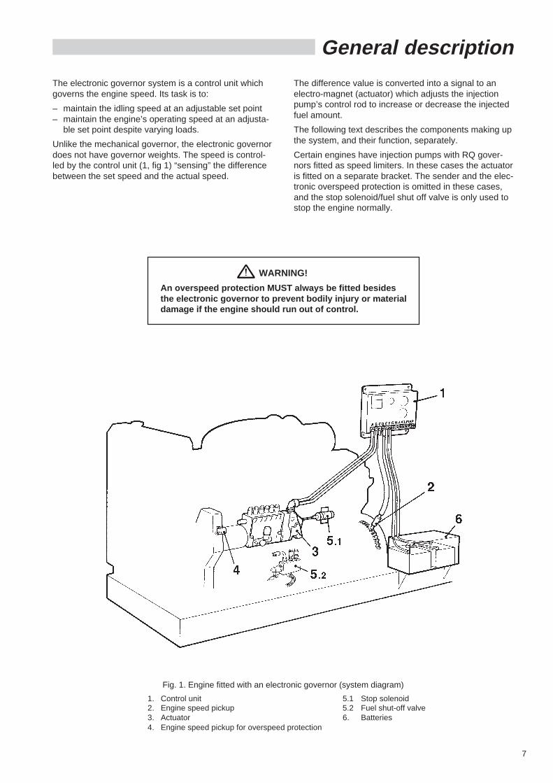
General description
The difference value is converted into a signal to anelectro-magnet (actuator) which adjusts the injectionpump’s control rod to increase or decrease the injectedfuel amount.
The following text describes the components making upthe system, and their function, separately.
Certain engines have injection pumps with RQ gover-nors fitted as speed limiters. In these cases the actuatoris fitted on a separate bracket. The sender and the elec-tronic overspeed protection is omitted in these cases,and the stop solenoid/fuel shut off valve is only used tostop the engine normally.
The electronic governor system is a control unit whichgoverns the engine speed. Its task is to:
– maintain the idling speed at an adjustable set point– maintain the engine’s operating speed at an adjusta-
ble set point despite varying loads.
Unlike the mechanical governor, the electronic governordoes not have governor weights. The speed is control-led by the control unit (1, fig 1) “sensing” the differencebetween the set speed and the actual speed.
WARNING!
An overspeed protection MUST always be fitted besidesthe electronic governor to prevent bodily injury or materialdamage if the engine should run out of control.
Fig. 1. Engine fitted with an electronic governor (system diagram)
1. Control unit 5.1 Stop solenoid2. Engine speed pickup 5.2 Fuel shut-off valve3. Actuator 6. Batteries4. Engine speed pickup for overspeed protection
8
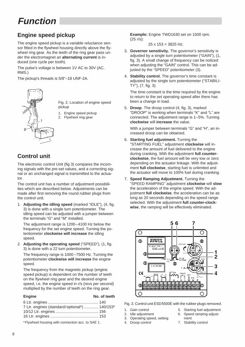
Engine speed pickupThe engine speed pickup is a variable reluctance sen-sor fitted in the flywheel housing directly above the fly-wheel ring gear. As the teeth of the ring gear pass un-der the electromagnet an alternating current is in-duced (one cycle per tooth).
The pulse's voltage is between 1V AC to 30V (AC.RMS.)
The pickup's threads is 5/8"–18 UNF-2A.
Function
Control unitThe electronic control Unit (fig 3) compares the incom-ing signals with the pre-set values, and a correcting sig-nal or an unchanged signal is transmitted to the actua-tor.
The control unit has a number of adjustment possibili-ties which are described below. Adjustments can bemade after first removing the round rubber plugs fromthe control unit.
1. Adjusting the idling speed (marked “IDLE”), (4, fig.3) is done with a single turn potentiometer. Theidling speed can be adjusted with a jumper betweenthe terminals “G” and “M” installed.
The adjustment range is 1200–4100 Hz below thefrequency for the set engine speed. Turning the po-tentiometer clockwise will increase the idlingspeed.
2. Adjusting the operating speed (“SPEED”), (1, fig.3) is done with a 22 turn potentiometer.
The frequency range is 1000–7500 Hz. Turning thepotentiometer clockwise will increase the enginespeed.
The frequency from the magnetic pickup (enginespeed pickup) is dependent on the number of teethon the flywheel ring gear and the desired enginespeed, i.e. the engine speed in r/s (revs per second)multiplied by the number of teeth on the ring gear.
Engine No. of teeth
6 Ltr. engines .............................................. 1407 Ltr. engines (standard/optional*) ............. 140/153*10/12 Ltr. engines ....................................... 15616 Ltr. engines ............................................ 153
*Flywheel housing with connection acc. to SAE 1.
Fig. 2. Location of engine speedpickup
1. Engine speed pickup2. Flywheel ring gear
Example: Engine TWD1630 set on 1500 rpm.(25 r/s):
25 x 153 = 3825 Hz.
3. Governor sensitivity. The governor’s sensitivity isadjusted by a single turn potentiometer (“GAIN”), (1,fig. 3). A small change of frequency can be noticedwhen adjusting the “GAIN” control. This can be ad-justed by the “SPEED” potentiometer (3).
4. Stability control. The governor’s time constant isadjusted by the single turn potentiometer (“STABILI-TY”), (7, fig. 3).
The time constant is the time required by the engineto return to the set operating speed after there hasbeen a change in load.
5. Droop . The droop control (4, fig. 3), marked“DROOP” is working when terminals “K” and ”L” areconnected. The adjustment range is 1–5%. Turningclockwise will increase the value.
With a jumper between terminals “G” and “H”, an in-creased droop can be obtained.
6. Starting fuel adjustment. Turning the“STARTING FUEL” adjustment clockwise will in-crease the amount of fuel delivered to the engineduring cranking. With the adjustment full counter-clockwise , the fuel amount will be very low or zerodepending on the actuator linkage. With the adjust-ment full clockwise , starting fuel is unlimited andthe actuator will move to 100% fuel during cranking.
7. Speed Ramping Adjustment. Turning the“SPEED RAMPING” adjustment clockwise will slowthe acceleration of the engine speed. With the ad-justment full clockwise , the acceleration can be aslong as 20 seconds depending on the speed rangeselected. With the adjustment full counter-clock-wise , the ramping will be effectively eliminated.
Fig. 3. Control unit ESD5500E with the rubber plugs removed.
1. Gain control 5. Starting fuel adjustment2. Idle adjustment 6. Speed ramping adjust-3. Operating speed, setting ment4. Droop control 7. Stability control
9
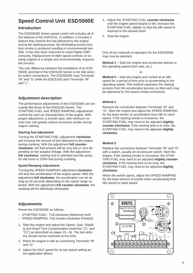
Speed Control Unit ESD5500EIntroductionThe ESD5500E Series speed contol unit includes all ofthe features of the ESD5131. In addition, it includes afeature that controls the fuel delivered to the engineduring the starting process. By eliminating excess fuel,less smoke is produced resulting in environmental ben-efits. It has also been improved to reach higher EMCimmunity. Replacement of older speed controls on ex-isting engines is a simple and environmentally responsi-ble process.
The only difference between the installation of an ESD5500E and that of the ESD5100 Series is the Idle selec-tor switch connections. The ESD5500E uses Terminals“M” and “G” while the ESD5100 used Terminals “M”and “L”.
Adjustment descriptionThe performance adjustments of the ESD5500E are setexactly like those of the ESD5100 Series. TheSTARTING FUEL and SPEED RAMPING adjustmentscontrol the start up characteristics of the engine. Withproper adjustment, a smooth start, with minimum ex-cess fuel, can greatly reduce excessive smoke duringengine starting.
Starting fuel adjustment
Turning the STARTING FUEL adjustment clockwisewill increase the amount of fuel delivered to the engineduring cranking. With the adjustment full counter-clockwise , the fuel amount will be very low or zero de-pending on the actuator linkage. With the adjustmentfull clockwise , starting fuel is unlimited and the actua-tor will move to 100% fuel during cranking.
Speed Ramping Adjustment
Turning the SPEED RAMPING adjustment clockwisewill slow the acceleration of the engine speed. With theadjustment full clockwise , the acceleration can be aslong as 20 seconds depending on the speed range se-lected. With the adjustment full counter-clockwise , theramping will be effectively eliminated.
AdjustmentsPreset the ESD5500E as follows:
– STARTING FUEL: Full clockwise (Maximum fuel)– SPEED RAMPING: Full counter-clockwise (Fastest)
1. Start the engine and adjust the Speed, Gain, Stabili-ty and Dead Time Compensation (switches “C1” and“C2”) as described on pages 15–16. The fuel deliv-ery should not be restricted at this time.
2. Place the engine in idle by connecting Terminals “M”and “G”.
3. Adjust the IDLE speed for as low speed setting asthe application allows.
4. Adjust the STARTING FUEL counter-clockwiseuntil the engine speed begins to fall. Increase theSTARTING FUEL slightly so that the idle speed isreturned to the desired level.
5. Stop the engine.
One of two methods of operation for the ESD5500Emay now be selected.
Method 1 – Start the engine and accelerate directly tothe operating speed (Gen sets, etc.).
or
Method 2 – Start the engine and control at an idlespeed for a period of time prior to accelerating to theoperating speed. This method separates the startingprocess from the acceleration process so that each maybe optimized for the lowest smoke emmisions.
Method 1
Remove the connection between Terminals “M” and“G”. Start the engine and adjust the SPEED RAMPINGfor the least smoke on acceleration from idle to ratedspeed. If the starting smoke is excessive, theSTARTING FUEL may need to be adjusted slightlycounter-clockwise . If the starting time is to slow, theSTARTING FUEL may need to be adjusted slightlyclockwise .
Method 2
Replace the connection between Terminals “M” and “G”with a switch, usually an oil pressure switch. Start theengine. If the starting smoke is excessive, the STAR-TING FUEL may need to be adjusted slightly counter-clockwise . If the starting time is too long, theSTARTING FUEL may need to be adjusted slightlyclockwise .
When the switch opens, adjust the SPEED RAMPINGfor the least amount of smoke when accelerating fromidle speed to rated speed.
10
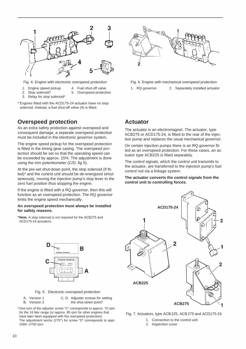
Fig. 5. Electronic overspeed protection
A. Version 1 C, D. Adjuster screws for settingB. Version 2 the shut-down point*
*One turn of the adjuster screw “C” corresponds to approx. 70 rpmfor the 16 liter range (or approx. 85 rpm for other engines thathave later been equipped with the overspeed protection).The adjustment sector (270°) for screw “D” corresponds to appr.1560–2700 rpm.
Fig. 4. Engine with electronic overspeed protection
1. Engine speed pickup 4. Fuel shut-off valve2. Stop solenoid* 5. Overspeed protection3. Relay for stop solenoid*
* Engines fitted with the ACD175-24 actuator have no stopsolenoid. Instead, a fuel shut-off valve (4) is fitted.
ACB225
ACB275
ACD175-24
Overspeed protectionAs an extra safety protection against overspeed andconsequent damage, a separate overspeed protectionmust be included in the electronic governor system.
The engine speed pickup for the overspeed protectionis fitted in the timing gear casing. The overspeed pro-tection should be set so that the operating speed canbe exceeded by approx. 15%. The adjustment is doneusing the trim potentiometer (C/D, fig 5).
At the pre-set shut-down point, the stop solenoid (if fit-ted)* and the control unit should be de-energized simul-taneously, moving the injection pump’s stop lever to thezero fuel position thus stopping the engine.
If the engine is fitted with a RQ governor, then this willfunction as an overspeed protection. The RQ governorlimits the engine speed mechanically.
An overspeed protection must always be installedfor safety reasons.
*Note. A stop solenoid is not required for the ACB275 andACD175-24 actuators.
Fig. 6. Engine with mechanical overspeed protection
1. RQ governor 2. Separately installed actuator
ActuatorThe actuator is an electromagnet. The actuator, typeACB275 or ACD175-24, is fitted to the rear of the injec-tion pump and replaces the usual mechanical governor.
On certain injection pumps there is an RQ governor fit-ted as an overspeed protection. For these cases, an ac-tuator type ACB225 is fitted separately.
The control signals, which the control unit transmits tothe actuator, are transferred to the injection pump’s fuelcontrol rod via a linkage system.
The actuator converts the control signals from thecontrol unit to controlling forces.
Fig. 7. Actuators, type ACB225, ACB275 and ACD175-24
1. Connection to the control unit2. Inspection cover
11
Installation
24V
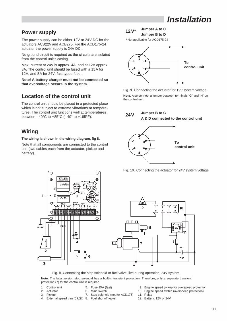
Power supplyThe power supply can be either 12V or 24V DC for theactuators ACB225 and ACB275. For the ACD175-24actuator the power supply is 24V DC.
No ground circuit is required as the circuits are isolatedfrom the control unit’s casing.
Max. current at 24V is approx. 4A, and at 12V approx.8A. The control unit should be fused with a 15A for12V, and 8A for 24V, fast typed fuse.
Note! A battery charger must not be connected sothat overvoltage occurs in the system.
Location of the control unitThe control unit should be placed in a protected placewhich is not subject to extreme vibrations or tempera-tures. The control unit functions well at temperaturesbetween –40°C to +85°C (– 40° to +185°F).
WiringThe wiring is shown in the wiring diagram, fig 8.
Note that all components are connected to the controlunit (two cables each from the actuator, pickup andbattery).
Tocontrol unit
Fig. 9. Connecting the actuator for 12V system voltage.
Note. Also connect a jumper between terminals “G” and “H” onthe control unit.
Jumper B to C
A & D connected to the control unit
Fig. 8. Connecting the stop solenoid or fuel valve, live during operation, 24V system.
Note. The later version stop solenoid has a built-in transient protection. Therefore, only a separate transientprotection (7) for the control unit is required.
1. Control unit 5. Fuse 15A (fast) 9. Engine speed pickup for overspeed protection2. Actuator 6. Main switch 10. Engine speed switch (overspeed protection)3. Pickup 7. Stop solenoid (not for ACD175) 11. Relay4. External speed trim (5 kΩ) 8. Fuel shut off valve 12. Battery: 12V or 24V
12V* Jumper A to C
Jumper B to D* Not applicable for ACD175-24
Fig. 10. Connecting the actuator for 24V system voltage
Tocontrol unit
12
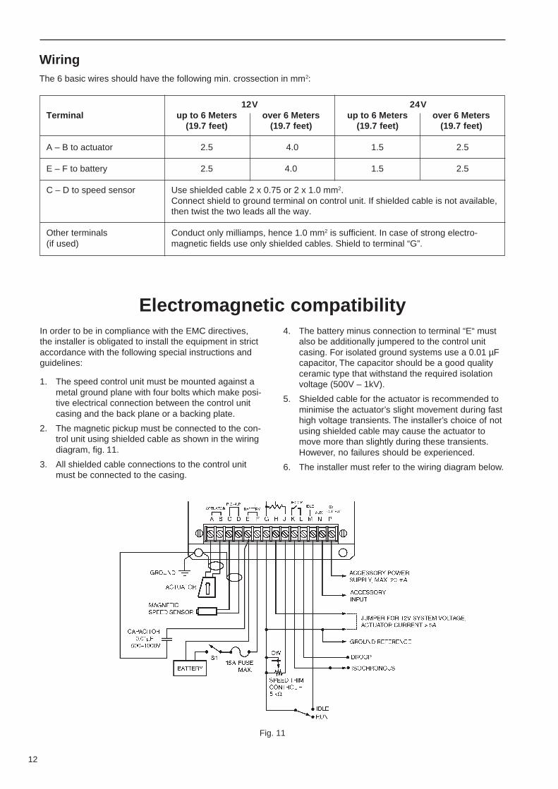
WiringThe 6 basic wires should have the following min. crossection in mm2:
4. The battery minus connection to terminal “E“ mustalso be additionally jumpered to the control unitcasing. For isolated ground systems use a 0.01 µFcapacitor, The capacitor should be a good qualityceramic type that withstand the required isolationvoltage (500V – 1kV).
5. Shielded cable for the actuator is recommended tominimise the actuator’s slight movement during fasthigh voltage transients. The installer’s choice of notusing shielded cable may cause the actuator tomove more than slightly during these transients.However, no failures should be experienced.
6. The installer must refer to the wiring diagram below.
In order to be in compliance with the EMC directives,the installer is obligated to install the equipment in strictaccordance with the following special instructions andguidelines:
1. The speed control unit must be mounted against ametal ground plane with four bolts which make posi-tive electrical connection between the control unitcasing and the back plane or a backing plate.
2. The magnetic pickup must be connected to the con-trol unit using shielded cable as shown in the wiringdiagram, fig. 11.
3. All shielded cable connections to the control unitmust be connected to the casing.
Fig. 11
12V 24VTerminal up to 6 Meters over 6 Meters up to 6 Meters over 6 Meters
(19.7 feet) (19.7 feet) (19.7 feet) (19.7 feet)
A – B to actuator 2.5 4.0 1.5 2.5
E – F to battery 2.5 4.0 1.5 2.5
C – D to speed sensor Use shielded cable 2 x 0.75 or 2 x 1.0 mm2.Connect shield to ground terminal on control unit. If shielded cable is not available,then twist the two leads all the way.
Other terminals Conduct only milliamps, hence 1.0 mm2 is sufficient. In case of strong electro-(if used) magnetic fields use only shielded cables. Shield to terminal “G”.
Electromagnetic compatibility
13
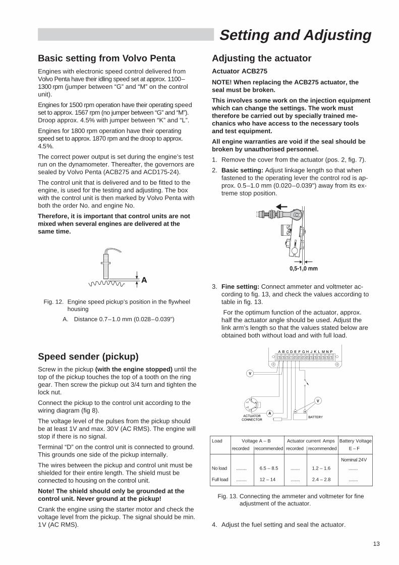
Adjusting the actuatorActuator ACB275
NOTE! When replacing the ACB275 actuator, theseal must be broken.
This involves some work on the injection equipmentwhich can change the settings. The work musttherefore be carried out by specially trained me-chanics who have access to the necessary toolsand test equipment.
All engine warranties are void if the seal should bebroken by unauthorised personnel.
1. Remove the cover from the actuator (pos. 2, fig. 7).
2. Basic setting: Adjust linkage length so that whenfastened to the operating lever the control rod is ap-prox. 0.5–1.0 mm (0.020–0.039") away from its ex-treme stop position.
Basic setting from Volvo PentaEngines with electronic speed control delivered fromVolvo Penta have their idling speed set at approx. 1100–1300 rpm (jumper between “G” and “M” on the controlunit).
Engines for 1500 rpm operation have their operating speedset to approx. 1567 rpm (no jumper between “G” and “M”).Droop approx. 4.5% with jumper between “K” and “L”.
Engines for 1800 rpm operation have their operatingspeed set to approx. 1870 rpm and the droop to approx.4.5%.
The correct power output is set during the engine’s testrun on the dynamometer. Thereafter, the governors aresealed by Volvo Penta (ACB275 and ACD175-24).
The control unit that is delivered and to be fitted to theengine, is used for the testing and adjusting. The boxwith the control unit is then marked by Volvo Penta withboth the order No. and engine No.
Therefore, it is important that control units are notmixed when several engines are delivered at thesame time.
Setting and Adjusting
Speed sender (pickup)Screw in the pickup (with the engine stopped) until thetop of the pickup touches the top of a tooth on the ringgear. Then screw the pickup out 3/4 turn and tighten thelock nut.
Connect the pickup to the control unit according to thewiring diagram (fig 8).
The voltage level of the pulses from the pickup shouldbe at least 1V and max. 30V (AC RMS). The engine willstop if there is no signal.
Terminal “D” on the control unit is connected to ground.This grounds one side of the pickup internally.
The wires between the pickup and control unit must beshielded for their entire length. The shield must beconnected to housing on the control unit.
Note! The shield should only be grounded at thecontrol unit. Never ground at the pickup!
Crank the engine using the starter motor and check thevoltage level from the pickup. The signal should be min.1V (AC RMS). 4. Adjust the fuel setting and seal the actuator.
3. Fine setting: Connect ammeter and voltmeter ac-cording to fig. 13, and check the values according totable in fig. 13.
For the optimum function of the actuator, approx.half the actuator angle should be used. Adjust thelink arm’s length so that the values stated below areobtained both without load and with full load.
Fig. 12. Engine speed pickup’s position in the flywheelhousing
A. Distance 0.7–1.0 mm (0.028–0.039")
Load Voltage A – B Actuator current Amps Battery Voltage
recorded recommended recorded recommended E – F
Nominal 24V
No load ......... 6.5 – 8.5 ........ 1.2 – 1.6 ........
Full load ......... 12 – 14 ........ 2.4 – 2.8 ........
Fig. 13. Connecting the ammeter and voltmeter for fineadjustment of the actuator.
14
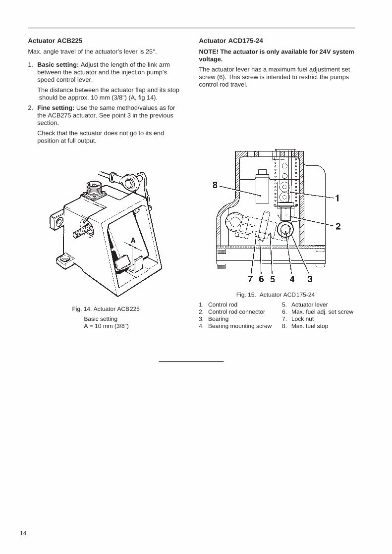
Actuator ACB225
Max. angle travel of the actuator’s lever is 25°.
1. Basic setting: Adjust the length of the link armbetween the actuator and the injection pump’sspeed control lever.
The distance between the actuator flap and its stop should be approx. 10 mm (3/8") (A, fig 14).
2. Fine setting: Use the same method/values as forthe ACB275 actuator. See point 3 in the previoussection.
Check that the actuator does not go to its endposition at full output.
Fig. 14. Actuator ACB225
Basic settingA = 10 mm (3/8")
Actuator ACD175-24
NOTE! The actuator is only available for 24V systemvoltage.
The actuator lever has a maximum fuel adjustment setscrew (6). This screw is intended to restrict the pumpscontrol rod travel.
Fig. 15. Actuator ACD175-24
1. Control rod 5. Actuator lever2. Control rod connector 6. Max. fuel adj. set screw3. Bearing 7. Lock nut4. Bearing mounting screw 8. Max. fuel stop
15
RunningBefore the first startCheck the following before connecting the batteries:
1. That the system voltage is correct (12V or 24V).
2. That the polarity is correct at the “E” (minus) termi-nal on the control unit, and the “F” terminal (plus).
NOTE! The control unit has several built-in protec-tions. Any possible short-circuiting of the actuator orthe wires will stop the engine. After the batterieshave been disconnected and the cause remedied,the unit will work correctly again.
Provided that a fast fuse is used in the batterycable as shown in the wiring diagrams fig. 8 andfig. 11, reversed polarity will not ruin the controlunit. However, other incorrect connections cancause the control unit to be ruined.
3. That the wiring is otherwise correct. See wiring dia-grams figs 8, 9, 10 and 11.
4. Set the potentiometers “GAIN” and “STABILITY” inthe control unit to the center position.
5. Temporarily connect terminals “G” and “M” on thecontrol unit to get low idle (approx. 600–800 rpm).
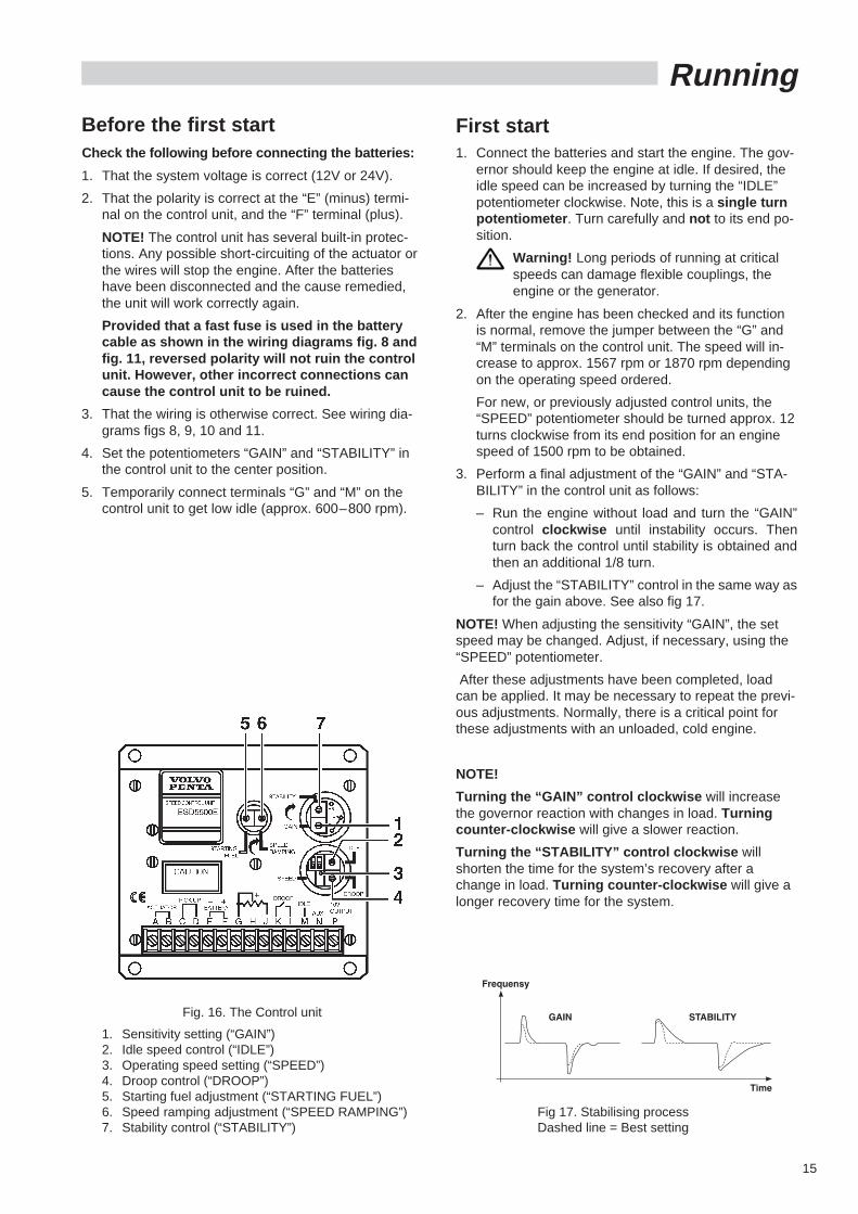
Fig. 16. The Control unit
1. Sensitivity setting (“GAIN”)2. Idle speed control (“IDLE”)3. Operating speed setting (“SPEED”)4. Droop control (“DROOP”)5. Starting fuel adjustment (“STARTING FUEL”)6. Speed ramping adjustment (“SPEED RAMPING”)7. Stability control (“STABILITY”)
First start1. Connect the batteries and start the engine. The gov-
ernor should keep the engine at idle. If desired, theidle speed can be increased by turning the “IDLE”potentiometer clockwise. Note, this is a single turnpotentiometer . Turn carefully and not to its end po-sition.
Warning! Long periods of running at criticalspeeds can damage flexible couplings, theengine or the generator.
2. After the engine has been checked and its functionis normal, remove the jumper between the “G” and“M” terminals on the control unit. The speed will in-crease to approx. 1567 rpm or 1870 rpm dependingon the operating speed ordered.
For new, or previously adjusted control units, the“SPEED” potentiometer should be turned approx. 12turns clockwise from its end position for an enginespeed of 1500 rpm to be obtained.
3. Perform a final adjustment of the “GAIN” and “STA-BILITY” in the control unit as follows:
– Run the engine without load and turn the “GAIN”control clockwise until instability occurs. Thenturn back the control until stability is obtained andthen an additional 1/8 turn.
– Adjust the “STABILITY” control in the same way asfor the gain above. See also fig 17.
NOTE! When adjusting the sensitivity “GAIN”, the setspeed may be changed. Adjust, if necessary, using the“SPEED” potentiometer.
After these adjustments have been completed, loadcan be applied. It may be necessary to repeat the previ-ous adjustments. Normally, there is a critical point forthese adjustments with an unloaded, cold engine.
NOTE!
Turning the “GAIN” control clockwise will increasethe governor reaction with changes in load. Turningcounter-clockwise will give a slower reaction.
Turning the “STABILITY” control clockwise willshorten the time for the system’s recovery after achange in load. Turning counter-clockwise will give alonger recovery time for the system.
Fig 17. Stabilising processDashed line = Best setting
16
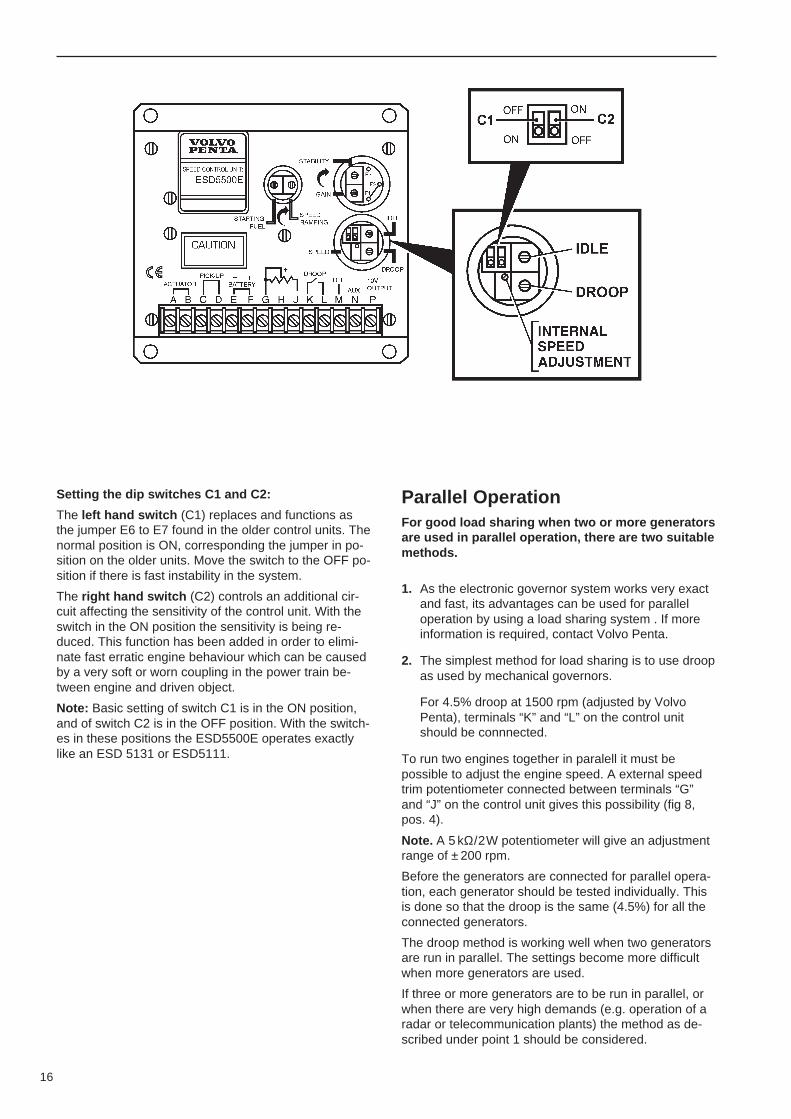
Setting the dip switches C1 and C2:
The left hand switch (C1) replaces and functions asthe jumper E6 to E7 found in the older control units. Thenormal position is ON, corresponding the jumper in po-sition on the older units. Move the switch to the OFF po-sition if there is fast instability in the system.
The right hand switch (C2) controls an additional cir-cuit affecting the sensitivity of the control unit. With theswitch in the ON position the sensitivity is being re-duced. This function has been added in order to elimi-nate fast erratic engine behaviour which can be causedby a very soft or worn coupling in the power train be-tween engine and driven object.
Note: Basic setting of switch C1 is in the ON position,and of switch C2 is in the OFF position. With the switch-es in these positions the ESD5500E operates exactlylike an ESD 5131 or ESD5111.
Parallel OperationFor good load sharing when two or more generatorsare used in parallel operation, there are two suitablemethods.
1. As the electronic governor system works very exactand fast, its advantages can be used for paralleloperation by using a load sharing system . If moreinformation is required, contact Volvo Penta.
2. The simplest method for load sharing is to use droopas used by mechanical governors.
For 4.5% droop at 1500 rpm (adjusted by VolvoPenta), terminals “K” and “L” on the control unitshould be connnected.
To run two engines together in paralell it must bepossible to adjust the engine speed. A external speedtrim potentiometer connected between terminals “G”and “J” on the control unit gives this possibility (fig 8,pos. 4).
Note. A 5 kΩ/2W potentiometer will give an adjustmentrange of ± 200 rpm.
Before the generators are connected for parallel opera-tion, each generator should be tested individually. Thisis done so that the droop is the same (4.5%) for all theconnected generators.
The droop method is working well when two generatorsare run in parallel. The settings become more difficultwhen more generators are used.
If three or more generators are to be run in parallel, orwhen there are very high demands (e.g. operation of aradar or telecommunication plants) the method as de-scribed under point 1 should be considered.
17
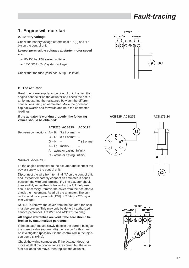
B. The actuator.
Break the power supply to the control unit. Loosen theangled connector on the actuator and check the actua-tor by measuring the resistance between the differentconnections using an ohmmeter. Move the governorflap backwards and forwards and note the ohmmeterreadings.
If the actuator is working properly, the followingvalues should be obtained:
ACB225, ACB275 ACD175
Between connections: A – B: 3 ±1 ohms* –
C – D: 3 ±1 ohms* –
G – H: – 7 ±1 ohms*
A – C: Infinity –
A – actuator casing: Infinity
C – actuator casing: Infinity
* Note. At +25°C (77°F).
Fit the angled connector to the actuator and connect thepower supply to the control unit.
Disconnect the wire from terminal “A” on the control unitand instead temporarily connect an ammeter in seriesbetween the wire and terminal “F”. The actuator shouldthen audibly move the control rod to the full fuel posi-tion. If necessary, remove the cover from the actuator tocheck the movement. Read off the ammeter. The cur-rent should be approx. 4A (12V) or 2.5A (for 24V sys-tem voltage).
NOTE! To remove the cover from the actuator, the sealmust be broken. This may only be done by authorizedservice personnel (ACB275 and ACD175-24 only).
All engine warranties are void if the seal should bebroken by unauthorized personnel
If the actuator moves slowly despite the current being atthe correct value (approx. 4A) the reason for this mustbe investigated (possibly it is the control rod in the injec-tion pump sticking).
Check the wiring connections if the actuator does notmove at all. If the connections are correct but the actu-ator still does not move, then replace the actuator.
1. Engine will not startA. Battery voltage
Check the battery voltage at terminals “E” (–) and “F”(+) on the control unit.
Lowest permissible voltages at starter motor speedare:
– 8V DC for 12V system voltage.
– 17V DC for 24V system voltage.
Check that the fuse (fast) pos. 5, fig 8 is intact.
Fault-tracing
ACB225, ACB275 ACD175-24
18
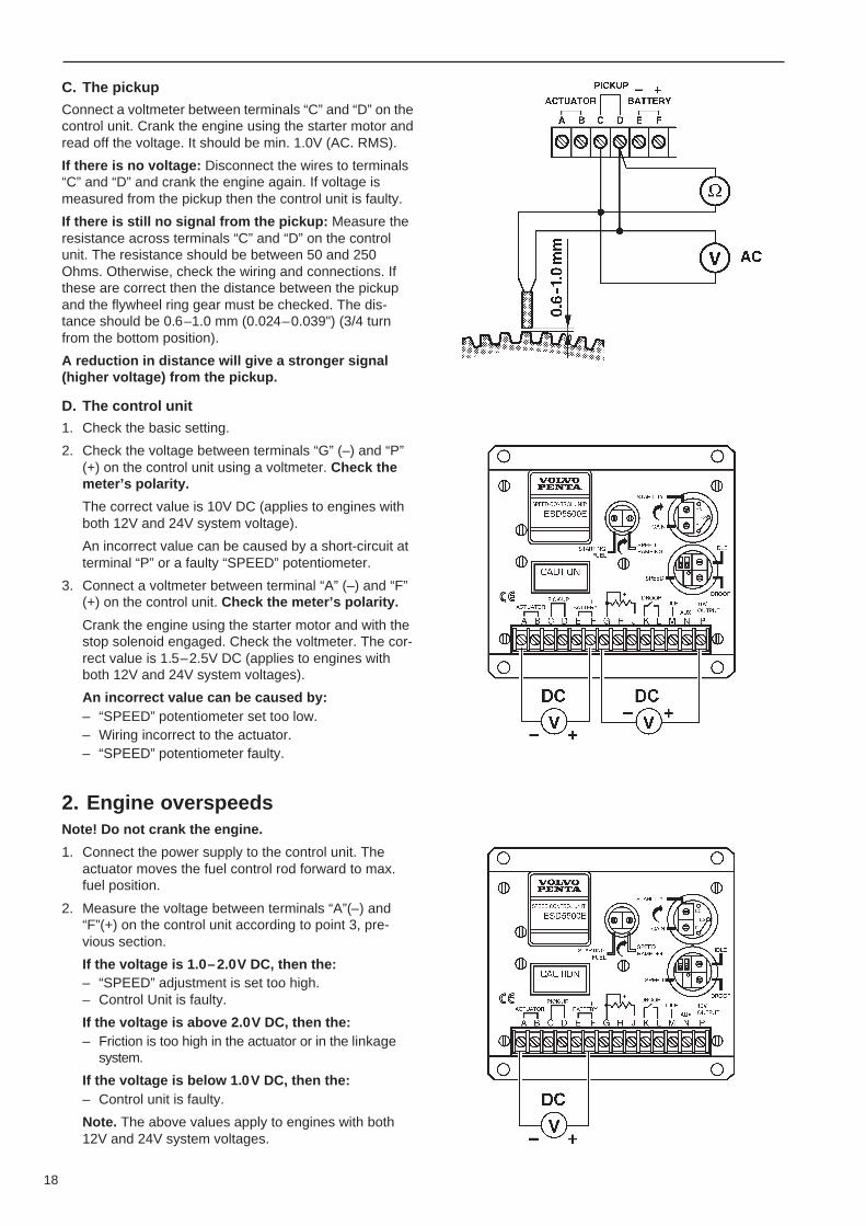
C. The pickup
Connect a voltmeter between terminals “C” and “D” on thecontrol unit. Crank the engine using the starter motor andread off the voltage. It should be min. 1.0V (AC. RMS).
If there is no voltage: Disconnect the wires to terminals“C” and “D” and crank the engine again. If voltage ismeasured from the pickup then the control unit is faulty.
If there is still no signal from the pickup: Measure theresistance across terminals “C” and “D” on the controlunit. The resistance should be between 50 and 250Ohms. Otherwise, check the wiring and connections. Ifthese are correct then the distance between the pickupand the flywheel ring gear must be checked. The dis-tance should be 0.6–1.0 mm (0.024–0.039") (3/4 turnfrom the bottom position).
A reduction in distance will give a stronger signal(higher voltage) from the pickup.
D. The control unit
1. Check the basic setting.
2. Check the voltage between terminals “G” (–) and “P”(+) on the control unit using a voltmeter. Check themeter’s polarity.
The correct value is 10V DC (applies to engines withboth 12V and 24V system voltage).
An incorrect value can be caused by a short-circuit atterminal “P” or a faulty “SPEED” potentiometer.
3. Connect a voltmeter between terminal “A” (–) and “F”(+) on the control unit. Check the meter’s polarity.
Crank the engine using the starter motor and with thestop solenoid engaged. Check the voltmeter. The cor-rect value is 1.5–2.5V DC (applies to engines withboth 12V and 24V system voltages).
An incorrect value can be caused by:– “SPEED” potentiometer set too low.– Wiring incorrect to the actuator.– “SPEED” potentiometer faulty.
2. Engine overspeedsNote! Do not crank the engine.
1. Connect the power supply to the control unit. Theactuator moves the fuel control rod forward to max.fuel position.
2. Measure the voltage between terminals “A”(–) and“F”(+) on the control unit according to point 3, pre-vious section.
If the voltage is 1.0–2.0V DC, then the:– “SPEED” adjustment is set too high.– Control Unit is faulty.
If the voltage is above 2.0V DC, then the:– Friction is too high in the actuator or in the linkage
system.
If the voltage is below 1.0V DC, then the:– Control unit is faulty.
Note. The above values apply to engines with both12V and 24V system voltages.
19
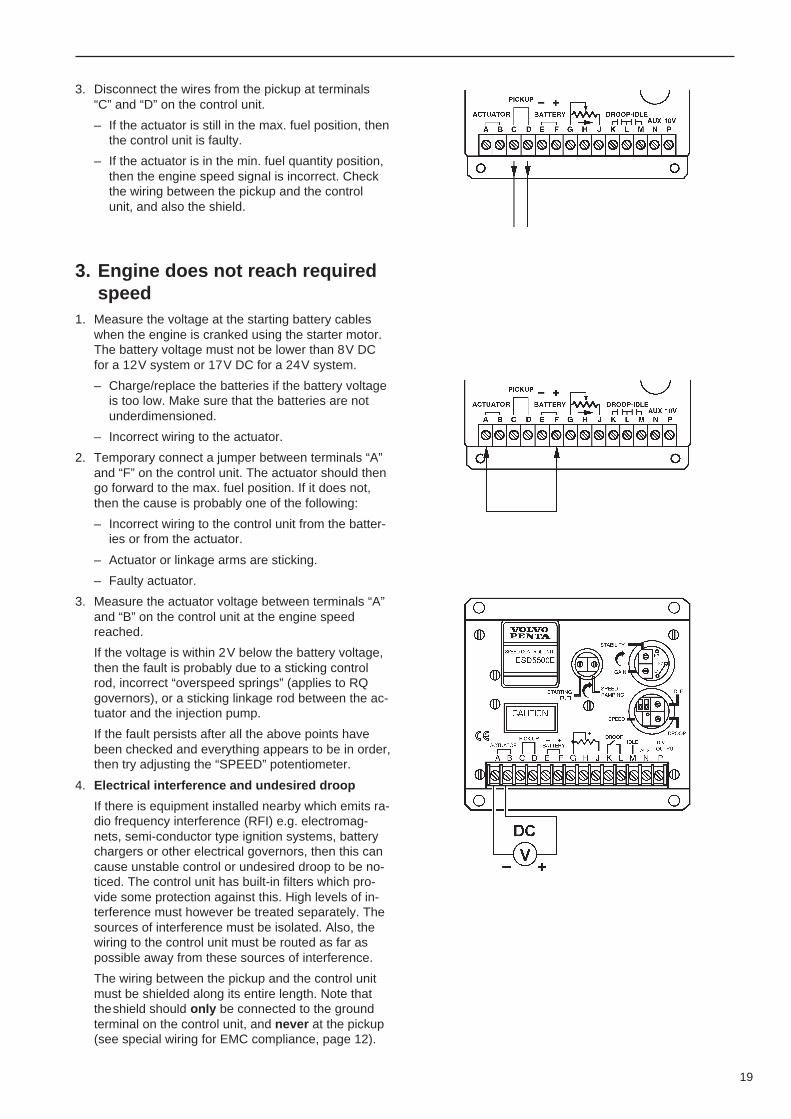
3. Disconnect the wires from the pickup at terminals“C” and “D” on the control unit.
– If the actuator is still in the max. fuel position, thenthe control unit is faulty.
– If the actuator is in the min. fuel quantity position,then the engine speed signal is incorrect. Checkthe wiring between the pickup and the controlunit, and also the shield.
3. Engine does not reach requiredspeed
1. Measure the voltage at the starting battery cableswhen the engine is cranked using the starter motor.The battery voltage must not be lower than 8V DCfor a 12V system or 17V DC for a 24V system.
– Charge/replace the batteries if the battery voltageis too low. Make sure that the batteries are notunderdimensioned.
– Incorrect wiring to the actuator.
2. Temporary connect a jumper between terminals “A”and “F” on the control unit. The actuator should thengo forward to the max. fuel position. If it does not,then the cause is probably one of the following:
– Incorrect wiring to the control unit from the batter-ies or from the actuator.
– Actuator or linkage arms are sticking.
– Faulty actuator.
3. Measure the actuator voltage between terminals “A”and “B” on the control unit at the engine speedreached.
If the voltage is within 2V below the battery voltage,then the fault is probably due to a sticking controlrod, incorrect “overspeed springs” (applies to RQgovernors), or a sticking linkage rod between the ac-tuator and the injection pump.
If the fault persists after all the above points havebeen checked and everything appears to be in order,then try adjusting the “SPEED” potentiometer.
4. Electrical interference and undesired droop
If there is equipment installed nearby which emits ra-dio frequency interference (RFI) e.g. electromag-nets, semi-conductor type ignition systems, batterychargers or other electrical governors, then this cancause unstable control or undesired droop to be no-ticed. The control unit has built-in filters which pro-vide some protection against this. High levels of in-terference must however be treated separately. Thesources of interference must be isolated. Also, thewiring to the control unit must be routed as far aspossible away from these sources of interference.
The wiring between the pickup and the control unitmust be shielded along its entire length. Note thattheshield should only be connected to the groundterminal on the control unit, and never at the pickup(see special wiring for EMC compliance, page 12).
20
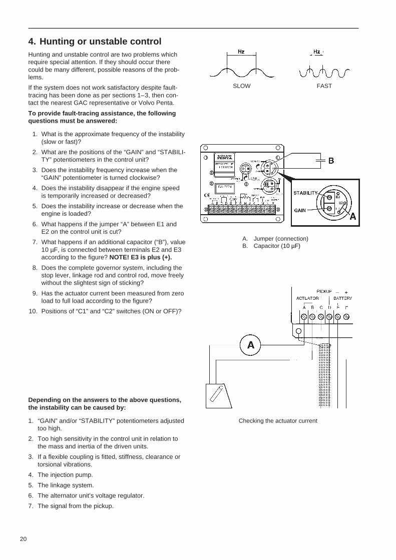
4. Hunting or unstable controlHunting and unstable control are two problems whichrequire special attention. If they should occur therecould be many different, possible reasons of the prob-lems.
If the system does not work satisfactory despite fault-tracing has been done as per sections 1–3, then con-tact the nearest GAC representative or Volvo Penta.
To provide fault-tracing assistance, the followingquestions must be answered:
1. What is the approximate frequency of the instability(slow or fast)?
2. What are the positions of the “GAIN” and “STABILI-TY” potentiometers in the control unit?
3. Does the instability frequency increase when the“GAIN” potentiometer is turned clockwise?
4. Does the instability disappear if the engine speedis temporarily increased or decreased?
5. Does the instability increase or decrease when theengine is loaded?
6. What happens if the jumper “A” between E1 andE2 on the control unit is cut?
7. What happens if an additional capacitor (“B”), value10 µF, is connected between terminals E2 and E3according to the figure? NOTE! E3 is plus (+).
8. Does the complete governor system, including thestop lever, linkage rod and control rod, move freelywithout the slightest sign of sticking?
9. Has the actuator current been measured from zeroload to full load according to the figure?
10. Positions of “C1” and “C2” switches (ON or OFF)?
Depending on the answers to the above questions,the instability can be caused by:
1. “GAIN” and/or “STABILITY” potentiometers adjustedtoo high.
2. Too high sensitivity in the control unit in relation tothe mass and inertia of the driven units.
3. If a flexible coupling is fitted, stiffness, clearance ortorsional vibrations.
4. The injection pump.
5. The linkage system.
6. The alternator unit’s voltage regulator.
7. The signal from the pickup.
A. Jumper (connection)B. Capacitor (10 µF)
Checking the actuator current
SLOW FAST

21
Recordings during testing
24V (ACB225 and ACB275):
Load Voltage A – B (V1) Actuator Current Amps Battery Voltage Voltage (V3)(V2)
recorded recommended recorded recommended E– F Speed Sensor
Nominal 24 Volt
No load ........ 6.5 – 8.5 ........ 1.2 – 1.6 .......... Starting...........
Full Load ........ 12 – 14 ........ 2.4 – 2.8 ........... Nom. Speed....
12V (ACB225 and ACB275):
Load Voltage A – B (V1) Actuator Current Amps Battery Voltage Voltage (V3)(V2)
recorded recommended recorded recommended E– F Speed Sensor
Nominal 12 Volt
No load ........ 2.9 – 3.3 ........ 2.3 – 2.6 .......... Starting...........
Full Load ........ 4.9 – 5.4 ........ 3.9 – 4.3 ........... Nom. Speed....
24V (ACD175-24):
Load Voltage A – B (V1) Actuator Current Amps Battery Voltage Voltage (V3)(V2)
recorded recommended recorded recommended E– F Speed Sensor
Nominal 24 Volt
No load ........ 6.0 – 9.0 ........ 0.9 – 1.3 .......... Starting...........
Full Load ........ 10 – 13 ........ 1.5 – 1.9 ........... Nom. Speed....

22
......................................................................................................................................................................................................
......................................................................................................................................................................................................
......................................................................................................................................................................................................
......................................................................................................................................................................................................
......................................................................................................................................................................................................
......................................................................................................................................................................................................
......................................................................................................................................................................................................
......................................................................................................................................................................................................
......................................................................................................................................................................................................
......................................................................................................................................................................................................
......................................................................................................................................................................................................
......................................................................................................................................................................................................
......................................................................................................................................................................................................
......................................................................................................................................................................................................
......................................................................................................................................................................................................
......................................................................................................................................................................................................
......................................................................................................................................................................................................
......................................................................................................................................................................................................
......................................................................................................................................................................................................
......................................................................................................................................................................................................
......................................................................................................................................................................................................
......................................................................................................................................................................................................
......................................................................................................................................................................................................
......................................................................................................................................................................................................
......................................................................................................................................................................................................
......................................................................................................................................................................................................
References to Service Bulletins
Group No. Date Concerning

23
Notes
......................................................................................................................................................................................................
......................................................................................................................................................................................................
......................................................................................................................................................................................................
......................................................................................................................................................................................................
......................................................................................................................................................................................................
......................................................................................................................................................................................................
......................................................................................................................................................................................................
......................................................................................................................................................................................................
......................................................................................................................................................................................................
......................................................................................................................................................................................................
......................................................................................................................................................................................................
......................................................................................................................................................................................................
......................................................................................................................................................................................................
......................................................................................................................................................................................................
......................................................................................................................................................................................................
......................................................................................................................................................................................................
......................................................................................................................................................................................................
......................................................................................................................................................................................................
......................................................................................................................................................................................................
......................................................................................................................................................................................................
......................................................................................................................................................................................................
......................................................................................................................................................................................................
......................................................................................................................................................................................................
......................................................................................................................................................................................................
......................................................................................................................................................................................................
......................................................................................................................................................................................................
......................................................................................................................................................................................................

24
Notes
......................................................................................................................................................................................................
......................................................................................................................................................................................................
......................................................................................................................................................................................................
......................................................................................................................................................................................................
......................................................................................................................................................................................................
......................................................................................................................................................................................................
......................................................................................................................................................................................................
......................................................................................................................................................................................................
......................................................................................................................................................................................................
......................................................................................................................................................................................................
......................................................................................................................................................................................................
......................................................................................................................................................................................................
......................................................................................................................................................................................................
......................................................................................................................................................................................................
......................................................................................................................................................................................................
......................................................................................................................................................................................................
......................................................................................................................................................................................................
......................................................................................................................................................................................................
......................................................................................................................................................................................................
......................................................................................................................................................................................................
......................................................................................................................................................................................................
......................................................................................................................................................................................................
......................................................................................................................................................................................................
......................................................................................................................................................................................................
......................................................................................................................................................................................................
......................................................................................................................................................................................................
......................................................................................................................................................................................................

Report form
Do you have any complaints or other comments about this manual. Please makea copy of this page, write your comments down and send them to us. Theaddress is at the bottom. We would prefer you to write in English or Swedish.
From: ............................................................................
......................................................................................
......................................................................................
......................................................................................
Refers to publication: .............................................................................................................................................
Publication No.: ............................................................. Date of issue: .................................................................
Proposal/motivation: ..............................................................................................................................................
..............................................................................................................................................................................
..............................................................................................................................................................................
..............................................................................................................................................................................
..............................................................................................................................................................................
..............................................................................................................................................................................
..............................................................................................................................................................................
..............................................................................................................................................................................
..............................................................................................................................................................................
Date: ................................................................
Signed: .............................................................
AB Volvo PentaTechnical Information
Dept. 42200SE-405 08 Göteborg
Sweden

773
9757
-8 E
nglis
h 1
2–
1999