Embed Size (px)
Citation preview

Function Manual
SIMOCODE pro - Communication
Motor Management and Control Devices
Edition
Industrial Controls
siemens.com04/2017 Siemens Parts
___________________
___________________
___________________
___________________
Industrial Controls
Motor management and control devices SIMOCODE pro - Communication
Function Manual
04/2017 A5E40508495002A/RS-AA/001
Introduction 1
Communication 2
Tables, data records 3
List of abbreviations A

Siemens AG Division Digital Factory Postfach 48 48 90026 NÜRNBERG GERMANY
A5E40508495002A/RS-AA/001 Ⓟ 04/2017 Subject to change
Copyright © Siemens AG 2017. All rights reserved
Legal information Warning notice system
This manual contains notices you have to observe in order to ensure your personal safety, as well as to prevent damage to property. The notices referring to your personal safety are highlighted in the manual by a safety alert symbol, notices referring only to property damage have no safety alert symbol. These notices shown below are graded according to the degree of danger.
DANGER indicates that death or severe personal injury will result if proper precautions are not taken.
WARNING indicates that death or severe personal injury may result if proper precautions are not taken.
CAUTION indicates that minor personal injury can result if proper precautions are not taken.
NOTICE indicates that property damage can result if proper precautions are not taken.
If more than one degree of danger is present, the warning notice representing the highest degree of danger will be used. A notice warning of injury to persons with a safety alert symbol may also include a warning relating to property damage.
Qualified Personnel The product/system described in this documentation may be operated only by personnel qualified for the specific task in accordance with the relevant documentation, in particular its warning notices and safety instructions. Qualified personnel are those who, based on their training and experience, are capable of identifying risks and avoiding potential hazards when working with these products/systems.
Proper use of Siemens products Note the following:
WARNING Siemens products may only be used for the applications described in the catalog and in the relevant technical documentation. If products and components from other manufacturers are used, these must be recommended or approved by Siemens. Proper transport, storage, installation, assembly, commissioning, operation and maintenance are required to ensure that the products operate safely and without any problems. The permissible ambient conditions must be complied with. The information in the relevant documentation must be observed.
Trademarks All names identified by ® are registered trademarks of Siemens AG. The remaining trademarks in this publication may be trademarks whose use by third parties for their own purposes could violate the rights of the owner.
Disclaimer of Liability We have reviewed the contents of this publication to ensure consistency with the hardware and software described. Since variance cannot be precluded entirely, we cannot guarantee full consistency. However, the information in this publication is reviewed regularly and any necessary corrections are included in subsequent editions.
Siemens Parts

SIMOCODE pro - Communication 4 Function Manual, 04/2017, A5E40508495002A/RS-AA/001
Table of contents
1 Introduction ................................................................................................................................................ 8
1.1 Important information ............................................................................................................... 8
1.2 Security information ............................................................................................................... 11
1.3 Current information about operational safety ......................................................................... 12
2 Communication ........................................................................................................................................ 13
2.1 PROFIBUS communication ................................................................................................... 13 2.1.1 Definitions .............................................................................................................................. 13 2.1.2 Data transfer .......................................................................................................................... 15 2.1.3 Fail-safe data transfer via PROFIBUS / PROFIsafe .............................................................. 16 2.1.4 Telegram description and data access .................................................................................. 17 2.1.4.1 Cyclic data .............................................................................................................................. 17 2.1.4.2 Diagnostics data and alarms .................................................................................................. 18 2.1.4.3 Structure of the slave diagnostics .......................................................................................... 19 2.1.5 Integration of SIMOCODE pro in DP master systems ........................................................... 28 2.1.5.1 Slave operating modes .......................................................................................................... 28 2.1.5.2 Preparing the data transfer .................................................................................................... 29 2.1.5.3 Integration of SIMOCODE pro as a DPV1 slave via GSD in the configuring software .......... 29 2.1.5.4 Integration of SIMOCODE pro as a SIMATIC PDM object (DPV1 slave via GSD) in
STEP7 HW Config ................................................................................................................. 31 2.1.5.5 Integration of SIMOCODE pro as an S7 slave via OM SIMOCODE pro ............................... 32 2.1.5.6 Compatibility of SIMOCODE pro S and SIMOCODE pro V ................................................... 33 2.1.6 Evaluating diagnostics data ................................................................................................... 34 2.1.6.1 Evaluating diagnostics data ................................................................................................... 34 2.1.6.2 SIMOCODE pro integrated with GSD .................................................................................... 34 2.1.6.3 Integration of SIMOCODE pro in SIMATIC S7 with OM SIMOCODE ES ............................. 36 2.1.7 Data records ........................................................................................................................... 37 2.1.8 Parameterization via PROFIBUS ........................................................................................... 38 2.1.8.1 SIMOCODE ES Premium ...................................................................................................... 38 2.1.8.2 SIMATIC PDM ........................................................................................................................ 39 2.1.8.3 Parameter data during startup ............................................................................................... 40 2.1.9 Timestamping/time synchronization....................................................................................... 40
2.2 PROFINET communication .................................................................................................... 41 2.2.1 Definitions .............................................................................................................................. 41 2.2.2 Data security in automation ................................................................................................... 43 2.2.3 Data transfer .......................................................................................................................... 46 2.2.4 Communication via PROFINET IO ........................................................................................ 47 2.2.5 Integration of SIMOCODE pro into the automation system (PLC) ........................................ 48 2.2.6 Integration of SIMOCODE pro V PN via GSD ....................................................................... 51 2.2.7 Integration of SIMOCODE pro V PN in SIMATIC STEP 7 V5 via OM SIMOCODE pro ........ 52 2.2.8 Configuring SIMOCODE pro V PN ports ............................................................................... 53 2.2.9 Configuration of further properties of SIMOCODE pro V PN as an IO device....................... 54 2.2.10 Identification data for PROFINET IO ..................................................................................... 57 2.2.11 Shared device ........................................................................................................................ 58
Table of contents
SIMOCODE pro - Communication Function Manual, 04/2017, A5E40508495002A/RS-AA/001 5
2.2.12 Media redundancy .................................................................................................................. 58 2.2.13 System redundancy ................................................................................................................ 59 2.2.14 Diagnostics ............................................................................................................................. 65 2.2.15 Data records ........................................................................................................................... 78 2.2.16 PROFIenergy .......................................................................................................................... 79 2.2.17 Further communication functions via Ethernet ....................................................................... 82
2.3 Modbus communication .......................................................................................................... 96 2.3.1 Modbus RTU communication ................................................................................................. 96 2.3.1.1 Modbus RTU - general ........................................................................................................... 96 2.3.1.2 Supported data transfer rates for RTU ................................................................................... 96 2.3.1.3 Assignment of SIMOCODE data to Modbus addresses with Modbus RTU ........................... 97 2.3.1.4 Modbus RTU data transfer ..................................................................................................... 98 2.3.1.5 Modbus RTU telegram format ................................................................................................ 99 2.3.1.6 Modbus RTU function codes ................................................................................................ 100 2.3.1.7 Modbus RTU error codes ..................................................................................................... 112
2.4 EtherNet/IP communication .................................................................................................. 113 2.4.1 Important notes ..................................................................................................................... 113 2.4.2 Definitions ............................................................................................................................. 114 2.4.3 Data security in automation .................................................................................................. 115 2.4.4 Data transmission ................................................................................................................. 116 2.4.5 Electronic Data Sheet (EDS) file ........................................................................................... 117 2.4.6 Setting up the IP address ..................................................................................................... 118 2.4.7 Parameterizing the device .................................................................................................... 120 2.4.8 Integrating SIMOCODE pro into the automation system (PLC) ........................................... 121 2.4.9 Integration and commissioning in Rockwell Studio 5000 ..................................................... 122 2.4.10 Ethernet/IP Device Level Ring functionality .......................................................................... 124 2.4.11 Web diagnostics (web server) .............................................................................................. 125 2.4.12 Time-of-day synchronization by the NTP procedure ............................................................ 127 2.4.13 Simple Network Management Protocol (SNMP) .................................................................. 128
3 Tables, data records .............................................................................................................................. 129
3.1 Tables general ...................................................................................................................... 129 3.1.1 Active control stations, contactor controls, lamp controls and status information for the
control functions .................................................................................................................... 129
3.2 Assignment of cyclic receive and send data for predefined control functions ...................... 132 3.2.1 Overload relay ....................................................................................................................... 132 3.2.2 Direct starter ......................................................................................................................... 134 3.2.3 Reversing starter ................................................................................................................... 135 3.2.4 Molded-case circuit breaker (MCCB) .................................................................................... 136 3.2.5 Star-delta starter ................................................................................................................... 137 3.2.6 Star-delta reversing starter ................................................................................................... 138 3.2.7 Dahlander ............................................................................................................................. 139 3.2.8 Dahlander reversing starter .................................................................................................. 140 3.2.9 Pole-changing starter ............................................................................................................ 141 3.2.10 Pole-changing reversing starter ............................................................................................ 142 3.2.11 Solenoid valve ....................................................................................................................... 143 3.2.12 Positioner .............................................................................................................................. 144 3.2.13 Soft starter ............................................................................................................................ 145 3.2.14 Soft starter with reversing contactor ..................................................................................... 146
Siemens Parts

Table of contents
SIMOCODE pro - Communication 6 Function Manual, 04/2017, A5E40508495002A/RS-AA/001
3.3 Tables, PROFIBUS data records ......................................................................................... 147 3.3.1 PROFIBUS tables ................................................................................................................ 147 3.3.1.1 Abbreviations and specifications .......................................................................................... 147 3.3.1.2 Socket assignment table - digital ......................................................................................... 148 3.3.1.3 Socket assignment table - analog ........................................................................................ 155 3.3.1.4 Detailed messages of the slave diagnostics ........................................................................ 158 3.3.2 PROFIBUS data records ...................................................................................................... 162 3.3.2.1 PROFIBUS data records - general ...................................................................................... 162 3.3.2.2 Data record 0/1 - S7 system diagnostics ............................................................................. 166 3.3.2.3 Data record 63 - Analog value recording ............................................................................. 168 3.3.2.4 Data record 67 - Process image output ............................................................................... 168 3.3.2.5 Data record 69 - Process image input ................................................................................. 169 3.3.2.6 Data record 72 - Error buffer ................................................................................................ 170 3.3.2.7 Data record 73 - Event memory ........................................................................................... 170 3.3.2.8 Data record 92 - Device diagnostics .................................................................................... 171 3.3.2.9 Data record 94 - measured values....................................................................................... 178 3.3.2.10 Data record 95 - Service data/statistical data ...................................................................... 180 3.3.2.11 Data record 130 - Basic device parameters 1 ..................................................................... 181 3.3.2.12 Data record 131 - Basic device parameters 2 (plug binary) ................................................ 188 3.3.2.13 Data record 132 - Extended device parameters 1 ............................................................... 192 3.3.2.14 Data record 133 - Extended device parameters 2 (plug binary) .......................................... 200 3.3.2.15 Data record 134 - Extended device parameters 2 ............................................................... 203 3.3.2.16 Data record 135 - Extended device parameters 2 ............................................................... 203 3.3.2.17 Data record 139 - Marking ................................................................................................... 204 3.3.2.18 Data record 160 - Communication parameters .................................................................... 205 3.3.2.19 Data record 165 - Identification ............................................................................................ 205 3.3.2.20 Data record 202 - Acyclic receive ........................................................................................ 206 3.3.2.21 Data record 203 - Acyclic send ............................................................................................ 207 3.3.2.22 Data record 224 - Password protection ............................................................................... 208
3.4 Tables, PROFINET data records ......................................................................................... 209 3.4.1 PROFINET tables ................................................................................................................ 209 3.4.1.1 Active control stations, contactor controls, lamp controls and status information for the
control functions ................................................................................................................... 209 3.4.1.2 OPC UA variables ................................................................................................................ 212 3.4.1.3 Abbreviations and specifications .......................................................................................... 221 3.4.1.4 Socket assignment table - digital ......................................................................................... 223 3.4.1.5 Socket assignment table - analog ........................................................................................ 230 3.4.2 PROFINET data records ...................................................................................................... 234 3.4.2.1 PROFINET data records - general....................................................................................... 234 3.4.2.2 Data record 63 - Analog value recording ............................................................................. 238 3.4.2.3 Data record 67 - Process image output ............................................................................... 238 3.4.2.4 Data record 69 - Process image input ................................................................................. 239 3.4.2.5 Data record 72 - Error buffer ................................................................................................ 240 3.4.2.6 Data record 73 - Event memory ........................................................................................... 240 3.4.2.7 Data record 92 - Device diagnostics .................................................................................... 241 3.4.2.8 Data record 94 - measured values....................................................................................... 249 3.4.2.9 Data record 95 - Service data/statistical data ...................................................................... 250 3.4.2.10 Data record 130 - Basic device parameters 1 ..................................................................... 252 3.4.2.11 Data record 131 - Basic device parameters 2 (plug binary) ................................................ 258 3.4.2.12 Data record 132 - Extended device parameters 1 ............................................................... 262 3.4.2.13 Data record 133 - Extended device parameters 2 (plug binary) .......................................... 269 3.4.2.14 Data record 134 - Extended device parameters 1 ............................................................... 272
Table of contents
SIMOCODE pro - Communication Function Manual, 04/2017, A5E40508495002A/RS-AA/001 7
3.4.2.15 Data record 135 - Extended device parameters 2 ................................................................ 276 3.4.2.16 Data record 139 - Marking .................................................................................................... 279 3.4.2.17 Data record 140 - Marking 2 ................................................................................................. 280 3.4.2.18 Data record 165 - Identification ............................................................................................. 281 3.4.2.19 Data record 224 - Password protection ................................................................................ 281
3.5 Modbus data tables............................................................................................................... 282 3.5.1 General information .............................................................................................................. 282 3.5.1.1 Memory image ...................................................................................................................... 282 3.5.1.2 Byte arrangement ................................................................................................................. 283 3.5.1.3 Specifications ........................................................................................................................ 283 3.5.2 Modbus RTU data tables ...................................................................................................... 284 3.5.2.1 Process image output - command data ................................................................................ 284 3.5.2.2 Process image input - monitoring data ................................................................................. 285 3.5.2.3 Measured values ................................................................................................................... 286 3.5.2.4 Display and statistical data ................................................................................................... 287 3.5.2.5 Device diagnostics ................................................................................................................ 288 3.5.2.6 Error memory ........................................................................................................................ 296 3.5.2.7 Event memory ....................................................................................................................... 297 3.5.2.8 Trace data ............................................................................................................................. 298 3.5.2.9 I&M0 - device identification ................................................................................................... 298 3.5.2.10 I&M1 data .............................................................................................................................. 299 3.5.2.11 I&M2 - Installation date ......................................................................................................... 299 3.5.2.12 I&M3 - Comment ................................................................................................................... 299 3.5.2.13 Basic device parameter 1 ..................................................................................................... 300 3.5.2.14 Extended device parameters 1 ............................................................................................. 307 3.5.2.15 Marking ................................................................................................................................. 319
3.6 EtherNet/IP data tables ......................................................................................................... 320 3.6.1 Supported objects ................................................................................................................. 320 3.6.2 Identity object ........................................................................................................................ 320 3.6.3 Message Router object ......................................................................................................... 322 3.6.4 Assembly object .................................................................................................................... 322 3.6.5 Connection Manager object .................................................................................................. 333 3.6.6 Device Diagnosis object ....................................................................................................... 334 3.6.7 Measurement object ............................................................................................................. 335 3.6.8 Statistical Data object ........................................................................................................... 337 3.6.9 Motor Parameter object ........................................................................................................ 338 3.6.10 TCP/IP Interface object ......................................................................................................... 340 3.6.11 Ethernet Link object .............................................................................................................. 341
A List of abbreviations ............................................................................................................................... 342
A.1 List of abbreviations .............................................................................................................. 342
Index ...................................................................................................................................................... 343
Siemens Parts

SIMOCODE pro - Communication 8 Function Manual, 04/2017, A5E40508495002A/RS-AA/001
Introduction 1 1.1 Important information
Scope of application This manual is applicable to the listed SIMOCODE pro system components. It contains a description of the components applicable at the time of printing the manual. SIEMENS reserves the right to include updated information about new components or new versions of components in a Product Information.
Manual Collection A Manual Collection (https://support.industry.siemens.com/cs/document/109743951), a collection of the following five SIMOCODE pro manuals is at your disposal in Industry Online Support:
● SIMOCODE pro - 1 Getting Started
● SIMOCODE pro - 2 System Manual
● SIMOCODE pro - 3 Parameterization
● SIMOCODE pro - 4 Applications
● SIMOCODE pro - 5 Communication

Introduction 1.1 Important information
SIMOCODE pro - Communication Function Manual, 04/2017, A5E40508495002A/RS-AA/001 9
SIMOCODE pro response tables Specific responses (deactivated, signaling, warning, tripping) can be parameterized for various SIMOCODE pro functions, such as overload. These are always displayed in tabular form:
● "X" = Applicable
● "—" = Not applicable
● Default values are marked "d" for "default" in parentheses.
Response Function 1 Function 2 Function 3
Tripping — X (d) X Warning X (d) X — Signaling X X — Deactivated X X X (d) Delay 0 ... 25.5 s (default: 0) — —
Brief description of the responses:
● Tripping: The contactor controls QE* are tripped. A fault message is generated which is available as a diagnosis via PROFIBUS DP. The fault message and the device-internal signal remain on until the appropriate length of time has elapsed or the cause of the fault has been eliminated and acknowledged.
● Warning: In addition to the device-internal signal, a warning signal is generated that is available as diagnostics via the communication bus.
● Signaling: Only a device-internal signal is generated, which can be further processed as required.
● Deactivated: The appropriate function is switched off, no signals are generated.
A delay time can also be set for specific responses.
Further information Please read the operating instructions of the respective components. You can find the operating instructions for SIMOCODE pro at Operating instructions (www.siemens.com/sirius/manuals).
You will find further information on the Internet:
● Internet (www.siemens.com/simocode)
● Information and Download Center (www.siemens.com/sirius/infomaterial)
● Product Information System (ProdIS) (www.siemens.com/sirius/support)
● Certificates (www.siemens.com/sirius/approvals)
Siemens Parts

Introduction 1.1 Important information
SIMOCODE pro - Communication 10 Function Manual, 04/2017, A5E40508495002A/RS-AA/001
Further support (Service and Support) Service and Support (www.siemens.com/sirius/technical-assistance)
Telephone: +49 (0) 911-895-5900 (8 a.m. to 5 p.m. CET)
Fax: +49 (0) 911-895-59 07
E-Mail: [email protected]
Disclaimer of liability The products described here have been developed to carry out safety-related functions as part of a complete plant or machine. In general, a complete safety system consists of sensors, evaluation units, signaling devices and methods for safe tripping. The manufacturer is responsible for ensuring safe functioning of the complete plant or machine. Siemens AG, its subsidiaries, and associated companies (hereinafter referred to as "Siemens") are not in a position to guarantee every characteristic of a complete plant or machine not designed by Siemens.
Siemens also denies all responsibility for any recommendations that are made or implied in the following description. No new guarantee, warranty, or liability claims above those standard to Siemens can be derived from the following description.

Introduction 1.2 Security information
SIMOCODE pro - Communication Function Manual, 04/2017, A5E40508495002A/RS-AA/001 11
1.2 Security information Siemens provides products and solutions with industrial security functions that support the secure operation of plants, systems, machines and networks.
In order to protect plants, systems, machines and networks against cyber threats, it is necessary to implement – and continuously maintain – a holistic, state-of-the-art industrial security concept. Siemens’ products and solutions only form one element of such a concept.
Customer is responsible to prevent unauthorized access to its plants, systems, machines and networks. Systems, machines and components should only be connected to the enterprise network or the internet if and to the extent necessary and with appropriate security measures (e.g. use of firewalls and network segmentation) in place.
Additionally, Siemens’ guidance on appropriate security measures should be taken into account. For more information about industrial security, please visit: (http://www.siemens.com/industrialsecurity)
Siemens’ products and solutions undergo continuous development to make them more secure. Siemens strongly recommends to apply product updates as soon as available and to always use the latest product versions. Use of product versions that are no longer supported, and failure to apply latest updates may increase customer’s exposure to cyber threats.
To stay informed about product updates, subscribe to the Siemens Industrial Security RSS Feed under: (http://www.siemens.com/industrialsecurity)
Siemens Parts

Introduction 1.3 Current information about operational safety
SIMOCODE pro - Communication 12 Function Manual, 04/2017, A5E40508495002A/RS-AA/001
1.3 Current information about operational safety
Important note for maintaining operational safety of your system
DANGER
Hazardous Voltage
Can Cause Death, Serious Injury or Risk of Property Damage
Please take note of our latest information!
Systems with safety-related characteristics are subject to special operational safety requirements on the part of the operator. The supplier is also obliged to comply with special product monitoring measures. For this reason, we publish a special newsletter containing information on product developments and features that are (or could be) relevant to operation of safety-related systems. By subscribing to the appropriate newsletter in the Industry newsletter system (https://www.industry.siemens.com/newsletter), you will ensure that you are always up-to-date and able to make changes to your system, when necessary. Sign on to the following newsletter under "Products & Solutions": • Control Components and System Engineering News • Safety Integrated Newsletter.

SIMOCODE pro - Communication Function Manual, 04/2017, A5E40508495002A/RS-AA/001 13
Communication 2 2.1 PROFIBUS communication
2.1.1 Definitions
PROFIBUS DP PROFIBUS bus system with the DP protocol (decentralized peripherals). The main task of PROFIBUS DP is to manage the fast, cyclic data exchange between the central DP master and the I/O devices.
PROFIBUS DPV1 PROFIBUS DPV1 is an extension of the DP protocol. It enables acyclic data exchange of parameter, diagnostic, receive and test data.
DP master A master with characteristics to EN 50 170, Volume 2, PROFIBUS with the DP protocol is referred to as the DP master.
Class 1 master A Class 1 master is an active station on PROFIBUS DP. It is characteristically used for cyclic data exchange with other stations. Typical Class 1 masters include PLCs with a PROFIBUS DP connection.
Class 2 master A class 2 master is an optional station on the PROFIBUS DP. Typical class 2 masters include:
● PC / PG devices with the SIMOCODE ES software
● SIMATIC PDM (PCS7)
● PC with SIMATIC powercontrol software (power management).
Siemens Parts

Communication 2.1 PROFIBUS communication
SIMOCODE pro - Communication 14 Function Manual, 04/2017, A5E40508495002A/RS-AA/001
DPV1 slave A slave operated on the PROFIBUS with the PROFIBUS DP protocol that behaves in accordance with EN 50 170, Volume 2, PROFIBUS is referred to as a DPV1 slave.
GSD Device master data (GSD) contains DP slave descriptions in a standardized format. The use of device master data simplifies the configuration of the DP slave in a DP master system.
OM SIMOCODE pro OM SIMOCODE pro (object manager) is used instead of GSD to integrate SIMOCODE pro into STEP7. OM SIMOCODE pro enables the use of SIMOCODE ES (if it is installed) for parameterization within STEP7.
SIMATIC PDM Software package for the configuration, parameterization, commissioning and maintenance of devices (e.g. transducers, controllers, SIMOCODE) and for configuring networks and PCs.
SIMOCODE pro S7 slave A SIMOCODE pro S7 slave is a slave which is fully integrated into STEP7. It is connected via OM SIMOCODE pro. It supports the S7 model (diagnosis interrupts, hardware interrupts).
Writing data Writing data means that data is transmitted to the SIMOCODE pro system.
Reading data Reading data means that data is transmitted from the SIMOCODE pro system.
PROFIsafe PROFIsafe is a safety profile developed and tested according to IEC 61508 for the widely used field bus protocols PROFIBUS and PROFINET. The PROFIsafe profile defines how failsafe protective devices (e.g. EMERGENCY OFF pushbutton) will be connected to programmable controllers by means of PROFIBUS.

Communication 2.1 PROFIBUS communication
SIMOCODE pro - Communication Function Manual, 04/2017, A5E40508495002A/RS-AA/001 15
2.1.2 Data transfer
Options for data transfer The following figure shows the data transfer options:
Figure 2-1 Options for data transfer
Siemens Parts

Communication 2.1 PROFIBUS communication
SIMOCODE pro - Communication 16 Function Manual, 04/2017, A5E40508495002A/RS-AA/001
Communication principle The following figure shows the communication principle and the way data is transmitted depending on the master and slave operating modes:
Figure 2-2 Communication principle
2.1.3 Fail-safe data transfer via PROFIBUS / PROFIsafe SIMOCODE pro V as from version *E07* in conjunction with a fail-safe control (F-CPU) and the SIMOCODE pro expansion module DM-F PROFIsafe supports fail-safe shutdown of motors by means of data transmission via the PROFIsafe profile.
You will find more information on using this function in System Manual "Fail-safe digital modules SIMOCODE pro Safety."
Communication 2.1 PROFIBUS communication
SIMOCODE pro - Communication Function Manual, 04/2017, A5E40508495002A/RS-AA/001 17
2.1.4 Telegram description and data access
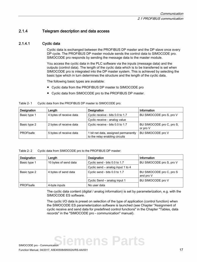
2.1.4.1 Cyclic data Cyclic data is exchanged between the PROFIBUS DP master and the DP slave once every DP cycle. The PROFIBUS DP master module sends the control data to SIMOCODE pro. SIMOCODE pro responds by sending the message data to the master module.
You access the cyclic data in the PLC software via the inputs (message data) and the outputs (control data). The length of the cyclic data which is to be transferred is set when SIMOCODE pro is integrated into the DP master system. This is achieved by selecting the basic type which in turn determines the structure and the length of the cyclic data.
The following basic types are available:
● Cyclic data from the PROFIBUS DP master to SIMOCODE pro
● Cyclic data from SIMOCODE pro to the PROFIBUS DP master.
Table 2- 1 Cyclic data from the PROFIBUS DP master to SIMOCODE pro:
Designation Length Designation Information Basic type 1 4 bytes of receive data Cyclic receive - bits 0.0 to 1.7 BU SIMOCODE pro S, pro V
Cyclic receive - analog value Basic type 2 2 bytes of receive data Cyclic receive - bits 0.0 to 1.7 BU SIMOCODE pro C, pro S,
or pro V PROFIsafe 5 bytes of receive data 1 bit net data, assigned permanently
to the relay enabling circuits BU SIMOCODE pro V
Table 2- 2 Cyclic data from SIMOCODE pro to the PROFIBUS DP master:
Designation Length Designation Information Basic type 1 10 bytes of send data Cyclic send - bits 0.0 to 1.7 BU SIMOCODE pro S, pro V
Cyclic send – analog input 1 to 4 Basic type 2 4 bytes of send data Cyclic send - bits 0.0 to 1.7 BU SIMOCODE pro C, pro S
and pro V Cyclic Send – analog input 1 BU SIMOCODE pro V
PROFIsafe 4-byte inputs No user data
The cyclic data content (digital / analog information) is set by parameterization, e.g. with the SIMOCODE ES software.
The cyclic I/O data is preset on selection of the type of application (control function) when the SIMOCODE ES parameterization software is launched (see Chapter "Assignment of cyclic receive and send data for predefined control functions" in the Chapter "Tables, data records" in the "SIMOCODE pro - communication" manual).
Siemens Parts

Communication 2.1 PROFIBUS communication
SIMOCODE pro - Communication 18 Function Manual, 04/2017, A5E40508495002A/RS-AA/001
2.1.4.2 Diagnostics data and alarms
Diagnostic data and interrupts - overview Diagnostics data contains important information about the status of SIMOCODE pro. This information simplifies troubleshooting. Unlike cyclic data, the diagnostics data is only transmitted to the master module if it changes. PROFIBUS DP differentiates between:
● Standard diagnostics
● Status information
● Channel-related diagnostics
● DPV1 process and diagnostic interrupts.
Configuring diagnostic response In SIMOCODE pro, you can set which diagnostic events trigger the transmission of diagnostics data or interrupts to the PLC:
● Diagnostics for device faults, e.g. parameterization errors, hardware faults
● Diagnostics for process faults: In the case of events identified as "S" in the column headed "DP diagnostics" in the "Data record 92 - Diagnostics" table, the diagnostics data or interrupts are transferred to the PLC.
● Diagnostics for process warnings: In the case of events identified as "W" in the column headed "DP diagnostics" in the "Data record 92 - Diagnostics" table, the diagnostics data or interrupts are transferred to the PLC.
● Diagnostics for process events: In the case of events identified as "M" in the column headed "DP diagnostics" in the "Data record 92 - Diagnostics" table, the diagnostics data or interrupts are transferred to the PLC.
Setting with SIMOCODE ES Set the response in dialog Device Parameters > Bus Parameters >Diagnosis .

Communication 2.1 PROFIBUS communication
SIMOCODE pro - Communication Function Manual, 04/2017, A5E40508495002A/RS-AA/001 19
2.1.4.3 Structure of the slave diagnostics
Standard diagnostics/extended diagnostics
Figure 2-3 Structure of the slave diagnostics
The diagnostics telegram has a maximum length of 62 bytes.
Siemens Parts

Communication 2.1 PROFIBUS communication
SIMOCODE pro - Communication 20 Function Manual, 04/2017, A5E40508495002A/RS-AA/001
Station status - definition The station status provides an overview of the state of a DP slave.
Station status 1
Table 2- 3 Structure of station status 1 (byte 0)
Bit Meaning Cause / corrective measure 0 The DP master cannot address the DP slave. Check the following:
• Is the correct PROFIBUS address set on the DP slave?
• Is the bus connection plug connected? • Is the DP slave connected to the
power supply? • Is the RS485 repeater correctly
configured?
1 The DP slave is not yet ready for the data transfer. The DP slave is still starting up. Wait until the startup is completed.
2 The configuration data transferred from the DP master to the DP slave does not match the DP slave configuration.
Check that the correct station type and the correct DP slave configuration have been entered in the configuring software.
3 External diagnostics data exists (group diagnostics indication). Evaluate the identifier-related diagnostics, the status information and / or the channel-related diagnostics. Bit 3 is reset as soon as all faults have been rectified. The bit will be set again when there is a new diagnostics message in the bytes of the aforementioned diagnostics.
4 The function you requested is not supported by the DP slave. Check the configuration. 5 The DP master cannot interpret the response from the DP slave. Check the bus configuration. 6 The DP slave type does not match the software configuration. Enter the correct station type in the
configuring software. 7 The DP slave has been parameterized by another DP master (not
by the DP master which has access to the DP slave at the moment).
The bit is always 1, for example, if you access the DP slave with the PG or another DP master. The "Master PROFIBUS address" diagnostic byte contains the PROFIBUS address of the DP master that assigned parameters to the DP slave.
Communication 2.1 PROFIBUS communication
SIMOCODE pro - Communication Function Manual, 04/2017, A5E40508495002A/RS-AA/001 21
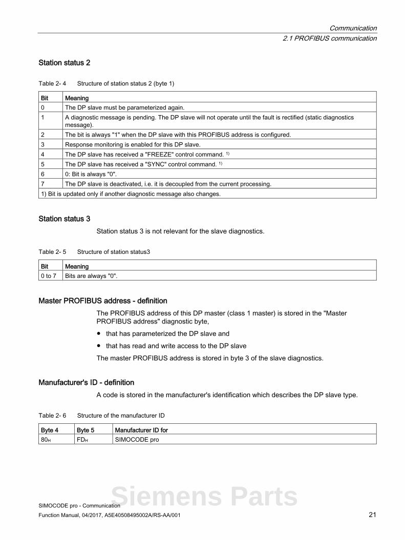
Station status 2
Table 2- 4 Structure of station status 2 (byte 1)
Bit Meaning 0 The DP slave must be parameterized again. 1 A diagnostic message is pending. The DP slave will not operate until the fault is rectified (static diagnostics
message). 2 The bit is always "1" when the DP slave with this PROFIBUS address is configured. 3 Response monitoring is enabled for this DP slave. 4 The DP slave has received a "FREEZE" control command. 1) 5 The DP slave has received a "SYNC" control command. 1) 6 0: Bit is always "0". 7 The DP slave is deactivated, i.e. it is decoupled from the current processing. 1) Bit is updated only if another diagnostic message also changes.
Station status 3 Station status 3 is not relevant for the slave diagnostics.
Table 2- 5 Structure of station status3
Bit Meaning 0 to 7 Bits are always "0".
Master PROFIBUS address - definition The PROFIBUS address of this DP master (class 1 master) is stored in the "Master PROFIBUS address" diagnostic byte,
● that has parameterized the DP slave and
● that has read and write access to the DP slave
The master PROFIBUS address is stored in byte 3 of the slave diagnostics.
Manufacturer's ID - definition A code is stored in the manufacturer's identification which describes the DP slave type.
Table 2- 6 Structure of the manufacturer ID
Byte 4 Byte 5 Manufacturer ID for 80H FDH SIMOCODE pro
Siemens Parts
Communication 2.1 PROFIBUS communication
SIMOCODE pro - Communication 22 Function Manual, 04/2017, A5E40508495002A/RS-AA/001
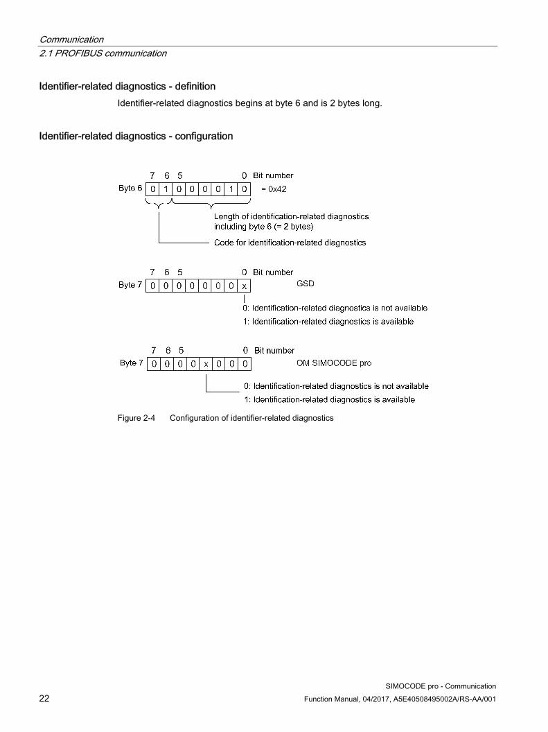
Identifier-related diagnostics - definition Identifier-related diagnostics begins at byte 6 and is 2 bytes long.
Identifier-related diagnostics - configuration
Figure 2-4 Configuration of identifier-related diagnostics
Communication 2.1 PROFIBUS communication
SIMOCODE pro - Communication Function Manual, 04/2017, A5E40508495002A/RS-AA/001 23
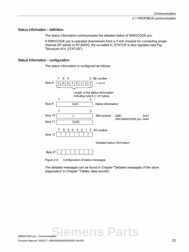
Status information - definition The status information communicates the detailed status of SIMOCODE pro.
If SIMOCODE pro is operated downstream from a Y-link (module for connecting single-channel DP slaves to S7-400H), the so-called H_STATUS is also signaled (see Fig. "Structure of H_STATUS").
Status information - configuration The status information is configured as follows:
Figure 2-5 Configuration of status messages
The detailed messages can be found in Chapter "Detailed messages of the slave diagnostics" in Chapter "Tables, data records”.
Siemens Parts

Communication 2.1 PROFIBUS communication
SIMOCODE pro - Communication 24 Function Manual, 04/2017, A5E40508495002A/RS-AA/001
The H_STATUS has the following structure:
Figure 2-6 Structure of H_STATUS
Communication 2.1 PROFIBUS communication
SIMOCODE pro - Communication Function Manual, 04/2017, A5E40508495002A/RS-AA/001 25
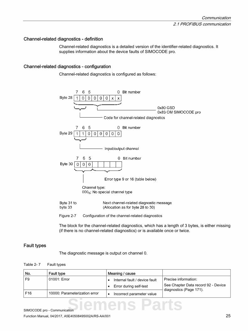
Channel-related diagnostics - definition Channel-related diagnostics is a detailed version of the identifier-related diagnostics. It supplies information about the device faults of SIMOCODE pro.
Channel-related diagnostics - configuration Channel-related diagnostics is configured as follows:
Figure 2-7 Configuration of the channel-related diagnostics
The block for the channel-related diagnostics, which has a length of 3 bytes, is either missing (if there is no channel-related diagnostics) or is available once or twice.
Fault types The diagnostic message is output on channel 0.
Table 2- 7 Fault types
No. Fault type Meaning / causeF9 01001: Error • Internal fault / device fault
• Error during self-test
Precise information: See Chapter Data record 92 - Device diagnostics (Page 171).
F16 10000: Parameterization error • Incorrect parameter value
Siemens Parts

Communication 2.1 PROFIBUS communication
SIMOCODE pro - Communication 26 Function Manual, 04/2017, A5E40508495002A/RS-AA/001
Interrupts - diagnostic interrupt Device faults or parameter errors are interrupt sources for diagnostic interrupts.
As soon as SIMOCODE pro sets a diagnostic interrupt, the OB 82 diagnostic interrupt will be started in the SIMATIC S7.
Diagnosis interrupt - structure The diagnostic interrupt has the following structure:
Figure 2-8 Structure of the diagnostic interrupt
The first byte of the block for diagnostic interrupt can be shifted by 3 or 6 bytes depending on the number of blocks for channel-related diagnostics.
A description of the information contained in data record 1 can be found in Chapter "Detailed messages of the slave diagnostics" in Chapter "Tables, data records”.

Communication 2.1 PROFIBUS communication
SIMOCODE pro - Communication Function Manual, 04/2017, A5E40508495002A/RS-AA/001 27
Interrupts - hardware interrupt Process faults, warnings, and status information are interrupt sources for hardware interrupts.
As soon as SIMOCODE pro sets a hardware interrupt, the hardware interrupt OB 40 will be started in the SIMATIC S7.
Hardware interrupt - structure The hardware interrupt has the following structure:
Figure 2-9 Structure of the hardware interrupt
The first byte of the block for hardware interrupts can be shifted by 3 or 6 bytes depending on the number of blocks for channel-related diagnostics.
The detailed messages can be found in Chapter "Detailed messages of the slave diagnostics" in Chapter “Tables, data records”.
Siemens Parts
Communication 2.1 PROFIBUS communication
SIMOCODE pro - Communication 28 Function Manual, 04/2017, A5E40508495002A/RS-AA/001
2.1.5 Integration of SIMOCODE pro in DP master systems
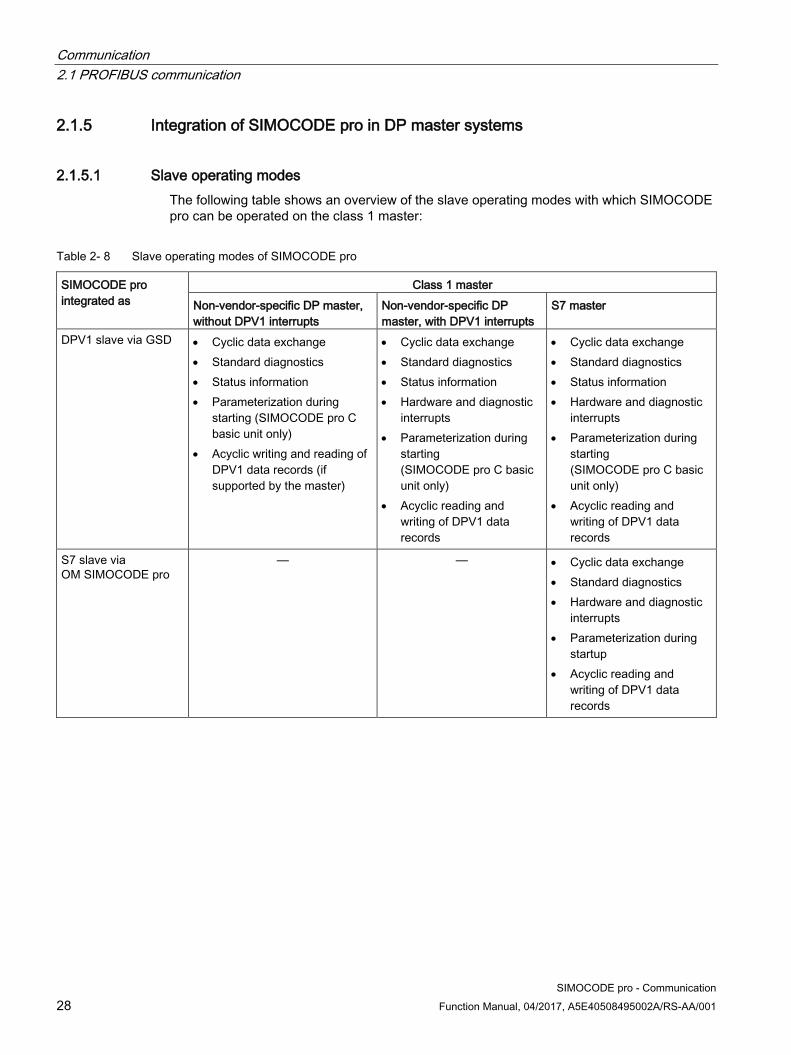
2.1.5.1 Slave operating modes The following table shows an overview of the slave operating modes with which SIMOCODE pro can be operated on the class 1 master:
Table 2- 8 Slave operating modes of SIMOCODE pro
SIMOCODE pro integrated as
Class 1 master Non-vendor-specific DP master, without DPV1 interrupts
Non-vendor-specific DP master, with DPV1 interrupts
S7 master
DPV1 slave via GSD • Cyclic data exchange • Standard diagnostics • Status information • Parameterization during
starting (SIMOCODE pro C basic unit only)
• Acyclic writing and reading of DPV1 data records (if supported by the master)
• Cyclic data exchange • Standard diagnostics • Status information • Hardware and diagnostic
interrupts • Parameterization during
starting (SIMOCODE pro C basic unit only)
• Acyclic reading and writing of DPV1 data records
• Cyclic data exchange • Standard diagnostics • Status information • Hardware and diagnostic
interrupts • Parameterization during
starting (SIMOCODE pro C basic unit only)
• Acyclic reading and writing of DPV1 data records
S7 slave via OM SIMOCODE pro
— — • Cyclic data exchange • Standard diagnostics • Hardware and diagnostic
interrupts • Parameterization during
startup • Acyclic reading and
writing of DPV1 data records

Communication 2.1 PROFIBUS communication
SIMOCODE pro - Communication Function Manual, 04/2017, A5E40508495002A/RS-AA/001 29
2.1.5.2 Preparing the data transfer The precondition for communication with a master class 1 (PLC) is integration according to table "Slave modes of SIMOCODE pro" and the setting for the PROFIBUS DP address.
You will find information about setting the address in Chapter "Setting the PROFIBUS DP address" in Chapter "Commissioning and service" in the system manual.
2.1.5.3 Integration of SIMOCODE pro as a DPV1 slave via GSD in the configuring software SIMOCODE pro is integrated into your system as a standard slave via the GSD file.
You can download the GSD file from GSD file (http://www.siemens.com/profibus-gsd) (switching devices).
The following GSD files are available for SIMOCODE pro C:
● SI0180FD.GSG (German)
● SI0180FD.GSE (English).
● SI0180FD.GSF (French).
The following GSD files are available for SIMOCODE pro S:
● SI0181A7.GSG (German)
● SI0181A7.GSE (English)
● SI0181A7.GSF (French).
The following GSD files are available for SIMOCODE pro V:
● SI1180FD.GSG (German)
● SI1180FD.GSE (English)
● SI1180FD.GSF (French).
Note
If you want to utilize the complete functionality of SIMOCODE pro (e.g. time stamping), your configuration tool must support GSD files - Rev.5 such as STEP7 V5.3 and higher.
Siemens Parts

Communication 2.1 PROFIBUS communication
SIMOCODE pro - Communication 30 Function Manual, 04/2017, A5E40508495002A/RS-AA/001
The following table describes how to integrate the GSD file in SIMATIC S7 and SIMOCODE pro from the hardware catalog.
Table 2- 9 Integration of SIMOCODE pro as a DPV1 slave via GSD in the configuring software
Step STEP7, V5.1+SP2 and higher 1 Start STEP7 and select "Options" > "Install New GSD File" in HW Config. 2 In the dialog box that then opens, select the GSD file to be installed and confirm with "OK" → the field device will
be displayed in the hardware catalog in the "PROFIBUS DP" directory under "Other field devices > Switching devices > SIMOCODE pro."
3 Enter "SIMOCODE pro C", "SIMOCODE pro S" or "SIMOCODE pro V" on the PROFIBUS. 4 For SIMOCODE pro S and SIMOCODE pro V only.
SIMOCODE pro S and SIMOCODE pro V can be integrated into two basic types (basic type 1 or basic type 2) (see Chapter Cyclic data (Page 17)). The default setting is basic type 2. If you wish to use "basic type 1," delete the default "basic type 2" module and insert "basic type 1" instead. Only in conjunction with the fail-safe digital module DM-F PROFIsafe: Insert the "PROFIsafe" module in the second position in addition to "Basic type 1" or "Basic type 2." You will find more information about using the DM-F PROFIsafe in the manual SIMOCODE pro Safety fail-safe digital modules (http://support.automation.siemens.com/WW/view/en/50564852).
5 Check the set DP interrupt mode (DPV0 or DPV1) as well as the enable of the DPV-1 interrupts on the properties page of the DP slave. These settings influence the evaluation of the diagnostics data and interrupts (see Chapter Evaluating diagnostics data (Page 34) and Chapter "Timestamping" in the operating manual (standard functions)).
6 For SIMOCODE pro C only: It is possible to set the device parameters, which are automatically transmitted to SIMOCODE pro during every startup, in the object properties of the DP slave under "Parameterization > Device-specific parameters" (see Chapter Parameter data during startup (Page 40)).
Communication 2.1 PROFIBUS communication
SIMOCODE pro - Communication Function Manual, 04/2017, A5E40508495002A/RS-AA/001 31
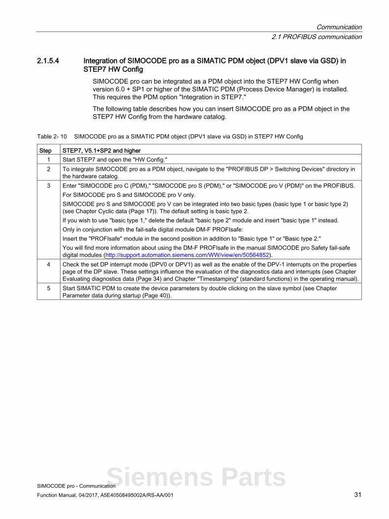
2.1.5.4 Integration of SIMOCODE pro as a SIMATIC PDM object (DPV1 slave via GSD) in STEP7 HW Config
SIMOCODE pro can be integrated as a PDM object into the STEP7 HW Config when version 6.0 + SP1 or higher of the SIMATIC PDM (Process Device Manager) is installed. This requires the PDM option "Integration in STEP7."
The following table describes how you can insert SIMOCODE pro as a PDM object in the STEP7 HW Config from the hardware catalog.
Table 2- 10 SIMOCODE pro as a SIMATIC PDM object (DPV1 slave via GSD) in STEP7 HW Config
Step STEP7, V5.1+SP2 and higher 1 Start STEP7 and open the "HW Config." 2 To integrate SIMOCODE pro as a PDM object, navigate to the "PROFIBUS DP > Switching Devices" directory in
the hardware catalog. 3 Enter "SIMOCODE pro C (PDM)," "SIMOCODE pro S (PDM)," or "SIMOCODE pro V (PDM)" on the PROFIBUS.
For SIMOCODE pro S and SIMOCODE pro V only. SIMOCODE pro S and SIMOCODE pro V can be integrated into two basic types (basic type 1 or basic type 2) (see Chapter Cyclic data (Page 17)). The default setting is basic type 2. If you wish to use "basic type 1," delete the default "basic type 2" module and insert "basic type 1" instead. Only in conjunction with the fail-safe digital module DM-F PROFIsafe: Insert the "PROFIsafe" module in the second position in addition to "Basic type 1" or "Basic type 2." You will find more information about using the DM-F PROFIsafe in the manual SIMOCODE pro Safety fail-safe digital modules (http://support.automation.siemens.com/WW/view/en/50564852).
4 Check the set DP interrupt mode (DPV0 or DPV1) as well as the enable of the DPV-1 interrupts on the properties page of the DP slave. These settings influence the evaluation of the diagnostics data and interrupts (see Chapter Evaluating diagnostics data (Page 34) and Chapter "Timestamping" (standard functions) in the operating manual).
5 Start SIMATIC PDM to create the device parameters by double clicking on the slave symbol (see Chapter Parameter data during startup (Page 40)).
Siemens Parts

Communication 2.1 PROFIBUS communication
SIMOCODE pro - Communication 32 Function Manual, 04/2017, A5E40508495002A/RS-AA/001
2.1.5.5 Integration of SIMOCODE pro as an S7 slave via OM SIMOCODE pro The "OM SIMOCODE pro" software must be installed to utilize the advantages of SIMOCODE ES and parameterize SIMOCODE pro from the STEP7 HW Config. OM SIMOCODE pro is included in the scope of supply of the "SIMOCODE ES Premium" software.
Install the software accordingly.
The following table describes how to insert SIMOCODE pro into STEP7 HW Config from the hardware catalog.
Table 2- 11 Integration of SIMOCODE pro as an S7 slave via OM SIMOCODE pro
Step STEP7 1 Start STEP7 and open the "HW Config." 2 To integrate SIMOCODE pro as an S7 slave, navigate through the hardware
catalog to directory "PROFIBUS DP → Switching Devices → Motor Management System" 3 Enter SIMOCODE pro C, SIMOCODE pro S, SIMOCODE pro V (basic type 1) or SIMOCODE pro S,
SIMOCODE pro V (basic type 2) on the PROFIBUS. For SIMOCODE pro S and SIMOCODE pro V only. SIMOCODE pro S and SIMOCODE pro V can be integrated into two basic types (basic type 1 or basic type 2) (see Chapter Cyclic data (Page 17)). Enter the desired basic type "Basic type 1" or "Basic type 2" as the module. Only in conjunction with the fail-safe digital module DM-F PROFIsafe: Enter the desired basic type "Basic type 1 - PROFIsafe" or "Basic type 2 - PROFIsafe" as the module. You will find more information about using the DM-F PROFIsafe in the manual SIMOCODE pro Safety fail-safe digital modules (http://support.automation.siemens.com/WW/view/en/50564852).
4 Start the SIMOCODE ES software to generate the device parameters with the "Parameters" button under "Parameters" in the object properties of slot 4 of this S7 slave. The created parameters are incorporated in STEP7 and automatically transmitted to SIMOCODE pro during startup (see Chapter Parameter data during startup (Page 40)).
If SIMOCODE pro has been integrated as an S7 slave, you can utilize the routing functionality provided by SIMOCODE ES Premium.
A prerequisite for the availability of this function is that an online connection can be established (for example via Industrial Ethernet) between the PC on which SIMOCODE ES is installed and the SIMATIC controller that supports routing.
In this manner, you can use routing to access all SIMOCODE pro devices connected to the controller.

Communication 2.1 PROFIBUS communication
SIMOCODE pro - Communication Function Manual, 04/2017, A5E40508495002A/RS-AA/001 33
2.1.5.6 Compatibility of SIMOCODE pro S and SIMOCODE pro V SIMOCODE pro S and SIMOCODE pro C each have their own gsd file (see Integration of SIMOCODE pro as a DPV1 slave via GSD in the configuring software (Page 29)).
It is nevertheless possible to replace a SIMOCODE pro C basic unit with a SIMOCODE pro S basic unit.
SIMOCODE pro S basic units can be addressed with unchanged functionality by configuring with a SIMOCODE pro C gsd file. SIMOCODE pro C parameter settings using output 3 of the basic unit are changed in such a way when using SIMOCODE pro S that output 1 of the multifunction module is used instead of output 3 of the basic unit.
For configurations that use the new functions of the SIMOCODE pro S multifunction module (additional inputs and outputs, ground fault detection, temperature measurement), configuring using the SIMOCODE pro S gsd file is absolutely necessary.
The same applies when integrating into STEP 7 via the Object Manager of SIMOCODE pro C.
Siemens Parts

Communication 2.1 PROFIBUS communication
SIMOCODE pro - Communication 34 Function Manual, 04/2017, A5E40508495002A/RS-AA/001
2.1.6 Evaluating diagnostics data
2.1.6.1 Evaluating diagnostics data The way in which the diagnostics data is read out depends in which DP master system you have integrated SIMOCODE pro and the method of integration used (see Chapter Integration of SIMOCODE pro as a DPV1 slave via GSD in the configuring software (Page 29)).
2.1.6.2 SIMOCODE pro integrated with GSD
DP master with DPV1 interrupt support (DPV1 interrupt mode) (e.g. all later SIMATIC S7-300 / 400 DP master systems)
In a DP master system with DPV1 interrupt support, the diagnostics data is transferred and evaluated by means of diagnostic and hardware interrupts.
These interrupts must be enabled in the PROFIBUS configuring tool for this purpose (diagnostic interrupts, hardware interrupts).
Using the configuring tool, you can define the DP interrupt mode in which the integration took place in the DP slave properties and specify whether interrupts are enabled. In SIMATIC STEP7, this is carried out in HW Config via the properties of the DP slave.
● Behavior and sequence in STEP7: Behavior and sequence in STEP7A diagnosis interrupt (OB 82) is triggered in the CPU every time a new device fault is diagnosed, whereas a hardware interrupt (OB 40) is triggered every time a new process fault / warning / status information is diagnosed. If OB 82 or OB 40 has not been programmed, the CPU switches to "STOP" mode.
● Interrupts from a DPV1 slave, received with STEP7: The interrupt is read directly in OB 82 or OB 40 with SFB 54 "RALRM." The data range addressed with SFB 54 by means of the "AINFO" parameter contains the interrupt information described in Section "Diagnostic interrupt - structure" and in the Section "Hardware interrupt - structure." The first byte which is read corresponds to byte 28.
Note
The interface of SFB 54 "RALRM" is identical to the interface of FB "RALRM" as defined in the "PROFIBUS Guideline PROFIBUS Communication and Proxy Function Blocks according to IEC 61131-3" standard.
You will find further information about SFB 54 in the STEP7 online help.

Communication 2.1 PROFIBUS communication
SIMOCODE pro - Communication Function Manual, 04/2017, A5E40508495002A/RS-AA/001 35
DP master without DPV1 interrupt support (DPV0 interrupt mode) (e.g. all later SIMATIC S7-300 / 400 DP master systems)
SIMOCODE pro diagnostics data can be evaluated via device-specific diagnostics (status information) and channel-related diagnostics (as part of extended diagnostics, see Chapter Structure of the slave diagnostics (Page 19)) in DP master systems without DPV1 interrupt support.
Using the configuring tool, you can define the DP interrupt mode in which the integration took place in the DP slave properties.
Device-specific diagnostics contain detailed information about faults, warnings and status information which are recorded by the process via SIMOCODE pro. Information concerning hardware faults is transmitted via channel-related diagnostics.
● Behavior and sequence in STEP7: OB 82 is started in the CPU every time a new device or process fault / warning / status information is diagnosed. If OB 82 has not been programmed, the CPU switches to "STOP" mode.
● Readout of the slave diagnostics data with STEP7: You can determine which DP slave has supplied diagnostics data by evaluating the start information in OB 82 ("OB82_MDL_ADDR" variable). OB82_MDL_ADDR corresponds here to the diagnostics address of the slave that is configured in HW Config. The diagnostics data itself is read, for instance, in the cyclic part of the user program with SFC 13 "DPNRM_DG." The diagnostics data that is read with SFC 13 has the structure described in Chapter Structure of the slave diagnostics (Page 19). For further information on SFC 13, please refer to the STEP7 Online Help system.
Siemens Parts

Communication 2.1 PROFIBUS communication
SIMOCODE pro - Communication 36 Function Manual, 04/2017, A5E40508495002A/RS-AA/001
2.1.6.3 Integration of SIMOCODE pro in SIMATIC S7 with OM SIMOCODE ES
Diagnostic interrupt/hardware interrupt The diagnostics data concerning diagnosis alarms and process interrupts is transmitted and evaluated during the integration of SIMOCODE pro as an S7 slave.
DP masters operated in DP mode "DPV1" (e.g. all later SIMATIC S7-300/400 DP master systems) Behavior and sequence in STEP7:
Behavior and sequence in STEP7A diagnosis interrupt (OB 82) is triggered in the CPU every time a new device fault is diagnosed, whereas a hardware interrupt (OB 40) is triggered every time a new process fault / warning / status information is diagnosed. If OB 82 or OB 40 has not been programmed, the CPU switches to "STOP" mode.
Interrupts from a DPV1 slave, received with STEP7:
The interrupt is read directly in OB 82 or OB 40 with SFB 54 "RALRM."
The data range addressed with SFB 54 by means of the "AINFO" parameter contains the interrupt information described in Section "Structure of the slave diagnostics (Page 19)". The first byte which is read corresponds to byte 28.
You will find further information on SFB 54 in the STEP7 online help.
DP masters operated in DP mode "S7-compatible" (e.g. all early SIMATIC S7-300/400 DP master systems)
Behavior and sequence in STEP7:
Behavior and sequence in STEP7A diagnosis interrupt (OB 82) is triggered in the CPU every time a new device fault is diagnosed, whereas a hardware interrupt (OB 40) is triggered every time a new process fault / warning / status information is diagnosed. If OB 82 or OB 40 has not been programmed, the CPU switches to "STOP" mode.
You will find information about the device fault in the start information of OB 82 in the "OB82_MDL_DEFECT" variable. The start information of OB 40 contains the "OB40_POINT_ADDR" variable, which in turn contains the data of the hardware interrupt that is described in bytes 32 to 35 (see Section "Structure of the slave diagnostics (Page 19)"). Reading the entire diagnosis can then be initiated, for example, from OB 40, while the complete diagnostic record 92 is being read in the cyclic user program with the SFC 52 "RD_REC", for example.
You will find further information on SFB 59 in the STEP7 online help.

Communication 2.1 PROFIBUS communication
SIMOCODE pro - Communication Function Manual, 04/2017, A5E40508495002A/RS-AA/001 37
2.1.7 Data records
Records - general information Data records contain additional information about the DP slave that can be read and, in some cases, written.
Access is effected via acyclic DPV1 services for reading and writing these records. Operation, monitoring, and parameterization is possible, for example, by SIMOCODE pro.
You can use these services as long as they are supported by your DP master. You will find an overview of the records provided by SIMOCODE pro in Chapter PROFIBUS data records (Page 162).
Unlike when cyclic I/O data is accessed, special function blocks must be called in the PLC to access DPV1 data records in the user program.
Access to data records in STEP7 Read and write access to the data records takes with the system function blocks SFB 52 "RDREC" and SFB 53 "WRREC".
You will find further information about SFB and SFC in the STEP7 online help.
Siemens Parts

Communication 2.1 PROFIBUS communication
SIMOCODE pro - Communication 38 Function Manual, 04/2017, A5E40508495002A/RS-AA/001
2.1.8 Parameterization via PROFIBUS
2.1.8.1 SIMOCODE ES Premium With SIMOCODE ES Premium you can parameterize all the SIMOCODE pro devices which are connected to the same PROFIBUS DP network from a central location. Parameter data which has been previously created with the software can therefore be transmitted directly to SIMOCODE pro via PROFIBUS DP.
Note
A PC with a system connection for PROFIBUS (e.g. SIMATIC NET CP 5612 (PCI) or CP 5622 (PCI-Express)) is required to execute online functions via PROFIBUS DP, e.g. transfer of SIMOCODE pro parameters.
The system connections for PROFIBUS mentioned above are operated in conjunction with SIMOCODE ES Premium as master class 2 and use acyclic DPV1 communication functions for communication with SIMOCODE pro.
If SIMOCODE pro has been integrated as an S7 slave, you can utilize the routing functionality provided by SIMOCODE ES Premium. A prerequisite for the availability of this function is that an online connection can be established (for example via Industrial Ethernet) between the PC on which SIMOCODE ES is installed and the SIMATIC controller that supports routing. In this manner, you can use routing to access all SIMOCODE pro devices connected to the controller.
Note
The startup parameter block (Device Parameters > Bus Parameters) must always be set for this form of parameterization to avoid the device parameters from being overwritten by any existing parameter data during startup.

Communication 2.1 PROFIBUS communication
SIMOCODE pro - Communication Function Manual, 04/2017, A5E40508495002A/RS-AA/001 39
2.1.8.2 SIMATIC PDM The standard version of SIMATIC PDM (PDM Basic) is available to you for parameterizing functionality comparable to that of SIMOCODE ES Professional via PROFIBUS for SIMOCODE pro.
The PDM options "Integration in STEP7" provides the following functions in addition:
● "Offline saving" of SIMOCODE pro parameter data in the STEP7 project and manual transmission (no automatic transfer of parameter data during startup!)
● "Routing via S7 stations." Example: Parameterization of all SIMOCODE pro devices from a central engineering station, together with hardware components which provide a data record gateway (CP443-5 Extended, IE / PB link), beyond the boundaries of different networks where required.
Note
The startup parameter block (Device parameters > Bus parameters) must always be set for this form of parameterization to avoid the device parameters from being overwritten by any existing parameter data during startup.
You will find further information about SIMATIC PDM in the Manual SIMATIC Process Control System PCS 7 SIMATIC PDM (http://support.automation.siemens.com/WW/view/en/57355963).
Siemens Parts

Communication 2.1 PROFIBUS communication
SIMOCODE pro - Communication 40 Function Manual, 04/2017, A5E40508495002A/RS-AA/001
2.1.8.3 Parameter data during startup Parameter data is transferred to the unit on the PROFIBUS DP each time SIMOCODE pro is started up.
Either standard parameters only or standard and device-specific parameters (SIMOCODE pro parameters) are transferred, depending on the master module used and the type of integration into the DP master system. The parameters are stored in the PLC or the DP master and automatically transferred to the DP slave when the system is started up.
You can set the device-specific parameters
● with the configuration tool with loaded GSD (SIMOCODE pro C basic unit only), e.g. with STEP7-HW Config. This option is available for SIMOCODE pro C. The SIMOCODE pro parameters are created by configuring the device-specific parameters on the slave properties page.
● in the SIMOCODE ES software with integration of SIMOCODE pro into STEP7-HW Config as an S7 slave via OM SIMOCODE pro. This option is available for SIMOCODE pro C, SIMOCODE pro S, and SIMOCODE pro V. You can start the SIMOCODE ES software for easy configuration of the parameterization from STEP7 HW Config using the button in the "Parameter" tab in the object properties of slot 4.
Note
To allow device parameterization during startup, the startup parameter block (Device parameters > Bus parameters) must not be set.
SIMOCODE pro is then parameterized with the device-specific parameters stored in the DP master. Any parameters already in the device will be overwritten.
2.1.9 Timestamping/time synchronization See Chapter "Timestamping" (standard functions) in the operating manual.

Communication 2.2 PROFINET communication
SIMOCODE pro - Communication Function Manual, 04/2017, A5E40508495002A/RS-AA/001 41
2.2 PROFINET communication
2.2.1 Definitions
GSD file The properties of a PROFINET devices are described in a GSD (General Station Description) file that contains all the necessary information for the configuration. Just as with PROFIBUS, you can link a PROFINET device into an automation system using a GSD file: PROFINET GSD (http://www.siemens.com/profinet-gsd)
In the case of PROFINET IO, the GSD file is in XML format. The structure of the GSD file conforms to ISO 15734, the worldwide standard for device descriptions.
Device name Before an IO device can be addressed by an IO controller, it must have a device name because the IP address is permanently assigned to the device name. In the case of PROFINET, this method was chosen because names are easier to handle than complex IP addresses.
Assignment of a device name for a specific IO device is comparable to setting the PROFIBUS address on a DP slave.
An IO device does not have a device name when it is delivered. It can only be addressed by an IO controller once a device name has been assigned to it, e.g. for transmission of the configuration data (including the IP address) during startup or for exchanging useful data in cyclic operation.
IO Device Distributed field device assigned to one of the IO controllers.
As a field device, the SIMOCODE pro V PN basic unit functions as a PROFINET-IO device.
IP address To enable a PROFINET device to be addressed as a node on Industrial Ethernet, this device also requires an IP address that is unique within the network. The IP address is made up of 4 decimal numbers with a range of values from 0 through 255. The decimal numbers are separated by a decimal point.
The IP address is made up of
● The address of the (sub)net and
● The address of the node (generally called the host or network node)
Siemens Parts

Communication 2.2 PROFINET communication
SIMOCODE pro - Communication 42 Function Manual, 04/2017, A5E40508495002A/RS-AA/001
MAC address Each PROFINET device is assigned a globally unique device identifier at the factory. This 6-byte long device identifier is the MAC address.
The MAC address is divided up as follows:
● 3 bytes manufacturer's ID and
● 3 bytes device identifier (consecutive number).
The MAC address can generally be read from the front on the device, e.g.: 08-00-06-6B-80-C0
OPC Unified Architecture (UA) OPC Unified Architecture (UA) is the next generation technology of the OPC Foundation for safe and reliable data transfer and defines access to industrial communication networks.
OPC UA client An OPC UA client is a user program that accesses process data via the OPC UA interface. Access to the process data is made possible by the OPC UA server.
OPC UA server The OPC server provides the OPC client with a wide range of functions with which it can communicate via industrial networks. SIMOCODE pro V PN provides extensive process data via OPC UA.
PROFINET Within the context of Totally Integrated Automation (TIA), PROFINET is the systematic development of the following systems:
● PROFIBUS DP, the established fieldbus
● Industrial Ethernet, the communications bus for the cell level.
Experiences from both systems have been and are being integrated in PROFINET. PROFINET was defined as an Ethernet-based automation standard of PROFIBUS International (PROFIBUS Nutzerorganisation e. V.).
PROFINET IO controller Device via which the connected IO devices are addressed. That means the IO controller exchanges input and output signals with assigned field devices. The IO controller is often the controller on which the automation program runs.
PROFINET IO Supervisor PG/PC for commissioning and diagnostics.

Communication 2.2 PROFINET communication
SIMOCODE pro - Communication Function Manual, 04/2017, A5E40508495002A/RS-AA/001 43
2.2.2 Data security in automation
Introduction The topic of data security and access protection (security) is becoming more and more important in industrial environments. Increased networking of entire industrial plants, vertical integration and networking of the levels within a company, and new technologies, such as remote maintenance, are resulting in more increased requirements for protection of the industrial plant. Security is the generic term for all protection measures
● Loss of confidentiality due to unauthorized accessing of data
● Loss of integrity due to data manipulation
● Loss of availability due to destruction of data
To provide protection from manipulation in sensitive plant and production networks, it is not enough to apply data security solutions for offices to industrial applications without any adaptation.
Requirements The special requirements of communication in an industrial environment (e.g. communication in real time) result in additional requirements for security in industrial use:
● Protection against interaction between automated cells
● Protection of network segments
● Protection from unauthorized access
● Scalability of the security functionality
● No influence on the network structure.
Siemens Parts
Communication 2.2 PROFINET communication
SIMOCODE pro - Communication 44 Function Manual, 04/2017, A5E40508495002A/RS-AA/001
Threats Threats can arise from external and internal manipulation. Loss of data security is not always caused by deliberate actions.
Internal threats arise due to:
● Technical faults
● Operating errors
● Errors in programs.
This internal hazards are compounded by external threats. The external hazards do not differ from the known threats in the office environment:
● Computer viruses and computer worms
● Trojan horses
● Unauthorized access
● Password phishing.
Password phishing means attempting to get a user to divulge access data and passwords by masquerading as a different identity in an e-mail.
Precautions The most important precautions against manipulation and loss of data security in an industrial environment are:
● Filtering and verification of data traffic through virtual private networks (VPN). A virtual private network is used to exchange private data in a public network (e.g. the Internet). The most common VPN technology is IPsec. IPsec is a collection of protocols based on the IP protocol at the network layer.
● Segmentation into protected automation cells. The aim of this concept is to protect devices in the network through security modules. A group of protected devices forms a protected automation cell. Only security modules in the same group or the device protected by you can be interchanged.
● Authentication (identification) of the networked devices. The security modules identify themselves to each other via a secure (encrypted) channel using authentication procedures. This prevents access to a protected segment by unauthorized persons from outside.
● Encryption of the data traffic. The confidentiality of the data is ensured by encrypting the data traffic. For this purpose, every security module is given a VPN certificate which includes the encryption key.

Communication 2.2 PROFINET communication
SIMOCODE pro - Communication Function Manual, 04/2017, A5E40508495002A/RS-AA/001 45
Guidelines on information security in industrial automation
VDI guideline
The VDI/VDE Association of German Engineers "Measurement and Automation" has published with the VDI guideline "VDI/VDE 2182 Sheet 1, IT Security for Industrial Automation - General Model" a guideline in implementation of a security architecture in the industrial environment. The guideline is found under "VDI guidelines" on the VDI home page: VDI guidelines (http://www.vdi.eu/engineering/vdi-standards)
PROFINET Security Guideline
The PROFIBUS & PROFINET user organization supports you with building up safety standards in your company with the PROFINET Security Guideline. These guidelines are found under downloads on the home page of the PROFIBUS & PROFINET user organization: PI - PROFIBUS & PROFINET International Home (http://www.profibus.com)
Security information See Security information (Page 11).
Siemens Parts

Communication 2.2 PROFINET communication
SIMOCODE pro - Communication 46 Function Manual, 04/2017, A5E40508495002A/RS-AA/001
2.2.3 Data transfer
Options for data transfer The following figure shows an overview of the communication functions supported by SIMOCODE, which are described in the following sections:
Figure 2-10 SIMOCODE pro V PN communication functions
1 Communication between PLC (IO controller) and SIMOCODE pro (IO device) via PROFINET / Ethernet
2 Communication between PC with parameterization software SIMOCODE ES and SIMOCODE pro via PROFINET
3 Communication between PC with parameterization software SIMOCODE ES Premium and SIMOCODE pro via SIMATIC S7 (SIMOCODE pro integrated into SIMOCODE ES (TIA-Portal))
4 Communication between PC parameterization software SIMOCODE and SIMOCODE pro via the SIMOCODE pro system interface (point-to-point via RS 232 or USB)
5 Communication between PC or HMI with OPC UA Client and SIMOCODE pro via Ethernet/OPC UA
6 Communication between PC with a web browser and SIMOCODE pro via TCP/IP and HTTP
Communication 2.2 PROFINET communication
SIMOCODE pro - Communication Function Manual, 04/2017, A5E40508495002A/RS-AA/001 47
2.2.4 Communication via PROFINET IO SIMOCODE pro V PN provides communication functions via PROFINET IO with the following properties: ● Integrated switch with 2 ports
With the integrated 2-port switch, it is possible to build PROFINET bus and ring topologies without additional switches. The integrated 2-port switch supports functions for port diagnostics if this functions are used by the automation system. ● Device replacement without removable medium/programming device
This is a function that permits replacement of a device (e.g. in case of a device defect) by a new device with factory settings without the help of PCs or programming devices without a memory module. ● Shared device
Shared device is the function with which an IO device is used simultaneously by two or more IO controllers. This function can be used in conjunction with the fail-safe DM-F PROFIsafe digital module. An automation system communicates with SIMOCODE pro via PROFINET IO and performs the standard control tasks while a second fail-safe automation system via PROFINET IO can be used for safety-related tripping using the PROFIsafe profile.
Use of this function depends on whether the automation system supports the function. It is configured using the configuration tool of the automation system, e.g. with STEP 7 HW Config. ● Media redundancy
SIMOCODE pro V PN supports media redundancy according to the Media Redundancy Protocol (MRP). This function is configured using the configuration tool of the automation system, e.g., HW Config with STEP 7. ● System redundancy
Product version *E05* and higher of SIMOCODE pro V PN supports a redundant-system connection with two S7-400H CPUs. This provides for a communication link (Application Relation) between each IO device and each of the two H CPUs. The communication link can be set up by means of a freely selectable topological connection. This function is configured using the configuration tool of the automation system, e.g., HW Config with STEP 7. ● RT communication
As a motor management system, SIMOCODE pro V PN does not have any time-critical communication functions itself but it does support PROFINET hardware RT used. The integrated 2-port switch can therefore be used to forward RT data. ● Support for PROFIenergy
PROFIenergy, a protocol defined by the PROFINET User Organization, lays the foundations for a vendor-neutral, universal system for flexible, short-term, and intelligent shutdown of individual loads or whole production units. SIMOCODE pro V PN supports the functions defined in the protocol in the form of a switchgear with switching and measuring functions You will find more information in the system manual "SIMATIC PROFINET System Description" (see System manual "SIMATIC PROFINET System Description" (http://support.automation.siemens.com/WW/view/en/19292127)).
Siemens Parts

Communication 2.2 PROFINET communication
SIMOCODE pro - Communication 48 Function Manual, 04/2017, A5E40508495002A/RS-AA/001
2.2.5 Integration of SIMOCODE pro into the automation system (PLC)
I/O configurations SIMOCODE pro V PN supports a number of I/O configurations which define the structure and length of the I/O data that are cyclically transferred between the IO controller (PLC) and the IO device (SIMOCODE pro). In the case of SIMOCODE pro, these configurations are termed Basic types.
Cyclic data to SIMOCODE pro V (PN)
The following basic types are available:
● Basic type 1, 4 bytes:
Figure 2-11 Cyclic data to SIMOCODE pro, basic type 1, 4 bytes
● Basic type 2, 2 bytes:
Figure 2-12 Cyclic data to SIMOCODE pro, basic type 2, 2 bytes
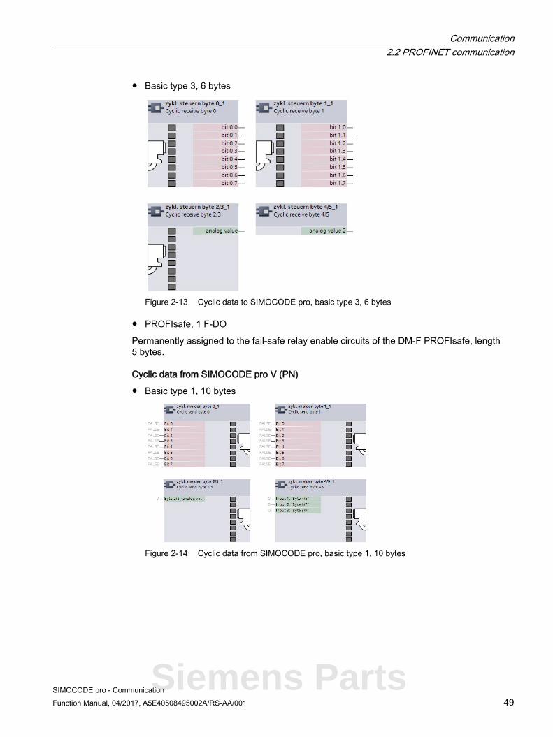
Communication 2.2 PROFINET communication
SIMOCODE pro - Communication Function Manual, 04/2017, A5E40508495002A/RS-AA/001 49
● Basic type 3, 6 bytes
Figure 2-13 Cyclic data to SIMOCODE pro, basic type 3, 6 bytes
● PROFIsafe, 1 F-DO
Permanently assigned to the fail-safe relay enable circuits of the DM-F PROFIsafe, length 5 bytes.
Cyclic data from SIMOCODE pro V (PN)
● Basic type 1, 10 bytes
Figure 2-14 Cyclic data from SIMOCODE pro, basic type 1, 10 bytes
Siemens Parts
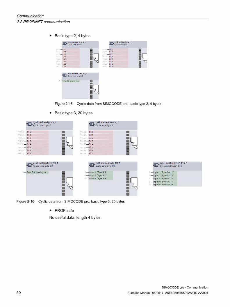
Communication 2.2 PROFINET communication
SIMOCODE pro - Communication 50 Function Manual, 04/2017, A5E40508495002A/RS-AA/001
● Basic type 2, 4 bytes
Figure 2-15 Cyclic data from SIMOCODE pro, basic type 2, 4 bytes
● Basic type 3, 20 bytes
Figure 2-16 Cyclic data from SIMOCODE pro, basic type 3, 20 bytes
● PROFIsafe
No useful data, length 4 bytes.

Communication 2.2 PROFINET communication
SIMOCODE pro - Communication Function Manual, 04/2017, A5E40508495002A/RS-AA/001 51
2.2.6 Integration of SIMOCODE pro V PN via GSD Using the GSD, integration into the PROFINET-IO system and device diagnostics are possible. For parameterization of the device function of SIMOCODE pro, use the SIMOCODE ES software.
Integrate the GSD for SIMOCODE pro V PN into the configuration tool of your automation system (e.g. STEP 7 HW Config). The GSD is available for downloading at the following link: PROFINET GSD (http://www.siemens.com/profinet-gsd)
After installation of the GSD, you will find SIMOCODE pro V PN in the hardware catalog of STEP7 V5 under "Hardware Catalog → Additional Field Devices → PROFINET IO → Switching Devices → Siemens AG → Motor Management System." Insert the SIMOCODE pro V (PN) into the PROFINET IO system.
After insertion of SIMOCODE pro V (PN), configure one of the three possible basic types in Slot 1 of the IO device inserted in this way (see figures about "Cyclic data to SIMOCODE pro" and "Cyclic data of SIMOCODE pro").
If SIMOCODE pro V PN is used in conjunction with the fail-safe DM-F PROFIsafe digital module, additionally configure the I/O configuration for PROFIsafe in Slot 2.
Siemens Parts

Communication 2.2 PROFINET communication
SIMOCODE pro - Communication 52 Function Manual, 04/2017, A5E40508495002A/RS-AA/001
2.2.7 Integration of SIMOCODE pro V PN in SIMATIC STEP 7 V5 via OM SIMOCODE pro
Integration of SIMOCODE pro V PN in SIMATIC STEP 7 V5 via OM SIMOCODE pro In addition to integration via GSD, with SIMATIC S7 controllers from Siemens it is possible to integrate SIMOCODE pro V PN in STEP 7 V5 using the "Object Manager (OM) SIMOCODE pro V PN" software as part of Totally Integrated Automation (TIA).
The advantage is that the SIMOCODE ES parameterization software can be called directly from STEP 7 HW Config and can be used for developing SIMOCODE pro V PN device parameters.
The SIMOCODE pro device parameters are stored in the STEP 7 project. After transmission of the hardware configuration, the device parameters are available in the form of start-up parameter data records in the CPU and are automatically transmitted during start-up.
The necessary OM SIMOCODE pro V PN software is part of SIMOCODE ES. During installation of SIMOCODE ES, select the "Integration in STEP 7" installation option to use the described function.
When the hardware is being configured, SIMOCODE pro V PN is integrated by selecting SIMOCODE pro in the hardware catalog from STEP 7 HW Config under "PROFINET IO → Switching Devices → Motor Management System".
Insert the SIMOCODE pro V PN into the PROFINET IO system.
Select one of the three possible basic types (see figure "Cyclic data to SIMOCODE pro" and figure "Cyclic data from SIMOCODE pro").
Note Changing the slot
It is only possible to change the slot by selecting another SIMOCODE type!
When using SIMOCODE pro V PN in conjunction with the fail-safe DM-F PROFIsafe digital module, select the relevant configuration with PROFIsafe.
Communication 2.2 PROFINET communication
SIMOCODE pro - Communication Function Manual, 04/2017, A5E40508495002A/RS-AA/001 53
Module replacement without exchangeable medium/PC
Note Precondition for module replacement without exchangeable medium/PC
The use of this function depends whether the IO controller and the neighboring IO devices support this function.
Assuming SIMOCODE pro in STEP 7 V5 has been integrated and parameterized using OM SIMOCODE pro, the IO controller can automatically restore the device name, the IP configuration, and then the complete device parameterization performed with SIMOCODE ES of the replaced device.
Note Do not use a memory module or initialization module!
To use this function, you do not have to and indeed must not use of a memory module or an initialization module!
For further information, see Chapter "Restoring factory settings" in the SIMOCODE pro system manual.
2.2.8 Configuring SIMOCODE pro V PN ports
Configuring the ports SIMOCODE pro V PN has two RJ45 ports labeled 1 and 2 on the front. In the configuration tool of the automation system (e.g. STEP 7 HW Config), the settings for topology, diagnostics and other options of the two ports X1P1 and X1P2 are defined.
Siemens Parts

Communication 2.2 PROFINET communication
SIMOCODE pro - Communication 54 Function Manual, 04/2017, A5E40508495002A/RS-AA/001
2.2.9 Configuration of further properties of SIMOCODE pro V PN as an IO device
Device name and IP parameters The precondition for PROFINET IO communications is setting and configuring the IO device name and IP parameters.
The device name and the IP parameters can be assigned in different ways:
● Assigning device names using the configuration tool of the automation system
● Configure device names with SIMOCODE ES parameterization software and download to the device.
Assigning device names using the configuration tool of the automation system
The device name is assigned during the commissioning phase by the configuration tool of the automation system (e.g. STEP 7) or with the SIMOCODE ES configuration software and transmitted into the IO device via Ethernet. For transmission, the basic unit must be connected and accessible via the Ethernet interface. Using the MAC address (e.g. 00-0E-8C-BD-1F-27) printed on the front of the basic unit, the device can be accessible via LAN. In this case, the "Overwrite device name in device" parameter set with the SIMOCODE ES parameterization software under "PROFINET Parameters → Station" must not be active.
1. Device is given a technological name as part of configuration by the user (device name here: Motor-1). STEP 7 automatically assigns an IP parameter
2. The user assigns the device name to an IO device based on the MAC address and transfers this in the Online & Diagnostic functions of SIMOCODE ES (TIA Portal)
3. The user loads the configuration into the IO controller
4. IO controller assigns the IP parameters during start-up based on the device name

Communication 2.2 PROFINET communication
SIMOCODE pro - Communication Function Manual, 04/2017, A5E40508495002A/RS-AA/001 55
Configuring device names with SIMOCODE ES parameterization software and downloading to the device
In this case, the device name must be configured under "PROFINET Parameters → Station" and the "Overwrite device name in device" parameter must be active.
Note Transferring the device parameters
It is always possible to transfer the device parameters via the system interface.
If the PROFINET IO device name has already been configured in a different way, the device parameters can be transferred via PROFINET, too.
Note Assignment of the device name
The device name can be assigned with the "SIMOCODE ES" parameterization software in the Online & Diagnostic Functions. This function is not identical with parameterization with the "PROFINET parameter" dialog box. Unlike in this dialog box, under "PROFINET Parameters → Station," the "Overwrite device name in device" parameter must not be active.
Note Changing the device name
Every change to the device name with SIMOCODE ES in the "PROFINET Parameters" dialog box requires a restart of the communication interface. A new start interrupts all Ethernet and PROFINET links and reestablishes them afterward.
1. Device is given a technological name (device name here: Motor-1)
2. Configuration is loaded into the IO controller
3. Configuration of device names and IP parameters with SIMOCODE ES: a) Device name "Motor-1" is configured with SIMOCODE ES and is transferred into the device via the system interface / PROFINET b) Device name and IP parameter are configured with SIMOCODE ES and are transferred into the device via the system interface / PROFINET
Siemens Parts
Communication 2.2 PROFINET communication
SIMOCODE pro - Communication 56 Function Manual, 04/2017, A5E40508495002A/RS-AA/001
Transferring IP parameters
The IP parameters, consisting of IP address, subnet mask, and router can also be assigned in various ways and transferred to the IO Device.
Possibilities for this are:
● The IO Controller assigns the IP parameters to the IO Device. In this case, the "Overwrite IP parameters in device" parameter set with the SIMOCODE ES parameterization software under "PROFINET Parameters → IP Parameters" must not be active.
Note
Deleting IP parameters
IP parameters assigned by the IO controller are stored non-retentively in the device, i.e. they are deleted again when the supply voltage is switched off.
● The IP parameters are configured with SIMOCODE ES parameterization software and transferred to the device. In this case, the "Overwrite IP parameters in device" parameter under "PROFINET Parameters → IP Parameters" must be active.
Note
Transferring the device parameters
It is always possible to transfer the device parameters via the system interface.
If the PROFINET IO device name has already been configured in a different way, the device parameters can be transferred via PROFINET, too.
Note
Assigning the IP parameters
The IP parameters can be assigned with the "SIMOCODE ES" parameterization software in the Online & Diagnostic Functions. This function is not identical with the parameterization of the IP parameters with the "PROFINET Parameters" dialog box. Unlike in this dialog box, under "PROFINET Parameters → IP Parameters," the "Overwrite IP parameters in device" parameter must not be active.
Note
Restarting the communication interface
Every change to the IP parameter with SIMOCODE ES in the "PROFINET Parameters" dialog box requires a restart of the communication interface.
A new start of the communication interface interrupts all Ethernet and PROFINET links and reestablishes them afterward.

Communication 2.2 PROFINET communication
SIMOCODE pro - Communication Function Manual, 04/2017, A5E40508495002A/RS-AA/001 57
2.2.10 Identification data for PROFINET IO
Brief description of the identification data Identification data are information that is stored in the PROFINET IO device and supports the user with the following activities:
● Checking the system configuration
● Locating modified system hardware
● Troubleshooting a system.
With the identification data, SIMOCODE pro V PN can be uniquely identified online.
The identification data can be edited with the configuration tool of the automation system (e.g. STEP 7) and with SIMOCODE ES and transferred to the device or read out of the device.
In STEP 7, the identification data are displayed on the "Module status" and "Properties ..." tab cards and loaded into the modules with "Load module identification data ..." with menu item "Target System." It is possible to transfer data already in the device into the configuration with "Load module identification data into the programming device" when configuring via GSD file (see STEP 7 Online Help on this function).
You can also assign the identification data with SIMOCODE ES. You will find this under "Identification." Only I&M 1 to I&M 3 can be changed.
The following identification data records are supported:
● I&M 0: Identification (device identification); read only
● I&M 1: Tag (plant identifier, location designation)
● I&M 2: Installation Date
● I&M 3: Descriptor (comment).
Siemens Parts

Communication 2.2 PROFINET communication
SIMOCODE pro - Communication 58 Function Manual, 04/2017, A5E40508495002A/RS-AA/001
2.2.11 Shared device
Shared device provision PROFINET IO provides the shared device function. Shared device enables access by two IO controllers to one IO device. Input and output data can be flexibly assigned to different IO controllers.
This function can only be used in conjunction with the fail-safe DM-F PROFIsafe expansion module. While one controller accesses the standard I/O data via an IO controller and performs the routine control, the fail-safe program is processed in a separate, fail-safe controller that is responsible for safety-related tripping via PROFIsafe.
Shared device configuration
The I/O data is assigned to the IO controllers in the configuration tool of the automation system (e.g. STEP 7 HW Config).
Note Shared device function
The system redundancy function is not available when the "Shared Device Function" is used.
2.2.12 Media redundancy
Media redundancy support The media redundancy protocol manages a redundant network. The data that are exchanged between IO controller and IO device are transmitted via two different paths.
If both Ethernet ports are used, the function enables communication to be maintained even if one of the two transmission channels fails.
Settings for media redundancy
In the configuration tool of the automation system (e.g. STEP 7 HW Config), the settings for media redundancy in the properties of Slot X1 of the relevant PN-IO devices. In particular, the MRP domain is assigned and the role is defined that will be taken over in the MRP by the device. SIMOCODE pro V PN supports ring redundancy in the role as a client.
Information material for media redundancy
You will also find useful information about "Ring redundancy with the Media Redundancy Protocol (MRP)" under: Ring redundancy with the Media Redundancy Protocol (MRP) (http://support.automation.siemens.com/WW/view/en/33696406)

Communication 2.2 PROFINET communication
SIMOCODE pro - Communication Function Manual, 04/2017, A5E40508495002A/RS-AA/001 59
2.2.13 System redundancy
System redundancy with H CPUs The redundant-system connection via PROFINET provides a communication link (Application Relation) between each SIMOCODE pro V PN IO device and each of the two H CPUs. The communication link can be set up by means of a freely selectable topological connection, i.e. the topology of a plant does not indicate whether or not SIMOCODE pro V PN is interfaced via a redundant-system connection. In addition to operation as a redundant system, the SIMOCODE pro V PN can also be operated on H CPUs as a so-called "non-redundant IO device". In this mode, only one of the two CPUs establishes a communication link to the IO device. The disadvantage of operating an IO device as a non-redundant device is that it will fail in the event of failure of the CPU to which it is linked.
Note Firmware version of the H CPU
System redundancy is supported with H CPU firmware version V6.0.3 and higher.
SIMOCODE pro V PN with system redundancy The diagram below illustrates a configuration with two redundant-system SIMOCODE pro V PN basic units. This topology offers particular advantages. The entire system can remain in operation if a line break occurs anywhere in the configuration. One of the two SIMOCODE pro V PN communication links always remains operational. The SIMOCODE pro V PN units then function like non-redundant devices.
Figure 2-17 S7-400 H system with redundant I/Os
① S7-400H system
② SIMOCODE pro V PN as a redundant IO device
Siemens Parts

Communication 2.2 PROFINET communication
SIMOCODE pro - Communication 60 Function Manual, 04/2017, A5E40508495002A/RS-AA/001
PN/IO with non-redundant I/Os The following diagram illustrates an example of a topographical configuration with one switch. Two IO devices are connected as non-redundant units and the other three IO devices as redundant-system units.
Figure 2-18 S7-400 H system with redundant and non-redundant I/Os
① S7-400H system
② SCALANCE (e.g. X400)
③ SIMOCODE pro as a redundant IO device
④ SIMOCODE pro as a non-redundant IO device
Maximum number of IO devices You can connect a maximum number of 256 IO devices to the two integrated PN/IO interfaces. The station numbers range from 1 to 256 and must be unique at both the PN/IO interfaces, i.e. they must not be assigned to a station more than once.

Communication 2.2 PROFINET communication
SIMOCODE pro - Communication Function Manual, 04/2017, A5E40508495002A/RS-AA/001 61
Configuring system redundancy with PROFINET IO
Requirements
In the example below, you will configure a redundant-system PROFINET configuration with redundant I/Os as discussed in diagram "S7-400 H system with redundant I/Os" in the previous chapter.
The PROFIBUS elements have been excluded from this example. Please refer to manual Fault-tolerant S7-400H systems (http://support.automation.siemens.com/WW/view/en/1186523) for basic instructions on configuring H systems.
Procedure
Set up a new H station in the SIMATIC Manager and open "HW Config" for the station.
1. Insert a rack 400 (e.g. UR2-H) for redundant controllers.
2. Insert a CPU 400-H PN/DP (e.g. CPU 4174-5H PN/DP).
3. Network the Ethernet interface in the normal way and set the IP parameters.
4. Configure a power supply module and the H-Sync modules.
5. Copy the station that you have set up: To do this, select the station and then select command Edit → Copy followed by command Edit → Paste.
6. Configure SIMOCODE pro V PN as a redundant IO device by dragging the IO devices in the normal way to one of the two IO systems. The modules will be connected as redundant units (to both PROFINET lines) as standard.
Figure 2-19 SIMOCODE pro V PN as a redundant I/O unit in HW Config
Siemens Parts

Communication 2.2 PROFINET communication
SIMOCODE pro - Communication 62 Function Manual, 04/2017, A5E40508495002A/RS-AA/001
There are two methods by which you can connect SIMOCODE pro V PN as a non-redundant IO device:
● Configure a SIMOCODE pro V PN as a redundant IO device as described above and then navigate to the tab card labeled "Redundancy" in the module properties dialog. By activating the checkbox, you can assign the IO device to a single IO system and thus to a single CPU.
Figure 2-20 "Redundancy" tab card in module properties screen
Configure the SIMOCODE pro V PN specifically as a non-redundant IO at the relevant IO system.
Figure 2-21 SIMOCODE pro V PN connected as a non-redundant device

Communication 2.2 PROFINET communication
SIMOCODE pro - Communication Function Manual, 04/2017, A5E40508495002A/RS-AA/001 63
Note H systems and separate subnets
IO devices are connected as redundant units only if the two PROFINET I/O systems of the H system are in the same subnet. As an alternative, each CPU can be networked with a different subnet. In this case, the IO devices will always be connected as non-redundant units.
Note Shared device function
The system redundancy function is not available when the "Shared Device Function" is used.
Note Product version of SIMOCODE pro V PN basic unit
System redundancy is supported by product version *E05* and higher of SIMOCODE pro V PN with firmware version V1.2.
Siemens Parts

Communication 2.2 PROFINET communication
SIMOCODE pro - Communication 64 Function Manual, 04/2017, A5E40508495002A/RS-AA/001
Possible topologies You can also combine PROFINET-based system redundancy with other PROFINET functions.
System redundancy with media redundancy:
Figure 2-22 Sample configuration for system redundancy with MRP
① S7-400H system
② SCALANCE X400 (non-redundant IO device)
③ SIMOCODE pro V PN (non-redundant/redundant-system IO device)
④ SIMOCODE pro V PN (MRP, non-redundant/redundant-system IO device)
Note Response monitoring time of IO devices
RT communication is interrupted (station failure) if the reconfiguration time setting of the ring is higher than the response monitoring time setting of the IO devices.
For this reason, make sure that the response monitoring time of the IO devices is set to a high enough value. This also applies to IO devices configured with MRP outside the ring.

Communication 2.2 PROFINET communication
SIMOCODE pro - Communication Function Manual, 04/2017, A5E40508495002A/RS-AA/001 65
2.2.14 Diagnostics
Diagnosis - Overview When an error occurs, the defective IO device generates a diagnostics alarm and sends it to the IO controller. To respond to errors with a defined (programmed) response, this alarm calls a corresponding part in the user program (e.g. in the case of SIMATIC S7: organization block OB 82 for the diagnostics alarm).
SIMOCODE pro V PN provides the diagnostics as channel diagnostics data records. Channel diagnostics data records are generated as an alarm for
● Selected signals (see Chapter "Data record 92 - Device diagnostics", PNIO diagnostics column, marked with "1")
● Warnings
● Faults
● Device faults.
Diagnostic status The channel diagnostics is transmitted with different diagnostics states:
● Maintenance required:
● Maintenance demand (maintenance requested):
All SIMOCODE pro monitoring functions with "warn" configured as their response are transmitted with this diagnostics status.
● Failure:
All SIMOCODE pro monitoring functions with "trip" configured as their response are transmitted with this diagnostics status.
Siemens Parts

Communication 2.2 PROFINET communication
SIMOCODE pro - Communication 66 Function Manual, 04/2017, A5E40508495002A/RS-AA/001
Configuring the diagnostics response The diagnostics response is configured with the SIMOCODE ES configuration software. The global enable of the diagnostics can be set for the following events under "PROFINET Parameters → Diagnostics":
Diagnostics for process events
Selected diagnostics events are transmitted with the "maintenance required" diagnostics status.
See also Chapter "Data record 92 - Device diagnostics", diagnostics events marked "1" in the "PNIO diagnostics" column.
Diagnostics for process warnings
All SIMOCODE pro monitoring functions in which the response has been configured with "warn" are transmitted with the "maintenance demand" diagnostics status.
Diagnostics for process faults
All SIMOCODE pro monitoring functions with "trip" configured as their response are transmitted with the "fault" diagnostics status.
Diagnostics for device faults
Diagnostics events that can occur in connection with defective hardware or incorrect parameterization are also transmitted with the "fault" diagnostics status.
The response of the different monitoring functions can be configured individually. Depending on the function, the following can be selected by configuration:
● Deactivated: There is no response. No diagnostics are produced.
● Signaling: The diagnostics event is entered in data record 92 and is displayed in the "Faults/Warnings/Events" online dialog box of SIMOCODE ES. No diagnostics alarm is triggered.
● Warning: A diagnostics alarm is generated with the "maintenance demand" diagnostics status.
● Tripping: A diagnostics alarm is generated with the "fault" diagnostics status.
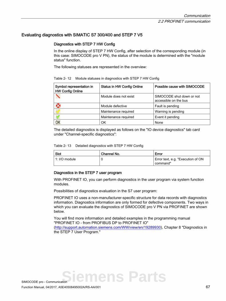
Communication 2.2 PROFINET communication
SIMOCODE pro - Communication Function Manual, 04/2017, A5E40508495002A/RS-AA/001 67
Evaluating diagnostics with SIMATIC S7 300/400 and STEP 7 V5
Diagnostics with STEP 7 HW Config
In the online display of STEP 7 HW Config, after selection of the corresponding module (in this case: SIMOCODE pro V PN), the status of the module is determined with the "module status" function.
The following statuses are represented in the overview:
Table 2- 12 Module statuses in diagnostics with STEP 7 HW Config
Symbol representation in HW Config Online
Status in HW Config Online Possible cause with SIMOCODE
Module does not exist SIMOCODE shut down or not accessible on the bus
Module defective Fault is pending
Maintenance required Warning is pending
Maintenance required Event it pending
OK None
The detailed diagnostics is displayed as follows on the "IO device diagnostics" tab card under "Channel-specific diagnostics":
Table 2- 13 Detailed diagnostics with STEP 7 HW Config
Slot Channel No. Error 1: I/O module 0 Error text, e.g. "Execution of ON
command"
Diagnostics in the STEP 7 user program
With PROFINET IO, you can perform diagnostics in the user program via system function modules.
Possibilities of diagnostics evaluation in the S7 user program:
PROFINET IO uses a non-manufacturer-specific structure for data records with diagnostics information. Diagnostics information are only formed for defective components. Two ways in which you can evaluate the diagnostics of SIMOCODE pro V PN via PROFINET are shown below.
You will find more information and detailed examples in the programming manual "PROFINET IO - from PROFIBUS DP to PROFINET IO" (http://support.automation.siemens.com/WW/view/en/19289930), Chapter 8 "Diagnostics in the STEP 7 User Program."
Siemens Parts

Communication 2.2 PROFINET communication
SIMOCODE pro - Communication 68 Function Manual, 04/2017, A5E40508495002A/RS-AA/001
Evaluating diagnostics alarms with SFB 54 "RALRM" in OB 82
SIMOCODE pro V PN as a diagnostics-capable IO device detects both internal faults (e.g. of hardware components) and events relating to the motor feeder and generates a diagnostics alarm to which you can respond using an alarm OB.
Initial information on the cause and class of the error is already available, based on the OB number and start information for the fault event.
You can then obtain detailed information on the error event in this error OB with the SFB 54 "RALRM" (read supplementary alarm information).
Note STEP 7 online help
You will find a detailed explanation of SFB 54 "RALRM" in the STEP 7 Online Help.
Alarm processing
On process warnings, process faults, and device faults, SIMOCODE pro V PN makes diagnostic interrupt requests to the CPU (on both the raised and the cleared event). The precondition is that the diagnostics response has been enabled for these events in the device parameterization (see Section "Configuring the diagnostics response" above).
The operating system calls the OB 82 based on the diagnostics request. The local variables of OB 82 contain the logical base address and four bytes of diagnostics data about the SIMOCODE pro V PN device in question.
If you have not programmed OB 82, the CPU will switch to the "STOP" status.

Communication 2.2 PROFINET communication
SIMOCODE pro - Communication Function Manual, 04/2017, A5E40508495002A/RS-AA/001 69
Reading diagnostics data records with SFB 52 "RDREC" in OB 1
With SFB 52 "RDREC," you read the data record with number INDEX from the SIMOCODE pro V PN IO Device addressed by means of ID. ID contains the logical address with which SIMOCODE pro V PN was configured in STEP 7 HW Config.
Example:
If you want to obtain diagnostic information with the 0xE00A diagnostics data record for the pending faults from SIMOCODE pro V PN at the device level, INDEX = W#16#E00A.
With the MLEN variable, you specify the maximum number of bytes to be read. For this reason, you select the target area RECORD to be at least the same size as MLEN.
The "true" value of the VALID output parameter indicates that the data record has been successfully transferred to the target area RECORD. In this case, the output parameter LEN has the length of the read data in bytes.
If an error occurs during data record transmission, this will be displayed in the "ERROR" output parameter. In case of an error, "ERROR = true" is set and the error data will be contained in the "STATUS" output parameter.
Note STEP 7 online help
You will find a detailed explanation of SFB 52 "RDREC" in the STEP 7 Online Help.
Note Complete diagnostics information from SIMOCODE pro V PN
Note that reading the diagnostics data records 0xCXXX only ever provides the pending diagnostics.
You can evaluate the complete diagnostics information of SIMOCODE pro V PN by reading data record 92 (0x005C).
You will find more information and detailed examples in Chapter 8 of the programming manual "PROFINET IO - from PROFIBUS DP to PROFINET IO" (http://support.automation.siemens.com/WW/view/en/19289930).
Siemens Parts

Communication 2.2 PROFINET communication
SIMOCODE pro - Communication 70 Function Manual, 04/2017, A5E40508495002A/RS-AA/001
Addressing levels PROFINET IO defines different addressing levels via which diagnostics information of the IO devices can be accessed. You will find more information in Chapter 5 of the programming manual "PROFINET IO - from PROFIBUS DP to PROFINET IO" (http://support.automation.siemens.com/WW/view/en/19289930).
Diagnostics information from SIMOCODE pro V PN is evaluated at the addressing level for the slot.
Overview of the diagnostics data records
Table 2- 14 Diagnostics data records at slot level
Diagnostics data record No. Diagnostic status 0xC010 Maintenance required 0xC011 Maintenance demand 0xC00A Fault 0xC00C All (maintenance required, maintenance demand, fault)
Example:
● Reading the diagnostics data record 0xC00C provides all pending diagnostics information (maintenance required, maintenance demand, fault).
● Reading the diagnostics data record 0xC011 provides all pending diagnostics information with the "maintenance demand" diagnostics status at slot level.
Structure of the diagnostics data records
Data blocks, diagnostics data records
In the following description, the main structure of the diagnostics data records at slot level (0xC010, 0xC011, 0xC00A) is described with the individual data blocks:
Table 2- 15 Data blocks, diagnostics data records
BlockType 2 bytes BlockLength 2 bytes BlockVersion 2 bytes API (Application Process Identifier) 4 bytes SlotNumber 2 bytes SubslotNumber 2 bytes ChannelNumber 2 bytes ChannelProperties 2 bytes USI (User Structure Identifier) 2 bytes Number of repeats = number of entries ChannelNumber 2 bytes ChannelProperties 2 bytes ChannelErrorType 2 bytes

Communication 2.2 PROFINET communication
SIMOCODE pro - Communication Function Manual, 04/2017, A5E40508495002A/RS-AA/001 71
Data block "BlockType"
Table 2- 16 Data block "BlockType"
BlockType Meaning 0x0010 Diagnostics data record 0x0001 Alarm transport channel 1 0x0002 Alarm transport channel 2
Data block "BlockLength"
In the "BlockLength" data field, the number of the following bytes of the diagnostics data record is coded. This is the length of the diagnostics data record without the number of bytes for the data fields "BlockType" and "BlockLength," which each have a length of 2 bytes.
Data block "BlockVersion"
Table 2- 17 Data block "BlockVersion"
BlockVersion Value Meaning BlockVersionHigh 0x01 First value of the version number, 0x01 BlockVersionLow 0x01 Version number, always 0x01 in the case of
SIMOCODE pro
Data block "API"
API (Application Process Identifier): SIMOCODE pro uses the standard API 0.
Data blocks "SlotNumber," "SubslotNumber"
As a compact PROFINET IO Device, SIMOCODE pro V PN has the following structure:
Table 2- 18 Data blocks "SlotNumber," "SubslotNumber"
Designation SlotNumber SubslotNumber Head module - Interface - Port 1 - Port 2
0x0000 0x0001 0x8000 0x8001 0x8002
I/O module 0x0001 0x0001 PROFIsafe 1) 0x0002 0x0001
1) Only in conjunction with fail-safe DM-F PROFIsafe expansion module
Siemens Parts
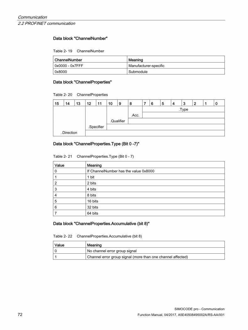
Communication 2.2 PROFINET communication
SIMOCODE pro - Communication 72 Function Manual, 04/2017, A5E40508495002A/RS-AA/001
Data block "ChannelNumber"
Table 2- 19 ChannelNumber
ChannelNumber Meaning 0x0000 - 0x7FFF Manufacturer-specific 0x8000 Submodule
Data block "ChannelProperties"
Table 2- 20 ChannelProperties
15 14 13 12 11 10 9 8 7 6 5 4 3 2 1 0
.Direction
.Specifier
.Qualifier
.Acc.
.Type
Data block "ChannelProperties.Type (Bit 0 -7)"
Table 2- 21 ChannelProperties.Type (Bit 0 - 7)
Value Meaning 0 If ChannelNumber has the value 0x8000 1 1 bit 2 2 bits 3 4 bits 4 8 bits 5 16 bits 6 32 bits 7 64 bits
Data block "ChannelProperties.Accumulative (bit 8)"
Table 2- 22 ChannelProperties.Accumulative (bit 8)
Value Meaning 0 No channel error group signal 1 Channel error group signal (more than one channel affected)
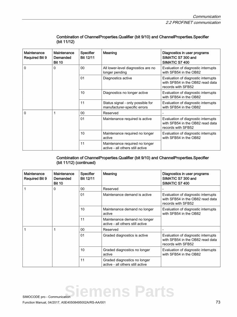
Communication 2.2 PROFINET communication
SIMOCODE pro - Communication Function Manual, 04/2017, A5E40508495002A/RS-AA/001 73
Combination of ChannelProperties.Qualifier (bit 9/10) and ChannelProperties.Specifier (bit 11/12)
Maintenance Required Bit 9
Maintenance Demanded Bit 10
Specifier Bit 12/11
Meaning Diagnostics in user programs SIMATIC S7 300 and SIMATIC S7 400
0 0 00 All lower-level diagnostics are no longer pending
Evaluation of diagnostic interrupts with SFB54 in the OB82
01 Diagnostics active Evaluation of diagnostic interrupts with SFB54 in the OB82 read data records with SFB52
10 Diagnostics no longer active Evaluation of diagnostic interrupts with SFB54 in the OB82
11 Status signal - only possible for manufacturer-specific errors
Evaluation of diagnostic interrupts with SFB54 in the OB82
0 1 00 Reserved - 01 Maintenance required is active Evaluation of diagnostic interrupts
with SFB54 in the OB82 read data records with SFB52
10 Maintenance required no longer active
Evaluation of diagnostic interrupts with SFB54 in the OB82
11 Maintenance required no longer active - all others still active
Combination of ChannelProperties.Qualifier (bit 9/10) and ChannelProperties.Specifier (bit 11/12) (continued)
Maintenance Required Bit 9
Maintenance Demanded Bit 10
Specifier Bit 12/11
Meaning Diagnostics in user programs SIMATIC S7 300 and SIMATIC S7 400
1 0 00 Reserved - 01 Maintenance demand is active Evaluation of diagnostic interrupts
with SFB54 in the OB82 read data records with SFB52
10 Maintenance demand no longer active
Evaluation of diagnostic interrupts with SFB54 in the OB82
11 Maintenance demand no longer active - all others still active
1 1 00 Reserved - 01 Graded diagnostics is active Evaluation of diagnostic interrupts
with SFB54 in the OB82 read data records with SFB52
10 Graded diagnostics no longer active
Evaluation of diagnostic interrupts with SFB54 in the OB82
11 Graded diagnostics no longer active - all others still active
Siemens Parts

Communication 2.2 PROFINET communication
SIMOCODE pro - Communication 74 Function Manual, 04/2017, A5E40508495002A/RS-AA/001
Data block "ChannelProperties.Specifier (Bit 11/12)"
Table 2- 23 ChannelProperties.Specifier (bit 11/12)
Value Meaning Diagnostics in user programs SIMATIC S7 300 and SIMATIC S7 400
00 Reserved - 01 Pending diagnostics Evaluation of diagnostic interrupts with SFB54 in the OB82 read
data records with SFB52 10 Cleared event and no further events Evaluation of diagnostic interrupts with SFB54 in the OB82 11 Cleared events, but other events remain
Data block "ChannelProperties.Direction (bits 13 - 15)"
Table 2- 24 ChannelProperties.Direction (bit 13 - 15)
Value Meaning 000 Manufacturer-specific 001 Input 010 Output 011 Input/Output 100 - 111 Reserved

Communication 2.2 PROFINET communication
SIMOCODE pro - Communication Function Manual, 04/2017, A5E40508495002A/RS-AA/001 75
Data block "ChannelErrorType"
The ChannelErrorType does not indicate the "Fault" status. For this purpose, there is the PNIO diagnostics status for the raised alarm: Maintenance Required, Maintenance Demanded, Failure.
Table 2- 25 ChannelErrorType
ChannelErrorType Meaning 0x0009 Error 1) 0x0010 Parameterization error 1) Error of the PROFINET interface 0x8000 Data transmission not possible 0x8001 Incorrect neighborhood 0x8002 Loss of redundancy 0x8003 Loss of synchronization (bus end) 0x8004 Loss of clock synchronization (device end) 0x8005 Slave-to-slave traffic connection error 0x8008 Error in network component 0x8009 Timebase error Device diagnostics 0x1000 Execution ON command 0x1001 Execution stop command 0x1002 Feedback (FB) ON 0x1003 Feedback (FB) OFF 0x1004 Stalled positioner 0x1005 Double 0 0x1006 Double 1 0x1007 End position 0x1008 Antivalence 0x100A Cold start (TPF) 0x100B Power failure (UVO) 0x100C Operational protection OFF (OPO) 0x1021 Unbalance 0x1022 Overload 0x1023 Overload + Loss of phase 0x1024 Thermistor overload 0x1025 Thermistor short circuit 0x1026 Thermistor open circuit 0x1027 Internal ground fault 0x1028 EM/EM+ External ground fault 0x1029 EM+ open circuit 0x1030 TM2 out of range 0x102A EM+ short circuit 0x102B TM1 trip level T>
Siemens Parts

Communication 2.2 PROFINET communication
SIMOCODE pro - Communication 76 Function Manual, 04/2017, A5E40508495002A/RS-AA/001
ChannelErrorType Meaning 0x102C TM1 sensor error 0x102D TM1 out of range 0x102E TM2 trip level T> 0x102F TM2 sensor error 0x1040 Trip level I> 0x1041 Trip level I< 0x1042 Trip level P> 0x1043 Trip level P< 0x1045 Trip level cos phi< 0x1047 Trip level U< 0x1048 AM1 trip level 0/4-20mA> 0x1049 AM1 trip level 0/4-20mA< 0x104A AM2 trip level 0/4-20mA> 0x104B AM2 trip level 0/4-20mA< 0x104C Stalled rotor 0x1055 Test trip 0x1057 Number of starts> 0x105B AM1 open circuit 0x105C AM2 open circuit 0x105D DM-F safety-related tripping 0x1061 DM-F wiring 0x1062 DM-F cross circuit 0x1070 External fault 1 0x1071 External fault 2 0x1072 External fault 3 0x1073 External fault 4 0x1074 External fault 5 0x1075 External fault 6
1) Further details of the cause of error can be obtained by reading data record 92 "Device diagnostics."

Communication 2.2 PROFINET communication
SIMOCODE pro - Communication Function Manual, 04/2017, A5E40508495002A/RS-AA/001 77
Data block "User Structure Identifier (USI)"
Table 2- 26 User Structure Identifier (USI)
USI Meaning 0x0000 - 0x7FFF Manufacturer-specific diagnostics 0x8000 Channel diagnostics 0x8002 Extended channel diagnostics 0x9000 - 0x9FFF Profile-specific
Example of the diagnostics data records The following example shows the content of the data record 0xC010 with the pending fault "execution of ON command":
Table 2- 27 Content of data record 0xC010 for the pending fault "execution ON command"
BlockType 0x0010: Diagnostics data record BlockLength 0x0016: Block length 22 bytes BlockVersion 0x0101: always 0x0101 in the case of SIMOCODE API 0x00000000: always 0 in the case of SIMOCODE SlotNumber 0x0001: Slot 1 - I/O address SubslotNumber 0x0001: Sub-slot 1 ChannelNumber 0x8000: Submodule ChannelProperties 0x0800: Pending diagnostics USI (User Structure Identifier) 0x8000: Channel diagnostics ChannelNumber 0x0000: always 0 in the case of SIMOCODE ChannelProperties 0x6804: Pending diagnostics ChannelErrorType 0x1000: Execution ON command
Siemens Parts

Communication 2.2 PROFINET communication
SIMOCODE pro - Communication 78 Function Manual, 04/2017, A5E40508495002A/RS-AA/001
2.2.15 Data records
Reading and writing data records in the STEP7 user program With SFB 52 "RDREC," you read the data record with number INDEX from the SIMOCODE pro V PN IO Device addressed by means of ID.
ID contains the logical address with which SIMOCODE pro V PN was configured in STEP 7 HW Config.
Example:
SIMOCODE pro V PN was configured in STEP 7 HW Config with basic type 2 (I address 0 / O address 0).
You want to read data record 94 - measured values. SFB "RDREC" INDEX: W#16#005E Data record 94 - measured values (0x005E) ID: DW#16#0 Logical address 0 LEN: W#16#00AC Data record length 172 bytes (0x00AC)
With SFB 53 "WRREC," you read the data record with number INDEX into the SIMOCODE pro V PN IO device addressed by means of ID.
ID contains the logical address with which SIMOCODE pro V PN was configured in STEP 7 HW Config.
Example:
SIMOCODE pro V PN was configured in STEP 7 HW Config with basic type 2 (I address 16 / O address 16).
You want to write data record 95 - service data/statistical data (data record length 148 bytes (0x0094)). SFB "WRREC" INDEX: W#16#005F Data record 95 - service data/statistical data (0x005F) ID: DW#16#F Logical address 16 LEN: W#16#0094 Data record length 148 bytes (0x0094C)
Note STEP 7 online help
You will find a detailed explanation of SFB 52 "RDREC" in the STEP 7 Online Help.
An overview of the data records is provided in Chapter PROFINET data records (Page 234).
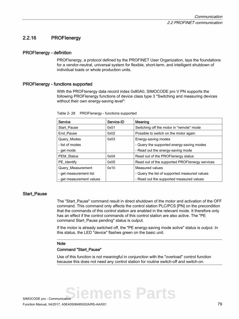
Communication 2.2 PROFINET communication
SIMOCODE pro - Communication Function Manual, 04/2017, A5E40508495002A/RS-AA/001 79
2.2.16 PROFIenergy
PROFIenergy - definition PROFIenergy, a protocol defined by the PROFINET User Organization, lays the foundations for a vendor-neutral, universal system for flexible, short-term, and intelligent shutdown of individual loads or whole production units.
PROFIenergy - functions supported With the PROFIenergy data record index 0x80A0, SIMOCODE pro V PN supports the following PROFIenergy functions of device class type 3 "Switching and measuring devices without their own energy-saving level":
Table 2- 28 PROFIenergy - functions supported
Service Service-ID Meaning Start_Pause 0x01 Switching off the motor in "remote" mode End_Pause 0x02 Possible to switch on the motor again Query_Modes - list of modes - get mode
0x03 Energy-saving modes - Query the supported energy-saving modes - Read out the energy-saving mode
PEM_Status 0x04 Read out of the PROFIenergy status PE_Identify 0x05 Read out of the supported PROFIenergy services Query_Measurement - get measurement list - get measurement values
0x10 Measured values - Query the list of supported measured values - Read out the supported measured values
Start_Pause The "Start_Pause" command result in direct shutdown of the motor and activation of the OFF command. This command only affects the control station PLC/PCS [PN] on the precondition that the commands of this control station are enabled in the relevant mode. It therefore only has an effect if the control commands of this control station are also active. The "PE command Start_Pause pending" status is output.
If the motor is already switched off, the "PE energy-saving mode active" status is output. In this status, the LED "device" flashes green on the basic unit.
Note Command "Start_Pause"
Use of this function is not meaningful in conjunction with the "overload" control function because this does not need any control station for routine switch-off and switch-on.
Siemens Parts

Communication 2.2 PROFINET communication
SIMOCODE pro - Communication 80 Function Manual, 04/2017, A5E40508495002A/RS-AA/001
Minimum pause time A pause time is transferred with the "Start_Pause" command. SIMOCODE pro V PN executes this command if the pause time is greater than the minimum pause time configured in the device. The minimum pause time of the motor is configured with the SIMOCODE ES software under "PROFIenergy." The minimum pause time is preset to the smallest possible value 0.1 s. You can increase the minimum pause time if executing the command in longer pauses is convenient for technological reasons.
End_Pause The "End_Pause" command results in the stop command being canceled at the PLC/PCS control station and the motor being switched on again via enabled control stations.
Note Command "End_Pause"
The command to switch on has to be output again because subsequent automatic switch-on is not performed.
Note Switching on the motor in the paused condition
If the PLC/PCS control station is disabled, the motor can also be switched on in the paused condition.
Query_Measurement Depending on the use of the current measuring or the current-voltage measuring module, the following measured values are supported:
Table 2- 29 Query_Measurement
Measurement-ID PROFIenergy identifier SIMOCODE pro identifier Unit 4 Voltage (a-b) Voltage U_L12 V V 5 Voltage (b-c) Voltage U_L31 V V 6 Voltage (c-a) Voltage U_L31 V V 7 Current (a) Phase current I_L1 A A 8 Current (b) Phase current I_L2 A A 9 Current (c) Phase current I_L3 A A 33 Current average (abc) Average phase current I_L A A 34 Active power (total) Active power P W 36 Apparent power (total) Apparent power S VA 37 Power factor (total) Cos phi - 200 Active energy import (total) Energy W Wh
Communication 2.2 PROFINET communication
SIMOCODE pro - Communication Function Manual, 04/2017, A5E40508495002A/RS-AA/001 81
Function blocks for SIMATIC S7 The application description "Saving Energy with SIMATIC S7 and ET200 S" (http://support.automation.siemens.com/WW/view/en/41986454), which also contains an example program for using PROFIenergy functions, is available on the Internet service portal of Siemens AG, Industry Automation and Drives Technologies. You can also make use of the blocks from the example to implement PROFIenergy functions in conjunction with SIMOCODE pro V PN.
In the application description in Chapter 4.2 "FB 815 PE_START_END functionality," you will find the description of the block with which the "PE_START_Pause" or "PE_END_Pause" commands can be directly transferred to an IO device.
With the FB 815 "PE_START_END" function block, you can transfer the "START_Pause" or "END_Pause" commands directly to SIMOCODE pro V PN.
For use of further functions, in Chapter 4.3 "FB 816 PE_CMD functionality" you will find a universal function block with which you can transfer further commands of the PROFIenergy profile (e.g. Query_Modes, PEM_Status, PE_Identify, Query_Measurement).
You will also find the structure of the command and response data of the FB 816 in Chapter 4.4 "Response Data" of the application description "Saving Energy with SIMATIC S7 and ET200 S."
Siemens Parts
Communication 2.2 PROFINET communication
SIMOCODE pro - Communication 82 Function Manual, 04/2017, A5E40508495002A/RS-AA/001
2.2.17 Further communication functions via Ethernet
OPC basics The OPC Foundation (an interest group of renowned manufacturers for definition of standard interfaces) has defined numerous software interfaces over the past years to standardize the flow of information from the process level to the management level. In the past, the various OPC specifications have been drawn up in line with the different requirements within an industrial application.
Based on the experience of these classic OPC interfaces, the OPC Foundation has defined a new platform with the name OPC Unified Architecture (UA). The aim of this new standard is generic description and standardized access to all information that has to be exchanged between systems and/or applications.
What is OPC?
In the past, OPC was a collection of software interfaces for data exchange between PC applications and process devices. These software interfaces were defined according to the rules of Microsoft COM (component object model) and can therefore be easily integrated on Microsoft operating systems. COM or DCOM (Distributed COM) provides the functionality of interprocess communication and organizes information exchange between applications, including across computer boundaries (DCOM).
An OPC client (COM client) can therefore exchange information with an OPC server (COM server) using mechanisms of the Microsoft operating system.
The OPC server provides process information of a device at its interface. The OPC client connect to the server and can access the data offered.
The consequence of using COM or DCOM is that the OPC server and clients can only run on a Windows PC or in the local area network and usually have to implement communication with the corresponding automation system via proprietary protocols. This practice, in particular, results in additional communication and software layers that increase the configuration effort and complexity.
To resolve the above restrictions in practice and to meet the additional requirements, the OPC Foundation has defined a new platform with the name OPC Unified Architecture, which provides a standardized basis for exchanging information between components and systems. OPC-UA will also be available as an IEC 62541 standard and will thus form the basis for other international standards.

Communication 2.2 PROFINET communication
SIMOCODE pro - Communication Function Manual, 04/2017, A5E40508495002A/RS-AA/001 83
To summarize, OPC-UA offers the following features:
● Use of open and non-platform-specific protocols for network communication.
● Internet access and communication through firewalls.
● Integrated access control and security mechanisms at the protocol and application level.
Figure 2-23 Block diagram of OPC-UA
Configuring the SIMOCODE pro V PN OPC UA server - Requirements
Activating the OPC UA server
In the default setting, the OPC UA server is not active. For activation, the parameter "PROFINET Parameters → OPC UA Server Activated" must be set.
Note Restarting the communication interface
Each change to the "Activate OPC UA server" parameter requires that the communication interface be restarted.
A new start of the communication interface interrupts all Ethernet and PROFINET links and reestablishes them afterward.
Note Firmware version of SIMOCODE pro V PN basic unit
OPC UA is supported by SIMOCOCE pro V PN from firmware version V1.2.2.
Siemens Parts

Communication 2.2 PROFINET communication
SIMOCODE pro - Communication 84 Function Manual, 04/2017, A5E40508495002A/RS-AA/001
Setting the IP parameters
To enable a link to be established via OPC-UA, SIMOCODE pro V PN must have valid IP parameters.
Example of the URL of the SIMOCODE pro V PN-OPC UA server:
opc.tcp://192.168.0.2:4840, where 192.168.0.2 is the IP address of SIMOCODE pro V PN.
The IP parameters, consisting of IP address, subnet mask, and router can be configured with SIMOCODE ES and transferred to the device.
If SIMOCODE pro V PN does not obtain these parameters in another way (e.g. from the controller via PROFINET IO), the "Overwrite IP parameters in device" parameter must be activated under "PROFINET Parameters → IP Parameters."
Note
If the IP parameters are modified using the SIMOCODE ES function “Target system → Edit Ethernet participants” while the OPC UA connection is active, the device has to be restarted using “Target system → Command" to accept the parameters.
Connecting to the SIMOCODE pro OPC UA server
Introduction
An OPC UA client can access process values in the hierarchical namespace of the SIMOCODE pro V PN-OPC UA server.
To enable this, the OPC UA server and the OPC UA client authorize each other by exchanging certificates. You can additionally encrypt the data traffic.
The SIMOCODE pro V PN-OPC UA server classes every certificate of an OPC UA client as "trustworthy" by default.
Note Configuring the connection on the client side
You can obtain information directly from the manufacturer of the software that is to access the data of the SIMOCODE pro V PN-OPC UA server via OPC UA.
Supported OPC UA services of the SIMOCODE pro V PN OPC UA server
SIMOCODE pro V PN supports the following OPC UA services:
● SecurityPolicy:
– None
– Basic128Rsa15
● MessageSecurityMode:
– None
– Sign&Encrypt.

Communication 2.2 PROFINET communication
SIMOCODE pro - Communication Function Manual, 04/2017, A5E40508495002A/RS-AA/001 85
Explanation of security settings:
The following table shows the security functions supported by the SIMOCODE pro V PN-OPC UA server, which have to be set in the connection configuration of the OPC UA client:
Table 2- 30 Security functions that have to be set in the connection configuration of the OPC UA client
Security Policy MessageSecurityMode None 1) None Basic128Rsa152 SignAndEncrypt 2)
1) Exchange of certificates is deactivated
2) The data packets are signed and encrypted with the certificates.
Note
When using the MessageSecurityMode “SignAndEncrypt”, the connection timeout effective in the OPC UA Client must be set to at least 15 s.
DANGER
Unsecured connection between the client and the server possible!
Use the setting "none" for test purposes only. During productive operation, use the following settings for secure communication between the client and server: • Security Policy: Basic128Rsa15 • Message Security Mode: SignAndEncrypt.
Note Requirement for certificate exchange in SIMOCODE pro V PN
The precondition for certificate exchange in SIMOCODE pro V PN is the presence of a valid time (see Section "Time-of-day synchronization by the NTP procedure" below).
Siemens Parts

Communication 2.2 PROFINET communication
SIMOCODE pro - Communication 86 Function Manual, 04/2017, A5E40508495002A/RS-AA/001
Access to SIMOCODE pro V PN-OPC UA variables
The OPC-UA server integrated into SIMOCODE pro V PN provides the following structured objects in its address space to which the client can have read access and, in some case, write access. The precondition for write access is a secure connection with Security Policy "Basic128Rsa15" and Message Security Mode "SignAndEncrypt."
Table 2- 31 Access to SIMOCODE pro V PN-OPC UA variables
Tag Designation Read / write Diagnostics Device diagnostics Read Diagnostic events Diagnostic status Diagnostic trips Diagnostic warnings Measured values Measured values Read Statistics Display and statistical data Read Acyclic receive Receive data (OPC UA Receive) Read / write Analog value Analog value Bit 0.0 - 1.7 Digital receive data Acyclic send Send data (OPC UA Send) Read Bit 0.0 - 1.7 1) Digital send data
1) The current assignment of the OPC UA send data is displayed as it was configured in SIMOCODE pro V PN.
You will find a detailed description of each variable in Chapter OPC UA variables (Page 212) Write access is only possible via a secure connection.
Table 2- 32 Quantities and update interval
Maximum number of clients Max. 2 Maximum number of monitored terms 160 Maximum number of subscriptions 2 Shortest update interval for subscriptions 100 ms

Communication 2.2 PROFINET communication
SIMOCODE pro - Communication Function Manual, 04/2017, A5E40508495002A/RS-AA/001 87
Configuring the OPC UA receive and send data with SIMOCODE ES
OPC UA Receive
The bit information that is to be transferred via OPC UA Receive to SIMOCODE pro is also assigned by configuring with SIMOCODE ES.
OPC-UA variables (write):
● Receive data byte 0, bits 0-7
● Receive data byte 1, bits 0-7
● Receive data byte 2/3
Data to SIMOCODE pro V PN:
Figure 2-24 OPC UA Receive 0, 1, 2/3 function blocks
Siemens Parts

Communication 2.2 PROFINET communication
SIMOCODE pro - Communication 88 Function Manual, 04/2017, A5E40508495002A/RS-AA/001
Example:
The motor is to be switched on and off via the control station "PC/OPC UA."
OPC UA - Acyclic receive - Bit 0.0 → Motor ON<
OPC UA - Acyclic receive - Bit 0.1 → Motor OFF
OPC UA - Acyclic receive - Bit 0.2 → Motor ON>
Figure 2-25 Example of OPC UA motor control
Note Write access
Write access is only possible if a secure connection is used with Security policy "Basic128Rsa15" and with Message security mode "SignAndEncrypt."
Note Non-maintained command mode
Do not use the "non-maintained command mode" for motor control with OPC UA!

Communication 2.2 PROFINET communication
SIMOCODE pro - Communication Function Manual, 04/2017, A5E40508495002A/RS-AA/001 89
Connection monitoring The OPC UA connection is monitored over time. The monitoring time is set by the OPC UA client and is in the range of 10 s to 100 s. If the OPC UA connection is terminated, the OPC UA control variables set by this OPC client will be deleted in SIMOCODE pro only after this time has expired. In SIMOCODE pro, no fault is triggered.
If failure of the OPC UA connection of SIMOCODE pro is to be monitored, this can be done as follows:
WARNING
The drive cannot be controlled.
Can result in death, serious injury, or property damage.
If the connection is interrupted, the drive cannot be controlled while the OPC-UA connection monitoring time is active.
Take suitable safety measures to avoid personal injury or property damage.
Example:
Makes sure that Bit 0.7 is set statically at the client end. If the connection is interrupted, this will activate the "PLC/PCS" fault in "remote" mode (mode selector S1=1, S2=1).
Figure 2-26 Example of connection monitoring
Siemens Parts

Communication 2.2 PROFINET communication
SIMOCODE pro - Communication 90 Function Manual, 04/2017, A5E40508495002A/RS-AA/001
OPC UA send
The bit information that is to be transferred to the client via OPC UA Send is also defined by configuring with SIMOCODE ES.
OPC-UA variables (read):
● Send data byte 0, bits 0-7
● Send data byte 1, bits 0-7
Data from SIMOCODE PRO V PN:
Figure 2-27 OPC UA Send 0, 1 function blocks
Example:
The feedback of the switching state of the motor is transferred to the client via OPC UA. When selecting the variables in the OPC UA client, the assigned status signals are then as follows:
Figure 2-28 Configuration of OPC UA Send in SIMOCODE ES

Communication 2.2 PROFINET communication
SIMOCODE pro - Communication Function Manual, 04/2017, A5E40508495002A/RS-AA/001 91
Figure 2-29 Representation in the object directory of the SIMOCODE pro V PN-OPC UA server (see
also table below)
Configuration of OPC UA Send in SIMOCODE ES Representation in the object directory of the SIMOCODE pro V PN-OPC UA server
OPC UA Send - Bit 0.0: "Status ON<" Acyclic Send → Status - On < OPC UA Send - Bit 0.1: "Status Off" Acyclic Send → Status - Off OPC UA Send - Bit 0.2: "Status ON>" Acyclic Send → Status - On > ... ... OPC UA Send - Bit 0.3: "Not connected" Acyclic Send → Not connected OPC UA Send - Bit 1.7: "Not connected" Acyclic Send → Status - On <
Note Restarting the communication interface
Each change to the configuration of the OPC UA send data requires that the communication interface be restarted.
A new start of the communication interface interrupts all Ethernet and PROFINET links and reestablishes them afterward.
Siemens Parts
Communication 2.2 PROFINET communication
SIMOCODE pro - Communication 92 Function Manual, 04/2017, A5E40508495002A/RS-AA/001
Web diagnostics (web server) SIMOCODE pro V PN offers you with the web diagnosis the possibility of calling the following information of the motor feeder from a PG/PC using an HTTP client:
● Status information
● Faults, warnings, events
● Measured values
● Service and statistical data
● Error buffer, error protocol.
The following functions for controlling the motor feeder is available for authorized users after log-on with user name and password:
● Receive (switching the motor on and off, not available in non-maintained command mode)
● Acknowledging faults
● Execution of the test function.
Number of web server connections: One connection is supported.
Web diagnostics are available in Chinese, Russian, English and German.
Activating the web server:
The default setting of the web server is "not active." To activate it, the "PROFINET Parameters →Web Server Activated" parameter must be active.
Note Restarting the communication interface
Each change to the configuration of the web server requires that the communication interface be restarted.
A new start of the communication interface interrupts all Ethernet and PROFINET links and reestablishes them afterward.
Setting the IP parameters:
To enable a link to be established via the web, SIMOCODE pro V PN must have valid IP parameters. You can find out how to make these settings in Chapter Configuration of further properties of SIMOCODE pro V PN as an IO device (Page 54).

Communication 2.2 PROFINET communication
SIMOCODE pro - Communication Function Manual, 04/2017, A5E40508495002A/RS-AA/001 93
Configuration of the user name and password:
If the functions are to be used to control the motor feeder, a user must additionally be configured with the user name and password. User name and password must not contain any blanks. Configuration is performed under "PROFINET Parameters → OPC UA server / web server"
Note Control station PC/OPC UA
The control via the web uses the SIMOCODE pro control station PC/OPC UA [HMI], for which the configured enabled commands are then active.
Web browser
For access to the HTML pages in the SIMOCODE pro V PN, you need a web browser.
The following web browsers are suitable for communication with SIMOCODE pro etc.:
● Internet Explorer (recommended version: Version 10)
● Firefox (recommended version: Version 29).
Note Connection to a web client
Connection to a web client is supported.
Settings of the web browser for access to the information
Check the following settings, which are a precondition for access to the information made available via the web:
● To load the diagnostics data, Javascript must be activated in the Internet browser.
● The browser must support frames.
● Cookies must be permitted.
● The browser should be set in such a way that whenever it accesses a page, it automatically loads the current data from the server.
In the Internet Explorer, you will find these settings with menu "Tools" → "Internet Options" → "General" tab card → "Temporary Internet Files" group box → "Settings" button.
To use a firewall in your PG/PC, the following port must be enabled for use of the web diagnostics: "http Port 80/TCP" or, in the case of secure connections, "https Port 443/TCP".
Siemens Parts

Communication 2.2 PROFINET communication
SIMOCODE pro - Communication 94 Function Manual, 04/2017, A5E40508495002A/RS-AA/001
Logging on to the web server
You can only use functions for controlling the motor feeder after you have logged on to the web server with user name and password. Only then are the buttons with a controlling function active.
The log-on dialog box is only available via a secure https connection.
Certificates:
To enable the web browser to access the web server via an https connection, certificates are mutually exchanged. On each change of the SIMOCODE pro V PN IP address, a unique certificate with a validity of five years is created for this purpose.
You can also install a CA certificate with a validity up to 2037 via the integrated web server as follows: Click the "Download certificate" link in the header of the home page and open or install the CA certificate.
Note Installing the SIMOCODE pro CA certificate
You only have to install the SIMOCODE pro CA certificate once for the web client inquestion and it then applies to all SIMOCODE pro V PN devices.
If you do not install the CA certificate, the web browser will signal a certificate error when the connection is established to SIMOCODE pro V PN.
Time-of-day synchronization by the NTP procedure SIMOCODE pro V PN has a non-battery-backed realtime clock that can be synchronized via the NTP procedure.
Network Time Protocol (NTP) is the implementation of a TCP/IP protocol for time synchronization in network. The NTP procedure uses hierarchical time synchronization, that is, an external clock (e.g. SICLOCK TM or a PC in the network) is used for synchronization.
The device transmits time-of-day queries to the configured NTP server at configured time intervals. Using the responses of the server, the time of day of the non-battery-backed clock is synchronized in SIMOCODE pro. This ensures that a synchronized time of day is available shortly after the supply voltage is switched on.
The NTP synchronization is configured with the SIMOCODE ES configuration software under "PROFINET Parameters → NTP procedure/synchronization."
The following settings are also made:
● NTP server address: Enter the NTP server address when the "Activate NTP synchronization" checkbox is selected.
Note
Adoption of the NTP server address
The NTP server address is not adopted until the device has been restarted after the supply voltage has been switched off and on again.

Communication 2.2 PROFINET communication
SIMOCODE pro - Communication Function Manual, 04/2017, A5E40508495002A/RS-AA/001 95
● Cyclic update interval: Time interval in seconds at which synchronization of the time of day with the NTP server is performed
● Time shift: Time difference in minutes between UTC time (UTC = Universal Time Coordinated) and the time in the device.
Examples:
● Time shift for CET (Central European Time): +60 min
● Time shift for CST (Central Standard Time, North America): -360 min.
If an NTP server address has not been configured or a server was not found on the network, you can also set the time of day using SIMOCODE ES. To do this, proceed as follows:
Mark the relevant SIMOCODE device in the project navigation window and then select "Connect online" to establish a direct connection to the device. Expand the list of device settings by clicking on the arrow on the left of the SIMOCODE device: You can now select "Commissioning → Set time (= PC time in UTC)" to download the time of day of your PC to the SIMOCODE device.
Note Command execution
Commands are executed immediately.
If a valid time of day is available (either synchronized by NTP or set via SIMOCODE ES), the entries in the error buffer / error protocol (i.e. log) will be additionally displayed with the time of day. In addition, the "Clock set (NTP)" and "Clock synchronized (NTP)" messages are displayed.
Note Access using OPC UA
A valid time of day is necessary to be able to use the "Sign" and "SignAndEncrypt" OPC-UA Security Modes.
Simple Network Management Protocol (SNMP) SNMP is a network protocol for monitoring and controlling network elements (e.g. switches).
SIMOCODE pro V PN supports the Ethernet service SNMP. MIB-2 (RFC1213) is supported. R/W objects can be changed with SNMP tools and are stored in the basic unit.
After replacement with a new basic unit from the factory or a basic unit that has undergone a general reset, the R/W objects will be in the factory settings.
Siemens Parts

Communication 2.3 Modbus communication
SIMOCODE pro - Communication 96 Function Manual, 04/2017, A5E40508495002A/RS-AA/001
2.3 Modbus communication
2.3.1 Modbus RTU communication
2.3.1.1 Modbus RTU - general Modbus RTU (Remote Terminal Unit) is a standard protocol for network communication and uses the electrical RS485 connection for serial data transmission between Modbus devices in the network.
Modbus RTU uses a master/slave network in which the entire communication is triggered by only one master device while the slaves can only respond to the request of the master. The master sends a request to a slave address and only this slave address responds to the command (exception: broadcast frames to slave address 0 which are not acknowledged by the slaves).
2.3.1.2 Supported data transfer rates for RTU SIMOCODE pro supports the following data transfer rates in Modbus RTU mode:
● 300 baud
● 600 baud
● 1,200 baud
● 2,400 baud
● 4,800 baud
● 9,600 baud
● 19,200 baud (default setting)
● 57,600 baud.

Communication 2.3 Modbus communication
SIMOCODE pro - Communication Function Manual, 04/2017, A5E40508495002A/RS-AA/001 97
2.3.1.3 Assignment of SIMOCODE data to Modbus addresses with Modbus RTU All SIRIUS data are available in datasets or in the process image:
● System datasets
● Datasets specific to a device subfamily
● Product-specific datasets.
To be addressable via Modbus, the data in these datasets or in this process image are converted to Modbus data formats. Data access to Data type according to Modbus nomenclature Read-only bits Discrete inputs Read/write bits Coils Read-only datasets and words (16-bit) Input registers Read/write datasets and words Holding registers
1 coil corresponds to 1 bit.
1 register corresponds to 1 word (2 bytes).
Siemens Parts

Communication 2.3 Modbus communication
SIMOCODE pro - Communication 98 Function Manual, 04/2017, A5E40508495002A/RS-AA/001
2.3.1.4 Modbus RTU data transfer
Principle of Modbus RTU data transfer In contrast to cyclic/acyclic data transfer in the PROFIBUS bus system, the data are transferred linearly using the Modbus protocol.
The master is an automation system (PLC). The slave is a SIMOCODE pro device.
The master takes the initiative in the data transfer. SIMOCODE pro works as a slave and supplies the corresponding feedback signals to the bits/registers called up by the master, or it accepts the bits/registers written by the master into the internal SIMOCODE memory.
The master sends requests to one or more slaves. The slave processes the requests of the master and responds within a certain time with an acknowledgment, or with the requested data, or an error code if applicable. The requests contain the function code and additional data. The data can only be transferred between the master and a slave. Requests cannot be transferred between slaves. A slave cannot transfer any information, e.g. alarms, autonomously to the master. This always requires continuous polling of the corresponding bit by the master.
Data transfer options with Modbus RTU The following figure shows the data transfer options:
Figure 2-30 Options for data transfer

Communication 2.3 Modbus communication
SIMOCODE pro - Communication Function Manual, 04/2017, A5E40508495002A/RS-AA/001 99
2.3.1.5 Modbus RTU telegram format The data exchange "Master → Slave" and/or the corresponding response "Slave → Master" begins with the slave address, followed by the function code. Following this, the data are transferred. The structure of the data field depends on the function code used. The CRC check is transmitted at the end of the frame. The response frame from the slave to the master contains the same slave address and the same function code. The data area is filled according to the requested data. Slave address Function code DATA CRC-CHECK 1 byte 1 byte n bytes 2 bytes
● Slave address: This address is used to address a defined slave on the bus. Standard address: 1 to 247
● Function code: Defines the slave function desired by the frame
● DATA = frame data: Function-code-dependent administration data and net data. When transferring the register data, the high byte is always transferred first, followed by the low byte, in accordance with the Modbus specification.
● CRC CHECK = frame checksum: The end of the frame is identified by the CRC-16 checksum of two bytes in length,
End of frame The end of frame is recognized when no transmission takes place during the time period required for the transmission of three and a half characters (3.5 times character delay time) (see Modbus Protocol Reference Guide).
Exception responses On recognition of an error in the request frame from the master (illegal register address, for example), the slave sets the highest value bit in the function code of the response frame (that is, the requested function code + 80h). This step is followed by transmission of a byte with the exception code that describes the cause of the error.
For details: See Modbus RTU error codes (Page 112).
Siemens Parts

Communication 2.3 Modbus communication
SIMOCODE pro - Communication 100 Function Manual, 04/2017, A5E40508495002A/RS-AA/001
2.3.1.6 Modbus RTU function codes
General
Definition of function code The function code defines the meaning of the message frame. The frame structure is also defined by the function code.
Overview of the function codes The table below provides an overview of the supported function codes. Which of these are supported by SIMOCODE pro depends on the start address (see Section Modbus RTU data tables (Page 284)).
Table 2- 33 Overview of the function codes
Function code (decimal/hexadecimal)
Designation according to Modbus specification
01 / 0x01 (Page 102) Read Coils 02 / 0x02 (Page 102) Read Discrete Inputs 03 / 0x03 (Page 104) Read Holding Registers 04 / 0x04 (Page 104) Read Input Registers 05 / 0x05 (Page 105) Write Single Coil 06 / 0x06 (Page 106) Write Single Register 15 / 0x0F (Page 106) Write Multiple Coils 16 / 0x10 (Page 108) Write Multiple Registers 23 / 0x17 (Page 109) Read/Write Multiple Registers 43 / 0x2B (Page 111) Read Device Identification

Communication 2.3 Modbus communication
SIMOCODE pro - Communication Function Manual, 04/2017, A5E40508495002A/RS-AA/001 101
Access to memory areas In SIMOCODE pro, only two memory areas are used, one each for addressing the bit information and the register information.
The function codes for bit information (01, 02, 05, 15) thus always access the bit memory area. The function codes for register information (03, 04, 06, 16, 23) always access the register memory area.
The distinction as to whether information is read-only (r) or read/writeable (r/w), can be seen from the dataset tables (see Section Modbus RTU data tables (Page 284)).
Figure 2-31 Memory areas used in SIMOCODE pro
Siemens Parts

Communication 2.3 Modbus communication
SIMOCODE pro - Communication 102 Function Manual, 04/2017, A5E40508495002A/RS-AA/001
Function codes 01 - Read Coils and 02 - Read Discrete Inputs
Function
These functions enable the Modbus master system to read individual bits from the SIMOCODE pro bit memory area.
Functions codes 01 and 02 behave in the same way here and supply an identical feedback signal. A valid offset from the bit memory area is expected as the start address. Up to 2000 bits can be read per frame.
If a number that is not equal to a multiple of eight bits is called up, the remaining bits are filled with zeros. The number of bytes n always refers to the number of fully returned bytes.
Note Start address and number of coils
The start address and the number of coils must be within the valid range.
Request message frame Slave address Function code Start address Number of bits CRC 1 byte 1 byte 2 bytes 2 bytes 2 bytes
Response message frame Slave address Function code Number of bytes n Bit status CRC 1 byte 1 byte 1 byte n bytes 2 bytes
Example
Reading in of the SIMOCODE pro device statuses from slave number 16. The device statuses start from offset 0x1C08 and are 16 bits in length.
Request message frame Slave address Function code Start address Number of bits CRC 1 byte 1 byte 2 bytes 2 bytes 2 bytes 0x10 0x01 0x1C08 0x000F 0x....
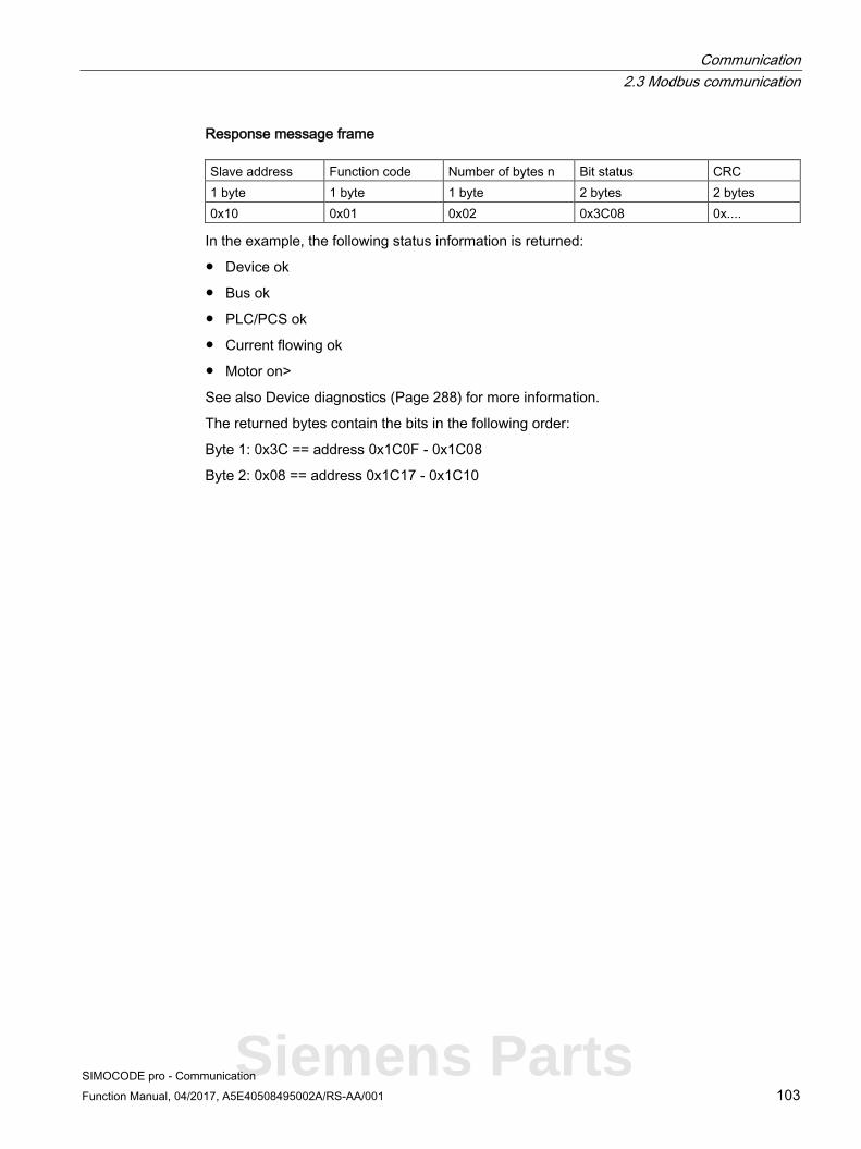
Communication 2.3 Modbus communication
SIMOCODE pro - Communication Function Manual, 04/2017, A5E40508495002A/RS-AA/001 103
Response message frame Slave address Function code Number of bytes n Bit status CRC 1 byte 1 byte 1 byte 2 bytes 2 bytes 0x10 0x01 0x02 0x3C08 0x....
In the example, the following status information is returned:
● Device ok
● Bus ok
● PLC/PCS ok
● Current flowing ok
● Motor on>
See also Device diagnostics (Page 288) for more information.
The returned bytes contain the bits in the following order:
Byte 1: 0x3C == address 0x1C0F - 0x1C08
Byte 2: 0x08 == address 0x1C17 - 0x1C10
Siemens Parts

Communication 2.3 Modbus communication
SIMOCODE pro - Communication 104 Function Manual, 04/2017, A5E40508495002A/RS-AA/001
Function codes 03 - Read Holding Register and 04 - Read Input Registers
Function
This function enables the Modbus master system to read registers from the SIMOCODE pro register memory area.
Functions codes 03 and 04 behave in the same way here and supply an identical feedback signal. A valid offset from the register memory area is expected as the start address. Up to 125 registers per frame can be read.
Request message frame Slave address Function code Start address Number of registers CRC 1 byte 1 byte 2 bytes 2 bytes 2 bytes
Response message frame Slave address Function code Number of bytes Register value CRC 1 byte 1 byte 1 byte n registers 2 bytes
Example: Reading in of the SIMOCODE pro current measured values from slave number 16. The current measured values start from offset 0x0807 and comprise 3 registers.
Request message frame Slave address Function code Start address Number of registers CRC 1 byte 1 byte 2 bytes 2 bytes 2 bytes 0x10 0x03 0x8007 0x00 0x03 0x ....
Response message frame Slave address Function code Number of bytes Register value CRC 1 byte 1 byte 1 byte 3 registers (6 bytes) 2 bytes 0x10 0x03 0x06 0x0064 0x0064 0x0064 0x ....
In the example, the measured values of the current motor current in phases 1, 2 and 3, each with 100 % (0x0064) of the rated motor current, are returned as the feedback signal.

Communication 2.3 Modbus communication
SIMOCODE pro - Communication Function Manual, 04/2017, A5E40508495002A/RS-AA/001 105
Function code 05 - Write Single Coil
Function
This function enables the Modbus master system to write an individual bit from the SIMOCODE pro bit memory area.
A valid address from the bit memory area is expected as the start address. The selected address must be designated as writable (see the tables in Section Modbus RTU data tables (Page 284), "Access" column).
0000h for a logical zero and FF00h for a logical one are accepted as data. Any other value is impermissible and given a negative acknowledgment.
Request message frame Slave address Function code Start address Data CRC 1 byte 1 byte 2 bytes 2 bytes 2 bytes
Response message frame Slave address Function code Start address Data CRC 1 byte 1 byte 2 bytes 2 bytes 2 bytes
Example
Controlling a motor connected to SIMOCODE pro from slave address 16 (assuming the assignment of the process image corresponds to the default settings). For this purpose, bit address 00 0x02 (see the tables in Section Modbus RTU data tables (Page 284)) is controlled with logical one. This bit address lies within the process image output that can be accessed both by bit access and by register access.
Request message frame Slave address Function code Start address Data CRC 1 byte 1 byte 2 bytes 2 bytes 2 bytes 0x10 0x05 0x00 0x02 0xFF 0x00 0x....
Response message frame Slave address Function code Start address Data CRC 1 byte 1 byte 2 bytes 2 bytes 2 bytes 0x10 0x05 0x00 0x02 0xFF 0x00 0x....
Siemens Parts
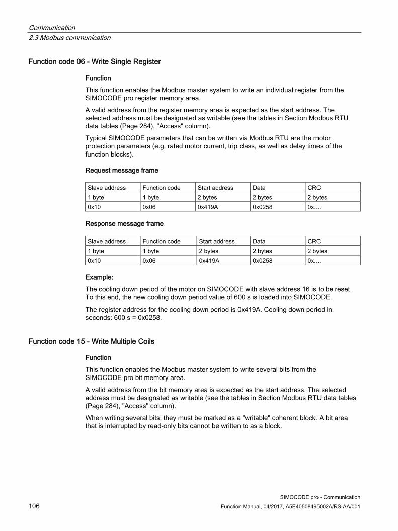
Communication 2.3 Modbus communication
SIMOCODE pro - Communication 106 Function Manual, 04/2017, A5E40508495002A/RS-AA/001
Function code 06 - Write Single Register
Function
This function enables the Modbus master system to write an individual register from the SIMOCODE pro register memory area.
A valid address from the register memory area is expected as the start address. The selected address must be designated as writable (see the tables in Section Modbus RTU data tables (Page 284), "Access" column).
Typical SIMOCODE parameters that can be written via Modbus RTU are the motor protection parameters (e.g. rated motor current, trip class, as well as delay times of the function blocks).
Request message frame Slave address Function code Start address Data CRC 1 byte 1 byte 2 bytes 2 bytes 2 bytes 0x10 0x06 0x419A 0x0258 0x....
Response message frame Slave address Function code Start address Data CRC 1 byte 1 byte 2 bytes 2 bytes 2 bytes 0x10 0x06 0x419A 0x0258 0x....
Example:
The cooling down period of the motor on SIMOCODE with slave address 16 is to be reset. To this end, the new cooling down period value of 600 s is loaded into SIMOCODE.
The register address for the cooling down period is 0x419A. Cooling down period in seconds: 600 s = 0x0258.
Function code 15 - Write Multiple Coils
Function
This function enables the Modbus master system to write several bits from the SIMOCODE pro bit memory area.
A valid address from the bit memory area is expected as the start address. The selected address must be designated as writable (see the tables in Section Modbus RTU data tables (Page 284), "Access" column).
When writing several bits, they must be marked as a "writable" coherent block. A bit area that is interrupted by read-only bits cannot be written to as a block.
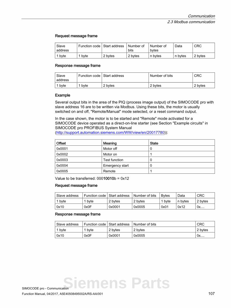
Communication 2.3 Modbus communication
SIMOCODE pro - Communication Function Manual, 04/2017, A5E40508495002A/RS-AA/001 107
Request message frame Slave address
Function code Start address Number of bits
Number of bytes
Data CRC
1 byte 1 byte 2 bytes 2 bytes n bytes n bytes 2 bytes
Response message frame Slave address
Function code Start address Number of bits CRC
1 byte 1 byte 2 bytes 2 bytes 2 bytes
Example
Several output bits in the area of the PIQ (process image output) of the SIMOCODE pro with slave address 16 are to be written via Modbus. Using these bits, the motor is usually switched on and off, "Remote/Manual" mode selected, or a reset command output.
In the case shown, the motor is to be started and "Remote" mode activated for a SIMOCODE device operated as a direct-on-line starter (see Section "Example circuits" in SIMOCODE pro PROFIBUS System Manual (http://support.automation.siemens.com/WW/view/en/20017780)): Offset Meaning State 0x0001 Motor off 0 0x0002 Motor on 1 0x0003 Test function 0 0x0004 Emergency start 0 0x0005 Remote 1
Value to be transferred: 00010010b = 0x12
Request message frame Slave address Function code Start address Number of bits Bytes Data CRC 1 byte 1 byte 2 bytes 2 bytes 1 byte n bytes 2 bytes 0x10 0x0F 0x0001 0x0005 0x01 0x12 0x....
Response message frame Slave address Function code Start address Number of bits CRC 1 byte 1 byte 2 bytes 2 bytes 2 bytes 0x10 0x0F 0x0001 0x0005 0x....
Siemens Parts

Communication 2.3 Modbus communication
SIMOCODE pro - Communication 108 Function Manual, 04/2017, A5E40508495002A/RS-AA/001
Function code 16 - Write Multiple Registers
Function
This function enables the Modbus master system to write several registers from the SIMOCODE pro register memory area.
A valid address from the register memory area is expected as the start address. The selected addresses must be designated as writable (see the tables in Section Modbus RTU data tables (Page 284), "Access" column).
Typical SIMOCODE parameters that can be written via Modbus RTU are the motor protection parameters (e.g. rated motor current, trip class) and the warning and trip levels, as well as delay times of the function blocks.
When writing several registers, they must be marked as a "writable" coherent block. A register area that is interrupted by read-only registers cannot be written to as a block.
Request message frame Slave address
Function code
Start address
Number of registers
Number of bytes Data CRC
1 byte 1 byte 2 bytes 2 bytes 1 byte n x 2 bytes 2 bytes
Response message frame Slave address
Function code
Start address
Number of registers CRC
1 byte 1 byte 2 bytes 2 bytes 2 bytes
Example
The rated motor current of the SIMOCODE pro with slave address 16, stored as a double word, is to be changed via Modbus. For this purpose, the new rated motor current of 10 A is to be written to the device. The expected value is the rated motor current in units of 10 mA, that is, 10 A = 10,000 mA = 1000 x 10 mA = 03E8h x 10 mA.
Request message frame Slave address
Function code
Start address
Number of registers
Number of bytes
Data CRC
1 byte 1 byte 2 bytes 2 bytes 1 byte n x 2 bytes 2 bytes 0x10 0x10h 0x41A8 0x0002 0x04 0x0000 0x03E8 0x....
Response message frame Slave address
Function code
Start address
Number of registers CRC
1 byte 1 byte 2 bytes 2 bytes 2 bytes 0x10h 0x10 0x41A8 0x0002 0x....

Communication 2.3 Modbus communication
SIMOCODE pro - Communication Function Manual, 04/2017, A5E40508495002A/RS-AA/001 109
Function code 23 - Read/Write Multiple Registers
Function
This function enables the Modbus master system to write and read several registers from SIMOCODE using a single function call. The write operation is the first executed operation here. This function is the typically used function call for outputting cyclic data in SIMOCODE and for reading back inputs or device statuses.
A valid address from the register memory area is expected as the start address. The selected address must be designated as writable (see the tables in Section Modbus RTU data tables (Page 284), "Access" column).
Request message frame Slave address
Function code
Start address read operation
Number of registers (read access)
Start address write operation
Number of registers N (write access)
Number of bytes (write access)
Data (write access)
CRC
1 byte 1 byte 2 bytes 2 bytes 2 bytes 2 bytes 1 byte Nx2 bytes
2 bytes
Response message frame Slave address Function code Number of bytes N Data CRC 1 byte 1 byte 1 byte Nx2 bytes 2 bytes
Example
Writing the outputs and reading back the input signals of the SIMOCODE pro device. To do this, register 0x0000 in the PIQ (process image output) is written, and at the same time, 4 registers from 0x0400 in the PII (process image input) are read. Slave address of the SIMOCODE pro = 16 (10h).
The register written to SIMOCODE here is to start the motor in clockwise rotation in "Remote" mode (24h).
In this example, it must be noted that the requested function "Start motor clockwise" is not returned in the same cycle as the new status. This is due to the ON command execution time in SIMOCODE and the delay of the contactors. Not until a few communication cycles later will the feedback signal of the PII also begin with 0x0024.
Note Read/Write Multiple Registers
The FC23 can only access the PII/PIQ.
Siemens Parts

Communication 2.3 Modbus communication
SIMOCODE pro - Communication 110 Function Manual, 04/2017, A5E40508495002A/RS-AA/001
Request message frame Slave address
Function code
Start address read operation
Number of registers (read access)
Start address write operation
Number of registers N (write access)
Number of bytes (write access)
Data (write access)
CRC
1 byte 1 byte 2 bytes 2 bytes 2 bytes 2 bytes 1 byte Nx2bytes 2 bytes
0x10 0x17 0x04 0x00 0x0004 0x00 0x00 0x00 0x01 0x02 0x00 0x24
Response message frame Slave address Function code Number_bytes Data CRC 1 byte 1 byte 1 byte Nx2 bytes 2 bytes 0x10 0x17 0x08 0x00 0x00 0x00 0x00
Note "Read/Write Multiple Registers" function
The "Read/Write Multiple Registers" function cannot be used for writing parameter values via Modbus.
Writing of parameter values results in an execution time in SIMOCODE for writing parameters to the internal memory during which this SIMOCODE cannot respond to a communication request and/or the command "Read/Write Multiple Registers" cannot be concluded.

Communication 2.3 Modbus communication
SIMOCODE pro - Communication Function Manual, 04/2017, A5E40508495002A/RS-AA/001 111
Function code 43 - Read Device Identification
Function The function "43/14 (0x2B/0x0E) Read Device Identification" enables identification of the addressed device configuration.
Modbus identification data The Modbus identification data are a representation of the device I&M0 data.
Table 2- 34 Assignment of the I&M0 for Modbus identification
Modbus object ID SIRIUS device information Type Mandatory/optional Assignment of I&M0 Manufacturer SIEMENS AG ASCII string Mandatory Name of manufacturer Article number MLFB ASCII string Mandatory FW version Vx.x ASCII string Mandatory Software revision Internet address of the manufacturer
Device-specific ASCII string Optional -
Device family Device-specific ASCII string Optional - Device subfamily Device-specific ASCII string Optional - Name of the user Device-specific ASCII string Optional
Siemens Parts
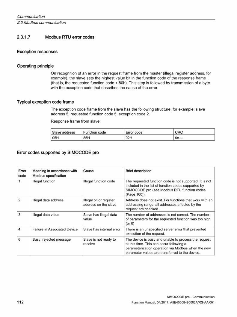
Communication 2.3 Modbus communication
SIMOCODE pro - Communication 112 Function Manual, 04/2017, A5E40508495002A/RS-AA/001
2.3.1.7 Modbus RTU error codes
Exception responses
Operating principle On recognition of an error in the request frame from the master (illegal register address, for example), the slave sets the highest value bit in the function code of the response frame (that is, the requested function code + 80h). This step is followed by transmission of a byte with the exception code that describes the cause of the error.
Typical exception code frame The exception code frame from the slave has the following structure, for example: slave address 5, requested function code 5, exception code 2.
Response frame from slave: Slave address Function code Error code CRC 05H 85H 02H 0x....
Error codes supported by SIMOCODE pro
Error code
Meaning in accordance with Modbus specification
Cause Brief description
1 Illegal function Illegal function code The requested function code is not supported. It is not included in the list of function codes supported by SIMOCODE pro (see Modbus RTU function codes (Page 100)).
2 Illegal data address Illegal bit or register address on the slave
Address does not exist. For functions that work with an addressing range, all addresses affected by the request are checked.
3 Illegal data value Slave has illegal data value
The number of addresses is not correct. The number of parameters for the requested function was too high (or 0)
4 Failure in Associated Device Slave has internal error There is an unspecified server error that prevented execution of the request.
6 Busy, rejected message Slave is not ready to receive
The device is busy and unable to process the request at this time. This can occur following a parameterization operation via Modbus when the new parameter values are transferred to the device.

Communication 2.4 EtherNet/IP communication
SIMOCODE pro - Communication Function Manual, 04/2017, A5E40508495002A/RS-AA/001 113
2.4 EtherNet/IP communication
2.4.1 Important notes
Note Trademarks
This chapter makes reference to technologies with names protected by the Open DeviceNet Vendor Association (ODVA).
The ODVA technologies referred to in this manual are as follows: • EtherNet/IP (EtherNet Industrial Protocol, often referred to as EIP) ™ • CIP (Common Industrial Protocol) ™
Further information about ODVA and technologies protected by ODVA can be found on the ODVA website ((www.odva.org)).
Siemens Parts
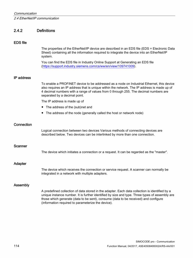
Communication 2.4 EtherNet/IP communication
SIMOCODE pro - Communication 114 Function Manual, 04/2017, A5E40508495002A/RS-AA/001
2.4.2 Definitions
EDS file The properties of the EtherNet/IP device are described in an EDS file (EDS = Electronic Data Sheet) containing all the information required to integrate the device into an EtherNet/IP system.
You can find the EDS file in Industry Online Support at Generating an EDS file (https://support.industry.siemens.com/cs/ww/en/view/109741009).
IP address To enable a PROFINET device to be addressed as a node on Industrial Ethernet, this device also requires an IP address that is unique within the network. The IP address is made up of 4 decimal numbers with a range of values from 0 through 255. The decimal numbers are separated by a decimal point.
The IP address is made up of
● The address of the (sub)net and
● The address of the node (generally called the host or network node)
Connection Logical connection between two devices Various methods of connecting devices are described below. Two devices can be interlinked by more than one connection.
Scanner The device which initiates a connection or a request. It can be regarded as the "master".
Adapter The device which receives the connection or service request. A scanner can normally be integrated in a network with multiple adapters.
Assembly A predefined collection of data stored in the adapter. Each data collection is identified by a unique instance number. It is further identified by size and type. Three types of assembly are those which generate (data to be sent), consume (data to be received) and configure (information required to parameterize the device).

Communication 2.4 EtherNet/IP communication
SIMOCODE pro - Communication Function Manual, 04/2017, A5E40508495002A/RS-AA/001 115
MAC address The MAC address can generally be read from the front on the device, e.g.: 08-00-06-6B-80-C0.
CIP Message-based application protocol. This protocol implements a relative path for sending a message from the modules that generate the message in one system to the modules that consume the message. CIP operates with a generator-consumer model rather than a source-destination model (master/slave). With a generator-consumer model, the volume of network traffic is lower and transmission times shorter.
EIP Abbreviation for EtherNet/IP.
Requested Packet Interval (RIP) EtherNet/IP devices normally generate or consume data on the basis of an RPI value (Requested Packet Interval). Generating devices transmit data packets in predefined time intervals on the basis of RPI, while consumer devices wait for data packets at a specific RPI.
2.4.3 Data security in automation See Data security in automation (Page 43).
Siemens Parts

Communication 2.4 EtherNet/IP communication
SIMOCODE pro - Communication 116 Function Manual, 04/2017, A5E40508495002A/RS-AA/001
2.4.4 Data transmission
Key statement The following figure shows an overview of the EtherNet/IP communication functions supported by SIMOCODE pro which are described in more detail in the following sections:
Figure 2-32 EtherNet/IP communication functions
1 Communication between PLC (I/O scanner) and SIMOCODE pro (I/O adapter) via EtherNet/IP
2 Communication between PC with parameterization software SIMOCODE ES (TIA Portal) and SIMOCODE pro via Ethernet
3 Communication between PC with parameterization software SIMOCODE ES (TIA Portal) and SIMOCODE pro via the SIMOCODE pro system interface (point-to-point via USB)
4 Communication between PC with web browser and SIMOCODE pro via Ethernet (TCP/IP); transmission of time of day via NTP from a PC with NTP server to the SIMOCODE pro V EIP devices

Communication 2.4 EtherNet/IP communication
SIMOCODE pro - Communication Function Manual, 04/2017, A5E40508495002A/RS-AA/001 117
2.4.5 Electronic Data Sheet (EDS) file
Integrating SIMOCODE pro EIP using an EDS file SIMOCODE pro V EIP can be integrated into an automation system by means of an EDS file (see also Definitions (Page 114)). This can be downloaded from Siemens Industry Online Support via the following link:
(https://support.industry.siemens.com/cs/ww/de/view/109741009)
The EDS file contains various information such as:
● Product symbol
● Manufacturer and device names
● Available cyclic data.
Note Integration in Rockwell Studio 5000
To facilitate integration of SIMOCODE pro EIP into Rockwell Studio 5000, a function example and an add-on instruction for Studio 5000 are also provided on the Siemens Industry Online Support webpage mentioned above.
Siemens Parts
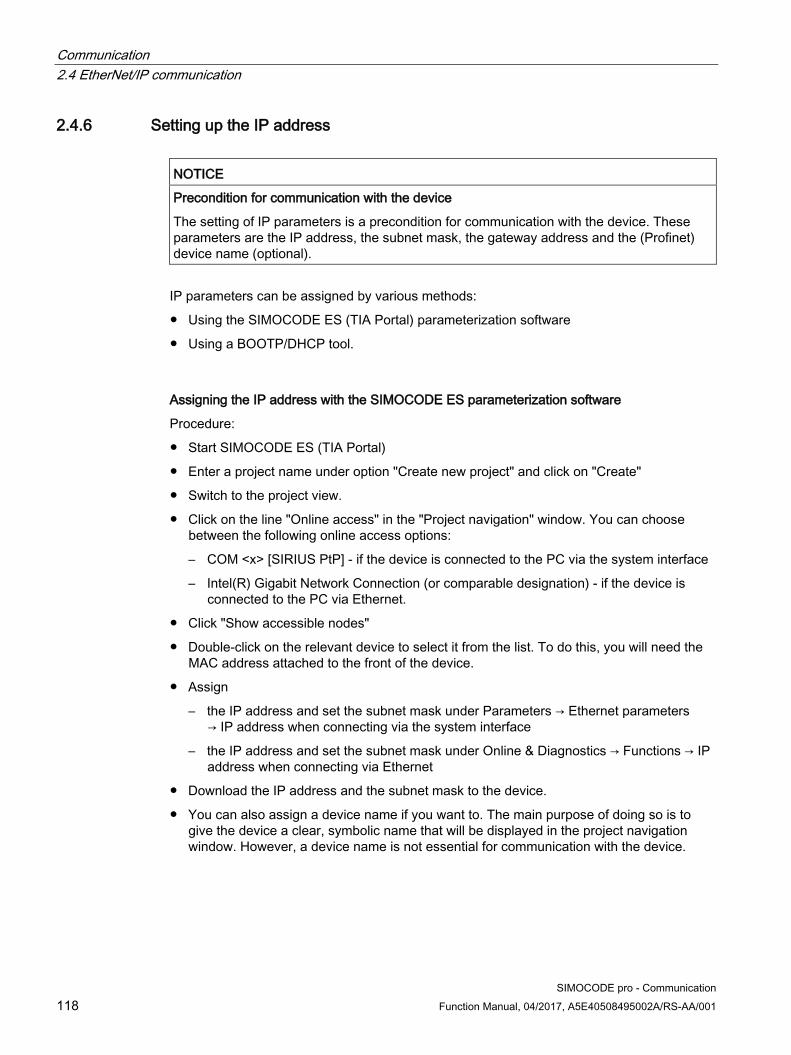
Communication 2.4 EtherNet/IP communication
SIMOCODE pro - Communication 118 Function Manual, 04/2017, A5E40508495002A/RS-AA/001
2.4.6 Setting up the IP address
NOTICE
Precondition for communication with the device
The setting of IP parameters is a precondition for communication with the device. These parameters are the IP address, the subnet mask, the gateway address and the (Profinet) device name (optional).
IP parameters can be assigned by various methods:
● Using the SIMOCODE ES (TIA Portal) parameterization software
● Using a BOOTP/DHCP tool.
Assigning the IP address with the SIMOCODE ES parameterization software
Procedure:
● Start SIMOCODE ES (TIA Portal)
● Enter a project name under option "Create new project" and click on "Create"
● Switch to the project view.
● Click on the line "Online access" in the "Project navigation" window. You can choose between the following online access options:
– COM <x> [SIRIUS PtP] - if the device is connected to the PC via the system interface
– Intel(R) Gigabit Network Connection (or comparable designation) - if the device is connected to the PC via Ethernet.
● Click "Show accessible nodes"
● Double-click on the relevant device to select it from the list. To do this, you will need the MAC address attached to the front of the device.
● Assign
– the IP address and set the subnet mask under Parameters → Ethernet parameters → IP address when connecting via the system interface
– the IP address and set the subnet mask under Online & Diagnostics → Functions → IP address when connecting via Ethernet
● Download the IP address and the subnet mask to the device.
● You can also assign a device name if you want to. The main purpose of doing so is to give the device a clear, symbolic name that will be displayed in the project navigation window. However, a device name is not essential for communication with the device.

Communication 2.4 EtherNet/IP communication
SIMOCODE pro - Communication Function Manual, 04/2017, A5E40508495002A/RS-AA/001 119
Assigning the IP address with a BOOTP/DHCP tool
Procedure:
● Start the BOOTP/DHCP server tool (e.g. from the Rockwell Studio 5000 package)
● Set the subnet mask of your network and, if applicable, the gateway address in the tool network settings; all of the devices that transmit BOOTP or DHCP messages into the network are displayed under "Request History" in the tool.
● Select the relevant device from this list. To do this, you will need the MAC address of the device: this is attached to the front panel of the SIMOCODE device.
● By clicking on button "Add to Relation List", you can assign an IP address, a host name and (if necessary) a description to the device. After the IP address has been assigned, the device with appear in the "Relation List", the list of all devices in this network segment with a valid IP address.
● After the IP address has been successfully assigned, deactivate the BOOTP/DHCP mechanism in the SIMOCODE device by selecting the device and clicking on the button labeled "Disable BOOTP/DHCP".
Note
Behavior of SIMOCODE pro if BOOTP/DHCP is not deactivated in the SIMOCODE device
If you do not deactivate the BOOTP/DHCP mechanism in the SIMOCODE device, it will restart after the next Power ON without a valid IP address and start sending BOOTP/DHCP messages again.
Siemens Parts
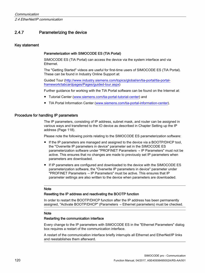
Communication 2.4 EtherNet/IP communication
SIMOCODE pro - Communication 120 Function Manual, 04/2017, A5E40508495002A/RS-AA/001
2.4.7 Parameterizing the device
Key statement
Parameterization with SIMOCODE ES (TIA Portal)
SIMOCODE ES (TIA Portal) can access the device via the system interface and via Ethernet.
The "Getting Started" videos are useful for first-time users of SIMOCODE ES (TIA Portal). These can be found in Industry Online Support at:
Guided Tour (http://www.industry.siemens.com/topics/global/en/tia-portal/tia-portal-framework/tabcardpages/Pages/guided-tour.aspx)
Further guidance for working with the TIA Portal software can be found on the Internet at:
● Tutorial Center (www.siemens.com/tia-portal-tutorial-center) and
● TIA Portal Information Center (www.siemens.com/tia-portal-information-center).
Procedure for handling IP parameters The IP parameters, consisting of IP address, subnet mask, and router can be assigned in various ways and transferred to the IO device as described in Chapter Setting up the IP address (Page 118).
Please note the following points relating to the SIMOCODE ES parameterization software:
● If the IP parameters are managed and assigned to the device via a BOOTP/DHCP tool, the "Overwrite IP parameters in device" parameter set in the SIMOCODE ES parameterization software under "PROFINET Parameters → IP Parameters" must not be active. This ensures that no changes are made to previously set IP parameters when parameters are downloaded.
● If IP parameters are configured and downloaded to the device with the SIMOCODE ES parameterization software, the "Overwrite IP parameters in device" parameter under "PROFINET Parameters → IP Parameters" must be active. This ensures that IP parameter settings are also written to the device when parameters are downloaded.
Note Resetting the IP address and reactivating the BOOTP function
In order to restart the BOOTP/DHCP function after the IP address has been permanently assigned, "Activate BOOTP/DHCP" (Parameters → Ethernet parameters) must be checked.
Note Restarting the communication interface
Every change to the IP parameters with SIMOCODE ES in the "Ethernet Parameters" dialog box requires a restart of the communication interface.
A restart of the communication interface briefly interrupts all Ethernet and EtherNet/IP links and reestablishes them afterward.

Communication 2.4 EtherNet/IP communication
SIMOCODE pro - Communication Function Manual, 04/2017, A5E40508495002A/RS-AA/001 121
2.4.8 Integrating SIMOCODE pro into the automation system (PLC)
I/O configurations
SIMOCODE pro V PN supports a number of I/O configurations which define the structure and length of the I/O data that are cyclically exchanged between the EtherNet/IP scanner (PLC) and the adapter (SIMOCODE pro). These configurations are referred to as "basic types" and can be selected on the basis of the chosen assembly instances when the device is integrated in Studio 5000.
The data that are exchanged with the EtherNet/IP scanner can be set by means of function blocks such as, for example, "Cyclic receive byte 0" or "Cyclic send byte 0" in the SIMOCODE ES software. Detailed information about the relationship between SIMOCODE ES function blocks and assembly instances can be found in Chapter Assembly object (Page 322).
Overview of the cyclic data available with SIMOCODE pro V EtherNet/IP: Input data length Input assembly Output data length Output assembly Basic Type 1 10 byte 150 4 bytes 100 Basic Type 2 4 bytes 151 2 bytes 101 Basic Type 3 20 bytes 152 6 bytes 102 Basic Type 4 488 bytes 153 6 bytes 102
Siemens Parts
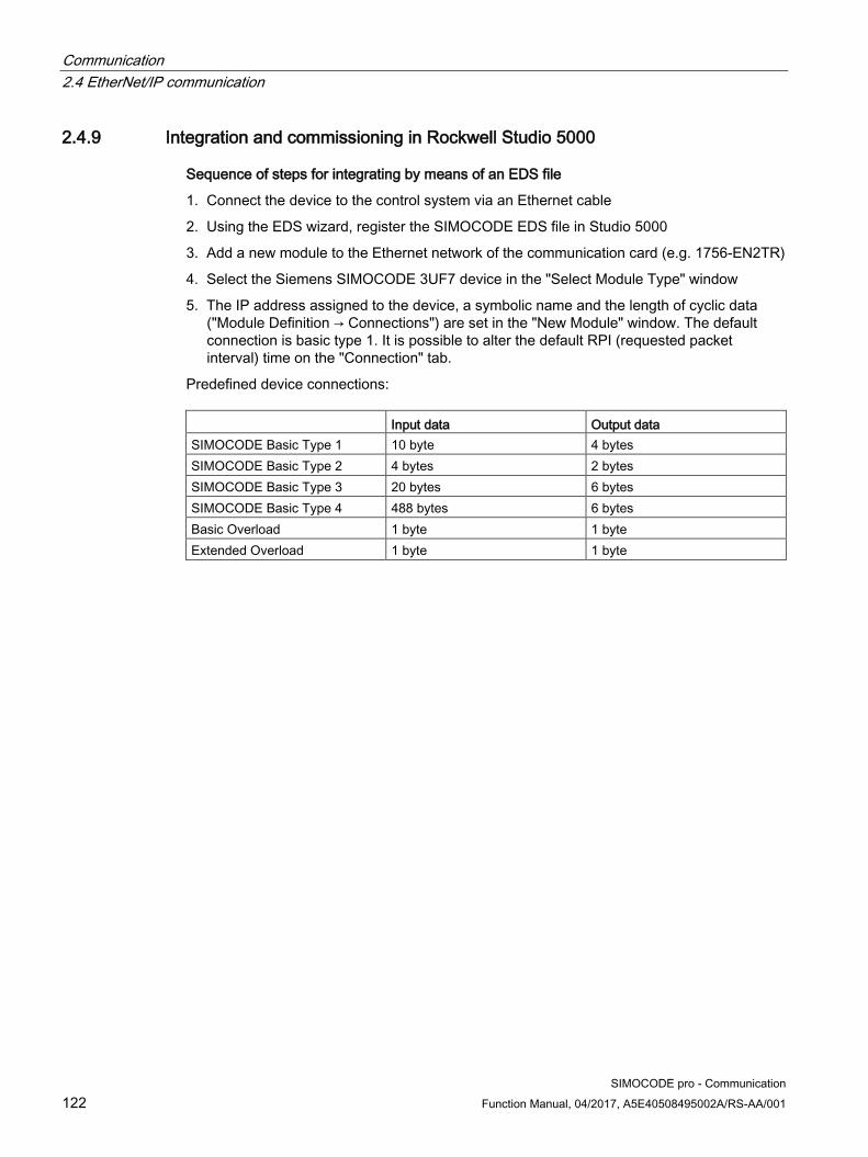
Communication 2.4 EtherNet/IP communication
SIMOCODE pro - Communication 122 Function Manual, 04/2017, A5E40508495002A/RS-AA/001
2.4.9 Integration and commissioning in Rockwell Studio 5000
Sequence of steps for integrating by means of an EDS file
1. Connect the device to the control system via an Ethernet cable
2. Using the EDS wizard, register the SIMOCODE EDS file in Studio 5000
3. Add a new module to the Ethernet network of the communication card (e.g. 1756-EN2TR)
4. Select the Siemens SIMOCODE 3UF7 device in the "Select Module Type" window
5. The IP address assigned to the device, a symbolic name and the length of cyclic data ("Module Definition → Connections") are set in the "New Module" window. The default connection is basic type 1. It is possible to alter the default RPI (requested packet interval) time on the "Connection" tab.
Predefined device connections: Input data Output data SIMOCODE Basic Type 1 10 byte 4 bytes SIMOCODE Basic Type 2 4 bytes 2 bytes SIMOCODE Basic Type 3 20 bytes 6 bytes SIMOCODE Basic Type 4 488 bytes 6 bytes Basic Overload 1 byte 1 byte Extended Overload 1 byte 1 byte

Communication 2.4 EtherNet/IP communication
SIMOCODE pro - Communication Function Manual, 04/2017, A5E40508495002A/RS-AA/001 123
Sequence of steps for integrating by means of a generic Ethernet module
1. Connect the device to the control system via an Ethernet cable
2. Add a new generic Ethernet module to the Ethernet network of the communication card (e.g. 1756-EN2TR)
3. Enter the symbolic name and the IP address of the SIMOCODE pro EIP device. The IP address must match the IP address parameterized via BOOTP/DHCP or SIMOCODE ES.
4. Enter the connection parameters in the "Assembly Instance" and "Size" boxes on the screen. It is possible to alter the default RPI (requested packet interval) time on the "Connection" tab.
Figure 2-33 Adding a new generic Ethernet module in Studio 5000
Siemens Parts
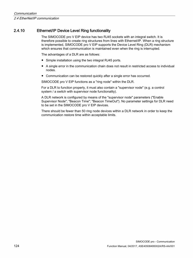
Communication 2.4 EtherNet/IP communication
SIMOCODE pro - Communication 124 Function Manual, 04/2017, A5E40508495002A/RS-AA/001
2.4.10 Ethernet/IP Device Level Ring functionality The SIMOCODE pro V EIP device has two RJ45 sockets with an integral switch. It is therefore possible to create ring structures from lines with Ethernet/IP. When a ring structure is implemented, SIMOCODE pro V EIP supports the Device Level Ring (DLR) mechanism which ensures that communication is maintained even when the ring is interrupted.
The advantages of a DLR are as follows:
● Simple installation using the two integral RJ45 ports.
● A single error in the communication chain does not result in restricted access to individual nodes.
● Communication can be restored quickly after a single error has occurred.
SIMOCODE pro V EIP functions as a "ring node" within the DLR.
For a DLR to function properly, it must also contain a "supervisor node" (e.g. a control system / a switch with supervisor node functionality).
A DLR network is configured by means of the "supervisor node" parameters ("Enable Supervisor Node"; "Beacon Time"; "Beacon TimeOut"). No parameter settings for DLR need to be set in the SIMOCODE pro V EIP devices.
There should be fewer than 50 ring node devices within a DLR network in order to keep the communication restore time within acceptable limits.

Communication 2.4 EtherNet/IP communication
SIMOCODE pro - Communication Function Manual, 04/2017, A5E40508495002A/RS-AA/001 125
2.4.11 Web diagnostics (web server) SIMOCODE pro V EIP offers you with the web diagnosis the possibility of calling the following information of the motor feeder from a PG/PC using an HTTP client:
● Status information
● Faults, warnings, events
● Measured values
● Service and statistical data
● Error buffer, error protocol
Web diagnostics are available in Chinese, Russian, English and German.
Activating the web server:
The default setting of the web server is "not active." To activate it, the "Ethernet Parameters →Web Server Activated" parameter must be active.
Note Restarting the communication interface
Each change to the configuration of the web server requires that the communication interface be restarted.
A new start of the communication interface interrupts all Ethernet and PROFINET links and reestablishes them afterward.
Setting the IP parameters:
To enable a link to be established via the web, SIMOCODE pro V EIP must have valid IP parameters. You can find out how to make these settings in Chapter Setting up the IP address (Page 118).
Siemens Parts

Communication 2.4 EtherNet/IP communication
SIMOCODE pro - Communication 126 Function Manual, 04/2017, A5E40508495002A/RS-AA/001
Web browser
For access to the HTML pages in the SIMOCODE pro V EIP, you need a web browser.
The following web browsers are suitable for communication with SIMOCODE pro etc.:
● Internet Explorer (recommended version: Version 11)
● Firefox (recommended version: Version 49)
● Google Chrome (recommended version: Version 54)
Note Connection to a web client
Connection to a web client is supported.
Settings of the web browser for access to the information
Check the following settings, which are a precondition for access to the information made available via the web:
● To load the diagnostics data, Javascript must be activated in the Internet browser.
● The browser must support frames.
● Cookies must be permitted.
● The browser should be set in such a way that whenever it accesses a page, it automatically loads the current data from the server.
In the Internet Explorer, you will find these settings with menu "Tools" → "Internet Options" → "General" tab card → "Temporary Internet Files" group box → "Settings" button.
To use a firewall in your PG/PC, the following port must be enabled for use of the web diagnostics: "http Port 80/TCP" or, in the case of secure connections, "https Port 443/TCP".

Communication 2.4 EtherNet/IP communication
SIMOCODE pro - Communication Function Manual, 04/2017, A5E40508495002A/RS-AA/001 127
2.4.12 Time-of-day synchronization by the NTP procedure SIMOCODE pro V EIP has a non-battery-backed realtime clock that can be synchronized via the NTP procedure.
Network Time Protocol (NTP) is the implementation of a TCP/IP protocol for time synchronization in networks. The NTP procedure uses hierarchical time synchronization, that is, an external clock (e.g. SICLOCK TM or a PC in the network) is used for synchronization.
The device transmits time-of-day queries to the configured NTP server at configured time intervals. Using the responses of the server, the time of day of the non-battery-backed clock is synchronized in SIMOCODE pro. This ensures that a synchronized time of day is available shortly after the supply voltage is switched on.
The NTP synchronization is configured with the "SIMOCODE ES (TIA Portal)" configuration software under "EtherNet/IP Parameters → NTP procedure/synchronization."
The following settings are also made:
● NTP server address: Enter the NTP server address when the "Activate NTP synchronization" checkbox is selected.
Note
Adoption of the NTP server address
The NTP server address is not accepted until the device has been restarted or after the supply voltage has been switched off and on again.
● Cyclic update interval: Time interval in seconds at which synchronization of the time of day with the NTP server is performed
● Time shift: Time difference in minutes between UTC time (UTC = Universal Time Coordinated) and the time in the device.
Examples:
● Time shift for CET (Central European Time): +60 min
● Time shift for CST (Central Standard Time, North America): -360 min.
If an NTP server address has not been configured or a server was not found on the network, you can also set the time of day using SIMOCODE ES. To do this, proceed as follows:
Mark the relevant SIMOCODE device in the project navigation window and then select "Connect online" to establish a direct connection to the device. Expand the list of device settings by clicking on the arrow on the left of the SIMOCODE device: You can now select "Commissioning → Command → Set time (= PC time in UTC)" to download the time of day of your PC to the SIMOCODE device.
If a valid time of day is available (either synchronized by NTP or set via SIMOCODE ES), the entries in the error buffer/error protocol (i.e. log) will be additionally displayed with the time of day. In addition, the "Clock set (NTP)" and "Clock synchronized (NTP)" messages are displayed.
Siemens Parts

Communication 2.4 EtherNet/IP communication
SIMOCODE pro - Communication 128 Function Manual, 04/2017, A5E40508495002A/RS-AA/001
2.4.13 Simple Network Management Protocol (SNMP) SNMP is a network protocol for monitoring and controlling network elements (e.g. switches).
SIMOCODE pro V EIP supports the Ethernet service SNMP. MIB-2 (RFC1213) is supported. R/W objects can be changed with SNMP tools and are stored in the basic unit.
After replacement with a new basic unit from the factory or a basic unit that has undergone a general reset, the R/W objects will be in the factory settings.

SIMOCODE pro - Communication Function Manual, 04/2017, A5E40508495002A/RS-AA/001 129
Tables, data records 3 3.1 Tables general
3.1.1 Active control stations, contactor controls, lamp controls and status information for the control functions
Table 3- 1 Active control stations of control functions
Designation / control function Control station ON << ON < OFF ОN > ON >> Overload 1) 2) 3) - - - - - Direct starter (direct-on-line starter) 1) 2) 3) - - OFF ON - Reversing starter 1) 2) 3) - CCW OFF CW - Circuit breaker 1) 2) 3) - - OFF ON - Star-delta starter 2) 3) - - OFF ON - Star-delta reversing starter 3) - CCW OFF CW - Dahlander 3) - - OFF SLOW FAST Dahlander reversing starter 3) CCW-FAST CCW-SLOW OFF CW-SLOW CW-FAST Pole-changing starter 3) - - OFF SLOW FAST Pole-changing reversing starter 3) CCW-FAST CCW-SLOW OFF CW-SLOW CW-FAST Solenoid valve 3) - - CLOSED OPEN - Positioner 1 3) - CLOSED Stop OPEN - Positioner 2 3) - CLOSED Stop OPEN - Positioner 3 3) - CLOSED Stop OPEN - Positioner 4 3) - CLOSED Stop OPEN - Positioner 5 3) - CLOSED Stop OPEN - Soft starter 2) 3) - - OFF ON - Soft starter with reversing contactor 3) - CCW OFF CW -
Siemens Parts

Tables, data records 3.1 Tables general
SIMOCODE pro - Communication 130 Function Manual, 04/2017, A5E40508495002A/RS-AA/001
Table 3- 2 Contactor control with control functions
Designation / control function Contactor control QE1 QE2 QE3 QE4 QE5 Overload 1) 2) 3) - - Active - - Direct-on-line starter 1) 2) 3) ON - - - - Reversing starter 1) 2) 3) CW CCW - - - Circuit breaker 1) 2) 3) ON pulse - OFF pulse - - Star-delta starter 2) 3) Star contactor Delta contactor Line contactor - - Star-delta reversing starter 3) Star contactor Delta contactor RIGHT line
contactor LEFT line contactor
-
Dahlander 3) FAST SLOW Star contactor FAST
- -
Dahlander reversing starter 3) CW-FAST CW-SLOW Star contactor FAST
CCW-SLOW CCW-FAST
Pole-changing starter 3) FAST SLOW - - - Pole-changing reversing starter 3) CW-FAST CW-SLOW - CCW-SLOW CCW-FAST Solenoid valve 3) OPEN - - - - Positioner 1 3) OPEN CLOSED - - - Positioner 2 3) OPEN CLOSED - - - Positioner 3 3) OPEN CLOSED - - - Positioner 4 3) OPEN CLOSED - - - Positioner 5 3) OPEN CLOSED - - - Soft starter 2) 3) ON line contactor - Reset ON command - Soft starter with reversing contactor 3) RIGHT line
contactor LEFT line contactor
Reset ON command -

Tables, data records 3.1 Tables general
SIMOCODE pro - Communication Function Manual, 04/2017, A5E40508495002A/RS-AA/001 131
Table 3- 3 Lamp control with control functions
Designation / control function Lamp control QLE << (ON <<) QLE < (ON <) QLA (OFF) QLE < (ON >) QLE >> (ON >>) Overload 1) 2) 3) - - - - - Direct-on-line starter 1) 2) 3) - - OFF ON - Reversing starter 1) 2) 3) - CCW OFF CW - Circuit breaker 1) 2) 3) - - OFF ON - Star-delta starter 2) 3) - - OFF ON - Star-delta reversing starter 3) - CCW OFF CW - Dahlander 3) - - OFF SLOW FAST Dahlander reversing starter 3) CCW-FAST CCW-SLOW OFF CW-SLOW CW-FAST Pole-changing starter 3) - - OFF SLOW FAST Pole-changing reversing starter 3) CCW-FAST CCW-SLOW OFF CW-SLOW CW-FAST Solenoid valve 3) - - CLOSED OPEN - Positioner 1 3) - CLOSED Stop OPEN - Positioner 2 3) - CLOSED Stop OPEN - Positioner 3 3) - CLOSED Stop OPEN - Positioner 4 3) - CLOSED Stop OPEN - Positioner 5 3) - CLOSED Stop OPEN - Soft starter 2) 3) - - OFF ON - Soft starter with reversing contactor 3)
- CCW OFF CW -
1) SIMOCODE pro C
2) SIMOCODE pro S
3) SIMOCODE pro V
Siemens Parts

Tables, data records 3.2 Assignment of cyclic receive and send data for predefined control functions
SIMOCODE pro - Communication 132 Function Manual, 04/2017, A5E40508495002A/RS-AA/001
3.2 Assignment of cyclic receive and send data for predefined control functions
3.2.1 Overload relay
Table 3- 4 Assignment of cyclic receive / send data, overload relay
Cycl. receive data Bit 0.0 Not connected Bit 0.1 Not connected Bit 0.2 Not connected Bit 0.3 Further function blocks → Standard functions → Test / Reset → Test1 - Input Bit 0.4 Further function blocks → Standard functions → Emergency start → Emergency start - Input Bit 0.5 Not connected Bit 0.6 Further function blocks → Standard functions → Test / Reset → Reset1 - Input Bit 0.7 Not connected Bit 1.0 Not connected Bit 1.1 Not connected Bit 1.2 Not connected Bit 1.3 Not connected Bit 1.4 Not connected Bit 1.5 Not connected Bit 1.6 Not connected Bit 1.7 Not connected Byte 2/3 *) (analog value) Not connected

Tables, data records 3.2 Assignment of cyclic receive and send data for predefined control functions
SIMOCODE pro - Communication Function Manual, 04/2017, A5E40508495002A/RS-AA/001 133
Cycl. send data Bit 0.0 Not connected Bit 0.1 Not connected Bit 0.2 Not connected Bit 0.3 Event - Prewarning overload (I>115 %) Bit 0.4 Not connected Bit 0.5 Not connected Bit 0.6 Status - General fault Bit 0.7 Status - general warning Bit 1.0 Not connected Bit 1.1 Not connected Bit 1.2 Not connected Bit 1.3 Not connected Bit 1.4 Not connected Bit 1.5 Not connected Bit 1.6 Not connected Bit 1.7 Not connected Byte 2/3 (analog value) Maximum current I_max Byte 4/5 *) (analog value) Not connected Byte 6/7 *) (analog value) Not connected Byte 8/9 *) (analog value) Not connected
*) for SIMOCODE pro V / pro S, basic type 1 only
Siemens Parts
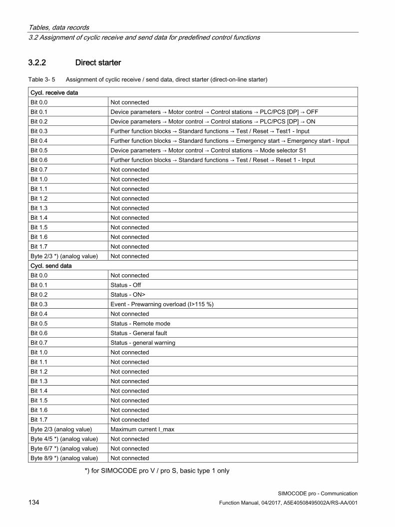
Tables, data records 3.2 Assignment of cyclic receive and send data for predefined control functions
SIMOCODE pro - Communication 134 Function Manual, 04/2017, A5E40508495002A/RS-AA/001
3.2.2 Direct starter
Table 3- 5 Assignment of cyclic receive / send data, direct starter (direct-on-line starter)
Cycl. receive data Bit 0.0 Not connected Bit 0.1 Device parameters → Motor control → Control stations → PLC/PCS [DP] → OFF Bit 0.2 Device parameters → Motor control → Control stations → PLC/PCS [DP] → ON Bit 0.3 Further function blocks → Standard functions → Test / Reset → Test1 - Input Bit 0.4 Further function blocks → Standard functions → Emergency start → Emergency start - Input Bit 0.5 Device parameters → Motor control → Control stations → Mode selector S1 Bit 0.6 Further function blocks → Standard functions → Test / Reset → Reset 1 - Input Bit 0.7 Not connected Bit 1.0 Not connected Bit 1.1 Not connected Bit 1.2 Not connected Bit 1.3 Not connected Bit 1.4 Not connected Bit 1.5 Not connected Bit 1.6 Not connected Bit 1.7 Not connected Byte 2/3 *) (analog value) Not connected Cycl. send data Bit 0.0 Not connected Bit 0.1 Status - Off Bit 0.2 Status - ON> Bit 0.3 Event - Prewarning overload (I>115 %) Bit 0.4 Not connected Bit 0.5 Status - Remote mode Bit 0.6 Status - General fault Bit 0.7 Status - general warning Bit 1.0 Not connected Bit 1.1 Not connected Bit 1.2 Not connected Bit 1.3 Not connected Bit 1.4 Not connected Bit 1.5 Not connected Bit 1.6 Not connected Bit 1.7 Not connected Byte 2/3 (analog value) Maximum current I_max Byte 4/5 *) (analog value) Not connected Byte 6/7 *) (analog value) Not connected Byte 8/9 *) (analog value) Not connected
*) for SIMOCODE pro V / pro S, basic type 1 only

Tables, data records 3.2 Assignment of cyclic receive and send data for predefined control functions
SIMOCODE pro - Communication Function Manual, 04/2017, A5E40508495002A/RS-AA/001 135
3.2.3 Reversing starter
Table 3- 6 Assignment of cyclic receive / send data, reversing starter
Cyclic receive data Bit 0.0 Device parameters → Motor control → Control stations → PLC/PCS [DP] → ON Bit 0.1 Device parameters → Motor control → Control stations → PLC/PCS [DP] → OFF Bit 0.2 Device parameters → Motor control → Control stations → PLC/PCS [DP] → ON Bit 0.3 Further function blocks → Standard functions → Test / Reset → Test1 - Input Bit 0.4 Further function blocks → Standard functions → Emergency start → Emergency start - Input Bit 0.5 Device parameters → Motor control → Control stations → Mode selector S1 Bit 0.6 Further function blocks → Standard functions → Test / Reset → Reset1 - Input Bit 0.7 Not connected Bit 1.0 Not connected Bit 1.1 Not connected Bit 1.2 Not connected Bit 1.3 Not connected Bit 1.4 Not connected Bit 1.5 Not connected Bit 1.6 Not connected Bit 1.7 Not connected Byte 2/3 *) (analog value) Not connected Cyclic send data Bit 0.0 Status - ON< Bit 0.1 Status - Off Bit 0.2 Status - ON> Bit 0.3 Event - Prewarning overload (I>115 %) Bit 0.4 Status - Interlocking time active Bit 0.5 Status - Remote mode Bit 0.6 Status - General fault Bit 0.7 Status - general warning Bit 1.0 Not connected Bit 1.1 Not connected Bit 1.2 Not connected Bit 1.3 Not connected Bit 1.4 Not connected Bit 1.5 Not connected Bit 1.6 Not connected Bit 1.7 Not connected Byte 2/3 (analog value) Maximum current I_max Byte 4/5 *) (analog value) Not connected Byte 6/7 *) (analog value) Not connected Byte 8/9 *) (analog value) Not connected
*) for SIMOCODE pro V / pro S, basic type 1 only
Siemens Parts

Tables, data records 3.2 Assignment of cyclic receive and send data for predefined control functions
SIMOCODE pro - Communication 136 Function Manual, 04/2017, A5E40508495002A/RS-AA/001
3.2.4 Molded-case circuit breaker (MCCB)
Table 3- 7 Assignment of cyclic receive / send data, molded-case circuit breaker (MCCB)
Cyclic receive data Bit 0.0 Not connected Bit 0.1 Device parameters → Motor control → Control stations → PLC/PCS [DP] → OFF Bit 0.2 Device parameters → Motor control → Control stations → PLC/PCS [DP] → ON Bit 0.3 Further function blocks → Standard functions → Test / Reset → Test1 - Input Bit 0.4 Further function blocks → Standard functions → Emergency start → Emergency start - Input Bit 0.5 Device parameters → Motor control → Control stations → Mode selector S1 Bit 0.6 Further function blocks → Standard functions → Test / Reset → Reset 1 - Input Bit 0.7 Not connected Bit 1.0 Not connected Bit 1.1 Not connected Bit 1.2 Not connected Bit 1.3 Not connected Bit 1.4 Not connected Bit 1.5 Not connected Bit 1.6 Not connected Bit 1.7 Not connected Byte 2/3 *) (analog value) Not connected Cyclic send data Bit 0.0 Not connected Bit 0.1 Status - Off Bit 0.2 Status - ON> Bit 0.3 Event - Prewarning overload (I>115 %) Bit 0.4 Not connected Bit 0.5 Status - Remote mode Bit 0.6 Status - General fault Bit 0.7 Status - general warning Bit 1.0 Not connected Bit 1.1 Not connected Bit 1.2 Not connected Bit 1.3 Not connected Bit 1.4 Not connected Bit 1.5 Not connected Bit 1.6 Not connected Bit 1.7 Not connected Byte 2/3 (analog value) Maximum current I_max Byte 4/5 *) (analog value) Not connected Byte 6/7 *) (analog value) Not connected Byte 8/9 *) (analog value) Not connected
*) for SIMOCODE pro V / pro S, basic type 1 only

Tables, data records 3.2 Assignment of cyclic receive and send data for predefined control functions
SIMOCODE pro - Communication Function Manual, 04/2017, A5E40508495002A/RS-AA/001 137
3.2.5 Star-delta starter
Table 3- 8 Assignment of cyclic receive / send data, star/delta starter
Cyclic receive data Bit 0.0 Not connected Bit 0.1 Device parameters → Motor control → Control stations → PLC/PCS [DP] → OFF Bit 0.2 Device parameters → Motor control → Control stations → PLC/PCS [DP] → ON Bit 0.3 Further function blocks → Standard functions → Test / Reset → Test1 - Input Bit 0.4 Further function blocks → Standard functions → Emergency start → Emergency start - Input Bit 0.5 Device parameters → Motor control → Control stations → Mode selector S1 Bit 0.6 Further function blocks → Standard functions → Test / Reset → Reset 1 - Input Bit 0.7 Not connected Bit 1.0 Not connected Bit 1.1 Not connected Bit 1.2 Not connected Bit 1.3 Not connected Bit 1.4 Not connected Bit 1.5 Not connected Bit 1.6 Not connected Bit 1.7 Not connected Byte 2/3 *) (analog value) Not connected Cycl. send data Bit 0.0 Not connected Bit 0.1 Status - Off Bit 0.2 Status - ON Bit 0.3 Event - Prewarning overload (I>115 %) Bit 0.4 Status - Change-over pause active Bit 0.5 Status - Remote mode Bit 0.6 Status - General fault Bit 0.7 Status - general warning Bit 1.0 Not connected Bit 1.1 Not connected Bit 1.2 Not connected Bit 1.3 Not connected Bit 1.4 Not connected Bit 1.5 Not connected Bit 1.6 Not connected Bit 1.7 Not connected Byte 2/3 (analog value) Maximum current I_max Byte 4/5 *) (analog value) Not connected Byte 6/7 *) (analog value) Not connected Byte 8/9 *) (analog value) Not connected
*) for SIMOCODE pro V / pro S, basic type 1 only
Siemens Parts

Tables, data records 3.2 Assignment of cyclic receive and send data for predefined control functions
SIMOCODE pro - Communication 138 Function Manual, 04/2017, A5E40508495002A/RS-AA/001
3.2.6 Star-delta reversing starter
Table 3- 9 Assignment of cyclic receive / send data, star/delta reversing starter
Cyclic receive data Bit 0.0 Device parameters → Motor control → Control stations → PLC/PCS [DP] → ON < Bit 0.1 Device parameters → Motor control → Control stations -> PLC/PCS [DP] -> OFF Bit 0.2 Device parameters → Motor control → Control stations → PLC/PCS [DP] → ON > Bit 0.3 Further function blocks → Standard functions → Test / Reset → Test1 - Input Bit 0.4 Further function blocks → Standard functions → Emergency start → Emergency start - Input Bit 0.5 Device parameters → Motor control → Control stations → Mode selector S1 Bit 0.6 Further function blocks → Standard functions → Test / Reset → Reset 1 - Input Bit 0.7 Not connected Bit 1.0 Not connected Bit 1.1 Not connected Bit 1.2 Not connected Bit 1.3 Not connected Bit 1.4 Not connected Bit 1.5 Not connected Bit 1.6 Not connected Bit 1.7 Not connected Byte 2/3 *) (analog value) Not connected Cyclic send data Bit 0.0 Status - ON< Bit 0.1 Status - Off Bit 0.2 Status - ON> Bit 0.3 Event - Prewarning overload (I>115 %) Bit 0.4 Status - Change-over pause active Bit 0.5 Status - Remote mode Bit 0.6 Status - General fault Bit 0.7 Status - general warning Bit 1.0 Not connected Bit 1.1 Not connected Bit 1.2 Not connected Bit 1.3 Status - Interlocking time active Bit 1.4 Not connected Bit 1.5 Not connected Bit 1.6 Not connected Bit 1.7 Not connected Byte 2/3 (analog value) Maximum current I_max Byte 4/5 *) (analog value) Not connected Byte 6/7 *) (analog value) Not connected Byte 8/9 *) (analog value) Not connected
*) for SIMOCODE pro V / pro S, basic type 1 only

Tables, data records 3.2 Assignment of cyclic receive and send data for predefined control functions
SIMOCODE pro - Communication Function Manual, 04/2017, A5E40508495002A/RS-AA/001 139
3.2.7 Dahlander
Table 3- 10 Assignment of cyclic receive / send data, Dahlander
Cyclic receive data Bit 0.0 Device parameters → Motor control → Control stations → PLC/PCS [DP] → ON >> Bit 0.1 Device parameters → Motor control → Control stations → PLC/PCS [DP] → OFF Bit 0.2 Device parameters → Motor control → Control stations → PLC/PCS [DP] → ON > Bit 0.3 Further function blocks → Standard functions → Test / Reset → Test1 - Input Bit 0.4 Further function blocks → Standard functions → Emergency start → Emergency start - Input Bit 0.5 Device parameters → Motor control → Control stations → Mode selector S1 Bit 0.6 Further function blocks → Standard functions → Test / Reset → Reset 1 - Input Bit 0.7 Not connected Bit 1.0 Not connected Bit 1.1 Not connected Bit 1.2 Not connected Bit 1.3 Not connected Bit 1.4 Not connected Bit 1.5 Not connected Bit 1.6 Not connected Bit 1.7 Not connected Byte 2/3 *) (analog value) Not connected Cyclic send data Bit 0.0 Status - ON>> Bit 0.1 Status - Off Bit 0.2 Status - ON> Bit 0.3 Event - Prewarning overload (I>115 %) Bit 0.4 Status - Change-over pause active Bit 0.5 Status - Remote mode Bit 0.6 Status - General fault Bit 0.7 Status - general warning Bit 1.0 Not connected Bit 1.1 Not connected Bit 1.2 Not connected Bit 1.3 Not connected Bit 1.4 Not connected Bit 1.5 Not connected Bit 1.6 Not connected Bit 1.7 Not connected Byte 2/3 (analog value) Maximum current I_max Byte 4/5 *) (analog value) Not connected Byte 6/7 *) (analog value) Not connected Byte 8/9 *) (analog value) Not connected
*) for SIMOCODE pro V / pro S, basic type 1 only
Siemens Parts
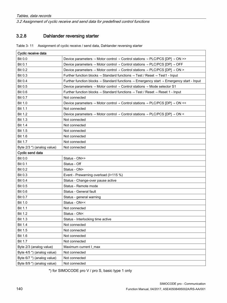
Tables, data records 3.2 Assignment of cyclic receive and send data for predefined control functions
SIMOCODE pro - Communication 140 Function Manual, 04/2017, A5E40508495002A/RS-AA/001
3.2.8 Dahlander reversing starter
Table 3- 11 Assignment of cyclic receive / send data, Dahlander reversing starter
Cyclic receive data Bit 0.0 Device parameters → Motor control → Control stations → PLC/PCS [DP] → ON >> Bit 0.1 Device parameters → Motor control → Control stations → PLC/PCS [DP] → OFF Bit 0.2 Device parameters → Motor control → Control stations → PLC/PCS [DP] → ON > Bit 0.3 Further function blocks → Standard functions → Test / Reset → Test1 - Input Bit 0.4 Further function blocks → Standard functions → Emergency start → Emergency start - Input Bit 0.5 Device parameters → Motor control → Control stations → Mode selector S1 Bit 0.6 Further function blocks → Standard functions → Test / Reset → Reset 1 - Input Bit 0.7 Not connected Bit 1.0 Device parameters → Motor control → Control stations → PLC/PCS [DP] → ON << Bit 1.1 Not connected Bit 1.2 Device parameters → Motor control → Control stations → PLC/PCS [DP] → ON < Bit 1.3 Not connected Bit 1.4 Not connected Bit 1.5 Not connected Bit 1.6 Not connected Bit 1.7 Not connected Byte 2/3 *) (analog value) Not connected Cyclic send data Bit 0.0 Status - ON>> Bit 0.1 Status - Off Bit 0.2 Status - ON> Bit 0.3 Event - Prewarning overload (I>115 %) Bit 0.4 Status - Change-over pause active Bit 0.5 Status - Remote mode Bit 0.6 Status - General fault Bit 0.7 Status - general warning Bit 1.0 Status - ON<< Bit 1.1 Not connected Bit 1.2 Status - ON< Bit 1.3 Status - Interlocking time active Bit 1.4 Not connected Bit 1.5 Not connected Bit 1.6 Not connected Bit 1.7 Not connected Byte 2/3 (analog value) Maximum current I_max Byte 4/5 *) (analog value) Not connected Byte 6/7 *) (analog value) Not connected Byte 8/9 *) (analog value) Not connected
*) for SIMOCODE pro V / pro S, basic type 1 only
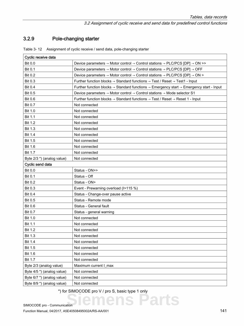
Tables, data records 3.2 Assignment of cyclic receive and send data for predefined control functions
SIMOCODE pro - Communication Function Manual, 04/2017, A5E40508495002A/RS-AA/001 141
3.2.9 Pole-changing starter
Table 3- 12 Assignment of cyclic receive / send data, pole-changing starter
Cyclic receive data Bit 0.0 Device parameters → Motor control → Control stations → PLC/PCS [DP] → ON >> Bit 0.1 Device parameters → Motor control → Control stations → PLC/PCS [DP] → OFF Bit 0.2 Device parameters → Motor control → Control stations → PLC/PCS [DP] → ON > Bit 0.3 Further function blocks → Standard functions → Test / Reset → Test1 - Input Bit 0.4 Further function blocks → Standard functions → Emergency start → Emergency start - Input Bit 0.5 Device parameters → Motor control → Control stations → Mode selector S1 Bit 0.6 Further function blocks → Standard functions → Test / Reset → Reset 1 - Input Bit 0.7 Not connected Bit 1.0 Not connected Bit 1.1 Not connected Bit 1.2 Not connected Bit 1.3 Not connected Bit 1.4 Not connected Bit 1.5 Not connected Bit 1.6 Not connected Bit 1.7 Not connected Byte 2/3 *) (analog value) Not connected Cyclic send data Bit 0.0 Status - ON>> Bit 0.1 Status - Off Bit 0.2 Status - ON> Bit 0.3 Event - Prewarning overload (I>115 %) Bit 0.4 Status - Change-over pause active Bit 0.5 Status - Remote mode Bit 0.6 Status - General fault Bit 0.7 Status - general warning Bit 1.0 Not connected Bit 1.1 Not connected Bit 1.2 Not connected Bit 1.3 Not connected Bit 1.4 Not connected Bit 1.5 Not connected Bit 1.6 Not connected Bit 1.7 Not connected Byte 2/3 (analog value) Maximum current I_max Byte 4/5 *) (analog value) Not connected Byte 6/7 *) (analog value) Not connected Byte 8/9 *) (analog value) Not connected
*) for SIMOCODE pro V / pro S, basic type 1 only
Siemens Parts
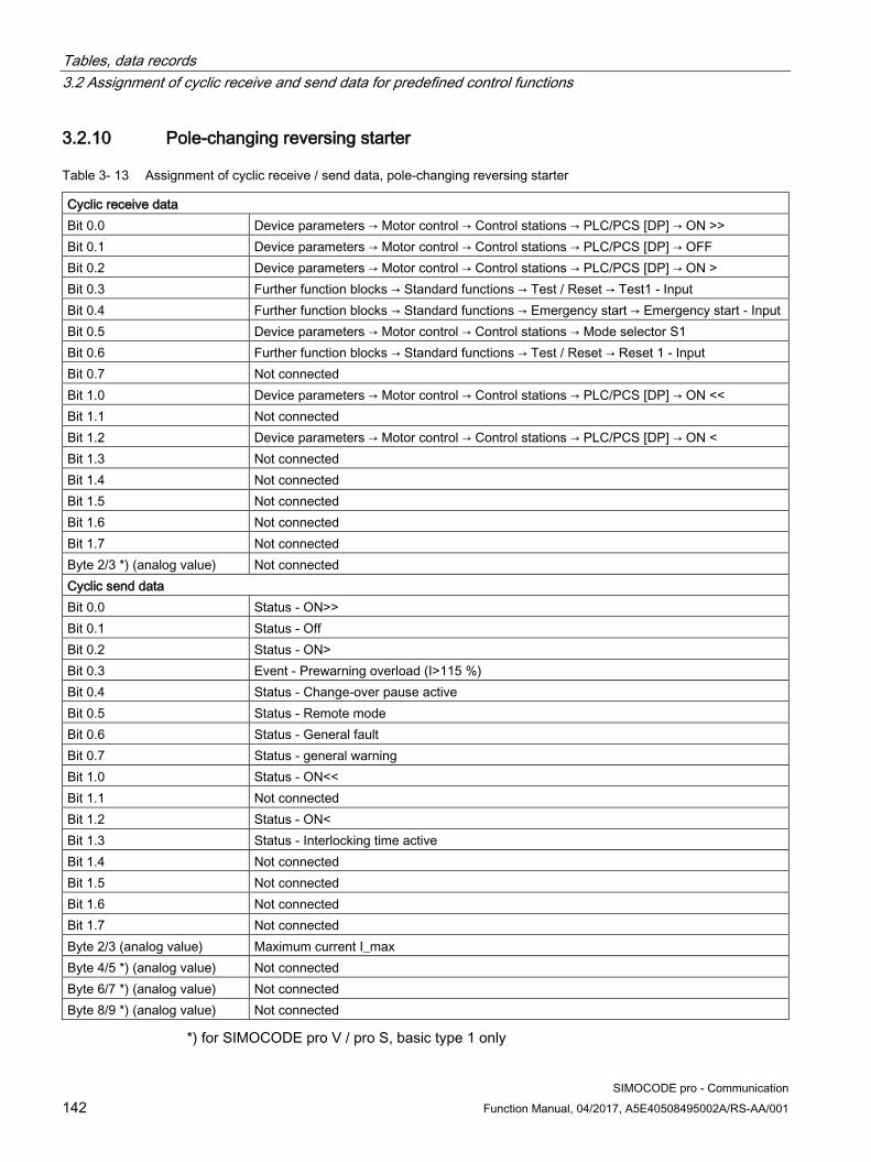
Tables, data records 3.2 Assignment of cyclic receive and send data for predefined control functions
SIMOCODE pro - Communication 142 Function Manual, 04/2017, A5E40508495002A/RS-AA/001
3.2.10 Pole-changing reversing starter
Table 3- 13 Assignment of cyclic receive / send data, pole-changing reversing starter
Cyclic receive data Bit 0.0 Device parameters → Motor control → Control stations → PLC/PCS [DP] → ON >> Bit 0.1 Device parameters → Motor control → Control stations → PLC/PCS [DP] → OFF Bit 0.2 Device parameters → Motor control → Control stations → PLC/PCS [DP] → ON > Bit 0.3 Further function blocks → Standard functions → Test / Reset → Test1 - Input Bit 0.4 Further function blocks → Standard functions → Emergency start → Emergency start - Input Bit 0.5 Device parameters → Motor control → Control stations → Mode selector S1 Bit 0.6 Further function blocks → Standard functions → Test / Reset → Reset 1 - Input Bit 0.7 Not connected Bit 1.0 Device parameters → Motor control → Control stations → PLC/PCS [DP] → ON << Bit 1.1 Not connected Bit 1.2 Device parameters → Motor control → Control stations → PLC/PCS [DP] → ON < Bit 1.3 Not connected Bit 1.4 Not connected Bit 1.5 Not connected Bit 1.6 Not connected Bit 1.7 Not connected Byte 2/3 *) (analog value) Not connected Cyclic send data Bit 0.0 Status - ON>> Bit 0.1 Status - Off Bit 0.2 Status - ON> Bit 0.3 Event - Prewarning overload (I>115 %) Bit 0.4 Status - Change-over pause active Bit 0.5 Status - Remote mode Bit 0.6 Status - General fault Bit 0.7 Status - general warning Bit 1.0 Status - ON<< Bit 1.1 Not connected Bit 1.2 Status - ON< Bit 1.3 Status - Interlocking time active Bit 1.4 Not connected Bit 1.5 Not connected Bit 1.6 Not connected Bit 1.7 Not connected Byte 2/3 (analog value) Maximum current I_max Byte 4/5 *) (analog value) Not connected Byte 6/7 *) (analog value) Not connected Byte 8/9 *) (analog value) Not connected
*) for SIMOCODE pro V / pro S, basic type 1 only

Tables, data records 3.2 Assignment of cyclic receive and send data for predefined control functions
SIMOCODE pro - Communication Function Manual, 04/2017, A5E40508495002A/RS-AA/001 143
3.2.11 Solenoid valve
Table 3- 14 Assignment of cyclic receive/send data, solenoid valve
Cyclic receive data Bit 0.0 Not connected Bit 0.1 Device parameters → Motor control → Control stations → PLC/PCS [DP] → Close Bit 0.2 Device parameters → Motor control → Control stations → PLC/PCS [DP] → Open Bit 0.3 Further function blocks → Standard functions → Test / Reset → Test1 - Input Bit 0.4 Not connected Bit 0.5 Device parameters → Motor control → Control stations → Mode selector S1 Bit 0.6 Further function blocks → Standard functions → Test / Reset → Reset 1 → Input Bit 0.7 Not connected Bit 1.0 Not connected Bit 1.1 Not connected Bit 1.2 Not connected Bit 1.3 Not connected Bit 1.4 Not connected Bit 1.5 Not connected Bit 1.6 Not connected Bit 1.7 Not connected Byte 2/3 *) (analog value) Not connected Cycl. send data Bit 0.0 Not connected Bit 0.1 Status - OFF (CLOSED) Bit 0.2 Status - ON > (OPEN) Bit 0.3 Not connected Bit 0.4 Not connected Bit 0.5 Status - Remote mode Bit 0.6 Status - General fault Bit 0.7 Status - general warning Bit 1.0 Not connected Bit 1.1 Not connected Bit 1.2 Not connected Bit 1.3 Not connected Bit 1.4 Not connected Bit 1.5 Not connected Bit 1.6 Not connected Bit 1.7 Not connected Byte 2/3 (analog value) Not connected Byte 4/5 *) (analog value) Not connected Byte 6/7 *) (analog value) Not connected Byte 8/9 *) (analog value) Not connected
*) for SIMOCODE pro V / pro S, basic type 1 only
Siemens Parts

Tables, data records 3.2 Assignment of cyclic receive and send data for predefined control functions
SIMOCODE pro - Communication 144 Function Manual, 04/2017, A5E40508495002A/RS-AA/001
3.2.12 Positioner
Table 3- 15 Assignment of cyclic receive / send data, positioner
Cyclic receive data Bit 0.0 Device parameters → Motor control → Control stations → PLC/PCS [DP] → Close Bit 0.1 Device parameters → Motor control → Control stations → PLC/PCS [DP] → Stop Bit 0.2 Device parameters → Motor control → Control stations → PLC/PCS [DP] → Open Bit 0.3 Further function blocks → Standard functions → Test / Reset → Test1 - Input Bit 0.4 Further function blocks → Standard functions → Emergency start → Emergency start - Input Bit 0.5 Device parameters → Motor control → Control stations → Mode selector S1 Bit 0.6 Further function blocks → Standard functions → Test / Reset → Reset 1 - Input Bit 0.7 Not connected Bit 1.0 Not connected Bit 1.1 Not connected Bit 1.2 Not connected Bit 1.3 Not connected Bit 1.4 Not connected Bit 1.5 Not connected Bit 1.6 Not connected Bit 1.7 Not connected Byte 2/3 *) (analog value) Not connected Cycl. send data Bit 0.0 Status - ON < (CLOSED) Bit 0.1 Status - OFF (Stop) Bit 0.2 Status - ON > (OPEN) Bit 0.3 Event - Prewarning overload (I>115 %) Bit 0.4 Status - Interlocking time active Bit 0.5 Status - Remote mode Bit 0.6 Status - General fault Bit 0.7 Status - general warning Bit 1.0 Status - positioner runs in OPEN direction Bit 1.1 Not connected Bit 1.2 Status - positioner runs in CLOSED direction Bit 1.3 Not connected Bit 1.4 Not connected Bit 1.5 Not connected Bit 1.6 Not connected Bit 1.7 Not connected Byte 2/3 (analog value) Maximum current I_max Byte 4/5 *) (analog value) Not connected Byte 6/7 *) (analog value) Not connected Byte 8/9 *) (analog value) Not connected
*) for SIMOCODE pro V / pro S, basic type 1 only

Tables, data records 3.2 Assignment of cyclic receive and send data for predefined control functions
SIMOCODE pro - Communication Function Manual, 04/2017, A5E40508495002A/RS-AA/001 145
3.2.13 Soft starter
Table 3- 16 Assignment of cyclic receive / send data, soft starter
Cycl. receive data Bit 0.0 Not connected Bit 0.1 Device parameters → Motor control → Control stations → PLC/PCS [DP] → OFF Bit 0.2 Device parameters → Motor control → Control stations → PLC/PCS [DP] → ON Bit 0.3 Further function blocks → Standard functions → Test / Reset → Test1 - Input Bit 0.4 Further function blocks → Standard functions → Emergency start → Emergency start - Input Bit 0.5 Device parameters → Motor control → Control stations → Mode selector S1 Bit 0.6 Further function blocks → Standard functions → Test / Reset → Reset 1 - Input Bit 0.7 Not connected Bit 1.0 Not connected Bit 1.1 Not connected Bit 1.2 Not connected Bit 1.3 Not connected Bit 1.4 Not connected Bit 1.5 Not connected Bit 1.6 Not connected Bit 1.7 Not connected Byte 2/3 *) (analog value) Not connected Cycl. send data Bit 0.0 Not connected Bit 0.1 Status - Off Bit 0.2 Status - ON> Bit 0.3 Event - Prewarning overload (I>115 %) Bit 0.4 Not connected Bit 0.5 Status - Remote mode Bit 0.6 Status - General fault Bit 0.7 Status - general warning Bit 1.0 Not connected Bit 1.1 Not connected Bit 1.2 Not connected Bit 1.3 Not connected Bit 1.4 Not connected Bit 1.5 Not connected Bit 1.6 Not connected Bit 1.7 Not connected Byte 2/3 (analog value) Maximum current I_max Byte 4/5 *) (analog value) Not connected Byte 6/7 *) (analog value) Not connected Byte 8/9 *) (analog value) Not connected
*) for SIMOCODE pro V / pro S, basic type 1 only
Siemens Parts

Tables, data records 3.2 Assignment of cyclic receive and send data for predefined control functions
SIMOCODE pro - Communication 146 Function Manual, 04/2017, A5E40508495002A/RS-AA/001
3.2.14 Soft starter with reversing contactor
Table 3- 17 Assignment of cyclic receive / send data, soft starter with reversing contactor
Cycl. receive data Bit 0.0 Device parameters → Motor control → Control stations → PLC/PCS [DP] → ON < Bit 0.1 Device parameters → Motor control → Control stations → PLC/PCS [DP] → OFF Bit 0.2 Device parameters → Motor control → Control stations → PLC/PCS [DP] → ON > Bit 0.3 Further function blocks → Standard functions → Test / Reset → Test1 - Input Bit 0.4 Further function blocks → Standard functions → Emergency start → Emergency start - Input Bit 0.5 Device parameters → Motor control → Control stations → Mode selector S1 Bit 0.6 Further function blocks → Standard functions → Test / Reset → Reset 1 - Input Bit 0.7 Not connected Bit 1.0 Not connected Bit 1.1 Not connected Bit 1.2 Not connected Bit 1.3 Not connected Bit 1.4 Not connected Bit 1.5 Not connected Bit 1.6 Not connected Bit 1.7 Not connected Byte 2/3 *) (analog value) Not connected Cycl. send data Bit 0.0 Status - ON< Bit 0.1 Status - Off Bit 0.2 Status - ON> Bit 0.3 Event - Prewarning overload (I>115 %) Bit 0.4 Status - Interlocking time active Bit 0.5 Status - Remote mode Bit 0.6 Status - General fault Bit 0.7 Status - general warning Bit 1.0 Not connected Bit 1.1 Not connected Bit 1.2 Not connected Bit 1.3 Not connected Bit 1.4 Not connected Bit 1.5 Not connected Bit 1.6 Not connected Bit 1.7 Not connected Byte 2/3 (analog value) Maximum current I_max Byte 4/5 *) (analog value) Not connected Byte 6/7 *) (analog value) Not connected Byte 8/9 *) (analog value) Not connected
*) for SIMOCODE pro V / pro S, basic type 1 only

Tables, data records 3.3 Tables, PROFIBUS data records
SIMOCODE pro - Communication Function Manual, 04/2017, A5E40508495002A/RS-AA/001 147
3.3 Tables, PROFIBUS data records
3.3.1 PROFIBUS tables
3.3.1.1 Abbreviations and specifications
Abbreviations The following abbreviations are used in the tables:
Table 3- 18 Abbreviations
Abbreviation Meaning BU0 SIMOCODE pro S basic unit BU1 SIMOCODE pro C basic unit BU2 SIMOCODE Pro V basic unit BU2+ 2nd generation SIMOCODE pro V basic unit (for UM+) IM Current measuring module UM 1st generation current / voltage measuring module UM+ 2nd generation current / voltage measuring module DM1 Digital module 1 DM2 Digital module 2 DM-FL DM-F Local fail-safe digital module DM-FP DM-F PROFIsafe fail-safe digital module OP Operator panel OPD Operator panel with display AM Analog module EM 3UF7500 ground-fault module EM+ 3UF7510 ground-fault module MM Multifunction module TM Temperature module Th Thermistor GF Group fault, control function Cycl. Cyclic Acycl. Acyclic F Fault M Status information W Warning
Siemens Parts

Tables, data records 3.3 Tables, PROFIBUS data records
SIMOCODE pro - Communication 148 Function Manual, 04/2017, A5E40508495002A/RS-AA/001
Specifications
The following specifications apply in the tables: Table 3- 19 Table specifications (example)
Designation Type Range Unit Information Reserved Byte[4] *) Cos phi Byte 0 ... 100 1 % BU2 Reserved Byte[5] *) Max. current I_max Word 0 ... 65535 1 % / Is BU0, BU1, BU2 **) *) Items in italics are not relevant (reserved) and must be filled with "0" when written to. **) Entry relevant for basic unit 1 and basic unit 2
Parameters that can be changed during operation
Event - PRM error number (bytes):
If parameterization is not possible, the number of the parameter group (PRM group) that caused the error is communicated here.
Figure 3-1 Example for parameter group
3.3.1.2 Socket assignment table - digital This table contains all assignment numbers (No.) of the sockets (digital). You only need these assignment numbers if you, for example, use a user program to fill data records and write them back.
Table 3- 20 Socket assignment table - digital
No. Designation Designation Information 0 Static level Not connected BU0 BU1 BU2(+) 1 Fixed level ,0 BU0 BU1 BU2(+) 2 Fixed level ,1 BU0 BU1 BU2(+) 3 Reserved 4 Reserved 5 Reserved 6 Reserved 7 Reserved 8 Basic unit (BU) BU - Test / Reset button BU0 BU1 BU2(+)
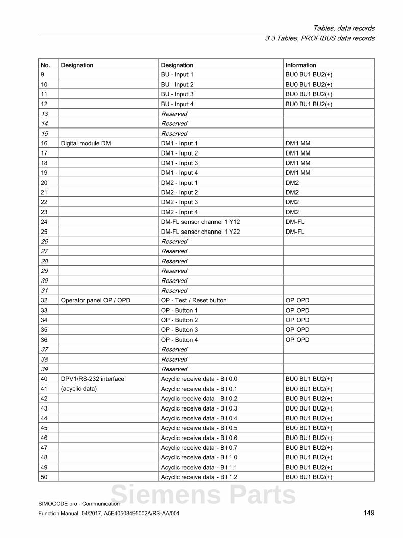
Tables, data records 3.3 Tables, PROFIBUS data records
SIMOCODE pro - Communication Function Manual, 04/2017, A5E40508495002A/RS-AA/001 149
No. Designation Designation Information 9 BU - Input 1 BU0 BU1 BU2(+) 10 BU - Input 2 BU0 BU1 BU2(+) 11 BU - Input 3 BU0 BU1 BU2(+) 12 BU - Input 4 BU0 BU1 BU2(+) 13 Reserved 14 Reserved 15 Reserved 16 Digital module DM DM1 - Input 1 DM1 MM 17 DM1 - Input 2 DM1 MM 18 DM1 - Input 3 DM1 MM 19 DM1 - Input 4 DM1 MM 20 DM2 - Input 1 DM2 21 DM2 - Input 2 DM2 22 DM2 - Input 3 DM2 23 DM2 - Input 4 DM2 24 DM-FL sensor channel 1 Y12 DM-FL 25 DM-FL sensor channel 1 Y22 DM-FL 26 Reserved 27 Reserved 28 Reserved 29 Reserved 30 Reserved 31 Reserved 32 Operator panel OP / OPD OP - Test / Reset button OP OPD 33 OP - Button 1 OP OPD 34 OP - Button 2 OP OPD 35 OP - Button 3 OP OPD 36 OP - Button 4 OP OPD 37 Reserved 38 Reserved 39 Reserved 40 DPV1/RS-232 interface
(acyclic data) Acyclic receive data - Bit 0.0 BU0 BU1 BU2(+)
41 Acyclic receive data - Bit 0.1 BU0 BU1 BU2(+) 42 Acyclic receive data - Bit 0.2 BU0 BU1 BU2(+) 43 Acyclic receive data - Bit 0.3 BU0 BU1 BU2(+) 44 Acyclic receive data - Bit 0.4 BU0 BU1 BU2(+) 45 Acyclic receive data - Bit 0.5 BU0 BU1 BU2(+) 46 Acyclic receive data - Bit 0.6 BU0 BU1 BU2(+) 47 Acyclic receive data - Bit 0.7 BU0 BU1 BU2(+) 48 Acyclic receive data - Bit 1.0 BU0 BU1 BU2(+) 49 Acyclic receive data - Bit 1.1 BU0 BU1 BU2(+) 50 Acyclic receive data - Bit 1.2 BU0 BU1 BU2(+)
Siemens Parts

Tables, data records 3.3 Tables, PROFIBUS data records
SIMOCODE pro - Communication 150 Function Manual, 04/2017, A5E40508495002A/RS-AA/001
No. Designation Designation Information 51 Acyclic receive data - Bit 1.3 BU0 BU1 BU2(+) 52 Acyclic receive data - Bit 1.4 BU0 BU1 BU2(+) 53 Acyclic receive data - Bit 1.5 BU0 BU1 BU2(+) 54 Acyclic receive data - Bit 1.6 BU0 BU1 BU2(+) 55 Acyclic receive data - Bit 1.7 BU0 BU1 BU2(+) 56 PLC/PCS
interface PLC [DPV0] (cyclic data) Cyclic receive data - Bit 0.0 BU0 BU1 BU2(+)
57 Cyclic receive data - Bit 0.1 BU0 BU1 BU2(+) 58 Cyclic receive data - Bit 0.2 BU0 BU1 BU2(+) 59 Cyclic receive data - Bit 0.3 BU0 BU1 BU2(+) 60 Cyclic receive data - Bit 0.4 BU0 BU1 BU2(+) 61 Cyclic receive data - Bit 0.5 BU0 BU1 BU2(+) 62 Cyclic receive data - Bit 0.6 BU0 BU1 BU2(+) 63 Cyclic receive data - Bit 0.7 BU0 BU1 BU2(+) 64 Cyclic receive data - Bit 1.0 BU0 BU1 BU2(+) 65 Cyclic receive data - Bit 1.1 BU0 BU1 BU2(+) 66 Cyclic receive data - Bit 1.2 BU0 BU1 BU2(+) 67 Cyclic receive data - Bit 1.3 BU0 BU1 BU2(+) 68 Cyclic receive data - Bit 1.4 BU0 BU1 BU2(+) 69 Cyclic receive data - Bit 1.5 BU0 BU1 BU2(+) 70 Cyclic receive data - Bit 1.6 BU0 BU1 BU2(+) 71 Cyclic receive data - Bit 1.7 BU0 BU1 BU2(+) 72 Enabled control command Enabled control command ON<< Dependent on the control
function 73 Enabled control command ON< 74 Enabled control command - OFF 75 Enabled control command ON> 76 Enabled control command ON>> 77 Reserved 78 Reserved 79 Reserved 80 Contactor controls Contactor controls 1 QE1 Dependent on the control
function 81 Contactor controls 2 QE2 82 Contactor controls 3 QE3 83 Contactor controls 4 QE4 84 Contactor controls 5 QE5 85 Reserved 86 Reserved 87 Reserved 88 Lamp controls Display - QLE<<(ON<<) Dependent on the control
function 89 Display - QLE<(ON<) 90 Indication - QLA (OFF) 91 Display - QLE>(ON>) 92 Display - QLE>>(ON>>)

Tables, data records 3.3 Tables, PROFIBUS data records
SIMOCODE pro - Communication Function Manual, 04/2017, A5E40508495002A/RS-AA/001 151
No. Designation Designation Information 93 Display - QLS (fault) BU0 BU1 BU2(+) 94 Reserved 95 Reserved 96 Status information - General Status - General fault BU0 BU1 BU2(+) 97 Status - General warning BU0 BU1 BU2(+) 98 Status - Device BU0 BU1 BU2(+) 99 Status - Bus BU0 BU1 BU2(+) 100 Status - PLC/PCS BU0 BU1 BU2(+) 101 Status - current flowing IM UM 102 Reserved 103 Reserved 104 Status information - Receive Status - ON<< Dependent on the control
function 105 Status - ON< 106 Status - Off 107 Status - ON> 108 Status - ON>> 109 Status - Start active BU0 BU1 BU2(+) 110 Status - Interlocking time active All reversing starters and
positioners 111 Status - Change-over pause active Star-delta, Dahlander,
pole-changing starters 112 Status - Runs in open direction Dependent on the control
function 113 Status - Runs in close direction 114 Status - FC 115 Status - FO 116 Status - TC 117 Status - TO 118 Status - Cold starting (TPF) BU0 BU1 BU2(+) 119 Status - OPO BU2(+) 120 Status - Remote mode BU0 BU1 BU2(+) 121 Status information - Protection Status - Emergency start executed IM UM 122 Status - Cooling down period active IM UM 123 Status - Pause time active IM UM 124 Status information - Miscellaneous Status - Device check active BU0 BU1 BU2(+) 125 Status - Phase sequence 1-2-3 UM 126 Status - Phase sequence 3-2-1 UM 127 Status - DM-F enabling circuit DM-F 128 Events - Protection Event - Overload operation IM UM 129 Event - Unbalance IM UM 130 Event - Overload IM UM 131 Event - overload + phase failure IM UM 132 Event - internal ground fault IM UM
Siemens Parts

Tables, data records 3.3 Tables, PROFIBUS data records
SIMOCODE pro - Communication 152 Function Manual, 04/2017, A5E40508495002A/RS-AA/001
No. Designation Designation Information 133 Event - external ground fault EM MM 134 Event - warning ext. ground fault EM MM 135 Event - Thermistor overload Th 136 Event - Thermistor short-circuit Th 137 Event - Thermistor open circuit Th 138 Event - TM warning T> TM MM 139 Event - TM trip T> TM MM 140 Event - TM sensor fault TM MM 141 Event - TM out of range TM MM 142 Event - EM+ open circuit EM+ MM 143 Event - EM+ short-circuit EM+ MM 144 Events - Level monitoring Event - Warning I> IM UM 145 Event - Warning I< IM UM 146 Event - Warning P> UM 147 Event - Warning P< UM 148 Event - Warning cos phi< UM 149 Event - Warning U< UM 150 Event - Warning 0/4 - 20 mA> AM 151 Event - Warning 0/4 - 20 mA < AM 152 Event - Trip I> IM UM 153 Event - Trip I< IM UM 154 Event - Trip P> UM 155 Event - Trip P< UM 156 Event - Trip cos phi< UM 157 Event - Trip U< UM 158 Event - trip 0/4-20mA> AM 159 Event - trip 0/4-20mA< AM 160 Event - Stalled rotor IM UM 161 Events - Protection Event - Warning internal ground fault BU2(+) 162 Reserved 163 Event - no start permitted BU0 BU1 BU2(+) 164 Events - Level monitoring Event - No. of starts > BU0 BU1 BU2(+) 165 Event - Just one start possible BU0 BU1 BU2(+) 166 Event - motor operating hours > BU0 BU1 BU2(+) 167 Event - Motor stop time > BU0 BU1 BU2(+) 168 Event - Limit 1 BU2(+) 169 Event - Limit 2 BU2(+) 170 Event - Limit 3 BU2(+) 171 Event - Limit 4 BU2(+) 172 Events - Miscellaneous Event - External fault 1 BU0 BU1 BU2(+) 173 Event - External fault 2 BU0 BU1 BU2(+) 174 Event - External fault 3 BU0 BU1 BU2(+)
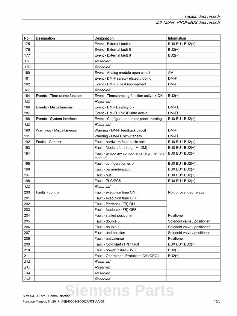
Tables, data records 3.3 Tables, PROFIBUS data records
SIMOCODE pro - Communication Function Manual, 04/2017, A5E40508495002A/RS-AA/001 153
No. Designation Designation Information 175 Event - External fault 4 BU0 BU1 BU2(+) 176 Event - External fault 5 BU2(+) 177 Event - External fault 6 BU2(+) 178 Reserved 179 Reserved 180 Event - Analog module open circuit AM 181 Event - DM-F safety-related tripping DM-F 182 Event - DM-F - Test requirement DM-F 183 Reserved 184 Events - Time stamp function Event - Timestamping function active + OK BU2(+) 185 Reserved 186 Events - Miscellaneous Event - DM-FL safety o.k DM-FL 187 Event - DM-FP PROFIsafe active DM-FP 188 Events - System interface Event - Configured operator panel missing BU0 BU1 BU2(+) 189 Reserved 190 Warnings - Miscellaneous Warning - DM-F feedback circuit DM-F 191 Warning - DM-FL simultaneity DM-FL 192 Faults - General Fault - hardware fault basic unit BU0 BU1 BU2(+) 193 Fault - Module fault (e.g. IM, DM) BU0 BU1 BU2(+) 194 Fault - temporary components (e.g. memory
module) BU0 BU1 BU2(+)
195 Fault - configuration error BU0 BU1 BU2(+) 196 Fault - parameterization BU0 BU1 BU2(+) 197 Fault - bus BU0 BU1 BU2(+) 198 Fault - PLC/PCS BU0 BU1 BU2(+) 199 Reserved 200 Faults - control Fault - execution time ON Not for overload relays 201 Fault - execution time OFF 202 Fault - feedback (FB) ON 203 Fault - feedback (FB) OFF 204 Fault - stalled positioner Positioner 205 Fault - double 0 Solenoid valve / positioner 206 Fault - double 1 Solenoid valve / positioner 207 Fault - end position Solenoid valve / positioner 208 Fault - antivalence Positioner 209 Fault - Cold start (TPF) fault BU0 BU1 BU2(+) 210 Fault - power failure (UVO) BU2(+) 211 Fault - Operational Protection Off (OPO) BU2(+) 212 Reserved 213 Reserved 214 Reserved 215 Reserved
Siemens Parts

Tables, data records 3.3 Tables, PROFIBUS data records
SIMOCODE pro - Communication 154 Function Manual, 04/2017, A5E40508495002A/RS-AA/001
No. Designation Designation Information 216 Freely-programmable elements Truth table 1 3I/1O output BU0 BU1 BU2(+) 217 Truth table 2 3I/1O output BU0 BU1 BU2(+) 218 Truth table 3 3I/1O output BU0 BU1 BU2(+) 219 Truth table 4 3I/1O output BU0 BU2(+) 220 Truth table 5 3I/1O output BU2(+) 221 Truth table 6 3I/1O output BU2(+) 222 Truth table 7 2I/1O output BU0 BU2(+) 223 Truth table 8 2I/1O output BU0 BU2(+) 224 Truth table 9 5I/2O output 1 BU2(+) 225 Truth table 9 5I/2O output 2 BU2(+) 226 Reserved 227 Reserved 228 Reserved 229 Reserved 230 Reserved 231 Reserved 232 Timer 1 output BU0 BU1 BU2(+) 233 Timer 2 output BU0 BU1 BU2(+) 234 Timer 3 output BU2(+) 235 Timer 4 output BU2(+) 236 Counter 1 output BU0 BU1 BU2(+) 237 Counter 2 output BU0 BU1 BU2(+) 238 Counter 3 output BU2(+) 339 Counter 4 output BU2(+) 240 Signal conditioning 1 output BU0 BU1 BU2(+) 241 Signal conditioning 2 output BU0 BU1 BU2(+) 242 Signal conditioning 3 output BU0 BU2(+) 243 Signal conditioning 4 output BU0 BU2(+) 244 Non-volatile element 1 output BU0 BU1 BU2(+) 245 Non-volatile element 2 output BU0 BU1 BU2(+) 246 Non-volatile element 3 output BU2(+) 247 Non-volatile element 4 output BU2(+) 248 Flashing 1 output BU0 BU1 BU2(+) 249 Flashing 2 output BU0 BU1 BU2(+) 250 Flashing 3 output BU0 BU1 BU2(+) 251 Flicker 1 output BU0 BU1 BU2(+) 252 Flicker 2 output BU0 BU1 BU2(+) 253 Flicker 3 output BU0 BU1 BU2(+) 254 Reserved 255 Reserved

Tables, data records 3.3 Tables, PROFIBUS data records
SIMOCODE pro - Communication Function Manual, 04/2017, A5E40508495002A/RS-AA/001 155
3.3.1.3 Socket assignment table - analog This table contains all assignment numbers (No.) of the sockets (analog). You only need these assignment numbers if you, for example, use a user program to fill data records and write them back. All inputs for analog data can only process values of type "Word" (2 bytes). In order to also be able to process values of type "Byte", the following applies:
The byte value is processed as a low byte, the high byte is always 0.
Table 3- 21 Socket assignment table - analog
No. Designation Unit Information 0 Not connected BU0 BU1 BU2(+) 1 Reserved 2 Reserved 3 Reserved 4 Timer 1 - Actual value 100 ms BU0 BU1 BU2(+) 5 Timer 2 - Actual value 100 ms BU0 BU1 BU2(+) 6 Timer 3 - Actual value 100 ms BU2(+) 7 Timer 4 - Actual value 100 ms BU2(+) 8 Counter 1 - Actual value BU0 BU1 BU2(+) 9 Counter 2 - Actual value BU0 BU1 BU2(+) 10 Counter 3 - Actual value BU2(+) 11 Counter 4 - Actual value BU2(+) 12 Reserved 13 Reserved 14 Reserved 15 Reserved 16 Max. current I_max 1 % / Is IM UM 17 Current I_L1 1 % / Is IM UM 18 Current I_L2 1 % / Is IM UM 19 Current I_L3 1 % / Is IM UM 20 Phase unbalance 1 % IM UM 21 Ground-fault current 1 mA UM+ 22 Internal ground fault - last trip current 1 mA UM+ 23 Voltage U_min 1 V UM UM+ 24 Voltage U_L1 1 V UM 25 Voltage U_L2 1 V UM 26 Voltage U_L3 1 V UM 27 Cos phi 1 % UM 28 Frequency 0.01 Hz UM+ 29 Reserved 30 Number of overload trips IM UM 31 Int. number of overload trips IM UM 32 Thermal motor model 2 % IM UM 33 Time to trip 100 ms IM UM
Siemens Parts

Tables, data records 3.3 Tables, PROFIBUS data records
SIMOCODE pro - Communication 156 Function Manual, 04/2017, A5E40508495002A/RS-AA/001
No. Designation Unit Information 34 Recovery time 100 ms IM UM 35 Last trip current 1 % / I_e IM UM 36 TM - Max. temperature 1 K TM MM 37 TM - Temperature 1 1 K TM MM 38 TM - Temperature 2 1 K TM 39 TM - Temperature 3 1 K TM 40 Permissible starts - actual value BU0 BU1 BU2(+) 41 Motor stop time 1 h BU0 BU1 BU2(+) 42 DM-F - Time until test required 1 week DM-F 43 Last trip current 1 mA EM+ MM 44 AM - Input 1 See 1) AM 45 AM - Input 2 See 1) AM 46 Reserved 47 Ground-fault current 1 mA MMa EM+ 48 Acyclic receive data - analog value BU0 BU1 BU2(+) 49 PLC / PCS receive - analog value 1 BU0 BU2(+) 50 Reserved 51 Number of parameterizations BU0 BU1 BU2(+) 52 Motor operating hours - H word 1 s BU0 BU1 BU2(+) 53 Motor operating hours - L word BU0 BU1 BU2(+) 54 Int. motor operating hours - H word BU0 BU1 BU2(+) 55 Int. motor operating hours - L word BU0 BU1 BU2(+) 56 Device operating hours - H word BU0 BU1 BU2(+) 57 Device operating hours - L word BU0 BU1 BU2(+) 58 Number of starts - H word BU0 BU1 BU2(+) 59 Number of starts - L word BU0 BU1 BU2(+) 60 Int. number of starts CW - H word BU0 BU1 BU2(+) 61 Int. number of starts CW - L word BU0 BU1 BU2(+) 62 Int. number of starts CCW - H word BU0 BU1 BU2(+) 63 Int. number of starts CCW - L word BU0 BU1 BU2(+) 64 Energy W - H word UM UM+ 65 Energy W - L word 1 kWh UM UM+ 66 ... 69 Reserved 70 Active power P - H word 1 W BU2(+) 71 Active power P - L word BU2(+) 72 Apparent power S - H word 1 VA BU2(+) 73 Apparent power S - L word BU2(+) 74 ... 85 Reserved 86 Calculator 1 - output BU2(+) 87 ... 89 Reserved 90 Calculator 2 - output BU2(+) 91 ... 103 Reserved
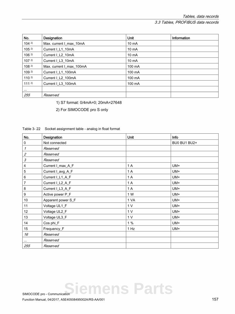
Tables, data records 3.3 Tables, PROFIBUS data records
SIMOCODE pro - Communication Function Manual, 04/2017, A5E40508495002A/RS-AA/001 157
No. Designation Unit Information 104 2) Max. current I_max_10mA 10 mA 105 2) Current I_L1_10mA 10 mA 106 2) Current I_L2_10mA 10 mA 107 2) Current I_L3_10mA 10 mA 108 2) Max. current I_max_100mA 100 mA 109 2) Current I_L1_100mA 100 mA 110 2) Current I_L2_100mA 100 mA 111 2) Current I_L3_100mA 100 mA ... 255 Reserved
1) S7 format: 0/4mA=0; 20mA=27648
2) For SIMOCODE pro S only
Table 3- 22 Socket assignment table - analog in float format
No. Designation Unit Info 0 Not connected BU0 BU1 BU2+ 1 Reserved 2 Reserved 3 Reserved 4 Current I_max_A_F 1 A UM+ 5 Current I_avg_A_F 1 A UM+ 6 Current I_L1_A_F 1 A UM+ 7 Current I_L2_A_F 1 A UM+ 8 Current I_L3_A_F 1 A UM+ 9 Active power P_F 1 W UM+ 10 Apparent power S_F 1 VA UM+ 11 Voltage UL1_F 1 V UM+ 12 Voltage UL2_F 1 V UM+ 13 Voltage UL3_F 1 V UM+ 14 Cos phi_F 1 % UM+ 15 Frequency_F 1 Hz UM+ 16 Reserved ... Reserved 255 Reserved
Siemens Parts

Tables, data records 3.3 Tables, PROFIBUS data records
SIMOCODE pro - Communication 158 Function Manual, 04/2017, A5E40508495002A/RS-AA/001
3.3.1.4 Detailed messages of the slave diagnostics The following table contains the detailed messages of the slave diagnostics for status information and the hardware interrupt. This information is also contained in data record 92.
Note Structure of the slave diagnostics
The diagnostic messages listed below are the same as those contained in the hardware interrupts transferred via PROFIBUS. See also Chapter "Structure of the slave diagnostics → Hardware interrupt - Structure" in the system manual.
Table 3- 23 Detailed messages of the slave diagnostics
Byte.Bit Status message Information 0.0 Faults - control Fault - execution ON command BU0 BU1 BU2(+) 0.1 Fault - execution STOP command BU0 BU1 BU2(+) 0.2 Fault - feedback (FB) ON BU0 BU1 BU2(+) 0.3 Fault - feedback (FB) OFF BU0 BU1 BU2(+) 0.4 Fault - stalled positioner BU2(+) 0.5 Fault - double 0 BU2(+) 0.6 Fault - double 1 BU2(+) 0.7 Fault - end position BU2(+) 1.0 Fault - antivalence BU2(+) 1.1 Fault - Cold start (TPF) fault BU0 BU1 BU2(+) 1.2 Fault - power failure (UVO) BU2(+) 1.3 Fault - Operational Protection Off (OPO) BU2(+) 1.4 Reserved 2.0 Reserved 2.1 Faults - Protection Fault - unbalance IM UM 2.2 Fault - overload IM UM 2.3 Fault - overload + phase failure IM UM 2.4 Fault - int. ground fault IM UM 2.5 Fault - ext. ground fault EM 2.6 Reserved 2.7 Fault - thermistor overload Th 3.0 Fault - thermistor short circuit Th 3.1 Fault - thermistor open circuit Th 3.2 Reserved 3.3 Fault - TM trip T> TM MM 3.4 Fault - TM sensor fault TM MM 3.5 Fault - TM out of range TM MM 3.6 Fault - EM+ open circuit MM EM+ 3.7 Fault - EM+ short-circuit MM EM+

Tables, data records 3.3 Tables, PROFIBUS data records
SIMOCODE pro - Communication Function Manual, 04/2017, A5E40508495002A/RS-AA/001 159
Byte.Bit Status message Information 4.0 Trips - level monitoring Fault - trip I> IM UM 4.1 Fault - trip I< IM UM 4.2 Fault - trip P> UM 4.3 Fault - trip P< UM 4.4 Fault - trip cos phi< UM 4.5 Fault - trip U< UM 4.6 Fault - trip 0/4 - 20 mA> AM 4.7 Fault - trip 0/4 - 20 mA< AM 5.0 Fault - stalled rotor IM UM 5.1 Reserved 5.4 Fault - number of starts > BU0 BU1 BU2(+) 5.5 Reserved 6.0 Faults - Miscellaneous Fault - external fault 1 BU0 BU1 BU2(+) 6.1 Fault - external fault 2 BU0 BU1 BU2(+) 6.2 Fault - external fault 3 BU0 BU1 BU2(+) 6.3 Fault - external fault 4 BU0 BU1 BU2(+) 6.4 Fault - external fault 5 BU2(+) 6.5 Fault - external fault 6 BU2(+) 6.6 Reserved 6.7 Reserved 7.0 Fault - analog module open circuit AM 7.1 Fault - test trip BU0 BU1 BU2(+) 7.2 DM-F safety-related tripping DM-FL DM-FP 7.3 Fault - DM-F wiring DM-FL DM-FP 7.4 Fault - DM-FL cross circuit DM-FL 8.0 Warnings - Protection Warning - Overload operation IM UM 8.1 Warning - Unbalance IM UM 8.2 Warning - Overload IM UM 8.3 Warning - Overload + phase failure IM UM 8.4 Warning - internal ground fault IM UM 8.5 Warning - external ground fault EM MM 8.6 Reserved 8.7 Warning - Thermistor overload Th 9.0 Warning - Thermistor short circuit Th 9.1 Warning - Thermistor open circuit Th 9.2 Warning - TM warning T> TM MM 9.3 Reserved 9.4 Warning - TM sensor fault TM MM 9.5 Warning - TM out of range TM MM 9.6 Reserved
Siemens Parts

Tables, data records 3.3 Tables, PROFIBUS data records
SIMOCODE pro - Communication 160 Function Manual, 04/2017, A5E40508495002A/RS-AA/001
Byte.Bit Status message Information 10.0 Warnings - Level monitoring Warning - Warning I> IM UM 10.1 Warning - Warning I< IM UM 10.2 Warning - Warning P> UM 10.3 Warning - Warning P< UM 10.4 Warning - Warning cos phi< UM 10.5 Warning - Warning U< UM 10.6 Warning - warning 0/4 - 20 mA> AM 10.7 Warning - warning 0/4 - 20 mA> AM 11.0 Warning - Stalled rotor IM UM 11.1 Reserved 11.3 Warning - No start permitted BU0 BU1 BU2(+) 11.4 Warning - Number of starts > BU0 BU1 BU2(+) 11.5 Warning - Just one start possible BU0 BU1 BU2(+) 11.6 Warning - Motor operating hours> BU0 BU1 BU2(+) 11.7 Warning - Motor stop time > BU0 BU1 BU2(+) 12.0 Warnings - Miscellaneous Warning - external fault 1 BU0 BU1 BU2(+) 12.1 Warning - external fault 2 BU0 BU1 BU2(+) 12.2 Warning - external fault 3 BU0 BU1 BU2(+) 12.3 Warning - external fault 4 BU0 BU1 BU2(+) 12.4 Warning - external fault 5 BU2(+) 12.5 Warning - external fault 6 BU2(+) 12.6 Reserved 12.7 Reserved 13.0 Warning - Analog module open circuit BU2(+) 13.1 Warning - DM-F safety-related tripping 13.2 Warning - Test requirement DM-FL DM-FP 13.3 Reserved 13.4 Reserved 13.5 Reserved 13.6 Warning - DM-F feedback circuit DM-FL DM-FP 13.7 Warning - DM-FL DM-FL 14.0 Reserved 14.1 Status information - Protection Status - Emergency start executed IM UM 14.2 Status - Cooling down period active IM UM 14.3 Status - Pause time active IM UM 14.4 Reserved 14.5 Reserved 14.6 Status information - Receive Status - Cold starting (TPF) BU0 BU1 BU2(+) 14.7 Reserved

Tables, data records 3.3 Tables, PROFIBUS data records
SIMOCODE pro - Communication Function Manual, 04/2017, A5E40508495002A/RS-AA/001 161
Byte.Bit Status message Information 15.0 Events - parameterization Event - startup parameter block active BU0 BU1 BU2(+) 15.1 Event - Parameter changes not allowed in the current
operating state BU0 BU1 BU2(+)
15.2 Event - Device does not support the required functions BU0 BU1 BU2(+) 15.3 Event - Wrong parameter BU0 BU1 BU2(+) 15.4 Event - Wrong password BU0 BU1 BU2(+) 15.5 Event - Password protection active BU0 BU1 BU2(+) 15.6 Event - Factory settings BU0 BU1 BU2(+) 15.7 Event - Parameterization active BU0 BU1 BU2(+) 17.0 Event - DM-FL configuration mode DM-FL 17.1 Event - DM FL configuration deviation DM-FL 17.2 Event - DM-FL waiting for start-up test DM-FL 17.3 Event - DM FP F PRM error DM-FP 17.4 Reserved
Siemens Parts
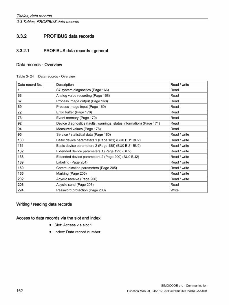
Tables, data records 3.3 Tables, PROFIBUS data records
SIMOCODE pro - Communication 162 Function Manual, 04/2017, A5E40508495002A/RS-AA/001
3.3.2 PROFIBUS data records
3.3.2.1 PROFIBUS data records - general
Data records - Overview
Table 3- 24 Data records - Overview
Data record No. Description Read / write 1 S7 system diagnostics (Page 166) Read 63 Analog value recording (Page 168) Read 67 Process image output (Page 168) Read 69 Process image input (Page 169) Read 72 Error buffer (Page 170) Read 73 Event memory (Page 170) Read 92 Device diagnostics (faults, warnings, status information) (Page 171) Read 94 Measured values (Page 178) Read 95 Service / statistical data (Page 180) Read / write 130 Basic device parameters 1 (Page 181) (BU0 BU1 BU2) Read / write 131 Basic device parameters 2 (Page 188) (BU0 BU1 BU2) Read / write 132 Extended device parameters 1 (Page 192) (BU2) Read / write 133 Extended device parameters 2 (Page 200) (BU0 BU2) Read / write 139 Labeling (Page 204) Read / write 160 Communication parameters (Page 205) Read / write 165 Marking (Page 205) Read / write 202 Acyclic receive (Page 206) Read / write 203 Acyclic send (Page 207) Read 224 Password protection (Page 208) Write
Writing / reading data records
Access to data records via the slot and index ● Slot: Access via slot 1
● Index: Data record number

Tables, data records 3.3 Tables, PROFIBUS data records
SIMOCODE pro - Communication Function Manual, 04/2017, A5E40508495002A/RS-AA/001 163
Writing / reading data records with STEP7 You can access the data records from the user program.
● Writing data records:
– S7-DPV1 master: by calling SFB 53 "WR_REC" or SFC 58
– S7 master: by calling SFC58
● Reading data sets:
– S7-DPV1 master: by calling SFB 52 "RD_REC" or SFC 59
– S7 master: by calling SFC 59
Further information
You will find further information about the SFBs:
● in Reference Manual System software for the S7-300/400, system and standard functions (http://support.automation.siemens.com/WW/view/en/44240604)
● In the STEP7 online help
Byte arrangements When data longer than one byte is stored, the bytes are arranged as follows ("big endian"):
Figure 3-2 Byte arrangement in "big endian" format
Siemens Parts

Tables, data records 3.3 Tables, PROFIBUS data records
SIMOCODE pro - Communication 164 Function Manual, 04/2017, A5E40508495002A/RS-AA/001
Abbreviations The following abbreviations are used in the tables:
Table 3- 25 Abbreviations
Abbreviation Meaning BU0 SIMOCODE pro S basic unit BU1 SIMOCODE pro C basic unit BU2 SIMOCODE pro V basic unit BU2+ 2nd generation SIMOCODE pro V basic unit (for UM+) IM Current measuring module UM Current / voltage measuring module DM1 Digital module 1 DM2 Digital module 2 DM-FL DM-F Local fail-safe digital module DM-FP DM-F PROFIsafe fail-safe digital module MM Multifunction module OP Operator panel OPD Operator panel with display AM Analog module EM Ground-fault module TM Temperature module Th Thermistor GF Control function Cycl. Cyclic Acycl. Acyclic F Fault M Status information W Warning

Tables, data records 3.3 Tables, PROFIBUS data records
SIMOCODE pro - Communication Function Manual, 04/2017, A5E40508495002A/RS-AA/001 165
Specifications The following specifications apply in the tables: Designation Type Range Unit Information Reserved *) Byte[4] *)
Max. current I_max Word 0 … 65535 1 % / Is BU0 BU1 BU2 *) Items in italics are not relevant (reserved) and must be filled with "0" when written to.
Parameters that can be changed during operation. BU0 BU1 BU2: Entry relevant for basic units SIMOCODE pro S, SIMOCODE pro C, and SIMOCODE pro V.
Settings are valid/can only be made when the corresponding system components are used.
"Float" data type
32-bit floating-point number
S: Sign (0 = positive; 1 = negative)
E: Exponent
M: Mantissa 31
30
29
28
27
26
25
24
23
22
21
20
19
18
17
16
15
114
13
12
11
10
9 8 7 6 5 4 3 2 1 0
S E: Exponent + 127 (8 bits) M: Mantissa (23 bits)
Siemens Parts
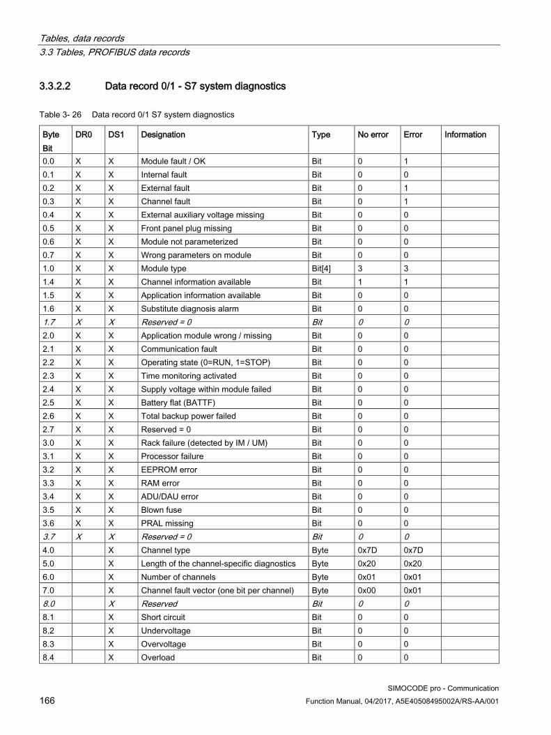
Tables, data records 3.3 Tables, PROFIBUS data records
SIMOCODE pro - Communication 166 Function Manual, 04/2017, A5E40508495002A/RS-AA/001
3.3.2.2 Data record 0/1 - S7 system diagnostics
Table 3- 26 Data record 0/1 S7 system diagnostics
Byte Bit
DR0 DS1 Designation Type No error Error Information
0.0 X X Module fault / OK Bit 0 1 0.1 X X Internal fault Bit 0 0 0.2 X X External fault Bit 0 1 0.3 X X Channel fault Bit 0 1 0.4 X X External auxiliary voltage missing Bit 0 0 0.5 X X Front panel plug missing Bit 0 0 0.6 X X Module not parameterized Bit 0 0 0.7 X X Wrong parameters on module Bit 0 0 1.0 X X Module type Bit[4] 3 3 1.4 X X Channel information available Bit 1 1 1.5 X X Application information available Bit 0 0 1.6 X X Substitute diagnosis alarm Bit 0 0 1.7 X X Reserved = 0 Bit 0 0 2.0 X X Application module wrong / missing Bit 0 0 2.1 X X Communication fault Bit 0 0 2.2 X X Operating state (0=RUN, 1=STOP) Bit 0 0 2.3 X X Time monitoring activated Bit 0 0 2.4 X X Supply voltage within module failed Bit 0 0 2.5 X X Battery flat (BATTF) Bit 0 0 2.6 X X Total backup power failed Bit 0 0 2.7 X X Reserved = 0 Bit 0 0 3.0 X X Rack failure (detected by IM / UM) Bit 0 0 3.1 X X Processor failure Bit 0 0 3.2 X X EEPROM error Bit 0 0 3.3 X X RAM error Bit 0 0 3.4 X X ADU/DAU error Bit 0 0 3.5 X X Blown fuse Bit 0 0 3.6 X X PRAL missing Bit 0 0 3.7 X X Reserved = 0 Bit 0 0 4.0 X Channel type Byte 0x7D 0x7D 5.0 X Length of the channel-specific diagnostics Byte 0x20 0x20 6.0 X Number of channels Byte 0x01 0x01 7.0 X Channel fault vector (one bit per channel) Byte 0x00 0x01 8.0 X Reserved Bit 0 0 8.1 X Short circuit Bit 0 0 8.2 X Undervoltage Bit 0 0 8.3 X Overvoltage Bit 0 0 8.4 X Overload Bit 0 0

Tables, data records 3.3 Tables, PROFIBUS data records
SIMOCODE pro - Communication Function Manual, 04/2017, A5E40508495002A/RS-AA/001 167
Byte Bit
DR0 DS1 Designation Type No error Error Information
8.5 X Overtemperature Bit 0 0 8.6 X Open circuit Bit 0 0 8.7 X Upper limit overshot Bit 0 0 9.0 X Lower limit undershot Bit 0 0 9.1 X Error Bit 0 X Fault F9 9.2 X Reserved Bit 0 0 9.3 X Reserved Bit 0 0 9.4 X Reserved Bit 0 0 9.5 X Reserved Bit 0 0 9.6 X Reserved Bit 0 0 9.7 X Reserved Bit 0 0 10.0 X Parameterization error Bit 0 X Fault F16 10.1 X Sensor or load voltage missing Bit 0 0 10.2 X Fuse defective Bit 0 0 10.3 X Reserved Bit 0 0 10.4 X Earth fault Bit 0 0 10.5 X Reference channel fault Bit 0 0 10.6 X Process alarm missing Bit 0 0 10.7 X Actuator warning Bit 0 0 11.0 X Actuator trip Bit 0 0 11.1 X Safety-related tripping Bit 0 0 11.2 X External fault Bit 0 0 11.3 X Non-specific error Bit 0 0 11.4 X Reserved Bit 0 0 11.5 X Reserved Bit 0 0 11.6 X Reserved Bit 0 0 11.7 X Reserved Bit 0 0 12.0 X Reserved Byte[4] 0 0
Siemens Parts

Tables, data records 3.3 Tables, PROFIBUS data records
SIMOCODE pro - Communication 168 Function Manual, 04/2017, A5E40508495002A/RS-AA/001
3.3.2.3 Data record 63 - Analog value recording
Table 3- 27 Data record 63 - Analog value recording
Byte.Bit Designation Type Range Information 0.0 StartPos Word 0 BU2(+) 2.0 Channel No. Byte 1 BU2(+) 3.0 Analog value record currently running Bit 0, 1 BU2(+) 3.1 Trigger event occurred Bit 0, 1 BU2(+) 3.2 Reserved Bit[6] 0 4.0 Measured value (0) Word 0 ... 65535 BU2(+) 6.0 Measured value (1) Word 0 ... 65535 BU2(+) ... 122.0 Measured value (59) Word 0 ... 65535 BU2(+) 124.0 Reserved Byte[76] 0
The unit of the measured value is dependent on the assigned analog value. You will find all available analog values with their units in Chapter Socket assignment table - analog (Page 155).
3.3.2.4 Data record 67 - Process image output
Table 3- 28 Data record 67 - Process image output
Byte.Bit Designation Default (also see parameters) Type Information 0.0 Cyclic receive - Bit 0.0 Control station - PLC/ PCS [DP] ON< Bit BU0 BU1 BU2(+) 0.1 Cyclic receive - Bit 0.1 Control station - PLC/PCS [DP] OFF Bit 0.2 Cyclic receive - Bit 0.2 Control station - PLC/PCS [DP] ON> Bit 0.3 Cyclic receive - Bit 0.3 Test 1 Bit 0.4 Cyclic receive - Bit 0.4 Motor protection - Emergency start Bit 0.5 Cyclic receive - Bit 0.5 Mode selector S1 Bit 0.6 Cyclic receive - Bit 0.6 Reset 1 Bit 0.7 Cyclic receive - Bit 0.7 Not assigned Bit 1.0 Cyclic receive - Bit 1.0 Not assigned Bit 1.1 Cyclic receive - Bit 1.1 Not assigned Bit 1.2 Cyclic receive - Bit 1.2 Not assigned Bit 1.3 Cyclic receive - Bit 1.3 Not assigned Bit 1.4 Cyclic receive - Bit 1.4 Not assigned Bit 1.5 Cyclic receive - Bit 1.5 Not assigned Bit 1.6 Cyclic receive - Bit 1.6 Not assigned Bit 1.7 Cyclic receive - Bit 1.7 Not assigned Bit 2.0 to 3.7 Cyclic receive - Analog value Not assigned Word BU0 BU2(+)

Tables, data records 3.3 Tables, PROFIBUS data records
SIMOCODE pro - Communication Function Manual, 04/2017, A5E40508495002A/RS-AA/001 169
3.3.2.5 Data record 69 - Process image input
Table 3- 29 Data record 69 - Process image input
Byte.Bit Designation Default (also see parameters) Type Information 0.0 Cyclic send - Bit 0.0 Status - ON< Bit BU0 BU1 BU2(+)
0.1 Cyclic send - Bit 0.1 Status - Off Bit 0.2 Cyclic send - Bit 0.2 Status - ON> Bit 0.3 Cyclic send - Bit 0.3 Event - Overload operation Bit 0.4 Cyclic send - Bit 0.4 Status - Interlocking time active Bit 0.5 Cyclic send - Bit 0.5 Status - Remote mode Bit 0.6 Cyclic send - Bit 0.6 Status - General fault Bit 0.7 Cyclic send - Bit 0.7 Status - general warning Bit 1.0 Cyclic send - Bit 1.0 Not assigned Bit 1.1 Cyclic send - Bit 1.1 Not assigned Bit 1.2 Cyclic send - Bit 1.2 Not assigned Bit 1.3 Cyclic send - Bit 1.3 Not assigned Bit 1.4 Cyclic send - Bit 1.4 Not assigned Bit 1.5 Cyclic send - Bit 1.5 Not assigned Bit 1.6 Cyclic send - Bit 1.6 Not assigned Bit 1.7 Cyclic send - Bit 1.7 Not assigned Bit 2.0 PLC/PCS analog Input 1 Max. current I_max Word Float BU0, BU1, BU2 BU2+ 4.0 PLC/PCS analog input 2 Not assigned Word BU0, BU2 6.0 PLC/PCS analog input 3 Not assigned Word Float 8.0 PLC/PCS analog input 4 Not assigned Word
Siemens Parts

Tables, data records 3.3 Tables, PROFIBUS data records
SIMOCODE pro - Communication 170 Function Manual, 04/2017, A5E40508495002A/RS-AA/001
3.3.2.6 Data record 72 - Error buffer
Table 3- 30 Data record 72 - Error buffer
Byte.Bit Entry Designation Type Information 0.0 1 Time stamp D-word BU0 BU1 BU2(+) 4.0 Type Byte 5.0 Error number Byte 6.0 2 Time stamp D-word 10.0 Type Byte 11.0 Error number Byte ... 120.0 21 Time stamp D-word BU0 BU1 BU2(+) 124.0 Type Byte 125.0 Error number Byte
Time stamp
The operating hours of the device are used as a time stamp (resolution: 1 s).
Type/error number
Refer to the error numbers for detailed information. You will find the meaning in Chapter Data record 92 - Device diagnostics (Page 171) in column "Error number" of table "Data record 92 - Diagnostics."
3.3.2.7 Data record 73 - Event memory
Table 3- 31 Data record 73 - Event memory
Byte.Bit Entry Designation Type Information 0.0 1 Time stamp D-word BU2(+) 4.0 Type Byte BU2(+) 5.0 Information Byte BU2(+) 8.0 2
Time stamp D-word BU2(+)
12.0 Type Byte BU2(+) 13.0 Information Byte BU2(+) 14.0 Info Byte[2] BU2(+)

Tables, data records 3.3 Tables, PROFIBUS data records
SIMOCODE pro - Communication Function Manual, 04/2017, A5E40508495002A/RS-AA/001 171
3.3.2.8 Data record 92 - Device diagnostics
Table 3- 32 Data record 92 - Device diagnostics
Byte.Bit Designation Information DP Diagn.*) Error no. 0.0 Reserved 1.0 Status information -
general Status - group fault BU0 BU1 BU2(+)
1.1 Status - General warning BU0 BU1 BU2(+) 1.2 Status - Device BU0 BU1 BU2(+) 1.3 Status - Bus BU0 BU1 BU2(+) 1.4 Status - PLC/PCS BU0 BU1 BU2(+) 1.5 Status - current flowing IM UM 1.6 Reserved 2.0 Status information -
Receive Status - ON<< Dependent on the
control function
2.1 Status - ON< 2.2 Status - Off 2.3 Status - ON> 2.4 Status - ON>> 2.5 Status - Start active BU0 BU1 BU2(+) 2.6 Status - Interlocking time active All reversing starters
and positioners
2.7 Status - Change-over pause active Star-delta, Dahlander, pole-changing starters
3.0 Status - Runs in open direction Dependent on the control function
3.1 Status - Runs in close direction 3.2 Status - FC 3.3 Status - FO 3.4 Status - TC 3.5 Status - TO 3.6 Status - Cold starting (TPF) BU0 BU1 BU2(+) M 3.7 Status - OPO BU2 4.0 Status - Remote mode BU0 BU1 BU2(+) 4.1 Status information -
Protection Status - Emergency start executed IM UM M
4.2 Status - Cooling down period active IM UM M 4.3 Status - Pause time active IM UM 4.4 Status information -
Miscellaneous Status - Device check active BU0 BU1 BU2(+)
4.5 Status - Phase sequence 1-2-3 UM 4.6 Status - Phase sequence 3-2-1 UM 4.7 Status - DM-F enabling circuit DM-F
Siemens Parts

Tables, data records 3.3 Tables, PROFIBUS data records
SIMOCODE pro - Communication 172 Function Manual, 04/2017, A5E40508495002A/RS-AA/001
Byte.Bit Designation Information DP Diagn.*) Error no. 5.0 Events - Protection Event - Overload operation IM UM 5.1 Event - Unbalance IM UM 5.2 Event - Overload IM UM 5.3 Event - overload + phase failure IM UM 5.4 Event - internal ground fault IM UM 5.5 Event - external ground fault EM 5.6 Event - warning ext. ground fault EM 5.7 Event - Thermistor overload Th 6.0 Event - Thermistor short-circuit Th 6.1 Event - Thermistor open circuit Th 6.2 Event - TM warning T> TM MM 6.3 Event - TM trip T> TM MM 6.4 Event - TM sensor fault TM MM 6.5 Event - TM out of range TM MM 6.6 Event - EM+ open circuit MM EM+ 1) 6.7 Event - EM+ short-circuit MM EM+ 1) 7.0 Events - Level
monitoring Event - Warning I> IM UM
7.1 Event - Warning I< IM UM 7.2 Event - Warning P> UM 7.3 Event - Warning P< UM 7.4 Event - Warning cos phi< UM 7.5 Event - Warning U< UM 7.6 Event - warning 0/4 - 20mA> AM 7.7 Event - warning 0/4 - 20mA< AM 8.0 Event - Trip I> IM UM 8.1 Event - Trip I< IM UM 8.2 Event - Trip P> UM 8.3 Event - Trip P< UM 8.4 Event - Trip cos phi< UM 8.5 Event - Trip U< UM 8.6 Event - trip 0/4 - 20mA> AM 8.7 Event - trip 0/4 - 20mA< AM 9.0 Event - Stalled rotor IM UM 9.1 Events - Protection Warning - Internal ground fault UM+ 9.2 Reserved

Tables, data records 3.3 Tables, PROFIBUS data records
SIMOCODE pro - Communication Function Manual, 04/2017, A5E40508495002A/RS-AA/001 173
Byte.Bit Designation Information DP Diagn.*) Error no. 9.3 Events - Level
monitoring Event - no start permitted BU0 BU1 BU2(+)
9.4 Event - No. of starts > BU0 BU1 BU2(+) 9.5 Event - Just one start possible BU0 BU1 BU2(+) 9.6 Event - motor operating hours > BU0 BU1 BU2(+) 9.7 Event - Motor stop time > BU0 BU1 BU2(+) 10.0 Event - Limit 1 BU2(+) 10.1 Event - Limit 2 BU2(+) 10.2 Event - Limit 3 BU2(+) 10.3 Event - Limit 4 BU2(+) 10.4 Events -
Miscellaneous Event - ext. fault 1 BU0 BU1 BU2(+)
10.5 Event - ext. fault 2 BU0 BU1 BU2(+) 10.6 Event - ext. fault 3 BU0 BU1 BU2(+) 10.7 Event - ext. fault 4 BU0 BU1 BU2(+) 11.0 Event - ext. fault 5 BU2(+) 11.1 Event - ext. fault 6 BU2(+) 11.2 Events - FW update Event - BU FW update active BU2+ 11.3 Event - Module FW update active BU2+ 11.4 Events -
Miscellaneous Event - Analog module open circuit AM
11.5 Event - DM-F safety-related tripping DM-F 11.6 Event - DM-F - Test requirement DM-F 11.7 Reserved 12.0 Events - Time stamp
function Event - Timestamping function active + OK
BU2
12.1 Reserved 12.2 Events -
Miscellaneous Event - DM-FL safety ok DM-FL
12.3 Event - DM-FP PROFIsafe active DM-FP 12.4 Events - System
interfaces Event - Configured operator panel missing
BU0 BU1 BU2(+)
12.5 Event - Module not supported BU0 BU1 BU2(+) 12.6 Event - No module voltage BU2 13.0 Events - Memory
module Event - Memory module read in BU0 BU1 BU2(+)
13.1 Event - Memory module programmed
BU0 BU1 BU2(+)
13.2 Event - Memory module erased BU0 BU1 BU2(+) 13.3 Reserved 13.4 Event - Initialization module read in BU0 BU2(+) 13.5 Event - Initialization module
programmed BU0 BU2(+)
13.6 Event - Initialization module cleared BU0 BU2(+)
Siemens Parts
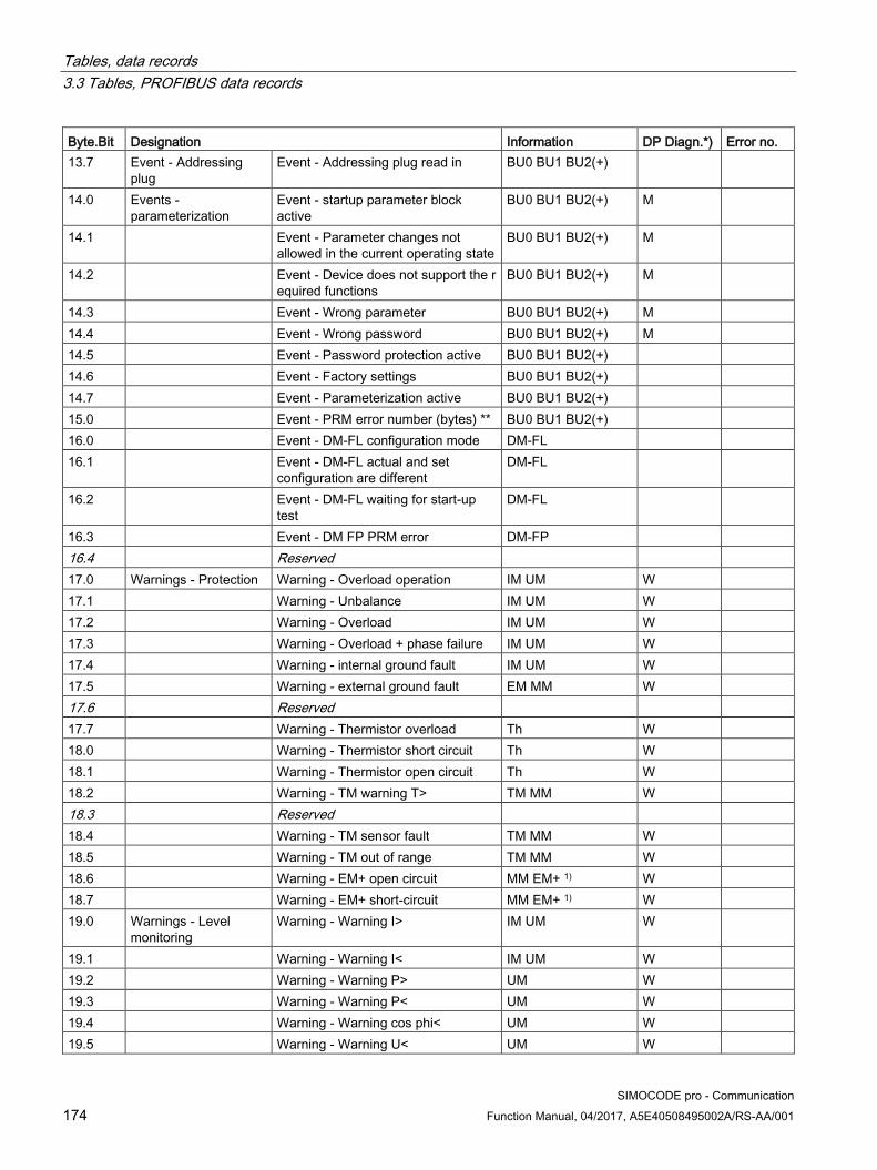
Tables, data records 3.3 Tables, PROFIBUS data records
SIMOCODE pro - Communication 174 Function Manual, 04/2017, A5E40508495002A/RS-AA/001
Byte.Bit Designation Information DP Diagn.*) Error no. 13.7 Event - Addressing
plug Event - Addressing plug read in BU0 BU1 BU2(+)
14.0 Events - parameterization
Event - startup parameter block active
BU0 BU1 BU2(+) M
14.1 Event - Parameter changes not allowed in the current operating state
BU0 BU1 BU2(+) M
14.2 Event - Device does not support the required functions
BU0 BU1 BU2(+) M
14.3 Event - Wrong parameter BU0 BU1 BU2(+) M 14.4 Event - Wrong password BU0 BU1 BU2(+) M 14.5 Event - Password protection active BU0 BU1 BU2(+) 14.6 Event - Factory settings BU0 BU1 BU2(+) 14.7 Event - Parameterization active BU0 BU1 BU2(+) 15.0 Event - PRM error number (bytes) ** BU0 BU1 BU2(+) 16.0 Event - DM-FL configuration mode DM-FL 16.1 Event - DM-FL actual and set
configuration are different DM-FL
16.2 Event - DM-FL waiting for start-up test
DM-FL
16.3 Event - DM FP PRM error DM-FP 16.4 Reserved 17.0 Warnings - Protection Warning - Overload operation IM UM W 17.1 Warning - Unbalance IM UM W 17.2 Warning - Overload IM UM W 17.3 Warning - Overload + phase failure IM UM W 17.4 Warning - internal ground fault IM UM W 17.5 Warning - external ground fault EM MM W 17.6 Reserved 17.7 Warning - Thermistor overload Th W 18.0 Warning - Thermistor short circuit Th W 18.1 Warning - Thermistor open circuit Th W 18.2 Warning - TM warning T> TM MM W 18.3 Reserved 18.4 Warning - TM sensor fault TM MM W 18.5 Warning - TM out of range TM MM W 18.6 Warning - EM+ open circuit MM EM+ 1) W 18.7 Warning - EM+ short-circuit MM EM+ 1) W 19.0 Warnings - Level
monitoring Warning - Warning I> IM UM W
19.1 Warning - Warning I< IM UM W 19.2 Warning - Warning P> UM W 19.3 Warning - Warning P< UM W 19.4 Warning - Warning cos phi< UM W 19.5 Warning - Warning U< UM W
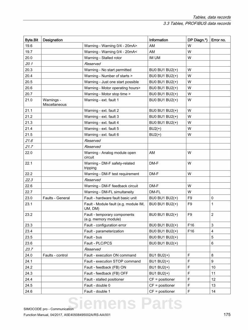
Tables, data records 3.3 Tables, PROFIBUS data records
SIMOCODE pro - Communication Function Manual, 04/2017, A5E40508495002A/RS-AA/001 175
Byte.Bit Designation Information DP Diagn.*) Error no. 19.6 Warning - Warning 0/4 - 20mA> AM W 19.7 Warning - Warning 0/4 - 20mA< AM W 20.0 Warning - Stalled rotor IM UM W 20.1 Reserved 20.3 Warning - No start permitted BU0 BU1 BU2(+) W 20.4 Warning - Number of starts > BU0 BU1 BU2(+) W 20.5 Warning - Just one start possible BU0 BU1 BU2(+) W 20.6 Warning - Motor operating hours> BU0 BU1 BU2(+) W 20.7 Warning - Motor stop time > BU0 BU1 BU2(+) W 21.0 Warnings -
Miscellaneous Warning - ext. fault 1 BU0 BU1 BU2(+) W
21.1 Warning - ext. fault 2 BU0 BU1 BU2(+) W 21.2 Warning - ext. fault 3 BU0 BU1 BU2(+) W 21.3 Warning - ext. fault 4 BU0 BU1 BU2(+) W 21.4 Warning - ext. fault 5 BU2(+) W 21.5 Warning - ext. fault 6 BU2(+) W 21.6 Reserved 21.7 Reserved 22.0 Warning - Analog module open
circuit AM W
22.1 Warning - DM-F safety-related tripping
DM-F W
22.2 Warning - DM-F test requirement DM-F W 22.3 Reserved 22.6 Warning - DM-F feedback circuit DM-F W 22.7 Warning - DM-FL simultaneity DM-FL W 23.0 Faults - General Fault - hardware fault basic unit BU0 BU1 BU2(+) F9 0 23.1 Fault - Module fault (e.g. module IM,
UM, DM) BU0 BU1 BU2(+) F9 1
23.2 Fault - temporary components (e.g. memory module)
BU0 BU1 BU2(+) F9 2
23.3 Fault - configuration error BU0 BU1 BU2(+) F16 3 23.4 Fault - parameterization BU0 BU1 BU2(+) F16 4 23.5 Fault - bus BU0 BU1 BU2(+) 5 23.6 Fault - PLC/PCS BU0 BU1 BU2(+) 6 23.7 Reserved 24.0 Faults - control Fault - execution ON command BU1 BU2(+) F 8 24.1 Fault - execution STOP command BU1 BU2(+) F 9 24.2 Fault - feedback (FB) ON BU1 BU2(+) F 10 24.3 Fault - feedback (FB) OFF BU1 BU2(+) F 11 24.4 Fault - stalled positioner CF = positioner F 12 24.5 Fault - double 0 CF = positioner F 13 24.6 Fault - double 1 CF = positioner F 14
Siemens Parts

Tables, data records 3.3 Tables, PROFIBUS data records
SIMOCODE pro - Communication 176 Function Manual, 04/2017, A5E40508495002A/RS-AA/001
Byte.Bit Designation Information DP Diagn.*) Error no. 24.7 Fault - end position CF = positioner F 15 25.0 Fault - antivalence CF = positioner F 16 25.1 Fault - Cold start (TPF) fault BU0 BU1 BU2(+) F 17 25.2 Fault - power failure (UVO) BU2(+) F 18 25.3 Fault - Operational Protection Off
(OPO) BU2(+) F 19
25.4 Reserved 26.0 Reserved 26.1 Faults - Protection Fault - unbalance IM UM F 25 26.2 Fault - overload IM UM F 26 26.3 Fault - overload + phase failure IM UM F 27 26.4 Fault - int. ground fault IM UM F 28 26.5 Fault - ext. ground fault EM MM F 29 26.6 Reserved 26.7 Fault - thermistor overload Th F 31 27.0 Fault - thermistor short circuit Th F 32 27.1 Fault - thermistor open circuit Th F 33 27.2 Reserved 27.3 Fault - TM trip T> TM MM F 35 27.4 Fault - TM sensor fault TM MM F 36 27.5 Fault - TM out of range TM MM F 37 27.6 Fault - EM+ open circuit MM EM+ 1) F 27.7 Fault - EM+ short-circuit MM EM+ 1) F 28.0 Faults - level
monitoring Fault - trip I> IM UM F 40
28.1 Fault - trip I< IM UM F 41 28.2 Fault - trip P> UM F 42 28.3 Fault - trip P< UM F 43 28.4 Fault - trip cos phi< UM F 44 28.5 Fault - trip U< UM F 45 28.6 Fault - Trip 0/4 - 20mA> AM F 46 28.7 Fault - Trip 0/4 - 20mA< AM F 47 29.0 Fault - stalled rotor IM UM F 48 29.1 Reserved 29.4 Fault - number of starts > BU0 BU1 BU2(+) F 52 29.5 Reserved

Tables, data records 3.3 Tables, PROFIBUS data records
SIMOCODE pro - Communication Function Manual, 04/2017, A5E40508495002A/RS-AA/001 177
Byte.Bit Designation Information DP Diagn.*) Error no. 30.0 Faults - Miscellaneous Fault - external fault 1 BU0 BU1 BU2(+) F 56 30.1 Fault - external fault 2 BU0 BU1 BU2(+) F 57 30.2 Fault - external fault 3 BU0 BU1 BU2(+) F 58 30.3 Fault - external fault 4 BU0 BU1 BU2(+) F 59 30.4 Fault - external fault 5 BU2(+) F 60 30.5 Fault - external fault 6 BU2(+) F 61 30.6 Reserved 30.7 Reserved 31.0 Fault - analog module open circuit AM F 64 31.1 Fault - test trip BU0 BU1 BU2(+) F 65 31.2 Fault - DM-F - safety-related tripping DM-F F 66 31.3 Fault - DM-F wiring DM-F F 67 31.4 Fault - DM-FL cross circuit DM-FL F 68 31.5 Reserved
*) The "DP Diagn." column contains the bits that are additionally available in the diagnostics using PROFIBUS DP:
● F: Fault
● M: Status information
● W: Warning
● F9, F16: Fault types
See also Chapter Detailed messages of the slave diagnostics (Page 158).
**) Events - PRM error number (bytes):
If parameterization is not possible, the number of the parameter group (PRM group) that caused the error is communicated here. You will find the parameter group in the parameter data records 130 to133.
Figure 3-3 Example for parameter group
1) 3UF7510-1AA00-0 ground-fault module
Siemens Parts

Tables, data records 3.3 Tables, PROFIBUS data records
SIMOCODE pro - Communication 178 Function Manual, 04/2017, A5E40508495002A/RS-AA/001
3.3.2.9 Data record 94 - measured values
Table 3- 33 Data record 94 - Measured values
Byte.Bit Designation Type Range Unit Information 0.0 Reserved Byte[4] 4.0 Thermal motor model Byte 0 - 255 See 2) IM UM 5.0 Phase unbalance Byte 0 - 100 1 % IM UM 6.0 cos phi Byte 0 - 100 1 % UM 7.0 Reserved Byte[5] 12.0 Max. current I_max Word 0 - 65535 1 % / Is IM UM 14.0 Current I_L1 Word 0 - 65535 1 % / Is IM UM 16.0 Current I_L2 Word 0 - 65535 1 % / Is IM UM 18.0 Current I_L3 Word 0 - 65535 1 % / Is IM UM 20.0 Last trip current Word 0 - 65535 1 % / Is IM UM 22.0 Time to trip Word 0 - 65535 100 ms IM UM 24.0 Cooling down period Word 0 - 65535 100 ms IM UM 26.0 Voltage U_L1 Word 0 - 65535 1 V UM 28.0 Voltage U_L2 Word 0 - 65535 1 V UM 30.0 Voltage U_L3 Word 0 - 65535 1 V UM 32.0 AM output Word 0 - 32767 See 1) AM 34.0 AM - Input 1 Word 0 - 32767 AM 36.0 AM - Input 2 Word 0 - 32767 AM 38.0 Reserved 40.0 TM - Max. temperature Word 0 - 65535 1 K see 3) TM MM 42.0 TM - Temperature 1 Word 0 - 65535 1 K see 3) TM MM 44.0 TM - Temperature 2 Word 0 - 65535 1 K see 3) TM 46.0 TM - Temperature 3 Word 0 - 65535 1 K see 3) TM 48.0 EM+ 4) - ground-fault current Word 0 - 65535 1 mA MM EM+ 50.0 EM+ 4) - last tripping current Word 0 - 65535 1 mA MM EM+ 52.0 Active power P D-word 0 - 0xFFFFFFFF 1 W UM 56.0 Apparent power S D-word 0 - 0xFFFFFFFF 1 VA UM 60.0 Reserved Byte[14] 132.0 Frequency Word 0 - 65535 0.01 Hz UM+ 134.0 Reserved 136.0 Reserved 138.0 Reserved 140.0 Reserved Byte[4] 144.0 Current I_max_A_F (float) Float 1 A UM+ 148.0 Current I_avg_A_F Float 1 A UM+ 152.0 Current I_L1_A_F Float 1 A UM+ 156.0 Current I_L2_A_F Float 1 A UM+ 160.0 Current I_L3_A_F Float 1 A UM+ 164.0 Active power P_F Float 1 W UM+

Tables, data records 3.3 Tables, PROFIBUS data records
SIMOCODE pro - Communication Function Manual, 04/2017, A5E40508495002A/RS-AA/001 179
Byte.Bit Designation Type Range Unit Information 168.0 Apparent power S_F Float 1 VA UM+ 172.0 Voltage U1_F Float 1 V UM+ 176.0 Voltage U2_F Float 1 V UM+ 180.0 Voltage U3_F Float 1 V UM+ 184.0 Cos phi_F Float UM+ 188.0 Frequency_F Float 1 Hz UM+ 192.0 Reserved Byte[8]
1) S7 format:
0/4 mA = 0
20 mA = 27648
2) Representation of the "Thermal motor model":
Value always refers to symm. trip level, representation in 2 % increments in bits 6 - 0 (range 0 to 254 %), bit 7 shows unbalance (fixed level 50 %).
3) Representation in Kelvin.
4) 3UF7510-1AA00-0 ground-fault module
Siemens Parts

Tables, data records 3.3 Tables, PROFIBUS data records
SIMOCODE pro - Communication 180 Function Manual, 04/2017, A5E40508495002A/RS-AA/001
3.3.2.10 Data record 95 - Service data/statistical data
Writing the service data/statistical data Writing is only possible if password protection is not active.
Additional abbreviations:
● r / w = value can be written / changed
● r = value can only be read
Table 3- 34 Data record 95 - Diagnostics - Statistical data
Byte.Bit Designation Type Range Unit Information 0.0 Coordination Byte[4] BU0 BU1 BU2(+) 4.0 Permissible starts - actual value Byte 0 - 255 r 1) BU0 BU1 BU2(+) 5.0 DM-F - Time until test required Byte 0 - 255 1 week r BU2(+) 6.0 Reserved Byte[2] 8.0 Number of parameterizations Word 0 - 65535 r BU0 BU1 BU2(+) 10.0 Number of overload trips Word 0 - 65535 r / w BU0 BU1 BU2(+) 12.0 Number of internal overload trips Word 0 - 65535 r BU0 BU1 BU2(+) 14.0 Motor stop time Word 0 - 65535 1 h r / w BU0 BU1 BU2(+) 16.0 Timer 1 - Actual value Word 0 - 65535 100 ms r BU0 BU1 BU2(+) 18.0 Timer 2 - Actual value Word 0 - 65535 100 ms r BU0 BU1 BU2(+) 20.0 Timer 3 - Actual value Word 0 - 65535 100 ms r BU2(+) 22.0 Timer 4 - Actual value Word 0 - 65535 100 ms r BU2(+) 24.0 Counter 1 - Actual value Word 0 - 65535 r BU0 BU1 BU2(+) 26.0 Counter 2 - Actual value Word 0 - 65535 r BU0 BU1 BU2(+) 28.0 Counter 3 - Actual value Word 0 - 65535 r BU2(+) 30.0 Counter 4 - Actual value Word 0 - 65535 r BU2(+) 32.0 Calculation module 1 - Output Word 0 - 65535 r BU2(+) 34.0 Calculation module 2 - Output 0 - 65535 r BU2(+) 36.0 Reserved Byte[4] 0 40.0 Motor operating hours D-word 0 - 0xFFFFFFFF 1 s r / w BU0 BU1 BU2(+) 44.0 Int. motor operating hours D-word 0 - 0xFFFFFFFF 1 s r BU0 BU1 BU2(+) 48.0 Device operating hours D-word 0 - 0xFFFFFFFF 1 s r BU0 BU1 BU2(+) 52.0 Number of starts D-word 0 - 0xFFFFFFFF r / w BU0 BU1 BU2(+) 56.0 Internal number of starts CW D-word 0 - 0xFFFFFFFF r BU0 BU1 BU2(+) 60.0 Internal number of starts CCW D-word 0 - 0xFFFFFFFF r BU0 BU1 BU2(+) 64.0 Consumed energy D-word 0 - 0xFFFFFFFF 1 kWh r / w UM(+) 68.0 Energy W_F (float) Byte[8] 1 kWh r BU2+
1) Can only be written when the start monitoring function is active!
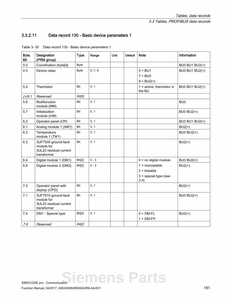
Tables, data records 3.3 Tables, PROFIBUS data records
SIMOCODE pro - Communication Function Manual, 04/2017, A5E40508495002A/RS-AA/001 181
3.3.2.11 Data record 130 - Basic device parameters 1
Table 3- 35 Data record 130 - Basic device parameters 1
Byte. Bit
Designation (PRM group)
Type Range Unit Default Note Information
0.0 Coordination (byte[4] Byte BU0 BU1 BU2(+) 4.0 Device class Byte 5, 7, 9 5 = BU1
7 = BU0 9 = BU2(+)
BU0 BU1 BU2(+)
5.0 Thermistor Bit 0, 1 1 = active; thermistor in the BU
BU0 BU1 BU2(+)
(+)5.1 Reserved Bit[5] 5.6 Multifunction
module (MM). Bit 0, 1 BU0
5.7 Initialization module (InM)
Bit 0, 1 BU0 BU2(+)
6.0 Operator panel (OP) Bit 0, 1 BU0 BU1 BU2(+) 6.1 Analog module 1 (AM1) Bit 0, 1 BU2(+) 6.2 Temperature
module 1 (TM1) Bit 0, 1 BU0 BU2(+)
6.3 3UF7500 ground-fault module for 3UL22 residual current transformer
Bit 0, 1 BU2(+)
6.4 Digital module 1 (DM1) Bit[2] 0 - 3 0 = no digital module 1 = monostable 2 = bistable 3 = special type (see 3.4)
BU0 BU2(+) 6.6 Digital module 2 (DM2) Bit[2] 0 - 2 BU2(+)
7.0 Operator panel with display (OPD)
Bit 0, 1 BU2(+)
7.1 3UF7510 ground-fault module for 3UL23 residual current transformer
Bit 0, 1 BU0 BU2(+)
7.4 DM1 - Special type Bit[2] 0, 1 0 = DM-FL 1 = DM-FP
BU2(+)
7.6 Reserved Bit[2]
Siemens Parts
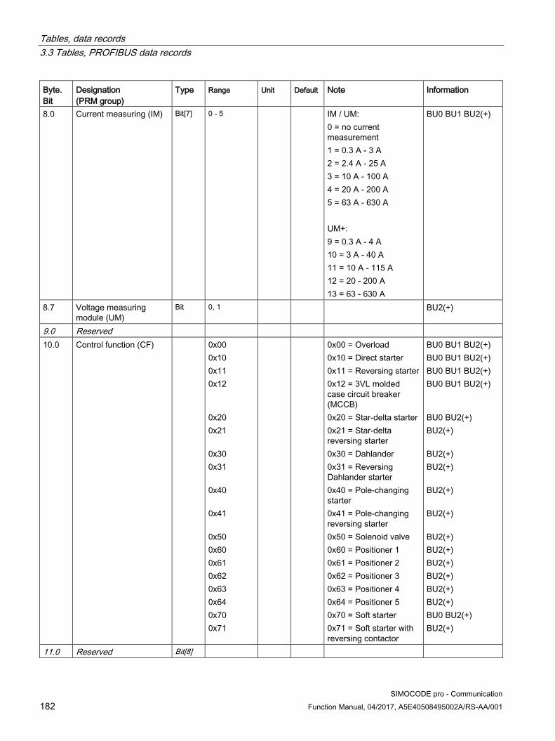
Tables, data records 3.3 Tables, PROFIBUS data records
SIMOCODE pro - Communication 182 Function Manual, 04/2017, A5E40508495002A/RS-AA/001
Byte. Bit
Designation (PRM group)
Type Range Unit Default Note Information
8.0 Current measuring (IM) Bit[7] 0 - 5 IM / UM: 0 = no current measurement 1 = 0.3 A - 3 A 2 = 2.4 A - 25 A 3 = 10 A - 100 A 4 = 20 A - 200 A 5 = 63 A - 630 A UM+: 9 = 0.3 A - 4 A 10 = 3 A - 40 A 11 = 10 A - 115 A 12 = 20 - 200 A 13 = 63 - 630 A
BU0 BU1 BU2(+)
8.7 Voltage measuring module (UM)
Bit 0, 1 BU2(+)
9.0 Reserved 10.0 Control function (CF) 0x00
0x10 0x11 0x12 0x20 0x21 0x30 0x31 0x40 0x41 0x50 0x60 0x61 0x62 0x63 0x64 0x70 0x71
0x00 = Overload 0x10 = Direct starter 0x11 = Reversing starter 0x12 = 3VL molded case circuit breaker (MCCB) 0x20 = Star-delta starter 0x21 = Star-delta reversing starter 0x30 = Dahlander 0x31 = Reversing Dahlander starter 0x40 = Pole-changing starter 0x41 = Pole-changing reversing starter 0x50 = Solenoid valve 0x60 = Positioner 1 0x61 = Positioner 2 0x62 = Positioner 3 0x63 = Positioner 4 0x64 = Positioner 5 0x70 = Soft starter 0x71 = Soft starter with reversing contactor
BU0 BU1 BU2(+) BU0 BU1 BU2(+) BU0 BU1 BU2(+) BU0 BU1 BU2(+) BU0 BU2(+) BU2(+) BU2(+) BU2(+) BU2(+) BU2(+) BU2(+) BU2(+) BU2(+) BU2(+) BU2(+) BU2(+) BU0 BU2(+) BU2(+)
11.0 Reserved Bit[8]

Tables, data records 3.3 Tables, PROFIBUS data records
SIMOCODE pro - Communication Function Manual, 04/2017, A5E40508495002A/RS-AA/001 183
Byte. Bit
Designation (PRM group)
Type Range Unit Default Note Information
12.0 Bit parameters (16) 12.0 No configuration fault
due to OP Bit 0, 1 0 BU0 BU1 BU2(+)
12.1 Startup parameter block active
Bit 0, 1 1 BU0 BU1 BU2(+)
12.2 Test / Reset keys disabled
Bit 0, 1 0 BU0 BU1 BU2(+)
12.3 Bus and PLC/PCS - Reset
Bit 0, 1 0 0 = Manual 1 = Auto
BU0 BU1 BU2(+)
12.1 Startup parameter block active
Bit 0, 1 1 BU0 BU1 BU2(+)
12.2 Test / Reset keys disabled
Bit 0, 1 0 BU0 BU1 BU2(+)
12.3 Bus and PLC/PCS - Reset
Bit 0, 1 0 0 = Manual 1 = Auto
BU0 BU1 BU2(+)
12.3 Bus and PLC/PCS - Reset
Bit 0, 1 0 0 = Manual 1 = Auto
BU0 BU1 BU2(+)
12.2 Test / Reset keys disabled
Bit 0, 1 0 BU0 BU1 BU2(+)
12.3 Bus and PLC/PCS - Reset
Bit 0, 1 0 0 = Manual 1 = Auto
BU0 BU1 BU2(+)
12.4 Reserved Bit 0 12.5 Reserved Bit 0 12.6 Reserved Bit 0 12.7 Reserved Bit 0 13.0 Diagnostics for
process events Bit 0, 1 0 BU0 BU1 BU2(+)
13.1 Diagnostics for process warnings
Bit 0, 1 1 BU0 BU1 BU2(+)
13.2 Diagnostics for process faults
Bit 0, 1 1 BU0 BU1 BU2(+)
13.3 Diagnostics for device faults
Bit 0, 1 1 BU0 BU1, BU2(+)
13.4 Reserved Bit 0 13.5 Reserved Bit 0 13.6 Bus monitoring Bit 0, 1 1 BU0 BU1 BU2(+) 13.7 PLC/PCS monitoring Bit 0, 1 1 BU0 BU1 BU2(+) 14.0 Overload protection -
Load type Bit 0, 1 0 0 = 3-phase
1 = 1-phase IM UM
14.1 Overload protection - Reset
Bit 0, 1 0 0 = Manual 1 = Auto
IM UM
14.2 Reserved Bit 0 14.3 Save change-over
command Bit 0, 1 0 BU0 BU1 BU2(+)
Siemens Parts

Tables, data records 3.3 Tables, PROFIBUS data records
SIMOCODE pro - Communication 184 Function Manual, 04/2017, A5E40508495002A/RS-AA/001
Byte. Bit
Designation (PRM group)
Type Range Unit Default Note Information
14.4 Non-maintained command mode
Bit 0, 1 0 BU0 BU1 BU2(+)
14.5 Cold start level (TPF) Bit 0, 1 0 0 = NO contact 1 = NC contact
BU0 BU1 BU2(+)
14.6 Type of consumer load Bit 0, 1 0 0 = Motor 1 = ohmic load
BU0 BU1 BU2(+)
14.7 Reserved Bit 0 15.0 External fault 1 - Type Bit 0, 1 0 0 = NO contact
1 = NC contact BU0 BU1 BU2(+)
15.1 External fault 2 - Type Bit 0, 1 0 BU0 BU1 BU2(+) 15.2 External fault 3 - Type Bit 0, 1 0 BU0 BU1 BU2(+) 15.3 External fault 4 - Type Bit 0, 1 0 BU0 BU1 BU2(+) 15.4 External fault 1 - active
status Bit 0, 1 0 0 = Always
1 = Only motor ON BU0 BU1 BU2(+)
15.5 External fault 2 - Activity Bit 0, 1 0 BU0 BU1 BU2(+) 15.6 External fault 3 - Activity Bit 0, 1 0 BU0 BU1 BU2(+) 15.7 External fault 4 - Activity Bit 0, 1 0 BU0 BU1 BU2(+) 16.0 Bit[2] - Parameters (20) 16.0 Thermistor - Overload
response Bit[2] 1, 2, 3 3 0 = disabled
1 = signaling 2 = warn 3 = tripping
Th
16.2 Thermistor - Response to sensor fault
Bit[2] 0, 1, 2, 3 2 Th
16.4 Internal ground fault - Response
Bit[2] 0, 1, 2, 3 0 BU0 BU1 BU2(+)
16.6 Motor protection - Overload response
Bit[2] 0, 1, 2, 3 3 IM
17.0 Motor protection - Overload response
Bit[2] 0, 1, 2 2 IM
17.2 Unbalance protection - Response
Bit[2] 0, 1, 2, 3 2 IM
17.4 Trip response I> Bit[2] 0, 1, 3 0 BU0 BU1 BU2(+) 17.6 Warning response I> Bit[2] 0, 1, 2 0 BU0 BU1 BU2(+) 18.0 Trip response I< Bit[2] 0, 1, 3 0 BU0 BU1 BU2(+) 18.2 Warning response I< Bit[2] 0, 1, 2 0 BU0 BU1 BU2(+) 18.4 Stalled rotor - Response Bit[2] 0, 1, 2, 3 0 BU0 BU1 BU2(+) 18.6 EM+ 1) - response to
sensor fault Bit[2] 0, 1, 2, 3 0 BU0 BU2(+)
19.0 Monitoring the number of starts - Response to overshoot
Bit[2] 0, 1, 2, 3 0 BU0 BU1 BU2(+)
19.2 Monitoring the number of starts - Response to prewarning
Bit[2] 0, 1, 2 0 BU0 BU1 BU2(+)
19.4 Motor operating hours monitoring - Response
Bit[2] 0, 1, 2 0 BU0 BU1 BU2(+)

Tables, data records 3.3 Tables, PROFIBUS data records
SIMOCODE pro - Communication Function Manual, 04/2017, A5E40508495002A/RS-AA/001 185
Byte. Bit
Designation (PRM group)
Type Range Unit Default Note Information
19.6 Motor stop time monitoring - Response
Bit[2] 0, 1, 2 0 BU0 BU1 BU2(+)
20.0 External fault 1 - Response
Bit[2] 1, 2, 3 1 BU0 BU1 BU2(+)
20.2 External fault 2 - Response
Bit[2] 1, 2, 3 1 BU0 BU1 BU2(+)
20.4 External fault 3 - Response
Bit[2] 1, 2, 3 1 BU0 BU1 BU2(+)
20.6 External fault 4 - Response
Bit[2] 1, 2, 3 1 BU0 BU1 BU2(+)
21.0 Reserved Bit[2] 0 21.2 Basic unit - Debounce
time inputs Bit[2] 0 - 3 10 ms 1 Offset 6 ms BU0 BU1 BU2(+)
21.4 Timer 1 - Type Bit[2] 0, 1, 2, 3 0 0 = With closing delay 1 = Closing delay with memory 2 = With opening delay 3 = With fleeting closing
BU0 BU1 BU2(+) 21.6 Timer 2 - Type Bit[2] 0, 1, 2, 3 0 BU0 BU1 BU2(+)
22.0 Signal conditioning 1 - Type
Bit[2] 0, 1, 2, 3 0 0 = Non-inverting 1 = Inverting 2 = Edge rising with memory 3 = Edge falling with memory
BU0 BU1 BU2(+)
22.2 Signal conditioning 2 - Type
Bit[2] 0, 1, 2, 3 0 BU0 BU1 BU2(+)
22.4 Non-volatile element 1 - Type
Bit[2] 0, 1, 2, 3 0 BU0 BU1 BU2(+)
22.6 Non-volatile element 2 - Type
Bit[2] 0, 1, 2, 3 0 BU0 BU1 BU2(+)
23.0 EM+ 2) - monitoring Bit[2] 0, 1, 2, 3 0 0 = on 1 = on+ 2 = run 3 = run+
BU0 BU2(+) 23.2 EM+ 2) - monitoring
warning Bit[2] 0, 1, 2, 3 0 BU0 BU2(+)
23.4 EM - response to an external ground fault
Bit[2] 1, 3 1 0 = disabled 1 = signaling 2 = warn 3 = tripping
BU0 BU1 BU2(+)
23.6 EM - response to warning of an external ground fault
Bit[2] 0, 1, 2, 0 BU0 BU1 BU2(+)
24.0 Part - Bit[4] parameters 24.0 External fault 1 - Reset
also by Bit[4] 0 - 1111B 0101B Bit[0] = Panel reset
Bit[1] = Auto-reset Bit[2] = Remote reset Bit[4] = OFF command reset
BU0 BU1 BU2(+)
24.4 External fault 2 - Reset also by
Bit[4] 0 - 1111B 0101B BU0 BU1 BU2(+)
25.0 External fault 3 - Reset also by
Bit[4] 0 - 1111B 0101B BU0 BU1 BU2(+)
25.4 External fault 4 - Reset also by
Bit[4] 0 - 1111B 0101B BU0 BU1 BU2(+)
Siemens Parts

Tables, data records 3.3 Tables, PROFIBUS data records
SIMOCODE pro - Communication 186 Function Manual, 04/2017, A5E40508495002A/RS-AA/001
Byte. Bit
Designation (PRM group)
Type Range Unit Default Note Information
26.0 Limit monitor - Hysteresis for limit monitor
Bit[4] 0 - 15 1 % 5 BU2(+)
26.4 EM+ 2) - hysteresis Bit[4] 0 - 15 1 % 5 BU0 BU2(+) 27.0 Reserved Bit[4] 0 BU0 BU1 BU2(+) 27.4 Reserved Bit[4] 0 BU2+ 28.0 Byte parameters (28) 28.0 Internal ground fault -
Delay Byte 0 - 255 100 ms 5 IM / UM
29.0 Overload protection - Class
Byte 5, 7 3), 10 ... 35, 40
10 BU0 BU1 BU2(+)
30.0 Motor protection - Delay with overload operation
Byte 0 - 255 100 ms 5 IM / UM
31.0 Motor protection - Unbalance protection level
Byte 0 - 100 1 % 40 IM / UM
32.0 Unbalance protection - Delay with unbalance
Byte 0 - 255 100 ms 5 IM / UM
33.0 Interlocking time Byte 0 - 255 1 s 0 34.0 FB time Byte 0 - 255 100 ms 5 0 = disabled 35.0 Trip level I> Byte 0 - 255 4 % / Is 0 IM / UM 36.0 Warning level I> Byte 0 - 255 4 % / Is 0 IM / UM 37.0 Trip level I< Byte 0 - 255 4 % / Is 0 IM / UM 38.0 Warning level I< Byte 0 - 255 4 % / Is 0 IM / UM 39.0 Stalled rotor level Byte 0 - 255 4 % / Is 0 IM / UM 40.0 Trip delay I> Byte 0 - 255 100 ms 5 IM / UM 41.0 Warning delay I> Byte 0 - 255 100 ms 5 IM / UM 42.0 Trip delay I< Byte 0 - 255 100 ms 5 IM / UM 43.0 Warning delay I< Byte 0 - 255 100 ms 5 IM / UM 44.0 Blocking delay Byte 0 - 255 100 ms 5 IM / UM 45.0 Monitoring the number
of starts - Permissible starts
Byte 1 - 255 1 BU0 BU1 BU2(+)
46.0 Reserved Byte 0 47.0 EM / MM 2) - delay
warning Byte 0 - 255 100 ms 1 BU0 BU2(+)
48.0 Truth table 1 type 3I/1O Byte 0 - 11111111B
0 BU0 BU1 BU2(+)
49.0 Truth table 2 type 3I/1O Byte 0 - 11111111B
0 BU0 BU1 BU2(+)
50.0 Truth table 3 type 3I/1O Byte 0 - 11111111B
0 BU0 BU1 BU2(+)
51.0 Reserved Byte 0

Tables, data records 3.3 Tables, PROFIBUS data records
SIMOCODE pro - Communication Function Manual, 04/2017, A5E40508495002A/RS-AA/001 187
Byte. Bit
Designation (PRM group)
Type Range Unit Default Note Information
52.0 Word parameters (32) 52.0 Motor protection -
Cooling down period Word 600 - 65535 100 ms 3000 IM / UM
54.0 Motor protection - Pause time
Word 0 - 65535 100 ms 0 0 = disabled IM / UM
56.0 Execution time Word 0 - 65535 100 ms 10 0 = disabled BU0 BU1 BU2(+)
58.0 Monitoring the number of starts - Time range for starts
Word 0 - 65535 1 s 0 BU0 BU1 BU2(+)
60.0 Monitoring the number of starts - Interlocking time
Word 0 - 65535 1 s 0 BU0 BU1 BU2(+)
62.0 Motor stop time level > Word 0 - 65535 1 h 0 BU0 BU1 BU2(+)
64.0 Timer 1 - Limit Word 0 - 65535 100 ms 0 BU0 BU1 BU2(+)
66.0 Timer 2 - Limit Word 0 - 65535 100 ms 0 BU0 BU1 BU2(+)
68.0 Counter 1 - Limit Word 0 - 65535 0 BU0 BU1 BU2(+)
70.0 Counter 2 - Limit Word 0 - 65535 0 BU0 BU1 BU2(+)
72.0 EM+ 2) - trip level Word 30 - 40000 1 mA 1000 BU0 BU2(+) 74.0 EM+ 2) - warning level Word 30 - 40000 1 mA 500 BU0 BU2(+) 76.0 D-word parameters (36) 76.0 Operator control enable Bit[32] 0 ... 1..1B 0..0B 80.0 Motor protection - set
current Is1 D-word 1) 10 mA 30 IM / UM
84.0 Motor operating hours level >
D-word 0 - 0x FFFFFFFF
1 s 0 BU0 BU1 BU2(+)
88.0 Reserved D-word 0
1) Value range dependent on current range of the IM / UM and the conversion factor; bit 31 = 1, i.e. conversion factor is active
2) 3UF7510-1AA00-0 ground-fault module
3) Class 7 only for BU2+
Siemens Parts

Tables, data records 3.3 Tables, PROFIBUS data records
SIMOCODE pro - Communication 188 Function Manual, 04/2017, A5E40508495002A/RS-AA/001
3.3.2.12 Data record 131 - Basic device parameters 2 (plug binary)
Table 3- 36 Data record 131 - Basic device parameters 2
Byte.Bit Designation (PRM group) Type Range Default Note Information 0.0 Reserved Byte[4] 4.0 Byte parameters (40) 4.0 BU - Output 1 Byte 0 - 255 0 BU0 BU1 BU2(+) 5.0 BU - Output 2 Byte 0 - 255 0 BU0 BU1 BU2(+) 6.0 BU - Output 3 Byte 0 - 255 0 BU1 BU2(+) 7.0 Reserved Byte 0 8.0 OP - LED green 1 Byte 0 - 255 0 OP OPD 9.0 OP - LED green 2 Byte 0 - 255 0 OP OPD 10.0 OP - LED green 3 Byte 0 - 255 0 OP OPD 11.0 OP - LED green 4 Byte 0 - 255 0 OP OPD 12.0 OP - LED yellow 1 Byte 0 - 255 0 OP 13.0 OP - LED yellow 2 Byte 0 - 255 0 OP 14.0 OP - LED yellow 3 Byte 0 - 255 0 OP 15.0 Reserved Byte 0 16.0 Cyclic send - Bit 0.0 Byte 0 - 255 105 Default: Status -
ON< BU0 BU1 BU2(+)
17.0 Cyclic send - Bit 0.1 Byte 0 - 255 106 Default: Status - Off
BU0 BU1 BU2(+)
18.0 Cyclic send - Bit 0.2 Byte 0 - 255 107 Default: Status - ON>
BU0 BU1 BU2(+)
19.0 Cyclic send - Bit 0.3 Byte 0 - 255 128 Default: Event - Overload operation
BU0 BU1 BU2(+)
20.0 Cyclic send - Bit 0.4 Byte 0 - 255 110 Default: Status - Interlocking time active
BU0 BU1 BU2(+)
21.0 Cyclic send - Bit 0.5 Byte 0 - 255 120 Default: Status - Auto mode
BU0 BU1 BU2(+)
22.0 Cyclic send - Bit 0.6 Byte 0 - 255 96 Default: Status - General fault
BU0 BU1 BU2(+)
23.0 Cyclic send - Bit 0.7 Byte 0 - 255 97 Default: Status - group warning
BU0 BU1 BU2(+)
24.0 Cyclic send - Bit 1.0 Byte 0 - 255 0 BU0 BU1 BU2(+) 25.0 Cyclic send - Bit 1.1 Byte 0 - 255 0 BU0 BU1 BU2(+) 26.0 Cyclic send - Bit 1.2 Byte 0 - 255 0 BU0 BU1 BU2(+) 27.0 Cyclic send - Bit 1.3 Byte 0 - 255 0 BU0 BU1 BU2(+) 28.0 Cyclic send - Bit 1.4 Byte 0 - 255 0 BU0 BU1 BU2(+) 29.0 Cyclic send - Bit 1.5 Byte 0 - 255 0 BU0 BU1 BU2(+) 30.0 Cyclic send - Bit 1.6 Byte 0 - 255 0 BU0 BU1 BU2(+) 31.0 Cyclic send - Bit 1.7 Byte 0 - 255 0 BU0 BU1 BU2(+) 32.0 Acyclic send - Bit 0.0 Byte 0 - 255 0 BU0 BU1 BU2(+) 33.0 Acyclic send - Bit 0.1 Byte 0 - 255 0 BU0 BU1 BU2(+)
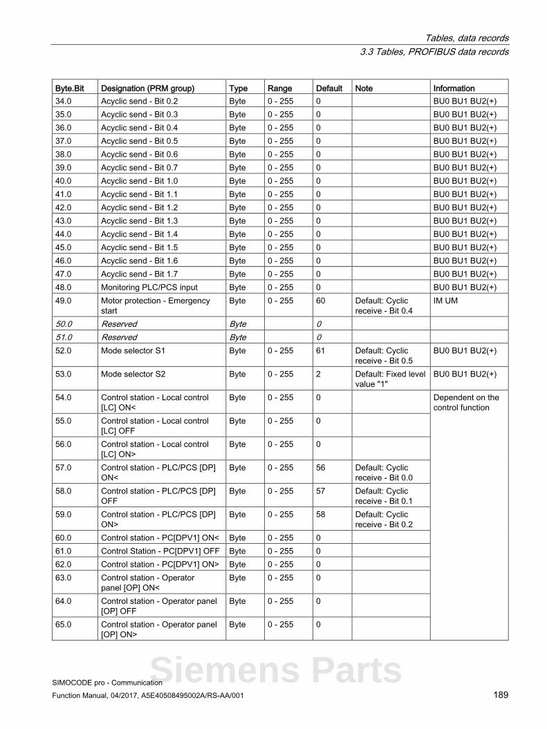
Tables, data records 3.3 Tables, PROFIBUS data records
SIMOCODE pro - Communication Function Manual, 04/2017, A5E40508495002A/RS-AA/001 189
Byte.Bit Designation (PRM group) Type Range Default Note Information 34.0 Acyclic send - Bit 0.2 Byte 0 - 255 0 BU0 BU1 BU2(+) 35.0 Acyclic send - Bit 0.3 Byte 0 - 255 0 BU0 BU1 BU2(+) 36.0 Acyclic send - Bit 0.4 Byte 0 - 255 0 BU0 BU1 BU2(+) 37.0 Acyclic send - Bit 0.5 Byte 0 - 255 0 BU0 BU1 BU2(+) 38.0 Acyclic send - Bit 0.6 Byte 0 - 255 0 BU0 BU1 BU2(+) 39.0 Acyclic send - Bit 0.7 Byte 0 - 255 0 BU0 BU1 BU2(+) 40.0 Acyclic send - Bit 1.0 Byte 0 - 255 0 BU0 BU1 BU2(+) 41.0 Acyclic send - Bit 1.1 Byte 0 - 255 0 BU0 BU1 BU2(+) 42.0 Acyclic send - Bit 1.2 Byte 0 - 255 0 BU0 BU1 BU2(+) 43.0 Acyclic send - Bit 1.3 Byte 0 - 255 0 BU0 BU1 BU2(+) 44.0 Acyclic send - Bit 1.4 Byte 0 - 255 0 BU0 BU1 BU2(+) 45.0 Acyclic send - Bit 1.5 Byte 0 - 255 0 BU0 BU1 BU2(+) 46.0 Acyclic send - Bit 1.6 Byte 0 - 255 0 BU0 BU1 BU2(+) 47.0 Acyclic send - Bit 1.7 Byte 0 - 255 0 BU0 BU1 BU2(+) 48.0 Monitoring PLC/PCS input Byte 0 - 255 0 BU0 BU1 BU2(+) 49.0 Motor protection - Emergency
start Byte 0 - 255 60 Default: Cyclic
receive - Bit 0.4 IM UM
50.0 Reserved Byte 0 51.0 Reserved Byte 0 52.0 Mode selector S1 Byte 0 - 255 61 Default: Cyclic
receive - Bit 0.5 BU0 BU1 BU2(+)
53.0 Mode selector S2 Byte 0 - 255 2 Default: Fixed level value "1"
BU0 BU1 BU2(+)
54.0 Control station - Local control [LC] ON<
Byte 0 - 255 0 Dependent on the control function
55.0 Control station - Local control [LC] OFF
Byte 0 - 255 0
56.0 Control station - Local control [LC] ON>
Byte 0 - 255 0
57.0 Control station - PLC/PCS [DP] ON<
Byte 0 - 255 56 Default: Cyclic receive - Bit 0.0
58.0 Control station - PLC/PCS [DP] OFF
Byte 0 - 255 57 Default: Cyclic receive - Bit 0.1
59.0 Control station - PLC/PCS [DP] ON>
Byte 0 - 255 58 Default: Cyclic receive - Bit 0.2
60.0 Control station - PC[DPV1] ON< Byte 0 - 255 0 61.0 Control Station - PC[DPV1] OFF Byte 0 - 255 0 62.0 Control station - PC[DPV1] ON> Byte 0 - 255 0 63.0 Control station - Operator
panel [OP] ON< Byte 0 - 255 0
64.0 Control station - Operator panel [OP] OFF
Byte 0 - 255 0
65.0 Control station - Operator panel [OP] ON>
Byte 0 - 255 0
Siemens Parts

Tables, data records 3.3 Tables, PROFIBUS data records
SIMOCODE pro - Communication 190 Function Manual, 04/2017, A5E40508495002A/RS-AA/001
Byte.Bit Designation (PRM group) Type Range Default Note Information 66.0 Control function - ON< Byte 0 - 255 73 Default: Group
control station ON< 67.0 Control function - OFF Byte 0 - 255 74 Default: Group
control station OFF 68.0 Control function - ON> Byte 0 - 255 75 Default: Group
control station ON> 69.0 Control function - Feedback ON Byte 0 - 255 101 Default: Status -
current flowing
70.0 External fault 1 - input Byte 0 - 255 0 BU0 BU1 BU2(+) 71.0 External fault 2 - input Byte 0 - 255 0 BU0 BU1 BU2(+) 72.0 External fault 3 - input Byte 0 - 255 0 BU0 BU1 BU2(+) 73.0 External fault 4 - input Byte 0 - 255 0 BU0 BU1 BU2(+) 74.0 External fault 1 - Reset Byte 0 - 255 0 BU0 BU1 BU2(+) 75.0 External fault 2 - Reset Byte 0 - 255 0 BU0 BU1 BU2(+) 76.0 External fault 3 - Reset Byte 0 - 255 0 BU0 BU1 BU2(+) 77.0 External fault 4 - Reset Byte 0 - 255 0 BU0 BU1 BU2(+) 78.0 Cold starting (TPF) Byte 0 - 255 0 BU0 BU1 BU2(+) 79.0 Test 1 - Input Byte 0 - 255 59 Default: Cyclic
receive - Bit 0.3 BU0 BU1 BU2(+)
80.0 Test 2 - Input Byte 0 - 255 0 BU0 BU1 BU2(+) 81.0 Reset 1 - Input Byte 0 - 255 62 Default: Cyclic
receive - Bit 0.6 BU0 BU1 BU2(+)
82.0 Reset 2 - Input Byte 0 - 255 0 BU0 BU1 BU2(+) 83.0 Reset 3 - Input Byte 0 - 255 0 BU0 BU1 BU2(+) 84.0 Reserved Byte 0 85.0 Reserved Byte 0 86.0 Reserved Byte 0 87.0 Reserved Byte 0 88.0 Truth table 1 3I/1O - input 1 Byte 0 - 255 0 BU0 BU1 BU2(+) 89.0 Truth table 1 3I/1O - input 2 Byte 0 - 255 0 BU0 BU1 BU2(+) 90.0 Truth table 1 3I/1O - input 3 Byte 0 - 255 0 BU0 BU1 BU2(+) 91.0 Truth table 2 3I/1O - input 1 Byte 0 - 255 0 BU0 BU1 BU2(+) 92.0 Truth table 2 3I/1O - input 2 Byte 0 - 255 0 BU0 BU1 BU2(+) 93.0 Truth table 2 3I/1O - input 3 Byte 0 - 255 0 BU0 BU1 BU2(+) 94.0 Truth table 3 3I/1O - input 1 Byte 0 - 255 0 BU0 BU1 BU2(+) 95.0 Truth table 3 3I/1O - input 2 Byte 0 - 255 0 BU0 BU1 BU2(+) 96.0 Truth table 3 3I/1O - input 3 Byte 0 - 255 0 BU0 BU1 BU2(+) 97.0 Reserved Byte 0 98.0 Timer 1 - input Byte 0 - 255 0 BU0 BU1 BU2(+) 99.0 Timer 1 - reset Byte 0 - 255 0 BU0 BU1 BU2(+) 100.0 Timer 2 - input Byte 0 - 255 0 BU0 BU1 BU2(+) 101.0 Timer 2 - reset Byte 0 - 255 0 BU0 BU1 BU2(+) 102.0 Counter 1 - input + Byte 0 - 255 0 BU0 BU1 BU2(+)
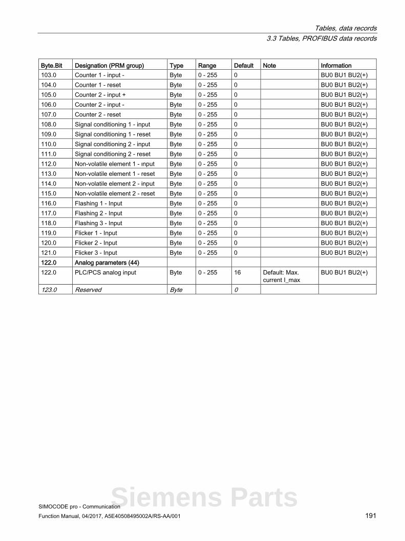
Tables, data records 3.3 Tables, PROFIBUS data records
SIMOCODE pro - Communication Function Manual, 04/2017, A5E40508495002A/RS-AA/001 191
Byte.Bit Designation (PRM group) Type Range Default Note Information 103.0 Counter 1 - input - Byte 0 - 255 0 BU0 BU1 BU2(+) 104.0 Counter 1 - reset Byte 0 - 255 0 BU0 BU1 BU2(+) 105.0 Counter 2 - input + Byte 0 - 255 0 BU0 BU1 BU2(+) 106.0 Counter 2 - input - Byte 0 - 255 0 BU0 BU1 BU2(+) 107.0 Counter 2 - reset Byte 0 - 255 0 BU0 BU1 BU2(+) 108.0 Signal conditioning 1 - input Byte 0 - 255 0 BU0 BU1 BU2(+) 109.0 Signal conditioning 1 - reset Byte 0 - 255 0 BU0 BU1 BU2(+) 110.0 Signal conditioning 2 - input Byte 0 - 255 0 BU0 BU1 BU2(+) 111.0 Signal conditioning 2 - reset Byte 0 - 255 0 BU0 BU1 BU2(+) 112.0 Non-volatile element 1 - ιnput Byte 0 - 255 0 BU0 BU1 BU2(+) 113.0 Non-volatile element 1 - reset Byte 0 - 255 0 BU0 BU1 BU2(+) 114.0 Non-volatile element 2 - input Byte 0 - 255 0 BU0 BU1 BU2(+) 115.0 Non-volatile element 2 - reset Byte 0 - 255 0 BU0 BU1 BU2(+) 116.0 Flashing 1 - Input Byte 0 - 255 0 BU0 BU1 BU2(+) 117.0 Flashing 2 - Input Byte 0 - 255 0 BU0 BU1 BU2(+) 118.0 Flashing 3 - Input Byte 0 - 255 0 BU0 BU1 BU2(+) 119.0 Flicker 1 - Input Byte 0 - 255 0 BU0 BU1 BU2(+) 120.0 Flicker 2 - Input Byte 0 - 255 0 BU0 BU1 BU2(+) 121.0 Flicker 3 - Input Byte 0 - 255 0 BU0 BU1 BU2(+) 122.0 Analog parameters (44) 122.0 PLC/PCS analog input Byte 0 - 255 16 Default: Max.
current I_max BU0 BU1 BU2(+)
123.0 Reserved Byte 0
Siemens Parts

Tables, data records 3.3 Tables, PROFIBUS data records
SIMOCODE pro - Communication 192 Function Manual, 04/2017, A5E40508495002A/RS-AA/001
3.3.2.13 Data record 132 - Extended device parameters 1
Table 3- 37 Data record 132 - Extended device parameters 1
Byte. Bit
Designation (PRM group) Type Range Unit Default Note Information
0.0 Coordination Byte[4] BU0 BU2(+) 4.0 Bit parameters (17) 4.0 3UF50 compatibility mode Bit 0, 1 0 BU2(+) 4.1 3UF50 operating mode Bit 0, 1 0 0 = DPV0
1 = DPV1 BU2(+)
4.2 Reserved Bit 0 4.3 Reserved Bit 0 4.4 Reserved Bit 0 4.5 Reserved Bit 0 4.6 Reserved Bit 0 4.7 Reserved Bit 0 5.0 Reserved Bit 0 5.1 Reserved Bit 0 5.2 OPD - Warnings Bit 0, 1 0 0 = Do not
display 1 = Display
BU2+ 5.3 OPD - Faults Bit 0, 1 0 BU2+
5.4 Analog module - Measuring range input
Bit 0, 1 0 0 = 0 - 20mA 1 = 4 - 20mA
AM1
5.5 Analog module - Measuring range output
Bit 0, 1 0 AM1
5.6 Reserved Bit 0 5.7 Reserved Bit 0 6.0 Overshooting/undershooting
limit 1 Bit 0, 1 0 0 = ">"
(over-shooting) 1 = "<" (under-shooting)
BU2(+)
6.1 Overshooting/undershooting limit 2
Bit 0, 1 0 BU2(+)
6.2 Overshooting/undershooting limit 3
Bit 0, 1 0 BU2(+)
6.3 Overshooting/undershooting limit 4
Bit 0, 1 0 BU2(+)
6.4 Line-to-line voltage Bit 0, 1 0 0 = No, 1 = Yes
BU2(+)
6.5 OPO level Bit 0, 1 0 0 = NO contact 1 = NC contact
BU2(+)
6.6 Positioner response for OPO Bit 0, 1 0 0 = CLOSED 1 = OPEN
BU2(+)

Tables, data records 3.3 Tables, PROFIBUS data records
SIMOCODE pro - Communication Function Manual, 04/2017, A5E40508495002A/RS-AA/001 193
Byte. Bit
Designation (PRM group) Type Range Unit Default Note Information
6.7 Star-delta - Transformer mounting
Bit 0, 1 0 0 = Delta 1 = In supply cable
BU0 BU2(+)
7.0 External fault 5 - Type Bit 0, 1 0 0 = NO contact 1 = NC contact
BU2(+) 7.1 External fault 6 - Type Bit 0, 1 0 BU2(+)
7.2 Reserved Bit 0 7.3 Reserved Bit 0 7.4 Monitoring external fault 5 Bit 0, 1 0 0 = Always
1 = Only motor ON
BU2(+) 7.5 Monitoring external fault 6 Bit 0, 1 0 BU2(+)
7.6 Reserved Bit 0 7.7 Reserved Bit 0 8.0 Calculation module 2 -
Operating mode Bit 0, 1 0 0 = Word
1 = D-word BU2(+)
8.1 Reserved Bit 0 8.2 DM-F - Safe tripping function Bit 0, 1 0 0 = No
1 = Yes DM-F
8.3 DM-F - reset safety-related tripping
Bit 0, 1 0 0 = Manual, 1 = Auto
DM-F
8.4 Time stamping active Bit 0, 1 0 BU2(+) 8.5 Reserved Bit 0 8.6 Reserved Bit 0 8.7 Reserved Bit 0 9.0 DM-FL - Configuration 1 Bit 0, 1 0 Configurable
parameters comparable with the module configuration
DM-FL 9.1 DM-FL - Configuration 2 Bit 0, 1 0 DM-FL 9.2 DM-FL - Configuration 3 Bit 0, 1 0 DM-FL 9.3 DM-FL - Configuration 4 Bit 0, 1 0 DM-FL 9.4 DM-FL - Configuration 5 Bit 0, 1 0 DM-FL 9.5 DM-FL - Configuration 6 Bit 0, 1 0 DM-FL 9.6 DM-FL - Configuration 7 Bit 0, 1 0 DM-FL 9.7 DM-FL - Configuration 8 Bit 0, 1 0 DM-FL 10.0 Bit[2] - Parameters (21) 10.0 3UF50 basic type Bit[2] 0, 1, 2 0 BU2(+) 10.2 Reserved Bit[2] 0 10.4 UVO timebase Bit[2] 0, 1, 2 0 0 = 100 ms,
1 = 1 s, 2 = 10 s
BU2(+)
10.6 UVO operating mode Bit[2] 0, 1 0 0 = Deactivated, 1 = Activated
BU2(+)
Siemens Parts

Tables, data records 3.3 Tables, PROFIBUS data records
SIMOCODE pro - Communication 194 Function Manual, 04/2017, A5E40508495002A/RS-AA/001
Byte. Bit
Designation (PRM group) Type Range Unit Default Note Information
11.0 Trip monitoring U< Bit[2] 0, 1, 2 1 0 = ON (always) 1 = on+ (always, not TPF) 2 = RUN (motor ON, not TPF)
UM 11.2 Warning monitoring U< Bit[2] 0, 1, 2 1 UM
11.4 Reserved Bit[2] 0 11.6 Reserved Bit[2] 0 12.0 Trip monitoring 0/4-20 mA> Bit[2] 0, 1, 2, 3 0 0 = ON
(always) 1 = ON + (always, not TPF) 2 = RUN (motor ON, not TPF) 3 = RUN+ (motor ON, not TPF, startup override)
AM1 12.2 Warning monitoring 0/4-20 mA> Bit[2] 0, 1, 2, 3 0 AM1 12.4 Trip monitoring 0/4-20 mA< Bit[2] 0, 1, 2, 3 0 AM1 12.6 Warning monitoring 0/4-20 mA< Bit[2] 0, 1, 2, 3 0 AM1 13.0 Monitoring limit 1 Bit[2] 0, 1, 2, 3 0 BU2(+) 13.2 Monitoring limit 2 Bit[2] 0, 1, 2, 3 0 BU2(+) 13.4 Monitoring limit 3 Bit[2] 0, 1, 2, 3 0 BU2(+) 13.6 Monitoring limit 4 Bit[2] 0, 1, 2, 3 0 BU2(+)
14.0 Reserved Bit[2] 0 14.2 Reserved Bit[2] 0 14.4 Reserved Bit[2] 0 14.6 AM1 - active inputs Bit[2] 0, 1, 2 0 0 = 1 input
1 = 2 inputs 2 = 3 inputs
AM1
15.0 DM - Debounce time inputs Bit[2] 0, 1, 2, 3 10 ms 1 Offset 6ms DM1 DM2 MM
15.2 AM1 - Response for open circuit
Bit[2] 1, 2, 3 2 0 = disabled 1 = signal 2 = warn 3 = tripping
AM1
15.4 EM - response to an external ground fault
Bit[2] 1, 3 1 EM EM+ MM
15.6 EM - response to warning of an external ground fault
Bit[2] 0, 1, 2 0 EM EM+ MM
16.0 Reserved Bit[2] 0 16.2 Reserved Bit[2] 0

Tables, data records 3.3 Tables, PROFIBUS data records
SIMOCODE pro - Communication Function Manual, 04/2017, A5E40508495002A/RS-AA/001 195
Byte. Bit
Designation (PRM group) Type Range Unit Default Note Information
16.4 DM-F - Test requirement response
Bit[2] 0, 1, 2 0 0 = disabled 1 = signal 2 = warn 3 = tripping
DM-F
16.6 DM-F - safety-related tripping response
Bit[2] 0, 1, 2, 3 0 DM-F
17.0 TM1 - Trip response T> Bit[2] 1, 3 3 TM1 MM 17.2 TM1 - Warning response T> Bit[2] 0, 1, 2 2 TM1 MM 17.4 TM1 - Response to a sensor
fault / out of range Bit[2] 0, 1, 2, 3 2 TM1 MM
17.6 TM1 - Active sensors Bit[2] 0, 1, 2 2 0 = 1 sensors 1 = 2 sensors 2 = 3 sensors
TM1 MM
18.0 Trip response P> Bit[2] 0, 1, 3 0 0 = disabled 1 = signal 2 = warn 3 = tripping
UM 18.2 Warning response P> Bit[2] 0, 1, 2 0 UM 18.4 Trip response P< Bit[2] 0, 1, 3 0 UM 18.6 Warning response P< Bit[2] 0, 1, 2 0 UM 19.0 Trip response cos phi < Bit[2] 0, 1, 3 0 UM 19.2 Warning response cos phi < Bit[2] 0, 1, 2 0 UM 19.4 Trip response U< Bit[2] 0, 1, 3 0 UM 19.6 Warning response U< Bit[2] 0, 1, 2 0 UM 20.0 Trip response 0/4-20 mA> Bit[2] 0, 1, 3 0 AM1 20.2 Warning response 0/4-20 mA> Bit[2] 0, 1, 2 0 AM1 20.4 Trip response 0/4-20 mA< Bit[2] 0, 1, 3 0 AM1 20.6 Warning response 0/4-20 mA< Bit[2] 0, 1, 2 0 AM1 21.0 Reserved Bit[2] 0 21.2 Reserved Bit[2] 0 21.4 Reserved Bit[2] 0 21.6 Reserved Bit[2] 0 22.0 External fault 5 - Response Bit[2] 1, 2, 3 1 0 = disabled
1 = signal 2 = warn 3 = tripping
BU2(+) 22.2 External fault 6 - Response Bit[2] 1, 2, 3 1 BU2(+)
22.4 Reserved Bit[2] 0 22.6 Reserved Bit[2] 0 23.0 Analog-value recording -
Trigger edge Bit[2] 0, 1 0 0 = positive
1 = Negative BU2(+)
23.2 Reserved Bit[2] 0
Siemens Parts

Tables, data records 3.3 Tables, PROFIBUS data records
SIMOCODE pro - Communication 196 Function Manual, 04/2017, A5E40508495002A/RS-AA/001
Byte. Bit
Designation (PRM group) Type Range Unit Default Note Information
23.4 Reserved Bit[2] 0 23.6 Reserved Bit[2] 0 24.0 Reserved Bit[2] 0 24.2 Reserved Bit[2] 0 24.4 Reserved Bit[2] 0 24.6 Reserved Bit[2] 0 25.0 Timer 3 - Type Bit[2] 0, 1, 2, 3 0 0 = With
closing delay 1 = Closing delay with memory 2 = With opening delay 3 = With fleeting closing
BU2(+) 25.2 Timer 4 - Type Bit[2] 0, 1, 2, 3 0 BU2(+)
25.4 Signal conditioning 3 - Type Bit[2] 0, 1, 2, 3 0 0 = Non-inverting 1 = Inverting 2 = Edge rising with memory 3 = Edge falling with memory
BU0 BU2(+) 25.6 Signal conditioning 4 - Type Bit[2] 0, 1, 2, 3 0 BU0 BU2(+) 26.0 Non-volatile element 3 - Type Bit[2] 0, 1, 2, 3 0 BU2(+) 26.2 Non-volatile element 4 - Type Bit[2] 0, 1, 2, 3 0 BU2(+)
26.4 Calculation module 2 - Operator Bit[2] 0, 1, 2, 3 0 0 = +, 1 = -, 2 = *, 3 = /
BU2(+)
26.6 Reserved Bit[2] 0 27.0 Reserved Bit[2] 0 27.2 Reserved Bit[2] 0 27.4 OPD - Operator panel display
(bit 0 to 1) Bit[2] 0 - 4 2
0 = Manual 1 = 3 s 2 = 10 s 3 = 1 min 4 = 5 min
BU2+
27.6 OPD - Operator panel display (bit 2 to 3)
Bit[2] 0 - 4 BU2+

Tables, data records 3.3 Tables, PROFIBUS data records
SIMOCODE pro - Communication Function Manual, 04/2017, A5E40508495002A/RS-AA/001 197
Byte. Bit
Designation (PRM group) Type Range Unit Default Note Information
28.0 Bit[4] - Parameters (25) 28.0 TM - sensor type Bit[3] +
Bit 000B to 100B 000B 000B =
PT100 001B = PT1000 010B = KTY83 011B = KTY84 100B = NTC
TM1 MM
28.4 OPD - Language Bit[4] 0 - 15 0 BU2+ 29.0 External fault 5 - Reset also by Bit[4] 0 - 1111B 0101B Bit[0] =
Panel reset Bit[1] = Auto-reset Bit[2] = Remote reset Bit[3] = OFF command reset
BU2(+) 29.4 External fault 6 - Reset also by Bit[4] 0 - 1111B 0101B BU2(+)
30.0 OPD - Contrast (bit 0 to 3) Bit[4] 0 - 255
1%
50
BU2+ 30.4 OPD - Contrast (bit 4 to 7) Bit[4] BU2+ 31.0 OPD - Profile (bit 0 to 3) Bit[4] 0 - 33
0 BU2+
31.4 OPD - Profile (bit 4 to 7) Bit[4] BU2+ 32.0 Truth table 7 type 2I/1O Bit[4] 0 - 1111B 0 BU0 BU2(+) 32.4 Truth table 8 type 2I/1O Bit[4] 0 - 1111B 0 BU0 BU2(+) 33.0 Is1 conversion factor -
Denominator Bit[4] 0 - 15 0 BU2(+)
33.4 Is2 conversion factor - Denominator
Bit[4] 0 - 15 0 BU2(+)
34.0 Hysteresis P - Cos phi - U Bit[4] 0 - 15 5 1% UM 34.4 Hysteresis 0/4-20 mA Bit[4] 0 - 15 5 1% AM1 35.0 Hysteresis free limits Bit[4] 0 - 15 5 1% BU2(+) 35.4 OPD - Lighting Bit[4] 0 - 4 2 0 = Off
1 = 3 s 2 = 10 s 3 = 1 min 4 = 5 min
BU2+
Siemens Parts

Tables, data records 3.3 Tables, PROFIBUS data records
SIMOCODE pro - Communication 198 Function Manual, 04/2017, A5E40508495002A/RS-AA/001
Byte. Bit
Designation (PRM group) Type Range Unit Default Note Information
36.0 Byte parameters (29) 36.0 Reserved Byte 0 37.0 EM / MM - delay trip Byte 0 - 255 100 ms 5 EM MM 38.0 Trip level cos phi< Byte 0 - 100 1% 0 UM 39.0 Warning level cos phi< Byte 0 - 100 1% 0 UM 40.0 Trip level U< Byte 0 - 255 8 V 0 UM 41.0 Warning level U< Byte 0 - 255 8 V 0 UM 42.0 Trip level 0/4-20 mA> Byte 0 - 255 *128 0 AM1 43.0 Warning level 0/4-20 mA> Byte 0 - 255 *128 0 AM1 44.0 Trip level 0/4-20 mA< Byte 0 - 255 *128 0 AM1 45.0 Warning level 0/4-20 mA< Byte 0 - 255 *128 0 AM1 46.0 Trip delay P> Byte 0 - 255 100 ms 5 UM 47.0 Warning delay P> Byte 0 - 255 100 ms 5 UM 48.0 Trip delay P< Byte 0 - 255 100 ms 5 UM 49.0 Warning delay P< Byte 0 - 255 100 ms 5 UM 50.0 Trip delay cos phi< Byte 0 - 255 100 ms 5 UM 51.0 Warning delay cos phi< Byte 0 - 255 100 ms 5 UM 52.0 Trip delay U< Byte 0 - 255 100 ms 5 UM 53.0 Warning delay U< Byte 0 - 255 100 ms 5 UM 54.0 Trip delay 0/4-20 mA> Byte 0 - 255 100 ms 5 AM1 55.0 Warning delay 0/4-20 mA> Byte 0 - 255 100 ms 5 AM1 56.0 Trip delay 0/4-20 mA< Byte 0 - 255 100 ms 5 AM1 57.0 Warning delay 0/4-20 mA< Byte 0 - 255 100 ms 5 AM1 58.0 Delay limit 1 Byte 0 - 255 100 ms 5 BU2 59.0 Delay limit 2 Byte 0 - 255 100 ms 5 BU2 60.0 Delay limit 3 Byte 0 - 255 100 ms 5 BU2 61.0 Delay limit 4 Byte 0 - 255 100 ms 5 BU2 62.0 TM - Hysteresis Byte 0 - 255 1 K 5 TM1 MM 63.0 Max. star time Byte 0 - 255 1 s 20 Star-delta
starter BU0 BU2
64.0 UVO time Byte 0 - 255 100 ms 0 BU2 65.0 Staggering time Byte 0 - 255 1 s 0 BU2 66.0 Analog value recording -
Sampling rate Byte 0 - 20 5% 0 BU2
67.0 Calculation module 2 - Denominator 1
Byte 0 - 255 0 BU2
68.0 Calculation module 2 - Numerator 2
Byte 0 - 255 0 BU2
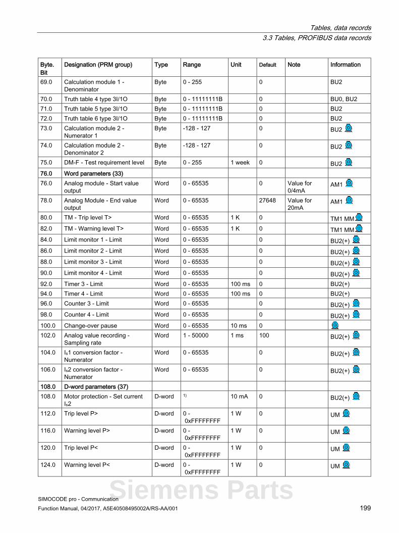
Tables, data records 3.3 Tables, PROFIBUS data records
SIMOCODE pro - Communication Function Manual, 04/2017, A5E40508495002A/RS-AA/001 199
Byte. Bit
Designation (PRM group) Type Range Unit Default Note Information
69.0 Calculation module 1 - Denominator
Byte 0 - 255 0 BU2
70.0 Truth table 4 type 3I/1O Byte 0 - 11111111B 0 BU0, BU2 71.0 Truth table 5 type 3I/1O Byte 0 - 11111111B 0 BU2 72.0 Truth table 6 type 3I/1O Byte 0 - 11111111B 0 BU2 73.0 Calculation module 2 -
Numerator 1 Byte -128 - 127 0 BU2
74.0 Calculation module 2 - Denominator 2
Byte -128 - 127 0 BU2
75.0 DM-F - Test requirement level Byte 0 - 255 1 week 0 BU2 76.0 Word parameters (33) 76.0 Analog module - Start value
output Word 0 - 65535 0 Value for
0/4mA AM1
78.0 Analog Module - End value output
Word 0 - 65535 27648 Value for 20mA
AM1
80.0 TM - Trip level T> Word 0 - 65535 1 K 0 TM1 MM 82.0 TM - Warning level T> Word 0 - 65535 1 K 0 TM1 MM 84.0 Limit monitor 1 - Limit Word 0 - 65535 0 BU2(+) 86.0 Limit monitor 2 - Limit Word 0 - 65535 0 BU2(+) 88.0 Limit monitor 3 - Limit Word 0 - 65535 0 BU2(+) 90.0 Limit monitor 4 - Limit Word 0 - 65535 0 BU2(+) 92.0 Timer 3 - Limit Word 0 - 65535 100 ms 0 BU2(+) 94.0 Timer 4 - Limit Word 0 - 65535 100 ms 0 BU2(+) 96.0 Counter 3 - Limit Word 0 - 65535 0 BU2(+) 98.0 Counter 4 - Limit Word 0 - 65535 0 BU2(+) 100.0 Change-over pause Word 0 - 65535 10 ms 0 102.0 Analog value recording -
Sampling rate Word 1 - 50000 1 ms 100 BU2(+)
104.0 Is1 conversion factor - Numerator
Word 0 - 65535 0 BU2(+)
106.0 Is2 conversion factor - Numerator
Word 0 - 65535 0 BU2(+)
108.0 D-word parameters (37) 108.0 Motor protection - Set current
Is2 D-word 1) 10 mA 0 BU2(+)
112.0 Trip level P> D-word 0 - 0xFFFFFFFF
1 W 0 UM
116.0 Warning level P> D-word 0 - 0xFFFFFFFF
1 W 0 UM
120.0 Trip level P< D-word 0 - 0xFFFFFFFF
1 W 0 UM
124.0 Warning level P< D-word 0 - 0xFFFFFFFF
1 W 0 UM
Siemens Parts
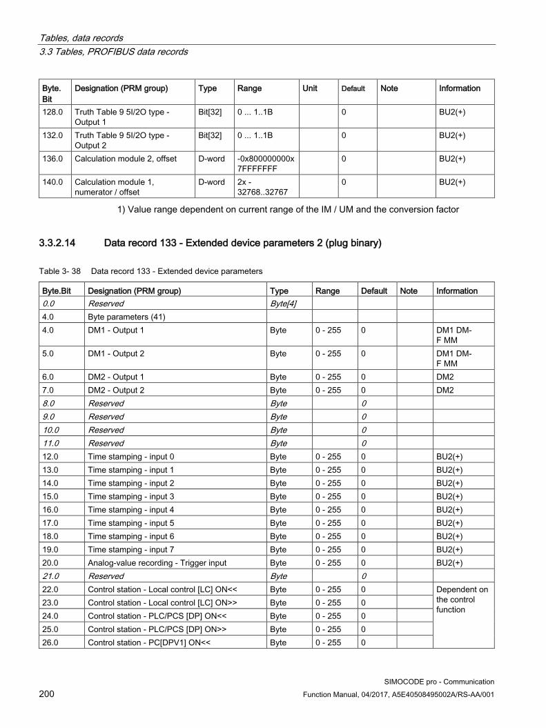
Tables, data records 3.3 Tables, PROFIBUS data records
SIMOCODE pro - Communication 200 Function Manual, 04/2017, A5E40508495002A/RS-AA/001
Byte. Bit
Designation (PRM group) Type Range Unit Default Note Information
128.0 Truth Table 9 5I/2O type - Output 1
Bit[32] 0 ... 1..1B 0 BU2(+)
132.0 Truth Table 9 5I/2O type - Output 2
Bit[32] 0 ... 1..1B 0 BU2(+)
136.0 Calculation module 2, offset D-word -0x800000000x 7FFFFFFF
0 BU2(+)
140.0 Calculation module 1, numerator / offset
D-word 2x -32768..32767
0 BU2(+)
1) Value range dependent on current range of the IM / UM and the conversion factor
3.3.2.14 Data record 133 - Extended device parameters 2 (plug binary)
Table 3- 38 Data record 133 - Extended device parameters
Byte.Bit Designation (PRM group) Type Range Default Note Information 0.0 Reserved Byte[4] 4.0 Byte parameters (41) 4.0 DM1 - Output 1 Byte 0 - 255 0 DM1 DM-
F MM 5.0 DM1 - Output 2 Byte 0 - 255 0 DM1 DM-
F MM 6.0 DM2 - Output 1 Byte 0 - 255 0 DM2 7.0 DM2 - Output 2 Byte 0 - 255 0 DM2 8.0 Reserved Byte 0 9.0 Reserved Byte 0 10.0 Reserved Byte 0 11.0 Reserved Byte 0 12.0 Time stamping - input 0 Byte 0 - 255 0 BU2(+) 13.0 Time stamping - input 1 Byte 0 - 255 0 BU2(+) 14.0 Time stamping - input 2 Byte 0 - 255 0 BU2(+) 15.0 Time stamping - input 3 Byte 0 - 255 0 BU2(+) 16.0 Time stamping - input 4 Byte 0 - 255 0 BU2(+) 17.0 Time stamping - input 5 Byte 0 - 255 0 BU2(+) 18.0 Time stamping - input 6 Byte 0 - 255 0 BU2(+) 19.0 Time stamping - input 7 Byte 0 - 255 0 BU2(+) 20.0 Analog-value recording - Trigger input Byte 0 - 255 0 BU2(+) 21.0 Reserved Byte 0 22.0 Control station - Local control [LC] ON<< Byte 0 - 255 0 Dependent on
the control function
23.0 Control station - Local control [LC] ON>> Byte 0 - 255 0 24.0 Control station - PLC/PCS [DP] ON<< Byte 0 - 255 0 25.0 Control station - PLC/PCS [DP] ON>> Byte 0 - 255 0 26.0 Control station - PC[DPV1] ON<< Byte 0 - 255 0

Tables, data records 3.3 Tables, PROFIBUS data records
SIMOCODE pro - Communication Function Manual, 04/2017, A5E40508495002A/RS-AA/001 201
Byte.Bit Designation (PRM group) Type Range Default Note Information 27.0 Control station - PC[DPV1] ON>> Byte 0 - 255 0 28.0 Control station - Operator panels [OP] ON>> Byte 0 - 255 0 29.0 Control station - Operator panels [OP]<>/<<>> Byte 0 - 255 0 30.0 Control function - ON<< Byte 0 - 255 0 31.0 Control function - ON>> Byte 0 - 255 0 32.0 Auxiliary control input - FC Byte 0 - 255 0 33.0 Auxiliary control input - FO Byte 0 - 255 0 34.0 Auxiliary control input - TC Byte 0 - 255 0 35.0 Auxiliary control input - TO Byte 0 - 255 0 36.0 External fault 5 - input Byte 0 - 255 0 BU2(+) 37.0 External fault 6 - input Byte 0 - 255 0 BU2(+) 38.0 Reserved Byte 0 39.0 Reserved Byte 0 40.0 External fault 5 - Reset Byte 0 - 255 0 BU2(+) 41.0 External fault 6 - Reset Byte 0 - 255 0 BU2(+) 42.0 Reserved Byte 0 43.0 Reserved Byte 0 44.0 UVO fault Byte 0 - 255 0 BU2(+) 45.0 OPO error Byte 0 - 255 0 BU2(+) 46.0 Truth table 4 3E/1A - input 1 Byte 0 - 255 0 BU0 BU2(+) 47.0 Truth table 4 3I/1O - input 2 Byte 0 - 255 0 BU0 BU2(+) 48.0 Truth table 4 3I/1O - input 3 Byte 0 - 255 0 BU0 BU2(+) 49.0 Truth table 5 3I/1O - input 1 Byte 0 - 255 0 BU2(+) 50.0 Truth table 5 3I/1O - input 2 Byte 0 - 255 0 BU2(+) 51.0 Truth table 5 3I/1O - input 3 Byte 0 - 255 0 BU2(+) 52.0 Truth table 6 3I/1O - input 1 Byte 0 - 255 0 BU2(+) 53.0 Truth table 6 3I/1O - input 2 Byte 0 - 255 0 BU2(+) 54.0 Truth table 6 3I/1O - input 3 Byte 0 - 255 0 BU2(+) 55.0 Truth table 7 2I/1O - input 1 Byte 0 - 255 0 BU0 BU2(+) 56.0 Truth table 7 2I/1O - input 2 Byte 0 - 255 0 BU0 BU2(+) 57.0 Truth table 8 2I/1O - input 1 Byte 0 - 255 0 BU0 BU2(+) 58.0 Truth table 8 2I/1O - input 2 Byte 0 - 255 0 BU0 BU2(+) 59.0 Truth table 9 5I/2O - input 1 Byte 0 - 255 0 BU2(+) 60.0 Truth table 9 5I/2O - input 2 Byte 0 - 255 0 BU2(+) 61.0 Truth table 9 5I/2O - input 3 Byte 0 - 255 0 BU2(+) 62.0 Truth table 9 5I/2O - input 4 Byte 0 - 255 0 BU2(+) 63.0 Truth table 9 5I/2O - input 5 Byte 0 - 255 0 BU2(+) 64.0 Timer 3 - input Byte 0 - 255 0 BU2(+) 65.0 Timer 3 - reset Byte 0 - 255 0 BU2(+) 66.0 Timer 4 - input Byte 0 - 255 0 BU2(+) 67.0 Timer 4 - reset Byte 0 - 255 0 BU2(+) 68.0 Counter 3 - input + Byte 0 - 255 0 BU2(+)
Siemens Parts

Tables, data records 3.3 Tables, PROFIBUS data records
SIMOCODE pro - Communication 202 Function Manual, 04/2017, A5E40508495002A/RS-AA/001
Byte.Bit Designation (PRM group) Type Range Default Note Information 69.0 Counter 3 - input - Byte 0 - 255 0 BU2(+) 70.0 Counter 3 - reset Byte 0 - 255 0 BU2(+) 71.0 Counter 4 - input + Byte 0 - 255 0 BU2(+) 72.0 Counter 4 - input - Byte 0 - 255 0 BU2(+) 73.0 Counter 4 - reset Byte 0 - 255 0 BU2(+) 74.0 Signal conditioning 3 - input Byte 0 - 255 0 BU0 BU2(+) 75.0 Signal conditioning 3 - reset Byte 0 - 255 0 BU0 BU2(+) 76.0 Signal conditioning 4 - input Byte 0 - 255 0 BU0 BU2(+) 77.0 Signal conditioning 4 - reset Byte 0 - 255 0 BU0 BU2(+) 78.0 Non-volatile element 3 - input Byte 0 - 255 0 BU2(+) 79.0 Non-volatile element 3 - reset Byte 0 - 255 0 BU2(+) 80.0 Non-volatile element 4 - input Byte 0 - 255 0 BU2(+) 81.0 Non-volatile element 4 - reset Byte 0 - 255 0 BU2(+) 82.0 Reserved Byte 0 83.0 Reserved Byte 0 84.0 Reserved Byte 0 85.0 Reserved Byte 0 86.0 Reserved Byte 0 87.0 Reserved Byte 0 88.0 Analog parameters (45) 88.0 Analog module - output Byte 0 - 255 0 AM1 89.0 Analog input limit 1 Byte 0 - 255 0 BU2(+) 90.0 Analog input limit 2 Byte 0 - 255 0 BU2(+) 91.0 Analog input limit 3 Byte 0 - 255 0 BU2(+) 92.0 Analog input limit 4 Byte 0 - 255 0 BU2(+) 93.0 Calculator 1 - input Byte 0 - 255 0 BU2(+) 94.0 Analog value recording - analog input Byte 0 - 255 0 BU2(+) 95.0 PLC/PCS analog input 2 Byte 0 - 255 0 BU0 BU2(+) 96.0 PLC/PCS analog input 3 Byte 0 - 255 0 BU0 BU2(+) 97.0 PLC/PCS analog input 4 Byte 0 - 255 0 BU0 BU2(+) 98.0 Calculator 2, input 1 Byte 0 - 255 0 BU2(+) 99.0 Calculator 2, input 2 Byte 0 - 255 0 BU2(+)

Tables, data records 3.3 Tables, PROFIBUS data records
SIMOCODE pro - Communication Function Manual, 04/2017, A5E40508495002A/RS-AA/001 203
3.3.2.15 Data record 134 - Extended device parameters 2
Table 3- 39 Data record 134 - ExtendedPlus device parameters
Byte.Bit Designation (PRM group) Type Range Unit Default Note Info Part - Bit[2] parameters 17.0 Internal ground fault+ -
Warning response Bit[2] 0, 1, 2 0 0 = Disabled
1 = Signaling 2 = Warn
UM+
Part - Bit[4] parameters 22.4 Internal ground fault+ -
Hysteresis Bit[4] 0 ... 15 1 % 5 UM+
Part - Byte parameters 42.0 Internal ground fault+ -
warning delay Byte 0 ... 255 100 ms 1 UM+
Part - Word parameters 43.0 Internal ground fault+ - Trip
level Word 10 ... 200 % / I_e 0 Value range
dependent on current range of the UM+
UM+
44.0 Internal ground fault+ - Warning level
Word 10 ... 200 % / I_e 0 Value range dependent on current range of the UM+
UM+
148 Part - Float parameters 172.0 Reserved Float 176.0 Reserved Float
3.3.2.16 Data record 135 - Extended device parameters 2 This data record is available for the SIMOCODE pro V PROFIBUS basic unit from version V4.0 and the SIMOCODE pro V Modbus RTU basic unit from version V2.0.
The bytes of this data record that are not mentioned are reserved entries that are not used by the stated devices.
Table 3- 40 Data record 135 - ExtendedPlus device parameters 2
Byte.Bit Designation (PRM group) Type Range Unit Default Note Info Part - FII byte parameters 100.0 PLC / PCS analog FI input FII byte 0 ... 255 0 BU2+ 101.0 PLC / PCS analog FI input FII byte 0 ... 255 0 BU2+ 102.0 PLC / PCS analog FI input FII byte 0 ... 255 0 BU2+ 103.0 PLC / PCS analog FI input FII byte 0 ... 255 0 BU2+ 107 ... 113 Reserved
Siemens Parts

Tables, data records 3.3 Tables, PROFIBUS data records
SIMOCODE pro - Communication 204 Function Manual, 04/2017, A5E40508495002A/RS-AA/001
3.3.2.17 Data record 139 - Marking For external faults, limit monitors, and monitoring functions of the temperature and analog modules, user-specific texts can be configured for marking. The diagnostics
● External fault 1 to 6 (status information, warnings, and faults)
● Limit 1 to 4 (status information)
● TM warning T> / tripping T> (status information, warnings, and faults)
● AM Warning / tripping 0/4-20mA<> (status information, warnings, and faults)
can be parameterized to have various meanings, e.g. fill level >, bearing hot, etc. To simplify diagnostics, these texts can be saved in the device. These can be created, read out and displayed, for example, with SIMOCODE ES. The texts do not contain any functions.
You can access the following texts via data record 139:
Table 3- 41 Data record 139 - Marking
Byte.Bit Designation Type Information 0.0 Reserved Byte[4] 4.0 Reserved Byte[6] 10.0 Marking - External fault 1 Byte[10] BU0 BU1 BU2(+) 20.0 Marking - External fault 2 Byte[10] BU0 BU1 BU2(+) 30.0 Marking - External fault 3 Byte[10] BU0 BU1 BU2(+) 40.0 Marking - External fault 4 Byte[10] BU0 BU1 BU2(+) 50.0 Marking - External fault 5 Byte[10] BU2(+) 60.0 Marking - External fault 6 Byte[10] BU2(+) 70.0 Reserved Byte[10] 80.0 Reserved Byte[10] 90.0 Marking limit 1 Byte[10] BU2(+) 100.0 Marking limit 2 Byte[10] BU2(+) 110.0 Marking limit 3 Byte[10] BU2(+) 120.0 Marking limit 4 Byte[10] BU2(+) 130.0 Marking - TM warning T> Byte[10] BU0 BU2(+) 140.0 Marking - TM trip T> Byte[10] BU0 BU2(+) 150.0 Marking warning 0/4-20mA> Byte[10] BU2(+) 160.0 Marking - Warning 0/4-20 mA< Byte[10] BU2(+) 170.0 Marking - Trip 0/4-20 mA> Byte[10] BU2(+) 180.0 Marking - Trip 0/4-20 mA< Byte[10] BU2(+) 190.0 Reserved Byte[10]

Tables, data records 3.3 Tables, PROFIBUS data records
SIMOCODE pro - Communication Function Manual, 04/2017, A5E40508495002A/RS-AA/001 205
3.3.2.18 Data record 160 - Communication parameters
Note
Only the address is relevant for writing. The baud rate is detected automatically. The actual baud rate is read.
Table 3- 42 Data record 160 - Communication parameters
Byte.Bit Designation Type Information 0.0 Reserved Byte[4] BU0 BU1 BU2(+) 4.0 Station address Byte 5.0 Baud rate Byte 6.0 to 9.0 Reserved Byte[6] 10.0 PROFIsafe address (read only) Word BU2(+)
3.3.2.19 Data record 165 - Identification
Table 3- 43 Data record 165 - Identification
Byte.Bit Designation Type Information 0.0 Reserved Byte[4] BU0 BU1 BU2(+) 4.0 Plant identifier Byte[32] 36.0 Location designation Byte[22] 58.0 Date installed Byte[16] 74.0 Reserved Byte[38] 112.0 Description Byte[54]
Siemens Parts

Tables, data records 3.3 Tables, PROFIBUS data records
SIMOCODE pro - Communication 206 Function Manual, 04/2017, A5E40508495002A/RS-AA/001
3.3.2.20 Data record 202 - Acyclic receive
Description The acyclic receive data can be used for any functions. The receive data is available as device-internal outputs (sockets).
Table 3- 44 Data record 202 - Acyclic receive
Byte.Bit Designation Type Information 0.0 Reserved Byte[4] BU0 BU1 BU2(+) 4.0 Acyclic receive - Bit 0.0 Bit 4.1 Acyclic receive - Bit 0.1 Bit 4.2 Acyclic receive - Bit 0.2 Bit 4.3 Acyclic receive - Bit 0.3 Bit 4.4 Acyclic receive - Bit 0.4 Bit 4.5 Acyclic receive - Bit 0.5 Bit 4.6 Acyclic receive - Bit 0.6 Bit 4.7 Acyclic receive - Bit 0.7 Bit 5.0 Acyclic receive - Bit 1.0 Bit 5.1 Acyclic receive - Bit 1.1 Bit 5.2 Acyclic receive - Bit 1.2 Bit 5.3 Acyclic receive - Bit 1.3 Bit 5.4 Acyclic receive - Bit 1.4 Bit 5.5 Acyclic receive - Bit 1.5 Bit 5.6 Acyclic receive - Bit 1.6 Bit 5.7 Acyclic receive - Bit 1.7 Bit 6.0 Acyclic receive - Analog value Word

Tables, data records 3.3 Tables, PROFIBUS data records
SIMOCODE pro - Communication Function Manual, 04/2017, A5E40508495002A/RS-AA/001 207
3.3.2.21 Data record 203 - Acyclic send
Description Any data can be transmitted via the acyclic send data. The send data is available as device-internal inputs (plugs).
Table 3- 45 Data record 203 - Acyclic send
Byte.Bit Designation Type Information 0.0 Acyclic send - Bit 0.0 Bit BU0 BU1 BU2(+) 0.1 Acyclic send - Bit 0.1 Bit 0.2 Acyclic send - Bit 0.2 Bit 0.3 Acyclic send - Bit 0.3 Bit 0.4 Acyclic send - Bit 0.4 Bit 0.5 Acyclic send - Bit 0.5 Bit 0.6 Acyclic send - Bit 0.6 Bit 0.7 Acyclic send - Bit 0.7 Bit 1.0 Acyclic send - Bit 1.0 Bit 1.1 Acyclic send - Bit 1.1 Bit 1.2 Acyclic send - Bit 1.2 Bit 1.3 Acyclic send - Bit 1.3 Bit 1.4 Acyclic send - Bit 1.4 Bit 1.5 Acyclic send - Bit 1.5 Bit 1.6 Acyclic send - Bit 1.6 Bit 1.7 Acyclic send - Bit 1.7 Bit
Siemens Parts

Tables, data records 3.3 Tables, PROFIBUS data records
SIMOCODE pro - Communication 208 Function Manual, 04/2017, A5E40508495002A/RS-AA/001
3.3.2.22 Data record 224 - Password protection
Description ● Password protection ON
If the data record is received with this control flag, the password protection is activated and the password applied. If "Password protection on" applies and the password is not identical at the time of receipt, the event "Event - Wrong password" is set and no change will be made.
● Password protection OFF
If the data record is received with this control flag, the password protection is deactivated. If the password is incorrect, the event "Event - Wrong password" is set and no change is made.
Table 3- 46 Data record 224 - Password protection
Byte.Bit Designation Type Information 0.0 Reserved Byte[4] BU0 BU1 BU2 4.0 Control flag:
0 = Password protection off, 1 = Password protection on Bit
4.1 Reserved Bit[31] 8.0 Password Byte[8] BU0 BU1 BU2 16.0 Reserved Byte[8]
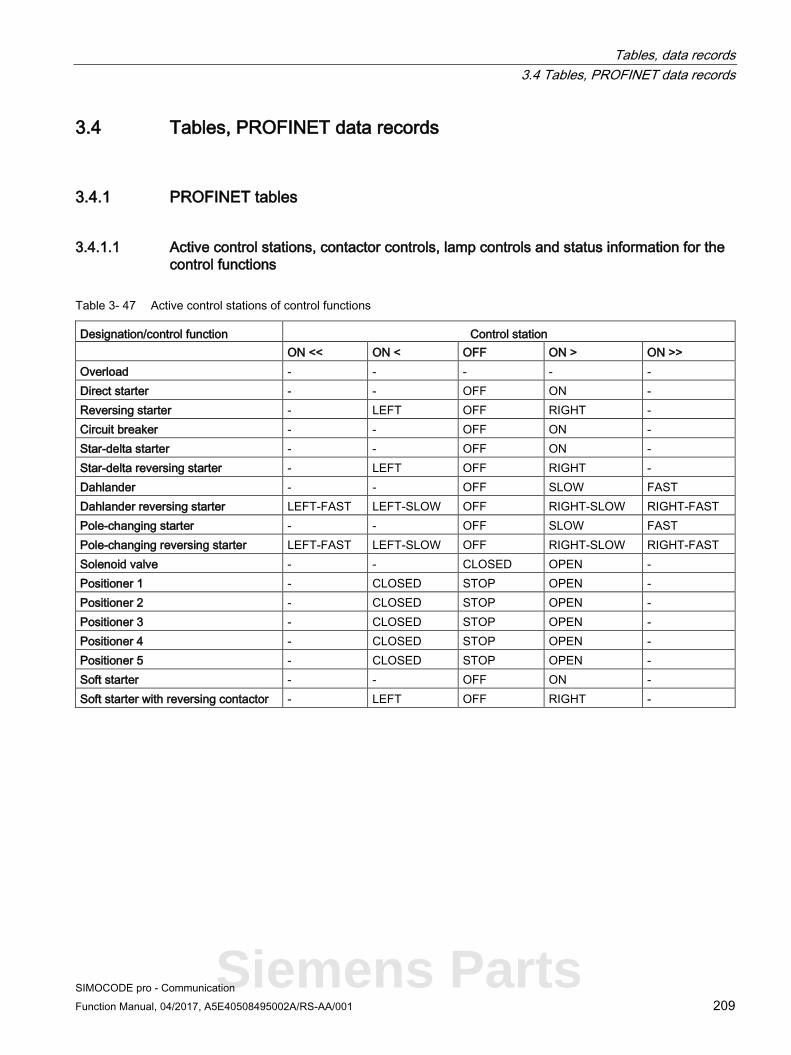
Tables, data records 3.4 Tables, PROFINET data records
SIMOCODE pro - Communication Function Manual, 04/2017, A5E40508495002A/RS-AA/001 209
3.4 Tables, PROFINET data records
3.4.1 PROFINET tables
3.4.1.1 Active control stations, contactor controls, lamp controls and status information for the control functions
Table 3- 47 Active control stations of control functions
Designation/control function Control station ON << ON < OFF ОN > ON >> Overload - - - - - Direct starter - - OFF ON - Reversing starter - LEFT OFF RIGHT - Circuit breaker - - OFF ON - Star-delta starter - - OFF ON - Star-delta reversing starter - LEFT OFF RIGHT - Dahlander - - OFF SLOW FAST Dahlander reversing starter LEFT-FAST LEFT-SLOW OFF RIGHT-SLOW RIGHT-FAST Pole-changing starter - - OFF SLOW FAST Pole-changing reversing starter LEFT-FAST LEFT-SLOW OFF RIGHT-SLOW RIGHT-FAST Solenoid valve - - CLOSED OPEN - Positioner 1 - CLOSED STOP OPEN - Positioner 2 - CLOSED STOP OPEN - Positioner 3 - CLOSED STOP OPEN - Positioner 4 - CLOSED STOP OPEN - Positioner 5 - CLOSED STOP OPEN - Soft starter - - OFF ON - Soft starter with reversing contactor - LEFT OFF RIGHT -
Siemens Parts

Tables, data records 3.4 Tables, PROFINET data records
SIMOCODE pro - Communication 210 Function Manual, 04/2017, A5E40508495002A/RS-AA/001
Table 3- 48 Contactor control with control functions
Designation/control function Contactor control QE1 QE2 QE3 QE4 QE5 Overload - - Active - - Direct starter ON - - - - Reversing starter RIGHT LEFT - - - Circuit breaker ON pulse - OFF pulse - - Star-delta starter Star contactor Delta contactor Line contactor - - Star-delta reversing starter Star contactor Delta contactor RIGHT line
contactor LEFT line contactor
-
Dahlander FAST SLOW Star contactor FAST
- -
Dahlander reversing starter RIGHT-FAST RIGHT-SLOW Star contactor FAST
LEFT-SLOW LEFT-FAST
Pole-changing starter FAST SLOW - - - Pole-changing reversing starter RIGHT-FAST RIGHT-SLOW - LEFT-SLOW LEFT-FAST Solenoid valve OPEN - - - - Positioner 1 OPEN CLOSED - - - Positioner 2 OPEN CLOSED - - - Positioner 3 OPEN CLOSED - - - Positioner 4 OPEN CLOSED - - - Positioner 5 OPEN CLOSED - - - Soft starter ON line
contactor - Reset ON command -
Soft starter with reversing contactor RIGHT line contactor
LEFT line contactor
Reset ON command -

Tables, data records 3.4 Tables, PROFINET data records
SIMOCODE pro - Communication Function Manual, 04/2017, A5E40508495002A/RS-AA/001 211
Table 3- 49 Lamp control with control functions
Designation/control function Lamp control QLE << (ON <<) QLE < (ON <) QLA (OFF) QLE < (ON >) QLE >> (ON >>) Overload - - - - - Direct starter - - OFF ON - Reversing starter - LEFT OFF RIGHT - Circuit breaker - - OFF ON - Star-delta starter - - OFF ON - Star-delta reversing starter - LEFT OFF RIGHT - Dahlander - - OFF SLOW FAST Dahlander reversing starter LEFT-FAST LEFT-SLOW OFF RIGHT-SLOW RIGHT-FAST Pole-changing starter - - OFF SLOW FAST Pole-changing reversing starter LEFT-FAST LEFT-SLOW OFF RIGHT-SLOW RIGHT-FAST Solenoid valve - - CLOSED OPEN - Positioner 1 - CLOSED STOP OPEN - Positioner 2 - CLOSED STOP OPEN - Positioner 3 - CLOSED STOP OPEN - Positioner 4 - CLOSED STOP OPEN - Positioner 5 - CLOSED STOP OPEN - Soft starter - - OFF ON - Soft starter with reversing contactor - LEFT OFF RIGHT -
Siemens Parts

Tables, data records 3.4 Tables, PROFINET data records
SIMOCODE pro - Communication 212 Function Manual, 04/2017, A5E40508495002A/RS-AA/001
3.4.1.2 OPC UA variables
Node IDs The name of the variable is composed of the namespace ID2 and the node ID as follows:
ns=http://siemens.com/automation/simocode/provpn;i=Node ID of the relevant variable.
Example:
You want to access the maximum motor current. You search for the node ID of the variable "Max. Current I_max" in the following table: Node ID=33
Table 3- 50 Node IDs (1)
Node ID Data type Description Acyclic receive 11 Boolean Acyclic receive - Bit 0.0 12 Boolean Acyclic receive - Bit 0.1 13 Boolean Acyclic receive - Bit 0.2 14 Boolean Acyclic receive - Bit 0.3 15 Boolean Acyclic receive - Bit 0.4 16 Boolean Acyclic receive - Bit 0.5 17 Boolean Acyclic receive - Bit 0.6 18 Boolean Acyclic receive - Bit 0.7 19 Boolean Acyclic receive - Bit 1.0 20 Boolean Acyclic receive - Bit 1.1 21 Boolean Acyclic receive - Bit 1.2 22 Boolean Acyclic receive - Bit 1.3 23 Boolean Acyclic receive - Bit 1.4 24 Boolean Acyclic receive - Bit 1.5 25 Boolean Acyclic receive - Bit 1.6 26 Boolean Acyclic receive - Bit 1.7 27 Unsigned word Acyclic receive - analog value Measured values 30 Unsigned byte Thermal memory 31 Unsigned byte Phase unbalance 32 Unsigned byte Cos phi 33 Unsigned word Max. current I_max 34 Unsigned word Current I_L1 35 Unsigned word Current I_L2 36 Unsigned word Current I_L3 37 Unsigned word Last trip current 38 Unsigned word Time to trip 39 Unsigned word Cooling down period 40 Unsigned word Phase voltage UL1-N 41 Unsigned word Phase voltage UL2-N 42 Unsigned word Phase voltage UL3-N

Tables, data records 3.4 Tables, PROFINET data records
SIMOCODE pro - Communication Function Manual, 04/2017, A5E40508495002A/RS-AA/001 213
Node ID Data type Description 43 Unsigned word AM1 output 44 Unsigned word AM1 input 1 45 Unsigned word AM1 input 2 46 Unsigned word AM1 input 3 47 Unsigned word TM1 max. temperature 48 Unsigned word TM1 temperature 1 49 Unsigned word TM1 temperature 2 50 Unsigned word TM1 temperature 3 51 Unsigned Dword Active power P 52 Unsigned Dword Apparent power S 53 Unsigned word AM2 output 54 Unsigned word AM2 input 1 55 Unsigned word AM2 input 2 56 Unsigned word AM2 input 3 57 Unsigned word Max. temperature 58 Unsigned word TM2 temperature 1 59 Unsigned word TM2 temperature 2 60 Unsigned word TM2 temperature 3 61 Unsigned Word EM Ground Fault Current 62 Unsigned Word EM Last Trip Current Statistics 70 Unsigned byte Permissible starts - actual value 71 Unsigned byte Time until test required 72 Unsigned word Number of parameterizations 73 Unsigned word Number of overload trips 74 Unsigned word Int. number of overload trips 75 Unsigned word Motor stop time 76 Unsigned word Timer 1 77 Unsigned word Timer 2 78 Unsigned word Timer 3 79 Unsigned word Timer 4 80 Unsigned word Counter 1 81 Unsigned word Counter 2 82 Unsigned word Counter 3 83 Unsigned word Counter 4 84 Unsigned word Calculation module 1 - output 85 Unsigned word Calculation module 2 - output 86 Unsigned Dword Motor operating hours 87 Unsigned Dword Int. motor operating hours 88 Unsigned Dword Device operating hours 89 Unsigned Dword Number of starts 90 Unsigned Dword Int. number of direct starts
Siemens Parts

Tables, data records 3.4 Tables, PROFINET data records
SIMOCODE pro - Communication 214 Function Manual, 04/2017, A5E40508495002A/RS-AA/001
Node ID Data type Description 91 Unsigned Dword Int. number of reverse starts 92 Unsigned Dword Consumed energy 93 Unsigned word Timer 5 94 Unsigned word Timer 6 95 Unsigned word Counter 5 96 Unsigned word Counter 6 97 Unsigned word Calculation module 3 - output 98 Unsigned word Calculation module 4 - output 99 Unsigned word Analog multiplexer - output Diagnostic status 108 Boolean Status - General fault 109 Boolean Status - General warning 110 Boolean Status - Device OK 111 Boolean Status - Bus OK 112 Boolean Status - PLC/DCS in run 113 Boolean Status - Current flowing 114 Boolean Status - PE command Start_Pause is pending 115 Boolean Status - PE energy-saving mode active 116 Boolean Status - On<< 117 Boolean Status - On < 118 Boolean Status - Off 119 Boolean Status - On > 120 Boolean Status - On >> 121 Boolean Status - Start active 122 Boolean Status - Interlocking time active 123 Boolean Status - Change-over pause active 124 Boolean Status - Positioner running in open direction 125 Boolean Status - Positioner running in open direction 126 Boolean Status - Feedback closed (FC) 127 Boolean Status - Feedback open (FO) 128 Boolean Status - Torque closed (TC) 129 Boolean Status - Torque open (TO) 130 Boolean Status - Test position (TPF) 131 Boolean Status - Operational Protection OFF (OPO) 132 Boolean Status - Remote mode 133 Boolean Status - Emergency start executed 134 Boolean Status - Cooling down period active 135 Boolean Status - Pause time active 136 Boolean Status - Device check active 137 Boolean Status - Phase-sequence 1-2-3 138 Boolean Status - Phase-sequence 3-2-1 139 Boolean Status - Enabling circuit closed

Tables, data records 3.4 Tables, PROFINET data records
SIMOCODE pro - Communication Function Manual, 04/2017, A5E40508495002A/RS-AA/001 215
Node ID Data type Description Diagnostic events 140 Boolean Event - Prewarning overload (I>115%Is) 141 Boolean Event - Unbalance 142 Boolean Event - Overload 143 Boolean Event - Overload + loss of phase 144 Boolean Event - Internal ground fault 145 Boolean Event - External Ground Fault 146 Boolean Event - Warning external ground fault 147 Boolean Event - Thermistor trip level 148 Boolean Event - Thermistor short circuit 149 Boolean Event - Thermistor open circuit 150 Boolean Event - TM1 warning level T> 151 Boolean Event - TM1 trip level T> 152 Boolean Event - TM1 sensor fault 153 Boolean Event - TM1 out of range 154 Boolean Event - EM Open Circuit 155 Boolean Event - EM Short Circuit 156 Boolean Event - Warning level I> 157 Boolean Event - Warning level I< 158 Boolean Event - Warning level P> 159 Boolean Event - Warning level P< 160 Boolean Event - Warning level cos phi< 161 Boolean Event - Warning level U< 162 Boolean Event - AM1 warning level 0/4-20mA> 163 Boolean Event - AM1 warning level 0/4-20mA< 164 Boolean Event - Trip level I> 165 Boolean Event - Trip level I< 166 Boolean Event - Trip level P> 167 Boolean Event - Trip level P< 168 Boolean Event - Trip level cos phi< 169 Boolean Event - Trip level U< 170 Boolean Event - AM1 trip level 0/4-20mA> 171 Boolean Event - AM1 trip level 0/4-20mA< 172 Boolean Event - Stalled rotor 175 Boolean Event - No start possible 176 Boolean Event - No. of starts> 177 Boolean Event - Just one start possible 178 Boolean Event - Motor operating hours > 179 Boolean Event - Motor stop time > 180 Boolean Event - Limit monitor 1 181 Boolean Event - Limit monitor 2 182 Boolean Event - Limit monitor 3
Siemens Parts
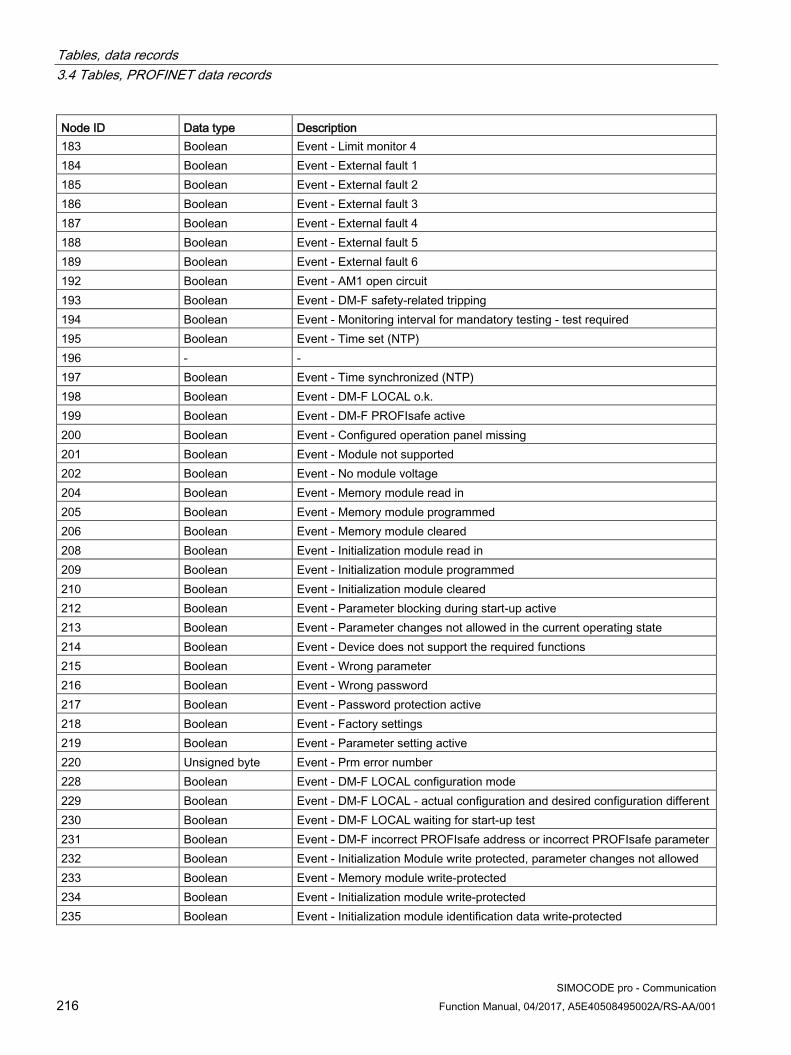
Tables, data records 3.4 Tables, PROFINET data records
SIMOCODE pro - Communication 216 Function Manual, 04/2017, A5E40508495002A/RS-AA/001
Node ID Data type Description 183 Boolean Event - Limit monitor 4 184 Boolean Event - External fault 1 185 Boolean Event - External fault 2 186 Boolean Event - External fault 3 187 Boolean Event - External fault 4 188 Boolean Event - External fault 5 189 Boolean Event - External fault 6 192 Boolean Event - AM1 open circuit 193 Boolean Event - DM-F safety-related tripping 194 Boolean Event - Monitoring interval for mandatory testing - test required 195 Boolean Event - Time set (NTP) 196 - - 197 Boolean Event - Time synchronized (NTP) 198 Boolean Event - DM-F LOCAL o.k. 199 Boolean Event - DM-F PROFIsafe active 200 Boolean Event - Configured operation panel missing 201 Boolean Event - Module not supported 202 Boolean Event - No module voltage 204 Boolean Event - Memory module read in 205 Boolean Event - Memory module programmed 206 Boolean Event - Memory module cleared 208 Boolean Event - Initialization module read in 209 Boolean Event - Initialization module programmed 210 Boolean Event - Initialization module cleared 212 Boolean Event - Parameter blocking during start-up active 213 Boolean Event - Parameter changes not allowed in the current operating state 214 Boolean Event - Device does not support the required functions 215 Boolean Event - Wrong parameter 216 Boolean Event - Wrong password 217 Boolean Event - Password protection active 218 Boolean Event - Factory settings 219 Boolean Event - Parameter setting active 220 Unsigned byte Event - Prm error number 228 Boolean Event - DM-F LOCAL configuration mode 229 Boolean Event - DM-F LOCAL - actual configuration and desired configuration different 230 Boolean Event - DM-F LOCAL waiting for start-up test 231 Boolean Event - DM-F incorrect PROFIsafe address or incorrect PROFIsafe parameter 232 Boolean Event - Initialization Module write protected, parameter changes not allowed 233 Boolean Event - Memory module write-protected 234 Boolean Event - Initialization module write-protected 235 Boolean Event - Initialization module identification data write-protected

Tables, data records 3.4 Tables, PROFINET data records
SIMOCODE pro - Communication Function Manual, 04/2017, A5E40508495002A/RS-AA/001 217
Node ID Data type Description Diagnostic warnings (1) 236 Boolean Warning - Prewarning overload (I>115%Is) 237 Boolean Warning - Unbalance 238 Boolean Warning - Overload 239 Boolean Warning - Overload + loss of phase 240 Boolean Warning - Internal ground fault 241 Boolean Warning - External ground fault 243 Boolean Warning - Thermistor trip level 244 Boolean Warning - Thermistor short circuit 245 Boolean Warning - Thermistor open circuit
Table 3- 51 Node IDs (2)
Node ID Data type Description Diagnostic warnings (2) 246 Boolean Warning - TM1 warning level T> 248 Boolean Warning - TM1 sensor fault 249 Boolean Warning - TM1 out of range 250 Boolean Warning - EM Open Circuit 251 Boolean Warning - EM Short Circuit 252 Boolean Warning - Warning level I> 253 Boolean Warning - Warning level I< 254 Boolean Warning - Warning level P> 255 Boolean Warning - Warning level P< 256 Boolean Warning - Warning level cos phi< 257 Boolean Warning - Warning level U< 258 Boolean Warning - AM1 warning level 0/4-20mA> 259 Boolean Warning - AM1 warning level 0/4-20mA< 260 Boolean Warning - Stalled rotor 263 Boolean Warning - No start possible 264 Boolean Warning - No. of starts> 265 Boolean Warning - Just one start possible 266 Boolean Warning - Motor operating hours > 267 Boolean Warning - Motor stop time > 268 Boolean Warning - External fault 1 269 Boolean Warning - External fault 2 270 Boolean Warning - External fault 3 271 Boolean Warning - External fault 4 272 Boolean Warning - External fault 5 273 Boolean Warning - External fault 6 276 Boolean Warning - AM1 open circuit
Siemens Parts
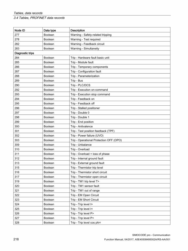
Tables, data records 3.4 Tables, PROFINET data records
SIMOCODE pro - Communication 218 Function Manual, 04/2017, A5E40508495002A/RS-AA/001
Node ID Data type Description 277 Boolean Warning - Safety-related tripping 278 Boolean Warning - Test required 282 Boolean Warning - Feedback circuit 283 Boolean Warning - Simultaneity Diagnostic trips 284 Boolean Trip - Hardware fault basic unit 285 Boolean Trip - Module fault 286 Boolean Trip - Temporary components 287 Boolean Trip - Configuration fault 288 Boolean Trip - Parameterization 289 Boolean Trip - Bus 290 Boolean Trip - PLC/DCS 292 Boolean Trip - Execution on-command 293 Boolean Trip - Execution stop command 294 Boolean Trip - Feedback on 295 Boolean Trip - Feedback off 296 Boolean Trip - Stalled positioner 297 Boolean Trip - Double 0 298 Boolean Trip - Double 1 299 Boolean Trip - End position 300 Boolean Trip - Antivalence 301 Boolean Trip - Test position feedback (TPF) 302 Boolean Trip - Power failure (UVO) 303 Boolean Trip - Operational Protection OFF (OPO) 309 Boolean Trip - Unbalance 310 Boolean Trip - Overload 311 Boolean Trip - Overload + loss of phase 312 Boolean Trip - Internal ground fault 313 Boolean Trip - External ground fault 315 Boolean Trip - Thermistor trip level 316 Boolean Trip - Thermistor short circuit 317 Boolean Trip - Thermistor open circuit 319 Boolean Trip - TM1 trip level T> 320 Boolean Trip - TM1 sensor fault 321 Boolean Trip - TM1 out of range 322 Boolean Trip - EM Open Circuit 323 Boolean Trip - EM Short Circuit 324 Boolean Trip - Trip level I> 325 Boolean Trip - Trip level I< 326 Boolean Trip - Trip level P> 327 Boolean Trip - Trip level P< 328 Boolean Trip - Trip level cos phi<

Tables, data records 3.4 Tables, PROFINET data records
SIMOCODE pro - Communication Function Manual, 04/2017, A5E40508495002A/RS-AA/001 219
Node ID Data type Description 329 Boolean Trip - Trip level U< 330 Boolean Trip - AM1 trip level 0/4-20mA> 331 Boolean Trip - AM1 trip level 0/4-20mA< 332 Boolean Trip - Stalled rotor 336 Boolean Trip - No. of starts > 340 Boolean Trip - External fault 1 341 Boolean Trip - External fault 2 342 Boolean Trip - External fault 3 343 Boolean Trip - External fault 4 344 Boolean Trip - External fault 5 345 Boolean Trip - External fault 6 348 Boolean Trip - AM1 open circuit 349 Boolean Trip - Test shutdown 350 Boolean Trip - Safety-related tripping 351 Boolean Trip - Wiring 352 Boolean Trip - Cross circuit 356 Boolean Trip - TM2 trip level T> 357 Boolean Trip - TM2 sensor fault 358 Boolean Trip - TM2 out of range 364 Boolean Trip - AM2 trip level 0/4-20mA> 365 Boolean Trip - AM2 trip level 0/4-20mA< 372 Boolean Trip - AM2 open circuit Diagnostic warnings 388 Boolean Warning - TM2 warning level T> 390 Boolean Warning - TM2 sensor fault 391 Boolean Warning - TM2 out of range 396 Boolean Warning - AM2 warning level 0/4-20mA> 397 Boolean Warning - AM2 warning level 0/4-20mA< 404 Boolean Warning - AM2 open circuit Diagnostic events 420 Boolean Event - TM2 warning level T> 421 Boolean Event - TM2 trip level T> 422 Boolean Event - TM2 sensor fault 423 Boolean Event - TM2 out of range 428 Boolean Event - AM2 warning level 0/4-20mA> 429 Boolean Event - AM2 warning level 0/4-20mA< 430 Boolean Event - AM2 trip level 0/4-20mA> 431 Boolean Event - AM2 trip level 0/4-20mA< 432 Boolean Event - Limit monitor 5 433 Boolean Event - Limit monitor 6 444 Boolean Event - AM2 open circuit
Siemens Parts
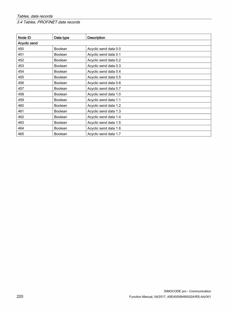
Tables, data records 3.4 Tables, PROFINET data records
SIMOCODE pro - Communication 220 Function Manual, 04/2017, A5E40508495002A/RS-AA/001
Node ID Data type Description Acyclic send 450 Boolean Acyclic send data 0.0 451 Boolean Acyclic send data 0.1 452 Boolean Acyclic send data 0.2 453 Boolean Acyclic send data 0.3 454 Boolean Acyclic send data 0.4 455 Boolean Acyclic send data 0.5 456 Boolean Acyclic send data 0.6 457 Boolean Acyclic send data 0.7 458 Boolean Acyclic send data 1.0 459 Boolean Acyclic send data 1.1 460 Boolean Acyclic send data 1.2 461 Boolean Acyclic send data 1.3 462 Boolean Acyclic send data 1.4 463 Boolean Acyclic send data 1.5 464 Boolean Acyclic send data 1.6 465 Boolean Acyclic send data 1.7

Tables, data records 3.4 Tables, PROFINET data records
SIMOCODE pro - Communication Function Manual, 04/2017, A5E40508495002A/RS-AA/001 221
3.4.1.3 Abbreviations and specifications
Abbreviations The following abbreviations are used in the tables:
Table 3- 52 Abbreviations
Abbreviation Meaning BU Basic unit IM Current measuring module UM Current / voltage measuring module DM1 Digital module 1 DM2 Digital module 2 DM-FL DM-F Local fail-safe digital module DM-FP DM-F PROFIsafe fail-safe digital module OP Operator panel OPD Operator panel with display AM Analog module EM 3UF7500 ground-fault module EM+ 3UF7510 ground-fault module TM Temperature module Th Thermistor GF General fault, control function Cycl. Cyclic Acycl. Acyclic F Fault M Event W Warning
Siemens Parts

Tables, data records 3.4 Tables, PROFINET data records
SIMOCODE pro - Communication 222 Function Manual, 04/2017, A5E40508495002A/RS-AA/001
Specifications
The following specifications apply in the tables:
Table 3- 53 Table specifications (example)
Designation Type Range Unit Information Reserved *) Byte[4] *) Max. current I_max Word 0 … 65535 1 % / Is
*) Items in italics are not relevant (reserved) and must be filled with "0" when written to.
Parameters that can be changed during operation.
Event - PRM error number (bytes):
If parameterization is not possible, the number of the parameter group (PRM group) which caused the error is transmitted here.
Figure 3-4 Example for parameter group

Tables, data records 3.4 Tables, PROFINET data records
SIMOCODE pro - Communication Function Manual, 04/2017, A5E40508495002A/RS-AA/001 223
3.4.1.4 Socket assignment table - digital This table contains all assignment numbers (No.) of the sockets (digital). You only need these assignment numbers if you, for example, use a user program to fill data records and write these back.
Table 3- 54 Socket assignment table - digital
No. Designation Designation Information 0 Static level Not connected 1 Fixed level value,0 2 Fixed level value,1 3 Reserved 4 Events – Level monitoring Event – Warning 0/4 - 20mA> AM2 5 Events – Level monitoring Event – Warning 0/4 - 20mA< AM2 6 Event – Trip 0/4 - 20mA> AM2 7 Event – Trip 0/4 - 20mA< AM2 8 Basic unit (BU) BU - Test / Reset button 9 BU - Input 1 10 BU - Input 2 11 BU - Input 3 12 BU - Input 4 13 Reserved 14 Reserved 15 Reserved 16 Digital module DM DM1 - Input 1 DM1 17 DM1 - Input 2 DM1 18 DM1 - Input 3 DM1 19 DM1 - Input 4 DM1 20 DM2 - Input 1 DM2 21 DM2 - Input 2 DM2 22 DM2 - Input 3 DM2 23 DM2 - Input 4 DM2 24 DM-FL sensor channel 1 Y12 DM-FL 25 DM-FL sensor channel 1 Y22 DM-FL 26 Reserved 27 Reserved 28 Events - Protection Event – TM2 sensor fault TM2 29 Event – TM2 out of range TM2 30 Event – TM2 warning T> TM2 31 Event – TM2 trip T> TM2 32 Operator panel OP / OPD OP – Test / Reset button OP, OPD 33 OP – Button 1 OP, OPD 34 OP – Button 2 OP, OPD 35 OP – Button 3 OP, OPD
Siemens Parts
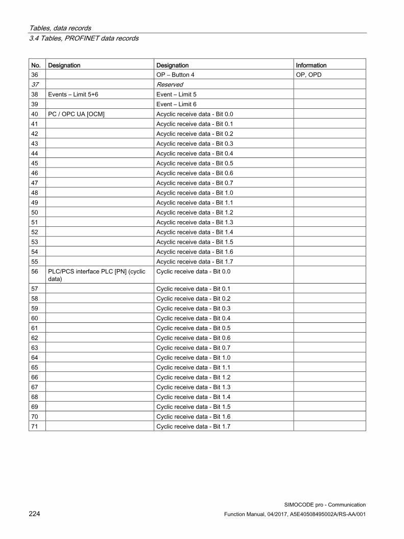
Tables, data records 3.4 Tables, PROFINET data records
SIMOCODE pro - Communication 224 Function Manual, 04/2017, A5E40508495002A/RS-AA/001
No. Designation Designation Information 36 OP – Button 4 OP, OPD 37 Reserved 38 Events – Limit 5+6 Event – Limit 5 39 Event – Limit 6 40 PC / OPC UA [OCM] Acyclic receive data - Bit 0.0 41 Acyclic receive data - Bit 0.1 42 Acyclic receive data - Bit 0.2 43 Acyclic receive data - Bit 0.3 44 Acyclic receive data - Bit 0.4 45 Acyclic receive data - Bit 0.5 46 Acyclic receive data - Bit 0.6 47 Acyclic receive data - Bit 0.7 48 Acyclic receive data - Bit 1.0 49 Acyclic receive data - Bit 1.1 50 Acyclic receive data - Bit 1.2 51 Acyclic receive data - Bit 1.3 52 Acyclic receive data - Bit 1.4 53 Acyclic receive data - Bit 1.5 54 Acyclic receive data - Bit 1.6 55 Acyclic receive data - Bit 1.7 56 PLC/PCS interface PLC [PN] (cyclic
data) Cyclic receive data - Bit 0.0
57 Cyclic receive data - Bit 0.1 58 Cyclic receive data - Bit 0.2 59 Cyclic receive data - Bit 0.3 60 Cyclic receive data - Bit 0.4 61 Cyclic receive data - Bit 0.5 62 Cyclic receive data - Bit 0.6 63 Cyclic receive data - Bit 0.7 64 Cyclic receive data - Bit 1.0 65 Cyclic receive data - Bit 1.1 66 Cyclic receive data - Bit 1.2 67 Cyclic receive data - Bit 1.3 68 Cyclic receive data - Bit 1.4 69 Cyclic receive data - Bit 1.5 70 Cyclic receive data - Bit 1.6 71 Cyclic receive data - Bit 1.7

Tables, data records 3.4 Tables, PROFINET data records
SIMOCODE pro - Communication Function Manual, 04/2017, A5E40508495002A/RS-AA/001 225
No. Designation Designation Information 72 Enabled control command Enabled control command ON<< Dependent on the
control function 73 Enabled control command ON< 74 Enabled control command - OFF 75 Enabled control command ON> 76 Enabled control command ON>> 77 Reserved 78 Reserved 79 Reserved 80 Contactor controls Contactor controls 1 QE1 Dependent on the
control function 81 Contactor controls 2 QE2 82 Contactor controls 3 QE3 83 Contactor controls 4 QE4 84 Contactor controls 5 QE5 85 Reserved 86 Reserved 87 Reserved 88 Lamp controls Display - QLE<<(ON<<) Dependent on the
control function 89 Display - QLE<(ON<) 90 Indication - QLA (OFF) 91 Display - QLE>(ON>) 92 Display - QLE>>(ON>>) 93 Indication - QLS (fault) 94 Reserved 95 Reserved 96 Status information - General Status - General fault 97 Status - General warning 98 Status - Device 99 Status - Bus 100 Status - PLC/PCS 101 Status - Motor current flowing IM UM 102 Status – PE command Start_Pause pending 103 Reserved 104 Status information - Receive Status - ON<< Dependent on the
control function 105 Status - ON< 106 Status - Off 107 Status - ON> 108 Status - ON>> 109 Status - Start active 110 Status - Interlocking time active All reversing starters
and positioners
Siemens Parts

Tables, data records 3.4 Tables, PROFINET data records
SIMOCODE pro - Communication 226 Function Manual, 04/2017, A5E40508495002A/RS-AA/001
No. Designation Designation Information 111 Status - Change-over pause active Star-delta, Dahlander,
pole-changing starters 112 Status - Runs in open direction Dependent on the
control function 113 Status - Runs in close direction 114 Status - FC 115 Status - FO 116 Status - TC 117 Status - TO 118 Status - Cold start (TPF) 119 Status - OPO 120 Status - Remote mode 121 Status information - Protection Status - Emergency start executed IM UM 122 Status - Cooling down period active IM UM 123 Status - Pause time active IM UM 124 Status information - Miscellaneous Status - Device check active 125 Status - Phase sequence 1-2-3 UM 126 Status - Phase sequence 3-2-1 UM 127 Status - DM-F enabling circuit DM-F 128 Events - Protection Event - Overload operation IM UM 129 Event - Unbalance IM UM 130 Event - Overload IM UM 131 Event - overload + phase failure IM UM 132 Event - Internal ground fault IM UM 133 Event - External ground fault EM 134 Event - Warning ext. ground fault EM 135 Event - Thermistor overload Th 136 Event - Thermistor short-circuit Th 137 Event - Thermistor open circuit Th 138 Event - TM1 warning T> TM1 139 Event - TM1 trip T> TM1 140 Event - TM1 sensor fault TM 141 Event - TM1 out of range TM 142 Event - EM+ open circuit EM+ 143 Event - EM+ short-circuit EM+ 144 Events - Level monitoring Event - Warning I> IM UM 145 Event - Warning I< IM UM 146 Event - Warning P> UM 147 Event - Warning P< UM 148 Event - Warning cos phi< UM 149 Event - Warning U< UM 150 Event - Warning 0/4 - 20mA> AM1 151 Event - Warning 0/4 - 20mA< AM1

Tables, data records 3.4 Tables, PROFINET data records
SIMOCODE pro - Communication Function Manual, 04/2017, A5E40508495002A/RS-AA/001 227
No. Designation Designation Information 152 Event - Trip I> IM UM 153 Event - Trip I< IM UM 154 Event - Trip P> UM 155 Event - Trip P< UM 156 Event - Trip cos phi< UM 157 Event - Trip U< UM 158 Event - Trip 0/4-20 mA> AM1 159 Event - Trip 0/4-20 mA< AM1 160 Event - Stalled rotor IM UM 161 Events - Protection Event - Warning internal ground fault 162 Reserved 163 Event - No start permitted 164 Events - Level monitoring Event - No. of starts > 165 Event - Just one start possible 166 Event - Motor operating hours > 167 Event - Motor stop time > 168 Event - Limit 1 169 Event - Limit 2 170 Event - Limit 3 171 Event - Limit 4 172 Events - Miscellaneous Event - External fault 1 173 Event - External fault 2 174 Event - External fault 3 175 Event - External fault 4 176 Event - External fault 5 177 Event - External fault 6 178 Reserved 179 Event - AM2 open circuit AM2 180 Event - AM1 open circuit AM1, AM2 181 Event - DM-F safety-related tripping DM-F 182 Event - DM-F - Test requirement DM-F 183 Reserved 184 Reserved 185 Reserved 186 Events - Miscellaneous Event - DM-FL safety o.k DM-FL 187 Event - DM-FP PROFIsafe active DM-FP 188 Events - System interface Event - Configured operator panel missing 189 Reserved 190 Warnings - Miscellaneous Warning - DM-F feedback circuit DM-F 191 Warning - DM-FL simultaneity DM-FL 192 Faults - General Fault - HW fault basic unit 193 Fault - Module fault (e.g. IM, DM)
Siemens Parts

Tables, data records 3.4 Tables, PROFINET data records
SIMOCODE pro - Communication 228 Function Manual, 04/2017, A5E40508495002A/RS-AA/001
No. Designation Designation Information 194 Fault - temporary components (e.g. memory
module)
195 Fault - configuration error 196 Fault - Parameterization 197 Fault - Bus 198 Fault - PLC/PCS 199 Reserved 200 Faults - Control Fault - Execution Time ON Not for overload relays 201 Fault - Execution time OFF 202 Fault - feedback (FB) ON 203 Fault - feedback (FB) OFF 204 Fault - Stalled positioner Positioner 205 Fault - Double 0 Solenoid valve /
positioner 206 Fault - Double 1 Solenoid valve /
positioner 207 Fault - End position Solenoid valve /
positioner 208 Fault - Antivalence Positioner 209 Fault - Cold start (TPF) fault 210 Fault - power failure (UVO) 211 Fault - Operational Protection Off (OPO) 212 Reserved 213 Reserved 214 Freely programmable elements Signal conditioning 5 output 215 Signal conditioning 6 output 216 Truth table 1 3I/1O output 217 Truth table 2 3I/1O output 218 Truth table 3 3I/1O output 219 Truth table 4 3I/1O output 220 Truth table 5 3I/1O output 221 Truth table 6 3I/1O output 222 Truth table 7 2I/1O output 223 Truth table 8 2I/1O output 224 Truth table 9 5I/2O output 1 225 Truth table 9 5I/2O output 2 226 Truth table 10 3I/1O output 227 Truth table 11 3I/1O output 228 Counter 5 output 229 Counter 6 output 230 Timer 5 output 231 Timer 6 output 232 Timer 1 output

Tables, data records 3.4 Tables, PROFINET data records
SIMOCODE pro - Communication Function Manual, 04/2017, A5E40508495002A/RS-AA/001 229
No. Designation Designation Information 233 Timer 2 output 234 Timer 3 output 235 Timer 4 output 236 Counter 1 output 237 Counter 2 output 238 Counter 3 output 239 Counter 4 output 240 Signal conditioning 1 output 241 Signal conditioning 2 output 242 Signal conditioning 3 output 243 Signal conditioning 4 output 244 Non-volatile element 1 output 245 Non-volatile element 2 output 246 Non-volatile element 3 output 247 Non-volatile element 4 output 248 Flashing 1 output 249 Flashing 2 output 250 Flashing 3 output 251 Flicker 1 output 252 Flicker 2 output 253 Flicker 3 output 254 PWM output 255 Reserved
Siemens Parts

Tables, data records 3.4 Tables, PROFINET data records
SIMOCODE pro - Communication 230 Function Manual, 04/2017, A5E40508495002A/RS-AA/001
3.4.1.5 Socket assignment table - analog This table contains all assignment numbers (No.) of the sockets (analog). You only need these assignment numbers if you, for example, use a user program to fill data records and write these back. All inputs for analog data can only process values of type "Word" (2 bytes). In order to also be able to process values of type "Byte", the following applies: The byte value is processed as a low byte, the high byte is always 0.
Table 3- 55 Socket assignment table - analog
No. Designation Unit Information 0 Not connected 1 Fixed level 2 Reserved 3 Reserved 4 Timer 1 - Actual value 100 ms 5 Timer 2 - Actual value 100 ms 6 Timer 3 - Actual value 100 ms 7 Timer 4 - Actual value 100 ms 8 Counter 1 - Actual value 9 Counter 2 - Actual value 10 Counter 3 - Actual value 11 Counter 4 - Actual value 12 Counter 5 - Actual value 13 Counter 6 - Actual value 14 Timer 5 - Actual value 100 ms 15 Timer 6 - Actual value 100 ms 16 Max. current I_max 1 % / Is IM UM 17 Current I_L1 1 % / Is IM UM 18 Current I_L2 1 % / Is IM UM 19 Current I_L3 1 % / Is IM UM 20 Phase unbalance 1 % IM UM 21 Ground-fault current 1 mA UM+ 22 Internal ground fault - last trip current 1 mA UM+ 23 Voltage U_min 1 V UM UM+ 24 Voltage U_L1 1 V see 2) UM 25 Voltage U_L2 1 V see 2) UM 26 Voltage U_L3 1 V see 2) UM 27 Cos phi 1 % UM 28 Frequency 0.01 Hz UM+ 29 Reserved 30 Number of overload trips IM UM 31 Int. Number of overload trips IM UM 32 Thermal motor model 2 % IM UM 33 Time to trip 100 ms IM UM

Tables, data records 3.4 Tables, PROFINET data records
SIMOCODE pro - Communication Function Manual, 04/2017, A5E40508495002A/RS-AA/001 231
No. Designation Unit Information 34 Recovery time 100 ms IM UM 35 Last trip current 1 % / Is IM UM 36 TM1 - max. temperature 1 K TM1 37 TM1 - temperature 1 1 K TM1 38 TM1 - temperature 2 1 K TM1 39 TM1 - temperature 3 1 K TM1 40 Permissible starts - Actual value 41 Motor stop time 1 h 42 DM-F - Time until test required 1 week DM-F 43 EM+ - last trip current 1 mA EM+ 44 AM1 - input 1 See 1) AM1 45 AM1 - input 2 See 1) AM1 46 AM1 - input 3 See 1) 47 EM+ - ground fault current 1 mA 48 Acyclic receive data - analog value 49 Cyclic receive data - analog value 1 50 Cyclic receive data - analog value 2 51 Number of parameterizations 52 Motor operating hours - H word 1 s 53 Motor operating hours - L word 1 s 54 Int. motor operating hours - H word 1 s 55 Int. motor operating hours - L word 1 s 56 Device operating hours - H word 1 s 57 Device operating hours - L word 1 s 58 Number of starts - H word 59 Number of starts - L word 60 Int. number of starts CW - H word 61 Int. number of starts CW - L word 62 Int. number of starts CCW - H word 63 Int. number of starts CCW - L word 64 Energy W - high word 1 kWh UM 65 Energy W - low word 1 kWh UM 66 Reserved .. Reserved 69 Reserved 70 Active power P - H word 1 W 71 Active power P - L word 1 W 72 Apparent power S - H word 1 VA 73 Apparent power S - L word 1 VA 74 Reserved .. Reserved 85 Reserved
Siemens Parts

Tables, data records 3.4 Tables, PROFINET data records
SIMOCODE pro - Communication 232 Function Manual, 04/2017, A5E40508495002A/RS-AA/001
No. Designation Unit Information 86 Calculation module 1 - Output 87 Reserved 88 Reserved 89 Reserved 90 Calculation module 2 - Output 91 Analog arithmetic 1 output 92 Analog arithmetic 2 output 93 Analog multiplexer output 94 Reserved .. Reserved 103 Reserved 104 Max. current I_max_10mA 10 mA UM IM 105 Current I_L1_10mA 10 mA UM IM 106 Current I_L2_10mA 10 mA UM IM 107 Current I_L3_10mA 10 mA UM IM 108 Max. current I_max_100mA 100 mA UM IM 109 Current I_L1_100mA 100 mA UM IM 110 Current I_L2_100mA 100 mA UM IM 111 Current I_L3_100mA 100 mA UM IM 112 Reserved 113 Reserved 114 Reserved 115 Reserved 116 TM2 - max. temperature 1 K TM2 117 TM2 - temperature 1 1 K TM2 118 TM2 - temperature 2 1 K TM2 119 TM2 - temperature 3 1 K TM2 120 AM2 - input 1 AM2 121 AM2 - input 2 AM2 122 AM2 - input 3 AM2 123 Reserved .. Reserved 255 Reserved
1) S7 format: 0/4mA=0; 20mA=27648
2) If "line-to-line voltage = 1," "Voltage U_Lx" contain the line-to-line voltages

Tables, data records 3.4 Tables, PROFINET data records
SIMOCODE pro - Communication Function Manual, 04/2017, A5E40508495002A/RS-AA/001 233
Table 3- 56 Socket assignment table - analog in float format
No. Designation Unit Info 0 Not connected 1 Reserved 2 Reserved 3 Reserved 4 Current I_max_A_F 1 A UM+ 5 Current I_avg_A_F 1 A UM+ 6 Current I_L1_A_F 1 A UM+ 7 Current I_L2_A_F 1 A UM+ 8 Current I_L3_A_F 1 A UM+ 9 Active power P_F 1 W UM+ 10 Apparent power S_F 1 VA UM+ 11 Voltage UL1_F 1 V UM+ 12 Voltage UL2_F 1 V UM+ 13 Voltage UL3_F 1 V UM+ 14 Cos phi_F 1 UM+ 15 Frequency_F 1 Hz UM+ 16 Reserved ... Reserved 255 Reserved
Siemens Parts
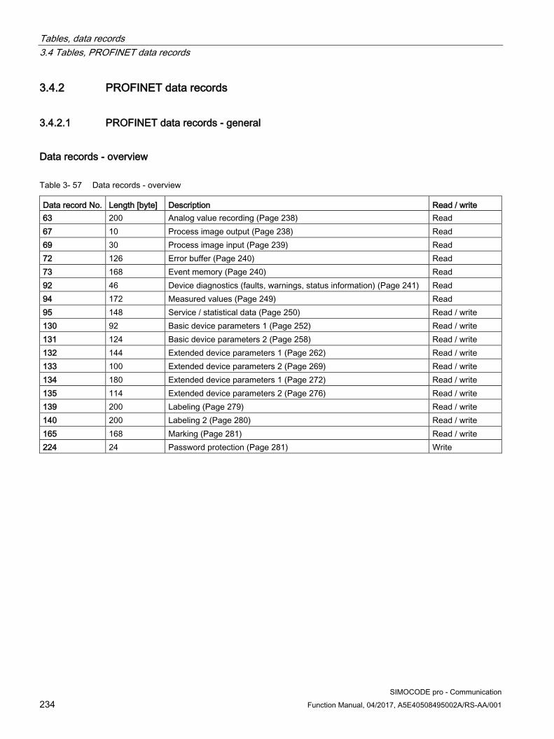
Tables, data records 3.4 Tables, PROFINET data records
SIMOCODE pro - Communication 234 Function Manual, 04/2017, A5E40508495002A/RS-AA/001
3.4.2 PROFINET data records
3.4.2.1 PROFINET data records - general
Data records - overview
Table 3- 57 Data records - overview
Data record No. Length [byte] Description Read / write 63 200 Analog value recording (Page 238) Read 67 10 Process image output (Page 238) Read 69 30 Process image input (Page 239) Read 72 126 Error buffer (Page 240) Read 73 168 Event memory (Page 240) Read 92 46 Device diagnostics (faults, warnings, status information) (Page 241) Read 94 172 Measured values (Page 249) Read 95 148 Service / statistical data (Page 250) Read / write 130 92 Basic device parameters 1 (Page 252) Read / write 131 124 Basic device parameters 2 (Page 258) Read / write 132 144 Extended device parameters 1 (Page 262) Read / write 133 100 Extended device parameters 2 (Page 269) Read / write 134 180 Extended device parameters 1 (Page 272) Read / write 135 114 Extended device parameters 2 (Page 276) Read / write 139 200 Labeling (Page 279) Read / write 140 200 Labeling 2 (Page 280) Read / write 165 168 Marking (Page 281) Read / write 224 24 Password protection (Page 281) Write

Tables, data records 3.4 Tables, PROFINET data records
SIMOCODE pro - Communication Function Manual, 04/2017, A5E40508495002A/RS-AA/001 235
Writing / reading data records
Access to data records via the slot and index ● Index: Data record number
Writing / reading data records with STEP7 You can access the data records from the user program.
● Writing data records: By calling SFB 53 "WR_REC"
● Reading data records: By calling SFB 52 "RD_REC"
Further information
You can find additional information about the SFBs
● in System Software for S7-300/400, System and Standard Functions reference manual (http://support.automation.siemens.com/WW/view/en/1214574)
● In the STEP7 online help
Byte arrangements When data longer than one byte is stored, the bytes are arranged as follows ("big endian"):
Figure 3-5 Byte arrangement in "big endian" format
Siemens Parts

Tables, data records 3.4 Tables, PROFINET data records
SIMOCODE pro - Communication 236 Function Manual, 04/2017, A5E40508495002A/RS-AA/001
Abbreviations The following abbreviations are used in the tables:
Table 3- 58 Abbreviations
Abbreviation Meaning BU Basic unit IM Current measuring module UM 1st generation current / voltage measuring module UM+ 2nd generation current / voltage measuring module DM1 Digital module 1 DM2 Digital module 2 DM-FL DM-F Local fail-safe digital module DM-FP DM-F PROFIsafe fail-safe digital module OP Operator panel OPD Operator panel with display AM Analog module EM Ground-fault module TM Temperature module Th Thermistor GF Control function Cycl. Cyclic Acycl. Acyclic F Fault M Event W Warning

Tables, data records 3.4 Tables, PROFINET data records
SIMOCODE pro - Communication Function Manual, 04/2017, A5E40508495002A/RS-AA/001 237
Specifications The following specifications apply in the tables:
Table 3- 59 Table specifications (example)
Designation Type Range Unit Information Reserved *) Byte[4] *)
Max. current I_max Word 0 … 65535 1 % / Is *) Items in italics are not relevant (reserved) and must be filled with "0" when written to.
Parameters that can be changed during operation.
Settings are valid/can only be made when the corresponding system components are used.
The following specifications apply in the tables:
Settings are valid/can only be made when the corresponding system components are used.
"Float" data type
32-bit floating-point number
S: Sign (0 = positive; 1 = negative)
E: Exponent
M: Mantissa 31
30
29
28
27
26
25
24
23
22
21
20
19
18
17
16
15
114
13
12
11
10
9 8 7 6 5 4 3 2 1 0
S E: Exponent + 127 (8 bits)
M: Mantissa (23 bits)
Siemens Parts

Tables, data records 3.4 Tables, PROFINET data records
SIMOCODE pro - Communication 238 Function Manual, 04/2017, A5E40508495002A/RS-AA/001
3.4.2.2 Data record 63 - Analog value recording You can read out the data of the "Analog value recording" function stored in the device.
Table 3- 60 Data record 63 - Analog value recording
Byte.Bit Designation Type Range Information 0.0 StartPos Word 0 2.0 Channel No. Byte 1 3.0 Analog value record currently running Bit 0, 1 3.1 Trigger event occurred Bit 0, 1 3.2 Reserved Bit[6] 0 4.0 Measured value (0) Word 0 - 65535 6.0 Measured value (1) Word 0 - 65535 ... 122.0 Measured value (59) Word 0 - 65535 124.0 Reserved Byte[76] 0
The unit of the measured value is dependent on the assigned analog value. You will find all available analog values with their units in Chapter Socket assignment table - analog (Page 230).
3.4.2.3 Data record 67 - Process image output
Table 3- 61 Data record 67 - Process image output
Byte.Bit Designation Default (also see parameters) Type Information 0.0 Cyclic receive - Bit 0.0 Control station - PLC/PCS [PN] ON< Bit 0.1 Cyclic receive - Bit 0.1 Control station - PLC/PCS [PN] OFF Bit 0.2 Cyclic receive - Bit 0.2 Control station - PLC/PCS [PN] ON> Bit 0.3 Cyclic receive - Bit 0.3 Test 1 Bit 0.4 Cyclic receive - Bit 0.4 Motor protection - Emergency start Bit 0.5 Cyclic receive - Bit 0.5 Mode selector S1 Bit 0.6 Cyclic receive - Bit 0.6 Reset 1 Bit 0.7 Cyclic receive - Bit 0.7 Not assigned Bit 1.0 Cyclic receive - Bit 1.0 Not assigned Bit 1.1 Cyclic receive - Bit 1.1 Not assigned Bit 1.2 Cyclic receive - Bit 1.2 Not assigned Bit 1.3 Cyclic receive - Bit 1.3 Not assigned Bit 1.4 Cyclic receive - Bit 1.4 Not assigned Bit 1.5 Cyclic receive - Bit 1.5 Not assigned Bit 1.6 Cyclic receive - Bit 1.6 Not assigned Bit 1.7 Cyclic receive - Bit 1.7 Not assigned Bit 2.0 Cyclic receive - analog value 1 Not assigned Word 4.0 Cyclic receive - analog value 2 Not assigned Word 6.0 Reserved Bytes[4]

Tables, data records 3.4 Tables, PROFINET data records
SIMOCODE pro - Communication Function Manual, 04/2017, A5E40508495002A/RS-AA/001 239
3.4.2.4 Data record 69 - Process image input
Table 3- 62 Data record 69 - Process image input
Byte.Bit Designation Default (also see parameters) Type Information 0.0 Cyclic send - Bit 0.0 Status - ON< Bit 0.1 Cyclic send - Bit 0.1 Status - Off Bit 0.2 Cyclic send - Bit 0.2 Status - ON> Bit 0.3 Cyclic send - Bit 0.3 Event - Overload operation Bit 0.4 Cyclic send - Bit 0.4 Status - Interlocking time active Bit 0.5 Cyclic send - Bit 0.5 Status - Remote mode Bit 0.6 Cyclic send - Bit 0.6 Status - General fault Bit 0.7 Cyclic send - Bit 0.7 Status - General warning Bit 1.0 Cyclic send - Bit 1.0 Not assigned Bit 1.1 Cyclic send - Bit 1.1 Not assigned Bit 1.2 Cyclic send - Bit 1.2 Not assigned Bit 1.3 Cyclic send - Bit 1.3 Not assigned Bit 1.4 Cyclic send - Bit 1.4 Not assigned Bit 1.5 Cyclic send - Bit 1.5 Not assigned Bit 1.6 Cyclic send - Bit 1.6 Not assigned Bit 1.7 Cyclic send - Bit 1.7 Not assigned Bit 2.0 PLC/PCS analog Input 1 Max. current I_max Word 4.0 PLC/PCS analog input 2 Not assigned Word 6.0 PLC/PCS analog input 3 Not assigned Word 8.0 PLC/PCS analog input 4 Not assigned Word 10.0 PLC/PCS analog input 5 Not assigned Word 12.0 PLC/PCS analog input 6 Not assigned Word 14.0 PLC/PCS analog input 7 Not assigned Word 16.0 PLC/PCS analog input 8 Not assigned Word 18.0 PLC/PCS analog input 9 Unassigned Word 20.0 Reserved Bytes[10]
Siemens Parts
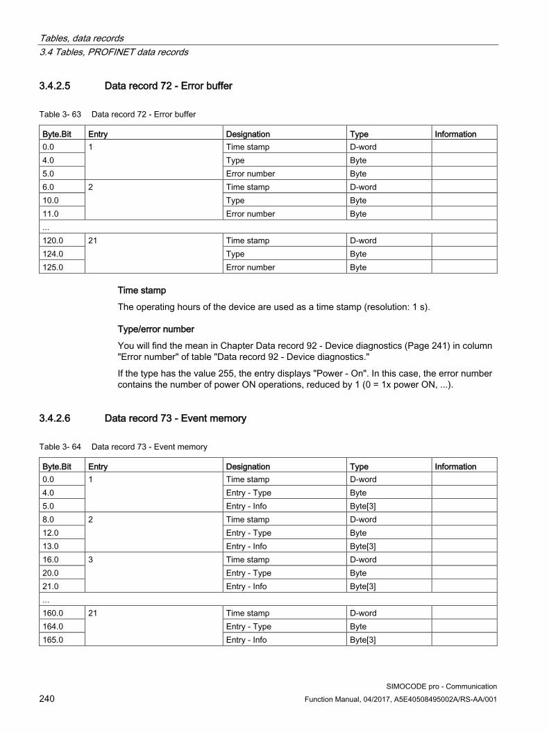
Tables, data records 3.4 Tables, PROFINET data records
SIMOCODE pro - Communication 240 Function Manual, 04/2017, A5E40508495002A/RS-AA/001
3.4.2.5 Data record 72 - Error buffer
Table 3- 63 Data record 72 - Error buffer
Byte.Bit Entry Designation Type Information 0.0 1 Time stamp D-word 4.0 Type Byte 5.0 Error number Byte 6.0 2 Time stamp D-word 10.0 Type Byte 11.0 Error number Byte ... 120.0 21 Time stamp D-word 124.0 Type Byte 125.0 Error number Byte
Time stamp
The operating hours of the device are used as a time stamp (resolution: 1 s).
Type/error number
You will find the mean in Chapter Data record 92 - Device diagnostics (Page 241) in column "Error number" of table "Data record 92 - Device diagnostics."
If the type has the value 255, the entry displays "Power - On". In this case, the error number contains the number of power ON operations, reduced by 1 (0 = 1x power ON, ...).
3.4.2.6 Data record 73 - Event memory
Table 3- 64 Data record 73 - Event memory
Byte.Bit Entry Designation Type Information 0.0 1 Time stamp D-word 4.0 Entry - Type Byte 5.0 Entry - Info Byte[3] 8.0 2 Time stamp D-word 12.0 Entry - Type Byte 13.0 Entry - Info Byte[3] 16.0 3 Time stamp D-word 20.0 Entry - Type Byte 21.0 Entry - Info Byte[3] ... 160.0 21 Time stamp D-word 164.0 Entry - Type Byte 165.0 Entry - Info Byte[3]
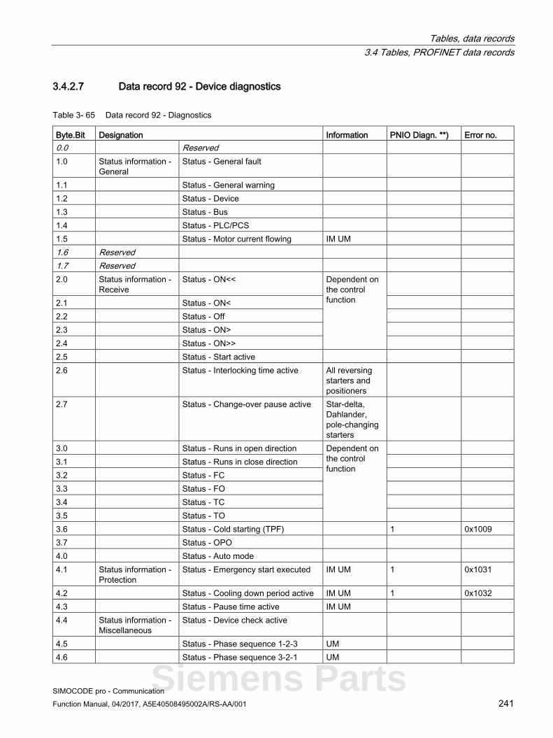
Tables, data records 3.4 Tables, PROFINET data records
SIMOCODE pro - Communication Function Manual, 04/2017, A5E40508495002A/RS-AA/001 241
3.4.2.7 Data record 92 - Device diagnostics
Table 3- 65 Data record 92 - Diagnostics
Byte.Bit Designation Information PNIO Diagn. **) Error no. 0.0 Reserved 1.0 Status information -
General Status - General fault
1.1 Status - General warning 1.2 Status - Device 1.3 Status - Bus 1.4 Status - PLC/PCS 1.5 Status - Motor current flowing IM UM 1.6 Reserved 1.7 Reserved 2.0 Status information -
Receive Status - ON<< Dependent on
the control function
2.1 Status - ON< 2.2 Status - Off 2.3 Status - ON> 2.4 Status - ON>> 2.5 Status - Start active 2.6 Status - Interlocking time active All reversing
starters and positioners
2.7 Status - Change-over pause active Star-delta, Dahlander, pole-changing starters
3.0 Status - Runs in open direction Dependent on the control function
3.1 Status - Runs in close direction 3.2 Status - FC 3.3 Status - FO 3.4 Status - TC 3.5 Status - TO 3.6 Status - Cold starting (TPF) 1 0x1009 3.7 Status - OPO 4.0 Status - Auto mode 4.1 Status information -
Protection Status - Emergency start executed IM UM 1 0x1031
4.2 Status - Cooling down period active IM UM 1 0x1032 4.3 Status - Pause time active IM UM 4.4 Status information -
Miscellaneous Status - Device check active
4.5 Status - Phase sequence 1-2-3 UM 4.6 Status - Phase sequence 3-2-1 UM
Siemens Parts

Tables, data records 3.4 Tables, PROFINET data records
SIMOCODE pro - Communication 242 Function Manual, 04/2017, A5E40508495002A/RS-AA/001
Byte.Bit Designation Information PNIO Diagn. **) Error no. 4.7 Status - DM-F enabling circuit DM-F 5.0 Events - Protection Event - Overload operation IM UM 5.1 Event - Unbalance IM UM 5.2 Event - Overload IM UM 5.3 Event - Overload + loss of phase IM UM 5.4 Event - Internal ground fault IM UM 5.5 Event - External ground fault EM 5.6 Event - Warning ext. ground fault EM 5.7 Event - Thermistor overload Th 6.0 Event - Thermistor short-circuit Th 6.1 Event - Thermistor open circuit Th 6.2 Event - TM1 warning T> TM1 6.3 Event - TM1 trip T> TM1 6.4 Event - TM1 sensor fault TM1 6.5 Event - TM1 out of range TM 6.6 Event - EM+ open circuit EM+ 1) 6.7 Event - EM+ short-circuit EM+ 1) 7.0 Events - Level
monitoring Event - Warning I> IM UM
7.1 Event - Warning I< IM UM 7.2 Event - Warning P> UM 7.3 Event - Warning P< UM 7.4 Event - Warning cos phi< UM 7.5 Event - Warning U< UM 7.6 Event - Warning 0/4-20 mA> AM1 7.7 Event - Warning 0/4-20 mA< AM1 8.0 Event - Trip I> IM UM 8.1 Event - Trip I< IM UM 8.2 Event - Trip P> UM 8.3 Event - Trip P< UM 8.4 Event - Trip cos phi< UM 8.5 Event - Trip U< UM 8.6 Event - Trip 0/4-20 mA> AM1 8.7 Event - Trip 0/4-20 mA< AM1 9.0 Event - Stalled rotor IM UM 9.1 Events - Protection Warning - Internal ground fault UM+ 9.2 Reserved 9.3 Events - Level
monitoring Event - No start possible
9.4 Event - No. of starts > 9.5 Event - Just one start possible 9.6 Event - Motor operating hours >
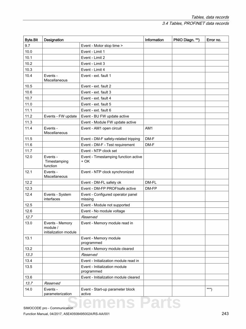
Tables, data records 3.4 Tables, PROFINET data records
SIMOCODE pro - Communication Function Manual, 04/2017, A5E40508495002A/RS-AA/001 243
Byte.Bit Designation Information PNIO Diagn. **) Error no. 9.7 Event - Motor stop time > 10.0 Event - Limit 1 10.1 Event - Limit 2 10.2 Event - Limit 3 10.3 Event - Limit 4 10.4 Events -
Miscellaneous Event - ext. fault 1
10.5 Event - ext. fault 2 10.6 Event - ext. fault 3 10.7 Event - ext. fault 4 11.0 Event - ext. fault 5 11.1 Event - ext. fault 6 11.2 Events - FW update Event - BU FW update active 11.3 Event - Module FW update active 11.4 Events -
Miscellaneous Event - AM1 open circuit AM1
11.5 Event - DM-F safety-related tripping DM-F 11.6 Event - DM-F - Test requirement DM-F 11.7 Event - NTP clock set 12.0 Events -
Timestamping function
Event - Timestamping function active + OK
12.1 Events - Miscellaneous
Event - NTP clock synchronized
12.2 Event - DM-FL safety ok DM-FL 12.3 Event - DM-FP PROFIsafe active DM-FP 12.4 Events - System
interfaces Event - Configured operator panel missing
12.5 Event - Module not supported 12.6 Event - No module voltage 12.7 Reserved 13.0 Events - Memory
module / initialization module
Event - Memory module read in
13.1 Event - Memory module programmed
13.2 Event - Memory module cleared 13.3 Reserved 13.4 Event - Initialization module read in 13.5 Event - Initialization module
programmed
13.6 Event - Initialization module cleared 13.7 Reserved 14.0 Events -
parameterization Event - Start-up parameter block active
***)
Siemens Parts

Tables, data records 3.4 Tables, PROFINET data records
SIMOCODE pro - Communication 244 Function Manual, 04/2017, A5E40508495002A/RS-AA/001
Byte.Bit Designation Information PNIO Diagn. **) Error no. 14.1 Event - Parameter changes not
allowed in the current operating state 1 0x0010
14.2 Event - Device does not support the required functions
1 0x0010
14.3 Event - Wrong parameter 1 0x0010 14.4 Event - Wrong password 1 0x0010 14.5 Event - Password protection active 14.6 Event - Factory settings 14.7 Event - Parameterization active 15.0 Event - PRM error number (bytes) 16.0 Event - DM-FL configuration mode 16.1 Event - DM-FL configuration
deviation
16.2 Event - DM-FL waiting for start-up test
16.3 Event - DM-FP F-Prm error *) 3 0x0010 16.4 Event - Initialization module
write-protected, parameter changes not allowed
1 0x0010
16.5 Events - Memory module - initialization module (InM)
Event - Memory module write-protected
16.6 Event - Initialization module write-protected
16.7 Event - Initialization module identification data write-protected
17.0 Warnings - Protection
Warning - Overload operation IM UM 2 0x1020
17.1 Warning - Unbalance IM UM 2 0x1021 17.2 Warning - Overload IM UM 2 0x1022 17.3 Warning - Overload + phase failure IM UM 2 0x1023 17.4 Warning - Internal ground fault IM UM 2 0x1027 17.5 Warning - External ground fault EM 2 0x1028 17.6 Reserved 17.7 Warning - Thermistor overload Th 2 0x1024 18.0 Warning - Thermistor short circuit Th 2 0x1025 18.1 Warning - Thermistor open circuit Th 2 0x1026 18.2 Warning - TM1 warning T > TM1 2 0x102B 18.3 Reserved 18.4 Warning - TM1 sensor fault TM1 2 0x102C 18.5 Warning - TM1 out of range TM1 2 0x102D 18.6 Warning - EM+ open circuit EM+ 1) 2 0x1029 18.7 Warning - EM+ short-circuit EM+ 1) 2 0x102A

Tables, data records 3.4 Tables, PROFINET data records
SIMOCODE pro - Communication Function Manual, 04/2017, A5E40508495002A/RS-AA/001 245
Byte.Bit Designation Information PNIO Diagn. **) Error no. 19.0 Warnings - Level
monitoring Warning - Warning I> IM UM 2 0x1040
19.1 Warning - Warning I< IM UM 2 0x1041 19.2 Warning - Warning P> UM 2 0x1042 19.3 Warning - Warning P< UM 2 0x1043 19.4 Warning - Warning cos phi< UM 2 0x1045 19.5 Warning - Warning U< UM 2 0x1047 19.6 Warning - Warning 0/4-20 mA> AM1 2 0x1048 19.7 Warning - Warning 0/4-20 mA< AM1 2 0x1049 20.0 Warning - Stalled rotor IM UM 2 0x104C 20.1 Reserved bit [2] 20.3 Warning - No start possible 2 0x1056 20.4 Warning - Number of starts > 2 0x1057 20.5 Warning - Just one start possible 2 0x1058 20.6 Warning - Motor operating hours> 2 0x1059 20.7 Warning - Motor stop time > 2 0x105A 21.0 Warnings -
Miscellaneous Warning - ext. fault 1 2 0x1070
21.1 Warning - ext. fault 2 2 0x1071 21.2 Warning - ext. fault 3 2 0x1072 21.3 Warning - ext. fault 4 2 0x1073 21.4 Warning - ext. fault 5 2 0x1074 21.5 Warning - ext. fault 6 2 0x1075 21.6 Reserved 21.7 Reserved 22.0 Warning - AM1 open circuit AM1 2 0x105B 22.1 Warning - DM-F safety-related
tripping DM-F 2 0x0019
22.2 Warning - DM-F test requirement DM-F 2 0x105E 22.3 Reserved bit[3] 22.6 Warning - DM-F feedback circuit DM-F 2 0x105F 22.7 Warning - DM-FL simultaneity DM-FL 2 0x1060 23.0 Faults - General Fault - HW fault basic unit 3 0x0009 23.1 Fault - Module fault (e.g. module IM,
UM, DM) 3 0x0009
23.2 Fault - Temporary components (e.g. memory module)
3 0x0009
23.3 Fault - Configuration fault 3 0x0010 23.4 Fault - Parameterization 3 0x0010 23.5 Fault - Bus 23.6 Fault - PLC/PCS 23.7 Reserved 24.0 Faults - Control Fault - Execution ON command 3 0x1000
Siemens Parts
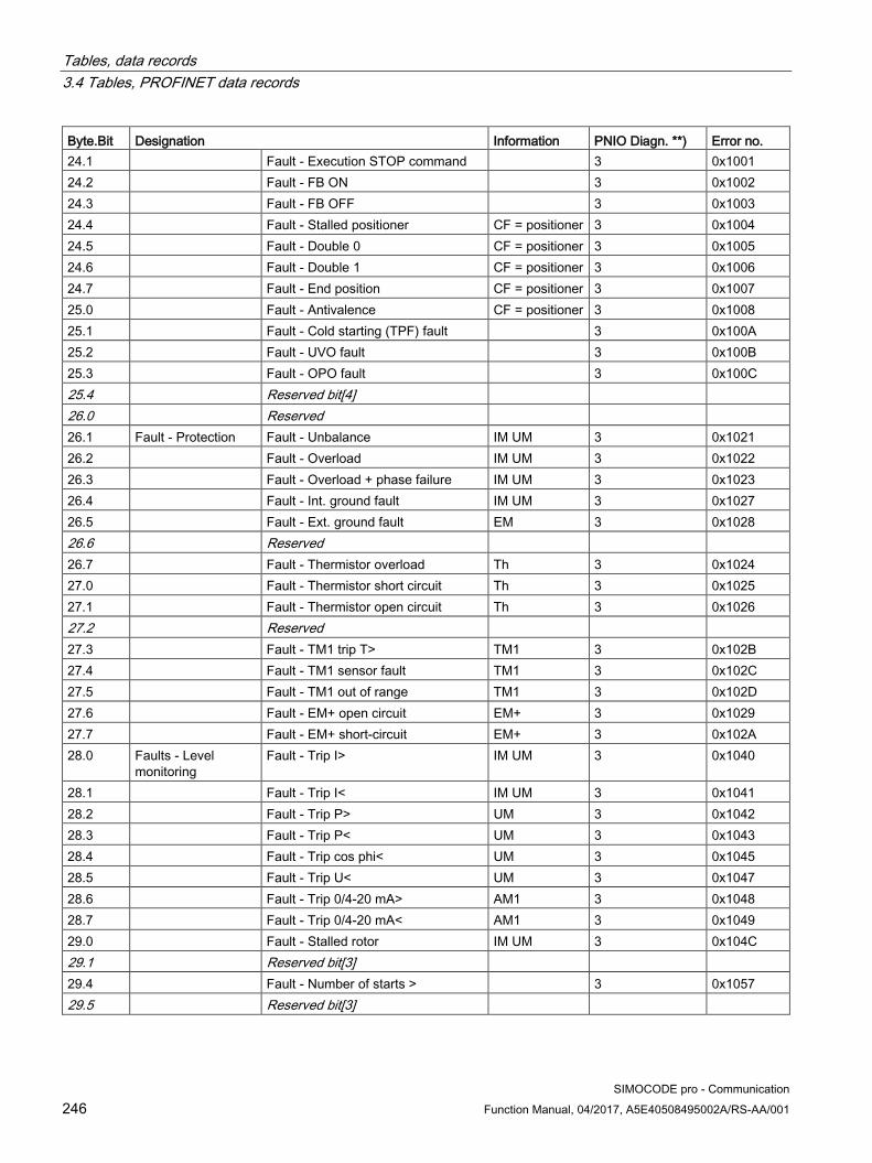
Tables, data records 3.4 Tables, PROFINET data records
SIMOCODE pro - Communication 246 Function Manual, 04/2017, A5E40508495002A/RS-AA/001
Byte.Bit Designation Information PNIO Diagn. **) Error no. 24.1 Fault - Execution STOP command 3 0x1001 24.2 Fault - FB ON 3 0x1002 24.3 Fault - FB OFF 3 0x1003 24.4 Fault - Stalled positioner CF = positioner 3 0x1004 24.5 Fault - Double 0 CF = positioner 3 0x1005 24.6 Fault - Double 1 CF = positioner 3 0x1006 24.7 Fault - End position CF = positioner 3 0x1007 25.0 Fault - Antivalence CF = positioner 3 0x1008 25.1 Fault - Cold starting (TPF) fault 3 0x100A 25.2 Fault - UVO fault 3 0x100B 25.3 Fault - OPO fault 3 0x100C 25.4 Reserved bit[4] 26.0 Reserved 26.1 Fault - Protection Fault - Unbalance IM UM 3 0x1021 26.2 Fault - Overload IM UM 3 0x1022 26.3 Fault - Overload + phase failure IM UM 3 0x1023 26.4 Fault - Int. ground fault IM UM 3 0x1027 26.5 Fault - Ext. ground fault EM 3 0x1028 26.6 Reserved 26.7 Fault - Thermistor overload Th 3 0x1024 27.0 Fault - Thermistor short circuit Th 3 0x1025 27.1 Fault - Thermistor open circuit Th 3 0x1026 27.2 Reserved 27.3 Fault - TM1 trip T> TM1 3 0x102B 27.4 Fault - TM1 sensor fault TM1 3 0x102C 27.5 Fault - TM1 out of range TM1 3 0x102D 27.6 Fault - EM+ open circuit EM+ 3 0x1029 27.7 Fault - EM+ short-circuit EM+ 3 0x102A 28.0 Faults - Level
monitoring Fault - Trip I> IM UM 3 0x1040
28.1 Fault - Trip I< IM UM 3 0x1041 28.2 Fault - Trip P> UM 3 0x1042 28.3 Fault - Trip P< UM 3 0x1043 28.4 Fault - Trip cos phi< UM 3 0x1045 28.5 Fault - Trip U< UM 3 0x1047 28.6 Fault - Trip 0/4-20 mA> AM1 3 0x1048 28.7 Fault - Trip 0/4-20 mA< AM1 3 0x1049 29.0 Fault - Stalled rotor IM UM 3 0x104C 29.1 Reserved bit[3] 29.4 Fault - Number of starts > 3 0x1057 29.5 Reserved bit[3]

Tables, data records 3.4 Tables, PROFINET data records
SIMOCODE pro - Communication Function Manual, 04/2017, A5E40508495002A/RS-AA/001 247
Byte.Bit Designation Information PNIO Diagn. **) Error no. 30.0 Faults -
Miscellaneous Fault - External fault 1 3 0x1070
30.1 Fault - External fault 2 3 0x1071 30.2 Fault - External fault 3 3 0x1072 30.3 Fault - External fault 4 3 0x1073 30.4 Fault - External fault 5 3 0x1074 30.5 Fault - External fault 6 3 0x1075 30.6 Reserved 30.7 Reserved 31.0 Fault - AM1 open circuit AM1 3 0x105B 31.1 Fault - Test trip 3 0x1055 31.2 Fault - DM-F safety-related tripping DM-F 3 0x0019 31.3 Fault - DM-F wiring DM-FL 3 0x1061 31.4 Fault - DM-FL cross circuit DM-FL 3 0x1062 31.5 Reserved bit[3] 32.0 Faults - Protection
extended Fault - TM2 trip T > TM2 3 0x102E
32.1 Fault - TM2 sensor fault TM2 3 0x102F 32.2 Fault - TM2 out of range TM2 3 0x1030 32.3 Reserved bit[5] 33.0 Faults - Level
monitoring extended Fault - Trip 0/4-20mA > AM2 3 0x104A
33.1 Fault - Trip 0/4-20mA < AM2 3 0x104B 33.2 Reserved bit[6] 34.0 Faults -
Miscellaneous extended
Fault - AM2 open circuit AM2 3 0x105C
34.1 Reserved bit[7] 35.0 Reserved bit[8] 36.0 Warnings -
Protection extended Warning - TM2 warning T > TM2 2 0x102E
36.1 Reserved 36.2 Warning - TM2 sensor fault TM2 2 0x102F 36.3 Warning - TM2 out of range TM2 2 0x1030 36.4 Reserved bit[4] 37.0 Warnings - Level
monitoring extended Warning - Warning 0/4-20mA > AM2 2 0x104A
37.1 Warning - Warning 0/4-20mA < AM2 2 0x104B 37.2 Reserved bit[6] 38.0 Warnings -
Miscellaneous extended
Warning - AM2 open circuit AM2 2 0x105C
38.1 Reserved bit[7] 39.0 Reserved bit[8]
Siemens Parts

Tables, data records 3.4 Tables, PROFINET data records
SIMOCODE pro - Communication 248 Function Manual, 04/2017, A5E40508495002A/RS-AA/001
Byte.Bit Designation Information PNIO Diagn. **) Error no. 40.0 Events - Protection
extended Event - TM2 warning T> TM2
40.1 Event - TM2 trip T> TM2 40.2 Event - TM2 sensor fault TM2 40.3 Event – TM2 out of range TM2 40.4 Reserved bit[4] 41.0 Events - Level
monitoring Event - Warning 0/4-20mA > AM2
41.1 Event - Warning 0/4-20mA < AM2 41.2 Event - Trip 0/4-20mA > 2 AM2 41.3 Event - Trip 0/4-20mA < AM2 41.4 Event - Limit 5 Limit monitor 5 41.5 Event - Limit 6 Limit monitor 6 41.6 Reserved bit[2] 42.0 Reserved bit[8] 43.0 Events -
Miscellaneous extended
Event - AM2 open circuit AM2
43.1 Reserved bit[7] 44.0 Reserved Bit[16] 45.0 Reserved bit[8]
*) The "GEN. FAULT" LED on the basic unit is not activated; instead, the "SF" LED lights up on the DM-FP (because PROFIsafe is not active)
**) Left column: PNIO diagnostics status for the raised alarm:
● 1 = Maintenance required
● 2 = Maintenance demanded
● 3 = Failure
Right column: PNIO error number (channel error type)
***) No PNIO diagnostics
1) 3UF7510-1AA00-0 ground-fault module

Tables, data records 3.4 Tables, PROFINET data records
SIMOCODE pro - Communication Function Manual, 04/2017, A5E40508495002A/RS-AA/001 249
3.4.2.8 Data record 94 - measured values
Table 3- 66 Data record 94 - measured values
Byte.Bit Designation Type Range Unit Information 0.0 Reserved Byte[4] 4.0 Thermal motor model Byte 0 - 255 See 2) IM UM 5.0 Phase unbalance Byte 0 - 100 1 % IM UM 6.0 cos phi Byte 0 - 100 1 % UM 7.0 Reserved Byte[5] 12.0 Max. current I_max Word 0 - 65535 1 % / Is IM UM 14.0 Current I_L1 Word 0 - 65535 1 % / Is IM UM 16.0 Current I_L2 Word 0 - 65535 1 % / Is IM UM 18.0 Current I_L3 Word 0 - 65535 1 % / Is IM UM 20.0 Last trip current Word 0 - 65535 1 % / Is IM UM 22.0 Time to trip Word 0 - 65535 100 ms IM UM 24.0 Cooling down period Word 0 - 65535 100 ms IM UM 26.0 Voltage U_L1 Word 0 - 65535 1 V UM 28.0 Voltage U_L2 Word 0 - 65535 1 V UM 30.0 Voltage U_L3 Word 0 - 65535 1 V UM 32.0 AM1 - output Word 0 - 32767 See 1) AM1 34.0 AM1 - input Word 0 - 32767 AM1 36.0 AM1 - input 2 Word 0 - 32767 AM1 38.0 Reserved 40.0 TM1 - max. temperature Word 0 - 65535 1 K see 3) TM1 42.0 TM1 - temperature 1 Word 0 - 65535 TM1 44.0 TM1 - temperature 2 Word 0 - 65535 TM1 46.0 TM1 - temperature 3 Word 0 - 65535 TM1 48.0 EM+ 4) - ground-fault current Word 0 - 65535 EM+ 50.0 EM+ 4 - last trip current Word 0 - 65535 EM+ 52.0 Active power P D-word 0 - 0xFFFFFFFF 1 W UM 56.0 Apparent power S D-word 0 - 0xFFFFFFFF 1 VA UM 60.0 Reserved Byte[14] 64.0 Reserved Byte[28] 92.0 Reserved Byte[24] 116.0 AM2 - output Word 0 - 32767 See 1) AM2 118.0 AM2 - input 1 Word 0 - 32767 AM2 120.0 AM2 - input 2 Word 0 - 32767 AM2 122.0 Reserved 124.0 TM2 - max. temperature Word 0 - 65535 1 K see 3) TM2 126.0 TM2 - temperature 1 Word 0 - 65535 TM2 128.0 TM2 - temperature 2 Word 0 - 65535 TM2 130.0 TM2 - temperature 3 Word 0 - 65535 TM2 132.0 Frequency Word 0 - 65535 0.01 Hz UM+
Siemens Parts

Tables, data records 3.4 Tables, PROFINET data records
SIMOCODE pro - Communication 250 Function Manual, 04/2017, A5E40508495002A/RS-AA/001
Byte.Bit Designation Type Range Unit Information 134.0 Reserved 136.0 Ground-fault current Word 0 - 65535 1 mA UM+ 138.0 Reserved 140.0 Reserved Byte[4] 144.0 Current I_max_A_F (float) Float 1 A UM+ 148.0 Current I_avg_A_F Float 1 A UM+ 152.0 Current I_L1_A_F Float 1 A UM+ 156.0 Current I_L2_A_F Float 1 A UM+ 160.0 Current I_L3_A_F Float 1 A UM+ 164.0 Active power P_F Float 1 W UM+ 168.0 Apparent power S_F Float 1 VA UM+ 172.0 Voltage U1_F Float 1 V UM+ 176.0 Voltage U2_F Float 1 V UM+ 180.0 Voltage U3_F Float 1 V UM+ 184.0 Cos phi_F Float UM+ 188.0 Frequency_F Float 1 Hz UM+ 192.0 Reserved Byte[8]
1) S7 format:
0/4 mA = 0
20 mA = 27648
2) Representation of the "Thermal motor model":
Value always refers to symm. trip level, representation in steps of 2% in bits 6 - 0 (range 0 to 254%), bit 7 shows unbalance (fixed level 50%).
3) Representation in Kelvin.
4) 3UF7510-1AA00-0 ground-fault module
3.4.2.9 Data record 95 - Service data/statistical data
Writing the service data/statistical data Writing is only possible if password protection is not active.
Additional abbreviations:
● r / w = value can be written / changed
● r = value can only be read

Tables, data records 3.4 Tables, PROFINET data records
SIMOCODE pro - Communication Function Manual, 04/2017, A5E40508495002A/RS-AA/001 251
Table 3- 67 Data record 95 - service data/statistical data
Byte.Bit Designation Type Range Unit Information 0.0 Coordination Byte[4] 4.0 Permissible starts - Actual value Byte 0 - 255 r 1) 5.0 DM-F - Time until test required Byte 0 - 255 1 week r 6.0 Reserved Byte[2] 8.0 Number of parameterizations Word 0 - 65535 r 10.0 Number of overload trips Word 0 - 65535 r / w 12.0 Number of internal overload trips Word 0 - 65535 r 14.0 Motor stop time Word 0 - 65535 1 h r / w 16.0 Timer 1 - Actual value Word 0 - 65535 100 ms r 18.0 Timer 2 - Actual value Word 0 - 65535 100 ms r 20.0 Timer 3 - Actual value Word 0 - 65535 100 ms r 22.0 Timer 4 - Actual value Word 0 - 65535 100 ms r 24.0 Counter 1 - Actual value Word 0 - 65535 r 26.0 Counter 2 - Actual value Word 0 - 65535 r 28.0 Counter 3 - Actual value Word 0 - 65535 r 30.0 Counter 4 - Actual value Word 0 - 65535 r 32.0 Calculation module 1 - Output Word 0 - 65535 r 34.0 Calculation module 2 - Output Word 0 - 65535 r 36.0 Reserved Byte[4] 0 40.0 Motor operating hours D-word 0 - 0xFFFFFFFF 1 s r / w 44.0 Int. motor operating hours D-word 0 - 0xFFFFFFFF 1 s r 48.0 Device operating hours D-word 0 - 0xFFFFFFFF 1 s r 52.0 Number of starts D-word 0 - 0xFFFFFFFF r / w 56.0 Internal number of starts CW D-word 0 - 0xFFFFFFFF r 60.0 Internal number of starts CCW D-word 0 - 0xFFFFFFFF r 64.0 Consumed energy D-word 0 - 0xFFFFFFFF 1 kWh r / w UM 68.0 Energy W_F (float) Byte[8] 1 kWh 76.0 Reserved D-word[6] 100.0 Reserved Byte[16] 116.0 Timer 5 - Actual value Word 0 - 65535 100 ms r 118.0 Timer 6 - Actual value Word 0 - 65535 100 ms r 120.0 Counter 5 - Actual value Word 0 - 65535 r 122.0 Counter 6 - Actual value Word 0 - 65535 r 124.0 Analog arithmetic 1 output Word 0 - 65535 r 126.0 Analog arithmetic 2 output Word 0 - 65535 r 128.0 Analog multiplexer output Word 0 - 65535 r 130 Reserved Word[9]
1) Can only be written when the start monitoring function is active!
Siemens Parts

Tables, data records 3.4 Tables, PROFINET data records
SIMOCODE pro - Communication 252 Function Manual, 04/2017, A5E40508495002A/RS-AA/001
3.4.2.10 Data record 130 - Basic device parameters 1
Table 3- 68 Data record 130 - Basic device parameters 1
Byte.Bit Designation (PRM group) Type Range Unit Default Note Information 0.0 Coordination (byte[4] Byte 4.0 Device class Byte 5, 7, 9, 13 5 = BU1
7 = BU0 9 = BU2 13 = BU3
5.0 Thermistor (Th) Bit 0, 1 1 = active; thermistor in the BU
5.1 Reserved Bit[5] 5.6 Reserved 5.7 Initialization module (InM) Bit 0, 1 6.0 Operator panel (OP) Bit 0, 1 6.1 Analog module (AM1) Bit 0, 1 6.2 Temperature module
(TM1) Bit 0, 1
6.3 Ground-fault module (EM) Bit 0, 1 6.4 Digital module 1 (DM1) Bit[2] 0 - 3 0 = no digital module
1 = monostable 2 = bistable 3 = DM-F (see Byte.Bit 3.4)
6.6 Digital module 2 (DM2) Bit[2] 0 - 2
7.0 Operator panel with display (OPD)
Bit 0, 1
7.1 Ground-fault module for 3UL23 transformer (EM+)
Bit 0, 1
7.2 Analog module 2 (AM2) Bit 0, 1 7.3 Temperature
module 2 (TM2) Bit 0, 1
7.4 DM1 - Special type Bit[2] 0, 1 0 = DM-FL 1 = DM-FP
7.6 Reserved
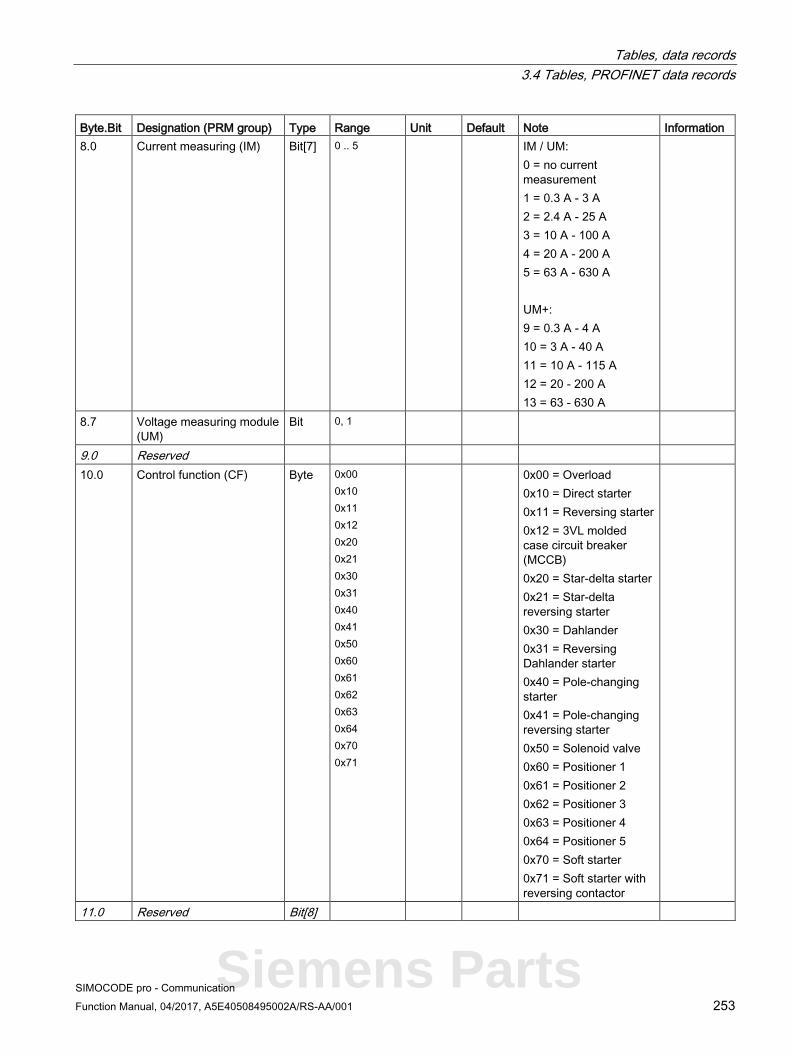
Tables, data records 3.4 Tables, PROFINET data records
SIMOCODE pro - Communication Function Manual, 04/2017, A5E40508495002A/RS-AA/001 253
Byte.Bit Designation (PRM group) Type Range Unit Default Note Information 8.0 Current measuring (IM) Bit[7] 0 .. 5 IM / UM:
0 = no current measurement 1 = 0.3 A - 3 A 2 = 2.4 A - 25 A 3 = 10 A - 100 A 4 = 20 A - 200 A 5 = 63 A - 630 A UM+: 9 = 0.3 A - 4 A 10 = 3 A - 40 A 11 = 10 A - 115 A 12 = 20 - 200 A 13 = 63 - 630 A
8.7 Voltage measuring module (UM)
Bit 0, 1
9.0 Reserved 10.0 Control function (CF) Byte 0x00
0x10 0x11 0x12 0x20 0x21 0x30 0x31 0x40 0x41 0x50 0x60 0x61 0x62 0x63 0x64 0x70 0x71
0x00 = Overload 0x10 = Direct starter 0x11 = Reversing starter 0x12 = 3VL molded case circuit breaker (MCCB) 0x20 = Star-delta starter 0x21 = Star-delta reversing starter 0x30 = Dahlander 0x31 = Reversing Dahlander starter 0x40 = Pole-changing starter 0x41 = Pole-changing reversing starter 0x50 = Solenoid valve 0x60 = Positioner 1 0x61 = Positioner 2 0x62 = Positioner 3 0x63 = Positioner 4 0x64 = Positioner 5 0x70 = Soft starter 0x71 = Soft starter with reversing contactor
11.0 Reserved Bit[8]
Siemens Parts

Tables, data records 3.4 Tables, PROFINET data records
SIMOCODE pro - Communication 254 Function Manual, 04/2017, A5E40508495002A/RS-AA/001
Byte.Bit Designation (PRM group) Type Range Unit Default Note Information 12.0 Bit parameters (16) 12.0 No configuration fault due
to OP Bit 0, 1 0
12.1 Startup parameter block active
Bit 0, 1 1
12.2 Test/Reset keys disabled Bit 0, 1 0 12.3 Bus and PLC/PCS - Reset Bit 0, 1 0 0 = Manual
1 = Auto
12.4 Reserved Bit 0 12.5 Reserved Bit 0 12.6 Reserved Bit 0 12.7 Reserved Bit 0 13.0 Diagnostics for process
events Bit 0, 1 0
13.1 Diagnostics for process warnings
Bit 0, 1 1
13.2 Diagnostics for process faults
Bit 0, 1 1
13.3 Diagnostics for device faults
Bit 0, 1 1
13.4 Reserved Bit 0 13.5 Reserved Bit 0 13.6 Bus monitoring Bit 0, 1 1 13.7 PLC/PCS monitoring Bit 0, 1 1 14.0 Overload protection - Load
type Bit 0, 1 0 0 = 3-phase
1 = 1-phase IM UM
14.1 Overload protection - Reset
Bit 0, 1 0 0 = Manual 1 = Auto
IM UM
14.2 Reserved Bit 0 14.3 Save change-over
command Bit 0, 1 0
14.4 Non-maintained command mode
Bit 0, 1 0
14.5 Cold start level (TPF) Bit 0, 1 0 0 = NO contact 1 = NC contact
14.6 Type of consumer load Bit 0, 1 0 0 = Motor 1 = Resistive load
14.7 Reserved Bit 0 15.0 External fault 1 - Type Bit 0, 1 0 0 = NO contact
1 = NC contact
15.1 External fault 2 - Type Bit 0, 1 0 15.2 External fault 3 - Type Bit 0, 1 0 15.3 External fault 4 - Type Bit 0, 1 0

Tables, data records 3.4 Tables, PROFINET data records
SIMOCODE pro - Communication Function Manual, 04/2017, A5E40508495002A/RS-AA/001 255
Byte.Bit Designation (PRM group) Type Range Unit Default Note Information 15.4 External fault 1 - Activity Bit 0, 1 0 0 = Always
1 = Only motor ON
15.5 External fault 2 - Activity Bit 0, 1 0 15.6 External fault 3 - Activity Bit 0, 1 0 15.7 External fault 4 - Activity Bit 0, 1 0 16.0 Bit[2] - Parameters (20) 16.0 Thermistor - Overload
response Bit[2] 1, 2, 3 3 0 = Disabled
1 = Signaling 2 = Warn 3 = Tripping
Th
16.2 Thermistor - Response to sensor fault
Bit[2] 0, 1, 2, 3 2 Th
16.4 Internal ground fault - Response
Bit[2] 0, 1, 2, 3 0
16.6 Motor protection - Overload response
Bit[2] 0, 1, 2, 3 3 IM
17.0 Motor protection - Overload response
Bit[2] 0, 1, 2 2 IM
17.2 Unbalance protection - Response
Bit[2] 0, 1, 2, 3 2 IM
17.4 Trip response I> Bit[2] 0, 1, 3 0 17.6 Warning response I> Bit[2] 0, 1, 2 0 18.0 Trip response I< Bit[2] 0, 1, 3 0 18.2 Warning response I< Bit[2] 0, 1, 2 0 18.4 Stalled rotor - Response Bit[2] 0, 1, 2, 3 0 18.6 EM+ 1)- Response to
sensor fault Bit[2] 0, 1, 2, 3 0
19.0 Monitoring the number of starts - Response to overshoot
Bit[2] 0, 1, 2, 3 0
19.2 Monitoring the number of starts - Response to prewarning
Bit[2] 0, 1, 2 0
19.4 Motor operating hours monitoring - Response
Bit[2] 0, 1, 2 0
19.6 Motor stop time monitoring - Response
Bit[2] 0, 1, 2 0
20.0 External fault 1 – Response
Bit[2] 1, 2, 3 1
20.2 External fault 2 – Response
Bit[2] 1, 2, 3 1
20.4 External fault 3 – Response
Bit[2] 1, 2, 3 1
20.6 External fault 4 – Response
Bit[2] 1, 2, 3 1
21.0 Reserved Bit[2] 0 21.2 Basic unit - Debounce time
inputs Bit[2] 0 - 3 10 ms 1 Offset 6 ms
Siemens Parts

Tables, data records 3.4 Tables, PROFINET data records
SIMOCODE pro - Communication 256 Function Manual, 04/2017, A5E40508495002A/RS-AA/001
Byte.Bit Designation (PRM group) Type Range Unit Default Note Information 21.4 Timer 1 - Type Bit[2] 0, 1, 2, 3 0 0 = With closing delay,
1 = Closing delay with memory 2 = With opening delay 3 = With fleeting closing
21.6 Timer 2 - Type Bit[2] 0, 1, 2, 3 0
22.0 Signal conditioning 1 - Type
Bit[2] 0, 1, 2, 3 0 0 = Non-inverting 1 = Inverting 2 = Edge rising with memory 3 = Edge falling with memory
22.2 Signal conditioning 2 - Type
Bit[2] 0, 1, 2, 3 0
22.4 Non-volatile element 1 - Type
Bit[2] 0, 1, 2, 3 0
22.6 Non-volatile element 2 - Type
Bit[2] 0, 1, 2, 3 0
23.0 EM+ 2) - monitoring Bit[2] 0, 1, 2, 3 0 0 = on 1 = on+ 2 = run 3 = run+
23.2 EM+ 2) - monitoring
warning Bit[2] 0, 1, 2, 3 0
23.4 EM - response to an external ground fault
Bit[2] 1, 3 1 0 = Disabled 1 = Signaling 2 = Warn 3 = Tripping
23.6 EM - response to warning of an external ground fault
Bit[2] 0, 1, 2 0
24.0 Bit[4] - Parameters (24) 24.0 External fault 1 - Reset
also by Bit[4] 0 - 1111B 0101B Bit[0] = Panel reset
Bit[1] = Auto-reset Bit[2] = Remote reset Bit[4] = OFF command reset
24.4 External fault 2 - Reset also by
Bit[4] 0 - 1111B 0101B
25.0 External fault 3 - Reset also by
Bit[4] 0 - 1111B 0101B
25.4 External fault 4 - Reset also by
Bit[4] 0 - 1111B 0101B
26.0 Limit monitor - Hysteresis for limit monitoring
Bit[4] 0 - 15 1 % 5
26.4 EM+ 2) - hysteresis Bit[4] 0 - 15 1 % 5 27.0 Parameter target version -
Part a Bit[4] 0
27.4 Parameter target version - Part b
Bit[4] 0
28.0 Byte parameters (28) 28.0 Internal ground fault -
Delay Byte 0 .. 255 100 ms 5 IM UM
29.0 Overload protection - Class
Byte 5, 7, 10 .. 35, 40
10
30.0 Motor protection - Delay with overload operation
Byte 0 - 255 100 ms 5 IM UM
31.0 Motor protection - unbalance protection level
Byte 0 - 100 1 % 40 IM UM

Tables, data records 3.4 Tables, PROFINET data records
SIMOCODE pro - Communication Function Manual, 04/2017, A5E40508495002A/RS-AA/001 257
Byte.Bit Designation (PRM group) Type Range Unit Default Note Information 32.0 Motor protection -
Unbalance protection - Delay in the event of unbalance
Byte 0 - 255 100 ms 5 IM UM
33.0 Interlocking time Byte 0 - 255 1 s 0 34.0 FB time Byte 0 - 255 100 ms 5 0 = Disabled 35.0 Trip level I> Byte 0 - 255 4 % / Is 0 IM UM 36.0 Warning level I> Byte 0 - 255 4 % / Is 0 IM UM 37.0 Trip level I< Byte 0 - 255 4 % / Is 0 IM UM 38.0 Warning level I< Byte 0 - 255 4 % / Is 0 IM UM 39.0 Stalled rotor level Byte 0 - 255 4 % / Is 0 IM UM 40.0 Trip delay I> Byte 0 - 255 100 ms 5 IM UM 41.0 Warning delay I> Byte 0 - 255 100 ms 5 IM UM 42.0 Trip delay I< Byte 0 - 255 100 ms 5 IM UM 43.0 Warning delay I< Byte 0 - 255 100 ms 5 IM UM 44.0 Blocking delay Byte 0 - 255 100 ms 5 IM UM 45.0 Monitoring the number of
starts - Permissible starts Byte 1 - 255 1
46.0 Reserved Byte 0 47.0 EM+ 2) - delay Byte 0 - 255 100 ms 0 48.0 Truth table 1 type 3I/1O Byte 0 -
11111111B 0
49.0 Truth table 2 type 3I/1O Byte 0 - 11111111B
0
50.0 Truth table 3 type 3I/1O Byte 0 - 11111111B
0
51.0 Reserved Byte 0 52.0 Word parameters (32) 52.0 Motor protection - Cooling
down period Word 600 - 65535 100 ms 3000 IM UM
54.0 Motor protection - Pause time
Word 0 - 65535 100 ms 0 0 = Disabled IM UM
56.0 Execution time Word 0 - 65535 100 ms 10 0 = Disabled 58.0 Monitoring the number of
starts - Time range for starts
Word 0 - 65535 1 s 0
60.0 Monitoring the number of starts - Interlocking time
Word 0 - 65535 1 s 0
62.0 Motor stop time level > Word 0 - 65535 1 h 0 64.0 Timer 1 - Limit Word 0 - 65535 100 ms 0 66.0 Timer 2 - Limit Word 0 - 65535 100 ms 0 68.0 Counter 1 - Limit Word 0 - 65535 0 70.0 Counter 2 - Limit Word 0 - 65535 0 72.0 EM+ 2) - trip level Word 30 - 40000 1 mA 1000
Siemens Parts

Tables, data records 3.4 Tables, PROFINET data records
SIMOCODE pro - Communication 258 Function Manual, 04/2017, A5E40508495002A/RS-AA/001
Byte.Bit Designation (PRM group) Type Range Unit Default Note Information 74.0 EM+ 2) - warning level Word 30 - 40000 1 mA 500 76.0 D-word parameters (36) 76.0 Operator control enables Bit[32] 0 - 1-1B 0-0B 80.0 Motor protection - Set
current Is1 D-word 1) 10 mA 30 IM UM
84.0 Motor operating hours level >
D-word 0 - 0x FFFFFFFF
1 s 0
88.0 Reserved D-word 0
1) Value range dependent on current range of the IM / UM and the conversion factor Bit 31 = 1, i.e. conversion factor active.
2) 3UF7510-1AA00-0 ground-fault module
3.4.2.11 Data record 131 - Basic device parameters 2 (plug binary)
Table 3- 69 Data record 131 - Basic device parameters 2
Byte.Bit Designation (PRM group) Type Range Default Note Information 0.0 Reserved Byte[4] 4.0 Byte parameters (40) 4.0 BU - Output 1 Byte 0 - 255 0 5.0 BU - Output 2 Byte 0 - 255 0 6.0 BU - Output 3 Byte 0 - 255 0 7.0 Reserved Byte 0 8.0 OP - LED green 1 Byte 0 - 255 0 OP OPD 9.0 OP - LED green 2 Byte 0 - 255 0 OP OPD 10.0 OP - LED green 3 Byte 0 - 255 0 OP OPD 11.0 OP - LED green 4 Byte 0 - 255 0 OP OPD 12.0 OP - LED yellow 1 Byte 0 - 255 0 OP 13.0 OP - LED yellow 2 Byte 0 - 255 0 OP 14.0 OP - LED yellow 3 Byte 0 - 255 0 OP 15.0 Reserved Byte 0 16.0 Cyclic send - Bit 0.0 Byte 0 - 255 105 Default: Status - ON< 17.0 Cyclic send - Bit 0.1 Byte 0 - 255 106 Default: Status - Off 18.0 Cyclic send - Bit 0.2 Byte 0 - 255 107 Default: Status - ON> 19.0 Cyclic send - Bit 0.3 Byte 0 - 255 128 Default: Event - Overload
operation
20.0 Cyclic send - Bit 0.4 Byte 0 - 255 110 Default: Status - Interlocking time active
21.0 Cyclic send - Bit 0.5 Byte 0 - 255 120 Default: Status - Auto mode 22.0 Cyclic send - Bit 0.6 Byte 0 - 255 96 Default: Status - General
fault
23.0 Cyclic send - Bit 0.7 Byte 0 - 255 97 Default: Status - General warning

Tables, data records 3.4 Tables, PROFINET data records
SIMOCODE pro - Communication Function Manual, 04/2017, A5E40508495002A/RS-AA/001 259
Byte.Bit Designation (PRM group) Type Range Default Note Information 24.0 OPC UA Send - Bit 1.0 Byte 0 - 255 0 25.0 OPC UA Send - Bit 1.1 Byte 0 - 255 0 26.0 OPC UA Send - Bit 1.2 Byte 0 - 255 0 27.0 OPC UA Send - Bit 1.3 Byte 0 .. 255 0 28.0 OPC UA Send - Bit 1.4 Byte 0 - 255 0 29.0 OPC UA Send - Bit 1.5 Byte 0 - 255 0 30.0 OPC UA Send - Bit 1.6 Byte 0 - 255 0 31.0 OPC UA Send - Bit 1.7 Byte 0 - 255 0 32.0 OPC UA Send - Bit 0.0 Byte 0 - 255 0 33.0 OPC UA Send - Bit 0.1 Byte 0 - 255 0 34.0 OPC UA Send - Bit 0.2 Byte 0 - 255 0 35.0 OPC UA Send - Bit 0.3 Byte 0 - 255 0 36.0 OPC UA Send - Bit 0.4 Byte 0 - 255 0 37.0 OPC UA Send - Bit 0.5 Byte 0 - 255 0 38.0 OPC UA Send - Bit 0.6 Byte 0 - 255 0 39.0 OPC UA Send - Bit 0.7 Byte 0 - 255 0 40.0 OPC UA Send - Bit 1.0 Byte 0 - 255 0 41.0 OPC UA Send - Bit 1.1 Byte 0 - 255 0 42.0 OPC UA Send - Bit 1.2 Byte 0 - 255 0 43.0 OPC UA Send - Bit 1.3 Byte 0 - 255 0 44.0 OPC UA Send - Bit 1.4 Byte 0 - 255 0 45.0 OPC UA Send - Bit 1.5 Byte 0 - 255 0 46.0 OPC UA Send - Bit 1.6 Byte 0 - 255 0 47.0 OPC UA Send - Bit 1.7 Byte 0 - 255 0 48.0 Monitoring PLC/PCS input Byte 0 - 255 0 49.0 Motor protection - Emergency
start Byte 0 - 255 60 Default: Cyclic receive -
Bit 0.4 IM UM
50.0 Reserved Byte 0 51.0 Reserved Byte 0 52.0 Mode selector S1 Byte 0 - 255 61 Default: Cyclic receive -
Bit 0.5
53.0 Mode selector S2 Byte 0 - 255 2 Default: Fixed level value "1" 54.0 Control station - Local control
[LC] ON< Byte 0 - 255 0 Dependent on
the control function 55.0 Control station - Local control
[LC] OFF Byte 0 - 255 0
56.0 Control station - Local control [LC] ON>
Byte 0 - 255 0
57.0 Control station - PLC/PCS [PN] ON<
Byte 0 - 255 56 Default: Cyclic receive - Bit 0.0
58.0 Control station - PLC/PCS [PN] OFF
Byte 0 - 255 57 Default: Cyclic receive - Bit 0.1
59.0 Control station - PLC/PCS [PN] ON>
Byte 0 - 255 58 Default: Cyclic receive - Bit 0.2
Siemens Parts

Tables, data records 3.4 Tables, PROFINET data records
SIMOCODE pro - Communication 260 Function Manual, 04/2017, A5E40508495002A/RS-AA/001
Byte.Bit Designation (PRM group) Type Range Default Note Information 60.0 Control station - PC/OPC-
UA[OCM] ON< Byte 0 - 255 0
61.0 Control station - PC/OPC-UA[OCM] OFF
Byte 0 - 255 0
62.0 Control station - PC/OPC-UA[OCM] ON>
Byte 0 - 255 0
63.0 Control station - Operator panel [OP] ON<
Byte 0 - 255 0
64.0 Control station - Operator panel [OP] OFF
Byte 0 - 255 0
65.0 Control station - Operator panel [OP] ON>
Byte 0 - 255 0
66.0 Control function - ON< Byte 0 - 255 73 Default: Group control station ON<
67.0 Control function - OFF Byte 0 - 255 74 Default: Group control station OFF
68.0 Control function - ON> Byte 0 - 255 75 Default: Group control station ON>
69.0 Control function - Feedback ON Byte 0 - 255 101 Default: Status - Motor current flowing
70.0 External fault 1 - Input Byte 0 - 255 0 71.0 External fault 2 - Input Byte 0 - 255 0 72.0 External fault 3 - Input Byte 0 - 255 0 73.0 External fault 4 - Input Byte 0 - 255 0 74.0 External fault 1 - Reset Byte 0 - 255 0 75.0 External fault 2 - Reset Byte 0 - 255 0 76.0 External fault 3 - Reset Byte 0 - 255 0 77.0 External fault 4 - Reset Byte 0 - 255 0 78.0 Cold start (TPF) Byte 0 - 255 0 79.0 Test 1 - Input Byte 0 - 255 59 Default: Cyclic receive -
Bit 0.3
80.0 Test 2 - Input Byte 0 - 255 0 81.0 Reset 1 - Input Byte 0 - 255 62 Default: Cyclic receive -
Bit 0.6
82.0 Reset 2 - Input Byte 0 - 255 0 83.0 Reset 3 - Input Byte 0 - 255 0 84.0 Reserved Byte 0 85.0 Reserved Byte 0 86.0 Reserved Byte 0 87.0 Reserved Byte 0 88.0 Truth table 1 3I/1O - Input 1 Byte 0 - 255 0 89.0 Truth table 1 3I/1O - Input 2 Byte 0 - 255 0 90.0 Truth table 1 3I/1O - Input 3 Byte 0 - 255 0 91.0 Truth table 2 3I/1O - Input 1 Byte 0 - 255 0 92.0 Truth table 2 3I/1O - Input 2 Byte 0 - 255 0

Tables, data records 3.4 Tables, PROFINET data records
SIMOCODE pro - Communication Function Manual, 04/2017, A5E40508495002A/RS-AA/001 261
Byte.Bit Designation (PRM group) Type Range Default Note Information 93.0 Truth table 2 3I/1O - Input 3 Byte 0 - 255 0 94.0 Truth table 3 3I/1O - Input 1 Byte 0 - 255 0 95.0 Truth table 3 3I/1O - Input 2 Byte 0 - 255 0 96.0 Truth table 3 3I/1O - Input 3 Byte 0 - 255 0 97.0 Reserved Byte 0 98.0 Timer 1 - Input Byte 0 - 255 0 99.0 Timer 1 - Reset Byte 0 - 255 0 100.0 Timer 2 - Input Byte 0 - 255 0 101.0 Timer 2 - Reset Byte 0 - 255 0 102.0 Counter 1 - Input + Byte 0 - 255 0 103.0 Counter 1 - Input - Byte 0 - 255 0 104.0 Counter 1 - Reset Byte 0 - 255 0 105.0 Counter 2 - Input + Byte 0 - 255 0 106.0 Counter 2 - Input - Byte 0 - 255 0 107.0 Counter 2 - Reset Byte 0 - 255 0 108.0 Signal conditioning 1 - Input Byte 0 - 255 0 109.0 Signal conditioning 1 - Reset Byte 0 - 255 0 110.0 Signal conditioning 2 - Input Byte 0 - 255 0 111.0 Signal conditioning 2 - Reset Byte 0 - 255 0 112.0 Non-volatile element 1 - Input Byte 0 - 255 0 113.0 Non-volatile element 1 - Reset Byte 0 - 255 0 114.0 Non-volatile element 2 - Input Byte 0 - 255 0 115.0 Non-volatile element 2 - Reset Byte 0 - 255 0 116.0 Flashing 1 - Input Byte 0 - 255 0 117.0 Flashing 2 - Input Byte 0 - 255 0 118.0 Flashing 3 - Input Byte 0 - 255 0 119.0 Flicker 1 - Input Byte 0 - 255 0 120.0 Flicker 2 - Input Byte 0 - 255 0 121.0 Flicker 3 - Input Byte 0 - 255 0 122.0 Analog parameters (44) 122.0 PLC/PCS analog input Byte 0 - 255 16 Default: Max. current I_max 123.0 Reserved Byte 0
Siemens Parts
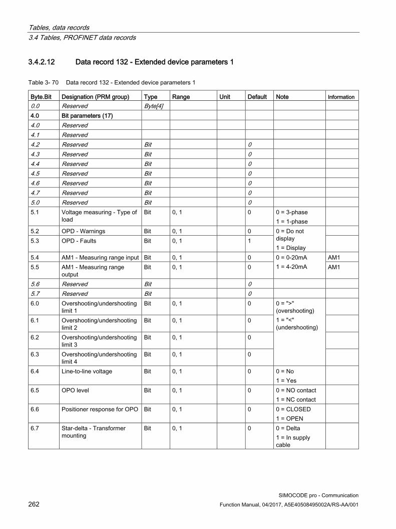
Tables, data records 3.4 Tables, PROFINET data records
SIMOCODE pro - Communication 262 Function Manual, 04/2017, A5E40508495002A/RS-AA/001
3.4.2.12 Data record 132 - Extended device parameters 1
Table 3- 70 Data record 132 - Extended device parameters 1
Byte.Bit Designation (PRM group) Type Range Unit Default Note Information 0.0 Reserved Byte[4] 4.0 Bit parameters (17) 4.0 Reserved 4.1 Reserved 4.2 Reserved Bit 0 4.3 Reserved Bit 0 4.4 Reserved Bit 0 4.5 Reserved Bit 0 4.6 Reserved Bit 0 4.7 Reserved Bit 0 5.0 Reserved Bit 0 5.1 Voltage measuring - Type of
load Bit 0, 1 0 0 = 3-phase
1 = 1-phase
5.2 OPD - Warnings Bit 0, 1 0 0 = Do not display 1 = Display
5.3 OPD - Faults Bit 0, 1 1
5.4 AM1 - Measuring range input Bit 0, 1 0 0 = 0-20mA 1 = 4-20mA
AM1 5.5 AM1 - Measuring range
output Bit 0, 1 0 AM1
5.6 Reserved Bit 0 5.7 Reserved Bit 0 6.0 Overshooting/undershooting
limit 1 Bit 0, 1 0 0 = ">"
(overshooting) 1 = "<" (undershooting)
6.1 Overshooting/undershooting limit 2
Bit 0, 1 0
6.2 Overshooting/undershooting limit 3
Bit 0, 1 0
6.3 Overshooting/undershooting limit 4
Bit 0, 1 0
6.4 Line-to-line voltage Bit 0, 1 0 0 = No 1 = Yes
6.5 OPO level Bit 0, 1 0 0 = NO contact 1 = NC contact
6.6 Positioner response for OPO Bit 0, 1 0 0 = CLOSED 1 = OPEN
6.7 Star-delta - Transformer mounting
Bit 0, 1 0 0 = Delta 1 = In supply cable

Tables, data records 3.4 Tables, PROFINET data records
SIMOCODE pro - Communication Function Manual, 04/2017, A5E40508495002A/RS-AA/001 263
Byte.Bit Designation (PRM group) Type Range Unit Default Note Information 7.0 External fault 5 - Type Bit 0, 1 0 0 = NO contact
1 = NC contact
7.1 External fault 6 - Type Bit 0, 1 0 7.2 Reserved Bit 0 7.3 Reserved Bit 0 7.4 Monitoring external fault 5 Bit 0, 1 0 0 = Always
1 = Only motor ON
7.5 Monitoring external fault 6 Bit 0, 1 0
7.6 Reserved Bit 0 7.7 Reserved Bit 0 8.0 Calculator 2, Operating
mode Bit 0, 1 0 0 = Word
1 = D-word
8.1 Reserved Bit 0 8.2 DM-F - Safe tripping function Bit 0, 1 0 0 = No
1 = Yes DM-F
8.3 DM-F - Safety-related tripping reset
Bit 0, 1 0 0 = Manual 1 = Auto
DM-F
8.4 Reserved 8.5 Reserved Bit 0 8.6 Reserved Bit 0 8.7 Reserved Bit 0 9.0 DM-FL - Configuration 1 Bit 0, 1 0 Configurable
parameters comparable with the module configuration
DM-FL 9.1 DM-FL - Configuration 2 Bit 0, 1 0 DM-FL 9.2 DM-FL - Configuration 3 Bit 0, 1 0 DM-FL 9.3 DM-FL - Configuration 4 Bit 0, 1 0 DM-FL 9.4 DM-FL - Configuration 5 Bit 0, 1 0 DM-FL 9.5 DM-FL - Configuration 6 Bit 0, 1 0 DM-FL 9.6 DM-FL - Configuration 7 Bit 0, 1 0 DM-FL 9.7 DM-FL - Configuration 8 Bit 0, 1 0 DM-FL 10.0 Bit[2] - Parameters (21) 10.0 Reserved Bit[2] 10.2 Reserved Bit[2] 0 10.4 UVO timebase Bit[2] 0, 1, 2 0 10.6 UVO operating mode Bit[2] 0, 1, 2 0 0 = Deactivated
1 = Activated
11.0 Trip monitoring U< Bit[2] 0, 1, 2 1 0 = ON (always) 1 = ON+ (always, not TPF) 2 = RUN (motor ON, not TPF)
UM 11.2 Warning monitoring U< Bit[2] 0, 1, 2 1 UM
Siemens Parts

Tables, data records 3.4 Tables, PROFINET data records
SIMOCODE pro - Communication 264 Function Manual, 04/2017, A5E40508495002A/RS-AA/001
Byte.Bit Designation (PRM group) Type Range Unit Default Note Information 11.4 Reserved Bit[2] 0 11.6 Reserved Bit[2] 0 12.0 Trip monitoring 0/4-20 mA> Bit[2] 0, 1, 2, 3 0 0 = ON (always)
1 = ON + (always, not TPF) 2 = RUN (motor ON, not TPF) 3 = RUN+ (motor ON, not TPF, startup override)
AM1 12.2 Warning monitoring
0/4-20 mA> Bit[2] 0, 1, 2, 3 0 AM1
12.4 Trip monitoring 0/4-20 mA< Bit[2] 0, 1, 2, 3 0 AM1 12.6 Warning monitoring
0/4-20 mA< Bit[2] 0, 1, 2, 3 0 AM1
13.0 Monitoring limit 1 Bit[2] 0, 1, 2, 3 0 13.2 Monitoring limit 2 Bit[2] 0, 1, 2, 3 0 13.4 Monitoring limit 3 Bit[2] 0, 1, 2, 3 0 13.6 Monitoring limit 4 Bit[2] 0, 1, 2, 3 0 14.0 Reserved Bit[2] 0 14.2 Reserved Bit[2] 0 14.4 Reserved Bit[2] 0 14.6 AM1 - active inputs Bit[2] 0, 1, 2 0 0 = 1 input
1 = 2 inputs 2 = 3 inputs
AM1
15.0 DM - Delays inputs Bit[2] 0, 1, 2, 3 10 ms 1 Offset 6ms DM1 DM2 15.2 AM1 - Response for open
circuit Bit[2] 1, 2, 3 2 0 = Disabled
1 = Signaling 2 = Warn 3 = Tripping
AM1
15.4 EM - Response to external ground fault
Bit[2] 1, 3 1 EM EM+
15.6 EM - response to warning of an external ground fault
Bit[2] 0, 1, 2 0 EM EM+
16.0 Reserved Bit[2] 0 16.2 Reserved Bit[2] 0 16.4 DM-F - Test requirement
response Bit[2] 0, 1, 2 0 0 = Disabled
1 = Signaling 2 = Warn 3 = Tripping
DM-F
16.6 DM-F - safety-related tripping response
Bit[2] 0, 1, 2, 3 0 DM-F
17.0 TM1 - Trip response T> Bit[2] 1, 3 3 TM1 17.2 TM1 - Warning response T> Bit[2] 0, 1, 2 2 TM1 17.4 TM1 - Response to a sensor
fault / out of range Bit[2] 0, 1, 2, 3 2 TM1
17.6 TM1 - Active sensors Bit[2] 0, 1, 2 2 0 = 1 sensor 1 = 2 sensors 2 = 3 sensors
TM1
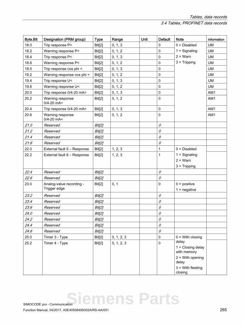
Tables, data records 3.4 Tables, PROFINET data records
SIMOCODE pro - Communication Function Manual, 04/2017, A5E40508495002A/RS-AA/001 265
Byte.Bit Designation (PRM group) Type Range Unit Default Note Information 18.0 Trip response P> Bit[2] 0, 1, 3 0 0 = Disabled
1 = Signaling 2 = Warn 3 = Tripping
UM 18.2 Warning response P> Bit[2] 0, 1, 2 0 UM 18.4 Trip response P< Bit[2] 0, 1, 3 0 UM 18.6 Warning response P< Bit[2] 0, 1, 2 0 UM 19.0 Trip response cos phi < Bit[2] 0, 1, 3 0 UM 19.2 Warning response cos phi < Bit[2] 0, 1, 2 0 UM 19.4 Trip response U< Bit[2] 0, 1, 3 0 UM 19.6 Warning response U< Bit[2] 0, 1, 2 0 UM 20.0 Trip response 0/4-20 mA> Bit[2] 0, 1, 3 0 AM1 20.2 Warning response
0/4-20 mA> Bit[2] 0, 1, 2 0 AM1
20.4 Trip response 0/4-20 mA< Bit[2] 0, 1, 3 0 AM1 20.6 Warning response
0/4-20 mA< Bit[2] 0, 1, 2 0 AM1
21.0 Reserved Bit[2] 0 21.2 Reserved Bit[2] 0 21.4 Reserved Bit[2] 0 21.6 Reserved Bit[2] 0 22.0 External fault 5 – Response Bit[2] 1, 2, 3 1 0 = Disabled
1 = Signaling 2 = Warn 3 = Tripping
22.2 External fault 6 – Response Bit[2] 1, 2, 3 1
22.4 Reserved Bit[2] 0 22.6 Reserved Bit[2] 0 23.0 Analog-value recording -
Trigger edge Bit[2] 0, 1 0 0 = positive
1 = negative
23.2 Reserved Bit[2] 0 23.4 Reserved Bit[2] 0 23.6 Reserved Bit[2] 0 24.0 Reserved Bit[2] 0 24.2 Reserved Bit[2] 0 24.4 Reserved Bit[2] 0 24.6 Reserved Bit[2] 0 25.0 Timer 3 - Type Bit[2] 0, 1, 2, 3 0 0 = With closing
delay 1 = Closing delay with memory 2 = With opening delay 3 = With fleeting closing
25.2 Timer 4 - Type Bit[2] 0, 1, 2, 3 0
Siemens Parts
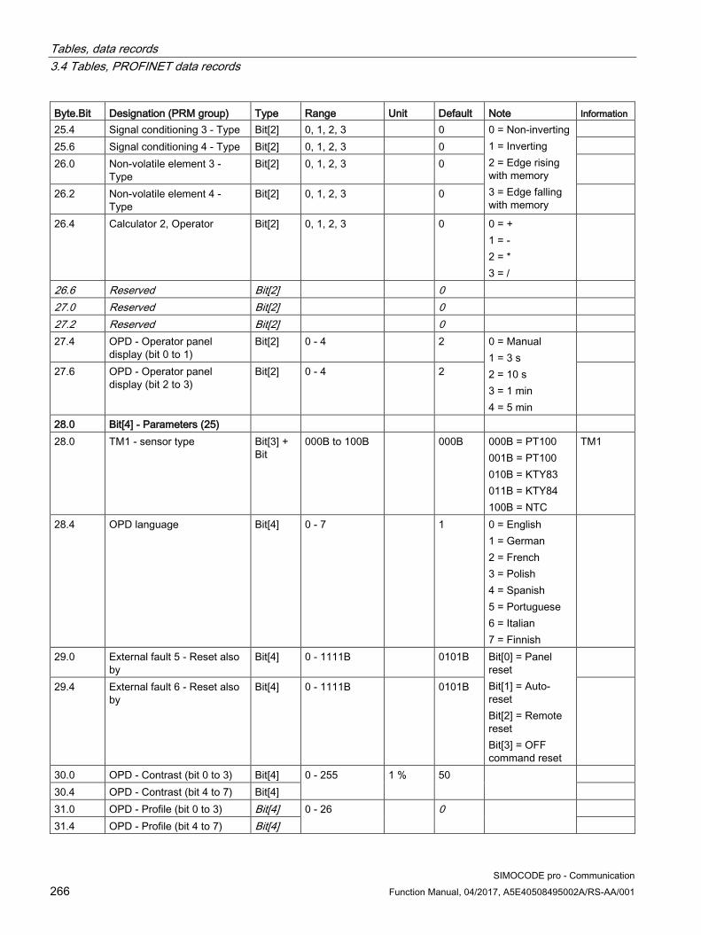
Tables, data records 3.4 Tables, PROFINET data records
SIMOCODE pro - Communication 266 Function Manual, 04/2017, A5E40508495002A/RS-AA/001
Byte.Bit Designation (PRM group) Type Range Unit Default Note Information 25.4 Signal conditioning 3 - Type Bit[2] 0, 1, 2, 3 0 0 = Non-inverting
1 = Inverting 2 = Edge rising with memory 3 = Edge falling with memory
25.6 Signal conditioning 4 - Type Bit[2] 0, 1, 2, 3 0 26.0 Non-volatile element 3 -
Type Bit[2] 0, 1, 2, 3 0
26.2 Non-volatile element 4 - Type
Bit[2] 0, 1, 2, 3 0
26.4 Calculator 2, Operator Bit[2] 0, 1, 2, 3 0 0 = + 1 = - 2 = * 3 = /
26.6 Reserved Bit[2] 0 27.0 Reserved Bit[2] 0 27.2 Reserved Bit[2] 0 27.4 OPD - Operator panel
display (bit 0 to 1) Bit[2] 0 - 4 2 0 = Manual
1 = 3 s 2 = 10 s 3 = 1 min 4 = 5 min
27.6 OPD - Operator panel display (bit 2 to 3)
Bit[2] 0 - 4 2
28.0 Bit[4] - Parameters (25) 28.0 TM1 - sensor type Bit[3] +
Bit 000B to 100B 000B 000B = PT100
001B = PT100 010B = KTY83 011B = KTY84 100B = NTC
TM1
28.4 OPD language Bit[4] 0 - 7 1 0 = English 1 = German 2 = French 3 = Polish 4 = Spanish 5 = Portuguese 6 = Italian 7 = Finnish
29.0 External fault 5 - Reset also by
Bit[4] 0 - 1111B 0101B Bit[0] = Panel reset Bit[1] = Auto-reset Bit[2] = Remote reset Bit[3] = OFF command reset
29.4 External fault 6 - Reset also by
Bit[4] 0 - 1111B 0101B
30.0 OPD - Contrast (bit 0 to 3) Bit[4] 0 - 255 1 % 50 30.4 OPD - Contrast (bit 4 to 7) Bit[4] 31.0 OPD - Profile (bit 0 to 3) Bit[4] 0 - 26
0
31.4 OPD - Profile (bit 4 to 7) Bit[4]
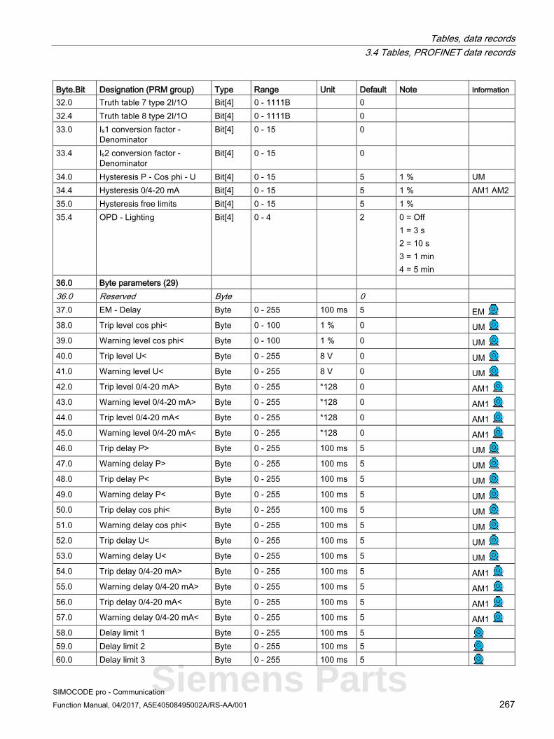
Tables, data records 3.4 Tables, PROFINET data records
SIMOCODE pro - Communication Function Manual, 04/2017, A5E40508495002A/RS-AA/001 267
Byte.Bit Designation (PRM group) Type Range Unit Default Note Information 32.0 Truth table 7 type 2I/1O Bit[4] 0 - 1111B 0 32.4 Truth table 8 type 2I/1O Bit[4] 0 - 1111B 0 33.0 Is1 conversion factor -
Denominator Bit[4] 0 - 15 0
33.4 Is2 conversion factor - Denominator
Bit[4] 0 - 15 0
34.0 Hysteresis P - Cos phi - U Bit[4] 0 - 15 5 1 % UM 34.4 Hysteresis 0/4-20 mA Bit[4] 0 - 15 5 1 % AM1 AM2 35.0 Hysteresis free limits Bit[4] 0 - 15 5 1 % 35.4 OPD - Lighting Bit[4] 0 - 4 2 0 = Off
1 = 3 s 2 = 10 s 3 = 1 min 4 = 5 min
36.0 Byte parameters (29) 36.0 Reserved Byte 0 37.0 EM - Delay Byte 0 - 255 100 ms 5 EM 38.0 Trip level cos phi< Byte 0 - 100 1 % 0 UM 39.0 Warning level cos phi< Byte 0 - 100 1 % 0 UM 40.0 Trip level U< Byte 0 - 255 8 V 0 UM 41.0 Warning level U< Byte 0 - 255 8 V 0 UM 42.0 Trip level 0/4-20 mA> Byte 0 - 255 *128 0 AM1 43.0 Warning level 0/4-20 mA> Byte 0 - 255 *128 0 AM1 44.0 Trip level 0/4-20 mA< Byte 0 - 255 *128 0 AM1 45.0 Warning level 0/4-20 mA< Byte 0 - 255 *128 0 AM1 46.0 Trip delay P> Byte 0 - 255 100 ms 5 UM 47.0 Warning delay P> Byte 0 - 255 100 ms 5 UM 48.0 Trip delay P< Byte 0 - 255 100 ms 5 UM 49.0 Warning delay P< Byte 0 - 255 100 ms 5 UM 50.0 Trip delay cos phi< Byte 0 - 255 100 ms 5 UM 51.0 Warning delay cos phi< Byte 0 - 255 100 ms 5 UM 52.0 Trip delay U< Byte 0 - 255 100 ms 5 UM 53.0 Warning delay U< Byte 0 - 255 100 ms 5 UM 54.0 Trip delay 0/4-20 mA> Byte 0 - 255 100 ms 5 AM1 55.0 Warning delay 0/4-20 mA> Byte 0 - 255 100 ms 5 AM1 56.0 Trip delay 0/4-20 mA< Byte 0 - 255 100 ms 5 AM1 57.0 Warning delay 0/4-20 mA< Byte 0 - 255 100 ms 5 AM1 58.0 Delay limit 1 Byte 0 - 255 100 ms 5 59.0 Delay limit 2 Byte 0 - 255 100 ms 5 60.0 Delay limit 3 Byte 0 - 255 100 ms 5
Siemens Parts
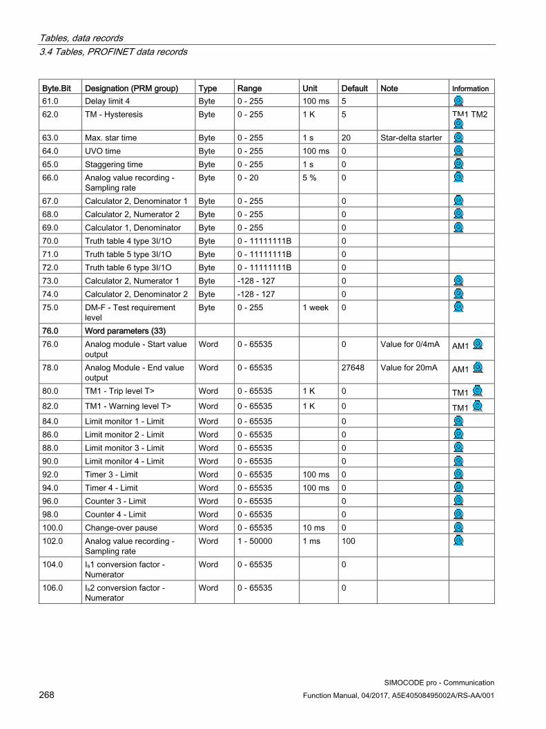
Tables, data records 3.4 Tables, PROFINET data records
SIMOCODE pro - Communication 268 Function Manual, 04/2017, A5E40508495002A/RS-AA/001
Byte.Bit Designation (PRM group) Type Range Unit Default Note Information 61.0 Delay limit 4 Byte 0 - 255 100 ms 5 62.0 TM - Hysteresis Byte 0 - 255 1 K 5 TM1 TM2
63.0 Max. star time Byte 0 - 255 1 s 20 Star-delta starter 64.0 UVO time Byte 0 - 255 100 ms 0 65.0 Staggering time Byte 0 - 255 1 s 0 66.0 Analog value recording -
Sampling rate Byte 0 - 20 5 % 0
67.0 Calculator 2, Denominator 1 Byte 0 - 255 0 68.0 Calculator 2, Numerator 2 Byte 0 - 255 0 69.0 Calculator 1, Denominator Byte 0 - 255 0 70.0 Truth table 4 type 3I/1O Byte 0 - 11111111B 0 71.0 Truth table 5 type 3I/1O Byte 0 - 11111111B 0 72.0 Truth table 6 type 3I/1O Byte 0 - 11111111B 0 73.0 Calculator 2, Numerator 1 Byte -128 - 127 0 74.0 Calculator 2, Denominator 2 Byte -128 - 127 0 75.0 DM-F - Test requirement
level Byte 0 - 255 1 week 0
76.0 Word parameters (33) 76.0 Analog module - Start value
output Word 0 - 65535 0 Value for 0/4mA AM1
78.0 Analog Module - End value output
Word 0 - 65535 27648 Value for 20mA AM1
80.0 TM1 - Trip level T> Word 0 - 65535 1 K 0 TM1 82.0 TM1 - Warning level T> Word 0 - 65535 1 K 0 TM1 84.0 Limit monitor 1 - Limit Word 0 - 65535 0 86.0 Limit monitor 2 - Limit Word 0 - 65535 0 88.0 Limit monitor 3 - Limit Word 0 - 65535 0 90.0 Limit monitor 4 - Limit Word 0 - 65535 0 92.0 Timer 3 - Limit Word 0 - 65535 100 ms 0 94.0 Timer 4 - Limit Word 0 - 65535 100 ms 0 96.0 Counter 3 - Limit Word 0 - 65535 0 98.0 Counter 4 - Limit Word 0 - 65535 0 100.0 Change-over pause Word 0 - 65535 10 ms 0 102.0 Analog value recording -
Sampling rate Word 1 - 50000 1 ms 100
104.0 Is1 conversion factor - Numerator
Word 0 - 65535 0
106.0 Is2 conversion factor - Numerator
Word 0 - 65535 0

Tables, data records 3.4 Tables, PROFINET data records
SIMOCODE pro - Communication Function Manual, 04/2017, A5E40508495002A/RS-AA/001 269
Byte.Bit Designation (PRM group) Type Range Unit Default Note Information 108.0 D-word parameters (37) 108.0 Motor protection - Set
current Is2 D-word 1) 10 mA 0
112.0 Trip level P> D-word 0 - 0xFFFFFFFF
1 W 0 UM
116.0 Warning level P> D-word 0 - 0xFFFFFFFF
1 W 0 UM
120.0 Trip level P< D-word 0 - 0xFFFFFFFF
1 W 0 UM
124.0 Warning level P< D-word 0 - 0xFFFFFFFF
1 W 0 UM
128.0 Truth Table 9 5I/2O type - Output 1
Bit[32] 0 - 1-1B 0
132.0 Truth Table 9 5I/2O type - Output 2
Bit[32] 0 - 1-1B 0
136.0 Calculator 2, Offset D-word -0x80000000 - 0x7FFFFFFF
0
140.0 Calculator 1, Numerator/Offset
D-word 2x -32768 - 32767
0
1) Value range dependent on current range of the IM/UM and the conversion factor; bit 31 = 1, i.e. conversion factor is active
3.4.2.13 Data record 133 - Extended device parameters 2 (plug binary)
Table 3- 71 Data record 133 - Extended device parameters
Byte.Bit Designation (PRM group) Type Range Default Note Information 0.0 Reserved Byte[4] 4.0 Byte parameters (41) 4.0 DM1 - Output 1 Byte 0 - 255 0 DM1 DM-F 5.0 DM1 - Output 2 Byte 0 - 255 0 DM1 FM-F 6.0 DM2 - Output 1 Byte 0 - 255 0 DM2 7.0 DM2 - Output 2 Byte 0 - 255 0 DM2 8.0 Reserved Byte 0 9.0 Reserved Byte 0 10.0 Reserved Byte 0 11.0 Reserved Byte 0 12.0 Reserved 13.0 Reserved 14.0 Reserved 15.0 Reserved 16.0 Reserved 17.0 Reserved 18.0 Reserved
Siemens Parts

Tables, data records 3.4 Tables, PROFINET data records
SIMOCODE pro - Communication 270 Function Manual, 04/2017, A5E40508495002A/RS-AA/001
Byte.Bit Designation (PRM group) Type Range Default Note Information 19.0 Reserved 20.0 Analog value recording - Trigger input Byte 0 - 255 0 21.0 Reserved Byte 0 22.0 Control station - Local control [LC] ON<< Byte 0 - 255 0 Dependent
on the control function
23.0 Control station - Local control [LC] ON>> Byte 0 - 255 0 24.0 Control station - PLC/PCS [PN] ON<< Byte 0 - 255 0 25.0 Control station - PLC/PCS [PN] ON>> Byte 0 - 255 0 26.0 Control station - PC/OPC UA[OCM] ON<< Byte 0 - 255 0 27.0 Control station - PC/OPC UA[OCM] ON<< Byte 0 - 255 0 28.0 Control station - Operator panels [OP] ON>> Byte 0 - 255 0 29.0 Control station - Operator panels
[OP]<>/<<>> Byte 0 - 255 0
30.0 Control function - ON<< Byte 0 - 255 0 31.0 Control function - ON>> Byte 0 - 255 0 32.0 Auxiliary control input - FC Byte 0 - 255 0 33.0 Auxiliary control input - FO Byte 0 - 255 0 34.0 Auxiliary control input - TC Byte 0 - 255 0 35.0 Auxiliary control input - TO Byte 0 - 255 0 36.0 External fault 5 - Input Byte 0 - 255 0 37.0 External fault 6 - Input Byte 0 - 255 0 38.0 Reserved Byte 0 39.0 Reserved Byte 0 40.0 External fault 5 - Reset Byte 0 - 255 0 41.0 External fault 6 - Reset Byte 0 - 255 0 42.0 Reserved Byte 0 43.0 Reserved Byte 0 44.0 UVO fault Byte 0 - 255 0 45.0 OPO error Byte 0 - 255 0 46.0 Truth table 4 3I/1O - Input 1 Byte 0 - 255 0 47.0 Truth table 4 3I/1O - Input 2 Byte 0 - 255 0 48.0 Truth table 4 3I/1O - Input 3 Byte 0 - 255 0 49.0 Truth table 5 3I/1O - Input 1 Byte 0 - 255 0 50.0 Truth table 5 3I/1O - Input 2 Byte 0 - 255 0 51.0 Truth table 5 3I/1O - Input 3 Byte 0 - 255 0 52.0 Truth table 6 3I/1O - Input 1 Byte 0 - 255 0 53.0 Truth table 6 3I/1O - Input 2 Byte 0 - 255 0 54.0 Truth table 6 3I/1O - Input 3 Byte 0 - 255 0 55.0 Truth table 7 2I/1O - Input 1 Byte 0 - 255 0 56.0 Truth table 7 2I/1O - Input 2 Byte 0 - 255 0 57.0 Truth table 8 2I/1O - Input 1 Byte 0 - 255 0 58.0 Truth table 8 2I/1O - Input 2 Byte 0 - 255 0 59.0 Truth table 9 5I/2O - Input 1 Byte 0 - 255 0

Tables, data records 3.4 Tables, PROFINET data records
SIMOCODE pro - Communication Function Manual, 04/2017, A5E40508495002A/RS-AA/001 271
Byte.Bit Designation (PRM group) Type Range Default Note Information 60.0 Truth table 9 5I/2O - Input 2 Byte 0 - 255 0 61.0 Truth table 9 5I/2O - Input 3 Byte 0 - 255 0 62.0 Truth table 9 5I/2O - Input 4 Byte 0 - 255 0 63.0 Truth table 9 5I/2O - Input 5 Byte 0 - 255 0 64.0 Timer 3 - Input Byte 0 - 255 0 65.0 Timer 3 - Reset Byte 0 - 255 0 66.0 Timer 4 - Input Byte 0 - 255 0 67.0 Timer 4 - Reset Byte 0 - 255 0 68.0 Counter 3 - Input + Byte 0 - 255 0 69.0 Counter 3 - Input - Byte 0 - 255 0 70.0 Counter 3 - Reset Byte 0 - 255 0 71.0 Counter 4 - Input + Byte 0 - 255 0 72.0 Counter 4 - Input - Byte 0 - 255 0 73.0 Counter 4 - Reset Byte 0 - 255 0 74.0 Signal conditioning 3 - Input Byte 0 - 255 0 75.0 Signal conditioning 3 - Reset Byte 0 - 255 0 76.0 Signal conditioning 4 - Input Byte 0 - 255 0 77.0 Signal conditioning 4 - Reset Byte 0 - 255 0 78.0 Non-volatile element 3 - Input Byte 0 - 255 0 79.0 Non-volatile element 3 - Reset Byte 0 - 255 0 80.0 Non-volatile element 4 - Input Byte 0 - 255 0 81.0 Non-volatile element 4 - Reset Byte 0 - 255 0 82.0 Reserved Byte 0 83.0 Reserved Byte 0 84.0 Reserved Byte 0 85.0 Reserved Byte 0 86.0 Reserved Byte 0 87.0 Reserved Byte 0 88.0 Analog parameters (45) 88.0 AM1 - Output Byte 0 - 255 0 AM1 89.0 Analog input limit 1 Byte 0 - 255 0 90.0 Analog input limit 2 Byte 0 - 255 0 91.0 Analog input limit 3 Byte 0 - 255 0 92.0 Analog input limit 4 Byte 0 - 255 0 93.0 Calculator 1, Input Byte 0 - 255 0 94.0 Analog value recording - Analog input Byte 0 - 255 0 95.0 PLC/PCS analog input 2 Byte 0 - 255 0 96.0 PLC/PCS analog input 3 Byte 0 - 255 0 97.0 PLC/PCS analog input 4 Byte 0 - 255 0 98.0 Calculator 2, Input 1 Byte 0 - 255 0 99.0 Calculator 2, Input 2 Byte 0 - 255 0
Siemens Parts
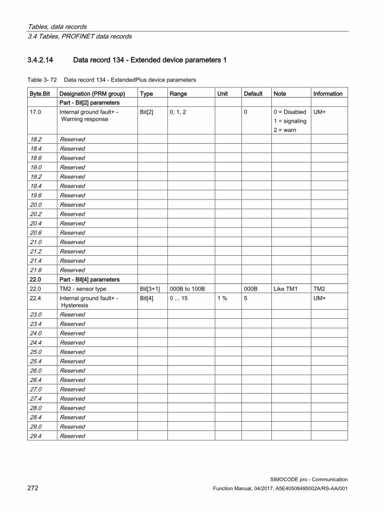
Tables, data records 3.4 Tables, PROFINET data records
SIMOCODE pro - Communication 272 Function Manual, 04/2017, A5E40508495002A/RS-AA/001
3.4.2.14 Data record 134 - Extended device parameters 1
Table 3- 72 Data record 134 - ExtendedPlus device parameters
Byte.Bit Designation (PRM group) Type Range Unit Default Note Information Part - Bit[2] parameters 17.0 Internal ground fault+ -
Warning response Bit[2] 0, 1, 2 0 0 = Disabled
1 = signaling 2 = warn
UM+
18.2 Reserved 18.4 Reserved 18.6 Reserved 19.0 Reserved 19.2 Reserved 19.4 Reserved 19.6 Reserved 20.0 Reserved 20.2 Reserved 20.4 Reserved 20.6 Reserved 21.0 Reserved 21.2 Reserved 21.4 Reserved 21.6 Reserved 22.0 Part - Bit[4] parameters 22.0 TM2 - sensor type Bit[3+1] 000B to 100B 000B Like TM1 TM2 22.4 Internal ground fault+ -
Hysteresis Bit[4] 0 ... 15 1 % 5 UM+
23.0 Reserved 23.4 Reserved 24.0 Reserved 24.4 Reserved 25.0 Reserved 25.4 Reserved 26.0 Reserved 26.4 Reserved 27.0 Reserved 27.4 Reserved 28.0 Reserved 28.4 Reserved 29.0 Reserved 29.4 Reserved

Tables, data records 3.4 Tables, PROFINET data records
SIMOCODE pro - Communication Function Manual, 04/2017, A5E40508495002A/RS-AA/001 273
Byte.Bit Designation (PRM group) Type Range Unit Default Note Information 30.0 Part - Byte parameters 30.0 Trip level 0/4-20 mA > Byte 0 - 255 *128 0 AM2
31.0 Warning level 0/4-20 mA > Byte 0 - 255 *128 0 AM2
32.0 Trip level 0/4-20 mA < Byte 0 - 255 *128 0 AM2
33.0 Warning level 0/4-20 mA < Byte 0 - 255 *128 0 AM2
34.0 Trip delay 0/4-20 mA > Byte 0 - 255 100 ms 5 AM2
35.0 Warning delay 0/4-20 mA > Byte 0 - 255 100 ms 5 AM2
36.0 Trip delay 0/4-20 mA < Byte 0 - 255 100 ms 5 AM2
37.0 Warning delay 0/4-20 mA < Byte 0 - 255 100 ms 5 AM2
38.0 Delay limit 5 Byte 0 - 255 100 ms 5
39.0 Delay limit 6 Byte 0 - 255 100 ms 5
40.0 Truth table 10 type 3I/1O Byte 0 - 11111111B 0 41.0 Truth table 11 type 3I/1O Byte 0 - 11111111B 0 Part - Byte parameters 42.0 Internal ground fault+ -
warning delay Byte 0 ... 255 100 ms 1 UM+
43.0 Reserved 44.0 Reserved 45.0 Reserved 46.0 Reserved 47.0 Reserved 48.0 Reserved 49.0 Reserved 50.0 Reserved 51.0 Reserved 52.0 Reserved 53.0 Reserved 54.0 Reserved 55.0 Reserved
Siemens Parts

Tables, data records 3.4 Tables, PROFINET data records
SIMOCODE pro - Communication 274 Function Manual, 04/2017, A5E40508495002A/RS-AA/001
Byte.Bit Designation (PRM group) Type Range Unit Default Note Information 56.0 Reserved 57.0 Reserved 58.0 Reserved 59.0 Reserved 60.0 Part - Word parameters 60.0 AM2 - Start value output Word 0 - 65535 0 Value for
0/4 mA AM2
62.0 AM2 - End value output Word 0 - 65535 27648 Value for
20 mA AM2
64.0 TM2 - Trip level T> Word 0 - 65535 1K 0 TM2
66.0 TM2 - Warning level T> Word 0 - 65535 1K 0 TM2
68.0 Limit level 5 Word 0 - 65535 0 70.0 Limit level 6 Word 0 - 65535 0 72.0 Timer 5 value Word 0 - 65535 100 ms 0 74.0 Timer 6 value Word 0 - 65535 100 ms 0 76.0 Counter 5 value Word 0 - 65535 0 78.0 Counter 6 value Word 0 - 65535 0 80.0 Calculator 3 const 1 Word 0 - 65535 0 82.0 Calculator 3 const 2 Word 0 - 65535 0 84.0 Calculator 3 const 3 Word 0 - 65535 0 86.0 Calculator 3 const 4 Word 0 - 65535 0 88.0 Calculator 4 const 1 Word 0 - 65535 0 90.0 Calculator 4 const 2 Word 0 - 65535 0 92.0 Calculator 4 const 3 Word 0 - 65535 0 94.0 Calculator 4 const 4 Word 0 - 65535 0 96.0 Analog multiplexer const 1 Word 0 - 65535 0 98.0 Analog multiplexer const 2 Word 0 - 65535 0 100.0 Analog multiplexer const 3 Word 0 - 65535 0 102.0 Analog multiplexer const 4 Word 0 - 65535 0 104.0 PWM input const Word 0 - 65535 0 106.0 PWM input Min Word 0 - 65535 0 108.0 PWM input Max Word 0 - 65535 0 110.0 PWM duration Word 0 - 65535 100 ms 20

Tables, data records 3.4 Tables, PROFINET data records
SIMOCODE pro - Communication Function Manual, 04/2017, A5E40508495002A/RS-AA/001 275
Byte.Bit Designation (PRM group) Type Range Unit Default Note Information Part - Word parameters 112.0 Internal ground fault+ - Trip
level Word 0 ... 65535 1 mA 0 Value range
dependent on current range of the UM+
UM+
114.0 Internal ground fault+ - Warning level
Word 0 ... 65535 1 mA 0 Value range dependent on current range of the UM+
UM+
116.0 Reserved Word 118.0 Reserved Word 120.0 Reserved Word 122.0 Reserved Word 124.0 Reserved Word 126.0 Reserved Word 128.0 Reserved Word 130.0 Reserved Word 132.0 Reserved Word 134.0 Reserved Word 136.0 Reserved Word 138.0 Reserved Word 140.0 Part - D-word parameters 140.0 PE - min. pause time motor D-word 0 - FFFFFFFF 1 ms 0 144.0 Reserved D-word 148 Part - Float parameters 148.0 .. 168.0
Reserved Float
172.0 Reserved D-word 176.0 Reserved D-word
Siemens Parts

Tables, data records 3.4 Tables, PROFINET data records
SIMOCODE pro - Communication 276 Function Manual, 04/2017, A5E40508495002A/RS-AA/001
3.4.2.15 Data record 135 - Extended device parameters 2
Table 3- 73 Data record 135 - ExtendedPlus device parameters 2
Byte.Bit Designation (PRM group) Type Range Unit Default Note Information 0.0 Coordination Byte[4] 4.0 Part - DI byte parameters 4.0 Truth table 10 3I/1O - Input 1 DI byte 0 - 255 0 5.0 Truth table 10 3I/1O - Input 2 DI byte 0 - 255 0 6.0 Truth table 10 3I/1O - Input 3 DI byte 0 - 255 0 7.0 Truth table 11 3I/1O - Input 1 DI byte 0 - 255 0 8.0 Truth table 11 3I/1O - Input 2 DI byte 0 - 255 0 9.0 Truth table 11 3I/1O - Input 3 DI byte 0 - 255 0 10.0 Timer 5 input DI byte 0 - 255 0 11.0 Timer 5 reset DI byte 0 - 255 0 12.0 Timer 6 input DI byte 0 - 255 0 13.0 Timer 6 reset DI byte 0 - 255 0 14.0 Counter 5 input + DI byte 0 - 255 0 15.0 Counter 5 input - DI byte 0 - 255 0 16.0 Counter 5 reset DI byte 0 - 255 0 17.0 Counter 6 input + DI byte 0 - 255 0 18.0 Counter 6 input - DI byte 0 - 255 0 19.0 Counter 6 reset DI byte 0 - 255 0 20.0 Signal conditioning 5 input DI byte 0 - 255 0 21.0 Signal conditioning 5 reset DI byte 0 - 255 0 22.0 Signal conditioning 6 input DI byte 0 - 255 0 23.0 Signal conditioning 6 reset DI byte 0 - 255 0 24.0 Analog multiplexer S1 DI byte 0 - 255 0 25.0 Analog multiplexer S2 DI byte 0 - 255 0 26.0 Reserved 27.0 Reserved 28.0 Reserved 29.0 Reserved 30.0 Reserved 31.0 Reserved 32.0 Reserved 33.0 Reserved 34.0 Reserved 35.0 Reserved 36.0 Reserved 37.0 Reserved 38.0 Reserved 39.0 Reserved 40.0 Reserved

Tables, data records 3.4 Tables, PROFINET data records
SIMOCODE pro - Communication Function Manual, 04/2017, A5E40508495002A/RS-AA/001 277
Byte.Bit Designation (PRM group) Type Range Unit Default Note Information 41.0 Reserved 42.0 Reserved 43.0 Reserved 44.0 Reserved 45.0 Reserved 46.0 Reserved 47.0 Reserved 48.0 Reserved 49.0 Reserved 50.0 Reserved 51.0 Reserved 52.0 Reserved 53.0 Reserved 54.0 Reserved 55.0 Reserved 56.0 Reserved 57.0 Reserved 58.0 Reserved 59.0 Reserved 60.0 Reserved 61.0 Reserved 62.0 Reserved 63.0 Reserved 64.0 Part - AI byte parameters 64.0 AM2 - Output AI byte 0 - 255 0 AM2 65.0 SPS/PLS_analog input 5 AI byte 0 - 255 0 66.0 SPS/PLS_analog input 6 AI byte 0 - 255 0 67.0 SPS/PLS_analog input 7 AI byte 0 - 255 0 68.0 SPS/PLS_analog input 8 AI byte 0 - 255 0 69.0 SPS/PLS_analog input 9 AI byte 0 - 255 0 70.0 Analog input limit 5 AI byte 0 - 255 0 71.0 Analog input limit 6 AI byte 0 - 255 0 72.0 Analog arithmetic 1 input 1 AI byte 0 - 255 0 73.0 Analog arithmetic 1 input 2 AI byte 0 - 255 0 74.0 Analog arithmetic 1 input 3 AI byte 0 - 255 0 75.0 Analog arithmetic 1 input 4 AI byte 0 - 255 0 76.0 Analog arithmetic 2 input 1 AI byte 0 - 255 0 77.0 Analog arithmetic 2 input 2 AI byte 0 - 255 0 78.0 Analog arithmetic 2 input 3 AI byte 0 - 255 0 79.0 Analog arithmetic 2 input 4 AI byte 0 - 255 0 80.0 Analog multiplexer input 1 AI byte 0 - 255 0 81.0 Analog multiplexer input 2 AI byte 0 - 255 0
Siemens Parts

Tables, data records 3.4 Tables, PROFINET data records
SIMOCODE pro - Communication 278 Function Manual, 04/2017, A5E40508495002A/RS-AA/001
Byte.Bit Designation (PRM group) Type Range Unit Default Note Information 82.0 Analog multiplexer input 3 AI byte 0 - 255 0 83.0 Analog multiplexer input 4 AI byte 0 - 255 0 84.0 PWM input AI byte 0 - 255 0 85.0 Reserved AI byte 86.0 Reserved AI byte 87.0 Reserved AI byte 88.0 Reserved AI byte 89.0 Reserved AI byte 90.0 Reserved AI byte 91.0 Reserved AI byte 92.0 Reserved AI byte 93.0 Reserved AI byte 94.0 Reserved AI byte 95.0 Reserved AI byte 96.0 Reserved AI byte 97.0 Reserved AI byte 98.0 Reserved AI byte 99.0 Reserved AI byte Part - FII byte parameters 100.0 PLC / PCS analog FI input FII byte 0 ... 255 0 101.0 PLC / PCS analog FI input FII byte 0 ... 255 0 102.0 PLC / PCS analog FI input FII byte 0 ... 255 0 103.0 PLC / PCS analog FI input FII byte 0 ... 255 0 107 ... 113 Reserved

Tables, data records 3.4 Tables, PROFINET data records
SIMOCODE pro - Communication Function Manual, 04/2017, A5E40508495002A/RS-AA/001 279
3.4.2.16 Data record 139 - Marking For external faults, limit monitors, and monitoring functions of the temperature and analog modules, user-specific texts can be configured for marking.
You can access the following texts via data record 139:
● External fault 1 to 6 (status information, warnings, and faults)
● Limit 1 to 4 (status information)
● TM1 warnings T> / trip T> (status information, warnings, and faults)
● AM1 warning/tripping 0/4 - 20 mA<> (status information, warnings and faults).
Can be parameterized to have various meanings, e.g. fill level >, bearing hot, etc. To simplify diagnostics, these texts can be saved in the device. These can be created, read out and displayed, for example, with SIMOCODE ES. The texts do not contain any functions.
Note Changing the marking
Each change to the marking requires that the communication interface be restarted when the web server is active. A new start interrupts all Ethernet and PROFINET links and reestablishes them afterward.
Table 3- 74 Data record 139 - Marking
Byte.Bit Designation Type Information 0.0 Reserved Byte[4] 4.0 Reserved Byte[6] 10.0 Marking - External fault 1 Byte[10] 20.0 Marking - External fault 2 Byte[10] 30.0 Marking - External fault 3 Byte[10] 40.0 Marking - External fault 4 Byte[10] 50.0 Marking - External fault 5 Byte[10] 60.0 Marking - External fault 6 Byte[10] 70.0 Reserved Byte[10] 80.0 Reserved Byte[10] 90.0 Marking limit 1 Byte[10] 100.0 Marking limit 2 Byte[10] 110.0 Marking limit 3 Byte[10] 120.0 Marking limit 4 Byte[10] 130.0 Marking - TM warning T> Byte[10] 140.0 Marking - TM trip T> Byte[10] 150.0 Marking - Warning 0/4-20 mA> Byte[10] 160.0 Marking - Warning 0/4-20 mA< Byte[10] 170.0 Marking - Trip 0/4-20 mA> Byte[10] 180.0 Marking - Trip 0/4-20 mA< Byte[10] 190.0 Reserved Byte[10]
Siemens Parts
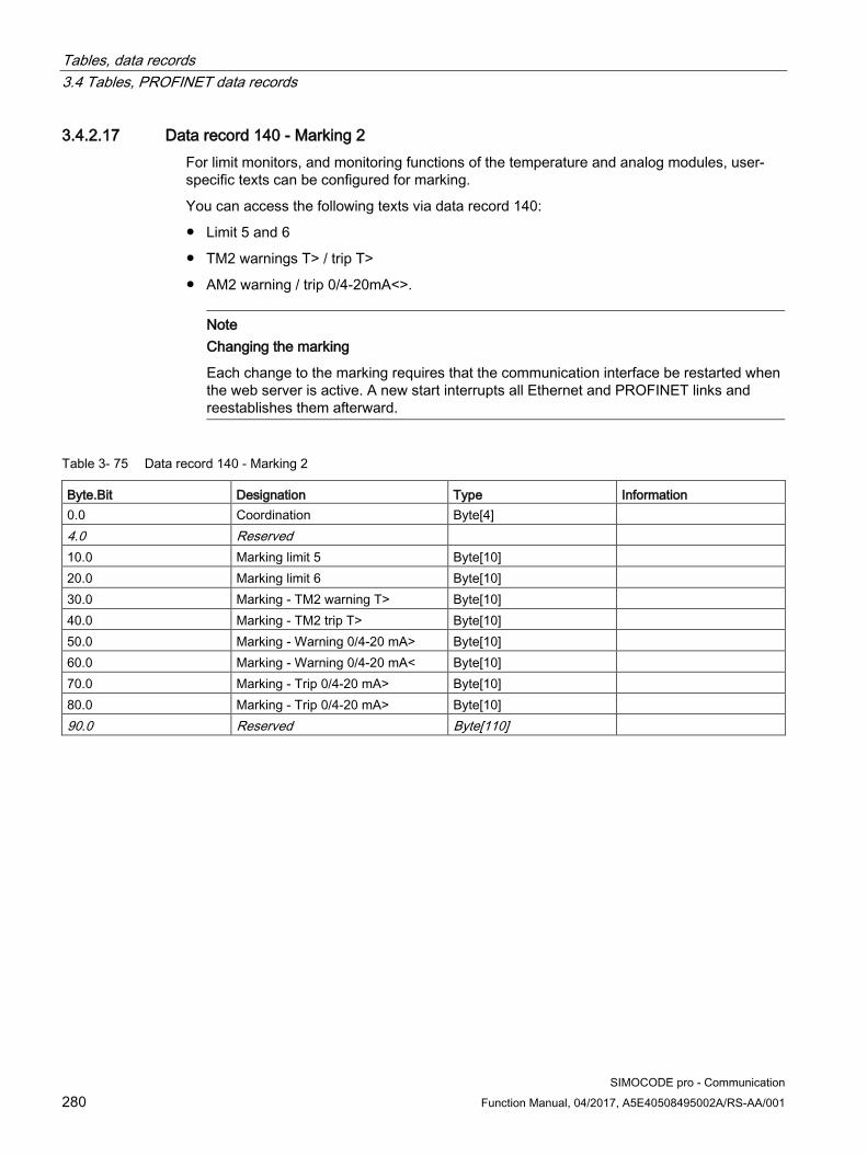
Tables, data records 3.4 Tables, PROFINET data records
SIMOCODE pro - Communication 280 Function Manual, 04/2017, A5E40508495002A/RS-AA/001
3.4.2.17 Data record 140 - Marking 2 For limit monitors, and monitoring functions of the temperature and analog modules, user-specific texts can be configured for marking.
You can access the following texts via data record 140:
● Limit 5 and 6
● TM2 warnings T> / trip T>
● AM2 warning / trip 0/4-20mA<>.
Note
Changing the marking
Each change to the marking requires that the communication interface be restarted when the web server is active. A new start interrupts all Ethernet and PROFINET links and reestablishes them afterward.
Table 3- 75 Data record 140 - Marking 2
Byte.Bit Designation Type Information 0.0 Coordination Byte[4] 4.0 Reserved 10.0 Marking limit 5 Byte[10] 20.0 Marking limit 6 Byte[10] 30.0 Marking - TM2 warning T> Byte[10] 40.0 Marking - TM2 trip T> Byte[10] 50.0 Marking - Warning 0/4-20 mA> Byte[10] 60.0 Marking - Warning 0/4-20 mA< Byte[10] 70.0 Marking - Trip 0/4-20 mA> Byte[10] 80.0 Marking - Trip 0/4-20 mA> Byte[10] 90.0 Reserved Byte[110]
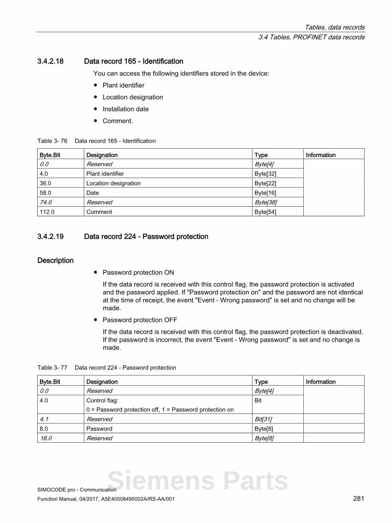
Tables, data records 3.4 Tables, PROFINET data records
SIMOCODE pro - Communication Function Manual, 04/2017, A5E40508495002A/RS-AA/001 281
3.4.2.18 Data record 165 - Identification You can access the following identifiers stored in the device:
● Plant identifier
● Location designation
● Installation date
● Comment.
Table 3- 76 Data record 165 - Identification
Byte.Bit Designation Type Information 0.0 Reserved Byte[4] 4.0 Plant identifier Byte[32] 36.0 Location designation Byte[22] 58.0 Date Byte[16] 74.0 Reserved Byte[38] 112.0 Comment Byte[54]
3.4.2.19 Data record 224 - Password protection
Description ● Password protection ON
If the data record is received with this control flag, the password protection is activated and the password applied. If "Password protection on" and the password are not identical at the time of receipt, the event "Event - Wrong password" is set and no change will be made.
● Password protection OFF
If the data record is received with this control flag, the password protection is deactivated. If the password is incorrect, the event "Event - Wrong password" is set and no change is made.
Table 3- 77 Data record 224 - Password protection
Byte.Bit Designation Type Information 0.0 Reserved Byte[4] 4.0 Control flag:
0 = Password protection off, 1 = Password protection on Bit
4.1 Reserved Bit[31] 8.0 Password Byte[8] 16.0 Reserved Byte[8]
Siemens Parts

Tables, data records 3.5 Modbus data tables
SIMOCODE pro - Communication 282 Function Manual, 04/2017, A5E40508495002A/RS-AA/001
3.5 Modbus data tables
3.5.1 General information
3.5.1.1 Memory image Hexadecimal address Chapter 0x0000 See Process image output - command data (Page 284) 0x0400 See Process image input - monitoring data (Page 285) 0x0800 See Measured values (Page 286) 0x0C00 See Display and statistical data (Page 287) 0x1C00 See Device diagnostics (Page 288) 0x2100 See Error memory (Page 296) 0x2200 See Event memory (Page 297) 0x2A80 See Trace data (Page 298) 0x4000 See I&M0 - device identification (Page 298) 0x4020 See I&M1 data (Page 299) 0x4040 See I&M2 - Installation date (Page 299) 0x4060 See I&M3 - Comment (Page 299) 0x4180 See Basic device parameter 1 (Page 300) 0x4380 See Extended device parameters 1 (Page 307) 0x4880 See Marking (Page 319)

Tables, data records 3.5 Modbus data tables
SIMOCODE pro - Communication Function Manual, 04/2017, A5E40508495002A/RS-AA/001 283
3.5.1.2 Byte arrangement
Byte arrangement When data longer than one byte is stored, the bytes are arranged as follows ("big endian"):
Figure 3-6 Byte arrangement in "big endian" format
3.5.1.3 Specifications The following specifications apply in the tables:
Table 3- 78 Table specifications (example)
Register address *)
Identifier Type Area Units Access ***) Info
15 Reserved **) Byte[4] **) R
16 Max. current I_max Word 0 … 65535 1 % / Is R BU
*) The values given are decimal values
**) Items in italics are not relevant (reserved) and must be filled with "0" when written to
Parameters that can be changed during operation
BU: Entry for SIMOCODE Modbus basic unit
***) Access: R: Read; W: Write; R/W: Read Write
Siemens Parts

Tables, data records 3.5 Modbus data tables
SIMOCODE pro - Communication 284 Function Manual, 04/2017, A5E40508495002A/RS-AA/001
3.5.2 Modbus RTU data tables
3.5.2.1 Process image output - command data The command data can be written via the register memory area with the function codes 06 and 16, or via the coil memory area with function codes 05 and 15.
The process image output and the process image input can also be accessed via function code 23 as a combined write/read access operation.
Read access is possible from the register memory area with function codes 03 and 04, or the coil memory area with function codes 01 and 02.
Max. data length per access: 2 registers, 16 coils.
Table 3- 79 Process image output - command data
Register address
high/low Coil address
Type Description Default value Access
0x0000 low 0x0000 Bit Cyclic receive - bit 0.0 Control station - PLC/PCS [DP] ON< r/w 0x0001 Bit Cyclic receive - bit 0.1 Control station - PLC/PCS [DP] OFF r/w 0x0002 Bit Cyclic receive - bit 0.2 Control station - PLC/PCS [DP] ON> r/w 0x0003 Bit Cyclic receive - bit 0.3 Test 1 r/w 0x0004 Bit Cyclic receive - bit 0.4 Motor protection emergency start r/w 0x0005 Bit Cyclic receive - bit 0.5 Mode selector S1 r/w 0x0006 Bit Cyclic receive - bit 0.6 Reset 1 r/w 0x0007 Bit Cyclic receive - bit 0.7 Unassigned r/w
high 0x0008 Bit Cyclic receive - bit 1.0 Unassigned r/w 0x0009 Bit Cyclic receive - bit 1.1 Unassigned r/w 0x000A Bit Cyclic receive - bit 1.2 Unassigned r/w 0x000B Bit Cyclic receive - bit 1.3 Unassigned r/w 0x000C Bit Cyclic receive - bit 1.4 Unassigned r/w 0x000D Bit Cyclic receive - bit 1.5 Unassigned r/w 0x000E Bit Cyclic receive - bit 1.6 Unassigned r/w 0x000F Bit Cyclic receive - bit 1.7 Unassigned r/w
0x0001 Word Cyclic receive - Analog value Unassigned r/w
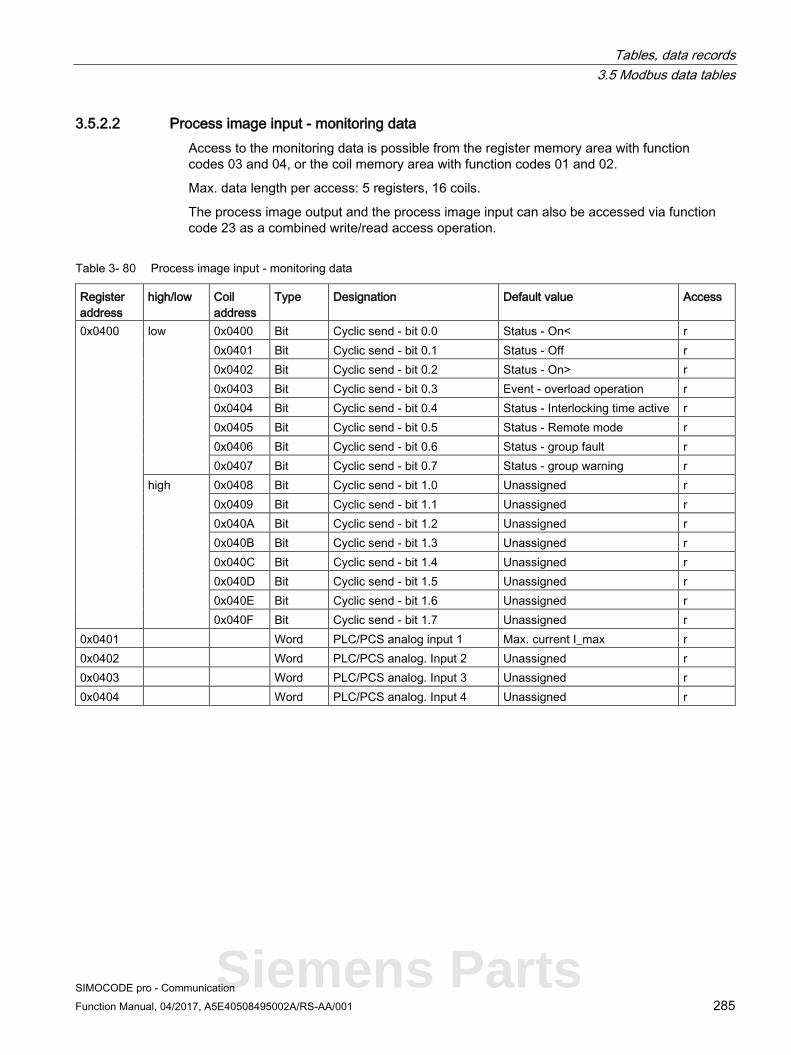
Tables, data records 3.5 Modbus data tables
SIMOCODE pro - Communication Function Manual, 04/2017, A5E40508495002A/RS-AA/001 285
3.5.2.2 Process image input - monitoring data Access to the monitoring data is possible from the register memory area with function codes 03 and 04, or the coil memory area with function codes 01 and 02.
Max. data length per access: 5 registers, 16 coils.
The process image output and the process image input can also be accessed via function code 23 as a combined write/read access operation.
Table 3- 80 Process image input - monitoring data
Register address
high/low Coil address
Type Designation Default value Access
0x0400 low 0x0400 Bit Cyclic send - bit 0.0 Status - On< r 0x0401 Bit Cyclic send - bit 0.1 Status - Off r 0x0402 Bit Cyclic send - bit 0.2 Status - On> r 0x0403 Bit Cyclic send - bit 0.3 Event - overload operation r 0x0404 Bit Cyclic send - bit 0.4 Status - Interlocking time active r 0x0405 Bit Cyclic send - bit 0.5 Status - Remote mode r 0x0406 Bit Cyclic send - bit 0.6 Status - group fault r 0x0407 Bit Cyclic send - bit 0.7 Status - group warning r
high 0x0408 Bit Cyclic send - bit 1.0 Unassigned r 0x0409 Bit Cyclic send - bit 1.1 Unassigned r 0x040A Bit Cyclic send - bit 1.2 Unassigned r 0x040B Bit Cyclic send - bit 1.3 Unassigned r 0x040C Bit Cyclic send - bit 1.4 Unassigned r 0x040D Bit Cyclic send - bit 1.5 Unassigned r 0x040E Bit Cyclic send - bit 1.6 Unassigned r 0x040F Bit Cyclic send - bit 1.7 Unassigned r
0x0401 Word PLC/PCS analog input 1 Max. current I_max r 0x0402 Word PLC/PCS analog. Input 2 Unassigned r 0x0403 Word PLC/PCS analog. Input 3 Unassigned r 0x0404 Word PLC/PCS analog. Input 4 Unassigned r
Siemens Parts

Tables, data records 3.5 Modbus data tables
SIMOCODE pro - Communication 286 Function Manual, 04/2017, A5E40508495002A/RS-AA/001
3.5.2.3 Measured values Read-only access to the measured values is possible from the register memory area with function codes 03 and 04. Max. data length per access: 31 registers.
Table 3- 81 Measured values
Input/holding register Identifier Type Range Units Access 5) Address offset high/low 0x0800 Reserved Byte[2] r 0x0801 Reserved Byte[2] r 0x0802
high Thermal motor model Byte 0 - 255 See 2) r low Phase unbalance Byte 0 - 100 1 % r
0x0803
high Cos phi Byte 0 - 100 1 % r low Reserved Byte[1] r
0x0804 Reserved Byte[2] r 0x0805 Reserved Byte[2] r 0x0806 Max. current I_max Word 0 - 65535 1 % / Is r 0x0807 Current I_L1 Word 0 - 65535 1 % / Is r 0x0808 Current I_L2 Word 0 - 65535 1 % / Is r 0x0809 Current I_L3 Word 0 - 65535 1 % / Is r 0x080A Last trip current Word 0 - 65535 1 % / Is r 0x080B Time to trip Word 0 - 65535 100 ms r 0x080C Cooling down period Word 0 - 65535 100 ms r 0x080D Voltage U_L1 Word 0 - 65535 1 V r 0x080E Voltage U_L2 Word 0 - 65535 1 V r 0x080F Voltage U_L3 Word 0 - 65535 1 V r 0x0810 AM1 - output Word 0 - 32767 See 1) r 0x0811 AM1 - input 1 Word 0 - 32767 r 0x0812 AM1 - input 2 Word 0 - 32767 r 0x0813 Reserved Word 0 - 32767 r 0x0814 TM1 - Temperature Word 0 - 65535 1 K see 3) r 0x0815 TM1 - temperature 1 Word 0 - 65535 r 0x0816 TM1 - temperature 2 Word 0 - 65535 r 0x0817 TM1 - temperature 3 Word 0 - 65535 r 0x0818 EM+ 4) - ground-fault current Word 0 - 65535 r 0x0819 EM+ 4) - last tripping current Word 0 - 65535 r 0x081A Active power P D-word 0 - 0xFFFFFFFF 1 W r 0x081C Apparent power S D word 0 - 0xFFFFFFFF 1 VA r
1) S7 format: 0/4 mA = 0; 20 mA = 27648 2) Representation of the "Thermal motor model": Value related to symmetrical trip level, representation in steps of 2 % in bits 6 ...0 (range 0 to 254 %), bit 7 shows unbalance (fixed level 50 %) 3) Representation in Kelvin 4) 3UF7510-1AA00-0 ground-fault module 5) r/w: Value is read/write; r: Value is read-only

Tables, data records 3.5 Modbus data tables
SIMOCODE pro - Communication Function Manual, 04/2017, A5E40508495002A/RS-AA/001 287
3.5.2.4 Display and statistical data Read access to the display and statistical data is possible from the register memory area with function codes 03 and 04.
Individual statistical data can be written via the register memory area with function codes 06 and 16, and be reset, for example.
Max. data length per access: 34 registers.
Table 3- 82 Display and statistical data
Input/holding register Description Type Range Unit Access 1) Address high/low 0x0C00 Coordination Byte[4] r 0x0C02
high Permissible starts - actual value Byte 0 .. 255 r/w low DM-F - Time until test requirement Byte 0 .. 255 1 week r
0x0C03 Reserved Byte[2] r 0x0C04 Number of parameterizations Word 0 .. 65535 r 0x0C05 Number of overload trips Word 0 .. 65535 r/w 0x0C06 Number of internal overload trips Word 0 .. 65535 r 0x0C07 Motor stop time Word 0 .. 65535 1 h r/w 0x0C08 Timer 1 actual value Word 0 .. 65535 100 ms r 0x0C09 Timer 2 actual value Word 0 .. 65535 100 ms r 0x0C0A Timer 3 actual value Word 0 .. 65535 100 ms r 0x0C0B Timer 4 actual value Word 0 .. 65535 100 ms r 0x0C0C Counter 1 actual value Word 0 .. 65535 r 0x0C0D Counter 2 actual value Word 0 .. 65535 r 0x0C0E Counter 3 actual value Word 0 .. 65535 r 0x0C0F Counter 4 actual value Word 0 .. 65535 r 0x0C10 Calculator 1 output Word 0 .. 65535 r 0x0C11 Calculator 2 output Word 0 .. 65535 r 0x0C12 Reserved Word[2] r 0x0C14 Motor operating hours D word 0 .. 0xFFFFFFFF 1 s r/w 0x0C16 Internal motor operating hours D word 0 .. 0xFFFFFFFF 1 s r 0x0C18 Device operating hours D word 0 .. 0xFFFFFFFF 1 s r 0x0C1A Number of starts D word 0 .. 0xFFFFFFFF r/w 0x0C1C Number of internal starts CW D word 0 .. 0xFFFFFFFF r 0x0C1E Number of internal starts CCW D word 0 .. 0xFFFFFFFF r 0x0C20 Energy W D word 0 .. 0xFFFFFFFF 1 kWh r/w
1) r/w: Value is read/write; r: Value is read-only
Siemens Parts

Tables, data records 3.5 Modbus data tables
SIMOCODE pro - Communication 288 Function Manual, 04/2017, A5E40508495002A/RS-AA/001
3.5.2.5 Device diagnostics Read-only access to the device diagnostics is possible from the register memory area with function codes 03 and 04, or the coil memory area with function codes 01 and 02.
Max. data length per access: 16 registers.
Table 3- 83 Device diagnostics
Input/holding register Type Discrete input / coil address
Identifier Access 1) Address high/low 0x1C00
low Bit 0x1C00 Reserved r 0x1C01 Reserved r 0x1C02 Reserved r 0x1C03 Reserved r 0x1C04 Reserved r 0x1C05 Reserved r 0x1C06 Reserved r 0x1C07 Reserved r
high
Bit 0x1C08 Status - group fault r 0x1C09 Status - group warning r 0x1C0A Status - device r 0x1C0B Status - bus r 0x1C0C Status - PLC/PCS r 0x1C0D Status - current flowing r 0x1C0E Status - PE command Start_Pause pending r 0x1C0F Status - PE energy saving mode active r
0x1C01
low Bit 0x1C10 Status - On<< r 0x1C11 Status - On< r 0x1C12 Status - Off r 0x1C13 Status - On> r 0x1C14 Status - On>> r 0x1C15 Status - start active r 0x1C16 Status - Interlocking time active r 0x1C17 Status - Change-over pause active r
high
Bit 0x1C18 Status - Runs in open direction r 0x1C19 Status - Runs in close direction r 0x1C1A Status - FC r 0x1C1B Status - FO r 0x1C1C Status - TC r 0x1C1D Status - TO r 0x1C1E Status - Cold run TPF r 0x1C1F Status - OPO r

Tables, data records 3.5 Modbus data tables
SIMOCODE pro - Communication Function Manual, 04/2017, A5E40508495002A/RS-AA/001 289
Input/holding register Type Discrete input / coil address
Identifier Access 1) Address high/low 0x1C02
low Bit 0x1C20 Status - Auto mode r 0x1C21 Status - Emergency start executed r 0x1C22 Status - Cooling down period active r 0x1C23 Status - Pause time active r 0x1C24 Status - Device test active r 0x1C25 Status - Phase sequence 1-2-3 r 0x1C26 Status - Phase sequence 3-2-1 r 0x1C27 Status - DM-F enabling circuit r
high Bit 0x1C28 Event - overload operation r 0x1C29 Event - unbalance r 0x1C2A Event - overload r 0x1C2B Event - overload + phase failure r 0x1C2C Event - internal ground fault r 0x1C2D Event - external ground fault r 0x1C2E Event - external ground fault warning r 0x1C2F Event - thermistor overload r
0x1C03
low Bit 0x1C30 Event - thermistor short circuit r 0x1C31 Event - thermistor open circuit r 0x1C32 Event - TM warning T> r 0x1C33 Event - TM trip T> r 0x1C34 Event - TM sensor fault r 0x1C35 Event - TM out of range r 0x1C36 Event - EM+ open circuit r 0x1C37 Event - EM+ short-circuit r
high Bit 0x1C38 Event - Warning I> r 0x1C39 Event - Warning I< r 0x1C3A Event - Warning P> r 0x1C3B Event - Warning P< r 0x1C3C Event - Warning cos phi< r 0x1C3D Event - Warning U< r 0x1C3E Event - warning 0/4 - 20mA> r 0x1C3F Event - warning 0/4 - 20mA< r
Siemens Parts
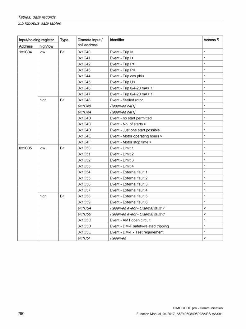
Tables, data records 3.5 Modbus data tables
SIMOCODE pro - Communication 290 Function Manual, 04/2017, A5E40508495002A/RS-AA/001
Input/holding register Type Discrete input / coil address
Identifier Access 1) Address high/low 1x1C04
low Bit 0x1C40 Event - Trip I> r 0x1C41 Event - Trip I< r 0x1C42 Event - Trip P> r 0x1C43 Event - Trip P< r 0x1C44 Event - Trip cos phi< r 0x1C45 Event - Trip U< r 0x1C46 Event - Trip 0/4-20 mA> 1 r 0x1C47 Event - Trip 0/4-20 mA< 1 r
high Bit 0x1C48 Event - Stalled rotor r 0x1C49 Reserved bit[1] r 0x1C4A Reserved bit[1] r 0x1C4B Event - no start permitted r 0x1C4C Event - No. of starts > r 0x1C4D Event - Just one start possible r 0x1C4E Event - Motor operating hours > r 0x1C4F Event - Motor stop time > r
0x1C05
low Bit 0x1C50 Event - Limit 1 r 0x1C51 Event - Limit 2 r 0x1C52 Event - Limit 3 r 0x1C53 Event - Limit 4 r 0x1C54 Event - External fault 1 r 0x1C55 Event - External fault 2 r 0x1C56 Event - External fault 3 r 0x1C57 Event - External fault 4 r
high Bit 0x1C58 Event - External fault 5 r 0x1C59 Event - External fault 6 r 0x1C5A Reserved event - External fault 7 r 0x1C5B Reserved event - External fault 8 r 0x1C5C Event - AM1 open circuit r 0x1C5D Event - DM-F safety-related tripping r 0x1C5E Event - DM-F - Test requirement r 0x1C5F Reserved r

Tables, data records 3.5 Modbus data tables
SIMOCODE pro - Communication Function Manual, 04/2017, A5E40508495002A/RS-AA/001 291
Input/holding register Type Discrete input / coil address
Identifier Access 1) Address high/low 0x1C06
low Bit 0x1C60 Event - timestamp function active + ok r 0x1C61 Reserved r 0x1C62 Event - DM-FL safety ok r 0x1C63 Reserved r 0x1C64 Event - Configured operator panel missing r 0x1C65 Event - Module not supported r 0x1C66 Event - module voltage missing r 0x1C67 Reserved r
high Bit 0x1C68 Event - memory module read in r 0x1C69 Event - memory module programmed r 0x1C6A Event - Memory module erased r 0x1C6B Reserved r 0x1C6C Event - Initialization module read in r 0x1C6D Event - Initialization module programmed r 0x1C6E Event - Initialization module cleared r 0x1C6F Event - Addressing plug read in r
0x1C07
low Bit 0x1C70 Event - startup parameter block active r 0x1C71 Event - parameter changes not allowed in the current
operating state r
0x1C72 Event - Device does not support the required functions r 0x1C73 Event - Bad parameter r 0x1C74 Event - Password wrong r 0x1C75 Event - Password protection active r 0x1C76 Event - Factory settings r 0x1C77 Event - Parameterization active r
high Bit 0x1C78 Event - Prm error number r 0x1C79 Event - Prm error number r 0x1C7A Event - Prm error number r 0x1C7B Event - Prm error number r 0x1C7C Event - Prm error number r 0x1C7D Event - Prm error number r 0x1C7E Event - Prm error number r 0x1C7F Event - Prm error number r
Siemens Parts
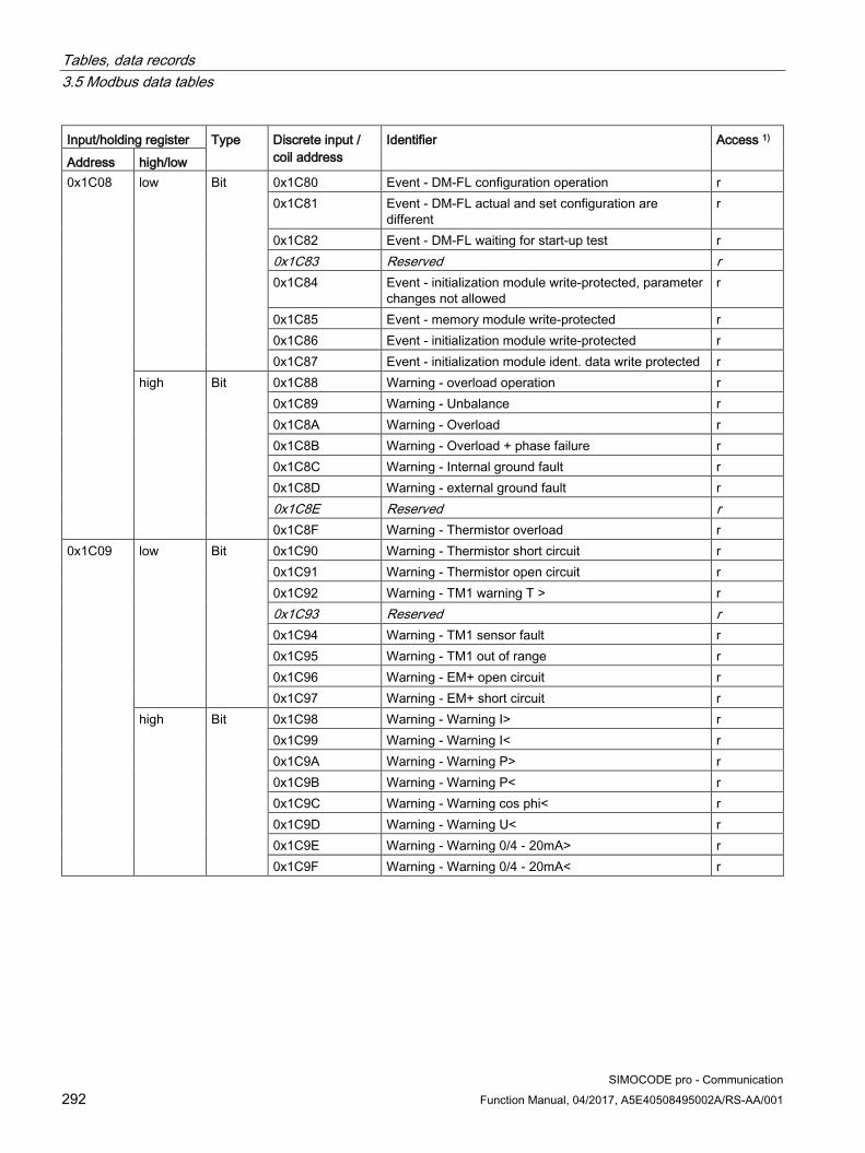
Tables, data records 3.5 Modbus data tables
SIMOCODE pro - Communication 292 Function Manual, 04/2017, A5E40508495002A/RS-AA/001
Input/holding register Type Discrete input / coil address
Identifier Access 1) Address high/low 0x1C08
low Bit 0x1C80 Event - DM-FL configuration operation r 0x1C81 Event - DM-FL actual and set configuration are
different r
0x1C82 Event - DM-FL waiting for start-up test r 0x1C83 Reserved r 0x1C84 Event - initialization module write-protected, parameter
changes not allowed r
0x1C85 Event - memory module write-protected r 0x1C86 Event - initialization module write-protected r 0x1C87 Event - initialization module ident. data write protected r
high Bit 0x1C88 Warning - overload operation r 0x1C89 Warning - Unbalance r 0x1C8A Warning - Overload r 0x1C8B Warning - Overload + phase failure r 0x1C8C Warning - Internal ground fault r 0x1C8D Warning - external ground fault r 0x1C8E Reserved r 0x1C8F Warning - Thermistor overload r
0x1C09
low Bit 0x1C90 Warning - Thermistor short circuit r 0x1C91 Warning - Thermistor open circuit r 0x1C92 Warning - TM1 warning T > r 0x1C93 Reserved r 0x1C94 Warning - TM1 sensor fault r 0x1C95 Warning - TM1 out of range r 0x1C96 Warning - EM+ open circuit r 0x1C97 Warning - EM+ short circuit r
high Bit 0x1C98 Warning - Warning I> r 0x1C99 Warning - Warning I< r 0x1C9A Warning - Warning P> r 0x1C9B Warning - Warning P< r 0x1C9C Warning - Warning cos phi< r 0x1C9D Warning - Warning U< r 0x1C9E Warning - Warning 0/4 - 20mA> r 0x1C9F Warning - Warning 0/4 - 20mA< r

Tables, data records 3.5 Modbus data tables
SIMOCODE pro - Communication Function Manual, 04/2017, A5E40508495002A/RS-AA/001 293
Input/holding register Type Discrete input / coil address
Identifier Access 1) Address high/low 0x1C0A
low Bit 0x1CA0 Warning - Stalled rotor r 0x1CA1 Reserved r 0x1CA2 Reserved r 0x1CA3 Warning - No start possible r 0x1CA4 Warning - Number of starts > r 0x1CA5 Warning - Just one start possible r 0x1CA6 Warning - Motor operating hours> r 0x1CA7 Warning - Motor stop time > r
high Bit 0x1CA8 Warning - External fault 1 r 0x1CA9 Warning - External fault 2 r 0x1CAA Warning - External fault 3 r 0x1CAB Warning - External fault 4 r 0x1CAC Warning - External fault 5 r 0x1CAD Warning - External fault 6 r 0x1CAE Reserved warning - External fault 7 r 0x1CAF Reserved warning - External fault 8 r
0x1C0B
low Bit 0x1CB0 Warning - AM1 open circuit r 0x1CB1 Warning - DM-F safety-related tripping r 0x1CB2 Warning - DM-F test requirement r 0x1CB3 Reserved r 0x1CB4 Reserved r 0x1CB5 Reserved r 0x1CB6 Warning - DM-F feedback circuit r 0x1CB7 Warning - DM-FL simultaneity r
high Bit 0x1CB8 Fault - hardware fault basic unit r 0x1CB9 Fault - Module fault r 0x1CBA Fault - Temporary components r 0x1CBB Fault - configuration error r 0x1CBC Fault - Parameterization r 0x1CBD Fault - bus r 0x1CBE Fault - PLC/PCS r 0x1CBF Reserved r
Siemens Parts
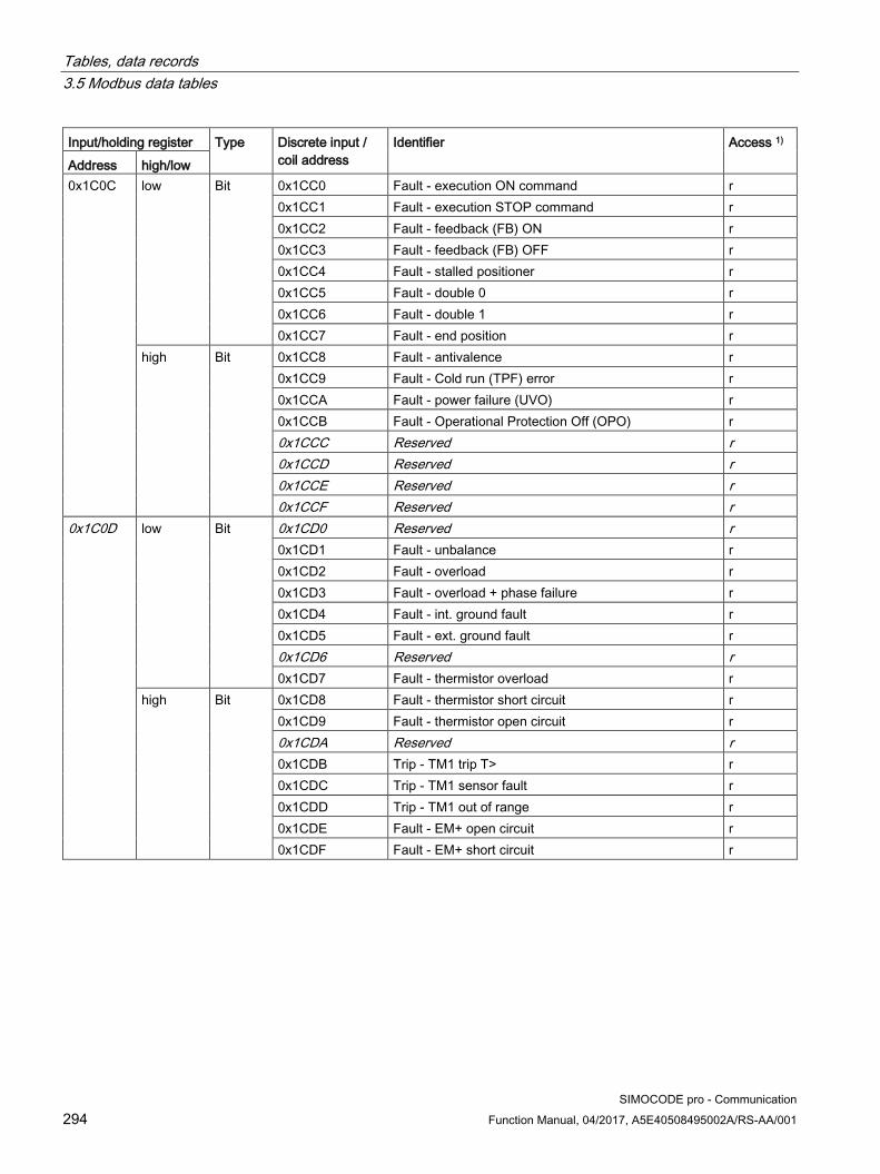
Tables, data records 3.5 Modbus data tables
SIMOCODE pro - Communication 294 Function Manual, 04/2017, A5E40508495002A/RS-AA/001
Input/holding register Type Discrete input / coil address
Identifier Access 1) Address high/low 0x1C0C
low Bit 0x1CC0 Fault - execution ON command r 0x1CC1 Fault - execution STOP command r 0x1CC2 Fault - feedback (FB) ON r 0x1CC3 Fault - feedback (FB) OFF r 0x1CC4 Fault - stalled positioner r 0x1CC5 Fault - double 0 r 0x1CC6 Fault - double 1 r 0x1CC7 Fault - end position r
high Bit 0x1CC8 Fault - antivalence r 0x1CC9 Fault - Cold run (TPF) error r 0x1CCA Fault - power failure (UVO) r 0x1CCB Fault - Operational Protection Off (OPO) r 0x1CCC Reserved r 0x1CCD Reserved r 0x1CCE Reserved r 0x1CCF Reserved r
0x1C0D
low Bit 0x1CD0 Reserved r 0x1CD1 Fault - unbalance r 0x1CD2 Fault - overload r 0x1CD3 Fault - overload + phase failure r 0x1CD4 Fault - int. ground fault r 0x1CD5 Fault - ext. ground fault r 0x1CD6 Reserved r 0x1CD7 Fault - thermistor overload r
high Bit 0x1CD8 Fault - thermistor short circuit r 0x1CD9 Fault - thermistor open circuit r 0x1CDA Reserved r 0x1CDB Trip - TM1 trip T> r 0x1CDC Trip - TM1 sensor fault r 0x1CDD Trip - TM1 out of range r 0x1CDE Fault - EM+ open circuit r 0x1CDF Fault - EM+ short circuit r
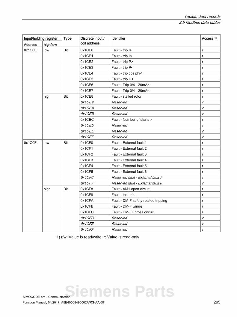
Tables, data records 3.5 Modbus data tables
SIMOCODE pro - Communication Function Manual, 04/2017, A5E40508495002A/RS-AA/001 295
Input/holding register Type Discrete input / coil address
Identifier Access 1) Address high/low 0x1C0E
low Bit 0x1CE0 Fault - trip I> r 0x1CE1 Fault - trip I< r 0x1CE2 Fault - trip P> r 0x1CE3 Fault - trip P< r 0x1CE4 Fault - trip cos phi< r 0x1CE5 Fault - trip U< r 0x1CE6 Fault - Trip 0/4 - 20mA> r 0x1CE7 Fault - Trip 0/4 - 20mA< r
high Bit 0x1CE8 Fault - stalled rotor r 0x1CE9 Reserved r 0x1CEA Reserved r 0x1CEB Reserved r 0x1CEC Fault - Number of starts > r 0x1CED Reserved r 0x1CEE Reserved r 0x1CEF Reserved r
0x1C0F
low Bit 0x1CF0 Fault - External fault 1 r 0x1CF1 Fault - External fault 2 r 0x1CF2 Fault - External fault 3 r 0x1CF3 Fault - External fault 4 r 0x1CF4 Fault - External fault 5 r 0x1CF5 Fault - External fault 6 r 0x1CF6 Reserved fault - External fault 7 r 0x1CF7 Reserved fault - External fault 8 r
high Bit 0x1CF8 Fault - AM1 open circuit r 0x1CF9 Fault - test trip r 0x1CFA Fault - DM-F safety-related tripping r 0x1CFB Fault - DM-F wiring r 0x1CFC Fault - DM-FL cross circuit r 0x1CFD Reserved r 0x1CFE Reserved r 0x1CFF Reserved r
1) r/w: Value is read/write; r: Value is read-only
Siemens Parts

Tables, data records 3.5 Modbus data tables
SIMOCODE pro - Communication 296 Function Manual, 04/2017, A5E40508495002A/RS-AA/001
3.5.2.6 Error memory Read-only access to the error memory is possible via function codes 03 and 04 .
Max. data length per access: 63 registers.
Table 3- 84 Error buffer
Input register Entry Designation1) Type Units Access 2) Address high/low 0x2100 1 Time stamp D word 1 s r 0x2102
high Entry - Type Byte r low Entry - Info Byte r
0x2103 2 Time stamp D word 1 s r 0x2105
high Entry - Type Byte r low Entry - Info Byte r
... ... r 0x213C 21 Time stamp D word 1 s r 0x213E
high Entry - Type Byte r low Entry - Info Byte r
1 ) The meaning of the error events can be found in the table "Alarm, fault, and system events, PROFIBUS error handling" in the SIMOCODE pro system manual.
2) r/w: Value is read/write; r: Value is read-only

Tables, data records 3.5 Modbus data tables
SIMOCODE pro - Communication Function Manual, 04/2017, A5E40508495002A/RS-AA/001 297
3.5.2.7 Event memory Read-only access to the event memory is possible via function codes 03 and 04.
Max. data length per access: 84 registers.
Table 3- 85 Event memory
Input/holding register Entry Identifier Type Units Access 2) Address high/low 0x2200 1
Time stamp D word 1 s r
0x2202
high Entry - Type Byte r low Entry - Info (part 1) 1) Byte r
0x2203 high/low Entry - Info (part 2) 1) Byte[2] r 0x2204 2 Time stamp D word 1 s r 0x2206
high Entry - Type Byte r low Entry - Info (part 1) 1) Byte r
0x2207 high/low Entry - Info (part 2) 1) Byte[2] r 0x2208 3 Time stamp D word 1 s r 0x220A
high Entry - Type Byte r low Entry - Info (part 1) 1) Byte r
0x220B Entry - Info (part 2) 1) Byte[2] r ... r 0x2250 21 Time stamp D word 1 s r 0x2252
high Entry - Type Byte r low Entry - Info (part 1) 1) Byte r
0x2253 high/low Entry - Info (part 2) 1) Byte[2] r
1) Entry - Info consists of a total of 3 bytes distributed across two register addresses respectively.
The following applies for the data set length: SIMOCODE pro V basic unit Modbus RTU: 168 byte
2) r/w: Value is read/write; r: Value is read-only
Siemens Parts

Tables, data records 3.5 Modbus data tables
SIMOCODE pro - Communication 298 Function Manual, 04/2017, A5E40508495002A/RS-AA/001
3.5.2.8 Trace data Read-only access to the trace data is possible via function codes 03 and 04.
Max. data length per access: 63 registers.
Table 3- 86 Trace data
Input/holding register Identifier Type Range Access 1) Address high/low byte; bit
position Bit
0x2A80 StartPos Word 0 r 0x2A81
high Channel No. Byte 0 ... 59 r low 0 Trace status - Trace recording in progress Bit 0, 1 r
1 Trace status - Trigger event occurred Bit 0, 1 r 2-7 Reserved Bit[6]
0 r
0x2A82 Measured value (0) Word 0 ... 65535 r 0x2A83 Measured value (1) Word 0 ... 65535 r ... ... Word 0 ... 65535 r 0x2ABD Measured value (59) Word 0 ... 65535 r
1) r/w: Value is read/write; r: Value is read-only
3.5.2.9 I&M0 - device identification Read-only access to the I&M0 device identification is possible via function codes 03 and 04.
Max. data length per access: 32 registers.
Table 3- 87 I&M (device identification)
Input register Content Size Coding (H) Access 1) Address 0x4000 RESERVED 10 byte 0x00, ... 0x00 r 0x4005 MANUFACTURER_ID 2 bytes 42 = 0x002A (SIEMENS AG) r 0x4006 ORDER_ID 20 byte "3UF7 ..." r 0x4010 SERIAL_NUMBER 16 byte ASCII r 0x4018 HARDWARE_REVISION 2 bytes r 0x4019 SOFTWARE_REVISION 4 byte Va.b.c r 0x401B REVISION_COUNTER 2 bytes 0x0000 r 0x401C PROFILE_ID 2 bytes 0x5E10 = VA, GG3 = 0 r 0x401D PROFILE_SPECIFIC_TYPE 2 bytes 0x1039 = GG2_MBR r 0x401E IM_VERSION 2 bytes 0x0101 (V1.1) r 0x401F IM_SUPPORTED 2 bytes 0x000E r
Data record length: 64 bytes
1) r/w: Value is read/write; r: Value is read-only
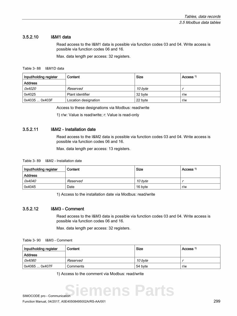
Tables, data records 3.5 Modbus data tables
SIMOCODE pro - Communication Function Manual, 04/2017, A5E40508495002A/RS-AA/001 299
3.5.2.10 I&M1 data Read access to the I&M1 data is possible via function codes 03 and 04. Write access is possible via function codes 06 and 16.
Max. data length per access: 32 registers.
Table 3- 88 I&M1D data
Input/holding register Content Size Access 1) Address 0x4020 Reserved 10 byte r 0x4025 Plant identifier 32 byte r/w 0x4035 ... 0x403F Location designation 22 byte r/w
Access to these designations via Modbus: read/write
1) r/w: Value is read/write; r: Value is read-only
3.5.2.11 I&M2 - Installation date Read access to the I&M2 data is possible via function codes 03 and 04. Write access is possible via function codes 06 and 16.
Max. data length per access: 13 registers.
Table 3- 89 I&M2 - Installation date
Input/holding register Content Size Access 1) Address 0x4040 Reserved 10 byte r 0x4045 Date 16 byte r/w
1) Access to the installation date via Modbus: read/write
3.5.2.12 I&M3 - Comment Read access to the I&M3 data is possible via function codes 03 and 04. Write access is possible via function codes 06 and 16.
Max. data length per access: 32 registers.
Table 3- 90 I&M3 - Comment
Input/holding register Content Size Access 1) Address 0x4060 Reserved 10 byte r 0x4065 ... 0x407F Comments 54 byte r/w
1) Access to the comment via Modbus: read/write
Siemens Parts

Tables, data records 3.5 Modbus data tables
SIMOCODE pro - Communication 300 Function Manual, 04/2017, A5E40508495002A/RS-AA/001
3.5.2.13 Basic device parameter 1 Read access to the device parameters is possible from the register memory area with function codes 03 and 04.
Individual parameter data (marked with the motor symbol in the "Info" column) can be written via Modbus RTU via the register memory area with function codes 06 and 16. This function can be used to adjust settings such as the rated motor current during operation of the motor.
Max. data record length per access: 46 registers.
The "SIMOCODE ES (TIA Portal)" software is nonetheless required for full parameterization of the SIMOCODE pro V Modbus devices (see also Chapter "Commissioning with Modbus RTU" in the SIMOCODE pro system manual).
Table 3- 91 Basic device parameter 1
Input/holding register Designation Type Range Unit Default Comments Info Access 1)
Address high/low Bit 0x4180 Coordination Byte[4] r 0x4182 Device
configuration Byte[8] r
0x4186
high 0 No configuration fault due to OP
Bit 0, 1 0 r
1 Startup parameter block active
Bit 0, 1 0 r
2 TEST/RESET buttons blocked
Bit 0, 1 0 r
3 Bus and PLC/PCS - Reset
Bit 0, 1 0 0 = Manual 1 = Auto
r
4 Reserved Bit 0 r 5 Reserved Bit 0 r 6 Reserved Bit 0 r 7 Reserved Bit 0 r
low 0 Diagnostics for process events
Bit 0, 1 0 r
1 Diagnostics for process warnings
Bit 0, 1 1 r
2 Diagnostics for process faults
Bit 0, 1 1 r
3 Diagnostics for device faults
Bit 0, 1 1 r
4 Reserved Bit 0 r 5 Reserved Bit 0 r 6 Bus monitoring Bit 0, 1 1 r 7 PLC/PCS
monitoring Bit 0, 1 1 r

Tables, data records 3.5 Modbus data tables
SIMOCODE pro - Communication Function Manual, 04/2017, A5E40508495002A/RS-AA/001 301
Input/holding register Designation Type Range Unit Default Comments Info Access 1)
Address high/low Bit 0x4187 high 0 Motor protection -
Type of load Bit 0, 1 0 0 = 3-phase
1 = 1-phase r
1 Motor protection - Reset
Bit 0, 1 0 0 = Manual 1 = Auto
r
2 Reserved Bit 0 r 3 Save change-over
command Bit 0, 1 0 r
4 Non-maintained command mode
Bit 0, 1 0 r
5 Cold start level (TPF)
Bit 0, 1 0 0 = NO contact 1 = NC contact
r
6 Type of consumer load
Bit 0, 1 0 0 = Motor 1 = ohmic load
r
7 Reserved Bit 0 r low 0 External fault
level 1 Bit 0, 1 0 0 = NO
contact 1 = NC contact
r
1 External fault level 2
Bit 0, 1 0 r
2 External fault level 3
Bit 0, 1 0 r
3 External fault level 4
Bit 0, 1 0 r
4 Monitoring external fault 1
Bit 0, 1 0 0 = Always 1 = Only motor ON
r
5 Monitoring external fault 2
Bit 0, 1 0 r
6 Monitoring external fault 3
Bit 0, 1 0 r
7 Monitoring external fault 4
Bit 0, 1 0 r
Siemens Parts

Tables, data records 3.5 Modbus data tables
SIMOCODE pro - Communication 302 Function Manual, 04/2017, A5E40508495002A/RS-AA/001
Input/holding register Designation Type Range Unit Default Comments Info Access 1)
Address high/low Bit Part - Bit[2]
parameter
0x4188 high 0-1 Thermistor - Overload response
Bit[2] 1, 2, 3 3 0 = Disabled 1 = Signaling 2 = Warn 3 = Tripping
r
2-3 Thermistor - Response to sensor fault
Bit[2] 0, 1, 2, 3 2 r
4-5 Internal ground fault - Response
Bit[2] 0, 1, 2, 3 0 r
6-7 Motor protection - Overload response
Bit[2] 0, 1, 2, 3 0 r
low 0-1 Motor protection - Overload response
Bit[2] 0, 1, 2 2 r
2-3 Motor protection - Response to unbalance
Bit[2] 0, 1, 2, 3 2 r
4-5 Trip response I> Bit[2] 0, 1, 3 0 r 6-7 Warning response
I> Bit[2] 0, 1, 2 0 r
0x4189 high 0-1 Trip response I< Bit[2] 0, 1, 3 0 r 2-3 Warning response
I< Bit[2] 0, 1, 2 0 r
4-5 Response to stalled rotor
Bit[2] 0, 1, 2, 3 0 r
6-7 EM+ - Response to sensor fault
Bit[2] 0, 1, 2, 3 0 r
low 0-1 Response to number of starts >
Bit[2] 0, 1, 2, 3 0 r
2-3 Response to early warning number of starts >
Bit[2] 0, 1, 2 0 r
4-5 Motor operating hours response >
Bit[2] 0, 1, 2 0 r
6-7 Motor stop time response >
Bit[2] 0, 1, 2 0 r

Tables, data records 3.5 Modbus data tables
SIMOCODE pro - Communication Function Manual, 04/2017, A5E40508495002A/RS-AA/001 303
Input/holding register Designation Type Range Unit Default Comments Info Access 1)
Address high/low Bit 0x418A high 0-1 External fault
response 1 Bit[2] 1, 2, 3 1 r
2-3 External fault response 2
Bit[2] 1, 2, 3 1 r
4-5 External fault response 3
Bit[2] 1, 2, 3 1 r
6-7 External fault response 4
Bit[2] 1, 2, 3 1 r
low 0-1 Reserved Bit[2] 0 r 2-3 Delay for BU inputs Bit[2] 0 ... 3 10 ms 1 Offset 6 ms r 4-5 Timer 1 - type Bit[2] 0, 1, 2, 3 0 0 = With
closing delay 1 = Closing delay with memory 2 = With OFF delay 3 = With fleeting closing
r 6-7 Timer 2 - type Bit[2] 0, 1, 2, 3 0 r
0x418B high 0-1 Signal conditioning 1 - type
Bit[2] 0, 1, 2, 3 0 0 = Non-inverting 1 = Inverting 2 = Edge rising with memory 3 = Edge falling with memory
r
2-3 Signal conditioning 2 - type
Bit[2] 0, 1, 2, 3 0 r
4-5 Non-volatile element 1 - type
Bit[2] 0, 1, 2, 3 0 r
6-7 Non-volatile element 2 - type
Bit[2] 0, 1, 2, 3 0 r
low 0-1 EM+ - monitoring Bit[2] 0, 1, 2, 3 0 0 = on 1 = on+ 2 = run 3 = run+
r 2-3 EM+ - monitoring
warning Bit[2] 0, 1, 2, 3 0 r
4-5 Reserved Bit[2] 0 r 6-7 Reserved Bit[2] 0 r
Siemens Parts

Tables, data records 3.5 Modbus data tables
SIMOCODE pro - Communication 304 Function Manual, 04/2017, A5E40508495002A/RS-AA/001
Input/holding register Designation Type Range Unit Default Comments Info Access 1)
Address high/low Bit Part - Bit[4]
parameters r
0x418C high Reset response external fault 1
Bit[4] 0 ... 1111B
0101B Bit[0] = Panel reset Bit[1] = Auto reset Bit[2] = Remote reset Bit[1] = OFF command reset
r
Reset response external fault 2
Bit[4] 0 ... 1111B
0101B r
low Reset response external fault 3
Bit[4] 0 ... 1111B
0101B r
Reset response external fault 4
Bit[4] 0 ... 1111B
0101B r
0x418D high 0-3 Hysteresis current levels
Bit[4] 0 ... 15 1 % 5 r
4-7 EM+ - hysteresis Bit[4] 0 ... 15 1 % 5 r low Reserved Bit[4] 0 r
Reserved Bit[4] 0 r Part - Byte
parameters
0x418E
high Internal ground fault - Delay
Byte 0 ... 255 100 ms 5 IM/UM
r/w
low Motor protection - Class
Byte 5, 10 ... 35, 40
10
r/w
0x418F
high Motor protection - Delay with overload operation
Byte 0 ... 255 100 ms 5 IM/UM
r/w
low Motor protection - Unbalance level
Byte 0 ... 100 1 % 40 IM/UM
r/w
0x4190
high Motor protection - Delay with unbalance
Byte 0 ... 255 100 ms 5 IM/UM
r/w
low Interlocking time Byte 0 ... 255 1 s 0
r/w
0x4191
high FB time Byte 0 ... 255 100 ms 5 0 = disabled
r/w
low Trip level I> Byte 0 ... 255 4 % / I_s
0 IM/UM
r/w

Tables, data records 3.5 Modbus data tables
SIMOCODE pro - Communication Function Manual, 04/2017, A5E40508495002A/RS-AA/001 305
Input/holding register Designation Type Range Unit Default Comments Info Access 1)
Address high/low Bit 0x4192
high Warning level I> Byte 0 ... 255 4 % / I_s
0 IM/UM
r/w
low Trip level I< Byte 0 ... 255 4 % / I_s
0 IM/UM
r/w
0x4193
high Warning level I< Byte 0 ... 255 4 % / I_s
0 IM/UM
r/w
low Stalled rotor level Byte 0 ... 255 4 % / I_s
0 IM/UM
r/w
0x4194
high Trip delay I> Byte 0 ... 255 100 ms 5 IM/UM
r/w
low Warning delay I> Byte 0 ... 255 100 ms 5 IM/UM
r/w
0x4195
high Trip delay I< Byte 0 ... 255 100 ms 5 IM/UM
r/w
low Warning delay I< Byte 0 ... 255 100 ms 5 IM/UM
r/w
0x4196
high Blocking delay Byte 0 ... 255 100 ms 5 IM/UM
r/w
low Monitoring the number of starts - Permissible starts
Byte 1 ... 255 1
r/w
0x4197
high Reserved Byte 0 low EM+ - warning
delay Byte 0 ... 255 100 ms 1
r/w
0x4198
high Truth table 1 type 3I/1O
Byte 0 ... 11111111B
0 r
low Truth table 2 type 3I/1O
Byte 0 ... 11111111B
0 r
0x4199
high Truth table 3 type 3I/1O
Byte 0 ... 11111111B
0 r
low Reserved Byte 0 r
Siemens Parts

Tables, data records 3.5 Modbus data tables
SIMOCODE pro - Communication 306 Function Manual, 04/2017, A5E40508495002A/RS-AA/001
Input/holding register Designation Type Range Unit Default Comments Info Access 1)
Address high/low Bit Part - Word
parameters
0x419A Motor protection - Cooling down period
Word 600 ... 65535
100 ms 3000 IM/UM
r/w
0x419B Motor protection - Pause time
Word 0 ... 65535
100 ms 0 0 = disabled IM/UM
r/w
0x419C Validity period Word 0 ... 65535
100 ms 10 0 = disabled
r/w
0x419D Monitoring the number of starts - Time range for starts
Word 0 ... 65535
1 s 0
r/w
0x419E Monitoring the number of starts - Interlocking time
Word 0 ... 65535
1 s 0
r/w
0x419F Motor stop time level >
Word 0 ... 65535
1 h 0
r/w
0x41A0 Timer 1 value Word 0 ... 65535
100 ms 0
r/w
0x41A1 Timer 2 value Word 0 ... 65535
100 ms 0
r/w
0x41A2 Counter 1 value Word 0 ... 65535
0
r/w
0x41A3 Counter 2 value Word 0 ... 65535
0
r/w
0x41A4 EM+ - trip level Word 30 ... 40000
1 mA 1000
r/w
0x41A5 EM+ - warning level
Word 30 ... 40000
1 mA 500
r/w
Part - D word parameter
0x41A6 Operator control enables
Bit[32] 0 ... 1 ... 1B
0 ... 0B r
0x41A8 Motor protection - Set current Is1 2)
D word 10 mA 30 IM/UM
r/w
0x41AA Motor operating hours level >
D word 0 ... 0xFFFFFFFF
1 s 0
r/w
0x41AC Reserved D-word 0 r
1) r/w: Value is read/write; r: Value is read-only
2) Bit 15 = 1 → Transformation ratio active

Tables, data records 3.5 Modbus data tables
SIMOCODE pro - Communication Function Manual, 04/2017, A5E40508495002A/RS-AA/001 307
3.5.2.14 Extended device parameters 1 Read access to the device parameters is possible from the register memory area with function codes 03 and 04.
Individual parameter data (marked with the motor symbol in the "Info" column) can be written via Modbus RTU via the register memory area with function codes 06 and 16. This function can be used to adjust settings such as the rated motor current during operation of the motor.
The "SIMOCODE ES (TIA Portal)" software is nonetheless required for full parameterization of the SIMOCODE pro V Modbus devices (see also Chapter "Commissioning with Modbus RTU" in the SIMOCODE pro system manual).
Siemens Parts

Tables, data records 3.5 Modbus data tables
SIMOCODE pro - Communication 308 Function Manual, 04/2017, A5E40508495002A/RS-AA/001
Max. data length per access: 72 registers.
Table 3- 92 Extended device parameters 1
Input/holding register Designation Type Range Unit Default Comments Info Access 1)
Address high/ low
Bit
0x4380 Coordination Byte[4] r Part - Bit
parameters
0x4382 high 0 3UF50 compatibility mode
Bit 0, 1 0 r
1 3UF50 operating mode
Bit 0, 1 0 0 = DPV0 1 = DPV1
r
2 Reserved Bit 0 r 3 Reserved Bit 0 r 4 Reserved Bit 0 r 5 Reserved Bit 0 r 6 Reserved Bit 0 r 7 Reserved Bit 0 r
low 0 Reserved Bit 0 r 1 Voltage measuring
- Type of load Bit 0, 1 0 0 = 3-phase
1 = 1-phase r
2 OPD - Warnings Bit 0, 1 0 0 = Do not display 1 = Display
r 3 OPD - Faults Bit 0, 1 1
4 AM1 - Measuring range input
Bit 0, 1 0 0 = 0 ... 20 mA 1 = 4 ... 20 mA
r
5 AM1 - Measuring range Output
Bit 0, 1 0 r
6 Reserved Bit 0 r 7 Reserved Bit 0 r
0x4383 high 0 Overshooting/undershooting limit 1
Bit 0, 1 0 0 = > (over-shooting) 1 = < (under-shooting)
r
1 Overshooting/undershooting limit 2
Bit 0, 1 0 r
2 Overshooting/undershooting limit 3
Bit 0, 1 0 r
3 Overshooting/undershooting limit 4
Bit 0, 1 0 r
4 Line-to-line voltage Bit 0, 1 0 0 = No 1 = Yes
r
5 OPO level Bit 0, 1 0 0 = NO contact 1 = NC contact
r

Tables, data records 3.5 Modbus data tables
SIMOCODE pro - Communication Function Manual, 04/2017, A5E40508495002A/RS-AA/001 309
Input/holding register Designation Type Range Unit Default Comments Info Access 1)
Address high/ low
Bit
6 Positioner response for OPO
Bit 0, 1 0 0 = CLOSED 1 = OPEN
r
7 Star-delta - Transformer mounting
Bit 0, 1 0 0 = Delta 1 = In supply cable
r
low 0 External fault level 5
Bit 0, 1 0 0 = NO contact 1 = NC contact
r
1 External fault level 6
Bit 0, 1 0 r
2 Reserved Bit 0 r 3 Reserved Bit 0 r 4 Monitoring external
fault 5 Bit 0, 1 0 0 = Always
1 = Only motor ON
r
5 Monitoring external fault 5
Bit 0, 1 0 r
6 Reserved Bit 0, 1 0 r 7 Reserved Bit 0, 1 0 r
0x4384 high 0 Calculator 2 - Operating mode
Bit 0, 1 0 0 = Word 1 = D word
r
1 Reserved Bit 0 r 2 DM-F - Safe
tripping function Bit 0, 1 0 0 = No
1 = Yes r
3 DM-F - Safety-related tripping reset
Bit 0, 1 0 0 = Manual 1 = Auto
r
4 Time stamping active
Bit 0, 1 0 r
5 Reserved Bit 0 r 6 Reserved Bit 0 r 7 Reserved Bit 0 r
low
0 DM-FL - Configuration 1
Bit 0, 1 0 Configurable parameters comparable with the module configuration
r
1 DM-FL - Configuration 2
Bit 0, 1 0 r
2 DM-FL - Configuration 3
Bit 0, 1 0 r
3 DM-FL - Configuration 4
Bit 0, 1 0 r
4 DM-FL - Configuration 5
Bit 0, 1 0 r
5 DM-FL - Configuration 6
Bit 0, 1 0 r
6 DM-FL - Configuration 7
Bit 0, 1 0 r
7 DM-FL - Configuration 8
Bit 0, 1 0 r
Siemens Parts

Tables, data records 3.5 Modbus data tables
SIMOCODE pro - Communication 310 Function Manual, 04/2017, A5E40508495002A/RS-AA/001
Input/holding register Designation Type Range Unit Default Comments Info Access 1)
Address high/ low
Bit
Part - Bit[2] parameter
r
0x4385 high 0-1 3UF50 basic type Bit[2] 0, 1, 2 0 r 2-3 Reserved Bit[2] 0 r 4-5 UVO timebase Bit[2] 0, 1, 2 0 0 = 100 ms
1 = 1 s 2 = 10 s
r
6-7 UVO operating mode
Bit[2] 0, 1, 2 0 0 = Disabled 1 = Device connected to voltage (reserved) 2 = Voltage fails
r
low 0-1 Trip monitoring U< Bit[2] 0, 1, 2 1 0 = ON (always) 1 = ON+ (always, not TPF) 2 = RUN (motor ON, not TPF)
r 2-3 Warning
monitoring U < Bit[2] 0, 1, 2 1 r
4-5 Reserved Bit[2] 0 r 6-7 Reserved Bit[2] 0 r
0x4386 high 0-1 Trip monitoring 0/4-20mA >
Bit[2] 0, 1, 2, 3 0 r
2-3 Warning monitoring 0/4-20mA >
Bit[2] 0, 1, 2, 3 0 r
4-5 Trip monitoring 0/4-20mA <
Bit[2] 0, 1, 2, 3 0 r
6-7 Warning monitoring 0/4-20mA <
Bit[2] 0, 1, 2, 3 0 r
low 0-1 Monitoring limit 1 Bit[2] 0, 1, 2, 3 0 r 2-3 Monitoring limit 2 Bit[2] 0, 1, 2, 3 0 r 4-5 Monitoring limit 3 Bit[2] 0, 1, 2, 3 0 r 6-7 Monitoring limit 4 Bit[2] 0, 1, 2, 3 0 r
0x4387 high 0-1 Reserved Bit[2] 0 r 2-3 Reserved Bit[2] 0 r 4-5 Reserved Bit[2] 0 r 6-7 AM1 - active inputs Bit[2] 0, 1, 2 0 0 = 1 input
1 = 2 inputs 2 = 3 inputs
r

Tables, data records 3.5 Modbus data tables
SIMOCODE pro - Communication Function Manual, 04/2017, A5E40508495002A/RS-AA/001 311
Input/holding register Designation Type Range Unit Default Comments Info Access 1)
Address high/ low
Bit
low 0-1 DM - Input delay Bit[2] 0 ... 3 10 ms 1 Offset 6 ms r 2-3 AM1 - Response
to open circuit Bit[2] 1, 2, 3 2 0 = Disabled
1 = Signaling 2 = Warn 3 = Tripping
r
4-5 EM - response to an external ground fault
Bit[2] 1, 3 1 r
6-7 EM - response to warning of an external ground fault
Bit[2] 0, 1, 2 0 r
0x4388 high 0-1 Reserved Bit[2] 0 r 2-3 Reserved Bit[2] 0 r 4-5 DM-F - Test
requirement response
Bit[2] 0, 1, 2 0 r
6-7 DM-F - safety-related tripping response
Bit[2] 0, 1, 2, 3 0 r
low 0-1 TM1 - Trip response T>
Bit[2] 1, 3 3 r
2-3 TM1 - Warning response T>
Bit[2] 0, 1, 2 2 r
4-5 TM1 - Response to a sensor fault / out of range
Bit[2] 0, 1, 2, 3 2 r
6-7 TM1 - active sensors
Bit[2] 0, 1, 2 2*) 0 = 1 sensors 1 = 2 sensors 2 = 3 sensors
r
0x4389 high 0-1 Trip response P> Bit[2] 0, 1, 3 0 0 = Disabled 1 = Signaling 2 = Warn 3 = Tripping
r 2-3 Warning response
P> Bit[2] 0, 1, 2 0
4-5 Trip response P< Bit[2] 0, 1, 3 0 r 6-7 Warning response
P< Bit[2] 0, 1, 2 0 r
low 0-1 Trip response cos phi <
Bit[2] 0, 1, 3 0 r
2-3 Warning response cos phi <
Bit[2] 0, 1, 2 0 r
4-5 Trip response U< Bit[2] 0, 1, 3 0 r 6-7 Warning response
U< Bit[2] 0, 1, 2 0 r
Siemens Parts
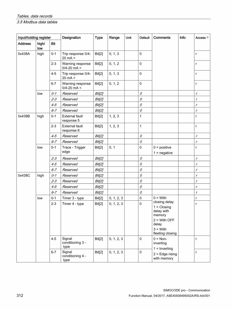
Tables, data records 3.5 Modbus data tables
SIMOCODE pro - Communication 312 Function Manual, 04/2017, A5E40508495002A/RS-AA/001
Input/holding register Designation Type Range Unit Default Comments Info Access 1)
Address high/ low
Bit
0x438A high 0-1 Trip response 0/4-20 mA >
Bit[2] 0, 1, 3 0 r
2-3 Warning response 0/4-20 mA >
Bit[2] 0, 1, 2 0 r
4-5 Trip response 0/4-20 mA <
Bit[2] 0, 1, 3 0 r
6-7 Warning response 0/4-20 mA <
Bit[2] 0, 1, 2 0 r
low 0-1 Reserved Bit[2] 0 r 2-3 Reserved Bit[2] 0 r 4-5 Reserved Bit[2] 0 r 6-7 Reserved Bit[2] 0 r
0x438B
high 0-1 External fault response 5
Bit[2] 1, 2, 3 1 r
2-3 External fault response 6
Bit[2] 1, 2, 3 1 r
4-5 Reserved Bit[2] 0 r 6-7 Reserved Bit[2] 0 r
low 0-1 Trace - Trigger edge
Bit[2] 0, 1 0 0 = positive 1 = negative
r
2-3 Reserved Bit[2] 0 r 4-5 Reserved Bit[2] 0 r 6-7 Reserved Bit[2] 0 r
0x438C high 0-1 Reserved Bit[2] 0 r 2-3 Reserved Bit[2] 0 r 4-5 Reserved Bit[2] 0 r 6-7 Reserved Bit[2] 0 r
low 0-1 Timer 3 - type Bit[2] 0, 1, 2, 3 0 0 = With closing delay 1 = Closing delay with memory 2 = With OFF delay 3 = With fleeting closing
r 2-3 Timer 4 - type Bit[2] 0, 1, 2, 3 0 r
4-5 Signal conditioning 3 - type
Bit[2] 0, 1, 2, 3 0 0 = Non-inverting 1 = Inverting 2 = Edge rising with memory
r
6-7 Signal conditioning 4 - type
Bit[2] 0, 1, 2, 3 0 r

Tables, data records 3.5 Modbus data tables
SIMOCODE pro - Communication Function Manual, 04/2017, A5E40508495002A/RS-AA/001 313
Input/holding register Designation Type Range Unit Default Comments Info Access 1)
Address high/ low
Bit
0x438D high 0-1 Non-volatile element 3 - type
Bit[2] 0, 1, 2, 3 0 r
2-3 Non-volatile element 4 - type
Bit[2] 0, 1, 2, 3 0 r
4-5 Calculator 2 - Operator
Bit[2] 0, 1, 2, 3 0 r
6-7 Reserved Bit[2] 0 r low 0-1 Reserved Bit[2] 0 r
2-3 Reserved Bit[2] 0 r 4-5 OPD - Operator
panel display (bit 0 ... 1)
Bit[2] 0 ... 4 2 0 = Manual 1 = 3 s 2 = 10 s 3 = 1 min 4 = 5 min
r
6-7 OPD - Operator panel display (bit 2 ... 3)
Bit[2] r
Part - Bit[4] parameters
r
0x438E high 0-2 TM1 - sensor type Bit[3] 000B to 100B
000B 000B = PT100 001B = PT1000 010B = KTY83 011B = KTY84 100B = NTC
r
Reserved Bit r 4-7 OPD language Bit[4] 0 ... 15 0 r
low 0-3 Reset response external fault 5
Bit[4] 0 ... 1111B
0101B Bit[0] = Panel reset Bit[1] = Auto reset Bit[2] = Remote reset Bit[3] = OFF command reset
r
4-7 Reset response external fault 6
Bit[4] 0 ... 1111B
0101B r
0x438F high 0-3 OPD - Contrast (bit 0 ... 3)
Bit[4] 0 ... 255 1 % 50 r
4-7 OPD - Contrast (bit 4 ... 7)
Bit[4] r
low 0-3 OPD - Profile (bit 0 ... 3)
Bit[4] 0 ... 33 0 r
4-7 OPD - Profile (bit 4 ... 7)
Bit[4] r
Siemens Parts

Tables, data records 3.5 Modbus data tables
SIMOCODE pro - Communication 314 Function Manual, 04/2017, A5E40508495002A/RS-AA/001
Input/holding register Designation Type Range Unit Default Comments Info Access 1)
Address high/ low
Bit
0x4390 high 0-3 Truth table 7 type 2I/1O
Bit[4] 0 ... 1111B
0 r
4-7 Truth table 8 type 2I/1O
Bit[4] 0 ... 1111B
0 r
low 0-3 Is1 conversion factor - Denominator
Bit[4] 0 ... 15 0 r
4-7 Is2 conversion factor - Denominator
Bit[4] 0 ... 15 0 r
0x4391 high 0-3 Hysteresis P - cos phi - U
Bit[4] 0 ... 15 1 % 5 r
4-7 Hysteresis 0/4-20 mA
Bit[4] 0 ... 15 1 % 5 r
low 0-3 Hysteresis free limits
Bit[4] 0 ... 15 1 % 5 r
4-7 OPD - Lighting Bit[4] 0 ... 4 2 0 = OFF 1 = 3 s 2 = 10 s 3 = 1 min 4 = 5 min
r
Part - Byte parameters
0x4392
high Byte r low EM - Delay Byte 0 ... 255 100 ms 5 EM
r/w
0x4393
high Trip level cos phi< Byte 0 ... 100 1 % 0 UM
r/w
low Warning level cos phi<
Byte 0 ... 100 1 % 0 UM
r/w
0x4394
high Trip level U< Byte 0 ... 255 8 V 0 UM
r/w
low Warning level U< Byte 0 ... 255 8 V 0 UM
r/w

Tables, data records 3.5 Modbus data tables
SIMOCODE pro - Communication Function Manual, 04/2017, A5E40508495002A/RS-AA/001 315
Input/holding register Designation Type Range Unit Default Comments Info Access 1)
Address high/ low
Bit
0x4395
high Trip level 0/4-20 mA>
Byte 0 ... 255 *128 0 AM1
r/w
low Warning level 0/4-20 mA>
Byte 0 ... 255 *128 0 AM1
r/w
0x4396
high Trip level 0/4-20 mA<
Byte 0 ... 255 *128 0 AM1
r/w
low Warning level 0/4-20 mA>
Byte 0 ... 255 *128 0 AM1
r/w
0x4397
high Trip delay P> Byte 0 ... 255 100 ms 5 UM
r/w
low Warning delay P> Byte 0 ... 255 100 ms 5 UM
r/w
0x4398 high Trip delay P< Byte 0 ... 255 100 ms 5 UM
r/w
low Warning delay P< Byte 0 ... 255 100 ms 5 UM
r/w
0x4399
high Trip delay cos phi< Byte 0 ... 255 100 ms 5 UM
r/w
low Warning delay cos phi<
Byte 0 ... 255 100 ms 5 UM
r/w
0x439A
high Trip delay U< Byte 0 ... 255 100 ms 5 UM
r/w
low Warning delay U< Byte 0 ... 255 100 ms 5 UM
r/w
0x439B high Trip delay 0/4-20 mA>
Byte 0 ... 255 100 ms 5 AM1
r/w
low Warning delay 0/4-20 mA>
Byte 0 ... 255 100 ms 5 AM1
r/w
Siemens Parts

Tables, data records 3.5 Modbus data tables
SIMOCODE pro - Communication 316 Function Manual, 04/2017, A5E40508495002A/RS-AA/001
Input/holding register Designation Type Range Unit Default Comments Info Access 1)
Address high/ low
Bit
0x439C
high Trip delay 0/4-20 mA<
Byte 0 ... 255 100 ms 5 AM1
r/w
low Warning delay 0/4-20 mA<
Byte 0 ... 255 100 ms 5 AM1
r/w
0x439D
high Delay limit 1 Byte 0 ... 255 100 ms 5
r/w
low Delay limit 2 Byte 0 ... 255 100 ms 5
r/w
0x439E
high Delay limit 3 Byte 0 ... 255 100 ms 5
r/w
low Delay limit 3 Byte 0 ... 255 100 ms 5
r/w
0x439F
high TM - Hysteresis Byte 0 ... 255 1 K 5 r low Max. star time Byte 0 ... 255 1 s 20 r
0x43A0
high UVO time Byte 0 ... 255 100 ms, 1 s, 10 s
0 r
low Staggering time Byte 0 ... 255 1 s 0 r 0x43A1 high Trace - Pre-trigger Byte 0 ... 20 5 % 0 r
low Calculator 2 - Denominator 1
Byte 0 ... 255 0 r
0x43A2
high Calculator 2 - Numerator 2
Byte 0 ... 255 0 r
low Calculator 1 - Denominator
Byte 0 ... 255 0 r
0x43A3
high Truth table 4 type 3I/1O
Byte 0 ... 11111111B
0 r
low Truth table 5 type 3I/1O
Byte 0 ... 11111111B
0 r
0x43A4 high Truth table 6 type 3I/1O
Byte 0 ... 11111111B
0 r
low Calculator 2 - Numerator 1
Byte -128 ... 127
0
r/w
0x43A5
high Calculator 2 - Denominator 2
Byte -128 ... 127
0
r/w
low DM-F - Test requirement level
Byte 0 ... 255 Week 0
r/w

Tables, data records 3.5 Modbus data tables
SIMOCODE pro - Communication Function Manual, 04/2017, A5E40508495002A/RS-AA/001 317
Input/holding register Designation Type Range Unit Default Comments Info Access 1)
Address high/ low
Bit
Part - Word parameters
r/w
0x43A6 AM1 - Start value output
Word 0 ... 65535
0 Value for 0/4 mA
AM1
r/w
0x43A7 AM1 - End value output
Word 0 ... 65535
27648 Value for 20 mA
AM1
r/w
0x43A8 TM1 - Trip level T> Word 0 ... 65535
1 K 0 TM1
r/w
0x43A9 TM1 - Warning level T>
Word 0 ... 65535
1 K 0 TM1
r/w
0x43AA Limit level 1 Word 0 ... 65535
0
r/w
0x43AB Limit level 2 Word 0 ... 65535
0
r/w
0x43AC Limit level 3 Word 0 ... 65535
0
r/w
0x43AD Limit level 4 Word 0 ... 65535
0
r/w
0x43AE Timer 3 - value Word 0 ... 65535
100 ms 0 r
0x43AE Timer 4 - value Word 0 ... 65535
100 ms 0 r
0x43B0 Counter 3 - value Word 0 ... 65535
0
r/w
0x43B1 Counter 4 - value Word 0 ... 65535
0
r/w
0x43B2 Change-over pause
Word 0 ... 65535
10 ms 0
r/w
0x43B3 Trace - Sampling period
Word 1 ... 50000
1 ms 100
r/w
0x43B4 Is1 - Conversion factor - Numerator
Word 0 ... 65535
1/8 0
r/w
0x43B5 Is2 - Conversion factor - Numerator
Word 0 ... 65535
1/8 0
r/w
Siemens Parts

Tables, data records 3.5 Modbus data tables
SIMOCODE pro - Communication 318 Function Manual, 04/2017, A5E40508495002A/RS-AA/001
Input/holding register Designation Type Range Unit Default Comments Info Access 1)
Address high/ low
Bit
Part - D word parameter
0x43B6 Motor protection - Set current Is2
D word 10 mA 0 r
0x43B8 Trip level P> D word 0 ... 0xFFFFFFFF
1 W 0
r/w
0x43BA Warning level P> D word 0 ... 0xFFFFFFFF
1 W 0
r/w
0x43BC Trip level P< D word 0 ... 0xFFFFFFFF
1 W 0
r/w
0x43BE Warning level P< D word 0 ... 0xFFFFFFFF
1 W 0
r/w
0x43C0 Truth table 9 5I/2O type - Output 1
Bit[32] 0 ... 1 ... 1B
0 r
0x43C2 Truth table 9 5I/2O type - Output 2
Bit[32] 0 ... 1 ... 1B
0 r
0x43C4 Calculator 2 - Offset
D word -0x80000000 ... 0x7FFFFFFF
0 r
0x43C6 ... 0x43C7
Calculator 1 - Numerator / offset
D word 2x -32768 ... 32767
0 r
1) r/w: Value is read/write; r: Value is read-only

Tables, data records 3.5 Modbus data tables
SIMOCODE pro - Communication Function Manual, 04/2017, A5E40508495002A/RS-AA/001 319
3.5.2.15 Marking Read access to the labeling is possible via function codes 03 and 04. Write access is possible via function codes 06 and 16.
Max. data length per access: 100 registers.
Table 3- 93 Marking
Input/holding register Identifier Type Access 1) Address high/low 0x4880 Coordination Byte[4] r 0x4882 Reserved Byte[6] r/w 0x4885 Marking - external fault 1 Byte[10] r/w 0x488A Marking external fault 2 Byte[10] r/w 0x488F Marking external fault 3 Byte[10] r/w 0x4894 Marking external fault 4 Byte[10] r/w 0x4899 Marking external fault 5 Byte[10] r/w 0x489E Marking external fault 6 Byte[10] r/w 0x48A3 Reserved Byte[10] r/w 0x48A8 Reserved Byte[10] r/w 0x48AD Marking limit 1 Byte[10] r/w 0x48B2 Marking limit 2 Byte[10] r/w 0x48B7 Marking limit 3 Byte[10] r/w 0x48BC Marking limit 4 Byte[10] r/w 0x48C1 Marking TM1 warning T > Byte[10] r/w 0x48C6 Marking TM1 trip T > Byte[10] r/w 0x48CB Marking warning 0/4-20mA > Byte[10] r/w 0x48D0 Marking warning 0/4-20mA < Byte[10] r/w 0x48D5 Trip marking 0/4-20mA > Byte[10] r/w 0x48DA Trip marking 0/4-20mA < Byte[10] r/w 0x48DF Reserved Byte[10] r/w
Data record length: 200 bytes
1) Access to the marking via Modbus: read/write
Siemens Parts
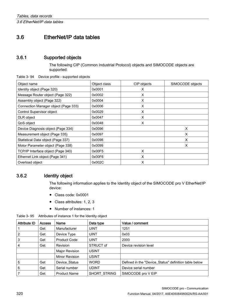
Tables, data records 3.6 EtherNet/IP data tables
SIMOCODE pro - Communication 320 Function Manual, 04/2017, A5E40508495002A/RS-AA/001
3.6 EtherNet/IP data tables
3.6.1 Supported objects The following CIP (Common Industrial Protocol) objects and SIMOCODE objects are supported:
Table 3- 94 Device profile - supported objects
Object name Object class CIP objects SIMOCODE objects Identity object (Page 320) 0x0001 X Message Router object (Page 322) 0x0002 X Assembly object (Page 322) 0x0004 X Connection Manager object (Page 333) 0x0006 X Control Supervisor object 0x0029 X DLR object 0x0047 X QoS object 0x0048 X Device Diagnosis object (Page 334) 0x0096 X Measurement object (Page 335) 0x0097 X Statistical Data object (Page 337) 0x0098 X Motor Parameter object (Page 338) 0x0099 X TCP/IP Interface object (Page 340) 0x00F5 X Ethernet Link object (Page 341) 0x00F6 X Overload object 0x002C X
3.6.2 Identity object The following information applies to the Identity object of the SIMOCODE pro V EtherNet/IP device:
● Class code: 0x0001
● Class attributes: 1, 2, 3
● Number of instances: 1
Table 3- 95 Attributes of instance 1 for the Identity object
Attribute ID Access Name Data type Value / comment 1 Get Manufacturer UINT 1251 2 Get Device Type UINT 0x03 3 Get Product Code UINT 2000 4 Get Revision STRUCT of Device revision level Major Revision USINT Minor Revision USINT 5 Get Device_Status WORD Defined in the "Device_Status" definition table below 6 Get Serial number UDINT Device serial number 7 Get Product Name SHORT_STRING SIMOCODE pro V EIP
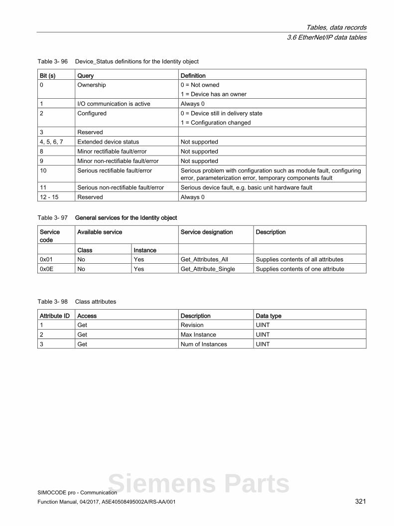
Tables, data records 3.6 EtherNet/IP data tables
SIMOCODE pro - Communication Function Manual, 04/2017, A5E40508495002A/RS-AA/001 321
Table 3- 96 Device_Status definitions for the Identity object
Bit (s) Query Definition 0 Ownership 0 = Not owned
1 = Device has an owner 1 I/O communication is active Always 0 2 Configured 0 = Device still in delivery state
1 = Configuration changed 3 Reserved 4, 5, 6, 7 Extended device status Not supported 8 Minor rectifiable fault/error Not supported 9 Minor non-rectifiable fault/error Not supported 10 Serious rectifiable fault/error Serious problem with configuration such as module fault, configuring
error, parameterization error, temporary components fault 11 Serious non-rectifiable fault/error Serious device fault, e.g. basic unit hardware fault 12 - 15 Reserved Always 0
Table 3- 97 General services for the Identity object
Service code
Available service Service designation Description
Class Instance 0x01 No Yes Get_Attributes_All Supplies contents of all attributes 0x0E No Yes Get_Attribute_Single Supplies contents of one attribute
Table 3- 98 Class attributes
Attribute ID Access Description Data type 1 Get Revision UINT 2 Get Max Instance UINT 3 Get Num of Instances UINT
Siemens Parts

Tables, data records 3.6 EtherNet/IP data tables
SIMOCODE pro - Communication 322 Function Manual, 04/2017, A5E40508495002A/RS-AA/001
3.6.3 Message Router object The Message Router object is defined by CIP. It does not possess any class or instance attributes, but simply transfers explicit messages to the relevant objects.
3.6.4 Assembly object The following information applies to the Assembly object of the SIMOCODE pro V EtherNet/IP device:
● Class code: 0x04
● Class attributes: 1, 2, 3
● Number of instances: 13.
Instance 2: Output assembly basic overload from ODVA Profile The tables below describe in each case the format of attribute 3 of the relevant assembly instance.
Byte Bit 7 Bit 6 Bit 5 Bit 4 Bit 3 Bit 2 Bit 1 Bit 0 0 Reserved Reserved Reserved Reserved Reserved Fault Reset Reserved Reserved
Instance 50: Input assembly basic overload from ODVA Profile The table below describes the format of attribute 3:
Byte Bit 7 Bit 6 Bit 5 Bit 4 Bit 3 Bit 2 Bit 1 Bit 0 0 Reserved Reserved Reserved Reserved Reserved Reserved Reserved Faulted / Trip
Instance 51: Input assembly extended overload from ODVA Profile The table below describes the format of attribute 3:
Byte Bit 7 Bit 6 Bit 5 Bit 4 Bit 3 Bit 2 Bit 1 Bit 0 0 Reserved Reserved Reserved Reserved Reserved Reserved Warning Faulted / Trip

Tables, data records 3.6 EtherNet/IP data tables
SIMOCODE pro - Communication Function Manual, 04/2017, A5E40508495002A/RS-AA/001 323
Instance 100: Output assembly SIMOCODE basic type 1 The table below describes the format of attribute 3:
Byte Bit 7 Bit 6 Bit 5 Bit 4 Bit 3 Bit 2 Bit 1 Bit 0 0 Cycl.
receive byte 0 - bit 0.7
Cycl. receive byte 0 - bit 0.6
Cycl. receive byte 0 - bit 0.5
Cycl. receive byte 0 - bit 0.4
Cycl. receive byte 0 - bit 0.3
Cycl. receive byte 0 - bit 0.2
Cycl. receive byte 0 - bit 0.1
Cycl. receive byte 0 - bit 0.0
1 Cycl. receive byte 1 - bit 1.7
Cycl. receive byte 1 - bit 1.6
Cycl. receive byte 1 - bit 1.5
Cycl. receive byte 1 - bit 1.4
Cycl. receive byte 1 - bit 1.3
Cycl. receive byte 1 - bit 1.2
Cycl. receive byte 1 - bit 1.1
Cycl. receive byte 1 - bit 1.0
2 ... 3 Cycl. receive byte 2/3 - analog value 1
The values passed to SIMOCODE pro via instance 100 can be processed further in the SIMOCODE ES (TIA Portal) software.
Corresponding function blocks in the SIMOCODE ES (TIA Portal) charts:
Default settings of cyclic receive and send data: See Assignment of cyclic receive and send data for predefined control functions (Page 132).
Siemens Parts

Tables, data records 3.6 EtherNet/IP data tables
SIMOCODE pro - Communication 324 Function Manual, 04/2017, A5E40508495002A/RS-AA/001
Instance 101: Output assembly SIMOCODE basic type 2 The table below describes the format of attribute 3:
Byte Bit 7 Bit 6 Bit 5 Bit 4 Bit 3 Bit 2 Bit 1 Bit 0 0 Cycl.
receive byte 0 - bit 0.7
Cycl. receive byte 0 - bit 0.6
Cycl. receive byte 0 - bit 0.5
Cycl. receive byte 0 - bit 0.4
Cycl. receive byte 0 - bit 0.3
Cycl. receive byte 0 - bit 0.2
Cycl. receive byte 0 - bit 0.1
Cycl. receive byte 0 - bit 0.0
1 Cycl. receive byte 1 - bit 1.7
Cycl. receive byte 1 - bit 1.6
Cycl. receive byte 1 - bit 1.5
Cycl. receive byte 1 - bit 1.4
Cycl. receive byte 1 - bit 1.3
Cycl. receive byte 1 - bit 1.2
Cycl. receive byte 1 - bit 1.1
Cycl. receive byte 1 - bit 1.0
The values passed to SIMOCODE pro via instance 101 can be processed further in the SIMOCODE ES (TIA Portal) software.
Corresponding function blocks in the SIMOCODE ES (TIA Portal) charts:
Default settings of cyclic receive and send data: See Assignment of cyclic receive and send data for predefined control functions (Page 132).

Tables, data records 3.6 EtherNet/IP data tables
SIMOCODE pro - Communication Function Manual, 04/2017, A5E40508495002A/RS-AA/001 325
Instance 102: Output assembly SIMOCODE basic type 3 The table below describes the format of attribute 3:
Byte Bit 7 Bit 6 Bit 5 Bit 4 Bit 3 Bit 2 Bit 1 Bit 0 0 Cycl.
receive byte 0 - bit 0.7
Cycl. receive byte 0 - bit 0.6
Cycl. receive byte 0 - bit 0.5
Cycl. receive byte 0 - bit 0.4
Cycl. receive byte 0 - bit 0.3
Cycl. receive byte 0 - bit 0.2
Cycl. receive byte 0 - bit 0.1
Cycl. receive byte 0 - bit 0.0
1 Cycl. receive byte 1 - bit 1.7
Cycl. receive byte 1 - bit 1.6
Cycl. receive byte 1 - bit 1.5
Cycl. receive byte 1 - bit 1.4
Cycl. receive byte 1 - bit 1.3
Cycl. receive byte 1 - bit 1.2
Cycl. receive byte 1 - bit 1.1
Cycl. receive byte 1 - bit 1.0
2, 3 Cycl. receive byte 2/3 - analog value 1 4, 5 Cycl. receive byte 4/5 - analog value 2
The values passed to SIMOCODE pro via instance 102 can be processed further in the SIMOCODE ES (TIA Portal) software.
Corresponding function blocks in the SIMOCODE ES (TIA Portal) charts:
Default settings of cyclic receive and send data for predefined control functions: SeeAssignment of cyclic receive and send data for predefined control functions (Page 132).
Siemens Parts

Tables, data records 3.6 EtherNet/IP data tables
SIMOCODE pro - Communication 326 Function Manual, 04/2017, A5E40508495002A/RS-AA/001
Instance 120: Configuration assembly Configuring of devices using a "Configuration assembly" is not supported by SIMOCODE. Devices are parameterized by means of the SIMOCODE ES (TIA Portal) parameterization software.
Integrating a SIMOCODE device as a "Generic Ethernet module" into the Rockwell Studio 5000 environment:
For this purpose, the "Configuration assembly" with the instance 120 and the length 0 must be specified as well:
Instance 150: Input assembly SIMOCODE basic type 1 The table below describes the format of attribute 3:
Byte Bit 7 Bit 6 Bit 5 Bit 4 Bit 3 Bit 2 Bit 1 Bit 0 0 Cycl. send
byte 0 - bit 0.7
Cycl. send byte 0 - bit 0.6
Cycl. send byte 0 - bit 0.5
Cycl. send byte 0 - bit 0.4
Cycl. send byte 0 - bit 0.3
Cycl. send byte 0 - bit 0.2
Cycl. send byte 0 - bit 0.1
Cycl. send byte 0 - bit 0.0
1 Cycl. send byte 1 - bit 1.7
Cycl. send byte 1 - bit 1.6
Cycl. send byte 1 - bit 1.5
Cycl. send byte 1 - bit 1.4
Cycl. send byte 1 - bit 1.3
Cycl. send byte 1 - bit 1.2
Cycl. send byte 1 - bit 1.1
Cycl. send byte 1 - bit 1.0
2 ... 3 Cycl. send byte 2/3 - analog value 1 Cycl. analog float input 1 4 ... 5 Cycl. send byte 4/5 - analog value 2 6 ... 7 Cycl. send byte 6/7 - analog value 3 Cycl. analog float input 2 8 ... 9 Cycl. send byte 8/9 - analog value 4
The bit and analog values signaled by SIMOCODE pro to the control system via instance 150 can be freely assigned in the SIMOCODE ES (TIA Portal) software.

Tables, data records 3.6 EtherNet/IP data tables
SIMOCODE pro - Communication Function Manual, 04/2017, A5E40508495002A/RS-AA/001 327
Corresponding function blocks in the SIMOCODE ES (TIA Portal) charts:
Default settings of cyclic receive and send data: See Assignment of cyclic receive and send data for predefined control functions (Page 132).
Siemens Parts

Tables, data records 3.6 EtherNet/IP data tables
SIMOCODE pro - Communication 328 Function Manual, 04/2017, A5E40508495002A/RS-AA/001
Instance 151: Input assembly SIMOCODE basic type 2 The table below describes the format of attribute 3:
Byte Bit 7 Bit 6 Bit 5 Bit 4 Bit 3 Bit 2 Bit 1 Bit 0 0 Cycl. send
byte 0 - bit 0.7
Cycl. send byte 0 - bit 0.6
Cycl. send byte 0 - bit 0.5
Cycl. send byte 0 - bit 0.4
Cycl. send byte 0 - bit 0.3
Cycl. send byte 0 - bit 0.2
Cycl. send byte 0 - bit 0.1
Cycl. send byte 0 - bit 0.0
1 Cycl. send byte 1 - bit 1.7
Cycl. send byte 1 - bit 1.6
Cycl. send byte 1 - bit 1.5
Cycl. send byte 1 - bit 1.4
Cycl. send byte 1 - bit 1.3
Cycl. send byte 1 - bit 1.2
Cycl. send byte 1 - bit 1.1
Cycl. send byte 1 - bit 1.0
2 ... 3 Cycl. send byte 2/3 - analog value 1
The bit and analog values signaled by SIMOCODE pro to the control system via instance 151 can be freely assigned in the SIMOCODE ES (TIA Portal) software.
Corresponding function blocks in the SIMOCODE ES (TIA Portal) charts:
Default settings of cyclic receive and send data: See Assignment of cyclic receive and send data for predefined control functions (Page 132).

Tables, data records 3.6 EtherNet/IP data tables
SIMOCODE pro - Communication Function Manual, 04/2017, A5E40508495002A/RS-AA/001 329
Instance 152: Input assembly SIMOCODE basic type 3 The table below describes the format of attribute 3:
Byte Bit 7 Bit 6 Bit 5 Bit 4 Bit 3 Bit 2 Bit 1 Bit 0 0 Cycl. send
byte 0 - bit 0.7
Cycl. send byte 0 - bit 0.6
Cycl. send byte 0 - bit 0.5
Cycl. send byte 0 - bit 0.4
Cycl. send byte 0 - bit 0.3
Cycl. send byte 0 - bit 0.2
Cycl. send byte 0 - bit 0.1
Cycl. send byte 0 - bit 0.0
1 Cycl. send byte 1 - bit 1.7
Cycl. send byte 1 - bit 1.6
Cycl. send byte 1 - bit 1.5
Cycl. send byte 1 - bit 1.4
Cycl. send byte 1 - bit 1.3
Cycl. send byte 1 - bit 1.2
Cycl. send byte 1 - bit 1.1
Cycl. send byte 1 - bit 1.0
2 ... 3 Cycl. send byte 2/3 - analog value 1 Cycl. analog float input 1 4 ... 5 Cycl. send byte 4/5 - analog value 2 6 ... 7 Cycl. send byte 6/7 - analog value 3 Cycl. analog float input 2 8 ... 9 Cycl. send byte 8/9 - analog value 4 10 ... 11 Cycl. send byte 8/9 - analog value 5 Cycl. analog float input 3 12 ... 13 Cycl. send byte 8/9 - analog value 6 14 ... 15 Cycl. send byte 8/9 - analog value 7 Cycl. analog float input 4 16 ... 17 Cycl. send byte 8/9 - analog value 8 18 ... 19 Cycl. send byte 8/9 - analog value 9
The bit and analog values signaled by SIMOCODE pro to the control system via instance 152 can be freely assigned in the SIMOCODE ES (TIA Portal) software.
Siemens Parts

Tables, data records 3.6 EtherNet/IP data tables
SIMOCODE pro - Communication 330 Function Manual, 04/2017, A5E40508495002A/RS-AA/001
Corresponding function blocks in the SIMOCODE ES (TIA Portal) charts:
Default settings of cyclic receive and send data: See Assignment of cyclic receive and send data for predefined control functions (Page 132).
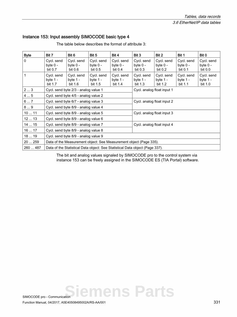
Tables, data records 3.6 EtherNet/IP data tables
SIMOCODE pro - Communication Function Manual, 04/2017, A5E40508495002A/RS-AA/001 331
Instance 153: Input assembly SIMOCODE basic type 4 The table below describes the format of attribute 3:
Byte Bit 7 Bit 6 Bit 5 Bit 4 Bit 3 Bit 2 Bit 1 Bit 0 0 Cycl. send
byte 0 - bit 0.7
Cycl. send byte 0 - bit 0.6
Cycl. send byte 0 - bit 0.5
Cycl. send byte 0 - bit 0.4
Cycl. send byte 0 - bit 0.3
Cycl. send byte 0 - bit 0.2
Cycl. send byte 0 - bit 0.1
Cycl. send byte 0 - bit 0.0
1 Cycl. send byte 1 - bit 1.7
Cycl. send byte 1 - bit 1.6
Cycl. send byte 1 - bit 1.5
Cycl. send byte 1 - bit 1.4
Cycl. send byte 1 - bit 1.3
Cycl. send byte 1 - bit 1.2
Cycl. send byte 1 - bit 1.1
Cycl. send byte 1 - bit 1.0
2 ... 3 Cycl. send byte 2/3 - analog value 1 Cycl. analog float input 1 4 ... 5 Cycl. send byte 4/5 - analog value 2 6 ... 7 Cycl. send byte 6/7 - analog value 3 Cycl. analog float input 2 8 ... 9 Cycl. send byte 8/9 - analog value 4 10 ... 11 Cycl. send byte 8/9 - analog value 5 Cycl. analog float input 3 12 ... 13 Cycl. send byte 8/9 - analog value 6 14 ... 15 Cycl. send byte 8/9 - analog value 7 Cycl. analog float input 4 16 ... 17 Cycl. send byte 8/9 - analog value 8 18 ... 19 Cycl. send byte 8/9 - analog value 9 20 ... 259 Data of the Measurement object: See Measurement object (Page 335). 260 ... 487 Data of the Statistical Data object: See Statistical Data object (Page 337).
The bit and analog values signaled by SIMOCODE pro to the control system via instance 153 can be freely assigned in the SIMOCODE ES (TIA Portal) software.
Siemens Parts

Tables, data records 3.6 EtherNet/IP data tables
SIMOCODE pro - Communication 332 Function Manual, 04/2017, A5E40508495002A/RS-AA/001
Corresponding function blocks in the SIMOCODE ES (TIA Portal) charts:
Default settings of cyclic receive and send data: See Assignment of cyclic receive and send data for predefined control functions (Page 132).
General services for the Assembly object Service code Available service Service designation Description
Class Instance 0x0E Yes Yes Get_Attribute_Single Supplies contents of one attribute 0x10 No Yes Set_Attribute_Single Changes an attribute value
Class attributes for the Assembly object Attribute ID Access Description Data type 1 Get Revision UINT 2 Get Max Instance UINT 3 Get Num of Instances UINT

Tables, data records 3.6 EtherNet/IP data tables
SIMOCODE pro - Communication Function Manual, 04/2017, A5E40508495002A/RS-AA/001 333
3.6.5 Connection Manager object The following information applies to the Connection Manager object of the SIMOCODE pro V EtherNet/IP device:
● Class code: 0x06
● Class attributes: 0
● Number of instances: 1
The instance attributes are defined according to Volume 1 of the CIP Specification.
All instance attributes that are defined as "required" in this specification are supported.
Table 3- 99 General services for the Connection Manager object
Service code Available service Service designation Description Class Instance
0x0E No Yes Get_Attribute_Single Supplies contents of one attribute 0x10 No Yes Set_Attribute_Single Changes an attribute value
Siemens Parts

Tables, data records 3.6 EtherNet/IP data tables
SIMOCODE pro - Communication 334 Function Manual, 04/2017, A5E40508495002A/RS-AA/001
3.6.6 Device Diagnosis object The Device Diagnosis object supplies information about the current status of the device. This object contains details of all fault messages, warnings and events that relate to the relevant SIMOCODE device.
● Class code: 0x0096
● Class attributes: 0
● Number of instances: 1
Table 3- 100 General services for the Device Diagnosis object
Service code Available service Service designation Description Class Instance
0x01 No Yes Get_Attributes_All Supplies contents of all attributes 0x0E No Yes Get_Attribute_Single Supplies contents of one attribute
Table 3- 101 Attributes of instance 1 for the Diagnosis object
Attribute ID Access Designation Data type 1 Get Diagnostic bits Byte[46]
Details of the meaning of individual diagnostic bits can be found in Chapter Data record 92 - Device diagnostics (Page 241).
Note Functional Example of EtherNet/IP
A functional example of Ethernet/IP in the Industry Online Support provides this information as a preprogrammed, user-defined data type for the Rockwell Studio 5000 environment.

Tables, data records 3.6 EtherNet/IP data tables
SIMOCODE pro - Communication Function Manual, 04/2017, A5E40508495002A/RS-AA/001 335
3.6.7 Measurement object The Measurement object supplies the latest measurements of quantities such as current, voltage, output, cos phi, etc. of the SIMOCODE pro V EtherNet/IP device.
● Class code: 0x0097
● Class attributes: 0
● Number of instances: 1.
Table 3- 102 General services for the Measurement object
Service code Available service Service designation Description Class Instance
0x01 No Yes Get_Attributes_All Supplies contents of all attributes 0x0E No Yes Get_Attribute_Single Supplies contents of one attribute
Table 3- 103 Attributes of instance 1 for the Measurement object
Attribute ID Access Designation Data type Range Unit 1 Get Thermal motor model INT See 2) 2 Get Phase unbalance SINT 0 .. 127 1 % 3 Get Cos φ SINT 0 .. 127 1 % 4..8 Get Reserved INT[5] 9 Get Max. current I_max INT 0 .. 32767 1 % / Is 10 Get Current I_L1 INT 0 .. 32767 1 % / Is 11 Get Current I_L2 INT 0 .. 32767 1 % / Is 12 Get Current I_L3 INT 0 .. 32767 1 % / Is 13 Get Last trip current INT 0 .. 32767 1 % / Is 14 Get Time to trip DINT 100 ms 6) 15 Get Recovery time DINT 100 ms 16 Get Voltage U_L1 INT 0 .. 32767 1 V 17 Get Voltage U_L2 INT 0 .. 32767 1 V 18 Get Voltage U_L3 INT 0 .. 32767 1 V 19 Get AM1 - output INT 0 .. 32767 See 1) 20 Get AM1 - input INT 0 .. 32767 21 Get AM1 - input 2 INT 0 .. 32767 22 Get Reserved INT 23 Get TM1 - temperature INT 0 .. 32767 1 K see 3) 24 Get TM1 - temperature 1 INT 0 .. 32767 1 K see 3) 25 Get TM1 - temperature 2 INT 0 .. 32767 1 K see 3) 26 Get TM1 - temperature 3 INT 0 .. 32767 1 K see 3) 27 Get Reserved INT 28 Get EM+ - ground fault current DINT 1 mA 29 Get EM+ - last trip current DINT 1 mA
Siemens Parts

Tables, data records 3.6 EtherNet/IP data tables
SIMOCODE pro - Communication 336 Function Manual, 04/2017, A5E40508495002A/RS-AA/001
Attribute ID Access Designation Data type Range Unit 30 Get Active power P DINT 0..0x7FFFFFFF 1 W 31 Get Apparent power S DINT 0..0x7FFFFFFF 1 VA 32 Get Reserved DINT 33..39 Get Reserved DINT[7] 40..63 Get Reserved INT[24] 64 Get AM2 - output INT 0 .. 32767 See 1) 65 Get AM2 - input INT 0 .. 32767 66 Get AM2 - input 2 INT 0 .. 32767 67 Get Reserved INT 68 Get TM2 - temperature INT 0 .. 32767 1 K see 3) 69 Get TM2 - temperature 1 INT 0 .. 32767 1 K see 3) 70 Get TM2 - temperature 2 INT 0 .. 32767 1 K see 3) 71 Get TM2 - temperature 3 INT 0 .. 32767 1 K see 3) 72 Get Frequency INT 0 .. 32767 0.01 Hz 73 Get INT 74 Get Reserved DINT 75 Get Reserved DINT 76 Get Reserved DINT 77 Get Current I_max_A_F REAL 1 A 78 Get Current I_avg_A_F REAL 1 A 79 Get Current I_L1_A_F REAL 1 A 80 Get Current I_L2_A_F REAL 1 A 81 Get Current I_L3_A_F REAL 1 A 82 Get Active power P_F REAL 1 W 83 Get Apparent power S_F REAL 1 VA 84 Get Voltage UL1_F REAL 1 V 85 Get Voltage UL2_F REAL 1 V 86 Get Voltage UL3_F REAL 1 V 87 Get Cos phi_F REAL 1 88 Get Frequency_F REAL 1 Hz 89..90 Get Reserved REAL[2]
1) S7 format:
0/4 mA = 0
20 mA = 27648
2) Representation of the "Thermal motor model":
Value always refers to symm. trip level, representation in 2 % increments in bits 6 - 0 (range 0 to 254 %), bit 7 shows unbalance (fixed level 50 %).
3) Representation in Kelvin.

Tables, data records 3.6 EtherNet/IP data tables
SIMOCODE pro - Communication Function Manual, 04/2017, A5E40508495002A/RS-AA/001 337
3.6.8 Statistical Data object The Statistical Data object supplies the statistical data (such as operating hours, number of overload trips, number of starts, etc.) of the SIMOCODE pro V EtherNet/IP device.
● Class code: 0x0098
● Class attributes: 0
● Number of instances: 1
Table 3- 104 General services for the Statistical Data object
Service code Available service Service designation Description Class Instance
0x01 No Yes Get_Attributes_All Supplies contents of all attributes 0x0E No Yes Get_Attribute_Single Supplies contents of one attribute
Table 3- 105 Attributes of instance 1 for the Statistical Data object
Attribute ID Access Designation Data type Range Unit 1 Get Permissible starts - actual value INT 0 - 255 2 Get DM-F - Time until test required INT 0 - 255 1 week 3 Get Reserved DINT 4 Get Number of parameterizations DINT 0 - 65535 5 Get Number of overload trips DINT 0 - 65535 6 Get Int. number of overload trips DINT 0 - 65535 7 Get Motor stop time DINT 0 - 65535 1 h 8 Get Timer 1 actual value DINT 0 - 65535 100 ms 9 Get Timer 2 actual value DINT 0 - 65535 100 ms 10 Get Timer 3 actual value DINT 0 - 65535 100 ms 11 Get Timer 4 actual value DINT 0 - 65535 100 ms 12 Get Counter 1 actual value DINT 0 - 65535 13 Get Counter 2 actual value DINT 0 - 65535 14 Get Counter 3 actual value DINT 0 - 65535 15 Get Counter 4 actual value DINT 0 - 65535 16 Get Calculation module 1 output DINT 0 - 65535 17 Get Calculation module 2 output DINT 0 - 65535 18..19 Get Reserved DINT[2] 20 Get Motor operating hours DINT 0..0x7FFFFFFF 1 s 21 Get Int. Motor operating hours DINT 0..0x7FFFFFFF 1 s 22 Get Device operating hours DINT 0..0x7FFFFFFF 1 s 23 Get Number of starts DINT 0..0x7FFFFFFF 24 Get Int. number of starts CW DINT 0..0x7FFFFFFF 25 Get Int. number of starts CCW DINT 0..0x7FFFFFFF 26 Get Energy W DINT 0..0x7FFFFFFF 1 kWh
Siemens Parts

Tables, data records 3.6 EtherNet/IP data tables
SIMOCODE pro - Communication 338 Function Manual, 04/2017, A5E40508495002A/RS-AA/001
Attribute ID Access Designation Data type Range Unit 27 Get Energy W_F REAL 1 kWh 28 Get Reserved DINT 29..34 Get Reserved DINT[6] 35..50 Get Reserved INT[16] 51 Get Timer 5 actual value DINT 0 - 65535 100 ms 52 Get Timer 6 actual value DINT 0 - 65535 100 ms 53 Get Counter 5 actual value DINT 0 - 65535 54 Get Counter 6 actual value DINT 0 - 65535 55 Get Analog arithmetic 1 output DINT 0 - 65535 56 Get Analog arithmetic 2 output DINT 0 - 65535 57 Get Analog multiplexer output DINT 0 - 65535 58..66 Get Reserved DINT[9]
3.6.9 Motor Parameter object Selected device parameters of the SIMOCODE pro V EtherNet/IP device can be read or written via the Motor Parameter object. This allows the device parameters to be adjusted via the controller or a connected control system.
● Class code: 0x0099
● Class attributes: 0
● Number of instances: 1
Table 3- 106 General services for the Motor Parameter object
Service code Available service Service designation Description Class Instance
0x0E No Yes Get_Attribute_Single Supplies contents of one attribute 0x10 No Yes Set_Attribute_Single Changes an attribute value
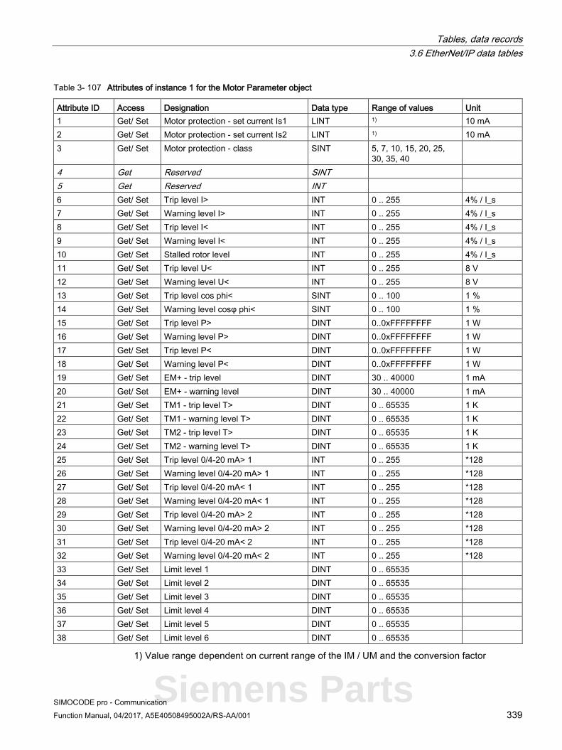
Tables, data records 3.6 EtherNet/IP data tables
SIMOCODE pro - Communication Function Manual, 04/2017, A5E40508495002A/RS-AA/001 339
Table 3- 107 Attributes of instance 1 for the Motor Parameter object
Attribute ID Access Designation Data type Range of values Unit 1 Get/ Set Motor protection - set current Is1 LINT 1) 10 mA 2 Get/ Set Motor protection - set current Is2 LINT 1) 10 mA 3 Get/ Set Motor protection - class SINT 5, 7, 10, 15, 20, 25,
30, 35, 40
4 Get Reserved SINT 5 Get Reserved INT 6 Get/ Set Trip level I> INT 0 .. 255 4% / I_s 7 Get/ Set Warning level I> INT 0 .. 255 4% / I_s 8 Get/ Set Trip level I< INT 0 .. 255 4% / I_s 9 Get/ Set Warning level I< INT 0 .. 255 4% / I_s 10 Get/ Set Stalled rotor level INT 0 .. 255 4% / I_s 11 Get/ Set Trip level U< INT 0 .. 255 8 V 12 Get/ Set Warning level U< INT 0 .. 255 8 V 13 Get/ Set Trip level cos phi< SINT 0 .. 100 1 % 14 Get/ Set Warning level cosφ phi< SINT 0 .. 100 1 % 15 Get/ Set Trip level P> DINT 0..0xFFFFFFFF 1 W 16 Get/ Set Warning level P> DINT 0..0xFFFFFFFF 1 W 17 Get/ Set Trip level P< DINT 0..0xFFFFFFFF 1 W 18 Get/ Set Warning level P< DINT 0..0xFFFFFFFF 1 W 19 Get/ Set EM+ - trip level DINT 30 .. 40000 1 mA 20 Get/ Set EM+ - warning level DINT 30 .. 40000 1 mA 21 Get/ Set TM1 - trip level T> DINT 0 .. 65535 1 K 22 Get/ Set TM1 - warning level T> DINT 0 .. 65535 1 K 23 Get/ Set TM2 - trip level T> DINT 0 .. 65535 1 K 24 Get/ Set TM2 - warning level T> DINT 0 .. 65535 1 K 25 Get/ Set Trip level 0/4-20 mA> 1 INT 0 .. 255 *128 26 Get/ Set Warning level 0/4-20 mA> 1 INT 0 .. 255 *128 27 Get/ Set Trip level 0/4-20 mA< 1 INT 0 .. 255 *128 28 Get/ Set Warning level 0/4-20 mA< 1 INT 0 .. 255 *128 29 Get/ Set Trip level 0/4-20 mA> 2 INT 0 .. 255 *128 30 Get/ Set Warning level 0/4-20 mA> 2 INT 0 .. 255 *128 31 Get/ Set Trip level 0/4-20 mA< 2 INT 0 .. 255 *128 32 Get/ Set Warning level 0/4-20 mA< 2 INT 0 .. 255 *128 33 Get/ Set Limit level 1 DINT 0 .. 65535 34 Get/ Set Limit level 2 DINT 0 .. 65535 35 Get/ Set Limit level 3 DINT 0 .. 65535 36 Get/ Set Limit level 4 DINT 0 .. 65535 37 Get/ Set Limit level 5 DINT 0 .. 65535 38 Get/ Set Limit level 6 DINT 0 .. 65535
1) Value range dependent on current range of the IM / UM and the conversion factor
Siemens Parts

Tables, data records 3.6 EtherNet/IP data tables
SIMOCODE pro - Communication 340 Function Manual, 04/2017, A5E40508495002A/RS-AA/001
3.6.10 TCP/IP Interface object The TCP/IP Interface object provides the mechanism for configuring the TCP/IP network interface of the SIMOCODE pro V EtherNet/IP device.
The configured elements include, for example, the IP address, the network mask, the gateway address and the host name of the device.
● Class code: 0x00F5
● Class attributes: 1, 2, 3
● Number of instances: 1
The instance attributes are defined according to Volume 2 of the CIP Specification. All instance attributes that are defined as "required" in this specification are supported.
Table 3- 108 General services for the TCP/IP Interface object
Attribute ID Available service Service designation Description Class Service
0x01 No Yes Get_Attributes_All Supplies contents of all attributes 0x0E No Yes Get_Attribute_Single Supplies contents of one attribute 0x10 No Yes Set_Attribute_Single Changes an attribute value
Table 3- 109 Class attributes
Attribute ID Service Data type Name 1 Get UINT Revision 2 Get UINT Max Instance 3 Get UINT Num of Instances

Tables, data records 3.6 EtherNet/IP data tables
SIMOCODE pro - Communication Function Manual, 04/2017, A5E40508495002A/RS-AA/001 341
3.6.11 Ethernet Link object The Ethernet Link object stores link-specific counters and status information for an IEEE 802.3 communication interface.
● Class code: 0x00F6
● Class attributes: 0
● Number of instances: 3
The instance attributes are defined according to Volume 2 of the CIP Specification.
All instance attributes that are defined as "required" in this specification are supported.
Table 3- 110 General services for the EtherNet Link object
Attribute ID Available service Service designation Description Class Service
0x01 No Yes Get_Attributes_All Supplies contents of all attributes 0x0E No Yes Get_Attributes_Single Supplies contents of one attribute 0x10 No Yes Set_Attributes_Single Changes an attribute value 0x4C No Yes Get_and_Clear Receive attribute and set to 0
Siemens Parts

SIMOCODE pro - Communication 342 Function Manual, 04/2017, A5E40508495002A/RS-AA/001
List of abbreviations A A.1 List of abbreviations
See the System Manual.

SIMOCODE pro - Communication Function Manual, 04/2017, A5E40508495002A/RS-AA/001 343
Index
" "Float" data type, 165, 237
A Abbreviations, 147, 164, 221, 236 Access to data records in STEP7, 37 Access to data records via the slot and index, 162 Access to memory areas, 101 Access to SIMOCODE pro V PN-OPC UA variables, 86 Activating the OPC-UA server, 83 Activating the web server, 92, 125 Active control stations of control functions, 129, 209 Acyclic reading and writing of DPV1 data records, 28 Adapter, 114 Addressing levels, 70 Alarm processing, 68 AM1 warning/tripping 0/4 - 20 mA<> (status information, warnings and faults), 279 Assembly, 114 Assembly object, 322 Assigning device names using the configuration tool of the automation system, 54 Assigning the IP address with a BootP/DHCP tool, 119 Assigning the IP address with the SIMOCODE ES parameterization software, 118 Assignment of cyclic receive / send data, Dahlander, 139 Assignment of cyclic receive / send data, Dahlander reversing starter, 140 Assignment of cyclic receive / send data, direct starter (direct-on-line starter), 134 Assignment of cyclic receive / send data, molded-case circuit breaker (MCCB), 136 Assignment of cyclic receive / send data, overload relay, 132 Assignment of cyclic receive / send data, pole-changing reversing starter, 142 Assignment of cyclic receive / send data, pole-changing starter, 141 Assignment of cyclic receive / send data, positioner, 144 Assignment of cyclic receive / send data, reversing starter, 135
Assignment of cyclic receive / send data, soft starter, 145 Assignment of cyclic receive / send data, soft starter with reversing contactor, 146 Assignment of cyclic receive / send data, star/delta reversing starter, 138 Assignment of cyclic receive / send data, star/delta starter, 137 Assignment of cyclic receive/send data, solenoid valve, 143 Attributes of instance 1 for the Diagnosis object, 334 Attributes of instance 1 for the Identity object, 320 Attributes of instance 1 for the Measurement object, 335 Attributes of instance 1 for the Motor Parameter object, 339 Attributes of instance 1 for the Statistical Data object, 337
B Basic device parameter 1, 300 Byte arrangement, 283 Byte arrangements, 163, 235
C Channel diagnostics data records, 65 ChannelErrorType, 75 ChannelNumber, 72 ChannelProperties, 72 ChannelProperties.Accumulative (bit 8), 72 ChannelProperties.Direction (bit 13 - 15), 74 ChannelProperties.Specifier (bit 11/12), 74 ChannelProperties.Type (Bit 0 - 7), 72 Channel-related diagnostics, 18, 25 CIP, 115 Circuit breaker, 129, 209 Class 1 master, 13, 28 Class 2 master, 13 Class attributes for the Assembly object, 332 Combination of ChannelProperties.Qualifier (bit 9/10) and ChannelProperties.Specifier (bit 11/12), 73 Comment, 281 Communication principle, 16 Configuration of the user name and password, 93
Siemens Parts

Index
SIMOCODE pro - Communication 344 Function Manual, 04/2017, A5E40508495002A/RS-AA/001
Configuring device names with SIMOCODE ES parameterization software and downloading to the device, 55 Configuring diagnostic response, 18 Configuring system redundancy with PROFINET IO, 61 Configuring the diagnostics response, 66 Configuring the OPC-UA receive and send data with SIMOCODE ES, 87 Configuring the ports, 53 Configuring the SIMOCODE pro V PN OPC UA server - Requirements, 83 Connecting to the SIMOCODE pro OPC-UA server, 84 Connection, 114 Connection monitoring, 89 Connection to a web client, 93, 126 Contactor control, 210 Contactor control with control functions, 130 Control functions - overview, 209 Control station, 209 Current notes on operational safety, 12 Cyclic data exchange, 28 Cyclic data from SIMOCODE pro V (PN), 49 Cyclic data from the PROFIBUS DP master to SIMOCODE pro:, 17, 17 Cyclic data to SIMOCODE pro V (PN), 48 Cyclic receive, 17 Cyclic send, 17
D Dahlander, 129, 209 Dahlander reversing starter, 129, 209 DATA, 99 Data block "API", 71 Data block "BlockLength", 71 Data block "BlockType", 71 Data block "BlockVersion", 71 Data block "ChannelErrorType", 75 Data block "ChannelNumber", 72 Data block "ChannelProperties", 72 Data block "ChannelProperties.Accumulative (bit 8)", 72 Data block "ChannelProperties.Direction (bits 13 - 15)", 74 Data block "ChannelProperties.Specifier (Bit 11/12)", 74 Data block "ChannelProperties.Type (Bit 0 -7)", 72 Data block "User Structure Identifier (USI)", 77 Data blocks "SlotNumber," "SubslotNumber", 71 Data blocks, diagnostics data records, 70 Data record 0/1 S7 system diagnostics, 166 Data record 130 - Basic device parameters 1, 181, 252
Data record 131 - Basic device parameters 2, 188, 258 Data record 132 - Extended device parameters 1, 192, 262 Data record 133 - Extended device parameters, 200, 269 Data record 134 - ExtendedPlus device parameters, 203, 272 Data record 135 - ExtendedPlus device parameters 2, 203, 276 Data record 139 - Marking, 204, 279 Data record 140 - Marking 2, 280 Data record 160 - Communication parameters, 205 Data record 165 - Identification, 205, 281 Data record 202 - Acyclic receive, 206 Data record 203 - Acyclic send, 207 Data record 224 - Password protection, 208, 281 Data record 63 - Analog value recording, 168, 238 Data record 67 - Process image output, 168, 238 Data record 69 - Process image input, 169, 239 Data record 72 - Error buffer, 170, 240 Data record 73 - Event memory, 170, 240 Data record 92 - Device diagnostics, 171 Data record 92 - Diagnostics, 241 Data record 94 - measured values, 249 Data record 94 - Measured values, 178 Data record 95 - service data/statistical data, 251 Data record 95 - Service data/statistical data, 180 Data records, 37, 162, 235 Data records - Overview, 162 Data transfer, 15, 46 Detailed diagnostics with STEP 7 HW Config, 67 Device diagnostics, 288 Device master data (GSD), 14 Device name, 41, 54 Device profile - supported objects, 320 Device replacement without removable data storage medium, 47 Device_Status definitions for the Identity object, 321 Diagnostic interrupt, 26, 28, 65 Diagnostic interrupt/hardware interrupt, 36 Diagnostic status, 65 Diagnostics, 65 Diagnostics data, 18 Diagnostics data records, 70 Diagnostics data records - data blocks, 70 Diagnostics data records at slot level, 70 Diagnostics for device faults, 18, 66 Diagnostics for process events, 18, 66 Diagnostics for process faults, 18, 66 Diagnostics for process warnings, 18, 66 Diagnostics in the STEP 7 user program, 67 Diagnostics with STEP 7 HW Config, 67

Index
SIMOCODE pro - Communication Function Manual, 04/2017, A5E40508495002A/RS-AA/001 345
Direct starter, 209 Display and statistical data, 287 DP master, 13 DP master with DPV1 interrupt support (DPV0 interrupt mode), 35 DP master with DPV1 interrupt support (DPV1 interrupt mode), 34 DP masters operated in DP mode "DPV1", 36 DP masters operated in DP mode "S7-compatible", 36 DPV1 hardware and diagnostic interrupts, 18 DPV1 slave, 14 DPV1 slave via GSD, 28
E EDS file, 114 EIP, 115 End of frame, 99 End_Pause, 80 Error buffer, 296 Error number, 170 Ethernet Link object, 341 EtherNet/IP communication functions, 116 Evaluating diagnostics alarms with SFB 54 "RALRM" in OB 82, 68 Evaluating diagnostics data, 34 Evaluating diagnostics with SIMATIC S7 300/400 and STEP 7 V5, 67 Event memory, 297 Example of the diagnostics data records, 77 Exception responses, 99 Extended device parameters 1, 308 External fault 1 to 6 (status information, warnings, and faults), 279
F Fail-safe data transfer via PROFIBUS / PROFIsafe, 16 Failure, 65 Fault message, 9 Fault types, 25 float, 165, 237 frame checksum, 99 Function blocks for SIMATIC S7, 81 Function code, 99
G General services for the Assembly object, 332 General services for the Connection Manager object, 333
General services for the Device Diagnosis object, 334 General services for the EtherNet Link object, 341 General services for the Identity object, 321 General services for the Measurement object, 335 General services for the Motor Parameter object, 338 General services for the Statistical Data object, 337 General services for the TCP/IP Interface object, 340 GSD file, 41 Guidelines on information security in industrial automation, 45
H Hardware interrupt, 26, 28
I I&M (device identification), 298 I&M1D data, 299 I&M2 - Installation date, 299 I&M3 - Comment, 299 I/O configurations, 48, 121 Identification data, 57 Identifier-related diagnostics, 22 Identity object of the SIMOCODE pro V EtherNet/IP device, 320, 333 IEEE 802.3 communication interface, 341 Installation date, 281 Instance 100: Output assembly SIMOCODE basic type 1, 323 Instance 101: Output assembly SIMOCODE basic type 2, 324 Instance 102: Output assembly SIMOCODE basic type 3, 325 Instance 120: Configuration assembly, 326 Instance 150: Input assembly SIMOCODE basic type 1, 326 Instance 151: Input assembly SIMOCODE basic type 2, 328 Instance 152: Input assembly SIMOCODE basic type 3, 329 Instance 153: Input assembly SIMOCODE basic type 4, 331 Instance 2: Output assembly basic overload from ODVA Profile, 322 Instance 50: Input assembly basic overload from ODVA Profile, 322 Instance 51: Input assembly extended overload from ODVA Profile, 322 Integrating SIMOCODE pro EIP using an EDS file, 117 Integration in Rockwell Studio 5000, 117
Siemens Parts

Index
SIMOCODE pro - Communication 346 Function Manual, 04/2017, A5E40508495002A/RS-AA/001
Integration of SIMOCODE pro as a DPV1 slave via GSD in the configuring software, 30 Integration of SIMOCODE pro as a SIMATIC PDM object (DPV1 slave via GSD) in STEP7 HW Config, 31 Integration of SIMOCODE pro as an S7 slave via OM SIMOCODE pro, 32 Integration of SIMOCODE pro in SIMATIC S7 with OM SIMOCODE ES, 36 Integration of SIMOCODE pro V PN in SIMATIC STEP 7 V5 via OM SIMOCODE pro, 52 IO Device, 41 IP address, 41, 114 IP parameters, 54
L Lamp control, 211 Lamp control with control functions, 131, 211 Limit 1 to 4 (status information), 279 Location designation, 281 Logging on to the web server, 94
M MAC address, 42, 115 Maintenance demand (maintenance requested), 65 Maintenance required, 65 Manual Collection, 8 Manufacturer's ID, 21 Marking, 319 Master PROFIBUS address, 21 Maximum number of IO devices - system redundancy, 60 Measured values, 286 Measurement object, 335 Media redundancy, 47 Media redundancy - information material, 58 Media redundancy support, 58 Message Router object, 322 Messages of the slave diagnostics, 158 Minimum pause time, 80 Modbus identification data, 111 Module replacement without exchangeable medium/PC, 53 Module statuses in diagnostics with STEP 7 HW Config, 67
N Newsletter, 12 Node IDs, 212
Non-maintained command mode, 88
O OM SIMOCODE pro, 14 OM SIMOCODE pro V PN, 52 OPC, 82 OPC basics, 82 OPC UA client, 42 OPC UA server, 42 OPC Unified Architecture (UA), 42 OPC-UA Receive, 87 OPC-UA send, 90 OPC-UA services of the SIMOCODE pro V PN OPC-UA server - supported, 84 Options for data transfer, 98 Overload, 129, 209
P Parameter data during startup, 40 Parameter object, 338 Parameterization during starting (SIMOCODE pro C basic unit only), 28 Parameterization with SIMATIC PDM, 39 Parameterization with SIMOCODE ES (TIA Portal), 120 Parameterization with SIMOCODE ES Premium, 38 Password protection OFF, 281 Password protection ON, 281 Plant identifier, 281 PN/IO with non-redundant I/Os, 60 Pole-changing reversing starter, 129, 209 Pole-changing starter, 129, 209 Positioner 1, 209 Positioner 2, 209 Positioner 3, 209 Positioner 4, 209 Positioner 5, 209 Positioners 1,2,3,4,5, 129 Procedure for handling IP parameters, 120 Process image input - monitoring data, 285 Process image output - command data, 284 PROFIBUS DP, 13 PROFIBUS DPV1, 13 PROFIenergy, 47 PROFIenergy - definition, 79 PROFIenergy - functions supported, 79 PROFINET, 42 PROFINET IO controller, 42 PROFINET IO Supervisor, 42
Index
SIMOCODE pro - Communication Function Manual, 04/2017, A5E40508495002A/RS-AA/001 347
PROFINET Security Guideline, 45 PROFIsafe, 14
Q Query_Measurement, 80
R Reading and writing data records in the STEP7 user program, 78 Reading data, 14 Reading diagnostics data records with SFB 52 "RDREC" in OB 1, 69 Requested Packet Interval (RIP), 115 Resetting the IP address and reactivating the BOOTP function, 120 Response, 9 Restarting the communication interface, 120 Reversing starter, 129, 209 RT communication, 47
S S7 slave via OM SIMOCODE pro, 28 S7-400 H system with redundant I/Os, 59 Scanner, 114 Security functions - supported by the SIMOCODE pro V PN-OPC UA server, 85 Security information, 45 Sequence of steps for integrating by means of a generic Ethernet module, 123 Sequence of steps for integrating by means of an EDS file, 122 Setting the IP parameters, 84, 92, 125 Settings for media redundancy, 58 Settings of the web browser for access to the information, 93, 126 Shared device, 47, 63 Shared device configuration, 58 Shared device provision, 58 SIMATIC PDM, 13, 14 SIMATIC powercontrol, 13 SIMOCODE ES, 13 SIMOCODE pro integrated with GSD, 34 SIMOCODE pro S7 slave, 14 SIMOCODE pro V PN communication functions, 46 SIMOCODE pro V PN with system redundancy, 59 Simple Network Management Protocol (SNMP), 95 Slave address, 99 Slave diagnostics, 21
Slave operating modes, 28 Socket assignment table - analog in float format, 157, 233 Socket assignment table - digital, 148 Socket assignment table, analog, 155, 230 Socket assignment table, digital, 223 Soft starter, 129, 209 Soft starter with reversing contactor, 129, 209 Solenoid valve, 129, 209 Specifications, 222, 237 Standard diagnostics, 18, 28 Star-delta reversing starter, 129, 209 Star-delta starter, 129, 209 Start_Pause, 79 Station status 1, 20 Station status 2, 21 Station status 3, 21 Statistical Data object, 337 Status information, 18, 22, 28 Structure of the diagnostics data records, 70 Switch, 47 System redundancy, 47, 59 System redundancy - topologies, 64 System redundancy with H CPUs, 59 System redundancy with media redundancy, 64
T Table specifications, 148, 165, 237, 283 TCP/IP Interface object, 340 TCP/IP network interface of the SIMOCODE pro V EtherNet/IP device, 340 Time stamp, 170 Time stamping/time synchronization, 40 Time-of-day synchronization by the NTP procedure, 94 TM1 warnings T> / trip T> (status information, warnings, and faults), 279 Trace data, 298 Transferring IP parameters, 56 Type, 170
U User Structure Identifier (USI), 77
V VDI guideline, 45
Siemens Parts

Index
SIMOCODE pro - Communication 348 Function Manual, 04/2017, A5E40508495002A/RS-AA/001
W Web browser, 93, 126 Web diagnostics (web server), 92 Writing / reading data records with STEP7, 163, 235 Writing data, 14


![Manual SIMOCODE Pro Safety Es%2DMX[1]](https://img.pdfslide.net/doc/110x75/557201114979599169a0b0c2/manual-simocode-pro-safety-es2dmx1.jpg)


![Manual Simocode Pro Profibus Es-mx[1]](https://img.pdfslide.net/doc/110x75/577c77bf1a28abe0548d549a/manual-simocode-pro-profibus-es-mx1.jpg)