Embed Size (px)
Citation preview
Function-oriented Design ©Ian Sommerville 1994
Version 1.0 April 26, 2000, 11:06 AMPage 15.1
Function-oriented 15Design
Objectives
• To explain how a software design may be represented as a set offunctions which share system state information.
• To introduce notations which may be used to represent a function-oriented design.
• To develop an example which illustrates the process of function-oriented design.
• To compare, using a common example, sequential and concurrentfunction-oriented design and object-oriented design.
Contents
15.1 Data-flow design15.2 Structural decomposition15.3 Detailed design15.4 A comparison of design strategies
Function-oriented Design ©Ian Sommerville 1994
Version 1.0 April 26, 2000, 11:06 AMPage 15.2
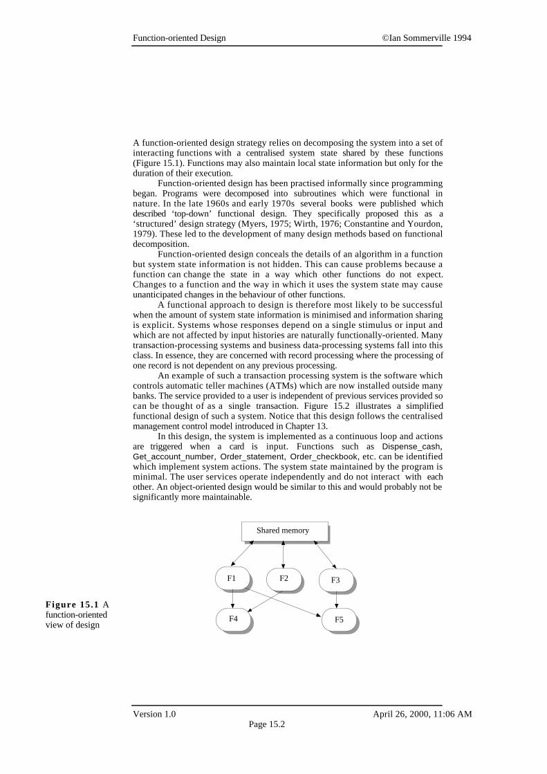
A function-oriented design strategy relies on decomposing the system into a set ofinteracting functions with a centralised system state shared by these functions(Figure 15.1). Functions may also maintain local state information but only for theduration of their execution.
Function-oriented design has been practised informally since programmingbegan. Programs were decomposed into subroutines which were functional innature. In the late 1960s and early 1970s several books were published whichdescribed ‘top-down’ functional design. They specifically proposed this as a‘structured’ design strategy (Myers, 1975; Wirth, 1976; Constantine and Yourdon,1979). These led to the development of many design methods based on functionaldecomposition.
Function-oriented design conceals the details of an algorithm in a functionbut system state information is not hidden. This can cause problems because afunction can change the state in a way which other functions do not expect.Changes to a function and the way in which it uses the system state may causeunanticipated changes in the behaviour of other functions.
A functional approach to design is therefore most likely to be successfulwhen the amount of system state information is minimised and information sharingis explicit. Systems whose responses depend on a single stimulus or input andwhich are not affected by input histories are naturally functionally-oriented. Manytransaction-processing systems and business data-processing systems fall into thisclass. In essence, they are concerned with record processing where the processing ofone record is not dependent on any previous processing.
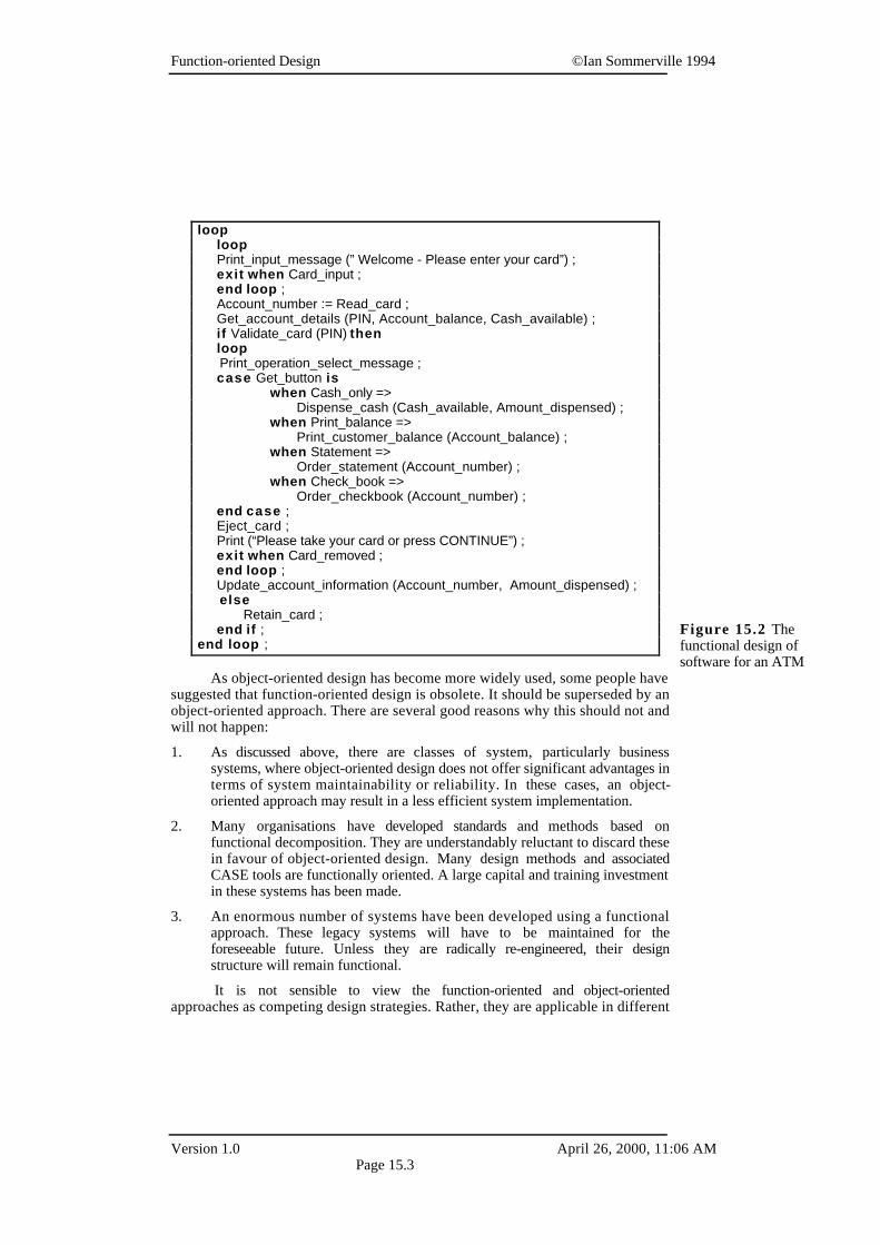
An example of such a transaction processing system is the software whichcontrols automatic teller machines (ATMs) which are now installed outside manybanks. The service provided to a user is independent of previous services provided socan be thought of as a single transaction. Figure 15.2 illustrates a simplifiedfunctional design of such a system. Notice that this design follows the centralisedmanagement control model introduced in Chapter 13.
In this design, the system is implemented as a continuous loop and actionsare triggered when a card is input. Functions such as Dispense_cash,Get_account_number, Order_statement, Order_checkbook, etc. can be identifiedwhich implement system actions. The system state maintained by the program isminimal. The user services operate independently and do not interact with eachother. An object-oriented design would be similar to this and would probably not besignificantly more maintainable.
Shared memory
F1 F2 F3
F4 F5
Figure 15.1 Afunction-orientedview of design
Function-oriented Design ©Ian Sommerville 1994
Version 1.0 April 26, 2000, 11:06 AMPage 15.3
As object-oriented design has become more widely used, some people havesuggested that function-oriented design is obsolete. It should be superseded by anobject-oriented approach. There are several good reasons why this should not andwill not happen:
1. As discussed above, there are classes of system, particularly businesssystems, where object-oriented design does not offer significant advantages interms of system maintainability or reliability. In these cases, an object-oriented approach may result in a less efficient system implementation.
2. Many organisations have developed standards and methods based onfunctional decomposition. They are understandably reluctant to discard thesein favour of object-oriented design. Many design methods and associatedCASE tools are functionally oriented. A large capital and training investmentin these systems has been made.
3. An enormous number of systems have been developed using a functionalapproach. These legacy systems will have to be maintained for theforeseeable future. Unless they are radically re-engineered, their designstructure will remain functional.
It is not sensible to view the function-oriented and object-orientedapproaches as competing design strategies. Rather, they are applicable in different
looploop
Print_input_message (” Welcome - Please enter your card”) ; exit when Card_input ; end loop ; Account_number := Read_card ; Get_account_details (PIN, Account_balance, Cash_available) ; if Validate_card (PIN) then loop Print_operation_select_message ; case Get_button is when Cash_only => Dispense_cash (Cash_available, Amount_dispensed) ; when Print_balance => Print_customer_balance (Account_balance) ; when Statement => Order_statement (Account_number) ; when Check_book =>
Order_checkbook (Account_number) ; end case ; Eject_card ; Print (“Please take your card or press CONTINUE”) ; exit when Card_removed ; end loop ; Update_account_information (Account_number, Amount_dispensed) ; else Retain_card ; end if ;end loop ;
Figure 15.2 Thefunctional design ofsoftware for an ATM
Function-oriented Design ©Ian Sommerville 1994
Version 1.0 April 26, 2000, 11:06 AMPage 15.4
circumstances and for different types of application. Good designers chose the mostappropriate strategy for the application that is being developed rather than use asingle approach.
In this chapter, I illustrate a function-oriented design process using a numberof examples. The activities in that process are:
1. Data-flow design Model the system design using data-flow diagrams. Thisshould show how data passes through the system and is transformed by eachsystem function. This model may be derived from data-flow modelsdeveloped during the analysis process.
2. Structural decomposition Model how functions are decomposed into sub-functions using graphical structure charts.
3. Detailed design description Describe the entities in the design and theirinterfaces. These descriptions may be recorded in a data dictionary. Alsodescribe the control structure of the design using a program descriptionlanguage (PDL) which includes conditional statements and loopingconstructs.
As with all design processes, these activities are not carried out in sequencebut are interleaved during the design process.
15.1 Data-flow design
Data-flow design is concerned with designing a sequence of functionaltransformations that convert system inputs into the required outputs. The design isrepresented as data-flow diagrams. These diagrams illustrate how data flows througha system and how the output is derived from the input through a sequence offunctional transformations.
Data-flow diagrams are a useful and intuitive way of describing a system.They are normally understandable without special training, especially if controlinformation is excluded. They show end-to-end processing. That is, the flow ofprocessing from when data enters the system to where it leaves the system can betraced.
Data-flow design is an integral part of a number of design methods and mostCASE tools support data-flow diagram creation. Different methods may usedifferent icons to represent data-flow diagram entities but their meanings are similar.The notation which I use is based on the following symbols:
1. Rounded rectangles represent functions which transform inputs to outputs.The transformation name indicates its function.
2. Rectangles represent data stores. Again, they should be given a descriptivename.
3. Circles represent user interactions with the system that provide input orreceive output.
Function-oriented Design ©Ian Sommerville 1994
Version 1.0 April 26, 2000, 11:06 AMPage 15.5
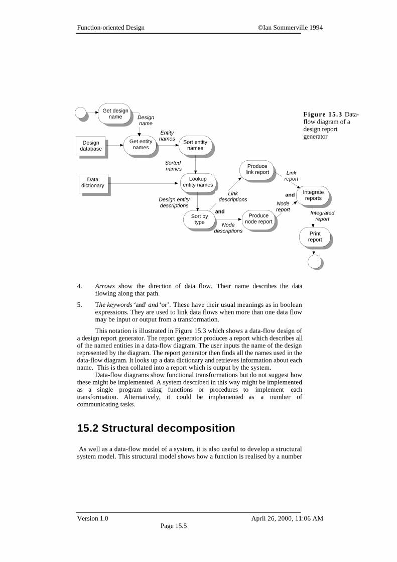
4. Arrows show the direction of data flow. Their name describes the dataflowing along that path.
5. The keywords ‘and’ and ‘or’. These have their usual meanings as in booleanexpressions. They are used to link data flows when more than one data flowmay be input or output from a transformation.
This notation is illustrated in Figure 15.3 which shows a data-flow design ofa design report generator. The report generator produces a report which describes allof the named entities in a data-flow diagram. The user inputs the name of the designrepresented by the diagram. The report generator then finds all the names used in thedata-flow diagram. It looks up a data dictionary and retrieves information about eachname. This is then collated into a report which is output by the system.
Data-flow diagrams show functional transformations but do not suggest howthese might be implemented. A system described in this way might be implementedas a single program using functions or procedures to implement eachtransformation. Alternatively, it could be implemented as a number ofcommunicating tasks.
15.2 Structural decomposition
As well as a data-flow model of a system, it is also useful to develop a structuralsystem model. This structural model shows how a function is realised by a number
Get designname Design
name
Designdatabase
Get entitynames
Sort entitynames
Datadictionary
Lookupentity names
Sorted names
Entitynames
Sort bytype
Producelink report
Produce node report
Integrate reportsDesign entity
descriptionsand
Linkdescriptions
Nodedescriptions
Linkreport
Nodereport
Printreport
and
Integratedreport
Figure 15.3 Data-flow diagram of adesign reportgenerator
Function-oriented Design ©Ian Sommerville 1994
Version 1.0 April 26, 2000, 11:06 AMPage 15.6
of other functions which it calls. Structure charts are a graphical way to representthis decomposition hierarchy. Like data-flow diagrams, they are dynamic rather thanstatic system models. They show how one function calls others. They do not showthe static block structure of a function or procedure.
A function is represented on a structure chart as a rectangle. The hierarchy isdisplayed by linking rectangles with lines. Inputs and outputs (which may beimplemented either as parameters or shared variables) are indicated with annotatedarrows. An arrow entering a box implies input, leaving a box implies output. Datastores are shown as rounded rectangles and user inputs as circles.
Converting a data-flow diagram to a structure chart is not a mechanicalprocess. It requires designer insight and creativity. However, there are several ‘rulesof thumb’ which may be applied to help designers assess if their decomposition islikely to be a reasonable one:
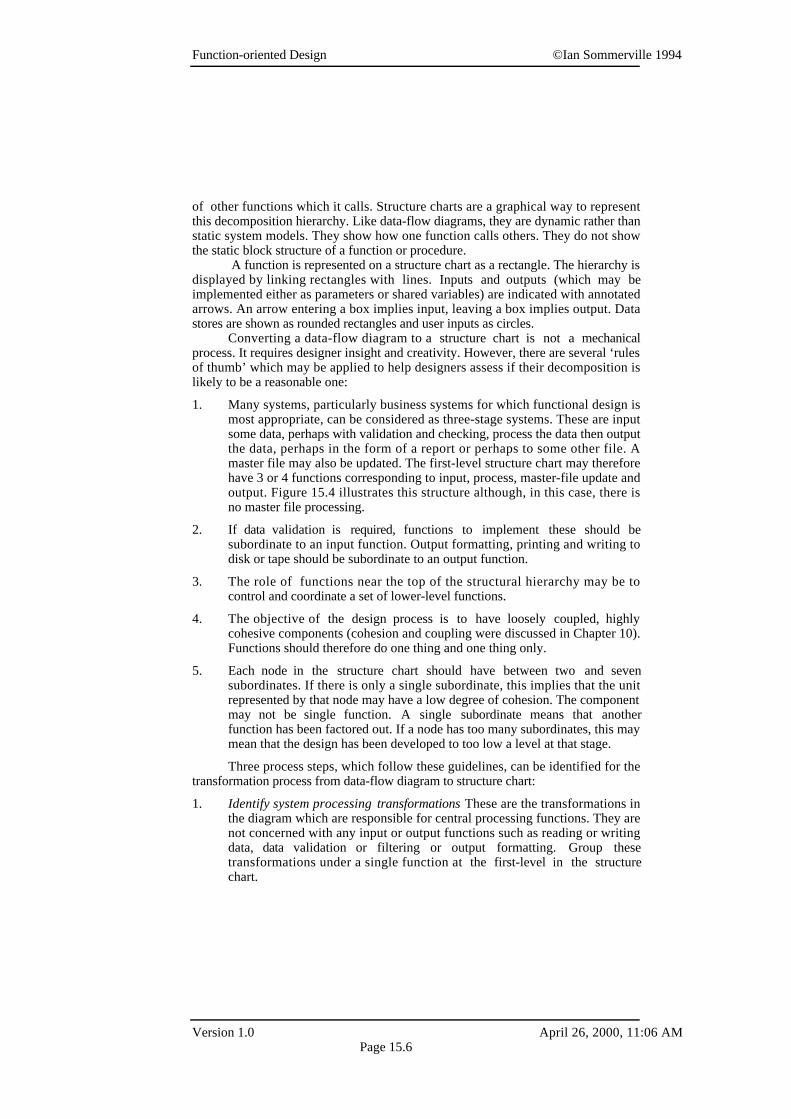
1. Many systems, particularly business systems for which functional design ismost appropriate, can be considered as three-stage systems. These are inputsome data, perhaps with validation and checking, process the data then outputthe data, perhaps in the form of a report or perhaps to some other file. Amaster file may also be updated. The first-level structure chart may thereforehave 3 or 4 functions corresponding to input, process, master-file update andoutput. Figure 15.4 illustrates this structure although, in this case, there isno master file processing.
2. If data validation is required, functions to implement these should besubordinate to an input function. Output formatting, printing and writing todisk or tape should be subordinate to an output function.
3. The role of functions near the top of the structural hierarchy may be tocontrol and coordinate a set of lower-level functions.
4. The objective of the design process is to have loosely coupled, highlycohesive components (cohesion and coupling were discussed in Chapter 10).Functions should therefore do one thing and one thing only.
5. Each node in the structure chart should have between two and sevensubordinates. If there is only a single subordinate, this implies that the unitrepresented by that node may have a low degree of cohesion. The componentmay not be single function. A single subordinate means that anotherfunction has been factored out. If a node has too many subordinates, this maymean that the design has been developed to too low a level at that stage.
Three process steps, which follow these guidelines, can be identified for thetransformation process from data-flow diagram to structure chart:
1. Identify system processing transformations These are the transformations inthe diagram which are responsible for central processing functions. They arenot concerned with any input or output functions such as reading or writingdata, data validation or filtering or output formatting. Group thesetransformations under a single function at the first-level in the structurechart.
Function-oriented Design ©Ian Sommerville 1994
Version 1.0 April 26, 2000, 11:06 AMPage 15.7
2. Identify input transformations These are concerned with reading data,checking it, removing duplicates, etc. These should also be grouped under asingle function at the first-level in the structure chart.
3. Identify output transformations These are transformations which prepare andformat output or write it to the user’s screen or other device. However, thereare several ‘rules of thumb’ that can be applied to help designers in thisprocess.
In the design report generator data-flow diagram (Figure 15.3), the processingfunctions are those which sort the input, look up the data dictionary and sort theinformation retrieved from the data dictionary. In the structure chart (Figure 15.4)these are collected together into a single function called Collate entities. This initialstructure chart can be decomposed to show subordinate functions which also reflecttransformations in the data-flow diagram (Figure 15.5).
Producedesign reports
Get designentity names
Collate entities
Generatereport
entitynames
entitynames
entitydata
Design name
Designentity
names
Design report
entitydata
Figure 15.4 Initialstructure chart for thedesign reportgenerator
Producedesign reports
Get designentity names
Collate entities
Generatereport
Get design name
Get entity names
Sort entities by name
Get entitydata
Sort entities by type
Produceintegrated report
Printreport
names
design name
entitynames
names
names sortednames
entitydata
sortedentity data
Integrated report
entity names
design name
entity data
report
sortedentity data
sortedentity data
Figure 15.5Second-levelstructure chart for thedesign reportgenerator
Function-oriented Design ©Ian Sommerville 1994
Version 1.0 April 26, 2000, 11:06 AMPage 15.8
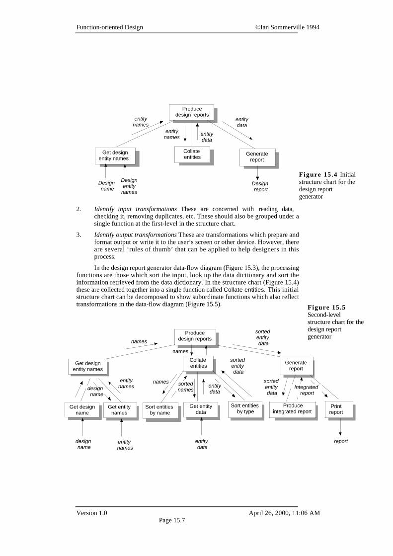
The input transformations stop at the function Sort entity names. In thiscase they are simply concerned with reading information. No data checking isrequired. They are represented as a function called Get design entity names .
The output transformations are concerned with producing reports for link andnode type, report integration and printing. These are all concerned with theformatting and organisation of design entity descriptions. These are grouped underthe function Generate report.
All the principal routines in the design report generator have now beenidentified. It only remains to add a final level of more detailed routines and to showhow the system data stores are accessed. The final structure chart is shown in Figure15.6. This chart does not show the access functions to the data dictionary and thedesign database. I assume that these data stores are like abstract data types and havetheir own access functions.
Other components may be included in a structure chart which are not directlyconcerned with data transformation. Because they do not transform data, they do notappear on the data-flow diagram. For example, components which are concernedwith logging-in and logging-out a user, system initialisation and any othercomponents concerned with system control rather than data processing may beincluded at the structural decomposition level.
15.3 Detailed design description
At this stage in the design process, the designer should know the organisation ofthe design and what each function should do. Design entity description is concerned
Producedesign reports
Get designentity names
Collate entities Generate
report
Get design name
Get entity names
Sort entities by name
Get entitydata
Sort entities by type
Produceintegrated report
Printreport
names
design name
entity
names
names
names sorted
namesentitydata
sortedentity data
Integrated report
entity names
design name
entity data
report
sortedentity data
design name
Designdatabase
Datadictionary
entityname
Producelink report
Producenode report
Link report
Linkdata
Nodedata Node
report
sortedentity data
Figure 15.6 Finalstructure chart for thedesign reportgenerator
Function-oriented Design ©Ian Sommerville 1994
Version 1.0 April 26, 2000, 11:06 AMPage 15.9
with producing a short design specification (sometimes called a minispec) of eachfunction. This requires describing the function, its inputs and its outputs.
Making this information explicit usually reveals flaws in the initialdecomposition or functions which have been omitted. The data-flow diagrams andstructure charts must be re-visited and modified to incorporate the improvedunderstanding of the design.
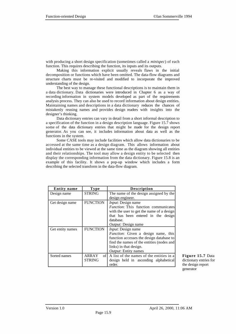
The best way to manage these functional descriptions is to maintain them ina data dictionary. Data dictionaries were introduced in Chapter 6 as a way ofrecording information in system models developed as part of the requirementsanalysis process. They can also be used to record information about design entities.Maintaining names and descriptions in a data dictionary reduces the chances ofmistakenly reusing names and provides design readers with insights into thedesigner’s thinking.
Data dictionary entries can vary in detail from a short informal description toa specification of the function in a design description language. Figure 15.7 showssome of the data dictionary entries that might be made for the design reportgenerator. As you can see, it includes information about data as well as thefunctions in the system.
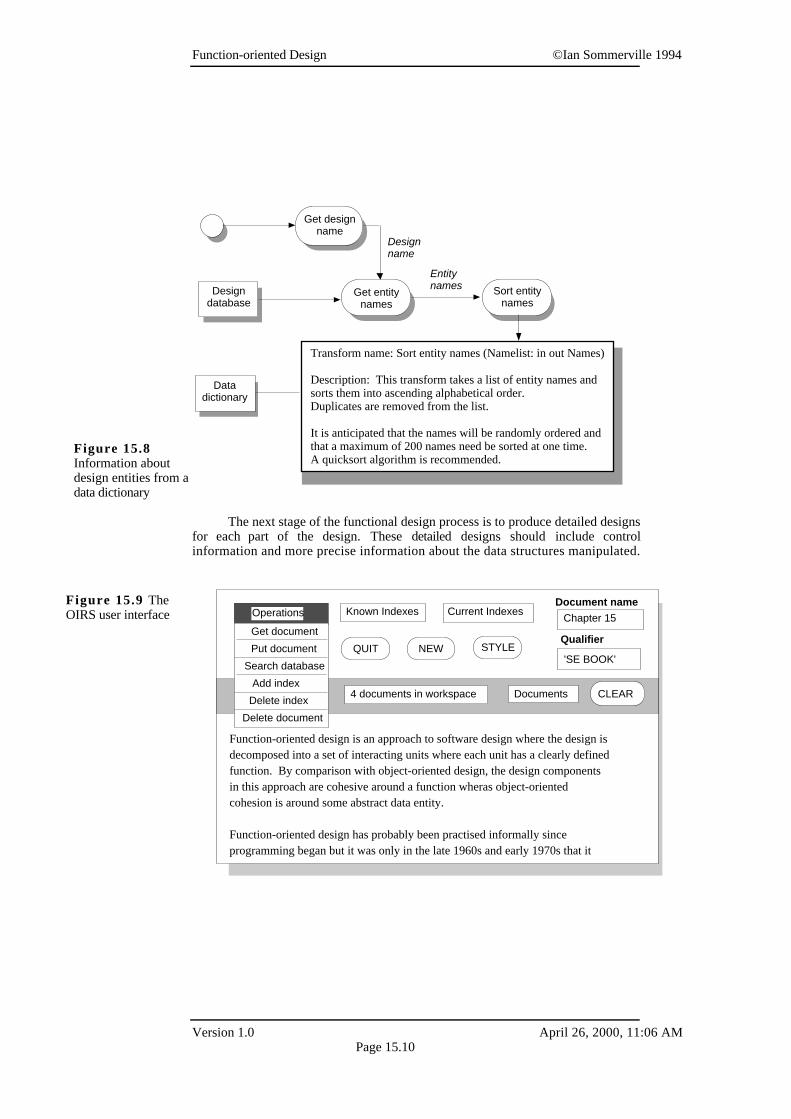
Some CASE tools may include facilities which allow data dictionaries to beaccessed at the same time as a design diagram. This allows information aboutindividual entities to be viewed at the same time as the diagram showing all entitiesand their relationships. The tool may allow a design entity to be selected thendisplay the corresponding information from the data dictionary. Figure 15.8 is anexample of this facility. It shows a pop-up window which includes a formdescribing the selected transform in the data-flow diagram.
Entity name Type DescriptionDesign name STRING The name of the design assigned by the
design engineer.Get design name FUNCTION Input: Design name
Function: This function communicateswith the user to get the name of a designthat has been entered in the designdatabase.Output: Design name
Get entity names FUNCTION Input: Design nameFunction: Given a design name, thisfunction accesses the design database tofind the names of the entities (nodes andlinks) in that design.Output: Entity names
Sorted names ARRAY ofSTRING
A list of the names of the entities in adesign held in ascending alphabeticalorder.
Figure 15.7 Datadictionary entries forthe design reportgenerator
Function-oriented Design ©Ian Sommerville 1994
Version 1.0 April 26, 2000, 11:06 AMPage 15.10
The next stage of the functional design process is to produce detailed designsfor each part of the design. These detailed designs should include controlinformation and more precise information about the data structures manipulated.
Get designname
Design name
Designdatabase
Get entitynames
Sort entitynames
Datadictionary
Entitynames
Transform name: Sort entity names (Namelist: in out Names)
Description: This transform takes a list of entity names and sorts them into ascending alphabetical order.Duplicates are removed from the list.
It is anticipated that the names will be randomly ordered and that a maximum of 200 names need be sorted at one time.A quicksort algorithm is recommended.
Figure 15.8Information aboutdesign entities from adata dictionary
Current IndexesDocument name
Qualifier
Known IndexesChapter 15Operations
4 documents in workspace Documents CLEAR
Function-oriented design is an approach to software design where the design isdecomposed into a set of interacting units where each unit has a clearly definedfunction. By comparison with object-oriented design, the design componentsin this approach are cohesive around a function wheras object-oriented cohesion is around some abstract data entity.
Function-oriented design has probably been practised informally since programming began but it was only in the late 1960s and early 1970s that it
Get document
Put document
Search database
Add index
Delete index
'SE BOOK'
Delete document
QUIT NEW STYLE
Figure 15.9 TheOIRS user interface
Function-oriented Design ©Ian Sommerville 1994
Version 1.0 April 26, 2000, 11:06 AMPage 15.11
These detailed designs may be expressed using some program description language,in some more detailed graphical notation or directly in a programming language. Ihave already shown examples of how a PDL may be used to describe a design inFigure 15.2. Further examples are shown in Figures 15.11, 15.14 and 15.16.
15.4 A comparison of design strategies
In Chapter 14, I introduced an example of an office information system. This wasused to illustrate object identification using a grammatical analysis of a systemdescription. In this section, this example will be expanded and used to comparefunctional and object-oriented approaches to design. I will also show how a designcan be developed for the same system using concurrent processes.
The Office Information Retrieval System (OIRS) is an office system whichcan file documents in one or more indexes, retrieve documents, display and maintaindocument indexes, archive documents and delete documents. Users requestoperations from a menu-based interface and the system always returns a message tothe user indicating the success or failure of the request.
The interface to this system is a form which has a number of fields (Figure15.9). Some of these fields are menu fields where the user can choose a particularoption. Other fields allow user textual input. Menu items may be selected bypointing with a mouse or by moving a cursor using keyboard commands.
The fields displayed in the form are as follows:
1. The operation field Selecting this field causes a menu of allowed operationsto be displayed as shown in Figure 15.9.
2. The known indexes field Selecting this field causes a menu of existing indexnames to be displayed. Selecting an item from this list adds it to the currentindex list.
3. The current indexes field Selecting this field displays a list of the indexeswhere the current document is to be indexed.
4. The document name field This specifies the name of the document to be filedor the name of the document to be retrieved. If this name is not filled in, theuser is prompted for a value.
5. The qualifier field This is a pattern which is used in searching. For example,the pattern ‘A-K’ may be specified with a command to look up the names ofdocuments in the current index lists. The qualifier causes only those nameswhich begin with a letter from A to K to be listed. Alternatively, thequalifier field might contain a keyword such as ‘Software Engineering’. Anindex search retrieves all documents which contain this keyword.
6. The current workspace Documents are retrieved to the current workspace thatmay contain several documents. The user may choose a document in theworkspace by selecting its name from the workspace menu. Clicking on theClear button in the workspace control bar removes the selection from the
Function-oriented Design ©Ian Sommerville 1994
Version 1.0 April 26, 2000, 11:06 AMPage 15.12
workspace. Moving the cursor into the workspace causes the system to enterdocument edit mode.
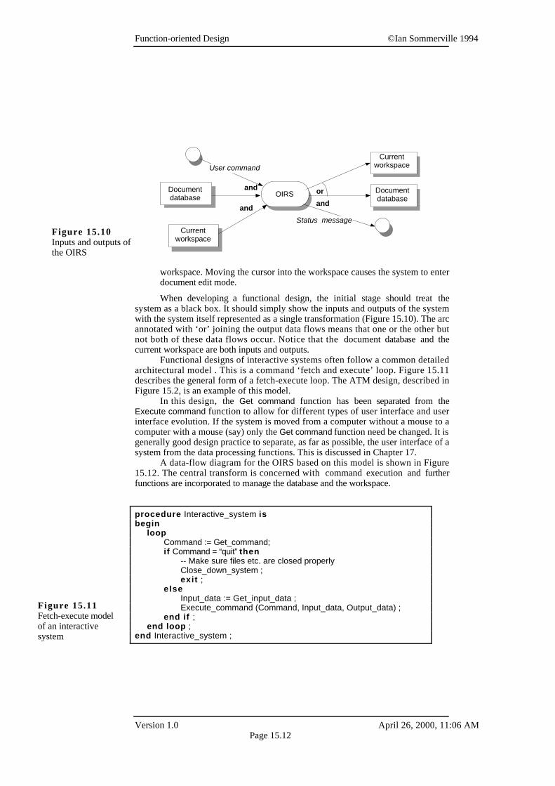
When developing a functional design, the initial stage should treat thesystem as a black box. It should simply show the inputs and outputs of the systemwith the system itself represented as a single transformation (Figure 15.10). The arcannotated with ‘or’ joining the output data flows means that one or the other butnot both of these data flows occur. Notice that the document database and thecurrent workspace are both inputs and outputs.
Functional designs of interactive systems often follow a common detailedarchitectural model . This is a command ‘fetch and execute’ loop. Figure 15.11describes the general form of a fetch-execute loop. The ATM design, described inFigure 15.2, is an example of this model.
In this design, the Get command function has been separated from theExecute command function to allow for different types of user interface and userinterface evolution. If the system is moved from a computer without a mouse to acomputer with a mouse (say) only the Get command function need be changed. It isgenerally good design practice to separate, as far as possible, the user interface of asystem from the data processing functions. This is discussed in Chapter 17.
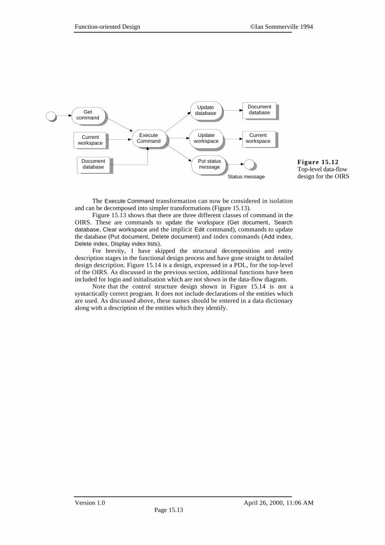
A data-flow diagram for the OIRS based on this model is shown in Figure15.12. The central transform is concerned with command execution and furtherfunctions are incorporated to manage the database and the workspace.
and orOIRS
Status message
User command
andand
Documentdatabase
Currentworkspace
Documentdatabase
Currentworkspace
Figure 15.10Inputs and outputs ofthe OIRS
procedure Interactive_system isbegin
loopCommand := Get_command;if Command = “quit” then
-- Make sure files etc. are closed properlyClose_down_system ;exit ;
elseInput_data := Get_input_data ;Execute_command (Command, Input_data, Output_data) ;
end if ;end loop ;
end Interactive_system ;
Figure 15.11Fetch-execute modelof an interactivesystem
Function-oriented Design ©Ian Sommerville 1994
Version 1.0 April 26, 2000, 11:06 AMPage 15.13
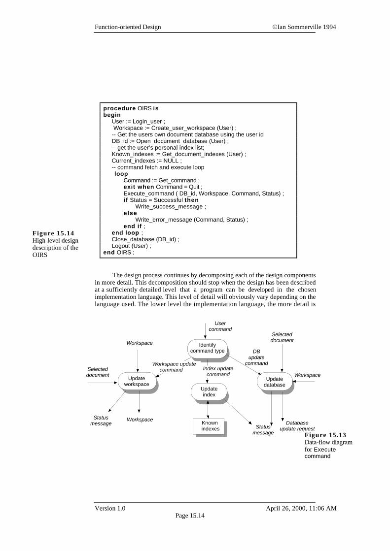
The Execute Command transformation can now be considered in isolationand can be decomposed into simpler transformations (Figure 15.13).
Figure 15.13 shows that there are three different classes of command in theOIRS. These are commands to update the workspace (Get document, Searchdatabase, Clear workspace and the implicit Edit command), commands to updatethe database (Put document, Delete document) and index commands (Add index,Delete index, Display index lists).
For brevity, I have skipped the structural decomposition and entitydescription stages in the functional design process and have gone straight to detaileddesign description. Figure 15.14 is a design, expressed in a PDL, for the top-levelof the OIRS. As discussed in the previous section, additional functions have beenincluded for login and initialisation which are not shown in the data-flow diagram.
Note that the control structure design shown in Figure 15.14 is not asyntactically correct program. It does not include declarations of the entities whichare used. As discussed above, these names should be entered in a data dictionaryalong with a description of the entities which they identify.
Get command
Update database
Updateworkspace
Put statusmessage
ExecuteCommand
Documentdatabase
Currentworkspace
Currentworkspace
Documentdatabase
Status message
Figure 15.12Top-level data-flowdesign for the OIRS
Function-oriented Design ©Ian Sommerville 1994
Version 1.0 April 26, 2000, 11:06 AMPage 15.14
The design process continues by decomposing each of the design componentsin more detail. This decomposition should stop when the design has been describedat a sufficiently detailed level that a program can be developed in the chosenimplementation language. This level of detail will obviously vary depending on thelanguage used. The lower level the implementation language, the more detail is
Identifycommand type
Workspace update command Index update
command
DB update
command
Update index
Update workspace
Workspace
Workspace
WorkspaceUpdate
database
Databaseupdate request
Selecteddocument
Selecteddocument
Known indexes
User command
Statusmessage
Status message Figure 15.13
Data-flow diagramfor Executecommand
procedure OIRS isbegin User := Login_user ; Workspace := Create_user_workspace (User) ;
-- Get the users own document database using the user idDB_id := Open_document_database (User) ;
-- get the user’s personal index list;Known_indexes := Get_document_indexes (User) ;Current_indexes := NULL ;-- command fetch and execute loop loop
Command := Get_command ;exit when Command = Quit ;Execute_command ( DB_id, Workspace, Command, Status) ;if Status = Successful then
Write_success_message ;else
Write_error_message (Command, Status) ;end if ;
end loop ;Close_database (DB_id) ;Logout (User) ;
end OIRS ;
Figure 15.14High-level designdescription of theOIRS
Function-oriented Design ©Ian Sommerville 1994
Version 1.0 April 26, 2000, 11:06 AMPage 15.15
required in the design.
15.4.1 Concurrent systems design
The above functional design models the OIRS as a sequential system with a singlecontrol loop which fetches and executes commands in sequence. An alternativeapproach to the detailed design is to implement the system as a number ofconcurrent process. As data-flow diagrams explicitly exclude control information,they can also be the starting point for a concurrent design. A standardimplementation technique for real-time systems (see Chapter 16) is to take a data-flow diagram and to implement each of its transformations as a separate process.
In this case, implementing each data-flow transformation as a separateprocess would not be an efficient way of designing the system. There is ascheduling overhead involved in starting and stopping processes and managingprocess communications. Unless it is absolutely necessary because of real-timerequirements, it is best to avoid decomposing a system into many small processes.
However, to improve real-time response in window-based systems, it is oftennecessary to identify those parts of the system which must respond to user eventsand implement these as separate processes. This allows the system to be responsiveto time-critical user events such as mouse movements. The strict sequence which isforced by a fetch-execute cycle can be avoided. In the OIRS, there are two situationswhere user actions cause an event to be generated:
1. When a command is selected. The user moves the cursor into a menu andmakes a choice. An event is generated informing the system that a commandhas been chosen.
2. When the cursor is moved into the workspace and the user starts to type.
The user can move the cursor between these areas at any time so the systemmust be able to cope with the change. This can be handled in a fetch-execute systemby making sure that the workspace editor keeps track of the cursor but some codeduplication in such a situation is inevitable.
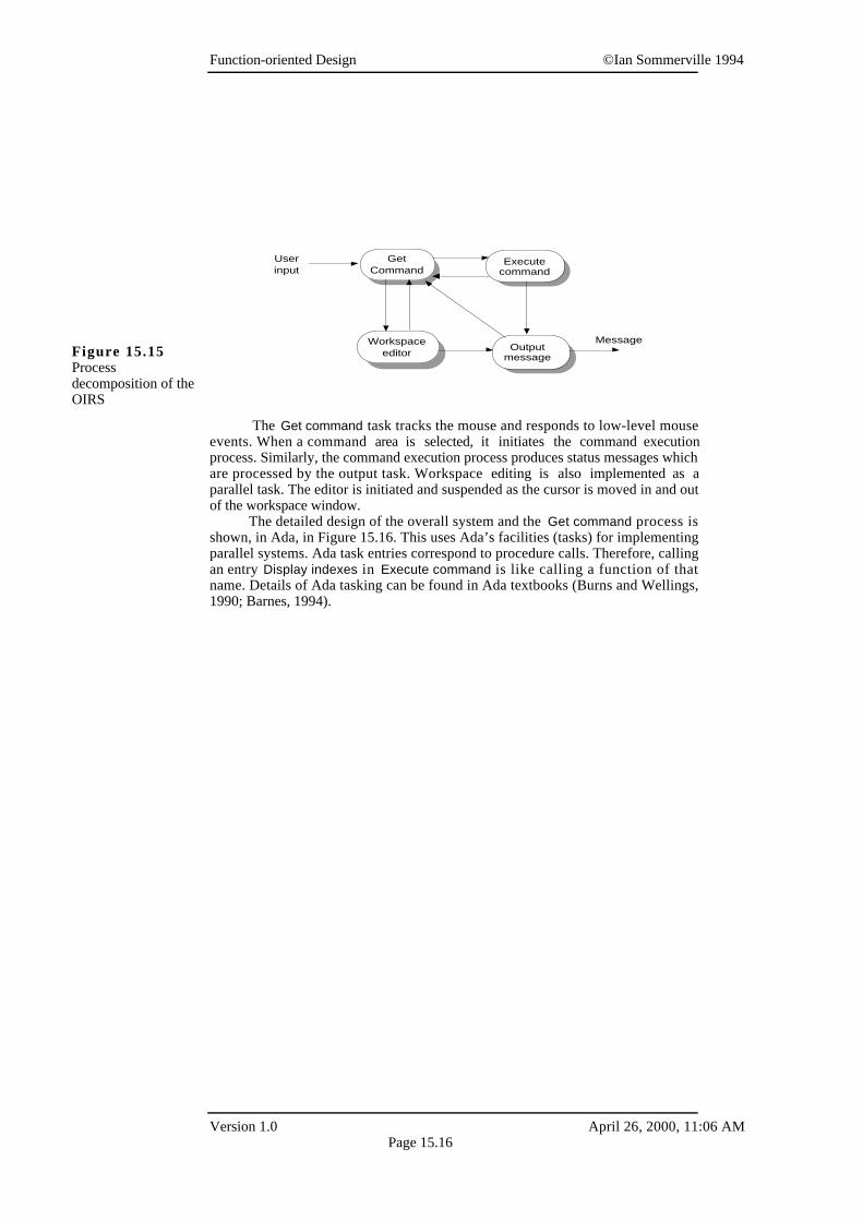
Given that the input processing (commands and text) is to be implementedusing separate processes, it then makes sense to identify corresponding processes tohandle command execution and output processing. This leads to a set of fourprocesses as shown in Figure 15.15. Control passes from process to process inresponse to events such as a cursor being positioned in a workspace, a commandmenu being selected, etc.
Function-oriented Design ©Ian Sommerville 1994
Version 1.0 April 26, 2000, 11:06 AMPage 15.16
The Get command task tracks the mouse and responds to low-level mouseevents. When a command area is selected, it initiates the command executionprocess. Similarly, the command execution process produces status messages whichare processed by the output task. Workspace editing is also implemented as aparallel task. The editor is initiated and suspended as the cursor is moved in and outof the workspace window.
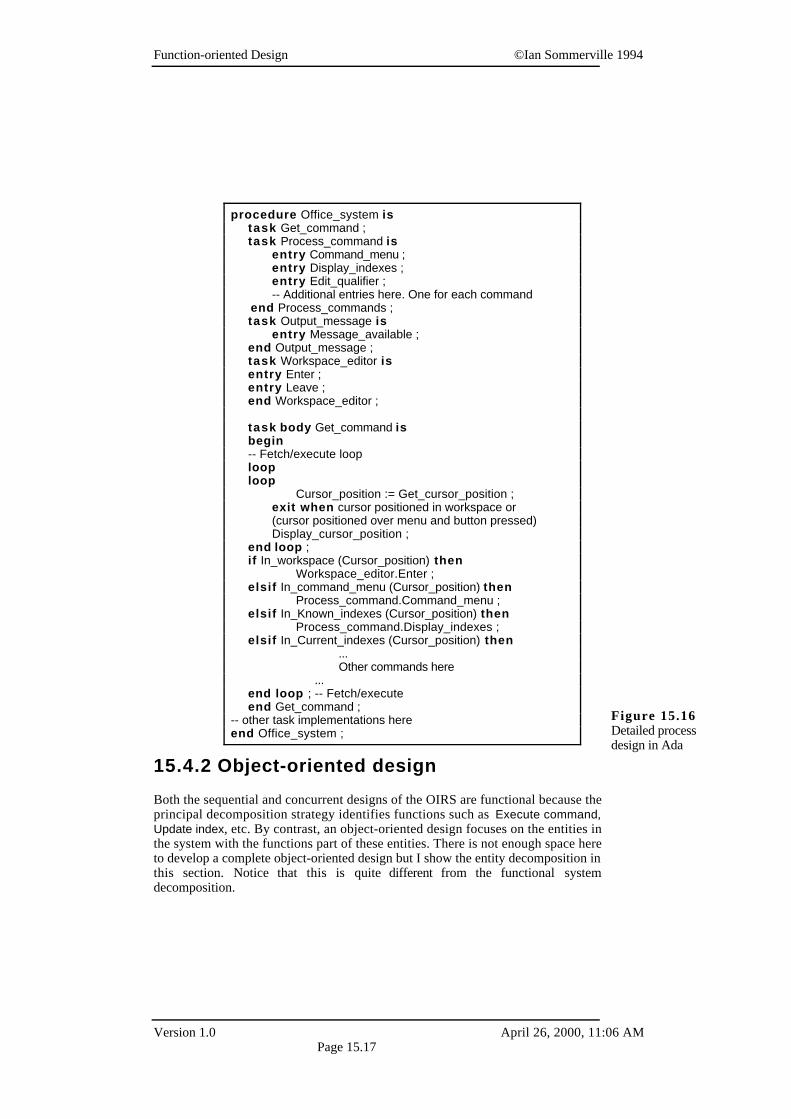
The detailed design of the overall system and the Get command process isshown, in Ada, in Figure 15.16. This uses Ada’s facilities (tasks) for implementingparallel systems. Ada task entries correspond to procedure calls. Therefore, callingan entry Display indexes in Execute command is like calling a function of thatname. Details of Ada tasking can be found in Ada textbooks (Burns and Wellings,1990; Barnes, 1994).
GetCommand
Workspaceeditor
Executecommand
Outputmessage
Userinput
MessageFigure 15.15Processdecomposition of theOIRS
Function-oriented Design ©Ian Sommerville 1994
Version 1.0 April 26, 2000, 11:06 AMPage 15.17
15.4.2 Object-oriented design
Both the sequential and concurrent designs of the OIRS are functional because theprincipal decomposition strategy identifies functions such as Execute command,Update index, etc. By contrast, an object-oriented design focuses on the entities inthe system with the functions part of these entities. There is not enough space hereto develop a complete object-oriented design but I show the entity decomposition inthis section. Notice that this is quite different from the functional systemdecomposition.
procedure Office_system istask Get_command ;
task Process_command is entry Command_menu ; entry Display_indexes ; entry Edit_qualifier ; -- Additional entries here. One for each command end Process_commands ; task Output_message is entry Message_available ; end Output_message ; task Workspace_editor is entry Enter ; entry Leave ; end Workspace_editor ;
task body Get_command is begin
-- Fetch/execute loop loop loop Cursor_position := Get_cursor_position ; exit when cursor positioned in workspace or (cursor positioned over menu and button pressed) Display_cursor_position ; end loop ; if In_workspace (Cursor_position) then Workspace_editor.Enter ; elsif In_command_menu (Cursor_position) then Process_command.Command_menu ; elsif In_Known_indexes (Cursor_position) then Process_command.Display_indexes ; elsif In_Current_indexes (Cursor_position) then
... Other commands here
...end loop ; -- Fetch/execute
end Get_command ;-- other task implementations hereend Office_system ;
Figure 15.16Detailed processdesign in Ada
Function-oriented Design ©Ian Sommerville 1994
Version 1.0 April 26, 2000, 11:06 AMPage 15.18
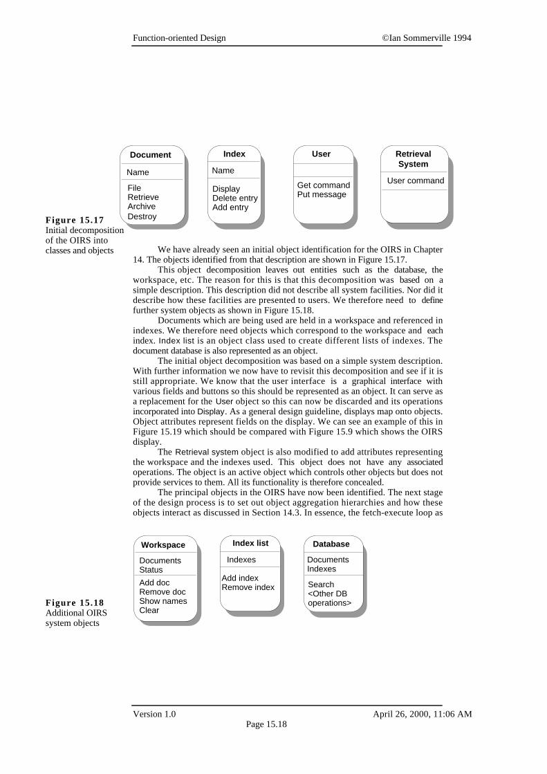
We have already seen an initial object identification for the OIRS in Chapter14. The objects identified from that description are shown in Figure 15.17.
This object decomposition leaves out entities such as the database, theworkspace, etc. The reason for this is that this decomposition was based on asimple description. This description did not describe all system facilities. Nor did itdescribe how these facilities are presented to users. We therefore need to definefurther system objects as shown in Figure 15.18.
Documents which are being used are held in a workspace and referenced inindexes. We therefore need objects which correspond to the workspace and eachindex. Index list is an object class used to create different lists of indexes. Thedocument database is also represented as an object.
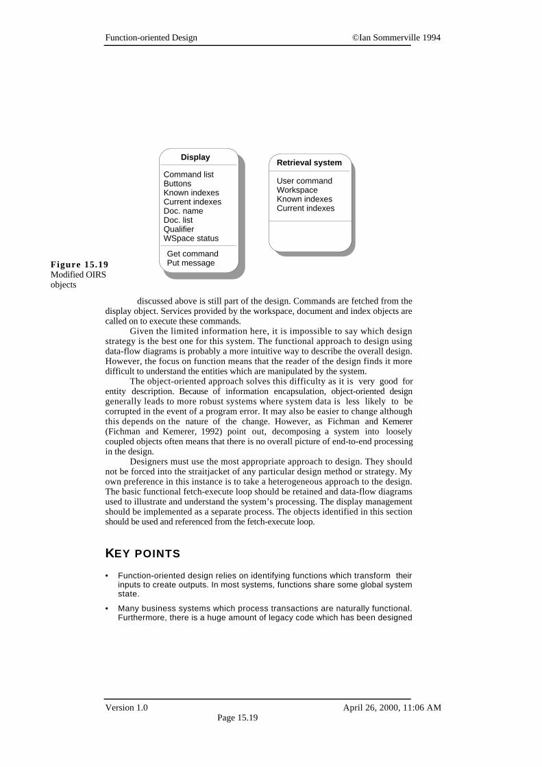
The initial object decomposition was based on a simple system description.With further information we now have to revisit this decomposition and see if it isstill appropriate. We know that the user interface is a graphical interface withvarious fields and buttons so this should be represented as an object. It can serve asa replacement for the User object so this can now be discarded and its operationsincorporated into Display. As a general design guideline, displays map onto objects.Object attributes represent fields on the display. We can see an example of this inFigure 15.19 which should be compared with Figure 15.9 which shows the OIRSdisplay.
The Retrieval system object is also modified to add attributes representingthe workspace and the indexes used. This object does not have any associatedoperations. The object is an active object which controls other objects but does notprovide services to them. All its functionality is therefore concealed.
The principal objects in the OIRS have now been identified. The next stageof the design process is to set out object aggregation hierarchies and how theseobjects interact as discussed in Section 14.3. In essence, the fetch-execute loop as
Document
Name
FileRetrieveArchiveDestroy
Index
Name
DisplayDelete entryAdd entry
User Retrieval System
Get commandPut message
User command
Figure 15.17Initial decompositionof the OIRS intoclasses and objects
DocumentsStatus
Add docRemove docShow namesClear
Index list
Indexes
Add indexRemove index
Database Workspace
DocumentsIndexes
Search<Other DBoperations>Figure 15.18
Additional OIRSsystem objects
Function-oriented Design ©Ian Sommerville 1994
Version 1.0 April 26, 2000, 11:06 AMPage 15.19
discussed above is still part of the design. Commands are fetched from thedisplay object. Services provided by the workspace, document and index objects arecalled on to execute these commands.
Given the limited information here, it is impossible to say which designstrategy is the best one for this system. The functional approach to design usingdata-flow diagrams is probably a more intuitive way to describe the overall design.However, the focus on function means that the reader of the design finds it moredifficult to understand the entities which are manipulated by the system.
The object-oriented approach solves this difficulty as it is very good forentity description. Because of information encapsulation, object-oriented designgenerally leads to more robust systems where system data is less likely to becorrupted in the event of a program error. It may also be easier to change althoughthis depends on the nature of the change. However, as Fichman and Kemerer(Fichman and Kemerer, 1992) point out, decomposing a system into looselycoupled objects often means that there is no overall picture of end-to-end processingin the design.
Designers must use the most appropriate approach to design. They shouldnot be forced into the straitjacket of any particular design method or strategy. Myown preference in this instance is to take a heterogeneous approach to the design.The basic functional fetch-execute loop should be retained and data-flow diagramsused to illustrate and understand the system’s processing. The display managementshould be implemented as a separate process. The objects identified in this sectionshould be used and referenced from the fetch-execute loop.
KEY POINTS
• Function-oriented design relies on identifying functions which transform theirinputs to create outputs. In most systems, functions share some global systemstate.
• Many business systems which process transactions are naturally functional.Furthermore, there is a huge amount of legacy code which has been designed
Command listButtonsKnown indexesCurrent indexesDoc. nameDoc. listQualifierWSpace status
Retrieval systemDisplay
Get commandPut message
User commandWorkspaceKnown indexesCurrent indexes
Figure 15.19Modified OIRSobjects
Function-oriented Design ©Ian Sommerville 1994
Version 1.0 April 26, 2000, 11:06 AMPage 15.20
using this approach. For these reasons, function-oriented design will continuealongside object-oriented design as an important design strategy.
• The functional design process involves identifying data transformations in thesystem, decomposing functions into a hierarchy of sub-functions, describingthe operation and interface of each system entity and documenting the flow ofcontrol in the system.
• Data-flow diagrams are a means of documenting end-to-end data flow through asystem. They do not include control information. Structure charts are a way ofrepresenting the hierarchical organisation of a system. Control may bedocumented using a program description language (PDL).
• Data-flow diagrams can be implemented directly as a set of cooperatingsequential processes. Each transform in the data-flow diagram is implementedas a separate process. Alternatively, they can be realised as a number ofprocedures in a sequential program.
• Functional design and object-oriented design usually result in totally differentsystem decompositions. However, the most appropriate design strategy is oftena heterogeneous one where both functional and object-oriented approaches areused.
FURTHER READING
Software Design This book is a good general survey of software design techniques.Its orientation is towards functional approaches to design for the valid reason thatthese are more mature than object-oriented approaches. ( D. Budgen, 1993, Addison-Wesley)
‘Object-Oriented and Conventional Analysis and Design Methodologies’ This is anexcellent comparison of object-oriented and functional approaches to design. Itsconclusion is that the claimed advantages of object-oriented design have not beenconclusively demonstrated. (IEEE Computer, 25 (10), October 1992)
EXERCISES
15.1 Using examples, describe how data-flow diagrams may be used to document asystem design. What are the advantages of using this type of design model?
15.2 Draw possible data-flow diagrams of system designs for the followingapplications. You may make any reasonable assumptions about theseapplications.
• Part of an electronic mail system which presents a mail form to a user,accepts the completed form and sends it to the identified destination.
• A salary system which computes employee salaries and deductions. The inputis a list of employee numbers who are to be paid that month. The systemmaintains tables holding tax rates and the annual salary for each employee.The output is a salary slip for each employee plus a list of automatedpayments to be made by the company’s bank.
Function-oriented Design ©Ian Sommerville 1994
Version 1.0 April 26, 2000, 11:06 AMPage 15.21
15.3 Modify the design of the report generator shown in Figure 15.3 so that itbecomes an interactive system. The user may give a design entity name andthe report generator provides information about that entity. Alternatively, theuser may provide a type name and the report generator produces a report abouteach entity of that type in a design. Document your modified design usingdata-flow diagrams and structure charts.
15.4 Convert the data-flow diagram of the report generator system described inFigure 15.3 into a design consisting of concurrent processes.
15.5 Using a design description language, describe a possible design for the designreport generator whose data-flow diagram is given in Figure 15.3 andstructure chart in Figure 15.7.
15.6 Explain how data dictionaries may be used to supplement design informationin data-flow diagrams and structure charts.
15.7 Develop the data-flow diagrams shown in Figure 15.12 so that all transformsare documented with more detailed data-flow diagrams.
15.8 Develop the design of Execute Command in the office information retrievalsystem and describe its detailed design in a design description language.
15.9 Develop function-oriented designs for the systems described in Exercise 14.6.What are the principal differences between these and object-oriented designs?


![Object Oriented Design 2.ppt [Read-Only]home.gwu.edu/~blankeng/Classes/CSCI253/Object Oriented Design 2… · Object Oriented Design Part 2 Program Design •Analysis •Design •](https://img.pdfslide.net/doc/110x75/5fc2c8953a884e54934fe012/object-oriented-design-2ppt-read-onlyhomegwuedublankengclassescsci253object.jpg)