Embed Size (px)
Citation preview
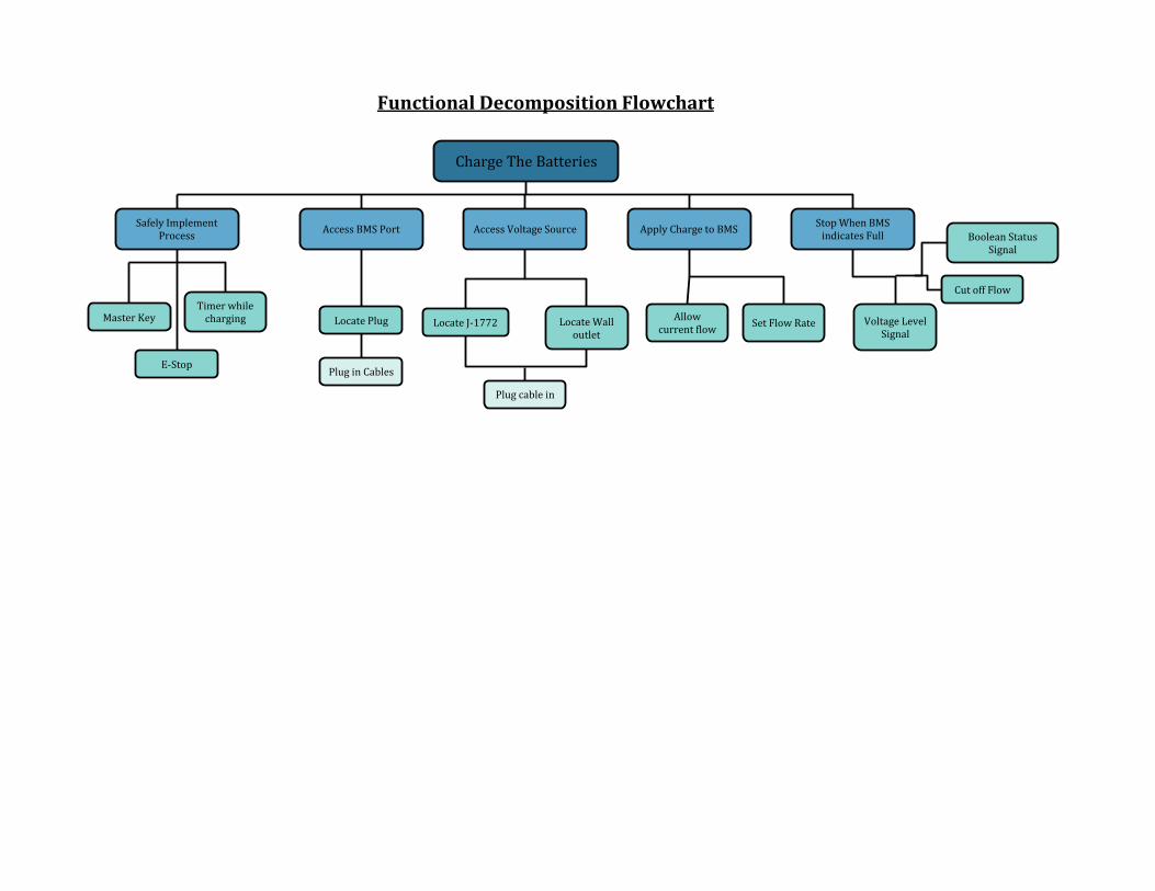
Charge The Batteries
Safely ImplementProcess
Access BMS Port Access Voltage Source Apply Charge to BMSStop When BMS
indicates Full
Voltage Level Signal
Cut off Flow
Boolean Status Signal
Allowcurrent flow
Set Flow RateLocate J-1772 Locate Wall outlet
Plug cable in
Locate Plug
Plug in Cables
Master KeyTimer while
charging
E-Stop
Functional Decomposition Flowchart

Method 1 2 3 4 5
Power on button voice command clap/sound detection remote control signal from bike
Set rate dial potentiometer signal from bike buttons sliding potentiometer voice input
Detect charge from bike current sensor voltage detection temperature gauge coulomb counting
Stop flow of charge relays power transistors reactive decoupling robotic arm disconnect self termination
Emergency disconnect relays stop conducting reactive disconnect transistors software
Notify user when done audible alert visible alert both none
Prevent unauth. use pin code lock/key software password
Selection Criteria1. Safe to use2. Easy to use
3. Charges quickly4. Returns useful data
5. Portability
Legend1st choice2nd choice3rd choice
Morphological Chart & Concept Selection

Item Justification
Mechanical button powers on the charger A mechanical button is the easiest, cheapest and most reliable method of powering on the
charger. Other options involve significant time and resources to develop.
A dial potentiometer sets the charge rate A potentiometer is the most practical and user-friendly way of setting the charge rate, as the charge level can be adjusted in a continuous
manner (there aren’t discrete charge levels). A sliding potentiometer may also work; the choice of a dial potentiometer is a matter of personal
preference.
The charge on a battery pack is detected via coulomb counting
Coulomb counting is the method requested by EVT, as it is already implemented on their bike
and it offers the most accurate measurement of charge. Coulomb counting also only requires a wire with a resistance of 1 ohm and a voltage
sensor to implement, making it cost effective as well.
Power transistors are used in place of a transformer
Power transistors are far safer than a transformer, generate less heat, and have a much
smaller physical footprint.
Power transistors are used to stop the flow of charge
Since power transistors are being used in place of a transformer, they can also be used to stop the
flow of charge without needing extra components (like relays).
The user is notified via an audio-visual alert when the battery is finished charging
An audio-visual alert ensures that the user does not have to “guess” when the charging is complete. The visual alert also ensures an
optimal user experience for deaf/hard-of-hearing users.
A key must be inserted into the device in order for charging to initiate.
Requiring the use of a key to facilitate charging ensures that unauthorized use of the charger does not occur. This allows EVT to ensure that
every user is trained in using the charger before being able to use the charger.

Architecture
Control System
User Interface
Voltage regulation
Emergency Saftey Systems
CAN Communications

MSD Project Risk Assessment Template
ID Risk Item Effect Cause Like
liho
od
Seve
rity
Imp
ort
ance
Action to Minimize Risk Owner
Describe the risk briefly What is the effect on any or all of the project deliverables if the cause actually happens?
What are the possible cause(s) of this risk?
L*S What action(s) will you take (and by when) to prevent, reduce the impact of, or transfer the risk of this occurring?
Who is responsible for following through on mitigation?
1
J-1772 interface unobtainable
The charger will not be usable with J-1772 chargers unless an adapter is manufactured in house
IP restrictions/low demand or supply for the interface
1 6 6 Conduct proper research into the ability to purchase this interface
Team
2 Electrocution from arc flash
Damaged equipment, injured operator/bystander Battery failure 1 9 9
Researching and developing a safety mechanism that shuts down the charger and electrical system when failure is detected Team
3
Battery management system fails to cut off the charge
Batteries overcharge/lifecycle decreases
Microcontroller fails to detect a full battery/communication disconnect 3 7 21
Thorough debugging of code/firmware will be implemented, a microcontroller that can effectively communicate with the BMS will be researched and purchased. Use test equipment to ensure that the battery cells will not exceed or meet 100% capacity Team
4 Automatic switching system does not exist
Charger cannot automatically detect and switch between 120V and J-1772 charging
Unforeseen issues with the J-1772 protocol that prevent current switching 2 4 8
Researching J-1772 charging standard to ensure that automatic switching is possible, discuss alternate methods to implement current switching if a problem is found Team
5 Damage to charger
Must replace damaged equipment/increased cost due to replacement
Improper use, overheating, system design, short circuit 2 9 18
Implementation of redundant safety systems and procedures. Adequate research and testing to validate design Team

6 Design Over-Budget Not all components are obtainable
Lack of oversight, incorrect parts ordered, replacement to damaged parts 2 7 14
Keep a log of desired items/components, assign an estimate cost to each system, and minimize risk 5.
Team/Project Manager
7 Design behind schedule Project deliverables incomplete
Unforeseen design complications, Risk 5, Lack of communication between team 3 5 15
Team must update/adhere to schedule on a regular basis and maintain communication of any possible complications or FMEA’s
Project Manager/Team
8 System function fails test Function must be corrected
Inadequate components within system, not designed to interface with other functions 2 6 12
Adequate research will minimize risks. Having multiple concepts per subsystem/function will provide a backup in case system is proven to fail. Team
Likelihood scale Severity scale
1 - This cause is unlikely to happen 1 - The impact on the project is very minor. We will still meet deliverables on time and within budget, but it will cause extra work
2 - This cause could conceivably happen 4 - The impact on the project is noticeable. We will deliver reduced functionality, go over budget, or fail to meet some of our Engineering Specifications.
3 - This cause is very likely to happen 9 - The impact on the project is severe. We will not be able to deliver, or what we deliver will not meet the customer's needs.
“Importance Score” (Likelihood x Severity) – use this to guide your preference for a risk management strategy
Prevent Action will be taken to prevent the cause(s) from occurring in the first place.
Reduce Action will be taken to reduce the likelihood of the cause and/or the severity of the effect on the project, should the cause occur
Transfer Action will be taken to transfer the risk to something else. Insurance is an example of this. You purchase an insurance policy that contractually binds an insurance company to pay for your loss in the event of accident. This transfers the financial consequences of the accident to someone else. Your car is still a wreck, of course.
Accept Low importance risks may not justify any action at all. If they happen, you simply accept the consequences.

Test Plan ( First Cut )
1) Test AC/DC converter
a) Verify proper rectification of AC signal to DC
2) Test Voltage regulator
a) Verify proper control and accuracy of voltage regulator
3) Test User Interface
a) Verify Ease of use
4) Test Emergency systems
a) Verify proper reactions to error states
5) Test CAN Communication
a) Verify Communications to the BMS