Embed Size (px)
Citation preview
FULL P
APER
© 2015 WILEY-VCH Verlag GmbH & Co. KGaA, Weinheim (1 of 9) 1500771wileyonlinelibrary.com
Functional Pillared Graphene Frameworks for Ultrahigh Volumetric Performance Supercapacitors
Lili Jiang , Lizhi Sheng , Conglai Long , Tong Wei , and Zhuangjun Fan *
Dr. L. Jiang, Dr. L. Sheng, Dr. C. Long, Prof. T. Wei, Prof. Z. Fan Key Laboratory of Superlight Materials and Surface Technology Ministry of EducationCollege of Material Science and Chemical Engineering Harbin Engineering University Harbin 150001 , P. R. China E-mail: [email protected]
DOI: 10.1002/aenm.201500771
on porous carbon electrodes, has limited capacitance and energy density restricted by the active electrode surface area and the pore size distribution (≈200 F g −1 and 4–5 Wh kg −1 for commercial carbon-based supercapacitors). [ 11–13 ]
To improve the specifi c capacitance and the energy density, considerable efforts have been focused on developing carbon supported pseudocapacitive transition-metal oxides electrodes by the combi-nation of high pseudo-capacitance and high energy density from metal oxides, and good rate capability and high power density from carbon nanostructure. [ 14–17 ] Whereas, maintaining the intimate con-tact at the carbon–metal oxide interface during manufacturing and electrochem-ical cycling, which is necessary for quick charge transfer in pseudo-capacitive redox reactions, ensuring good rate capa-bility and cyclic stability, still remains a challenge.
Alternatively, introducing oxygenated functionalities in the carbon networks, instead of carbon–metal oxide interface, open up new ways to address this challenge. [ 18–23 ] A signifi cant pseudo-capacitance, apart from EDLC, contributed by chemi-cally bounded electroactive oxygen species on the carbon sur-face could be provided in a basic electrolyte as follows: [ 24–26 ]
− − −> C OH+OH = > CO +H O2 (1)
= + = − +− −> C O OH COOH e (2)
− + = − +− −COOH OH COO H O2 (3)
As a result, oxygen species doped carbons without high porosity can also deliver higher volumetric capacitance and energy density compared with highly porous carbons. [ 27 ] However, these groups through chemical treatment, [ 28 ] elec-trochemical polarization, [ 29 ] and plasma treatment, [ 30 ] are not always stable with cycling, leading to the gradual decrease of the capacitance. [ 18 ] Moreover, it is another challenge to integrate high content of oxygen species on carbon electrodes without seriously undermining the high electrical conductivity.
Here, we report a novel strategy to design functional pillared graphene frameworks (FPGF), graphene fragments in-between graphene sheets, through thermal reduction of ozone-treated graphene oxide (O-GO), as shown in Figure 1 a. A large amount
Supercapacitors, also known as electrochemical capacitors, can provide much faster charge–discharge, greater power density, and cyclability than batteries, but they are still limited by lower energy densities (or the amount of energy stored per unit volume). Here, a novel strategy for the synthesis of functional pillared graphene frameworks, in which graphene fragments in-between graphene sheets, through simple thermal-treatment of ozone (O 3 )-treated graphene oxide at very low temperature of 200 °C is reported. Due to its high packing density, high content of stable oxygen species, and continues ion transport network in-between graphene sheets, the functional pillared-graphene framework delivers not only high gravimetric capacitance (353 F g −1 based on the mass of the active material) and ultrahigh volumetric capaci-tance (400 F cm −3 based on total mass of electrode material) in aqueous electrolyte but also excellent cyclic stability with 104% of its initial capaci-tance retention after 10 000 cycles. Moreover, the assembled symmetric supercapacitor achieves as high as 27 Wh L −1 of volumetric energy density at a power density of 272 W L −1 . This novel strategy holds great promise for future design of high volumetric capacitance supercapacitors.
1. Introduction
With the increasing need for portable electronic devices, hybrid electric vehicles, and clean energy, a dramatic expansion of research in the area of electrochemical supercapacitor has been attracting attention during the past decades. [ 1–5 ] Electrochemical supercapacitors provide much faster charge–discharge, greater power density, and cyclability than batteries, but their energy density (or the amount of energy stored per unit volume) is still lower, at least one order of magnitude than those of traditional batteries. [ 6–8 ]
Currently the electrodes of most commercial superca-pacitors are made of porous carbon that has excellent cyclic stability, long surface life time, and good resistance to cor-rosion. [ 9,10 ] However, the electrical double-layer capacitance (EDLC) that can store the energy via electrosorption of ions
Adv. Energy Mater. 2015, 5, 1500771
www.MaterialsViews.comwww.advenergymat.de
FULL
PAPER
© 2015 WILEY-VCH Verlag GmbH & Co. KGaA, Weinheim1500771 (2 of 9) wileyonlinelibrary.com
of highly stable oxygen-containing functional groups are readily incorporated into the carbon networks through the selective ozone etching of unstable oxygen species on graphene oxide (GO), followed by thermal reduction process. More impor-tantly, the FPGF electrode shows a continuous ion transport network and high ion-accessible surface area for fast redox reaction, resulting in an ultrahigh volumetric capacitance of 400 F cm −3 (based on total mass of electrode material), and high volumetric energy density of 27 Wh L −1 at a power den-sity of 272 W L −1 (based on total mass of electrode material) in aqueous electrolyte.
2. Results and Discussion
2.1. Morphological and Structural Characterization
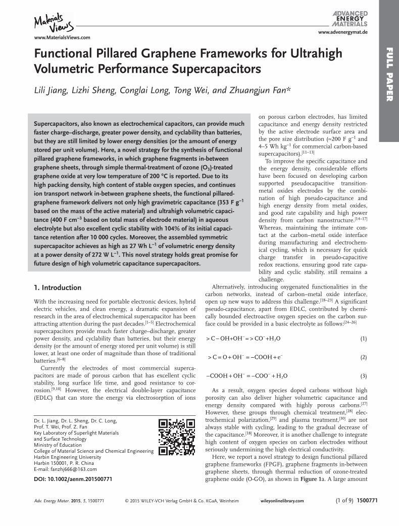
After ozone treatment, numerous defects and additional oxygen containing functional groups such as carboxylic and ketone, are generated on the basal plane or edges of ozone-treated GO sheets. [ 31 ] The color of GO suspension changes from brown to yellow (Figure 1 b). Afterwards, O-GO sheets are self-assembled into a dense structure by the evaporation of water (Figure 1 c). During subsequent heat treatment, these defects as chemically
reactive sites and the breaking of the C–C, C–O bonds in car-bonyl, carboxyl, and ester groups, can lead to the cracking of O-GO sheets due to the production of CO 2 and H 2 O and fur-ther the formation of fragments. [ 32 ] In this work, 0.5 mg mL −1 GO was used as precursor. It is worth mentioning that the thickness of GO by atomic force microscopy (AFM) is about 1–5 nm (Figure S1a–c, Supporting Information), meaning the coexistence of single and multilayered GO. Single-layered GO sheet can be completely cracked to form cross-linked graphene fragments due to the etched O-GO sheets along active points driven by thermal treatment (Figure S1d, Supporting Infor-mation). However, for multilayered GO sheets, only the top and bottom surfaces of GO sheets are prone to oxidation and cracking, and no obvious fragments are found on multilayered GO (Figure S1e, Supporting Information). Therefore, graphene fragments are mainly from single-layered GO sheet, which are assembled with multilayered GO sheets to form pillared gra-phene structure.
Scanning electron microscopy (SEM) characterizations of FPGF-200 show a dense structure with some fragments (200–300 nm) in-between graphene sheets (Figure 1 e,f) com-pared with thermal-reduced GO without ozone treatment (TRGO-200, Figure S2, Supporting Information). Transmission electron microscopy (TEM) images of FPGF-200 exhibit the
Adv. Energy Mater. 2015, 5, 1500771
www.MaterialsViews.comwww.advenergymat.de
Figure 1. a) Schematic illustration of the preparation of FPGF-200 sample. b) Digital photos of GO and O-GO suspension, c) O-GO powder, and d) FPGF-200 powder. e,f) Scanning electron microscope (SEM) images of FPGF-200. Scale bar, 20 µm e) and 1 µm f). g,h) Transmission electron microscopy (TEM) images of FPGF-200. Scale bar, 200 nm g) and 50 nm h). i) XRD patterns of FPGF and TRGO-200.
FULL P
APER
© 2015 WILEY-VCH Verlag GmbH & Co. KGaA, Weinheim (3 of 9) 1500771wileyonlinelibrary.com
existence in cross-linked ultrasmall graphene in-between sheets (Figure 1 g,h). N 2 adsorption–desorption isotherm of FPGF-200 exhibits an extremely low pore volume of 0.021 cm 3 g −1 , and Brunauer–Emmett–Teller (BET) surface area of ≈7 m 2 g −1 (Figure S3a, Supporting Information), much lower than chem-ical reduction of GO (267 m 2 g −1 ) [ 33 ] and thermal exfoliation of GO (375 m 2 g −1 ). [ 34 ] With an increase in treatment temperature, the surface area of FPGF gradually increases, but less than 20 m 2 g −1 (Table S1, Supporting Information). Pore size dis-tribution exhibits that FPGF-200 has more mesopore with the size range from 2 to 5 nm than that of TRGO-200 (Figure S3b, Supporting Information), suggesting pillared structure. X-ray diffraction (XRD) patterns of GO and O-GO (Figure S4, Sup-porting Information) show that the weaker and broader dif-fraction peak of O-GO was shifted to a low angle (8.7°), cor-responding to the d -spacing of 10.2 Å, which indicates that additional oxygen-containing functional groups can increase the d -spacing. [ 31 ] As shown in Figure 1 i, after thermal treat-ment of O-GO at 200 °C, the (002) plane peak of FPGF-200 is shifted towards lower angle compared with that of TRGO-200, meaning higher interlayer spacing (3.9 nm) which would be benefi cial for fast ion diffusion/transport. Moreover, the (002) plane peak of FPGF gradually shifts to higher degree with treat-ment temperature, suggesting the agglomeration or increased orientation of sheets due to the further elimination of the oxygen containing groups.
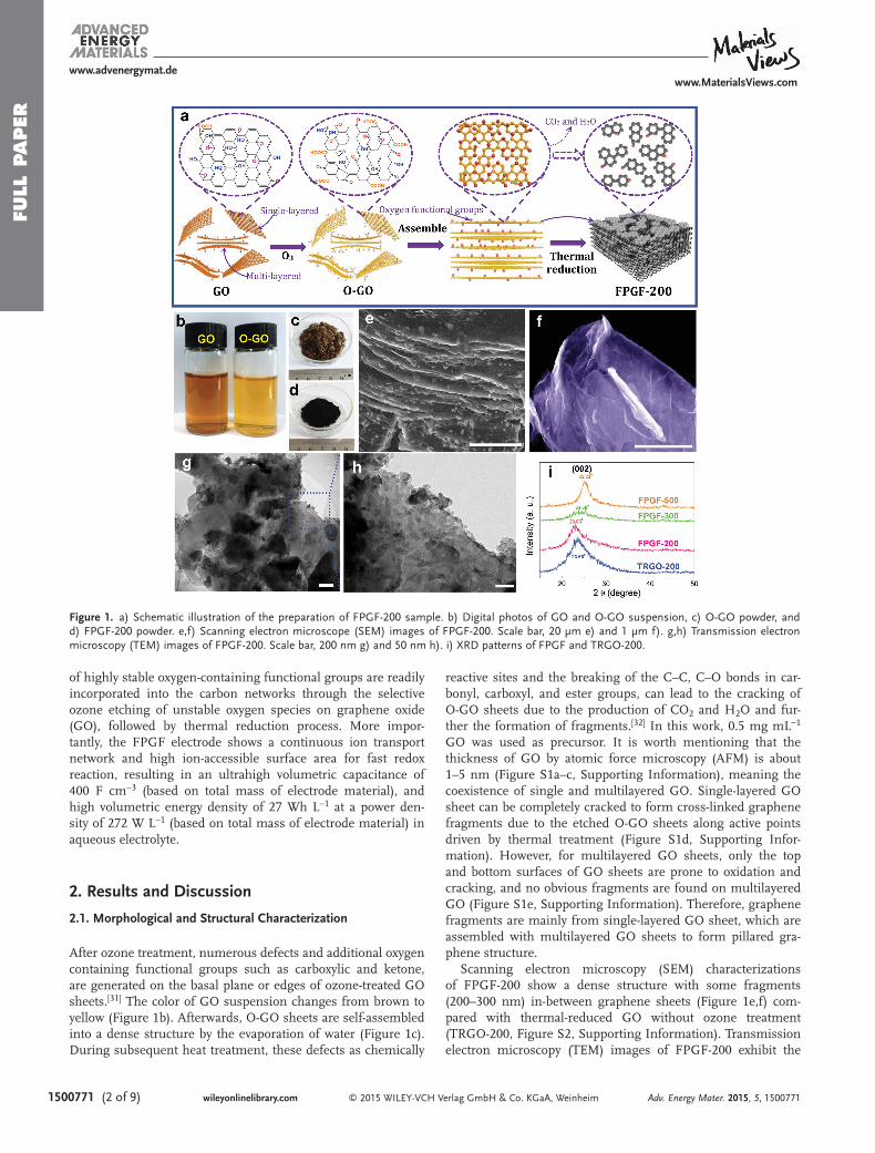
X-ray photoelectron spectroscopy (XPS) analysis shows that the atom ratio of O/C for O-GO is 0.63, much higher than that of GO (0.42) ( Figure 2 a and Figure S5a,b, Supporting
Information) meaning the additional oxygen functional groups derived from the ozonation reactions. More inter-estingly, Fourier transform infrared spectroscopy (FTIR) of O-GO (Figure 2 b) exhibits the increased absorption intensi-ties at ≈3430 cm −1 ( OH), ≈1735 cm −1 (C O), and ≈1137 cm −1 (C–O–C) compared to those of GO, indicating that hydroxy can transform to carbonyl and ether through the selective ozona-tion of GO. [ 31,35 ] By contrast, thermogravimetric analysis (TGA) shows that O-GO is much more stable than GO above 500 °C (Figure 2 c), which is consistent with recent previously reported experimental results. [ 31,36 ] A signifi cant low-temperature mass loss at around 200 °C is seen from O-GO due to the removal of highly oxidative debris. [ 37,38 ]
To study the effect of annealing temperature on struc-ture evolution of oxygen species doped FPGF, we calculated the amounts of the remaining functional groups by O1s XPS spectra. The atom ratios of O/C for FPGF gradually decrease with annealing temperature (Figure S5c, Supporting Infor-mation), in agreement with FTIR spectra (Figure S5d, Sup-porting Information). By deconvolving the O1s peaks for FPGF (Figure S6 and Table S2, Supporting Information), it reveals that the O content in FPGF remains nearly unchanged during the mild annealing, except the slight decreases at the tempera-ture above 200 °C (Figure 2 d), confi rming once again the pres-ence of highly stable oxygen functional groups on O-GO. [ 36,39 ] Notably, the concentration of C–O decreases during thermal annealing process, whereas the concentrations of C O and O
C–O increases and maintains after 200 °C, demonstrating that the labile epoxy and hydroxyl groups can transform to
Adv. Energy Mater. 2015, 5, 1500771
www.MaterialsViews.comwww.advenergymat.de
Figure 2. a) XPS survey spectra (100–700 eV) of the GO and O-GO showing the relative intensities of carbon C1s and oxygen O1s. b) FTIR spectra of the GO and O-GO. c) TGA results of GO, O-GO, and FPGF-200. d) XPS O1s at% content and the variation of the amount of oxygen groups for sample GO, O-GO, FPGF-150, FPGF-200, FPGF-300, and FPGF-500.
FULL
PAPER
© 2015 WILEY-VCH Verlag GmbH & Co. KGaA, Weinheim1500771 (4 of 9) wileyonlinelibrary.com
stable C=O groups due to the dehydration driven by heat treat-ment. [ 32,35,36 ] Correspondingly, highly stable oxygen functional FPGF exhibits a weight loss of 34% at 800 °C. Therefore, the presence of larger amounts of highly stable oxygen functional groups on FPGF is benefi cial for providing high pseudo-capaci-tance for supercapacitors.
2.2. Electrochemical Characterizations of the FPGF-200 Electrode
In order to demonstrate the superior performance of the FPGF-200 electrode for electrochemical energy storage, the electrochemical mesurements were fi rstly carried out using a three-electrode system in 6 M KOH. CV curves of the FPGF-200
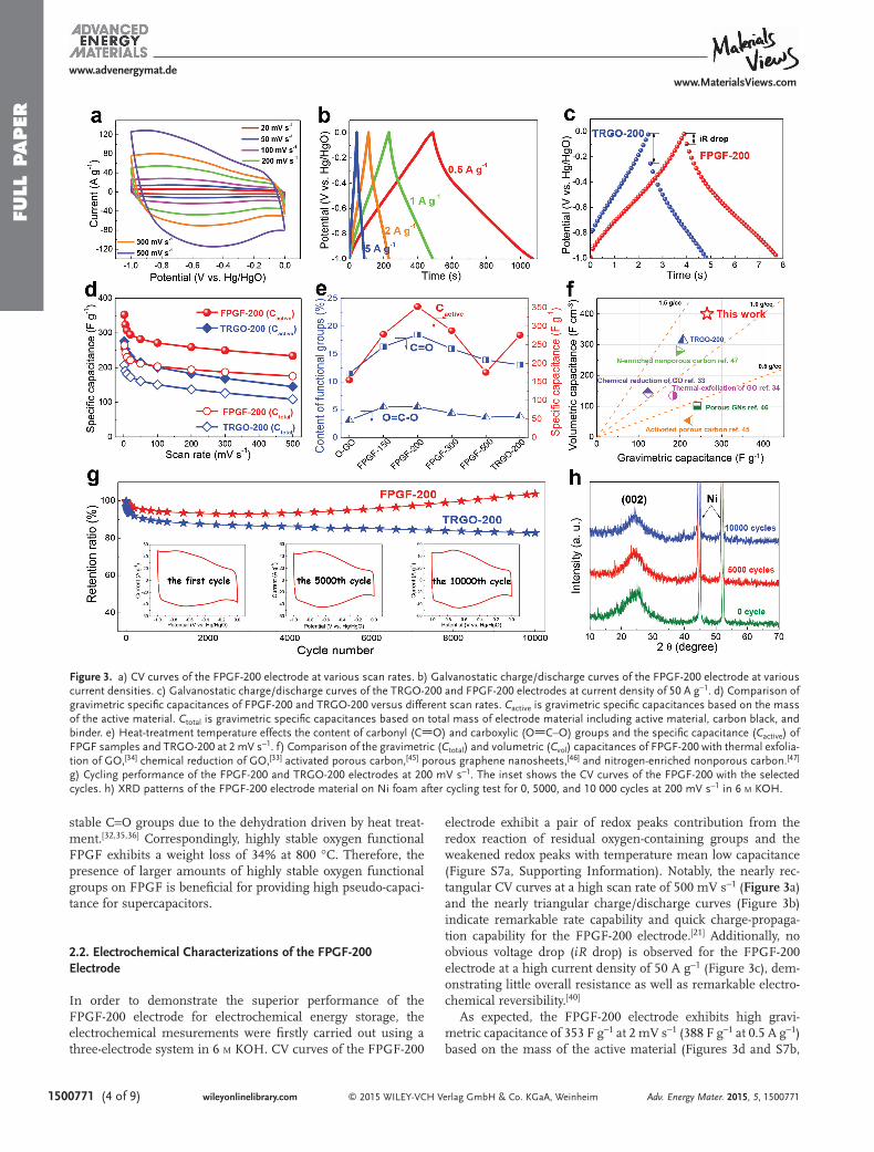
electrode exhibit a pair of redox peaks contribution from the redox reaction of residual oxygen-containing groups and the weakened redox peaks with temperature mean low capacitance (Figure S7a, Supporting Information). Notably, the nearly rec-tangular CV curves at a high scan rate of 500 mV s −1 ( Figure 3 a) and the nearly triangular charge/discharge curves (Figure 3 b) indicate remarkable rate capability and quick charge-propaga-tion capability for the FPGF-200 electrode. [ 21 ] Additionally, no obvious voltage drop ( iR drop) is observed for the FPGF-200 electrode at a high current density of 50 A g −1 (Figure 3 c), dem-onstrating little overall resistance as well as remarkable electro-chemical reversibility. [ 40 ]
As expected, the FPGF-200 electrode exhibits high gravi-metric capacitance of 353 F g −1 at 2 mV s −1 (388 F g −1 at 0.5 A g −1 ) based on the mass of the active material (Figures 3 d and S7b,
Adv. Energy Mater. 2015, 5, 1500771
www.MaterialsViews.comwww.advenergymat.de
Figure 3. a) CV curves of the FPGF-200 electrode at various scan rates. b) Galvanostatic charge/discharge curves of the FPGF-200 electrode at various current densities. c) Galvanostatic charge/discharge curves of the TRGO-200 and FPGF-200 electrodes at current density of 50 A g −1 . d) Comparison of gravimetric specifi c capacitances of FPGF-200 and TRGO-200 versus different scan rates. C active is gravimetric specifi c capacitances based on the mass of the active material. C total is gravimetric specifi c capacitances based on total mass of electrode material including active material, carbon black, and binder. e) Heat-treatment temperature effects the content of carbonyl (C O) and carboxylic (O C–O) groups and the specifi c capacitance ( C active ) of FPGF samples and TRGO-200 at 2 mV s −1 . f) Comparison of the gravimetric ( C total ) and volumetric ( C vol ) capacitances of FPGF-200 with thermal exfolia-tion of GO, [ 34 ] chemical reduction of GO, [ 33 ] activated porous carbon, [ 45 ] porous graphene nanosheets, [ 46 ] and nitrogen-enriched nonporous carbon. [ 47 ] g) Cycling performance of the FPGF-200 and TRGO-200 electrodes at 200 mV s −1 . The inset shows the CV curves of the FPGF-200 with the selected cycles. h) XRD patterns of the FPGF-200 electrode material on Ni foam after cycling test for 0, 5000, and 10 000 cycles at 200 mV s −1 in 6 M KOH.
FULL P
APER
© 2015 WILEY-VCH Verlag GmbH & Co. KGaA, Weinheim (5 of 9) 1500771wileyonlinelibrary.com
Supporting Information), higher than TRGO-200 (276 F g −1 ), thermal exfoliation of GO (183 F g −1 ), [ 34 ] and chemical reduc-tion of GO (122.6 F g −1 ). [ 33 ] At a high scan rate up to 500 mV s −1 , the FPGF-200 maintains about 66% of its initial capacitance (234 F g −1 ), while the TRGO-200 only shows a 52% capacitance retention (145 F g −1 ). Oxygen-containing functional groups on carbon not only effectively increase the wettability between electrolyte ions and the electrode materials, but also provide pseudocapcitance from the reversible redox reactions of oxygen-containing functional groups. [ 18,21 ] Moreover, it does not mean that the higher amount of oxygen functional groups, the higher the capacitance is. Although O-GO treated at 150 °C possess a high oxygen content of ≈0.6 (O/C), the low capacitance is due to its poor electric conductivity (Figure 3 e), meaning that electron transport is important for the drive of redox reactions. There-fore, the specifi c capacitance depends on both the electric con-ductivity and content of oxygen-containing functional groups for the FPGF electrode. As shown in Figure 3 e, the content of carbonyl (C O) and carboxylic (O C–O) groups decreases monotonically above 200 °C. Simultaneously, the capacitance also decreases with increasing temperature (Figure S7c, Sup-porting Information). More importantly, the pseudocapacitance from C O group on carbon mainly contributes to the overall capacitance of the electrode, suggesting that the balance of the content of oxygen-containing functional groups and the con-ductivity is essential for achieving the maximum specifi c capac-itance for oxygen doped carbon materials.
With regard to the view of practical application, the volu-metric and areal capacitances of the electrode materials are considered as important parameters for the miniaturized supercapacitors. The FPGF-200 electrode exhibits also ultra-high volumetric and areal capacitances due to its extremely low specifi c surface area (SSA) and high packing density. The surface area normalized capacitance based on the BET sur-face area for FPGF-200 is 4875 μF cm −2 (Table S1, Supporting Information), much higher than those of activated carbon (4.9 μF cm −2 ), [ 41 ] activated graphene (6.9 μF cm −2 ), [ 11 ] nitrogen-doped reduced graphene oxide (3400 μF cm −2 ), [ 42 ] and chem-ical reduction of GO (27 μF cm −2 ). [ 43 ] Additionally, the FPGF-200 exhibits ultrahigh volumetric capacitance of 400 F cm −3 based on total mass of electrode material (Figure 3 f), much higher than those of TRGO-200 (314 F cm −3 ), chemical reduc-tion of GO (143.2 F cm −3 ), [ 33,44 ] thermal exfoliation of GO (134.6 F cm −3 ), [ 34,44 ] and other previously reported carbon mate-rials [ 45–47 ] (Table S3, Supporting Information).
The cycling test of the FPGF-200 electrode shows 104% of capacitance retention over 10 000 cycles at 200 mV s −1 (Figure 3 g), demonstrating excellent electrochemical stability. At the beginning of 100 cycles, cycling performance slightly decreases due to trace amounts of unstable oxygen functional groups on FPGF-200. After that, the gradually increased capaci-tance comes from the continuous diffusion of polarized elec-trolyte ion into the dense graphene sheets induced by electric fi eld. [ 48 ] Interestingly, the enhanced redox peaks in CV curve are clearly observed after 10 000 cycles, confi rming that most oxygen-containing groups are stable and ion-accessible surface area of the FPGF-200 gradually increases.
Recently, a pioneering work by Yury Gogotsi reported the spontaneous intercalation of cations (such as Na + , K + , Mg 2+ ,
NH 4+ , and Al 3+ ) from aqueous salt solutions between 2D Ti 3 C 2 MXene layers. [ 49 ] As for FPGF-200, the as-obtained capacitance by far exceeds double-layer capacitance calculated solely on the basis of a material's surface area, meaning that electrolyte ions maybe intercalate into dense graphene layers like Ti 3 C 2 MXene. To test this idea, we performed in situ XRD studies of the intercalation process of FPGF-200 using CV measurement at 200 mV s −1 in 6 M KOH. The intensities of the (002) peak after 5000 and 10 000 CV cycles become obviously weak and broad, indicating the loss of layer ordering upon ion intercala-tion (Figure 3 h). Recently, some groups demonstrated that the electrochemical activation of graphitized carbon and partially reduced graphite oxide led to an irreversible increase in inter-layer distance through ion intercalation into multilayer gra-phene. [ 50–52 ] Clearly, the polarization induced by electric fi eld is key step, resulting that the distorted and desolvated ions can enter in pores smaller than their limiting size. [ 48 ] Therefore, a large amounts of oxygen functional groups on carbon materials can provide high pseudocapacitance, at the same time, the pil-lared graphene frameworks would be benefi cial to ion intercala-tion and diffusion into the electrode.
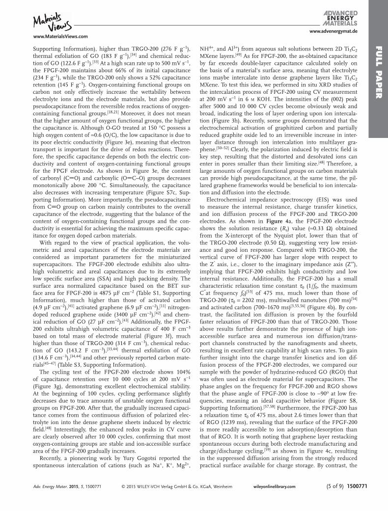
Electrochemical impedance spectroscopy (EIS) was used to measure the internal resistance, charge transfer kinetics, and ion diffusion process of the FPGF-200 and TRGO-200 electrodes. As shown in Figure 4 a, the FPGF-200 electrode shows the solution resistance ( R s ) value (≈0.33 Ω) obtained from the X-intercept of the Nyquist plot, lower than that of the TRGO-200 electrode (0.50 Ω), suggesting very low resist-ance and good ion response. Compared with TRGO-200, the vertical curve of FPGF-200 has larger slope with respect to the Z ′ axis, i.e., closer to the imaginary impedance axis (Z ′′ ), implying that FPGF-200 exhibits high conductivity and low internal resistance. Additionally, the FPGF-200 has a small characteristic relaxation time constant τ 0 (1/ f 0 , the maximum C ′′ at frequency f 0 ) [ 53 ] of 475 ms, much lower than those of TRGO-200 ( τ 0 = 2202 ms), multiwalled nanotubes (700 ms) [ 54 ] and activated carbon (700–1670 ms) [ 3,55,56 ] (Figure 4 b). By con-trast, the facilitated ion diffusion is proven by the fourfold faster relaxation of FPGF-200 than that of TRGO-200. Those above results further demonstrate the presence of high ion-accessible surface area and numerous ion diffusion/trans-port channels constructed by the nanofragments and sheets, resulting in excellent rate capability at high scan rates. To gain further insight into the charge transfer kinetics and ion dif-fusion process of the FPGF-200 electrodes, we compared our sample with the powder of hydrazine-reduced GO (RGO) that was often used as electrode material for supercapacitors. The phase angles on the frequency for FPGF-200 and RGO shows that the phase angle of FPGF-200 is close to −90 o at low fre-quencies, meaning an ideal capacitive behavior (Figure S8, Supporting Information). [ 57,58 ] Furthermore, the FPGF-200 has a relaxation time τ 0 of 475 ms, about 2.6 times lower than that of RGO (1239 ms), revealing that the surface of the FPGF-200 is more readily accessible to ion adsorption/desorption than that of RGO. It is worth noting that graphene layer restacking spontaneous occurs during both electrode manufacturing and charge/discharge cycling, [ 59 ] as shown in Figure 4 c, resulting in the suppressed diffusion arising from the strongly reduced practical surface available for charge storage. By contrast, the
Adv. Energy Mater. 2015, 5, 1500771
www.MaterialsViews.comwww.advenergymat.de
FULL
PAPER
© 2015 WILEY-VCH Verlag GmbH & Co. KGaA, Weinheim1500771 (6 of 9) wileyonlinelibrary.com
rapid frequency response of the FPGF-200 is due to its pillared network nanostructure. During manufacturing and cycling, the pillared graphene network guarantees suffi cient ion diffu-sion/transport channels and ion-accessible surfaces due to its pillared structure, leading to a large capacitance at extremely high currents/frequencies.
2.3. Electrochemical Characterizations of Symmetric Capacitors
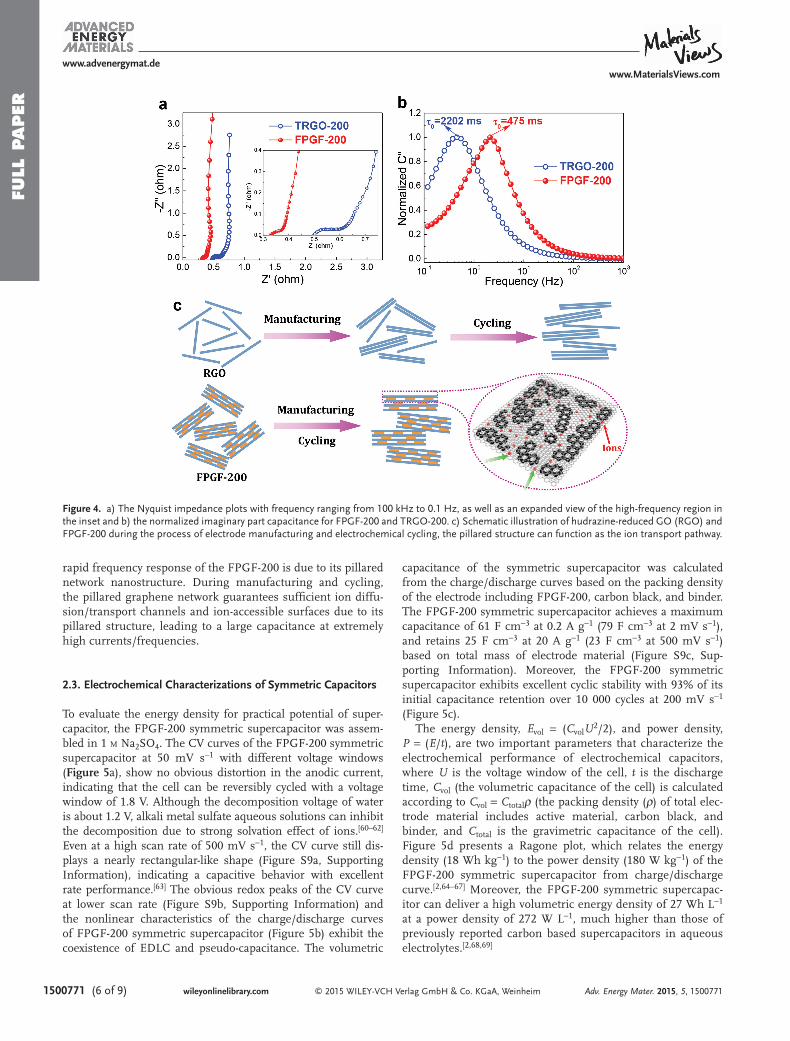
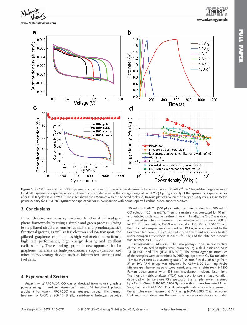
To evaluate the energy density for practical potential of super-capacitor, the FPGF-200 symmetric supercapacitor was assem-bled in 1 M Na 2 SO 4 . The CV curves of the FPGF-200 symmetric supercapacitor at 50 mV s −1 with different voltage windows ( Figure 5 a), show no obvious distortion in the anodic current, indicating that the cell can be reversibly cycled with a voltage window of 1.8 V. Although the decomposition voltage of water is about 1.2 V, alkali metal sulfate aqueous solutions can inhibit the decomposition due to strong solvation effect of ions. [ 60–62 ] Even at a high scan rate of 500 mV s −1 , the CV curve still dis-plays a nearly rectangular-like shape (Figure S9a, Supporting Information), indicating a capacitive behavior with excellent rate performance. [ 63 ] The obvious redox peaks of the CV curve at lower scan rate (Figure S9b, Supporting Information) and the nonlinear characteristics of the charge/discharge curves of FPGF-200 symmetric supercapacitor (Figure 5 b) exhibit the coexistence of EDLC and pseudo-capacitance. The volumetric
capacitance of the symmetric supercapacitor was calculated from the charge/discharge curves based on the packing density of the electrode including FPGF-200, carbon black, and binder. The FPGF-200 symmetric supercapacitor achieves a maximum capacitance of 61 F cm −3 at 0.2 A g −1 (79 F cm −3 at 2 mV s −1 ), and retains 25 F cm −3 at 20 A g −1 (23 F cm −3 at 500 mV s −1 ) based on total mass of electrode material (Figure S9c, Sup-porting Information). Moreover, the FPGF-200 symmetric supercapacitor exhibits excellent cyclic stability with 93% of its initial capacitance retention over 10 000 cycles at 200 mV s −1 (Figure 5 c).
The energy density, E vol = ( C vol U 2 /2), and power density, P = ( E / t ), are two important parameters that characterize the electrochemical performance of electrochemical capacitors, where U is the voltage window of the cell, t is the discharge time, C vol (the volumetric capacitance of the cell) is calculated according to C vol = C total ρ (the packing density ( ρ ) of total elec-trode material includes active material, carbon black, and binder, and C total is the gravimetric capacitance of the cell). Figure 5 d presents a Ragone plot, which relates the energy density (18 Wh kg −1 ) to the power density (180 W kg −1 ) of the FPGF-200 symmetric supercapacitor from charge/discharge curve. [ 2,64–67 ] Moreover, the FPGF-200 symmetric supercapac-itor can deliver a high volumetric energy density of 27 Wh L −1 at a power density of 272 W L −1 , much higher than those of previously reported carbon based supercapacitors in aqueous electrolytes. [ 2,68,69 ]
Adv. Energy Mater. 2015, 5, 1500771
www.MaterialsViews.comwww.advenergymat.de
Figure 4. a) The Nyquist impedance plots with frequency ranging from 100 kHz to 0.1 Hz, as well as an expanded view of the high-frequency region in the inset and b) the normalized imaginary part capacitance for FPGF-200 and TRGO-200. c) Schematic illustration of hudrazine-reduced GO (RGO) and FPGF-200 during the process of electrode manufacturing and electrochemical cycling, the pillared structure can function as the ion transport pathway.
FULL P
APER
© 2015 WILEY-VCH Verlag GmbH & Co. KGaA, Weinheim (7 of 9) 1500771wileyonlinelibrary.com
3. Conclusions
In conclusion, we have synthesized functional pillared-gra-phene frameworks by using a simple and green process. Owing to its pillared structure, numerous stable and pseudocapacitive functional groups, as well as fast electron and ion transport, the pillared graphene exhibits ultrahigh volumetric capacitance, high rate performance, high energy density, and excellent cyclic stability. These fi ndings promote new opportunities for graphene materials as high-performance supercapacitors and other energy-storage devices such as lithium ion batteries and fuel cells.
4. Experimental Section Preparation of FPGF-200 : GO was synthesized from natural graphite
powder using a modifi ed Hummers’ method. [ 70 ] Functional pillared graphene framework (FPGF-200) was prepared through the thermal treatment of O-GO at 200 °C. Briefl y, a mixture of hydrogen peroxide
(40 mL) and HNO 3 (200 µL) solution was fi rst added into 200 mL of GO solution (0.5 mg mL −1 ). Then, the mixture was sonicated for 10 min and bubbled under ozone treatment for 4 h. Finally, the O-GO was dried and heated in a tubular furnace under nitrogen atmosphere at 200 °C for 2 h. For comparison, O-GO was treated at 150, 300, and 500 °C, and the obtained samples were denoted by FPGF- x , where x referred to the treatment temperature. GO without ozone treatment was also heated under nitrogen atmosphere at 200 °C for 2 h, and the obtained product was denoted as TRGO-200.
Characterization Methods : The morphology and microstructure of the as-obtained samples were examined by a fi eld emission SEM (SU70-HSD) and TEM (JEOL JEM2010). The crystallographic structures of the samples were determined by XRD equipped with Cu Kα radiation ( λ = 0.15406 nm) at a scanning rate of 10° min −1 in the 2 θ range from 5° to 80°. AFM image was obtained by CSPM5500 Scanning Probe Microscope. Raman spectra were conducted on a Jobin-Yvon HR800 Raman spectrometer with 458 nm wavelength incident laser light. Thermogravimetric analyzer (TGA) was used to see a mass variation depended on temperature. XPS spectra of the samples were measured by a Perkin-Elmer PHI-5700 ESCA System with a monochromated Al K α X-ray source (1486.6 eV). The N 2 adsorption–desorption isotherms of the samples were measured at 77 K using NOVA 2000 (Quantachrome, USA) in order to determine the specifi c surface area which was calculated
Adv. Energy Mater. 2015, 5, 1500771
www.MaterialsViews.comwww.advenergymat.de
Figure 5. a) CV curves of FPGF-200 symmetric supercapacitor measured in different voltage windows at 50 mV s −1 . b) Charge/discharge curves of FPGF-200 symmetric supercapacitor at different current densities in the voltage range of 0–1.8 V. c) Cycling stability of the symmetric supercapacitor after 10 000 cycles at 200 mV s −1 . The inset shows the CV curves with the selected cycles. d) Ragone plot of gravimetric energy density versus gravimetric power density for FPGF-200 symmetric supercapacitor in comparison with some reported carbon-based supercapacitors.
FULL
PAPER
© 2015 WILEY-VCH Verlag GmbH & Co. KGaA, Weinheim1500771 (8 of 9) wileyonlinelibrary.com Adv. Energy Mater. 2015, 5, 1500771
www.MaterialsViews.comwww.advenergymat.de
from the BET plot of the nitrogen adsorption isotherm. The pore size distribution curves were obtained from adsorption branch isotherms by density functional theory method. The adsorbed amount at a relative pressure P / P 0 of 0.99 was used to estimate the total pore volume ( V total ).
Electrochemical Measurements : The electrochemical measurements were carried out in three-electrode and two-electrode system using Autolab PGSTAT302N electrochemical workstation. The mixture of active material, carbon black and polytetrafl uoroethylene binder with a mass ratio of 75:20:5 was pressed onto the nickel current collector (with a size of around 1 cm × 1 cm) under the pressure of 10 Mpa and dried at 100 °C for 12 h in a vacuum oven. In three-electrode system, the as-prepared samples served as the working electrode, a platinum gauze electrode and an Hg/HgO electrode served as counter and reference electrodes respectively. The cyclic voltammetry (CV), the constant current charge/discharge and the EIS test were carried out in a 6 M KOH aqueous solution at room temperature. CV tests were investigated between −1 and 0 V (vs Hg/HgO). The constant current charge/discharge was performed in the same potential range at the current densities ranging from 0.5 to 50 A g −1 . The EIS measurements were evaluated in the frequency range from 100 kHz to 0.1 Hz at open circuit potential. The symmetric two-electrode supercapacitors were assembled in 1 M Na 2 SO 4 aqueous solution using two electrodes with exactly the same mass and the electrochemical measurements of symmetric cell were performed in the voltage range of 0–1.8 V.
The gravimetric specifi c capacitances ( C active ) were calculated according to the CV curves at different scan rates:
C I V m Vd /active ∫ υ( ) ( )=
(4)
where I is the current density (A cm −2 ), V is the potential (V), υ is the potential scan rate (V s −1 ), m is the mass of the active material in the electrode (g cm −2 ). The loading mass of the electrode is about 2 mg cm −2 .
The volumetric specifi c capacitances ( C vol ) were evaluated according to the following equation:
C Cvol totalρ= (5)
m V/ρ = (6)
where C total (F g −1 ) is gravimetric specifi c capacitances based on total mass of electrode material including active material, carbon black, and binder, ρ (g cm −3 ) is the packing density of total electrode material, m (g) is a certain mass of total electrode material, and V (cm 3 ) is the volume of these total electrode material. We calculated the volume of total electrode material by measuring the radius ( r ) and thickness ( h ) of the compressed total electrode material under the pressure of 10 MPa ( V = h * π * r 2 ).
The complex form of capacitance C ( w ) is dependent on real part the cell capacitance C′ ( w ), the imaginary part C ″( w ) related to the losses of energy dissipation and frequency, which is defi ned as follows: [ 53 ]
C C w jC w( ) ( )= ′ − ′′ (7)
C wZ w
w Z w2( ) ( )
( )′ = − ′′
(8)
C wZ w
w Z w2( ) ( )
( )′′ =
′
(9)
where Z′ ( w ) and Z ″( w ) are the respective real and imaginary parts of the complex impedance Z ( w ). w is the angular frequency which is given by w = 2π f .
Supporting Information Supporting Information is available from the Wiley Online Library or from the author.
Acknowledgements The authors acknowledge fi nancial support from Harbin Innovation Talents of Science and Technology Research Special Fund Project (2012RFXXG005), Fundamental Research funds for the Central Universities, Natural Science Foundation of Heilongjiang Province (E201416), and Excellent Youth Foundation of Heilongjiang Province of China (JC201210).
Received: April 19, 2015Published online: June 5, 2015
[1] Z. S. Wu , K. Parvez , X. L. Feng , K. Mullen , Nat. Commun. 2013 , 4 , 2487 .
[2] Y. Tao , X. Xie , W. Lv , D. M. Tang , D. Kong , Z. Huang , H. Nishihara , T. Ishii , B. Li , D. Golberg , F. Kang , T. Kyotani , Q. H. Yang , Sci. Rep. 2013 , 3 , 2975 .
[3] D. Pech , M. Brunet , H. Durou , P. Huang , V. Mochalin , Y. Gogotsi , P. L. Taberna , P. Simon , Nat. Nanotechnol. 2010 , 5 , 651 .
[4] L. Kou , T. Huang , B. Zheng , Y. Han , X. Zhao , K. Gopalsamy , H. Sun , C. Gao , Nat. Commun. 2014 , 5 , 3754 .
[5] J. Y. Hong , B. M. Bak , J. J. Wie , J. Kong , H. S. Park , Adv. Funct. Mater. 2015 , 25 , 1053 .
[6] P. Simon , Y. Gogotsi , B. Dunn , Science 2014 , 343 , 1210 . [7] F. Bonaccorso , L. Colombo , G. Yu , M. Stoller , V. Tozzini ,
A. C. Ferrari , R. S. Ruoff , V. Pellegrini , Science 2015 , 347 , 1246501 . [8] J. R. Miller , P. Simon , Science 2008 , 321 , 651 . [9] L. L. Zhang , Y. Gu , X. S. Zhao , J. Mater. Chem. A 2013 , 1 , 9395 .
[10] S. Han , D. Wu , S. Li , F. Zhang , X. Feng , Adv. Mater. 2014 , 26 , 849 . [11] Y. Zhu , S. Murali , M. D. Stoller , K. J. Ganesh , W. Cai , P. J. Ferreira ,
A. Pirkle , R. M. Wallace , K. A. Cychosz , M. Thommes , D. Su , E. A. Stach , R. S. Ruoff , Science 2011 , 332 , 1537 .
[12] M. F. El-Kady , V. Strong , S. Dubin , R. B. Kaner , Science 2012 , 335 , 1326 .
[13] P. Simon , Y. Gogotsi , Nat. Mater. 2008 , 7 , 845 . [14] M. Zhi , C. Xiang , J. Li , M. Li , N. Wu , Nanoscale 2013 , 5 , 72 . [15] B. G. Choi , M. Yang , W. H. Hong , J. W. Choi , Y. S. Huh , ACS Nano
2012 , 6 , 4020 . [16] X. Zhang , W. Shi , J. Zhu , D. J. Kharistal , W. Zhao , B. S. Lalia ,
H. H. Hng , Q. Yan , ACS Nano 2011 , 5 , 2013 . [17] X. Li , B. Wei , Nano Energy 2012 , 1 , 479 . [18] E. Frackowiak , F. Béguin , Carbon 2001 , 39 , 937 . [19] L. Dai , Acc. Chem. Res. 2012 , 46 , 31 . [20] S. K. Park , Q. Mahmood , H. S. Park , Nanoscale 2013 , 5 , 12304 . [21] Y. Fang , B. Luo , Y. Jia , X. Li , B. Wang , Q. Song , F. Kang , L. Zhi , Adv.
Mater. 2012 , 24 , 6348 . [22] F. Beguin , V. Presser , A. Balducci , E. Frackowiak , Adv. Mater. 2014 ,
26 , 2219 . [23] Y. Yan , T. Kuila , N. H. Kim , B.-C. Ku , J. H. Lee , J. Mater. Chem. A
2013 , 1 , 5892 . [24] D. W. Wang , F. Li , M. Liu , H. M. Cheng , New Carbon Mater. 2007 ,
22 , 307 . [25] L. X. Li , F. Li , New Carbon Mater. 2011 , 26 , 224 . [26] Y. Yan , T. Kuila , N. H. Kim , J. H. Lee , Carbon 2014 , 74 , 195 . [27] E. Raymundo-Piñero , M. Cadek , F. Béguin , Adv. Funct. Mater. 2009 ,
19 , 1032 . [28] K. Jurewicz , E. Frackowiak , Mol. Phys. Rep. 2000 , 27 , 36 .
FULL P
APER
© 2015 WILEY-VCH Verlag GmbH & Co. KGaA, Weinheim (9 of 9) 1500771wileyonlinelibrary.comAdv. Energy Mater. 2015, 5, 1500771
www.MaterialsViews.comwww.advenergymat.de
[29] T. Momma , X. Liu , T. Osaka , Y. Ushio , Y. Sawada , J. Power Sources 1996 , 60 , 249 .
[30] M. Ishikawa , A. Sakamoto , M. Monta , Y. Matsuda , K. Ishida , J. Power Sources 1996 , 60 , 233 .
[31] F. Yang , M. Zhao , Z. Wang , H. Ji , B. Zheng , D. Xiao , L. Wu , Y. Guo , RSC Adv. 2014 , 4 , 58325 .
[32] F. Yang , M. Zhao , B. Zheng , D. Xiao , L. Wu , Y. Guo , J. Mater. Chem. 2012 , 22 , 25471 .
[33] J. Yan , T. Wei , B. Shao , F. Ma , Z. Fan , M. Zhang , C. Zheng , Y. Shang , W. Qian , F. Wei , Carbon 2010 , 48 , 1731 .
[34] J. Yan , J. Liu , Z. Fan , T. Wei , L. Zhang , Carbon 2012 , 50 , 2179 . [35] A. Bagri , C. Mattevi , M. Acik , Y. J. Chabal , M. Chhowalla ,
V. B. Shenoy , Nat. Chem. 2010 , 2 , 581 . [36] X. Xiao , T. Li , Z. Peng , H. Jin , Q. Zhong , Q. Hu , B. Yao , Q. Luo ,
C. Zhang , L. Gong , J. Chen , Y. Gogotsi , J. Zhou , Nano Energy 2014 , 6 , 1 .
[37] Z. Wang , M. D. Shirley , S. T. Meikle , R. L. D. Whitby , S. V. Mikhalovsky , Carbon 2009 , 47 , 73 .
[38] J. P. Rourke , P. A. Pandey , J. J. Moore , M. Bates , I. A. Kinloch , R. J. Young , N. R. Wilson , Angew. Chem. Int. Ed. 2011 , 50 , 3173 .
[39] H. R. Byon , B. M. Gallant , S. W. Lee , Y. Shao-Horn , Adv. Funct. Mater. 2013 , 23 , 1037 .
[40] J. Yan , Q. Wang , C. Lin , T. Wei , Z. Fan , Adv. Energy Mater. 2014 , 4 , 1400500 .
[41] H. Wang , Z. Xu , A. Kohandehghan , Z. Li , K. Cui , X. Tan , T. J. Stephenson , C. K. King’ondu , C. M. B. Holt , B. C. Olsen , J. K. Tak , D. Harfi eld , A. O. Anyia , D. Mitlin , ACS Nano 2013 , 7 , 5131 .
[42] S. Liu , J. Xie , H. Li , Y. Wang , H. Y. Yang , T. Zhu , S. Zhang , G. Cao , X. Zhao , J. Mater. Chem. A 2014 , 2 , 18125 .
[43] Z. Lei , N. Christov , X. S. Zhao , Energy Environ. Sci. 2011 , 4 , 1866 . [44] J. Yan , Q. Wang , T. Wei , L. Jiang , M. Zhang , X. Jing , Z. Fan , ACS
Nano 2014 , 8 , 4720 . [45] K. Xia , Q. Gao , J. Jiang , J. Hu , Carbon 2008 , 46 , 1718 . [46] Z. Fan , Q. Zhao , T. Li , J. Yan , Y. Ren , J. Feng , T. Wei , Carbon 2012 ,
50 , 1699 . [47] D. Hulicova-Jurcakova , M. Kodama , S. Shiraishi , H. Hatori ,
Z. H. Zhu , G. Q. Lu , Adv. Funct. Mater. 2009 , 19 , 1800 . [48] C. O. Ania , J. Pernak , F. Stefaniak , E. Raymundo-Piñero , F. Béguin ,
Carbon 2009 , 47 , 3158 .
[49] M. R. Lukatskaya , O. Mashtalir , C. E. Ren , Y. Dall’Agnese , P. Rozier , P. L. Taberna , M. Naguib , P. Simon , M. W. Barsoum , Y. Gogotsi , Science 2013 , 341 , 1502 .
[50] M. Takeuchi , K. Koike , T. Maruyama , A. Mogami , M. Okamura , Denki Kagaku oyobi Kogyo Butsuri Kagaku 1998 , 66 , 1311 .
[51] M. Takeuchi , T. Maruyama , K. Koike , A. Mogami , T. Oyama , H. Kobayashi , Electrochemistry 2001 , 6 , 487 .
[52] H. K. Bok , M. O. Seung , J. Electrochem. Soc. 2008 , 155 , A685 . [53] B. G. Choi , J. Hong , W. H. Hong , P. T. Hammond , H. Park , ACS
Nano 2011 , 5 , 7205 . [54] C. Portet , G. Yushin , Y. Gogotsi , Carbon 2007 , 45 , 2511 . [55] T. Kim , G. Jung , S. Yoo , K. S. Suh , R. S. Ruoff , ACS Nano 2013 , 7 ,
6899 . [56] L. Wei , N. Nitta , G. Yushin , ACS Nano 2013 , 7 , 6498 . [57] Y. Xu , Z. Lin , X. Zhong , X. Huang , N. O. Weiss , Y. Huang , X. Duan ,
Nat. Commun. 2014 , 5 , 4554 . [58] X. Yang , C. Cheng , Y. Wang , L. Qiu , D. Li , Science 2013 , 341 , 534 . [59] R. Raccichini , A. Varzi , S. Passerini , B. Scrosati , Nat. Mater. 2015 ,
14 , 271 . [60] L. Demarconnay , E. Raymundo-Piñero , F. Béguin , Electrochem.
Commun. 2010 , 12 , 1275 . [61] M. P. Bichat , E. Raymundo-Piñero , F. Béguin , Carbon 2010 , 48 ,
4351 . [62] K. Fic , G. Lota , M. Meller , E. Frackowiak , Energy Environ. Sci. 2012 ,
5 , 5842 . [63] M. D. Stoller , S. Park , Y. Zhu , J. An , R. S. Ruoff , Nano Lett. 2008 , 8 ,
3498 . [64] L. F. Chen , X. D. Zhang , H. W. Liang , M. Kong , Q. F. Guan , P. Chen ,
Z. Y. Wu , S. H. Yu , ACS Nano 2012 , 6 , 7092 . [65] Q. Wang , J. Yan , T. Wei , J. Feng , Y. Ren , Z. Fan , M. Zhang , X. Jing ,
Carbon 2013 , 60 , 481 . [66] D. W. Wang , F. Li , M. Liu , G. Q. Lu , H. M. Cheng , Angew. Chem. Int.
Ed. 2008 , 47 , 373 . [67] Q. Wang , J. Yan , Y. Wang , G. Ning , Z. Fan , T. Wei , J. Cheng ,
M. Zhang , X. Jing , Carbon 2013 , 52 , 209 . [68] M. Seredych , T. J. Bandosz , J. Mater. Chem. A 2013 , 1 , 11717 . [69] Y. Yoon , K. Lee , S. Kwon , S. Seo , H. Yoo , S. Kim , Y. Shin , Y. Park ,
D. Kim , J. Y. Choi , H. Lee , ACS Nano 2014 , 8 , 4580 . [70] W. S. Hummers , R. E. Offeman , J. Am. Chem. Soc. 1958 , 80 ,
1339 .