Embed Size (px)
Citation preview
FUNCTIONAL VERIFICATION AND PROGRAMMING MODEL OF
WiNC2R FOR 802.16e MOBILE WIMAX PROTOCOL
BY GURUGUHANATHAN VENKATARAMANAN
A thesis submitted to the
Graduate School – New Brunswick
Rutgers, the State University of New Jersey
in partial fulfillment of the requirements
for the degree of
Master of Science
Graduate Program in Electrical and Computer Engineering
Written under the direction of
Prof. Predrag Spasojevic
and approved by
___________________________________
___________________________________
___________________________________
New Brunswick, New Jersey
October 2011

© 2011
GURUGUHANATHAN VENKATARAMANAN
ALL RIGHTS RESERVED
ii
ABSTRACT OF THE THESIS
Functional Verification and Programming Model of WiNC2R for
802.16e Mobile WiMAX Protocol
Guruguhanathan Venkataramanan
Thesis Director: Prof. Predrag Spasojevic
The WiNLAB Network Centric Cognitive Radio (WiNC2R) is a task-based, programmable, multi-
processor system-on-a-chip architecture for radio processing. It provides robust support for
multiple wireless standards and excellent runtime flexibility using a ‘Virtual Flow Pipelining’
(VFP) mechanism.
WiNC2R defines a cluster based architecture with a shared VFP controller, with specific
functionalities for the VFP controller, to enable efficient processing of tasks in a given protocol
flow. Given the stringent requirements of modern wireless protocols, it becomes critical to
ensure that the WiNC2R implementation adheres to the design specifications.
Implementing a transceiver design on WiNC2R for complex protocols requires a large number of
processing engines. In this thesis, we have laid emphasis on architecture scalability, by
addressing features like multi-clustering and next task processing.
We have performed a detailed functional verification of the VFP controller using a
SystemVerilog testbench, based on Open Verification Methodology (OVM) principles. We base

iii
the work on proposing a framework for using the WiNC2R platform for 802.16e Mobile WiMAX
flows, by defining the specifications and performance requirements for each processor in the
cluster. We have also provided sample programmable tasks for implementing WiMAX flows.

iv
Acknowledgements
I would like to use this opportunity to convey my gratitude to all those who have been
instrumental in the successful completion of this thesis.
I would like to dedicate my first and foremost token of gratitude to my advisors, Prof. Predrag
Spasojevic and Prof. Zoran Miljanic, for providing me the opportunity and their invaluable time
and guidance. Their constant motivation and drive for excellence has served as a great source of
inspiration to me.
I would also like to thank the entire WiNC2R team – Khanh Le, Akshay Jog, Onkar Sarode and
Madhura Joshi for their dedicated support over the course of the project. My sincere thanks to
the entire Winlab staff for their timely help and support.
Last but not the least, I would like to express my heartfelt gratitude to my family and friends for
their firm belief in my abilities and constant backing in all my endeavors.
v
Table of Contents
Abstract .......................................................................................................................................... ii
Acknowledgements ....................................................................................................................... iv
List of Tables .................................................................................................................................. ix
List of Figures .................................................................................................................................. x
1. Introduction to WiNC2R ............................................................................................................. 1
1.1 WiNC2R Block Diagram .......................................................................................................... 2
1.2 Functional Unit ....................................................................................................................... 3
1.3 Configuration and Programmability ...................................................................................... 3
2. IEEE 802.16e Mobile WiMAX on WiNC2R................................................................................... 5
2.1 Motivation .............................................................................................................................. 5
2.2 Protocol Description .............................................................................................................. 5
2.3 PHY Layer ............................................................................................................................... 6
2.4 MAC Layer .............................................................................................................................. 6
2.4.1 MAC Frame ................................................................................................................ 6
2.4.2 MAC PDU Flow ........................................................................................................... 8
2.5 The WiNC2R WiMAX Model ................................................................................................... 9
2.5.1 Outline of the 802.16e WiMAX Transmitter ............................................................ 10
2.5.2. Considerations ........................................................................................................ 12
2.6 Calculation of Processing Engine Data Sizes ........................................................................ 12
vi
2.6.1 MAC Processing Engine (PE_MAC) .......................................................................... 14
2.6.2 Header Processing Engine (PE_HDR) ....................................................................... 15
2.6.3 Randomizer / Scrambler (PE_SCR) ........................................................................... 16
2.6.4 Reed Solomon Encoder (PE_RS) .............................................................................. 17
2.6.5 Convolution Encoder (PE_ENC) ............................................................................... 18
2.6.6 Interleaver (PE_INT) ................................................................................................. 20
2.6.7 Modulator (PE_MOD) .............................................................................................. 20
2.6.8 Inverse Fast Fourier Transform (PE_IFFT) ................................................................ 22
2.7 802.16e WiMAX Receiver .................................................................................................... 22
2.8 WiNC2R Programming Model for 802.16e WiMAX ............................................................ 26
3. Functional Verification of the VFP Controller .......................................................................... 30
3.1 Functional Verification of WiNC2R ...................................................................................... 30
3.2 Testbench ............................................................................................................................ 31
3.3 WiNC2R Testbench .............................................................................................................. 32
3.4 Requirements for 802.16e Mobile WiMAX Protocol Implementation ................................ 32
3.5 Next Task Processing ............................................................................................................ 34
3.6 Next Task Processing Flow ................................................................................................... 36
3.6.1 Functional Description ............................................................................................. 37
3.6.2 System Flow ............................................................................................................. 37
3.6.3 Functional Tests ....................................................................................................... 38
vii
3.6.4 Test plan .................................................................................................................. 39
3.6.5 Test Setup ................................................................................................................ 41
3.6.6 Testbench Setup ...................................................................................................... 41
3.6.7 Customized Lookup Table ........................................................................................ 43
3.6.8 Scoreboard ............................................................................................................... 43
3.6.9 Implementation and Results .................................................................................... 44
3.7 WiNC2R Tasks ...................................................................................................................... 44
3.8 Chunking .............................................................................................................................. 47
3.9.1 Functional Description ............................................................................................. 47
3.9.2 Functional Tests ....................................................................................................... 49
3.9.3 Testbench Setup ...................................................................................................... 50
3.9.4 Implementation and Results .................................................................................... 51
3.9 De-chunking ........................................................................................................................ 58
3.9.1 Functional Description ............................................................................................. 58
3.9.2 Testbench Setup ...................................................................................................... 59
3.9.3 Test Cases ................................................................................................................ 60
3.9.3 Implementation and Results ................................................................................... 60
4. Performance and Scalability of WiNC2R Architecture ............................................................. 70
4.1 Running Sync and Async Tasks on the Same Processing Engine .......................................... 70
4.1.1 Functional Description ............................................................................................. 70
viii
4.1.2 Task Activation Rule ................................................................................................. 71
4.1.3 Functional Tests ....................................................................................................... 72
4.1.4 Testbench ................................................................................................................. 73
4.1.5 Test Cases................................................................................................................. 73
4.1.6 Implementation and Results ................................................................................... 74
4.2 Scalability of WiNC2R ........................................................................................................... 78
4.3 Inter-cluster Communication .............................................................................................. 78
4.3.1 Functional Description ............................................................................................. 80
4.3.2 VFP Controller Mailbox ........................................................................................... 81
4.3.3 Functional Tests ....................................................................................................... 82
4.3.4 Implementation Complexity .................................................................................... 82
4.3.5 Test Plan ................................................................................................................... 83
5. Conclusion and Future Work .................................................................................................... 84
References .................................................................................................................................... 87
ix
List of Tables
2.1 MAC PDU Header Field ............................................................................................................. 7
2.2 SOFDMA Parameters for 802.16e .......................................................................................... 11
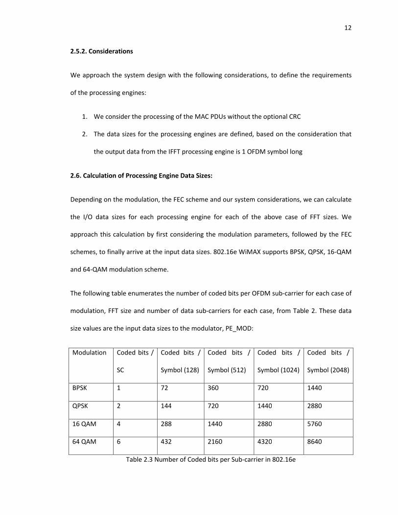
2.3 Number of Coded bits per Sub-carrier in 802.16e ................................................................. 12
2.4 Modulation and FEC Parameters for 802.16e ........................................................................ 13
2.5 I/O Data Sizes for PE_MAC ..................................................................................................... 15
2.6 I/O Data Sizes for PE_HDR ..................................................................................................... 16
2.7 I/O Data Sizes for PE_SCR ...................................................................................................... 17
2.8 Reed Solomon Coding Rates .................................................................................................. 17
2.9 I/O Data Sizes for PE_RS ......................................................................................................... 18
2.10 I/O Data Sizes for PE_ENC .................................................................................................... 19
2.11 I/O Data Sizes for PE_INT ..................................................................................................... 20
2.12 I/O Data Sizes for PE_MOD .................................................................................................. 21
2.13 I/O Data Sizes for PE_IFFT .................................................................................................... 22
2.14 I/O Data Sizes for PE_FFT ..................................................................................................... 23
2.15 I/O Data Sizes for PE_DEMOD .............................................................................................. 23
2.16 I/O Data Sizes for PE_DEINT ................................................................................................. 24
2.17 I/O Data Sizes for PE_DEC .................................................................................................... 24
2.18 I/O Data Sizes for PE_RSD .................................................................................................... 25
2.19 I/O Data Sizes for PE_DSCR .................................................................................................. 26
x
3.1 Indicative Parameters for Next Task Processing .................................................................... 39
3.2 Scoreboard Lookup Table ...................................................................................................... 43
3.3 Next Task Processing Test Results ......................................................................................... 44
4.1 Task Scheduling Parameters .................................................................................................. 74
4.2 Test Parameters ..................................................................................................................... 74
xi
List of Figures
1.1 WiNC2R Block Diagram ............................................................................................................ 2
1.2 Functional Unit ......................................................................................................................... 3
2.1 MAC PDU Format ..................................................................................................................... 7
2.2 TDD 802.16e OFDMA Frame .................................................................................................... 8
2.3 802.16e WiMAX Physical Layer Block Diagram ........................................................................ 9
2.4 WiNC2R Block Diagram for 802.16e WiMAX Transmitter ..................................................... 11
2.5 Block Diagram of PE_MOD ..................................................................................................... 21
2.6 WiNC2R Block Diagram for 802.16e WiMAX Receiver ........................................................... 23
3.1 Block Diagram of a Testbench ................................................................................................ 31
3.2 Global Task Table ................................................................................................................... 34
3.3 Task Descriptor Table ............................................................................................................. 35
3.4 Next Task Table ...................................................................................................................... 36
3.5 Next Task Processing Flow Diagram ....................................................................................... 37
3.6 Block Diagram of Next Task Processing ................................................................................ 39
3.7 Command Termination Message Format .............................................................................. 40
3.8 WiNC2R Platform Configuration ............................................................................................ 41
3.9 Next Task Processing Testbench Setup .................................................................................. 42
3.10 Chunking Task ...................................................................................................................... 48
3.11 De-chunking Task ................................................................................................................. 58

xii
4.1 Sample Task Flow ................................................................................................................... 78
4.2 Two Cluster Configuration ..................................................................................................... 79
4.3 VFP Control Transfer Mechanism .......................................................................................... 81
1
Chapter 1 – Introduction to WiNC2R
WINLAB Network Centric Cognitive Radio (WiNC2R) is a hardware-based cognitive radio
platform for programmable radio processing. WiNC2R system architecture is characterized by a
heterogeneous multiprocessor configuration based on a System on a Chip (SoC) design [1].
WiNC2R aims to provide deterministically programmable support for running multiple wireless
protocols simultaneously, and be adaptive to their constant evolution.
In order to meet its goals, WiNC2R architecture needs to satisfy the requirements for speed,
ease of programmability and runtime flexibility to provision wireless protocol flows. The design
is hence characterized by its support for multifunctional hardware units and software
programmable CPUs, configured by an elegant task level programmable framework, based on a
Virtual Flow Pipelining model [4].
Virtual Flow Pipelining is a mechanism of introducing runtime flexibility in the hardware
architecture. This is accomplished by creating data paths called ‘Virtual Flow Graphs’ between
the constituent hardware units on-the-fly depending on runtime conditions. This creates an
Operating System-like hardware based support for executing soft-control flow programs.
Virtual Flow Pipelining is implemented in WiNC2R using a programmable hardware module
called the ‘Virtual Flow Pipelining (VFP) Controller’. The VFP controller implements the task
based programming model by creating Virtual Flow Graphs, depending on the runtime
conditions, so as to comply with the wireless protocol requirements.
WiNC2R architecture is defined as a cluster-based design. The motivation behind this design
feature is to support easy scalability and to mitigate hardware overhead in implementing
complex wireless protocols. The following sec
WiNC2R’s cluster-based design.
1.1. WiNC2R Block Diagram:
The figure below shows the block d
As depicted by the above block diagram, WiNC2R has
shared VFP controllers. Each cluster consists of several ‘Functional Units’ (FU), which consist of
processing engines that may be multifunctional hardware units or software programmable
CPUs. A cluster can support u
The control messages are communicated between the VFP controller and the FUs through
customized simple buses in each cluster. The VFP controller and all the FUs in a cluster are
connected to a cluster interconnect, which is an Advanced Microcontroller Bus Architecture
complex wireless protocols. The following section describes the features and functions of
based design.
WiNC2R Block Diagram:
The figure below shows the block diagram of the WiNC2R platform [6]:
Figure 1.1 WiNC2R Block Diagram
As depicted by the above block diagram, WiNC2R has a cluster based design with distributed,
shared VFP controllers. Each cluster consists of several ‘Functional Units’ (FU), which consist of
processing engines that may be multifunctional hardware units or software programmable
CPUs. A cluster can support up to 15 functional units, with one shared VFP controller per cluster.
The control messages are communicated between the VFP controller and the FUs through
customized simple buses in each cluster. The VFP controller and all the FUs in a cluster are
ed to a cluster interconnect, which is an Advanced Microcontroller Bus Architecture
2
tion describes the features and functions of
a cluster based design with distributed,
shared VFP controllers. Each cluster consists of several ‘Functional Units’ (FU), which consist of
processing engines that may be multifunctional hardware units or software programmable
p to 15 functional units, with one shared VFP controller per cluster.
The control messages are communicated between the VFP controller and the FUs through
customized simple buses in each cluster. The VFP controller and all the FUs in a cluster are
ed to a cluster interconnect, which is an Advanced Microcontroller Bus Architecture
(AMBA) Advanced eXtensible Interface (AXI)
interconnects are used for data transfer between the cluster’s FUs.
1.2. Functional Unit:
A functional unit consists of VFP compliant interfaces, a Direct Memory Access (DMA) engine for
data transfer, input / output data buffers and a processing engine as described above. A
functional unit implements tasks with the processing engine working o
buffer and storing the results in the output buffer.
The figure shown below depicts a sample functional unit implementing interleaving. Interleaving
is a process of mitigating burst errors by rearranging the input data sequence s
consecutive data is separated apart.
As shown in the above figure, the processing engine of the FU interleaver rearranges an input
data sequence of [A1 A2 B1 B2 C1 C2] to produce an output data sequence of [A1 B1 C1 A2
C2]. The above functionality of rearranging the data is known as a ‘task’ for the interleaver.
1.3. Configuration and Programmability:
The WiNC2R system can be configured to implement the PHY layer design of wireless protocols
by designing clusters with the required FUs / processing engines, which serve as signal
processing blocks. The system can now be programmed to implement the protocol flow
(AMBA) Advanced eXtensible Interface (AXI) [22] bus in WiNC2R. The AMBA AXI cluster
interconnects are used for data transfer between the cluster’s FUs.
A functional unit consists of VFP compliant interfaces, a Direct Memory Access (DMA) engine for
data transfer, input / output data buffers and a processing engine as described above. A
functional unit implements tasks with the processing engine working on the data from the input
buffer and storing the results in the output buffer.
The figure shown below depicts a sample functional unit implementing interleaving. Interleaving
is a process of mitigating burst errors by rearranging the input data sequence s
consecutive data is separated apart.
Figure 1.2 Functional Unit
As shown in the above figure, the processing engine of the FU interleaver rearranges an input
data sequence of [A1 A2 B1 B2 C1 C2] to produce an output data sequence of [A1 B1 C1 A2
C2]. The above functionality of rearranging the data is known as a ‘task’ for the interleaver.
Configuration and Programmability:
The WiNC2R system can be configured to implement the PHY layer design of wireless protocols
h the required FUs / processing engines, which serve as signal
processing blocks. The system can now be programmed to implement the protocol flow
3
bus in WiNC2R. The AMBA AXI cluster
A functional unit consists of VFP compliant interfaces, a Direct Memory Access (DMA) engine for
data transfer, input / output data buffers and a processing engine as described above. A
n the data from the input
The figure shown below depicts a sample functional unit implementing interleaving. Interleaving
is a process of mitigating burst errors by rearranging the input data sequence such that
As shown in the above figure, the processing engine of the FU interleaver rearranges an input
data sequence of [A1 A2 B1 B2 C1 C2] to produce an output data sequence of [A1 B1 C1 A2 B2
C2]. The above functionality of rearranging the data is known as a ‘task’ for the interleaver.
The WiNC2R system can be configured to implement the PHY layer design of wireless protocols
h the required FUs / processing engines, which serve as signal
processing blocks. The system can now be programmed to implement the protocol flow
4
amongst the constituent FUs, by loading the scheduling and performance requirements of all
the tasks supported in a cluster into its VFP controller’s memory and the task execution details
into the specific FU’s internal memory.
The organization of the rest of the thesis is as follows; based on the architectural and
performance goals of the WiNC2R platform outlined in this chapter, Chapter 2 discusses the
motivation behind designing 802.16e Mobile WiMAX flows on WiNC2R. We then provide a brief
introduction to the Mobile WiMAX protocol and its goals, so as to define the system
requirements its implementation. We then introduce our proposed WiNC2R system design for
Mobile WiMAX protocol with a basic programmable flow, describing each required functional
unit in detail.
In Chapter 3, we address the specific functional requirements of the WiNC2R system to support
Mobile WiMAX flows. We then describe our functional verification testplan, testbench setup,
implementation and results for three features – Next Task Processing, Chunking and De-
chunking. In Chapter 4, we address the performance requirements of the WiNC2R system to
support complex wireless protocols by defining a coverage driven verification plan for features
like – Priority based task scheduling and Inter-cluster communication. In Chapter 5, we conclude
with an assessment of WiNC2R’s support for Mobile WiMAX protocol, based on our verification
work and outline the scope for future work.
5
Chapter 2 – IEEE 802.16e Mobile WiMAX on WiNC2R
2.1. Motivation:
The class of WiMAX standards has been a subject of keen interest for researchers, network
operators and the industry alike, owing to its performance and economic benefits compared to
the existing solutions for broadband wireless access. WiMAX is hence a complex, constantly
evolving wireless standard which aims to cater to a diverse community of backers.
Revisiting the primary goals of the WiNC2R architecture to support modern wireless protocols
and be adaptive their constant evolution; it makes an interesting case study to evaluate the
design and programmability of the WiNC2R platform for supporting WiMAX flows.
The objective of this case study is to analyze:
i. Configurability of WiNC2R platform for different wireless protocols
ii. Sufficiency of WiNC2R’s task based programming model to provision such protocol flows
We present this work with a brief description of the 802.16e standard, followed by the proposed
design of the platform configuration and programming model for WiNC2R.
2.2. Protocol Description:
IEEE 802.16 is a class of broadband wireless standards, commercially known as WiMAX. IEEE
802.16e is an amendment supporting fixed, nomadic, portable and mobile broadband wireless
access. IEEE 802.16e is commonly known as ‘Mobile WiMAX’, owing to its support for mobile
subscriber stations travelling at road speeds up to 75 mph. This standard defines the PHY and
MAC layer specifications for mobile WiMAX protocols.
6
2.3. PHY Layer:
It can be operated in the 2.3 GHz, 2.5 GHz and 3.65 GHz licensed frequency bands in the United
States, using 128, 512, 1024 or 2048 carrier Scalable Orthogonal Frequency Division Multiple
Access (SOFDMA), supporting channel bandwidths of 1.25 MHz, 5 MHz, 10 MHz and 20 MHz
respectively. The purpose of different bandwidth configurations is to support different data
sizes. In a 10 MHz channel, 802.16e can support downlink data rates up to 25 Mbps and uplink
data rates up to 6.7 Mbps implementing a 3:1 Time Division Duplex (TDD) scheme with 64 QAM
modulation and 5/6 error correction coding scheme.
2.4. MAC Layer:
The 802.16e MAC layer consists of three sub-layers:
i. Convergence Sub-layer (CS)
ii. Mac Common Part Sub-layer (CPS)
iii. Security Sub-layer
The primary function of the MAC CS layer is to classify the incoming data and map them
appropriately with the MAC CPS layer, which is responsible for system scheduling and QoS
guarantees. The security sub-layer handles security aspects like authentication, encryption, etc.
2.4.1. MAC Frame:
The 802.16e standard defines the MAC Protocol Data Unit (PDU), which is the basic packet used
to exchange information. The terms MAC Frame and MAC PDU are used interchangeably. The
MAC PDUs can be of three types: Data PDUs, Management PDUs or Bandwidth Request PDUs.
The generic MAC PDU consists of a standard header which is 6 bytes long, an optional Fragment
Sub-Header (FSH), a payload of variable length and an optional CRC.
7
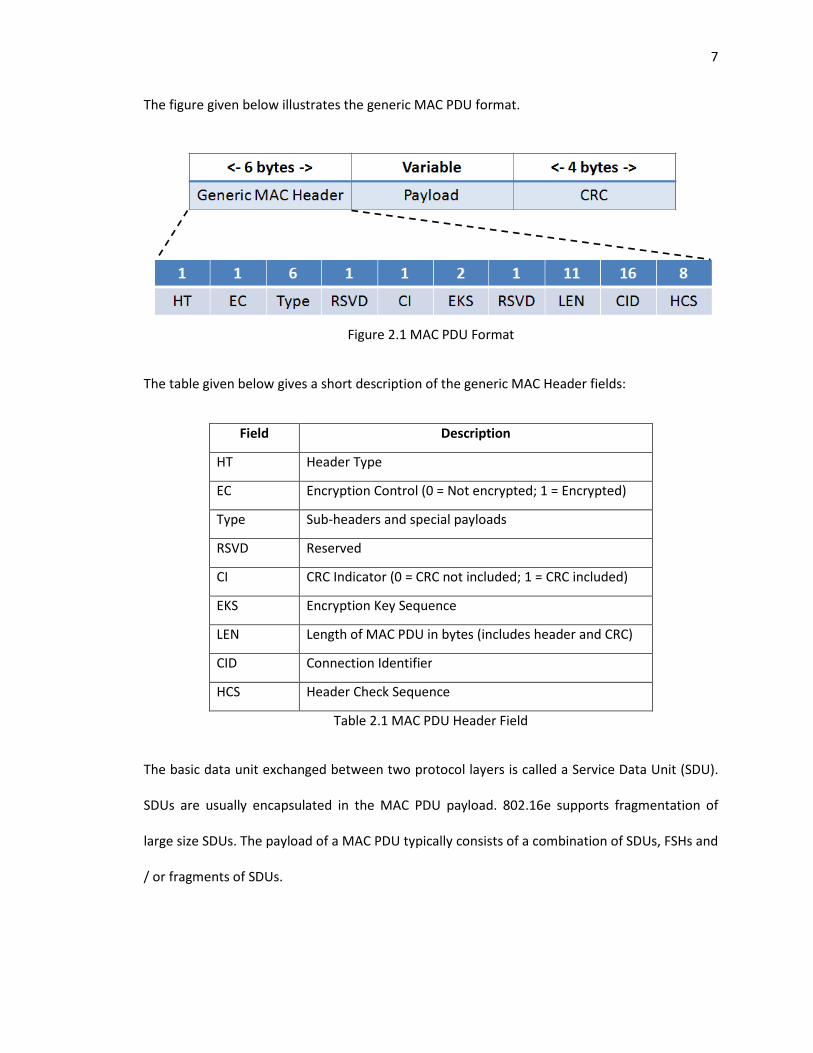
The figure given below illustrates the generic MAC PDU format.
Figure 2.1 MAC PDU Format
The table given below gives a short description of the generic MAC Header fields:
Field Description
HT Header Type
EC Encryption Control (0 = Not encrypted; 1 = Encrypted)
Type Sub-headers and special payloads
RSVD Reserved
CI CRC Indicator (0 = CRC not included; 1 = CRC included)
EKS Encryption Key Sequence
LEN Length of MAC PDU in bytes (includes header and CRC)
CID Connection Identifier
HCS Header Check Sequence
Table 2.1 MAC PDU Header Field
The basic data unit exchanged between two protocol layers is called a Service Data Unit (SDU).
SDUs are usually encapsulated in the MAC PDU payload. 802.16e supports fragmentation of
large size SDUs. The payload of a MAC PDU typically consists of a combination of SDUs, FSHs and
/ or fragments of SDUs.
The primary function of the 802.16e PHY layer is to transmit and receive the MAC PDUs
according to the standard’s specifications.
2.4.2. MAC PDU Flow:
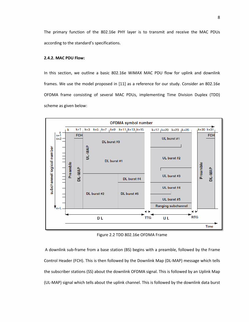
In this section, we outline a basic 802.16e WiMAX MAC PDU
frames. We use the model proposed in [11
OFDMA frame consisting of several MAC PDUs, implementing Time Division Duplex (TDD)
scheme as given below:
A downlink sub-frame from a base station (BS) begins with a preamble, followed by the Frame
Control Header (FCH). This is t
the subscriber stations (SS) about the downlink OFDMA signal.
(UL-MAP) signal which tells about the uplink channel. This is followed by the downlink
The primary function of the 802.16e PHY layer is to transmit and receive the MAC PDUs
according to the standard’s specifications.
In this section, we outline a basic 802.16e WiMAX MAC PDU flow for uplink and downlink
We use the model proposed in [11] as a reference for our study. Consider an 802.16e
OFDMA frame consisting of several MAC PDUs, implementing Time Division Duplex (TDD)
Figure 2.2 TDD 802.16e OFDMA Frame
frame from a base station (BS) begins with a preamble, followed by the Frame
Control Header (FCH). This is then followed by the Downlink Map (DL-MAP) message which tells
the subscriber stations (SS) about the downlink OFDMA signal. This is followed by a
signal which tells about the uplink channel. This is followed by the downlink
8
The primary function of the 802.16e PHY layer is to transmit and receive the MAC PDUs
flow for uplink and downlink
Consider an 802.16e
OFDMA frame consisting of several MAC PDUs, implementing Time Division Duplex (TDD)
frame from a base station (BS) begins with a preamble, followed by the Frame
MAP) message which tells
This is followed by an Uplink Map
signal which tells about the uplink channel. This is followed by the downlink data burst
9
frames, which may be unicast, multicast or broadcast. This is followed by a Transmit Transition
Gap (TTG). Then begins the uplink frame, which consists of the uplink data bursts from all the
SSs. This also contains the sub-frame for bandwidth / ranging requests. This is then followed by
the Receive Transition Gap (RTG).
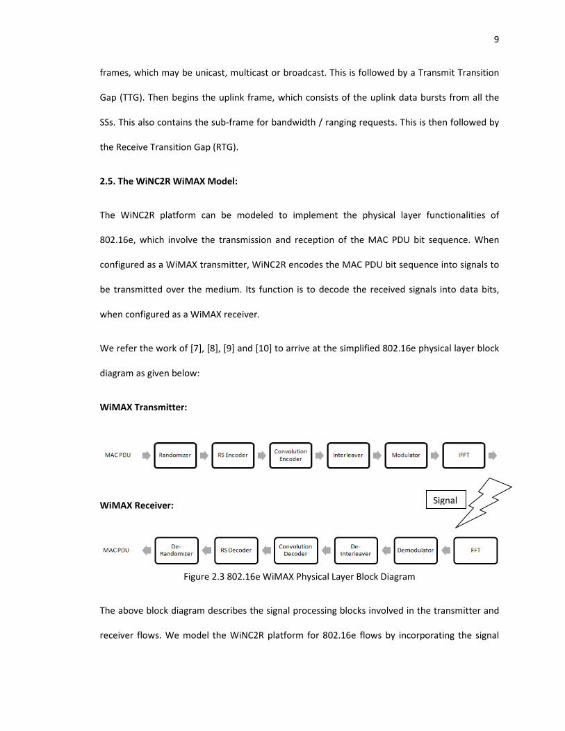
2.5. The WiNC2R WiMAX Model:
The WiNC2R platform can be modeled to implement the physical layer functionalities of
802.16e, which involve the transmission and reception of the MAC PDU bit sequence. When
configured as a WiMAX transmitter, WiNC2R encodes the MAC PDU bit sequence into signals to
be transmitted over the medium. Its function is to decode the received signals into data bits,
when configured as a WiMAX receiver.
We refer the work of [7], [8], [9] and [10] to arrive at the simplified 802.16e physical layer block
diagram as given below:
WiMAX Transmitter:
WiMAX Receiver:
Figure 2.3 802.16e WiMAX Physical Layer Block Diagram
The above block diagram describes the signal processing blocks involved in the transmitter and
receiver flows. We model the WiNC2R platform for 802.16e flows by incorporating the signal
Signal
10
processing blocks from the above block diagram, whose functionalities are implemented using
the Processing Engines (PE) in WiNC2R. We propose the WiMAX design on WiNC2R, by
describing the specific function of each signal processing block and how it is encapsulated in the
processing engines.
We propose the design of a WiMAX system by a adopting a modular approach to the above
block diagram. For this purpose, we first look at the transmitter design to understand its
operation in a step-wise manner; define the specifics of each step with their implementation
considerations. The modeling of the receiver module is on the same lines of the transmitter,
since their functionalities are in essence, reciprocities.
2.5.1. Outline of the 802.16e WiMAX Transmitter:
We have identified the following as the main steps involved in the transmitter module:
I. Generation of MAC PDUs
II. Error Correction and Protection Encoding
III. Modulation and Transmission
We describe each step in brief, outlining how we propose to implement them, followed by a
detailed description of the proposed design.
I. Generating the MAC PDUs:
As described in the previous section, we can envision the MAC PDUs as the input data stream to
the transmitter. The task of MAC PDU generation will be shared by two processing engines –
PE_MAC and PE_HDR. The generated MAC PDUs are then fed to the processing engine
implementing scrambling – PE_SCR.
11
II. Error Correction and Protection Encoding:
Forward Error Correction (FEC) is a mechanism of error control for data transmission, wherein
the transmitter creates error control codes, by adding systematically generated redundant bits
to the data received from the scrambler. 802.16e WiMAX defines FEC using a Reed Solomon (RS)
encoder and a convolution encoder. We propose to implement FEC using a dedicated processing
engine for each function, PE_RS and PE_ENC along with a data scrambler and an interleaver for
added error protection before and after FEC respectively.
III. Modulation and Transmission:
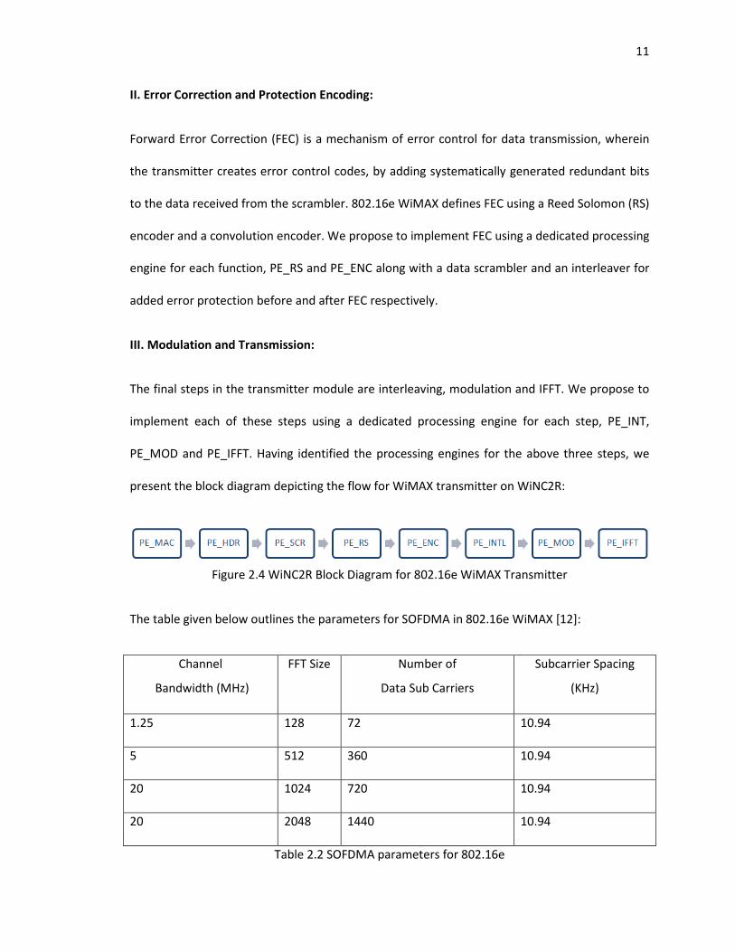
The final steps in the transmitter module are interleaving, modulation and IFFT. We propose to
implement each of these steps using a dedicated processing engine for each step, PE_INT,
PE_MOD and PE_IFFT. Having identified the processing engines for the above three steps, we
present the block diagram depicting the flow for WiMAX transmitter on WiNC2R:
Figure 2.4 WiNC2R Block Diagram for 802.16e WiMAX Transmitter
The table given below outlines the parameters for SOFDMA in 802.16e WiMAX [12]:
Channel
Bandwidth (MHz)
FFT Size Number of
Data Sub Carriers
Subcarrier Spacing
(KHz)
1.25 128 72 10.94
5 512 360 10.94
20 1024 720 10.94
20 2048 1440 10.94
Table 2.2 SOFDMA parameters for 802.16e
12
2.5.2. Considerations
We approach the system design with the following considerations, to define the requirements
of the processing engines:
1. We consider the processing of the MAC PDUs without the optional CRC
2. The data sizes for the processing engines are defined, based on the consideration that
the output data from the IFFT processing engine is 1 OFDM symbol long
2.6. Calculation of Processing Engine Data Sizes:
Depending on the modulation, the FEC scheme and our system considerations, we can calculate
the I/O data sizes for each processing engine for each of the above case of FFT sizes. We
approach this calculation by first considering the modulation parameters, followed by the FEC
schemes, to finally arrive at the input data sizes. 802.16e WiMAX supports BPSK, QPSK, 16-QAM
and 64-QAM modulation scheme.
The following table enumerates the number of coded bits per OFDM sub-carrier for each case of
modulation, FFT size and number of data sub-carriers for each case, from Table 2. These data
size values are the input data sizes to the modulator, PE_MOD:
Modulation Coded bits /
SC
Coded bits /
Symbol (128)
Coded bits /
Symbol (512)
Coded bits /
Symbol (1024)
Coded bits /
Symbol (2048)
BPSK 1 72 360 720 1440
QPSK 2 144 720 1440 2880
16 QAM 4 288 1440 2880 5760
64 QAM 6 432 2160 4320 8640
Table 2.3 Number of Coded bits per Sub-carrier in 802.16e
13
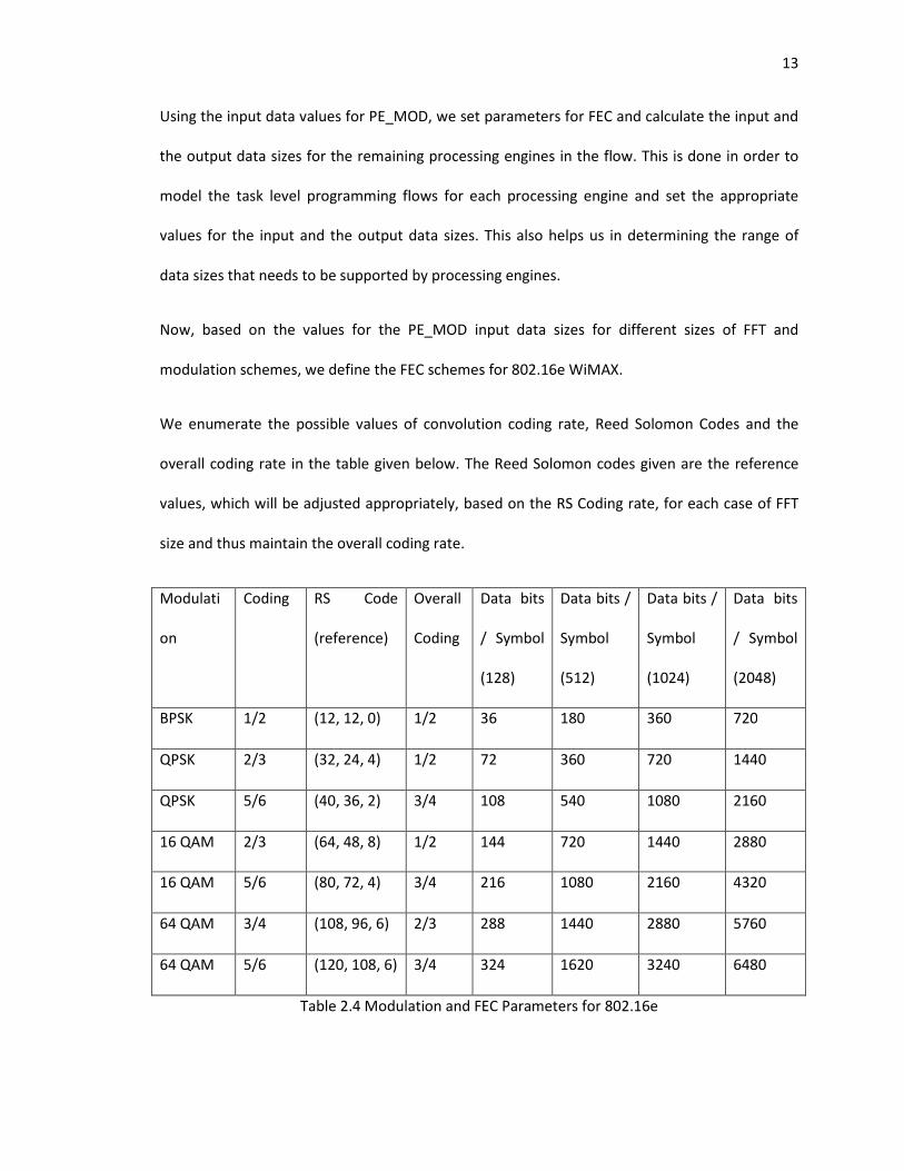
Using the input data values for PE_MOD, we set parameters for FEC and calculate the input and
the output data sizes for the remaining processing engines in the flow. This is done in order to
model the task level programming flows for each processing engine and set the appropriate
values for the input and the output data sizes. This also helps us in determining the range of
data sizes that needs to be supported by processing engines.
Now, based on the values for the PE_MOD input data sizes for different sizes of FFT and
modulation schemes, we define the FEC schemes for 802.16e WiMAX.
We enumerate the possible values of convolution coding rate, Reed Solomon Codes and the
overall coding rate in the table given below. The Reed Solomon codes given are the reference
values, which will be adjusted appropriately, based on the RS Coding rate, for each case of FFT
size and thus maintain the overall coding rate.
Modulati
on
Coding RS Code
(reference)
Overall
Coding
Data bits
/ Symbol
(128)
Data bits /
Symbol
(512)
Data bits /
Symbol
(1024)
Data bits
/ Symbol
(2048)
BPSK 1/2 (12, 12, 0) 1/2 36 180 360 720
QPSK 2/3 (32, 24, 4) 1/2 72 360 720 1440
QPSK 5/6 (40, 36, 2) 3/4 108 540 1080 2160
16 QAM 2/3 (64, 48, 8) 1/2 144 720 1440 2880
16 QAM 5/6 (80, 72, 4) 3/4 216 1080 2160 4320
64 QAM 3/4 (108, 96, 6) 2/3 288 1440 2880 5760
64 QAM 5/6 (120, 108, 6) 3/4 324 1620 3240 6480
Table 2.4 Modulation and FEC Parameters for 802.16e
14
The above table gives the values of the number of uncoded bits for each case, which in other
words, is the number of data bits for each case. The data bits are the inputs given to the first
processing engine in the flow. Hence, the above table has given us the range of values for the
packet sizes of the MAC PDUs that need to be supported by the processing engines before FEC.
The range is between 36 bits and 6480 bits, which in other words are between 5 bytes and 810
bytes. This calculation is based on the consideration that 1 set of data from the IFFT output is 1
OFDM symbol long.
In the following section, we define the specific functionalities of each processing engine.
2.6.1. MAC Processing Engine (PE_MAC)
The PE_MAC processing engine provides the functionality of a reconfigurable MAC. It can be
programmed to extend support for different MAC protocols for 802.16e applications. This
module works on a random sequence of generated input data and provides its output to the
PE_HDR.
Based on our considerations, we have calculated the sizes of the uncoded data bits per OFDM
symbol in Table 4. This calculation has given us the set of data size values that need to be
supported by the processing engines in the flow before FEC.
In our calculations in the preceding section, we have determined that the values of the MAC
PDU sizes before FEC range from 5 bytes to 810 bytes. This must include a standard 6 byte
header appended by the header. Hence, we ignore the case of 5 bytes and consider the cases
from the size 9 bytes. PE_MAC feeds the input data to PE_HDR. Hence the size of the input data
is equal to the size of the output data.
15
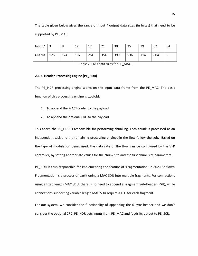
The table given below gives the range of input / output data sizes (in bytes) that need to be
supported by PE_MAC:
Input /
Output
3 8 12 17 21 30 35 39 62 84
126 174 197 264 354 399 536 714 804 -
Table 2.5 I/O data sizes for PE_MAC
2.6.2. Header Processing Engine (PE_HDR)
The PE_HDR processing engine works on the input data frame from the PE_MAC. The basic
function of this processing engine is twofold:
1. To append the MAC Header to the payload
2. To append the optional CRC to the payload
This apart, the PE_HDR is responsible for performing chunking. Each chunk is processed as an
independent task and the remaining processing engines in the flow follow the suit. Based on
the type of modulation being used, the data rate of the flow can be configured by the VFP
controller, by setting appropriate values for the chunk size and the first chunk size parameters.
PE_HDR is thus responsible for implementing the feature of ‘Fragmentation’ in 802.16e flows.
Fragmentation is a process of partitioning a MAC SDU into multiple fragments. For connections
using a fixed length MAC SDU, there is no need to append a Fragment Sub-Header (FSH), while
connections supporting variable length MAC SDU require a FSH for each fragment.
For our system, we consider the functionality of appending the 6 byte header and we don’t
consider the optional CRC. PE_HDR gets inputs from PE_MAC and feeds its output to PE_SCR.
16
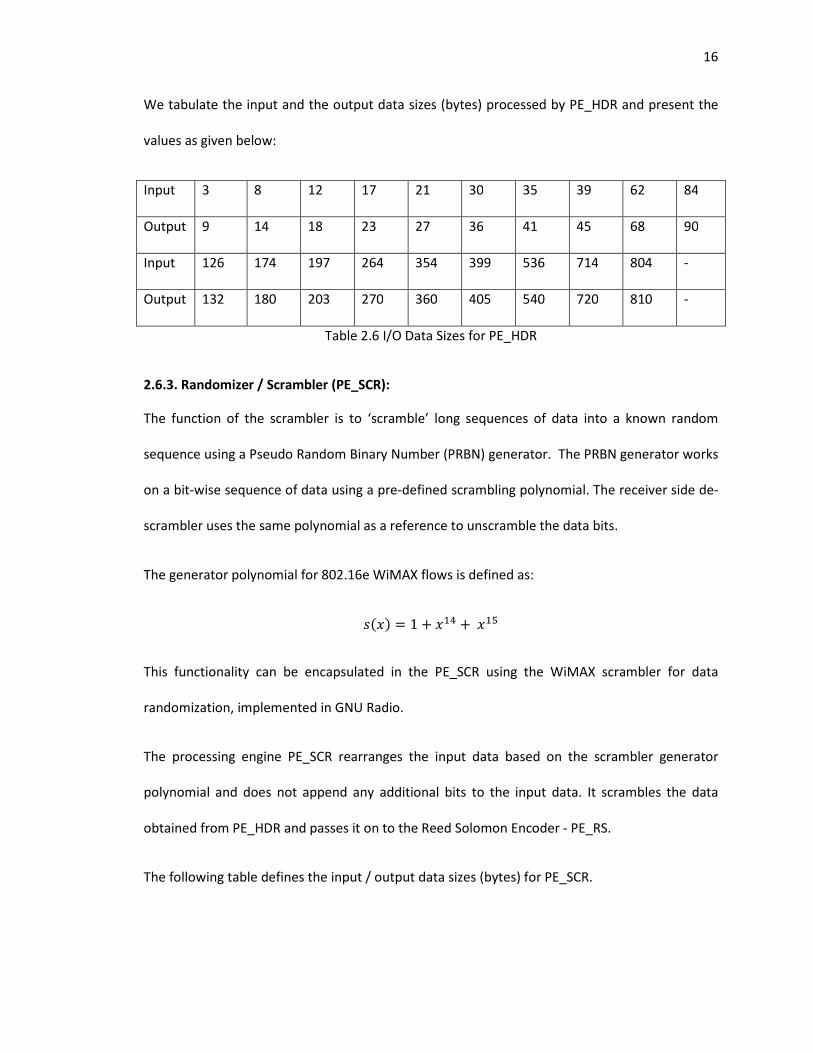
We tabulate the input and the output data sizes (bytes) processed by PE_HDR and present the
values as given below:
Input 3 8 12 17 21 30 35 39 62 84
Output 9 14 18 23 27 36 41 45 68 90
Input 126 174 197 264 354 399 536 714 804 -
Output 132 180 203 270 360 405 540 720 810 -
Table 2.6 I/O Data Sizes for PE_HDR
2.6.3. Randomizer / Scrambler (PE_SCR):
The function of the scrambler is to ‘scramble’ long sequences of data into a known random
sequence using a Pseudo Random Binary Number (PRBN) generator. The PRBN generator works
on a bit-wise sequence of data using a pre-defined scrambling polynomial. The receiver side de-
scrambler uses the same polynomial as a reference to unscramble the data bits.
The generator polynomial for 802.16e WiMAX flows is defined as:
���� = 1 + �� +���
This functionality can be encapsulated in the PE_SCR using the WiMAX scrambler for data
randomization, implemented in GNU Radio.
The processing engine PE_SCR rearranges the input data based on the scrambler generator
polynomial and does not append any additional bits to the input data. It scrambles the data
obtained from PE_HDR and passes it on to the Reed Solomon Encoder - PE_RS.
The following table defines the input / output data sizes (bytes) for PE_SCR.
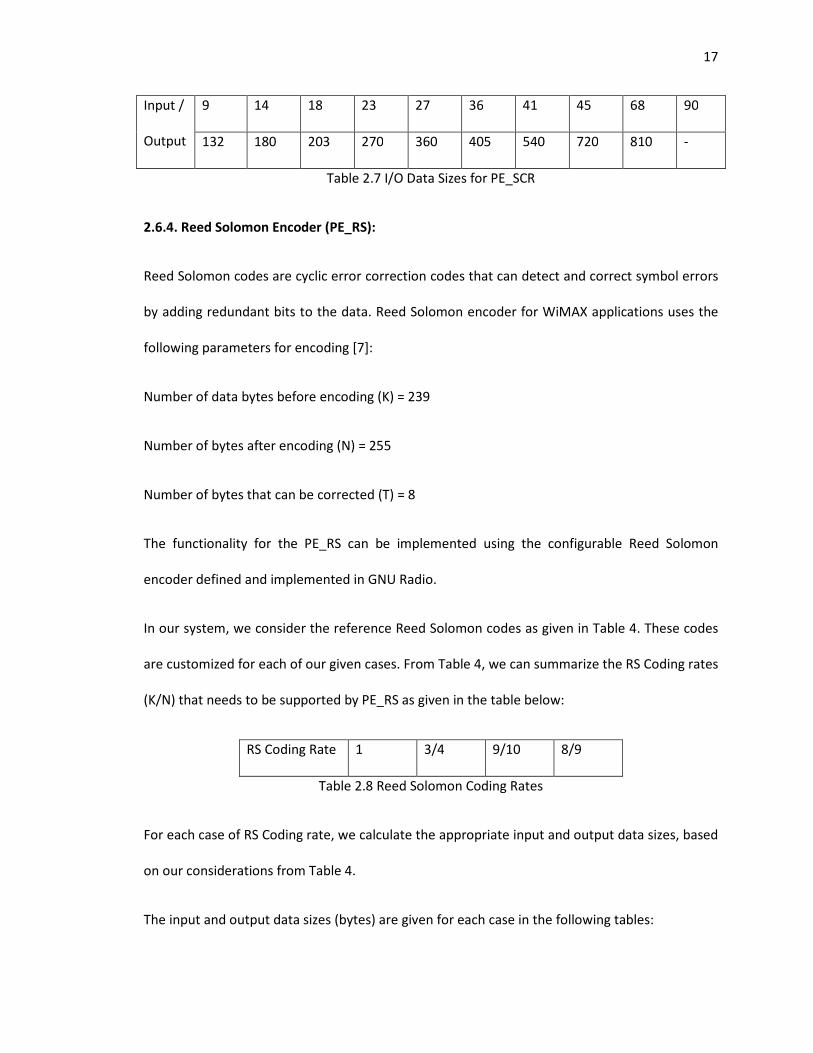
17
Input /
Output
9 14 18 23 27 36 41 45 68 90
132 180 203 270 360 405 540 720 810 -
Table 2.7 I/O Data Sizes for PE_SCR
2.6.4. Reed Solomon Encoder (PE_RS):
Reed Solomon codes are cyclic error correction codes that can detect and correct symbol errors
by adding redundant bits to the data. Reed Solomon encoder for WiMAX applications uses the
following parameters for encoding [7]:
Number of data bytes before encoding (K) = 239
Number of bytes after encoding (N) = 255
Number of bytes that can be corrected (T) = 8
The functionality for the PE_RS can be implemented using the configurable Reed Solomon
encoder defined and implemented in GNU Radio.
In our system, we consider the reference Reed Solomon codes as given in Table 4. These codes
are customized for each of our given cases. From Table 4, we can summarize the RS Coding rates
(K/N) that needs to be supported by PE_RS as given in the table below:
RS Coding Rate 1 3/4 9/10 8/9
Table 2.8 Reed Solomon Coding Rates
For each case of RS Coding rate, we calculate the appropriate input and output data sizes, based
on our considerations from Table 4.
The input and output data sizes (bytes) are given for each case in the following tables:
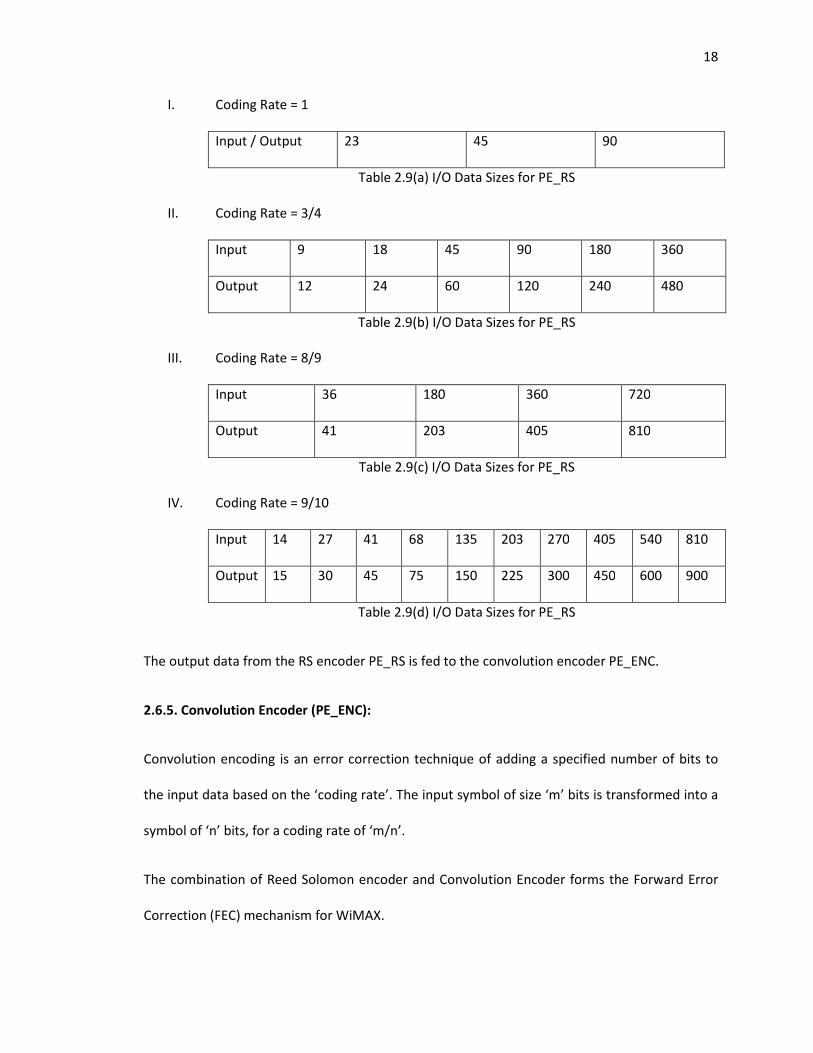
18
I. Coding Rate = 1
Input / Output 23 45 90
Table 2.9(a) I/O Data Sizes for PE_RS
II. Coding Rate = 3/4
Input 9 18 45 90 180 360
Output 12 24 60 120 240 480
Table 2.9(b) I/O Data Sizes for PE_RS
III. Coding Rate = 8/9
Input 36 180 360 720
Output 41 203 405 810
Table 2.9(c) I/O Data Sizes for PE_RS
IV. Coding Rate = 9/10
Input 14 27 41 68 135 203 270 405 540 810
Output 15 30 45 75 150 225 300 450 600 900
Table 2.9(d) I/O Data Sizes for PE_RS
The output data from the RS encoder PE_RS is fed to the convolution encoder PE_ENC.
2.6.5. Convolution Encoder (PE_ENC):
Convolution encoding is an error correction technique of adding a specified number of bits to
the input data based on the ‘coding rate’. The input symbol of size ‘m’ bits is transformed into a
symbol of ‘n’ bits, for a coding rate of ‘m/n’.
The combination of Reed Solomon encoder and Convolution Encoder forms the Forward Error
Correction (FEC) mechanism for WiMAX.
19
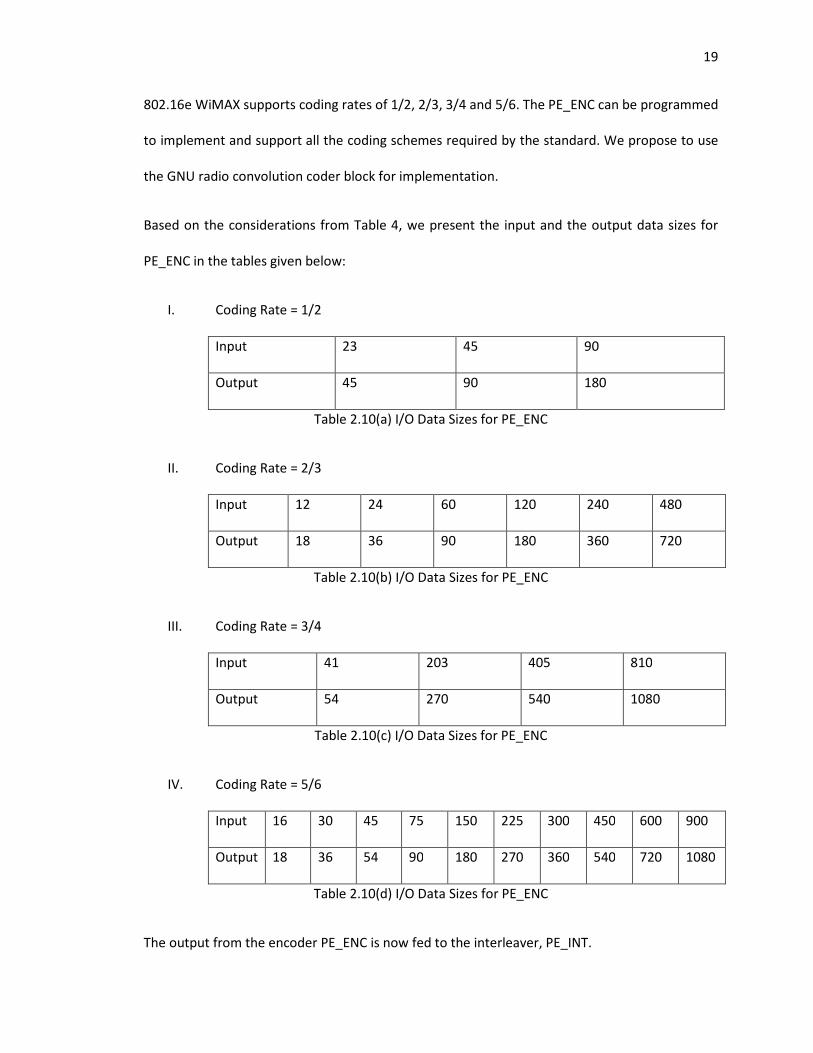
802.16e WiMAX supports coding rates of 1/2, 2/3, 3/4 and 5/6. The PE_ENC can be programmed
to implement and support all the coding schemes required by the standard. We propose to use
the GNU radio convolution coder block for implementation.
Based on the considerations from Table 4, we present the input and the output data sizes for
PE_ENC in the tables given below:
I. Coding Rate = 1/2
Input 23 45 90
Output 45 90 180
Table 2.10(a) I/O Data Sizes for PE_ENC
II. Coding Rate = 2/3
Input 12 24 60 120 240 480
Output 18 36 90 180 360 720
Table 2.10(b) I/O Data Sizes for PE_ENC
III. Coding Rate = 3/4
Input 41 203 405 810
Output 54 270 540 1080
Table 2.10(c) I/O Data Sizes for PE_ENC
IV. Coding Rate = 5/6
Input 16 30 45 75 150 225 300 450 600 900
Output 18 36 54 90 180 270 360 540 720 1080
Table 2.10(d) I/O Data Sizes for PE_ENC
The output from the encoder PE_ENC is now fed to the interleaver, PE_INT.
20
2.6.6. Interleaver (PE_INT):
The primary function of an interleaver is to improve the performance of the FEC codes by
arranging the data in a non-contiguous way. In this case, the implementation is a block
interleaver, which works on a block size equal to the number of bits in the OFDM symbol.
Interleaving is implemented as a two step permutation process. First, permutation of the bits of
the matrix as per a given formula followed by the second step of mapping of coded bits based
on modulation schemes using a second permutation formula.
We propose to implement the schemes of interleaving by using a simple C function for the
formulae from [7] and encapsulating functionality in PE_ENC.
PE_INT does not add any additional bits to the input data, but it just re-arranges it and feeds it
to the PE_MOD. Hence the input and the output data sizes for PE_INT are the same. The values
of these (bytes) are as tabulated below:
Input / Output 18 36 45 54 90 180 270 360 540 720 1080
Table 2.11 I/O Data Sizes for PE_INT
We hence note that these values are in accordance to the values of the input data size to the
PE_MOD, as given in Table 3. We now proceed to define the PE_MOD and PE_IFFT.
2.6.7. Modulator (PE_MOD):
802.16e standard supports BPSK, QPSK, 16 QAM and 64 QAM. This has already been
implemented in the existing version of WiNC2R as a configurable VHDL entity. We propose to
use the same module in our design.
21
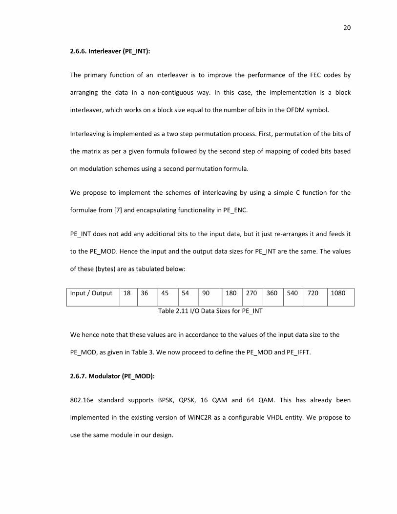
The interleaver keeps writing its output data into a FIFO meant for PE_MOD input buffer. This
ensures continuous modulation. The function of the modulator is to read the 32 bit input data
and convert it into a 32 bit I/Q sample as shown in the figure below:
Figure 2.5 Block Diagram of PE_MOD
The lower 16 bits of the output denote the Q sample and the higher 16 bits denote the I sample.
Hence, for each value of the input provided by the PE_INT, we define the output data size. Since
PE_MOD reads input data in units of 32 bits (4 bytes) wide, we pad zeros for input data which
are not multiples of 32 bit words.
Given below is the table which summarizes the input and the output data sizes (bytes) of
PE_MOD:
Input 18 36 45 54 90 180 270 360 540 720 1080
Output 20 36 48 56 92 180 272 360 540 720 1080
Table 2.12 I/O Data Sizes for PE_MOD
The output data from the PE_MOD is fed into another FIFO. The next processing engine in the
chain, PE_IFFT reads its input data from this FIFO and processes it.
22
2.6.8. Inverse Fast Fourier Transform (PE_IFFT):
This is the processing engine which implements IFFT on the input data. This again has already
been successfully implemented in the existing version of WiNC2R as PE_IFFT. We propose to use
the same module in our WiMAX design.
For our WiMAX design, the IFFT output would be an OFDM symbol, whose size depends on the
number of OFDM sub-carriers used - 128, 512, 1024 or 2048.
Since the size of each I/Q sample generated by PE_IFFT is 32 bits, for an ‘N’ sub-carrier OFDM
implementation, the output size is (N*32) bits or (N*4) bytes. Hence, the size of output from
PE_IFFT for each case is as follows:
FFT Size Input Data Size (bytes) Output Data Size (bits) Output Data Size (bytes)
128 20 / 36 / 56 4096 512
512 48 / 92 / 180 / 272 16384 2048
1024 180 / 272 / 360 / 540 32768 4096
2048 272 / 360 / 720 / 1080 65536 8192
Table 2.13 I/O Data Sizes for PE_IFFT
The output of the PE_IFFT is now fed to the DAC and then transmitted.
2.7. 802.16e WiMAX Receiver:
As described in the previous section, the function of each processing engine in the receiver
module is to invert the operations of their corresponding transmitter module equivalents. Thus,
the processing engines involved in the receiver module implement FFT, Demodulation, De-
Interleaving, Decoding (Convolution Decoder), Reed Solomon Decoder and Descrambler.
23
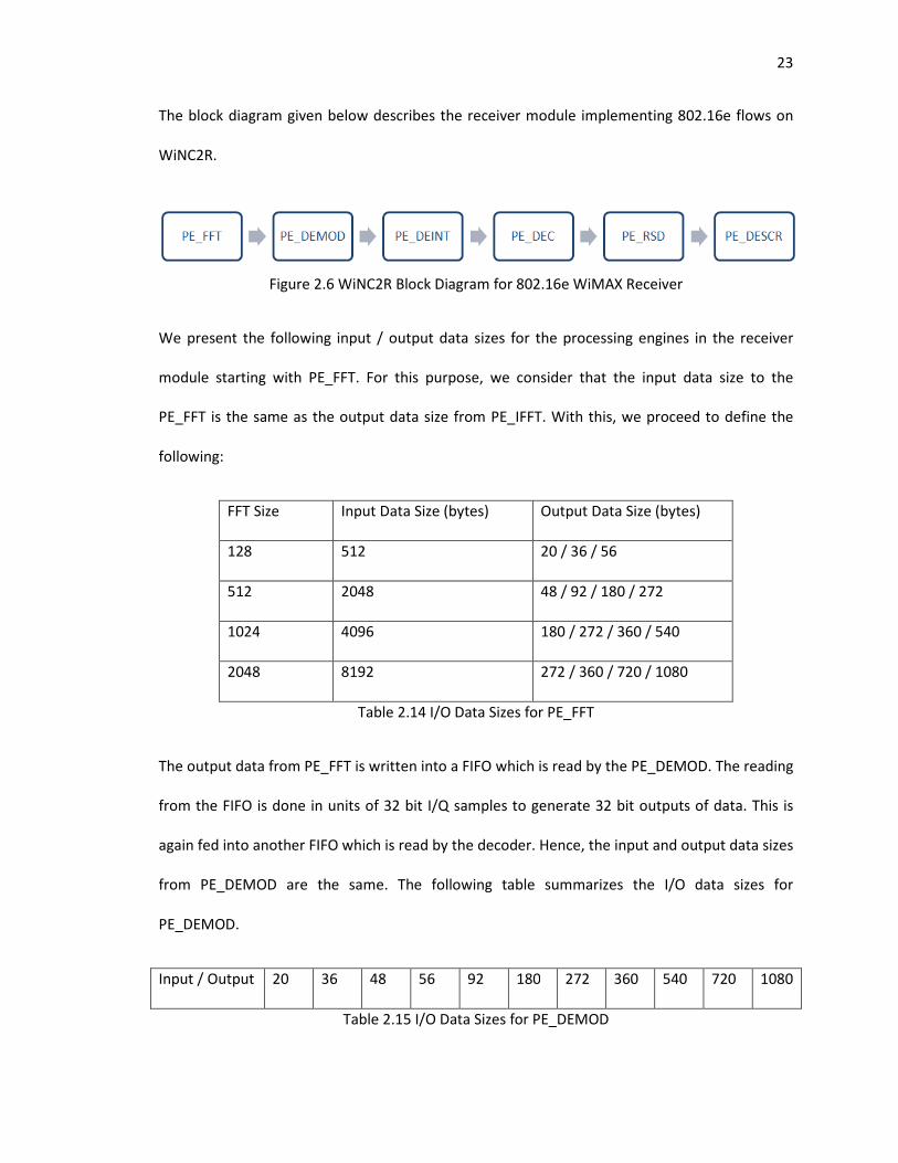
The block diagram given below describes the receiver module implementing 802.16e flows on
WiNC2R.
Figure 2.6 WiNC2R Block Diagram for 802.16e WiMAX Receiver
We present the following input / output data sizes for the processing engines in the receiver
module starting with PE_FFT. For this purpose, we consider that the input data size to the
PE_FFT is the same as the output data size from PE_IFFT. With this, we proceed to define the
following:
FFT Size Input Data Size (bytes) Output Data Size (bytes)
128 512 20 / 36 / 56
512 2048 48 / 92 / 180 / 272
1024 4096 180 / 272 / 360 / 540
2048 8192 272 / 360 / 720 / 1080
Table 2.14 I/O Data Sizes for PE_FFT
The output data from PE_FFT is written into a FIFO which is read by the PE_DEMOD. The reading
from the FIFO is done in units of 32 bit I/Q samples to generate 32 bit outputs of data. This is
again fed into another FIFO which is read by the decoder. Hence, the input and output data sizes
from PE_DEMOD are the same. The following table summarizes the I/O data sizes for
PE_DEMOD.
Input / Output 20 36 48 56 92 180 272 360 540 720 1080
Table 2.15 I/O Data Sizes for PE_DEMOD
24
The processing engine De-interleaver PE_DEINT reads the data from this buffer in sizes as
required by the data sizes. PE_DEINT rearranges the interleaved data sequentially to produce
the output.
The following table summarizes the I/O data sizes for de-interleaver.
Input / Output 18 36 45 54 90 180 270 360 540 720 1080
Table 2.16 I/O Data Sizes for PE_DEINT
These sets of data are now read by the decoder - PE_DEC which inverts the operation of
encoding to provide the outputs to the Reed Solomon decoder.
The following set of tables defines the I/O data sizes for different coding rates.
I. Coding Rate = 1/2
Input 45 90 180
Output 23 45 90
Table 2.17(a) I/O Data Sizes for PE_DEC
II. Coding Rate = 2/3
Input 18 36 90 180 360 720
Output 12 24 60 120 240 480
Table 2.17(b) I/O Data Sizes for PE_DEC
III. Coding Rate = 3/4
Input 54 270 540 1080
Output 41 203 405 810
Table 2.17(c) I/O Data Sizes for PE_DEC
25
IV. Coding Rate = 5/6
Input 18 36 54 90 180 270 360 540 720 1080
Output 16 30 45 75 150 225 300 450 600 900
Table 2.17(d) I/O Data Sizes for PE_DEC
The Reed Solomon decoder PE_RSD reads the data from the PE_DEC and to perform Reed
Solomon decoding and provide the output to the descrambler PE_DSCR.
The following tables outline the I/O data sizes for PE_RSD.
I. Coding Rate = 1
Input / Output 23 45 90
Table 2.18(a) I/O Data Sizes for PE_RSD
II. Coding Rate = 3/4
Input 12 24 60 120 240 480
Output 9 18 45 90 180 360
Table 2.18(b) I/O Data Sizes for PE_RSD
III. Coding Rate = 8/9
Input 41 203 405 810
Output 36 180 360 720
Table 2.18(c) I/O Data Sizes for PE_RSD
IV. Coding Rate = 9/10
Input 15 30 45 75 150 225 300 450 600 900
Output 14 27 41 68 135 203 270 405 540 810
Table 2.18(d) I/O Data Sizes for PE_RSD
26
The final stage in the receiver module for WiMAX processing is descrambling. PE_DSCR
implements this function. The input and the output data sizes are the same, since the
descrambler does not add / decode any bits. The following table summarizes the I/O sizes for
PE_DSCR:
Input /
Output
9 14 18 23 27 36 41 45 68 90
132 180 203 270 360 405 540 720 810 -
Table 2.19 I/O Data Sizes for PE_DSCR
This data from PE_DSCR is now read by the MAC processing engine of the receiver side.
2.8. WiNC2R Programming Model for 802.16e WiMAX
In this section, we unify the protocol aspects of 802.16e with our proposed implementation of
the 802.16e standard on the WiNC2R platform, by defining the WiNC2R programming model for
WiMAX flows.
From the preceding sections outlining the OFDMA frame descriptor for the uplink and downlink
frames, we have identified three different types of task flows which need to be supported by
WiNC2R, based on the properties of the MAC PDUs:
1. PDUs with Payload
2. PDUs without Payload
3. Fragmentation
In the following sections, we describe the above flows in detail, along with the proposed
programming model.
27
I. PDUs with Payload:
This type of flow consists of generic data, management MAC PDUs and Preamble messages with
a header and a payload.
• Generic DL/UL data MAC PDUs consist of a header and a payload consisting of Service
Data Units (SDU) from the upper layers. These are transmitted on data connections.
• Management MAC PDUs consist of a header and a payload of MAC management
messages or IP packets. These are transmitted on management connections.
• Preamble messages can also be treated as a type of management message. However,
they are always BPSK modulated with a coding rate of 1/2.
WiNC2R supports two kinds of tasks to provision protocol flows – Synchronous (Sync) tasks and
Asynchronous (Async) tasks. Sync tasks have deterministic guarantees of scheduling, activation
and rescheduling (if necessary). Asynchronous tasks have statistical guarantees like best effort
policy.
Since each downlink frame begins with a preamble, the preamble tasks can be programmed as
Sync tasks. To ensure the protocol guarantees, the preamble should adhere to a BPSK
modulation scheme with a coding rate 1/2.
Management PDUs like the DL-MAP and the UL-MAP immediately need to follow the Frame
Control Header (FCH) in succession. Thus, the next task after the FCH transmission is the Sync
task for DL-MAP and the one after DL_MAP transmission is UL_MAP.
The generic downlink / uplink data frames which follow the preamble and the management
tasks can be programmed as Async tasks. The justification for programming these as Async tasks
28
is that the BS / SS get to transmit their data frames only during a pre-decided window and hence
require a basic best-effort scheduling policy.
Also, judicial use of Sync tasks results in better utilization of the VFP controller and improved
system performance.
II. PDUs without Payload:
This type of flow deals with PDUs consisting of just the header and no payload. Frame Control
Headers (FCH) and the bandwidth / ranging request messages fall in this category of flows. FCH
messages are transmitted immediately after the preamble and hence need to be programmed
as Sync tasks, which get activated at the end of preamble transmission.
Bandwidth / ranging request messages are sent by SS during the uplink sub-frame. Since these
are continually transmitted over the ranging sub-channel, these can be programmed as Aync
tasks.
III. Fragmentation and Packing:
Fragmentation is a feature supported by the 802.16e WiMAX standard, which allows data
frames to be fragmented into smaller portions. Packing is a feature of combination of multiple
data units into one payload. Fragmentation and Packing are direct use cases of WiNC2R’s
chunking and de-chunking features respectively. Since chunking and de-chunking are supported
only by Sync tasks, all fragmentation flows are implemented as Sync tasks at the processing
engine initiating chunking / de-chunking.
The BS / SS implements the fragmentation tasks as chunking tasks. When a stream of input data
is given to the processing engines of the transmitter for chunking, beginning with PE_HDR, each
processing engine treats each piece of chunk as an individual task, ensuing fragmentation.
29
This is achieved by setting the chunk flag and first chunk flag to 1 at PE_MAC or PE_HDR
depending on performance requirements. It can be noted that the remaining PEs can process
the tasks as Sync or Async depending on protocol and performance requirements.
The number of chunks is determined by the fragmentation size as well as the required data rate.
Chunking is defined by the chunk size and the first chunk size parameters, which are set by the
programmer. We define the methodology for chunk size calculation in later sections.
Packing is implemented as a de-chunking task. By setting the de-chunk flag to 1 at the
processing engine PE_MAC, the engine processing its next tasks (PE_HDR) will collate all the
fragments of data (chunks) and will begin processing them only after the last chunk is obtained.
This means that the function of adding a header to the data payload is done only when all the
portions of the fragments are collected together.
30
Chapter 3 – Functional Verification of the VFP Controller
Functional verification is the task of verifying if the logic design conforms to the design
specifications. Functional verification, popularly known as ‘Pre-silicon verification’, is done using
a software environment, before the design is produced in Silicon.
Studies have shown that a majority of product failures and recalls are owing to logic bugs in the
design. From a business perspective, costs of a manufacturing setup to produce a design are
high and modifications owing to bugs add significant time and cost overheads. Hence, functional
verification accounts for almost three-fourths of a product design cycle of modern ICs.
The modern design and fabrication tools allow the designers to work on the design at a register
transfer level (RTL) abstraction. RTL designs are built using a Hardware Description Language
(HDL) like Verilog HDL. The syntax and semantics of modern HDLs to design hardware
components are similar to the popular procedural programming languages. Hence, pre-silicon
verification environments, popularly known as ‘Testbench’ are in the software domain.
3.1. Functional Verification of WiNC2R:
Drawing from the significance and merits of functional verification from the preceding section,
the importance of WiNC2R architecture verification becomes evident. The VFP Controller forms
the backbone of the WiNC2R architecture, which is responsible for the scheduling of the task
based model to implement wireless protocol flows. The VFP controller design has been
implemented using SystemVerilog Hardware Description Language. In this chapter, we cover the
functional verification of specific functionalities of the VFP controller, required for 802.16e
WiMAX implementation.
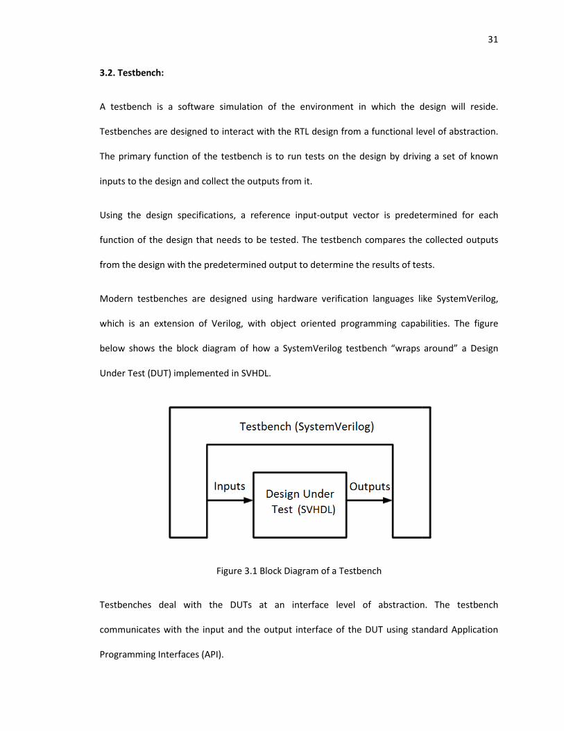
3.2. Testbench:
A testbench is a software simulation of the environment in which the design will reside.
Testbenches are designed to interact with the RTL design from a functional level of abstraction.
The primary function of the testbench is to run tests on the design by
inputs to the design and collect the outputs from it.
Using the design specifications, a reference input
function of the design that needs to be tested. The testbench compares the collected o
from the design with the predetermined output to determine the results of tests.
Modern testbenches are designed using
which is an extension of Verilog, with object oriented programming capabilitie
below shows the block diagram of how a SystemVerilog testbench “wraps around” a Design
Under Test (DUT) implemented in
Testbenches deal with the DUTs at an interface level of abstraction. The
communicates with the input and the output interface of the DUT using standard Application
Programming Interfaces (API).
A testbench is a software simulation of the environment in which the design will reside.
Testbenches are designed to interact with the RTL design from a functional level of abstraction.
The primary function of the testbench is to run tests on the design by driving a set of known
inputs to the design and collect the outputs from it.
Using the design specifications, a reference input-output vector is predetermined for each
function of the design that needs to be tested. The testbench compares the collected o
from the design with the predetermined output to determine the results of tests.
Modern testbenches are designed using hardware verification languages like SystemVerilog,
is an extension of Verilog, with object oriented programming capabilitie
below shows the block diagram of how a SystemVerilog testbench “wraps around” a Design
Under Test (DUT) implemented in SVHDL.
Figure 3.1 Block Diagram of a Testbench
Testbenches deal with the DUTs at an interface level of abstraction. The
communicates with the input and the output interface of the DUT using standard Application
Programming Interfaces (API).
31
A testbench is a software simulation of the environment in which the design will reside.
Testbenches are designed to interact with the RTL design from a functional level of abstraction.
driving a set of known
output vector is predetermined for each
function of the design that needs to be tested. The testbench compares the collected outputs
from the design with the predetermined output to determine the results of tests.
languages like SystemVerilog,
is an extension of Verilog, with object oriented programming capabilities. The figure
below shows the block diagram of how a SystemVerilog testbench “wraps around” a Design
Testbenches deal with the DUTs at an interface level of abstraction. The testbench
communicates with the input and the output interface of the DUT using standard Application
32
The components of the testbench which thus communicate with the DUT are called Bus
Functional Models (BFM). These components are designed to drive and read transactions to the
DUT interface, based on the BUS protocol.
3.3. WiNC2R Testbench:
A SystemVerilog testbench based on Open Verification Methodology (OVM) principles has been
built for WiNC2R [14]. OVM is an open-source verification methodology, which provides a
standard library of SystemVerilog classes to build verification environments. OVM is based on a
transaction level model, which allows the testbench components to encapsulate input / output
signals and data into discrete transactions.
The focus of this thesis is to identify, design and implement test cases for the functional
verification of the VFP controller using our testbench. We have identified the features to be
tested by first identifying the specific requirements of the Mobile WiMAX protocol, followed by
mapping the requirements to the VFP controller functions.
3.4. Requirements for 802.16e Mobile WiMAX Protocol Implementation:
IEEE 802.16e WiMAX is a complex wireless protocol, catering to a diverse range of applications.
It hence has very strict requirements which need to be met for its efficient implementation. We
have identified the following requirements, based on our study of the protocol:
i. Scheduling Requirements: Mobile WiMAX protocol supports duplexing schemes of
communication between the base station and the subscriber stations. For the Time
Division Duplex (TDD) case that we have considered, it is critical to meet the timing
and scheduling requirements of the control and the data MAC PDUs.
33
The VFP controller is the unit which handles the scheduling and activation of the
tasks in the functional units by following a discrete set of procedures. These set of
procedures constitute to the functionality called ‘Next Task Processing’.
ii. Fragmentation and Packing: Mobile WiMAX supports two modes of packing the
MAC Service Data Units (SDU) into the MAC PDU payload. Fragmentation is the
process of division of a single SDU into one or more fragments. Packing is the
process of combination of one or more MAC SDUs into a single payload. These
features are supported by WiMAX protocol to:
a. Improve the efficiency of data transmission
b. Provide flexibility for different run-time conditions
The WiNC2R architecture provides inherent support for fragmentation and packing
with features known as ‘Chunking’ and ‘De-chunking’ respectively.
Chunking involves splitting of input data into one or more smaller chunks and
processing them as individual units of data. De-chunking is the process of
recombination of all the chunks of data to be processed as a single unit of data.
In the following sections, we address each of the above features of the VFP controller in detail,
along with our functional verification test plans, implementation, results and analysis of each
feature.
3.5. Next Task Processing
A protocol flow is implemented as a sequence of tasks
processing engines in the flow. The VFP controller schedules and activates tasks in the
processing engines based on the
with a VFP controller and a set of functional u
provision protocol flows. This is done by loading the internal memories of the VFP controller and
the functional units with the required task parameters.
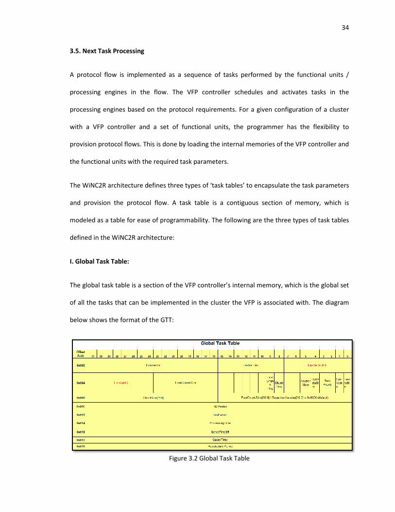
The WiNC2R architecture defines three types of ‘task tabl
and provision the protocol flow. A task table is a contiguous section of memory, which is
modeled as a table for ease of programmability. The following are the three types of task tables
defined in the WiNC2R architec
I. Global Task Table:
The global task table is a section of the VFP controller’s internal memory, which is the global set
of all the tasks that can be implemented in the cluster
below shows the format of the GT
A protocol flow is implemented as a sequence of tasks performed by the functional units /
processing engines in the flow. The VFP controller schedules and activates tasks in the
processing engines based on the protocol requirements. For a given configuration of a cluster
with a VFP controller and a set of functional units, the programmer has the flexibility to
provision protocol flows. This is done by loading the internal memories of the VFP controller and
the functional units with the required task parameters.
The WiNC2R architecture defines three types of ‘task tables’ to encapsulate the task parameters
and provision the protocol flow. A task table is a contiguous section of memory, which is
modeled as a table for ease of programmability. The following are the three types of task tables
defined in the WiNC2R architecture:
The global task table is a section of the VFP controller’s internal memory, which is the global set
of all the tasks that can be implemented in the cluster the VFP is associated with
below shows the format of the GTT:
Figure 3.2 Global Task Table
34
by the functional units /
processing engines in the flow. The VFP controller schedules and activates tasks in the
protocol requirements. For a given configuration of a cluster
nits, the programmer has the flexibility to
provision protocol flows. This is done by loading the internal memories of the VFP controller and
es’ to encapsulate the task parameters
and provision the protocol flow. A task table is a contiguous section of memory, which is
modeled as a table for ease of programmability. The following are the three types of task tables
The global task table is a section of the VFP controller’s internal memory, which is the global set
the VFP is associated with. The diagram
Each task is granted 32 bytes of memory location, within which all the task related parameters
are loaded. The GTT provides information about the runtime parameters of each task, which is
used by the VFP controller to sched
Pointer is the unique identifier for each task. This is the pointer to the ‘Task Descriptor Table’
memory location of the functional unit, where the execution details of this specific task are
stored.
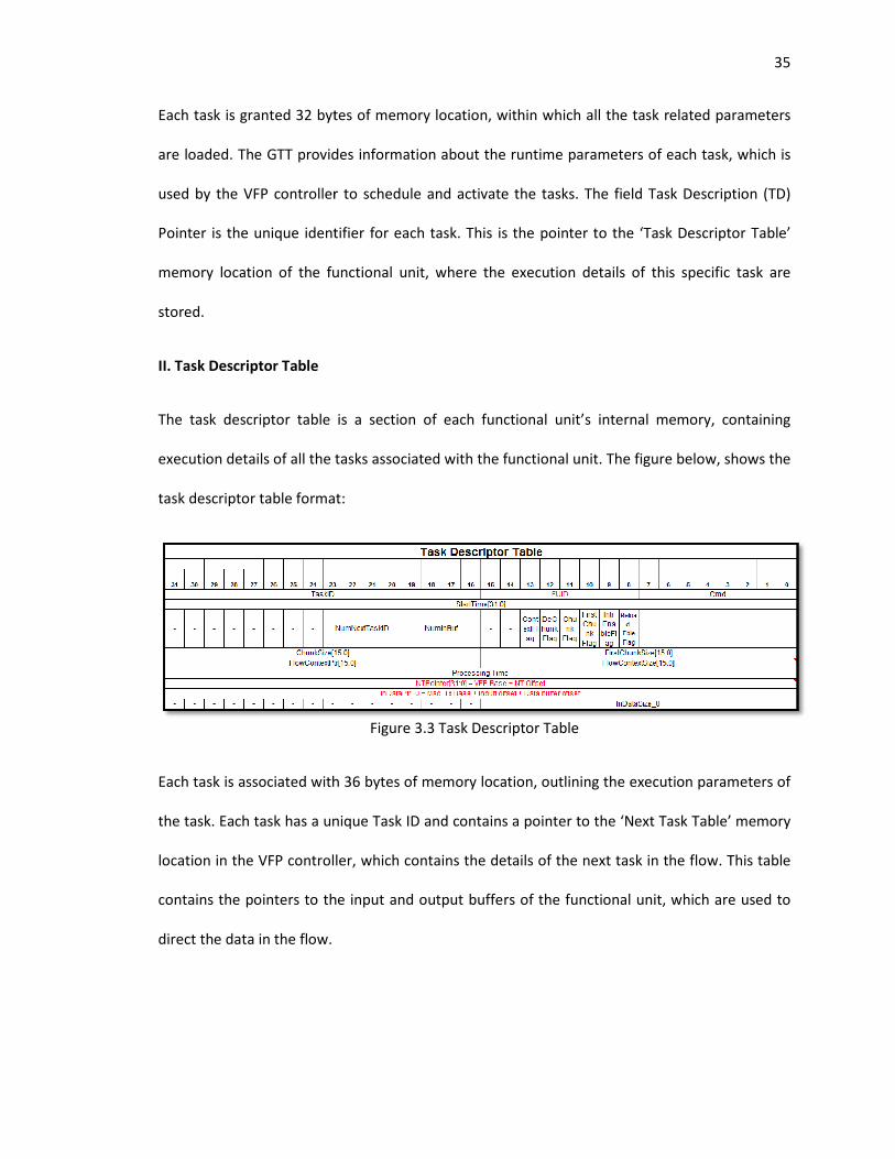
II. Task Descriptor Table
The task descriptor table is a section of each functional unit’s internal memory, containing
execution details of all the tasks associated with the functional unit.
task descriptor table format:
Each task is associated with 36 bytes of memory location, outlining the execution parameters of
the task. Each task has a unique Task ID and contains a pointer to the ‘Next Task Table’ memory
location in the VFP controller,
contains the pointers to the input and output buffers of the functional unit, which are used to
direct the data in the flow.
Each task is granted 32 bytes of memory location, within which all the task related parameters
are loaded. The GTT provides information about the runtime parameters of each task, which is
used by the VFP controller to schedule and activate the tasks. The field Task Description (TD)
Pointer is the unique identifier for each task. This is the pointer to the ‘Task Descriptor Table’
memory location of the functional unit, where the execution details of this specific task are
task descriptor table is a section of each functional unit’s internal memory, containing
execution details of all the tasks associated with the functional unit. The figure below, shows the
task descriptor table format:
Figure 3.3 Task Descriptor Table
Each task is associated with 36 bytes of memory location, outlining the execution parameters of
the task. Each task has a unique Task ID and contains a pointer to the ‘Next Task Table’ memory
location in the VFP controller, which contains the details of the next task in the flow. This table
contains the pointers to the input and output buffers of the functional unit, which are used to
35
Each task is granted 32 bytes of memory location, within which all the task related parameters
are loaded. The GTT provides information about the runtime parameters of each task, which is
ule and activate the tasks. The field Task Description (TD)
Pointer is the unique identifier for each task. This is the pointer to the ‘Task Descriptor Table’
memory location of the functional unit, where the execution details of this specific task are
task descriptor table is a section of each functional unit’s internal memory, containing
The figure below, shows the
Each task is associated with 36 bytes of memory location, outlining the execution parameters of
the task. Each task has a unique Task ID and contains a pointer to the ‘Next Task Table’ memory
which contains the details of the next task in the flow. This table
contains the pointers to the input and output buffers of the functional unit, which are used to
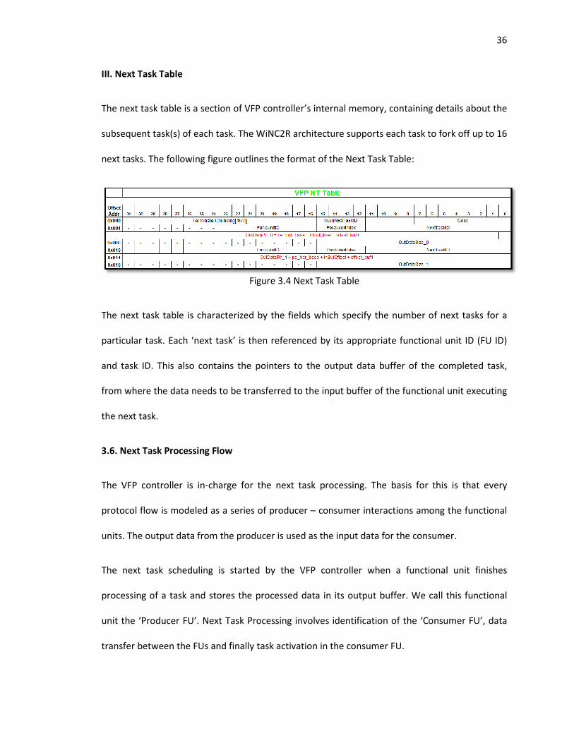
III. Next Task Table
The next task table is a section of VFP
subsequent task(s) of each task. The WiNC2R architecture supports each task to fork off up to 16
next tasks. The following figure outlines the format of the Next Task Table:
The next task table is characterized by the fields which specify the number of next tasks for a
particular task. Each ‘next task’ is then referenced by its appropriate functional unit ID (FU ID)
and task ID. This also contains the pointers to the outp
from where the data needs to be transferred to the input buffer of the functional unit
the next task.
3.6. Next Task Processing Flow
The VFP controller is in-charge for the next task processing.
protocol flow is modeled as a series of producer
units. The output data from the producer is used as the input data for the consumer.
The next task scheduling is started by the VFP controller
processing of a task and stores the processed data in its
unit the ‘Producer FU’. Next Task Processing involves identification of the ‘Consumer FU’, data
transfer between the FUs and f
The next task table is a section of VFP controller’s internal memory, containing
subsequent task(s) of each task. The WiNC2R architecture supports each task to fork off up to 16
next tasks. The following figure outlines the format of the Next Task Table:
Figure 3.4 Next Task Table
The next task table is characterized by the fields which specify the number of next tasks for a
particular task. Each ‘next task’ is then referenced by its appropriate functional unit ID (FU ID)
and task ID. This also contains the pointers to the output data buffer of the completed task,
from where the data needs to be transferred to the input buffer of the functional unit
Next Task Processing Flow
charge for the next task processing. The basis for
protocol flow is modeled as a series of producer – consumer interactions among the functional
units. The output data from the producer is used as the input data for the consumer.
The next task scheduling is started by the VFP controller when a functional unit
stores the processed data in its output buffer. We call this functional
unit the ‘Producer FU’. Next Task Processing involves identification of the ‘Consumer FU’, data
transfer between the FUs and finally task activation in the consumer FU.
36
controller’s internal memory, containing details about the
subsequent task(s) of each task. The WiNC2R architecture supports each task to fork off up to 16
The next task table is characterized by the fields which specify the number of next tasks for a
particular task. Each ‘next task’ is then referenced by its appropriate functional unit ID (FU ID)
ut data buffer of the completed task,
from where the data needs to be transferred to the input buffer of the functional unit executing
this is that every
consumer interactions among the functional
units. The output data from the producer is used as the input data for the consumer.
a functional unit finishes
We call this functional
unit the ‘Producer FU’. Next Task Processing involves identification of the ‘Consumer FU’, data
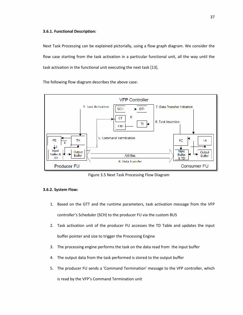
3.6.1. Functional Description:
Next Task Processing can be explained pictorially, using a flow graph diagram. We consider the
flow case starting from the task activation in a particular functional unit, all the wa
task activation in the functional
The following flow diagram describes the above case:
Figure 3.5 Next Task Processing Flow Diagram
3.6.2. System Flow:
1. Based on the GTT and the runtime parameters, t
controller’s Scheduler (SCH)
2. Task activation unit of the producer FU accesses the TD Table and updates the input
buffer pointer and size to trigger the Processing Engine
3. The processing engine
4. The output data from the task performed is stored to the output buffer
5. The producer FU sends a ‘Command Termination’ message to the VFP controller, which
is read by the VFP’s Command Termination un
Functional Description:
Next Task Processing can be explained pictorially, using a flow graph diagram. We consider the
flow case starting from the task activation in a particular functional unit, all the wa
task activation in the functional unit executing the next task [13].
The following flow diagram describes the above case:
Figure 3.5 Next Task Processing Flow Diagram
Based on the GTT and the runtime parameters, task activation message from the VFP
’s Scheduler (SCH) to the producer FU via the custom BUS
Task activation unit of the producer FU accesses the TD Table and updates the input
buffer pointer and size to trigger the Processing Engine
The processing engine performs the task on the data read from the input buffer
The output data from the task performed is stored to the output buffer
The producer FU sends a ‘Command Termination’ message to the VFP controller, which
is read by the VFP’s Command Termination unit
37
Next Task Processing can be explained pictorially, using a flow graph diagram. We consider the
flow case starting from the task activation in a particular functional unit, all the way until the
ation message from the VFP
Task activation unit of the producer FU accesses the TD Table and updates the input
performs the task on the data read from the input buffer
The output data from the task performed is stored to the output buffer
The producer FU sends a ‘Command Termination’ message to the VFP controller, which
38
6. VFP’s Consumer Identification (CID) unit accesses the Next Task Table to determine the
consumer FU that needs to execute the next task and sends a message to the VFP’s Data
Transfer Initiator (DTI) unit
7. The DTI unit sends a message to the identified consumer FU to initiate data transfer
from the producer FU
8. The consumer FU’s DMA engine initiates a transfer of data from the output buffer of the
producer FU to the input buffer of the consumer FU over the AXI BUS
9. Consumer FU signals to the VFP, the completion of data transfer, upon which the VFP’s
Task Inserter (TI) unit inserts the task into the consumer FU’s internal task queue
The whole process now repeats with the ‘consumer FU’ becoming the ‘producer FU’ for the next
task and the VFP’s scheduler activating the task in this FU, based on the GTT and the runtime
parameters.
3.6.3. Functional Tests:
As described in the preceding section, the next task processing feature is implemented by the
VFP controller block. Next Task Processing is a combination of the functionalities of the
Scheduler, Command Termination block, Consumer Identification block, Data Transfer Initiator
block and the Task Inserter block. The basis for the functionality of these blocks is defined by the
programmer using the GTT, NTT and the TD tables.
Hence, next task processing is a complex feature to test. In order to approach the problem from
a higher level of abstraction, we aim to verify this feature treating the VFP controller as a black
box. This means that our tests look at the combined results of all the steps described in the flow,
rather than each individual step. We describe our test plan in the following section.
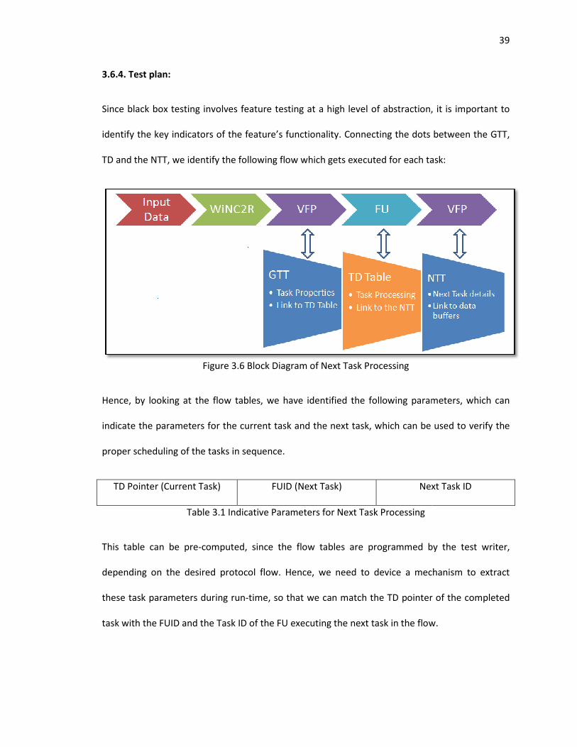
3.6.4. Test plan:
Since black box testing involves feature testing at a high level of abstraction, it is important to
identify the key indicators of the feature’s functionality.
TD and the NTT, we identify the following flow which gets e
Figure 3.6 Block Diagram of Next Task Processing
Hence, by looking at the flow tables, we have identified the following parameters, which can
indicate the parameters for the current task and the next task, which can be used to verif
proper scheduling of the tasks in sequence.
TD Pointer (Current Task)
Table 3.1 Indicative Parameters for Next Task Processing
This table can be pre-computed, since the flow tables are programmed by the test writer,
depending on the desired protocol flow. Hence, we need to device a mechanism to extract
these task parameters during run
task with the FUID and the Task ID of the FU executing the next task in the flow.
Since black box testing involves feature testing at a high level of abstraction, it is important to
identify the key indicators of the feature’s functionality. Connecting the dots between the GTT,
TD and the NTT, we identify the following flow which gets executed for each task:
Figure 3.6 Block Diagram of Next Task Processing
Hence, by looking at the flow tables, we have identified the following parameters, which can
indicate the parameters for the current task and the next task, which can be used to verif
proper scheduling of the tasks in sequence.
TD Pointer (Current Task) FUID (Next Task) Next Task ID
Table 3.1 Indicative Parameters for Next Task Processing
computed, since the flow tables are programmed by the test writer,
depending on the desired protocol flow. Hence, we need to device a mechanism to extract
task parameters during run-time, so that we can match the TD pointer of t
task with the FUID and the Task ID of the FU executing the next task in the flow.
39
Since black box testing involves feature testing at a high level of abstraction, it is important to
Connecting the dots between the GTT,
xecuted for each task:
Hence, by looking at the flow tables, we have identified the following parameters, which can
indicate the parameters for the current task and the next task, which can be used to verify the
Next Task ID
computed, since the flow tables are programmed by the test writer,
depending on the desired protocol flow. Hence, we need to device a mechanism to extract
time, so that we can match the TD pointer of the completed
task with the FUID and the Task ID of the FU executing the next task in the flow.
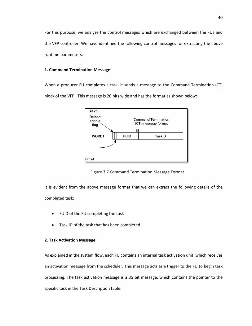
For this purpose, we analyze the control messages which are exchanged between the FUs and
the VFP controller. We have identified the
runtime parameters:
1. Command Termination Message:
When a producer FU completes a task, it sends a message to the Command Termination (CT)
block of the VFP. This message is 26 bits wide and has the format as shown below:
Figur
It is evident from the above message format that we can extract the following details of the
completed task:
• FUID of the FU completing the task
• Task ID of the task that has been completed
2. Task Activation Message
As explained in the system flow, each FU contains an internal task activation unit, which receives
an activation message from the scheduler. This message acts as a trigger to the FU to begin task
processing. The task activation message is a 35 bit message,
specific task in the Task Description table.
we analyze the control messages which are exchanged between the FUs and
the VFP controller. We have identified the following control messages for extracting
1. Command Termination Message:
When a producer FU completes a task, it sends a message to the Command Termination (CT)
block of the VFP. This message is 26 bits wide and has the format as shown below:
Figure 3.7 Command Termination Message Format
It is evident from the above message format that we can extract the following details of the
FUID of the FU completing the task
Task ID of the task that has been completed
2. Task Activation Message
As explained in the system flow, each FU contains an internal task activation unit, which receives
an activation message from the scheduler. This message acts as a trigger to the FU to begin task
processing. The task activation message is a 35 bit message, which contains the pointer to the
specific task in the Task Description table.
40
we analyze the control messages which are exchanged between the FUs and
extracting the above
When a producer FU completes a task, it sends a message to the Command Termination (CT)
block of the VFP. This message is 26 bits wide and has the format as shown below:
It is evident from the above message format that we can extract the following details of the
As explained in the system flow, each FU contains an internal task activation unit, which receives
an activation message from the scheduler. This message acts as a trigger to the FU to begin task
which contains the pointer to the
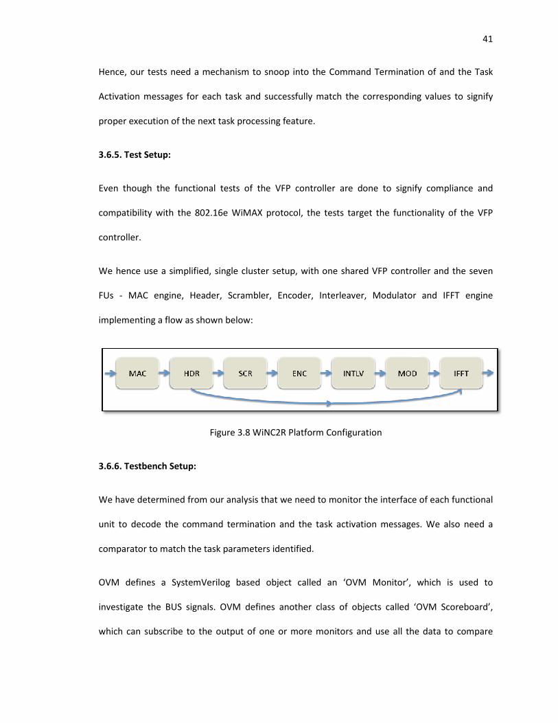
Hence, our tests need a mechanism to snoop into the Command Termination
Activation messages for each task and successfully match the corresponding values to sig
proper execution of the next task processing feature.
3.6.5. Test Setup:
Even though the functional tests of the VFP controller are done to signify compliance and
compatibility with the 802.16e WiMAX protocol, the tests target the functionality of the VFP
controller.
We hence use a simplified, single cluster setup, with one sh
FUs - MAC engine, Header, Scrambler, Encoder, Interleaver, Modulator and IFFT engine
implementing a flow as shown below:
3.6.6. Testbench Setup:
We have determined from our analysis that we need to monitor the interface of each functional
unit to decode the command termination and the task activation messages. We also need a
comparator to match the task parameters identified.
OVM defines a SystemVerilog based object called an ‘OVM Monitor’, which is used to
investigate the BUS signals. OVM defines another class of objects called ‘OVM Scoreboard’,
which can subscribe to the output of one or more monitors and use all the data to compare
Hence, our tests need a mechanism to snoop into the Command Termination
Activation messages for each task and successfully match the corresponding values to sig
proper execution of the next task processing feature.
Even though the functional tests of the VFP controller are done to signify compliance and
compatibility with the 802.16e WiMAX protocol, the tests target the functionality of the VFP
We hence use a simplified, single cluster setup, with one shared VFP controller and the seven
MAC engine, Header, Scrambler, Encoder, Interleaver, Modulator and IFFT engine
implementing a flow as shown below:
Figure 3.8 WiNC2R Platform Configuration
We have determined from our analysis that we need to monitor the interface of each functional
unit to decode the command termination and the task activation messages. We also need a
comparator to match the task parameters identified.
erilog based object called an ‘OVM Monitor’, which is used to
investigate the BUS signals. OVM defines another class of objects called ‘OVM Scoreboard’,
which can subscribe to the output of one or more monitors and use all the data to compare
41
Hence, our tests need a mechanism to snoop into the Command Termination of and the Task
Activation messages for each task and successfully match the corresponding values to signify
Even though the functional tests of the VFP controller are done to signify compliance and
compatibility with the 802.16e WiMAX protocol, the tests target the functionality of the VFP
VFP controller and the seven
MAC engine, Header, Scrambler, Encoder, Interleaver, Modulator and IFFT engine
We have determined from our analysis that we need to monitor the interface of each functional
unit to decode the command termination and the task activation messages. We also need a
erilog based object called an ‘OVM Monitor’, which is used to
investigate the BUS signals. OVM defines another class of objects called ‘OVM Scoreboard’,
which can subscribe to the output of one or more monitors and use all the data to compare
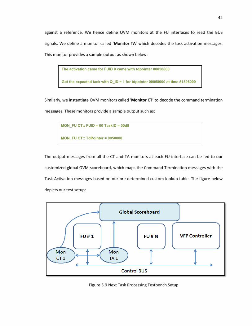
against a reference. We hence define OVM monitors at the FU interfaces to read the BUS
signals. We define a monitor
This monitor provides a sample output as shown below:
Similarly, we instantiate OVM monitors
messages. These monitors provide a sample output such as:
The output messages from
customized global OVM scoreboard, which maps the Command Termination messages with the
Task Activation messages based on
depicts our test setup:
Figure 3.9 Next Task Processing Testbench Setup
The activation came for FUID 0 came with tdpointer 00058000
Got the expected task with Q_ID = 1 for tdpointer 00058000 at time 51595000
MON_FU CT:: FUID = 00 TaskID = 00d8
MON_FU CT:: TdPointer = 0058000
We hence define OVM monitors at the FU interfaces to read the BUS
signals. We define a monitor called ‘Monitor TA’ which decodes the task activation messages.
This monitor provides a sample output as shown below:
Similarly, we instantiate OVM monitors called ‘Monitor CT’ to decode the comm
monitors provide a sample output such as:
The output messages from all the CT and TA monitors at each FU interface
scoreboard, which maps the Command Termination messages with the
Task Activation messages based on our pre-determined custom lookup table.
Figure 3.9 Next Task Processing Testbench Setup
The activation came for FUID 0 came with tdpointer 00058000
Got the expected task with Q_ID = 1 for tdpointer 00058000 at time 51595000
MON_FU CT:: FUID = 00 TaskID = 00d8
MON_FU CT:: TdPointer = 0058000
42
We hence define OVM monitors at the FU interfaces to read the BUS
’ which decodes the task activation messages.
to decode the command termination
at each FU interface can be fed to our
scoreboard, which maps the Command Termination messages with the
determined custom lookup table. The figure below
Got the expected task with Q_ID = 1 for tdpointer 00058000 at time 51595000
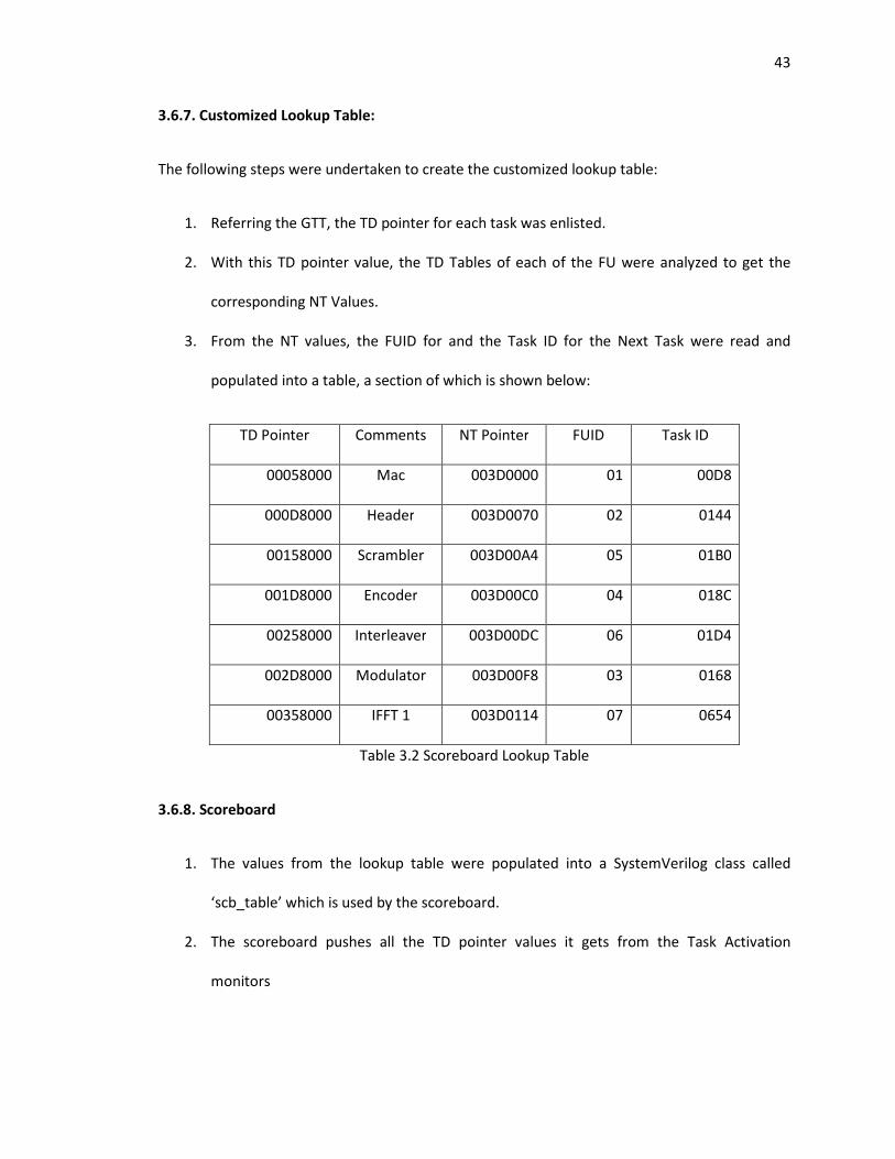
43
3.6.7. Customized Lookup Table:
The following steps were undertaken to create the customized lookup table:
1. Referring the GTT, the TD pointer for each task was enlisted.
2. With this TD pointer value, the TD Tables of each of the FU were analyzed to get the
corresponding NT Values.
3. From the NT values, the FUID for and the Task ID for the Next Task were read and
populated into a table, a section of which is shown below:
TD Pointer Comments NT Pointer FUID Task ID
00058000 Mac 003D0000 01 00D8
000D8000 Header 003D0070 02 0144
00158000 Scrambler 003D00A4 05 01B0
001D8000 Encoder 003D00C0 04 018C
00258000 Interleaver 003D00DC 06 01D4
002D8000 Modulator 003D00F8 03 0168
00358000 IFFT 1 003D0114 07 0654
Table 3.2 Scoreboard Lookup Table
3.6.8. Scoreboard
1. The values from the lookup table were populated into a SystemVerilog class called
‘scb_table’ which is used by the scoreboard.
2. The scoreboard pushes all the TD pointer values it gets from the Task Activation
monitors
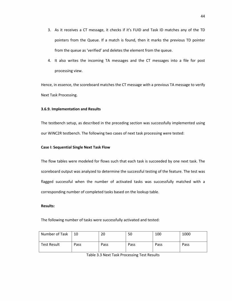
44
3. As it receives a CT message, it checks if it’s FUID and Task ID matches any of the TD
pointers from the Queue. If a match is found, then it marks the previous TD pointer
from the queue as ‘verified’ and deletes the element from the queue.
4. It also writes the incoming TA messages and the CT messages into a file for post
processing view.
Hence, in essence, the scoreboard matches the CT message with a previous TA message to verify
Next Task Processing.
3.6.9. Implementation and Results
The testbench setup, as described in the preceding section was successfully implemented using
our WiNC2R testbench. The following two cases of next task processing were tested:
Case I: Sequential Single Next Task Flow
The flow tables were modeled for flows such that each task is succeeded by one next task. The
scoreboard output was analyzed to determine the successful testing of the feature. The test was
flagged successful when the number of activated tasks was successfully matched with a
corresponding number of completed tasks based on the lookup table.
Results:
The following number of tasks were successfully activated and tested:
Number of Task 10 20 50 100 1000
Test Result Pass Pass Pass Pass Pass
Table 3.3 Next Task Processing Test Results
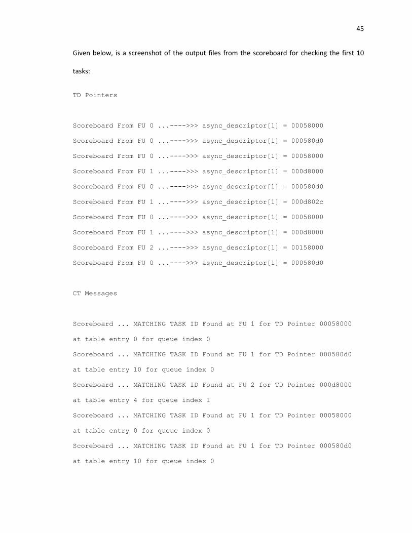
45
Given below, is a screenshot of the output files from the scoreboard for checking the first 10
tasks:
TD Pointers
Scoreboard From FU 0 ...---->>> async_descriptor[1] = 00058000
Scoreboard From FU 0 ...---->>> async_descriptor[1] = 000580d0
Scoreboard From FU 0 ...---->>> async_descriptor[1] = 00058000
Scoreboard From FU 1 ...---->>> async_descriptor[1] = 000d8000
Scoreboard From FU 0 ...---->>> async_descriptor[1] = 000580d0
Scoreboard From FU 1 ...---->>> async_descriptor[1] = 000d802c
Scoreboard From FU 0 ...---->>> async_descriptor[1] = 00058000
Scoreboard From FU 1 ...---->>> async_descriptor[1] = 000d8000
Scoreboard From FU 2 ...---->>> async_descriptor[1] = 00158000
Scoreboard From FU 0 ...---->>> async_descriptor[1] = 000580d0
CT Messages
Scoreboard ... MATCHING TASK ID Found at FU 1 for TD Pointer 00058000
at table entry 0 for queue index 0
Scoreboard ... MATCHING TASK ID Found at FU 1 for TD Pointer 000580d0
at table entry 10 for queue index 0
Scoreboard ... MATCHING TASK ID Found at FU 2 for TD Pointer 000d8000
at table entry 4 for queue index 1
Scoreboard ... MATCHING TASK ID Found at FU 1 for TD Pointer 00058000
at table entry 0 for queue index 0
Scoreboard ... MATCHING TASK ID Found at FU 1 for TD Pointer 000580d0
at table entry 10 for queue index 0
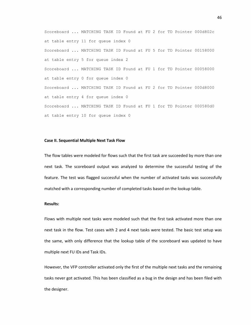
46
Scoreboard ... MATCHING TASK ID Found at FU 2 for TD Pointer 000d802c
at table entry 11 for queue index 0
Scoreboard ... MATCHING TASK ID Found at FU 5 for TD Pointer 00158000
at table entry 5 for queue index 2
Scoreboard ... MATCHING TASK ID Found at FU 1 for TD Pointer 00058000
at table entry 0 for queue index 0
Scoreboard ... MATCHING TASK ID Found at FU 2 for TD Pointer 000d8000
at table entry 4 for queue index 0
Scoreboard ... MATCHING TASK ID Found at FU 1 for TD Pointer 000580d0
at table entry 10 for queue index 0
Case II. Sequential Multiple Next Task Flow
The flow tables were modeled for flows such that the first task are succeeded by more than one
next task. The scoreboard output was analyzed to determine the successful testing of the
feature. The test was flagged successful when the number of activated tasks was successfully
matched with a corresponding number of completed tasks based on the lookup table.
Results:
Flows with multiple next tasks were modeled such that the first task activated more than one
next task in the flow. Test cases with 2 and 4 next tasks were tested. The basic test setup was
the same, with only difference that the lookup table of the scoreboard was updated to have
multiple next FU IDs and Task IDs.
However, the VFP controller activated only the first of the multiple next tasks and the remaining
tasks never got activated. This has been classified as a bug in the design and has been filed with
the designer.
47
3.7. WiNC2R Tasks
The WiNC2R programming model supports two types of tasks in its programming model to
provision the deterministic and statistical guarantees of protocol flows. The two types are:
a. Synchronous Tasks: These are the tasks associated with deterministic guarantees. These
types of tasks are necessary in the programming model to provision the synchronization
in protocols supporting duplexing modes like Time Division Duplexing (TDD).
Synchronous tasks are associated with a parameter called ‘Rescheduling Period’ to
provision their allocation repeatedly after a finite durations of time.
b. Asynchronous Tasks: These tasks are associated with statistical guarantees. These types
of tasks are implemented as ‘best effort policy’ after meeting the processing and
allocation requirements of the synchronous tasks.
A task can be configured as a Synchronous (Sync) task or an Asynchronous (Async) task by
setting the Sync Async flag for the particular task in the GTT to 0 for Sync tasks and to 1 for
Async tasks.
3.8. Chunking
3.8.1. Functional Description:
Chunking is a technique by which the input data to a task is divided into finite number of bytes,
called ‘chunks’, to be processed by the processing engine. All the chunks are processed as
individual tasks. All the remaining processing engines in the flow now treat the output data from
the chunking tasks as individual units of data and process them as separate tasks.
WiNC2R architecture defines that chunking can be enabled only by a synchronous tasks. Hence,
it is not possible to configure an asynchronous task as a chunking task.
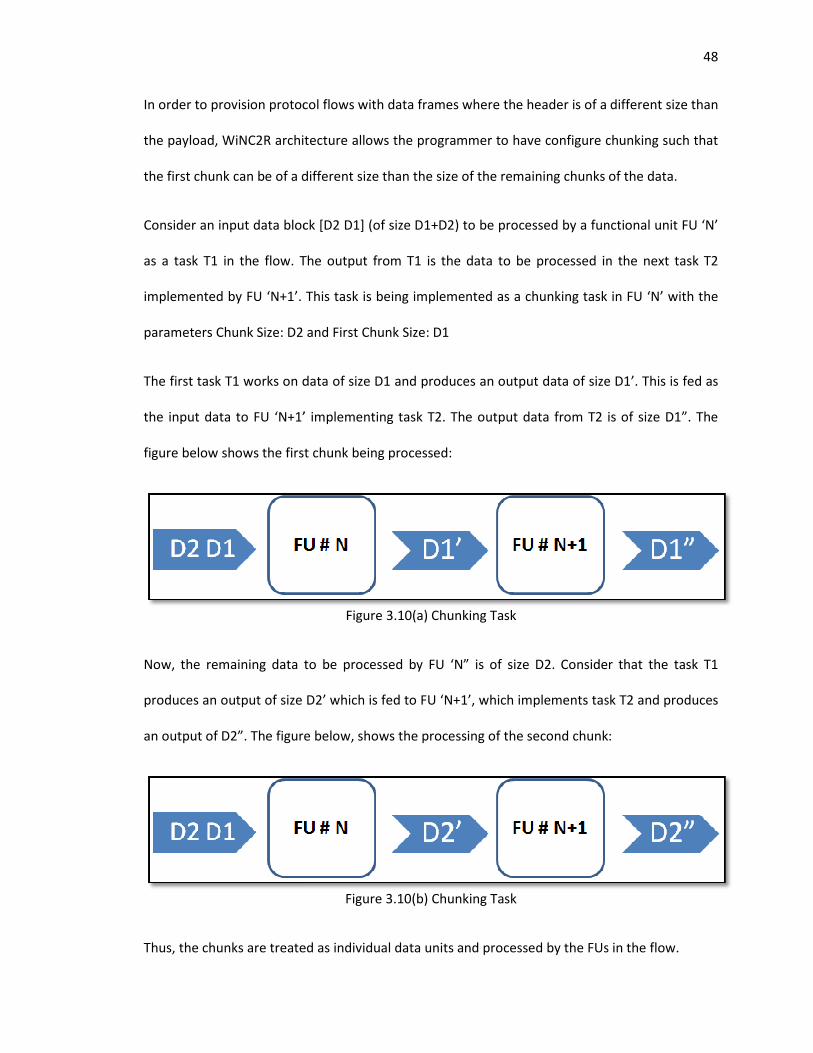
In order to provision protocol flows with data frames where the header is of a different size than
the payload, WiNC2R archi
the first chunk can be of a different size than the size of the remaining chunks of the data.
Consider an input data block [D2 D1] (of size D1+D2) to be processed by a functional unit FU ‘N
as a task T1 in the flow. The output from T1 is the data to be processed in the next task T2
implemented by FU ‘N+1’. This task is being implemented as a chunking task in FU ‘N’ with the
parameters Chunk Size: D2 and First Chunk Size: D1
The first task T1 works on data of size D1 and produces an output data of size D1’. This is fed as
the input data to FU ‘N+1’ implementing task T2. The output data from T2 is of size D1”. The
figure below shows the first chunk being processed:
Now, the remaining data to be processed by FU ‘N” is of size D2. Consider that the task T1
produces an output of size D2’ which is fed to FU ‘N+1’, which implements task T2 and produces
an output of D2”. The figure below, shows the processing of the
Thus, the chunks are treated as individual data units and processed by the FUs in the flow.
In order to provision protocol flows with data frames where the header is of a different size than
the payload, WiNC2R architecture allows the programmer to have configure chunking such that
the first chunk can be of a different size than the size of the remaining chunks of the data.
Consider an input data block [D2 D1] (of size D1+D2) to be processed by a functional unit FU ‘N
as a task T1 in the flow. The output from T1 is the data to be processed in the next task T2
implemented by FU ‘N+1’. This task is being implemented as a chunking task in FU ‘N’ with the
parameters Chunk Size: D2 and First Chunk Size: D1
1 works on data of size D1 and produces an output data of size D1’. This is fed as
the input data to FU ‘N+1’ implementing task T2. The output data from T2 is of size D1”. The
figure below shows the first chunk being processed:
Figure 3.10(a) Chunking Task
Now, the remaining data to be processed by FU ‘N” is of size D2. Consider that the task T1
produces an output of size D2’ which is fed to FU ‘N+1’, which implements task T2 and produces
an output of D2”. The figure below, shows the processing of the second chunk:
Figure 3.10(b) Chunking Task
Thus, the chunks are treated as individual data units and processed by the FUs in the flow.
48
In order to provision protocol flows with data frames where the header is of a different size than
tecture allows the programmer to have configure chunking such that
the first chunk can be of a different size than the size of the remaining chunks of the data.
Consider an input data block [D2 D1] (of size D1+D2) to be processed by a functional unit FU ‘N’
as a task T1 in the flow. The output from T1 is the data to be processed in the next task T2
implemented by FU ‘N+1’. This task is being implemented as a chunking task in FU ‘N’ with the
1 works on data of size D1 and produces an output data of size D1’. This is fed as
the input data to FU ‘N+1’ implementing task T2. The output data from T2 is of size D1”. The
Now, the remaining data to be processed by FU ‘N” is of size D2. Consider that the task T1
produces an output of size D2’ which is fed to FU ‘N+1’, which implements task T2 and produces
second chunk:
Thus, the chunks are treated as individual data units and processed by the FUs in the flow.
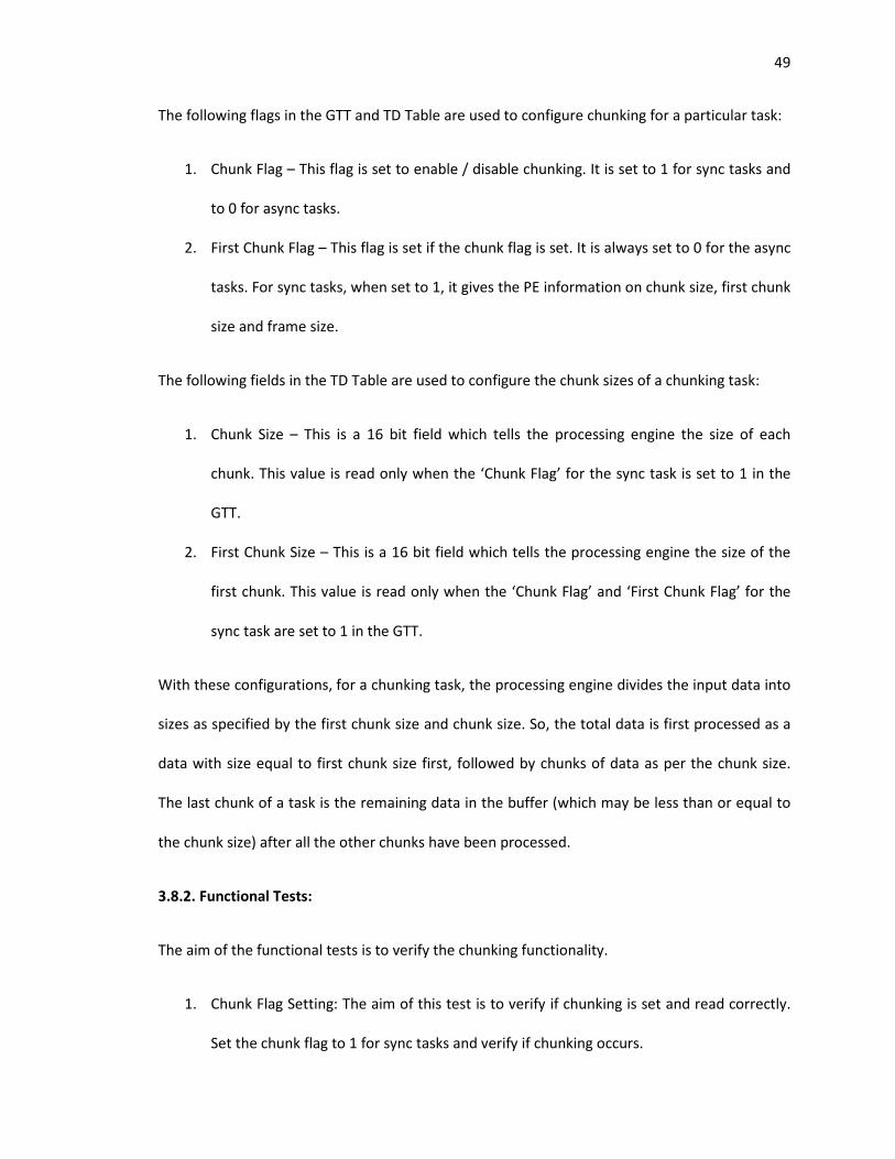
49
The following flags in the GTT and TD Table are used to configure chunking for a particular task:
1. Chunk Flag – This flag is set to enable / disable chunking. It is set to 1 for sync tasks and
to 0 for async tasks.
2. First Chunk Flag – This flag is set if the chunk flag is set. It is always set to 0 for the async
tasks. For sync tasks, when set to 1, it gives the PE information on chunk size, first chunk
size and frame size.
The following fields in the TD Table are used to configure the chunk sizes of a chunking task:
1. Chunk Size – This is a 16 bit field which tells the processing engine the size of each
chunk. This value is read only when the ‘Chunk Flag’ for the sync task is set to 1 in the
GTT.
2. First Chunk Size – This is a 16 bit field which tells the processing engine the size of the
first chunk. This value is read only when the ‘Chunk Flag’ and ‘First Chunk Flag’ for the
sync task are set to 1 in the GTT.
With these configurations, for a chunking task, the processing engine divides the input data into
sizes as specified by the first chunk size and chunk size. So, the total data is first processed as a
data with size equal to first chunk size first, followed by chunks of data as per the chunk size.
The last chunk of a task is the remaining data in the buffer (which may be less than or equal to
the chunk size) after all the other chunks have been processed.
3.8.2. Functional Tests:
The aim of the functional tests is to verify the chunking functionality.
1. Chunk Flag Setting: The aim of this test is to verify if chunking is set and read correctly.
Set the chunk flag to 1 for sync tasks and verify if chunking occurs.
50
2. First Chunk Flag Setting: The aim of this test is to verify if the parameters first chunk
size, chunk size and frame size are read correctly when the first chunk flag is set to 1.
This test should also verify:
a. Verify that the First Chunk size is not reflected for chunks other than first
b. If chunking occurs based on the set parameters and the task is repeated as
many times as the chunk size until the frame ends
It is evident from the description that the tests should use a mechanism to find the size of data
being processed each time, to verify chunking. We describe our testbench monitor which
precisely does this in the following section.
3.8.3. Testbench Setup:
The VFP sends a message called the Synchronous Task Descriptor to each functional unit’s task
scheduler queue, each time a sync task is scheduled. By analyzing the synchronous task
descriptor format, we have determined that it contains all the information about chunking like
the chunk size, first chunk size and the size of data being processed in this iteration.
We have hence designed monitors which can decode the sync task descriptors and print out the
information that it reads from the descriptor. Since these messages are unique to each FU,
monitors have been instantiated at each queue interface, to monitor the sync task descriptor.
These monitor provide us the following information that they decode from the sync descriptors:
Timestamp Sync Task for FU ‘n’ - >>>>> queue_sync_desc = [remaining data size][ ]
Timestamp Sync Task for FU ‘n’ - >>>>> queue_sync_desc = [chunk size][first chunk size]
Timestamp Sync Task for FU ‘n’ - >>>>> queue_sync_desc = [TD Pointer]
51
The monitors can also detect proper activation of the sync task based on start and reschedule
time and print the following messages:
Also, at the end of the final chunk, the monitor can print how many times the chunking was
done with the following message:
With this, the monitors can verify the following aspects of Chunking in Sync Tasks:
1. Setting of chunking and first chunk flags
a. Ensuring that the Chunk Size and First Chunk Size values are properly read and
executed
b. At each execution of the chunk, the monitors print if it is the first chunk,
intermediate chunk or the last chunk
2. Vary the values of Chunk Size and First Chunk Size
a. Repeated the same test for several different values
b. Successfully checking if first chunk sizes and the chunk sizes are read and
executed accordingly for all test cases
We present our test plan, simulation and results in the following sections.
3.8.4. Implementation and Results:
In our tests, we set the chunking flag and first chunk flag in the GTT for the Sync tasks we wish to
run as chunking tasks. We then set the values of the following parameters and run the tests:
Timestamp: The activation came for FuID ‘n’ for --- TD Pointer
Timestamp The SYNC task with TD Pointer xxxxxxxx was activated timely
SYNC task with tdpointer=== xxxxxxx was activated 'N' times correctly
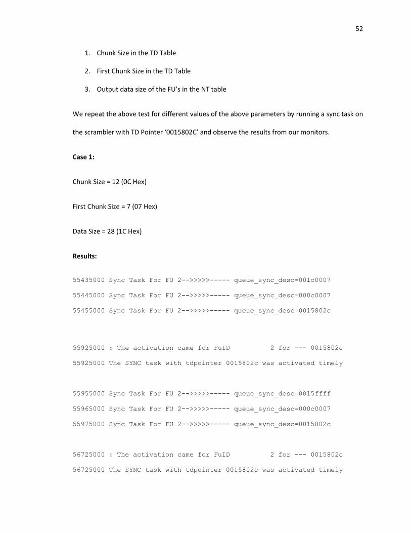
52
1. Chunk Size in the TD Table
2. First Chunk Size in the TD Table
3. Output data size of the FU’s in the NT table
We repeat the above test for different values of the above parameters by running a sync task on
the scrambler with TD Pointer ‘0015802C’ and observe the results from our monitors.
Case 1:
Chunk Size = 12 (0C Hex)
First Chunk Size = 7 (07 Hex)
Data Size = 28 (1C Hex)
Results:
55435000 Sync Task For FU 2-->>>>>----- queue_sync_desc=001c0007
55445000 Sync Task For FU 2-->>>>>----- queue_sync_desc=000c0007
55455000 Sync Task For FU 2-->>>>>----- queue_sync_desc=0015802c
55925000 : The activation came for FuID 2 for --- 0015802c
55925000 The SYNC task with tdpointer 0015802c was activated timely
55955000 Sync Task For FU 2-->>>>>----- queue_sync_desc=0015ffff
55965000 Sync Task For FU 2-->>>>>----- queue_sync_desc=000c0007
55975000 Sync Task For FU 2-->>>>>----- queue_sync_desc=0015802c
56725000 : The activation came for FuID 2 for --- 0015802c
56725000 The SYNC task with tdpointer 0015802c was activated timely
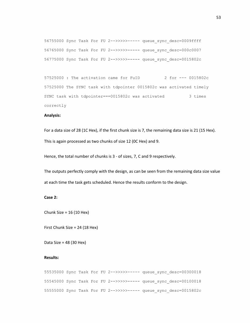
53
56755000 Sync Task For FU 2-->>>>>----- queue_sync_desc=0009ffff
56765000 Sync Task For FU 2-->>>>>----- queue_sync_desc=000c0007
56775000 Sync Task For FU 2-->>>>>----- queue_sync_desc=0015802c
57525000 : The activation came for FuID 2 for --- 0015802c
57525000 The SYNC task with tdpointer 0015802c was activated timely
SYNC task with tdpointer===0015802c was activated 3 times
correctly
Analysis:
For a data size of 28 (1C Hex), if the first chunk size is 7, the remaining data size is 21 (15 Hex).
This is again processed as two chunks of size 12 (0C Hex) and 9.
Hence, the total number of chunks is 3 - of sizes, 7, C and 9 respectively.
The outputs perfectly comply with the design, as can be seen from the remaining data size value
at each time the task gets scheduled. Hence the results conform to the design.
Case 2:
Chunk Size = 16 (10 Hex)
First Chunk Size = 24 (18 Hex)
Data Size = 48 (30 Hex)
Results:
55535000 Sync Task For FU 2-->>>>>----- queue_sync_desc=00300018
55545000 Sync Task For FU 2-->>>>>----- queue_sync_desc=00100018
55555000 Sync Task For FU 2-->>>>>----- queue_sync_desc=0015802c
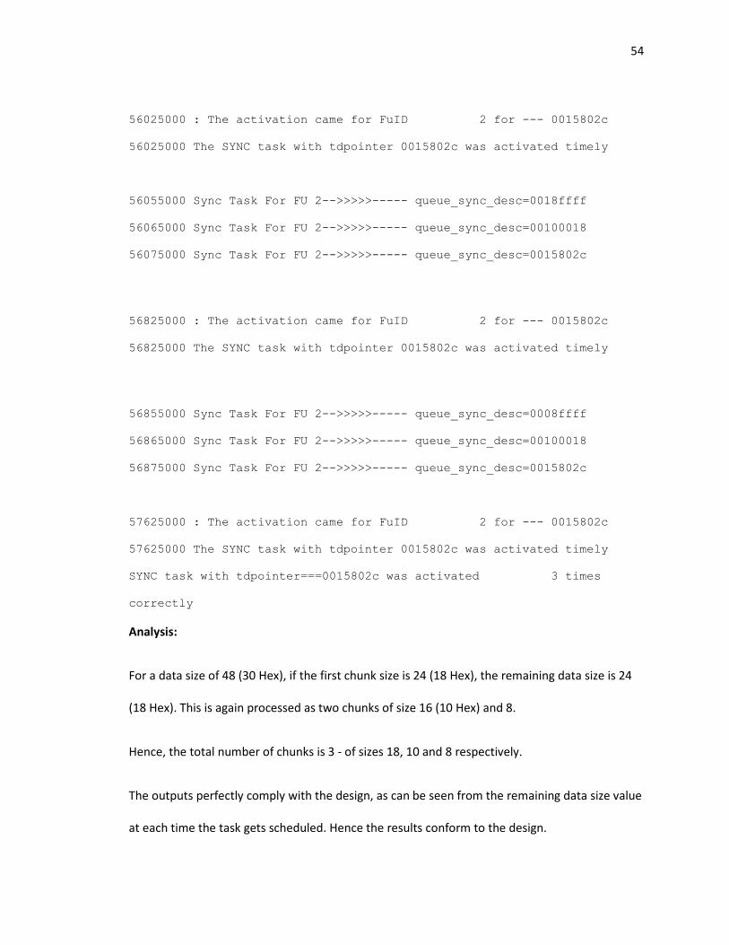
54
56025000 : The activation came for FuID 2 for --- 0015802c
56025000 The SYNC task with tdpointer 0015802c was activated timely
56055000 Sync Task For FU 2-->>>>>----- queue_sync_desc=0018ffff
56065000 Sync Task For FU 2-->>>>>----- queue_sync_desc=00100018
56075000 Sync Task For FU 2-->>>>>----- queue_sync_desc=0015802c
56825000 : The activation came for FuID 2 for --- 0015802c
56825000 The SYNC task with tdpointer 0015802c was activated timely
56855000 Sync Task For FU 2-->>>>>----- queue_sync_desc=0008ffff
56865000 Sync Task For FU 2-->>>>>----- queue_sync_desc=00100018
56875000 Sync Task For FU 2-->>>>>----- queue_sync_desc=0015802c
57625000 : The activation came for FuID 2 for --- 0015802c
57625000 The SYNC task with tdpointer 0015802c was activated timely
SYNC task with tdpointer===0015802c was activated 3 times
correctly
Analysis:
For a data size of 48 (30 Hex), if the first chunk size is 24 (18 Hex), the remaining data size is 24
(18 Hex). This is again processed as two chunks of size 16 (10 Hex) and 8.
Hence, the total number of chunks is 3 - of sizes 18, 10 and 8 respectively.
The outputs perfectly comply with the design, as can be seen from the remaining data size value
at each time the task gets scheduled. Hence the results conform to the design.
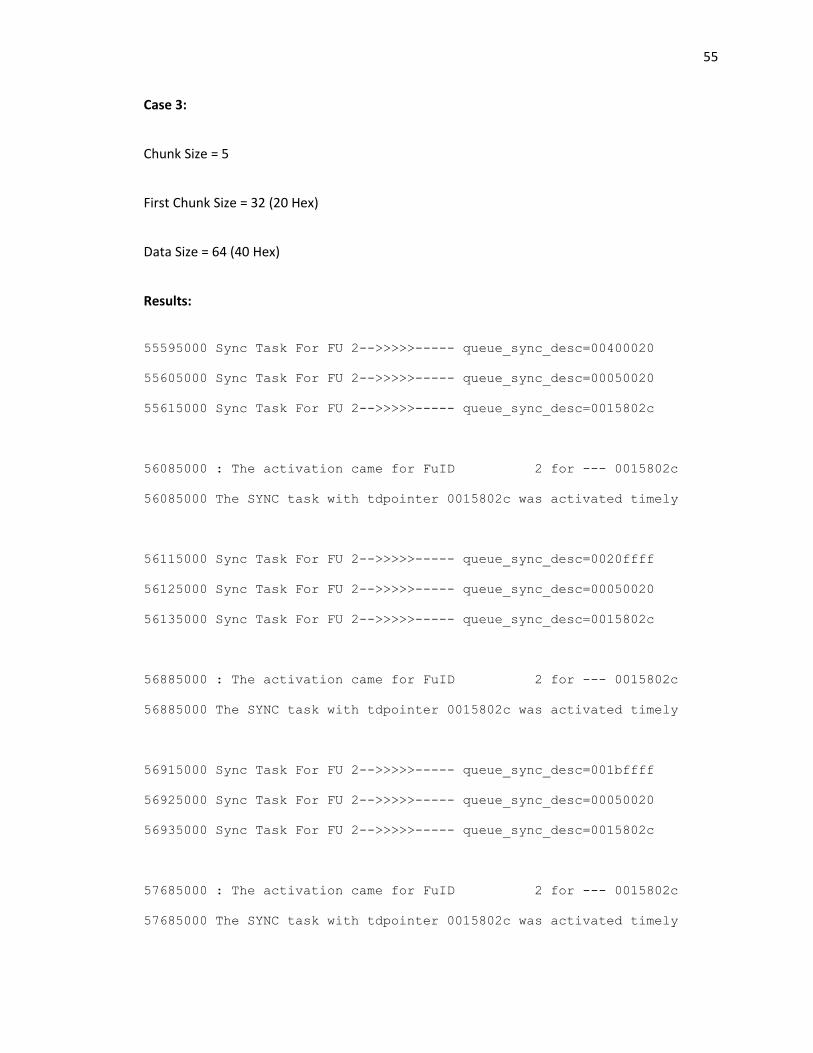
55
Case 3:
Chunk Size = 5
First Chunk Size = 32 (20 Hex)
Data Size = 64 (40 Hex)
Results:
55595000 Sync Task For FU 2-->>>>>----- queue_sync_desc=00400020
55605000 Sync Task For FU 2-->>>>>----- queue_sync_desc=00050020
55615000 Sync Task For FU 2-->>>>>----- queue_sync_desc=0015802c
56085000 : The activation came for FuID 2 for --- 0015802c
56085000 The SYNC task with tdpointer 0015802c was activated timely
56115000 Sync Task For FU 2-->>>>>----- queue_sync_desc=0020ffff
56125000 Sync Task For FU 2-->>>>>----- queue_sync_desc=00050020
56135000 Sync Task For FU 2-->>>>>----- queue_sync_desc=0015802c
56885000 : The activation came for FuID 2 for --- 0015802c
56885000 The SYNC task with tdpointer 0015802c was activated timely
56915000 Sync Task For FU 2-->>>>>----- queue_sync_desc=001bffff
56925000 Sync Task For FU 2-->>>>>----- queue_sync_desc=00050020
56935000 Sync Task For FU 2-->>>>>----- queue_sync_desc=0015802c
57685000 : The activation came for FuID 2 for --- 0015802c
57685000 The SYNC task with tdpointer 0015802c was activated timely
56
57715000 Sync Task For FU 2-->>>>>----- queue_sync_desc=0016ffff
57725000 Sync Task For FU 2-->>>>>----- queue_sync_desc=00050020
57735000 Sync Task For FU 2-->>>>>----- queue_sync_desc=0015802c
58485000 : The activation came for FuID 2 for --- 0015802c
58485000 The SYNC task with tdpointer 0015802c was activated timely
58515000 Sync Task For FU 2-->>>>>----- queue_sync_desc=0011ffff
58525000 Sync Task For FU 2-->>>>>----- queue_sync_desc=00050020
58535000 Sync Task For FU 2-->>>>>----- queue_sync_desc=0015802c
59355000 : The activation came for FuID 2 for --- 0015802c
59355000 The SYNC task with tdpointer 0015802c was activated timely
59385000 Sync Task For FU 2-->>>>>----- queue_sync_desc=000cffff
59395000 Sync Task For FU 2-->>>>>----- queue_sync_desc=00050020
59405000 Sync Task For FU 2-->>>>>----- queue_sync_desc=0015802c
60155000 : The activation came for FuID 2 for --- 0015802c
60155000 The SYNC task with tdpointer 0015802c was activated timely
60185000 Sync Task For FU 2-->>>>>----- queue_sync_desc=0007ffff
60195000 Sync Task For FU 2-->>>>>----- queue_sync_desc=00050020
60205000 Sync Task For FU 2-->>>>>----- queue_sync_desc=0015802c
61055000 : The activation came for FuID 2 for --- 0015802c
61055000 The SYNC task with tdpointer 0015802c was activated timely
57
61085000 Sync Task For FU 2-->>>>>----- queue_sync_desc=0002ffff
61095000 Sync Task For FU 2-->>>>>----- queue_sync_desc=00050020
61105000 Sync Task For FU 2-->>>>>----- queue_sync_desc=0015802c
61855000 : The activation came for FuID 2 for --- 0015802c
61855000 The SYNC task with tdpointer 0015802c was activated timely
SYNC task with tdpointer===0015802c was activated 8 times
correctly
Analysis:
The outputs perfectly comply with the design, as can be seen from the remaining data size value
at each time the task gets scheduled. Hence the results conform to the design.
For a data size of 64 (40 Hex), if the first chunk size is 32 (20 Hex), the remaining data size is 32
(20 Hex). This is again processed as six chunks of size 5 and a last chunk of size 2.
Hence, the total number of chunks is 8 - of sizes, 20, 5, 5, 5, 5, 5, 5 and 2 respectively.
Hence, the chunking feature is successfully tested.
3.9. De-Chunking
3.9.1. Functional Description:
The de-chunking feature is a method of recombination of chunks of data from a chunking task.
This feature, when enabled
only when all the chunks of data are obtained
treated as a single unit for the task processing.
WiNC2R allows the programmer to
the Task Descriptor Table.
unit, the next unit in the flow waits until all the chunks are obtained, combines them into one
single unit of data and processed them at once as a single task.
Consider the same case as considered for the chunking task an input data block [D2 D1] (of size
D1+D2) to be processed by a functional unit FU ‘N’ as a task T1 in the flow. The next functional
unit FU ‘N+1’ implements de
T2 is fed to FU ‘N+2’ which implements task T3. Since the de
‘N+2’ in the flow waits until both the chunks of data D1” and D2” are obtained from FU ‘N+1’ to
process them together. The figure below shows the
Functional Description:
is a method of recombination of chunks of data from a chunking task.
enabled in a functional unit, allows activation of the next
only when all the chunks of data are obtained from the flow. The combined chunks of data a
treated as a single unit for the task processing.
WiNC2R allows the programmer to configure de-chunking by setting the de-
By setting the de-chunk flag to 1 for a task in a particular functional
t unit in the flow waits until all the chunks are obtained, combines them into one
single unit of data and processed them at once as a single task.
Consider the same case as considered for the chunking task an input data block [D2 D1] (of size
processed by a functional unit FU ‘N’ as a task T1 in the flow. The next functional
unit FU ‘N+1’ implements de-chunking by setting the de-chunk flag to 1. The output of its task
T2 is fed to FU ‘N+2’ which implements task T3. Since the de-chunking flag i
‘N+2’ in the flow waits until both the chunks of data D1” and D2” are obtained from FU ‘N+1’ to
The figure below shows the entire process in a stepwise manner:
Figure 3.11(a) De-chunking Task
58
is a method of recombination of chunks of data from a chunking task.
next task in the flow
the flow. The combined chunks of data are
-chunk flag to 1 in
chunk flag to 1 for a task in a particular functional
t unit in the flow waits until all the chunks are obtained, combines them into one
Consider the same case as considered for the chunking task an input data block [D2 D1] (of size
processed by a functional unit FU ‘N’ as a task T1 in the flow. The next functional
chunk flag to 1. The output of its task
chunking flag is set, the unit FU
‘N+2’ in the flow waits until both the chunks of data D1” and D2” are obtained from FU ‘N+1’ to
entire process in a stepwise manner:
Now the FU ‘N+2’ has obtained the first chunk D1”, but does not trigger the task T3 as yet.
The second chunk is also processed as shown below:
Now FU ‘N+2’ combines D1” and D2” to treat them as a single unit of data and runs task T3 to
produce the output D2~D1~ as shown below:
Thus, de-chunking is implemented in WiNC2R.
3.9.2. Testbench Setup:
It is evident from the functional description that we need to monitor the task activation of the
task T3 in the flow and ensure it is after task T2 gets completed twice. Hence, the verification of
the de-chunking feature can be achieved from the same test setup as our chunking tests and
just use the output messages from the monitors to verify the functionality.
obtained the first chunk D1”, but does not trigger the task T3 as yet.
The second chunk is also processed as shown below:
Figure 3.11(b) De-chunking Task
Now FU ‘N+2’ combines D1” and D2” to treat them as a single unit of data and runs task T3 to
the output D2~D1~ as shown below:
Figure 3.11(c) De-chunking Task
chunking is implemented in WiNC2R.
It is evident from the functional description that we need to monitor the task activation of the
ensure it is after task T2 gets completed twice. Hence, the verification of
chunking feature can be achieved from the same test setup as our chunking tests and
just use the output messages from the monitors to verify the functionality.
59
obtained the first chunk D1”, but does not trigger the task T3 as yet.
Now FU ‘N+2’ combines D1” and D2” to treat them as a single unit of data and runs task T3 to
It is evident from the functional description that we need to monitor the task activation of the
ensure it is after task T2 gets completed twice. Hence, the verification of
chunking feature can be achieved from the same test setup as our chunking tests and
60
3.9.3. Test Case:
The aim of the test is to set up a de-chunking task for various first chunk, chunk and data frame
sizes and verify that the consumer task is not activated until the last chunk is processed. These
tests verify the de-chunking feature by setting up a flow with two tasks in succession, one
implementing chunking and the second one implementing de-chunking. This is configured by
setting the chunking flag, first chunk flag, chunk size and first chunk size for the first task, and
setting the de-chunking flag for the second task. The way our test sets up the flow is one where:
1. It first executes a Sync task with TD Pointer ‘15802C’ on the scrambler which does
chunking (set chunk flag and first chunk flag to 1)
2. The next task is a Sync task on the modulator with TD Pointer ‘2D802C’ which does de-
chunking (set dechunking flag to 1)
3. The third task is again a Sync task on the encoder with TD Pointer ‘1D802C’ which
should be de-chunked
4. The final task in the flow is an Async task on the inter-leaver with TD Pointer ‘25802C’
We make use of the same monitors we used for chunking to test the scheduling and activation
of these Sync tasks and the same chunking parameters as the chunking tests.
3.9.4. Implementation and Results
Case 1:
Chunk size = C
First chunk size = 7
Data size = C
61
Results:
55275000 Sync Task For FU 2-->>>>>----- queue_sync_desc=000c0007
55285000 Sync Task For FU 2-->>>>>----- queue_sync_desc=000c0007
55295000 Sync Task For FU 2-->>>>>----- queue_sync_desc=0015802c
55795000 : The activation came for FuID 2 for --- 0015802c
55795000 The SYNC task with tdpointer 0015802c was activated timely
55825000 Sync Task For FU 2-->>>>>----- queue_sync_desc=0005ffff
55835000 Sync Task For FU 2-->>>>>----- queue_sync_desc=000c0007
55845000 Sync Task For FU 2-->>>>>----- queue_sync_desc=0015802c
56595000 : The activation came for FuID 2 for --- 0015802c
56595000 The SYNC task with tdpointer 0015802c was activated timely
SYNC task with tdpointer===0015802c was activated 2 times
correctly
57055000 Sync Task For FU 5-->>>>>----- queue_sync_desc=000c0000
57065000 Sync Task For FU 5-->>>>>----- queue_sync_desc=00000000
57075000 Sync Task For FU 5-->>>>>----- queue_sync_desc=002d802c
57595000 : The activation came for FuID 5 for --- 002d802c
57595000 The SYNC task with tdpointer 002d802c was activated timely
SYNC task with tdpointer===002d802c was activated 1 times
correctly
58855000 Sync Task For FU 3-->>>>>----- queue_sync_desc=000c0000
58865000 Sync Task For FU 3-->>>>>----- queue_sync_desc=00000000
62
58875000 Sync Task For FU 3-->>>>>----- queue_sync_desc=001d802c
59345000 : The activation came for FuID 3 for --- 001d802c
59345000 The SYNC task with tdpointer 001d802c was activated timely
SYNC task with tdpointer===001d802c was activated 1 times
correctly
60615000 Async Task for FU 4 ...---->>> Async Task with TD Pointer =
0025802c
60915000 : The activation came for FuID 4 for --- 0025802c
mon_async_q4 : Got the expected Task with Q_Id=1 for the
tdpointer=0025802c Time= 60915000
mon_async_q4 : Task with 0025802c tdpointer took 30 clock
cycles Current time= 60915000
Analysis:
For the given parameter values, the chunking task has to be executed twice, with chunk sizes 7
and 5 respectively. The scheduling and the activation of the next task which implements de-
chunking must be as many times as the chunking task (2 in this case) and all the remaining tasks
are executed just once.
However, the results from the monitors show that the system behaves differently, wherein the
task for which de-chunking is set is executed just once and not as many times as the number of
chunks in the chunking task.
This seems to be a bug. We test the other chunking cases to confirm the design bug.
63
Case 2:
Chunk Size = C
First Chunk Size = 7
Data Size = 1C
Results:
55435000 Sync Task For FU 2-->>>>>----- queue_sync_desc=001c0007
55445000 Sync Task For FU 2-->>>>>----- queue_sync_desc=000c0007
55455000 Sync Task For FU 2-->>>>>----- queue_sync_desc=0015802c
55925000 : The activation came for FuID 2 for --- 0015802c
55925000 The SYNC task with tdpointer 0015802c was activated timely
55955000 Sync Task For FU 2-->>>>>----- queue_sync_desc=0015ffff
55965000 Sync Task For FU 2-->>>>>----- queue_sync_desc=000c0007
55975000 Sync Task For FU 2-->>>>>----- queue_sync_desc=0015802c
56725000 : The activation came for FuID 2 for --- 0015802c
56725000 The SYNC task with tdpointer 0015802c was activated timely
56755000 Sync Task For FU 2-->>>>>----- queue_sync_desc=0009ffff
56765000 Sync Task For FU 2-->>>>>----- queue_sync_desc=000c0007
56775000 Sync Task For FU 2-->>>>>----- queue_sync_desc=0015802c
57265000 Sync Task For FU 5-->>>>>----- queue_sync_desc=001c0000
57275000 Sync Task For FU 5-->>>>>----- queue_sync_desc=00000000
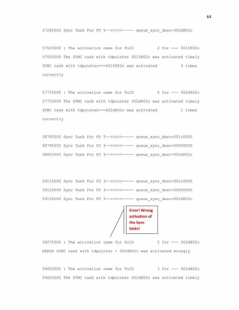
64
57285000 Sync Task For FU 5-->>>>>----- queue_sync_desc=002d802c
57525000 : The activation came for FuID 2 for --- 0015802c
57525000 The SYNC task with tdpointer 0015802c was activated timely
SYNC task with tdpointer===0015802c was activated 3 times
correctly
57755000 : The activation came for FuID 5 for --- 002d802c
57755000 The SYNC task with tdpointer 002d802c was activated timely
SYNC task with tdpointer===002d802c was activated 1 times
correctly
58785000 Sync Task For FU 5-->>>>>----- queue_sync_desc=001c0000
58795000 Sync Task For FU 5-->>>>>----- queue_sync_desc=00000000
58805000 Sync Task For FU 5-->>>>>----- queue_sync_desc=002d802c
59115000 Sync Task For FU 3-->>>>>----- queue_sync_desc=001c0000
59125000 Sync Task For FU 3-->>>>>----- queue_sync_desc=00000000
59135000 Sync Task For FU 3-->>>>>----- queue_sync_desc=001d802c
59275000 : The activation came for FuID 5 for --- 002d802c
ERROR SYNC task with tdpointer = 002d802c was activated wrongly
59605000 : The activation came for FuID 3 for --- 001d802c
59605000 The SYNC task with tdpointer 001d802c was activated timely
Error! Wrong
activation of
the Sync
tasks!
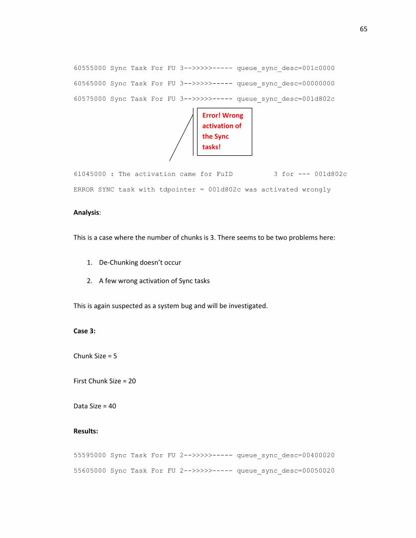
65
60555000 Sync Task For FU 3-->>>>>----- queue_sync_desc=001c0000
60565000 Sync Task For FU 3-->>>>>----- queue_sync_desc=00000000
60575000 Sync Task For FU 3-->>>>>----- queue_sync_desc=001d802c
61045000 : The activation came for FuID 3 for --- 001d802c
ERROR SYNC task with tdpointer = 001d802c was activated wrongly
Analysis:
This is a case where the number of chunks is 3. There seems to be two problems here:
1. De-Chunking doesn’t occur
2. A few wrong activation of Sync tasks
This is again suspected as a system bug and will be investigated.
Case 3:
Chunk Size = 5
First Chunk Size = 20
Data Size = 40
Results:
55595000 Sync Task For FU 2-->>>>>----- queue_sync_desc=00400020
55605000 Sync Task For FU 2-->>>>>----- queue_sync_desc=00050020
Error! Wrong
activation of
the Sync
tasks!
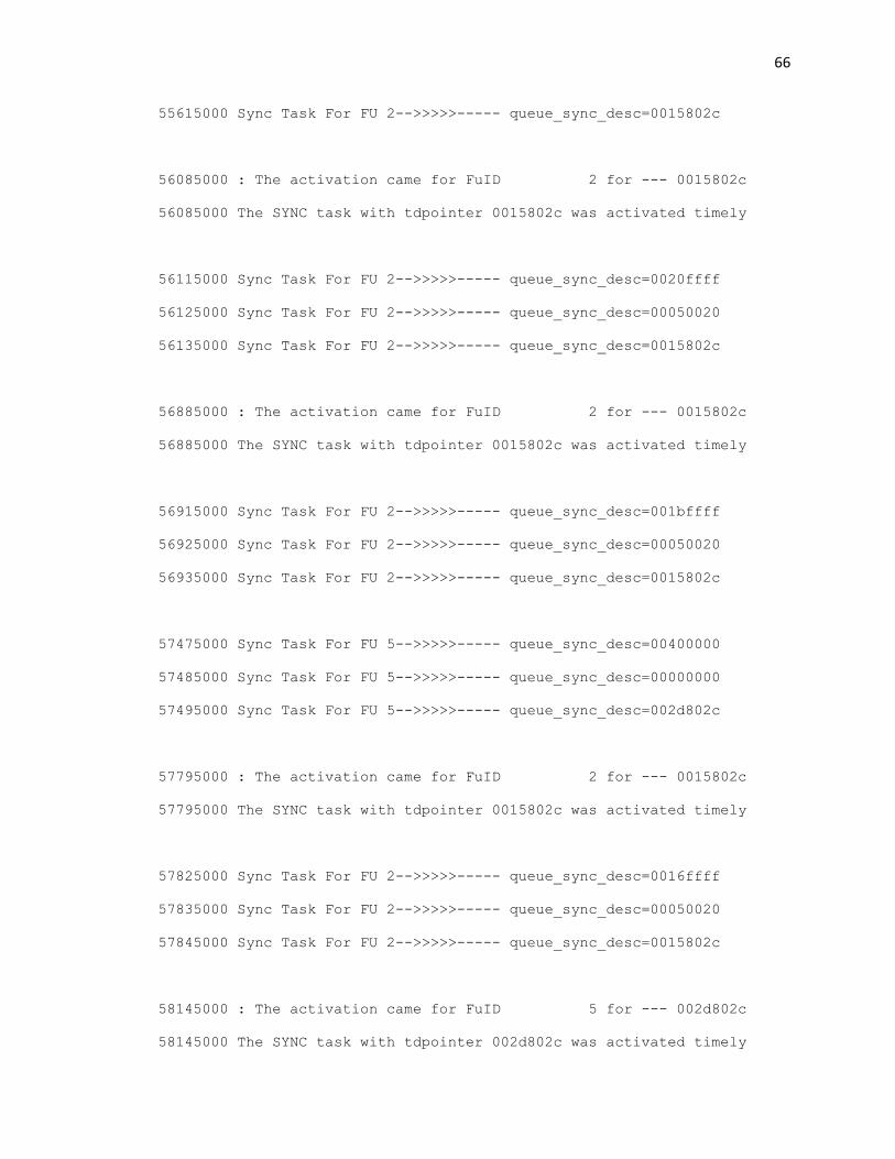
66
55615000 Sync Task For FU 2-->>>>>----- queue_sync_desc=0015802c
56085000 : The activation came for FuID 2 for --- 0015802c
56085000 The SYNC task with tdpointer 0015802c was activated timely
56115000 Sync Task For FU 2-->>>>>----- queue_sync_desc=0020ffff
56125000 Sync Task For FU 2-->>>>>----- queue_sync_desc=00050020
56135000 Sync Task For FU 2-->>>>>----- queue_sync_desc=0015802c
56885000 : The activation came for FuID 2 for --- 0015802c
56885000 The SYNC task with tdpointer 0015802c was activated timely
56915000 Sync Task For FU 2-->>>>>----- queue_sync_desc=001bffff
56925000 Sync Task For FU 2-->>>>>----- queue_sync_desc=00050020
56935000 Sync Task For FU 2-->>>>>----- queue_sync_desc=0015802c
57475000 Sync Task For FU 5-->>>>>----- queue_sync_desc=00400000
57485000 Sync Task For FU 5-->>>>>----- queue_sync_desc=00000000
57495000 Sync Task For FU 5-->>>>>----- queue_sync_desc=002d802c
57795000 : The activation came for FuID 2 for --- 0015802c
57795000 The SYNC task with tdpointer 0015802c was activated timely
57825000 Sync Task For FU 2-->>>>>----- queue_sync_desc=0016ffff
57835000 Sync Task For FU 2-->>>>>----- queue_sync_desc=00050020
57845000 Sync Task For FU 2-->>>>>----- queue_sync_desc=0015802c
58145000 : The activation came for FuID 5 for --- 002d802c
58145000 The SYNC task with tdpointer 002d802c was activated timely
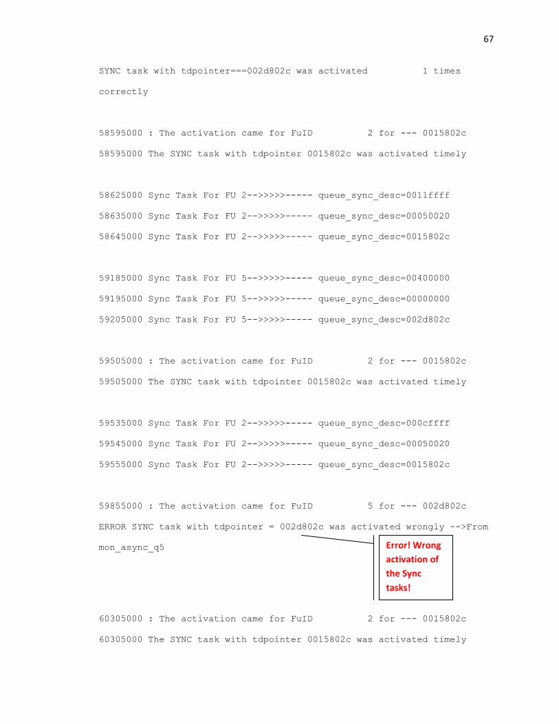
67
SYNC task with tdpointer===002d802c was activated 1 times
correctly
58595000 : The activation came for FuID 2 for --- 0015802c
58595000 The SYNC task with tdpointer 0015802c was activated timely
58625000 Sync Task For FU 2-->>>>>----- queue_sync_desc=0011ffff
58635000 Sync Task For FU 2-->>>>>----- queue_sync_desc=00050020
58645000 Sync Task For FU 2-->>>>>----- queue_sync_desc=0015802c
59185000 Sync Task For FU 5-->>>>>----- queue_sync_desc=00400000
59195000 Sync Task For FU 5-->>>>>----- queue_sync_desc=00000000
59205000 Sync Task For FU 5-->>>>>----- queue_sync_desc=002d802c
59505000 : The activation came for FuID 2 for --- 0015802c
59505000 The SYNC task with tdpointer 0015802c was activated timely
59535000 Sync Task For FU 2-->>>>>----- queue_sync_desc=000cffff
59545000 Sync Task For FU 2-->>>>>----- queue_sync_desc=00050020
59555000 Sync Task For FU 2-->>>>>----- queue_sync_desc=0015802c
59855000 : The activation came for FuID 5 for --- 002d802c
ERROR SYNC task with tdpointer = 002d802c was activated wrongly -->From
mon_async_q5
60305000 : The activation came for FuID 2 for --- 0015802c
60305000 The SYNC task with tdpointer 0015802c was activated timely
Error! Wrong
activation of
the Sync
tasks!
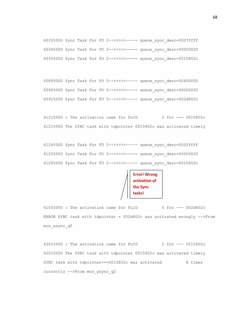
68
60335000 Sync Task For FU 2-->>>>>----- queue_sync_desc=0007ffff
60345000 Sync Task For FU 2-->>>>>----- queue_sync_desc=00050020
60355000 Sync Task For FU 2-->>>>>----- queue_sync_desc=0015802c
60895000 Sync Task For FU 5-->>>>>----- queue_sync_desc=00400000
60905000 Sync Task For FU 5-->>>>>----- queue_sync_desc=00000000
60915000 Sync Task For FU 5-->>>>>----- queue_sync_desc=002d802c
61215000 : The activation came for FuID 2 for --- 0015802c
61215000 The SYNC task with tdpointer 0015802c was activated timely
61245000 Sync Task For FU 2-->>>>>----- queue_sync_desc=0002ffff
61255000 Sync Task For FU 2-->>>>>----- queue_sync_desc=00050020
61265000 Sync Task For FU 2-->>>>>----- queue_sync_desc=0015802c
61555000 : The activation came for FuID 5 for --- 002d802c
ERROR SYNC task with tdpointer = 002d802c was activated wrongly -->From
mon_async_q5
62015000 : The activation came for FuID 2 for --- 0015802c
62015000 The SYNC task with tdpointer 0015802c was activated timely
SYNC task with tdpointer===0015802c was activated 8 times
correctly -->From mon_async_q2
Error! Wrong
activation of
the Sync
tasks!
69
Analysis:
While chunking occurs as per design for the first task, our functional tests indicate that the
dechunking feature doesn’t seem to work properly (see comment boxes in the results).
Anomaly:
In order to investigate this feature further, several cases were run with different values for
chunk size, first chunk size and data size. The following were our observations:
1. When the number of chunks is two, task which implements de-chunking (de-chunk flag
=1) gets activated only once, and not as many times as the number of chunks!
2. It was found that whenever the number of chunks exceeded 2, the above case of
premature/wrong activation of the next task occurs and de-chunking doesn’t occur!
Bug:
The above anomaly is suspected to be a bug in the design and this issue has been filed with the
architects and the designers.
70
Chapter 4 – Performance and Scalability of WiNC2R Architecture
Through our directed functional tests in the previous chapters, we attempted to answer the
‘does it work’ question of the system design. Directed tests target specific functionalities that
we choose to verify, which are tested using predetermined stimuli. However, real time
operating conditions of the platform are characterized by several of these functionalities being
put to test simultaneously.
This brings us to another aspect of verification, known as ‘Concurrency Testing’. Concurrency
tests are characterized by running a number of tests simultaneously. Modern verification
methodologies like OVM allow the test writers to easily run concurrent test cases with several
configuration ‘knobs’ to cover different scenarios. This verification technique is commonly
known as ‘Coverage Driven Verification’, where the aim is to cover as many runtime scenarios
and ‘corner cases’ in the tests.
The focus of this chapter is to test two such aspects of the WiNC2R platform – (a) Scheduling of
Sync and Async tasks on the same functional unit / processing engine and (b) Inter-cluster
communication. We address each of these aspects in detail, followed by our test plans,
implementation and results.
4.1. Running Sync and Async Tasks on the Same Processing Engine
4.1.1. Functional Description:
In WiNC2R platform, the scheduler sub-block of the VFP controller is responsible for scheduling
tasks on the processing engines. As outlined in the previous chapter, WiNC2R supports two
types of tasks - Sync tasks (tasks with deterministic guarantees) and Async tasks (with statistical
71
guarantees). These ‘guarantees’ are met with by the proper functioning of the scheduler in the
VFP controller.
The main functionality of the scheduler is schedule tasks on the processing engines, while still
maintaining the guarantees of the system, which essentially signify:
i. Adherence to protocol
ii. System performance
This, in a typical runtime scenario means resolving the priority between async tasks and sync
tasks and scheduling them accordingly. The WiNC2R architecture defines a standard rule for
resolving the priority to schedule tasks on the processing engines. We describe this in the
following section.
4.1.2. Task Activation Rule
This rule describes how the scheduler resolves the priority when both an Async task and a Sync
task are to be scheduled on the same processing engine. In essence, this rule describes which
task gets activated first, based on runtime parameters.
Parameters:
The following parameters are always checked by the VFP before deciding if it needs to activate a
Sync / Async task from the scheduler queue:
1. Processing Time of an Async Task - Maximum task processing time. The VFP controller
reads this value for a specific task from the Global Task Table.
2. Guard time of a Sync Task - Used to limit the wait for scheduling the synchronous task.
The VFP controller reads this value for a specific task from the Global Task Table.
72
3. Start time of a Sync Task - Task start time expressed in the clock ticks of the global
SchedulerTimer. This value is stored in the Task Descriptor Table of the task.
All the above values are filled in by the appropriate task scheduler descriptor depending on the
type of task.
Consider:
A. (Current time + Processing Time of Async Task)
B. (Guard Time + Start time of the Sync Task)
Rule:
• If A < B, then the Async task gets activated, even though a Sync Task is already in the
scheduler
• If A ≥ B, then the Sync task gets activated first
Each time a Sync and Async task compete in the scheduler to get activated, the above
parameters are computed and the tasks are activated accordingly.
4.1.3. Functional Tests:
The aim of these tests is to verify the scheduling of Sync and Async tasks on the same PE. Our
tests will initialize two or more tasks, one being sync and the other being Async, with different
processing times and a set guard time. The tests will verify if the scheduler schedules the tasks
to be processed based on the conditions described above.
From an implementation point of view, the goals of the test are to study the order of execution
of the tasks. Hence, these tests are an extension of the next task processing tests.
73
4.1.4. Testbench:
We have monitors for each FU interface, which print the scheduling messages in the log file as
shown below:
Sync Task Scheduling:
Sync Task Activation:
Async Task Scheduling:
Async Task Activation:
4.1.5. Test cases:
Our tests need to check if the VFP adheres to the task activation rule explained above, for all
corner cases. The following are the cases tested:
Consider a flow where a Sync task is already queued in the scheduler. Now another flow
enqueues an Async task into the scheduler
Timestamp Sync Task For FU ‘n’-->>>>>----- queue_sync_desc = TD Pointer
Timestamp: The activation came for FuID ‘n’ for --- TD Pointer
Timestamp The SYNC task with tdpointer xxxxxxx was activated timely
Timestamp Async Task FU ‘n’ ...---->>> Async Task with TD Pointer = xxxxxxxx
Timestamp : The activation came for FuID ‘n’ for --- TD Pointer
mon_async_q’n’ : Got the expected Task with Q_Id=1 for the tdpointer= xxxxxxx
Time= xxxxxxxx
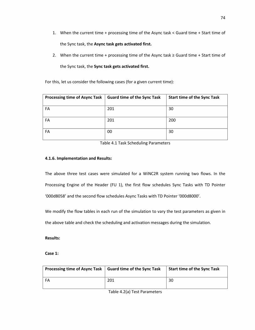
74
1. When the current time + processing time of the Async task < Guard time + Start time of
the Sync task, the Async task gets activated first.
2. When the current time + processing time of the Async task ≥ Guard time + Start time of
the Sync task, the Sync task gets activated first.
For this, let us consider the following cases (for a given current time):
Processing time of Async Task Guard time of the Sync Task Start time of the Sync Task
FA 201 30
FA 201 200
FA 00 30
Table 4.1 Task Scheduling Parameters
4.1.6. Implementation and Results:
The above three test cases were simulated for a WiNC2R system running two flows. In the
Processing Engine of the Header (FU 1), the first flow schedules Sync Tasks with TD Pointer
‘000d8058’ and the second flow schedules Async Tasks with TD Pointer ‘000d8000’.
We modify the flow tables in each run of the simulation to vary the test parameters as given in
the above table and check the scheduling and activation messages during the simulation.
Results:
Case 1:
Processing time of Async Task Guard time of the Sync Task Start time of the Sync Task
FA 201 30
Table 4.2(a) Test Parameters
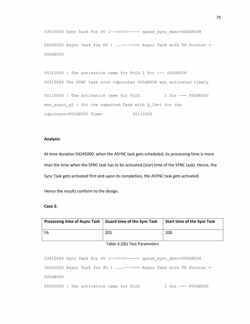
75
53615000 Sync Task For FU 1-->>>>>----- queue_sync_desc=000d8058
54245000 Async Task for FU 1 ...---->>> Async Task with TD Pointer =
000d8000
54315000 : The activation came for FuID 1 for --- 000d8058
54315000 The SYNC task with tdpointer 000d8058 was activated timely
55115000 : The activation came for FuID 1 for --- 000d8000
mon_async_q1 : Got the expected Task with Q_Id=1 for the
tdpointer=000d8000 Time= 55115000
Analysis:
At time duration 54245000, when the ASYNC task gets scheduled, its processing time is more
than the time when the SYNC task has to be activated (start time of the SYNC task). Hence, the
Sync Task gets activated first and upon its completion, the ASYNC task gets activated.
Hence the results conform to the design.
Case 2:
Processing time of Async Task Guard time of the Sync Task Start time of the Sync Task
FA 201 200
Table 4.2(b) Test Parameters
53615000 Sync Task For FU 1-->>>>>----- queue_sync_desc=000d8058
54245000 Async Task for FU 1 ...---->>> Async Task with TD Pointer =
000d8000
54545000 : The activation came for FuID 1 for --- 000d8000
76
mon_async_q1 : Got the expected Task with Q_Id=1 for the
tdpointer=000d8000 Time= 54545000
58955000 : The activation came for FuID 1 for --- 000d8058
58955000 The SYNC task with tdpointer 000d8058 was activated timely
Analysis:
At time duration 54245000, when the ASYNC task gets scheduled, its processing time is less than
the time when the SYNC task has to be activated (start time of the SYNC task). Hence, the ASYNC
Task gets activated first and upon its completion, the SYNC task gets activated.
Hence the results conform to the design.
Case 3:
Processing time of Async Task Guard time of the Sync Task Start time of the Sync Task
FA 00 30
Table 4.2(c) Test Parameters
Results:
53615000 Sync Task For FU 1-->>>>>----- queue_sync_desc=000d8058
54245000 Async Task for FU 1 ...---->>> Async Task with TD Pointer =
000d8000
54315000 : The activation came for FuID 1 for --- 000d8058
54315000 The SYNC task with tdpointer 000d8058 was activated timely
77
55115000 : The activation came for FuID 1 for --- 000d8000
mon_async_q1 : Got the expected Task with Q_Id=1 for the
tdpointer=000d8000 Time= 55115000
Analysis:
The results in this case are similar to the results in Case 1. The reason for this is probably
because the following condition is met as per the architecture spec:
The task is eligible for activation if its StartTime is greater or equal to the global SchedulerTimer
and StartTime+GuardTime is less than global SchedulerTimer.
Hence, the testing of sync and async task activation on the same processing engine was tested
successfully.
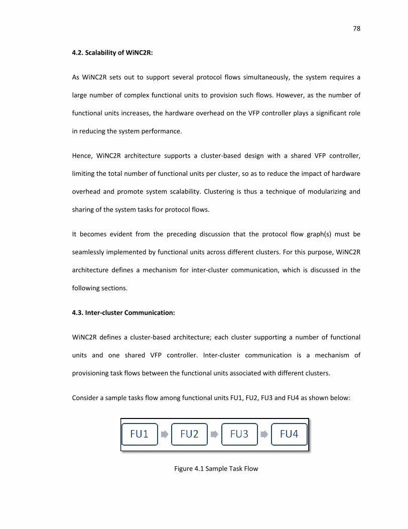
4.2. Scalability of WiNC2R:
As WiNC2R sets out to support several protocol flows simultaneously, the system requires a
large number of complex functional units
functional units increases, the
in reducing the system performa
Hence, WiNC2R architecture supports a cluster
limiting the total number of functional units per cluster, so as to
overhead and promote system scalability
sharing of the system tasks for protocol flows.
It becomes evident from the preced
seamlessly implemented by functional units
architecture defines a mechanism for inter
following sections.
4.3. Inter-cluster Communication:
WiNC2R defines a cluster-based
units and one shared VFP controller
provisioning task flows between the funct
Consider a sample tasks flow
Scalability of WiNC2R:
As WiNC2R sets out to support several protocol flows simultaneously, the system requires a
complex functional units to provision such flows. However,
functional units increases, the hardware overhead on the VFP controller plays a significant role
in reducing the system performance.
WiNC2R architecture supports a cluster-based design with a shared VFP controller,
al number of functional units per cluster, so as to reduce the impact of hardware
and promote system scalability. Clustering is thus a technique of modularizing and
sharing of the system tasks for protocol flows.
It becomes evident from the preceding discussion that the protocol flow graph(s) must be
by functional units across different clusters. For this purpose, WiNC2R
architecture defines a mechanism for inter-cluster communication, which is discussed in the
cluster Communication:
based architecture; each cluster supporting a number of functional
units and one shared VFP controller. Inter-cluster communication is a mechanism of
provisioning task flows between the functional units associated with different clusters.
flow among functional units FU1, FU2, FU3 and FU4 as shown below:
Figure 4.1 Sample Task Flow
78
As WiNC2R sets out to support several protocol flows simultaneously, the system requires a
to provision such flows. However, as the number of
plays a significant role
with a shared VFP controller,
reduce the impact of hardware
Clustering is thus a technique of modularizing and
ing discussion that the protocol flow graph(s) must be
across different clusters. For this purpose, WiNC2R
cluster communication, which is discussed in the
architecture; each cluster supporting a number of functional
cluster communication is a mechanism of
ional units associated with different clusters.
as shown below:
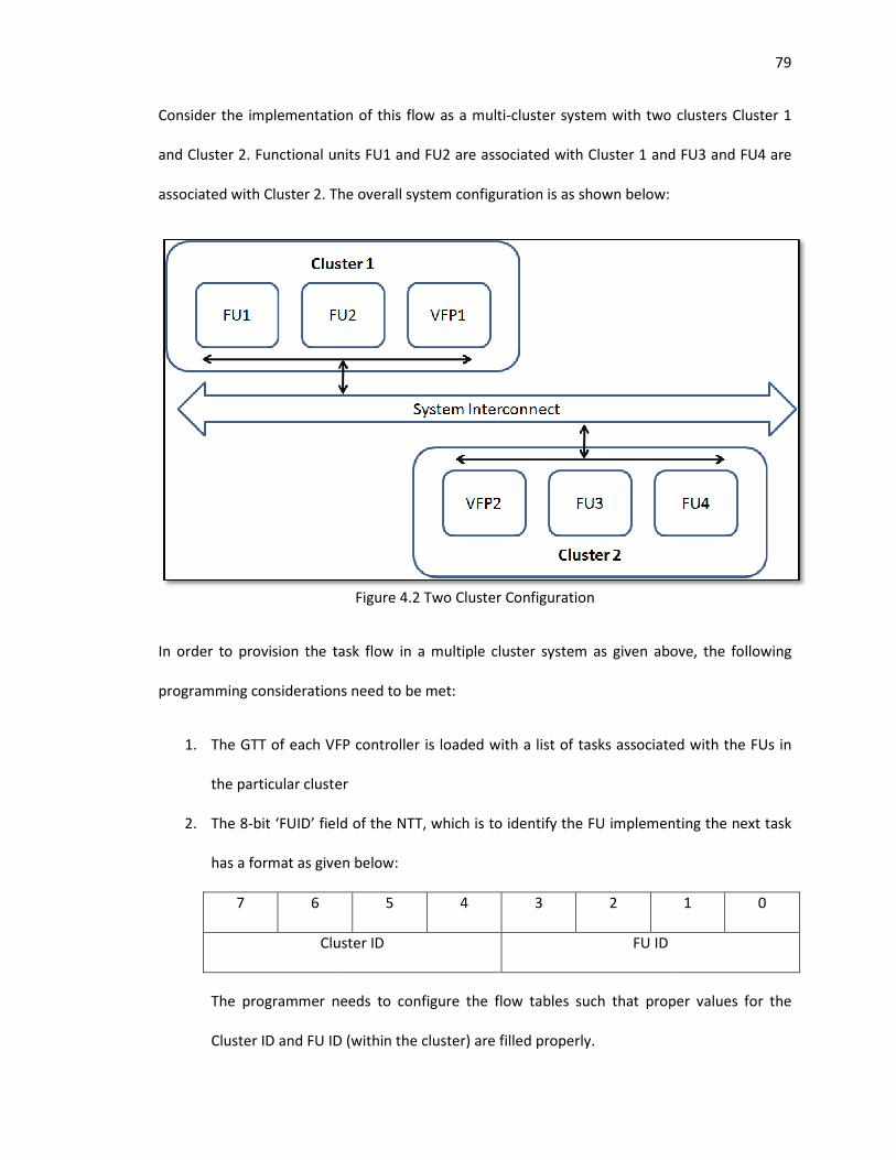
Consider the implementation of this flow as a multi
and Cluster 2. Functional units FU1 and FU2 are associated with Cluster 1 and FU3 and FU4 are
associated with Cluster 2. The overall system configuration is as shown below:
In order to provision the task flow
programming considerations need to be met:
1. The GTT of each VFP controller is loaded with a list of tasks associated with the FUs in
the particular cluster
2. The 8-bit ‘FUID’ field of the NTT, which i
has a format as given below:
7 6
Cluster ID
The programmer needs to configure the flow tables such that proper values for the
Cluster ID and FU ID (within the cluster) are filled
Consider the implementation of this flow as a multi-cluster system with two clusters Cl
Functional units FU1 and FU2 are associated with Cluster 1 and FU3 and FU4 are
The overall system configuration is as shown below:
Figure 4.2 Two Cluster Configuration
In order to provision the task flow in a multiple cluster system as given above, the following
programming considerations need to be met:
The GTT of each VFP controller is loaded with a list of tasks associated with the FUs in
the particular cluster
bit ‘FUID’ field of the NTT, which is to identify the FU implementing the next task
has a format as given below:
5 4 3 2
Cluster ID FU ID
The programmer needs to configure the flow tables such that proper values for the
Cluster ID and FU ID (within the cluster) are filled properly.
79
cluster system with two clusters Cluster 1
Functional units FU1 and FU2 are associated with Cluster 1 and FU3 and FU4 are
in a multiple cluster system as given above, the following
The GTT of each VFP controller is loaded with a list of tasks associated with the FUs in
s to identify the FU implementing the next task
1 0
The programmer needs to configure the flow tables such that proper values for the
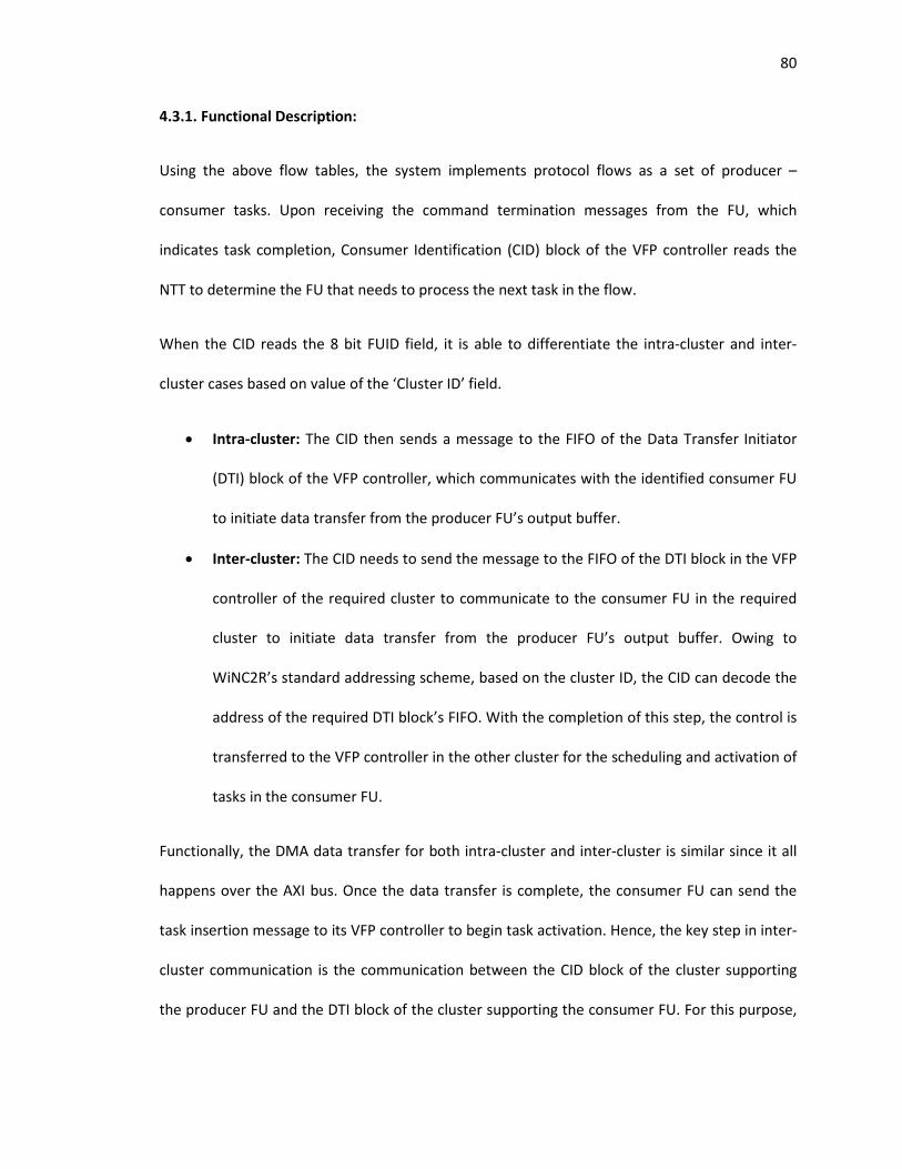
80
4.3.1. Functional Description:
Using the above flow tables, the system implements protocol flows as a set of producer –
consumer tasks. Upon receiving the command termination messages from the FU, which
indicates task completion, Consumer Identification (CID) block of the VFP controller reads the
NTT to determine the FU that needs to process the next task in the flow.
When the CID reads the 8 bit FUID field, it is able to differentiate the intra-cluster and inter-
cluster cases based on value of the ‘Cluster ID’ field.
• Intra-cluster: The CID then sends a message to the FIFO of the Data Transfer Initiator
(DTI) block of the VFP controller, which communicates with the identified consumer FU
to initiate data transfer from the producer FU’s output buffer.
• Inter-cluster: The CID needs to send the message to the FIFO of the DTI block in the VFP
controller of the required cluster to communicate to the consumer FU in the required
cluster to initiate data transfer from the producer FU’s output buffer. Owing to
WiNC2R’s standard addressing scheme, based on the cluster ID, the CID can decode the
address of the required DTI block’s FIFO. With the completion of this step, the control is
transferred to the VFP controller in the other cluster for the scheduling and activation of
tasks in the consumer FU.
Functionally, the DMA data transfer for both intra-cluster and inter-cluster is similar since it all
happens over the AXI bus. Once the data transfer is complete, the consumer FU can send the
task insertion message to its VFP controller to begin task activation. Hence, the key step in inter-
cluster communication is the communication between the CID block of the cluster supporting
the producer FU and the DTI block of the cluster supporting the consumer FU. For this purpose,
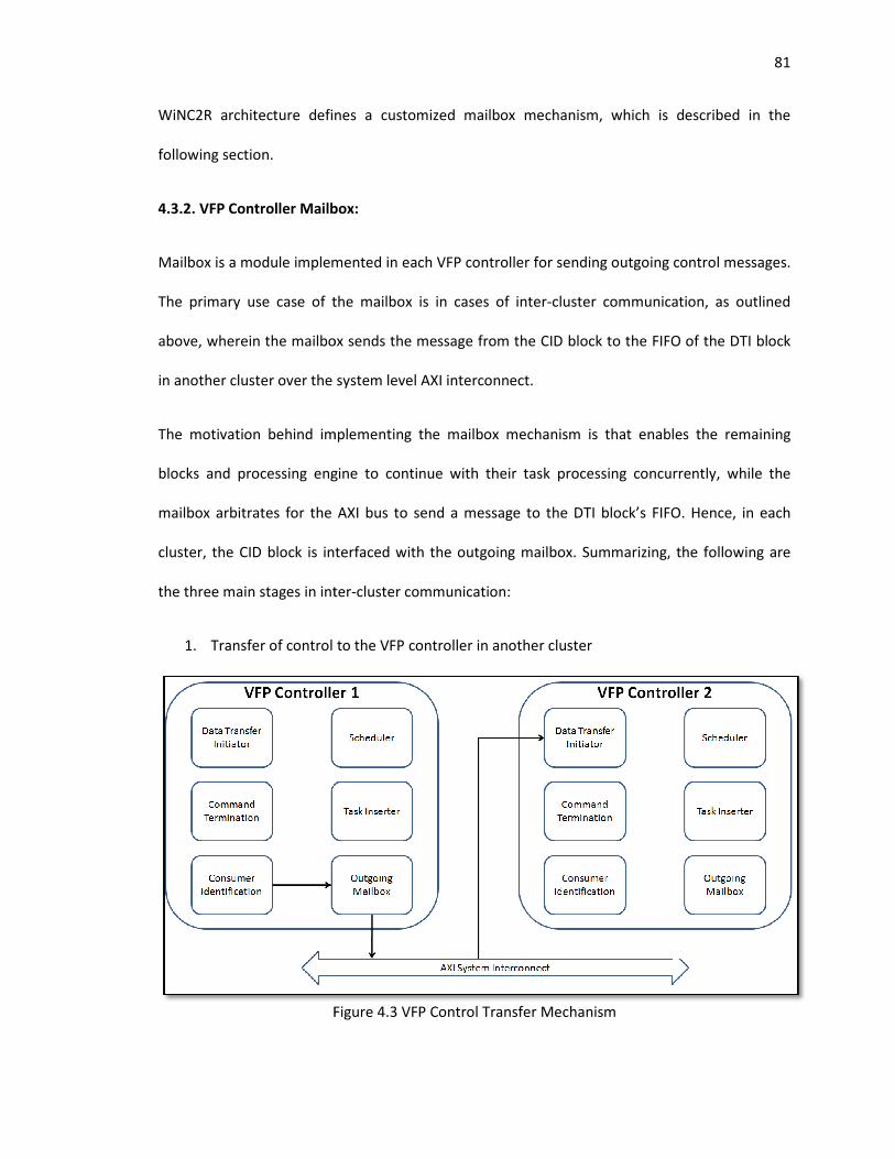
WiNC2R architecture defines a customized mailbox mechanism, which is described in the
following section.
4.3.2. VFP Controller Mailbox:
Mailbox is a module implemented in each VFP controller for sending outgoing control messages.
The primary use case of the mailbox is in cases of inter
above, wherein the mailbox sends the message from the CID block to the FIFO of the DTI block
in another cluster over the system level AXI interconnect.
The motivation behind implement
blocks and processing engine to continue with their task processing concurrently, while the
mailbox arbitrates for the AXI bus to send a message to the DTI block’s FIFO.
cluster, the CID block is interfaced with the outgoing mailbox.
the three main stages in inter
1. Transfer of control to the VFP controller in another cluster
Figure 4.3 VFP Control Transfer Mechanism
WiNC2R architecture defines a customized mailbox mechanism, which is described in the
VFP Controller Mailbox:
Mailbox is a module implemented in each VFP controller for sending outgoing control messages.
e of the mailbox is in cases of inter-cluster communication, as outlined
the mailbox sends the message from the CID block to the FIFO of the DTI block
in another cluster over the system level AXI interconnect.
The motivation behind implementing the mailbox mechanism is that enables the remaining
blocks and processing engine to continue with their task processing concurrently, while the
mailbox arbitrates for the AXI bus to send a message to the DTI block’s FIFO.
D block is interfaced with the outgoing mailbox. Summarizing, the following are
the three main stages in inter-cluster communication:
Transfer of control to the VFP controller in another cluster
Figure 4.3 VFP Control Transfer Mechanism
81
WiNC2R architecture defines a customized mailbox mechanism, which is described in the
Mailbox is a module implemented in each VFP controller for sending outgoing control messages.
cluster communication, as outlined
the mailbox sends the message from the CID block to the FIFO of the DTI block
ing the mailbox mechanism is that enables the remaining
blocks and processing engine to continue with their task processing concurrently, while the
mailbox arbitrates for the AXI bus to send a message to the DTI block’s FIFO. Hence, in each
Summarizing, the following are
82
2. DTI in cluster 2 sending a data transfer initiation message to the identified consumer FU
3. Transfer of data from the output buffer of the producer FU to the input buffer of the
consumer FU
4. Task insertion and activation in the consumer FU
Steps 2 thorough 4 are similar to the constituent steps of intra cluster next task processing, with
the exception that the data is transferred from an FU in another cluster.
4.3.3. Functional Tests:
The functional tests verifying this feature must test for the proper execution of the steps
involved in inter-cluster communication, as summarized in the preceding section. For this
purpose, we can consider a two-cluster system designed as follows:
1. Instantiate the mailbox module and interface it with the CID block of the VFP controller
2. Configured the programming flow tables as per the rules given in the previous section
Use customized monitors to verify every stage of inter-cluster communication along with
appropriate time stamps and post process the results to verify the feature.
4.3.4. Implementation Complexity:
The implementation of a two cluster system described in the functional test is a complex task
because of the following reasons:
1. AXI Bus Generation: WiNC2R project implements the AXI Bus Functional Model (BFM)
using the Verification Intellectual Property (VIP) from Design Ware. The bus generation
is a complex process of using Design Ware’s proprietary tools to identify the AXI masters
and slaves and classifying them based on their required address ranges.
83
2. Memory mapping and Address Decoding: Implementing such a 2 cluster design is
complex owing to the instantiation of the cluster components based on the global
memory maps. Also, each VFP controller needs to be programmed with an updated
address decoder based on the global memory map.
In order to overcome the above long poles, our verification test plan simplifies the functional
verification using a single cluster system.
4.3.5. Test plan:
In our test plan, we target each of the 4 stages of inter-cluster communication as an individual
test to perform step-wise feature verification. For this, we use the test setup as defined in the
functional verification case by instantiating the mailbox and programming the flow tables for an
inter-cluster flow.
From the producer side, we verify the transfer of control by snooping into the CID – Mailbox
interface using our monitors and verifying if the Mailbox initiates an AXI transaction on the
system bus. This is run as the first test and the results will be recorded.
We now run the second test with the same cluster, with the flow tables programmed as
required by the consumer side to mimic a consumer cluster. Now, using our testbench, we force
the CID messages onto the DTI FIFO and then verify if the DTI block sends a message to the
required consumer FU. Now we verify if the consumer FU initiates an AXI transaction for data
transfer.
Thus, we have successfully abstracted the inter-cluster communication tests for a two cluster
system using one cluster.
84
Chapter 5 – Conclusion and Future Work
The focus of this thesis was to evaluate the WiNC2R platform implementation and programming
model against its goals to provide deterministically programmable support for constantly
evolving complex wireless protocols. Programmability and configurability of the WiNC2R
platform to provision IEEE 802.16e Mobile WiMAX standard was used as a benchmark to
evaluate the system.
From our system design and comprehensive functional verification of the system, we have the
following conclusions:
System Configurability:
The heart of WiNC2R’s functionality lies in the control of the functional units by the VFP
controller. Complex wireless protocols like Mobile WiMAX require a number of complex
computation-intensive functional units for their physical layer implementation. From our task of
designing the WiMAX physical layer, we have observed that:
• Several signal processing blocks from a variety of sources ranging from open source
projects like GNU Radio to custom IP vendors are available to implement the
multifunctional processing engines
• Licensed programmable processing cores from vendors are available to implement the
software programmable CPUs
Hence, proper interfacing of these cores with the VFP controller block using the standard
application programming interfaces makes it relatively straightforward to design a library of
parameterized functional units for WiNC2R.
85
System Functionality:
Comprehensive analysis of Mobile WiMAX implementation requirements on WiNC2R has
indicated adequate support from the platform for most features of complex modern wireless
protocols.
• Features like Next Task Processing and Running Sync and Async tasks on the same
processing engine support the stringent timing and flow requirements of Mobile WiMAX
protocol.
• Features like Chunking and De-chunking support the runtime performance regulatory
aspects of the WiMAX protocol by enabling Fragmentation and Packing by regulating
end-to-end latency of the system.
• Features like clustering and inter-cluster communication point the architecture in the
right direction for support of constantly evolving wireless standards by reducing the
hardware overhead and improving scalability. Future implementations can modularize
functions like data generation, Forward Error Correction (FEC), etc., into separate
clusters for improved system performance.
System Programmability:
The key aspect of the WiNC2R architecture which makes it an effective solution for wireless
protocols is its elegant task programming model. The highlight of the programming model is its
standard flow programming methodology for implementing any protocol flow. The abstraction
of specific physical layer functionalities into tasks, which are programmable as a flow graph with
runtime performance regulations make the WiNC2R programming model extremely suited for
the platform’s adaptability for supporting a multitude of current and future wireless protocols.
86
5.1. Future Work
The following aspects can be considered to build upon the work done in this thesis:
• OVM to UVM Migration: Unified Verification Methodology (UVM) is an evolving
standard for verification, which draws heavily from OVM principles and syntax.
Migration of the testbench from OVM to UVM would aid in providing a more powerful
verification environment and support future iterations of the system.
• Emulation: The typical follow up step to simulation based functional verification is FPGA
based ‘emulation’ verification. This is intended to mimic the system on an FPGA board
to test and debug the system under real time operating characteristics.
• Power Requirements: The power requirements of the system need to be defined and
appropriate power control mechanisms must be introduced to match the power and
performance requirements of wireless protocol implementation.
87
References
[1] Z.Miljanic, P.Spasojevic, and Onkar Sarode. A Dynamically Programmable Radio
Processing MPSoC with Hardware-based Task Management. Proceedings of Asilomar
Conference on Signals, Systems, and Computers, 2010
[2] Z.Miljanic, P.Spasojevic, Mohit Wani and Jerry Redington. ASIP Data Plane Processor for
Multi-Standard Interleaving and De-Interleaving. Proceedings of Asilomar Conference on
Signals, Systems, and Computers, 2010
[3] Zoran Miljanic et al. Architecture for Cognitive Radio Testbeds and Demonstrators – an
Overview. Proceedings of CrownComm 2010
[4] Z.Miljanic and P.Spasojevic. Resource Virtualization with Programmable Radio
Processing. Proceedings of WICON - The Wireless Internet Conference, 2008
[5] Z.Miljanic, I. Seskar, K. Le and D. Raychaudhuri. The WINLAB Network Centric Cognitive
Radio Platform – WiNC2R. Proceedings of CrownComm 2007
[6] Onkar Sarode. Architecture Of A Programmable System-On-Chip Platform For Flexible
Radio Processing. Master’s Thesis – Rutgers, The State University of New Jersey,
October 2010
[7] Muhammad Nadeem Khan and Sabir Ghauri. The WiMAX 802.16e Physical Layer Model.
University of the West of England, United Kingdom
[8] M.A. Mohamed, F.W. Zaki and R.H. Mosbeh. Simulation of WiMAX Physical Layer: IEEE
802.16e. IJCSNS International Journal of Computer Science and Network Security,
VOL.10 No.11, November 2010
[9] Gazi Faisal Ahmed Jubair, Muhammad Imran Hasan and Md. Obaid Ullah. Performance
Evaluation of IEEE 802.16e (Mobile WiMAX) in OFDM Physical Layer. Master’s Thesis –
Blekinge Institute of Technology August 2009
[10] Jamal Mountassir, Horia Balta, Marius Oltean, Maria Kovaci and Alexandru Isar. A
Physical layer simulator for WiMAX in Rayleigh Fading Channel. 6th IEEE International
Symposium on Applied Computational Intelligence and Informatics May 19–21, 2011
Timişoara, Romania
[11] Ariton E. Xhafa, Shantanu Kangude, and Xiaolin Lu. MAC Performance of IEEE 802.16e.
Vehicular Technology Conference, 2005. VTC-2005-Fall. 2005 IEEE 62nd.
88
[12] Mikko Kivistö and Petri Järvelä. 802.16e Mobile WiMAX. Tampere University of
Technology
[13] Madhura Joshi. System Integration and Performance Evaluation of WINLAB Network
Centric Cognitive Radio Platform for 802.11a Like Protocol. Master’s Thesis – Rutgers
the State University of New Jersey, October 2010
[14] Akshay Jog. Architecture Validation of VFP Control for the WiNC2R Platform. Master’s
Thesis – Rutgers the State University of New Jersey, October 2010
[15] Lihua Wan, Wenchao Ma and Zihua Guo. A Cross-layer Packet Scheduling and
Subchannel Allocation Scheme in 802.16e OFDMA System. Wireless Communications
and Networking Conference, 2007.
[16] Jeffrey G Andrews, Arunabha Ghosh, Rias Muhamed. Fundamentals of WiMAX:
Understanding Broadband Wireless Networking. Upper Saddle River, NJ: Prentice Hall,
2007.
[17] Bo Li, Yang Qin, Chor Ping Low and Choon Lim Gwee. A Survey on Mobile WiMAX.
Communications Magazine, IEEE, vol. 45, no. 12, pp. 70–75, December 2007
[18] Arunabha Ghosh, David R. Wolter, Jeffrey G. Andrews and Runhua Chen. Broadband
Wireless Access with WiMax/802.16: Current Performance Benchmarks and Future
Potential. Communications Magazine, IEEE, vol. 43, no. 2, pp. 129–136, February 2007
[19] M. Benjamin, D. Geist, A. Hartman, Y. Wolfsthal, G. Mas, and R.Smeets, “A study in
coverage-driven test generation,” in Proc. Des. Autom. Conf., Jun. 1999, pp. 970–975.
[20] Chris Spear. SystemVerilog for Verification: A guide to Learning the Testbench Language
Features. Springer, 2006.
[21] Mark Glasser. Open Verification Methodology Cookbook. Springer 2009
[22] AMBA 3.0 AXI www.arm.com