Embed Size (px)
Citation preview

Scott E. Stapleton and Anthony M. WaasUniversity of Michigan, Ann Arbor, Michigan
Steven M. ArnoldGlenn Research Center, Cleveland, Ohio
Functionally Graded Adhesives for Composite Joints
NASA/TM—2011-217202
December 2011
https://ntrs.nasa.gov/search.jsp?R=20120001792 2020-06-04T15:32:35+00:00Z

NASA STI Program . . . in Profile
Since its founding, NASA has been dedicated to the advancement of aeronautics and space science. The NASA Scientific and Technical Information (STI) program plays a key part in helping NASA maintain this important role.
The NASA STI Program operates under the auspices of the Agency Chief Information Officer. It collects, organizes, provides for archiving, and disseminates NASA’s STI. The NASA STI program provides access to the NASA Aeronautics and Space Database and its public interface, the NASA Technical Reports Server, thus providing one of the largest collections of aeronautical and space science STI in the world. Results are published in both non-NASA channels and by NASA in the NASA STI Report Series, which includes the following report types: • TECHNICAL PUBLICATION. Reports of
completed research or a major significant phase of research that present the results of NASA programs and include extensive data or theoretical analysis. Includes compilations of significant scientific and technical data and information deemed to be of continuing reference value. NASA counterpart of peer-reviewed formal professional papers but has less stringent limitations on manuscript length and extent of graphic presentations.
• TECHNICAL MEMORANDUM. Scientific
and technical findings that are preliminary or of specialized interest, e.g., quick release reports, working papers, and bibliographies that contain minimal annotation. Does not contain extensive analysis.
• CONTRACTOR REPORT. Scientific and
technical findings by NASA-sponsored contractors and grantees.
• CONFERENCE PUBLICATION. Collected papers from scientific and technical conferences, symposia, seminars, or other meetings sponsored or cosponsored by NASA.
• SPECIAL PUBLICATION. Scientific,
technical, or historical information from NASA programs, projects, and missions, often concerned with subjects having substantial public interest.
• TECHNICAL TRANSLATION. English-
language translations of foreign scientific and technical material pertinent to NASA’s mission.
Specialized services also include creating custom thesauri, building customized databases, organizing and publishing research results.
For more information about the NASA STI program, see the following:
• Access the NASA STI program home page at http://www.sti.nasa.gov
• E-mail your question via the Internet to help@
sti.nasa.gov • Fax your question to the NASA STI Help Desk
at 443–757–5803 • Telephone the NASA STI Help Desk at 443–757–5802 • Write to:
NASA Center for AeroSpace Information (CASI) 7115 Standard Drive Hanover, MD 21076–1320

Scott E. Stapleton and Anthony M. WaasUniversity of Michigan, Ann Arbor, Michigan
Steven M. ArnoldGlenn Research Center, Cleveland, Ohio
Functionally Graded Adhesives for Composite Joints
NASA/TM—2011-217202
December 2011
National Aeronautics andSpace Administration
Glenn Research Center Cleveland, Ohio 44135

Acknowledgments
The authors would like to thank Brett Bednarcyk from NASA Glenn for valuable input. Portions of this work were financially supported by the Space Vehicle Technology Institute under grant NCC3-989 jointly funded by NASA and the Department of
Defense. Additional financial support was provided by NASA Glenn Research Center through the GSRP Fellowship.
Available from
NASA Center for Aerospace Information7115 Standard DriveHanover, MD 21076–1320
National Technical Information Service5301 Shawnee Road
Alexandria, VA 22312
Available electronically at http://www.sti.nasa.gov
Trade names and trademarks are used in this report for identification only. Their usage does not constitute an official endorsement, either expressed or implied, by the National Aeronautics and
Space Administration.
Level of Review: This material has been technically reviewed by technical management.

NASA/TM—2011-217202 1
Functionally Graded Adhesives for Composite Joints
Scott E. Stapleton and Anthony M. Waas University of Michigan
Ann Arbor, Michigan 48105
Steven M. Arnold National Aeronautics and Space Administration
Glenn Research Center Cleveland, Ohio 44135
Abstract Adhesives with functionally graded material properties are being considered for use in adhesively
bonded joints to reduce the peel stress concentrations located near adherend discontinuities. Several practical concerns impede the actual use of such adhesives. These include increased manufacturing complications, alterations to the grading due to adhesive flow during manufacturing, and whether changing the loading conditions significantly impact the effectiveness of the grading. An analytical study is conducted to address these three concerns. An enhanced joint finite element, which uses an analytical formulation to obtain exact shape functions, is used to model the joint. Furthermore, proof of concept testing is conducted to show the potential advantages of functionally graded adhesives. In this study, grading is achieved by strategically placing glass beads within the adhesive layer at different densities along the joint.
1.0 Introduction With the increasing demand for composites in lightweight aerospace structures, adhesively bonded
joints are becoming increasingly attractive. Bolts and rivets cause stress concentrations and premature failure in composite materials, while adhesive bonds spread the load more evenly over the composite, facilitating a lighter overall structure.
One major drawback of adhesively bonded joints is that the load path eccentricity causes the appearance of peel stress concentrations at the end of the adhesive layer. There has been a vast amount of research conducted in an attempt to reduce these stress concentrations, such as tapering the end of the adherend (Ref. 1), increasing thickness of the adhesive at the end (Ref. 2), fillets (Ref. 3), novel joint geometries (Ref. 4), and joint insertions (Ref. 5), to name a few. All of these methods involve local details of adherend geometry (except the adhesive fillets), which typically increases part complexity.
Material grading occurs in nature at material interfaces to reduce stress concentrations (Ref. 6). Biological interfaces such as tendon to bone joints have been found to have graded material properties, which distributes the stress more evenly across the joint (Refs. 7 and 8). In this same spirit, material grading has been applied to adhesively bonded joints. Although grading the adherends has shown promise (Ref. 9), many more researchers have investigated grading the adhesive properties to reduce the peel stress concentration at the end of the adhesive. Some of the earliest grading of the adhesive was reported by Patrick (Ref. 10) and Raphael (Ref. 11), where grading was discretely achieved using two adhesive materials (i.e., bi-adhesive). Recently many other researchers have investigated the concept of grading using bi-adhesive joints with mixed results. Sancaktar and Kumar (Ref. 12) graded the adhesive by making rubber toughened regions near the stress concentrations, and found that the selectively toughened joints had the same strength as the fully toughened joints. Piresa et al. (Ref. 13) used two adhesives to bond aluminum, and found up to a 22 percent increase in joint strength. Fitton and Broughton (Ref. 14) bonded CFRP to steel, and found that it was crucial to optimize the amount of each adhesive and that some configurations did not benefit from grading. Da Silva and Lopes (Ref. 15) looked at the influence of

NASA/TM—2011-217202 2
the ductility of adhesives on joint strength in a bi-adhesive joint. It was found that the mixed adhesive joints always out-performed the joints with only the most brittle adhesive. Kumar and Pandey (Ref. 16) more recently looked at modeling bi-adhesive single lap joints using 3D finite elements with nonlinear geometry and materials, and compared that with 2D finite element model. Valleé et al. (Ref. 17) compared stress reduction methods, including bi-adhesive joints and found that the adhesive stress was not linked to the strength of the joint for the configurations tested. This finding is not unexpected because the failure mode occurred in the adherend, not the adhesive.
It appears that the first instance of grading the adhesive with a non-stepwise function was introduced by Kumar (Ref. 18). In that study, grading the adhesive in a tubular joint was investigated. The purely theoretical investigation first compared a continuous (non step-wise) functionally graded adhesive (FGA), where the modulus was graded using a quadratic function, with a step-wise graded equivalent for different overlap lengths and adhesive thicknesses. It was found that the continuous FGA reduced the shear and peel stresses in all cases. Second, four “arbitrarily chosen” functions were compared to show that the grading function can be manipulated to optimize joint performance. The current study aims to increase the understanding of both bi-adhesive and non-stepwise FGAs to make them a more viable, realistic, and advantageous choice for actual application in composite structures.
Some potential drawbacks to FGAs have also been discussed in the literature. The first two were identified by Hart-Smith (Ref. 2), where he pointed out that: 1) small gains over just using the ductile adhesive alone may be inadequate when considering the production difficulties and 2) during manufacturing, there is the “inevitable tendency for the stiff adhesive to squeeze out and displace the ductile adhesive,” making it probable that the resulting joint will be worse-off than using the ductile adhesive alone. A third concern was raised by Aboudi et al. (Ref. 19) while investigating the response of metal matrix composites with tailored microstructures. They found that functionally grading the properties of a material may be detrimental when the loading is changed, such that the stress gradient in the material is reversed; this is a valid concern for practical situations where all loading cases cannot necessarily be predicted. The current study aims to address these practical concerns to show that FGAs are a viable means of decreasing the peel stress in an adhesively bonded joint. An analytical model is constructed and used to compare the stresses in a butt-end joint configuration with four different functions of modulus graded adhesive: constant (single adhesive), discrete (bi-adhesive), linear, and exponential. First, the potential gains in stress reduction for FGA joints over joints with a single adhesive are shown. Along these lines, it is shown that additional stress reductions can be achieved by lowering the modulus of the more compliant adhesive. Since it is likely that step-wise grading will appeal from a manufacturing perspective, stress reduction of a step-wise graded adhesive with many steps is investigated (with single or bi-adhesive being a special case). Second, the study addresses the issue of adhesive flow during bonding by showing how sensitive the optimum for the three FGAs is to perturbation of the grading. Third, multiple load scenarios will be examined to address the concern of changing loading conditions. Results indicate that the stress magnitude gradient in the adhesive remains unchanged under different loading conditions, thus making joints a perfect application for material grading. It will be shown that the adhesive peel stress magnitude gradient remains the same for varied loading conditions, but also for different joint types. Additionally, the sensitivity of the optimum for the four grading functions to different loading cases will be investigated to show that the grading can still be optimal under different loading conditions. Addressing these three concerns will provide significant impetus for the use of FGAs in industrial applications.
The model used to obtain the adhesive stress for different FGAs is a structural finite element made specifically for adhesively bonded joints. Motivated by the desire to create a computationally efficient tool for designing joints within a coarse, vehicle scale finite element model (Ref. 20), the joint element combines an analytical formulation with a finite element. This concept has been often referred to as the exact stiffness matrix method, and has been previously applied to the beam on an elastic foundation problem (Refs. 21 and 22). The joint element is capable of capturing the stresses in a mesh-independent, efficient manner. Such an efficient method is pivotal to the current study, allowing the analysis of over 20,000 different joints for optimization and parametric studies on a desktop computer in a fraction of a

NASA/TM—2011-217202 3
second per joint. The formulation adopted here is altered from past formulations (Ref. 23) to account for a graded adhesive modulus and is presented below. A linear elastic material model is used for several reasons, simplicity being the most prominent. Also, since a controlled method and material system for manufacturing FGAs has not yet been identified, failure of the joint and post-failure response is not addressed. Finally, it should be noted that after initial departure from material linearity (due to damage or plasticity) and before crack formation, the adhesive modulus is effectively a continuous function across the joint, which causes more load to be transferred to the inner regions of the joint. However, the main idea of a FGA is that this effect can be achieved without taking on irrecoverable damage. Since the benefit of FGAs can be realized without material damage, this study will be limited to the linearly elastic regime of the adhesive. Geometric nonlinearity is also ignored for simplicity and because it is not expected to have a large effect on a stress comparison study between adhesive systems.
The analytical findings are complemented with an experimental “proof of concept” testing to illustrate the benefits of FGAs. The adhesive was graded by adding different volume percentages of glass beads, although no precise method was used to control the grading except the eye and hand of the person preparing the specimens. By showing that a joint can benefit from grading in such a rudimentary manner, the potential for more drastic gains through controlled and precise grading can be argued for.
2.0 Method 2.1 Formulation
An adhesively bonded joint finite element was used to assess the performance of FGA joints. This joint finite element uses an analytical formulation to get the exact stiffness matrix for N number of adherends held together by N-1 adhesive layers. The adhesives and adherends were assumed to be linearly elastic, but not necessarily isotropic. The adherends were modeled as wide plates under cylindrical bending, using Euler-Bernoulli beam theory and Classical Lamination Theory (CLT). The adhesive response is captured through a continuous bed of shear and normal springs. This assumption ignores the traction free boundary condition which is present for an adhesive modeled as a continuum. However, most joints in application have some sort of adhesive spew coming out of the joint, which makes the imposition of a traction free boundary condition unrealistic. The material and geometric parameters are shown in Figure 1. The subscript i refers to adherend i, and ai refers to adhesive layer i. The width of the joint in the y-direction is b.
Figure 1.—Geometric and material parameters for overlap
region of an adhesively bonded joint.
Eai,Gai
Ei
Ei+1
adhesivei
adherendi+1
l
adherendi
ηi
ti
ti+1
ui(x), wi(x)
ui+1(x), wi+1(x)

NASA/TM—2011-217202 4
2.1.1 Governing Equations The strain energy of the joint, Ujoint, is written as:
1
1 1joint 2 2
1 1 1( )
i
j i i i iai i
MN Nj
i a a a aiV Vi j i
U dV dV−
= = =
= σ ε + σ ε + τ γ∑∑ ∑∫ ∫ (1)
Where jiσ is the axial stress in the jth layer of the ith adherend, and iε represents the axial strain in
adherend i in the x–direction. iaσ and
iaε are the normal stress/strain in the ith adhesive in the z-direction,
iaτ and iaγ represent the shear stress/strain in the ith adhesive on the xz-plane, and all integrals are taken
over the volume, jiV or
iaV of adherend i, layer j or adhesive i respectively. Using CLT, the stress can be
written in terms of the strain and the 1,1 component of the transformed lamina compliance matrix, j
Q :
11j j
ii Qσ = ε (2)
and the strain can be written in terms of the adherend centerline displacements of adherend i, ui and wi:
, ,i i x i xxu zwε = − . (3)
It is assumed that the displacements in the adhesive layers vary linearly in the z-direction and that the adhesive and adherends are perfectly bonded at the interface. The normal and shear stress in adhesive ai can be written in terms of the adherend displacement above and below the adhesive layer:
( )12 2
11
t ti iia i iz zi
w w ++=− =ε = −
η (4a)
and
( )12 2
11
t ti iia i iz zi
u u ++=− =γ = −
η (4b)
and the corresponding stresses are:
( )i i ia a aE xσ = ε (5a)
and
( )i i ia a aG xτ = γ . (5b)
Using the principle of stationarity of potential energy, 2N fully coupled governing equilibrium differential equations are obtained from the energy expression in Equation (1). Of the 2N governing equations, N equations correspond to the axial equilibrium, while N equations correspond to the transverse equilibrium. The axial displacement equilibrium equations contain second order derivatives, while the transverse displacement equations have fourth order derivatives. The order of these equations can be reduced and assembled into a system of first order non-constant coefficient homogeneous ordinary differential equations of the form:
, ( )x x=u A u (6)

NASA/TM—2011-217202 5
where
1TT T T
i N= u u u u (7a)
and
, , , ,T
i i i x i i x i xx i xxxu u w w w w= u . (7b)
2.1.2 Method of Constant Segments for Solving Linear, Homogeneous, Non-Constant Coefficient System of Ordinary Differential Equations
In order to solve the system of equations found in Equation (6), a semi-numerical method of solution was adopted. Traditional differential equation solving techniques employing numerical boundary conditions could not be employed because the boundaries (nodes) contain unknown, symbolic conditions. Therefore, the domain was split into segments in which the coefficient matrix, A(x), is considered constant and solved using the matrix exponential. First, consider segment n+1, with a local x-direction coordinate system x’ which originates at the left side of the segment, x=xn (Figure 2). The other end of the segment is at x’=Δx and x=xn+1.
It is assumed that Δx is significantly small so that A(x), can be considered constant within each such segment. The linearized coefficient matrix An+1, is taken to be the coefficient matrix evaluated at the midpoint of the segment:
( )1 2x
n nx ∆+ = +A A (8)
Within segment n+1, the system can now be expressed as a system of ordinary constant coefficient differential equations in the local coordinate system, x’, of the form:
, ' 1x n+=u A u . (9)
Figure 2.—Method of linear segments involves breaking up a function into
small segments and assuming the function is constant within the segment.
u
x
u(x)
u
xxn
un
xn+1
un+1
ux'
Δx
Δx

NASA/TM—2011-217202 6
Inspecting the matrix An+1 can be helpful in determining the nature of the solution and determining the solution method. There are 6N eigenvalues of An+1: N real eigenvalues, 2N complex eigenvalues, and 3N repeating eigenvalues. Therefore, the solution is made up of N exponential terms, 2N exponential terms multiplied by a sine or cosine, and the 3N repeating eigenvalues correspond to a third order polynomial found in a standard beam solution. Such a complex solution shows that merely employing standard beam shape functions to the joint problem would be inadequate in capturing the nature of the complete solution. The solution of the system in Equation (8) can be written in terms of the matrix exponential, 1 'n x+Ae , and a vector of unknown constants, Cn+1, as
1 '1( ') n x
nx + += Au e C . (10)
The matrix exponential can be expressed as the infinite series (Ref. 24)
1 '
0 !n
kx k
k
xk
+
∞
=
=∑Ae A . (11)
To get faster convergence, a method of scaling and squaring (Ref. 25) is employed, and the series is calculated up to a value of k which yields an acceptable error, ε. The error can be defined many ways, but the current study defined the error as the difference between the 1-norms of 1 'n x+Ae for k–1 and k. The value of the acceptable error was set at 0.0001ε = .
In the local coordinate system, the solution un at x’=0 can be expressed as
101 1nn n n+ + += =Au e C C (12)
and the solution, un+1, at the end of the segment (x’=Δx) can be written in terms of the solution at the beginning of the segment,
11 n xn n+ ∆+ = Au e u , (13)
to eliminate the vector of constants, Cn+1. Similarly, the solution at the end of the previous segment can be expressed as
1n xn n
∆−= Au e u (14)
and so on, down to the first segment, which has the solution:
00 0x∆= Au e C . (15)
Therefore, the solution at any segment, n+1, can be expressed in terms of the vector of constants from the first segment, C0, by the equation:
1( )1 0nx x
n ++ = Au e C . (16)
where
1
1( )
0
n m
nx x x
m
+
+∆
=
=∏A Ae e . (17)

NASA/TM—2011-217202 7
Figure 3.—A comparison of solutions to the homogeneous, linear, non-constant coefficient differential equation
= −3, ( sin4 )xxy x e x y with initial conditions =(0) 1y and =, (0) 0xy (a) using the method of constant segments with
two, four, and six segments and (b) the relative error as a function of the number of segments used.
Figure 4.—Boundary conditions for adherend i: prescribed
nodal displacements and rotations at x=0 and x=l.
To demonstate this method, Figure 3 shows a convergence study for the differential equation 2
, ( sin 4 )xxy x e x y= − with initial conditions (0) 1y = and , (0) 0xy = . It can be seen that the percent error
between the method of constant segments and the solution found using a 4th order Runga-Kutta (Ref. 26) solver with a step size of 0.001 diminishes with the number of segments. For the current study, 200 segments were used in each element.
2.1.3 Stiffness Matrix The next step is to solve for the vector of constants, C0, using the boundary conditions. This is where
the analytical formulation is discretized and the displacements are obtained in terms of the nodal displacements as defined in Figure 4. For adherend i, the boundary conditions on the left side of the joint (x=0) can be expressed in the following equation:
0 (0)i c i=q b u (18)
where ui(0) is ui evaluated at x=0, qi0 is a vector containing the prescribed nodal degrees of freedom of adherend i at x=0, and
1 0 0 0 0 00 0 1 0 0 00 0 0 1 0 0
c
=
b (19)
Equation (18) for all N adherends can be assembled together, and a relation between the nodal degrees of freedom at x=0 and the vector of constants can be found using Equation (16):
(a) (b)
0
20
40
60
80
1 3 5 7 9
% E
rror
Number of Segments
0.4
0.6
0.8
1.0
0 0.2 0.4 0.6 0.8 1
y
x
2 Segments
4 Segments6 Segments
y(x)
adherendi
qi2qi1
qi3
qi5qi4qi6

NASA/TM—2011-217202 8
( )00 0
xN= Aq B e C (20)
where
0 10 0 0TT T T
i N= q q q q (21)
and
c
N
c
=
bB
b (22)
where the subscript N denotes the number of matrices on the diagonal. After performing the same operations at x=l, all of the boundary conditions can be combined in the form
00
l
= =
qzC q
q (23)
where
( )0
2 ( )
x
N x l
=
A
A
ez B
e. (24)
Using this relation, one can obtain an expression for the vector of unknown constants:
10
−=C z q . (25)
This relation can be inserted into Equation (16) to get the adherend centerline displacements in terms of the nodal degrees of freedom,
=u Nq , (26)
where the exact shape functions, N are defined as:
( ) 1x x −= AN e z . (27)
Next, Equation (1) is rewritten in terms of the centerline displacements using Equations (2-5) and put into matrix form:
joint 0
lTU dx= ∫ u Uu . (28)
Inserting Equation (26) into Equation (28) and minimizing the energy yields the exact stiffness matrix of the joint
joint 0
lT dx= ∫k N UN . (29)

NASA/TM—2011-217202 9
Figure 5.—The building block approach facilitates modeling complex joints with simple joint
element building blocks.
This formulation gives the exact stiffness matrix for a simple region of constant thickness adherend overlap. However, many joints in application contain complicated geometries, including ply steps and tapers. To use the simple joint element for efficient modeling of complex joints, a building block approach was implemented. This approach involves combining simple, constant-thickness joint sections to create complicated joints with very few elements. This concept is illustrated in Figure 5, where single, double and triple adherend joint building blocks are combined to make complicated joints such as a PI joint, tapered single lap joint, and spliced sandwich joint.
Adherends joined together at the adherend centerlines are related to each other with the equation
iL iRq q= , 1..3i = (30)
where the subscript L is for the adherend on the left, R is for the adherend on the right, and the numerical subscripts 1, 2, and 3 refer to axial, transverse, and rotational degrees of freedom respectively. To model a ply step or taper, the transverse and rotational degrees of freedom are equal, but the axial degree of freedom of the left adherend is related to that of the right adherend through the following equation:
1 1 offset 3L R Rq q t q= − (31)
where offsett is the vertical (z-direction) offset distance between the two nodes.
3.0 Results and Discussion 3.1 Baseline Configuration
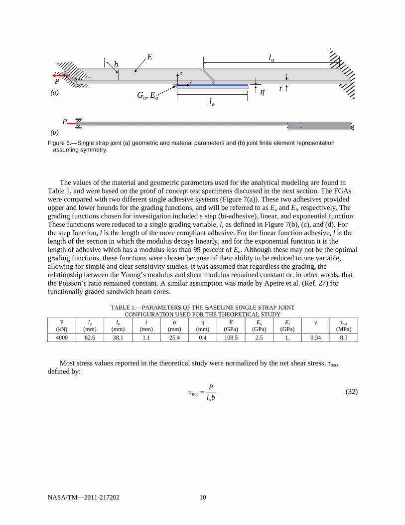
To assess the performance of functionally graded adhesives (FGAs), a baseline joint configuration was identified based on the configuration in the proof of concept testing (Section 3.5). A single strap joint (or butt end joint) was chosen because of its ease of manufacturing, symmetry, and single dominant stress concentration in the middle of the joint. The geometric and material properties are defined in Figure 6(a), and the finite element representation is shown in Figure 6(b). Only half of the joint was modeled due to symmetry, and the overlap section was modeled by one or several joint elements (depending on the number of discrete regions of continuous adhesive modulus) while the non-joint adherend section is modeled with one beam element. The loaded end is constrained from rotation and vertical translation, while the symmetric face of the doubler is constrained from horizontal translation and rotation.
Beam
Single Lap
Double Lap
NASA/TM—2011-217202 10
Figure 6.—Single strap joint (a) geometric and material parameters and (b) joint finite element representation
assuming symmetry.
The values of the material and geometric parameters used for the analytical modeling are found in Table 1, and were based on the proof of concept test specimens discussed in the next section. The FGAs were compared with two different single adhesive systems (Figure 7(a)). These two adhesives provided upper and lower bounds for the grading functions, and will be referred to as Eu and El, respectively. The grading functions chosen for investigation included a step (bi-adhesive), linear, and exponential function. These functions were reduced to a single grading variable, l, as defined in Figure 7(b), (c), and (d). For the step function, l is the length of the more compliant adhesive. For the linear function adhesive, l is the length of the section in which the modulus decays linearly, and for the exponential function it is the length of adhesive which has a modulus less than 99 percent of Eu. Although these may not be the optimal grading functions, these functions were chosen because of their ability to be reduced to one variable, allowing for simple and clear sensitivity studies. It was assumed that regardless the grading, the relationship between the Young’s modulus and shear modulus remained constant or, in other words, that the Poisson’s ratio remained constant. A similar assumption was made by Apetre et al. (Ref. 27) for functionally graded sandwich beam cores.
TABLE 1.—PARAMETERS OF THE BASELINE SINGLE STRAP JOINT
CONFIGURATION USED FOR THE THEORETICAL STUDY P
(kN) la
(mm) lo
(mm) t
(mm) b
(mm) η
(mm) E
(GPa) Eu
(GPa) El
(GPa) ν
τnet (MPa)
4000 82.6 38.1 1.1 25.4 0.4 108.5 2.5 1. 0.34 8.3 Most stress values reported in the theoretical study were normalized by the net shear stress, τnet,
defined by:
neto
Pl b
τ = (32)
P
lo
lab
tη
P
(a)
(b)
E
Ga, Ea
xz

NASA/TM—2011-217202 11
Figure 7.—Single strap joints with (a) constant modulus adhesives were compared with joints
with functionally graded adhesives, including (b) step-wise graded, (c) linearly graded, and (d) exponentially graded.
3.2 Stress Comparison
The first goal of this study was to address the concern that functionally graded adhesives (FGAs) are not worth the increase in manufacturing difficulty. This section addresses this concern by showing the potential adhesive peel stress reduction due to FGAs over single adhesive joints. This will be shown for the three functions defined previously (Figure 7). Next, the result of changing the lower bound modulus, El, will show how further stress reductions can be achieved. Finally, since stepped adhesives will most likely be the easiest FGAs to manufacture, the effect of increasing the number of steps and spacing optimization will be investigated. All optimization was carried out using a genetic algorithm.
The grading parameter, l, was optimized to reduce the maximum peel stress in the adhesive for the three FGAs, and the resulting moduli are plotted in Figure 8(a). As shown, the region of gradation is very small, about 2 percent of the overlap length for the step and linear function adhesives, and around 5 percent for the exponential. The peel stress in the adhesive for half of the symmetric joint is plotted in Figure 8(b) for each adhesive. The single adhesive joints are in blue, and the FGAs are in black. The step FGA has two stress peaks; one at the end of the adhesive and one at the interface between the two adhesives. The linear and exponential FGAs have a rounded stress peak, and appear to result in very similar stress distributions.
The maximum stress in the adherend, doubler, and adhesive for the single adhesive joints and the optimized FGA joints is found in Figure 9. All stress values are normalized by the maximum stress found in the stiffer single adhesive for viewing all stress components in the same plot. The stress reported for the adherend and the doubler is the normal stress in the x-direction, and the maximum value of the stress is found at the upper and lower surfaces of the adherend and doubler, respectively. With composite laminate adherends, the most important stress in the adherend is usually the peel stress (z-direction) between the plies because this is where failure often initiates. However, the current configuration contains only one ply, so this stress cannot be captured.
0.0
0.5
1.0
0 0.25 0.5
E a/ E
u
x / lo
Eu
El
(a)
0.0
0.5
1.0
0 0.25 0.5
E a/ E
u
x / lo
l/lo
(b)
0.0
0.5
1.0
0 0.25 0.5
E a/ E
u
x / lo
l/lo
(c)
0.0
0.5
1.0
0 0.25 0.5E a
/ Eu
x / lo
l/lo
99% Eu
(d)

NASA/TM—2011-217202 12
Figure 8.—Optimized configurations for the single strap joints for different functions of graded adhesive compared: (a)
modulus across the adhesive and (b) centerline peel stress across the adhesive.
Some important aspects of using FGAs are illustrated in Figure 9. First, the FGAs in this study outperformed the stiffer single adhesive joint, El. Adhesive stresses were considerably lower and adherend and doubler stresses were not significantly impacted. This is important because the more compliant single adhesive joint had lower adhesive stresses, but higher adherend stress. The FGAs were able to lower the adhesive stress without affecting the adherend stress. Second, when compared with the El adhesive, the FGAs reduced the adhesive peel stress but did not necessarily reduce the shear stress. It will be shown later that the optimum value of the grading variable l is not the same for minimizing peel as it is for minimizing shear stress. Therefore, the relative levels of peel and shear must be considered when designing FGAs so that the dominant stress can be minimized. However, typical adhesives are more ductile under shear loading, so peel stresses will normally be the minimized variable.
In order to further reduce the maximum adhesive peel stress, the lower bound modulus can be decreased. The affect of changing the lower bound modulus on the maximum joint stresses is shown in Figure 10 for the linear FGA only (Figure 7(c)). For each value of El, the grading parameter l has been selected to produce for the smallest maximum peel stress. By grading the adhesive from a very low modulus to a higher one, the peel stress can be lowered significantly, with peel stress reductions in this case of up to 90 percent. At the same time, the shear stress is also significantly lowered. For low lower bound modulus values, the maximum adherend and doubler stresses are also impacted. The maximum adherend stress increases with decreasing El, while the maximum doubler stress decreases slightly. While it may appear that the adherend stress is raised considerably while the doubler is only slightly decreased,
-6
4
14
24
0.45 0.475 0.5
σ z/ τ
net
x / lo
-10
0
10
20
30
0 0.25 0.5
FM 300AF 163-2kMixLinearExponential
σ z/ τ
net
x / lo
0
0.5
1
0 0.25 0.5
UpperLowerDiscreteLinearExponential
Ea
/ Eu
x / lo
0.4
0.6
0.8
1
0.45 0.475 0.5
Ea
/ Eu
x / lo(a)
(b)
Constant (Eu )Constant (El )StepLinearExponential
Constant (Eu )Constant (El )StepLinearExponential

NASA/TM—2011-217202 13
Figure 9.—Comparison of the maximum stresses in the joints with
different adhesives, where all maximum stress values are normalized by the maximum stress value found in the stiffer constant modulus (single adhesive) joint, and adherend and doubler stresses refer to those in the x-direction.
Figure 10.—The maximum stresses in joints with linear FGAs and
different lower bound modulus, El, where all maximum stress values are normalized by the maximum stress value found in the stiffer constant modulus (single adhesive) joint, and adherend and doubler stresses refer to those in the x-direction.
0.0
0.5
1.0
1.5
Adherend Doubler Normal Shear
FM 300AF 163-2kMixLinearExponential
Adhesive
σ max
/σE
u
Constant (Eu )Constant (El )StepLinearExponential
0
0.5
1
1.5
0 0.5 1
El/Eu
σ max
/σE
u
Adherend
Doubler
Adhesive NormalAdhesive Shear

NASA/TM—2011-217202 14
Figure 11.—Increasing the number of adhesives used for a discretely graded adhesive and optimizing the adhesive
spacing lowers the maximum adhesive peel stress; (a) stress versus number of adhesives, and (b) modulus at the end of the adhesive for 20 steps compared with the other functions.
it should be kept in mind that these values are normalized by the stresses found in the stiffer single adhesive system. The maximum doubler stress is around three times higher than the maximum adherend stress, so the stress is being taken from the highly loaded doubler to the less loaded adherend, which is advantageous when they are all made of the same material as in this case.
Since it is likely that grading of adhesives will be accomplished using a step function with different adhesives for each step, the effect of the number of steps used on the adhesive peel stress was plotted in Figure 11(a). For each point, it was assumed that the moduli of the steps are equispaced between El and Eu. The length of each step was optimized using a genetic optimization routine to reduce the peel stress. Using more steps led to a lower maximum peel stress, eventually even lower than the linear and exponential functions. The optimized modulus for 20 steps is shown in Figure 11(b), along with the optimal linear and exponential moduli. This sheds a little light on a better grading function, consisting of a constant modulus region followed by an exponentially higher order declining region.
This section has shown that there are significant stress reductions possible by using FGAs. Unlike simply using a lower modulus adhesive, FGAs do not have a significant effect on adherend and doubler stresses. Furthermore, lowering the lower bound modulus leads to even greater stress reductions. These stress reductions are even possible using stepped modulus adhesives, although the length of each step needs to be optimized.
3.3 Sensitivity Study
The second goal of this study was to address the concern that during manufacturing, the adhesive is pressurized and heated, often causing the adhesive to flow and even squeeze out of the joint. If a functionally graded adhesive (FGA) is specifically designed for a certain joint, this could either change the shape of the grading, the lower bound modulus, or both. This could result in an FGA which has higher stress than using the more compliant adhesive alone. This section seeks to address this concern by presenting a grading sensitivity study. For the purposes of this study, sensitivity will refer to the narrowness of the range of l values which results in lower maximum stresses than those obtained using the lower bound adhesive, El. First, the effects of changing the grading parameter l on the maximum adhesive stress are quantified (Figure 12), followed by an investigation into changing the lower bound modulus El and l (Figure 13). Through this study, insight is gained into the sensitivity of the grading and which functions are more tolerant to changes in the grading.
12
14
16
18
2 8 14 20
σ max
/ τne
t
Number of Adhesives (b)
0.4
0.6
0.8
1
0.47 0.48 0.49 0.5
Upper
Lower
Linear
Exponential
20
x/lo
Ea
/ Eu
Constant (Eu )Constant (El )LinearExponentialStep (20 Steps)
(a)
Constant (El )
Step
LinearExponential

NASA/TM—2011-217202 15
Figure 12.—Observing the maximum adhesive (a) peel and
(b) shear stress as a function of l as defined in Figure 7 shows how sensitive the maximum stress is to the shape of the grading.
The effects of changing the grading parameter l on the maximum adhesive peel and shear stresses for
the three FGAs are found in Figure 12(a) and (b), respectively. For all three FGAs, the maximum shear stress is less sensitive to the grading parameter than the peel stress. Also, the optimum value of l is always greater for minimizing the shear stress than the peel stress. This is most likely because the peel stress peak is much more concentrated than the shear stress peak, so a steeper gradation is needed to minimize the peak. Also, if l becomes too short, the stress goes above the stress which would be found in a joint with just the more compliant adhesive. Unfortunately, with the addition of pressure, a decreasing l is more likely. The step function adhesive was the most sensitive: only a very small range of values of l results in lower stresses than just using the more compliant adhesive, El. The linear function adhesive was not as sensitive, and it converges to a stress less than that of El when l is large. Finally, the exponential function adhesive had a broad range of l values resulting in low maximum stress, making it the most tolerant to changing the grading parameter.
14
18
22
26
0 0.25 0.5
FM300Af 163-2kDisLinExp
σ max
/ τne
t
l/lo
Constant (Eu )Constant (El )StepLinearExponential
7
9
11
13
0 0.25 0.5
FM300Af 163-2kDisLinExp
l/lo
-τm
ax/ τ
net
Constant (Eu )Constant (El )StepLinearExponential
(a)
(b)

NASA/TM—2011-217202 16
When the joint is being manufactured, the adhesive is heated and pressure is applied. The most likely result will be that the adhesive will spew out and the modulus of the adhesive at where the adherend ends will be greater. At the same time, the grading parameter l may also change. Therefore, it is important to know how sensitive the stress is to increasing the modulus and how that affects the grading parameter sensitivity. Based on Figure 13, the sensitivity of the maximum adhesive stress for all three FGAs to l increases with increasing lower bound modulus El. Additionally, the optimum grading parameter l decreases as the lower bound modulus increases. Therefore, it is recommended that while using FGAs in joints, one should either figure out how much flow will occur and plan accordingly, or use a grading system which will not move when adhesive flows. An example of such a system is the glass beads used for the proof of concept testing which will be described in Section 3.5. Since beads are used for thickness control also, applying pressure causes the beads to be clamped between the adherend and doubler and unable to move. Such a system of grading is independent of adhesive flow.
3.4 Effect of Loading
The third goal of this study was to show the effect of changing the loading conditions when using FGAs in joints. In many applications of functionally graded materials, a change in loading can lessen or even reverse the stress gradient, rendering the material grading useless or even detrimental. To show that this is not the case with adhesively bonded joints, six different loading scenarios and their respective adhesive peel stress distributions are shown in Figure 14. The boundary conditions were altered from that of the baseline configuration (Figure 6) to facilitate an end moment and shear force. The end of the doubler was clamped, with no other constraints. The peel stress in the adhesive layer for a tensile and compressive axial load, positive and negative moment, and up and down vertical shear force is shown in Figure 14(b), (d), and (f), respectively, while the loading, deformed configuration, and boundary conditions are shown in Figure 14(a), (c), and (e). For all of these loading cases, the gradient of stress goes from high stress (tensile or compressive) at the ends to low stress in the middle. Therefore, functionally grading the adhesive in the manner prescribed will always be beneficial under mechanical loading; thermal loading conditions will be addressed in a future publication. To simplify the parametric studies, the FGAs investigated were only designed to minimize the stress concentration in the middle of the joint (x/lo=0.5) because this was the dominant stress concentration in the baseline configuration. However, Figure 14d and f shows that changing the loading can cause both ends to be highly stressed. Therefore, it is highly recommended that the grading be applied to every area of a joint where there will be a stress concentration; i.e. at the ends of the adherends and doubler. Applying grading to all ends of the joint will ensure that the FGA will still be optimal regardless of loading conditions.
Although Figure 14 does not explore all possible loading conditions, it is believed that these represent a large and varied enough sample to draw general conclusions. Different loading conditions away from the actual joint overlap region can always be resolved into a shear load, axial load, and moment near the joint overlap as has been done for many classical analytical formulations (Ref. 28). Therefore, changing the loading at the end of the adherend results in merely changing the relative magnitudes of the load components near the joint overlap region.
To study the effect of changing the loading on the optimal grading shape and grading sensitivity, the normalized maximum normal (Figure 15(a) and (c)) and shear (Figure 15(b) and (d)) stress in the adhesive for joints with the linear FGA with different grading shapes was plotted. Figure 15(a) and (b) show the effect of different ratios of an end vertical shear force to axial force, and Figure 15(c) and (d) show the effect of different ratios of end moment to axial force. The loading was chosen so that the maximum stress in the adhesive remained at x/lo=0.5. As can be seen, the loading investigated here did not affect either the optimum grading or the sensitivity of the grading shape. Therefore, it can be concluded that the same grading would be beneficial for multiple loading scenarios.
NASA/TM—2011-217202 17
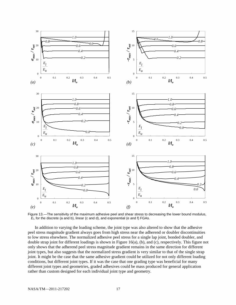
Figure 13.—The sensitivity of the maximum adhesive peel and shear stress to decreasing the lower bound modulus,
El, for the discrete (a and b), linear (c and d), and exponential (e and f) FGAs.
In addition to varying the loading scheme, the joint type was also altered to show that the adhesive peel stress magnitude gradient always goes from high stress near the adherend or doubler discontinuities to low stress elsewhere. The normalized adhesive peel stress for a single lap joint, bonded doubler, and double strap joint for different loadings is shown in Figure 16(a), (b), and (c), respectively. This figure not only shows that the adherend peel stress magnitude gradient remains in the same direction for different joint types, but also suggests that the normalized stress gradient is very similar to that of the single strap joint. It might be the case that the same adhesive gradient could be utilized for not only different loading conditions, but different joint types. If it was the case that one grading type was beneficial for many different joint types and geometries, graded adhesives could be mass produced for general application rather than custom designed for each individual joint type and geometry.
0
5
10
15
0 0.1 0.2 0.3 0.4 0.5
-τm
ax/ τ
net
l/lo
0
10
20
30
0 0.1 0.2 0.3 0.4 0.5
σ max
/ τne
t
l/lo
0
5
10
15
0 0.1 0.2 0.3 0.4 0.5l/lo
-τm
ax/ τ
net
0
10
20
30
0 0.1 0.2 0.3 0.4 0.5l/lo
σ max
/ τne
t
0
5
10
15
0 0.1 0.2 0.3 0.4 0.5
-τm
ax/ τ
net
l/lo
0
10
20
30
0 0.1 0.2 0.3 0.4 0.5
σ max
/ τne
t
l/lo
1.00.8
0.60.4
0.2
0.0
ElEu
1.00.8
0.6
0.4
0.20.0El
Eu
1.00.8
0.6
0.4
0.20.0El
Eu
1.00.8
0.60.4
0.20.0El
Eu
1.00.8
0.60.4
0.2
0.0
ElEu
1.00.8
0.60.4
0.2
0.0
ElEu
(a)
(c)
(e)
(b)
(d)
(f)

NASA/TM—2011-217202 18
Figure 14.—For different loading scenarios at the end of the joint ( (a) axial load, (c) moment, and (e) vertical load)
the stress gradients of the adhesive peel stress ((b), (d), and (f)) remains the same direction; high at the ends and low in the middle.
Figure 15.—Maximum peel and shear adhesive stress and its sensitivity to grading parameter, l, for different amounts
of end moment ((a) and (b)) and end shear force ((c) and (d)) for joints with a linear FGA.
-1
0
1
0 0.25 0.5
σ z/ σ
max
x / lo
-1
0
1
0 0.25 0.5
σ z/ σ
max
x / lo
σ z/ σ
max
-1
0
1
0 0.25 0.5
σ z/ σ
max
x / lo
(a)
(c)
(e)
(b)
(d)
(f)
P
-P
M
-M
-V
V
P
-M
-V
-P
M
V
10
20
30
40
0 0.1 0.2 0.3 0.4 0.5
σ max
/ τne
t
l/lo
5
10
15
20
0 0.1 0.2 0.3 0.4 0.5
-τm
ax/ τ
net
l/lo(a) (b)
VP−V
P−
0.01 0.0080.006
0.0040.002
0.0
0.010.008
0.0060.004
0.0020.0
5
10
15
20
25
0 0.1 0.2 0.3 0.4 0.5
-τm
ax/ τ
net
l/lo
10
20
30
40
50
0 0.1 0.2 0.3 0.4 0.5
σ max
/ τne
t
l/lo
1.00.8
0.60.4
0.20.0
MP−
1.00.8
0.60.4
0.20.0
MP−
(c) (d)

NASA/TM—2011-217202 19
Figure 16.—For different loading scenarios for a (a) single lap joint, (b) bonded doubler, and (c) double strap joint, the
stress gradients of the adhesive peel stress (b, d, and f) remains the same direction; high at the ends and low in the middle.
3.5 Proof of Concept Testing
To illustrate the potential gains of FGAs, proof of concept testing was performed on single strap joints (the baseline case). The adherends and doubler consisted of a single ply of 0/±45 triaxially braided composites, with the axial tows consisting of around 80,000 fibers, biased tows with 12,000 fibers, a fiber volume fraction of 52 percent, and matrix of Epon 862 epoxy resin (Ref. 29). The axial 0° direction was aligned with the global x-direction as defined in Figure 6. The adhesive used was AF 163-2k (Ref. 30) and the bond line was two layers thick in order for glass beads, normally used for thickness control, to be inserted in between (Figure 17).
-1
0
1
0 0.5 1
σ z/ σ
max
x / lo
-1
0
1
0 0.5 1
σ z/ σ
max
x / lo
-1
0
1
0 0.25 0.5
σ z/ σ
max
x / lo
σ z/ σ
max
x / lo
σ z/ σ
max
x / lo
(a)
(b)
P
M
P
M
M M
V
(c)
M
V
P
M M
P
M

NASA/TM—2011-217202 20
Figure 17.—Diagram of single strap joint with placed glass beads to test functionally graded
adhesive concept.
Figure 18.—Photographs of the adhesive layer before placement of the doubler for the single strap joint with (a) no
beads, (b) uniform beads, and (c) graded beads.
All specimens were manufactured together as a plate, with individual specimens cut out of the plate by means of a wet saw with a diamond-coated blade. The adherends and doubler were pre-infiltrated and cured prior to bonding. After bonding, the adhesive was cured in a heated press at 177° C under 0.43 MPa for 120 min, and specimens were not handled for 24 hr. The average dimensions of the specimens along with the standard deviation are shown in Table 2. The specimens were placed in grips and pulled in tension under displacement control at a rate of 0.005 mm/s. Load and displacement data was recorded, and the joint strength was defined as the maximum load held by the joint.
TABLE 2.—GEOMETRIC PARAMETERS FOR PROOF OF CONCEPT TESTING
la (mm)
lo (mm)
t (mm)
b (mm)
η (mm)
68.76±0.38 37.49±0.25 1.08 ±0.02 22.73±0.17 0.42±0.03
The grading was accomplished by means of inserting glass beads between the adhesive layers to
change the properties of the adhesive. Bead placement was done purely by hand, and a photograph of the adhesive prior to doubler bonding of a representative specimen for each adhesive system is shown in Figure 18. Two specimens were made with no beads in the adhesive, two with a high density of beads uniformly spread throughout the adhesive region, and three with beads placed strategically by hand. Care was taken to ensure that the location of the stress concentration, where the two adherends meet, was devoid of beads with a gradual increase in beads going out from the center.
Doubler
Adhesive
Adherend
AdherendGlass Beads
1 mm 1 mm1 mm(a) (c)(b)
border between adherends

NASA/TM—2011-217202 21
Figure 19.—Single strap joint test: (a) photograph of typical specimen prior to failure and (b) joint strengths of the
specimens tested with different adhesive systems.
An image of a single strap joint prior to complete joint separation is shown in Figure 19(a). The resulting strengths of the joints tested are plotted in Figure 19(b). Each bar represents a specimen; with two specimens with no beads, two with a uniform distribution of beads, and three specimens with graded beads in the adhesive. The specimens with no beads performed the worst, with an average strength of 3.18 kN. The uniform beaded joints had an average strength of 4.29 kN, and the graded bead specimens had an average strength of 5.43 kN, 26.5 percent higher than the uniform beads.
A few words should be said about the effects of FGAs and failure modes. As was shown earlier in Figure 9, grading the adhesive has little or no effect on the adherends for the configuration studied. Therefore, a difference in strengths was only manifested when the failure occurred in the adhesive, not in the adherend or doubler.
For these specimens, an improvement existed using FGAs because the failures consisted mostly of cohesive failure with a few areas of adhesive failure (Figure 20). Another round of testing was performed with the same type of specimens cured at a lower temperature. These specimens all failed in the adherend, and there was no statistical difference in strengths between graded and non graded specimens. Therefore, it should be noted that grading the adhesive can improve joint strength when failure occurs in or around the adhesive, and may even drive a joint to fail in the adherend when ungraded specimens fail in the adhesive, but FGAs most likely will not have a significant effect when failure already occurs in the adherends without grading.
0
2
4
6
No Beads Uniform Beads Graded Beads
Join
t Stre
ngth
(kN)
(a) (b)5 mm

NASA/TM—2011-217202 22
Figure 20.—Post mortem photographs of the failed adhesive layer for the single strap joints with
(a) no beads, (b) uniform beads, and (c) graded beads.
4.0 Concluding Remarks The peel stress concentration found in adhesively bonded joints can be reduced by grading the
modulus of the adhesive material. More recently, grading of the joints in a continuous manner has become of interest. However, the actual use of such joints has been limited because of a few concerns which this study has addressed. These concerns were addressed by comparing the stresses in single adhesive, bi-adhesive, linear, and exponential functionally graded adhesives (FGAs) using an analytical model. This unique model allows efficient analysis of adhesively bonded joints in the context of a finite element framework. The efficiency of the model facilitated vast parametric and optimization studies, while still having the ability to be placed within a larger, global structural-scale model.
The first concern was that gains to be made using FGAs were not worth the added manufacturing complications. It was shown that for the single strap joint configuration investigated; FGAs could reduce the maximum peel stress in the adhesive by up to 17 percent over the more compliant single adhesive joint without having an adverse effect on the adherend stress. Since the optimum grading for shear stress was not the same as that for peel stress, there was a slight increase in shear stress when peel stress was minimized. However, all grading functions resulted in a significant reduction (> 45 percent) in peel stress over the stiffer single adhesive joint without adversely affecting the load carrying capability or the stress in the adherends. Furthermore, decreasing the lower bound modulus of the grading caused even more dramatic stress reductions. Finally, it was shown that peel stress reductions comparable to those of the continuous functions studied here could be reached using a stepped function with around five or more different modulus adhesives, which is probably easier to manufacture.
The second concern about using FGAs was that the flow of adhesive during manufacturing would change the shape of the grading and cause the grading to be ineffective. Therefore, a sensitivity study was conducted on the three FGAs to see the effect of changing the shape of the grading (l) and the lower bound modulus (El) to reflect what might occur when adhesive is squeezed out of the joint. The maximum
Doubler
Adherend
1 mm(a) (c)(b) 1 mm1 mm

NASA/TM—2011-217202 23
adhesive peel stress levels did increase for all FGAs when the lower bound modulus increased, but the exponential FGA proved to be quite tolerant to changes in grading shape. This could be the basis for a justification for using the more complicated exponential FGA over the bi-adhesive. Although the peel stress reductions were all very similar, the tolerability of the exponential grading to perturbation of grading shape which can occur due to adhesive flow might make it worth the extra complications. Also, it is recommended that care be taken to account for adhesive flow by adding more lower modulus adhesive at the end of the joint than is required, or using a grading system which does not change when adhesive flows.
Third, functionally graded materials used in structures can become useless or detrimental when the loading conditions are changed. It was shown that changing the loading configuration does not change the stress magnitude gradient of the adhesive in the case of a single strap joint. Consequently, the optimum grading shape and sensitivity was shown to not be significantly impacted by changing the loading conditions. However, in the case of moment and shear loading, both ends of the joint are subjected to high peel stresses thus suggesting for generality that both ends be always graded. It was also shown that the stress magnitude gradient remains the same for other joint types; high stress at the adherend discontinuities with low stress elsewhere; thus suggesting the possibility of using the same adhesive grading for a myriad of joint configurations.
Additionally, proof of concept testing was conducted to show the potential of joints with FGAs. Grading was done by strategically placing glass beads to change the stiffness of the adhesive along the joint. The results indicated that these graded joints held over 26.5 percent more load than specimens with no beads or uniformly distributed beads. Additionally, it was discovered that grading did not result in an increase in strength when the failure without grading occurred in the adherend. Through theoretical and experimental means, this study has shown the practical benefits of and offered some guidelines on how to effectively use and design joints with FGAs. FGAs have the potential to spread the stress more evenly across the adhesive without unrecoverable damage, making them another means of improving adhesively bonded joints.
References 1. Hart-Smith L.J., Analysis and design of advanced composite bonded joints, Hampton, Virginia,
1974. 2. Hart-Smith L.J., Adhesive-Bonded Double-Lap Joints, Hampton, Virginia, 1973. 3. Lang T.P., Mallick P.K., Effect of spew geometry on stresses in single lap adhesive joints, Int J
Adhes Adhes, 18 (1998) 167-77. 4. Zeng Q.-G., Sun C.T., Novel Design of a Bonded Lap Joint, AIAA Journal, 39 (2001) 5. 5. Turuga U., Sun C.T., Improved Design for Metallic and Composite Single-Lap Joints, Anglais, 45
(2008) 8. 6. Birman V., Byrd L.W., Modeling and analysis of functionally graded materials and structures, Appl
Mech Rev, 60 (2007) 195-216. 7. Thomopoulos S., Genin G.M., Kent A., Birman V., Wopenka B., Pasteris J.D., et al., Functional
Grading of Mineral and Collagen in the Attachment of Tendon to Bone, Biophys J, 97 (2009) 976–85.
8. Birman V., Liu Y.X., Chen C.Q., Thomopoulos S., Genin G.M., Mechanisms of Bimaterial Attachment at the Interface of Tendon to Bone, J Eng Mater-T Asme, 133 (2011).
9. Boss J.N., Ganesh V.K., Lim C.T., Modulus grading versus geometrical grading of composite adherends in single-lap bonded joints, Compos Struct, 62 (2003) 113-21.
10. Patrick R.L., Structural adhesives with emphasis on aerospace applications, Marcel Dekker, Inc., New York, 1976.
11. Raphael C., Variable-Adhesive Bonded Joints, Applied Polymer Symposium, 3 (1966) 9. 12. Sancaktar E., Kumar S., Selective use of rubber toughening to optimize lap-joint strength, J Adhes
Sci Technol, 14 (2000) 1265-96.

NASA/TM—2011-217202 24
13. Piresa I., Quintinoa L.F., J. D., Beevers A., Performance of bi-adhesive bonded aluminium lapjoints, International Journal of Adhesion & Adhesives, 23 (2003) 8.
14. Fitton M.D., Broughton I.G., Variable modulus adhesives: an approach to optimised joint performance, Int J Adhes Adhes, 25 (2005) 329-36.
15. da Silva L.F.M., Lopes M.J.C.Q., Joint strength optimization by the mixed-adhesive technique, International Journal of Adhesion & Adhesives, 29 (2009) 5.
16. Kumar S., Pandey P.C., Behaviour of Bi-adhesive Joints, J Adhes Sci Technol, 24 (2010) 1251-81. 17. Vallee T., Tannert T., Murcia-Delso J., Quinn D.J., Influence of stress-reduction methods on the
strength of adhesively bonded joints composed of orthotropic brittle adherends, Int J Adhes Adhes, 30 (2010) 583-94.
18. Kumar S., Analysis of tubular adhesive joints with a functionally modulus graded bondline subjected to axial loads, Int J Adhes Adhes, 29 (2009) 785-95.
19. Aboudi J., Pindera M.J., Arnold S.M., Elastic Response of Metal-Matrix Composites with Tailored Microstructures to Thermal-Gradients, Int J Solids Struct, 31 (1994) 1393-428.
20. Waas A.M., Gustafson P.A., A bonded joint finite element for a symmetric double lap joint subjected to mechanical and thermal loads, Int J Numer Meth Eng, 79 (2009) 94-126.
21. Eisenberger M., Yankelevsky D.Z., Exact Stiffness Matrix for Beams on Elastic-Foundation, Comput Struct, 21 (1985) 1355-9.
22. Aydogan M., Stiffness-Matrix Formulation of Beams with Shear Effects on Elastic Foundation, Journal of Structural Engineering, 121 (1995) 5.
23. Stapleton S.E., Waas A.M., Macroscopic Finite Element for a Single Lap Joint, AIAA/ASME/ASCE/AHS/ASC 50th SDM Conference, Palm Springs, California, 2009.
24. Chen C., Linear System Theory and Design, 3rd ed., Oxford University Press, New York, 1999. 25. Molder C., Van Loan C., Nineteen Dubious Ways to Compute the Exponential of a Matrix, Twenty-
Five Years Later, SIAM Review, 45 (2003) 46. 26. Chapra S.C., Canale R.P., Numerical methods for engineers, 3rd ed., WCB/McGraw-Hill, Boston,
1998. 27. Apetre N.A., Sankar B.V., Ambur D.R., Low-velocity impact response of sandwich beams with
functionally graded core, Int J Solids Struct, 43 (2006) 2479-96. 28. Tsai M.Y., Oplinger D.W., Morton J., Improved theoretical solutions for adhesive lap joints, Int J
Solids Struct, 35 (1998) 1163-85. 29. Waas A.M., Salvi A.G., Caliskan A., Energy absorption and damage propagation in 2D triaxially
braided carbon fiber composites: effects of in situ matrix properties, J Mater Sci, 43 (2008) 5168-84. 30. 3M, AF 163-2 Technical Datasheet, 2009.

REPORT DOCUMENTATION PAGE Form Approved OMB No. 0704-0188
The public reporting burden for this collection of information is estimated to average 1 hour per response, including the time for reviewing instructions, searching existing data sources, gathering and maintaining the data needed, and completing and reviewing the collection of information. Send comments regarding this burden estimate or any other aspect of this collection of information, including suggestions for reducing this burden, to Department of Defense, Washington Headquarters Services, Directorate for Information Operations and Reports (0704-0188), 1215 Jefferson Davis Highway, Suite 1204, Arlington, VA 22202-4302. Respondents should be aware that notwithstanding any other provision of law, no person shall be subject to any penalty for failing to comply with a collection of information if it does not display a currently valid OMB control number. PLEASE DO NOT RETURN YOUR FORM TO THE ABOVE ADDRESS. 1. REPORT DATE (DD-MM-YYYY) 01-12-2011
2. REPORT TYPE Technical Memorandum
3. DATES COVERED (From - To)
4. TITLE AND SUBTITLE Functionally Graded Adhesives for Composite Joints
5a. CONTRACT NUMBER
5b. GRANT NUMBER
5c. PROGRAM ELEMENT NUMBER
6. AUTHOR(S) Stapleton, Scott, E.; Waas, Anthony, M.; Arnold, Steven, M.
5d. PROJECT NUMBER
5e. TASK NUMBER
5f. WORK UNIT NUMBER WBS 031102.02.02.03.0249.11
7. PERFORMING ORGANIZATION NAME(S) AND ADDRESS(ES) National Aeronautics and Space Administration John H. Glenn Research Center at Lewis Field Cleveland, Ohio 44135-3191
8. PERFORMING ORGANIZATION REPORT NUMBER E-17887
9. SPONSORING/MONITORING AGENCY NAME(S) AND ADDRESS(ES) National Aeronautics and Space Administration Washington, DC 20546-0001
10. SPONSORING/MONITOR'S ACRONYM(S) NASA
11. SPONSORING/MONITORING REPORT NUMBER NASA/TM-2011-217202
12. DISTRIBUTION/AVAILABILITY STATEMENT Unclassified-Unlimited Subject Categories: 24 and 39 Available electronically at http://www.sti.nasa.gov This publication is available from the NASA Center for AeroSpace Information, 443-757-5802
13. SUPPLEMENTARY NOTES Submitted to the International Journal of Adhesion and Adhesives.
14. ABSTRACT Adhesives with functionally graded material properties are being considered for use in adhesively bonded joints to reduce the peel stress concentrations located near adherend discontinuities. Several practical concerns impede the actual use of such adhesives. These include increased manufacturing complications, alterations to the grading due to adhesive flow during manufacturing, and whether changing the loading conditions significantly impact the effectiveness of the grading. An analytical study is conducted to address these three concerns. An enhanced joint finite element, which uses an analytical formulation to obtain exact shape functions, is used to model the joint. Furthermore, proof of concept testing is conducted to show the potential advantages of functionally graded adhesives. In this study, grading is achieved by strategically placing glass beads within the adhesive layer at different densities along the joint. 15. SUBJECT TERMS Polymer matrix composites; Braided composites; Finite element method; Micromechanics
16. SECURITY CLASSIFICATION OF: 17. LIMITATION OF ABSTRACT UU
18. NUMBER OF PAGES
32
19a. NAME OF RESPONSIBLE PERSON STI Help Desk (email:[email protected])
a. REPORT U
b. ABSTRACT U
c. THIS PAGE U
19b. TELEPHONE NUMBER (include area code) 443-757-5802
Standard Form 298 (Rev. 8-98)Prescribed by ANSI Std. Z39-18


![Analysis of Viscoelastic Functionally Graded Sandwich ...journals.iau.ir/article_668608_b33f4af4905ff4be3afd5b0759e29604.p… · can be laminated composites [4], functionally graded](https://img.pdfslide.net/doc/110x75/60222b2a2fef0d1447096621/analysis-of-viscoelastic-functionally-graded-sandwich-can-be-laminated-composites.jpg)