Embed Size (px)
Citation preview

PiCPro™
Function/Function Block Reference Guide
Version 16.2
G & L Motion Control Inc.

NOTE
Progress is an on going commitment at G & L Motion Control Inc. We continually strive to offer the most advanced products in the industry; therefore, information in this document is subject to change without notice. The illustrations and specifications are not binding in detail. G & L Motion Control Inc. shall not be liable for any technical or editorial omissions occurring in this document, nor for any consequential or incidental damages resulting from the use of this document.
DO NOT ATTEMPT to use any G & L Motion Control Inc. product until the use of such product is completely understood. It is the responsibility of the user to make certain proper operation practices are understood. G & L Motion Control Inc. products should be used only by qualified personnel and for the express purpose for which said products were designed.
Should information not covered in this document be required, contact the Customer Service Department, G & L Motion Control Inc., 672 South Military Road, P.O. Box 1960, Fond du Lac, WI 54936-1960. G & L Motion Control Inc. can be reached by telephone at (920) 921-7100 or (800) 558-4808 in the United States or by e-mail at [email protected].
Release 1008
Catalog No. (Order No.) M.1300.7591
Printed Version Part Number M.3000.0522
Electronic Version Part Number M.3000.0521
© 1995-2007 G & L Motion Control Inc.
IBM is a registered trademark of International Business Machines Corp.Microsoft® and MS-DOS® are registered trademarks of Microsoft Corporation. ARCNET® is a registered trademanrk of Datapoint PiC900, PiCPro, MMC, PiCServoPro, PiCTune, PiCProfile, LDOMerge, PiCMicroTerm, and PiC Programming Pendant are registered trademarks of G & L Motion Control Inc.
Table of Contents:Function/Function Block
Reference Guide
CHAPTER 1- PiCPro Function/Blocks Overview............................................................ 1-1
Introduction.............................................................................................................. 1-1
Arithmetic Category ............................................................................................... 1-6
ARITH group ............................................................................................... 1-6DATETIME group ...................................................................................... 1-7TRIG group ................................................................................................. 1-8
Binary Category ...................................................................................................... 1-9
Counters Category .................................................................................................. 1-10
Datatype Category .................................................................................................. 1-11
BOOL2BYT group ..................................................................................... 1-11BYTECONV group ....................................................................................... 1-11DINTCONV group ..................................................................................... 1-12DWORDCNV group ................................................................................... 1-12D_TCONV group ....................................................................................... 1-13INTCONV group ........................................................................................ 1-13LINTCONV group ...................................................................................... 1-14LREALCNV group ..................................................................................... 1-14LWORDCNV group ................................................................................... 1-14NUM2STR group ....................................................................................... 1-15REALCONV group .................................................................................... 1-15SINTCONV group ...................................................................................... 1-15SIZEOF group ............................................................................................. 1-15STRCONV group ......................................................................................... 1-16UDINTCNV group ..................................................................................... 1-16UINTCONV group ..................................................................................... 1-16ULINTCNV group ...................................................................................... 1-17USINTCNV group......................................................................................... 1-17WORDCONV group ................................................................................... 1-18
Evaluate Category .................................................................................................. 1-18
Fbinter Category...................................................................................................... 1-20
Filter Category ......................................................................................................... 1-21
I/O Category ........................................................................................................... 1-22
ANLGIN group ........................................................................................... 1-22ANLGOUT group.......................................................................................... 1-22BAT_OK? group............................................................................................ 1-23
TOC-1
BIO_PERF group........................................................................................... 1-23COMM group ....................................................................................... 1-24JKTHERM group........................................................................................... 1-25NETWORK group ...................................................................................... 1-26PID group .................................................................................................... 1-27READFDBK group ..................................................................................... 1-27RTDTEMP group ...................................................................................... 1-27SOCKETS group ........................................................................................... 1-28STEPPER group ........................................................................................... 1-28
Motion Category ..................................................................................................... 1-29
DATA group ................................................................................................. 1-30ERRORS group ............................................................................................. 1-32INIT group .................................................................................................... 1-34MOVE group ................................................................................................ 1-35MOVE_SUP group ....................................................................................... 1-36QUE group .................................................................................................... 1-37RATIOMOV group........................................................................................ 1-38REF group ..................................................................................................... 1-39SERC_SLV group ......................................................................................... 1-40SERC_SYS group ......................................................................................... 1-41
String Category ...................................................................................................... 1-42
PID Category ......................................................................................................... 1-43
Timers Category ..................................................................................................... 1-43
Xclock Category ...................................................................................................... 1-43
CHAPTER 2-Function/Block Descriptions ..................................................................... 2-1
ABRTALL ..................................................................................................... 2-2ABRTMOVE ................................................................................................. 2-2ABS................................................................................................................ 2-3ACC_DEC ..................................................................................................... 2-4ACC_JERK.................................................................................................... 2-5ACOS............................................................................................................. 2-9ADD............................................................................................................... 2-9AND............................................................................................................... 2-10ANLGINIT .................................................................................................... 2-11ANLG_OUT .................................................................................................. 2-13ARTDCHIT ................................................................................................... 2-17ARTDCHRD ................................................................................................. 2-19ARTDMDIT .................................................................................................. 2-21ASIN .............................................................................................................. 2-22ASSIGN ......................................................................................................... 2-23ATAN ............................................................................................................ 2-25ATMPCHIT ................................................................................................... 2-26ATMPCHRD ................................................................................................. 2-28
TOC-2
ATMPMDIT .................................................................................................. 2-30A_DT_T......................................................................................................... 2-31A_IN_MMC................................................................................................... 2-32A_INCHIT ..................................................................................................... 2-33A_INCHRD ................................................................................................... 2-36A_INMDIT .................................................................................................... 2-40A_TOD_T...................................................................................................... 2-41BAT_OK?...................................................................................................... 2-42BIO_PERF ..................................................................................................... 2-43BOOL2BYT................................................................................................... 2-46BTMPCHIT ................................................................................................... 2-47BTMPCHRD ................................................................................................. 2-48BTMPMGR ................................................................................................... 2-50BYT2BOOL................................................................................................... 2-51BYTE2DW .................................................................................................... 2-52BYTE2LW..................................................................................................... 2-52BYTE2SI ....................................................................................................... 2-53BYTE2USI..................................................................................................... 2-53BYTE2WO .................................................................................................... 2-54CAM_OUT .................................................................................................... 2-55CAPTINIT ..................................................................................................... 2-60CAPTSTAT ................................................................................................... 2-67CLOCK.......................................................................................................... 2-68CLOSE........................................................................................................... 2-69CLOSLOOP................................................................................................... 2-70CLSLOOP?.................................................................................................... 2-71CONCAT ....................................................................................................... 2-72CONFIG......................................................................................................... 2-73COORD2RL .................................................................................................. 2-75COS................................................................................................................ 2-79CTD ............................................................................................................... 2-79CTU ............................................................................................................... 2-80CTUD............................................................................................................. 2-81C_ERRORS ................................................................................................... 2-82C_RESET....................................................................................................... 2-84C_STOP ......................................................................................................... 2-84C_STOP? ....................................................................................................... 2-85DATE2STR ................................................................................................... 2-86DELETE ........................................................................................................ 2-87DELFIL.......................................................................................................... 2-88DINT2DW ..................................................................................................... 2-89DINT2INT ..................................................................................................... 2-89DINT2LI ........................................................................................................ 2-90DINT2RE....................................................................................................... 2-90DINT2SI ........................................................................................................ 2-91DINT2UDI..................................................................................................... 2-91
TOC-3
DIRECT ......................................................................................................... 2-92DISTANCE.................................................................................................... 2-94DIV ................................................................................................................ 2-95DLS_INIT...................................................................................................... 2-96DLS_RECV ................................................................................................... 2-98DLS_SEND ................................................................................................... 2-99DLS_STAT.................................................................................................... 2-100DPOSMODE ................................................................................................. 2-101DRSETFLT.................................................................................................... 2-102DSTRTSRV ................................................................................................... 2-103DT2DATE ..................................................................................................... 2-104DT2STR......................................................................................................... 2-104DT2TOD........................................................................................................ 2-105DTORQCMD................................................................................................. 2-106DVELCMD.................................................................................................... 2-107DWORD2BYT .............................................................................................. 2-108DWOR2DI ..................................................................................................... 2-109DWOR2LW ................................................................................................... 2-109DWOR2RE .................................................................................................... 2-110DWOR2UDI .................................................................................................. 2-110DWOR2WO................................................................................................... 2-111D_TOD2DT ................................................................................................... 2-111EQ .................................................................................................................. 2-112EXIST? .......................................................................................................... 2-113EXP................................................................................................................ 2-114E_ERRORS ................................................................................................... 2-115E_RESET....................................................................................................... 2-117E_STOP ......................................................................................................... 2-117E_STOP? ....................................................................................................... 2-118FAST_QUE ................................................................................................... 2-119FAST_REF .................................................................................................... 2-122FB_CLS ......................................................................................................... 2-127FB_OPN......................................................................................................... 2-128FB_RCV ........................................................................................................ 2-129FB_SND......................................................................................................... 2-130FB_STA ......................................................................................................... 2-131FIND .............................................................................................................. 2-134FRESPACE.................................................................................................... 2-135FU2LU ........................................................................................................... 2-136GE .................................................................................................................. 2-137GETDAY ....................................................................................................... 2-138GR_END........................................................................................................ 2-139GT .................................................................................................................. 2-140HOLD ............................................................................................................ 2-140HOLD_END .................................................................................................. 2-141INSERT ......................................................................................................... 2-142
TOC-4
INT2DINT ..................................................................................................... 2-143INT2LINT...................................................................................................... 2-143INT2SINT...................................................................................................... 2-144INT2UINT ..................................................................................................... 2-144INT2WORD................................................................................................... 2-145IN_POS? ........................................................................................................ 2-145IO_CFG ......................................................................................................... 2-146IPACCEPT..................................................................................................... 2-150IPCLOSE ....................................................................................................... 2-151IPCONN......................................................................................................... 2-152IPHOSTID ..................................................................................................... 2-153IPIP2NAM ..................................................................................................... 2-154IPLISTEN ...................................................................................................... 2-155IPNAM2IP ..................................................................................................... 2-156IPREAD ......................................................................................................... 2-157IPRECV ......................................................................................................... 2-158IPSEND ......................................................................................................... 2-160IPSOCK ......................................................................................................... 2-161IPSTAT.......................................................................................................... 2-162IPWRITE ....................................................................................................... 2-163
Overview for Using the Ethernet -TCP/IP Function Blocks ................... 2-164Ethernet-TCP/IP Errors............................................................................ 2-166
LAD_REF...................................................................................................... 2-169LE................................................................................................................... 2-172LEFT.............................................................................................................. 2-173LEN................................................................................................................ 2-174LIMIT ............................................................................................................ 2-175LINT2DI ........................................................................................................ 2-176LINT2INT...................................................................................................... 2-176LINT2LR ....................................................................................................... 2-177LINT2LW ...................................................................................................... 2-177LINT2SI......................................................................................................... 2-178LINT2ULI...................................................................................................... 2-178LN .................................................................................................................. 2-179LOG ............................................................................................................... 2-179LREA2LI ....................................................................................................... 2-180LREA2LW..................................................................................................... 2-180LREA2RE...................................................................................................... 2-181LREA2ULI .................................................................................................... 2-181LT................................................................................................................... 2-182LU2FU ........................................................................................................... 2-183LWOR2BYT.................................................................................................. 2-183LWOR2DW ................................................................................................... 2-184LWOR2LI...................................................................................................... 2-184LWOR2LR..................................................................................................... 2-185LWOR2ULI ................................................................................................... 2-185
TOC-5
LWOR2WO ................................................................................................... 2-186LWR_CASE .................................................................................................. 2-186MAX .............................................................................................................. 2-187MEASURE .................................................................................................... 2-187MID................................................................................................................ 2-188MIN................................................................................................................ 2-189MOD .............................................................................................................. 2-189MOVE............................................................................................................ 2-190MUL............................................................................................................... 2-191MUX .............................................................................................................. 2-192NE .................................................................................................................. 2-193NEG ............................................................................................................... 2-193NETCLS ........................................................................................................ 2-194NETFRE ........................................................................................................ 2-194NETMON ...................................................................................................... 2-195NETOPN........................................................................................................ 2-196NETRCV ....................................................................................................... 2-198NETSND........................................................................................................ 2-200NETSTA ........................................................................................................ 2-202NEWRATIO .................................................................................................. 2-203NEW_RATE.................................................................................................. 2-205NOT ............................................................................................................... 2-206NO_OFFST.................................................................................................... 2-207NUM2STR..................................................................................................... 2-209OK_ERROR .................................................................................................. 2-210OPEN ............................................................................................................. 2-211OPENLOOP................................................................................................... 2-213OR.................................................................................................................. 2-214PART_CLR ................................................................................................... 2-215PART_REF.................................................................................................... 2-216PID ................................................................................................................. 2-217PID2 ............................................................................................................... 2-226PLS................................................................................................................. 2-231PLS_EDIT ..................................................................................................... 2-235POSITION ..................................................................................................... 2-236P_ERRORS.................................................................................................... 2-237P_RESET ....................................................................................................... 2-240PWDTY ......................................................................................................... 2-241Q_AVAIL? .................................................................................................... 2-242Q_NUMBER ................................................................................................. 2-243RAMP ............................................................................................................ 2-244RATIOCAM .................................................................................................. 2-245RATIOSCL.................................................................................................... 2-256RATIOSLP .................................................................................................... 2-260RATIOSYN ................................................................................................... 2-272RATIO_GR.................................................................................................... 2-282
TOC-6
RATIO_RL .................................................................................................... 2-285READ............................................................................................................. 2-294READFDBK.................................................................................................. 2-296READ_SV ..................................................................................................... 2-307READ_SVF ................................................................................................... 2-348REAL2DI....................................................................................................... 2-349REAL2DW .................................................................................................... 2-349REAL2LR...................................................................................................... 2-350REAL2UDI.................................................................................................... 2-350REF_DNE? .................................................................................................... 2-351REF_END...................................................................................................... 2-351REGIST ......................................................................................................... 2-352RENAME....................................................................................................... 2-361REPLACE...................................................................................................... 2-363REP_END...................................................................................................... 2-364RESMODE?................................................................................................... 2-365RESUME ....................................................................................................... 2-366RIGHT ........................................................................................................... 2-368ROL ............................................................................................................... 2-369ROR ............................................................................................................... 2-370R_PERCEN ................................................................................................... 2-371SC_INIT......................................................................................................... 2-372SCA_ACKR................................................................................................... 2-373SCA_CLOS ................................................................................................... 2-374SCA_CTRL ................................................................................................... 2-375SCA_ERST.................................................................................................... 2-378SCA_PBIT ..................................................................................................... 2-379SCA_RCYC................................................................................................... 2-381SCA_RECV ................................................................................................... 2-383SCA_REF ...................................................................................................... 2-385SCA_RFIT ..................................................................................................... 2-387SCA_SEND ................................................................................................... 2-390SCA_STAT.................................................................................................... 2-392SCA_WCYC.................................................................................................. 2-393SCR_CONT ................................................................................................... 2-394SCR_ERR ...................................................................................................... 2-395SCR_PHAS.................................................................................................... 2-398SCS_ACKR ................................................................................................... 2-399SCS_CTRL .................................................................................................... 2-400SCS_RECV.................................................................................................... 2-402SCS_REF ....................................................................................................... 2-404SCS_SEND.................................................................................................... 2-406SCS_STAT .................................................................................................... 2-408SCURVE........................................................................................................ 2-413SEEK ............................................................................................................. 2-418SEL ................................................................................................................ 2-420
TOC-7
SERVOCLK .................................................................................................. 2-421SHL................................................................................................................ 2-422SHR................................................................................................................ 2-423SIN ................................................................................................................. 2-424SINT2BYT..................................................................................................... 2-424SINT2DI ........................................................................................................ 2-425SINT2INT...................................................................................................... 2-425SINT2LI......................................................................................................... 2-426SINT2USI ...................................................................................................... 2-426SIZEOF.......................................................................................................... 2-427SQRT ............................................................................................................. 2-429STATUS ........................................................................................................ 2-430STATUSSV ................................................................................................... 2-431STEPCNTL.................................................................................................... 2-433STEPINIT ...................................................................................................... 2-437STEPSTAT .................................................................................................... 2-439STEP_CMD ................................................................................................... 2-442STEP_POS..................................................................................................... 2-452STR2D_T....................................................................................................... 2-453STR2NUM..................................................................................................... 2-454STR2USI........................................................................................................ 2-454STRTSERV ................................................................................................... 2-455SUB................................................................................................................ 2-458SYN_END ..................................................................................................... 2-459S_DT_DT....................................................................................................... 2-460S_DT_T ......................................................................................................... 2-461S_D_D ........................................................................................................... 2-462S_TOD_T....................................................................................................... 2-463S_TOD_TO.................................................................................................... 2-464TAN ............................................................................................................... 2-465TAUFFAC ..................................................................................................... 2-465TAUFILT....................................................................................................... 2-466TIM2UDIN .................................................................................................... 2-466TIME2STR .................................................................................................... 2-467TME_ERR? ................................................................................................... 2-468TOD2STR...................................................................................................... 2-468TOF................................................................................................................ 2-469TON ............................................................................................................... 2-470TP................................................................................................................... 2-471TUNEREAD.................................................................................................. 2-472TUNEWRIT................................................................................................... 2-473UDIN2DI ....................................................................................................... 2-476UDIN2DW..................................................................................................... 2-476UDIN2RE ...................................................................................................... 2-477UDIN2TIM .................................................................................................... 2-477UDIN2UI ....................................................................................................... 2-478
TOC-8
UDIN2ULI..................................................................................................... 2-478UDIN2USI ..................................................................................................... 2-479UINT2INT ..................................................................................................... 2-479UINT2UDI..................................................................................................... 2-480UINT2ULI ..................................................................................................... 2-480UINT2USI ..................................................................................................... 2-481UINT2WO ..................................................................................................... 2-481ULIN2LI ........................................................................................................ 2-482ULIN2LR....................................................................................................... 2-482ULIN2LW...................................................................................................... 2-483ULIN2UDI..................................................................................................... 2-483ULIN2UI........................................................................................................ 2-484ULIN2USI ..................................................................................................... 2-484UPR_CASE ................................................................................................... 2-485USIN2BYT .................................................................................................... 2-485USIN2SI......................................................................................................... 2-486USIN2STR..................................................................................................... 2-486USIN2UDI ..................................................................................................... 2-487USIN2UI........................................................................................................ 2-487USIN2ULI ..................................................................................................... 2-488VEL_END ..................................................................................................... 2-488VEL_STRT.................................................................................................... 2-489VFASTIN....................................................................................................... 2-490WORD2BYT ................................................................................................. 2-491WORD2DW................................................................................................... 2-491WORD2INT................................................................................................... 2-492WORD2LW ................................................................................................... 2-492WORD2UI ..................................................................................................... 2-493WRITE........................................................................................................... 2-494WRITE_SV.................................................................................................... 2-495WRIT_SVF.................................................................................................... 2-496XOR ............................................................................................................... 2-497
A.1 --Operator Interface ASFB................................................................... A.1 -1
OI_COMM..................................................................................................... A.1 -2OI_SER.......................................................................................................... A.1 -4
B.1 --OPC Server ASFB.............................................................................. B.1 -1
OPC_ENET ................................................................................................... B.1 -2OPC_10.......................................................................................................... B.1 -6
C.1 --Temperature Function Errors........................................................... C.1 - 1
-INDEX ......................................................................................................... IND-1
TOC-9

NOTES
TOC-10
CHAPTER 1 PiCPro Function/Blocks Overview
Introduction
Function and function blocks are the programming tools used to perform opera-tions on data in PiCPro ladder diagram programs. They are similar to the subrou-tines of other programming languages.
The difference between functions and function blocks is that a function completes an operation in one scan whereas a function block may take more than one scan to complete an operation. Therefore, function blocks must have internal storage for their variables from scan to scan until their operation is complete. You must declare and assign a name to function blocks in the software declaration table so that PiCPro can reserve memory for them.
Chapter 1 of this reference manual presents a summary of all the standard func-tions and function blocks available within PiCPro. This summary will familiarize you with what is available for programming.
Chapter 2 presents descriptions of all the function/function blocks in alphabetical order.
NOTE
You must have a math coprocessor (NPX) installed in the control to perform any functions involving logarithmic, exponential, trigonometric, and floating point mathematical operations. The PiC 904x series, PiC94x series, MMC, and MMC for PC CPUs already have an integrated math coprocessor. To determine if your control has a math coprocessor, start PiCPro and select Online | Status. The CPU line contains an “NPX” if you have a math coprocessor.
Chapter 1 Function/Function Block Description 1-1
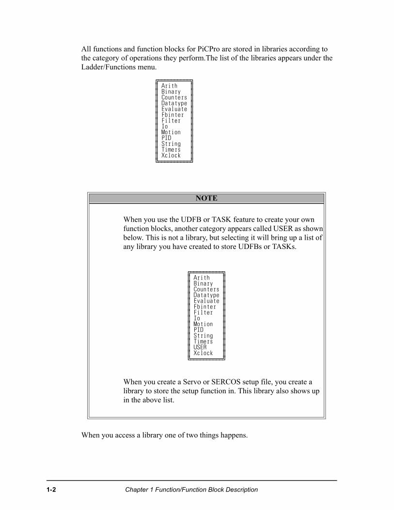
All functions and function blocks for PiCPro are stored in libraries according to the category of operations they perform.The list of the libraries appears under the Ladder/Functions menu.
When you access a library one of two things happens.
…ÕÕÕÕÕÕÕÕÕÕª∫ Arith ∫∫ Binary ∫∫ Counters ∫∫ Datatype ∫∫ Evaluate ∫∫ Fbinter ∫∫ Filter ∫∫ Io ∫∫ Motion ∫∫ PID ∫∫ String ∫∫ Timers ∫∫ Xclock ∫»ÕÕÕÕÕÕÕÕÕÕº
NOTE
When you use the UDFB or TASK feature to create your own function blocks, another category appears called USER as shown below. This is not a library, but selecting it will bring up a list of any library you have created to store UDFBs or TASKs.
…ÕÕÕÕÕÕÕÕÕÕª∫ Arith ∫∫ Binary ∫∫ Counters ∫∫ Datatype ∫∫ Evaluate ∫∫ Fbinter ∫∫ Filter ∫∫ Io ∫∫ Motion ∫∫ PID ∫∫ String ∫∫ Timers ∫∫ USER ∫∫ Xclock ∫»ÕÕÕÕÕÕÕÕÕÕº
When you create a Servo or SERCOS setup file, you create a library to store the setup function in. This library also shows up in the above list.
1-2 Chapter 1 Function/Function Block Description
or
1. You are given a list of all the function/blocks available in that library. You select the function/block you want to insert into a network of your module from this list.
2. You are given a list of groups into which all the function/blocks have been divided. You select the group that holds the function/block you want. This brings up the list of function/blocks in that group and now you can select the one you want to insert into the network of your module.
Chapter 1 Function/Function Block Description 1-3
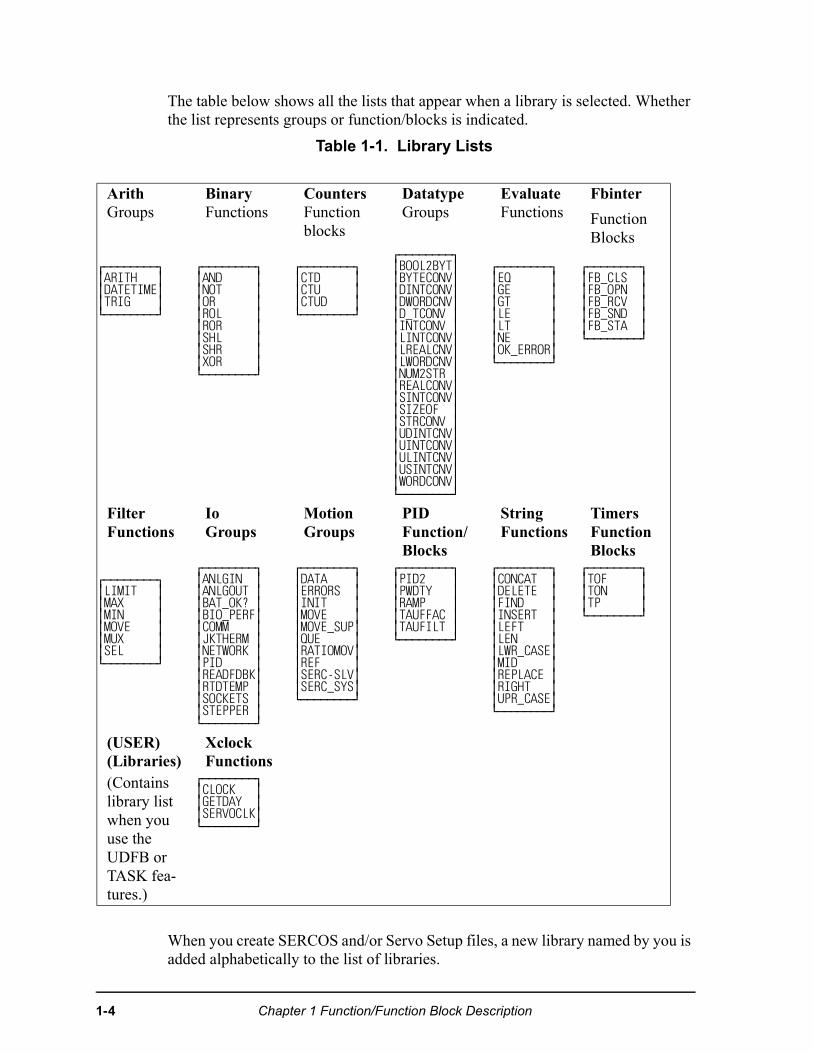
The table below shows all the lists that appear when a library is selected. Whether the list represents groups or function/blocks is indicated.
Table 1-1. Library Lists
When you create SERCOS and/or Servo Setup files, a new library named by you is added alphabetically to the list of libraries.
ArithGroups
BinaryFunctions
CountersFunction blocks
DatatypeGroups
EvaluateFunctions
Fbinter
Function Blocks
⁄ƒƒƒƒƒƒƒƒø ≥ARITH ≥ ≥DATETIME≥ ≥TRIG ≥ ¿ƒƒƒƒƒƒƒƒŸ
⁄ƒƒƒƒƒƒƒƒø ≥AND ≥ ≥NOT ≥ ≥OR ≥ ≥ROL ≥ ≥ROR ≥ ≥SHL ≥ ≥SHR ≥ ≥XOR ≥ ¿ƒƒƒƒƒƒƒƒŸ
⁄ƒƒƒƒƒƒƒƒø≥CTD ≥≥CTU ≥≥CTUD ≥¿ƒƒƒƒƒƒƒƒŸ
⁄ƒƒƒƒƒƒƒƒø≥BOOL2BYT≥≥BYTECONV≥≥DINTCONV≥≥DWORDCNV≥≥D_TCONV ≥≥INTCONV ≥≥LINTCONV≥≥LREALCNV≥≥LWORDCNV≥≥NUM2STR ≥≥REALCONV≥≥SINTCONV≥≥SIZEOF ≥≥STRCONV ≥≥UDINTCNV≥≥UINTCONV≥≥ULINTCNV≥≥USINTCNV≥≥WORDCONV≥¿ƒƒƒƒƒƒƒƒŸ
⁄ƒƒƒƒƒƒƒƒø≥EQ ≥≥GE ≥≥GT ≥≥LE ≥≥LT ≥≥NE ≥≥OK_ERROR≥¿ƒƒƒƒƒƒƒƒŸ
⁄ƒƒƒƒƒƒƒƒø≥FB_CLS ≥≥FB_OPN ≥≥FB_RCV ≥≥FB_SND ≥≥FB_STA ≥¿ƒƒƒƒƒƒƒƒŸ
FilterFunctions
IoGroups
MotionGroups
PIDFunction/Blocks
StringFunctions
TimersFunction Blocks
⁄ƒƒƒƒƒƒƒƒø ≥LIMIT ≥ ≥MAX ≥ ≥MIN ≥ ≥MOVE ≥ ≥MUX ≥ ≥SEL ≥ ¿ƒƒƒƒƒƒƒƒŸ
⁄ƒƒƒƒƒƒƒƒø ≥ANLGIN ≥ ≥ANLGOUT ≥ ≥BAT_OK? ≥ ≥BIO_PERF≥ ≥COMM ≥ ≥JKTHERM ≥ ≥NETWORK ≥ ≥PID ≥ ≥READFDBK≥ ≥RTDTEMP ≥ ≥SOCKETS ≥ ≥STEPPER ≥ ¿ƒƒƒƒƒƒƒƒŸ
⁄ƒƒƒƒƒƒƒƒø ≥DATA ≥ ≥ERRORS ≥ ≥INIT ≥ ≥MOVE ≥ ≥MOVE_SUP≥ ≥QUE ≥ ≥RATIOMOV≥ ≥REF ≥ ≥SERC-SLV≥ ≥SERC_SYS≥ ¿ƒƒƒƒƒƒƒƒŸ
⁄ƒƒƒƒƒƒƒƒø≥PID2 ≥≥PWDTY ≥≥RAMP ≥≥TAUFFAC ≥≥TAUFILT ≥¿ƒƒƒƒƒƒƒƒŸ
⁄ƒƒƒƒƒƒƒƒø≥CONCAT ≥≥DELETE ≥≥FIND ≥≥INSERT ≥≥LEFT ≥≥LEN ≥≥LWR_CASE≥≥MID ≥≥REPLACE ≥≥RIGHT ≥≥UPR_CASE≥¿ƒƒƒƒƒƒƒƒŸ
⁄ƒƒƒƒƒƒƒƒø≥TOF ≥≥TON ≥≥TP ≥¿ƒƒƒƒƒƒƒƒŸ
(USER)(Libraries)
XclockFunctions
(Contains library list when you use the UDFB or TASK fea-tures.)
⁄ƒƒƒƒƒƒƒƒø≥CLOCK ≥≥GETDAY ≥≥SERVOCLK≥¿ƒƒƒƒƒƒƒƒŸ
1-4 Chapter 1 Function/Function Block Description
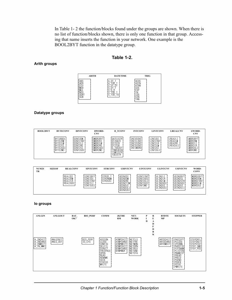
In Table 1- 2 the function/blocks found under the groups are shown. When there is no list of function/blocks shown, there is only one function in that group. Access-ing that name inserts the function in your network. One example is the BOOL2BYT function in the datatype group.
Table 1-2. Arith groups
Datatype groups
Io groups
ARITH DATETIME TRIG⁄ƒƒƒƒƒƒƒƒø ≥ABS ≥ ≥ADD ≥ ≥DIV ≥ ≥MOD ≥ ≥MUL ≥ ≥NEG ≥ ≥SQRT ≥ ≥SUB ≥ ¿ƒƒƒƒƒƒƒƒŸ
⁄ƒƒƒƒƒƒƒƒø≥A_DT_T ≥≥A_TOD_T ≥≥S_DT_DT ≥≥S_DT_T ≥≥S_D_D ≥≥S_TOD_T ≥≥S_TOD_TO≥¿ƒƒƒƒƒƒƒƒŸ
⁄ƒƒƒƒƒƒƒƒø≥ACOS ≥≥ASIN ≥≥ATAN ≥≥COS ≥≥EXP ≥≥LN ≥≥LOG ≥≥SIN ≥≥TAN ≥¿ƒƒƒƒƒƒƒƒŸ
BOOL2BYT BYTECONV DINTCONV DWORD-CNV
D_TCONV INTCONV LINTCONV LREALCNV LWORD-CNV
⁄ƒƒƒƒƒƒƒƒø≥BYT2BOOL≥≥BYTE2DW ≥≥BYTE2LW ≥≥BYTE2SI ≥≥BYTE2USI≥≥BYTE2WO ≥¿ƒƒƒƒƒƒƒƒŸ
⁄ƒƒƒƒƒƒƒƒø≥DINT2DW ≥≥DINT2INT≥≥DINT2LI ≥≥DINT2RE ≥≥DINT2SI ≥≥DINT2UDI≥¿ƒƒƒƒƒƒƒƒŸ
⁄ƒƒƒƒƒƒƒƒø≥DWOR2BYT≥≥DWOR2DI ≥≥DWOR2LW ≥≥DWOR2RE ≥≥DWOR2UDI≥≥DWOR2WO ≥¿ƒƒƒƒƒƒƒƒŸ
⁄ƒƒƒƒƒƒƒƒø≥DATE2STR≥≥DT2DATE ≥≥DT2STR ≥≥DT2TOD ≥≥D_TOD2DT≥≥TIM2UDIN≥≥TIME2STR≥≥TOD2STR ≥¿ƒƒƒƒƒƒƒƒŸ
⁄ƒƒƒƒƒƒƒƒø≥INT2DINT≥≥INT2LINT≥≥INT2SINT≥≥INT2UINT≥≥INT2WORD≥¿ƒƒƒƒƒƒƒƒŸ
⁄ƒƒƒƒƒƒƒƒø≥LINT2DI ≥≥LINT2INT≥≥LINT2LR ≥≥LINT2LW ≥≥LINT2SI ≥≥LINT2ULI≥¿ƒƒƒƒƒƒƒƒŸ
⁄ƒƒƒƒƒƒƒƒø≥LREA2LI ≥≥LREA2LW ≥≥LREA2RE ≥≥LREA2ULI≥¿ƒƒƒƒƒƒƒƒŸ
⁄ƒƒƒƒƒƒƒƒø≥LWOR2BYT≥≥LWOR2DW ≥≥LWOR2LI ≥≥LWOR2LR ≥≥LWOR2ULI≥≥LWOR2WO ≥¿ƒƒƒƒƒƒƒƒŸ
NUM2STR
SIZEOF REALCONV SINTCONV STRCONV UDINTCNV UINTCONV ULINTCNV USINTCNV WORD-CONV
⁄ƒƒƒƒƒƒƒƒø≥REAL2DI ≥≥REAL2DW ≥≥REAL2LR ≥≥REAL2UDI≥¿ƒƒƒƒƒƒƒƒŸ
⁄ƒƒƒƒƒƒƒƒø≥SINT2BYT≥≥SINT2DI ≥≥SINT2INT≥≥SINT2LI ≥≥SINT2USI≥¿ƒƒƒƒƒƒƒƒŸ
⁄ƒƒƒƒƒƒƒƒø≥STR2D_T ≥≥STR2NUM ≥≥STR2USI ≥¿ƒƒƒƒƒƒƒƒŸ
⁄ƒƒƒƒƒƒƒƒø≥UDIN2DI ≥≥UDIN2DW ≥≥UDIN2RE ≥≥UDIN2TIM≥≥UDIN2UI ≥≥UDIN2ULI≥≥UDIN2USI≥¿ƒƒƒƒƒƒƒƒŸ
⁄ƒƒƒƒƒƒƒƒø≥UINT2INT≥≥UINT2UDI≥≥UINT2ULI≥≥UINT2USI≥≥UINT2WO ≥¿ƒƒƒƒƒƒƒƒŸ
⁄ƒƒƒƒƒƒƒƒø≥ULIN2LI ≥≥ULIN2LR ≥≥ULIN2LW ≥≥ULIN2UDI≥≥ULIN2UI ≥≥ULIN2USI≥¿ƒƒƒƒƒƒƒƒŸ
⁄ƒƒƒƒƒƒƒƒø ≥USIN2BYT≥ ≥USIN2SI ≥≥USIN2STR≥≥USIN2UDI≥ ≥USIN2UI ≥≥USIN2ULI≥ ¿ƒƒƒƒƒƒƒƒŸ
⁄ƒƒƒƒƒƒƒƒø≥WORD2BYT≥≥WORD2DW ≥≥WORD2INT≥≥WORD2LW ≥≥WORD2UI ≥¿ƒƒƒƒƒƒƒƒŸ
ANLGIN ANLGOUT BAT_OK?
BIO_PERF COMM JKTHERM
NET-WORK
PID
READFDBK
RTDTEMP
SOCKETS STEPPER
⁄ƒƒƒƒƒƒƒƒø≥A_INCHIT≥≥A_INCHRD≥≥A_INMDIT≥≥A_IN_MMC≥¿ƒƒƒƒƒƒƒƒŸ
⁄ƒƒƒƒƒƒƒƒø≥ANLGINIT≥≥ANLG_OUT≥¿ƒƒƒƒƒƒƒƒŸ
⁄ƒƒƒƒƒƒƒƒø≥BIO_PERF≥≥IO_CFG ≥¿ƒƒƒƒƒƒƒƒŸ
⁄ƒƒƒƒƒƒƒƒø≥ASSIGN ≥≥CLOSE ≥≥CONFIG ≥≥DELFIL ≥≥DIRECT ≥≥FRESPACE≥≥OPEN ≥≥READ ≥≥RENAME ≥≥SEEK ≥≥STATUS ≥≥WRITE ≥¿ƒƒƒƒƒƒƒƒŸ
⁄ƒƒƒƒƒƒƒƒø≥ATMPCHIT≥≥ATMPCHRD≥≥ATMPMDIT≥≥BTMPCHIT≥≥BTMPCHRD≥≥BTMPMGR ≥¿ƒƒƒƒƒƒƒƒŸ
⁄ƒƒƒƒƒƒƒƒø≥NETCLS ≥≥NETFRE ≥≥NETMON ≥≥NETOPN ≥≥NETRCV ≥≥NETSND ≥≥NETSTA ≥¿ƒƒƒƒƒƒƒƒŸ
⁄ƒƒƒƒƒƒƒƒø≥ARTDCHIT≥≥ARTDCHRD≥≥ARTDMDIT≥¿ƒƒƒƒƒƒƒƒŸ
⁄ƒƒƒƒƒƒƒƒø≥IPACCEPT≥≥IPCLOSE ≥≥IIPCONN ≥≥IPHOSTID≥≥IPIP2NAM≥≥IPLISTEN≥≥IPNAM2IP≥≥IPREAD ≥≥IPRECV ≥≥IPSEND ≥≥IPSOCK ≥≥IPSTAT ≥≥IPWRITE ≥¿ƒƒƒƒƒƒƒƒŸ
⁄ƒƒƒƒƒƒƒƒø≥STEPCNTL≥≥STEPINIT≥≥STEPSTAT≥≥STEP_CMD≥≥STEP_POS≥¿ƒƒƒƒƒƒƒƒŸ
Chapter 1 Function/Function Block Description 1-5
Motion groups
Arithmetic Category
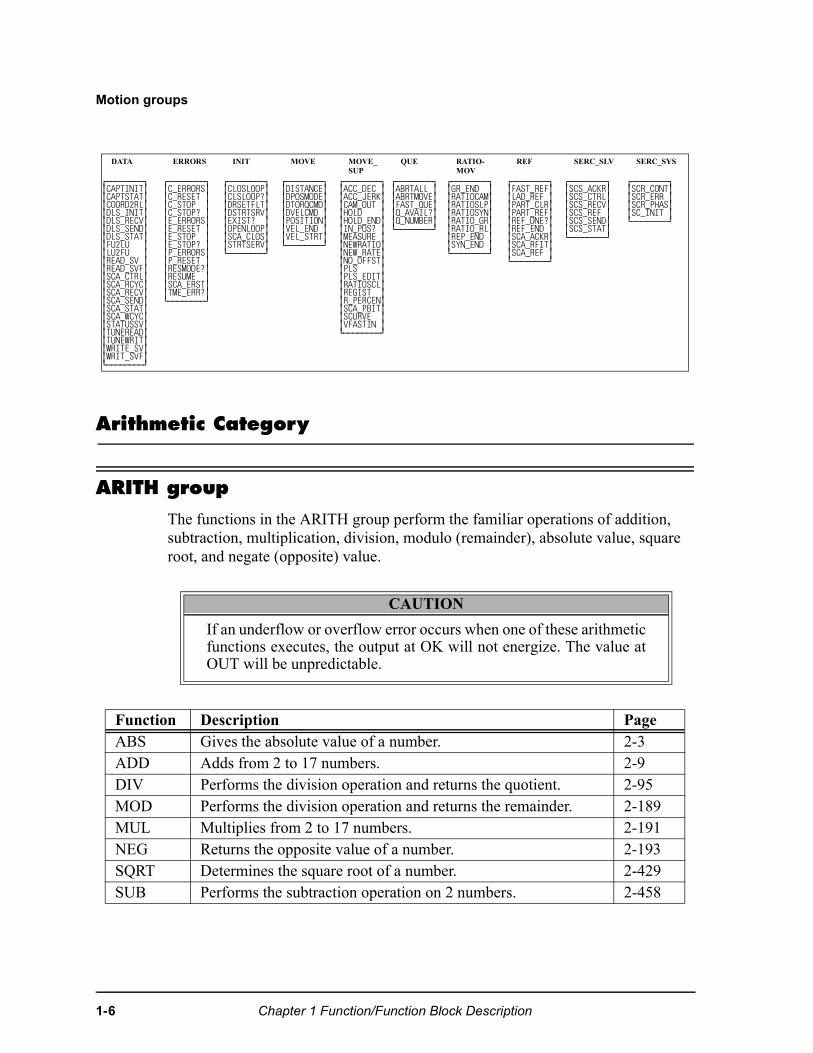
ARITH group
The functions in the ARITH group perform the familiar operations of addition, subtraction, multiplication, division, modulo (remainder), absolute value, square root, and negate (opposite) value.
DATA ERRORS INIT MOVE MOVE_SUP
QUE RATIO-MOV
REF SERC_SLV SERC_SYS
⁄ƒƒƒƒƒƒƒƒø≥CAPTINIT≥≥CAPTSTAT≥≥COORD2RL≥≥DLS_INIT≥≥DLS_RECV≥≥DLS_SEND≥≥DLS_STAT≥≥FU2LU ≥≥LU2FU ≥≥READ_SV ≥≥READ_SVF≥≥SCA_CTRL≥≥SCA_RCYC≥≥SCA_RECV≥≥SCA_SEND≥≥SCA_STAT≥≥SCA_WCYC≥≥STATUSSV≥≥TUNEREAD≥≥TUNEWRIT≥≥WRITE_SV≥≥WRIT_SVF≥¿ƒƒƒƒƒƒƒƒŸ
⁄ƒƒƒƒƒƒƒƒø≥C_ERRORS≥≥C_RESET ≥≥C_STOP ≥≥C_STOP? ≥≥E_ERRORS≥≥E_RESET ≥≥E_STOP ≥≥E_STOP? ≥≥P_ERRORS≥≥P_RESET ≥≥RESMODE?≥≥RESUME ≥≥SCA_ERST≥≥TME_ERR?≥¿ƒƒƒƒƒƒƒƒŸ
⁄ƒƒƒƒƒƒƒƒø≥CLOSLOOP≥≥CLSLOOP?≥≥DRSETFLT≥≥DSTRTSRV≥≥EXIST? ≥≥OPENLOOP≥≥SCA_CLOS≥≥STRTSERV≥¿ƒƒƒƒƒƒƒƒŸ
⁄ƒƒƒƒƒƒƒƒø≥DISTANCE≥≥DPOSMODE≥≥DTORQCMD≥≥DVELCMD ≥≥POSITION≥≥VEL_END ≥≥VEL_STRT≥¿ƒƒƒƒƒƒƒƒŸ
⁄ƒƒƒƒƒƒƒƒø≥ACC_DEC ≥≥ACC_JERK≥≥CAM_OUT ≥≥HOLD ≥≥HOLD_END≥≥IN_POS? ≥≥MEASURE ≥≥NEWRATIO≥≥NEW_RATE≥≥NO_OFFST≥≥PLS ≥≥PLS_EDIT≥≥RATIOSCL≥≥REGIST ≥≥R_PERCEN≥≥SCA_PBIT≥≥SCURVE ≥≥VFASTIN ≥¿ƒƒƒƒƒƒƒƒŸ
⁄ƒƒƒƒƒƒƒƒø≥ABRTALL ≥≥ABRTMOVE≥≥FAST_QUE≥≥Q_AVAIL?≥≥Q_NUMBER≥¿ƒƒƒƒƒƒƒƒŸ
⁄ƒƒƒƒƒƒƒƒø≥GR_END ≥≥RATIOCAM≥≥RATIOSLP≥≥RATIOSYN≥≥RATIO_GR≥≥RATIO_RL≥≥REP_END ≥≥SYN_END ≥¿ƒƒƒƒƒƒƒƒŸ
⁄ƒƒƒƒƒƒƒƒø≥FAST_REF≥≥LAD_REF ≥≥PART_CLR≥≥PART_REF≥≥REF_DNE?≥≥REF_END ≥≥SCA_ACKR≥≥SCA_RFIT≥≥SCA_REF ≥¿ƒƒƒƒƒƒƒƒŸ
⁄ƒƒƒƒƒƒƒƒø≥SCS_ACKR≥≥SCS_CTRL≥≥SCS_RECV≥≥SCS_REF ≥≥SCS_SEND≥≥SCS_STAT≥¿ƒƒƒƒƒƒƒƒŸ
⁄ƒƒƒƒƒƒƒƒø≥SCR_CONT≥≥SCR_ERR ≥≥SCR_PHAS≥≥SC_INIT ≥¿ƒƒƒƒƒƒƒƒŸ
CAUTION
If an underflow or overflow error occurs when one of these arithmeticfunctions executes, the output at OK will not energize. The value atOUT will be unpredictable.
Function Description PageABS Gives the absolute value of a number. 2-3ADD Adds from 2 to 17 numbers. 2-9DIV Performs the division operation and returns the quotient. 2-95MOD Performs the division operation and returns the remainder. 2-189MUL Multiplies from 2 to 17 numbers. 2-191NEG Returns the opposite value of a number. 2-193SQRT Determines the square root of a number. 2-429SUB Performs the subtraction operation on 2 numbers. 2-458
1-6 Chapter 1 Function/Function Block Description
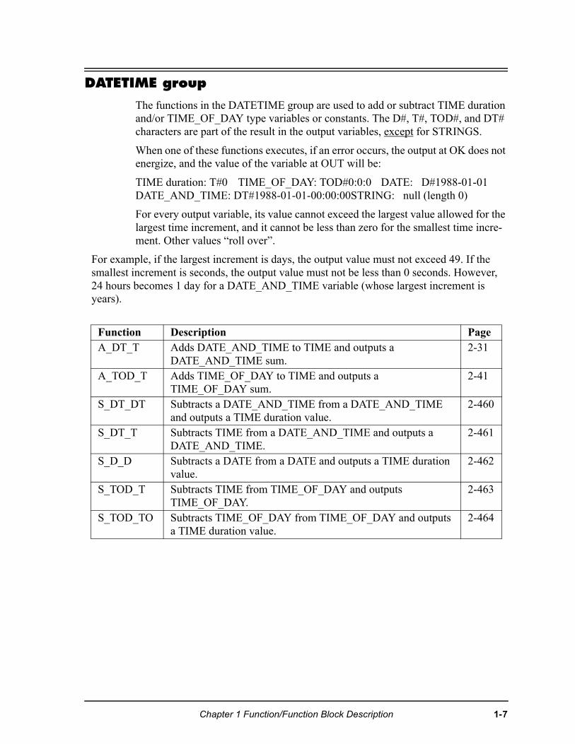
DATETIME group
The functions in the DATETIME group are used to add or subtract TIME duration and/or TIME_OF_DAY type variables or constants. The D#, T#, TOD#, and DT# characters are part of the result in the output variables, except for STRINGS.
When one of these functions executes, if an error occurs, the output at OK does not energize, and the value of the variable at OUT will be:
TIME duration: T#0 TIME_OF_DAY: TOD#0:0:0 DATE: D#1988-01-01DATE_AND_TIME: DT#1988-01-01-00:00:00STRING: null (length 0)
For every output variable, its value cannot exceed the largest value allowed for the largest time increment, and it cannot be less than zero for the smallest time incre-ment. Other values “roll over”.
For example, if the largest increment is days, the output value must not exceed 49. If the smallest increment is seconds, the output value must not be less than 0 seconds. However, 24 hours becomes 1 day for a DATE_AND_TIME variable (whose largest increment is years).
Function Description PageA_DT_T Adds DATE_AND_TIME to TIME and outputs a
DATE_AND_TIME sum. 2-31
A_TOD_T Adds TIME_OF_DAY to TIME and outputs a TIME_OF_DAY sum.
2-41
S_DT_DT Subtracts a DATE_AND_TIME from a DATE_AND_TIME and outputs a TIME duration value.
2-460
S_DT_T Subtracts TIME from a DATE_AND_TIME and outputs a DATE_AND_TIME.
2-461
S_D_D Subtracts a DATE from a DATE and outputs a TIME duration value.
2-462
S_TOD_T Subtracts TIME from TIME_OF_DAY and outputs TIME_OF_DAY.
2-463
S_TOD_TO Subtracts TIME_OF_DAY from TIME_OF_DAY and outputs a TIME duration value.
2-464
Chapter 1 Function/Function Block Description 1-7
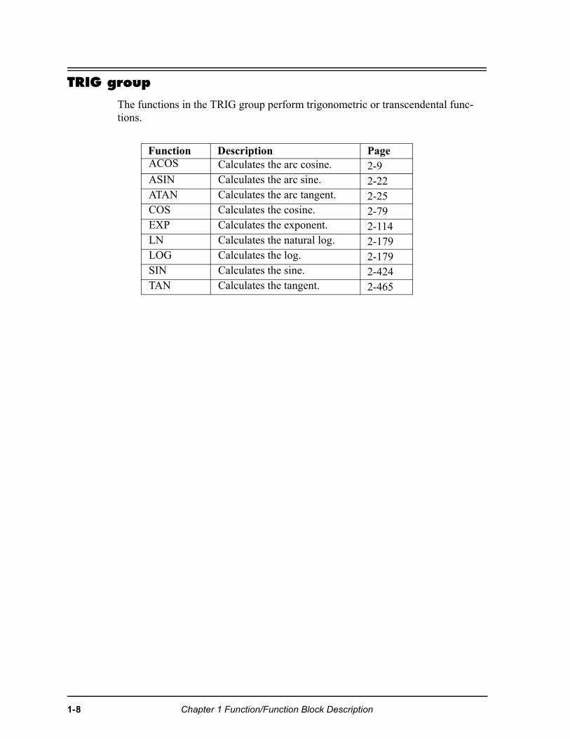
TRIG group
The functions in the TRIG group perform trigonometric or transcendental func-tions.
Function Description PageACOS Calculates the arc cosine. 2-9ASIN Calculates the arc sine. 2-22ATAN Calculates the arc tangent. 2-25COS Calculates the cosine. 2-79EXP Calculates the exponent. 2-114LN Calculates the natural log. 2-179LOG Calculates the log. 2-179SIN Calculates the sine. 2-424TAN Calculates the tangent. 2-465
1-8 Chapter 1 Function/Function Block Description
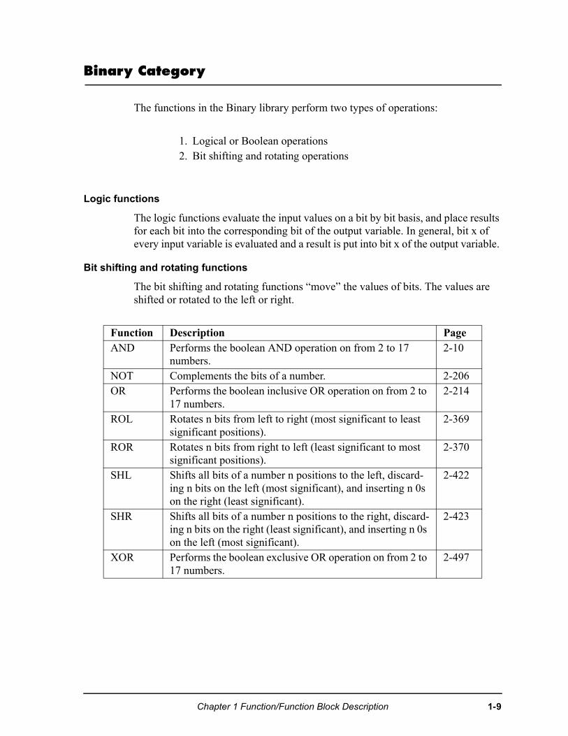
Binary Category
The functions in the Binary library perform two types of operations:
Logic functions
The logic functions evaluate the input values on a bit by bit basis, and place results for each bit into the corresponding bit of the output variable. In general, bit x of every input variable is evaluated and a result is put into bit x of the output variable.
Bit shifting and rotating functions
The bit shifting and rotating functions “move” the values of bits. The values are shifted or rotated to the left or right.
1. Logical or Boolean operations2. Bit shifting and rotating operations
Function Description PageAND Performs the boolean AND operation on from 2 to 17
numbers. 2-10
NOT Complements the bits of a number. 2-206OR Performs the boolean inclusive OR operation on from 2 to
17 numbers. 2-214
ROL Rotates n bits from left to right (most significant to least significant positions).
2-369
ROR Rotates n bits from right to left (least significant to most significant positions).
2-370
SHL Shifts all bits of a number n positions to the left, discard-ing n bits on the left (most significant), and inserting n 0s on the right (least significant).
2-422
SHR Shifts all bits of a number n positions to the right, discard-ing n bits on the right (least significant), and inserting n 0s on the left (most significant).
2-423
XOR Performs the boolean exclusive OR operation on from 2 to 17 numbers.
2-497
Chapter 1 Function/Function Block Description 1-9
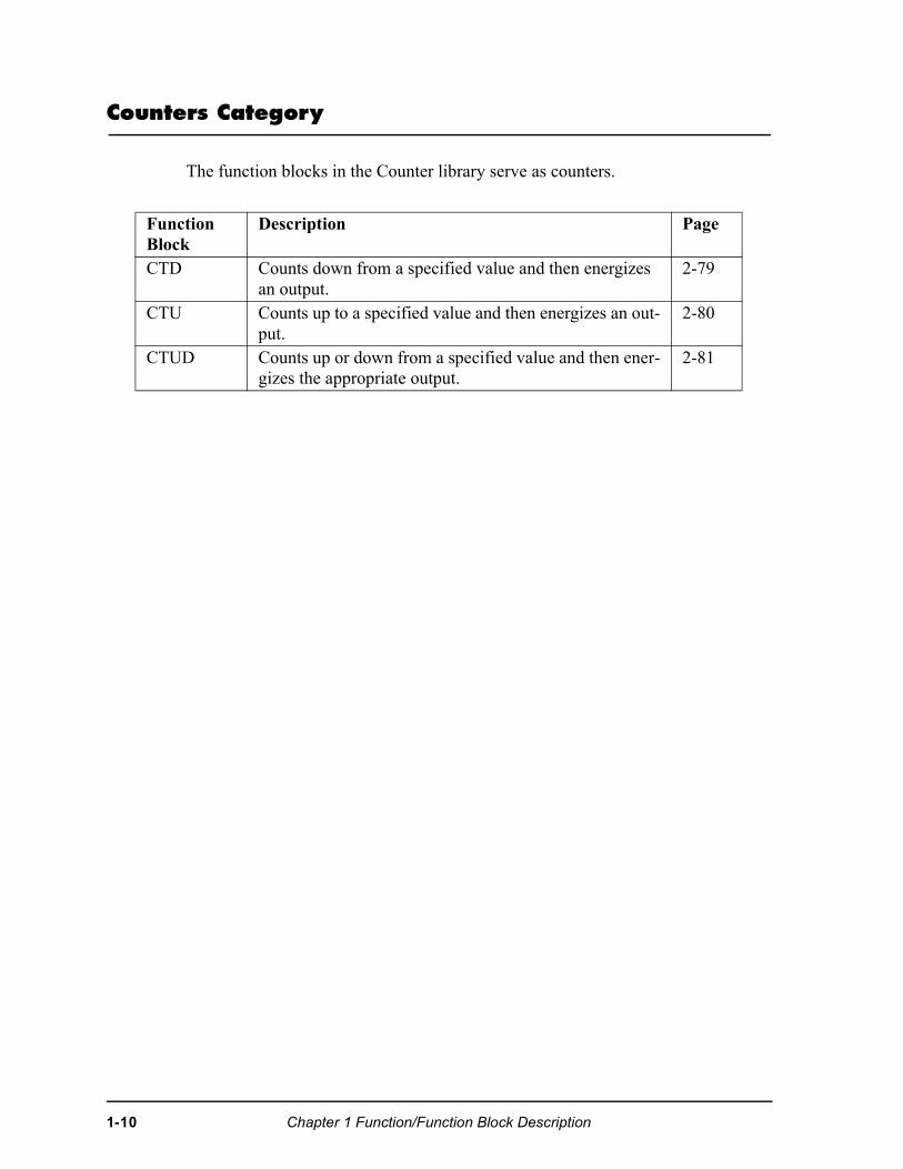
Counters Category
The function blocks in the Counter library serve as counters.
Function Block
Description Page
CTD Counts down from a specified value and then energizes an output.
2-79
CTU Counts up to a specified value and then energizes an out-put.
2-80
CTUD Counts up or down from a specified value and then ener-gizes the appropriate output.
2-81
1-10 Chapter 1 Function/Function Block Description
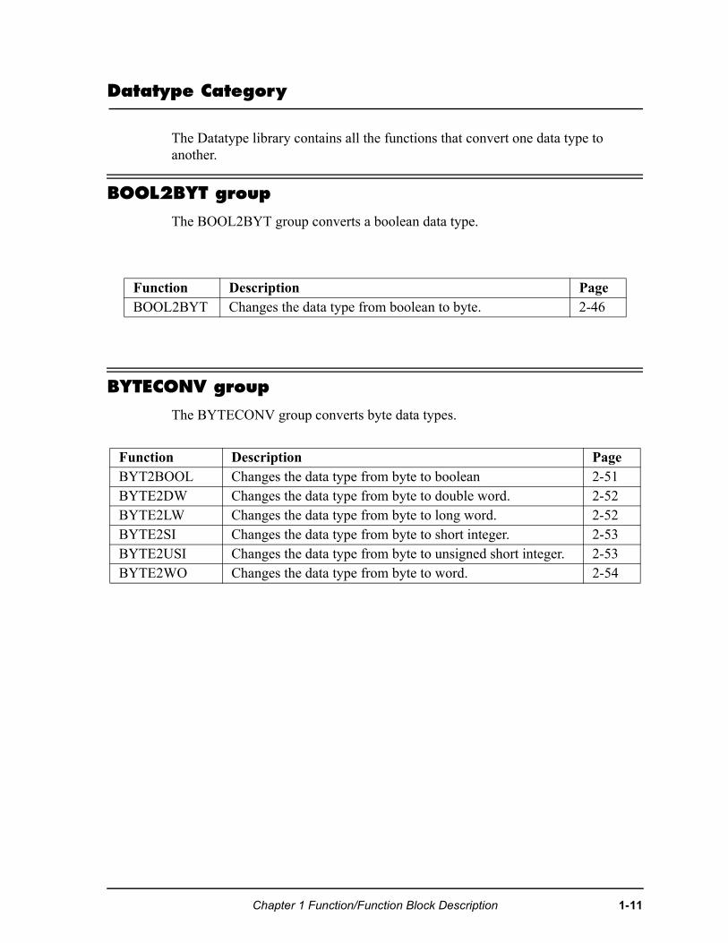
Datatype Category
The Datatype library contains all the functions that convert one data type to another.
BOOL2BYT group
The BOOL2BYT group converts a boolean data type.
BYTECONV group
The BYTECONV group converts byte data types.
Function Description PageBOOL2BYT Changes the data type from boolean to byte. 2-46
Function Description PageBYT2BOOL Changes the data type from byte to boolean 2-51BYTE2DW Changes the data type from byte to double word. 2-52BYTE2LW Changes the data type from byte to long word. 2-52BYTE2SI Changes the data type from byte to short integer. 2-53BYTE2USI Changes the data type from byte to unsigned short integer. 2-53BYTE2WO Changes the data type from byte to word. 2-54
Chapter 1 Function/Function Block Description 1-11
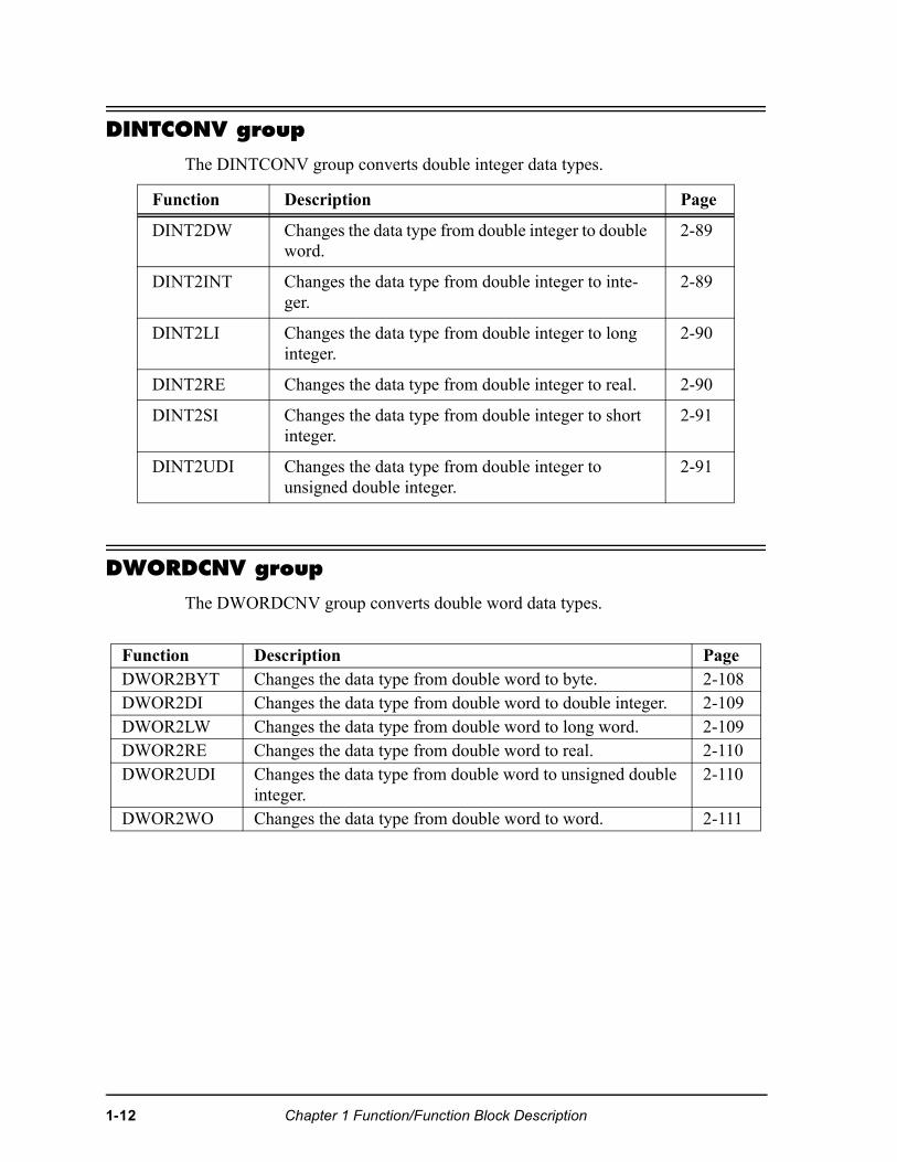
DINTCONV group
The DINTCONV group converts double integer data types.
DWORDCNV group
The DWORDCNV group converts double word data types.
Function Description Page
DINT2DW Changes the data type from double integer to double word.
2-89
DINT2INT Changes the data type from double integer to inte-ger.
2-89
DINT2LI Changes the data type from double integer to long integer.
2-90
DINT2RE Changes the data type from double integer to real. 2-90
DINT2SI Changes the data type from double integer to short integer.
2-91
DINT2UDI Changes the data type from double integer to unsigned double integer.
2-91
Function Description PageDWOR2BYT Changes the data type from double word to byte. 2-108DWOR2DI Changes the data type from double word to double integer. 2-109DWOR2LW Changes the data type from double word to long word. 2-109DWOR2RE Changes the data type from double word to real. 2-110DWOR2UDI Changes the data type from double word to unsigned double
integer. 2-110
DWOR2WO Changes the data type from double word to word. 2-111
1-12 Chapter 1 Function/Function Block Description
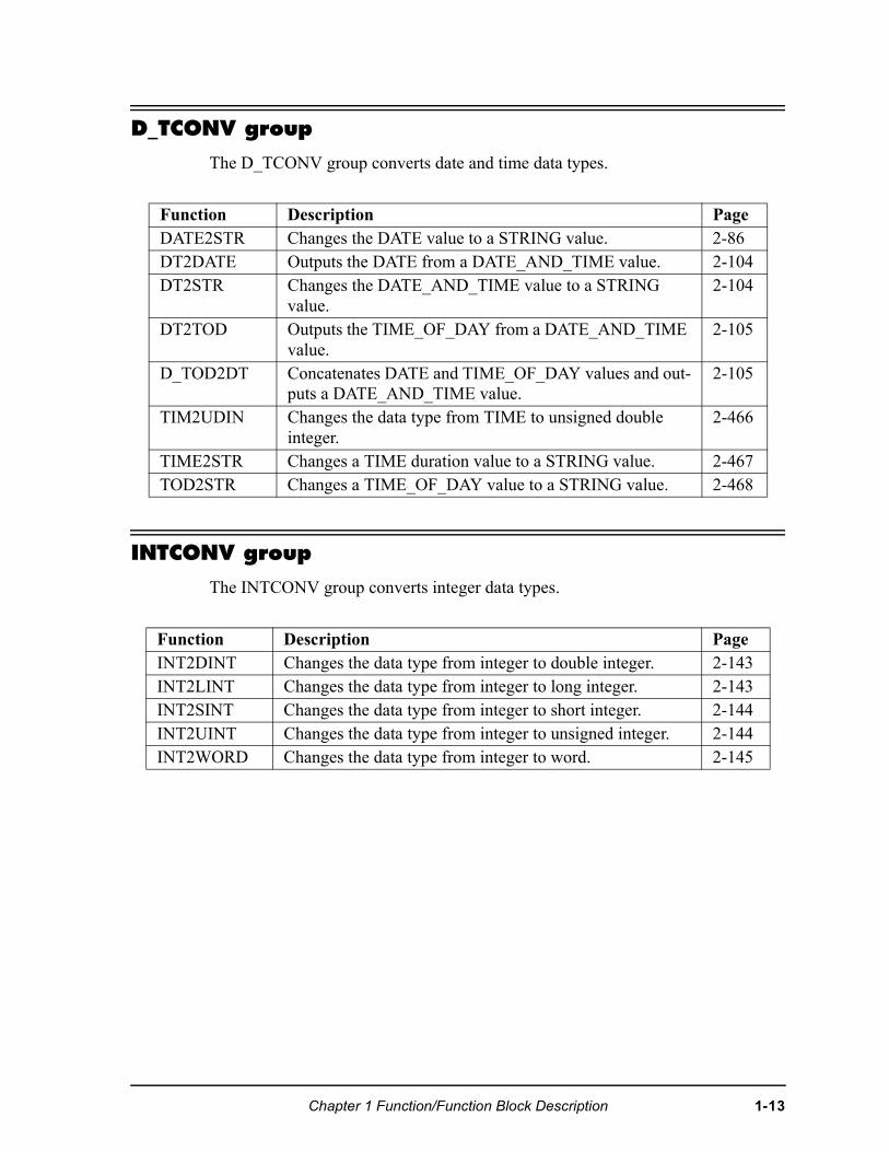
D_TCONV group
The D_TCONV group converts date and time data types.
INTCONV group
The INTCONV group converts integer data types.
Function Description PageDATE2STR Changes the DATE value to a STRING value. 2-86DT2DATE Outputs the DATE from a DATE_AND_TIME value. 2-104DT2STR Changes the DATE_AND_TIME value to a STRING
value. 2-104
DT2TOD Outputs the TIME_OF_DAY from a DATE_AND_TIME value.
2-105
D_TOD2DT Concatenates DATE and TIME_OF_DAY values and out-puts a DATE_AND_TIME value.
2-105
TIM2UDIN Changes the data type from TIME to unsigned double integer.
2-466
TIME2STR Changes a TIME duration value to a STRING value. 2-467TOD2STR Changes a TIME_OF_DAY value to a STRING value. 2-468
Function Description PageINT2DINT Changes the data type from integer to double integer. 2-143INT2LINT Changes the data type from integer to long integer. 2-143INT2SINT Changes the data type from integer to short integer. 2-144INT2UINT Changes the data type from integer to unsigned integer. 2-144INT2WORD Changes the data type from integer to word. 2-145
Chapter 1 Function/Function Block Description 1-13
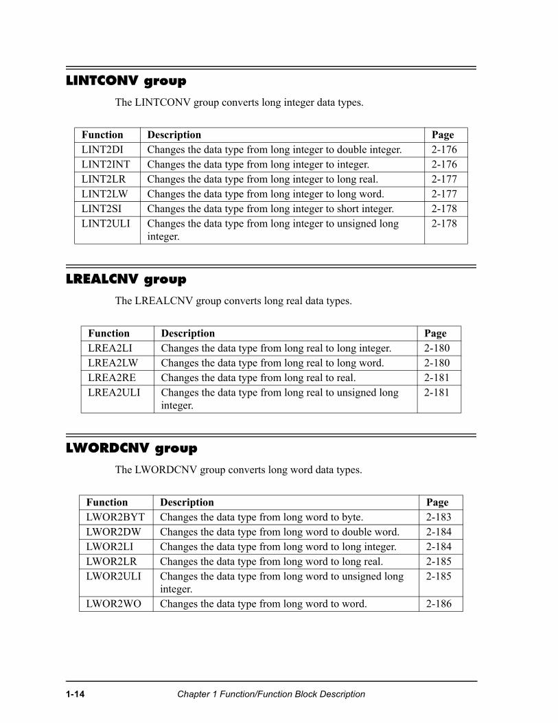
LINTCONV group
The LINTCONV group converts long integer data types.
LREALCNV group
The LREALCNV group converts long real data types.
LWORDCNV group
The LWORDCNV group converts long word data types.
Function Description PageLINT2DI Changes the data type from long integer to double integer. 2-176LINT2INT Changes the data type from long integer to integer. 2-176LINT2LR Changes the data type from long integer to long real. 2-177LINT2LW Changes the data type from long integer to long word. 2-177LINT2SI Changes the data type from long integer to short integer. 2-178LINT2ULI Changes the data type from long integer to unsigned long
integer. 2-178
Function Description PageLREA2LI Changes the data type from long real to long integer. 2-180LREA2LW Changes the data type from long real to long word. 2-180LREA2RE Changes the data type from long real to real. 2-181LREA2ULI Changes the data type from long real to unsigned long
integer. 2-181
Function Description PageLWOR2BYT Changes the data type from long word to byte. 2-183LWOR2DW Changes the data type from long word to double word. 2-184LWOR2LI Changes the data type from long word to long integer. 2-184LWOR2LR Changes the data type from long word to long real. 2-185LWOR2ULI Changes the data type from long word to unsigned long
integer. 2-185
LWOR2WO Changes the data type from long word to word. 2-186
1-14 Chapter 1 Function/Function Block Description
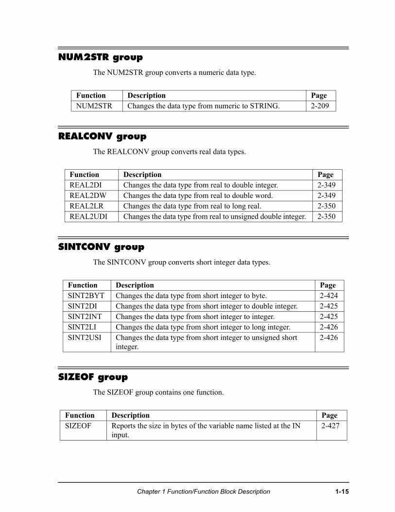
NUM2STR group
The NUM2STR group converts a numeric data type.
REALCONV group
The REALCONV group converts real data types.
SINTCONV group
The SINTCONV group converts short integer data types.
SIZEOF group
The SIZEOF group contains one function.
Function Description PageNUM2STR Changes the data type from numeric to STRING. 2-209
Function Description PageREAL2DI Changes the data type from real to double integer. 2-349REAL2DW Changes the data type from real to double word. 2-349REAL2LR Changes the data type from real to long real. 2-350REAL2UDI Changes the data type from real to unsigned double integer. 2-350
Function Description PageSINT2BYT Changes the data type from short integer to byte. 2-424SINT2DI Changes the data type from short integer to double integer. 2-425SINT2INT Changes the data type from short integer to integer. 2-425SINT2LI Changes the data type from short integer to long integer. 2-426SINT2USI Changes the data type from short integer to unsigned short
integer. 2-426
Function Description PageSIZEOF Reports the size in bytes of the variable name listed at the IN
input. 2-427
Chapter 1 Function/Function Block Description 1-15
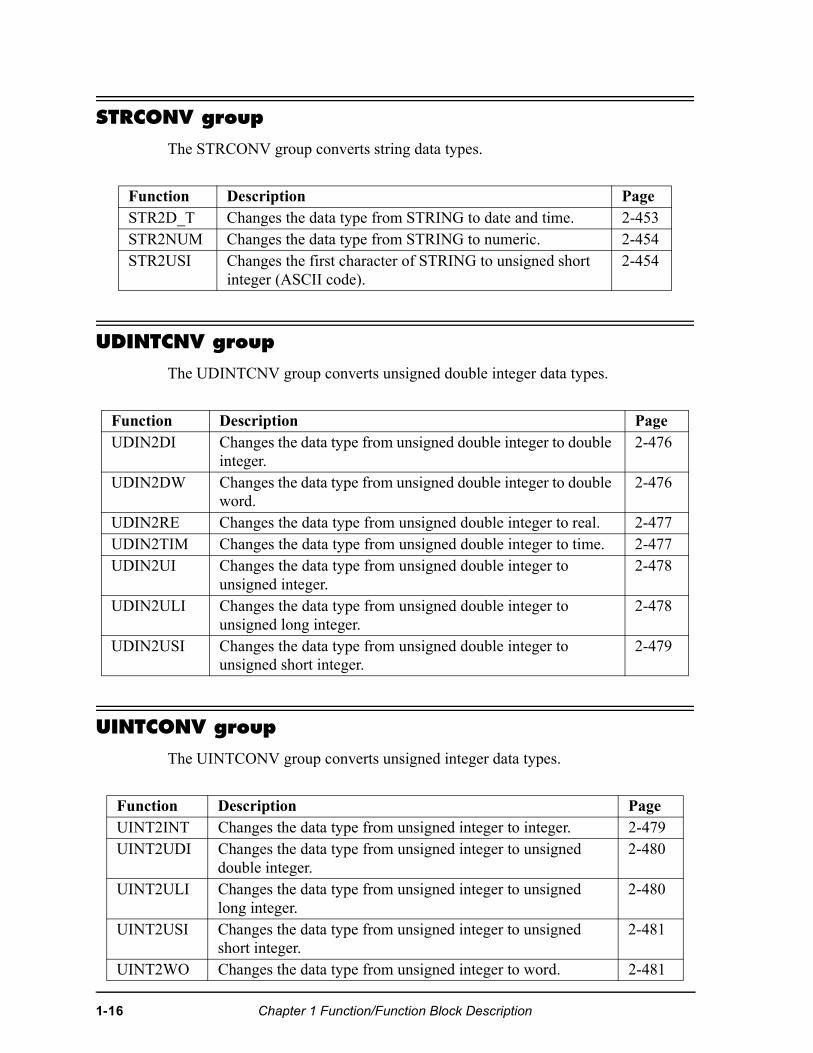
STRCONV group
The STRCONV group converts string data types.
UDINTCNV group
The UDINTCNV group converts unsigned double integer data types.
UINTCONV group
The UINTCONV group converts unsigned integer data types.
Function Description PageSTR2D_T Changes the data type from STRING to date and time. 2-453STR2NUM Changes the data type from STRING to numeric. 2-454STR2USI Changes the first character of STRING to unsigned short
integer (ASCII code). 2-454
Function Description PageUDIN2DI Changes the data type from unsigned double integer to double
integer. 2-476
UDIN2DW Changes the data type from unsigned double integer to double word.
2-476
UDIN2RE Changes the data type from unsigned double integer to real. 2-477UDIN2TIM Changes the data type from unsigned double integer to time. 2-477UDIN2UI Changes the data type from unsigned double integer to
unsigned integer. 2-478
UDIN2ULI Changes the data type from unsigned double integer to unsigned long integer.
2-478
UDIN2USI Changes the data type from unsigned double integer to unsigned short integer.
2-479
Function Description PageUINT2INT Changes the data type from unsigned integer to integer. 2-479UINT2UDI Changes the data type from unsigned integer to unsigned
double integer. 2-480
UINT2ULI Changes the data type from unsigned integer to unsigned long integer.
2-480
UINT2USI Changes the data type from unsigned integer to unsigned short integer.
2-481
UINT2WO Changes the data type from unsigned integer to word. 2-481
1-16 Chapter 1 Function/Function Block Description
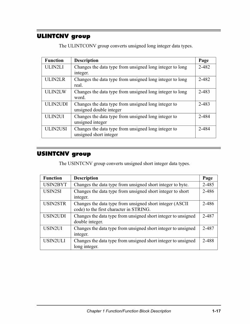
ULINTCNV group
The ULINTCONV group converts unsigned long integer data types.
USINTCNV group
The USINTCNV group converts unsigned short integer data types.
Function Description PageULIN2LI Changes the data type from unsigned long integer to long
integer. 2-482
ULIN2LR Changes the data type from unsigned long integer to long real.
2-482
ULIN2LW Changes the data type from unsigned long integer to long word.
2-483
ULIN2UDI Changes the data type from unsigned long integer to unsigned double integer
2-483
ULIN2UI Changes the data type from unsigned long integer to unsigned integer
2-484
ULIN2USI Changes the data type from unsigned long integer to unsigned short integer
2-484
Function Description PageUSIN2BYT Changes the data type from unsigned short integer to byte. 2-485USIN2SI Changes the data type from unsigned short integer to short
integer. 2-486
USIN2STR Changes the data type from unsigned short integer (ASCII code) to the first character in STRING.
2-486
USIN2UDI Changes the data type from unsigned short integer to unsigned double integer.
2-487
USIN2UI Changes the data type from unsigned short integer to unsigned integer.
2-487
USIN2ULI Changes the data type from unsigned short integer to unsigned long integer.
2-488
Chapter 1 Function/Function Block Description 1-17
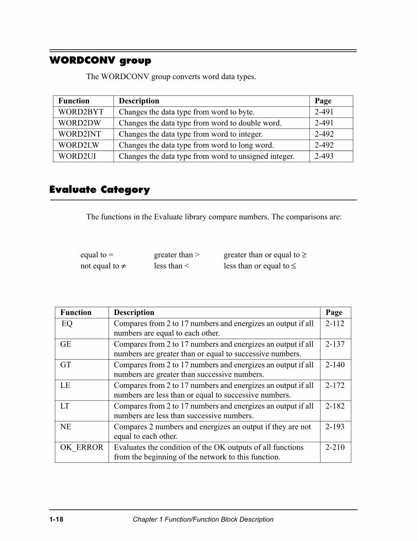
WORDCONV group
The WORDCONV group converts word data types.
Evaluate Category
The functions in the Evaluate library compare numbers. The comparisons are:
Function Description PageWORD2BYT Changes the data type from word to byte. 2-491WORD2DW Changes the data type from word to double word. 2-491WORD2INT Changes the data type from word to integer. 2-492WORD2LW Changes the data type from word to long word. 2-492WORD2UI Changes the data type from word to unsigned integer. 2-493
equal to = greater than > greater than or equal to ≥not equal to ≠ less than < less than or equal to ≤
Function Description PageEQ Compares from 2 to 17 numbers and energizes an output if all
numbers are equal to each other. 2-112
GE Compares from 2 to 17 numbers and energizes an output if all numbers are greater than or equal to successive numbers.
2-137
GT Compares from 2 to 17 numbers and energizes an output if all numbers are greater than successive numbers.
2-140
LE Compares from 2 to 17 numbers and energizes an output if all numbers are less than or equal to successive numbers.
2-172
LT Compares from 2 to 17 numbers and energizes an output if all numbers are less than successive numbers.
2-182
NE Compares 2 numbers and energizes an output if they are not equal to each other.
2-193
OK_ERROR Evaluates the condition of the OK outputs of all functions from the beginning of the network to this function.
2-210
1-18 Chapter 1 Function/Function Block Description
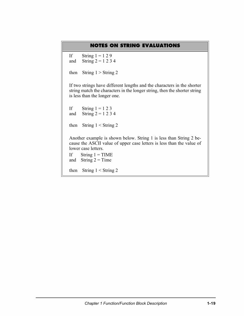
NOTES ON STRING EVALUATIONS
If String 1 = 1 2 9and String 2 = 1 2 3 4
then String 1 > String 2
If two strings have different lengths and the characters in the shorterstring match the characters in the longer string, then the shorter stringis less than the longer one.
If String 1 = 1 2 3 and String 2 = 1 2 3 4
then String 1 < String 2
Another example is shown below. String 1 is less than String 2 be-cause the ASCII value of upper case letters is less than the value oflower case letters. If String 1 = TIMEand String 2 = Time
then String 1 < String 2
Chapter 1 Function/Function Block Description 1-19
Fbinter Category
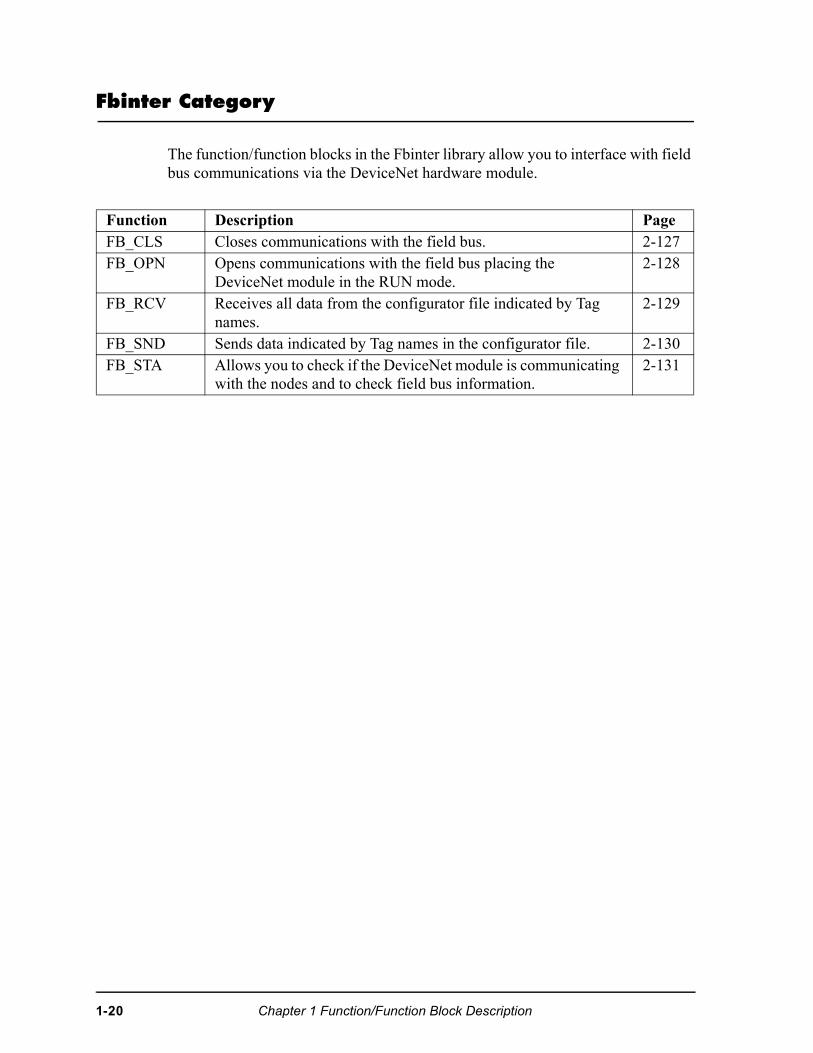
The function/function blocks in the Fbinter library allow you to interface with field bus communications via the DeviceNet hardware module.
Function Description PageFB_CLS Closes communications with the field bus. 2-127FB_OPN Opens communications with the field bus placing the
DeviceNet module in the RUN mode.2-128
FB_RCV Receives all data from the configurator file indicated by Tag names.
2-129
FB_SND Sends data indicated by Tag names in the configurator file. 2-130FB_STA Allows you to check if the DeviceNet module is communicating
with the nodes and to check field bus information.2-131
1-20 Chapter 1 Function/Function Block Description
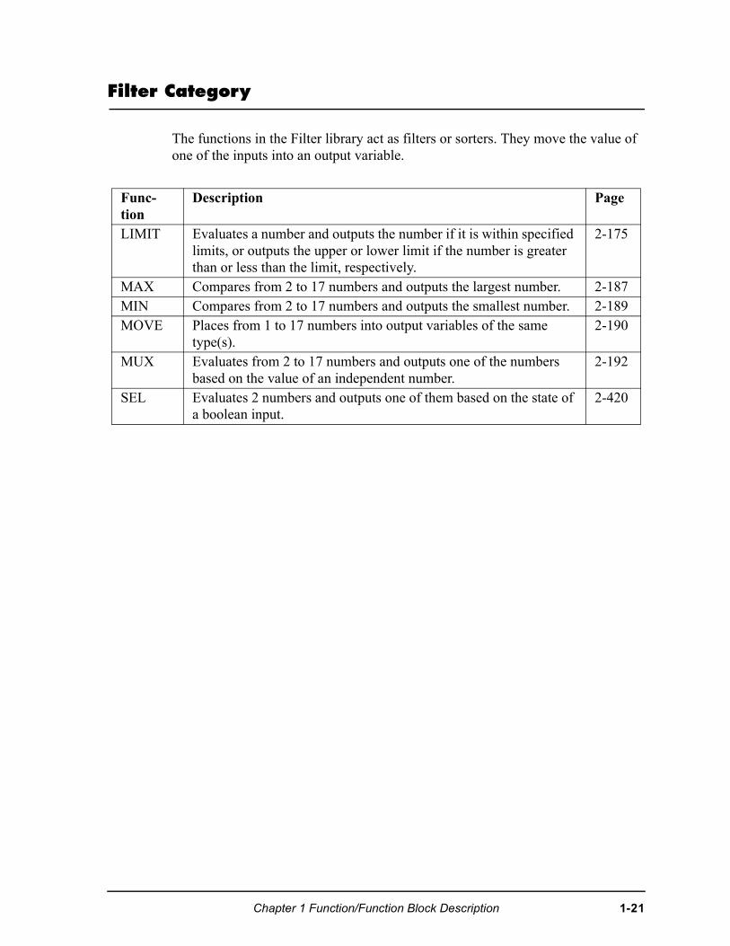
Filter Category
The functions in the Filter library act as filters or sorters. They move the value of one of the inputs into an output variable.
Func-tion
Description Page
LIMIT Evaluates a number and outputs the number if it is within specified limits, or outputs the upper or lower limit if the number is greater than or less than the limit, respectively.
2-175
MAX Compares from 2 to 17 numbers and outputs the largest number. 2-187MIN Compares from 2 to 17 numbers and outputs the smallest number. 2-189MOVE Places from 1 to 17 numbers into output variables of the same
type(s). 2-190
MUX Evaluates from 2 to 17 numbers and outputs one of the numbers based on the value of an independent number.
2-192
SEL Evaluates 2 numbers and outputs one of them based on the state of a boolean input.
2-420
Chapter 1 Function/Function Block Description 1-21
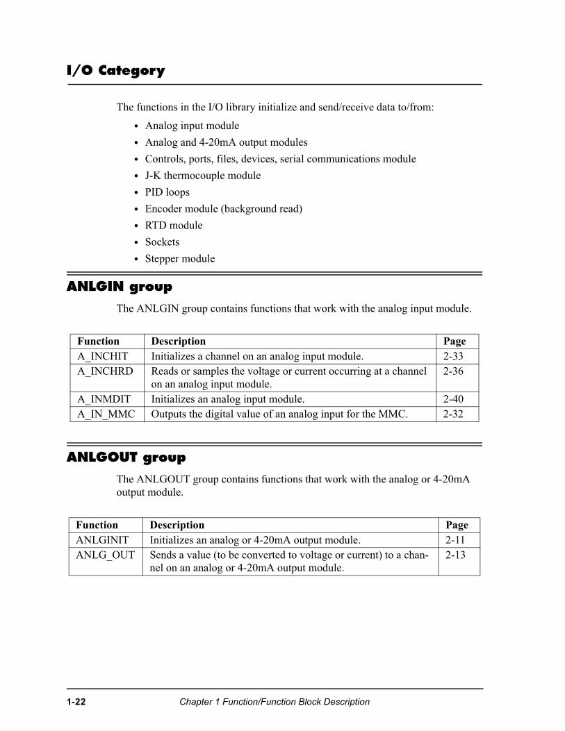
I/O Category
The functions in the I/O library initialize and send/receive data to/from:
• Analog input module
• Analog and 4-20mA output modules
• Controls, ports, files, devices, serial communications module
• J-K thermocouple module
• PID loops
• Encoder module (background read)
• RTD module
• Sockets
• Stepper module
ANLGIN group
The ANLGIN group contains functions that work with the analog input module.
ANLGOUT group
The ANLGOUT group contains functions that work with the analog or 4-20mA output module.
Function Description PageA_INCHIT Initializes a channel on an analog input module. 2-33A_INCHRD Reads or samples the voltage or current occurring at a channel
on an analog input module. 2-36
A_INMDIT Initializes an analog input module. 2-40A_IN_MMC Outputs the digital value of an analog input for the MMC. 2-32
Function Description PageANLGINIT Initializes an analog or 4-20mA output module. 2-11ANLG_OUT Sends a value (to be converted to voltage or current) to a chan-
nel on an analog or 4-20mA output module. 2-13
1-22 Chapter 1 Function/Function Block Description
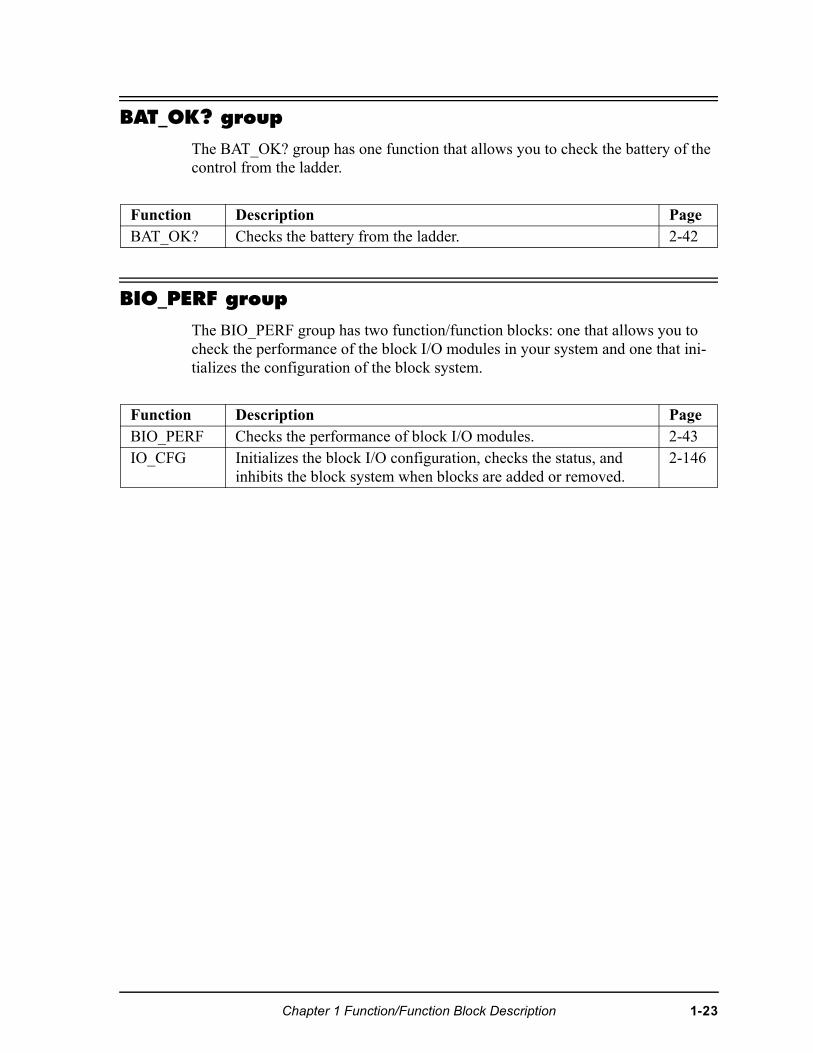
BAT_OK? group
The BAT_OK? group has one function that allows you to check the battery of the control from the ladder.
BIO_PERF group
The BIO_PERF group has two function/function blocks: one that allows you to check the performance of the block I/O modules in your system and one that ini-tializes the configuration of the block system.
Function Description PageBAT_OK? Checks the battery from the ladder. 2-42
Function Description PageBIO_PERF Checks the performance of block I/O modules. 2-43IO_CFG Initializes the block I/O configuration, checks the status, and
inhibits the block system when blocks are added or removed.2-146
Chapter 1 Function/Function Block Description 1-23
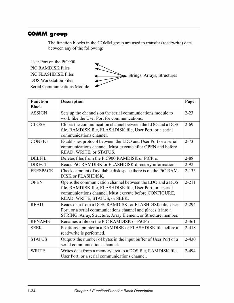
COMM group
The function blocks in the COMM group are used to transfer (read/write) data between any of the following:
User Port on the PiC900PiC RAMDISK Files
Strings, Arrays, StructuresPiC FLASHDISK FilesDOS Workstation FilesSerial Communications Module
Function Block
Description Page
ASSIGN Sets up the channels on the serial communications module to work like the User Port for communications.
2-23
CLOSE Closes the communication channel between the LDO and a DOS file, RAMDISK file, FLASHDISK file, User Port, or a serial communications channel.
2-69
CONFIG Establishes protocol between the LDO and User Port or a serial communications channel. Must execute after OPEN and before READ, WRITE, or STATUS.
2-73
DELFIL Deletes files from the PiC900 RAMDISK or PiCPro. 2-88DIRECT Reads PiC RAMDISK or FLASHDISK directory information. 2-92FRESPACE Checks amount of available disk space there is on the PiC RAM-
DISK or FLASHDISK. 2-135
OPEN Opens the communication channel between the LDO and a DOS file, RAMDISK file, FLASHDISK file, User Port, or a serial communications channel. Must execute before CONFIGURE, READ, WRITE, STATUS, or SEEK.
2-211
READ Reads data from a DOS, RAMDISK, or FLASHDISK file, User Port, or a serial communications channel and places it into a STRING, Array, Structure, Array Element, or Structure member.
2-294
RENAME Renames a file on the PiC RAMDISK or PiCPro. 2-361SEEK Positions a pointer in a RAMDISK or FLASHDISK file before a
read/write is performed. 2-418
STATUS Outputs the number of bytes in the input buffer of User Port or a serial communications channel.
2-430
WRITE Writes data from a memory area to a DOS file, RAMDISK file, User Port, or a serial communications channel.
2-494
1-24 Chapter 1 Function/Function Block Description
JKTHERM group
The JKTHERM group contains functions that work with the JK thermocouple module.
Function Description PageATMPCHIT Initializes a channel on a J-K thermocouple module. 2-26ATMPCHRD Reads or senses the temperature or voltage occurring at a
channel on a J-K thermocouple module. 2-28
ATMPMDIT Initializes Block I/O thermocouple or A/D channel. 2-30BTMPCHIT Initializes Block I/O thermocouple or A/D initialization. 2-47BTMPCHRD Reads or senses the temperature or A/D value. 2-48BTMPMGR Communicates with a J-K thermocouple Block I/O module. 2-50
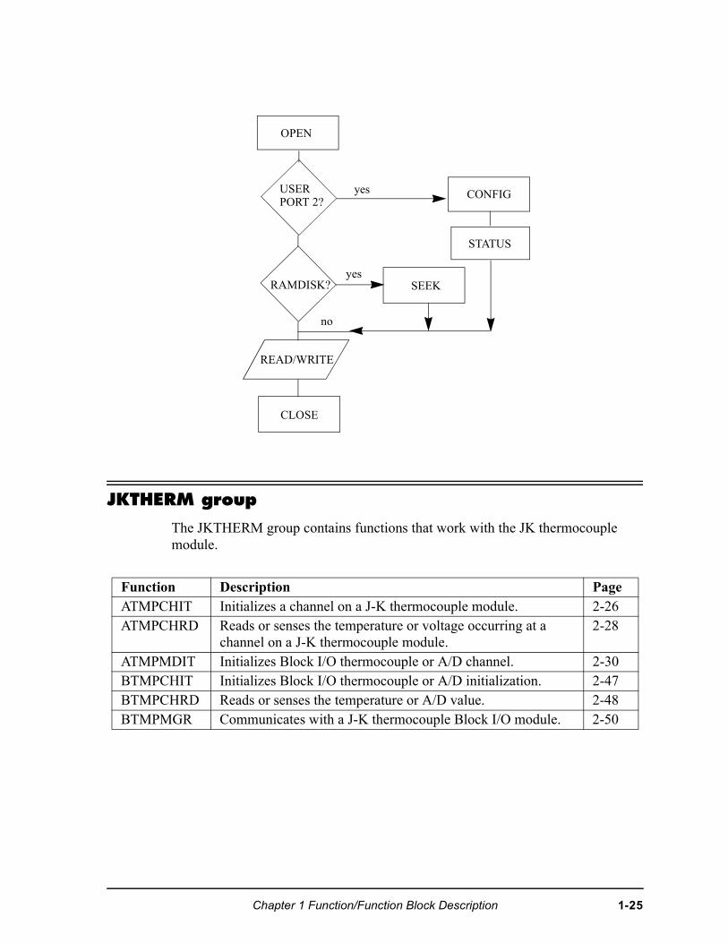
OPEN
USERPORT 2?
yes CONFIG
STATUS
SEEKRAMDISK?yes
no
READ/WRITE
CLOSE
Chapter 1 Function/Function Block Description 1-25
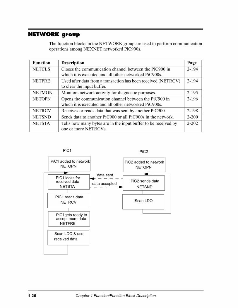
NETWORK group
The function blocks in the NETWORK group are used to perform communication operations among NEXNET networked PiC900s.
Function Description PageNETCLS Closes the communication channel between the PiC900 in
which it is executed and all other networked PiC900s. 2-194
NETFRE Used after data from a transaction has been received (NETRCV) to clear the input buffer.
2-194
NETMON Monitors network activity for diagnostic purposes. 2-195NETOPN Opens the communication channel between the PiC900 in
which it is executed and all other networked PiC900s. 2-196
NETRCV Receives or reads data that was sent by another PiC900. 2-198NETSND Sends data to another PiC900 or all PiC900s in the network. 2-200NETSTA Tells how many bytes are in the input buffer to be received by
one or more NETRCVs. 2-202
PiC1 added to networkNETOPN
PiC1
PiC1 looks forreceived data
NETSTA
PiC1 reads dataNETRCV
PiC1gets ready toaccept more data
NETFRE
Scan LDO & usereceived data
PiC2 added to networkNETOPN
PiC2 sends data
NETSND
Scan LDO
PiC2
data sent
data accepted
1-26 Chapter 1 Function/Function Block Description
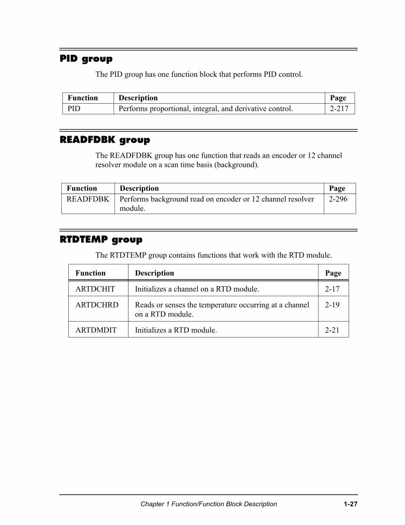
PID group
The PID group has one function block that performs PID control.
READFDBK group
The READFDBK group has one function that reads an encoder or 12 channel resolver module on a scan time basis (background).
RTDTEMP group
The RTDTEMP group contains functions that work with the RTD module.
Function Description PagePID Performs proportional, integral, and derivative control. 2-217
Function Description PageREADFDBK Performs background read on encoder or 12 channel resolver
module.2-296
Function Description Page
ARTDCHIT Initializes a channel on a RTD module. 2-17
ARTDCHRD Reads or senses the temperature occurring at a channel on a RTD module.
2-19
ARTDMDIT Initializes a RTD module. 2-21
Chapter 1 Function/Function Block Description 1-27
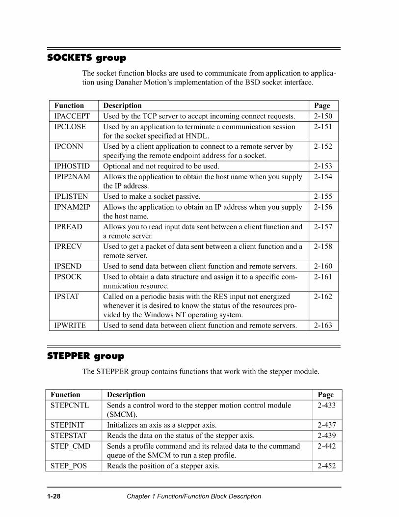
SOCKETS group
The socket function blocks are used to communicate from application to applica-tion using Danaher Motion’s implementation of the BSD socket interface.
STEPPER group
The STEPPER group contains functions that work with the stepper module.
Function Description PageIPACCEPT Used by the TCP server to accept incoming connect requests. 2-150IPCLOSE Used by an application to terminate a communication session
for the socket specified at HNDL.2-151
IPCONN Used by a client application to connect to a remote server by specifying the remote endpoint address for a socket.
2-152
IPHOSTID Optional and not required to be used. 2-153IPIP2NAM Allows the application to obtain the host name when you supply
the IP address.2-154
IPLISTEN Used to make a socket passive. 2-155IPNAM2IP Allows the application to obtain an IP address when you supply
the host name.2-156
IPREAD Allows you to read input data sent between a client function and a remote server.
2-157
IPRECV Used to get a packet of data sent between a client function and a remote server.
2-158
IPSEND Used to send data between client function and remote servers. 2-160IPSOCK Used to obtain a data structure and assign it to a specific com-
munication resource.2-161
IPSTAT Called on a periodic basis with the RES input not energized whenever it is desired to know the status of the resources pro-vided by the Windows NT operating system.
2-162
IPWRITE Used to send data between client function and remote servers. 2-163
Function Description PageSTEPCNTL Sends a control word to the stepper motion control module
(SMCM). 2-433
STEPINIT Initializes an axis as a stepper axis. 2-437STEPSTAT Reads the data on the status of the stepper axis. 2-439STEP_CMD Sends a profile command and its related data to the command
queue of the SMCM to run a step profile.2-442
STEP_POS Reads the position of a stepper axis. 2-452
1-28 Chapter 1 Function/Function Block Description
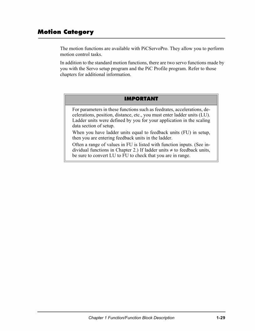
Motion Category
The motion functions are available with PiCServoPro. They allow you to perform motion control tasks.
In addition to the standard motion functions, there are two servo functions made by you with the Servo setup program and the PiC Profile program. Refer to those chapters for additional information.
IMPORTANT
For parameters in these functions such as feedrates, accelerations, de-celerations, position, distance, etc., you must enter ladder units (LU).Ladder units were defined by you for your application in the scalingdata section of setup. When you have ladder units equal to feedback units (FU) in setup,then you are entering feedback units in the ladder.Often a range of values in FU is listed with function inputs. (See in-dividual functions in Chapter 2.) If ladder units ≠ to feedback units,be sure to convert LU to FU to check that you are in range.
Chapter 1 Function/Function Block Description 1-29
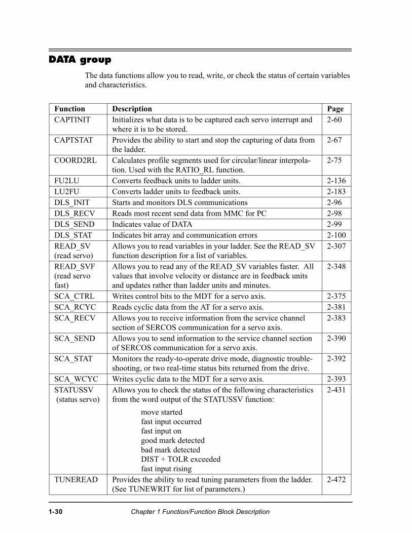
DATA group
The data functions allow you to read, write, or check the status of certain variables and characteristics.
Function Description PageCAPTINIT Initializes what data is to be captured each servo interrupt and
where it is to be stored. 2-60
CAPTSTAT Provides the ability to start and stop the capturing of data from the ladder.
2-67
COORD2RL Calculates profile segments used for circular/linear interpola-tion. Used with the RATIO_RL function.
2-75
FU2LU Converts feedback units to ladder units. 2-136LU2FU Converts ladder units to feedback units. 2-183DLS_INIT Starts and monitors DLS communications 2-96DLS_RECV Reads most recent send data from MMC for PC 2-98DLS_SEND Indicates value of DATA 2-99DLS_STAT Indicates bit array and communication errors 2-100READ_SV (read servo)
Allows you to read variables in your ladder. See the READ_SV function description for a list of variables.
2-307
READ_SVF (read servo fast)
Allows you to read any of the READ_SV variables faster. All values that involve velocity or distance are in feedback units and updates rather than ladder units and minutes.
2-348
SCA_CTRL Writes control bits to the MDT for a servo axis. 2-375SCA_RCYC Reads cyclic data from the AT for a servo axis. 2-381SCA_RECV Allows you to receive information from the service channel
section of SERCOS communication for a servo axis.2-383
SCA_SEND Allows you to send information to the service channel section of SERCOS communication for a servo axis.
2-390
SCA_STAT Monitors the ready-to-operate drive mode, diagnostic trouble-shooting, or two real-time status bits returned from the drive.
2-392
SCA_WCYC Writes cyclic data to the MDT for a servo axis. 2-393STATUSSV (status servo)
Allows you to check the status of the following characteristics from the word output of the STATUSSV function:
move startedfast input occurredfast input ongood mark detectedbad mark detectedDIST + TOLR exceededfast input rising
2-431
TUNEREAD Provides the ability to read tuning parameters from the ladder. (See TUNEWRIT for list of parameters.)
2-472
1-30 Chapter 1 Function/Function Block Description
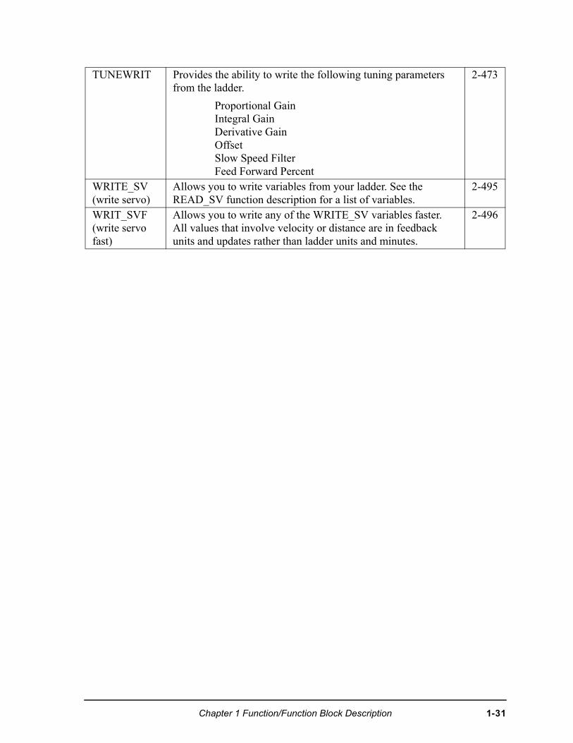
TUNEWRIT Provides the ability to write the following tuning parameters from the ladder.
Proportional GainIntegral GainDerivative GainOffsetSlow Speed FilterFeed Forward Percent
2-473
WRITE_SV (write servo)
Allows you to write variables from your ladder. See the READ_SV function description for a list of variables.
2-495
WRIT_SVF (write servo fast)
Allows you to write any of the WRITE_SV variables faster. All values that involve velocity or distance are in feedback units and updates rather than ladder units and minutes.
2-496
Chapter 1 Function/Function Block Description 1-31
ERRORS group
There are three types of errors that affect an axis as described below.
There is a fourth type of error connected to the entire system called a timing error. It is moni-tored by the TME_ERR? function.
1. C-stop (controlled-stop) errors
When a C-stop occurs, the following happens:
• The axis remains in servo lock and the axis is brought to a con-trolled stop at the rate specified by the controlled stop ramp in setup.
• The active and next queues are cleared.
• The FAST_QUE mode is canceled when the C-stop is reset.2. E-stop (Emergency-stop) errors
When an E-stop occurs, the following happens:
• The system is out of servo lock.
• zero voltage is sent to the analog outputs.
• The active and next queues are cleared.
• The FAST_QUE mode is canceled when the E-stop is reset.
• If it is a loss of feedback E-stop error, then the machine reference must be redone.
In most respects, you are in a condition immediately following initialization with the exception of the queue number. The queue number does not start over but continues from where it left off when the E-stop occurred.
Remember that the queue number is assigned by the software from 1 to 255. When 255 is reached, it rolls over to 1.
3. Programming errors
These errors occur during master/slave moves or a FAST_QUE call. They may prevent the move from being placed in the queue (or if the move is in the queue, abort the move) or they may prevent the OK on the function from being set.
4. Timing error
All the servo calculations for one interrupt must be completed in the time frame selected by you in setup before the next interrupt can perform its calculations. If they are not, this timing error occurs and the ERR output of the TME_ERR? function is set.
1-32 Chapter 1 Function/Function Block Description
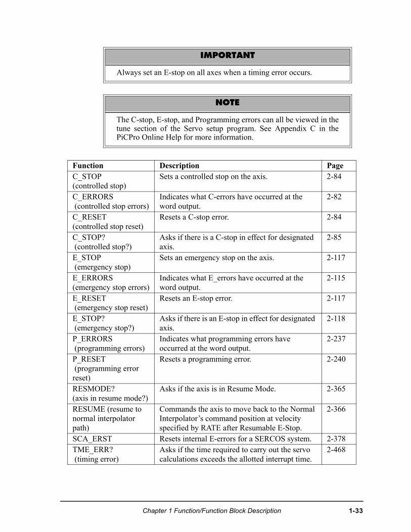
IMPORTANT
Always set an E-stop on all axes when a timing error occurs.
NOTE
The C-stop, E-stop, and Programming errors can all be viewed in thetune section of the Servo setup program. See Appendix C in thePiCPro Online Help for more information.
Function Description PageC_STOP (controlled stop)
Sets a controlled stop on the axis. 2-84
C_ERRORS (controlled stop errors)
Indicates what C-errors have occurred at the word output.
2-82
C_RESET (controlled stop reset)
Resets a C-stop error. 2-84
C_STOP? (controlled stop?)
Asks if there is a C-stop in effect for designated axis.
2-85
E_STOP (emergency stop)
Sets an emergency stop on the axis. 2-117
E_ERRORS (emergency stop errors)
Indicates what E_errors have occurred at the word output.
2-115
E_RESET (emergency stop reset)
Resets an E-stop error. 2-117
E_STOP? (emergency stop?)
Asks if there is an E-stop in effect for designated axis.
2-118
P_ERRORS (programming errors)
Indicates what programming errors have occurred at the word output.
2-237
P_RESET (programming error reset)
Resets a programming error. 2-240
RESMODE?(axis in resume mode?)
Asks if the axis is in Resume Mode. 2-365
RESUME (resume to normal interpolator path)
Commands the axis to move back to the Normal Interpolator’s command position at velocity specified by RATE after Resumable E-Stop.
2-366
SCA_ERST Resets internal E-errors for a SERCOS system. 2-378TME_ERR? (timing error)
Asks if the time required to carry out the servo calculations exceeds the allotted interrupt time.
2-468
Chapter 1 Function/Function Block Description 1-33
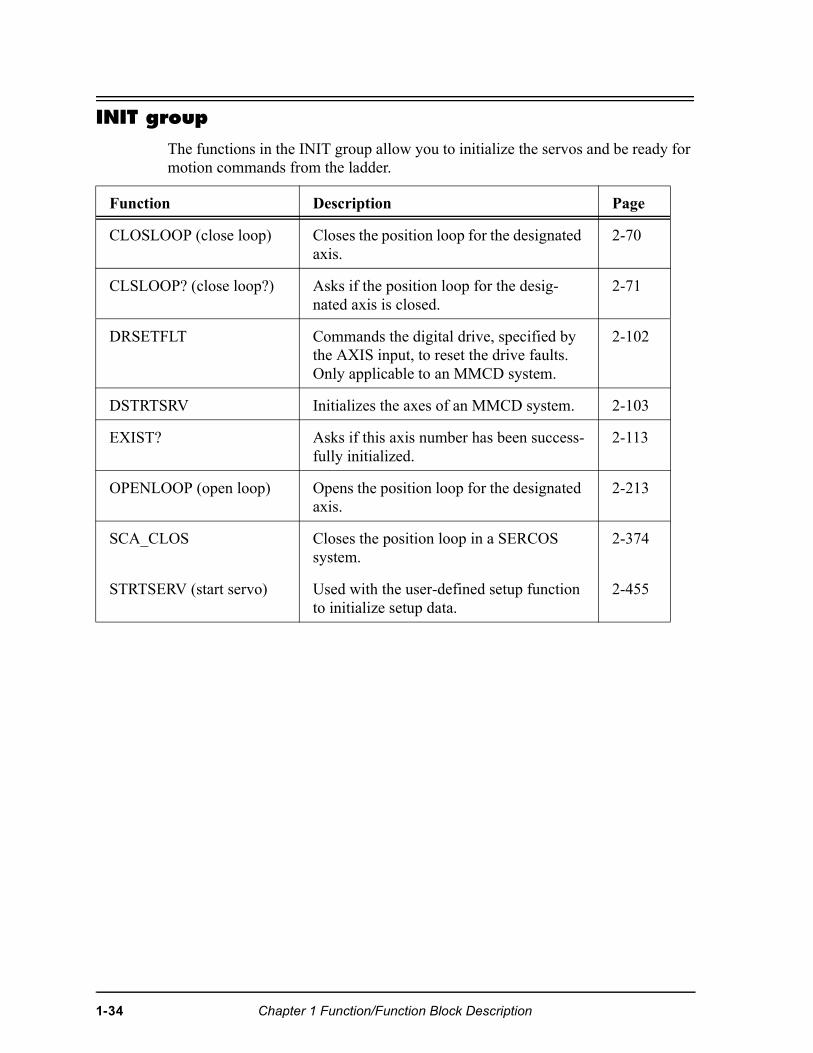
INIT group
The functions in the INIT group allow you to initialize the servos and be ready for motion commands from the ladder.
Function Description Page
CLOSLOOP (close loop) Closes the position loop for the designated axis.
2-70
CLSLOOP? (close loop?) Asks if the position loop for the desig-nated axis is closed.
2-71
DRSETFLT Commands the digital drive, specified by the AXIS input, to reset the drive faults. Only applicable to an MMCD system.
2-102
DSTRTSRV Initializes the axes of an MMCD system. 2-103
EXIST? Asks if this axis number has been success-fully initialized.
2-113
OPENLOOP (open loop) Opens the position loop for the designated axis.
2-213
SCA_CLOS Closes the position loop in a SERCOS system.
2-374
STRTSERV (start servo) Used with the user-defined setup function to initialize setup data.
2-455
1-34 Chapter 1 Function/Function Block Description
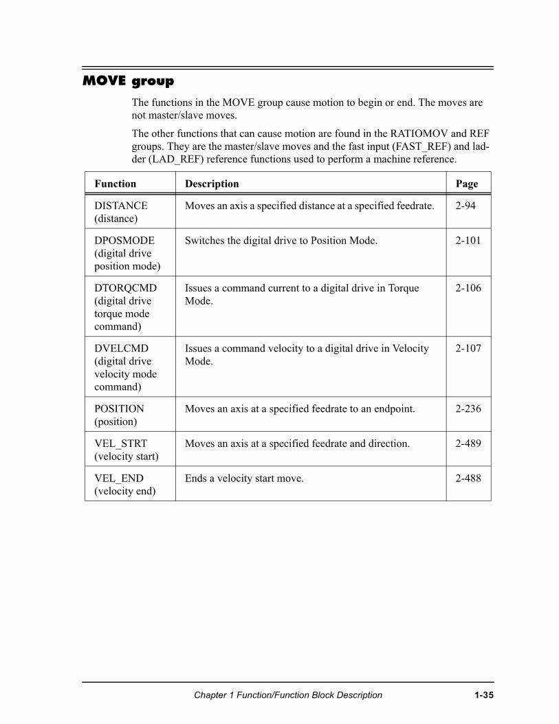
MOVE group
The functions in the MOVE group cause motion to begin or end. The moves are not master/slave moves.
The other functions that can cause motion are found in the RATIOMOV and REF groups. They are the master/slave moves and the fast input (FAST_REF) and lad-der (LAD_REF) reference functions used to perform a machine reference.
Function Description Page
DISTANCE (distance)
Moves an axis a specified distance at a specified feedrate. 2-94
DPOSMODE (digital drive position mode)
Switches the digital drive to Position Mode. 2-101
DTORQCMD (digital drive torque mode command)
Issues a command current to a digital drive in Torque Mode.
2-106
DVELCMD (digital drive velocity mode command)
Issues a command velocity to a digital drive in Velocity Mode.
2-107
POSITION (position)
Moves an axis at a specified feedrate to an endpoint. 2-236
VEL_STRT (velocity start)
Moves an axis at a specified feedrate and direction. 2-489
VEL_END (velocity end)
Ends a velocity start move. 2-488
Chapter 1 Function/Function Block Description 1-35
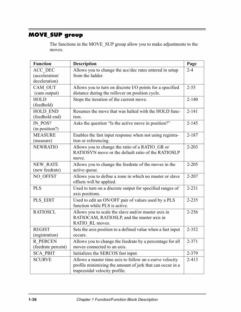
MOVE_SUP group
The functions in the MOVE_SUP group allow you to make adjustments to the moves.
Function Description PageACC_DEC(acceleration/deceleration)
Allows you to change the acc/dec rates entered in setup from the ladder.
2-4
CAM_OUT (cam output)
Allows you to turn on discrete I/O points for a specified distance during the rollover on position cycle.
2-55
HOLD (feedhold)
Stops the iteration of the current move. 2-140
HOLD_END (feedhold end)
Resumes the move that was halted with the HOLD func-tion.
2-141
IN_POS? (in position?)
Asks the question “Is the active move in position?” 2-145
MEASURE (measure)
Enables the fast input response when not using registra-tion or referencing.
2-187
NEWRATIO Allows you to change the ratio of a RATIO_GR or RATIOSYN move or the default ratio of the RATIOSLP move.
2-203
NEW_RATE (new feedrate)
Allows you to change the feedrate of the moves in the active queue.
2-205
NO_OFFST Allows you to define a zone in which no master or slave offsets will be applied.
2-207
PLS Used to turn on a discrete output for specified ranges of axis positions.
2-231
PLS_EDIT Used to edit an ON/OFF pair of values used by a PLS function while PLS is active.
2-235
RATIOSCL Allows you to scale the slave and/or master axis in RATIOCAM, RATIOSLP, and the master axis in RATIO_RL moves.
2-256
REGIST (registration)
Sets the axis position to a defined value when a fast input occurs.
2-352
R_PERCEN (feedrate percent)
Allows you to change the feedrate by a percentage for all moves connected to an axis.
2-371
SCA_PBIT Initializes the SERCOS fast input. 2-379SCURVE Allows a master time axis to follow an s-curve velocity
profile minimizing the amount of jerk that can occur in a trapezoidal velocity profile.
2-413
1-36 Chapter 1 Function/Function Block Description
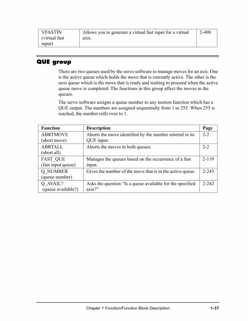
QUE group
There are two queues used by the servo software to manage moves for an axis. One is the active queue which holds the move that is currently active. The other is the next queue which is the move that is ready and waiting to proceed when the active queue move is completed. The functions in this group affect the moves in the queues.
The servo software assigns a queue number to any motion function which has a QUE output. The numbers are assigned sequentially from 1 to 255. When 255 is reached, the number rolls over to 1.
VFASTIN(virtual fast input)
Allows you to generate a virtual fast input for a virtual axis.
2-490
Function Description PageABRTMOVE (abort move)
Aborts the move identified by the number entered in its QUE input.
2-2
ABRTALL (abort all)
Aborts the moves in both queues. 2-2
FAST_QUE (fast input queue)
Manages the queues based on the occurrence of a fast input.
2-119
Q_NUMBER(queue number)
Gives the number of the move that is in the active queue. 2-243
Q_AVAIL? (queue available?)
Asks the question “Is a queue available for the specified axis?”
2-242
Chapter 1 Function/Function Block Description 1-37
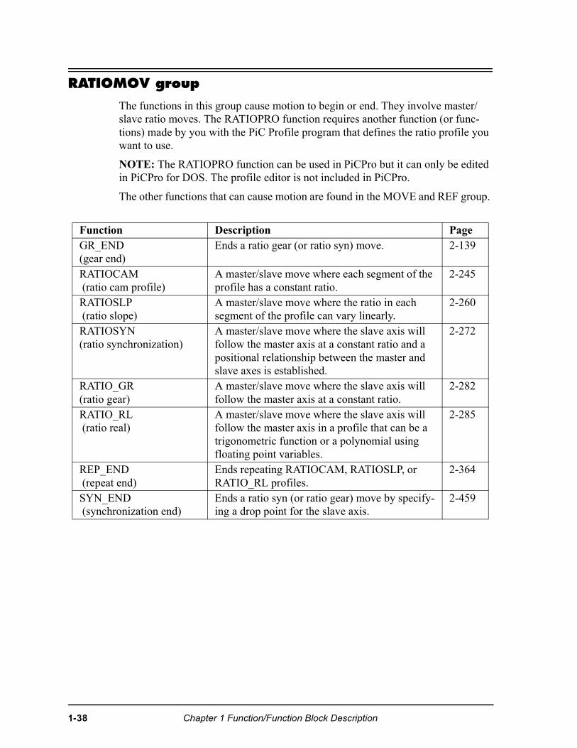
RATIOMOV group
The functions in this group cause motion to begin or end. They involve master/slave ratio moves. The RATIOPRO function requires another function (or func-tions) made by you with the PiC Profile program that defines the ratio profile you want to use.
NOTE: The RATIOPRO function can be used in PiCPro but it can only be edited in PiCPro for DOS. The profile editor is not included in PiCPro.
The other functions that can cause motion are found in the MOVE and REF group.
Function Description PageGR_END (gear end)
Ends a ratio gear (or ratio syn) move. 2-139
RATIOCAM (ratio cam profile)
A master/slave move where each segment of the profile has a constant ratio.
2-245
RATIOSLP (ratio slope)
A master/slave move where the ratio in each segment of the profile can vary linearly.
2-260
RATIOSYN (ratio synchronization)
A master/slave move where the slave axis will follow the master axis at a constant ratio and a positional relationship between the master and slave axes is established.
2-272
RATIO_GR (ratio gear)
A master/slave move where the slave axis will follow the master axis at a constant ratio.
2-282
RATIO_RL (ratio real)
A master/slave move where the slave axis will follow the master axis in a profile that can be a trigonometric function or a polynomial using floating point variables.
2-285
REP_END (repeat end)
Ends repeating RATIOCAM, RATIOSLP, or RATIO_RL profiles.
2-364
SYN_END (synchronization end)
Ends a ratio syn (or ratio gear) move by specify-ing a drop point for the slave axis.
2-459
1-38 Chapter 1 Function/Function Block Description
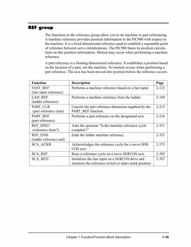
REF group
The functions in the reference group allow you to do machine or part referencing. A machine reference provides position information to the PiC900 with respect to the machine. It is a fixed dimensional reference used to establish a repeatable point of reference between servo initializations. The PiC900 bases its position calcula-tions on this position information. Motion may occur when performing a machine reference.
A part reference is a floating dimensional reference. It establishes a position based on the location of a part, not the machine. No motion occurs when performing a part reference. The axis has been moved into position before the reference occurs.
Function Description PageFAST_REF(fast input reference)
Performs a machine reference based on a fast input. 2-122
LAD_REF (ladder reference)
Performs a machine reference from the ladder. 2-169
PART_CLR (part reference clear)
Cancels the part reference dimension supplied by the PART_REF function.
2-215
PART_REF (part reference)
Performs a part reference on the designated axis. 2-216
REF_DNE? (reference done?)
Asks the question “Is the machine reference cycle complete?”
2-351
REF_END(ladder reference end)
Ends the ladder machine reference. 2-351
SCA_ACKR Acknowledges the reference cycle for a servo SER-COS axis.
2-373
SCA_REF Runs a reference cycle on a servo SERCOS axis. 2-385SCA_RFIT Initializes the fast input on a SERCOS drive and
monitors the reference switch or index mark position.2-387
Chapter 1 Function/Function Block Description 1-39
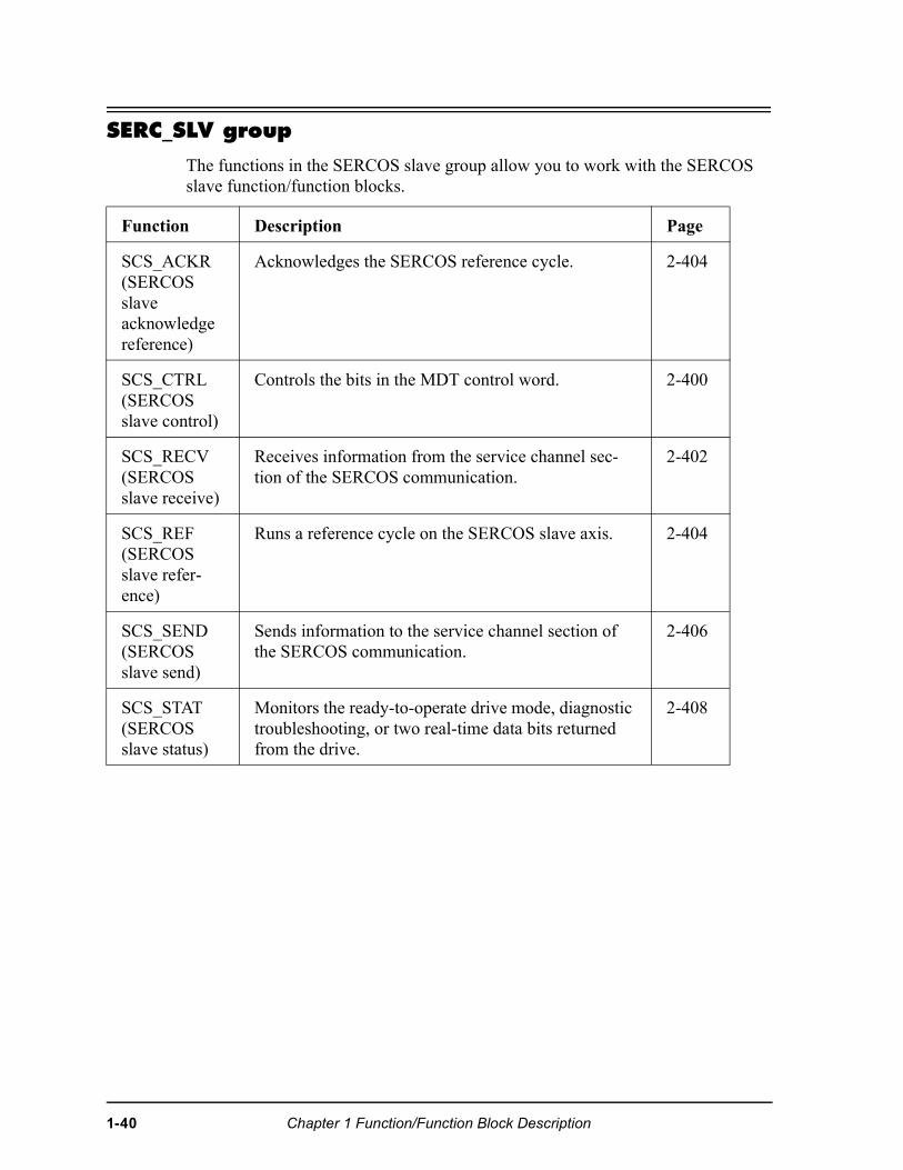
SERC_SLV group
The functions in the SERCOS slave group allow you to work with the SERCOS slave function/function blocks.
Function Description Page
SCS_ACKR(SERCOS slave acknowledge reference)
Acknowledges the SERCOS reference cycle. 2-404
SCS_CTRL(SERCOS slave control)
Controls the bits in the MDT control word. 2-400
SCS_RECV (SERCOS slave receive)
Receives information from the service channel sec-tion of the SERCOS communication.
2-402
SCS_REF (SERCOS slave refer-ence)
Runs a reference cycle on the SERCOS slave axis. 2-404
SCS_SEND (SERCOS slave send)
Sends information to the service channel section of the SERCOS communication.
2-406
SCS_STAT (SERCOS slave status)
Monitors the ready-to-operate drive mode, diagnostic troubleshooting, or two real-time data bits returned from the drive.
2-408
1-40 Chapter 1 Function/Function Block Description
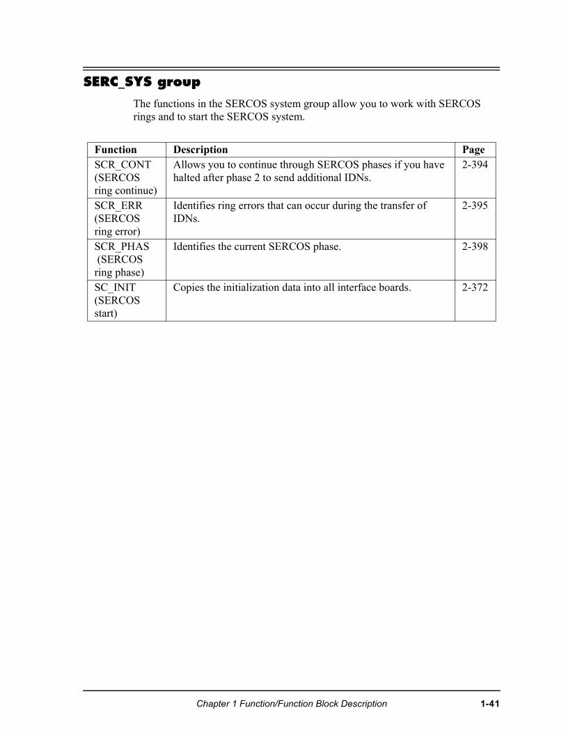
SERC_SYS group
The functions in the SERCOS system group allow you to work with SERCOS rings and to start the SERCOS system.
Function Description PageSCR_CONT(SERCOS ring continue)
Allows you to continue through SERCOS phases if you have halted after phase 2 to send additional IDNs.
2-394
SCR_ERR (SERCOS ring error)
Identifies ring errors that can occur during the transfer of IDNs.
2-395
SCR_PHAS (SERCOS ring phase)
Identifies the current SERCOS phase. 2-398
SC_INIT (SERCOS start)
Copies the initialization data into all interface boards. 2-372
Chapter 1 Function/Function Block Description 1-41
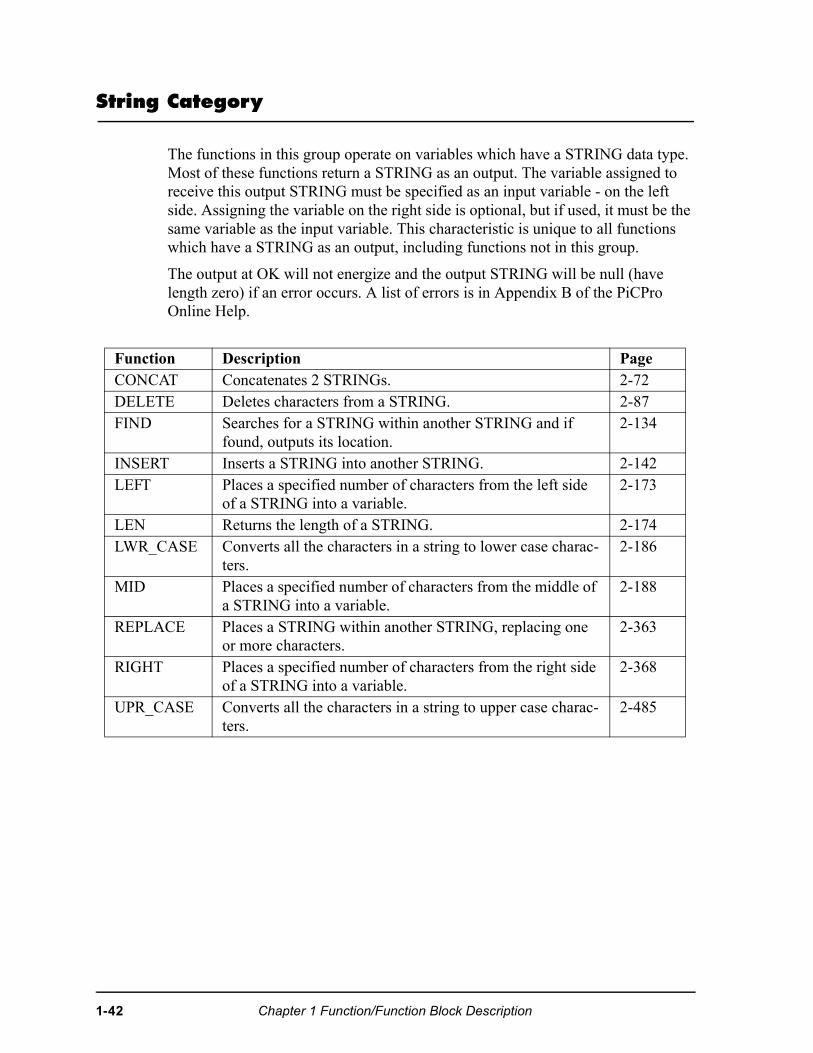
String Category
The functions in this group operate on variables which have a STRING data type. Most of these functions return a STRING as an output. The variable assigned to receive this output STRING must be specified as an input variable - on the left side. Assigning the variable on the right side is optional, but if used, it must be the same variable as the input variable. This characteristic is unique to all functions which have a STRING as an output, including functions not in this group.
The output at OK will not energize and the output STRING will be null (have length zero) if an error occurs. A list of errors is in Appendix B of the PiCPro Online Help.
Function Description PageCONCAT Concatenates 2 STRINGs. 2-72DELETE Deletes characters from a STRING. 2-87FIND Searches for a STRING within another STRING and if
found, outputs its location. 2-134
INSERT Inserts a STRING into another STRING. 2-142LEFT Places a specified number of characters from the left side
of a STRING into a variable. 2-173
LEN Returns the length of a STRING. 2-174LWR_CASE Converts all the characters in a string to lower case charac-
ters.2-186
MID Places a specified number of characters from the middle of a STRING into a variable.
2-188
REPLACE Places a STRING within another STRING, replacing one or more characters.
2-363
RIGHT Places a specified number of characters from the right side of a STRING into a variable.
2-368
UPR_CASE Converts all the characters in a string to upper case charac-ters.
2-485
1-42 Chapter 1 Function/Function Block Description
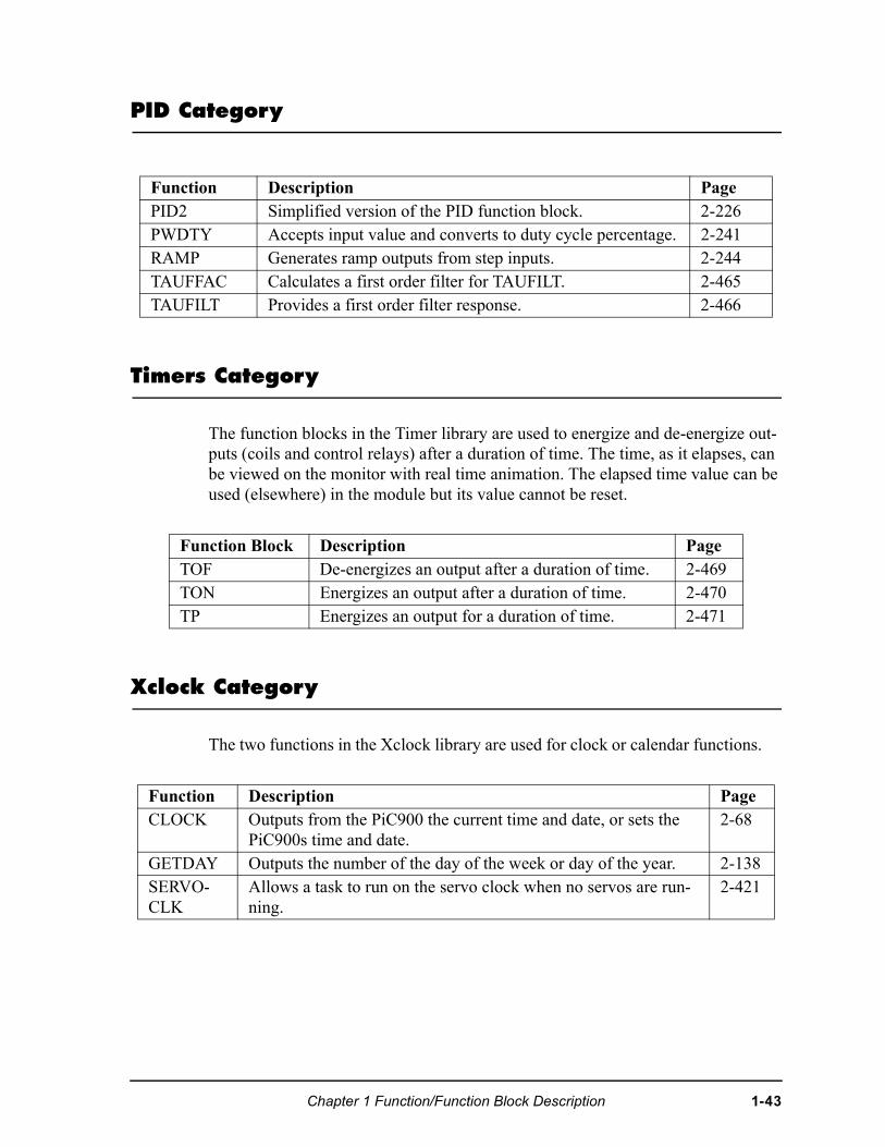
PID Category
Timers Category
The function blocks in the Timer library are used to energize and de-energize out-puts (coils and control relays) after a duration of time. The time, as it elapses, can be viewed on the monitor with real time animation. The elapsed time value can be used (elsewhere) in the module but its value cannot be reset.
Xclock Category
The two functions in the Xclock library are used for clock or calendar functions.
Function Description PagePID2 Simplified version of the PID function block. 2-226PWDTY Accepts input value and converts to duty cycle percentage. 2-241RAMP Generates ramp outputs from step inputs. 2-244TAUFFAC Calculates a first order filter for TAUFILT. 2-465TAUFILT Provides a first order filter response. 2-466
Function Block Description PageTOF De-energizes an output after a duration of time. 2-469TON Energizes an output after a duration of time. 2-470TP Energizes an output for a duration of time. 2-471
Function Description PageCLOCK Outputs from the PiC900 the current time and date, or sets the
PiC900s time and date. 2-68
GETDAY Outputs the number of the day of the week or day of the year. 2-138SERVO-CLK
Allows a task to run on the servo clock when no servos are run-ning.
2-421
Chapter 1 Function/Function Block Description 1-43

NOTES
1-44 Chapter 1 Function/Function Block Description
CHAPTER 2
Function/Block Descriptions
Chapter 2 describes all the functions available with PiCPro/PiCServoPro in alpha-betical order. Each heading contains:
• The name of the function as it appears in PiCPro
• The title of the function (underneath the name)
• The name of the function menu group (in right-hand corner) to which each function belongs.
Below the heading is an illustration of each function. To the right are listed the inputs and outputs for the function with data types in parentheses. The description of each function is beneath this information.
PROGRAMMING NOTE
Functions with an EN input are usually enabled either by a transitional(one-shot) contact if the function should execute one time or by logicthat will hold the function on if it should execute every scan. Typically, one-shot any function in the Motion library that affects orcauses motion. Also, one-shot any function that has a request (REQ) instead of an en-able (EN) input. REQ inputs are found on function blocks. A functionblock may not complete its operation in one scan. The EN or REQ inputs that are typically transitioned are labeled “Typ-ically one-shot” and those that should always be transitioned are la-beled “One-shot” in the descriptions that follow.
NOTE
You must have a math coprocessor installed on your PiC900//90 CPUmodule to perform any functions involving any 64 bit registers, loga-rithmic, exponential, trigonometric, and floating point mathematicaloperations.
NOTE ON ALPHABETICAL ORDER
When an underscore character (_) occurs within the name of a func-tion, that function is placed after those without an underscore. For ex-ample, RATIO_GR will be found after RATIOSYN.
Chapter 2 Function/Function Block Description 2-1
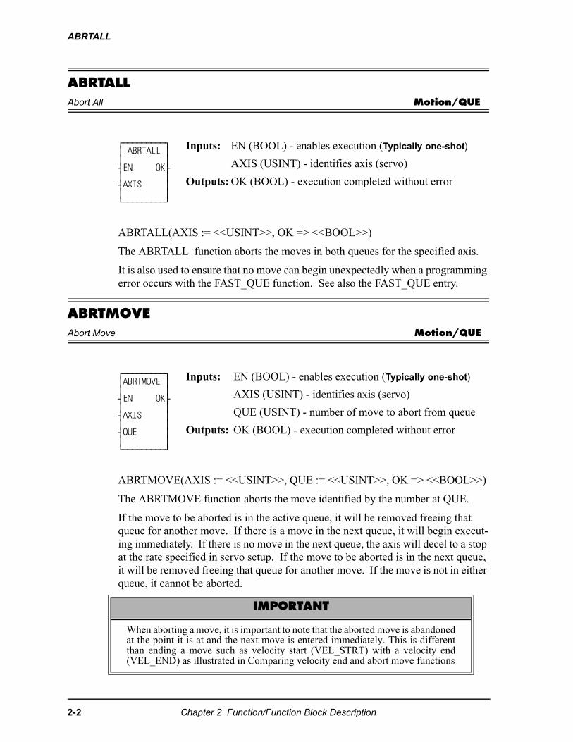
ABRTALL
ABRTALLAbort All Motion/QUE
ABRTALL(AXIS := <<USINT>>, OK => <<BOOL>>)
The ABRTALL function aborts the moves in both queues for the specified axis.
It is also used to ensure that no move can begin unexpectedly when a programming error occurs with the FAST_QUE function. See also the FAST_QUE entry.
ABRTMOVEAbort Move Motion/QUE
ABRTMOVE(AXIS := <<USINT>>, QUE := <<USINT>>, OK => <<BOOL>>)
The ABRTMOVE function aborts the move identified by the number at QUE.
If the move to be aborted is in the active queue, it will be removed freeing that queue for another move. If there is a move in the next queue, it will begin execut-ing immediately. If there is no move in the next queue, the axis will decel to a stop at the rate specified in servo setup. If the move to be aborted is in the next queue, it will be removed freeing that queue for another move. If the move is not in either queue, it cannot be aborted.
⁄ƒƒƒƒƒƒƒƒƒø ≥ ABRTALL ≥ ≥ ≥ ¥EN OK√ ≥ ≥ ¥AXIS ≥ ≥ ≥ ¿ƒƒƒƒƒƒƒƒƒŸ
Inputs: EN (BOOL) - enables execution (Typically one-shot)
AXIS (USINT) - identifies axis (servo)
Outputs: OK (BOOL) - execution completed without error
⁄ƒƒƒƒƒƒƒƒƒø ≥ABRTMOVE ≥ ≥ ≥ ¥EN OK√ ≥ ≥ ¥AXIS ≥ ≥ ≥ ¥QUE ≥ ≥ ≥ ¿ƒƒƒƒƒƒƒƒƒŸ
Inputs: EN (BOOL) - enables execution (Typically one-shot)
AXIS (USINT) - identifies axis (servo)
QUE (USINT) - number of move to abort from queue
Outputs: OK (BOOL) - execution completed without error
IMPORTANT
When aborting a move, it is important to note that the aborted move is abandonedat the point it is at and the next move is entered immediately. This is differentthan ending a move such as velocity start (VEL_STRT) with a velocity end(VEL_END) as illustrated in Comparing velocity end and abort move functions
2-2 Chapter 2 Function/Function Block Description
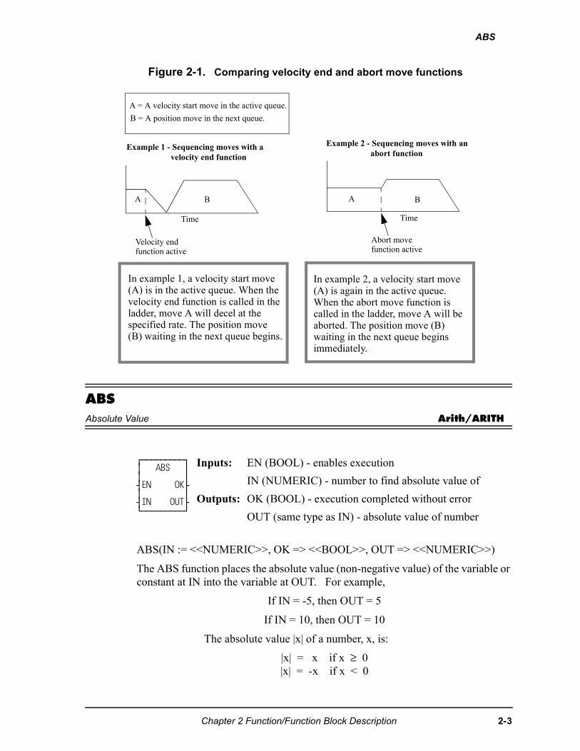
ABS
Figure 2-1. Comparing velocity end and abort move functions
ABSAbsolute Value Arith/ARITH
ABS(IN := <<NUMERIC>>, OK => <<BOOL>>, OUT => <<NUMERIC>>)
The ABS function places the absolute value (non-negative value) of the variable or constant at IN into the variable at OUT. For example,
If IN = -5, then OUT = 5
If IN = 10, then OUT = 10
The absolute value |x| of a number, x, is:
|x| = x if x ≥ 0 |x| = -x if x < 0
⁄ƒƒƒƒƒƒƒƒƒø ≥ ABS ≥ ≥ ≥ ¥EN OK√ ≥ ≥ ¥IN OUT√ ¿ƒƒƒƒƒƒƒƒƒŸ
Inputs: EN (BOOL) - enables execution
IN (NUMERIC) - number to find absolute value of
Outputs: OK (BOOL) - execution completed without error
OUT (same type as IN) - absolute value of number
A = A velocity start move in the active queue.
B = A position move in the next queue.
BA
Time
A B
Velocity endfunction active
Time
Abort movefunction active
In example 1, a velocity start move(A) is in the active queue. When thevelocity end function is called in theladder, move A will decel at thespecified rate. The position move(B) waiting in the next queue begins.
In example 2, a velocity start move(A) is again in the active queue. When the abort move function iscalled in the ladder, move A will beaborted. The position move (B)waiting in the next queue beginsimmediately.
Example 1 - Sequencing moves with avelocity end function
Example 2 - Sequencing moves with anabort function
Chapter 2 Function/Function Block Description 2-3
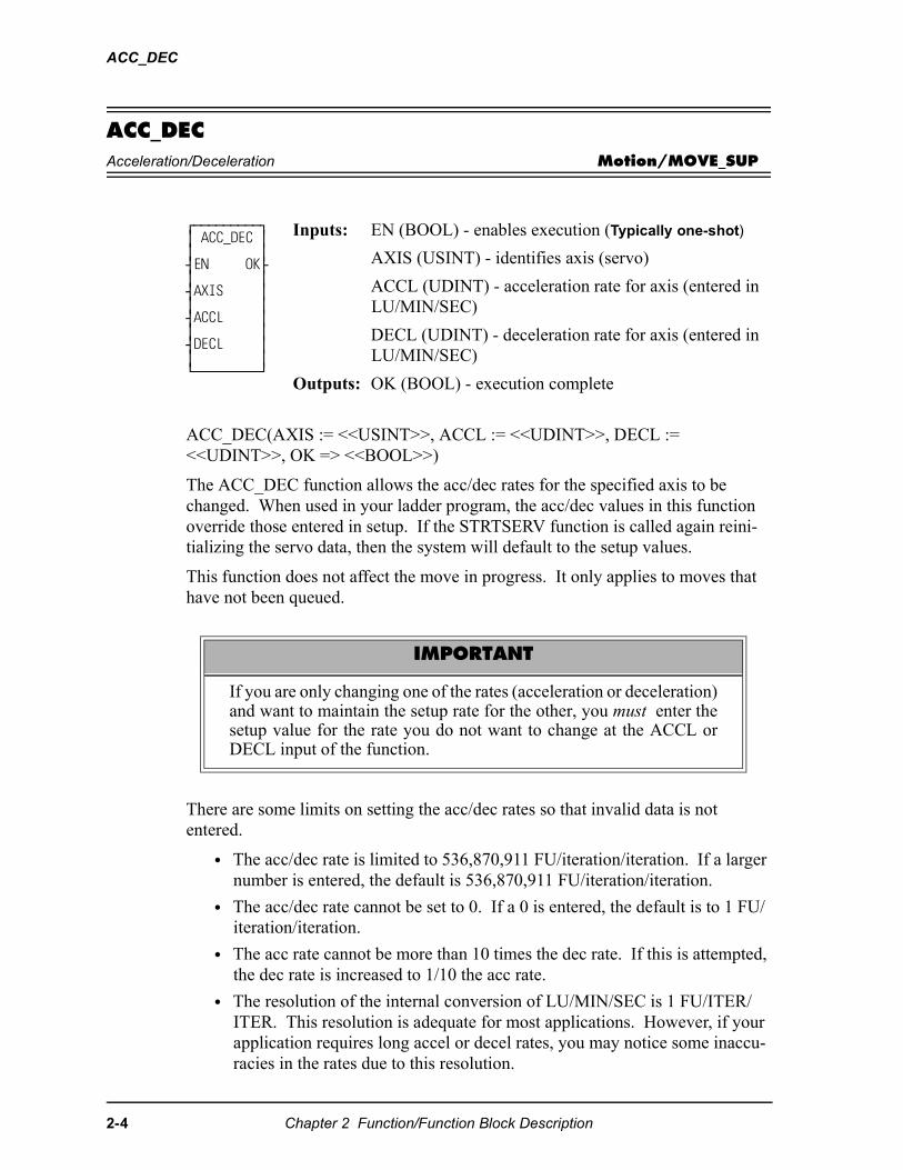
ACC_DEC
ACC_DECAcceleration/Deceleration Motion/MOVE_SUP
ACC_DEC(AXIS := <<USINT>>, ACCL := <<UDINT>>, DECL := <<UDINT>>, OK => <<BOOL>>)
The ACC_DEC function allows the acc/dec rates for the specified axis to be changed. When used in your ladder program, the acc/dec values in this function override those entered in setup. If the STRTSERV function is called again reini-tializing the servo data, then the system will default to the setup values.
This function does not affect the move in progress. It only applies to moves that have not been queued.
There are some limits on setting the acc/dec rates so that invalid data is not entered.
• The acc/dec rate is limited to 536,870,911 FU/iteration/iteration. If a larger number is entered, the default is 536,870,911 FU/iteration/iteration.
• The acc/dec rate cannot be set to 0. If a 0 is entered, the default is to 1 FU/iteration/iteration.
• The acc rate cannot be more than 10 times the dec rate. If this is attempted, the dec rate is increased to 1/10 the acc rate.
• The resolution of the internal conversion of LU/MIN/SEC is 1 FU/ITER/ITER. This resolution is adequate for most applications. However, if your application requires long accel or decel rates, you may notice some inaccu-racies in the rates due to this resolution.
⁄ƒƒƒƒƒƒƒƒƒø≥ ACC_DEC ≥≥ ≥¥EN OK√≥ ≥¥AXIS ≥≥ ≥¥ACCL ≥≥ ≥¥DECL ≥≥ ≥¿ƒƒƒƒƒƒƒƒƒŸ
Inputs: EN (BOOL) - enables execution (Typically one-shot)
AXIS (USINT) - identifies axis (servo)
ACCL (UDINT) - acceleration rate for axis (entered in LU/MIN/SEC)
DECL (UDINT) - deceleration rate for axis (entered in LU/MIN/SEC)
Outputs: OK (BOOL) - execution complete
IMPORTANT
If you are only changing one of the rates (acceleration or deceleration)and want to maintain the setup rate for the other, you must enter thesetup value for the rate you do not want to change at the ACCL orDECL input of the function.
2-4 Chapter 2 Function/Function Block Description
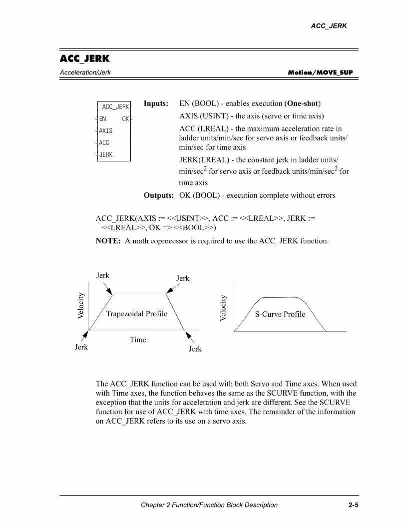
ACC_JERK
ACC_JERKAcceleration/Jerk Motion/MOVE_SUP
ACC_JERK(AXIS := <<USINT>>, ACC := <<LREAL>>, JERK := <<LREAL>>, OK => <<BOOL>>)
NOTE: A math coprocessor is required to use the ACC_JERK function.
The ACC_JERK function can be used with both Servo and Time axes. When used with Time axes, the function behaves the same as the SCURVE function, with the exception that the units for acceleration and jerk are different. See the SCURVE function for use of ACC_JERK with time axes. The remainder of the information on ACC_JERK refers to its use on a servo axis.
⁄ƒƒƒƒƒƒƒƒƒø ≥ ACC_JERK≥ ≥ ≥ ¥EN OK√ ≥ ≥ ¥AXIS ≥ ≥ ≥ ¥ACC ≥ ≥ ≥ ¥JERK ≥ ¿ƒƒƒƒƒƒƒƒƒŸ
Inputs: EN (BOOL) - enables execution (One-shot)
AXIS (USINT) - the axis (servo or time axis)
ACC (LREAL) - the maximum acceleration rate in ladder units/min/sec for servo axis or feedback units/min/sec for time axis
JERK(LREAL) - the constant jerk in ladder units/
min/sec2 for servo axis or feedback units/min/sec2 for
time axis
Outputs: OK (BOOL) - execution complete without errors
Jerk Jerk
TimeJerk Jerk
S-Curve Profile
Vel
ocit
y
Trapezoidal ProfileVel
ocit
y
Chapter 2 Function/Function Block Description 2-5
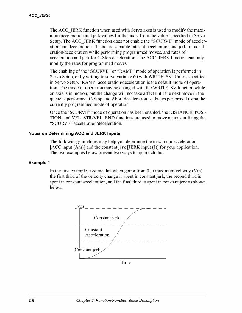
ACC_JERK
The ACC_JERK function when used with Servo axes is used to modify the maxi-mum acceleration and jerk values for that axis, from the values specified in Servo Setup. The ACC_JERK function does not enable the “SCURVE” mode of acceler-ation and deceleration. There are separate rates of acceleration and jerk for accel-eration/deceleration while performing programmed moves, and rates of acceleration and jerk for C-Stop deceleration. The ACC_JERK function can only modify the rates for programmed moves.
The enabling of the “SCURVE” or “RAMP” mode of operation is performed in Servo Setup, or by writing to servo variable 60 with WRITE_SV. Unless specified in Servo Setup, ‘RAMP’ acceleration/deceleration is the default mode of opera-tion. The mode of operation may be changed with the WRITE_SV function while an axis is in motion, but the change will not take affect until the next move in the queue is performed. C-Stop and Abort deceleration is always performed using the currently programmed mode of operation.
Once the ‘SCURVE” mode of operation has been enabled, the DISTANCE, POSI-TION, and VEL_STR/VEL_END functions are used to move an axis utilizing the “SCURVE” acceleration/deceleration.
Notes on Determining ACC and JERK Inputs
The following guidelines may help you determine the maximum acceleration [ACC input (Am)] and the constant jerk [JERK input (J)] for your application. The two examples below present two ways to approach this.
Example 1
In the first example, assume that when going from 0 to maximum velocity (Vm) the first third of the velocity change is spent in constant jerk, the second third is spent in constant acceleration, and the final third is spent in constant jerk as shown below.
Vm
Constant jerk
ConstantAcceleration
Constant jerk
Time
2-6 Chapter 2 Function/Function Block Description
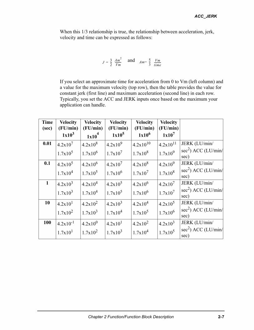
ACC_JERK
When this 1/3 relationship is true, the relationship between acceleration, jerk, velocity and time can be expressed as follows:
If you select an approximate time for acceleration from 0 to Vm (left column) and a value for the maximum velocity (top row), then the table provides the value for constant jerk (first line) and maximum acceleration (second line) in each row. Typically, you set the ACC and JERK inputs once based on the maximum your application can handle.
and
Time(sec)
Velocity (FU/min)
1x10³
Velocity (FU/min)
1x10⁴
Velocity (FU/min)
1x10⁵
Velocity (FU/min)
1x10⁶
Velocity (FU/min)
1x10⁷
0.01 4.2x10⁷
1.7x10⁵
4.2x10⁸
1.7x10⁶
4.2x10⁹
1.7x10⁷
4.2x10¹⁰
1.7x10⁸
4.2x10¹¹
1.7x10⁹
JERK (LU/min/
sec2) ACC (LU/min/sec)
0.1 4.2x10⁵
1.7x10⁴
4.2x10⁶
1.7x10⁵
4.2x10⁷
1.7x10⁶
4.2x10⁸
1.7x10⁷
4.2x10⁹
1.7x10⁸
JERK (LU/min/
sec2) ACC (LU/min/sec)
1 4.2x10³
1.7x10³
4.2x10⁴
1.7x10⁴
4.2x10⁵
1.7x10⁵
4.2x10⁶
1.7x10⁶
4.2x10⁷
1.7x10⁷
JERK (LU/min/
sec2) ACC (LU/min/sec)
10 4.2x101
1.7x10²
4.2x10²
1.7x10³
4.2x10³
1.7x10⁴
4.2x10⁴
1.7x10⁵
4.2x10⁵
1.7x10⁶
JERK (LU/min/
sec2) ACC (LU/min/sec)
100 4.2x10⁻¹
1.7x101
4.2x100
1.7x10²
4.2x101
1.7x10³
4.2x10²
1.7x10⁴
4.2x10³
1.7x10⁵
JERK (LU/min/
sec2) ACC (LU/min/sec)
��
�---�
���
��---------- ��
�
�---�
��
����-----------
Chapter 2 Function/Function Block Description 2-7

ACC_JERK
Example 2:
Vm = Maximum velocity
tm =The total time to reach velocity Vm if the axis starts at 0
tj = The total constant jerk time
ta = The total constant acceleration time
s= The fraction of time spent in constant jerk calculated by:
If you know Vm, tm, and s, then you can calculate jerk and acceleration using the following formulas.
The units for JERK are ladder units per minute/second2; therefore, Vm is in ladder units per minute and tm is in seconds. The units for ACCL are ladder units per
second2.
0
ta 0.5 tj0.5 tj
tm
Vel
ocit
yVm
Time���������������������������� = constant jerk
= constant acceleration
��
��-----�
���� ��×
� ���× � ���� �×( )
--------------------------------------------�
� ���
�� � ���� �×( )-----------------------------------�
2-8 Chapter 2 Function/Function Block Description
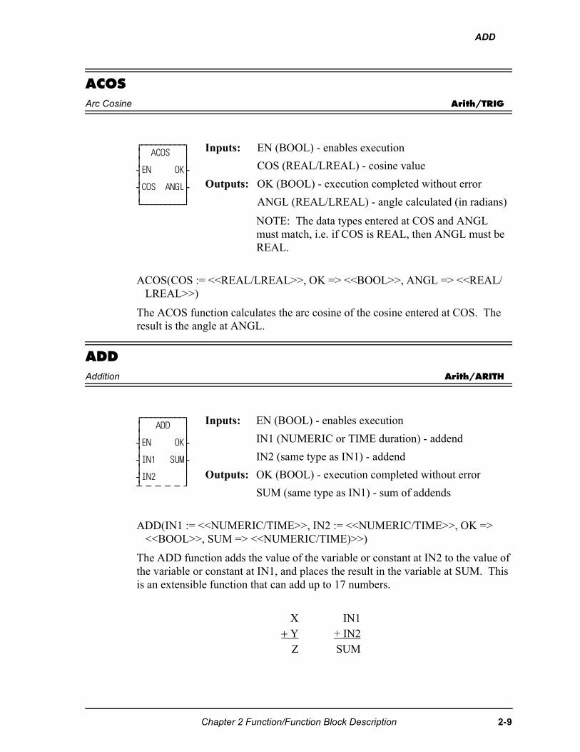
ADD
ACOSArc Cosine Arith/TRIG
ACOS(COS := <<REAL/LREAL>>, OK => <<BOOL>>, ANGL => <<REAL/LREAL>>)
The ACOS function calculates the arc cosine of the cosine entered at COS. The result is the angle at ANGL.
ADDAddition Arith/ARITH
ADD(IN1 := <<NUMERIC/TIME>>, IN2 := <<NUMERIC/TIME>>, OK => <<BOOL>>, SUM => <<NUMERIC/TIME)>>)
The ADD function adds the value of the variable or constant at IN2 to the value of the variable or constant at IN1, and places the result in the variable at SUM. This is an extensible function that can add up to 17 numbers.
⁄ƒƒƒƒƒƒƒƒƒø ≥ ACOS ≥ ≥ ≥ ¥EN OK√ ≥ ≥ ¥COS ANGL√ ≥ ≥ ¿ƒƒƒƒƒƒƒƒƒŸ
Inputs: EN (BOOL) - enables execution
COS (REAL/LREAL) - cosine value
Outputs: OK (BOOL) - execution completed without error
ANGL (REAL/LREAL) - angle calculated (in radians)
NOTE: The data types entered at COS and ANGL must match, i.e. if COS is REAL, then ANGL must be REAL.
⁄ƒƒƒƒƒƒƒƒƒø ≥ ADD ≥ ≥ ≥ ¥EN OK√ ≥ ≥ ¥IN1 SUM√ ≥ ≥ ¥IN2 ≥ ¡ ƒ ƒ ƒ ƒ Ÿ
Inputs: EN (BOOL) - enables execution
IN1 (NUMERIC or TIME duration) - addend
IN2 (same type as IN1) - addend
Outputs: OK (BOOL) - execution completed without error
SUM (same type as IN1) - sum of addends
X IN1+ Y + IN2
Z SUM
Chapter 2 Function/Function Block Description 2-9
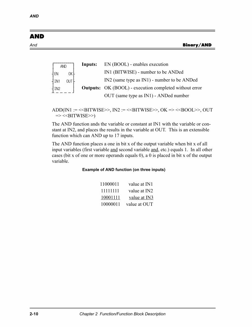
AND
ANDAnd Binary/AND
ADD(IN1 := <<BITWISE>>, IN2 := <<BITWISE>>, OK => <<BOOL>>, OUT => <<BITWISE>>)
The AND function ands the variable or constant at IN1 with the variable or con-stant at IN2, and places the results in the variable at OUT. This is an extensible function which can AND up to 17 inputs.
The AND function places a one in bit x of the output variable when bit x of all input variables (first variable and second variable and, etc.) equals 1. In all other cases (bit x of one or more operands equals 0), a 0 is placed in bit x of the output variable.
Example of AND function (on three inputs)
⁄ƒƒƒƒƒƒƒƒƒø ≥ AND ≥ ≥ ≥ ¥EN OK√ ≥ ≥ ¥IN1 OUT√ ≥ ≥ ¥IN2 ≥ ¡ ƒ ƒ ƒ ƒ Ÿ
Inputs: EN (BOOL) - enables execution
IN1 (BITWISE) - number to be ANDed
IN2 (same type as IN1) - number to be ANDed
Outputs: OK (BOOL) - execution completed without error
OUT (same type as IN1) - ANDed number
11000011 value at IN1 11111111 value at IN210001111 value at IN310000011 value at OUT
2-10 Chapter 2 Function/Function Block Description
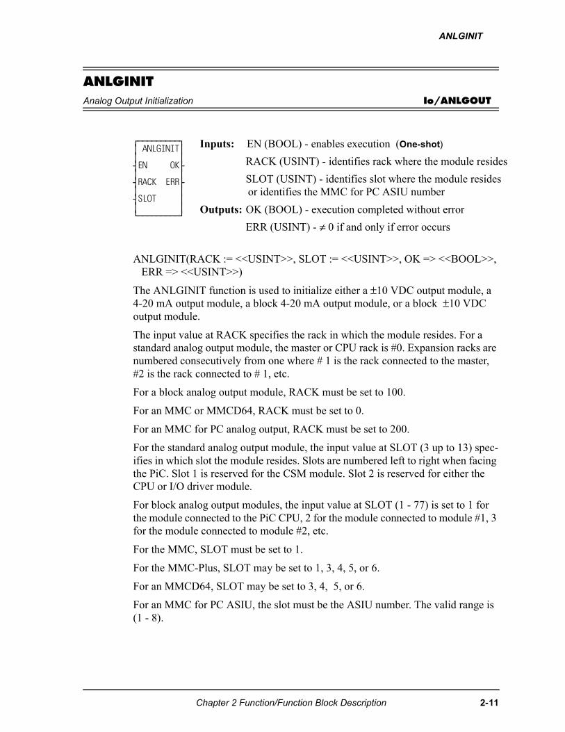
ANLGINIT
ANLGINITAnalog Output Initialization Io/ANLGOUT
ANLGINIT(RACK := <<USINT>>, SLOT := <<USINT>>, OK => <<BOOL>>, ERR => <<USINT>>)
The ANLGINIT function is used to initialize either a ±10 VDC output module, a 4-20 mA output module, a block 4-20 mA output module, or a block ±10 VDC output module.
The input value at RACK specifies the rack in which the module resides. For a standard analog output module, the master or CPU rack is #0. Expansion racks are numbered consecutively from one where # 1 is the rack connected to the master, #2 is the rack connected to # 1, etc.
For a block analog output module, RACK must be set to 100.
For an MMC or MMCD64, RACK must be set to 0.
For an MMC for PC analog output, RACK must be set to 200.
For the standard analog output module, the input value at SLOT (3 up to 13) spec-ifies in which slot the module resides. Slots are numbered left to right when facing the PiC. Slot 1 is reserved for the CSM module. Slot 2 is reserved for either the CPU or I/O driver module.
For block analog output modules, the input value at SLOT (1 - 77) is set to 1 for the module connected to the PiC CPU, 2 for the module connected to module #1, 3 for the module connected to module #2, etc.
For the MMC, SLOT must be set to 1.
For the MMC-Plus, SLOT may be set to 1, 3, 4, 5, or 6.
For an MMCD64, SLOT may be set to 3, 4, 5, or 6.
For an MMC for PC ASIU, the slot must be the ASIU number. The valid range is (1 - 8).
⁄ƒƒƒƒƒƒƒƒƒø ≥ ANLGINIT≥ ≥ ≥ ¥EN OK√ ≥ ≥ ¥RACK ERR√ ≥ ≥ ¥SLOT ≥ ≥ ≥ ¿ƒƒƒƒƒƒƒƒƒŸ
Inputs: EN (BOOL) - enables execution (One-shot)
RACK (USINT) - identifies rack where the module resides
SLOT (USINT) - identifies slot where the module resides or identifies the MMC for PC ASIU number
Outputs: OK (BOOL) - execution completed without error
ERR (USINT) - ≠ 0 if and only if error occurs
Chapter 2 Function/Function Block Description 2-11
ANLGINIT
If an error occurs the output at OK is not energized; output at ERR equals 1 - 4:
Output ±10 VDC Module
If the channels on the output ±10 VDC module will be used for open loop control only, then it is necessary to initialize the module with the ANLGINIT function. It is not necessary to enter a user-defined setup function containing all the setup data needed for closed loop control or input only axes.
If some of the channels are used for closed loop control or input only and some for output only, then the servo initialization procedure is followed and the ANLGINIT function is not used.
Output 4-20 mA Module
The ANLGINIT function must always be called to initialize the 4-20mA module and the block 4-20 mA output module.
ERR Description1 The input at RACK is out of range2 The input at SLOT is out of range3 Not used4 The module at the location specified is not an analog output module or
the MMC for PC ASIU does not exist
2-12 Chapter 2 Function/Function Block Description
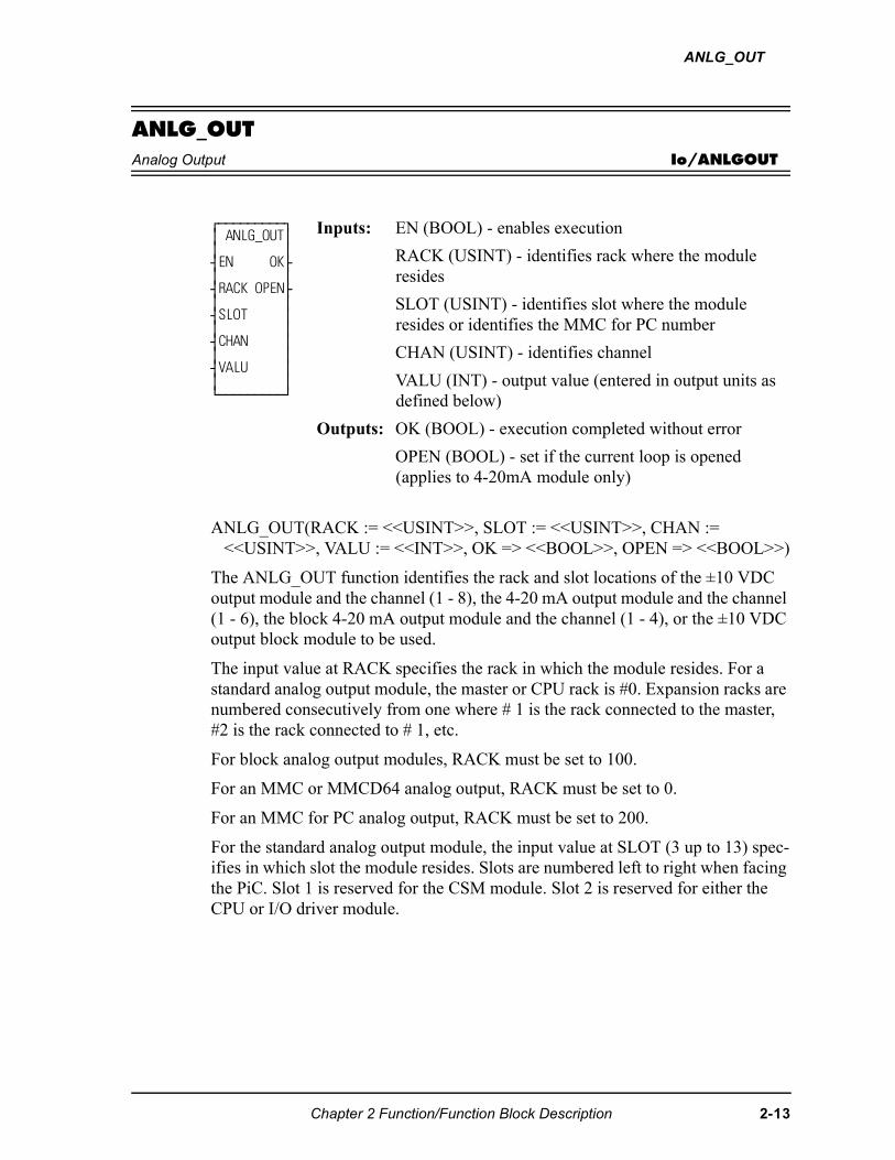
ANLG_OUT
ANLG_OUTAnalog Output Io/ANLGOUT
ANLG_OUT(RACK := <<USINT>>, SLOT := <<USINT>>, CHAN := <<USINT>>, VALU := <<INT>>, OK => <<BOOL>>, OPEN => <<BOOL>>)
The ANLG_OUT function identifies the rack and slot locations of the ±10 VDC output module and the channel (1 - 8), the 4-20 mA output module and the channel (1 - 6), the block 4-20 mA output module and the channel (1 - 4), or the ±10 VDC output block module to be used.
The input value at RACK specifies the rack in which the module resides. For a standard analog output module, the master or CPU rack is #0. Expansion racks are numbered consecutively from one where # 1 is the rack connected to the master, #2 is the rack connected to # 1, etc.
For block analog output modules, RACK must be set to 100.
For an MMC or MMCD64 analog output, RACK must be set to 0.
For an MMC for PC analog output, RACK must be set to 200.
For the standard analog output module, the input value at SLOT (3 up to 13) spec-ifies in which slot the module resides. Slots are numbered left to right when facing the PiC. Slot 1 is reserved for the CSM module. Slot 2 is reserved for either the CPU or I/O driver module.
⁄ƒƒƒƒƒƒƒƒƒø ≥ ANLG_OUT≥ ≥ ≥ ¥EN OK√ ≥ ≥ ¥RACK OPEN√ ≥ ≥ ¥SLOT ≥ ≥ ≥ ¥CHAN ≥ ≥ ≥ ¥VALU ≥ ≥ ≥ ¿ƒƒƒƒƒƒƒƒƒŸ
Inputs: EN (BOOL) - enables execution
RACK (USINT) - identifies rack where the module resides
SLOT (USINT) - identifies slot where the module resides or identifies the MMC for PC number
CHAN (USINT) - identifies channel
VALU (INT) - output value (entered in output units as defined below)
Outputs: OK (BOOL) - execution completed without error
OPEN (BOOL) - set if the current loop is opened (applies to 4-20mA module only)
Chapter 2 Function/Function Block Description 2-13
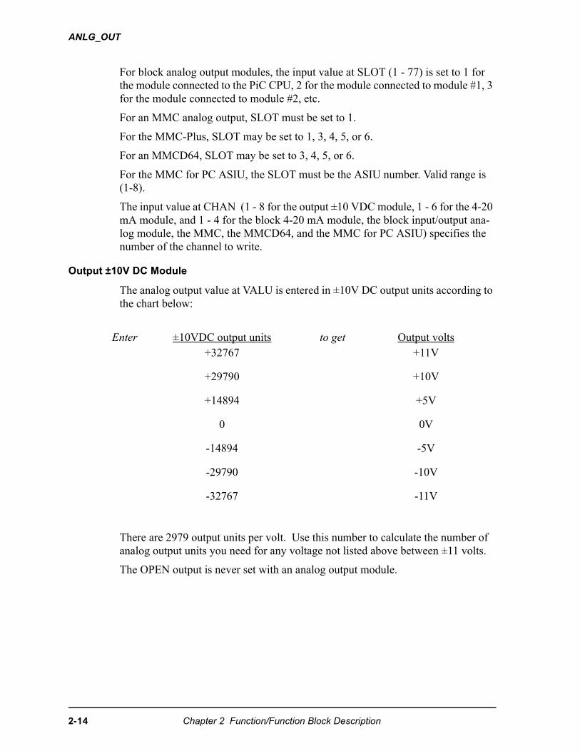
ANLG_OUT
For block analog output modules, the input value at SLOT (1 - 77) is set to 1 for the module connected to the PiC CPU, 2 for the module connected to module #1, 3 for the module connected to module #2, etc.
For an MMC analog output, SLOT must be set to 1.
For the MMC-Plus, SLOT may be set to 1, 3, 4, 5, or 6.
For an MMCD64, SLOT may be set to 3, 4, 5, or 6.
For the MMC for PC ASIU, the SLOT must be the ASIU number. Valid range is (1-8).
The input value at CHAN (1 - 8 for the output ±10 VDC module, 1 - 6 for the 4-20 mA module, and 1 - 4 for the block 4-20 mA module, the block input/output ana-log module, the MMC, the MMCD64, and the MMC for PC ASIU) specifies the number of the channel to write.
Output ±10V DC Module
The analog output value at VALU is entered in ±10V DC output units according to the chart below:
There are 2979 output units per volt. Use this number to calculate the number of analog output units you need for any voltage not listed above between ±11 volts.
The OPEN output is never set with an analog output module.
Enter ±10VDC output units to get Output volts+32767 +11V
+29790 +10V
+14894 +5V
0 0V
-14894 -5V
-29790 -10V
-32767 -11V
2-14 Chapter 2 Function/Function Block Description
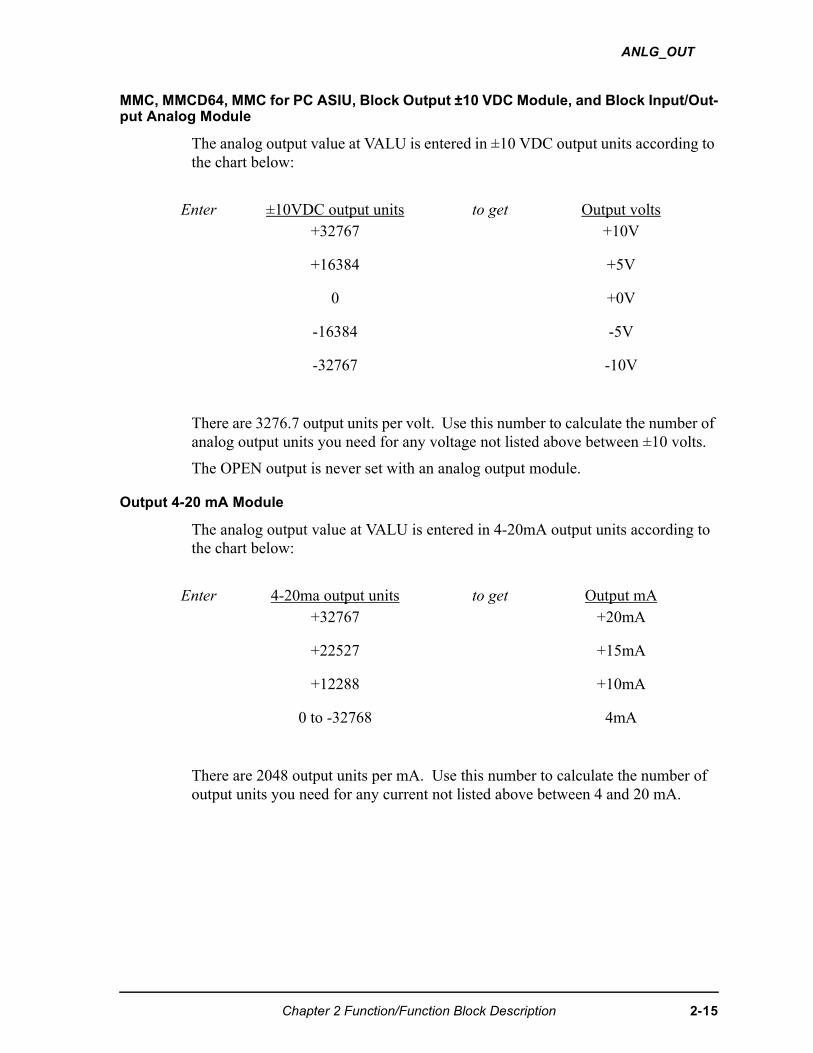
ANLG_OUT
MMC, MMCD64, MMC for PC ASIU, Block Output ±10 VDC Module, and Block Input/Out-put Analog Module
The analog output value at VALU is entered in ±10 VDC output units according to the chart below:
There are 3276.7 output units per volt. Use this number to calculate the number of analog output units you need for any voltage not listed above between ±10 volts.
The OPEN output is never set with an analog output module.
Output 4-20 mA Module
The analog output value at VALU is entered in 4-20mA output units according to the chart below:
There are 2048 output units per mA. Use this number to calculate the number of output units you need for any current not listed above between 4 and 20 mA.
Enter ±10VDC output units to get Output volts+32767 +10V
+16384 +5V
0 +0V
-16384 -5V
-32767 -10V
Enter 4-20ma output units to get Output mA+32767 +20mA
+22527 +15mA
+12288 +10mA
0 to -32768 4mA
Chapter 2 Function/Function Block Description 2-15
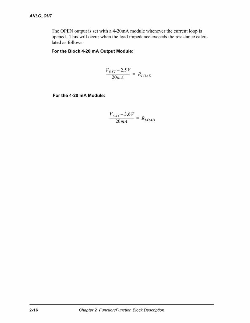
ANLG_OUT
The OPEN output is set with a 4-20mA module whenever the current loop is opened. This will occur when the load impedance exceeds the resistance calcu-lated as follows:
For the Block 4-20 mA Output Module:
For the 4-20 mA Module:
��� �����
����----------------------------- ������
��� ����
����----------------------------- ������
2-16 Chapter 2 Function/Function Block Description
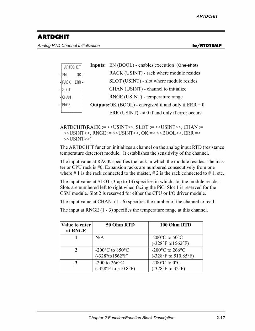
ARTDCHIT
ARTDCHITAnalog RTD Channel Initialization Io/RTDTEMP
ARTDCHIT(RACK := <<USINT>>, SLOT := <<USINT>>, CHAN := <<USINT>>, RNGE := <<USINT>>, OK => <<BOOL>>, ERR => <<USINT>>)
The ARTDCHIT function initializes a channel on the analog input RTD (resistance temperature detector) module. It establishes the sensitivity of the channel.
The input value at RACK specifies the rack in which the module resides. The mas-ter or CPU rack is #0. Expansion racks are numbered consecutively from one where # 1 is the rack connected to the master, # 2 is the rack connected to # 1, etc.
The input value at SLOT (3 up to 13) specifies in which slot the module resides. Slots are numbered left to right when facing the PiC. Slot 1 is reserved for the CSM module. Slot 2 is reserved for either the CPU or I/O driver module.
The input value at CHAN (1 - 6) specifies the number of the channel to read.
The input at RNGE (1 - 3) specifies the temperature range at this channel.
⁄ƒƒƒƒƒƒƒƒƒø ≥ ARTDCHIT≥ ≥ ≥ ¥EN OK√ ≥ ≥ ¥RACK ERR√ ≥ ≥ ¥SLOT ≥ ≥ ≥ ¥CHAN ≥ ≥ ≥ ¥RNGE ≥ ≥ ≥ ¿ƒƒƒƒƒƒƒƒƒŸ
Inputs: EN (BOOL) - enables execution (One-shot)
RACK (USINT) - rack where module resides
SLOT (USINT) - slot where module resides
CHAN (USINT) - channel to initialize
RNGE (USINT) - temperature range
Outputs:OK (BOOL) - energized if and only if ERR = 0
ERR (USINT) - ≠ 0 if and only if error occurs
Value to enter at RNGE
50 Ohm RTD 100 Ohm RTD
1 N/A -200°C to 50°C(-328°F to1562°F)
2 -200°C to 850°C(-328°to1562°F)
-200°C to 266°C(-328°F to 510.85°F)
3 -200 to 266°C(-328°F to 510.8°F)
-200°C to 0°C(-328°F to 32°F)
Chapter 2 Function/Function Block Description 2-17
ARTDCHIT
If an error occurs, the OK output will not be energized and the ERR output will return the error code. See Appendix C Temperature Function Errors for the list of error codes.
NOTE: This function works in conjunction with the ARTDMDIT and ARTD-CHRD functions.
The ARTDCHIT function must be executed once (the input at EN should be a one-shot) after the ARTDMDIT function is executed, and before the ARTDCHRD function is executed.
2-18 Chapter 2 Function/Function Block Description
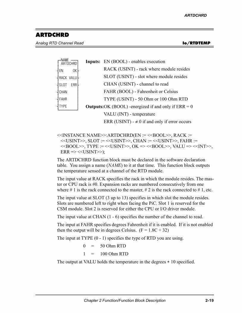
ARTDCHRD
ARTDCHRDAnalog RTD Channel Read Io/RTDTEMP
<<INSTANCE NAME>>:ARTDCHRD(EN := <<BOOL>>, RACK := <<USINT>>, SLOT := <<USINT>>, CHAN := <<USINT>>, FAHR := <<BOOL>>, TYPE := <<USINT>>, OK => <<BOOL>>, VALU => <<INT>>, ERR => <<USINT>>);
The ARTDCHRD function block must be declared in the software declaration table. You assign a name (NAME) to it at that time. This function block outputs the temperature sensed at a channel of the RTD module.
The input value at RACK specifies the rack in which the module resides. The mas-ter or CPU rack is #0. Expansion racks are numbered consecutively from one where # 1 is the rack connected to the master, # 2 is the rack connected to # 1, etc.
The input value at SLOT (3 up to 13) specifies in which slot the module resides. Slots are numbered left to right when facing the PiC. Slot 1 is reserved for the CSM module. Slot 2 is reserved for either the CPU or I/O driver module.
The input value at CHAN (1 - 6) specifies the number of the channel to read.
The input at FAHR specifies degrees Fahrenheit if it is enabled. If it is not enabled then the output will be in degrees Celsius. (F = 1.8C + 32)
The input at TYPE (0 - 1) specifies the type of RTD you are using.
0 = 50 Ohm RTD
1 = 100 Ohm RTD
The output at VALU holds the temperature in the degrees * 10 specified.
⁄ƒNAME ƒƒƒø ≥ ARTDCHRD≥ ≥ ≥ ¥EN OK√ ≥ ≥ ¥RACK VALU√ ≥ ≥ ¥SLOT ERR√ ≥ ≥ ¥CHAN ≥ ≥ ≥ ¥FAHR ≥ ≥ ≥ ¥TYPE ≥ ¿ƒƒƒƒƒƒƒƒƒŸ
Inputs: EN (BOOL) - enables execution
RACK (USINT) - rack where module resides
SLOT (USINT) - slot where module resides
CHAN (USINT) - channel to read
FAHR (BOOL) - Fahrenheit or Celsius
TYPE (USINT) - 50 Ohm or 100 Ohm RTD
Outputs:OK (BOOL) -energized if and only if ERR = 0
VALU (INT) - temperature
ERR (USINT) - ≠ 0 if and only if error occurs
Chapter 2 Function/Function Block Description 2-19
ARTDCHRD
If an error occurs, the OK output will not be energized and the ERR output will return the error code. See Appendix C Temperature Function Errors for the list of error codes.
NOTE: Values outside the temperature limits (defined by ARTDCHIT) may be read but should not be used for control purposes.
NOTE: This function works in conjunction with the ARTDCHIT and ARTDM-DIT functions.
The ARTDCHIT function must be executed once after the ARTDMDIT function is executed, and before the ARTDCHRD function block is executed.
2-20 Chapter 2 Function/Function Block Description
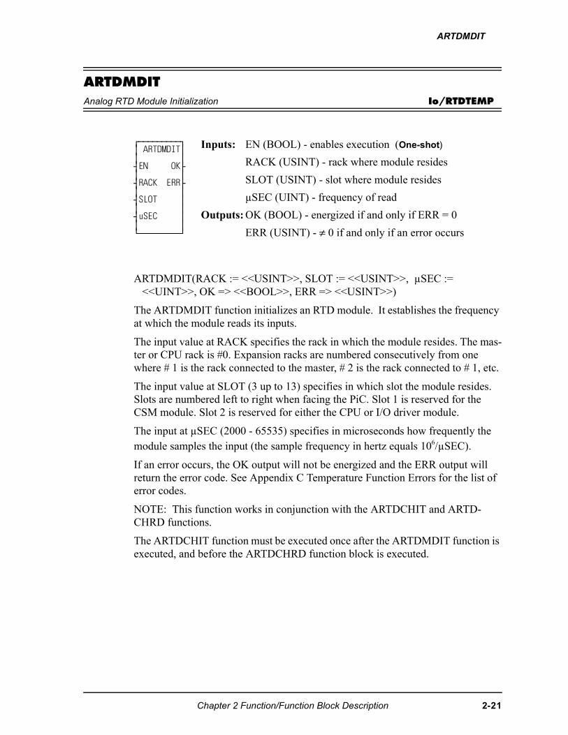
ARTDMDIT
ARTDMDITAnalog RTD Module Initialization Io/RTDTEMP
ARTDMDIT(RACK := <<USINT>>, SLOT := <<USINT>>, µSEC := <<UINT>>, OK => <<BOOL>>, ERR => <<USINT>>)
The ARTDMDIT function initializes an RTD module. It establishes the frequency at which the module reads its inputs.
The input value at RACK specifies the rack in which the module resides. The mas-ter or CPU rack is #0. Expansion racks are numbered consecutively from one where # 1 is the rack connected to the master, # 2 is the rack connected to # 1, etc.
The input value at SLOT (3 up to 13) specifies in which slot the module resides. Slots are numbered left to right when facing the PiC. Slot 1 is reserved for the CSM module. Slot 2 is reserved for either the CPU or I/O driver module.
The input at µSEC (2000 - 65535) specifies in microseconds how frequently the module samples the input (the sample frequency in hertz equals 106/µSEC).
If an error occurs, the OK output will not be energized and the ERR output will return the error code. See Appendix C Temperature Function Errors for the list of error codes.
NOTE: This function works in conjunction with the ARTDCHIT and ARTD-CHRD functions.
The ARTDCHIT function must be executed once after the ARTDMDIT function is executed, and before the ARTDCHRD function block is executed.
⁄ƒƒƒƒƒƒƒƒƒø ≥ ARTDMDIT≥ ≥ ≥ ¥EN OK√ ≥ ≥ ¥RACK ERR√ ≥ ≥ ¥SLOT ≥ ≥ ≥ ¥uSEC ≥ ≥ ≥ ¿ƒƒƒƒƒƒƒƒƒŸ
Inputs: EN (BOOL) - enables execution (One-shot)
RACK (USINT) - rack where module resides
SLOT (USINT) - slot where module resides
µSEC (UINT) - frequency of read
Outputs: OK (BOOL) - energized if and only if ERR = 0
ERR (USINT) - ≠ 0 if and only if an error occurs
Chapter 2 Function/Function Block Description 2-21
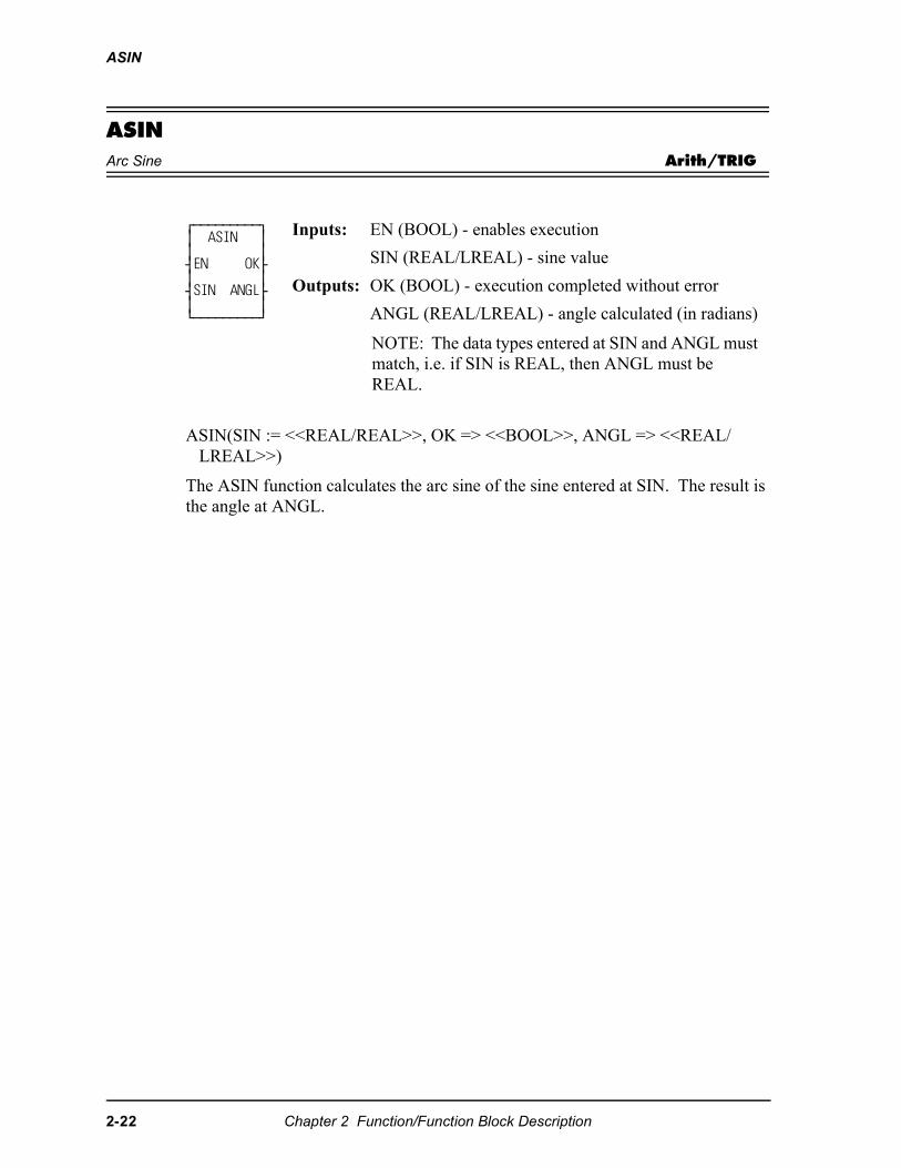
ASIN
ASINArc Sine Arith/TRIG
ASIN(SIN := <<REAL/REAL>>, OK => <<BOOL>>, ANGL => <<REAL/LREAL>>)
The ASIN function calculates the arc sine of the sine entered at SIN. The result is the angle at ANGL.
⁄ƒƒƒƒƒƒƒƒƒø ≥ ASIN ≥ ≥ ≥ ¥EN OK√ ≥ ≥ ¥SIN ANGL√ ≥ ≥ ¿ƒƒƒƒƒƒƒƒƒŸ
Inputs: EN (BOOL) - enables execution
SIN (REAL/LREAL) - sine value
Outputs: OK (BOOL) - execution completed without error
ANGL (REAL/LREAL) - angle calculated (in radians)
NOTE: The data types entered at SIN and ANGL must match, i.e. if SIN is REAL, then ANGL must be REAL.
2-22 Chapter 2 Function/Function Block Description
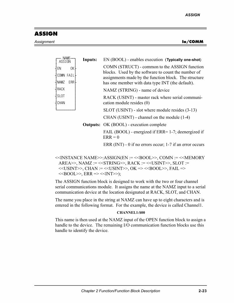
ASSIGN
ASSIGNAssignment Io/COMM
<<INSTANCE NAME>>:ASSIGN(EN := <<BOOL>>, COMN := <<MEMORY AREA>>, NAMZ := <<STRING>>, RACK := <<USINT>>, SLOT := <<USINT>>, CHAN := <<USINT>>, OK => <<BOOL>>, FAIL => <<BOOL>>, ERR => <<INT>>);
The ASSIGN function block is designed to work with the two or four channel serial communications module. It assigns the name at the NAMZ input to a serial communication device at the location designated at RACK, SLOT, and CHAN.
The name you place in the string at NAMZ can have up to eight characters and is entered in the following format. For the example, the device is called Channel1.
CHANNEL1:$00
This name is then used at the NAMZ input of the OPEN function block to assign a handle to the device. The remaining I/O communication function blocks use this handle to identify the device.
⁄ƒƒ NAMEƒƒø ≥ ASSIGN ≥ ≥ ≥ ¥EN OK√ ≥ ≥ ¥COMN FAIL√ ≥ ≥ ¥NAMZ ERR√ ≥ ≥ ¥RACK ≥ ≥ ≥ ¥SLOT ≥ ≥ ≥ ¥CHAN ≥ ≥ ≥ ¿ƒƒƒƒƒƒƒƒƒŸ
Inputs: EN (BOOL) - enables execution (Typically one-shot)
COMN (STRUCT) - common to the ASSIGN function blocks. Used by the software to count the number of assignments made by the function block. The structure has one member with data type INT (the default).
NAMZ (STRING) - name of device
RACK (USINT) - master rack where serial communi-cation module resides (0)
SLOT (USINT) - slot where module resides (3-13)
CHAN (USINT) - channel on the module (1-4)
Outputs: OK (BOOL) - execution complete
FAIL (BOOL) - energized if ERR= 1-7; deenergized if ERR = 0
ERR (INT) - 0 if no errors occur; 1-7 if an error occurs
Chapter 2 Function/Function Block Description 2-23
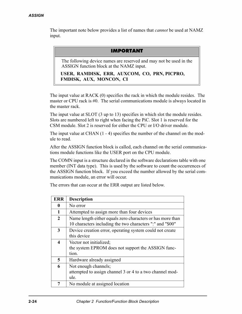
ASSIGN
The important note below provides a list of names that cannot be used at NAMZ input.
The input value at RACK (0) specifies the rack in which the module resides. The master or CPU rack is #0. The serial communications module is always located in the master rack.
The input value at SLOT (3 up to 13) specifies in which slot the module resides. Slots are numbered left to right when facing the PiC. Slot 1 is reserved for the CSM module. Slot 2 is reserved for either the CPU or I/O driver module.
The input value at CHAN (1 - 4) specifies the number of the channel on the mod-ule to read.
After the ASSIGN function block is called, each channel on the serial communica-tions module functions like the USER port on the CPU module.
The COMN input is a structure declared in the software declarations table with one member (INT data type). This is used by the software to count the occurrences of the ASSIGN function block. If you exceed the number allowed by the serial com-munications module, an error will occur.
The errors that can occur at the ERR output are listed below.
IMPORTANT
The following device names are reserved and may not be used in theASSIGN function block at the NAMZ input.
USER, RAMDISK, ERR, AUXCOM, CO, PRN, PICPRO, FMDISK, AUX, MONCON, CI
ERR Description0 No error1 Attempted to assign more than four devices2 Name length either equals zero characters or has more than
10 characters including the two characters ":" and "$00"3 Device creation error, operating system could not create
this device4 Vector not initialized;
the system EPROM does not support the ASSIGN func-tion.
5 Hardware already assigned6 Not enough channels;
attempted to assign channel 3 or 4 to a two channel mod-ule.
7 No module at assigned location
2-24 Chapter 2 Function/Function Block Description
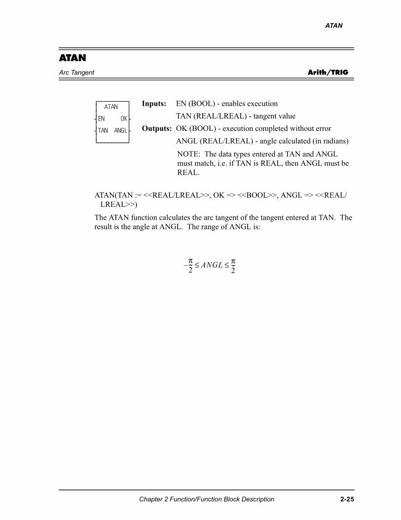
ATAN
ATANArc Tangent Arith/TRIG
ATAN(TAN := <<REAL/LREAL>>, OK => <<BOOL>>, ANGL => <<REAL/LREAL>>)
The ATAN function calculates the arc tangent of the tangent entered at TAN. The result is the angle at ANGL. The range of ANGL is:
⁄ƒƒƒƒƒƒƒƒƒø ≥ ATAN ≥ ≥ ≥ ¥EN OK√ ≥ ≥ ¥TAN ANGL√ ≥ ≥ ¿ƒƒƒƒƒƒƒƒƒŸ
Inputs: EN (BOOL) - enables execution
TAN (REAL/LREAL) - tangent value
Outputs: OK (BOOL) - execution completed without error
ANGL (REAL/LREAL) - angle calculated (in radians)
NOTE: The data types entered at TAN and ANGL must match, i.e. if TAN is REAL, then ANGL must be REAL.
π�---� ����
π�---≤ ≤
Chapter 2 Function/Function Block Description 2-25
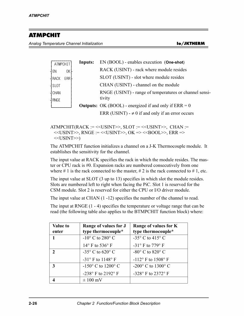
ATMPCHIT
ATMPCHITAnalog Temperature Channel Initialization Io/JKTHERM
ATMPCHIT(RACK := <<USINT>>, SLOT := <<USINT>>, CHAN := <<USINT>>, RNGE := <<USINT>>, OK => <<BOOL>>, ERR => <<USINT>>)
The ATMPCHIT function initializes a channel on a J-K Thermocouple module. It establishes the sensitivity for the channel.
The input value at RACK specifies the rack in which the module resides. The mas-ter or CPU rack is #0. Expansion racks are numbered consecutively from one where # 1 is the rack connected to the master, # 2 is the rack connected to # 1, etc.
The input value at SLOT (3 up to 13) specifies in which slot the module resides. Slots are numbered left to right when facing the PiC. Slot 1 is reserved for the CSM module. Slot 2 is reserved for either the CPU or I/O driver module.
The input value at CHAN (1 -12) specifies the number of the channel to read.
The input at RNGE (1 - 4) specifies the temperature or voltage range that can be read (the following table also applies to the BTMPCHIT function block) where:
⁄ƒƒƒƒƒƒƒƒƒø ≥ ATMPCHIT≥ ≥ ≥ ¥EN OK√ ≥ ≥ ¥RACK ERR√ ≥ ≥ ¥SLOT ≥ ≥ ≥ ¥CHAN ≥ ≥ ≥ ¥RNGE ≥ ≥ ≥ ¿ƒƒƒƒƒƒƒƒƒŸ
Inputs: EN (BOOL) - enables execution (One-shot)
RACK (USINT) - rack where module resides
SLOT (USINT) - slot where module resides
CHAN (USINT) - channel on the module
RNGE (USINT) - range of temperatures or channel sensi-tivity
Outputs: OK (BOOL) - energized if and only if ERR = 0
ERR (USINT) - ≠ 0 if and only if an error occurs
Value to enter
Range of values for J type thermocouple*
Range of values for K type thermocouple*
1 -10° C to 280° C
14° F to 536° F
-35° C to 415° C
-31° F to 779° F2 -35° C to 620° C
-31° F to 1148° F
-80° C to 820° C
-112° F to 1508° F3 -150° C to 1200° C
-238° F to 2192° F
-200° C to 1300° C
-328° F to 2372° F4 ± 100 mV
2-26 Chapter 2 Function/Function Block Description
ATMPCHIT
*The temperature ranges apply over the temperature rating of the module. Tem-perature values outside the specified range should not be used for control purposes.
If an error occurs, the OK output will not be energized and the ERR output will return the error code. See Appendix C Temperature Function Errors for the list of ERR errors.
NOTE: This function works in conjunction with the ATMPMDIT and ATMPCHRD functions.
The ATMPCHIT function must be executed once (the input at EN should be a one-shot) after the ATMPMDIT function is executed, and before the ATMPCHRD function block is executed.
Chapter 2 Function/Function Block Description 2-27
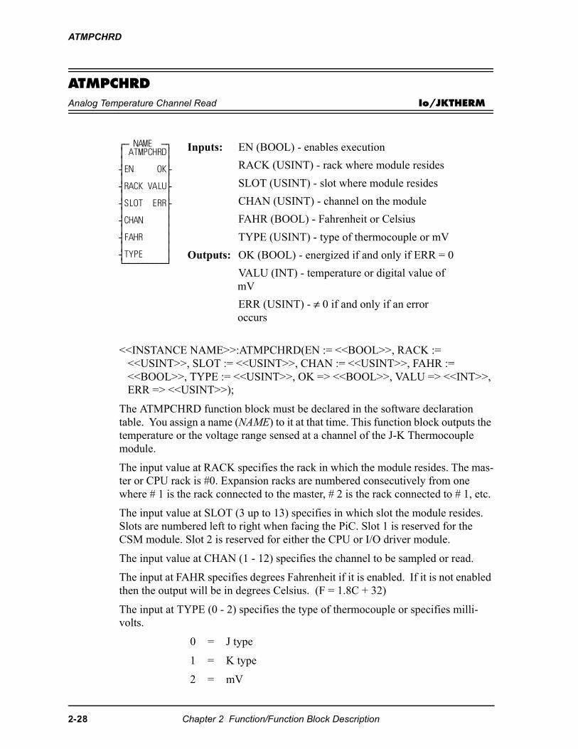
ATMPCHRD
ATMPCHRDAnalog Temperature Channel Read Io/JKTHERM
<<INSTANCE NAME>>:ATMPCHRD(EN := <<BOOL>>, RACK := <<USINT>>, SLOT := <<USINT>>, CHAN := <<USINT>>, FAHR := <<BOOL>>, TYPE := <<USINT>>, OK => <<BOOL>>, VALU => <<INT>>, ERR => <<USINT>>);
The ATMPCHRD function block must be declared in the software declaration table. You assign a name (NAME) to it at that time. This function block outputs the temperature or the voltage range sensed at a channel of the J-K Thermocouple module.
The input value at RACK specifies the rack in which the module resides. The mas-ter or CPU rack is #0. Expansion racks are numbered consecutively from one where # 1 is the rack connected to the master, # 2 is the rack connected to # 1, etc.
The input value at SLOT (3 up to 13) specifies in which slot the module resides. Slots are numbered left to right when facing the PiC. Slot 1 is reserved for the CSM module. Slot 2 is reserved for either the CPU or I/O driver module.
The input value at CHAN (1 - 12) specifies the channel to be sampled or read.
The input at FAHR specifies degrees Fahrenheit if it is enabled. If it is not enabled then the output will be in degrees Celsius. (F = 1.8C + 32)
The input at TYPE (0 - 2) specifies the type of thermocouple or specifies milli-volts.
0 = J type
1 = K type
2 = mV
⁄ƒ NAME ƒø ≥ ATMPCHRD≥ ≥ ≥ ¥EN OK√ ≥ ≥ ¥RACK VALU√ ≥ ≥ ¥SLOT ERR√ ≥ ≥ ¥CHAN ≥ ≥ ≥ ¥FAHR ≥ ≥ ≥ ¥TYPE ≥ ¿ƒƒƒƒƒƒƒƒƒŸ
Inputs: EN (BOOL) - enables execution
RACK (USINT) - rack where module resides
SLOT (USINT) - slot where module resides
CHAN (USINT) - channel on the module
FAHR (BOOL) - Fahrenheit or Celsius
TYPE (USINT) - type of thermocouple or mV
Outputs: OK (BOOL) - energized if and only if ERR = 0
VALU (INT) - temperature or digital value of mV
ERR (USINT) - ≠ 0 if and only if an error occurs
2-28 Chapter 2 Function/Function Block Description
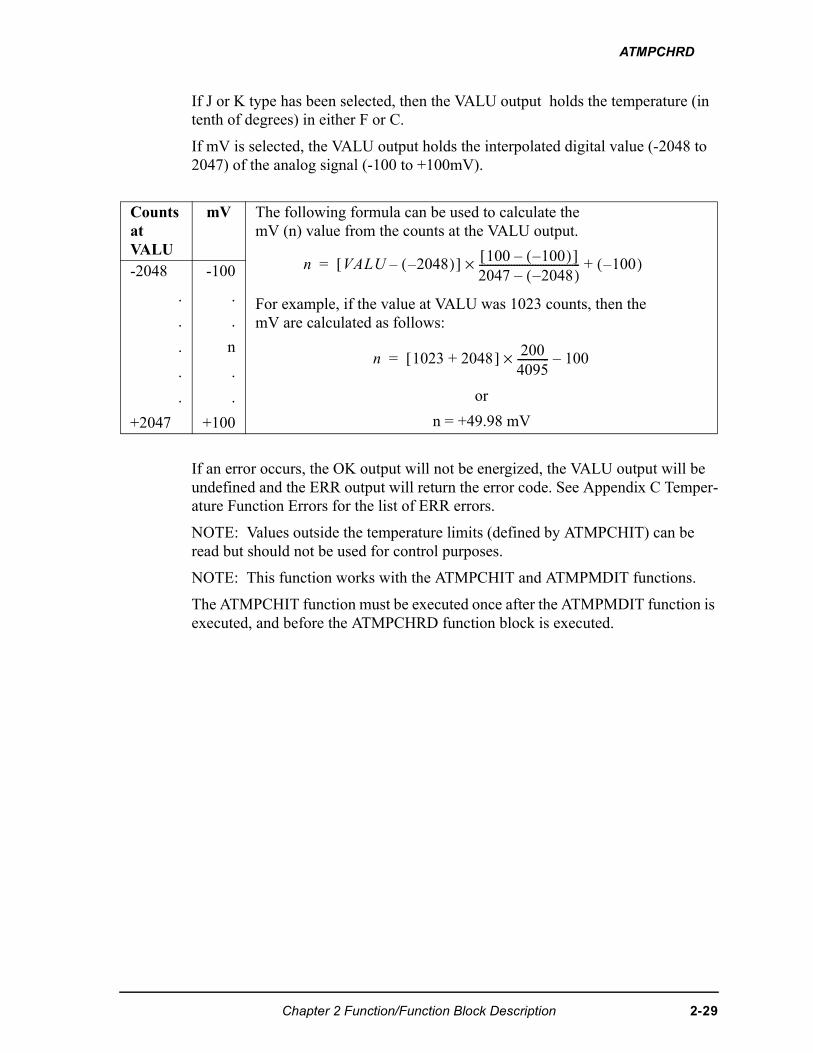
ATMPCHRD
If J or K type has been selected, then the VALU output holds the temperature (in tenth of degrees) in either F or C.
If mV is selected, the VALU output holds the interpolated digital value (-2048 to 2047) of the analog signal (-100 to +100mV).
If an error occurs, the OK output will not be energized, the VALU output will be undefined and the ERR output will return the error code. See Appendix C Temper-ature Function Errors for the list of ERR errors.
NOTE: Values outside the temperature limits (defined by ATMPCHIT) can be read but should not be used for control purposes.
NOTE: This function works with the ATMPCHIT and ATMPMDIT functions.
The ATMPCHIT function must be executed once after the ATMPMDIT function is executed, and before the ATMPCHRD function block is executed.
Counts at VALU
mV The following formula can be used to calculate themV (n) value from the counts at the VALU output.
For example, if the value at VALU was 1023 counts, then themV are calculated as follows:
or
n = +49.98 mV
-2048
.
.
.
.
.
+2047
-100
.
.
n
.
.
+100
� ���� ����( )�[ ] ��� ����( )�[ ]��� ����( )�--------------------------------------× ����( ) �
� ���� ��� [ ] ���
���------------× �����
Chapter 2 Function/Function Block Description 2-29
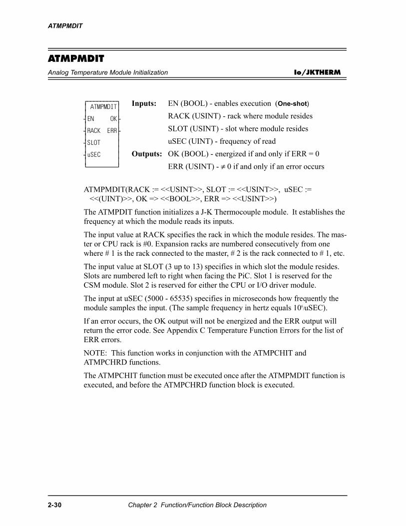
ATMPMDIT
ATMPMDITAnalog Temperature Module Initialization Io/JKTHERM
ATMPMDIT(RACK := <<USINT>>, SLOT := <<USINT>>, uSEC := <<(UINT)>>, OK => <<BOOL>>, ERR => <<USINT>>)
The ATMPDIT function initializes a J-K Thermocouple module. It establishes the frequency at which the module reads its inputs.
The input value at RACK specifies the rack in which the module resides. The mas-ter or CPU rack is #0. Expansion racks are numbered consecutively from one where # 1 is the rack connected to the master, # 2 is the rack connected to # 1, etc.
The input value at SLOT (3 up to 13) specifies in which slot the module resides. Slots are numbered left to right when facing the PiC. Slot 1 is reserved for the CSM module. Slot 2 is reserved for either the CPU or I/O driver module.
The input at uSEC (5000 - 65535) specifies in microseconds how frequently the module samples the input. (The sample frequency in hertz equals 106
/uSEC).
If an error occurs, the OK output will not be energized and the ERR output will return the error code. See Appendix C Temperature Function Errors for the list of ERR errors.
NOTE: This function works in conjunction with the ATMPCHIT and ATMPCHRD functions.
The ATMPCHIT function must be executed once after the ATMPMDIT function is executed, and before the ATMPCHRD function block is executed.
⁄ƒƒƒƒƒƒƒƒƒø ≥ ATMPMDIT≥ ≥ ≥ ¥EN OK√ ≥ ≥ ¥RACK ERR√ ≥ ≥ ¥SLOT ≥ ≥ ≥ ¥uSEC ≥ ≥ ≥ ¿ƒƒƒƒƒƒƒƒƒŸ
Inputs: EN (BOOL) - enables execution (One-shot)
RACK (USINT) - rack where module resides
SLOT (USINT) - slot where module resides
uSEC (UINT) - frequency of read
Outputs: OK (BOOL) - energized if and only if ERR = 0
ERR (USINT) - ≠ 0 if and only if an error occurs
2-30 Chapter 2 Function/Function Block Description
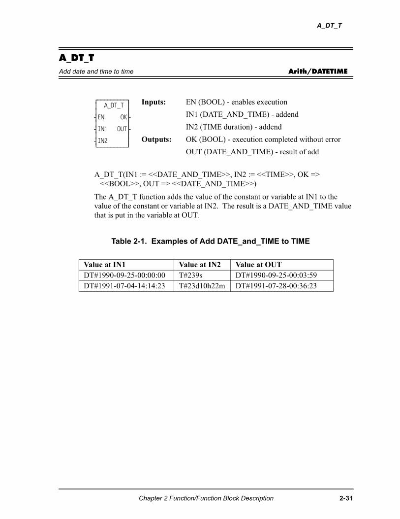
A_DT_T
A_DT_TAdd date and time to time Arith/DATETIME
A_DT_T(IN1 := <<DATE_AND_TIME>>, IN2 := <<TIME>>, OK => <<BOOL>>, OUT => <<DATE_AND_TIME>>)
The A_DT_T function adds the value of the constant or variable at IN1 to the value of the constant or variable at IN2. The result is a DATE_AND_TIME value that is put in the variable at OUT.
Table 2-1. Examples of Add DATE_and_TIME to TIME
⁄ƒƒƒƒƒƒƒƒƒø ≥ A_DT_T ≥ ≥ ≥ ¥EN OK√ ≥ ≥ ¥IN1 OUT√ ≥ ≥ ¥IN2 ≥ ¿ƒƒƒƒƒƒƒƒƒŸ
Inputs: EN (BOOL) - enables execution
IN1 (DATE_AND_TIME) - addend
IN2 (TIME duration) - addend
Outputs: OK (BOOL) - execution completed without error
OUT (DATE_AND_TIME) - result of add
Value at IN1 Value at IN2 Value at OUTDT#1990-09-25-00:00:00 T#239s DT#1990-09-25-00:03:59DT#1991-07-04-14:14:23 T#23d10h22m DT#1991-07-28-00:36:23
Chapter 2 Function/Function Block Description 2-31
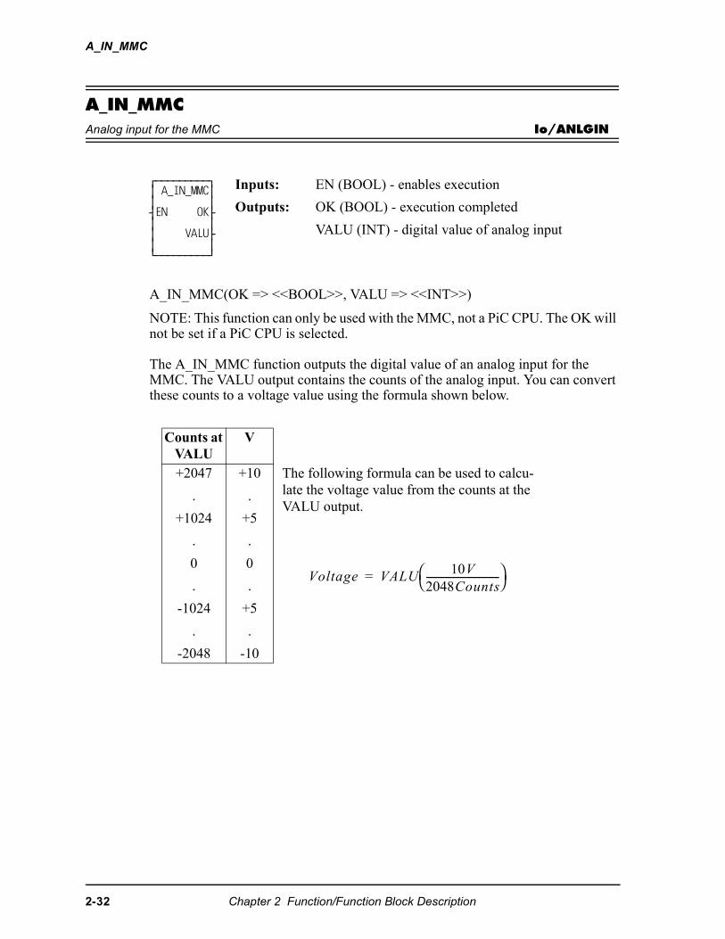
A_IN_MMC
A_IN_MMCAnalog input for the MMC Io/ANLGIN
A_IN_MMC(OK => <<BOOL>>, VALU => <<INT>>)
NOTE: This function can only be used with the MMC, not a PiC CPU. The OK will not be set if a PiC CPU is selected.
The A_IN_MMC function outputs the digital value of an analog input for the MMC. The VALU output contains the counts of the analog input. You can convert these counts to a voltage value using the formula shown below.
⁄ƒƒƒƒƒƒƒƒƒø ≥ A_IN_MMC≥≥ ≥¥EN OK√≥ ≥≥ VALU√≥ ≥¿ƒƒƒƒƒƒƒƒƒŸ
Inputs: EN (BOOL) - enables execution
Outputs: OK (BOOL) - execution completed
VALU (INT) - digital value of analog input
Counts at VALU
V
+2047
.
+1024
.
0
.
-1024
.
-2048
+10
.
+5
.
0
.
+5
.
-10
The following formula can be used to calcu-late the voltage value from the counts at the VALU output.
������� �������
��� �����-------------------------------
�
2-32 Chapter 2 Function/Function Block Description
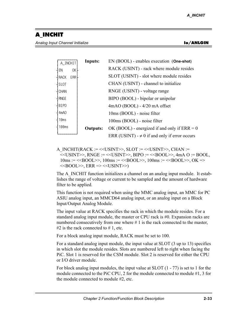
A_INCHIT
A_INCHITAnalog Input Channel Initialize Io/ANLGIN
A_INCHIT(RACK := <<USINT>>, SLOT := <<USINT>>, CHAN := <<USINT>>, RNGE := <<USINT>>, BIPO := <<BOOL>>, 4mA O := BOOL, 10ms := <<BOOL>>, 100ms := <<BOOL>>, 100ms := <<BOOL>>, OK => <<BOOL>>, ERR => <<USINT>>)
The A_INCHIT function initializes a channel on an analog input module. It estab-lishes the range of voltage or current to be sampled and the amount of hardware filter to be applied.
This function is not required when using the MMC analog input, an MMC for PC ASIU analog input, an MMCD64 analog input, or an analog input on a Block Input/Output Analog Module.
The input value at RACK specifies the rack in which the module resides. For a standard analog input module, the master or CPU rack is #0. Expansion racks are numbered consecutively from one where # 1 is the rack connected to the master, #2 is the rack connected to # 1, etc.
For a block analog input module, RACK must be set to 100.
For a standard analog input module, the input value at SLOT (3 up to 13) specifies in which slot the module resides. Slots are numbered left to right when facing the PiC. Slot 1 is reserved for the CSM module. Slot 2 is reserved for either the CPU or I/O driver module.
For block analog input modules, the input value at SLOT (1 - 77) is set to 1 for the module connected to the PiC CPU, 2 for the module connected to module #1, 3 for the module connected to module #2, etc.
⁄ƒƒƒƒƒƒƒƒƒø ≥ A_INCHIT≥ ≥ ≥ ¥EN OK√ ≥ ≥ ¥RACK ERR√ ≥ ≥ ¥SLOT ≥ ≥ ≥ ¥CHAN ≥ ≥ ≥ ¥RNGE ≥ ≥ ≥ ¥BIPO ≥ ≥ ≥ ¥4mAO ≥ ≥ ≥ ¥10ms ≥ ≥ ≥ ¥100ms ≥ ≥ ≥ ¿ƒƒƒƒƒƒƒƒƒŸ
Inputs: EN (BOOL) - enables execution (One-shot)
RACK (USINT) - rack where module resides
SLOT (USINT) - slot where module resides
CHAN (USINT) - channel to initialize
RNGE (USINT) - voltage range
BIPO (BOOL) - bipolar or unipolar
4mAO (BOOL) - 4/20 mA offset
10ms (BOOL) - noise filter
100ms (BOOL) - noise filter
Outputs: OK (BOOL) - energized if and only if ERR = 0
ERR (USINT) - ≠ 0 if and only if error occurs
Chapter 2 Function/Function Block Description 2-33
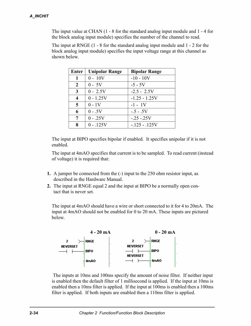
A_INCHIT
The input value at CHAN (1 - 8 for the standard analog input module and 1 - 4 for the block analog input module) specifies the number of the channel to read.
The input at RNGE (1 - 8 for the standard analog input module and 1 - 2 for the block analog input module) specifies the input voltage range at this channel as shown below.
The input at BIPO specifies bipolar if enabled. It specifies unipolar if it is not enabled.
The input at 4mAO specifies that current is to be sampled. To read current (instead of voltage) it is required that:
The input at 4mAO should have a wire or short connected to it for 4 to 20mA. The input at 4mAO should not be enabled for 0 to 20 mA. These inputs are pictured below.
The inputs at 10ms and 100ms specify the amount of noise filter. If neither input is enabled then the default filter of 1 millisecond is applied. If the input at 10ms is enabled then a 10ms filter is applied. If the input at 100ms is enabled then a 100ms filter is applied. If both inputs are enabled then a 110ms filter is applied.
Enter Unipolar Range Bipolar Range1 0 - 10V -10 - 10V2 0 - 5V -5 - 5V3 0 - 2.5V -2.5 - 2.5V4 0 - 1.25V -1.25 - 1.25V5 0 - 1V -1 - 1V6 0 - .5V -.5 - .5V7 0 - .25V -.25 -.25V8 0 - .125V -.125 - .125V
1. A jumper be connected from the (-) input to the 250 ohm resistor input, as described in the Hardware Manual.
2. The input at RNGE equal 2 and the input at BIPO be a normally open con-tact that is never set.
4 - 20 mA 0 - 20 mA
2-34 Chapter 2 Function/Function Block Description
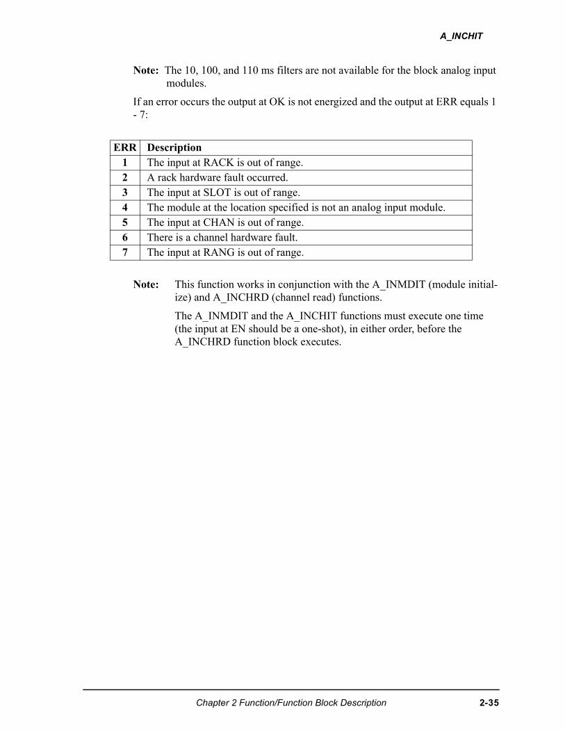
A_INCHIT
Note: The 10, 100, and 110 ms filters are not available for the block analog input modules.
If an error occurs the output at OK is not energized and the output at ERR equals 1 - 7:
Note: This function works in conjunction with the A_INMDIT (module initial-ize) and A_INCHRD (channel read) functions.
The A_INMDIT and the A_INCHIT functions must execute one time (the input at EN should be a one-shot), in either order, before the A_INCHRD function block executes.
ERR Description1 The input at RACK is out of range.2 A rack hardware fault occurred.3 The input at SLOT is out of range.4 The module at the location specified is not an analog input module.5 The input at CHAN is out of range. 6 There is a channel hardware fault. 7 The input at RANG is out of range.
Chapter 2 Function/Function Block Description 2-35
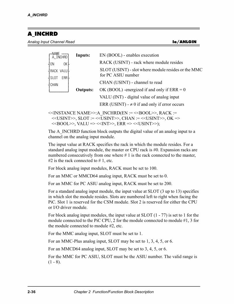
A_INCHRD
A_INCHRDAnalog Input Channel Read Io/ANLGIN
<<INSTANCE NAME>>:A_INCHRD(EN := <<BOOL>>, RACK := <<USINT>>, SLOT := <<USINT>>, CHAN := <<USINT>>, OK => <<BOOL>>, VALU => <<INT>>, ERR => <<USINT>>);
The A_INCHRD function block outputs the digital value of an analog input to a channel on the analog input module.
The input value at RACK specifies the rack in which the module resides. For a standard analog input module, the master or CPU rack is #0. Expansion racks are numbered consecutively from one where # 1 is the rack connected to the master, #2 is the rack connected to # 1, etc.
For block analog input modules, RACK must be set to 100.
For an MMC or MMCD64 analog input, RACK must be set to 0.
For an MMC for PC ASIU analog input, RACK must be set to 200.
For a standard analog input module, the input value at SLOT (3 up to 13) specifies in which slot the module resides. Slots are numbered left to right when facing the PiC. Slot 1 is reserved for the CSM module. Slot 2 is reserved for either the CPU or I/O driver module.
For block analog input modules, the input value at SLOT (1 - 77) is set to 1 for the module connected to the PiC CPU, 2 for the module connected to module #1, 3 for the module connected to module #2, etc.
For the MMC analog input, SLOT must be set to 1.
For an MMC-Plus analog input, SLOT may be set to 1, 3, 4, 5, or 6.
For an MMCD64 analog input, SLOT may be set to 3, 4, 5, or 6.
For the MMC for PC ASIU, SLOT must be the ASIU number. The valid range is (1 - 8).
⁄ƒNAME ƒƒƒø ≥ A_INCHRD≥ ≥ ≥ ¥EN OK√ ≥ ≥ ¥RACK VALU√ ≥ ≥ ¥SLOT ERR√ ≥ ≥ ¥CHAN ≥ ≥ ≥ ¿ƒƒƒƒƒƒƒƒƒŸ
Inputs: EN (BOOL) - enables execution
RACK (USINT) - rack where module resides
SLOT (USINT) - slot where module resides or the MMC for PC ASIU number
CHAN (USINT) - channel to read
Outputs: OK (BOOL) -energized if and only if ERR = 0
VALU (INT) - digital value of analog input
ERR (USINT) - ≠ 0 if and only if error occurs
2-36 Chapter 2 Function/Function Block Description
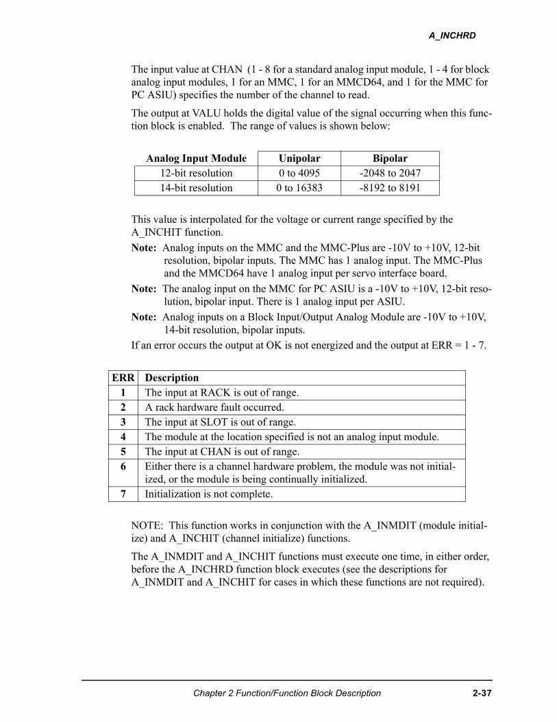
A_INCHRD
The input value at CHAN (1 - 8 for a standard analog input module, 1 - 4 for block analog input modules, 1 for an MMC, 1 for an MMCD64, and 1 for the MMC for PC ASIU) specifies the number of the channel to read.
The output at VALU holds the digital value of the signal occurring when this func-tion block is enabled. The range of values is shown below:
This value is interpolated for the voltage or current range specified by the A_INCHIT function.
Note: Analog inputs on the MMC and the MMC-Plus are -10V to +10V, 12-bit resolution, bipolar inputs. The MMC has 1 analog input. The MMC-Plus and the MMCD64 have 1 analog input per servo interface board.
Note: The analog input on the MMC for PC ASIU is a -10V to +10V, 12-bit reso-lution, bipolar input. There is 1 analog input per ASIU.
Note: Analog inputs on a Block Input/Output Analog Module are -10V to +10V, 14-bit resolution, bipolar inputs.
If an error occurs the output at OK is not energized and the output at ERR = 1 - 7.
NOTE: This function works in conjunction with the A_INMDIT (module initial-ize) and A_INCHIT (channel initialize) functions.
The A_INMDIT and A_INCHIT functions must execute one time, in either order, before the A_INCHRD function block executes (see the descriptions for A_INMDIT and A_INCHIT for cases in which these functions are not required).
Analog Input Module Unipolar Bipolar12-bit resolution 0 to 4095 -2048 to 204714-bit resolution 0 to 16383 -8192 to 8191
ERR Description 1 The input at RACK is out of range.2 A rack hardware fault occurred.3 The input at SLOT is out of range.4 The module at the location specified is not an analog input module.5 The input at CHAN is out of range. 6 Either there is a channel hardware problem, the module was not initial-
ized, or the module is being continually initialized. 7 Initialization is not complete.
Chapter 2 Function/Function Block Description 2-37
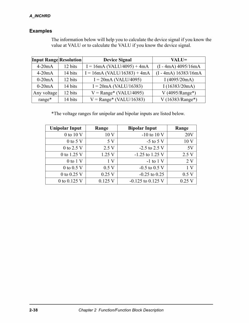
A_INCHRD
Examples
The information below will help you to calculate the device signal if you know the value at VALU or to calculate the VALU if you know the device signal.
*The voltage ranges for unipolar and bipolar inputs are listed below.
Input Range Resolution Device Signal VALU=4-20mA 12 bits I = 16mA (VALU/4095) + 4mA (I - 4mA) 4095/16mA4-20mA 14 bits I = 16mA (VALU/16383) + 4mA (I - 4mA) 16383/16mA0-20mA 12 bits I = 20mA (VALU/4095) I (4095/20mA)0-20mA 14 bits I = 20mA (VALU/16383) I (16383/20mA)
Any voltage 12 bits V = Range* (VALU/4095) V (4095/Range*)range* 14 bits V = Range* (VALU/16383) V (16383/Range*)
Unipolar Input Range Bipolar Input Range0 to 10 V 10 V -10 to 10 V 20V0 to 5 V 5 V -5 to 5 V 10 V
0 to 2.5 V 2.5 V -2.5 to 2.5 V 5V0 to 1.25 V 1.25 V -1.25 to 1.25 V 2.5 V
0 to 1 V 1 V -1 to 1 V 2 V0 to 0.5 V 0.5 V -0.5 to 0.5 V 1 V
0 to 0.25 V 0.25 V -0.25 to 0.25 0.5 V0 to 0.125 V 0.125 V -0.125 to 0.125 V 0.25 V
2-38 Chapter 2 Function/Function Block Description
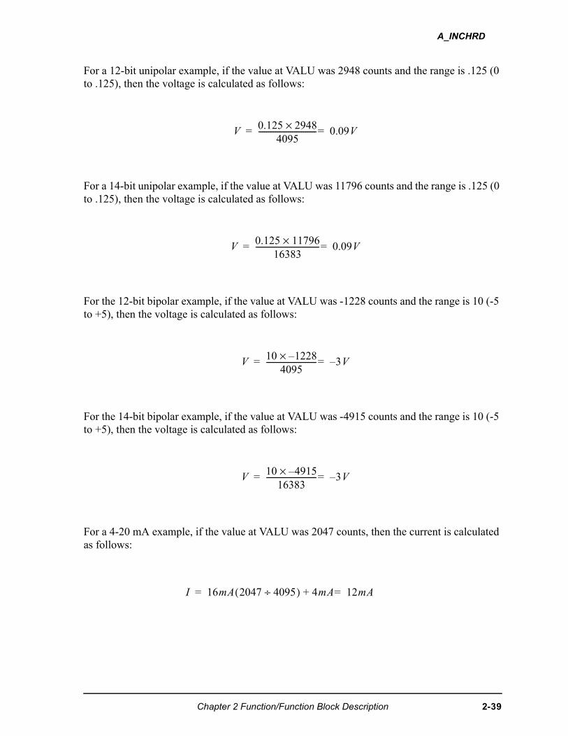
A_INCHRD
For a 12-bit unipolar example, if the value at VALU was 2948 counts and the range is .125 (0 to .125), then the voltage is calculated as follows:
For a 14-bit unipolar example, if the value at VALU was 11796 counts and the range is .125 (0 to .125), then the voltage is calculated as follows:
For the 12-bit bipolar example, if the value at VALU was -1228 counts and the range is 10 (-5 to +5), then the voltage is calculated as follows:
For the 14-bit bipolar example, if the value at VALU was -4915 counts and the range is 10 (-5 to +5), then the voltage is calculated as follows:
For a 4-20 mA example, if the value at VALU was 2047 counts, then the current is calculated as follows:
������ ���×
���------------------------------- �������
������ ����×
����---------------------------------- �������
��� �����×
���--------------------------- �����
��� ��������
--------------------------- �����
� ��� ��� ���÷( ) �� ����� �
Chapter 2 Function/Function Block Description 2-39
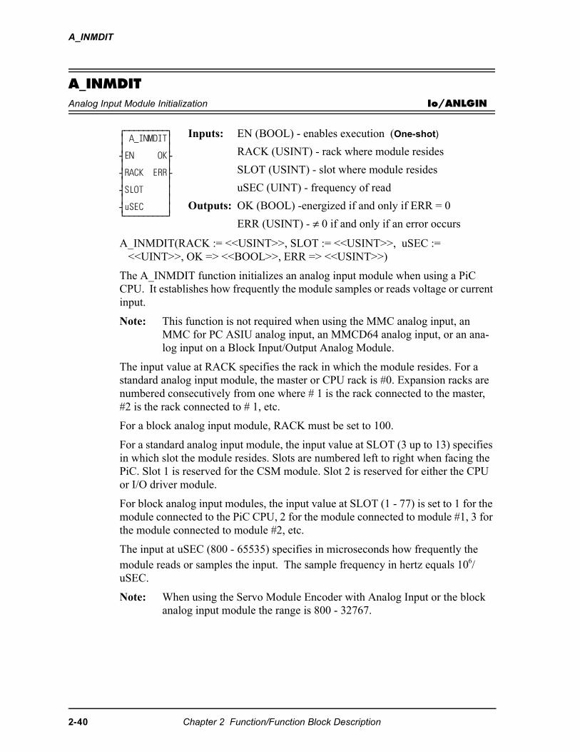
A_INMDIT
A_INMDITAnalog Input Module Initialization Io/ANLGIN
A_INMDIT(RACK := <<USINT>>, SLOT := <<USINT>>, uSEC := <<UINT>>, OK => <<BOOL>>, ERR => <<USINT>>)
The A_INMDIT function initializes an analog input module when using a PiC CPU. It establishes how frequently the module samples or reads voltage or current input.
Note: This function is not required when using the MMC analog input, an MMC for PC ASIU analog input, an MMCD64 analog input, or an ana-log input on a Block Input/Output Analog Module.
The input value at RACK specifies the rack in which the module resides. For a standard analog input module, the master or CPU rack is #0. Expansion racks are numbered consecutively from one where # 1 is the rack connected to the master, #2 is the rack connected to # 1, etc.
For a block analog input module, RACK must be set to 100.
For a standard analog input module, the input value at SLOT (3 up to 13) specifies in which slot the module resides. Slots are numbered left to right when facing the PiC. Slot 1 is reserved for the CSM module. Slot 2 is reserved for either the CPU or I/O driver module.
For block analog input modules, the input value at SLOT (1 - 77) is set to 1 for the module connected to the PiC CPU, 2 for the module connected to module #1, 3 for the module connected to module #2, etc.
The input at uSEC (800 - 65535) specifies in microseconds how frequently the module reads or samples the input. The sample frequency in hertz equals 106/uSEC.
Note: When using the Servo Module Encoder with Analog Input or the block analog input module the range is 800 - 32767.
⁄ƒƒƒƒƒƒƒƒƒø ≥ A_INMDIT≥ ≥ ≥ ¥EN OK√ ≥ ≥ ¥RACK ERR√ ≥ ≥ ¥SLOT ≥ ≥ ≥ ¥uSEC ≥ ¿ƒƒƒƒƒƒƒƒƒŸ
Inputs: EN (BOOL) - enables execution (One-shot)
RACK (USINT) - rack where module resides
SLOT (USINT) - slot where module resides
uSEC (UINT) - frequency of read
Outputs: OK (BOOL) -energized if and only if ERR = 0
ERR (USINT) - ≠ 0 if and only if an error occurs
2-40 Chapter 2 Function/Function Block Description
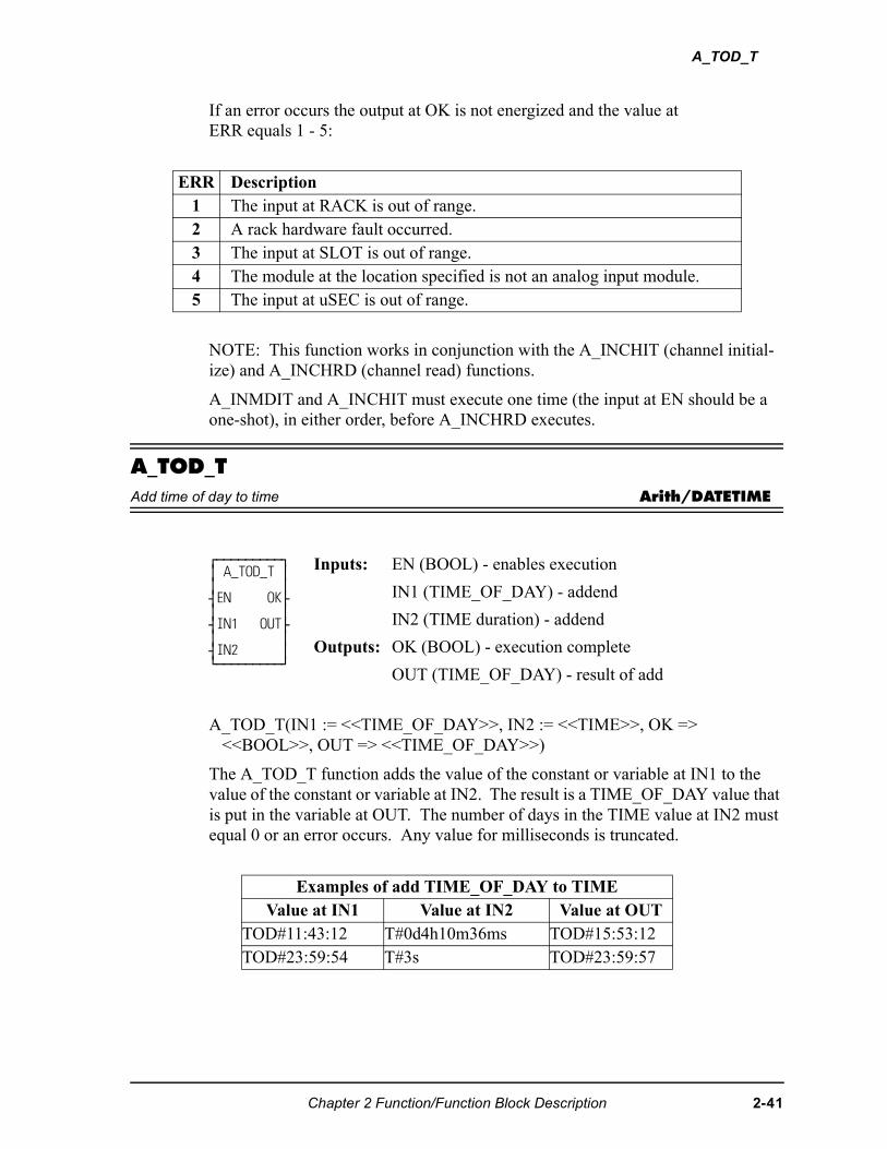
A_TOD_T
If an error occurs the output at OK is not energized and the value atERR equals 1 - 5:
NOTE: This function works in conjunction with the A_INCHIT (channel initial-ize) and A_INCHRD (channel read) functions.
A_INMDIT and A_INCHIT must execute one time (the input at EN should be a one-shot), in either order, before A_INCHRD executes.
A_TOD_TAdd time of day to time Arith/DATETIME
A_TOD_T(IN1 := <<TIME_OF_DAY>>, IN2 := <<TIME>>, OK => <<BOOL>>, OUT => <<TIME_OF_DAY>>)
The A_TOD_T function adds the value of the constant or variable at IN1 to the value of the constant or variable at IN2. The result is a TIME_OF_DAY value that is put in the variable at OUT. The number of days in the TIME value at IN2 must equal 0 or an error occurs. Any value for milliseconds is truncated.
ERR Description1 The input at RACK is out of range.2 A rack hardware fault occurred.3 The input at SLOT is out of range.4 The module at the location specified is not an analog input module.5 The input at uSEC is out of range.
⁄ƒƒƒƒƒƒƒƒƒø ≥ A_TOD_T ≥ ≥ ≥ ¥EN OK√ ≥ ≥ ¥IN1 OUT√ ≥ ≥ ¥IN2 ≥ ¿ƒƒƒƒƒƒƒƒƒŸ
Inputs: EN (BOOL) - enables execution
IN1 (TIME_OF_DAY) - addend
IN2 (TIME duration) - addend
Outputs: OK (BOOL) - execution complete
OUT (TIME_OF_DAY) - result of add
Examples of add TIME_OF_DAY to TIMEValue at IN1 Value at IN2 Value at OUT
TOD#11:43:12 T#0d4h10m36ms TOD#15:53:12TOD#23:59:54 T#3s TOD#23:59:57
Chapter 2 Function/Function Block Description 2-41
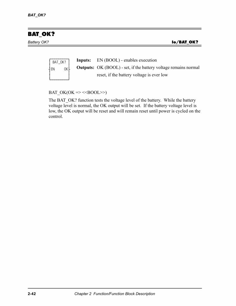
BAT_OK?
BAT_OK?Battery OK? Io/BAT_OK?
BAT_OK(OK => <<BOOL>>)
The BAT_OK? function tests the voltage level of the battery. While the battery voltage level is normal, the OK output will be set. If the battery voltage level is low, the OK output will be reset and will remain reset until power is cycled on the control.
⁄ƒƒƒƒƒƒƒƒƒø ≥ BAT_OK? ≥ ≥ ≥ ¥EN OK√ ≥ ≥ ≥ ≥ ¿ƒƒƒƒƒƒƒƒƒŸ
Inputs: EN (BOOL) - enables execution
Outputs: OK (BOOL) - set, if the battery voltage remains normal
reset, if the battery voltage is ever low
2-42 Chapter 2 Function/Function Block Description
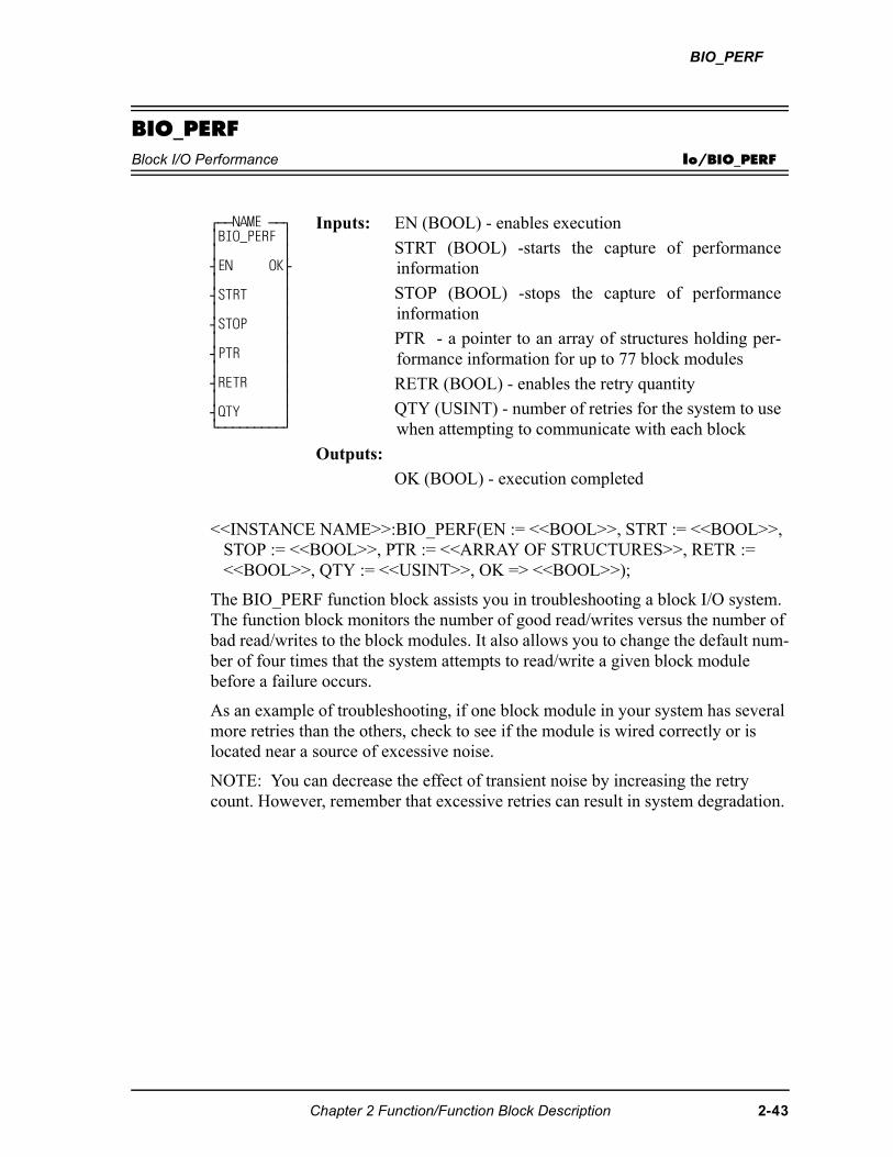
BIO_PERF
BIO_PERFBlock I/O Performance Io/BIO_PERF
<<INSTANCE NAME>>:BIO_PERF(EN := <<BOOL>>, STRT := <<BOOL>>, STOP := <<BOOL>>, PTR := <<ARRAY OF STRUCTURES>>, RETR := <<BOOL>>, QTY := <<USINT>>, OK => <<BOOL>>);
The BIO_PERF function block assists you in troubleshooting a block I/O system. The function block monitors the number of good read/writes versus the number of bad read/writes to the block modules. It also allows you to change the default num-ber of four times that the system attempts to read/write a given block module before a failure occurs.
As an example of troubleshooting, if one block module in your system has several more retries than the others, check to see if the module is wired correctly or is located near a source of excessive noise.
NOTE: You can decrease the effect of transient noise by increasing the retry count. However, remember that excessive retries can result in system degradation.
⁄ƒƒNAME ƒƒø ≥BIO_PERF ≥ ≥ ≥ ¥EN OK√ ≥ ≥ ¥STRT ≥ ≥ ≥ ¥STOP ≥ ≥ ≥ ¥PTR ≥ ≥ ≥ ¥RETR ≥ ≥ ≥ ¥QTY ≥ ¿ƒƒƒƒƒƒƒƒƒŸ
Inputs: EN (BOOL) - enables execution
STRT (BOOL) -starts the capture of performanceinformation
STOP (BOOL) -stops the capture of performanceinformation
PTR - a pointer to an array of structures holding per-formance information for up to 77 block modules
RETR (BOOL) - enables the retry quantity
QTY (USINT) - number of retries for the system to usewhen attempting to communicate with each block
Outputs:
OK (BOOL) - execution completed
Chapter 2 Function/Function Block Description 2-43
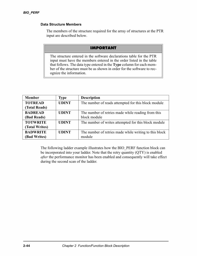
BIO_PERF
Data Structure Members
The members of the structure required for the array of structures at the PTR input are described below.
The following ladder example illustrates how the BIO_PERF function block can be incorporated into your ladder. Note that the retry quantity (QTY) is enabled after the performance monitor has been enabled and consequently will take effect during the second scan of the ladder.
IMPORTANT
The structure entered in the software declarations table for the PTRinput must have the members entered in the order listed in the tablethat follows. The data type entered in the Type column for each mem-ber of the structure must be as shown in order for the software to rec-ognize the information.
Member Type DescriptionTOTREAD(Total Reads)
UDINT The number of reads attempted for this block module
BADREAD(Bad Reads)
UDINT The number of retries made while reading from this block module
TOTWRITE(Total Writes)
UDINT The number of writes attempted for this block module
BADWRITE(Bad Writes)
UDINT The number of retries made while writing to this block module
2-44 Chapter 2 Function/Function Block Description
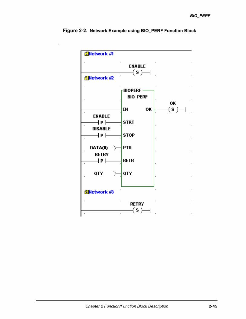
BIO_PERF
Figure 2-2. Network Example using BIO_PERF Function Block
.
Chapter 2 Function/Function Block Description 2-45
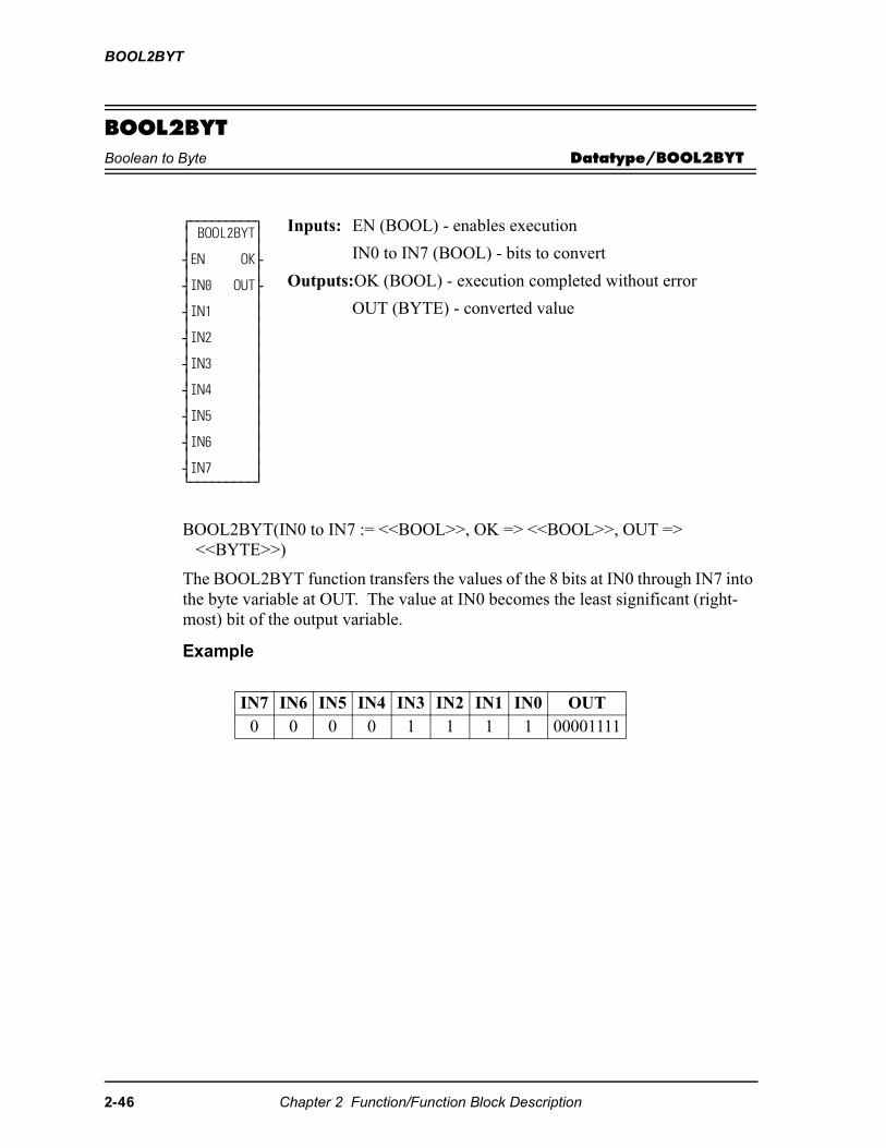
BOOL2BYT
BOOL2BYTBoolean to Byte Datatype/BOOL2BYT
BOOL2BYT(IN0 to IN7 := <<BOOL>>, OK => <<BOOL>>, OUT => <<BYTE>>)
The BOOL2BYT function transfers the values of the 8 bits at IN0 through IN7 into the byte variable at OUT. The value at IN0 becomes the least significant (right-most) bit of the output variable.
Example
⁄ƒƒƒƒƒƒƒƒƒø ≥ BOOL2BYT≥ ≥ ≥ ¥EN OK√ ≥ ≥ ¥IN0 OUT√ ≥ ≥ ¥IN1 ≥ ≥ ≥ ¥IN2 ≥ ≥ ≥ ¥IN3 ≥ ≥ ≥ ¥IN4 ≥ ≥ ≥ ¥IN5 ≥ ≥ ≥ ¥IN6 ≥ ≥ ≥ ¥IN7 ≥ ¿ƒƒƒƒƒƒƒƒƒŸ
Inputs: EN (BOOL) - enables execution
IN0 to IN7 (BOOL) - bits to convert
Outputs:OK (BOOL) - execution completed without error
OUT (BYTE) - converted value
IN7 IN6 IN5 IN4 IN3 IN2 IN1 IN0 OUT0 0 0 0 1 1 1 1 00001111
2-46 Chapter 2 Function/Function Block Description

BTMPCHIT
BTMPCHITBlock I/O Thermocouple or A/D Initialization Io/JKTHERM
BTMPCHIT(HNDL := <<USINT>>, SLOT := <<USINT>>, CHAN := <<USINT>>, RNGE := <<USINT>>, OK => <<BOOL>>, ERR => <<USINT>>)
This function initializes a Block I/O J-K Thermocouple or A/D channel. It will set up the range for the channel. This function should only be called to setup the range of the thermocouple channel. The range may be changed anytime after a handle has been obtained from the BTMPMGR function block.
The HNDL input specifies the block. Use the value obtained from the HNDL out-put of BTMPMGR. The CHAN input specifies the number (1 to 8) of the channel. The RNGE input specifies the temperature or voltage range (1 to 4) that can be read, where:
If an error occurs, the OK output will not be energized and the ERR output will return the error code.See Appendix C Temperature Function Errors for the list of ERR errors.
⁄ƒƒƒƒƒƒƒƒƒø ≥ BTMPCHIT≥ ≥ ≥ ¥EN OK√ ≥ ≥ ¥HNDL ERR√ ≥ ≥ ¥CHAN ≥ ≥ ≥ ¥RNGE ≥ ≥ ≥ ¿ƒƒƒƒƒƒƒƒƒŸ
Inputs: EN (BOOL) - enables execution
HNDL (DWORD) -handle to the block, obtained fromBTMPMGR
CHAN (USINT) - channel (1-8)
RNGE (USINT) - range (1-4)
Outputs: OK (BOOL) - OK
ERR (USINT) - error number
RNGE Range of values for J typethermocouple*
Range of values for K typethermocouple*
1 -10º C to 280º C14º F to 536º F
-35º C to 415º C-31º F to 779º F
2 -35º C to 620º C-31º F to 1148º F
-80º C to 820º C-112º F to 1508º F
3 -150º C to 1200º C-238º F to 2192º F
-200º C to 1300º C-328º F to 2372º F
4 ±100mV n/a
* The temperature ranges apply over the temperature rating of the module. Temperature values outside the specified range should not be used for control purposes.
Chapter 2 Function/Function Block Description 2-47
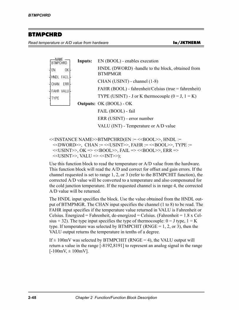
BTMPCHRD
BTMPCHRDRead temperature or A/D value from hardware Io/JKTHERM
<<INSTANCE NAME>>BTMPCHRD(EN := <<BOOL>>, HNDL := <<DWORD>>, CHAN := <<USINT>>, FAHR := <<BOOL>>, TYPE := <<USINT>>, OK => <<BOOL>>, FAIL => <<BOOL>>, ERR => <<USINT>>, VALU => <<INT>>);
Use this function block to read the temperature or A/D value from the hardware. This function block will read the A/D and correct for offset and gain errors. If the channel requested is set to range 1, 2, or 3 (refer to the BTMPCHIT function), the corrected A/D value will be converted to a temperature and also compensated for the cold junction temperature. If the requested channel is in range 4, the corrected A/D value will be returned.
The HNDL input specifies the block. Use the value obtained from the HNDL out-put of BTMPMGR. The CHAN input specifies the channel (1 to 8) to be read. The FAHR input specifies if the temperature value returned in VALU is Fahrenheit or Celsius. Energized = Fahrenheit, de-energized = Celsius. (Fahrenheit = 1.8 x Cel-sius + 32). The type input specifies the type of thermocouple: 0 = J type, 1 = K type. If temperature was selected by BTMPCHIT (RNGE = 1, 2, or 3), then the VALU output returns the temperature in tenths of a degree.
If ± 100mV was selected by BTMPCHIT (RNGE = 4), the VALU output will return a value in the range [-8192,8191] to represent an analog signal in the range [-100mV, ± 100mV].
⁄ƒƒNAME ƒƒø ≥BTMPCHRD ≥ ≥ ≥ ¥EN OK√ ≥ ≥ ¥HNDL FAIL√ ≥ ≥ ¥CHAN ERR√ ≥ ≥ ¥FAHR VALU√ ≥ ≥ ¥TYPE ≥ ≥ ≥ ¿ƒƒƒƒƒƒƒƒƒŸ
Inputs: EN (BOOL) - enables execution
HNDL (DWORD) -handle to the block, obtained from BTMPMGR
CHAN (USINT) - channel (1-8)
FAHR (BOOL) - fahrenheit/Celsius (true = fahrenheit)
TYPE (USINT) - J or K thermocouple (0 = J, 1 = K)
Outputs: OK (BOOL) - OK
FAIL (BOOL) - fail
ERR (USINT) - error number
VALU (INT) - Temperature or A/D value
2-48 Chapter 2 Function/Function Block Description
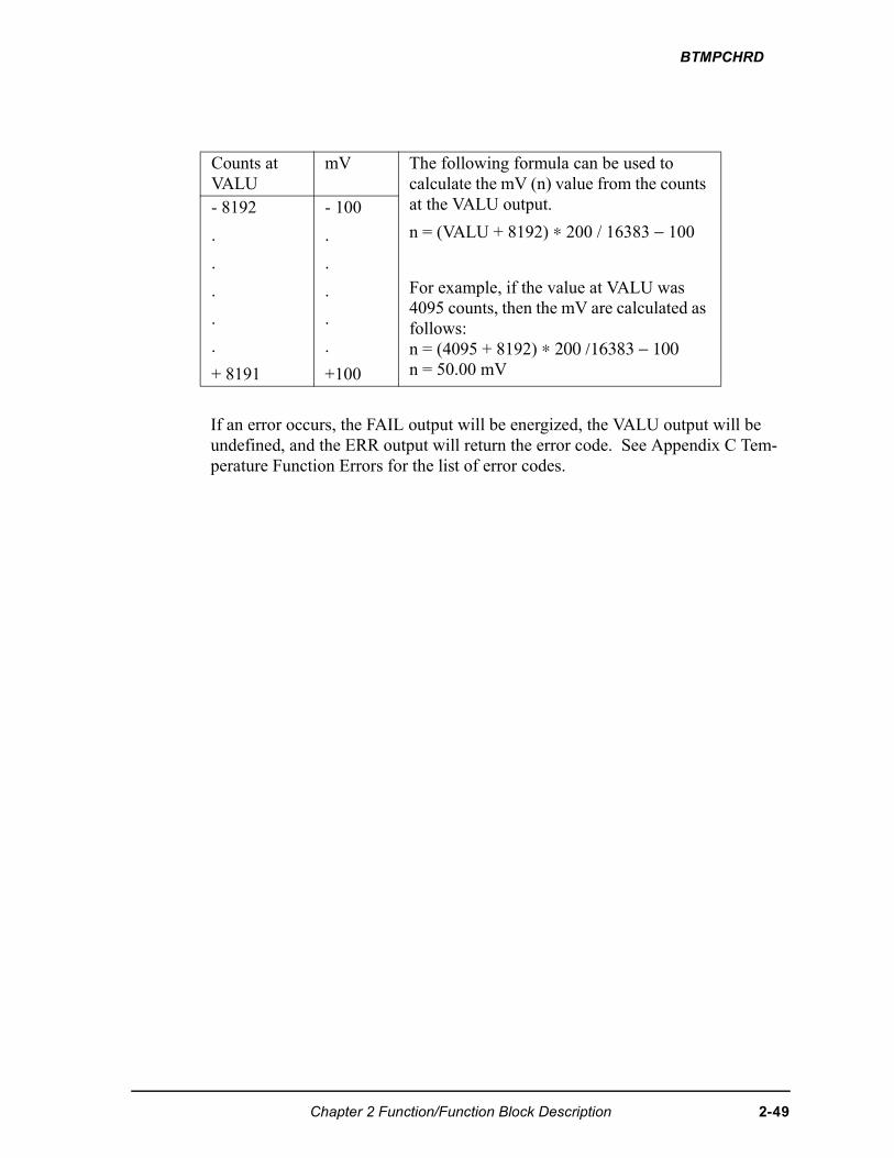
BTMPCHRD
If an error occurs, the FAIL output will be energized, the VALU output will be undefined, and the ERR output will return the error code. See Appendix C Tem-perature Function Errors for the list of error codes.
Counts at VALU
mV The following formula can be used tocalculate the mV (n) value from the counts at the VALU output.
n = (VALU + 8192) ∗ 200 / 16383 − 100
For example, if the value at VALU was 4095 counts, then the mV are calculated as follows:n = (4095 + 8192) ∗ 200 /16383 − 100n = 50.00 mV
- 8192
.
.
.
.
.
+ 8191
- 100
.
.
.
.
.
+100
Chapter 2 Function/Function Block Description 2-49
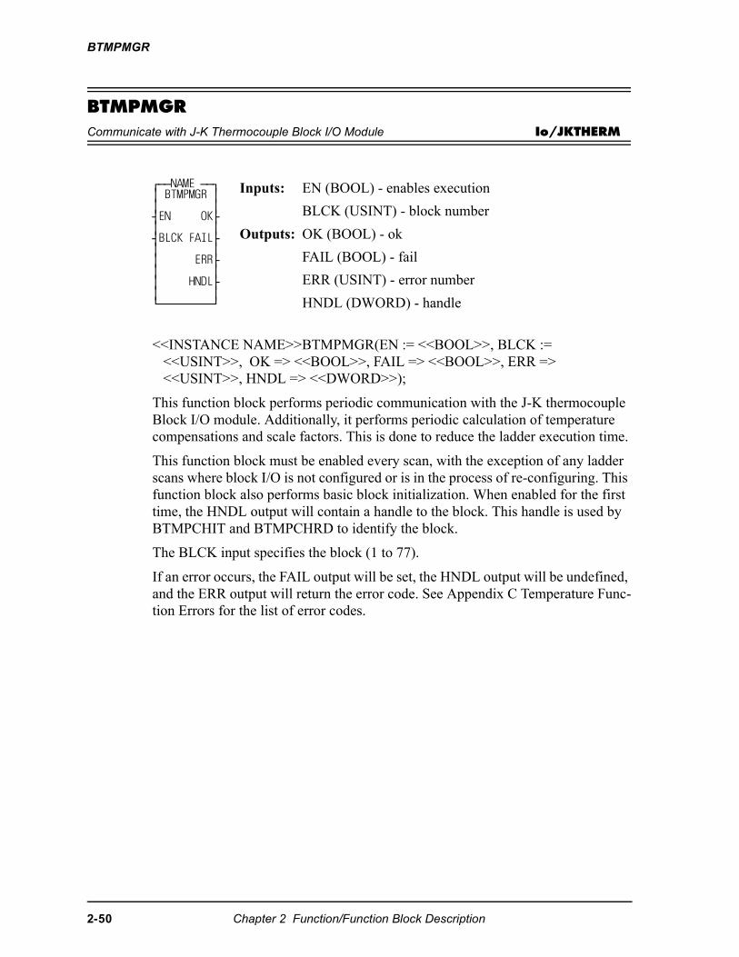
BTMPMGR
BTMPMGRCommunicate with J-K Thermocouple Block I/O Module Io/JKTHERM
<<INSTANCE NAME>>BTMPMGR(EN := <<BOOL>>, BLCK := <<USINT>>, OK => <<BOOL>>, FAIL => <<BOOL>>, ERR => <<USINT>>, HNDL => <<DWORD>>);
This function block performs periodic communication with the J-K thermocouple Block I/O module. Additionally, it performs periodic calculation of temperature compensations and scale factors. This is done to reduce the ladder execution time.
This function block must be enabled every scan, with the exception of any ladder scans where block I/O is not configured or is in the process of re-configuring. This function block also performs basic block initialization. When enabled for the first time, the HNDL output will contain a handle to the block. This handle is used by BTMPCHIT and BTMPCHRD to identify the block.
The BLCK input specifies the block (1 to 77).
If an error occurs, the FAIL output will be set, the HNDL output will be undefined, and the ERR output will return the error code. See Appendix C Temperature Func-tion Errors for the list of error codes.
⁄ƒƒNAME ƒƒø ≥ BTMPMGR ≥ ≥ ≥ ¥EN OK√ ≥ ≥ ¥BLCK FAIL√ ≥ ≥ ≥ ERR√ ≥ ≥ ≥ HNDL√ ≥ ≥ ¿ƒƒƒƒƒƒƒƒƒŸ
Inputs: EN (BOOL) - enables execution
BLCK (USINT) - block number
Outputs: OK (BOOL) - ok
FAIL (BOOL) - fail
ERR (USINT) - error number
HNDL (DWORD) - handle
2-50 Chapter 2 Function/Function Block Description
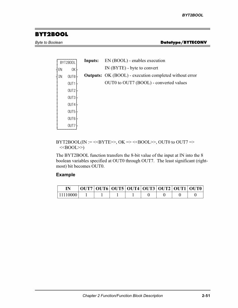
BYT2BOOL
BYT2BOOLByte to Boolean Datatype/BYTECONV
BYT2BOOL(IN := <<BYTE>>, OK => <<BOOL>>, OUT0 to OUT7 => <<BOOL>>)
The BYT2BOOL function transfers the 8-bit value of the input at IN into the 8 boolean variables specified at OUT0 through OUT7. The least significant (right-most) bit becomes OUT0.
Example
⁄ƒƒƒƒƒƒƒƒƒø ≥ BYT2BOOL≥ ≥ ≥ ¥EN OK√ ≥ ≥ ¥IN OUT0√ ≥ ≥ ≥ OUT1√ ≥ ≥ ≥ OUT2√ ≥ ≥ ≥ OUT3√ ≥ ≥ ≥ OUT4√ ≥ ≥ ≥ OUT5√ ≥ ≥ ≥ OUT6√ ≥ ≥ ≥ OUT7√ ¿ƒƒƒƒƒƒƒƒƒŸ
Inputs: EN (BOOL) - enables execution
IN (BYTE) - byte to convert
Outputs: OK (BOOL) - execution completed without error
OUT0 to OUT7 (BOOL) - converted values
IN OUT7 OUT6 OUT5 OUT4 OUT3 OUT2 OUT1 OUT011110000 1 1 1 1 0 0 0 0
Chapter 2 Function/Function Block Description 2-51
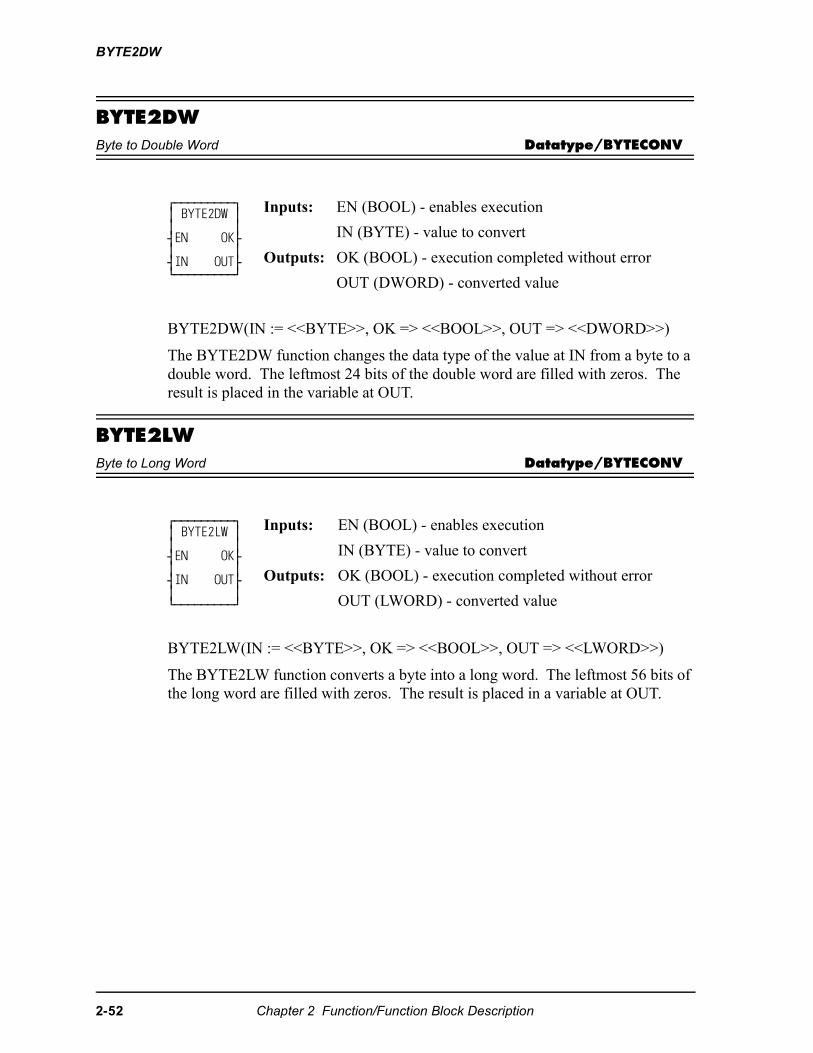
BYTE2DW
BYTE2DWByte to Double Word Datatype/BYTECONV
BYTE2DW(IN := <<BYTE>>, OK => <<BOOL>>, OUT => <<DWORD>>)
The BYTE2DW function changes the data type of the value at IN from a byte to a double word. The leftmost 24 bits of the double word are filled with zeros. The result is placed in the variable at OUT.
BYTE2LWByte to Long Word Datatype/BYTECONV
BYTE2LW(IN := <<BYTE>>, OK => <<BOOL>>, OUT => <<LWORD>>)
The BYTE2LW function converts a byte into a long word. The leftmost 56 bits of the long word are filled with zeros. The result is placed in a variable at OUT.
⁄ƒƒƒƒƒƒƒƒƒø ≥ BYTE2DW ≥ ≥ ≥ ¥EN OK√ ≥ ≥ ¥IN OUT√ ¿ƒƒƒƒƒƒƒƒƒŸ
Inputs: EN (BOOL) - enables execution
IN (BYTE) - value to convert
Outputs: OK (BOOL) - execution completed without error
OUT (DWORD) - converted value
⁄ƒƒƒƒƒƒƒƒƒø ≥ BYTE2LW ≥ ≥ ≥ ¥EN OK√ ≥ ≥ ¥IN OUT√ ≥ ≥ ¿ƒƒƒƒƒƒƒƒƒŸ
Inputs: EN (BOOL) - enables execution
IN (BYTE) - value to convert
Outputs: OK (BOOL) - execution completed without error
OUT (LWORD) - converted value
2-52 Chapter 2 Function/Function Block Description
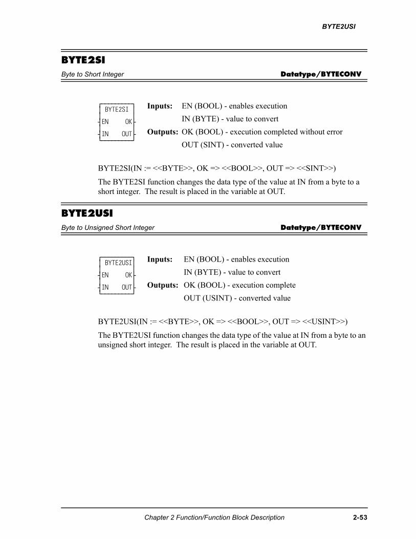
BYTE2USI
BYTE2SIByte to Short Integer Datatype/BYTECONV
BYTE2SI(IN := <<BYTE>>, OK => <<BOOL>>, OUT => <<SINT>>)
The BYTE2SI function changes the data type of the value at IN from a byte to a short integer. The result is placed in the variable at OUT.
BYTE2USIByte to Unsigned Short Integer Datatype/BYTECONV
BYTE2USI(IN := <<BYTE>>, OK => <<BOOL>>, OUT => <<USINT>>)
The BYTE2USI function changes the data type of the value at IN from a byte to an unsigned short integer. The result is placed in the variable at OUT.
⁄ƒƒƒƒƒƒƒƒƒø ≥ BYTE2SI ≥ ≥ ≥ ¥EN OK√ ≥ ≥ ¥IN OUT√ ¿ƒƒƒƒƒƒƒƒƒŸ
Inputs: EN (BOOL) - enables execution
IN (BYTE) - value to convert
Outputs: OK (BOOL) - execution completed without error
OUT (SINT) - converted value
⁄ƒƒƒƒƒƒƒƒƒø ≥ BYTE2USI≥ ≥ ≥ ¥EN OK√ ≥ ≥ ¥IN OUT√ ¿ƒƒƒƒƒƒƒƒƒŸ
Inputs: EN (BOOL) - enables execution
IN (BYTE) - value to convert
Outputs: OK (BOOL) - execution complete
OUT (USINT) - converted value
Chapter 2 Function/Function Block Description 2-53
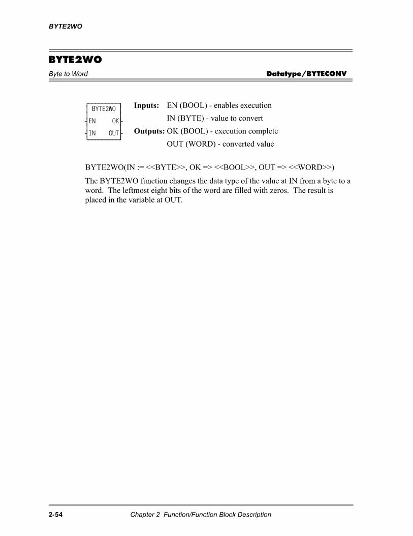
BYTE2WO
BYTE2WOByte to Word Datatype/BYTECONV
BYTE2WO(IN := <<BYTE>>, OK => <<BOOL>>, OUT => <<WORD>>)
The BYTE2WO function changes the data type of the value at IN from a byte to a word. The leftmost eight bits of the word are filled with zeros. The result is placed in the variable at OUT.
⁄ƒƒƒƒƒƒƒƒƒø ≥ BYTE2WO ≥ ≥ ≥ ¥EN OK√ ≥ ≥ ¥IN OUT√ ¿ƒƒƒƒƒƒƒƒƒŸ
Inputs: EN (BOOL) - enables execution
IN (BYTE) - value to convert
Outputs: OK (BOOL) - execution complete
OUT (WORD) - converted value
2-54 Chapter 2 Function/Function Block Description
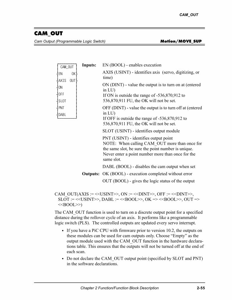
CAM_OUT
CAM_OUTCam Output (Programmable Logic Switch) Motion/MOVE_SUP
CAM_OUT(AXIS := <<USINT>>, ON := <<DINT>>, OFF := <<DINT>>, SLOT := <<USINT>>, DABL := <<BOOL>>, OK => <<BOOL>>, OUT => <<BOOL>>)
The CAM_OUT function is used to turn on a discrete output point for a specified distance during the rollover cycle of an axis. It performs like a programmable logic switch (PLS). The controlled outputs are updated every servo interrupt.
• If you have a PiC CPU with firmware prior to version 10.2, the outputs on these modules can be used for cam outputs only. Choose “Empty” as the output module used with the CAM_OUT function in the hardware declara-tions table. This ensures that the outputs will not be turned off at the end of each scan.
• Do not declare the CAM_OUT output point (specified by SLOT and PNT) in the software declarations.
⁄ƒƒƒƒƒƒƒƒƒø ≥ CAM_OUT ≥ ≥ ≥ ¥EN OK√ ≥ ≥ ¥AXIS OUT√ ≥ ≥ ¥ON ≥ ≥ ≥ ¥OFF ≥ ≥ ≥ ¥SLOT ≥ ≥ ≥ ¥PNT ≥ ≥ ≥ ¥DABL ≥ ¿ƒƒƒƒƒƒƒƒƒŸ
Inputs: EN (BOOL) - enables execution
AXIS (USINT) - identifies axis (servo, digitizing, or time)
ON (DINT) - value the output is to turn on at (entered in LU) If ON is outside the range of -536,870,912 to 536,870,911 FU, the OK will not be set.
OFF (DINT) - value the output is to turn off at (entered in LU) If OFF is outside the range of -536,870,912 to 536,870,911 FU, the OK will not be set.
SLOT (USINT) - identifies output module
PNT (USINT) - identifies output pointNOTE: When calling CAM_OUT more than once for the same slot, be sure the point number is unique. Never enter a point number more than once for the same slot.
DABL (BOOL) - disables the cam output when set
Outputs: OK (BOOL) - execution completed without error
OUT (BOOL) - gives the logic status of the output
Chapter 2 Function/Function Block Description 2-55
CAM_OUT
• Valid SLOT values are dependent on the type of control:
• If SLOT = 100, only servo or digitizing axes are allowed at AXIS.
• No more than two different SLOT values may be specified by multiple calls to CAM_OUT. Slot values 100 through 232 are considered one slot.
• Valid values for PNT are 1 through the number of outputs available on the module specified by SLOT.
• Rollover must be on for the axis identified in AXIS.
• The ON and OFF values must be less than the rollover value. ON must not equal OFF.
• The CAM_OUT function does not support controlling PiC expansion rack outputs, block outputs, DeviceNet outputs, or SERCOS drive outputs.
Control Valid SLOT valuesPiC900/PiC90 3 through 13, specifying the slot number in the main rack
(must be an output module, not an input/output module)MMC 2, specifying the CPU board
4 through 7, specifying an expansion moduleMMC-for-PC 1 through 8, specifying the ASIU numberMMCD 2, specifying the CPU board
100, specifying a digital drive output (AXIS indicates which digital drive)
101 through 232, specifying a digital drive output.101 indicates the digital drive of axis1.102 indicates the digital drive of axis 2. : :232 indicates the digital drive of axis 132.Only servo or digitizing axes can be specified.
MMCD64 /MMCD32
4 through 7, specifying an expansion module
100, specifying a digital drive output (AXIS indicates which digital drive)
101 through 232, specifying a digital drive output.101 indicates the digital drive of axis1.102 indicates the digital drive of axis 2. : :232 indicates the digital drive of axis 132.Only servo or digitizing axes can be specified.
All Controls 0 is a valid SLOT value for any control. SLOT = 0 indi-cates no physical output will be controlled; only the function output, OUT, will be controlled.
2-56 Chapter 2 Function/Function Block Description
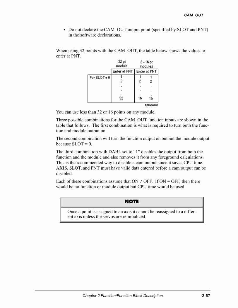
CAM_OUT
• Do not declare the CAM_OUT output point (specified by SLOT and PNT) in the software declarations.
When using 32 points with the CAM_OUT, the table below shows the values to enter at PNT.
You can use less than 32 or 16 points on any module.
Three possible combinations for the CAM_OUT function inputs are shown in the table that follows. The first combination is what is required to turn both the func-tion and module output on.
The second combination will turn the function output on but not the module output because SLOT = 0.
The third combination with DABL set to “1” disables the output from both the function and the module and also removes it from any foreground calculations. This is the recommended way to disable a cam output since it saves CPU time. AXIS, SLOT, and PNT must have valid data entered before a cam output can be disabled.
Each of these combinations assume that ON ≠ OFF. If ON = OFF, then there would be no function or module output but CPU time would be used.
NOTE
Once a point is assigned to an axis it cannot be reassigned to a differ-ent axis unless the servos are reinitialized.
Chapter 2 Function/Function Block Description 2-57
CAM_OUT
Table 2-2. Cam input combinations and results
An * means that any valid data may be entered at the designated input.
From 1 to 32 outputs (identified at PNT) can be turned on by calling the CAM_OUT function once for each output desired. The distance during which each output remains on can vary by changing the values in ON and OFF in each function.
If these Cam functioninputs are:
Then the function OUT, moduleoutput, and CPU time use are:
SLOT DABLFunction
OUTModule Output
UseCPU time
SLOT ≠ 0 DABL = 0 YES YES YESSLOT = 0 DABL = 0 YES NO YES
* DABL = 1 NO NO NO
2-58 Chapter 2 Function/Function Block Description
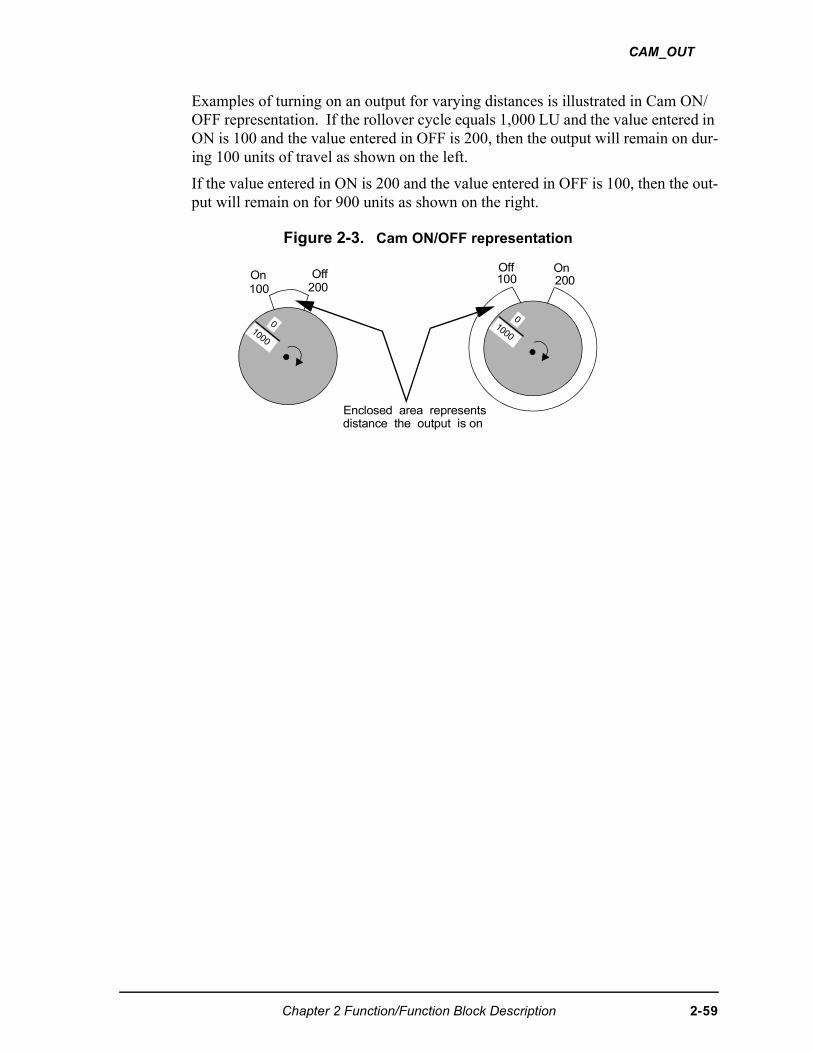
CAM_OUT
Examples of turning on an output for varying distances is illustrated in Cam ON/OFF representation. If the rollover cycle equals 1,000 LU and the value entered in ON is 100 and the value entered in OFF is 200, then the output will remain on dur-ing 100 units of travel as shown on the left.
If the value entered in ON is 200 and the value entered in OFF is 100, then the out-put will remain on for 900 units as shown on the right.
Figure 2-3. Cam ON/OFF representation
1000
0
Off100
On200
1000
0
Off200
On100
Enclosed area representsdistance the output is on
Chapter 2 Function/Function Block Description 2-59
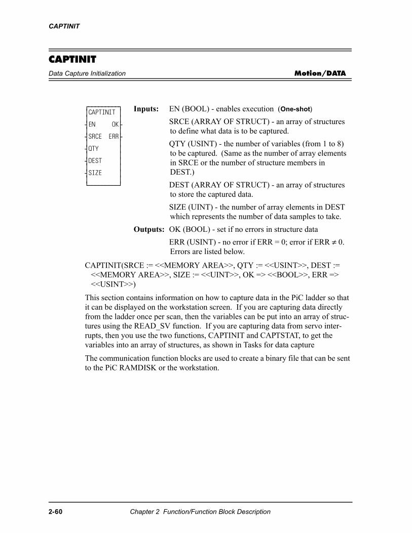
CAPTINIT
CAPTINITData Capture Initialization Motion/DATA
CAPTINIT(SRCE := <<MEMORY AREA>>, QTY := <<USINT>>, DEST := <<MEMORY AREA>>, SIZE := <<UINT>>, OK => <<BOOL>>, ERR => <<USINT>>)
This section contains information on how to capture data in the PiC ladder so that it can be displayed on the workstation screen. If you are capturing data directly from the ladder once per scan, then the variables can be put into an array of struc-tures using the READ_SV function. If you are capturing data from servo inter-rupts, then you use the two functions, CAPTINIT and CAPTSTAT, to get the variables into an array of structures, as shown in Tasks for data capture
The communication function blocks are used to create a binary file that can be sent to the PiC RAMDISK or the workstation.
⁄ƒƒƒƒƒƒƒƒƒø ≥CAPTINIT ≥ ≥ ≥ ¥EN OK√ ≥ ≥ ¥SRCE ERR√ ≥ ≥ ¥QTY ≥ ≥ ≥ ¥DEST ≥ ≥ ≥ ¥SIZE ≥ ≥ ≥ ¿ƒƒƒƒƒƒƒƒƒŸ
Inputs: EN (BOOL) - enables execution (One-shot)
SRCE (ARRAY OF STRUCT) - an array of structures to define what data is to be captured.
QTY (USINT) - the number of variables (from 1 to 8) to be captured. (Same as the number of array elements in SRCE or the number of structure members in DEST.)
DEST (ARRAY OF STRUCT) - an array of structures to store the captured data.
SIZE (UINT) - the number of array elements in DEST which represents the number of data samples to take.
Outputs: OK (BOOL) - set if no errors in structure data
ERR (USINT) - no error if ERR = 0; error if ERR ≠ 0. Errors are listed below.
2-60 Chapter 2 Function/Function Block Description
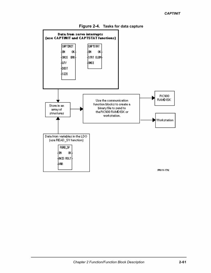
CAPTINIT
Figure 2-4. Tasks for data capture
Chapter 2 Function/Function Block Description 2-61
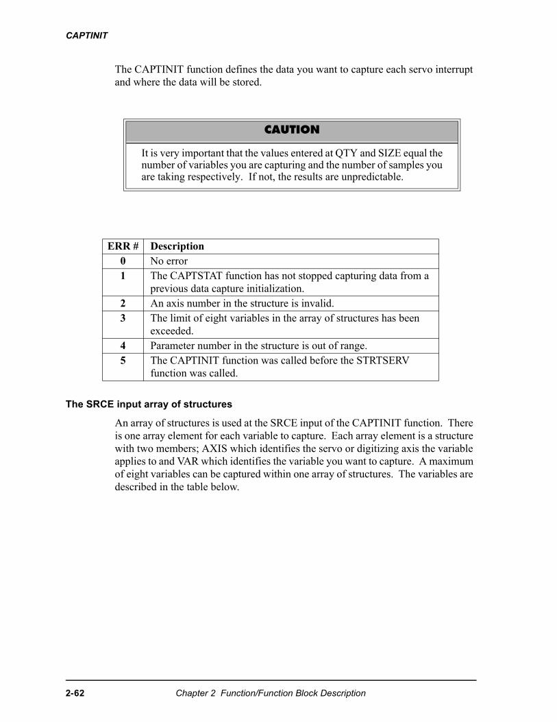
CAPTINIT
The CAPTINIT function defines the data you want to capture each servo interrupt and where the data will be stored.
The SRCE input array of structures
An array of structures is used at the SRCE input of the CAPTINIT function. There is one array element for each variable to capture. Each array element is a structure with two members; AXIS which identifies the servo or digitizing axis the variable applies to and VAR which identifies the variable you want to capture. A maximum of eight variables can be captured within one array of structures. The variables are described in the table below.
CAUTION
It is very important that the values entered at QTY and SIZE equal thenumber of variables you are capturing and the number of samples youare taking respectively. If not, the results are unpredictable.
ERR # Description0 No error1 The CAPTSTAT function has not stopped capturing data from a
previous data capture initialization.2 An axis number in the structure is invalid.3 The limit of eight variables in the array of structures has been
exceeded. 4 Parameter number in the structure is out of range.5 The CAPTINIT function was called before the STRTSERV
function was called.
2-62 Chapter 2 Function/Function Block Description
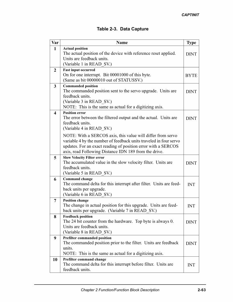
CAPTINIT
Table 2-3. Data Capture
Var Name Type1 Actual position
The actual position of the device with reference reset applied. Units are feedback units. (Variable 1 in READ_SV.)
DINT
2 Fast input occurredOn for one interrupt. Bit 00001000 of this byte. (Same as bit 00000010 out of STATUSSV.)
BYTE
3 Commanded positionThe commanded position sent to the servo upgrade. Units are feedback units. (Variable 3 in READ_SV.)NOTE: This is the same as actual for a digitizing axis.
DINT
4 Position errorThe error between the filtered output and the actual. Units are feedback units. (Variable 4 in READ_SV.)
NOTE: With a SERCOS axis, this value will differ from servo variable 4 by the number of feedback units traveled in four servo updates. For an exact reading of position error with a SERCOS axis, read Following Distance IDN 189 from the drive.
DINT
5 Slow Velocity Filter errorThe accumulated value in the slow velocity filter. Units are feedback units. (Variable 5 in READ_SV.)
DINT
6 Command changeThe command delta for this interrupt after filter. Units are feed-back units per upgrade. (Variable 6 in READ_SV.)
INT
7 Position changeThe change in actual position for this upgrade. Units are feed-back units per upgrade. (Variable 7 in READ_SV.)
INT
8 Feedback positionThe 24 bit counter from the hardware. Top byte is always 0. Units are feedback units. (Variable 8 in READ_SV.)
DINT
9 Prefilter commanded position The commanded position prior to the filter. Units are feedback units. NOTE: This is the same as actual for a digitizing axis.
DINT
10 Prefilter command changeThe command delta for this interrupt before filter. Units are feedback units.
INT
Chapter 2 Function/Function Block Description 2-63
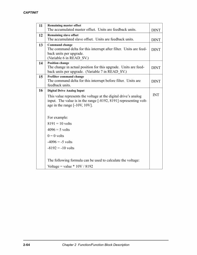
CAPTINIT
11 Remaining master offsetThe accumulated master offset. Units are feedback units. DINT
12 Remaining slave offsetThe accumulated slave offset. Units are feedback units. DINT
13 Command changeThe command delta for this interrupt after filter. Units are feed-back units per upgrade. (Variable 6 in READ_SV.)
DINT
14 Position changeThe change in actual position for this upgrade. Units are feed-back units per upgrade. (Variable 7 in READ_SV.)
DINT
15 Prefilter command changeThe command delta for this interrupt before filter. Units are feedback units.
DINT
16 Digital Drive Analog Input
This value represents the voltage at the digital drive’s analog input. The value is in the range [-8192, 8191] representing volt-age in the range [-10V, 10V].
For example:
8191 = 10 volts
4096 = 5 volts
0 = 0 volts
-4096 = -5 volts
-8192 = -10 volts
The following formula can be used to calculate the voltage:
Voltage = value * 10V / 8192
INT
2-64 Chapter 2 Function/Function Block Description
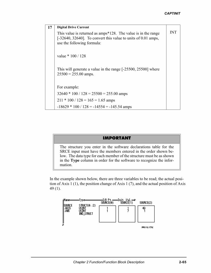
CAPTINIT
In the example shown below, there are three variables to be read; the actual posi-tion of Axis 1 (1), the position change of Axis 1 (7), and the actual position of Axis 49 (1).
17 Digital Drive Current
This value is returned as amps*128. The value is in the range [-32640, 32640]. To convert this value to units of 0.01 amps, use the following formula:
value * 100 / 128
This will generate a value in the range [-25500, 25500] where 25500 = 255.00 amps.
For example:
32640 * 100 / 128 = 25500 = 255.00 amps
211 * 100 / 128 = 165 = 1.65 amps
-18629 * 100 / 128 = -14554 = -145.54 amps
INT
IMPORTANT
The structure you enter in the software declarations table for theSRCE input must have the members entered in the order shown be-low. The data type for each member of the structure must be as shownin the Type column in order for the software to recognize the infor-mation.
Chapter 2 Function/Function Block Description 2-65
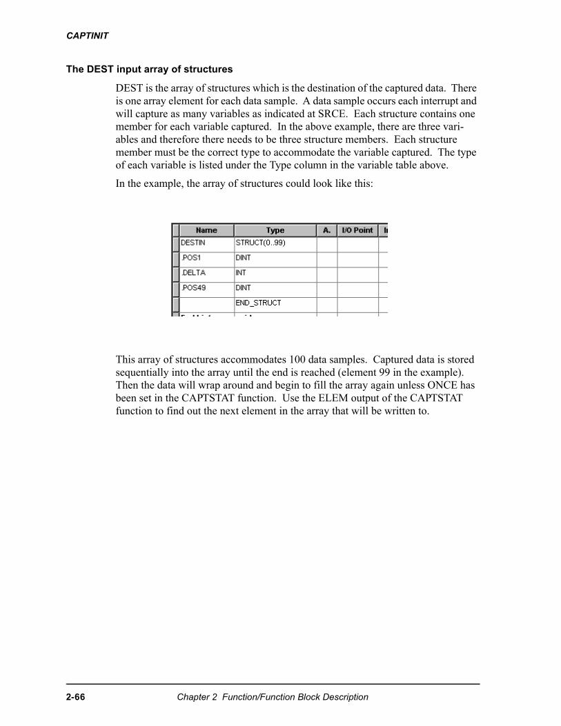
CAPTINIT
The DEST input array of structures
DEST is the array of structures which is the destination of the captured data. There is one array element for each data sample. A data sample occurs each interrupt and will capture as many variables as indicated at SRCE. Each structure contains one member for each variable captured. In the above example, there are three vari-ables and therefore there needs to be three structure members. Each structure member must be the correct type to accommodate the variable captured. The type of each variable is listed under the Type column in the variable table above.
In the example, the array of structures could look like this:
This array of structures accommodates 100 data samples. Captured data is stored sequentially into the array until the end is reached (element 99 in the example). Then the data will wrap around and begin to fill the array again unless ONCE has been set in the CAPTSTAT function. Use the ELEM output of the CAPTSTAT function to find out the next element in the array that will be written to.
2-66 Chapter 2 Function/Function Block Description
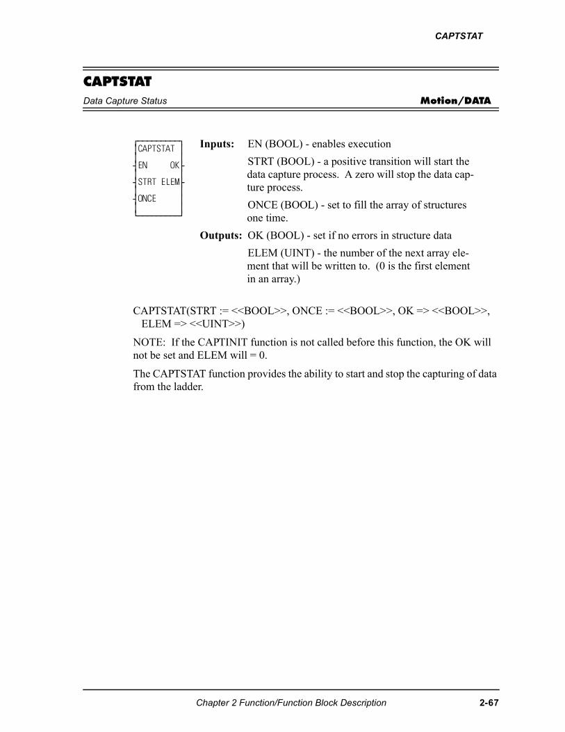
CAPTSTAT
CAPTSTATData Capture Status Motion/DATA
CAPTSTAT(STRT := <<BOOL>>, ONCE := <<BOOL>>, OK => <<BOOL>>, ELEM => <<UINT>>)
NOTE: If the CAPTINIT function is not called before this function, the OK will not be set and ELEM will = 0.
The CAPTSTAT function provides the ability to start and stop the capturing of data from the ladder.
⁄ƒƒƒƒƒƒƒƒƒø ≥CAPTSTAT ≥ ≥ ≥ ¥EN OK√ ≥ ≥ ¥STRT ELEM√ ≥ ≥ ¥ONCE ≥ ≥ ≥ ¿ƒƒƒƒƒƒƒƒƒŸ
Inputs: EN (BOOL) - enables execution
STRT (BOOL) - a positive transition will start the data capture process. A zero will stop the data cap-ture process.
ONCE (BOOL) - set to fill the array of structures one time.
Outputs: OK (BOOL) - set if no errors in structure data
ELEM (UINT) - the number of the next array ele-ment that will be written to. (0 is the first element in an array.)
Chapter 2 Function/Function Block Description 2-67
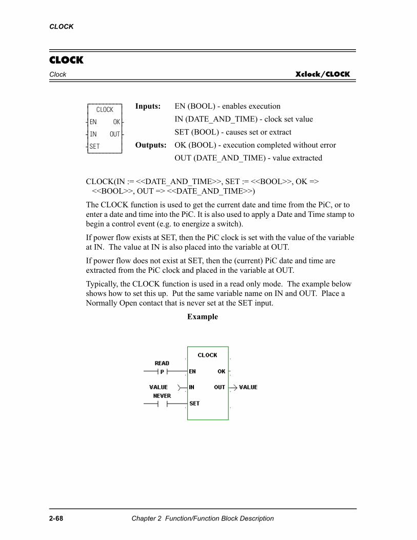
CLOCK
CLOCKClock Xclock/CLOCK
CLOCK(IN := <<DATE_AND_TIME>>, SET := <<BOOL>>, OK => <<BOOL>>, OUT => <<DATE_AND_TIME>>)
The CLOCK function is used to get the current date and time from the PiC, or to enter a date and time into the PiC. It is also used to apply a Date and Time stamp to begin a control event (e.g. to energize a switch).
If power flow exists at SET, then the PiC clock is set with the value of the variable at IN. The value at IN is also placed into the variable at OUT.
If power flow does not exist at SET, then the (current) PiC date and time are extracted from the PiC clock and placed in the variable at OUT.
Typically, the CLOCK function is used in a read only mode. The example below shows how to set this up. Put the same variable name on IN and OUT. Place a Normally Open contact that is never set at the SET input.
Example
⁄ƒƒƒƒƒƒƒƒƒø ≥ CLOCK ≥ ≥ ≥ ¥EN OK√ ≥ ≥ ¥IN OUT√ ≥ ≥ ¥SET ≥ ¿ƒƒƒƒƒƒƒƒƒŸ
Inputs: EN (BOOL) - enables execution
IN (DATE_AND_TIME) - clock set value
SET (BOOL) - causes set or extract
Outputs: OK (BOOL) - execution completed without error
OUT (DATE_AND_TIME) - value extracted
2-68 Chapter 2 Function/Function Block Description
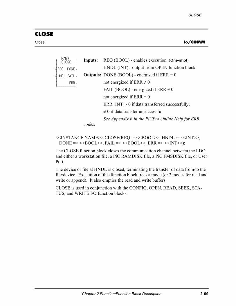
CLOSE
CLOSEClose Io/COMM
<<INSTANCE NAME>>:CLOSE(REQ := <<BOOL>>, HNDL := <<INT>>, DONE => <<BOOL>>, FAIL => <<BOOL>>, ERR => <<INT>>);
The CLOSE function block closes the communication channel between the LDO and either a workstation file, a PiC RAMDISK file, a PiC FMSDISK file, or User Port.
The device or file at HNDL is closed, terminating the transfer of data from/to the file/device. Execution of this function block frees a mode (or 2 modes for read and write or append). It also empties the read and write buffers.
CLOSE is used in conjunction with the CONFIG, OPEN, READ, SEEK, STA-TUS, and WRITE I/O function blocks.
⁄ƒƒNAME ƒƒø ≥ CLOSE ≥ ≥ ≥ ¥REQ DONE√ ≥ ≥ ¥HNDL FAIL√ ≥ ≥ ≥ ERR√ ¿ƒƒƒƒƒƒƒƒƒŸ
Inputs: REQ (BOOL) - enables execution (One-shot)
HNDL (INT) - output from OPEN function block
Outputs: DONE (BOOL) - energized if ERR = 0
not energized if ERR ≠ 0
FAIL (BOOL) - energized if ERR ≠ 0
not energized if ERR = 0
ERR (INT) - 0 if data transferred successfully;
≠ 0 if data transfer unsuccessful
See Appendix B in the PiCPro Online Help for ERR codes.
Chapter 2 Function/Function Block Description 2-69
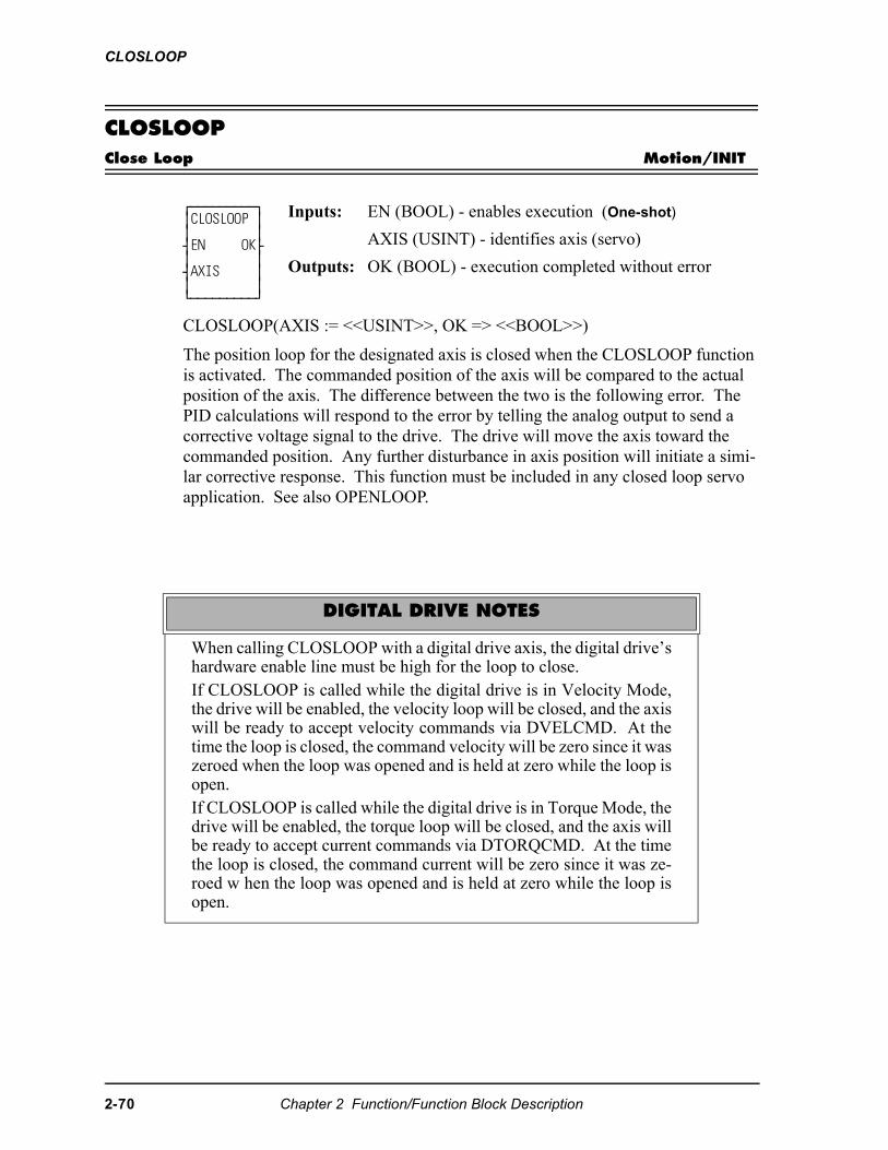
CLOSLOOP
CLOSLOOPClose Loop Motion/INIT
CLOSLOOP(AXIS := <<USINT>>, OK => <<BOOL>>)
The position loop for the designated axis is closed when the CLOSLOOP function is activated. The commanded position of the axis will be compared to the actual position of the axis. The difference between the two is the following error. The PID calculations will respond to the error by telling the analog output to send a corrective voltage signal to the drive. The drive will move the axis toward the commanded position. Any further disturbance in axis position will initiate a simi-lar corrective response. This function must be included in any closed loop servo application. See also OPENLOOP.
⁄ƒƒƒƒƒƒƒƒƒø ≥CLOSLOOP ≥ ≥ ≥ ¥EN OK√ ≥ ≥ ¥AXIS ≥ ≥ ≥ ¿ƒƒƒƒƒƒƒƒƒŸ
Inputs: EN (BOOL) - enables execution (One-shot)
AXIS (USINT) - identifies axis (servo)
Outputs: OK (BOOL) - execution completed without error
DIGITAL DRIVE NOTES
When calling CLOSLOOP with a digital drive axis, the digital drive’shardware enable line must be high for the loop to close.If CLOSLOOP is called while the digital drive is in Velocity Mode,the drive will be enabled, the velocity loop will be closed, and the axiswill be ready to accept velocity commands via DVELCMD. At thetime the loop is closed, the command velocity will be zero since it waszeroed when the loop was opened and is held at zero while the loop isopen.If CLOSLOOP is called while the digital drive is in Torque Mode, thedrive will be enabled, the torque loop will be closed, and the axis willbe ready to accept current commands via DTORQCMD. At the timethe loop is closed, the command current will be zero since it was ze-roed w hen the loop was opened and is held at zero while the loop isopen.
2-70 Chapter 2 Function/Function Block Description
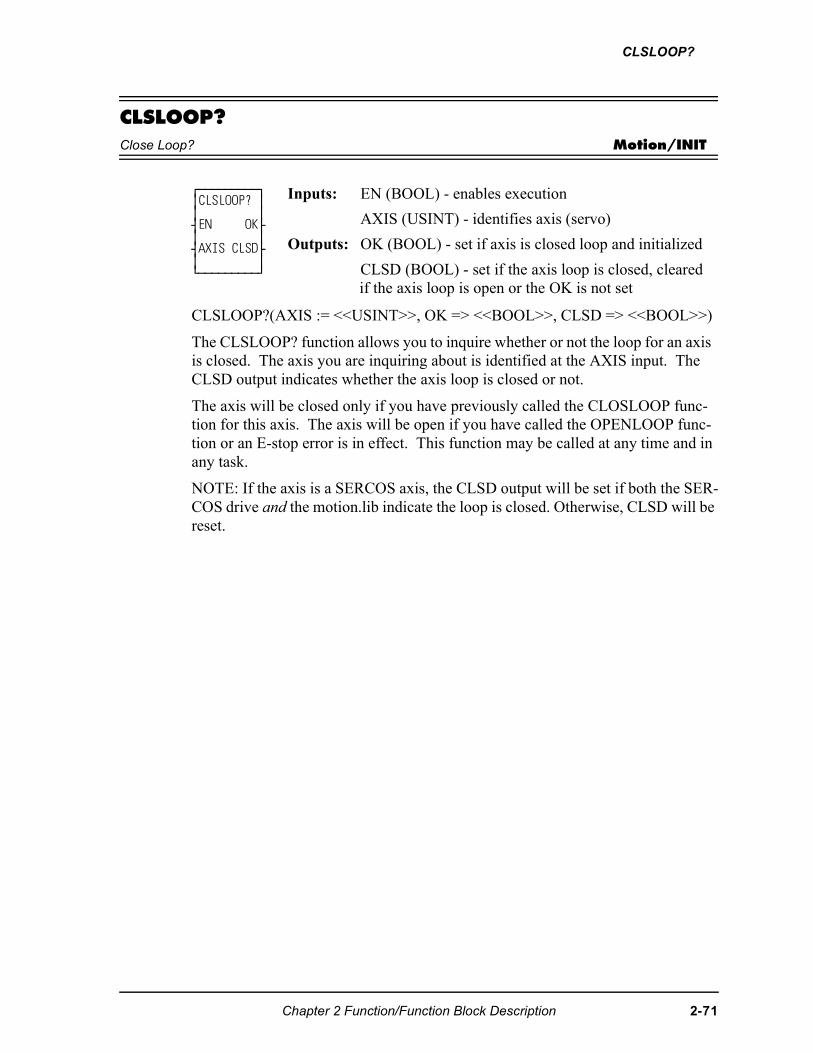
CLSLOOP?
CLSLOOP?Close Loop? Motion/INIT
CLSLOOP?(AXIS := <<USINT>>, OK => <<BOOL>>, CLSD => <<BOOL>>)
The CLSLOOP? function allows you to inquire whether or not the loop for an axis is closed. The axis you are inquiring about is identified at the AXIS input. The CLSD output indicates whether the axis loop is closed or not.
The axis will be closed only if you have previously called the CLOSLOOP func-tion for this axis. The axis will be open if you have called the OPENLOOP func-tion or an E-stop error is in effect. This function may be called at any time and in any task.
NOTE: If the axis is a SERCOS axis, the CLSD output will be set if both the SER-COS drive and the motion.lib indicate the loop is closed. Otherwise, CLSD will be reset.
⁄ƒƒƒƒƒƒƒƒƒø ≥CLSLOOP? ≥ ≥ ≥ ¥EN OK√ ≥ ≥ ¥AXIS CLSD√ ≥ ≥ ¿ƒƒƒƒƒƒƒƒƒŸ
Inputs: EN (BOOL) - enables execution
AXIS (USINT) - identifies axis (servo)
Outputs: OK (BOOL) - set if axis is closed loop and initialized
CLSD (BOOL) - set if the axis loop is closed, cleared if the axis loop is open or the OK is not set
Chapter 2 Function/Function Block Description 2-71
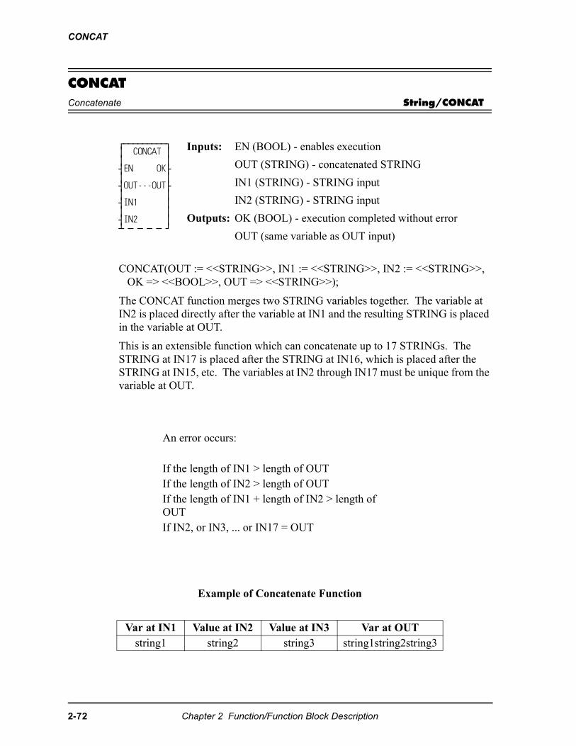
CONCAT
CONCATConcatenate String/CONCAT
CONCAT(OUT := <<STRING>>, IN1 := <<STRING>>, IN2 := <<STRING>>, OK => <<BOOL>>, OUT => <<STRING>>);
The CONCAT function merges two STRING variables together. The variable at IN2 is placed directly after the variable at IN1 and the resulting STRING is placed in the variable at OUT.
This is an extensible function which can concatenate up to 17 STRINGs. The STRING at IN17 is placed after the STRING at IN16, which is placed after the STRING at IN15, etc. The variables at IN2 through IN17 must be unique from the variable at OUT.
⁄ƒƒƒƒƒƒƒƒƒø ≥ CONCAT ≥ ≥ ≥ ¥EN OK√ ≥ ≥ ¥OUT---OUT√ ≥ ≥ ¥IN1 ≥ ≥ ≥ ¥IN2 ≥ ¡ ƒ ƒ ƒ ƒ Ÿ
Inputs: EN (BOOL) - enables execution
OUT (STRING) - concatenated STRING
IN1 (STRING) - STRING input
IN2 (STRING) - STRING input
Outputs: OK (BOOL) - execution completed without error
OUT (same variable as OUT input)
An error occurs:
If the length of IN1 > length of OUT If the length of IN2 > length of OUTIf the length of IN1 + length of IN2 > length of OUTIf IN2, or IN3, ... or IN17 = OUT
Example of Concatenate Function
Var at IN1 Value at IN2 Value at IN3 Var at OUTstring1 string2 string3 string1string2string3
2-72 Chapter 2 Function/Function Block Description
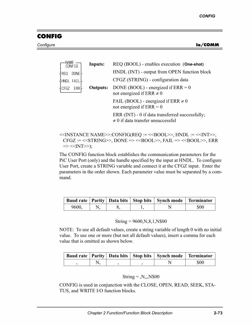
CONFIG
CONFIGConfigure Io/COMM
<<INSTANCE NAME>>:CONFIG(REQ := <<BOOL>>, HNDL := <<INT>>, CFGZ := <<STRING>>, DONE => <<BOOL>>, FAIL => <<BOOL>>, ERR => <<INT>>);
The CONFIG function block establishes the communication parameters for the PiC User Port (only) and the handle specified by the input at HNDL. To configure User Port, create a STRING variable and connect it at the CFGZ input. Enter the parameters in the order shown. Each parameter value must be separated by a com-mand.
String = 9600,N,8,1,N$00
NOTE: To use all default values, create a string variable of length 0 with no initial value. To use one or more (but not all default values), insert a comma for each value that is omitted as shown below.
String = ,N,,,N$00
CONFIG is used in conjunction with the CLOSE, OPEN, READ, SEEK, STA-TUS, and WRITE I/O function blocks.
⁄ƒƒNAME ƒƒø ≥ CONFIG ≥ ≥ ≥ ¥REQ DONE√ ≥ ≥ ¥HNDL FAIL√ ≥ ≥ ¥CFGZ ERR√ ¿ƒƒƒƒƒƒƒƒƒŸ
Inputs: REQ (BOOL) - enables execution (One-shot)
HNDL (INT) - output from OPEN function block
CFGZ (STRING) - configuration data
Outputs: DONE (BOOL) - energized if ERR = 0not energized if ERR ≠ 0
FAIL (BOOL) - energized if ERR ≠ 0not energized if ERR = 0
ERR (INT) - 0 if data transferred successfully;≠ 0 if data transfer unsuccessful
Baud rate Parity Data bits Stop bits Synch mode Terminator9600, N, 8, 1, N $00
Baud rate Parity Data bits Stop bits Synch mode Terminator, N, , , N $00
Chapter 2 Function/Function Block Description 2-73
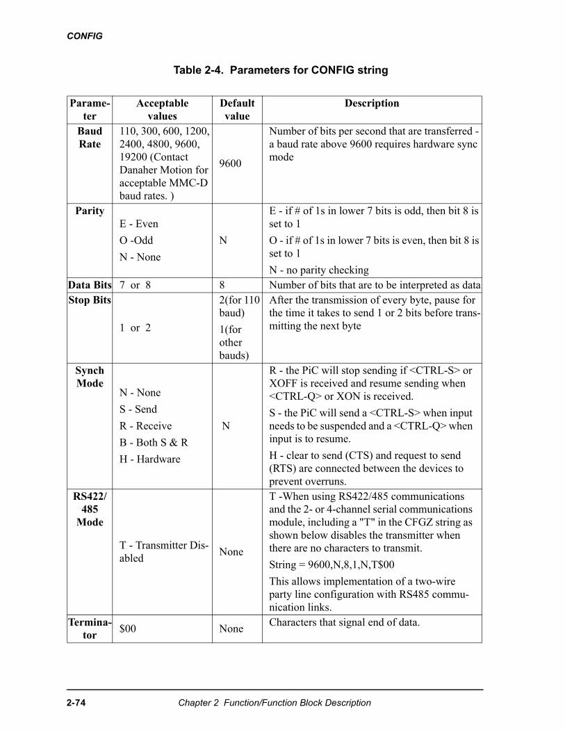
CONFIG
Table 2-4. Parameters for CONFIG string
Parame-ter
Acceptablevalues
Default value
Description
Baud Rate
110, 300, 600, 1200, 2400, 4800, 9600, 19200 (Contact Danaher Motion foracceptable MMC-D baud rates. )
9600
Number of bits per second that are transferred - a baud rate above 9600 requires hardware sync mode
ParityE - Even
O -Odd
N - None
N
E - if # of 1s in lower 7 bits is odd, then bit 8 is set to 1
O - if # of 1s in lower 7 bits is even, then bit 8 is set to 1
N - no parity checkingData Bits 7 or 8 8 Number of bits that are to be interpreted as dataStop Bits
1 or 2
2(for 110 baud)
1(for other bauds)
After the transmission of every byte, pause for the time it takes to send 1 or 2 bits before trans-mitting the next byte
Synch Mode
N - None
S - Send
R - Receive
B - Both S & R
H - Hardware
N
R - the PiC will stop sending if <CTRL-S> or XOFF is received and resume sending when <CTRL-Q> or XON is received.
S - the PiC will send a <CTRL-S> when input needs to be suspended and a <CTRL-Q> when input is to resume.
H - clear to send (CTS) and request to send (RTS) are connected between the devices to prevent overruns.
RS422/485
Mode
T - Transmitter Dis-abled
None
T -When using RS422/485 communications and the 2- or 4-channel serial communications module, including a "T" in the CFGZ string as shown below disables the transmitter when there are no characters to transmit.
String = 9600,N,8,1,N,T$00
This allows implementation of a two-wire party line configuration with RS485 commu-nication links.
Termina-tor
$00 NoneCharacters that signal end of data.
2-74 Chapter 2 Function/Function Block Description
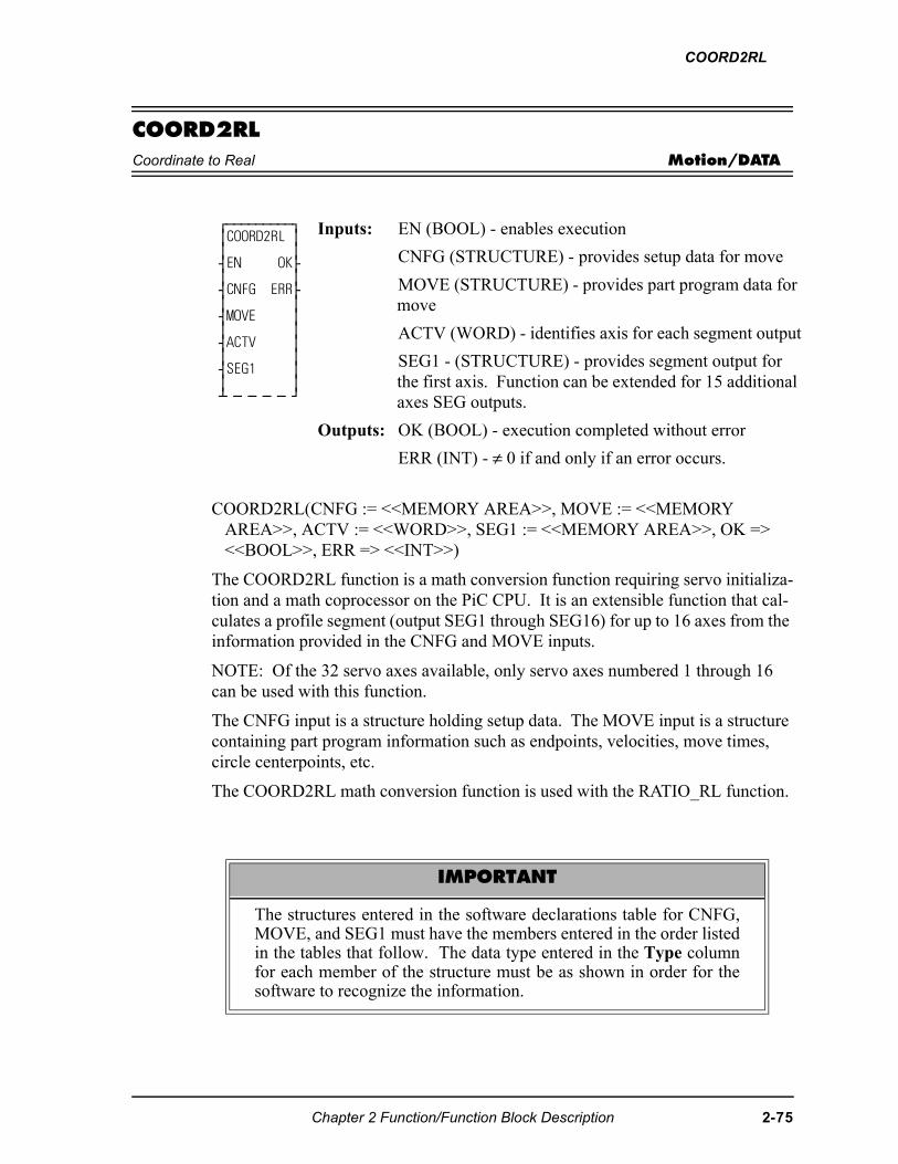
COORD2RL
COORD2RLCoordinate to Real Motion/DATA
COORD2RL(CNFG := <<MEMORY AREA>>, MOVE := <<MEMORY AREA>>, ACTV := <<WORD>>, SEG1 := <<MEMORY AREA>>, OK => <<BOOL>>, ERR => <<INT>>)
The COORD2RL function is a math conversion function requiring servo initializa-tion and a math coprocessor on the PiC CPU. It is an extensible function that cal-culates a profile segment (output SEG1 through SEG16) for up to 16 axes from the information provided in the CNFG and MOVE inputs.
NOTE: Of the 32 servo axes available, only servo axes numbered 1 through 16 can be used with this function.
The CNFG input is a structure holding setup data. The MOVE input is a structure containing part program information such as endpoints, velocities, move times, circle centerpoints, etc.
The COORD2RL math conversion function is used with the RATIO_RL function.
⁄ƒƒƒƒƒƒƒƒƒø ≥COORD2RL ≥ ≥ ≥ ¥EN OK√ ≥ ≥ ¥CNFG ERR√ ≥ ≥ ¥MOVE ≥ ≥ ≥ ¥ACTV ≥ ≥ ≥ ¥SEG1 ≥ ≥ ≥ ¡ ƒ ƒ ƒ ƒ Ÿ
Inputs: EN (BOOL) - enables execution
CNFG (STRUCTURE) - provides setup data for move
MOVE (STRUCTURE) - provides part program data for move
ACTV (WORD) - identifies axis for each segment output
SEG1 - (STRUCTURE) - provides segment output for the first axis. Function can be extended for 15 additional axes SEG outputs.
Outputs: OK (BOOL) - execution completed without error
ERR (INT) - ≠ 0 if and only if an error occurs.
IMPORTANT
The structures entered in the software declarations table for CNFG,MOVE, and SEG1 must have the members entered in the order listedin the tables that follow. The data type entered in the Type columnfor each member of the structure must be as shown in order for thesoftware to recognize the information.
Chapter 2 Function/Function Block Description 2-75
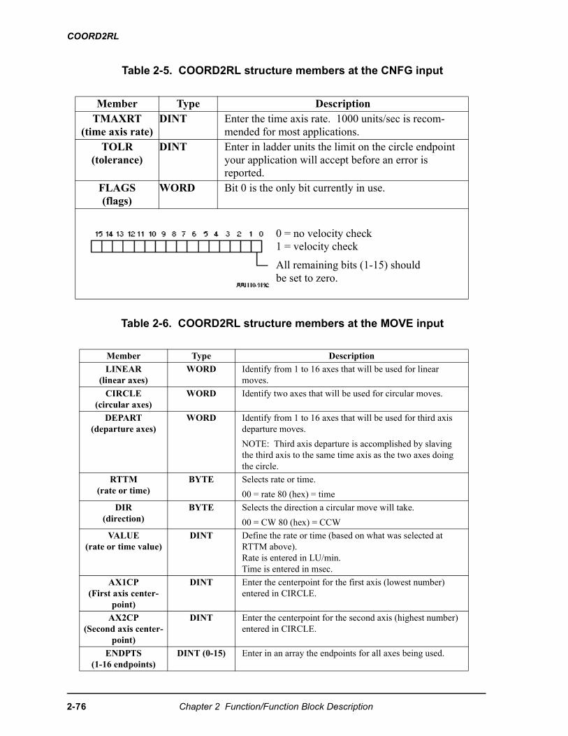
COORD2RL
Table 2-5. COORD2RL structure members at the CNFG input
Table 2-6. COORD2RL structure members at the MOVE input
Member Type DescriptionTMAXRT
(time axis rate)DINT Enter the time axis rate. 1000 units/sec is recom-
mended for most applications.TOLR
(tolerance)DINT Enter in ladder units the limit on the circle endpoint
your application will accept before an error is reported.
FLAGS(flags)
WORD Bit 0 is the only bit currently in use.
Member Type Description
LINEAR(linear axes)
WORD Identify from 1 to 16 axes that will be used for linear moves.
CIRCLE(circular axes)
WORD Identify two axes that will be used for circular moves.
DEPART(departure axes)
WORD Identify from 1 to 16 axes that will be used for third axis departure moves.
NOTE: Third axis departure is accomplished by slaving the third axis to the same time axis as the two axes doing the circle.
RTTM(rate or time)
BYTE Selects rate or time.
00 = rate 80 (hex) = time
DIR(direction)
BYTE Selects the direction a circular move will take.
00 = CW 80 (hex) = CCW
VALUE(rate or time value)
DINT Define the rate or time (based on what was selected at RTTM above). Rate is entered in LU/min.Time is entered in msec.
AX1CP(First axis center-
point)
DINT Enter the centerpoint for the first axis (lowest number) entered in CIRCLE.
AX2CP(Second axis center-
point)
DINT Enter the centerpoint for the second axis (highest number) entered in CIRCLE.
ENDPTS(1-16 endpoints)
DINT (0-15) Enter in an array the endpoints for all axes being used.
0 = no velocity check1 = velocity check
All remaining bits (1-15) should be set to zero.
2-76 Chapter 2 Function/Function Block Description
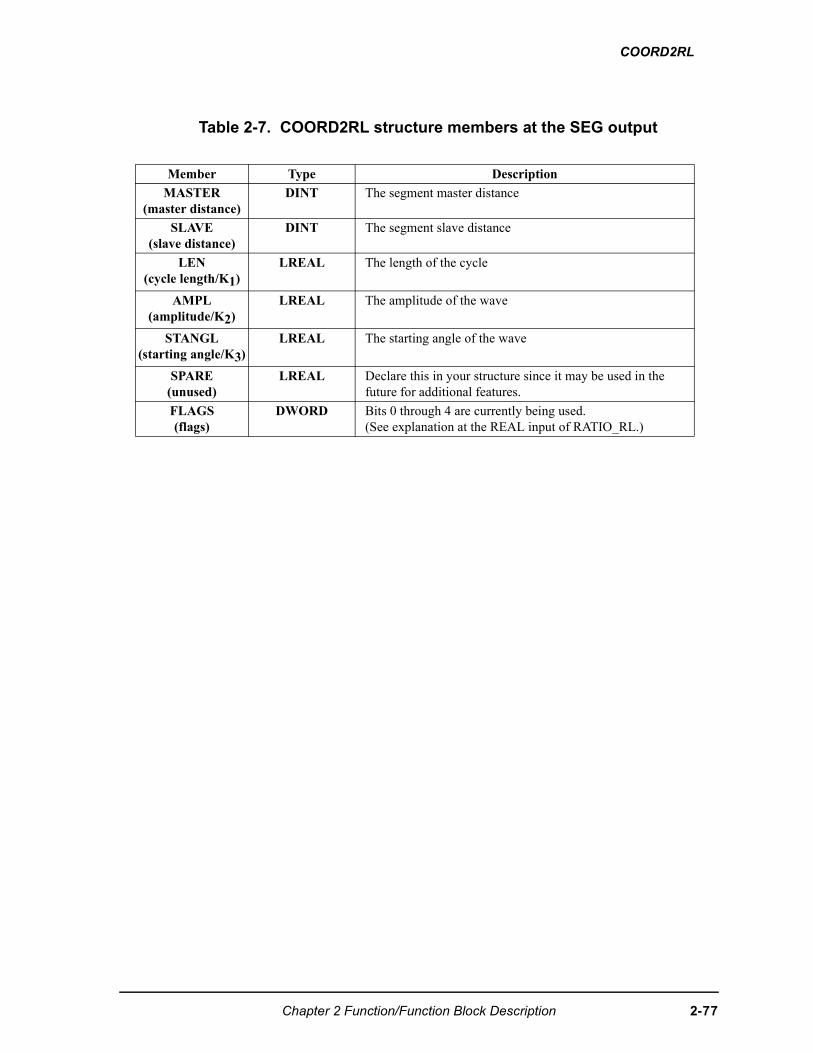
COORD2RL
Table 2-7. COORD2RL structure members at the SEG output
Member Type Description
MASTER (master distance)
DINT The segment master distance
SLAVE(slave distance)
DINT The segment slave distance
LEN(cycle length/K1)
LREAL The length of the cycle
AMPL(amplitude/K2)
LREAL The amplitude of the wave
STANGL(starting angle/K3)
LREAL The starting angle of the wave
SPARE(unused)
LREAL Declare this in your structure since it may be used in the future for additional features.
FLAGS(flags)
DWORD Bits 0 through 4 are currently being used. (See explanation at the REAL input of RATIO_RL.)
Chapter 2 Function/Function Block Description 2-77
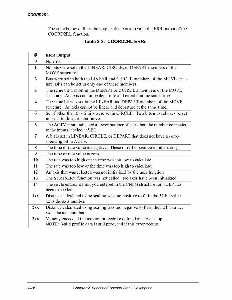
COORD2RL
The table below defines the outputs that can appear at the ERR output of the COORD2RL function.
Table 2-8. COORD2RL ERRs
# ERR Output0 No error1 No bits were set in the LINEAR, CIRCLE, or DEPART members of the
MOVE structure. 2 Bits were set in both the LINEAR and CIRCLE members of the MOVE struc-
ture. Bits can be set in only one of these members.3 The same bit was set in the DEPART and CIRCLE members of the MOVE
structure. An axis cannot be departure and circular at the same time. 4 The same bit was set in the LINEAR and DEPART members of the MOVE
structure. An axis cannot be linear and departure at the same time. 5 Set if other than 0 or 2 bits were set in CIRCLE. Two bits must always be set
in order to do a circular move. 6 The ACTV input indicated a fewer number of axes than the number connected
to the inputs labeled at SEG. 7 A bit is set in LINEAR, CIRCLE, or DEPART that does not have a corre-
sponding bit in ACTV. 8 The time or rate value is negative. These must be positive numbers only. 9 The time or rate value is zero. 10 The rate was too high or the time was too low to calculate.11 The rate was too low or the time was too high to calculate.12 An axis that was selected was not initialized by the user function. 13 The STRTSERV function was not called. No axes have been initialized. 14 The circle endpoint limit you entered in the CNFG structure for TOLR has
been exceeded. 1xx Distance calculated using scaling was too positive to fit in the 32 bit value.
xx is the axis number.2xx Distance calculated using scaling was too negative to fit in the 32 bit value.
xx is the axis number.3xx Velocity exceeded the maximum feedrate defined in servo setup.
NOTE: Valid profile data is still produced if this error occurs.
2-78 Chapter 2 Function/Function Block Description
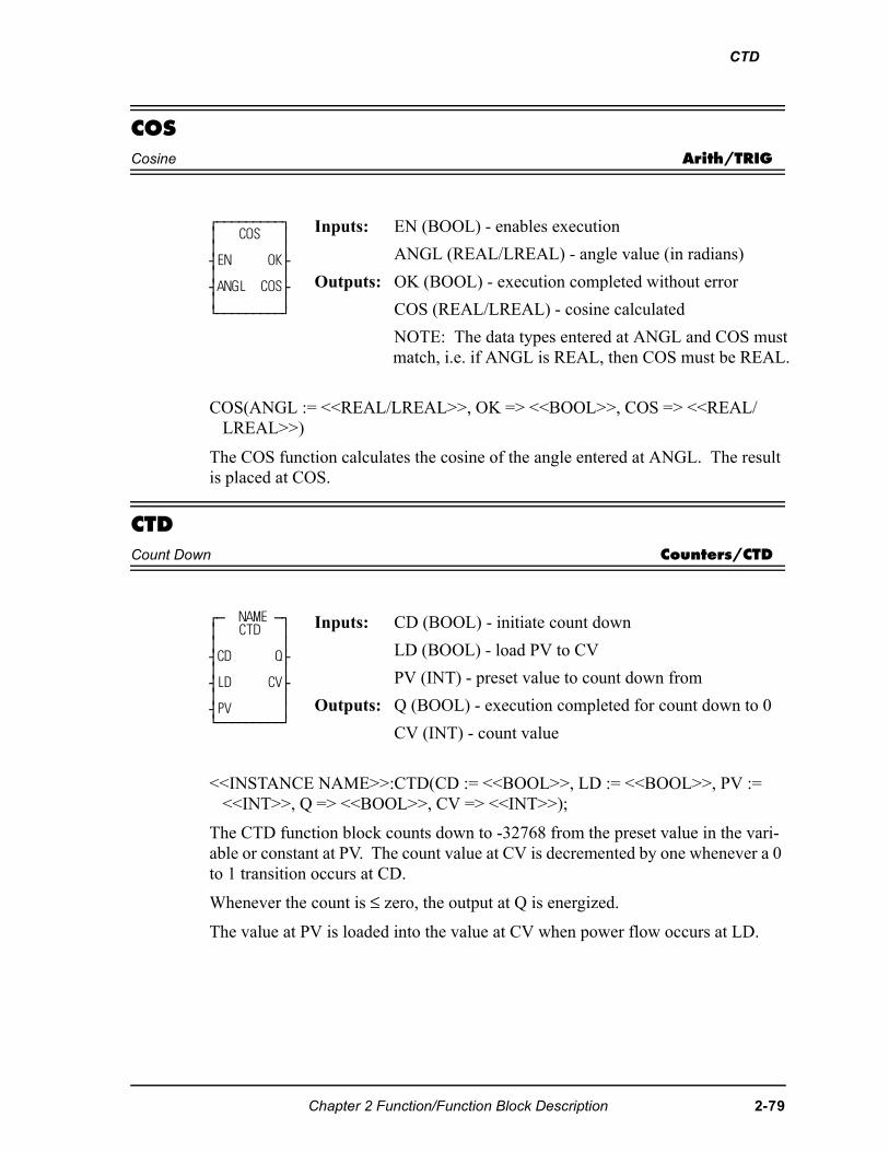
CTD
COSCosine Arith/TRIG
COS(ANGL := <<REAL/LREAL>>, OK => <<BOOL>>, COS => <<REAL/LREAL>>)
The COS function calculates the cosine of the angle entered at ANGL. The result is placed at COS.
CTDCount Down Counters/CTD
<<INSTANCE NAME>>:CTD(CD := <<BOOL>>, LD := <<BOOL>>, PV := <<INT>>, Q => <<BOOL>>, CV => <<INT>>);
The CTD function block counts down to -32768 from the preset value in the vari-able or constant at PV. The count value at CV is decremented by one whenever a 0 to 1 transition occurs at CD.
Whenever the count is ≤ zero, the output at Q is energized.
The value at PV is loaded into the value at CV when power flow occurs at LD.
⁄ƒƒƒƒƒƒƒƒƒø ≥ COS ≥ ≥ ≥ ¥EN OK√ ≥ ≥ ¥ANGL COS√ ≥ ≥ ¿ƒƒƒƒƒƒƒƒƒŸ
Inputs: EN (BOOL) - enables execution
ANGL (REAL/LREAL) - angle value (in radians)
Outputs: OK (BOOL) - execution completed without error
COS (REAL/LREAL) - cosine calculated
NOTE: The data types entered at ANGL and COS must match, i.e. if ANGL is REAL, then COS must be REAL.
⁄ƒ NAME ƒø ≥ CTD ≥ ≥ ≥ ¥CD Q√ ≥ ≥ ¥LD CV√ ≥ ≥ ¥PV ≥ ¿ƒƒƒƒƒƒƒƒƒŸ
Inputs: CD (BOOL) - initiate count down
LD (BOOL) - load PV to CV
PV (INT) - preset value to count down from
Outputs: Q (BOOL) - execution completed for count down to 0
CV (INT) - count value
Chapter 2 Function/Function Block Description 2-79
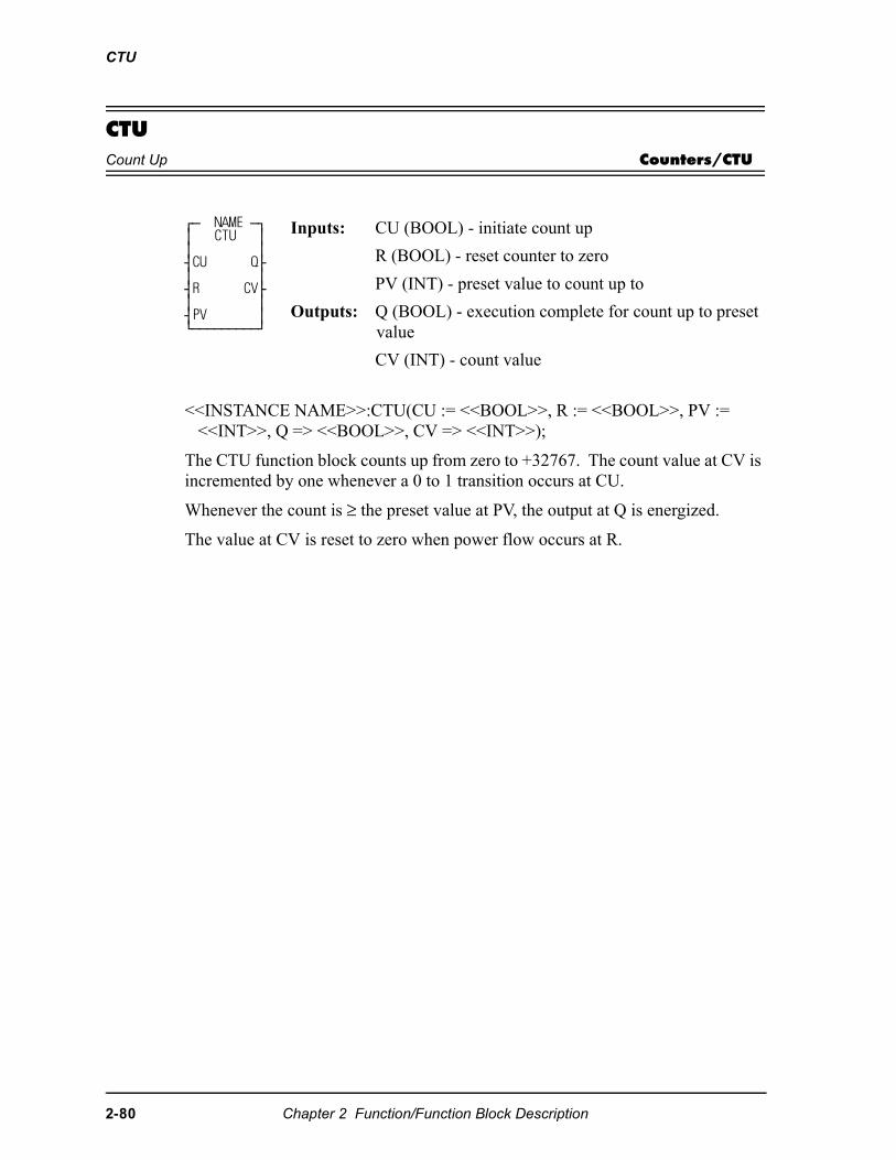
CTU
CTUCount Up Counters/CTU
<<INSTANCE NAME>>:CTU(CU := <<BOOL>>, R := <<BOOL>>, PV := <<INT>>, Q => <<BOOL>>, CV => <<INT>>);
The CTU function block counts up from zero to +32767. The count value at CV is incremented by one whenever a 0 to 1 transition occurs at CU.
Whenever the count is ≥ the preset value at PV, the output at Q is energized.
The value at CV is reset to zero when power flow occurs at R.
⁄ƒ NAME ƒø ≥ CTU ≥ ≥ ≥ ¥CU Q√ ≥ ≥ ¥R CV√ ≥ ≥ ¥PV ≥ ¿ƒƒƒƒƒƒƒƒƒŸ
Inputs: CU (BOOL) - initiate count up
R (BOOL) - reset counter to zero
PV (INT) - preset value to count up to
Outputs: Q (BOOL) - execution complete for count up to preset value
CV (INT) - count value
2-80 Chapter 2 Function/Function Block Description
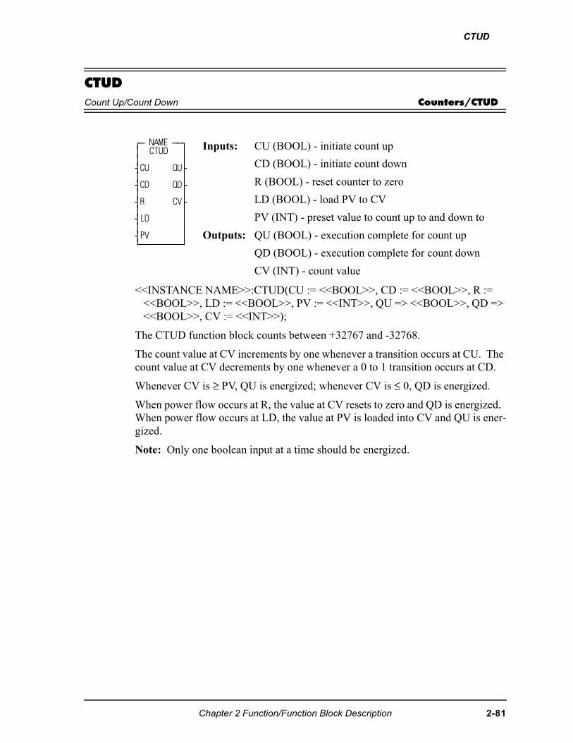
CTUD
CTUDCount Up/Count Down Counters/CTUD
<<INSTANCE NAME>>:CTUD(CU := <<BOOL>>, CD := <<BOOL>>, R := <<BOOL>>, LD := <<BOOL>>, PV := <<INT>>, QU => <<BOOL>>, QD => <<BOOL>>, CV := <<INT>>);
The CTUD function block counts between +32767 and -32768.
The count value at CV increments by one whenever a transition occurs at CU. The count value at CV decrements by one whenever a 0 to 1 transition occurs at CD.
Whenever CV is ≥ PV, QU is energized; whenever CV is ≤ 0, QD is energized.
When power flow occurs at R, the value at CV resets to zero and QD is energized. When power flow occurs at LD, the value at PV is loaded into CV and QU is ener-gized.
Note: Only one boolean input at a time should be energized.
⁄ƒ NAME ƒƒø≥ CTUD ≥≥ ≥¥CU QU√≥ ≥¥CD QD√≥ ≥¥R CV√≥ ≥¥LD ≥≥ ≥¥PV ≥¿ƒƒƒƒƒƒƒƒƒŸ
Inputs: CU (BOOL) - initiate count up
CD (BOOL) - initiate count down
R (BOOL) - reset counter to zero
LD (BOOL) - load PV to CV
PV (INT) - preset value to count up to and down to
Outputs: QU (BOOL) - execution complete for count up
QD (BOOL) - execution complete for count down
CV (INT) - count value
Chapter 2 Function/Function Block Description 2-81
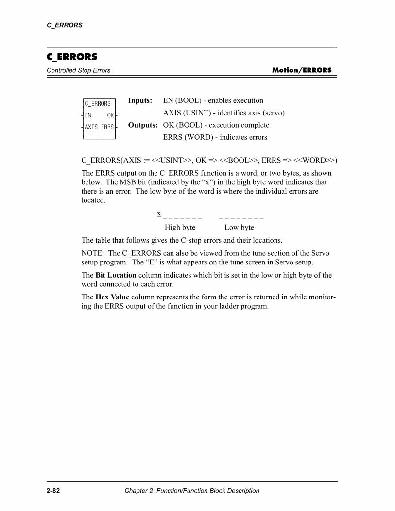
C_ERRORS
C_ERRORSControlled Stop Errors Motion/ERRORS
C_ERRORS(AXIS := <<USINT>>, OK => <<BOOL>>, ERRS => <<WORD>>)
The ERRS output on the C_ERRORS function is a word, or two bytes, as shown below. The MSB bit (indicated by the “x”) in the high byte word indicates that there is an error. The low byte of the word is where the individual errors are located.
x _ _ _ _ _ _ _ _ _ _ _ _ _ _ _
High byte Low byte
The table that follows gives the C-stop errors and their locations.
NOTE: The C_ERRORS can also be viewed from the tune section of the Servo setup program. The “E” is what appears on the tune screen in Servo setup.
The Bit Location column indicates which bit is set in the low or high byte of the word connected to each error.
The Hex Value column represents the form the error is returned in while monitor-ing the ERRS output of the function in your ladder program.
⁄ƒƒƒƒƒƒƒƒƒø≥C_ERRORS ≥≥ ≥¥EN OK√≥ ≥¥AXIS ERRS√≥ ≥¿ƒƒƒƒƒƒƒƒƒŸ
Inputs: EN (BOOL) - enables execution
AXIS (USINT) - identifies axis (servo)
Outputs: OK (BOOL) - execution complete
ERRS (WORD) - indicates errors
2-82 Chapter 2 Function/Function Block Description
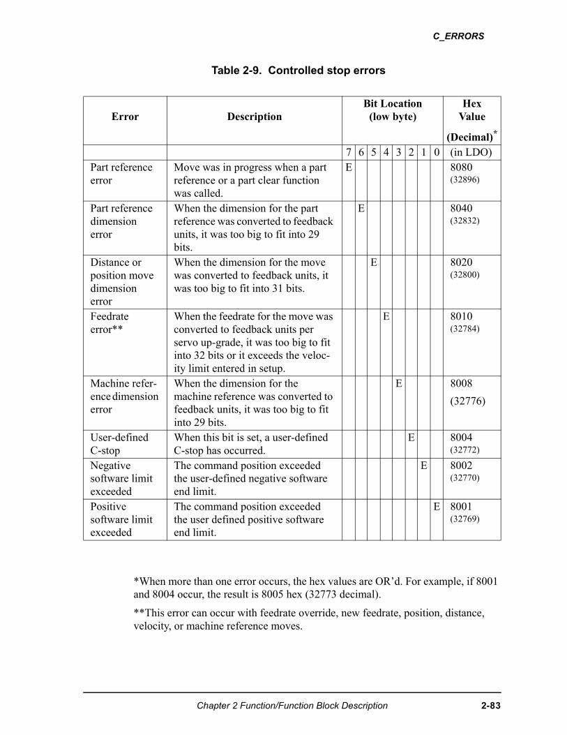
C_ERRORS
Table 2-9. Controlled stop errors
*When more than one error occurs, the hex values are OR’d. For example, if 8001 and 8004 occur, the result is 8005 hex (32773 decimal).
**This error can occur with feedrate override, new feedrate, position, distance, velocity, or machine reference moves.
Error DescriptionBit Location
(low byte)Hex
Value
(Decimal)*
7 6 5 4 3 2 1 0 (in LDO)Part reference error
Move was in progress when a part reference or a part clear function was called.
E 8080(32896)
Part reference dimension error
When the dimension for the part reference was converted to feedback units, it was too big to fit into 29 bits.
E 8040(32832)
Distance or position move dimension error
When the dimension for the move was converted to feedback units, it was too big to fit into 31 bits.
E 8020(32800)
Feedrate error**
When the feedrate for the move was converted to feedback units per servo up-grade, it was too big to fit into 32 bits or it exceeds the veloc-ity limit entered in setup.
E 8010(32784)
Machine refer-ence dimension error
When the dimension for the machine reference was converted to feedback units, it was too big to fit into 29 bits.
E 8008
(32776)
User-definedC-stop
When this bit is set, a user-defined C-stop has occurred.
E 8004(32772)
Negativesoftware limit exceeded
The command position exceeded the user-defined negative software end limit.
E 8002(32770)
Positive software limit exceeded
The command position exceeded the user defined positive software end limit.
E 8001(32769)
Chapter 2 Function/Function Block Description 2-83
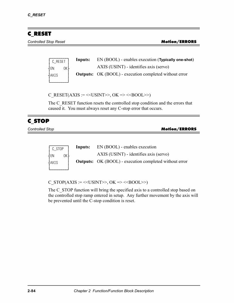
C_RESET
C_RESETControlled Stop Reset Motion/ERRORS
C_RESET(AXIS := <<USINT>>, OK => <<BOOL>>)
The C_RESET function resets the controlled stop condition and the errors that caused it. You must always reset any C-stop error that occurs.
C_STOPControlled Stop Motion/ERRORS
C_STOP(AXIS := <<USINT>>, OK => <<BOOL>>)
The C_STOP function will bring the specified axis to a controlled stop based on the controlled stop ramp entered in setup. Any further movement by the axis will be prevented until the C-stop condition is reset.
⁄ƒƒƒƒƒƒƒƒƒø ≥ C_RESET ≥ ≥ ≥ ¥EN OK√ ≥ ≥ ¥AXIS ≥ ≥ ≥ ¿ƒƒƒƒƒƒƒƒƒŸ
Inputs: EN (BOOL) - enables execution (Typically one-shot)
AXIS (USINT) - identifies axis (servo)
Outputs: OK (BOOL) - execution completed without error
⁄ƒƒƒƒƒƒƒƒƒø ≥ C_STOP ≥ ≥ ≥ ¥EN OK√ ≥ ≥ ¥AXIS ≥ ≥ ≥ ¿ƒƒƒƒƒƒƒƒƒŸ
Inputs: EN (BOOL) - enables execution
AXIS (USINT) - identifies axis (servo)
Outputs: OK (BOOL) - execution completed without error
2-84 Chapter 2 Function/Function Block Description
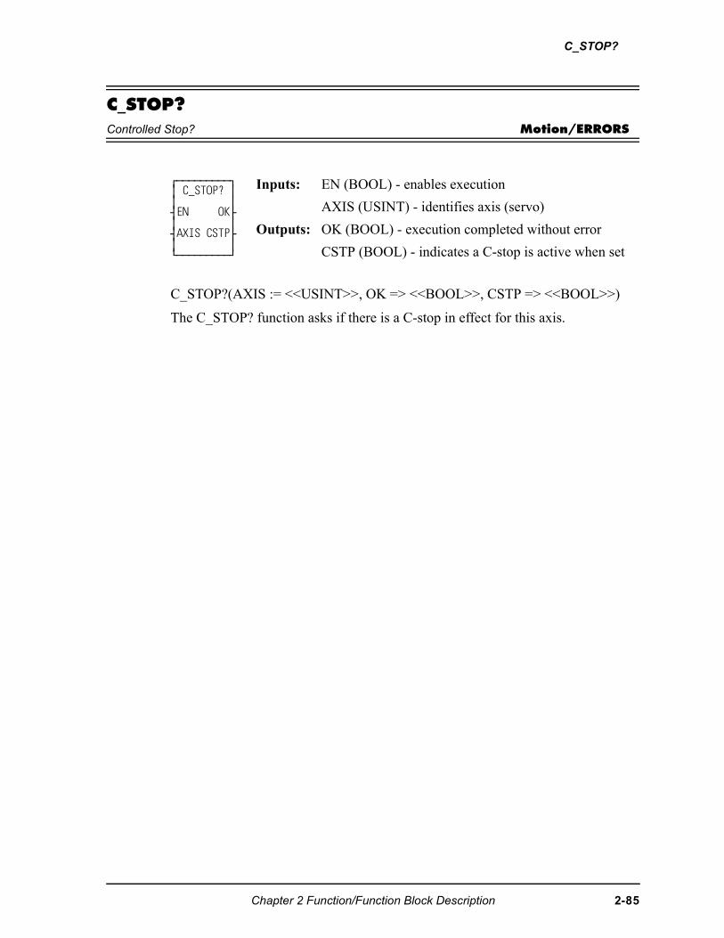
C_STOP?
C_STOP?Controlled Stop? Motion/ERRORS
C_STOP?(AXIS := <<USINT>>, OK => <<BOOL>>, CSTP => <<BOOL>>)
The C_STOP? function asks if there is a C-stop in effect for this axis.
⁄ƒƒƒƒƒƒƒƒƒø ≥ C_STOP? ≥ ≥ ≥ ¥EN OK√ ≥ ≥ ¥AXIS CSTP√ ≥ ≥ ¿ƒƒƒƒƒƒƒƒƒŸ
Inputs: EN (BOOL) - enables execution
AXIS (USINT) - identifies axis (servo)
Outputs: OK (BOOL) - execution completed without error
CSTP (BOOL) - indicates a C-stop is active when set
Chapter 2 Function/Function Block Description 2-85
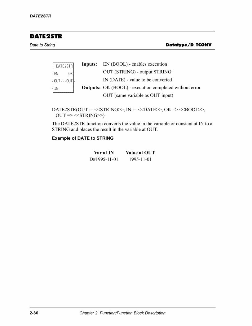
DATE2STR
DATE2STRDate to String Datatype/D_TCONV
DATE2STR(OUT := <<STRING>>, IN := <<DATE>>, OK => <<BOOL>>, OUT => <<STRING>>)
The DATE2STR function converts the value in the variable or constant at IN to a STRING and places the result in the variable at OUT.
Example of DATE to STRING
⁄ƒƒƒƒƒƒƒƒƒø ≥ DATE2STR≥ ≥ ≥ ¥EN OK√ ≥ ≥ ¥OUT---OUT√ ≥ ≥ ¥IN ≥ ¿ƒƒƒƒƒƒƒƒƒŸ
Inputs: EN (BOOL) - enables execution
OUT (STRING) - output STRING
IN (DATE) - value to be converted
Outputs: OK (BOOL) - execution completed without error
OUT (same variable as OUT input)
Var at IN Value at OUTD#1995-11-01 1995-11-01
2-86 Chapter 2 Function/Function Block Description
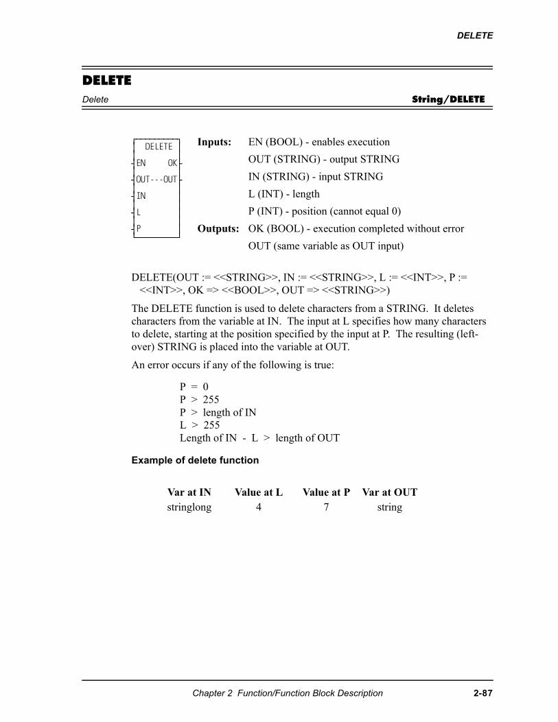
DELETE
DELETEDelete String/DELETE
DELETE(OUT := <<STRING>>, IN := <<STRING>>, L := <<INT>>, P := <<INT>>, OK => <<BOOL>>, OUT => <<STRING>>)
The DELETE function is used to delete characters from a STRING. It deletes characters from the variable at IN. The input at L specifies how many characters to delete, starting at the position specified by the input at P. The resulting (left-over) STRING is placed into the variable at OUT.
An error occurs if any of the following is true:
Example of delete function
⁄ƒƒƒƒƒƒƒƒƒø ≥ DELETE ≥ ≥ ≥ ¥EN OK√ ≥ ≥ ¥OUT---OUT√ ≥ ≥ ¥IN ≥ ≥ ≥ ¥L ≥ ≥ ≥ ¥P ≥ ¿ƒƒƒƒƒƒƒƒƒŸ
Inputs: EN (BOOL) - enables execution
OUT (STRING) - output STRING
IN (STRING) - input STRING
L (INT) - length
P (INT) - position (cannot equal 0)
Outputs: OK (BOOL) - execution completed without error
OUT (same variable as OUT input)
P = 0P > 255P > length of INL > 255Length of IN - L > length of OUT
Var at IN Value at L Value at P Var at OUTstringlong 4 7 string
Chapter 2 Function/Function Block Description 2-87
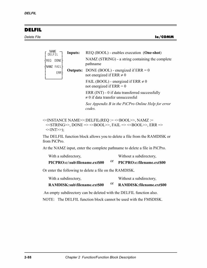
DELFIL
DELFILDelete File Io/COMM
<<INSTANCE NAME>>:DELFIL(REQ := <<BOOL>>, NAMZ := <<STRING>>, DONE => <<BOOL>>, FAIL => <<BOOL>>, ERR => <<INT>>);
The DELFIL function block allows you to delete a file from the RAMDISK or from PiCPro.
At the NAMZ input, enter the complete pathname to delete a file in PiCPro.
Or enter the following to delete a file on the RAMDISK.
An empty subdirectory can be deleted with the DELFIL function also.
NOTE: The DELFIL function block cannot be used with the FMSDISK.
⁄ NAME ƒø ≥ DELFIL ≥ ≥ ≥ ¥REQ DONE√ ≥ ≥ ¥NAMZ FAIL√ ≥ ≥ ≥ ERR√ ≥ ≥ ¿ƒƒƒƒƒƒƒƒƒŸ
Inputs: REQ (BOOL) - enables execution (One-shot)
NAMZ (STRING) - a string containing the complete pathname
Outputs: DONE (BOOL) - energized if ERR = 0not energized if ERR ≠ 0
FAIL (BOOL) - energized if ERR ≠ 0not energized if ERR = 0
ERR (INT) - 0 if data transferred successfully≠ 0 if data transfer unsuccessful
See Appendix B in the PiCPro Online Help for error codes.
With a subdirectory,
PICPRO:c:\sub\filename.ext$00 orWithout a subdirectory,
PICPRO:c:filename.ext$00
With a subdirectory,
RAMDISK:sub\filename.ext$00 orWithout a subdirectory,
RAMDISK:filename.ext$00
2-88 Chapter 2 Function/Function Block Description
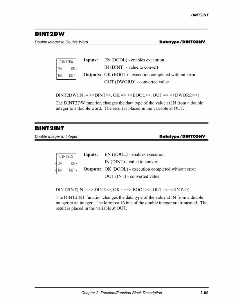
DINT2INT
DINT2DWDouble Integer to Double Word Datatype/DINTCONV
DINT2DW(IN := <<DINT>>, OK => <<BOOL>>, OUT => <<DWORD>>)
The DINT2DW function changes the data type of the value at IN from a double integer to a double word. The result is placed in the variable at OUT.
DINT2INTDouble Integer to Integer Datatype/DINTCONV
DINT2INT(IN := <<DINT>>, OK => <<BOOL>>, OUT => <<INT>>)
The DINT2INT function changes the data type of the value at IN from a double integer to an integer. The leftmost 16 bits of the double integer are truncated. The result is placed in the variable at OUT.
⁄ƒƒƒƒƒƒƒƒƒø ≥ DINT2DW ≥ ≥ ≥ ¥EN OK√ ≥ ≥ ¥IN OUT√ ¿ƒƒƒƒƒƒƒƒƒŸ
Inputs: EN (BOOL) - enables execution
IN (DINT) - value to convert
Outputs: OK (BOOL) - execution completed without error
OUT (DWORD) - converted value
⁄ƒƒƒƒƒƒƒƒƒø ≥ DINT2INT≥ ≥ ≥ ¥EN OK√ ≥ ≥ ¥IN OUT√ ¿ƒƒƒƒƒƒƒƒƒŸ
Inputs: EN (BOOL) - enables execution
IN (DINT) - value to convert
Outputs: OK (BOOL) - execution completed without error
OUT (INT) - converted value
Chapter 2 Function/Function Block Description 2-89
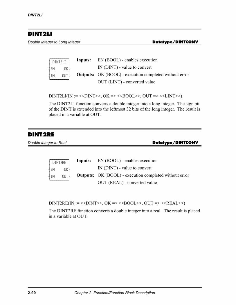
DINT2LI
DINT2LIDouble Integer to Long Integer Datatype/DINTCONV
DINT2LI(IN := <<DINT>>, OK => <<BOOL>>, OUT => <<LINT>>)
The DINT2LI function converts a double integer into a long integer. The sign bit of the DINT is extended into the leftmost 32 bits of the long integer. The result is placed in a variable at OUT.
DINT2REDouble Integer to Real Datatype/DINTCONV
DINT2RE(IN := <<DINT>>, OK => <<BOOL>>, OUT => <<REAL>>)
The DINT2RE function converts a double integer into a real. The result is placed in a variable at OUT.
⁄ƒƒƒƒƒƒƒƒƒø ≥ DINT2LI ≥ ≥ ≥ ¥EN OK√ ≥ ≥ ¥IN OUT√ ¿ƒƒƒƒƒƒƒƒƒŸ
Inputs: EN (BOOL) - enables execution
IN (DINT) - value to convert
Outputs: OK (BOOL) - execution completed without error
OUT (LINT) - converted value
⁄ƒƒƒƒƒƒƒƒƒø ≥ DINT2RE ≥ ≥ ≥ ¥EN OK√ ≥ ≥ ¥IN OUT√ ¿ƒƒƒƒƒƒƒƒƒŸ
Inputs: EN (BOOL) - enables execution
IN (DINT) - value to convert
Outputs: OK (BOOL) - execution completed without error
OUT (REAL) - converted value
2-90 Chapter 2 Function/Function Block Description
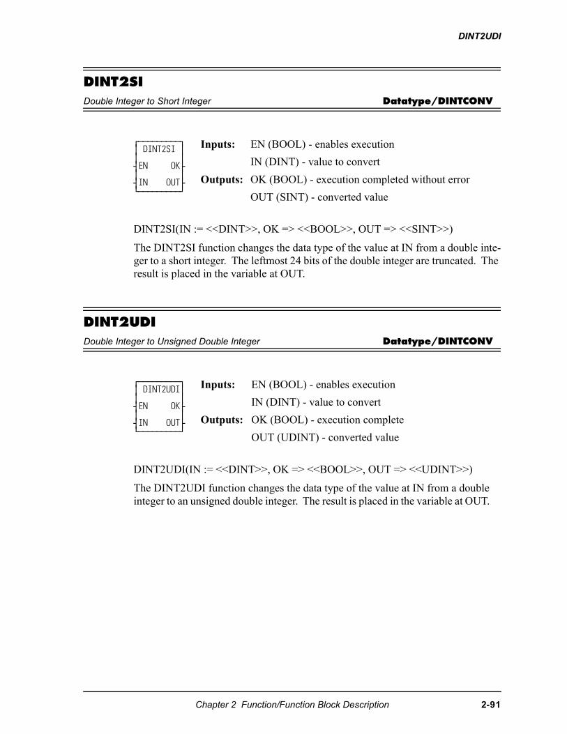
DINT2UDI
DINT2SIDouble Integer to Short Integer Datatype/DINTCONV
DINT2SI(IN := <<DINT>>, OK => <<BOOL>>, OUT => <<SINT>>)
The DINT2SI function changes the data type of the value at IN from a double inte-ger to a short integer. The leftmost 24 bits of the double integer are truncated. The result is placed in the variable at OUT.
DINT2UDIDouble Integer to Unsigned Double Integer Datatype/DINTCONV
DINT2UDI(IN := <<DINT>>, OK => <<BOOL>>, OUT => <<UDINT>>)
The DINT2UDI function changes the data type of the value at IN from a double integer to an unsigned double integer. The result is placed in the variable at OUT.
⁄ƒƒƒƒƒƒƒƒƒø ≥ DINT2SI ≥ ≥ ≥ ¥EN OK√ ≥ ≥ ¥IN OUT√ ¿ƒƒƒƒƒƒƒƒƒŸ
Inputs: EN (BOOL) - enables execution
IN (DINT) - value to convert
Outputs: OK (BOOL) - execution completed without error
OUT (SINT) - converted value
⁄ƒƒƒƒƒƒƒƒƒø ≥ DINT2UDI≥ ≥ ≥ ¥EN OK√ ≥ ≥ ¥IN OUT√ ¿ƒƒƒƒƒƒƒƒƒŸ
Inputs: EN (BOOL) - enables execution
IN (DINT) - value to convert
Outputs: OK (BOOL) - execution complete
OUT (UDINT) - converted value
Chapter 2 Function/Function Block Description 2-91
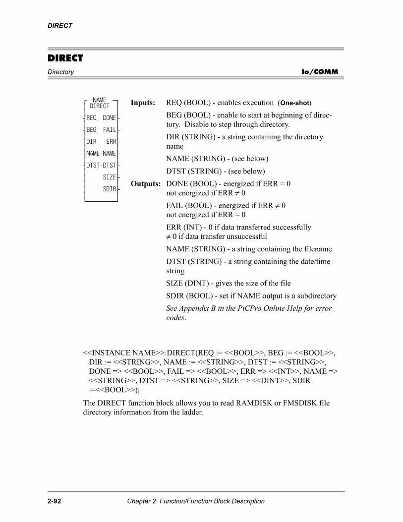
DIRECT
DIRECTDirectory Io/COMM
<<INSTANCE NAME>>:DIRECT(REQ := <<BOOL>>, BEG := <<BOOL>>, DIR := <<STRING>>, NAME := <<STRING>>, DTST := <<STRING>>, DONE => <<BOOL>>, FAIL => <<BOOL>>, ERR => <<INT>>, NAME => <<STRING>>, DTST => <<STRING>>, SIZE => <<DINT>>, SDIR :=<<BOOL>>);
The DIRECT function block allows you to read RAMDISK or FMSDISK file directory information from the ladder.
⁄ NAME ƒø ≥ DIRECT ≥ ≥ ≥ ¥REQ DONE√ ≥ ≥ ¥BEG FAIL√ ≥ ≥ ¥DIR ERR√ ≥ ≥ ¥NAME-NAME√ ≥ ≥ ¥DTST-DTST√ ≥ ≥ ≥ SIZE√ ≥ ≥ ≥ SDIR√ ≥ ≥ ¿ƒƒƒƒƒƒƒƒƒŸ
Inputs: REQ (BOOL) - enables execution (One-shot)
BEG (BOOL) - enable to start at beginning of direc-tory. Disable to step through directory.
DIR (STRING) - a string containing the directory name
NAME (STRING) - (see below)
DTST (STRING) - (see below)
Outputs: DONE (BOOL) - energized if ERR = 0not energized if ERR ≠ 0
FAIL (BOOL) - energized if ERR ≠ 0not energized if ERR = 0
ERR (INT) - 0 if data transferred successfully≠ 0 if data transfer unsuccessful
NAME (STRING) - a string containing the filename
DTST (STRING) - a string containing the date/time string
SIZE (DINT) - gives the size of the file
SDIR (BOOL) - set if NAME output is a subdirectory
See Appendix B in the PiCPro Online Help for error codes.
2-92 Chapter 2 Function/Function Block Description
DIRECT
The directory name is entered at DIR using one of the formats shown below.
Set the BEG input in order to start at the beginning of the directory.
Transition the REQ input. This places the first file in NAME, the date/time in DTST, and the file size in SIZE. (SDIR is set when the name at the NAME output is a subdirectory.)
Turn the BEG off to step through the remaining files in the directory. When the last file is reached, you can go back to the beginning by setting BEG again.
When using:
To list contents of a subdirectory, enter the name of the subdirecto-ry at sub in the following:
To list the contents of the current di-rectory, enter the following:
When the main directory is not the current directory and you want to list the contents of the main directory , enter the following:
RAM-DISK
RAMDISK:sub\$00 RAMDISK:$00 RAMDISK:\*.*$00
FMSDISK FMSDISK:sub\$00 FMSDISK:$00 FMSDISK:\*.*$00
Chapter 2 Function/Function Block Description 2-93
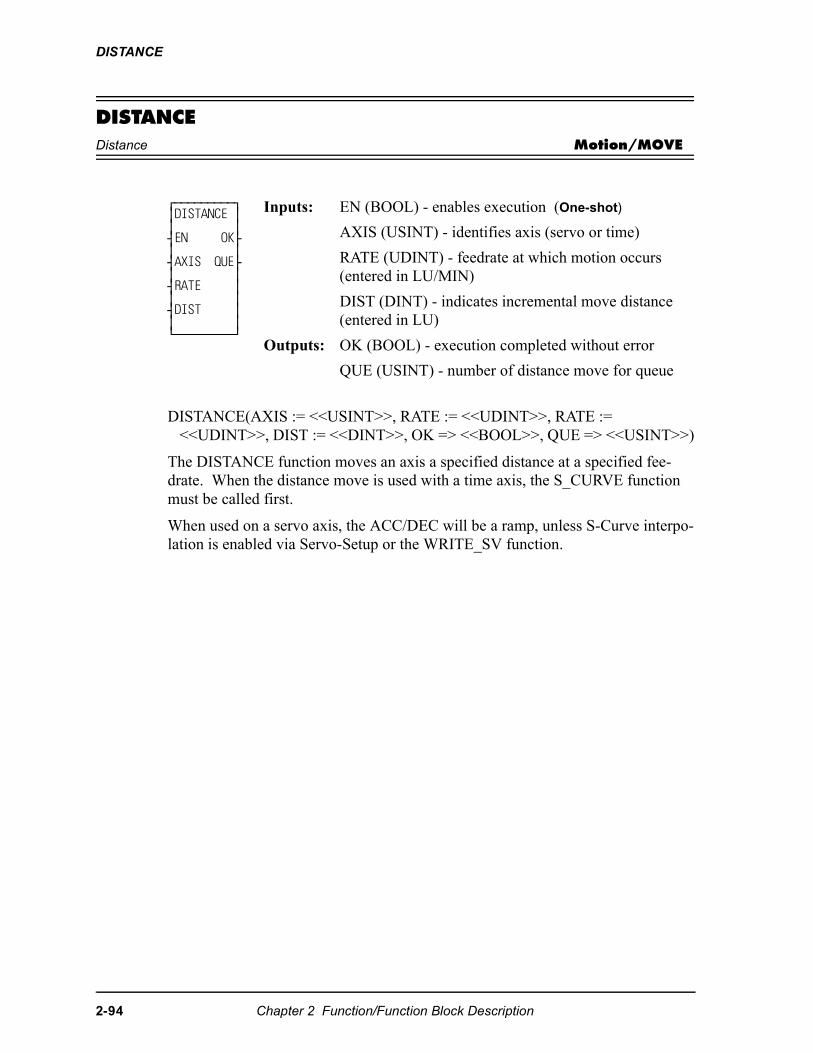
DISTANCE
DISTANCEDistance Motion/MOVE
DISTANCE(AXIS := <<USINT>>, RATE := <<UDINT>>, RATE := <<UDINT>>, DIST := <<DINT>>, OK => <<BOOL>>, QUE => <<USINT>>)
The DISTANCE function moves an axis a specified distance at a specified fee-drate. When the distance move is used with a time axis, the S_CURVE function must be called first.
When used on a servo axis, the ACC/DEC will be a ramp, unless S-Curve interpo-lation is enabled via Servo-Setup or the WRITE_SV function.
⁄ƒƒƒƒƒƒƒƒƒø ≥DISTANCE ≥ ≥ ≥ ¥EN OK√ ≥ ≥ ¥AXIS QUE√ ≥ ≥ ¥RATE ≥ ≥ ≥ ¥DIST ≥ ≥ ≥ ¿ƒƒƒƒƒƒƒƒƒŸ
Inputs: EN (BOOL) - enables execution (One-shot)
AXIS (USINT) - identifies axis (servo or time)
RATE (UDINT) - feedrate at which motion occurs (entered in LU/MIN)
DIST (DINT) - indicates incremental move distance (entered in LU)
Outputs: OK (BOOL) - execution completed without error
QUE (USINT) - number of distance move for queue
2-94 Chapter 2 Function/Function Block Description
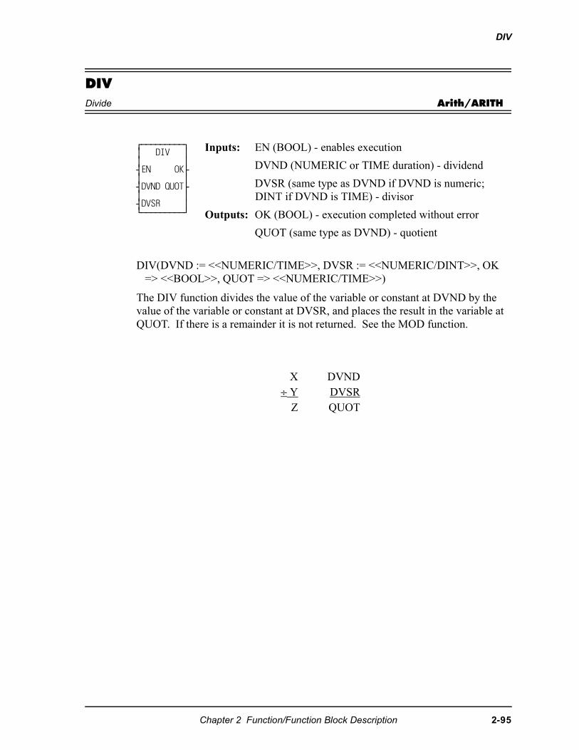
DIV
DIVDivide Arith/ARITH
DIV(DVND := <<NUMERIC/TIME>>, DVSR := <<NUMERIC/DINT>>, OK => <<BOOL>>, QUOT => <<NUMERIC/TIME>>)
The DIV function divides the value of the variable or constant at DVND by the value of the variable or constant at DVSR, and places the result in the variable at QUOT. If there is a remainder it is not returned. See the MOD function.
⁄ƒƒƒƒƒƒƒƒƒø ≥ DIV ≥ ≥ ≥ ¥EN OK√ ≥ ≥ ¥DVND QUOT√ ≥ ≥ ¥DVSR ≥ ¿ƒƒƒƒƒƒƒƒƒŸ
Inputs: EN (BOOL) - enables execution
DVND (NUMERIC or TIME duration) - dividend
DVSR (same type as DVND if DVND is numeric; DINT if DVND is TIME) - divisor
Outputs: OK (BOOL) - execution completed without error
QUOT (same type as DVND) - quotient
X DVND÷ Y DVSR
Z QUOT
Chapter 2 Function/Function Block Description 2-95
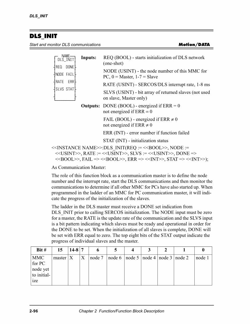
DLS_INIT
DLS_INITStart and monitor DLS communications Motion/DATA
<<INSTANCE NAME>>:DLS_INIT(REQ := <<BOOL>>, NODE := <<USINT>>, RATE := <<USINT>>, SLVS := <<USINT>>, DONE => <<BOOL>>, FAIL => <<BOOL>>, ERR => <<INT>>, STAT => <<INT>>);
As Communication Master:
The role of this function block as a communication master is to define the node number and the interrupt rate, start the DLS communications and then monitor the communications to determine if all other MMC for PCs have also started up. When programmed in the ladder of an MMC for PC communication master, it will indi-cate the progress of the initialization of the slaves.
The ladder in the DLS master must receive a DONE set indication from DLS_INIT prior to calling SERCOS initialization. The NODE input must be zero for a master, the RATE is the update rate of the communication and the SLVS input is a bit pattern indicating which slaves must be ready and operational in order for the DONE to be set. When the initialization of all slaves is complete, DONE will be set with ERR equal to zero. The top eight bits of the STAT output indicate the progress of individual slaves and the master.
⁄ƒ NAMEƒƒø ≥ DLS_INIT≥ ≥ ≥ ¥REQ DONE√ ≥ ≥ ¥NODE FAIL√ ≥ ≥ ¥RATE ERR√ ≥ ≥ ¥SLVS STAT√ ≥ ≥ ¥ √ ¿ƒƒƒƒƒƒƒƒƒŸ
Inputs: REQ (BOOL) - starts initialization of DLS network(one-shot)
NODE (USINT) - the node number of this MMC for PC, 0 = Master, 1-7 = Slave
RATE (USINT) - SERCOS/DLS interrupt rate, 1-8 ms
SLVS (USINT) - bit array of returned slaves (not used on slave, Master only)
Outputs: DONE (BOOL) - energized if ERR = 0not energized if ERR = 0
FAIL (BOOL) - energized if ERR ≠ 0not energized if ERR ≠ 0
ERR (INT) - error number if function failed
STAT (INT) - initialization status
Bit # 15 14-8 7 6 5 4 3 2 1 0
MMC for PC node yet to initial-ize
master X X node 7 node 6 node 5 node 4 node 3 node 2 node 1
2-96 Chapter 2 Function/Function Block Description
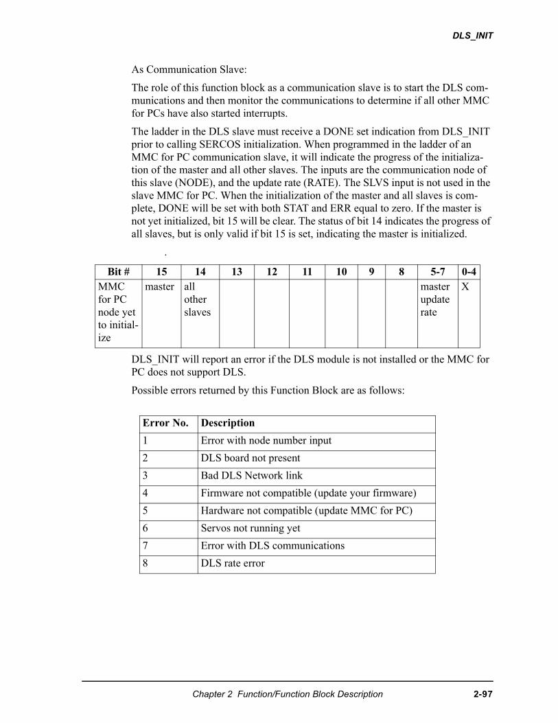
DLS_INIT
As Communication Slave:
The role of this function block as a communication slave is to start the DLS com-munications and then monitor the communications to determine if all other MMC for PCs have also started interrupts.
The ladder in the DLS slave must receive a DONE set indication from DLS_INIT prior to calling SERCOS initialization. When programmed in the ladder of an MMC for PC communication slave, it will indicate the progress of the initializa-tion of the master and all other slaves. The inputs are the communication node of this slave (NODE), and the update rate (RATE). The SLVS input is not used in the slave MMC for PC. When the initialization of the master and all slaves is com-plete, DONE will be set with both STAT and ERR equal to zero. If the master is not yet initialized, bit 15 will be clear. The status of bit 14 indicates the progress of all slaves, but is only valid if bit 15 is set, indicating the master is initialized.
.
DLS_INIT will report an error if the DLS module is not installed or the MMC for PC does not support DLS.
Possible errors returned by this Function Block are as follows:
Bit # 15 14 13 12 11 10 9 8 5-7 0-4MMC for PC node yet to initial-ize
master all other slaves
master update rate
X
Error No. Description
1 Error with node number input
2 DLS board not present
3 Bad DLS Network link
4 Firmware not compatible (update your firmware)
5 Hardware not compatible (update MMC for PC)
6 Servos not running yet
7 Error with DLS communications
8 DLS rate error
Chapter 2 Function/Function Block Description 2-97
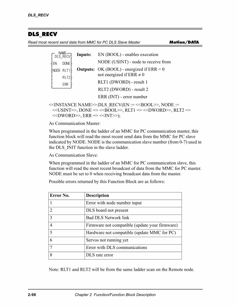
DLS_RECV
DLS_RECVRead most recent send data from MMC for PC DLS Slave Master Motion/DATA
<<INSTANCE NAME>>:DLS_RECV(EN := <<BOOL>>, NODE := <<USINT>>, DONE => <<BOOL>>, RLT1 => <<DWORD>>, RLT2 => <<DWORD>>, ERR => <<INT>>);
As Communication Master:
When programmed in the ladder of an MMC for PC communication master, this function block will read the most recent send data from the MMC for PC slave indicated by NODE. NODE is the communication slave number (from 0-7) used in the DLS_INIT function in the slave ladder.
As Communication Slave:
When programmed in the ladder of an MMC for PC communication slave, this function will read the most recent broadcast of data from the MMC for PC master. NODE must be set to 0 when receiving broadcast data from the master.
Possible errors returned by this Function Block are as follows:
Note: RLT1 and RLT2 will be from the same ladder scan on the Remote node.
⁄ƒ NAMEƒƒø ≥ DLS_RECV≥ ≥ ≥ ¥EN DONE√ ≥ ≥ ¥NODE RLT1√ ≥ ≥ ≥ RLT2√ ≥ ≥ ≥ ERR √ ¿ƒƒƒƒƒƒƒƒƒŸ
Inputs: EN (BOOL) - enables execution
NODE (USINT) - node to receive from
Outputs: OK (BOOL) - energized if ERR = 0not energized if ERR ≠ 0
RLT1 (DWORD) - result 1
RLT2 (DWORD) - result 2
ERR (INT) - error number
Error No. Description
1 Error with node number input
2 DLS board not present
3 Bad DLS Network link
4 Firmware not compatible (update your firmware)
5 Hardware not compatible (update MMC for PC)
6 Servos not running yet
7 Error with DLS communications
8 DLS rate error
2-98 Chapter 2 Function/Function Block Description
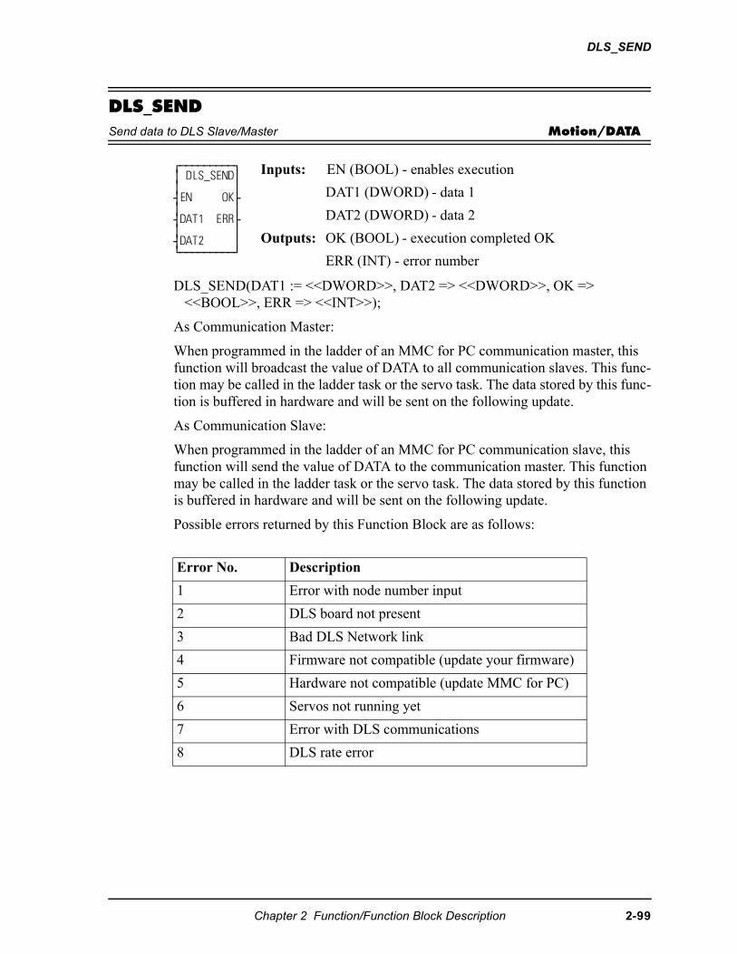
DLS_SEND
DLS_SENDSend data to DLS Slave/Master Motion/DATA
DLS_SEND(DAT1 := <<DWORD>>, DAT2 => <<DWORD>>, OK => <<BOOL>>, ERR => <<INT>>);
As Communication Master:
When programmed in the ladder of an MMC for PC communication master, this function will broadcast the value of DATA to all communication slaves. This func-tion may be called in the ladder task or the servo task. The data stored by this func-tion is buffered in hardware and will be sent on the following update.
As Communication Slave:
When programmed in the ladder of an MMC for PC communication slave, this function will send the value of DATA to the communication master. This function may be called in the ladder task or the servo task. The data stored by this function is buffered in hardware and will be sent on the following update.
Possible errors returned by this Function Block are as follows:
⁄ƒƒƒƒƒƒƒƒƒø ≥ DLS_SEND≥ ≥ ≥ ¥EN OK√ ≥ ≥ ¥DAT1 ERR√ ≥ ≥ ¥DAT2 ≥ ¿ƒƒƒƒƒƒƒƒƒŸ
Inputs: EN (BOOL) - enables execution
DAT1 (DWORD) - data 1
DAT2 (DWORD) - data 2
Outputs: OK (BOOL) - execution completed OK
ERR (INT) - error number
Error No. Description
1 Error with node number input
2 DLS board not present
3 Bad DLS Network link
4 Firmware not compatible (update your firmware)
5 Hardware not compatible (update MMC for PC)
6 Servos not running yet
7 Error with DLS communications
8 DLS rate error
Chapter 2 Function/Function Block Description 2-99
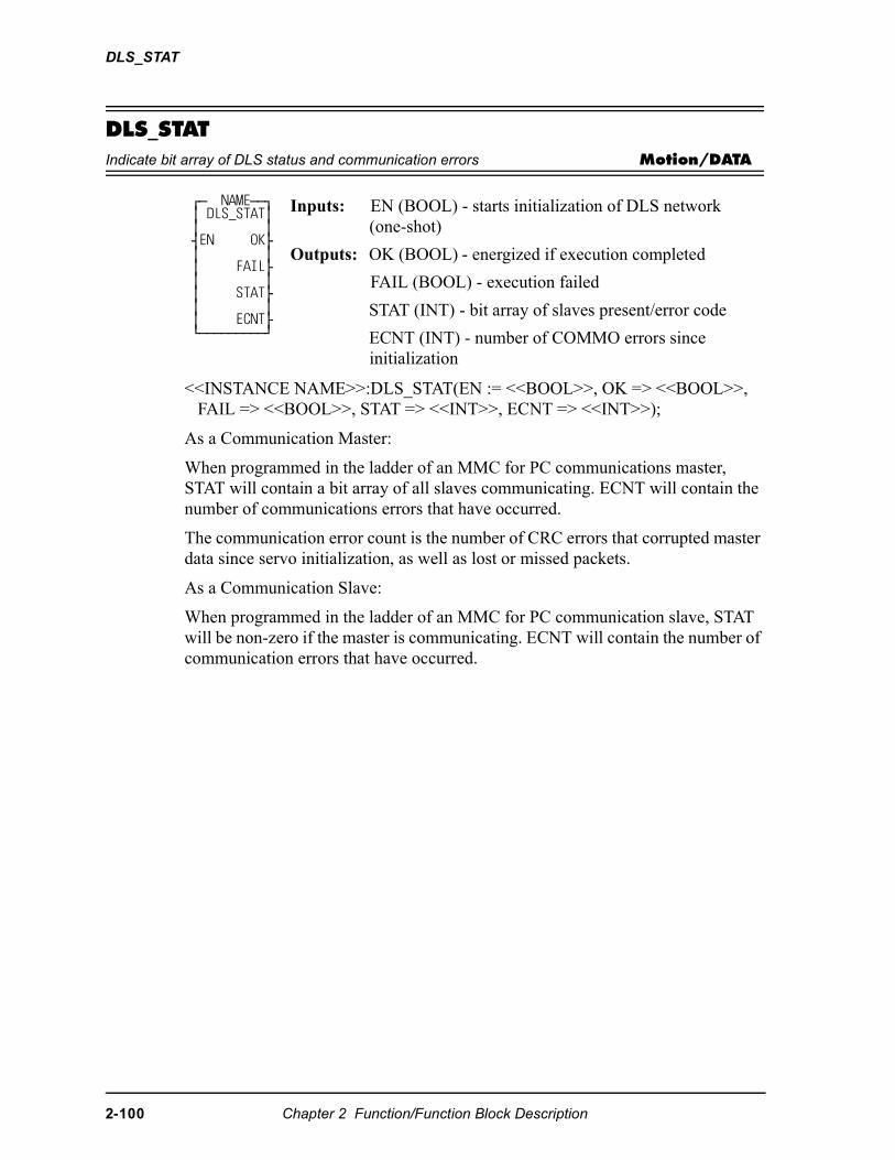
DLS_STAT
DLS_STATIndicate bit array of DLS status and communication errors Motion/DATA
<<INSTANCE NAME>>:DLS_STAT(EN := <<BOOL>>, OK => <<BOOL>>, FAIL => <<BOOL>>, STAT => <<INT>>, ECNT => <<INT>>);
As a Communication Master:
When programmed in the ladder of an MMC for PC communications master, STAT will contain a bit array of all slaves communicating. ECNT will contain the number of communications errors that have occurred.
The communication error count is the number of CRC errors that corrupted master data since servo initialization, as well as lost or missed packets.
As a Communication Slave:
When programmed in the ladder of an MMC for PC communication slave, STAT will be non-zero if the master is communicating. ECNT will contain the number of communication errors that have occurred.
⁄ƒ NAMEƒƒø ≥ DLS_STAT≥ ≥ ≥ ¥EN OK√ ≥ ≥ ≥ FAIL√ ≥ ≥ ≥ STAT√ ≥ ≥ ≥ ECNT√ ¿ƒƒƒƒƒƒƒƒƒŸ
Inputs: EN (BOOL) - starts initialization of DLS network(one-shot)
Outputs: OK (BOOL) - energized if execution completed
FAIL (BOOL) - execution failed
STAT (INT) - bit array of slaves present/error code
ECNT (INT) - number of COMMO errors sinceinitialization
2-100 Chapter 2 Function/Function Block Description
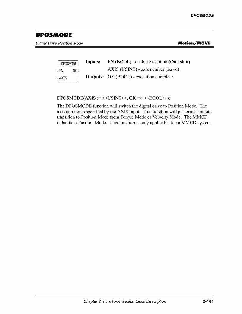
DPOSMODE
DPOSMODEDigital Drive Position Mode Motion/MOVE
DPOSMODE(AXIS := <<USINT>>, OK => <<BOOL>>);
The DPOSMODE function will switch the digital drive to Position Mode. The axis number is specified by the AXIS input. This function will perform a smooth transition to Position Mode from Torque Mode or Velocity Mode. The MMCD defaults to Position Mode. This function is only applicable to an MMCD system.
⁄ƒƒƒƒƒƒƒƒƒø ≥ DPOSMODE≥ ≥ ≥ ¥EN OK√ ≥ ≥ ¥AXIS ≥ ¿ƒƒƒƒƒƒƒƒƒŸ
Inputs: EN (BOOL) - enable execution (One-shot)
AXIS (USINT) - axis number (servo)
Outputs: OK (BOOL) - execution complete
Chapter 2 Function/Function Block Description 2-101
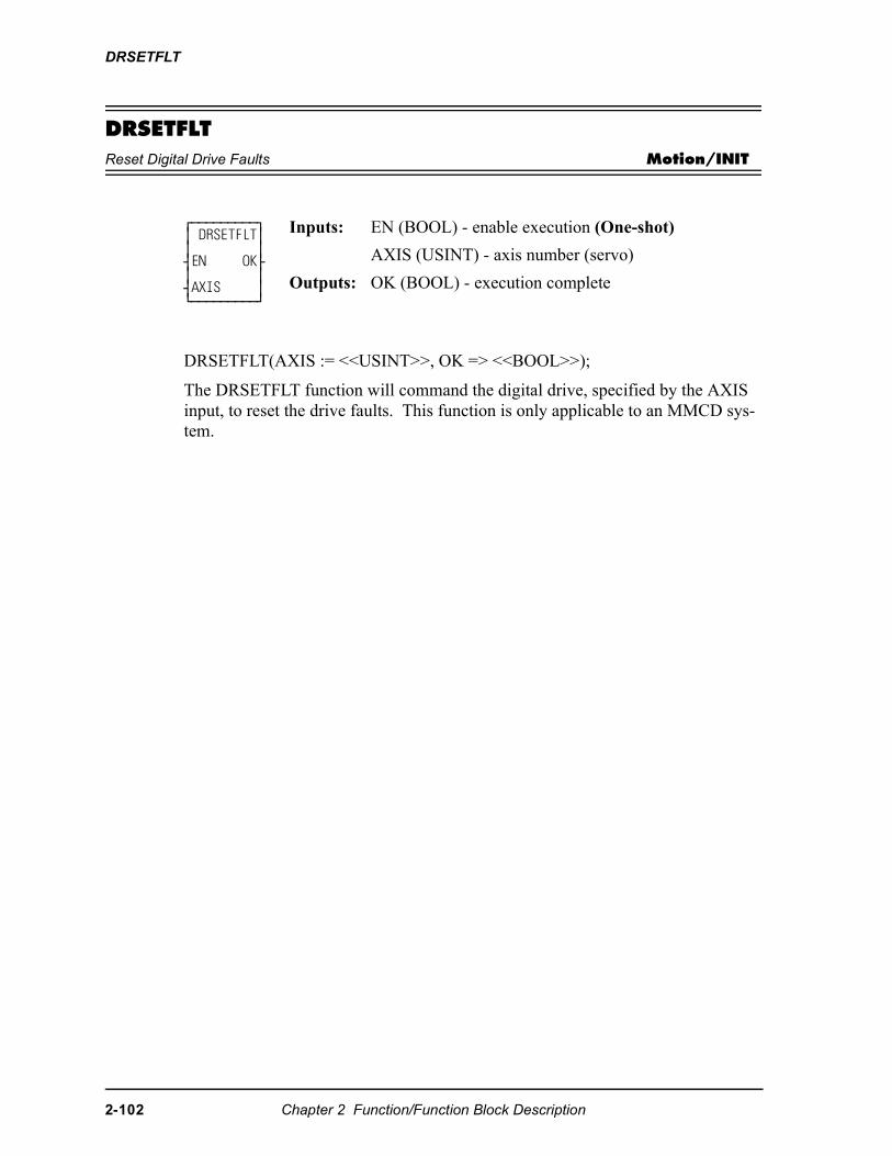
DRSETFLT
DRSETFLTReset Digital Drive Faults Motion/INIT
DRSETFLT(AXIS := <<USINT>>, OK => <<BOOL>>);
The DRSETFLT function will command the digital drive, specified by the AXIS input, to reset the drive faults. This function is only applicable to an MMCD sys-tem.
⁄ƒƒƒƒƒƒƒƒƒø ≥ DRSETFLT≥ ≥ ≥ ¥EN OK√ ≥ ≥ ¥AXIS ≥ ¿ƒƒƒƒƒƒƒƒƒŸ
Inputs: EN (BOOL) - enable execution (One-shot)
AXIS (USINT) - axis number (servo)
Outputs: OK (BOOL) - execution complete
2-102 Chapter 2 Function/Function Block Description
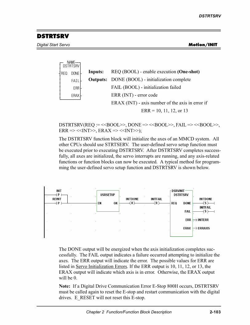
DSTRTSRV
DSTRTSRVDigital Start Servo Motion/INIT
DSTRTSRV(REQ := <<BOOL>>, DONE => <<BOOL>>, FAIL => <<BOOL>>, ERR => <<INT>>, ERAX => <<INT>>);
The DSTRTSRV function block will initialize the axes of an MMCD system. All other CPUs should use STRTSERV. The user-defined servo setup function must be executed prior to executing DSTRTSRV. After DSTRTSRV completes success-fully, all axes are initialized, the servo interrupts are running, and any axis-related functions or function blocks can now be executed. A typical method for program-ming the user-defined servo setup function and DSTRTSRV is shown below.
The DONE output will be energized when the axis initialization completes suc-cessfully. The FAIL output indicates a failure occurred attempting to initialize the axes. The ERR output will indicate the error. The possible values for ERR are listed in Servo Initialization Errors. If the ERR output is 10, 11, 12, or 13, the ERAX output will indicate which axis is in error. Otherwise, the ERAX output will be 0.
Note: If a Digital Drive Communication Error E-Stop 800H occurs, DSTRTSRV must be called again to reset the E-stop and restart communication with the digital drives. E_RESET will not reset this E-stop.
⁄ƒ NAMEƒƒø ≥ DSTRTSRV≥ ≥ ≥ ¥REQ DONE√ ≥ ≥ ≥ FAIL√ ≥ ≥ ≥ ERR√ ≥ ≥ ≥ ERAX√ ¿ƒƒƒƒƒƒƒƒƒŸ
Inputs: REQ (BOOL) - enable execution (One-shot)
Outputs: DONE (BOOL) - initialization complete
FAIL (BOOL) - initialization failed
ERR (INT) - error code
ERAX (INT) - axis number of the axis in error if
ERR = 10, 11, 12, or 13
Chapter 2 Function/Function Block Description 2-103
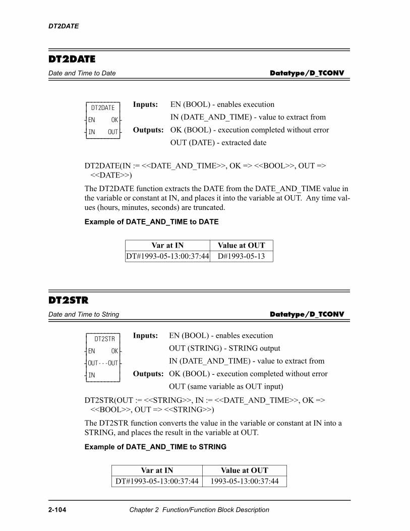
DT2DATE
DT2DATEDate and Time to Date Datatype/D_TCONV
DT2DATE(IN := <<DATE_AND_TIME>>, OK => <<BOOL>>, OUT => <<DATE>>)
The DT2DATE function extracts the DATE from the DATE_AND_TIME value in the variable or constant at IN, and places it into the variable at OUT. Any time val-ues (hours, minutes, seconds) are truncated.
Example of DATE_AND_TIME to DATE
DT2STRDate and Time to String Datatype/D_TCONV
DT2STR(OUT := <<STRING>>, IN := <<DATE_AND_TIME>>, OK => <<BOOL>>, OUT => <<STRING>>)
The DT2STR function converts the value in the variable or constant at IN into a STRING, and places the result in the variable at OUT.
Example of DATE_AND_TIME to STRING
⁄ƒƒƒƒƒƒƒƒƒø ≥ DT2DATE ≥ ≥ ≥ ¥EN OK√ ≥ ≥ ¥IN OUT√ ¿ƒƒƒƒƒƒƒƒƒŸ
Inputs: EN (BOOL) - enables execution
IN (DATE_AND_TIME) - value to extract from
Outputs: OK (BOOL) - execution completed without error
OUT (DATE) - extracted date
Var at IN Value at OUTDT#1993-05-13:00:37:44 D#1993-05-13
⁄ƒƒƒƒƒƒƒƒƒø ≥ DT2STR ≥ ≥ ≥ ¥EN OK√ ≥ ≥ ¥OUT---OUT√ ≥ ≥ ¥IN ≥ ¿ƒƒƒƒƒƒƒƒƒŸ
Inputs: EN (BOOL) - enables execution
OUT (STRING) - STRING output
IN (DATE_AND_TIME) - value to extract from
Outputs: OK (BOOL) - execution completed without error
OUT (same variable as OUT input)
Var at IN Value at OUTDT#1993-05-13:00:37:44 1993-05-13:00:37:44
2-104 Chapter 2 Function/Function Block Description
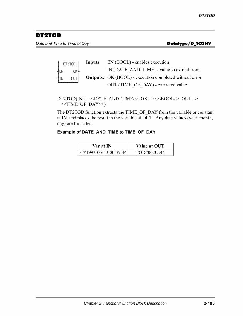
DT2TOD
DT2TODDate and Time to Time of Day Datatype/D_TCONV
DT2TOD(IN := <<DATE_AND_TIME>>, OK => <<BOOL>>, OUT => <<TIME_OF_DAY>>)
The DT2TOD function extracts the TIME_OF_DAY from the variable or constant at IN, and places the result in the variable at OUT. Any date values (year, month, day) are truncated.
Example of DATE_AND_TIME to TIME_OF_DAY
⁄ƒƒƒƒƒƒƒƒƒø ≥ DT2TOD ≥ ≥ ≥ ¥EN OK√ ≥ ≥ ¥IN OUT√ ¿ƒƒƒƒƒƒƒƒƒŸ
Inputs: EN (BOOL) - enables execution
IN (DATE_AND_TIME) - value to extract from
Outputs: OK (BOOL) - execution completed without error
OUT (TIME_OF_DAY) - extracted value
Var at IN Value at OUTDT#1993-05-13:00:37:44 TOD#00:37:44
Chapter 2 Function/Function Block Description 2-105
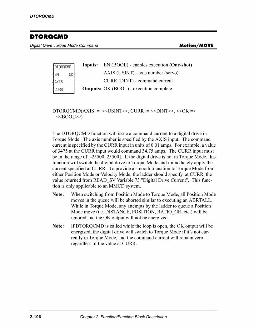
DTORQCMD
DTORQCMDDigital Drive Torque Mode Command Motion/MOVE
DTORQCMD(AXIS := <<USINT>>, CURR := <<DINT>>, <<OK => <<BOOL>>)
The DTORQCMD function will issue a command current to a digital drive in Torque Mode. The axis number is specified by the AXIS input. The command current is specified by the CURR input in units of 0.01 amps. For example, a value of 3475 at the CURR input would command 34.75 amps. The CURR input must be in the range of [-25500, 25500]. If the digital drive is not in Torque Mode, this function will switch the digital drive to Torque Mode and immediately apply the current specified at CURR. To provide a smooth transition to Torque Mode from either Position Mode or Velocity Mode, the ladder should specify, at CURR, the value returned from READ_SV Variable 73 "Digital Drive Current". This func-tion is only applicable to an MMCD system.
Note: When switching from Position Mode to Torque Mode, all Position Mode moves in the queue will be aborted similar to executing an ABRTALL. While in Torque Mode, any attempts by the ladder to queue a Position Mode move (i.e. DISTANCE, POSITION, RATIO_GR, etc.) will be ignored and the OK output will not be energized.
Note: If DTORQCMD is called while the loop is open, the OK output will be energized, the digital drive will switch to Torque Mode if it’s not cur-rently in Torque Mode, and the command current will remain zero regardless of the value at CURR.
⁄ƒƒƒƒƒƒƒƒƒø ≥DTORQCMD ≥ ≥ ≥ ¥EN OK√ ≥ ≥ ¥AXIS ≥ ≥ ≥ ¥CURR ≥ ¿ƒƒƒƒƒƒƒƒƒŸ
Inputs: EN (BOOL) - enables execution (One-shot)
AXIS (USINT) - axis number (servo)
CURR (DINT) - command current
Outputs: OK (BOOL) - execution complete
2-106 Chapter 2 Function/Function Block Description
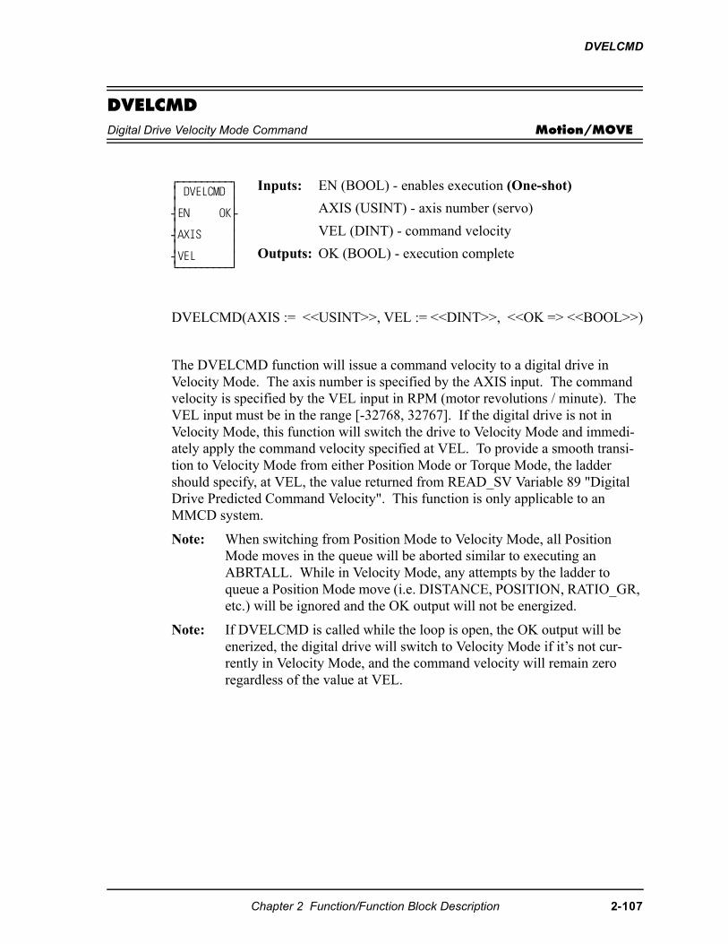
DVELCMD
DVELCMDDigital Drive Velocity Mode Command Motion/MOVE
DVELCMD(AXIS := <<USINT>>, VEL := <<DINT>>, <<OK => <<BOOL>>)
The DVELCMD function will issue a command velocity to a digital drive in Velocity Mode. The axis number is specified by the AXIS input. The command velocity is specified by the VEL input in RPM (motor revolutions / minute). The VEL input must be in the range [-32768, 32767]. If the digital drive is not in Velocity Mode, this function will switch the drive to Velocity Mode and immedi-ately apply the command velocity specified at VEL. To provide a smooth transi-tion to Velocity Mode from either Position Mode or Torque Mode, the ladder should specify, at VEL, the value returned from READ_SV Variable 89 "Digital Drive Predicted Command Velocity". This function is only applicable to an MMCD system.
Note: When switching from Position Mode to Velocity Mode, all Position Mode moves in the queue will be aborted similar to executing an ABRTALL. While in Velocity Mode, any attempts by the ladder to queue a Position Mode move (i.e. DISTANCE, POSITION, RATIO_GR, etc.) will be ignored and the OK output will not be energized.
Note: If DVELCMD is called while the loop is open, the OK output will be enerized, the digital drive will switch to Velocity Mode if it’s not cur-rently in Velocity Mode, and the command velocity will remain zero regardless of the value at VEL.
⁄ƒƒƒƒƒƒƒƒƒø ≥ DVELCMD ≥ ≥ ≥ ¥EN OK√ ≥ ≥ ¥AXIS ≥ ≥ ≥ ¥VEL ≥ ¿ƒƒƒƒƒƒƒƒƒŸ
Inputs: EN (BOOL) - enables execution (One-shot)
AXIS (USINT) - axis number (servo)
VEL (DINT) - command velocity
Outputs: OK (BOOL) - execution complete
Chapter 2 Function/Function Block Description 2-107
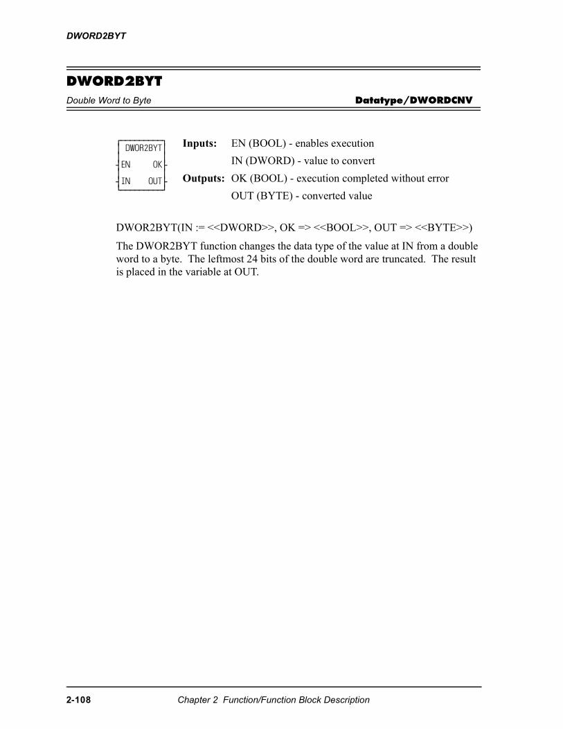
DWORD2BYT
DWORD2BYTDouble Word to Byte Datatype/DWORDCNV
DWOR2BYT(IN := <<DWORD>>, OK => <<BOOL>>, OUT => <<BYTE>>)
The DWOR2BYT function changes the data type of the value at IN from a double word to a byte. The leftmost 24 bits of the double word are truncated. The result is placed in the variable at OUT.
⁄ƒƒƒƒƒƒƒƒƒø ≥ DWOR2BYT≥ ≥ ≥ ¥EN OK√ ≥ ≥ ¥IN OUT√ ¿ƒƒƒƒƒƒƒƒƒŸ
Inputs: EN (BOOL) - enables execution
IN (DWORD) - value to convert
Outputs: OK (BOOL) - execution completed without error
OUT (BYTE) - converted value
2-108 Chapter 2 Function/Function Block Description
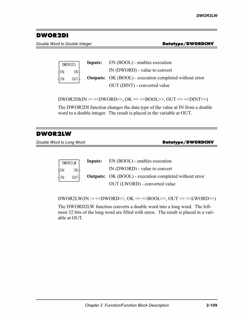
DWOR2LW
DWOR2DIDouble Word to Double Integer Datatype/DWORDCNV
DWOR2DI(IN := <<DWORD>>, OK => <<BOOL>>, OUT => <<DINT>>)
The DWOR2DI function changes the data type of the value at IN from a double word to a double integer. The result is placed in the variable at OUT.
DWOR2LWDouble Word to Long Word Datatype/DWORDCNV
DWOR2LW(IN := <<DWORD>>, OK => <<BOOL>>, OUT => <<LWORD>>)
The DWORD2LW function converts a double word into a long word. The left-most 32 bits of the long word are filled with zeros. The result is placed in a vari-able at OUT.
⁄ƒƒƒƒƒƒƒƒƒø ≥ DWOR2DI ≥ ≥ ≥ ¥EN OK√ ≥ ≥ ¥IN OUT√ ¿ƒƒƒƒƒƒƒƒƒŸ
Inputs: EN (BOOL) - enables execution
IN (DWORD) - value to convert
Outputs: OK (BOOL) - execution completed without error
OUT (DINT) - converted value
⁄ƒƒƒƒƒƒƒƒƒø ≥ DWOR2LW ≥ ≥ ≥ ¥EN OK√ ≥ ≥ ¥IN OUT√ ¿ƒƒƒƒƒƒƒƒƒŸ
Inputs: EN (BOOL) - enables execution
IN (DWORD) - value to convert
Outputs: OK (BOOL) - execution completed without error
OUT (LWORD) - converted value
Chapter 2 Function/Function Block Description 2-109
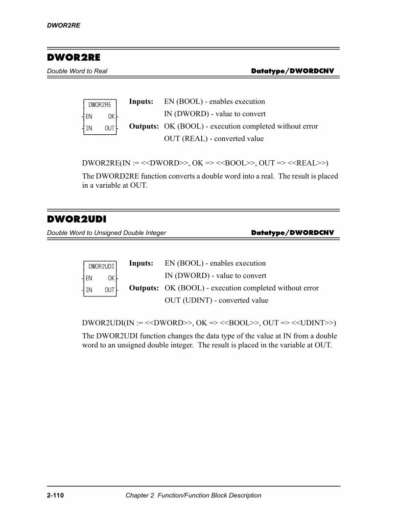
DWOR2RE
DWOR2REDouble Word to Real Datatype/DWORDCNV
DWOR2RE(IN := <<DWORD>>, OK => <<BOOL>>, OUT => <<REAL>>)
The DWORD2RE function converts a double word into a real. The result is placed in a variable at OUT.
DWOR2UDIDouble Word to Unsigned Double Integer Datatype/DWORDCNV
DWOR2UDI(IN := <<DWORD>>, OK => <<BOOL>>, OUT => <<UDINT>>)
The DWOR2UDI function changes the data type of the value at IN from a double word to an unsigned double integer. The result is placed in the variable at OUT.
⁄ƒƒƒƒƒƒƒƒƒø ≥ DWOR2RE ≥ ≥ ≥ ¥EN OK√ ≥ ≥ ¥IN OUT√ ¿ƒƒƒƒƒƒƒƒƒŸ
Inputs: EN (BOOL) - enables execution
IN (DWORD) - value to convert
Outputs: OK (BOOL) - execution completed without error
OUT (REAL) - converted value
⁄ƒƒƒƒƒƒƒƒƒø ≥ DWOR2UDI≥ ≥ ≥ ¥EN OK√ ≥ ≥ ¥IN OUT√ ¿ƒƒƒƒƒƒƒƒƒŸ
Inputs: EN (BOOL) - enables execution
IN (DWORD) - value to convert
Outputs: OK (BOOL) - execution completed without error
OUT (UDINT) - converted value
2-110 Chapter 2 Function/Function Block Description
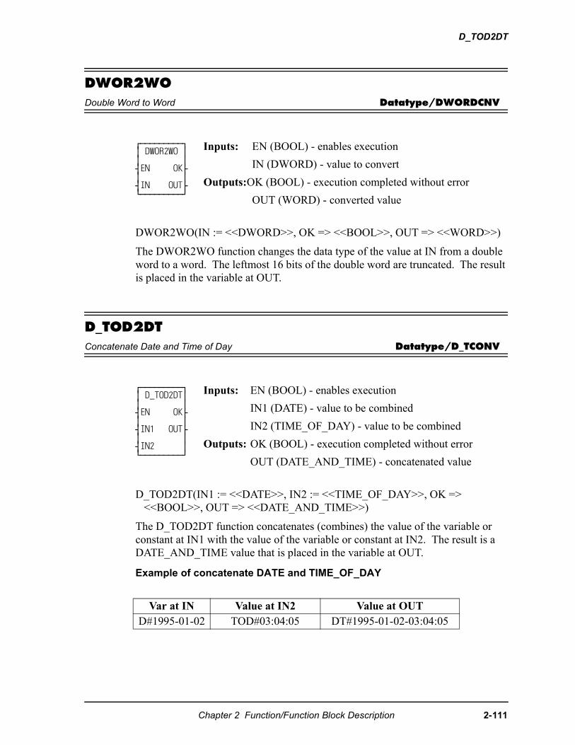
D_TOD2DT
DWOR2WODouble Word to Word Datatype/DWORDCNV
DWOR2WO(IN := <<DWORD>>, OK => <<BOOL>>, OUT => <<WORD>>)
The DWOR2WO function changes the data type of the value at IN from a double word to a word. The leftmost 16 bits of the double word are truncated. The result is placed in the variable at OUT.
D_TOD2DTConcatenate Date and Time of Day Datatype/D_TCONV
D_TOD2DT(IN1 := <<DATE>>, IN2 := <<TIME_OF_DAY>>, OK => <<BOOL>>, OUT => <<DATE_AND_TIME>>)
The D_TOD2DT function concatenates (combines) the value of the variable or constant at IN1 with the value of the variable or constant at IN2. The result is a DATE_AND_TIME value that is placed in the variable at OUT.
Example of concatenate DATE and TIME_OF_DAY
⁄ƒƒƒƒƒƒƒƒƒø ≥ DWOR2WO ≥ ≥ ≥ ¥EN OK√ ≥ ≥ ¥IN OUT√ ¿ƒƒƒƒƒƒƒƒƒŸ
Inputs: EN (BOOL) - enables execution
IN (DWORD) - value to convert
Outputs:OK (BOOL) - execution completed without error
OUT (WORD) - converted value
⁄ƒƒƒƒƒƒƒƒƒø ≥ D_TOD2DT≥ ≥ ≥ ¥EN OK√ ≥ ≥ ¥IN1 OUT√ ≥ ≥ ¥IN2 ≥ ¿ƒƒƒƒƒƒƒƒƒŸ
Inputs: EN (BOOL) - enables execution
IN1 (DATE) - value to be combined
IN2 (TIME_OF_DAY) - value to be combined
Outputs: OK (BOOL) - execution completed without error
OUT (DATE_AND_TIME) - concatenated value
Var at IN Value at IN2 Value at OUTD#1995-01-02 TOD#03:04:05 DT#1995-01-02-03:04:05
Chapter 2 Function/Function Block Description 2-111
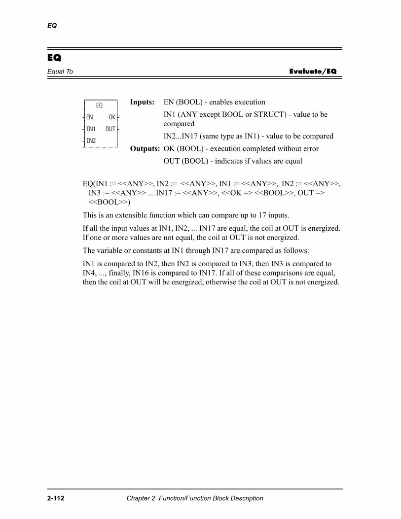
EQ
EQEqual To Evaluate/EQ
EQ(IN1 := <<ANY>>, IN2 := <<ANY>>, IN1 := <<ANY>>, IN2 := <<ANY>>, IN3 := <<ANY>> ... IN17 := <<ANY>>, <<OK => <<BOOL>>, OUT => <<BOOL>>)
This is an extensible function which can compare up to 17 inputs.
If all the input values at IN1, IN2, ... IN17 are equal, the coil at OUT is energized. If one or more values are not equal, the coil at OUT is not energized.
The variable or constants at IN1 through IN17 are compared as follows:
IN1 is compared to IN2, then IN2 is compared to IN3, then IN3 is compared to IN4, ..., finally, IN16 is compared to IN17. If all of these comparisons are equal, then the coil at OUT will be energized, otherwise the coil at OUT is not energized.
⁄ƒƒƒƒƒƒƒƒƒø ≥ EQ ≥ ≥ ≥ ¥EN OK√ ≥ ≥ ¥IN1 OUT√ ≥ ≥ ¥IN2 ≥ ¡ ƒ ƒ ƒ ƒ Ÿ
Inputs: EN (BOOL) - enables execution
IN1 (ANY except BOOL or STRUCT) - value to be compared
IN2...IN17 (same type as IN1) - value to be compared
Outputs: OK (BOOL) - execution completed without error
OUT (BOOL) - indicates if values are equal
2-112 Chapter 2 Function/Function Block Description
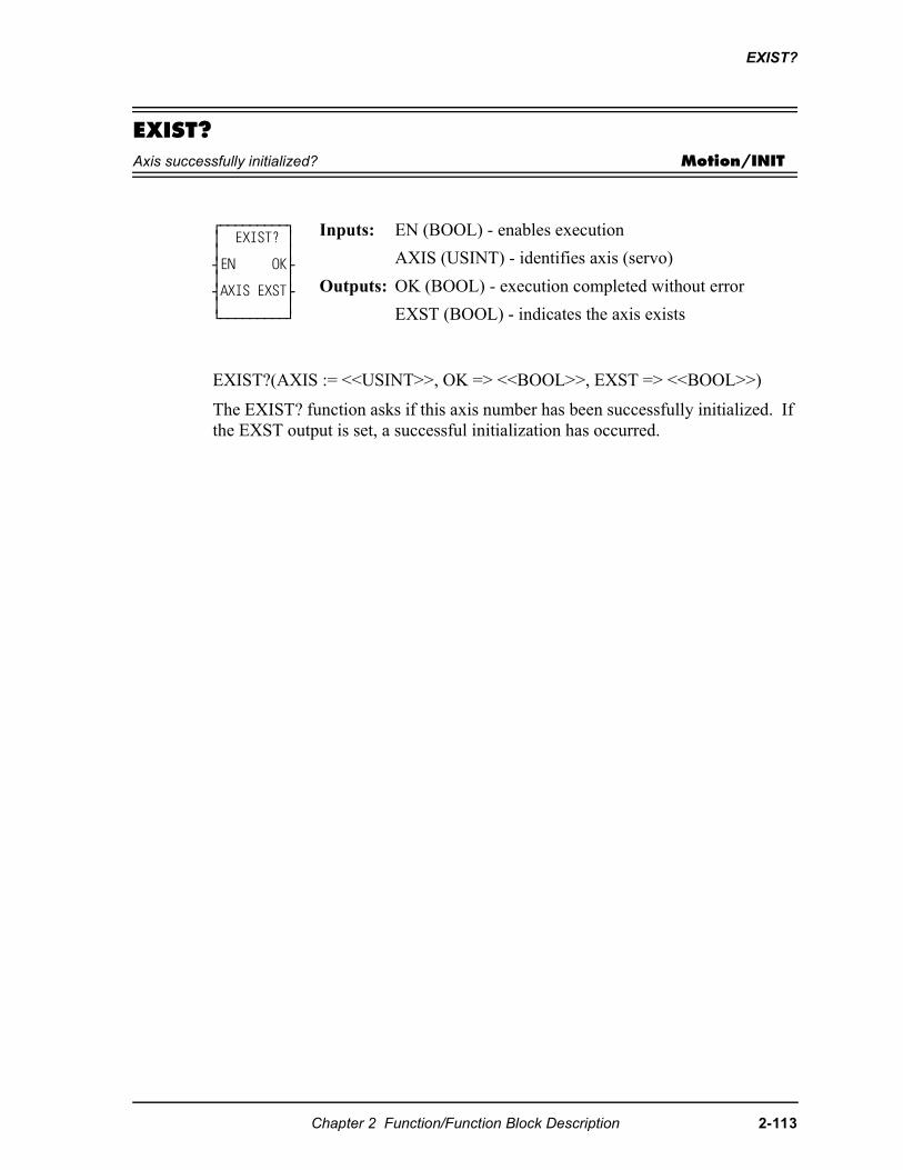
EXIST?
EXIST?Axis successfully initialized? Motion/INIT
EXIST?(AXIS := <<USINT>>, OK => <<BOOL>>, EXST => <<BOOL>>)
The EXIST? function asks if this axis number has been successfully initialized. If the EXST output is set, a successful initialization has occurred.
⁄ƒƒƒƒƒƒƒƒƒø ≥ EXIST? ≥ ≥ ≥ ¥EN OK√ ≥ ≥ ¥AXIS EXST√ ≥ ≥ ¿ƒƒƒƒƒƒƒƒƒŸ
Inputs: EN (BOOL) - enables execution
AXIS (USINT) - identifies axis (servo)
Outputs: OK (BOOL) - execution completed without error
EXST (BOOL) - indicates the axis exists
Chapter 2 Function/Function Block Description 2-113
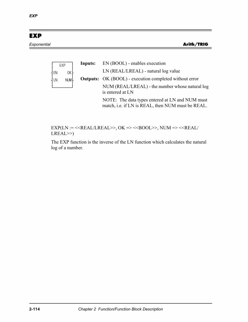
EXP
EXPExponential Arith/TRIG
EXP(LN := <<REAL/LREAL>>, OK => <<BOOL>>, NUM => <<REAL/LREAL>>)
The EXP function is the inverse of the LN function which calculates the natural log of a number.
⁄ƒƒƒƒƒƒƒƒƒø ≥ EXP ≥ ≥ ≥ ¥EN OK√ ≥ ≥ ¥LN NUM√ ≥ ≥ ¿ƒƒƒƒƒƒƒƒƒŸ
Inputs: EN (BOOL) - enables execution
LN (REAL/LREAL) - natural log value
Outputs: OK (BOOL) - execution completed without error
NUM (REAL/LREAL) - the number whose natural log is entered at LN
NOTE: The data types entered at LN and NUM must match, i.e. if LN is REAL, then NUM must be REAL.
2-114 Chapter 2 Function/Function Block Description
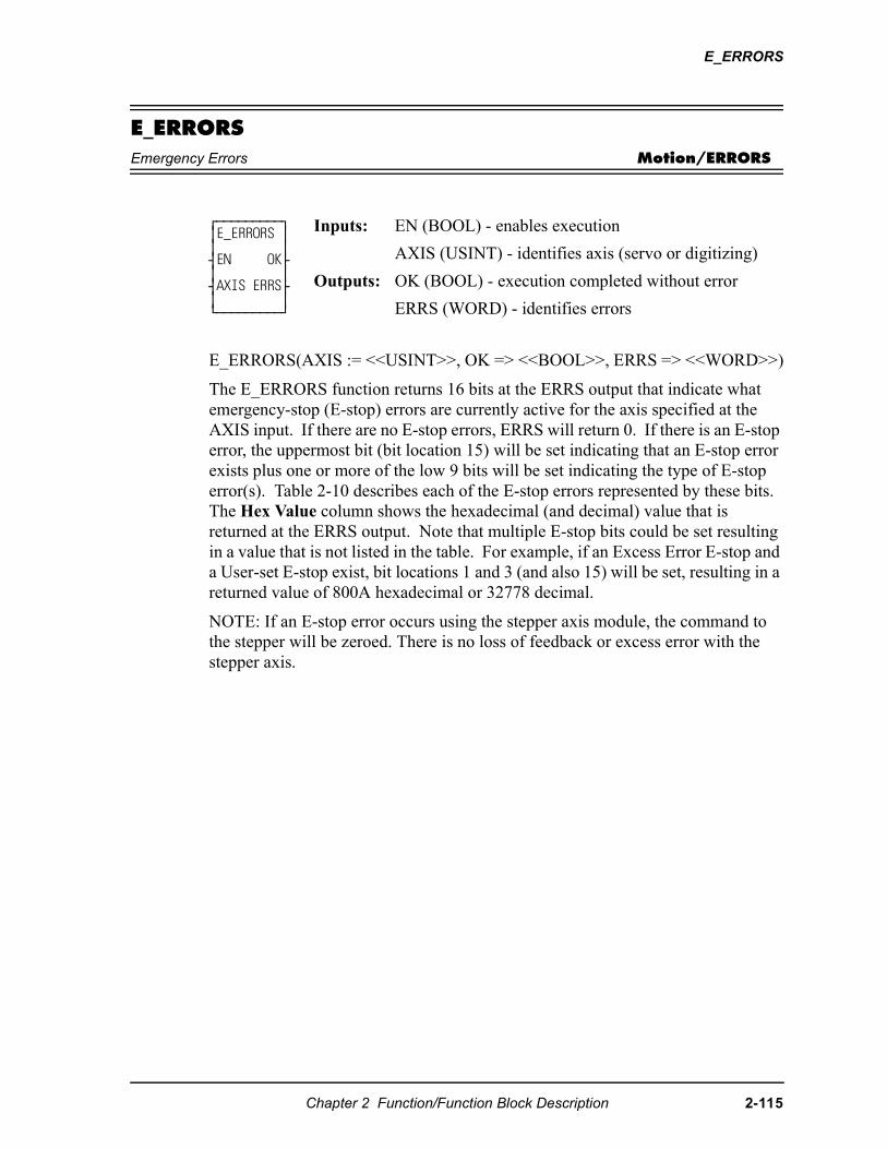
E_ERRORS
E_ERRORSEmergency Errors Motion/ERRORS
E_ERRORS(AXIS := <<USINT>>, OK => <<BOOL>>, ERRS => <<WORD>>)
The E_ERRORS function returns 16 bits at the ERRS output that indicate what emergency-stop (E-stop) errors are currently active for the axis specified at the AXIS input. If there are no E-stop errors, ERRS will return 0. If there is an E-stop error, the uppermost bit (bit location 15) will be set indicating that an E-stop error exists plus one or more of the low 9 bits will be set indicating the type of E-stop error(s). Table 2-10 describes each of the E-stop errors represented by these bits. The Hex Value column shows the hexadecimal (and decimal) value that is returned at the ERRS output. Note that multiple E-stop bits could be set resulting in a value that is not listed in the table. For example, if an Excess Error E-stop and a User-set E-stop exist, bit locations 1 and 3 (and also 15) will be set, resulting in a returned value of 800A hexadecimal or 32778 decimal.
NOTE: If an E-stop error occurs using the stepper axis module, the command to the stepper will be zeroed. There is no loss of feedback or excess error with the stepper axis.
⁄ƒƒƒƒƒƒƒƒƒø≥E_ERRORS ≥≥ ≥¥EN OK√≥ ≥¥AXIS ERRS√≥ ≥¿ƒƒƒƒƒƒƒƒƒŸ
Inputs: EN (BOOL) - enables execution
AXIS (USINT) - identifies axis (servo or digitizing)
Outputs: OK (BOOL) - execution completed without error
ERRS (WORD) - identifies errors
Chapter 2 Function/Function Block Description 2-115
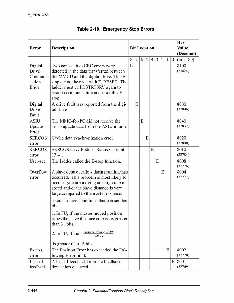
E_ERRORS
Table 2-10. Emergency Stop Errors.
Error Description Bit LocationHex Value(Decimal)
8 7 6 5 4 3 2 1 0 (in LDO)Digital Drive Communi-cation Error
Two consecutive CRC errors were detected in the data transferred between the MMCD and the digital drive. This E-stop cannot be reset with E_RESET. The ladder must call DSTRTSRV again to restart communication and reset this E-stop.
E 8100(33024)
Digital Drive Fault
A drive fault was reported from the digi-tal drive
E 8080(32896)
ASIU Update Error
The MMC-for-PC did not receive the servo update data from the ASIU in time
E 8040(32832)
SERCOS error
Cyclic data synchronization error E 8020(32800)
SERCOS error
SERCOS drive E-stop - Status word bit 13 = 1.
E 8010(32784)
User-set The ladder called the E-stop function. E 8008(32776)
Overflow error
A slave delta overflow during runtime has occurred. This problem is most likely to occur if you are moving at a high rate of speed and/or the slave distance is very large compared to the master distance.
There are two conditions that can set this bit.
1. In FU, if the master moved position times the slave distance entered is greater than 31 bits.
2. In FU, if the
is greater than 16 bits.
E 8004(32772)
Excess error
The Position Error has exceeded the Fol-lowing Error limit.
E 8002(32770)
Loss of feedback
A loss of feedback from the feedback device has occurred.
E 8001(32769)
mastermoved × SDIS MDIS
2-116 Chapter 2 Function/Function Block Description
E_STOP
E_RESETEmergency Stop Reset Motion/ERRORS
E_RESET(AXIS := <<USINT>>, OK => <<BOOL>>)
The E_RESET function resets the E-stop condition and all the errors that caused it. After an E-stop error occurs, you must always reset it. If the E-Stop being reset is a Resumable E-Stop (see READ_SV Variable 63), the moves in the active and next queues will remain intact. If it is not a Resumable E-Stop, the active and next queues will be cleared.
Note: The E_RESET function will close the loop if a CLOSLOOP function is executed before the E_STOP.
Note: If the axis is a digital drive servo axis, E_RESET will also reset the digital drive faults.
Note: E_RESET will not reset a Digital Drive Communication Error E-stop 8100H. The ladder must call DSTRTSRV again to reset this E-stop and restart communication.
E_STOPEmergency Stop Motion/ERRORS
E_STOP(AXIS := <<USINT>>, OK => <<BOOL>>)
The E_STOP function will open the servo loop and zero the analog output.
If Resumable E-Stop Allow is set (Servo Setup or WRITE_SV Variable 63), this function will also cause the axis to go into Resume Mode. See READ_SV Variable 63 & 64, RESMODE?, and RESUME.
⁄ƒƒƒƒƒƒƒƒƒø≥ E_RESET ≥≥ ≥¥EN OK√≥ ≥¥AXIS ≥≥ ≥¿ƒƒƒƒƒƒƒƒƒŸ
Inputs:EN (BOOL) - enables execution (Typically one-shot)
AXIS (USINT) - identifies axis (servo or digitizing)
Outputs:OK (BOOL) - execution completed without error
⁄ƒƒƒƒƒƒƒƒƒø ≥ E_STOP ≥ ≥ ≥ ¥EN OK√ ≥ ≥ ¥AXIS ≥ ≥ ≥ ¿ƒƒƒƒƒƒƒƒƒŸ
Inputs: EN (BOOL) - enables execution (Typically one-shot)
AXIS (USINT) - identifies axis (servo)
Outputs: OK (BOOL) - execution completed without error
Chapter 2 Function/Function Block Description 2-117
E_STOP?
E_STOP?Emergency Stop? Motion/ERRORS
E_STOP?(AXIS := <<USINT>>, OK => <<BOOL>>, ESTP => <<BOOL>>)
The E_STOP? function asks if there is a E-stop in effect for this axis.
⁄ƒƒƒƒƒƒƒƒƒø ≥ E_STOP? ≥ ≥ ≥ ¥EN OK√ ≥ ≥ ¥AXIS ESTP√ ≥ ≥ ¿ƒƒƒƒƒƒƒƒƒŸ
Inputs: EN (BOOL) - enables execution
AXIS (USINT) - identifies axis (servo or digitizing)
Outputs: OK (BOOL) - execution completed without error
ESTP (BOOL) - indicates an E-stop is active when set
2-118 Chapter 2 Function/Function Block Description
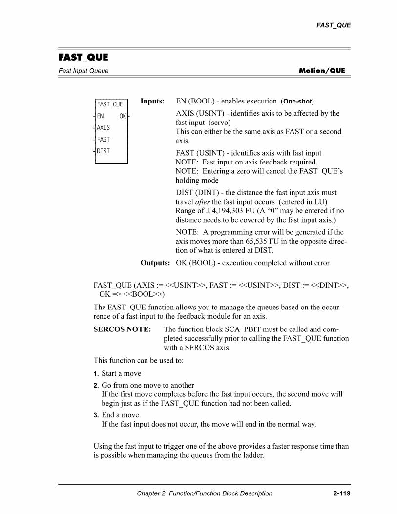
FAST_QUE
FAST_QUEFast Input Queue Motion/QUE
FAST_QUE (AXIS := <<USINT>>, FAST := <<USINT>>, DIST := <<DINT>>, OK => <<BOOL>>)
The FAST_QUE function allows you to manage the queues based on the occur-rence of a fast input to the feedback module for an axis.
SERCOS NOTE: The function block SCA_PBIT must be called and com-pleted successfully prior to calling the FAST_QUE function with a SERCOS axis.
This function can be used to:
1. Start a move
2. Go from one move to anotherIf the first move completes before the fast input occurs, the second move will begin just as if the FAST_QUE function had not been called.
3. End a moveIf the fast input does not occur, the move will end in the normal way.
Using the fast input to trigger one of the above provides a faster response time than is possible when managing the queues from the ladder.
⁄ƒƒƒƒƒƒƒƒƒø ≥FAST_QUE ≥ ≥ ≥ ¥EN OK√ ≥ ≥ ¥AXIS ≥ ≥ ≥ ¥FAST ≥ ≥ ≥ ¥DIST ≥ ≥ ≥ ¿ƒƒƒƒƒƒƒƒƒŸ
Inputs: EN (BOOL) - enables execution (One-shot)
AXIS (USINT) - identifies axis to be affected by the fast input (servo)This can either be the same axis as FAST or a second axis.
FAST (USINT) - identifies axis with fast inputNOTE: Fast input on axis feedback required.NOTE: Entering a zero will cancel the FAST_QUE’s holding mode
DIST (DINT) - the distance the fast input axis must travel after the fast input occurs (entered in LU)Range of ± 4,194,303 FU (A “0” may be entered if no distance needs to be covered by the fast input axis.)
NOTE: A programming error will be generated if the axis moves more than 65,535 FU in the opposite direc-tion of what is entered at DIST.
Outputs: OK (BOOL) - execution completed without error
Chapter 2 Function/Function Block Description 2-119
FAST_QUE
The update rate entered in setup for the axis identified at AXIS and the axis identi-fied at FAST must be the same.
NOTE: An internal bit remains on for eight updates after a fast input event occurs. If the FAST_QUE is called during those eight updates, the bit is ignored until it changes state again. Therefore, to ensure that you do not miss a fast input event, there should always be nine or more updates between events. (One iteration equals eight updates.)
When the FAST_QUE is called, a “holding” mode for any of the three actions is in effect until the following two conditions are met:
• The fast input on the axis identified at FAST occurs.
• The FAST axis has moved the designated distance entered at DIST.
The holding mode is cleared when both of these conditions are met and it is then possible to manipulate the moves in the queue(s) in one of the following ways.
TO START A MOVE:
Step 1.Call the FAST_QUE function.
Step 2.Put the move to occur on the fast input in the active queue.
The move will start after the fast input occurs and the FAST axis has moved the specified distance. If the fast input occurs before the FAST_QUE is called, it will be ignored. You must call the FAST_QUE before the fast input occurs.
TO MOVE FROM ONE MOVE TO ANOTHER:
Step 1. Put the first move in the active queue. It will begin.
Step 2. Call the FAST_QUE function.
Step 3. Put the second move in the next queue.
The first move will be aborted and the second move will begin after the fast input occurs and the fast input axis has moved the specified distance. Again, the FAST_QUE function must be called before the fast input occurs or it will be ignored until the next fast input.
TO END A MOVE:
Step 1. Put the move in the active queue. It will begin.
Step 2. Call the FAST_QUE function.
The move will end when the fast in occurs and the axis moves the distance entered at DIST. Do not put any move in the next queue until after the fast input occurs. If you do, the second move will begin when the fast input occurs as described above.
A programming error (P_ERRORS function) will occur on the axis identi-fied at AXIS on the FAST_QUE function if the fast axis travels in the wrong direction more than 65,535 FU. If the axis continued to move in the wrong direction, a move could be started unexpectedly.
2-120 Chapter 2 Function/Function Block Description
FAST_QUE
It is important that you ensure this does not occur. Do this by programming an ABORTALL function at the occurrence of this programming error to remove all moves from the queues.
The programming error must be reset with the P_RESET function.
Note: The move will travel the distance specified in DIST and then you abort the move. The total distance traveled beyond the fast input will equal the DIST value plus whatever distance it takes to decel.
The holding mode can be cancelled by calling the FAST_QUE function with a zero on the function input labeled “FAST”. Cancelling the holding mode will cause the axis to behave as if no FAST_QUE had been called. Note that if a queued move is waiting on a fast input to begin, canceling the holding mode will cause the move to begin.
Chapter 2 Function/Function Block Description 2-121
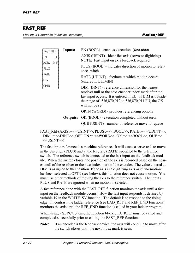
FAST_REF
FAST_REFFast Input Reference (Machine Reference) Motion/REF
FAST_REF(AXIS := <<USINT>>, PLUS := <<BOOL>>, RATE := <<UDINT>>, DIM := <<DINT>>, OPTION := <<WORD>>, OK => <<BOOL>>, QUE => <<USINT>>)
The fast input reference is a machine reference. It will cause a servo axis to move in the direction (PLUS) and at the feedrate (RATE) specified to the reference switch. The reference switch is connected to the fast input on the feedback mod-ule. When the switch closes, the position of the axis is recorded based on the near-est null of the resolver or the next index mark of the encoder. The value entered at DIM is assigned to this position. If the axis is a digitizing axis or if “no motion” has been selected at OPTN (see below), this function does not cause motion. You must use other methods of moving the axis to the reference switch. The inputs PLUS and RATE are ignored when no motion is selected.
A fast reference done with the FAST_REF function monitors the axis until a fast input on the feedback module occurs. How the fast input responds is defined by variable 19 in the WRITE_SV function. The default is to respond to the rising edge. In contrast, the ladder reference (see LAD_REF and REF_END functions) monitors the axis until the REF_END function is called in your ladder program.
When using a SERCOS axis, the function block SCA_RFIT must be called and completed successfully prior to calling the FAST_REF function.
Note: If an encoder is the feedback device, the axis will continue to move after the switch closes until the next index mark is seen.
⁄ƒƒƒƒƒƒƒƒƒø ≥FAST_REF ≥ ≥ ≥ ¥EN OK√ ≥ ≥ ¥AXIS QUE√ ≥ ≥ ¥PLUS ≥ ≥ ≥ ¥RATE ≥ ≥ ≥ ¥DIM ≥ ≥ ≥ ¥OPTN ≥ ¿ƒƒƒƒƒƒƒƒƒŸ
Inputs: EN (BOOL) - enables execution (One-shot)
AXIS (USINT) - identifies axis (servo or digitizing)NOTE: Fast input on axis feedback required.
PLUS (BOOL) - indicates direction of motion to refer-ence switch
RATE (UDINT) - feedrate at which motion occurs (entered in LU/MIN)
DIM (DINT) - reference dimension for the nearest resolver null or the next encoder index mark after the fast input occurs. It is entered in LU. If DIM is outside the range of -536,870,912 to 536,870,911 FU, the OK will not be set.
OPTN (WORD) - provides referencing options
Outputs: OK (BOOL) - execution completed without error
QUE (USINT) - number of reference move for queue
2-122 Chapter 2 Function/Function Block Description
FAST_REF
The OPTN input provides the following options:
If no option is desired, enter a “0.”
Option inputs
Ignore the index/null
Choosing this option allows a reference to occur which ignores the index mark of an encoder or the null of a resolver during the reference cycle. If bit 0 is set to “1,” the reference position assigned by DIM will be assigned to the position the axis is at when the fast input makes its transition.
With an encoder, the axis will stop immediately after the fast input transitions. The axis does not continue movement until the index mark is reached. NOTE: This makes the reference switch position given with the READ_SV function invalid. With a resolver, the reference switch position available with the READ_SV func-tion is valid.
No motion
The no motion option allows a reference to occur without any motion. The axis is put into a mode whereby it is watching for the conditions of a reference cycle. Even though no move is placed in the queue, a queue must be available. A move will be initiated by the ladder following the reference cycle.
Once the call is made, the reference complete flag goes low until the fast input occurs and the index mark (unless “ignore index” option is active) is received. The reference complete flag goes high once these events occur and the axis position takes on the reference value at DIM.
If the move type is VEL, RATIO_GR, LAD_REF, or FAST_REF, the new axis position assigned by the no-motion reference has no effect on the move itself. With a DISTANCE move, the actual distance covered will be the same. If a no-motion reference occurs during a position move, the endpoint will be reached.
If a no-motion reference is used during a RATIO_PRO move, the lock on point of the slave axis to the master axis may be undefined. This is not recommended.
Note: A fast reference can also be performed on a digitizing axis. You must cause the axis to move and the fast input to occur. Use variable 29 with the READ_SV function to read the reference switch position. REF_DNE? can also be used with digitizing axes.
Option Binary value Hex value1. Ignore index/null 00000000 00000001 00012. No motion 00000000 00000010 00023. Null setup 00000000 00000100 0004
Chapter 2 Function/Function Block Description 2-123
FAST_REF
Null Setup
This option will establish a null position for a digital drive axis with resolver feed-back or single-turn Stegmann encoder feedback in addition to perfoming the fast reference. The null position will be stored in the digital drive’s flash memory and will be retained through power cycles. This feature allows the user to omit the setup process of physically positioning the reference switch to be near the null. To provide repeatable references, this option bit should be set with the first call to FAST_REF and should be reset for subsequent calls.
2-124 Chapter 2 Function/Function Block Description
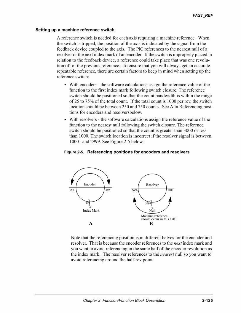
FAST_REF
Setting up a machine reference switch
A reference switch is needed for each axis requiring a machine reference. When the switch is tripped, the position of the axis is indicated by the signal from the feedback device coupled to the axis. The PiC references to the nearest null of a resolver or the next index mark of an encoder. If the switch is improperly placed in relation to the feedback device, a reference could take place that was one revolu-tion off of the previous reference. To ensure that you will always get an accurate repeatable reference, there are certain factors to keep in mind when setting up the reference switch:
• With encoders - the software calculations assign the reference value of the function to the first index mark following switch closure. The reference switch should be positioned so that the count bandwidth is within the range of 25 to 75% of the total count. If the total count is 1000 per rev, the switch location should be between 250 and 750 counts. See A in Referencing posi-tions for encoders and resolversbelow.
• With resolvers - the software calculations assign the reference value of the function to the nearest null following the switch closure. The reference switch should be positioned so that the count is greater than 3000 or less than 1000. The switch location is incorrect if the resolver signal is between 10001 and 2999. See Figure 2-5 below.
Figure 2-5. Referencing positions for encoders and resolvers
Note that the referencing position is in different halves for the encoder and resolver. That is because the encoder references to the next index mark and you want to avoid referencing in the same half of the encoder revolution as the index mark. The resolver references to the nearest null so you want to avoid referencing around the half-rev point.
Encoder
750 250
0
999
Resolver
3000 1000
0Null
BA
Index Mark
Machine referenceshould occur in this half.
3999
Chapter 2 Function/Function Block Description 2-125
FAST_REF
• After a machine reference is completed, the READ_SV function (see servo data functions) can be used to read the reference switch position after the switch closes by entering variable 29 in the VAR input and viewing the RSLT output (in feedback units) in PiCPro. An encoder reference switch position is the distance between the switch closure and the index mark. A resolver reference switch position is the position of the resolver when the switch is closed.
If the reference switch position read from the READ_SV function is between 25% and 75% for the total encoder count or less than 1000 or more than 3000 for a resolver, than your reference switch is positioned properly to ensure accurate, repeatable referencing. If the position read is outside of these ranges you can change the position of the feedback device when the switch transitions by either moving the reference switch or the feedback device. Perform the machine refer-ence again and read the reference switch position to see if it is within the range.
One factor to keep in mind when performing a machine reference from the ladder with the LAD_REF function is there can be a lag time between the actual closing of the reference switch and the software calculations. This is caused by up to 32 ms of update time and up to 200 ms of scan time. (200 ms is the maximum time limit for one scan before a loss of scan occurs.) This could affect the repeatability of your reference especially when referencing at high velocities.
The example which follows illustrates this. Assume an axis using resolver feed-back is moving at a velocity of 50000 counts per minute (NOTE: 50000 C/MIN = .83333 C/ms). Looking at an example with the maximum update and scan time: (32 ms + 200 ms) * .83333 C/ms = 193.333 or 193 C. If the READ_SV function gave a reading of 1000 C for the reference switch position, the actual position of the device when the switch closed could be up to 1193 counts (or 807 counts if referencing in the negative direction). By using a lower velocity, the number of counts is lowered. For example, if the velocity is 5000 C/MIN, then the count is as follows (NOTE: 5000 C/MIN = .08333 C/ms): (32 ms + 200 ms) * .08333 C/ms = 193.33 or 193 C.
The actual position of the reference could be up to 1019 counts (981 counts if ref-erencing in the negative direction). When the machine reference is done using the fast input with the FAST_REF function, the recording of the reference switch tran-sition is not affected by what the ladder scan is executing at the time. There is vir-tually no lag between the time the reference occurs and the time it is recorded. This is a very accurate method of referencing. The only time consideration for the fast input is a short (50 µs ) turn-on time.
Note: This function cannot be used with the stepper axis module.
NOTE
If in adjusting the location of the reference switch or the feedback de-vice, you find that the result of variable 29 increases when you expectit to decrease after performing the machine reference, move the de-vice in the opposite direction until the reading is acceptable.
2-126 Chapter 2 Function/Function Block Description
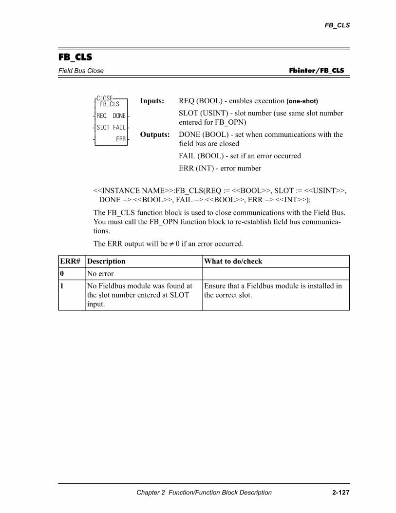
FB_CLS
FB_CLSField Bus Close Fbinter/FB_CLS
<<INSTANCE NAME>>:FB_CLS(REQ := <<BOOL>>, SLOT := <<USINT>>, DONE => <<BOOL>>, FAIL => <<BOOL>>, ERR => <<INT>>);
The FB_CLS function block is used to close communications with the Field Bus. You must call the FB_OPN function block to re-establish field bus communica-tions.
The ERR output will be ≠ 0 if an error occurred.
⁄CLOSEƒƒƒƒø ≥ FB_CLS ≥ ≥ ≥ ¥REQ DONE√ ≥ ≥ ¥SLOT FAIL√ ≥ ≥ ¥ ERR√ ¿ƒƒƒƒƒƒƒƒƒŸ
Inputs: REQ (BOOL) - enables execution (one-shot)
SLOT (USINT) - slot number (use same slot number entered for FB_OPN)
Outputs: DONE (BOOL) - set when communications with the field bus are closed
FAIL (BOOL) - set if an error occurred
ERR (INT) - error number
ERR# Description What to do/check
0 No error
1 No Fieldbus module was found at the slot number entered at SLOT input.
Ensure that a Fieldbus module is installed in the correct slot.
Chapter 2 Function/Function Block Description 2-127
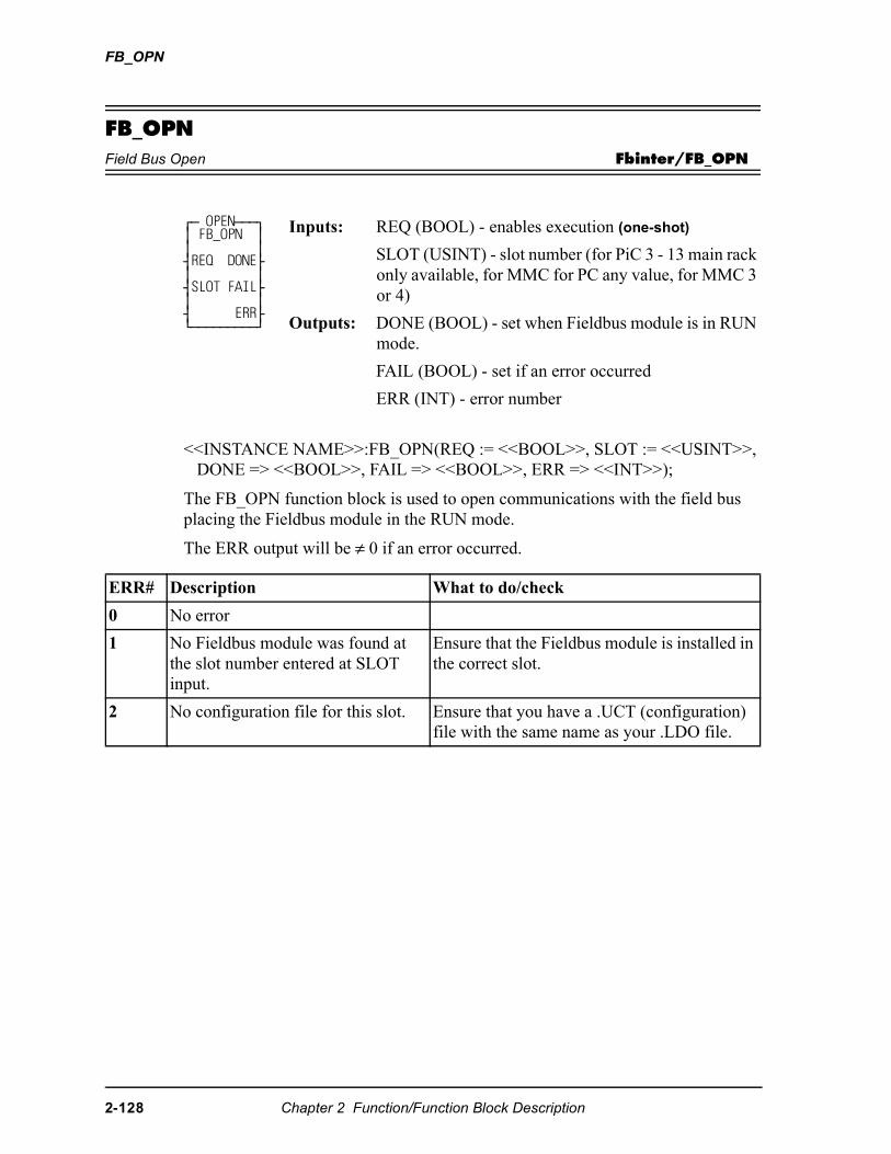
FB_OPN
FB_OPNField Bus Open Fbinter/FB_OPN
<<INSTANCE NAME>>:FB_OPN(REQ := <<BOOL>>, SLOT := <<USINT>>, DONE => <<BOOL>>, FAIL => <<BOOL>>, ERR => <<INT>>);
The FB_OPN function block is used to open communications with the field bus placing the Fieldbus module in the RUN mode.
The ERR output will be ≠ 0 if an error occurred.
⁄ƒ OPENƒƒƒø ≥ FB_OPN ≥ ≥ ≥ ¥REQ DONE√ ≥ ≥ ¥SLOT FAIL√ ≥ ≥ ¥ ERR√ ¿ƒƒƒƒƒƒƒƒƒŸ
Inputs: REQ (BOOL) - enables execution (one-shot)
SLOT (USINT) - slot number (for PiC 3 - 13 main rack only available, for MMC for PC any value, for MMC 3 or 4)
Outputs: DONE (BOOL) - set when Fieldbus module is in RUN mode.
FAIL (BOOL) - set if an error occurred
ERR (INT) - error number
ERR# Description What to do/check
0 No error
1 No Fieldbus module was found at the slot number entered at SLOT input.
Ensure that the Fieldbus module is installed in the correct slot.
2 No configuration file for this slot. Ensure that you have a .UCT (configuration) file with the same name as your .LDO file.
2-128 Chapter 2 Function/Function Block Description
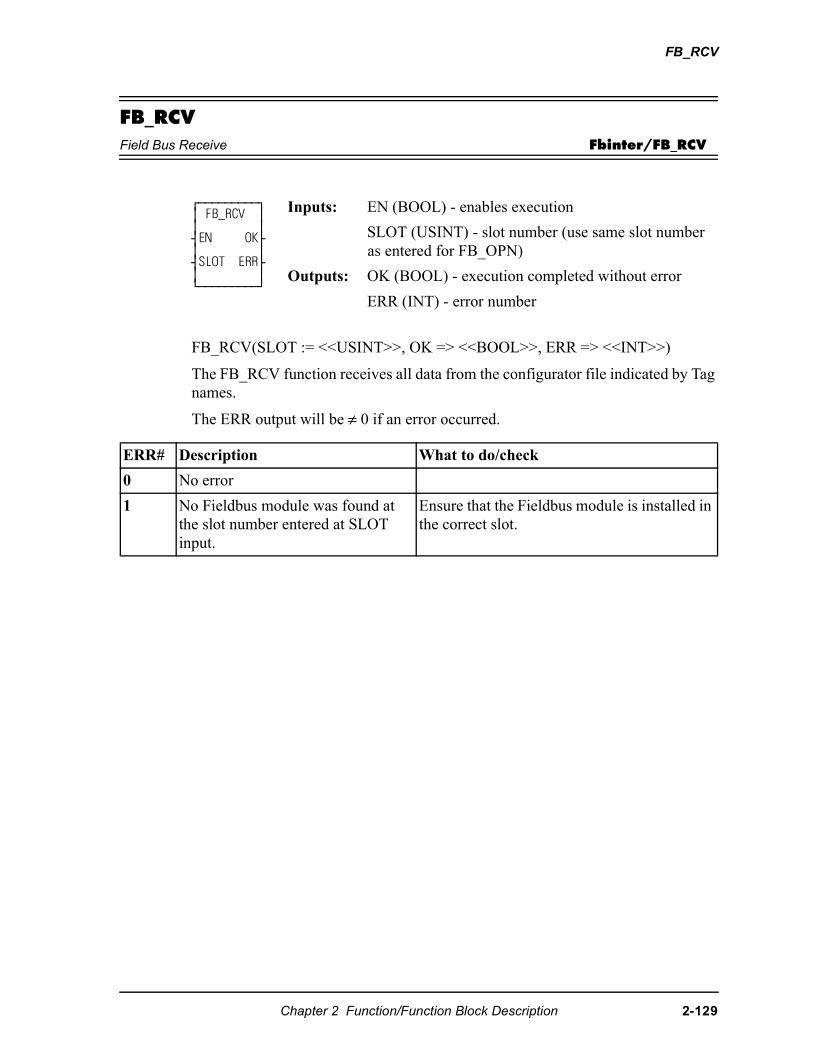
FB_RCV
FB_RCVField Bus Receive Fbinter/FB_RCV
FB_RCV(SLOT := <<USINT>>, OK => <<BOOL>>, ERR => <<INT>>)
The FB_RCV function receives all data from the configurator file indicated by Tag names.
The ERR output will be ≠ 0 if an error occurred.
⁄ƒƒƒƒƒƒƒƒƒø ≥ FB_RCV ≥ ≥ ≥ ¥EN OK√ ≥ ≥ ¥SLOT ERR√ ≥ ≥ ¿ƒƒƒƒƒƒƒƒƒŸ
Inputs: EN (BOOL) - enables execution
SLOT (USINT) - slot number (use same slot number as entered for FB_OPN)
Outputs: OK (BOOL) - execution completed without error
ERR (INT) - error number
ERR# Description What to do/check
0 No error
1 No Fieldbus module was found at the slot number entered at SLOT input.
Ensure that the Fieldbus module is installed in the correct slot.
Chapter 2 Function/Function Block Description 2-129
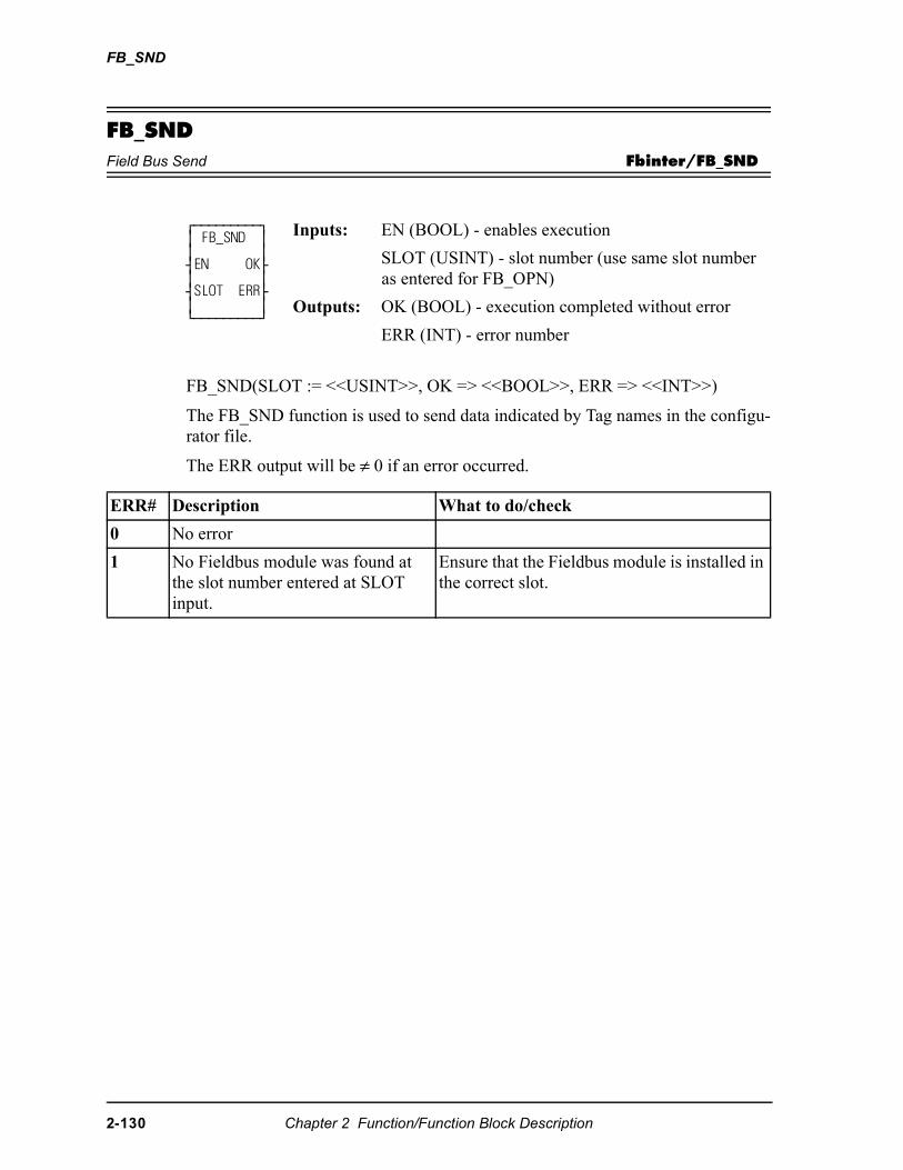
FB_SND
FB_SNDField Bus Send Fbinter/FB_SND
FB_SND(SLOT := <<USINT>>, OK => <<BOOL>>, ERR => <<INT>>)
The FB_SND function is used to send data indicated by Tag names in the configu-rator file.
The ERR output will be ≠ 0 if an error occurred.
⁄ƒƒƒƒƒƒƒƒƒø ≥ FB_SND ≥ ≥ ≥ ¥EN OK√ ≥ ≥ ¥SLOT ERR√ ≥ ≥ ¿ƒƒƒƒƒƒƒƒƒŸ
Inputs: EN (BOOL) - enables execution
SLOT (USINT) - slot number (use same slot number as entered for FB_OPN)
Outputs: OK (BOOL) - execution completed without error
ERR (INT) - error number
ERR# Description What to do/check
0 No error
1 No Fieldbus module was found at the slot number entered at SLOT input.
Ensure that the Fieldbus module is installed in the correct slot.
2-130 Chapter 2 Function/Function Block Description
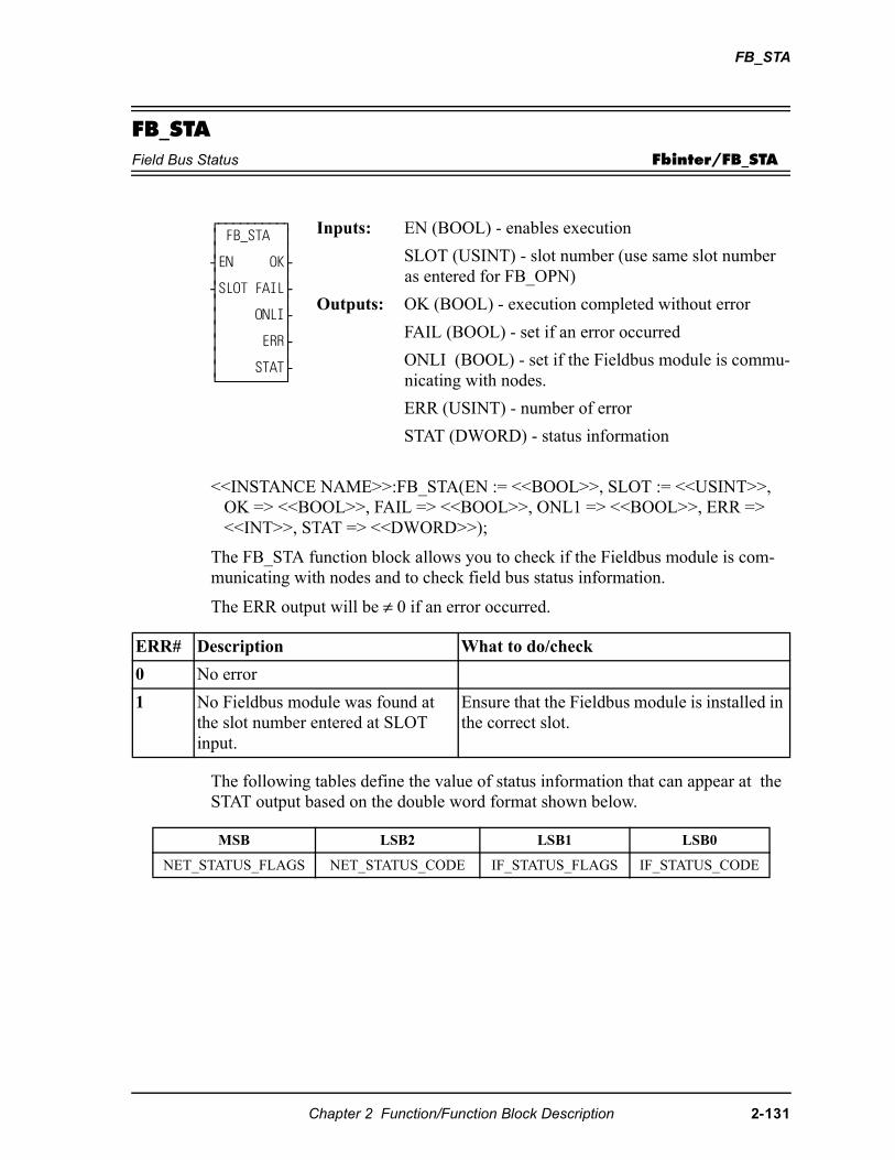
FB_STA
FB_STAField Bus Status Fbinter/FB_STA
<<INSTANCE NAME>>:FB_STA(EN := <<BOOL>>, SLOT := <<USINT>>, OK => <<BOOL>>, FAIL => <<BOOL>>, ONL1 => <<BOOL>>, ERR => <<INT>>, STAT => <<DWORD>>);
The FB_STA function block allows you to check if the Fieldbus module is com-municating with nodes and to check field bus status information.
The ERR output will be ≠ 0 if an error occurred.
The following tables define the value of status information that can appear at the STAT output based on the double word format shown below.
⁄ƒƒƒƒƒƒƒƒƒø ≥ FB_STA ≥ ≥ ≥ ¥EN OK√ ≥ ≥ ¥SLOT FAIL√ ≥ ≥ ≥ ONLI√ ≥ ≥ ≥ ERR√ ≥ ≥ ≥ STAT√ ¿ƒƒƒƒƒƒƒƒƒŸ
Inputs: EN (BOOL) - enables execution
SLOT (USINT) - slot number (use same slot number as entered for FB_OPN)
Outputs: OK (BOOL) - execution completed without error
FAIL (BOOL) - set if an error occurred
ONLI (BOOL) - set if the Fieldbus module is commu-nicating with nodes.
ERR (USINT) - number of error
STAT (DWORD) - status information
ERR# Description What to do/check
0 No error
1 No Fieldbus module was found at the slot number entered at SLOT input.
Ensure that the Fieldbus module is installed in the correct slot.
MSB LSB2 LSB1 LSB0
NET_STATUS_FLAGS NET_STATUS_CODE IF_STATUS_FLAGS IF_STATUS_CODE
Chapter 2 Function/Function Block Description 2-131
FB_STA
NET_STATUS_FLAGS
NET_STATUS_FLAGS indicates various conditions related to the Fieldbus mod-ule network interface. Each Fieldbus module supports a subset of the status flags as appropriate.
NET_STATUS_CODE
NET_STATUS_CODE indicates the status of the Fieldbus module network inter-face. Each Fieldbus module supports a subset of the status codes as appropriate.
Bit Name Description
0 Warning The communication error warning threshold has been exceeded.
1 NO_POWER Bus power is not present.
2 NO_BUS Bus is not connected.
3 - 7 (Reserved)
Value Name Description
00 OFFLINE Network interface is offline.
01 OFFLINE_FAULT Network interface is offline due to a network fault.
02 OFFLINE_BAD_CFG
Network interface is offline due to a configuration fault (invalid or duplicate station address, invalid baud rate, invalid DIP-switch data, etc.)
03 ONLINE Network interface is online, no faults detected.
04 ONLINE_FAULT Network interface is online, one or more network services has failed.
05 ONLINE_ACTIVE Network interface is online and is exchanging data, no faults detected.
Any failure of a secure service is reported.
06 ONLINE_IDLE Network interface is online and is exchanging data, one or more services is receiving an idle indication, no faults detected.
07 ONLINE_INACTIVE Network interface is online, one or more previously active services has been suspended, no faults detected.
08-0FFh
(Reserved)
2-132 Chapter 2 Function/Function Block Description
FB_STA
IF_STATUS_FLAGS
IF_STATUS_FLAGS indicates various conditions related to the Fieldbus module end of the data exchange interface.
IF_STATUS_CODE
IF_STATUS_CODE indicates various conditions related to the Fieldbus module data exchange interface.
NOTE: FB_XXX functions can be used with either a DeviceNet or Profibus net-work. Fieldbus is used as a generic term.
Bit Name Description
0 EVENT_LOST An event was lost due to a full event queue. This flag is cleared when the data exchange interface is closed.
1 - 7 (Reserved)
Value Name Description
00 CLOSED Data exchange interface is closed.
01 OPEN Data exchange interface is open.
02 HEARTBEAT_FAULT
Data exchange interface is faulted due to heartbeat timeout. (Same behavior as closed.)
03h - 0FFh
(Reserved)
Chapter 2 Function/Function Block Description 2-133
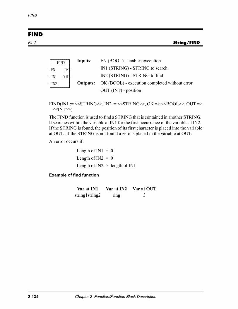
FIND
FINDFind String/FIND
FIND(IN1 := <<STRING>>, IN2 := <<STRING>>, OK => <<BOOL>>, OUT => <<INT>>)
The FIND function is used to find a STRING that is contained in another STRING. It searches within the variable at IN1 for the first occurrence of the variable at IN2. If the STRING is found, the position of its first character is placed into the variable at OUT. If the STRING is not found a zero is placed in the variable at OUT.
An error occurs if:
Example of find function
⁄ƒƒƒƒƒƒƒƒƒø ≥ FIND ≥ ≥ ≥ ¥EN OK√ ≥ ≥ ¥IN1 OUT√ ≥ ≥ ¥IN2 ≥ ¿ƒƒƒƒƒƒƒƒƒŸ
Inputs: EN (BOOL) - enables execution
IN1 (STRING) - STRING to search
IN2 (STRING) - STRING to find
Outputs: OK (BOOL) - execution completed without error
OUT (INT) - position
Length of IN1 = 0
Length of IN2 = 0
Length of IN2 > length of IN1
Var at IN1 Var at IN2 Var at OUTstring1string2 ring 3
2-134 Chapter 2 Function/Function Block Description
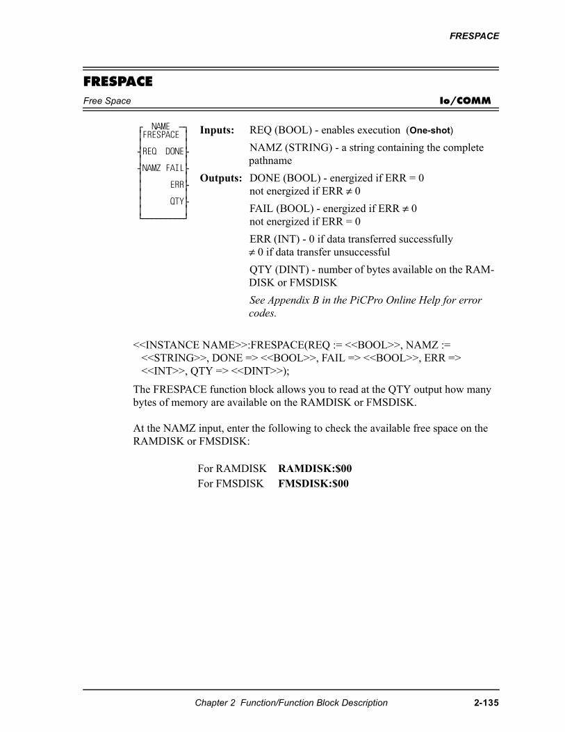
FRESPACE
FRESPACEFree Space Io/COMM
<<INSTANCE NAME>>:FRESPACE(REQ := <<BOOL>>, NAMZ := <<STRING>>, DONE => <<BOOL>>, FAIL => <<BOOL>>, ERR => <<INT>>, QTY => <<DINT>>);
The FRESPACE function block allows you to read at the QTY output how many bytes of memory are available on the RAMDISK or FMSDISK.
At the NAMZ input, enter the following to check the available free space on the RAMDISK or FMSDISK:
⁄ NAME ƒø ≥FRESPACE ≥ ≥ ≥ ¥REQ DONE√ ≥ ≥ ¥NAMZ FAIL√ ≥ ≥ ≥ ERR√ ≥ ≥ ≥ QTY√ ≥ ≥ ¿ƒƒƒƒƒƒƒƒƒŸ
Inputs: REQ (BOOL) - enables execution (One-shot)
NAMZ (STRING) - a string containing the complete pathname
Outputs: DONE (BOOL) - energized if ERR = 0not energized if ERR ≠ 0
FAIL (BOOL) - energized if ERR ≠ 0not energized if ERR = 0
ERR (INT) - 0 if data transferred successfully≠ 0 if data transfer unsuccessful
QTY (DINT) - number of bytes available on the RAM-DISK or FMSDISK
See Appendix B in the PiCPro Online Help for error codes.
For RAMDISK RAMDISK:$00For FMSDISK FMSDISK:$00
Chapter 2 Function/Function Block Description 2-135
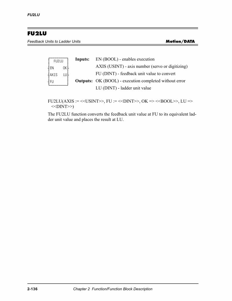
FU2LU
FU2LUFeedback Units to Ladder Units Motion/DATA
FU2LU(AXIS := <<USINT>>, FU := <<DINT>>, OK => <<BOOL>>, LU => <<DINT>>)
The FU2LU function converts the feedback unit value at FU to its equivalent lad-der unit value and places the result at LU.
⁄ƒƒƒƒƒƒƒƒƒø ≥ FU2LU ≥ ≥ ≥ ¥EN OK√ ≥ ≥ ¥AXIS LU√ ≥ ≥ ¥FU ≥¿ƒƒƒƒƒƒƒƒƒŸ
Inputs: EN (BOOL) - enables execution
AXIS (USINT) - axis number (servo or digitizing)
FU (DINT) - feedback unit value to convert
Outputs: OK (BOOL) - execution completed without error
LU (DINT) - ladder unit value
2-136 Chapter 2 Function/Function Block Description
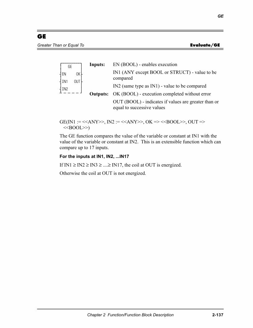
GE
GEGreater Than or Equal To Evaluate/GE
GE(IN1 := <<ANY>>, IN2 := <<ANY>>, OK => <<BOOL>>, OUT => <<BOOL>>)
The GE function compares the value of the variable or constant at IN1 with the value of the variable or constant at IN2. This is an extensible function which can compare up to 17 inputs.
For the inputs at IN1, IN2, ...IN17
If IN1 ≥ IN2 ≥ IN3 ≥ ....≥ IN17, the coil at OUT is energized.
Otherwise the coil at OUT is not energized.
⁄ƒƒƒƒƒƒƒƒƒø ≥ GE ≥ ≥ ≥ ¥EN OK√ ≥ ≥ ¥IN1 OUT√ ≥ ≥ ¥IN2 ≥ ¡ ƒ ƒ ƒ ƒ Ÿ
Inputs: EN (BOOL) - enables execution
IN1 (ANY except BOOL or STRUCT) - value to be compared
IN2 (same type as IN1) - value to be compared
Outputs: OK (BOOL) - execution completed without error
OUT (BOOL) - indicates if values are greater than or equal to successive values
Chapter 2 Function/Function Block Description 2-137
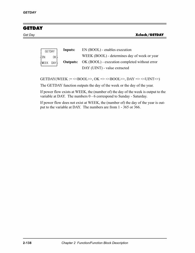
GETDAY
GETDAYGet Day Xclock/GETDAY
GETDAY(WEEK := <<BOOL>>, OK => <<BOOL>>, DAY => <<UINT>>)
The GETDAY function outputs the day of the week or the day of the year.
If power flow exists at WEEK, the (number of) the day of the week is output to the variable at DAY. The numbers 0 - 6 correspond to Sunday - Saturday.
If power flow does not exist at WEEK, the (number of) the day of the year is out-put to the variable at DAY. The numbers are from 1 - 365 or 366.
⁄ƒƒƒƒƒƒƒƒƒø ≥ GETDAY ≥ ≥ ≥ ¥EN OK√ ≥ ≥ ¥WEEK DAY√ ¿ƒƒƒƒƒƒƒƒƒŸ
Inputs: EN (BOOL) - enables execution
WEEK (BOOL) - determines day of week or year
Outputs: OK (BOOL) - execution completed without error
DAY (UINT) - value extracted
2-138 Chapter 2 Function/Function Block Description
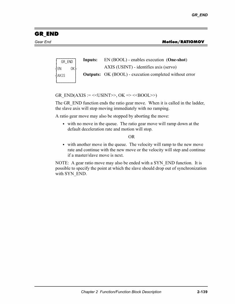
GR_END
GR_ENDGear End Motion/RATIOMOV
GR_END(AXIS := <<USINT>>, OK => <<BOOL>>)
The GR_END function ends the ratio gear move. When it is called in the ladder, the slave axis will stop moving immediately with no ramping.
A ratio gear move may also be stopped by aborting the move:
• with no move in the queue. The ratio gear move will ramp down at the default deceleration rate and motion will stop.
OR
• with another move in the queue. The velocity will ramp to the new move rate and continue with the new move or the velocity will step and continue if a master/slave move is next.
NOTE: A gear ratio move may also be ended with a SYN_END function. It is possible to specify the point at which the slave should drop out of synchronization with SYN_END.
⁄ƒƒƒƒƒƒƒƒƒø ≥ GR_END ≥ ≥ ≥ ¥EN OK√ ≥ ≥ ¥AXIS ≥ ≥ ≥ ¿ƒƒƒƒƒƒƒƒƒŸ
Inputs: EN (BOOL) - enables execution (One-shot)
AXIS (USINT) - identifies axis (servo)
Outputs: OK (BOOL) - execution completed without error
Chapter 2 Function/Function Block Description 2-139
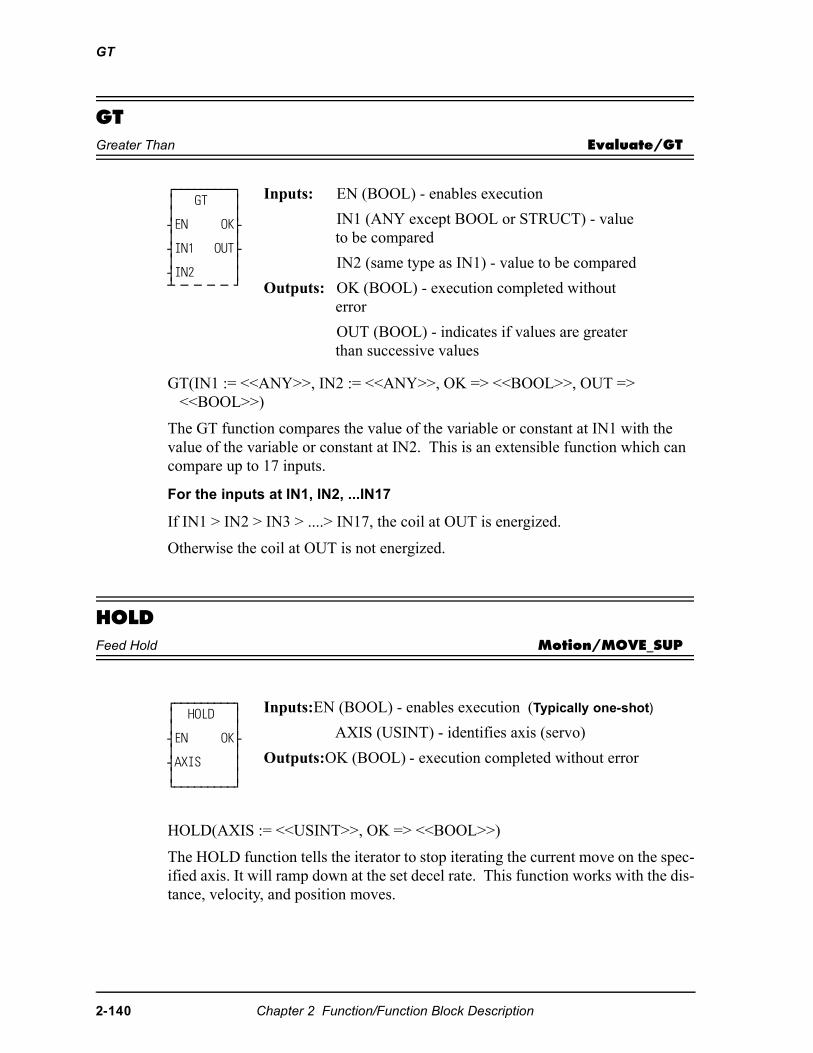
GT
GTGreater Than Evaluate/GT
GT(IN1 := <<ANY>>, IN2 := <<ANY>>, OK => <<BOOL>>, OUT => <<BOOL>>)
The GT function compares the value of the variable or constant at IN1 with the value of the variable or constant at IN2. This is an extensible function which can compare up to 17 inputs.
For the inputs at IN1, IN2, ...IN17
If IN1 > IN2 > IN3 > ....> IN17, the coil at OUT is energized.
Otherwise the coil at OUT is not energized.
HOLDFeed Hold Motion/MOVE_SUP
HOLD(AXIS := <<USINT>>, OK => <<BOOL>>)
The HOLD function tells the iterator to stop iterating the current move on the spec-ified axis. It will ramp down at the set decel rate. This function works with the dis-tance, velocity, and position moves.
⁄ƒƒƒƒƒƒƒƒƒø ≥ GT ≥ ≥ ≥ ¥EN OK√ ≥ ≥ ¥IN1 OUT√ ≥ ≥ ¥IN2 ≥ ¡ ƒ ƒ ƒ ƒ Ÿ
Inputs: EN (BOOL) - enables execution
IN1 (ANY except BOOL or STRUCT) - value to be compared
IN2 (same type as IN1) - value to be compared
Outputs: OK (BOOL) - execution completed without error
OUT (BOOL) - indicates if values are greater than successive values
⁄ƒƒƒƒƒƒƒƒƒø ≥ HOLD ≥ ≥ ≥ ¥EN OK√ ≥ ≥ ¥AXIS ≥ ≥ ≥ ¿ƒƒƒƒƒƒƒƒƒŸ
Inputs:EN (BOOL) - enables execution (Typically one-shot)
AXIS (USINT) - identifies axis (servo)
Outputs:OK (BOOL) - execution completed without error
2-140 Chapter 2 Function/Function Block Description
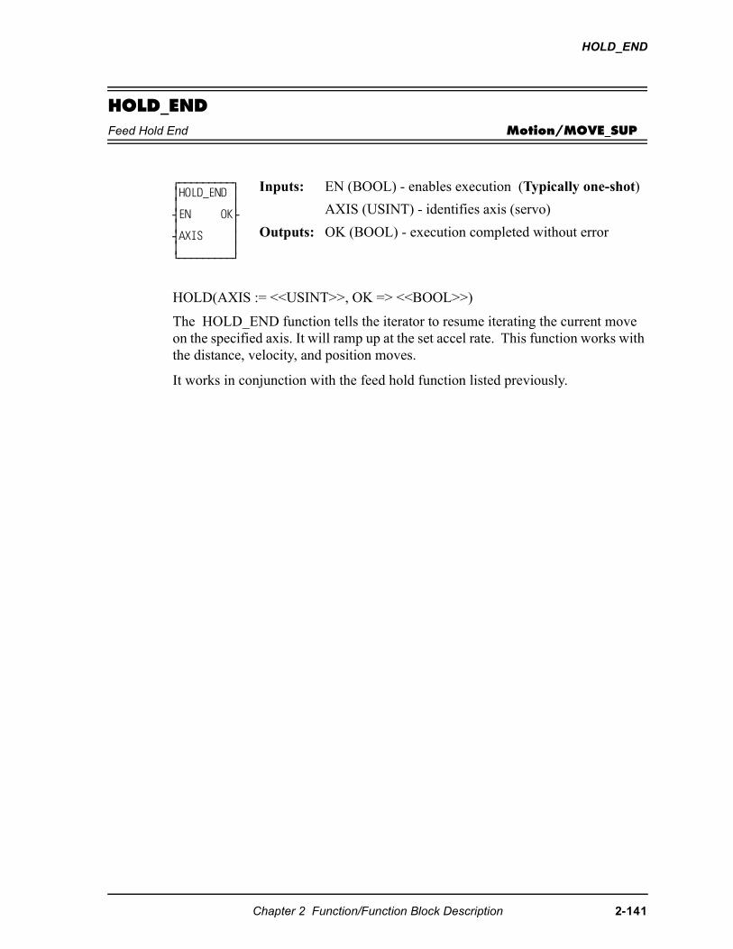
HOLD_END
HOLD_ENDFeed Hold End Motion/MOVE_SUP
HOLD(AXIS := <<USINT>>, OK => <<BOOL>>)
The HOLD_END function tells the iterator to resume iterating the current move on the specified axis. It will ramp up at the set accel rate. This function works with the distance, velocity, and position moves.
It works in conjunction with the feed hold function listed previously.
⁄ƒƒƒƒƒƒƒƒƒø ≥HOLD_END ≥ ≥ ≥ ¥EN OK√ ≥ ≥ ¥AXIS ≥ ≥ ≥ ¿ƒƒƒƒƒƒƒƒƒŸ
Inputs: EN (BOOL) - enables execution (Typically one-shot)
AXIS (USINT) - identifies axis (servo)
Outputs: OK (BOOL) - execution completed without error
Chapter 2 Function/Function Block Description 2-141
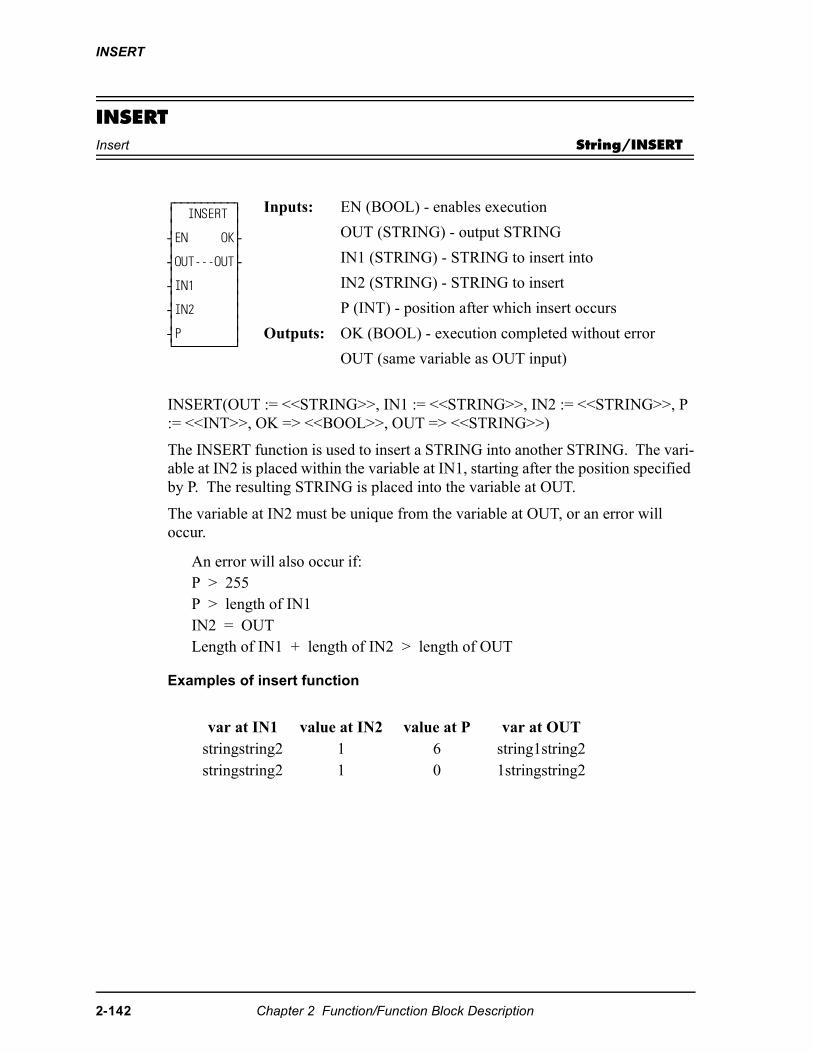
INSERT
INSERTInsert String/INSERT
INSERT(OUT := <<STRING>>, IN1 := <<STRING>>, IN2 := <<STRING>>, P := <<INT>>, OK => <<BOOL>>, OUT => <<STRING>>)
The INSERT function is used to insert a STRING into another STRING. The vari-able at IN2 is placed within the variable at IN1, starting after the position specified by P. The resulting STRING is placed into the variable at OUT.
The variable at IN2 must be unique from the variable at OUT, or an error will occur.
Examples of insert function
⁄ƒƒƒƒƒƒƒƒƒø ≥ INSERT ≥ ≥ ≥ ¥EN OK√ ≥ ≥ ¥OUT---OUT√ ≥ ≥ ¥IN1 ≥ ≥ ≥ ¥IN2 ≥ ≥ ≥ ¥P ≥ ¿ƒƒƒƒƒƒƒƒƒŸ
Inputs: EN (BOOL) - enables execution
OUT (STRING) - output STRING
IN1 (STRING) - STRING to insert into
IN2 (STRING) - STRING to insert
P (INT) - position after which insert occurs
Outputs: OK (BOOL) - execution completed without error
OUT (same variable as OUT input)
An error will also occur if:P > 255P > length of IN1IN2 = OUTLength of IN1 + length of IN2 > length of OUT
var at IN1 value at IN2 value at P var at OUTstringstring2 1 6 string1string2stringstring2 1 0 1stringstring2
2-142 Chapter 2 Function/Function Block Description
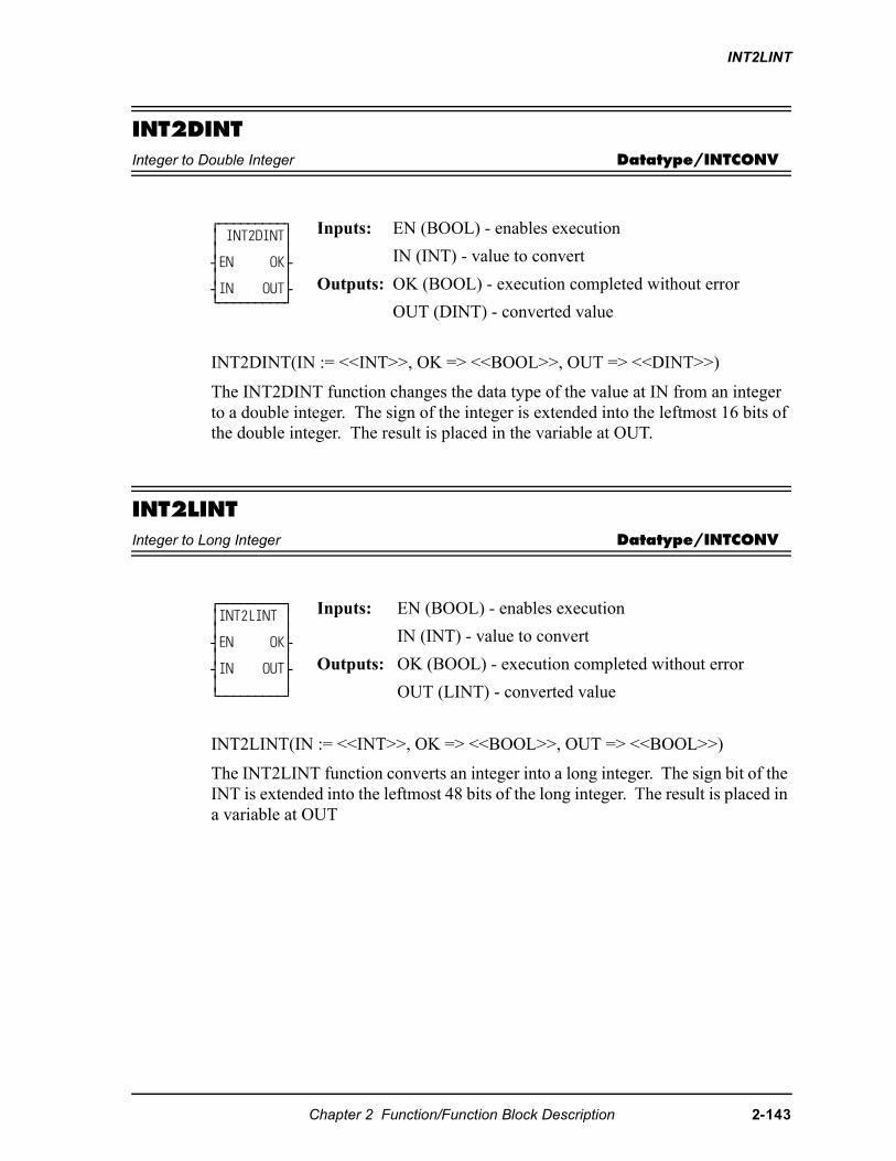
INT2LINT
INT2DINTInteger to Double Integer Datatype/INTCONV
INT2DINT(IN := <<INT>>, OK => <<BOOL>>, OUT => <<DINT>>)
The INT2DINT function changes the data type of the value at IN from an integer to a double integer. The sign of the integer is extended into the leftmost 16 bits of the double integer. The result is placed in the variable at OUT.
INT2LINTInteger to Long Integer Datatype/INTCONV
INT2LINT(IN := <<INT>>, OK => <<BOOL>>, OUT => <<BOOL>>)
The INT2LINT function converts an integer into a long integer. The sign bit of the INT is extended into the leftmost 48 bits of the long integer. The result is placed in a variable at OUT
⁄ƒƒƒƒƒƒƒƒƒø ≥ INT2DINT≥ ≥ ≥ ¥EN OK√ ≥ ≥ ¥IN OUT√ ¿ƒƒƒƒƒƒƒƒƒŸ
Inputs: EN (BOOL) - enables execution
IN (INT) - value to convert
Outputs: OK (BOOL) - execution completed without error
OUT (DINT) - converted value
⁄ƒƒƒƒƒƒƒƒƒø≥INT2LINT ≥≥ ≥¥EN OK√≥ ≥¥IN OUT√≥ ≥¿ƒƒƒƒƒƒƒƒƒŸ
Inputs: EN (BOOL) - enables execution
IN (INT) - value to convert
Outputs: OK (BOOL) - execution completed without error
OUT (LINT) - converted value
Chapter 2 Function/Function Block Description 2-143
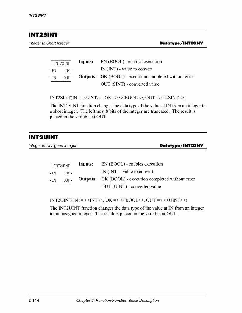
INT2SINT
INT2SINTInteger to Short Integer Datatype/INTCONV
INT2SINT(IN := <<INT>>, OK => <<BOOL>>, OUT => <<SINT>>)
The INT2SINT function changes the data type of the value at IN from an integer to a short integer. The leftmost 8 bits of the integer are truncated. The result is placed in the variable at OUT.
INT2UINTInteger to Unsigned Integer Datatype/INTCONV
INT2UINT(IN := <<INT>>, OK => <<BOOL>>, OUT => <<UINT>>)
The INT2UINT function changes the data type of the value at IN from an integer to an unsigned integer. The result is placed in the variable at OUT.
⁄ƒƒƒƒƒƒƒƒƒø ≥ INT2SINT≥ ≥ ≥ ¥EN OK√ ≥ ≥ ¥IN OUT√ ¿ƒƒƒƒƒƒƒƒƒŸ
Inputs: EN (BOOL) - enables execution
IN (INT) - value to convert
Outputs: OK (BOOL) - execution completed without error
OUT (SINT) - converted value
⁄ƒƒƒƒƒƒƒƒƒø ≥ INT2UINT≥ ≥ ≥ ¥EN OK√ ≥ ≥ ¥IN OUT√ ¿ƒƒƒƒƒƒƒƒƒŸ
Inputs: EN (BOOL) - enables execution
IN (INT) - value to convert
Outputs: OK (BOOL) - execution completed without error
OUT (UINT) - converted value
2-144 Chapter 2 Function/Function Block Description
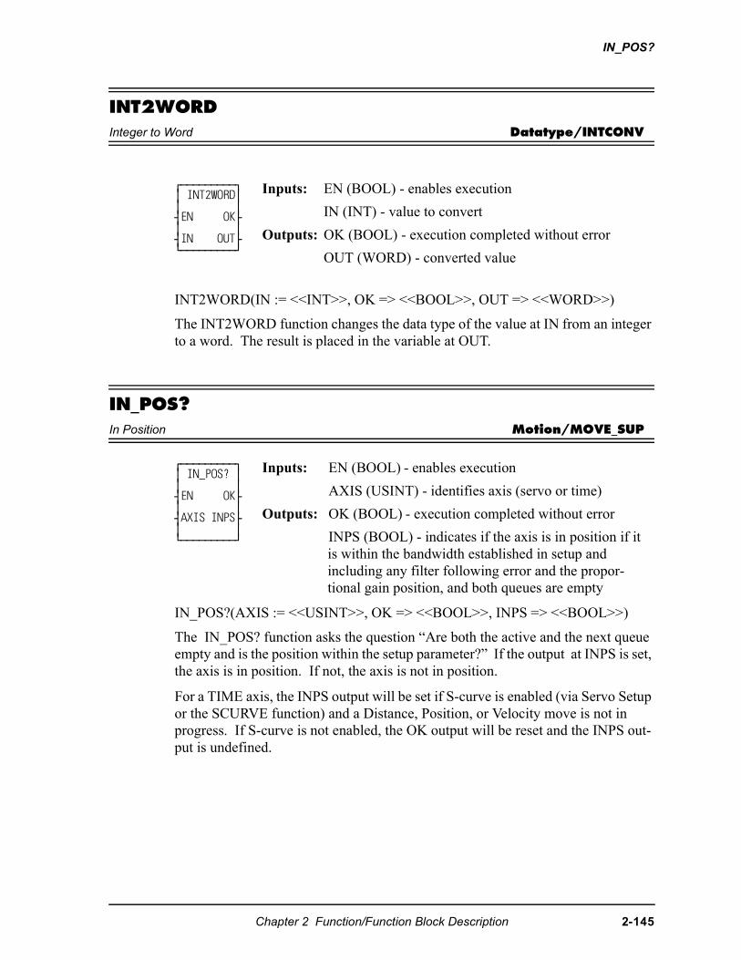
IN_POS?
INT2WORDInteger to Word Datatype/INTCONV
INT2WORD(IN := <<INT>>, OK => <<BOOL>>, OUT => <<WORD>>)
The INT2WORD function changes the data type of the value at IN from an integer to a word. The result is placed in the variable at OUT.
IN_POS?In Position Motion/MOVE_SUP
IN_POS?(AXIS := <<USINT>>, OK => <<BOOL>>, INPS => <<BOOL>>)
The IN_POS? function asks the question “Are both the active and the next queue empty and is the position within the setup parameter?” If the output at INPS is set, the axis is in position. If not, the axis is not in position.
For a TIME axis, the INPS output will be set if S-curve is enabled (via Servo Setup or the SCURVE function) and a Distance, Position, or Velocity move is not in progress. If S-curve is not enabled, the OK output will be reset and the INPS out-put is undefined.
⁄ƒƒƒƒƒƒƒƒƒø ≥ INT2WORD≥ ≥ ≥ ¥EN OK√ ≥ ≥ ¥IN OUT√ ¿ƒƒƒƒƒƒƒƒƒŸ
Inputs: EN (BOOL) - enables execution
IN (INT) - value to convert
Outputs: OK (BOOL) - execution completed without error
OUT (WORD) - converted value
⁄ƒƒƒƒƒƒƒƒƒø ≥ IN_POS? ≥ ≥ ≥ ¥EN OK√ ≥ ≥ ¥AXIS INPS√ ≥ ≥ ¿ƒƒƒƒƒƒƒƒƒŸ
Inputs: EN (BOOL) - enables execution
AXIS (USINT) - identifies axis (servo or time)
Outputs: OK (BOOL) - execution completed without error
INPS (BOOL) - indicates if the axis is in position if it is within the bandwidth established in setup and including any filter following error and the propor-tional gain position, and both queues are empty
Chapter 2 Function/Function Block Description 2-145
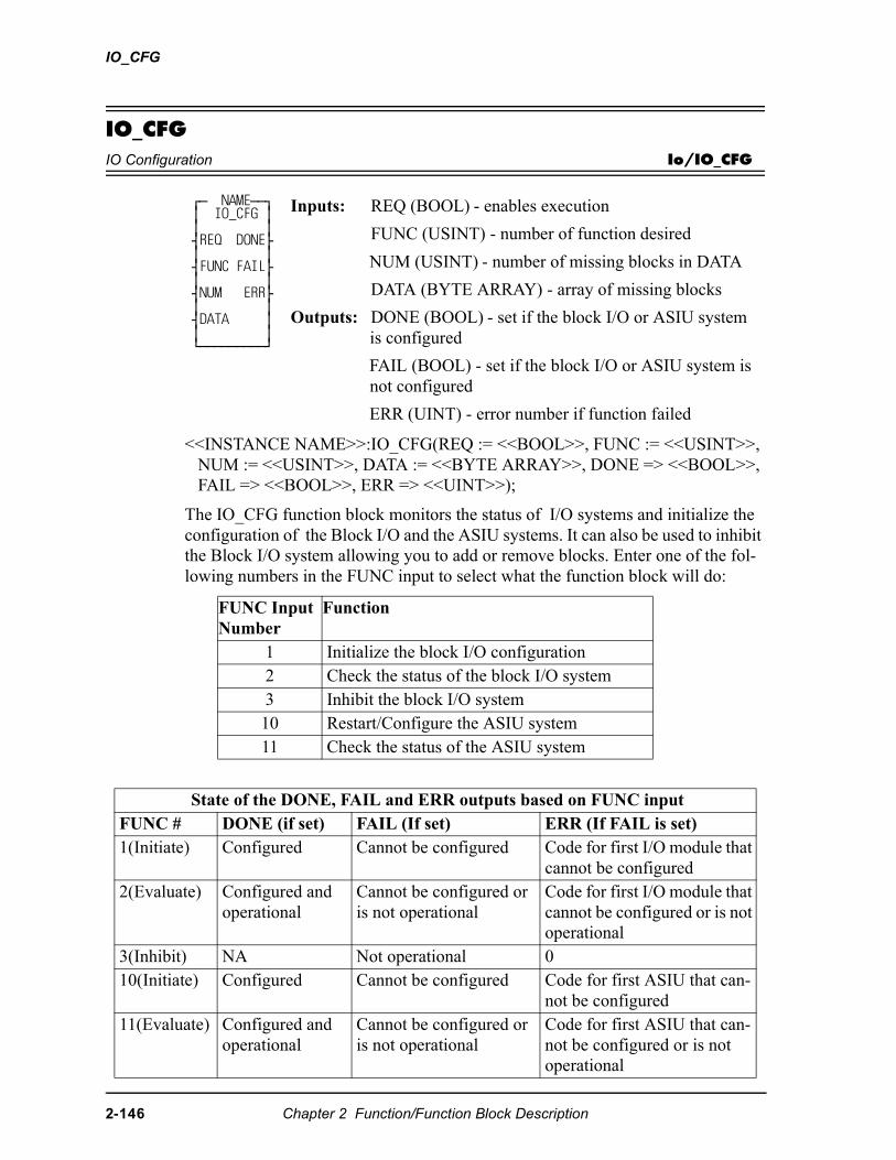
IO_CFG
IO_CFGIO Configuration Io/IO_CFG
<<INSTANCE NAME>>:IO_CFG(REQ := <<BOOL>>, FUNC := <<USINT>>, NUM := <<USINT>>, DATA := <<BYTE ARRAY>>, DONE => <<BOOL>>, FAIL => <<BOOL>>, ERR => <<UINT>>);
The IO_CFG function block monitors the status of I/O systems and initialize the configuration of the Block I/O and the ASIU systems. It can also be used to inhibit the Block I/O system allowing you to add or remove blocks. Enter one of the fol-lowing numbers in the FUNC input to select what the function block will do:
⁄ƒ NAMEƒƒø ≥ IO_CFG ≥ ≥ ≥ ¥REQ DONE√ ≥ ≥ ¥FUNC FAIL√ ≥ ≥ ¥NUM ERR√ ≥ ≥ ¥DATA ≥ ≥ ≥ ¿ƒƒƒƒƒƒƒƒƒŸ
Inputs: REQ (BOOL) - enables execution
FUNC (USINT) - number of function desired
NUM (USINT) - number of missing blocks in DATA
DATA (BYTE ARRAY) - array of missing blocks
Outputs: DONE (BOOL) - set if the block I/O or ASIU system is configured
FAIL (BOOL) - set if the block I/O or ASIU system is not configured
ERR (UINT) - error number if function failed
FUNC Input Number
Function
1 Initialize the block I/O configuration2 Check the status of the block I/O system3 Inhibit the block I/O system10 Restart/Configure the ASIU system11 Check the status of the ASIU system
State of the DONE, FAIL and ERR outputs based on FUNC inputFUNC # DONE (if set) FAIL (If set) ERR (If FAIL is set)1(Initiate) Configured Cannot be configured Code for first I/O module that
cannot be configured2(Evaluate) Configured and
operationalCannot be configured or is not operational
Code for first I/O module that cannot be configured or is not operational
3(Inhibit) NA Not operational 010(Initiate) Configured Cannot be configured Code for first ASIU that can-
not be configured11(Evaluate) Configured and
operationalCannot be configured or is not operational
Code for first ASIU that can-not be configured or is not operational
2-146 Chapter 2 Function/Function Block Description
IO_CFG
The error number at the ERR output can be a master rack diagnostic code (22_) or an expansion rack diagnostic code (3_ _) or an MMC for PC ASIU diagnostic code (24_), (25_), (260), where the _ indicates the number of the module or ASIU. Note: Only the -01 or later block I/O modules are capable of changing their initial configuration. Any block I/O modules in your system with a part number ending with -00 cannot be used with this function block to change the configuration of modules (function 1). These -00 modules must be addressed consecutively in the hardware declarations starting with “1” and all declared blocks must be physically in the system before scanning can occur.
The IO_CFG function block is used in conjunction with the I/O Config/Scan Options radio buttons on the hardware declarations page of the main ladder. If the radio button is checked for Reconfigurable I/O and continue to scan with Mas-ter Rack, Remote Rack or Block I/O failures, the CPU will no longer indicate a blink code when an I/O configuration error or failure is detected. This function block provides that blink code to the ladder. If the operator needs that code, then the ladder must make it available to the operator. Otherwise, the operator can use PiCPro to do an Online | Status... to get the error information in the Run Time Failure description (a message that indicates which module or connection has failed). If the radio button is checked for Reconfigurable I/O and continue to scan with Master Rack, Remote Rack, Block or ASIU failures, the CPU will no longer indicate a blink code when an I/O configuration error or failure is detected; and additionally, ASIU failures will not cause a ladder to stop scanning. This func-tion block provides that blink code to the ladder. Note: A separate instance of IO_CFG is required for the Master Rack/Block/Remote I/O system and a separate instance is required for the ASIU system as different FUNC inputs are required to monitor each system.
When the programmer checks any of these radio buttons, a dialog is immediately displayed reminding the programmer of the I/O_CFG function block in the ladder. When this feature is enabled, the CPU will continue to scan with an I/O or ASIU failure. If this feature is enabled, the ladder must have an IO_CFG function block to monitor the I/O systems, and an IO_CFG function block to monitor the ASIU system (if used). This allows the ladder to react to any failures.
Chapter 2 Function/Function Block Description 2-147
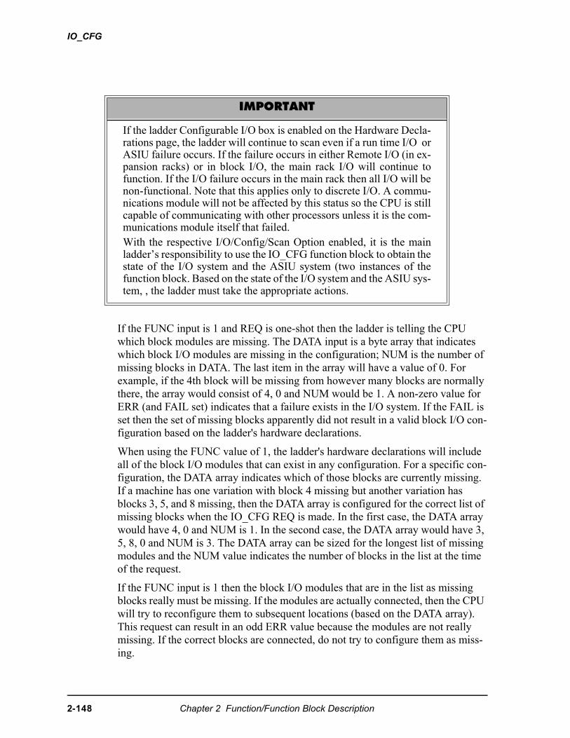
IO_CFG
If the FUNC input is 1 and REQ is one-shot then the ladder is telling the CPU which block modules are missing. The DATA input is a byte array that indicates which block I/O modules are missing in the configuration; NUM is the number of missing blocks in DATA. The last item in the array will have a value of 0. For example, if the 4th block will be missing from however many blocks are normally there, the array would consist of 4, 0 and NUM would be 1. A non-zero value for ERR (and FAIL set) indicates that a failure exists in the I/O system. If the FAIL is set then the set of missing blocks apparently did not result in a valid block I/O con-figuration based on the ladder's hardware declarations.
When using the FUNC value of 1, the ladder's hardware declarations will include all of the block I/O modules that can exist in any configuration. For a specific con-figuration, the DATA array indicates which of those blocks are currently missing. If a machine has one variation with block 4 missing but another variation has blocks 3, 5, and 8 missing, then the DATA array is configured for the correct list of missing blocks when the IO_CFG REQ is made. In the first case, the DATA array would have 4, 0 and NUM is 1. In the second case, the DATA array would have 3, 5, 8, 0 and NUM is 3. The DATA array can be sized for the longest list of missing modules and the NUM value indicates the number of blocks in the list at the time of the request.
If the FUNC input is 1 then the block I/O modules that are in the list as missing blocks really must be missing. If the modules are actually connected, then the CPU will try to reconfigure them to subsequent locations (based on the DATA array). This request can result in an odd ERR value because the modules are not really missing. If the correct blocks are connected, do not try to configure them as miss-ing.
IMPORTANT
If the ladder Configurable I/O box is enabled on the Hardware Decla-rations page, the ladder will continue to scan even if a run time I/O orASIU failure occurs. If the failure occurs in either Remote I/O (in ex-pansion racks) or in block I/O, the main rack I/O will continue tofunction. If the I/O failure occurs in the main rack then all I/O will benon-functional. Note that this applies only to discrete I/O. A commu-nications module will not be affected by this status so the CPU is stillcapable of communicating with other processors unless it is the com-munications module itself that failed.With the respective I/O/Config/Scan Option enabled, it is the mainladder’s responsibility to use the IO_CFG function block to obtain thestate of the I/O system and the ASIU system (two instances of thefunction block. Based on the state of the I/O system and the ASIU sys-tem, , the ladder must take the appropriate actions.
2-148 Chapter 2 Function/Function Block Description
IO_CFG
If the FUNC input is 2 then the ladder is asking the CPU to provide the state of the I/O system. A non-zero value for ERR (and FAIL set) indicates that a failure exists in the I/O system. This value is the blink code that would be sent by the CPU if this PiCPro feature is not used. If the FAIL is set then the ladder must react appropri-ately to the failure in its I/O system.
If the FUNC input is 3 then the remote I/O system is inhibited (for all block I/O modules and any remote expansion racks). The main rack I/O remains operational in this state. Block I/O modules may be moved or removed without causing an I/O failure. The FAIL output is set indicating the I/O system is not operational but the ERR output will be zero. To enable the I/O system after inhibiting the block I/O chain in this manner, the IO_CFG must be triggered (with REQ) with the FUNC at 1 so that the block I/O system is configured again.
If the FUNC input is 10 then the ladder is requesting the CPU to restart the ASIU’s. This is used after a ASIU failure or power loss. After the ASIU’s are restarted, it will be necessary for the ladder to perform the servo start up sequence with SV_INIT etc.
If the FUNC input is 11, the ladder is requesting the CPU to provide the state of the ASIU system. A non-zero value for ERR (and FAIL set) indicates that a failure still exists in the ASIU system. This value is the blink code that would be sent by the CPU if this PiCPro feature was not used. If the FAIL is set, the ladder must react appropriately to the failure in the ASIU system.
For the FUNC inputs of 1, 2, 10, and 11 the ERR output is the blink code value. The default animation display for a UINT variable will be decimal. By entering an initial value of 16#0 for this variable, the animation will display the value in hexa-decimal format. For example, if the first block I/O module failed or was not con-nected, the ERR output would be shown as 929 in decimal or 3A1 in hexidecimal (depending on an initial value, if any). The 3A1 hex value is read as 3-10-1, which corresponds to a blink code of 3-10-1. This blink code sequence indicates the first block I/O module. To make this important data easier to reference using animation, the initial value of 16#0 for the ERR output variable is recommended.
Chapter 2 Function/Function Block Description 2-149
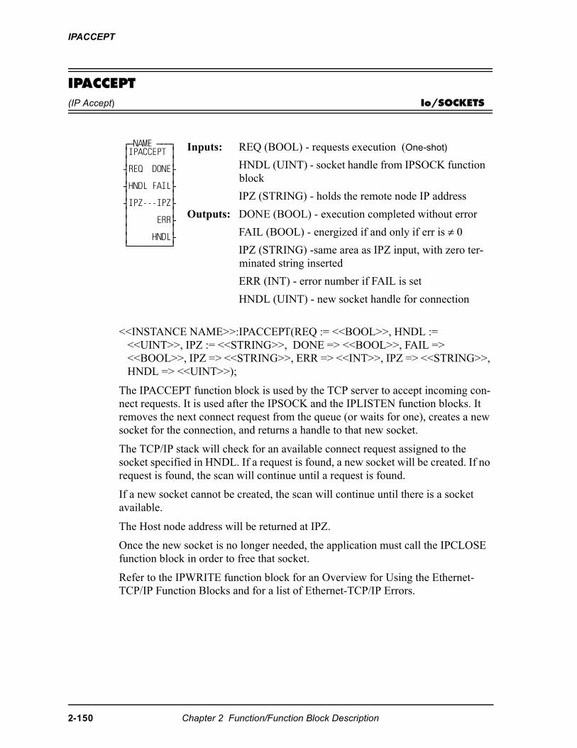
IPACCEPT
IPACCEPT(IP Accept) Io/SOCKETS
<<INSTANCE NAME>>:IPACCEPT(REQ := <<BOOL>>, HNDL := <<UINT>>, IPZ := <<STRING>>, DONE => <<BOOL>>, FAIL => <<BOOL>>, IPZ => <<STRING>>, ERR => <<INT>>, IPZ => <<STRING>>, HNDL => <<UINT>>);
The IPACCEPT function block is used by the TCP server to accept incoming con-nect requests. It is used after the IPSOCK and the IPLISTEN function blocks. It removes the next connect request from the queue (or waits for one), creates a new socket for the connection, and returns a handle to that new socket.
The TCP/IP stack will check for an available connect request assigned to the socket specified in HNDL. If a request is found, a new socket will be created. If no request is found, the scan will continue until a request is found.
If a new socket cannot be created, the scan will continue until there is a socket available.
The Host node address will be returned at IPZ.
Once the new socket is no longer needed, the application must call the IPCLOSE function block in order to free that socket.
Refer to the IPWRITE function block for an Overview for Using the Ethernet-TCP/IP Function Blocks and for a list of Ethernet-TCP/IP Errors.
⁄ƒNAME ƒƒƒø ≥IPACCEPT ≥ ≥ ≥ ¥REQ DONE√ ≥ ≥ ¥HNDL FAIL√ ≥ ≥ ¥IPZ---IPZ√ ≥ ≥ ≥ ERR√ ≥ ≥ ≥ HNDL√ ¿ƒƒƒƒƒƒƒƒƒŸ
Inputs: REQ (BOOL) - requests execution (One-shot)
HNDL (UINT) - socket handle from IPSOCK function block
IPZ (STRING) - holds the remote node IP address
Outputs: DONE (BOOL) - execution completed without error
FAIL (BOOL) - energized if and only if err is ≠ 0
IPZ (STRING) -same area as IPZ input, with zero ter-minated string inserted
ERR (INT) - error number if FAIL is set
HNDL (UINT) - new socket handle for connection
2-150 Chapter 2 Function/Function Block Description
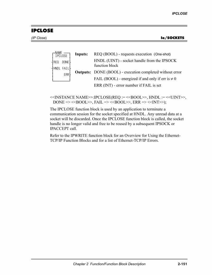
IPCLOSE
IPCLOSE(IP Close) Io/SOCKETS
<<INSTANCE NAME>>:IPCLOSE(REQ := <<BOOL>>, HNDL := <<UINT>>, DONE => <<BOOL>>, FAIL => <<BOOL>>, ERR => <<INT>>);
The IPCLOSE function block is used by an application to terminate a communication session for the socket specified at HNDL. Any unread data at a socket will be discarded. Once the IPCLOSE function block is called, the socket handle is no longer valid and free to be reused by a subsequent IPSOCK or IPACCEPT call.
Refer to the IPWRITE function block for an Overview for Using the Ethernet-TCP/IP Function Blocks and for a list of Ethernet-TCP/IP Errors.
⁄ƒNAME ƒƒƒø ≥ IPCLOSE ≥ ≥ ≥ ¥REQ DONE√ ≥ ≥ ¥HNDL FAIL√ ≥ ≥ ≥ ERR√ ≥ ≥ ¿ƒƒƒƒƒƒƒƒƒŸ
Inputs: REQ (BOOL) - requests execution (One-shot)
HNDL (UINT) - socket handle from the IPSOCK function block
Outputs: DONE (BOOL) - execution completed without error
FAIL (BOOL) - energized if and only if err is ≠ 0
ERR (INT) - error number if FAIL is set
Chapter 2 Function/Function Block Description 2-151
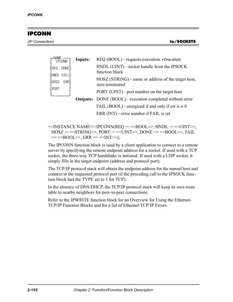
IPCONN
IPCONN(IP Connection) Io/SOCKETS
<<INSTANCE NAME>>:IPCONN(REQ := <<BOOL>>, HNDL := <<UINT>>, HOSZ := <<STRING>>, PORT := <<UINT>>, DONE => <<BOOL>>, FAIL => <<BOOL>>, ERR => <<INT>>);
The IPCONN function block is used by a client application to connect to a remote server by specifying the remote endpoint address for a socket. If used with a TCP socket, the three-way TCP handshake is initiated. If used with a UDP socket, it simply fills in the target endpoint (address and protocol port).
The TCP/IP protocol stack will obtain the endpoint address for the named host and connect to the requested protocol port (if the preceding call to the IPSOCK func-tion block had the TYPE set to 1 for TCP).
In the absence of DNS/DHCP, the TCP/IP protocol stack will keep its own route table to nearby neighbors for peer-to-peer connections.
Refer to the IPWRITE function block for an Overview for Using the Ethernet-TCP/IP Function Blocks and for a list of Ethernet-TCP/IP Errors.
⁄ƒNAME ƒƒƒø ≥ IPCONN ≥ ≥ ≥ ¥REQ DONE√ ≥ ≥ ¥HNDL FAIL√ ≥ ≥ ¥HOSZ ERR√ ≥ ≥ ¥PORT ≥ ≥ ≥ ¿ƒƒƒƒƒƒƒƒƒŸ
Inputs: REQ (BOOL) - requests execution (One-shot)
HNDL (UINT) - socket handle from the IPSOCK function block
HOSZ (STRING) - name or address of the target host, zero terminated
PORT (UINT) - port number on the target host
Outputs: DONE (BOOL) - execution completed without error
FAIL (BOOL) - energized if and only if err is ≠ 0
ERR (INT) - error number if FAIL is set
2-152 Chapter 2 Function/Function Block Description
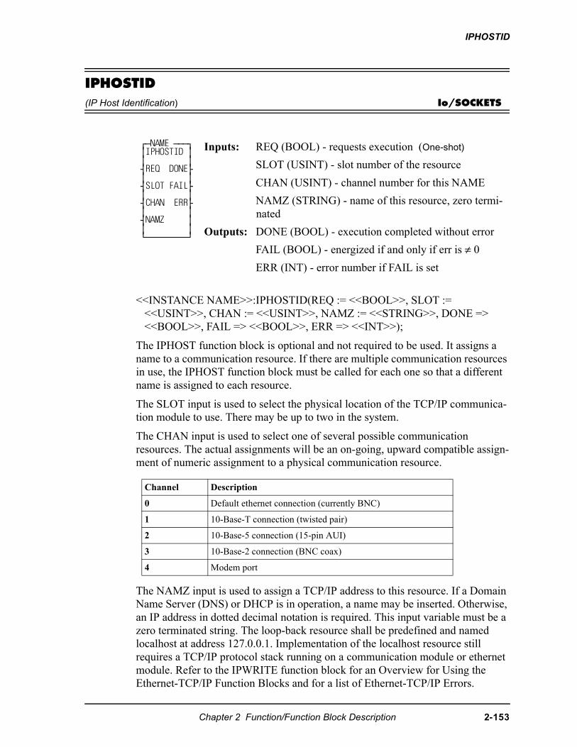
IPHOSTID
IPHOSTID(IP Host Identification) Io/SOCKETS
<<INSTANCE NAME>>:IPHOSTID(REQ := <<BOOL>>, SLOT := <<USINT>>, CHAN := <<USINT>>, NAMZ := <<STRING>>, DONE => <<BOOL>>, FAIL => <<BOOL>>, ERR => <<INT>>);
The IPHOST function block is optional and not required to be used. It assigns a name to a communication resource. If there are multiple communication resources in use, the IPHOST function block must be called for each one so that a different name is assigned to each resource.
The SLOT input is used to select the physical location of the TCP/IP communica-tion module to use. There may be up to two in the system.
The CHAN input is used to select one of several possible communication resources. The actual assignments will be an on-going, upward compatible assign-ment of numeric assignment to a physical communication resource.
The NAMZ input is used to assign a TCP/IP address to this resource. If a Domain Name Server (DNS) or DHCP is in operation, a name may be inserted. Otherwise, an IP address in dotted decimal notation is required. This input variable must be a zero terminated string. The loop-back resource shall be predefined and named localhost at address 127.0.0.1. Implementation of the localhost resource still requires a TCP/IP protocol stack running on a communication module or ethernet module. Refer to the IPWRITE function block for an Overview for Using the Ethernet-TCP/IP Function Blocks and for a list of Ethernet-TCP/IP Errors.
⁄ƒNAME ƒƒƒø ≥IPHOSTID ≥ ≥ ≥ ¥REQ DONE√ ≥ ≥ ¥SLOT FAIL√ ≥ ≥ ¥CHAN ERR√ ≥ ≥ ¥NAMZ ≥ ≥ ≥ ¿ƒƒƒƒƒƒƒƒƒŸ
Inputs: REQ (BOOL) - requests execution (One-shot)
SLOT (USINT) - slot number of the resource
CHAN (USINT) - channel number for this NAME
NAMZ (STRING) - name of this resource, zero termi-nated
Outputs: DONE (BOOL) - execution completed without error
FAIL (BOOL) - energized if and only if err is ≠ 0
ERR (INT) - error number if FAIL is set
Channel Description
0 Default ethernet connection (currently BNC)
1 10-Base-T connection (twisted pair)
2 10-Base-5 connection (15-pin AUI)
3 10-Base-2 connection (BNC coax)
4 Modem port
Chapter 2 Function/Function Block Description 2-153
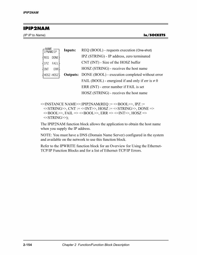
IPIP2NAM
IPIP2NAM(IP IP to Name) Io/SOCKETS
<<INSTANCE NAME>>:IPIP2NAM(REQ := <<BOOL>>, IPZ := <<STRING>>, CNT := <<INT>>, HOSZ := <<STRING>>, DONE => <<BOOL>>, FAIL => <<BOOL>>, ERR => <<INT>>, HOSZ => <<STRING>>);
The IPIP2NAM function block allows the application to obtain the host name when you supply the IP address.
NOTE: You must have a DNS (Domain Name Server) configured in the system and available on the network to use this function block.
Refer to the IPWRITE function block for an Overview for Using the Ethernet-TCP/IP Function Blocks and for a list of Ethernet-TCP/IP Errors.
⁄ƒNAME ƒƒƒø ≥IPNAM2IP ≥ ≥ ≥ ¥REQ DONE√ ≥ ≥ ¥IPZ FAIL√ ≥ ≥ ¥CNT ERR√ ≥ ≥ ¥HOSZ-HOSZ√ ¿ƒƒƒƒƒƒƒƒƒŸ
Inputs: REQ (BOOL) - requests execution (One-shot)
IPZ (STRING) - IP address, zero terminated
CNT (INT) - Size of the HOSZ buffer
HOSZ (STRING) - receives the host name
Outputs: DONE (BOOL) - execution completed without error
FAIL (BOOL) - energized if and only if err is ≠ 0
ERR (INT) - error number if FAIL is set
HOSZ (STRING) - receives the host name
2-154 Chapter 2 Function/Function Block Description
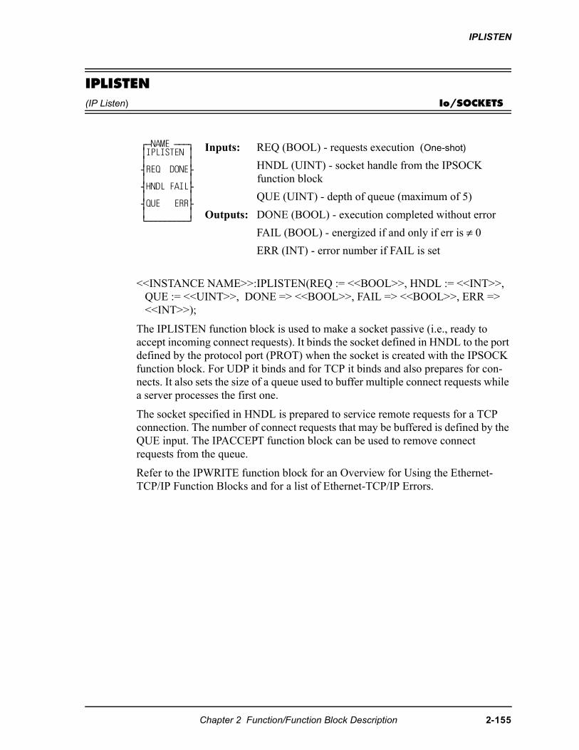
IPLISTEN
IPLISTEN(IP Listen) Io/SOCKETS
<<INSTANCE NAME>>:IPLISTEN(REQ := <<BOOL>>, HNDL := <<INT>>, QUE := <<UINT>>, DONE => <<BOOL>>, FAIL => <<BOOL>>, ERR => <<INT>>);
The IPLISTEN function block is used to make a socket passive (i.e., ready to accept incoming connect requests). It binds the socket defined in HNDL to the port defined by the protocol port (PROT) when the socket is created with the IPSOCK function block. For UDP it binds and for TCP it binds and also prepares for con-nects. It also sets the size of a queue used to buffer multiple connect requests while a server processes the first one.
The socket specified in HNDL is prepared to service remote requests for a TCP connection. The number of connect requests that may be buffered is defined by the QUE input. The IPACCEPT function block can be used to remove connect requests from the queue.
Refer to the IPWRITE function block for an Overview for Using the Ethernet-TCP/IP Function Blocks and for a list of Ethernet-TCP/IP Errors.
⁄ƒNAME ƒƒƒø ≥IPLISTEN ≥ ≥ ≥ ¥REQ DONE√ ≥ ≥ ¥HNDL FAIL√ ≥ ≥ ¥QUE ERR√ ≥ ≥ ¿ƒƒƒƒƒƒƒƒƒŸ
Inputs: REQ (BOOL) - requests execution (One-shot)
HNDL (UINT) - socket handle from the IPSOCK function block
QUE (UINT) - depth of queue (maximum of 5)
Outputs: DONE (BOOL) - execution completed without error
FAIL (BOOL) - energized if and only if err is ≠ 0
ERR (INT) - error number if FAIL is set
Chapter 2 Function/Function Block Description 2-155
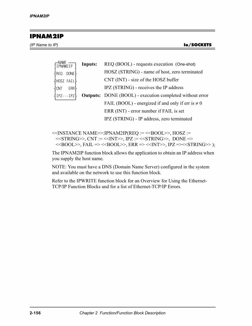
IPNAM2IP
IPNAM2IP(IP Name to IP) Io/SOCKETS
<<INSTANCE NAME>>:IPNAM2IP(REQ := <<BOOL>>, HOSZ := <<STRING>>, CNT := <<INT>>, IPZ := <<STRING>>, DONE => <<BOOL>>, FAIL => <<BOOL>>, ERR => <<INT>>, IPZ =><<STRING>> );
The IPNAM2IP function block allows the application to obtain an IP address when you supply the host name.
NOTE: You must have a DNS (Domain Name Server) configured in the system and available on the network to use this function block.
Refer to the IPWRITE function block for an Overview for Using the Ethernet-TCP/IP Function Blocks and for a list of Ethernet-TCP/IP Errors.
⁄ƒNAME ƒƒƒø ≥IPNAM2IP ≥ ≥ ≥ ¥REQ DONE√ ≥ ≥ ¥HOSZ FAIL√ ≥ ≥ ¥CNT ERR√ ≥ ≥ ¥IPZ---IPZ√ ¿ƒƒƒƒƒƒƒƒƒŸ
Inputs: REQ (BOOL) - requests execution (One-shot)
HOSZ (STRING) - name of host, zero terminated
CNT (INT) - size of the HOSZ buffer
IPZ (STRING) - receives the IP address
Outputs: DONE (BOOL) - execution completed without error
FAIL (BOOL) - energized if and only if err is ≠ 0
ERR (INT) - error number if FAIL is set
IPZ (STRING) - IP address, zero terminated
2-156 Chapter 2 Function/Function Block Description
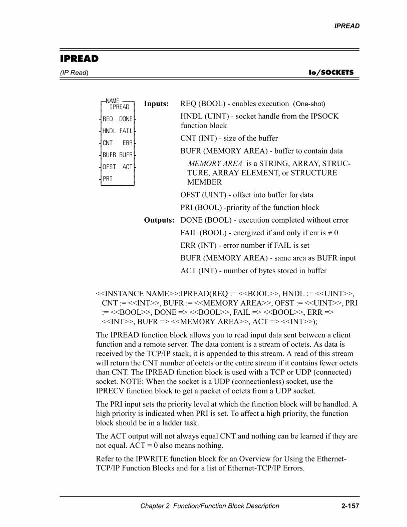
IPREAD
IPREAD(IP Read) Io/SOCKETS
<<INSTANCE NAME>>:IPREAD(REQ := <<BOOL>>, HNDL := <<UINT>>, CNT := <<INT>>, BUFR := <<MEMORY AREA>>, OFST := <<UINT>>, PRI := <<BOOL>>, DONE => <<BOOL>>, FAIL => <<BOOL>>, ERR => <<INT>>, BUFR => <<MEMORY AREA>>, ACT => <<INT>>);
The IPREAD function block allows you to read input data sent between a client function and a remote server. The data content is a stream of octets. As data is received by the TCP/IP stack, it is appended to this stream. A read of this stream will return the CNT number of octets or the entire stream if it contains fewer octets than CNT. The IPREAD function block is used with a TCP or UDP (connected) socket. NOTE: When the socket is a UDP (connectionless) socket, use the IPRECV function block to get a packet of octets from a UDP socket.
The PRI input sets the priority level at which the function block will be handled. A high priority is indicated when PRI is set. To affect a high priority, the function block should be in a ladder task.
The ACT output will not always equal CNT and nothing can be learned if they are not equal. ACT = 0 also means nothing.
Refer to the IPWRITE function block for an Overview for Using the Ethernet-TCP/IP Function Blocks and for a list of Ethernet-TCP/IP Errors.
⁄ƒNAME ƒƒƒø ≥ IPREAD ≥ ≥ ≥ ¥REQ DONE√ ≥ ≥ ¥HNDL FAIL√ ≥ ≥ ¥CNT ERR√ ≥ ≥ ¥BUFR BUFR√ ≥ ≥ ¥OFST ACT√ ≥ ≥ ¥PRI ≥ ¿ƒƒƒƒƒƒƒƒƒŸ
Inputs: REQ (BOOL) - enables execution (One-shot)
HNDL (UINT) - socket handle from the IPSOCK function block
CNT (INT) - size of the buffer
BUFR (MEMORY AREA) - buffer to contain data
MEMORY AREA is a STRING, ARRAY, STRUC-TURE, ARRAY ELEMENT, or STRUCTURE MEMBER
OFST (UINT) - offset into buffer for data
PRI (BOOL) -priority of the function block
Outputs: DONE (BOOL) - execution completed without error
FAIL (BOOL) - energized if and only if err is ≠ 0
ERR (INT) - error number if FAIL is set
BUFR (MEMORY AREA) - same area as BUFR input
ACT (INT) - number of bytes stored in buffer
Chapter 2 Function/Function Block Description 2-157
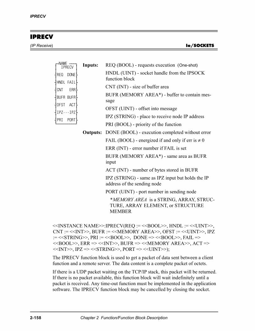
IPRECV
IPRECV(IP Receive) Io/SOCKETS
<<INSTANCE NAME>>:IPRECV(REQ := <<BOOL>>, HNDL := <<UINT>>, CNT := <<INT>>, BUFR := <<MEMORY AREA>>, OFST := <<UINT>>, IPZ := <<STRING>>, PRI := <<BOOL>>, DONE => <<BOOL>>, FAIL => <<BOOL>>, ERR => <<INT>>, BUFR => <<MEMORY AREA>>, ACT => <<INT>>, IPZ => <<STRING>>, PORT => <<UINT>>);
The IPRECV function block is used to get a packet of data sent between a client function and a remote server. The data content is a complete packet of octets.
If there is a UDP packet waiting on the TCP/IP stack, this packet will be returned. If there is no packet available, this function block will wait indefinitely until a packet is received. Any time-out function must be implemented in the application software. The IPRECV function block may be cancelled by closing the socket.
⁄ƒNAME ƒƒƒø ≥ IPRECV ≥ ≥ ≥ ¥REQ DONE√ ≥ ≥ ¥HNDL FAIL√ ≥ ≥ ¥CNT ERR√ ≥ ≥ ¥BUFR BUFR√ ≥ ≥ ¥OFST ACT√ ≥ ≥ ¥IPZ---IPZ√ ≥ ≥ ¥PRI PORT√ ¿ƒƒƒƒƒƒƒƒƒŸ
Inputs: REQ (BOOL) - requests execution (One-shot)
HNDL (UINT) - socket handle from the IPSOCK function block
CNT (INT) - size of buffer area
BUFR (MEMORY AREA*) - buffer to contain mes-sage
OFST (UINT) - offset into message
IPZ (STRING) - place to receive node IP address
PRI (BOOL) - priority of the function
Outputs: DONE (BOOL) - execution completed without error
FAIL (BOOL) - energized if and only if err is ≠ 0
ERR (INT) - error number if FAIL is set
BUFR (MEMORY AREA*) - same area as BUFR input
ACT (INT) - number of bytes stored in BUFR
IPZ (STRING) - same as IPZ input but holds the IP address of the sending node
PORT (UINT) - port number in sending node
*MEMORY AREA is a STRING, ARRAY, STRUC-TURE, ARRAY ELEMENT, or STRUCTURE MEMBER
2-158 Chapter 2 Function/Function Block Description

IPRECV
The PRI input sets the priority level at which the function block will be handled. A high priority is indicated when PRI is set. To affect a high priority, the function block should be in a ladder task
The IPRECV function block is used with a UDP (connectionless) socket. NOTE: When the socket is a TCP or UDP (connected) socket, use the IPREAD function block.
Refer to the IPWRITE function block for an Overview for Using the Ethernet-TCP/IP Function Blocks and for a list of Ethernet-TCP/IP Errors.
Chapter 2 Function/Function Block Description 2-159
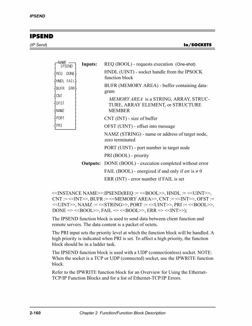
IPSEND
IPSEND(IP Send) Io/SOCKETS
<<INSTANCE NAME>>:IPSEND(REQ := <<BOOL>>, HNDL := <<UINT>>, CNT := <<INT>>, BUFR := <<MEMORY AREA>>, CNT := <<INT>>, OFST := <<UINT>>, NAMZ := <<STRING>>, PORT := <<UINT>>, PRI := <<BOOL>>, DONE => <<BOOL>>, FAIL => <<BOOL>>, ERR => <<INT>>);
The IPSEND function block is used to send data between client function and remote servers. The data content is a packet of octets.
The PRI input sets the priority level at which the function block will be handled. A high priority is indicated when PRI is set. To affect a high priority, the function block should be in a ladder task.
The IPSEND function block is used with a UDP (connectionless) socket. NOTE: When the socket is a TCP or UDP (connected) socket, use the IPWRITE function block.
Refer to the IPWRITE function block for an Overview for Using the Ethernet-TCP/IP Function Blocks and for a list of Ethernet-TCP/IP Errors.
⁄ƒNAME ƒƒƒø ≥ IPSEND ≥ ≥ ≥ ¥REQ DONE√ ≥ ≥ ¥HNDL FAIL√ ≥ ≥ ¥BUFR ERR√ ≥ ≥ ¥CNT ≥ ≥ ≥ ¥OFST ≥ ≥ ≥ ¥NAMZ ≥ ≥ ≥ ¥PORT ≥ ≥ ≥ ¥PRI ≥ ¿ƒƒƒƒƒƒƒƒƒŸ
Inputs: REQ (BOOL) - requests execution (One-shot)
HNDL (UINT) - socket handle from the IPSOCK function block
BUFR (MEMORY AREA) - buffer containing data-gram
MEMORY AREA is a STRING, ARRAY, STRUC-TURE, ARRAY ELEMENT, or STRUCTURE MEMBER
CNT (INT) - size of buffer
OFST (UINT) - offset into message
NAMZ (STRING) - name or address of target node, zero terminated
PORT (UINT) - port number in target node
PRI (BOOL) - priority
Outputs: DONE (BOOL) - execution completed without error
FAIL (BOOL) - energized if and only if err is ≠ 0
ERR (INT) - error number if FAIL is set
2-160 Chapter 2 Function/Function Block Description
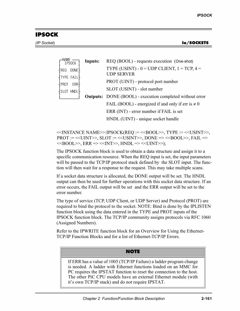
IPSOCK
IPSOCK(IP Socket) Io/SOCKETS
<<INSTANCE NAME>>:IPSOCK(REQ := <<BOOL>>, TYPE := <<USINT>>, PROT := <<UINT>>, SLOT := <<USINT>>, DONE => <<BOOL>>, FAIL => <<BOOL>>, ERR => <<INT>>, HNDL => <<UINT>>);
The IPSOCK function block is used to obtain a data structure and assign it to a specific communication resource. When the REQ input is set, the input parameters will be passed to the TCP/IP protocol stack defined by the SLOT input. The func-tion will then wait for a response to the request. This may take multiple scans.
If a socket data structure is allocated, the DONE output will be set. The HNDL output can then be used for further operations with this socket data structure. If an error occurs, the FAIL output will be set and the ERR output will be set to the error number.
The type of service (TCP, UDP Client, or UDP Server) and Protocol (PROT) are required to bind the protocol to the socket. NOTE: Bind is done by the IPLISTEN function block using the data entered in the TYPE and PROT inputs of the IPSOCK function block. The TCP/IP community assigns protocols via RFC 1060 (Assigned Numbers).
Refer to the IPWRITE function block for an Overview for Using the Ethernet-TCP/IP Function Blocks and for a list of Ethernet-TCP/IP Errors.
⁄ƒNAME ƒƒƒø ≥ IPSOCK ≥ ≥ ≥ ¥REQ DONE√ ≥ ≥ ¥TYPE FAIL√ ≥ ≥ ¥PROT ERR√ ≥ ≥ ¥SLOT HNDL√ ≥ ≥ ¿ƒƒƒƒƒƒƒƒƒŸ
Inputs: REQ (BOOL) - requests execution (One-shot)
TYPE (USINT) - 0 = UDP CLIENT, 1 = TCP, 4 = UDP SERVER
PROT (UINT) - protocol port number
SLOT (USINT) - slot number
Outputs: DONE (BOOL) - execution completed without error
FAIL (BOOL) - energized if and only if err is ≠ 0
ERR (INT) - error number if FAIL is set
HNDL (UINT) - unique socket handle
NOTE
If ERR has a value of 1005 (TCP/IP Failure) a ladder program changeis needed. A ladder with Ethernet functions loaded on an MMC forPC requires the IPSTAT function to reset the connection to the host.The other PiC CPU models have an external Ethernet module (withit’s own TCP/IP stack) and do not require IPSTAT.
Chapter 2 Function/Function Block Description 2-161
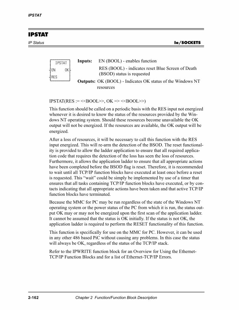
IPSTAT
IPSTATIP Status Io/SOCKETS
IPSTAT(RES := <<BOOL>>, OK => <<BOOL>>)
This function should be called on a periodic basis with the RES input not energized whenever it is desired to know the status of the resources provided by the Win-dows NT operating system. Should these resources become unavailable the OK output will not be energized. If the resources are available, the OK output will be energized. After a loss of resources, it will be necessary to call this function with the RES input energized. This will re-arm the detection of the BSOD. The reset functional-ity is provided to allow the ladder application to ensure that all required applica-tion code that requires the detection of the loss has seen the loss of resources. Furthermore, it allows the application ladder to ensure that all appropriate actions have been completed before the BSOD flag is reset. Therefore, it is recommended to wait until all TCP/IP function blocks have executed at least once before a reset is requested. This “wait” could be simply be implemented by use of a timer that ensures that all tasks containing TCP/IP function blocks have executed, or by con-tacts indicating that all appropriate actions have been taken and that active TCP/IP function blocks have terminated.
Because the MMC for PC may be run regardless of the state of the Windows NT operating system or the power status of the PC from which it is run, the status out-put OK may or may not be energized upon the first scan of the application ladder. It cannot be assumed that the status is OK initially. If the status is not OK, the application ladder is required to perform the RESET functionality of this function.
This function is specifically for use on the MMC for PC. However, it can be used in any other 486 based PiC without causing any problems. In this case the status will always be OK, regardless of the status of the TCP/IP stack.
Refer to the IPWRITE function block for an Overview for Using the Ethernet-TCP/IP Function Blocks and for a list of Ethernet-TCP/IP Errors.
⁄ƒƒƒƒƒƒƒƒƒø ≥ IPSTAT ≥ ≥ ≥ ¥EN OK√ ≥ ≥ ¥RES ≥ ¿ƒƒƒƒƒƒƒƒƒŸ
Inputs: EN (BOOL) - enables function
RES (BOOL) - indicates reset Blue Screen of Death (BSOD) status is requested
Outputs: OK (BOOL) - Indicates OK status of the Windows NT resources
2-162 Chapter 2 Function/Function Block Description
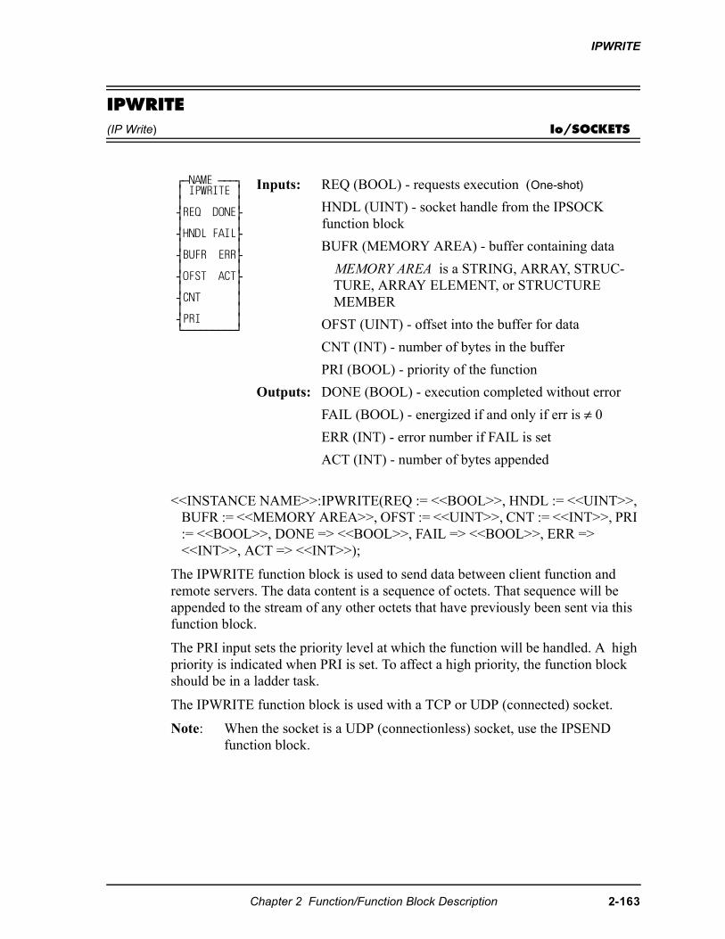
IPWRITE
IPWRITE(IP Write) Io/SOCKETS
<<INSTANCE NAME>>:IPWRITE(REQ := <<BOOL>>, HNDL := <<UINT>>, BUFR := <<MEMORY AREA>>, OFST := <<UINT>>, CNT := <<INT>>, PRI := <<BOOL>>, DONE => <<BOOL>>, FAIL => <<BOOL>>, ERR => <<INT>>, ACT => <<INT>>);
The IPWRITE function block is used to send data between client function and remote servers. The data content is a sequence of octets. That sequence will be appended to the stream of any other octets that have previously been sent via this function block.
The PRI input sets the priority level at which the function will be handled. A high priority is indicated when PRI is set. To affect a high priority, the function block should be in a ladder task.
The IPWRITE function block is used with a TCP or UDP (connected) socket.
Note: When the socket is a UDP (connectionless) socket, use the IPSEND function block.
⁄ƒNAME ƒƒƒø ≥ IPWRITE ≥ ≥ ≥ ¥REQ DONE√ ≥ ≥ ¥HNDL FAIL√ ≥ ≥ ¥BUFR ERR√ ≥ ≥ ¥OFST ACT√ ≥ ≥ ¥CNT ≥ ≥ ≥ ¥PRI ≥ ¿ƒƒƒƒƒƒƒƒƒŸ
Inputs: REQ (BOOL) - requests execution (One-shot)
HNDL (UINT) - socket handle from the IPSOCK function block
BUFR (MEMORY AREA) - buffer containing data
MEMORY AREA is a STRING, ARRAY, STRUC-TURE, ARRAY ELEMENT, or STRUCTURE MEMBER
OFST (UINT) - offset into the buffer for data
CNT (INT) - number of bytes in the buffer
PRI (BOOL) - priority of the function
Outputs: DONE (BOOL) - execution completed without error
FAIL (BOOL) - energized if and only if err is ≠ 0
ERR (INT) - error number if FAIL is set
ACT (INT) - number of bytes appended
Chapter 2 Function/Function Block Description 2-163
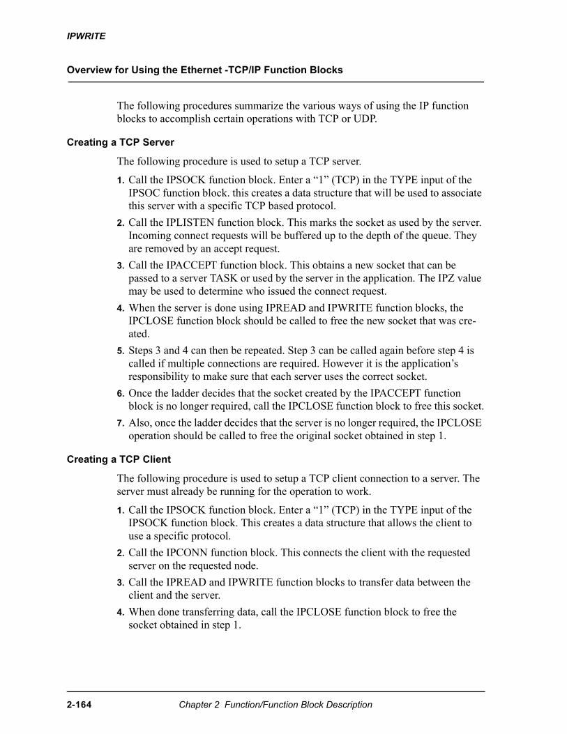
IPWRITE
Overview for Using the Ethernet -TCP/IP Function Blocks
The following procedures summarize the various ways of using the IP function blocks to accomplish certain operations with TCP or UDP.
Creating a TCP Server
The following procedure is used to setup a TCP server.
1. Call the IPSOCK function block. Enter a “1” (TCP) in the TYPE input of the IPSOC function block. this creates a data structure that will be used to associate this server with a specific TCP based protocol.
2. Call the IPLISTEN function block. This marks the socket as used by the server. Incoming connect requests will be buffered up to the depth of the queue. They are removed by an accept request.
3. Call the IPACCEPT function block. This obtains a new socket that can be passed to a server TASK or used by the server in the application. The IPZ value may be used to determine who issued the connect request.
4. When the server is done using IPREAD and IPWRITE function blocks, the IPCLOSE function block should be called to free the new socket that was cre-ated.
5. Steps 3 and 4 can then be repeated. Step 3 can be called again before step 4 is called if multiple connections are required. However it is the application’s responsibility to make sure that each server uses the correct socket.
6. Once the ladder decides that the socket created by the IPACCEPT function block is no longer required, call the IPCLOSE function block to free this socket.
7. Also, once the ladder decides that the server is no longer required, the IPCLOSE operation should be called to free the original socket obtained in step 1.
Creating a TCP Client
The following procedure is used to setup a TCP client connection to a server. The server must already be running for the operation to work.
1. Call the IPSOCK function block. Enter a “1” (TCP) in the TYPE input of the IPSOCK function block. This creates a data structure that allows the client to use a specific protocol.
2. Call the IPCONN function block. This connects the client with the requested server on the requested node.
3. Call the IPREAD and IPWRITE function blocks to transfer data between the client and the server.
4. When done transferring data, call the IPCLOSE function block to free the socket obtained in step 1.
2-164 Chapter 2 Function/Function Block Description
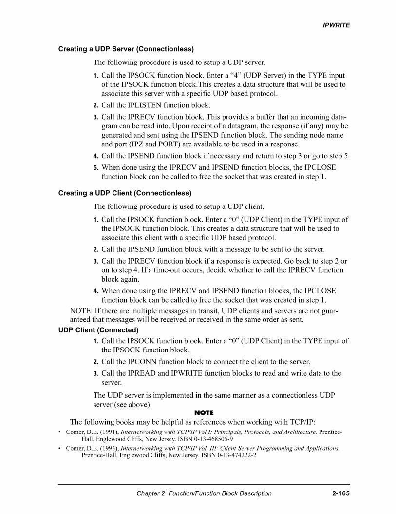
IPWRITE
Creating a UDP Server (Connectionless)
The following procedure is used to setup a UDP server.
1. Call the IPSOCK function block. Enter a “4” (UDP Server) in the TYPE input of the IPSOCK function block.This creates a data structure that will be used to associate this server with a specific UDP based protocol.
2. Call the IPLISTEN function block.
3. Call the IPRECV function block. This provides a buffer that an incoming data-gram can be read into. Upon receipt of a datagram, the response (if any) may be generated and sent using the IPSEND function block. The sending node name and port (IPZ and PORT) are available to be used in a response.
4. Call the IPSEND function block if necessary and return to step 3 or go to step 5.
5. When done using the IPRECV and IPSEND function blocks, the IPCLOSE function block can be called to free the socket that was created in step 1.
Creating a UDP Client (Connectionless)
The following procedure is used to setup a UDP client.
1. Call the IPSOCK function block. Enter a “0” (UDP Client) in the TYPE input of the IPSOCK function block. This creates a data structure that will be used to associate this client with a specific UDP based protocol.
2. Call the IPSEND function block with a message to be sent to the server.
3. Call the IPRECV function block if a response is expected. Go back to step 2 or on to step 4. If a time-out occurs, decide whether to call the IPRECV function block again.
4. When done using the IPRECV and IPSEND function blocks, the IPCLOSE function block can be called to free the socket that was created in step 1.
NOTE: If there are multiple messages in transit, UDP clients and servers are not guar-anteed that messages will be received or received in the same order as sent.
UDP Client (Connected)
1. Call the IPSOCK function block. Enter a “0” (UDP Client) in the TYPE input of the IPSOCK function block.
2. Call the IPCONN function block to connect the client to the server.
3. Call the IPREAD and IPWRITE function blocks to read and write data to the server.
The UDP server is implemented in the same manner as a connectionless UDP server (see above).
NOTEThe following books may be helpful as references when working with TCP/IP:
• Comer, D.E. (1991), Internetworking with TCP/IP Vol.I: Principals, Protocols, and Architecture. Prentice-Hall, Englewood Cliffs, New Jersey. ISBN 0-13-468505-9
• Comer, D.E. (1993), Internetworking with TCP/IP Vol. III: Client-Server Programming and Applications. Prentice-Hall, Englewood Cliffs, New Jersey. ISBN 0-13-474222-2
Chapter 2 Function/Function Block Description 2-165
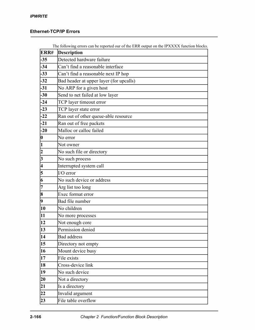
IPWRITE
Ethernet-TCP/IP Errors
The following errors can be reported our of the ERR output on the IPXXXX function blocks.
ERR# Description
-35 Detected hardware failure
-34 Can’t find a reasonable interface
-33 Can’t find a reasonable next IP hop
-32 Bad header at upper layer (for upcalls)
-31 No ARP for a given host
-30 Send to net failed at low layer
-24 TCP layer timeout error
-23 TCP layer state error
-22 Ran out of other queue-able resource
-21 Ran out of free packets
-20 Malloc or calloc failed
0 No error
1 Not owner
2 No such file or directory
3 No such process
4 Interrupted system call
5 I/O error
6 No such device or address
7 Arg list too long
8 Exec format error
9 Bad file number
10 No children
11 No more processes
12 Not enough core
13 Permission denied
14 Bad address
15 Directory not empty
16 Mount device busy
17 File exists
18 Cross-device link
19 No such device
20 Not a directory
21 Is a directory
22 Invalid argument
23 File table overflow
2-166 Chapter 2 Function/Function Block Description
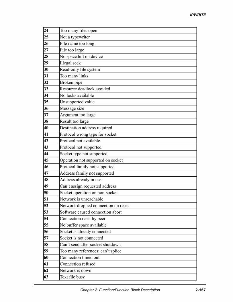
IPWRITE
24 Too many files open
25 Not a typewriter
26 File name too long
27 File too large
28 No space left on device
29 Illegal seek
30 Read-only file system
31 Too many links
32 Broken pipe
33 Resource deadlock avoided
34 No locks available
35 Unsupported value
36 Message size
37 Argument too large
38 Result too large
40 Destination address required
41 Protocol wrong type for socket
42 Protocol not available
43 Protocol not supported
44 Socket type not supported
45 Operation not supported on socket
46 Protocol family not supported
47 Address family not supported
48 Address already in use
49 Can’t assign requested address
50 Socket operation on non-socket
51 Network is unreachable
52 Network dropped connection on reset
53 Software caused connection abort
54 Connection reset by peer
55 No buffer space available
56 Socket is already connected
57 Socket is not connected
58 Can’t send after socket shutdown
59 Too many references: can’t splice
60 Connection timed out
61 Connection refused
62 Network is down
63 Text file busy
Chapter 2 Function/Function Block Description 2-167
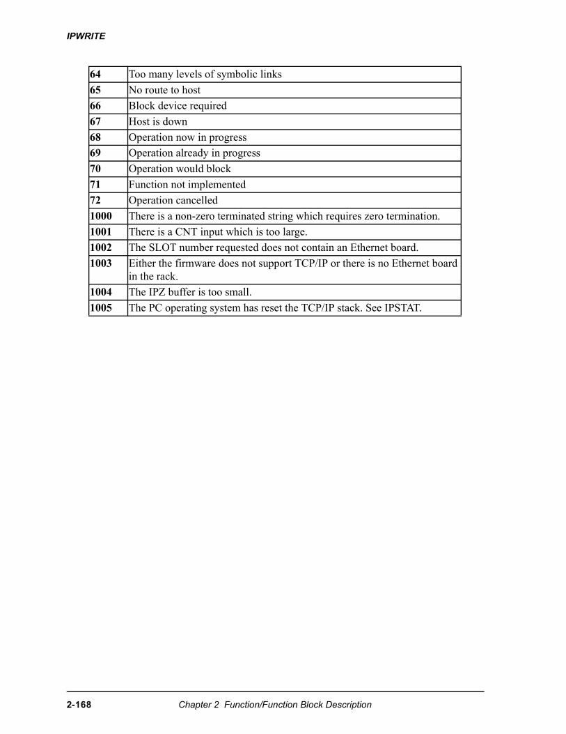
IPWRITE
64 Too many levels of symbolic links
65 No route to host
66 Block device required
67 Host is down
68 Operation now in progress
69 Operation already in progress
70 Operation would block
71 Function not implemented
72 Operation cancelled
1000 There is a non-zero terminated string which requires zero termination.
1001 There is a CNT input which is too large.
1002 The SLOT number requested does not contain an Ethernet board.
1003 Either the firmware does not support TCP/IP or there is no Ethernet board in the rack.
1004 The IPZ buffer is too small.
1005 The PC operating system has reset the TCP/IP stack. See IPSTAT.
2-168 Chapter 2 Function/Function Block Description
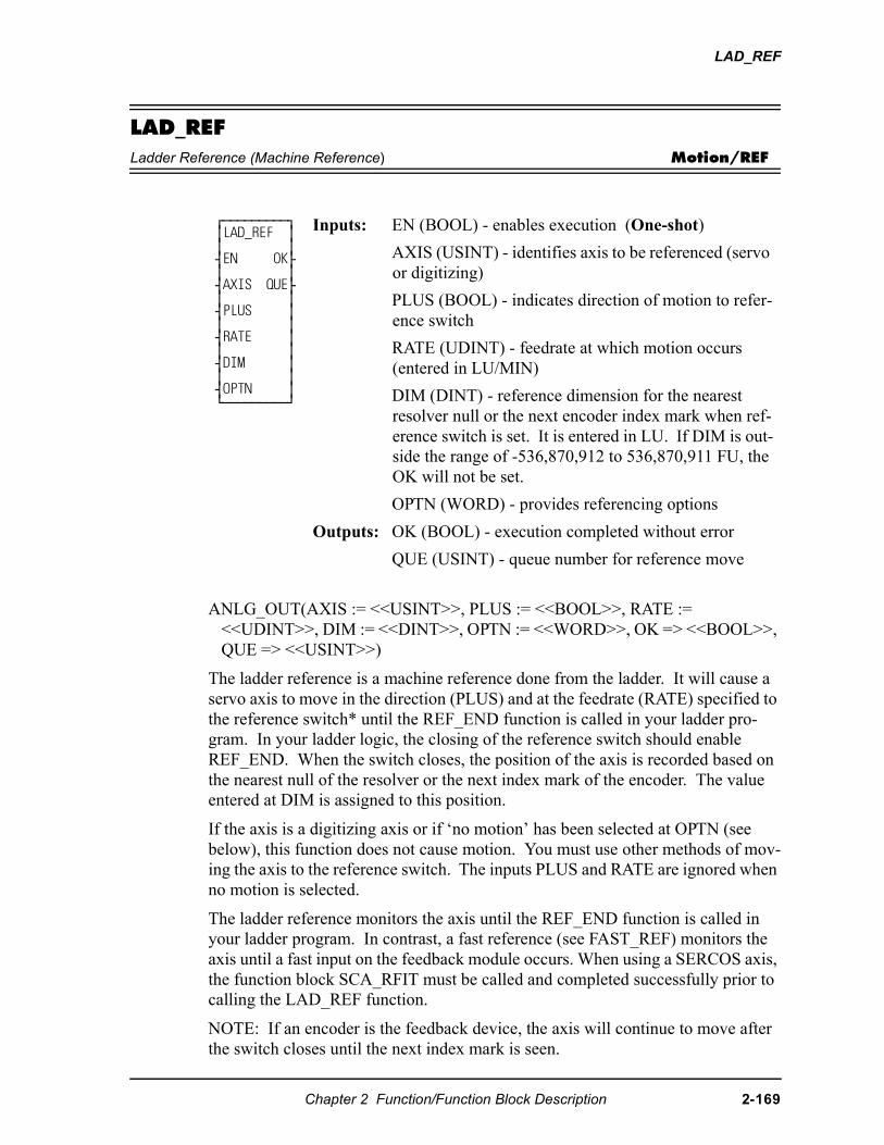
LAD_REF
LAD_REFLadder Reference (Machine Reference) Motion/REF
ANLG_OUT(AXIS := <<USINT>>, PLUS := <<BOOL>>, RATE := <<UDINT>>, DIM := <<DINT>>, OPTN := <<WORD>>, OK => <<BOOL>>, QUE => <<USINT>>)
The ladder reference is a machine reference done from the ladder. It will cause a servo axis to move in the direction (PLUS) and at the feedrate (RATE) specified to the reference switch* until the REF_END function is called in your ladder pro-gram. In your ladder logic, the closing of the reference switch should enable REF_END. When the switch closes, the position of the axis is recorded based on the nearest null of the resolver or the next index mark of the encoder. The value entered at DIM is assigned to this position.
If the axis is a digitizing axis or if ‘no motion’ has been selected at OPTN (see below), this function does not cause motion. You must use other methods of mov-ing the axis to the reference switch. The inputs PLUS and RATE are ignored when no motion is selected.
The ladder reference monitors the axis until the REF_END function is called in your ladder program. In contrast, a fast reference (see FAST_REF) monitors the axis until a fast input on the feedback module occurs. When using a SERCOS axis, the function block SCA_RFIT must be called and completed successfully prior to calling the LAD_REF function.
NOTE: If an encoder is the feedback device, the axis will continue to move after the switch closes until the next index mark is seen.
⁄ƒƒƒƒƒƒƒƒƒø ≥LAD_REF ≥ ≥ ≥ ¥EN OK√ ≥ ≥ ¥AXIS QUE√ ≥ ≥ ¥PLUS ≥ ≥ ≥ ¥RATE ≥ ≥ ≥ ¥DIM ≥ ≥ ≥ ¥OPTN ≥ ¿ƒƒƒƒƒƒƒƒƒŸ
Inputs: EN (BOOL) - enables execution (One-shot)
AXIS (USINT) - identifies axis to be referenced (servo or digitizing)
PLUS (BOOL) - indicates direction of motion to refer-ence switch
RATE (UDINT) - feedrate at which motion occurs (entered in LU/MIN)
DIM (DINT) - reference dimension for the nearest resolver null or the next encoder index mark when ref-erence switch is set. It is entered in LU. If DIM is out-side the range of -536,870,912 to 536,870,911 FU, the OK will not be set.
OPTN (WORD) - provides referencing options
Outputs: OK (BOOL) - execution completed without error
QUE (USINT) - queue number for reference move
Chapter 2 Function/Function Block Description 2-169
LAD_REF
The OPTN input provides the following options:
If no option is desired, enter a “0.”
*See FAST_REF function for information on setting up a reference switch.
Option inputs
Ignore the index/null
Choosing this option allows a reference to occur which ignores the index mark of an encoder or the null of a resolver during the reference cycle. If bit 0 is set to “1,” the reference position assigned by DIM will be assigned to the position the axis is at when REF_END is enabled.
With an encoder, the axis will stop immediately after the fast input transitions. The axis does not continue movement until the index mark is reached. NOTE: This makes the reference switch position given with the READ_SV function invalid.
With a resolver, the reference switch position available with the READ_SV func-tion is valid.
No motion
The no motion option allows a reference to occur without any motion. The axis is put into a mode whereby it is watching for the conditions of a reference cycle.
Even though no move is placed in the queue, a queue must be available. A move will be initiated by the ladder following the reference cycle.
Once the call is made, the reference complete flag goes low until the reference switch input occurs and the index mark (unless “ignore index” option is active) is received. The reference complete flag goes high once these events occur and the axis position takes on the reference value at DIM.
If the move type is VEL, RATIO_GR, LAD_REF, or FAST_REF, the new axis position assigned by the no-motion reference has no effect on the move itself. With a DISTANCE move, the actual distance covered will be the same. If a no-motion reference occurs during a position move, the endpoint will be reached.
If a no-motion reference is used during a RATIO_PRO move, the lock on point of the slave axis to the master axis may be undefined. This is not recommended.
Note:A ladder reference can also be performed on a digitizing axis. You must cause the axis to move and the fast input to occur. Use variable 29 with the READ_SV function to read the reference switch position. REF_DNE? can also be used with digitizing axes. This function cannot be used with the stepper axis mod-ule.
Option Binary value Hex valueIgnore index/null 00000000 00000001 0001No motion 00000000 00000010 0002Null setup 00000000 00000100 0004
2-170 Chapter 2 Function/Function Block Description
LAD_REF
Null Setup
This option will establish a null position for a digital drive axis with resolver feed-back or single-turn Stegmann encoder feedback in addition to performing the ref-erence. The null position will be stored in the digital drive’s flash memory and will be retained through power cycles. This feature allows the user to omit the setup process of physically positioning the reference switch to be near the null. To provide repeatable references, this option bit should be set with the first call to LAD_REF and should be reset for subsequest calls.
Chapter 2 Function/Function Block Description 2-171
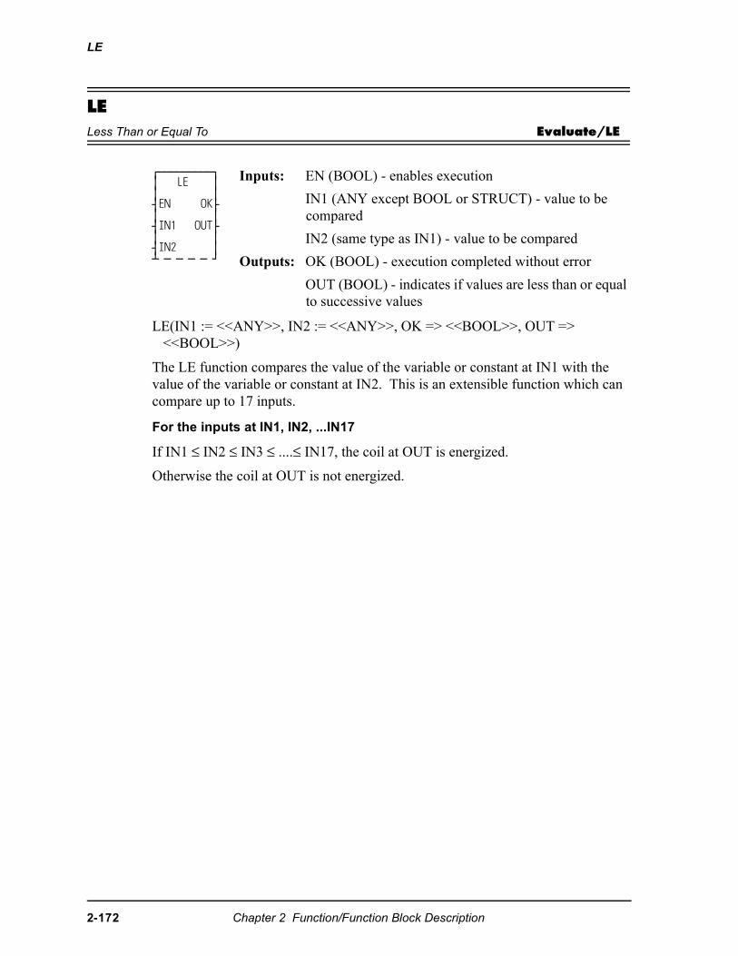
LE
LELess Than or Equal To Evaluate/LE
LE(IN1 := <<ANY>>, IN2 := <<ANY>>, OK => <<BOOL>>, OUT => <<BOOL>>)
The LE function compares the value of the variable or constant at IN1 with the value of the variable or constant at IN2. This is an extensible function which can compare up to 17 inputs.
For the inputs at IN1, IN2, ...IN17
If IN1 ≤ IN2 ≤ IN3 ≤ ....≤ IN17, the coil at OUT is energized.
Otherwise the coil at OUT is not energized.
⁄ƒƒƒƒƒƒƒƒƒø ≥ LE ≥ ≥ ≥ ¥EN OK√ ≥ ≥ ¥IN1 OUT√ ≥ ≥ ¥IN2 ≥ ¡ ƒ ƒ ƒ ƒ Ÿ
Inputs: EN (BOOL) - enables execution
IN1 (ANY except BOOL or STRUCT) - value to be compared
IN2 (same type as IN1) - value to be compared
Outputs: OK (BOOL) - execution completed without error
OUT (BOOL) - indicates if values are less than or equal to successive values
2-172 Chapter 2 Function/Function Block Description
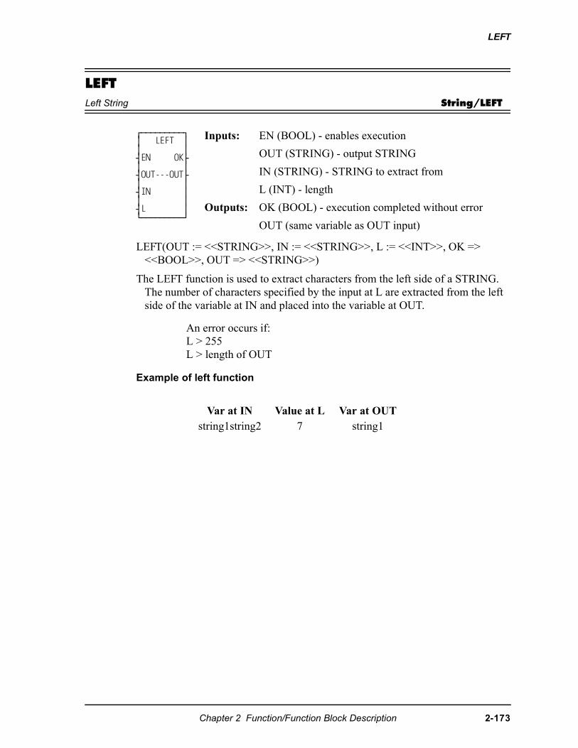
LEFT
LEFTLeft String String/LEFT
LEFT(OUT := <<STRING>>, IN := <<STRING>>, L := <<INT>>, OK => <<BOOL>>, OUT => <<STRING>>)
The LEFT function is used to extract characters from the left side of a STRING. The number of characters specified by the input at L are extracted from the left side of the variable at IN and placed into the variable at OUT.
Example of left function
⁄ƒƒƒƒƒƒƒƒƒø ≥ LEFT ≥ ≥ ≥ ¥EN OK√ ≥ ≥ ¥OUT---OUT√ ≥ ≥ ¥IN ≥ ≥ ≥ ¥L ≥ ¿ƒƒƒƒƒƒƒƒƒŸ
Inputs: EN (BOOL) - enables execution
OUT (STRING) - output STRING
IN (STRING) - STRING to extract from
L (INT) - length
Outputs: OK (BOOL) - execution completed without error
OUT (same variable as OUT input)
An error occurs if: L > 255L > length of OUT
Var at IN Value at L Var at OUTstring1string2 7 string1
Chapter 2 Function/Function Block Description 2-173
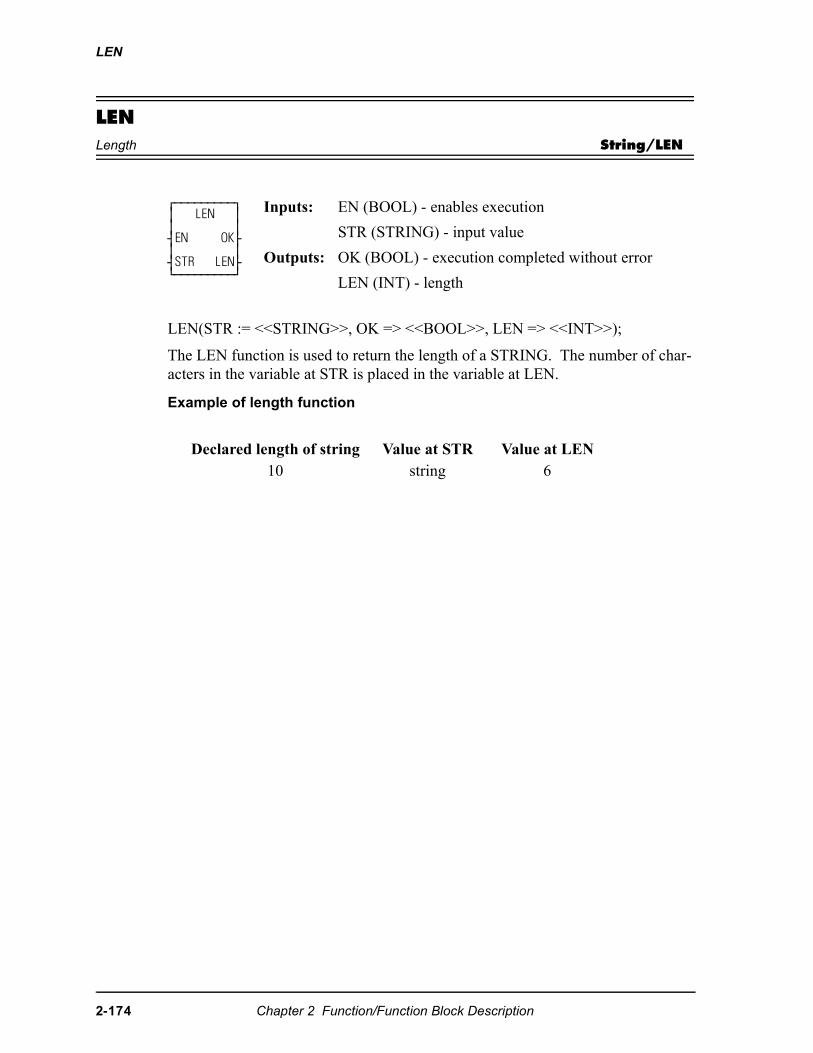
LEN
LENLength String/LEN
LEN(STR := <<STRING>>, OK => <<BOOL>>, LEN => <<INT>>);
The LEN function is used to return the length of a STRING. The number of char-acters in the variable at STR is placed in the variable at LEN.
Example of length function
⁄ƒƒƒƒƒƒƒƒƒø ≥ LEN ≥ ≥ ≥ ¥EN OK√ ≥ ≥ ¥STR LEN√ ¿ƒƒƒƒƒƒƒƒƒŸ
Inputs: EN (BOOL) - enables execution
STR (STRING) - input value
Outputs: OK (BOOL) - execution completed without error
LEN (INT) - length
Declared length of string Value at STR Value at LEN10 string 6
2-174 Chapter 2 Function/Function Block Description
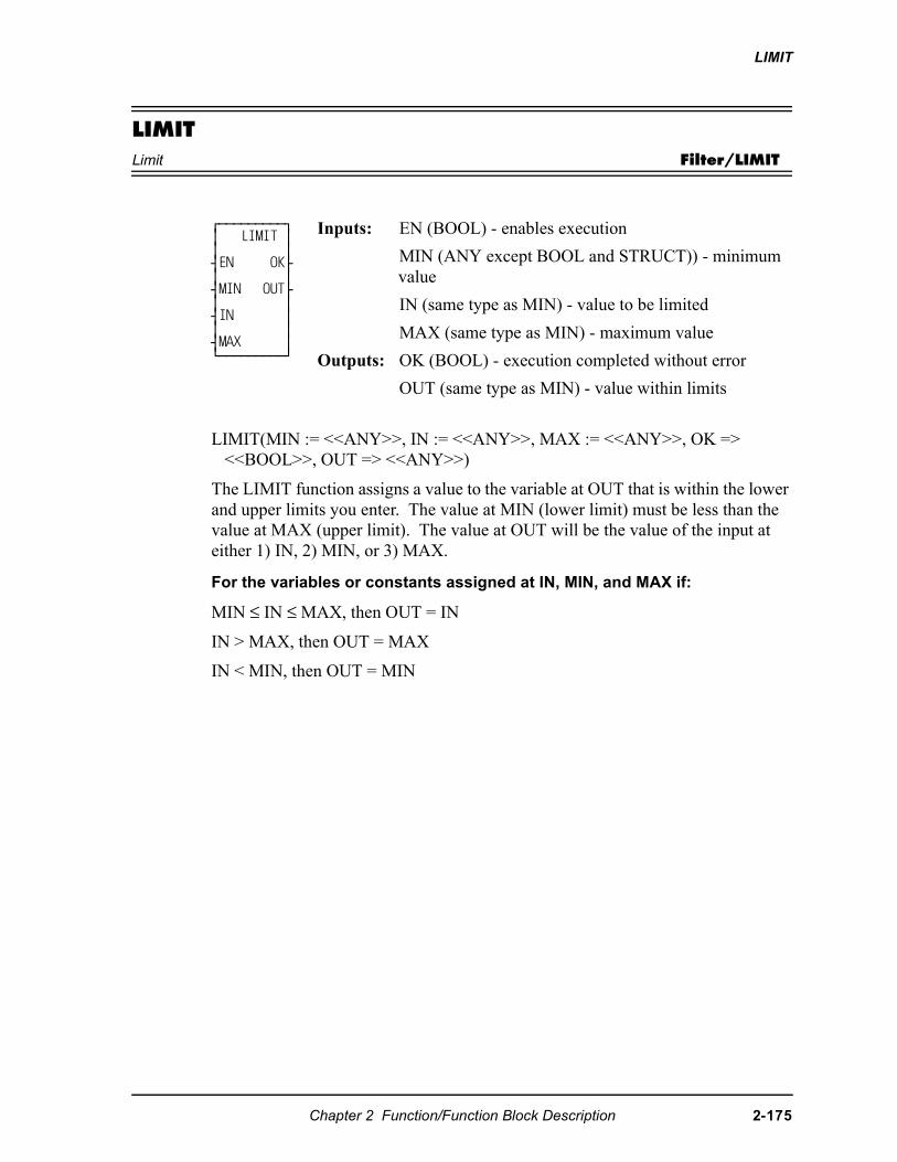
LIMIT
LIMITLimit Filter/LIMIT
LIMIT(MIN := <<ANY>>, IN := <<ANY>>, MAX := <<ANY>>, OK => <<BOOL>>, OUT => <<ANY>>)
The LIMIT function assigns a value to the variable at OUT that is within the lower and upper limits you enter. The value at MIN (lower limit) must be less than the value at MAX (upper limit). The value at OUT will be the value of the input at either 1) IN, 2) MIN, or 3) MAX.
For the variables or constants assigned at IN, MIN, and MAX if:
MIN ≤ IN ≤ MAX, then OUT = IN
IN > MAX, then OUT = MAX
IN < MIN, then OUT = MIN
⁄ƒƒƒƒƒƒƒƒƒø ≥ LIMIT ≥ ≥ ≥ ¥EN OK√ ≥ ≥ ¥MIN OUT√ ≥ ≥ ¥IN ≥ ≥ ≥ ¥MAX ≥ ¿ƒƒƒƒƒƒƒƒƒŸ
Inputs: EN (BOOL) - enables execution
MIN (ANY except BOOL and STRUCT)) - minimum value
IN (same type as MIN) - value to be limited
MAX (same type as MIN) - maximum value
Outputs: OK (BOOL) - execution completed without error
OUT (same type as MIN) - value within limits
Chapter 2 Function/Function Block Description 2-175
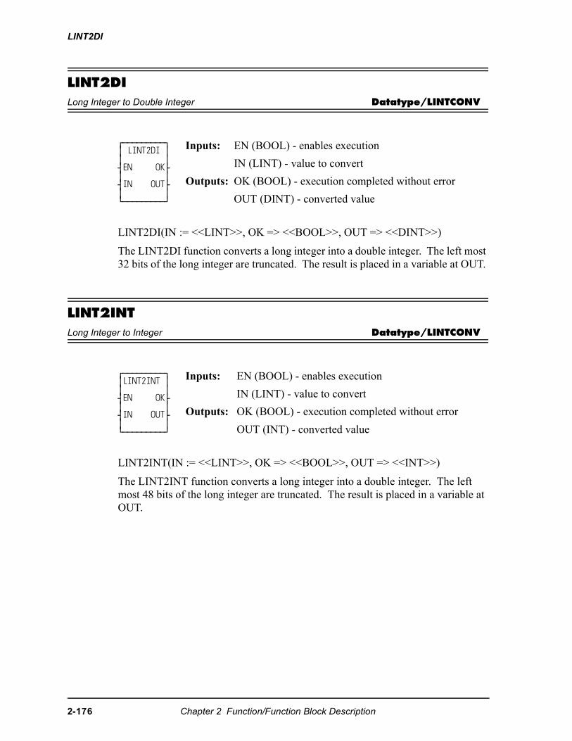
LINT2DI
LINT2DILong Integer to Double Integer Datatype/LINTCONV
LINT2DI(IN := <<LINT>>, OK => <<BOOL>>, OUT => <<DINT>>)
The LINT2DI function converts a long integer into a double integer. The left most 32 bits of the long integer are truncated. The result is placed in a variable at OUT.
LINT2INTLong Integer to Integer Datatype/LINTCONV
LINT2INT(IN := <<LINT>>, OK => <<BOOL>>, OUT => <<INT>>)
The LINT2INT function converts a long integer into a double integer. The left most 48 bits of the long integer are truncated. The result is placed in a variable at OUT.
⁄ƒƒƒƒƒƒƒƒƒø≥ LINT2DI ≥≥ ≥¥EN OK√≥ ≥¥IN OUT√≥ ≥¿ƒƒƒƒƒƒƒƒƒŸ
Inputs: EN (BOOL) - enables execution
IN (LINT) - value to convert
Outputs: OK (BOOL) - execution completed without error
OUT (DINT) - converted value
⁄ƒƒƒƒƒƒƒƒƒø ≥LINT2INT ≥ ≥ ≥ ¥EN OK√ ≥ ≥ ¥IN OUT√ ≥ ≥ ¿ƒƒƒƒƒƒƒƒƒŸ
Inputs: EN (BOOL) - enables execution
IN (LINT) - value to convert
Outputs: OK (BOOL) - execution completed without error
OUT (INT) - converted value
2-176 Chapter 2 Function/Function Block Description
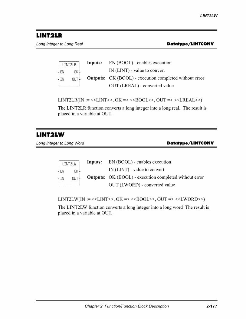
LINT2LW
LINT2LRLong Integer to Long Real Datatype/LINTCONV
LINT2LR(IN := <<LINT>>, OK => <<BOOL>>, OUT => <<LREAL>>)
The LINT2LR function converts a long integer into a long real. The result is placed in a variable at OUT.
LINT2LWLong Integer to Long Word Datatype/LINTCONV
LINT2LW(IN := <<LINT>>, OK => <<BOOL>>, OUT => <<LWORD>>)
The LINT2LW function converts a long integer into a long word The result is placed in a variable at OUT.
⁄ƒƒƒƒƒƒƒƒƒø ≥ LINT2LR ≥ ≥ ≥ ¥EN OK√ ≥ ≥ ¥IN OUT√ ≥ ≥ ¿ƒƒƒƒƒƒƒƒƒŸ
Inputs: EN (BOOL) - enables execution
IN (LINT) - value to convert
Outputs: OK (BOOL) - execution completed without error
OUT (LREAL) - converted value
⁄ƒƒƒƒƒƒƒƒƒø ≥ LINT2LW ≥ ≥ ≥ ¥EN OK√ ≥ ≥ ¥IN OUT√ ≥ ≥ ¿ƒƒƒƒƒƒƒƒƒŸ
Inputs: EN (BOOL) - enables execution
IN (LINT) - value to convert
Outputs: OK (BOOL) - execution completed without error
OUT (LWORD) - converted value
Chapter 2 Function/Function Block Description 2-177
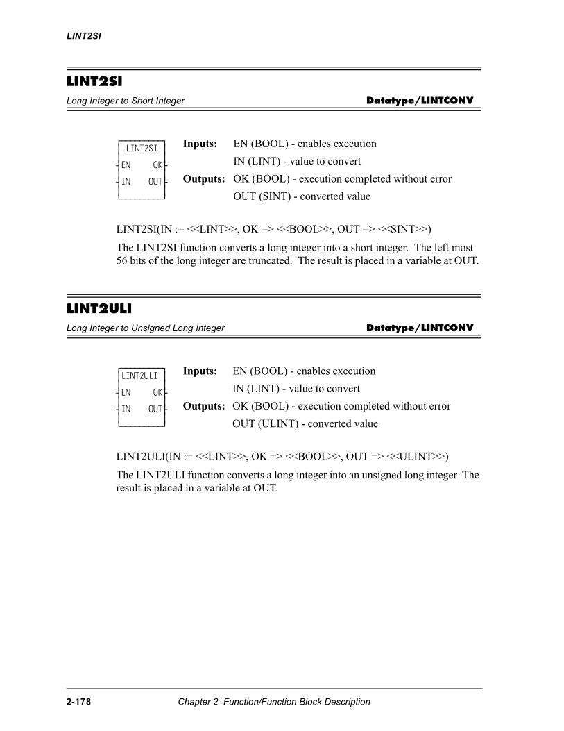
LINT2SI
LINT2SILong Integer to Short Integer Datatype/LINTCONV
LINT2SI(IN := <<LINT>>, OK => <<BOOL>>, OUT => <<SINT>>)
The LINT2SI function converts a long integer into a short integer. The left most 56 bits of the long integer are truncated. The result is placed in a variable at OUT.
LINT2ULILong Integer to Unsigned Long Integer Datatype/LINTCONV
LINT2ULI(IN := <<LINT>>, OK => <<BOOL>>, OUT => <<ULINT>>)
The LINT2ULI function converts a long integer into an unsigned long integer The result is placed in a variable at OUT.
⁄ƒƒƒƒƒƒƒƒƒø ≥ LINT2SI ≥ ≥ ≥ ¥EN OK√ ≥ ≥ ¥IN OUT√ ≥ ≥ ¿ƒƒƒƒƒƒƒƒƒŸ
Inputs: EN (BOOL) - enables execution
IN (LINT) - value to convert
Outputs: OK (BOOL) - execution completed without error
OUT (SINT) - converted value
⁄ƒƒƒƒƒƒƒƒƒø ≥LINT2ULI ≥ ≥ ≥ ¥EN OK√ ≥ ≥ ¥IN OUT√ ≥ ≥ ¿ƒƒƒƒƒƒƒƒƒŸ
Inputs: EN (BOOL) - enables execution
IN (LINT) - value to convert
Outputs: OK (BOOL) - execution completed without error
OUT (ULINT) - converted value
2-178 Chapter 2 Function/Function Block Description
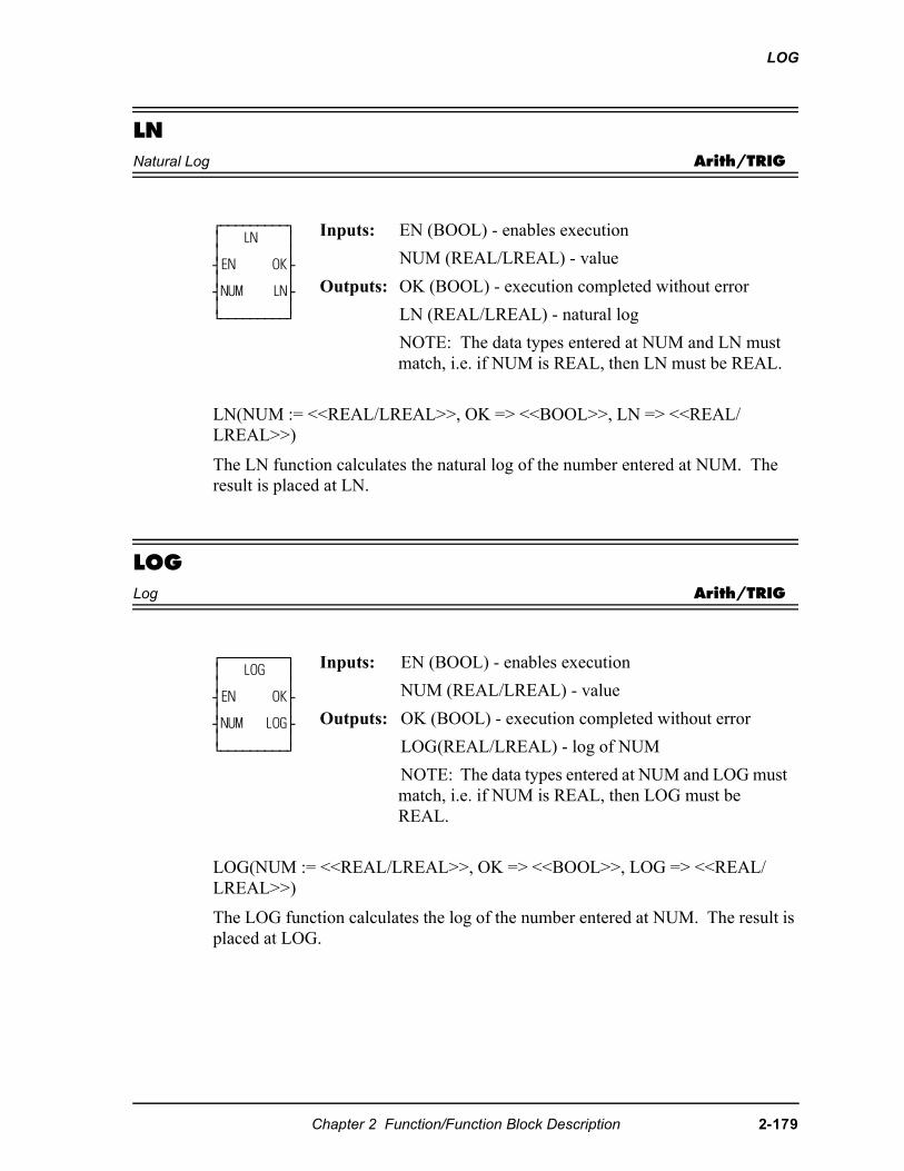
LOG
LNNatural Log Arith/TRIG
LN(NUM := <<REAL/LREAL>>, OK => <<BOOL>>, LN => <<REAL/LREAL>>)
The LN function calculates the natural log of the number entered at NUM. The result is placed at LN.
LOGLog Arith/TRIG
LOG(NUM := <<REAL/LREAL>>, OK => <<BOOL>>, LOG => <<REAL/LREAL>>)
The LOG function calculates the log of the number entered at NUM. The result is placed at LOG.
⁄ƒƒƒƒƒƒƒƒƒø≥ LN ≥≥ ≥¥EN OK√≥ ≥¥NUM LN√≥ ≥¿ƒƒƒƒƒƒƒƒƒŸ
Inputs: EN (BOOL) - enables execution
NUM (REAL/LREAL) - value
Outputs: OK (BOOL) - execution completed without error
LN (REAL/LREAL) - natural log
NOTE: The data types entered at NUM and LN must match, i.e. if NUM is REAL, then LN must be REAL.
⁄ƒƒƒƒƒƒƒƒƒø ≥ LOG ≥ ≥ ≥ ¥EN OK√ ≥ ≥ ¥NUM LOG√ ≥ ≥ ¿ƒƒƒƒƒƒƒƒƒŸ
Inputs: EN (BOOL) - enables execution
NUM (REAL/LREAL) - value
Outputs: OK (BOOL) - execution completed without error
LOG(REAL/LREAL) - log of NUM
NOTE: The data types entered at NUM and LOG must match, i.e. if NUM is REAL, then LOG must be REAL.
Chapter 2 Function/Function Block Description 2-179
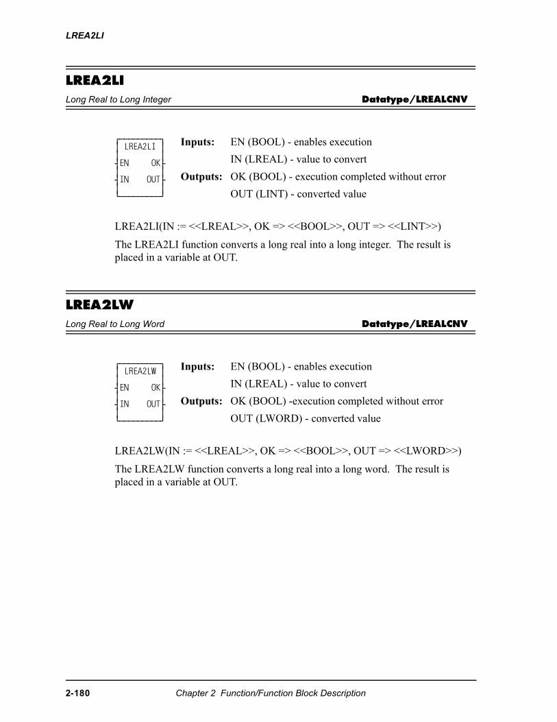
LREA2LI
LREA2LILong Real to Long Integer Datatype/LREALCNV
LREA2LI(IN := <<LREAL>>, OK => <<BOOL>>, OUT => <<LINT>>)
The LREA2LI function converts a long real into a long integer. The result is placed in a variable at OUT.
LREA2LWLong Real to Long Word Datatype/LREALCNV
LREA2LW(IN := <<LREAL>>, OK => <<BOOL>>, OUT => <<LWORD>>)
The LREA2LW function converts a long real into a long word. The result is placed in a variable at OUT.
⁄ƒƒƒƒƒƒƒƒƒø≥ LREA2LI ≥≥ ≥¥EN OK√≥ ≥¥IN OUT√≥ ≥¿ƒƒƒƒƒƒƒƒƒŸ
Inputs: EN (BOOL) - enables execution
IN (LREAL) - value to convert
Outputs: OK (BOOL) - execution completed without error
OUT (LINT) - converted value
⁄ƒƒƒƒƒƒƒƒƒø≥ LREA2LW ≥≥ ≥¥EN OK√≥ ≥¥IN OUT√≥ ≥¿ƒƒƒƒƒƒƒƒƒŸ
Inputs: EN (BOOL) - enables execution
IN (LREAL) - value to convert
Outputs: OK (BOOL) -execution completed without error
OUT (LWORD) - converted value
2-180 Chapter 2 Function/Function Block Description
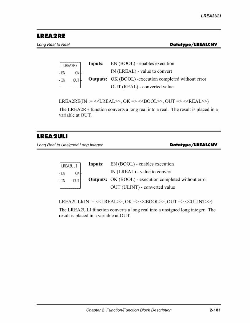
LREA2ULI
LREA2RELong Real to Real Datatype/LREALCNV
LREA2RE(IN := <<LREAL>>, OK => <<BOOL>>, OUT => <<REAL>>)
The LREA2RE function converts a long real into a real. The result is placed in a variable at OUT.
LREA2ULILong Real to Unsigned Long Integer Datatype/LREALCNV
LREA2ULI(IN := <<LREAL>>, OK => <<BOOL>>, OUT => <<ULINT>>)
The LREA2ULI function converts a long real into a unsigned long integer. The result is placed in a variable at OUT.
⁄ƒƒƒƒƒƒƒƒƒø ≥ LREA2RE ≥ ≥ ≥ ¥EN OK√ ≥ ≥ ¥IN OUT√ ≥ ≥ ¿ƒƒƒƒƒƒƒƒƒŸ
Inputs: EN (BOOL) - enables execution
IN (LREAL) - value to convert
Outputs: OK (BOOL) -execution completed without error
OUT (REAL) - converted value
⁄ƒƒƒƒƒƒƒƒƒø ≥LREA2ULI ≥ ≥ ≥ ¥EN OK√ ≥ ≥ ¥IN OUT√ ≥ ≥ ¿ƒƒƒƒƒƒƒƒƒŸ
Inputs: EN (BOOL) - enables execution
IN (LREAL) - value to convert
Outputs: OK (BOOL) - execution completed without error
OUT (ULINT) - converted value
Chapter 2 Function/Function Block Description 2-181
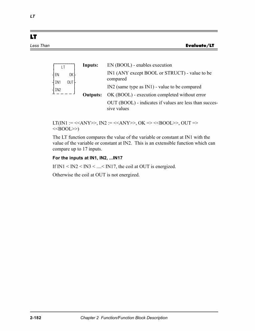
LT
LTLess Than Evaluate/LT
LT(IN1 := <<ANY>>, IN2 := <<ANY>>, OK => <<BOOL>>, OUT => <<BOOL>>)
The LT function compares the value of the variable or constant at IN1 with the value of the variable or constant at IN2. This is an extensible function which can compare up to 17 inputs.
For the inputs at IN1, IN2, ...IN17
If IN1 < IN2 < IN3 < ....< IN17, the coil at OUT is energized.
Otherwise the coil at OUT is not energized.
⁄ƒƒƒƒƒƒƒƒƒø ≥ LT ≥ ≥ ≥ ¥EN OK√ ≥ ≥ ¥IN1 OUT√ ≥ ≥ ¥IN2 ≥ ¡ ƒ ƒ ƒ ƒ Ÿ
Inputs: EN (BOOL) - enables execution
IN1 (ANY except BOOL or STRUCT) - value to be compared
IN2 (same type as IN1) - value to be compared
Outputs: OK (BOOL) - execution completed without error
OUT (BOOL) - indicates if values are less than succes-sive values
2-182 Chapter 2 Function/Function Block Description
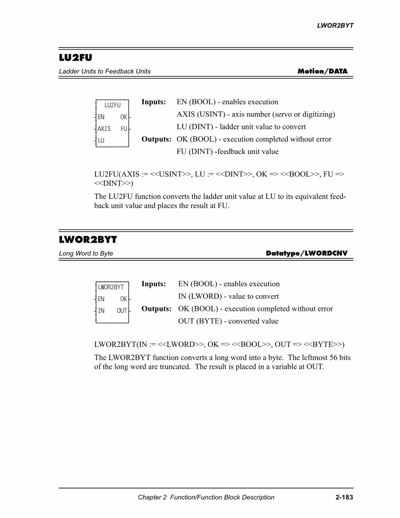
LWOR2BYT
LU2FULadder Units to Feedback Units Motion/DATA
LU2FU(AXIS := <<USINT>>, LU := <<DINT>>, OK => <<BOOL>>, FU => <<DINT>>)
The LU2FU function converts the ladder unit value at LU to its equivalent feed-back unit value and places the result at FU.
LWOR2BYTLong Word to Byte Datatype/LWORDCNV
LWOR2BYT(IN := <<LWORD>>, OK => <<BOOL>>, OUT => <<BYTE>>)
The LWOR2BYT function converts a long word into a byte. The leftmost 56 bits of the long word are truncated. The result is placed in a variable at OUT.
⁄ƒƒƒƒƒƒƒƒƒø ≥ LU2FU ≥ ≥ ≥ ¥EN OK√ ≥ ≥ ¥AXIS FU√ ≥ ≥ ¥LU ≥¿ƒƒƒƒƒƒƒƒƒŸ
Inputs: EN (BOOL) - enables execution
AXIS (USINT) - axis number (servo or digitizing)
LU (DINT) - ladder unit value to convert
Outputs: OK (BOOL) - execution completed without error
FU (DINT) -feedback unit value
⁄ƒƒƒƒƒƒƒƒƒø ≥LWOR2BYT ≥ ≥ ≥ ¥EN OK√ ≥ ≥ ¥IN OUT√ ≥ ≥ ¿ƒƒƒƒƒƒƒƒƒŸ
Inputs: EN (BOOL) - enables execution
IN (LWORD) - value to convert
Outputs: OK (BOOL) - execution completed without error
OUT (BYTE) - converted value
Chapter 2 Function/Function Block Description 2-183
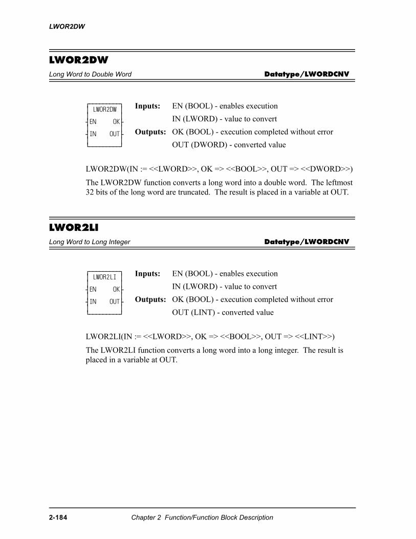
LWOR2DW
LWOR2DWLong Word to Double Word Datatype/LWORDCNV
LWOR2DW(IN := <<LWORD>>, OK => <<BOOL>>, OUT => <<DWORD>>)
The LWOR2DW function converts a long word into a double word. The leftmost 32 bits of the long word are truncated. The result is placed in a variable at OUT.
LWOR2LILong Word to Long Integer Datatype/LWORDCNV
LWOR2LI(IN := <<LWORD>>, OK => <<BOOL>>, OUT => <<LINT>>)
The LWOR2LI function converts a long word into a long integer. The result is placed in a variable at OUT.
⁄ƒƒƒƒƒƒƒƒƒø ≥ LWOR2DW ≥ ≥ ≥ ¥EN OK√ ≥ ≥ ¥IN OUT√ ≥ ≥ ¿ƒƒƒƒƒƒƒƒƒŸ
Inputs: EN (BOOL) - enables execution
IN (LWORD) - value to convert
Outputs: OK (BOOL) - execution completed without error
OUT (DWORD) - converted value
⁄ƒƒƒƒƒƒƒƒƒø ≥ LWOR2LI ≥ ≥ ≥ ¥EN OK√ ≥ ≥ ¥IN OUT√ ≥ ≥ ¿ƒƒƒƒƒƒƒƒƒŸ
Inputs: EN (BOOL) - enables execution
IN (LWORD) - value to convert
Outputs: OK (BOOL) - execution completed without error
OUT (LINT) - converted value
2-184 Chapter 2 Function/Function Block Description
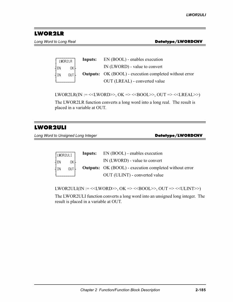
LWOR2ULI
LWOR2LRLong Word to Long Real Datatype/LWORDCNV
LWOR2LR(IN := <<LWORD>>, OK => <<BOOL>>, OUT => <<LREAL>>)
The LWOR2LR function converts a long word into a long real. The result is placed in a variable at OUT.
LWOR2ULILong Word to Unsigned Long Integer Datatype/LWORDCNV
LWOR2ULI(IN := <<LWORD>>, OK => <<BOOL>>, OUT => <<ULINT>>)
The LWOR2ULI function converts a long word into an unsigned long integer. The result is placed in a variable at OUT.
⁄ƒƒƒƒƒƒƒƒƒø ≥ LWOR2LR ≥ ≥ ≥ ¥EN OK√ ≥ ≥ ¥IN OUT√ ≥ ≥ ¿ƒƒƒƒƒƒƒƒƒŸ
Inputs: EN (BOOL) - enables execution
IN (LWORD) - value to convert
Outputs: OK (BOOL) - execution completed without error
OUT (LREAL) - converted value
⁄ƒƒƒƒƒƒƒƒƒø≥LWOR2ULI ≥≥ ≥¥EN OK√≥ ≥¥IN OUT√≥ ≥¿ƒƒƒƒƒƒƒƒƒŸ
Inputs: EN (BOOL) - enables execution
IN (LWORD) - value to convert
Outputs: OK (BOOL) - execution completed without error
OUT (ULINT) - converted value
Chapter 2 Function/Function Block Description 2-185
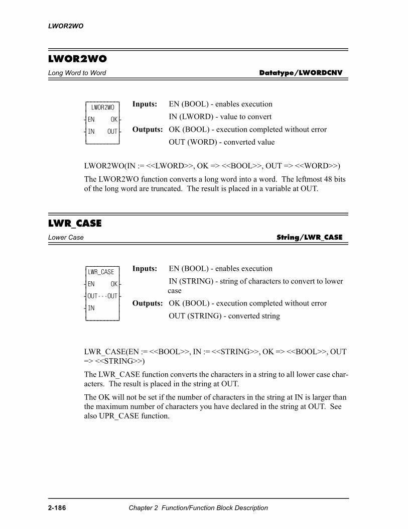
LWOR2WO
LWOR2WOLong Word to Word Datatype/LWORDCNV
LWOR2WO(IN := <<LWORD>>, OK => <<BOOL>>, OUT => <<WORD>>)
The LWOR2WO function converts a long word into a word. The leftmost 48 bits of the long word are truncated. The result is placed in a variable at OUT.
LWR_CASELower Case String/LWR_CASE
LWR_CASE(EN := <<BOOL>>, IN := <<STRING>>, OK => <<BOOL>>, OUT => <<STRING>>)
The LWR_CASE function converts the characters in a string to all lower case char-acters. The result is placed in the string at OUT.
The OK will not be set if the number of characters in the string at IN is larger than the maximum number of characters you have declared in the string at OUT. See also UPR_CASE function.
⁄ƒƒƒƒƒƒƒƒƒø ≥ LWOR2WO ≥ ≥ ≥ ¥EN OK√ ≥ ≥ ¥IN OUT√ ≥ ≥ ¿ƒƒƒƒƒƒƒƒƒŸ
Inputs: EN (BOOL) - enables execution
IN (LWORD) - value to convert
Outputs: OK (BOOL) - execution completed without error
OUT (WORD) - converted value
⁄ƒƒƒƒƒƒƒƒƒø ≥LWR_CASE ≥ ≥ ≥ ¥EN OK√ ≥ ≥ ¥OUT---OUT√ ≥ ≥ ¥IN ≥ ≥ ≥ ¿ƒƒƒƒƒƒƒƒƒŸ
Inputs: EN (BOOL) - enables execution
IN (STRING) - string of characters to convert to lower case
Outputs: OK (BOOL) - execution completed without error
OUT (STRING) - converted string
2-186 Chapter 2 Function/Function Block Description
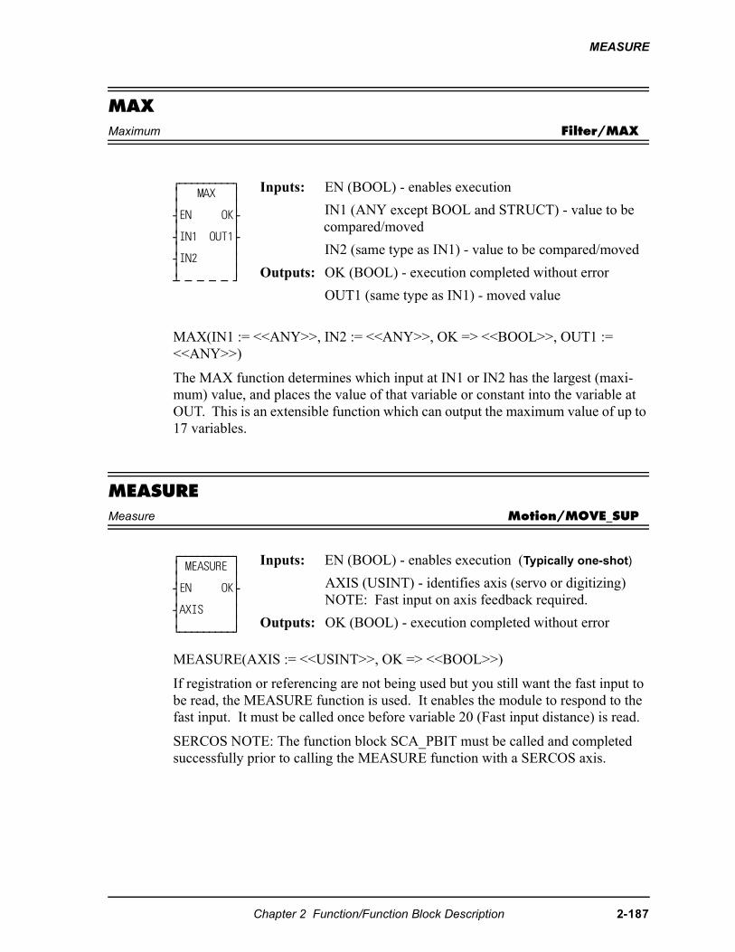
MEASURE
MAXMaximum Filter/MAX
MAX(IN1 := <<ANY>>, IN2 := <<ANY>>, OK => <<BOOL>>, OUT1 := <<ANY>>)
The MAX function determines which input at IN1 or IN2 has the largest (maxi-mum) value, and places the value of that variable or constant into the variable at OUT. This is an extensible function which can output the maximum value of up to 17 variables.
MEASUREMeasure Motion/MOVE_SUP
MEASURE(AXIS := <<USINT>>, OK => <<BOOL>>)
If registration or referencing are not being used but you still want the fast input to be read, the MEASURE function is used. It enables the module to respond to the fast input. It must be called once before variable 20 (Fast input distance) is read.
SERCOS NOTE: The function block SCA_PBIT must be called and completed successfully prior to calling the MEASURE function with a SERCOS axis.
⁄ƒƒƒƒƒƒƒƒƒø ≥ MAX ≥ ≥ ≥ ¥EN OK√ ≥ ≥ ¥IN1 OUT1√ ≥ ≥ ¥IN2 ≥ ≥ ≥ ¡ ƒ ƒ ƒ ƒ Ÿ
Inputs: EN (BOOL) - enables execution
IN1 (ANY except BOOL and STRUCT) - value to be compared/moved
IN2 (same type as IN1) - value to be compared/moved
Outputs: OK (BOOL) - execution completed without error
OUT1 (same type as IN1) - moved value
⁄ƒƒƒƒƒƒƒƒƒø ≥ MEASURE ≥ ≥ ≥ ¥EN OK√ ≥ ≥ ¥AXIS ≥≥ ≥¿ƒƒƒƒƒƒƒƒƒŸ
Inputs: EN (BOOL) - enables execution (Typically one-shot)
AXIS (USINT) - identifies axis (servo or digitizing)NOTE: Fast input on axis feedback required.
Outputs: OK (BOOL) - execution completed without error
Chapter 2 Function/Function Block Description 2-187
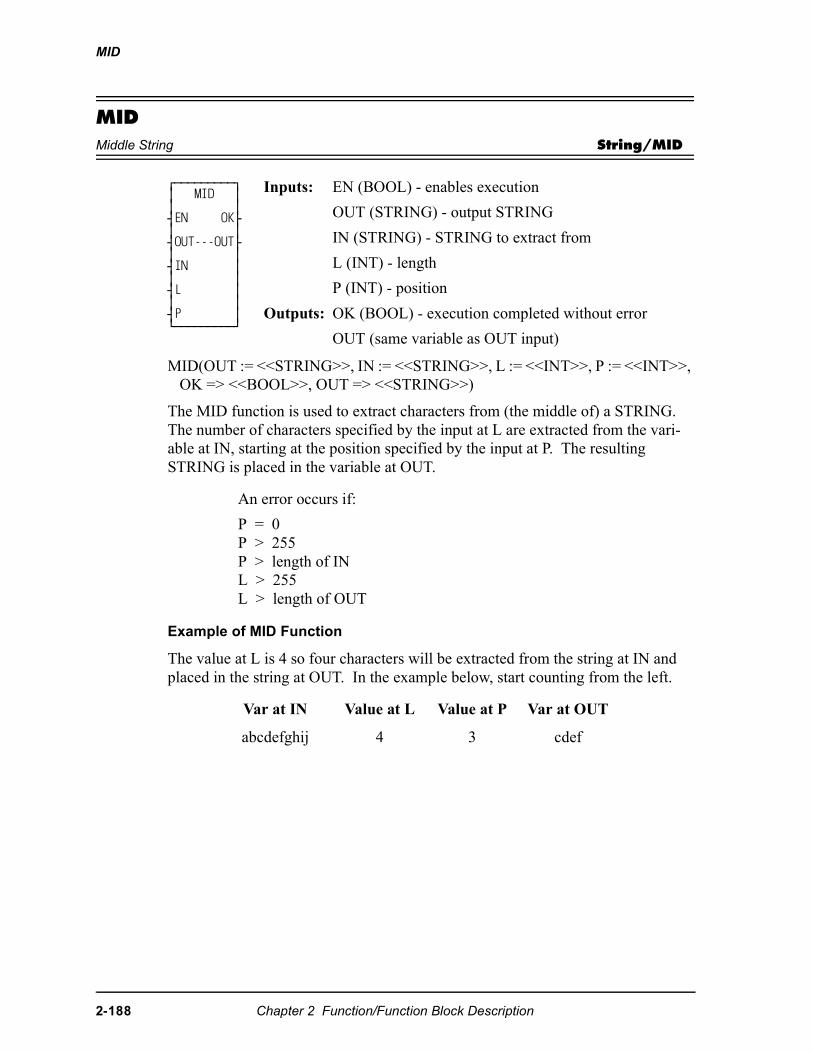
MID
MIDMiddle String String/MID
MID(OUT := <<STRING>>, IN := <<STRING>>, L := <<INT>>, P := <<INT>>, OK => <<BOOL>>, OUT => <<STRING>>)
The MID function is used to extract characters from (the middle of) a STRING. The number of characters specified by the input at L are extracted from the vari-able at IN, starting at the position specified by the input at P. The resulting STRING is placed in the variable at OUT.
Example of MID Function
The value at L is 4 so four characters will be extracted from the string at IN and placed in the string at OUT. In the example below, start counting from the left.
⁄ƒƒƒƒƒƒƒƒƒø ≥ MID ≥ ≥ ≥ ¥EN OK√ ≥ ≥ ¥OUT---OUT√ ≥ ≥ ¥IN ≥ ≥ ≥ ¥L ≥ ≥ ≥ ¥P ≥ ¿ƒƒƒƒƒƒƒƒƒŸ
Inputs: EN (BOOL) - enables execution
OUT (STRING) - output STRING
IN (STRING) - STRING to extract from
L (INT) - length
P (INT) - position
Outputs: OK (BOOL) - execution completed without error
OUT (same variable as OUT input)
An error occurs if:
P = 0P > 255P > length of INL > 255L > length of OUT
Var at IN Value at L Value at P Var at OUT
abcdefghij 4 3 cdef
2-188 Chapter 2 Function/Function Block Description
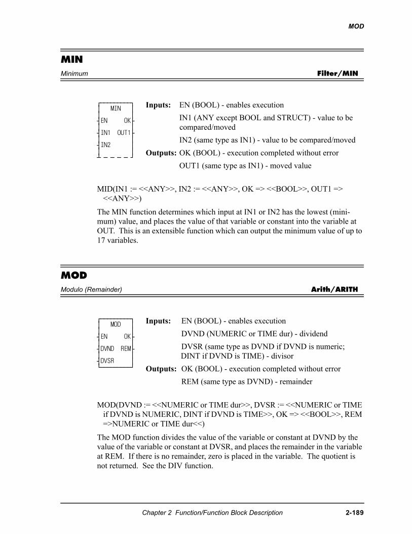
MOD
MINMinimum Filter/MIN
MID(IN1 := <<ANY>>, IN2 := <<ANY>>, OK => <<BOOL>>, OUT1 => <<ANY>>)
The MIN function determines which input at IN1 or IN2 has the lowest (mini-mum) value, and places the value of that variable or constant into the variable at OUT. This is an extensible function which can output the minimum value of up to 17 variables.
MODModulo (Remainder) Arith/ARITH
MOD(DVND := <<NUMERIC or TIME dur>>, DVSR := <<NUMERIC or TIME if DVND is NUMERIC, DINT if DVND is TIME>>, OK => <<BOOL>>, REM =>NUMERIC or TIME dur<<)
The MOD function divides the value of the variable or constant at DVND by the value of the variable or constant at DVSR, and places the remainder in the variable at REM. If there is no remainder, zero is placed in the variable. The quotient is not returned. See the DIV function.
⁄ƒƒƒƒƒƒƒƒƒø ≥ MIN ≥ ≥ ≥ ¥EN OK√ ≥ ≥ ¥IN1 OUT1√ ≥ ≥ ¥IN2 ≥ ≥ ≥ ¡ ƒ ƒ ƒ ƒ Ÿ
Inputs: EN (BOOL) - enables execution
IN1 (ANY except BOOL and STRUCT) - value to be compared/moved
IN2 (same type as IN1) - value to be compared/moved
Outputs: OK (BOOL) - execution completed without error
OUT1 (same type as IN1) - moved value
⁄ƒƒƒƒƒƒƒƒƒø ≥ MOD ≥ ≥ ≥ ¥EN OK√ ≥ ≥ ¥DVND REM√ ≥ ≥ ¥DVSR ≥ ¿ƒƒƒƒƒƒƒƒƒŸ
Inputs: EN (BOOL) - enables execution
DVND (NUMERIC or TIME dur) - dividend
DVSR (same type as DVND if DVND is numeric; DINT if DVND is TIME) - divisor
Outputs: OK (BOOL) - execution completed without error
REM (same type as DVND) - remainder
Chapter 2 Function/Function Block Description 2-189
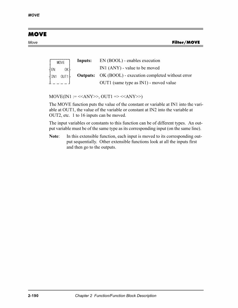
MOVE
MOVEMove Filter/MOVE
MOVE(IN1 := <<ANY>>, OUT1 => <<ANY>>)
The MOVE function puts the value of the constant or variable at IN1 into the vari-able at OUT1, the value of the variable or constant at IN2 into the variable at OUT2, etc. 1 to 16 inputs can be moved.
The input variables or constants to this function can be of different types. An out-put variable must be of the same type as its corresponding input (on the same line).
Note: In this extensible function, each input is moved to its corresponding out-put sequentially. Other extensible functions look at all the inputs first and then go to the outputs.
⁄ƒƒƒƒƒƒƒƒƒø ≥ MOVE ≥ ≥ ≥ ¥EN OK√ ≥ ≥ ¥IN1 OUT1√ ≥ ≥ ¡ ƒ ƒ ƒ ƒ Ÿ
Inputs: EN (BOOL) - enables execution
IN1 (ANY) - value to be moved
Outputs: OK (BOOL) - execution completed without error
OUT1 (same type as IN1) - moved value
2-190 Chapter 2 Function/Function Block Description
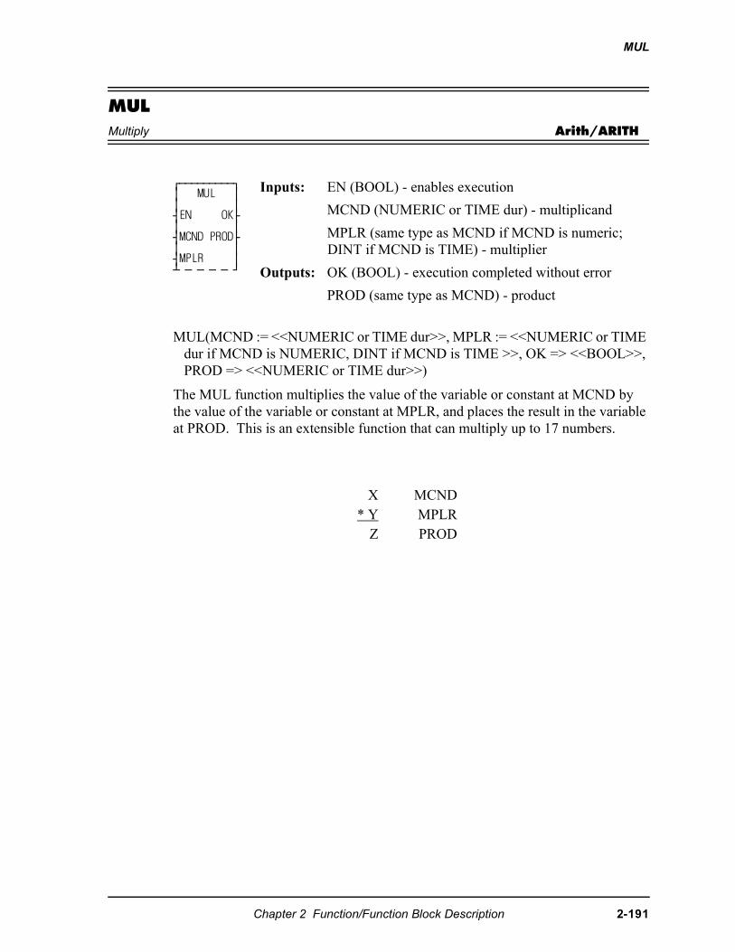
MUL
MULMultiply Arith/ARITH
MUL(MCND := <<NUMERIC or TIME dur>>, MPLR := <<NUMERIC or TIME dur if MCND is NUMERIC, DINT if MCND is TIME >>, OK => <<BOOL>>, PROD => <<NUMERIC or TIME dur>>)
The MUL function multiplies the value of the variable or constant at MCND by the value of the variable or constant at MPLR, and places the result in the variable at PROD. This is an extensible function that can multiply up to 17 numbers.
⁄ƒƒƒƒƒƒƒƒƒø ≥ MUL ≥ ≥ ≥ ¥EN OK√ ≥ ≥ ¥MCND PROD√ ≥ ≥ ¥MPLR ≥ ¡ ƒ ƒ ƒ ƒ Ÿ
Inputs: EN (BOOL) - enables execution
MCND (NUMERIC or TIME dur) - multiplicand
MPLR (same type as MCND if MCND is numeric; DINT if MCND is TIME) - multiplier
Outputs: OK (BOOL) - execution completed without error
PROD (same type as MCND) - product
X MCND* Y MPLR
Z PROD
Chapter 2 Function/Function Block Description 2-191
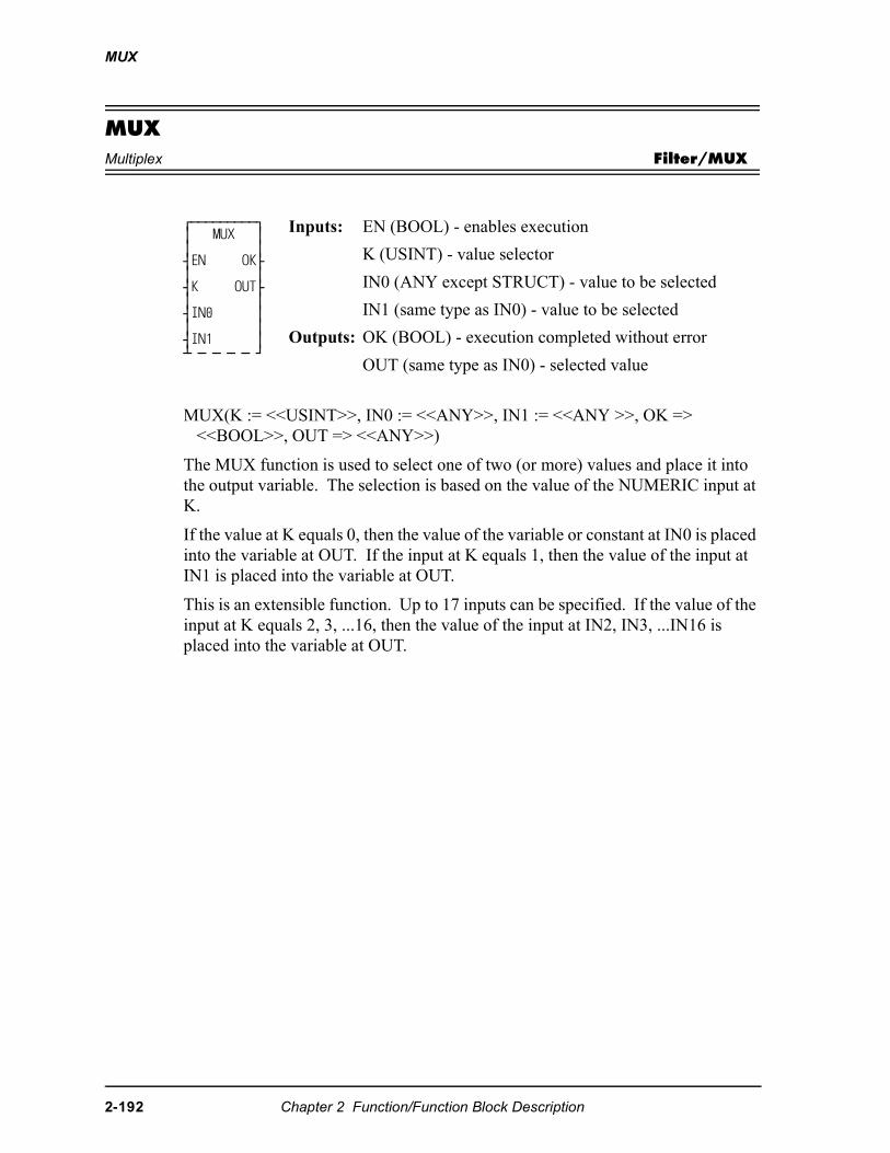
MUX
MUXMultiplex Filter/MUX
MUX(K := <<USINT>>, IN0 := <<ANY>>, IN1 := <<ANY >>, OK => <<BOOL>>, OUT => <<ANY>>)
The MUX function is used to select one of two (or more) values and place it into the output variable. The selection is based on the value of the NUMERIC input at K.
If the value at K equals 0, then the value of the variable or constant at IN0 is placed into the variable at OUT. If the input at K equals 1, then the value of the input at IN1 is placed into the variable at OUT.
This is an extensible function. Up to 17 inputs can be specified. If the value of the input at K equals 2, 3, ...16, then the value of the input at IN2, IN3, ...IN16 is placed into the variable at OUT.
⁄ƒƒƒƒƒƒƒƒƒø ≥ MUX ≥ ≥ ≥ ¥EN OK√ ≥ ≥ ¥K OUT√ ≥ ≥ ¥IN0 ≥ ≥ ≥ ¥IN1 ≥ ¡ ƒ ƒ ƒ ƒ Ÿ
Inputs: EN (BOOL) - enables execution
K (USINT) - value selector
IN0 (ANY except STRUCT) - value to be selected
IN1 (same type as IN0) - value to be selected
Outputs: OK (BOOL) - execution completed without error
OUT (same type as IN0) - selected value
2-192 Chapter 2 Function/Function Block Description
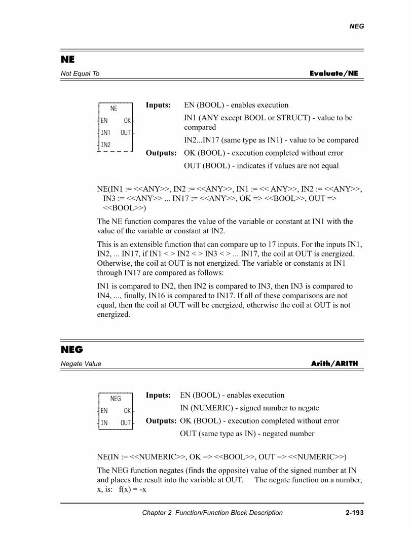
NEG
NENot Equal To Evaluate/NE
NE(IN1 := <<ANY>>, IN2 := <<ANY>>, IN1 := << ANY>>, IN2 := <<ANY>>, IN3 := <<ANY>> ... IN17 := <<ANY>>, OK => <<BOOL>>, OUT => <<BOOL>>)
The NE function compares the value of the variable or constant at IN1 with the value of the variable or constant at IN2.
This is an extensible function that can compare up to 17 inputs. For the inputs IN1, IN2, ... IN17, if IN1 < > IN2 < > IN3 < > ... IN17, the coil at OUT is energized. Otherwise, the coil at OUT is not energized. The variable or constants at IN1 through IN17 are compared as follows:
IN1 is compared to IN2, then IN2 is compared to IN3, then IN3 is compared to IN4, ..., finally, IN16 is compared to IN17. If all of these comparisons are not equal, then the coil at OUT will be energized, otherwise the coil at OUT is not energized.
NEGNegate Value Arith/ARITH
NE(IN := <<NUMERIC>>, OK => <<BOOL>>, OUT => <<NUMERIC>>)
The NEG function negates (finds the opposite) value of the signed number at IN and places the result into the variable at OUT. The negate function on a number, x, is: f(x) = -x
⁄ƒƒƒƒƒƒƒƒƒø ≥ NE ≥ ≥ ≥ ¥EN OK√ ≥ ≥ ¥IN1 OUT√ ≥ ≥ ¥IN2 ≥ ¡ ƒ ƒ ƒ ƒ Ÿ
Inputs: EN (BOOL) - enables execution
IN1 (ANY except BOOL or STRUCT) - value to be compared
IN2...IN17 (same type as IN1) - value to be compared
Outputs: OK (BOOL) - execution completed without error
OUT (BOOL) - indicates if values are not equal
⁄ƒƒƒƒƒƒƒƒƒø ≥ NEG ≥ ≥ ≥ ¥EN OK√ ≥ ≥ ¥IN OUT√ ¿ƒƒƒƒƒƒƒƒƒŸ
Inputs: EN (BOOL) - enables execution
IN (NUMERIC) - signed number to negate
Outputs: OK (BOOL) - execution completed without error
OUT (same type as IN) - negated number
Chapter 2 Function/Function Block Description 2-193
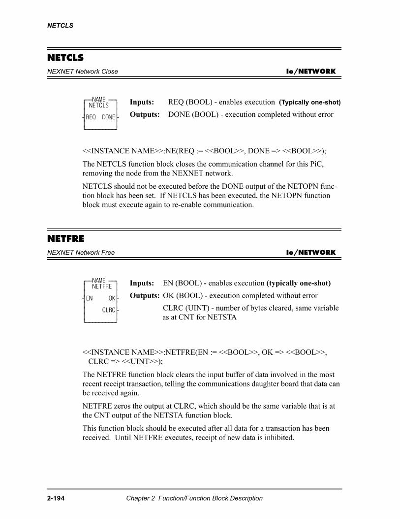
NETCLS
NETCLS NEXNET Network Close Io/NETWORK
<<INSTANCE NAME>>:NE(REQ := <<BOOL>>, DONE => <<BOOL>>);
The NETCLS function block closes the communication channel for this PiC, removing the node from the NEXNET network.
NETCLS should not be executed before the DONE output of the NETOPN func-tion block has been set. If NETCLS has been executed, the NETOPN function block must execute again to re-enable communication.
NETFRENEXNET Network Free Io/NETWORK
<<INSTANCE NAME>>:NETFRE(EN := <<BOOL>>, OK => <<BOOL>>, CLRC => <<UINT>>);
The NETFRE function block clears the input buffer of data involved in the most recent receipt transaction, telling the communications daughter board that data can be received again.
NETFRE zeros the output at CLRC, which should be the same variable that is at the CNT output of the NETSTA function block.
This function block should be executed after all data for a transaction has been received. Until NETFRE executes, receipt of new data is inhibited.
⁄ƒƒNAME ƒƒø ≥ NETCLS ≥ ≥ ≥ ¥REQ DONE√ ≥ ≥ ¿ƒƒƒƒƒƒƒƒƒŸ
Inputs: REQ (BOOL) - enables execution (Typically one-shot)
Outputs: DONE (BOOL) - execution completed without error
⁄ƒƒNAME ƒƒø ≥ NETFRE ≥ ≥ ≥ ¥EN OK√ ≥ ≥ ≥ CLRC√ ≥ ≥ ¿ƒƒƒƒƒƒƒƒƒŸ
Inputs: EN (BOOL) - enables execution (typically one-shot)
Outputs: OK (BOOL) - execution completed without error
CLRC (UINT) - number of bytes cleared, same variable as at CNT for NETSTA
2-194 Chapter 2 Function/Function Block Description
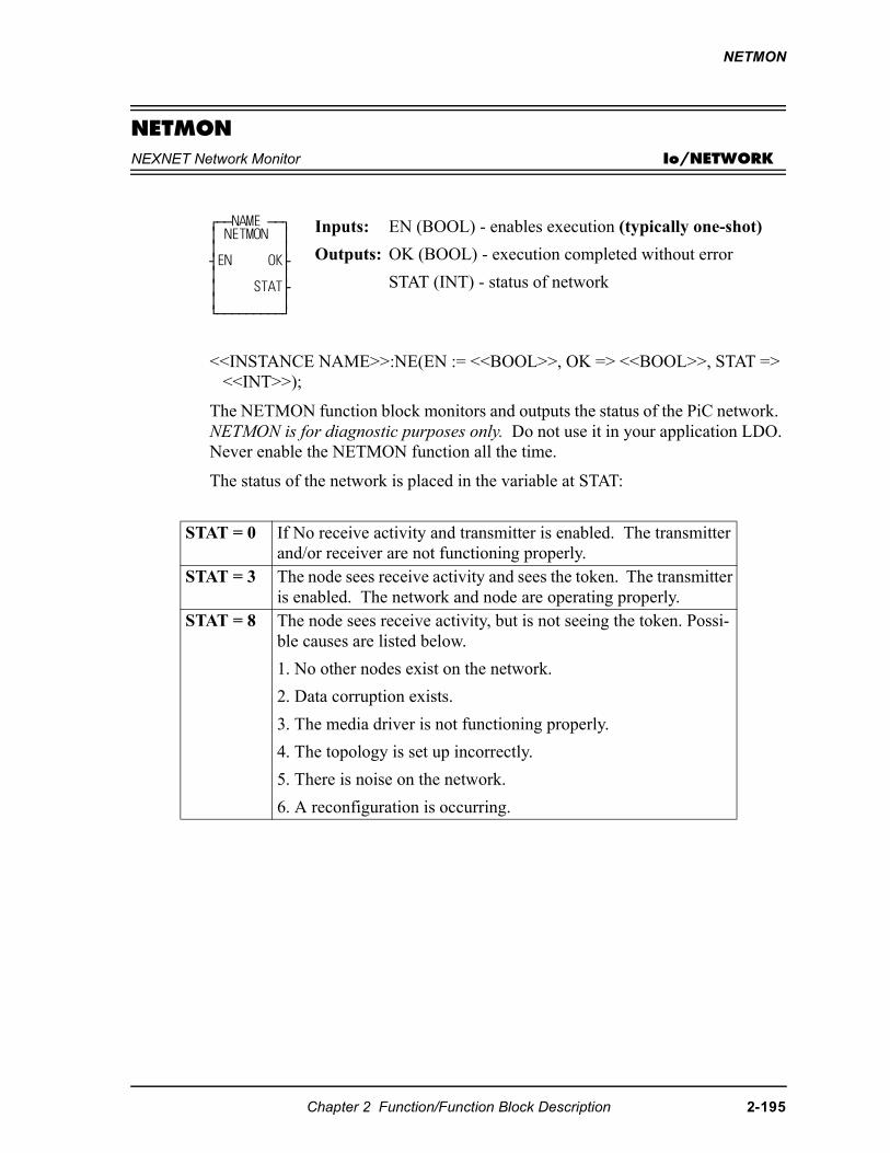
NETMON
NETMONNEXNET Network Monitor Io/NETWORK
<<INSTANCE NAME>>:NE(EN := <<BOOL>>, OK => <<BOOL>>, STAT => <<INT>>);
The NETMON function block monitors and outputs the status of the PiC network. NETMON is for diagnostic purposes only. Do not use it in your application LDO. Never enable the NETMON function all the time.
The status of the network is placed in the variable at STAT:
⁄ƒƒNAME ƒƒø ≥ NETMON ≥ ≥ ≥ ¥EN OK√ ≥ ≥ ≥ STAT√ ≥ ≥ ¿ƒƒƒƒƒƒƒƒƒŸ
Inputs: EN (BOOL) - enables execution (typically one-shot)
Outputs: OK (BOOL) - execution completed without error
STAT (INT) - status of network
STAT = 0 If No receive activity and transmitter is enabled. The transmitter and/or receiver are not functioning properly.
STAT = 3 The node sees receive activity and sees the token. The transmitter is enabled. The network and node are operating properly.
STAT = 8 The node sees receive activity, but is not seeing the token. Possi-ble causes are listed below.
1. No other nodes exist on the network.
2. Data corruption exists.
3. The media driver is not functioning properly.
4. The topology is set up incorrectly.
5. There is noise on the network.
6. A reconfiguration is occurring.
Chapter 2 Function/Function Block Description 2-195
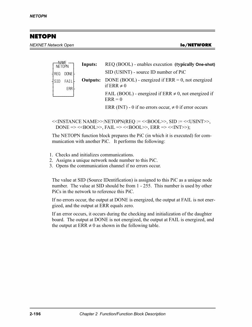
NETOPN
NETOPNNEXNET Network Open Io/NETWORK
<<INSTANCE NAME>>:NETOPN(REQ := <<BOOL>>, SID := <<USINT>>, DONE => <<BOOL>>, FAIL => <<BOOL>>, ERR => <<INT>>);
The NETOPN function block prepares the PiC (in which it is executed) for com-munication with another PiC. It performs the following:
The value at SID (Source IDentification) is assigned to this PiC as a unique node number. The value at SID should be from 1 - 255. This number is used by other PiCs in the network to reference this PiC.
If no errors occur, the output at DONE is energized, the output at FAIL is not ener-gized, and the output at ERR equals zero.
If an error occurs, it occurs during the checking and initialization of the daughter board. The output at DONE is not energized, the output at FAIL is energized, and the output at ERR ≠ 0 as shown in the following table.
⁄ƒƒNAME ƒƒø ≥ NETOPN ≥ ≥ ≥ ¥REQ DONE√ ≥ ≥ ¥SID FAIL√ ≥ ≥ ≥ ERR√ ≥ ≥ ¿ƒƒƒƒƒƒƒƒƒŸ
Inputs: REQ (BOOL) - enables execution (typically One-shot)
SID (USINT) - source ID number of PiC
Outputs: DONE (BOOL) - energized if ERR = 0, not energized if ERR ≠ 0FAIL (BOOL) - energized if ERR ≠ 0, not energized if ERR = 0
ERR (INT) - 0 if no errors occur, ≠ 0 if error occurs
1. Checks and initializes communications.2. Assigns a unique network node number to this PiC.3. Opens the communication channel if no errors occur.
2-196 Chapter 2 Function/Function Block Description
NETOPN
All PiCs in a network should execute the NETOPN function block one time (the input at REQ should be a one-shot) before they execute any other NEXNET func-tion blocks.
Other NEXNET function blocks are: NETCLS, NETFRE, NETMON, NETRCV, NETSND, and NETSTA.
If a PiC has executed a NETCLS, it must execute NETOPN again to re-enable communications.
ERR = 1 The ARCNET hardware ID check failed. ERR = 2 The transmitter is not available. An ARCNET communications
failure has occurred.ERR = 3 The power-on reset flag cannot be cleared. An ARCNET commu-
nications failure has occurred.ERR = 4 The SID specified is assigned to another node. Check SID num-
bers. ERR = 5 to 44 Check Appendix B in the PiCPro Online Help for errors connected
to the OPEN function block. ERR > 1XXX The node number has been set by PiCPro and is different than the
number you entered at the SID input. The XXX holds the PiCPro node number 001 through 255.
Chapter 2 Function/Function Block Description 2-197
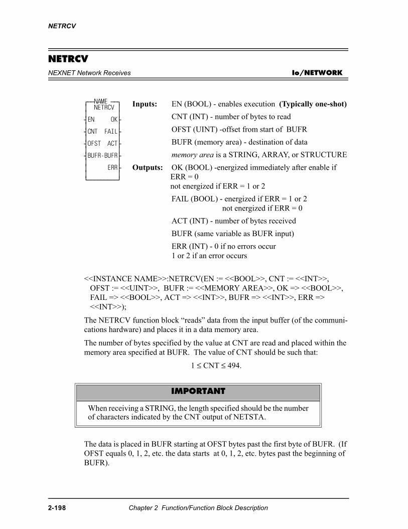
NETRCV
NETRCVNEXNET Network Receives Io/NETWORK
<<INSTANCE NAME>>:NETRCV(EN := <<BOOL>>, CNT := <<INT>>, OFST := <<UINT>>, BUFR := <<MEMORY AREA>>, OK => <<BOOL>>, FAIL => <<BOOL>>, ACT => <<INT>>, BUFR => <<INT>>, ERR => <<INT>>);
The NETRCV function block “reads” data from the input buffer (of the communi-cations hardware) and places it in a data memory area.
The number of bytes specified by the value at CNT are read and placed within the memory area specified at BUFR. The value of CNT should be such that:
1 ≤ CNT ≤ 494.
The data is placed in BUFR starting at OFST bytes past the first byte of BUFR. (If OFST equals 0, 1, 2, etc. the data starts at 0, 1, 2, etc. bytes past the beginning of BUFR).
⁄ƒƒNAME ƒƒø ≥ NETRCV ≥ ≥ ≥ ¥EN OK√ ≥ ≥ ¥CNT FAIL√ ≥ ≥ ¥OFST ACT√ ≥ ≥ ¥BUFR-BUFR√ ≥ ≥ ≥ ERR√ ≥ ≥ ¿ƒƒƒƒƒƒƒƒƒŸ
Inputs: EN (BOOL) - enables execution (Typically one-shot)
CNT (INT) - number of bytes to read
OFST (UINT) -offset from start of BUFR
BUFR (memory area) - destination of data
memory area is a STRING, ARRAY, or STRUCTURE
Outputs: OK (BOOL) -energized immediately after enable if ERR = 0not energized if ERR = 1 or 2
FAIL (BOOL) - energized if ERR = 1 or 2not energized if ERR = 0
ACT (INT) - number of bytes received
BUFR (same variable as BUFR input)
ERR (INT) - 0 if no errors occur1 or 2 if an error occurs
IMPORTANT
When receiving a STRING, the length specified should be the numberof characters indicated by the CNT output of NETSTA.
2-198 Chapter 2 Function/Function Block Description
NETRCV
The number of bytes actually read is placed in the variable at ACT. The value of ACT will be less than the value of CNT when an error occurs. Otherwise the value of ACT will equal the value of CNT.
Multiple NETRCV function blocks may be executed to sequentially read the data from one transaction, allowing for the separation of the data into different memory areas. The total number of bytes read by one or more NETRCVs should equal the value of the CNT output of the NETSTA function block.
If an error occurs the output at DONE is not energized, the output at FAIL is ener-gized, the value at ACT equals 0, the value at BUFR is unchanged, and the output at ERR equals 1 or 2.
ERR = 1 There is no data in the input buffer to receive. ERR = 2 The value of CNT is greater than the number of bytes in the input
buffer.
NOTE: The NETFRE function block should be executed after all data (for one transaction) has been read from the input buffer.
Chapter 2 Function/Function Block Description 2-199
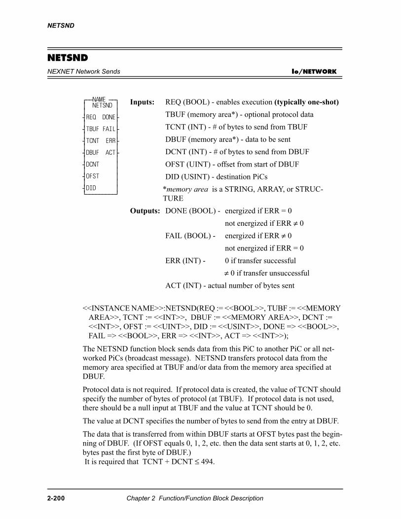
NETSND
NETSNDNEXNET Network Sends Io/NETWORK
<<INSTANCE NAME>>:NETSND(REQ := <<BOOL>>, TUBF := <<MEMORY AREA>>, TCNT := <<INT>>, DBUF := <<MEMORY AREA>>, DCNT := <<INT>>, OFST := <<UINT>>, DID := <<USINT>>, DONE => <<BOOL>>, FAIL => <<BOOL>>, ERR => <<INT>>, ACT => <<INT>>);
The NETSND function block sends data from this PiC to another PiC or all net-worked PiCs (broadcast message). NETSND transfers protocol data from the memory area specified at TBUF and/or data from the memory area specified at DBUF.
Protocol data is not required. If protocol data is created, the value of TCNT should specify the number of bytes of protocol (at TBUF). If protocol data is not used, there should be a null input at TBUF and the value at TCNT should be 0.
The value at DCNT specifies the number of bytes to send from the entry at DBUF.
The data that is transferred from within DBUF starts at OFST bytes past the begin-ning of DBUF. (If OFST equals 0, 1, 2, etc. then the data sent starts at 0, 1, 2, etc. bytes past the first byte of DBUF.) It is required that TCNT + DCNT ≤ 494.
⁄ƒƒNAME ƒƒø ≥ NETSND ≥ ≥ ≥ ¥REQ DONE√ ≥ ≥ ¥TBUF FAIL√ ≥ ≥ ¥TCNT ERR√ ≥ ≥ ¥DBUF ACT√ ≥ ≥ ¥DCNT ≥ ≥ ≥ ¥OFST ≥ ≥ ≥ ¥DID ≥ ¿ƒƒƒƒƒƒƒƒƒŸ
Inputs: REQ (BOOL) - enables execution (typically one-shot)
TBUF (memory area*) - optional protocol data
TCNT (INT) - # of bytes to send from TBUF
DBUF (memory area*) - data to be sent
DCNT (INT) - # of bytes to send from DBUF
OFST (UINT) - offset from start of DBUF
DID (USINT) - destination PiCs
*memory area is a STRING, ARRAY, or STRUC-TURE
Outputs: DONE (BOOL) - energized if ERR = 0
not energized if ERR ≠ 0FAIL (BOOL) - energized if ERR ≠ 0
not energized if ERR = 0
ERR (INT) - 0 if transfer successful
≠ 0 if transfer unsuccessful
ACT (INT) - actual number of bytes sent
2-200 Chapter 2 Function/Function Block Description
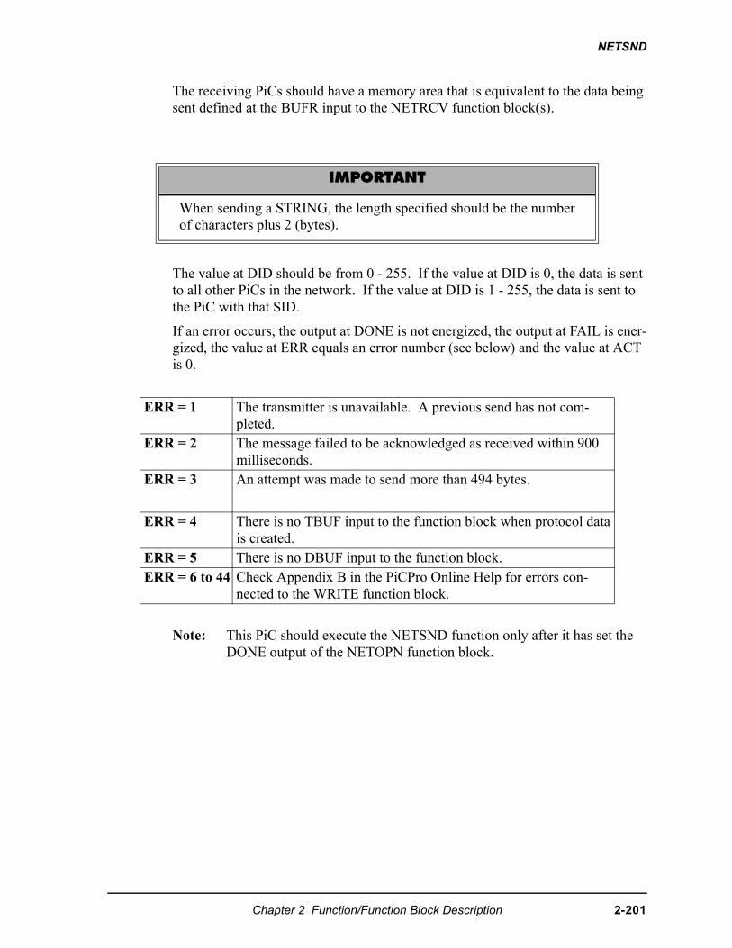
NETSND
The receiving PiCs should have a memory area that is equivalent to the data being sent defined at the BUFR input to the NETRCV function block(s).
The value at DID should be from 0 - 255. If the value at DID is 0, the data is sent to all other PiCs in the network. If the value at DID is 1 - 255, the data is sent to the PiC with that SID.
If an error occurs, the output at DONE is not energized, the output at FAIL is ener-gized, the value at ERR equals an error number (see below) and the value at ACT is 0.
Note: This PiC should execute the NETSND function only after it has set the DONE output of the NETOPN function block.
IMPORTANT
When sending a STRING, the length specified should be the numberof characters plus 2 (bytes).
ERR = 1 The transmitter is unavailable. A previous send has not com-pleted.
ERR = 2 The message failed to be acknowledged as received within 900 milliseconds.
ERR = 3 An attempt was made to send more than 494 bytes.
ERR = 4 There is no TBUF input to the function block when protocol data is created.
ERR = 5 There is no DBUF input to the function block.ERR = 6 to 44 Check Appendix B in the PiCPro Online Help for errors con-
nected to the WRITE function block.
Chapter 2 Function/Function Block Description 2-201
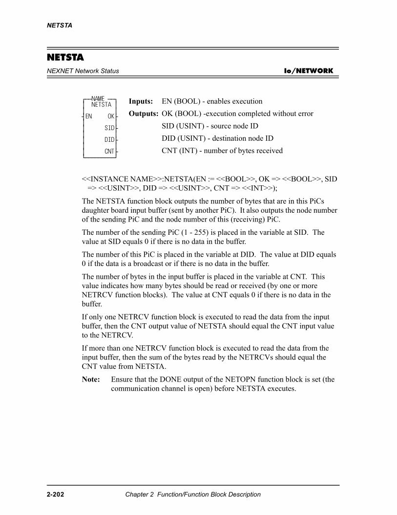
NETSTA
NETSTANEXNET Network Status Io/NETWORK
<<INSTANCE NAME>>:NETSTA(EN := <<BOOL>>, OK => <<BOOL>>, SID => <<USINT>>, DID => <<USINT>>, CNT => <<INT>>);
The NETSTA function block outputs the number of bytes that are in this PiCs daughter board input buffer (sent by another PiC). It also outputs the node number of the sending PiC and the node number of this (receiving) PiC.
The number of the sending PiC (1 - 255) is placed in the variable at SID. The value at SID equals 0 if there is no data in the buffer.
The number of this PiC is placed in the variable at DID. The value at DID equals 0 if the data is a broadcast or if there is no data in the buffer.
The number of bytes in the input buffer is placed in the variable at CNT. This value indicates how many bytes should be read or received (by one or more NETRCV function blocks). The value at CNT equals 0 if there is no data in the buffer.
If only one NETRCV function block is executed to read the data from the input buffer, then the CNT output value of NETSTA should equal the CNT input value to the NETRCV.
If more than one NETRCV function block is executed to read the data from the input buffer, then the sum of the bytes read by the NETRCVs should equal the CNT value from NETSTA.
Note: Ensure that the DONE output of the NETOPN function block is set (the communication channel is open) before NETSTA executes.
⁄ƒƒNAME ƒƒø ≥ NETSTA ≥ ≥ ≥ ¥EN OK√ ≥ ≥ ≥ SID√ ≥ ≥ ≥ DID√ ≥ ≥ ≥ CNT√ ¿ƒƒƒƒƒƒƒƒƒŸ
Inputs: EN (BOOL) - enables execution
Outputs: OK (BOOL) -execution completed without error
SID (USINT) - source node ID
DID (USINT) - destination node ID
CNT (INT) - number of bytes received
2-202 Chapter 2 Function/Function Block Description
NEWRATIO
NEWRATIONew Ratio Motion/MOVE_SUP
NEWRATIO(AXIS := <<USINT>>, MAST := <<USINT>>, SDST := <<DINT>>, MDST := <<DINT>>, OK => <<BOOL>>)
The NEWRATIO function allows you to change the current constant ratio in a RATIO_GR or a RATIOSYN move and change the default ratio in a RATIOSLP move.
Changing the ratio in RATIO_GR and RATIOSYN
You define a constant ratio when using the RATIO_GR or RATIOSYN moves. The NEWRATIO function is called after the RATIO_GR or RATIOSYN move is active and allows you to change this constant ratio. The new ratio takes effect after the next servo interrupt.
The function does not use the queue but changes the ratio of the move in the active queue.
Changing the default ratio in RATIOSLP and RATIO_RL
The RATIOSLP and RATIO_RL moves have a default ratio of 1:1. The NEWRA-TIO function is normally called before the move is active and allows you to change this default ratio.
⁄ƒƒƒƒƒƒƒƒƒø≥ NEWRATIO≥≥ ≥¥EN OK√≥ ≥¥AXIS ≥≥ ≥¥MAST ≥≥ ≥¥SDST ≥≥ ≥¥MDST ≥¿ƒƒƒƒƒƒƒƒƒŸ
Inputs: EN (BOOL) - enables execution
AXIS (USINT) - identifies the slave axis (servo)
MAST (USINT) - identifies the master axis the slave axis follows in the ratio move
SDST (DINT) - (slave distance) indicates the new dis-tance the slave should move for each MDST distance (entered in LU*)
MDST (DINT) - (master distance) indicates the new distance the master axis will move during each SDST (entered in LU*)
*NOTE: The range of values entered in SDST and MDST is -536870912 to +536870911 FU (excluding 0 for the MDST input.) If you are using ladder units, make sure they do not exceed this range when con-verted to feedback units.
Outputs: OK (BOOL) - execution complete without errors
Chapter 2 Function/Function Block Description 2-203
NEWRATIO
If the NEWRATIO function is called after the move, the current ratio of the move is used initially and the ratio defined by NEWRATIO takes effect after the next servo interrupt.
The OK will not be set if any of the following programming errors occur:
1. Master axis not available2. Master distance not valid3. Slave distance not valid.
IMPORTANT
Whenever the NEWRATIO function is called, it always sets the default ratiofor a RATIOSLP move.
If, for example, the NEWRATIO function is called for a RATIO_GRor RATIOSYN move, and later a RATIOSLP move is called, the RA-TIOSLP move will also use the ratio established in the NEWRATIOfunction as its default ratio.
If you do not want to use this ratio, call the NEWRATIO functionagain.
2-204 Chapter 2 Function/Function Block Description
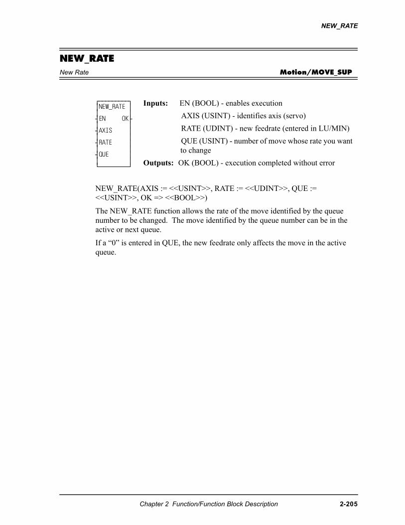
NEW_RATE
NEW_RATENew Rate Motion/MOVE_SUP
NEW_RATE(AXIS := <<USINT>>, RATE := <<UDINT>>, QUE := <<USINT>>, OK => <<BOOL>>)
The NEW_RATE function allows the rate of the move identified by the queue number to be changed. The move identified by the queue number can be in the active or next queue.
If a “0” is entered in QUE, the new feedrate only affects the move in the active queue.
⁄ƒƒƒƒƒƒƒƒƒø ≥NEW_RATE ≥ ≥ ≥ ¥EN OK√ ≥ ≥ ¥AXIS ≥ ≥ ≥ ¥RATE ≥ ≥ ≥ ¥QUE ≥ ≥ ≥ ¿ƒƒƒƒƒƒƒƒƒŸ
Inputs: EN (BOOL) - enables execution
AXIS (USINT) - identifies axis (servo)
RATE (UDINT) - new feedrate (entered in LU/MIN)
QUE (USINT) - number of move whose rate you want to change
Outputs: OK (BOOL) - execution completed without error
Chapter 2 Function/Function Block Description 2-205
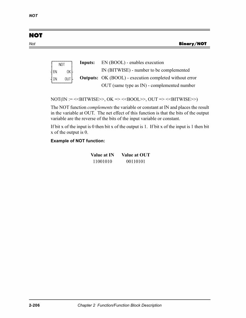
NOT
NOTNot Binary/NOT
NOT(IN := <<BITWISE>>, OK => <<BOOL>>, OUT => <<BITWISE>>)
The NOT function complements the variable or constant at IN and places the result in the variable at OUT. The net effect of this function is that the bits of the output variable are the reverse of the bits of the input variable or constant.
If bit x of the input is 0 then bit x of the output is 1. If bit x of the input is 1 then bit x of the output is 0.
Example of NOT function:
⁄ƒƒƒƒƒƒƒƒƒø ≥ NOT ≥ ≥ ≥ ¥EN OK√ ≥ ≥ ¥IN OUT√ ¿ƒƒƒƒƒƒƒƒƒŸ
Inputs: EN (BOOL) - enables execution
IN (BITWISE) - number to be complemented
Outputs: OK (BOOL) - execution completed without error
OUT (same type as IN) - complemented number
Value at IN Value at OUT11001010 00110101
2-206 Chapter 2 Function/Function Block Description
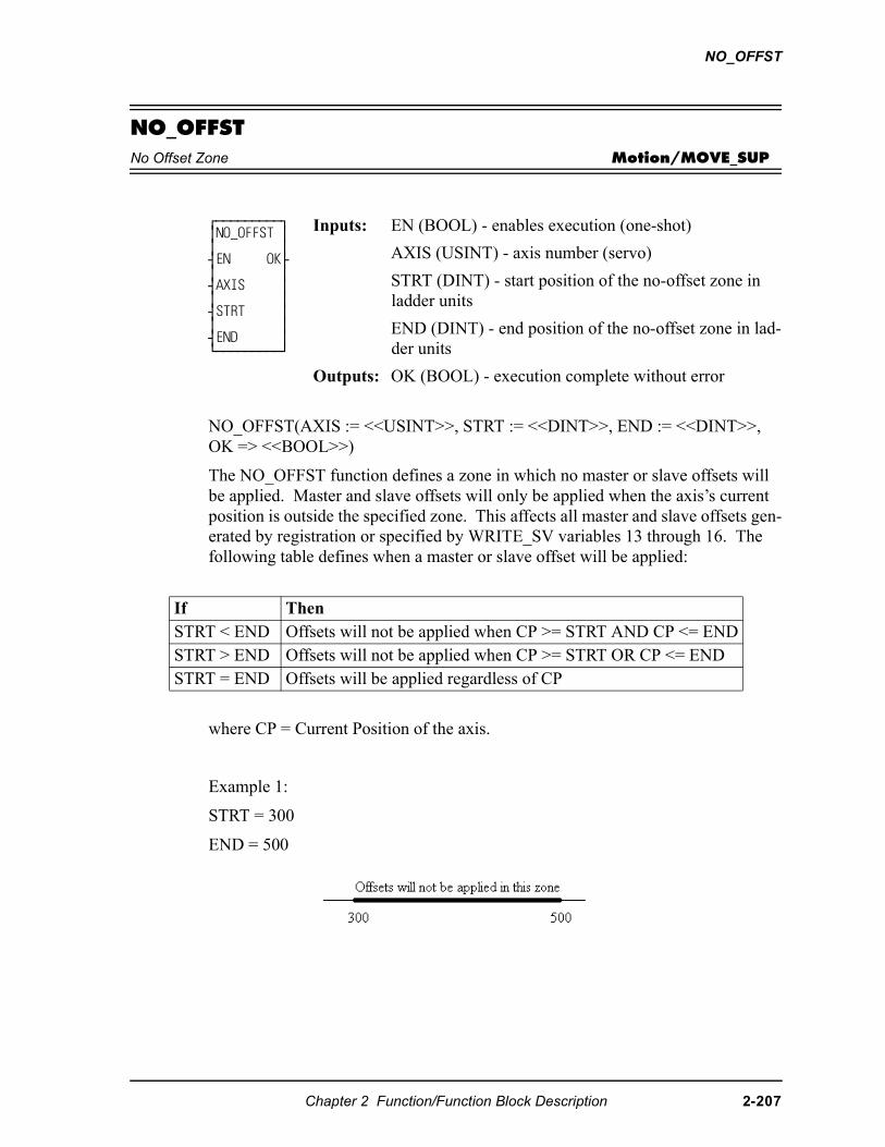
NO_OFFST
NO_OFFSTNo Offset Zone Motion/MOVE_SUP
NO_OFFST(AXIS := <<USINT>>, STRT := <<DINT>>, END := <<DINT>>, OK => <<BOOL>>)
The NO_OFFST function defines a zone in which no master or slave offsets will be applied. Master and slave offsets will only be applied when the axis’s current position is outside the specified zone. This affects all master and slave offsets gen-erated by registration or specified by WRITE_SV variables 13 through 16. The following table defines when a master or slave offset will be applied:
where CP = Current Position of the axis.
Example 1:
STRT = 300
END = 500
⁄ƒƒƒƒƒƒƒƒƒø ≥NO_OFFST ≥ ≥ ≥ ¥EN OK√ ≥ ≥ ¥AXIS ≥ ≥ ≥ ¥STRT ≥ ≥ ≥ ¥END ≥ ¿ƒƒƒƒƒƒƒƒƒŸ
Inputs: EN (BOOL) - enables execution (one-shot)
AXIS (USINT) - axis number (servo)
STRT (DINT) - start position of the no-offset zone in ladder units
END (DINT) - end position of the no-offset zone in lad-der units
Outputs: OK (BOOL) - execution complete without error
If ThenSTRT < END Offsets will not be applied when CP >= STRT AND CP <= ENDSTRT > END Offsets will not be applied when CP >= STRT OR CP <= ENDSTRT = END Offsets will be applied regardless of CP
Chapter 2 Function/Function Block Description 2-207
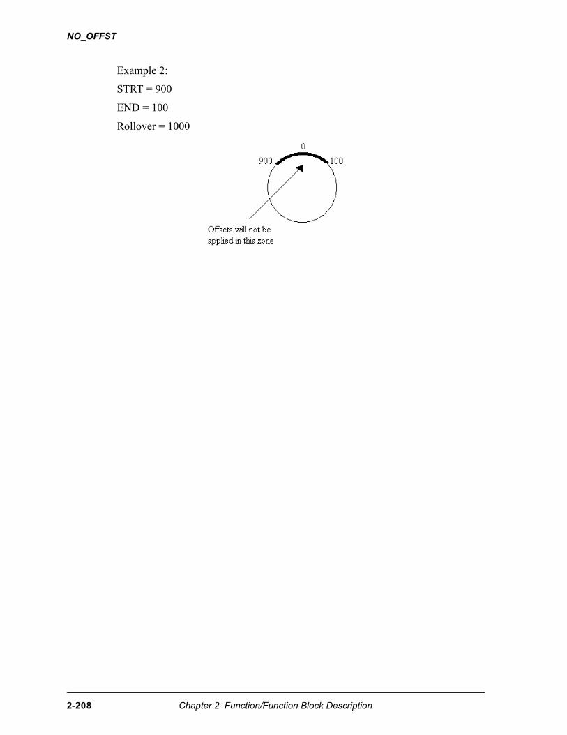
NO_OFFST
Example 2:
STRT = 900
END = 100
Rollover = 1000
2-208 Chapter 2 Function/Function Block Description
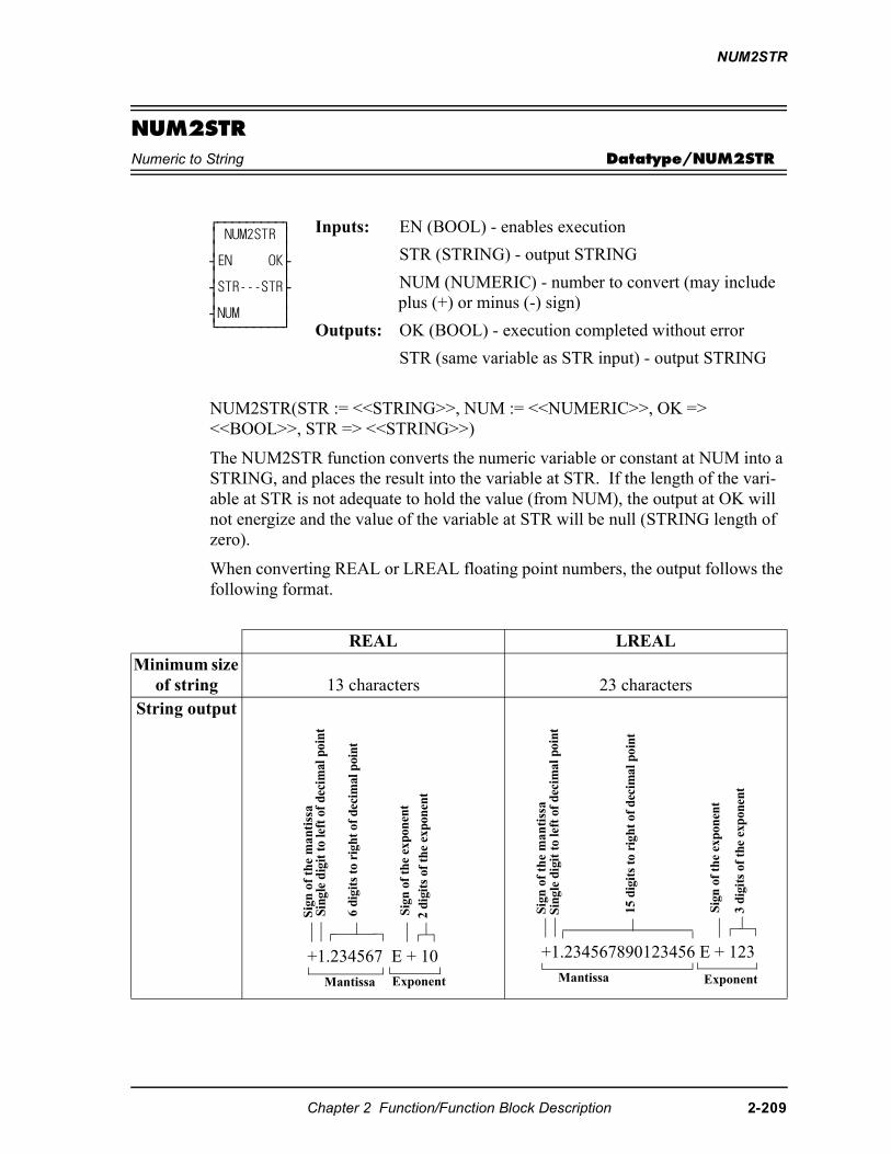
NUM2STR
NUM2STRNumeric to String Datatype/NUM2STR
NUM2STR(STR := <<STRING>>, NUM := <<NUMERIC>>, OK => <<BOOL>>, STR => <<STRING>>)
The NUM2STR function converts the numeric variable or constant at NUM into a STRING, and places the result into the variable at STR. If the length of the vari-able at STR is not adequate to hold the value (from NUM), the output at OK will not energize and the value of the variable at STR will be null (STRING length of zero).
When converting REAL or LREAL floating point numbers, the output follows the following format.
⁄ƒƒƒƒƒƒƒƒƒø ≥ NUM2STR ≥ ≥ ≥ ¥EN OK√ ≥ ≥ ¥STR---STR√ ≥ ≥ ¥NUM ≥ ¿ƒƒƒƒƒƒƒƒƒŸ
Inputs: EN (BOOL) - enables execution
STR (STRING) - output STRING
NUM (NUMERIC) - number to convert (may include plus (+) or minus (-) sign)
Outputs: OK (BOOL) - execution completed without error
STR (same variable as STR input) - output STRING
REAL LREALMinimum size
of string 13 characters 23 charactersString output
+1.234567 E + 10
Mantissa Exponent
Sig
n o
f th
e m
anti
ssa
Sing
le d
igit
to le
ft o
f dec
imal
poi
nt
6 di
gits
to
righ
t of
dec
imal
poi
nt
Sign
of
the
expo
nent
2 di
gits
of
the
expo
nent
+1.234567890123456 E + 123
Mantissa
Sig
n o
f th
e m
anti
ssa
Sing
le d
igit
to
left
of
deci
mal
poi
nt
Sign
of
the
expo
nent
15 d
igit
s to
rig
ht o
f de
cim
al p
oint
3 d i
gits
of
the
expo
nent
Exponent
Chapter 2 Function/Function Block Description 2-209
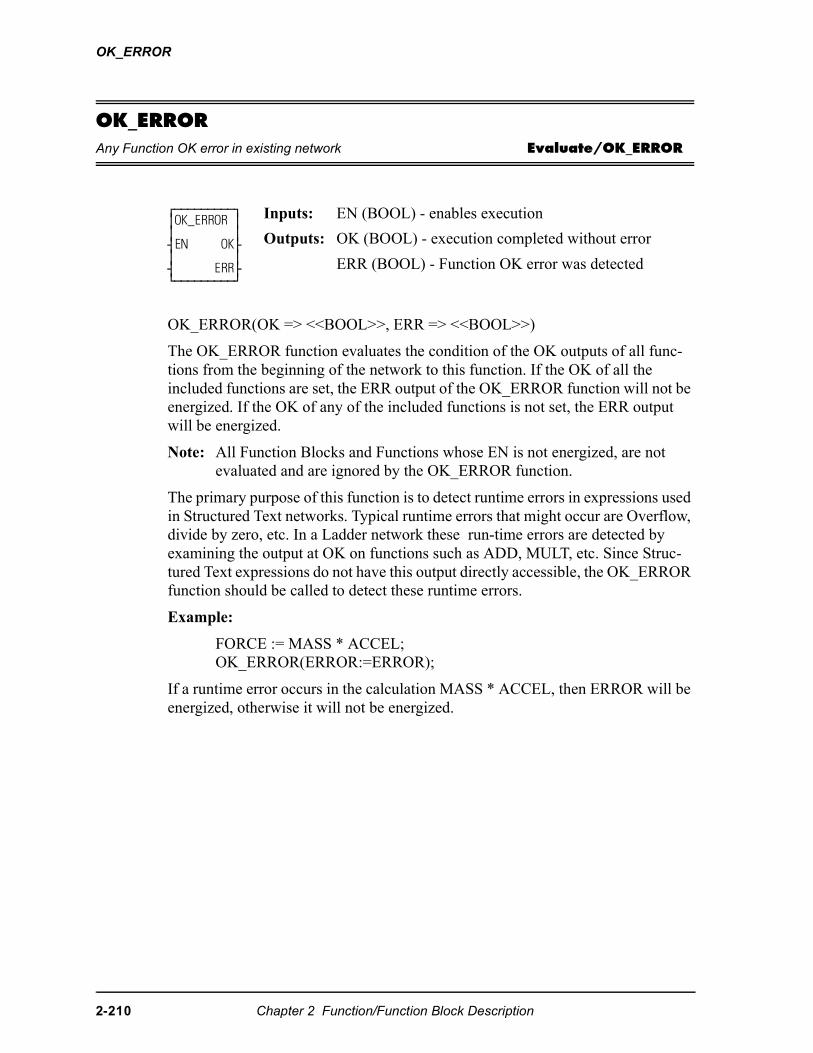
OK_ERROR
OK_ERRORAny Function OK error in existing network Evaluate/OK_ERROR
OK_ERROR(OK => <<BOOL>>, ERR => <<BOOL>>)
The OK_ERROR function evaluates the condition of the OK outputs of all func-tions from the beginning of the network to this function. If the OK of all the included functions are set, the ERR output of the OK_ERROR function will not be energized. If the OK of any of the included functions is not set, the ERR output will be energized.
Note: All Function Blocks and Functions whose EN is not energized, are not evaluated and are ignored by the OK_ERROR function.
The primary purpose of this function is to detect runtime errors in expressions used in Structured Text networks. Typical runtime errors that might occur are Overflow, divide by zero, etc. In a Ladder network these run-time errors are detected by examining the output at OK on functions such as ADD, MULT, etc. Since Struc-tured Text expressions do not have this output directly accessible, the OK_ERROR function should be called to detect these runtime errors.
Example:
FORCE := MASS * ACCEL;OK_ERROR(ERROR:=ERROR);
If a runtime error occurs in the calculation MASS * ACCEL, then ERROR will be energized, otherwise it will not be energized.
⁄ƒƒƒƒƒƒƒƒƒø ≥OK_ERROR ≥ ≥ ≥ ¥EN OK√ ≥ ≥ ¥ ERR√ ¿ƒƒƒƒƒƒƒƒƒŸ
Inputs: EN (BOOL) - enables execution
Outputs: OK (BOOL) - execution completed without error
ERR (BOOL) - Function OK error was detected
2-210 Chapter 2 Function/Function Block Description
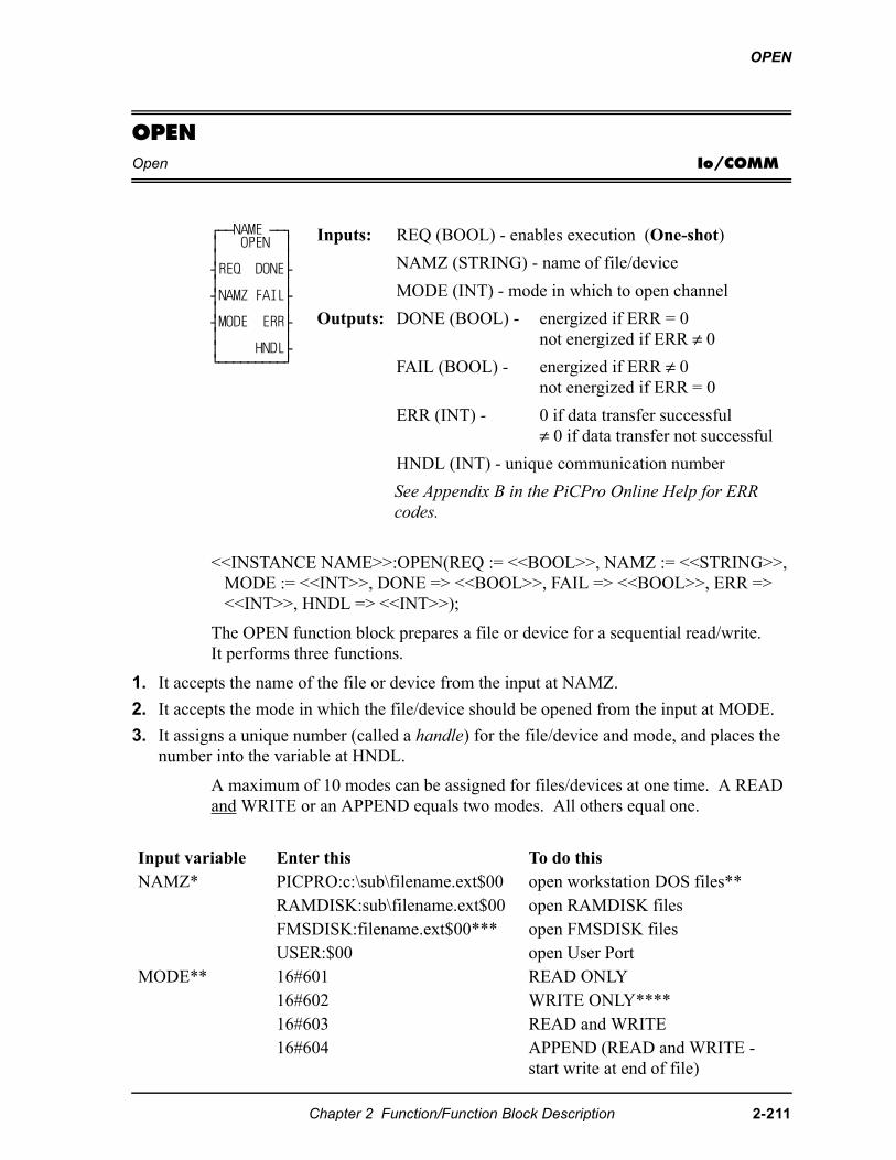
OPEN
OPENOpen Io/COMM
<<INSTANCE NAME>>:OPEN(REQ := <<BOOL>>, NAMZ := <<STRING>>, MODE := <<INT>>, DONE => <<BOOL>>, FAIL => <<BOOL>>, ERR => <<INT>>, HNDL => <<INT>>);
The OPEN function block prepares a file or device for a sequential read/write. It performs three functions.
1. It accepts the name of the file or device from the input at NAMZ.
2. It accepts the mode in which the file/device should be opened from the input at MODE.
3. It assigns a unique number (called a handle) for the file/device and mode, and places the number into the variable at HNDL.
A maximum of 10 modes can be assigned for files/devices at one time. A READ and WRITE or an APPEND equals two modes. All others equal one.
⁄ƒƒNAME ƒƒø ≥ OPEN ≥ ≥ ≥ ¥REQ DONE√ ≥ ≥ ¥NAMZ FAIL√ ≥ ≥ ¥MODE ERR√ ≥ ≥ ≥ HNDL√ ¿ƒƒƒƒƒƒƒƒƒŸ
Inputs: REQ (BOOL) - enables execution (One-shot)
NAMZ (STRING) - name of file/device
MODE (INT) - mode in which to open channel
Outputs: DONE (BOOL) - energized if ERR = 0not energized if ERR ≠ 0
FAIL (BOOL) - energized if ERR ≠ 0not energized if ERR = 0
ERR (INT) - 0 if data transfer successful≠ 0 if data transfer not successful
HNDL (INT) - unique communication number
See Appendix B in the PiCPro Online Help for ERR codes.
Input variable Enter this To do thisNAMZ* PICPRO:c:\sub\filename.ext$00 open workstation DOS files**
RAMDISK:sub\filename.ext$00 open RAMDISK filesFMSDISK:filename.ext$00*** open FMSDISK filesUSER:$00 open User Port
MODE** 16#601 READ ONLY16#602 WRITE ONLY****16#603 READ and WRITE16#604 APPEND (READ and WRITE -
start write at end of file)
Chapter 2 Function/Function Block Description 2-211
OPEN
* PICPRO, RAMDISK, FMSDISK, and USER must be entered in capital let-ters, followed by a colon (:). A full (directory) path must be specified for files. The $00 characters are required at the end. NOTE: The total number of characters is limited to 77.
** Workstation files can be opened only in the read (16#601) or write (16#602) mode; and only one workstation file at a time can be open.
*** FMSDISK files can be opened only in the read mode.
**** If there is an existing file, opening it in the write only mode will delete the existing data. The new data will then be written to it. A subdirectory can be created by opening in the WRITE ONLY mode. If the sub-directory and filename do not exist when the OPEN is performed, both will be cre-ated.
OPEN is used in conjunction with the CLOSE, CONFIG, READ, SEEK, STA-TUS, and WRITE I/O function blocks.
2-212 Chapter 2 Function/Function Block Description
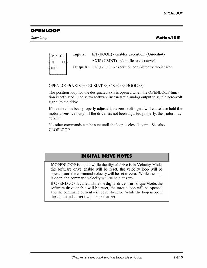
OPENLOOP
OPENLOOPOpen Loop Motion/INIT
OPENLOOP(AXIS := <<USINT>>, OK => <<BOOL>>)
The position loop for the designated axis is opened when the OPENLOOP func-tion is activated. The servo software instructs the analog output to send a zero-volt signal to the drive.
If the drive has been properly adjusted, the zero-volt signal will cause it to hold the motor at zero velocity. If the drive has not been adjusted properly, the motor may “drift.”
No other commands can be sent until the loop is closed again. See also CLOSLOOP.
⁄ƒƒƒƒƒƒƒƒƒø ≥OPENLOOP ≥ ≥ ≥ ¥EN OK√ ≥ ≥ ¥AXIS ≥ ≥ ≥ ¿ƒƒƒƒƒƒƒƒƒŸ
Inputs: EN (BOOL) - enables execution (One-shot)
AXIS (USINT) - identifies axis (servo)
Outputs: OK (BOOL) - execution completed without error
DIGITAL DRIVE NOTES
If OPENLOOP is called while the digital drive is in Velocity Mode,the software drive enable will be reset, the velocity loop will beopened, and the command velocity will be set to zero. While the loopis open, the command velocity will be held at zero.If OPENLOOP is called while the digital drive is in Torque Mode, thesoftware drive enable will be reset, the torque loop will be opened,and the command current will be set to zero. While the loop is open,the command current will be held at zero.
Chapter 2 Function/Function Block Description 2-213
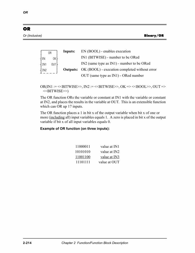
OR
OROr (Inclusive) Binary/OR
OR(IN1 := <<BITWISE>>, IN2 := <<BITWISE>>, OK => <<BOOL>>, OUT => <<BITWISE>>)
The OR function ORs the variable or constant at IN1 with the variable or constant at IN2, and places the results in the variable at OUT. This is an extensible function which can OR up 17 inputs.
The OR function places a 1 in bit x of the output variable when bit x of one or more (including all) input variables equals 1. A zero is placed in bit x of the output variable if bit x of all input variables equals 0.
Example of OR function (on three inputs):
⁄ƒƒƒƒƒƒƒƒƒø ≥ OR ≥ ≥ ≥ ¥EN OK√ ≥ ≥ ¥IN1 OUT√ ≥ ≥ ¥IN2 ≥ ¡ ƒ ƒ ƒ ƒ Ÿ
Inputs: EN (BOOL) - enables execution
IN1 (BITWISE) - number to be ORed
IN2 (same type as IN1) - number to be ORed
Outputs: OK (BOOL) - execution completed without error
OUT (same type as IN1) - ORed number
11000011 value at IN110101010 value at IN211001100 value at IN311101111 value at OUT
2-214 Chapter 2 Function/Function Block Description
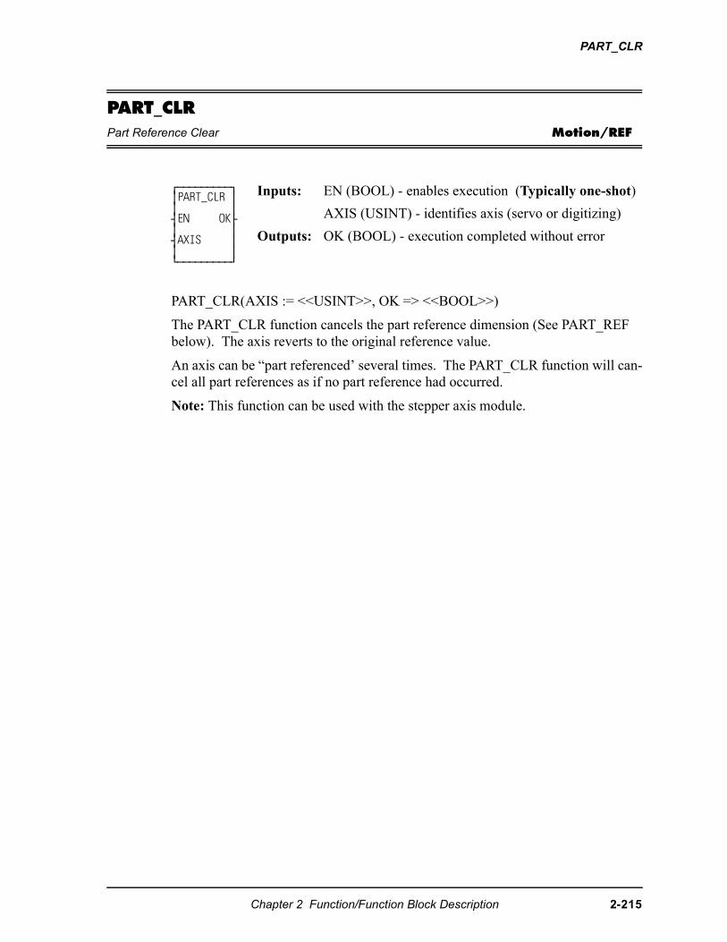
PART_CLR
PART_CLRPart Reference Clear Motion/REF
PART_CLR(AXIS := <<USINT>>, OK => <<BOOL>>)
The PART_CLR function cancels the part reference dimension (See PART_REF below). The axis reverts to the original reference value.
An axis can be “part referenced’ several times. The PART_CLR function will can-cel all part references as if no part reference had occurred.
Note: This function can be used with the stepper axis module.
⁄ƒƒƒƒƒƒƒƒƒø≥PART_CLR ≥≥ ≥¥EN OK√≥ ≥¥AXIS ≥≥ ≥¿ƒƒƒƒƒƒƒƒƒŸ
Inputs: EN (BOOL) - enables execution (Typically one-shot)
AXIS (USINT) - identifies axis (servo or digitizing)
Outputs: OK (BOOL) - execution completed without error
Chapter 2 Function/Function Block Description 2-215
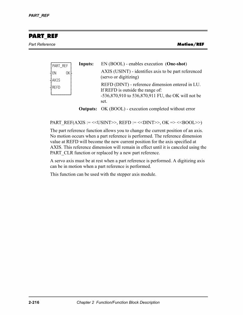
PART_REF
PART_REFPart Reference Motion/REF
PART_REF(AXIS := <<USINT>>, REFD := <<DINT>>, OK => <<BOOL>>)
The part reference function allows you to change the current position of an axis. No motion occurs when a part reference is performed. The reference dimension value at REFD will become the new current position for the axis specified at AXIS. This reference dimension will remain in effect until it is canceled using the PART_CLR function or replaced by a new part reference.
A servo axis must be at rest when a part reference is performed. A digitizing axis can be in motion when a part reference is performed.
This function can be used with the stepper axis module.
⁄ƒƒƒƒƒƒƒƒƒø ≥PART_REF ≥ ≥ ≥ ¥EN OK√ ≥ ≥ ¥AXIS ≥ ≥ ≥ ¥REFD ≥ ≥ ≥ ¿ƒƒƒƒƒƒƒƒƒŸ
Inputs: EN (BOOL) - enables execution (One-shot)
AXIS (USINT) - identifies axis to be part referenced (servo or digitizing)
REFD (DINT) - reference dimension entered in LU.If REFD is outside the range of:-536,870,910 to 536,870,911 FU, the OK will not be set.
Outputs: OK (BOOL) - execution completed without error
2-216 Chapter 2 Function/Function Block Description
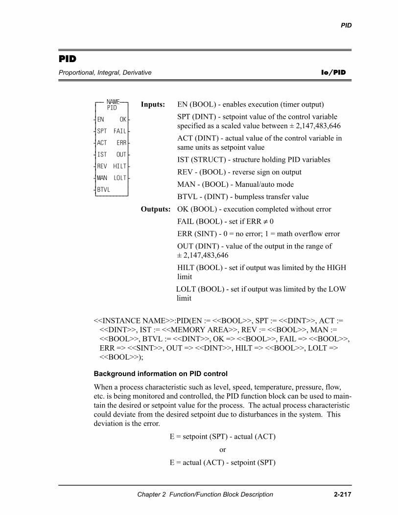
PID
PIDProportional, Integral, Derivative Io/PID
<<INSTANCE NAME>>:PID(EN := <<BOOL>>, SPT := <<DINT>>, ACT := <<DINT>>, IST := <<MEMORY AREA>>, REV := <<BOOL>>, MAN := <<BOOL>>, BTVL := <<DINT>>, OK => <<BOOL>>, FAIL => <<BOOL>>, ERR => <<SINT>>, OUT => <<DINT>>, HILT => <<BOOL>>, LOLT => <<BOOL>>);
Background information on PID control
When a process characteristic such as level, speed, temperature, pressure, flow, etc. is being monitored and controlled, the PID function block can be used to main-tain the desired or setpoint value for the process. The actual process characteristic could deviate from the desired setpoint due to disturbances in the system. This deviation is the error.
E = setpoint (SPT) - actual (ACT)
or
E = actual (ACT) - setpoint (SPT)
⁄ƒƒ NAMEƒƒø≥ PID ≥≥ ≥¥EN OK√≥ ≥¥SPT FAIL√≥ ≥¥ACT ERR√≥ ≥¥IST OUT√≥ ≥¥REV HILT√≥ ≥¥MAN LOLT√≥ ≥¥BTVL ≥¿ƒƒƒƒƒƒƒƒƒŸ
Inputs: EN (BOOL) - enables execution (timer output)
SPT (DINT) - setpoint value of the control variable specified as a scaled value between ± 2,147,483,646
ACT (DINT) - actual value of the control variable in same units as setpoint value
IST (STRUCT) - structure holding PID variables
REV - (BOOL) - reverse sign on output
MAN - (BOOL) - Manual/auto mode
BTVL - (DINT) - bumpless transfer value
Outputs: OK (BOOL) - execution completed without error
FAIL (BOOL) - set if ERR ≠ 0
ERR (SINT) - 0 = no error; 1 = math overflow error
OUT (DINT) - value of the output in the range of ± 2,147,483,646
HILT (BOOL) - set if output was limited by the HIGH limit
LOLT (BOOL) - set if output was limited by the LOW limit
Chapter 2 Function/Function Block Description 2-217
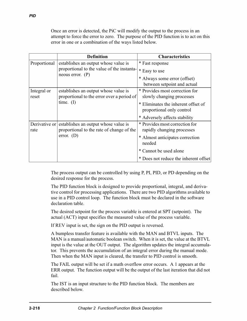
PID
Once an error is detected, the PiC will modify the output to the process in an attempt to force the error to zero. The purpose of the PID function is to act on this error in one or a combination of the ways listed below.
The process output can be controlled by using P, PI, PID, or PD depending on the desired response for the process.
The PID function block is designed to provide proportional, integral, and deriva-tive control for processing applications. There are two PID algorithms available to use in a PID control loop. The function block must be declared in the software declaration table.
The desired setpoint for the process variable is entered at SPT (setpoint). The actual (ACT) input specifies the measured value of the process variable.
If REV input is set, the sign on the PID output is reversed.
A bumpless transfer feature is available with the MAN and BTVL inputs. The MAN is a manual/automatic boolean switch. When it is set, the value at the BTVL input is the value at the OUT output. The algorithm updates the integral accumula-tor. This prevents the accumulation of an integral error during the manual mode. Then when the MAN input is cleared, the transfer to PID control is smooth.
The FAIL output will be set if a math overflow error occurs. A 1 appears at the ERR output. The function output will be the output of the last iteration that did not fail.
The IST is an input structure to the PID function block. The members are described below.
Definition CharacteristicsProportional establishes an output whose value is
proportional to the value of the instanta-neous error. (P)
* Fast response
* Easy to use
* Always some error (offset) between setpoint and actual
Integral or reset
establishes an output whose value is proportional to the error over a period of time. (I)
* Provides most correction for slowly changing processes
* Eliminates the inherent offset of proportional only control
* Adversely affects stabilityDerivative or rate
establishes an output whose value is proportional to the rate of change of the error. (D)
* Provides most correction for rapidly changing processes
* Almost anticipates correction needed
* Cannot be used alone
* Does not reduce the inherent offset
2-218 Chapter 2 Function/Function Block Description
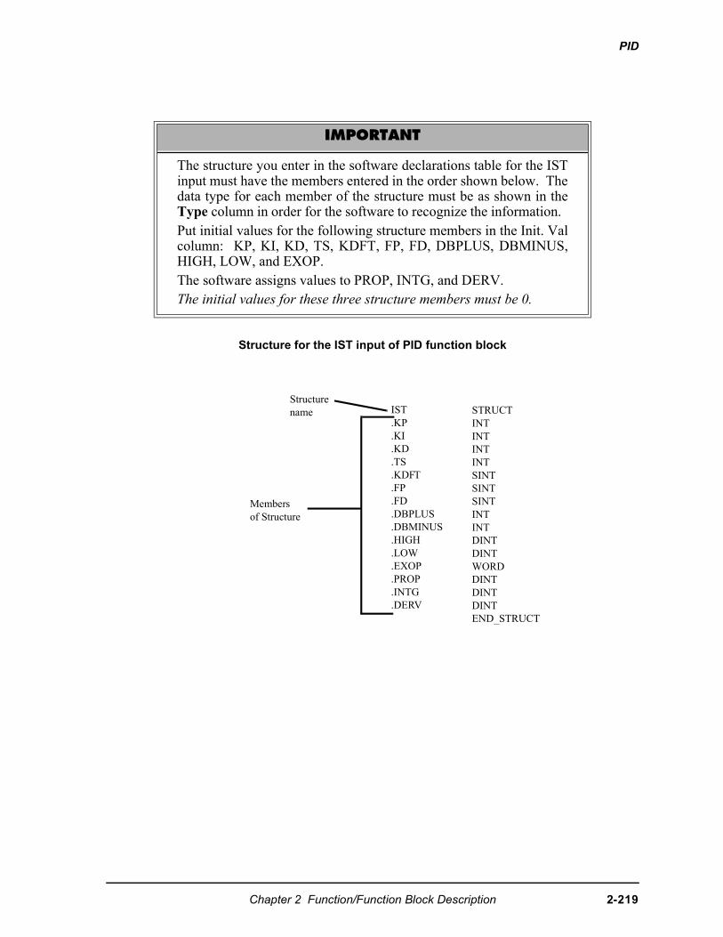
PID
Structure for the IST input of PID function block
IMPORTANT
The structure you enter in the software declarations table for the ISTinput must have the members entered in the order shown below. Thedata type for each member of the structure must be as shown in theType column in order for the software to recognize the information. Put initial values for the following structure members in the Init. Valcolumn: KP, KI, KD, TS, KDFT, FP, FD, DBPLUS, DBMINUS,HIGH, LOW, and EXOP.The software assigns values to PROP, INTG, and DERV. The initial values for these three structure members must be 0.
IST.KP.KI.KD.TS.KDFT.FP.FD.DBPLUS.DBMINUS.HIGH.LOW.EXOP.PROP.INTG.DERV
Membersof Structure
Structurename STRUCT
INTINTINTINTSINTSINTSINTINTINTDINTDINTWORDDINTDINTDINTEND_STRUCT
Chapter 2 Function/Function Block Description 2-219
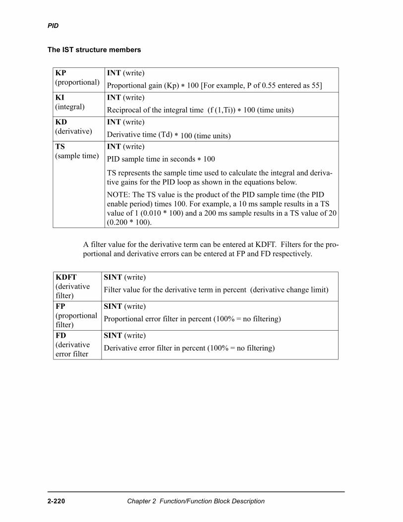
PID
The IST structure members
A filter value for the derivative term can be entered at KDFT. Filters for the pro-portional and derivative errors can be entered at FP and FD respectively.
KP(proportional)
INT (write)
Proportional gain (Kp) * 100 [For example, P of 0.55 entered as 55]
KI(integral)
INT (write)
Reciprocal of the integral time (f (1,Ti)) * 100 (time units)
KD(derivative)
INT (write)
Derivative time (Td) * 100 (time units)TS(sample time)
INT (write)
PID sample time in seconds * 100
TS represents the sample time used to calculate the integral and deriva-tive gains for the PID loop as shown in the equations below.
NOTE: The TS value is the product of the PID sample time (the PID enable period) times 100. For example, a 10 ms sample results in a TS value of 1 (0.010 * 100) and a 200 ms sample results in a TS value of 20 (0.200 * 100).
KDFT(derivative filter)
SINT (write)
Filter value for the derivative term in percent (derivative change limit)
FP(proportional filter)
SINT (write)
Proportional error filter in percent (100% = no filtering)
FD(derivative error filter
SINT (write)
Derivative error filter in percent (100% = no filtering)
2-220 Chapter 2 Function/Function Block Description
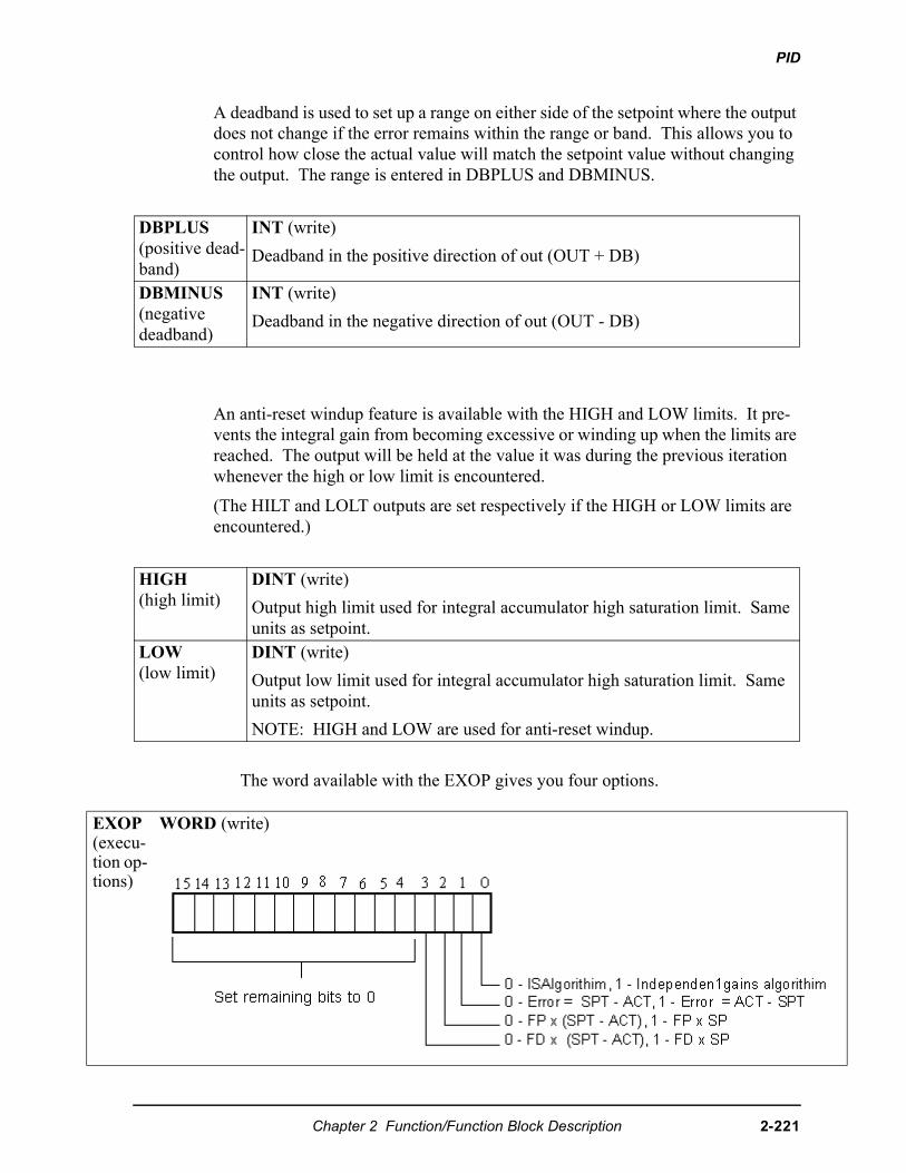
PID
EXO(exetiontion
A deadband is used to set up a range on either side of the setpoint where the output does not change if the error remains within the range or band. This allows you to control how close the actual value will match the setpoint value without changing the output. The range is entered in DBPLUS and DBMINUS.
An anti-reset windup feature is available with the HIGH and LOW limits. It pre-vents the integral gain from becoming excessive or winding up when the limits are reached. The output will be held at the value it was during the previous iteration whenever the high or low limit is encountered.
(The HILT and LOLT outputs are set respectively if the HIGH or LOW limits are encountered.)
The word available with the EXOP gives you four options.
DBPLUS(positive dead-band)
INT (write)
Deadband in the positive direction of out (OUT + DB)
DBMINUS(negative deadband)
INT (write)
Deadband in the negative direction of out (OUT - DB)
HIGH(high limit)
DINT (write)
Output high limit used for integral accumulator high saturation limit. Same units as setpoint.
LOW(low limit)
DINT (write)
Output low limit used for integral accumulator high saturation limit. Same units as setpoint.
NOTE: HIGH and LOW are used for anti-reset windup.
Pcu- op-s)
WORD (write)
Chapter 2 Function/Function Block Description 2-221
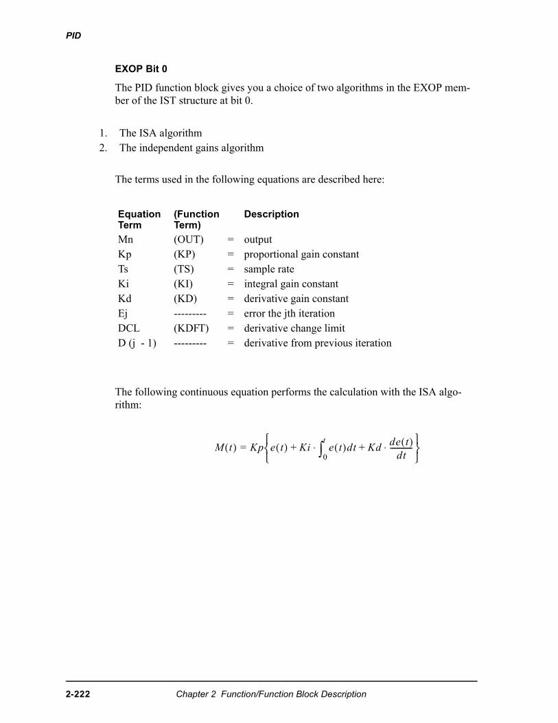
PID
EXOP Bit 0
The PID function block gives you a choice of two algorithms in the EXOP mem-ber of the IST structure at bit 0.
The terms used in the following equations are described here:
The following continuous equation performs the calculation with the ISA algo-rithm:
1. The ISA algorithm 2. The independent gains algorithm
Equation Term
(Function Term)
Description
Mn (OUT) = outputKp (KP) = proportional gain constantTs (TS) = sample rateKi (KI) = integral gain constantKd (KD) = derivative gain constantEj --------- = error the jth iterationDCL (KDFT) = derivative change limitD (j - 1) --------- = derivative from previous iteration
� �( ) �� � � �( ) �� ��
�
∫ �( )�� ���� �( )��
------------⋅ ⋅
2-222 Chapter 2 Function/Function Block Description
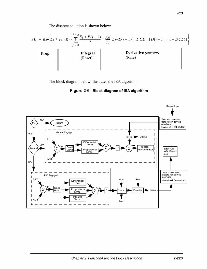
PID
Y
The discrete equation is shown below:
The block diagram below illustrates the ISA algorithm.
Figure 2-6. Block diagram of ISA algorithm
� �� �� �� ��( )
�------------------------------- ��
��------- ��( )�[ ] � � � ��( ) � � ��( )⋅[ ] ⋅
��
��
∑⋅ ⋅
�
Prop Integral(Reset)
Derivative (current)(Rate)
ReturnEN
Manual
NO
YES
SPT
ACT
DeadBand
DifferentialTerm
ProportionalError
P
BTVL Output
IntegralAccumulator
User conversionfactors for deviceinterfaceDevice Unit Output
PID Engaged
SPT
ACT
DeadBand
DifferentialTerm
ProportionalError
P
High
OutputClamp
IntegralTerm
Low
Rev
Polarity
User conversionfactors for deviceinterfaceOutput Device Unit
DEVICEAD Boardetc.
NO
Manual Engaged
Manual Input
ES
Chapter 2 Function/Function Block Description 2-223
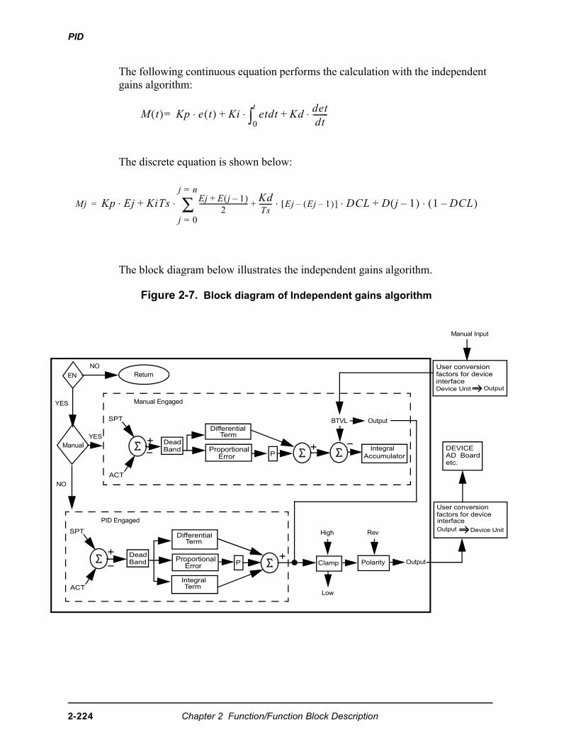
PID
t
it
N
Y
The following continuous equation performs the calculation with the independent gains algorithm:
The discrete equation is shown below:
The block diagram below illustrates the independent gains algorithm.
Figure 2-7. Block diagram of Independent gains algorithm
� �( ) �� � �( )⋅ �� ��
�
∫ ��� �����
��--------⋅ ⋅�
� �� ���� ��( )
�------------------------------- ��
��-------- ��( )�[ ] � � � ��( ) � � ��( )⋅ ⋅ ⋅
��
��
∑⋅ ⋅�
ReturnEN
Manual
NO
YES
SPT
ACT
DeadBand
DifferentialTerm
ProportionalError
BTVL Output
IntegralAccumulator
User conversionfactors for deviceinterfaceDevice Unit Outpu
PID Engaged
SPT
ACT
DeadBand
DifferentialTerm
ProportionalError P
High
OutputClamp
IntegralTerm
Low
Rev
Polarity
User conversionfactors for deviceinterfaceOutput Device Un
DEVICEAD Boardetc.
O
Manual Engaged
Manual Input
ES
P
2-224 Chapter 2 Function/Function Block Description
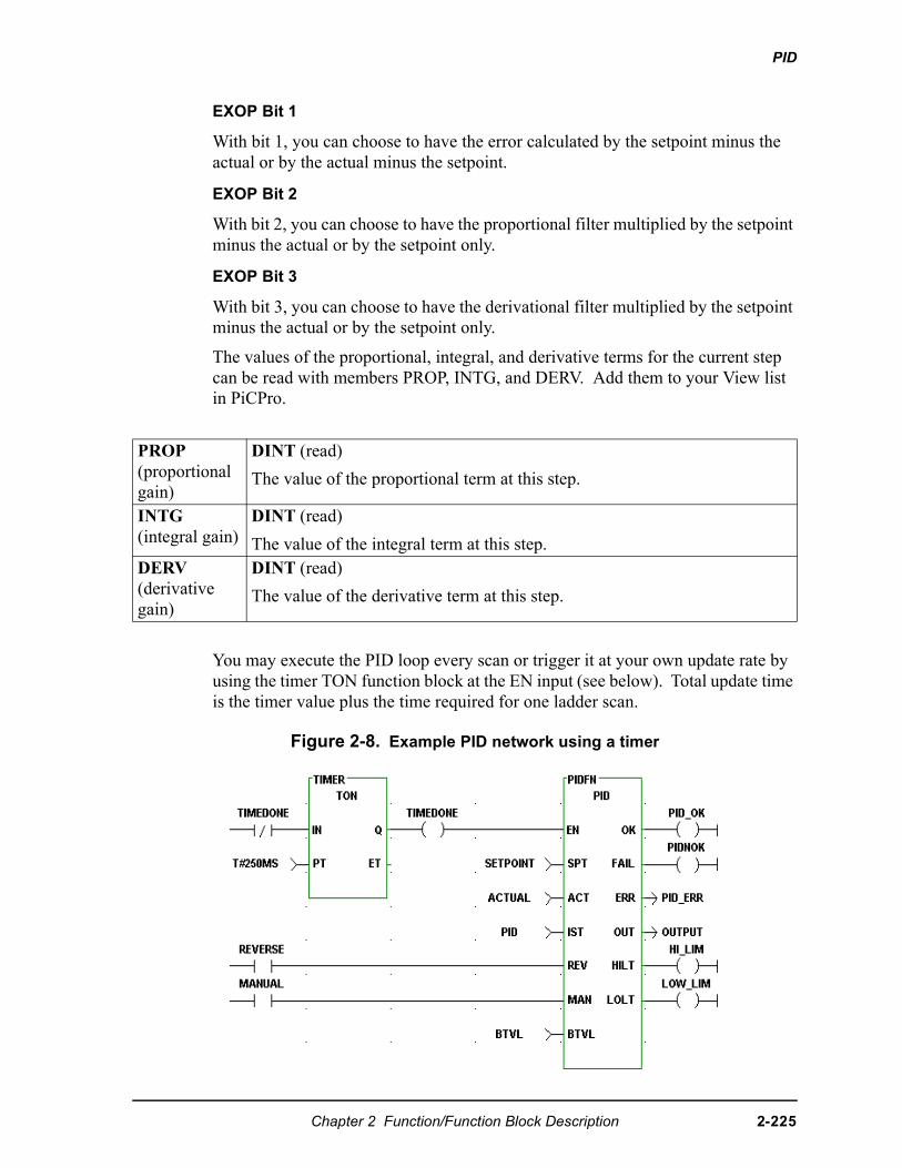
PID
EXOP Bit 1
With bit 1, you can choose to have the error calculated by the setpoint minus the actual or by the actual minus the setpoint.
EXOP Bit 2
With bit 2, you can choose to have the proportional filter multiplied by the setpoint minus the actual or by the setpoint only.
EXOP Bit 3
With bit 3, you can choose to have the derivational filter multiplied by the setpoint minus the actual or by the setpoint only.
The values of the proportional, integral, and derivative terms for the current step can be read with members PROP, INTG, and DERV. Add them to your View list in PiCPro.
You may execute the PID loop every scan or trigger it at your own update rate by using the timer TON function block at the EN input (see below). Total update time is the timer value plus the time required for one ladder scan.
Figure 2-8. Example PID network using a timer
PROP(proportional gain)
DINT (read)
The value of the proportional term at this step.
INTG(integral gain)
DINT (read)
The value of the integral term at this step. DERV(derivative gain)
DINT (read)
The value of the derivative term at this step.
Chapter 2 Function/Function Block Description 2-225
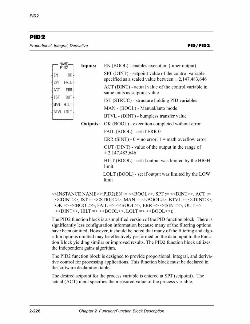
PID2
PID2Proportional, Integral, Derivative PID/PID2
<<INSTANCE NAME>>:PID2(EN := <<BOOL>>, SPT := <<DINT>>, ACT := <<DINT>>, IST := <<STRUC>>, MAN := <<BOOL>>, BTVL := <<DINT>>, OK => <<BOOL>>, FAIL => <<BOOL>>, ERR => <<SINT>>, OUT => <<DINT>>, HILT => <<BOOL>>, LOLT => <<BOOL>>);
The PID2 function block is a simplified version of the PID function block. There is significantly less configuration information because many of the filtering options have been omitted. However, it should be noted that many of the filtering and algo-rithm options omitted may be effectively performed on the data input to the Func-tion Block yielding similar or improved results. The PID2 function block utilizes the Independent gains algorithm.
The PID2 function block is designed to provide proportional, integral, and deriva-tive control for processing applications. This function block must be declared in the software declaration table.
The desired setpoint for the process variable is entered at SPT (setpoint). The actual (ACT) input specifies the measured value of the process variable.
⁄ƒƒ NAMEƒƒø≥ PID2 ≥≥ ≥¥EN OK√≥ ≥¥SPT FAIL√≥ ≥¥ACT ERR√≥ ≥¥IST OUT√≥ ≥¥MAN HILT√≥ ≥¥BTVL LOLT√≥ ≥¿ƒƒƒƒƒƒƒƒƒŸ
Inputs: EN (BOOL) - enables execution (timer output)
SPT (DINT) - setpoint value of the control variable specified as a scaled value between ± 2,147,483,646
ACT (DINT) - actual value of the control variable in same units as setpoint value
IST (STRUC) - structure holding PID variables
MAN - (BOOL) - Manual/auto mode
BTVL - (DINT) - bumpless transfer value
Outputs: OK (BOOL) - execution completed without error
FAIL (BOOL) - set if ERR 0
ERR (SINT) - 0 = no error; 1 = math overflow error
OUT (DINT) - value of the output in the range of ± 2,147,483,646
HILT (BOOL) - set if output was limited by the HIGH limit
LOLT (BOOL) - set if output was limited by the LOW limit
2-226 Chapter 2 Function/Function Block Description
PID2
A bumpless transfer feature is available with the MAN and BTVL inputs. The MAN is a manual/automatic boolean switch. When it is set, the value at the BTVL input is the value at the OUT output. The algorithm updates the integral accumula-tor. This prevents the accumulation of an integral error during the manual mode. Then when the MAN input is cleared, the transfer to PID2 control is smooth.
The FAIL output will be set if an error occurs. A 1 appears at the ERR output. The function output will be the output of the last iteration that did not fail.
An error value of 1 indicates a math error. An error value of 2 indicates a parame-ter error.
The HIGH and LOW limits are used for “Anti-Reset Windup”. The range of the output value of the PID2 is limited by the HIGH or LOW limits. If the output is limited, the amount of limitation is fed back to the integrator to prevent continued integration, thereby limiting windup. The HIGH and LOW limits do not directly limit the integral term, but rather, indirectly limit the integral (reset windup) from integrating the output into saturation.
The HILT and LOLT outputs are set respectively if the HIGH or LOW limits are encountered.
The integral and derivative gains in this function block are dependent on the fre-quency upon which it is executed. Therefore, it becomes important to ensure that the rate at which the function is executed is as consistent as necessary for the appli-cation. This can be accomplished by placing the PID2 function block in a Time Tick Task, or by enabling the function block with a timer output in the main ladder. If the function block is enabled by a timer, the rate at which it is enabled should be significantly longer than the scan time for best results. It is also important to ensure that TS is set equal to the rate at which the function block is enabled.
The IST is an input structure to the PID2 function block. The members are described below.
IMPORTANT
IST is an input structure to the PID2 Function Block. The structureand members are described as follows:The structure you enter in the software declarations table for the ISTinput must have the members entered in the order shown below. Thedata type for each member of the structure must be as shown in theType column in order for the software to recognize the information. Put initial values for the following structure members in the Init. Valcolumn: KP, KI, KD, DBPLUS, DBMINUS, HIGH, LOW, and OPT.The software assigns values to PROP, INTG, and DERV. The initial values for these three structure members must be 0.
Chapter 2 Function/Function Block Description 2-227
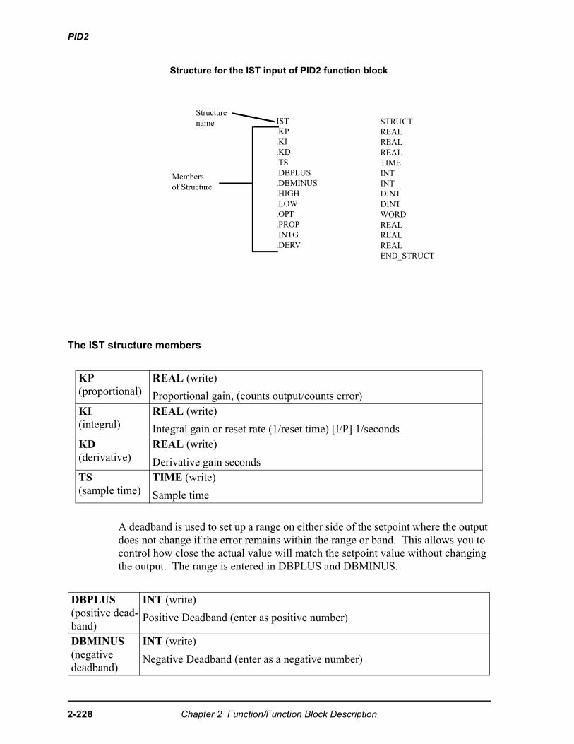
PID2
Structure for the IST input of PID2 function block
The IST structure members
A deadband is used to set up a range on either side of the setpoint where the output does not change if the error remains within the range or band. This allows you to control how close the actual value will match the setpoint value without changing the output. The range is entered in DBPLUS and DBMINUS.
KP(proportional)
REAL (write)
Proportional gain, (counts output/counts error)KI(integral)
REAL (write)
Integral gain or reset rate (1/reset time) [I/P] 1/secondsKD(derivative)
REAL (write)
Derivative gain secondsTS(sample time)
TIME (write)
Sample time
DBPLUS(positive dead-band)
INT (write)
Positive Deadband (enter as positive number)
DBMINUS(negative deadband)
INT (write)
Negative Deadband (enter as a negative number)
IST.KP.KI.KD.TS.DBPLUS.DBMINUS.HIGH.LOW.OPT.PROP.INTG.DERV
Membersof Structure
Structurename STRUCT
REALREALREALTIMEINTINTDINTDINTWORDREALREALREALEND_STRUCT
2-228 Chapter 2 Function/Function Block Description
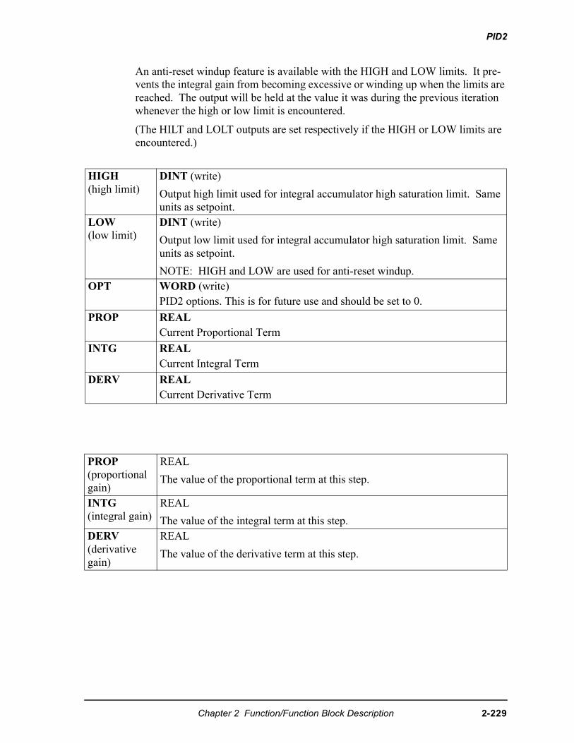
PID2
An anti-reset windup feature is available with the HIGH and LOW limits. It pre-vents the integral gain from becoming excessive or winding up when the limits are reached. The output will be held at the value it was during the previous iteration whenever the high or low limit is encountered.
(The HILT and LOLT outputs are set respectively if the HIGH or LOW limits are encountered.)
HIGH(high limit)
DINT (write)
Output high limit used for integral accumulator high saturation limit. Same units as setpoint.
LOW(low limit)
DINT (write)
Output low limit used for integral accumulator high saturation limit. Same units as setpoint.
NOTE: HIGH and LOW are used for anti-reset windup.OPT WORD (write)
PID2 options. This is for future use and should be set to 0.
PROP REALCurrent Proportional Term
INTG REALCurrent Integral Term
DERV REALCurrent Derivative Term
PROP(proportional gain)
REAL
The value of the proportional term at this step.
INTG(integral gain)
REAL
The value of the integral term at this step. DERV(derivative gain)
REAL
The value of the derivative term at this step.
Chapter 2 Function/Function Block Description 2-229
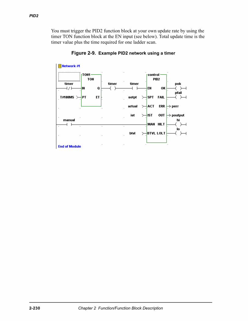
PID2
You must trigger the PID2 function block at your own update rate by using the timer TON function block at the EN input (see below). Total update time is the timer value plus the time required for one ladder scan.
Figure 2-9. Example PID2 network using a timer
2-230 Chapter 2 Function/Function Block Description
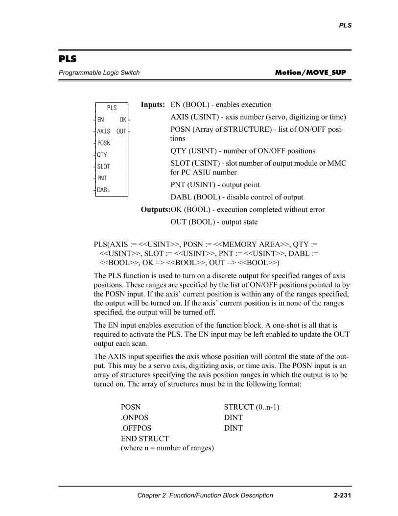
PLS
PLSProgrammable Logic Switch Motion/MOVE_SUP
PLS(AXIS := <<USINT>>, POSN := <<MEMORY AREA>>, QTY := <<USINT>>, SLOT := <<USINT>>, PNT := <<USINT>>, DABL := <<BOOL>>, OK => <<BOOL>>, OUT => <<BOOL>>)
The PLS function is used to turn on a discrete output for specified ranges of axis positions. These ranges are specified by the list of ON/OFF positions pointed to by the POSN input. If the axis’ current position is within any of the ranges specified, the output will be turned on. If the axis’ current position is in none of the ranges specified, the output will be turned off.
The EN input enables execution of the function block. A one-shot is all that is required to activate the PLS. The EN input may be left enabled to update the OUT output each scan.
The AXIS input specifies the axis whose position will control the state of the out-put. This may be a servo axis, digitizing axis, or time axis. The POSN input is an array of structures specifying the axis position ranges in which the output is to be turned on. The array of structures must be in the following format:
⁄ƒƒƒƒƒƒƒƒƒø ≥ PLS ≥≥ ≥¥EN OK√≥ ≥¥AXIS OUT√≥ ≥¥POSN ≥≥ ≥¥QTY ≥≥ ≥¥SLOT ≥≥ ≥¥PNT ≥≥ ≥¥DABL ≥¿ƒƒƒƒƒƒƒƒƒŸ
Inputs: EN (BOOL) - enables execution
AXIS (USINT) - axis number (servo, digitizing or time)
POSN (Array of STRUCTURE) - list of ON/OFF posi-tions
QTY (USINT) - number of ON/OFF positions
SLOT (USINT) - slot number of output module or MMC for PC ASIU number
PNT (USINT) - output point
DABL (BOOL) - disable control of output
Outputs:OK (BOOL) - execution completed without error
OUT (BOOL) - output state
POSN STRUCT (0..n-1).ONPOS DINT.OFFPOS DINTEND STRUCT(where n = number of ranges)
Chapter 2 Function/Function Block Description 2-231
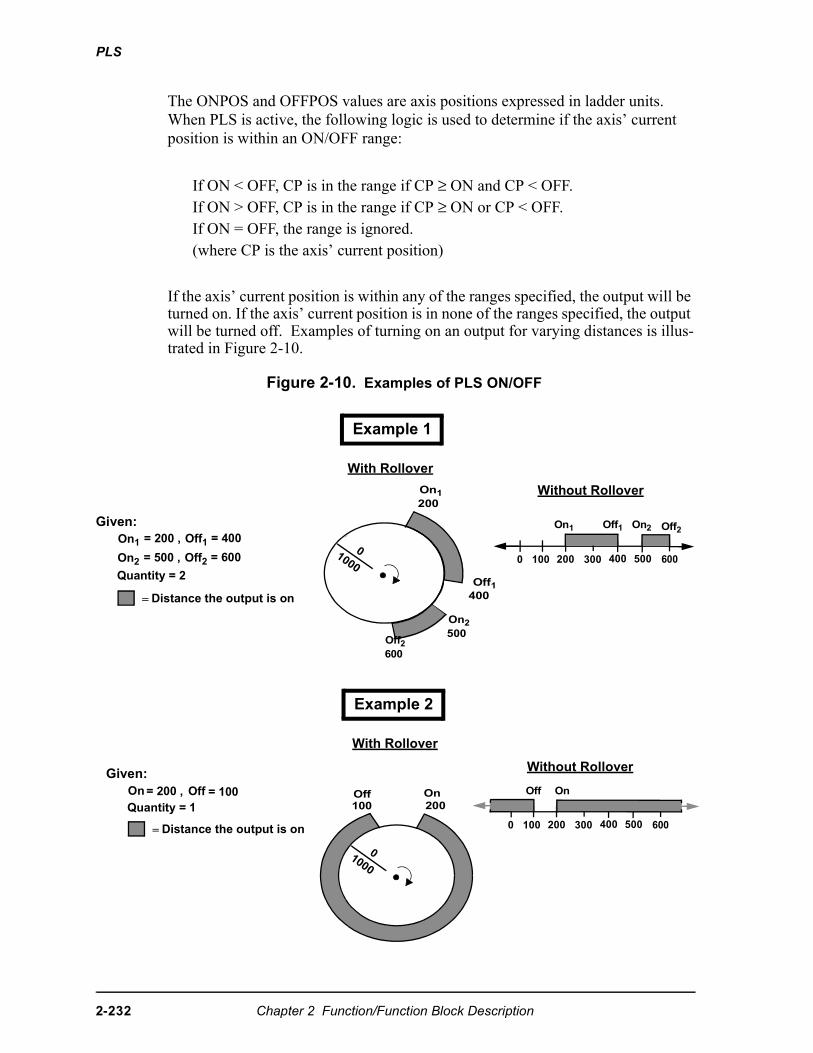
PLS
The ONPOS and OFFPOS values are axis positions expressed in ladder units. When PLS is active, the following logic is used to determine if the axis’ current position is within an ON/OFF range:
If the axis’ current position is within any of the ranges specified, the output will be turned on. If the axis’ current position is in none of the ranges specified, the output will be turned off. Examples of turning on an output for varying distances is illus-trated in Figure 2-10.
Figure 2-10. Examples of PLS ON/OFF
If ON < OFF, CP is in the range if CP ≥ ON and CP < OFF.If ON > OFF, CP is in the range if CP ≥ ON or CP < OFF.If ON = OFF, the range is ignored.(where CP is the axis’ current position)
Example 1
On1 = 200 , Off1 = 400
On2 = 500 , Off2 = 600
Quantity = 2
With Rollover
Given:
Off1400
On1200
On2500
Without Rollover
0 100 200 300 400 500 600
Example 2
On = 200 , Off = 100Quantity = 1
With Rollover
Given:
=
Without Rollover
0 100 200 300 400 500 600
Off On
On1 Off1 On2 Off2
Distance the output is on
= Distance the output is on
1000
0
Off100
On200
1000
0
Off2600
2-232 Chapter 2 Function/Function Block Description
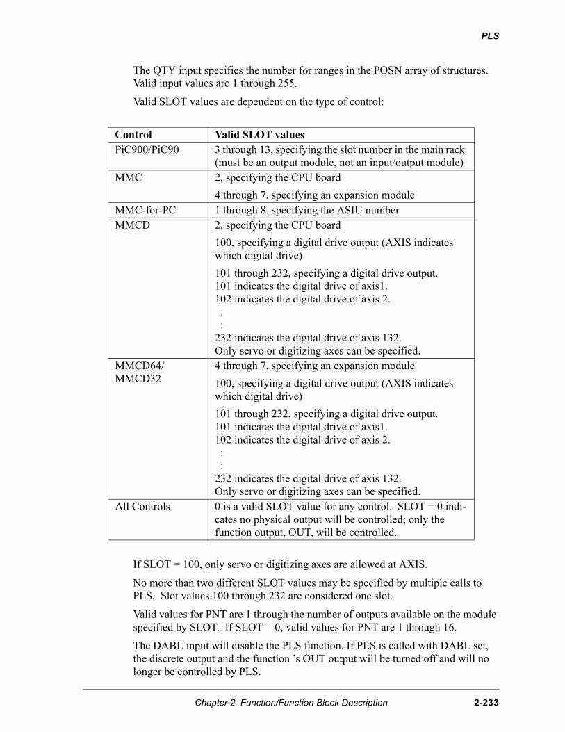
PLS
The QTY input specifies the number for ranges in the POSN array of structures. Valid input values are 1 through 255.
Valid SLOT values are dependent on the type of control:
If SLOT = 100, only servo or digitizing axes are allowed at AXIS.
No more than two different SLOT values may be specified by multiple calls to PLS. Slot values 100 through 232 are considered one slot.
Valid values for PNT are 1 through the number of outputs available on the module specified by SLOT. If SLOT = 0, valid values for PNT are 1 through 16.
The DABL input will disable the PLS function. If PLS is called with DABL set, the discrete output and the function ’s OUT output will be turned off and will no longer be controlled by PLS.
Control Valid SLOT valuesPiC900/PiC90 3 through 13, specifying the slot number in the main rack
(must be an output module, not an input/output module)MMC 2, specifying the CPU board
4 through 7, specifying an expansion moduleMMC-for-PC 1 through 8, specifying the ASIU numberMMCD 2, specifying the CPU board
100, specifying a digital drive output (AXIS indicates which digital drive)
101 through 232, specifying a digital drive output.101 indicates the digital drive of axis1.102 indicates the digital drive of axis 2. : :232 indicates the digital drive of axis 132.Only servo or digitizing axes can be specified.
MMCD64/MMCD32
4 through 7, specifying an expansion module
100, specifying a digital drive output (AXIS indicates which digital drive)
101 through 232, specifying a digital drive output.101 indicates the digital drive of axis1.102 indicates the digital drive of axis 2. : :232 indicates the digital drive of axis 132.Only servo or digitizing axes can be specified.
All Controls 0 is a valid SLOT value for any control. SLOT = 0 indi-cates no physical output will be controlled; only the function output, OUT, will be controlled.
Chapter 2 Function/Function Block Description 2-233
PLS
The OK output indicates the function block executed successfully. If the OK out-put is reset, any of the following errors occurred:
• AXIS input is invalid
• SLOT input is invalid
• PNT input is invalid
• Too many slots have been specified by multiple calls to PLS functions
The OUT output is set when the axis’ current position is within is any of the ON/OFF ranges and the DABL input is reset. The OUT output is reset when the axis’ current position is none of the ON/OFF ranges. It is also reset when the DABL input is set.
The distance during which each output remains on can vary by changing the values in ON and OFF in each function.
Notes:
1. PLS will operate with or without rollover-on-position specified for the axis.
2. The outputs being controlled by PLS are updated every servo interrupt.
3. While the PLS is active, the ON/OFF values may only be modified via the PLS _EDIT function. Modifying these values by any other means while the PLS is active may cause outputs to unexpectedly turn on or off. If the DABL input is set or if the EN input has never been set, the ON/OFF values may be modified by conventional means (i.e. MOVE function).
4. Do not declare the PLS output point (specified by SLOT and PNT) in the software decla-rations.
2-234 Chapter 2 Function/Function Block Description
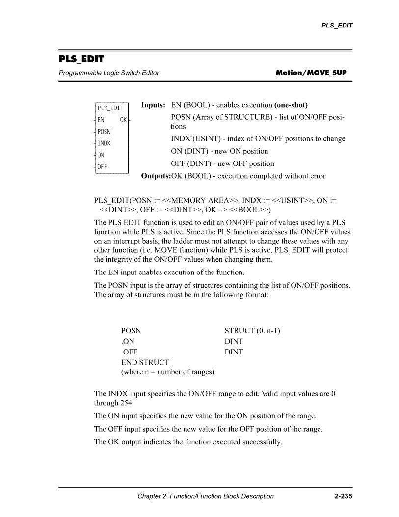
PLS_EDIT
PLS_EDITProgrammable Logic Switch Editor Motion/MOVE_SUP
PLS_EDIT(POSN := <<MEMORY AREA>>, INDX := <<USINT>>, ON := <<DINT>>, OFF := <<DINT>>, OK => <<BOOL>>)
The PLS EDIT function is used to edit an ON/OFF pair of values used by a PLS function while PLS is active. Since the PLS function accesses the ON/OFF values on an interrupt basis, the ladder must not attempt to change these values with any other function (i.e. MOVE function) while PLS is active. PLS_EDIT will protect the integrity of the ON/OFF values when changing them.
The EN input enables execution of the function.
The POSN input is the array of structures containing the list of ON/OFF positions. The array of structures must be in the following format:
The INDX input specifies the ON/OFF range to edit. Valid input values are 0 through 254.
The ON input specifies the new value for the ON position of the range.
The OFF input specifies the new value for the OFF position of the range.
The OK output indicates the function executed successfully.
⁄ƒƒƒƒƒƒƒƒƒø ≥PLS_EDIT ≥≥ ≥¥EN OK√≥ ≥¥POSN ≥≥ ≥¥INDX ≥≥ ≥¥ON ≥≥ ≥¥OFF ≥¿ƒƒƒƒƒƒƒƒƒŸ
Inputs: EN (BOOL) - enables execution (one-shot)
POSN (Array of STRUCTURE) - list of ON/OFF posi-tions
INDX (USINT) - index of ON/OFF positions to change
ON (DINT) - new ON position
OFF (DINT) - new OFF position
Outputs:OK (BOOL) - execution completed without error
POSN STRUCT (0..n-1).ON DINT.OFF DINTEND STRUCT(where n = number of ranges)
Chapter 2 Function/Function Block Description 2-235
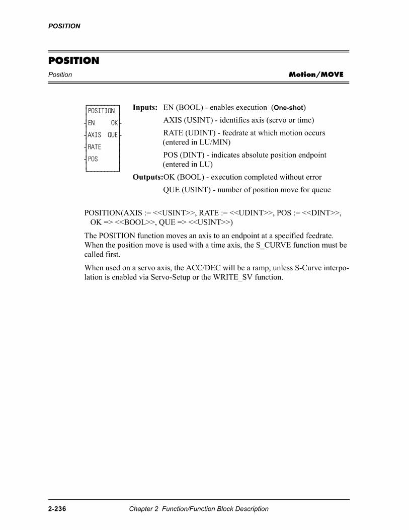
POSITION
POSITIONPosition Motion/MOVE
POSITION(AXIS := <<USINT>>, RATE := <<UDINT>>, POS := <<DINT>>, OK => <<BOOL>>, QUE => <<USINT>>)
The POSITION function moves an axis to an endpoint at a specified feedrate. When the position move is used with a time axis, the S_CURVE function must be called first.
When used on a servo axis, the ACC/DEC will be a ramp, unless S-Curve interpo-lation is enabled via Servo-Setup or the WRITE_SV function.
⁄ƒƒƒƒƒƒƒƒƒø ≥POSITION ≥ ≥ ≥ ¥EN OK√ ≥ ≥ ¥AXIS QUE√ ≥ ≥ ¥RATE ≥ ≥ ≥ ¥POS ≥ ≥ ≥ ¿ƒƒƒƒƒƒƒƒƒŸ
Inputs: EN (BOOL) - enables execution (One-shot)
AXIS (USINT) - identifies axis (servo or time)
RATE (UDINT) - feedrate at which motion occurs (entered in LU/MIN)
POS (DINT) - indicates absolute position endpoint (entered in LU)
Outputs:OK (BOOL) - execution completed without error
QUE (USINT) - number of position move for queue
2-236 Chapter 2 Function/Function Block Description
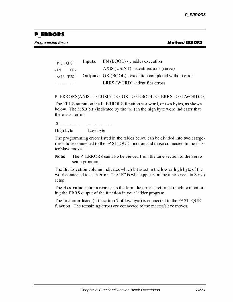
P_ERRORS
P_ERRORSProgramming Errors Motion/ERRORS
P_ERRORS(AXIS := <<USINT>>, OK => <<BOOL>>, ERRS => <<WORD>>)
The ERRS output on the P_ERRORS function is a word, or two bytes, as shown below. The MSB bit (indicated by the “x”) in the high byte word indicates that there is an error.
x _ _ _ _ _ _ _ _ _ _ _ _ _ _
High byte Low byte
The programming errors listed in the tables below can be divided into two catego-ries--those connected to the FAST_QUE function and those connected to the mas-ter/slave moves.
Note: The P_ERRORS can also be viewed from the tune section of the Servo setup program.
The Bit Location column indicates which bit is set in the low or high byte of the word connected to each error. The “E” is what appears on the tune screen in Servo setup.
The Hex Value column represents the form the error is returned in while monitor-ing the ERRS output of the function in your ladder program.
The first error listed (bit location 7 of low byte) is connected to the FAST_QUE function. The remaining errors are connected to the master/slave moves.
⁄ƒƒƒƒƒƒƒƒƒø ≥P_ERRORS ≥ ≥ ≥ ¥EN OK√ ≥ ≥ ¥AXIS ERRS√ ≥ ≥ ¿ƒƒƒƒƒƒƒƒƒŸ
Inputs: EN (BOOL) - enables execution
AXIS (USINT) - identifies axis (servo)
Outputs: OK (BOOL) - execution completed without error
ERRS (WORD) - identifies errors
Chapter 2 Function/Function Block Description 2-237
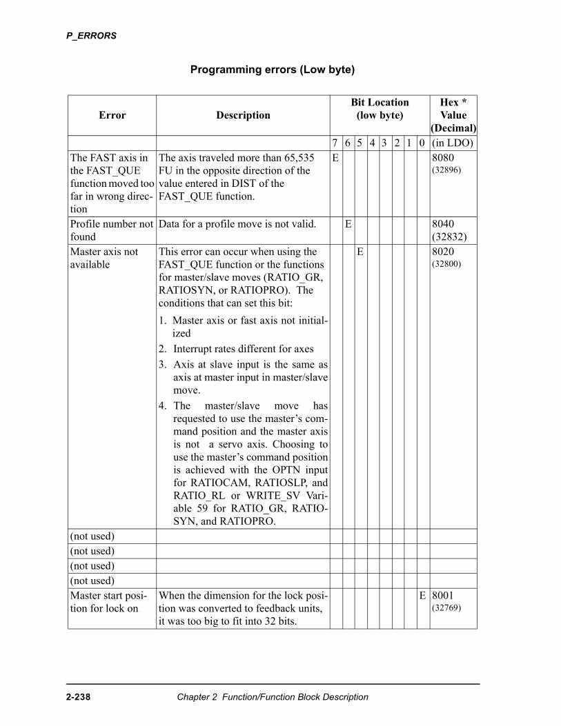
P_ERRORS
Programming errors (Low byte)
Error DescriptionBit Location
(low byte)Hex *Value
(Decimal)7 6 5 4 3 2 1 0 (in LDO)
The FAST axis in the FAST_QUE function moved too far in wrong direc-tion
The axis traveled more than 65,535 FU in the opposite direction of the value entered in DIST of the FAST_QUE function.
E 8080(32896)
Profile number not found
Data for a profile move is not valid. E 8040(32832)
Master axis not available
This error can occur when using the FAST_QUE function or the functions for master/slave moves (RATIO_GR, RATIOSYN, or RATIOPRO). The conditions that can set this bit:
1. Master axis or fast axis not initial-ized
2. Interrupt rates different for axes
3. Axis at slave input is the same asaxis at master input in master/slavemove.
4. The master/slave move hasrequested to use the master’s com-mand position and the master axisis not a servo axis. Choosing touse the master’s command positionis achieved with the OPTN inputfor RATIOCAM, RATIOSLP, andRATIO_RL or WRITE_SV Vari-able 59 for RATIO_GR, RATIO-SYN, and RATIOPRO.
E 8020(32800)
(not used)(not used)(not used)(not used)Master start posi-tion for lock on
When the dimension for the lock posi-tion was converted to feedback units, it was too big to fit into 32 bits.
E 8001(32769)
2-238 Chapter 2 Function/Function Block Description
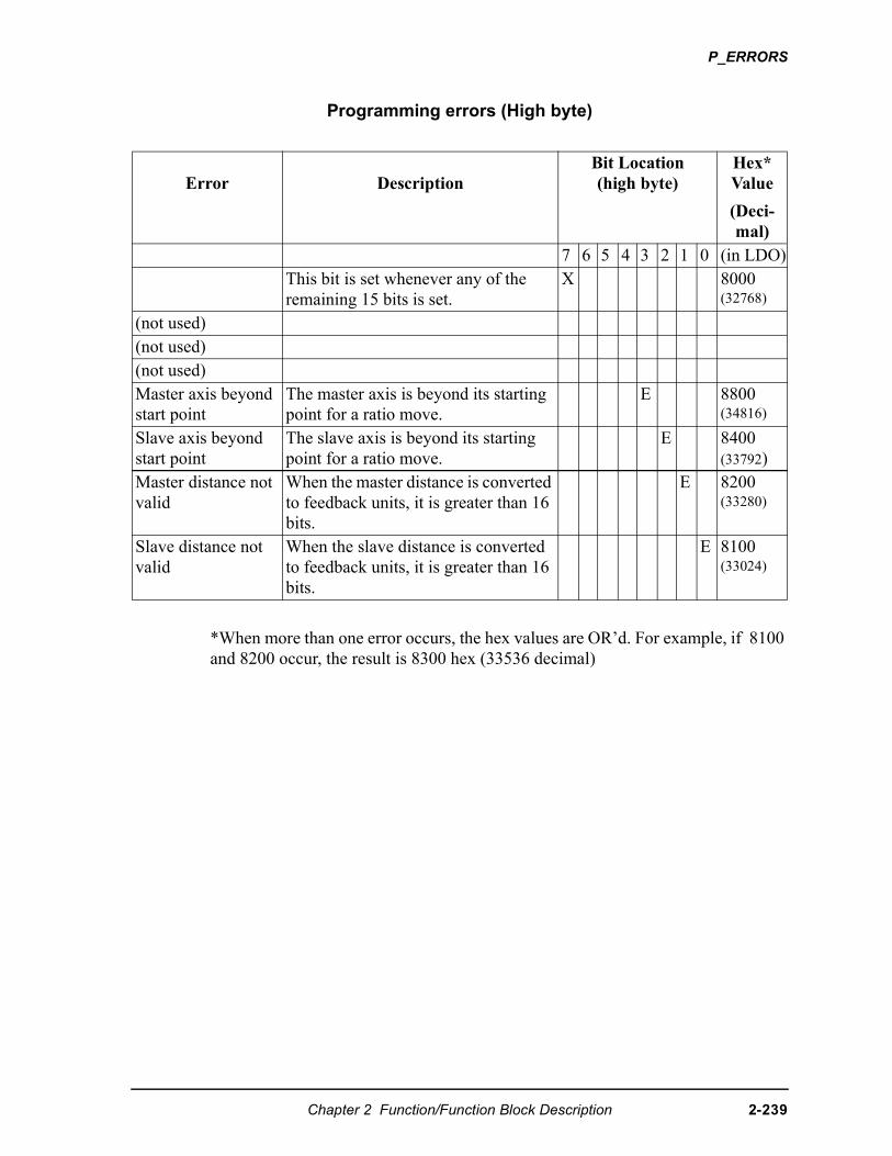
P_ERRORS
Programming errors (High byte)
*When more than one error occurs, the hex values are OR’d. For example, if 8100 and 8200 occur, the result is 8300 hex (33536 decimal)
Error DescriptionBit Location(high byte)
Hex*Value
(Deci-mal)
7 6 5 4 3 2 1 0 (in LDO)This bit is set whenever any of the remaining 15 bits is set.
X 8000(32768)
(not used)(not used)(not used)Master axis beyond start point
The master axis is beyond its starting point for a ratio move.
E 8800(34816)
Slave axis beyond start point
The slave axis is beyond its starting point for a ratio move.
E 8400(33792)
Master distance not valid
When the master distance is converted to feedback units, it is greater than 16 bits.
E 8200(33280)
Slave distance not valid
When the slave distance is converted to feedback units, it is greater than 16 bits.
E 8100(33024)
Chapter 2 Function/Function Block Description 2-239
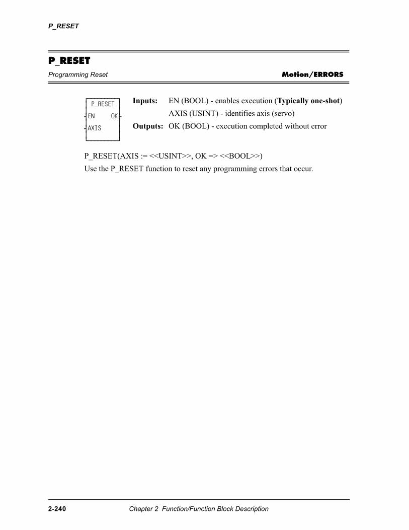
P_RESET
P_RESETProgramming Reset Motion/ERRORS
P_RESET(AXIS := <<USINT>>, OK => <<BOOL>>)
Use the P_RESET function to reset any programming errors that occur.
⁄ƒƒƒƒƒƒƒƒƒø≥ P_RESET ≥≥ ≥¥EN OK√≥ ≥¥AXIS ≥≥ ≥¿ƒƒƒƒƒƒƒƒƒŸ
Inputs: EN (BOOL) - enables execution (Typically one-shot)
AXIS (USINT) - identifies axis (servo)
Outputs: OK (BOOL) - execution completed without error
2-240 Chapter 2 Function/Function Block Description
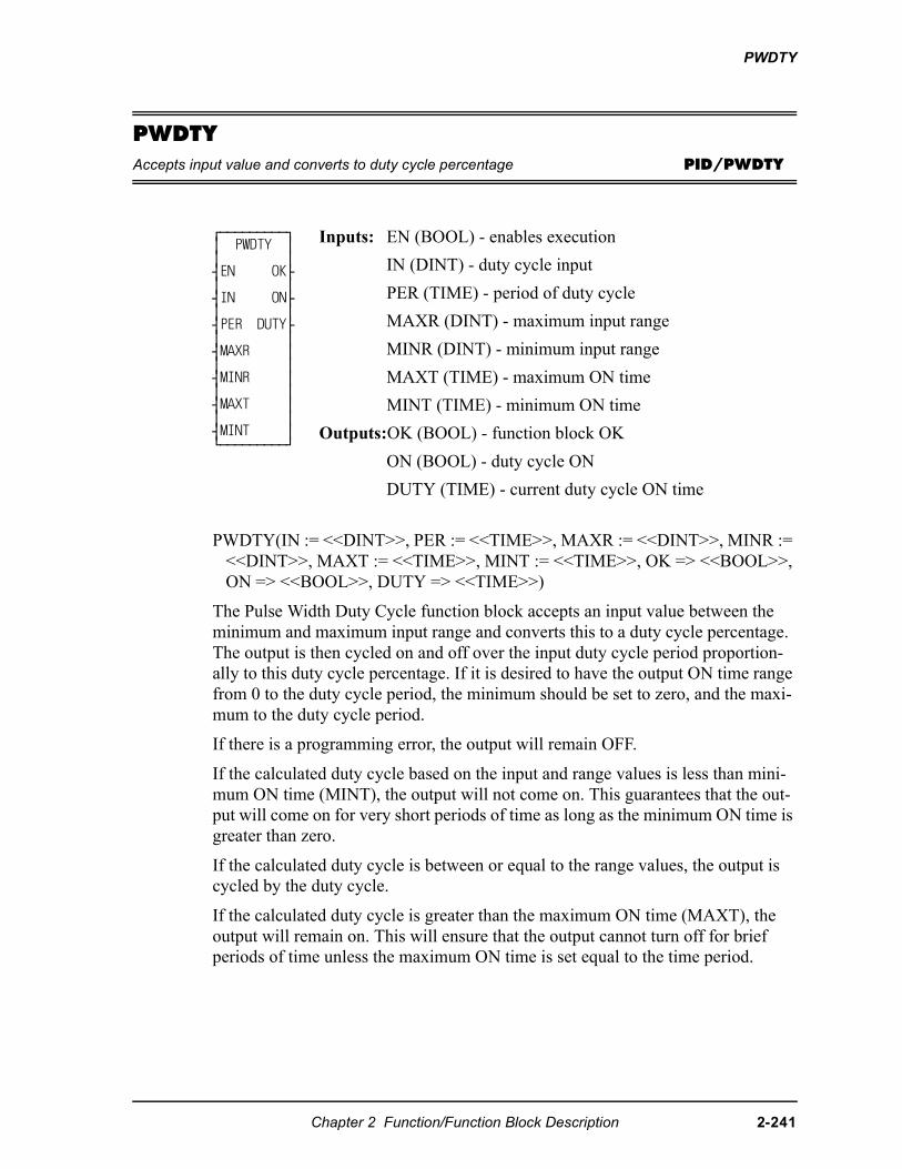
PWDTY
PWDTYAccepts input value and converts to duty cycle percentage PID/PWDTY
PWDTY(IN := <<DINT>>, PER := <<TIME>>, MAXR := <<DINT>>, MINR := <<DINT>>, MAXT := <<TIME>>, MINT := <<TIME>>, OK => <<BOOL>>, ON => <<BOOL>>, DUTY => <<TIME>>)
The Pulse Width Duty Cycle function block accepts an input value between the minimum and maximum input range and converts this to a duty cycle percentage. The output is then cycled on and off over the input duty cycle period proportion-ally to this duty cycle percentage. If it is desired to have the output ON time range from 0 to the duty cycle period, the minimum should be set to zero, and the maxi-mum to the duty cycle period.
If there is a programming error, the output will remain OFF.
If the calculated duty cycle based on the input and range values is less than mini-mum ON time (MINT), the output will not come on. This guarantees that the out-put will come on for very short periods of time as long as the minimum ON time is greater than zero.
If the calculated duty cycle is between or equal to the range values, the output is cycled by the duty cycle.
If the calculated duty cycle is greater than the maximum ON time (MAXT), the output will remain on. This will ensure that the output cannot turn off for brief periods of time unless the maximum ON time is set equal to the time period.
⁄ƒƒƒƒƒƒƒƒƒø ≥ PWDTY ≥≥ ≥¥EN OK√≥ ≥¥IN ON√≥ ≥¥PER DUTY√≥ ≥¥MAXR ≥≥ ≥¥MINR ≥≥ ≥¥MAXT ≥≥ ≥¥MINT ≥¿ƒƒƒƒƒƒƒƒƒŸ
Inputs: EN (BOOL) - enables execution
IN (DINT) - duty cycle input
PER (TIME) - period of duty cycle
MAXR (DINT) - maximum input range
MINR (DINT) - minimum input range
MAXT (TIME) - maximum ON time
MINT (TIME) - minimum ON time
Outputs:OK (BOOL) - function block OK
ON (BOOL) - duty cycle ON
DUTY (TIME) - current duty cycle ON time
Chapter 2 Function/Function Block Description 2-241
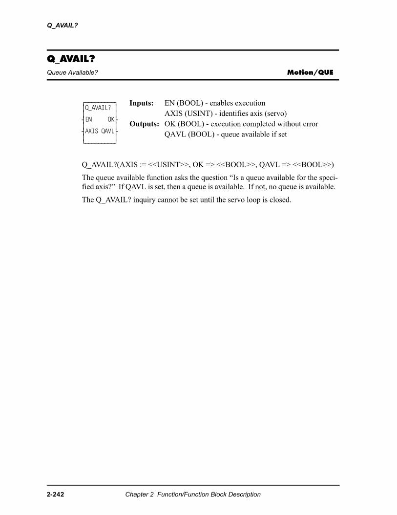
Q_AVAIL?
Q_AVAIL?Queue Available? Motion/QUE
Q_AVAIL?(AXIS := <<USINT>>, OK => <<BOOL>>, QAVL => <<BOOL>>)
The queue available function asks the question “Is a queue available for the speci-fied axis?” If QAVL is set, then a queue is available. If not, no queue is available.
The Q_AVAIL? inquiry cannot be set until the servo loop is closed.
⁄ƒƒƒƒƒƒƒƒƒø ≥Q_AVAIL? ≥ ≥ ≥ ¥EN OK√ ≥ ≥ ¥AXIS QAVL√ ≥ ≥ ¿ƒƒƒƒƒƒƒƒƒŸ
Inputs: EN (BOOL) - enables executionAXIS (USINT) - identifies axis (servo)
Outputs: OK (BOOL) - execution completed without errorQAVL (BOOL) - queue available if set
2-242 Chapter 2 Function/Function Block Description
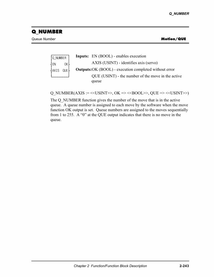
Q_NUMBER
Q_NUMBERQueue Number Motion/QUE
Q_NUMBER(AXIS := <<USINT>>, OK => <<BOOL>>, QUE => <<USINT>>)
The Q_NUMBER function gives the number of the move that is in the active queue. A queue number is assigned to each move by the software when the move function OK output is set. Queue numbers are assigned to the moves sequentially from 1 to 255. A “0” at the QUE output indicates that there is no move in the queue.
⁄ƒƒƒƒƒƒƒƒƒø ≥Q_NUMBER ≥ ≥ ≥ ¥EN OK√ ≥ ≥ ¥AXIS QUE√ ≥ ≥ ¿ƒƒƒƒƒƒƒƒƒŸ
Inputs: EN (BOOL) - enables execution
AXIS (USINT) - identifies axis (servo)
Outputs:OK (BOOL) - execution completed without error
QUE (USINT) - the number of the move in the active queue
Chapter 2 Function/Function Block Description 2-243
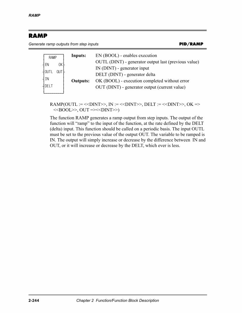
RAMP
RAMPGenerate ramp outputs from step inputs PID/RAMP
RAMP(OUTL := <<DINT>>, IN := <<DINT>>, DELT := <<DINT>>, OK => <<BOOL>>, OUT =><<DINT>>)
The function RAMP generates a ramp output from step inputs. The output of the function will “ramp” to the input of the function, at the rate defined by the DELT (delta) input. This function should be called on a periodic basis. The input OUTL must be set to the previous value of the output OUT. The variable to be ramped is IN. The output will simply increase or decrease by the difference between IN and OUT, or it will increase or decrease by the DELT, which ever is less.
⁄ƒƒƒƒƒƒƒƒƒø ≥ RAMP ≥ ≥ ≥ ¥EN OK√ ≥ ≥ ¥OUTL QUT√ ≥ ≥ ¥IN ≥ ≥ ≥ ¥DELT ≥ ≥ ≥ ¿ƒƒƒƒƒƒƒƒƒŸ
Inputs: EN (BOOL) - enables executionOUTL (DINT) - generator output last (previous value)IN (DINT) - generator inputDELT (DINT) - generator delta
Outputs: OK (BOOL) - execution completed without errorOUT (DINT) - generator output (current value)
2-244 Chapter 2 Function/Function Block Description
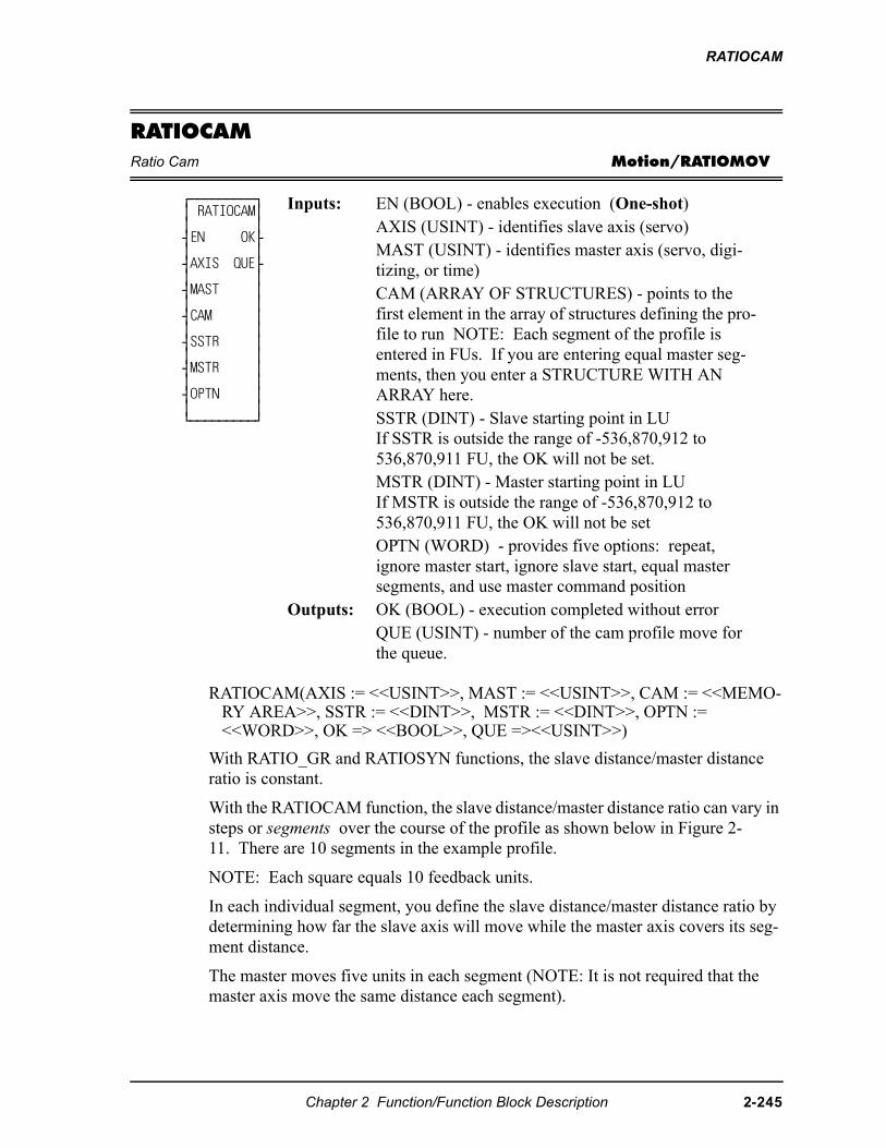
RATIOCAM
RATIOCAMRatio Cam Motion/RATIOMOV
RATIOCAM(AXIS := <<USINT>>, MAST := <<USINT>>, CAM := <<MEMO-RY AREA>>, SSTR := <<DINT>>, MSTR := <<DINT>>, OPTN := <<WORD>>, OK => <<BOOL>>, QUE =><<USINT>>)
With RATIO_GR and RATIOSYN functions, the slave distance/master distance ratio is constant.
With the RATIOCAM function, the slave distance/master distance ratio can vary in steps or segments over the course of the profile as shown below in Figure 2-11. There are 10 segments in the example profile.
NOTE: Each square equals 10 feedback units.
In each individual segment, you define the slave distance/master distance ratio by determining how far the slave axis will move while the master axis covers its seg-ment distance.
The master moves five units in each segment (NOTE: It is not required that the master axis move the same distance each segment).
⁄ƒƒƒƒƒƒƒƒƒø ≥ RATIOCAM≥ ≥ ≥ ¥EN OK√ ≥ ≥ ¥AXIS QUE√ ≥ ≥ ¥MAST ≥ ≥ ≥ ¥CAM ≥ ≥ ≥ ¥SSTR ≥ ≥ ≥ ¥MSTR ≥ ≥ ≥ ¥OPTN ≥ ≥ ≥ ¿ƒƒƒƒƒƒƒƒƒŸ
Inputs: EN (BOOL) - enables execution (One-shot)AXIS (USINT) - identifies slave axis (servo)MAST (USINT) - identifies master axis (servo, digi-tizing, or time)CAM (ARRAY OF STRUCTURES) - points to the first element in the array of structures defining the pro-file to run NOTE: Each segment of the profile is entered in FUs. If you are entering equal master seg-ments, then you enter a STRUCTURE WITH AN ARRAY here. SSTR (DINT) - Slave starting point in LUIf SSTR is outside the range of -536,870,912 to 536,870,911 FU, the OK will not be set.MSTR (DINT) - Master starting point in LUIf MSTR is outside the range of -536,870,912 to 536,870,911 FU, the OK will not be setOPTN (WORD) - provides five options: repeat, ignore master start, ignore slave start, equal master segments, and use master command position
Outputs: OK (BOOL) - execution completed without errorQUE (USINT) - number of the cam profile move for the queue.
Chapter 2 Function/Function Block Description 2-245
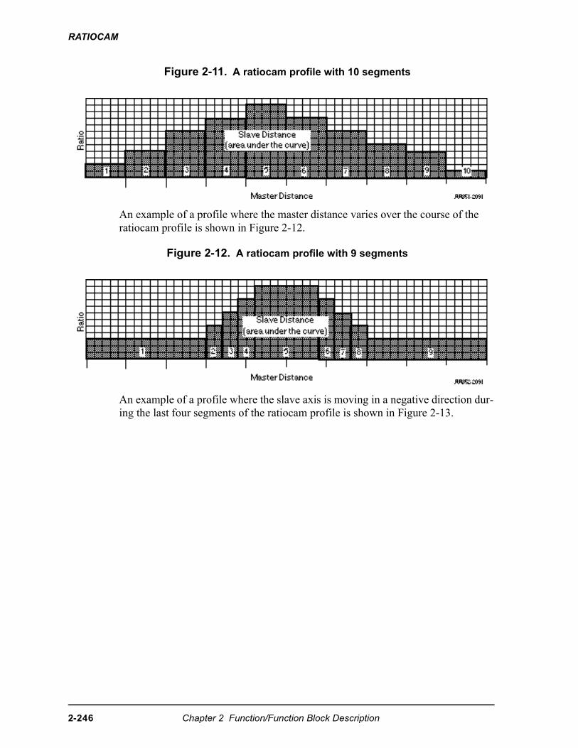
RATIOCAM
Figure 2-11. A ratiocam profile with 10 segments
An example of a profile where the master distance varies over the course of the ratiocam profile is shown in Figure 2-12.
Figure 2-12. A ratiocam profile with 9 segments
An example of a profile where the slave axis is moving in a negative direction dur-ing the last four segments of the ratiocam profile is shown in Figure 2-13.
2-246 Chapter 2 Function/Function Block Description
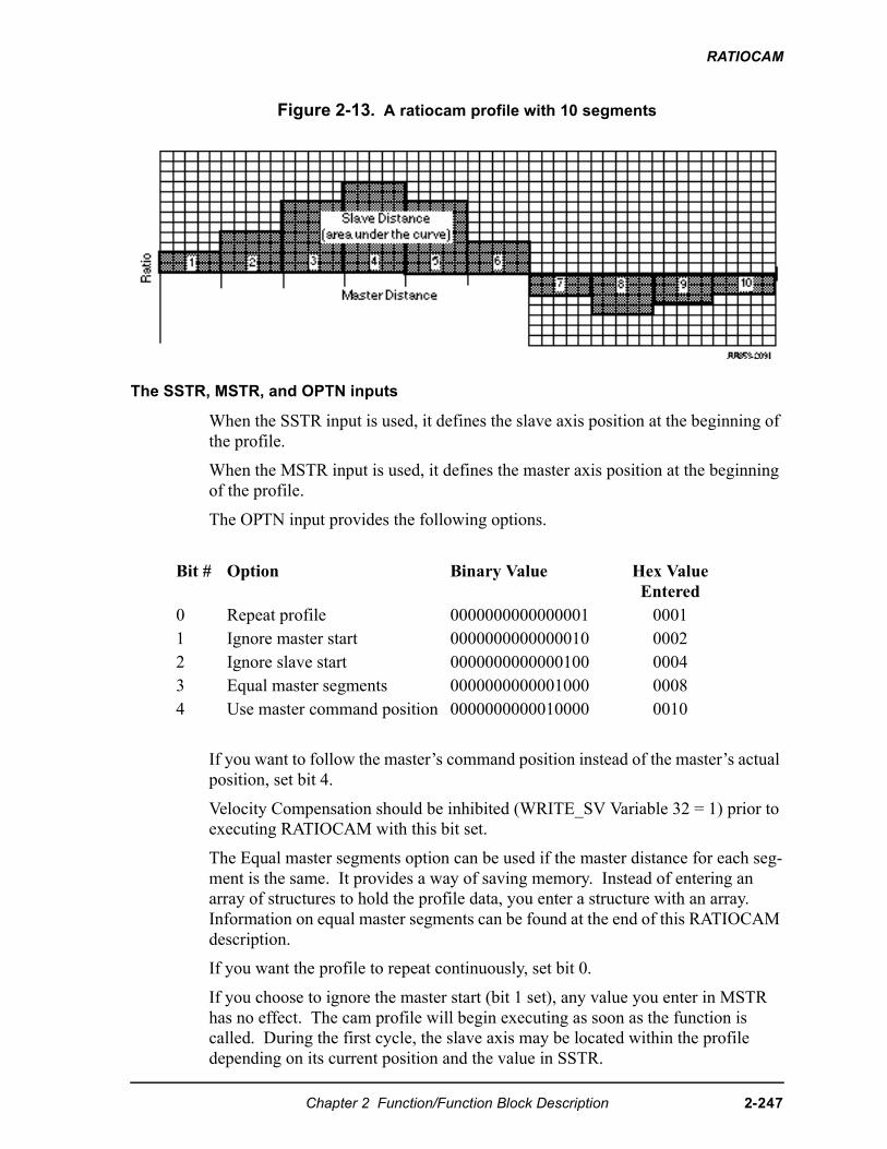
RATIOCAM
Figure 2-13. A ratiocam profile with 10 segments
The SSTR, MSTR, and OPTN inputs
When the SSTR input is used, it defines the slave axis position at the beginning of the profile.
When the MSTR input is used, it defines the master axis position at the beginning of the profile.
The OPTN input provides the following options.
If you want to follow the master’s command position instead of the master’s actual position, set bit 4.
Velocity Compensation should be inhibited (WRITE_SV Variable 32 = 1) prior to executing RATIOCAM with this bit set.
The Equal master segments option can be used if the master distance for each seg-ment is the same. It provides a way of saving memory. Instead of entering an array of structures to hold the profile data, you enter a structure with an array. Information on equal master segments can be found at the end of this RATIOCAM description.
If you want the profile to repeat continuously, set bit 0.
If you choose to ignore the master start (bit 1 set), any value you enter in MSTR has no effect. The cam profile will begin executing as soon as the function is called. During the first cycle, the slave axis may be located within the profile depending on its current position and the value in SSTR.
Bit # Option Binary Value Hex Value Entered
0 Repeat profile 0000000000000001 00011 Ignore master start 0000000000000010 00022 Ignore slave start 0000000000000100 00043 Equal master segments 0000000000001000 00084 Use master command position 0000000000010000 0010
Chapter 2 Function/Function Block Description 2-247
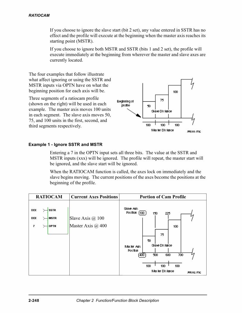
RATIOCAM
If you choose to ignore the slave start (bit 2 set), any value entered in SSTR has no effect and the profile will execute at the beginning when the master axis reaches its starting point (MSTR).
If you choose to ignore both MSTR and SSTR (bits 1 and 2 set), the profile will execute immediately at the beginning from wherever the master and slave axes are currently located.
Example 1 - Ignore SSTR and MSTR
Entering a 7 in the OPTN input sets all three bits. The value at the SSTR and MSTR inputs (xxx) will be ignored. The profile will repeat, the master start will be ignored, and the slave start will be ignored.
When the RATIOCAM function is called, the axes lock on immediately and the slave begins moving. The current positions of the axes become the positions at the beginning of the profile.
The four examples that follow illustrate what affect ignoring or using the SSTR and MSTR inputs via OPTN have on what the beginning position for each axis will be.
Three segments of a ratiocam profile (shown on the right) will be used in each example. The master axis moves 100 units in each segment. The slave axis moves 50, 75, and 100 units in the first, second, and third segments respectively.
RATIOCAM Current Axes Positions Portion of Cam Profile
Slave Axis @ 100
Master Axis @ 400
2-248 Chapter 2 Function/Function Block Description
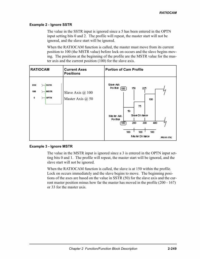
RATIOCAM
Example 2 - Ignore SSTR
The value in the SSTR input is ignored since a 5 has been entered in the OPTN input setting bits 0 and 2. The profile will repeat, the master start will not be ignored, and the slave start will be ignored.
When the RATIOCAM function is called, the master must move from its current position to 100 (the MSTR value) before lock on occurs and the slave begins mov-ing. The positions at the beginning of the profile are the MSTR value for the mas-ter axis and the current position (100) for the slave axis.
Example 3 - Ignore MSTR
The value in the MSTR input is ignored since a 3 is entered in the OPTN input set-ting bits 0 and 1. The profile will repeat, the master start will be ignored, and the slave start will not be ignored.
When the RATIOCAM function is called, the slave is at 150 within the profile. Lock on occurs immediately and the slave begins to move. The beginning posi-tions of the axes are based on the value in SSTR (50) for the slave axis and the cur-rent master position minus how far the master has moved in the profile (200 - 167) or 33 for the master axis.
RATIOCAM Current Axes Positions
Portion of Cam Profile
Slave Axis @ 100
Master Axis @ 50
Chapter 2 Function/Function Block Description 2-249
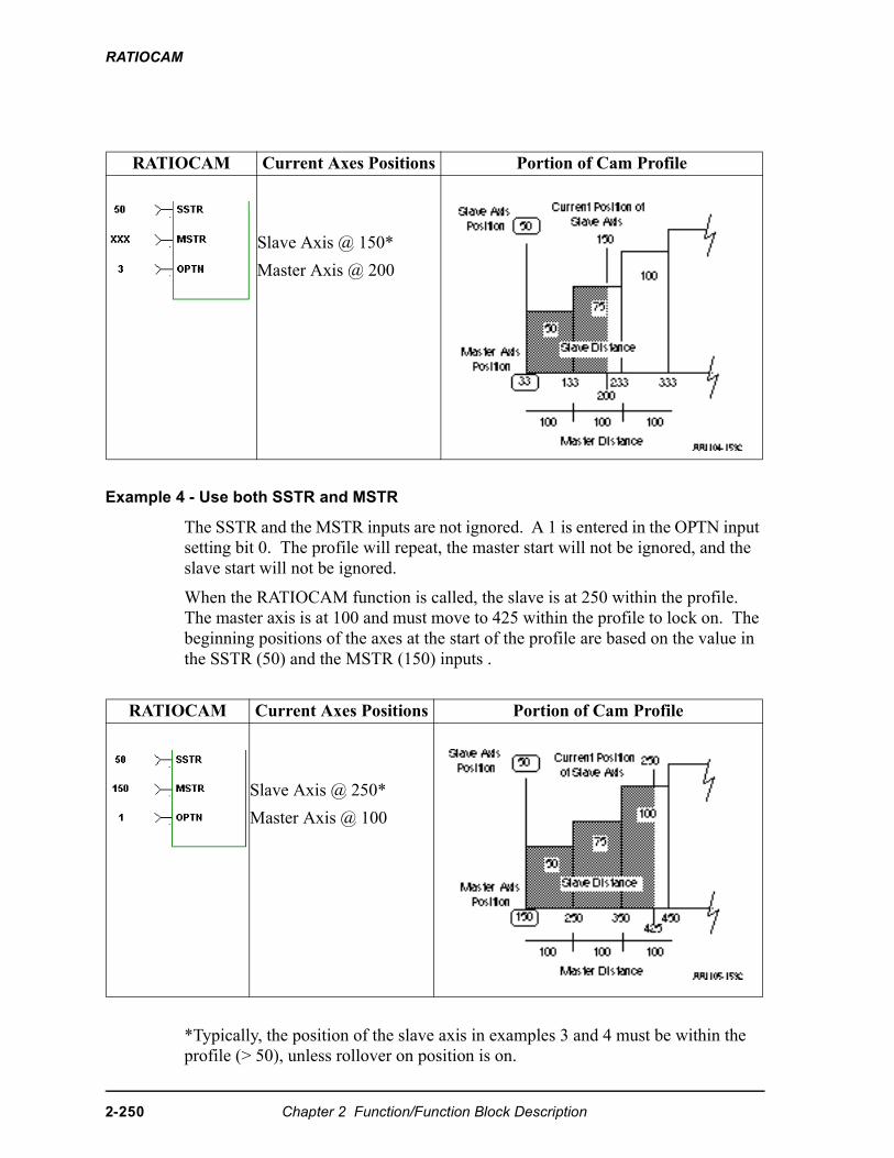
RATIOCAM
Example 4 - Use both SSTR and MSTR
The SSTR and the MSTR inputs are not ignored. A 1 is entered in the OPTN input setting bit 0. The profile will repeat, the master start will not be ignored, and the slave start will not be ignored.
When the RATIOCAM function is called, the slave is at 250 within the profile. The master axis is at 100 and must move to 425 within the profile to lock on. The beginning positions of the axes at the start of the profile are based on the value in the SSTR (50) and the MSTR (150) inputs .
*Typically, the position of the slave axis in examples 3 and 4 must be within the profile (> 50), unless rollover on position is on.
RATIOCAM Current Axes Positions Portion of Cam Profile
Slave Axis @ 150*
Master Axis @ 200
RATIOCAM Current Axes Positions Portion of Cam Profile
Slave Axis @ 250*
Master Axis @ 100
2-250 Chapter 2 Function/Function Block Description
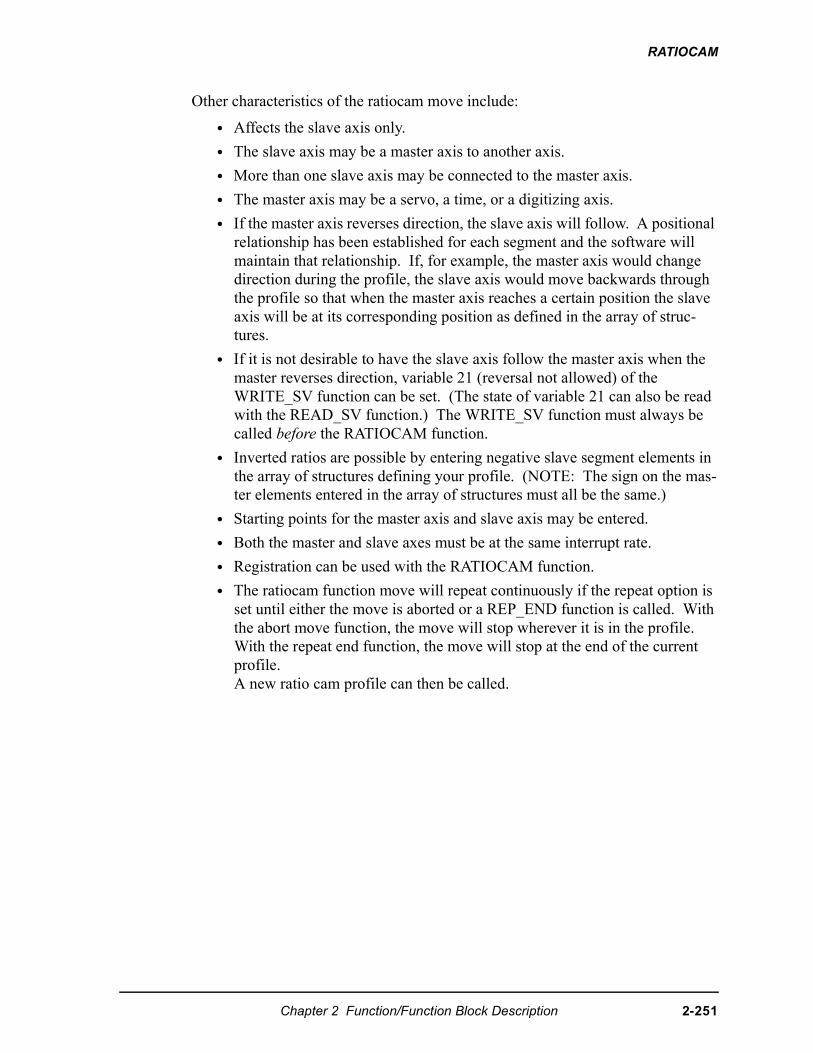
RATIOCAM
Other characteristics of the ratiocam move include:
• Affects the slave axis only.
• The slave axis may be a master axis to another axis.
• More than one slave axis may be connected to the master axis.
• The master axis may be a servo, a time, or a digitizing axis.
• If the master axis reverses direction, the slave axis will follow. A positional relationship has been established for each segment and the software will maintain that relationship. If, for example, the master axis would change direction during the profile, the slave axis would move backwards through the profile so that when the master axis reaches a certain position the slave axis will be at its corresponding position as defined in the array of struc-tures.
• If it is not desirable to have the slave axis follow the master axis when the master reverses direction, variable 21 (reversal not allowed) of the WRITE_SV function can be set. (The state of variable 21 can also be read with the READ_SV function.) The WRITE_SV function must always be called before the RATIOCAM function.
• Inverted ratios are possible by entering negative slave segment elements in the array of structures defining your profile. (NOTE: The sign on the mas-ter elements entered in the array of structures must all be the same.)
• Starting points for the master axis and slave axis may be entered.
• Both the master and slave axes must be at the same interrupt rate.
• Registration can be used with the RATIOCAM function.
• The ratiocam function move will repeat continuously if the repeat option is set until either the move is aborted or a REP_END function is called. With the abort move function, the move will stop wherever it is in the profile. With the repeat end function, the move will stop at the end of the current profile. A new ratio cam profile can then be called.
Chapter 2 Function/Function Block Description 2-251
RATIOCAM
• Some conditions for which the OK will not be set and the queue will be “0” include:
1. Master axis not available (P-error) [Master axis not initialized, master and slave interrupts different, the same axis was entered as master and slave, or OPTN bit 4 is set and the master axis is not a servo axis.]
2. Profile error (P-error) [A number less than two entered as the size of the profile, a master segment is zero, or not all master segments have the same sign]
3. Slave start value is out of range, current slave position is not within profile, or not ignoring slave start with both queues not available (NOTE: Rollover on position will not be used by the servo software to correct this condition.)]
4. Master start value is out of range.
5. Slave axis (AXIS) not initialized during setup
• A P-error will occur if the master axis is beyond it’s start point.
• A P-error will occur if the slave axis is beyond it’s start point.
• An E-error will occur if there is a slave delta overflow during runtime. The hex code 0004 indicates this error on the ERRS output of the E_ERRORS function. To ensure that this E-error will not occur, calculate the worst case for your application as explained below. With feedback units equal to ladder units,master distance/interrupt (velocity) X largest slave array value<32 bits
Creating a profile with an array of structures
Each segment or step in the cam profile is defined by you in PiCPro by creating an array of structures in the software declarations table. (More information on arrays and structures can be found in the PiCPro Online Help.)
There are two members of the structure--the master distance and the slave dis-tance. These distances are entered in feedback units. Each element in the array represents the master distance and the slave distance for one segment of the cam profile.
In order to create the array of structures, you need to know:
1. The master distance and the slave distance for each segment. The table on the left that follows contains this information for the example in Figure 2-11.
NOTE
An array of structures is always used to create the ratio cam profile ifthe master distance varies with each segment. It can also be used ifthe master distance for each segment is equal as shown in the examplethat follows. However, if you want to save memory, you can set op-tion bit 3 and enter a structure with an array.
2-252 Chapter 2 Function/Function Block Description
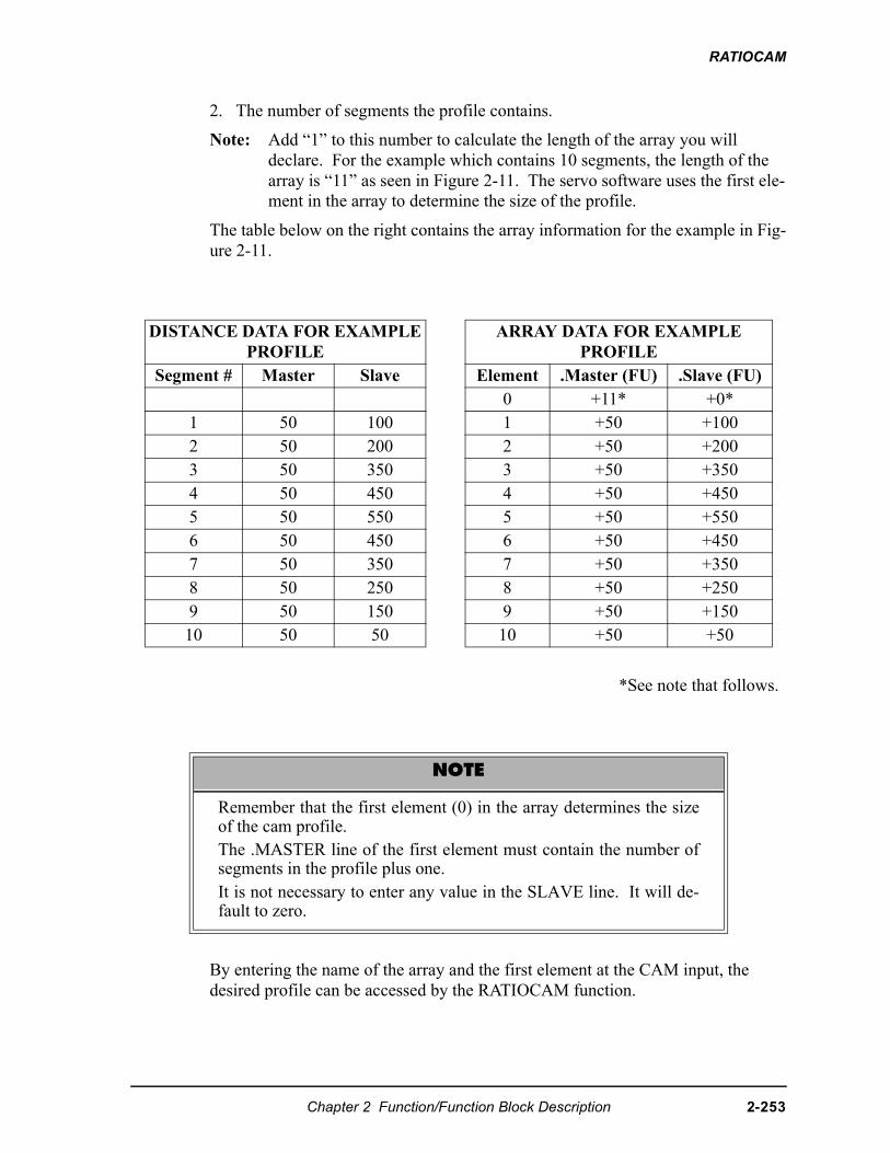
RATIOCAM
2. The number of segments the profile contains.
Note: Add “1” to this number to calculate the length of the array you will declare. For the example which contains 10 segments, the length of the array is “11” as seen in Figure 2-11. The servo software uses the first ele-ment in the array to determine the size of the profile.
The table below on the right contains the array information for the example in Fig-ure 2-11.
*See note that follows.
By entering the name of the array and the first element at the CAM input, the desired profile can be accessed by the RATIOCAM function.
DISTANCE DATA FOR EXAMPLE PROFILE
ARRAY DATA FOR EXAMPLEPROFILE
Segment # Master Slave Element .Master (FU) .Slave (FU)0 +11* +0*
1 50 100 1 +50 +1002 50 200 2 +50 +2003 50 350 3 +50 +3504 50 450 4 +50 +4505 50 550 5 +50 +5506 50 450 6 +50 +4507 50 350 7 +50 +3508 50 250 8 +50 +2509 50 150 9 +50 +15010 50 50 10 +50 +50
NOTE
Remember that the first element (0) in the array determines the sizeof the cam profile.The .MASTER line of the first element must contain the number ofsegments in the profile plus one. It is not necessary to enter any value in the SLAVE line. It will de-fault to zero.
Chapter 2 Function/Function Block Description 2-253
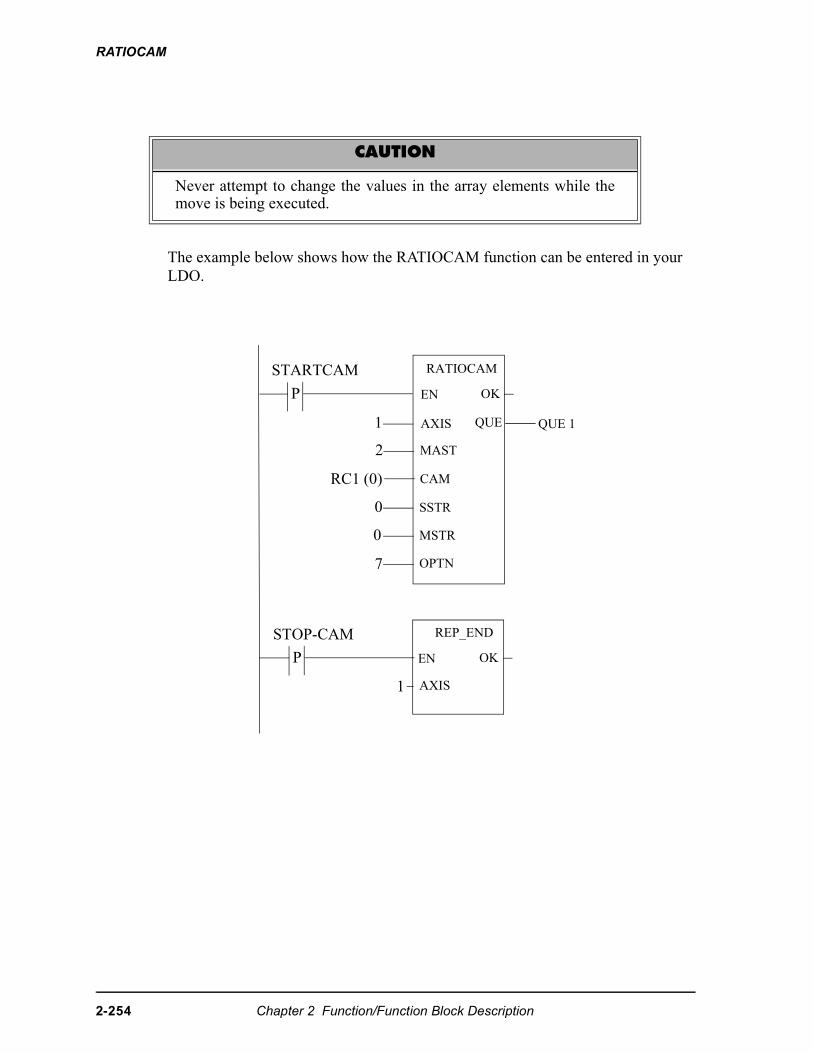
RATIOCAM
The example below shows how the RATIOCAM function can be entered in your LDO.
CAUTION
Never attempt to change the values in the array elements while themove is being executed.
P EN
STARTCAM
OK
1
2
RC1 (0)
0
0
7
AXIS QUE
MAST
CAM
SSTR
MSTR
OPTN
QUE 1
P EN
STOP-CAM
RATIOCAM
REP_END
OK
1 AXIS
2-254 Chapter 2 Function/Function Block Description
RATIOCAM
Equal Master Segments
If the master distance for all the segments in the RATIOCAM profile is the same, you can define the profile in the software declarations table with a structure with an array as shown below in order to save memory.
In this structure with an array,
.SIZE is the number of slave segments in the profile plus 2
.MASTER is the master distance for all segments
.SLAVE is an array holding the slave distances for each segment (In this example, there are 10 slave segments.)
Bit 3 of the option bits must be set when you use this structure with an array.
The array of structures used in the previous examples (shown below) must be used if the master distance for all the segments varies in the RATIOCAM profile. It can also be used when the master distance for each segment is equal but it uses more memory than using the structure with an array above.
Structure with an array (if master distance for all segments is equal)RC1.SIZE.MASTER.SLAVE
STRUCTINTINTINT (0..9)
Array of Structures (if master distance for all segments varies)RC1.MASTER.SLAVE
STRUCT (0..10)INTINT
Chapter 2 Function/Function Block Description 2-255
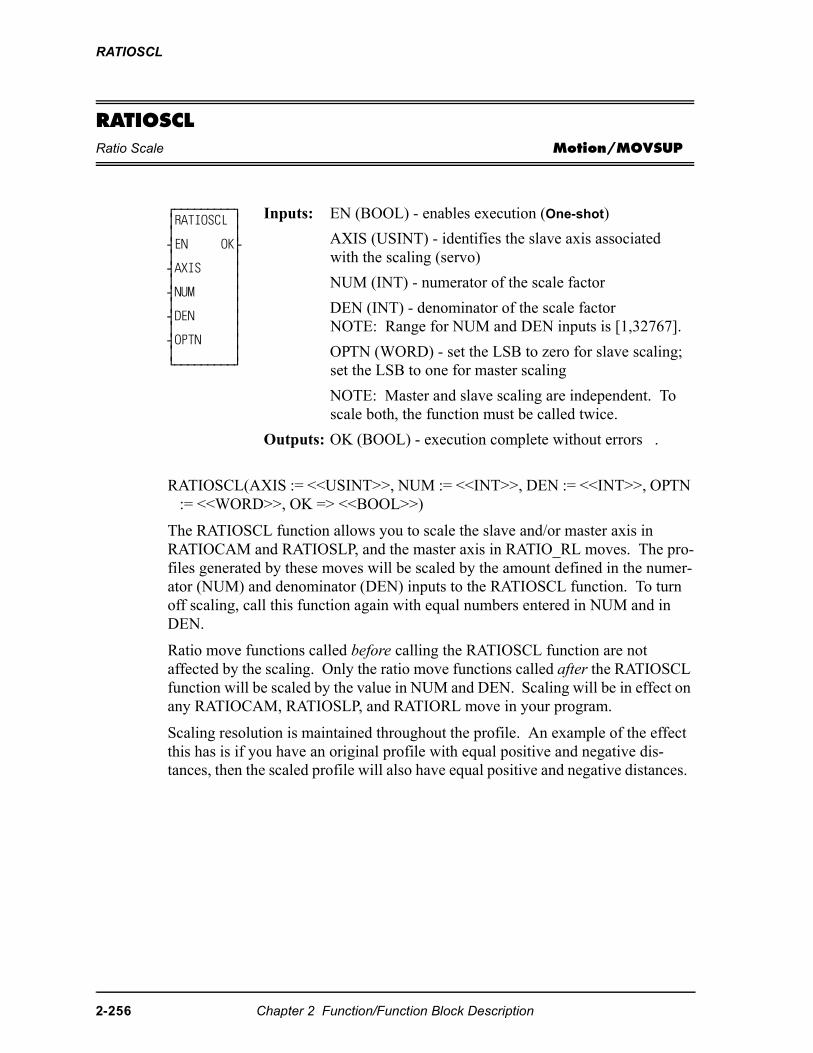
RATIOSCL
RATIOSCLRatio Scale Motion/MOVSUP
RATIOSCL(AXIS := <<USINT>>, NUM := <<INT>>, DEN := <<INT>>, OPTN := <<WORD>>, OK => <<BOOL>>)
The RATIOSCL function allows you to scale the slave and/or master axis in RATIOCAM and RATIOSLP, and the master axis in RATIO_RL moves. The pro-files generated by these moves will be scaled by the amount defined in the numer-ator (NUM) and denominator (DEN) inputs to the RATIOSCL function. To turn off scaling, call this function again with equal numbers entered in NUM and in DEN.
Ratio move functions called before calling the RATIOSCL function are not affected by the scaling. Only the ratio move functions called after the RATIOSCL function will be scaled by the value in NUM and DEN. Scaling will be in effect on any RATIOCAM, RATIOSLP, and RATIORL move in your program.
Scaling resolution is maintained throughout the profile. An example of the effect this has is if you have an original profile with equal positive and negative dis-tances, then the scaled profile will also have equal positive and negative distances.
⁄ƒƒƒƒƒƒƒƒƒø≥RATIOSCL ≥≥ ≥¥EN OK√≥ ≥¥AXIS ≥≥ ≥¥NUM ≥≥ ≥¥DEN ≥≥ ≥¥OPTN ≥≥ ≥¿ƒƒƒƒƒƒƒƒƒŸ
Inputs: EN (BOOL) - enables execution (One-shot)
AXIS (USINT) - identifies the slave axis associated with the scaling (servo)
NUM (INT) - numerator of the scale factor
DEN (INT) - denominator of the scale factorNOTE: Range for NUM and DEN inputs is [1,32767].
OPTN (WORD) - set the LSB to zero for slave scaling; set the LSB to one for master scaling
NOTE: Master and slave scaling are independent. To scale both, the function must be called twice.
Outputs: OK (BOOL) - execution complete without errors .
2-256 Chapter 2 Function/Function Block Description
RATIOSCL
To change the scaling of an already repeating ratio move, follow these steps in order.
1. Call the RATIOSCL function with a new ratio. This will change the scaling for subsequent moves.
2. Call the ratio move again. This will queue the move with the new scaling.
3. Call the REP_END function. This will end the first move and blend into the second profile with the new scaling.
An overflow in the calculations will cause an E-stop error to be set. Overflows can be caused by a profile segment and/or scaling that is extremely large.
The scaling does not affect the default gear ratio that can be used with the RATIO-SLP and RATIO_RL functions. Use the NEWRATIO function to change the default gear ratio value.
It is important to remember that the scaling affects the master/slave relationship, not the individual axes. Multiple slave axes following the same master can each have different master scaling.
With slave scaling, the slave distance is multiplied by the scaling factor. With master scaling, the master distance as viewed by the slave is multiplied by the scal-ing factor as it occurs. This is illustrated by the examples for a RATIOCAM and a RATIOSLP move that follow.
Chapter 2 Function/Function Block Description 2-257
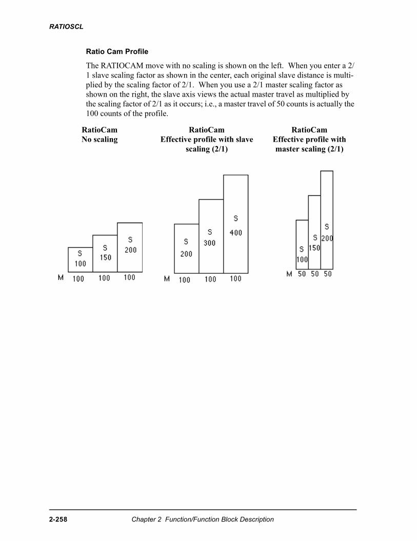
RATIOSCL
Ratio Cam Profile
The RATIOCAM move with no scaling is shown on the left. When you enter a 2/1 slave scaling factor as shown in the center, each original slave distance is multi-plied by the scaling factor of 2/1. When you use a 2/1 master scaling factor as shown on the right, the slave axis views the actual master travel as multiplied by the scaling factor of 2/1 as it occurs; i.e., a master travel of 50 counts is actually the 100 counts of the profile.
RatioCamNo scaling
RatioCamEffective profile with slave
scaling (2/1)
RatioCamEffective profile with master scaling (2/1)
2-258 Chapter 2 Function/Function Block Description
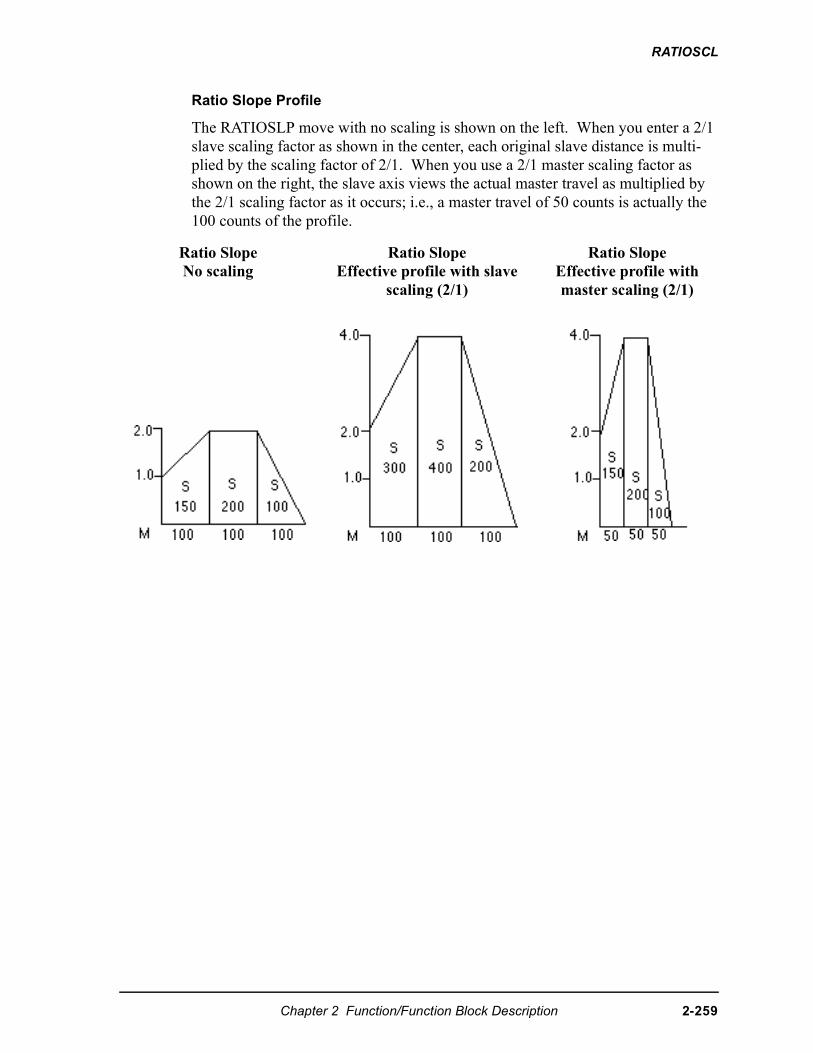
RATIOSCL
Ratio Slope Profile
The RATIOSLP move with no scaling is shown on the left. When you enter a 2/1 slave scaling factor as shown in the center, each original slave distance is multi-plied by the scaling factor of 2/1. When you use a 2/1 master scaling factor as shown on the right, the slave axis views the actual master travel as multiplied by the 2/1 scaling factor as it occurs; i.e., a master travel of 50 counts is actually the 100 counts of the profile.
Ratio SlopeNo scaling
Ratio SlopeEffective profile with slave
scaling (2/1)
Ratio SlopeEffective profile with master scaling (2/1)
Chapter 2 Function/Function Block Description 2-259
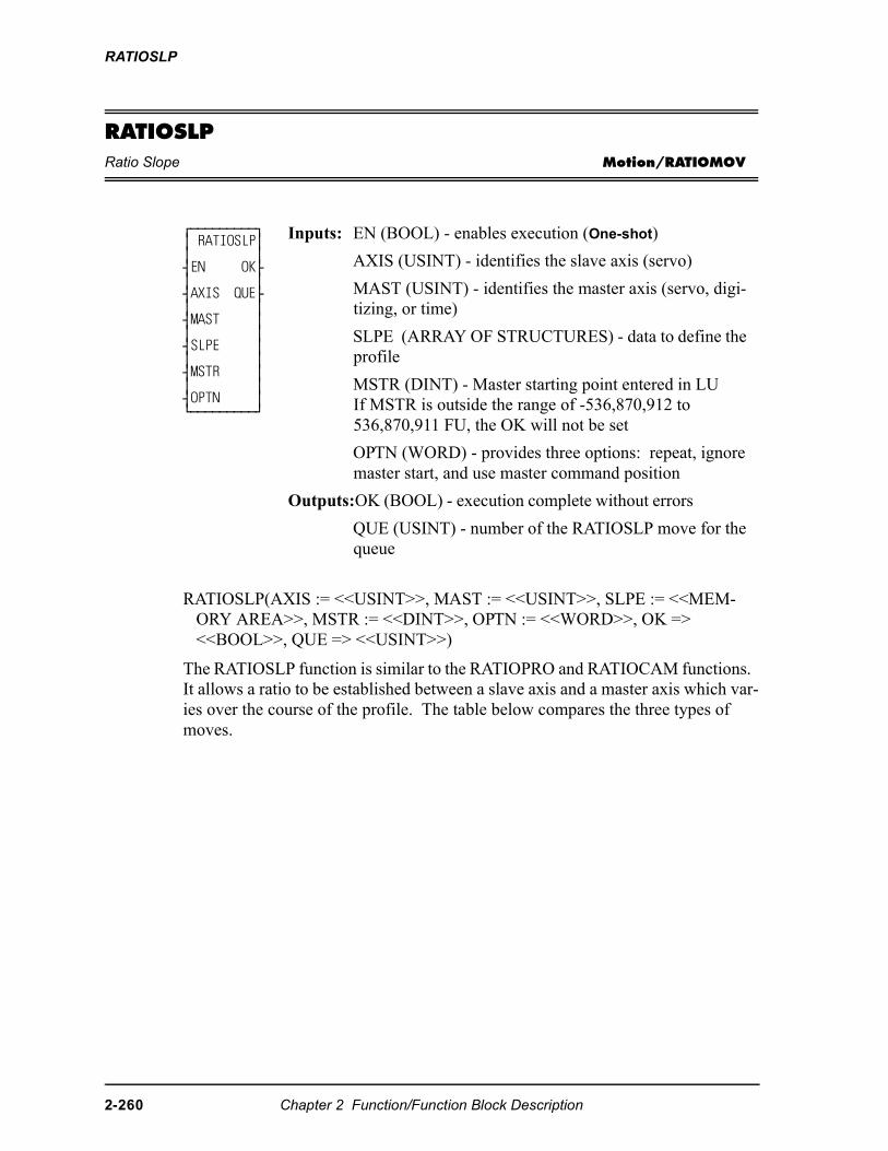
RATIOSLP
RATIOSLPRatio Slope Motion/RATIOMOV
RATIOSLP(AXIS := <<USINT>>, MAST := <<USINT>>, SLPE := <<MEM-ORY AREA>>, MSTR := <<DINT>>, OPTN := <<WORD>>, OK => <<BOOL>>, QUE => <<USINT>>)
The RATIOSLP function is similar to the RATIOPRO and RATIOCAM functions. It allows a ratio to be established between a slave axis and a master axis which var-ies over the course of the profile. The table below compares the three types of moves.
⁄ƒƒƒƒƒƒƒƒƒø≥ RATIOSLP≥≥ ≥¥EN OK√≥ ≥¥AXIS QUE√≥ ≥¥MAST ≥≥ ≥¥SLPE ≥≥ ≥¥MSTR ≥≥ ≥¥OPTN ≥¿ƒƒƒƒƒƒƒƒƒŸ
Inputs: EN (BOOL) - enables execution (One-shot)
AXIS (USINT) - identifies the slave axis (servo)
MAST (USINT) - identifies the master axis (servo, digi-tizing, or time)
SLPE (ARRAY OF STRUCTURES) - data to define the profile
MSTR (DINT) - Master starting point entered in LUIf MSTR is outside the range of -536,870,912 to 536,870,911 FU, the OK will not be set
OPTN (WORD) - provides three options: repeat, ignore master start, and use master command position
Outputs:OK (BOOL) - execution complete without errors
QUE (USINT) - number of the RATIOSLP move for the queue
2-260 Chapter 2 Function/Function Block Description
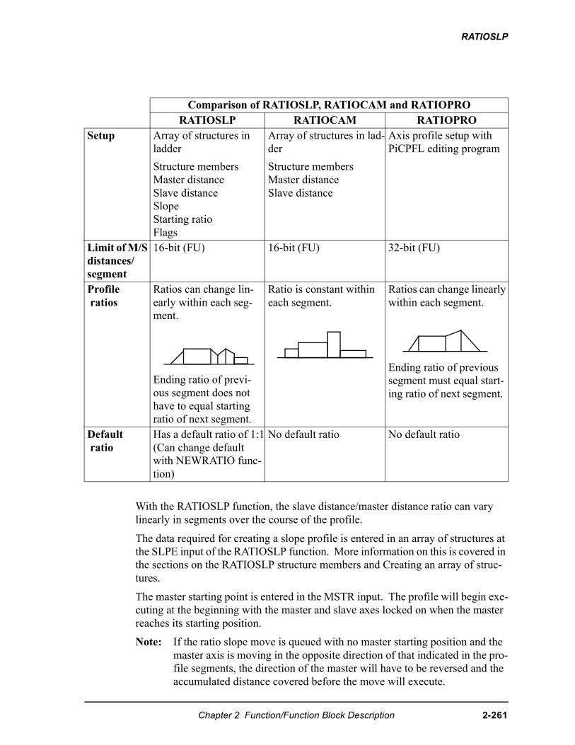
RATIOSLP
With the RATIOSLP function, the slave distance/master distance ratio can vary linearly in segments over the course of the profile.
The data required for creating a slope profile is entered in an array of structures at the SLPE input of the RATIOSLP function. More information on this is covered in the sections on the RATIOSLP structure members and Creating an array of struc-tures.
The master starting point is entered in the MSTR input. The profile will begin exe-cuting at the beginning with the master and slave axes locked on when the master reaches its starting position.
Note: If the ratio slope move is queued with no master starting position and the master axis is moving in the opposite direction of that indicated in the pro-file segments, the direction of the master will have to be reversed and the accumulated distance covered before the move will execute.
Comparison of RATIOSLP, RATIOCAM and RATIOPRORATIOSLP RATIOCAM RATIOPRO
Setup Array of structures in ladder
Structure membersMaster distanceSlave distanceSlopeStarting ratioFlags
Array of structures in lad-der
Structure membersMaster distanceSlave distance
Axis profile setup with PiCPFL editing program
Limit of M/S distances/segment
16-bit (FU) 16-bit (FU) 32-bit (FU)
Profile ratios
Ratios can change lin-early within each seg-ment.
Ending ratio of previ-ous segment does not have to equal starting ratio of next segment.
Ratio is constant within each segment.
Ratios can change linearly within each segment.
Ending ratio of previous segment must equal start-ing ratio of next segment.
Default ratio
Has a default ratio of 1:1(Can change default with NEWRATIO func-tion)
No default ratio No default ratio
Chapter 2 Function/Function Block Description 2-261
RATIOSLP
The OPTN input provides the following options
If you want the profile to repeat continuously, bit 0 is set. If bit 0 is not set, the profile will execute once and then stop.
If you choose to ignore the master start (bit 1 set), any value you have entered in MSTR has no effect. The slope profile will begin executing as soon as the func-tion is called.
If you want to follow the master’s command position instead of the master’s actual position, set bit 4.
Velocity Compensation should be inhibited (WRITE_SV Variable 32 = 1) prior to executing RATIOSLP with this bit set.
Other characteristics of the ratio slope move include:
• Affects the slave axis only.
• The slave axis may be a master axis to another axis.
• More than one slave axis may be connected to the master axis.
• The master axis may be a servo, a time, or a digitizing axis.
• If the master axis reverses direction, the slave axis will follow. A positional relationship has been established for each segment and the software will maintain that relationship. If, for example, the master axis would change direction during the profile, the slave axis would move backwards through the profile so that when the master axis reaches a certain position the slave axis will be at its corresponding position as defined in the array of struc-tures.
• If it is not desirable to have the slave axis follow the master axis when the master reverses direction, variable 21 (reversal not allowed) of the WRITE_SV function can be set. (The state of variable 21 can also be read with the READ_SV function.) The WRITE_SV function must always be called before the RATIOSLP function.
• Inverted ratios are possible by entering negative slave segment elements in the array of structures defining your profile. (NOTE: The sign on the mas-ter elements entered in the array of structures must all be the same.)
• An individual segment of the profile may pass through zero. Segment 3 in the profile on the left passes through zero to cover the slave distance (shaded areas). The profile on the right uses two segments to accomplish the same thing.
Bit # Option Binary ValueHex Value Entered
0 Repeat profile 0000000000000001 00011 Ignore master start 0000000000000010 00024 Use master command position 0000000000010000 0010
2-262 Chapter 2 Function/Function Block Description
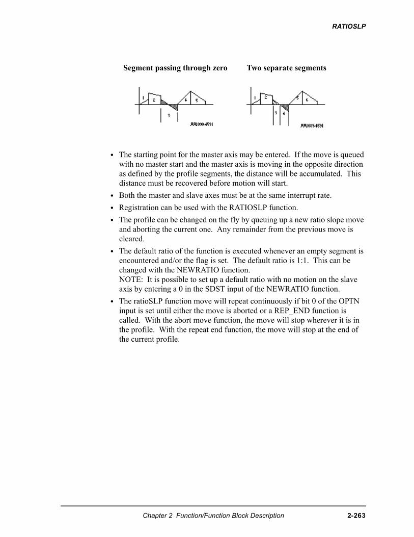
RATIOSLP
• The starting point for the master axis may be entered. If the move is queued with no master start and the master axis is moving in the opposite direction as defined by the profile segments, the distance will be accumulated. This distance must be recovered before motion will start.
• Both the master and slave axes must be at the same interrupt rate.
• Registration can be used with the RATIOSLP function.
• The profile can be changed on the fly by queuing up a new ratio slope move and aborting the current one. Any remainder from the previous move is cleared.
• The default ratio of the function is executed whenever an empty segment is encountered and/or the flag is set. The default ratio is 1:1. This can be changed with the NEWRATIO function.NOTE: It is possible to set up a default ratio with no motion on the slave axis by entering a 0 in the SDST input of the NEWRATIO function.
• The ratioSLP function move will repeat continuously if bit 0 of the OPTN input is set until either the move is aborted or a REP_END function is called. With the abort move function, the move will stop wherever it is in the profile. With the repeat end function, the move will stop at the end of the current profile.
Segment passing through zero Two separate segments
Chapter 2 Function/Function Block Description 2-263
RATIOSLP
• Some conditions for which the OK will not be set and the queue will be “0” include:
1. Master axis not available (P-error) [Master axis not initialized, master and slave interrupts different, the same axis was entered as master and slave, or OPTN bit 4 is set and the master axis is not a servo axis.]
2. Profile error (P-error) [A number less than two entered as the size of the profile, a master segment is zero, or not all master segments have the same sign]
3. Master start value is out of range.
4. Slave axis (AXIS) not initialized during setup
• A P-error will occur if the master axis is beyond it’s start point.
• An E-error will occur if there are calculation errors during runtime. The hex code 0004 indicates this error on the ERRS output of the E_ERRORS func-tion.
2-264 Chapter 2 Function/Function Block Description
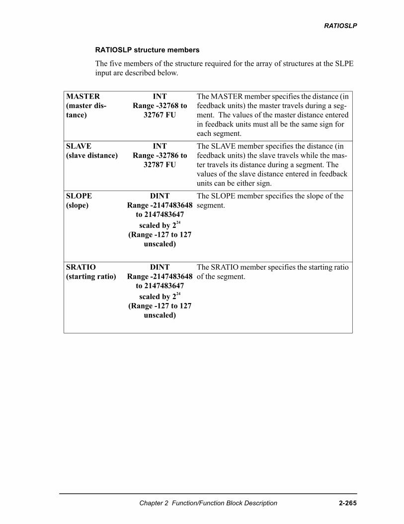
RATIOSLP
RATIOSLP structure members
The five members of the structure required for the array of structures at the SLPE input are described below.
MASTER(master dis-tance)
INT Range -32768 to
32767 FU
The MASTER member specifies the distance (in feedback units) the master travels during a seg-ment. The values of the master distance entered in feedback units must all be the same sign for each segment.
SLAVE(slave distance)
INT Range -32786 to
32787 FU
The SLAVE member specifies the distance (in feedback units) the slave travels while the mas-ter travels its distance during a segment. The values of the slave distance entered in feedback units can be either sign.
SLOPE(slope)
DINT Range -2147483648
to 2147483647 scaled by 224
(Range -127 to 127 unscaled)
The SLOPE member specifies the slope of the segment.
SRATIO(starting ratio)
DINT Range -2147483648
to 2147483647 scaled by 224
(Range -127 to 127 unscaled)
The SRATIO member specifies the starting ratio of the segment.
Chapter 2 Function/Function Block Description 2-265
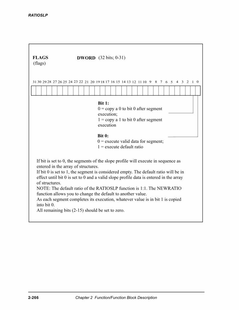
RATIOSLP
Bit 0:0 = execute valid data for segment;1 = execute default ratio
Bit 1:0 = copy a 0 to bit 0 after segment execution;1 = copy a 1 to bit 0 after segment execution
31 30 29 28 27 26 25 24 23 22 21 20 19 18 17 16 15 14 13 12 11 10 9 8 6 4 3 2 1 0
DWORDFLAGS(flags)
If bit is set to 0, the segments of the slope profile will execute in sequence as entered in the array of structures.If bit 0 is set to 1, the segment is considered empty. The default ratio will be in effect until bit 0 is set to 0 and a valid slope profile data is entered in the array of structures.NOTE: The default ratio of the RATIOSLP function is 1:1. The NEWRATIOfunction allows you to change the default to another value.As each segment completes its execution, whatever value is in bit 1 is copied into bit 0.All remaining bits (2-15) should be set to zero.
57
(32 bits; 0-31)
2-266 Chapter 2 Function/Function Block Description
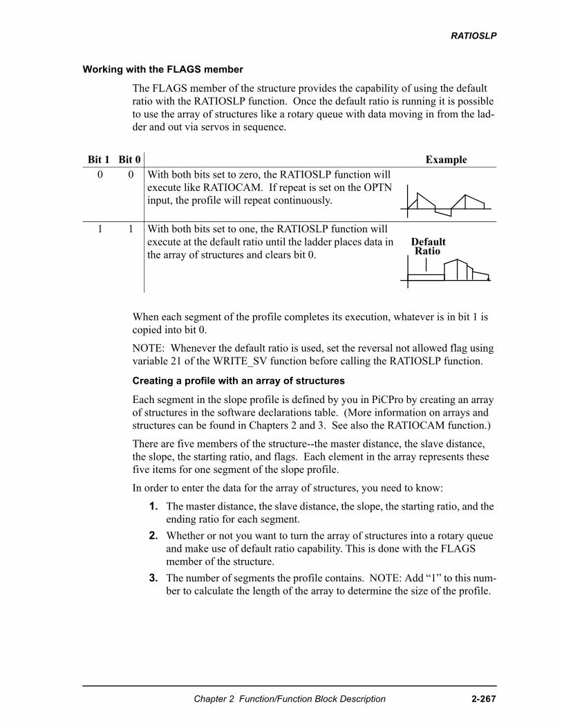
RATIOSLP
Working with the FLAGS member
The FLAGS member of the structure provides the capability of using the default ratio with the RATIOSLP function. Once the default ratio is running it is possible to use the array of structures like a rotary queue with data moving in from the lad-der and out via servos in sequence.
When each segment of the profile completes its execution, whatever is in bit 1 is copied into bit 0.
NOTE: Whenever the default ratio is used, set the reversal not allowed flag using variable 21 of the WRITE_SV function before calling the RATIOSLP function.
Creating a profile with an array of structures
Each segment in the slope profile is defined by you in PiCPro by creating an array of structures in the software declarations table. (More information on arrays and structures can be found in Chapters 2 and 3. See also the RATIOCAM function.)
There are five members of the structure--the master distance, the slave distance, the slope, the starting ratio, and flags. Each element in the array represents these five items for one segment of the slope profile.
In order to enter the data for the array of structures, you need to know:
1. The master distance, the slave distance, the slope, the starting ratio, and the ending ratio for each segment.
2. Whether or not you want to turn the array of structures into a rotary queue and make use of default ratio capability. This is done with the FLAGS member of the structure.
3. The number of segments the profile contains. NOTE: Add “1” to this num-ber to calculate the length of the array to determine the size of the profile.
Bit 1 Bit 0 Example0 0 With both bits set to zero, the RATIOSLP function will
execute like RATIOCAM. If repeat is set on the OPTN input, the profile will repeat continuously.
1 1 With both bits set to one, the RATIOSLP function will execute at the default ratio until the ladder places data in the array of structures and clears bit 0.
DefaultRatio
Chapter 2 Function/Function Block Description 2-267
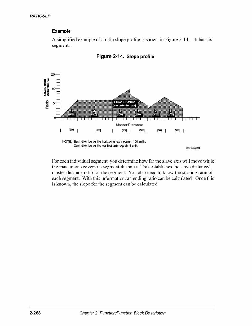
RATIOSLP
Example
A simplified example of a ratio slope profile is shown in Figure 2-14. It has six segments.
Figure 2-14. Slope profile
For each individual segment, you determine how far the slave axis will move while the master axis covers its segment distance. This establishes the slave distance/master distance ratio for the segment. You also need to know the starting ratio of each segment. With this information, an ending ratio can be calculated. Once this is known, the slope for the segment can be calculated.
2-268 Chapter 2 Function/Function Block Description
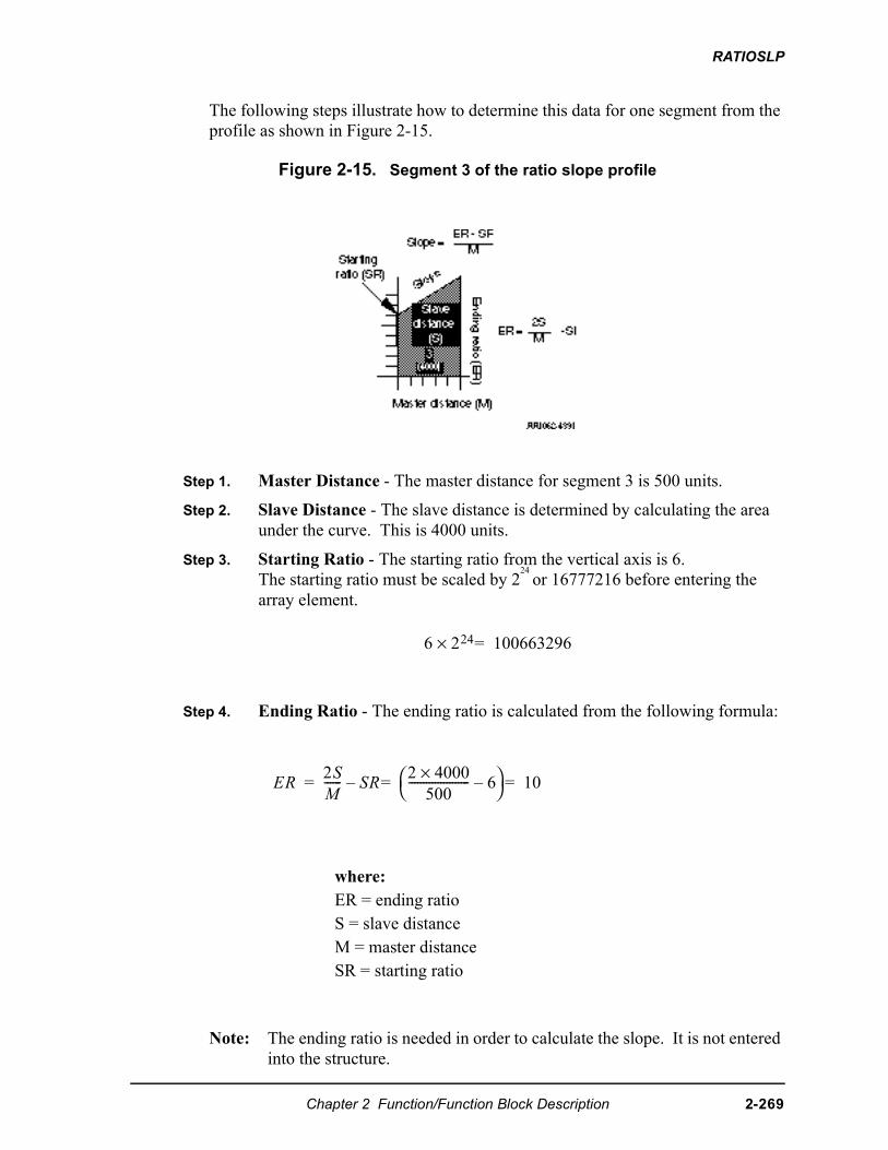
RATIOSLP
The following steps illustrate how to determine this data for one segment from the profile as shown in Figure 2-15.
Figure 2-15. Segment 3 of the ratio slope profile
Step 1. Master Distance - The master distance for segment 3 is 500 units.
Step 2. Slave Distance - The slave distance is determined by calculating the area under the curve. This is 4000 units.
Step 3. Starting Ratio - The starting ratio from the vertical axis is 6.The starting ratio must be scaled by 2
24 or 16777216 before entering the array element.
Step 4. Ending Ratio - The ending ratio is calculated from the following formula:
Note: The ending ratio is needed in order to calculate the slope. It is not entered into the structure.
where:ER = ending ratioS = slave distanceM = master distanceSR = starting ratio
��× �������
��
�------ �
� ������
--------------------- � ������
Chapter 2 Function/Function Block Description 2-269
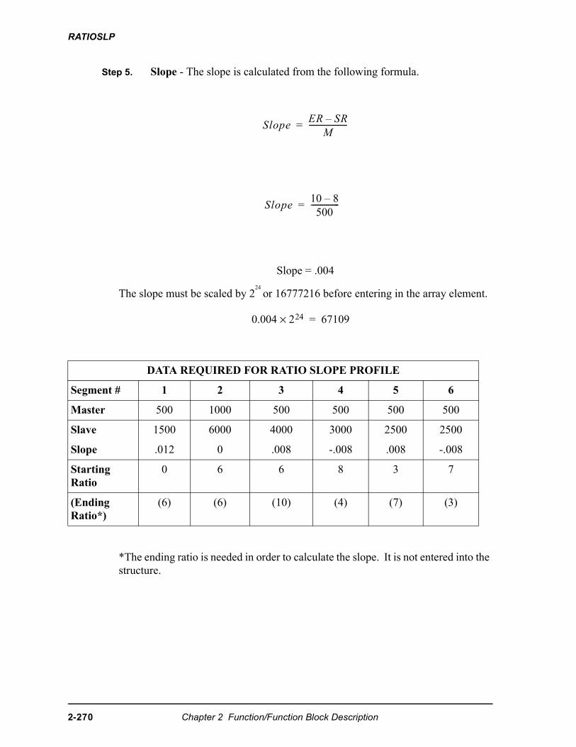
RATIOSLP
Step 5. Slope - The slope is calculated from the following formula.
Slope = .004
The slope must be scaled by 224 or 16777216 before entering in the array element.
*The ending ratio is needed in order to calculate the slope. It is not entered into the structure.
DATA REQUIRED FOR RATIO SLOPE PROFILE
Segment # 1 2 3 4 5 6
Master 500 1000 500 500 500 500
Slave 1500 6000 4000 3000 2500 2500
Slope .012 0 .008 -.008 .008 -.008
Starting Ratio
0 6 6 8 3 7
(Ending Ratio*)
(6) (6) (10) (4) (7) (3)
����� ��
�--------------------�
������ ��
���---------------�
���� ��× �����
2-270 Chapter 2 Function/Function Block Description
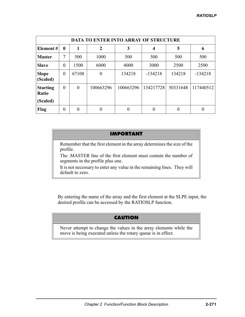
RATIOSLP
By entering the name of the array and the first element at the SLPE input, the desired profile can be accessed by the RATIOSLP function.
DATA TO ENTER INTO ARRAY OF STRUCTURE
Element # 0 1 2 3 4 5 6
Master 7 500 1000 500 500 500 500
Slave 0 1500 6000 4000 3000 2500 2500
Slope (Scaled)
0 67108 0 134218 -134218 134218 -134218
Starting Ratio
(Scaled)
0 0 100663296 100663296 134217728 50331648 117440512
Flag 0 0 0 0 0 0 0
IMPORTANT
Remember that the first element in the array determines the size of theprofile.The .MASTER line of the first element must contain the number ofsegments in the profile plus one.It is not necessary to enter any value in the remaining lines. They willdefault to zero.
CAUTION
Never attempt to change the values in the array elements while themove is being executed unless the rotary queue is in effect.
Chapter 2 Function/Function Block Description 2-271
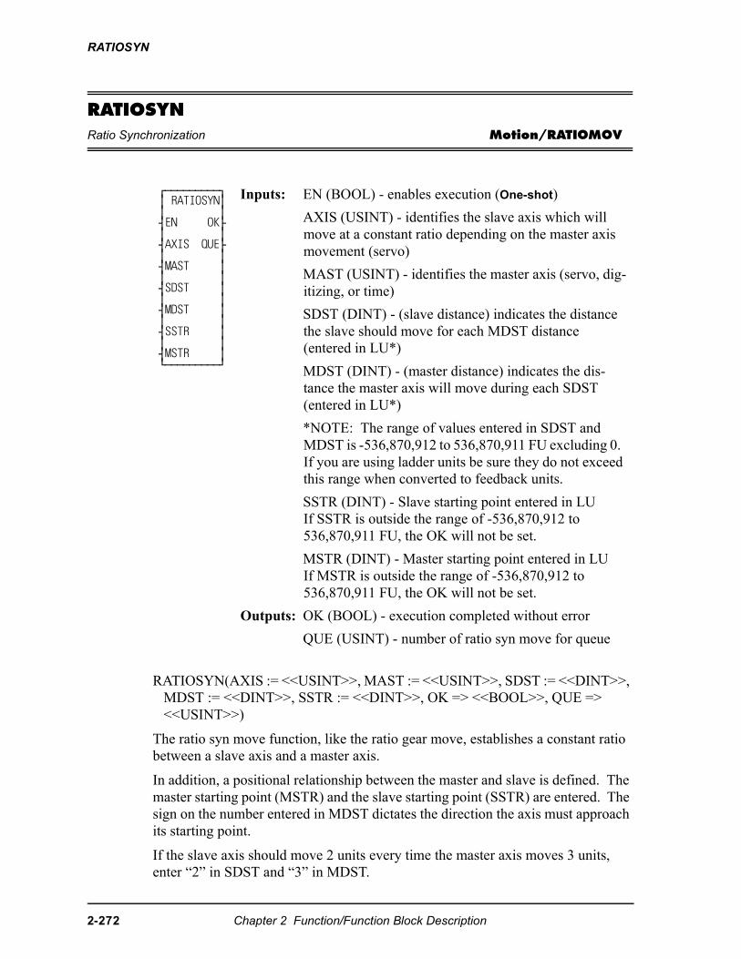
RATIOSYN
RATIOSYNRatio Synchronization Motion/RATIOMOV
RATIOSYN(AXIS := <<USINT>>, MAST := <<USINT>>, SDST := <<DINT>>, MDST := <<DINT>>, SSTR := <<DINT>>, OK => <<BOOL>>, QUE => <<USINT>>)
The ratio syn move function, like the ratio gear move, establishes a constant ratio between a slave axis and a master axis.
In addition, a positional relationship between the master and slave is defined. The master starting point (MSTR) and the slave starting point (SSTR) are entered. The sign on the number entered in MDST dictates the direction the axis must approach its starting point.
If the slave axis should move 2 units every time the master axis moves 3 units, enter “2” in SDST and “3” in MDST.
⁄ƒƒƒƒƒƒƒƒƒø ≥ RATIOSYN≥ ≥ ≥ ¥EN OK√ ≥ ≥ ¥AXIS QUE√ ≥ ≥ ¥MAST ≥ ≥ ≥ ¥SDST ≥ ≥ ≥ ¥MDST ≥ ≥ ≥ ¥SSTR ≥ ≥ ≥ ¥MSTR ≥ ¿ƒƒƒƒƒƒƒƒƒŸ
Inputs: EN (BOOL) - enables execution (One-shot)
AXIS (USINT) - identifies the slave axis which will move at a constant ratio depending on the master axis movement (servo)
MAST (USINT) - identifies the master axis (servo, dig-itizing, or time)
SDST (DINT) - (slave distance) indicates the distance the slave should move for each MDST distance (entered in LU*)
MDST (DINT) - (master distance) indicates the dis-tance the master axis will move during each SDST (entered in LU*)
*NOTE: The range of values entered in SDST and MDST is -536,870,912 to 536,870,911 FU excluding 0. If you are using ladder units be sure they do not exceed this range when converted to feedback units.
SSTR (DINT) - Slave starting point entered in LUIf SSTR is outside the range of -536,870,912 to 536,870,911 FU, the OK will not be set.
MSTR (DINT) - Master starting point entered in LUIf MSTR is outside the range of -536,870,912 to 536,870,911 FU, the OK will not be set.
Outputs: OK (BOOL) - execution completed without error
QUE (USINT) - number of ratio syn move for queue
2-272 Chapter 2 Function/Function Block Description
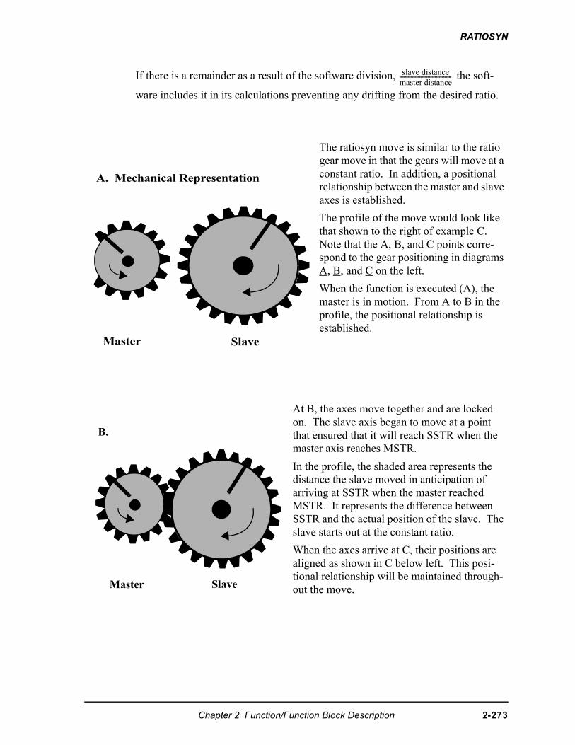
RATIOSYN
If there is a remainder as a result of the software division, the soft-
ware includes it in its calculations preventing any drifting from the desired ratio.
The ratiosyn move is similar to the ratio gear move in that the gears will move at a constant ratio. In addition, a positional relationship between the master and slave axes is established.
The profile of the move would look like that shown to the right of example C. Note that the A, B, and C points corre-spond to the gear positioning in diagrams A, B, and C on the left.
When the function is executed (A), the master is in motion. From A to B in the profile, the positional relationship is established.
At B, the axes move together and are locked on. The slave axis began to move at a point that ensured that it will reach SSTR when the master axis reaches MSTR.
In the profile, the shaded area represents the distance the slave moved in anticipation of arriving at SSTR when the master reached MSTR. It represents the difference between SSTR and the actual position of the slave. The slave starts out at the constant ratio.
When the axes arrive at C, their positions are aligned as shown in C below left. This posi-tional relationship will be maintained through-out the move.
��������������
���������������-------------------------------------
Master Slave
A. Mechanical Representation
B.
Master Slave
Chapter 2 Function/Function Block Description 2-273
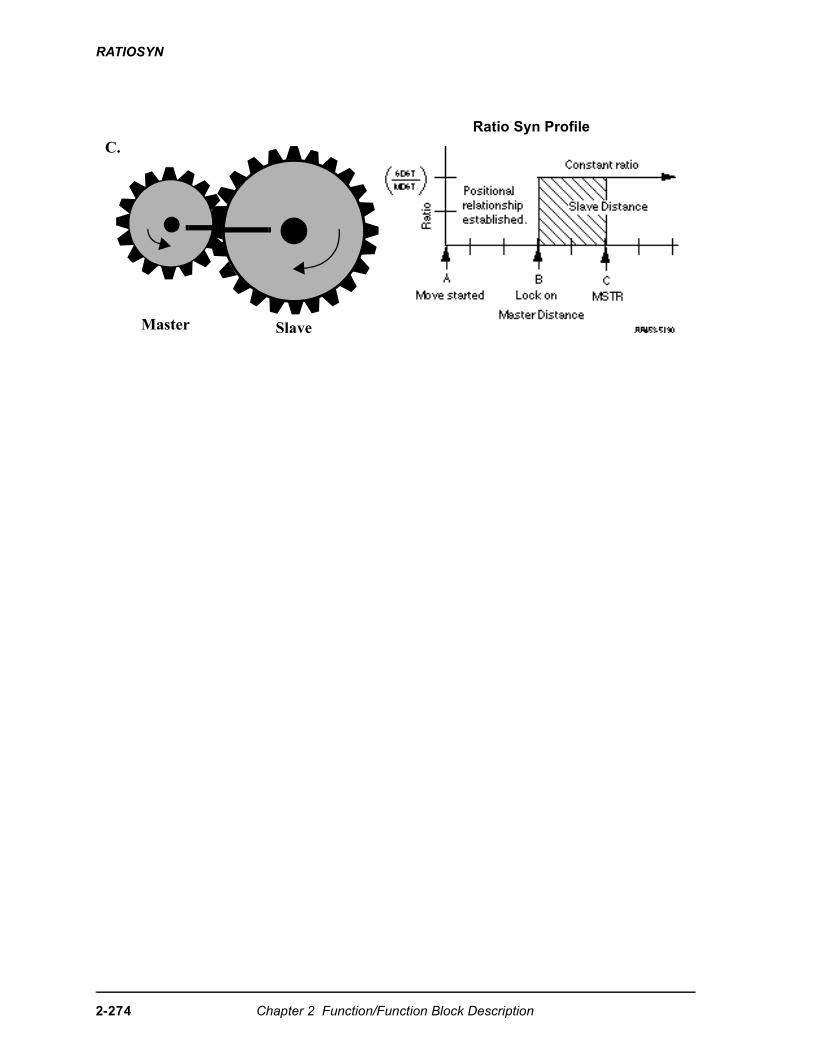
RATIOSYN
Ratio Syn Profile
C.
Master Slave
2-274 Chapter 2 Function/Function Block Description
RATIOSYN
Some characteristics of the ratio syn move include:
• Affects the slave axis only.
• The slave axis may be a master axis to another axis.
• More than one slave axis may be connected to the master axis.
• The master axis may be a servo or a digitizing axis.
• If the master axis reverses direction, the slave will follow.
• Inverted ratios are possible by making either SDST or MDST negative. (Making both signs negative has the same affect as making both signs posi-tive.)
• Starting points for the master axis and slave axis are entered. (See the explanation that follows for conditions necessary to ensure that a ratio syn move will begin.)
• Both the master and slave axes must be at the same interrupt rate.
• The ratio can be changed on the fly by using the NEWRATIO function
• If WRITE_SV Variable 59 = 0 (default), RATIOSYN will use the master’s actual position. If Variable 59 = 1, RATIOSYN will use the master’s com-mand position. Also, if Variable 59 = 1, the master axis must be a servo axis.
Master and slave axes starting points
For a RATIOSYN move to occur, the slave axis must start at a point so that when the master axis arrives at the value entered in MSTR, the slave axis will be at the value entered at SSTR. The following guidelines ensure that this will happen.
• Both axes must be below their respective starting points.
• The master axis must be moving in the correct direction to reach its starting points. Direction is defined by the sign of the number entered in MDST.
• The master axis must be a greater distance from its MSTR position than the slave axis is from its SSTR position.
When you enter a value in SSTR, the software uses that information plus what it knows about the slave’s actual position to calculate the ratio syn starting position for the master. Several examples of how the master start is calculated follow. The first three follow the guidelines listed above.
Examples 4 and 5 show the effect of rollover on position in allowing the guidelines to be “stretched.”
Chapter 2 Function/Function Block Description 2-275
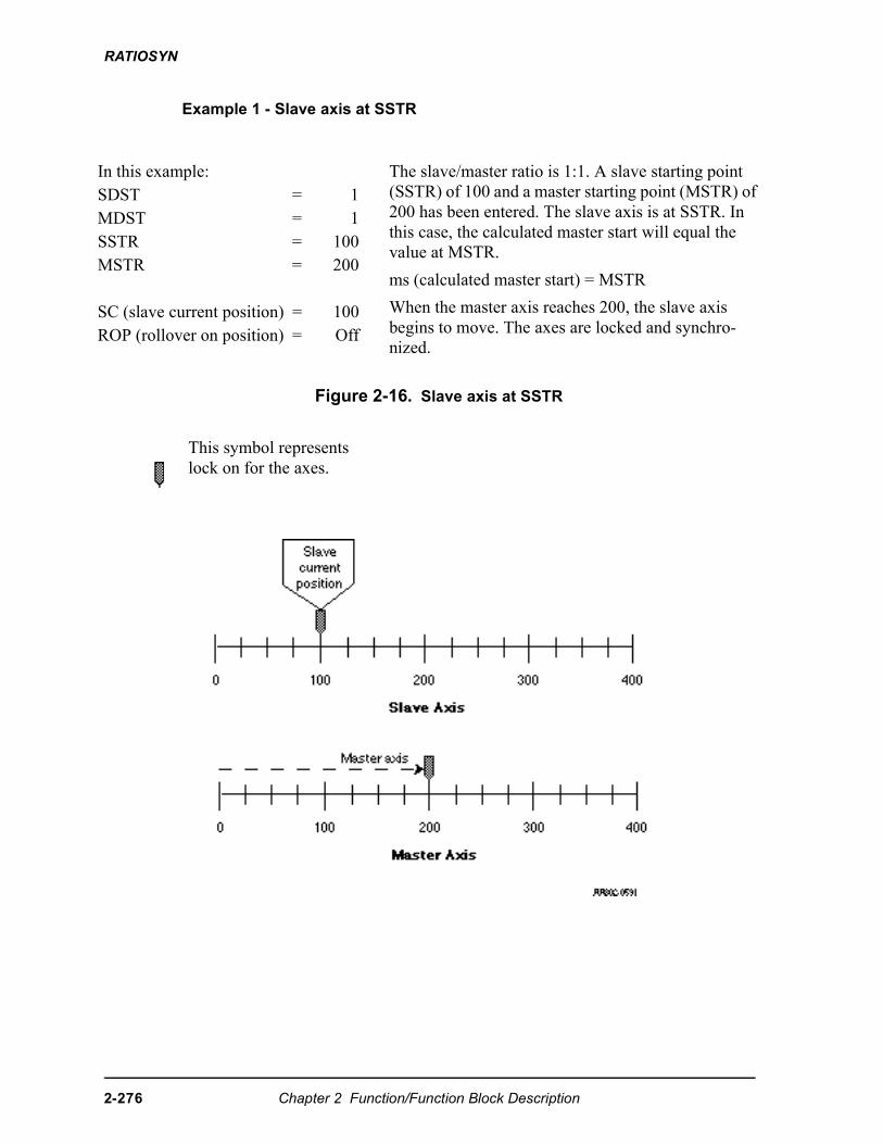
RATIOSYN
Example 1 - Slave axis at SSTR
Figure 2-16. Slave axis at SSTR
In this example: The slave/master ratio is 1:1. A slave starting point (SSTR) of 100 and a master starting point (MSTR) of 200 has been entered. The slave axis is at SSTR. In this case, the calculated master start will equal the value at MSTR.
ms (calculated master start) = MSTR
When the master axis reaches 200, the slave axis begins to move. The axes are locked and synchro-nized.
SDST = 1MDST = 1SSTR = 100MSTR = 200
SC (slave current position) = 100ROP (rollover on position) = Off
This symbol represents lock on for the axes.
2-276 Chapter 2 Function/Function Block Description
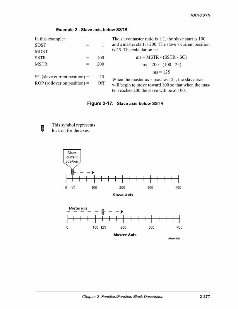
RATIOSYN
Example 2 - Slave axis below SSTR
Figure 2-17. Slave axis below SSTR
In this example: The slave/master ratio is 1:1, the slave start is 100 and a master start is 200. The slave’s current position is 25. The calculation is:
ms = MSTR - (SSTR - SC)
ms = 200 - (100 - 25)
ms = 125
When the master axis reaches 125, the slave axis will begin to move toward 100 so that when the mas-ter reaches 200 the slave will be at 100.
SDST = 1MDST = 1SSTR = 100MSTR = 200
SC (slave current position) = 25ROP (rollover on position) = Off
This symbol represents lock on for the axes.
Chapter 2 Function/Function Block Description 2-277
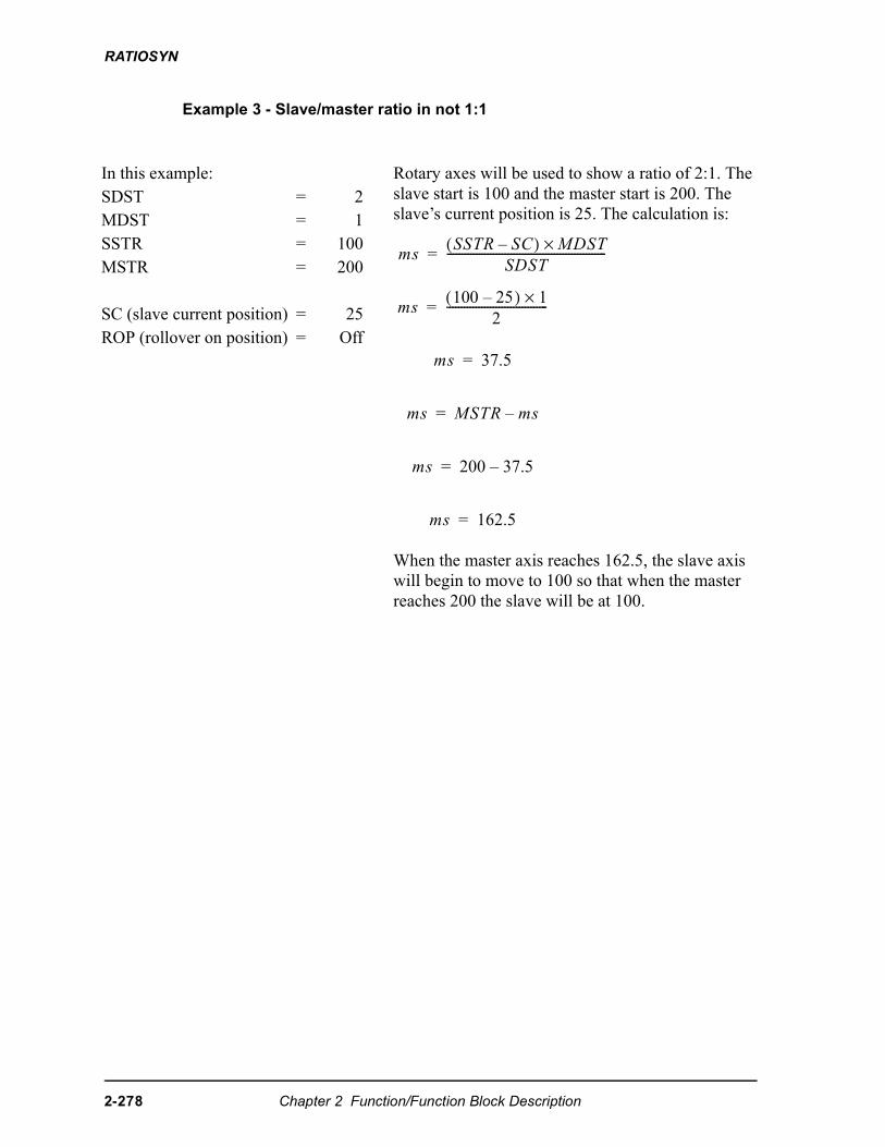
RATIOSYN
Example 3 - Slave/master ratio in not 1:1
In this example: Rotary axes will be used to show a ratio of 2:1. The slave start is 100 and the master start is 200. The slave’s current position is 25. The calculation is:
When the master axis reaches 162.5, the slave axis will begin to move to 100 so that when the master reaches 200 the slave will be at 100.
SDST = 2MDST = 1SSTR = 100MSTR = 200
SC (slave current position) = 25ROP (rollover on position) = Off
�� �� �( ) �� �×
� �-------------------------------------------------------�
����� ���( ) �×
�-----------------------------------�
�� �����
�� � �� ����
�� ��� ������
�� �����
2-278 Chapter 2 Function/Function Block Description
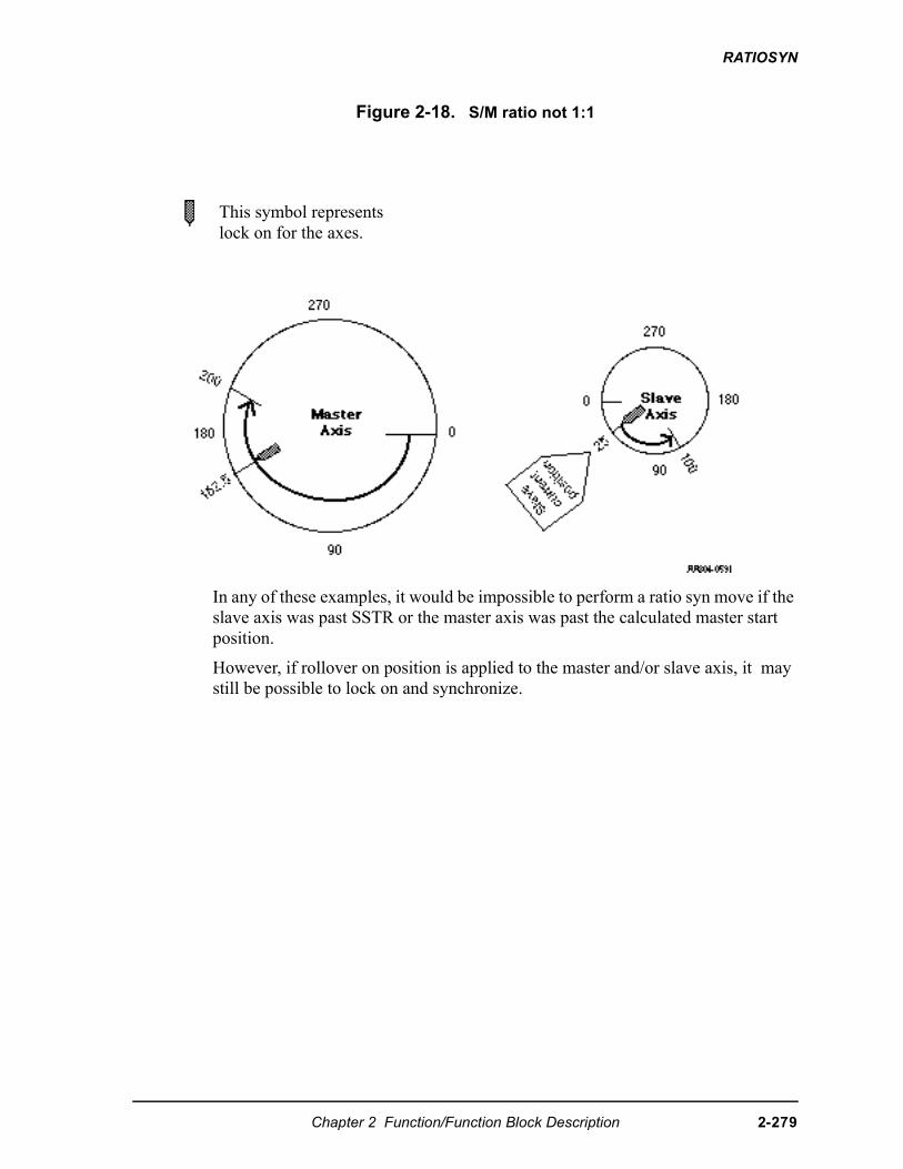
RATIOSYN
Figure 2-18. S/M ratio not 1:1
In any of these examples, it would be impossible to perform a ratio syn move if the slave axis was past SSTR or the master axis was past the calculated master start position.
However, if rollover on position is applied to the master and/or slave axis, it may still be possible to lock on and synchronize.
This symbol represents lock on for the axes.
Chapter 2 Function/Function Block Description 2-279
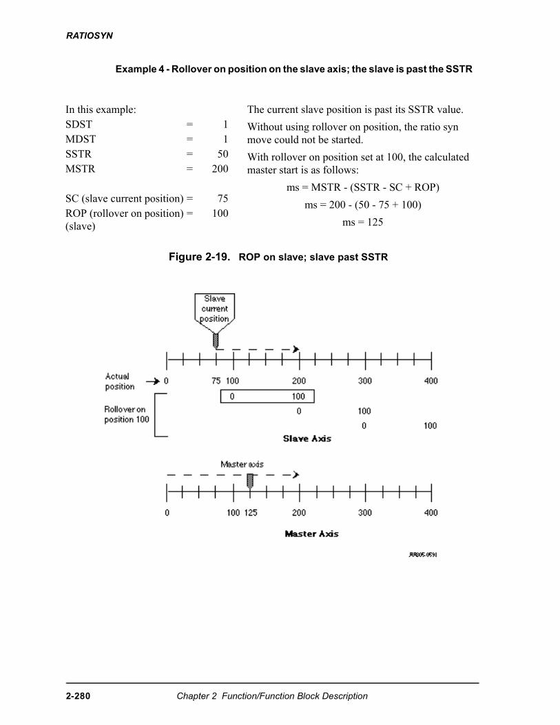
RATIOSYN
Example 4 - Rollover on position on the slave axis; the slave is past the SSTR
Figure 2-19. ROP on slave; slave past SSTR
In this example: The current slave position is past its SSTR value.
Without using rollover on position, the ratio syn move could not be started.
With rollover on position set at 100, the calculated master start is as follows:
ms = MSTR - (SSTR - SC + ROP)
ms = 200 - (50 - 75 + 100)
ms = 125
SDST = 1MDST = 1SSTR = 50MSTR = 200
SC (slave current position) = 75ROP (rollover on position)(slave)
= 100
2-280 Chapter 2 Function/Function Block Description
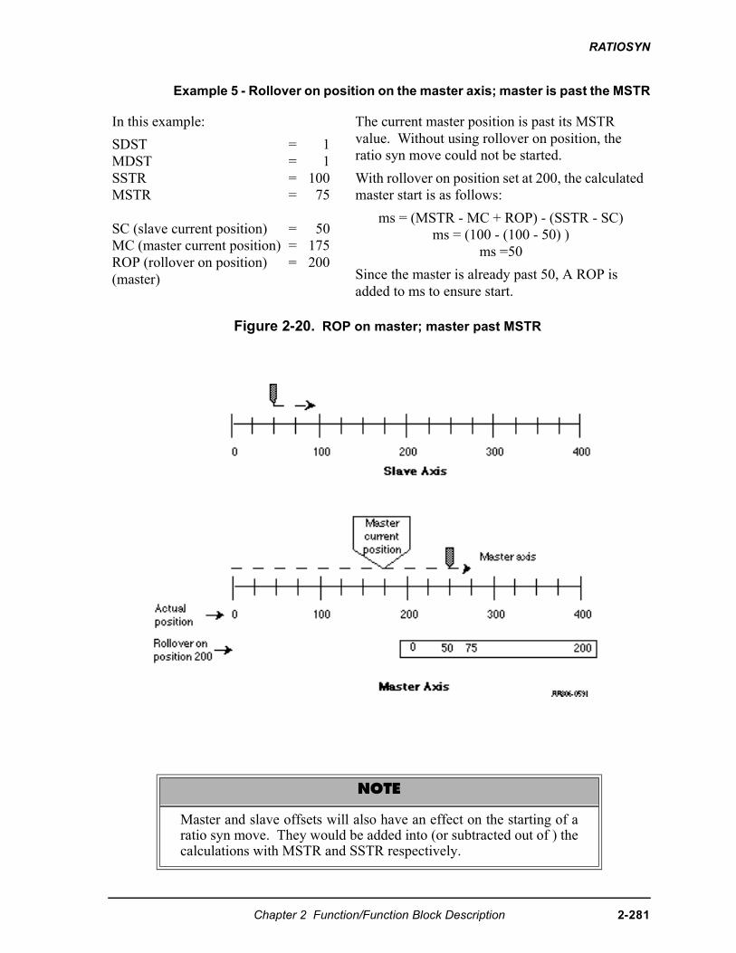
RATIOSYN
Example 5 - Rollover on position on the master axis; master is past the MSTR
Figure 2-20. ROP on master; master past MSTR
In this example:
SDST = 1MDST = 1SSTR = 100MSTR = 75
SC (slave current position) = 50MC (master current position) = 175ROP (rollover on position) = 200(master)
The current master position is past its MSTR value. Without using rollover on position, the ratio syn move could not be started.
With rollover on position set at 200, the calculated master start is as follows:
ms = (MSTR - MC + ROP) - (SSTR - SC)ms = (100 - (100 - 50) )
ms =50
Since the master is already past 50, A ROP is added to ms to ensure start.
NOTE
Master and slave offsets will also have an effect on the starting of aratio syn move. They would be added into (or subtracted out of ) thecalculations with MSTR and SSTR respectively.
Chapter 2 Function/Function Block Description 2-281
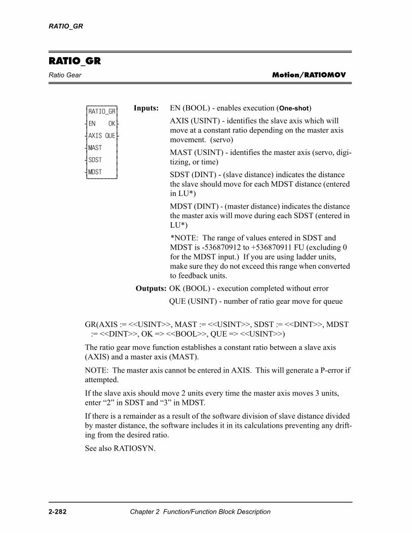
RATIO_GR
RATIO_GRRatio Gear Motion/RATIOMOV
GR(AXIS := <<USINT>>, MAST := <<USINT>>, SDST := <<DINT>>, MDST := <<DINT>>, OK => <<BOOL>>, QUE => <<USINT>>)
The ratio gear move function establishes a constant ratio between a slave axis (AXIS) and a master axis (MAST).
NOTE: The master axis cannot be entered in AXIS. This will generate a P-error if attempted.
If the slave axis should move 2 units every time the master axis moves 3 units, enter “2” in SDST and “3” in MDST.
If there is a remainder as a result of the software division of slave distance divided by master distance, the software includes it in its calculations preventing any drift-ing from the desired ratio.
See also RATIOSYN.
⁄ƒƒƒƒƒƒƒƒø≥RATIO_GR≥≥ ≥¥EN OK√≥ ≥¥AXIS QUE√≥ ≥¥MAST ≥≥ ≥¥SDST ≥≥ ≥¥MDST ≥¿ƒƒƒƒƒƒƒƒŸ
Inputs: EN (BOOL) - enables execution (One-shot)
AXIS (USINT) - identifies the slave axis which will move at a constant ratio depending on the master axis movement. (servo)
MAST (USINT) - identifies the master axis (servo, digi-tizing, or time)
SDST (DINT) - (slave distance) indicates the distance the slave should move for each MDST distance (entered in LU*)
MDST (DINT) - (master distance) indicates the distance the master axis will move during each SDST (entered in LU*)
*NOTE: The range of values entered in SDST and MDST is -536870912 to +536870911 FU (excluding 0 for the MDST input.) If you are using ladder units, make sure they do not exceed this range when converted to feedback units.
Outputs: OK (BOOL) - execution completed without error
QUE (USINT) - number of ratio gear move for queue
2-282 Chapter 2 Function/Function Block Description
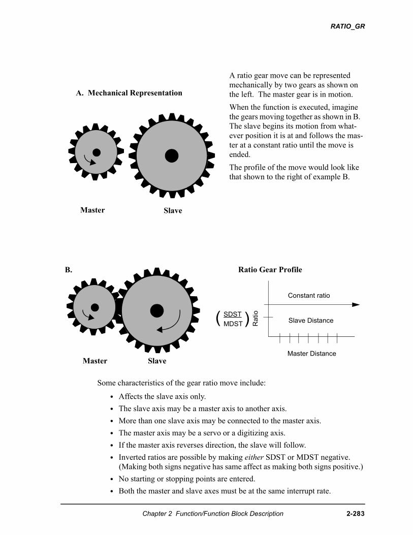
RATIO_GR
Some characteristics of the gear ratio move include:
• Affects the slave axis only.
• The slave axis may be a master axis to another axis.
• More than one slave axis may be connected to the master axis.
• The master axis may be a servo or a digitizing axis.
• If the master axis reverses direction, the slave will follow.
• Inverted ratios are possible by making either SDST or MDST negative. (Making both signs negative has same affect as making both signs positive.)
• No starting or stopping points are entered.
• Both the master and slave axes must be at the same interrupt rate.
A ratio gear move can be represented mechanically by two gears as shown on the left. The master gear is in motion.
When the function is executed, imagine the gears moving together as shown in B. The slave begins its motion from what-ever position it is at and follows the mas-ter at a constant ratio until the move is ended.
The profile of the move would look like that shown to the right of example B.
Master Slave
A. Mechanical Representation
B.
Master Distance
Ratio( )
Constant ratio
Slave DistanceSDST
MDST
Ratio Gear Profile
Master Slave
Chapter 2 Function/Function Block Description 2-283
RATIO_GR
• The ratio can be changed on the fly by:
•Calling the NEWRATIO function
•Queuing up a new ratio move and aborting the current one. Any remainder from the previous move is cleared.
• If WRITE_SV Variable 59 = 0 (default), RATIO_GR will use the master’s actual position. If Variable 59 = 1, RATIO_GR will use the master’s com-mand position.
• Some conditions for which OK will not be set and the queue is “0” include:
•Master axis not available (P-error) [Master axis not initialized, master and slave interrupts different, same axis entered as master and slave, or variable 59 = 1 and the master axis is not a servo axis.]
•Slave distance not valid (P-error)
•Master distance not valid (P-error)
•Slave axis (AXIS) not initialized during setup
• An E-error will occur if there is a slave delta overflow during runtime. The hex code 0004 indicates this error on the ERRS output of the E_ERRORS function.
2-284 Chapter 2 Function/Function Block Description
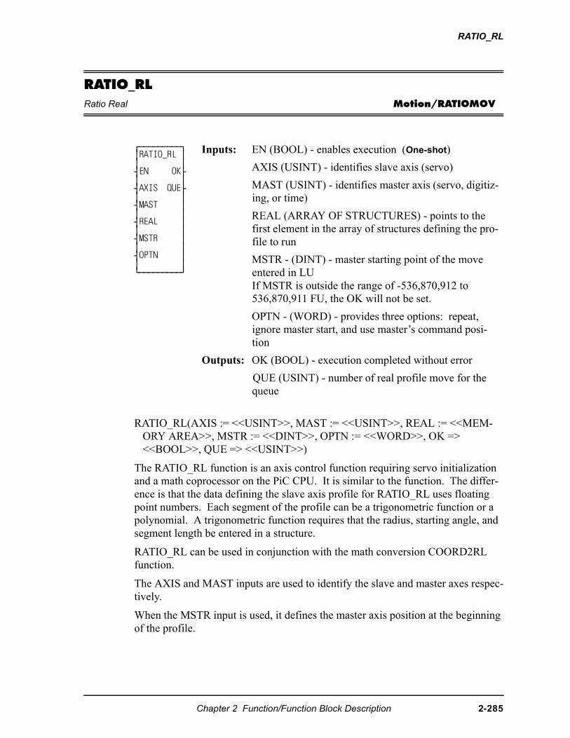
RATIO_RL
RATIO_RLRatio Real Motion/RATIOMOV
RATIO_RL(AXIS := <<USINT>>, MAST := <<USINT>>, REAL := <<MEM-ORY AREA>>, MSTR := <<DINT>>, OPTN := <<WORD>>, OK => <<BOOL>>, QUE => <<USINT>>)
The RATIO_RL function is an axis control function requiring servo initialization and a math coprocessor on the PiC CPU. It is similar to the function. The differ-ence is that the data defining the slave axis profile for RATIO_RL uses floating point numbers. Each segment of the profile can be a trigonometric function or a polynomial. A trigonometric function requires that the radius, starting angle, and segment length be entered in a structure.
RATIO_RL can be used in conjunction with the math conversion COORD2RL function.
The AXIS and MAST inputs are used to identify the slave and master axes respec-tively.
When the MSTR input is used, it defines the master axis position at the beginning of the profile.
⁄ƒƒƒƒƒƒƒƒƒø≥RATIO_RL ≥≥ ≥¥EN OK√≥ ≥¥AXIS QUE√≥ ≥¥MAST ≥≥ ≥¥REAL ≥≥ ≥¥MSTR ≥≥ ≥¥OPTN ≥≥ ≥¿ƒƒƒƒƒƒƒƒƒŸ
Inputs: EN (BOOL) - enables execution (One-shot)
AXIS (USINT) - identifies slave axis (servo)
MAST (USINT) - identifies master axis (servo, digitiz-ing, or time)
REAL (ARRAY OF STRUCTURES) - points to the first element in the array of structures defining the pro-file to run
MSTR - (DINT) - master starting point of the move entered in LUIf MSTR is outside the range of -536,870,912 to 536,870,911 FU, the OK will not be set.
OPTN - (WORD) - provides three options: repeat, ignore master start, and use master’s command posi-tion
Outputs: OK (BOOL) - execution completed without error
QUE (USINT) - number of real profile move for the queue
Chapter 2 Function/Function Block Description 2-285
RATIO_RL
The OPTN input provides the following options:
If you want the profile to repeat continuously, bit 0 is set. If bit 0 is not set, the profile will execute once and then stop.
If you choose to ignore the master start (bit 1 set), any value you have entered in MSTR has no effect. The slope profile will begin executing as soon as the func-tion is called.
If you want to follow the master’s command position instead of the master’s actual position, set bit 4.
Velocity Compensation should be inhibited (WRITE_SV Variable 32 = 1) prior to executing RATIO_RL with this bit set.
Bit # Option Binary ValueHex Value Entered
0 Repeat profile 0000000000000001 00011 Ignore master start 0000000000000010 00024 Use master command position 0000000000010000 0010
2-286 Chapter 2 Function/Function Block Description
RATIO_RL
Some characteristics of the ratio real move include:
• Affects the slave axis only.
• The slave axis may be a master axis to another axis.
• More than one slave axis may be connected to the master axis.
• The master axis may be a servo, a time, or a digitizing axis.
• If the master axis reverses direction, the slave axis will follow. A positional relationship has been established for each segment and the software will maintain that relationship. If, for example, the master axis would change direction during the profile, the slave axis would move backwards through the profile so that when the master axis reaches a certain position the slave axis will be at its corresponding position as defined in array of structures.
• If it is not desirable to have the slave axis follow the master axis when the master reverses direction, variable 21 (reversal not allowed) of the WRITE_SV function can be set. (The state of variable 21 can also be read with the READ_SV function.) The WRITE_SV function must always be called before the RATIO_RL function.
• Inverted ratios are possible by entering negative slave segment elements in the array of structures defining your profile. (NOTE: The sign on the mas-ter elements entered in the array of structures must all be the same.)
• The starting point for the master axis may be entered. If the move is queued with no master start and the master axis is moving in the opposite direction as defined by the profile segments, the distance will be accumu-lated. This distance must be recovered before motion will start.
• Both the master and slave axes must be at the same interrupt rate.
• Registration can be used with the RATIO_RL function.
• The ratio_RL function move may repeat continuously if the repeat option is set until either the move is aborted or a REP_END function is called. With the abort move function, the move will stop wherever it is in the profile. With the repeat end function, the move will stop at the end of the current profile.
• Some conditions for which the OK will not be set and the queue will be “0” include
1. Master axis not available (P-error) [Master axis not initialized, master and slave interrupts different, the same axis was entered as master and slave, or OPTN bit 4 is set and the master axis is not a servo axis.]
2. Profile error (P-error) [A number less than two entered as the size of the profile, a master segment is zero, or not all master segments have the same sign]
3. Master start value is out of range.
4. Slave axis (AXIS) not initialized during setup.
• A P-error will occur if the master axis is beyond it’s start point.
• An E-error will occur if there is a slave delta overflow during runtime.
Chapter 2 Function/Function Block Description 2-287
RATIO_RL
RATIO_RL structure members for the REAL input
The members of the structure required for the array of structures at the REAL input are described below.
IMPORTANT
The structure entered in the software declarations table for the REALinput must have the members entered in the order listed in the tablethat follows. The data type entered in the Type column for eachmember of the structure must be as shown in order for the software torecognize the information.
NOTE
Remember that the first (0) element in the array determines the sizeof the profile. The .MASTER line of the first element must containthe number of segments in the profile plus one. It is not necessary to enter any value in the other lines. They will de-fault to zero.
2-288 Chapter 2 Function/Function Block Description
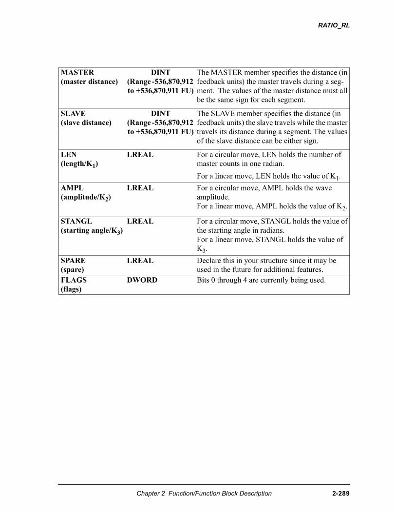
RATIO_RL
MASTER(master distance)
DINT (Range -536,870,912 to +536,870,911 FU)
The MASTER member specifies the distance (in feedback units) the master travels during a seg-ment. The values of the master distance must all be the same sign for each segment.
SLAVE(slave distance)
DINT (Range -536,870,912 to +536,870,911 FU)
The SLAVE member specifies the distance (in feedback units) the slave travels while the master travels its distance during a segment. The values of the slave distance can be either sign.
LEN(length/K1)
LREAL For a circular move, LEN holds the number of master counts in one radian.
For a linear move, LEN holds the value of K1.
AMPL(amplitude/K2)
LREAL For a circular move, AMPL holds the wave amplitude.For a linear move, AMPL holds the value of K2.
STANGL(starting angle/K3)
LREAL For a circular move, STANGL holds the value of the starting angle in radians.For a linear move, STANGL holds the value of K3.
SPARE (spare)
LREAL Declare this in your structure since it may be used in the future for additional features.
FLAGS (flags)
DWORD Bits 0 through 4 are currently being used.
Chapter 2 Function/Function Block Description 2-289
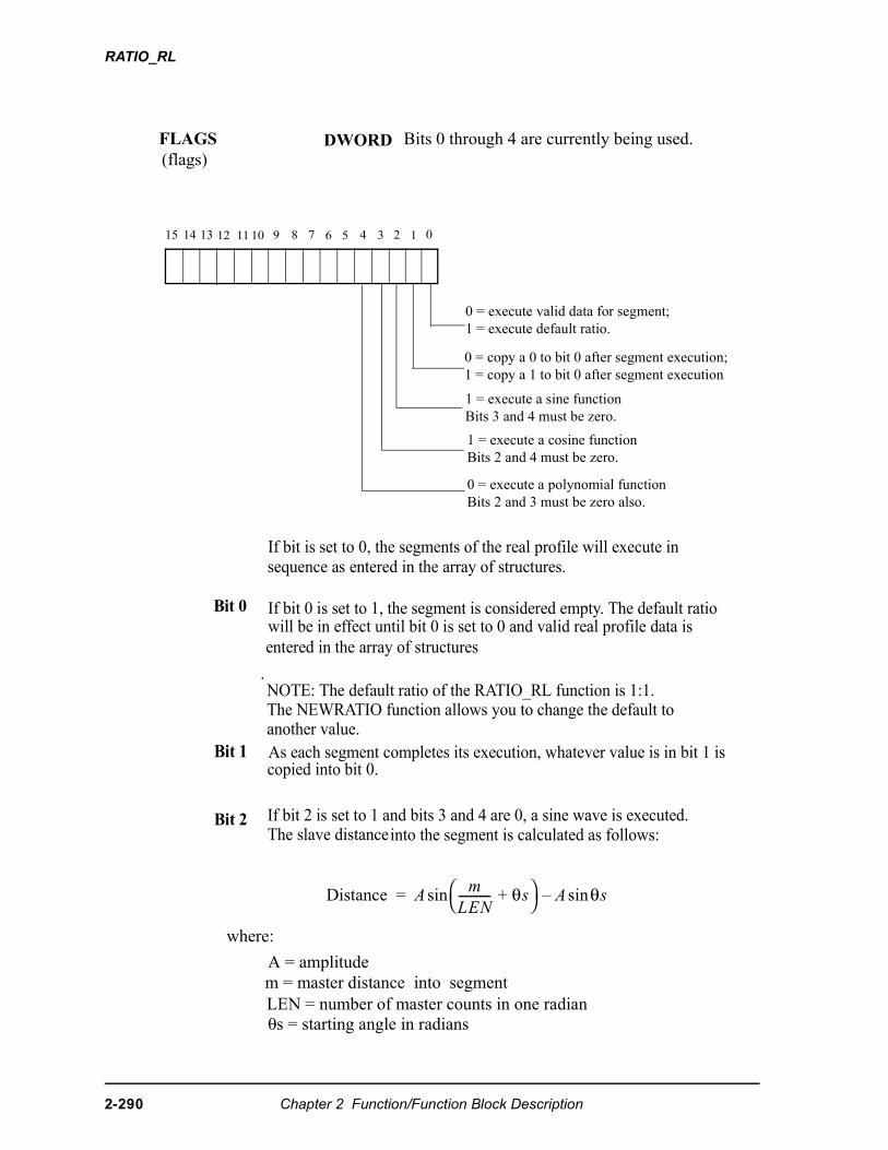
RATIO_RL
0 = copy a 0 to bit 0 after segment execution;1 = copy a 1 to bit 0 after segment execution
0 = execute valid data for segment;1 = execute default ratio.
15 14 13 12 11 10 9 8 6 4 3 2 1 0
DWORDFLAGS(flags)
57
Bits 0 through 4 are currently being used.
1 = execute a sine functionBits 3 and 4 must be zero.
1 = execute a cosine functionBits 2 and 4 must be zero.
0 = execute a polynomial functionBits 2 and 3 must be zero also.
If bit is set to 0, the segments of the real profile will execute in
Bit 0 If bit 0 is set to 1, the segment is considered empty. The default ratio
entered in the array of structures
NOTE: The default ratio of the RATIO_RL function is 1:1. .
As each segment completes its execution, whatever value is in bit 1 is
If bit 2 is set to 1 and bits 3 and 4 are 0, a sine wave is executed.
Bit 1
Bit 2
where:
A = amplitude
LEN = number of master counts in one radian0s = starting angle in radians
m = master distance into segment
�������� ��
��-----------
��� θ� � θ������
will be in effect until bit 0 is set to 0 and valid real profile data is
The NEWRATIO function allows you to change the default to
copied into bit 0.
The slave distance into the segment is calculated as follows:
sequence as entered in the array of structures.
another value.
2-290 Chapter 2 Function/Function Block Description
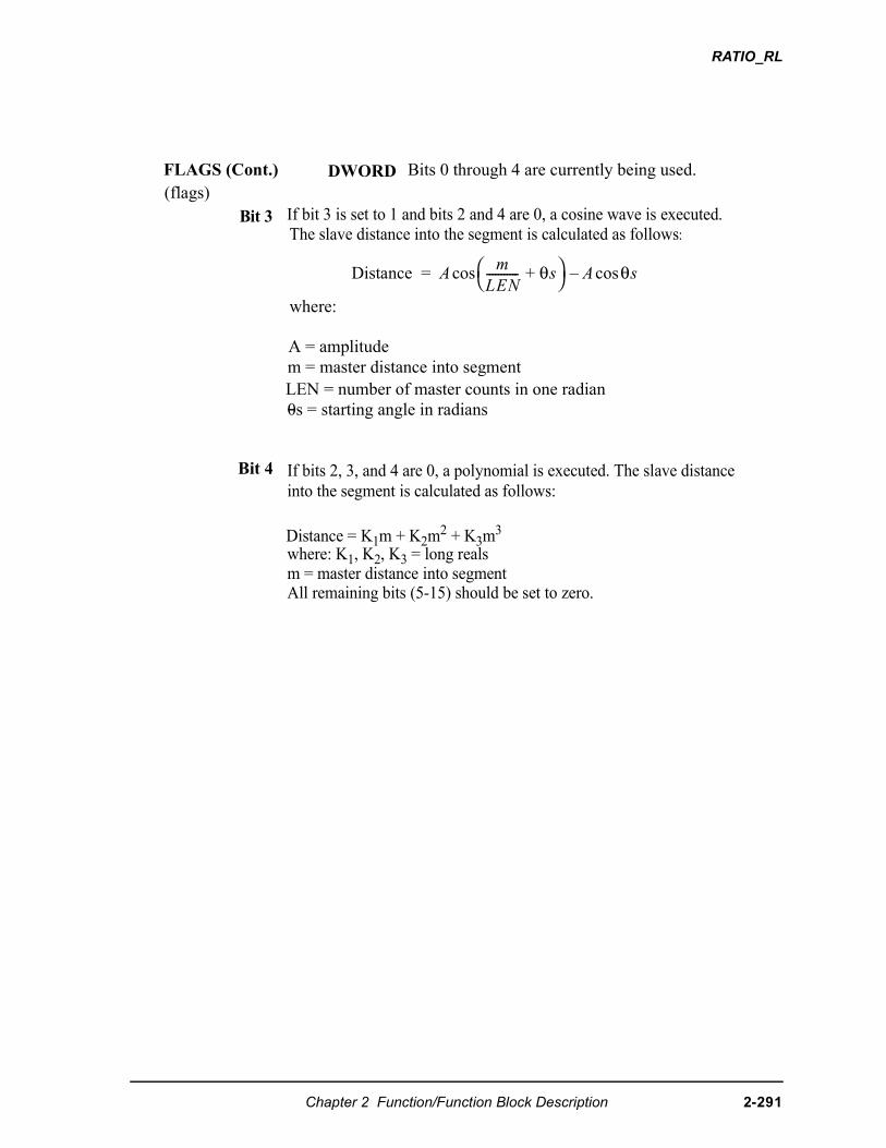
RATIO_RL
If bit 3 is set to 1 and bits 2 and 4 are 0, a cosine wave is executed.
where:
A = amplitude
LEN = number of master counts in one radian0s = starting angle in radians
m = master distance into segment
The slave distance into the segment is calculated as follows:
�������� ��
��-----------
��� θ�
� �� ���
Bit 4 If bits 2, 3, and 4 are 0, a polynomial is executed. The slave distanceinto the segment is calculated as follows:
Distance = K1m + K2m2 + K3m3
where: K1, K2, K3 = long realsm = master distance into segment
All remaining bits (5-15) should be set to zero.
Bit 3
DWORDFLAGS (Cont.) Bits 0 through 4 are currently being used.(flags)
Chapter 2 Function/Function Block Description 2-291
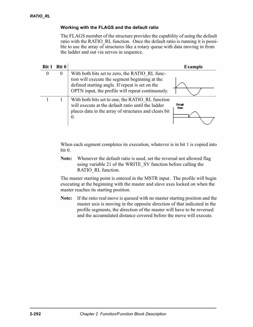
RATIO_RL
2-2
Working with the FLAGS and the default ratio
The FLAGS member of the structure provides the capability of using the default ratio with the RATIO_RL function. Once the default ratio is running it is possi-ble to use the array of structures like a rotary queue with data moving in from the ladder and out via servos in sequence.
When each segment completes its execution, whatever is in bit 1 is copied into bit 0.
Note: Whenever the default ratio is used, set the reversal not allowed flag using variable 21 of the WRITE_SV function before calling the RATIO_RL function.
The master starting point is entered in the MSTR input. The profile will begin executing at the beginning with the master and slave axes locked on when the master reaches its starting position.
Note: If the ratio real move is queued with no master starting position and the master axis is moving in the opposite direction of that indicated in the profile segments, the direction of the master will have to be reversed and the accumulated distance covered before the move will execute.
Bit 1 Bit 0 Example0 0 With both bits set to zero, the RATIO_RL func-
tion will execute the segment beginning at the defined starting angle. If repeat is set on the OPTN input, the profile will repeat continuously.
1 1 With both bits set to one, the RATIO_RL function will execute at the default ratio until the ladder places data in the array of structures and clears bit 0.
92 Chapter 2 Function/Function Block Description
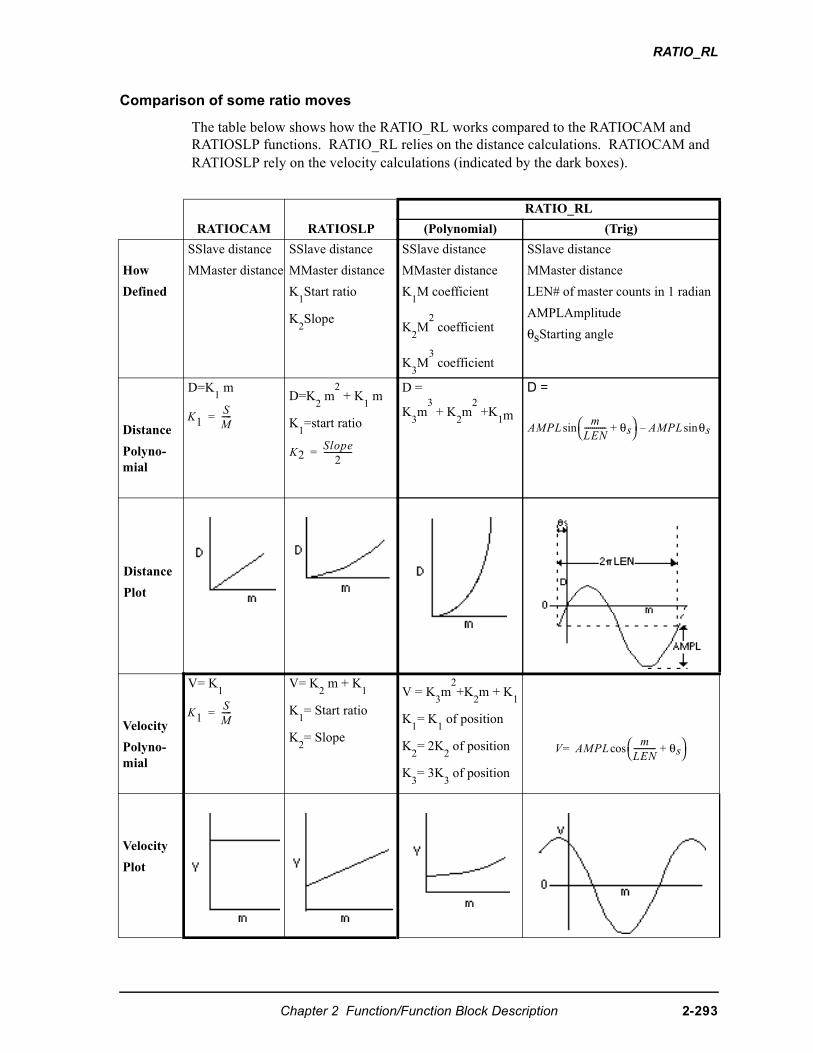
RATIO_RL
Comparison of some ratio moves
The table below shows how the RATIO_RL works compared to the RATIOCAM and RATIOSLP functions. RATIO_RL relies on the distance calculations. RATIOCAM and RATIOSLP rely on the velocity calculations (indicated by the dark boxes).
RATIO_RL
RATIOCAM RATIOSLP (Polynomial) (Trig)
How
Defined
SSlave distance
MMaster distance
SSlave distance
MMaster distance
K1Start ratio
K2Slope
SSlave distance
MMaster distance
K1M coefficient
K2M
2 coefficient
K3M
3 coefficient
SSlave distance
MMaster distance
LEN# of master counts in 1 radian
AMPLAmplitude
θsStarting angle
Distance
Polyno-mial
D=K1 m
D=K2 m
2 + K
1 m
K1=start ratio
D =
K3m
3 + K2m
2 +K1m
D =
Distance
Plot
Velocity
Polyno-mial
V= K1
V= K2 m + K
1
K1= Start ratio
K2= Slope
V = K3m
2+K
2m + K
1
K1= K
1 of position
K2= 2K
2 of position
K3= 3K
3 of position
Velocity
Plot
��
�-----�
�� ����
�--------------�
��!��
��----------- θ�
��� ��!� ����
��
�-----�
� ��!��
��----------- θ�
����
Chapter 2 Function/Function Block Description 2-293
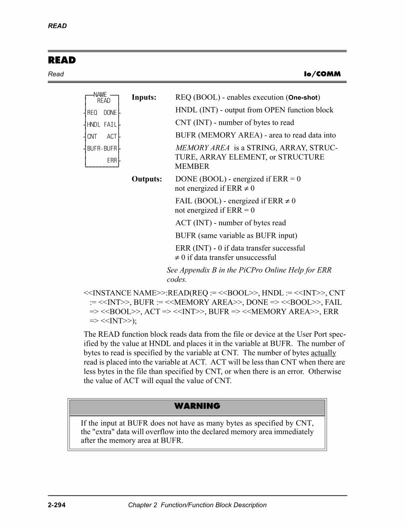
READ
READRead Io/COMM
<<INSTANCE NAME>>:READ(REQ := <<BOOL>>, HNDL := <<INT>>, CNT := <<INT>>, BUFR := <<MEMORY AREA>>, DONE => <<BOOL>>, FAIL => <<BOOL>>, ACT => <<INT>>, BUFR => <<MEMORY AREA>>, ERR => <<INT>>);
The READ function block reads data from the file or device at the User Port spec-ified by the value at HNDL and places it in the variable at BUFR. The number of bytes to read is specified by the variable at CNT. The number of bytes actually read is placed into the variable at ACT. ACT will be less than CNT when there are less bytes in the file than specified by CNT, or when there is an error. Otherwise the value of ACT will equal the value of CNT.
⁄ƒƒNAME ƒƒø ≥ READ ≥ ≥ ≥ ¥REQ DONE√ ≥ ≥ ¥HNDL FAIL√ ≥ ≥ ¥CNT ACT√ ≥ ≥ ¥BUFR-BUFR√ ≥ ≥ ≥ ERR√ ¿ƒƒƒƒƒƒƒƒƒŸ
Inputs: REQ (BOOL) - enables execution (One-shot)
HNDL (INT) - output from OPEN function block
CNT (INT) - number of bytes to read
BUFR (MEMORY AREA) - area to read data into
MEMORY AREA is a STRING, ARRAY, STRUC-TURE, ARRAY ELEMENT, or STRUCTURE MEMBER
Outputs: DONE (BOOL) - energized if ERR = 0not energized if ERR ≠ 0
FAIL (BOOL) - energized if ERR ≠ 0not energized if ERR = 0
ACT (INT) - number of bytes read
BUFR (same variable as BUFR input)
ERR (INT) - 0 if data transfer successful≠ 0 if data transfer unsuccessful
See Appendix B in the PiCPro Online Help for ERR codes.
WARNING
If the input at BUFR does not have as many bytes as specified by CNT,the "extra" data will overflow into the declared memory area immediatelyafter the memory area at BUFR.
2-294 Chapter 2 Function/Function Block Description
READ
READ is used in conjunction with the CLOSE, CONFIG, OPEN, SEEK, STA-TUS, and WRITE I/O function blocks.
IMPORTANT
See APPLICATION NOTE # 1 in the Application Note section (atend of the PiCPro Online Help) for information about READing fromand WRITing to STRINGs.
Chapter 2 Function/Function Block Description 2-295
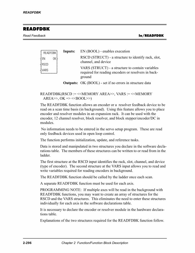
READFDBK
READFDBKRead Feedback Io/READFDBK
READFDBK(RSCD := <<MEMORY AREA>>, VARS := <<MEMORY AREA>>, OK => <<BOOL>>)
The READFDBK function allows an encoder or a resolver feedback device to be read on a scan time basis (in background). Using this feature allows you to place encoder and resolver modules in an expansion rack. It can be used with the encoder, 12 channel resolver, block resolver, and block stepper/encoder/DC in modules.
No information needs to be entered in the servo setup program. These are read only feedback devices used in open loop control.
The function performs initialization, update, and reference tasks.
Data is stored and manipulated in two structures you declare in the software decla-rations table. The members of these structures can be written to or read from in the ladder.
The first structure at the RSCD input identifies the rack, slot, channel, and device (type of encoder). The second structure at the VARS input allows you to read and write variables required for reading encoders in background.
The READFDBK function should be called by the ladder once each scan.
A separate READFDBK function must be used for each axis.
PROGRAMMING NOTE: If multiple axes will be read in the background with READFDBK functions, you may want to create an array of structures for the RSCD and the VARS structures. This eliminates the need to enter these structures individually for each axis in the software declarations table.
It is necessary to declare the encoder or resolver module in the hardware declara-tions table.
Explanations of the two structures required for the READFDBK function follow.
⁄ƒƒƒƒƒƒƒƒƒø≥ READFDBK≥≥ ≥¥EN OK√≥ ≥¥RSCD ≥≥ ≥¥VARS ≥¿ƒƒƒƒƒƒƒƒƒŸ
Inputs: EN (BOOL) - enables execution
RSCD (STRUCT) - a structure to identify rack, slot, channel, and device
VARS (STRUCT) - a structure to contain variables required for reading encoders or resolvers in back-ground
Outputs: OK (BOOL) - set if no errors in structure data
2-296 Chapter 2 Function/Function Block Description
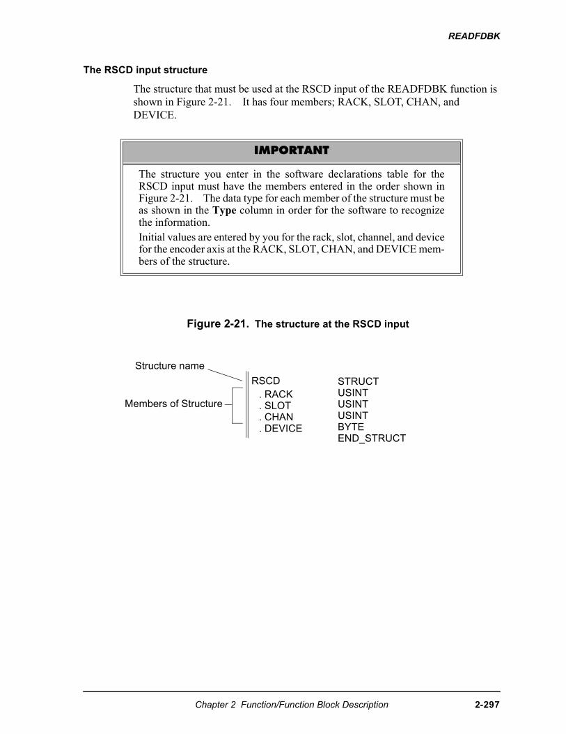
READFDBK
The RSCD input structure
The structure that must be used at the RSCD input of the READFDBK function is shown in Figure 2-21. It has four members; RACK, SLOT, CHAN, and DEVICE.
Figure 2-21. The structure at the RSCD input
IMPORTANT
The structure you enter in the software declarations table for theRSCD input must have the members entered in the order shown inFigure 2-21. The data type for each member of the structure must beas shown in the Type column in order for the software to recognizethe information.Initial values are entered by you for the rack, slot, channel, and devicefor the encoder axis at the RACK, SLOT, CHAN, and DEVICE mem-bers of the structure.
Structure name
Members of Structure
RSCD. RACK. SLOT. CHAN. DEVICE
STRUCTUSINTUSINTUSINTBYTEEND_STRUCT
Chapter 2 Function/Function Block Description 2-297
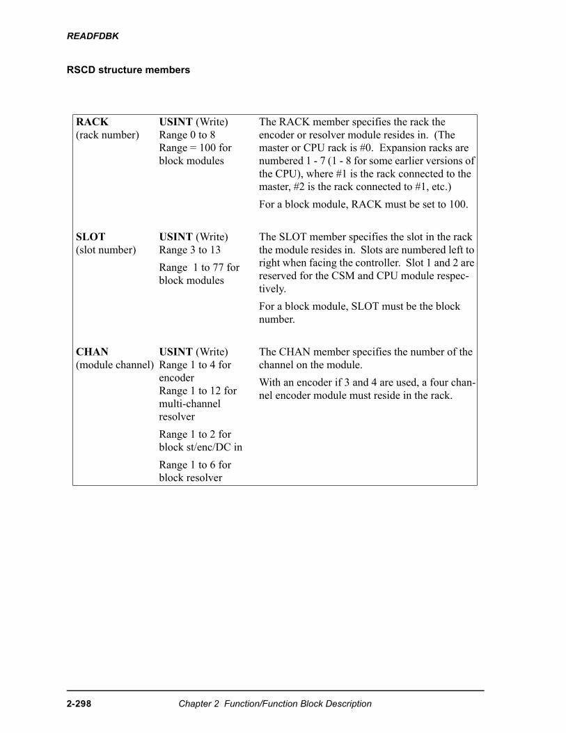
READFDBK
RSCD structure members
RACK(rack number)
USINT (Write)Range 0 to 8Range = 100 for block modules
The RACK member specifies the rack the encoder or resolver module resides in. (The master or CPU rack is #0. Expansion racks are numbered 1 - 7 (1 - 8 for some earlier versions of the CPU), where #1 is the rack connected to the master, #2 is the rack connected to #1, etc.)
For a block module, RACK must be set to 100.
SLOT(slot number)
USINT (Write)Range 3 to 13
Range 1 to 77 for block modules
The SLOT member specifies the slot in the rack the module resides in. Slots are numbered left to right when facing the controller. Slot 1 and 2 are reserved for the CSM and CPU module respec-tively.
For a block module, SLOT must be the block number.
CHAN(module channel)
USINT (Write)Range 1 to 4 for encoderRange 1 to 12 for multi-channel resolver
Range 1 to 2 for block st/enc/DC in
Range 1 to 6 for block resolver
The CHAN member specifies the number of the channel on the module.
With an encoder if 3 and 4 are used, a four chan-nel encoder module must reside in the rack.
2-298 Chapter 2 Function/Function Block Description
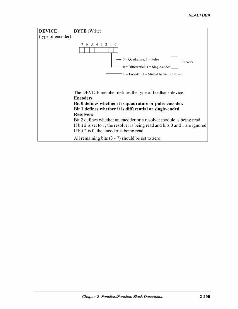
READFDBK
DEVICE(type of encoder)
BYTE (Write)
The DEVICE member defines the type of feedback device. EncodersBit 0 defines whether it is quadrature or pulse encoder. Bit 1 defines whether it is differential or single-ended.ResolversBit 2 defines whether an encoder or a resolver module is being read. If bit 2 is set to 1, the resolver is being read and bits 0 and 1 are ignored.If bit 2 is 0, the encoder is being read.
All remaining bits (3 - 7) should be set to zero.
01234567
0 = Quadrature; 1 = Pulse
0 = Differential; 1 = Single-ended
0 = Encoder; 1 = Multi-Channel Resolver
Encoder
Chapter 2 Function/Function Block Description 2-299
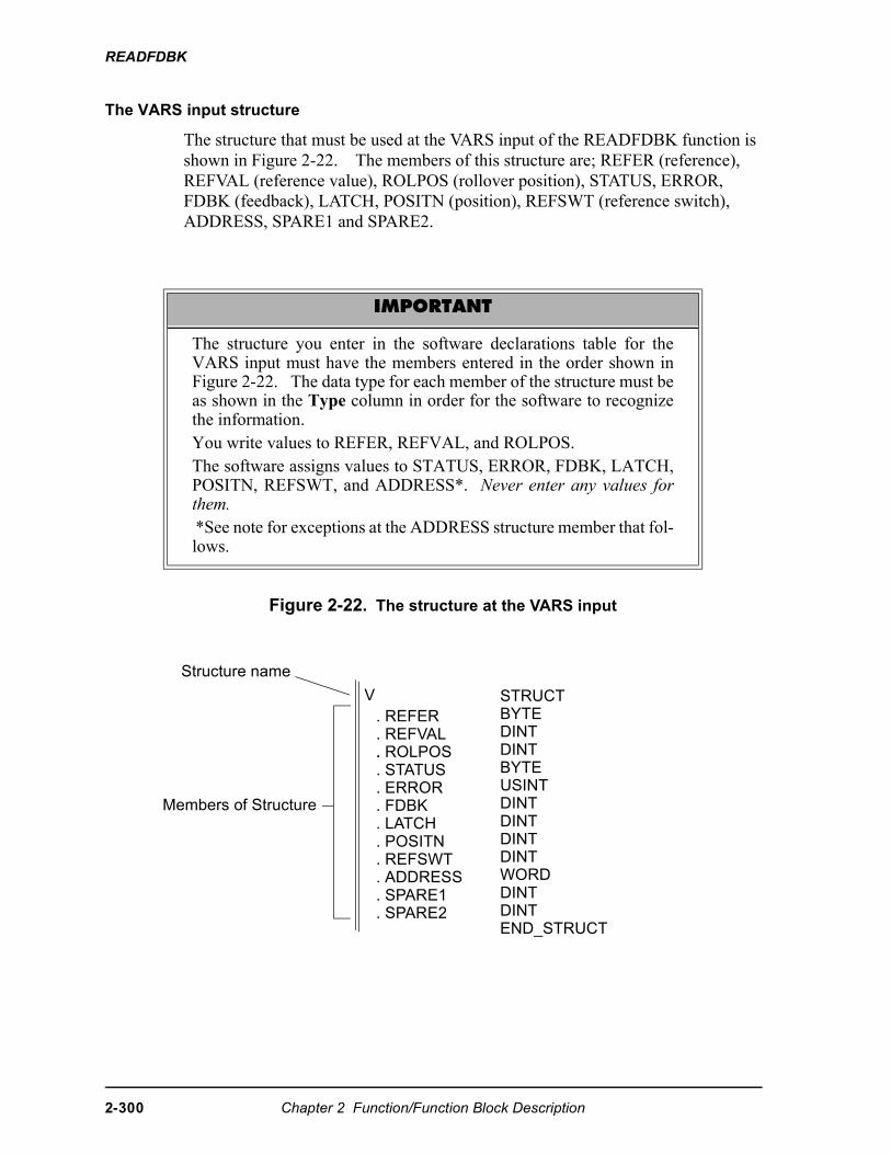
READFDBK
The VARS input structure
The structure that must be used at the VARS input of the READFDBK function is shown in Figure 2-22. The members of this structure are; REFER (reference), REFVAL (reference value), ROLPOS (rollover position), STATUS, ERROR, FDBK (feedback), LATCH, POSITN (position), REFSWT (reference switch), ADDRESS, SPARE1 and SPARE2.
Figure 2-22. The structure at the VARS input
IMPORTANT
The structure you enter in the software declarations table for theVARS input must have the members entered in the order shown inFigure 2-22. The data type for each member of the structure must beas shown in the Type column in order for the software to recognizethe information.You write values to REFER, REFVAL, and ROLPOS.The software assigns values to STATUS, ERROR, FDBK, LATCH,POSITN, REFSWT, and ADDRESS*. Never enter any values forthem. *See note for exceptions at the ADDRESS structure member that fol-lows.
Structure name
Members of Structure
V. REFER. REFVAL. . STATUS
STRUCTBYTEDINTDINTBYTEUSINT
. ROLPOS
. ERROR
. FDBK
. LATCH
. POSITN
. REFSWT
. ADDRESS
. SPARE1
. SPARE2
DINTDINTDINTDINTWORDDINTDINTEND_STRUCT
2-300 Chapter 2 Function/Function Block Description
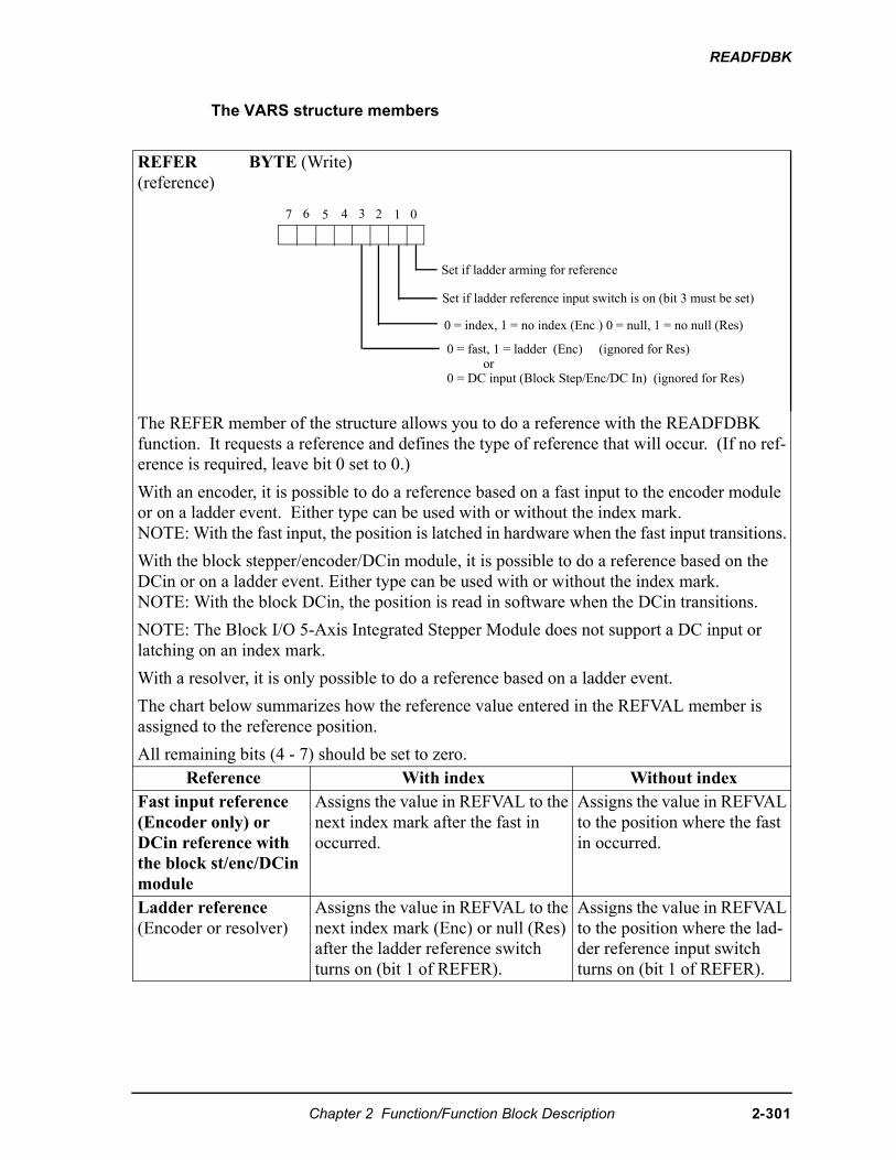
READFDBK
The VARS structure members
REFER(reference)
BYTE (Write)
The REFER member of the structure allows you to do a reference with the READFDBK function. It requests a reference and defines the type of reference that will occur. (If no ref-erence is required, leave bit 0 set to 0.)
With an encoder, it is possible to do a reference based on a fast input to the encoder module or on a ladder event. Either type can be used with or without the index mark.NOTE: With the fast input, the position is latched in hardware when the fast input transitions.
With the block stepper/encoder/DCin module, it is possible to do a reference based on the DCin or on a ladder event. Either type can be used with or without the index mark.NOTE: With the block DCin, the position is read in software when the DCin transitions.
NOTE: The Block I/O 5-Axis Integrated Stepper Module does not support a DC input or latching on an index mark.
With a resolver, it is only possible to do a reference based on a ladder event.
The chart below summarizes how the reference value entered in the REFVAL member is assigned to the reference position.
All remaining bits (4 - 7) should be set to zero. Reference With index Without index
Fast input reference(Encoder only) orDCin reference with the block st/enc/DCin module
Assigns the value in REFVAL to the next index mark after the fast in occurred.
Assigns the value in REFVAL to the position where the fast in occurred.
Ladder reference (Encoder or resolver)
Assigns the value in REFVAL to the next index mark (Enc) or null (Res) after the ladder reference switch turns on (bit 1 of REFER).
Assigns the value in REFVAL to the position where the lad-der reference input switch turns on (bit 1 of REFER).
01234567
Set if ladder arming for reference
Set if ladder reference input switch is on (bit 3 must be set)
0 = index, 1 = no index (Enc ) 0 = null, 1 = no null (Res)
0 = fast, 1 = ladder (Enc) (ignored for Res)or
0 = DC input (Block Step/Enc/DC In) (ignored for Res)
Chapter 2 Function/Function Block Description 2-301
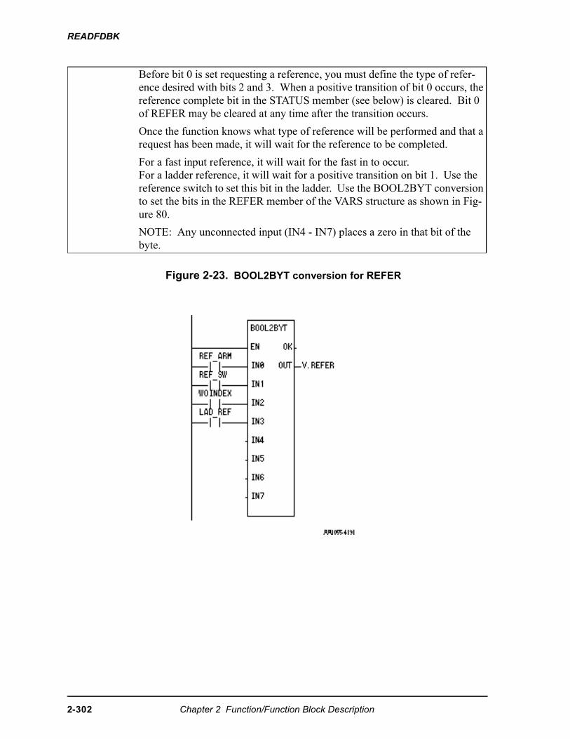
READFDBK
Figure 2-23. BOOL2BYT conversion for REFER
Before bit 0 is set requesting a reference, you must define the type of refer-ence desired with bits 2 and 3. When a positive transition of bit 0 occurs, the reference complete bit in the STATUS member (see below) is cleared. Bit 0 of REFER may be cleared at any time after the transition occurs.
Once the function knows what type of reference will be performed and that a request has been made, it will wait for the reference to be completed.
For a fast input reference, it will wait for the fast in to occur.For a ladder reference, it will wait for a positive transition on bit 1. Use the reference switch to set this bit in the ladder. Use the BOOL2BYT conversion to set the bits in the REFER member of the VARS structure as shown in Fig-ure 80.
NOTE: Any unconnected input (IN4 - IN7) places a zero in that bit of the byte.
2-302 Chapter 2 Function/Function Block Description
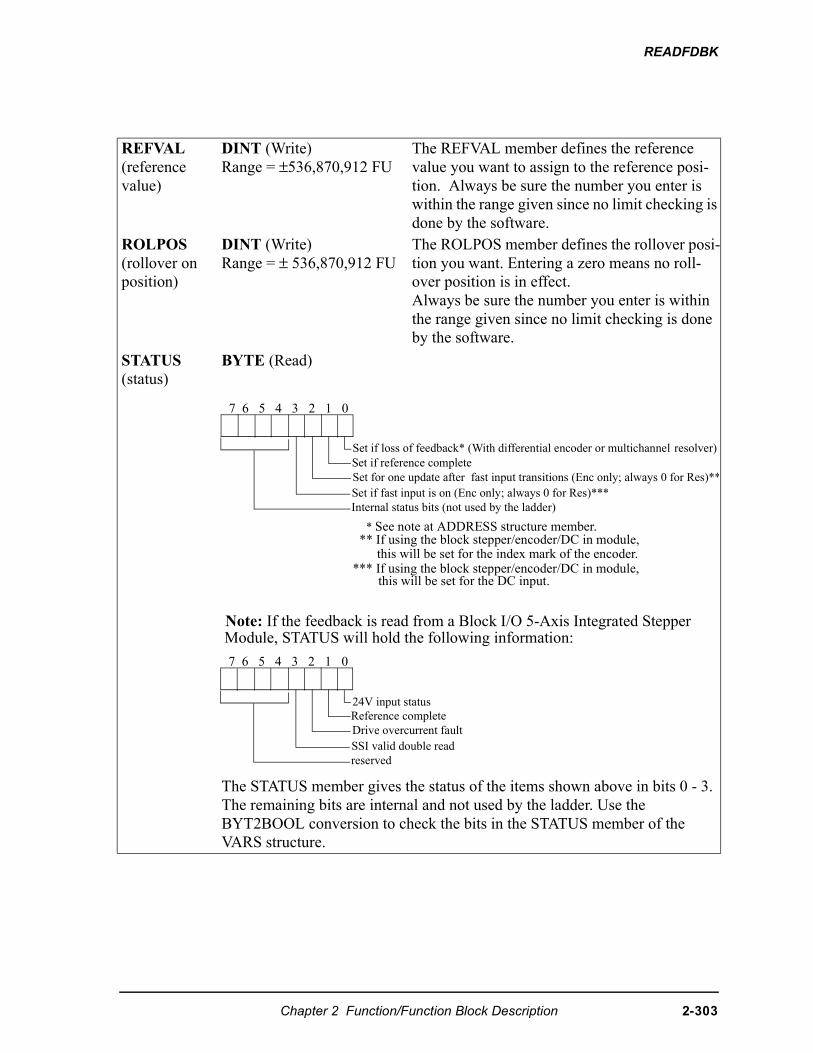
READFDBK
REFVAL(reference value)
DINT (Write)Range = ±536,870,912 FU
The REFVAL member defines the reference value you want to assign to the reference posi-tion. Always be sure the number you enter is within the range given since no limit checking is done by the software.
ROLPOS(rollover on position)
DINT (Write)Range = ± 536,870,912 FU
The ROLPOS member defines the rollover posi-tion you want. Entering a zero means no roll-over position is in effect.Always be sure the number you enter is within the range given since no limit checking is done by the software.
STATUS(status)
BYTE (Read)
The STATUS member gives the status of the items shown above in bits 0 - 3.The remaining bits are internal and not used by the ladder. Use the BYT2BOOL conversion to check the bits in the STATUS member of the VARS structure.
Set if reference completeSet for one update after fast input transitions (Enc only; always 0 for Res)**Set if fast input is on (Enc only; always 0 for Res)***Internal status bits (not used by the ladder)
* See note at ADDRESS structure member.** If using the block stepper/encoder/DC in module,
this will be set for the index mark of the encoder.*** If using the block stepper/encoder/DC in module,
this will be set for the DC input.
7 6 5 4 3 2 1 0
Set if loss of feedback* (With differential encoder or multichannel resolver)
24V input status
Drive overcurrent faultSSI valid double readreserved
7 6 5 4 3 2 1 0
Note: If the feedback is read from a Block I/O 5-Axis Integrated StepperModule, STATUS will hold the following information:
Reference complete
Chapter 2 Function/Function Block Description 2-303
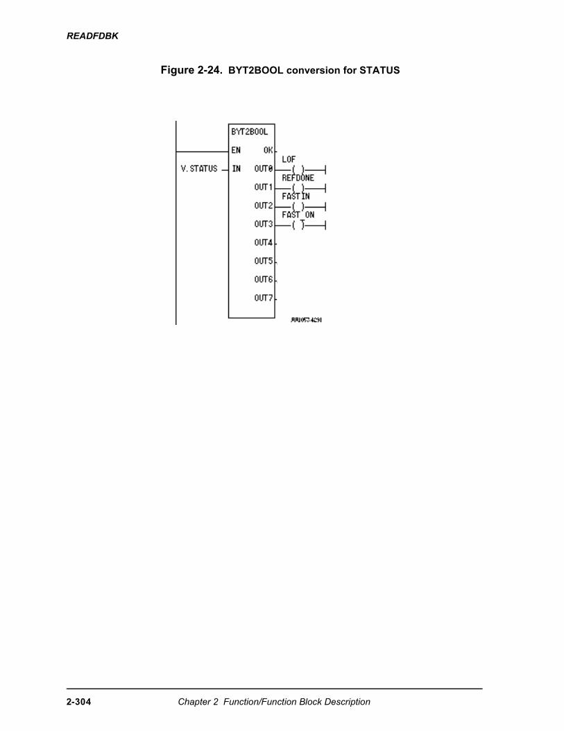
READFDBK
Figure 2-24. BYT2BOOL conversion for STATUS
2-304 Chapter 2 Function/Function Block Description
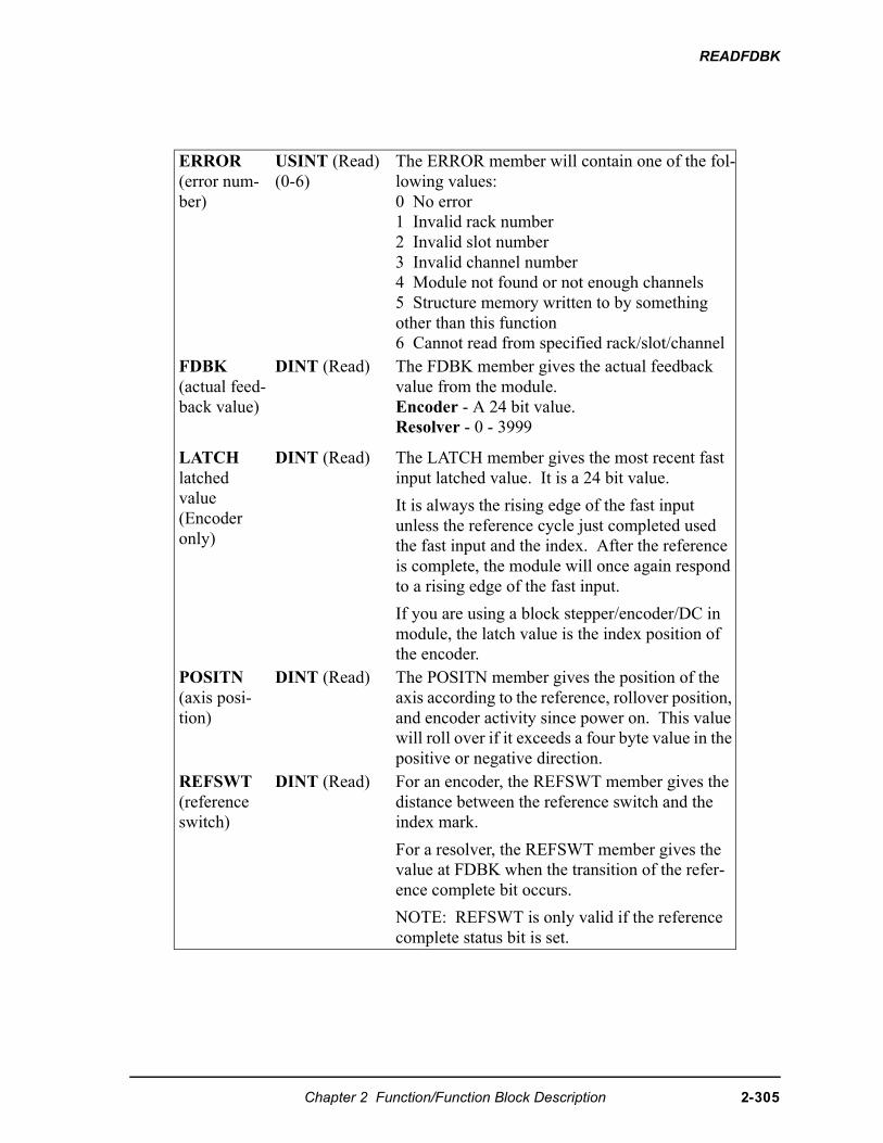
READFDBK
ERROR(error num-ber)
USINT (Read)(0-6)
The ERROR member will contain one of the fol-lowing values:0 No error1 Invalid rack number2 Invalid slot number3 Invalid channel number4 Module not found or not enough channels5 Structure memory written to by something other than this function6 Cannot read from specified rack/slot/channel
FDBK(actual feed-back value)
DINT (Read) The FDBK member gives the actual feedback value from the module.Encoder - A 24 bit value.Resolver - 0 - 3999
LATCHlatched value (Encoder only)
DINT (Read) The LATCH member gives the most recent fast input latched value. It is a 24 bit value.
It is always the rising edge of the fast input unless the reference cycle just completed used the fast input and the index. After the reference is complete, the module will once again respond to a rising edge of the fast input.
If you are using a block stepper/encoder/DC in module, the latch value is the index position of the encoder.
POSITN(axis posi-tion)
DINT (Read) The POSITN member gives the position of the axis according to the reference, rollover position, and encoder activity since power on. This value will roll over if it exceeds a four byte value in the positive or negative direction.
REFSWT(reference switch)
DINT (Read) For an encoder, the REFSWT member gives the distance between the reference switch and the index mark.
For a resolver, the REFSWT member gives the value at FDBK when the transition of the refer-ence complete bit occurs.
NOTE: REFSWT is only valid if the reference complete status bit is set.
Chapter 2 Function/Function Block Description 2-305
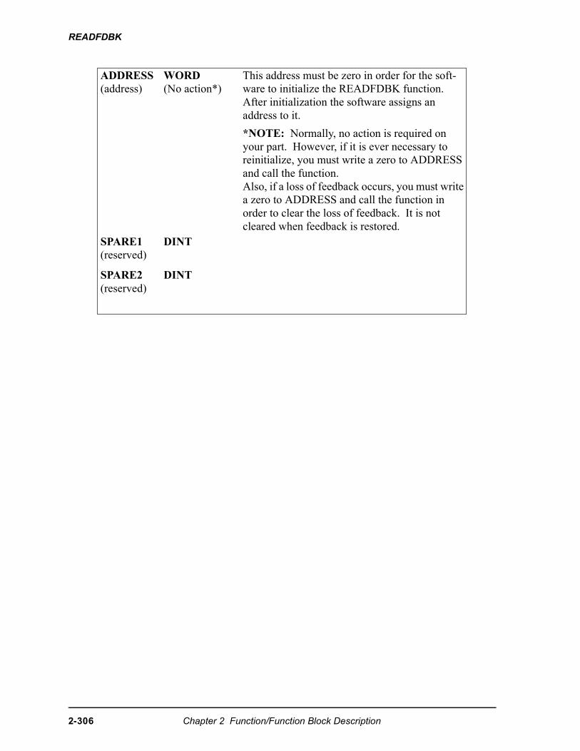
READFDBK
ADDRESS(address)
WORD (No action*)
This address must be zero in order for the soft-ware to initialize the READFDBK function. After initialization the software assigns an address to it.
*NOTE: Normally, no action is required on your part. However, if it is ever necessary to reinitialize, you must write a zero to ADDRESS and call the function. Also, if a loss of feedback occurs, you must write a zero to ADDRESS and call the function in order to clear the loss of feedback. It is not cleared when feedback is restored.
SPARE1(reserved)
DINT
SPARE2(reserved)
DINT
2-306 Chapter 2 Function/Function Block Description
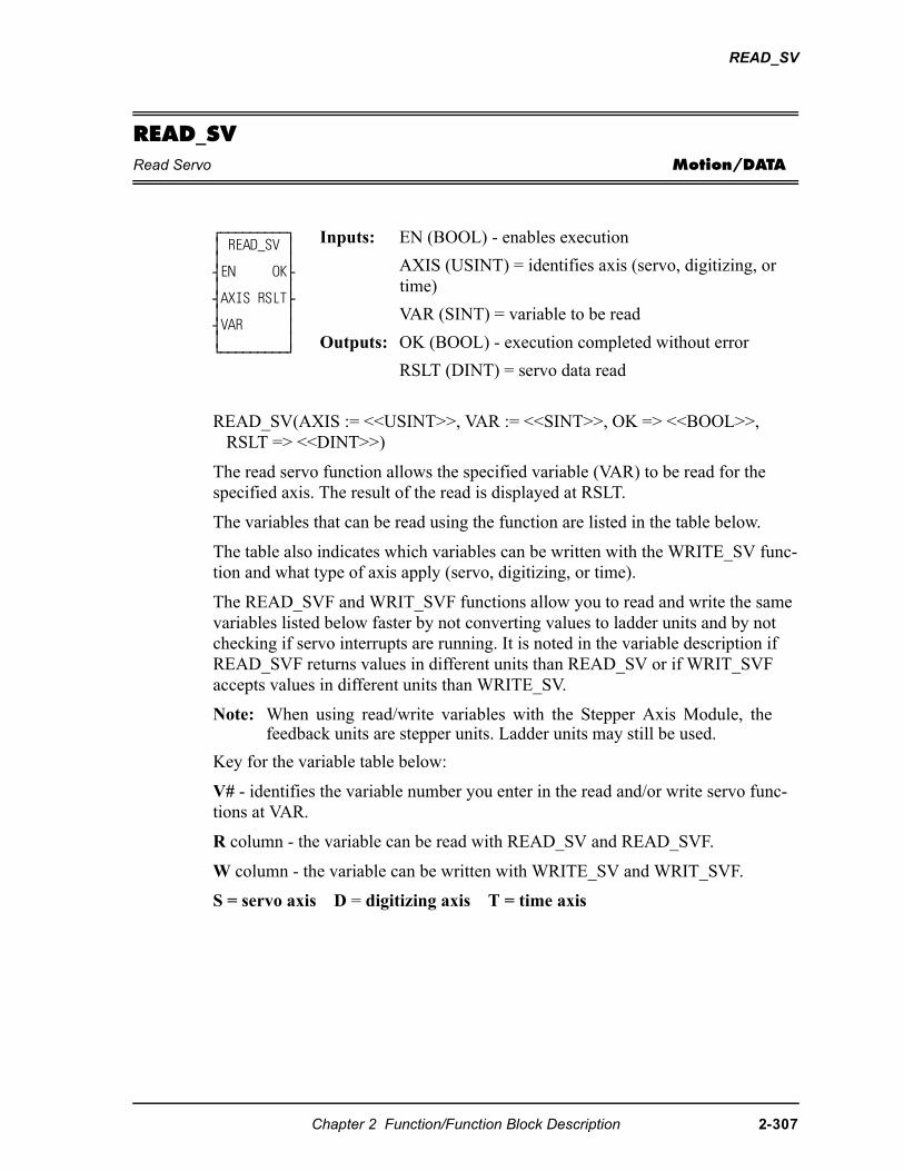
READ_SV
READ_SVRead Servo Motion/DATA
READ_SV(AXIS := <<USINT>>, VAR := <<SINT>>, OK => <<BOOL>>, RSLT => <<DINT>>)
The read servo function allows the specified variable (VAR) to be read for the specified axis. The result of the read is displayed at RSLT.
The variables that can be read using the function are listed in the table below.
The table also indicates which variables can be written with the WRITE_SV func-tion and what type of axis apply (servo, digitizing, or time).
The READ_SVF and WRIT_SVF functions allow you to read and write the same variables listed below faster by not converting values to ladder units and by not checking if servo interrupts are running. It is noted in the variable description if READ_SVF returns values in different units than READ_SV or if WRIT_SVF accepts values in different units than WRITE_SV.
Note: When using read/write variables with the Stepper Axis Module, thefeedback units are stepper units. Ladder units may still be used.
Key for the variable table below:
V# - identifies the variable number you enter in the read and/or write servo func-tions at VAR.
R column - the variable can be read with READ_SV and READ_SVF.
W column - the variable can be written with WRITE_SV and WRIT_SVF.
S = servo axis D = digitizing axis T = time axis
⁄ƒƒƒƒƒƒƒƒƒø ≥ READ_SV ≥ ≥ ≥ ¥EN OK√ ≥ ≥ ¥AXIS RSLT√ ≥ ≥ ¥VAR ≥ ≥ ≥ ¿ƒƒƒƒƒƒƒƒƒŸ
Inputs: EN (BOOL) - enables execution
AXIS (USINT) = identifies axis (servo, digitizing, or time)
VAR (SINT) = variable to be read
Outputs: OK (BOOL) - execution completed without error
RSLT (DINT) = servo data read
Chapter 2 Function/Function Block Description 2-307
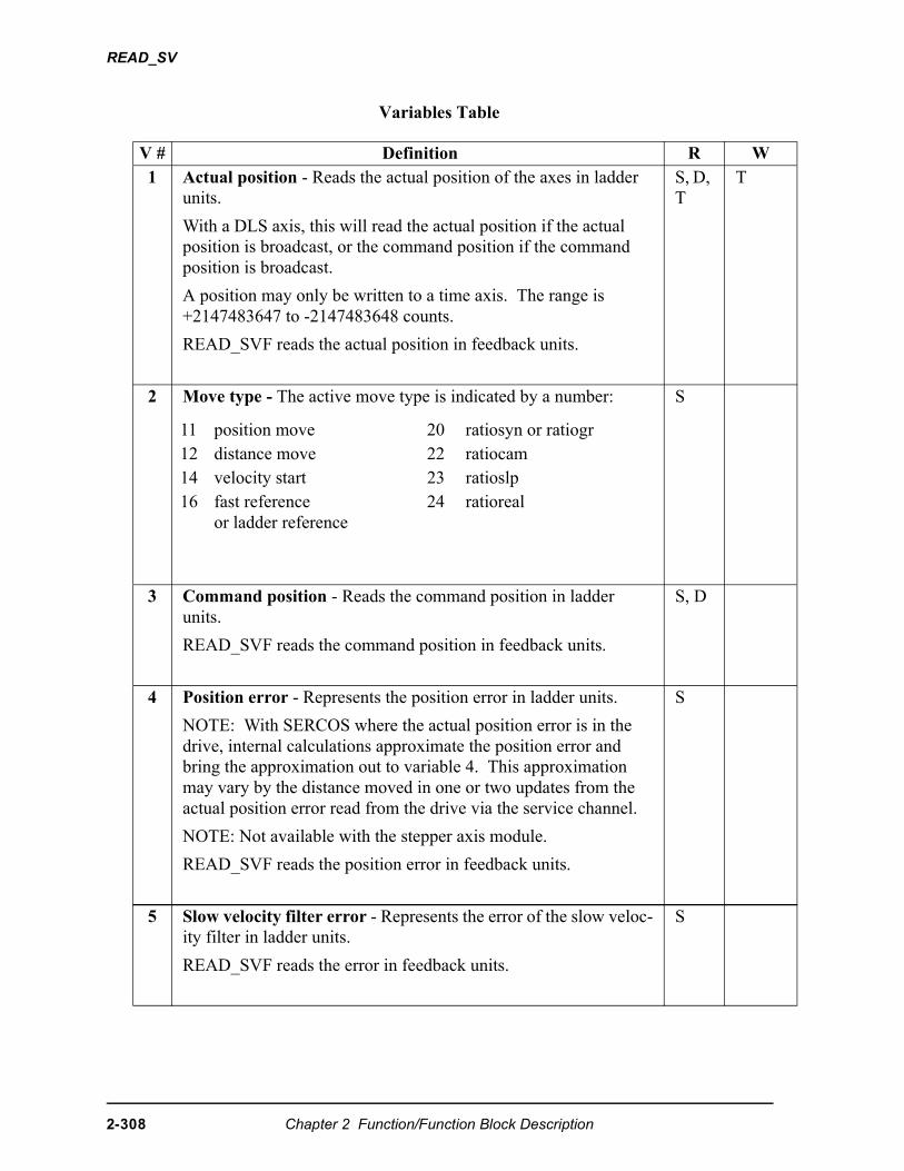
READ_SV
Variables Table
V # Definition R W1 Actual position - Reads the actual position of the axes in ladder
units.
With a DLS axis, this will read the actual position if the actual position is broadcast, or the command position if the command position is broadcast.
A position may only be written to a time axis. The range is +2147483647 to -2147483648 counts.
READ_SVF reads the actual position in feedback units.
S, D, T
T
2 Move type - The active move type is indicated by a number: S
3 Command position - Reads the command position in ladder units.
READ_SVF reads the command position in feedback units.
S, D
4 Position error - Represents the position error in ladder units.
NOTE: With SERCOS where the actual position error is in the drive, internal calculations approximate the position error and bring the approximation out to variable 4. This approximation may vary by the distance moved in one or two updates from the actual position error read from the drive via the service channel.
NOTE: Not available with the stepper axis module.
READ_SVF reads the position error in feedback units.
S
5 Slow velocity filter error - Represents the error of the slow veloc-ity filter in ladder units.
READ_SVF reads the error in feedback units.
S
11 position move 20 ratiosyn or ratiogr 12 distance move 22 ratiocam 14 velocity start 23 ratioslp 16 fast reference
or ladder reference24 ratioreal
2-308 Chapter 2 Function/Function Block Description
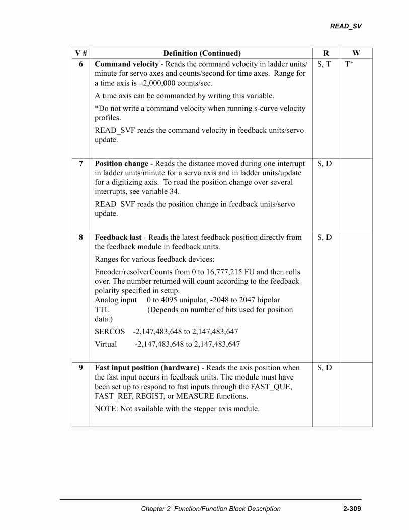
READ_SV
6 Command velocity - Reads the command velocity in ladder units/minute for servo axes and counts/second for time axes. Range for a time axis is ±2,000,000 counts/sec.
A time axis can be commanded by writing this variable.
*Do not write a command velocity when running s-curve velocity profiles.
READ_SVF reads the command velocity in feedback units/servo update.
S, T T*
7 Position change - Reads the distance moved during one interrupt in ladder units/minute for a servo axis and in ladder units/update for a digitizing axis. To read the position change over several interrupts, see variable 34.
READ_SVF reads the position change in feedback units/servo update.
S, D
8 Feedback last - Reads the latest feedback position directly from the feedback module in feedback units.
Ranges for various feedback devices:
Encoder/resolverCounts from 0 to 16,777,215 FU and then rolls over. The number returned will count according to the feedback polarity specified in setup. Analog input 0 to 4095 unipolar; -2048 to 2047 bipolarTTL (Depends on number of bits used for position data.)
SERCOS -2,147,483,648 to 2,147,483,647
Virtual -2,147,483,648 to 2,147,483,647
S, D
9 Fast input position (hardware) - Reads the axis position when the fast input occurs in feedback units. The module must have been set up to respond to fast inputs through the FAST_QUE, FAST_REF, REGIST, or MEASURE functions.
NOTE: Not available with the stepper axis module.
S, D
V # Definition (Continued) R W
Chapter 2 Function/Function Block Description 2-309
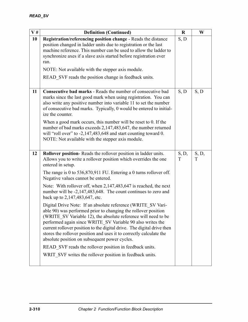
READ_SV
V # Definition (Continued) R W10 Registration/referencing position change - Reads the distance
position changed in ladder units due to registration or the last machine reference. This number can be used to allow the ladder to synchronize axes if a slave axis started before registration ever ran.
NOTE: Not available with the stepper axis module.
READ_SVF reads the position change in feedback units.
S, D
11 Consecutive bad marks - Reads the number of consecutive bad marks since the last good mark when using registration. You can also write any positive number into variable 11 to set the number of consecutive bad marks. Typically, 0 would be entered to initial-ize the counter.
When a good mark occurs, this number will be reset to 0. If the number of bad marks exceeds 2,147,483,647, the number returned will “roll over” to -2,147,483,648 and start counting toward 0. NOTE: Not available with the stepper axis module.
S, D S, D
12 Rollover position- Reads the rollover position in ladder units. Allows you to write a rollover position which overrides the one entered in setup.
The range is 0 to 536,870,911 FU. Entering a 0 turns rollover off. Negative values cannot be entered.
Note: With rollover off, when 2,147,483,647 is reached, the next number will be -2,147,483,648. The count continues to zero and back up to 2,147,483,647, etc.
Digital Drive Note: If an absolute reference (WRITE_SV Vari-able 90) was performed prior to changing the rollover position (WRITE_SV Variable 12), the absolute reference will need to be performed again since WRITE_SV Variable 90 also writes the current rollover position to the digital drive. The digital drive then stores the rollover position and uses it to correctly calculate the absolute position on subsequent power cycles.
READ_SVF reads the rollover position in feedback units.
WRIT_SVF writes the rollover position in feedback units.
S, D, T
S, D, T
2-310 Chapter 2 Function/Function Block Description
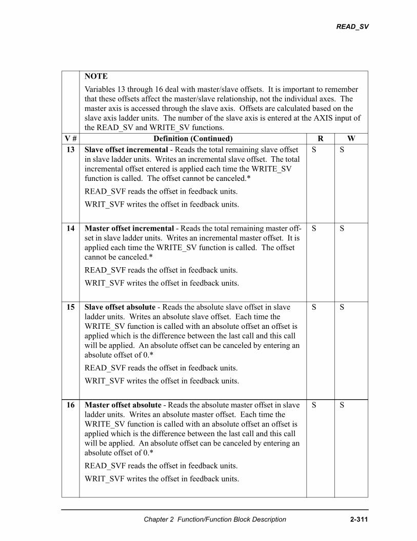
READ_SV
NOTE
Variables 13 through 16 deal with master/slave offsets. It is important to remember that these offsets affect the master/slave relationship, not the individual axes. The master axis is accessed through the slave axis. Offsets are calculated based on the slave axis ladder units. The number of the slave axis is entered at the AXIS input of the READ_SV and WRITE_SV functions.
V # Definition (Continued) R W13 Slave offset incremental - Reads the total remaining slave offset
in slave ladder units. Writes an incremental slave offset. The total incremental offset entered is applied each time the WRITE_SV function is called. The offset cannot be canceled.*
READ_SVF reads the offset in feedback units.
WRIT_SVF writes the offset in feedback units.
S S
14 Master offset incremental - Reads the total remaining master off-set in slave ladder units. Writes an incremental master offset. It is applied each time the WRITE_SV function is called. The offset cannot be canceled.*
READ_SVF reads the offset in feedback units.
WRIT_SVF writes the offset in feedback units.
S S
15 Slave offset absolute - Reads the absolute slave offset in slave ladder units. Writes an absolute slave offset. Each time the WRITE_SV function is called with an absolute offset an offset is applied which is the difference between the last call and this call will be applied. An absolute offset can be canceled by entering an absolute offset of 0.*
READ_SVF reads the offset in feedback units.
WRIT_SVF writes the offset in feedback units.
S S
16 Master offset absolute - Reads the absolute master offset in slave ladder units. Writes an absolute master offset. Each time the WRITE_SV function is called with an absolute offset an offset is applied which is the difference between the last call and this call will be applied. An absolute offset can be canceled by entering an absolute offset of 0.*
READ_SVF reads the offset in feedback units.
WRIT_SVF writes the offset in feedback units.
S S
Chapter 2 Function/Function Block Description 2-311
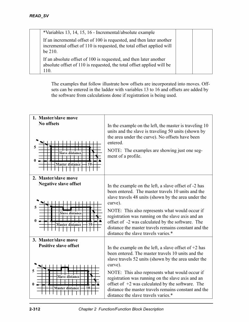
READ_SV
The examples that follow illustrate how offsets are incorporated into moves. Off-sets can be entered in the ladder with variables 13 to 16 and offsets are added by the software from calculations done if registration is being used.
*Variables 13, 14, 15, 16 - Incremental/absolute example
If an incremental offset of 100 is requested, and then later another incremental offset of 110 is requested, the total offset applied will be 210.
If an absolute offset of 100 is requested, and then later another absolute offset of 110 is requested, the total offset applied will be 110.
1. Master/slave moveNo offsets In the example on the left, the master is traveling 10
units and the slave is traveling 50 units (shown by the area under the curve). No offsets have been entered.
NOTE: The examples are showing just one seg-ment of a profile.
2. Master/slave moveNegative slave offset In the example on the left, a slave offset of -2 has
been entered. The master travels 10 units and the slave travels 48 units (shown by the area under the curve).
NOTE: This also represents what would occur if registration was running on the slave axis and an offset of -2 was calculated by the software. The distance the master travels remains constant and the distance the slave travels varies.*
3. Master/slave movePositive slave offset In the example on the left, a slave offset of +2 has
been entered. The master travels 10 units and the slave travels 52 units (shown by the area under the curve).
NOTE: This also represents what would occur if registration was running on the slave axis and an offset of +2 was calculated by the software. The distance the master travels remains constant and the distance the slave travels varies.*
0
5Slave distance
Master distance 10
0
5Slave distance
Master distance 10
0
5Slave distance
Master distance 10
2-312 Chapter 2 Function/Function Block Description
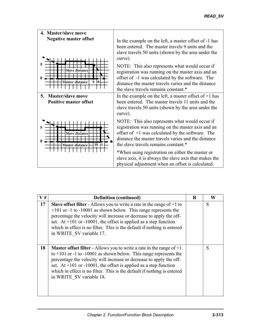
READ_SV
4. Master/slave moveNegative master offset In the example on the left, a master offset of -1 has
been entered. The master travels 9 units and the slave travels 50 units (shown by the area under the curve).
NOTE: This also represents what would occur if registration was running on the master axis and an offset of -1 was calculated by the software. The distance the master travels varies and the distance the slave travels remains constant.*
5. Master/slave movePositive master offset
In the example on the left, a master offset of +1 has been entered. The master travels 11 units and the slave travels 50 units (shown by the area under the curve).
NOTE: This also represents what would occur if registration was running on the master axis and an offset of +1 was calculated by the software. The distance the master travels varies and the distance the slave travels remains constant.*
*When using registration on either the master or slave axis, it is always the slave axis that makes the physical adjustment when an offset is calculated.
V # Definition (continued) R W17 Slave offset filter - Allows you to write a rate in the range of +1 to
+101 or -1 to -10001 as shown below. This range represents the percentage the velocity will increase or decrease to apply the off-set. At +101 or -10001, the offset is applied as a step function which in effect is no filter. This is the default if nothing is entered in WRITE_SV variable 17.
S
18 Master offset filter - Allows you to write a rate in the range of +1 to +101 or -1 to -10001 as shown below. This range represents the percentage the velocity will increase or decrease to apply the off-set. At +101 or -10001, the offset is applied as a step function which in effect is no filter. This is the default if nothing is entered in WRITE_SV variable 18.
S
0
5Slave distance
Master distance 109
0
5Slave distance
Master distance 10 11
Chapter 2 Function/Function Block Description 2-313
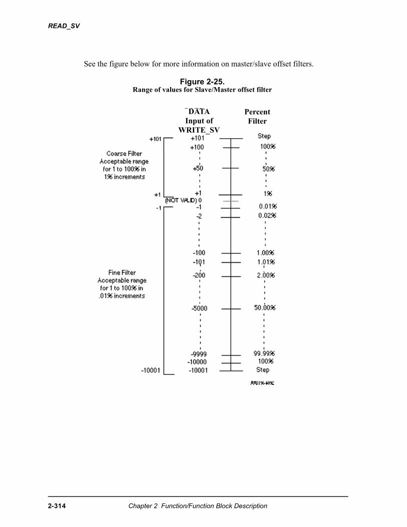
READ_SV
See the figure below for more information on master/slave offset filters.
Figure 2-25.Range of values for Slave/Master offset filter
DATAInput of
WRITE_SV
PercentFilter
2-314 Chapter 2 Function/Function Block Description
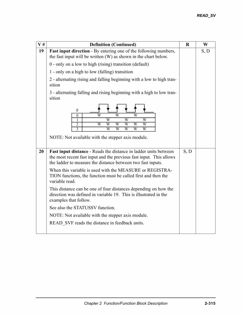
READ_SV
V # Definition (Continued) R W19 Fast input direction - By entering one of the following numbers,
the fast input will be written (W) as shown in the chart below.
0 - only on a low to high (rising) transition (default)
1 - only on a high to low (falling) transition
2 - alternating rising and falling beginning with a low to high tran-sition
3 - alternating falling and rising beginning with a high to low tran-sition
NOTE: Not available with the stepper axis module.
S, D
20 Fast input distance - Reads the distance in ladder units between the most recent fast input and the previous fast input. This allows the ladder to measure the distance between two fast inputs.
When this variable is used with the MEASURE or REGISTRA-TION functions, the function must be called first and then the variable read.
This distance can be one of four distances depending on how the direction was defined in variable 19. This is illustrated in the examples that follow.
See also the STATUSSV function.
NOTE: Not available with the stepper axis module.
READ_SVF reads the distance in feedback units.
S, D
0123
W W WW W WW W WW W WW W WW W
#
Chapter 2 Function/Function Block Description 2-315
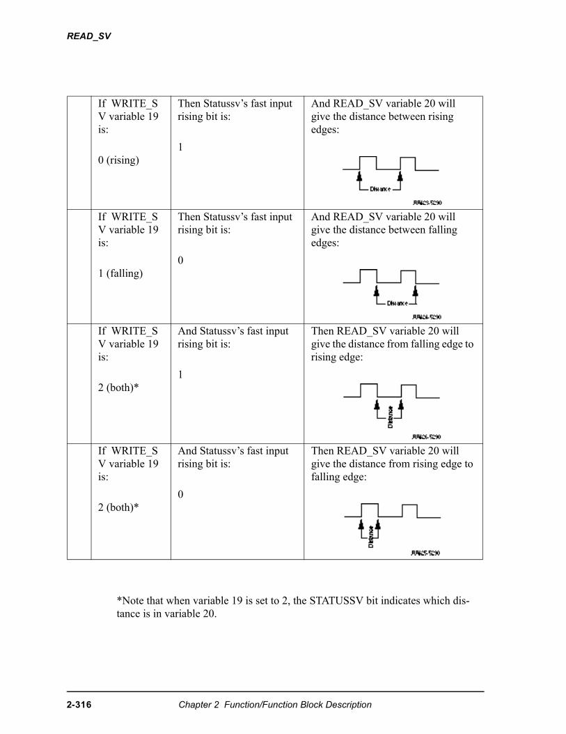
READ_SV
*Note that when variable 19 is set to 2, the STATUSSV bit indicates which dis-tance is in variable 20.
If WRITE_SV variable 19 is:
0 (rising)
Then Statussv’s fast input rising bit is:
1
And READ_SV variable 20 will give the distance between rising edges:
If WRITE_SV variable 19 is:
1 (falling)
Then Statussv’s fast input rising bit is:
0
And READ_SV variable 20 will give the distance between falling edges:
If WRITE_SV variable 19 is:
2 (both)*
And Statussv’s fast input rising bit is:
1
Then READ_SV variable 20 will give the distance from falling edge to rising edge:
If WRITE_SV variable 19 is:
2 (both)*
And Statussv’s fast input rising bit is:
0
Then READ_SV variable 20 will give the distance from rising edge to falling edge:
2-316 Chapter 2 Function/Function Block Description
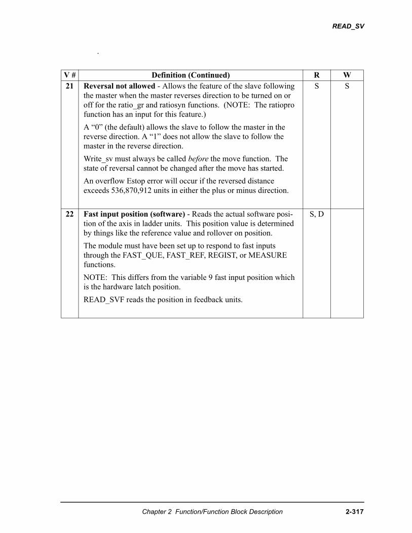
READ_SV
.
V # Definition (Continued) R W21 Reversal not allowed - Allows the feature of the slave following
the master when the master reverses direction to be turned on or off for the ratio_gr and ratiosyn functions. (NOTE: The ratiopro function has an input for this feature.)
A “0” (the default) allows the slave to follow the master in the reverse direction. A “1” does not allow the slave to follow the master in the reverse direction.
Write_sv must always be called before the move function. The state of reversal cannot be changed after the move has started.
An overflow Estop error will occur if the reversed distance exceeds 536,870,912 units in either the plus or minus direction.
S S
22 Fast input position (software) - Reads the actual software posi-tion of the axis in ladder units. This position value is determined by things like the reference value and rollover on position.
The module must have been set up to respond to fast inputs through the FAST_QUE, FAST_REF, REGIST, or MEASURE functions.
NOTE: This differs from the variable 9 fast input position which is the hardware latch position.
READ_SVF reads the position in feedback units.
S, D
Chapter 2 Function/Function Block Description 2-317
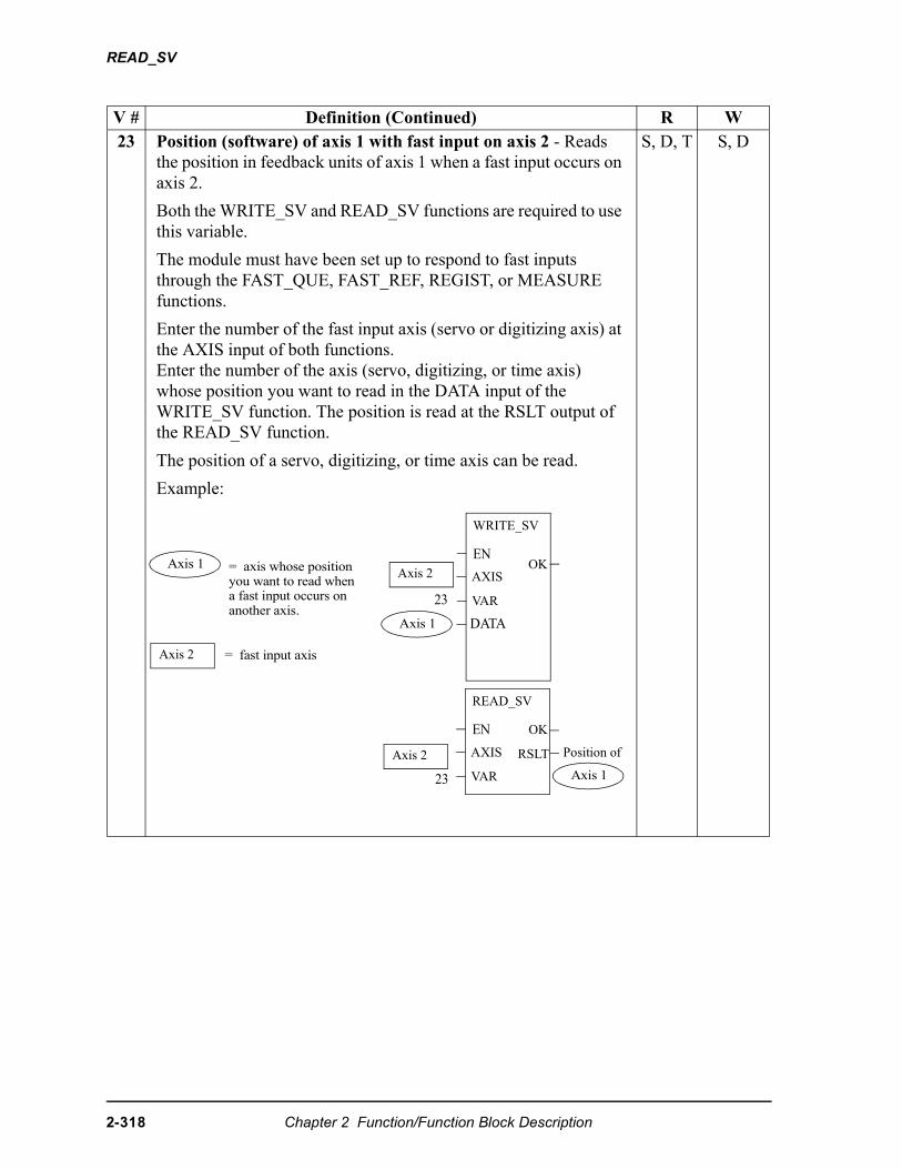
READ_SV
V # Definition (Continued) R W23 Position (software) of axis 1 with fast input on axis 2 - Reads
the position in feedback units of axis 1 when a fast input occurs on axis 2.
Both the WRITE_SV and READ_SV functions are required to use this variable.
The module must have been set up to respond to fast inputs through the FAST_QUE, FAST_REF, REGIST, or MEASURE functions.
Enter the number of the fast input axis (servo or digitizing axis) at the AXIS input of both functions. Enter the number of the axis (servo, digitizing, or time axis) whose position you want to read in the DATA input of the WRITE_SV function. The position is read at the RSLT output of the READ_SV function.
The position of a servo, digitizing, or time axis can be read.
Example:
S, D, T S, D
Axis 1Axis 2= axis whose position
you want to read when a fast input occurs on another axis.
= fast input axis
READ_SV
EN
AXIS
VAR
OK
Axis 1
Axis 2
23
WRITE_SV
EN
AXIS
VAR
DATA
OK
RSLTAxis 2
23 Axis 1
Position of
2-318 Chapter 2 Function/Function Block Description
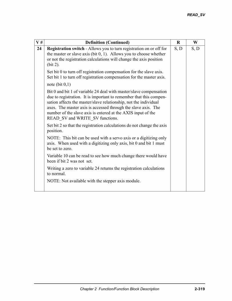
READ_SV
V # Definition (Continued) R W24 Registration switch - Allows you to turn registration on or off for
the master or slave axis (bit 0, 1). Allows you to choose whether or not the registration calculations will change the axis position (bit 2).
Set bit 0 to turn off registration compensation for the slave axis.Set bit 1 to turn off registration compensation for the master axis.
note (bit 0,1)
Bit 0 and bit 1 of variable 24 deal with master/slave compensation due to registration. It is important to remember that this compen-sation affects the master/slave relationship, not the individual axes. The master axis is accessed through the slave axis. The number of the slave axis is entered at the AXIS input of the READ_SV and WRITE_SV functions.
Set bit 2 so that the registration calculations do not change the axis position.
NOTE: This bit can be used with a servo axis or a digitizing only axis. When used with a digitizing only axis, bit 0 and bit 1 must be set to zero.
Variable 10 can be read to see how much change there would have been if bit 2 was not set.
Writing a zero to variable 24 returns the registration calculations to normal.
NOTE: Not available with the stepper axis module.
S, D S, D
Chapter 2 Function/Function Block Description 2-319
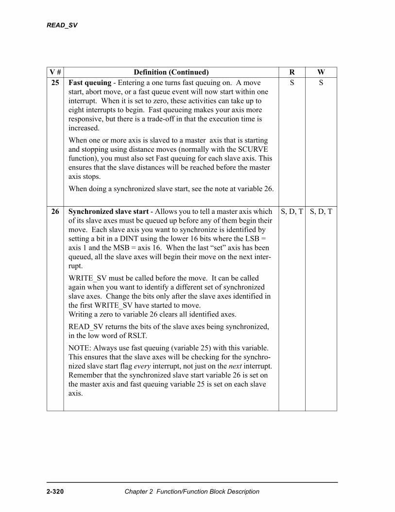
READ_SV
V # Definition (Continued) R W25 Fast queuing - Entering a one turns fast queuing on. A move
start, abort move, or a fast queue event will now start within one interrupt. When it is set to zero, these activities can take up to eight interrupts to begin. Fast queueing makes your axis more responsive, but there is a trade-off in that the execution time is increased.
When one or more axis is slaved to a master axis that is starting and stopping using distance moves (normally with the SCURVE function), you must also set Fast queuing for each slave axis. This ensures that the slave distances will be reached before the master axis stops.
When doing a synchronized slave start, see the note at variable 26.
S S
26 Synchronized slave start - Allows you to tell a master axis which of its slave axes must be queued up before any of them begin their move. Each slave axis you want to synchronize is identified by setting a bit in a DINT using the lower 16 bits where the LSB = axis 1 and the MSB = axis 16. When the last “set” axis has been queued, all the slave axes will begin their move on the next inter-rupt.
WRITE_SV must be called before the move. It can be called again when you want to identify a different set of synchronized slave axes. Change the bits only after the slave axes identified in the first WRITE_SV have started to move. Writing a zero to variable 26 clears all identified axes.
READ_SV returns the bits of the slave axes being synchronized, in the low word of RSLT.
NOTE: Always use fast queuing (variable 25) with this variable. This ensures that the slave axes will be checking for the synchro-nized slave start flag every interrupt, not just on the next interrupt. Remember that the synchronized slave start variable 26 is set on the master axis and fast queuing variable 25 is set on each slave axis.
S, D, T S, D, T
2-320 Chapter 2 Function/Function Block Description
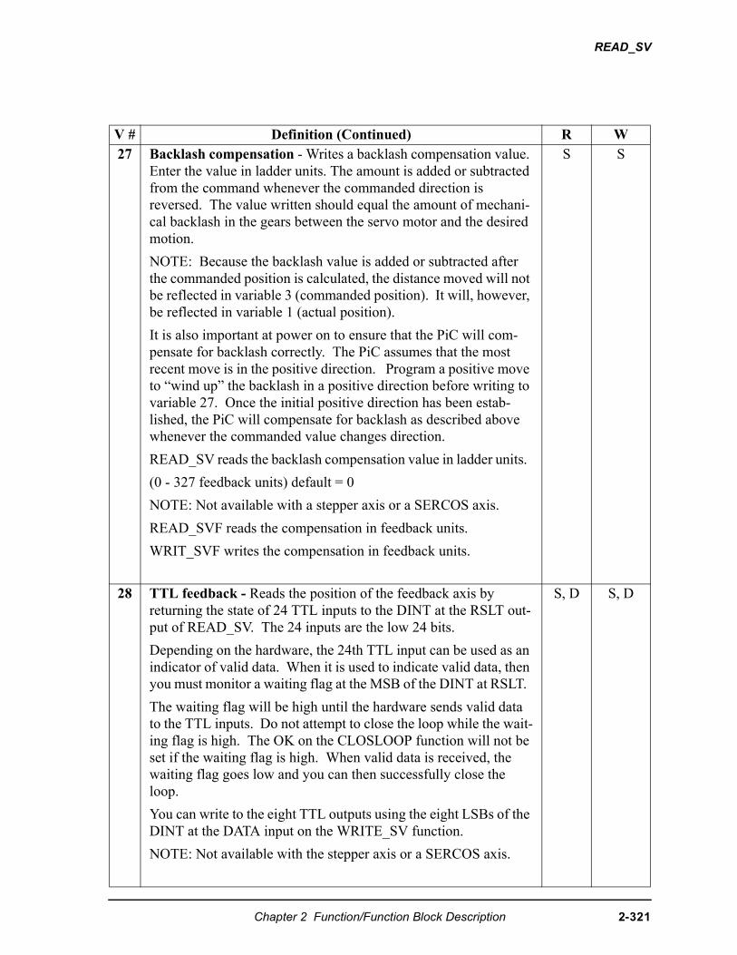
READ_SV
V # Definition (Continued) R W27 Backlash compensation - Writes a backlash compensation value.
Enter the value in ladder units. The amount is added or subtracted from the command whenever the commanded direction is reversed. The value written should equal the amount of mechani-cal backlash in the gears between the servo motor and the desired motion.
NOTE: Because the backlash value is added or subtracted after the commanded position is calculated, the distance moved will not be reflected in variable 3 (commanded position). It will, however, be reflected in variable 1 (actual position).
It is also important at power on to ensure that the PiC will com-pensate for backlash correctly. The PiC assumes that the most recent move is in the positive direction. Program a positive move to “wind up” the backlash in a positive direction before writing to variable 27. Once the initial positive direction has been estab-lished, the PiC will compensate for backlash as described above whenever the commanded value changes direction.
READ_SV reads the backlash compensation value in ladder units.
(0 - 327 feedback units) default = 0
NOTE: Not available with a stepper axis or a SERCOS axis.
READ_SVF reads the compensation in feedback units.
WRIT_SVF writes the compensation in feedback units.
S S
28 TTL feedback - Reads the position of the feedback axis by returning the state of 24 TTL inputs to the DINT at the RSLT out-put of READ_SV. The 24 inputs are the low 24 bits.
Depending on the hardware, the 24th TTL input can be used as an indicator of valid data. When it is used to indicate valid data, then you must monitor a waiting flag at the MSB of the DINT at RSLT.
The waiting flag will be high until the hardware sends valid data to the TTL inputs. Do not attempt to close the loop while the wait-ing flag is high. The OK on the CLOSLOOP function will not be set if the waiting flag is high. When valid data is received, the waiting flag goes low and you can then successfully close the loop.
You can write to the eight TTL outputs using the eight LSBs of the DINT at the DATA input on the WRITE_SV function.
NOTE: Not available with the stepper axis or a SERCOS axis.
S, D S, D
Chapter 2 Function/Function Block Description 2-321
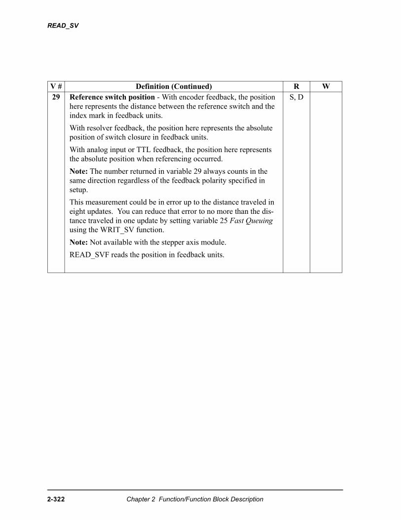
READ_SV
V # Definition (Continued) R W29 Reference switch position - With encoder feedback, the position
here represents the distance between the reference switch and the index mark in feedback units.
With resolver feedback, the position here represents the absolute position of switch closure in feedback units.
With analog input or TTL feedback, the position here represents the absolute position when referencing occurred.
Note: The number returned in variable 29 always counts in the same direction regardless of the feedback polarity specified in setup.
This measurement could be in error up to the distance traveled in eight updates. You can reduce that error to no more than the dis-tance traveled in one update by setting variable 25 Fast Queuing using the WRIT_SV function.
Note: Not available with the stepper axis module.
READ_SVF reads the position in feedback units.
S, D
2-322 Chapter 2 Function/Function Block Description
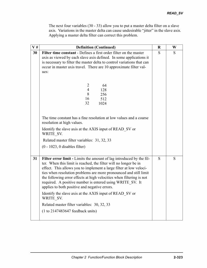
READ_SV
The next four variables (30 - 33) allow you to put a master delta filter on a slave axis. Variations in the master delta can cause undesirable “jitter” in the slave axis. Applying a master delta filter can correct this problem.
V # Definition (Continued) R W30 Filter time constant - Defines a first order filter on the master
axis as viewed by each slave axis defined. In some applications it is necessary to filter the master delta to control variations that can occur in master axis travel. There are 10 approximate filter val-ues:
The time constant has a fine resolution at low values and a coarse resolution at high values.
Identify the slave axis at the AXIS input of READ_SV or WRITE_SV.
Related master filter variables: 31, 32, 33
(0 - 1023, 0 disables filter)
S S
31 Filter error limit - Limits the amount of lag introduced by the fil-ter. When this limit is reached, the filter will no longer be in effect. This allows you to implement a large filter at low veloci-ties when resolution problems are more pronounced and still limit the following error effects at high velocities when filtering is not required. A positive number is entered using WRITE_SV. It applies to both positive and negative errors.
Identify the slave axis at the AXIS input of READ_SV or WRITE_SV.
Related master filter variables: 30, 32, 33
(1 to 2147483647 feedback units)
S S
2 4 81632
64 128 256 5121024
Chapter 2 Function/Function Block Description 2-323
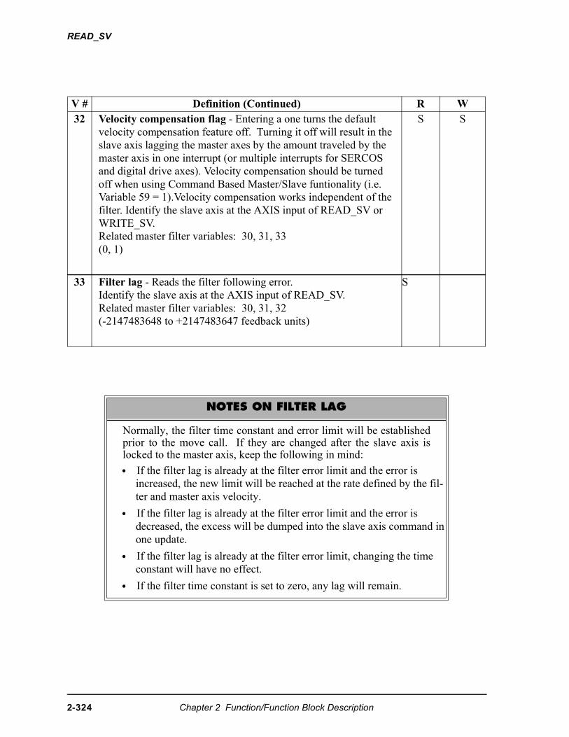
READ_SV
V # Definition (Continued) R W32 Velocity compensation flag - Entering a one turns the default
velocity compensation feature off. Turning it off will result in the slave axis lagging the master axes by the amount traveled by the master axis in one interrupt (or multiple interrupts for SERCOS and digital drive axes). Velocity compensation should be turned off when using Command Based Master/Slave funtionality (i.e. Variable 59 = 1).Velocity compensation works independent of the filter. Identify the slave axis at the AXIS input of READ_SV or WRITE_SV.Related master filter variables: 30, 31, 33(0, 1)
S S
33 Filter lag - Reads the filter following error. Identify the slave axis at the AXIS input of READ_SV.Related master filter variables: 30, 31, 32(-2147483648 to +2147483647 feedback units)
S
NOTES ON FILTER LAG
Normally, the filter time constant and error limit will be establishedprior to the move call. If they are changed after the slave axis islocked to the master axis, keep the following in mind:
• If the filter lag is already at the filter error limit and the error is increased, the new limit will be reached at the rate defined by the fil-ter and master axis velocity.
• If the filter lag is already at the filter error limit and the error is decreased, the excess will be dumped into the slave axis command in one update.
• If the filter lag is already at the filter error limit, changing the time constant will have no effect.
• If the filter time constant is set to zero, any lag will remain.
2-324 Chapter 2 Function/Function Block Description
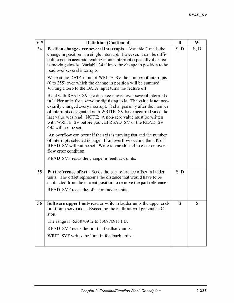
READ_SV
V # Definition (Continued) R W34 Position change over several interrupts - Variable 7 reads the
change in position in a single interrupt. However, it can be diffi-cult to get an accurate reading in one interrupt especially if an axis is moving slowly. Variable 34 allows the change in position to be read over several interrupts.
Write at the DATA input of WRITE_SV the number of interrupts (0 to 255) over which the change in position will be summed. Writing a zero to the DATA input turns the feature off.
Read with READ_SV the distance moved over several interrupts in ladder units for a servo or digitizing axis. The value is not nec-essarily changed every interrupt. It changes only after the number of interrupts designated with WRITE_SV have occurred since the last value was read. NOTE: A non-zero value must be written with WRITE_SV before you call READ_SV or the READ_SV OK will not be set.
An overflow can occur if the axis is moving fast and the number of interrupts selected is large. If an overflow occurs, the OK of READ_SV will not be set. Write to variable 34 to clear an over-flow error condition.
READ_SVF reads the change in feedback units.
S, D S, D
35 Part reference offset - Reads the part reference offset in ladder units. The offset represents the distance that would have to be subtracted from the current position to remove the part reference.
READ_SVF reads the offset in ladder units.
S, D
36 Software upper limit- read or write in ladder units the upper end-limit for a servo axis. Exceeding the endlimit will generate a C-stop.
The range is -536870912 to 536870911 FU.
READ_SVF reads the limit in feedback units.
WRIT_SVF writes the limit in feedback units.
S S
Chapter 2 Function/Function Block Description 2-325
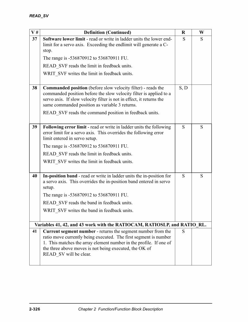
READ_SV
V # Definition (Continued) R W37 Software lower limit - read or write in ladder units the lower end-
limit for a servo axis. Exceeding the endlimit will generate a C-stop.
The range is -536870912 to 536870911 FU.
READ_SVF reads the limit in feedback units.
WRIT_SVF writes the limit in feedback units.
S S
38 Commanded position (before slow velocity filter) - reads the commanded position before the slow velocity filter is applied to a servo axis. If slow velocity filter is not in effect, it returns the same commanded position as variable 3 returns.
READ_SVF reads the command position in feedback units.
S, D
39 Following error limit - read or write in ladder units the following error limit for a servo axis. This overrides the following error limit entered in servo setup.
The range is -536870912 to 536870911 FU.
READ_SVF reads the limit in feedback units.
WRIT_SVF writes the limit in feedback units.
S S
40 In-position band - read or write in ladder units the in-position for a servo axis. This overrides the in-position band entered in servo setup.
The range is -536870912 to 536870911 FU.
READ_SVF reads the band in feedback units.
WRIT_SVF writes the band in feedback units.
S S
Variables 41, 42, and 43 work with the RATIOCAM, RATIOSLP, and RATIO_RL.41 Current segment number - returns the segment number from the
ratio move currently being executed. The first segment is number 1. This matches the array element number in the profile. If one of the three above moves is not being executed, the OK of READ_SV will be clear.
S
2-326 Chapter 2 Function/Function Block Description
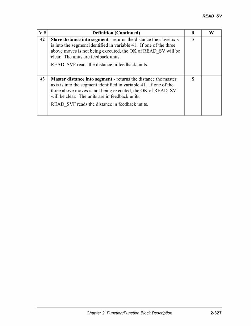
READ_SV
V # Definition (Continued) R W42 Slave distance into segment - returns the distance the slave axis
is into the segment identified in variable 41. If one of the three above moves is not being executed, the OK of READ_SV will be clear. The units are feedback units.
READ_SVF reads the distance in feedback units.
S
43 Master distance into segment - returns the distance the master axis is into the segment identified in variable 41. If one of the three above moves is not being executed, the OK of READ_SV will be clear. The units are in feedback units.
READ_SVF reads the distance in feedback units.
S
Chapter 2 Function/Function Block Description 2-327
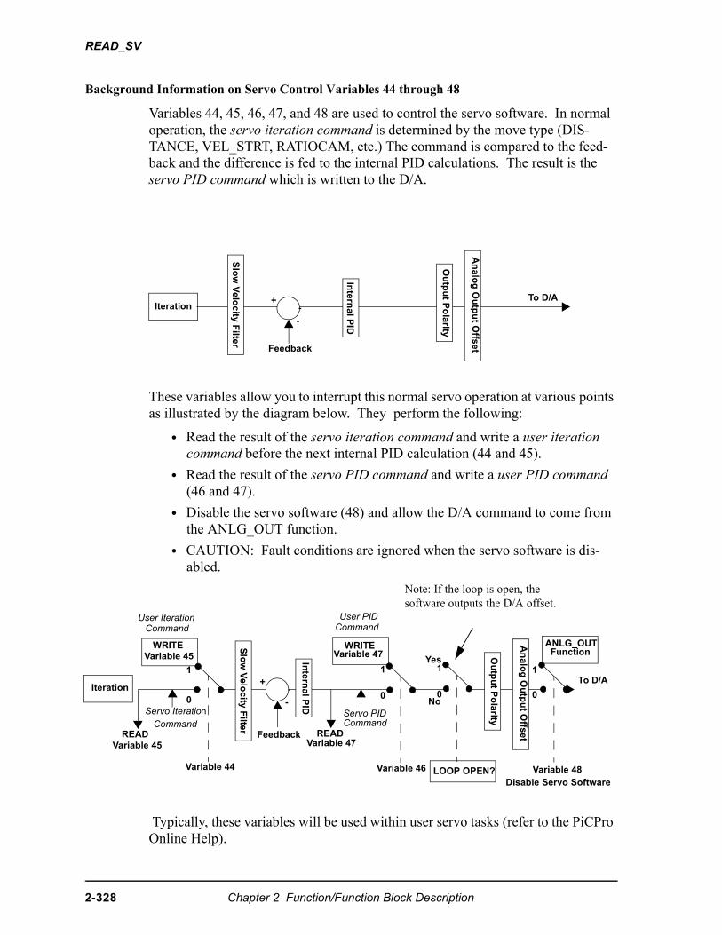
READ_SV
Background Information on Servo Control Variables 44 through 48
Variables 44, 45, 46, 47, and 48 are used to control the servo software. In normal operation, the servo iteration command is determined by the move type (DIS-TANCE, VEL_STRT, RATIOCAM, etc.) The command is compared to the feed-back and the difference is fed to the internal PID calculations. The result is the servo PID command which is written to the D/A.
These variables allow you to interrupt this normal servo operation at various points as illustrated by the diagram below. They perform the following:
• Read the result of the servo iteration command and write a user iteration command before the next internal PID calculation (44 and 45).
• Read the result of the servo PID command and write a user PID command (46 and 47).
• Disable the servo software (48) and allow the D/A command to come from the ANLG_OUT function.
• CAUTION: Fault conditions are ignored when the servo software is dis-abled.
Typically, these variables will be used within user servo tasks (refer to the PiCPro Online Help).
Iteration
Inte
rna
l PID
Feedback
+
-
To D/A
Slo
w V
elo
city
Filte
r
Ou
tpu
t Po
larity
An
alo
g O
utp
ut O
ffse
t
+
-
Slo
w V
elo
city
Filte
r
Inte
rna
l PID
Ou
tpu
t Po
larity
An
alo
g O
utp
ut O
ffse
t
1
0
READVariable 45
READVariable 47
1
0
1
0
To D/A
WRITEVariable 45
WRITEVariable 47
Variable 44 Variable 46 Variable 48
ANLG_OUT Function
Iteration
Disable Servo Software
Feedback
CommandUser Iteration
Command
Servo Iteration Command
User PID
CommandServo PID
1
0
LOOP OPEN?
Yes
No
Note: If the loop is open, the software outputs the D/A offset.
2-328 Chapter 2 Function/Function Block Description
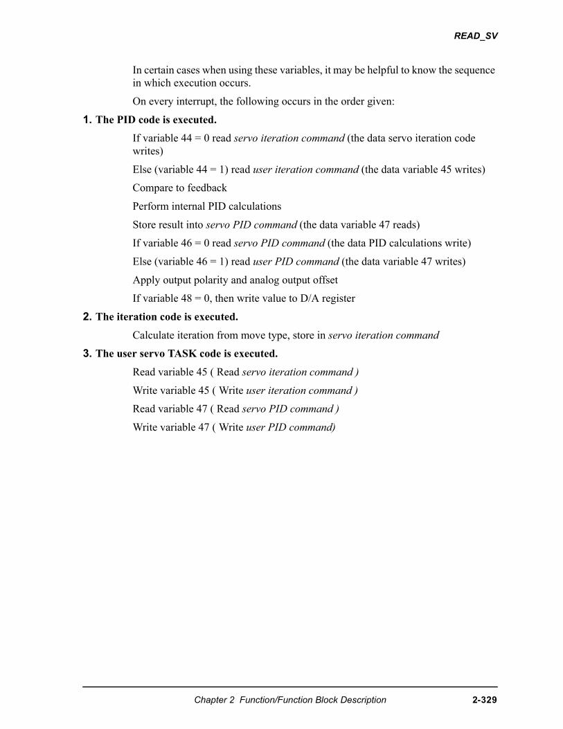
READ_SV
In certain cases when using these variables, it may be helpful to know the sequence in which execution occurs.
On every interrupt, the following occurs in the order given:
1. The PID code is executed.
If variable 44 = 0 read servo iteration command (the data servo iteration code writes)
Else (variable 44 = 1) read user iteration command (the data variable 45 writes)
Compare to feedback
Perform internal PID calculations
Store result into servo PID command (the data variable 47 reads)
If variable 46 = 0 read servo PID command (the data PID calculations write)
Else (variable 46 = 1) read user PID command (the data variable 47 writes)
Apply output polarity and analog output offset
If variable 48 = 0, then write value to D/A register
2. The iteration code is executed.
Calculate iteration from move type, store in servo iteration command
3. The user servo TASK code is executed.
Read variable 45 ( Read servo iteration command )
Write variable 45 ( Write user iteration command )
Read variable 47 ( Read servo PID command )
Write variable 47 ( Write user PID command)
Chapter 2 Function/Function Block Description 2-329
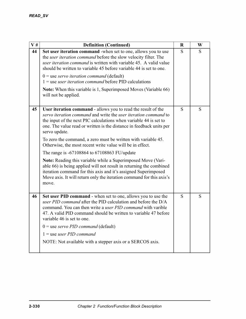
READ_SV
V # Definition (Continued) R W44 Set user iteration command -when set to one, allows you to use
the user iteration command before the slow velocity filter. The user iteration command is written with variable 45. A valid value should be written to variable 45 before variable 44 is set to one.
0 = use servo iteration command (default)1 = use user iteration command before PID calculations
Note: When this variable is 1, Superimposed Moves (Variable 66) will not be applied.
S S
45 User iteration command - allows you to read the result of the servo iteration command and write the user iteration command to the input of the next PIC calculations when variable 44 is set to one. The value read or written is the distance in feedback units per servo update.
To zero the command, a zero must be written with variable 45. Otherwise, the most recent write value will be in effect.
The range is -67108864 to 67108863 FU/update
Note: Reading this variable while a Superimposed Move (Vari-able 66) is being applied will not result in returning the combined iteration command for this axis and it’s assigned Superimposed Move axis. It will return only the iteration command for this axis’s move.
S S
46 Set user PID command - when set to one, allows you to use the user PID command after the PID calculation and before the D/A command. You can then write a user PID command with varible 47. A valid PID command should be written to variable 47 before variable 46 is set to one.
0 = use servo PID command (default)
1 = use user PID command
NOTE: Not available with a stepper axis or a SERCOS axis.
S S
2-330 Chapter 2 Function/Function Block Description
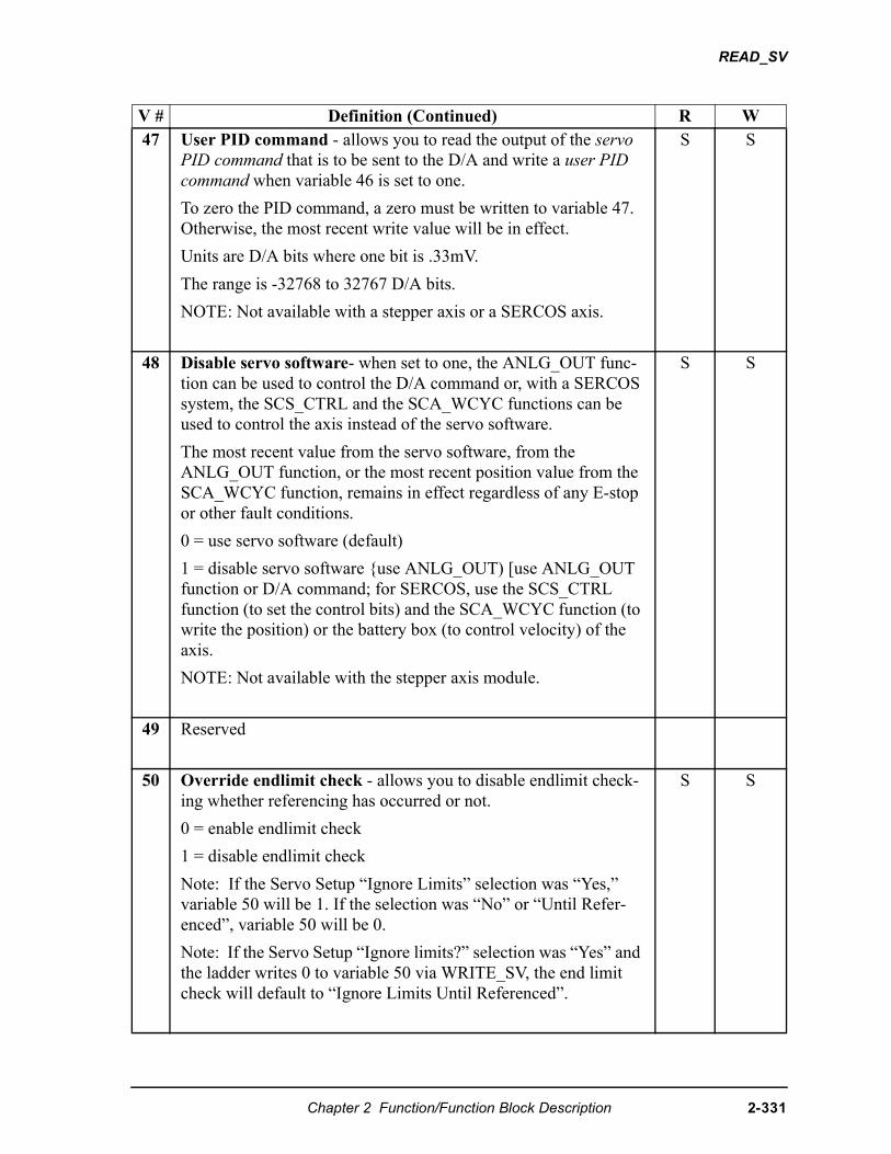
READ_SV
V # Definition (Continued) R W47 User PID command - allows you to read the output of the servo
PID command that is to be sent to the D/A and write a user PID command when variable 46 is set to one.
To zero the PID command, a zero must be written to variable 47. Otherwise, the most recent write value will be in effect.
Units are D/A bits where one bit is .33mV.
The range is -32768 to 32767 D/A bits.
NOTE: Not available with a stepper axis or a SERCOS axis.
S S
48 Disable servo software- when set to one, the ANLG_OUT func-tion can be used to control the D/A command or, with a SERCOS system, the SCS_CTRL and the SCA_WCYC functions can be used to control the axis instead of the servo software.
The most recent value from the servo software, from the ANLG_OUT function, or the most recent position value from the SCA_WCYC function, remains in effect regardless of any E-stop or other fault conditions.
0 = use servo software (default)
1 = disable servo software {use ANLG_OUT) [use ANLG_OUT function or D/A command; for SERCOS, use the SCS_CTRL function (to set the control bits) and the SCA_WCYC function (to write the position) or the battery box (to control velocity) of the axis.
NOTE: Not available with the stepper axis module.
S S
49 Reserved
50 Override endlimit check - allows you to disable endlimit check-ing whether referencing has occurred or not.
0 = enable endlimit check
1 = disable endlimit check
Note: If the Servo Setup “Ignore Limits” selection was “Yes,” variable 50 will be 1. If the selection was “No” or “Until Refer-enced”, variable 50 will be 0.
Note: If the Servo Setup “Ignore limits?” selection was “Yes” and the ladder writes 0 to variable 50 via WRITE_SV, the end limit check will default to “Ignore Limits Until Referenced”.
S S
Chapter 2 Function/Function Block Description 2-331
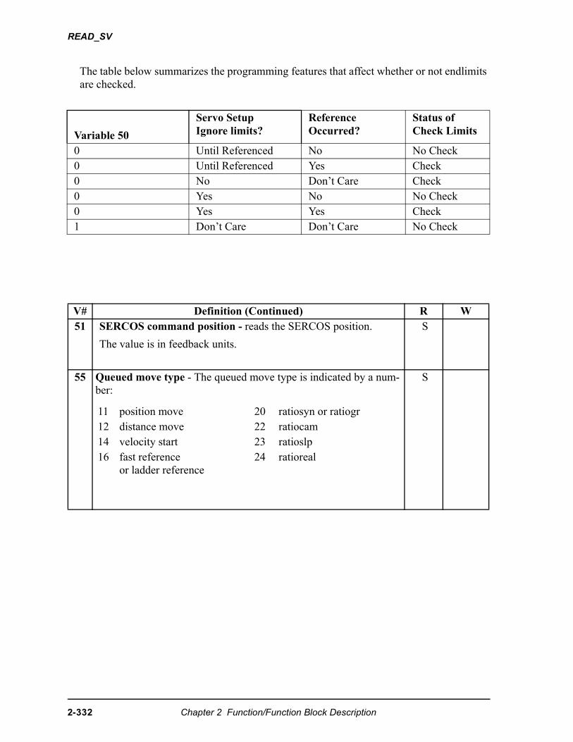
READ_SV
The table below summarizes the programming features that affect whether or not endlimits are checked.
Variable 50
Servo SetupIgnore limits?
Reference Occurred?
Status of Check Limits
0 Until Referenced No No Check0 Until Referenced Yes Check0 No Don’t Care Check0 Yes No No Check0 Yes Yes Check1 Don’t Care Don’t Care No Check
V# Definition (Continued) R W51 SERCOS command position - reads the SERCOS position.
The value is in feedback units.
S
55 Queued move type - The queued move type is indicated by a num-ber:
S
11 position move 20 ratiosyn or ratiogr 12 distance move 22 ratiocam 14 velocity start 23 ratioslp 16 fast reference
or ladder reference24 ratioreal
2-332 Chapter 2 Function/Function Block Description
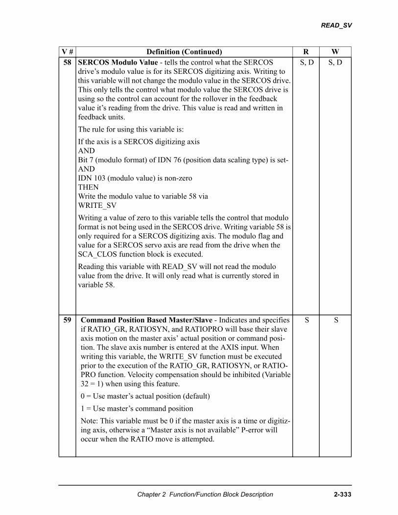
READ_SV
V # Definition (Continued) R W58 SERCOS Modulo Value - tells the control what the SERCOS
drive’s modulo value is for its SERCOS digitizing axis. Writing to this variable will not change the modulo value in the SERCOS drive. This only tells the control what modulo value the SERCOS drive is using so the control can account for the rollover in the feedback value it’s reading from the drive. This value is read and written in feedback units.
The rule for using this variable is:
If the axis is a SERCOS digitizing axisANDBit 7 (modulo format) of IDN 76 (position data scaling type) is set-ANDIDN 103 (modulo value) is non-zeroTHENWrite the modulo value to variable 58 viaWRITE_SV
Writing a value of zero to this variable tells the control that modulo format is not being used in the SERCOS drive. Writing variable 58 is only required for a SERCOS digitizing axis. The modulo flag and value for a SERCOS servo axis are read from the drive when the SCA_CLOS function block is executed.
Reading this variable with READ_SV will not read the modulo value from the drive. It will only read what is currently stored in variable 58.
S, D S, D
59 Command Position Based Master/Slave - Indicates and specifies if RATIO_GR, RATIOSYN, and RATIOPRO will base their slave axis motion on the master axis’ actual position or command posi-tion. The slave axis number is entered at the AXIS input. When writing this variable, the WRITE_SV function must be executed prior to the execution of the RATIO_GR, RATIOSYN, or RATIO-PRO function. Velocity compensation should be inhibited (Variable 32 = 1) when using this feature.
0 = Use master’s actual position (default)
1 = Use master’s command position
Note: This variable must be 0 if the master axis is a time or digitiz-ing axis, otherwise a “Master axis is not available” P-error will occur when the RATIO move is attempted.
S S
Chapter 2 Function/Function Block Description 2-333
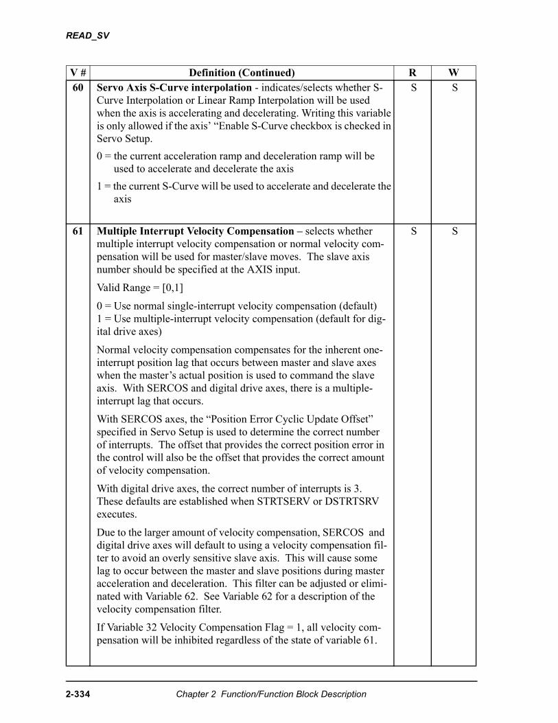
READ_SV
V # Definition (Continued) R W60 Servo Axis S-Curve interpolation - indicates/selects whether S-
Curve Interpolation or Linear Ramp Interpolation will be used when the axis is accelerating and decelerating. Writing this variable is only allowed if the axis’ “Enable S-Curve checkbox is checked in Servo Setup.
0 = the current acceleration ramp and deceleration ramp will beused to accelerate and decelerate the axis
1 = the current S-Curve will be used to accelerate and decelerate the axis
S S
61 Multiple Interrupt Velocity Compensation – selects whether multiple interrupt velocity compensation or normal velocity com-pensation will be used for master/slave moves. The slave axis number should be specified at the AXIS input.
Valid Range = [0,1]
0 = Use normal single-interrupt velocity compensation (default)1 = Use multiple-interrupt velocity compensation (default for dig-ital drive axes)
Normal velocity compensation compensates for the inherent one-interrupt position lag that occurs between master and slave axes when the master’s actual position is used to command the slave axis. With SERCOS and digital drive axes, there is a multiple-interrupt lag that occurs.
With SERCOS axes, the “Position Error Cyclic Update Offset” specified in Servo Setup is used to determine the correct number of interrupts. The offset that provides the correct position error in the control will also be the offset that provides the correct amount of velocity compensation.
With digital drive axes, the correct number of interrupts is 3. These defaults are established when STRTSERV or DSTRTSRV executes.
Due to the larger amount of velocity compensation, SERCOS and digital drive axes will default to using a velocity compensation fil-ter to avoid an overly sensitive slave axis. This will cause some lag to occur between the master and slave positions during master acceleration and deceleration. This filter can be adjusted or elimi-nated with Variable 62. See Variable 62 for a description of the velocity compensation filter.
If Variable 32 Velocity Compensation Flag = 1, all velocity com-pensation will be inhibited regardless of the state of variable 61.
S S
2-334 Chapter 2 Function/Function Block Description
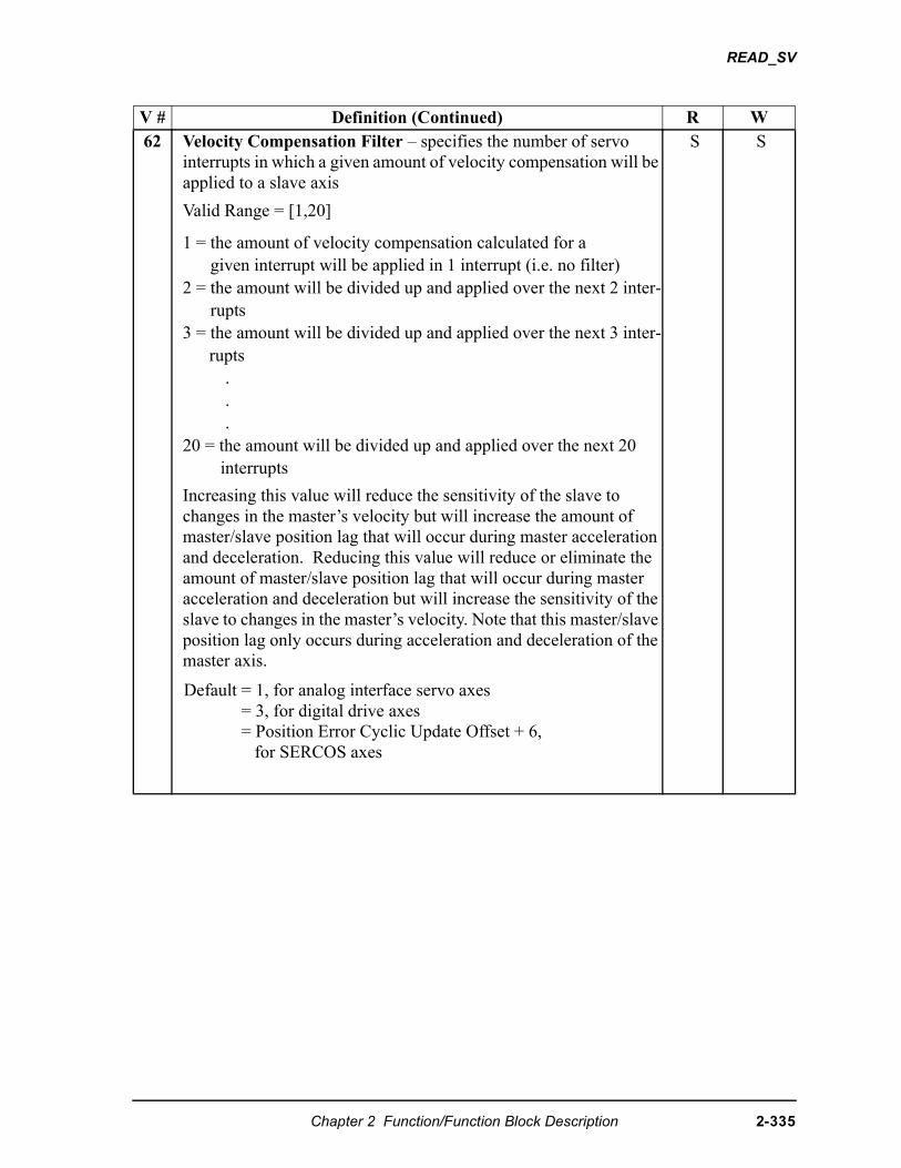
READ_SV
V # Definition (Continued) R W62 Velocity Compensation Filter – specifies the number of servo
interrupts in which a given amount of velocity compensation will be applied to a slave axis
Valid Range = [1,20]
1 = the amount of velocity compensation calculated for agiven interrupt will be applied in 1 interrupt (i.e. no filter)
2 = the amount will be divided up and applied over the next 2 inter-rupts
3 = the amount will be divided up and applied over the next 3 inter-rupts
.
.
.20 = the amount will be divided up and applied over the next 20
interrupts
Increasing this value will reduce the sensitivity of the slave to changes in the master’s velocity but will increase the amount of master/slave position lag that will occur during master acceleration and deceleration. Reducing this value will reduce or eliminate the amount of master/slave position lag that will occur during master acceleration and deceleration but will increase the sensitivity of the slave to changes in the master’s velocity. Note that this master/slave position lag only occurs during acceleration and deceleration of the master axis.
Default = 1, for analog interface servo axes = 3, for digital drive axes = Position Error Cyclic Update Offset + 6, for SERCOS axes
S S
Chapter 2 Function/Function Block Description 2-335
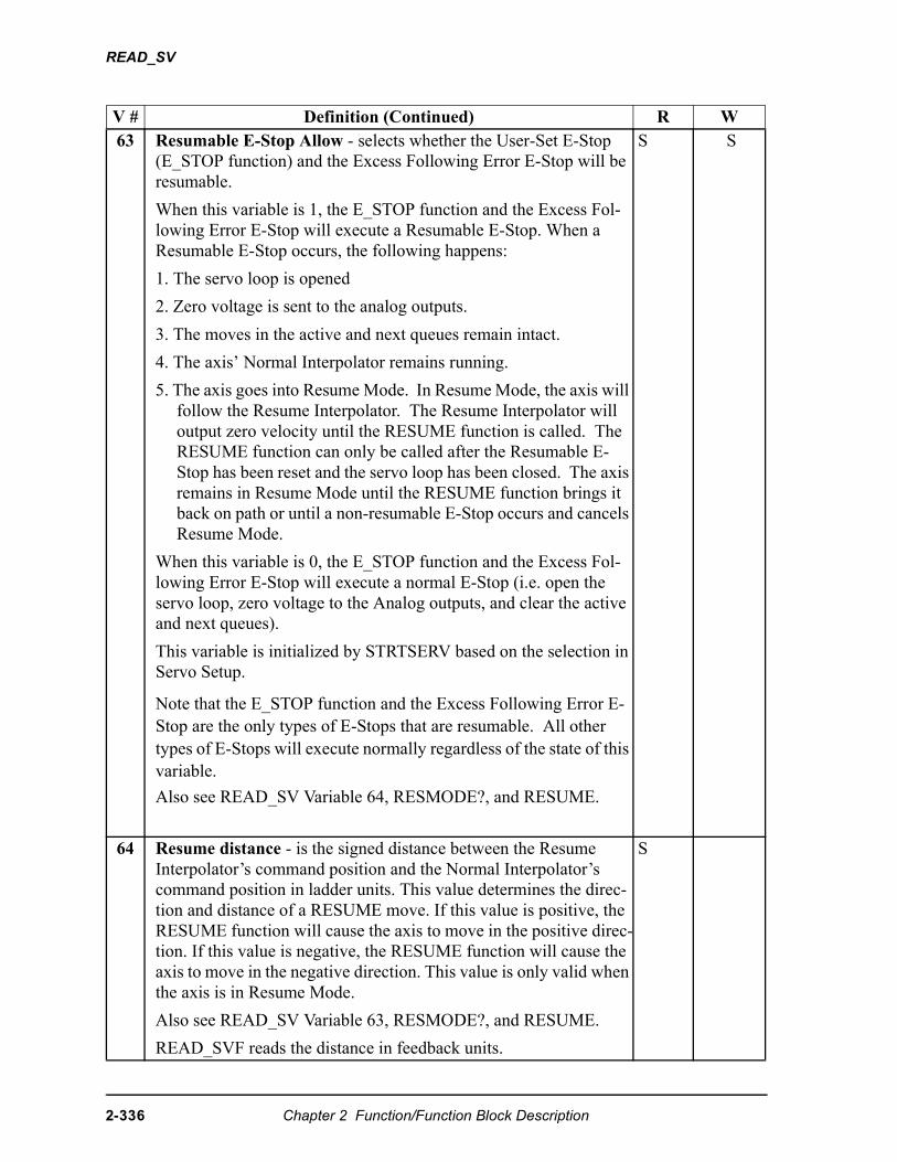
READ_SV
V # Definition (Continued) R W63 Resumable E-Stop Allow - selects whether the User-Set E-Stop
(E_STOP function) and the Excess Following Error E-Stop will be resumable.
When this variable is 1, the E_STOP function and the Excess Fol-lowing Error E-Stop will execute a Resumable E-Stop. When a Resumable E-Stop occurs, the following happens:
1. The servo loop is opened
2. Zero voltage is sent to the analog outputs.
3. The moves in the active and next queues remain intact.
4. The axis’ Normal Interpolator remains running.
5. The axis goes into Resume Mode. In Resume Mode, the axis will follow the Resume Interpolator. The Resume Interpolator will output zero velocity until the RESUME function is called. The RESUME function can only be called after the Resumable E-Stop has been reset and the servo loop has been closed. The axis remains in Resume Mode until the RESUME function brings it back on path or until a non-resumable E-Stop occurs and cancels Resume Mode.
When this variable is 0, the E_STOP function and the Excess Fol-lowing Error E-Stop will execute a normal E-Stop (i.e. open the servo loop, zero voltage to the Analog outputs, and clear the active and next queues).
This variable is initialized by STRTSERV based on the selection in Servo Setup.
Note that the E_STOP function and the Excess Following Error E-Stop are the only types of E-Stops that are resumable. All other types of E-Stops will execute normally regardless of the state of this variable.
Also see READ_SV Variable 64, RESMODE?, and RESUME.
S S
64 Resume distance - is the signed distance between the Resume Interpolator’s command position and the Normal Interpolator’s command position in ladder units. This value determines the direc-tion and distance of a RESUME move. If this value is positive, the RESUME function will cause the axis to move in the positive direc-tion. If this value is negative, the RESUME function will cause the axis to move in the negative direction. This value is only valid when the axis is in Resume Mode.
Also see READ_SV Variable 63, RESMODE?, and RESUME.
READ_SVF reads the distance in feedback units.
S
2-336 Chapter 2 Function/Function Block Description
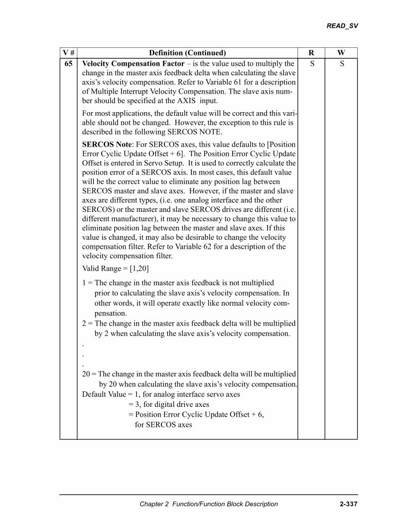
READ_SV
V # Definition (Continued) R W65 Velocity Compensation Factor – is the value used to multiply the
change in the master axis feedback delta when calculating the slave axis’s velocity compensation. Refer to Variable 61 for a description of Multiple Interrupt Velocity Compensation. The slave axis num-ber should be specified at the AXIS input.
For most applications, the default value will be correct and this vari-able should not be changed. However, the exception to this rule is described in the following SERCOS NOTE.
SERCOS Note: For SERCOS axes, this value defaults to [Position Error Cyclic Update Offset + 6]. The Position Error Cyclic Update Offset is entered in Servo Setup. It is used to correctly calculate the position error of a SERCOS axis. In most cases, this default value will be the correct value to eliminate any position lag between SERCOS master and slave axes. However, if the master and slave axes are different types, (i.e. one analog interface and the other SERCOS) or the master and slave SERCOS drives are different (i.e. different manufacturer), it may be necessary to change this value to eliminate position lag between the master and slave axes. If this value is changed, it may also be desirable to change the velocity compensation filter. Refer to Variable 62 for a description of the velocity compensation filter.
Valid Range = [1,20]
1 = The change in the master axis feedback is not multipliedprior to calculating the slave axis’s velocity compensation. In other words, it will operate exactly like normal velocity com-pensation.
2 = The change in the master axis feedback delta will be multiplied by 2 when calculating the slave axis’s velocity compensation.
.
.
.20 = The change in the master axis feedback delta will be multiplied
by 20 when calculating the slave axis’s velocity compensation.Default Value = 1, for analog interface servo axes
= 3, for digital drive axes = Position Error Cyclic Update Offset + 6, for SERCOS axes
S S
Chapter 2 Function/Function Block Description 2-337
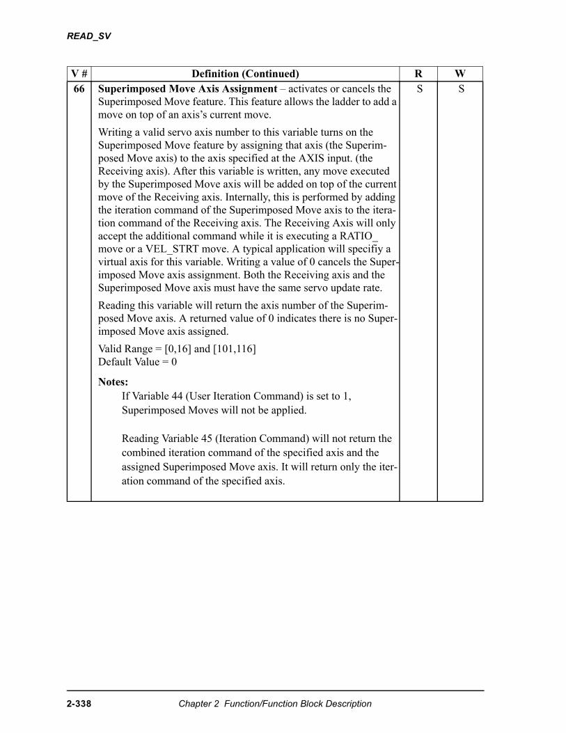
READ_SV
V # Definition (Continued) R W66 Superimposed Move Axis Assignment – activates or cancels the
Superimposed Move feature. This feature allows the ladder to add a move on top of an axis’s current move.
Writing a valid servo axis number to this variable turns on the Superimposed Move feature by assigning that axis (the Superim-posed Move axis) to the axis specified at the AXIS input. (the Receiving axis). After this variable is written, any move executed by the Superimposed Move axis will be added on top of the current move of the Receiving axis. Internally, this is performed by adding the iteration command of the Superimposed Move axis to the itera-tion command of the Receiving axis. The Receiving Axis will only accept the additional command while it is executing a RATIO_ move or a VEL_STRT move. A typical application will specifiy a virtual axis for this variable. Writing a value of 0 cancels the Super-imposed Move axis assignment. Both the Receiving axis and the Superimposed Move axis must have the same servo update rate.
Reading this variable will return the axis number of the Superim-posed Move axis. A returned value of 0 indicates there is no Super-imposed Move axis assigned.
Valid Range = [0,16] and [101,116]Default Value = 0
Notes:If Variable 44 (User Iteration Command) is set to 1, Superimposed Moves will not be applied.
Reading Variable 45 (Iteration Command) will not return thecombined iteration command of the specified axis and the assigned Superimposed Move axis. It will return only the iter-ation command of the specified axis.
S S
2-338 Chapter 2 Function/Function Block Description
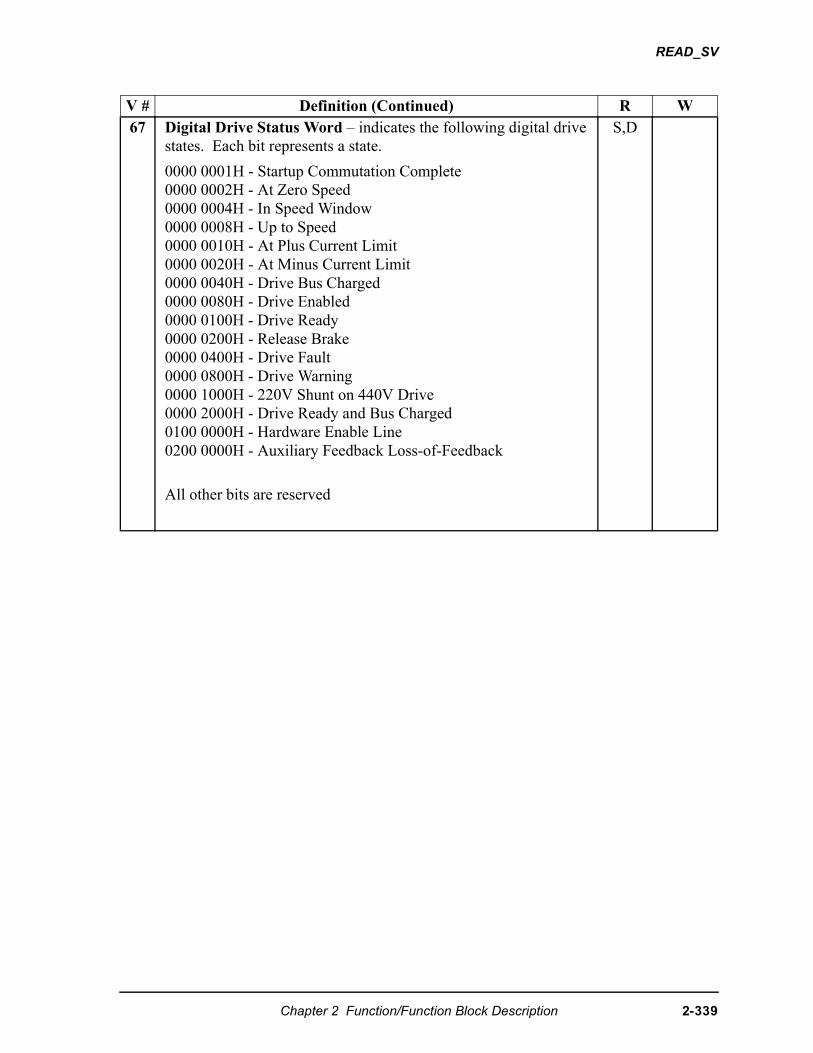
READ_SV
V # Definition (Continued) R W67 Digital Drive Status Word – indicates the following digital drive
states. Each bit represents a state.
0000 0001H - Startup Commutation Complete 0000 0002H - At Zero Speed 0000 0004H - In Speed Window 0000 0008H - Up to Speed0000 0010H - At Plus Current Limit 0000 0020H - At Minus Current Limit 0000 0040H - Drive Bus Charged0000 0080H - Drive Enabled0000 0100H - Drive Ready0000 0200H - Release Brake0000 0400H - Drive Fault0000 0800H - Drive Warning0000 1000H - 220V Shunt on 440V Drive0000 2000H - Drive Ready and Bus Charged0100 0000H - Hardware Enable Line0200 0000H - Auxiliary Feedback Loss-of-Feedback
All other bits are reserved
S,D
Chapter 2 Function/Function Block Description 2-339
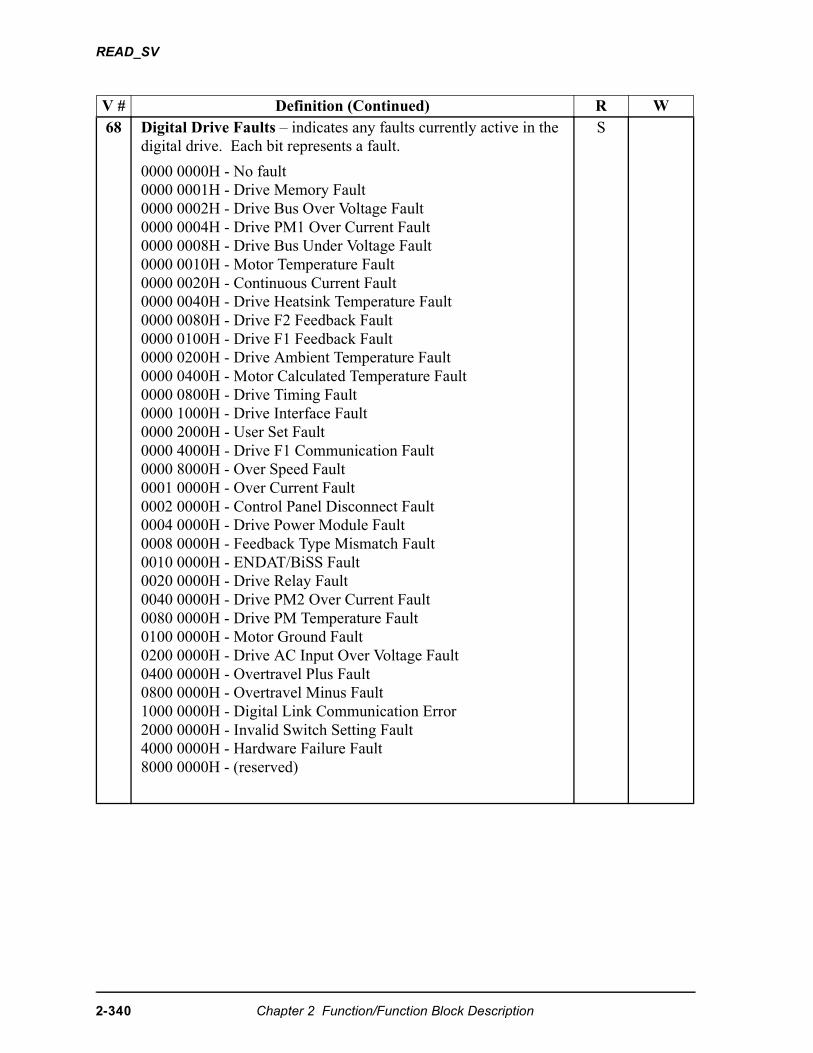
READ_SV
V # Definition (Continued) R W68 Digital Drive Faults – indicates any faults currently active in the
digital drive. Each bit represents a fault.
0000 0000H - No fault 0000 0001H - Drive Memory Fault 0000 0002H - Drive Bus Over Voltage Fault0000 0004H - Drive PM1 Over Current Fault 0000 0008H - Drive Bus Under Voltage Fault 0000 0010H - Motor Temperature Fault0000 0020H - Continuous Current Fault0000 0040H - Drive Heatsink Temperature Fault0000 0080H - Drive F2 Feedback Fault 0000 0100H - Drive F1 Feedback Fault 0000 0200H - Drive Ambient Temperature Fault0000 0400H - Motor Calculated Temperature Fault0000 0800H - Drive Timing Fault0000 1000H - Drive Interface Fault 0000 2000H - User Set Fault 0000 4000H - Drive F1 Communication Fault0000 8000H - Over Speed Fault0001 0000H - Over Current Fault 0002 0000H - Control Panel Disconnect Fault0004 0000H - Drive Power Module Fault0008 0000H - Feedback Type Mismatch Fault0010 0000H - ENDAT/BiSS Fault0020 0000H - Drive Relay Fault 0040 0000H - Drive PM2 Over Current Fault0080 0000H - Drive PM Temperature Fault0100 0000H - Motor Ground Fault 0200 0000H - Drive AC Input Over Voltage Fault0400 0000H - Overtravel Plus Fault0800 0000H - Overtravel Minus Fault1000 0000H - Digital Link Communication Error2000 0000H - Invalid Switch Setting Fault4000 0000H - Hardware Failure Fault8000 0000H - (reserved)
S
2-340 Chapter 2 Function/Function Block Description
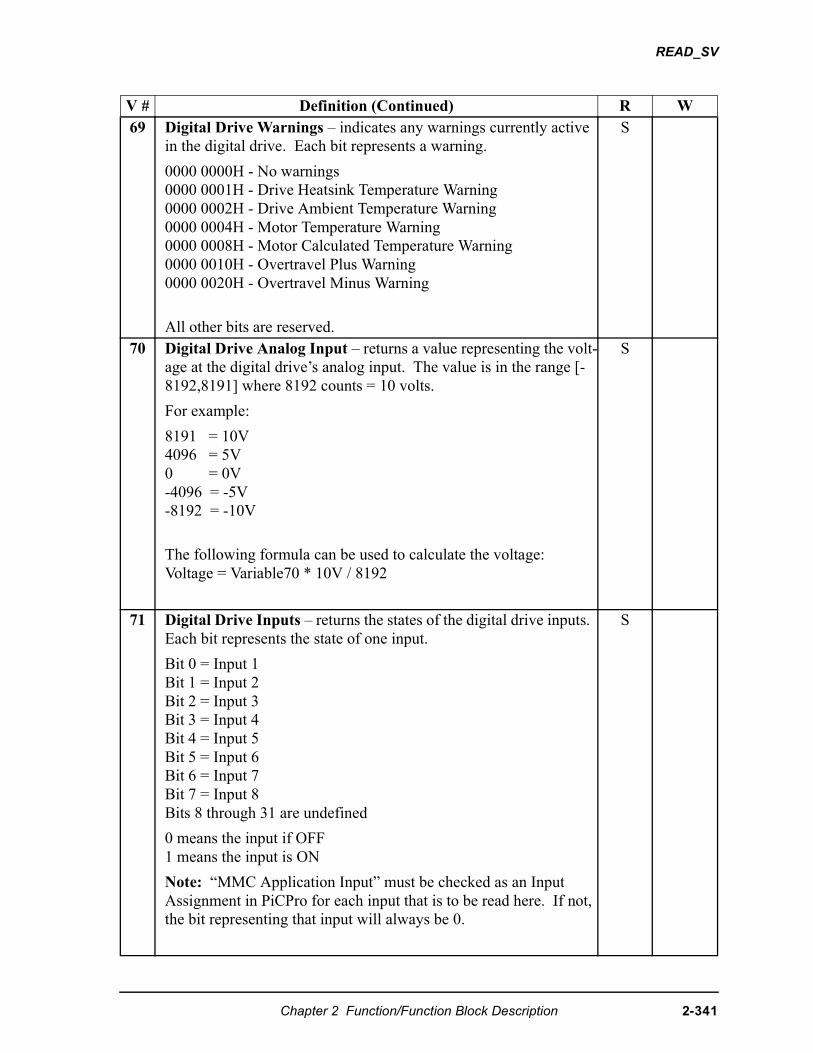
READ_SV
V # Definition (Continued) R W69 Digital Drive Warnings – indicates any warnings currently active
in the digital drive. Each bit represents a warning.
0000 0000H - No warnings0000 0001H - Drive Heatsink Temperature Warning 0000 0002H - Drive Ambient Temperature Warning0000 0004H - Motor Temperature Warning0000 0008H - Motor Calculated Temperature Warning0000 0010H - Overtravel Plus Warning0000 0020H - Overtravel Minus Warning
All other bits are reserved.
S
70 Digital Drive Analog Input – returns a value representing the volt-age at the digital drive’s analog input. The value is in the range [-8192,8191] where 8192 counts = 10 volts.
For example:
8191 = 10V 4096 = 5V 0 = 0V -4096 = -5V -8192 = -10V
The following formula can be used to calculate the voltage: Voltage = Variable70 * 10V / 8192
S
71 Digital Drive Inputs – returns the states of the digital drive inputs. Each bit represents the state of one input.
Bit 0 = Input 1Bit 1 = Input 2Bit 2 = Input 3Bit 3 = Input 4Bit 4 = Input 5Bit 5 = Input 6Bit 6 = Input 7Bit 7 = Input 8Bits 8 through 31 are undefined
0 means the input if OFF1 means the input is ON
Note: “MMC Application Input” must be checked as an Input Assignment in PiCPro for each input that is to be read here. If not, the bit representing that input will always be 0.
S
Chapter 2 Function/Function Block Description 2-341
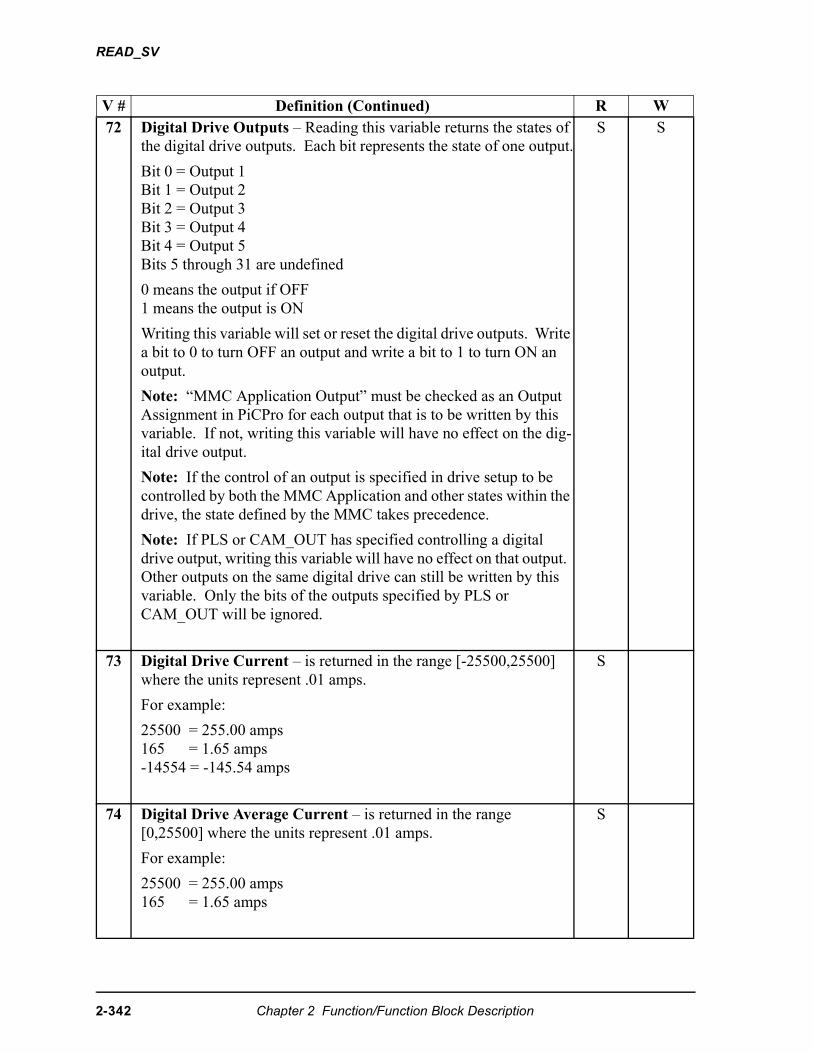
READ_SV
V # Definition (Continued) R W72 Digital Drive Outputs – Reading this variable returns the states of
the digital drive outputs. Each bit represents the state of one output.
Bit 0 = Output 1Bit 1 = Output 2Bit 2 = Output 3Bit 3 = Output 4Bit 4 = Output 5Bits 5 through 31 are undefined
0 means the output if OFF1 means the output is ON
Writing this variable will set or reset the digital drive outputs. Write a bit to 0 to turn OFF an output and write a bit to 1 to turn ON an output.
Note: “MMC Application Output” must be checked as an Output Assignment in PiCPro for each output that is to be written by this variable. If not, writing this variable will have no effect on the dig-ital drive output.
Note: If the control of an output is specified in drive setup to be controlled by both the MMC Application and other states within the drive, the state defined by the MMC takes precedence.
Note: If PLS or CAM_OUT has specified controlling a digital drive output, writing this variable will have no effect on that output. Other outputs on the same digital drive can still be written by this variable. Only the bits of the outputs specified by PLS or CAM_OUT will be ignored.
S S
73 Digital Drive Current – is returned in the range [-25500,25500] where the units represent .01 amps.
For example:
25500 = 255.00 amps 165 = 1.65 amps-14554 = -145.54 amps
S
74 Digital Drive Average Current – is returned in the range [0,25500] where the units represent .01 amps.
For example:
25500 = 255.00 amps 165 = 1.65 amps
S
2-342 Chapter 2 Function/Function Block Description
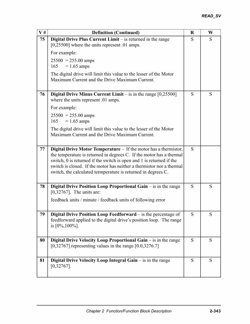
READ_SV
V # Definition (Continued) R W75 Digital Drive Plus Current Limit – is returned in the range
[0,25500] where the units represent .01 amps.
For example:
25500 = 255.00 amps 165 = 1.65 amps
The digital drive will limit this value to the lesser of the Motor Maximum Current and the Drive Maximum Current.
S S
76 Digital Drive Minus Current Limit – is in the range [0,25500] where the units represent .01 amps.
For example:
25500 = 255.00 amps 165 = 1.65 amps
The digital drive will limit this value to the lesser of the Motor Maximum Current and the Drive Maximum Current.
S S
77 Digital Drive Motor Temperature – If the motor has a thermistor, the temperature is returned in degrees C. If the motor has a thermal switch, 0 is returned if the switch is open and 1 is returned if the switch is closed. If the motor has neither a thermistor nor a thermal switch, the calculated termperature is returned in degrees C.
S
78 Digital Drive Position Loop Proportional Gain – is in the range [0,32767]. The units are:
feedback units / minute / feedback units of following error
S S
79 Digital Drive Position Loop Feedforward – is the percentage of feedforward applied to the digital drive’s position loop. The range is [0%,100%].
S S
80 Digital Drive Velocity Loop Proportional Gain – is in the range [0,32767] representing values in the range [0.0,3276.7]
S S
81 Digital Drive Velocity Loop Integral Gain – is in the range [0,32767].
S S
Chapter 2 Function/Function Block Description 2-343

READ_SV
V # Definition (Continued) R W82 Digital Drive Velocity Loop Integrator Inhibit
0 = do not inhibit the digital drive velocity loop integrator1 = inhibit the digital drive velocity loop integrator
S S
83 Digital Drive Velocity Loop Integrator Hold
0 = do not hold the digital drive velocity loop integrator1 = hold the digital drive velocity loop integrator
S S
84 Digital Drive Current Plus Enable
0 = disable digital drive plus current1 = enable digital drive plus currentdefault = 1
S S
85 Digital Drive Current Minus Enable
0 = disable digital drive minus current1 = enable digital drive minus currentdefault = 1
S S
86 Prevent Digital Drive Overtravel Plus Fault – is typically used to prevent a Digital Drive Overtravel Plus Fault from occurring while the axis is being moved off the plus limit switch. This only applies to a digital drive system.
0 = generate an Overtravel Plus Fault when the plus travel limit is reached1 = do not generate an Overtravel Plus Fault when the plus travel limit is reached
Note: The drive will always prohibit travel beyond the plus limit regardless of the state of this variable. This variable only prevents the drive fault from being generated.
Note: A drive warning is always generated when the axis reaches the plus limit switch regardless of the state of this variable. See variable 69.
S S
2-344 Chapter 2 Function/Function Block Description
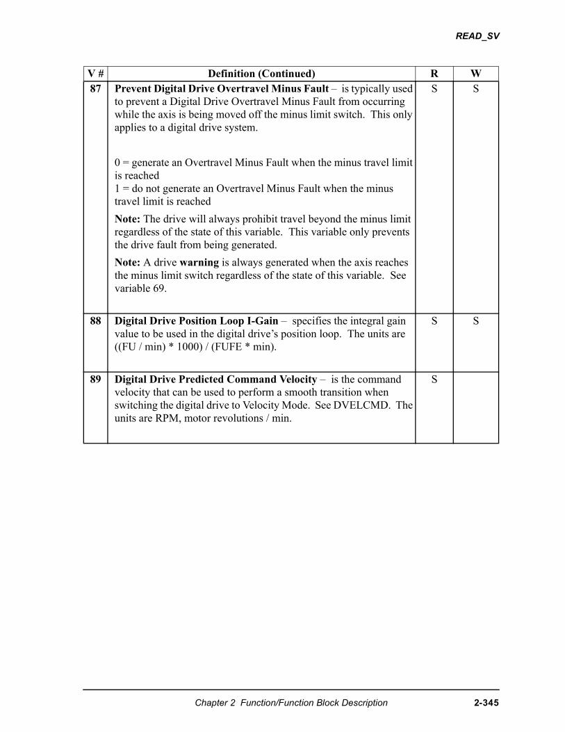
READ_SV
V # Definition (Continued) R W87 Prevent Digital Drive Overtravel Minus Fault – is typically used
to prevent a Digital Drive Overtravel Minus Fault from occurring while the axis is being moved off the minus limit switch. This only applies to a digital drive system.
0 = generate an Overtravel Minus Fault when the minus travel limit is reached1 = do not generate an Overtravel Minus Fault when the minus travel limit is reached
Note: The drive will always prohibit travel beyond the minus limit regardless of the state of this variable. This variable only prevents the drive fault from being generated.
Note: A drive warning is always generated when the axis reaches the minus limit switch regardless of the state of this variable. See variable 69.
S S
88 Digital Drive Position Loop I-Gain – specifies the integral gain value to be used in the digital drive’s position loop. The units are ((FU / min) * 1000) / (FUFE * min).
S S
89 Digital Drive Predicted Command Velocity – is the command velocity that can be used to perform a smooth transition when switching the digital drive to Velocity Mode. See DVELCMD. The units are RPM, motor revolutions / min.
S
Chapter 2 Function/Function Block Description 2-345
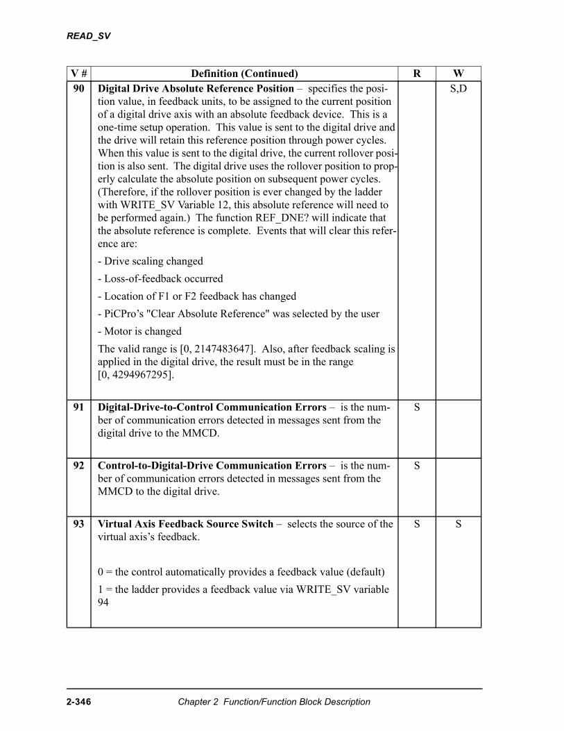
READ_SV
V # Definition (Continued) R W90 Digital Drive Absolute Reference Position – specifies the posi-
tion value, in feedback units, to be assigned to the current position of a digital drive axis with an absolute feedback device. This is a one-time setup operation. This value is sent to the digital drive and the drive will retain this reference position through power cycles. When this value is sent to the digital drive, the current rollover posi-tion is also sent. The digital drive uses the rollover position to prop-erly calculate the absolute position on subsequent power cycles. (Therefore, if the rollover position is ever changed by the ladder with WRITE_SV Variable 12, this absolute reference will need to be performed again.) The function REF_DNE? will indicate that the absolute reference is complete. Events that will clear this refer-ence are:
- Drive scaling changed
- Loss-of-feedback occurred
- Location of F1 or F2 feedback has changed
- PiCPro’s "Clear Absolute Reference" was selected by the user
- Motor is changed
The valid range is [0, 2147483647]. Also, after feedback scaling is applied in the digital drive, the result must be in the range [0, 4294967295].
S,D
91 Digital-Drive-to-Control Communication Errors – is the num-ber of communication errors detected in messages sent from the digital drive to the MMCD.
S
92 Control-to-Digital-Drive Communication Errors – is the num-ber of communication errors detected in messages sent from the MMCD to the digital drive.
S
93 Virtual Axis Feedback Source Switch – selects the source of the virtual axis’s feedback.
0 = the control automatically provides a feedback value (default)
1 = the ladder provides a feedback value via WRITE_SV variable 94
S S
2-346 Chapter 2 Function/Function Block Description
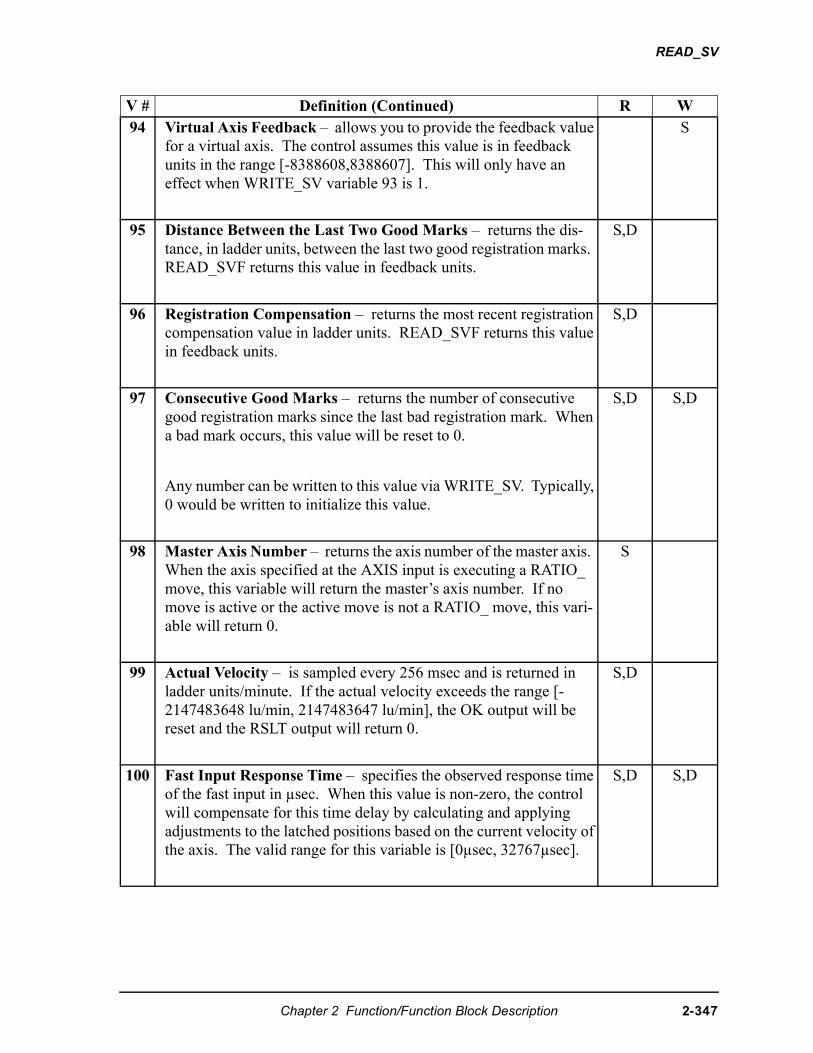
READ_SV
V # Definition (Continued) R W94 Virtual Axis Feedback – allows you to provide the feedback value
for a virtual axis. The control assumes this value is in feedback units in the range [-8388608,8388607]. This will only have an effect when WRITE_SV variable 93 is 1.
S
95 Distance Between the Last Two Good Marks – returns the dis-tance, in ladder units, between the last two good registration marks. READ_SVF returns this value in feedback units.
S,D
96 Registration Compensation – returns the most recent registration compensation value in ladder units. READ_SVF returns this value in feedback units.
S,D
97 Consecutive Good Marks – returns the number of consecutive good registration marks since the last bad registration mark. When a bad mark occurs, this value will be reset to 0.
Any number can be written to this value via WRITE_SV. Typically, 0 would be written to initialize this value.
S,D S,D
98 Master Axis Number – returns the axis number of the master axis. When the axis specified at the AXIS input is executing a RATIO_ move, this variable will return the master’s axis number. If no move is active or the active move is not a RATIO_ move, this vari-able will return 0.
S
99 Actual Velocity – is sampled every 256 msec and is returned in ladder units/minute. If the actual velocity exceeds the range [-2147483648 lu/min, 2147483647 lu/min], the OK output will be reset and the RSLT output will return 0.
S,D
100 Fast Input Response Time – specifies the observed response time of the fast input in µsec. When this value is non-zero, the control will compensate for this time delay by calculating and applying adjustments to the latched positions based on the current velocity of the axis. The valid range for this variable is [0µsec, 32767µsec].
S,D S,D
Chapter 2 Function/Function Block Description 2-347
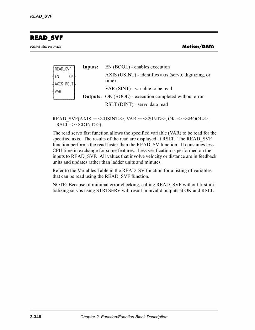
READ_SVF
READ_SVFRead Servo Fast Motion/DATA
READ_SVF(AXIS := <<USINT>>, VAR := <<SINT>>, OK => <<BOOL>>, RSLT => <<DINT>>)
The read servo fast function allows the specified variable (VAR) to be read for the specified axis. The results of the read are displayed at RSLT. The READ_SVF function performs the read faster than the READ_SV function. It consumes less CPU time in exchange for some features. Less verification is performed on the inputs to READ_SVF. All values that involve velocity or distance are in feedback units and updates rather than ladder units and minutes.
Refer to the Variables Table in the READ_SV function for a listing of variables that can be read using the READ_SVF function.
NOTE: Because of minimal error checking, calling READ_SVF without first ini-tializing servos using STRTSERV will result in invalid outputs at OK and RSLT.
⁄ƒƒƒƒƒƒƒƒƒø ≥READ_SVF ≥ ≥ ≥ ¥EN OK√ ≥ ≥ ¥AXIS RSLT√ ≥ ≥ ¥VAR ≥ ≥ ≥ ¿ƒƒƒƒƒƒƒƒƒŸ
Inputs: EN (BOOL) - enables execution
AXIS (USINT) - identifies axis (servo, digitizing, or time)
VAR (SINT) - variable to be read
Outputs: OK (BOOL) - execution completed without error
RSLT (DINT) - servo data read
2-348 Chapter 2 Function/Function Block Description
REAL2DW
REAL2DIReal to Double Integer Datatype/REALCONV
REAL2DI(N := <<REAL>>, OK => <<BOOL>>, OUT => <<DINT>>)
The REAL2DI function converts a real into a double integer. The result is placed in a variable at OUT.
REAL2DWReal to Double Word Datatype/REALCONV
REAL2DW(IN := <<REAL>>, OK => <<BOOL>>, OUT => <<DWORD>>)
The REAL2DW function converts a real into a double word. The result is placed in a variable at OUT.
⁄ƒƒƒƒƒƒƒƒƒø≥ REAL2DI ≥≥ ≥¥EN OK√≥ ≥¥IN OUT√≥ ≥¿ƒƒƒƒƒƒƒƒƒŸ
Inputs: EN (BOOL) - enables execution
IN (REAL) - value to convert
Outputs: OK (BOOL) - execution completed without error
OUT (DINT) - converted value
⁄ƒƒƒƒƒƒƒƒƒø≥ REAL2DW ≥≥ ≥¥EN OK√≥ ≥¥IN OUT√≥ ≥¿ƒƒƒƒƒƒƒƒƒŸ
Inputs: EN (BOOL) - enables execution
IN (REAL) - value to convert
Outputs: OK (BOOL) -execution completed without error
OUT (DWORD) - converted value
Chapter 2 Function/Function Block Description 2-349
REAL2LR
REAL2LRReal to Long Real Datatype/REALCONV
REAL2LR(IN := <<REAL>>, OK => <<BOOL>>, OUT => <<LREAL>>)
The REAL2LR function converts a real into a long real. The result is placed in a variable at OUT.
REAL2UDIReal to Unsigned Double Integer Datatype/REALCONV
REAL2UDI(IN := <<REAL>>, OK => <<BOOL>>, OUT => <<UDINT>>)
The REAL2UDI function converts a real into a unsigned double integer. The result is placed in a variable at OUT.
⁄ƒƒƒƒƒƒƒƒƒø≥ REAL2LR ≥≥ ≥¥EN OK√≥ ≥¥IN OUT√≥ ≥¿ƒƒƒƒƒƒƒƒƒŸ
Inputs: EN (BOOL) - enables execution
IN (REAL) - value to convert
Outputs: OK (BOOL) - execution completed without error
OUT (LREAL) - converted value
⁄ƒƒƒƒƒƒƒƒƒø≥ REAL2UDI≥≥ ≥¥EN OK√≥ ≥¥IN OUT√≥ ≥¿ƒƒƒƒƒƒƒƒƒŸ
Inputs: EN (BOOL) - enables execution
IN (REAL) - value to convert
Outputs:OK (BOOL) - execution completed without error
OUT (UDINT) - converted value
2-350 Chapter 2 Function/Function Block Description
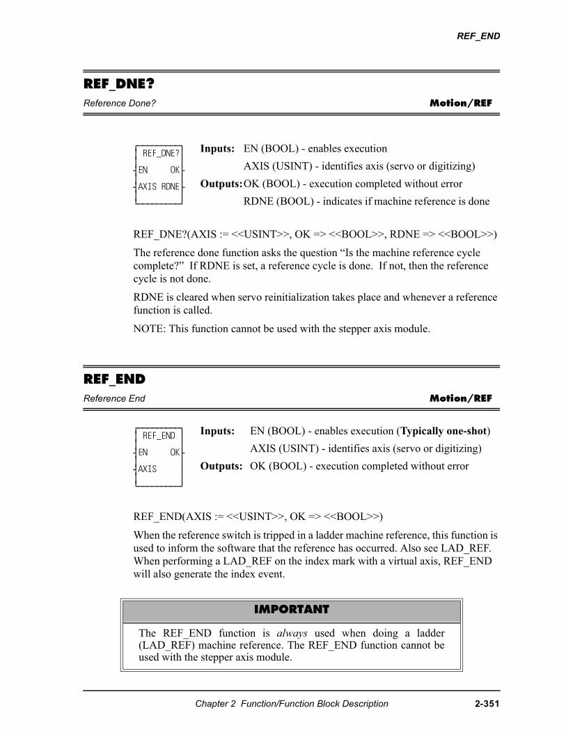
REF_END
REF_DNE?Reference Done? Motion/REF
REF_DNE?(AXIS := <<USINT>>, OK => <<BOOL>>, RDNE => <<BOOL>>)
The reference done function asks the question “Is the machine reference cycle complete?” If RDNE is set, a reference cycle is done. If not, then the reference cycle is not done.
RDNE is cleared when servo reinitialization takes place and whenever a reference function is called.
NOTE: This function cannot be used with the stepper axis module.
REF_ENDReference End Motion/REF
REF_END(AXIS := <<USINT>>, OK => <<BOOL>>)
When the reference switch is tripped in a ladder machine reference, this function is used to inform the software that the reference has occurred. Also see LAD_REF.When performing a LAD_REF on the index mark with a virtual axis, REF_END will also generate the index event.
⁄ƒƒƒƒƒƒƒƒƒø≥ REF_DNE?≥≥ ≥¥EN OK√≥ ≥¥AXIS RDNE√≥ ≥¿ƒƒƒƒƒƒƒƒƒŸ
Inputs: EN (BOOL) - enables execution
AXIS (USINT) - identifies axis (servo or digitizing)
Outputs:OK (BOOL) - execution completed without error
RDNE (BOOL) - indicates if machine reference is done
⁄ƒƒƒƒƒƒƒƒƒø ≥ REF_END ≥ ≥ ≥ ¥EN OK√ ≥ ≥ ¥AXIS ≥ ≥ ≥ ¿ƒƒƒƒƒƒƒƒƒŸ
Inputs: EN (BOOL) - enables execution (Typically one-shot)
AXIS (USINT) - identifies axis (servo or digitizing)
Outputs: OK (BOOL) - execution completed without error
IMPORTANT
The REF_END function is always used when doing a ladder(LAD_REF) machine reference. The REF_END function cannot beused with the stepper axis module.
Chapter 2 Function/Function Block Description 2-351
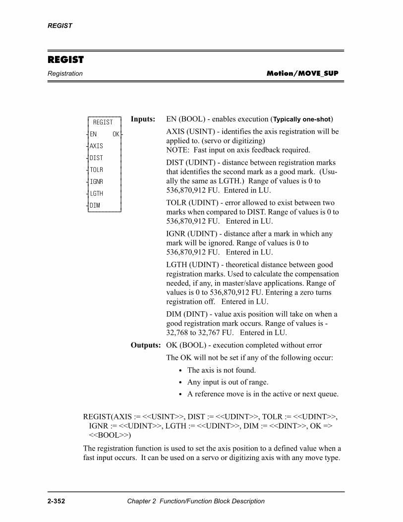
REGIST
REGISTRegistration Motion/MOVE_SUP
REGIST(AXIS := <<USINT>>, DIST := <<UDINT>>, TOLR := <<UDINT>>, IGNR := <<UDINT>>, LGTH := <<UDINT>>, DIM := <<DINT>>, OK => <<BOOL>>)
The registration function is used to set the axis position to a defined value when a fast input occurs. It can be used on a servo or digitizing axis with any move type.
⁄ƒƒƒƒƒƒƒƒƒø ≥ REGIST ≥ ≥ ≥ ¥EN OK√ ≥ ≥ ¥AXIS ≥ ≥ ≥ ¥DIST ≥ ≥ ≥ ¥TOLR ≥ ≥ ≥ ¥IGNR ≥ ≥ ≥ ¥LGTH ≥ ≥ ≥ ¥DIM ≥ ¿ƒƒƒƒƒƒƒƒƒŸ
Inputs: EN (BOOL) - enables execution (Typically one-shot)
AXIS (USINT) - identifies the axis registration will be applied to. (servo or digitizing)NOTE: Fast input on axis feedback required.
DIST (UDINT) - distance between registration marks that identifies the second mark as a good mark. (Usu-ally the same as LGTH.) Range of values is 0 to 536,870,912 FU. Entered in LU.
TOLR (UDINT) - error allowed to exist between two marks when compared to DIST. Range of values is 0 to 536,870,912 FU. Entered in LU.
IGNR (UDINT) - distance after a mark in which any mark will be ignored. Range of values is 0 to 536,870,912 FU. Entered in LU.
LGTH (UDINT) - theoretical distance between good registration marks. Used to calculate the compensation needed, if any, in master/slave applications. Range of values is 0 to 536,870,912 FU. Entering a zero turns registration off. Entered in LU.
DIM (DINT) - value axis position will take on when a good registration mark occurs. Range of values is -32,768 to 32,767 FU. Entered in LU.
Outputs: OK (BOOL) - execution completed without error
The OK will not be set if any of the following occur:
• The axis is not found.
• Any input is out of range.
• A reference move is in the active or next queue.
2-352 Chapter 2 Function/Function Block Description
REGIST
SERCOS NOTE: The function block SCA_PBIT must be called and completed successfully prior to calling the REGIST function with a SER-COS axis.
Registration is most frequently used in master/slave applications. When used with master/slave moves, it has the additional ability of compensating for errors that may occur. The end result is a system that remains synchronized with no accumu-lated error. Repeatable accuracy throughout a process can be maintained.
The axis identified at AXIS may be a master or a slave axis. Registration can run on either one. But because the control may not be controlling the master axis, any compensation for error is done on the slave axis.
The software calculates how much compensation is required by the value entered in LGTH (Note: A zero entered in LGTH turns registration off). This is the theo-retical distance between good registration marks. In a packaging application, this is often equivalent to the product length or the cycle length.
Note: For registration to work properly, the ratio of the LGTH to the slave or mas-ter distance entered in the ratio move function must equal a whole number as illus-trated in the following equations.
When registration is used in combination with master-slave ratio moves, you must ensure that registration and the ratio moves work together properly. In most appli-cations there is an integer relationship between the value entered at LGTH and the associated distance traveled for both the master and slave.
The next three inputs, DIST, TOLR, and IGNR, are used to determine whether or not the registration mark is good. For a mark to be recognized as good, it must be the value entered in DIST from the previous mark. A tolerance can be entered in TOLR which allows an error between two marks when compared to DIST.
, or 2 etc. (whole number)
�� !�"
#"
�"--------
×
$�$ #"
--------------------------------------------------- ��
For Slave Registration:
For Master Registration:
, or 2 etc. (whole number)
�� !�"
#"
�"--------
×
%�$ #"
--------------------------------------------------- ��
Chapter 2 Function/Function Block Description 2-353
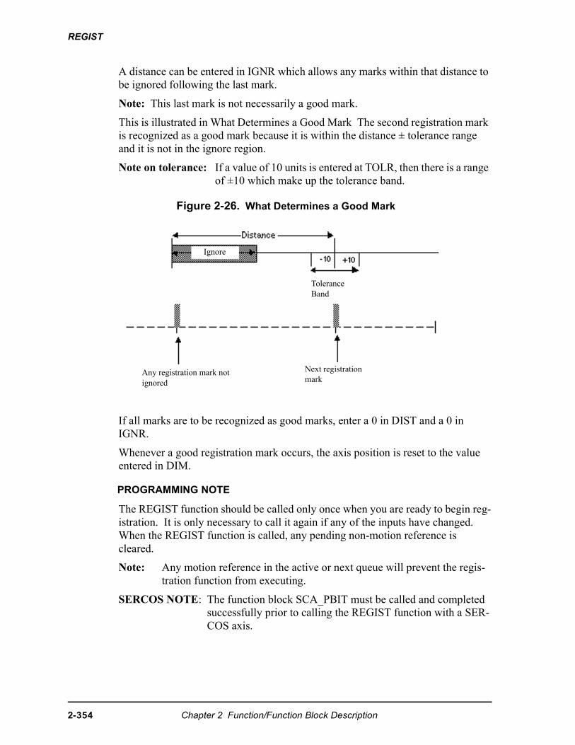
REGIST
A distance can be entered in IGNR which allows any marks within that distance to be ignored following the last mark.
Note: This last mark is not necessarily a good mark.
This is illustrated in What Determines a Good Mark The second registration mark is recognized as a good mark because it is within the distance ± tolerance range and it is not in the ignore region.
Note on tolerance: If a value of 10 units is entered at TOLR, then there is a range of ±10 which make up the tolerance band.
Figure 2-26. What Determines a Good Mark
If all marks are to be recognized as good marks, enter a 0 in DIST and a 0 in IGNR.
Whenever a good registration mark occurs, the axis position is reset to the value entered in DIM.
PROGRAMMING NOTE
The REGIST function should be called only once when you are ready to begin reg-istration. It is only necessary to call it again if any of the inputs have changed. When the REGIST function is called, any pending non-motion reference is cleared.
Note: Any motion reference in the active or next queue will prevent the regis-tration function from executing.
SERCOS NOTE: The function block SCA_PBIT must be called and completed successfully prior to calling the REGIST function with a SER-COS axis.
Any registration mark not ignored
Next registration mark
Tolerance Band
Ignore
2-354 Chapter 2 Function/Function Block Description
REGIST
Background on registration
In many closed-loop servo systems, it is often necessary to maintain synchroniza-tion and accurate positioning repeatedly throughout a process. This can be diffi-cult when the product or process itself is inconsistent. Using registration allows you to overcome this difficulty.
Many factors can contribute to inconsistency. Some examples of the numerous possibilities are as follows:
• Working with non-rigid material which may stretch or shrink during pro-cessing.
• Working with the mechanics of a system where the revolution of a feedback device may give you 5975 counts on one revolution and 5974 on the next.
• Unevenly spaced products on a belt.
Typically, when using registration, sensors are used to detect the position of the product. With non-rigid materials which may stretch or shrink, a photo eye can detect registration marks on the material. With rigid products (or processes), a proximity switch could detect material spacing.
Registration capabilities are available on any axis with any move type. The fast input on the feedback module allows a position at a registration event to be cap-tured. When this occurs, the system recalculates the numerical representation of the axis position.
This is important in applications such as packaging or converting where the pro-cess must be precisely coordinated and any non-rigid material cannot be depended upon to retain dimensional relationships. These applications usually involve mas-ter/slave moves. The fast input signals can be used as repeatable references to which the master and all subsequent slaves continually synchronize. This discus-sion uses a master/slave application.
Registration example
This example uses the RATIOPRO move which is based on a master/slave algo-rithm. The move has a defined cycle length. Registration compensation, when required, takes place within this cycle with the insertion of an offset value calcu-lated by the software. (There are also offsets that can be entered by you with the WRITE_SV function.)
Looking at a packaging process (Example of registration) where a labeled product coming off a web of non-rigid material (master axis) must be cut with a rotary knife (slave axis) to 5 inch lengths so that the label is always in the center of the product, you would want to compensate for any variation in product length during each cycle.
Chapter 2 Function/Function Block Description 2-355
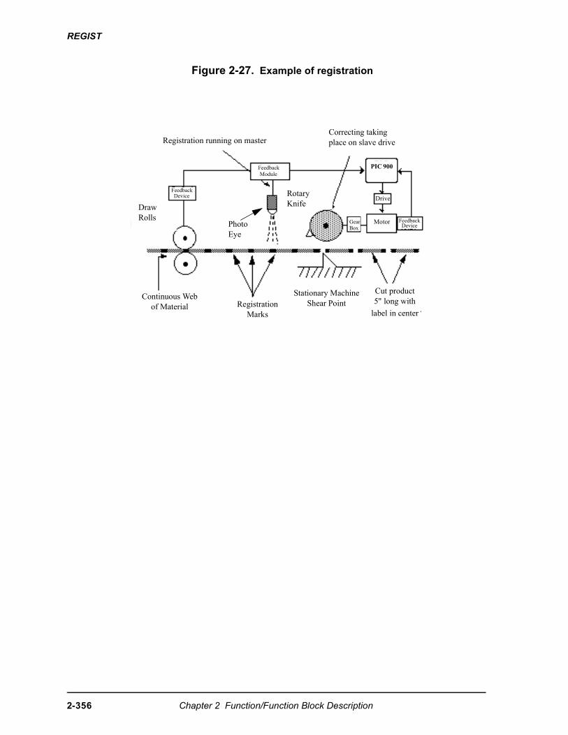
REGIST
Figure 2-27. Example of registration
Correcting taking place on slave driveRegistration running on master
Draw Rolls
Photo Eye
Rotary Knife
Continuous Webof Material Registration
Marks
Stationary MachineShear Point
Cut product5" long with
label in center
PIC 900
Drive
GearBox
Motor FeedbackDevice
FeedbackDevice
FeedbackModule
2-356 Chapter 2 Function/Function Block Description
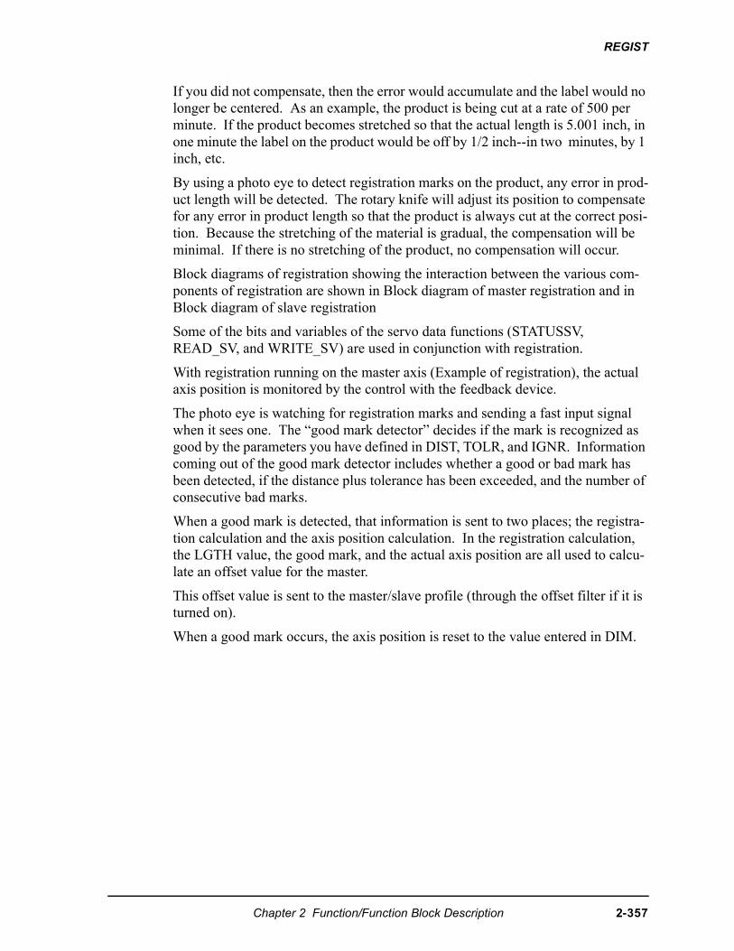
REGIST
If you did not compensate, then the error would accumulate and the label would no longer be centered. As an example, the product is being cut at a rate of 500 per minute. If the product becomes stretched so that the actual length is 5.001 inch, in one minute the label on the product would be off by 1/2 inch--in two minutes, by 1 inch, etc.
By using a photo eye to detect registration marks on the product, any error in prod-uct length will be detected. The rotary knife will adjust its position to compensate for any error in product length so that the product is always cut at the correct posi-tion. Because the stretching of the material is gradual, the compensation will be minimal. If there is no stretching of the product, no compensation will occur.
Block diagrams of registration showing the interaction between the various com-ponents of registration are shown in Block diagram of master registration and in Block diagram of slave registration
Some of the bits and variables of the servo data functions (STATUSSV, READ_SV, and WRITE_SV) are used in conjunction with registration.
With registration running on the master axis (Example of registration), the actual axis position is monitored by the control with the feedback device.
The photo eye is watching for registration marks and sending a fast input signal when it sees one. The “good mark detector” decides if the mark is recognized as good by the parameters you have defined in DIST, TOLR, and IGNR. Information coming out of the good mark detector includes whether a good or bad mark has been detected, if the distance plus tolerance has been exceeded, and the number of consecutive bad marks.
When a good mark is detected, that information is sent to two places; the registra-tion calculation and the axis position calculation. In the registration calculation, the LGTH value, the good mark, and the actual axis position are all used to calcu-late an offset value for the master.
This offset value is sent to the master/slave profile (through the offset filter if it is turned on).
When a good mark occurs, the axis position is reset to the value entered in DIM.
Chapter 2 Function/Function Block Description 2-357
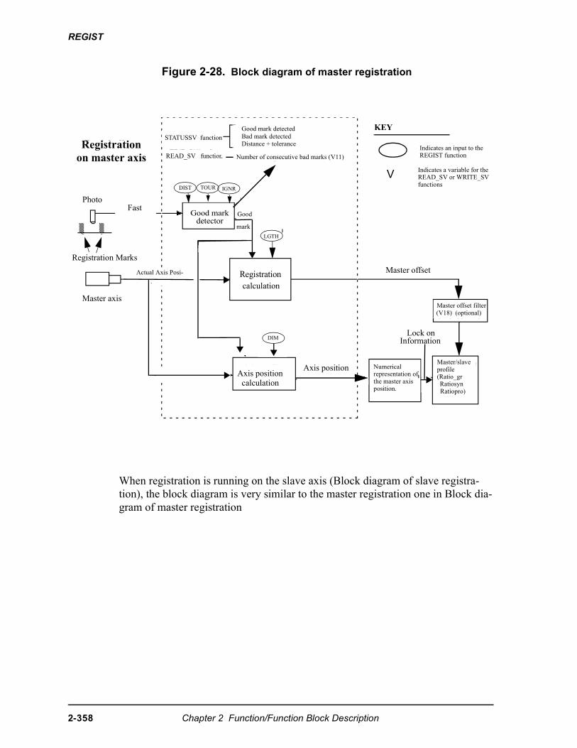
REGIST
Figure 2-28. Block diagram of master registration
When registration is running on the slave axis (Block diagram of slave registra-tion), the block diagram is very similar to the master registration one in Block dia-gram of master registration
Registrationon master axis
Photo Fast
Registration Marks
Master axis
Actual Axis Posi-
STATUSSV function
READ_SV function
Good mark detectedBad mark detectedDistance + tolerance
Number of consecutive bad marks (V11)
DIST TOUR IGNR
Good markdetector
Good
mark
LGTH
Registrationcalculation
Axis positioncalculation
DIM
Axis position Numericalrepresentation ofthe master axisposition.
Lock onInformation
Master offset
Master offset filter(V18) (optional)
Master/slaveprofile(Ratio_grRatiosynRatiopro)
KEY
Indicates an input to theREGIST function
V Indicates a variable for theREAD_SV or WRITE_SVfunctions
2-358 Chapter 2 Function/Function Block Description
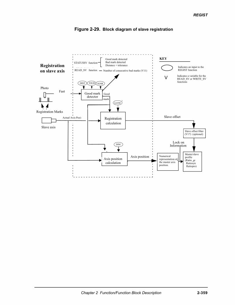
REGIST
Figure 2-29. Block diagram of slave registration
Registrationon slave axis
Photo Fast
Registration Marks
Slave axis
Actual Axis Posi-
STATUSSV function
READ_SV function
Good mark detectedBad mark detectedDistance + tolerance
Number of consecutive bad marks (V11)
DIST TOUR IGNR
Good markdetector
Good
mark
LGTH
Registrationcalculation
Axis positioncalculation
DIM
Axis position Numericalrepresentation ofthe master axisposition.
Lock onInformation
Slave offset
Slave offset filter(V17) (optional)
Master/slaveprofile(Ratio_grRatiosynRatiopro)
KEY
Indicates an input to theREGIST function
V Indicates a variable for theREAD_SV or WRITE_SVfunctions
Chapter 2 Function/Function Block Description 2-359
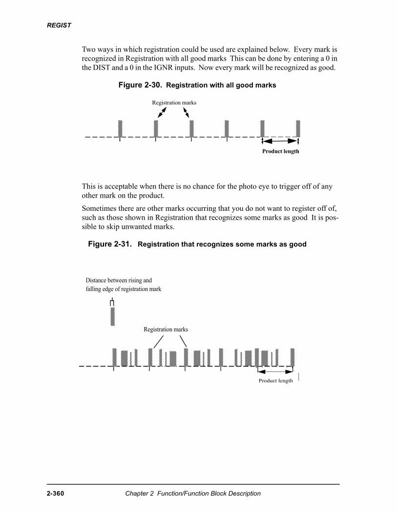
REGIST
Two ways in which registration could be used are explained below. Every mark is recognized in Registration with all good marks This can be done by entering a 0 in the DIST and a 0 in the IGNR inputs. Now every mark will be recognized as good.
Figure 2-30. Registration with all good marks
This is acceptable when there is no chance for the photo eye to trigger off of any other mark on the product.
Sometimes there are other marks occurring that you do not want to register off of, such as those shown in Registration that recognizes some marks as good It is pos-sible to skip unwanted marks.
Figure 2-31. Registration that recognizes some marks as good
Registration marks
Product length
Distance between rising andfalling edge of registration mark
Registration marks
Product length
2-360 Chapter 2 Function/Function Block Description
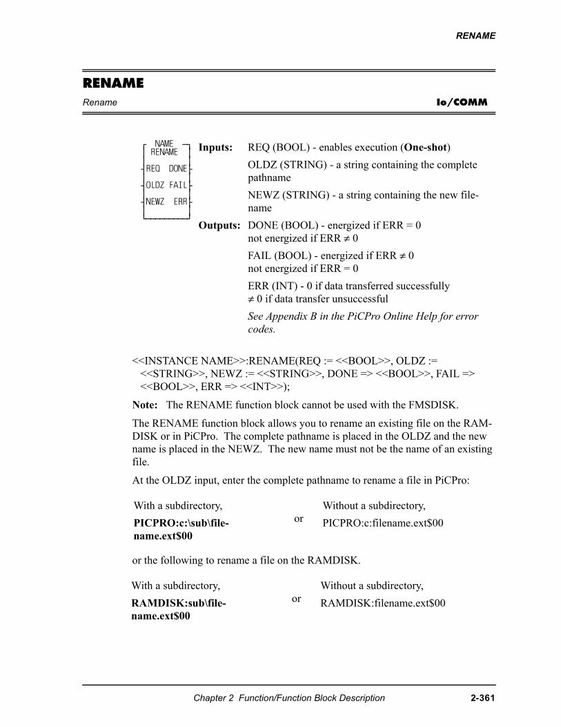
RENAME
RENAMERename Io/COMM
<<INSTANCE NAME>>:RENAME(REQ := <<BOOL>>, OLDZ := <<STRING>>, NEWZ := <<STRING>>, DONE => <<BOOL>>, FAIL => <<BOOL>>, ERR => <<INT>>);
Note: The RENAME function block cannot be used with the FMSDISK.
The RENAME function block allows you to rename an existing file on the RAM-DISK or in PiCPro. The complete pathname is placed in the OLDZ and the new name is placed in the NEWZ. The new name must not be the name of an existing file.
At the OLDZ input, enter the complete pathname to rename a file in PiCPro:
or the following to rename a file on the RAMDISK.
⁄ NAME ƒø ≥ RENAME ≥ ≥ ≥ ¥REQ DONE√ ≥ ≥ ¥OLDZ FAIL√ ≥ ≥ ¥NEWZ ERR√ ≥ ≥ ¿ƒƒƒƒƒƒƒƒƒŸ
Inputs: REQ (BOOL) - enables execution (One-shot)
OLDZ (STRING) - a string containing the complete pathname
NEWZ (STRING) - a string containing the new file-name
Outputs: DONE (BOOL) - energized if ERR = 0not energized if ERR ≠ 0
FAIL (BOOL) - energized if ERR ≠ 0not energized if ERR = 0
ERR (INT) - 0 if data transferred successfully≠ 0 if data transfer unsuccessful
See Appendix B in the PiCPro Online Help for error codes.
With a subdirectory,
PICPRO:c:\sub\file-name.ext$00
orWithout a subdirectory,
PICPRO:c:filename.ext$00
With a subdirectory,
RAMDISK:sub\file-name.ext$00
orWithout a subdirectory,
RAMDISK:filename.ext$00
Chapter 2 Function/Function Block Description 2-361

RENAME
At the NEWZ input, enter the new filename in the format shown below.
filename.ext$00
2-362 Chapter 2 Function/Function Block Description
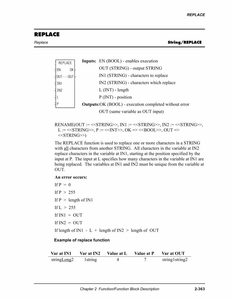
REPLACE
REPLACEReplace String/REPLACE
RENAME(OUT := <<STRING>>, IN1 := <<STRING>>, IN2 := <<STRING>>, L := <<STRING>>, P := <<INT>>, OK => <<BOOL>>, OUT => <<STRING>>)
The REPLACE function is used to replace one or more characters in a STRING with all characters from another STRING. All characters in the variable at IN2 replace characters in the variable at IN1, starting at the position specified by the input at P. The input at L specifies how many characters in the variable at IN1 are being replaced. The variables at IN1 and IN2 must be unique from the variable at OUT.
An error occurs:
If P = 0
If P > 255
If P > length of IN1
If L > 255
If IN1 = OUT
If IN2 = OUT
If length of IN1 - L + length of IN2 > length of OUT
Example of replace function
⁄ƒƒƒƒƒƒƒƒƒø ≥ REPLACE ≥ ≥ ≥ ¥EN OK√ ≥ ≥ ¥OUT---OUT√ ≥ ≥ ¥IN1 ≥ ≥ ≥ ¥IN2 ≥ ≥ ≥ ¥L ≥ ≥ ≥ ¥P ≥ ¿ƒƒƒƒƒƒƒƒƒŸ
Inputs: EN (BOOL) - enables execution
OUT (STRING) - output STRING
IN1 (STRING) - characters to replace
IN2 (STRING) - characters which replace
L (INT) - length
P (INT) - position
Outputs:OK (BOOL) - execution completed without error
OUT (same variable as OUT input)
Var at IN1 Var at IN2 Value at L Value at P Var at OUTstringLong2 1string 4 7 string1string2
Chapter 2 Function/Function Block Description 2-363
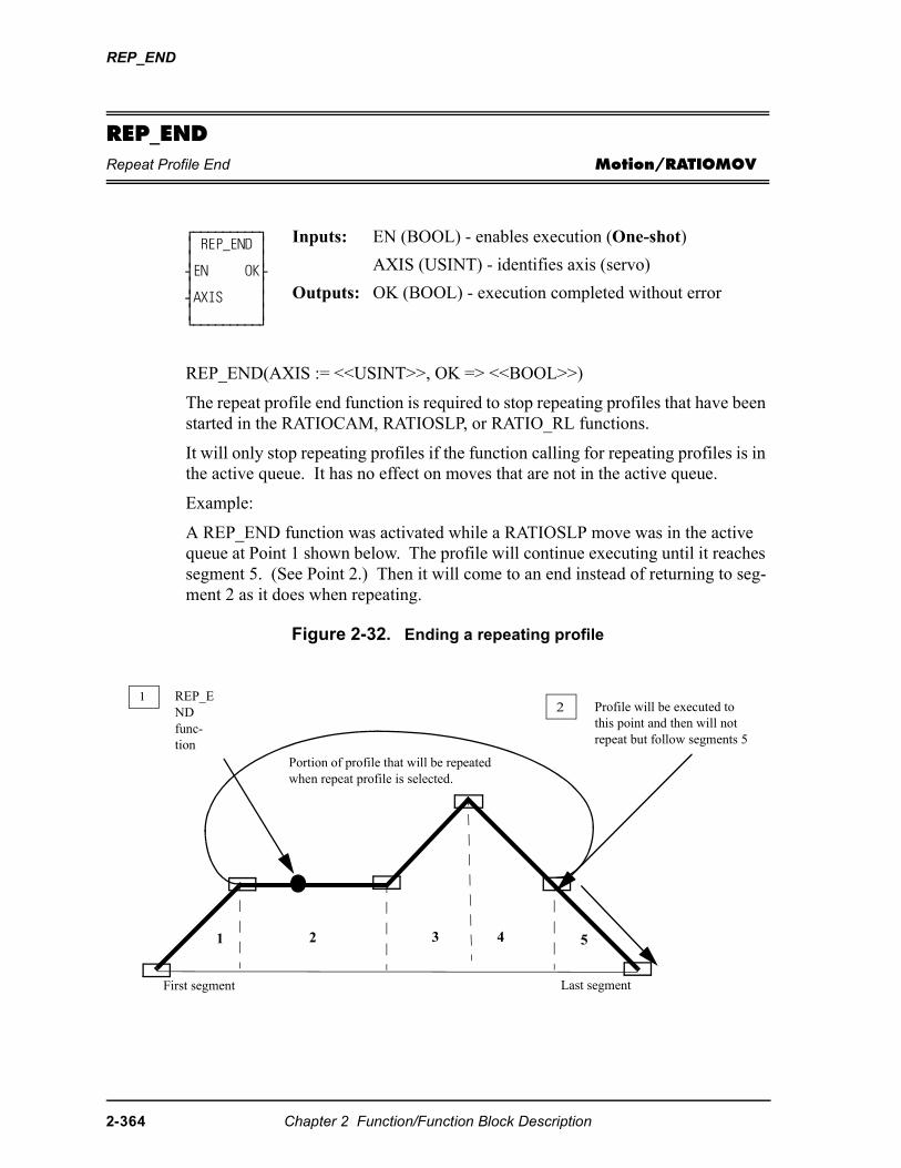
REP_END
REP_ENDRepeat Profile End Motion/RATIOMOV
REP_END(AXIS := <<USINT>>, OK => <<BOOL>>)
The repeat profile end function is required to stop repeating profiles that have been started in the RATIOCAM, RATIOSLP, or RATIO_RL functions.
It will only stop repeating profiles if the function calling for repeating profiles is in the active queue. It has no effect on moves that are not in the active queue.
Example:
A REP_END function was activated while a RATIOSLP move was in the active queue at Point 1 shown below. The profile will continue executing until it reaches segment 5. (See Point 2.) Then it will come to an end instead of returning to seg-ment 2 as it does when repeating.
Figure 2-32. Ending a repeating profile
⁄ƒƒƒƒƒƒƒƒƒø ≥ REP_END ≥ ≥ ≥ ¥EN OK√ ≥ ≥ ¥AXIS ≥ ≥ ≥ ¿ƒƒƒƒƒƒƒƒƒŸ
Inputs: EN (BOOL) - enables execution (One-shot)
AXIS (USINT) - identifies axis (servo)
Outputs: OK (BOOL) - execution completed without error
1 REP_END func-tion
Portion of profile that will be repeated when repeat profile is selected.
2 Profile will be executed to this point and then will not repeat but follow segments 5
1 2 3 4 5
First segment Last segment
2-364 Chapter 2 Function/Function Block Description
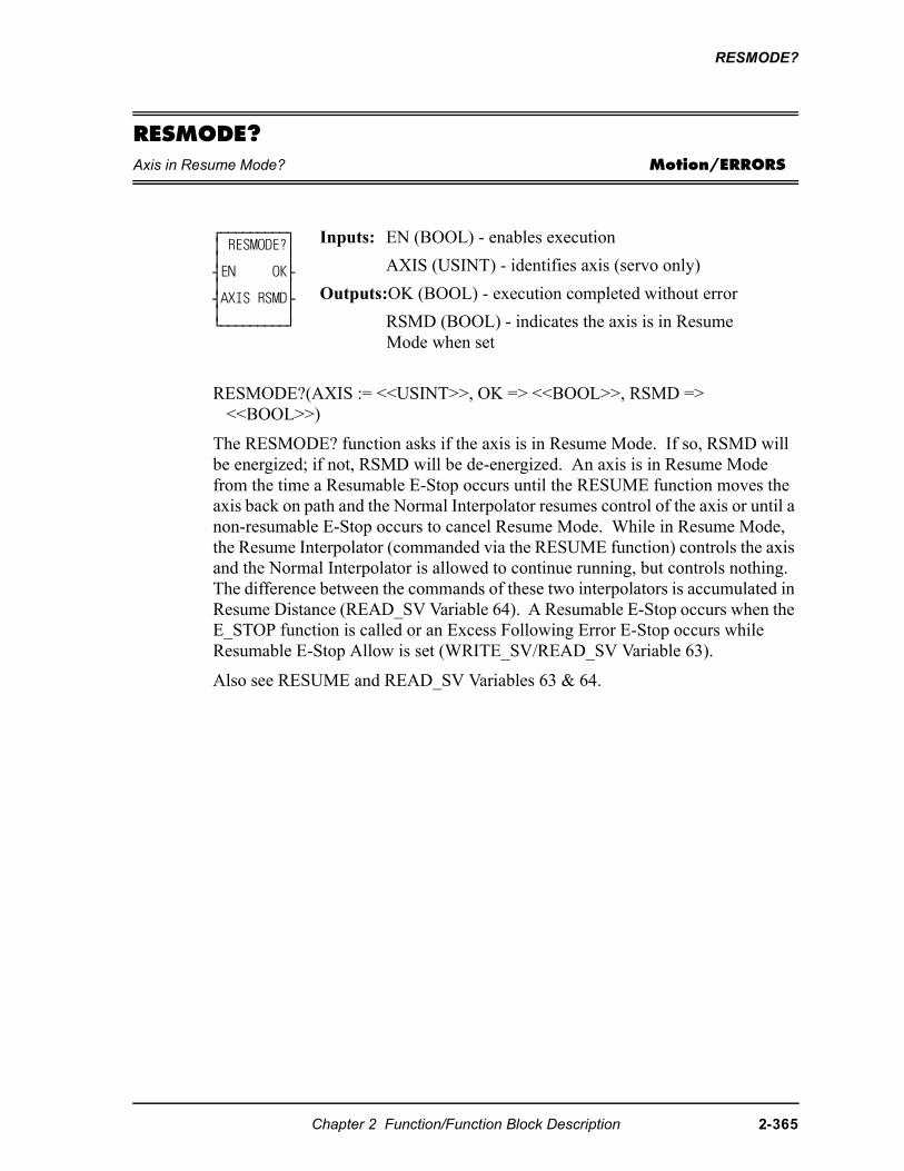
RESMODE?
RESMODE?Axis in Resume Mode? Motion/ERRORS
RESMODE?(AXIS := <<USINT>>, OK => <<BOOL>>, RSMD => <<BOOL>>)
The RESMODE? function asks if the axis is in Resume Mode. If so, RSMD will be energized; if not, RSMD will be de-energized. An axis is in Resume Mode from the time a Resumable E-Stop occurs until the RESUME function moves the axis back on path and the Normal Interpolator resumes control of the axis or until a non-resumable E-Stop occurs to cancel Resume Mode. While in Resume Mode, the Resume Interpolator (commanded via the RESUME function) controls the axis and the Normal Interpolator is allowed to continue running, but controls nothing. The difference between the commands of these two interpolators is accumulated in Resume Distance (READ_SV Variable 64). A Resumable E-Stop occurs when the E_STOP function is called or an Excess Following Error E-Stop occurs while Resumable E-Stop Allow is set (WRITE_SV/READ_SV Variable 63).
Also see RESUME and READ_SV Variables 63 & 64.
⁄ƒƒƒƒƒƒƒƒƒø ≥ RESMODE?≥ ≥ ≥ ¥EN OK√ ≥ ≥ ¥AXIS RSMD√ ≥ ≥ ¿ƒƒƒƒƒƒƒƒƒŸ
Inputs: EN (BOOL) - enables execution
AXIS (USINT) - identifies axis (servo only)
Outputs:OK (BOOL) - execution completed without error
RSMD (BOOL) - indicates the axis is in Resume Mode when set
Chapter 2 Function/Function Block Description 2-365
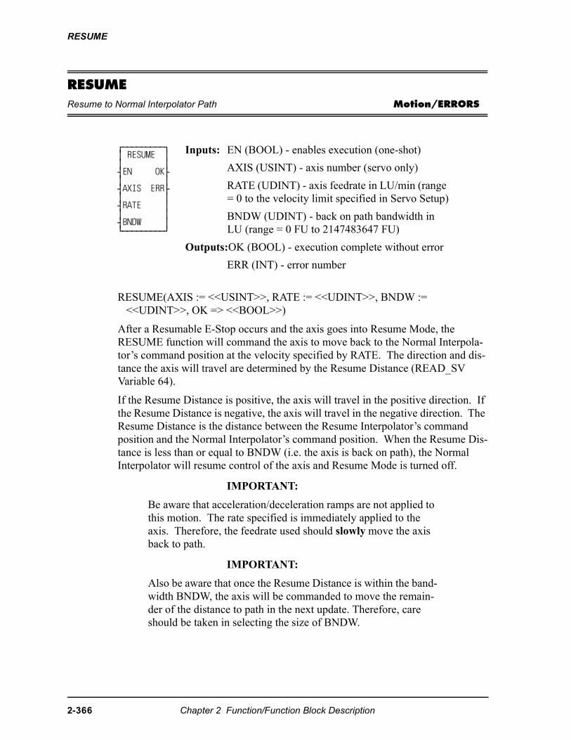
RESUME
RESUMEResume to Normal Interpolator Path Motion/ERRORS
RESUME(AXIS := <<USINT>>, RATE := <<UDINT>>, BNDW := <<UDINT>>, OK => <<BOOL>>)
After a Resumable E-Stop occurs and the axis goes into Resume Mode, the RESUME function will command the axis to move back to the Normal Interpola-tor’s command position at the velocity specified by RATE. The direction and dis-tance the axis will travel are determined by the Resume Distance (READ_SV Variable 64).
If the Resume Distance is positive, the axis will travel in the positive direction. If the Resume Distance is negative, the axis will travel in the negative direction. The Resume Distance is the distance between the Resume Interpolator’s command position and the Normal Interpolator’s command position. When the Resume Dis-tance is less than or equal to BNDW (i.e. the axis is back on path), the Normal Interpolator will resume control of the axis and Resume Mode is turned off.
IMPORTANT:
Be aware that acceleration/deceleration ramps are not applied to this motion. The rate specified is immediately applied to the axis. Therefore, the feedrate used should slowly move the axis back to path.
IMPORTANT:
Also be aware that once the Resume Distance is within the band-width BNDW, the axis will be commanded to move the remain-der of the distance to path in the next update. Therefore, care should be taken in selecting the size of BNDW.
⁄ƒƒƒƒƒƒƒƒƒø ≥ RESUME ≥ ≥ ≥ ¥EN OK√ ≥ ≥ ¥AXIS ERR√ ≥ ≥ ¥RATE ≥ ≥ ≥ ¥BNDW ≥ ¿ƒƒƒƒƒƒƒƒƒŸ
Inputs: EN (BOOL) - enables execution (one-shot)
AXIS (USINT) - axis number (servo only)
RATE (UDINT) - axis feedrate in LU/min (range = 0 to the velocity limit specified in Servo Setup)
BNDW (UDINT) - back on path bandwidth in LU (range = 0 FU to 2147483647 FU)
Outputs:OK (BOOL) - execution complete without error
ERR (INT) - error number
2-366 Chapter 2 Function/Function Block Description
RESUME
Notes:
• This function can only be called if the axis is in Resume Mode and the loop is closed.
• This function can be called multiple times while in Resume Mode if the lad-der desires to change the feedrate or bandwidth during the move.
• The Slow Velocity Filter is applied to the output of the Resume Interpolator
If no error occurs, OK will be energized and ERR will be 0. If an error occurs, OK will be de-energized and ERR will indicate the error. Possible values for ERR are:
0 = no error1 = invalid AXIS input2 = axis is not in Resume Mode3 = axis servo loop is not closed4 = invalid RATE input5 = invalid BNDW input
Also see RESMODE? and READ_SV Variables 63 & 64.
Chapter 2 Function/Function Block Description 2-367
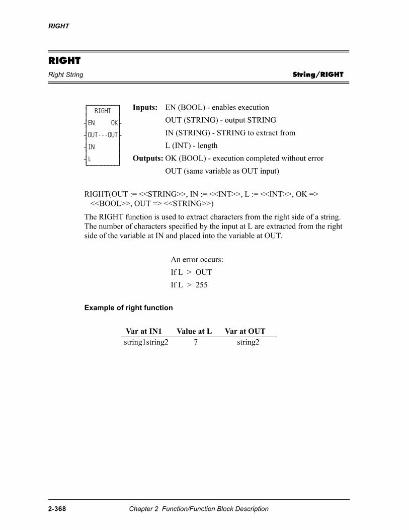
RIGHT
RIGHTRight String String/RIGHT
RIGHT(OUT := <<STRING>>, IN := <<INT>>, L := <<INT>>, OK => <<BOOL>>, OUT => <<STRING>>)
The RIGHT function is used to extract characters from the right side of a string. The number of characters specified by the input at L are extracted from the right side of the variable at IN and placed into the variable at OUT.
Example of right function
⁄ƒƒƒƒƒƒƒƒƒø ≥ RIGHT ≥ ≥ ≥ ¥EN OK√ ≥ ≥ ¥OUT---OUT√ ≥ ≥ ¥IN ≥ ≥ ≥ ¥L ≥ ¿ƒƒƒƒƒƒƒƒƒŸ
Inputs: EN (BOOL) - enables execution
OUT (STRING) - output STRING
IN (STRING) - STRING to extract from
L (INT) - length
Outputs: OK (BOOL) - execution completed without error
OUT (same variable as OUT input)
An error occurs:
If L > OUT
If L > 255
Var at IN1 Value at L Var at OUTstring1string2 7 string2
2-368 Chapter 2 Function/Function Block Description
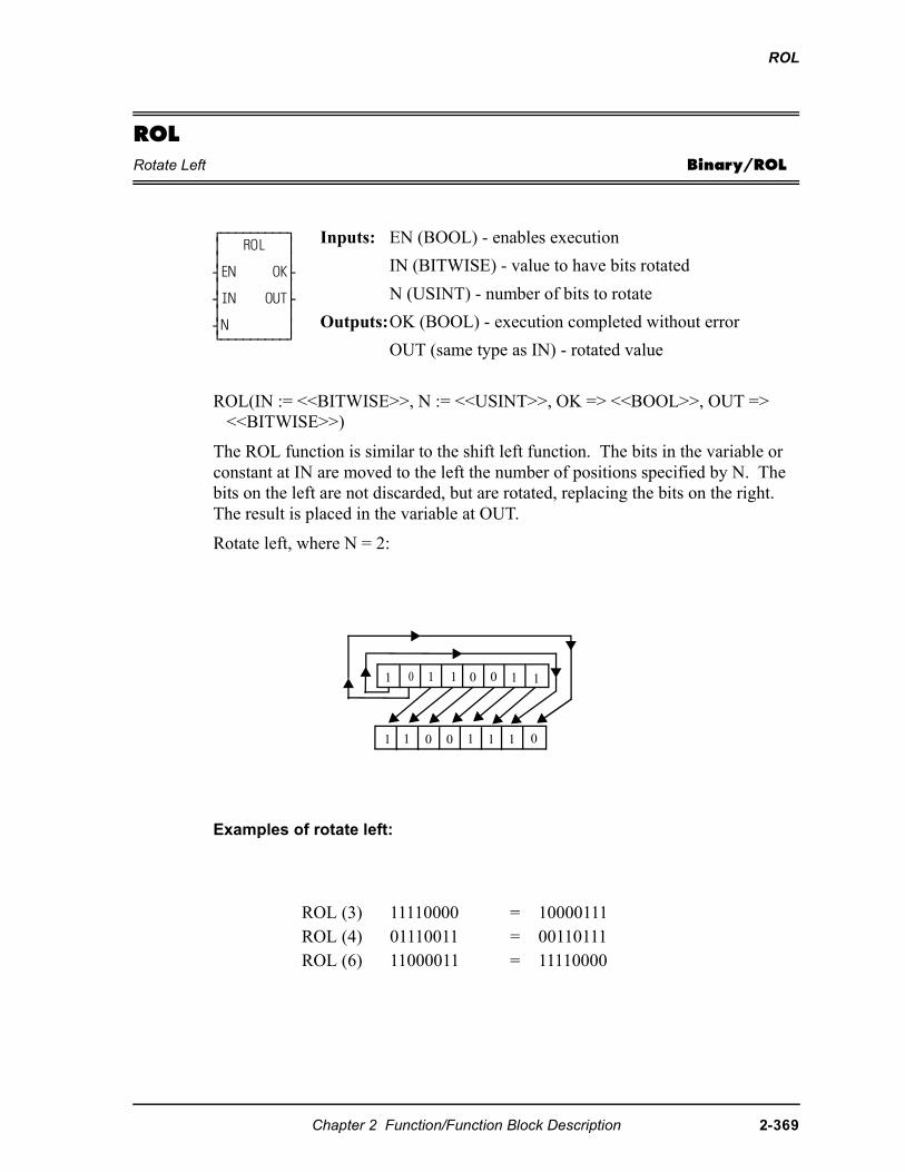
ROL
ROLRotate Left Binary/ROL
ROL(IN := <<BITWISE>>, N := <<USINT>>, OK => <<BOOL>>, OUT => <<BITWISE>>)
The ROL function is similar to the shift left function. The bits in the variable or constant at IN are moved to the left the number of positions specified by N. The bits on the left are not discarded, but are rotated, replacing the bits on the right. The result is placed in the variable at OUT.
Rotate left, where N = 2:
Examples of rotate left:
⁄ƒƒƒƒƒƒƒƒƒø ≥ ROL ≥ ≥ ≥ ¥EN OK√ ≥ ≥ ¥IN OUT√ ≥ ≥ ¥N ≥ ¿ƒƒƒƒƒƒƒƒƒŸ
Inputs: EN (BOOL) - enables execution
IN (BITWISE) - value to have bits rotated
N (USINT) - number of bits to rotate
Outputs:OK (BOOL) - execution completed without error
OUT (same type as IN) - rotated value
ROL (3) 11110000 = 10000111ROL (4) 01110011 = 00110111ROL (6) 11000011 = 11110000
11001101
0111001 1
Chapter 2 Function/Function Block Description 2-369
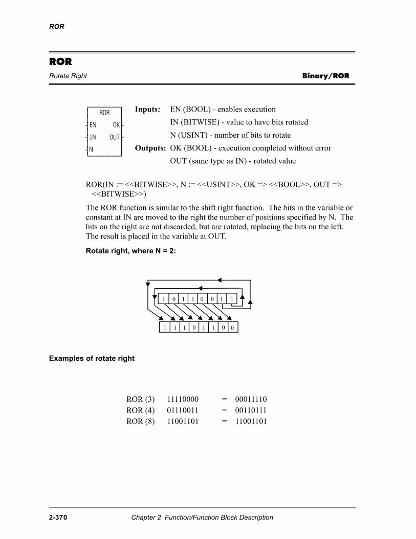
ROR
RORRotate Right Binary/ROR
ROR(IN := <<BITWISE>>, N := <<USINT>>, OK => <<BOOL>>, OUT => <<BITWISE>>)
The ROR function is similar to the shift right function. The bits in the variable or constant at IN are moved to the right the number of positions specified by N. The bits on the right are not discarded, but are rotated, replacing the bits on the left. The result is placed in the variable at OUT.
Rotate right, where N = 2:
Examples of rotate right
⁄ƒƒƒƒƒƒƒƒƒø ≥ ROR ≥ ≥ ≥ ¥EN OK√ ≥ ≥ ¥IN OUT√ ≥ ≥ ¥N ≥ ¿ƒƒƒƒƒƒƒƒƒŸ
Inputs: EN (BOOL) - enables execution
IN (BITWISE) - value to have bits rotated
N (USINT) - number of bits to rotate
Outputs: OK (BOOL) - execution completed without error
OUT (same type as IN) - rotated value
ROR (3) 11110000 = 00011110ROR (4) 01110011 = 00110111ROR (8) 11001101 = 11001101
1 0 1 1 0 0 1 1
1 1 1 0 1 1 00
2-370 Chapter 2 Function/Function Block Description
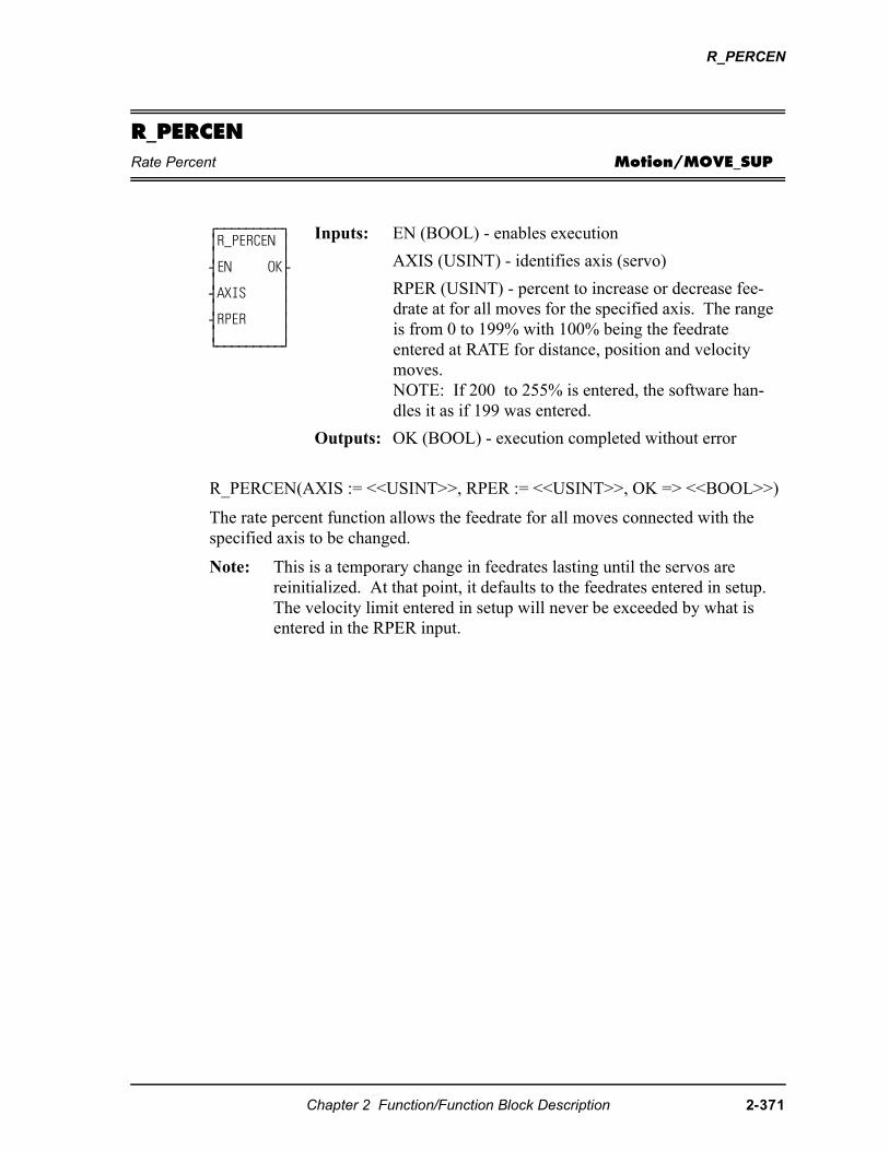
R_PERCEN
R_PERCENRate Percent Motion/MOVE_SUP
R_PERCEN(AXIS := <<USINT>>, RPER := <<USINT>>, OK => <<BOOL>>)
The rate percent function allows the feedrate for all moves connected with the specified axis to be changed.
Note: This is a temporary change in feedrates lasting until the servos arereinitialized. At that point, it defaults to the feedrates entered in setup. The velocity limit entered in setup will never be exceeded by what is entered in the RPER input.
⁄ƒƒƒƒƒƒƒƒƒø ≥R_PERCEN ≥ ≥ ≥ ¥EN OK√ ≥ ≥ ¥AXIS ≥ ≥ ≥ ¥RPER ≥ ≥ ≥ ¿ƒƒƒƒƒƒƒƒƒŸ
Inputs: EN (BOOL) - enables execution
AXIS (USINT) - identifies axis (servo)
RPER (USINT) - percent to increase or decrease fee-drate at for all moves for the specified axis. The range is from 0 to 199% with 100% being the feedrate entered at RATE for distance, position and velocity moves. NOTE: If 200 to 255% is entered, the software han-dles it as if 199 was entered.
Outputs: OK (BOOL) - execution completed without error
Chapter 2 Function/Function Block Description 2-371
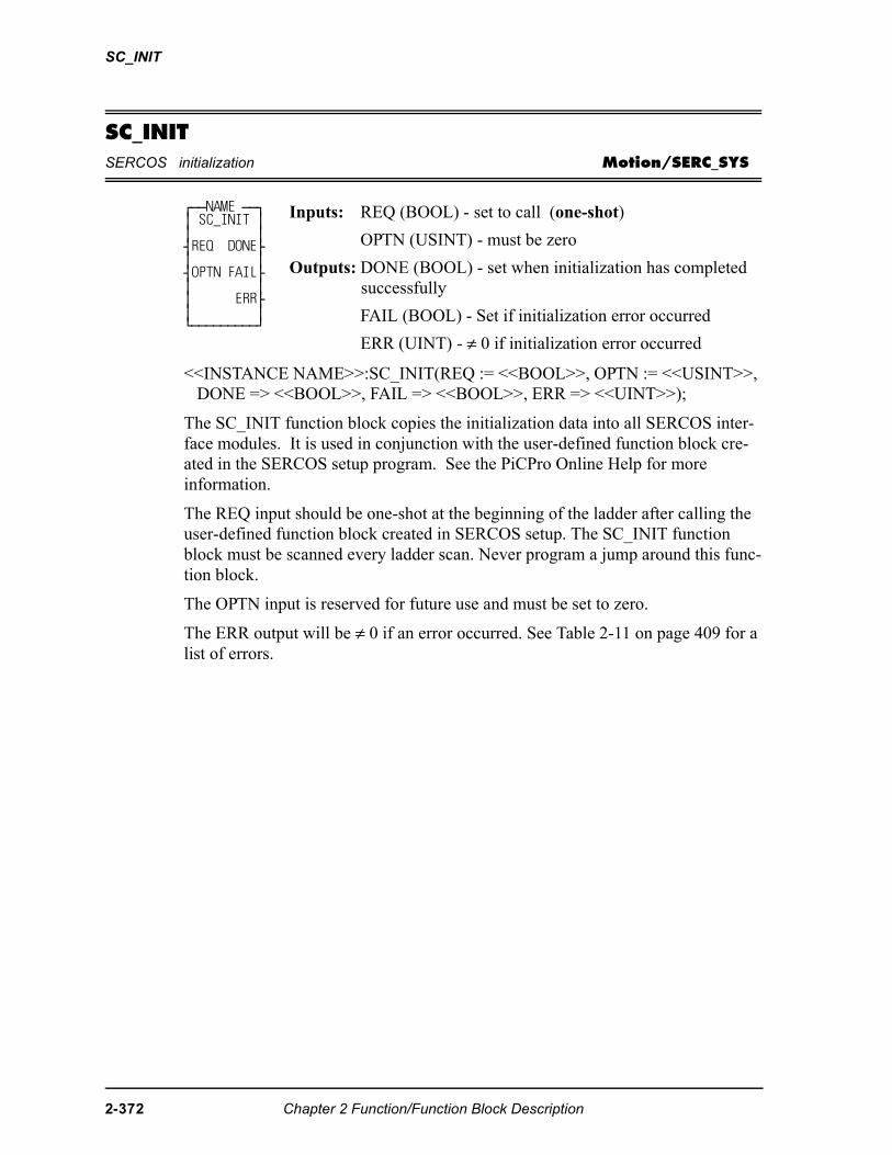
SC_INIT
SC_INITSERCOS initialization Motion/SERC_SYS
<<INSTANCE NAME>>:SC_INIT(REQ := <<BOOL>>, OPTN := <<USINT>>, DONE => <<BOOL>>, FAIL => <<BOOL>>, ERR => <<UINT>>);
The SC_INIT function block copies the initialization data into all SERCOS inter-face modules. It is used in conjunction with the user-defined function block cre-ated in the SERCOS setup program. See the PiCPro Online Help for more information.
The REQ input should be one-shot at the beginning of the ladder after calling the user-defined function block created in SERCOS setup. The SC_INIT function block must be scanned every ladder scan. Never program a jump around this func-tion block.
The OPTN input is reserved for future use and must be set to zero.
The ERR output will be ≠ 0 if an error occurred. See Table 2-11 on page 409 for a list of errors.
⁄ƒƒNAME ƒƒø ≥ SC_INIT ≥ ≥ ≥ ¥REQ DONE√ ≥ ≥ ¥OPTN FAIL√ ≥ ≥ ≥ ERR√ ≥ ≥ ¿ƒƒƒƒƒƒƒƒƒŸ
Inputs: REQ (BOOL) - set to call (one-shot)
OPTN (USINT) - must be zero
Outputs: DONE (BOOL) - set when initialization has completed successfully
FAIL (BOOL) - Set if initialization error occurred
ERR (UINT) - ≠ 0 if initialization error occurred
2-372 Chapter 2 Function/Function Block Description
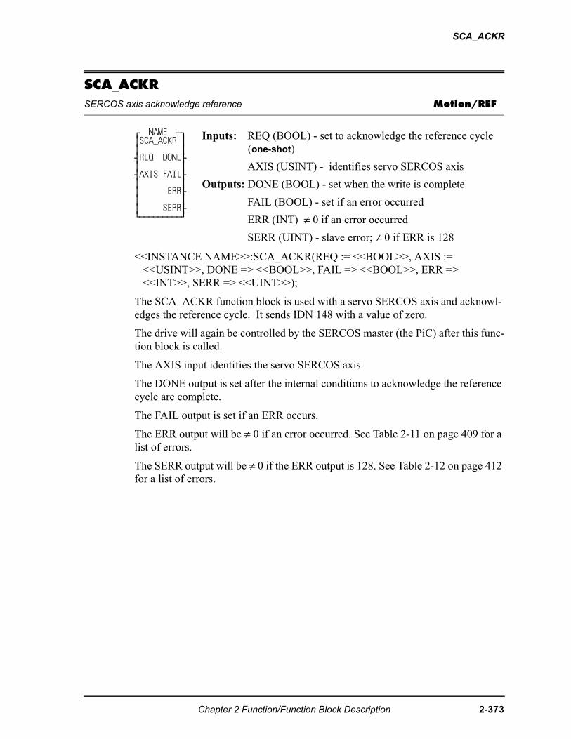
SCA_ACKR
SCA_ACKRSERCOS axis acknowledge reference Motion/REF
<<INSTANCE NAME>>:SCA_ACKR(REQ := <<BOOL>>, AXIS := <<USINT>>, DONE => <<BOOL>>, FAIL => <<BOOL>>, ERR => <<INT>>, SERR => <<UINT>>);
The SCA_ACKR function block is used with a servo SERCOS axis and acknowl-edges the reference cycle. It sends IDN 148 with a value of zero.
The drive will again be controlled by the SERCOS master (the PiC) after this func-tion block is called.
The AXIS input identifies the servo SERCOS axis.
The DONE output is set after the internal conditions to acknowledge the reference cycle are complete.
The FAIL output is set if an ERR occurs.
The ERR output will be ≠ 0 if an error occurred. See Table 2-11 on page 409 for a list of errors.
The SERR output will be ≠ 0 if the ERR output is 128. See Table 2-12 on page 412 for a list of errors.
⁄ NAME ƒø ≥SCA_ACKR ≥ ≥ ≥ ¥REQ DONE√ ≥ ≥ ¥AXIS FAIL√ ≥ ≥ ≥ ERR√ ≥ ≥ ≥ SERR√ ¿ƒƒƒƒƒƒƒƒƒŸ
Inputs: REQ (BOOL) - set to acknowledge the reference cycle (one-shot)
AXIS (USINT) - identifies servo SERCOS axis
Outputs: DONE (BOOL) - set when the write is complete
FAIL (BOOL) - set if an error occurred
ERR (INT) ≠ 0 if an error occurred
SERR (UINT) - slave error; ≠ 0 if ERR is 128
Chapter 2 Function/Function Block Description 2-373
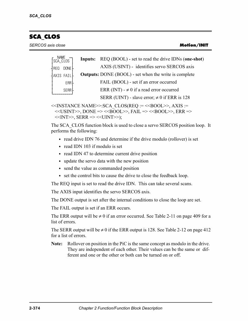
SCA_CLOS
SCA_CLOSSERCOS axis close Motion/INIT
<<INSTANCE NAME>>:SCA_CLOS(REQ := <<BOOL>>, AXIS := <<USINT>>, DONE => <<BOOL>>, FAIL => <<BOOL>>, ERR => <<INT>>, SERR => <<UINT>>);
The SCA_CLOS function block is used to close a servo SERCOS position loop. It performs the following:
• read drive IDN 76 and determine if the drive modulo (rollover) is set
• read IDN 103 if modulo is set
• read IDN 47 to determine current drive position
• update the servo data with the new position
• send the value as commanded position
• set the control bits to cause the drive to close the feedback loop.
The REQ input is set to read the drive IDN. This can take several scans.
The AXIS input identifies the servo SERCOS axis.
The DONE output is set after the internal conditions to close the loop are set.
The FAIL output is set if an ERR occurs.
The ERR output will be ≠ 0 if an error occurred. See Table 2-11 on page 409 for a list of errors.
The SERR output will be ≠ 0 if the ERR output is 128. See Table 2-12 on page 412 for a list of errors.
Note: Rollover on position in the PiC is the same concept as modulo in the drive. They are independent of each other. Their values can be the same or dif-ferent and one or the other or both can be turned on or off.
⁄ NAME ƒø ≥SCA_CLOS ≥ ≥ ≥ ¥REQ DONE√ ≥ ≥ ¥AXIS FAIL√ ≥ ≥ ≥ ERR√ ≥ ≥ ≥ SERR√ ¿ƒƒƒƒƒƒƒƒƒŸ
Inputs: REQ (BOOL) - set to read the drive IDNs (one-shot)
AXIS (USINT) - identifies servo SERCOS axis
Outputs: DONE (BOOL) - set when the write is complete
FAIL (BOOL) - set if an error occurred
ERR (INT) - ≠ 0 if a read error occurred
SERR (UINT) - slave error; ≠ 0 if ERR is 128
2-374 Chapter 2 Function/Function Block Description
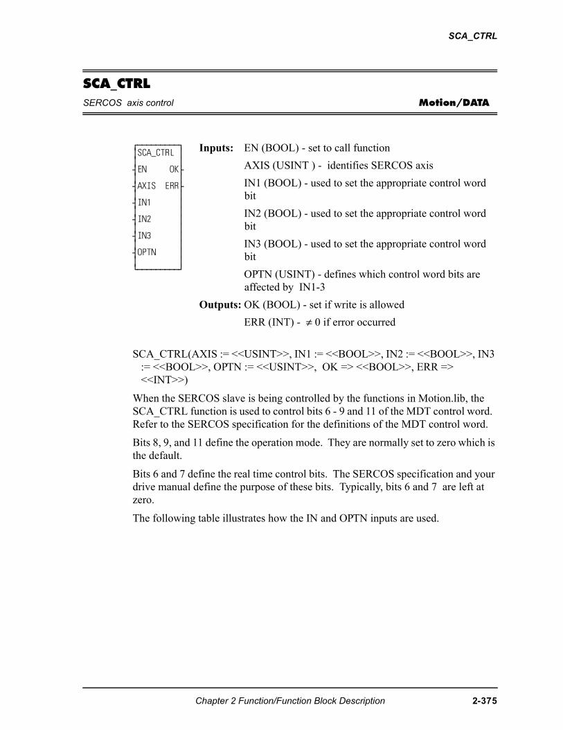
SCA_CTRL
SCA_CTRLSERCOS axis control Motion/DATA
SCA_CTRL(AXIS := <<USINT>>, IN1 := <<BOOL>>, IN2 := <<BOOL>>, IN3 := <<BOOL>>, OPTN := <<USINT>>, OK => <<BOOL>>, ERR => <<INT>>)
When the SERCOS slave is being controlled by the functions in Motion.lib, the SCA_CTRL function is used to control bits 6 - 9 and 11 of the MDT control word. Refer to the SERCOS specification for the definitions of the MDT control word.
Bits 8, 9, and 11 define the operation mode. They are normally set to zero which is the default.
Bits 6 and 7 define the real time control bits. The SERCOS specification and your drive manual define the purpose of these bits. Typically, bits 6 and 7 are left at zero.
The following table illustrates how the IN and OPTN inputs are used.
⁄ƒƒƒƒƒƒƒƒƒø ≥SCA_CTRL ≥ ≥ ≥ ¥EN OK√ ≥ ≥ ¥AXIS ERR√ ≥ ≥ ¥IN1 ≥ ≥ ≥ ¥IN2 ≥ ≥ ≥ ¥IN3 ≥ ≥ ≥ ¥OPTN ≥ ≥ ≥ ¿ƒƒƒƒƒƒƒƒƒŸ
Inputs: EN (BOOL) - set to call function
AXIS (USINT ) - identifies SERCOS axis
IN1 (BOOL) - used to set the appropriate control word bit
IN2 (BOOL) - used to set the appropriate control word bit
IN3 (BOOL) - used to set the appropriate control word bit
OPTN (USINT) - defines which control word bits are affected by IN1-3
Outputs: OK (BOOL) - set if write is allowed
ERR (INT) - ≠ 0 if error occurred
Chapter 2 Function/Function Block Description 2-375
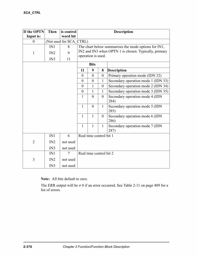
SCA_CTRL
Note: All bits default to zero.
The ERR output will be ≠ 0 if an error occurred. See Table 2-11 on page 409 for a list of errors.
If the OPTNInput is:
Then is control word bit
Description
0 (Not used for SCA_CTRL)
1
IN1
IN2
IN3
8
9
11
The chart below summarizes the mode options for IN1, IN2 and IN3 when OPTN 1 is chosen. Typically, primary operation is used.
Bits
11 9 8 Description0 0 0 Primary operation mode (IDN 32)0 0 1 Secondary operation mode 1 (IDN 33)0 1 0 Secondary operation mode 2 (IDN 34)0 1 1 Secondary operation mode 3 (IDN 35)1 0 0 Secondary operation mode 4 (IDN
284)1 0 1 Secondary operation mode 5 (IDN
285)1 1 0 Secondary operation mode 6 (IDN
286)1 1 1 Secondary operation mode 7 (IDN
287)
2
IN1
IN2
IN3
6
not used
not used
Real time control bit 1
3
IN1
IN2
IN3
7
not used
not used
Real time control bit 2
2-376 Chapter 2 Function/Function Block Description
SCA_CTRL
Application Note
When the SERCOS slave is controlled by Motion. lib, you follow the steps sum-marized below.
1. Initialize the SERCOS axis.
2. Initialize the servo axis.
3. Use the SCA_CTRL function to set the operation mode and the realtime bits 1 and 2. NOTE: The primary operation mode is the default mode and typically used for most applications.
4. Control bits 13, 14, and 15 for the drive loop closure with Motion.lib logic. NOTE: If the loop closure bits must be controlled by the ladder, WRITE_SV variable 48 must be set to 1 and the bits controlled by SCS_CTRL.
Chapter 2 Function/Function Block Description 2-377
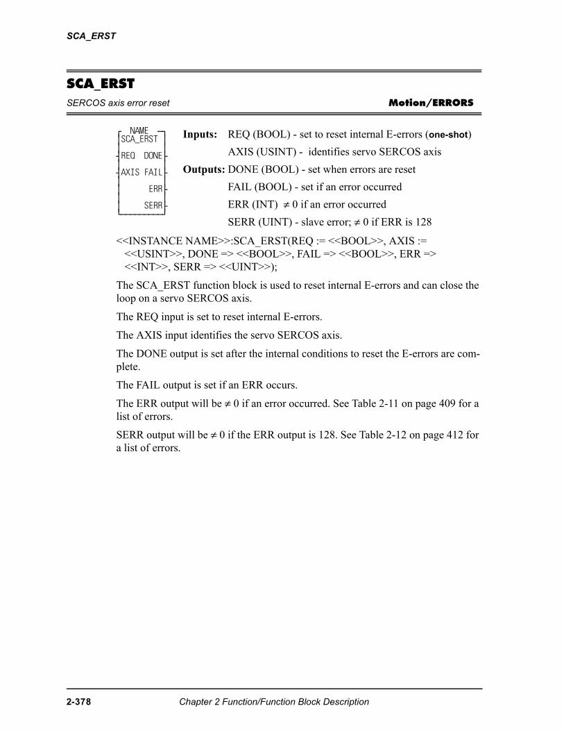
SCA_ERST
SCA_ERSTSERCOS axis error reset Motion/ERRORS
<<INSTANCE NAME>>:SCA_ERST(REQ := <<BOOL>>, AXIS := <<USINT>>, DONE => <<BOOL>>, FAIL => <<BOOL>>, ERR => <<INT>>, SERR => <<UINT>>);
The SCA_ERST function block is used to reset internal E-errors and can close the loop on a servo SERCOS axis.
The REQ input is set to reset internal E-errors.
The AXIS input identifies the servo SERCOS axis.
The DONE output is set after the internal conditions to reset the E-errors are com-plete.
The FAIL output is set if an ERR occurs.
The ERR output will be ≠ 0 if an error occurred. See Table 2-11 on page 409 for a list of errors.
SERR output will be ≠ 0 if the ERR output is 128. See Table 2-12 on page 412 for a list of errors.
⁄ NAME ƒø ≥SCA_ERST ≥ ≥ ≥ ¥REQ DONE√ ≥ ≥ ¥AXIS FAIL√ ≥ ≥ ≥ ERR√ ≥ ≥ ≥ SERR√ ¿ƒƒƒƒƒƒƒƒƒŸ
Inputs: REQ (BOOL) - set to reset internal E-errors (one-shot)
AXIS (USINT) - identifies servo SERCOS axis
Outputs: DONE (BOOL) - set when errors are reset
FAIL (BOOL) - set if an error occurred
ERR (INT) ≠ 0 if an error occurred
SERR (UINT) - slave error; ≠ 0 if ERR is 128
2-378 Chapter 2 Function/Function Block Description
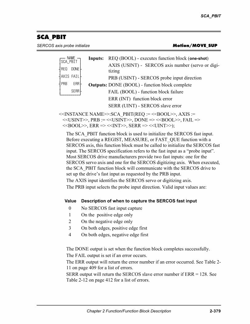
SCA_PBIT
SCA_PBITSERCOS axis probe initialize Motion/MOVE_SUP
<<INSTANCE NAME>>:SCA_PBIT(REQ := <<BOOL>>, AXIS := <<USINT>>, PRB := <<USINT>>, DONE => <<BOOL>>, FAIL => <<BOOL>>, ERR => <<INT>>, SERR => <<UINT>>);
The SCA_PBIT function block is used to initialize the SERCOS fast input. Before executing a REGIST, MEASURE, or FAST_QUE function with a SERCOS axis, this function block must be called to initialize the SERCOS fast input. The SERCOS specification refers to the fast input as a “probe input”. Most SERCOS drive manufacturers provide two fast inputs: one for the SERCOS servo axis and one for the SERCOS digitizing axis. When executed, the SCA_PBIT function block will communicate with the SERCOS drive to set up the drive’s fast input as requested by the PRB input.The AXIS input identifies the SERCOS servo or digitizing axis. The PRB input selects the probe input direction. Valid input values are:
The DONE output is set when the function block completes successfully. The FAIL output is set if an error occurs.The ERR output will return the error number if an error occurred. See Table 2-11 on page 409 for a list of errors.SERR output will return the SERCOS slave error number if ERR = 128. See Table 2-12 on page 412 for a list of errors.
⁄ƒƒ NAME ƒø ≥SCA_PBIT ≥ ≥ ≥ ¥REQ DONE√ ≥ ≥ ¥AXIS FAIL√ ≥ ≥ ¥PRB ERR√ ≥ ≥ ≥ SERR√ ¿ƒƒƒƒƒƒƒƒƒŸ
Inputs: REQ (BOOL) - executes function block (one-shot)
AXIS (USINT) - SERCOS axis number (servo or digi-tizing
PRB (USINT) - SERCOS probe input direction
Outputs: DONE (BOOL) - function block complete
FAIL (BOOL) - function block failure
ERR (INT) function block error
SERR (UINT) - SERCOS slave error
Value Description of when to capture the SERCOS fast input
0 No SERCOS fast input capture1 On the positive edge only2 On the negative edge only3 On both edges, positive edge first4 On both edges, negative edge first
Chapter 2 Function/Function Block Description 2-379
SCA_PBIT
Note: The SCA_PBIT function block uses the SERCOS slave’s real-time control bits and may also use the real-time status bits. Therefore, while SCA_PBIT and the subsequent registration, measure, or fast queue operations are active, the ladder should NOT attempt to do any of the following:
• Assign IDN numbers to the real-time status bits.• Assign IDN numbers to the real-time control bits.• Modify the control bits.• Modify any IDN related to the probe inputs.
Note: When programming two SCA_PBIT function blocks, one for a SER-COS servo axis and another for a SERCOS digitizing axis on the same SERCOS drive, the execution of the two function blocks must not occur simultaneously. In other words, the execution of the second func-tion block must not begin until the execution of the first function block is complete.
2-380 Chapter 2 Function/Function Block Description
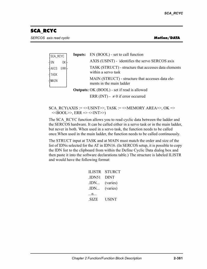
SCA_RCYC
SCA_RCYCSERCOS axis read cyclic Motion/DATA
SCA_RCY(AXIS := <<USINT>>, TASK := <<MEMORY AREA>>, OK => <<BOOL>>, ERR => <<INT>>)
The SCA_RCYC function allows you to read cyclic data between the ladder and the SERCOS hardware. It can be called either in a servo task or in the main ladder, but never in both. When used in a servo task, the function needs to be called once.When used in the main ladder, the function needs to be called continuously.
The STRUCT input at TASK and at MAIN must match the order and size of the list of IDNs selected for the AT in IDN16. (In SERCOS setup, it is possible to copy the IDN list to the clipboard from within the Define Cyclic Data dialog box and then paste it into the software declarations table.) The structure is labeled ILISTR and would have the following format:
⁄ƒƒƒƒƒƒƒƒƒø ≥SCA_RCYC ≥ ≥ ≥ ¥EN OK√ ≥ ≥ ¥AXIS ERR√ ≥ ≥ ¥TASK ≥ ≥ ≥ ¥MAIN ≥ ≥ ≥ ¿ƒƒƒƒƒƒƒƒƒŸ
Inputs: EN (BOOL) - set to call function
AXIS (USINT) - identifies the servo SERCOS axis
TASK (STRUCT) - structure that accesses data elements within a servo task
MAIN (STRUCT) - structure that accesses data ele-ments in the main ladder
Outputs: OK (BOOL) - set if read is allowed
ERR (INT) - ≠ 0 if error occurred
ILISTR STURCT.IDN51 DINT.IDN... (varies).IDN... (varies)...n....SIZE USINT
Chapter 2 Function/Function Block Description 2-381
SCA_RCYC
The SIZE member of the structure indicates the number of bytes in the AT cyclic data as well as the number of bytes in the structure less the SIZE byte. The SIZE will be compared with the size indicated on the SERCOS module and an error will be generated if they are not equal. This preserves the integrity of the data.
Note: Regardless of where this function is used (in a servo task or in the main ladder), you must enter the above structure at both the TASK input and the MAIN input. The structure name must be different for each one, but the members must be the same. Or you can make an array of structures entering a different array on each input.
When the function is initially called, the address of TASK is stored in servo data memory. During each servo update, the TASK structure is copied from the SER-COS module to data memory.
Every time the function is called, the information in the TASK structure is copied to the MAIN structure. There are internal checks that ensure the entire group of IDNs came from the same interrupt.
The ERR output will be ≠ 0 if an error occurred.See Table 2-11 on page 409 for a list of errors.
2-382 Chapter 2 Function/Function Block Description
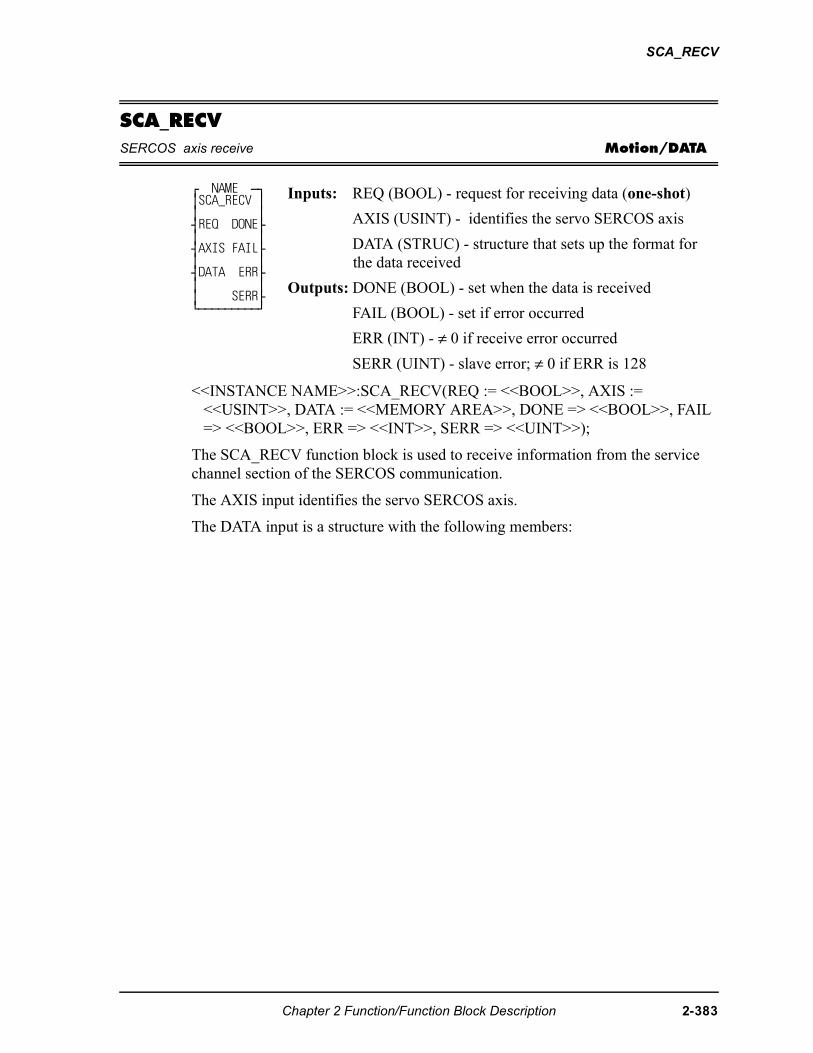
SCA_RECV
SCA_RECVSERCOS axis receive Motion/DATA
<<INSTANCE NAME>>:SCA_RECV(REQ := <<BOOL>>, AXIS := <<USINT>>, DATA := <<MEMORY AREA>>, DONE => <<BOOL>>, FAIL => <<BOOL>>, ERR => <<INT>>, SERR => <<UINT>>);
The SCA_RECV function block is used to receive information from the service channel section of the SERCOS communication.
The AXIS input identifies the servo SERCOS axis.
The DATA input is a structure with the following members:
⁄ NAME ƒø ≥SCA_RECV ≥ ≥ ≥ ¥REQ DONE√ ≥ ≥ ¥AXIS FAIL√ ≥ ≥ ¥DATA ERR√ ≥ ≥ ≥ SERR√ ¿ƒƒƒƒƒƒƒƒƒŸ
Inputs: REQ (BOOL) - request for receiving data (one-shot)
AXIS (USINT) - identifies the servo SERCOS axis
DATA (STRUC) - structure that sets up the format for the data received
Outputs: DONE (BOOL) - set when the data is received
FAIL (BOOL) - set if error occurred
ERR (INT) - ≠ 0 if receive error occurred
SERR (UINT) - slave error; ≠ 0 if ERR is 128
Chapter 2 Function/Function Block Description 2-383
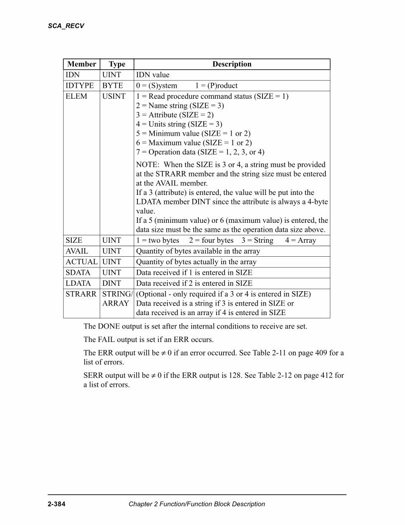
SCA_RECV
The DONE output is set after the internal conditions to receive are set.
The FAIL output is set if an ERR occurs.
The ERR output will be ≠ 0 if an error occurred. See Table 2-11 on page 409 for a list of errors.
SERR output will be ≠ 0 if the ERR output is 128. See Table 2-12 on page 412 for a list of errors.
Member Type DescriptionIDN UINT IDN valueIDTYPE BYTE 0 = (S)ystem 1 = (P)roductELEM USINT 1 = Read procedure command status (SIZE = 1)
2 = Name string (SIZE = 3)3 = Attribute (SIZE = 2)4 = Units string (SIZE = 3)5 = Minimum value (SIZE = 1 or 2)6 = Maximum value (SIZE = 1 or 2)7 = Operation data (SIZE = 1, 2, 3, or 4)
NOTE: When the SIZE is 3 or 4, a string must be provided at the STRARR member and the string size must be entered at the AVAIL member. If a 3 (attribute) is entered, the value will be put into the LDATA member DINT since the attribute is always a 4-byte value.If a 5 (minimum value) or 6 (maximum value) is entered, the data size must be the same as the operation data size above.
SIZE UINT 1 = two bytes 2 = four bytes 3 = String 4 = ArrayAVAIL UINT Quantity of bytes available in the arrayACTUAL UINT Quantity of bytes actually in the arraySDATA UINT Data received if 1 is entered in SIZELDATA DINT Data received if 2 is entered in SIZESTRARR STRING/
ARRAY(Optional - only required if a 3 or 4 is entered in SIZE)Data received is a string if 3 is entered in SIZE ordata received is an array if 4 is entered in SIZE
2-384 Chapter 2 Function/Function Block Description
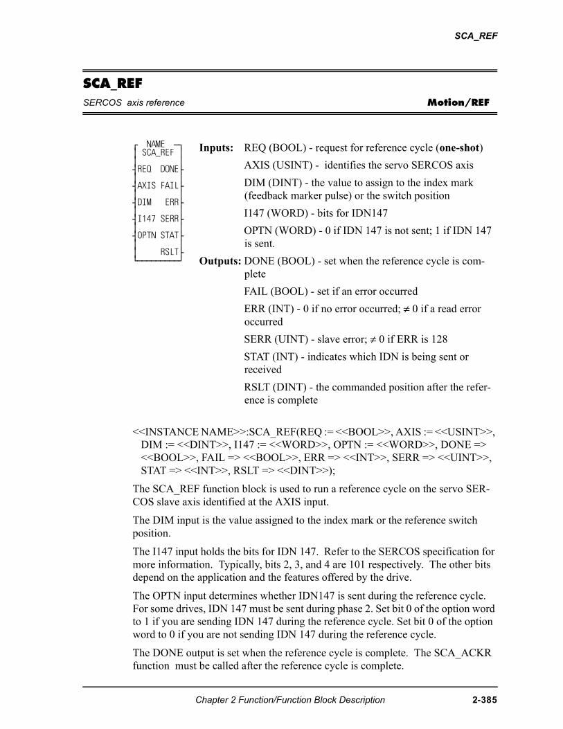
SCA_REF
SCA_REFSERCOS axis reference Motion/REF
<<INSTANCE NAME>>:SCA_REF(REQ := <<BOOL>>, AXIS := <<USINT>>, DIM := <<DINT>>, I147 := <<WORD>>, OPTN := <<WORD>>, DONE => <<BOOL>>, FAIL => <<BOOL>>, ERR => <<INT>>, SERR => <<UINT>>, STAT => <<INT>>, RSLT => <<DINT>>);
The SCA_REF function block is used to run a reference cycle on the servo SER-COS slave axis identified at the AXIS input.
The DIM input is the value assigned to the index mark or the reference switch position.
The I147 input holds the bits for IDN 147. Refer to the SERCOS specification for more information. Typically, bits 2, 3, and 4 are 101 respectively. The other bits depend on the application and the features offered by the drive.
The OPTN input determines whether IDN147 is sent during the reference cycle. For some drives, IDN 147 must be sent during phase 2. Set bit 0 of the option word to 1 if you are sending IDN 147 during the reference cycle. Set bit 0 of the option word to 0 if you are not sending IDN 147 during the reference cycle.
The DONE output is set when the reference cycle is complete. The SCA_ACKR function must be called after the reference cycle is complete.
⁄ NAME ƒø ≥ SCA_REF ≥ ≥ ≥ ¥REQ DONE√ ≥ ≥ ¥AXIS FAIL√ ≥ ≥ ¥DIM ERR√ ≥ ≥ ¥I147 SERR√ ≥ ≥ ¥OPTN STAT√ ≥ ≥ ≥ RSLT√ ¿ƒƒƒƒƒƒƒƒƒŸ
Inputs: REQ (BOOL) - request for reference cycle (one-shot)
AXIS (USINT) - identifies the servo SERCOS axis
DIM (DINT) - the value to assign to the index mark (feedback marker pulse) or the switch position
I147 (WORD) - bits for IDN147
OPTN (WORD) - 0 if IDN 147 is not sent; 1 if IDN 147 is sent.
Outputs: DONE (BOOL) - set when the reference cycle is com-plete
FAIL (BOOL) - set if an error occurred
ERR (INT) - 0 if no error occurred; ≠ 0 if a read error occurred
SERR (UINT) - slave error; ≠ 0 if ERR is 128
STAT (INT) - indicates which IDN is being sent or received
RSLT (DINT) - the commanded position after the refer-ence is complete
Chapter 2 Function/Function Block Description 2-385
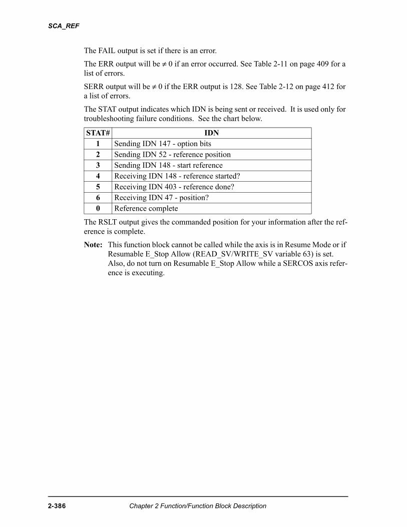
SCA_REF
The FAIL output is set if there is an error.
The ERR output will be ≠ 0 if an error occurred. See Table 2-11 on page 409 for a list of errors.
SERR output will be ≠ 0 if the ERR output is 128. See Table 2-12 on page 412 for a list of errors.
The STAT output indicates which IDN is being sent or received. It is used only for troubleshooting failure conditions. See the chart below.
The RSLT output gives the commanded position for your information after the ref-erence is complete.
Note: This function block cannot be called while the axis is in Resume Mode or if Resumable E_Stop Allow (READ_SV/WRITE_SV variable 63) is set. Also, do not turn on Resumable E_Stop Allow while a SERCOS axis refer-ence is executing.
STAT# IDN1 Sending IDN 147 - option bits2 Sending IDN 52 - reference position3 Sending IDN 148 - start reference4 Receiving IDN 148 - reference started?5 Receiving IDN 403 - reference done?6 Receiving IDN 47 - position?0 Reference complete
2-386 Chapter 2 Function/Function Block Description
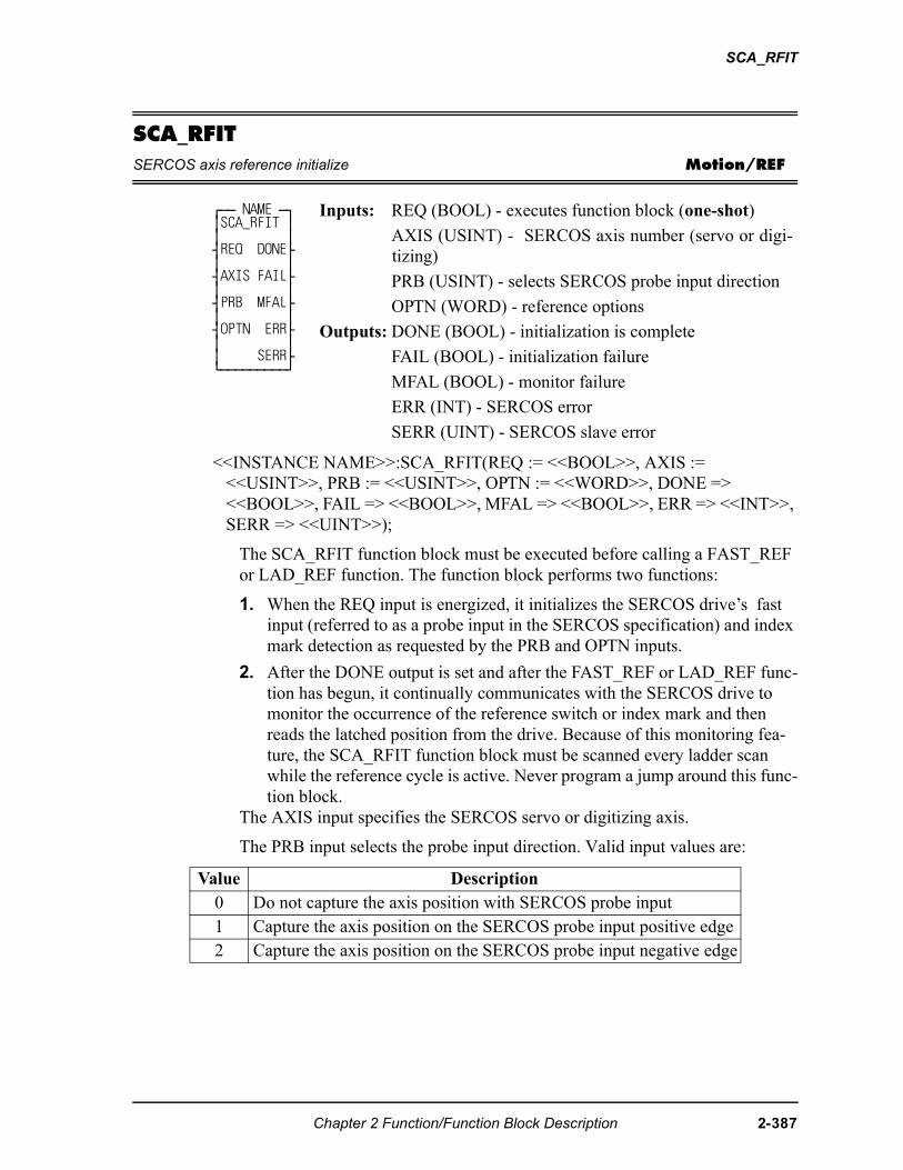
SCA_RFIT
SCA_RFITSERCOS axis reference initialize Motion/REF
<<INSTANCE NAME>>:SCA_RFIT(REQ := <<BOOL>>, AXIS := <<USINT>>, PRB := <<USINT>>, OPTN := <<WORD>>, DONE => <<BOOL>>, FAIL => <<BOOL>>, MFAL => <<BOOL>>, ERR => <<INT>>, SERR => <<UINT>>);
The SCA_RFIT function block must be executed before calling a FAST_REF or LAD_REF function. The function block performs two functions:
1. When the REQ input is energized, it initializes the SERCOS drive’s fast input (referred to as a probe input in the SERCOS specification) and index mark detection as requested by the PRB and OPTN inputs.
2. After the DONE output is set and after the FAST_REF or LAD_REF func-tion has begun, it continually communicates with the SERCOS drive to monitor the occurrence of the reference switch or index mark and then reads the latched position from the drive. Because of this monitoring fea-ture, the SCA_RFIT function block must be scanned every ladder scan while the reference cycle is active. Never program a jump around this func-tion block.
The AXIS input specifies the SERCOS servo or digitizing axis.
The PRB input selects the probe input direction. Valid input values are:
⁄ƒƒ NAME ƒø ≥SCA_RFIT ≥ ≥ ≥ ¥REQ DONE√ ≥ ≥ ¥AXIS FAIL√ ≥ ≥ ¥PRB MFAL√ ≥ ≥ ¥OPTN ERR√ ≥ ≥ ≥ SERR√ ¿ƒƒƒƒƒƒƒƒƒŸ
Inputs: REQ (BOOL) - executes function block (one-shot)
AXIS (USINT) - SERCOS axis number (servo or digi-tizing)
PRB (USINT) - selects SERCOS probe input direction
OPTN (WORD) - reference options
Outputs: DONE (BOOL) - initialization is complete
FAIL (BOOL) - initialization failure
MFAL (BOOL) - monitor failure
ERR (INT) - SERCOS error
SERR (UINT) - SERCOS slave error
Value Description0 Do not capture the axis position with SERCOS probe input1 Capture the axis position on the SERCOS probe input positive edge2 Capture the axis position on the SERCOS probe input negative edge
Chapter 2 Function/Function Block Description 2-387
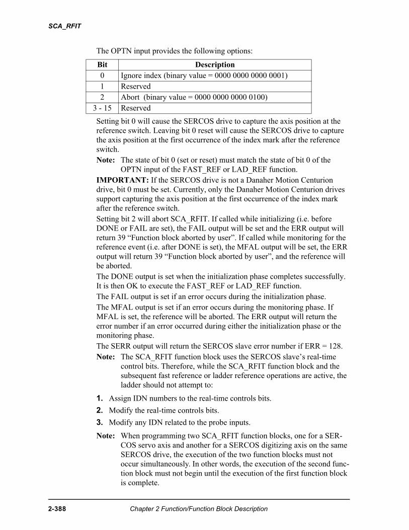
SCA_RFIT
The OPTN input provides the following options:
Setting bit 0 will cause the SERCOS drive to capture the axis position at the reference switch. Leaving bit 0 reset will cause the SERCOS drive to capture the axis position at the first occurrence of the index mark after the reference switch. Note: The state of bit 0 (set or reset) must match the state of bit 0 of the
OPTN input of the FAST_REF or LAD_REF function.IMPORTANT: If the SERCOS drive is not a Danaher Motion Centurion drive, bit 0 must be set. Currently, only the Danaher Motion Centurion drives support capturing the axis position at the first occurrence of the index mark after the reference switch.Setting bit 2 will abort SCA_RFIT. If called while initializing (i.e. before DONE or FAIL are set), the FAIL output will be set and the ERR output will return 39 “Function block aborted by user”. If called while monitoring for the reference event (i.e. after DONE is set), the MFAL output will be set, the ERR output will return 39 “Function block aborted by user”, and the reference will be aborted.The DONE output is set when the initialization phase completes successfully. It is then OK to execute the FAST_REF or LAD_REF function.The FAIL output is set if an error occurs during the initialization phase. The MFAL output is set if an error occurs during the monitoring phase. If MFAL is set, the reference will be aborted. The ERR output will return the error number if an error occurred during either the initialization phase or the monitoring phase.The SERR output will return the SERCOS slave error number if ERR = 128. Note: The SCA_RFIT function block uses the SERCOS slave’s real-time
control bits. Therefore, while the SCA_RFIT function block and the subsequent fast reference or ladder reference operations are active, the ladder should not attempt to:
1. Assign IDN numbers to the real-time controls bits.
2. Modify the real-time controls bits.
3. Modify any IDN related to the probe inputs.
Note: When programming two SCA_RFIT function blocks, one for a SER-COS servo axis and another for a SERCOS digitizing axis on the same SERCOS drive, the execution of the two function blocks must not occur simultaneously. In other words, the execution of the second func-tion block must not begin until the execution of the first function block is complete.
Bit Description 0 Ignore index (binary value = 0000 0000 0000 0001)1 Reserved2 Abort (binary value = 0000 0000 0000 0100)
3 - 15 Reserved
2-388 Chapter 2 Function/Function Block Description
SCA_RFIT
Note: If the MEASURE function is active when SCA_RFIT is called with PRB not equal to zero or OPTN equal to zero, the MEASURE function will be turned off. To reactivate the MEASURE function, call it after the reference is complete.
Chapter 2 Function/Function Block Description 2-389
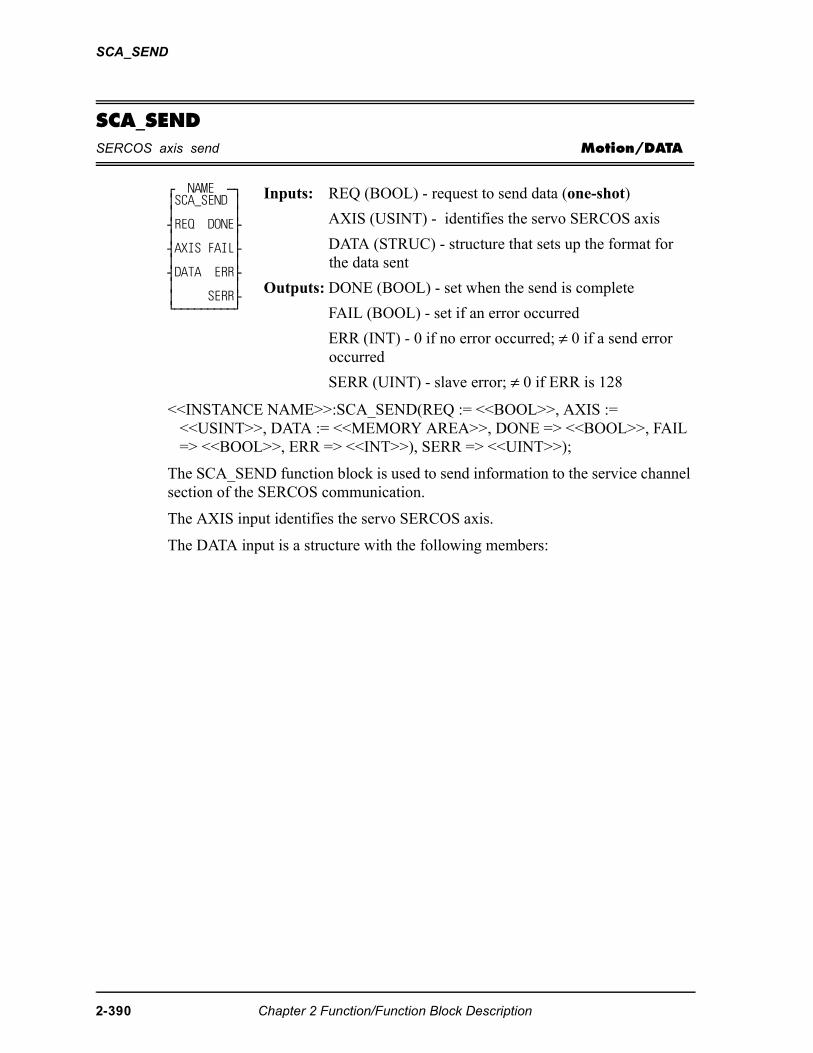
SCA_SEND
SCA_SENDSERCOS axis send Motion/DATA
<<INSTANCE NAME>>:SCA_SEND(REQ := <<BOOL>>, AXIS := <<USINT>>, DATA := <<MEMORY AREA>>, DONE => <<BOOL>>, FAIL => <<BOOL>>, ERR => <<INT>>), SERR => <<UINT>>);
The SCA_SEND function block is used to send information to the service channel section of the SERCOS communication.
The AXIS input identifies the servo SERCOS axis.
The DATA input is a structure with the following members:
⁄ NAME ƒø ≥SCA_SEND ≥ ≥ ≥ ¥REQ DONE√ ≥ ≥ ¥AXIS FAIL√ ≥ ≥ ¥DATA ERR√ ≥ ≥ ≥ SERR√ ¿ƒƒƒƒƒƒƒƒƒŸ
Inputs: REQ (BOOL) - request to send data (one-shot)
AXIS (USINT) - identifies the servo SERCOS axis
DATA (STRUC) - structure that sets up the format for the data sent
Outputs: DONE (BOOL) - set when the send is complete
FAIL (BOOL) - set if an error occurred
ERR (INT) - 0 if no error occurred; ≠ 0 if a send error occurred
SERR (UINT) - slave error; ≠ 0 if ERR is 128
2-390 Chapter 2 Function/Function Block Description
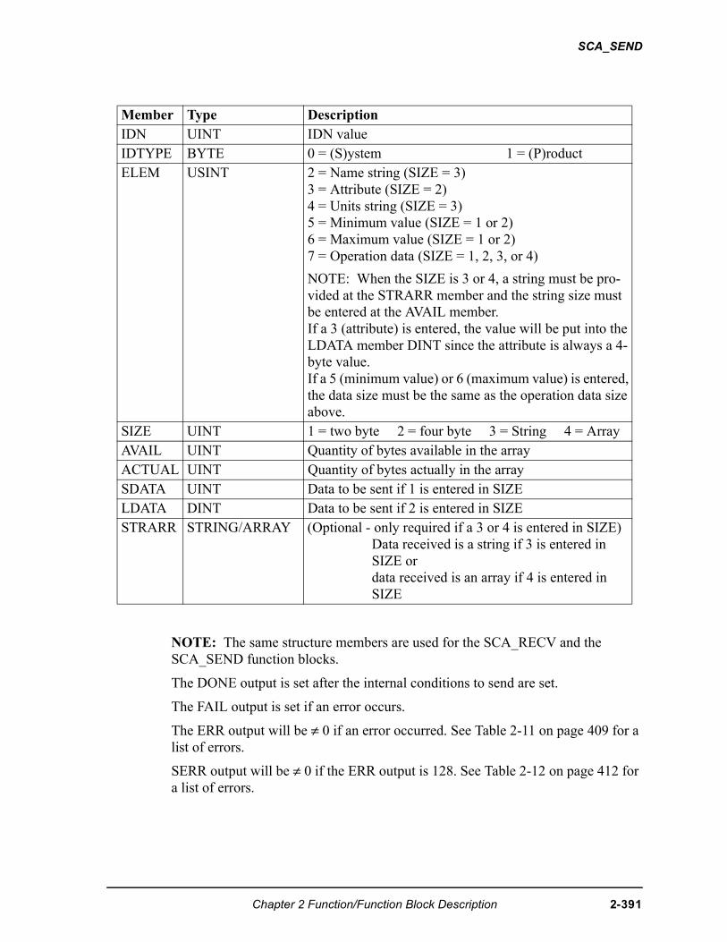
SCA_SEND
NOTE: The same structure members are used for the SCA_RECV and the SCA_SEND function blocks.
The DONE output is set after the internal conditions to send are set.
The FAIL output is set if an error occurs.
The ERR output will be ≠ 0 if an error occurred. See Table 2-11 on page 409 for a list of errors.
SERR output will be ≠ 0 if the ERR output is 128. See Table 2-12 on page 412 for a list of errors.
Member Type DescriptionIDN UINT IDN valueIDTYPE BYTE 0 = (S)ystem 1 = (P)roductELEM USINT 2 = Name string (SIZE = 3)
3 = Attribute (SIZE = 2)4 = Units string (SIZE = 3)5 = Minimum value (SIZE = 1 or 2)6 = Maximum value (SIZE = 1 or 2)7 = Operation data (SIZE = 1, 2, 3, or 4)
NOTE: When the SIZE is 3 or 4, a string must be pro-vided at the STRARR member and the string size must be entered at the AVAIL member. If a 3 (attribute) is entered, the value will be put into the LDATA member DINT since the attribute is always a 4-byte value.If a 5 (minimum value) or 6 (maximum value) is entered, the data size must be the same as the operation data size above.
SIZE UINT 1 = two byte 2 = four byte 3 = String 4 = ArrayAVAIL UINT Quantity of bytes available in the arrayACTUAL UINT Quantity of bytes actually in the arraySDATA UINT Data to be sent if 1 is entered in SIZELDATA DINT Data to be sent if 2 is entered in SIZESTRARR STRING/ARRAY (Optional - only required if a 3 or 4 is entered in SIZE)
Data received is a string if 3 is entered in SIZE ordata received is an array if 4 is entered in SIZE
Chapter 2 Function/Function Block Description 2-391
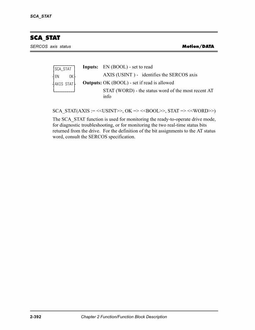
SCA_STAT
SCA_STATSERCOS axis status Motion/DATA
SCA_STAT(AXIS := <<USINT>>, OK => <<BOOL>>, STAT => <<WORD>>)
The SCA_STAT function is used for monitoring the ready-to-operate drive mode, for diagnostic troubleshooting, or for monitoring the two real-time status bits returned from the drive. For the definition of the bit assignments to the AT status word, consult the SERCOS specification.
⁄ƒƒƒƒƒƒƒƒƒø ≥SCA_STAT ≥ ≥ ≥ ¥EN OK√ ≥ ≥ ¥AXIS STAT√ ≥ ≥ ¿ƒƒƒƒƒƒƒƒƒŸ
Inputs: EN (BOOL) - set to read
AXIS (USINT ) - identifies the SERCOS axis
Outputs: OK (BOOL) - set if read is allowed
STAT (WORD) - the status word of the most recent AT info
2-392 Chapter 2 Function/Function Block Description
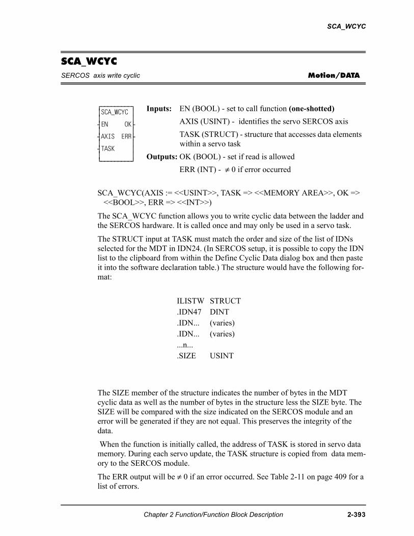
SCA_WCYC
SCA_WCYCSERCOS axis write cyclic Motion/DATA
SCA_WCYC(AXIS := <<USINT>>, TASK => <<MEMORY AREA>>, OK => <<BOOL>>, ERR => <<INT>>)
The SCA_WCYC function allows you to write cyclic data between the ladder and the SERCOS hardware. It is called once and may only be used in a servo task.
The STRUCT input at TASK must match the order and size of the list of IDNs selected for the MDT in IDN24. (In SERCOS setup, it is possible to copy the IDN list to the clipboard from within the Define Cyclic Data dialog box and then paste it into the software declaration table.) The structure would have the following for-mat:
The SIZE member of the structure indicates the number of bytes in the MDT cyclic data as well as the number of bytes in the structure less the SIZE byte. The SIZE will be compared with the size indicated on the SERCOS module and an error will be generated if they are not equal. This preserves the integrity of the data.
When the function is initially called, the address of TASK is stored in servo data memory. During each servo update, the TASK structure is copied from data mem-ory to the SERCOS module.
The ERR output will be ≠ 0 if an error occurred. See Table 2-11 on page 409 for a list of errors.
⁄ƒƒƒƒƒƒƒƒƒø ≥SCA_WCYC ≥ ≥ ≥ ¥EN OK√ ≥ ≥ ¥AXIS ERR√ ≥ ≥ ¥TASK ≥ ≥ ≥ ¿ƒƒƒƒƒƒƒƒƒŸ
Inputs: EN (BOOL) - set to call function (one-shotted)
AXIS (USINT) - identifies the servo SERCOS axis
TASK (STRUCT) - structure that accesses data elements within a servo task
Outputs: OK (BOOL) - set if read is allowed
ERR (INT) - ≠ 0 if error occurred
ILISTW STRUCT.IDN47 DINT.IDN... (varies).IDN... (varies)...n....SIZE USINT
Chapter 2 Function/Function Block Description 2-393
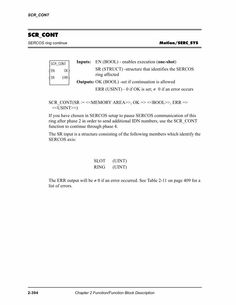
SCR_CONT
SCR_CONTSERCOS ring continue Motion/SERC_SYS
SCR_CONT(SR := <<MEMORY AREA>>, OK => <<BOOL>>, ERR => <<USINT>>)
If you have chosen in SERCOS setup to pause SERCOS communication of this ring after phase 2 in order to send additional IDN numbers, use the SCR_CONT function to continue through phase 4.
The SR input is a structure consisting of the following members which identify the SERCOS axis:
The ERR output will be ≠ 0 if an error occurred. See Table 2-11 on page 409 for a list of errors.
⁄ƒƒƒƒƒƒƒƒƒø ≥SCR_CONT ≥ ≥ ≥ ¥EN OK√ ≥ ≥ ¥SR ERR√ ≥ ≥ ¿ƒƒƒƒƒƒƒƒƒŸ
Inputs: EN (BOOL) - enables execution (one-shot)
SR (STRUCT) -structure that identifies the SERCOS ring affected
Outputs: OK (BOOL) -set if continuation is allowed
ERR (USINT) - 0 if OK is set; ≠ 0 if an error occurs
SLOT (UINT)RING (UINT)
2-394 Chapter 2 Function/Function Block Description
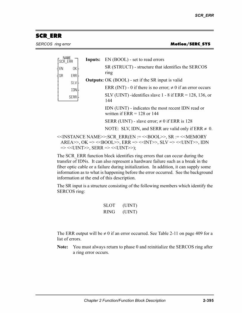
SCR_ERR
SCR_ERRSERCOS ring error Motion/SERC_SYS
<<INSTANCE NAME>>:SCR_ERR(EN := <<BOOL>>, SR := <<MEMORY AREA>>, OK => <<BOOL>>, ERR => <<INT>>, SLV => <<UINT>>, IDN => <<UINT>>, SERR => <<UINT>>);
The SCR_ERR function block identifies ring errors that can occur during the transfer of IDNs. It can also represent a hardware failure such as a break in the fiber optic cable or a failure during initialization. In addition, it can supply some information as to what is happening before the error occurred. See the background information at the end of this description.
The SR input is a structure consisting of the following members which identify the SERCOS ring:
The ERR output will be ≠ 0 if an error occurred. See Table 2-11 on page 409 for a list of errors.
Note: You must always return to phase 0 and reinitialize the SERCOS ring after a ring error occurs.
⁄ NAME ƒø ≥SCR_ERR ≥ ≥ ≥ ¥EN OK√ ≥ ≥ ¥SR ERR√ ≥ ≥ ≥ SLV√ ≥ ≥ ≥ IDN√ ≥ ≥ ≥ SERR√ ¿ƒƒƒƒƒƒƒƒƒŸ
Inputs: EN (BOOL) - set to read errors
SR (STRUCT) - structure that identifies the SERCOS ring
Outputs: OK (BOOL) - set if the SR input is valid
ERR (INT) - 0 if there is no error; ≠ 0 if an error occurs
SLV (UINT) -identifies slave 1 - 8 if ERR = 128, 136, or 144
IDN (UINT) - indicates the most recent IDN read or written if ERR = 128 or 144
SERR (UINT) - slave error; ≠ 0 if ERR is 128
NOTE: SLV, IDN, and SERR are valid only if ERR ≠ 0.
SLOT (UINT)RING (UINT)
Chapter 2 Function/Function Block Description 2-395
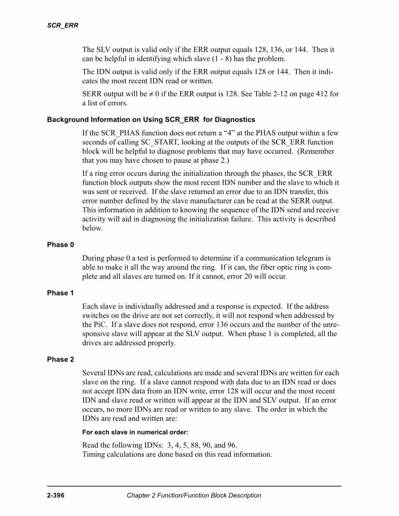
SCR_ERR
The SLV output is valid only if the ERR output equals 128, 136, or 144. Then it can be helpful in identifying which slave (1 - 8) has the problem.
The IDN output is valid only if the ERR output equals 128 or 144. Then it indi-cates the most recent IDN read or written.
SERR output will be ≠ 0 if the ERR output is 128. See Table 2-12 on page 412 for a list of errors.
Background Information on Using SCR_ERR for Diagnostics
If the SCR_PHAS function does not return a “4” at the PHAS output within a few seconds of calling SC_START, looking at the outputs of the SCR_ERR function block will be helpful to diagnose problems that may have occurred. (Remember that you may have chosen to pause at phase 2.)
If a ring error occurs during the initialization through the phases, the SCR_ERR function block outputs show the most recent IDN number and the slave to which it was sent or received. If the slave returned an error due to an IDN transfer, this error number defined by the slave manufacturer can be read at the SERR output. This information in addition to knowing the sequence of the IDN send and receive activity will aid in diagnosing the initialization failure. This activity is described below.
Phase 0
During phase 0 a test is performed to determine if a communication telegram is able to make it all the way around the ring. If it can, the fiber optic ring is com-plete and all slaves are turned on. If it cannot, error 20 will occur.
Phase 1
Each slave is individually addressed and a response is expected. If the address switches on the drive are not set correctly, it will not respond when addressed by the PiC. If a slave does not respond, error 136 occurs and the number of the unre-sponsive slave will appear at the SLV output. When phase 1 is completed, all the drives are addressed properly.
Phase 2
Several IDNs are read, calculations are made and several IDNs are written for each slave on the ring. If a slave cannot respond with data due to an IDN read or does not accept IDN data from an IDN write, error 128 will occur and the most recent IDN and slave read or written will appear at the IDN and SLV output. If an error occurs, no more IDNs are read or written to any slave. The order in which the IDNs are read and written are:
For each slave in numerical order:
Read the following IDNs: 3, 4, 5, 88, 90, and 96.Timing calculations are done based on this read information.
2-396 Chapter 2 Function/Function Block Description
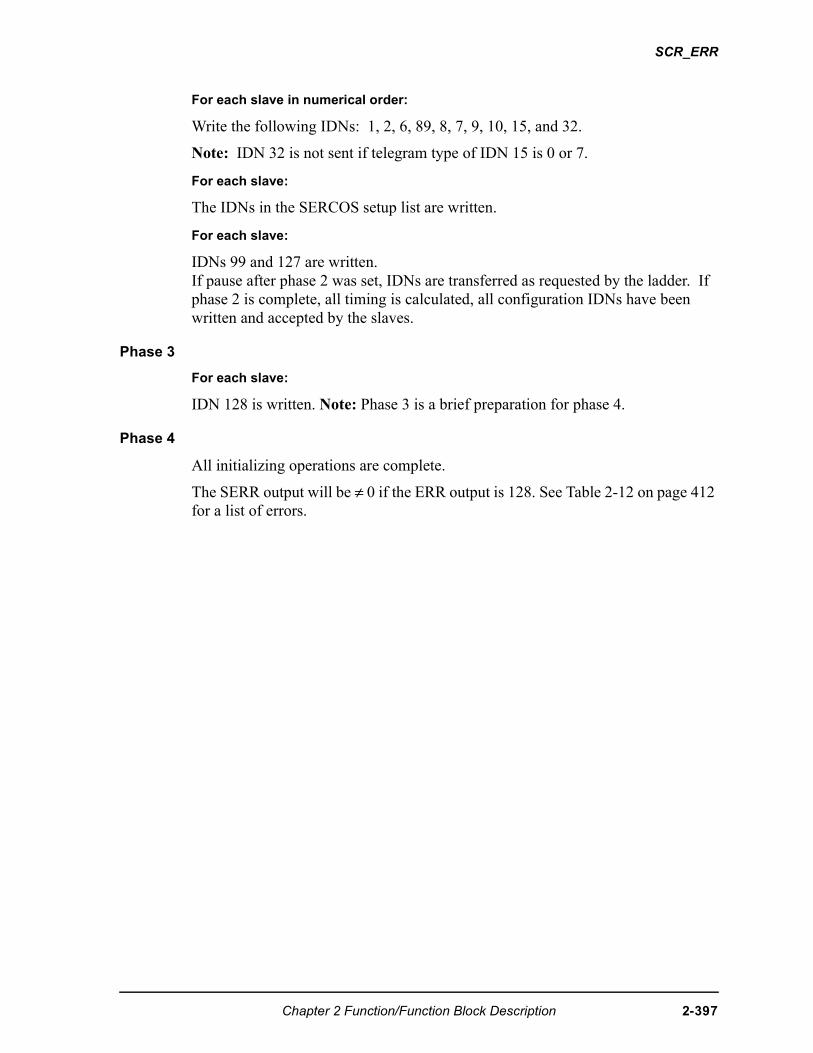
SCR_ERR
For each slave in numerical order:
Write the following IDNs: 1, 2, 6, 89, 8, 7, 9, 10, 15, and 32.
Note: IDN 32 is not sent if telegram type of IDN 15 is 0 or 7.
For each slave:
The IDNs in the SERCOS setup list are written.
For each slave:
IDNs 99 and 127 are written.If pause after phase 2 was set, IDNs are transferred as requested by the ladder. If phase 2 is complete, all timing is calculated, all configuration IDNs have been written and accepted by the slaves.
Phase 3
For each slave:
IDN 128 is written. Note: Phase 3 is a brief preparation for phase 4.
Phase 4
All initializing operations are complete.
The SERR output will be ≠ 0 if the ERR output is 128. See Table 2-12 on page 412 for a list of errors.
Chapter 2 Function/Function Block Description 2-397
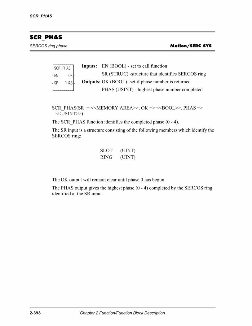
SCR_PHAS
SCR_PHASSERCOS ring phase Motion/SERC_SYS
SCR_PHAS(SR := <<MEMORY AREA>>, OK => <<BOOL>>, PHAS => <<USINT>>)
The SCR_PHAS function identifies the completed phase (0 - 4).
The SR input is a structure consisting of the following members which identify the SERCOS ring:
The OK output will remain clear until phase 0 has begun.
The PHAS output gives the highest phase (0 - 4) completed by the SERCOS ring identified at the SR input.
⁄ƒƒƒƒƒƒƒƒƒø ≥SCR_PHAS ≥ ≥ ≥ ¥EN OK√ ≥ ≥ ¥SR PHAS√ ≥ ≥ ¿ƒƒƒƒƒƒƒƒƒŸ
Inputs: EN (BOOL) - set to call function
SR (STRUC) -structure that identifies SERCOS ring
Outputs: OK (BOOL) -set if phase number is returned
PHAS (USINT) - highest phase number completed
SLOT (UINT)RING (UINT)
2-398 Chapter 2 Function/Function Block Description
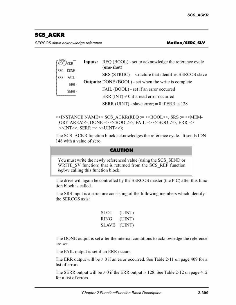
SCS_ACKR
SCS_ACKRSERCOS slave acknowledge reference Motion/SERC_SLV
<<INSTANCE NAME>>:SCS_ACKR(REQ := <<BOOL>>, SRS := <<MEM-ORY AREA>>, DONE => <<BOOL>>, FAIL => <<BOOL>>, ERR => <<INT>>, SERR => <<UINT>>);
The SCS_ACKR function block acknowledges the reference cycle. It sends IDN 148 with a value of zero.
The drive will again be controlled by the SERCOS master (the PiC) after this func-tion block is called.
The SRS input is a structure consisting of the following members which identify the SERCOS axis:
The DONE output is set after the internal conditions to acknowledge the reference are set.
The FAIL output is set if an ERR occurs.
The ERR output will be ≠ 0 if an error occurred. See Table 2-11 on page 409 for a list of errors.
The SERR output will be ≠ 0 if the ERR output is 128. See Table 2-12 on page 412 for a list of errors.
⁄ NAME ƒø ≥SCS_ACKR ≥ ≥ ≥ ¥REQ DONE√ ≥ ≥ ¥SRS FAIL√ ≥ ≥ ≥ ERR√ ≥ ≥ ≥ SERR√ ¿ƒƒƒƒƒƒƒƒƒŸ
Inputs: REQ (BOOL) - set to acknowledge the reference cycle (one-shot)
SRS (STRUC) - structure that identifies SERCOS slave
Outputs: DONE (BOOL) - set when the write is complete
FAIL (BOOL) - set if an error occurred
ERR (INT) ≠ 0 if a read error occurred
SERR (UINT) - slave error; ≠ 0 if ERR is 128
CAUTION
You must write the newly referenced value (using the SCS_SEND orWRITE_SV function) that is returned from the SCS_REF functionbefore calling this function block.
SLOT (UINT)RING (UINT)SLAVE (UINT)
Chapter 2 Function/Function Block Description 2-399
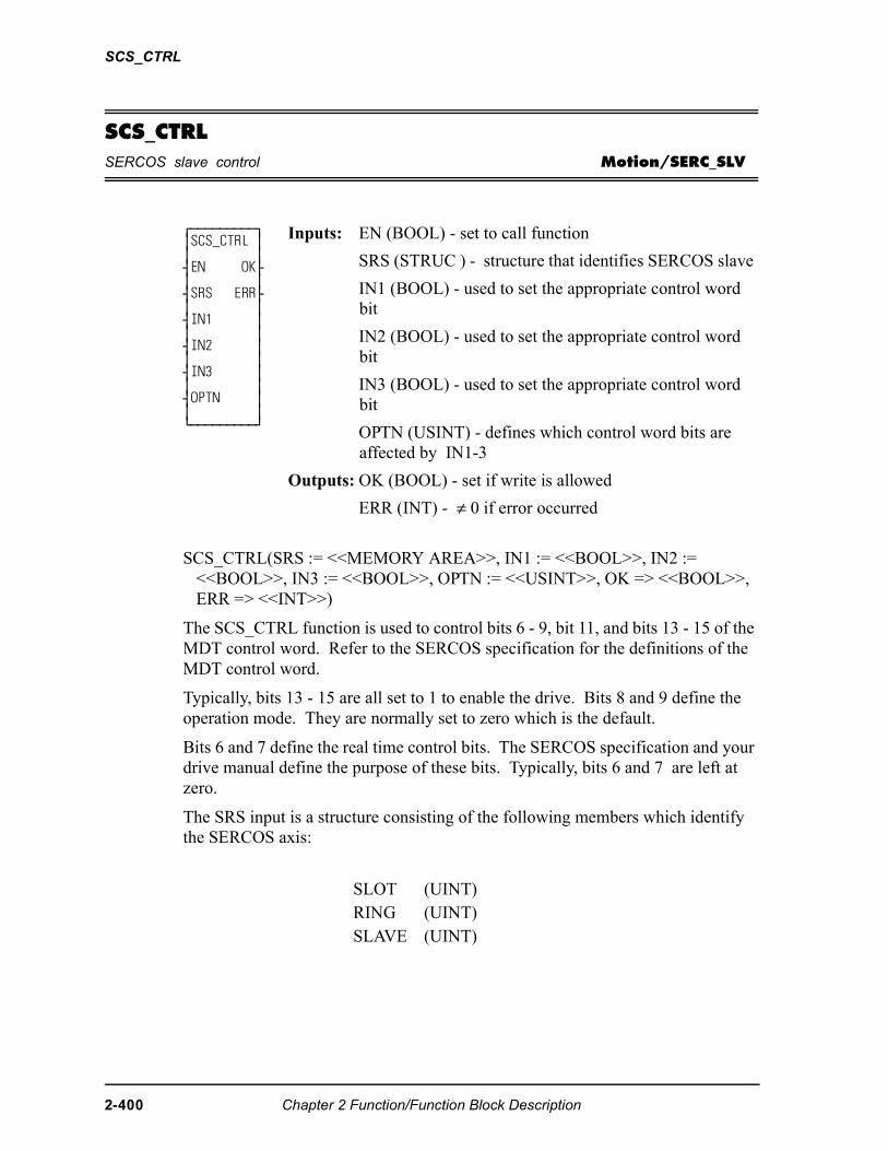
SCS_CTRL
SCS_CTRLSERCOS slave control Motion/SERC_SLV
SCS_CTRL(SRS := <<MEMORY AREA>>, IN1 := <<BOOL>>, IN2 := <<BOOL>>, IN3 := <<BOOL>>, OPTN := <<USINT>>, OK => <<BOOL>>, ERR => <<INT>>)
The SCS_CTRL function is used to control bits 6 - 9, bit 11, and bits 13 - 15 of the MDT control word. Refer to the SERCOS specification for the definitions of the MDT control word.
Typically, bits 13 - 15 are all set to 1 to enable the drive. Bits 8 and 9 define the operation mode. They are normally set to zero which is the default.
Bits 6 and 7 define the real time control bits. The SERCOS specification and your drive manual define the purpose of these bits. Typically, bits 6 and 7 are left at zero.
The SRS input is a structure consisting of the following members which identify the SERCOS axis:
⁄ƒƒƒƒƒƒƒƒƒø ≥SCS_CTRL ≥ ≥ ≥ ¥EN OK√ ≥ ≥ ¥SRS ERR√ ≥ ≥ ¥IN1 ≥ ≥ ≥ ¥IN2 ≥ ≥ ≥ ¥IN3 ≥ ≥ ≥ ¥OPTN ≥ ≥ ≥ ¿ƒƒƒƒƒƒƒƒƒŸ
Inputs: EN (BOOL) - set to call function
SRS (STRUC ) - structure that identifies SERCOS slave
IN1 (BOOL) - used to set the appropriate control word bit
IN2 (BOOL) - used to set the appropriate control word bit
IN3 (BOOL) - used to set the appropriate control word bit
OPTN (USINT) - defines which control word bits are affected by IN1-3
Outputs: OK (BOOL) - set if write is allowed
ERR (INT) - ≠ 0 if error occurred
SLOT (UINT)RING (UINT)SLAVE (UINT)
2-400 Chapter 2 Function/Function Block Description
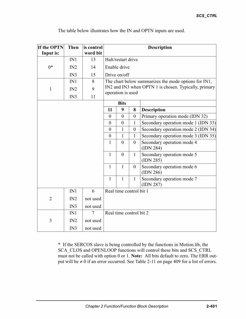
SCS_CTRL
The table below illustrates how the IN and OPTN inputs are used.
* If the SERCOS slave is being controlled by the functions in Motion.lib, the SCA_CLOS and OPENLOOP functions will control these bits and SCS_CTRL must not be called with option 0 or 1. Note: All bits default to zero. The ERR out-put will be ≠ 0 if an error occurred. See Table 2-11 on page 409 for a list of errors.
If the OPTNInput is:
Then is control word bit
Description
0*
IN1
IN2
IN3
13
14
15
Halt/restart drive
Enable drive
Drive on/off
1
IN1
IN2
IN3
8
9
11
The chart below summarizes the mode options for IN1, IN2 and IN3 when OPTN 1 is chosen. Typically, primary operation is used
Bits11 9 8 Description0 0 0 Primary operation mode (IDN 32)0 0 1 Secondary operation mode 1 (IDN 33)0 1 0 Secondary operation mode 2 (IDN 34)0 1 1 Secondary operation mode 3 (IDN 35)1 0 0 Secondary operation mode 4
(IDN 284)1 0 1 Secondary operation mode 5
(IDN 285)1 1 0 Secondary operation mode 6
(IDN 286)1 1 1 Secondary operation mode 7
(IDN 287)
2
IN1
IN2
IN3
6
not used
not used
Real time control bit 1
3
IN1
IN2
IN3
7
not used
not used
Real time control bit 2
Chapter 2 Function/Function Block Description 2-401
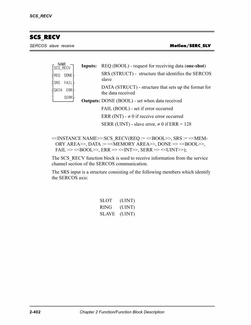
SCS_RECV
SCS_RECVSERCOS slave receive Motion/SERC_SLV
<<INSTANCE NAME>>:SCS_RECV(REQ := <<BOOL>>, SRS := <<MEM-ORY AREA>>, DATA := <<MEMORY AREA>>, DONE => <<BOOL>>, FAIL => <<BOOL>>, ERR => <<INT>>, SERR => <<UINT>>);
The SCS_RECV function block is used to receive information from the service channel section of the SERCOS communication.
The SRS input is a structure consisting of the following members which identify the SERCOS axis:
⁄ NAME ƒø ≥SCS_RECV ≥ ≥ ≥ ¥REQ DONE√ ≥ ≥ ¥SRS FAIL√ ≥ ≥ ¥DATA ERR√ ≥ ≥ ≥ SERR√ ¿ƒƒƒƒƒƒƒƒƒŸ
Inputs: REQ (BOOL) - request for receiving data (one-shot)
SRS (STRUCT) - structure that identifies the SERCOS slave
DATA (STRUCT) - structure that sets up the format for the data received
Outputs: DONE (BOOL) - set when data received
FAIL (BOOL) - set if error occurred
ERR (INT) - ≠ 0 if receive error occurred
SERR (UINT) - slave error, ≠ 0 if ERR = 128
SLOT (UINT)RING (UINT)SLAVE (UINT)
2-402 Chapter 2 Function/Function Block Description
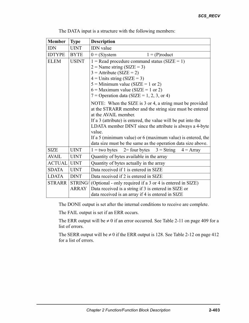
SCS_RECV
The DATA input is a structure with the following members:
The DONE output is set after the internal conditions to receive are complete.
The FAIL output is set if an ERR occurs.
The ERR output will be ≠ 0 if an error occurred. See Table 2-11 on page 409 for a list of errors.
The SERR output will be ≠ 0 if the ERR output is 128. See Table 2-12 on page 412 for a list of errors.
Member Type DescriptionIDN UINT IDN valueIDTYPE BYTE 0 = (S)ystem 1 = (P)roductELEM USINT 1 = Read procedure command status (SIZE = 1)
2 = Name string (SIZE = 3)3 = Attribute (SIZE = 2)4 = Units string (SIZE = 3)5 = Minimum value (SIZE = 1 or 2)6 = Maximum value (SIZE = 1 or 2)7 = Operation data (SIZE = 1, 2, 3, or 4)
NOTE: When the SIZE is 3 or 4, a string must be provided at the STRARR member and the string size must be entered at the AVAIL member. If a 3 (attribute) is entered, the value will be put into the LDATA member DINT since the attribute is always a 4-byte value.If a 5 (minimum value) or 6 (maximum value) is entered, the data size must be the same as the operation data size above.
SIZE UINT 1 = two bytes 2= four bytes 3 = String 4 = ArrayAVAIL UINT Quantity of bytes available in the arrayACTUAL UINT Quantity of bytes actually in the arraySDATA UINT Data received if 1 is entered in SIZELDATA DINT Data received if 2 is entered in SIZESTRARR STRING/
ARRAY(Optional - only required if a 3 or 4 is entered in SIZE)Data received is a string if 3 is entered in SIZE ordata received is an array if 4 is entered in SIZE
Chapter 2 Function/Function Block Description 2-403
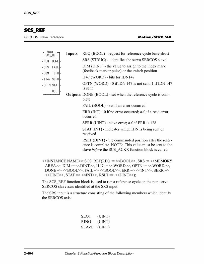
SCS_REF
SCS_REFSERCOS slave reference Motion/SERC_SLV
<<INSTANCE NAME>>:SCS_REF(REQ := <<BOOL>>, SRS := <<MEMORY AREA>>, DIM := <<DINT>>, I147 := <<WORD>>, OPTN := <<WORD>>, DONE => <<BOOL>>, FAIL => <<BOOL>>, ERR => <<INT>>, SERR => <<UINT>>, STAT => <<INT>>, RSLT => <<DINT>>);
The SCS_REF function block is used to run a reference cycle on the non-servo SERCOS slave axis identified at the SRS input.
The SRS input is a structure consisting of the following members which identify the SERCOS axis:
⁄ NAME ƒø ≥ SCS_REF ≥ ≥ ≥ ¥REQ DONE√ ≥ ≥ ¥SRS FAIL√ ≥ ≥ ¥DIM ERR√ ≥ ≥ ¥I147 SERR√ ≥ ≥ ¥OPTN STAT√ ≥ ≥ ≥ RSLT√ ¿ƒƒƒƒƒƒƒƒƒŸ
Inputs: REQ (BOOL) - request for reference cycle (one-shot)
SRS (STRUC) - identifies the servo SERCOS slave
DIM (DINT) - the value to assign to the index mark (feedback marker pulse) or the switch position
I147 (WORD) - bits for IDN147
OPTN (WORD) - 0 if IDN 147 is not sent; 1 if IDN 147 is sent.
Outputs: DONE (BOOL) - set when the reference cycle is com-plete
FAIL (BOOL) - set if an error occurred
ERR (INT) - 0 if no error occurred; ≠ 0 if a read error occurred
SERR (UINT) - slave error; ≠ 0 if ERR is 128
STAT (INT) - indicates which IDN is being sent or received
RSLT (DINT) - the commanded position after the refer-ence is complete NOTE: This value must be sent to the slave before the SCS_ACKR function block is called.
SLOT (UINT)RING (UINT)SLAVE (UINT)
2-404 Chapter 2 Function/Function Block Description
SCS_REF
The DIM input is the value assigned to the index mark or the reference switch Position.
The I147 input holds the bits for IDN 147. Refer to the SERCOS specification for more information. Typically, bits 2, 3, and 4 are 101 respectively. The other bits depend on the application and the features offered by the drive.
The OPTN input determines whether IDN147 is sent during the reference cycle. For some drives, IDN 147 must be sent during phase 2. Set bit 0 of the option word to 1 if you are sending IDN 147 during the reference cycle. Set bit 0 of the option word to 0 if you are not sending IDN 147 during the reference cycle.
The DONE output is set when the reference cycle is complete. The SCS_ACKR function must be called after the reference cycle is complete.
The ERR output will be ≠ 0 if an error occurred. See Table 2-11 on page 409 for a list of errors.
The SERR output will be ≠ 0 if the ERR output is 128. See Table 2-12 on page 412 for a list of errors.
The STAT output indicates which IDN is being sent or received. It is used only for troubleshooting failure conditions. See the chart below.
The RSLT output gives the commanded position after the reference is complete. If the ladder is using the SCS_SEND function to write the drive position, this new value must be used prior to calling the SCS_ACKR function.
STAT# IDN1 Sending IDN 147 - option bits2 Sending IDN 52 - reference position3 Sending IDN 148 - start reference4 Receiving IDN 148 - reference started?5 Receiving IDN 403 - reference done?6 Receiving IDN 47 - position?0 Reference complete
Chapter 2 Function/Function Block Description 2-405
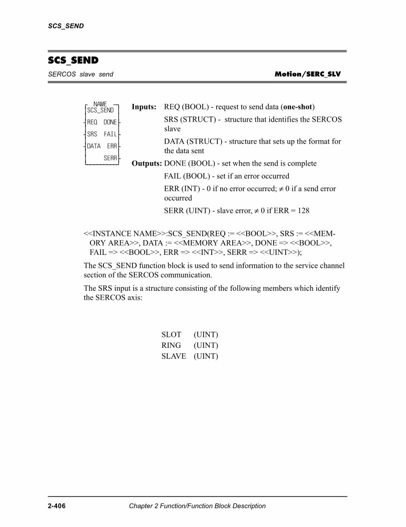
SCS_SEND
SCS_SENDSERCOS slave send Motion/SERC_SLV
<<INSTANCE NAME>>:SCS_SEND(REQ := <<BOOL>>, SRS := <<MEM-ORY AREA>>, DATA := <<MEMORY AREA>>, DONE => <<BOOL>>, FAIL => <<BOOL>>, ERR => <<INT>>, SERR => <<UINT>>);
The SCS_SEND function block is used to send information to the service channel section of the SERCOS communication.
The SRS input is a structure consisting of the following members which identify the SERCOS axis:
⁄ NAME ƒø ≥SCS_SEND ≥ ≥ ≥ ¥REQ DONE√ ≥ ≥ ¥SRS FAIL√ ≥ ≥ ¥DATA ERR√ ≥ ≥ ≥ SERR√ ¿ƒƒƒƒƒƒƒƒƒŸ
Inputs: REQ (BOOL) - request to send data (one-shot)
SRS (STRUCT) - structure that identifies the SERCOS slave
DATA (STRUCT) - structure that sets up the format for the data sent
Outputs: DONE (BOOL) - set when the send is complete
FAIL (BOOL) - set if an error occurred
ERR (INT) - 0 if no error occurred; ≠ 0 if a send error occurred
SERR (UINT) - slave error, ≠ 0 if ERR = 128
SLOT (UINT)RING (UINT)SLAVE (UINT)
2-406 Chapter 2 Function/Function Block Description
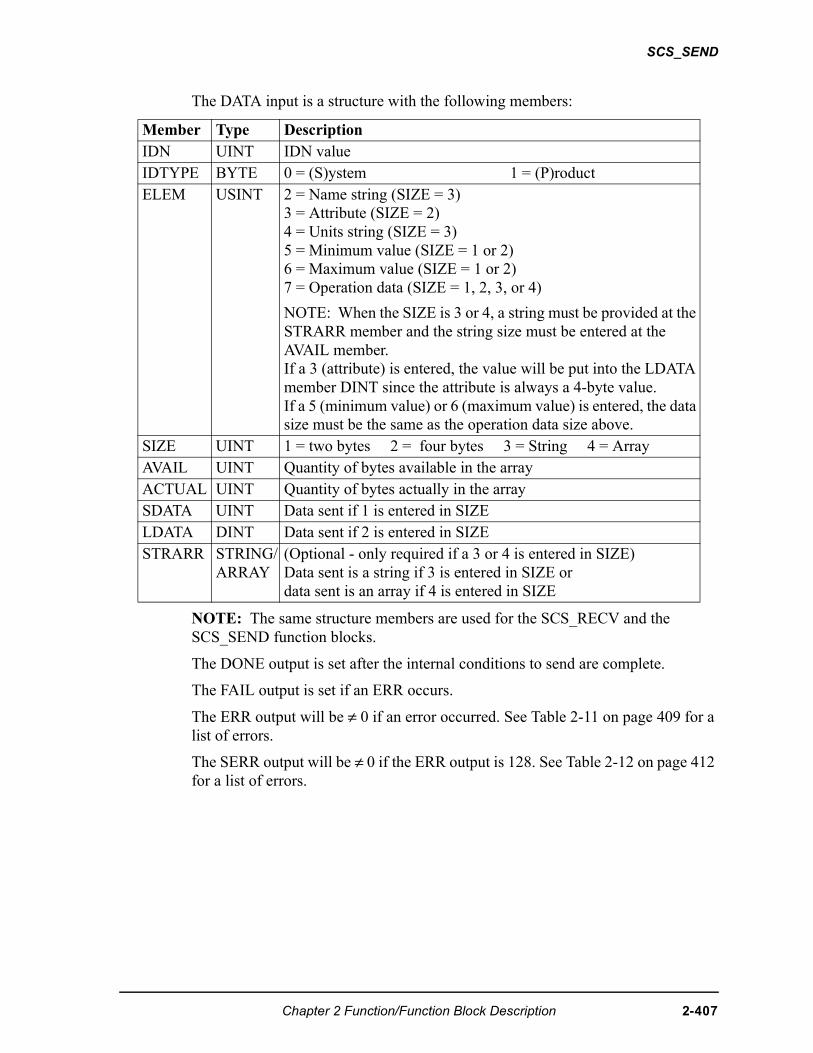
SCS_SEND
The DATA input is a structure with the following members:
NOTE: The same structure members are used for the SCS_RECV and the SCS_SEND function blocks.
The DONE output is set after the internal conditions to send are complete.
The FAIL output is set if an ERR occurs.
The ERR output will be ≠ 0 if an error occurred. See Table 2-11 on page 409 for a list of errors.
The SERR output will be ≠ 0 if the ERR output is 128. See Table 2-12 on page 412 for a list of errors.
Member Type DescriptionIDN UINT IDN valueIDTYPE BYTE 0 = (S)ystem 1 = (P)roductELEM USINT 2 = Name string (SIZE = 3)
3 = Attribute (SIZE = 2)4 = Units string (SIZE = 3)5 = Minimum value (SIZE = 1 or 2)6 = Maximum value (SIZE = 1 or 2)7 = Operation data (SIZE = 1, 2, 3, or 4)
NOTE: When the SIZE is 3 or 4, a string must be provided at the STRARR member and the string size must be entered at the AVAIL member. If a 3 (attribute) is entered, the value will be put into the LDATA member DINT since the attribute is always a 4-byte value.If a 5 (minimum value) or 6 (maximum value) is entered, the data size must be the same as the operation data size above.
SIZE UINT 1 = two bytes 2 = four bytes 3 = String 4 = ArrayAVAIL UINT Quantity of bytes available in the arrayACTUAL UINT Quantity of bytes actually in the arraySDATA UINT Data sent if 1 is entered in SIZELDATA DINT Data sent if 2 is entered in SIZESTRARR STRING/
ARRAY(Optional - only required if a 3 or 4 is entered in SIZE)Data sent is a string if 3 is entered in SIZE ordata sent is an array if 4 is entered in SIZE
Chapter 2 Function/Function Block Description 2-407
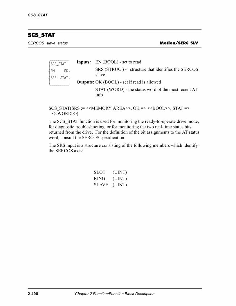
SCS_STAT
SCS_STATSERCOS slave status Motion/SERC_SLV
SCS_STAT(SRS := <<MEMORY AREA>>, OK => <<BOOL>>, STAT => <<WORD>>)
The SCS_STAT function is used for monitoring the ready-to-operate drive mode, for diagnostic troubleshooting, or for monitoring the two real-time status bits returned from the drive. For the definition of the bit assignments to the AT status word, consult the SERCOS specification.
The SRS input is a structure consisting of the following members which identify the SERCOS axis:
⁄ƒƒƒƒƒƒƒƒƒø ≥SCS_STAT ≥ ≥ ≥ ¥EN OK√ ≥ ≥ ¥SRS STAT√ ≥ ≥ ¿ƒƒƒƒƒƒƒƒƒŸ
Inputs: EN (BOOL) - set to read
SRS (STRUC ) - structure that identifies the SERCOS slave
Outputs: OK (BOOL) - set if read is allowed
STAT (WORD) - the status word of the most recent AT info
SLOT (UINT)RING (UINT)SLAVE (UINT)
2-408 Chapter 2 Function/Function Block Description
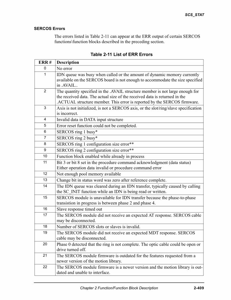
SCS_STAT
SERCOS Errors
The errors listed in Table 2-11 can appear at the ERR output of certain SERCOS functions\function blocks described in the preceding section.
Table 2-11 List of ERR Errors
ERR # Description0 No error1 IDN queue was busy when called or the amount of dynamic memory currently
available on the SERCOS board is not enough to accommodate the size specified in .AVAIL..
2 The quantity specified in the .AVAIL structure member is not large enough for the received data. The actual size of the received data is returned in the .ACTUAL structure member. This error is reported by the SERCOS firmware.
3 Axis is not initialized, is not a SERCOS axis, or the slot/ring/slave specification is incorrect.
4 Invalid data in DATA input structure5 Error reset function could not be completed.6 SERCOS ring 1 busy*7 SERCOS ring 2 busy*8 SERCOS ring 1 configuration size error**9 SERCOS ring 2 configuration size error**10 Function block enabled while already in process11 Bit 3 or bit 8 set in the procedure command acknowledgment (data status)
Either operation data invalid or procedure command error12 Not enough pool memory available13 Change bit in status word was zero after reference complete.14 The IDN queue was cleared during an IDN transfer, typically caused by calling
the SC_INIT function while an IDN is being read or written. 15 SERCOS module is unavailable for IDN transfer because the phase-to-phase
transistion in progress is between phase 2 and phase 4. 16 Slave response timed out17 The SERCOS module did not receive an expected AT response. SERCOS cable
may be disconnected.18 Number of SERCOS slots or slaves is invalid.19 The SERCOS module did not receive an expected MDT response. SERCOS
cable may be disconnected.20 Phase 0 detected that the ring is not complete. The optic cable could be open or
drive turned off.21 The SERCOS module firmware is outdated for the features requested from a
newer version of the motion library.22 The SERCOS module firmware is a newer version and the motion library is out-
dated and unable to interface.
Chapter 2 Function/Function Block Description 2-409
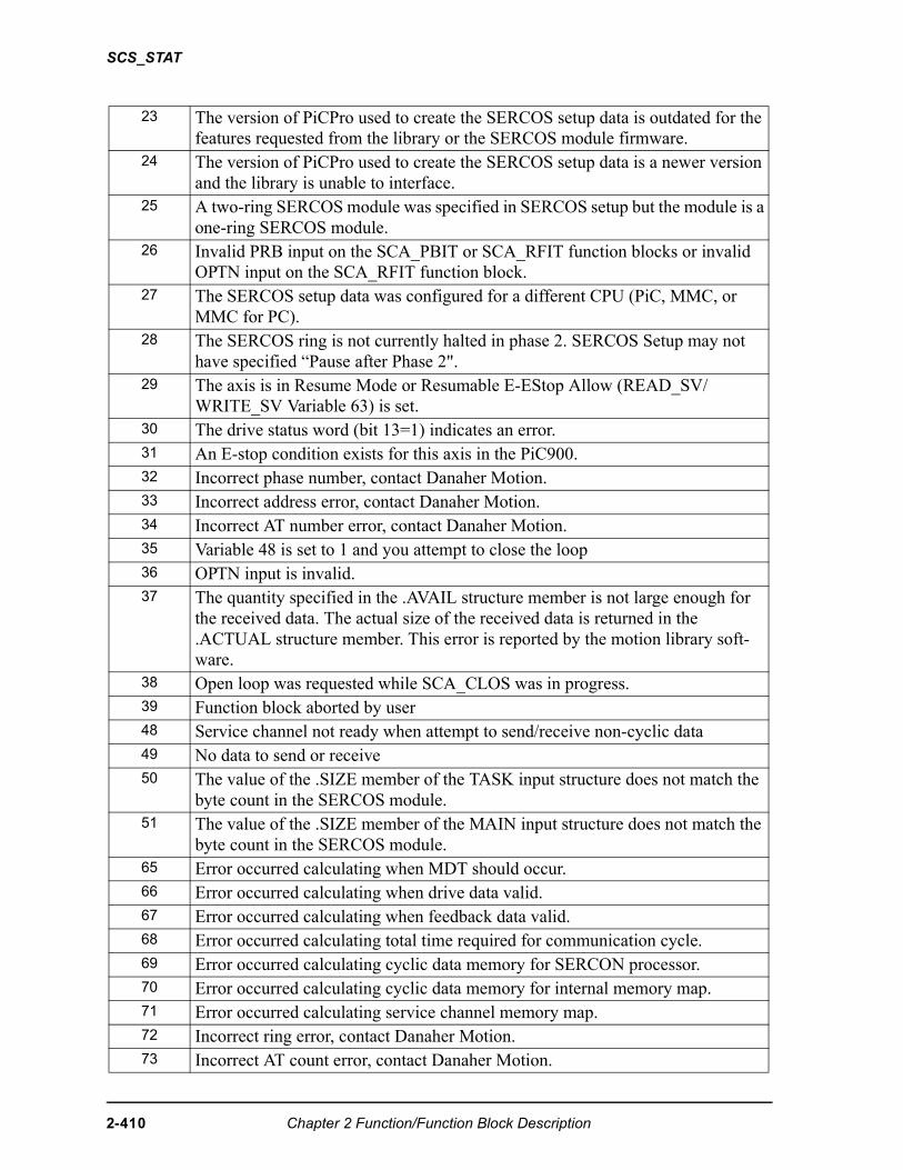
SCS_STAT
23 The version of PiCPro used to create the SERCOS setup data is outdated for the features requested from the library or the SERCOS module firmware.
24 The version of PiCPro used to create the SERCOS setup data is a newer version and the library is unable to interface.
25 A two-ring SERCOS module was specified in SERCOS setup but the module is a one-ring SERCOS module.
26 Invalid PRB input on the SCA_PBIT or SCA_RFIT function blocks or invalid OPTN input on the SCA_RFIT function block.
27 The SERCOS setup data was configured for a different CPU (PiC, MMC, or MMC for PC).
28 The SERCOS ring is not currently halted in phase 2. SERCOS Setup may not have specified “Pause after Phase 2".
29 The axis is in Resume Mode or Resumable E-EStop Allow (READ_SV/WRITE_SV Variable 63) is set.
30 The drive status word (bit 13=1) indicates an error.31 An E-stop condition exists for this axis in the PiC900.32 Incorrect phase number, contact Danaher Motion.33 Incorrect address error, contact Danaher Motion.34 Incorrect AT number error, contact Danaher Motion.35 Variable 48 is set to 1 and you attempt to close the loop36 OPTN input is invalid.37 The quantity specified in the .AVAIL structure member is not large enough for
the received data. The actual size of the received data is returned in the .ACTUAL structure member. This error is reported by the motion library soft-ware.
38 Open loop was requested while SCA_CLOS was in progress.39 Function block aborted by user48 Service channel not ready when attempt to send/receive non-cyclic data 49 No data to send or receive50 The value of the .SIZE member of the TASK input structure does not match the
byte count in the SERCOS module.51 The value of the .SIZE member of the MAIN input structure does not match the
byte count in the SERCOS module.65 Error occurred calculating when MDT should occur.66 Error occurred calculating when drive data valid.67 Error occurred calculating when feedback data valid.68 Error occurred calculating total time required for communication cycle.69 Error occurred calculating cyclic data memory for SERCON processor.70 Error occurred calculating cyclic data memory for internal memory map.71 Error occurred calculating service channel memory map.72 Incorrect ring error, contact Danaher Motion.73 Incorrect AT count error, contact Danaher Motion.
2-410 Chapter 2 Function/Function Block Description
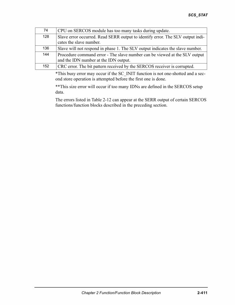
SCS_STAT
*This busy error may occur if the SC_INIT function is not one-shotted and a sec-ond store operation is attempted before the first one is done.
**This size error will occur if too many IDNs are defined in the SERCOS setup data.
The errors listed in Table 2-12 can appear at the SERR output of certain SERCOS functions/function blocks described in the preceding section.
74 CPU on SERCOS module has too many tasks during update.128 Slave error occurred. Read SERR output to identify error. The SLV output indi-
cates the slave number.136 Slave will not respond in phase 1. The SLV output indicates the slave number.144 Procedure command error - The slave number can be viewed at the SLV output
and the IDN number at the IDN output.152 CRC error. The bit pattern received by the SERCOS receiver is corrupted.
Chapter 2 Function/Function Block Description 2-411
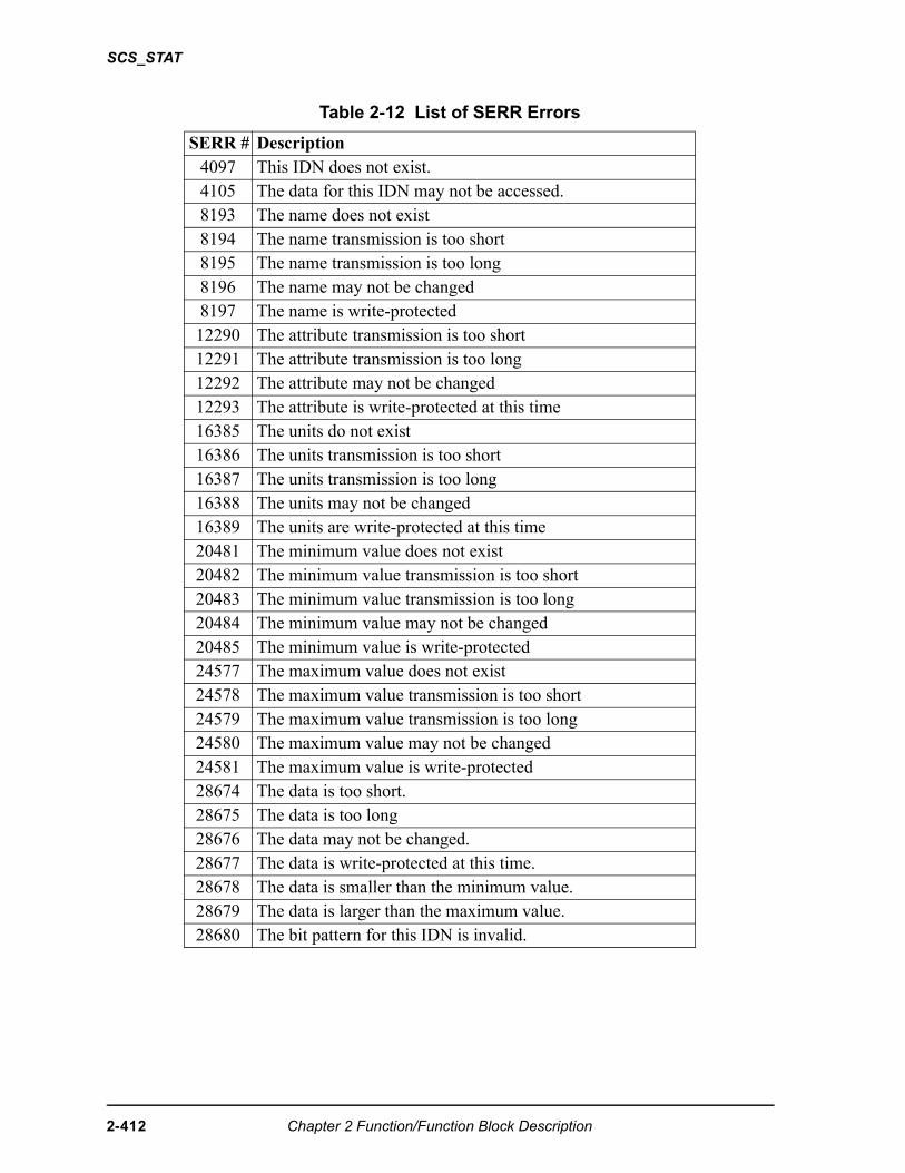
SCS_STAT
Table 2-12 List of SERR Errors
SERR # Description4097 This IDN does not exist.4105 The data for this IDN may not be accessed.8193 The name does not exist8194 The name transmission is too short8195 The name transmission is too long8196 The name may not be changed8197 The name is write-protected12290 The attribute transmission is too short12291 The attribute transmission is too long12292 The attribute may not be changed12293 The attribute is write-protected at this time16385 The units do not exist16386 The units transmission is too short16387 The units transmission is too long16388 The units may not be changed16389 The units are write-protected at this time20481 The minimum value does not exist20482 The minimum value transmission is too short20483 The minimum value transmission is too long20484 The minimum value may not be changed20485 The minimum value is write-protected24577 The maximum value does not exist24578 The maximum value transmission is too short24579 The maximum value transmission is too long24580 The maximum value may not be changed24581 The maximum value is write-protected28674 The data is too short.28675 The data is too long28676 The data may not be changed.28677 The data is write-protected at this time.28678 The data is smaller than the minimum value.28679 The data is larger than the maximum value.28680 The bit pattern for this IDN is invalid.
2-412 Chapter 2 Function/Function Block Description
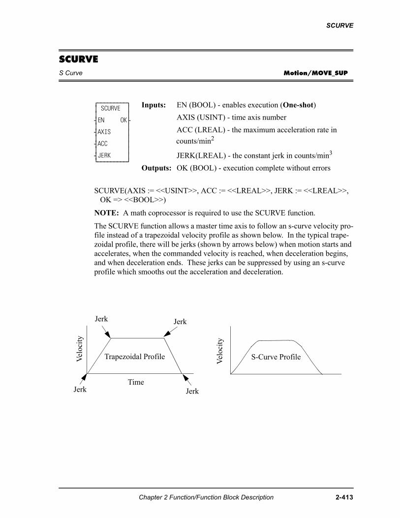
SCURVE
SCURVES Curve Motion/MOVE_SUP
SCURVE(AXIS := <<USINT>>, ACC := <<LREAL>>, JERK := <<LREAL>>, OK => <<BOOL>>)
NOTE: A math coprocessor is required to use the SCURVE function.
The SCURVE function allows a master time axis to follow an s-curve velocity pro-file instead of a trapezoidal velocity profile as shown below. In the typical trape-zoidal profile, there will be jerks (shown by arrows below) when motion starts and accelerates, when the commanded velocity is reached, when deceleration begins, and when deceleration ends. These jerks can be suppressed by using an s-curve profile which smooths out the acceleration and deceleration.
⁄ƒƒƒƒƒƒƒƒƒø ≥ SCURVE ≥ ≥ ≥ ¥EN OK√ ≥ ≥ ¥AXIS ≥ ≥ ≥ ¥ACC ≥ ≥ ≥ ¥JERK ≥ ¿ƒƒƒƒƒƒƒƒƒŸ
Inputs: EN (BOOL) - enables execution (One-shot)
AXIS (USINT) - time axis number
ACC (LREAL) - the maximum acceleration rate in
counts/min2
JERK(LREAL) - the constant jerk in counts/min3
Outputs: OK (BOOL) - execution complete without errors
Jerk Jerk
TimeJerk Jerk
S-Curve Profile
Vel
ocit
y
Trapezoidal ProfileVel
ocit
y
Chapter 2 Function/Function Block Description 2-413
SCURVE
You create an s-curve profile by defining a maximum acceleration rate (ACC) and a constant jerk rate (J) for a master time axis in the SCURVE function. (See the Notes that follow.) Then you can use the DISTANCE, POSITION, or VEL_STR/ VEL_END functions to move a distance, reach an endpoint, or follow a velocity.
Two other functions can be used with the SCURVE function. The IN_POS? func-tion is used to indicate when the distance or position move is complete. The NEWRATE function is used to change the velocity of the time axis while it is moving.
The command velocity (variable 6) can be read with the READ_SV function. This value is given in counts/sec. It will read the velocity command due to the s-curve profile. When the axis is accelerating or decelerating, the value will be different than the value commanded . NOTE: Do not write a command velocity with vari-able 6 when a non-zero value is entered in the ACC and JERK inputs.
You can turn the s-curve off by entering a zero in the ACC input and in the JERK input. The acceleration and deceleration of the time axis will then work with a position and a step velocity written with variables 1 and 6 using the WRITE_SV function. DISTANCE, POSITION, and VEL_STR/END functions are not used.
To improve performance, it is recommended that the velocity compensation flag (read servo variable 32) be turned off for any slaves following the s-curve master time axis.
Time axes do not use the queue like servo axes do. If the time axis is already mov-ing when another function call is made, the new move will begin immediately. The moves are blended together. For example if a second distance move is called before the first is completed, the distance values of the first and second move will be summed. The rate specified in the second move will also take effect immedi-ately. Depending upon distance, endpoint, or direction selected in a distance, posi-tion or velocity move, the axis could reverse direction.
2-414 Chapter 2 Function/Function Block Description
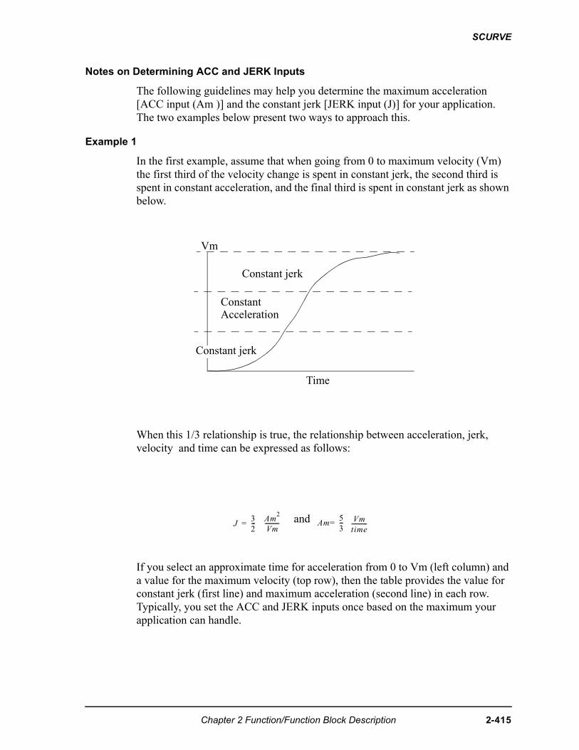
SCURVE
Notes on Determining ACC and JERK Inputs
The following guidelines may help you determine the maximum acceleration [ACC input (Am )] and the constant jerk [JERK input (J)] for your application. The two examples below present two ways to approach this.
Example 1
In the first example, assume that when going from 0 to maximum velocity (Vm) the first third of the velocity change is spent in constant jerk, the second third is spent in constant acceleration, and the final third is spent in constant jerk as shown below.
When this 1/3 relationship is true, the relationship between acceleration, jerk, velocity and time can be expressed as follows:
If you select an approximate time for acceleration from 0 to Vm (left column) and a value for the maximum velocity (top row), then the table provides the value for constant jerk (first line) and maximum acceleration (second line) in each row. Typically, you set the ACC and JERK inputs once based on the maximum your application can handle.
and
Vm
Constant jerk
ConstantAcceleration
Constant jerk
Time
��
�---�
���
��---------- ��
�
�---�
��
����-----------
Chapter 2 Function/Function Block Description 2-415
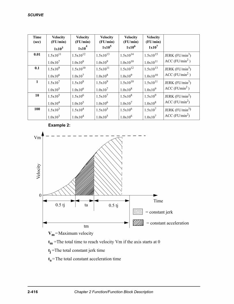
SCURVE
Example 2:
Vm = Maximum velocity
tm =The total time to reach velocity Vm if the axis starts at 0
tj = The total constant jerk time
ta = The total constant acceleration time
Time(sec)
Velocity(FU/min)
1x10³
Velocity(FU/min)
1x10⁴
Velocity(FU/min)
1x10⁵
Velocity(FU/min)
1x10⁶
Velocity(FU/min)
1x10⁷
0.01 1.5x10¹¹
1.0x10⁷
1.5x10¹²
1.0x10⁸
1.5x10¹³
1.0x10⁹
1.5x10¹⁴
1.0x10¹⁰
1.5x10¹⁵
1.0x10¹¹
JERK (FU/min3)
ACC (FU/min2 )
0.1 1.5x10⁹
1.0x10⁶
1.5x10¹⁰
1.0x10⁷
1.5x10¹¹
1.0x10⁸
1.5x10¹²
1.0x10⁹
1.5x10¹³
1.0x10¹⁰
JERK (FU/min3)
ACC (FU/min2 )
1 1.5x10⁷
1.0x10⁵
1.5x10⁸
1.0x10⁶
1.5x10⁹
1.0x10⁷
1.5x10¹⁰
1.0x10⁸
1.5x10¹¹
1.0x10⁹
JERK (FU/min3)
ACC (FUmin2 )
10 1.5x10⁵
1.0x10⁴
1.5x10⁶
1.0x10⁵
1.5x10⁷
1.0x10⁶
1.5x10⁸
1.0x10⁷
1.5x10⁹
1.0x10⁸
JERK (FU/min2)
ACC (FU/min2)
100 1.5x10³
1.0x10³
1.5x10⁴
1.0x10⁴
1.5x10⁵
1.0x10⁵
1.5x10⁶
1.0x10⁶
1.5x10⁷
1.0x10⁷
JERK (FU/min3)
ACC (FU/min2)
0
ta 0.5 tj0.5 tj
tm
Vel
ocit
y
Vm
Time���������������������������� = constant jerk
= constant acceleration
2-416 Chapter 2 Function/Function Block Description
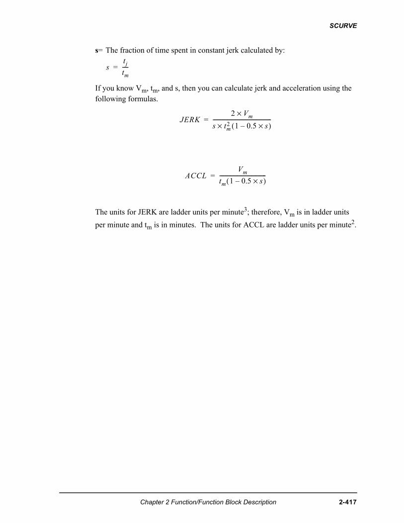
SCURVE
s= The fraction of time spent in constant jerk calculated by:
If you know Vm, tm, and s, then you can calculate jerk and acceleration using the following formulas.
The units for JERK are ladder units per minute3; therefore, Vm is in ladder units
per minute and tm is in minutes. The units for ACCL are ladder units per minute2.
��
��-----�
���� ��×
� ���× � ���� �×( )
--------------------------------------------�
� ���
�� � ���� �×( )-----------------------------------�
Chapter 2 Function/Function Block Description 2-417

SEEK
SEEKSeek Io/COMM
<<INSTANCE NAME>>:SEEK(REQ := <<BOOL>>, HNDL := <<INT>>, ORG := <<INT>>, OFF := <<DINT>>, DONE => <<BOOL>>, FAIL => <<BOOL>>, ERR => <<INT>>);
When you use the OPEN function block, the file or device is set up for a sequential read/write. The SEEK function block allows you to change the location of the pointer.
This function block positions a pointer in a RAMDISK or FMSDISK file. A READ or WRITE executed after this function block will start reading from or writing at that point. The pointer is positioned from one of three origins specified by the value at ORG. It is offset from the origin by the number of bytes specified at OFF. The offset value can be positive (for forward) or negative (for backward).
If the offset value moves the pointer beyond the end of file, the pointer will be at the end of the file. If the offset value moves the pointer before the beginning of file, the pointer will be at the beginning of the file.
⁄ƒƒNAME ƒƒø ≥ SEEK ≥ ≥ ≥ ¥REQ DONE√ ≥ ≥ ¥HNDL FAIL√ ≥ ≥ ¥ORG ERR√ ≥ ≥ ¥OFF ≥ ¿ƒƒƒƒƒƒƒƒƒŸ
Inputs: REQ (BOOL) - enables execution (One-shot)
HNDL (INT) - output from OPEN function block
ORG (INT) - origin
OFF (DINT) - offset
Outputs: DONE (BOOL) - energized if ERR = 0not energized if ERR ≠ 0
FAIL (BOOL) - energized if ERR ≠ 0not energized if ERR = 0
ERR (INT) - 0 if data transfer successful≠ 0 if data transfer unsuccessful
See Appendix B in the PiCPro Online Help for ERR codes.
Enter at ORG Positions pointer at OFF bytes from:16#A00 beginning of file16#A01 its current location16#A02 end of file
2-418 Chapter 2 Function/Function Block Description
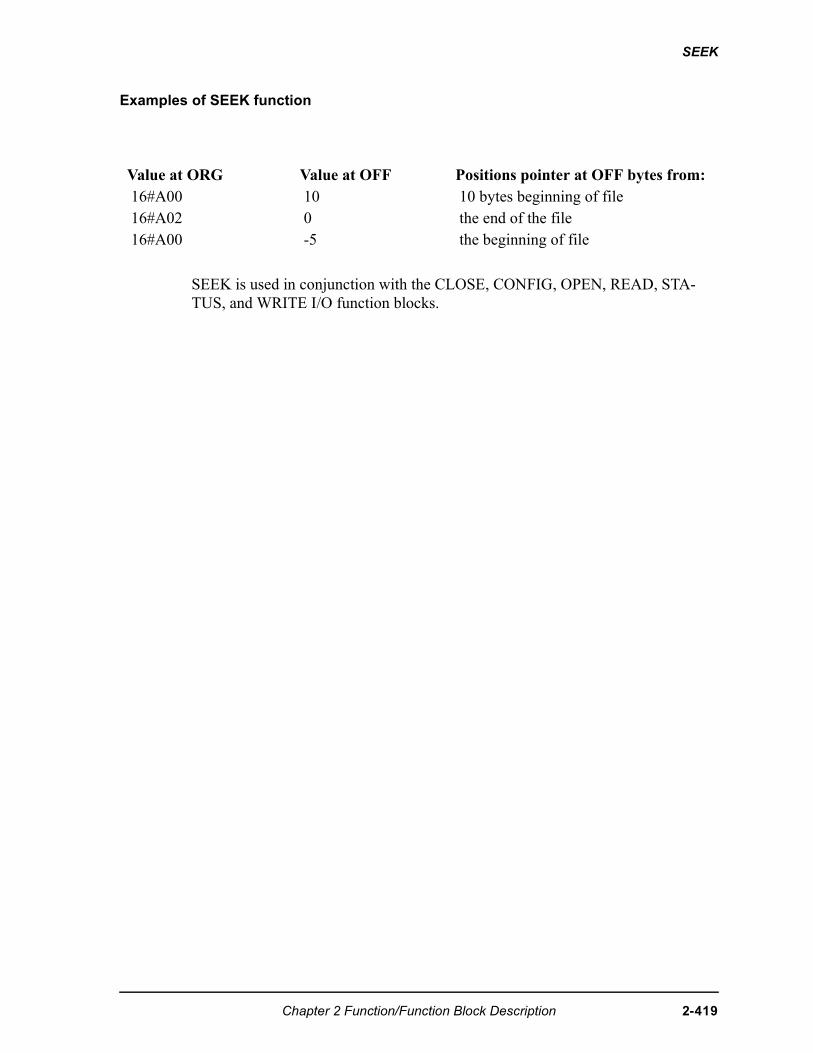
SEEK
Examples of SEEK function
SEEK is used in conjunction with the CLOSE, CONFIG, OPEN, READ, STA-TUS, and WRITE I/O function blocks.
Value at ORG Value at OFF Positions pointer at OFF bytes from:16#A00 10 10 bytes beginning of file16#A02 0 the end of the file16#A00 -5 the beginning of file
Chapter 2 Function/Function Block Description 2-419
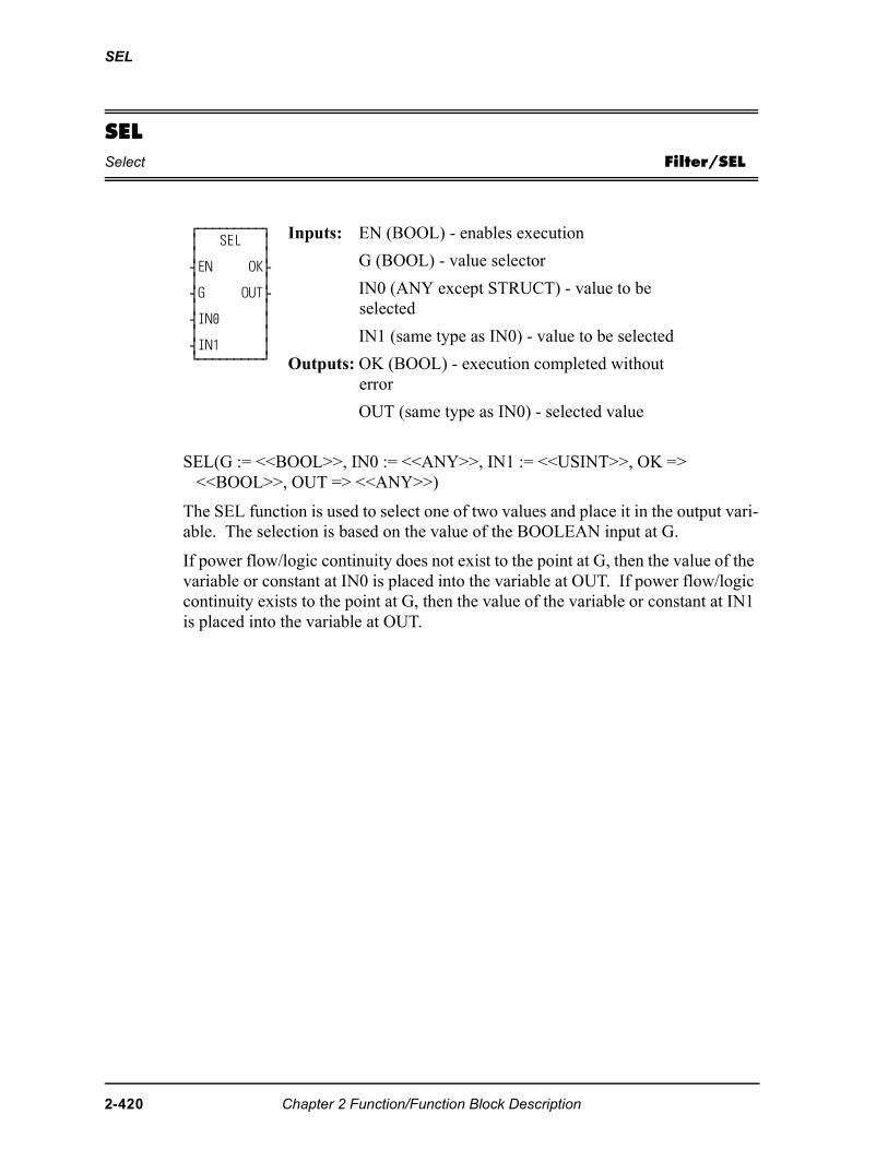
SEL
SELSelect Filter/SEL
SEL(G := <<BOOL>>, IN0 := <<ANY>>, IN1 := <<USINT>>, OK => <<BOOL>>, OUT => <<ANY>>)
The SEL function is used to select one of two values and place it in the output vari-able. The selection is based on the value of the BOOLEAN input at G.
If power flow/logic continuity does not exist to the point at G, then the value of the variable or constant at IN0 is placed into the variable at OUT. If power flow/logic continuity exists to the point at G, then the value of the variable or constant at IN1 is placed into the variable at OUT.
⁄ƒƒƒƒƒƒƒƒƒø ≥ SEL ≥ ≥ ≥ ¥EN OK√ ≥ ≥ ¥G OUT√ ≥ ≥ ¥IN0 ≥ ≥ ≥ ¥IN1 ≥ ¿ƒƒƒƒƒƒƒƒƒŸ
Inputs: EN (BOOL) - enables execution
G (BOOL) - value selector
IN0 (ANY except STRUCT) - value to be selected
IN1 (same type as IN0) - value to be selected
Outputs: OK (BOOL) - execution completed without error
OUT (same type as IN0) - selected value
2-420 Chapter 2 Function/Function Block Description
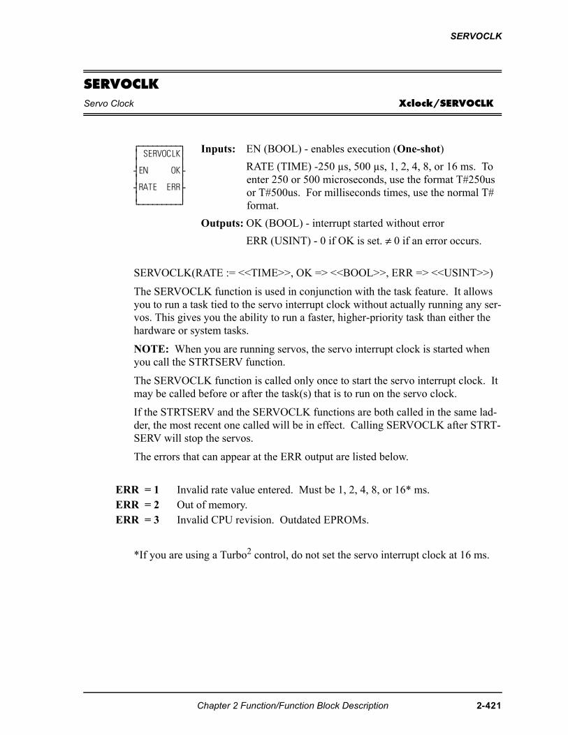
SERVOCLK
SERVOCLKServo Clock Xclock/SERVOCLK
SERVOCLK(RATE := <<TIME>>, OK => <<BOOL>>, ERR => <<USINT>>)
The SERVOCLK function is used in conjunction with the task feature. It allows you to run a task tied to the servo interrupt clock without actually running any ser-vos. This gives you the ability to run a faster, higher-priority task than either the hardware or system tasks.
NOTE: When you are running servos, the servo interrupt clock is started when you call the STRTSERV function.
The SERVOCLK function is called only once to start the servo interrupt clock. It may be called before or after the task(s) that is to run on the servo clock.
If the STRTSERV and the SERVOCLK functions are both called in the same lad-der, the most recent one called will be in effect. Calling SERVOCLK after STRT-SERV will stop the servos.
The errors that can appear at the ERR output are listed below.
*If you are using a Turbo2 control, do not set the servo interrupt clock at 16 ms.
⁄ƒƒƒƒƒƒƒƒƒø ≥ SERVOCLK≥ ≥ ≥ ¥EN OK√ ≥ ≥ ¥RATE ERR√ ≥ ≥ ¿ƒƒƒƒƒƒƒƒƒŸ
Inputs: EN (BOOL) - enables execution (One-shot)
RATE (TIME) -250 µs, 500 µs, 1, 2, 4, 8, or 16 ms. To enter 250 or 500 microseconds, use the format T#250us or T#500us. For milliseconds times, use the normal T# format.
Outputs: OK (BOOL) - interrupt started without error
ERR (USINT) - 0 if OK is set. ≠ 0 if an error occurs.
ERR = 1 Invalid rate value entered. Must be 1, 2, 4, 8, or 16* ms. ERR = 2 Out of memory.ERR = 3 Invalid CPU revision. Outdated EPROMs.
Chapter 2 Function/Function Block Description 2-421
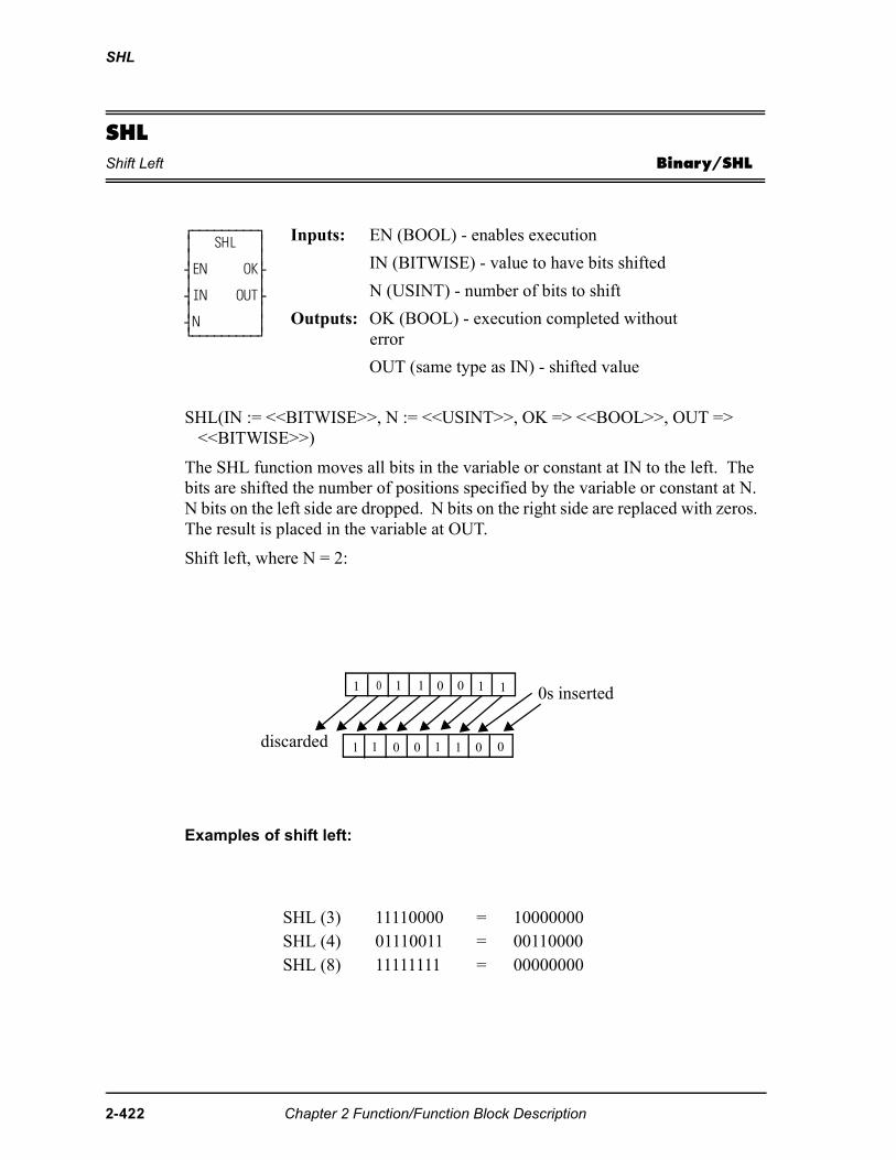
SHL
SHLShift Left Binary/SHL
SHL(IN := <<BITWISE>>, N := <<USINT>>, OK => <<BOOL>>, OUT => <<BITWISE>>)
The SHL function moves all bits in the variable or constant at IN to the left. The bits are shifted the number of positions specified by the variable or constant at N. N bits on the left side are dropped. N bits on the right side are replaced with zeros. The result is placed in the variable at OUT.
Shift left, where N = 2:
Examples of shift left:
⁄ƒƒƒƒƒƒƒƒƒø ≥ SHL ≥ ≥ ≥ ¥EN OK√ ≥ ≥ ¥IN OUT√ ≥ ≥ ¥N ≥ ¿ƒƒƒƒƒƒƒƒƒŸ
Inputs: EN (BOOL) - enables execution
IN (BITWISE) - value to have bits shifted
N (USINT) - number of bits to shift
Outputs: OK (BOOL) - execution completed without error
OUT (same type as IN) - shifted value
SHL (3) 11110000 = 10000000SHL (4) 01110011 = 00110000SHL (8) 11111111 = 00000000
11001101
0011001 1
0s inserted
discarded
2-422 Chapter 2 Function/Function Block Description
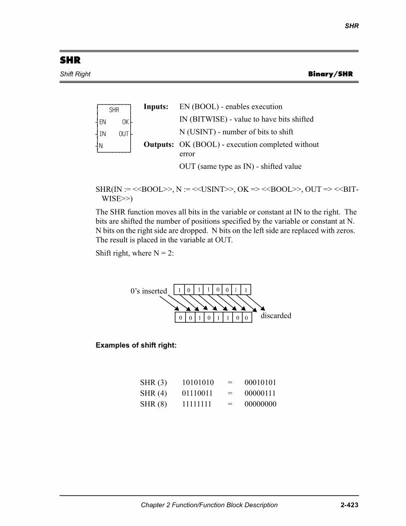
SHR
SHRShift Right Binary/SHR
SHR(IN := <<BOOL>>, N := <<USINT>>, OK => <<BOOL>>, OUT => <<BIT-WISE>>)
The SHR function moves all bits in the variable or constant at IN to the right. The bits are shifted the number of positions specified by the variable or constant at N. N bits on the right side are dropped. N bits on the left side are replaced with zeros. The result is placed in the variable at OUT.
Shift right, where N = 2:
Examples of shift right:
⁄ƒƒƒƒƒƒƒƒƒø ≥ SHR ≥ ≥ ≥ ¥EN OK√ ≥ ≥ ¥IN OUT√ ≥ ≥ ¥N ≥ ¿ƒƒƒƒƒƒƒƒƒŸ
Inputs: EN (BOOL) - enables execution
IN (BITWISE) - value to have bits shifted
N (USINT) - number of bits to shift
Outputs: OK (BOOL) - execution completed without error
OUT (same type as IN) - shifted value
SHR (3) 10101010 = 00010101SHR (4) 01110011 = 00000111SHR (8) 11111111 = 00000000
1 1
0 0 1 0 1 1 00
0’s inserted
discarded
1 1 10 0 0
Chapter 2 Function/Function Block Description 2-423
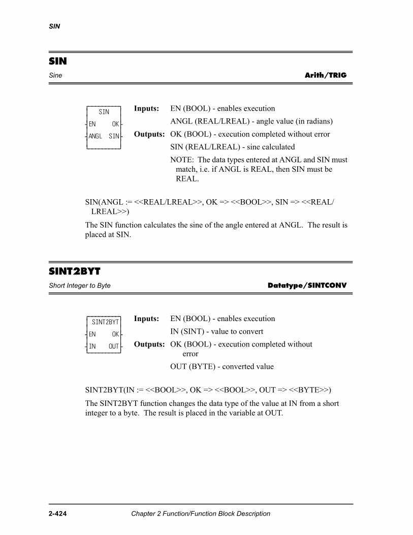
SIN
SINSine Arith/TRIG
SIN(ANGL := <<REAL/LREAL>>, OK => <<BOOL>>, SIN => <<REAL/LREAL>>)
The SIN function calculates the sine of the angle entered at ANGL. The result is placed at SIN.
SINT2BYTShort Integer to Byte Datatype/SINTCONV
SINT2BYT(IN := <<BOOL>>, OK => <<BOOL>>, OUT => <<BYTE>>)
The SINT2BYT function changes the data type of the value at IN from a short integer to a byte. The result is placed in the variable at OUT.
⁄ƒƒƒƒƒƒƒƒƒø ≥ SIN ≥ ≥ ≥ ¥EN OK√ ≥ ≥ ¥ANGL SIN√ ≥ ≥ ¿ƒƒƒƒƒƒƒƒƒŸ
Inputs: EN (BOOL) - enables execution
ANGL (REAL/LREAL) - angle value (in radians)
Outputs: OK (BOOL) - execution completed without error
SIN (REAL/LREAL) - sine calculated
NOTE: The data types entered at ANGL and SIN must match, i.e. if ANGL is REAL, then SIN must be REAL.
⁄ƒƒƒƒƒƒƒƒƒø ≥ SINT2BYT≥ ≥ ≥ ¥EN OK√ ≥ ≥ ¥IN OUT√ ¿ƒƒƒƒƒƒƒƒƒŸ
Inputs: EN (BOOL) - enables execution
IN (SINT) - value to convert
Outputs: OK (BOOL) - execution completed without error
OUT (BYTE) - converted value
2-424 Chapter 2 Function/Function Block Description
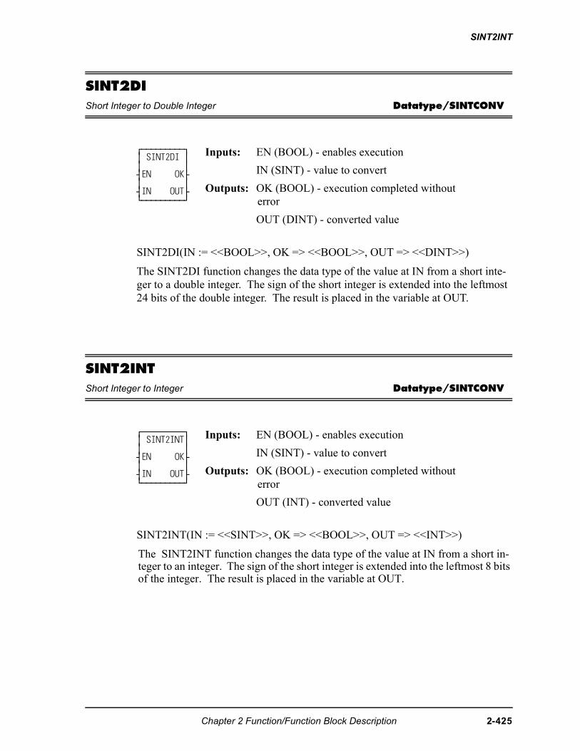
SINT2INT
SINT2DIShort Integer to Double Integer Datatype/SINTCONV
SINT2DI(IN := <<BOOL>>, OK => <<BOOL>>, OUT => <<DINT>>)
The SINT2DI function changes the data type of the value at IN from a short inte-ger to a double integer. The sign of the short integer is extended into the leftmost 24 bits of the double integer. The result is placed in the variable at OUT.
SINT2INTShort Integer to Integer Datatype/SINTCONV
SINT2INT(IN := <<SINT>>, OK => <<BOOL>>, OUT => <<INT>>)
The SINT2INT function changes the data type of the value at IN from a short in-teger to an integer. The sign of the short integer is extended into the leftmost 8 bits of the integer. The result is placed in the variable at OUT.
⁄ƒƒƒƒƒƒƒƒƒø ≥ SINT2DI ≥ ≥ ≥ ¥EN OK√ ≥ ≥ ¥IN OUT√ ¿ƒƒƒƒƒƒƒƒƒŸ
Inputs: EN (BOOL) - enables execution
IN (SINT) - value to convert
Outputs: OK (BOOL) - execution completed without error
OUT (DINT) - converted value
⁄ƒƒƒƒƒƒƒƒƒø ≥ SINT2INT≥ ≥ ≥ ¥EN OK√ ≥ ≥ ¥IN OUT√ ¿ƒƒƒƒƒƒƒƒƒŸ
Inputs: EN (BOOL) - enables execution
IN (SINT) - value to convert
Outputs: OK (BOOL) - execution completed without error
OUT (INT) - converted value
Chapter 2 Function/Function Block Description 2-425
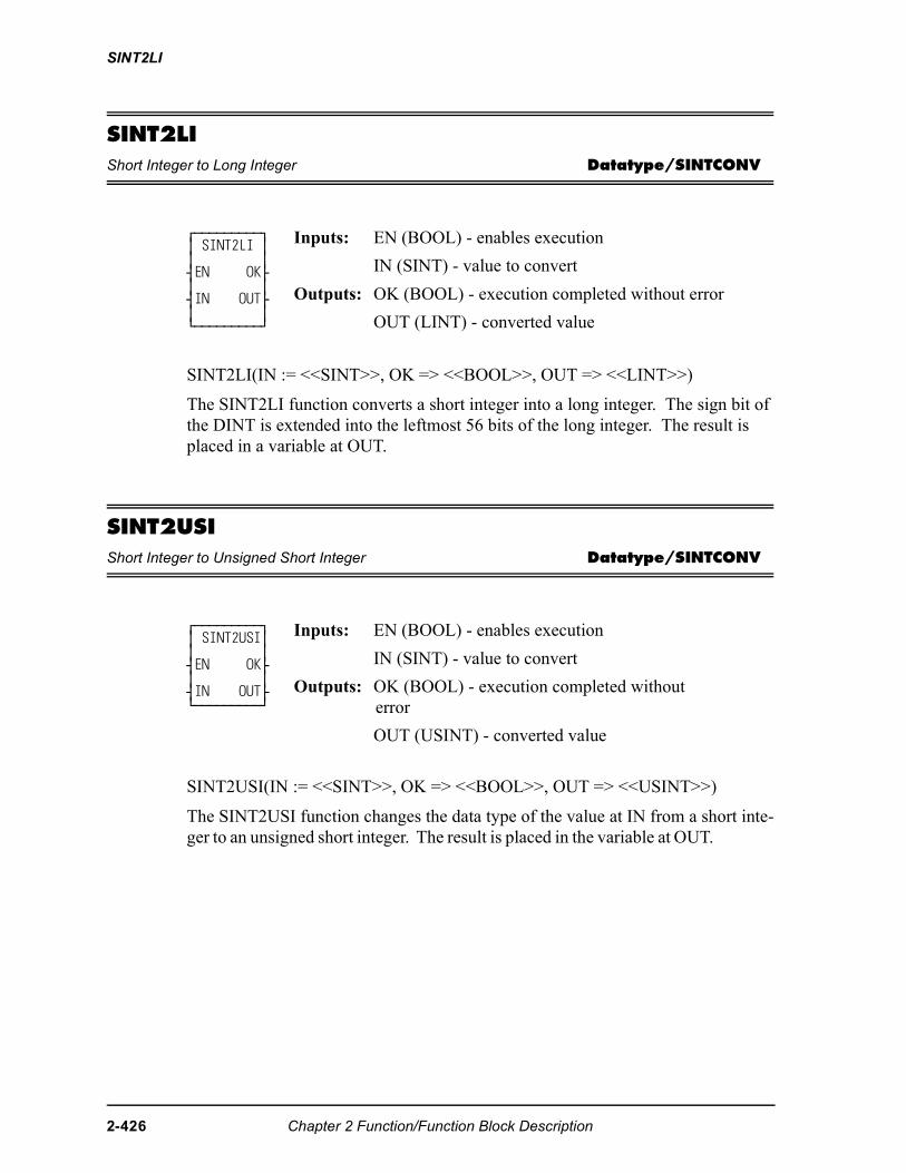
SINT2LI
SINT2LIShort Integer to Long Integer Datatype/SINTCONV
SINT2LI(IN := <<SINT>>, OK => <<BOOL>>, OUT => <<LINT>>)
The SINT2LI function converts a short integer into a long integer. The sign bit of the DINT is extended into the leftmost 56 bits of the long integer. The result is placed in a variable at OUT.
SINT2USIShort Integer to Unsigned Short Integer Datatype/SINTCONV
SINT2USI(IN := <<SINT>>, OK => <<BOOL>>, OUT => <<USINT>>)
The SINT2USI function changes the data type of the value at IN from a short inte-ger to an unsigned short integer. The result is placed in the variable at OUT.
⁄ƒƒƒƒƒƒƒƒƒø ≥ SINT2LI ≥ ≥ ≥ ¥EN OK√ ≥ ≥ ¥IN OUT√ ≥ ≥ ¿ƒƒƒƒƒƒƒƒƒŸ
Inputs: EN (BOOL) - enables execution
IN (SINT) - value to convert
Outputs: OK (BOOL) - execution completed without error
OUT (LINT) - converted value
⁄ƒƒƒƒƒƒƒƒƒø ≥ SINT2USI≥ ≥ ≥ ¥EN OK√ ≥ ≥ ¥IN OUT√ ¿ƒƒƒƒƒƒƒƒƒŸ
Inputs: EN (BOOL) - enables execution
IN (SINT) - value to convert
Outputs: OK (BOOL) - execution completed without error
OUT (USINT) - converted value
2-426 Chapter 2 Function/Function Block Description
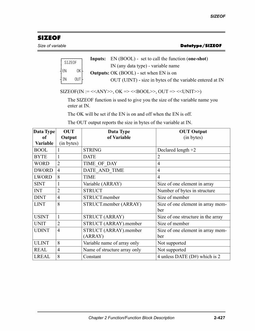
SIZEOF
D
SIZEOFSize of variable Datatype/SIZEOF
SIZEOF(IN := <<ANY>>, OK => <<BOOL>>, OUT => <<UNIT>>)
The SIZEOF function is used to give you the size of the variable name you enter at IN.
The OK will be set if the EN is on and off when the EN is off.
The OUT output reports the size in bytes of the variable at IN.
⁄ƒƒƒƒƒƒƒƒƒø ≥ SIZEOF ≥ ≥ ≥ ¥EN OK√ ≥ ≥ ¥IN OUT√ ¿ƒƒƒƒƒƒƒƒƒŸ
Inputs: EN (BOOL) - set to call the function (one-shot)
IN (any data type) - variable name
Outputs: OK (BOOL) - set when EN is on
OUT (UINT) - size in bytes of the variable entered at IN
ata Type of
Variable
OUTOutput
(in bytes)
Data Type of Variable
OUT Output (in bytes)
BOOL 1 STRING Declared length +2BYTE 1 DATE 2WORD 2 TIME_OF_DAY 4DWORD 4 DATE_AND_TIME 4LWORD 8 TIME 4SINT 1 Variable (ARRAY) Size of one element in arrayINT 2 STRUCT Number of bytes in structureDINT 4 STRUCT.member Size of memberLINT 8 STRUCT.member (ARRAY) Size of one element in array mem-
berUSINT 1 STRUCT (ARRAY) Size of one structure in the arrayUNIT 2 STRUCT (ARRAY).member Size of memberUDINT 4 STRUCT (ARRAY).member
(ARRAY)Size of one element in array mem-ber
ULINT 8 Variable name of array only Not supportedREAL 4 Name of structure array only Not supportedLREAL 8 Constant 4 unless DATE (D#) which is 2
Chapter 2 Function/Function Block Description 2-427
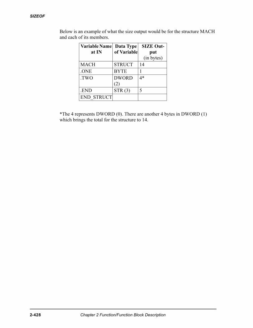
SIZEOF
Below is an example of what the size output would be for the structure MACH and each of its members.
*The 4 represents DWORD (0). There are another 4 bytes in DWORD (1) which brings the total for the structure to 14.
Variable Name at IN
Data Type of Variable
SIZE Out-put
(in bytes)MACH STRUCT 14.ONE BYTE 1.TWO DWORD
(2)4*
.END STR (3) 5END_STRUCT
2-428 Chapter 2 Function/Function Block Description
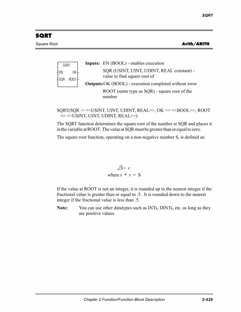
SQRT
SQRTSquare Root Arith/ARITH
SQRT(SQR := <<USINT, UINT, UDINT, REAL>>, OK => <<BOOL>>, ROOT => <<USINT, UINT, UDINT, REAL>>)
The SQRT function determines the square root of the number at SQR and places it in the variable at ROOT. The value at SQR must be greater than or equal to zero.
The square root function, operating on a non-negative number S, is defined as:
If the value at ROOT is not an integer, it is rounded up to the nearest integer if the fractional value is greater than or equal to .5. It is rounded down to the nearest integer if the fractional value is less than .5.
Note: You can use other datatypes such as INTs, DINTs, etc. as long as they are positive values.
⁄ƒƒƒƒƒƒƒƒƒø ≥ SQRT ≥ ≥ ≥ ¥EN OK√ ≥ ≥ ¥SQR ROOT√ ≥ ≥ ¿ƒƒƒƒƒƒƒƒƒŸ
Inputs: EN (BOOL) - enables execution
SQR (USINT, UINT, UDINT, REAL constant) - value to find square root of
Outputs:OK (BOOL) - execution completed without error
ROOT (same type as SQR) - square root of the number
where r * r = S
"�
Chapter 2 Function/Function Block Description 2-429
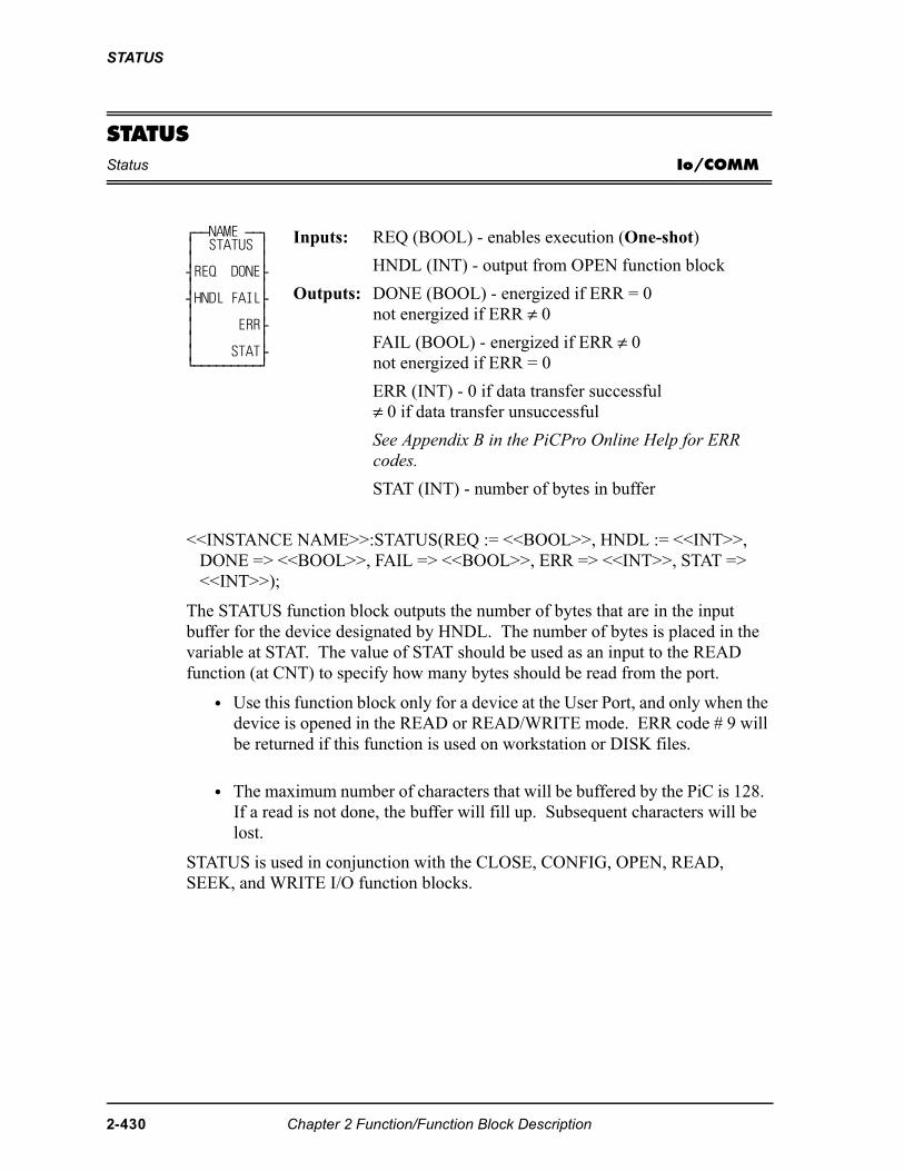
STATUS
STATUSStatus Io/COMM
<<INSTANCE NAME>>:STATUS(REQ := <<BOOL>>, HNDL := <<INT>>, DONE => <<BOOL>>, FAIL => <<BOOL>>, ERR => <<INT>>, STAT => <<INT>>);
The STATUS function block outputs the number of bytes that are in the input buffer for the device designated by HNDL. The number of bytes is placed in the variable at STAT. The value of STAT should be used as an input to the READ function (at CNT) to specify how many bytes should be read from the port.
• Use this function block only for a device at the User Port, and only when the device is opened in the READ or READ/WRITE mode. ERR code # 9 will be returned if this function is used on workstation or DISK files.
• The maximum number of characters that will be buffered by the PiC is 128. If a read is not done, the buffer will fill up. Subsequent characters will be lost.
STATUS is used in conjunction with the CLOSE, CONFIG, OPEN, READ, SEEK, and WRITE I/O function blocks.
⁄ƒƒNAME ƒƒø ≥ STATUS ≥ ≥ ≥ ¥REQ DONE√ ≥ ≥ ¥HNDL FAIL√ ≥ ≥ ≥ ERR√ ≥ ≥ ≥ STAT√ ¿ƒƒƒƒƒƒƒƒƒŸ
Inputs: REQ (BOOL) - enables execution (One-shot)
HNDL (INT) - output from OPEN function block
Outputs: DONE (BOOL) - energized if ERR = 0not energized if ERR ≠ 0FAIL (BOOL) - energized if ERR ≠ 0not energized if ERR = 0
ERR (INT) - 0 if data transfer successful≠ 0 if data transfer unsuccessful
See Appendix B in the PiCPro Online Help for ERR codes.
STAT (INT) - number of bytes in buffer
2-430 Chapter 2 Function/Function Block Description
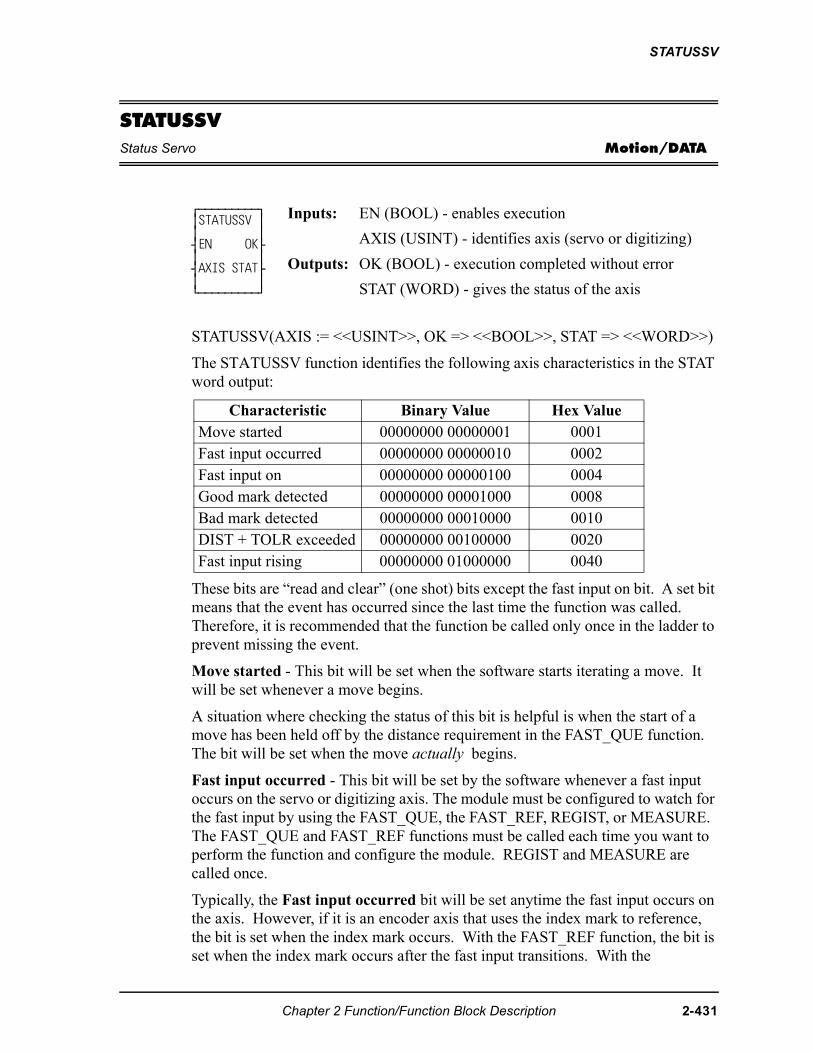
STATUSSV
STATUSSVStatus Servo Motion/DATA
STATUSSV(AXIS := <<USINT>>, OK => <<BOOL>>, STAT => <<WORD>>)
The STATUSSV function identifies the following axis characteristics in the STAT word output:
These bits are “read and clear” (one shot) bits except the fast input on bit. A set bit means that the event has occurred since the last time the function was called. Therefore, it is recommended that the function be called only once in the ladder to prevent missing the event.
Move started - This bit will be set when the software starts iterating a move. It will be set whenever a move begins.
A situation where checking the status of this bit is helpful is when the start of a move has been held off by the distance requirement in the FAST_QUE function. The bit will be set when the move actually begins.
Fast input occurred - This bit will be set by the software whenever a fast input occurs on the servo or digitizing axis. The module must be configured to watch for the fast input by using the FAST_QUE, the FAST_REF, REGIST, or MEASURE. The FAST_QUE and FAST_REF functions must be called each time you want to perform the function and configure the module. REGIST and MEASURE are called once.
Typically, the Fast input occurred bit will be set anytime the fast input occurs on the axis. However, if it is an encoder axis that uses the index mark to reference, the bit is set when the index mark occurs. With the FAST_REF function, the bit is set when the index mark occurs after the fast input transitions. With the
⁄ƒƒƒƒƒƒƒƒƒø ≥STATUSSV ≥ ≥ ≥ ¥EN OK√ ≥ ≥ ¥AXIS STAT√ ≥ ≥ ¿ƒƒƒƒƒƒƒƒƒŸ
Inputs: EN (BOOL) - enables execution
AXIS (USINT) - identifies axis (servo or digitizing)
Outputs: OK (BOOL) - execution completed without error
STAT (WORD) - gives the status of the axis
Characteristic Binary Value Hex ValueMove started 00000000 00000001 0001Fast input occurred 00000000 00000010 0002Fast input on 00000000 00000100 0004Good mark detected 00000000 00001000 0008Bad mark detected 00000000 00010000 0010DIST + TOLR exceeded 00000000 00100000 0020Fast input rising 00000000 01000000 0040
Chapter 2 Function/Function Block Description 2-431
STATUSSV
LAD_REF function, the bit is set when the index mark occurs after the REF_END function is called in the ladder.
Fast input on - This bit is set by the hardware when the fast input is on. NOTE: If the STATUS_SV function is called after the fast input turns on but before a servo interrupt occurs, the Fast input on bit is set and the Fast input occurred bit will not be set until the next scan. NOTE: This bit is not supported with SERCOS or virtual axes. It will always be reset.
Good mark detected- This bit will be set when a good mark is detected.
Bad mark detected - This bit keeps track of bad marks. NOTE: Since the first mark is always “bad,” it will be set on the first mark after registration is called.
Distance + tolerance exceeded - This bit is set as soon as the distance from the last mark exceeds the value of DIST + TOLR whether or not a mark has occurred. It will be reset when any mark occurs.
Fast input rising - This bit indicates the direction of the most recent fast input until the next fast input occurs.
If the transition direction is defined as rising (a 0 entered in variable 19 of WRITE_SV), then this bit will always be on.
If the transition direction is defined as falling (a 1 entered in variable 19 of WRITE_SV), then this bit will always be off.
If the transition direction is defined as both rising and falling (a 2 entered invariable 19 of WRITE_SV), then this bit will alternate between on and off as the fast input signal alternates.
See also the table of variables at the READ_SV function.
2-432 Chapter 2 Function/Function Block Description
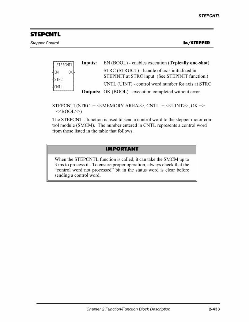
STEPCNTL
STEPCNTLStepper Control Io/STEPPER
STEPCNTL(STRC := <<MEMORY AREA>>, CNTL := <<UINT>>, OK => <<BOOL>>)
The STEPCNTL function is used to send a control word to the stepper motor con-trol module (SMCM). The number entered in CNTL represents a control word from those listed in the table that follows.
⁄ƒƒƒƒƒƒƒƒƒø ≥ STEPCNTL≥ ≥ ≥ ¥EN OK√ ≥ ≥ ¥STRC ≥ ≥ ≥ ¥CNTL ≥ ¿ƒƒƒƒƒƒƒƒƒŸ
Inputs: EN (BOOL) - enables execution (Typically one-shot)
STRC (STRUCT) - handle of axis initialized inSTEPINIT at STRC input (See STEPINIT function.)
CNTL (UINT) - control word number for axis at STRC
Outputs: OK (BOOL) - execution completed without error
IMPORTANT
When the STEPCNTL function is called, it can take the SMCM up to3 ms to process it. To ensure proper operation, always check that the“control word not processed” bit in the status word is clear beforesending a control word.
Chapter 2 Function/Function Block Description 2-433
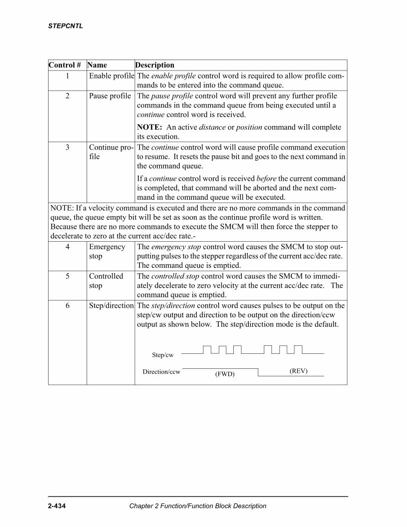
STEPCNTL
Control # Name Description1 Enable profile The enable profile control word is required to allow profile com-
mands to be entered into the command queue. 2 Pause profile The pause profile control word will prevent any further profile
commands in the command queue from being executed until a continue control word is received.
NOTE: An active distance or position command will complete its execution.
3 Continue pro-file
The continue control word will cause profile command execution to resume. It resets the pause bit and goes to the next command in the command queue.
If a continue control word is received before the current command is completed, that command will be aborted and the next com-mand in the command queue will be executed.
NOTE: If a velocity command is executed and there are no more commands in the command queue, the queue empty bit will be set as soon as the continue profile word is written. Because there are no more commands to execute the SMCM will then force the stepper to decelerate to zero at the current acc/dec rate.-
4 Emergency stop
The emergency stop control word causes the SMCM to stop out-putting pulses to the stepper regardless of the current acc/dec rate. The command queue is emptied.
5 Controlled stop
The controlled stop control word causes the SMCM to immedi-ately decelerate to zero velocity at the current acc/dec rate. The command queue is emptied.
6 Step/direction The step/direction control word causes pulses to be output on the step/cw output and direction to be output on the direction/ccw output as shown below. The step/direction mode is the default.
Step/cw
Direction/ccw (FWD) (REV)
2-434 Chapter 2 Function/Function Block Description
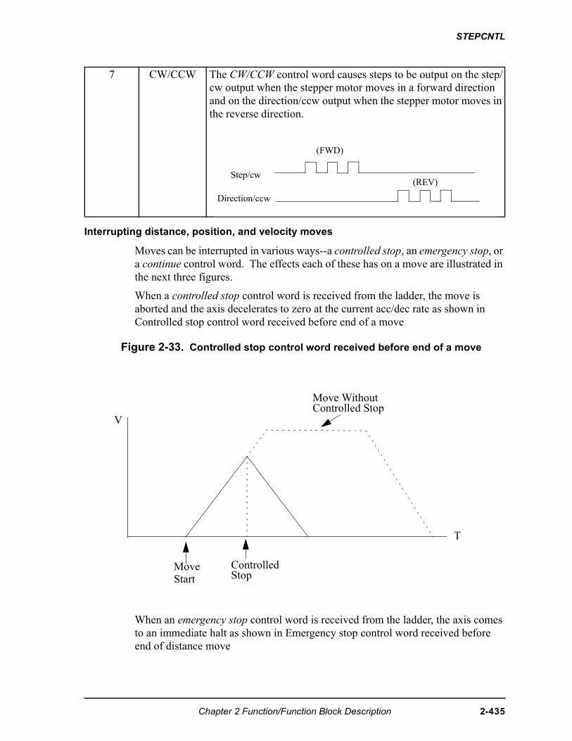
STEPCNTL
Interrupting distance, position, and velocity moves
Moves can be interrupted in various ways--a controlled stop, an emergency stop, or a continue control word. The effects each of these has on a move are illustrated in the next three figures.
When a controlled stop control word is received from the ladder, the move is aborted and the axis decelerates to zero at the current acc/dec rate as shown in Controlled stop control word received before end of a move
Figure 2-33. Controlled stop control word received before end of a move
When an emergency stop control word is received from the ladder, the axis comes to an immediate halt as shown in Emergency stop control word received before end of distance move
7 CW/CCW The CW/CCW control word causes steps to be output on the step/cw output when the stepper motor moves in a forward direction and on the direction/ccw output when the stepper motor moves in the reverse direction.
Step/cw
Direction/ccw
(FWD)
(REV)
T
ControlledStop
Move WithoutControlled Stop
V
MoveStart
Chapter 2 Function/Function Block Description 2-435
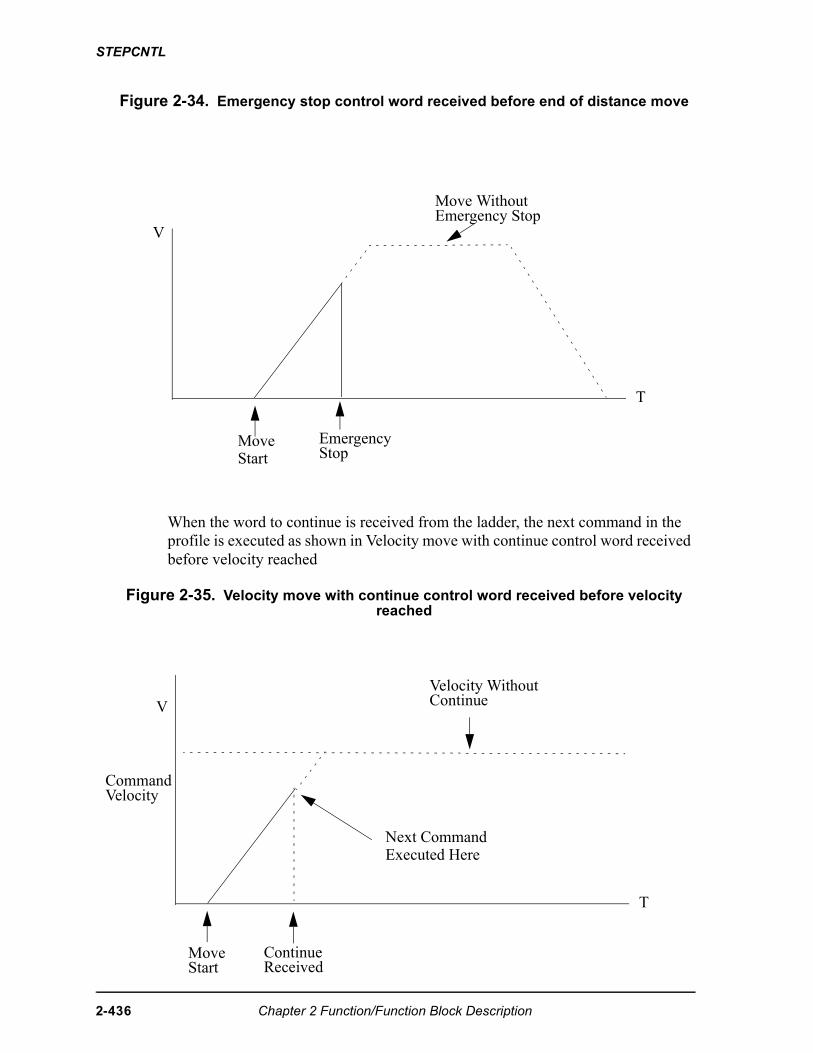
STEPCNTL
Figure 2-34. Emergency stop control word received before end of distance move
When the word to continue is received from the ladder, the next command in the profile is executed as shown in Velocity move with continue control word received before velocity reached
Figure 2-35. Velocity move with continue control word received before velocity reached
T
EmergencyStop
Move WithoutEmergency Stop
V
MoveStart
T
Move ContinueReceivedStart
Velocity WithoutContinue
Next CommandExecuted Here
V
CommandVelocity
2-436 Chapter 2 Function/Function Block Description
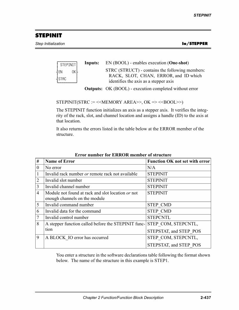
STEPINIT
STEPINITStep Initialization Io/STEPPER
STEPINIT(STRC := <<MEMORY AREA>>, OK => <<BOOL>>)
The STEPINIT function initializes an axis as a stepper axis. It verifies the integ-rity of the rack, slot, and channel location and assigns a handle (ID) to the axis at that location.
It also returns the errors listed in the table below at the ERROR member of the structure.
You enter a structure in the software declarations table following the format shown below. The name of the structure in this example is STEP1.
⁄ƒƒƒƒƒƒƒƒƒø ≥ STEPINIT≥ ≥ ≥ ¥EN OK√ ≥ ≥ ¥STRC ≥ ¿ƒƒƒƒƒƒƒƒƒŸ
Inputs: EN (BOOL) - enables execution (One-shot)
STRC (STRUCT) - contains the following members: RACK, SLOT, CHAN, ERROR, and ID which identifies the axis as a stepper axis
Outputs: OK (BOOL) - execution completed without error
Error number for ERROR member of structure# Name of Error Function OK not set with error0 No error N/A1 Invalid rack number or remote rack not available STEPINIT2 Invalid slot number STEPINIT3 Invalid channel number STEPINIT4 Module not found at rack and slot location or not
enough channels on the moduleSTEPINIT
5 Invalid command number STEP_CMD6 Invalid data for the command STEP_CMD7 Invalid control number STEPCNTL8 A stepper function called before the STEPINIT func-
tion STEP_COM, STEPCNTL,
STEPSTAT, and STEP_POS9 A BLOCK_IO error has occurred STEP_COM, STEPCNTL,
STEPSTAT, and STEP_POS
Chapter 2 Function/Function Block Description 2-437
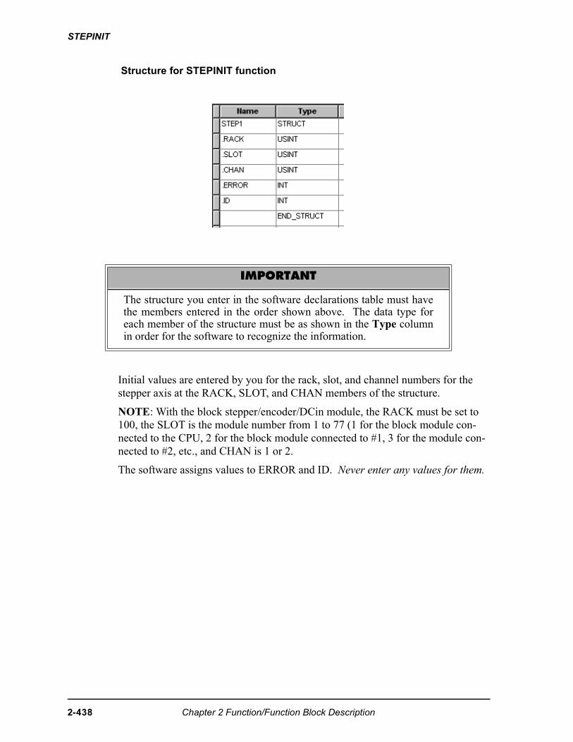
STEPINIT
Structure for STEPINIT function
Initial values are entered by you for the rack, slot, and channel numbers for the stepper axis at the RACK, SLOT, and CHAN members of the structure.
NOTE: With the block stepper/encoder/DCin module, the RACK must be set to 100, the SLOT is the module number from 1 to 77 (1 for the block module con-nected to the CPU, 2 for the block module connected to #1, 3 for the module con-nected to #2, etc., and CHAN is 1 or 2.
The software assigns values to ERROR and ID. Never enter any values for them.
IMPORTANT
The structure you enter in the software declarations table must havethe members entered in the order shown above. The data type foreach member of the structure must be as shown in the Type columnin order for the software to recognize the information.
2-438 Chapter 2 Function/Function Block Description
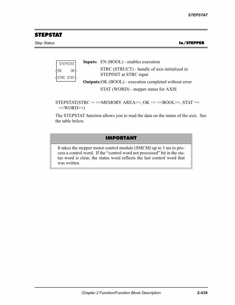
STEPSTAT
STEPSTATStep Status Io/STEPPER
STEPSTAT(STRC := <<MEMORY AREA>>, OK => <<BOOL>>, STAT => <<WORD>>)
The STEPSTAT function allows you to read the data on the status of the axis. See the table below.
⁄ƒƒƒƒƒƒƒƒƒø ≥ STEPSTAT≥ ≥ ≥ ¥EN OK√ ≥ ≥ ¥STRC STAT√ ¿ƒƒƒƒƒƒƒƒƒŸ
Inputs: EN (BOOL) - enables execution
STRC (STRUCT) - handle of axis initialized inSTEPINIT at STRC input
Outputs:OK (BOOL) - execution completed without error
STAT (WORD) - stepper status for AXIS
IMPORTANT
It takes the stepper motor control module (SMCM) up to 3 ms to pro-cess a control word. If the “control word not processed” bit in the sta-tus word is clear, the status word reflects the last control word thatwas written.
Chapter 2 Function/Function Block Description 2-439
STEPSTAT
Table 2-13. WORD Output from STEPSTAT Function
Name Description Binary value Dec HexProfile enabled
When set, this bit indicates that commands can be sent to the queue for execution. It is set by sending the enable profile control word.
The following conditions will reset this bit:
• Sending an emergency stop control word
• Completing a controlled stop
• Controller scan loss
• Illegal command/data is executed
• Illegal control word received
• Calculation error occurred
• Command queue overflow
When reset, the following occurs:
• The SMCM stops outputting pulse
• The queue is emptied
• Any commands sent to the queue are lost
• Status information for the axis is invalid
00000000 00000001 1 0001
Profile paused
When set, this bit indicates that no more commands will be executed from the queue. The following commands will set this bit:
• A pause profile command or control word
• A velocity move command
This bit is reset by sending a continue profile control word.
00000000 00000010 2 0002
At veloc-ity
When set, this bit indicates that the desired velocity has been reached. This bit is set when a velocity move command is executed and the desired velocity is reached.
This bit is reset by sending a continue profile control word.
00000000 00000100 4 0004
Queue empty
This bit is set when the final command in the queue has completed execution.
This bit is reset when a command is placed into the queue for execution.
00000000 00001000 8 0008
2-440 Chapter 2 Function/Function Block Description
STEPSTAT
NOTE: If a velocity command is executed and there are no more commands in the command queue, the queue empty bit will be set as soon as the continue profile word is written. Because there are no more commands to execute the SMCM will then force the stepper to decelerate to zero at the current acc/dec rate.Queue full
This bit is set when the queue is full (500 commands). An E-stop will occur if another command is sent to the queue.
This bit is reset when a command is removed from the queue for execution.
00000000 00010000 16 0010
Control word not pro-cessed
This bit is set until the control word is pro-cessed.
00000000 00100000 32 0020
(not used) 00000000 0X000000 64 0040(not used) 00000000 X0000000 128 0080(not used) 0000000X 00000000 256 0100(not used) 000000X0 00000000 512 0200(not used) 00000X00 00000000 1024 0400(not used) 0000X000 00000000 2048 0800(not used) 000X0000 00000000 4096 1000(not used) 00X00000 00000000 8192 2000Reserved for future version # of firmware 0V000000 00000000 16384 4000Reserved for future version # of firmware V0000000 00000000 32768 8000
Name Description Binary value Dec Hex
Chapter 2 Function/Function Block Description 2-441
STEP_CMD
STEP_CMDStep Command Io/STEPPER
STEP_CMD(STRC := <<MEMORY AREA>>, CMD := <<UINT>>, DATA := <<DINT>>, OK => <<BOOL>>)
The STEP_CMD function sends a profile command and its related data to the step-per axis identified in STRC. The commands available and their range of data are listed in the table below. Several commands (up to 500) can be sent to the com-mand queue on the stepper motor control module (SMCM) to run a profile for the axis identified at STRC.
⁄ƒƒƒƒƒƒƒƒƒø ≥ STEP_CMD≥ ≥ ≥ ¥EN OK√ ≥ ≥ ¥STRC ≥ ≥ ≥ ¥CMD ≥ ≥ ≥ ¥DATA ≥ ¿ƒƒƒƒƒƒƒƒƒŸ
Inputs: EN (BOOL) - enables execution (Typically one-shot)
STRC (STRUCT) - handle of axis initialized inSTEPINIT at STRC input (See STEPINIT function.)
CMD (UINT) - stepper command for STRC
DATA (DINT) - command data for STRC
Outputs: OK (BOOL) - execution completed without error
IMPORTANT
When the STEP_CMD function is called, the command is moved intoa command queue on the SMCM. It can take up to 3 ms for theSMCM to process a command after it has been moved into the com-mand queue. In some cases, it is important that the command be pro-cessed before some other action is taken (i.e. sending a control word). To ensure that the command is processed before some other action,send a pause command immediately after the command. Check to seethat the pause bit in the status word is set before initiating the next ac-tion.
NOTE
If the command queue is empty when the SMCM is ready to executeanother command, the SMCM will force the stepper to decelerate tozero at the current acc/dec rate. If another command is sent to thecommand queue during this deceleration, that command will be exe-cuted immediately.
2-442 Chapter 2 Function/Function Block Description
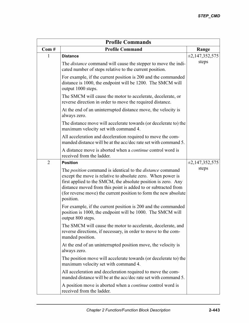
STEP_CMD
Profile CommandsCom # Profile Command Range
1 Distance
The distance command will cause the stepper to move the indi-cated number of steps relative to the current position.
For example, if the current position is 200 and the commanded distance is 1000, the endpoint will be 1200. The SMCM will output 1000 steps.
The SMCM will cause the motor to accelerate, decelerate, or reverse direction in order to move the required distance.
At the end of an uninterrupted distance move, the velocity is always zero.
The distance move will accelerate towards (or decelerate to) the maximum velocity set with command 4.
All acceleration and deceleration required to move the com-manded distance will be at the acc/dec rate set with command 5.
A distance move is aborted when a continue control word is received from the ladder.
±2,147,352,575 steps
2 Position
The position command is identical to the distance command except the move is relative to absolute zero. When power is first applied to the SMCM, the absolute position is zero. Any distance moved from this point is added to or subtracted from (for reverse move) the current position to form the new absolute position.
For example, if the current position is 200 and the commanded position is 1000, the endpoint will be 1000. The SMCM will output 800 steps.
The SMCM will cause the motor to accelerate, decelerate, and reverse directions, if necessary, in order to move to the com-manded position.
At the end of an uninterrupted position move, the velocity is always zero.
The position move will accelerate towards (or decelerate to) the maximum velocity set with command 4.
All acceleration and deceleration required to move the com-manded distance will be at the acc/dec rate set with command 5.
A position move is aborted when a continue control word is received from the ladder.
±2,147,352,575 steps
Chapter 2 Function/Function Block Description 2-443
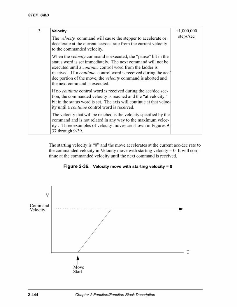
STEP_CMD
The starting velocity is “0” and the move accelerates at the current acc/dec rate to the commanded velocity in Velocity move with starting velocity = 0 It will con-tinue at the commanded velocity until the next command is received.
Figure 2-36. Velocity move with starting velocity = 0
3 Velocity
The velocity command will cause the stepper to accelerate or decelerate at the current acc/dec rate from the current velocity to the commanded velocity.
When the velocity command is executed, the “pause” bit in the status word is set immediately. The next command will not be executed until a continue control word from the ladder is received. If a continue control word is received during the acc/dec portion of the move, the velocity command is aborted and the next command is executed.
If no continue control word is received during the acc/dec sec-tion, the commanded velocity is reached and the “at velocity” bit in the status word is set. The axis will continue at that veloc-ity until a continue control word is received.
The velocity that will be reached is the velocity specified by the command and is not related in any way to the maximum veloc-ity . Three examples of velocity moves are shown in Figures 9-37 through 9-39.
±1,000,000 steps/sec
T
MoveStart
V
CommandVelocity
2-444 Chapter 2 Function/Function Block Description
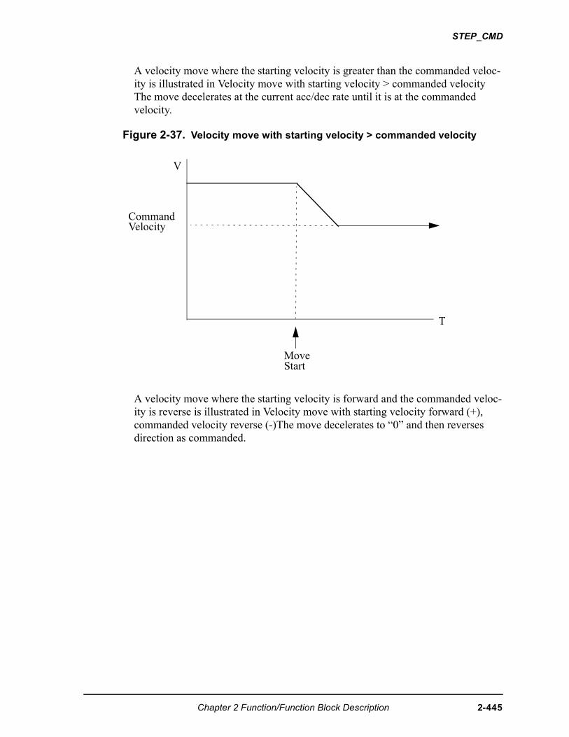
STEP_CMD
A velocity move where the starting velocity is greater than the commanded veloc-ity is illustrated in Velocity move with starting velocity > commanded velocity The move decelerates at the current acc/dec rate until it is at the commanded velocity.
Figure 2-37. Velocity move with starting velocity > commanded velocity
A velocity move where the starting velocity is forward and the commanded veloc-ity is reverse is illustrated in Velocity move with starting velocity forward (+), commanded velocity reverse (-)The move decelerates to “0” and then reverses direction as commanded.
T
MoveStart
V
CommandVelocity
Chapter 2 Function/Function Block Description 2-445
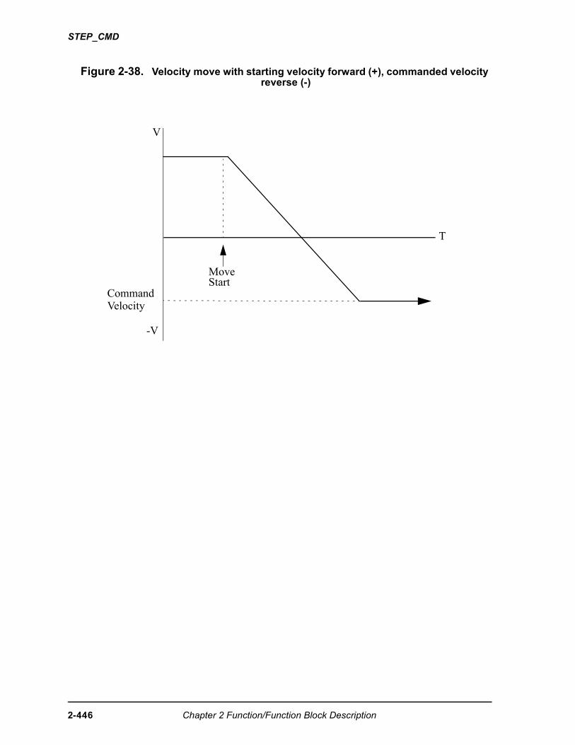
STEP_CMD
Figure 2-38. Velocity move with starting velocity forward (+), commanded velocity reverse (-)
T
MoveStart
V
-V
CommandVelocity
2-446 Chapter 2 Function/Function Block Description
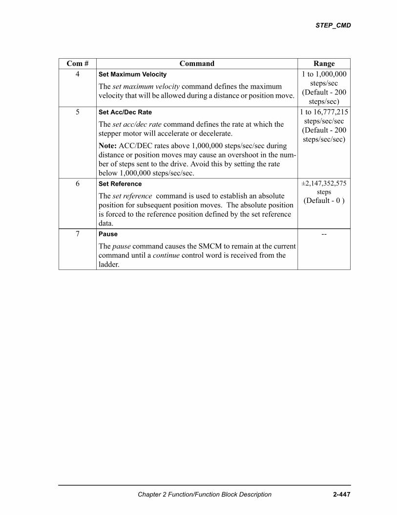
STEP_CMD
Com # Command Range4 Set Maximum Velocity
The set maximum velocity command defines the maximum velocity that will be allowed during a distance or position move.
1 to 1,000,000 steps/sec
(Default - 200 steps/sec)
5 Set Acc/Dec Rate
The set acc/dec rate command defines the rate at which the stepper motor will accelerate or decelerate.
Note: ACC/DEC rates above 1,000,000 steps/sec/sec during distance or position moves may cause an overshoot in the num-ber of steps sent to the drive. Avoid this by setting the rate below 1,000,000 steps/sec/sec.
1 to 16,777,215 steps/sec/sec
(Default - 200 steps/sec/sec)
6 Set Reference
The set reference command is used to establish an absolute position for subsequent position moves. The absolute position is forced to the reference position defined by the set reference data.
±2,147,352,575 steps
(Default - 0 )
7 Pause
The pause command causes the SMCM to remain at the current command until a continue control word is received from the ladder.
--
Chapter 2 Function/Function Block Description 2-447
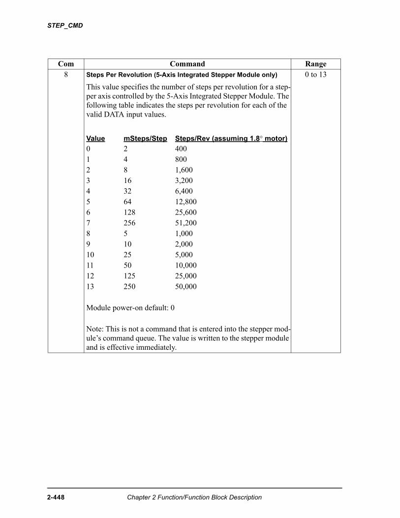
STEP_CMD
Com Command Range8 Steps Per Revolution (5-Axis Integrated Stepper Module only)
This value specifies the number of steps per revolution for a step-per axis controlled by the 5-Axis Integrated Stepper Module. The following table indicates the steps per revolution for each of the valid DATA input values.
0 to 13
Value mSteps/Step Steps/Rev (assuming 1.8° motor)
0 2 4001 4 8002 8 1,6003 16 3,2004 32 6,4005 64 12,8006 128 25,6007 256 51,2008 5 1,0009 10 2,00010 25 5,00011 50 10,00012 125 25,00013 250 50,000
Module power-on default: 0
Note: This is not a command that is entered into the stepper mod-ule’s command queue. The value is written to the stepper module and is effective immediately.
2-448 Chapter 2 Function/Function Block Description
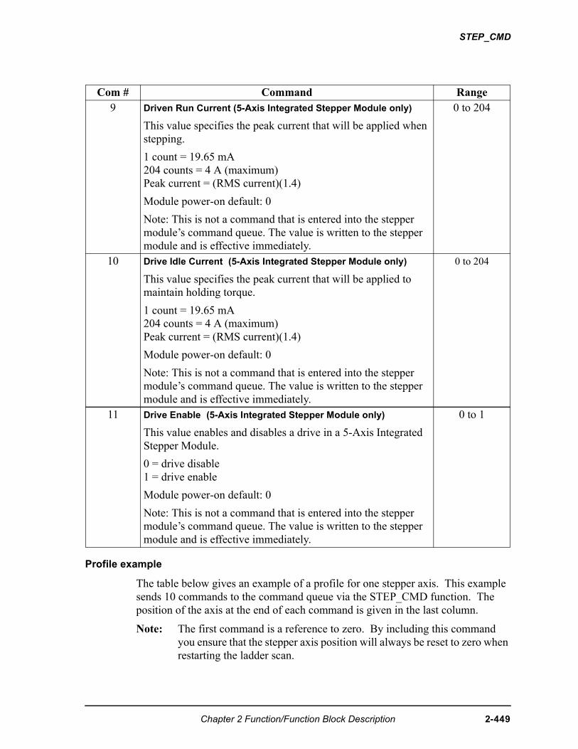
STEP_CMD
Profile example
The table below gives an example of a profile for one stepper axis. This example sends 10 commands to the command queue via the STEP_CMD function. The position of the axis at the end of each command is given in the last column.
Note: The first command is a reference to zero. By including this command you ensure that the stepper axis position will always be reset to zero when restarting the ladder scan.
Com # Command Range9 Driven Run Current (5-Axis Integrated Stepper Module only)
This value specifies the peak current that will be applied when stepping.
1 count = 19.65 mA204 counts = 4 A (maximum)Peak current = (RMS current)(1.4)
Module power-on default: 0
Note: This is not a command that is entered into the stepper module’s command queue. The value is written to the stepper module and is effective immediately.
0 to 204
10 Drive Idle Current (5-Axis Integrated Stepper Module only)
This value specifies the peak current that will be applied to maintain holding torque.
1 count = 19.65 mA204 counts = 4 A (maximum)Peak current = (RMS current)(1.4)
Module power-on default: 0
Note: This is not a command that is entered into the stepper module’s command queue. The value is written to the stepper module and is effective immediately.
0 to 204
11 Drive Enable (5-Axis Integrated Stepper Module only)
This value enables and disables a drive in a 5-Axis Integrated Stepper Module.
0 = drive disable1 = drive enable
Module power-on default: 0
Note: This is not a command that is entered into the stepper module’s command queue. The value is written to the stepper module and is effective immediately.
0 to 1
Chapter 2 Function/Function Block Description 2-449
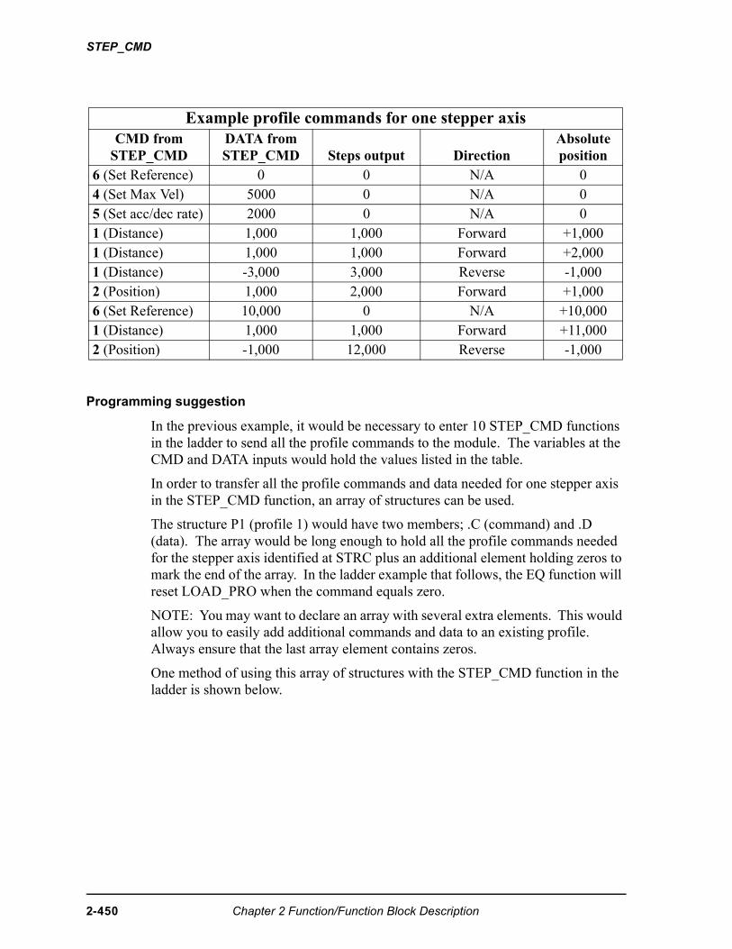
STEP_CMD
Programming suggestion
In the previous example, it would be necessary to enter 10 STEP_CMD functions in the ladder to send all the profile commands to the module. The variables at the CMD and DATA inputs would hold the values listed in the table.
In order to transfer all the profile commands and data needed for one stepper axis in the STEP_CMD function, an array of structures can be used.
The structure P1 (profile 1) would have two members; .C (command) and .D (data). The array would be long enough to hold all the profile commands needed for the stepper axis identified at STRC plus an additional element holding zeros to mark the end of the array. In the ladder example that follows, the EQ function will reset LOAD_PRO when the command equals zero.
NOTE: You may want to declare an array with several extra elements. This would allow you to easily add additional commands and data to an existing profile. Always ensure that the last array element contains zeros.
One method of using this array of structures with the STEP_CMD function in the ladder is shown below.
Example profile commands for one stepper axisCMD from
STEP_CMDDATA from STEP_CMD Steps output Direction
Absolute position
6 (Set Reference) 0 0 N/A 04 (Set Max Vel) 5000 0 N/A 05 (Set acc/dec rate) 2000 0 N/A 01 (Distance) 1,000 1,000 Forward +1,0001 (Distance) 1,000 1,000 Forward +2,0001 (Distance) -3,000 3,000 Reverse -1,0002 (Position) 1,000 2,000 Forward +1,0006 (Set Reference) 10,000 0 N/A +10,0001 (Distance) 1,000 1,000 Forward +11,0002 (Position) -1,000 12,000 Reverse -1,000
2-450 Chapter 2 Function/Function Block Description
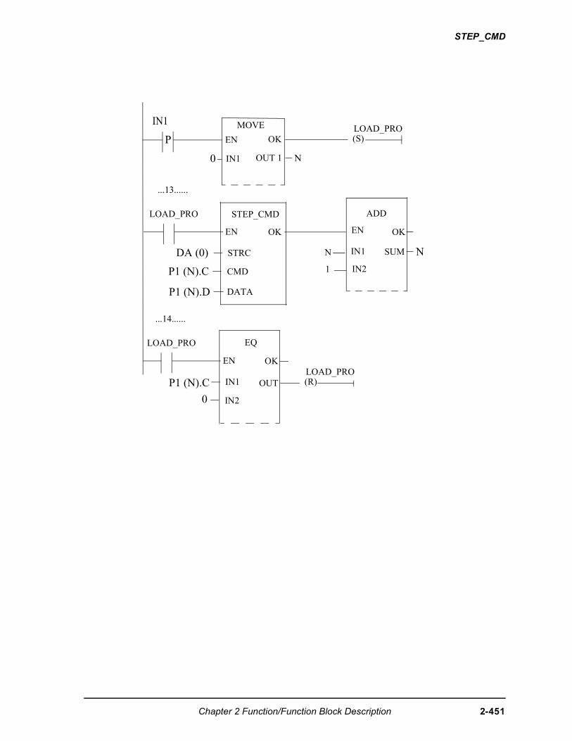
STEP_CMD
P EN
IN1 MOVE
OK
IN1
OK
P1 (N).C
STRC
CMD
DATA
STEP_CMD
0 OUT 1 N
(S)LOAD_PRO
...13......
LOAD_PRO ADD
EN
IN1N
IN21
OK
SUM
EN
DA (0)
P1 (N).D
N
OK
P1 (N).C IN1
IN2
EQ
...14......
LOAD_PRO
EN
0
OUT (R)LOAD_PRO
Chapter 2 Function/Function Block Description 2-451
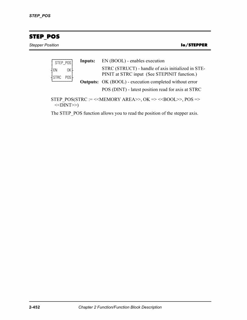
STEP_POS
STEP_POSStepper Position Io/STEPPER
STEP_POS(STRC := <<MEMORY AREA>>, OK => <<BOOL>>, POS => <<DINT>>)
The STEP_POS function allows you to read the position of the stepper axis.
⁄ƒƒƒƒƒƒƒƒƒø ≥ STEP_POS≥ ≥ ≥ ¥EN OK√ ≥ ≥ ¥STRC POS√ ¿ƒƒƒƒƒƒƒƒƒŸ
Inputs: EN (BOOL) - enables execution
STRC (STRUCT) - handle of axis initialized in STE-PINIT at STRC input (See STEPINIT function.)
Outputs: OK (BOOL) - execution completed without error
POS (DINT) - latest position read for axis at STRC
2-452 Chapter 2 Function/Function Block Description
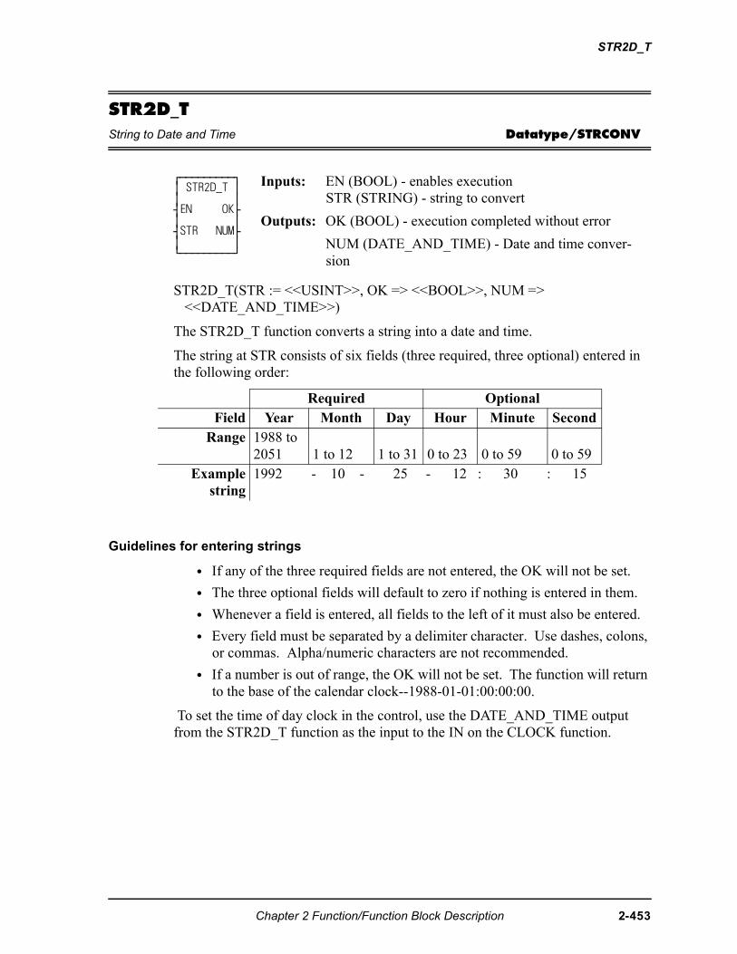
STR2D_T
STR2D_TString to Date and Time Datatype/STRCONV
STR2D_T(STR := <<USINT>>, OK => <<BOOL>>, NUM => <<DATE_AND_TIME>>)
The STR2D_T function converts a string into a date and time.
The string at STR consists of six fields (three required, three optional) entered in the following order:
Guidelines for entering strings
• If any of the three required fields are not entered, the OK will not be set.
• The three optional fields will default to zero if nothing is entered in them.
• Whenever a field is entered, all fields to the left of it must also be entered.
• Every field must be separated by a delimiter character. Use dashes, colons, or commas. Alpha/numeric characters are not recommended.
• If a number is out of range, the OK will not be set. The function will return to the base of the calendar clock--1988-01-01:00:00:00.
To set the time of day clock in the control, use the DATE_AND_TIME output from the STR2D_T function as the input to the IN on the CLOCK function.
⁄ƒƒƒƒƒƒƒƒƒø ≥ STR2D_T ≥ ≥ ≥ ¥EN OK√ ≥ ≥ ¥STR NUM√ ≥ ≥ ¿ƒƒƒƒƒƒƒƒƒŸ
Inputs: EN (BOOL) - enables executionSTR (STRING) - string to convert
Outputs: OK (BOOL) - execution completed without error
NUM (DATE_AND_TIME) - Date and time conver-sion
Required OptionalField Year Month Day Hour Minute Second
Range 1988 to 2051 1 to 12 1 to 31 0 to 23 0 to 59 0 to 59
Examplestring
1992 - 10 - 25 - 12 : 30 : 15
Chapter 2 Function/Function Block Description 2-453
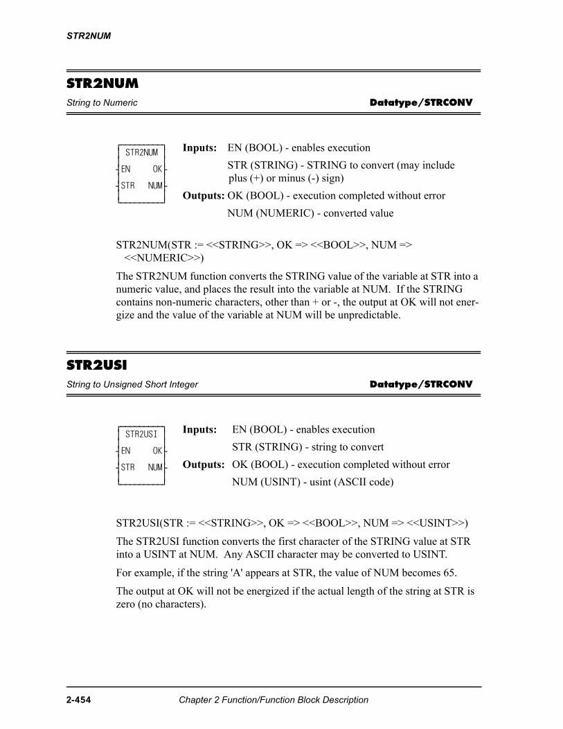
STR2NUM
STR2NUMString to Numeric Datatype/STRCONV
STR2NUM(STR := <<STRING>>, OK => <<BOOL>>, NUM => <<NUMERIC>>)
The STR2NUM function converts the STRING value of the variable at STR into a numeric value, and places the result into the variable at NUM. If the STRING contains non-numeric characters, other than + or -, the output at OK will not ener-gize and the value of the variable at NUM will be unpredictable.
STR2USIString to Unsigned Short Integer Datatype/STRCONV
STR2USI(STR := <<STRING>>, OK => <<BOOL>>, NUM => <<USINT>>)
The STR2USI function converts the first character of the STRING value at STR into a USINT at NUM. Any ASCII character may be converted to USINT.
For example, if the string 'A' appears at STR, the value of NUM becomes 65.
The output at OK will not be energized if the actual length of the string at STR is zero (no characters).
⁄ƒƒƒƒƒƒƒƒƒø ≥ STR2NUM ≥ ≥ ≥ ¥EN OK√ ≥ ≥ ¥STR NUM√ ≥ ≥ ¿ƒƒƒƒƒƒƒƒƒŸ
Inputs: EN (BOOL) - enables execution
STR (STRING) - STRING to convert (may include plus (+) or minus (-) sign)
Outputs: OK (BOOL) - execution completed without error
NUM (NUMERIC) - converted value
⁄ƒƒƒƒƒƒƒƒƒø ≥ STR2USI ≥ ≥ ≥ ¥EN OK√ ≥ ≥ ¥STR NUM√ ≥ ≥ ¿ƒƒƒƒƒƒƒƒƒŸ
Inputs: EN (BOOL) - enables execution
STR (STRING) - string to convert
Outputs: OK (BOOL) - execution completed without error
NUM (USINT) - usint (ASCII code)
2-454 Chapter 2 Function/Function Block Description
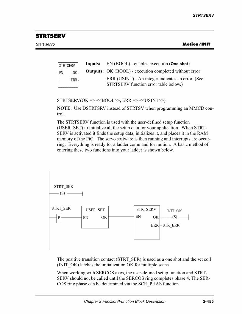
STRTSERV
STRTSERVStart servo Motion/INIT
STRTSERV(OK => <<BOOL>>, ERR => <<USINT>>)
NOTE: Use DSTRTSRV instead of STRTSV when programming an MMCD con-trol.
The STRTSERV function is used with the user-defined setup function (USER_SET) to initialize all the setup data for your application. When STRT-SERV is activated it finds the setup data, initializes it, and places it in the RAM memory of the PiC. The servo software is then running and interrupts are occur-ring. Everything is ready for a ladder command for motion. A basic method of entering these two functions into your ladder is shown below.
The positive transition contact (STRT_SER) is used as a one shot and the set coil (INIT_OK) latches the initialization OK for multiple scans.
When working with SERCOS axes, the user-defined setup function and STRT-SERV should not be called until the SERCOS ring completes phase 4. The SER-COS ring phase can be determined via the SCR_PHAS function.
⁄ƒƒƒƒƒƒƒƒƒø≥STRTSERV ≥≥ ≥¥EN OK√≥ ≥≥ ERR√≥ ≥¿ƒƒƒƒƒƒƒƒƒŸ
Inputs: EN (BOOL) - enables execution (One-shot)
Outputs: OK (BOOL) - execution completed without error
ERR (USINT) - An integer indicates an error (See STRTSERV function error table below.)
P EN
USER_SET
OK
STRTSERV
EN OK
ERR
(S)
STRT_SER
STRT_SER
(S)
INIT_OK
STR_ERR
Chapter 2 Function/Function Block Description 2-455
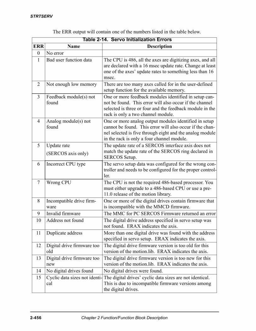
STRTSERV
The ERR output will contain one of the numbers listed in the table below.
Table 2-14. Servo Initialization ErrorsERR Name Description
0 No error1 Bad user function data The CPU is 486, all the axes are digitizing axes, and all
are declared with a 16 msec update rate. Change at least one of the axes’ update rates to something less than 16 msec.
2 Not enough low memory There are too many axes called for in the user-defined setup function for the available memory.
3 Feedback module(s) not found
One or more feedback modules identified in setup can-not be found. This error will also occur if the channel selected is three or four and the feedback module in the rack is only a two channel module.
4 Analog module(s) not found
One or more analog output modules identified in setup cannot be found. This error will also occur if the chan-nel selected is five through eight and the analog module in the rack is only a four channel module.
5 Update rate
(SERCOS axis only)
The update rate of a SERCOS interface axis does not match the update rate of the SERCOS ring declared in SERCOS Setup.
6 Incorrect CPU type The servo setup data was configured for the wrong con-troller and needs to be configured for the proper control-ler.
7 Wrong CPU The CPU is not the required 486-based processor. You must either upgrade to a 486-based CPU or use a pre-11.0 release of the motion library.
8 Incompatible drive firm-ware
One or more of the digital drives contain firmware that is incompatible with the MMCD firmware.
9 Invalid firmware The MMC for PC SERCOS Firmware returned an error10 Address not found The digital drive address specified in servo setup was
not found. ERAX indicates the axis.11 Duplicate address More than one digital drive was found with the address
specified in servo setup. ERAX indicates the axis.12 Digital drive firmware too
oldThe digital drive firmware version is too old for this version of the motion.lib. ERAX indicates the axis.
13 Digital drive firmware too new
The digital drive firmware version is too new for this version of the motion.lib. ERAX indicates the axis.
14 No digital drives found No digital drives were found.15 Cyclic data sizes not identi-
calThe digital drives’ cyclic data sizes are not identical. This is due to incompatible firmware versions among the digital drives.
2-456 Chapter 2 Function/Function Block Description
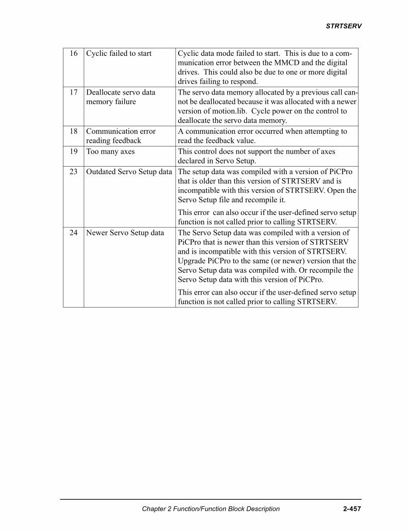
STRTSERV
16 Cyclic failed to start Cyclic data mode failed to start. This is due to a com-munication error between the MMCD and the digital drives. This could also be due to one or more digital drives failing to respond.
17 Deallocate servo data memory failure
The servo data memory allocated by a previous call can-not be deallocated because it was allocated with a newer version of motion.lib. Cycle power on the control to deallocate the servo data memory.
18 Communication error reading feedback
A communication error occurred when attempting to read the feedback value.
19 Too many axes This control does not support the number of axes declared in Servo Setup.
23 Outdated Servo Setup data The setup data was compiled with a version of PiCPro that is older than this version of STRTSERV and is incompatible with this version of STRTSERV. Open the Servo Setup file and recompile it.
This error can also occur if the user-defined servo setup function is not called prior to calling STRTSERV.
24 Newer Servo Setup data The Servo Setup data was compiled with a version of PiCPro that is newer than this version of STRTSERV and is incompatible with this version of STRTSERV. Upgrade PiCPro to the same (or newer) version that the Servo Setup data was compiled with. Or recompile the Servo Setup data with this version of PiCPro.
This error can also occur if the user-defined servo setup function is not called prior to calling STRTSERV.
Chapter 2 Function/Function Block Description 2-457
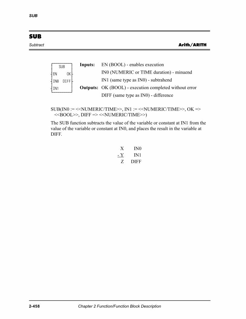
SUB
SUBSubtract Arith/ARITH
SUB(IN0 := <<NUMERIC/TIME>>, IN1 := <<NUMERIC/TIME>>, OK => <<BOOL>>, DIFF => <<NUMERIC/TIME>>)
The SUB function subtracts the value of the variable or constant at IN1 from the value of the variable or constant at IN0, and places the result in the variable at DIFF.
⁄ƒƒƒƒƒƒƒƒƒø ≥ SUB ≥ ≥ ≥ ¥EN OK√ ≥ ≥ ¥IN0 DIFF√ ≥ ≥ ¥IN1 ≥ ¿ƒƒƒƒƒƒƒƒƒŸ
Inputs: EN (BOOL) - enables execution
IN0 (NUMERIC or TIME duration) - minuend
IN1 (same type as IN0) - subtrahend
Outputs: OK (BOOL) - execution completed without error
DIFF (same type as IN0) - difference
X IN0- Y IN1
Z DIFF
2-458 Chapter 2 Function/Function Block Description
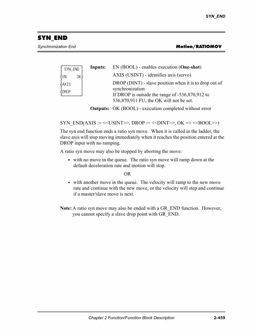
SYN_END
SYN_ENDSynchronization End Motion/RATIOMOV
SYN_END(AXIS := <<USINT>>, DROP := <<DINT>>, OK => <<BOOL>>)
The syn end function ends a ratio syn move. When it is called in the ladder, the slave axis will stop moving immediately when it reaches the position entered at the DROP input with no ramping.
A ratio syn move may also be stopped by aborting the move:
• with no move in the queue. The ratio syn move will ramp down at the default deceleration rate and motion will stop.
OR
• with another move in the queue. The velocity will ramp to the new move rate and continue with the new move, or the velocity will step and continue if a master/slave move is next.
Note: A ratio syn move may also be ended with a GR_END function. However, you cannot specify a slave drop point with GR_END.
⁄ƒƒƒƒƒƒƒƒƒø ≥ SYN_END ≥ ≥ ≥ ¥EN OK√ ≥ ≥ ¥AXIS ≥ ≥ ≥ ¥DROP ≥ ¿ƒƒƒƒƒƒƒƒƒŸ
Inputs: EN (BOOL) - enables execution (One-shot)
AXIS (USINT) - identifies axis (servo)
DROP (DINT) - slave position when it is to drop out of synchronizationIf DROP is outside the range of -536,870,912 to 536,870,911 FU, the OK will not be set.
Outputs: OK (BOOL) - execution completed without error
Chapter 2 Function/Function Block Description 2-459
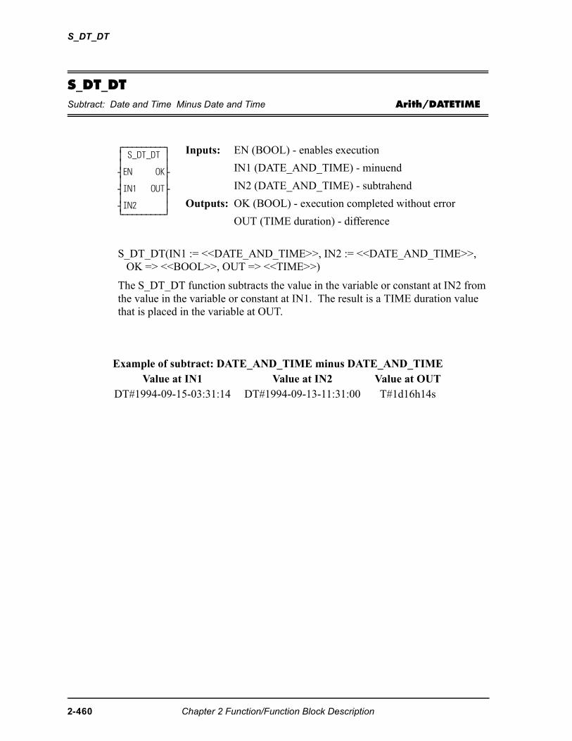
S_DT_DT
S_DT_DTSubtract: Date and Time Minus Date and Time Arith/DATETIME
S_DT_DT(IN1 := <<DATE_AND_TIME>>, IN2 := <<DATE_AND_TIME>>, OK => <<BOOL>>, OUT => <<TIME>>)
The S_DT_DT function subtracts the value in the variable or constant at IN2 from the value in the variable or constant at IN1. The result is a TIME duration value that is placed in the variable at OUT.
⁄ƒƒƒƒƒƒƒƒƒø ≥ S_DT_DT ≥ ≥ ≥ ¥EN OK√ ≥ ≥ ¥IN1 OUT√ ≥ ≥ ¥IN2 ≥ ¿ƒƒƒƒƒƒƒƒƒŸ
Inputs: EN (BOOL) - enables execution
IN1 (DATE_AND_TIME) - minuend
IN2 (DATE_AND_TIME) - subtrahend
Outputs: OK (BOOL) - execution completed without error
OUT (TIME duration) - difference
Example of subtract: DATE_AND_TIME minus DATE_AND_TIMEValue at IN1 Value at IN2 Value at OUT
DT#1994-09-15-03:31:14 DT#1994-09-13-11:31:00 T#1d16h14s
2-460 Chapter 2 Function/Function Block Description
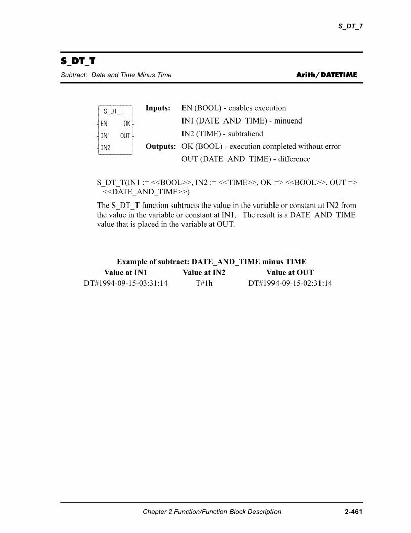
S_DT_T
S_DT_TSubtract: Date and Time Minus Time Arith/DATETIME
S_DT_T(IN1 := <<BOOL>>, IN2 := <<TIME>>, OK => <<BOOL>>, OUT => <<DATE_AND_TIME>>)
The S_DT_T function subtracts the value in the variable or constant at IN2 from the value in the variable or constant at IN1. The result is a DATE_AND_TIME value that is placed in the variable at OUT.
⁄ƒƒƒƒƒƒƒƒƒø ≥ S_DT_T ≥ ≥ ≥ ¥EN OK√ ≥ ≥ ¥IN1 OUT√ ≥ ≥ ¥IN2 ≥ ¿ƒƒƒƒƒƒƒƒƒŸ
Inputs: EN (BOOL) - enables execution
IN1 (DATE_AND_TIME) - minuend
IN2 (TIME) - subtrahend
Outputs: OK (BOOL) - execution completed without error
OUT (DATE_AND_TIME) - difference
Example of subtract: DATE_AND_TIME minus TIMEValue at IN1 Value at IN2 Value at OUT
DT#1994-09-15-03:31:14 T#1h DT#1994-09-15-02:31:14
Chapter 2 Function/Function Block Description 2-461
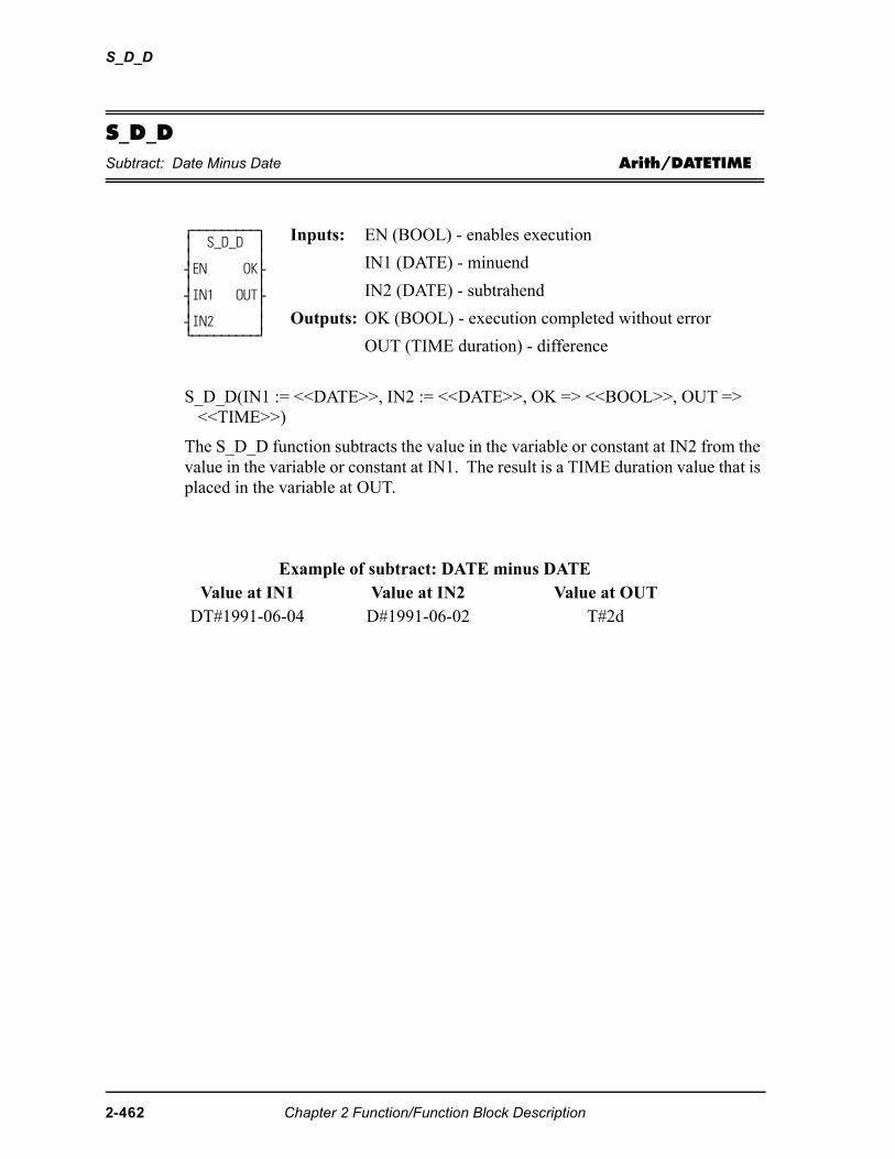
S_D_D
S_D_DSubtract: Date Minus Date Arith/DATETIME
S_D_D(IN1 := <<DATE>>, IN2 := <<DATE>>, OK => <<BOOL>>, OUT => <<TIME>>)
The S_D_D function subtracts the value in the variable or constant at IN2 from the value in the variable or constant at IN1. The result is a TIME duration value that is placed in the variable at OUT.
⁄ƒƒƒƒƒƒƒƒƒø ≥ S_D_D ≥ ≥ ≥ ¥EN OK√ ≥ ≥ ¥IN1 OUT√ ≥ ≥ ¥IN2 ≥ ¿ƒƒƒƒƒƒƒƒƒŸ
Inputs: EN (BOOL) - enables execution
IN1 (DATE) - minuend
IN2 (DATE) - subtrahend
Outputs: OK (BOOL) - execution completed without error
OUT (TIME duration) - difference
Example of subtract: DATE minus DATEValue at IN1 Value at IN2 Value at OUT
DT#1991-06-04 D#1991-06-02 T#2d
2-462 Chapter 2 Function/Function Block Description
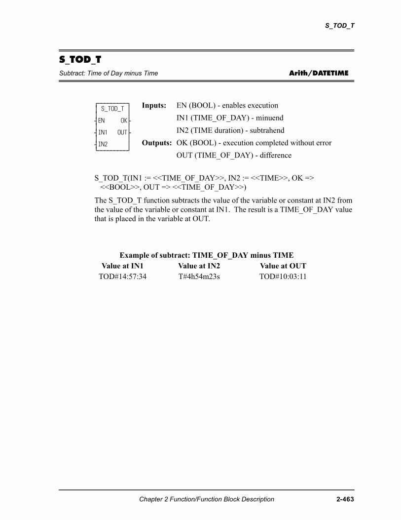
S_TOD_T
S_TOD_TSubtract: Time of Day minus Time Arith/DATETIME
S_TOD_T(IN1 := <<TIME_OF_DAY>>, IN2 := <<TIME>>, OK => <<BOOL>>, OUT => <<TIME_OF_DAY>>)
The S_TOD_T function subtracts the value of the variable or constant at IN2 from the value of the variable or constant at IN1. The result is a TIME_OF_DAY value that is placed in the variable at OUT.
⁄ƒƒƒƒƒƒƒƒƒø ≥ S_TOD_T ≥ ≥ ≥ ¥EN OK√ ≥ ≥ ¥IN1 OUT√ ≥ ≥ ¥IN2 ≥ ¿ƒƒƒƒƒƒƒƒƒŸ
Inputs: EN (BOOL) - enables execution
IN1 (TIME_OF_DAY) - minuend
IN2 (TIME duration) - subtrahend
Outputs: OK (BOOL) - execution completed without error
OUT (TIME_OF_DAY) - difference
Example of subtract: TIME_OF_DAY minus TIMEValue at IN1 Value at IN2 Value at OUT
TOD#14:57:34 T#4h54m23s TOD#10:03:11
Chapter 2 Function/Function Block Description 2-463
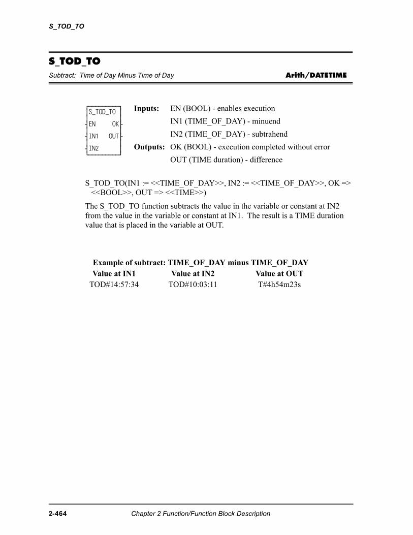
S_TOD_TO
S_TOD_TOSubtract: Time of Day Minus Time of Day Arith/DATETIME
S_TOD_TO(IN1 := <<TIME_OF_DAY>>, IN2 := <<TIME_OF_DAY>>, OK => <<BOOL>>, OUT => <<TIME>>)
The S_TOD_TO function subtracts the value in the variable or constant at IN2 from the value in the variable or constant at IN1. The result is a TIME duration value that is placed in the variable at OUT.
⁄ƒƒƒƒƒƒƒƒƒø ≥S_TOD_TO ≥ ≥ ≥ ¥EN OK√ ≥ ≥ ¥IN1 OUT√ ≥ ≥ ¥IN2 ≥ ¿ƒƒƒƒƒƒƒƒƒŸ
Inputs: EN (BOOL) - enables execution
IN1 (TIME_OF_DAY) - minuend
IN2 (TIME_OF_DAY) - subtrahend
Outputs: OK (BOOL) - execution completed without error
OUT (TIME duration) - difference
Example of subtract: TIME_OF_DAY minus TIME_OF_DAYValue at IN1 Value at IN2 Value at OUT
TOD#14:57:34 TOD#10:03:11 T#4h54m23s
2-464 Chapter 2 Function/Function Block Description
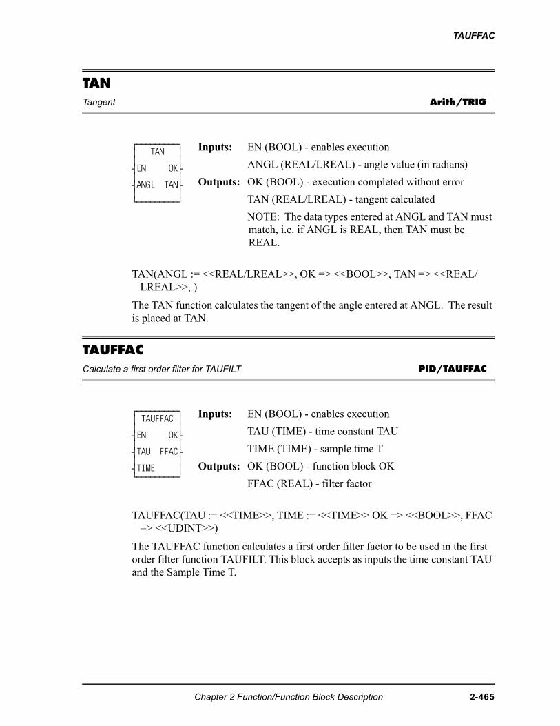
TAUFFAC
TANTangent Arith/TRIG
TAN(ANGL := <<REAL/LREAL>>, OK => <<BOOL>>, TAN => <<REAL/LREAL>>, )
The TAN function calculates the tangent of the angle entered at ANGL. The result is placed at TAN.
TAUFFACCalculate a first order filter for TAUFILT PID/TAUFFAC
TAUFFAC(TAU := <<TIME>>, TIME := <<TIME>> OK => <<BOOL>>, FFAC => <<UDINT>>)
The TAUFFAC function calculates a first order filter factor to be used in the first order filter function TAUFILT. This block accepts as inputs the time constant TAU and the Sample Time T.
⁄ƒƒƒƒƒƒƒƒƒø ≥ TAN ≥ ≥ ≥ ¥EN OK√ ≥ ≥ ¥ANGL TAN√ ≥ ≥ ¿ƒƒƒƒƒƒƒƒƒŸ
Inputs: EN (BOOL) - enables execution
ANGL (REAL/LREAL) - angle value (in radians)
Outputs: OK (BOOL) - execution completed without error
TAN (REAL/LREAL) - tangent calculated
NOTE: The data types entered at ANGL and TAN must match, i.e. if ANGL is REAL, then TAN must be REAL.
⁄ƒƒƒƒƒƒƒƒƒø ≥ TAUFFAC ≥ ≥ ≥ ¥EN OK√ ≥ ≥ ¥TAU FFAC√ ≥ ≥ ¥TIME ≥ ¿ƒƒƒƒƒƒƒƒƒŸ
Inputs: EN (BOOL) - enables execution
TAU (TIME) - time constant TAU
TIME (TIME) - sample time T
Outputs: OK (BOOL) - function block OK
FFAC (REAL) - filter factor
Chapter 2 Function/Function Block Description 2-465
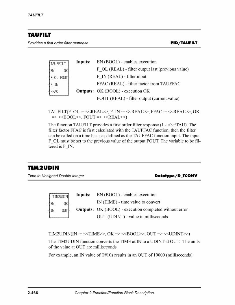
TAUFILT
TAUFILTProvides a first order filter response PID/TAUFILT
TAUFILT(F_OL := <<REAL>>, F_IN := <<REAL>>, FFAC := <<REAL>>, OK => <<BOOL>>, FOUT => <<REAL>>)
The function TAUFILT provides a first order filter response (1 - e^-t/TAU). The filter factor FFAC is first calculated with the TAUFFAC function, then the filter can be called on a time basis as defined as the TAUFFAC function input. The input F_OL must be set to the previous value of the output FOUT. The variable to be fil-tered is F_IN.
TIM2UDINTime to Unsigned Double Integer Datatype/D_TCONV
TIM2UDIN(IN := <<TIME>>, OK => <<BOOL>>, OUT => <<UDINT>>)
The TIM2UDIN function converts the TIME at IN to a UDINT at OUT. The units of the value at OUT are milliseconds.
For example, an IN value of T#10s results in an OUT of 10000 (milliseconds).
⁄ƒƒƒƒƒƒƒƒƒø ≥TAUFFILT ≥ ≥ ≥ ¥EN OK√ ≥ ≥ ¥F_OL FOUT√ ≥ ≥ ¥F_IN ≥ ≥ ≥ ¥FFAC ≥ ¿ƒƒƒƒƒƒƒƒƒŸ
Inputs: EN (BOOL) - enables execution
F_OL (REAL) - filter output last (previous value)
F_IN (REAL) - filter input
FFAC (REAL) - filter factor from TAUFFAC
Outputs: OK (BOOL) - execution OK
FOUT (REAL) - filter output (current value)
⁄ƒƒƒƒƒƒƒƒƒø ≥ TIM2UDIN≥ ≥ ≥ ¥EN OK√ ≥ ≥ ¥IN OUT√ ≥ ≥ ¿ƒƒƒƒƒƒƒƒƒŸ
Inputs: EN (BOOL) - enables execution
IN (TIME) - time value to convert
Outputs: OK (BOOL) - execution completed without error
OUT (UDINT) - value in milliseconds
2-466 Chapter 2 Function/Function Block Description
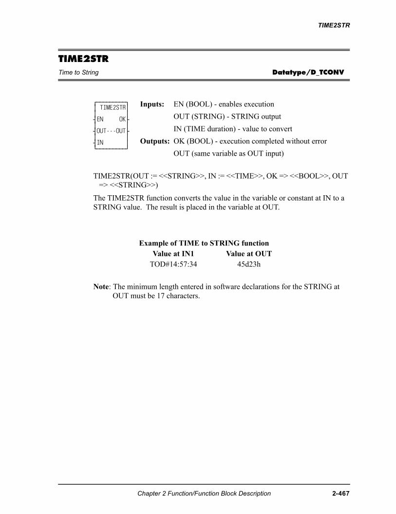
TIME2STR
TIME2STRTime to String Datatype/D_TCONV
TIME2STR(OUT := <<STRING>>, IN := <<TIME>>, OK => <<BOOL>>, OUT => <<STRING>>)
The TIME2STR function converts the value in the variable or constant at IN to a STRING value. The result is placed in the variable at OUT.
Note: The minimum length entered in software declarations for the STRING at OUT must be 17 characters.
⁄ƒƒƒƒƒƒƒƒƒø ≥ TIME2STR≥ ≥ ≥ ¥EN OK√ ≥ ≥ ¥OUT---OUT√ ≥ ≥ ¥IN ≥ ¿ƒƒƒƒƒƒƒƒƒŸ
Inputs: EN (BOOL) - enables execution
OUT (STRING) - STRING output
IN (TIME duration) - value to convert
Outputs: OK (BOOL) - execution completed without error
OUT (same variable as OUT input)
Example of TIME to STRING functionValue at IN1 Value at OUT
TOD#14:57:34 45d23h
Chapter 2 Function/Function Block Description 2-467
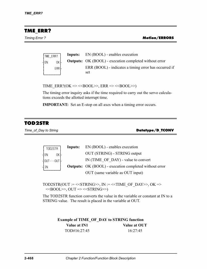
TME_ERR?
TME_ERR?Timing Error ? Motion/ERRORS
TIME_ERR?(OK => <<BOOL>>, ERR => <<BOOL>>)
The timing error inquiry asks if the time required to carry out the servo calcula-tions exceeds the allotted interrupt time.
IMPORTANT: Set an E-stop on all axes when a timing error occurs.
TOD2STRTime_of_Day to String Datatype/D_TCONV
TOD2STR(OUT := <<STRING>>, IN := <<TIME_OF_DAY>>, OK => <<BOOL>>, OUT => <<STRING>>)
The TOD2STR function converts the value in the variable or constant at IN to a STRING value. The result is placed in the variable at OUT.
⁄ƒƒƒƒƒƒƒƒƒø ≥TME_ERR? ≥ ≥ ≥ ¥EN OK√ ≥ ≥ ≥ ERR√ ≥ ≥ ¿ƒƒƒƒƒƒƒƒƒŸ
Inputs: EN (BOOL) - enables execution
Outputs: OK (BOOL) - execution completed without error
ERR (BOOL) - indicates a timing error has occurred if set
⁄ƒƒƒƒƒƒƒƒƒø ≥ TOD2STR ≥ ≥ ≥ ¥EN OK√ ≥ ≥ ¥OUT---OUT√ ≥ ≥ ¥IN ≥ ¿ƒƒƒƒƒƒƒƒƒŸ
Inputs: EN (BOOL) - enables execution
OUT (STRING) - STRING output
IN (TIME_OF_DAY) - value to convert
Outputs: OK (BOOL) - execution completed without error
OUT (same variable as OUT input)
Example of TIME_OF_DAY to STRING functionValue at IN1 Value at OUT
TOD#16:27:45 16:27:45
2-468 Chapter 2 Function/Function Block Description
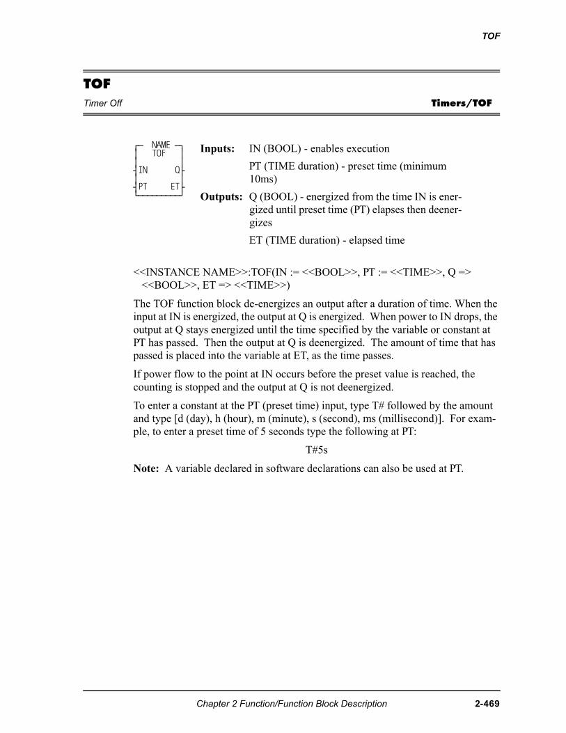
TOF
TOFTimer Off Timers/TOF
<<INSTANCE NAME>>:TOF(IN := <<BOOL>>, PT := <<TIME>>, Q => <<BOOL>>, ET => <<TIME>>)
The TOF function block de-energizes an output after a duration of time. When the input at IN is energized, the output at Q is energized. When power to IN drops, the output at Q stays energized until the time specified by the variable or constant at PT has passed. Then the output at Q is deenergized. The amount of time that has passed is placed into the variable at ET, as the time passes.
If power flow to the point at IN occurs before the preset value is reached, the counting is stopped and the output at Q is not deenergized.
To enter a constant at the PT (preset time) input, type T# followed by the amount and type [d (day), h (hour), m (minute), s (second), ms (millisecond)]. For exam-ple, to enter a preset time of 5 seconds type the following at PT:
T#5s
Note: A variable declared in software declarations can also be used at PT.
⁄ƒ NAME ƒø ≥ TOF ≥ ≥ ≥ ¥IN Q√ ≥ ≥ ¥PT ET√ ¿ƒƒƒƒƒƒƒƒƒŸ
Inputs: IN (BOOL) - enables execution
PT (TIME duration) - preset time (minimum 10ms)
Outputs: Q (BOOL) - energized from the time IN is ener-gized until preset time (PT) elapses then deener-gizes
ET (TIME duration) - elapsed time
Chapter 2 Function/Function Block Description 2-469
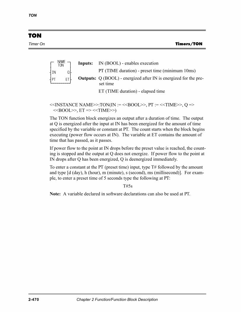
TON
TONTimer On Timers/TON
<<INSTANCE NAME>>:TON(IN := <<BOOL>>, PT := <<TIME>>, Q => <<BOOL>>, ET => <<TIME>>)
The TON function block energizes an output after a duration of time. The output at Q is energized after the input at IN has been energized for the amount of time specified by the variable or constant at PT. The count starts when the block begins executing (power flow occurs at IN). The variable at ET contains the amount of time that has passed, as it passes.
If power flow to the point at IN drops before the preset value is reached, the count-ing is stopped and the output at Q does not energize. If power flow to the point at IN drops after Q has been energized, Q is deenergized immediately.
To enter a constant at the PT (preset time) input, type T# followed by the amount and type [d (day), h (hour), m (minute), s (second), ms (millisecond)]. For exam-ple, to enter a preset time of 5 seconds type the following at PT:
T#5s
Note: A variable declared in software declarations can also be used at PT.
⁄ƒ NAME ƒø ≥ TON ≥ ≥ ≥ ¥IN Q√ ≥ ≥ ¥PT ET√ ¿ƒƒƒƒƒƒƒƒƒŸ
Inputs: IN (BOOL) - enables execution
PT (TIME duration) - preset time (minimum 10ms)
Outputs: Q (BOOL) - energized after IN is energized for the pre-set time
ET (TIME duration) - elapsed time
2-470 Chapter 2 Function/Function Block Description
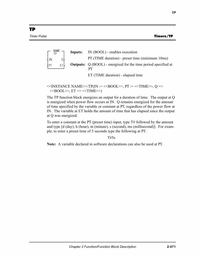
TP
TPTimer Pulse Timers/TP
<<INSTANCE NAME>>:TP(IN := <<BOOL>>, PT := <<TIME>>, Q => <<BOOL>>, ET => <<TIME>>)
The TP function block energizes an output for a duration of time. The output at Q is energized when power flow occurs at IN. Q remains energized for the amount of time specified by the variable or constant at PT, regardless of the power flow at IN. The variable at ET holds the amount of time that has elapsed since the output at Q was energized.
To enter a constant at the PT (preset time) input, type T# followed by the amount and type [d (day), h (hour), m (minute), s (second), ms (millisecond)]. For exam-ple, to enter a preset time of 5 seconds type the following at PT:
T#5s
Note: A variable declared in software declarations can also be used at PT.
⁄ƒ NAME ƒø ≥ TP ≥ ≥ ≥ ¥IN Q√ ≥ ≥ ¥PT ET√ ¿ƒƒƒƒƒƒƒƒƒŸ
Inputs: IN (BOOL) - enables execution
PT (TIME duration) - preset time (minimum 10ms)
Outputs: Q (BOOL) - energized for the time period specified at PT
ET (TIME duration) - elapsed time
Chapter 2 Function/Function Block Description 2-471
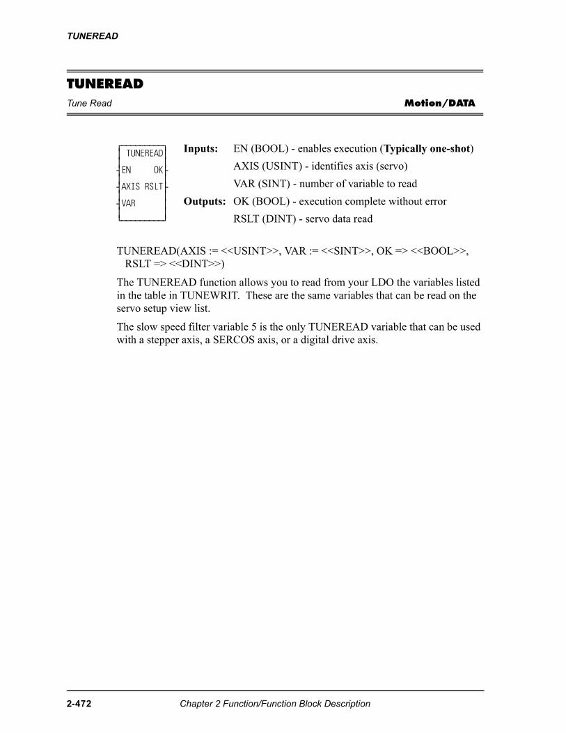
TUNEREAD
TUNEREADTune Read Motion/DATA
TUNEREAD(AXIS := <<USINT>>, VAR := <<SINT>>, OK => <<BOOL>>, RSLT => <<DINT>>)
The TUNEREAD function allows you to read from your LDO the variables listed in the table in TUNEWRIT. These are the same variables that can be read on the servo setup view list.
The slow speed filter variable 5 is the only TUNEREAD variable that can be used with a stepper axis, a SERCOS axis, or a digital drive axis.
⁄ƒƒƒƒƒƒƒƒƒø ≥ TUNEREAD≥ ≥ ≥ ¥EN OK√ ≥ ≥ ¥AXIS RSLT√ ≥ ≥ ¥VAR ≥ ≥ ≥ ¿ƒƒƒƒƒƒƒƒƒŸ
Inputs: EN (BOOL) - enables execution (Typically one-shot)
AXIS (USINT) - identifies axis (servo)
VAR (SINT) - number of variable to read
Outputs: OK (BOOL) - execution complete without error
RSLT (DINT) - servo data read
2-472 Chapter 2 Function/Function Block Description
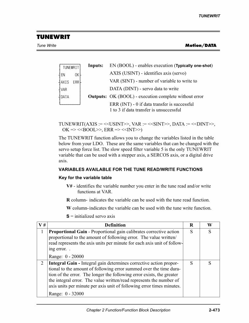
TUNEWRIT
TUNEWRITTune Write Motion/DATA
TUNEWRIT(AXIS := <<USINT>>, VAR := <<SINT>>, DATA := <<DINT>>, OK => <<BOOL>>, ERR => <<INT>>)
The TUNEWRIT function allows you to change the variables listed in the table below from your LDO. These are the same variables that can be changed with the servo setup force list. The slow speed filter variable 5 is the only TUNEWRIT variable that can be used with a stepper axis, a SERCOS axis, or a digital drive axis.
VARIABLES AVAILABLE FOR THE TUNE READ/WRITE FUNCTIONS
Key for the variable table
V# - identifies the variable number you enter in the tune read and/or write functions at VAR.
R column- indicates the variable can be used with the tune read function.
W column-indicates the variable can be used with the tune write function.
S = initialized servo axis
⁄ƒƒƒƒƒƒƒƒƒø ≥ TUNEWRIT≥ ≥ ≥ ¥EN OK√ ≥ ≥ ¥AXIS ERR√ ≥ ≥ ¥VAR ≥ ≥ ≥ ¥DATA ≥ ≥ ≥ ¿ƒƒƒƒƒƒƒƒƒŸ
Inputs: EN (BOOL) - enables execution (Typically one-shot)
AXIS (USINT) - identifies axis (servo)
VAR (SINT) - number of variable to write to
DATA (DINT) - servo data to write
Outputs: OK (BOOL) - execution complete without error
ERR (INT) - 0 if data transfer is successful1 to 3 if data transfer is unsuccessful
V # Definition R W1 Proportional Gain - Proportional gain calibrates corrective action
proportional to the amount of following error. The value written/read represents the axis units per minute for each axis unit of follow-ing error. .
Range: 0 - 20000
S S
2 Integral Gain - Integral gain determines corrective action propor-tional to the amount of following error summed over the time dura-tion of the error. The longer the following error exists, the greater the integral error. The value written/read represents the number of axis units per minute per axis unit of following error times minutes.
Range: 0 - 32000
S S
Chapter 2 Function/Function Block Description 2-473
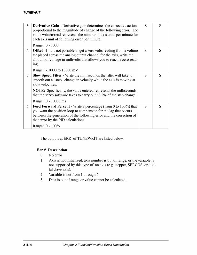
TUNEWRIT
The outputs at ERR of TUNEWRIT are listed below.
3 Derivative Gain - Derivative gain determines the corrective action proportional to the magnitude of change of the following error. The value written/read represents the number of axis units per minute for each axis unit of following error per minute.
Range: 0 - 1000
S S
4 Offset - If it is not possible to get a zero volts reading from a voltme-ter placed across the analog output channel for the axis, write the amount of voltage in millivolts that allows you to reach a zero read-ing.
Range: -10000 to 10000 mV
S S
5 Slow Speed Filter - Write the milliseconds the filter will take to smooth out a “step” change in velocity while the axis is moving at slow velocities.
NOTE: Specifically, the value entered represents the milliseconds that the servo software takes to carry out 63.2% of the step change.
Range: 0 - 10000 ms
S S
6 Feed Forward Percent - Write a percentage (from 0 to 100%) that you want the position loop to compensate for the lag that occurs between the generation of the following error and the correction of that error by the PID calculations.
Range: 0 - 100%
S S
Err # Description0 No error1 Axis is not initialized, axis number is out of range, or the variable is
not supported by this type of an axis (e.g. stepper, SERCOS, or digi-tal drive axis).
2 Variable is not from 1 through 63 Data is out of range or value cannot be calculated.
2-474 Chapter 2 Function/Function Block Description
TUNEWRIT
Note: The CPU must have a math coprocessor in order to use the TUNEREAD and TUNEWRIT functions. The axis must be an initialized servo axis.
NOTE
When using the TUNEREAD AND TUNEWRIT functions, note that:The values you enter with TUNEWRIT are stored in the PiC memoryas approximate conversions. Therefore, there may be some discrep-ancy when these values are read back with TUNEREAD. Calculated values are stored directly in the PiC memory and used toissue servo commands. Be aware that when gains are changed, it hasan immediate effect on the axis. The D/A signal may step to a newvoltage causing the axis to jump. The larger the change, the greaterthe jump. If Servo Setup Force and the TUNEREAD and TUNEWRIT are allbeing used, the last data written from any source will be what is in ef-fect.
Chapter 2 Function/Function Block Description 2-475
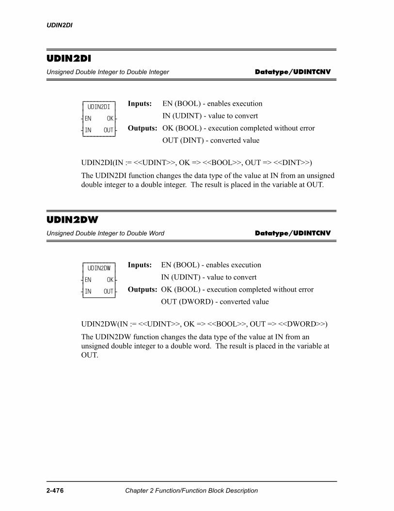
UDIN2DI
UDIN2DIUnsigned Double Integer to Double Integer Datatype/UDINTCNV
UDIN2DI(IN := <<UDINT>>, OK => <<BOOL>>, OUT => <<DINT>>)
The UDIN2DI function changes the data type of the value at IN from an unsigned double integer to a double integer. The result is placed in the variable at OUT.
UDIN2DWUnsigned Double Integer to Double Word Datatype/UDINTCNV
UDIN2DW(IN := <<UDINT>>, OK => <<BOOL>>, OUT => <<DWORD>>)
The UDIN2DW function changes the data type of the value at IN from an unsigned double integer to a double word. The result is placed in the variable at OUT.
⁄ƒƒƒƒƒƒƒƒƒø ≥ UDIN2DI ≥ ≥ ≥ ¥EN OK√ ≥ ≥ ¥IN OUT√ ¿ƒƒƒƒƒƒƒƒƒŸ
Inputs: EN (BOOL) - enables execution
IN (UDINT) - value to convert
Outputs: OK (BOOL) - execution completed without error
OUT (DINT) - converted value
⁄ƒƒƒƒƒƒƒƒƒø ≥ UDIN2DW ≥ ≥ ≥ ¥EN OK√ ≥ ≥ ¥IN OUT√ ¿ƒƒƒƒƒƒƒƒƒŸ
Inputs: EN (BOOL) - enables execution
IN (UDINT) - value to convert
Outputs: OK (BOOL) - execution completed without error
OUT (DWORD) - converted value
2-476 Chapter 2 Function/Function Block Description
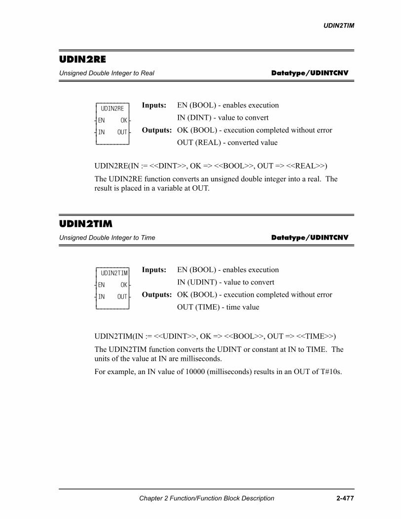
UDIN2TIM
UDIN2REUnsigned Double Integer to Real Datatype/UDINTCNV
UDIN2RE(IN := <<DINT>>, OK => <<BOOL>>, OUT => <<REAL>>)
The UDIN2RE function converts an unsigned double integer into a real. The result is placed in a variable at OUT.
UDIN2TIMUnsigned Double Integer to Time Datatype/UDINTCNV
UDIN2TIM(IN := <<UDINT>>, OK => <<BOOL>>, OUT => <<TIME>>)
The UDIN2TIM function converts the UDINT or constant at IN to TIME. The units of the value at IN are milliseconds.
For example, an IN value of 10000 (milliseconds) results in an OUT of T#10s.
⁄ƒƒƒƒƒƒƒƒƒø≥ UDIN2RE ≥≥ ≥¥EN OK√≥ ≥¥IN OUT√≥ ≥¿ƒƒƒƒƒƒƒƒƒŸ
Inputs: EN (BOOL) - enables execution
IN (DINT) - value to convert
Outputs: OK (BOOL) - execution completed without error
OUT (REAL) - converted value
⁄ƒƒƒƒƒƒƒƒƒø ≥ UDIN2TIM≥ ≥ ≥ ¥EN OK√ ≥ ≥ ¥IN OUT√ ≥ ≥ ¿ƒƒƒƒƒƒƒƒƒŸ
Inputs: EN (BOOL) - enables execution
IN (UDINT) - value to convert
Outputs: OK (BOOL) - execution completed without error
OUT (TIME) - time value
Chapter 2 Function/Function Block Description 2-477
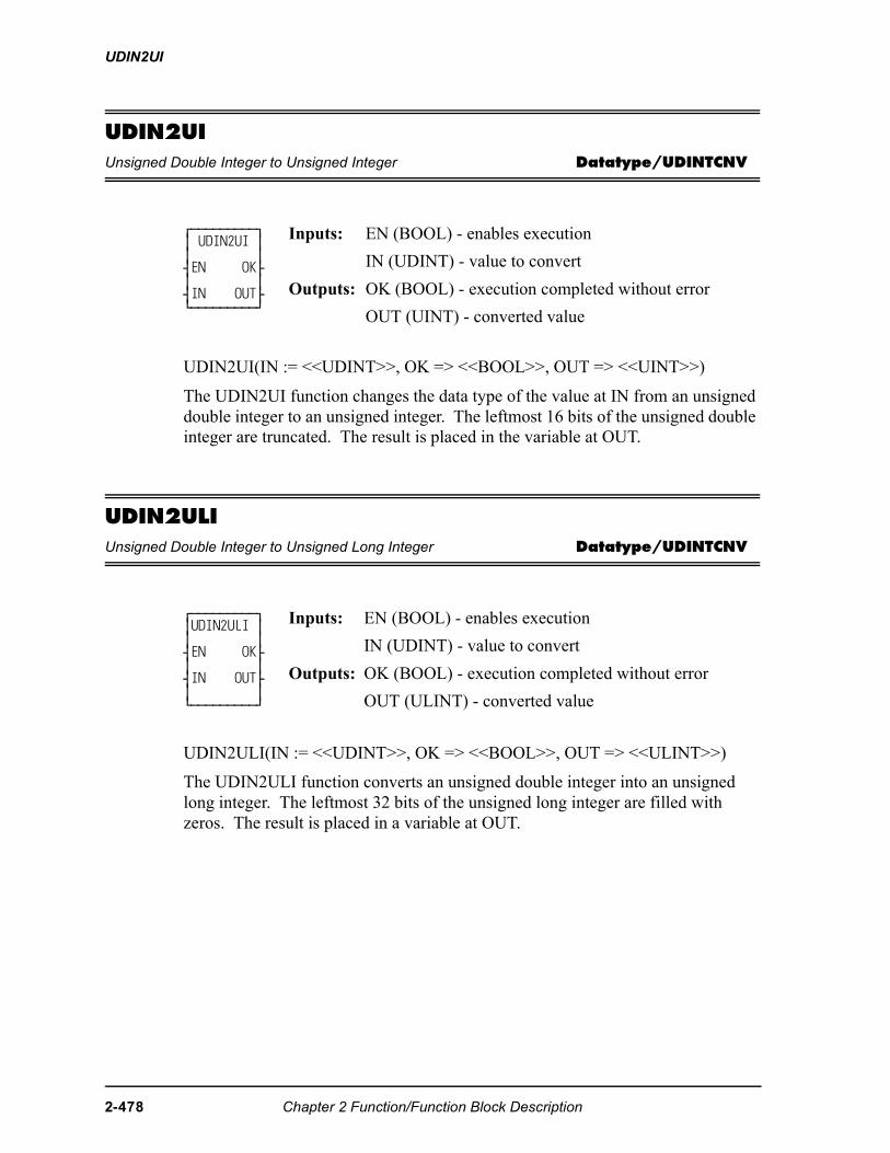
UDIN2UI
UDIN2UIUnsigned Double Integer to Unsigned Integer Datatype/UDINTCNV
UDIN2UI(IN := <<UDINT>>, OK => <<BOOL>>, OUT => <<UINT>>)
The UDIN2UI function changes the data type of the value at IN from an unsigned double integer to an unsigned integer. The leftmost 16 bits of the unsigned double integer are truncated. The result is placed in the variable at OUT.
UDIN2ULIUnsigned Double Integer to Unsigned Long Integer Datatype/UDINTCNV
UDIN2ULI(IN := <<UDINT>>, OK => <<BOOL>>, OUT => <<ULINT>>)
The UDIN2ULI function converts an unsigned double integer into an unsigned long integer. The leftmost 32 bits of the unsigned long integer are filled with zeros. The result is placed in a variable at OUT.
⁄ƒƒƒƒƒƒƒƒƒø ≥ UDIN2UI ≥ ≥ ≥ ¥EN OK√ ≥ ≥ ¥IN OUT√ ¿ƒƒƒƒƒƒƒƒƒŸ
Inputs: EN (BOOL) - enables execution
IN (UDINT) - value to convert
Outputs: OK (BOOL) - execution completed without error
OUT (UINT) - converted value
⁄ƒƒƒƒƒƒƒƒƒø≥UDIN2ULI ≥≥ ≥¥EN OK√≥ ≥¥IN OUT√≥ ≥¿ƒƒƒƒƒƒƒƒƒŸ
Inputs: EN (BOOL) - enables execution
IN (UDINT) - value to convert
Outputs: OK (BOOL) - execution completed without error
OUT (ULINT) - converted value
2-478 Chapter 2 Function/Function Block Description
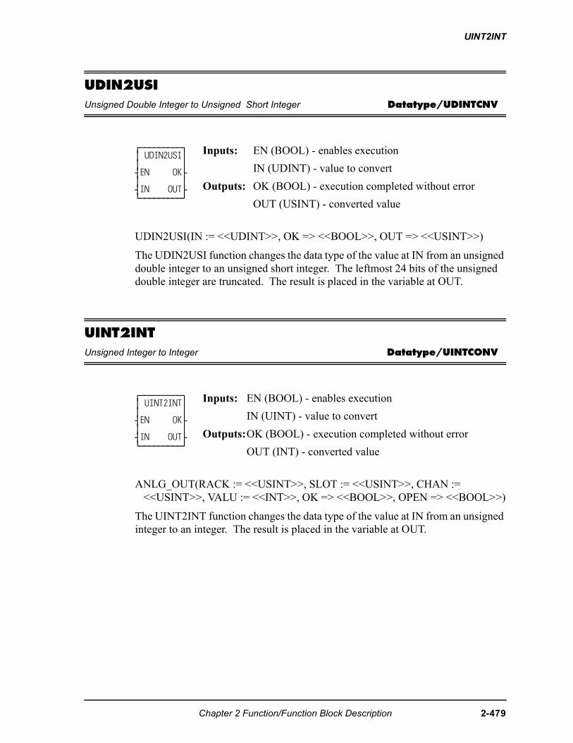
UINT2INT
UDIN2USIUnsigned Double Integer to Unsigned Short Integer Datatype/UDINTCNV
UDIN2USI(IN := <<UDINT>>, OK => <<BOOL>>, OUT => <<USINT>>)
The UDIN2USI function changes the data type of the value at IN from an unsigned double integer to an unsigned short integer. The leftmost 24 bits of the unsigned double integer are truncated. The result is placed in the variable at OUT.
UINT2INTUnsigned Integer to Integer Datatype/UINTCONV
ANLG_OUT(RACK := <<USINT>>, SLOT := <<USINT>>, CHAN := <<USINT>>, VALU := <<INT>>, OK => <<BOOL>>, OPEN => <<BOOL>>)
The UINT2INT function changes the data type of the value at IN from an unsigned integer to an integer. The result is placed in the variable at OUT.
⁄ƒƒƒƒƒƒƒƒƒø ≥ UDIN2USI≥ ≥ ≥ ¥EN OK√ ≥ ≥ ¥IN OUT√ ¿ƒƒƒƒƒƒƒƒƒŸ
Inputs: EN (BOOL) - enables execution
IN (UDINT) - value to convert
Outputs: OK (BOOL) - execution completed without error
OUT (USINT) - converted value
⁄ƒƒƒƒƒƒƒƒƒø ≥ UINT2INT≥ ≥ ≥ ¥EN OK√ ≥ ≥ ¥IN OUT√ ¿ƒƒƒƒƒƒƒƒƒŸ
Inputs: EN (BOOL) - enables execution
IN (UINT) - value to convert
Outputs:OK (BOOL) - execution completed without error
OUT (INT) - converted value
Chapter 2 Function/Function Block Description 2-479
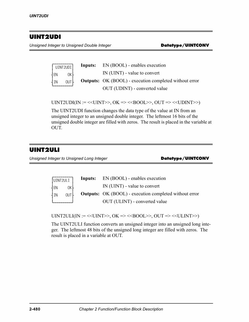
UINT2UDI
UINT2UDIUnsigned Integer to Unsigned Double Integer Datatype/UINTCONV
UINT2UDI(IN := <<UINT>>, OK => <<BOOL>>, OUT => <<UDINT>>)
The UINT2UDI function changes the data type of the value at IN from an unsigned integer to an unsigned double integer. The leftmost 16 bits of the unsigned double integer are filled with zeros. The result is placed in the variable at OUT.
UINT2ULIUnsigned Integer to Unsigned Long Integer Datatype/UINTCONV
UINT2ULI(IN := <<UINT>>, OK => <<BOOL>>, OUT => <<ULINT>>)
The UINT2ULI function converts an unsigned integer into an unsigned long inte-ger. The leftmost 48 bits of the unsigned long integer are filled with zeros. The result is placed in a variable at OUT.
⁄ƒƒƒƒƒƒƒƒƒø ≥ UINT2UDI≥ ≥ ≥ ¥EN OK√ ≥ ≥ ¥IN OUT√ ¿ƒƒƒƒƒƒƒƒƒŸ
Inputs: EN (BOOL) - enables execution
IN (UINT) - value to convert
Outputs: OK (BOOL) - execution completed without error
OUT (UDINT) - converted value
⁄ƒƒƒƒƒƒƒƒƒø ≥UINT2ULI ≥ ≥ ≥ ¥EN OK√ ≥ ≥ ¥IN OUT√ ≥ ≥ ¿ƒƒƒƒƒƒƒƒƒŸ
Inputs: EN (BOOL) - enables execution
IN (UINT) - value to convert
Outputs: OK (BOOL) - execution completed without error
OUT (ULINT) - converted value
2-480 Chapter 2 Function/Function Block Description
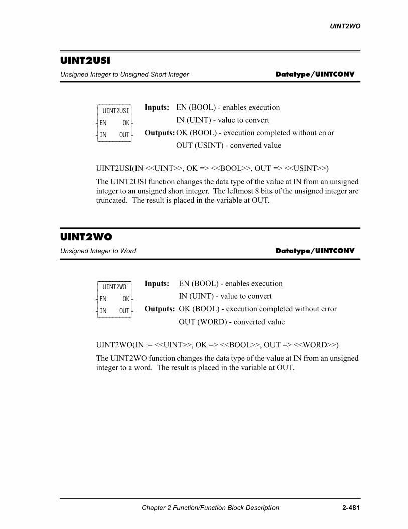
UINT2WO
UINT2USIUnsigned Integer to Unsigned Short Integer Datatype/UINTCONV
UINT2USI(IN <<UINT>>, OK => <<BOOL>>, OUT => <<USINT>>)
The UINT2USI function changes the data type of the value at IN from an unsigned integer to an unsigned short integer. The leftmost 8 bits of the unsigned integer are truncated. The result is placed in the variable at OUT.
UINT2WOUnsigned Integer to Word Datatype/UINTCONV
UINT2WO(IN := <<UINT>>, OK => <<BOOL>>, OUT => <<WORD>>)
The UINT2WO function changes the data type of the value at IN from an unsigned integer to a word. The result is placed in the variable at OUT.
⁄ƒƒƒƒƒƒƒƒƒø ≥ UINT2USI≥ ≥ ≥ ¥EN OK√ ≥ ≥ ¥IN OUT√ ¿ƒƒƒƒƒƒƒƒƒŸ
Inputs: EN (BOOL) - enables execution
IN (UINT) - value to convert
Outputs: OK (BOOL) - execution completed without error
OUT (USINT) - converted value
⁄ƒƒƒƒƒƒƒƒƒø ≥ UINT2WO ≥ ≥ ≥ ¥EN OK√ ≥ ≥ ¥IN OUT√ ¿ƒƒƒƒƒƒƒƒƒŸ
Inputs: EN (BOOL) - enables execution
IN (UINT) - value to convert
Outputs: OK (BOOL) - execution completed without error
OUT (WORD) - converted value
Chapter 2 Function/Function Block Description 2-481
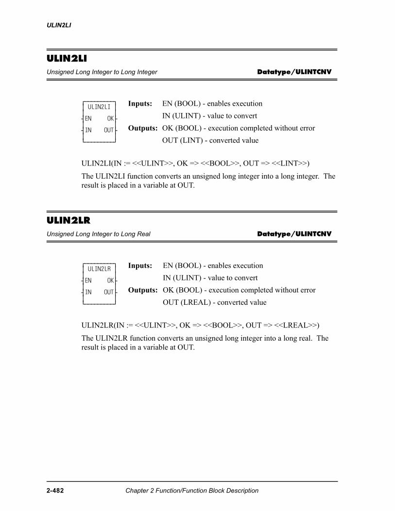
ULIN2LI
ULIN2LIUnsigned Long Integer to Long Integer Datatype/ULINTCNV
ULIN2LI(IN := <<ULINT>>, OK => <<BOOL>>, OUT => <<LINT>>)
The ULIN2LI function converts an unsigned long integer into a long integer. The result is placed in a variable at OUT.
ULIN2LRUnsigned Long Integer to Long Real Datatype/ULINTCNV
ULIN2LR(IN := <<ULINT>>, OK => <<BOOL>>, OUT => <<LREAL>>)
The ULIN2LR function converts an unsigned long integer into a long real. The result is placed in a variable at OUT.
⁄ƒƒƒƒƒƒƒƒƒø≥ ULIN2LI ≥≥ ≥¥EN OK√≥ ≥¥IN OUT√≥ ≥¿ƒƒƒƒƒƒƒƒƒŸ
Inputs: EN (BOOL) - enables execution
IN (ULINT) - value to convert
Outputs: OK (BOOL) - execution completed without error
OUT (LINT) - converted value
⁄ƒƒƒƒƒƒƒƒƒø≥ ULIN2LR ≥≥ ≥¥EN OK√≥ ≥¥IN OUT√≥ ≥¿ƒƒƒƒƒƒƒƒƒŸ
Inputs: EN (BOOL) - enables execution
IN (ULINT) - value to convert
Outputs: OK (BOOL) - execution completed without error
OUT (LREAL) - converted value
2-482 Chapter 2 Function/Function Block Description
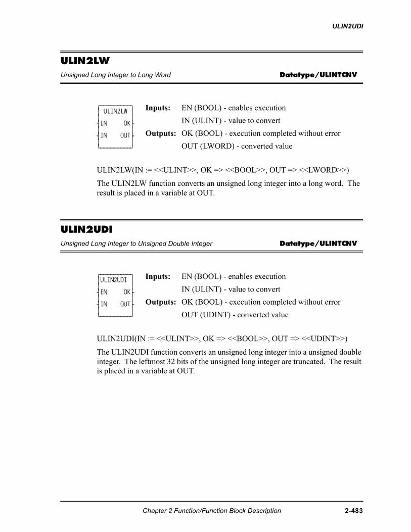
ULIN2UDI
ULIN2LWUnsigned Long Integer to Long Word Datatype/ULINTCNV
ULIN2LW(IN := <<ULINT>>, OK => <<BOOL>>, OUT => <<LWORD>>)
The ULIN2LW function converts an unsigned long integer into a long word. The result is placed in a variable at OUT.
ULIN2UDIUnsigned Long Integer to Unsigned Double Integer Datatype/ULINTCNV
ULIN2UDI(IN := <<ULINT>>, OK => <<BOOL>>, OUT => <<UDINT>>)
The ULIN2UDI function converts an unsigned long integer into a unsigned double integer. The leftmost 32 bits of the unsigned long integer are truncated. The result is placed in a variable at OUT.
⁄ƒƒƒƒƒƒƒƒƒø ≥ ULIN2LW ≥ ≥ ≥ ¥EN OK√ ≥ ≥ ¥IN OUT√ ≥ ≥ ¿ƒƒƒƒƒƒƒƒƒŸ
Inputs: EN (BOOL) - enables execution
IN (ULINT) - value to convert
Outputs: OK (BOOL) - execution completed without error
OUT (LWORD) - converted value
⁄ƒƒƒƒƒƒƒƒƒø ≥ULIN2UDI ≥ ≥ ≥ ¥EN OK√ ≥ ≥ ¥IN OUT√ ≥ ≥ ¿ƒƒƒƒƒƒƒƒƒŸ
Inputs: EN (BOOL) - enables execution
IN (ULINT) - value to convert
Outputs: OK (BOOL) - execution completed without error
OUT (UDINT) - converted value
Chapter 2 Function/Function Block Description 2-483
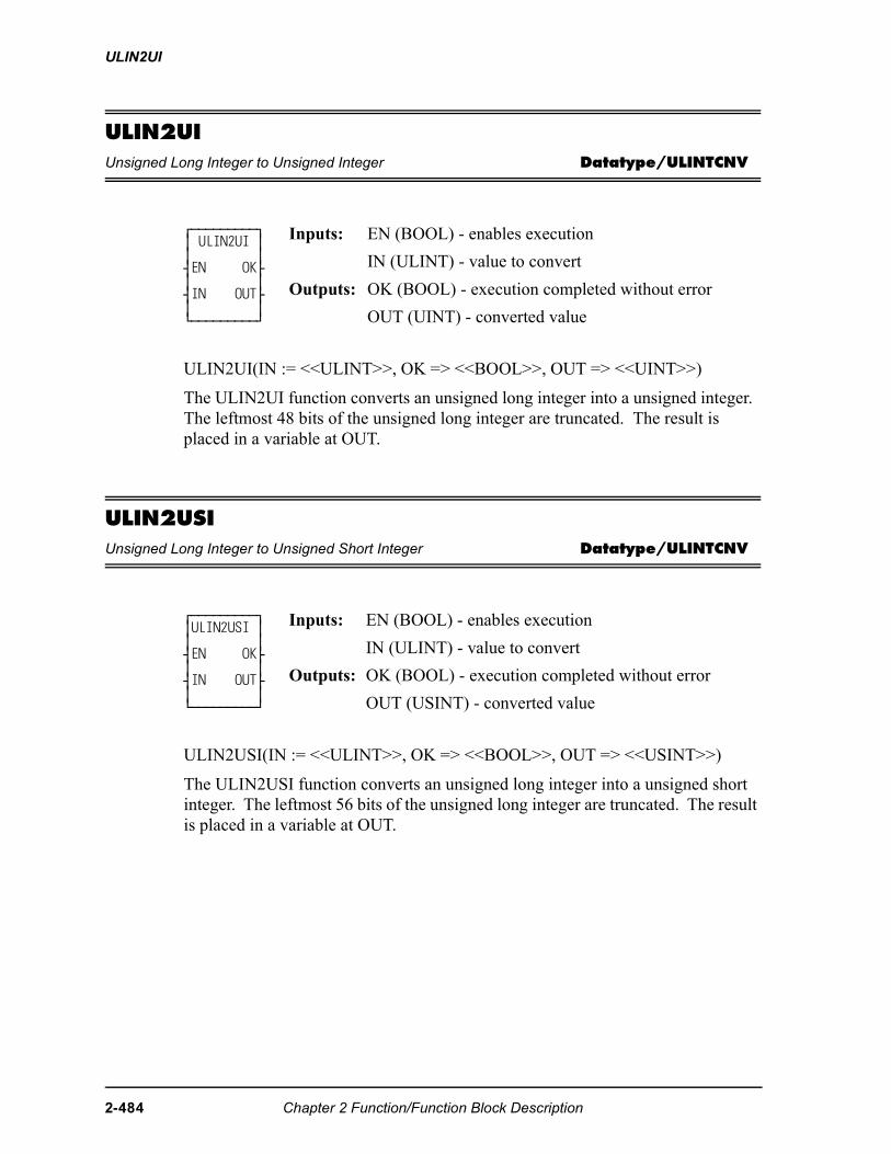
ULIN2UI
ULIN2UIUnsigned Long Integer to Unsigned Integer Datatype/ULINTCNV
ULIN2UI(IN := <<ULINT>>, OK => <<BOOL>>, OUT => <<UINT>>)
The ULIN2UI function converts an unsigned long integer into a unsigned integer. The leftmost 48 bits of the unsigned long integer are truncated. The result is placed in a variable at OUT.
ULIN2USIUnsigned Long Integer to Unsigned Short Integer Datatype/ULINTCNV
ULIN2USI(IN := <<ULINT>>, OK => <<BOOL>>, OUT => <<USINT>>)
The ULIN2USI function converts an unsigned long integer into a unsigned short integer. The leftmost 56 bits of the unsigned long integer are truncated. The result is placed in a variable at OUT.
⁄ƒƒƒƒƒƒƒƒƒø≥ ULIN2UI ≥≥ ≥¥EN OK√≥ ≥¥IN OUT√≥ ≥¿ƒƒƒƒƒƒƒƒƒŸ
Inputs: EN (BOOL) - enables execution
IN (ULINT) - value to convert
Outputs: OK (BOOL) - execution completed without error
OUT (UINT) - converted value
⁄ƒƒƒƒƒƒƒƒƒø ≥ULIN2USI ≥ ≥ ≥ ¥EN OK√ ≥ ≥ ¥IN OUT√ ≥ ≥ ¿ƒƒƒƒƒƒƒƒƒŸ
Inputs: EN (BOOL) - enables execution
IN (ULINT) - value to convert
Outputs: OK (BOOL) - execution completed without error
OUT (USINT) - converted value
2-484 Chapter 2 Function/Function Block Description
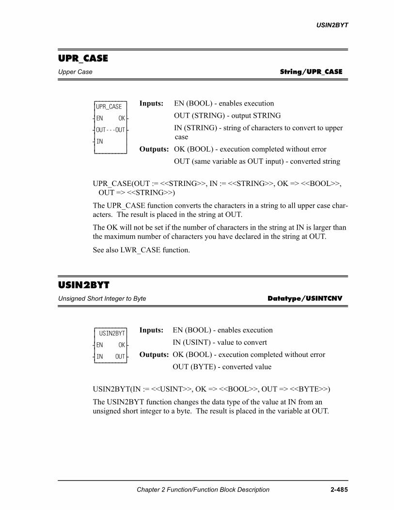
USIN2BYT
UPR_CASEUpper Case String/UPR_CASE
UPR_CASE(OUT := <<STRING>>, IN := <<STRING>>, OK => <<BOOL>>, OUT => <<STRING>>)
The UPR_CASE function converts the characters in a string to all upper case char-acters. The result is placed in the string at OUT.
The OK will not be set if the number of characters in the string at IN is larger than the maximum number of characters you have declared in the string at OUT.
See also LWR_CASE function.
USIN2BYTUnsigned Short Integer to Byte Datatype/USINTCNV
USIN2BYT(IN := <<USINT>>, OK => <<BOOL>>, OUT => <<BYTE>>)
The USIN2BYT function changes the data type of the value at IN from an unsigned short integer to a byte. The result is placed in the variable at OUT.
⁄ƒƒƒƒƒƒƒƒƒø ≥UPR_CASE ≥ ≥ ≥ ¥EN OK√ ≥ ≥ ¥OUT---OUT√ ≥ ≥ ¥IN ≥ ≥ ≥ ¿ƒƒƒƒƒƒƒƒƒŸ
Inputs: EN (BOOL) - enables execution
OUT (STRING) - output STRING
IN (STRING) - string of characters to convert to upper case
Outputs: OK (BOOL) - execution completed without error
OUT (same variable as OUT input) - converted string
⁄ƒƒƒƒƒƒƒƒƒø ≥ USIN2BYT≥ ≥ ≥ ¥EN OK√ ≥ ≥ ¥IN OUT√ ¿ƒƒƒƒƒƒƒƒƒŸ
Inputs: EN (BOOL) - enables execution
IN (USINT) - value to convert
Outputs: OK (BOOL) - execution completed without error
OUT (BYTE) - converted value
Chapter 2 Function/Function Block Description 2-485
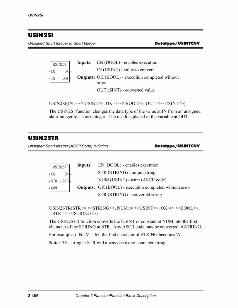
USIN2SI
USIN2SIUnsigned Short Integer to Short Integer Datatype/USINTCNV
USIN2SI(IN := <<USINT>>, OK => <<BOOL>>, OUT => <<SINT>>)
The USIN2SI function changes the data type of the value at IN from an unsigned short integer to a short integer. The result is placed in the variable at OUT.
USIN2STRUnsigned Short Integer (ASCII Code) to String Datatype/USINTCNV
USIN2STR(STR := <<STRING>>, NUM := <<USINT>>, OK => <<BOOL>>, STR => <<STRING>>)
The USIN2STR function converts the USINT or constant at NUM into the first character of the STRING at STR. Any ASCII code may be converted to STRING.
For example, if NUM = 65, the first character of STRING becomes 'A'.
Note: The string at STR will always be a one-character string.
⁄ƒƒƒƒƒƒƒƒƒø ≥ USIN2SI ≥ ≥ ≥ ¥EN OK√ ≥ ≥ ¥IN OUT√ ¿ƒƒƒƒƒƒƒƒƒŸ
Inputs: EN (BOOL) - enables execution
IN (USINT) - value to convert
Outputs: OK (BOOL) - execution completed without error
OUT (SINT) - converted value
⁄ƒƒƒƒƒƒƒƒƒø ≥ USIN2STR≥ ≥ ≥ ¥EN OK√ ≥ ≥ ¥STR---STR√ ≥ ≥ ¥NUM ≥ ¿ƒƒƒƒƒƒƒƒƒŸ
Inputs: EN (BOOL) - enables execution
STR (STRING) - output string
NUM (USINT) - usint (ASCII code)
Outputs: OK (BOOL) - execution completed without error
STR (STRING) - converted string
2-486 Chapter 2 Function/Function Block Description
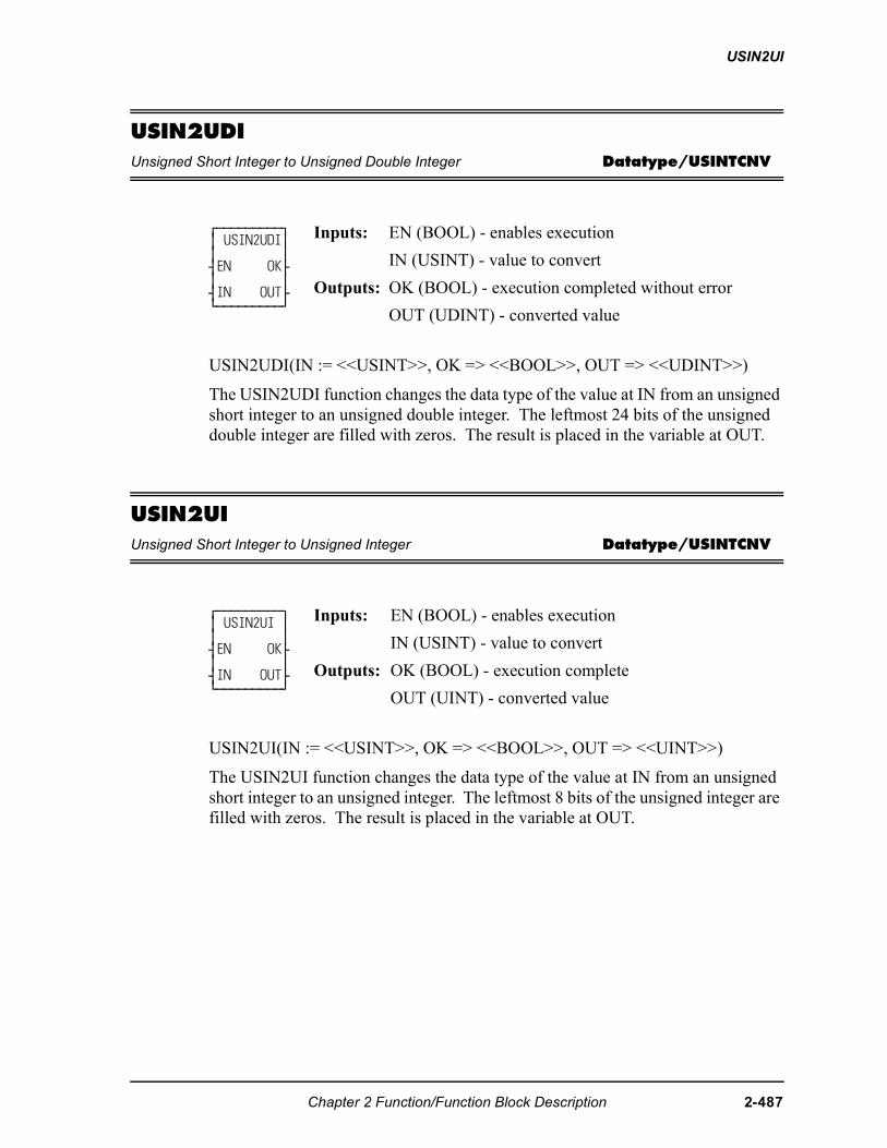
USIN2UI
USIN2UDIUnsigned Short Integer to Unsigned Double Integer Datatype/USINTCNV
USIN2UDI(IN := <<USINT>>, OK => <<BOOL>>, OUT => <<UDINT>>)
The USIN2UDI function changes the data type of the value at IN from an unsigned short integer to an unsigned double integer. The leftmost 24 bits of the unsigned double integer are filled with zeros. The result is placed in the variable at OUT.
USIN2UIUnsigned Short Integer to Unsigned Integer Datatype/USINTCNV
USIN2UI(IN := <<USINT>>, OK => <<BOOL>>, OUT => <<UINT>>)
The USIN2UI function changes the data type of the value at IN from an unsigned short integer to an unsigned integer. The leftmost 8 bits of the unsigned integer are filled with zeros. The result is placed in the variable at OUT.
⁄ƒƒƒƒƒƒƒƒƒø ≥ USIN2UDI≥ ≥ ≥ ¥EN OK√ ≥ ≥ ¥IN OUT√ ¿ƒƒƒƒƒƒƒƒƒŸ
Inputs: EN (BOOL) - enables execution
IN (USINT) - value to convert
Outputs: OK (BOOL) - execution completed without error
OUT (UDINT) - converted value
⁄ƒƒƒƒƒƒƒƒƒø ≥ USIN2UI ≥ ≥ ≥ ¥EN OK√ ≥ ≥ ¥IN OUT√ ¿ƒƒƒƒƒƒƒƒƒŸ
Inputs: EN (BOOL) - enables execution
IN (USINT) - value to convert
Outputs: OK (BOOL) - execution complete
OUT (UINT) - converted value
Chapter 2 Function/Function Block Description 2-487
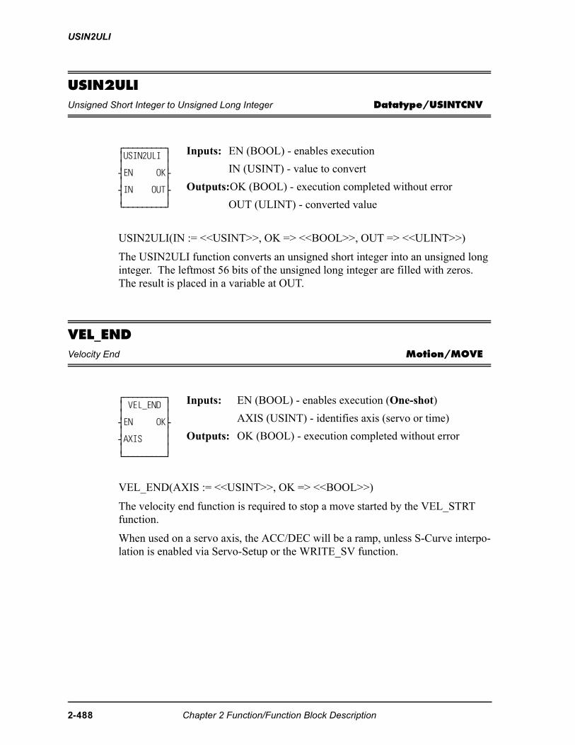
USIN2ULI
USIN2ULIUnsigned Short Integer to Unsigned Long Integer Datatype/USINTCNV
USIN2ULI(IN := <<USINT>>, OK => <<BOOL>>, OUT => <<ULINT>>)
The USIN2ULI function converts an unsigned short integer into an unsigned long integer. The leftmost 56 bits of the unsigned long integer are filled with zeros. The result is placed in a variable at OUT.
VEL_ENDVelocity End Motion/MOVE
VEL_END(AXIS := <<USINT>>, OK => <<BOOL>>)
The velocity end function is required to stop a move started by the VEL_STRT function.
When used on a servo axis, the ACC/DEC will be a ramp, unless S-Curve interpo-lation is enabled via Servo-Setup or the WRITE_SV function.
⁄ƒƒƒƒƒƒƒƒƒø≥USIN2ULI ≥≥ ≥¥EN OK√≥ ≥¥IN OUT√≥ ≥¿ƒƒƒƒƒƒƒƒƒŸ
Inputs: EN (BOOL) - enables execution
IN (USINT) - value to convert
Outputs:OK (BOOL) - execution completed without error
OUT (ULINT) - converted value
⁄ƒƒƒƒƒƒƒƒƒø≥ VEL_END ≥≥ ≥¥EN OK√≥ ≥¥AXIS ≥≥ ≥¿ƒƒƒƒƒƒƒƒƒŸ
Inputs: EN (BOOL) - enables execution (One-shot)
AXIS (USINT) - identifies axis (servo or time)
Outputs: OK (BOOL) - execution completed without error
2-488 Chapter 2 Function/Function Block Description
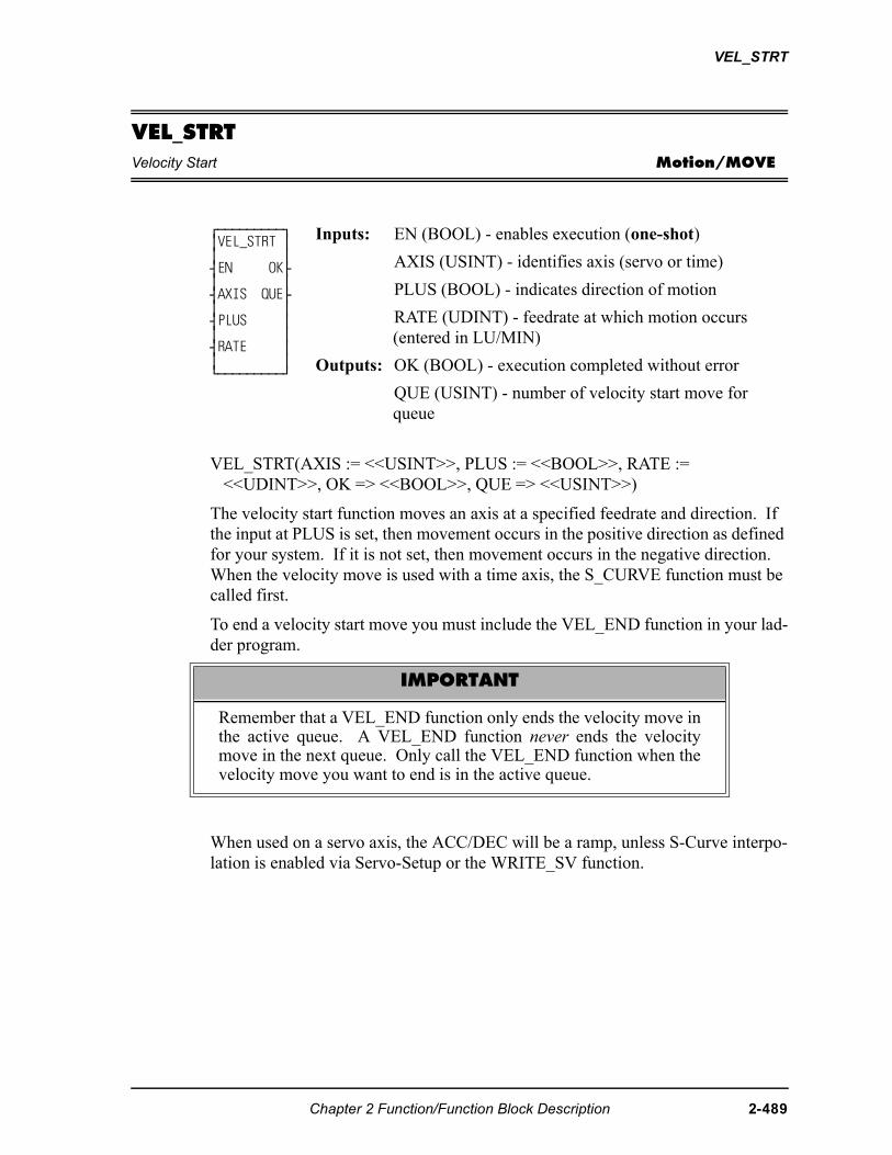
VEL_STRT
VEL_STRTVelocity Start Motion/MOVE
VEL_STRT(AXIS := <<USINT>>, PLUS := <<BOOL>>, RATE := <<UDINT>>, OK => <<BOOL>>, QUE => <<USINT>>)
The velocity start function moves an axis at a specified feedrate and direction. If the input at PLUS is set, then movement occurs in the positive direction as defined for your system. If it is not set, then movement occurs in the negative direction. When the velocity move is used with a time axis, the S_CURVE function must be called first.
To end a velocity start move you must include the VEL_END function in your lad-der program.
When used on a servo axis, the ACC/DEC will be a ramp, unless S-Curve interpo-lation is enabled via Servo-Setup or the WRITE_SV function.
⁄ƒƒƒƒƒƒƒƒƒø ≥VEL_STRT ≥ ≥ ≥ ¥EN OK√ ≥ ≥ ¥AXIS QUE√ ≥ ≥ ¥PLUS ≥ ≥ ≥ ¥RATE ≥ ≥ ≥ ¿ƒƒƒƒƒƒƒƒƒŸ
Inputs: EN (BOOL) - enables execution (one-shot)
AXIS (USINT) - identifies axis (servo or time)
PLUS (BOOL) - indicates direction of motion
RATE (UDINT) - feedrate at which motion occurs (entered in LU/MIN)
Outputs: OK (BOOL) - execution completed without error
QUE (USINT) - number of velocity start move for queue
IMPORTANT
Remember that a VEL_END function only ends the velocity move inthe active queue. A VEL_END function never ends the velocitymove in the next queue. Only call the VEL_END function when thevelocity move you want to end is in the active queue.
Chapter 2 Function/Function Block Description 2-489
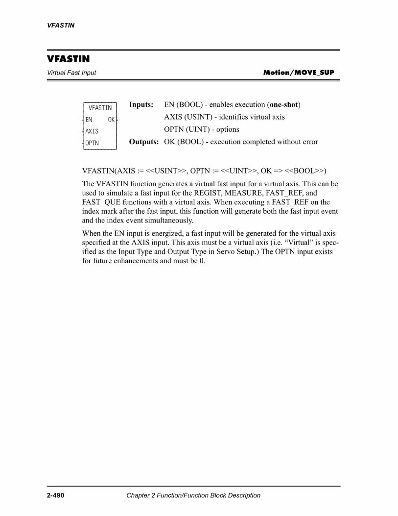
VFASTIN
VFASTINVirtual Fast Input Motion/MOVE_SUP
VFASTIN(AXIS := <<USINT>>, OPTN := <<UINT>>, OK => <<BOOL>>)
The VFASTIN function generates a virtual fast input for a virtual axis. This can be used to simulate a fast input for the REGIST, MEASURE, FAST_REF, and FAST_QUE functions with a virtual axis. When executing a FAST_REF on the index mark after the fast input, this function will generate both the fast input event and the index event simultaneously.
When the EN input is energized, a fast input will be generated for the virtual axis specified at the AXIS input. This axis must be a virtual axis (i.e. “Virtual” is spec-ified as the Input Type and Output Type in Servo Setup.) The OPTN input exists for future enhancements and must be 0.
⁄ƒƒƒƒƒƒƒƒƒø ≥ VFASTIN ≥ ≥ ≥ ¥EN OK√ ≥ ≥ ¥AXIS ≥ ≥ ≥ ¥OPTN ≥ ¿ƒƒƒƒƒƒƒƒƒŸ
Inputs: EN (BOOL) - enables execution (one-shot)
AXIS (USINT) - identifies virtual axis
OPTN (UINT) - options
Outputs: OK (BOOL) - execution completed without error
2-490 Chapter 2 Function/Function Block Description
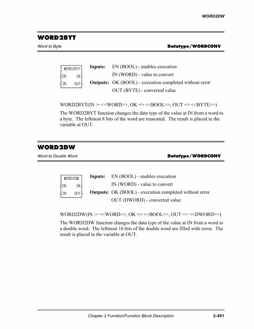
WORD2DW
WORD2BYTWord to Byte Datatype/WORDCONV
WORD2BYT(IN := <<WORD>>, OK => <<BOOL>>, OUT => <<BYTE>>)
The WORD2BYT function changes the data type of the value at IN from a word to a byte. The leftmost 8 bits of the word are truncated. The result is placed in the variable at OUT.
WORD2DWWord to Double Word Datatype/WORDCONV
WORD2DW(IN := <<WORD>>, OK => <<BOOL>>, OUT => <<DWORD>>)
The WORD2DW function changes the data type of the value at IN from a word to a double word. The leftmost 16 bits of the double word are filled with zeros. The result is placed in the variable at OUT.
⁄ƒƒƒƒƒƒƒƒƒø ≥ WORD2BYT≥ ≥ ≥ ¥EN OK√ ≥ ≥ ¥IN OUT√ ¿ƒƒƒƒƒƒƒƒƒŸ
Inputs: EN (BOOL) - enables execution
IN (WORD) - value to convert
Outputs: OK (BOOL) - execution completed without error
OUT (BYTE) - converted value
⁄ƒƒƒƒƒƒƒƒƒø ≥ WORD2DW ≥ ≥ ≥ ¥EN OK√ ≥ ≥ ¥IN OUT√ ¿ƒƒƒƒƒƒƒƒƒŸ
Inputs: EN (BOOL) - enables execution
IN (WORD) - value to convert
Outputs: OK (BOOL) - execution completed without error
OUT (DWORD) - converted value
Chapter 2 Function/Function Block Description 2-491
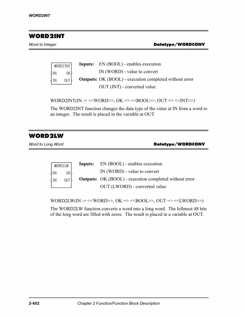
WORD2INT
WORD2INTWord to Integer Datatype/WORDCONV
WORD2INT(IN := <<WORD>>, OK => <<BOOL>>, OUT => <<INT>>)
The WORD2INT function changes the data type of the value at IN from a word to an integer. The result is placed in the variable at OUT.
WORD2LWWord to Long Word Datatype/WORDCONV
WORD2LW(IN := <<WORD>>, OK => <<BOOL>>, OUT => <<LWORD>>)
The WORD2LW function converts a word into a long word. The leftmost 48 bits of the long word are filled with zeros. The result is placed in a variable at OUT.
⁄ƒƒƒƒƒƒƒƒƒø ≥ WORD2INT≥ ≥ ≥ ¥EN OK√ ≥ ≥ ¥IN OUT√ ¿ƒƒƒƒƒƒƒƒƒŸ
Inputs: EN (BOOL) - enables execution
IN (WORD) - value to convert
Outputs: OK (BOOL) - execution completed without error
OUT (INT) - converted value
⁄ƒƒƒƒƒƒƒƒƒø≥ WORD2LW ≥≥ ≥¥EN OK√≥ ≥¥IN OUT√≥ ≥¿ƒƒƒƒƒƒƒƒƒŸ
Inputs: EN (BOOL) - enables execution
IN (WORD) - value to convert
Outputs: OK (BOOL) - execution completed without error
OUT (LWORD) - converted value
2-492 Chapter 2 Function/Function Block Description
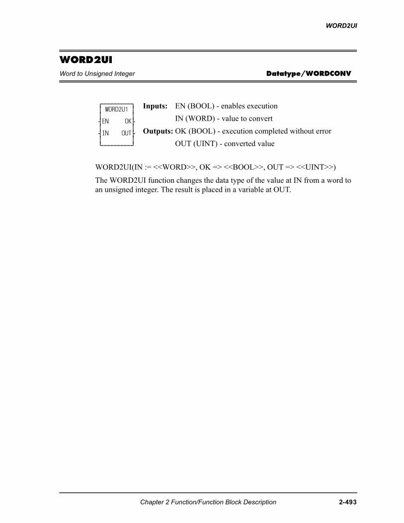
WORD2UI
WORD2UIWord to Unsigned Integer Datatype/WORDCONV
WORD2UI(IN := <<WORD>>, OK => <<BOOL>>, OUT => <<UINT>>)
The WORD2UI function changes the data type of the value at IN from a word to an unsigned integer. The result is placed in a variable at OUT.
⁄ƒƒƒƒƒƒƒƒƒø ≥ WORD2U1 ≥ ≥ ≥ ¥EN OK√ ≥ ≥ ¥IN OUT√ ≥ ≥ ¿ƒƒƒƒƒƒƒƒƒŸ
Inputs: EN (BOOL) - enables execution
IN (WORD) - value to convert
Outputs: OK (BOOL) - execution completed without error
OUT (UINT) - converted value
Chapter 2 Function/Function Block Description 2-493
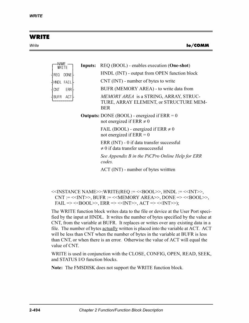
WRITE
WRITEWrite Io/COMM
<<INSTANCE NAME>>:WRITE(REQ := <<BOOL>>, HNDL := <<INT>>, CNT := <<INT>>, BUFR := <<MEMORY AREA>>, DONE => <<BOOL>>, FAIL => <<BOOL>>, ERR => <<INT>>, ACT => <<INT>>);
The WRITE function block writes data to the file or device at the User Port speci-fied by the input at HNDL. It writes the number of bytes specified by the value at CNT, from the variable at BUFR. It replaces or writes over any existing data in a file. The number of bytes actually written is placed into the variable at ACT. ACT will be less than CNT when the number of bytes in the variable at BUFR is less than CNT, or when there is an error. Otherwise the value of ACT will equal the value of CNT.
WRITE is used in conjunction with the CLOSE, CONFIG, OPEN, READ, SEEK, and STATUS I/O function blocks.
Note: The FMSDISK does not support the WRITE function block.
⁄ƒƒNAME ƒƒø ≥ WRITE ≥ ≥ ≥ ¥REQ DONE√ ≥ ≥ ¥HNDL FAIL√ ≥ ≥ ¥CNT ERR√ ≥ ≥ ¥BUFR ACT√ ¿ƒƒƒƒƒƒƒƒƒŸ
Inputs: REQ (BOOL) - enables execution (One-shot)
HNDL (INT) - output from OPEN function block
CNT (INT) - number of bytes to write
BUFR (MEMORY AREA) - to write data from
MEMORY AREA is a STRING, ARRAY, STRUC-TURE, ARRAY ELEMENT, or STRUCTURE MEM-BER
Outputs: DONE (BOOL) - energized if ERR = 0not energized if ERR ≠ 0
FAIL (BOOL) - energized if ERR ≠ 0not energized if ERR = 0
ERR (INT) - 0 if data transfer successful≠ 0 if data transfer unsuccessful
See Appendix B in the PiCPro Online Help for ERR codes.
ACT (INT) - number of bytes writtten
2-494 Chapter 2 Function/Function Block Description
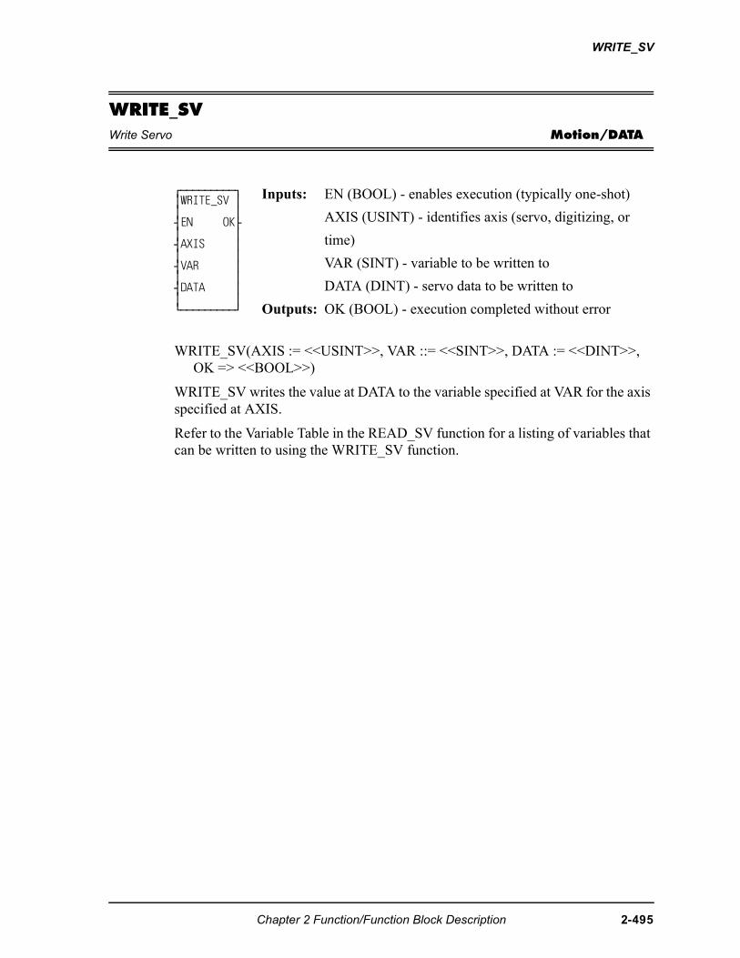
WRITE_SV
WRITE_SVWrite Servo Motion/DATA
WRITE_SV(AXIS := <<USINT>>, VAR ::= <<SINT>>, DATA := <<DINT>>, OK => <<BOOL>>)
WRITE_SV writes the value at DATA to the variable specified at VAR for the axis specified at AXIS.
Refer to the Variable Table in the READ_SV function for a listing of variables that can be written to using the WRITE_SV function.
⁄ƒƒƒƒƒƒƒƒƒø ≥WRITE_SV ≥ ≥ ≥ ¥EN OK√ ≥ ≥ ¥AXIS ≥ ≥ ≥ ¥VAR ≥ ≥ ≥ ¥DATA ≥ ≥ ≥ ¿ƒƒƒƒƒƒƒƒƒŸ
Inputs: EN (BOOL) - enables execution (typically one-shot)
AXIS (USINT) - identifies axis (servo, digitizing, or
time)
VAR (SINT) - variable to be written to
DATA (DINT) - servo data to be written to
Outputs: OK (BOOL) - execution completed without error
Chapter 2 Function/Function Block Description 2-495
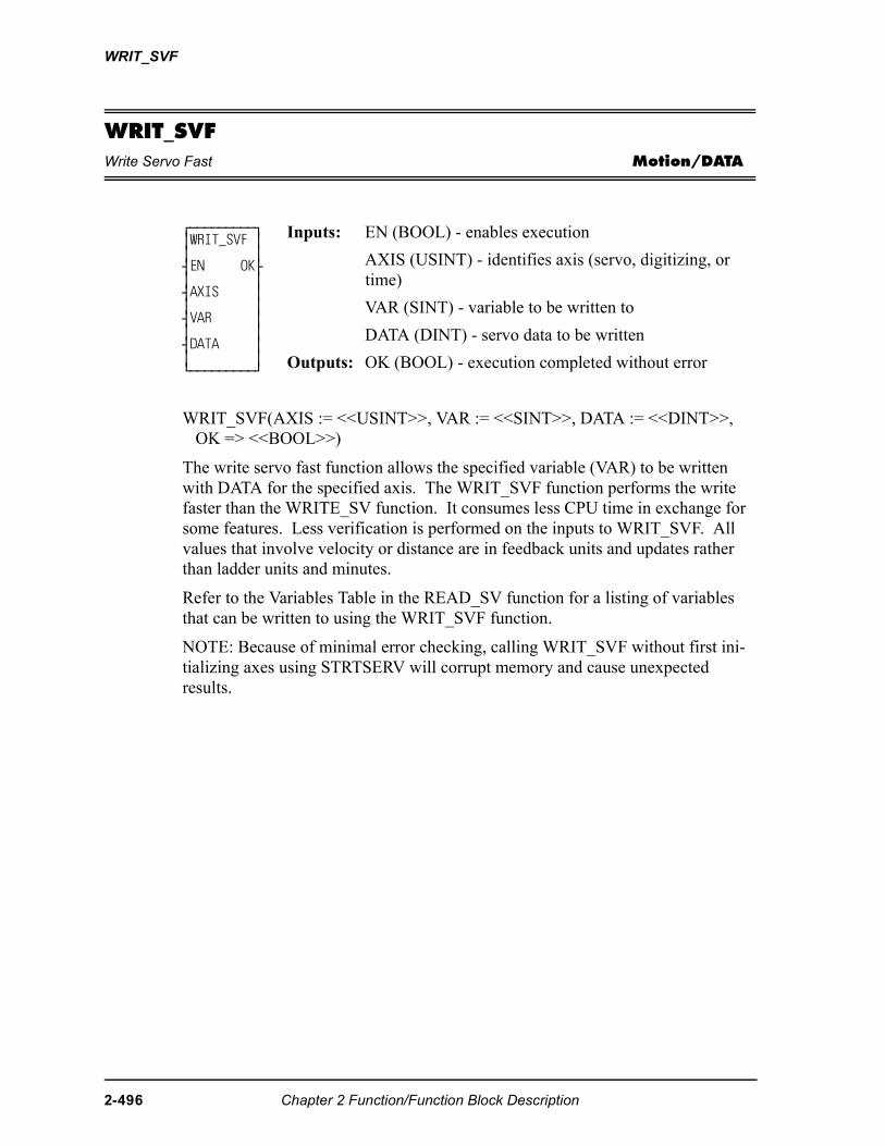
WRIT_SVF
WRIT_SVFWrite Servo Fast Motion/DATA
WRIT_SVF(AXIS := <<USINT>>, VAR := <<SINT>>, DATA := <<DINT>>, OK => <<BOOL>>)
The write servo fast function allows the specified variable (VAR) to be written with DATA for the specified axis. The WRIT_SVF function performs the write faster than the WRITE_SV function. It consumes less CPU time in exchange for some features. Less verification is performed on the inputs to WRIT_SVF. All values that involve velocity or distance are in feedback units and updates rather than ladder units and minutes.
Refer to the Variables Table in the READ_SV function for a listing of variables that can be written to using the WRIT_SVF function.
NOTE: Because of minimal error checking, calling WRIT_SVF without first ini-tializing axes using STRTSERV will corrupt memory and cause unexpected results.
⁄ƒƒƒƒƒƒƒƒƒø ≥WRIT_SVF ≥ ≥ ≥ ¥EN OK√ ≥ ≥ ¥AXIS ≥ ≥ ≥ ¥VAR ≥ ≥ ≥ ¥DATA ≥ ≥ ≥ ¿ƒƒƒƒƒƒƒƒƒŸ
Inputs: EN (BOOL) - enables execution
AXIS (USINT) - identifies axis (servo, digitizing, or time)
VAR (SINT) - variable to be written to
DATA (DINT) - servo data to be written
Outputs: OK (BOOL) - execution completed without error
2-496 Chapter 2 Function/Function Block Description
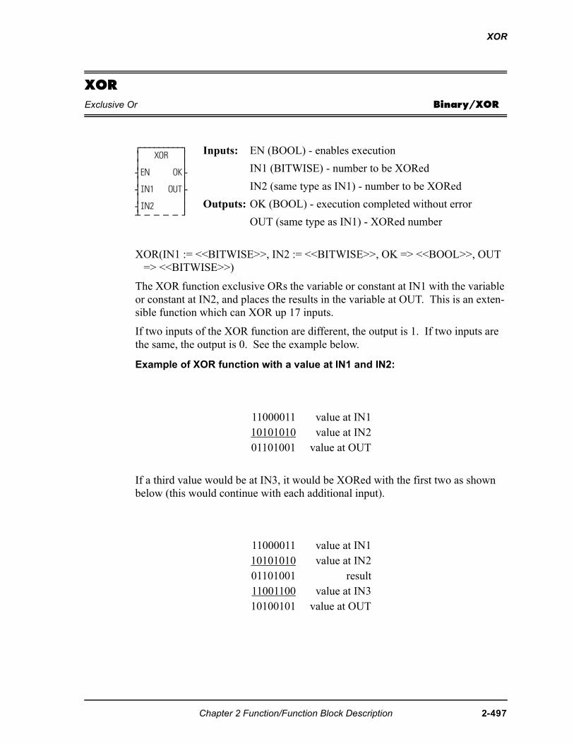
XOR
XORExclusive Or Binary/XOR
XOR(IN1 := <<BITWISE>>, IN2 := <<BITWISE>>, OK => <<BOOL>>, OUT => <<BITWISE>>)
The XOR function exclusive ORs the variable or constant at IN1 with the variable or constant at IN2, and places the results in the variable at OUT. This is an exten-sible function which can XOR up 17 inputs.
If two inputs of the XOR function are different, the output is 1. If two inputs are the same, the output is 0. See the example below.
Example of XOR function with a value at IN1 and IN2:
If a third value would be at IN3, it would be XORed with the first two as shown below (this would continue with each additional input).
⁄ƒƒƒƒƒƒƒƒƒø ≥ XOR ≥ ≥ ≥ ¥EN OK√ ≥ ≥ ¥IN1 OUT√ ≥ ≥ ¥IN2 ≥ ¡ ƒ ƒ ƒ ƒ Ÿ
Inputs: EN (BOOL) - enables execution
IN1 (BITWISE) - number to be XORed
IN2 (same type as IN1) - number to be XORed
Outputs: OK (BOOL) - execution completed without error
OUT (same type as IN1) - XORed number
11000011 value at IN110101010 value at IN201101001 value at OUT
11000011 value at IN110101010 value at IN201101001 result11001100 value at IN310100101 value at OUT
Chapter 2 Function/Function Block Description 2-497

XOR
2-498 Chapter 2 Function/Function Block Description

A.1 - Operator Interface ASFB
Your TrueView and Cimrex operator interface device requires the following ASFBs in your LDO to set up communications between the PiC and the operator interface device.
A.1 - 1
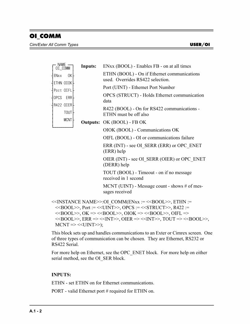
OI_COMMCim/Exter All Comm Types USER/OI
<<INSTANCE NAME>>:OI_COMM(ENxx := <<BOOL>>, ETHN := <<BOOL>>, Port := <<UINT>>, OPCS := <<STRUCT>>, R422 := <<BOOL>>, OK => <<BOOL>>, OIOK => <<BOOL>>, OIFL => <<BOOL>>, ERR => <<INT>>, OIER => <<INT>>, TOUT => <<BOOL>>, MCNT => <<UINT>>);
This block sets up and handles communications to an Exter or Cimrex screen. One of three types of communication can be chosen. They are Ethernet, RS232 or RS422 Serial.
For more help on Ethernet, see the OPC_ENET block. For more help on either serial method, see the OI_SER block.
INPUTS:
ETHN - set ETHN on for Ethernet communications.
PORT - valid Ethernet port # required for ETHN on.
⁄ƒ NAME ƒƒø ≥ OI_COMM ≥ ≥ ≥ ¥ENxx OK√ ≥ ≥ ¥ETHN OIOK√ ≥ ≥ ¥Port OIFL√ ≥ ≥ ¥OPCS ERR√ ≥ ≥ ¥R422 OIER√ ≥ ≥ ≥ TOUT√ ≥ ≥ ≥ MCNT√ ≥ ≥ ¿ƒƒƒƒƒƒƒƒƒŸ
Inputs: ENxx (BOOL) - Enables FB - on at all times
ETHN (BOOL) - On if Ethernet communications used. Overrides RS422 selection.
Port (UINT) - Ethernet Port Number
OPCS (STRUCT) - Holds Ethernet communication data
R422 (BOOL) - On for RS422 communications - ETHN must be off also
Outputs: OK (BOOL) - FB OK
OIOK (BOOL) - Communications OK
OIFL (BOOL) - OI or communications failure
ERR (INT) - see OI_SERR (ERR) or OPC_ENET (ERR) help
OIER (INT) - see OI_SERR (OIER) or OPC_ENET (DERR) help
TOUT (BOOL) - Timeout - on if no message received in 1 second
MCNT (UINT) - Message count - shows # of mes-sages received
A.1 - 2
OPCS - Structure to hold Ethernet status data for debug and ladder use - see OPC_ENET help.
R422 - If ETHN is off and this is off, RS232 communications are used. Turn R422 on for RS422 communications.
OUTPUTS:
OK - Ethernet or serial communications established OK.
OIOK - Operator station communications OK.
OIFL - any communication failure. Will also put a value in one of the two error numbers.
ERR - Error number - See OI_SER (OIER) or OPC_ENET (DERR) help.
OIER - Operator interface error number - See OI_SER (OIER) or OPC_ENET (DERR) help depending on method being used.
TOUT - Timeout - message not received in 1 second. Use to create ladder action for loss of screen communications.
MCNT - Message count - total messages received from operator interface.
A.1 - 3
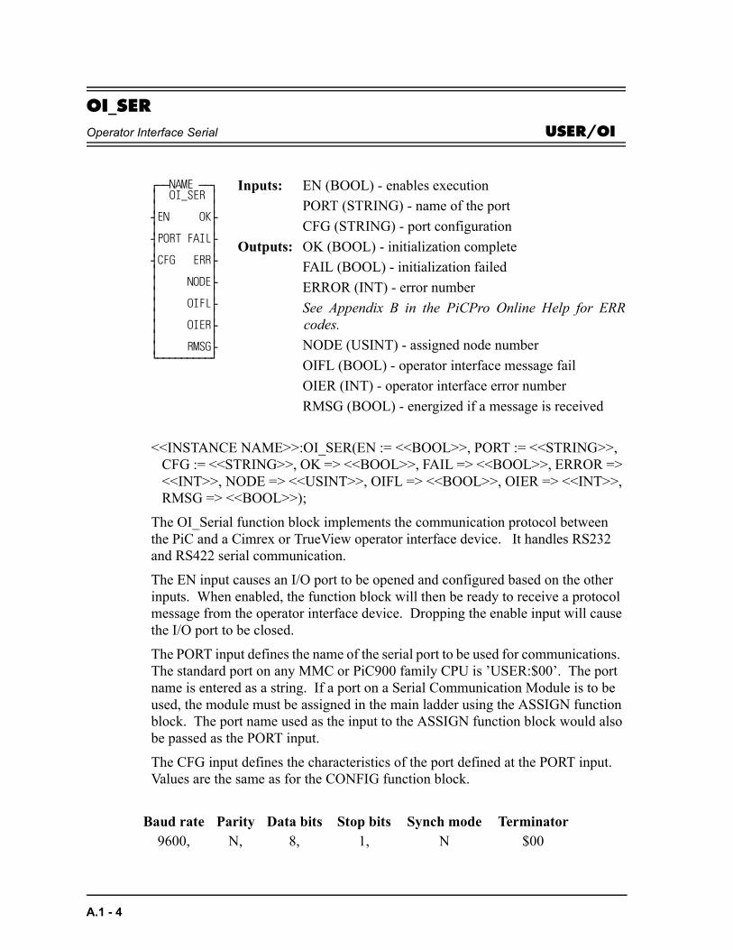
OI_SEROperator Interface Serial USER/OI
<<INSTANCE NAME>>:OI_SER(EN := <<BOOL>>, PORT := <<STRING>>, CFG := <<STRING>>, OK => <<BOOL>>, FAIL => <<BOOL>>, ERROR => <<INT>>, NODE => <<USINT>>, OIFL => <<BOOL>>, OIER => <<INT>>, RMSG => <<BOOL>>);
The OI_Serial function block implements the communication protocol between the PiC and a Cimrex or TrueView operator interface device. It handles RS232 and RS422 serial communication.
The EN input causes an I/O port to be opened and configured based on the other inputs. When enabled, the function block will then be ready to receive a protocol message from the operator interface device. Dropping the enable input will cause the I/O port to be closed.
The PORT input defines the name of the serial port to be used for communications. The standard port on any MMC or PiC900 family CPU is ’USER:$00’. The port name is entered as a string. If a port on a Serial Communication Module is to be used, the module must be assigned in the main ladder using the ASSIGN function block. The port name used as the input to the ASSIGN function block would also be passed as the PORT input.
The CFG input defines the characteristics of the port defined at the PORT input. Values are the same as for the CONFIG function block.
⁄ƒƒNAME ƒƒø ≥ OI_SER ≥ ≥ ≥ ¥EN OK√ ≥ ≥ ¥PORT FAIL√ ≥ ≥ ¥CFG ERR√ ≥ ≥ ≥ NODE√ ≥ ≥ ≥ OIFL√ ≥ ≥ ≥ OIER√ ≥ ≥ ≥ RMSG√ ¿ƒƒƒƒƒƒƒƒƒŸ
Inputs: EN (BOOL) - enables execution
PORT (STRING) - name of the port
CFG (STRING) - port configuration
Outputs: OK (BOOL) - initialization complete
FAIL (BOOL) - initialization failed
ERROR (INT) - error number
See Appendix B in the PiCPro Online Help for ERRcodes.
NODE (USINT) - assigned node number
OIFL (BOOL) - operator interface message fail
OIER (INT) - operator interface error number
RMSG (BOOL) - energized if a message is received
Baud rate Parity Data bits Stop bits Synch mode Terminator9600, N, 8, 1, N $00
A.1 - 4
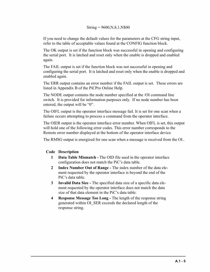
If you need to change the default values for the parameters at the CFG string input, refer to the table of acceptable values found at the CONFIG function block.
The OK output is set if the function block was successful in opening and configuring the serial port. It is latched and reset only when the enable is dropped and enabled again.
The FAIL output is set if the function block was not successful in opening and configuring the serial port. It is latched and reset only when the enable is dropped and enabled again.
The ERR output contains an error number if the FAIL output is set. These errors are listed in Appendix B of the PiCPro Online Help.
The NODE output contains the node number specified at the /OI command line switch. It is provided for information purposes only. If no node number has been entered, the output will be “0”.
The OIFL output is the operator interface message fail. It is set for one scan when a failure occurs attempting to process a command from the operator interface.
The OIER output is the operator interface error number. When OIFL is set, this output will hold one of the following error codes. This error number corresponds to the Remote error number displayed at the bottom of the operator interface device
The RMSG output is energized for one scan when a message is received from the OI..
String = 9600,N,8,1,N$00
Code Description1 Data Table Mismatch - The OID file used in the operator interface
configuration does not match the PiC’s data table.2 Index Number Out of Range - The index number of the data ele-
ment requested by the operator interface is beyond the end of the PiC’s data table.
3 Invalid Data Size - The specified data size of a specific data ele-ment requested by the operator interface does not match the data size of that data element in the PiC’s data table.
4 Response Message Too Long - The length of the response string generated within OI_SER exceeds the declared length of the response string.
A.1 - 5

NOTES
A.1 - 6

B.1 - OPC Server ASFB
The OPC [OLE (Object Linking and Embedding) for Process Control] Server was designed to read and write data to and from the control via Ethernet.
B.1 - 1
OPC_ENETOPC_Ethernet USER/OPC_ENET
<<INSTANCE NAME>>:OPC_ENET(EN := <<BOOL>>, SLOT := <<USINT>>, PORT :=<<UINT>>, STAT:=<<MEMORY AREA>>, OK => <<BOOL>>, FAIL => <<BOOL>>, ERR => <<INT>>, DERR => <<INT>>);
The OPC_ENET function block enables the control to communicate with the G&L Motion Control OPC Server. It provides a protocol for this communication and error checking capabilities for the data sent. Any OPC compliant client can be used with the OPC server.
The function block is configured as a UDP server. It will service incoming UDP requests but will not solicit information from other controls or PCs.
All the variables to be passed to the OPC Server via this function block must be declared globally within the ladder. For more information on setting up the OPC server, refer to the OPC Server Manual.
When the EN input is set, a UDP socket is created on the TCP/IP module defined in SLOT. It binds that socket to the PORT. It services requests for read or write data from an OPC server.
The PORT input defines the port to be used for Ethernet communications. You must assign an available port number above 1024. Use this same number in your OPC setup to ensure that communications will be established.
The STAT input provides status or debug information on the last message received. It includes a valid message BOOL that can be used to re-trigger a watch dog timer.
The OK output is set if the function block was successful in opening and configuring the port.
The FAIL output is set if the function block was not successful in opening and configuring the port.
The ERR output contains an error number if the FAIL output is set. These are the same errors that can occur in the IP function/function blocks.
⁄ƒƒNAME ƒƒø ≥ OPC_ENET≥ ≥ ≥ ¥EN OK√ ≥ ≥ ¥SLOT FAIL√ ≥ ≥ ¥PORT ERR√ ≥ ≥ ¥STAT DERR√ ¿ƒƒƒƒƒƒƒƒƒŸ
Inputs: EN (BOOL) - enables execution, set every scan
SLOT (USINT) - slot number of Ethernet - TCP/IPmodule in rack
PORT (UINT) - UDP protocol port number Choose any available UDP port above 1024.
STAT (STRUCT) - status of last message received
Outputs: OK (BOOL) - execution complete
FAIL (BOOL) - error, execution incomplete
ERR (INT) - error number from IP functions thatoccurred during execution
DERR (INT) - data transfer errors
B.1 - 2
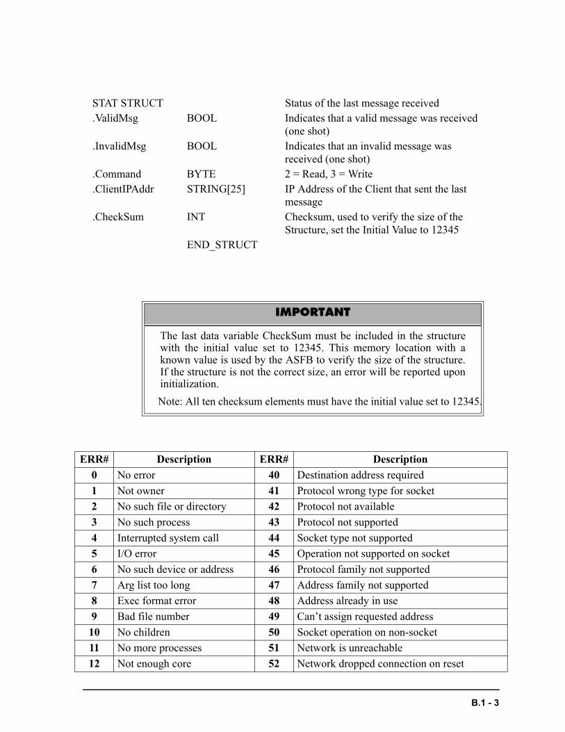
STAT STRUCT Status of the last message received.ValidMsg BOOL Indicates that a valid message was received
(one shot).InvalidMsg BOOL Indicates that an invalid message was
received (one shot).Command BYTE 2 = Read, 3 = Write.ClientIPAddr STRING[25] IP Address of the Client that sent the last
message.CheckSum INT Checksum, used to verify the size of the
Structure, set the Initial Value to 12345END_STRUCT
IMPORTANT
The last data variable CheckSum must be included in the structurewith the initial value set to 12345. This memory location with aknown value is used by the ASFB to verify the size of the structure.If the structure is not the correct size, an error will be reported uponinitialization.
Note: All ten checksum elements must have the initial value set to 12345.
ERR# Description ERR# Description
0 No error 40 Destination address required
1 Not owner 41 Protocol wrong type for socket
2 No such file or directory 42 Protocol not available
3 No such process 43 Protocol not supported
4 Interrupted system call 44 Socket type not supported
5 I/O error 45 Operation not supported on socket
6 No such device or address 46 Protocol family not supported
7 Arg list too long 47 Address family not supported
8 Exec format error 48 Address already in use
9 Bad file number 49 Can’t assign requested address
10 No children 50 Socket operation on non-socket
11 No more processes 51 Network is unreachable
12 Not enough core 52 Network dropped connection on reset
B.1 - 3
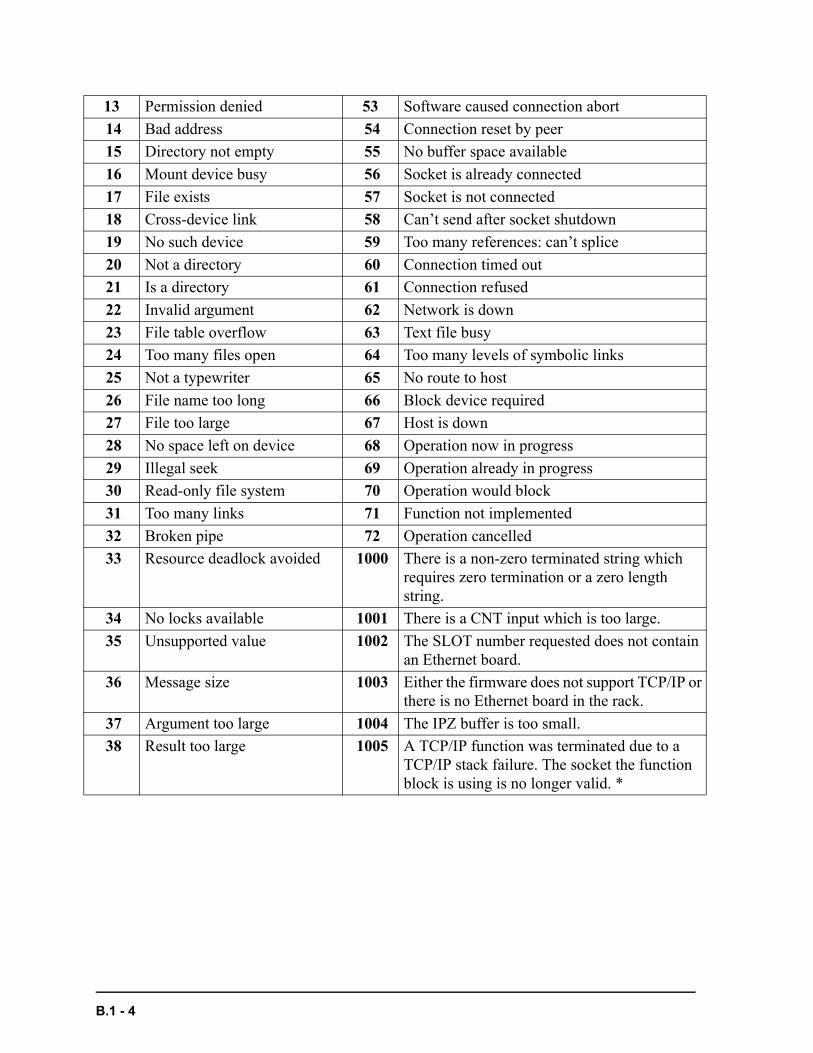
13 Permission denied 53 Software caused connection abort
14 Bad address 54 Connection reset by peer
15 Directory not empty 55 No buffer space available
16 Mount device busy 56 Socket is already connected
17 File exists 57 Socket is not connected
18 Cross-device link 58 Can’t send after socket shutdown
19 No such device 59 Too many references: can’t splice
20 Not a directory 60 Connection timed out
21 Is a directory 61 Connection refused
22 Invalid argument 62 Network is down
23 File table overflow 63 Text file busy
24 Too many files open 64 Too many levels of symbolic links
25 Not a typewriter 65 No route to host
26 File name too long 66 Block device required
27 File too large 67 Host is down
28 No space left on device 68 Operation now in progress
29 Illegal seek 69 Operation already in progress
30 Read-only file system 70 Operation would block
31 Too many links 71 Function not implemented
32 Broken pipe 72 Operation cancelled
33 Resource deadlock avoided 1000 There is a non-zero terminated string which requires zero termination or a zero length string.
34 No locks available 1001 There is a CNT input which is too large.
35 Unsupported value 1002 The SLOT number requested does not contain an Ethernet board.
36 Message size 1003 Either the firmware does not support TCP/IP or there is no Ethernet board in the rack.
37 Argument too large 1004 The IPZ buffer is too small.
38 Result too large 1005 A TCP/IP function was terminated due to a TCP/IP stack failure. The socket the function block is using is no longer valid. *
B.1 - 4
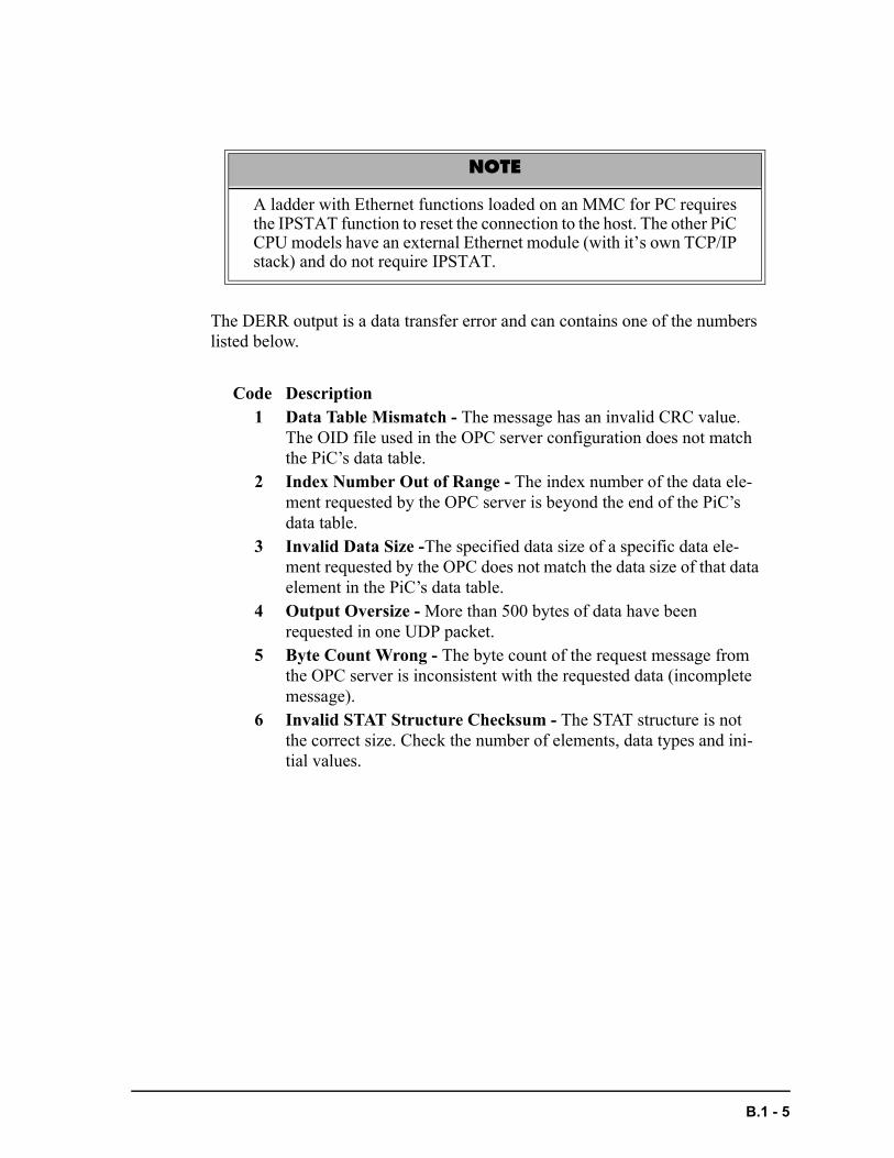
The DERR output is a data transfer error and can contains one of the numbers listed below.
NOTE
A ladder with Ethernet functions loaded on an MMC for PC requiresthe IPSTAT function to reset the connection to the host. The other PiCCPU models have an external Ethernet module (with it’s own TCP/IPstack) and do not require IPSTAT.
Code Description1 Data Table Mismatch - The message has an invalid CRC value.
The OID file used in the OPC server configuration does not match the PiC’s data table.
2 Index Number Out of Range - The index number of the data ele-ment requested by the OPC server is beyond the end of the PiC’s data table.
3 Invalid Data Size -The specified data size of a specific data ele-ment requested by the OPC does not match the data size of that data element in the PiC’s data table.
4 Output Oversize - More than 500 bytes of data have been requested in one UDP packet.
5 Byte Count Wrong - The byte count of the request message from the OPC server is inconsistent with the requested data (incomplete message).
6 Invalid STAT Structure Checksum - The STAT structure is not the correct size. Check the number of elements, data types and ini-tial values.
B.1 - 5
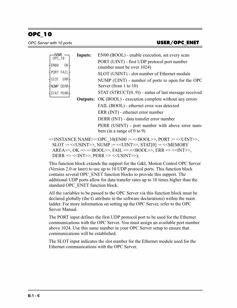
OPC_10OPC Server with 10 ports USER/OPC_ENET
<<INSTANCE NAME>>:OPC_10(EN00 := <<BOOL>>, PORT := <<UINT>>, SLOT := <<USINT>>, NUMP := <<UINT>>, STAT[0] := <<MEMORY AREA>>, OK => <<BOOL>>, FAIL => <<BOOL>>, ERR => <<INT>>, DERR => <<INT>>, PERR => <<USINT>>);
This function block extends the support for the G&L Motion Control OPC Server (Version 2.0 or later) to use up to 10 UDP protocol ports. This function block contains several OPC_ENET function blocks to provide this support. The additional UDP ports allow for data transfer rates up to 10 times higher than the standard OPC_ENET function block.
All the variables to be passed to the OPC Server via this function block must be declared globally (the G attribute in the software declarations) within the main ladder. For more information on setting up the OPC Server, refer to the OPC Server Manual.
The PORT input defines the first UDP protocol port to be used for the Ethernet communications with the OPC Server. You must assign an available port number above 1024. Use this same number in your OPC Server setup to ensure that communications will be established.
The SLOT input indicates the slot number for the Ethernet module used for the Ethernet communications with the OPC Server.
⁄ƒƒNAME ƒƒø ≥ OPC_10 ≥ ≥ ≥ ¥EN00 OK√ ≥ ≥ ¥PORT FAIL√ ≥ ≥ ¥SLOT ERR√ ≥ ≥ ¥NUMP DERR√ ≥ ≥ ¥STAT PERR√ ¿ƒƒƒƒƒƒƒƒƒŸ
Inputs: EN00 (BOOL) - enable execution, set every scan
PORT (UINT) - first UDP protocol port number (number must be over 1024)
SLOT (USINT) - slot number of Ethernet module
NUMP (UINT) - number of ports to open for the OPCServer (from 1 to 10)
STAT (STRUCT(0..9)) - status of last message received
Outputs: OK (BOOL) - execution complete without any errors
FAIL (BOOL) - ethernet error was detected
ERR (INT) - ethernet error number
DERR (INT) - data transfer error number
PERR (USINT) - port number with above error num-bers (in a range of 0 to 9)
B.1 - 6
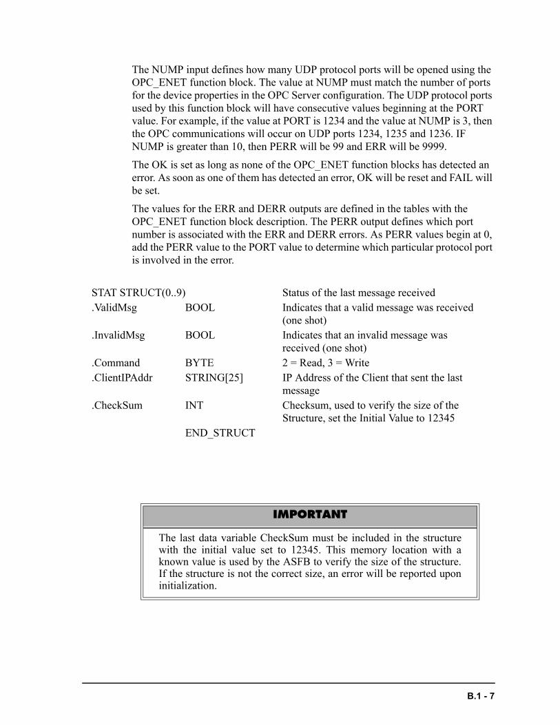
The NUMP input defines how many UDP protocol ports will be opened using the OPC_ENET function block. The value at NUMP must match the number of ports for the device properties in the OPC Server configuration. The UDP protocol ports used by this function block will have consecutive values beginning at the PORT value. For example, if the value at PORT is 1234 and the value at NUMP is 3, then the OPC communications will occur on UDP ports 1234, 1235 and 1236. IF NUMP is greater than 10, then PERR will be 99 and ERR will be 9999.
The OK is set as long as none of the OPC_ENET function blocks has detected an error. As soon as one of them has detected an error, OK will be reset and FAIL will be set.
The values for the ERR and DERR outputs are defined in the tables with the OPC_ENET function block description. The PERR output defines which port number is associated with the ERR and DERR errors. As PERR values begin at 0, add the PERR value to the PORT value to determine which particular protocol port is involved in the error.
STAT STRUCT(0..9) Status of the last message received.ValidMsg BOOL Indicates that a valid message was received
(one shot).InvalidMsg BOOL Indicates that an invalid message was
received (one shot).Command BYTE 2 = Read, 3 = Write.ClientIPAddr STRING[25] IP Address of the Client that sent the last
message.CheckSum INT Checksum, used to verify the size of the
Structure, set the Initial Value to 12345END_STRUCT
IMPORTANT
The last data variable CheckSum must be included in the structurewith the initial value set to 12345. This memory location with aknown value is used by the ASFB to verify the size of the structure.If the structure is not the correct size, an error will be reported uponinitialization.
B.1 - 7

NOTES
B.1 - 8
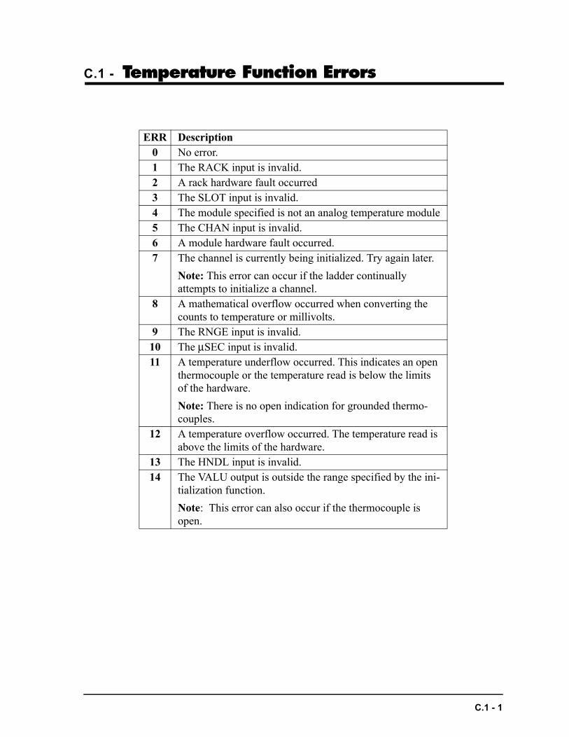
C.1 - Temperature Function Errors
ERR Description0 No error.1 The RACK input is invalid.2 A rack hardware fault occurred3 The SLOT input is invalid.4 The module specified is not an analog temperature module5 The CHAN input is invalid.6 A module hardware fault occurred.7 The channel is currently being initialized. Try again later.
Note: This error can occur if the ladder continually attempts to initialize a channel.
8 A mathematical overflow occurred when converting the counts to temperature or millivolts.
9 The RNGE input is invalid.10 The µSEC input is invalid.11 A temperature underflow occurred. This indicates an open
thermocouple or the temperature read is below the limits of the hardware.
Note: There is no open indication for grounded thermo-couples.
12 A temperature overflow occurred. The temperature read is above the limits of the hardware.
13 The HNDL input is invalid.14 The VALU output is outside the range specified by the ini-
tialization function.
Note: This error can also occur if the thermocouple is open.
C.1 - 1

C.1 - 2
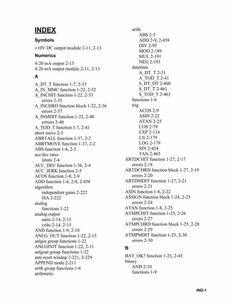
INDEXSymbols
±10V DC output module 2-11, 2-13
Numerics
4-20 mA output 2-134-20 mA output module 2-11, 2-13
A
A_DT_T function 1-7, 2-31A_IN_MMC function 1-22, 2-32A_INCHIT function 1-22, 2-33
errors 2-35A_INCHRD function block 1-22, 2-36
errors 2-37A_INMDIT function 1-22, 2-40
errrors 2-40A_TOD_T function 1-7, 2-41abort move 2-3ABRTALL function 1-37, 2-2ABRTMOVE function 1-37, 2-2ABS function 1-6, 2-3acc/dec rates
limits 2-4ACC_DEC function 1-36, 2-4ACC_JERK function 2-5ACOS function 1-8, 2-9ADD function 1-6, 2-9, 2-458algorithm
independent gains 2-222ISA 2-222
analogfunctions 1-22
analog outputunits 2-14, 2-15volts 2-14, 2-15
AND function 1-9, 2-10ANLG_OUT function 1-22, 2-13anlgin group functions 1-22ANLGINIT function 1-22, 2-11anlgout group functions 1-22anti-reset windup 2-221, 2-229APPEND mode 2-211arith group functions 1-6arithmetic
arithABS 2-3ADD 2-9, 2-458DIV 2-95MOD 2-189MUL 2-191NEG 2-193
datetimeA_DT_T 2-31A_TOD_T 2-41S_DT_DT 2-460S_DT_T 2-461S_TOD_T 2-463
functions 1-6trig
ACOS 2-9ASIN 2-22ATAN 2-25COS 2-79EXP 2-114LN 2-179LOG 2-179SIN 2-424TAN 2-465
ARTDCHIT function 1-27, 2-17errors 2-18
ARTDCHRD function block 1-27, 2-19errors 2-20
ARTDMDIT function 1-27, 2-21errors 2-21
ASIN function 1-8, 2-22ASSIGN function block 1-24, 2-23
errors 2-24ATAN function 1-8, 2-25ATMPCHIT function 1-25, 2-26
errors 2-27ATMPCHRD function block 1-25, 2-28
errors 2-29ATMPMDIT function 1-25, 2-30
errors 2-30
B
BAT_OK? function 1-23, 2-43binary
AND 2-10functions 1-9
IND-1
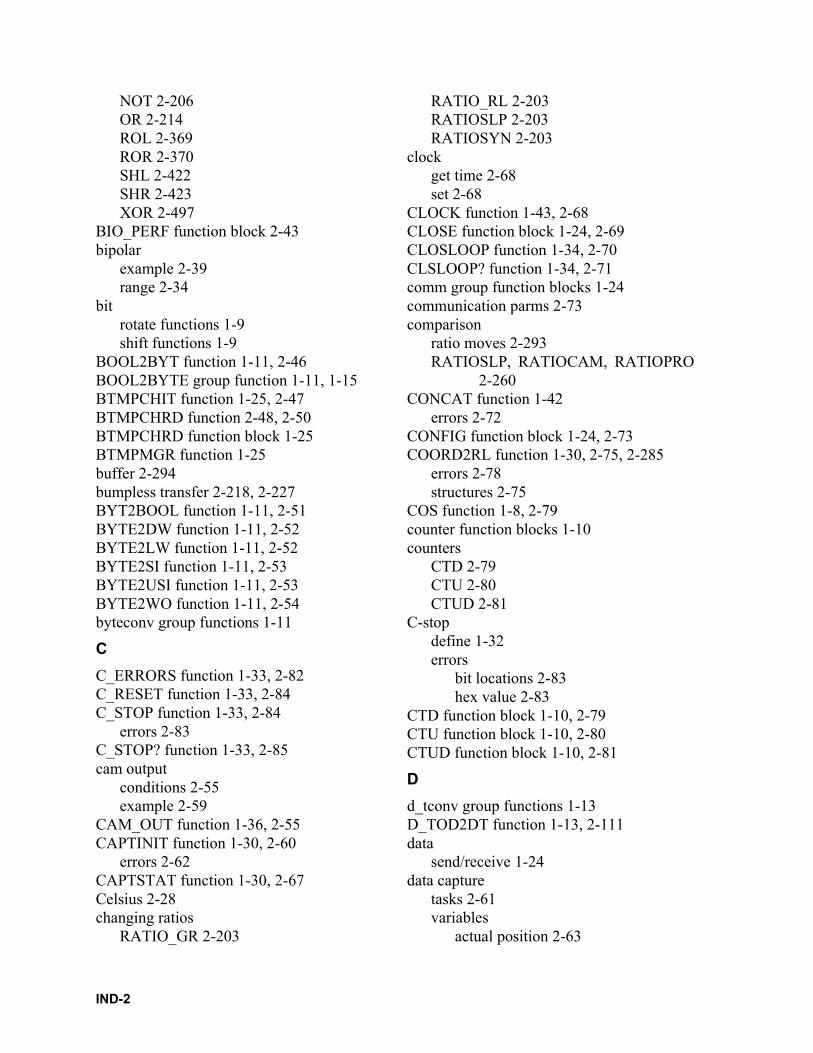
NOT 2-206OR 2-214ROL 2-369ROR 2-370SHL 2-422SHR 2-423XOR 2-497
BIO_PERF function block 2-43bipolar
example 2-39range 2-34
bitrotate functions 1-9shift functions 1-9
BOOL2BYT function 1-11, 2-46BOOL2BYTE group function 1-11, 1-15BTMPCHIT function 1-25, 2-47BTMPCHRD function 2-48, 2-50BTMPCHRD function block 1-25BTMPMGR function 1-25buffer 2-294bumpless transfer 2-218, 2-227BYT2BOOL function 1-11, 2-51BYTE2DW function 1-11, 2-52BYTE2LW function 1-11, 2-52BYTE2SI function 1-11, 2-53BYTE2USI function 1-11, 2-53BYTE2WO function 1-11, 2-54byteconv group functions 1-11
C
C_ERRORS function 1-33, 2-82C_RESET function 1-33, 2-84C_STOP function 1-33, 2-84
errors 2-83C_STOP? function 1-33, 2-85cam output
conditions 2-55example 2-59
CAM_OUT function 1-36, 2-55CAPTINIT function 1-30, 2-60
errors 2-62CAPTSTAT function 1-30, 2-67Celsius 2-28changing ratios
RATIO_GR 2-203
RATIO_RL 2-203RATIOSLP 2-203RATIOSYN 2-203
clockget time 2-68set 2-68
CLOCK function 1-43, 2-68CLOSE function block 1-24, 2-69CLOSLOOP function 1-34, 2-70CLSLOOP? function 1-34, 2-71comm group function blocks 1-24communication parms 2-73comparison
ratio moves 2-293RATIOSLP, RATIOCAM, RATIOPRO
2-260CONCAT function 1-42
errors 2-72CONFIG function block 1-24, 2-73COORD2RL function 1-30, 2-75, 2-285
errors 2-78structures 2-75
COS function 1-8, 2-79counter function blocks 1-10counters
CTD 2-79CTU 2-80CTUD 2-81
C-stopdefine 1-32errors
bit locations 2-83hex value 2-83
CTD function block 1-10, 2-79CTU function block 1-10, 2-80CTUD function block 1-10, 2-81
D
d_tconv group functions 1-13D_TOD2DT function 1-13, 2-111data
send/receive 1-24data capture
tasks 2-61variables
actual position 2-63
IND-2
command change 2-63, 2-64commanded position 2-63fast input occurred 2-63feedback position 2-63filter error 2-63position change 2-63, 2-64position error 2-63prefilter command change 2-63, 2-64prefilter commanded 2-63remaining master offset 2-64remaining slave offset 2-64
datatypeBOOL2BYT 2-46byteconv
BYT2BOOL 2-51BYTE2DW 2-52BYTE2LW 2-52BYTE2SI 2-53BYTE2USI 2-53BYTE2WO 2-54
d_tconvD_TOD2DT 2-111DATE2STR 2-86DT2DATE 2-103, 2-104DT2STR 2-104DT2TOD 2-105TIM2UDIN 2-466
dintconvDINT2DW 2-89DINT2INT 2-89DINT2LI 2-90DINT2SI 2-91DINT2UDI 2-91
dwordcnvDWOR2BYT 2-108DWOR2DI 2-109DWOR2LW 2-109DWOR2RE 2-110DWOR2UDI 2-110DWOR2WO 2-111
intconvINT2DINT 2-143INT2LINT 2-143INT2SINT 2-144INT2UINT 2-144INT2WORD 2-145
lintconvLINT2DI 2-176LINT2INT 2-176LINT2LR 2-177LINT2LW 2-177LINT2SI 2-178LINT2ULI 2-178
lrealcnvLREA2LI 2-180LREA2LW 2-180LREA2RE 2-181LREA2ULI 2-181
lwordcnvLWOR2BYT 2-183LWOR2DW 2-184LWOR2LR 2-185LWOR2WO 2-186LWORD2ULI 2-185
NUM2STR 2-209realconv
REAL2DI 2-349REAL2DW 2-349REAL2LR 2-350REAL2UDI 2-350, 2-351
sintconvSINT2BYT 2-424SINT2DI 2-425SINT2INT 2-425SINT2LI 2-426SINT2USI 2-426
strconvSTR2NUM 2-454STR2USI 2-454
udintcnvUDIN2DI 2-476UDIN2DW 2-476UDIN2RE 2-477UDIN2TIM 2-477UDIN2ULI 2-478
uintconvUINT2ULI 2-480
ulintcnvULIN2LI 2-482ULIN2LR 2-482ULIN2LW 2-483ULIN2UDI 2-483
IND-3
ULIN2UI 2-484ULIN2USI 2-484
usintcnvUSIN2STR 2-486USIN2ULI 2-488
wordconvWORD2BYT 2-491WORD2DW 2-491WORD2INT 2-492WORD2LW 2-492WORD2UI 2-493
datatype functions 1-11DATE2STR function 1-13, 2-86datetime group functions 1-7deadband 2-221, 2-228DELETE function 1-42, 2-87DELFIL function block 1-24, 2-88derivative 2-218
control 2-218DeviceNet
if status code 2-133if status flags 2-133network status 2-132network status flags 2-132
digitizing axes 2-170, 2-308, 2-313, 2-315, 2-317, 2-319, 2-323
DINT2DW function 1-12, 2-89DINT2INT function 1-12, 2-89DINT2LI function 1-12, 2-90DINT2RE function 1-12DINT2SI function 1-12, 2-91DINT2UDI function 1-12, 2-91dintconv group functions 1-12DIRECT function block 1-24, 2-92DISTANCE function 1-35, 2-94DIV function 1-6, 2-95DLS_INIT function block 1-30DLS_RECV function block 1-30DLS_SEND function 1-30DLS_STAT function block 1-30DNS (Domain Name Server) 2-154, 2-156DOS
file read/write 1-24DPOSMODE function 1-35, 2-101DRSETFLT function 1-34DRSTRTSRV function 1-34
DT2DATE function 1-13, 2-103, 2-104DT2STR function 1-13, 2-104DT2TOD function 1-13, 2-105DTORQCMD function 1-35, 2-106DVELCMD function 1-35, 2-107DWOR2BYT function 1-12, 2-108DWOR2DI function 1-12, 2-109DWOR2LW function 1-12, 2-109DWOR2RE function 1-12, 2-110DWOR2UDI function 1-12, 2-110DWOR2WO function 1-12, 2-111dwordcnv group functions 1-12
E
E_ERRORS function 1-33, 2-115E_RESET function 1-33, 2-117E_STOP function 1-33, 2-117E_STOP? function 1-33, 2-118encoder 2-122, 2-169
ignore index 2-123, 2-170end a move
ratio gear 2-139syn end 2-459vel end 2-488
EQ function 1-18, 2-112ERR errors 2-409error (registration)
accumulate 2-357errors
C-stop 1-32ERR 2-409E-stop 1-32programming 1-32SERCOS 2-409SERR 2-412temperature function C.1 - 1timing 1-32
E-stopdefine 1-32errors
bit locations 2-116hex value 2-116
reset 2-117ethernet-TCP/IP
errors 2-166ethernet-TCP/IP functions
IND-4
IPACCEPT 2-150IPCLOSE 2-151IPCONN 2-152IPHOST 2-153IPIP2NAM 2-154IPLISTEN 2-155IPNAM2IP 2-156IPREAD 2-157IPRECV 2-158IPSEND 2-160IPSOCK 2-161IPWRITE 2-163
evaluateEQ 2-112GE 2-137GT 2-140LE 2-172LT 2-182NE 2-193
evaluate functions 1-18EXIST? function 1-34, 2-113EXP function 1-8, 2-114
F
Fahrenheit 2-28FAST_QUE function 1-37, 2-119, 2-237
programming error 2-120, 2-237uses 2-119
FAST_REF function 1-39, 1-40, 1-41, 2-122FB_CLS function block 1-20, 2-127FB_OPN function block 1-20, 2-128FB_RCV function 1-20, 2-129FB_SND function 1-20, 2-130FB_STA function 1-20, 2-131feedrate
changeall moves 2-371
field bus function/blocksFB_CLS 2-127FB_OPN 2-128FB_RCV 2-129FB_SND 2-130FB_STA 2-131
filterLIMIT 2-175MAX 2-187
MIN 2-189MOVE 2-190MUX 2-192SEL 2-420
filter functions 1-20, 1-21filter value
derivative 2-220proportional 2-220
FIND function 1-42, 2-134FRESPACE function block 1-24FU2LU function 1-30functions
menu 1-2
G
GE function 1-18, 2-137GETDAY function 1-43, 2-138GR_END function 1-38, 2-139GT function 1-18, 2-140
H
HOLD function 1-36, 2-140HOLD_END function 1-36, 2-141
I
I/O function blocks 1-22IDN
147 2-385148 2-373
IN_POS? function 1-36, 2-145INSERT function 1-42, 2-142INT2DINT function 1-13, 2-143INT2LINT function 1-13, 2-143INT2SINT function 1-13, 2-144INT2UINT function 1-13, 2-144INT2WORD function 1-13, 2-145intconv group functions 1-13integral 2-218
control 2-218io
anlginA_INCHIT 2-33A_INCHRD 2-36A_INMDIT 2-40
anlgoutANLG_OUT 2-13
IND-5
ANLGINIT 2-11BAT_OK? 2-43BIO_PERF 2-43comm
ASSIGN 2-23CLOSE 2-69CONFIG 2-73DELFIL 2-88DIRECT 2-92OPEN 2-211READ 2-294RENAME 2-361SEEK 2-418WRITE 2-494
JKthermATMPCHIT 2-26ATMPCHRD 2-28ATMPMDIT 2-30BTMPCHIT 2-47BTMPCHRD 2-48, 2-50
networkNETCLS 2-194NETFRE 2-194NETMON 2-195NETOPEN 2-196NETRCV 2-198NETSND 2-200NETSTA 2-202
PID 2-218PID2 2-226READFDBK 2-296rtdtemp
ARTDCHIT 2-17ARTDCHRD 2-19ARTDMDIT 2-21
socketsIPSTAT 2-162
stepperSTEP_POS 2-452STEPCNTL 2-433STEPINIT 2-437
IP socketerror numbers B.1 -2
IPACCEPT function block 1-28, 2-150IPCLOSE function block 1-28, 2-151IPCONN function block 1-28, 2-152
IPHOST function block 2-153IPHOSTID function block 1-28IPIP2NAM function block 1-28, 2-154IPLISTEN function block 1-28, 2-155IPNAM2IP function block 1-28, 2-156IPREAD function block 1-28, 2-157IPRECV function block 1-28IPRECV funtion block 2-158IPSEND function block 1-28, 2-160IPSOCK function block 1-28, 2-161IPSTAT function 1-28, 2-162IPWRITE function block 1-28, 2-163
J
jerks 2-414J-K thermocouple module 2-28
L
LAD_REF function 1-39, 1-40, 1-41, 2-126,2-169
ladder reference 2-169ladder units 1-29LE function 1-18, 2-172LEFT function 1-42, 2-173LEN function 1-42, 2-174less than 2-182LIMIT function 1-21, 2-175LINT2DI function 1-14, 2-176LINT2INT function 1-14, 2-176LINT2LR function 1-14, 2-177LINT2LW function 1-14, 2-177LINT2SI function 1-14, 2-178LINT2ULI function 1-14, 2-178lintconv group functions 1-14LN function 1-8, 2-179LOG function 1-8, 2-179loss of feedback 2-116LREA2LI function 1-14, 2-180LREA2LW function 1-14, 2-180LREA2RE function 1-14, 2-181LREA2ULI function 1-14, 2-181lrealcnv group functions 1-14LT function 1-18, 2-182LU2FU function 1-30LWOR2BYT function 1-14, 2-183LWOR2DW function 1-14, 2-184
IND-6
LWOR2LI function 1-14, 2-184LWOR2LR function 1-14, 2-185LWOR2ULI function 1-14, 2-185LWOR2WO function 1-14, 2-186lwordcnv group functions 1-14LWR_CASE function 1-42
M
machine reference 2-122, 2-169machine reference switch
set up 2-125master/slave moves
programming errors 2-237ratio gear 2-282ratio slope 2-260ratio synchronization 2-272
math coprocessor 2-1MAX function 1-21, 2-187MEASURE function 1-36, 2-187MID function 1-42, 2-188MIN function 1-21, 2-189MMC
A_IN_MMC function 2-32MOD function 1-6, 2-189mode
APPEND 2-211READ 2-211WRITE 2-211
module 2-13±10V DC output 2-11, 2-134-20 mA output 2-11J-K thermocouple 2-28
MotionINIT
EXIST? 1-34, 2-113MOVE_SUP
NO_OFFST 2-207motion
dataCAPINIT 2-62CAPSTAT 2-67COORD2RL 2-75READ_SV 2-307SCA_STAT 2-392STATUSSV 2-431TUNEREAD 2-472
TUNEWRIT 2-473WRITE_SV 2-495
errorsC_ERRORS 2-82C_RESET 2-84C_STOP 2-84C_STOP? 2-85E_ERRORS 2-115E_RESET 2-117E_STOP 2-117E_STOP? 2-118P_ERRORS 2-237P_RESET 2-240TME_ERR? 2-468
initCLOSLOOP 2-70CLSLOOP? 2-71OPENLOOP 2-213STRTSERV 2-455
moveDISTANCE 2-94DPOSMODE 2-101DTORQCMD 2-106DVELCMD 2-107POSTION 2-236VEL_END 2-488VEL_STR 2-489
move_supACC_DEC 2-4ACC_JERK 2-5CAM_OUT 2-55HOLD 2-140HOLD_END 2-141IN_POS 2-145MEASURE 2-187NEW_RATE 2-205NEWRATIO 2-203PLS 2-231PLS_EDIT 2-235R_PERCEN 2-371RATIOSCL 2-256REGIST 2-352SCURVE 2-413VFASTIN 2-490
queABRTALL 2-2
IND-7
ABRTMOVE 2-2FAST_QUE 2-119Q_AVAIL? 2-242Q_NUMBER 2-243
ratiomovGR_END 2-139RATIO_GR 2-282RATIO_RL 2-285RATIOCAM 2-245RATIOSLP 2-260RATIOSYN 2-272REP_END 2-364SYN_END 2-459
refFAST_REF 2-122LAD_REF 2-169PART_CLR 2-215PART_REF 2-216REF_DNE? 2-351REF_END 2-351
motion data group functions 1-30motion error group functions 1-32motion functions 1-29motion init group functions 1-34motion move group functions 1-35motion move_sup group functions 1-36motion que group functions 1-37motion ratiomov group functions 1-38motion ref group functions 1-39, 1-40, 1-41MOVE function 1-21, 2-190moves
distance 2-94position 2-236ratio cam 2-245ratio gear 2-282ratio real 2-285ratio slope 2-260ratio synchronization 2-272velocity start 2-489
MUL function 1-6, 2-191MUX function 1-21, 2-192mV range 2-29
N
NE function 1-18, 2-193NEG function 1-6, 2-193
NETCLS function block 1-26, 2-194NETFRE function block 1-26, 2-194NETMON function block 1-26, 2-195NETOPN function block 1-26, 2-196
errors 2-196NETRCV function block 1-26, 2-198
errors 2-199NETSND function block 1-26, 2-200
errors 2-201NETSTA function block 1-26, 2-202network 1-26
group functions 1-26status 2-195
NEW_RATE function 1-36, 2-205NEWRATIO function 1-36, 2-203NEXNET
function blocks 1-26NO_OFFST function 1-36, 2-207noise filter 2-34NOT function 1-9, 2-206NUM2STR function 1-15, 2-209NUM2STR group function 1-15
O
offsetexamples 2-312
offset bytes 2-418OI_COMM A.1 -2OI_SER A.1 -4OI_SER function block A.1 -4OK_ERROR 2-210OK_ERROR function 1-18one-shot 2-1OPC B.1 -6OPC server B.1 -2OPC_10 function block B.1 -6OPC_ENET function block B.1 -2OPEN function block 1-24, 2-23, 2-211OPENLOOP function 1-34, 2-213OR function 1-9, 2-214origin 2-418
P
P_ERRORS function 1-33, 2-237P_RESET function 1-33, 2-240part reference 2-215
IND-8
part reference offset 2-325PART_CLR function 1-39, 2-215PART_REF function 1-39, 1-41, 2-216photo eye 2-357PID
algorithms 2-222control 2-217equations 2-222, 2-224example network 2-225, 2-230RAMP 2-244structure 2-219, 2-227
pidPWDTY 2-241TAUFFAC 2-465TAUFILT 2-466
PID code 2-329PID command 2-328PID function block 1-27, 2-218
equation terms 2-222PID functions/blocks 1-43PID group function 1-27PID2 function 1-43PID2 function block 2-226PLS 2-55PLS function 1-36, 2-231PLS_EDIT function 1-36, 2-235POSITION function 1-35, 2-236profile
end repeat 2-364profile (step)
example 2-449programming errors
bit locations 2-238, 2-239define 1-32hex value 2-238, 2-239
proportional 2-218control 2-218
PWDTY function 2-241PWDTY function block 1-43
Q
Q_AVAIL? function 1-37, 2-242Q_NUMBER function 1-37, 2-243queue
abort all moves 2-2and fast input 2-119
available 2-242number 1-37
R
R_PERCEN function 1-36, 2-371RAMDISK
read/write 1-24RAMP function 1-43, 2-244ratio gear
characteristics 2-283mechanical representation 2-283
ratio realcharacteristics 2-287structure members 2-44, 2-288
RATIO_GR function 1-38, 2-282RATIO_RL function 1-38, 2-285ratiocam
and scaling 2-258array of structures 2-252characteristics 2-251master start position 2-247profile 2-245slave start position 2-247
RATIOCAM function 1-38, 2-245RATIOSCL function 1-36, 2-256ratioslp
and scaling 2-259array of structures 2-267characteristics 2-262profile 2-268slope 2-270
RATIOSLP function 1-38, 2-260ratiosyn
characteristics 2-275master start position 2-275mechanical representation 2-273rollover on position 2-280slave start position 2-275
RATIOSYN function 1-38, 2-272READ function block 1-24, 2-294READ mode 2-211READ_SV function 1-30, 2-307READ_SV function (see variable servo)READ_SVF function 1-30, 2-348READFDBK function 1-27, 2-296, 2-361READFDBK group function 1-27
IND-9
REAL2DI function 1-15, 2-349REAL2DW function 1-15, 2-349REAL2LR function 1-15, 2-350REAL2UDI function 1-15, 2-350, 2-351realconv group functions 1-15REF_DNE? function 1-39, 2-351REF_END function 1-39, 2-351reference
complete 2-351fast input
define 2-122, 2-169function 2-122
ladderend function 2-351function 2-169
no motion 2-123, 2-170null setup 2-124, 2-171part
clear function 2-215switch setup 2-125
REGIST function 1-36, 2-352registration
background 2-355example 2-355fast input 2-352good marks 2-360master 2-358slave 2-359
remainder 2-189RENAME function block 1-24, 2-361REP_END function 1-38, 2-364REPLACE function 1-42, 2-363RESMODE function 2-365RESMODE? function 1-33resolver
ignore null 2-123, 2-170RESUME function 1-33, 2-366RIGHT function 1-42, 2-368ROL function 1-9, 2-369ROR function 1-9, 2-370RS422/485 2-73RTD
channel read errors 2-20initialize
channel 2-17errors (channel) C.1 - 1
module 2-21temperature range 2-17
RTD functions 1-27RTDtemp group functions 1-27
S
S_D_D function 1-7S_DT_DT function 1-7, 2-460S_DT_T function 1-7, 2-461S_TOD_T function 1-7, 2-463S_TOD_TO function 1-7SC_INIT function block 1-41, 2-372, 2-427SCA_ACKR function block 1-39, 2-373SCA_CLOS function block 1-34, 2-374SCA_CTRL function 1-30, 2-375SCA_ERST function 1-33SCA_ERST function block 2-378, 2-379SCA_PBIT function 1-36SCA_RCYC function 1-30, 2-381SCA_RECV function block 1-30, 2-383SCA_REF function block 1-39, 2-385SCA_RFIT function 1-39SCA_SEND function block 1-30, 2-390SCA_STAT function 1-30, 2-392SCA_WCYC function 1-30, 2-393SCR_CONT function 1-41, 2-394SCR_ERR function block 1-41, 2-395SCR_PHAS function 1-41, 2-398SCS_ACKR function block 1-40, 2-399SCS_CTRL function 1-40, 2-400SCS_RECV function block 1-40, 2-402SCS_REF function block 1-40, 2-404SCS_SEND function block 1-40, 2-406SCS_STAT function 1-40, 2-408SCURVE function 1-36, 2-413SEEK function block 1-24, 2-418SEL function 1-21, 2-420SERCOS
function blocksSC_INIT 2-372, 2-427SCA_ACKR 2-373SCA_CLOS 2-374SCA_ERST 2-378, 2-379SCA_RECV 2-383SCA_REF 2-385SCA_SEND 2-390
IND-10
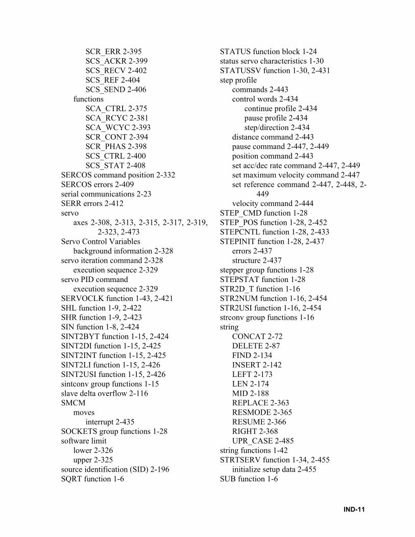
SCR_ERR 2-395SCS_ACKR 2-399SCS_RECV 2-402SCS_REF 2-404SCS_SEND 2-406
functionsSCA_CTRL 2-375SCA_RCYC 2-381SCA_WCYC 2-393SCR_CONT 2-394SCR_PHAS 2-398SCS_CTRL 2-400SCS_STAT 2-408
SERCOS command position 2-332SERCOS errors 2-409serial communications 2-23SERR errors 2-412servo
axes 2-308, 2-313, 2-315, 2-317, 2-319,2-323, 2-473
Servo Control Variablesbackground information 2-328
servo iteration command 2-328execution sequence 2-329
servo PID commandexecution sequence 2-329
SERVOCLK function 1-43, 2-421SHL function 1-9, 2-422SHR function 1-9, 2-423SIN function 1-8, 2-424SINT2BYT function 1-15, 2-424SINT2DI function 1-15, 2-425SINT2INT function 1-15, 2-425SINT2LI function 1-15, 2-426SINT2USI function 1-15, 2-426sintconv group functions 1-15slave delta overflow 2-116SMCM
movesinterrupt 2-435
SOCKETS group functions 1-28software limit
lower 2-326upper 2-325
source identification (SID) 2-196SQRT function 1-6
STATUS function block 1-24status servo characteristics 1-30STATUSSV function 1-30, 2-431step profile
commands 2-443control words 2-434
continue profile 2-434pause profile 2-434step/direction 2-434
distance command 2-443pause command 2-447, 2-449position command 2-443set acc/dec rate command 2-447, 2-449set maximum velocity command 2-447set reference command 2-447, 2-448, 2-
449velocity command 2-444
STEP_CMD function 1-28STEP_POS function 1-28, 2-452STEPCNTL function 1-28, 2-433STEPINIT function 1-28, 2-437
errors 2-437structure 2-437
stepper group functions 1-28STEPSTAT function 1-28STR2D_T function 1-16STR2NUM function 1-16, 2-454STR2USI function 1-16, 2-454strconv group functions 1-16string
CONCAT 2-72DELETE 2-87FIND 2-134INSERT 2-142LEFT 2-173LEN 2-174MID 2-188REPLACE 2-363RESMODE 2-365RESUME 2-366RIGHT 2-368UPR_CASE 2-485
string functions 1-42STRTSERV function 1-34, 2-455
initialize setup data 2-455SUB function 1-6
IND-11
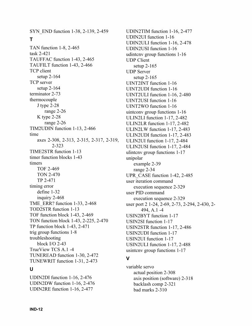
SYN_END function 1-38, 2-139, 2-459
T
TAN function 1-8, 2-465task 2-421TAUFFAC function 1-43, 2-465TAUFILT function 1-43, 2-466TCP client
setup 2-164TCP server
setup 2-164terminator 2-73thermocouple
J type 2-28range 2-26
K type 2-28range 2-26
TIM2UDIN function 1-13, 2-466time
axes 2-308, 2-313, 2-315, 2-317, 2-319,2-323
TIME2STR function 1-13timer function blocks 1-43timers
TOF 2-469TON 2-470TP 2-471
timing errordefine 1-32inquiry 2-468
TME_ERR? function 1-33, 2-468TOD2STR function 1-13TOF function block 1-43, 2-469TON function block 1-43, 2-225, 2-470TP function block 1-43, 2-471trig group functions 1-8troubleshooting
block I/O 2-43TrueView TCS A.1 -4TUNEREAD function 1-30, 2-472TUNEWRIT function 1-31, 2-473
U
UDIN2DI function 1-16, 2-476UDIN2DW function 1-16, 2-476UDIN2RE function 1-16, 2-477
UDIN2TIM function 1-16, 2-477UDIN2UI function 1-16UDIN2ULI function 1-16, 2-478UDIN2USI function 1-16udintcnv group functions 1-16UDP Client
setup 2-165UDP Server
setup 2-165UINT2INT function 1-16UINT2UDI function 1-16UINT2ULI function 1-16, 2-480UINT2USI function 1-16UINT2WO function 1-16uintconv group functions 1-16ULIN2LI function 1-17, 2-482ULIN2LR function 1-17, 2-482ULIN2LW function 1-17, 2-483ULIN2UDI function 1-17, 2-483ULIN2UI function 1-17, 2-484ULIN2USI function 1-17, 2-484ulintcnv group functions 1-17unipolar
example 2-39range 2-34
UPR_CASE function 1-42, 2-485user iteration command
execution sequence 2-329user PID command
execution sequence 2-329user port 2 1-24, 2-69, 2-73, 2-294, 2-430, 2-
494, A.1 -4USIN2BYT function 1-17USIN2SI function 1-17USIN2STR function 1-17, 2-486USIN2UDI function 1-17USIN2UI function 1-17USIN2ULI function 1-17, 2-488usintcnv group functions 1-17
V
variable servoactual position 2-308axis position (software) 2-318backlash comp 2-321bad marks 2-310
IND-12
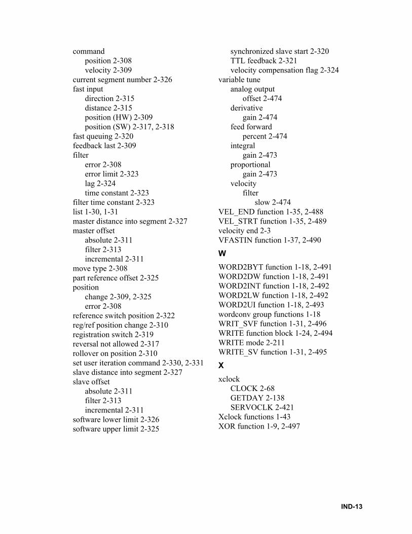
commandposition 2-308velocity 2-309
current segment number 2-326fast input
direction 2-315distance 2-315position (HW) 2-309position (SW) 2-317, 2-318
fast queuing 2-320feedback last 2-309filter
error 2-308error limit 2-323lag 2-324time constant 2-323
filter time constant 2-323list 1-30, 1-31master distance into segment 2-327master offset
absolute 2-311filter 2-313incremental 2-311
move type 2-308part reference offset 2-325position
change 2-309, 2-325error 2-308
reference switch position 2-322reg/ref position change 2-310registration switch 2-319reversal not allowed 2-317rollover on position 2-310set user iteration command 2-330, 2-331slave distance into segment 2-327slave offset
absolute 2-311filter 2-313incremental 2-311
software lower limit 2-326software upper limit 2-325
synchronized slave start 2-320TTL feedback 2-321velocity compensation flag 2-324
variable tuneanalog output
offset 2-474derivative
gain 2-474feed forward
percent 2-474integral
gain 2-473proportional
gain 2-473velocity
filterslow 2-474
VEL_END function 1-35, 2-488VEL_STRT function 1-35, 2-489velocity end 2-3VFASTIN function 1-37, 2-490
W
WORD2BYT function 1-18, 2-491WORD2DW function 1-18, 2-491WORD2INT function 1-18, 2-492WORD2LW function 1-18, 2-492WORD2UI function 1-18, 2-493wordconv group functions 1-18WRIT_SVF function 1-31, 2-496WRITE function block 1-24, 2-494WRITE mode 2-211WRITE_SV function 1-31, 2-495
X
xclockCLOCK 2-68GETDAY 2-138SERVOCLK 2-421
Xclock functions 1-43XOR function 1-9, 2-497
IND-13

NOTES
IND-14


![Cost Function[1]](https://img.pdfslide.net/doc/110x75/577cc6bc1a28aba7119f0266/cost-function1.jpg)


![Cell structure function[1]](https://img.pdfslide.net/doc/110x75/5558b510d8b42a7e298b4b5b/cell-structure-function1-55849eb51b14e.jpg)