Embed Size (px)
Citation preview
A-6
I n (A)
t (s)
RH99MVigirex
DB
1259
80.e
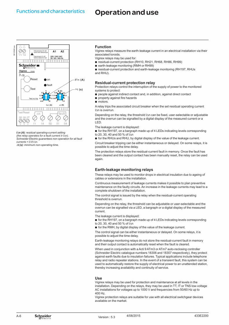
ps FunctionVigirex relays measure the earth-leakage current in an electrical installation via their associated toroids.Vigirex relays may be used for:
b residual-current protection (RH10, RH21, RH68, RH86, RH99) b earth-leakage monitoring (RMH or RH99) b residual-current protection and earth-leakage monitoring (RH197, RHUs
and RHU).
Residual-current protection relayProtection relays control the interruption of the supply of power to the monitored systems to protect:
b people against indirect contact and, in addition, against direct contact b property against fire hazards b motors.
A relay trips the associated circuit breaker when the set residual operating current IDn is overrun. Depending on the relay, the threshold IDn can be fixed, user-selectable or adjustable and the overrun can be signalled by a digital display of the measured current or a LED. The leakage current is displayed:
b for the RH197, on a bargraph made up of 4 LEDs indicating levels corresponding to 20, 30, 40 and 50 % of IDn
b for the RHUs and RHU, by digital display of the value of the leakage current.Circuit breaker tripping can be either instantaneous or delayed. On some relays, it is possible to adjust the time delay.The protection relays store the residual-current fault in memory. Once the fault has been cleared and the output contact has been manually reset, the relay can be used again.
Earth-leakage monitoring relaysThese relays may be used to monitor drops in electrical insulation due to ageing of cables or extensions in the installation.Continuous measurement of leakage currents makes it possible to plan preventive maintenance on the faulty circuits. An increase in the leakage currents may lead to a complete shutdown of the installation.The control signal is issued by the relay when the residual-current operating threshold is overrun.Depending on the relay, the threshold can be adjustable or user-selectable and the overrun can be signalled via a LED, a bargraph or a digital display of the measured current.The leakage current is displayed:
b for the RH197, on a bargraph made up of 4 LEDs indicating levels corresponding to 20, 30, 40 and 50 % of IDn
b for the RMH, by digital display of the value of the leakage current. The control signal can be either instantaneous or delayed. On some relays, it is possible to adjust the time delay.Earth-leakage monitoring relays do not store the residual-current fault in memory and their output contact is automatically reset when the fault is cleared.When used in conjunction with a Acti 9 ATm3 or ATm7 auto-reclosing controller (Schneider Electric catalogue numbers 18306 and 18307 respectively), they protect against earth faults due to insulation failures. Typical applications include telephone relay and radio repeater stations. In the event of a transient fault, this system can be used to automatically restore the supply of electrical power to an unattended station, thereby increasing availability and continuity of service.
UseVigirex relays may be used for protection and maintenance at all levels in the installation. Depending on the relays, they may be used in TT, IT or TNS low-voltage AC installations for voltages up to 1000 V and frequencies from 50/60 Hz up to 400 Hz.Vigirex protection relays are suitable for use with all electrical switchgear devices available on the market.
IDn (A): residual operating-current setting(the relay operates for a fault current u IDn).Schneider Electric guarantees non-operation for all fault currents < 0.8 IDn.Dt (s): minimum non-operating time.
Functions and characteristics Operation and use
433E2200Version : 5.3 4/08/2015

A-7
DB
4035
71.e
ps Compliance with standardsVigirex relays are designed to comply with the following standards:
b IEC/EN 60755: general rules for residual-current protection devices b IEC/EN 60947-2 annex M: low-voltage switchgear and controlgear, part 2 (circuit
breakers) b IEC/EN 60947-5-1: low-voltage switchgear and controlgear, part 5-1
(electromechanical devices) b IEC/EN 61000-4-2: electrostatic-discharge immunity test b IEC/EN 61000-4-3: radiated, radio-frequency, electromagnetic-field immunity test b IEC/EN 61000-4-4: electrical fast transient/burst immunity test b IEC/EN 61000-4-5: surge immunity test b IEC/EN 61000-4-6: immunity to conducted disturbances, induced by radio-
frequency fields b CISPR 11: limits and methods of measurement of electromagnetic disturbance
characteristics of industrial, scientific and medical (ISM) radiofrequency equipment b mandatory for CE marking: v EN 61000-6-2: immunity to industrial environments v EN 50081-1: emissions for commercial and residential environments b IEC/EN 60664-1: insulation coordination for equipment within low-voltage
systems, part 1 b EN 50102: degrees of protection provided by electrical enclosures against external
mechanical impact b IEC 60364 and NF C 15100: installation rules for low-voltage electrical distribution b UL 1053 and CSA 22.2 No. 144: relays RH10, RH21 and RH99 up to and including
220/240 V comply with these standards.
Ground fault sensing and relaying equipment UL 1053 and CSA 22.2 No. 144 for North American and North American influenced marketsThe basic standard used to investigate products in this category is UL1053 “Ground-Fault Sensing and Relaying Equipment”.The Listing Mark of Underwriters Laboratories Inc. on the products is the only method provided by UL to identify products manufactured under its Listing and Follow Up Service.The Listing Mark for these products includes the name and/or symbol of Underwriters Laboratories Inc. (as illustrated on the label) together with the word “LISTED”, a control number and the following product name “Ground Fault Sensing and Relaying Equipment”.This category covers ground fault current sensing devices, relaying equipment, or combinations of ground fault current sensing devices and relaying equipment which will operate to cause a disconnecting means to function at predetermined values of ground fault current in accordance with the National Electrical Code, ANSI/NFPA70.The RH99, RH21 and RH10 (M and P) ground fault relays are control powered ground-fault protection devices used to protect an electrical distribution system from ground faults. The relay receives input from sensors, processes the information and if necessary closes output contacts which will cause the associated protection device to trip.The product is a class 1 combination ground fault current sensor and relay. This equipment is intended to operate devices with shunt trip coils such as moulded case circuit breakers, moulded case switches and the like, which constitute the disconnecting means, by opening all ungrounded conductors at predetermined values of ground fault current.This product is designed to protect circuits of not more than 600 V AC, 50/60 Hz only.The relay should be marked with the following electrical ratings, for the two types M and P:
b type M: DIN format (Acti 9 type fast mounting or screw mounting) b type P: front-panel mount (on panel, door, etc.) b ratings: v fixed IDn threshold (a number of choices) and no time delay (instantaneous) or v selectable IDn threshold from 0.03 to 30 A and user-selectable time delay
from 0 to 4.5 s (see settings on pages A-26 to A-35) b input voltages: v AC: 20 to 24 V AC, 48 V AC, 110 to 130V AC or 220 to 240 V AC, 50/60 Hz, or v DC: 12 to 48 V DC b maximum consumption: 4 W.
DB
1010
79.e
ps
The mark indicates that the product meets both US and Canadian safety requirements.
General characteristics
433E2200 Version : 5.3 4/08/2015

A-16
Functions and characteristicsPB
1004
37-3
2_SE
_r.e
ps Relay marking1 Type of relay.4 Customer marking zone (circuit identification).11 Sensitivity (RH10M): IDn (A) / Dt (s).14 Relay class.
Controls7 Press and hold the Reset button, then press the Test button to test the device
without actuating the output contacts.12 Test button.13 Reset button.
Indications5 Green voltage-presence LED (on).6 Red insulation-fault LED (fault).
RH10M
PB10
0440
-32_
SE_r
.eps
LED status Meaningon fault
Normal operationFault current detected
Relay/sensor link faultNo voltage or device not in serviceMalfunction detected
Key:off
( ) green (or red) flashing.
RH21M.
PB
1081
73-4
8.ep
s
Settings15 Threshold and time-delay selectors (RH21): IDn (A) / Dt (s)
Three possible settings: b 0.03 A sensitivity, instantaneous b 0.3 A sensitivity, instantaneous b 0.3 A sensitivity, 0.06 s delay
16 Time-delay selector (RH99): Dt (s) Nine possible settings (instantaneous – 0.06 s – 0.15 s – 0.25 s – 0.31 s – 0.5 s – 0.8 s – 1 s – 4.5 s).
17 Threshold selector (RH99): IDn (A) Nine possible settings (0.03 A – 0.1 A – 0.3 A – 0.5 A – 1 A – 3 A – 5 A – 10 A – 30 A).
Connection2 Sensor.3 Plug-in supply.8 Fault contact.9 Voltage-presence contact.10 Remote reset/test.
RH�8M.
PB
1081
74-4
8.ep
s
RH8�M.
PB10
0439
-32_
SE_r
.eps
RH99M.
DescriptionRH10M, RH21M, RH68M, RH86M and RH99M relays
433E2300Version : 5.6 4/08/2015

B-7
Connection of relays
DB
1260
21.e
ps Acti 9 format
Déconnecter A1-A2avant test diélectrique
Disconnect A1-A2before dielectric test
A1 A2
220 / 240 VAC50 / 60 / 400 Hz
Vigirex RH99M
RH99MVigirex
DB
4031
48.e
ps(1) See table page B-�.
Front-panel mount format
T
DB
4031
49.e
ps
Connection of toroidsTA30 and PA50 closed toroids (connectors supplied) IA80, MA120, SA200 and GA300 closed toroids
DB
4031
50.e
ps
DB
4031
51.e
ps
(1) See table page B-�. (1) See table page B-�.
433E3300 Version : 1.5 28/07/2015

C-2
Dimensions and connection
Mounting on a DIN railRH10M, RH21M, RH68M, RH86M and RH99M RH197M
DB
4031
47.e
ps
RH10MVigirex
DB
1260
39.e
ps
71.2
8998.7
45
45
65.8
DB
4032
05.e
ps
Mounting on a mounting plateRH10M, RH21M, RH68M, RH86M and RH99M
Plate drilling layout
DB
1260
40.e
ps
RH10MVigirex
DB
1260
41.e
ps
DB
1260
42.e
ps
Door cutout
Mounting on a DIN rail Mounting on a mounting plate
DB
1260
43.e
ps
DB
1260
44.e
ps
72 max.(2)
DB
4149
35.e
ps
(1) For IP4 requirements.(2) For RH197M.
DimensionsRH10M, RH21M, RH68M, RH86M, RH99M and RH197M relays
433E310029/07/2015Version : 5.4

D-2
RH10M, RH21M, RH68M, RH86M and RH99M wiring with MX shunt release
All diagrams are shown with circuits de-energised, all devices open and relays in released position.
See page D-11
DB
4149
36.e
ps
L1: lampMX: shunt releaseQ1: circuit breaker protecting the main circuitQ2: DPN circuit breakerRH10M, RH21M, RH68M, RH86M and RH99M:
b A1-A2: auxiliary power supply b T1-T2: A or TOA type toroid or rectangular sensor
(if IDn u 500 mA) b 11-14: “voltage-presence” contact b 26-25: relay test b 27-25: “fault” reset b 31-32-34: “fault” contact.
Note: for the RH99 earth leakage monitor use the “fault” contact 31, 32, 34.
RH10P, RH21P, RH86P and RH99P wiring with MX shunt releaseL1: lampMX: shunt releaseQ1: circuit breaker protecting the main circuitQ2: DPN circuit breakerRH10P, RH21P, RH86P and RH99P:
b A1-A2: auxiliary power supply b T1-T2: A or TOA type toroid or rectangular sensor
(if IDn u 500 mA) b 11-14: “voltage-presence” contact b 26-25: relay test b 27-25: “fault” reset b 31-32-34: “fault” contact.
See page D-11
DB
4149
47.e
ps
Note: for the RH99 earth leakage monitor use the “fault” contact 31, 32, 34.
Wiring diagrams Wiring diagramsRH10, RH21, RH68, RH86 and RH99M RH10, RH21, RH86 and RH99PWiring for optimum continuity of service
433E3200Version : 5.4 3/08/2015

D-3
RH10M, RH21M, RH68M, RH86M and RH99M wiring with MN undervoltage release
All diagrams are shown with circuits de-energised, all devices open and relays in released position.
DB
4149
37.e
ps See page D-11
MN: undervoltage releaseQ1: circuit breaker protecting the main circuitQ2: DPN circuit breakerRH10M, RH21M, RH68M, RH86M and RH99M:
b A1-A2: auxiliary power supply b T1-T2: A or TOA type toroid or rectangular sensor
(if IDn u 500 mA) b 11-14: “voltage-presence” contact b 26-25: relay test b 27-25: “fault” reset b 31-32-34: “fault” contact.
Note: for the RH99 earth leakage monitor use the “fault” contact 31, 32, 34.
RH10P, RH21P, RH86P and RH99P wiring with MN undervoltage releaseMN: undervoltage releaseQ1: circuit breaker protecting the main circuitQ2: DPN circuit breakerRH10MP, RH21P, RH86P and RH99P:
b A1-A2: auxiliary power supply b T1-T2: A or TOA type toroid or rectangular sensor
(if IDn u 500 mA) b 11-14: “voltage-presence” contact b 26-25: relay test b 27-25: “fault” reset b 31-32-34: “fault” contact.
DB
4149
48.e
ps See page D-11
Note: for the RH99 earth leakage monitor, use the “fault” contact 31, 32, 34.
Wiring for optimum safety
433E3200 Version : 5.4 3/08/2015