Embed Size (px)
Citation preview

240-208 Fundamental of Computer Architecture Chapter 3 - The Processing Unit 2
Chapter 3 โพรเซสเซอร�และการทำ�างานThe Processing Unit

240-208 Fundamental of Computer Architecture Chapter 3 - The Processing Unit 3
เน��อหา
นิ�ยาม และคำาศั�พท์�ท์��คำวรร� �เกี่��ยวกี่�บไมโคำร โพรเซสเซอร�และ ไมโคำรคำอมพ�วเตอร�
ประว�ต�คำวามเป นิมาของไมโคำรโพรเซสเซอร�ข�อดี�ข�อเส�ยของไมโคำรโพรเซสเซอร�ข�อพ�จารณาในิกี่ารเล'อกี่ใช้�ไมโคำรโพรเซสเซอร�

240-208 Fundamental of Computer Architecture Chapter 3 - The Processing Unit 4
Computer BUS A group of wires that connects several devices
Three types of Bus Address bus Data bus Control bus

240-208 Fundamental of Computer Architecture Chapter 3 - The Processing Unit 5
Address bus Used to specify memory location that the cpu want to access(read/write)
n-bit address bus provides 2n addresses For Example
MCS-51 16-bit address bus -> 216 = 16 Kbyte of memory
8086 20-bit address bus -> 220 = 1 Mbyte of memory
Pentium 32-bit address bus -> 232 = 4 Gbyte of memory

240-208 Fundamental of Computer Architecture Chapter 3 - The Processing Unit 6
Databus Used to sent data between CPU and peripheral(memory, i/o)
The more bit of data bus, the more speed achieved
For Example MCS-51 8-bit data bus 8086 16-bit data bus Pentium 64-bit data bus

240-208 Fundamental of Computer Architecture Chapter 3 - The Processing Unit 7
BUS
Mic
ropr
oces
sor
RO
M
RAM
I/O
Data bus
Address bus
Control bus

240-208 Fundamental of Computer Architecture Chapter 3 - The Processing Unit 8
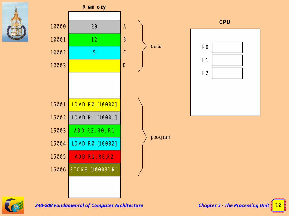
CPU : Basic operations
Fetch : Read the instructions and data from memory
Execute : perform the desired operation and write the result into the memory or registers
FetchExecuteFetch Execute
Instruction Cycle
Fetch Execute

240-208 Fundamental of Computer Architecture Chapter 3 - The Processing Unit 9
FETC
H
12
5
20
data
10000
10001
10002
10003
Mem ory
A
B
C
D
LO AD R1,[10001]
ADD R2, R0, R1
LO AD R0,[10002]
ADD R1, R0,R2
LO AD R0,[10000]
ST O RE [10003] ,R1
program
15001
15002
15003
15004
15005
15006
CPU
R0
R1
R2
Address : 15001
contro l: read
LO AD R0,[10000]I R
Contro lU n it
M AR
data : load R0,[10000]
240-208 Fundamental of Computer Architecture Chapter 3 - The Processing Unit 10
12
5
20
data
10000
10001
10002
10003
Mem ory
CPU
R0
R1
R2
A
B
C
D
LO AD R1,[10001]
ADD R2, R0, R1
LO AD R0,[10002]
ADD R1, R0,R2
LO AD R0,[10000]
ST O RE [10003] ,R1
program
15001
15002
15003
15004
15005
15006

240-208 Fundamental of Computer Architecture Chapter 3 - The Processing Unit 11
Terminology IR : Instruction Register MAR : Memory Address Register
240-208 Fundamental of Computer Architecture Chapter 3 - The Processing Unit 12
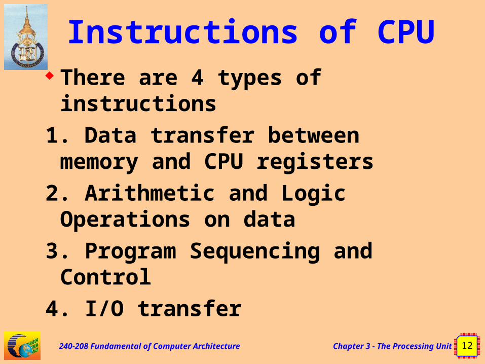
Instructions of CPU There are 4 types of instructions
1. Data transfer between memory and CPU registers
2. Arithmetic and Logic Operations on data
3. Program Sequencing and Control
4. I/O transfer

240-208 Fundamental of Computer Architecture Chapter 3 - The Processing Unit 13
Basic instruction types : three address instruction
LOAD R0,[10000]
LOAD R1,[10001]
ADD R2, R0, R1
LOAD R0,[10002]
ADD R1, R0,R2
STORE [10003],R1
12
5
20
data
27
10000
10001
10002
10003
Mem ory
CPU
5R0
37R1
32R2
A
B
C
D
D = A+B+C
Note ADD R2,R0,R1 means R2 = R0+R1

240-208 Fundamental of Computer Architecture Chapter 3 - The Processing Unit 14
Basic instruction types : two address
instruction
LOAD R0,[10000]
LOAD R1,[10001]
ADD R0,R1
LOAD R2,[10002]
ADD R0,R2
STORE [10003],R0
D = A+B+C
Note ADD R0,R1 means R0 = R0+R1
12
5
20
data
27
10000
10001
10002
10003
Mem ory
CPU
5R0
37R1
32R2
A
B
C
D

240-208 Fundamental of Computer Architecture Chapter 3 - The Processing Unit 15
Basic instruction types : one address
instruction
LOAD [10000]
ADD [10001]
ADD [10002]
STORE [10003]
D = A+B+C
Note ADD [10001] means Acc = Acc + [10001]
12
5
20
data
27
10000
10001
10002
10003
Mem ory
CPU
A
B
C
D
5ACC

240-208 Fundamental of Computer Architecture Chapter 3 - The Processing Unit 16
CPU registers General purpose registers
R0,R1…Rn A,B, C,….
Special purpose register PC SP Accumulator Flag or Condition code

240-208 Fundamental of Computer Architecture Chapter 3 - The Processing Unit 17
PC :Program Counter register
Used to keep the next address of memory that CPU want to access
PC and address-bus have the same size

240-208 Fundamental of Computer Architecture Chapter 3 - The Processing Unit 18
PC :Program Counter (continued)
Instruction 1
Instruction 2
Instruction 3
Instruction 3
Instruction 4
Instruction 5
Instruction 5
Instruction 5
0000H
0001H
0002H
0003H
0004H
0005H
0006H
0007H
PC
Instruction 60008H

240-208 Fundamental of Computer Architecture Chapter 3 - The Processing Unit 19
Instruction 1
Instruction 2
Instruction 3
Instruction 3
Instruction 4
Instruction 5
Instruction 5
Instruction 5
0000H
0001H
0002H
0003H
0004H
0005H
0006H
0007H
PC
Instruction 60008H
PC :Program Counter (continued)

240-208 Fundamental of Computer Architecture Chapter 3 - The Processing Unit 20
Instruction 1
Instruction 2
Instruction 3
Instruction 3
Instruction 4
Instruction 5
Instruction 5
Instruction 5
0000H
0001H
0002H
0003H
0004H
0005H
0006H
0007H
PC
Instruction 60008H
PC :Program Counter (continued)

240-208 Fundamental of Computer Architecture Chapter 3 - The Processing Unit 21
Instruction 1
Instruction 2
Instruction 3
Instruction 3
Instruction 4
Instruction 5
Instruction 5
Instruction 5
0000H
0001H
0002H
0003H
0004H
0005H
0006H
0007H
PC
Instruction 60008H
PC :Program Counter (continued)

240-208 Fundamental of Computer Architecture Chapter 3 - The Processing Unit 22
Instruction 1
Instruction 2
Instruction 3
Instruction 3
Instruction 4
Instruction 5
Instruction 5
Instruction 5
0000H
0001H
0002H
0003H
0004H
0005H
0006H
0007H
PC
Instruction 60008H
PC :Program Counter (continued)

240-208 Fundamental of Computer Architecture Chapter 3 - The Processing Unit 23
Instruction 1
Instruction 2
Instruction 3
Instruction 3
Instruction 4
Instruction 5
Instruction 5
Instruction 5
0000H
0001H
0002H
0003H
0004H
0005H
0006H
0007H
PC
Instruction 60008H
PC :Program Counter (continued)

240-208 Fundamental of Computer Architecture Chapter 3 - The Processing Unit 24
Branching
LOC35000: LOAD R0,#0
LOAD R1,#14999
LOAD R3,#10000
LOC35003: LOAD R2,[R3]
ADD R0, R2
INC R3
DEC R1
Branch_NZ LOC35003
STORE [R3],R0
12
5
20
input data27
10000
10001
10002
10003
Memory
result
24999
25000
[25000] = [10000]+[10002]+[10003]+….+[24999]

240-208 Fundamental of Computer Architecture Chapter 3 - The Processing Unit 25
Flag or Condition code Register
keep the status after perform arithmetic and logic operationS Z X H X P /V N C
7 6 5 4 3 2 1 0
C arry flag
N egative flag
Parity/O verflow flag
N ot used
H alf-carry flag
N ot used
Zero flag
S ign flagExample: Flags of CPU z80

240-208 Fundamental of Computer Architecture Chapter 3 - The Processing Unit 26
Addressing modes of CPU
Immediate #valueload R0,#00001
Register Ri load R0,R1 Direct(absolute) [mem_loc]
load R0,[100000] Register indirect [Ri]
load R0,[R1] Relative X[PC] Index

240-208 Fundamental of Computer Architecture Chapter 3 - The Processing Unit 27
Immediate addressing
load R1,#00001
2500
R1
00001H
00000H3900H
Before
00001
R1
00001H
00000H3900H
After
240-208 Fundamental of Computer Architecture Chapter 3 - The Processing Unit 28
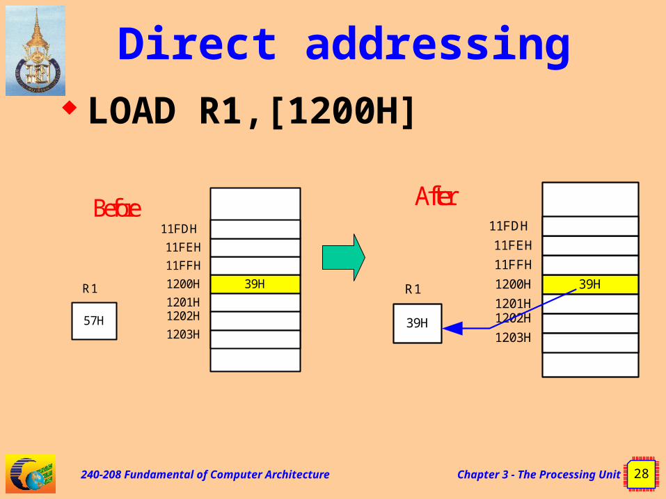
Direct addressing LOAD R1,[1200H]
39H1200H
57H
R1
11FFH
11FEH
11FDH
1201H1202H
1203H
Before
39H1200H
39H
R1
11FFH
11FEH
11FDH
1201H1202H
1203H
After

240-208 Fundamental of Computer Architecture Chapter 3 - The Processing Unit 29
Register indirect load R0,[R1]
2500R0 00001H
00000H
638
1457
2400
6713
3900H
Before
00006R1
00002H
00003H
00004H
00005H
00006H
2400R0 00001H
00000H
638
1457
2400
6713
3900H
After
00006R1
00002H
00003H
00004H
00005H
00006H

240-208 Fundamental of Computer Architecture Chapter 3 - The Processing Unit 30
Index addressing Use index register Effective address = X + [Ri] When X = offset (or displacement)
Ri = index register or Base register

240-208 Fundamental of Computer Architecture Chapter 3 - The Processing Unit 31
Index addressing
Array
R1
04
Array
displacement
Array+1
Array+2
Array+3
Array+4
ADD R2,04(R1)
Offset is given as a constant

240-208 Fundamental of Computer Architecture Chapter 3 - The Processing Unit 32
Index addressing
Offset is in the index register
Array
R1
04
Array
displacement Array+1
Array+2
Array+3
Array+4
ADD R2,Array(R1)

240-208 Fundamental of Computer Architecture Chapter 3 - The Processing Unit 33
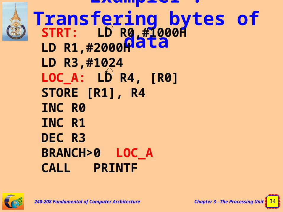
Example1 : Transfering bytes of
data Copy values in memory location 1000h-1400h to location 2000h-2400h (1024 byte)
2000H
2001H
2002H
23FEH
23FFH
2400H
07H
05H
00H
1000H
1001H
1002H
13FEH
13FFH
1400H
61H
72H
74H
240-208 Fundamental of Computer Architecture Chapter 3 - The Processing Unit 34
Example1 : Transfering bytes of
dataSTRT: LD R0,#1000H
LD R1,#2000HLD R3,#1024
LOC_A: LD R4, [R0]STORE [R1], R4INC R0INC R1DEC R3BRANCH>0
LOC_ACALL PRINTF

240-208 Fundamental of Computer Architecture Chapter 3 - The Processing Unit 35
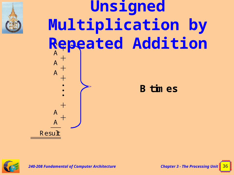
Example2: Unsigned
Multiplication by Repeated Addition Multiply 8-bit unsigned
number C = A * B
240-208 Fundamental of Computer Architecture Chapter 3 - The Processing Unit 36
A
A
A
A
A
A
Result
B times
Example2: Unsigned
Multiplication by Repeated Addition

240-208 Fundamental of Computer Architecture Chapter 3 - The Processing Unit 37
Example2: Unsigned
Multiplication by Repeated AdditionSTRT : LOAD R1,#0LOAD R3, [mem_loc_A]LOAD R2, [mem_loc_B]
LOOP: ADD R1,R3DEC R2BRANCH>0 LOOPSTORE [mem_loc_C],R1CALL PRINTF

240-208 Fundamental of Computer Architecture Chapter 3 - The Processing Unit 38
Example2: Unsigned
Multiplication by Repeated Addition Problem of the program
in page 37 If B = 0 then the result is A , not 0
How to remedy the problem

240-208 Fundamental of Computer Architecture Chapter 3 - The Processing Unit 39
Example2: Unsigned
Multiplication by Repeated AdditionSTRT : LOAD R1,#0LOAD R3, [mem_loc_A]LOAD R2, [mem_loc_B]Compare R2,#0Branch_Z STR
LOOP: ADD R1,R3DEC R2Branch>0 LOOP
STR: STORE [mem_loc_C],R1

240-208 Fundamental of Computer Architecture Chapter 3 - The Processing Unit 40
Example3: if-then-else
if (mem_loc_a == 5)
mem_loc_b++;
else
mem_loc_b = mem_loc_a + mem_loc_b;

240-208 Fundamental of Computer Architecture Chapter 3 - The Processing Unit 41
Example3: if-then-else
Load R1,[mem_loc_a]
Load R2,[mem_loc_b]
Compare r1,#5
Branch_NZ b_p_a
inc r2
branch stre
b_p_a: Add r2,r1
stre: Store [mem_loc_a],r1
Store [mem_loc_b],r2

240-208 Fundamental of Computer Architecture Chapter 3 - The Processing Unit 42
Example4: checking greater-than
if (mem_loc_a > 5)
mem_loc_b++;
else
mem_loc_b = mem_loc_a + mem_loc_b;

240-208 Fundamental of Computer Architecture Chapter 3 - The Processing Unit 43
Example4: checking greater-thanLoad R1,[mem_loc_a]Load R2,[mem_loc_b]compare r1,#5branch_z equ_g_5 ;equal 5branch_M equ_g_5 ;M= minusinc r2branch stre
equ_g_5: Add r2,r1stre: Store [mem_loc_a],r1
Store [mem_loc_b],r2

240-208 Fundamental of Computer Architecture Chapter 3 - The Processing Unit 44
Example4: checking greater-thanLoad R1,[mem_loc_a]Load R2,[mem_loc_b]sub r1,#5branch>0 gt_5Add r2,r1
branch stregt_5: inc r2stre: Store [mem_loc_a],r1
Store [mem_loc_b],r2

240-208 Fundamental of Computer Architecture Chapter 3 - The Processing Unit 45
Basic processing unit the structure of simple CPU
How the internal parts of CPU work
How to design the simple processor Datapath Control Unit

240-208 Fundamental of Computer Architecture Chapter 3 - The Processing Unit 46
Inside simple CPU with Single-bus Datapath
MA
R
YZ
MU
X
PC
MD
R
R0
IRR1
R(n
-1)
: :
Te
mp

240-208 Fundamental of Computer Architecture Chapter 3 - The Processing Unit 47
Perform instruction ADD R1,R2
MAR <= PC ADDRESS_BUS <= MAR, read MDR <=
MEMORY[MAR] IR <= MDR Z <= PC + 4 PC <= Z Y <= R1 Z <= Y + R2 R2 <= Z
Fetch phase
Execution phase

240-208 Fundamental of Computer Architecture Chapter 3 - The Processing Unit 48
Perform instruction ADD R1,R2
MAR <= PC PCout, MARin
ADDRESS_BUS <= MAR,read read MDR <= MEMORY[MAR] MDRinE, WMFC IR <= MDR MDRout,IRin
Z <= PC + 4 PCout, MUX_sel4, Add,Zin
PC <= Z Zout,PCin
Y <= R1 Yin, R1out
Z <= Y + R2 R2out, MUX_selY, Add, Zin
R2 <= Z Zout, R2in
Active Signals
240-208 Fundamental of Computer Architecture Chapter 3 - The Processing Unit 49
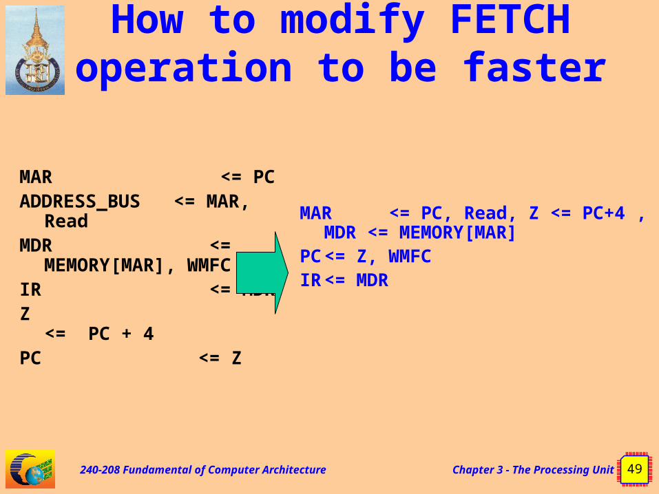
How to modify FETCH operation to be faster
MAR <= PCADDRESS_BUS <= MAR,
ReadMDR <=
MEMORY[MAR], WMFCIR <= MDRZ <= PC +
4PC <= Z
MAR <= PC, Read, Z <= PC+4 , MDR <= MEMORY[MAR]
PC <= Z, WMFCIR <= MDR

240-208 Fundamental of Computer Architecture Chapter 3 - The Processing Unit 50
Modified FETCH operation
MAR <= PC, Read, Z <= PC+4 , MDR <= MEMORY[MAR]
PC <= Z, WMFCIR <= MDR
PCout, MARin, Read, Mux_sel4, Add, Zin
Zout, PCin, Yin, WMFCMDRout, IRin
Active Signals

240-208 Fundamental of Computer Architecture Chapter 3 - The Processing Unit 51
Perform instruction load R1,[mem_locA]
MAR <= PC, Read, Z <= PC+4 , MDR <= MEMORY[MAR]
PC <= Z, WMFC IR <= MDR
MAR <= 00000000 & IR24..0
ADDRESS_BUS <= MAR MDR <= MEMORY[MAR] R1 <= MDR
Fetch phase
Execution phase

240-208 Fundamental of Computer Architecture Chapter 3 - The Processing Unit 52
Three-bus organization
PC

240-208 Fundamental of Computer Architecture Chapter 3 - The Processing Unit 53
Perform Instruction ADD R6,R5, R4
Step Action 1 PCout, R=B, MARin, Read, incPC
2 WMFC, MDRin_from_databus
3 MDRout_busB, R= B, IRin
4 R4out_busB, R5out_busA, Add, R6in, End

240-208 Fundamental of Computer Architecture Chapter 3 - The Processing Unit 54
Control Units 2 types of Control units
Hardwired Microprogrammed

240-208 Fundamental of Computer Architecture Chapter 3 - The Processing Unit 55
Control sequence for instruction ADD R1,(R3)Step Action1 PCout, MARin, Read, Select4,
Add, Zin
2 Zout, PCin, Yin, WMFC
3 MDRout, IRin
4 R3out, MARin, Read
5 R1out, Yin, WMFC
6 MDRout, SelectY, Add, Zin
7 Zout, R1in, End
240-208 Fundamental of Computer Architecture Chapter 3 - The Processing Unit 56
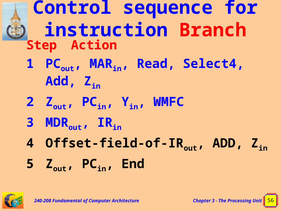
Control sequence for instruction Branch
Step Action1 PCout, MARin, Read, Select4,
Add, Zin
2 Zout, PCin, Yin, WMFC
3 MDRout, IRin
4 Offset-field-of-IRout, ADD, Zin
5 Zout, PCin, End

240-208 Fundamental of Computer Architecture Chapter 3 - The Processing Unit 57
Control sequence for instruction Branch<0
Step Action1 PCout, MARin, Read, Select4,
Add, Zin
2 Zout, PCin, Yin, WMFC
3 MDRout, IRin
4 Offset-field-of-IRout, ADD, Zin, if N=0 then End
5 Zout, PCin, End

240-208 Fundamental of Computer Architecture Chapter 3 - The Processing Unit 58
Hardwired Control Unit
D ecoder/E ncoder
IR
E xterna l Inpu ts
C ond ition codes
C ontro l S tepC ounter
C lock
C ontro l s igna ls

240-208 Fundamental of Computer Architecture Chapter 3 - The Processing Unit 59
Control Unit organization
E ncoder
C ontro l S tepC ounter
C lock
C ontro l s igna ls
InstructionD ecoder
S tep decoder
E ndR un
IN S 1
IN S 2
IN S 3
IN S m
T1
T2
Tn
E xte rna l Inpu ts
C ond ition codes
IR

240-208 Fundamental of Computer Architecture Chapter 3 - The Processing Unit 60
Zin and END control signals
Zin = T1 + (T6ADD) + (T4 BR)+…..End = (T7 ADD) + (T5 BR) + (((T5 N)+(T4 N)) BRN)+....
NoteBR = Branch instructionBRN = Branch<0 instructionN = Negative flag

240-208 Fundamental of Computer Architecture Chapter 3 - The Processing Unit 61
Generation of Zin control signal
Zin
T6
Add
T4
BR
T1

240-208 Fundamental of Computer Architecture Chapter 3 - The Processing Unit 62
Generation of END control signal
End
T5
BR
N
T4
BRN
T7
Add

240-208 Fundamental of Computer Architecture Chapter 3 - The Processing Unit 63
Microprogrammed control unit
C lock
IR
E xterna linpu ts
C ond itioncodes
uP C
S tarting andbranch address
genera tor
C ontro l s to re C ontro l W ord

240-208 Fundamental of Computer Architecture Chapter 3 - The Processing Unit 64
“Control words” stored in “Control
Store”
From Figure 7.15 page 430 of “Computer Organization”, 5th edition, Carl Hamacher, McGraw Hill

240-208 Fundamental of Computer Architecture Chapter 3 - The Processing Unit 65
จบ บทำทำ�� 3