Embed Size (px)
Citation preview
FUNDAMENTALS OF
APPLIEDELECTROMAGNETICS
Eighth Edition
Fawwaz T. UlabyUniversity of Michigan, Ann Arbor
Umberto RavaioliUniversity of Illinois, Urbana-Champaign

[Copyright page]

We dedicate this book to
Jean and Ann Lucia.
Building on the core content and style of its predecessor, this
eighth edition (8/e) of Applied Electromagnetics includes fea-
tures designed to help students develop deep understanding of
electromagnetic concepts and applications. Prominent among
them is a set of 52 web-based simulation modules that allow
the user to interactively analyze and design transmission line
circuits; generate spatial patterns of the electric and magnetic
fields induced by charges and currents; visualize in 2-D and
3-D space how the gradient, divergence, and curl operate on
spatial functions; observe the temporal and spatial waveforms
of plane waves propagating in lossless and lossy media;
calculate and display field distributions inside a rectangular
waveguide; and generate radiation patterns for linear anten-
nas and parabolic dishes. These are valuable learning tools;
we encourage students to use them and urge instructors to
incorporate them into their lecture materials and homework
assignments.
Additionally, by enhancing the book’s graphs and illustra-
tions, and by expanding the scope of topics of the Technology
Briefs, additional bridges between electromagnetic fundamen-
tals and their countless engineering and scientific applications
are established. In summary:
NEW TO THIS EDITION
• Additional Exercises
• Updated Technology Briefs
• Enhanced figures and images
• New/updated end-of-chapter problems
* The interactive modules and Technology Briefs
can be found at the book companion website:
em8e.eecs.umich.edu.
ACKNOWLEDGMENTS
As authors, we were blessed to have worked on this book with
the best team of professionals: Richard Carnes, Leland Pierce,
Janice Richards, Rose Kernan, and Paul Mailhot. We are
exceedingly grateful for their superb support and unwavering
dedication to the project.
We enjoyed working on this book. We hope you enjoy
learning from it.
FAWWAZ T. ULABY
UMBERTO RAVAIOLI
iv
Preface to Eighth Edition
v
CONTENT
The book begins by building a bridge between what should be
familiar to a third-year electrical engineering student and the
electromagnetics (EM) material covered in the book. Prior to
enrolling in an EM course, a typical student will have taken
one or more courses in circuits. He or she should be familiar
with circuit analysis, Ohm’s law, Kirchhoff’s current and volt-
age laws, and related topics. Transmission lines constitute a
natural bridge between electric circuits and electromagnetics.
Without having to deal with vectors or fields, the student
uses already familiar concepts to learn about wave motion,
the reflection and transmission of power, phasors, impedance
matching, and many of the properties of wave propagation
in a guided structure. All of these newly learned concepts
will prove invaluable later (in Chapters 7 through 9) and will
facilitate the learning of how plane waves propagate in free
space and in material media. Transmission lines are covered
in Chapter 2, which is preceded in Chapter 1 with reviews of
complex numbers and phasor analysis.
The next part of the book, contained in Chapters 3 through 5,
covers vector analysis, electrostatics, and magnetostatics. The
electrostatics chapter begins with Maxwell’s equations for the
time-varying case, which are then specialized to electrostatics
and magnetostatics, thereby providing the student with an
overall framework for what is to come and showing him or
her why electrostatics and magnetostatics are special cases of
the more general time-varying case.
Chapter 6 deals with time-varying fields and sets the stage
for the material in Chapters 7 through 9. Chapter 7 covers
plane-wave propagation in dielectric and conducting media,
and Chapter 8 covers reflection and transmission at discon-
tinuous boundaries and introduces the student to fiber optics,
waveguides and resonators.
In Chapter 9, the student is introduced to the principles of
radiation by currents flowing in wires, such as dipoles, as well
as to radiation by apertures, such as a horn antenna or an
opening in an opaque screen illuminated by a light source.
To give the student a taste of the wide-ranging applications
of electromagnetics in today’s technological society, Chap-
ter 10 concludes the book with overview presentations of two
system examples: satellite communication systems and radar
sensors.
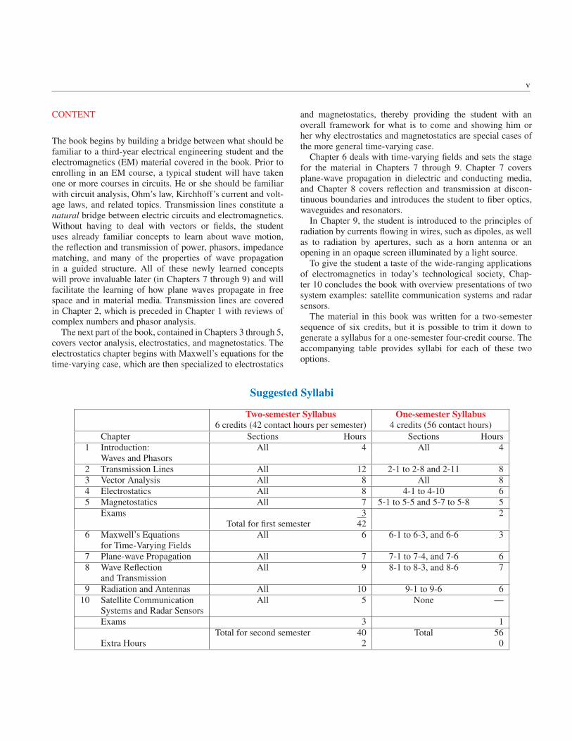
The material in this book was written for a two-semester
sequence of six credits, but it is possible to trim it down to
generate a syllabus for a one-semester four-credit course. The
accompanying table provides syllabi for each of these two
options.
Suggested Syllabi
Two-semester Syllabus One-semester Syllabus
6 credits (42 contact hours per semester) 4 credits (56 contact hours)
Chapter Sections Hours Sections Hours
1 Introduction: All 4 All 4
Waves and Phasors
2 Transmission Lines All 12 2-1 to 2-8 and 2-11 8
3 Vector Analysis All 8 All 8
4 Electrostatics All 8 4-1 to 4-10 6
5 Magnetostatics All 7 5-1 to 5-5 and 5-7 to 5-8 5
Exams 3 2
Total for first semester 42
6 Maxwell’s Equations All 6 6-1 to 6-3, and 6-6 3
for Time-Varying Fields
7 Plane-wave Propagation All 7 7-1 to 7-4, and 7-6 6
8 Wave Reflection All 9 8-1 to 8-3, and 8-6 7
and Transmission
9 Radiation and Antennas All 10 9-1 to 9-6 6
10 Satellite Communication All 5 None —
Systems and Radar Sensors
Exams 3 1
Total for second semester 40 Total 56
Extra Hours 2 0
vi
MESSAGE TO THE STUDENT
The web-based interactive modules of this book were devel-
oped with you, the student, in mind. Take the time to use them
in conjunction with the material in the textbook. The multiple-
window feature of electronic displays makes it possible to
design interactive modules with “help” buttons to guide the
student through the solution of a problem when needed. Video
animations can show you how fields and waves propagate in
time and space, how the beam of an antenna array can be made
to scan electronically, and examples of how current is induced
in a circuit under the influence of a changing magnetic field.
The modules are a useful resource for self-study. You can find
them at the book companion website em8e.eecs.umich.edu.
Use them!
BOOK COMPANION WEBSITE
Throughout the book, we use the symbol EM to denote the book
companion website em8e.eecs.umich.edu, which contains a
wealth of information and tons of useful tools.
ACKNOWLEDGMENTS
Special thanks are due to reviewers for their valuable com-
ments and suggestions. They include Constantine Balanis of
Arizona State University, Harold Mott of the University of Al-
abama, David Pozar of the University of Massachusetts, S. N.
Prasad of Bradley University, Robert Bond of New Mexico
Institute of Technology, Mark Robinson of the University of
Colorado at Colorado Springs, and Raj Mittra of the University
of Illinois. I appreciate the dedicated efforts of the staff at
Prentice Hall and I am grateful for their help in shepherding
this project through the publication process in a very timely
manner.
FAWWAZ T. ULABY
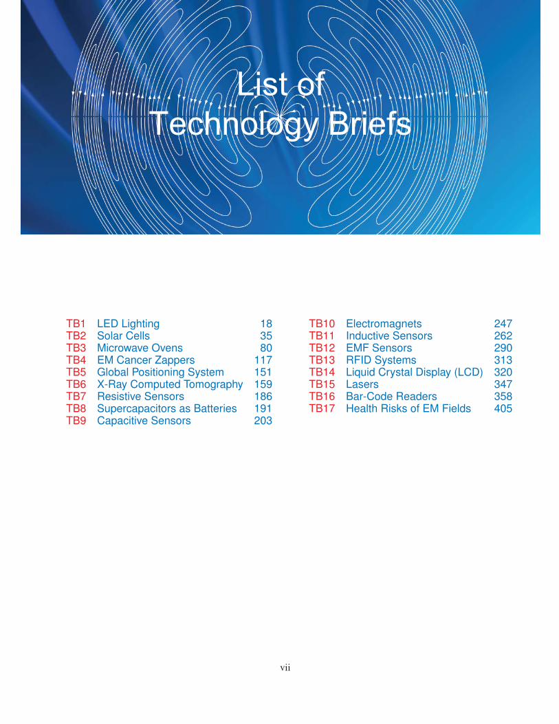
TB1 LED Lighting 18TB2 Solar Cells 35TB3 Microwave Ovens 80TB4 EM Cancer Zappers 117TB5 Global Positioning System 151TB6 X-Ray Computed Tomography 159TB7 Resistive Sensors 186TB8 Supercapacitors as Batteries 191TB9 Capacitive Sensors 203
TB10 Electromagnets 247TB11 Inductive Sensors 262TB12 EMF Sensors 290TB13 RFID Systems 313TB14 Liquid Crystal Display (LCD) 320TB15 Lasers 347TB16 Bar-Code Readers 358TB17 Health Risks of EM Fields 405
vii
List ofTechnology Briefs
Contents
Preface iv
List of Technology Briefs vii
List of Modules xii
Photo Credits xiii
1 Introduction: Waves and Phasors 11-1 Historical Timeline . . . . . . . . . . . . . . . . . . . . . . . . . . . . . . . . . . . . . . 31-2 Dimensions, Units, and Notation . . . . . . . . . . . . . . . . . . . . . . . . . . . . . . . 111-3 The Nature of Electromagnetism . . . . . . . . . . . . . . . . . . . . . . . . . . . . . . . 11TB1 LED Lighting . . . . . . . . . . . . . . . . . . . . . . . . . . . . . . . . . . . . . . . . . 181-4 Traveling Waves . . . . . . . . . . . . . . . . . . . . . . . . . . . . . . . . . . . . . . . . 221-5 The Electromagnetic Spectrum . . . . . . . . . . . . . . . . . . . . . . . . . . . . . . . . 301-6 Review of Complex Numbers . . . . . . . . . . . . . . . . . . . . . . . . . . . . . . . . . 31TB2 Solar Cells . . . . . . . . . . . . . . . . . . . . . . . . . . . . . . . . . . . . . . . . . . . 351-7 Review of Phasors . . . . . . . . . . . . . . . . . . . . . . . . . . . . . . . . . . . . . . . 38
2 Transmission Lines 462-1 General Considerations . . . . . . . . . . . . . . . . . . . . . . . . . . . . . . . . . . . . 472-2 Lumped-Element Model . . . . . . . . . . . . . . . . . . . . . . . . . . . . . . . . . . . . 502-3 Transmission-Line Equations . . . . . . . . . . . . . . . . . . . . . . . . . . . . . . . . . 532-4 Wave Propagation on a Transmission Line . . . . . . . . . . . . . . . . . . . . . . . . . . 542-5 The Lossless Microstrip Line . . . . . . . . . . . . . . . . . . . . . . . . . . . . . . . . . 592-6 The Lossless Transmission Line: General Considerations . . . . . . . . . . . . . . . . . . 622-7 Wave Impedance of the Lossless Line . . . . . . . . . . . . . . . . . . . . . . . . . . . . . 71TB3 Microwave Ovens . . . . . . . . . . . . . . . . . . . . . . . . . . . . . . . . . . . . . . . 802-9 Power Flow on a Lossless Transmission Line . . . . . . . . . . . . . . . . . . . . . . . . . 822-10 The Smith Chart . . . . . . . . . . . . . . . . . . . . . . . . . . . . . . . . . . . . . . . . 842-11 Impedance Matching . . . . . . . . . . . . . . . . . . . . . . . . . . . . . . . . . . . . . 942-12 Transients on Transmission Lines . . . . . . . . . . . . . . . . . . . . . . . . . . . . . . . 108TB4 EM Cancer Zappers . . . . . . . . . . . . . . . . . . . . . . . . . . . . . . . . . . . . . . 117
viii
Contents
CONTENTS ix
3 Vector Analysis 130
3-1 Basic Laws of Vector Algebra . . . . . . . . . . . . . . . . . . . . . . . . . . . . . . . . . 1313-2 Orthogonal Coordinate Systems . . . . . . . . . . . . . . . . . . . . . . . . . . . . . . . . 1373-3 Transformations between Coordinate Systems . . . . . . . . . . . . . . . . . . . . . . . . 1433-4 Gradient of a Scalar Field . . . . . . . . . . . . . . . . . . . . . . . . . . . . . . . . . . . 147TB5 Global Positioning System . . . . . . . . . . . . . . . . . . . . . . . . . . . . . . . . . . 1513-5 Divergence of a Vector Field . . . . . . . . . . . . . . . . . . . . . . . . . . . . . . . . . 1533-6 Curl of a Vector Field . . . . . . . . . . . . . . . . . . . . . . . . . . . . . . . . . . . . . 157TB6 X-Ray Computed Tomography . . . . . . . . . . . . . . . . . . . . . . . . . . . . . . . . 1593-7 Laplacian Operator . . . . . . . . . . . . . . . . . . . . . . . . . . . . . . . . . . . . . . 162
4 Electrostatics 172
4-1 Maxwell’s Equations . . . . . . . . . . . . . . . . . . . . . . . . . . . . . . . . . . . . . 1734-2 Charge and Current Distributions . . . . . . . . . . . . . . . . . . . . . . . . . . . . . . . 1734-3 Coulomb’s Law . . . . . . . . . . . . . . . . . . . . . . . . . . . . . . . . . . . . . . . . 1764-4 Gauss’s Law . . . . . . . . . . . . . . . . . . . . . . . . . . . . . . . . . . . . . . . . . . 1804-5 Electric Scalar Potential . . . . . . . . . . . . . . . . . . . . . . . . . . . . . . . . . . . . 183TB7 Resistive Sensors . . . . . . . . . . . . . . . . . . . . . . . . . . . . . . . . . . . . . . . 1864-6 Conductors . . . . . . . . . . . . . . . . . . . . . . . . . . . . . . . . . . . . . . . . . . . 190TB8 Supercapacitors as Batteries . . . . . . . . . . . . . . . . . . . . . . . . . . . . . . . . . . 1914-7 Dielectrics . . . . . . . . . . . . . . . . . . . . . . . . . . . . . . . . . . . . . . . . . . . 1974-8 Electric Boundary Conditions . . . . . . . . . . . . . . . . . . . . . . . . . . . . . . . . . 200TB9 Capacitive Sensors . . . . . . . . . . . . . . . . . . . . . . . . . . . . . . . . . . . . . . . 2034-9 Capacitance . . . . . . . . . . . . . . . . . . . . . . . . . . . . . . . . . . . . . . . . . . 2094-10 Electrostatic Potential Energy . . . . . . . . . . . . . . . . . . . . . . . . . . . . . . . . . 2134-11 Image Method . . . . . . . . . . . . . . . . . . . . . . . . . . . . . . . . . . . . . . . . . 215
5 Magnetostatics 227
5-1 Magnetic Forces and Torques . . . . . . . . . . . . . . . . . . . . . . . . . . . . . . . . . 2285-2 The Biot–Savart Law . . . . . . . . . . . . . . . . . . . . . . . . . . . . . . . . . . . . . 2365-3 Maxwell’s Magnetostatic Equations . . . . . . . . . . . . . . . . . . . . . . . . . . . . . . 2425-4 Vector Magnetic Potential . . . . . . . . . . . . . . . . . . . . . . . . . . . . . . . . . . . 246TB10 Electromagnets . . . . . . . . . . . . . . . . . . . . . . . . . . . . . . . . . . . . . . . . 2475-5 Magnetic Properties of Materials . . . . . . . . . . . . . . . . . . . . . . . . . . . . . . . 2515-6 Magnetic Boundary Conditions . . . . . . . . . . . . . . . . . . . . . . . . . . . . . . . . 2545-7 Inductance . . . . . . . . . . . . . . . . . . . . . . . . . . . . . . . . . . . . . . . . . . . 2565-8 Magnetic Energy . . . . . . . . . . . . . . . . . . . . . . . . . . . . . . . . . . . . . . . . 261TB11 Inductive Sensors . . . . . . . . . . . . . . . . . . . . . . . . . . . . . . . . . . . . . . . 262
6 Maxwell’s Equations for Time-Varying Fields 272
6-1 Faraday’s Law . . . . . . . . . . . . . . . . . . . . . . . . . . . . . . . . . . . . . . . . . 2736-2 Stationary Loop in a Time-Varying Magnetic Field . . . . . . . . . . . . . . . . . . . . . . 2746-3 The Ideal Transformer . . . . . . . . . . . . . . . . . . . . . . . . . . . . . . . . . . . . . 2786-4 Moving Conductor in a Static Magnetic Field . . . . . . . . . . . . . . . . . . . . . . . . 279
x CONTENTS
6-5 The Electromagnetic Generator . . . . . . . . . . . . . . . . . . . . . . . . . . . . . . . . 2836-6 Moving Conductor in a Time-Varying Magnetic Field . . . . . . . . . . . . . . . . . . . . 2846-7 Displacement Current . . . . . . . . . . . . . . . . . . . . . . . . . . . . . . . . . . . . . 2856-8 Boundary Conditions for Electromagnetics . . . . . . . . . . . . . . . . . . . . . . . . . . 2876-9 Charge-Current Continuity Relation . . . . . . . . . . . . . . . . . . . . . . . . . . . . . . 2886-10 Free-Charge Dissipation in a Conductor . . . . . . . . . . . . . . . . . . . . . . . . . . . 289TB12 EMF Sensors . . . . . . . . . . . . . . . . . . . . . . . . . . . . . . . . . . . . . . . . . . 2906-11 Electromagnetic Potentials . . . . . . . . . . . . . . . . . . . . . . . . . . . . . . . . . . 292
7 Plane-Wave Propagation 301
7-1 Time-Harmonic Fields . . . . . . . . . . . . . . . . . . . . . . . . . . . . . . . . . . . . . 3037-2 Plane-Wave Propagation in Lossless Media . . . . . . . . . . . . . . . . . . . . . . . . . . 3047-3 Wave Polarization . . . . . . . . . . . . . . . . . . . . . . . . . . . . . . . . . . . . . . . 309TB13 RFID Systems . . . . . . . . . . . . . . . . . . . . . . . . . . . . . . . . . . . . . . . . . 3137-4 Plane-Wave Propagation in Lossy Media . . . . . . . . . . . . . . . . . . . . . . . . . . . 317TB14 Liquid Crystal Display (LCD) . . . . . . . . . . . . . . . . . . . . . . . . . . . . . . . . . 3207-5 Current Flow in a Good Conductor . . . . . . . . . . . . . . . . . . . . . . . . . . . . . . 3257-6 Electromagnetic Power Density . . . . . . . . . . . . . . . . . . . . . . . . . . . . . . . . 328
8 Wave Reflection and Transmission 337
8-1 Wave Reflection and Transmission at Normal Incidence . . . . . . . . . . . . . . . . . . . 338TB15 Lasers . . . . . . . . . . . . . . . . . . . . . . . . . . . . . . . . . . . . . . . . . . . . . 3478-2 Snell’s Laws . . . . . . . . . . . . . . . . . . . . . . . . . . . . . . . . . . . . . . . . . . 3498-3 Fiber Optics . . . . . . . . . . . . . . . . . . . . . . . . . . . . . . . . . . . . . . . . . . 3518-4 Wave Reflection and Transmission at Oblique Incidence . . . . . . . . . . . . . . . . . . . 353TB16 Bar-Code Readers . . . . . . . . . . . . . . . . . . . . . . . . . . . . . . . . . . . . . . . 3588-5 Reflectivity and Transmissivity . . . . . . . . . . . . . . . . . . . . . . . . . . . . . . . . 3618-6 Waveguides . . . . . . . . . . . . . . . . . . . . . . . . . . . . . . . . . . . . . . . . . . 3648-7 General Relations for E and H . . . . . . . . . . . . . . . . . . . . . . . . . . . . . . . . 3668-8 TM Modes in Rectangular Waveguide . . . . . . . . . . . . . . . . . . . . . . . . . . . . 3678-9 TE Modes in Rectangular Waveguide . . . . . . . . . . . . . . . . . . . . . . . . . . . . . 3708-10 Propagation Velocities . . . . . . . . . . . . . . . . . . . . . . . . . . . . . . . . . . . . . 3718-11 Cavity Resonators . . . . . . . . . . . . . . . . . . . . . . . . . . . . . . . . . . . . . . . 374
9 Radiation and Antennas 384
9-1 The Hertzian Dipole . . . . . . . . . . . . . . . . . . . . . . . . . . . . . . . . . . . . . . 3879-2 Antenna Radiation Characteristics . . . . . . . . . . . . . . . . . . . . . . . . . . . . . . 3909-3 Half-Wave Dipole Antenna . . . . . . . . . . . . . . . . . . . . . . . . . . . . . . . . . . 3979-4 Dipole of Arbitrary Length . . . . . . . . . . . . . . . . . . . . . . . . . . . . . . . . . . 4009-5 Effective Area of a Receiving Antenna . . . . . . . . . . . . . . . . . . . . . . . . . . . . 4019-6 Friis Transmission Formula . . . . . . . . . . . . . . . . . . . . . . . . . . . . . . . . . . 403TB17 Health Risks of EM Fields . . . . . . . . . . . . . . . . . . . . . . . . . . . . . . . . . . . 4059-7 Radiation by Large-Aperture Antennas . . . . . . . . . . . . . . . . . . . . . . . . . . . . 4089-8 Rectangular Aperture with Uniform Aperture Distribution . . . . . . . . . . . . . . . . . . 410
CONTENTS xi
9-9 Antenna Arrays . . . . . . . . . . . . . . . . . . . . . . . . . . . . . . . . . . . . . . . . 4129-10 N-Element Array with Uniform Phase Distribution . . . . . . . . . . . . . . . . . . . . . . 4199-11 Electronic Scanning of Arrays . . . . . . . . . . . . . . . . . . . . . . . . . . . . . . . . . 421
10 Satellite Communication Systems and Radar Sensors 43410-1 Satellite Communication Systems . . . . . . . . . . . . . . . . . . . . . . . . . . . . . . . 43510-2 Satellite Transponders . . . . . . . . . . . . . . . . . . . . . . . . . . . . . . . . . . . . . 43610-3 Communication-Link Power Budget . . . . . . . . . . . . . . . . . . . . . . . . . . . . . 43910-4 Antenna Beams . . . . . . . . . . . . . . . . . . . . . . . . . . . . . . . . . . . . . . . . 44010-5 Radar Sensors . . . . . . . . . . . . . . . . . . . . . . . . . . . . . . . . . . . . . . . . . 44110-6 Target Detection . . . . . . . . . . . . . . . . . . . . . . . . . . . . . . . . . . . . . . . . 44310-7 Doppler Radar . . . . . . . . . . . . . . . . . . . . . . . . . . . . . . . . . . . . . . . . . 44510-8 Monopulse Radar . . . . . . . . . . . . . . . . . . . . . . . . . . . . . . . . . . . . . . . 447
Appendix A: Symbols, Quantities, and Units 451
Appendix B: Material Constants of Some Common Materials 454
Appendix C: Mathematical Formulas 457
Appendix D: Answers to Selected Problems 459
Bibliography 463
Index 465
To access and exercise the following electronic modules, go to em8e.eecs.umich.edu.
1.1 Sinusoidal Waveforms 27 5.4 Magnetic Forces between Two 2411.2 Traveling Waves 29 Parallel Conductors1.3 Phase Lead/Lag 33 6.1 Circular Loop in Time-Varying 2772.1 Two-Wire Line 56 Magnetic Field2.2 Coaxial Line 57 6.2 Rotating Wire Loop in Constant 2822.3 Lossless Microstrip Line 61 Magnetic Field2.4 Transmission Line Simulator 70 6.3 Displacement Current 2872.5 Wave and Input Impedance 74 7.1 Linking E to H 3082.6 Interactive Smith Chart 96 7.2 Plane Wave 3102.7 Quarter-Wavelength Transformer 106 7.3 Polarization I 3172.8 Discrete Element Matching 107 7.4 Polarization II 3182.9 Single-Stub Tuning 108 7.5 Wave Attenuation 3242.10 Transient Response 116 7.6 Current in a Conductor 3273.1 Points and Vectors 141 8.1 Incidence on Perfect Conductor 3463.2 Gradient 150 8.2 Multimode Step-Index Optical Fiber 3533.3 Divergence 156 8.3 Oblique Incidence 3633.4 Curl 162 8.4 Oblique Incidence in Lossy Medium 3644.1 Fields Due to Charges 195 8.5 Rectangular Waveguide 3764.2 Charges in Adjacent Dielectrics 208 9.1 Hertzian Dipole 3914.3 Charges above a Conducting Plane 210 9.3 Detailed Analysis of Linear Antenna 4024.4 Charges near a Conducting Sphere 211 9.4 Large Parabolic Reflector 4135.1 Electron Motion in Static Fields 231 9.5 Two-Dipole Array 4175.2 Magnetic Fields Due to Line Sources 235 9.7 N-Element Array 4225.3 Magnetic Field of a Current Loop 239 9.8 Uniform Dipole Array 425
xii
List of Modules
p. 4 (Ch 01-01A): Thales of Miletus (624–546 BC), Photo
Researchers, Inc./Science Source
p. 4 (Ch 01-01B): Isaac Newton, Mary Evans/Science Source
p. 4 (Ch 01-01C): Benjamin West, Benjamin Franklin Drawing
Electricity from the Sky, Painting/Alamy
p. 4 (Ch 01-01D): Replica of the Voltaic pile invented by
Alessandro Volta 1800, Clive Streeter/DK Images
p. 4 (Ch 01-01E): Hans Christian Ørsted, Danish Physicist,
Science Source
p. 4 (Ch 01-01F): Andre-Marie Ampere, Nickolae/Fotolia
p. 5 (Ch 01-01G): Michael Faraday, Nicku/Shutterstock
p. 5 (Ch 01-01H): James Clerk Maxwell (1831–1879),
SPL/Science Source
p. 5 (Ch 01-01I): Heinrich Rudolf Hertz, Science Source
p. 5 (Ch 01-01J): Nicola Tesla, Bain News Service/NASA
p. 5 (Ch 01-01K): Early X-Ray of Hand, Bettmann/Corbis
p. 5 (Ch 01-01M): Albert Einstein, Science Source
p. 6 (Ch 01-02A): Telegraph, Morse apparatus, vintage engraved
illustration, Morphart Creation/Shutterstock
p. 6 (Ch 01-02B): Thomas Alva Edison with his ‘Edison Effect’
Lamps, Education Images/Getty Images, Inc.
p. 6 (Ch 01-02C): Replica of an early type of telephone made by
Scottish-born telephony pioneer Alexander Graham Bell
(1847–1922), Science & Society Picture Library/Getty
Images
p. 6 (Ch 01-02D): Guglielmo Marconi, Pach Brothers/Library of
Congress Prints and Photographs Division
[LC-USZ62-39702]
p. 6 (Ch 01-02E): De Forest seated at his invention, the
radio-telephone, called the Audion, Jessica Wilson, Science
Source
p. 6 (Ch 01-02F): The staff of KDKA broadcast reports of the
1920 presidential election, Bettmann/Corbis
p. 7 (Ch 01-02G): This bottle-like object is a Cathode Ray tube
which forms the receiver of the new style television invented
by Dr. Vladimir Zworykin, Westinghouse research engineer,
who is holding it, Bettmann/Corbis
p. 7 (Ch 01-02H): Radar in operation in the Second World War,
Library of Congress Department of Prints and Photographs
[LC-USZ62-101012]
p. 7 (Ch 01-02I): Shockley, Brattain, and Bardeen with an
apparatus used in the early investigations which led to the
invention of the transistor, Photo Researchers, Inc., Science
Source
p. 7 (Ch 01-02J): A Photograph of Jack Kilby’s Model of the First
Working Integrated Circuit Ever Built circa 1958,
Fotosearch/Archive Photos/Getty Images
p. 7 (Ch 01-02K): Shown here is the 135-foot rigidized inflatable
balloon satellite undergoing tensile stress test in a dirigible
hanger at Weekesville, North Carolina, NASA
p. 7 (Ch 01-02L): Pathfinder on Mars, JPL/NASA
p. 8 (Ch 01-03A): Abacus isolated on white, Sikarin
Supphatada/Shutterstock
p. 8 (Ch 01-03B): Pascaline; a mechanical calculator invented by
Blaise Pascal in 1642, Science Source
p. 8 (Ch 01-03C): Original Caption: Portrait of American
electrical engineer Vannevar Bush, Bettmann/Corbis
p. 8 (Ch 01-03D): J. Presper Eckert and John W. Mauchly, are
pictured with the Electronic Numerical Integrator and
Computer (ENIAC) in this undated photo from the University
of Pennsylvania Archives, University of Pennsylvania/AP
images
p. 8 (Ch 01-03E): Description: DEC PDP-1 computer, on display
at the Computer History Museum, USA, Volker
Steger/Science Source
xiii
Photo Credits
xiv
p. 9 (Ch 01-03F): Classic Antique Red LED Diode Calculator,
James Brey/E+/Getty Images
p. 9 (Ch 01-03G): Apple I computer. This was released in April
1976 at the Homebrew Computer Club, USA, Volker
Steger/Science
p. 9 (Ch 01-03H): UNITED STATES—DECEMBER 07: The
IBM Personal Computer System was introduced to the
market in early 1981, SSPL/Getty Images, Inc.
p. 9 (Ch 01-03I): NEW YORK, UNITED STATES: Chess
enthusiasts watch world chess champion Garry Kasparov on a
television monitor as he holds his head in his hands, Stan
Honda/Getty Images, Inc.
p. 10 (Fig. 01-02A): The Very Large Array of Radio Telescopes,
VLA, NRAO/NASA
p. 10 (Fig. 01-02B): SCaN’s Benefits to Society—Global
Positioning System, Jet Propulsion Laboratory/NASA
p. 10 (Fig. 01-02C): Motor, ABB
p. 10 (Fig. 01-02D and Page 338 (Fig. TF14-04)): TV on white
background, Fad82/Fotolia
p. 10 (Fig. 01-02E): Nuclear Propulsion Through Direct
Conversion of Fusion Energy, John Slough/NASA
p. 10 (Fig. 01-02F): Tracking station has bird’s eye view onVAFB,
Ashley Tyler/US Air Force
p. 10 (Fig. 01-02G): Glass Fiber Cables, Kulka/Zefa/Corbis
p. 10 (Fig. 01-02H): Electromagnetic sensors, HW Group
p. 10 (Fig. 01-02I): Touchscreen smartphone, Oleksiy
Mark/Shutterstock
p. 10 (Fig. 01-02J): Line Art: Electromagnetics is at the heart of
numerous systems and applications:, Source: Based on IEEE
Spectrum
p. 18 (TF 01-01a): Lightbulb, Chones/Fotolia
p. 18 (TF 01-01b): Fluorescent bulb, Wolf1984/Fotolia
p. 18 (TF 01-01c): 3d render of an unbranded screw-in LED lamp,
isolated on a white background, Marcello Bortolino/Getty
Images, Inc.
p. 19 (TF 01-03): Line Art: Lighting efficiency, Source: Based on
Courtesy of National Research Council, 2009
p. 32 (Fig. 01-17): Individual bands of the radio spectrum and their
primary allocations in the US. [See expandable version on
book website: em8e.eecs.umich.edu.] Source: U.S.
Department of Commerce
p. 59 (Fig. 02-10c): Circuit board, Gabriel Rebeiz
p. 117 (TF 04-01): Microwave ablation for cancer liver treatment,
Radiological Society of North America (RSNA)
p. 117 (TF 04-02): Setup for a percutaneous microwave ablation
procedure shows three single microwave applicators
connected to three microwave generators, Radiological
Society of North America (RSNA)
p. 118 (TF 04-03): Line Art: Bryan Christie Design LLC
p. 150 (Mod 03-02): Screenshot: Gradient, Source: Graphics created
with Wolfram Mathematica R©
p. 151 (TF 05-01): Touchscreen smartphone with GPS navigation
isolated on white reflective background, Oleksiy
Mark/Shutterstock
p. 151 (TF 05-02): SCaN’s Benefits to Society—Global Positioning
System, Jet Propulsion Laboratory/NASA
p. 152 (TF 05-03): SUV, Konstantin/Fotolia
p. 156 (Mod 03-03): Screenshot: Divergence, Source: Graphics
created with Wolfram Mathematica R©
p. 159 (TF 06-01): X-ray of pelvis and spinal column, Cozyta/Getty
Images, Inc.
p. 159 (TF 06-02): CT scan advance technology for medical
diagnosis, Tawesit/Fotolia
p. 160 (TF 06-03c): Digitally enhanced CT scan of a normal brain in
transaxial (horizontal) section, Scott Camazine/Science
Source
p. 162 (Mod 03-04): Screenshot: Curl, Source: Graphics created
with Wolfram Mathematica R©
p. 191 (TF 08-01): Various electrolytic capacitors, David J.
Green/Alamy
p. 191 (TF08-02A): High-speed train in motion, Metlion/Fotolia
p. 191 (TF08-02B): Cordless Drill, Derek Hatfield/Shutterstock
p. 191 (TF08-02C): The 2006 BMW X3 Concept Gasoline Electric
Hybrid uses high-performance capacitors (or “Super Caps”)
to store and supply electric energy to the vehicle’s Active
Transmission, Passage/Car Culture/Corbis
p. 191 (TF 08-02D): LED Electric torch—laser pointer isolated on
white background, Artur Synenko/Shutterstock
p. 206 (TF 09-06): Line Art: Elements of a fingerprint matching
system, Source: IEEE Spectrum by Institute of Electrical and
Electronics Engineers. Reproduced with permission of
Institute of Electrical and Electronics Engineers, in the format
Republish in a book via Copyright Clearance Center
p. 206 (TF 09-07): Line Art: Fingerprint representation, Source:
Courtesy of Dr. M. Tartagni, University of Bologna, Italy
(Mod 05-01):
p. 249 (TF 10-05A): CHINA—JUNE 20: A maglev train awaits
departure in Shanghai, China, on Saturday, June 20, 2009,
Qilai Shen/Bloomberg/Getty Images
p. 249 (TF 10-5B and C): Line Art: Magnetic trains—(b) internal
workings of the Maglev train, Source: Amy Mast, Maglev
trains are making history right now. Flux, volume 3 issue 1,
National High Magnetic Field Laboratory
p. 313 (TF 13-01): Jersey cow on pasture, Lakeview
Images/Shutterstock
p. 314 (TF 13-2): Line Art: How an RFID system works is
illustrated through this EZ-Pass example: Tag, Source: Texas
Instruments
xv
p. 347 (TF 15-01A): Optical Computer Mouse, William
Whitehurst/Cusp/Corbis
p. 347 (TF 15-01B): Laser eye surgery, Will & Deni
McIntyre/Science Source
p. 347 (TF 15-01C): Laser Star Guide, NASA
p. 347 (TF 15-01D): Laser: TRUMPF GmbH + Co. KG
p. 405 (TF 17-01A): Smiling woman using computer,
Edbockstock/Fotolia
p. 405 (TF 17-01B): Vector silhouette of Power lines and electric
pylons, Ints Vikmanis/Alamy
p. 405 (TF 17-01C): Telecommunications tower, Poliki/Fotolia
p. 414 (Fig. 09-25): The AN/FPS-85 Phased Array Radar Facility in
the Florida panhandle, near the city of Freeport, NASA