Embed Size (px)
Citation preview
Fundamentals of Discharge Initiation in Gas-Fed
Pulsed Plasma Thrusters
IEPC-2005-153
Presented at the 29th International Electric Propulsion Conference, Princeton UniversityOctober 31 – November 4, 2005
James E. Cooley∗and Edgar Y. Choueiri†
Electric Propulsion and Plasma Dynamics Laboratory (EPPDyL)Princeton University, Princeton, New Jersey 08544
An investigation into the requirements for initiating discharges in gas-fed pulsed plasmathrusters (GFPPTs) is conducted. It is argued that undervoltage breakdown, in which apulse of electrons induces a discharge gap that is near but has not reached is self-breakdownconditions, is the basic mechanism a successful GFPPT initiation scheme is likely to use.Theoretical investigations based on order-of-magnitude characterizations of previous GF-PPT designs reveal that high-conductivity arc discharges are required for critically-dampedmatching of circuit components, and that relatively fast streamer breakdown is preferableto minimize delay between triggering and current sheet formation. Results of an idealizedexperiment designed to measure the number of electrons required to achieve undervoltagebreakdown for a given set of conditions are described. Two distinct breakdown mecha-nisms were observed, a relatively fast breakdown to a high conductivity and a relativelyslow breakdown to a lower conductivity. The faster mechanism is appropriate for GFPPTdischarge initiation. It is estimated that 1010 electrons are required to achieve the fasterbreakdown.
I. Introduction
Among the most important obstacles standing in the way of the gas-fed pulsed plasma thruster (GFPPT)becoming flight-ready hardware is the lack of a suitable discharge initiation system, the method by which
plasma is initially formed during a pulse. Previous research has resulted, largely through trial and error, intechniques passable for laboratory research, but to date no GFPPT has ever been tested that employed aninitiation system capable of producing uniform current sheets reliably for the entire required lifetime of athruster on a space mission.
A GFPPT is a pulsed electromagnetic accelerator in which small puffs of gas are injected between twoelectrodes across which sits a charged capacitor bank. When the discharge initiation system triggers gasbreakdown, the conductive plasma completes the circuit and the capacitor bank is allowed to discharge.Rapid current increase leads to the formation of a well-defined sheet of current, which is then accelerateddue to its self-induced j×B body force. As the current sheet moves along the discharge chamber, it entrainsneutral gas and accelerates it through collisions, exhausting a mass bit at high velocity. A common deviceknown as an ablative pulsed plasma thruster (APPT)1 operates under similar principles but utilizes solidpropellant instead of injected gas. While the thrusters share many attributes and physical phenomena,ablation of the solid propellant is of fundamental importance to the discharge initiation of an APPT but isnot relevant in a GFPPT. Arguments presented in this study do not consider ablation phenomena and arethus more appropriate for describing GFPPT discharge initiation.
In this paper we do not present an improvement on past discharge initiation techniques or an alternativemethod (that is the subject of previous2 and future publications). Rather, we examine the fundamentalphysical process that governs GFPPT discharge initiation to address a basic question: what specifically is
∗Graduate Research Assistant, Mechanical and Aerospace Engineering Department, [email protected].†Chief Scientist, EPPDyL. Associate Professor, Mechanical and Aerospace Engineering Department. Associated Faculty,
PPPL. [email protected].
1The 29th International Electric Propulsion Conference, Princeton University,
October 31 – November 4, 2005
required to suitably form current sheets in a GFPPT? To answer this question, we combine an analysis of thetype of discharge a GFPPT needs with the results of an experimental investigation into how that dischargemight be achieved.
Historically, GFPPTs and similar devices used as laboratory pulsed plasma accelerators employed dis-charge initiation systems based on one of three fundamental mechanisms. The first, which we call PaschenInitiation, involved setting the electrodes to the desired operating voltage, then injecting a puff of gas. Whenthe pressure between the electrodes became high enough that the electrode voltage was sufficient for break-down, plasma formed. Used in the early days of pulsed plasma accelerator research, this technique quicklyfell out of favor, especially for thruster applications, because of unreliability and inflexibility – changingthe mass bit or operating voltage changes the timing of breakdown. This seriously hinders performance asbreaking down too early results in current sheet acceleration before enough mass has accumulated, whilebreaking down too late allows gas to leak out the end of the thruster without being accelerated.
Accelerators using the second mechanism, overvoltage breakdown, injected the gas first before putting anyvoltage across the electrodes, then quickly switched on a voltage that greatly exceeded that required to breakthe gas down. Such a technique solves the problems of timing and repeatability but adds the complexityof a fast, high-voltage switch. Including such a switch, usually an Ignitron or gas-discharge switch, meansincluding additional mass, parasitic inductance, and (perhaps most importantly) a component proven tohave limited lifetime. Furthermore, overvoltage breakdown requires high voltages, often tens of kV, whichin turn requires heavy high-voltage capacitors. These issues are less relevant in a laboratory setting butbecome critical for thruster applications.
The final mechanism that pulsed plasma accelerators, specifically GFPPTs, use is undervoltage break-down. In this scheme, the electrodes are set to a voltage just below that which will cause a breakdown whengas is introduced. Propellant is injected, then a separate discharge initiation circuit fires at the appropriatetime, supplying a pulse of electrons that induces breakdown. This mechanism has several advantages: break-down timing can be acutely controlled, the isolation of the initiation circuit from the rest of the thruster’scircuitry allows for minimal parasitic inductance as well as more manageable charging voltages, and the dis-charge initiation circuitry is simpler and perhaps more rugged than the high-voltage switching technology.
Undervoltage breakdown is not without its drawbacks, however. The electron injectors, usually spark-plugs or needles, tend to create plasma in their local vicinity. The result is a nonuniform current sheet that ispresumably more permeable and less efficient that a well-formed one would be.3 Also, those injectors erodequickly4 and are the life-limiting component of the thruster. We have proposed another technique2,5 thatinvolves using laser pulses directed onto the thruster’s cathode to release electrons into the discharge gapand promises uniform current sheet formation with little or no erosion, but this idea is still in development.
Whether or not that technique ever comes to fruition, undervoltage breakdown has enjoyed the mostsuccess as a GFPPT discharge initiation mechanism and has the most promise for the reasons outlinedabove. Though advances in switching technology or additional initiation mechanisms may someday changethis picture, for now we will assume that any initiation system will employ undervoltage breakdown as itsfundamental mechanism.
We will begin with a discussion of different types of gas discharges and breakdown mechanisms, thenformulate arguments about which of those are appropriate for a GFPPT. We will then describe the results ofan experimental investigation into threshold requirements for undervoltage breakdown: how many electronsare required to achieve undervoltage breakdown of a given type for a given set of conditions? Finally, we willcombine these two avenues of investigation to determine how many electrons are required from each pulseto initiate discharges in GFPPTs.
II. Glow vs Arc, Townsend vs Streamer: What Kind of Discharge Does aGFPPT Need?
The word “breakdown” is generally used to describe the transition of nonconductive neutral gas toconductive plasma, but the actual phenomenon is more complex than the use of one generic term implies. Theplasma formed during a breakdown can have relatively low or relatively high conductivity and the processby which it breaks down can be relatively slow or relatively fast. We will see that two characteristicallydifferent types of breakdown can be achieved through electron pulse injection at an undervoltage, but firstwe will characterize the breakdown for which a GFPPT initiation system should aim.
Before we begin, we should establish some order-of-magnitude guidelines about the parameter space a
2The 29th International Electric Propulsion Conference, Princeton University,
October 31 – November 4, 2005
GFPPT is likely to inhabit. Based on the history of GFPPT development,6 we can say that a thrusterconsists of two electrodes with a separation distance on the order of 1 cm, a large capacitor bank withcapacitance on the order of 100 µF, negligible circuit resistance (which is to say the plasma dominates theresistance), and very small initial inductance, on the order of 100 nH. A well-designed thruster behaves asan RLC circuit whose components are matched to supply a critically damped, or nearly critically damped,current wave form with
R = 2
√L0
C, (1)
where R is the plasma resistance, L0 the initial inductance, and C the capacitance. Such a relation maximizesenergy transfer between the capacitors and the current sheet.6
Typically a GFPPT is a relatively low-pressure discharge device employing mass bits ranging from 1µg to a few hundred µg. Though the specifics of gas injection and timing imply complicated and oftenunknown mass distributions, we can estimate that thrusters and accelerators that have existed in the pastwere operated at pressures from around 1 mTorr up to several hundred mTorr.
Perhaps the most important guideline for a discharge initiation system to follow is the current riserequirement. In order for well-defined current sheets to form, the current has to increase very rapidly. Jahn7
reports the experimentally determined rule of thumb that a current rise of 1010 A/s per cm of sheet widthis required.
A. Plasma Conductivity
We can expect that a discharge formed in the gap of a GFPPT will take the form either of a low-conductivityglow discharge or a high-conductivity arc discharge – two types of discharge identified by the process by whichelectrons are emitted from the cathode.8
A glow discharge relies on secondary emission, primarily through electron bombardment, to emit electronsfrom a cold cathode. This process is relatively inefficient, so glow discharges tend to be less conductive thanarcs and can be expected to have total plasma resistances on the order of 1 kΩ - 1 MΩ.
An arc discharge employs a hot, thermionically emitting cathode to supply a very large flux of electrons.This very conductive discharge will have a resistance on the order of .1 mΩ - .1 Ω.
We can immediately use our critical damping relation, Equation 1, to calculate that a GFPPT, at leastone similar to those that have been tested in the past, relies on a plasma resistance on the order of .1 Ω andtherefore requires an arc discharge.
B. Breakdown Time
How quickly does the plasma need to form in a GFPPT discharge? There are two distinct mechanisms forDC gas breakdown and they are characterized by very different timescales.
In a Townsend breakdown, electrons drifting from the cathode towards the anode collide with neutralatoms and ionize them, producing ions and more electrons. As the electrons traverse the discharge gap,their number grows in an ever-increasing avalanche. The ions left behind drift back towards the cathode ata speed much lower than that of the electrons, eventually reaching the cathode and releasing more electronsthrough secondary emission. These electrons in turn drift towards the anode producing another avalanche.If each successive avalanche is larger than the previous one, current rapidly increases and a breakdown isachieved.
If the number of electrons in the ith avalanche is µ times that in the (i− 1)th avalanche:
µ ≡ N ie
N i−1e
, (2)
then we can see that µ > 1 implies a breakdown. It can furthermore be shown8 that current growth duringthe breakdown can be described by
j(t) = j0eαd
[µ
µ− 1exp
(µ− 1
µ
t
τ
)− 1
µ− 1
], (3)
where j0 is the initial electron current at the time the breakdown first started (in practice usually dueto ambient electrons left over from cosmic ray ionization), α the number of ionizing collisions an electron
3The 29th International Electric Propulsion Conference, Princeton University,
October 31 – November 4, 2005
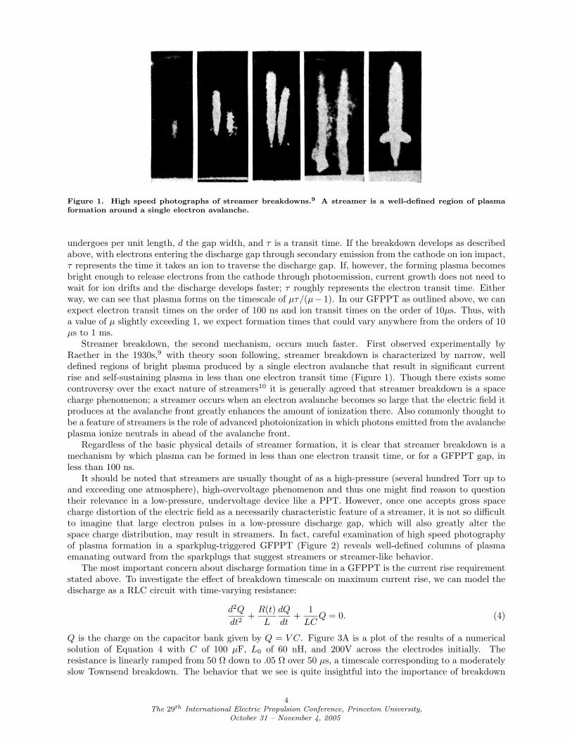
Figure 1. High speed photographs of streamer breakdowns.9 A streamer is a well-defined region of plasmaformation around a single electron avalanche.
undergoes per unit length, d the gap width, and τ is a transit time. If the breakdown develops as describedabove, with electrons entering the discharge gap through secondary emission from the cathode on ion impact,τ represents the time it takes an ion to traverse the discharge gap. If, however, the forming plasma becomesbright enough to release electrons from the cathode through photoemission, current growth does not need towait for ion drifts and the discharge develops faster; τ roughly represents the electron transit time. Eitherway, we can see that plasma forms on the timescale of µτ/(µ− 1). In our GFPPT as outlined above, we canexpect electron transit times on the order of 100 ns and ion transit times on the order of 10µs. Thus, witha value of µ slightly exceeding 1, we expect formation times that could vary anywhere from the orders of 10µs to 1 ms.
Streamer breakdown, the second mechanism, occurs much faster. First observed experimentally byRaether in the 1930s,9 with theory soon following, streamer breakdown is characterized by narrow, welldefined regions of bright plasma produced by a single electron avalanche that result in significant currentrise and self-sustaining plasma in less than one electron transit time (Figure 1). Though there exists somecontroversy over the exact nature of streamers10 it is generally agreed that streamer breakdown is a spacecharge phenomenon; a streamer occurs when an electron avalanche becomes so large that the electric field itproduces at the avalanche front greatly enhances the amount of ionization there. Also commonly thought tobe a feature of streamers is the role of advanced photoionization in which photons emitted from the avalancheplasma ionize neutrals in ahead of the avalanche front.
Regardless of the basic physical details of streamer formation, it is clear that streamer breakdown is amechanism by which plasma can be formed in less than one electron transit time, or for a GFPPT gap, inless than 100 ns.
It should be noted that streamers are usually thought of as a high-pressure (several hundred Torr up toand exceeding one atmosphere), high-overvoltage phenomenon and thus one might find reason to questiontheir relevance in a low-pressure, undervoltage device like a PPT. However, once one accepts gross spacecharge distortion of the electric field as a necessarily characteristic feature of a streamer, it is not so difficultto imagine that large electron pulses in a low-pressure discharge gap, which will also greatly alter thespace charge distribution, may result in streamers. In fact, careful examination of high speed photographyof plasma formation in a sparkplug-triggered GFPPT (Figure 2) reveals well-defined columns of plasmaemanating outward from the sparkplugs that suggest streamers or streamer-like behavior.
The most important concern about discharge formation time in a GFPPT is the current rise requirementstated above. To investigate the effect of breakdown timescale on maximum current rise, we can model thedischarge as a RLC circuit with time-varying resistance:
d2Q
dt2+
R(t)L
dQ
dt+
1LC
Q = 0. (4)
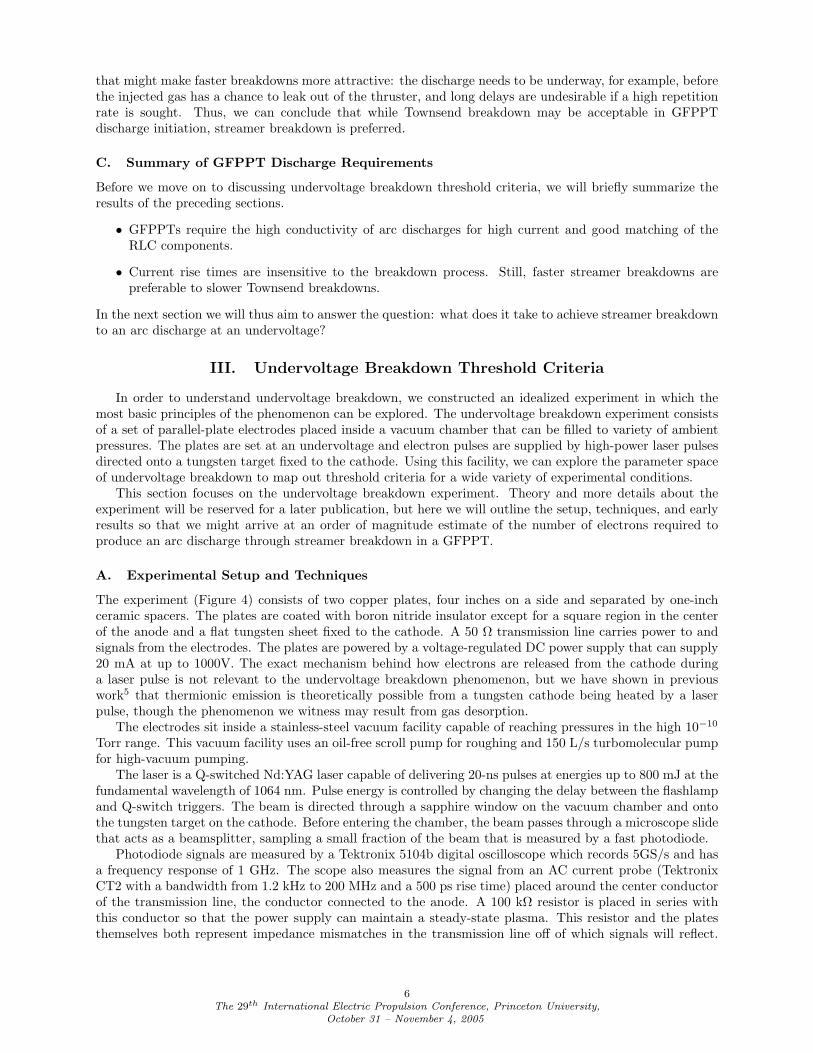
Q is the charge on the capacitor bank given by Q = V C. Figure 3A is a plot of the results of a numericalsolution of Equation 4 with C of 100 µF, L0 of 60 nH, and 200V across the electrodes initially. Theresistance is linearly ramped from 50 Ω down to .05 Ω over 50 µs, a timescale corresponding to a moderatelyslow Townsend breakdown. The behavior that we see is quite insightful into the importance of breakdown
4The 29th International Electric Propulsion Conference, Princeton University,
October 31 – November 4, 2005
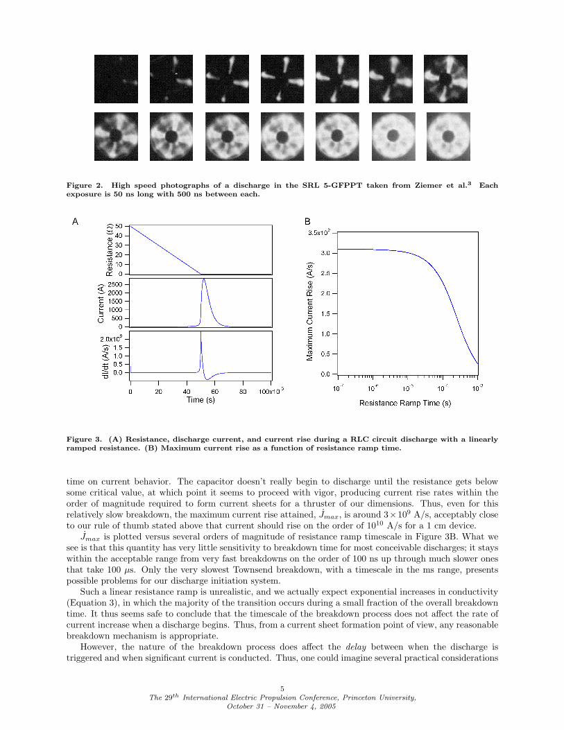
Figure 2. High speed photographs of a discharge in the SRL 5-GFPPT taken from Ziemer et al.3 Eachexposure is 50 ns long with 500 ns between each.
Figure 3. (A) Resistance, discharge current, and current rise during a RLC circuit discharge with a linearlyramped resistance. (B) Maximum current rise as a function of resistance ramp time.
time on current behavior. The capacitor doesn’t really begin to discharge until the resistance gets belowsome critical value, at which point it seems to proceed with vigor, producing current rise rates within theorder of magnitude required to form current sheets for a thruster of our dimensions. Thus, even for thisrelatively slow breakdown, the maximum current rise attained, Jmax, is around 3×10⁹ A/s, acceptably closeto our rule of thumb stated above that current should rise on the order of 1010 A/s for a 1 cm device.
Jmax is plotted versus several orders of magnitude of resistance ramp timescale in Figure 3B. What wesee is that this quantity has very little sensitivity to breakdown time for most conceivable discharges; it stayswithin the acceptable range from very fast breakdowns on the order of 100 ns up through much slower onesthat take 100 µs. Only the very slowest Townsend breakdown, with a timescale in the ms range, presentspossible problems for our discharge initiation system.
Such a linear resistance ramp is unrealistic, and we actually expect exponential increases in conductivity(Equation 3), in which the majority of the transition occurs during a small fraction of the overall breakdowntime. It thus seems safe to conclude that the timescale of the breakdown process does not affect the rate ofcurrent increase when a discharge begins. Thus, from a current sheet formation point of view, any reasonablebreakdown mechanism is appropriate.
However, the nature of the breakdown process does affect the delay between when the discharge istriggered and when significant current is conducted. Thus, one could imagine several practical considerations
5The 29th International Electric Propulsion Conference, Princeton University,
October 31 – November 4, 2005
that might make faster breakdowns more attractive: the discharge needs to be underway, for example, beforethe injected gas has a chance to leak out of the thruster, and long delays are undesirable if a high repetitionrate is sought. Thus, we can conclude that while Townsend breakdown may be acceptable in GFPPTdischarge initiation, streamer breakdown is preferred.
C. Summary of GFPPT Discharge Requirements
Before we move on to discussing undervoltage breakdown threshold criteria, we will briefly summarize theresults of the preceding sections.
• GFPPTs require the high conductivity of arc discharges for high current and good matching of theRLC components.
• Current rise times are insensitive to the breakdown process. Still, faster streamer breakdowns arepreferable to slower Townsend breakdowns.
In the next section we will thus aim to answer the question: what does it take to achieve streamer breakdownto an arc discharge at an undervoltage?
III. Undervoltage Breakdown Threshold Criteria
In order to understand undervoltage breakdown, we constructed an idealized experiment in which themost basic principles of the phenomenon can be explored. The undervoltage breakdown experiment consistsof a set of parallel-plate electrodes placed inside a vacuum chamber that can be filled to variety of ambientpressures. The plates are set at an undervoltage and electron pulses are supplied by high-power laser pulsesdirected onto a tungsten target fixed to the cathode. Using this facility, we can explore the parameter spaceof undervoltage breakdown to map out threshold criteria for a wide variety of experimental conditions.
This section focuses on the undervoltage breakdown experiment. Theory and more details about theexperiment will be reserved for a later publication, but here we will outline the setup, techniques, and earlyresults so that we might arrive at an order of magnitude estimate of the number of electrons required toproduce an arc discharge through streamer breakdown in a GFPPT.
A. Experimental Setup and Techniques
The experiment (Figure 4) consists of two copper plates, four inches on a side and separated by one-inchceramic spacers. The plates are coated with boron nitride insulator except for a square region in the centerof the anode and a flat tungsten sheet fixed to the cathode. A 50 Ω transmission line carries power to andsignals from the electrodes. The plates are powered by a voltage-regulated DC power supply that can supply20 mA at up to 1000V. The exact mechanism behind how electrons are released from the cathode duringa laser pulse is not relevant to the undervoltage breakdown phenomenon, but we have shown in previouswork5 that thermionic emission is theoretically possible from a tungsten cathode being heated by a laserpulse, though the phenomenon we witness may result from gas desorption.
The electrodes sit inside a stainless-steel vacuum facility capable of reaching pressures in the high 10−10
Torr range. This vacuum facility uses an oil-free scroll pump for roughing and 150 L/s turbomolecular pumpfor high-vacuum pumping.
The laser is a Q-switched Nd:YAG laser capable of delivering 20-ns pulses at energies up to 800 mJ at thefundamental wavelength of 1064 nm. Pulse energy is controlled by changing the delay between the flashlampand Q-switch triggers. The beam is directed through a sapphire window on the vacuum chamber and ontothe tungsten target on the cathode. Before entering the chamber, the beam passes through a microscope slidethat acts as a beamsplitter, sampling a small fraction of the beam that is measured by a fast photodiode.
Photodiode signals are measured by a Tektronix 5104b digital oscilloscope which records 5GS/s and hasa frequency response of 1 GHz. The scope also measures the signal from an AC current probe (TektronixCT2 with a bandwidth from 1.2 kHz to 200 MHz and a 500 ps rise time) placed around the center conductorof the transmission line, the conductor connected to the anode. A 100 kΩ resistor is placed in series withthis conductor so that the power supply can maintain a steady-state plasma. This resistor and the platesthemselves both represent impedance mismatches in the transmission line off of which signals will reflect.
6The 29th International Electric Propulsion Conference, Princeton University,
October 31 – November 4, 2005
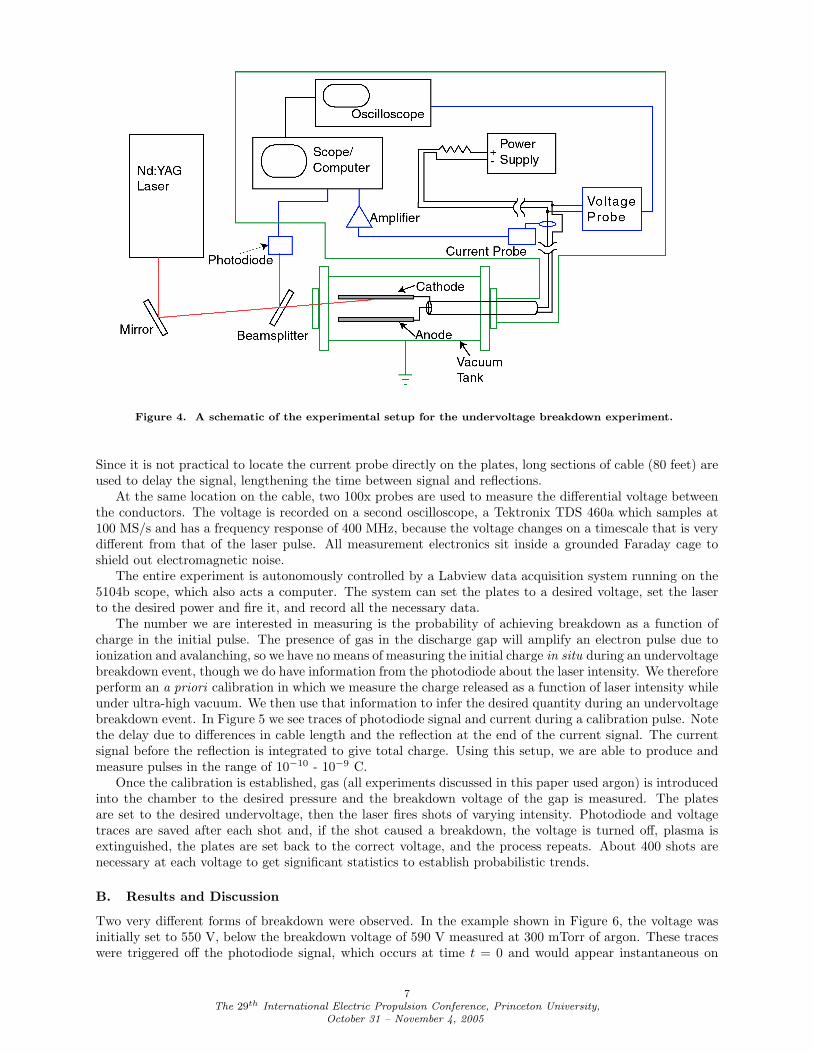
Figure 4. A schematic of the experimental setup for the undervoltage breakdown experiment.
Since it is not practical to locate the current probe directly on the plates, long sections of cable (80 feet) areused to delay the signal, lengthening the time between signal and reflections.
At the same location on the cable, two 100x probes are used to measure the differential voltage betweenthe conductors. The voltage is recorded on a second oscilloscope, a Tektronix TDS 460a which samples at100 MS/s and has a frequency response of 400 MHz, because the voltage changes on a timescale that is verydifferent from that of the laser pulse. All measurement electronics sit inside a grounded Faraday cage toshield out electromagnetic noise.
The entire experiment is autonomously controlled by a Labview data acquisition system running on the5104b scope, which also acts a computer. The system can set the plates to a desired voltage, set the laserto the desired power and fire it, and record all the necessary data.
The number we are interested in measuring is the probability of achieving breakdown as a function ofcharge in the initial pulse. The presence of gas in the discharge gap will amplify an electron pulse due toionization and avalanching, so we have no means of measuring the initial charge in situ during an undervoltagebreakdown event, though we do have information from the photodiode about the laser intensity. We thereforeperform an a priori calibration in which we measure the charge released as a function of laser intensity whileunder ultra-high vacuum. We then use that information to infer the desired quantity during an undervoltagebreakdown event. In Figure 5 we see traces of photodiode signal and current during a calibration pulse. Notethe delay due to differences in cable length and the reflection at the end of the current signal. The currentsignal before the reflection is integrated to give total charge. Using this setup, we are able to produce andmeasure pulses in the range of 10−10 - 10−9 C.
Once the calibration is established, gas (all experiments discussed in this paper used argon) is introducedinto the chamber to the desired pressure and the breakdown voltage of the gap is measured. The platesare set to the desired undervoltage, then the laser fires shots of varying intensity. Photodiode and voltagetraces are saved after each shot and, if the shot caused a breakdown, the voltage is turned off, plasma isextinguished, the plates are set back to the correct voltage, and the process repeats. About 400 shots arenecessary at each voltage to get significant statistics to establish probabilistic trends.
B. Results and Discussion
Two very different forms of breakdown were observed. In the example shown in Figure 6, the voltage wasinitially set to 550 V, below the breakdown voltage of 590 V measured at 300 mTorr of argon. These traceswere triggered off the photodiode signal, which occurs at time t = 0 and would appear instantaneous on
7The 29th International Electric Propulsion Conference, Princeton University,
October 31 – November 4, 2005
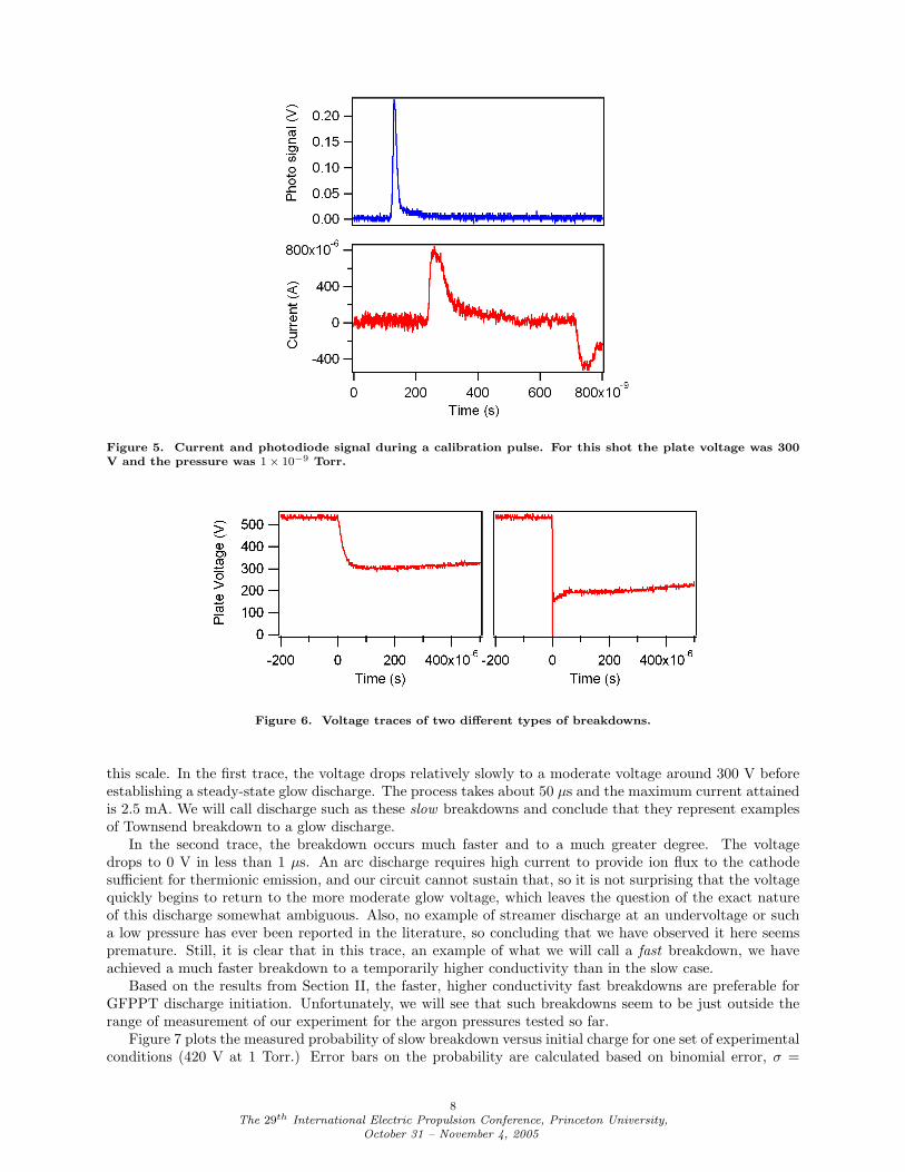
Figure 5. Current and photodiode signal during a calibration pulse. For this shot the plate voltage was 300V and the pressure was 1× 10⁻⁹ Torr.
Figure 6. Voltage traces of two different types of breakdowns.
this scale. In the first trace, the voltage drops relatively slowly to a moderate voltage around 300 V beforeestablishing a steady-state glow discharge. The process takes about 50 µs and the maximum current attainedis 2.5 mA. We will call discharge such as these slow breakdowns and conclude that they represent examplesof Townsend breakdown to a glow discharge.
In the second trace, the breakdown occurs much faster and to a much greater degree. The voltagedrops to 0 V in less than 1 µs. An arc discharge requires high current to provide ion flux to the cathodesufficient for thermionic emission, and our circuit cannot sustain that, so it is not surprising that the voltagequickly begins to return to the more moderate glow voltage, which leaves the question of the exact natureof this discharge somewhat ambiguous. Also, no example of streamer discharge at an undervoltage or sucha low pressure has ever been reported in the literature, so concluding that we have observed it here seemspremature. Still, it is clear that in this trace, an example of what we will call a fast breakdown, we haveachieved a much faster breakdown to a temporarily higher conductivity than in the slow case.
Based on the results from Section II, the faster, higher conductivity fast breakdowns are preferable forGFPPT discharge initiation. Unfortunately, we will see that such breakdowns seem to be just outside therange of measurement of our experiment for the argon pressures tested so far.
Figure 7 plots the measured probability of slow breakdown versus initial charge for one set of experimentalconditions (420 V at 1 Torr.) Error bars on the probability are calculated based on binomial error, σ =
8The 29th International Electric Propulsion Conference, Princeton University,
October 31 – November 4, 2005
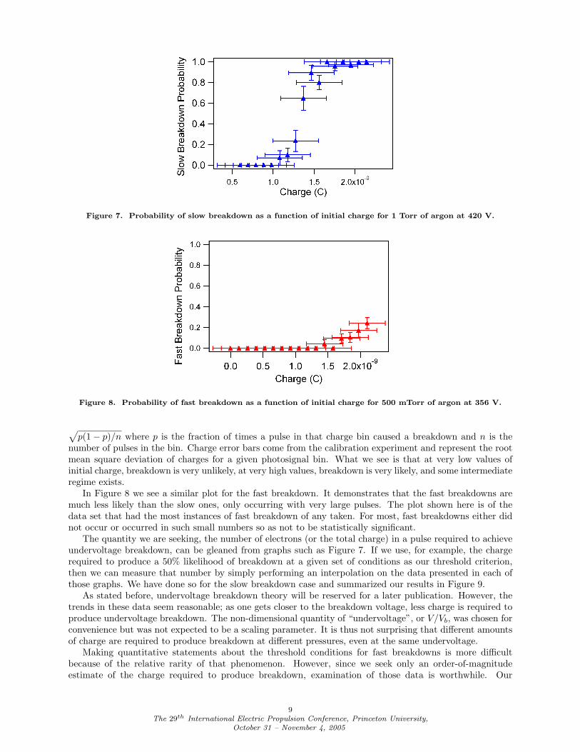
Figure 7. Probability of slow breakdown as a function of initial charge for 1 Torr of argon at 420 V.
Figure 8. Probability of fast breakdown as a function of initial charge for 500 mTorr of argon at 356 V.
√p(1− p)/n where p is the fraction of times a pulse in that charge bin caused a breakdown and n is the
number of pulses in the bin. Charge error bars come from the calibration experiment and represent the rootmean square deviation of charges for a given photosignal bin. What we see is that at very low values ofinitial charge, breakdown is very unlikely, at very high values, breakdown is very likely, and some intermediateregime exists.
In Figure 8 we see a similar plot for the fast breakdown. It demonstrates that the fast breakdowns aremuch less likely than the slow ones, only occurring with very large pulses. The plot shown here is of thedata set that had the most instances of fast breakdown of any taken. For most, fast breakdowns either didnot occur or occurred in such small numbers so as not to be statistically significant.
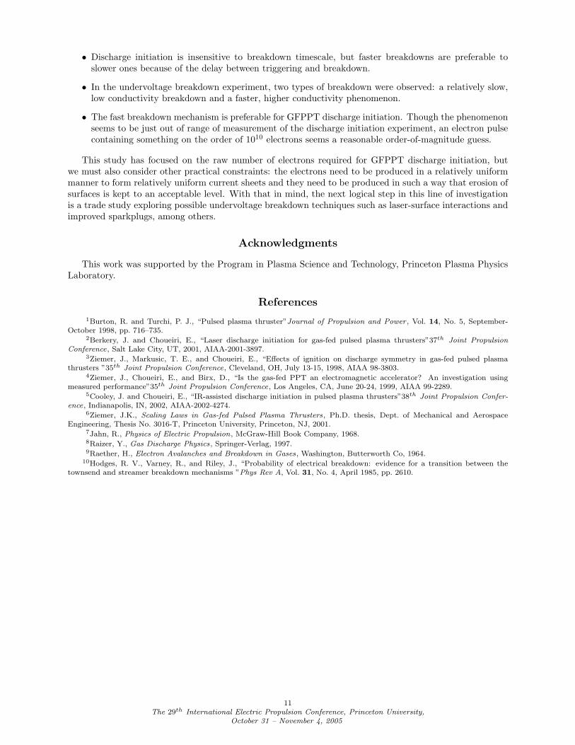
The quantity we are seeking, the number of electrons (or the total charge) in a pulse required to achieveundervoltage breakdown, can be gleaned from graphs such as Figure 7. If we use, for example, the chargerequired to produce a 50% likelihood of breakdown at a given set of conditions as our threshold criterion,then we can measure that number by simply performing an interpolation on the data presented in each ofthose graphs. We have done so for the slow breakdown case and summarized our results in Figure 9.
As stated before, undervoltage breakdown theory will be reserved for a later publication. However, thetrends in these data seem reasonable; as one gets closer to the breakdown voltage, less charge is required toproduce undervoltage breakdown. The non-dimensional quantity of “undervoltage”, or V/Vb, was chosen forconvenience but was not expected to be a scaling parameter. It is thus not surprising that different amountsof charge are required to produce breakdown at different pressures, even at the same undervoltage.
Making quantitative statements about the threshold conditions for fast breakdowns is more difficultbecause of the relative rarity of that phenomenon. However, since we seek only an order-of-magnitudeestimate of the charge required to produce breakdown, examination of those data is worthwhile. Our
9The 29th International Electric Propulsion Conference, Princeton University,
October 31 – November 4, 2005
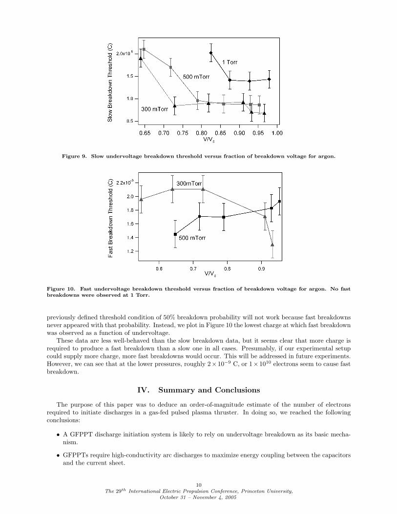
Figure 9. Slow undervoltage breakdown threshold versus fraction of breakdown voltage for argon.
Figure 10. Fast undervoltage breakdown threshold versus fraction of breakdown voltage for argon. No fastbreakdowns were observed at 1 Torr.
previously defined threshold condition of 50% breakdown probability will not work because fast breakdownsnever appeared with that probability. Instead, we plot in Figure 10 the lowest charge at which fast breakdownwas observed as a function of undervoltage.
These data are less well-behaved than the slow breakdown data, but it seems clear that more charge isrequired to produce a fast breakdown than a slow one in all cases. Presumably, if our experimental setupcould supply more charge, more fast breakdowns would occur. This will be addressed in future experiments.However, we can see that at the lower pressures, roughly 2× 10⁻⁹ C, or 1× 10¹⁰ electrons seem to cause fastbreakdown.
IV. Summary and Conclusions
The purpose of this paper was to deduce an order-of-magnitude estimate of the number of electronsrequired to initiate discharges in a gas-fed pulsed plasma thruster. In doing so, we reached the followingconclusions:
• A GFPPT discharge initiation system is likely to rely on undervoltage breakdown as its basic mecha-nism.
• GFPPTs require high-conductivity arc discharges to maximize energy coupling between the capacitorsand the current sheet.
10The 29th International Electric Propulsion Conference, Princeton University,
October 31 – November 4, 2005
• Discharge initiation is insensitive to breakdown timescale, but faster breakdowns are preferable toslower ones because of the delay between triggering and breakdown.
• In the undervoltage breakdown experiment, two types of breakdown were observed: a relatively slow,low conductivity breakdown and a faster, higher conductivity phenomenon.
• The fast breakdown mechanism is preferable for GFPPT discharge initiation. Though the phenomenonseems to be just out of range of measurement of the discharge initiation experiment, an electron pulsecontaining something on the order of 1010 electrons seems a reasonable order-of-magnitude guess.
This study has focused on the raw number of electrons required for GFPPT discharge initiation, butwe must also consider other practical constraints: the electrons need to be produced in a relatively uniformmanner to form relatively uniform current sheets and they need to be produced in such a way that erosion ofsurfaces is kept to an acceptable level. With that in mind, the next logical step in this line of investigationis a trade study exploring possible undervoltage breakdown techniques such as laser-surface interactions andimproved sparkplugs, among others.
Acknowledgments
This work was supported by the Program in Plasma Science and Technology, Princeton Plasma PhysicsLaboratory.
References
1Burton, R. and Turchi, P. J., “Pulsed plasma thruster”Journal of Propulsion and Power , Vol. 14, No. 5, September-October 1998, pp. 716–735.
2Berkery, J. and Choueiri, E., “Laser discharge initiation for gas-fed pulsed plasma thrusters”37th Joint PropulsionConference, Salt Lake City, UT, 2001, AIAA-2001-3897.
3Ziemer, J., Markusic, T. E., and Choueiri, E., “Effects of ignition on discharge symmetry in gas-fed pulsed plasmathrusters ”35th Joint Propulsion Conference, Cleveland, OH, July 13-15, 1998, AIAA 98-3803.
4Ziemer, J., Choueiri, E., and Birx, D., “Is the gas-fed PPT an electromagnetic accelerator? An investigation usingmeasured performance”35th Joint Propulsion Conference, Los Angeles, CA, June 20-24, 1999, AIAA 99-2289.
5Cooley, J. and Choueiri, E., “IR-assisted discharge initiation in pulsed plasma thrusters”38th Joint Propulsion Confer-ence, Indianapolis, IN, 2002, AIAA-2002-4274.
6Ziemer, J.K., Scaling Laws in Gas-fed Pulsed Plasma Thrusters, Ph.D. thesis, Dept. of Mechanical and AerospaceEngineering, Thesis No. 3016-T, Princeton University, Princeton, NJ, 2001.
7Jahn, R., Physics of Electric Propulsion, McGraw-Hill Book Company, 1968.8Raizer, Y., Gas Discharge Physics, Springer-Verlag, 1997.9Raether, H., Electron Avalanches and Breakdown in Gases, Washington, Butterworth Co, 1964.
10Hodges, R. V., Varney, R., and Riley, J., “Probability of electrical breakdown: evidence for a transition between thetownsend and streamer breakdown mechanisms ”Phys Rev A, Vol. 31, No. 4, April 1985, pp. 2610.
11The 29th International Electric Propulsion Conference, Princeton University,
October 31 – November 4, 2005


![Pulsed Initiation polymerization as a means of obtaining ...O'Driscoll and Kuindersma simulated the PLP experiments with Monte Carlo simulations [15], and Zammit, Davis, and Haddleton](https://img.pdfslide.net/doc/110x75/5f426c53eed2fd1b192ea595/pulsed-initiation-polymerization-as-a-means-of-obtaining-odriscoll-and-kuindersma.jpg)