Embed Size (px)
Citation preview

1
10 Fundamentals of Electricity OBJECTIVES This chapter has been written to provide a better introduction to the fields of electric circuits and electronics. We lead you through a study of the mathematics and physics as they are jointly applied to electric circuits. After completing this chapter you should be able to
Understand the physical meaning of variables used to describe electricity. List the three major parts of an atom. Define Coulomb’s law. Discuss the differences between conductors, semiconductors, and
insulators. Understand the basic quantities in electric circuits such as voltage and
current. Understand the characteristics of resistors, inductors, and capacitors. Define the concepts of RC and L/R time constants, which are very
important in science. Understand the behavior of electric circuits using Ohm’s law. Relate the three main parameters of an electric circuit: the voltage, the
electric current, and the electrical resistance. Realize how the above three parameters are used to compute circuit
characteristics and conditions. Realize how the above parameters are used to compute electrical power.
FOCUS ON MATHEMATICS
This chapter relates the application of mathematics to electrical concepts, covering fractions; functions; vectors; derivatives and integration; exponential equations; and graphing techniques.

2 Chapter 10
10.1 WHAT IS ELECTRICITY?
The word electricity originated about 600 B.C; it comes from elektron, which was the ancient Greek work for amber. However, the true nature of electricity was understood later.
What is electricity? This particular question is not easy to answer because the word “electricity” has different meanings, which complement each other. Electricity may mean electric charges, flow of electric charges, or electric energy. If we wish to agree on a single definition of electricity, then which one should we choose? May be we do not need to choose just one but all of the above definitions are true.
Just as coal enabled the industrial revolution, electricity is the unseen fuel of modern life. The dramatic increase in the use of electricity for domestic and industrial purposes proves that electrical energy plays an important part in our society. It is impossible to imagine what our lives would be like without access to this source of energy. Technologies associated with electricity have made our lives easier. Modern society is indeed unworkable without the existence of electrical appliances. Likewise, emerging telecommunication and information services have greatly enhanced the ability of individuals and groups to communicate with each other and have facilitated the speed of information to persons and machines in both urban and rural environments.
Whatever the particular field of services, possession of basic knowledge forms the basis for the performance of many varied tasks which today’s engineer is called on by industry and employers to do-and do well.
10.2 SYSTEMS OF UNITS
In order to state the value of some measurable quantity, we must give both a number (how much) and a unit (of what) (for example, 5 meters). Regarding numbers, fortunately, we all use the same number system. However, this is not true for units, and we need some efforts to familiarize ourselves with a suitable system. This could be accomplished by following a standard unit of efficient performance.
A measurement of any physical quantity must be expressed as a number followed by a unit. A unit is a standard by which a dimension can be expressed numerically. The units for the fundamental dimensions are called the fundamental or base units. While carrying out EM calculations, there are several systems of base units that are available. However, they may be broken into two main groups. First, the International System of Units (SI) introduced by Griorgi in 1901, including the meter-kilogram-second-ampere (MKSA) subsystem representing the four fundamental dimensions length, mass, time, and electric current,

Fundamentals of Electricity 3
respectively. Second is the centimeter-gram-second (CGS) system. The units for other dimensions are called secondary, or derived units and are based on the above fundamental units.
Table 10-1 The Seven Fundamental SI Units
Quantity Unit Abbreviation Length meter m Mass kilogram kg Time second s Electric current ampere A Temperature Kelvin K Luminous intensity candela cd Matter mole mol
Currently, most the engineers use the practical MKSA system. What is known
as the Gaussian system is an unrationalized CGS system, which is mixed in the sense that electric quantities are measured in electrostatic units, while magnetic quantities are measured in magnetostatic units. The CGS system is used mainly in the area of physics, where certain simplification in formulas results.
The SI is the standard system used in today’s scientific literature. The SI has seven base units, several derived units with special names, and many derived units with compound names. A few CGS system units are also used when appropriate. The complete SI system involves units but also other recommendations, one of which is that multiple and submultiples of the MKSA units be set in steps of 103 or 10-3. The fundamental SI units and abbreviations are listed in Table 10-1. Table 10-2 lists many of the SI derived units used in electric and electronic circuits.
The SI uses the decimal system to relate larger and smaller units to the basic units, and employs prefixes to signify the various powers of 10. A list of prefixes and their symbols is given in Table 10-3. These prefixes are very important in engineering studies and are worth memorizing. Table 10-2 SI Derived Units
Quantity Symbol Unit Unit Symbol Angle θ Radian rad
Capacitance C Farad F Conductance G Siemens S
Electric charge Q Coulomb C

4 Chapter 10
Electromotive force E Volt V Energy, work W Joule J
Force F Newton N Frequency f Hertz Hz Inductance L Henry H
Power P Watt W Resistance R Ohm Ω Pressure p Pascal Pa
Magnetic Flux Φ Weber Wb Magnetic Induction B Tesla T
Light Flux L Lumen lm Table 10-3 SI Prefixes Metric Symbol Metric Prefix Value Power of Ten
T One Trillion Tera 1012 G One Billion Giga 109 M One Million Mega 106 K One Thousand Kilo 103 m One Thousandth Milli 10-3 µ One Millionth Micro 10-6 n One Billionth Nano 10-9 p One Trillionth Pico 10-12
10.3 MATTER AND ELECTRICITY
To understand electricity, it is important to start with the study of atoms. The atom is the basic building of the universe. Electricity is made up of atom matter. Matter consists of very small particles, which together form an atom. Matter is commonly made up of mass and weight, which occupies space. This mass can become and take into form different states such as, solid, liquid, gas, or plasma. The atom also has motion and two kinds of energy types: potential energy, which is a result of its position and kinetic energy, which is the energy of motion.
An element is a substance, which cannot be reduced to a simpler substance by chemical means. Examples of elements with which we use everyday are iron, gold, silver, copper, and oxygen. There are now over 100 known elements. All the different substances we know about are composed of one or more of these elements. An atom is the smallest particle of an element that retains the characteristics of that element. The atoms of one element, however, differ from

Fundamentals of Electricity 5
the atoms of all other elements. Figure 10-1 Principal parts of an atom.
The center of the atom is called the nucleus, which is primarily made up of particles called protons and neutrons. These two particles make up most of the atoms weight and mass. Orbiting around it are electrons (like our planets orbiting around the sun) as shown in Figure 10-1. The electrons are many times smaller in mass than protons and neutrons.
Protons, electrons, and neutrons are very different from each other. They have their own properties. One of these properties is called an electrical charge. A proton has what we call a “positive” (+) charge. The electron has a “negative” (-) charge. The neutron that is in the center together with the proton has a neutral charge and that why it is called a neutron. The charge of one proton is equal in strength to the charge of one electron. When the number of protons in an atom equals the number of electrons, the atom itself has no overall charge, it is neutral.
Usually an atom has an equal amount of protons in the center as it has electrons around it. The number of protons (electrons) is called the atomic number. The total number of protons and neutrons in the center calculates the atomic weight. For example, the element of copper has an atomic number of 29 and an atomic weight of 64. It has 29 electrons, 29 protons and 35 neutrons. This means the atomic weight is 29 + 35 = 64 and the number of protons or electrons is 29.
Orbits referred to as shells arrange the electrons, which orbit around the center of atom. Each orbit or shell represents a different energy level away from the center or nucleus.
In the point of view of charges, the protons in the center of the atom and the
N
Proton
Electron
Neutron

6 Chapter 10
electrons that orbit the center exert not only forces of gravitational attraction between them but are also under forces due to their homologues.
There are many ways that the normal balance within the atom can be changed, natural or artificial. The key to remember is that a charge in a body remains until the body is discharged. Once discharged, the charge starts to move and forms a current. Assume in very dry weather, you rub your hair with a comb, then the net charge of the atoms in both your hair and the comb will change. As you rub the comb through your hair, you also rub off some of the electrons from your hair thereby making the comb more negatively charged with electrons and the hair more positively charged with protons. If you turn off the lights, you can even see small sparks of electricity jumping from the comb to the hair. This by the way is called static electricity. 10.4 CHARGE AND COULOMB’S LAW
Charge is one of the fundamental physical quantities in electric circuit analysis. A quantity of charge that does not change with time (i.e., time invariant) is typically represented by an uppercase Q. The instantaneous amount of charge, which is time dependent (changes over time), is commonly represented by q (t), or simply by using the lowercase letter q.
In the SI units, the unit of electric charge is the coulomb (C), which is a quantity measurement of electrons. One coulomb contains 6.25 ×10¹⁸ electrons. We know from basic physics that there are two types of charges: positive (corresponding to a proton), and negative (corresponding to an electron). The proton charge is equal to +1.602 ×10⁻¹⁹ C, while the electron charge is -1.602 ×10⁻¹⁹ C. The influence of charges is characterized in terms of the forces between them.
Although we regularly transfer charges between different parts of an electric circuit, we do nothing to change the total amount of charge. Clearly, we neither create nor destroy electrons or protons when operating electric circuits. Moving charges represents an electric current. In a neutral state (zero charge), electrons will neither leave nor enter the neutrally charged body should it come in contact with other neutral bodies. If, however, any number of electrons is removed from the atoms of a body of matter, there will remain more protons than electrons and the whole body of matter will become electrically positive. Should the positively charged body come in contact with another non-charged body, or having a negative charge, an electric current (I) will flow between them. Electrons will leave the more negative body and enter the positive body. This electron flow will continue until both bodies have equal charges. When two bodies of matter have charges and are near one another, an electric force (F) is exerted between them.

Fundamentals of Electricity 7
The existence of such force, where current does not flow, is referred to as “static.” The force of attraction (Figure 10-2) or repulsion (Figure 10-3) exerted between two charged bodies is directly proportional to the product of their charges (Q) and inversely proportional to the square of the distance (R) between them. This relationship between attracting or repelling charged bodies was first discovered by a French scientist named Charles A. Coulomb and accordingly is known as Coulomb’s law, which can be expressed mathematically by the following equation.
2o
21
4 a F
RQQ
επ=
(10.1)
where F is a vector quantity, which represents the electrical force acting on charge Q2 due to charge Q1 measured in Newton (N), a is a unit vector pointing from charge Q1 to charge Q2, and εo is a universal constant called the electrical permittivity of free space [εo = 8.854 × 10⁻¹² farad per meter (F/m)]. The two charges are assumed to be free space (vacuum) and isolated from all other charges.
Figure 10-2 Charges attract each other. Figure 10-3 Charges repel each other.

8 Chapter 10
Example 10-1 A positive charge of 4 × 10⁻¹⁰ C exerts a force on a negative charge of 7 × 10⁻¹⁰ C. The distance between the two charges is 4 cm. Find the magnitude of the attractive force that either charge exerts on the other. Solution: Apply Equation (10.1) to find the force
When length is measured, the quantity that results is called a scalar. The concept of vector is needed for quantities with both magnitude and direction. An arrow in which the magnitude of the vector is the number next to the arrow represents vector. The direction of the vector is the direction of the arrow (Figure 10.4).
Figure 10-4 Force as a vector quantity with magnitude and direction.
A force is a vector quantity. To fully describe the force acting
upon an object, you must describe both the magnitude (size) and the direction. Thus, the quantity “5 Newtons” is not a full description of the force acting upon an object. In contrast, saying “5 Newtons, upwards” is a full description of the force acting upon an object; both the magnitude (5 Newtons) and the direction (upwards) are given.
It is common to use special notation for vector quantities. For example F is used for the force and |F| for the magnitude of force.
Focus on Mathematics Scalars and Vectors
5 N
Fundamentals of Electricity 9
N 10 1.6 a 101610 8.854 4)10)(710(4 a
4 a F
6-
412-
10-10-
2o
21
×=
××××
××=
=
−π
επ RQQ
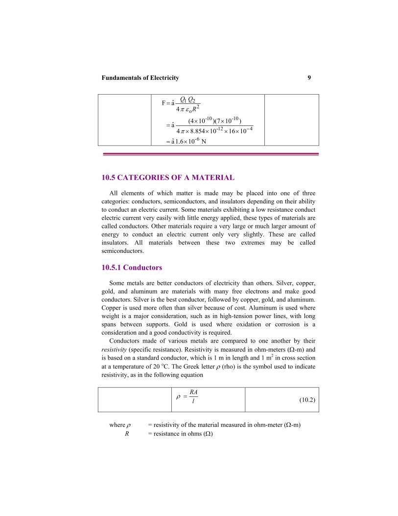
10.5 CATEGORIES OF A MATERIAL
All elements of which matter is made may be placed into one of three categories: conductors, semiconductors, and insulators depending on their ability to conduct an electric current. Some materials exhibiting a low resistance conduct electric current very easily with little energy applied, these types of materials are called conductors. Other materials require a very large or much larger amount of energy to conduct an electric current only very slightly. These are called insulators. All materials between these two extremes may be called semiconductors. 10.5.1 Conductors
Some metals are better conductors of electricity than others. Silver, copper,
gold, and aluminum are materials with many free electrons and make good conductors. Silver is the best conductor, followed by copper, gold, and aluminum. Copper is used more often than silver because of cost. Aluminum is used where weight is a major consideration, such as in high-tension power lines, with long spans between supports. Gold is used where oxidation or corrosion is a consideration and a good conductivity is required.
Conductors made of various metals are compared to one another by their resistivity (specific resistance). Resistivity is measured in ohm-meters (Ω-m) and is based on a standard conductor, which is 1 m in length and 1 m2 in cross section at a temperature of 20 oC. The Greek letter ρ (rho) is the symbol used to indicate resistivity, as in the following equation
lRA =ρ
(10.2)
where ρ = resistivity of the material measured in ohm-meter (Ω-m)
R = resistance in ohms (Ω)

10 Chapter 10
A = cross-sectional area in square meters (m2) l = length in meters (m)
Example 10-2 Calculate the resistance of a wire of 0.5-mm diameter and 5.0 m long. Assume ρ = 1.0 × 10⁻⁶ Ω.m Solution: Express the diameter in meters: m10 0.5 mm 0.5 -3×=
Calculate the area of the conductor in square meters
( )26-
23-
2
m 10 0.196 4
10 0.5 3.14
4
×=
×=
=dA π
Using Equation (10.2) to find the resistance R
( )
5.010 0.196 10 0.1
-66- ×
=×R
Accordingly, R = 25.5 Ω
10.5.2 Insulators
Insulators have few free electrons. An atom that has seven or eight valence electrons is extremely stable and does not easily give up an electron. Insulators are materials that resist the flow of electricity. Good insulators are plastic, rubber, glass, air, asbestos, mica, etc. Just as there is no perfect conductor, neither is there a perfect insulator.

Fundamentals of Electricity 11
10.5.3 Semiconductors
Semiconductors exist between conductors and insulators. They contain four valence electrons. Semiconductors are also characterized by the fact that, as they are heated, their resistance decreases. This is the opposite of a conductor, which increases its resistance with an increase of temperature. The two most common semiconductors are silicon (Si) and germanium (Ge).
A semiconductor is a material or device that may function as either a conductor or an insulator, depending on how its structure is arranged. Semiconductor materials have a crystal structure where electrons are tightly held and the element is stable. A pure semiconductor material does not conduct current. In order to function as semiconductors, impurities must be added to the silicon or germanium. The impurities allow for the flow of current. The amount of impurities determines the amount of current. The type of impurity determines what type of semiconductor will be produced.
Semiconductors have become very important in the electronics industry since the invention of the transistor in 1947. Currently, semiconductors are used to make all kinds of electronic devices. 10.6 CURRENT
The time rate of change of electric charge passing through a predetermined area is called electric current. Typically, this area is the cross-sectional area of a conductor (Figure 10-5). The unit of current is called ampere (A). The ampere is attributed to the French physicist André-Marie Ampère who lived in the 1700s and early 1800s. The ampere is defined as one coulomb per second. Mathematically, we may define the current as
tQ
tQi
or C/s,
=
∆∆
=
(10.3)
where I = intensity of the electric current in amperes (A) (1 A = 1 C/s) Q = quantity of electric charge in coulombs (C) t = time in seconds (s)
It is known from Table 10-1, the ampere (A) is one of the SI units and as such,
it is not a derived unite of measure. A current of one ampere is said to flow when one coulomb of charge passes a point in a circuit in one second. Remember that one coulomb is equal to the charge of 6.28 × 10¹⁸ electrons.

12 Chapter 10
Figure 10-5 Movement of electrons or ions through a conductor.
In the electrical power industry, an ampere is a small unit. In an electronic circuit it is big unit for measuring current. Therefore, the milliampere (mA), one-thousandth of an ampere (0.001 A), or the microampere (µA), one-millionth of an ampere (0.000001 A), is used. The device used to measure current is called an ammeter. Figure 10-6 shows a symbol of ammeter in an electric circuit. Figure 10-6 Measuring current flow.
There are different types of current as illustrated in Figure 10-7. A current that
is constant in time is termed a direct current (DC) as shown in Figure 10-7a. Another type of current is that varies sinusoidaly with time (Figure 10-7b). This type of current is referred to as alternating current (AC) and exists in household circuits. There are other types of currents but are not discussed in this book.
A
l
-
+
Element v
A

Fundamentals of Electricity 13
Figure 10-7 (a) Direct current (DC). (b) Sinusoidal or alternating current (AC).
t t
(a) (b)
i
Mathematically, the relationship between current i, charge Q, and time t can be written in differential form
C/s dtdQi = (10.4)
The charge transferred between time t0 and t may be expressed as a
definition integral
( )( )
∫ ∫=tQ
tQ
t
tidt dQ
0 0 (10.5)
According to Equation (10.4), the current need not be a constant-
valued function; that is, charge can vary with time in many ways. If the current does not change with time, but remains constant, we call it direct current (DC). The symbol I is used to represent such a constant current. A time-varying current is represented by the symbol i. A common form of such current is the sinusoidal current or alternating current (AC).
Focus on Mathematics Derivative and Integral
i
14 Chapter 10
Example 10-3 What is the current in a circuit where 400 C of charge passes a point in a conductor in 40 s. Solution: Use Equation (10.3) to find the current
A 10 40
400 ===sC
tQI
10.7 VOLTAGE
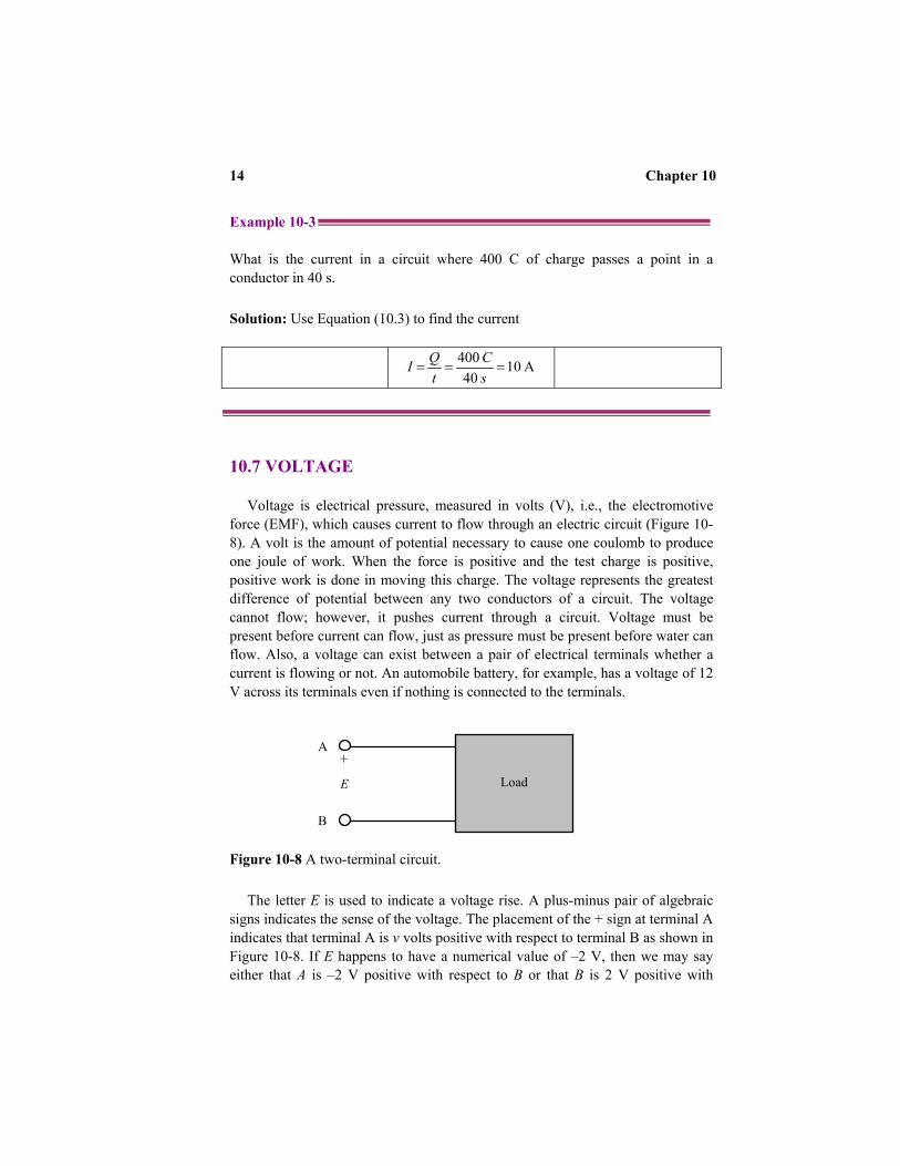
Voltage is electrical pressure, measured in volts (V), i.e., the electromotive force (EMF), which causes current to flow through an electric circuit (Figure 10-8). A volt is the amount of potential necessary to cause one coulomb to produce one joule of work. When the force is positive and the test charge is positive, positive work is done in moving this charge. The voltage represents the greatest difference of potential between any two conductors of a circuit. The voltage cannot flow; however, it pushes current through a circuit. Voltage must be present before current can flow, just as pressure must be present before water can flow. Also, a voltage can exist between a pair of electrical terminals whether a current is flowing or not. An automobile battery, for example, has a voltage of 12 V across its terminals even if nothing is connected to the terminals.
Figure 10-8 A two-terminal circuit.
The letter E is used to indicate a voltage rise. A plus-minus pair of algebraic signs indicates the sense of the voltage. The placement of the + sign at terminal A indicates that terminal A is v volts positive with respect to terminal B as shown in Figure 10-8. If E happens to have a numerical value of –2 V, then we may say either that A is –2 V positive with respect to B or that B is 2 V positive with
A +
Load
B
E

Fundamentals of Electricity 15
respect to A. The sign indicates also the polarity of a terminal, i.e., its particular state (positive or negative).
The abbreviation mV stands for millivolt (0.001 V), µV stands for microvolt (0.000001 V), and kV stands for kilovolt (1000 V). The range of values that is encountered in practice is large. The device used to measure voltage is called a voltmeter. Figure 10-9 shows a symbol of voltmeter in an electric circuit. Figure 10-9 Measuring voltage drop.
Voltage is expressed as energy per charge unit (joule/coulomb) as in the following equation ( )
QWVE or =
(10.6)
where E (or V) = potential difference measured in volts (V) W = energy (work) carried by charge in joules (J) Q = amount of electric charges in coulombs (C)
Example 10-4 What voltage will be measured across the load in Figure 10-9 if 100 mC of charge flows through the load and converts 1.00 Joule of energy into heat. Solution: Apply Equation (10.6) to compute the voltage drop across the load
V 0.1Joule 1.0
C 0.1 Joule 1.0
mC 100.0 QW ====V
+
Load E V
I

16 Chapter 10
10.8 PRODUCTION OF VOLTAGE
There are many ways for producing a voltage or EMF. Some of these ways are more widely used than others, and some are used mostly for specific applications. 10.8.1 Friction
This is possibly the oldest way for creating a voltage. The development of charges by rubbing a rod with fur is a good example of the way in which a voltage is generated by friction. Repeated contact and separation of dissimilar materials may produce very high voltage. Because of the nature of the materials and difficulties encountered during the process with which this voltage is generated, it cannot be conveniently used practically.
10.8.2 Pressure
One way of generating a voltage utilizes the characteristics of certain ionic crystals such as quartz. These crystals have an exceptional ability to generate a voltage whenever pressure is applied to their surfaces. Therefore, if a crystal of quartz is squeezed, charges of opposite polarity will appear on two opposite surfaces of the crystal. If the force is reversed and the crystal is stretched, charges will again appear, but will be of the opposite polarity from those produced by squeezing. If a crystal of this type is given a vibratory motion, it will produce a voltage of reversing polarity between two of its sides. Quartz may therefore be used to convert mechanical energy into electrical energy. This phenomenon is called “piezoelectric effect.” Some of the common devices that make use of piezoelectric crystals are microphones, phonograph cartridges, and oscillators used in radio equipment. This method of generating a voltage is not suitable for high-voltage applications, but is widely used in sound and communications systems where small voltage is required. 10.8.3 Heat
When a metal, such as copper, is heated at one end, electrons tend to move away from the hot end toward the cooler end. This is true of most metals. However, in some metals, such as iron, the opposite takes place and electrons tend to move toward the hot end. When associated, the negative charges (electrons) are moving through the copper away from the heat and through the iron toward the heat. They cross at the cold junction. This arrangement is generally referred to as a thermocouple.
Thermocouples have greater power capacities than crystals, but their capacity is still small compared to some other sources. The thermoelectric voltage in a thermocouple depends mainly on the difference in temperature between the hot

Fundamentals of Electricity 17
and cold junctions. Therefore, they are widely used to measure temperature, and as heat-sensing devices in automatic temperature control equipment. 10.8.4 Light
If light strikes the surface of a material, it may dislodge electrons from their orbits around the surface atoms of the material. This occurs because light has energy, the same as any moving force.
Some substances, mostly metallic ones, are far more sensitive to light than others. That is, more electrons will be dislodged and emitted from the surface of a highly sensitive metal, with a given amount of light, than will be emitted from a less sensitive substance. Upon losing electrons, the photosensitive (light-sensitive) metal becomes positively charged, and an electric force is created. Voltage produced in this way is referred to as a photoelectric. The photosensitive materials most commonly used to produce a photoelectric voltage are various compounds of silver oxide or copper oxide. A complete device, which operates on the photoelectric principle, is referred to as a “photoelectric cell.” There are many different sizes and types of photoelectric cells in use, and each serves the special purpose for which it is designed. 10.8.5 Chemical Interaction
If two different materials (usually metals or metallic materials) are immersed in a solution that produces a greater chemical action on one material than on the other, a difference of potential will exist between the two. If a conductor is then connected between them, electrons will flow through the conductor to equalize the charge. This arrangement is called a primary cell. The two metallic pieces are called electrodes and the solution is called the electrolyte. The difference of potential results from the fact that material from one or both of the electrodes goes into solution in the electrolyte, and in the process, ions form in the vicinity of the electrodes. Due to the electric field associated with the charged ions, the electrodes acquire charges. 10.8.6 Electromagnetic Induction
One of the most effective and widely used applications of electromagnetism is in the production of electric power from mechanical sources. The mechanical power may be provided by a number of different sources, such as gasoline or diesel engines, and water or steam turbines. However, generators employing the principle of electromagnetic induction do the final conversion of these source energies to electricity.
To begin with, there are three fundamental conditions, which must exist before a voltage can be produced by magnetism:

18 Chapter 10
1. There must be a conductor in which the voltage will be produced. 2. There must be a magnetic field in the conductor’s vicinity. 3. There must be relative motion between the field and conductor. The
conductor must be moved so as to cut across the magnetic lines of force, or the field must be moved so that the conductor cuts the lines of force.
In accordance with these conditions, when a conductor or conductors move across a magnetic field so as to cut the lines of force, electrons within the conductor are propelled in one direction or another. Therefore, an electric force, or voltage, is generated. 10.9 RESISTANCE
Resistance is the most common component in electric circuits. It is used mainly to control current and voltage within the circuit. It is measured in ohms. The ohm is named for a German scientist named George S. Ohm. Resistance determines the current produced by a given difference of potential; that property of a substance which impedes current and results in the dissipation of power in the form of heat. Figure 10-10 illustrates the analogy between a reducer in a water system and a resistor in an electric circuit.
σAl
Al R
=
= ρ
(10.7)
The resistance may be used as the basis for defining two commonly terms used
in Chapter 11, short circuit and open circuit. We define a short circuit as a resistance of zero ohms and an open circuit as an infinite resistance. A term that has a similar meaning as resistance is impedance, which is most often used in calculations of AC rather than DC.
A conductor has one ohm of resistance when an applied potential of one volt produces a current of one ampere. The symbol used to represent the ohm is the Greek letter omega (Ω). Resistance is determined by the resistivity (ρ) of a material and the material geometry. Resistivity is a measure of the ease with which electrons can travel through a certain material. The inverse of resistivity is called conductivity (σ). Every material has a different resistivity, which depends on temperature. The resistance of a particular object is obtained by multiplying the resistivity by the length l of the resistor, and dividing by the cross-sectional area (A). These parameters are illustrated in Figure 10-5.

Fundamentals of Electricity 19
Figure 10-10 Analogy between a water pipe and a resistor in an electric circuit. 10.9.1 Types of Resistors
A common type of resistors is the molded composition (carbon resistor). These resistors are manufactured in a variety of sizes and shapes. They are easy to manufacturer, inexpensive, and have a tolerance that suits most electrical and electronic applications. The chemical composition of the resistor determines its ohmic value and is controlled by the manufacturer in the development process. They are made in ohmic values that range from one ohm to millions of ohms. Disadvantage of carbon resistors is their accuracy and limited power handling capacity.
Another type is wirewound resistors, which have very accurate values and possess a higher current handling capability than carbon resistors. The material that is often used to manufacture wirewound resistors is German silver, which is composed of copper, nickel, and zinc. Disadvantages of the wirewound resistors are that they are bulky and costly.
Pump
Pipe reducer impede the flow of water through the system
Battery
A resistor impedes flow of current through the circuit.
Current

20 Chapter 10
10.9.2 Categories of Resistors
There are two categories of resistors, fixed and variable. The fixed resistor will have one value and will never change. While, the variable resistor has an adjustable collar that can be moved to tap off any resistance within the ohmic value range of the resistor. There are two types of variable resistors, one called a potentiometer and the other a rheostat. An example of the potentiometer is the volume control of a radio receiver, and an example of the rheostat is the dimmer control for the dash lights in an automobile. 10.9.3 Standard Color Code System
In the standard color code system, four bands are painted on the resistor, as shown in Figure 10-11.
Figure 10-11 Standard color code system.
The color of the first band indicates the value of the first significant digit. The color of the second band indicates the value of the second significant digit. The third color band represents a decimal multiplier by which the first two digits must be multiplied to obtain the resistance value of the resistor. The colors for the bands and their corresponding values are shown in Table 10-4.
Table 10-4 Band Color Number Values Black Brown Red Orange Yellow Green Blue Violet Gray White
0 1 2 3 4 5 6 7 8 9 The percent tolerance of carbon-film resistors is indicated by the fourth color
band. A gold color indicates that the tolerance is 5%; a silver color indicates that the tolerance is 10%.
1st number 2nd number
Multiplier Tolerance (gold = 5%; silver = 10%; none = 20%)

Fundamentals of Electricity 21
Percent is the ratio in which the denominator is 100. For
example, 50% is the ratio 50:100 and 90% is the ratio 90:100. Error in electrical measurements are often expressed in percent to show the difference between the measured and true values as shown in the following equation
%100valueTrue
valueTrue - valueMeasured error Percent ×= (10.8)
Percent error is used to indicate the degree of accuracy of a
measurement. Percent tolerance is the maximum permitted amount of
deviation from the nominal, or named, value. Percent deviation from the nominal value is an indication of the deviation between the actual value of an electrical component and the named or nominal value as shown in the following equation
%100valueNominal
valueNominal - valueActual deviation Percent ×= (10.9)
Example10-5 Calculate the percent error of a 200-Ω resistor with a silver band. The resistance was measured and found to have an actual value of 150 Ω. Is the resistance within the specified tolerance? Solution: Apply Equation (10.9)
%5.9100200
200-181 deviation Percent −=×=
A silver fourth band indicates a tolerance of ±10%. Does –9.5% lie between +10 and –10%? The answer is yes. Accordingly, the resistor is within the specified tolerance.
Focus on Mathematics Percent
22 Chapter 10
Example 10-6 Read the following resistors: Orange-Orange-Orange Gold = 33,000 Ω or 33 kΩ, 5% tolerance Blue-Gray-Black = 6.8 Ω, 20% tolerance 10.10 OHM’S LAW
Ohm’s law is the main basic electrical law and defines the resistance of a device to the flow of electrons. It was named after the German physicist Georg Simon Ohm (1787-1854). Ohm’s Law deals with the relationship between voltage and current in an ideal conductor. This relationship states that: the potential difference V across an ideal conductor is proportional to the current I through it. The constant of proportionality is called the resistance R. RIV ×= (10.10)
Ohm’s law may be used to solve simple circuits. A simple circuit means one which contains one source of voltage, and one potential drop i.e., a place where potential energy decreases. The sum of the voltages around a complete circuit is zero. 10.10.1 Ohm’s Law in Graphical Form
A very valuable way of analyzing an electric circuit is by drawing a graph. No other method provides a more convenient or more rapid way to observe the characteristics of an electrical device. The first step in drawing a graph is to obtain a table of data. The information in the table may be obtained by taking measurements on the circuit under test, or may be obtained theoretically through a series of Ohm’s law computations.
Since there are three variables (V, I, and R) to be analyzed, there are three distinct graphs that may be drawn. To construct any graph of electrical quantities, it is standard practice to vary one quantity in a specified way and note the changes, which occur in a second quantity. The quantity, which is intentionally varied is called the independent variable and is plotted on the horizontal axis. The horizontal axis is known as the x-axis. The second quantity, which varies as a result of changes in the first quantity, is called the dependent variable and is plotted on the vertical, or y-axis. Any other quantities involved are held constant.

Fundamentals of Electricity 23
When Equation (10.10) is plotted, the graph is a straight line passing through the origin as shown in Figure 10-12.
Laws are formulated by studying the cause and effect relationship between quantities. Ohm’s law was formed by such observation. You may have noticed that the three quantities represented by the variables (I, V, and R) are interrelated with one another. A change in the value of one quantity causes a change in other quantity. For example, let R remain constant, if various values of I are substituted into the formula, a value of V results in each case. Accordingly, V is a function of I. V (I) = I R Example 10-7 Determine how V changes when I is (a) doubled, and (b) halved. Solution: Apply Ohm’s law (Equation 10.10) (a) V (2 I) = 2 I R = 2 V(I), V is doubled when I is doubled. (b) V (I/2) = I R/2 = 1/2 V(I), V is halved when I is halved. We see that the change in I produces the same change in V. This means that V varies directly with the variation of I. This behavior is called direct variation.
Focus on Mathematics Function

24 Chapter 10
Figure 10-12 Ohm’s law in graphical form.
Graph
A graph is a representation of the relationship between two or more quantities. The objective of the graph is to interpret the circuit conditions from the information seen in the graph. Figure 10-11 shows a graph with horizontal and vertical axes of a rectangular coordinate system. The horizontal axis (x-axis) represents the values of voltage while the vertical axis (y-axis) represents the values of current. The x-axis and y-axis intersect at the origin. Pair of numbers called coordinates indicates each point on the graph. Usually, the independent variable is assigned to the x-coordinate (i.e., V), and the dependent variable is assigned to the y-coordinate (i.e., I). The coordinates of the points in a plane may be negative or positive depending upon the quadrant in which they are located.
A solution of the graph represents an equation. The coordinates of any point on the graph satisfy the conditions of the equation. The graph in Figure 10-12 represents a straight line (i.e., linear equation).
Focus on Mathematics Graphing Linear Equations
Slope = 1/R
V (volts)
I (amperes)
P1 (x1, y1)
P2 (x2, y2)
(0,0)

Fundamentals of Electricity 25
Slope
A linear equation has the general form
bmxy += (10.11) where y = dependent variable m = coefficient of x x = independent variable b = a constant
The straight line in Figure 10-12 has two points P1 and P2
with coordinates (x1, y1) and (x2, y2). The slope of a line is found by taking the difference between the y-coordinates and dividing by the difference between the x-coordinates. The slope is equal to m. The slope is positive if a point on the line rises as the point moves from left to right along the line. However, the slope is negative if a point on the line falls as the point moves from left to right along the line.
The point where the straight line intersects the x-coordinates is the root of the equation “mx + b = 0”. b is the y-coordinate of the point where the line and y-axis intersect. The point where the line intersects the y-axis in the graph of Figure 10-11 is (0, 0).
The equation for the graph in Figure 10-11 can be written as
VR
I ×=1
where m = 1/R, the coefficient of V in the general linear equation.
26 Chapter 10
Example 10-8 A voltage source of 9 volts is connected to a purely resistive lamp and a current of 2 amperes flows. All the wires are resistance-free. What is the resistance of the lamp? Solution: Use Equation (10.10) to find the resistance of the lamp.
Ω===
×=
5.429
RVR
RIV
Example 10-9 A digital clock requires 80 mA for operation when plugged into a 120-V outlet. Calculate the resistance of the clock. Solution: Use Equation (10.10) to find the resistance of the clock. Ω=
×== 1500
A1080V 120 3-I
VR
10.10.2 Conductance
The term that is the opposite of resistance is conductance, which is the ability of a material to pass electrons.
VI
R G ==
1 (10.12)
where G is called the conductance. The SI unit of conductance is the Siemen (S), 1 A/V. An older, unofficial unit for conductance is the mho (G), which is ohm spelled backwards.
We see from Equation (10.12) that the conductance is directly proportional to area, and inversely proportional to the length of the material.

Fundamentals of Electricity 27
Table 10-5 Quantities of an Electric Circuit Quantity Unit Unit Symbol Schematic
Symbol Equation
Current Ampere A I I = Q/t Potential rise Volt V E E = W/Q Potential drop Volt V V V = W
Resistance Ohm Ω R R = V/I
The quantities of electrical circuits discussed earlier are summarized in Table 10-5. 10.11 POWER AND ENERGY
Power and energy are the medium of exchange in a physical system. Whether electrical or mechanical, power pertains to the rate at which work is being done. Work is done whenever a force causes motion. When a mechanical force is used to lift or move a weight, work is done. Unit of power is the watt and is symbolized by P or p. The watt is named in honor of an English scientist named James Watt. By knowing the voltage and current throughout a circuit, we may monitor energy exchanges.
With a current arrow placed by the upper lead of Figure 10-13, directed to the right, an amount of power p = vi is being absorbed by the element to the right. It is also correct to say that a power p = vi is being delivered to the element.
Figure 10-13 Power absorbed by an element. Example 10-10 Calculate the power absorbed by each load in Figure 10-14. Solution: In Figure 10-14 (a), we see the current flow from the positive terminal through the circuit to the negative terminal (positive sign convention). This
-
+
Element v
i

28 Chapter 10
means that the element is absorbing power. According to the given values of current and voltage, we compute the power absorbed by the element as Figure 10-14 Examples of two-terminal elements. ( ) W24 A 6 V) (4 I V ==×=P
Now consider Figure 10-14 (b), which reflects a slightly different concept. We
see a current of –6 A flowing into the positive reference terminal, while, the voltage is negative at the other terminal. The absorbed power is ( )( ) W24 V 6- V 4- ==P
We conclude that both circuits are equivalent.
Example 10-11 Calculate the power absorbed by the element shown in Figure 10-15. Solution: We apply the passive sign convention rules and calculate the absorbed power Figure 10-15 A two-terminal element.
4 V
Element -4 V
+
Element
-
6 A
-6 A
-
+
(a) (b)
Element
-
-6 A
+ 4 V

Fundamentals of Electricity 29
( )( ) W24- A 6- V 4 ==P
The negative sign tells us that the element is supplying power. 10.12 CAPACITANCE 13.12.1 Capacitor
The capacitor is a passive component. It is defined as the ability to store an electric charge. It is symbolized by C and measured in farads (F). It is equal to the amount of charge (Q) that can be stored in a device or capacitor divided by the voltage (V) applied across the device or capacitor plates.
A typical capacitor has capacitance measured in microfarads (µF). A full farad of capacitance is theoretically possible, but it is not the usual circuit component. Capacitors cover the practical range from a few picofarads (pF) to thousands of microfarads (µF). A picofarad (pF) is one millionth of a microfarad.
Capacitors come in many shapes and forms, one of which is a foil capacitor. It is made from layers of metalized paper separated by insulators rolled into cylindrical shapes. Smaller capacitors are often just layers of metallized dielectrics. A basic capacitor is a version of Figure 10-16.
Figure 10-16 A capacitor.
+ v -
C i Conducting plate
Dielectric

30 Chapter 10
The capacitance may be defined by the voltage-current relationship
dtdvCi = (10.13)
The ideal capacitor defined by Equation (10.13) is a mathematical
model of a real device. The capacitor voltage may be expressed in terms of the current by integrating Equation (10.13)
( )dtt iC
dv 1 = (10.14)
Now, we integrate Equation (10.14) between the times t0 and t and
between the corresponding voltages v(t0) and v(t)
( ) ( )∫ += t
t t vdt ti C
v(t) 0 0
1 (10.15)
Equation (10.15) may be written as an indefinite integral plus a
constant of integration
( ) ∫ += kidt
C tv 1 (10.16)
The power delivered to the capacitor is
dtdv Cv vi p == (10.17)
Focus on Mathematics Derivative and Integration

Fundamentals of Electricity 31
10.12.2 Current Flow in a Capacitor
Consider a series circuit containing a voltage source V, a switch, a resistor R, and a capacitor C. This is called a series RC circuit. At the moment the switch is
The energy stored in its electric field is therefore
( )
( )[ ] ( )[ ] 20
221
0
00
tv - tvC
vdv C
dt dtdvv C pdt
ttv
tt
tt
=
∫=
∫=∫
(10.18)
Therefore,
( ) ( ) ( )[ ] ( )[ ] 2
02
0 21 tv - tvC t - wtw CC = (10.19)
wC(t) is the stored energy in Joules (J) and the voltage at t0 is v(t0). Assuming zero-energy reference at t0, implying that the capacitor voltage is also zero at that moment, we get
( ) 2
21 Cv twC = (10.20)
A real capacitor consists of two conducting surfaces of area A on
which charge is stored, separated by a thin insulating layer of distance d that has a very large resistance. The capacitance is defined as
dεA C = (10.21)
where ε is the permittivity, a constant of the insulating material. For air or vacuum, ε = εo = 8.854 pF/m.

32 Chapter 10
closed, there will be no charge on the plates of the capacitor and therefore, no voltage across the plates of the capacitor. At the moment of switch closure, all the source voltage appears across the resistor. This means that there is a current flow equal to V / R. As the current flows, electrons build up on one plate and holes with positive charge on the other plate. An electric field (E) will build up between the plates as the charges accumulate on the plates. In the circuit shown in Figure 10-17, the top plate of the capacitor would be positively charged and its bottom plate negatively charged since the plates are arbitrarily assigned as + and - according to their proximity to the nearest voltage source terminal.
The electric field intimates a voltage across the plates of the capacitor. As the voltage across the capacitor increases, the voltage across the resistor decreases reducing the current flow. Eventually, the capacitor is completely charged up and no more current will flow. The full charge is given by V C Q = (10.22) Figure 10-17 Series RC circuit.
Charges seem to flow around the circuit, but does it flow through the dielectric
(insulator)? The answer is no. However, charges are moving onto one plate and off the other plate. An answer to this question comes through the study of electric field E and considers a changing in electric displacement density D to be the equivalent of current. The more rapidly D changes, the more current flows. This current is called a displacement current. The larger the capacitor, the greater the current. 10.12.3 RC Time Constant
After the switch closes in Figure 10-17, the voltage across the capacitor begins
to rise. The voltage plotted against time is represented by an exponential curve where the exponent is –τ / RC as shown in Figure 10-18. The product RC has units of time when R is in Ohms and C is in farads. When τ = RC, the voltage reaches 63% of its final value. The value of τ is called time constant.
C E
R Switch
+
-
+
-
Fundamentals of Electricity 33
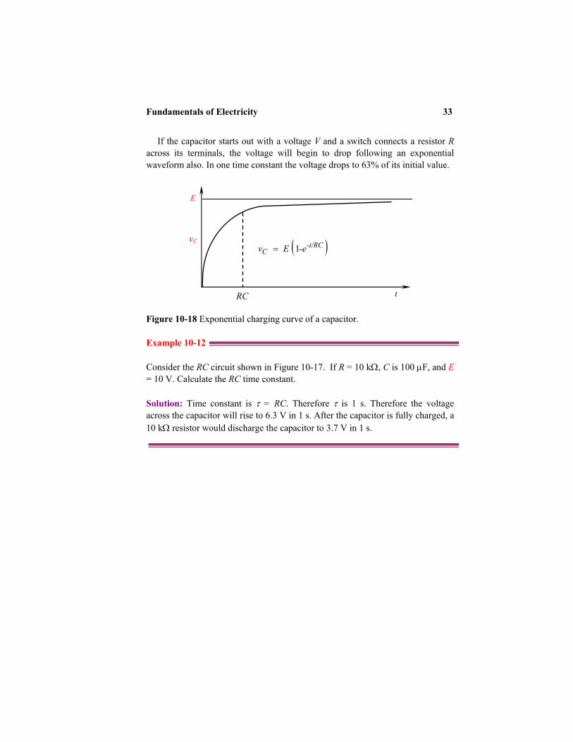
If the capacitor starts out with a voltage V and a switch connects a resistor R across its terminals, the voltage will begin to drop following an exponential waveform also. In one time constant the voltage drops to 63% of its initial value.
Figure 10-18 Exponential charging curve of a capacitor. Example 10-12 Consider the RC circuit shown in Figure 10-17. If R = 10 kΩ, C is 100 µF, and E = 10 V. Calculate the RC time constant. Solution: Time constant is τ = RC. Therefore τ is 1 s. Therefore the voltage across the capacitor will rise to 6.3 V in 1 s. After the capacitor is fully charged, a 10 kΩ resistor would discharge the capacitor to 3.7 V in 1 s.
E
t RC
vC ( )-t/RCC -e E v 1 =

34 Chapter 10
The graph of Figure 10-18 is not linear, but is an exponential function. During the transient time, the instantaneous value of the current in the circuit is determined by ( )-t/RC
C -e E v 1 = (10.23) where e is the base of the natural logarithms. Example 10-13 Determine how long it takes for the voltage across the capacitor in the circuit of Figure 10-17 to reach 90% of the source voltage once the switch is closed. Assume R = 10 kΩ, C = 10 µF, and E = 20 V. Solution: Use Equation (10.23). Let x = -t/RC
( ) E. v-e E v
C
xC
901
==
Solve for x by eliminating vC
( )0.9-1
190
=
=x
x
e
-e E E .
Take the ln:
( )30.2
0.1ln −=
=xx
Substitute –t/RC for the value of x and solve for t considering the values of R and C
-t/RC = -2.30 t = 2.30 RC
t = 2.30 × 10 × 103 × 10 × 10-6 t = 0.23 s
Focus on Mathematics Exponential Equations

Fundamentals of Electricity 35
10.13 INDUCTANCE 10.13.1 Inductor
Inductance is defined as the ability of a coil to store magnetic energy, induce a voltage in itself, and oppose changes in current flowing through it. It is symbolized by L and measured in henry (H). One henry is the amount of inductance (L) that permits one volt to be induced (V) when the current through the coil changes at a rate of one ampere per second.
In most applications the henry is a large unit and it is common to see component values in microhenries (µH) and millihenries (mH). The electrical symbol of an inductor is shown in Figure 10-19.
Figure 10-19 A simple inductor. 10.13.2 Current Flow in an Inductor
Consider the RL circuit shown in Figure 10-20. At the time the switch is closed, the magnetic energy is zero. This means the current in the inductor is zero. Since there is no current flow there is no voltage drop across the resistor. This means initially the source voltage appears directly across the inductor. As the current increases, the voltage drop across the resistor increases. The sum of
I

36 Chapter 10
the voltages across the inductor and resistor is equal to the source voltage. As time increases, the voltage across the resistor increases and the voltage across the inductor decreases. After a long time, the entire voltage appears across the resistor and there will be no voltage across the inductor.
The inductance may be defined by the voltage-current relationship
dtdi Lv = (10.24)
Re-writing Equation (10.24)
vdt
L di 1
= (10.25)
We apply integration. Let us consider the limits to be placed on
the two integrals. The lower limit may be assumed as current at initial time i (t0), therefore
( )( )
∫∫ = tt
titi v(t)dt
L di
00
1 (10.26)
By solving Equation (10.26), we have
( ) ( ) ∫= tt vdt
L t - iti
001 (10.27)
or
( ) ( )∫ += tt t ivdt
L ti
0 01 (10.28)
Focus on Mathematics Derivative and Integration

Fundamentals of Electricity 37
Figure 10-20 Current in an RL circuit
We may write the integral as an indefinite integral and include a constant of integration k
( ) ∫ += kvdt L
ti 1 (10.29)
The power absorbed in the inductor is given by
dtdi Li vi p == (10.30)
The energy wL delivered to the inductor is stored in the magnetic
field around the coil, and is expressed by the integral of the power over the desired time interval
( )( ) ( )[ ] ( )[ ] 22000 2
1o
titi
tt
tt ti - ti L idi L dt
dtdi L pdt =∫=∫=∫ (10.31)
Therefore,
( ) ( ) )]([)]([ 21 - 2
02
0 titiLtt LL −=ωω (10.32)
If we select the value of current at to as zero, we then have
( ) 2
21 LitwL = (10.33)
E
R
L I
R Switch
+
-

38 Chapter 10
10.13.3 L/R Time Constant
The current curve is exponential as shown in Figure 10-21. The final current is V/R. The voltage across the inductor is expected to fall off exponentially with time. The current rises to 63% in one time constant. The ratio τ = L/R has units of time and is a time constant.
As value of the resistance decreases, the value of τ will increase. For example consider an ideal inductor with no internal resistance and an external resistance (R) that zero, τ will be very large. This means that once a current is established, it continues to flow and never diminishes. Practically this situation exists when the conductor in the inductor is superconductive. This continuous current flow represents stored magnetic field energy. Figure 10-21 Exponential charging curve of an inductor. Example 10-14 Consider the RL circuit shown in Figure 10-20. If R = 10 Ω, L is 1.0 H, and E = 10 V. Calculate the L/R time constant. Solution: Time constant is τ = L/R. Therefore τ is 0.1 s. The current through the inductor will rise to 6.3 V in 0.1 s.
E/R
t L/R t = 0
I ( )[ ]L/RteREi /1 −−=
Fundamentals of Electricity 39
The graph of Figure 10-21 is not linear, but is an exponential function. During the transient time, the instantaneous value of the current in the circuit is ( )[ ]L/Rte
REi /1 −−=
(10.34)
Example 10-15: Determine the instantaneous current in the circuit of Figure 10-20 two seconds after the switch is closed. Assume R = 5 Ω, L = 10 H, t = 4 s, and E = 20 V. Solution: Use Equation (10.34) ( )[ ]
( )A46.30.135-1 4
1 520 5/10/4
==
−= −
ii
ei

40 Chapter 10
SUMMARY
• The atom is the smallest part of a matter. • The International System of Units has seven base units, several derived units
with special names, and many derived units with compound names. • Basic parts of an atom are the proton, electron, and neutron. • The presence of charge implies that there is an electric force field. • The system of units most commonly used in electrical engineering is the SI. • The work required moving a unit charge in electric field is a measure of
potential difference or voltage difference. Potential difference is measured in units of volts.
• To define a current, both a value and a direction must be available. • To define a voltage across an element, it is necessary to label the terminals
with “+” and “-“ signs as well as to provide a value. • Any element is said to supply positive power if the positive current flows out
of the positive voltage terminal. Any element absorbs positive power if positive current flows into the positive voltage terminal.
• Capacitors store electric field energy. The use of dielectrics between the plates of the capacitor increases the charge that can be stored. When electric displacement density D is changing in a capacitor it is analogous to current flow. This current is called a displacement current.
• Inductors are devices that are designed to store magnetic field energy. • A steady flow of charge is a current measured in amperes. The relationship
between resistance, voltage, and current is Ohm’s law.

Fundamentals of Electricity 41
REVIEW QUESTIONS
1. What is matter, and in what three states is it found? 2. What is an element? 3. What is Coulomb’s law? State its properties. 4. What determines whether a substance is a conductor or an insulator? 5. How are static charges created? 6. What is an electrostatic field? 7. What is the relationship of current to voltage in a circuit? 8. Name the six methods of producing a voltage. 9. What are the two disadvantages of carbon-type resistors?
10. What type resistor is used to overcome the disadvantages of the carbon resistor?
11. Which type of variable resistor should you select for controlling a large amount of current?
12. Are all the electrons flowing in a circuit provided by the battery? 13. Why must there be no gaps in an electric circuit for it to carry current?

42 Chapter 10
PROBLEMS
10-1 A positive charge of 8 × 10⁻¹⁰ C exerts a force on a negative charge of 8 × 10⁻¹⁰ C. The distance between the two charges is 10 cm. Find the magnitude of the attractive force that either charge exerts on the other.
10-2 Determine the resistance of 10.0 m of copper wire that has a diameter of 2.6 mm and ρ = 0.0172 × 10⁻⁶ Ω-m.
10-3 A battery charger puts 5 A into a 12-V auto battery. What is the power delivered into the battery?
10-4 Calculate the power absorbed by the element in Figure 10-8. Assume E = 200 mV and I = 5 V.
10-5 Repeat Problem 2 assuming E = 200 mV and I = -5 A. 10-6 If your skin has a resistance of 100,000 Ω, and you touch a 9-V battery,
what current will flow through you? 10-7 What current will flow through you if you touch 120-V residential
potential? 10-8 How many minutes will it take a 2.00 kC to pass through an electrical
conductor if the current is 3.00 A? 10-9 What voltage is needed to run a vacuum cleaner drawing 12 A of current
through a circuit with a resistance of 10 Ω? 10-10 How much resistance is in a toaster that draws 6 A of current when
plugged into a 120-V outlet socket? 10-11 Consider the RC circuit in Figure 10-17. Assume R = 1000 Ω, C = 10 µF,
and E = 20 V. At the moment the battery is connected to the RC circuit, what is the value of the current? What is the RC time constant?
10-12 Consider the RL circuit shown in Figure 10-20. If R = 100 Ω, L is 1.0 H, and E = 10 V. Calculate the L/R time constant. Repeat the problem if L becomes 10.0 H.

Fundamentals of Electricity 43
MULTIPLE CHOICE QUESTIONS • A ______ is a device that can hold an electrical charge for a period of time.
a. Resistor b. Capacitor c. Inductor d. Diode
• To determine whether a fuse is good, you actually measure
a. Current b. Voltage c. Resistance d. Capacitance
• What are three good electrical conductors?
a. Copper, gold, mica b. Gold, silver, wood c. Gold, silver, aluminum d. Copper, aluminum, paper
• What are four good electrical insulators?
a. Glass, air, plastic, porcelain b. Glass, wood, copper, porcelain c. Paper, glass, air, aluminum d. Plastic, rubber, wood, carbon
• _______ is the measure of the resistance of electrical flow in an electrical
circuit.
a. Volts b. Amperes c. Ohms d. Watts
• _____ are components in electrical circuits that oppose the flow of
electricity.
a. Capacitors b. Inductors c. Resistors d. Diodes

44 Chapter 10
• _______ is the measure of the flow of electrical current.
a. Volts b. Amperes c. Ohms d. Watts
• _______ is the measure of the potential difference in electrical charges on
either side of an electrical device in an electrical system.
a. Volts b. Amperes c. Ohms d. Watts
• As voltage increases, current _______.
a. Decreases b. Remain the same c. Increases d. Becomes zero
• _______ are calculated by multiplying volts by amps.
a. Volts b. Amps c. Ohms d. Watts
• What is the name of the pressure that forces electrons to flow through a
circuit?
a. Magnetomotive force, or inductance b. Electromotive force, or voltage c. Farad force, or capacitance d. Thermal force, or heat