Embed Size (px)
Citation preview

Fundamentals of Electrostatic Discharge Part One--An Introduction to ESD
© 2001, ESD Association, Rome, NY
History & Background
To many people, static electricity is little more than the shock experienced when touching
a metal doorknob after walking across a carpeted room or sliding across a car seat. However,
static electricity has been a serious industrial problem for centuries. As early as the 1400’s,
European and Caribbean forts were using static control procedures and devices to prevent
electrostatic discharge ignition of black powder stores. By the 1860's, paper mills throughout the
U.S. employed basic grounding, flame ionization techniques, and steam drums to dissipate static
electricity from the paper web as it traveled through the drying process.
The age of electronics brought with it new problems associated with static electricity and
electrostatic discharge. And, as electronic devices became faster and smaller, their sensitivity to
ESD increased. Today, ESD impacts productivity and product reliability in virtually every aspect
of today’s electronics environment. Many aspects of electrostatic control in the electronics
industry also apply in other industries such as clean room applications and graphic arts.
Despite a great deal of effort during the past decade, ESD still affects production yields,
manufacturing costs, product quality, product reliability, and profitability. Industry experts have
estimated average product losses due to static to range from 8-33%1 (Table 1). Others estimate
the actual cost of ESD damage to the electronics industry as running into the billions of dollars2
annually. The cost of damaged devices themselves ranges from only a few cents for a simple
diode to several hundred dollars for complex hybrids. When associated costs of repair and
rework, shipping, labor, and overhead are included, clearly the opportunities exist for significant
improvements.
1Stephen A. Halperin, "Guidelines for Static Control Management," Eurostat, 1990. 2Lonnie Brown and Dan Burns, "The ESD Control Process is a Tool for Managing Quality," Electronic Packaging and Production, April 1990, pp 50-53.

ESD BASICS— INTRODUCTION TO ESD, PAGE 2
Table 1 Informal Summary of Static Losses by Level
Static Losses Reported Description Min.
Loss Max. Loss
Est. Avg. Loss
Component Manufacturers
4% 97% 16-22%
Subcontractors 3% 70% 9-15% Contractors 2% 35% 8-14% User 5% 70% 27-33% Source: Stephen Halperin, "Guidelines for Static Control Management," Eurostat, 1990.
This first in a series of six articles on the fundamentals of ESD and its control focuses on
how electrostatic charge and discharge occur, how various materials affect the level of charge,
types of ESD damage, and how ESD events can damage electronic components. Future articles
will cover various ways to control the problem.
Static Electricity: Creating Charge
Static electricity is defined as an electrical charge caused by an imbalance of electrons on
the surface of a material. This imbalance of electrons produces an electric field that can be
measured and that can influence other objects at a distance. Electrostatic discharge is defined as
the transfer of charge between bodies at different electrical potentials.
Electrostatic discharge can change the electrical characteristics of a semiconductor
device, degrading or destroying it. Electrostatic discharge also may upset the normal operation of
an electronic system, causing equipment malfunction or failure. Another problem caused by
static electricity occurs in clean rooms. Charged surfaces can attract and hold contaminants,
making removal from the environment difficult. When attracted to the surface of a silicon wafer
or a device's electrical circuitry, these particulates can cause random wafer defects and reduce
product yields.
Controlling electrostatic discharge begins with understanding how electrostatic charge
occurs in the first place. Electrostatic charge is most commonly created by the contact and
separation of two materials. For example, a person walking across the floor generates static
electricity as shoe soles contact and then separate from the floor surface. An electronic device
sliding into or out of a bag, magazine or tube generates an electrostatic charge as the device's

ESD BASICS— INTRODUCTION TO ESD, PAGE 3
housing and metal leads make multiple contacts and separations with the surface of the
container. While the magnitude of electrostatic charge may be different in these examples, static
electricity is indeed generated.
Figure 1 The Triboelectric Charge. Materials Make Intimate Contact

ESD BASICS— INTRODUCTION TO ESD, PAGE 4
Figure 2 The Triboelectric Charge - Separation
Creating electrostatic charge by contact and separation of materials is known as
"triboelectric charging." It involves the transfer of electrons between materials. The atoms of a
material with no static charge have an equal number of positive (+) protons in their nucleus and
negative (-) electrons orbiting the nucleus. In Figure 1, Material "A" consists of atoms with equal
numbers of protons and electrons. Material B also consists of atoms with equal (though perhaps
different) numbers of protons and electrons. Both materials are electrically neutral.
When the two materials are placed in contact and then separated, negatively charged
electrons are transferred from the surface of one material to the surface of the other material.
Which material loses electrons and which gains electrons will depend on the nature of the two
materials. The material that loses electrons becomes positively charged, while the material that
gains electrons is negatively charged. This is shown in Figure 2.
Static electricity is measured in coulombs. The charge “q” on an object is determined by
the product of the capacitance of the object “C” and the voltage potential on the object (V):
q=CV

ESD BASICS— INTRODUCTION TO ESD, PAGE 5
Commonly, however, we speak of the electrostatic potential on an object, which is expressed as
voltage.
This process of material contact, electron transfer and separation is really a more
complex mechanism than described here. The amount of charge created by triboelectric
generation is affected by the area of contact, the speed of separation, relative humidity, and other
factors. Once the charge is created on a material, it becomes an "electrostatic" charge (if it
remains on the material). This charge may be transferred from the material, creating an
electrostatic discharge, or ESD, event. Additional factors such as the resistance of the actual
discharge circuit and the contact resistance at the interface between contacting surfaces also
affect the actual charge that can cause damage.
Table 2
Examples of Static Generation
Typical Voltage Levels
Means of Generation 10-25% RH 65-90% RH
Walking across carpet 35,000V 1,500V
Walking across vinyl tile 12,000V 250V
Worker at bench 6,000V 100V
Poly bag picked up from bench 20,000V 1,200V
Chair with urethane foam 18,000V 1,500V
An electrostatic charge also may be created on a material in other ways such as by
induction, ion bombardment, or contact with another charged object. However, triboelectric
charging is the most common.
How Material Characteristics Affect Static Charge
Triboelectric Series
When two materials contact and separate, the polarity and magnitude of the charge are
indicated by the materials’ positions in the triboelectric series. The triboelectric series tables
show how charges are generated on various materials. When two materials contact and separate,

ESD BASICS— INTRODUCTION TO ESD, PAGE 6
the one nearer the top of the series takes on a positive charge, the other a negative charge.
Materials further apart on the table typically generate a higher charge than ones closer together.
These tables, however, should only be used as a general guide because there are many variables
involved that cannot be controlled well enough to ensure repeatability. A typical triboelectric
series is shown in Table 3.
Table 3
Typical Triboelectric Series
+ Positive
Negative -
Rabbit fur Glass Mica Human Hair Nylon Wool Fur Lead Silk Aluminum Paper COTTON Steel Wood Amber Sealing Wax Nickel, copper Brass, silver Gold, platinum Sulfur Acetate rayon Polyester Celluloid Silicon Teflon

ESD BASICS— INTRODUCTION TO ESD, PAGE 7
Virtually all materials, including water and dirt particles in the air, can be
triboelectrically charged. How much charge is generated, where that charge goes, and how
quickly, are functions of the materials' electrical characteristics.
Insulative Materials
A material that prevents or limits the flow of electrons across its surface or through its
volume is called an insulator. Insulators have an extremely high electrical resistance, generally
greater than 1 x 10¹² ohms/sq (surface resistivity) and 1 x 10¹¹ ohm-cm (volume resistivity). A
considerable amount of charge can be generated on the surface of an insulator. Because an
insulative material does not readily allow the flow of electrons, both positive and negative
charges can reside on insulative surface at the same time, although at different locations. The
excess electrons at the negatively charged spot might be sufficient to satisfy the absence of
electrons at the positively charged spot. However, electrons cannot easily flow across the
insulative material's surface, and both charges may remain in place for a very long time.
Conductive Materials
A conductive material, because it has low electrical resistance, allows electrons to flow
easily across its surface or through its volume. Conductive materials have low electrical
resistance, generally less than 1 x 10⁵ ohms/sq (surface resistivity) and 1 x 10⁴ ohm-cm (volume
resistivity). When a conductive material becomes charged, the charge (i.e., the deficiency or
excess of electrons) will be uniformly distributed across the surface of the material. If the
charged conductive material makes contact with another conductive material, the electrons will
transfer between the materials quite easily. If the second conductor is attached to an earth
grounding point, the electrons will flow to ground and the excess charge on the conductor will be
"neutralized."
Electrostatic charge can be created triboelectrically on conductors the same way it is
created on insulators. As long as the conductor is isolated from other conductors or ground, the
static charge will remain on the conductor. If the conductor is grounded the charge will easily go
to ground. Or, if the charged conductor contacts or nears another conductor, the charge will flow
between the two conductors.

ESD BASICS— INTRODUCTION TO ESD, PAGE 8
Static Dissipative Materials
Static dissipative materials have an electrical resistance between insulative and
conductive materials (1 x 10⁵ - 1 x 10¹² ohms/sq (surface resistivity) and 1 x 10⁴ – 1 x 10¹¹ ohm-
cm (volume resistivity). There can be electron flow across or through the dissipative material,
but it is controlled by the surface resistance or volume resistance of the material.
As with the other two types of materials, charge can be generated triboelectrically on a
static dissipative material. However, like the conductive material, the static dissipative material
will allow the transfer of charge to ground or other conductive objects. The transfer of charge
from a static dissipative material will generally take longer than from a conductive material of
equivalent size. Charge transfers from static dissipative materials are significantly faster than
from insulators, and slower than from conductors.
Electrostatic Fields
Charged materials also have an electrostatic field and lines of force associated with them.
Conductive objects brought into the vicinity of this electric field will be polarized by a process
known as induction. A negative electric field will repel electrons on the surface of the
conducting item that is exposed to the field. A positive electric field will attract electrons to near
the surface thus leaving other areas positively charged. No change in the actual charge on the
item will occur in polarization. If, however, the item is conductive or dissipative and is touched
to ground while polarized, charge will flow from or to ground to compensate for the charge
imbalance. If the electrostatic field is removed and the ground contact disconnected, the charge
will be trapped on the item. If a nonconductive object is brought into the electric field, the
electrical dipoles will tend to align with the field creating apparent surface charges. A
nonconductor cannot be charged by induction.
ESD Damage—How Devices Fail
Electrostatic damage to electronic devices can occur at any point from manufacture to
field service. Damage results from handling the devices in uncontrolled surroundings or when

ESD BASICS— INTRODUCTION TO ESD, PAGE 9
poor ESD control practices are used. Generally damage is classified as either a catastrophic
failure or a latent defect.
Catastrophic Failure
When an electronic device is exposed to an ESD event, it may no longer function. The
ESD event may have caused a metal melt, junction breakdown, or oxide failure. The device's
circuitry is permanently damaged causing the device fail. Such failures usually can be detected
when the device is tested before shipment. If the ESD event occurs after test, the damage will go
undetected until the device fails in operation.
Latent Defect
A latent defect, on the other hand, is more difficult to identify. A device that is exposed
to an ESD event may be partially degraded, yet continue to perform its intended function.
However, the operating life of the device may be reduced dramatically. A product or system
incorporating devices with latent defects may experience premature failure after the user places
them in service. Such failures are usually costly to repair and in some applications may create
personnel hazards.
It is relatively easy with the proper equipment to confirm that a device has experienced
catastrophic failure. Basic performance tests will substantiate device damage. However, latent
defects are extremely difficult to prove or detect using current technology, especially after the
device is assembled into a finished product.
Basic ESD Events--What Causes Electronic Devices to Fail?
ESD damage is usually caused by one of three events: direct electrostatic discharge to the
device, electrostatic discharge from the device or field-induced discharges. Damage to an ESDS
device by the ESD event is determined by the device's ability to dissipate the energy of the
discharge or withstand the voltage levels involved. This is known as the device’s "ESD
sensitivity.

ESD BASICS— INTRODUCTION TO ESD, PAGE 10
Discharge to the Device
An ESD event can occur when any charged conductor (including the human body)
discharges to an ESDS (electrostatic discharge sensitive) device. The most common cause of
electrostatic damage is the direct transfer of electrostatic charge from the human body or a
charged material to the electrostatic discharge sensitive (ESDS) device. When one walks across a
floor, an electrostatic charge accumulates on the body. Simple contact of a finger to the leads of
an ESDS device or assembly allows the body to discharge, possibly causing device damage. The
model used to simulate this event is the Human Body Model (HBM). A similar discharge can
occur from a charged conductive object, such as a metallic tool or fixture. The model used to
characterize this event is known as the Machine Model.
Discharge from the Device
The transfer of charge from an ESDS device is also an ESD event. Static charge may
accumulate on the ESDS device itself through handling or contact with packaging materials,
worksurfaces, or machine surfaces. This frequently occurs when a device moves across a surface
or vibrates in a package. The model used to simulate the transfer of charge from an ESDS device
is referred to as the Charged Device Model (CDM). The capacitance and energies involved are
different from those of a discharge to the ESDS device. In some cases, a CDM event can be more
destructive than the HBM for some devices.
The trend towards automated assembly would seem to solve the problems of HBM ESD
events. However, it has been shown that components may be more sensitive to damage when
assembled by automated equipment. A device may become charged, for example, from sliding
down the feeder. If it then contacts the insertion head or another conductive surface, a rapid
discharge occurs from the device to the metal object.
Field Induced Discharges
Another event that can directly or indirectly damage devices is termed Field Induction.
As noted earlier, whenever any object becomes electrostatically charged, there is an electrostatic
field associated with that charge. If an ESDS device is placed in that electrostatic field, a charge
may be induced on the device. If the device is then momentarily grounded while within the
electrostatic field, a transfer of charge from the device occurs as a CDM event. If the device is

ESD BASICS— INTRODUCTION TO ESD, PAGE 11
removed from the region of the electrostatic field and grounded again, a second CDM event will
occur as charge (of opposite polarity from the first event) is transferred from the device.
How Much Static Protection is Needed?
As noted earlier, damage to an ESDS device by the ESD event is determined by the
device's ability to dissipate the energy of the discharge or withstand the voltage levels
involved—its ESD sensitivity. Defining the ESD sensitivity of electronic components is the first
step in determining the degree of ESD protection required. Test procedures based on the models
of ESD events help define the sensitivity of components to ESD. These procedures will be
covered in a future article in this series.
Many electronic components are susceptible to ESD damage at relatively low voltage
levels. Many are susceptible at less than 100 volts, and many disk drive components have
sensitivities below 10 volts. Current trends in product design and development pack more
circuitry onto these miniature devices, further increasing their sensitivity to ESD and making the
potential problem even more acute. Tables 4 and 5 indicate the ESD sensitivity of various types
of components.
Table 4 ESD Sensitivity of Representative Electronic Devices
Devices or Parts with Sensitivity Levels of 0-1,999 volts (HBM) Device or Part Type Microwave devices (Schottky barrier diodes, point contact diodes and other detector diodes >1 GHz) Discrete MOSFET devices Surface acoustic wave (SAW) devices Junction field effect transistors (JFETs) Charged coupled devices (CCDs) Precision voltage regulator diodes (line of load voltage regulation, <0.5%) Operational amplifiers (OP AMPs) Thin film resistors Integrated circuits AMR and GMR Disk Drive Recording Heads Laser Diodes Hybrids Very high speed integrated circuits (VHSIC) Silicon controlled rectifiers (SCRs) with Io <0.175 amp at 10 °C ambient

ESD BASICS— INTRODUCTION TO ESD, PAGE 12
Table 5 ESD Sensitivity of Representative Electronic Devices
Devices or Parts with Sensitivity Levels of 2,000 to 3,999 volts (HBM) Device or Part Type Discrete MOSFET devices JFETs Operational Amplifiers (OP Amps) Integrated circuits (ICs) Very high speed integrated circuits (VHSIC) Precision resistor networks (type RZ) Hybrids Low power bipolar transistors, PT £100 milliwatts with Ic <100 milliamps
Summary
In this introductory article on electrostatic discharge, we have discussed the basics of
electrostatic charge and discharge, types of failures, ESD events, and device sensitivity. We can
summarize this discussion as follows:
1. Virtually all materials, even conductors, can be triboelectrically charged.
2. The level of charge is affected by material type, speed of contact and separation, humidity,
and several other factors.
3. Electrostatic fields are associated with charged objects.
4. Electrostatic discharge can damage devices so they fail immediately, or ESD may result in
latent damage that may escape immediate attention, but cause the device to fail prematurely
once in service.
5. Electrostatic discharge can occur throughout the manufacturing, test, shipping, handling, or
operational processes.
6. Component damage can occur as the result of a discharge to the device, from the device, or
from charge transfers resulting from electrostatic fields. Devices vary significantly in their
sensitivity to ESD.
Protecting your products from the effects of static damage begins by understanding these
key concepts of ESD. Armed with this information, you can then begin to develop an effective
ESD control program. In Part Two we will focus on some basic concepts of ESD control.

ESD BASICS— INTRODUCTION TO ESD, PAGE 13
References
ESD-ADV 1.0, Glossary, ESD Association, Rome NY.
ESD TR20.20, Handbook, ESD Association, Rome, NY.
ESD ADV 11.2, Triboelectric Charge Accumulation Testing, ESD Association, Rome, NY.
ANSI/ESD S20.20—Standard for the Development of Electrostatic Discharge Control Program,
ESD Association, Rome, NY.
June 2001

Fundamentals of Electrostatic Discharge Part Two--Principles of ESD Control
© 2001, ESD Association, Rome, NY In Part One of this series, Introduction to Electrostatic Discharge, we discussed the basics of electrostatic charge, discharge, types of failures, ESD events, and device sensitivity. We concluded our discussion with the following summary: 1. Virtually all materials, even conductors, can be triboelectrically charged. 2. The level of charge is affected by material type, speed of contact and separation, humidity,
and several other factors. 3. Electrostatic fields are associated with charged objects. 4. Electrostatic discharge can damage devices so they fail immediately, or ESD may result in
latent damage that may escape immediate attention, but cause the device to fail prematurely once in service.
5. Electrostatic discharge can occur throughout the manufacturing, test, shipping, handling, or operational processes.
6. Component damage can occur as the result of a discharge to the device, from the device, or from charge transfers resulting from electrostatic fields. Devices vary significantly in their sensitivity to ESD.
Understanding these key concepts is crucial to protecting your products from the effects
of static damage. Armed with this information, you can then begin to develop an effective ESD control program. In Part Two we will focus on some basic concepts of ESD control. Basic Principles of Static Control
Sometimes, controlling electrostatic discharge (ESD) in the electronics environment seems to be a formidable challenge. However, the task of designing and implementing ESD control programs becomes less complex if we focus on just six basic principles of control. In doing so, we also need to keep in mind the ESD corollary to Murphy’s law, “no matter what we do, static charge will try to find a way to discharge.”
1. Design In Immunity
The first Principle is to design products and assemblies to be as immune as reasonable from the effects of ESD. This involves such steps as using less static sensitive devices or providing appropriate input protection on devices, boards, assemblies, and equipment. For engineers and designers, the paradox is that advancing product technology requires smaller and more complex geometries that often are more susceptible to ESD.

FUNDAMENTALS OF ESD CONTROL, PART 2 PAGE 2
2. Define the level of control needed in your environment.
What is the sensitivity level of the parts you are using and the products that you are manufacturing and shipping? ANSI/ESD S 20.20 defines a control program for items that are sensitive to 100 volts Human Body Model HBM. Your environment may be different.
3. Identify and define the electrostatic protected areas (EPA). These are the areas in which you will be handling sensitive parts and the areas in which you will need to bond or electrically connect all conductive and dissipative materials, including personnel, to a known ground. 4. Eliminate and Reduce Generation
Obviously, product design isn’t the whole answer. The fourth Principle of control is to eliminate or reduce the generation and accumulation of electrostatic charge in the first place. It’s fairly basic: no charge -- no discharge. We begin by reducing as many static generating processes or materials, such as the contact and separation of dissimilar materials and common plastics, as possible from the work environment. We keep other processes and materials at the same electrostatic potential. Electrostatic discharge does not occur between materials kept at the same potential or at zero potential. We provide ground paths, such as wrist straps, flooring and work surfaces, to reduce charge generation and accumulation. 5. Dissipate and Neutralize
Because we simply can’t eliminate all generation of static in the environment, our fifth Principle is to safely dissipate or neutralize those electrostatic charges that do occur. Proper grounding and the use of conductive or dissipative materials play major roles. For example, workers who “carry” a charge into the work environment can rid themselves of that charge when they attach a wrist strap or when they step on an ESD floor mat while wearing ESD control footwear. The charge goes to ground rather than being discharged into a sensitive part. To prevent damaging a charged device, the rate of discharge can be controlled with static dissipative materials. For some objects, such as common plastics and other insulators, grounding does not remove an electrostatic charge because there is no conductive pathway. Typically, ionization is used to neutralize charges on these insulating materials. The ionization process generates negative and positive ions that are attracted to the surface of a charged object, thereby effectively neutralizing the charge. 6. Protect Products
Our final ESD control Principle is to prevent discharges that do occur from reaching susceptible parts and assemblies. One way is to provide our parts and assemblies with proper grounding or shunting that will “dissipate” any discharge away from the product. A second method is to package and transport susceptible devices in proper packaging and materials

FUNDAMENTALS OF ESD CONTROL, PART 2 PAGE 3
handling products. These materials may effectively shield the product from charge, as well as reduce the generation of charge caused by any movement of product within the container. Elements of an Effective ESD Control Program
While these six principles may seem rather basic, they can guide us in the selection of appropriate materials and procedures to use in effectively controlling ESD. In most circumstances, effective programs will involve all of these principles. No single procedure or product will do the whole job; rather effective static control requires a full ESD control program.
How to we develop and maintain a program that puts these basic principles into practice? How do we start? What is the process? What do we do first? Ask a dozen experts and you may get a dozen different answers. But, if you dig a little deeper, you will find that most of the answers center on similar key elements. You will also find that starting and maintaining an ESD control program is similar to many other business activities and projects. Although each company is unique in terms of its ESD control needs, there are at least 6 critical elements to successfully developing and implementing an effective ESD control program.
1. Establish an ESD Coordinator and ESD Teams.
As the problem-solving style of the decade, the team approach particularly applies to ESD because the problems and the solutions cross various functions, departments, divisions and even suppliers in most companies. Team composition includes line employees as well as department heads or other management personnel. ESD teams or committees help assure a variety of viewpoints, the availability of the needed expertise, and commitment to success. An active ESD committee helps unify the effort and brings additional expertise to the project. Committee or team membership should include representation from areas such as engineering, manufacturing, field service, training, and quality.
Heading this team effort is an ESD Program Coordinator. Ideally this responsibility should be a full-time job. However, we seldom operate in an ideal environment and you may have to settle for the function to be a major responsibility of an individual. The ESD coordinator is responsible for developing, budgeting, and administering the program. The coordinator also serves as the company’s internal ESD consultant to all areas. 2. Assess Your Organization, Facility, Processes and Losses
Your next step is to gain a thorough understanding of your environment and its impact on ESD. Armed with your loss and sensitivity data, you can evaluate your facility, looking for areas and procedures that may be contributing to your defined ESD problems. Be on the lookout for things such as static generating materials and personnel handling procedures for ESD-sensitive items.
Document your processes. Observe the movement of people and materials through the areas. Note those areas that would appear to have the greatest potential for ESD problems. Remember, that ESD can occur in the warehouse just as it can in the assembly areas. Then conduct a thorough facility survey or audit. Measure personnel, equipment, and materials to identify the presence of electrostatic fields in your environment.

FUNDAMENTALS OF ESD CONTROL, PART 2 PAGE 4
Before seeking solutions to your problems, you will need to determine the extent of your losses to ESD. These losses may be reflected in receiving reports, QA and QC records, customer returns, in-plant yields, failure analysis reports, and other data that you may already have or that you need to gather. This information not only identifies the magnitude of the problem, but also helps to pinpoint and prioritize areas that need attention.
Document your actual and potential ESD losses in terms of DOA components, rework, customer returns, and failures during final test and inspection. Use data from outside sources or the results of your pilot program for additional support. Develop estimates of the savings to be realized from implementing an ESD control program. You will also want to identify those items (components, assemblies, and finished products) that are sensitive to ESD and the level of their sensitivity. You can test these items yourself, use data from suppliers, or rely on published data for similar items.
3. Establish and Document Your ESD Control Program Plan
After completing your assessment, you can begin to develop and document your ESD control program plan. The plan should cover the scope of the program and include the tasks, activities and procedures necessary to protect the ESD sensitive items at or above the ESD sensitivity level chosen for the plan. Prepare and distribute written procedures and specifications so that everyone has a clear understanding of what is to be done. Fully documented procedures will help you meet the administrative and technical elements of ANSI ESD S20.20, help you with ISO 9000 certification as well. 4. Build Justification to Get the Management Support Top Management
To be successful, an ESD program requires the support of your top management, at the highest level possible. What level of commitment is required? To obtain commitment, you will need to build justification for the plan. You will need to emphasize quality and reliability, the costs of ESD damage, the impact of ESD on customer service and product performance. You may even need to conduct a pilot program if the experience of other companies is not sufficient to help prove your point.
Prepare a short corporate policy statement on ESD control. Have top management co-sign it with the ESD coordinator. Periodically, reaffirm the policy statement and management’s commitment to it. 5. Define A Training Plan
Train and retrain your personnel in ESD and your company’s ESD control program and procedures. Proper training for line personnel is especially important. They are often the ones who have to live with the procedures on a day-to-day basis. A sustained commitment and mindset among all employees that ESD prevention is a valuable, on-going effort by everyone is one of the primary goals of training.
FUNDAMENTALS OF ESD CONTROL, PART 2 PAGE 5
6. Develop and Implement a Compliance Verification Plan
Developing and implementing the program itself is obvious. What might not be so obvious is the need to continually review, audit, analyze, feedback and improve. Auditing is essential to ensure that the ESD control program is successful. You will be asked to continually identify the return on investment of the program and to justify the savings realized. Technological changes will dictate improvements and modifications. Feedback to employees and top management is essential. Management commitment will need reinforcement.
Include both reporting and feedback to management, the ESD team, and other employees as part of your plan. Management will want to know that their investment in time and money is yielding a return in terms of quality, reliability and profits. Team members need a pat on the back for a job well done. Other employees will want to know that the procedures you have asked them to follow are indeed worthwhile.
Conduct periodic evaluations of your program and audits of your facility. You will find out if your program is successful and is giving you the expected return. You will spot weaknesses in the program and shore them up. You will discover whether the procedures are being followed. As you find areas that need work, be sure to make the necessary adjustments to keep the program on track. Conclusion
Six principles of static control and six key elements to program development and implementation: your guideposts for effective ESD control programs. In Part Three, we’ll take a close look at specific procedures and materials that become part of your program. For Additional Information
ANSI/ESD S20.20—Standard for the Development of Electrostatic Discharge Control Program, ESD Association, Rome, NY
Dangelmayer, Theodore, ESD Program Management: A Realistic Approach to Continuous, Measurable Improvement in Static Control, 1999, Kluwer Academic Publishers, Boston, MA
ESD TR20.20, ESD Control Handbook, ESD Association, Rome, NY. Halperin, Stephen A., “Facility Evaluation: Isolating Environmental ESD Issues,” EOS/ESD
Symposium Proceedings, 1980. ESD Association, Rome, NY June 2001

BASICS OF ESD, PART 3 PAGE 1
Fundamentals of Electrostatic Discharge Part Three--Basic ESD Control Procedures and Materials
© 2001, ESD Association, Rome, NY
In Part Two, Principles of ESD Control we introduced four principles of static control and nine
key elements of ESD program development and implementation. In Part Three, we will cover some of the
primary specific static control procedures and materials that become part of your program. First, a quick
review.
Basic Principles of Static Control
We suggested focusing on just six basic principles in the development and implementation of
effective ESD control programs:
Design in immunity by designing products and assemblies to be as immune as reasonable from the
effects of ESD.
Define the level of control needed in your environment.
Identify and define the electrostatic protected areas (EPA), the areas in which you will be handling
sensitive parts.
Eliminate and reduce generation by reducing and eliminating static generating processes, keeping
processes and materials at the same electrostatic potential, and by providing appropriate ground paths
to reduce charge generation and accumulation.
Dissipate and neutralize by grounding, ionization, and the use of conductive and dissipative static
control materials.
Protect products from ESD with proper grounding or shunting and the use of static control
packaging and materials handling products.
At the facility level our static control efforts concentrate on the last five principles. In this column
we will concentrate on the primary materials and procedures that eliminate and reduce generation,
dissipate and neutralize charges, or protect sensitive products from ESD.

BASICS OF ESD, PART 3 PAGE 2
Identifying the Problem Areas and the Level of Control
One of the first questions we need to answer is “How sensitive are the parts and assemblies we
are manufacturing or handling?” This information will guide you in determining the various procedures
and materials required to control ESD in your environment.
How do you determine the sensitivity of your parts and assemblies or where can you get
information about their ESD sensitivity? A first source would be the manufacturer or supplier of the
component itself. An additional source is ITT Research Institute/Reliability Analysis Center in Rome,
NY, which publishes ESD susceptibility data for 22,000 devices, including microcircuits. You may find
that you need to have your specific parts tested for ESD sensitivity. We will discuss device sensitivity
testing in part 5 of this series.
The second question you need to answer is “Which areas of our facility need ESD protection?”
This will allow to define your specific electrostatic protected areas (EPAs), the areas in which you will be
handling sensitive parts and the areas in which you will need to bond or electrically connect all
conductive and dissipative materials, including personnel, to a known ground. Often you will find that
there are more areas that require protection than you originally thought, usually wherever ESDS devices
are handled. Typical areas requiring ESD protection are shown in Table 1.
Table 1
Typical Facility Areas Requiring ESD Protection
Receiving
Inspection
Stores and warehouses
Assembly
Test and inspection
Research and development
Packaging
Field service repair
Offices and laboratories
Clean rooms

BASICS OF ESD, PART 3 PAGE 3
Grounding
Throughout our discussion, we will see how important grounding is to effective ESD control.
Effective ESD grounds are of critical importance in any operation, and ESD grounding should be clearly
defined and regularly evaluated.
A primary means of protecting of ESD susceptible (ESDS) items is to provide a ground path to
bring ESD protective materials and personnel to the same electrical potential. All conductors in the
environment, including personnel, must be bonded or electrically connected and attached to a known
ground or contrived ground, creating an equipotential balance between all items and personnel.
Electrostatic protection can be maintained at a potential above a "zero" voltage ground reference as long
as all items in the system are at the same potential. It is important to note that non-conductors in an
Electrostatic Protected Area (EPA) cannot lose their electrostatic charge by attachment to ground
ESD Association Standard ANSI EOS/ESD 6.1-Grounding recommends a two-step procedure for
grounding ESD protective equipment.
The first step is to ground all components of the work area (worksurfaces, people, equipment,
etc.) to the same electrical ground point called the “common point ground.” This common point ground is
defined as a “system or method for connecting two or more grounding conductors to the same electrical
potential.”
This ESD common point ground should be properly identified.
ESD Association standard EOS/ESD S8.1-1993 recommends the use of
the symbol in Figure 2 to identify the common point ground.
The second step is to connect the common point ground to the
equipment ground or the third wire (green) electrical ground connection.
This is the preferred ground connection because all electrical equipment
at the workstation is already connected to this ground. Connecting the
ESD control materials or equipment to the equipment ground brings all
components of the workstation to the same electrical potential. If a
soldering iron used to repair an ESDS item were connected to the electrical ground and the surface
containing the ESDS item were connected to an auxiliary ground, a difference in electrical potential could
exist between the iron and the ESDS item. This difference in potential could cause damage to the item.
Figure 1--Common Point Ground Symbol

BASICS OF ESD, PART 3 PAGE 4
Any auxiliary grounds (water pipe, building frame, ground stake) present and used at the
workstation must be bonded to the equipment ground to minimize differences in potential between the
two grounds.
Detailed information on ESD grounding can be found in ESD Association standard ESD-S6.1,
Grounding-Recommended Practices.
Controlling Static on Personnel and Moving Equipment
In many facilities, people are one of the prime generators of static electricity. The simple act of
walking around or repairing a board can generate several thousand volts on the human body. If not
properly controlled, this static charge can easily discharge into a static sensitive device—a human body
model (HBM) discharge.
Even in highly automated assembly and test processes, people still handle static sensitive
devices…in the warehouse, in repair, in the lab, in transport. For this reason, static control programs place
considerable emphasis on controlling personnel generated electrostatic discharge. Similarly, the
movement of carts and other wheeled equipment through the facility also can generate static charges that
can transfer to the products being transported on this equipment.
Wrist Straps
Typically, wrist straps are the primary means of controlling static charge on personnel. When
properly worn and connected to ground, a wrist strap keeps the person wearing it near ground potential.
Because the person and other grounded objects in the work area are at or near the same potential, there
can be no hazardous discharge between them. In addition, static charges are safely dissipated from the
person to ground and do not accumulate.
Wrist straps have two major components, the cuff that goes around the person’s wrist and the
ground cord that connects the cuff to the common point ground. Most wrist straps have a current limiting
resistor molded into the ground cord head on the end that connects to the cuff. The resistor most
commonly used is a one megohm, 1/4 watt with a working voltage rating of 250 volts.
Wrist straps should be tested on a regular basis. Daily testing or continuous monitoring is
recommended.
Floors, Floor Mats, Floor Finishes
A second method of controlling electrostatic charge on personnel is with the use of ESD
protective floors in conjunction with ESD control footwear or foot straps. This combination of floor

BASICS OF ESD, PART 3 PAGE 5
materials and footwear provides a ground path for the dissipation of electrostatic charge, thus reducing
the charge accumulation on personnel and other objects to safe levels. In addition to dissipating charge,
some floor materials (and floor finishes) also reduce triboelectric charging. The use of floor materials is
especially appropriate in those areas where increased personnel mobility is necessary. In addition, floor
materials can minimize charge accumulation on chairs, carts, lift trucks and other objects that move across
the floor. However, those items require dissipative or conductive casters or wheels to make electrical
contact with the floor. When used as the primary personnel grounding system, the resistance to ground
including the person, footwear and floor must be the same as specified for wrist straps (< 35 x 10E6
ohms) or the voltage accumulation on a person must be less than 100 volts.
Shoes, Grounders, Casters
Used in combination with ESD protective floor materials, static control shoes, grounders, casters
and wheels provide the necessary electrical contact between the person or object and the floor material.
Insulative footwear, casters, or wheels prevent static charges from flowing from the body to the floor to
ground.
Clothing
Clothing is a consideration in some ESD protective areas, especially in clean rooms and very dry
environments. Clothing materials can generate electrostatic charges that may discharge into sensitive
components or they may create electrostatic fields that may induce charges on the human body. Because
clothing usually is electrically insulated or isolated from the body, charges on clothing fabrics are not
necessarily dissipated to the skin and then to ground. Grounded static control garments are intended to
minimize the effects of electrostatic fields or charges that may be present on a person’s clothing.

BASICS OF ESD, PART 3 PAGE 6
Workstations and Worksurfaces
An ESD protective workstation refers to the
work area of a single individual that is constructed and
equipped with materials and equipment to limit damage
to ESD sensitive items. It may be a stand-alone station in
a stockroom, warehouse, or assembly area, or in a field
location such as a computer bay in commercial aircraft.
A workstation also may be located in a controlled area
such as a clean room. The key ESD control elements
comprising most workstations are a static dissipative worksurface, a means of grounding personnel
(usually a wrist strap), a common grounding connection, and appropriate signage and labeling. A typical
workstation is shown in Figure 3.
Figure 2--Typical ESD Workstation
The workstation provides a means for connecting all worksurfaces, fixtures, handling equipment,
and grounding devices to a common point ground. In addition, there may be provision for connecting
additional personal grounding devices, equipment, and accessories such as constant ground monitors and
ionizers.
Static protective worksurfaces with a resistance to ground of 106 to 109 provide a surface that is at
the same electrical potential as other ESD protective items in the workstation. They also provide an
electrical path to ground for the controlled dissipation of any static potentials on materials that contact the
surface. The worksurface also helps define a specific work area in which ESD sensitive devices may be
safely handled. The worksurface is connected to the common point ground.
Production Equipment and Production Aids
Although personnel generated static is usually the primary ESD culprit in many environments,
automated manufacturing and test equipment also can pose an ESD problem. For example, a device may
become charged from sliding down a feeder. If the device then contacts the insertion head or another
conductive surface, a rapid discharge occurs from the device to the metal object--a Charged Device
Model (CDM) event. In addition, various production aids such as hand tools, tapes, or solvents also be
ESD concerns,
Grounding is the primary means of controlling static charge on equipment and many production
aids. Much electrical equipment is required by the National Electrical Code to be connected to the
equipment ground (the green wire) in order to carry fault currents. This ground connection also will

BASICS OF ESD, PART 3 PAGE 7
function for ESD purposes. All electrical tools and equipment used to process ESD sensitive hardware
require the 3 prong grounded type AC plug. Hand tools that are not electrically powered, i.e., pliers, wire
cutters, and tweezers, are usually grounded through the ESD worksurface and the (grounded) person
using the conductive tools. Holding fixtures should be made of conductive or static dissipative materials
when possible. A separate ground wire may be required for conductive fixtures not sitting on an ESD
worksurface or handled by a grounded person. For those items that are composed of insulative materials,
the use of ionization or application of topical antistats may be required to control generation and
accumulation of static charges.
Packaging and Handling
Direct protection of ESDS devices from electrostatic discharge is provided by packaging
materials such as bags, corrugated, and rigid or semi-rigid packages. The primary use of these items is to
protect the product when it leaves the facility, usually when shipped to a customer. In addition, materials
handling products such as tote boxes and other containers primarily provide protection during inter or
intra facility transport.
The main ESD function of these packaging and materials handling products is to limit the
possible impact of ESD from triboelectric charge generation, direct discharge, and electrostatic fields. The
initial consideration is to have low charging materials in contact with ESD sensitive items. For example,
the low charging property would control triboelectric charge resulting from sliding a board or component
into the package or container. A second requirement is that the material provides protection from direct
electrostatic discharge as well as shield from electrostatic fields.
Many materials are available that provide all three benefits: low charging, discharge protection,
and electric field suppression. The inside of these packaging materials have a low charging layer, but also
have an outer layer with a surface resistance generally in the dissipative range.
Resistance or resistivity measurements help define the material’s ability to provide electrostatic
shielding or charge dissipation. Electrostatic shielding attenuates electrostatic fields on the surface of a
package in order to prevent a difference in electrical potential from existing inside the package.
Electrostatic shielding is provided by materials that have a surface resistance equal to or less than 1.0 x
103 when tested according to EOS/ESD-S11.11 or a volume resistivity of equal to or less than 1.0 x 10³
ohm-cm when tested according to the methods of EIA 541. In addition, shielding may be provided by
packaging materials that provide an air gap between the package and the product. Dissipative materials
provide charge dissipation characteristics. These materials have a surface resistance greater than 1.0 x 10⁴
but less than or equal to 1.0 x 10¹¹ when tested according to EOS/ESD-S11.11 or a volume resistivity
greater than 1.0 x 10⁵ ohm-cm but less than or equal to 1.0 x 10¹² ohm-cm when tested according to the

BASICS OF ESD, PART 3 PAGE 8
methods of EIA 541. ESD 11.31 on shield bags should be listed here as a way to measure ESD
Discharge for bags.
A material’s low charging properties are not necessarily predicted by its resistance or resistivity.
Ionization
However, most static control programs also deal with isolated conductors that cannot be
grounded, insulating materials (e.g., most common plastics). Topical antistats often are used to dissipate
static charges from these items under some circumstances
More frequently, however, air ionization can neutralize the static charge on insulated and isolated
objects by charging the molecules of the gases of the surrounding air. Whatever static charge is present on
objects in the work environment will be neutralized by attracting opposite polarity charges from the air.
Because it uses only the air that is already present in the work environment, air ionization may be
employed even in clean rooms where chemical sprays and some static dissipative materials are not usable.
Air ionization is one component of a complete static control program, not necessarily a substitute
for grounding or other methods. Ionizers are used when it is not possible to properly ground everything
and as backup to other static control methods. In clean rooms, air ionization may be one of the few
methods of static control available.
Cleanrooms
While the basic methods of static control discussed here are applicable in most environments,
cleanroom manufacturing processes require special considerations.
Many objects integral to the semiconductor manufacturing process (quartz, glass, plastic, and
ceramic) are inherently charge generating. Because these materials are insulators, this charge cannot be
removed easily by grounding. Many static control materials contain carbon particles or surfactant
additives that sometimes restrict their use in clean rooms. The need for personnel mobility and the use of
clean room garments often make the use of wrist straps difficult. In these circumstances, ionization and
flooring/footwear systems become key weapons against static charge.
Identification
A final element in our static control program is the use of appropriate symbols to identify static
sensitive devices and assemblies, as well as products intended to control ESD. The two most widely
accepted symbols for identifying ESDS parts or ESD control materials are defined in ESD Association
Standard ANSI ESD S8.1-1993 — ESD Awareness Symbols.

BASICS OF ESD, PART 3 PAGE 9
The ESD Susceptibility Symbol (Figure 3) consists of a
triangle, a reaching hand, and a slash through the reaching hand. The
triangle means “caution” and the slash through the reaching hand means
“Don’t touch.” Because of its broad usage, the hand in the triangle has
become associated with ESD and the symbol literally translates to “ESD
sensitive stuff, don’t touch.”
The ESD Susceptibility Symbol is applied directly to integrated
circuits, boards, and assemblies that are static sensitive. It indicates that
handling or use of this item may result in damage from ESD if proper
precautions are not taken. If desired, the sensitivity level of the item may be added to the label.
Figure 3--ESD Susceptibility Symbol
The ESD Protective Symbol (Figure 4) consists of the reaching
hand in the triangle. An arc around the triangle replaces the slash. This
“umbrella” means protection. The symbol indicates ESD protective
material. It is applied to mats, chairs, wrist straps, garments, packaging,
and other items that provide ESD protection. It also may be used on
equipment such as hand tools, conveyor belts, or automated handlers
that is especially designed or modified to provide ESD control.
Neither symbol is applied on ESD test equipment, footwear
checkers, wrist strap testers, resistance or resistivity meters or similar
items that are used for ESD purposes, but which do not provide actual protection.
Figure 4-- ESD Protective Symbol
Summary
Effective static control programs require a variety of procedures and materials. In this column, we
have provided a brief overview of the most commonly used elements of a program. Additional in-depth
discussion of individual materials and procedures can be found in publications such as the ESD
Handbook published by the ESD Association.
Your program is up and running. How do you determine whether it is effective? How do you
make sure your employees follow it? In Part 4, we will cover the topics of Auditing and Training.

BASICS OF ESD, PART 3 PAGE 10
For Additional Information
ESD Association Standards
ESD S1.1-1998: Evaluation, Acceptance, and Functional Testing of Wrist Straps, ESD Association,
Rome, NY 13440
ESD STM2.1-1997: Resistance Test Method for Electrostatic Discharge Protective Garments, ESD
Association, Rome, NY 13440
ESD STM3.1-2000: Ionization, ESD Association, Rome, NY 13440
ESD SP3.3-2000: Periodic Verification of Air Ionizers, ESD Association, Rome, NY 13440
ESD S4.1-1997 (Revised): Worksurfaces--Resistance Measurements, ESD Association, Rome, NY 13440
ESD STM4.2-1998: Worksurfaces - Charge Dissipation Characteristics, ESD Association, Rome, NY
13440
ESD S6.1-1999: Grounding -- Recommended Practice, ESD Association, Rome, NY 13440
ANSI ESD S7.1-1994: Floor Materials -- Resistive Characterization of Materials, ESD Association,
Rome, NY 13440
ANSI ESD S8.1-1993: ESD Awareness Symbols, ESD Association, Rome, NY 13440
ESD S9.1-1995: Resistive Characterization of Footwear, ESD Association, Rome, NY 13440
ESD SP10.1-2000: Automated Handling Equipment, ESD Association, Rome, NY 13440
ANSI ESD S11.11-1993: Surface Resistance Measurement of Static Dissipative Planar ESD, ESD
Association, Rome, NY 13440
ESD STM11.12-2000: Volume Resistance Measurement of Static Dissipative Planar Materials, ESD
Association, Rome, NY 13440
ANSI ESD S11.31-1994: Evaluating the Performance of Electrostatic Discharge Shielding Bags, ESD
Association, Rome, NY 13440
ESD STM12.1-1997: Seating-Resistive Characterization, ESD Association, Rome, NY 13440
ESD STM13.1-2000: Electrical Soldering/Desoldering Hand Tools, ESD Association, Rome, NY 13440
ANSI ESD S20.20-1999: Standard for the Development of an ESD Control Program, ESD Association,
Rome, NY 13440
ESD STM97.1-1999: Floor Materials and Footwear -- Resistance in Combination with a Person, ESD
Association, Rome, NY 13440
ESD STM97.2-1999 Floor Materials and Footwear Voltage Measurement in Combination with a Person,
ESD Association, Rome, NY 13440

BASICS OF ESD, PART 3 PAGE 11
ESD ADV3.2-1995: Selection and Acceptance of Air Ionizers, ESD Association, Rome, NY 13440
ESD ADV53.1-1995: ESD Protective Workstations, ESD Association, Rome, NY 13440
ESD TR 20.20: ESD Handbook, ESD Association, Rome, NY 13440
Other Resources IIT Research Institute / Reliability Analysis Center, 201 Mill Street, Rome, NY 13440-6916
ANSI/IEEE STD142, IEEE Green Book, Institute of Electrical and Electronics Engineers
ANSI/NFPA 70, National Electrical Code, Quincy, MA
National Fire Protection Association, Quincy, MA
June 2001

FUNDAMENTALS OF ESD PART 4 TRAINING AND AUDITING PAGE 1
Fundamentals of Electrostatic Discharge
Part Four--Training and Auditing
© 2001, ESD Association, Rome, NY
Your static control program is up and running. How do you determine whether it
is effective? How do you make sure your employees follow it? In Part Three, we
suggested that there were at least nine critical elements to successfully developing and
implementing an effective ESD control program. In Part Four, we will focus on two
more of these elements: training and auditing.
Personnel Training
The procedures are in place. The materials are in use. But, your ESD control
program just does not seem to yield the expected results. Failures declined initially, but
they have begun reversing direction. Or perhaps there was little improvement at all. The
solutions might not be apparent in inspection reports of incoming ESD materials. Nor in
the wrist strap log-in sheets. In large companies or small, it is hard to underestimate the
role of training in an ESD control program. The new ANSI/ESD S20.20 ESD Control
Program standard cites training as a basic administrative requirement of an ESD control
program. There is significant evidence to support the contribution of training to the
success of the program (References 2, 11, 18, 19, 23, 24). We would not send employees
to the factory floor without the proper soldering skills or the knowledge to operate the
automated insertion equipment. We should provide them with the same skill level
regarding ESD control procedures.
Elements of Effective Training Programs
Although individual requirements cause training programs to vary from company
to company, there are several common threads that run through the successful programs.

FUNDAMENTALS OF ESD PART 4 TRAINING AND AUDITING PAGE 2
1 -- Successful training programs cover all affected employees.
Obviously we train the line employees who test their wrist straps or place finished
products in static protective packaging. But we also include department heads, upper
management, and executive personnel in the process. Typically they are responsible for
the day-to-day supervision and administration of the program or they provide leadership
and support. Even subcontractors and suppliers should be considered for inclusion in the
training program.
Because ESD control programs cover such a variety of job disciplines and
educational levels, it may be necessary to develop special training modules for each
organizational entity. For example, the modules developed for management, engineering,
technicians and field service could differ significantly because their day-to-day concerns
and responsibilities are much different.
2 -- Effective training is comprehensive and consistent.
Training not only covers specific procedures, but also the physics of the problem
and the benefits of the program as well. Consistent content across various groups, plants,
and even countries (adjusted for cultural differences, of course) reduces confusion and
helps assure conformance. The training content should include topics such as the
fundamentals of ESD, the details of the organization’s ESD Control Program plan, and
each person's role in the plan.
3 -- Use a variety of training tools and techniques.
Choose the methods that will work best for your organization. Combine live
instruction with training videos or interactive CD-ROM programs. You may have in-
house instructors available, or you may need to go outside the company to find
instructors or training materials. You can also integrate industry symposia, tutorials, and
workshops into your program.
Effective training involves employees in the process. Reinforce the message with
demonstrations of ESD events and their impact. Bulletin boards, newsletters, and posters
provide additional reminders and reinforcement.

FUNDAMENTALS OF ESD PART 4 TRAINING AND AUDITING PAGE 3
Maintaining a central repository for educational ESD control materials will help
your employees keep current or answer questions that may occur outside the formal
training sessions. Materials in such a repository might include
• Material from initial and recurring training sessions
• ESD bulletins or newsletters
• Videos or CDs
• Computer based training materials
• Technical papers, studies, standards and specifications
• ESD Control material and equipment product sheets
In addition, a knowledgeable person in the organization should be available to answer
trainee questions once they have begun working.
4 -- Test, certify and retrain
Your training should assure material retention and emphasize the importance of
the effort. If properly implemented, testing and certification motivates and builds
employee pride. Retraining or refresher training is an ongoing process that reinforces,
reminds, and provides opportunities for implementing new or improved procedures.
Establish a system to highlight when employees are due for retraining, retesting, or
recertification
5 -- Feedback, auditing, and measurement
Motivate and provide the mechanism for program improvement. Sharing yield or
productivity data with employees demonstrates the effectiveness of the program and of
their efforts. Tracking these same numbers can indicate that it’s time for retraining or
whether modifications are required in the training program.
Design and delivery of an effective ESD training program can be just as important
as the procedures and materials used in your ESD control program. A training program
that is built on identifiable and measurable performance goals helps assure employee
understanding, implementation and success.

FUNDAMENTALS OF ESD PART 4 TRAINING AND AUDITING PAGE 4
Auditing
Developing and implementing an ESD control program itself is obvious. What
might not be so obvious is the need to continually review, audit, analyze, feedback and
improve. You will be asked to continually identify the program’s return on investment
and to justify the savings realized. Technological changes will dictate improvements and
modifications. Feedback to employees and top management is essential. Management
commitment will need reinforcement.
Like training, regular auditing becomes a key factor in the successful
management of ESD control programs. The mere presence of the auditing process spurs
compliance with program procedures. It helps strengthen management’s commitment.
Audit reports trigger corrective action and help foster continuous improvement.
The benefits to be gained from regular auditing of our ESD control procedures are
numerous.
• They allow us to prevent problems before they occur rather than always
fighting fires.
• They allow us to readily identify problems and take corrective action.
• They identify areas in which our programs may be weak and provide us
with information required for continuous improvement.
• They allow us to leverage limited resources effectively.
• They help us determine when our employees need to be retrained.
• They help us improve yields, productivity, and capacity.
• They help us bind our ESD program together into a successful effort.
An ESD audit measures performance to the defined standards and procedures of
the ESD control program. Typically, we think of an ESD audit as a periodic review and
inspection of the ESD work area covering use of the correct packaging materials, wearing
of wrist straps, following defined procedures, and similar items. Auditing can range from
informal surveys of the processes and facilities to the more formal third-party audits for
ISO 9000 or ANSI/ESD S20.20 certification.

FUNDAMENTALS OF ESD PART 4 TRAINING AND AUDITING PAGE 5
Requirements for Effective Auditing
Regardless of the structure, effective ESD auditing revolves around several
factors. First, auditing implies the existence of written and well-defined standards and
procedures. It is difficult to measure performance if you do not have anything to measure
against. Yet, you quite frequently hear an auditor ask, “Some people say you should
measure less than 500 volts in an ESD protected area, but others say you should measure
less than 100 volts. What’s acceptable when I audit the factory floor?” Obviously, this
question indicates a lack of standards and the audit will be relatively ineffective.
Second, most audits require the taking of some measurements – typically
resistance and the presence of charge or fields. Therefore, you will need specific
instrumentation to conduct work area audits. As a minimum, you will need an
electrostatic field meter, a wide range resistance meter, a ground/circuit tester, and
appropriate electrodes and accessories. Although this equipment must be accurate, it need
not be as sophisticated as laboratory instruments. The audit is intended to verify basic
functions and not as a full qualification of ESD control equipment or materials. You want
the right tool for the job. Remember, many of the instruments you might choose for
auditing are good indicators, but not suitable for precise evaluation of materials. Be sure
that you can correlate the values obtained with those obtained in the laboratory.
Third, our audits need to include all areas in which ESD control is required to
protect electrostatic discharge sensitive devices. Typically these areas would include
receiving, inspection, stores and warehouses, assembly, test and inspection, research and
development, packaging, field service repair, offices and laboratories, and clean rooms.
Similarly, we need to audit all of the various processes, materials, and procedures that are
used in our ESD control programs – personnel, equipment, wrist straps, floors, clothing,
worksurfaces, training, and grounding.
Fourth, we need to audit frequently and regularly. The actual frequency of audits
depends upon your facility and the ESD problems that you have. Following initial audit,
some experts recommend auditing each department once a month if possible and
probably a minimum of six times per year. If this seems like a high frequency level,
remember that these regular audits are based upon a sampling of work areas in each

FUNDAMENTALS OF ESD PART 4 TRAINING AND AUDITING PAGE 6
department, not necessarily every workstation. Once you have gotten your program
underway, your frequency of audit will be based on your experience. If your audits
regularly show acceptable levels of conformance and performance, you can reduce the
frequency of auditing. If, on the other hand, your audits regularly uncover continuing
problems, you may need to increase the frequency.
Fifth, we need to maintain trend charts and detailed records and prepare reports.
They help assure that specified procedures are followed on a regular basis. The records
are essential for quality control purposes, corrective action and compliance with ISO-
9000.
Finally, upon completion of the audit, it is essential to implement corrective
action if deficiencies are discovered. Trends need to be tracked and analyzed to help
establish corrective action, which may include retraining of personnel, revision of
requirement documents or processes, or modification of the existing facility.
Types of Audits
There are several types of ESD audits: program management audits, quality
process checking, and work place audits. Each type is distinctively different and each is
vitally important to the success of the ESD program
Program management audits measure how well a program is managed and how
strong management commitment is. The program management audit emphasizes factors
such as the existence of an effective implementation plan, realistic program requirements,
ESD training programs, regular audits, and other critical factors of program management.
The program management audit typically is conducted by a survey specifically tailored to
the factors being reviewed. Because it’s a survey, the audit can be conducted without
actually visiting the site. The results of this audit indirectly measure work place
compliance and are particularly effective as a means of self-assessment for small
companies as well as large global corporations.
Quality process checking applies classical statistical quality control procedures to
the ESD process and is performed by operations personnel. This is not a periodic audit,
but rather daily maintenance of the program. Visual and electrical checks of the

FUNDAMENTALS OF ESD PART 4 TRAINING AND AUDITING PAGE 7
procedures and materials, wrist strap testing for example, are used to monitor the quality
of the ESD control process. Checking is done on a daily, weekly or monthly basis.
Trend charts and detailed records trigger process adjustments and corrective
action. They help assure that specified procedures are followed on a regular basis. The
records are essential for quality control purposes, corrective action and compliance with
ISO-9000.
Work place audits verify that program procedures are followed and that ESD
control materials and equipment are within specification or are functioning properly.
Audits are performed on a regular basis, often monthly, and utilize sampling techniques
and statistical analysis of the results. The use of detailed checklists and a single auditor
assures that all items are covered and that the audits are performed consistently over
time.
Basic Auditing Instrumentation
Special instrumentation will be required to conduct work area audits. The specific
instrumentation will depend on what you are trying to measure, the precision you require
and the sophistication of your static control and material evaluation program. However,
as a minimum, you will need an electrostatic field meter, a wide range resistance meter,
a ground/circuit tester, and appropriate electrodes and accessories. Additional
instrumentation might include a charge plate monitor, footwear and wrist strap testers,
chart recorders and timing devices, discharge simulators, and ESD event detectors.
Although this equipment must be accurate, it need not be as sophisticated as
laboratory instruments. The audit is intended to verify basic functions and not as a full
qualification of ESD control equipment or materials. Remember, you want the right tool
for job. Just as you would not buy a hammer if you are were planning to saw wood, you
would not purchase an electrometer to measure static voltages on a production line. If
you are making measurements according to specific standards, be sure the
instrumentation meets the specifications of these standards.
With a hand held electrostatic field meter, you can measure the presence of
electrostatic charge in your environment allowing you to identify problem areas and
monitor your ESD control program. These instruments measure the electrostatic field

FUNDAMENTALS OF ESD PART 4 TRAINING AND AUDITING PAGE 8
associated with a charged object. Many field meters simply measure the gross level of the
electrostatic field and should be used as general indicators of the presence of a charge
and the approximate level of this charge. Others will provide more precise measurement
for material evaluation and comparison.
For greater precision in facility measurements or for laboratory evaluation, a
charge plate monitor can be attached to some field meters or connected to a voltmeter in
the laboratory. With these additional tools you can evaluate the performance of flooring
materials or balance ionizing equipment, for example.
Because resistance is one of the key factors in evaluating ESD control materials, a
wide range resistance meter becomes a crucial instrument. Most resistance
measurements are made at 100 volts, and some at 10 volts. The equipment you choose
should be capable of applying these voltages to the materials being tested. In addition, the
meter should be capable of measuring resistance ranges of 105 to 1011 ohms. With the
proper electrodes and cables, you will be able to measure the resistance of flooring
materials, worksurfaces, equipment, furniture, garments, and some packaging materials.
The final instrument is a ground/circuit tester. With this device you can measure
the continuity of your ESD grounds and also check the impedance as well as neutral to
ground shorts.
Areas, Processes, and Materials to be Audited
In our last column we stated that ESD protection was required wherever
“wherever ESDS devices are handled.” Obviously, our audits need to include these same
areas. Table 1 indicates some of the physical areas that require ESD protection and
auditing of the program.

FUNDAMENTALS OF ESD PART 4 TRAINING AND AUDITING PAGE 9
Table 1
Typical Facility Areas To Be Audited Receiving Inspection
Stores and Warehouses Assembly
Test and Inspection Research and Development
Packaging Field Service Repair
Offices and Laboratories Clean Rooms
Similarly, we need to conduct work area and program management audits all of
the various processes, materials, and procedures that are used in our ESD control
programs. Some of these are shown in Table 2.
Table 2 Typical Processes, Materials and Procedures
To Be Audited Personnel
Moving Equipment (Carts, lift trucks) Wrist Straps
Floors, Floor Mats, Floor Finishes Shoes, Grounders, Casters
Clothing Workstations Worksurfaces
Packaging and Materials Handling Ionization Grounding
Production Equipment Tools and Equipment (Soldering irons, fixtures, etc.)
Labeling and Identification Purchasing Specifications and Requisitions
ESD Control Program Procedures and Specifications ESD Measurement and Test Equipment
Personnel Training Engineering Specifications and Drawings

FUNDAMENTALS OF ESD PART 4 TRAINING AND AUDITING PAGE 10
Check Lists
Check lists can be helpful tools for conducting work place and program audits.
However, it is important that ESD control program requirements are well documented
and accessible to avoid a tendency for checklists becoming de facto lists of requirements.
Table 3 indicates the type of questions and information that might be included in an
auditing check list. Your own check lists, of course, will be based on your specific needs
and program requirements. They should conform to your actual ESD control procedures
and specifications and they should be consistent with any ISO 9000 requirements you
may have.
In addition to check lists, you will use various forms for recording the
measurements you make: resistance, voltage generation, etc. Part of your audit will also
include the daily logs used on the factory floor such as those used for wrist strap
checking.

FUNDAMENTALS OF ESD PART 4 TRAINING AND AUDITING PAGE 11
Table 3 Sample Audit Check List
ESD Control Program Function/Area Audited: Facilities Date: Auditor:
Audit Questions Y N Comments 1. Where ESD protective flooring is used for
personnel grounding, are foot grounding devices or conductive footwear worn?
2. Where conductive floors and footwear are used for personnel grounding, do personnel check continuity to ground upon entering the area?
3. Are personnel wearing grounded wrist straps at the ESD protective workstations?
4. Are personnel checking wrist straps for continuity or using a continuous ground monitor?
5. Where continuous ground monitors are not used, are wrist straps checked and logged routinely and at frequent intervals?
6. Are wrist strap checkers and continuous ground monitors checked and maintained periodically?
7. Do wrist straps and foot grounders fit correctly?
8. Are wrist straps and foot grounders working correctly?
9. Are wrist strap cords checked, on the person, at the workstation?
10. Are disposable foot grounders limited to one time use?
11. Are test records for wrist straps and foot grounders kept and maintained?
12. When required, are ESD protective garments correctly worn?
13. Are nonessential personal items kept out of ESD controlled areas?
14. Are personnel working in the ESD controlled area currently certified or escorted?
15. Are all personnel with access to the ESD controlled area trained?
16. Are ESD Control requirements imposed on visitors?

FUNDAMENTALS OF ESD PART 4 TRAINING AND AUDITING PAGE 12
Reporting and Corrective Action
Upon completion of the auditing process, Reports should be prepared and
distributed in a timely manner. Details of the audits need to be fully documented for ISO-
9000 or ANSI/ESD S20.20 certification. As with all audits, it is essential to implement
corrective action if deficiencies are discovered. Trends need to be tracked and analyzed
to help establish corrective action, which may include retraining of personnel, revision of
requirement documents or processes, or modification of the existing facility.
Conclusion
Auditing and training are key elements in maintaining an effective ESD control
program. They help assure that procedures are properly implemented and can provide a
management tool to gauge program effectiveness and make continuous improvement.
For Further Reference
1. "Internal Quality Auditing and ESD Control," D. H. Smith and C.D. Rier, EOS/ESD Symposium Proceedings, 1986, ESD Association, Rome, NY
2. “A Realistic and Systematic ESD Control Plan,” G. T. Dangelmayer, EOS/ESD Symposium Proceedings, 1984. ESD Association, Rome, NY.
3. “A Successful ESD Training Program,” L. Snow and G. T. Dangelmayer, EOS/ESD Symposium Proceedings, 1994, ESD Association, Rome, NY
4. “A Systematic ESD Program Revisited,” G. T. Dangelmayer, EOS/ESD Symposium Proceedings, 1992, ESD Association, Rome, NY
5. “A Tailorable ESD Control Program for the Manufacturing Environment,” Norman B. Fuqua, EOS/ESD Symposium Proceedings, 1986. ESD Association, Rome, NY.
6. “An Effective ESD Awareness Training Program,” Owen J. McAteer, EOS/ESD Symposium Proceedings, 1980. ESD Association, Rome, NY.
7. “ANSI/ESD 20.20—Electrostatic Discharge Control Program, ESD Association, Rome, NY
8. Auditing—The Essential Binding Force, G.T. Dangelmayer, EOS/ESD Symposium Tutorial, 1996
9. “Developing and Maintaining an Effective ESD Training Program,” F. Dinger, EOS/ESD Symposium Proceedings, 1988, ESD Association, Rome, NY
10. “Development of a Corporate Standardization Program for ESD Control Materials and Products at Hughes Aircraft Company and Delco Electronics,” J. L. Joyce and R. L. Johnson, EOS/ESD Symposium Proceedings, 1991. ESD Association, Rome, NY.

FUNDAMENTALS OF ESD PART 4 TRAINING AND AUDITING PAGE 13
11. “Effectiveness of ESD Training Using Multimedia,” G. Smalanskas, J. Mason, EOS/ESD Symposium Proceedings, 1995, ESD Association, Rome, NY
12. “Employee Training for Successful ESD Control,” G. T. Dangelmayer, E. S. Jesby, EOS/ESD Symposium Proceedings, 1985, ESD Association, Rome, NY
13. “ESD Demonstrations to Increase Engineering and Manufacturing Awareness,” G. Baumgartner, EOS/ESD Symposium Proceedings, 1996, ESD Association, Rome, NY
14. ESD Program Management: A Realistic Approach to Continuous Improvement in Static Control, G. T. Dangelmayer, Van Nostrand Reinhold, 1999
15. ESD TR20.20-2001, ESD Control Handbook, ESD Association, Rome, NY. 16. “Facility Evaluation: Isolating Environmental ESD Issues,” Stephen A. Halperin,
EOS/ESD Symposium Proceedings, 1980. ESD Association, Rome, NY. 17. “Fundamentals of ESD Evaluation and Auditing, S. Halperin, Regional ESD
Tutorial, 1998 18. “Implementation of Computer-Based ESD Training: A Case Study Comparing the
Computer Approach with Traditional Classroom Techniques,” J. Woodward-Jack, H. Sommerfeld, EOS/ESD Symposium Proceedings, 1991, ESD Association, Rome, NY
19. “Implementing an ESD Program in a Multi-National Company: A Cross-Cultural Experience,” W. H. Tan, EOS/ESD Symposium Proceedings, 1994, ESD Association, Rome, NY
20. “Modular ESD Certification Training Program,” M. Berkowitz, B. Hamel, EOS/ESD Symposium Proceedings, 1989, ESD Association, Rome, NY
21. “Standardized Qualification and Verification Procedures for Electrostatic Discharge (ESD) Protective Materials,” Adrienne R. Kudlich, Steven M. Naticchioni, and Denis O’Sullivan, EOS/ESD Symposium Proceedings, 1988. ESD Association, Rome, NY.
22. “The Production Operator: Weak Link or Warrior in the ESD Battle?” G. E. Hansel, EOS/ESD Symposium Proceedings, 1983, ESD Association, Rome, NY
23. “Tracking Results of an ESD Control Program Within a Telecommunications Service Company,” R. J. Zezulka, EOS/ESD Symposium Proceedings, 1989, ESD Association, Rome, NY
24. “You’ve Implemented An ESD Program -- What’s Next?” W. Y. McFarland, R. A. Brin, EOS/ESD Symposium Proceedings, 1993, ESD Association, Rome, NY
June 2001

ESD FUNDAMENTALS 5 DEVICE SENSITIVITY AND TESTING PAGE 1
Fundamentals of Electrostatic Discharge
Part Five--Device Sensitivity and Testing © 2001, ESD Association, Rome, NY
In Part Two of this series, we indicated that a key element in a successful static
control program was the identification of those items (components, assemblies, and
finished products) that are sensitive to ESD and the level of their sensitivity. Damage to
an ESDS device by the ESD event is determined by the device's ability to dissipate the
energy of the discharge or withstand the current levels involved. This is known as device
"ESD sensitivity" or “ESD susceptibility”.
Some devices may be more readily damaged by discharges occurring within
automated equipment, while others may be more prone to damage from handling by
personnel. In this article we will cover the models and test procedures used to
characterize, determine, and classify the sensitivity of components to ESD. These test
procedures are based on the three primary models of ESD events: Human Body Model
(HBM), Machine Model (MM), and Charged Device Model (CDM). The models used to
perform component testing cannot replicate the full spectrum of all possible ESD events.
Nevertheless, these models have been proven to be successful in reproducing over 95%
of all ESD field failure signatures. With the use of standardized test procedures, the
industry can
• Develop and measure suitable on-chip protection.
• Enable comparisons to be made between devices.
• Provide a system of ESD sensitivity classification to assist in the ESD design and
monitoring requirements of the manufacturing and assembly environments.
• Have documented test procedures to ensure reliable and repeatable results.

ESD FUNDAMENTALS 5 DEVICE SENSITIVITY AND TESTING PAGE 2
Human Body Model
One of the most common causes of electrostatic damage is the direct transfer of
electrostatic charge through a significant series resistor from the human body or from a
charged material to the electrostatic discharge sensitive (ESDS) device. When one walks
across a floor, an electrostatic charge accumulates on the body. Simple contact of a finger
to the leads of an ESDS device or assembly allows the body to discharge, possibly
causing device damage. The model used to simulate this event is the Human Body Model
(HBM).
The Human Body Model is the oldest and most commonly used model for
classifying device sensitivity to ESD. The HBM testing model represents the discharge
from the fingertip of a standing individual delivered to the device. It is modeled by a 100
pF capacitor discharged through a switching component and a 1.5kΩ series resistor into
the component. This model, which dates from the nineteenth century, was developed for
investigating explosions of gas mixtures in mines. It was adopted by the military in MIL-
STD-883 Method 3015, and is also used in ESD Association standard ESD STM5.1:
Electrostatic Discharge Sensitivity Testing -- Human Body Model. A typical Human
Body Model circuit is presented in Figure 1.
Figure 1: Typical Human Body Model Circuit
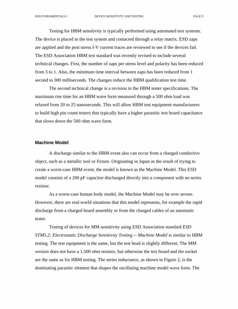
ESD FUNDAMENTALS 5 DEVICE SENSITIVITY AND TESTING PAGE 3
Testing for HBM sensitivity is typically performed using automated test systems.
The device is placed in the test system and contacted through a relay matrix. ESD zaps
are applied and the post stress I-V current traces are reviewed to see if the devices fail.
The ESD Association HBM test standard was recently revised to include several
technical changes. First, the number of zaps per stress level and polarity has been reduced
from 3 to 1. Also, the minimum time interval between zaps has been reduced from 1
second to 300 milliseconds. The changes reduce the HBM qualification test time.
The second technical change is a revision in the HBM tester specifications. The
maximum rise time for an HBM wave form measured through a 500 ohm load was
relaxed from 20 to 25 nanoseconds. This will allow HBM test equipment manufacturers
to build high pin count testers that typically have a higher parasitic test board capacitance
that slows down the 500 ohm wave form.
Machine Model
A discharge similar to the HBM event also can occur from a charged conductive
object, such as a metallic tool or fixture. Originating in Japan as the result of trying to
create a worst-case HBM event, the model is known as the Machine Model. This ESD
model consists of a 200 pF capacitor discharged directly into a component with no series
resistor.
As a worst-case human body model, the Machine Model may be over severe.
However, there are real-world situations that this model represents, for example the rapid
discharge from a charged board assembly or from the charged cables of an automatic
tester.
Testing of devices for MM sensitivity using ESD Association standard ESD
STM5.2: Electrostatic Discharge Sensitivity Testing -- Machine Model is similar to HBM
testing. The test equipment is the same, but the test head is slightly different. The MM
version does not have a 1,500 ohm resistor, but otherwise the test board and the socket
are the same as for HBM testing. The series inductance, as shown in Figure 2, is the
dominating parasitic element that shapes the oscillating machine model wave form. The

ESD FUNDAMENTALS 5 DEVICE SENSITIVITY AND TESTING PAGE 4
series inductance is indirectly defined through the specification of various waveform
parameters.
Figure 2: Typical Machine Model Circuit
Charged Device Model Testing
The transfer of charge from an ESDS device is also an ESD event. A device may
become charged, for example, from sliding down the feeder in an automated assembler. If
it then contacts the insertion head or another conductive surface, a rapid discharge may
occur from the device to the metal object. This event is known as the Charged Device
Model (CDM) event and can be more destructive than the HBM for some devices.
Although the duration of the discharge is very short--often less than one nanosecond--the
peak current can reach several tens of amperes.
Several test methods have been explored to duplicate the real-world CDM event
and provide a suitable test method that duplicates the types of failure that have been
observed in CDM caused field failures. Current work in the area is concentrating on two
separate CDM test methods. One is termed CDM and best replicates the real world
charged device event. The other addresses devices that are inserted in a socket and then
charged and discharged in the socket. It is termed the socketed discharge model (SDM).

ESD FUNDAMENTALS 5 DEVICE SENSITIVITY AND TESTING PAGE 5
The device testing standard for CDM (ESD STM5.3.1: Electrostatic Discharge
Sensitivity Testing - Charged Device Model) was published in 1999. The test procedure
involves placing the device on a field plate with its leads pointing up, then charging it
and discharging the device. Figure 3 illustrates a typical CDM test circuit.
Figure 3: Typical Charged Device Model Test
SDM testing is similar to testing for HBM and MM sensitivity. The device is
placed in a socket, charged from a high-voltage source and then discharged. This
procedure is still a work in process and has had to overcome a number of limitations
including too great a dependency on the specific design of the SDM tester. A draft
document may be ready for release later this year or in 2002. A technical report, ESD
TR08-00: Socket Device Model (SDM) Tester is also available from the ESD Association.
Device Sensitivity Classification
Each of the device testing methods includes a classification system for defining
the component sensitivity to the specified model (See Tables 1, 2, and 3). These
classification systems have a number of advantages. They allow easy grouping and

ESD FUNDAMENTALS 5 DEVICE SENSITIVITY AND TESTING PAGE 6
comparing of components according to their ESD sensitivity and the classification gives
you an indication of the level of ESD protection that is required for the component.
Table 1
ESDS Component Sensitivity Classification - Human Body Model (Per ESD STM5.1-1998)
Class Voltage Range Class 0 <250 volts Class 1A 250 volts to <500 volts Class 1B 500 volts to < 1,000 volts Class 1C 1000 volts to < 2,000 volts Class 2 2000 volts to < 4,000 volts Class 3A 4000 volts to < 8000 volts Class 3B >= 8000 volts
Table 2 ESDS Component Sensitivity Classification - Machine Model
(Per ESD STM5.2-1999)
Class Voltage Range Class M1 <100 volts Class M2 100 volts to <200 volts Class M3 200 volts to <400 volts Class M4 > or = 400 volts

ESD FUNDAMENTALS 5 DEVICE SENSITIVITY AND TESTING PAGE 7
Table 3
ESDS Component Sensitivity Classification - Charged Device Model (Per ESD STM5.3.1-1999)
Class Voltage Range Class C1 <125 volts Class C2 125 volts to <250 volts Class C3 250 volts to <500 volts Class C4 500 volts to <1,000 volts Class C5 1,000 volts to <1,500 volts Class C6 1,500 volts to <2,000 volts Class C7 =>2,000 volts
A fully characterized component should be classified using all three models:
Human Body Model, Machine Model, and Charged Device Model. For example, a fully
characterized component may have the following: Class 1B (500 volts to <1000 volts
HBM), Class M1 (<100 volts MM), and Class C3 (500 volts to <1000 volts CDM). This
would alert a potential user of the component to the need for a controlled environment,
whether assembly and manufacturing operations are performed by human beings or
machines.
A word of caution, however. These classification systems and component
sensitivity test results function as guides, not necessarily as absolutes. The events defined
by the test data produce narrowly restrictive data that must be carefully considered and
judiciously used. The three ESD models represent discrete points used in an attempt to
characterize ESD vulnerability. The data points are informative and useful, but to
arbitrarily extrapolate the data into a real world scenario can be misleading. The true
utility of the data is in comparing one device with another and to provide a starting point
for developing your ESD control programs.
Summary
Device failure models and device test methods define the sensitivity of the
electronic devices and assemblies to be protected from the effects of ESD. With this key
information, you can design more effective ESD control programs.

ESD FUNDAMENTALS 5 DEVICE SENSITIVITY AND TESTING PAGE 8
For Further Reference
Avery, L.R., “Beyond MIL HBM Testing - How to Evaluate the Real Capability of Protection Structures, EOS/ESD Symposium Proceedings, 1991, ESD Association, Rome, NY. Avery, L.R., “Charged Device Model Testing: Trying to Duplicate Reality,” EOS/ESD Symposium Proceedings, 1987, ESD Association, Rome, NY. Chaine, M., Verhaege, K., Avery, L., Kelly, M., Gieser, H., Bock, K., Henry, L.G., Meuse, T., Brodbeck, T., Barth, J., “Investigation into Socketed CDM (SDM) Tester Parasitics,” EOS/ESD Symposium Proceedings, 1998, ESD Association, Rome, NY. ESD STM5.1-1998: Electrostatic Discharge Sensitivity Testing -- Human Body Model. ESD Association, Rome, NY. ESD STM5.2-1999: Electrostatic Discharge Sensitivity Testing -- Machine Model. ESD Association, Rome, NY. ESD STM5.3.1-1999: Electrostatic Discharge Sensitivity Testing - Charged Device Model. ESD Association, Rome, NY. ESD TR08-00: Socket Device Model (SDM) Tester, ESD Association, Rome, NY Gieser, H., and Haunschild, M., “Very Fast Transmission Line Pulsing of Integrated Structures and the Charged Device Model,” EOS/ESD Symposium Proceedings, 1996, ESD Association, Rome, NY. Henry, L.G., Kelly, M., Diep, T., and Barth, J., “Issues Concering CDM ESD Verification Modules-The Need to Move to Alumina,” EOS/ESD Symposium Proceedings, 1999, ESD Association, Rome, NY. Henry, L.G., Kelly, M., Diep, T., and Barth, J., “The Importance of Standardizing CDM ESD Test Head Parameters to Obtain Data Correlation,” EOS/ESD Symposium Proceedings, 2000, ESD Association, Rome, NY. Hyatt, Hugh, Calvin, Hugh, and Mellberg, Hans, “A Closer Look at the Human ESD Event,” EOS/ESD Symposium Proceedings, 1981, ESD Association, Rome, NY. Kelly, M., et al, “A Comparison of Electrostatic Discharge Models and Failure Signatures for CMOS Integrated Circuit Devices,” EOS/ESD Symposium Proceedings, 1995, ESD Association, Rome, NY. Pierce, Donald C., “Critical Issues Regarding ESD Sensitivity Classification Testing,” EOS/ESD Symposium Proceedings, 1987, ESD Association, Rome, NY.

ESD FUNDAMENTALS 5 DEVICE SENSITIVITY AND TESTING PAGE 9
Renninger, Robert G., “Mechanisms of Charged-Device Electrostatic Discharges,” EOS/ESD Symposium Proceedings, 1991. ESD Association, Rome, NY. Russ, Christian., et al, “A Compact Model for the Grounded-Gate nMOS Behavior Under CDM ESD Stress,” EOS/ESD Symposium Proceedings, 1996, ESD Association, Rome, NY. Verhaege, Koen, “Component Level ESD Testing,” Review Paper, Microelectronics Reliability Journal, 1998. Verhaege, Koen., et al “ Analysis of HBM ESD Testers and Specifications Using a 4th Order Lumped Element Model,” EOS/ESD Symposium Proceedings, 1993, ESD Association, Rome, NY. Verhaege, Koen., et al, “Recommendations to Further Improvements of HBM ESD Component Level Test Specifications,” EOS/ESD Symposium Proceedings, 1996, ESD Association, Rome, NY. Wada, Tetsuaki. “Study of ESD Evaluation Methods for Charged Device Model,” EOS/ESD Symposium Proceedings, 1995, ESD Association, Rome, NY. June 2001

ESD BASICS, PART SIX PAGE 1
Fundamentals of Electrostatic Discharge Part Six--ESD Standards © 2001, ESD Association, Rome, NY
The electronics industry is continually shifting. Device density and technology is
more complex. Electronics manufacturing is more heavily reliant on out-sourcing. The
ESD industry seems to have jumped into this swirling eddy headfirst. ESD control
programs have mushroomed. Black has been replaced by green, blue and gold. Shielding
bags dominate the warehouse. Ionizers exist along side wrist straps and ground cords. An
early history of “smoke and mirrors,” magic and lofty claims of performance is rapidly
and safely being relegated to the past.
Today, more than ever, meeting the complex challenge of reducing ESD losses
requires more than reliance on faith alone. Users require a way to legitimately evaluate
and compare competing brands and types of products. They need objective confirmation
that their ESD control program provides effective solutions to their unique ESD
problems. Contract manufacturers and OEM’s require mutually agreed-upon ESD control
programs that reduce duplication of process controls.
That’s where standards come into play. They provide guidance in developing
programs that effective address ESD process control. They help define the sensitivity of
the products manufactured and used. They help define the performance requirements for
various ESD control materials, instruments, and tools. Standards are playing an ever-
increasing role in reducing marketplace confusion in the manufacture, evaluation, and
selection of ESD control products and programs.

ESD BASICS, PART SIX PAGE 2
The Who and Why of Standards
Who uses ESD standards? Manufacturers and users of ESD sensitive devices and
products, manufacturers and distributors of ESD control products, certification registrars,
and third party testers of ESD control products.
Why use ESD standards? They help assure consistency of ESD sensitive products
and consistency of ESD control products and services. They provide a means of objective
evaluation and comparison among competitive ESD control products. They help reduce
conflicts between users and suppliers of ESD control products. They help in developing,
implementing, auditing, and certifying ESD control programs. And, they help reduce
confusion in the marketplace.
In the United States, the use of standards is voluntary, although their use can be
written into contracts or purchasing agreements between buyer and seller. In most of the
rest of the world, the use of standards, where they exist, is compulsory.
Key Standards and Organizations
Just 20 years ago, there were relatively few reliable ESD standards and few ESD
standards development organizations. Today’s ESD standards landscape is not only
witnessing an increase in the number of standards, but also increasing cooperation among
the organizations that develop them.
Today’s standards fall into three main groups. First, there are those that provide
ESD program guidance or requirements. These include documents such as ANSI ESD
S20.20-1999--Standard for the Development of an ESD Control Program, ANSI/ESD
S8.1-ESD Awareness Symbols, or ESD TR20.20-ESD Handbook.

ESD BASICS, PART SIX PAGE 3
A second group covers requirements for specific products or procedures such as
packaging or grounding. Typical standards in this group are ANSI/ESD S6.1-Grounding
or ESD S11.11 for Shielding Bags.
A third group of documents covers the standardized test methods used to evaluate
products and materials. Historically, the electronics industry relied heavily on test
methods established for other industries or even other materials (e. g., ASTM-257-DC
Resistance or Conductance of Insulating Materials). Today, however, specific test
method standards focus on ESD in the electronics environment, largely as a result of the
ESD Association’s activity. These include standards such as ESD S5.1-Device Testing,
Human Body Model and ANSI/ESD S7.1: Floor Materials -- Resistive Characterization
to cite just a few.
Who Develops Standards?
Standards development and usage is a cooperative effort among all organizations
and individuals affected by standards. There are several key ESD standards development
organizations.
Military Standards
Traditionally, the U.S. military spearheaded the development of specific standards
and specifications with regard to ESD control in the U.S. Today, however, U.S. military
agencies are taking a less proactive approach, relying on commercially developed
standards rather than developing standards themselves. For example, the ESD
Association completed the assignment from the Department of Defense to convert MIL-
STD-1686 into a commercial standard.

ESD BASICS, PART SIX PAGE 4
ESD Association
The ESD Association has been a focal point for the development of ESD
standards in recent years. An ANSI-accredited standards development organization, the
Association is charged with the development of ESD standards and test methods. The
Association also represents the US on the International Electrotechnical Commission
Technical Committee 101-Electrostatics.
The ESD Association has published 26 standards documents and 9 technical
reports. These voluntary standards cover the areas of material requirements, electrostatic
sensitivity, and test methodology for evaluating ESD control materials and products. In
addition to standards documents, the Association also publishes a number of
informational advisories.
ESD Association Standards Classifications and Definitions
There are four types of ESD Association standards documents with specific
clarity of definition. The four document categories are consistent with other standards
development organizations. These four categories are defined below.
Standard: A precise statement of a set of requirements to be satisfied by a
material, product, system or process that also specifies the procedures for determining
whether each of the requirements is satisfied.
Standard Test Method: A definitive procedure for the identification,
measurement and evaluation of one or more qualities, characteristics or properties of a
material, product, system or process that yields a reproducible test result.

ESD BASICS, PART SIX PAGE 5
Standard Practice: A procedure for performing one or more operations or
functions that may or may not yield a test result. Note: If a test result is obtained, it may
not be reproducible between labs.
Technical Report: A collection of technical data or test results published as an
informational reference on a specific material, product, system, or process.
As new documents are approved and issued, they will be designated into one of
these four new categories. Existing documents are being reviewed and will be
reclassified as appropriate.
International Standards
The international community, led by the European-based International
Electrotechnical Commission, has also climbed on board the standards express. Europe’s
CENELEC has issued a European electrostatic standard EN100015 - Protection of
Electrostatic Sensitive Devices that was adopted as a European Norm. Additional work
by the IEC to will result in a comprehensive series of standards that may someday be the
successor to EN100015.
Japan also has released its proposed version of a national electrostatic Standard,
which also shares many aspects of the European and U.S. documents.
Organizational Cooperation
Perhaps one of the more intriguing changes in ESD standards has been the
organizational cooperation developing between various groups. One cooperative effort
was between the ESD Association and the U.S. Department of Defense, which resulted in
the Association preparing ANSI/ESD S20.20 as a successor to MIL-STD-1686.

ESD BASICS, PART SIX PAGE 6
Internationally, European standards development organizations and the ESD
Association have developed working relationships that result in an expanded review of
proposed documents, greater input, and closer harmonization of standards that impact the
international electronics community.
For users of ESD standards, this increased cooperation will have a significant
impact. First, we should see standards that are technically improved due to broader input.
Second, we should see fewer conflicts between different standards. Finally, we should
see less duplication of effort.
Summary
For the electronics community, the rapid propagation of ESD standards and
continuing change in the standards environment mean greater availability of the technical
references that will help improve ESD control programs. There will be recommendations
to help set up effective programs. There will be test methods and specifications to help
users of ESD control materials evaluate and select products that are applicable to their
specific needs. And there will be guidelines for vendors of ESD products and materials to
help them develop products that meet the real needs of their customers.
Standards will continue to fuel change in the international ESD community.
Principle ESD Standards
U.S. Military/Department of Defense
MIL-STD-1686C: Electrostatic Discharge Control Program for Protection of Electrical and Electronic Parts, Assemblies and Equipment (Excluding Electrically Initiated Explosive Devices) This military standard establishes requirements for ESD Control Programs. It applies to U.S. military agencies, contractors, subcontractors, suppliers and vendors. It requires the establishment, implementation and documentation of ESD control programs for static

ESD BASICS, PART SIX PAGE 7
sensitive devices, but does NOT mandate or preclude the use of any specific ESD control materials, products, or procedures. It is being updated and converted to a commercial standard by the ESD Association. Although DOD has accepted the new ANSI/ESD S20.20 document as a successor, it has not yet taken action to cancel STD-1686
MIL-HBDK-263B: Electrostatic Discharge Control Handbook for Protection of Electrical and Electronic Parts, Assemblies and Equipment (Excluding Electrically Initiated Explosive Devices) This document provides guidance, but NOT mandatory requirements, for the establishment and implementation of an electrostatic discharge control program in accordance with the requirements of MIL-STD-1686.
MIL-PRF 87893—Workstation, Electrostatic Discharge (ESD) Control This document defines the requirements for ESD protective workstations.
MIL-B-81705—Barrier Materials, Flexible, Electrostatic Protective, Heat Sealable This documents defines requirements for ESD protective flexible packaging materials.
MIL-STD-129—Marking for Shipment and Storage Covers procedures for marketing and labeling ESD sensitive items. International/European
EN100015: Protection of Electrostatic Sensitive Devices Adopted in 1992 and 1993, this European Norm covers ESD handling practices for electronic devices.
ESD Association
Standards Documents ESD S1.1—1998: Evaluation, Acceptance, and Functional Testing of Wrist Straps A successor to EOS/ESD S1.0, this document establishes test methods for evaluating the electrical and mechanical characteristics of wrist straps. It includes improved test methods and performance limits for evaluation, acceptance, and functional testing of wrist straps. ESD STM2.1—1997: Resistance Test Method for Electrostatic Discharge Protective Garments This Standard Test Method provides test methods for measuring the electrical resistance of garments used to control electrostatic discharge. It covers procedures for measuring sleeve-to-sleeve and point-to-point resistance. ESD STM3.1-2000: Ionization

ESD BASICS, PART SIX PAGE 8
Test methods and procedures for evaluating and selecting air ionization equipment and systems are covered in this standard. The document establishes measurement techniques to determine ion balance and charge neutralization time for ionizers. ESD SP3.3-2000: Periodic Verification of Air Ionizers. This Standard Practice provides test methods and procedures for periodic verification of the performance of air ionization equipment and systems (ionizers). ESD S4.1- 1997(Revised): Worksurfaces – Resistance Measurements This Standard establishes test methods for measuring the electrical resistance of worksurface materials used at workstations for protection of ESD susceptible items. It includes methods for evaluating and selecting materials, and testing new worksurface installations and previously installed worksurfaces. ESD STM4.2-1998: Worksurfaces - Charge Dissipation Characteristics This Standard Test Method provides a test method to measure the electrostatic charge dissipation characteristics of worksurfaces used for ESD control. The procedure is designed for use in a laboratory environment for qualification, evaluation or acceptance of worksurfaces. ESD STM5.1-1998 Revised: Electrostatic Discharge Sensitivity Testing -- Human Body Model This Standard Test Method updates and revises an existing Standard. It establishes a procedure for testing, evaluating and classifying the ESD sensitivity of components to the defined Human Body Model (HBM). ESD STM5.2-1999 (Revised): Electrostatic Discharge Sensitivity Testing -- Machine Model This Standard establishes a test procedure for evaluating the ESD sensitivity of components to a defined Machine Model (MM). It also provides a system of classifying the sensitivity of these components. The component damage caused by the Machine Model is often similar to that caused by the Human Body Model, but it occurs at a significantly lower voltage. ESD STM5.3-1999: Electrostatic Discharge Sensitivity Testing - Charged Device Model -- Non-Socketed Mode This Standard Test Method establishes a test method for evaluating the ESD sensitivity of active and passive components to a defined Charged Device Model (CDM). ESD S6.1-1999: Grounding -- Recommended Practice This Standard recommends the parameters, procedures, and types of materials needed to establish an ESD grounding system for the protection of electronic hardware from ESD damage. This system is used for personnel grounding devices, worksurfaces, chairs, carts, floors, and other related equipment. ANSI ESD S7.1-1994: Floor Materials -- Resistive Characterization of Materials

ESD BASICS, PART SIX PAGE 9
Measurement of the electrical resistance of various floor materials such as floor coverings, mats, and floor finishes is covered in this document. It provides test methods for qualifying floor materials before installation or application and for evaluating and monitoring materials after installation or application. ANSI ESD S8.1-1993: ESD Awareness Symbols Three types of ESD awareness symbols are established by this document. The first one is to be used on a device or assembly to indicate that it is susceptible to electrostatic charge. The second is to be used on items and materials intended to provide electrostatic protection. The third symbol indicates the common point ground ESD S9.1-1995: Resistive Characterization of Footwear This Standard defines a test method for measuring the electrical resistance of shoes used for ESD control in the electronics environment. ESD SP10.1-2000: Automated Handling Equipment This Standard Practice provides procedures for evaluating the electrostatic environment associated with automated handling equipment. ANSI ESD S11.11-1993: Surface Resistance Measurement of Static Dissipative Planar Materials This Standard defines a direct current test method for measuring electrical resistance. The Standard is designed specifically for static dissipative planar materials used in packaging of ESD sensitive devices and components. ESD STM11.12-2000: Volume Resistance Measurement of Static Dissipative Planar Materials This Standard Test Method provides test methods for measuring the volume resistance of static dissipative planar materials used in the packaging of ESD sensitive devices and components. ANSI ESD S11.31-1994: Evaluating the Performance of Electrostatic Discharge Shielding Bags This Standard provides a method for testing and determining the shielding capabilities of electrostatic shielding bags. ESD STM12.1-1997: Seating-Resistive Characterization This Standard provides test methods for measuring the electrical resistance of seating used to control ESD. The test methods can be used for qualification testing as well as for evaluating and monitoring seating after installation. It covers all types of seating, including chairs and stools. ESD STM13.1-2000: Electrical Soldering/Desoldering Hand Tools This Standard Test Method provides electric soldering/desoldering hand tool test methods for measuring the electrical leakage and tip to ground reference point resistance and provides parameters for EOS safe soldering operation.

ESD BASICS, PART SIX PAGE 10
ANSI ESD S20.20-1999: Standard for the Development of an ESD Control Program This Standard provides administrative, technical requirements and guidance for establishing, implementing and maintaining an ESD Control Program. ESD STM97.1-1999: Floor Materials and Footwear – Resistance in Combination with a Person. This Standard Test Method provides for measuring the electrical resistance of floor materials, footwear and personnel together, as a system. ESD STM97.2-1999 Floor Materials and Footwear Voltage Measurement in Combination with a Person This Standard Test Method provides for measuring the electrostatic voltage on a person in combination with floor materials and footwear, as a system. Advisory Documents Advisory Documents and Technical Reports are not Standards, but provide general information for the industry or additional information to aid in better understanding of Association Standards. ESD ADV1.0-1994: Glossary of Terms Definitions and explanations of various terms used in Association Standards and documents are covered in this Advisory. It also includes other terms commonly used in the ESD industry. ESD ADV3.2-1995: Selection and Acceptance of Air Ionizers This Advisory document provides end users with guidelines for creating a performance specification for selecting air ionization systems. It reviews four types of air ionizers and discusses applications, test method references, and general design, performance and safety requirements. ESD ADV11.2-1995: Triboelectric Charge Accumulation Testing The complex phenomenon of triboelectric charging is discussed in this Advisory. It covers the theory and effects of tribocharging. It reviews procedures and problems associated with various test methods that are often used to evaluate triboelectrification characteristics. The test methods reviewed indicate gross levels of charge and polarity, but are not necessarily repeatable in real world situations. ESD ADV53.1-1995: ESD Protective Workstations This Advisory document defines the minimum requirements for a basic ESD protective workstation used in ESD sensitive areas. It provides a test method for evaluating and monitoring workstations. It defines workstations as having the following components: support structure, static dissipative worksurface, a means of grounding personnel, and any attached shelving or drawers. ESD TR 20.20: ESD Handbook

ESD BASICS, PART SIX PAGE 11
New handbook provides detailed guidance for implementing an ESD control program in accordance with ANSI/ESD S20.20.
Sources of Standards
ESD Association, 7900 Turin Road, Building 3, Rome, NY 13440. Phone: 315-339-6937. Fax: 315-339-6793. Web Site: http://www.esda.org
HIS Global Engineering Documents, 15 Inverness Way East, Englewood, CO 80112. Phone: 800-854-7179. Fax: 303-397-2740. Web Site: http://global.ihs.com
International Electrotechnical Commission, 3, rue de Varembe, Case postale 131, 1211 Geneva 20, Switzerland. Fax: 41-22-919-0300. Web Site: http://www.iec.ch/
Military Standards, Naval Publications and Forms Center, 5801 Tabor Avenue, Philadelphia, PA 19120.
June 2001