Embed Size (px)
Citation preview
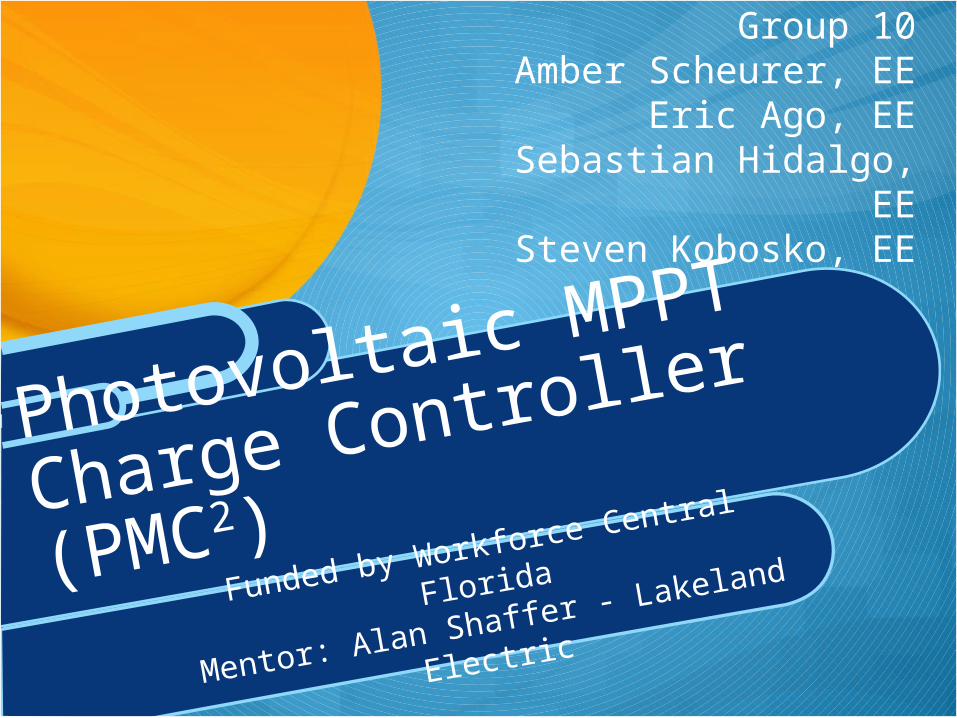
Funded by Workforce Central Florida
Mentor: Alan Shaffer - Lakeland Electric
Photovoltaic MPPT
Charge Controller (PMC2)
Group 10Amber Scheurer, EE
Eric Ago, EESebastian Hidalgo, EE
Steven Kobosko, EE
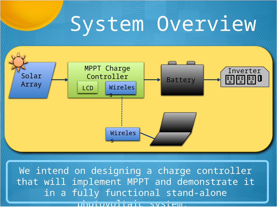
MPPT Charge ControllerSolar
ArrayBattery
LCD Wireless
Wireless
Inverter
System Overview
We intend on designing a charge controller that will implement MPPT and demonstrate it in a fully functional stand-alone photovoltaic system.
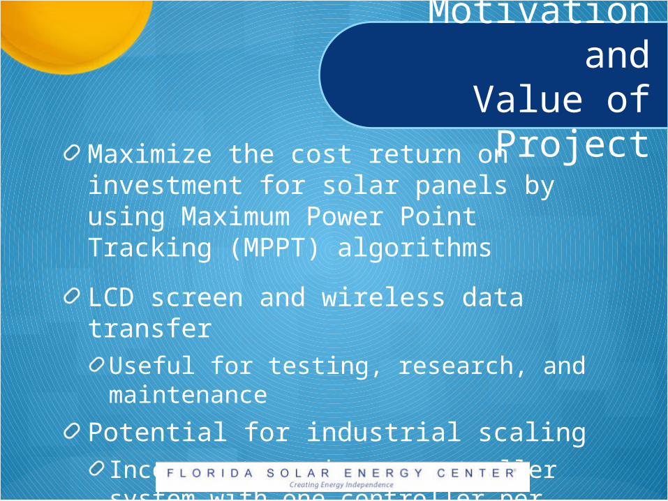
Motivation andValue of Project
Maximize the cost return on investment for solar panels by using Maximum Power Point Tracking (MPPT) algorithms
LCD screen and wireless data transfer Useful for testing, research, and maintenance
Potential for industrial scalingIncorporate a charge controller system with one controller per panel
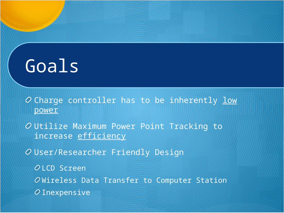
Goals
Charge controller has to be inherently low power
Utilize Maximum Power Point Tracking to increase efficiency
User/Researcher Friendly Design
LCD Screen
Wireless Data Transfer to Computer Station
Inexpensive
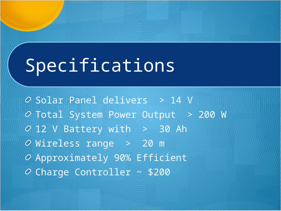
Specifications
Solar Panel delivers > 14 V
Total System Power Output > 200 W
12 V Battery with > 30 Ah
Wireless range > 20 m
Approximately 90% Efficient
Charge Controller ~ $200
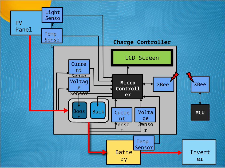
LCD Screen
Boost Buck
Current Sensor
Voltage Sensor
Charge Controller
PV Panel
Temp. Sensor
Micro Controller
XBee XBee
MCU
Battery Inverter
Temp. Sensor
Current Sensor
Voltage Sensor
LightSensor
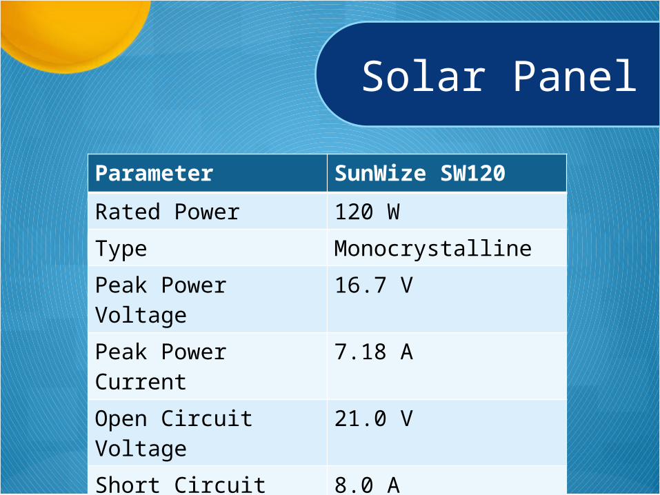
Solar Panel
Parameter SunWize SW120
Rated Power 120 W
Type Monocrystalline
Peak Power Voltage 16.7 V
Peak Power Current 7.18 A
Open Circuit Voltage 21.0 V
Short Circuit Current 8.0 A
Dimensions ~ 2 x 5 ft.
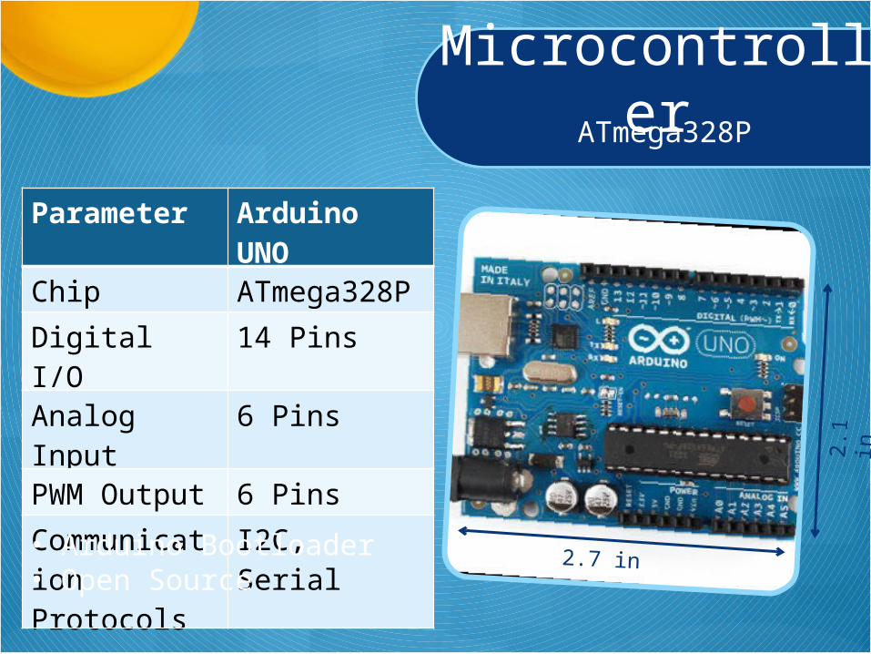
MicrocontrollerATmega328P
Parameter Arduino UNO
Chip ATmega328P
Digital I/O 14 Pins
Analog Input 6 Pins
PWM Output 6 Pins
Communication Protocols
I2C, Serial
2.7 in• Arduino Bootloader• Open Source
2.1
in
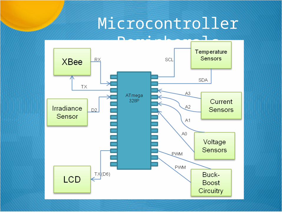
Microcontroller Peripherals
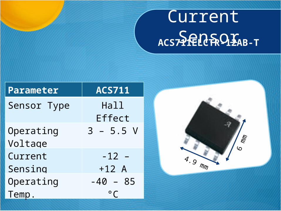
Current SensorACS711ELCTR-12AB-T
Parameter ACS711
Sensor Type Hall Effect
Operating Voltage 3 – 5.5 V
Current Sensing -12 – +12 A
Operating Temp. -40 – 85 °C4.9 mm
6 m
m
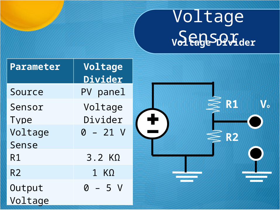
Voltage SensorVoltage Divider
Parameter Voltage Divider
Source PV panel
Sensor Type Voltage Divider
Voltage Sense 0 – 21 V
R1 3.2 KΩ
R2 1 KΩ
Output Voltage 0 – 5 V
R1
R2
Vo
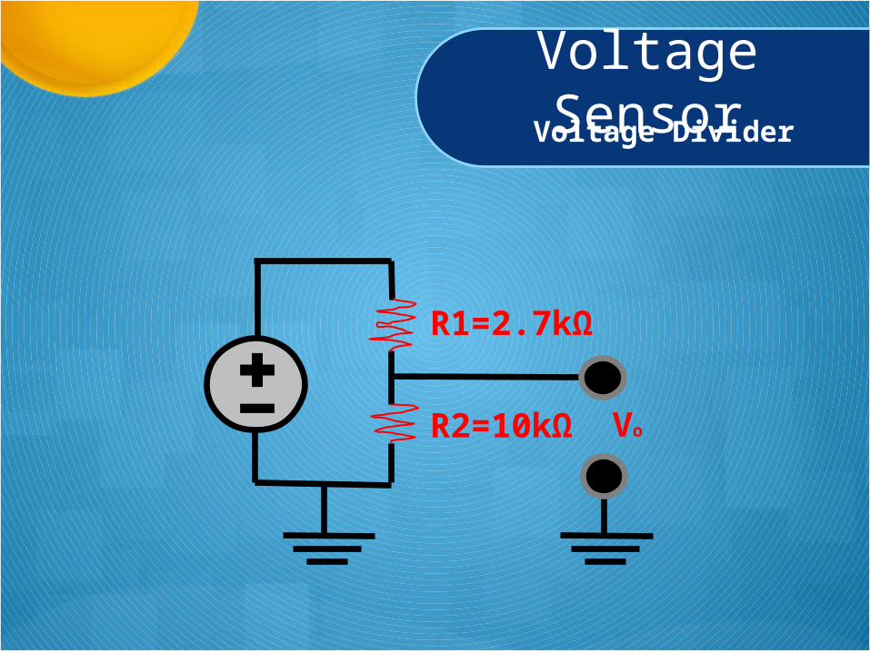
Voltage SensorVoltage Divider
R1=2.7kΩ
R2=10kΩ Vo
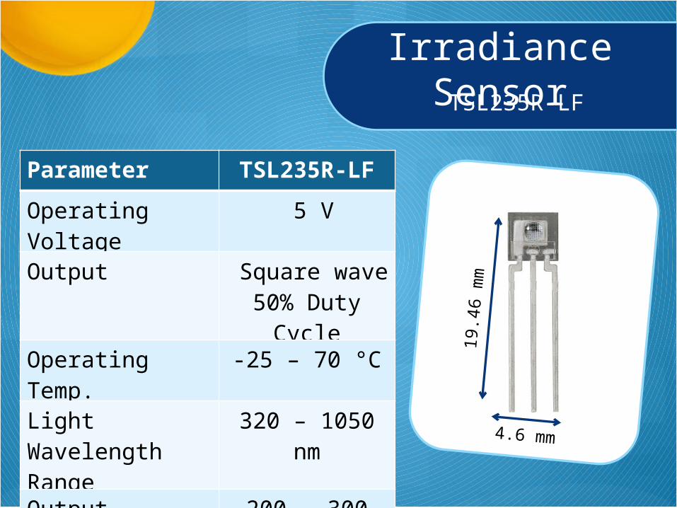
Irradiance SensorTSL235R-LF
Parameter TSL235R-LF
Operating Voltage 5 V
Output Square wave 50% Duty Cycle
Operating Temp. -25 – 70 °C
Light Wavelength Range
320 – 1050 nm
Output Frequency 200 – 300 KHz4.6 mm
19.4
6 m
m
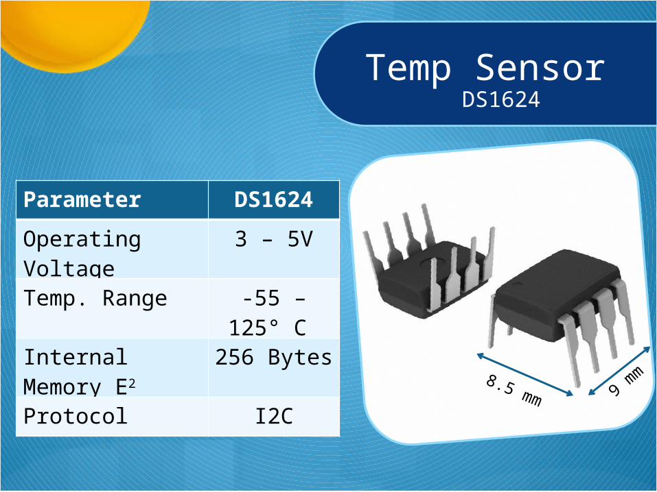
Temp SensorDS1624
Parameter DS1624
Operating Voltage 3 – 5V
Temp. Range -55 – 125° C
Internal Memory E2 256 Bytes
Protocol I2C8.5 mm 9 m
m
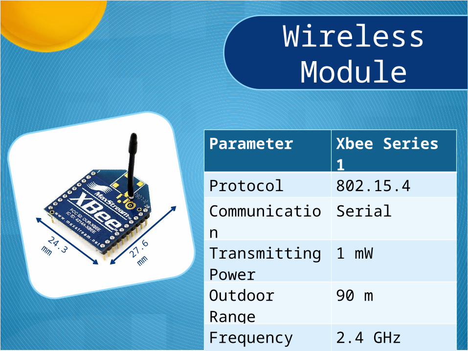
Wireless Module
24.3 mm 27.6
mm
Parameter Xbee Series 1
Protocol 802.15.4
Communication Serial
Transmitting Power
1 mW
Outdoor Range 90 m
Frequency Band 2.4 GHz
Operating Voltage 3.3 V
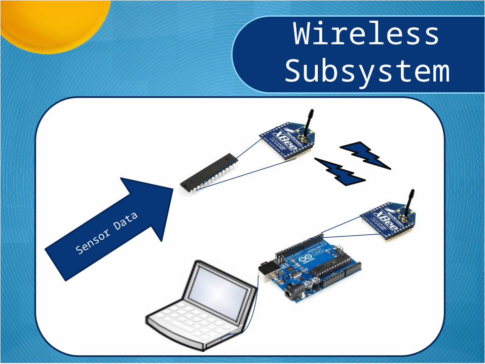
Sensor Data
Wireless Subsystem
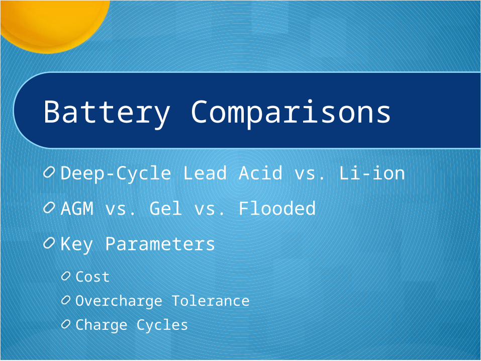
Battery Comparisons
Deep-Cycle Lead Acid vs. Li-ion
AGM vs. Gel vs. Flooded
Key Parameters
Cost
Overcharge Tolerance
Charge Cycles
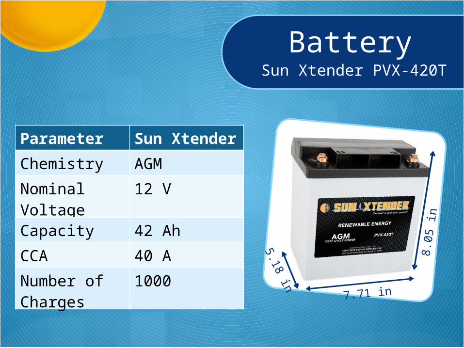
BatterySun Xtender PVX-420T
Parameter Sun Xtender
Chemistry AGM
Nominal Voltage 12 V
Capacity 42 Ah
CCA 40 A
Number of Charges
1000
7.71 in
8.05
in
5.18 in
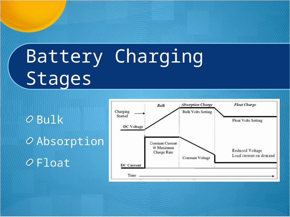
Battery Charging Stages
Bulk
Absorption
Float
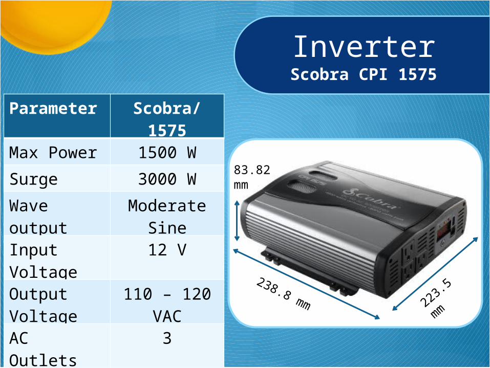
InverterScobra CPI 1575
Parameter Scobra/1575
Max Power 1500 W
Surge 3000 W
Wave output Moderate Sine
Input Voltage 12 V
Output Voltage
110 – 120 VAC
AC Outlets 3
USB 1
83.82 mm
223.5 mm238.8 mm
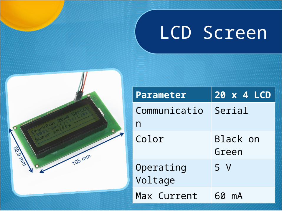
LCD Screen
Parameter 20 x 4 LCD
Communication Serial
Color Black on Green
Operating Voltage 5 V
Max Current 60 mA
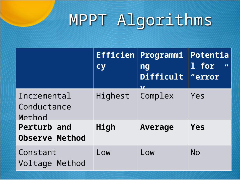
MPPT Algorithms
Efficiency Programming Difficulty
Potential for “error”
Incremental Conductance Method
Highest Complex Yes
Perturb and Observe Method
High Average Yes
Constant Voltage Method
Low Low No
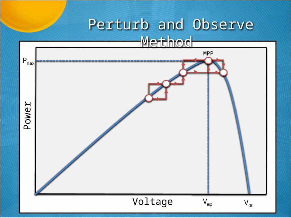
Voltage
Pow
er
MPPPmax
VOC
Perturb and Observe Method
Vmp

Adjust PWM
Start Sensor Read:Battery Voltage
Sensor Read:Battery Current &
Voltage
Float orAbsorption I x V > P0 I x V < P0
Increase Voltage
Decrease Voltage
Bulk
Regulated Power
Delivered to Battery
LCD: LCD.printXbee: Serial.write
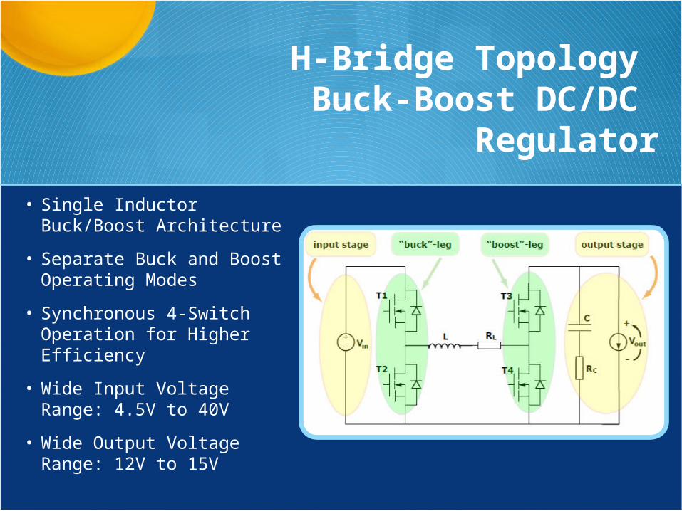
H-Bridge Topology Buck-Boost DC/DC
Regulator
• Single Inductor Buck/Boost Architecture
• Separate Buck and Boost Operating Modes
• Synchronous 4-Switch Operation for Higher Efficiency
• Wide Input Voltage Range: 4.5V to 40V
• Wide Output Voltage Range: 12V to 15V
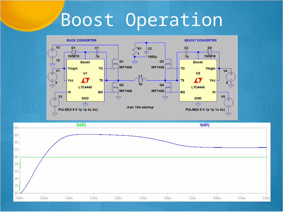
Boost Operation
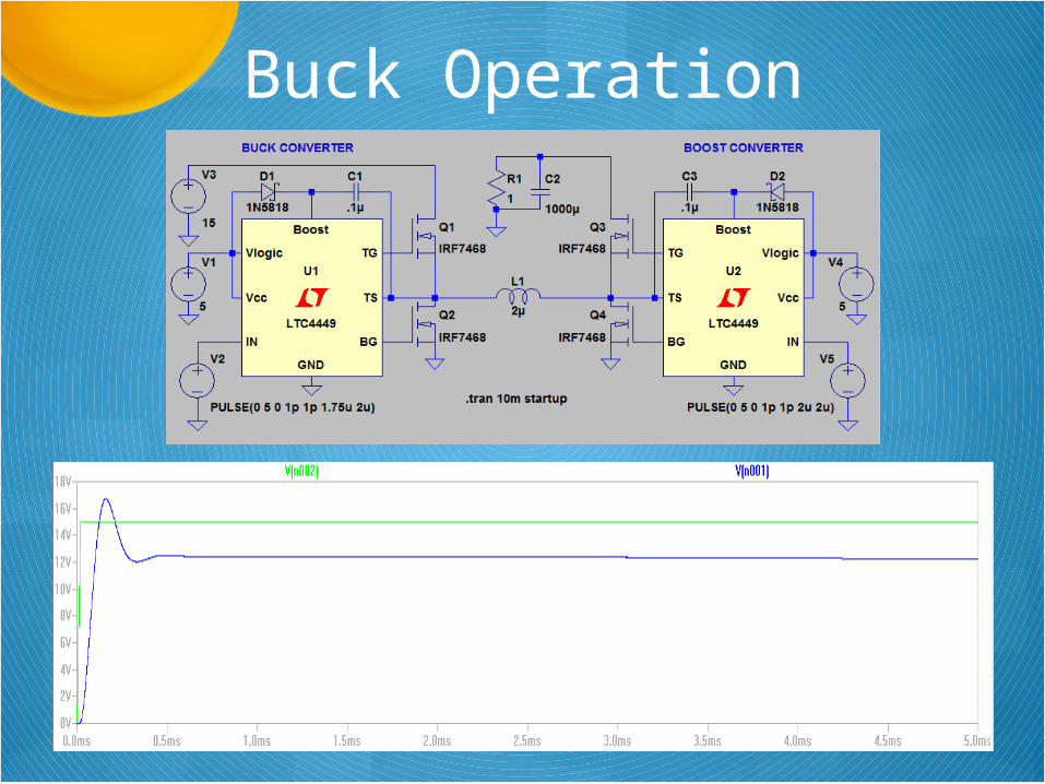
Buck Operation
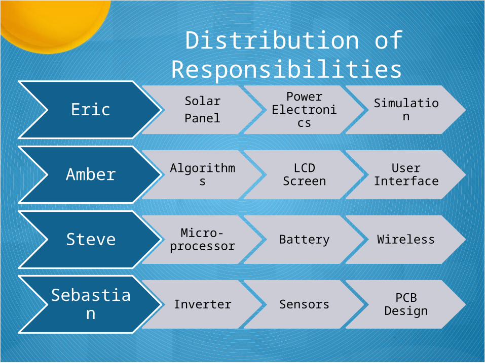
Distribution of Responsibilities
EricSolarPanel
Power Electronics Simulation
Amber Algorithms LCD Screen
User Interface
Steve Micro-processor Battery Wireless
Sebastian Inverter Sensors PCB Design
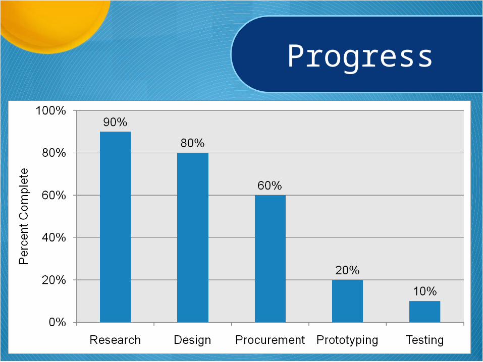
Progress
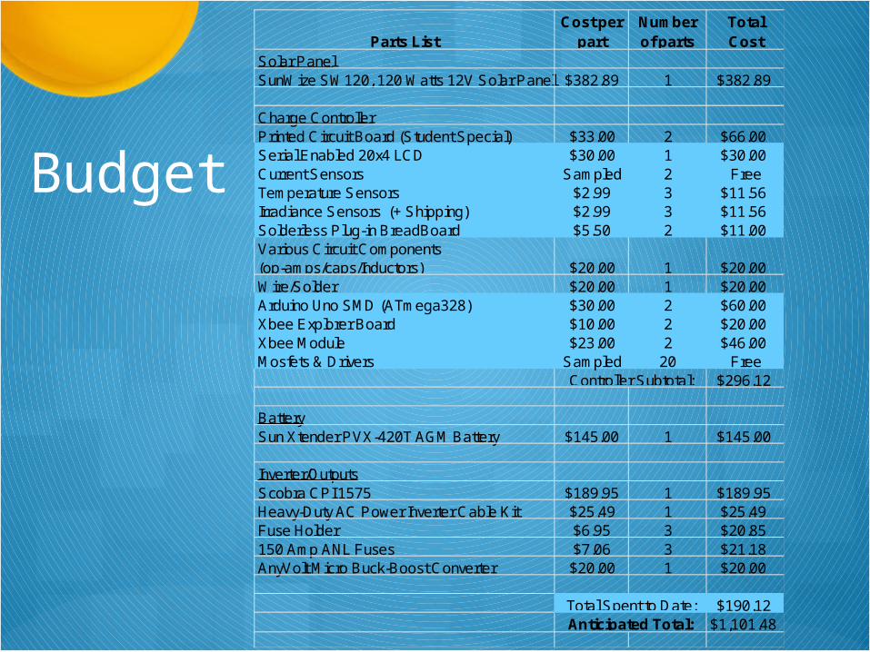
Budget
Parts ListCost per
partNumber of parts
Total Cost
Solar PanelSunWize SW120, 120 Watts 12V Solar Panel $382.89 1 $382.89
Charge ControllerPrinted Circuit Board (Student Special) $33.00 2 $66.00Serial Enabled 20x4 LCD $30.00 1 $30.00Current Sensors Sampled 2 FreeTemperature Sensors $2.99 3 $11.56Irradiance Sensors (+ Shipping) $2.99 3 $11.56Solderless Plug-in BreadBoard $5.50 2 $11.00Various Circuit Components (op-amps/caps/Inductors) $20.00 1 $20.00Wire/Solder $20.00 1 $20.00Arduino Uno SMD (ATmega328) $30.00 2 $60.00Xbee Explorer Board $10.00 2 $20.00Xbee Module $23.00 2 $46.00Mosfets & Drivers Sampled 20 Free
$296.12
BatterySun Xtender PVX-420T AGM Battery $145.00 1 $145.00
Inverter/OutputsScobra CPI 1575 $189.95 1 $189.95Heavy-Duty AC Power Inverter Cable Kit $25.49 1 $25.49Fuse Holder $6.95 3 $20.85150 Amp ANL Fuses $7.06 3 $21.18AnyVolt Micro Buck-Boost Converter $20.00 1 $20.00
$190.12$1,101.48Anticipated Total:
Total Spent to Date:
Controller Subtotal:
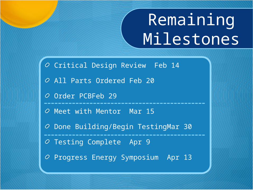
RemainingMilestones
Critical Design Review Feb 14
All Parts Ordered Feb 20
Order PCB Feb 29
Meet with Mentor Mar 15
Done Building/Begin Testing Mar 30
Testing Complete Apr 9
Progress Energy SymposiumApr 13
Anticipated Problems
Designing circuit to handle high power
Heat dissipation
Buck-Boost Circuitry

Questions?