Embed Size (px)
Citation preview
lssue Month:Committee
€fuor Eft-aron M fudaor ftr-drd
Irrf,sarrt xrf,rrxr. BLI.I vtr8rn f,IGrX
Annexure- A to ScteaulJ-D (part-D
No. CSC-24/R -| I UHI DH I p &D I 2o2o-2t
Technical specification of
35 KV Vacuum Circuit Breaker
for 33 KV Sub-Stations
Common Specifications
UHBVN & DHBVN
ara ?fum Eftdrun M edaor fudrd
&".orrrB Dtf,silr f,atyffr Bur ylrBttr m6tx
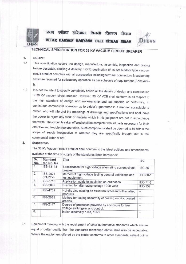
TEcHNtcAL spEctFtcATtoN FoR 36 KV vAcu rnc-urr ei-eArER
1. SCOPE:
1'1 This specification covers the design, manufacture, assembry, inspection and testingbefore despatch, packing & delivery F.O.R. destination of 36 KV outdoor type vacuumcircuit breaker comprete with a[ accessories incruding terminar connectors & supportingstructure required for satisfactory operation as per schedure of requirement (Annexure-
D.
1.2 lt is not the intent to specify compretery herein afl the detairs of design and constructionof 35 KV vacuum circuit breaker. However, 36 r(/ vcB shafl conform in arr respect tothe high standard of design and workmanship and be capable of performing in
continuous commerciar operation up to bidder's guarantee in a manner acceptabre toowner' who wirr interpret the meanings of drawings and specifications and shafl have
the pou,er to reject any work or material which in his judgment are not in accordance
therewith. The circuit breaker offered shaI be comprete with aI parts necessary for theireffective and troubre free operation. such components shafl be deemed to be \rvithin thescope of supply irrespective of whether they are specifically brought out in thecommercial order or not.
2. Standards:-
The 36 l(/ Vacuum circuit breaker sha[ conform to the ratest editions and amendments
available at the time of supply of the standards listed hereunder:
Sr.No.
Standardref. No. lss
Ti e lEc
I tss-'131 18 specification for h@breaker
IEC-56
2. rss-2071(PART-t)
Method of high volta@test equiprnent.
IEC-60-1
a lss-3716 Application guide to insulation co-ordinati; lEc-71-24. lss-2099 Bushing for alternating voltage 10oor/olis.- tEC-137
lss-4759 Hot-dip zinc coating on structuralsteEl and other alliedproducts.
6. tss-2633 Method for testing uniformity of coating-n zinE c6EiEI'articles.
7. lss-2147 Degree of protection provided by enclosure for lowvoltage switchgear and control.
a lndian electricity rules, 'l956
Equipment meeting with the requirement of other authoritative standards which ensure
equal or better quality than the standards mentioned above shall also be acceptable.
where the equipment offered by the bidder conforms to other standards, sarient points
3lJ*il
2.1
wect
UTTTB
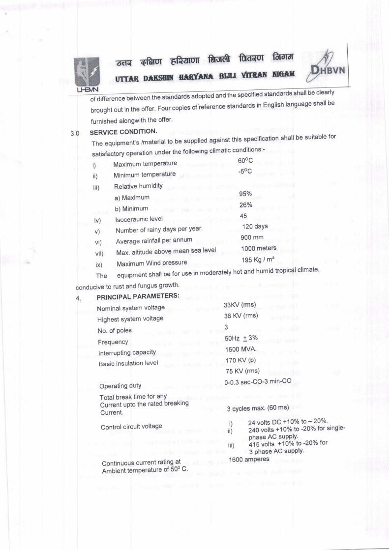
i) Maximum temperature
ii) Minimumtemperature
iii) Relative humidity
a) Maximum
b) Minimum
iv) lsoceraunic level
v) Number of rainY daYs Per Year:
Nominal system voltage
Highest system voltage
No. of poles
FrequencY
lnterrupting caPacitY
Basic insulation level
Operating dutY
Total break time for anY
Current upto the rated breaking
Current.
Control circuit voltage
Continuous current rating at
Ambient temPerature of 500 C'
600c
-50C
95%
26%
45
120 daYs
33KV (rms)
36 K/ (rms)
50Hz 13%
1 500 l\ilvA.
170 KV (P)
75 K/ (rms)
O-0.3 sec-Co-3 min-CO
3 cycles max. (60 ms)
24 volts DC +10% lo -20%240 volts +10% to -20% for single-
ohase AC suPPlY.
its volts +10o/o lo -ZQo/o lor
3 phase AC suPPlY.
furnished alongwith the offer'
3.0 SERVICE CONDITION.
The equlpment's /material to be supplied against this speciflcation shall be suitable for
satisfactory oPeration under the following climatic conditions:-
vi) Average rainfall per annum 900 mm
vii) Max. altitude above mean sea level 1000 meters
ix) Maximum Wind pressure 195 Kg / m"
The equipment shall be for use in moderately hot and humid tropical climate'
conducive to rust and fungus growth'
4. PRINCIPALPARAMETERS:
i)
ii)
iii)
1600 amPeres
lrh";* **"@rds shall be clearl,
brought out in the offer. Four copies ofieference standards in English language shall be
&rt.F€lal
B'tra ?fuor Efrarff M fod{uI €t-dr#
rrrTtf,. DrBsrf, urnt'rm Bur Yln&fit f,rGru
rtp{evx
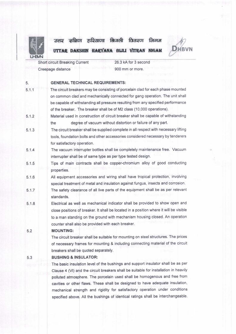
Short circuit Breaking Current
Creepage distance
26.3 kA for 3 second
900 mm or more.
5.
5.1.1
GENERAL TECHNICAL REQUIREMENTS:
The circuit breakers may be consisting of porcelain clad for each phase mounted
on common clad and mechanically connected for gang operation. The unit shall
be capable of withstanding all pressure resulting from any specified performance
of lhe breaker. The breaker shall be of M2 class ('10,000 operations).
Material used in construction of circuit breaker shall be capable of withstanding
the degree ofvacuum without distortion orfailure of any part.
The circuit breaker shall be supplied complete in all respect with necessary lifting
tools, foundation bolts and other accessories considered necessary by tenderers
for satisfactory operation.
The vacuum interrupter bottles shall be completely maintenance free. Vacuum
interrupter shall be of same type as per type tested design.
Tips of main contracts shall be copper-chromium alloy of good conducting
properties.
All equipment accessories and wiring shall have tropical protection, involving
special treatment of metal and insulation against fungus, insects and corrosion.
The safety clearance of all live parts of the equipment shall be as per relevant
standards.
Electrical as well as mechanical indicator shall be provided to show open and
close positions of breaker. lt shall be located in a position where it will be visible
to a man standing on the ground with mechanism housing closed. An operation
counter shall also be provided with each breaker.
MOUNTING:
The circuit breaker shall be sultable for mounting on steel structures. The prices
of necessary frames for mounting & including connecting material of the circuit
breakers shall be quoted separately.
BUSHING & INSULATOR:
The basic insulation level of the bushings and support insulator shall be as per
clause 4 (Vl) and the circuit breakers shall be suitable for installation in heavily
polluted atmosphere. The porcelain used shall be homogenous and free from
cavities or other flaws. These shall be designed to have adequate insulation,
mechanical strength and rigidity for satisfactory operation under conditions
specified above. All the bushings of identical ratings shall be interchangeable.
5.1.2
5.1.3
5.1 .4
5.1.5
5.1.6
5.1.7
5.1.8
5.2
5.3
wll€vN
:rtra TfuI EPdarutr ntilift ftrd{ul ftrdrff ,'fiurrrB Drrsilf, mgfrm BLIII lltrBtr f,lGil p{ovx
5.4
5.4.1
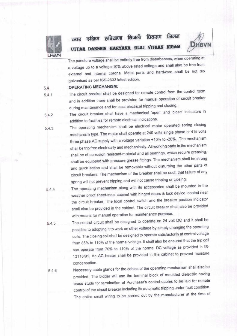
rbances' when operating at
a voltage up to a voltage 10% above rated voltage and shall also be free from
external and internal corona. Metal parts and hardware shall be hot dip
galvanised as per I55-2633 latest edition
OPERATING MECHANISM:
The circuit breaker shall be designed for remote control from the control room
and in addition there shall be provision for manual operation of circuit breaker
during maintenance and for local electrical triPping and closing'
Thecircuitbreakershallhaveamechanical,open,and,close'indicatorsin
addition to facilities for remote electrical indications'
The operating mechanism shall be electrical motor operated spring closing
mechanism type. The motor shall operate at 240 volts single phase or 415 volts
three phase AC supply with a voltage variation +10% to -20%' The mechanism
shall be trip free electrically and mechanically' All working parts in the mechanism
shall be of corroslon resistant-material and all bearings' which require greasing'
shall be equipped with pressure grease flttings' The mechanism shall be strong
and quick action and shall be removable without disturbing the other parts of
circuit breakers. The mechanism of the breaker shall be such that failure of any
spring will not prevent tripping and will not cause tripping or closing'
The operating mechanism along with its accessories shall be mounted in the
weather proof sheet-steel cabinet with hinged doors & lock device located near
the circuit breaker. The local control switch and the breaker position indicator
shall also be provided in the cabinet The circuit breaker shall also be provided
with means for manual operation for maintenance purpose'
The control circuit shall be designed to operate on 24 volt DC and it shall be
possible to adopting it to work on other voltage by simply changing the operating
coils. The closing coil shall be designed to operate satisfactorily at control voltage
from 85o/o to '1 10olo of the normal voltage' lt shall also be ensured that the trip coil
can operate lrcm TOok to 110% of the normal DC voltage as provided in lS-
13118/gl.AnACheatershallbeprovidedinthecabinettopreventmoisture
condensation.
Necessary cable glands for the cables of the operating mechanism shall also be
provided. The bidder will use the terminal block of moulded dielectric having
brass studs for termination of Purchaser's control cables to be laid for remote
control of the circuit breaker including its automatic tripping under fault condition'
The entire small wiring to be carried out by the manufacturer at the time of
5.4.2
5.4.3
5.4.4
5.4.5
5.4.6
wu€VN
B-f{ "ftor
EPfaror fundt fudaur fudrd
mrfl8, Drf,sm xiltrrf,a clu rtr8itr merf,
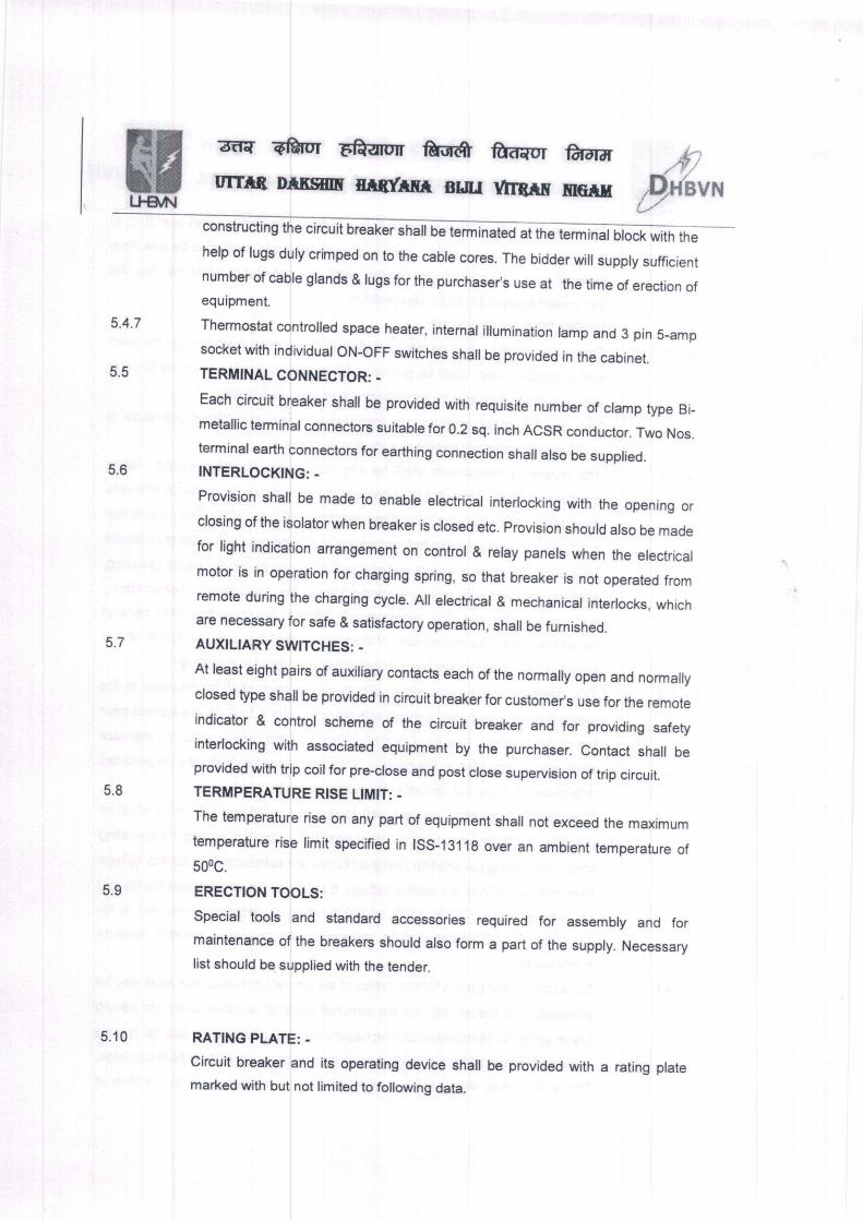
construcung the circuit breaker shall be tErm aGd aiit"G,nJ nioci *,itf, *,"
5.6
5.4.7
5.5
help of lugs duly crimped on to the cable cores. The bidder will supply sufficientnumber of cable grands & rugs for the purchaser's use at the time of erection ofequipment.
Thermostat controlled space heater, internal illumination lamp and 3 pin S_ampsocket with individual ON-OFF switches shall be provided in the cabinet.TERMINAL CONNECTOR: -
Each circuit breaker shall be provided with requisite number of clamp type Bi_
metallic terminal connectors suitable for 0.2 sq. inch ACSR conductor. Two Nos.terminal earth connectors for earthing connection shall also be supplied.INTERLOCKTNG: -
Provision shall be made to enable electrical interlocking with the opening orclosing ofthe isolatorwhen breaker is closed etc. provision should also be madefor light indication arangement on control & relay panels when the electricalmotor is in operation for charging spring, so that breaker is not operated fromremote during the charging cycre. A[ erectricar & mechanicar interrocks. whichare necessary for safe & satisfactory operation, shall be furnished.
AUXILIARY SWTTCHES: -
At least eight pairs of auxiliary contacts each of the normally open and normallyclosed type shall be provided in circuit breaker for customeds use for rhe remote
indicator & control scheme of the circuit breaker and for providing safetyinterlocking with associated equipment by the purchaser. Contact shall beprovided with trip coilfor pre-close and post close supervision of trip circuit.
TERMPEMTURE RISE LIMIT: ,
The temperature rise on any part of equipment shall not exceed the maximum
temperature rise limit specified in ISS-13118 over an ambient temperature of
500c.
ERECTION TOOLS:
Special tools and standard accessories required for assembly and formaintenance of lhe breakers should also form a part of the supply. Necessary
list should be supplied with the tender.
RATING PLATE: .
Circuil breaker and its operating device shall be provided with a rating plate
marked with but not limited to following data.
5.7
5.8
5.9
5.10
erU.AAI
ail{ qftor Fftarotr fuRfr fud-{ur ftr-drd
urrrB Dlf,sm xrxfrf,f, BIJII rrtrBrr fltcrx
t.
I.t.
lv.
v .
v t.
Manufacturer's name, type of breaker.Serial number.Rated voltageRated normal continuous cunentRated insulation level.Rated frequencyRated short time breaking current with rated duralion.Total weight of breaker.
WRING:Wiring shall be complete in all respects to ensure proper functioning of thecontrol, protection, monitoring and interlocking schemes. Wiring shall be done
with flexible 1100 V grade, pVC insulated switch board wires with 2.5 sq.mm.
stranded copper conductor. Control wires: FRHR / FRLS (Fire retardant, Low
Smoke) grade wires are procured confirming to IEC standards. Make.
Hardware:
All fasteners Exposed to Air are of stainless steel.
TESTS
TYPE TESTS:
AII the equipment otfered should be fully type tested as per relevant standards.
ln case the equipment of the type and design, offered, has already been type
tested (not later than five years) the Bidder shall furnish four sets of the type testreports along with the offer. The purchaser reserves lhe right to demand
repetition of the same or all type tests in the presence of purchase/s
representative. For this purpose Bidder may quote unit rates for carrying out
each type test. For any change in the design/type already type tested viz a viz
the design/type offered against this specification the purchaser reserves the right
to demand the repetition of the tests without any exlra cost. ln case the
equipment have not been type tested earlier, all the type tests as per relevant
standard shall be carried out by the successful Bidder in the presence ofPurchaser's representative. The following type test in respect of the VCBS are
required to be submitted alongwith the tender.
Lightening impulses voltage test.
Power Frequency voltage test (Dry and Wet).
Temperature rise test.
Measurement of resistantance of main circuit.
Short time withstand current test.
Peak time withstand current test.
Mechanical operation test at ambient air temperature.
&".
s.11
5.12
6.0
6.1
t.
ii.
iii.
iv.
vi.
vii.
&rt"Fsllal
ffi{ Efrrur Eft{Em Mt fuqur furduTmB Dtf,sm m(fffr arm rfrBrr neru
Basic short circuit duties (test duties 1,2,3,4a, 4b,5 ) and criticii current test.
Capacitor current switching test.
The tender without type test certificate of the offered equipment is liable to be
rejected.
Type test reports (should be less than five years old as on due date of tendeD of
tests canied out on offered design of outdoor vcB at srl [i.e. cpRl/ cESl/ KEMA] Accredited
Labs only shall be furnished by the bidder along with offer othenrvise otfer shall be rejected.
Provisional report will not be acceptable. Type test carried out at the factory/ in house premises
will not be accepted.
ACCEPTANCE AND ROUTINE TESTS: -
All acceptance and routine tests as specified hereunder shall be carried out by
the bidder in the presence of Purchaser's representative.
1) Dry power frequency voltages withstand tests on the main circuit.
2) Voltage withstand test on control and auxiliary swjtch.
3) Measurement of resistance of the main circuit.
4) Mechanical operation test.
5) Design and visual checks.
6.2.2 ln addition to above stated tests; the following shall also be performed:
Speed curves for each breaker shall be obtained with the help of a suitable
operation analyser to delermine the breaker contact movement during opening,
closing and trip free operation under normal as well as limiting operation
condition. The test shall show the speed of contacts directly at various siages of
operation, travel of contacts, opening time, closing time, shortest time between
separation and mating of contacts at breaUmake operatjon etc.
6.3 ADDITIONAL TESTS:
The purchaser reserves the right for carrying out any other type tests of a
reasonable nalure at the works of the supplier/laboratory or at any other
recognized laboratory/research institute in addition to the above mentioned type,
acceptance and routine tests at the cost of the purchaser to satisfy that the
material complies wilh the intent of this specification & also if there is any dispute
regarding quality of the equipment.
a. Capacitive current switching test
i) Cable charging test [CC'l& CC2]
ii) Single capacitor bank current switching test IBC1 & BC2].
viii.
lx,
6.2
6.2.1
,flp{evx
wtlgtr
aaa Efuur E&arun M ft-d{or fuEr
&,"
7.0
7.1
urrfi. rrtf,sf,rf, xtlfrf,r BUU VIrf,tf, f,rcrll
b. Seismic test at 0.6 g.
c. Out of phase making & breaking test.
d. Mechanical Operation test at ambient air temperature [M2 class _ 10000
operations.
e. Degree of Protection lp 55.
f. Electrical Endurance test [E21.
INSPECTION:
The inspection may be carried out by the authorized representative purchaser at
any stage of manufacture. The successful bidder shall grant free access to thepurchaser's representative at a reasonable time when the work is in progress.
lnspection and acceptance of any equipment under this specification by the
purchaser shall not relieve the bidder of his obligation of furnishing equipment in
accordance with the specification and shall not prevent subsequent rejection if the
equipment is found to be defective. The Bidder shall keep the purchaser informed
in advance about the manufacturing programme so that arrangement can be made
for inspection.
The purchaser reserves the right to insist for witnessing the acceptance/routine
testing of the bought out items.
No material shall be despatched from the point of manufacture unless the material
has been satisfactorily inspected tested and further despatch authorized by
purchaser.
DOCUMENTATION: -
All drawings shall conform to international standards organization (l.S.O.),A,
series of drawing sheeulndian Standards specification lS: 656. All drawings shall
be in ink and suitable for microfilming. All dimensions and data shall be in S.l.
Units.
LIST OF DRAWNGS AND DOCUMETS:.
The bidder shall furnish four sets of relevant descriptive and illustrative published
literature pamphlets and the following drawings for preliminary study alongwith the
offer.
General outline drawings showing dimensions and shipping weights, quantity of
insulating media etc.
Sectional views showing the general constructional features of the circuit breaker
including operating mechanism, arcing chambers, contacts with lifting dimensions
for maintenance.
Schematic diagrams of breaker offered for control supervision and reclosing.
7.2
8.0
o. I
8.2
a)
b)
c)
erU-qrN
rir{ Efuur Effaror fui,r(ft fud-{or fummmB Dlf,sm f,nxrfir Bu.t lrlnff llGilx &".
d)
e)
f)
8.3
Struclural drawing
Foundation drilling plan and loading data for foundation design.Type test reports.
8.4
The successful bidder shall within four weeks of placement of order submit foursets of final version of all the above drawlngs for purchaser,s approval. Thepurchaser shall communicate his comments/approvals on the drawings to thebidderwithin reasonable period. The biddershallif necessary, modify the drawingsfor purchaser's approvalwithin two weeks from the date of comments. After receiptof purchaser's approval the bidder shall within three weeks, submit 20 prints andtwo good quarity reproducibre of the approved drawings for purchaser,s use.The successfur bidder sha, arso furnish five copies per breaker of bound manuarscovering erection, commissioning, operation and maintenance instructions and aIrelevant information and drawings pertaining to the main equipment as well asauxiliary devices. Marked erection drawings shall identify the component parts ofthe equipment to enable purchaser to carry out erection with his own personnel.Each manual shall also contain one set of all the approved drawings, type testreports as well as acceptance reports of the corresponding constgnmentdispatched.
The manufacturing of the equipment shal be stricfly in accordance with the8.5
approved drawings and no deviafion shall be permitted without the writtenapprovar of the purchaser. A[ manufacturing and fabrication work in connectionwith the equipment prior to the approvar of the drawing shafl be at the bidder,s risk.
8'6 Approval of drawings Alork by the purchaser shal not rerieve the bidder of any of hisresponsibirity and Iiabirity for ensuring correctness and correct interpretation of thedrawings for meeting the requirements of the latest revision of the applicablestandards rules and code of practices. The equipment shall conform in all respectto high standard of engineering, design, workmanship and ratest revisions ofrelevant standards at the time of supply and purchaser shall have the power toreject any work or material which, is nol in full accordance therewith.
8,7 TEST REPORTS;
l. Four copies of type test reports shalr be furnished to the purchaser within onemonth of conducting the tests. One copy will be returned duly certified by thepurchaser to the bidder wiihin three vyeeks thereafter and on receipt of the same,bidder shall commence with the commercial production of the concerned material.
&aUqAI
aa{ qftur EPfaror ftine ft-d,{ur fuaa
&".urltB DrEifrf, xfiffir gr.u rtrf,xr mE*r
Four copies of acceptance Gstiport@copy will be returned, duly certified by the purchaser and only there afterwards thematerial shall be despatched.
All records of routine tesl repods shall be maintained by the bidder at his works forperiodic inspection by the purchaser.
All test reports of tests conducted during manufacture shall be maintained by thebidder. These shall be produced for verification as and when requested for by thepurchaser.
PACKING AND FORWARDING:
The equipment sha[ be packed in suitabre crates so as to withstand handringduring transit. The bidder shall be responsible for any damage to the equipmentduring transrt, due to improper and inadequate packing and handling. The easilydamageable materials shall be carefully packed and marked with the appropriatecaution symbols. Wherever necessary, ploper arrangement for lifting such asliftlng hooks etc. shall be provided. Any material found short inside the packing
cases shall be supplied by the bidder without any extra cost.
Each consignment shall be accompanied by a detailed packing list containing thefollowing information:
Name of the consignee
Details of consignment
Destination
Total weight of consignment
Sign showing upper/lower side of the crate.
Handling and unpacking instructions.
Bill of material indicating contents of each package and spare material.
The bidder shall ensure that the packing list and bill of material are approved by
the purchaser before dispatch.
TRAINING: -
The successful brdder shall be required to provide facilities for in plant training, at
no extra cost to the purchaser to at least two engineers to be nominated by the
purchaser at his works, where the equipment offered shall be manufactured.
lf the equipment offered is being designed and manufactured in coflaboration with
any other manufacturer, the Bidder shal provide facirities for additionar two
t.
a)
b)
c)
d)
e)
0
s)
'10
10.1
10.2
3nL,&N
trainees, shall
suitable for lodging and boarding as well as local conveyance to the placeof training.
nominated by the purctraser 6r. in ptant traidffi- it e
as allowances for out of pocket expenses in respect of theborne by the purchaser. However, the bidder shall provide for
E&-urorr M fi-a-{or ft-drff
f,r{rraf,ir cllr ttr8frn mcrrx
Engineers to
collaborator's
10.3 ln case of within lndia, to an fro travel expenses, lodging and boardingcharges as
Superintendirig engihYeryeaO
?frur E&arur .6o'6y ft''t r fudrd
Drrsmy mfffrf,r cttr.r itr8.tf, ucrx
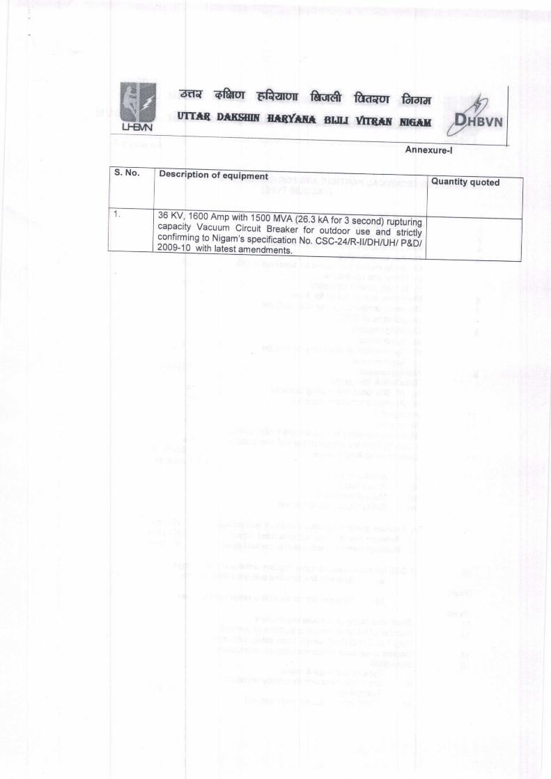
Annexure-l
::- , -,,l., ,,1.1, , .,vv rvrvA (zo.J KA Tor J second) ruDturind
L"^"1,y:_"]r::I pTgker. Jor -o-u!d9or
r"e "nd'strtctt!s to Nigam's specification No. csc_zan:riroriiuinii;ibl
With latest amcnrlmanr.
&rllclal
:rr{ ?fuur Eftarm for& frd"or frrdrfr i$;rrrruB rr*f,srf, f,rdrf,r suu r,rrf,rf, f,r*rf, ,6s{svu
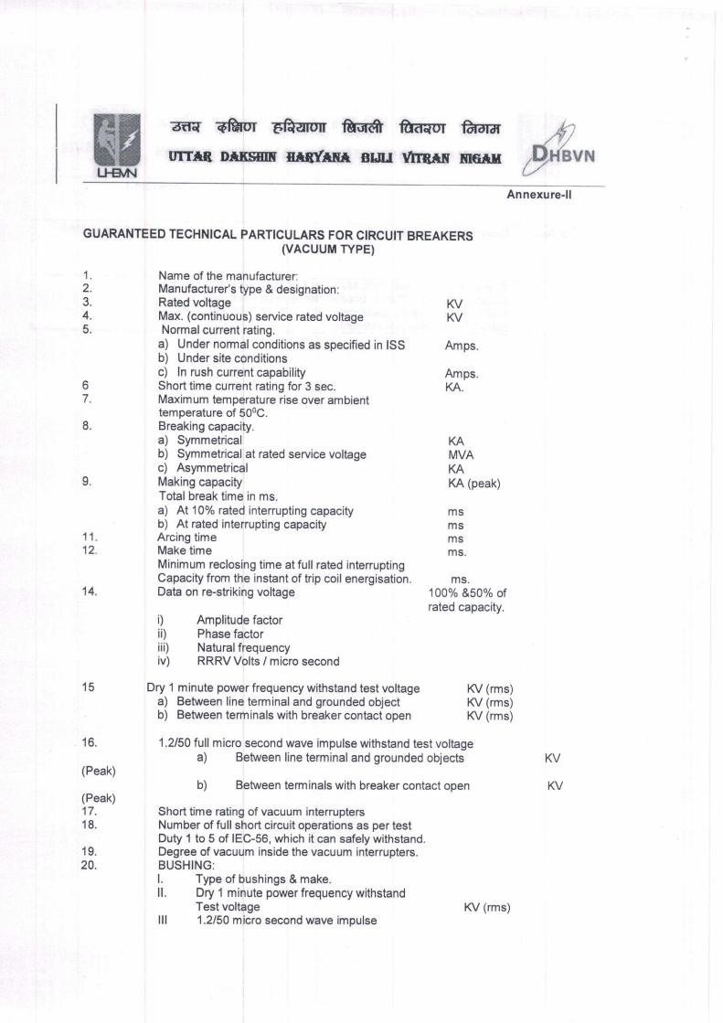
L-/Annexure-ll
GUAMNTEED TECHNICAL PARTICULARS FOR CIRCUIT BREAKERS(vAcuuM TYPE)
1. Name of the manufacturer:2. Manufacturefs type & designation:3. Rated voltage KV4. Max. (continuous) service rated voltage KV5. Normal cunent rating.
a) Under normal conditions as specified in ISS Amps.b) Under site conditionsc) ln rush current capability Amps.
6 Short time current rating for 3 sec. KA.7. Maximum temperature rise over ambient
temperature of 500C.8. Breaking capacity.
a) Symmetrical KAb) Symmetrical at rated service voltage MVAc) Asymmetrical KA
9. Making capacity KA (peak)
Total break time in ms.
a) At 10% rated interrupting capacity msb) At rated interrupting capacity ms
1 1. Arcing time ms12. Make time ms.
Minimum reclosing time atfull rated interruptingCapacity from the instant of trip coil energisation. ms.
14. Datra on re-striking voltage 100% &S0% ofrated capacity.
i) Amplitude factorii) Phase factoriiD Natural frequencyiv) RRRV Volts / micro second
15 Dry 1 minute power frequency withstand test voltage KV (rms)a) Between line terminal and grounded object K/ (rms)b) Between terminals with breaker contact open KV (rms)
16. 1.2/50 full micro second wave impulse withstand test voltagea) Between line terminal and grounded objects
(Peak)
b) Between terminals wlth breaker contact open(Peak)
17. Short time rating of vacuum interrupters18. Number of full short circuit operations as per test
Duty 1 to 5 of IEC-56, which it can safely withstand.19. Degree of vacuum inside the vacuum inlerrupters.20. BUSHING:
l. Type of bushings & make.
ll. Dry 1 minute power frequency withstandTest voltage KV (rms)
lll '1.2/50 micro second wave impulse
KV
KV
wL!€l,l\l
a.d{ Eftor Efrarur MI fu<raor ffil-drd
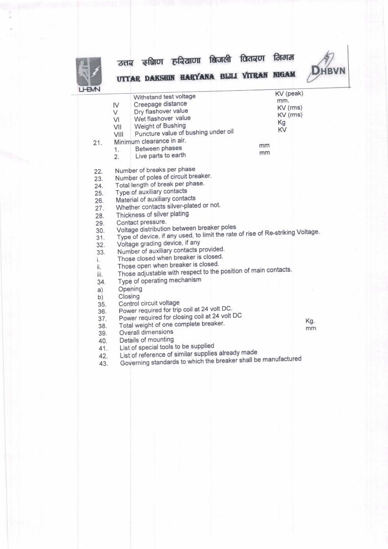
urrtB lrrf,sm rrr(rm BLlr rlrB'if, f,retr &,.Withstand test voltage
lV CreePage distance
KV (peak)
mm.
KV (rms)
KV (rms)
Kg
KV
V Dry flashover value
Vl Wet flashover value
Vll Weight of Bushing
viir Puniture value ofbushing under oil
21. Minimum clearance in air'
l. Between Phases mm
i. tir" Parts to earth mm
22. Number of breaks Per Phase
,i. Number of poles of circuit breaker'
24. Total length of break per Phase'
25. TvPe of auxiliary contacts
26. Itriaterial of auxiliary contacts
,7 . Whether contacts silver-plated or not
28. Thickness of silver Plating
29. Contact Pressure.
;0. iottig; iisttioution between breaker poles
31. Tvpe of device, it "nv
u""i, iJ ri'iiinl rate of rise ot Re-striking Voltage'
g2. Voltage grading devlce, if any
;4. tlumier-ot auxitiary contacts provided'
i- Those closed when breaker is closed'
ii. tho." opun when breaker is closed'
;i ihot" "iir"trur"
*ith respect to the position of main contacts'
34. Type of operating mechanism
Kg.
mm
a)
b)
35.36.
37.38.
39.
40.41.
42.
OpeningClosingControl circuit voltage
Power required for irip coil at 24 volt DC'
Power required for closing coil at 24 voll DC
Total weight of one complete breaker'
Overall dimensions
Details of mounting
List of soecial tools to be supplied
li.i ot iJr"run." ot similar supplies already made
Oor"tn,ng standards to which the breaker shall be manulactureo