Embed Size (px)
Citation preview
AIAA 2001-1261
FURLABLE REFLECTOR CONCEPT FOR SMALL SATELLITES
A.G. Tibert∗ and S. Pellegrino†
Department of Engineering, University of Cambridge,Trumpington Street, Cambridge, CB2 1PZ, U.K.
Abstract
A new concept for deployable mesh reflectors is pre-sented. It consists of a deployable ring structure and twoidentical cable nets (front and rear nets) connected by ten-sion ties. The reflecting mesh is attached to the front net.The concept has been demonstrated by means of simpledemonstrator hardware. A preliminary design of a 3 mdiameter, 10 GHz reflector with a focal length to diam-eter ratio F/D = 0.4 that could be packaged within anenvelope of 0.1 × 0.2 × 0.8 m3 is presented.
Introduction
There is currently a growing interest in low-cost deploy-able appendages for small satellites, and the developmentof structures for such applications is a lively area of re-search in the Deployable Structures Laboratory, at Cam-bridge University.
The work presented in this paper was motivated byan application requiring a 3 m diameter parabolic reflec-tor to be launched alongside a 0.6 × 0.6 × 0.8 m3 bus,packaged within an envelope of 0.1 × 0.2 × 0.8 m3, thelast dimension is a hard limit. The reflector is to havea focal length to diameter ratio F/D = 0.4 and operateat a frequency of 10 GHz. Excluding inflatables, whichstill cannot be regarded as a mature technology, none ofthe existing deployable reflector systems is suitable forthis application. It was considered that an adaptation ofthe AstroMesh concept (Thomson 1997) offers the great-est potential for meeting the requirements with a low-costsystem.
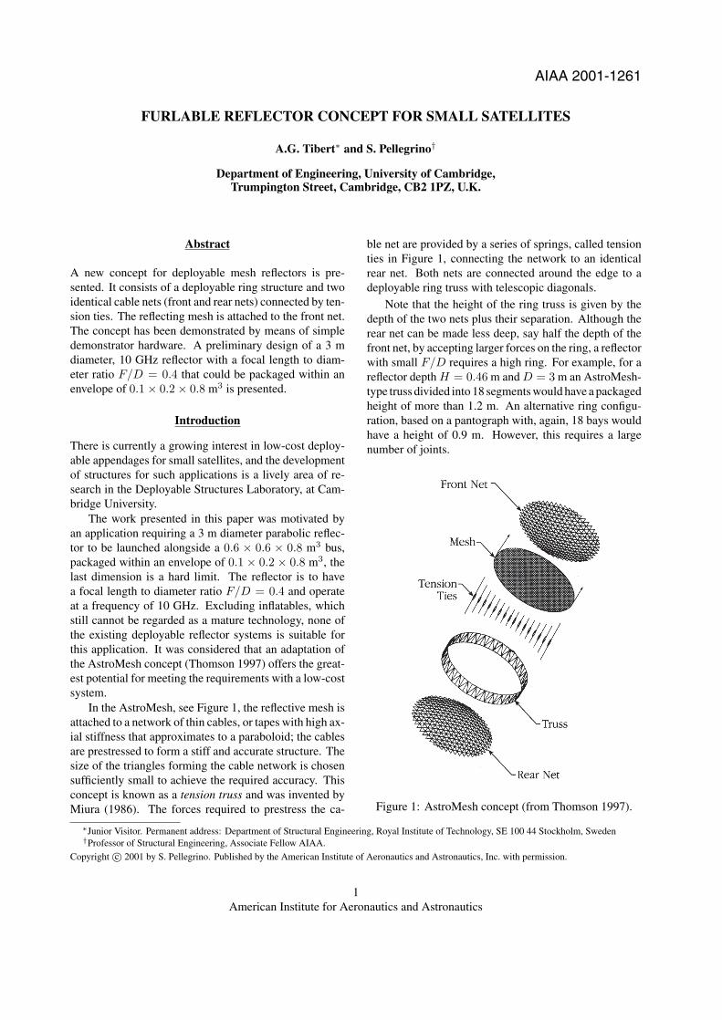
In the AstroMesh, see Figure 1, the reflective mesh isattached to a network of thin cables, or tapes with high ax-ial stiffness that approximates to a paraboloid; the cablesare prestressed to form a stiff and accurate structure. Thesize of the triangles forming the cable network is chosensufficiently small to achieve the required accuracy. Thisconcept is known as a tension truss and was invented byMiura (1986). The forces required to prestress the ca-
ble net are provided by a series of springs, called tensionties in Figure 1, connecting the network to an identicalrear net. Both nets are connected around the edge to adeployable ring truss with telescopic diagonals.
Note that the height of the ring truss is given by thedepth of the two nets plus their separation. Although therear net can be made less deep, say half the depth of thefront net, by accepting larger forces on the ring, a reflectorwith small F/D requires a high ring. For example, for areflector depth H = 0.46 m and D = 3 m an AstroMesh-type truss divided into 18 segments would have a packagedheight of more than 1.2 m. An alternative ring configu-ration, based on a pantograph with, again, 18 bays wouldhave a height of 0.9 m. However, this requires a largenumber of joints.
Figure 1: AstroMesh concept (from Thomson 1997).
∗Junior Visitor. Permanent address: Department of Structural Engineering, Royal Institute of Technology, SE 100 44 Stockholm, Sweden†Professor of Structural Engineering, Associate Fellow AIAA.
Copyright c© 2001 by S. Pellegrino. Published by the American Institute of Aeronautics and Astronautics, Inc. with permission.
1American Institute for Aeronautics and Astronautics

For the reasons stated above it was concluded that anew concept was needed in order to meet the present re-quirements. Hence, this paper presents a new concept thathas been developed. Simple demonstrator hardware hasbeen made to illustrate the concept and demonstrate itsviability. Finally, a preliminary design of a 3 m reflectorthat would meet all of the requirements is presented.
Ring structure
Front net
Rear net
Tension ties
(a)
(b)
(d)
(c)
Additionalmembers
Figure 2: New concept.
New Concept
The proposed reflector structure is based on the tensiontruss concept. Like the AstroMesh, it is composed of threemain parts:
• a deployable ring structure;
• two identical cable nets (front and rear nets) con-nected by tension ties;
• the reflecting mesh, attached to the front net.
Although the concept is a general one, for clarity it willbe explained with reference to the particular exampleshown in Figure 2. Basically, we are dealing with a struc-ture consisting of a large number of cable elements andconstant-tension springs with only six struts (compressionelements).
Figure 2(a) highlights the 18 cable elements and 6struts that form the deployable ring structure. This is awell-known “tensegrity structure” belonging to a familyinvented in 1948 by the sculptor Kenneth Snelson and R.Buckminster Fuller. Recently, Duffy et al. (2000) havepointed out the potential usefulness of deployable tenseg-rity structures for spacecraft applications. Two importantfeatures of tensegrity structures are that:
• there is no connection between compression ele-ments;
• the connections between compression and tensionmembers are simple.
These features make them particularly attractive in appli-cations requiring low-weight, low-cost deployables thatcan be packaged very compactly. A disadvantage of stan-dard tensegrity structures is that they are very flexible, dueto the existence of internal mechanisms of inextensionaldeformation, as will be shown next. However, we haveobtained a new solution that avoids this problem.
Consider the pin-jointed structure shown in Figure 3,whose layout is identical to the ring structure in Figure 2.The top six joints lie at the corners of a regular hexagonand the bottom six joints lie at the corners of an identi-cal hexagon. Each joint is connected by bars to the twoneighbouring joints in the same hexagon, and also to twojoints of the top hexagon. Note that it is not connectedto the joint directly above, but to the next and the secondnext joints, in an anti-clockwise sense.
(a) (b)
Figure 3: Hexagonal tensegrity module; (a) three-dimensional view; (b) top view.
This structure has j = 12 joints and b = 24 bars. Toinvestigate its static and kinematic properties we use theextended Maxwell’s rule (Calladine 1978)
3j − b = m − s (1)
where
2American Institute for Aeronautics and Astronautics

• m = number of independent inextensional mech-anisms, and
• s = number of independent states of self-stress
Substituting the values of j and b into Equation 1 we ob-tain
m − s = 12 (2)
It can be shown that this structure has one state of self-stress, s = 1, where the six longer bars connecting the twohexagons are in compression and all other members arein tension. Therefore, from Equation 2 we conclude thatm = 13 and, since six mechanisms will be rigid-bodymotions of the whole structure, this leaves seven inter-nal mechanisms. These mechanisms can be stiffened byprestressing the structure, but this will only provide a rel-atively small amount of stiffness.
Because this structure can be prestressed, as de-scribed, a deployable version can be made quite easily.The state of prestress will require only six members tocarry compressive forces, all other members are in ten-sion and therefore—instead of using bars—they can bereplaced with cables. Then, if the struts are collapsible,e.g. either telescopic or foldable at a series of hinge points,the whole structure can be folded.
This structure, however, has seven internal mecha-nisms, which is clearly undesirable. Therefore, we havemodified it by connecting two identical triangulated struc-tures to the hexagons, as shown in Figure 2(b); the layoutof these nets is more clearly shown in Figure 4.
(a)
(b)
Figure 4: (a) Top and (b) side views of front and rear nets.
The layout of these nets can be defined in many dif-ferent ways, for example it could be optimised such thatall triangles have equal area and are as close as possible
to equilateral. The particular layout that was chosen isbased on a simple two-dimensional, regular tessellationof equilateral triangles that is obtained by dividing eachside of a hexagon into three. Then, the outermost trian-gles were distorted to form a catenary-like edge for the netto improve the force distribution in it. Finally, all nodeswere projected onto a paraboloid, see the Appendix.
Consider the structure consisting of the original ringstructure plus the two triangulated nets; its static and kine-matic properties are investigated as follows.
• Number of joints: there are 6 joints in the symmetryunit of each net, hence
j = 2 × (1 + 6 × 6) = 74 (3)
• Number of bars: there are 15 bars in the symme-try unit of each net, plus the 24 bars of the ringstructure, hence
b = 2 × (15 × 6) + 24 = 204 (4)
Substituting Equations 3 and 4 into Equation 1 we obtain
m − s = 18 (5)
Since the state of self-stress is still statically possible, butno additional states of self-stress have been created, wehave s = 1. Hence, m = 19 and, of these mechanisms,6 are rigid-body motion and 13 internal. The 13 inter-nal mechanisms can be removed by adding 13 bars to thestructure, as shown in Figure 2(c). The resulting structurehas m = 6, and hence only rigid-body mechanisms, ands = 1.
To realise this structure in practice we need to finda way of prestressing the two nets. The obvious way ofdoing it is to connect corresponding nodes of the two netswith a series of tension ties that apply equal forces. Itturns out that this is not an ideal solution because
1. large compressive forces are induced in the cablesof the ring structure, which need to be counteractedby increasing the level of prestress of the ring; thiswould further increase the compression in the struts;
2. 12 of the 13 additional members shown in Fig-ure 2(c) are not pre-tensioned;
It was found that all of these issues can be resolvedby modifying the configuration of the ring structure. In-stead of using the original configuration, where the twohexagons are directly one above the other as shown inFigure 3(b), one hexagon is rotated through a small angle,Figure 5.
3American Institute for Aeronautics and Astronautics

front net
rear net
tension ties
struts
ring cords
Figure 5: Complete structure, additional 12 members notshown.
By itself, the resulting ring structure can no longerbe prestressed, as s = 0 and hence, from Equation 2,m = 12. However, when the structure is considered in itsentirety, including the prestressing forces applied by thetension ties, the following is found.
• To obtain a structure free of internal mechanismsonly 12 additional members are required, not 13,hence the member connecting the centres of the twonets can be replaced with a tension tie.
• For a 10◦ anti-clockwise rotation of the upperhexagon with respect to the bottom hexagon—asshown in Figure 5—all of the cables are in a stateof tension.∗
1.411.12 1.37
1.4 1.43
2.690.57 1.8 1.18
0.79
7.635.78
6.82
1.41
1.12
1.37
1.4
1.43
2.69
0.57
1.8
1.18
0.79
7.63
5.78
6.82
1.41
1.12
1.37
1.4
1.43
2.69
0.57
1.8
1.18
0.79
7.63
5.78
6.82
1.411.12
1.37
1.41.43
2.690.571.81.180.79
7.635.78
6.82
1.41
1.12
1.37
1.4
1.43
2.69
0.57
1.8
1.18
0.79
7.63
5.78
6.82
1.41
1.12
1.37
1.4
1.43
2.69
0.57
1.8
1.18
0.79
7.63
5.78
6.82
1.23
1.29 1.231.29
1.23
1.29
1.23
1.291.23 1.29
1.23
1.29
0.54
0.54
0.54
0.54
0.54
0.54
Figure 6: Forces in the two nets due to tension tie loadsof 1 N on the inner nodes and 2 N on the edge nodes.
Figure 6 shows the force distribution in the two nets;the corresponding forces in the ring structure are −68.8 Nin the struts, +25.9 N in the cables forming the hexagons,and +39.5 N in the six cables linking the hexagons.
Configuration of Tensegrity Reflector
In addition to studying the statical and kinematical prop-erties of the reflector structure, it is necessary to analysethe effect of different design parameters on the magnitudeand distribution of the forces within the structure. Our aimis to obtain a fairly uniform distribution of forces in thenet and to avoid large forces in the supporting structure,particularly the struts. The configuration study is dividedinto two parts. First, the influence of the sag-to-span ratioof the net edges and the tension ties forces on the forces inthe net is investigated. Then, for some particular values ofthe forces in the tension ties and a particular sag-to-spanratio, the effect of the relative rotation of the hexagons onthe forces in the nets and the ring structure is considered.
A detailed description of the procedure used for gen-erating the triangular net mesh and how the sag-to-spanratio is defined are given in the Appendix, at the end.
Sag-to-Span Ratio and Tension Tie Forces
Throughout this first study the tension ties are representedby vertical loads on the joints of the net, see Figure 7. Webegin by checking the statical and kinematical propertiesof the three-ring cable net in Figure 7. From the Appendix,the number of joints is
b = 63(1 + 3 × 3)
2= 90 (6)
and the number of bars is
j = 1 + 63(1 + 3)
2= 37 (7)
The extended Maxwell’s rule, Equation 1, yields
m − s = 21 (8)
From the synclastic shape of the net, it is obvious thatno state of self stress can be sustained giving s = 0. Byfixing 6 joints in space we get m = 3. Hence, we need tofix another three degrees of freedom to eliminate the in-ternal mechanisms. Following Pellegrino (1993) we haveanalysed the equilibrium matrix of the structure and thuscomputed three independent mechanisms. By looking atplots of these mechanisms we decided to fix one edge jointradially and tangentially, i.e. two perpendicular in-planedirections, and its neighbouring edge joint radially. Thisgives a statically and kinematically determinate structure.
∗Note that the forces in the outer ties have been set to twice the value of the internal ties.
4American Institute for Aeronautics and Astronautics

Figure 7: Loads applied to cable net to study the influenceof sag-to-span ratios on the force pattern.
The cable net in Figure 7 was analysed for three sag-to-span ratios: 5, 10 and 15%. For each ratio the initial set-ting of the tension tie forces was 1 N everywhere, which ismost practical as identical constant-tension springs wouldbe used in all of the tension ties. However, if the forcepattern in the net is irregular or, worse, some elements arein compression, the tension tie forces have to be adjusted.
The results for a 5% sag-to-span ratio are shown inFigure 8. For the case where the tension tie forces areall equal to 1 N, Figure 8(a), some members are in com-pression. By increasing the edge forces the compressiveforces gradually become smaller and then tensile, Figure8(b)–(d), as the edge forces are increased. An almost uni-form force distribution is obtained for edge forces of 4 N,however the largest force in the edge cable is now over15 N.
1.631.13
1.13
1.72 1.72
4.41-0.57
1.281.28
-0.57
4.25 3.054.25
1.34
1.29
(a)
1.561.19
1.19
1.62 1.62
3.720.07
1.341.34
0.07
7.92 6.73 7.92
1.32
1.29
(b)
1.48 1.24 1.24
1.52 1.52
3.020.43 1.40
1.400.43
11.59 10.4011.59
1.30
1.29
(c)
1.411.29
1.29
1.42 1.42
2.330.93
1.461.46
0.93
15.26 14.08 15.26
1.29
1.29
(d)
Figure 8: Forces in a net with 5% sag-to-span ratio. Loadson inner nodes: 1 N; loads on edge nodes (a) 1 N, (b) 2N, (c) 3 N, (d) 4 N.
When the sag-to-span ratio is increased to 10% thereis still compression for tension tie forces of 1 N, Figure
9(a). However, as the force in the edge ties is increasedto 2 N an acceptable distribution of net forces is obtainedand the edge forces are smaller than for the 5% sag-to-span ratio, Figure 9(b). The range of the inner net forcesis 0.75–2.69 N.
1.541.19
1.19
1.65 1.65
3.79-0.14
1.421.42
-0.14
4.112.80
4.11
1.32
1.29
(a)
1.421.28
1.28
1.48 1.48
2.690.75
1.52 1.52 0.75
7.566.37
7.56
1.29
1.29
(b)
Figure 9: Forces in a net with 10% sag-to-span ratio.Loads on inner nodes: 1 N; loads on edge nodes (a) 1 N,(b) 2 N.
Increasing the sag-to-span ratio further to 15% yieldsno compressed elements even for the case of uniform 1 Ntension tie loads, Figure 10(a). By increasing to 2 N theforces in the edge ties gives a very uniform force pattern,in the range 1.27–2.08 N, and the edge cable forces areslightly smaller than in the previous case.
1.491.23
1.23
1.58 1.58
3.380.22 1.57 1.57 0.22
4.002.56
4.00
1.30
1.29
(a)
1.331.35
1.35
1.36 1.36
2.081.44 1.72 1.72
1.44
7.266.06
7.26
1.27
1.29
(b)
Figure 10: Forces in a net with 15% sag-to-span ratio.Loads on inner nodes: 1 N; loads on edge nodes (a) 1 N,(b) 2 N.
Although a sag-to-span ratio of 15% gives a betterforce pattern than the 10% ratio, the further loss of re-flecting area is not justified, hence 10% is the value thatis selected.
Rotation of Hexagons
Next, the effect on the prestress distribution of a relativerotation θ between the hexagons of the ring structure isanalysed, assuming that the cable nets have a fixed sag-to-span ratio of 10%. The tension tie force is 1 N on theinner joints and 2 N on the edge joints, giving the forcedistribution shown in Figure 9(b) for θ = 0. However,when the hexagons are rotated, the force distribution in abay of the net is no longer symmetric, Figures 11 and 12.
Net forcesFigure 11 plots the variation in the forces of the inner net
5American Institute for Aeronautics and Astronautics

elements with the rotation of the hexagons. The forces inthe radial cables 1, 3 and 8 are approximately constant, forthe range of θ displayed. The other cable forces—exceptfor cables 9 and 10—are within 0.5–1.5 N. Most impor-tantly, cable 9 becomes compressed at θ ≈ 28◦ giving anupper limit on θ for the particular reflector configurationstudied here.
Figure 12 is a plot of the variation in the forces ofthe edge elements. The force in edge cable 13 initiallyincreases and then decreases. Edge forces 14 and 15 de-crease when θ is increased. This is due to the change inthe direction of the tension tie forces.
0 5 10 15 20 25 30-0.5
0
0.5
1
1.5
2
2.5
3
Angle of relative rotation, θ (deg)
For
ce (
N)
1
2
12
4
10
11
9
67
35
3 4 5
1
2
8
6 79 10 11 12
8
Figure 11: Variation of forces in net cables.
0 5 10 15 20 25 303.5
4
4.5
5
5.5
6
6.5
7
7.5
8
Angle of relative rotation, θ (deg)
For
ce (
N)
13 14 15
13
14
15
Figure 12: Variation of forces in edge cables.
Ring forcesThe element forces in the ring structure vary exponentiallywith θ, Figure 13. For small angles, the forces are far toolarge, especially in the struts. It is not until we reach
θ = 10◦ that the forces have decreased to an acceptablelevel. Further rotation decreases the force, although muchmore slowly, and for the practical limit of 28◦, discussedabove, the force in the lateral cables is 3.9 N. Note thatthe structure is statically and kinematically determinateand, therefore, is not dependent on the prestress level forstiffness. However, the cables must be tensioned to a suf-ficient level that they are able to take compressive loadswithout going slack.
Also shown in Figure 13 is the variation of the strutlength, which is not as dramatic as the strut forces, al-though shorter struts are preferable.
0 5 10 15 20 25 30-200
-150
-100
-50
0
50
100
150
200
Angle of relative rotation, θ (deg)
For
ce (
N)
Strut
Lateral cable
Horizontal cable
0 5 10 15 20 25 30
Leng
th (
m)
0.415
0.420
0.425
0.430
0.435
0.440
0.445
0.450
0.455
Strut length
Figure 13: Variation of forces in ring structure.
Additional membersThe additional elements, shown in Figure 2(c), were addedto make the structure statically and kinematically determi-nate but, of course, they need to be pre-tensioned if cablesare to be used. In the current configuration of these ele-ments, it turns out that they are always in tension when thehexagons are rotated, Figure 14, and the magnitude of thetension increases almost linearly up to about 10◦. How-ever, if the additional members were re-arranged froman anti-clockwise direction (defined from edge joints toring joints) to clockwise they would be in compression,instead.
Other issuesAnother important issue, not concerned with the force dis-tribution within the structure, is that the struts move closerto the centre of the reflector when θ is increased. Hence,the struts are more likely to interfere with the tension ties.This might complicate the deployment procedure; there-fore, it is important to keep θ small.
6American Institute for Aeronautics and Astronautics

0 5 10 15 20 25 300
0.2
0.4
0.6
0.8
1
1.2
1.4
Angle of relative rotation, θ (deg)
For
ce (
N)
Figure 14: Variation of forces in additional members.
Demonstration Model
To verify the feasibility of the proposed concept, a small-scale physical model was constructed, with a diameter of0.47 m.
The nets for the model were constructed onparaboloidal molds of PETG (a thermo-plastic materialwith the trade name of Vivak) with diameter D = 0.45 mand focal length F = 0.134 m, on which the position ofthe nodes of the net had been marked with a 3-axis CNCmachine. The elements of the net were 0.8 mm diameterKevlar cords which were pretensioned before being tapedto the mold; then, the cords were joined at all cross-overpoints by Nylon loops and bonded with epoxy resin. Cor-responding nodes of the two nets were connected withrubber bands, later replaced with steel springs.
Identical Al-alloy, 30 mm long joint fittings of cylin-drical shape with a diameter of 15 mm, were attached tothe six corners of each net. These fittings had been preci-sion drilled with 2.0 mm diameter holes in the directionsof all the cords that need to be connected to a node, andall connections were made with epoxy resin. The cords ofthe ring structure, also attached to the same joint fittings,were made from 1.0 mm Kevlar cord.
The telescopic struts are 0.46 m long, each made bycutting off the stick of a foldable umbrella. The umbrellasticks are inserted into 20 mm long, 6.4 mm diameter holesthat are co-axial with each fitting and fastened with a grubscrew. The structure can be easily folded and deployedby hand, photographs are shown in Figures 15–17.
The model works quite well, considering that it wasthe first attempt at putting together a structure of this kind.However, some of the net cables are slack and there issome interference between the nets and the struts, be-cause the diameter of the net—as manufactured—turnedout to be bigger than expected. Correcting these problems
should not be difficult when a new model is made.
Figure 17 shows the very compact packaged configu-ration; note the elongated shape of the package, compat-ible with the requirements.
Figure 15: Top and bottom views of model structure, ex-panded.
7American Institute for Aeronautics and Astronautics

Figure 16: Side view of model structure, expanded.
Figure 17: Model structure, folded.
Preliminary Design of 3 m Reflector
In this section we determine the main characteristics of areflector to meet the requirements: D = 3 m, F = 1.2 m,operation at 10 GHz. In particular, we aim to estimate themass of the reflector.
Network Density
The surface error of the reflector will originate from anumber of different sources, such as thermal distortionof the structure, etc. Only one contribution to the over-all error budget can be considered at this stage, namelythe effect of approximating the required paraboloid witha polyhedral surface. Therefore, it will be conservativelyrequired that the root-mean-square error δrms should beless than about 1/100 of the wavelength.
At 10 GHz the wavelength is 30 mm and so the al-lowable error is 0.3 mm. For a spherical surface of radiusR, Agrawal et al. (1981) have obtained the following re-
lationship between δrms and the side length, L, of thetriangles
δrms =L2
8√
15R(9)
For a shallow paraboloid the radius of curvature is ap-proximately twice the focal length F , thus
R ≈ 2F (10)
For D = 3.0 m and F = 0.4D = 1.2 m Equation 9 canbe solved for L and yields
L = 0.15 m
Thus, the number of triangles across a 3 m diagonal ofthe hexagon will be 20, which means that there will be10 rings of equilateral triangles. The corresponding totallength of the cables that make up both nets is ≈ 300 m.
It is assumed that the members of the cable nets aremade from graphite composite tapes (density 1740 kg/m3)with a rectangular cross section of 5.0 mm by 0.2 mm. Theweight of the joints in the net is accounted for by doublingthe density of the tapes to 3480 kg/m3. The total mass ofthe two nets is 1.04 kg.
Mesh
The reflective mesh is knitted gold-plated Molybdenumwire with a surface density of 0.025 kg/m2. To accountfor seams and surface treatment this value is doubled to0.05 kg/m2.
Approximating the mesh area with the area of a spher-ical cap, we have
A = 2πRH
where R is the radius of the sphere, hence R = 2F =2.4 m, and H is the height of the cap; hence H = 0.469 m.Thus, A = 7.07m2 and the corresponding mass is 0.35 kg.
Force in Springs
The tension in the mesh applies a lateral loading on thecable net to which it is attached, because the mesh formsa small kink, of angle L/R at the cross-over between ad-jacent triangles, see Figure 18(a). To prevent the sidesof the triangles from becoming significantly distorted, thetension T in the cables of the net must be significantlylarger than the transverse load.
TNL
T
N
NL
(a)LL
Ttie
TT
L/R
(b)
R
Figure 18: (a) load on cable; (b) equilibrium of a node.
8American Institute for Aeronautics and Astronautics

For a preliminary estimate T will be set equal to tentimes the mesh tension N multiplied by the triangle sidelength L. Taking N = 2.0 N/m the required tension inthe net cables is T = 3.0 N. The force in the tension tiesthat is required to obtain the specified tension T in thecables is, see Figure 18(b) but note that only two of thesix cables connected to this node are shown,
Ttie = 3TL/R = 3 × 3.0 × 0.150/2.4 = 0.56 N (11)
It is interesting to note that the average pressure on thenet, given by Ttie over the corresponding area of mesh†
is 29 N/m2. This pressure is considerably larger than theself-weight of the mesh under gravity, which is 0.5 N/m2.
Ring Structure
The cable net analysed in the section Configuration ofTensegrity Reflector consisted of only three rings of tri-angles while the current one has ten rings. A preliminaryestimate of the loads transmitted to the ring structure bythe full-size net can be obtained by assuming that eachcable in the three ring reflector represents 3.3 cables in aten ring reflector. So, we can calculate the forces in thesupporting structure by scaling the forces applied by thethree ring net, which gives equivalent forces in the ten-sion ties of 8 N. Table 1 lists the forces and length of themembers of the ring structure.
Element Force (N) Length (m)
Horizontal cable 310 1.50Lateral cable 376 1.96Strut −712 2.88
Table 1: Forces and lengths of elements of ring structure.
Design of Struts
The struts are designed to resist Euler buckling, subjectto a minimum slenderness, Le/r, of 200. Here, Le isthe effective length and r the radius of gyration. For athin-walled tube of radius R
r =
√I
A=
√πR3t
2πRt=
R√2
Since Le = 2.88 m, this yields R > 0.0204 m.Graphite fibre tubes (E = 227.5 GN/m2 and ρ =
1740 kg/m3) with an outer diameter of 42 mm and wallthickness of 0.5 mm are selected and a check on the buck-ling load, 3.8 kN, is amply satisfied. The total length ofthese struts is 17.3 m and the total mass 1.96 kg.
Cable Dimensions
We assume that graphite fibre is the material used alsofor the cables of the ring structure. Its tensile strengthis 2800 N/mm2 and a design strength of 500 N/mm2 isassumed. The maximum cable force is 1880 N, assuminga factor of safety of 5. Thus, the required cross-sectionalarea is 3.76 mm2 and, since the total length of the cablesin the ring structure is 29.8 m, their mass is 0.19 kg.
Connections and Hinges
With a length of 2.88 m, each strut must be collapsedto less than a quarter of its length to fit into the launchenvelope. One solution would be to use bi-stable com-posite tubes (Iqbal and Pellegrino 2000) or, alternatively,graphite fibre tubes with three self-locking hinges perstrut.
The latter solution is easier to quantify at the presenttime and so a preliminary mass estimate was obtained byconsidering the mass of recently developed demonstra-tor hardware. The tape-spring-rolamite hinges developedby Pellegrino et al. (2000) have a total mass, including at-tachments to the struts, of 0.2 kg. For the end connectionsbetween the strut and the ring structure cables a mass of0.1 kg per strut was assumed.
Element Quantity Unit mass Mass (kg)
Net cables 300 m 0.0087 kg/m 1.04Struts 17.3 m 0.113 kg/m 1.96Ring cables 29.8 m 0.0066 kg/m 0.19Hinges 18 0.20 kg/item 3.60Connections 12 0.050 kg/item 0.60Mesh 7.07 m2 0.050 kg/m2 0.35Total 7.74
Table 2: Mass estimates for 3 m diameter reflector.
Discussion and Conclusions
The proposed reflector concept offers a viable solution tothe requirements. Of course, a number of important as-pects have yet to be considered, such as the attachmentof the reflector to the spacecraft and the deployment se-quence of the reflector.
Based on the estimates in Table 2 the total mass of a3 m reflector with F/D = 0.4 is estimated at around 8 kg.
In concluding, it is noted that the proposed conceptis—in principle—suitable also for offset configurations,although no detailed study has yet been done.
†It is assumed that the surface associated with one node is twice the area of a triangle.
9American Institute for Aeronautics and Astronautics
Acknowledgments
The work presented in this report was partially supportedby research contract no. CU009-0000004842 between theDefence Evaluation Research Agency and the Universityof Cambridge, on behalf of the British National SpaceCentre.
Financial support from The Royal Swedish Academyof Sciences for AGT’s visit to the Deployable StructuresLaboratory, University of Cambridge, during the year2000 is gratefully acknowledged.
Appendix: Mesh Generation Procedure
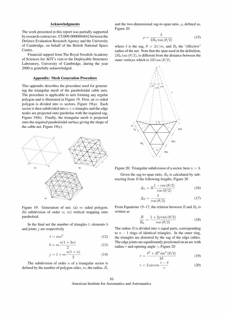
This appendix describes the procedure used for generat-ing the triangular mesh of the paraboloidal cable nets.The procedure is applicable to nets forming any regularpolygon and is illustrated in Figure 19. First, an m-sidedpolygon is divided into m sectors, Figure 19(a). Eachsector is then subdivided into n×n triangles and the edgenodes are projected onto parabolas with the required sag,Figure 19(b). Finally, the triangular mesh is projectedonto the required paraboloidal surface giving the shape ofthe cable net, Figure 19(c).
1
2
mm-1
(a)
n
n
(b)
(c)
Figure 19: Generation of net; (a) m sided polygon;(b) subdivision of order n; (c) vertical mapping ontoparaboloid.
In the final net the number of triangles t, elements band joints j are respectively
t = mn2 (12)
b = mn(1 + 3n)
2(13)
j = 1 + mn(1 + n)
2(14)
The subdivision of order n of a triangular sector isdefined by the number of polygon sides, m, the radius, R,
and the two-dimensional sag-to-span ratio, ρ, defined as,Figure 20
ρ =δ
2R0 tan (θ/2)(15)
where δ is the sag, θ = 2π/m, and R0 the “effective"radius of the net. Note that the span used in the definition,2R0 tan (θ/2), is different from the distance between theouter vertices which is 2R tan (θ/2).
γ /n γ /nγ /n
r
θ
δ
∆2
∆1
R0
R/n
R/n
R/n
Figure 20: Triangular subdivision of a sector, here n = 3.
Given the sag-to-span ratio, R0 is calculated by sub-tracting from R the following lengths, Figure 20
∆1 = R1 − cos (θ/2)
cos (θ/2)(16)
∆2 =δ
cos (θ/2)(17)
From Equations 15–17, the relation between R and R0 iswritten as
R
R0=
1 + 2ρ tan (θ/2)cos (θ/2)
(18)
The radius R is divided into n equal parts, correspondingto n − 1 rings of identical triangles. In the outer ring,the triangles are distorted by the sag of the edge cables.The edge joints are equidistantly positioned on an arc withradius r and opening angle γ, Figure 20
r =δ2 + R2 sin2 (θ/2)
2δ(19)
γ = 2 arccosr − δ
r(20)
10American Institute for Aeronautics and Astronautics

The horizontal projection of the length of the edge ele-ments is 2r sin (γ/2n). It should also be noted that forodd values of n the actual two-dimensional sag of the edgeelements will be slightly less than δ, as shown in Figure 20for n = 3.
References
Agrawal, P. K., Anderson, M. S. and Card, M. F. (1981).Preliminary design of large reflectors with flat facets.IEEE Transactions on Antenna and Propagation, AP-29,688-694.
Calladine, C. R. (1978). Buckminster Fuller’s Tensegritystructures and Clerk Maxwell’s rules for the constructionof stiff frames. International Journal of Solids and Struc-tures, 14, 161-172.
Duffy, J., Rooney, J., Knight, B. and Crane, C. D. (2000).A Review of a Family of Self-Deploying Tensegrity Struc-tures with Elastic Ties. The Shock and Vibration Digest,32, 100-106.
Iqbal, K. and Pellegrino, S. (2000). Bi-stable compos-ite shells. In: Proc. 41st AIAA/ASME/ ASCE/AHS/ASCStructures, Structural Dynamics and Materials Confer-ence, 3-6 April 2000, Atlanta GA, AIAA 2000-1385.
Miura, K. (1986). Concept of tension activated cable lat-tice antenna. In: Proc. 37th IAF Congress, 4-11 October,Innsbruck, Austria, IAF-86-206.
Pellegrino, S. (1993). Structural computations with theSingular Value Decomposition of the equilibrium matrix.Int. J. Solids Structures, 30, 3025-3035.
Pellegrino, S., Kukathasan, S., Tibert, G. and Watt, A.M. (2000). Small satellite deployment mechanisms. De-partment of Engineering, University of Cambridge, Cam-bridge Report CUED/D-STRUCT/TR190.
Thomson, M. W. (1997). The AstroMesh deployable re-flector. In: Proc. Fifth International Mobile SatelliteConference (IMSC’97), 16-18 June 1997, Pasadena, CApp 393-398. JPL Publication 97-11.
11American Institute for Aeronautics and Astronautics