Embed Size (px)
Citation preview
FURNACE-WALL CORROSION IN REFUSE-FIRED
BOILERS
ABSTRACf
P. L. DANIEL
Babcock & Wilcox Alliance Research Center
Alliance, Ohio
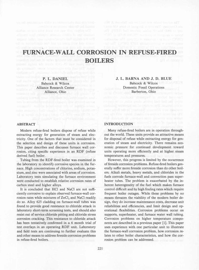
Modern refuse-fired boilers dispose of refuse while extracting energy for generation of steam and electricity. One of the factors that must be considered in the selection and design of these units is corrosion. This paper describes and discusses furnace wall corrosion, citing specific experience in an RDF (refuse derived fuel) boiler.
Tubing from the RDF-fired boiler was examined in the laboratory to identify corrosive species in the furnace. High concentrations of chlorine, sodium, potassium, and zinc were associated with areas of corrosion. Laboratory tests simulating the furnace environment were conducted to establish relative corrosion rates of carbon steel and higher alloys.
It is concluded that HCI and NaCI are not sufficiently corrosive to explain observed furnace-wall corrosion rates while mixtures of ZnClz and NaCI readily do so. Alloy 625 cladding on furnace-wall tubes was found to provide good resistance to chloride attack in laboratory short-term screening tests, and should also resist out of service chloride pitting and chloride stress corrosion cracking. This resistance to chloride attack has been tentatively confirmed in a 6 month trial of test overlays in an operating RDF unit. Laboratory and field tests are continuing to further evaluate this and other means to address fireside corrosion problems in refuse-fired boilers.
221
J. L. BARNA AND J. D. BLUE
Babcock & Wilcox Domestic Fossil Operations
Barberton, Ohio
INTRODUCfION
Many refuse-fired boilers are in operation throughout the world. These units provide an attractive means for disposal of refuse while extracting energy for generation of steam and electricity. There remains economic pressure for continued development toward units operating more efficiently and at higher steam temperatures and pressures.
However, this progress is limited by the occurrence of fireside corrosion problems. Refuse-fired boilers generally suffer more fireside corrosion than do other boilers. Alkali metals, heavy metals, and chlorides in the fuels corrode furnace-wall and convection pass superheater tubes. The problem is exacerbated by the inherent heterogeneity of the fuel which makes furnace control difficult and by high fouling rates which require frequent boiler outages. While these problems by no means threaten the viability of the modern boiler design, they do increase maintenance costs, decrease unit reliabilities and efficiencies, and limit design and operational flexibilities. Corrosion problems occur on supports, superheater, and furnace water wall tubing. Corrosion problems on higher temperature components are described in a previous paper [1]. This paper uses experience with one particular unit to illustrate the furnace-wall corrosion problem, how corrosion relates to other boiler characteristics, and how the corrosion problem can be addressed.

The subject boiler was built by the Babcock & Wilcox Company. The unit is designed to burn 950 tons/ day of 4800 Btu/lb refuse derived fuel (RDF). The boiler is designed to produce 250,000 lb/hr of 750°F (399°C) steam at a pressure of 650 psig. The saturation temperature is approximately 500°F (260°C). The furnace-wall tubes are 2.5 in. O.D. X 0.165 in. wall (63.5 mm X 4.2 mm), SA-I78A carbon steel tubing, in a membrane wall construction. The unit configuration is shown in Fig. 1 .
FURNACE-WALL CORROSION
Corrosion of furnace-wall panel tubes with fireside metal temperatures of 500-600°F (260-316°C) in refuse-fired boilers is frequently localized, occurring above the fuel feed points, along sides, or in corners of the furnace. The severity of the corrosion
' generally
increases with increasing proximity to the flame zone. The corrosion kinetics are usually linear, with the corrosion rate showing little tendency to decrease with the passage of time. Corrosion rates .increase rapidly with increasing tube metal temperatures [2].
Experience indiclttes strong correlation of these wastage problems with a number of boiler operating conditions. Conditions that aggravate the problems include:
(a) refuse fuel rich in PVC plastics and, hence, in organic chlorides
(b) higher fuel Btu-values and higher gas temperatures
(c) higher tube temperatures and waterside deposition which interferes with heat removal
(d) flame impingement and stratification of air flow (e) frequent and thorough fireside deposit and scale
removal Several approaches have been taken to ameliorate
the furnace-wall corrosion problems: (a) covering the wall with silicon carbide (b) controlling the fuel chemistry (e.g., burning a
mixture of coal and refuse) (c) lowering the steam pressure and thereby low
ering the saturation and tube-metal temperatures (d) decreasing the amount of flame contact with the
furnace wall Each of these ameliorative actions costs a penalty in terms of unit operating load, efficiency, and flexibility. Maximum steam temperatures and pressures, and boiler efficiencies are limited by the danger of corrosion; and boiler designers attempt to maximize these
222
desirable unit characteristics while minimizing the potential for fireside corrosion problems.
The subject unit was not lined with silicon carbide because use of silicon carbide impedes heat transfer. For the design fuel characteristics and metal temperatures and with good air and fuel distribution in the furnace, the unit was expected to operate within the envelope of safe operating conditions with respect to furnace-wall corrosion. However, once the unit went into operation, the heating value of the fuel delivered to the plant was 15-25% above the design heating value. The unit also experienced water chemistry upsets during the period of initial operation. The resultant high heat release rates and waterside deposition raised the tube-metal temperature into the range where fireside corrosion became a serious problem for localized areas of the furnace wall in the flame zone. In addition to raising the tube-metal temperature, the excessive heat release rates and resultant steep thermal gradient across fireside wall deposits accelerate diffusion of corrosive species to the tube-metal surface. Ultrasonic thickness measurements indicate that corrosion rates of 30-50 mpy (0.8-1.3 mm/year) may occur in localized sections of the lower furnace walls.
TUBE EXAMINATION
A rear wall tube from the subject unit was examined in the laboratory. The tube had been in service since the original unit startup in July, 1984. It was in service for approximately 6 months during which time it had suffered a 25%, 40 mil (1.0 mm) loss in thickness or a corrosion rate of 80 mpy (2.0 mm/year). When received for laboratory analysis, the tube retained a sooty external deposit. When one gram of deposit was dissolved in 100 g of water, the resultant solution had a pH of 4. The tube surface was generally rough and pitted.
Procedure
Bulk deposit chemistry of the fireside deposit was obtained from x-ray diffraction and spectrographic analyses. Optical metallography was used to determine the deposit and scale morphologies. To retain watersoluble constituents of the fireside peposits, kerosene was substituted for water during the metallographic preparation. Electron microprobe analysis of the metallographic samples provided microchemical information about the fireside deposits.

FIG. 1 DRAWING OF THE RDF-FIRED BOILER
223

Results
The chemical analysis of the fireside deposit on the rearwall tube are given in Table 1. The deposits were composed primarily of iron, sodium, and chlorine. Large amounts of the following elements were also identified: silicon, aluminum, titanium, calcium, zinc, lead, carbon, sulfur, potassium, and oxygen. X-ray diffraction analysis identified sodium chloride (NaCl) as the major crystalline constituent and identified hematite (F�03) and magnetite (Fe30.) as minor constituents.
Photomicrographs depicting the nature of the fireside corrosion and associated deposit morphology are shown in Fig. 2. The deposits were porous, grey in color, and multi-layered. A layer of protective iron oxide scale, adjacent to the tube metal, was not always visually apparent. The rearwall tube deposits were generally adherent and were measured from cross sections to be approximately 20 mils (0.5 rom) thick.
The x-ray scanning capability of the electron microprobe was used to determine the relative distribution of several elements in the fireside deposits. Resultant x-ray fluorescence maps, along with electron images of the area, are shown in Fig. 3.
Examination of the element maps in Figure 3 reveals several patterns:
(a) Chlorine and zinc are distributed throughout the deposit.
(b) Sodium is more abundant in outer portions of the deposit.
(c) Potassium is more abundant in the inner portion of the deposit near the tube surface.
(d) There is a thin layer at the metal/deposit interface that is iron-rich. This layer does not appear to be associated with oxygen, but there is a definite association with chlorine.
(e) Lead, while scarce, is concentrated near the metal/ deposit interfaces.
(j) Oxygen is present in relatively low concentrations uniformly distributed throughout the deposit.
(g) Relatively small amounts of sulfur are randomly distributed through the deposit.
LABORATORY TESTS
Laboratory tests were undertaken to measure corrosion rates in zinc chloride and sodium chloride salts at 600°F (316°C). The tests helped determine the corrosion mechanism and served to screen alloys for use as weld overlay materials to protect the wall tubes from further attack. The test temperature was 600°F
224
TABLE 1 SPECTROGRAPHIC SEMI-QUANTITATIVE
ANALYSIS (%)* OF FIRESIDE DEPOSITS
Silicon as );02
Alumlnum as A1Z03 Iron as FeZ03 Titanium as Ti02 ea lcium as CaD
Magnesium IS MgO
Sod; urn II S NIZO .... Nic.kel as NiD
Chromium as CrZO) MolyDdenum as MoG3 Vanadium as VZ05 Coba 1t as CoO
,,:anganese as I1n::l2 Copper a 5 CuD
Zinc as ZnO
leaa is P[)(l
Tin as �nv2 ZH\,.unium as ZruZ Caroon IS C···
!loultwr as SO) Clllorine as C1···
Phosphorus IS PZOS····
PoJtassium as K20··
)'-Ray L)iffration (Crystalline Constituents)
Major
Minor
Rear Will1 Tube
3.3
1.3
Major
3.0 2.5 0.2
20.89 <0.06 <0.06 <0.06 <0.1 <0.06
0.06 0.4 2.3 1.2 0.2
<0.06 5.68
22.7 NA
6.14
WaCl
-Tne results of spectrographic analysis are reported by the Research Center as tne oxides. Tnls does not necessarily lRean tnat the elelRents Ire present as sucn in the sample.
--Flal1'II: pnotometer analysis
.. .... et chemical analysis
...... lCP spectrographic analysis
Kajor - )201 JrriA - not ana lyzed
(316°C), which is approximately the maximum operating furnace wall tube metal temperature in this unit.
The materials test, which included carbon steel and higher alloys, are listed in Table 2. Iron oxide, Fe30., was included in the test to determine the extent to which the initially protective oxide, once formed on steel, would be attacked. Also tested, was a section of furnace-wall tubing (carbon steel) clad with the commercial nickel-base Alloy 625, an alloy believed to possess superior corrosion and pitting resistance in the anticipated furnace environment.
Each test specimen was a rectangular sheet coupon that was initially prepared by rinsing in deionized water and acetone followed by ultrasonic cleaning to remove any foreign material. The specimc;n coupons were weighed and placed in separate crucibles and covered with the chloride mixture with air as the cover gas. The chloride mixture used in the tests was of the two corrosive salts of particular concern, ZnC12 and NaCl.

ALLOY
FIG. 2 PHOTOMICROGRAPHS OF THE FIRESIDE
DEPOSIT AND SCALE ON THE REAR WALL TUBE
The mixture was 84 wt % ZnCI2 and 16 wt % NaCI. At the conclusion of each of the tests, the samples were rinsed with deionized water and acetone, acid cleaned to remove any oxide formation, and reweighed. Resultant corrosion rate data are presented in Table 2.
CORROSION MECHANISM
Corrosion in the RDF-fired unit appears to be caused by chlorides which deposit on the furnace-wall tubes. Several different modes of chloride corrosion may occur:
(a) corrosion by HCI in the combustion gas (b) corrosion by NaCI and KCI deposits on tube
surfaces (c) corrosion by low melting point metal chlorides
(mainly ZnCIJ (d) out-of-service corrosion by wet salts on the tube
surface
Corrosion by HO in the Combustion Gas
Chloride is present in the fuel mostly as polyvinylchloride in plastics, and it volatilizes largely as HCI. HCI reacts with steel to form FeC12• Short duration (1 day) tests indicate that the corrosion rate of carbon steel in dry HCI gas is approximately 45 mpy (1.1 mm/year) at 550°F (288°C) [3]. Lower HCI partial pressures should result in lower corrosion rates. If the corrosion rate were proportional to the HCI partial pressure in the combustion gas, then 0.1 % HCI would
225
TABLE 2 CORROSION RATES IN CHLORIDE SALTS AT
600'F <316°C)
Time a4� ZnCl2 + 16 wtl NaCl2 100S NaCI Material (hrs) Rate. m�x (IlIn/xr) Rate. m�x (�/xr)
Carbon S tee 1 168 1700 (43) 6 (0.15) Sample A
Carbon S.teel 336 910 (23) Sample 8
Croloy 2-1/4 168 410 (10) 1 (0.03)
Fe304 168 750 (19)
Alloy 600 168 5 (0.13) 0.1 (0.003)
Alloy 625 168 2 (0.05) 0.2 (0.005)
Alloy 625 clad 336 <10 «0.25) on carbon steel
Alloy 625 clad 672 <12 «0.30) on carbon steel
Alloy 690 168 3 (0.08) 0.0 (0.000)
Alloy 800 168 3 (0.08) 0.0 (0.000)
Alloy 304 168 3 (0.08) 0.1 (0.003)
Alloy 309 168 11 (0.28) 0.2 (0.005)
cause an 0.045 mpy (0.001 mm/year) corrosion rate. Hence, while HCI in the combustion gas may corrode furnace-wall tubes, the HCI corrosion rate is probably not high enough to account for the corrosion rate observed in the subject unit.
Corrosion by NaO Deposits on Tube Surfaces
Substantial amounts of sodium and potassium are present in paper, textiles, wood, and other components of refuse derived fuel. A portion of these alkali metals is volatilized, for example, as alkali metal chlorides and hydroxides. The hydroxides in the combustion gas react with HCI to form the alkali metal chlorides (e.g., NaOH + HCI -+ NaCI + H20) which deposit on the relatively cool furnace walls.
Short duration (50 hr) laboratory tests by Miller, et aI., indicate that, in oxidizing combustion gas atmospheres, sodium chloride deposits accelerate steel oxidation rates to approximately 35 mpy (0.89 mm/year) at 800T (472°C) [4]. Based on this data point, the corrosion rate was expected to be substantially less, but still significant at 600°F (316°C), perhaps several mpy. Out laboratory test results indicate that the corrosion rate for carbon steel in NaCI at 600°F (316°C) is only 6 mpy (0.15 mm/year). Hence, NaCI and KCI deposits alone can not account for the corrosion rate observed.
Corrosion by Zno2
Zinc compounds are present in textiles, leather, and rubber. Zinc oxide is the most common of the zinc

SCALE
-""""'"
ALLOY
I I 50 lim
(a) ELECTRON IMAGE (b) IRON MAP 50 lim
FIG. 3 ELEMENT MAPS OF REAR WALL TUBE DEPOSIT AT THE METAL/DEPOSIT INTERFACE. THIS AREA IS THE
SAME SHOWN IN THE PHOTOMICROGRAPHS IN FIG. 2.
226

compounds, and it is relatively nonvolatile and innocuous. However, in the flame zinc oxide is readily reduced to metallic zinc, and it reacts with HCl to form ZnCI2•
Zinc chloride is volatile, but readily condenses on the relatively cool furnace wall. Because of its high volatility, it moves through the surface deposit and condenses at the tube surface. The zinc (and lead) chloride may be present on the tube surface as a liquid: for example, zinc chloride and sodium chloride form a eutectic which melts at 504°F (262°C). Zinc chloride destroys the protective oxide film on steel (it is commonly used as a fluxing agent for soldering and brazing) and attacks the underlying metal. Furthermore, by disrupting the protective iron oxide on the steel, the zinc chloride facilitates rapid corrosion by HCl in the combustion gas. Laboratory tests by Miller, et aI., indicate that the addition of 30% ZnCl2 and 15% PbCl2 to sulfate deposits on steel increases the corrosion rate to 120 mpy (3.0 mm/year) at 600°F (316°C) [4]. The sulfates alone had comparatively little effect on the corrosion rate.
The aforementioned corrosion process occurs largely under reducing conditions. Oxidizing conditions convert ZnCl2 to ZnO and promotes the formation of a protective oxide scale on the tube surface. Reducing conditions facilitate formation of ZnCl2 and PbCl2 and retard formation of the protective scale. Where conditions are intermediate or alternating, some of the iron chloride corrosion product is subsequently oxidized and forms a nonprotective iron oxide within the deposit. Under these conditions, displaced chlorine may cause further corrosion of the steel substrate. Our laboratory tests indicate that under oxidizing conditions, a molten zinc chloride, sodium chloride mixture at 600°F (316°C) attacks carbon steel at a rate of several hundred mpy.
Out-of-Service Corrosion
Chloride-rich deposits on tube surfaces are hydroscopic and become moist during out-of-service periods. The pH of this moist surface deposit is acidic (1.0 g of deposit in 100 g of water gave a pH of 4). As a result, corrosion can proceed rapidly during out-ofservice periods and may account for a part of the tube metal loss. Corrosion of carbon steel in high chloride acidic environments typically causes general wastage and pitting.
Out-of-service corrosion is particularly dangerous for austenitic stainless steel overlays and cladding. Where the overlays have residual stresses and the sur-
227
face pH is acidic, the austenitic stainless steels may be subject to stress corrosion cracking [5].
Conclusions
Of the chemical species identified on wall tubes removed from the unit, zinc chloride is the most aggressive. Laboratory tests described in this paper indicate that zinc chloride can account for the particularly rapid corrosion occurring in the subject unit. This mechanism depends on a number of factors:
(a) chloride in the refuse derived fuel (b) zinc (and lead) in the fuel (c) sodium and potassium in the fuel (d) reducing conditions at the wall (e) high tube metal temperatures (j) furnace-wall material susceptible to chloride at
tack Reducing any of these factors is expected to reduce the corrosion rate. However, some of the factors may be beyond practical control. For example, the fuel composition can probably not be altered. Above about 500°F (260°C), corrosion rates generally increase exponentially with temperature [2]. Hence, avoidance of waterside deposition which increases tube metal temperature is imperative.
Promising weld overlay materials for protecting furnace tubes are Inconel 625 and similar high-chromium nickel-base alloys. Promising iron-base alloys are Incoloy 800 and 825. The greatest danger to austenitic stainless steel overlays is out-of-service chloride stress corrosion cracking. The greatest danger to nickel-base alloys (for furnace-wall application) is out-of-service pitting.
The objectives of this investigation were to identify a possible furnace-wall corrosion mechanism, measure the corrosivity of chloride compounds, and evaluate potential weld overlay materials. Results show that ZnCl2 can account for the high in-service corrosion rates of furnace wall tubing. Other similar low melting point compounds may also be involved. The effects of ZnCl2 and NaCl on carbon steel tubing at upper limit furnace-wall temperatures is severe. However, weld overlay of carbon steel furnace-wall tubing with Alloy 625 may provide a viable solution to the furnace-wall corrosion problem.
The viability of Alloy 625 overlay will be determined by long-term field tests. Alloy 625 overlay has been applied in the furnace of the RDF-fired boiler discussed in this report, and after 6 months of operation the overlay shows no evidence of corrosion (as determined by ultrasonic thickness measurements).
REFERENCES
[1] Chou, S. F., Pramik, A. I., Scott, M.E., and Daniel, P. L. "High-Temperature Corrosion of Tube Support and Attachment Materials for Refuse-Fired Boilers." Presented at the 1985 Joint Power Conference in Milwaukee, Wisconsin October, 1985. ASME Paper 85-1PGC-Pwr-41.
[2] Norwak, F. "Corrosion Problems in Incinerators." Combustion November 1968, 32-40.
[3] Vaughan, D. A., Krause, H. H., and Boyd, W. K. "Chloride Corrosion and Its Inhibition in Refuse Firing." In Ash Deposits and Corrosion Due to Impurities in Combustion Gases. Washington: Hemisphere Publishing Corporation, 1977, 455-472.
228
[4] Miller, P. D., Krause, H. H., Zupan, J., and Boyd, W. K. "Corrosion Effects of Various Salt Mixtures Under Combustion Gas Atmospheres." Corrosion 28 (June 1972): 222-225.
[5] Krause, H. H., Vaughan, D. A., and Miller, P.D. "Corrosion and Deposits from Combustion of Solid Waste, Part 2-Chloride Effects on Boiler Tube and Scrubber Metals." Transactions of the AIME (July 1974): 216-222.
Key Words: Boiler; Chlorine; Corrosion; Furnace; Incinerator; Refuse Derived Fuel; Waterwall