Embed Size (px)
Citation preview

Engineering Peer Review June 5-7, 2001 1
FUSION IGNITIONRESEARCH EXPERIMENT
(FIRE)Machine Configuration
Tom Brown (PPPL)
June 5 – 7 , 2001

Engineering Peer Review June 5-7, 2001 2
FIRE ConfigurationPresentation Outline
� Review the basicconfiguration concept.
� Define key componentdesign features andassembly approach.
� Summary.

Engineering Peer Review June 5-7, 2001 3
FIRE Configuration Features
� Double nulldivertors
� Double wall VVintegrating coolingand shielding
� Wedged, inertiallycooled (LN2) TFcoils
� Compression ringshelp support inplane loads
� RM of divertorsthrough midplaneport
Wedged TF coils;BeCu inner leg;
remainder OFHC.TF CompressionRings Double Walled
Vacuum Vessel
Double nulldivertors
Segmentedcentral solenoidof OFHC copper
OFHC PFcoils
Be coated Cufirst wall

Engineering Peer Review June 5-7, 2001 4
Close-up view of internal components
3.1 m

Engineering Peer Review June 5-7, 2001 5
• Double wall construction integrates coolingand shielding
• supports active and passive stability systems• Divided into 45° Octants• 16 horizontal ports• 16 upper/lower angled ports• 16 small circular ports, top/bottom
VV Octant
Weight of structure, shieldand ports is ~130 tonnes
VACUUM VESSEL
Engineering Peer Review June 5-7, 2001 6
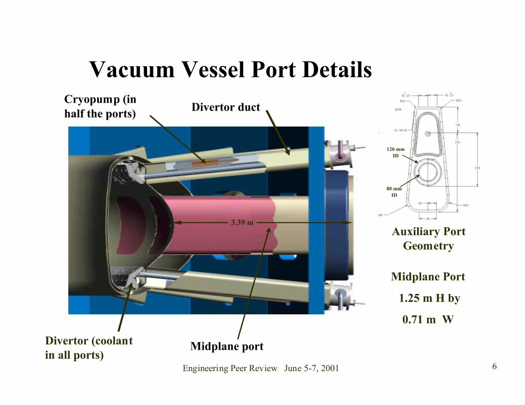
Midplane Port
1.25 m H by
0.71 m W
Vacuum Vessel Port Details
Auxiliary PortGeometry
80 mmID
120 mmID
Divertor ductCryopump (inhalf the ports)
Midplane portDivertor (coolantin all ports)
3.39 m

Engineering Peer Review June 5-7, 2001 7
INTERNAL CONTROLCOLL
INTERFACE DETAIL
2 sets of MgO insulated cables arelocated between the VV walls
Engineering Peer Review June 5-7, 2001 8
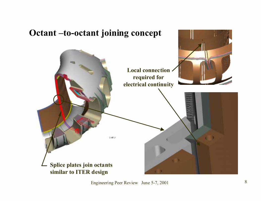
Splice plates join octantssimilar to ITER design
Octant –to-octant joining concept
Local connectionrequired for
electrical continuity
Engineering Peer Review June 5-7, 2001 9
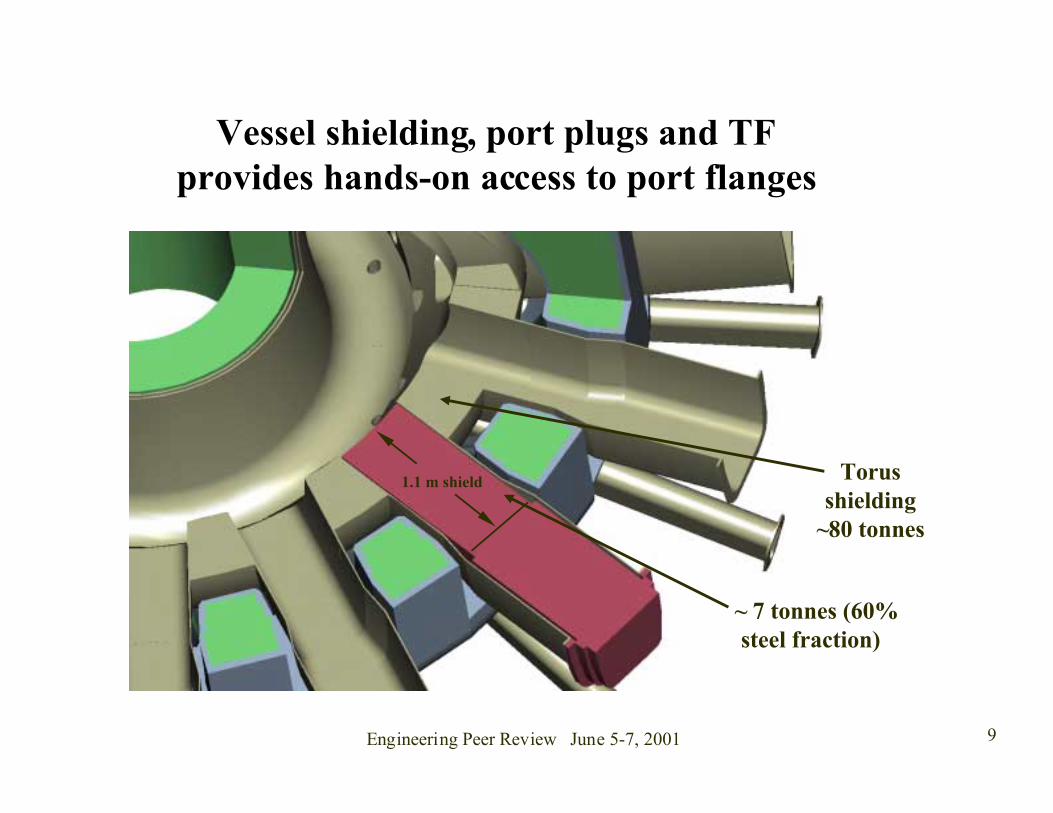
Vessel shielding, port plugs and TFprovides hands-on access to port flanges
~ 7 tonnes (60%steel fraction)
Torusshielding
~80 tonnes
1.1 m shield

Engineering Peer Review June 5-7, 2001 10
Vacuum Vessel Support Concept
An outboard link support to theTF case proposed for VV vertical
and lateral restraint.

Engineering Peer Review June 5-7, 2001 11
TF System� 16 coils with partial
cases� Inertially LN2 cooled� High strength BeCu
C17510 inner legs,OFHC copper used inremainder of coil
� Wedged support� Compression rings
help in supporting inplane loads

Engineering Peer Review June 5-7, 2001 12
Cast intercoil structure with rolledside plates.
31.7 tonnesconductor
11.6 tonnescase
Edge cooled
BeCu
OFHC

Engineering Peer Review June 5-7, 2001 13
TF Assembly Scheme
Local sculpture of theTF winding and caseis needed toaccommodate the VVport
Prior to an epoxy fill,the winding pack isoptically aligned.Adjustment pads andlift sling are used tomove the case.
Engineering Peer Review June 5-7, 2001 14
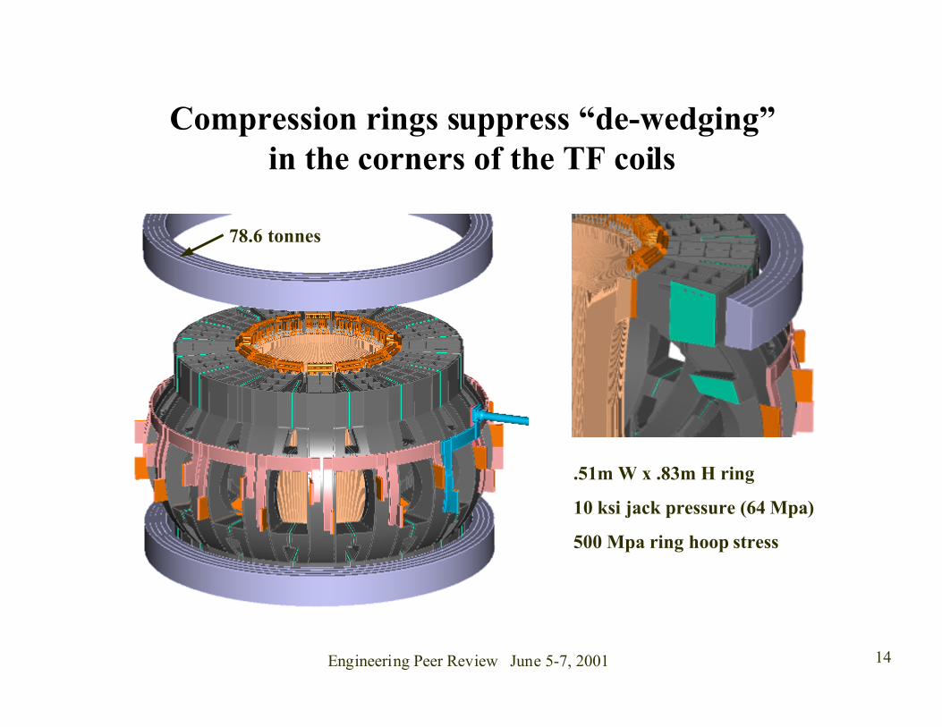
Compression rings suppress “de-wedging”in the corners of the TF coils
78.6 tonnes
.51m W x .83m H ring
10 ksi jack pressure (64 Mpa)
500 Mpa ring hoop stress
Engineering Peer Review June 5-7, 2001 15
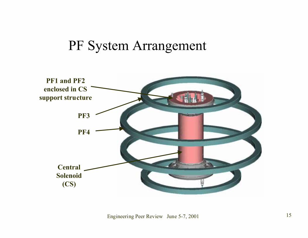
PF System Arrangement
CentralSolenoid
(CS)
PF1 and PF2enclosed in CS
support structure
PF3
PF4

Engineering Peer Review June 5-7, 2001 16
CS and PF1,2 Details
PF 2
PF 1
CS 3
CS 2
CS 1
Tie Rodsand leads
CS Windings

Engineering Peer Review June 5-7, 2001 17
FIRE device thermal enclosure andinterface detail
Polyurethane foaminsulation with fiberglass
inner and outer skins
VV to Cryostatseal
VV portflange
Midplaneport plug
Connectingplate
Cryostat panel

Engineering Peer Review June 5-7, 2001 18
Divertor / RM Interface
� Divertors installedthrough midplane ports
� Cantilevered articulatedboom provides in-vesselcoverage through 4 ports
� End-effector sized for 800kg divertor/baffle module
� A smaller power arm end-effector would be used forFW maintenance

Engineering Peer Review June 5-7, 2001 19
FIRE In-Vessel Remote Handling SystemMi
Transfer Cask
Articulated Boom
Boom End-Effector Midplane Port Assembly
In-vessel transporter
• High capacity (module wt. ~ 800 kg)
• Four positioning degrees of freedom
• Positioning accuracy of millimetersrequired
Divertor end-effector• Articulated boom deployed from sealed cask
• Complete in-vessel coverage from 4 midplane ports
• Fitted with different end-effector depending oncomponent to be handled
• First wall module end-effector shown

Engineering Peer Review June 5-7, 2001 20
COMPONENT BUILDDIMENSIONS
COMP BUILD COMP TOTALmm Dim Dim
Machine Center 0.0gap 410 410.0
CS Insulation inside 10.0Nom winding thk 370 605Insulation outside 10.0 390.0 800.0
CS shell 10gap 10 820.0
inbd TF CS side case thk 0.0ground insul / filler 12.0
winding pack 464.0ground insul / filler 12.0
plasma side case thk 0.0 488.0 1308.0Trapezoidal Effect 0.0 1308.0
TF TPT 5.0Minimum TF/VV gap 10.0
VV TPT 0.0Thermal Shield 12.0 27.0 1335.0
inbd VV VV shell thk 15.0water 20.0
VV shell thk 15.0 50.0 1385.0PFC Module Cu Heat Sink 25.0
FW 30.0 55.0 1440.0Plasma SO 35.0
Plasma minor radii 525 0
50 mm gap

Engineering Peer Review June 5-7, 2001 21
FIRE – Elevation Section View
Engineering Peer Review June 5-7, 2001 22
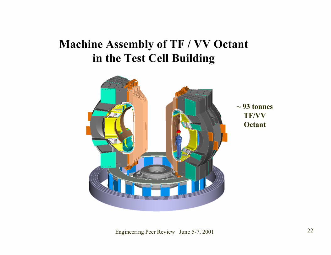
Machine Assembly of TF / VV Octantin the Test Cell Building
~ 93 tonnesTF/VVOctant

Engineering Peer Review June 5-7, 2001 23
FIRE Device Located inthe Test Cell

Engineering Peer Review June 5-7, 2001 24
Configuration Summary A baseline configuration has been developed for FIRE insufficient detail to address major design issues.
• No technical “show stoppers” have been uncovered,
• Component support requirements can be met,
• In-vessel access for RM, heating, auxiliary systems appear feasible.
Design issues still need to be addressed in the next design phase.
• The full array of diagnostic equipment needs to be integrated into the design,
• Assessment of RM of in-vessel components should continue,
• Service details needs to be integrated and their maintenance approach reviewed.