Embed Size (px)
Citation preview

An integrated program strategy of modelling and experiments in laboratory facilities and in a DT Fusion
Nuclear Science Facility to develop Fusion Nuclear Technology and Materials for DEMO
Seminar – Hefei, China
Institute of Nuclear Energy Safety Technology (INEST)
19 December 2014
Mohamed Abdou- Distinguished Professor of Engineering and Applied Science
- Director, Fusion Science and Technology Center
- Director, Center for Energy Science and Technology Advanced Research (CESTAR)
2
• World Energy Situation and Why Fusion is Needed
• Current World Fusion Program Goals
• Fusion Nuclear Science and Technology (FNST) : Introduction
• FNST/Blanket Major Issues/Challenges
• Innovative Concepts to Improve Fusion Attractiveness
– High Power Density
– High Temperature
– Progress on DCLL, Liquid Walls, EVOLVE
• Integrated Strategy for FNST R&D
• Modelling & Laboratory Facilities for Blanket R&D the next 10 yr
• FNST R&D in DT Fusion Testing Facilities, FNSF
• Concluding Remarks
Outline

3
World Energy Situation
The world uses a lot of energy– Average power consumption = 17 TW (2.5 KW per person)
– World energy market ~ $3 trillion / yr (electricity ~ $1 trillion / yr)
The world energy use is growing
– To lift people out of poverty, to improve standard of living, and to
meet population growth
Climate change and debilitating pollution concerns are on the rise– 80% of energy is generated by fossil fuels
– CO2 emission is increasing at an alarming rate
Oil supplies are dwindling– Special problem for transportation sector (need alternative fuel)

Total Projected Energy Use for Selected Countries
U.S. and China energy use will be the same in 2014
Source: Energy Information Administration, International Energy Outlook 20104
0
5
10
15
20
25P
erc
en
tag
e o
f W
orl
d E
ne
rgy C
on
su
mp
tio
n U.S.
China
India
1990 1995 2000 2007 2015 2020 2025 2030 2035
China energy use is rising faster than we anticipated.

5

6
What is problematic
about this future ?

7
The problem is not “running out” of energy
Some mid-range estimates of world energy resources. Units are
terawatt-years (TWy). Current world energy use is ~17 TWy/year.
OIL & GAS, CONVENTIONAL 1,000
UNCONVENTIONAL OIL & GAS (excluding clathrates) 2,000
COAL 5,000
METHANE CLATHRATES 20,000
OIL SHALE 30,000
URANIUM in conventional reactors 2,000
…in breeder reactors 2,000,000
FUSION (if the technology succeeds) 250,000,000,000
RENEWABLE ENERGY (available energy per year)
Sunlight on land 30,000
Energy in the wind 2,000
Energy captured by photosynthesis 120
From J. Holdren, OSTP

8
Real problems: the economic, environmental, and security risks of fossil-fuel dependence
• Coal burning for electricity & industry and oil burning in
vehicles are main sources of severe urban and regional air
pollution – SOx, NOx, hydrocarbons, soot – with big impacts
on public health, acid precipitation.
• Emissions of CO2 from all fossil-fuel burning are largest driver
of global climate disruption, already associated with
increasing harm to human well-being and rapidly becoming
more severe.
• Increasing dependence on imported oil & natural gas means
economic vulnerability, as well as international tensions and
potential for conflict over access & terms.

9
Real problems: Alternatives to conventional fossil fuels all have liabilities & limitations
• Traditional biofuels (fuelwood, charcoal, crop wastes, dung) create huge
indoor air-pollution hazard
• Industrial biofuels (ethanol, biodiesel) can take land from forests & food
production, increase food prices
• Hydropower and wind are limited by availability of suitable locations, conflicts
over siting
• Solar energy is costly and intermittent
• Nuclear fission has large requirements for capital & highly trained personnel,
currently lacks agreed solutions for radioactive waste & links to nuclear
weaponry
• Nuclear fusion doesn’t work yet
• Coal-to-gas and coal-to-liquids to reduce oil & gas imports doubles CO2
emissions per GJ of delivered fuel
• Increasing end-use efficiency needs consumer education

10
Solving the Energy Problem and Reducing
Greenhouse Gas Emission Requires Pursuing a
Diversified Portfolio Approach
Improve energy efficiency
Expand use of existing “clean” energy sources
(e.g. nuclear and renewable sources – solar, wind, etc.)
Develop technologies to reduce impact of fossil fuels
use (e.g. carbon capture and sequestration)
Develop major new (clean) energy sources
(e.g. fusion)
Develop alternate (synthetic) fuels and electrical
energy storage for transportation

CREATING a Star on Earth
Fusion: The Ultimate Energy Source for Humanity
11

077-05/rs
What is nuclear fusion?
Fusion powers the sun and stars: Fusion is the energy-producing
process taking place in the core of the sun and stars. Fusion research is
akin to “creating a star on earth”
Two light nuclei combining to form a heavier nuclei, converting mass to
energy - the opposite of nuclear fission where heavy nuclei split
In nuclear (fission and fusion),
mass is converted to energy ,
Einstein’s famous Eq.
E = mC2
Small mass Huge energy20% of energy
12
In contrast to fossil fuels
(oil, gas, coal) where
chemical energy is stored,
and huge mass needed to
“store” energy

077-05/rs 13
A number of fusion reactions are possible based on the choice of the light nuclides
The World Program is focused on the
Deuterium (D) - Tritium (T) Cycle
D-T Cycle is the easiest to achieve:
attainable at lower plasma temperature
because it has the largest reaction
rate and high Q value.
E = mc2
17.6 MeV
80% of energy
release
(14.1 MeV)
Used to breed
tritium and close
the DT fuel cycle
Li + n → T + HeLi in some form must be
used in the fusion
system
20% of energy release
(3.5 MeV)
DeuteriumNeutron
Tritium Helium

Incentives for Developing Fusion
Sustainable energy source
(for DT cycle: provided that Breeding Blankets are
successfully developed and tritium self-sufficiency
conditions are satisfied)
No emission of Greenhouse or other polluting gases
No risk of a severe accident
No long-lived radioactive waste
Fusion energy can be used to produce electricity and hydrogen, and for desalination.
14

(Illustration is from JAEA DEMO Design)
Cryostat Poloidal Ring Coil
Coil Gap
Rib Panel
Blanket
Vacuum
Vessel
Center Solenoid Coil Toroidal Coil
Maint.
PortPlasma
The World Fusion Program has a Goal for a Demonstration Power Plant (DEMO) by ~2040(?)
Plans for DEMO are based on Tokamaks
15

Fusion Research is about to transition from Plasma
Physics to Fusion Nuclear Science and Engineering
• 1950-2010
– The Physics of Plasmas
• 2010-2035
– The Physics of Fusion
– Fusion Plasmas-heated and sustained
• Q = (Ef / Einput )~10
• ITER (MFE) and NIF (inertial fusion)
• ITER is a major step forward for fusion research. It will demonstrate:1. Reactor-grade plasma
2. Plasma-support systems (S.C. magnets, fueling, heating)
But the most challenging phase of fusion development still lies ahead:The Development of Fusion Nuclear Science and Technology
The cost of R&D and the time to DEMO and commercialization of fusion energy will be determined largely by FNST.
16

Fusion Nuclear Science
and Technology
Grand Challenges
with Exciting Opportunities
for Young Researchers

FNST is the science, engineering, technology and materialsfor the fusion nuclear components that
generate, control and utilize neutrons, energetic particles & tritium.
Fusion Nuclear Science & Technology (FNST)
Key Supporting Systems
Tritium Fuel Cycle
Instrumentation & Control Systems
Remote Maintenance Components
Heat Transport & Power Conversion Systems
In-vessel Components (Core)
Divertor/PFC
Blanket and Integral First Wall
Vacuum Vessel and Shield
FNST Core
18
Exhaust Processing
PFCs
Blanket
T storage & management
Fueling system
DT plasma
T waste treatment
Impurity separation,Isotope separation
PFC & Blanket T processing
design dependent
Tritium Fuel Cycle pervades
entire fusion system

19
Plasma
Radiation
Neutrons
Coolant for energy
extraction
First Wall
Shield
Blanket Vacuum vessel
Magnets
Tritium breeding zone
The primary functions of the blanket are to provide for: Power Extraction & Tritium Breeding
DT
Lithium-containing Liquid metals (Li, PbLi) are strong candidates as
breeder/coolant. He-cooled Li ceramics are also candidates.
A Key FNST Component is the Blanket

20

1. Confined and Controlled Burning Plasma (feasibility)
2. Tritium Fuel Self-Sufficiency (feasibility)
3. Efficient Heat Extraction and Conversion (feasibility)
4. Reliable System Operation (feasibility/attractiveness)
5. Safe and Environmentally Advantageous (feasibility/attractiveness)
Fusion Goal: Demonstrate that fusion energy can be produced, extracted, and converted under practical and attractive conditions
FNST/Blanket plays the
KEY role
Requirements
Yet, FNST has not received the priority and resources needed.
E.g. No fusion blanket has ever been built or tested.
The challenge is to meet these
Requirements SIMULTANEOUSLY
21
22
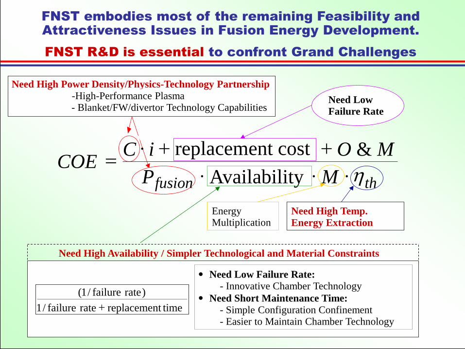
FNST embodies most of the remaining Feasibility and
Attractiveness Issues in Fusion Energy Development.
FNST R&D is essential to confront Grand Challenges
timereplacementratefailure/1
)ratefailure/1(
+
Need Low Failure Rate:
- Innovative Chamber Technology Need Short Maintenance Time:
- Simple Configuration Confinement- Easier to Maintain Chamber Technology
Need Low
Failure Rate
EnergyMultiplication
Need High Temp.
Energy Extraction
Need High Power Density/Physics-Technology Partnership
-High-Performance Plasma- Blanket/FW/divertor Technology Capabilities
thfusion MP
MOiCCOE
h
++=
Availability
&replacement cost
Need High Availability / Simpler Technological and Material Constraints

23
1. Tritium Supply &
Tritium Self-Sufficiency
2. High Power Density
3. High Temperature
4. MHD for Liquid Breeders / Coolants
5. Tritium Control (Permeation)
6. Reliability / Availability/ Maint./ Inspect.(RAMI)
7. R&D in non-fusion facilities: How to simulate the
complex FNST environment?
8. R&D in Fusion Facilities: How to build small DT
plasma-based devices to test and develop FNST?
Challenging Fusion Nuclear Science
and Technology Issues

24
Need for High Power Density Capability
A. To improve potential attractiveness of fusion power
compared to other energy sources (e.g., fission)
B. The larger challenge is to develop concepts that can
simultaneously achieve high power density AND
high temperature
PWR BWR LMFBR ITER-Type
Average core power
density (MW/m3) 96 56 240 0.4
– FW/Blanket/Divertor concepts developed in the 1970s and ’80s have
limitations on power density capability (wall load and surface heat flux)
– Some PROGRESS has been made in this area over the past
decade, but we still need more “innovation”, more “ingenuity”

25
Concepts considered for High Power Density
a) Liquid walls/liquid surfaces (mostly in the APEX and ALPS studies)
b) Advanced solid first wall concepts (e.g., EVOLVE and DCLL)
c) Advanced solid divertor concepts (especially in EU)
Some progress has been made over the past
several years in exploring first wall / blanket /
divertor concepts with high power density
capability:

26
Many liquid wall reactor concepts for high power
density were conceived & analyzed in APEX
Thin liquid wall concept (blanket
region behind LW not shown)
Many candidate liquids were studied: Li, Sn-Li, Sn, Flibe and Flinabe
Several liquid wall flow schemes were conceived: – Thick liquid walls
– Thin fast flowing protection layer (CLIFF)
– Inertial or EM assisted wall adhesion
– Integrated or stand-alone divertors
Concept performance was analyzed from many perspectives– Liquid wall flow MHD and heat transfer
– Breeding, shielding and activation potential
– Simplicity of system design, maintenance
Interactions of liquid walls with plasma operation were emphasized– Plasma edge effects, impurities & recycling
– Liquid metal motion coupling to plasma modes
Surface
Renewal
Divertor
Cassette
Fast Flow
Cassette
Outboard
Fast FlowInboard
Fast
Flow
Bottom Drain
Flow

27
Some Key Points From Liquid Wall Studies
Thin fast flowing layers protecting more conventional closed channel blankets appear to be the most feasible and attractive concept high power density capability
disruption survivability
improved plasma performance
(Thick liquid walls for tokamaks appear very difficult to implement for a number of reasons, especially MHD and flow control )
Based on comprehensive plasma edge modeling studying impurity vapor intrusion into core plasma, Liquid Sn and Sn-Li have the highest surface temperature capability (> 630ºC) Flinabe salt with low melting point (~300ºC) is a promising alternative to LMs
Liquid walls have strong possibilities to improve plasma performance Close fitting conducting shell effects
Hydrogen gettering leading to low recycling
Impurity gettering
Helium trapping and pumping in nano-bubbles
(but “Rotating shell” effects on Resistive Wall Modes due to fast LM motion do not appear to aid stabilization)

Why Consider Liquid Walls for Divertors?
Tungsten (W) is currently considered the only reactor relevant PFC material, but it has issues
– embrittlement below 700C,
– surface damage in DT+He plasmas (see right)
Can W be the only option we pursue? Risky!
Liquid walls have a completely different set of advantages and issues
– Continuously renewed surface: immune toerosion, particle and neutron damage
– Can potentially do two functions:
pump particles & remove heat
– Much thinner mechanical construction of the plasma-coolant interface possible
– Disruptive forces on LW not structural issue
– PMI issues include effect of sputtering + evaporation on plasma and LW Op. Temp.
– Liquid surface can move and interact electromagnetically with plasma/field
NAGDIS-II: pure He plasma
N. Ohno et al., in IAEA-TM, Vienna, 2006,
TEM - Kyushu Univ., Ts = 1250 K, t =
36,000 s, 3.5x1027 He+/m2, Eion = 11 eV
Tungsten surface after long-
term plasma exposure
•Structures a few tens of nm wide
• Structures contain nano
bubbles
100 nm (VPS W on C) (TEM)

Properties of candidate liquid metals
Gallium – low melting point & vapor pressure
– Z=31, atomic weight =69.7
– MP= 29.8 C, BP = 2204 C
– = 6.1g/cm3, cp = 0.37 J/g C
– k: 40.6 W/mC, h = 140 n m
– Vapor pressure = 10-7 Torr at 900 C
Tin – lowest overall vapor pressure and good thermal conductivity
– Z=50, atomic weight=118.7
– MP = 232 C, BP = 2602 C
– = 7.0 g/cm-3, cp = 0.23 J/g C
– k: 66.8 W/mC, h = 115 n m
– Vapor pressure = 10-7 Torr at 1000 C
Lithium – low Z and hydrogen retention, interesting for pumping the edge (see right)
– Z=3, atomic weight =6.9
– MP = 180.5 C, BP = 1342 C
– = 0.5 g/cm-3, cp = 3.58 J/g C
– k: 84.8 W/mC, h = 93 n m
– Vapor pressure = 10-7 Torr at 400 C
Li can hold nearly a 1:1 ratio of D:LiM. J. Baldwin et al., Nucl Fusion 42 (2002) 1318
Strong effects on plasma operation such
as improved confinement and ELM
suppression

Temperature limits for liquid metal PFCs set by the
evaporation rate (allowable influx to the plasma)
Gallium-1100 C
Tin-1300 C
Tin and Gallium surface temperature limits in the divertor are ~1300C and 1100C
Lithium has a low temperature limit (450C) in comparison to gallium and tin
Lithium would not be a candidate for a LM PFC except for its recycling properties and high k and cp
reduced recycling alternative is SnLi eutectic ; tin(~80%)-lithium(~20%)
Lithium~450 C
SnLi

31
Innovative Solid First Wall Concepts
EVOLVE (APEX)- Novel concept based on use of high
temperature refractory alloy (e.g. tungsten)
with innovative heat transfer/transport
scheme for vaporization of lithium
- Low pressure, low stresses
- Low velocity, MHD insulator not required
- High power density / temperature /
efficiency
- Key issues relate to
tungsten
• Attempts to extend the capabilities and attractiveness of solid walls
have required very advanced structural materials
• EVOLVE requires W alloy for high power density, high temperature
But the Material Community wasn’t enthusiastic 10 yrs ago (risky, costly, very long-term)
• But since W is being seriously considered now for the Divertor, we should
reconsider EVOLVE

32
Lessons learned:
The most challenging problems in FNST
are at the INTERFACES
• Examples:
– MHD insulators
– Thermal insulators
– Corrosion (liquid/structure interface temperature limit)
– Tritium permeation
• Research on these interfaces must be done
jointly by blanket and materials researchers

Prevents leakage of volumetric nuclear heat deposited in the PbLi from entering
the (lower efficiency) He coolant stream
Provides nominal electrical insulation to keep MHD pressure drop manageable
Is compatible with PbLi at elevated temperatures ~800C.
How can high outlet temperature
be reached?
Cool all RAFM steel structures with
He (Tin/Tout ~ 350/450C, carries 40-50% of
the total energy)
Have a PbLi breeding zone that is
flowing and self-cooled (Tin/Tout ~ 450/700C, carries other 50-60%
of the total energy)
Isolate the hot PbLi from the cooler
structure by use of a non-structural
liner called a Flow Channel Insert
(FCI) that:
DCLL Typical
Unit Cell
Pathway Toward Higher Temperature Through Innovative Designs with
Current Structural Material (RAFM Steel):
Dual Coolant Lead-Lithium (DCLL) FW/Blanket Concept
33

MAJOR IMPROVEMENTS OF THE DCLL BLANKET CONCEPT (In the US during the last 10 years)
A. Design Evolution
B. Tritium Extraction from the PbLi
C. Improvement of the SiC flow channel Inserts (concept, design, and materials)
D. Detailed modeling analysis of the MHD impact on the liquid metal flow in the DCLL blanket
‒ Fluid flow mixed convection
‒ Tritium permeation
‒ Corrosion of FS in PbLi
• China is working on similar concept: Need more close collaboration on modeling, experiments, design, and analyses
• Eurofusion and UCLA are initiating strong collaboration program on DCLL 34

All structural walls are RAFS actively cooled by He
Cold PbLi flows up the FW (where volumetric heating is strongest), turns, and flows back down the back of the blanket module
SiC FCIs separates and insulates the flowing PbLi from the RAFS walls
FCIs are loosely slip-fit together, and GAPs between FCIs and structure is filled in by nearly stagnant PbLi
The interface temperature between the RAFS structure and gap PbLi is controlled by the He cooling, and kept < 500C.
35
Simplified DCLL Blanket Module Flow Scheme
FW
He
at
Flu
x a
nd
Ne
utr
on
Wa
ll L
oa
d
SiC FCIs
Gap between FCI and Structure
(Filled with nearly stagnant PbLi)
PbLi Out
(700C)
PbLi In (450C)
Helium-cooled RAFS
FW and structure
PbLi
(625C)

Design of the SiC flow channel Inserts (FCI)
Initial FCI design:
• The flow channel inserts made of a SiC-composite serve as electrical and thermal insulator.
• The large temperature difference between the flowing LM on one side of the insert-wall (~ 700 ° C) and the steel wall at the other side (< 470 °C) can result in large thermal stresses, leading to cracks with a negative impact on electrical insulation.
Proposed improvement/solution:
• Split the function of the insert into two elements:
• Outer FCI provides thermal insulation• Inner FCI provides reliable electrical
insulation
“Nested FCI”
18
232
3.5
250
18
10
Pb83Li17
SiC
He-cooled Ferritic Steel
“Single FCI”
36

37
A Simplified DCLL System
Tritium Extraction
Pump
Heat Exchanger
Cold
Trap,
Chem.
Control
450C He
350C He
450C 650C
From/To Tritium
Processing System
From/To Helium Loops and Brayton
Cycle Power Conversion System
FW
He
at
Flu
x a
nd
Ne
utr
on
Wa
ll L
oa
d
PbLi Out
(700C)
PbLi In (450C)
PbLi
(625C)
There are many fundamental issues associated with this external system as well.
37

Low Temperatures DCLL blanket
Near-Term Option being evaluated
by US and EU
Characteristics:
- Intended for the use in an early FNSF and DEMO for the case
SiC FCI’s can’t be qualified in time (high fluence irradiation tests
in fusion typical neutron field required),
- FW and entire blanket structure cooled with Helium
- Sandwich FCI’s in all poloidal ducts are used for electrical and
thermal insulation,
- PbLi inlet/outlet temperatures ~ 350 C/470 C
- He inlet/outlet temperatures ~ 350 C/500 C
- Achievable efficiency in the power conversion system ~ 36 %
38

Principle of Sandwich Flow Channel Insert
Goal:
De-couple electrically the flowing liquid metal from the load-carrying steel walls for Low-temperature PbLiConcept (PbLi temperature <470C)
Technical Approach:
Flow channel inserts made of a sandwich steel-alumina-steel
39Principle of Sandwich Flow Channel Insert

Tritium Transport, Permeation, and Recovery
Tritium transport is affected by the tritium concentration profile and temperature
Tritium generated inside the breeder moves via diffusion due to concentration gradient, convection due to the bulk motion of the fluid, soret effect due to temperature gradient, etc .
Tritium solubility in PbLi is low and still not that well characterized. Tritium tends to permeate into He coolant
How much tritium is permeated into helium coolant, and how can it be controlled?
Tritium removal from PbLi, what are the methods, the extractor materials and tritium transport behavior
Tritium extraction with high efficiency can help control unwanted permeation
But tritium extraction must be compatible with high temperature PbLi in direct contact, as well as impurities
It is critical to be able to predict tritium transport, tritium inventory, and tritium permeation in lead-lithium liquid metal (LM) blankets with great accuracy to provide information for fusion reactor safety. Therefore, developing sophisticated and comprehensive phenomenological and computational models and performing experiments are necessary
40

Moving Forward: Need for an Integrated R&D Program Strategy
• During the period 1970 – 2000, the world spent much effort on exploring options and ideas for blanket concepts, structural materials, liquid and ceramic breeders, coolants, configurations, etc.
– Invested considerable resources on design and evaluation studies and exploratory R&D
• During the past decade, the world programs decided on their preferred concepts and selected primary and backup concepts, materials, and designs
– Larger investment was made in real experiments, more complex modeling, and more detailed analysis and designs
– But the experiments have been mostly limited to single-effects
• Going Forward We will need to build much more sophisticated facilities, perform multiple effect/ multiple interaction experiments and we need to do much more complex modeling
41
We need an integrated program strategy of modelling and experiments in laboratory facilities and in a DT Fusion Nuclear
Science Facility to develop Fusion Nuclear Technology and Materials for DEMO

An Integrated Program Strategy for Blanket/FW R&D involves modeling & experiments in non-fusion and fusion facilities.
•Scientific Feasibility
•Performance Verification
Property
MeasurementPhenomena Exploration
(non-neutron test stands,
fission reactors and accelerator-based
neutron sources)
Non-Fusion Facilities
•Concept Screening
Engineering
Development &
Reliability
Growth
Testing in Fusion Facilities
Theory/Modeling
BasicSeparate
Effects
Multiple Effect/
Interactions
Partially
IntegratedIntegrated
Design Codes/Data
Component
For each step, detailed performance parameters can be defined to quantify requirements of experiments and modeling and measure progress
42
It should be utilized to identify and prioritize R&D Tasks

Next 10 Years
We are now in mostly “Separate Effects” stage. We need to move to “multiple effects/multiple interactions” to discover new phenomena
and enable future integrated tests in ITER TBM and FNSF
Now
TBMs in ITER & FNSF in FNSF
Property
Measurement
Phenomena Exploration
Model Validation
Non-Fusion Facilities:
43
Theory/Modeling
BasicSeparate
Effects
Multiple Effect/
Interactions
Partially
IntegratedIntegrated
Design Codes/Data
Component
Multiple Effects / Multiple Interactions – bringing together different
combinations of multiple physical loads, multiple materials and complex
configurations that can drive new interacting and synergistic phenomena
Testing in Fusion Facilities

Right now, we do not know and cannot predict how the
blanket/FW will work in the fusion nuclear environment
There are many yet undiscovered phenomena caused by multiple
effects/multiple interactions and synergetic effects in the blanket/FW
Compelling examples from recent discoveries show that blankets
designed with current knowledge of phenomena and data will not work
– The source of this problem is that the fusion nuclear environment has many
fields with steep gradients (magnetic, neutrons, nuclear heating), and the blanket
has many functions and materials.
MTBF for Blanket/FW in any FNSF is estimated to be very short while MTTR is
predicted to be months – leading to low availability of only a few percent
– MTBF/MTTR will be the key issue in determining the feasibility of plasma
confinement configurations and the feasibility of blanket concepts
– Therefore, predicting prompt response and behavior of systems in the fusion
nuclear environment in the very early life must be the highest priority
44

What are the Principal Challenges in the
development of FNST/Blanket/FW
• The Fusion Nuclear Environment: Multiple field environment (neutrons,
heat/particle fluxes, magnetic field, etc.) with high magnitude and
steep gradients.
• Nuclear heating in a large volume with steep gradients
drives temperatures and most FNST phenomena.
very difficult to simulate in laboratory facilities
• Complex configuration with FW/Blanket/Divertor inside the vacuum
vessel.
45

Neutrons (flux, spectrum, gradients, pulses)
- Bulk Heating - Tritium Production
- Radiation Effects - Activation and Decay Heat
Combined Loads, Multiple Environmental Effects- Thermal-chemical-mechanical-electrical-magnetic-nuclear
interactions and synergistic effects- Interactions among physical elements of components
Magnetic Fields (3-components, gradients)
- Steady and Time-Varying Field
Mechanical Forces
- Normal (steady, cyclic) and Off-Normal (pulsed)
Heat Sources (thermal gradients, pulses)
- Bulk (neutrons) - Surface (particles, radiation)
Particle/Debris Fluxes (energy, density, gradients)
Fusion Nuclear Environment is Complex & Unique
Mu
ltip
le f
un
cti
on
s,
ma
teri
als
,
an
d m
an
y i
nte
rfa
ce
s i
n h
igh
ly
co
nstr
ain
ed
syste
m
46
Many new phenomena YET to be discovered – Experiments are a MUST
Simulating multiple effect/multiple interactions in Experiments & Models is necessary
Laboratory experiments need to be substantial to simulate multi loads and interactions

........
....
....
....
....
...
Volumetric Heating
0.0 100
5.0 10-9
1.0 10-8
1.5 10-8
2.0 10-8
2.5 10-8
3.0 10-8
0 5 10 15 20 25 30
Tri
tiu
m P
rod
uct
ion
Rate
(k
g/m
3.s
)
Radial Distance from FW (cm)
Radial Distribution of Tritium Production in LiPb Breeder
Neutron Wall Loading 0.78 MW/m2
DCLL TBM LiPb/He/FS
90% Li-6
Front Channel Back Channel
10-1
100
101
102
103
0 5 10 15 20 25 30 35 40
dpa/FPYHe appm/FPYH appm/FPY
Dam
age
Rate
in
Ste
el S
tru
ctu
re p
er F
PY
Depth in Blanket (cm)
Radial Distribution of Damage Rate in Steel Structure
Neutron Wall Loading 0.78 MW/m2
DCLL TBMLiPb/He/FS
90% Li-6
These gradients play a major role in the behavior of fusion nuclear components.
Simulating these gradients in experiments is challenging but Essential.
There are strong GRADIENTS in the multi-component fields of the
fusion environment
47
Tritium
(for ST)
Magnetic Field
Radial variation of tritium production rate in PbLi in DCLL
Damage parameters in ferritic steel structure (DCLL)

Example: Spatial Gradients in Nuclear Heating and Temperature in LM
Blanket Lead to New Phenomena that fundamentally alter our understanding
of the behavior of the blanket in the fusion nuclear environment
48
B
g
VUPWARD FLOW DOWNWARD FLOW
Vorticity Field shows
new instabilities that
affect flow dynamics and
transport phenomena
(Heat , T, Corrosion)
Base flow strongly altered
leading to velocity
gradients, stagnant zones
and even “flow reversal”
This result is from modeling at limited parameters in idealized geometry,
We need to go to higher parameters but there are computational challenges that
must be overcome
We need also to perform experiments that include multiple effects including high
magnetic field and bulk heating with gradients and flexibility in orientation to g
Buoyant MHD interactions result in “Mixed Convection” flow regime
Str
on
gly
he
ate
d z
on
e, to
wa
rds F
W

The Issues of mixed convection, flow instability and MHD turbulence drastically change our understanding of LM blankets
- Gr (and Ha) will be different at outboard, top/bottom and inboard
- Therefore, experiments, modelling and analysis will have to address ALL regions
- There will be many different types of blanket module designs in the same device 49

Next non-fusion facilities should be capable of simulating ALL variety of MHD flow conditions in LM blankets
- Right balancing among gravity, MHD, inertia and viscose forces – Ha/Re, Ha/Gr, Gr/Re
- Prototypic magnetic fields from moderate to strong with gradients
- Large magnet workspace- Arbitrary orientation of a magnet from
horizontal to vertical- Prototypic volumetric heating with
sharp gradients- Multiple channels- MHD flow + Heat transfer + Mass
transfer
Reproducing all these features in experiments is very challenging Strong large-workspace air-gap magnets are available but expensive Reproducing volumetric heating is challenging. IR or resistive heating is not relevant.
The idea of the Gamma-Ray source (A. Ibarra, CIEMAT) deserves to be explored
Construction of tilting system for the BOBmagnet is ongoing project at UCLA
50

51
ThermofluidMultiple Effect / Multiple
Interactions
Combined MHD/heat/mass transfer behavior
in a DCLL unit cell
PbLi Flow distribution in a
complex collection of
parallel channels
Corrosion and tritium mass
transfer in a non-isothermal PbLi
flow systemPbLi/He accident
scenario evaluation
Helium heat transfer and stability in
strongly heated complex flow configurations
What do we think we need to know about DCLL MHD
thermofluid multiple effects / multiple interactions

MHD Flow Dynamics
Predicting blanket behavior requires calculating many responses having
strong coupling & complex dependence on many interacting phenomena
Heat Transfer Mass Transfer
ConvectionTritium
transportCorrosion
He
Bubbles
formation
and their
transport
Diffusion Buoyancy-
driven flows
Dissolution and
diffusion through the
solid
Interfacial
phenomena
Transport of
corrosion
products
Deposition and
aggregation
Tritium Permeation
Dissolution, convection,
and diffusion through
the liquid
Modeling, computation, and experimental challenges to enable predicting blanket
behavior are enormous -- strong computational and experimental initiatives are required
Example: tritium permeation requires modeling & experiments that integrate
Momentum, Heat, and Mass Transfer with bulk & interfacial material phenomena

Next 10 Years
So how do we explore, discover, understand and accurately model multiple effect multiple interactions phenomena?
Now
TBMs in ITER & FNSF in FNSF
Property
Measurement
Phenomena Exploration
Model Validation
Non-Fusion Facilities:
53
Theory/Modeling
BasicSeparate
Effects
Multiple Effect/
Interactions
Partially
IntegratedIntegrated
Design Codes/Data
Component
Testing in Fusion Facilities
• Use real materials, prototypic temperatures• Simulate surface and bulk heating and gradients• Provide large volume and use multiple channels• Have more prototypic Ha, Gr, N, Re, etc.
A handful of upgraded/new
experimental facilities will
be needed that:

The World Programs need to Move more toward
“multiple effects/multiple interactions”
experiments and modeling
54
- To discover new phenomena that will arise due to multiple fields/multiple
interactions
- To attempt to understand the likely true behavior (currently unknown) of
materials, fluids, and subcomponents of the Blanket/FW in the fusion
nuclear environment
- To calibrate results of experimentally observed “synergistic” effects
against “synthesis” of separate effect experiments and modeling
- Provide much more reliable input to Blanket/FW designs
The World needs to construct a number of new facilities:
- With capabilities to simulate combined loads (thermal, mechanical,
chemical, nuclear, and EM load conditions); particularly surface and
volumetric heating, temperature and gradients
- With capabilities for experiments with prototypic geometry,
multi-material unit cells and mockups

We envision two thermofluid MHD facilities
beyond near term upgrades of existing facilities
Multiple Effect/Multiple Interactions Blanket Facility
Role: Address near full size DCLL unit cell thermofluid
flow and transport issues and reduced scale multi-
channel flow control
Partially Integrated Blanket Facility
Role: bring together all simulated conditions affecting
thermofluid/thermomechanical blanket/FW performance to
the maximal practical degree prior to FNSF
55
These are both non-nuclear facilities that can be flexibly operated and
instrumented to investigate both prompt and long time scale DCLL
blanket phenomena in a controlled and well characterized fashion

Blanket MHD thermofluid test facilities
Multiple Effect/Multiple Interactions Blanket Facility.
Role: Address near full size DCLL unit cell thermofluid flow
and transport issues and reduced scale multi-channel flow
control
– strong magnetic field, ~5T
– Magnetic volume capable to accommodate full single channel
size, ~0.3 x 1.5 m)
– controlled orientation with respect to gravity and channel walls
– simulated volumetric heating and gradients, temperature & grad.
– PbLi and He flow loops at prototypic temperatures (~1/2 TBM
scale)
56
$20M class facility, can be a gradual extension of
MTOR/MaPLE facilities at UCLA

Possible upgrades for MaPLE and BOB magnet
• Flexible B orientation
• Higher flowrate and
temperature PbLi
• Simulated volumetric
heating
• Online PbLi purification
• Instrumentation
• Secondary He coolant
• Higher magnetic field
• Larger magnetic volumeSystem to switch from Horizontal to
Vertical oriented “BOB” magnet gap
Evolve into the Multiple Effect Multiple Interaction facility just described
Collaboration with China/INEST?

Blanket MHD thermofluid test facilities
Partially Integrated Blanket Facility.
Role: bring together all simulated conditions affecting
thermofluid/thermomechanical blanket/FW performance to
the maximal practical degree prior to FNSF
– Simulated toroidal and poloidal magnetic field
– Up to full size FW/blanket test modules in multiple poloidal
orientations with respect to gravity
– Simulated surface and volumetric heating and gradients
– PbLi and He flow loop of ~full DEMO module size
– Prototypic temperatures, pressures, materials
58
$50-80M class National Laboratory facility to really prepare for
FNSF – requires significant design and construction effort
INEST? (needed to do R&D for CFTER)

Multiple Effect / Multiple Interaction Discussion Topics
How do we really simulate volumetric heating in
LMs without distorting the experiment? Simulate
the temperature gradients?
– Exploring ways to producing temperature gradients
with only surface heating (H lamp, graphite, radiative)
– Ideas beyond embedded heaters, in wall, FCI or flow
– Do we need to do MHD simulations with immersion
heaters to look at flow and transport distortion
– An Idea was proposed that a gamma-ray source
could do this. What kind of power is typical? Short
attenuation in Pb
– Induction heating, skin depth and unintentional stirring
– Microwaves for ceramic breeder, in resonant cavity59

Study on Blanket/FW
Multiple Effect/Multiple Interaction and
Partially Integrated Test Strategy and Facilities
60
Why the Study is Needed
• The subject of multiple effect/multiple interactions is very complex and
requires experienced blanket R&D experts
• But the cost of the facility for full simulation can be very expensive
• Therefore, tradeoffs between the capabilities incorporated in the facility
and COST are needed. Developing cost estimates require mechanical
design for a given set of specified parameters
• Requires Blanket R&D experts as well as mechanical engineers and
magnet designers and cost professionals. There are several US
institutions interested in developing proposals to construct blanket
facilities
The study could be “international” and a good
mechanism for collaboration

Testing in the Integrated Fusion Environment (100-1000’sM)
Functional tests: ITER TBM Experiments and PIE
Engineering Feasibility Testing in a Fusion Nuclear Science Facility
Multi-Effect Test Facilities (each ~5-20M and 50M class)
Blanket Mockup Thermomechanical/ Thermofluid Testing Facility
Tritium Fuel Cycle Development Facility
Bred Tritium Extraction Testing Facility
Fission Irradiation Effects Testing on Blanket Mockups and Unit Cells
Fundamental Research Thrusts (each ~1-3M per year)
PbLi Based Blanket Flow, Heat Transfer, and Transport Processes
Plasma Exhaust and Blanket Effluent Tritium Processing
Helium Cooling and Reliability of High Heat Flux Surfaces /Blanket/FW
Ceramic Breeder Thermomechanics and Tritium Release
Structural and Functional Materials Fabrication
Establish the base of the pyramid Before proceeding to the top
We need substantial NEW Laboratory-scale facilities NOW We must start NOW Blanket R&D for FNSF/CFETR
61

Testing in DT Fusion Facilities is a Major and Essential element of the Integrated Program Strategy for Blanket/FW R&D
ITER TBM limited But FNSF is for integrated and Component R&D
Next 3-7 Years
Now
TBM in ITER & FNSF
FNSF2 or more facilities will be needed, plus TBM in ITER/FNSF DD Phase
•Scientific Feasibility
•Performance Verification
Property
MeasurementPhenomena Exploration
(non-neutron test stands,
fission reactors and accelerator-based
neutron sources)
Non-Fusion Facilities
•Concept Screening
Engineering
Development &
Reliability
Growth
Testing in Fusion Facilities
62
Theory/Modeling
BasicSeparate
Effects
Multiple Effect/
Interactions
Partially
IntegratedIntegrated
Design Codes/Data
Component

Component Num
ber
Failure
rate in
hr-1
MTBF in
years
MTTR
for
Major
failure,
hr
MTTR
for Minor
failure, hr
Fraction of
failures that
are Major
Outage Risk Component
Availability
Toroidal
Coils
16 5 x10⁻⁶
23 104 240 0.1 0.098 0.91
Poloidal
Coils
8 5 x10⁻⁶
23 5x10³ 240 0.1 0.025 0.97
Magnet
supplies
4 1 x10⁻⁴
1.14 72 10 0.1 0.007 0.99
Cryogenics 2 2 x10⁻⁴
0.57 300 24 0.1 0.022 0.978
Blanket 100 1 x10⁻⁵
11.4 800 100 0.05 0.135 0.881
Divertor 32 2 x10⁻⁵
5.7 500 200 0.1 0.147 0.871
Htg/CD 4 2 x10⁻⁴
0.57 500 20 0.3 0.131 0.884
Fueling 1 3 x10⁻⁵
3.8 72 -- 1.0 0.002 0.998
Tritium
System
1 1 x10⁻⁴
1.14 180 24 0.1 0.005 0.995
Vacuum 3 5 x10⁻⁵
2.28 72 6 0.1 0.002 0.998
Conventional equipment- instrumentation, cooling, turbines, electrical plant --- 0.05 0.952
TOTAL SYSTEM 0.624 0.615
Availability required for each component needs to be high
DEMO availability of 50% requires:Blanket/Divertor Availability ~ 87% Blanket MTBF >11 yearsMTTR < 2 weeks
Component # failure MTBF MTTR/type Fraction Outage Componentrate Major Minor Failures Risk Availability(1/hr) (yrs) (hrs) (hrs) Major
MTBF – Mean time between failures
MTTR – Mean time to repairTwo key parameters:
Reliability/Availability/Maintainability/Inspectability (RAMI) is a serious challenge that has major impact on priorities and strategy for fusion R&D
(Due to unscheduled maintenances)
63
Extrapolation from other technologies shows expected MTBF for fusion blankets/divertor is as short as ~hours/days, and MTTR ~months
GRAND Challenge: Huge difference between Required and Expected!!
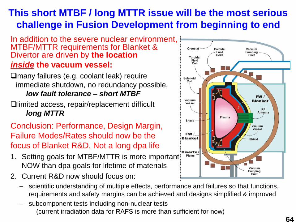
This short MTBF / long MTTR issue will be the most serious
challenge in Fusion Development from beginning to end
In addition to the severe nuclear environment,MTBF/MTTR requirements for Blanket & Divertor are driven by the location
inside the vacuum vessel:
many failures (e.g. coolant leak) require
immediate shutdown, no redundancy possible,
low fault tolerance – short MTBF
limited access, repair/replacement difficult
long MTTR
Conclusion: Performance, Design Margin,
Failure Modes/Rates should now be the
focus of Blanket R&D, Not a long dpa life
1. Setting goals for MTBF/MTTR is more important
NOW than dpa goals for lifetime of materials
2. Current R&D now should focus on:
– scientific understanding of multiple effects, performance and failures so that functions,
requirements and safety margins can be achieved and designs simplified & improved
– subcomponent tests including non-nuclear tests
(current irradiation data for RAFS is more than sufficient for now)
64

65
Fusion Nuclear Science Facility (FNSF)
• The idea of FNSF (also called VNS, CTF) is to build a small size, low
fusion power DT plasma-based device in which Fusion Nuclear
Science and Technology (FNST) experiments can be performed and
tritium self sufficiency can be demonstrated in the relevant fusion
environment:
1- at the smallest possible scale, cost, and risk, and
2- with practical strategy for solving the tritium consumption and
supply issues for FNST development.
In MFE: small-size, low fusion power can be obtained in a low-Q
(driven) plasma device, with normal conducting Cu magnets.
The DD Phase of FNSF also has a key role in providing integrated
testing without neutrons prior to the DT Phase.

66
Why FNSF should be low fusion power, small size
• To reduce risks associated with external T supply and internal
breeding shortfall
• Reduce cost (note Blanket/FW/ Divertor will fail and get replaced
many times)
• FNST key requirement 1-2 MW/m2 on 10-30 m2 test area
• Cost/risk/benefit analysis lead to the conclusion that FNSF fusion
power <150 MW
• For Tokamak (standard A & ST) this led to recommendation of:
- Low Q plasma (2-3) - and encourage minimum extrapolation
in physics
- Normal conducting TF coil (to reduce inboard B/S thickness,
also increase maintainability e.g. demountable coils).
Scope FNSF so that we can build it the soonest.
Planning facilities to be very ambitious leads to ever rising costs
AAnd very lengthy schedule delays (learn the lesson of ITER)
D
E
M
OPreparatory R&D
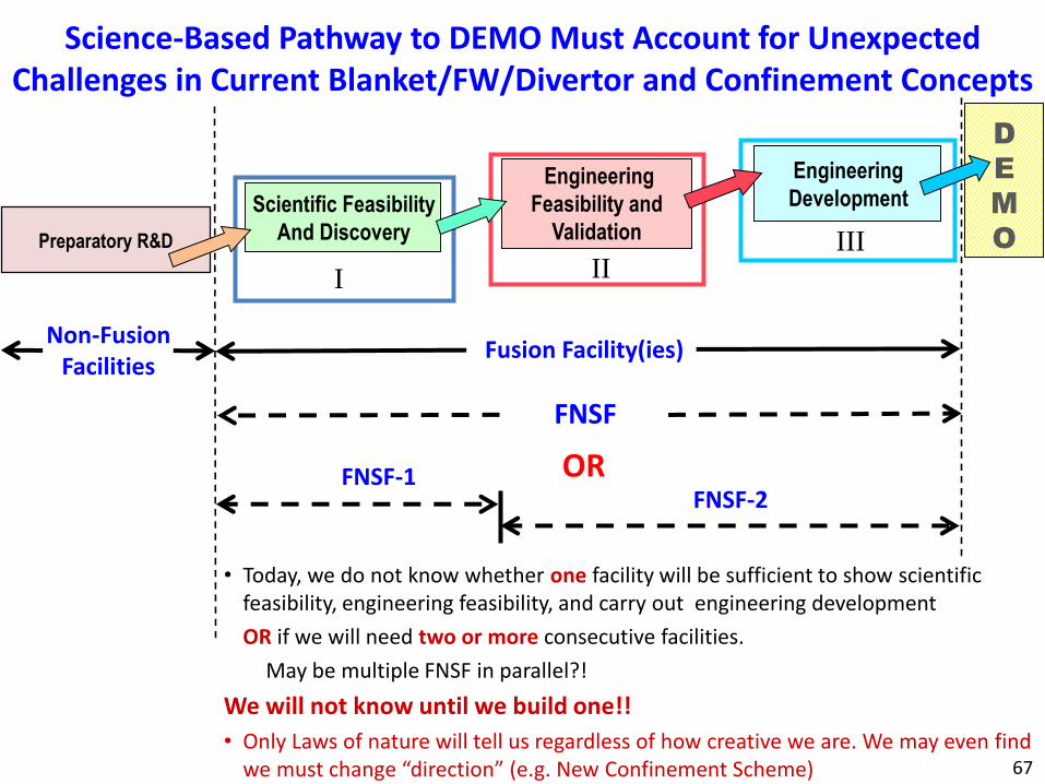
Science-Based Pathway to DEMO Must Account for Unexpected Challenges in Current Blanket/FW/Divertor and Confinement Concepts
Scientific Feasibility
And Discovery
Engineering
Feasibility and
Validation
Engineering
Development
• Today, we do not know whether one facility will be sufficient to show scientific feasibility, engineering feasibility, and carry out engineering development
OR if we will need two or more consecutive facilities.
May be multiple FNSF in parallel?!
We will not know until we build one!!
• Only Laws of nature will tell us regardless of how creative we are. We may even find we must change “direction” (e.g. New Confinement Scheme)
Non-Fusion Facilities
Fusion Facility(ies)
FNSF
ORFNSF-1FNSF-2
67
I IIIII

Base Breeding Blanket and Testing Strategy in FNSF
A Breeding Blanket should be installed as the “Base” Blanket on FNSF from the beginning
– Needed to breed tritium.
– Switching from non-breeding to breeding blanket involves complexity and long downtime. There is no non-breeding blanket for which there is more confidence than a breeding blanket.
– Using base breeding blanket will provide the large area essential to “reliability growth”. This makes full utilization of the “expensive” neutrons.
The primary concepts for DEMO should be used for both “testing ports” and “Base” Breeding Blanket in FNSF
Both “port-based” and “base” blanket will have “testing missions”– Base blanket operating in a more conservative mode (run initially at reduced
parameters/performance)
– Port-based blankets are more highly instrumented, specialized for experimental missions, and are operated near their high performance levels; and more readily replaceable
68

Reduced activation Ferritic/Martensitic Steel (FS) is the reference structural material option for DEMO
FS is used for TBMs in ITER and for mockup tests prior to ITER
FS should be the structural materials for both base and testing breeding blankets on FNSF.
FS irradiation data base from fission reactors extends to ~80 dpa, but it generally lacks He (only limited simulation of He in some experiments).
There is confidence in He data in fusion typical neutron energy spectrum up to at least 100 appm He (~10 dpa).
– Note: Many material experts state confidence that FS will work fine up to at least 300 appm He at irradiation temperature > 350°C.
69
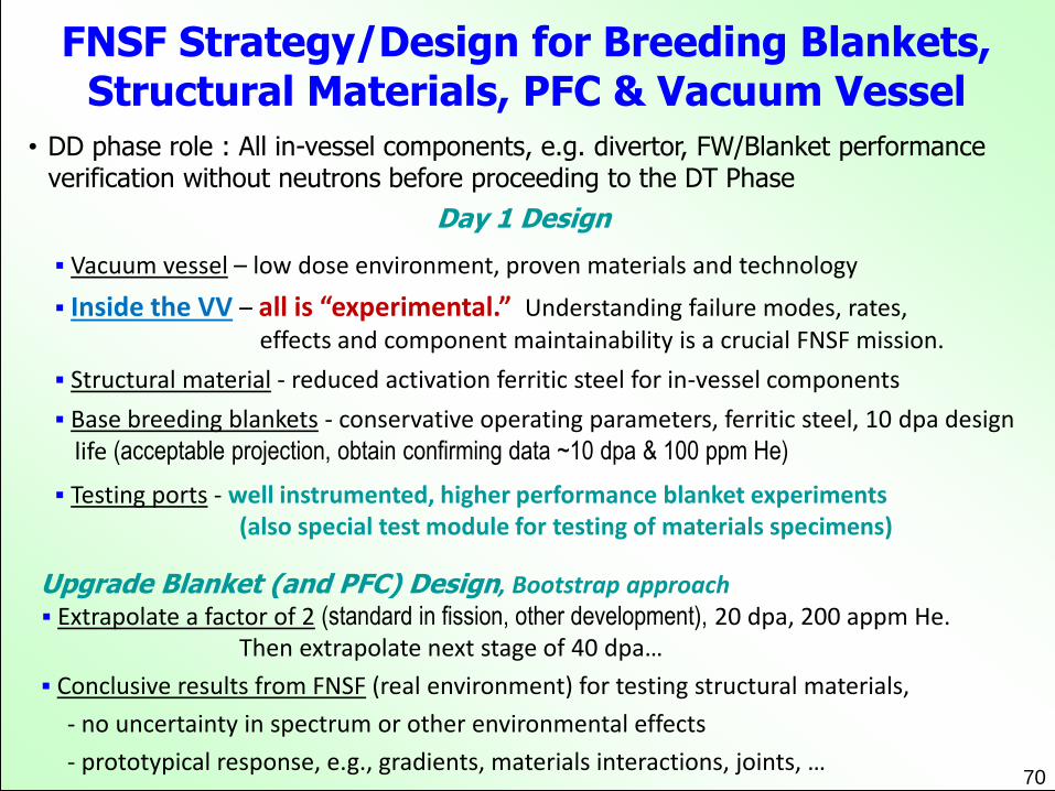
FNSF Strategy/Design for Breeding Blankets, Structural Materials, PFC & Vacuum Vessel
• DD phase role : All in-vessel components, e.g. divertor, FW/Blanket performance verification without neutrons before proceeding to the DT Phase
Day 1 Design
Vacuum vessel – low dose environment, proven materials and technology
Inside the VV – all is “experimental.” Understanding failure modes, rates, effects and component maintainability is a crucial FNSF mission.
Structural material - reduced activation ferritic steel for in-vessel components
Base breeding blankets - conservative operating parameters, ferritic steel, 10 dpa design life (acceptable projection, obtain confirming data ~10 dpa & 100 ppm He)
Testing ports - well instrumented, higher performance blanket experiments(also special test module for testing of materials specimens)
Upgrade Blanket (and PFC) Design, Bootstrap approach Extrapolate a factor of 2 (standard in fission, other development), 20 dpa, 200 appm He.
Then extrapolate next stage of 40 dpa…
Conclusive results from FNSF (real environment) for testing structural materials,
- no uncertainty in spectrum or other environmental effects
- prototypical response, e.g., gradients, materials interactions, joints, …70

The problem with fusion is that it is not being
developed fast enough (taking too long!)“The Time to Fusion seems to be always 40 years away”
The World Needs Fusion.
To accelerate the development of fusion energy requires
a change in Governments Policies and in
the Fusion Community strategy/focus:
- Need More Substantial Funding : Governments must invest in long-term solutions for the future
- Problems are challenging: Need More Ingenuity
- Fusion Community strategy/focus need to change: Need to Focus on the Major Remaining Challenge: Launch an aggressive FNST Program NOW
This is essential to realizing fusion in
the 21st Century71
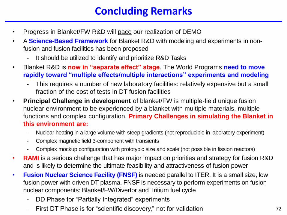
Concluding Remarks
72
• Progress in Blanket/FW R&D will pace our realization of DEMO
• A Science-Based Framework for Blanket R&D with modeling and experiments in non-
fusion and fusion facilities has been proposed
- It should be utilized to identify and prioritize R&D Tasks
• Blanket R&D is now in “separate effect” stage. The World Programs need to move
rapidly toward “multiple effects/multiple interactions” experiments and modeling
- This requires a number of new laboratory facilities: relatively expensive but a small
fraction of the cost of tests in DT fusion facilities
• Principal Challenge in development of blanket/FW is multiple-field unique fusion
nuclear environment to be experienced by a blanket with multiple materials, multiple
functions and complex configuration. Primary Challenges in simulating the Blanket in
this environment are:
- Nuclear heating in a large volume with steep gradients (not reproducible in laboratory experiment)
- Complex magnetic field 3-component with transients
- Complex mockup configuration with prototypic size and scale (not possible in fission reactors)
• RAMI is a serious challenge that has major impact on priorities and strategy for fusion R&D
and is likely to determine the ultimate feasibility and attractiveness of fusion power
• Fusion Nuclear Science Facility (FNSF) is needed parallel to ITER. It is a small size, low
fusion power with driven DT plasma. FNSF is necessary to perform experiments on fusion
nuclear components: Blanket/FW/Divertor and Tritium fuel cycle
- DD Phase for “Partially Integrated” experiments
- First DT Phase is for “scientific discovery,” not for validation

Thank you!

Backup slides
74