Embed Size (px)
Citation preview
International Journal of Scientific Engineering and Research (IJSER) www.ijser.in
ISSN (Online): 2347-3878
Volume 3 Issue 3, March 2015
Licensed Under Creative Commons Attribution CC BY
Fuzzy Implementation for Two BLDC Using Three
Phase Inverter
N. Saranraj1, S. Anitha Sampathkumar
2
1P.G. Scholar, Department of Electrical and Electronics Engineering,Bharath University, Chennai – 600002, India
2Assistant professor, Department of Electrical and Electronics Engineering, Bharath University, Chennai – 600002, India
Abstract: This project proposes an implementation which is capable to operate two brushless DC Motors (BLDC) using a three phase
inverter and controlled by fuzzy logic method. Conventional parallel connection method used in this application for the single DC
voltage applied to both motors can operate only at the same speed and have a high risk of loss of synchronism. On the other hand, the
proposed topology can employ the conventional six bridge power module without any modification or addition and operate two motors at
the different speeds using the superposition principle. In other inverter topologies, the number of switches increases or implementation
of inverter is complicated. The analysis of the proposed system is presented and the control method to independently operate two motors
is proposed. It is verified through experimental results.
Keywords: Three Phase Inverter, BLDC Motor, Fuzzy Logic, Matlab
1. Introduction
The conventional energy conversion system consists of
energy conversion circuits and energy conversion
machine. To operate several machines from a single
source, energy conversion circuits of the same number of
machines are required. In this case, the system becomes
complicated due to sharing ac or dc link and the cost
increases as the number of circuits. In a drive system for
two motors of the low power ratings, a power module
which has higher current rating is less expensive than low
rating ones. However, driving two motors using one
inverter has the limitation of single operating speed and
may cause loss of synchronism when it comes to
synchronous machines. In the applications that do not
require precise control as in fans, dual motor single
inverter system can reduce cost highly. Therefore, control
method that guarantees stable operation while having the
benefit of reduction in the number of power devices is
necessary.
For induction machines, various topologies and control
methods have been researched. Multiple induction
machine drive system using a modified current source
inverter (CSI) was introduced. Many research treated
parallel connection of induction machines. Various series
and parallel connections of multi-phase machines are
researched.
Many researches on a dual BLDC single inverter system
have focused on parallel connection of two motors.
„average phase current technique‟ that controls one
equivalent motor whose phase current and rotor position
are the average values of two parallel connected motors
was proposed. In one research, the controller selects the
motor under higher load as master motor and only controls
the master motor. And, only the q-axis currents of both
motors are controlled, while the d-axis currents remain
uncontrolled. These methods cause inaccuracies in control
and divergence in the system since only control the portion
of whole system and do not care the other parts. And in
parallel connection method where the voltage of single
frequency and magnitude is applied to both motors, the
two motors operate only at the same speed and have a high
risk of loss of synchronism when there is a large
discrepancy between two rotor positions.
Researches on the other inverter topologies were also
conducted. 2-leg inverter where each leg has three
switches was proposed in some research. And, 5-leg
inverter with ten switches are required than that of 6-
bridge inverter. Furthermore, implementation of new
inverter is complicated because the conventional power
module does not offer the topology.
This project proposed a novel topology for dual motor
single inverter systems and its control method. The
proposed topology consists of two BLDCs and a single
conventional 6-bridge inverter. The proposed control
method enables two BLDCs to be controlled
independently and to rotate at different speeds.
1.1. Proposed Topology
The proposed topology is shown in Fig. 1. Two c-phases
of each motor are connected each other and the rest of the
stator windings are connected to inverter leg A, B, C and
neutral point N. The dc bus voltage is divided by two
motors. As a result, the input voltages of two motors are
different from each other and the two motors can operate
different speeds.
Figure 1.1(a) Proposed topology
The operation of proposed topology can be described by
the superposition principle. The stator current of one motor
affects the other motor since c-phases of each motor are
Paper ID: IJSER1548 91 of 96
International Journal of Scientific Engineering and Research (IJSER) www.ijser.in
ISSN (Online): 2347-3878
Volume 3 Issue 3, March 2015
Licensed Under Creative Commons Attribution CC BY
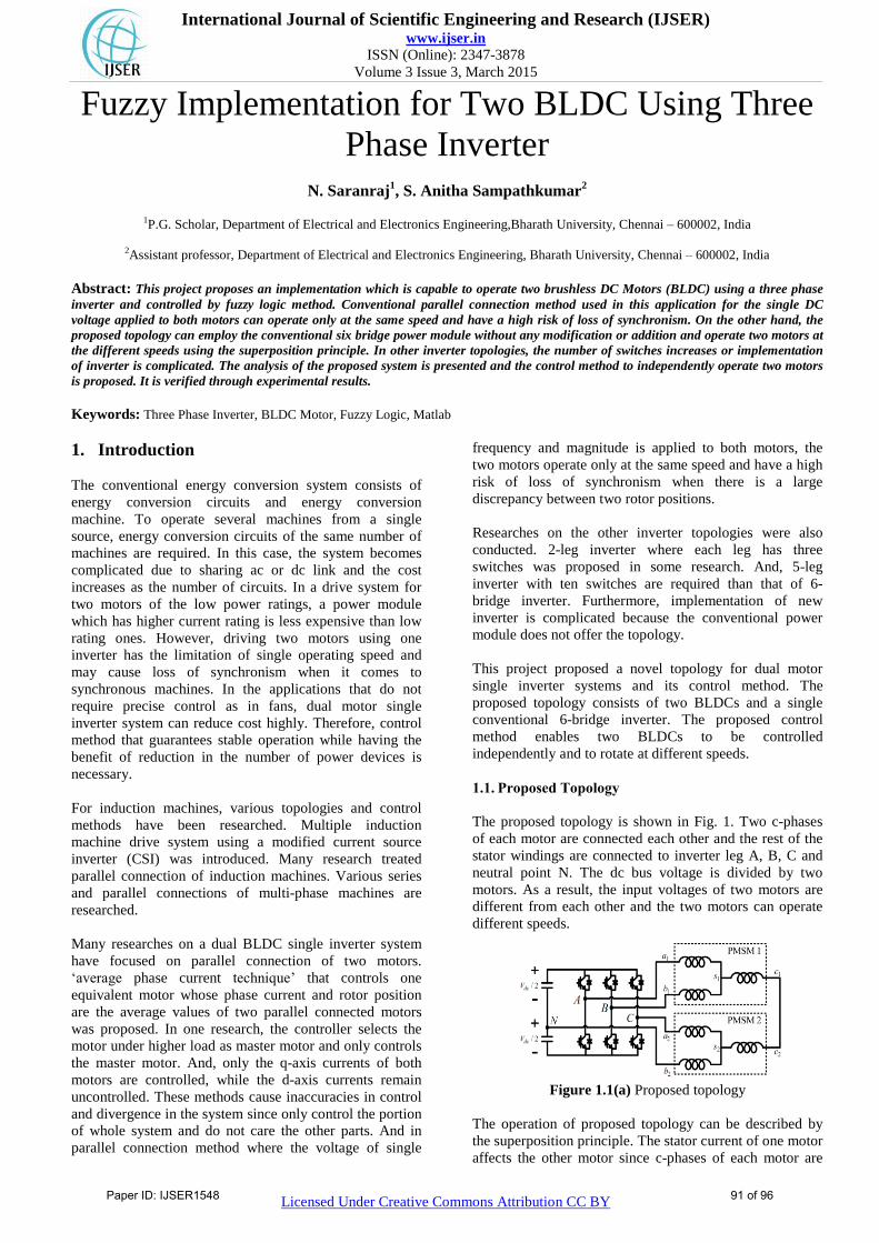
connected. Fig. 1.1 shows the current flowing through
each stator winding when phase currents of only one motor
flow. The subscripts a, b, and c indicate each phase of
motor, respectively, and the subscripts 1 and 2 imply each
motor. k1 and k2 are the ratios of the c-phase current of
one motor that is divided into a and b-phases of the other
motor. Consequently, sum of the currents of Fig. 1.1 (a)
and (b) flows through the motors.
Figure 1.1(b) Current distribution where phase currents of
only one motor flow
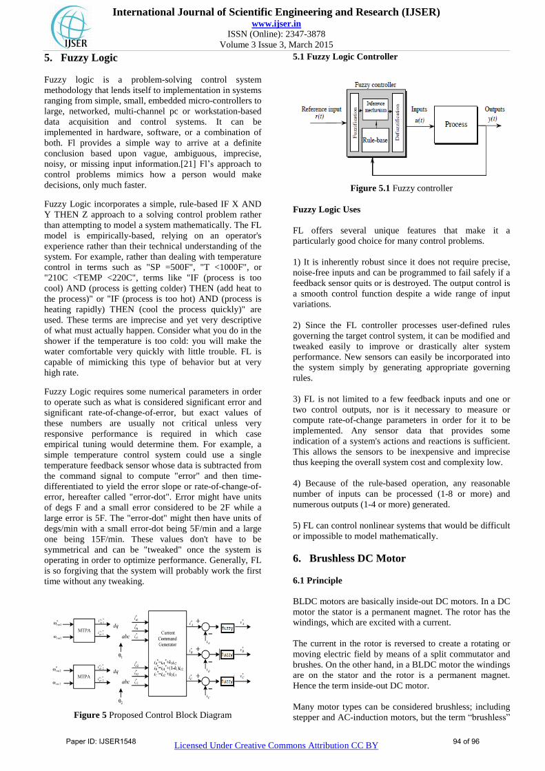
1.2. Control For Proposed Topology
The proportional and integral (PI) controllers are used for
speed controller as in a conventional single motor single
inverter system. To apply aforementioned superposition
principle, d and q-axis current references are the outputs of
the speed controller and they are transformed into a, b, and
c phase quantities. Then, the current command generator
outputs A, B, and C leg current references using the a, b,
and c phase current references as shown in Fig. 1.1(a) and
(b). Three fuzzy controllers are used as current controller
as shown in Fig. 5.The proposed controller requires three
current sensors for feedback while typical motor drive
system requires two ones per motor.
When the current command generator outputs current
references, k1 and k2 are required to be determined. Z is
the stator impedance, |Zx| is the magnitude of Z, and x is
each frequency component. After I1, I2, ω1, and ω2 have
been determined according to speed, torque, k1 and K2 are
calculated. They make peak value of maximum voltage
among (3), (4), and (5) minimize. The peak ones of
maximum voltage according to k1 and k2 are shown in
Fig. 6.
1.3. Existing Limitations
1. In parallel connection method where the voltage of
single frequency and magnitude is applied to both
motors, the two motors operate only at the same speed
and have a high risk of loss of synchronism when there
is a large discrepancy between two rotor positions.
2. The conventional 6-bridge inverter is used.
1.4. Proposed Merits
1. The proposed control method enables two BLDCs to be
controlled independently and to rotate at different
speeds.
2. In proposed topology, two c-phases of each motor are
connected each other and the rest of the stator windings
are connected to three inverter legs and neutral point,
respectively.
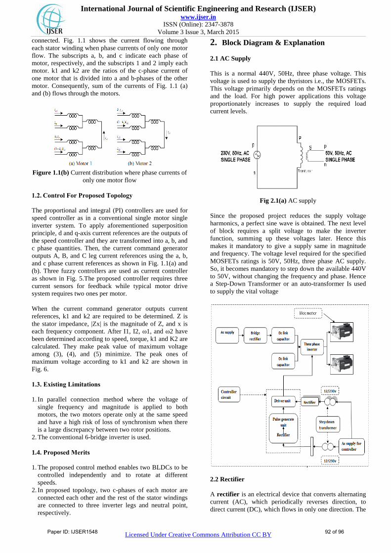
2. Block Diagram & Explanation
2.1 AC Supply
This is a normal 440V, 50Hz, three phase voltage. This
voltage is used to supply the thyristors i.e., the MOSFETs.
This voltage primarily depends on the MOSFETs ratings
and the load. For high power applications this voltage
proportionately increases to supply the required load
current levels.
Fig 2.1(a) AC supply
Since the proposed project reduces the supply voltage
harmonics, a perfect sine wave is obtained. The next level
of block requires a split voltage to make the inverter
function, summing up these voltages later. Hence this
makes it mandatory to give a supply same in magnitude
and frequency. The voltage level required for the specified
MOSFETs ratings is 50V, 50Hz, three phase AC supply.
So, it becomes mandatory to step down the available 440V
to 50V, without changing the frequency and phase. Hence
a Step-Down Transformer or an auto-transformer Is used
to supply the vital voltage
2.2 Rectifier
A rectifier is an electrical device that converts alternating
current (AC), which periodically reverses direction, to
direct current (DC), which flows in only one direction. The
Paper ID: IJSER1548 92 of 96
International Journal of Scientific Engineering and Research (IJSER) www.ijser.in
ISSN (Online): 2347-3878
Volume 3 Issue 3, March 2015
Licensed Under Creative Commons Attribution CC BY
process is known as rectification. Rectifiers have many
uses, but are often found serving as components of DC
power supplies and high-voltage direct current power
transmission systems. Rectification may serve in roles
other than to generate direct current for use as a source of
power. In gas heating systems flame rectification is used to
detect presence of flame. Because of the alternating nature
of the input AC sine wave, the process of rectification
alone produces a DC current that, though unidirectional,
consists of pulses of current. Many applications of
rectifiers, such as power supplies for radio, television and
computer equipment, require a steady constant DC current
(as would be produced by a battery). In these applications
the output of the rectifier is smoothed by an electronic
filter to produce a steady current.
3. DC Link Capacitors
These capacitors are designed for use on DC supplies and
are intended to protect the network from momentary
voltage spikes and surges and for filtering out AC ripple.
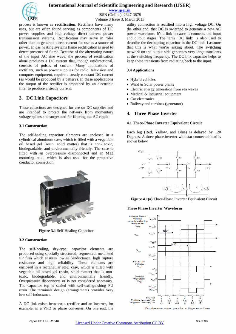
3.1 Construction
The self-healing capacitor elements are enclosed in a
cylindrical aluminum case, which is filled with a vegetable
oil based gel (resin, solid matter) that is non- toxic,
biodegradable, and environmentally friendly. The case is
fitted with an overpressure disconnected and an M12
mounting stud, which is also used for the protective
conductor connection.
Figure 3.1 Self-Healing Capacitor
3.2 Construction
The self-healing, dry-type, capacitor elements are
produced using specially structured, segmented, metalized
PP film which ensures low self-inductance, high rupture
resistance and high reliability. These elements are
enclosed in a rectangular steel case, which is filled with
vegetable-oil based gel (resin, solid matter) that is non-
toxic, biodegradable, and environmentally friendly.
Overpressure disconnects or is not considered necessary.
The capacitor top is sealed with self-extinguishing PU
resin. The terminals design (arrangement) provides very
low self-inductance.
A DC link exists between a rectifier and an inverter, for
example, in a VFD or phase converter. On one end, the
utility connection is rectified into a high voltage DC. On
the other end, that DC is switched to generate a new AC
power waveform. It's a link because it connects the input
and output stages. The term "DC link" is also used to
describe the decoupling capacitor in the DC link. I assume
that this is what you're asking about. The switching
network on the output side generates very large transients
at the switching frequency. The DC link capacitor helps to
keep these transients from radiating back to the input.
3.4 Applications
Hybrid vehicles
Wind & Solar power plants
Electric energy generation from sea waves
Medical & Industrial equipment
Car electronics
Railway and turbines (generator)
4. Three Phase Inverter
4.1 Three-Phase Inverter Equivalent Circuit
Each leg (Red, Yellow, and Blue) is delayed by 120
Degrees. A three-phase inverter with star connected load is
shown below
Figure 4.1(a) Three-Phase Inverter Equivalent Circuit
Three Phase Inverter Waveform
Paper ID: IJSER1548 93 of 96
International Journal of Scientific Engineering and Research (IJSER) www.ijser.in
ISSN (Online): 2347-3878
Volume 3 Issue 3, March 2015
Licensed Under Creative Commons Attribution CC BY
5. Fuzzy Logic
Fuzzy logic is a problem-solving control system
methodology that lends itself to implementation in systems
ranging from simple, small, embedded micro-controllers to
large, networked, multi-channel pc or workstation-based
data acquisition and control systems. It can be
implemented in hardware, software, or a combination of
both. Fl provides a simple way to arrive at a definite
conclusion based upon vague, ambiguous, imprecise,
noisy, or missing input information.[21] Fl‟s approach to
control problems mimics how a person would make
decisions, only much faster.
Fuzzy Logic incorporates a simple, rule-based IF X AND
Y THEN Z approach to a solving control problem rather
than attempting to model a system mathematically. The FL
model is empirically-based, relying on an operator's
experience rather than their technical understanding of the
system. For example, rather than dealing with temperature
control in terms such as "SP =500F", "T <1000F", or
"210C <TEMP <220C", terms like "IF (process is too
cool) AND (process is getting colder) THEN (add heat to
the process)" or "IF (process is too hot) AND (process is
heating rapidly) THEN (cool the process quickly)" are
used. These terms are imprecise and yet very descriptive
of what must actually happen. Consider what you do in the
shower if the temperature is too cold: you will make the
water comfortable very quickly with little trouble. FL is
capable of mimicking this type of behavior but at very
high rate.
Fuzzy Logic requires some numerical parameters in order
to operate such as what is considered significant error and
significant rate-of-change-of-error, but exact values of
these numbers are usually not critical unless very
responsive performance is required in which case
empirical tuning would determine them. For example, a
simple temperature control system could use a single
temperature feedback sensor whose data is subtracted from
the command signal to compute "error" and then time-
differentiated to yield the error slope or rate-of-change-of-
error, hereafter called "error-dot". Error might have units
of degs F and a small error considered to be 2F while a
large error is 5F. The "error-dot" might then have units of
degs/min with a small error-dot being 5F/min and a large
one being 15F/min. These values don't have to be
symmetrical and can be "tweaked" once the system is
operating in order to optimize performance. Generally, FL
is so forgiving that the system will probably work the first
time without any tweaking.
Figure 5 Proposed Control Block Diagram
5.1 Fuzzy Logic Controller
Figure 5.1 Fuzzy controller
Fuzzy Logic Uses
FL offers several unique features that make it a
particularly good choice for many control problems.
1) It is inherently robust since it does not require precise,
noise-free inputs and can be programmed to fail safely if a
feedback sensor quits or is destroyed. The output control is
a smooth control function despite a wide range of input
variations.
2) Since the FL controller processes user-defined rules
governing the target control system, it can be modified and
tweaked easily to improve or drastically alter system
performance. New sensors can easily be incorporated into
the system simply by generating appropriate governing
rules.
3) FL is not limited to a few feedback inputs and one or
two control outputs, nor is it necessary to measure or
compute rate-of-change parameters in order for it to be
implemented. Any sensor data that provides some
indication of a system's actions and reactions is sufficient.
This allows the sensors to be inexpensive and imprecise
thus keeping the overall system cost and complexity low.
4) Because of the rule-based operation, any reasonable
number of inputs can be processed (1-8 or more) and
numerous outputs (1-4 or more) generated.
5) FL can control nonlinear systems that would be difficult
or impossible to model mathematically.
6. Brushless DC Motor
6.1 Principle
BLDC motors are basically inside-out DC motors. In a DC
motor the stator is a permanent magnet. The rotor has the
windings, which are excited with a current.
The current in the rotor is reversed to create a rotating or
moving electric field by means of a split commutator and
brushes. On the other hand, in a BLDC motor the windings
are on the stator and the rotor is a permanent magnet.
Hence the term inside-out DC motor.
Many motor types can be considered brushless; including
stepper and AC-induction motors, but the term “brushless”
Paper ID: IJSER1548 94 of 96
International Journal of Scientific Engineering and Research (IJSER) www.ijser.in
ISSN (Online): 2347-3878
Volume 3 Issue 3, March 2015
Licensed Under Creative Commons Attribution CC BY
is given to a group of motors that act similarly to DC brush
type motors without the limitations of a physical
commutator. To build a brushless motor, the current-
carrying coils must be taken off the rotating mechanism. In
their place, the permanent magnet will be allowed to rotate
within the case. The current still needs to be switched
based on rotary position; here, shows a reversing switch is
activated by a cam.
Figure 6.1 Basic operation of BLDC motor and Waveform
of current and torque of basic BLDC motor
This orientation follows the same basic principle of rotary
motors; the torque produced by the rotor varies trapezoidal
with respect to the angle of the field. As the angle θ
increases, the torque drops to an unusable level.
Because of this, the reversible switch could have three
states: positive current flow, negative current flow, and
open circuit. In this configuration, the torque based on
rotary position will vary as the current is switched.
,
7. Simulation Results
7.1 General
Simulation has become a very powerful tool on the
industry application as well as in academics, nowadays. It
is now essential for an electrical engineer to understand the
concept of simulation and learn its use in various
applications. Simulation is one of the best ways to study
the system or circuit behavior without damaging it .The
tools for doing the simulation in various fields are
available in the market for engineering professionals.
Many industries are spending a considerable amount of
time and money in doing simulation before manufacturing
their product. In most of the research and development
(R&D) work, the simulation plays a very important role.
Without simulation it is quiet impossible to proceed
further. It should be noted that in power electronics,
computer simulation and a proof of concept hardware
prototype in the laboratory are complimentary to each
other. However computer simulation must not be
considered as a substitute for hardware prototype. The
objective of this chapter is to describe simulation of
impedance source inverter with R, R-L and RLE loads
using MATLAB tool.
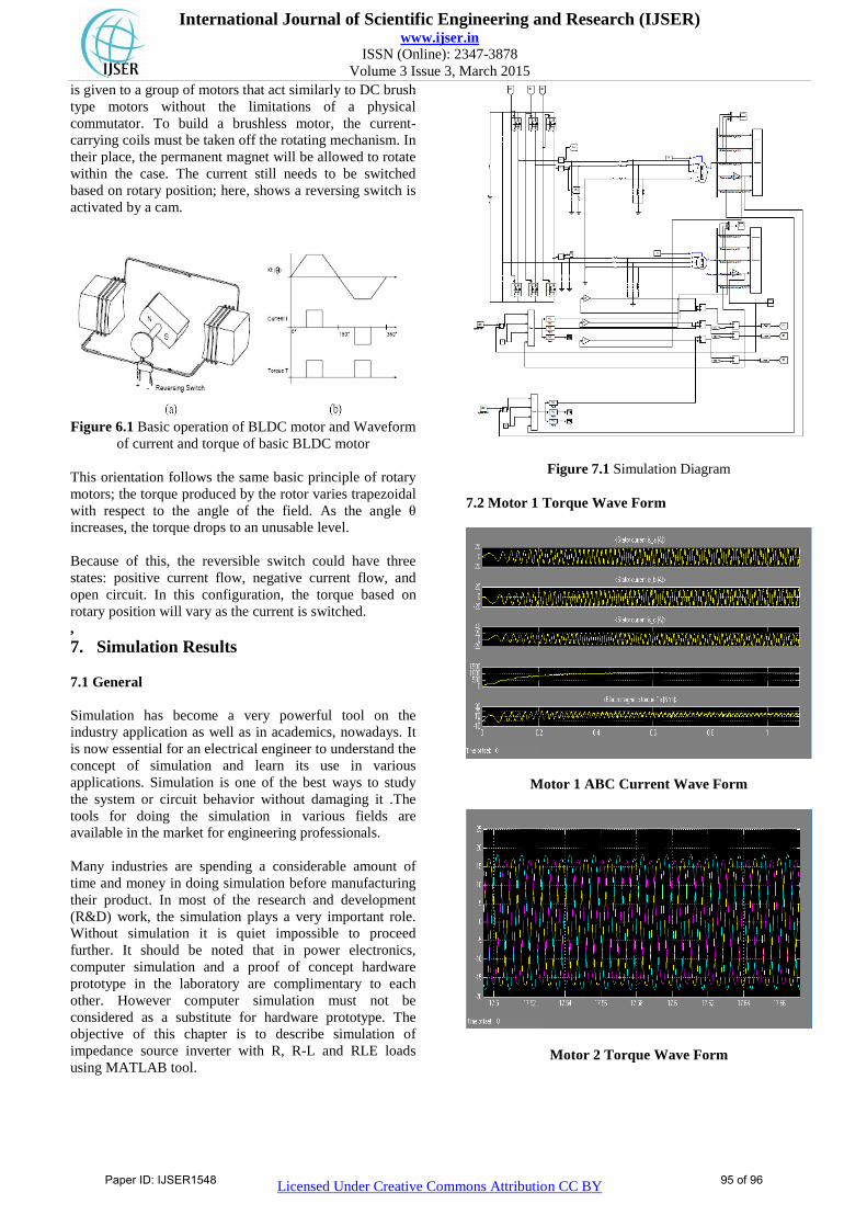
Figure 7.1 Simulation Diagram
7.2 Motor 1 Torque Wave Form
Motor 1 ABC Current Wave Form
Motor 2 Torque Wave Form
Paper ID: IJSER1548 95 of 96
International Journal of Scientific Engineering and Research (IJSER) www.ijser.in
ISSN (Online): 2347-3878
Volume 3 Issue 3, March 2015
Licensed Under Creative Commons Attribution CC BY
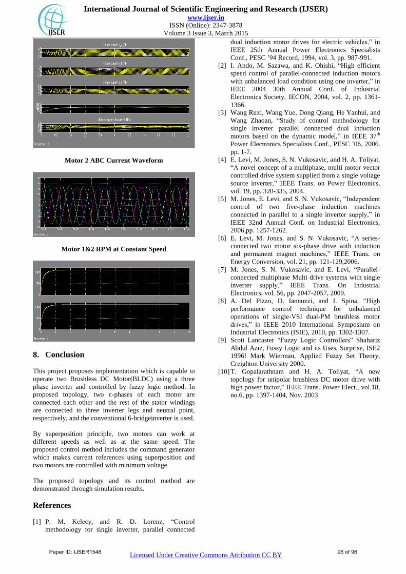
Motor 2 ABC Current Waveform
Motor 1&2 RPM at Constant Speed
8. Conclusion
This project proposes implementation which is capable to
operate two Brushless DC Motor(BLDC) using a three
phase inverter and controlled by fuzzy logic method. In
proposed topology, two c-phases of each motor are
connected each other and the rest of the stator windings
are connected to three inverter legs and neutral point,
respectively, and the conventional 6-bridgeinverter is used.
By superposition principle, two motors can work at
different speeds as well as at the same speed. The
proposed control method includes the command generator
which makes current references using superposition and
two motors are controlled with minimum voltage.
The proposed topology and its control method are
demonstrated through simulation results.
References
[1] P. M. Kelecy, and R. D. Lorenz, “Control
methodology for single inverter, parallel connected
dual induction motor drives for electric vehicles,” in
IEEE 25th Annual Power Electronics Specialists
Conf., PESC ‟94 Record, 1994, vol. 3, pp. 987-991.
[2] I. Ando, M. Sazawa, and K. Ohishi, “High efficient
speed control of parallel-connected induction motors
with unbalanced load condition using one inverter,” in
IEEE 2004 30th Annual Conf. of Industrial
Electronics Society, IECON, 2004, vol. 2, pp. 1361-
1366.
[3] Wang Ruxi, Wang Yue, Dong Qiang, He Yanhui, and
Wang Zhaoan, “Study of control methodology for
single inverter parallel connected dual induction
motors based on the dynamic model,” in IEEE 37th
Power Electronics Specialists Conf., PESC ‟06, 2006.
pp. 1-7.
[4] E. Levi, M. Jones, S. N. Vukosavic, and H. A. Toliyat,
“A novel concept of a multiphase, multi motor vector
controlled drive system supplied from a single voltage
source inverter,” IEEE Trans. on Power Electronics,
vol. 19, pp. 320-335, 2004.
[5] M. Jones, E. Levi, and S. N. Vukosavic, “Independent
control of two five-phase induction machines
connected in parallel to a single inverter supply,” in
IEEE 32nd Annual Conf. on Industrial Electronics,
2006,pp. 1257-1262.
[6] E. Levi, M. Jones, and S. N. Vukosavic, “A series-
connected two motor six-phase drive with induction
and permanent magnet machines,” IEEE Trans. on
Energy Conversion, vol. 21, pp. 121-129,2006.
[7] M. Jones, S. N. Vukosavic, and E. Levi, “Parallel-
connected multiphase Multi drive systems with single
inverter supply,” IEEE Trans. On Industrial
Electronics, vol. 56, pp. 2047-2057, 2009.
[8] A. Del Pizzo, D. Iannuzzi, and I. Spina, “High
performance control technique for unbalanced
operations of single-VSI dual-PM brushless motor
drives,” in IEEE 2010 International Symposium on
Industrial Electronics (ISIE), 2010, pp. 1302-1307.
[9] Scott Lancaster “Fuzzy Logic Controllers” Shahariz
Abdul Aziz, Fussy Logic and its Uses, Surprise, ISE2
1996! Mark Wierman, Applied Fuzzy Set Theory,
Creighton University 2000.
[10] T. Gopalarathnam and H. A. Toliyat, “A new
topology for unipolar brushless DC motor drive with
high power factor,” IEEE Trans. Power Elect., vol.18,
no.6, pp. 1397-1404, Nov. 2003
Paper ID: IJSER1548 96 of 96