Embed Size (px)
Citation preview

International Journal of Advances in Engineering & Technology, May 2012.
©IJAET ISSN: 2231-1963
668 Vol. 3, Issue 2, pp. 668-679
FUZZY LOGIC BASED CONTROLLER FOR A STAND-ALONE
HYBRID GENERATION SYSTEM USING WIND AND
PHOTOVOLTAIC ENERGY
G. Balasubramanian1 and S. Singaravelu
2
1Department of Electrical Engineering, Annamalai University, Annamalainagar, India
ABSTRACT
Fuzzy logic based voltage controller is proposed for hybrid generation scheme using solar and wind energy for
isolated applications. The fuzzy logic controller is designed to vary the duty-cycle of the DC-DC converter
automatically such that to maintain the load voltage constant. The hybrid scheme comprises one set of fixed
capacitor bank and a parallel connected three-phase fixed frequency pulse width modulation (PWM) inverter
fed from the solar panels which provide the reactive power requirements to the induction generator. A dynamic
d-q axis and steady-state mathematical model for the entire hybrid scheme is presented. The complete system is
modelled and simulated MATLAB/Simulink environment. Results from simulations and laboratory tests show
that the dynamic reactive power compensation is inherent.
KEYWORDS: Hybrid, Solar, Induction Generator, DC-DC Converter & Inverter.
I. INTRODUCTION
The rapid growth in power electronics techniques makes the feasibility in hybrid scheme generation
using wind and photovoltaic system [1]. The renewable energy systems can be used to supply power
either directly to a utility grid or to an isolated load. The stand-alone systems find wider application as
water-pumps, for village electrification, supply of power to isolated areas which are far away from the
utility grid [2]. Generally, PV power and wind power are complementary since sunny days are usually
calm and strong winds often occur on cloudy days or in night time. The hybrid PV-wind power
system therefore has higher availability to deliver continuous power and results in a better utilization
of power conversion and control equipment than with of the individual sources [3]. Further hybrid
PV-wind scheme has environmental benefits such as reduction of carbon emission due to use of
renewable energy sources [4]. In case of stand-alone wind power generation system with a self-
excited induction generator, it is necessary to provide a dynamically variable reactive power to
maintain constant output voltages [5-8]. But in case of solar-wind hybrid scheme the necessary
reactive power under varying rotor speed or load can be achieved by providing a three-phase fixed
frequency pulse width modulation (PWM) inverter fed from the photovoltaic array. In this paper
fuzzy logic controller is designed to vary the duty-cycle of the DC-DC converter such that to maintain
the load voltage constant under varying rotor speeds or loads.
The paper is arranged as follows: Section II describes the entire hybrid scheme for solar and wind
energy conversion. Section III explains the photo-voltaic, dynamic and the steady-state modeling.
Section IV and V describes the DC-DC converter and the proposed fuzzy logic controller. Section VI
discusses the results of the hybrid scheme and the conclusions from the study are given in Section
VII.
International Journal of Advances in Engineering & Technology, May 2012.
©IJAET ISSN: 2231-1963
669 Vol. 3, Issue 2, pp. 668-679
Figure 2: Equivalent circuit of PV cell
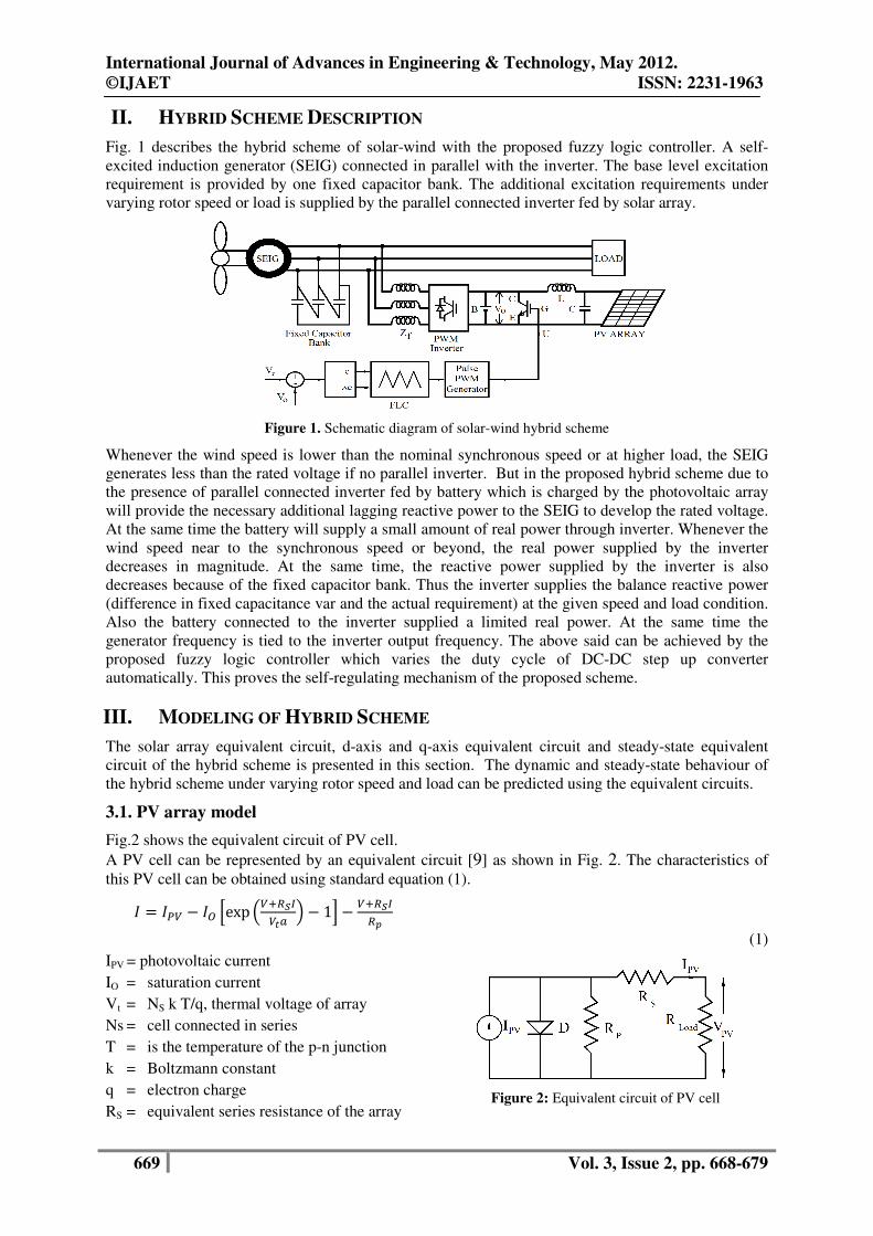
II. HYBRID SCHEME DESCRIPTION
Fig. 1 describes the hybrid scheme of solar-wind with the proposed fuzzy logic controller. A self-
excited induction generator (SEIG) connected in parallel with the inverter. The base level excitation
requirement is provided by one fixed capacitor bank. The additional excitation requirements under
varying rotor speed or load is supplied by the parallel connected inverter fed by solar array.
Figure 1. Schematic diagram of solar-wind hybrid scheme
Whenever the wind speed is lower than the nominal synchronous speed or at higher load, the SEIG
generates less than the rated voltage if no parallel inverter. But in the proposed hybrid scheme due to
the presence of parallel connected inverter fed by battery which is charged by the photovoltaic array
will provide the necessary additional lagging reactive power to the SEIG to develop the rated voltage.
At the same time the battery will supply a small amount of real power through inverter. Whenever the
wind speed near to the synchronous speed or beyond, the real power supplied by the inverter
decreases in magnitude. At the same time, the reactive power supplied by the inverter is also
decreases because of the fixed capacitor bank. Thus the inverter supplies the balance reactive power
(difference in fixed capacitance var and the actual requirement) at the given speed and load condition.
Also the battery connected to the inverter supplied a limited real power. At the same time the
generator frequency is tied to the inverter output frequency. The above said can be achieved by the
proposed fuzzy logic controller which varies the duty cycle of DC-DC step up converter
automatically. This proves the self-regulating mechanism of the proposed scheme.
III. MODELING OF HYBRID SCHEME
The solar array equivalent circuit, d-axis and q-axis equivalent circuit and steady-state equivalent
circuit of the hybrid scheme is presented in this section. The dynamic and steady-state behaviour of
the hybrid scheme under varying rotor speed and load can be predicted using the equivalent circuits.
3.1. PV array model
Fig.2 shows the equivalent circuit of PV cell.
A PV cell can be represented by an equivalent circuit [9] as shown in Fig. 2. The characteristics of
this PV cell can be obtained using standard equation (1).
= − exp − 1 −
(1)
IPV = photovoltaic current
IO = saturation current
Vt = NS k T/q, thermal voltage of array
Ns = cell connected in series
T = is the temperature of the p-n junction
k = Boltzmann constant
q = electron charge
RS = equivalent series resistance of the array

International Journal of Advances in Engineering & Technology, May 2012.
©IJAET ISSN: 2231-1963
670 Vol. 3, Issue 2, pp. 668-679
Imp 4.40 A Voc 21.20 V
Vmp 17.00 V a 1.3
Pmax 74.8 W Rse 0.511 Ω
Isc 5.02 A Rsh 44.25 Ω
Ns 36 Kv -74.7 mv/
IO,n 9.83 x 10⁻⁸A KI 2.80 mA/
RP = equivalent parallel resistance of the array
a = diode ideality constant
Fig. 1 shows the single diode model. A single solar cell will produce only a limited power. Therefore
it is usual practice in order to get desired power rating the solar cells are connected in parallel and
series circuits which form a module. Such modules are again connected in parallel and series to form
a solar array or panel to get required voltage and current. The equivalent series and parallel resistance
of the array are denoted by the symbol RS and RP respectively in the equivalent circuit.
From the general I-V characteristic of the practical photovoltaic device one can observe that the series
resistance RS value will dominate in the voltage source region and the parallel resistance RP value will
dominate in the current source region of operation.
The general equation of a PV cell describes the relationship between current and voltage of the cell.
Since the value of shunt resistance RP is high compared to value of series resistance RS the current
through the parallel resistance can be neglected. The light generated current of the photovoltaic cell
depends linearly on the solar irradiation and is also influenced by the temperature [10] given by the
equation (2) = , + ∆ ! (2) ,= is the light generated current at nominal condition(250C and 1000 W/ m
2)
∆T = T – Tn
T = actual temperature [K]
Tn = nominal temperature [K]
KI = current coefficients
G = irradiation on the device surface [W/m2]
Gn = nominal irradiation
The current and voltage coefficients KV and KI are included as shown in equation (3) in order to take
the saturation current IO which is strongly dependent on the temperature. = "#,!$%∆&'()*+,#,!-.+∆&/+ 012 (3)
KV = voltage coefficients
KI = current coefficients
The output voltage is increased (where the current remain unchanged) proportionally on number of
identical PV modules connected in series (Nser). Similarly the output current is increased (where the
voltage remain unchanged) proportionally on number of identical PV modules connected in parallel
(Npar).
It can be noted that the equivalent series and parallel resistance are directly proportional to the number
of series modules and inversely proportional to the number of parallel modules respectively.
The equation for array composed of Nser x Npar given by equation (4)
= 3)4 − 3)4 5exp 6 * 7"897/90 :"89 ; − 1< − * 7"897/90
=* 7"897/90 (4)
Table 1. Parameter of KCP -12075 solar array at 25, 1000W/m2
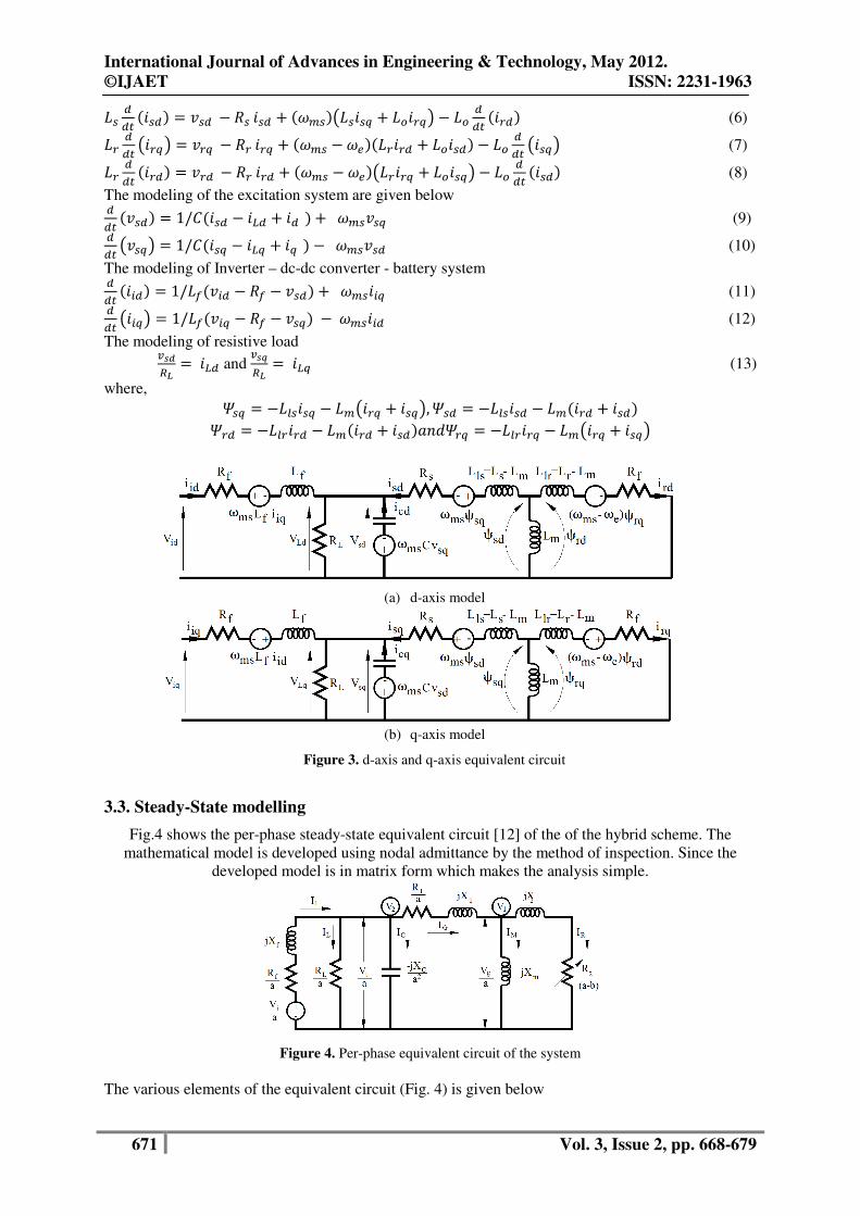
3.2. Dynamic Modelling
Fig.3 shows the d-axis and q-axis equivalent circuit of the hybrid scheme. The differential equations
governing the stator and rotor currents in stator flux reference frame of the induction machine can be
written as follows [11].
>? @@A BC?DE = F?D − G? C?D − HIJ?KH>?C?@ + >LC4@K − >L @@A BC4DE (5)
International Journal of Advances in Engineering & Technology, May 2012.
©IJAET ISSN: 2231-1963
671 Vol. 3, Issue 2, pp. 668-679
>? @@A HC?@K = F?@ − G? C?@ + HIJ?KB>?C?D + >LC4DE − >L @@A HC4@K (6) >4 @@A BC4DE = F4D − G4 C4D + HIJ? − I'KH>4C4@ + >LC?@K − >L @@A BC?DE (7) >4 @@A HC4@K = F4@ − G4 C4@ + HIJ? − I'KB>4C4D + >LC?DE − >L @@A HC?@K (8)
The modeling of the excitation system are given below @@A HF?@K = 1/NHC?@ − CO@ + C@ K + IJ?F?D (9) @@A BF?DE = 1/NHC?D − COD + CD K − IJ?F?@ (10)
The modeling of Inverter – dc-dc converter - battery system @@A HCP@K = 1/>QHFP@ − GQ − F?@K + IJ?CPD (11) @@A BCPDE = 1/>QHFPD − GQ − F?DK − IJ?CP@ (12)
The modeling of resistive load R"S T = CO@ and R"U T = COD (13)
where, V?D = −>W?C?D − >JBC4D + C?DE, V?@ = −>W?C?@ − >JHC4@ + C?@K V4@ = −>W4C4@ − >JHC4@ + C?@KXYZV4D = −>W4C4D − >JBC4D + C?DE
3.3. Steady-State modelling
Fig.4 shows the per-phase steady-state equivalent circuit [12] of the of the hybrid scheme. The
mathematical model is developed using nodal admittance by the method of inspection. Since the
developed model is in matrix form which makes the analysis simple.
Figure 4. Per-phase equivalent circuit of the system
The various elements of the equivalent circuit (Fig. 4) is given below
(a) d-axis model
(b) q-axis model
Figure 3. d-axis and q-axis equivalent circuit

International Journal of Advances in Engineering & Technology, May 2012.
©IJAET ISSN: 2231-1963
672 Vol. 3, Issue 2, pp. 668-679
[Q = \ + ] Q [? = _ + ] 2 [O = T
[ = `1a + ]^b [c = 0 − ] e#` [f = 0 + ]^J (14)
The various branch currents of the equivalent circuit (Fig. 4) is given below P = HgP X⁄ − gbK/[Q O = HgbK/[O
i = HgbK/[i j = Hgb − g2K/[? J = Hg2K/[J 4 = Hg2K/[ (15)
From Figure 4 the node equations can be written as follows
At node 1 (V1), the Kirchhoff’s Current Law equation can be written as
j = 4 + J (16)
By substituting the values of Ig, Ir and Im in equation (16) and rearranging we get
g2 2kl + 2km + 2k" − gb 2k" = 0 (17)
At node 2 (V2), the Kirchhoff’s Current Law equation can be written as
P = O + i + j (18)
By substituting the values of Ii, IL, IC and Ig in equation (18) and rearranging we get
+n/ 1k\ = kT + ko + 1_k" − g2 2k" + gb * 2kT + 2ko + 2k\ + 2k"0 = n * 2k\0 (19)
The equations (17) and (19) can be written in matrix from as follows
p 2kl + 2km + 2k" − 2k"− 2k"2kT + 2ko + 2k\ + 2k"
q rg2gbs = p 0+n/ 1 k\q (20)
The equation (20) is in matrix form which can be utilized to find the steady state analysis.
IV. DC – DC BOOST CONVERTER
A dual stage power electronic system comprising a boost type dc-dc converter and an inverter is used
to feed the power generated by the PV array to the load.To maintain the load voltage constant a DC-
DC step up converter is introduced between the PV array and the inverter. The block schematic of
the proposed scheme is shown in Fig. 1. In this scheme a PV array feeds DC-DC converter used in
step-up configuration. The voltage across the DC-DC converter is fed to a three-phase, six-step, quasi-
square-wave IGBT inverter a three-phase fixed amplitude and fixed frequency supply is obtained to
feed an isolated load. For a dc-dc boost converter, by using the averaging concept, the input–output
voltage relationship for continuous conduction mode is given by gt/gCY = 1/H1 − uK (21)
Where, D = duty cycle. Since the duty ratio “D” is between 0 and 1 the output voltage must be higher
than the input voltage in magnitude. It should be noted that the control logic of such dc-dc converter
has to be different when it is fed from a stiff DC source. The duty ratio of the chopper is found to
increase linearly with increase in cell temperature and hence the intensity.
International Journal of Advances in Engineering & Technology, May 2012.
©IJAET ISSN: 2231-1963
673 Vol. 3, Issue 2, pp. 668-679
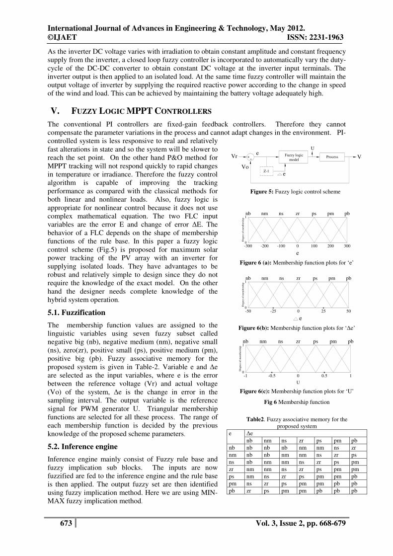
Figure 5: Fuzzy logic control scheme
+-
Fuzzy logic
model
Z-1
Process
e
eVoVr
Vo
U
Figure 6 (a): Membership function plots for ‘e’
Figure 6(b): Membership function plots for ‘∆e’
Figure 6(c): Membership function plots for ‘U’
Fig 6 Membership function
nm ns zr ps pm pbnb
0-100-200-300 100 200 300D
egre
e of
mem
ber
ship
1
0
e
nm ns zr ps pm pbnb
0-25-50 25 50
Deg
ree
of
mem
ber
ship
1
0
e
nm ns zr ps pm pbnb
0-0.5-1 0.5 1
Degre
e of
mem
bers
hip
1
0
U
Table2. Fuzzy associative memory for the
proposed system
e ∆e
nb nm ns zr ps pm pb
nb nb nb nb nm nm ns zr
nm nb nb nm nm ns zr ps
ns nb nm nm ns zr ps pm
zr nm nm ns zr ps pm pm
ps nm ns zr ps pm pm pb
pm ns zr ps pm pm pb pb
pb zr ps pm pm pb pb pb
As the inverter DC voltage varies with irradiation to obtain constant amplitude and constant frequency
supply from the inverter, a closed loop fuzzy controller is incorporated to automatically vary the duty-
cycle of the DC-DC converter to obtain constant DC voltage at the inverter input terminals. The
inverter output is then applied to an isolated load. At the same time fuzzy controller will maintain the
output voltage of inverter by supplying the required reactive power according to the change in speed
of the wind and load. This can be achieved by maintaining the battery voltage adequately high.
V. FUZZY LOGIC MPPT CONTROLLERS
The conventional PI controllers are fixed-gain feedback controllers. Therefore they cannot
compensate the parameter variations in the process and cannot adapt changes in the environment. PI-
controlled system is less responsive to real and relatively
fast alterations in state and so the system will be slower to
reach the set point. On the other hand P&O method for
MPPT tracking will not respond quickly to rapid changes
in temperature or irradiance. Therefore the fuzzy control
algorithm is capable of improving the tracking
performance as compared with the classical methods for
both linear and nonlinear loads. Also, fuzzy logic is
appropriate for nonlinear control because it does not use
complex mathematical equation. The two FLC input
variables are the error E and change of error ∆E. The
behavior of a FLC depends on the shape of membership
functions of the rule base. In this paper a fuzzy logic
control scheme (Fig.5) is proposed for maximum solar
power tracking of the PV array with an inverter for
supplying isolated loads. They have advantages to be
robust and relatively simple to design since they do not
require the knowledge of the exact model. On the other
hand the designer needs complete knowledge of the
hybrid system operation.
5.1. Fuzzification
The membership function values are assigned to the
linguistic variables using seven fuzzy subset called
negative big (nb), negative medium (nm), negative small
(ns), zero(zr), positive small (ps), positive medium (pm),
positive big (pb). Fuzzy associative memory for the
proposed system is given in Table-2. Variable e and ∆e
are selected as the input variables, where e is the error
between the reference voltage (Vr) and actual voltage
(Vo) of the system, ∆e is the change in error in the
sampling interval. The output variable is the reference
signal for PWM generator U. Triangular membership
functions are selected for all these process. The range of
each membership function is decided by the previous
knowledge of the proposed scheme parameters.
5.2. Inference engine
Inference engine mainly consist of Fuzzy rule base and
fuzzy implication sub blocks. The inputs are now
fuzzified are fed to the inference engine and the rule base
is then applied. The output fuzzy set are then identified
using fuzzy implication method. Here we are using MIN-
MAX fuzzy implication method.
International Journal of Advances in Engineering & Technology, May 2012.
©IJAET ISSN: 2231-1963
674 Vol. 3, Issue 2, pp. 668-679
5.3. Defuzzification
Once fuzzification is over, output fuzzy range is located. Since at this stage a non-fuzzy value of
control is available a defuzzification stage is needed. Centroid defuzzification method [13] is used for
defuzzification in the proposed scheme.
The membership function of the variables error, change in error and change in reference signal for
PWM generator are shown in Fig. 6a-6c respectively.
VI. RESULTS AND DISCUSSIONS
A MATLAB based modeling and simulation scheme (Appendix) with fuzzy logic controller is
proposed which are suitable for studying performance of the hybrid scheme (Fig.1). The experimental
setup and machine parameters details are also given in Appendix. The photovoltaic I-V and P-V
characteristics are discussed. Also, the steady-state and dynamic characteristics of the hybrid scheme
under varying speed and load conditions are discussed.
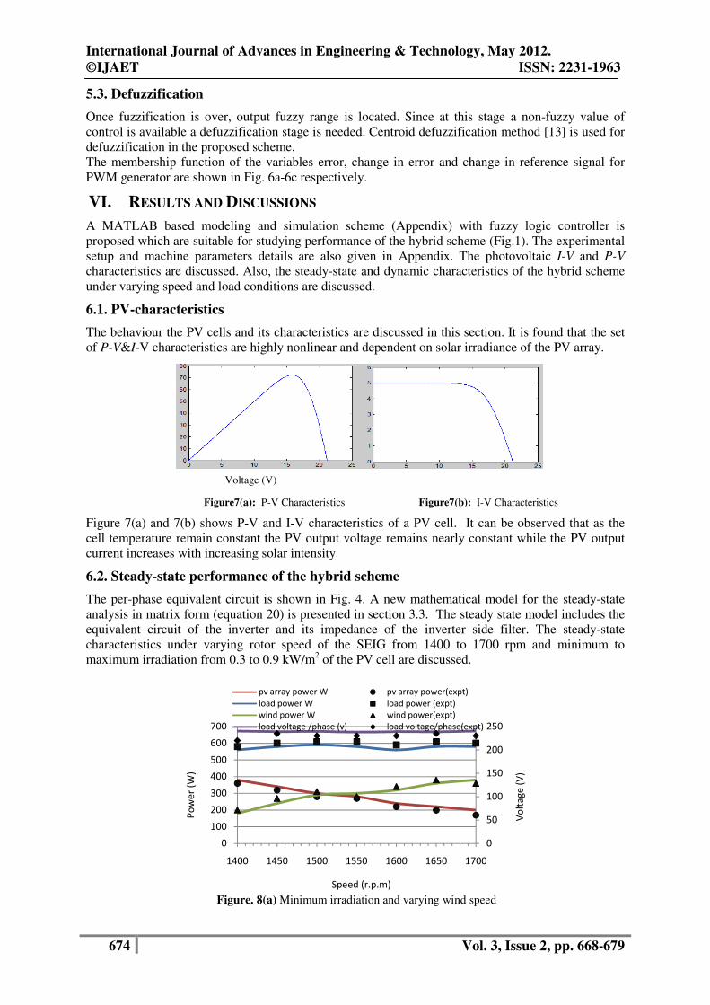
6.1. PV-characteristics
The behaviour the PV cells and its characteristics are discussed in this section. It is found that the set
of P-V&I-V characteristics are highly nonlinear and dependent on solar irradiance of the PV array.
Figure 7(a) and 7(b) shows P-V and I-V characteristics of a PV cell. It can be observed that as the
cell temperature remain constant the PV output voltage remains nearly constant while the PV output
current increases with increasing solar intensity.
6.2. Steady-state performance of the hybrid scheme
The per-phase equivalent circuit is shown in Fig. 4. A new mathematical model for the steady-state
analysis in matrix form (equation 20) is presented in section 3.3. The steady state model includes the
equivalent circuit of the inverter and its impedance of the inverter side filter. The steady-state
characteristics under varying rotor speed of the SEIG from 1400 to 1700 rpm and minimum to
maximum irradiation from 0.3 to 0.9 kW/m2 of the PV cell are discussed.
Figure7(a): P-V Characteristics Figure7(b): I-V Characteristics
Voltage (V) Voltage (V)
Po
wer
(W
)
Cu
rren
t (A
)
Figure. 8(a) Minimum irradiation and varying wind speed
0
50
100
150
200
250
0
100
200
300
400
500
600
700
1400 1450 1500 1550 1600 1650 1700
pv array power W pv array power(expt)
load power W load power (expt)
wind power W wind power(expt)
load voltage /phase (v) load voltage/phase(expt)
Po
we
r (W
)
Speed (r.p.m)
Vo
lta
ge
(V
)
International Journal of Advances in Engineering & Technology, May 2012.
©IJAET ISSN: 2231-1963
675 Vol. 3, Issue 2, pp. 668-679
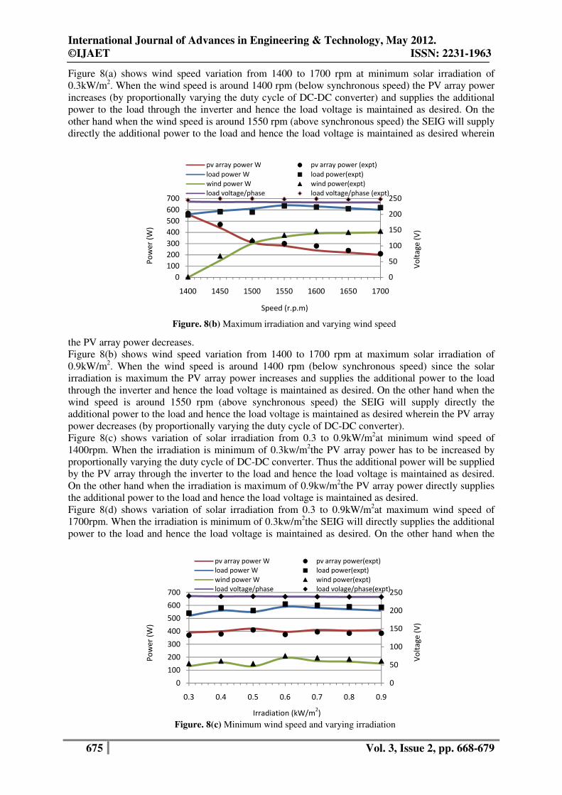
Figure 8(a) shows wind speed variation from 1400 to 1700 rpm at minimum solar irradiation of
0.3kW/m2. When the wind speed is around 1400 rpm (below synchronous speed) the PV array power
increases (by proportionally varying the duty cycle of DC-DC converter) and supplies the additional
power to the load through the inverter and hence the load voltage is maintained as desired. On the
other hand when the wind speed is around 1550 rpm (above synchronous speed) the SEIG will supply
directly the additional power to the load and hence the load voltage is maintained as desired wherein
the PV array power decreases.
Figure 8(b) shows wind speed variation from 1400 to 1700 rpm at maximum solar irradiation of
0.9kW/m2. When the wind speed is around 1400 rpm (below synchronous speed) since the solar
irradiation is maximum the PV array power increases and supplies the additional power to the load
through the inverter and hence the load voltage is maintained as desired. On the other hand when the
wind speed is around 1550 rpm (above synchronous speed) the SEIG will supply directly the
additional power to the load and hence the load voltage is maintained as desired wherein the PV array
power decreases (by proportionally varying the duty cycle of DC-DC converter).
Figure 8(c) shows variation of solar irradiation from 0.3 to 0.9kW/m2at minimum wind speed of
1400rpm. When the irradiation is minimum of 0.3kw/m2the PV array power has to be increased by
proportionally varying the duty cycle of DC-DC converter. Thus the additional power will be supplied
by the PV array through the inverter to the load and hence the load voltage is maintained as desired.
On the other hand when the irradiation is maximum of 0.9kw/m2the PV array power directly supplies
the additional power to the load and hence the load voltage is maintained as desired.
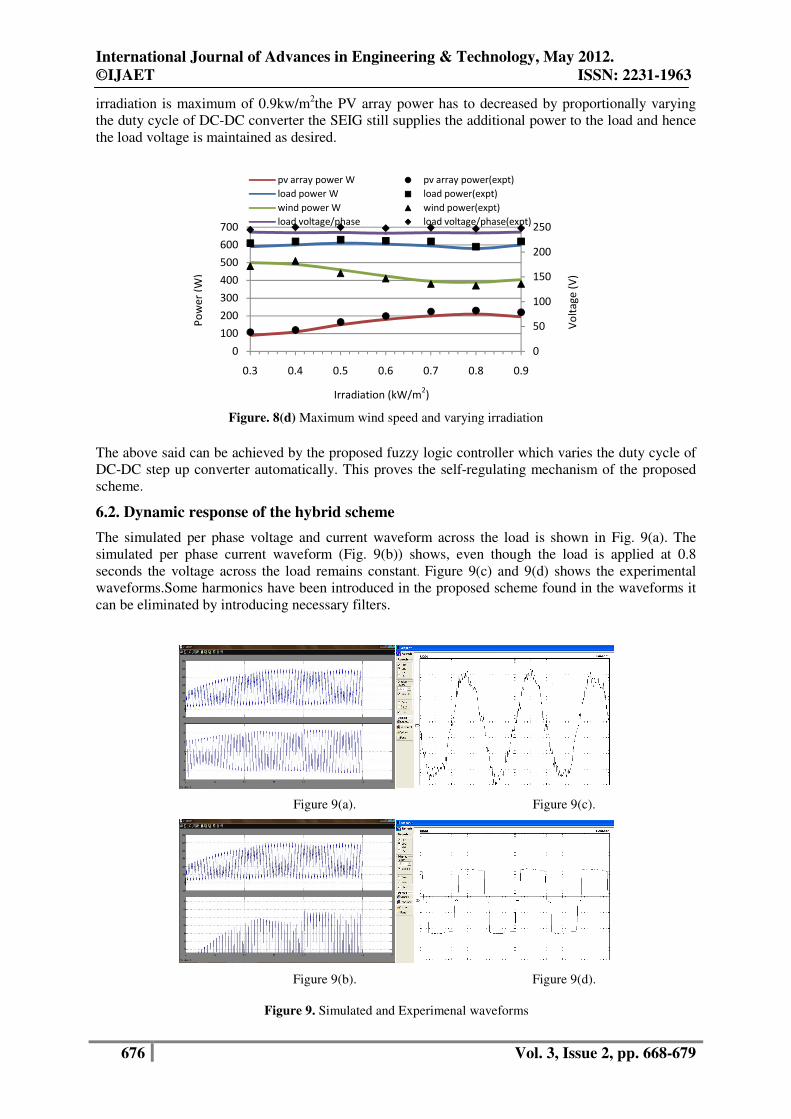
Figure 8(d) shows variation of solar irradiation from 0.3 to 0.9kW/m2at maximum wind speed of
1700rpm. When the irradiation is minimum of 0.3kw/m2the SEIG will directly supplies the additional
power to the load and hence the load voltage is maintained as desired. On the other hand when the
Figure. 8(b) Maximum irradiation and varying wind speed
0
50
100
150
200
250
0
100
200
300
400
500
600
700
1400 1450 1500 1550 1600 1650 1700
pv array power W pv array power (expt)
load power W load power(expt)
wind power W wind power(expt)
load voltage/phase load voltage/phase (expt)
Figure. 8(c) Minimum wind speed and varying irradiation
0
50
100
150
200
250
0
100
200
300
400
500
600
700
0.3 0.4 0.5 0.6 0.7 0.8 0.9
pv array power W pv array power(expt)
load power W load power(expt)
wind power W wind power(expt)
load voltage/phase load volage/phase(expt)
Po
we
r (W
)
Speed (r.p.m)
Vo
lta
ge
(V
)
Irradiation (kW/m2)
Po
we
r (W
)
Vo
lta
ge
(V
)
International Journal of Advances in Engineering & Technology, May 2012.
©IJAET ISSN: 2231-1963
676 Vol. 3, Issue 2, pp. 668-679
irradiation is maximum of 0.9kw/m2the PV array power has to decreased by proportionally varying
the duty cycle of DC-DC converter the SEIG still supplies the additional power to the load and hence
the load voltage is maintained as desired.
The above said can be achieved by the proposed fuzzy logic controller which varies the duty cycle of
DC-DC step up converter automatically. This proves the self-regulating mechanism of the proposed
scheme.
6.2. Dynamic response of the hybrid scheme
The simulated per phase voltage and current waveform across the load is shown in Fig. 9(a). The
simulated per phase current waveform (Fig. 9(b)) shows, even though the load is applied at 0.8
seconds the voltage across the load remains constant. Figure 9(c) and 9(d) shows the experimental
waveforms.Some harmonics have been introduced in the proposed scheme found in the waveforms it
can be eliminated by introducing necessary filters.
Figure. 8(d) Maximum wind speed and varying irradiation
0
50
100
150
200
250
0
100
200
300
400
500
600
700
0.3 0.4 0.5 0.6 0.7 0.8 0.9
pv array power W pv array power(expt)
load power W load power(expt)
wind power W wind power(expt)
load voltage/phase load voltage/phase(expt)
Figure 9(a). Figure 9(c).
Figure 9(b). Figure 9(d).
Figure 9. Simulated and Experimenal waveforms
Po
we
r (W
)
Vo
lta
ge
(V
)
Irradiation (kW/m2)

International Journal of Advances in Engineering & Technology, May 2012.
©IJAET ISSN: 2231-1963
677 Vol. 3, Issue 2, pp. 668-679
VII. CONCLUSIONS
This paper proposes a fuzzy logic controller suitable for solar and wind hybrid energy conversion for
isolated applications. The variations in duty-cycle to maintain constant load voltage with variations in
irradiation and wind speed is achieved with the proposed fuzzy logic controller with optimized rule-
base. Using the mathematical model described the photo-voltaic, dynamic and steady-state
characteristics are discussed. The simulated and experimental waveforms are focused on both the
steady-state and dynamic behaviour which demonstrate the validity of the proposed model. The
experimental result of hybrid scheme indicates the dual objectives of inherent power balance and load
voltage control.
ACKNOWLEDGEMENTS
The authors thank the authorities of Annamalai University for the facilities provided.
REFERENCES
[1]. B. Ravichandra Rao and R. Amala LollyFuzzy (2012) “Fuzzy control of squirrel cage induction
machine and wind generation system”, International Journal of Advances in Engineering and
Technology, Vol.2, no.1, pp 159-167.
[2]. S.Meenakshi, K.Rajambal, C.Chellamuthu, S.Elangovan, (2006) “Intelligent Controller for Stand-
Alone Hybrid Generation System”, Power India Conference IEEE, pp 8-15.
[3]. Ashraf A.Ahmed, Li Ran, Jim Bumby, (2008) “Simulation and control of a Hybrid PV-Wind
System”, Power Electronics Machines & Drives, PEMD 4th
IET conference, pp 421-425.
[4]. WeiQi, Jinfeng Liu, Xianzhong Chen, Panagiotis D. Christofides (2011) “Supervisory predictive
control of standalone wind/solar energy generation system”,IEEE Trans.on control system
technology,vol.19, no.1, pp 199-207.
[5]. T.Ahmed, N. Katsumi, N.Mutsuo, (2007) “Advanced control of PWM converter with variable-speed
induction generator”, IET Electr.Power Appl, pp 239-247.
[6]. S.Bhim, K.Gaurav kumar, (2008) “Solid state voltage and frequency controller for a stand- alone
wind power generating system”,IEEE Trans.Power Electron, pp 1170-1177.
[7]. B.Venkatesa perumal, K.Jayanta,(2008) “Voltage and frequency controller of a stand- alone brushless
wind electric generation using generalized impedance controller” IEEE Trans. Energy Convers, pp
632-641.
[8]. S.Bhim, K.Gaurav kumar, (2008) “Voltage and frequency controller for three phase four wire
autonomous wind energy conversion system”, IEEE Trans.Energy Convers,pp 509-518.
[9]. M.G.Villalva, J.R.Gazol, and E.R.Filho, (2009) “Comprehensive Approach to Modeling and
Simulation of Photovoltaic Arrays", IEEE trans. on Power Electronics, vol.24, no.5, pp.1198-1208.
[10]. H. Patel, and V. Agarwal, (2008) “MATLAB based modeling to study the effects of partial shading
on PV array characteristics”, IEEE trans. on energy conv., vol. 23, no.1, pp. 302-310.
[11]. T.Ahmed, Kastsumi Nishida, and Mutsuo Nakaoka, (2006) “Advanced control of PWM converter
with variable-speed induction generator” IEEE Trans.Ind.Appl,vol.42, no.4, pp. 934-945.
[12]. A.Karthikeyan, C.Nagamani, G.Saravana Illango, A.Sreenivasulu, (2011) “Hybrid, open-loop
excitation system for a wind turbine –driven stand-alone induction generator”, IET Renewable Power
Generation, Vol.5, no.2, pp.184-193.
[13]. Timothy, and J. Ross,(1997) “Fuzzy logic with engineering applications”, McGraw hill international
editions, Electrical engineering series, New York.
APPENDIX
A MATLAB (version 7.9.0.529) based modeling and simulation scheme along with fuzzy logic
controller is proposed (Fig. 10) which are suitable for studying the steady-state and dynamic
behaviour of the hybrid system. In order to achieve the load voltage constant the actual voltage fed to
the inverter is compared with the reference maximum voltage that can be obtained at the load. The
error is calculated and accordingly the reference signal to the PWM generator is changed in order to
maintain the load voltage constant.
International Journal of Advances in Engineering & Technology, May 2012.
©IJAET ISSN: 2231-1963
678 Vol. 3, Issue 2, pp. 668-679
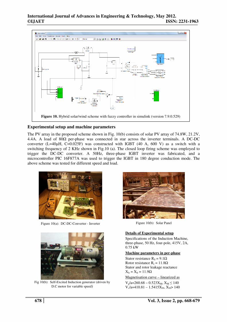
Figure 10(a): DC-DC-Converter - Inverter
Figure 10(b): Solar Panel
Experimental setup and machine parameters
The PV array in the proposed scheme shown in Fig. 10(b) consists of solar PV array of 74.8W, 21.2V,
4.4A. A load of 80Ω per-phase was connected in star across the inverter terminals. A DC-DC
converter (L=40µH, C=0.025F) was constructed with IGBT (40 A, 600 V) as a switch with a
switching frequency of 2 KHz shown in Fig.10 (a). The closed loop firing scheme was employed to
trigger the DC-DC converter. A 50Hz, three-phase IGBT inverter was fabricated, and a
microcontroller PIC 16F877A was used to trigger the IGBT in 180 degree conduction mode. The
above scheme was tested for different speed and load.
Figure 10. Hybrid solar/wind scheme with fuzzy controller in simulink (version 7.9.0.529)
Fig 10(b): Self-Excited Induction generator (driven by
D.C motor for variable speed)
Details of Experimental setup
Specifications of the Induction Machine,
three-phase, 50 Hz, four-pole, 415V, 2A,
0.75 kW
Machine parameters in per-phase
Stator resistance RS = 9.1Ω
Rotor resistance Rr = 11.8Ω
Stator and rotor leakage reactance
Xls = Xlr = 11.9Ω
Magnetisation curve – linearized as
Vg/a=260.68 – 0.523XM, XM ≤ 140
Vg/a=410.81 – 1.5415XM, XM> 140

International Journal of Advances in Engineering & Technology, May 2012.
©IJAET ISSN: 2231-1963
679 Vol. 3, Issue 2, pp. 668-679
Authors
G.Balasubramanian received Bachelor of Engineering in Electrical and Electronics
Engineering in 2000, Master of Engineering in Power System Engineering in 2005
from Annamalai University, Annamalainagar, Tamilnadu, India. He is Assistant
Professor in the Electrical Engineering department at Annamalai University. He is
currently pursing Ph.D degree in the Department of Electrical Engineering,
Annamalai University.His research interests are in electrical machines, power
systems, power electronics, solar and wind energy applications.
S.Singaravelu received Bachelor of Engineering in Electrical and Electronics
Engineering in 1990, Master of Engineering in Power System Engineering in 1992
and Ph.D in 2007 from Annamalai University, Annamalainagar, Tamilnadu, India.
He is Associate Professor in the Department of Electrical Engineering at Annamalai
University. His research interests are in power electronics, power systems, electrical
machines, wind/solar energy applications and high voltage DC transmission.