Embed Size (px)
Citation preview

Journal of ELECTRICAL ENGINEERING, VOL. 60, NO. 6, 2009, 328–334
FUZZY LOGIC CONTROL OF FUEL CELL SYSTEMFOR RESIDENTIAL POWER GENERATION
Khaled Mammar∗
— Abdelkader Chaker∗∗
This paper presents a dynamic model of a fuel cell system for residential power generation. The models proposed includea fuel cell stack model, reformer model and DC/AC inverter model. Furthermore a fuzzy logic (FLC) controller is used tocontrol the active power of PEM fuel cell system. The controller modifies the hydrogen flow feedback from the terminal load.Simulation results confirmed the high performance capability of the fuzzy logic controller to control power generation.
K e y w o r d s: polymer-electrolyte fuel cell, dynamic model, residential power, fuzzy controller
1 INTRODUCTION
Proton exchange membrane (PEM) fuel cells is one ofthe promising technologies for alternative power sourceof residential power generation in future. However, a fuelcell system is large, complex and consumptive. Designingand building prototypes is difficult and expensive. Thealternative is modelling the fuel cell system and its simu-lation. The modelling of the fuel cell is very important forthe power system because it facilitates the understandingof the involved phenomena. Many models have been pro-posed to simulate fuel cells in the literature [1-6], whichhave generally their own specificities and utilities, follow-ing the studied phenomena.
The model proposed in this paper includes the elec-trochemical and fluid dynamic aspects of chemical reac-tions inside the fuel-cell stack. Furthermore, voltage lossesdue to ohmic, activation, and concentration losses are ac-counted for. Therefore, this dynamic PEMFC model com-plements the existing models such as the ones developedin [5, 6]. The model is suitable for power generation. Tostudy the transient response of a grid-independent PEMfuel cell power plant, this paper proposes an electrochem-ical model for a 30 kW fuel cell which incorporates anexternal reformer to generate hydrogen from methane.
Fuel cells are dc voltage sources connected to the elec-tric power load through DC/AC inverters. A method toconnect the proposed PEMFC model to a grid - indepen-dent through an interface block is presented. The fuel-cellmodel, an external reformer and its interface block are im-plemented in MATLAB and incorporated with a powercontrol analysis package.
Finally, a fuzzy logic based controller is designed forthis purposes because of the numerous advantages it hashigh performance, higher than other types of controllers.The most important aspect is the cost of the controller de-sign and implementation. The proposed controller modi-
fies the hydrogen flow for controlling the active power tothe load change.
2 FUEL CELL STATICS MODEL
Hydrogen PEM fuel cells transform chemical energyinto electrical and thermal energy by the simple chemicalreaction [1-3]
H2 + 1/2 O2 → H2O + heat + electrical energy (1)
In order to get an electric current out of this reaction,hydrogen oxidation and oxygen reduction are separatedby a membrane which is conducting protons from theanode to the cathode side. The semi reactions on bothelectrodes are
H2 → 2 H+ + 2 e− anode
O2 + 4 e− → 2 O−
2 cathode(2)
While the protons are transported through the mem-brane, electrons are carried by an electric circuit in whichtheir energy can be used. Modelling of fuel cells is gettingmore and more important as powerful fuel cell stacks aregetting available and have to be integrated into powersystems. In [5, 6] Jeferson M. Correa introduced a modelfor the PEMFC . The model is based on simulating therelationship between the output voltage and partial pres-sure of hydrogen, oxygen, and current.
The output voltage of a single cell can be defined bythe following expression [5, 6]
VFC = ENernst − Vact − Vohm − Vconc (3)
where, ENernst is the thermodynamic potential of thecell and its represents reversible voltage; Vact is the volt-age drop due to the activation of the anode and of the
∗Department of Electrical Engineering , Universit of Bechar, Bp 417,Bechar, Algeria, [email protected];
∗∗Department
of Computers and Informatics, Faculty of Electrical Engineering and Informatics, Laboratory of Electrical network, ENSET, ENSET, BP1742 El M’naouar, Oran, Algeria, [email protected]
ISSN 1335-3632 c© 2009 FEI STU

Journal of ELECTRICAL ENGINEERING 60, NO. 6, 2009 329
cathode; Vohm is the ohmic voltage drop – a measure ofthe ohmic voltage drop associated with the conductionof the protons through the solid electrolyte and electronsthrough the internal electronic resistances; Vconc repre-sents the voltage drop resulting from the concentrationor mass transportation of the reacting gases [5]. The firstterm in (3) represents the FC open circuit voltage, whilethe three last terms represent reduction of the useful volt-age of cell for a certain operating condition. Each one ofthe terms in (3) can be calculated by the following equa-tions, using the parameters listed in Tab. 1 [6].
2.1 Cell Reversible Voltage
The reversible voltage of the cell is calculated startingfrom a modified version of the equation of Nernst, withan extra term to take into account the changes in temper-ature with respect to the standard reference temperature30 C [5]
ENernst =∆G
2F+
∆S
2F(T − Tref )+
RT
2F
[
ln(pH2) +1
2ln(pO2)
] (4)
where ∆G is the change in the free Gibbs energy (J/mol),F is the constant of Faraday (96.487 C), ∆S is thechange of the entropy (J/mol), R is the universal con-stant of the gases (8.314 J/K mol), pH2 and pO2 are thepartial pressures of hydrogen and oxygen (bar), respec-tively. Variable T denotes the cell operation temperature(K) and Tref the reference temperature. Using the stan-dard pressure and temperature (SPT) values for ∆G and∆S , (4) can be simplified to [5]
ENernst = 1.229 − 0.85 × 10⁻³(T − 298, 15)+
+ 4.31 × 10⁻⁵T
[
ln(pH2) +1
2ln(pO2)
]
(5)
2.2 Activation Voltage Drop
As shown in [5], the activation overpotential, includinganode and cathode can be calculated by
Vact = − [ξ1 + ξ2T + ξ3T ln(cO2) + ξ4 ln(Istack)] (6)
Here Istack is the cell operating current (A), and ξi ’s rep-resent parametric coefficients for each cell model, whosevalues are defined based on theoretical equations with ki-netic, thermodynamic, and electrochemical foundations[5], and cO2 is the concentration of oxygen in the cat-alytic interface of the cathode mol/cm, determined by
cO2 =pO2
5.08 × 10⁶e−498/T
2.3 Ohmic Voltage Drop
The ohmic voltage drop results from the resistanceto the electrons transfer through the collecting platesand carbon electrodes, and the resistance to the protonstransfer through the solid membrane. In this model, ageneral expression for resistance is defined to include allthe important parameters of the membrane.
Vohmic = Istack(Rm +Rc) (7)
Here Rc represents the resistance to the transfer of pro-tons through the membrane, usually considered constant.and
Rm = ρMl
A
ρM is the specific resistivity of the membrane for theelectron flow (Ωcm), A is the cell active area (cm2 ) andl is the thickness of the membrane (cm), which serves asthe ectrolyte of the cell.
The following numeric expression for the resistivityof the Nafion membranes is used [5] after introducing:the current density Jstack = Istack/A and the relativetemperature θ = T (K)/303 K
ρ =181.6
[
1 + 0.03Jstack + 0.062θ2J3.5stack
]
[ψ − 0.634 − 3Jstack] e4.18(1−θ)(8)
where 181.6Ψ−0.634 is the specific resistivity (Ωcm) at no
current and at 30 C, [5].
2.4 Concentration or Mass Transport VoltageDrop
To determine an equation for this voltage drop, a max-imum current density is defined Jmax under which thefuel is being used at the same rate of the maximum sup-ply speed. The current density cannot surpass this limitbecause the fuel cannot be supplied at a larger rate. Typ-ical values for are in the range of 500 – 1500 mA/cm2 .Thus, the voltage drop due to the mass transport can bedetermined by
Vcon = −B ln
(
1 −
J
Jmax
)
(9)
where B (in volts) is a parametric coefficient which de-pends on the cell and its operation state, and J representsthe actual current density of the cell (A/cm2 ).
The static model of the PEM fuel cell is shown inFig. 1, and the parameters are given in Tab. 1.
3 FUEL CELL SYSTEM MODEL
In [7-9] Sharkh, Rahman, and Alam introduced amodel of PEMFuel cell system for residential power gener-ation. This model has been modified to introduce a staticmodel show in Fig. 1 the new model is shown in Fig. 4.

330 K. Mammar — A. Chaker: FUZZY LOGIC CONTROL OF FUEL CELL SYSTEM FOR RESIDENTIAL POWER GENERATION . . .
Tab. 1. Model parameters [5, 6].
T 343 KA 333 cm2
L 178µmB 0.016 VRC 0.3 mΩζ1 -0.948
ζ2 0.00286+0.0002ln A + 4.3 × 10⁻⁵ ln(cH2)
ζ3 7.6×10⁻⁵
ζ4 -1.93×10⁻⁴
Ψ 23Jmax 1500 mA/cm2
Jn 1.2 mA/cm2
Fig. 1. PEMFC static model
Fig. 2. Typical PEMFC cell voltage response surface with simulta-neous changes in the inlet partial pressure of hydrogen and current
at a constant stack temperature of 70 C
Fig. 3. Typical PEMFC cell power response surface with simulta-neous changes in the inlet partial pressure of hydrogen and current
at a constant stack temperature of 70 C
3.1 Fuel Cell Dynamic Model
This model is based on simulating the relationship be-tween the output voltage and partial pressure of hydro-gen, oxygen, and current. A detailed model of the PEMfuel cell is shown in Fig. 4.
Fig. 4. PEMFC dynamic model
The model parameters are as follows:
qH2 input molar flow of hydrogen (kmol/s),qO2 input molar flow of oxygen (kmol/s),pH2 hydrogen partial pressure (bar),pO2 oxygen partial pressure (bar),KH2 hydrogen valve molar constant (kmol/bar/s)),KO2 oxygen valve molar constant (kmol/bar/s),N0 number of series fuel cells in the stack,Istack stack current (A),Kr = N0/4F – constant, (kmol/s/A)F Farady constant 9684600 C/kmol.
3.3 Reformer Model
In [7, 8] the authors introduced a simple model of a re-former that generates hydrogen through reforming methane.The model is a second-order transfer function. The mathemat-ical form of the model can be written as follows
qH2
qmethane
=CV
τ1τ2s2 + (τ1 + τ2)s + 1(11)
where, CV is the conversion factor (kmol of hydogen per kmolof methane), qmethane is the methane flow rate (kmol/s) andτ1, τ2 are the reformer time constants (s).
3.4 DC/AC inverter Model
In this paper, only a simple model of a DC/AC inverteris considered for the following reasons: the dynamic time con-stant of inverters is of the order of microseconds or at theutmost milliseconds. The time constants for the reformer andstack are of the order of seconds. The model of the inverteris given in [9], where the output voltage and output powerare controlled using the inverter modulation index and thephase angle δ of the AC voltage. Considering the fuel cell as
a source, the inverter and load connection is shown in Fig. 5.

Journal of ELECTRICAL ENGINEERING 60, NO. 6, 2009 331
Fig. 5. Fuel cell, Inverter and load connection diagram [9]
Fig. 6. The DC/AC inverter model [9]
Here the model parameter are as follows
Vac AC output voltage of the inverter (V)m inverter modulation indexδ phase angle of the AC voltage (rad)Pac AC output power from the inverter (W)Qac reactive output power from the inverter (W)VL load terminal voltage (V)X reactance of the line connecting the fuel cell to the
loadIL load current (A)θ load phase angle (rad)PL load power (W)Istack stack current (A)
The output voltage and the output power as a function of themodulation index and the phase angle δ – providing the phaseangle of the load voltage VL is set to zero – can be written as
Vac = m Vcell (12)
Pac =mVcellVL sin(δ)
X(13)
Qac = m Vcell
mVcell − VL cos(δ)
X(14)
IL =PL
Vs cos(θ)(15)
and assuming a lossless inverter
Pac = VcellIstack, (16)
we get
Istack = mILcos(θ + δ). (17)
PI controllers are used to control the modulation index.The transfer function of the modulation index can be ex-pressed as
m =K5 + sK6
s(Vr − Vac), (18)
were K5 , and K6 are the PI gain, and Vr is the referencevoltage signal. The block diagram of the inverter with the PIcontrollers is illustrated in Fig. 6.
According to electrochemical relationships, a relationshipbetween the stack current and the molar flow of hydrogen canbe written as
qH2 =N0Istack
2FU, (19)
were U is a utilization factor. From (13), (18 ) and (19)
sin(δ) =2FUX
mVsN0
qH2
.= δ, (20)
assuming a small phase angle. Equation (20) describes therelationship between the output voltage phase angle and hy-drogen flow. Equations (13) and (20) indicate that the activepower as a function of the voltage phase angle can be con-trolled by controlling the amount of hydrogen flow.
4 FUZZY LOGIC CONTROLLER
The active power flow from the PEMFC to the load is con-trolled though controlling the flow of hydrogen. The proposedfuzzy logic controller controls the active power by controllingthe hydrogen flow. The fuzzy controller consists of five differ-ent steps (Fig. 7) [10, 11].
Step (i) definition of input-output variables of controller
Step (ii) design of fuzzy control rule
Step (iii) fuzzification
Step (iv) inference
Step (v) defuzzification
The fuzzy controller inputs are the error e(k), and changeof error ce(k). The output of the controller is the duty ratioof the hydrogen flow uH2(k). The error, change of error, andthe output of the controller are given as follows
e(k) = qH2 + qmeth,ref − qH2,b. (22)
Here qH2 is the flow hydrogen from the current feedbacksignal proportional to the terminal load Fig. (6), qmethane isthe methane reference signal and qH2,b is the hydrogen flowfeedback signal.
Fig. 7. The block diagram of a fuzzy logic controller
332 K. Mammar — A. Chaker: FUZZY LOGIC CONTROL OF FUEL CELL SYSTEM FOR RESIDENTIAL POWER GENERATION . . .
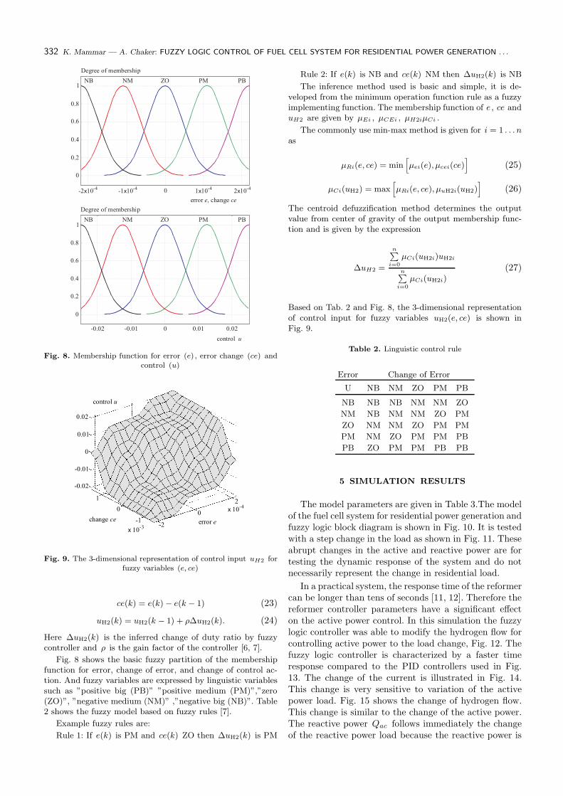
Fig. 8. Membership function for error (e) , error change (ce) andcontrol (u)
Fig. 9. The 3-dimensional representation of control input uH2 forfuzzy variables (e, ce)
ce(k) = e(k) − e(k − 1) (23)
uH2(k) = uH2(k − 1) + ρ∆uH2(k). (24)
Here ∆uH2(k) is the inferred change of duty ratio by fuzzycontroller and ρ is the gain factor of the controller [6, 7].
Fig. 8 shows the basic fuzzy partition of the membershipfunction for error, change of error, and change of control ac-tion. And fuzzy variables are expressed by linguistic variablessuch as ”positive big (PB)” ”positive medium (PM)”,”zero(ZO)”, ”negative medium (NM)” ,”negative big (NB)”. Table2 shows the fuzzy model based on fuzzy rules [7].
Example fuzzy rules are:
Rule 1: If e(k) is PM and ce(k) ZO then ∆uH2(k) is PM
Rule 2: If e(k) is NB and ce(k) NM then ∆uH2(k) is NB
The inference method used is basic and simple, it is de-veloped from the minimum operation function rule as a fuzzyimplementing function. The membership function of e , ce anduH2 are given by µEi , µCEi , µH2iµCi .
The commonly use min-max method is given for i = 1 . . . nas
µRi(e, ce) = min[
µei(e), µcei(ce)]
(25)
µCi(uH2) = max[
µRi(e, ce), µuH2i(uH2)]
(26)
The centroid defuzzification method determines the outputvalue from center of gravity of the output membership func-tion and is given by the expression
∆uH2 =
n∑
i=0
µCi(uH2i)uH2i
n∑
i=0
µCi(uH2i)(27)
Based on Tab. 2 and Fig. 8, the 3-dimensional representationof control input for fuzzy variables uH2(e, ce) is shown inFig. 9.
Table 2. Linguistic control rule
Error Change of Error
U NB NM ZO PM PB
NB NB NB NM NM ZO
NM NB NM NM ZO PM
ZO NM NM ZO PM PM
PM NM ZO PM PM PB
PB ZO PM PM PB PB
5 SIMULATION RESULTS
The model parameters are given in Table 3.The modelof the fuel cell system for residential power generation andfuzzy logic block diagram is shown in Fig. 10. It is testedwith a step change in the load as shown in Fig. 11. Theseabrupt changes in the active and reactive power are fortesting the dynamic response of the system and do notnecessarily represent the change in residential load.
In a practical system, the response time of the reformercan be longer than tens of seconds [11, 12]. Therefore thereformer controller parameters have a significant effecton the active power control. In this simulation the fuzzylogic controller was able to modify the hydrogen flow forcontrolling active power to the load change, Fig. 12. Thefuzzy logic controller is characterized by a faster timeresponse compared to the PID controllers used in Fig.13. The change of the current is illustrated in Fig. 14.This change is very sensitive to variation of the activepower load. Fig. 15 shows the change of hydrogen flow.This change is similar to the change of the active power.The reactive power Qac follows immediately the changeof the reactive power load because the reactive power is

Journal of ELECTRICAL ENGINEERING 60, NO. 6, 2009 333
Fig. 10. PEM fuel cell system and fuzzy logic block diagram
Fig. 11. Load step changes Fig. 12. Active output power change– with fuzzy logic controller
Fig. 13. Active output power change– with PID controller
Fig. 14. Current change Fig. 15. Hydrogen flow rate change Fig. 16. Reactive output power change
Fig. 17. Output voltage phase angle change Fig. 18. Modulation index change

334 K. Mammar — A. Chaker: FUZZY LOGIC CONTROL OF FUEL CELL SYSTEM FOR RESIDENTIAL POWER GENERATION . . .
controlled directly from DC/AC inverter and the responseof DC/AC inverter is not considerable, Fig. 16. We noticethat the reactive power value is superior to the reactivepower. This is due to inductive effect losses of the line(x). The change of the output voltage phase angle andmodulation index are illustrated in Figs. 15 and 16.
Tab. 3. System parameters [8, 9].
Conversion factor CV 2Faraday’s constant F 9684600 C/kmolUniversal gas constant R 8.31447 J/mol/KNumber of cells N0 333Hydrogen valve constant KH2 4.22×10⁻⁵
kmol/s/A
Oxygen valve constant KO2 2.11×10⁻⁵
kmol/s/barHydrogen time constant τH2 3.37 sOxygen time constant τO2 6.74 sUtilization factor U 0.8PI gain constants K5, K6 10H2 -O2 flow ratio rH-O 1.168Methane reference signal qref 0.000015 kmol/sReformer time constants τ1, τ2 2s, 2sLine reactance X 0.05 ΩVoltage reference signal Vr 240 V
6 CONCLUSION
In this paper the fuel cell system model for residentialgeneration is proposed. The proposed model includes a dy-namic fuel cell model, a gas reformer model, DC/AC invertermodel, and fuzzy logic controller unit block. Then the devel-oped model is tested using a computer-simulated step changein the load active and reactive power demands. The simulationresults indicate that the converter and fuel quantities have tobe controlled simultaneously to control the active and reac-tive power. They also indicate that the fuzzy logic controlleris very effective to control the hydrogen flow for active powerload variation.
References
[1] AMPHLETT, J. C.—MANN, R. F.—PEPPLEY, B. A.—ROB-
ERGE, P. R.—RODRIGUES, A. : A model predicting transient
responses of proton exchange membrane fuel cells, J. Power
Sources 61 (1996), 183–188.
[2] BASCHUCK, J. J.—LI, X. : Modelling of polymer electrolyte
membrane fuel cells with variable degrees of water flooding, J.
Power Sources 86 (2000), 181–196.
[3] FAMOURI, P.—GEMMEN, R. : PEM fuel cell electric circuit
model. presented at the Power Electronics for Fuel Cells Work-shop, Fuel Cells Res. Center, Univ. California, Irvine, CA, Aug.
8-9, 2002.
[4] HATZIADONIU, C. J. : A simplified dynamic model of grid-
connected fuel-cell generators, IEEE Trans. Power Delivery 17
(April 2000), 467–473.
[5] CORREA, J. M.—FARRET, F. A.—CANHA, L. N.—SIMOES,
M. G. : An Electrochemical-Based Fuel-Cell Model Suitable forElectrical Engineering Automation Approach, IEEE Transactios
on Industrial Electronics 51 No. 5 (October 2004).
[6] CORREA, J. M.—FARRET, F. A.—CANHA, L. N.—SIMOES,
M. G. : Simulation of Fuel-Cell Stacks Using a Computer- Con-trolled Power Rectifier With the Purposes of Actual High- Power
Injection Applications, EEE Transactios on Industrial Applica-tions 39 No. 4 (July/August 2003).
[7] EL-SHARKH, M. Y.—RAHMAN, A.—ALAM, M. S.—SAKLA,A. A.—BYRNE, P. C.—THOMAS, T. : Analysis of Active
and Reactive Power Control of a Stand-Alone PEM Fuel CellPower Plant, IEEE Transactions on Power Systems 19 No. 4
(November 2004).
[8] EL-SHARKH, M. Y.—ALAM, M. S. : A dynamic model for a
stand-alone PEM fuel cell power plant for residential application,
J. Power Sources, submitted for publication June 2004 ???.
[9] EL-SHARKH, M. Y.—RAHMAN, A.—ALAM, M. S. : Neu-
ral networks-based control of active and reactive power of aStand-Alone PEM Fuel Cell Power Plant, J. Power Sources 135
(June 2004), 88–94, Available online.
[10] SAKHARE, A.—DAVARI, A.—FELIACHI, A. : Fuzzy logic
control of fuel cell for stand-alone and grid connection, J. PowerSources 135 No. 1-2, 3 (September 2004), 165–176.
[11] KISACIKOGLU, M. C.—UZUNOGLU, M.—ALAM, M. S. :Fuzzy Logic Control of a Fuel Cell/Battery/Ultra-capacitor Hy-
brid Vehicular Power System, Vehicle Power and PropulsionConference, 2007, VPPC 2007. IEEE Volume, Issue 9-12 Sept.
pp.591–596.
Received 3 February 2009
Khaled Mammar was born in 1973 in Tiaret Algeria Hereceived his BS degree in Electrical Engineering from the Uni-versity of Sciences and Technology of Oran, Algeria, in1997,and the MS degree from the same University of Sciences andTechnology of Oran, in 2002. He is currently Assistant Profes-sor of Electrical and Computer Engineering at the Universityof Bechar. His research interests include fuel cell power sys-tems, power control, power electronics, as well as intelligentcontrol.
Abdelkader Chaker is Professor at the Department ofElectrical Engineering at the ENSET, in Oran Algeria. He re-ceived PhD degree in Engineering Systems from the Universityof Saint-Petersburg. His research activities include the controlof large power systems, multimachine multiconverter systems,the unified power flow controller. His teaching includes neuralprocess control and real time simulation of power systems.