Embed Size (px)
Citation preview
---
TEC! .. ~AL ilEP8RT SL-82-3
,t\ RE\f;,~vv OF ~~ETHODS FOR CONCRETE REMOVAL
by
Roy L. Campbell, Sr.
Structures Laboratory U S ,·\rmy En9incer Waterwavs Experiment Station
?. 0. Box 631, Vicksburg, Miss. 39180
u . , , · 1,y Olfiv W;~
April 1982
Final Report
.:1ief of Engineers, U. S. Army ·rJtOn, D. C. 20314
r CWIS 31553
Dt>c.troy this report when no longer nee dod. Do not return it to the originator.
The fimlings in this rep~rt ere not to be construed as an officiai De,.artment of the Army position ur.!!:'"'> so designott•d.
by other authorized documents.
Tf-Je contents of this report ere not to be used for cc!·.'~rti::;in~, pub!ic::~ion, or promotional purposes. Citation of trade ncmes does noi" ccmstitute an ohciol endorsement or approval of the use of
such ccmmerciol pre-ducts.
Unclessified ~~PG Ui .~ ____________
REPORT DOCUMENTATION4 PAGE 9ORCMU Oa1. REPORT NUIMBER GOVT ACCESSONCIPIENT'S CATAkLOG NunmEn
Technical Report SL-82-3 _170 .. i. J.- 64. TITLE find "d2do) STYEOREOT&PID vftO
j ~A REVIEW OF METHODS FOR CONCRETE REMOVAL Pn
7. AUTNOR(A) IL CONTRACT ON GRANT MUNSU~er-q
Roy L. Campbell, Sr.
9. PERFORMING ORGANIZATION HANK AND ADDRESS 10. P 3 fAjjSiM Tbjf. VANK
U. S. Army Engineer Waterways Experiment StationStructures LaboratoryP. 0. Box 631, Vicksburg, Miss. 39180 CWIS 3155311. CONTROLLING OFFICE NAME AND ADDRESS 12. REPORT DAT1EOffice, Chief of Engineers, U. S. Army April 1982Washington, D. C. 20314 IS. NUMBER orPAGES
6014. MONITORING AGENCY MNM & ADDNESS(Ii e .ms Can~aft om.Ao) IS. SECURITY CLASS. (.1 We. 0
Unclassified
16. DISTRIBUTION STATEMENT (01 9,5. Rape) m f r CA IR 01 6 AD
Approved for public release; distribution unlimited.
I7. DISTRISUTION STATEMENT (*fib abolve.9mmie 81a" Slee NIF iukm he Rpft)
1S. SUPIOLSMENTARY NOTES
Available from National Technical Information Service, 5285 Port Royal Road,Springfield, Va. 22151.
Z 9. KEY WORDS (C~Ihmue a *Am Mal" I0fi 0eeOM a AN.U ~pr Stock MmbwAetylene-air rock-breaker Concrete splitter
Borehole notching Diamond sawConcrete cutting Electric-arc equipmentConcrete removal El ec tro thermal lanceConcrete spaller Expansive agent (Continued)
2&ASSRACr (Clufilo onem MM N uoNInF Od ""NI Sle 611n0--- The purpose of this report is to aid the engineer In his selection of appli-
cable means of removal of distressed or deteriorated concrete for maintenanceand preservation work at Corps projects. The report reviews methods of concreteremoval and the particular devices that are presently being used or have poten-tial for use in removal of distressed or deteriorated surfaces from mass concretestructures. The report presents the main advantages and disadvantages of each ofthe following means:
JAN Va 0 ~e.S UnclassifiedSECJUTY CLPIICATION OF TNIS PAME F=~ DueS WA..0
AN
UnclassifiedSUgUlTY CLASSIFICATION OP THIS PAGUiM DOO M1M
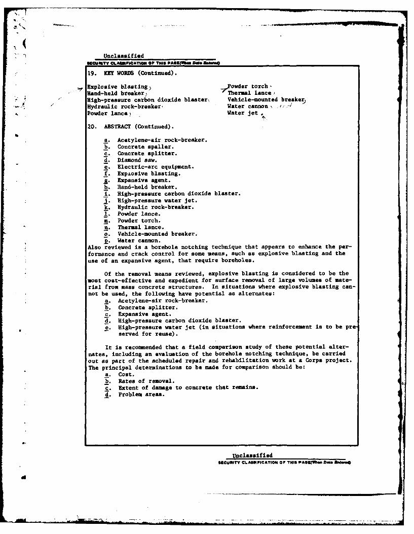
19. KEY WORDS (Continued).
Explosive blasting) Powder torch,Hand-held breaker, Thermal lance)High-pressure carbon dioxide blaster, Vehicle-mounted breaker)
Hydraulic rock-breaker, Water cannon,,Powder lance) Water jet
20. ABSTRACT (Continued).
a. Acetylene-air rock-breaker.b. Concrete spaller.c. Concrete splitter.d. Diamond saw.e. Electric-arc equipment.f. Expiosive blasting.J. Expansive agent.h. Hand-held breaker.i. High-pressure carbon dioxide blaster.j.High-pressure water jet.
k. Hydraulic rock-breaker.1. Powder lance.m. Powder torch.n. Thermal lance.o. Vehicle-mounted breaker.R. Water cannon.
Also reviewed is a borehole notching technique that appears to enhance the per-formance and crack control for some means, such as explosive blasting and the
use of an expansive agent, that require boreholes.
Of the removal means reviewed, explosive blasting is considered to be themost cost-effective and expedient for surface removal of large volumes of mate-
rial from mass concrete structures. In situations where explosive blasting can-not be used, the following have potential as alternates:
a. Acetylene-air rock-breaker.
b. Concrete splitter.
c. Expansive agent.d. High-pressure carbon dioxide blaster.e. High-pressure water jet (in situations where reinforcement is to be pre
served for reuse).
It is recommended that a field comparison study of these potential alter-
nates, including an evaluation of the borehole notching technique, be carried
out as part of the scheduled repair and rehabilitation work at a Corps project.
The principal determinations to be made for comparison should be:a. Cost.
b. Rates of removal.c. Extent of damage to concrete that remains.
d. Problem areas.
UnclassifiedSECURITY CLASSIICATION OF THIS PAeL(WlMe Data Rbntwo
d
PREFACE
This report was prepared at the Structures Laboratory (SL) of the
U. S. Army Engineer Waterways Experiment Station (WES) under the sponsor-
ship of the Office, Chief of Engineers (OCE), U. S. Army, as a part of
Civil Works Investigation Studies Work Unit 31553, Maintenance and Pres-
ervation of Civil Works Structures. Mr. Fred Anderson (DAEN-CWE-DC)
served as OCE Technical Monitor.
The study was conducted under the general supervision of
Mr. Bryant Mather, Chief, Structures Laboratory (SL), and Mr. John Scanlon,
Chief, Concrete Technology Division, SL; and under the direct supervision
of Mr. James E. McDonald, Chief, Evaluation and Monitoring Group, SL.
This report was prepared by Mr. Roy L. Campbell, Sr.
The Commanders and Directors of WES during this study and the
preparation and publication of this report were COL Nelson P. Conover,
CE, and COL Tilford C. Creel, CE. Mr. F. R. Brown was Technical Director.
NTTS "
Bvi: . DISC;
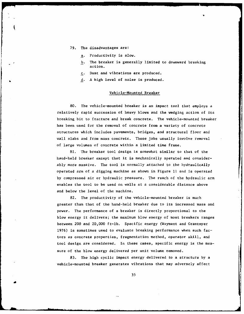
Di:t .
nH _
Nib"
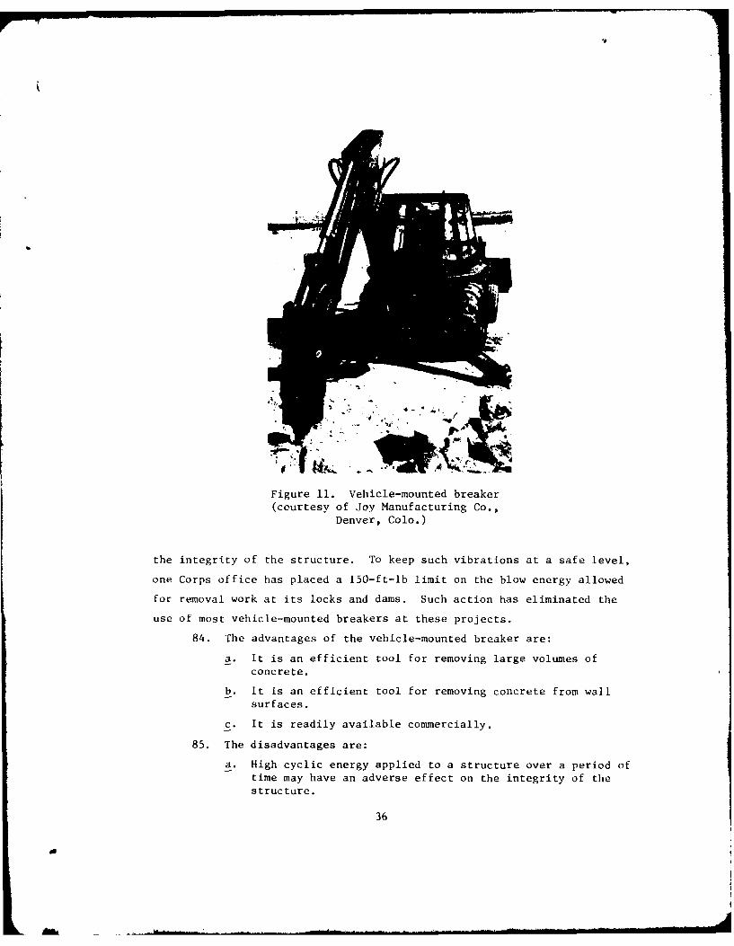
CONTENTS
Page
_ PREFACE . . . . ... 1
CONVERSION FACTORS, NON-SI TO METRIC (SI)UNITS OF MEASUREMENT ........... ..................... 3
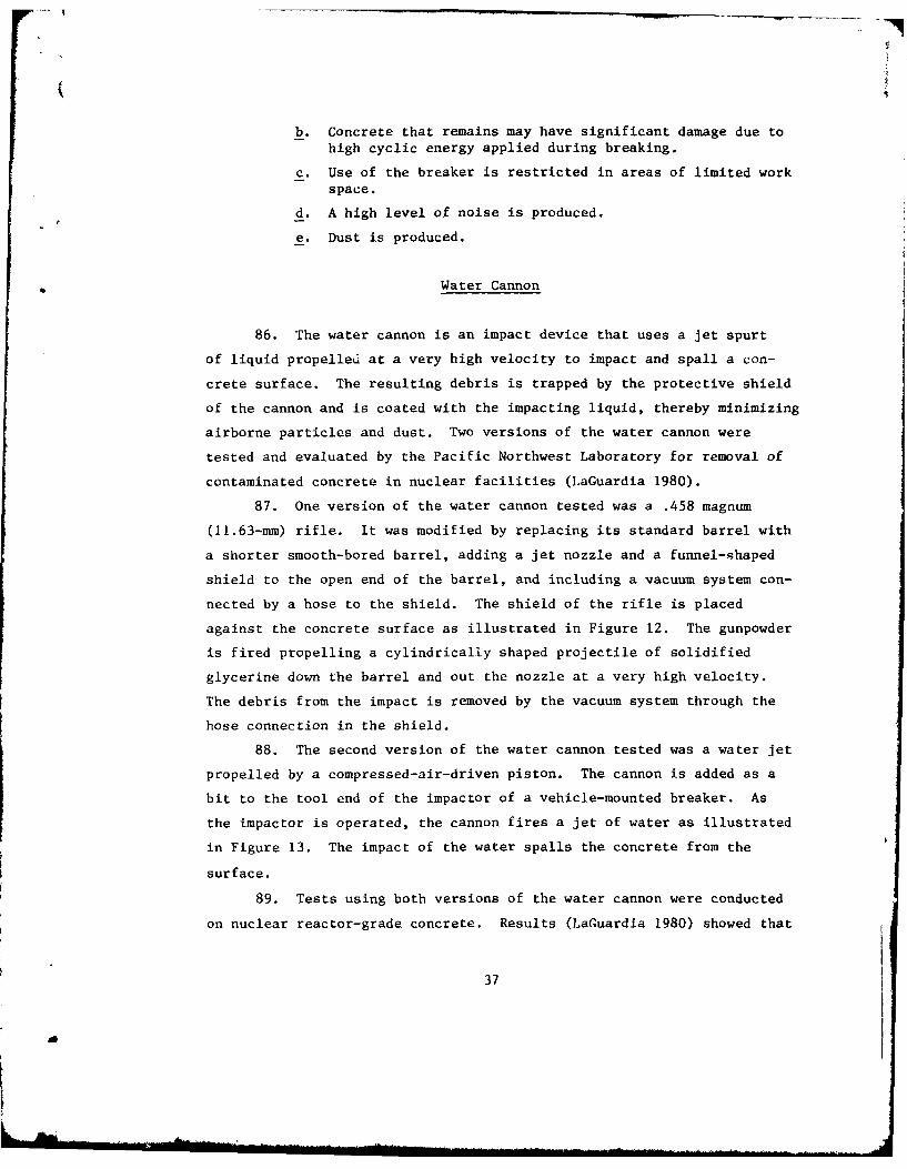
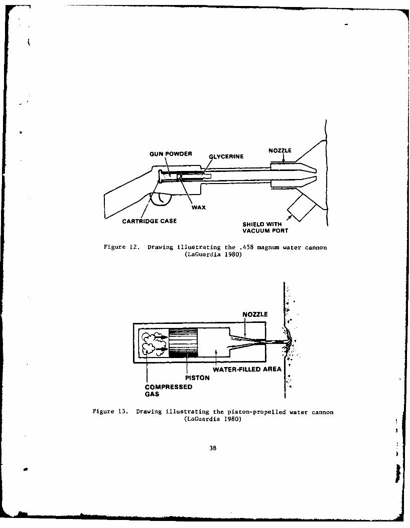
PART I: INTRODUCTION ........... ...................... 4
PART II: BLASTING...... ........ ................... 5
Explosives ............. ................. ..... 8High-Pressure Carbon Dioxide Blaster ..... .............. ... 11Acetylene-Air Rock-Breaker ........ .................. ... 14
PART III: CUTTING ......... ........................ ... 18
Diamond Saw ........... ......................... ... 18Powder Torch .......... .......................... ... 21Thermal Lance .......... ......................... ... 23Powder Lance .......... .......................... ... 25Electric-Arc Equipment .......... ..................... 27High-Pressure Water Jet ........ ...................... 28
PART IV: IMPACTING ........ ....................... .... 33
Hand-Held Breaker ........ ....................... .... 33Vehicle-Mounted Breaker .......... .................... 35Water Cannon .......... .......................... ... 37
PART V: PRESPLITTING ......... ...................... ... 40
Concrete Splitter ........ ....................... .... 40Expansive Agent ......... ........................ ... 42
PART VI: MECHANICAL SPALLING ....... .................. ... 46
Hydraulic Rock-Breaker ..... ............ .............. 46Concrete Spaller ......... ........................ ... 48
PART VII: BOREHOLE NOTCHING TECHNIQUE ..... .............. ... 51
PART VIII: DISCUSSION AND RECOMMENDATIONS .... ............ ... 55
Discussion .......... ........................... .... 55Recommendations ......... ........................ ... 58
REFERENCES ........... ............................ ... 59
2
Au -
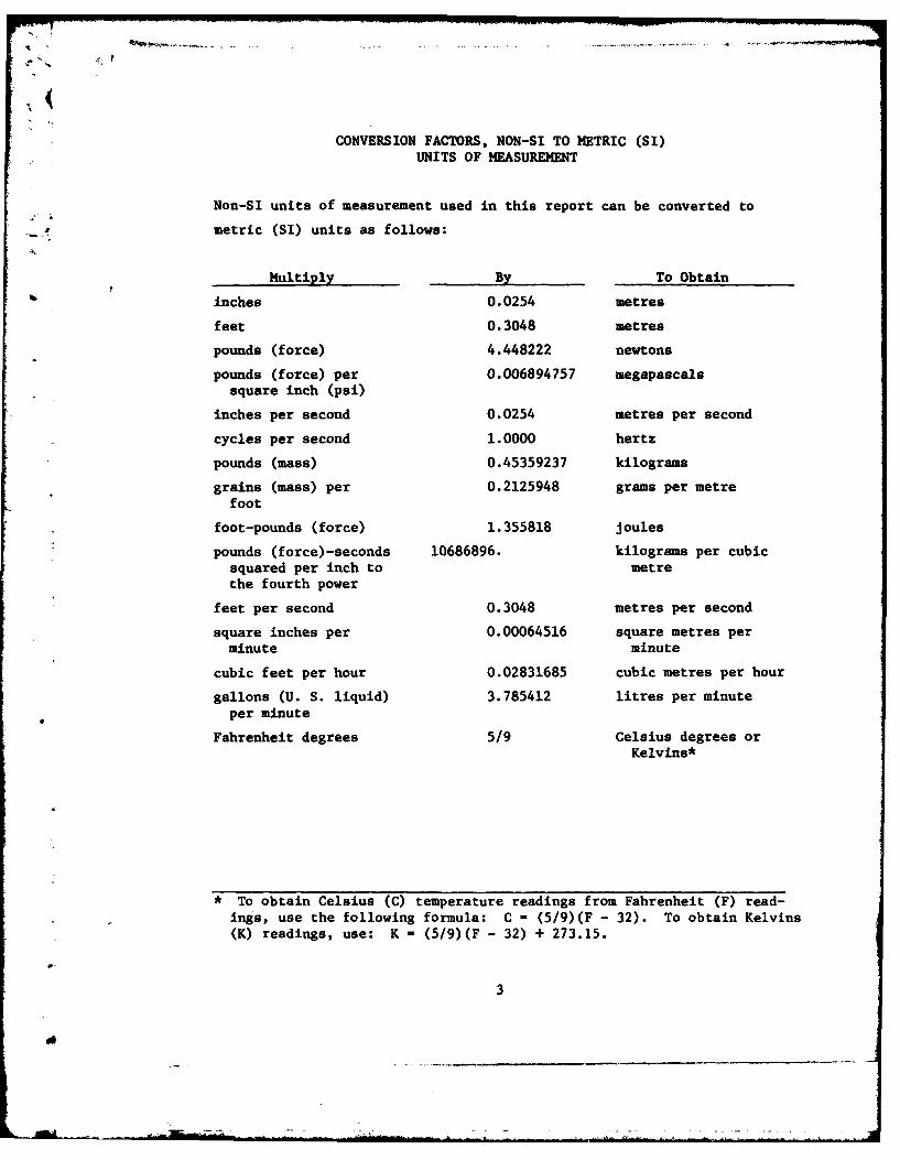
CONVERSION FACTORS, NON-SI TO METRIC (SI)UNITS OF MEASUREMENT
Non-SI units of measurement used in this report can be converted to
... metric (SI) units as follows:
Multiply By To Obtain
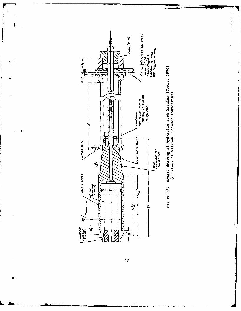
inches 0.0254 metres
feet 0.3048 metres
pounds (force) 4.448222 newtons
pounds (force) per 0.006894757 megapascalssquare inch (psi)
inches per second 0.0254 metres per second
cycles per second 1.0000 hertz
pounds (mass) 0.45359237 kilograms
grains (mass) per 0.2125948 grams per metrefoot
foot-pounds (force) 1.355818 joules
pounds (force)-seconds 10686896. kilograms per cubicsquared per inch to metrethe fourth power
feet per second 0.3048 metres per second
square inches per 0.00064516 square metres perminute minute
cubic feet per hour 0.02831685 cubic metres per hour
gallons (U. S. liquid) 3.785412 litres per minuteper minute
Fahrenheit degrees 5/9 Celsius degrees orKelvins*
* To obtain Celsius (C) temperature readings from Fahrenheit (F) read-ings, use the following formula: C = (5/9)(F - 32). To obtain Kelvins(K) readings, use: K = (5/9)(F - 32) + 273.15.
3
A REVIEW OF METHODS FOR CONCRETE REMOVAL
PART I: INTRODUCTION
1. The Corps has many concrete Civil Works structures, a number
of which either need repair to extend their service lives or have out-
lived their usefulness and are in need of replacement. In recent years,
environmental restraints and high construction costs have often slowed
and sometimes stopped planning and construction of replacement structures,
and repair work has often been required to extend service life. The in-
creased demand for repair and rehabilitation work will continue in the jfuture as other structures approach a state of disrepair or need replac-
ing, but cannot be replaced.
2. To prepare its engineers to deal better with present and future
demands, the Corps is in the process of updating its technology regarding
maintenance and rehabilitation of concrete structures. This report is a
part of this effort. It is written to aid the engineer in his/her selec-
tion of applicable methods and means of removal of distressed or dete-
riorated concrete for maintenance and rehabilitation work at Corps
projects.
3. The report includes means that are presently being used and
those that have a potential for use in the removal of distressed or dete-
riorated concrete. For presentation purposes these various means of re-
moval have been grouped into five basic categories: blasting, cutting,
impacting, presplitting, and mechanical spalling. The application of
these means and the methods used is limited to removal of surfaces from
mass concrete structures and is not intended for the total demolition of
a structure. Also included in this report is a review of a crack control
technique that appears to improve the performance of some of the removal
means that require borehole drilling.
4
PART II: BLASTING
4. Blasting methods employ rapidly expanding gas(es) confined
within a series of boreholes to produce controlled fracture and removal
of the concrete. In general, blasting methods are efficient means of
41 removing large volumes of distressed or deteriorated concrete. However,
due to dangers inherent in handling and usage, these methods are con-
b sidered the most dangerous and require more stringent controls than any
of the others. Planning a blasting project requires three basic areas
of concern:
a. The safety of personnel involved and the general public.
b. Damage to adjacent structures.
c. Damage to the concrete that remains.
Although the contractor may be liable for these concerns, the engineer
will want to implement controls that monitor and evaluate the performance
of the blasting operation.
5. "Safety and Health Requirements Manual," Engineer Manual 385-
1-1 (U. S. Army Corps of Engineers 1981), offers guidance to the engineer
in maintaining a safe operation. All phases of the blasting operation
should be monitored for compliance with EM 385-1-1 by qualified personnel.
6. Criteria for limiting damage to adjacent structures due to
blasting are set forth in EM 385-1-1. For ground vibrations, it limits
the total energy ratio to a maximum value of 1.00, or the total peak parti-
cle velocity to a maximum value of 2 in./sec.* The energy ratio for a
specified plane of motion is defined in EM 385-1-1 as:
U2
ER = (3.29 FA)2
where
ER = energy ratio
F - frequency of vibration, cps
A = amplitude (displacement) of vibration, in.
* A table of factors for converting non-SI units of measurement tometric (SI) units is presented on page 3.
5
a ! -J
The total energy ratio is the vector sum of the energy ratios of three
mutually perpendicular planes of motion at any one instant in time. It
should be noted, however, that the total energy limit is seldom used as
a present-day criterion for limiting damage to adjacent structures.
Total peak particle velocity is the vector sum of the peak particle ye-
locities along three mutually perpendicular planes of motion at any one
instant in time.
7. The peak particle velocity limit of 2 in./sec is widely ac-
cepted as a safe level for blasting vibrations and has been adopted as a
legal standard in some states. However, there are differences of opinion
as to what value(s) the limiting peak particle velocity should have. For
example, a study by the Bureau of Mines (Siskind et al 1980) concluded
that practical safe peak particle velocity criteria for blasts that gen-
erate ground frequencies of 40 Hz or less are 0.75 in./sec for modern
gypsum board houses and 0.50 in./sec for plaster or lath interiors. The
study also concluded that, for frequencies above 40 Hz, a safe maximum
particle velocity of 2 in./sec is recommended for all houses.
8. When planning a blasting project, the persons selected to per-
form and control the blast design and operation should be of proven ex-
perience and ability. Also, it is recommended that when possible a
pilot test program be implemented to evaluate the blast design and opera-
tion. For a blast design using explosives, the total peak particle veloc-
ity transmitted to adjacent structures can be estimated from the design
parameters by the following equation (Du Pont 1977):
V f 160(q
where
V - estimated total peak particle velocity, in./sec
D - distance between blast and structure, ft
W - maximum mass of explosive to be used perdelay period of 8 msec or more, lb
6
9. Monitoring for ground vibrations due to blasting is required
when it is estimated that damage may occur or, for explosive blasting,
when scaled distance is less than 50 ft/ib11 2 . Scaled distance is de-
fined in EM 385-1-1 as:
S D
where
S = scaled distance, ft/lb1/ 2
D = distance between blast and structure, ft
W = maximum mass of explosive per delay, lb
Monitoring for ground vibrations can be performed with a three-component
seismograph and should be accomplished, along with recording and inter-
preting of ground vibrations, by qualified personnel.
10. For limiting the damage to adjacent structures due to air-
blast, the safe blasting criterion presented in EM 385-1-1 limits air-
blast pressures exerted on structures to less than 0.1 psi. Airblast
gages can be used to monitor pressure variations.
11. The extent of damage to the concrete that remains after blast-
ing is usually evaluated by visual inspection of the remaining surfaces,
but, for a more detailed evaluation, a monitoring program can be imple-
mented. The program may consist of taking cores before and after blast-
ing and making visual, microscopic, and pulse velocity studies and ulti-
mate strength tests of the cores and may include a pulse velocity study
of the in situ concrete. A comparison of the before and after data can
be used to determine the extent of damage. To further document the ex-
tent of damage, an instrumentation program may be added. One approach
is to cut the cores taken before blasting in half along the axis of
drilling and to instrument one half with strain gages and accelerometers
(Plump 1980). The instrumented halves are then placed back into the
core holes and grouted into place. The strain and peak velocity data
obtained can be combined with other data to form conclusions regarding
the extent of damage.
7
do
12. In order to estimate the peak particle velocity that would
damage the remaining concrete at Lock and Dam No. 1 on the Mississippi
River, the St. Paul District used the following equation (Plump 1980):
v pc
b where
V = estimated peak particle velocity that would damage the concrete,in./sec
a = ultimate tensile or compressive strength of the concrete, psi
p = mass density of the concrete, lbf-sec 2/in.4
c = compressive wave pulse velocity of the concrete, in./sec
A test blasting design was made using the velocity estimate. The execu-
tion of the blast design showed the estimated peak particle velocity to
be lower than those measured. Estimates made using this equation are
considered conservative and can be used to design blast tests at other
blasting projects.
Explosives
13. Explosive blasting is a demolition method that employs
rapidly expanding gases produced by the detonation of an explosive to
fracture and remove the concrete. It has been used successfully
numerous times in the past at Corps projects to remove large volumes
of distressed and deteriorated concrete. The blast removal work
generally involves drilling a line of boreholes paralled to the
removal face, placing the explosive in each hole, and detonating the
explosive with electric blasting caps.
14. In the mid-1950's dynamite was the most widely used commercial
explosive. Since then ammonium-nitrate prill products and water gels
have generally replaced dynamite. The advantage of the ammonium-nitrate
prill products is their low sensitivity to impact; however, the disad-
vantages include their lack of water resistance (except when packaged in
water-resistant containers), low density, lack of ability to propagate
8
r4
in small-diameter holes (unless confined), and cap insensitivity. Water
gels do not share these disadvantages and also exhibit a low sensitivity
to impact.
15. Detonating cord is one of the most versatile explosive prod-
ucts on the market. It can be used to do blasting, detonate other high
explosives, or transmit detonation waves to other detonating cords. Its
main advantages are its water resistance, relatively low sensitivity to
impact, cap sensitivity, and desirable handling characteristics, such as
tensile strength, durability, and flexibility.
16. At Corps projects, all explosive detonations are init 4 'r1
using electric blasting caps. Recently, a new type of blasting cap
called a Magnadet (Anonymous 1981) has been developed that is reported
to be safer than the conventional electric blasting cap. It is designed
to detonate only when the current frequency is greater than 15 kHz.
This would reduce the chance of premature detonation due to standard
electric current (110 and 220 v), lightning, static electricity, or cur-
rents generated by radio transmissions to almost zero.
17. Controlled blasting techniques for explosives have been de-
veloped to minimize damage to the material that remains after blasting.
One such technique, known as cushion blasting (Du Pont 1977), involves
drilling 3-in.-diam or smaller holes, loading each hole with light
charges distributed along its depth, and cushioning the charges by com-
pletely stemming each hole. The distributing and cushioning of the
light charges produce a relatively sound surface with very little over-
break. Another technique, called smooth blasting (Du Pont 1977), is the
same as cushion blasting except that the cushion is not included. Also
used for controlled blasting are electrical blasting-cap delay series
that employ proper timing sequences to provide greater control in reduc-
ing ground vibration, noise, and fly rock. Note that the delay caps of
different manufacturers should not be mixed in the same series. An in-
compatibility may exist between systems that could cause misfires and
result in serious injury.
18. In the recent past, controlled blasting has been used success-
fully at Corps projects to remove distressed and deteriorated concrete.
9
A/
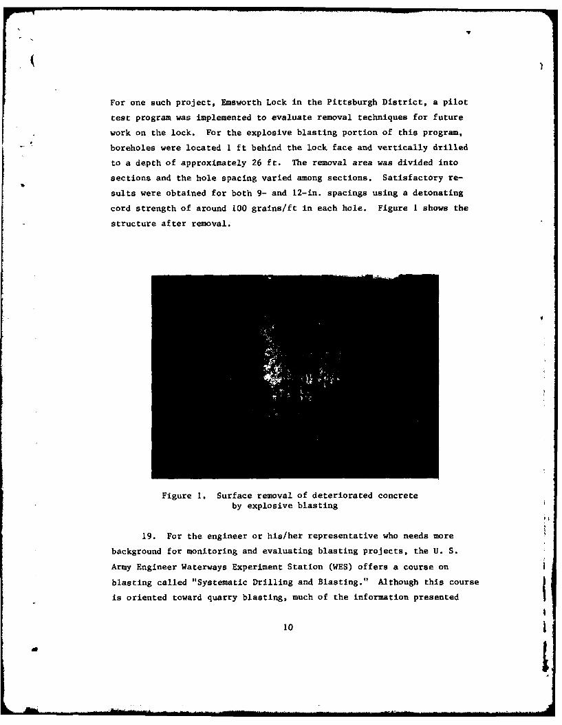
For one such project, Emsworth Lock in the Pittsburgh District, a pilot
test program was implemented to evaluate removal techniques for future
work on the lock. For the explosive blasting portion of this program,
* boreholes were located 1 ft behind the lock face and vertically drilled
to a depth of approximately 26 ft. The removal area was divided into
sections and the hole spacing varied among sections. Satisfactory re-
sults were obtained for both 9- and 12-in. spacings using a detonating
cord strength of around 100 grains/ft in each hole. Figure I shows the
structure after removal.
Figure 1. Surface removal of deteriorated concrete
by explosive blasting
19. For the engineer or his/her representative who needs more
background for monitoring and evaluating blasting projects, the U. S.
Army Engineer Waterways Experiment Station (WES) offers a course on
blasting called "Systematic Drilling and Blasting." Although this course
is oriented toward quarry blasting, much of the information presented
10a j
can be applied toward blast removal of concrete. Another source of in-
formation regarding the use of an explosive is the manufacturer, espe-
cially when a new product is to be used.
20. The advantages of explosive blasting are:
a. It is the most expedient and economical method for remov-
ing large volumes of concrete.
b. Good fragmentation of concrete debris is produced forhandling.
21. The disadvantages are:
a. Highly skilled personnel are required for design and exe-
cution of such projects.
b. Stringent safety regulations must be imposed due to theinherent dangers in handling and usage of explosives.
c. Explosive blasting has the potential to produce unwanted
levels of noise, ground vibration, gas fumes, and fly rock.
d. Special control techniques are required to limit damage
to concrete that remains.
High-Pressure Carbon Dioxide Blaster
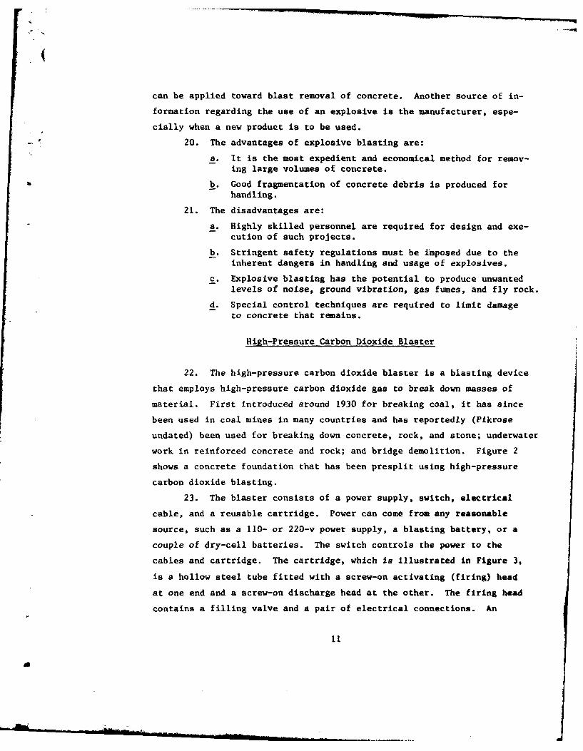
22. The high-pressure carbon dioxide blaster is a blasting device
that employs high-pressure carbon dioxide gas to break down masses of
material. First introduced around 1930 for breaking coal, it has since
been used in coal mines in many countries and has reportedly (Pikrose
undated) been used for breaking down concrete, rock, and stone; underwater
work in reinforced concrete and rock; and bridge demolition. Figure 2
shows a concrete foundation that has been presplit using high-pressure
carbon dioxide blasting.
23. The blaster consists of a power supply, switch, electrical
cable, and a reusable cartridge. Power can come from any reasonable
source, such as a 110- or 220-v power supply, a blasting battery, or a
couple of dry-cell batteries. The switch controls the power to the
cables and cartridge. The cartridge, which is illustrated in Figure 3,
is a hollow steel tube fitted with a screw-on activating (firing) head
at one end and a screw-on discharge head at the other. The firing head
contains a filling valve and a pair of electrical connections. An
11
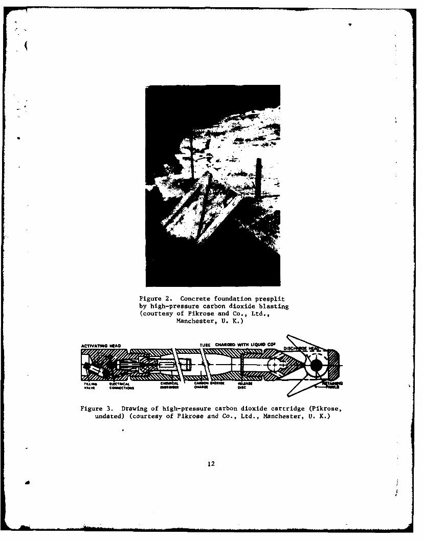
Figure 2. Concrete foundation presplitby high-pressure carbon dioxide blasting(courtesy of Pikrose and Co., Ltd.,
Manchester, U. K.)
ACTIVATING HEAD TUBE CHARGED WITH LI 0Ico CDIS
"t"~ coNNIcTIONs Cm 11
Figure 3. Drawing of high-pressure carbon dioxide cartridge (Pikrose,undated) (courtesy of Pikrose and Co., Ltd., Manchester, U. K.)
12
expendable chemical energizer connects to the end of the firing head
and extends into the storage chamber, which is filled with liquid carbon
dioxide. The discharge head contains a release (shear) disc that serves
as an exhaust valve.
24. In general, the field operation consists of drilling boreholes
to the desired depth, placing the cartridges into designated holes and
detonating them, removing the cartridges from the debris, and then re-
b moving the debris. Recommended borehole diameters (Pikrose undated)
range between 2-1/4 and 3 in. and are approximately 1/8 in. greater than
the size cartridge being used. Only one cartridge per hole is recommended.
For deep removals, holes must be redrilled for each additional cartridge
required. The blast is initiated when electrical power is switched to
activate the chemical energizer. The energizer provides heat that in-
creases the pressure within the storage chamber. The pressure will con-
tinue to increase until the shear disc yields, allowing gas to flow into
the borehole. When the carbon dioxide changes from liquid to gas, there
is a sudden drop in temperature in the hole. The pressure exerted in
the borehole breaks up the concrete material by the gentle heaving ac-
tion of the spreading volume of gas. Since the rate and magnitude of
pressure are low, no crushing of the material around the borehole occurs;
therefore, very little damage occurs to the material that remains.
25. The reusable cartridges and equipment for recharging them can
be purchased or rented. Since carbon dioxide at 87.8 F (31.00 C) starts
to turn from a liquid into a gas, for efficient transfer of liquid in
hot climates it is recommended that the recharging of cartridges be per-
formed in an air-conditioned environment. It is also recommended that
the empty cartridges be precooled in a freezer, if possible, for a couple
of hours before filling. The supply bottles containing the liquid carbon
dioxide should have siphon tubes to avoid having to invert the bottles
for gravity flows into the cartridges.
26. The advantages of high-pressure carbon dioxide blasting are:
a. Less violent breaking action occurs than with conventional
explosives, thereby resulting in less noise, ground vibra-tion, fly rock, and damage to concrete that remains.
13
a|
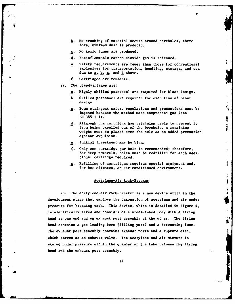
b. No crushing of material occurs around boreholes, there-fore, minimum dust is produced.
c. No toxic fumes are produced.
d. Noninflammable carbon dioxide gas is released.
e. Safety requirements are fewer than those for conventionalexplosives for transportation, handling, storage, and usedue to a, b, c, and d above.
f. Cartridges are reusable.
27. The disadvantages are:
a. Highly skilled personnel are required for blast design.
b Skilled personnel are required for execution of blastdesign.
c. Some stringent safety regulations and precautions must beimposed because the method uses compressed gas (seeEM 385-1-1).
d. Although the cartridge has retaining pawls to prevent itfrom being expelled out of the borehole, a retainingweight must be placed over the hole as an added precautionagainst expulsion.
e. Initial investment may be high.
f. Only one cartridge per hole is recommended; therefore,for deep removals, holes must be redrilled for each addi-tional cartridge required.
g. Refilling of cartridges requires special equipment and,for hot climates, an air-conditioned environment.
Acetylene-Air Rock-Breaker
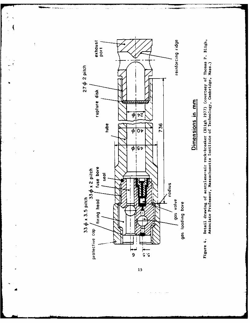
28. The acetylene-air rock-breaker is a new device still in the
development stage that employs the detonation of acetylene and air under
pressure for breaking rock. This device, which is detailed in Figure 4,
is electrically fired and consists of a steel-tubed body with a firing
head at one end and an exhaust port assembly at the other. The firing
head contains a gas loading bore (filling port) and a detonating fuse.
The exhaust port assembly contains exhaust ports and a rupture disc,
which serves as an exhaust valve. The acetylene and air mixture is
stored under pressure within the chamber of the tube between the firing
head and the exhaust port assembly.
14
Am I
x 00
0 m
C~j 44
0 cu
0%0
44
$4J
E (A
0 d 0
01~
.0.
01
00
0 -H w
0 0
-o-C
cuo
00
0.0
015
29. Because this device is still in the development stage, recom-
mended procedures for its operation have not been established. The
operation and results, however, will probably be similar to those of the
high-pressure carbon dioxide cartridge, with the following exceptions:
a. The acetylene-air mixture is used instead of liquid carbondioxide.
b. Recommended borehole diameters are slightly smaller.
c. The acetylene-air mixture is detonated electrically by afuse.
d. High heat is generated by detonation.
30. This device has been tested in limestone and granite quarries
and has shown great potential for excavation and mining work. It has
also been tested in the partial demolition of a massive concrete founda-
tion that contained reinforcing steel. The results showed promise, but
Bligh (1977) suggests that more work is needed before its capabilities
can be ascertained.
31. The advantages of the acetylene-air rock-breaker are:
a. Less violent breaking action occurs than with conventionalexplosives, thereby resulting in less noise, ground vibra-tion, fly rock, and damage to concrete that remains.
b. No crushing of material occurs around boreholes; therefore,mimimum dust is produced.
c. No toxic fumes are produced.
d. Safety requirements are fewer than those for conventionalexplosives for transportation, handling, storage, and usedue to a, b, and c above.
e. The device is reusable.
f. Danger of the device being ejected out of borehole is re-duced. Bligh (1974) states: "Pressure rises compara-tively rapidly so that there is insufficient time duringwhich to accelerate the shell out of the drillhole, dueto its inertia. Therefore, if the hole is not overbur-dened, the maximum pressure is reached rapidly and therock broken before the shell is ejected."
32. The disadvantages are:
a. Highly qkilled personnel are required for blast design.
b. Skilled personnel are required for execution of the blastdesign.
16
!V
c. Relatively stringent safety regulations and precautionsmust be imposed because the device contains combustiblegas under pressure (see EM 385-1-1).
d. Initial investment may be high.
e. At present, the device is in the development stage andwill require significant testing and documentation beforeit can be commercially marketed for removal of concrete.
17
. . . . . ... ..d m | I -" I -. . . .. . . .I I . . . . . . .. t -- . . .

PART III: CUTTING
33. Cutting methods are generally used to remove sections of a
structure by cutting along the perimeter of the section and removing it
with equipment of the proper size. These sections are usually a part of
a wall or slab containing reinforcement and vary in thickness from sev-
eral inches to several feet. The depth of the perimeter cut depends on
the cutting tool used. In general, cutting methods are considered slow
and costly for removal of large volumes of material from mass concrete
structures. However, these may be secondary concerns when demolition
criteria demand precision, reduced vibration, and reduced damage to the
material that remains.
Diamond Saw
34. Rotary-action diamond saws are the most common type of saw
used to cut concrete. These saws produce straight precision cuts up to
21 in. deep in concrete by the high-speed grinding action of the saw
blade, and they cause minimal vibration and damage to the concrete that
remains. In the past, rotary-action diamond saws have been successfully
used for structural and highway demolition. In particular, these saws
have been cost-effective for removal of free-standing walls and bridge
deckings. Figure 5 shows a bridge deck being cut with a rotary-action
diamond saw.
35. In general, the rotary-action diamond saw can be electrically
or hydraulically powered or driven by a combustion engine. The blade is
a thin rotary disc with diamond-tipped teeth along its outer perimeter.
Lubricant is supplied to the blade through a hose connected to a lubri-
cant storage container.
36. Before a cutting operation begins, utility lines within the
concrete in the vicinity of the cutting should be located and marked.
The size and location of the reinforcement should also be determined
before starting an operation. During the cutting operation, lubricant
must be continuously applied to the blade to cool it and protect it from
18
a
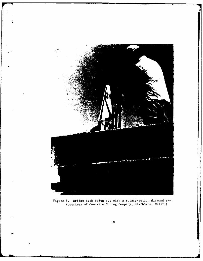
Figure 5. Bridge deck being cut with a rotary-action diamond saw
(courtesy of Concrete Coring Company, Hawthorne, Calif.)
19
excessive wear. The cutting pattern should yield sections of satisfac-
tory size to ensure safe handling for the equipment available for remov-
al. During a cutting operation, the hearing of the operator must be
protected from the noise generated by operation.2
37. The cutting rate generally ranges from 20 to 200 in. /min
(Palovchik 1975). This rate is dependent on many factors which include
the abrasion resistance of the concrete and the amount of reinforcement
in the cut.
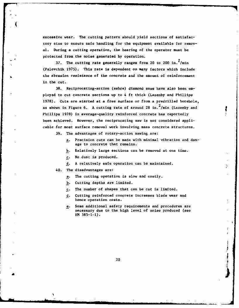
38. Reciprocating-action (sabre) diamond saws have also been em-
ployed to cut concrete sections up to 4 ft thick (Lazenby and Phillips
1978). Cuts are started at a free surface or from a predrilled borehole,
as shown in Figure 6. A cutting rate of around 28 in.2 /min (Lazenby and
Phillips 1978) in average-quality reinforced concrete has reportedly
been achieved. However, the reciprocating saw is not considered appli-
cable for most surface removal work involving mass concrete structures.
39. The advantages of rotary-action sawing are:
a. Precision cuts can be made with minimal vibration and dam-age to concrete that remains.
b. Relatively large sections can be removed at one time.
c. No dust is produced.
d. A relatively safe operation can be maintained.
40. The disadvantages are:
a. The cutting operation is slow and costly.
b. Cutting depths are limited.
c. The number of shapes that can be cut is limited.
d. Cutting reinforced concrete increases blade wear andhence operation costs.
e. Some additional safety requirements and procedures arenecessary due to the high level of noise produced (seeEM 385-1-1).
20
- )
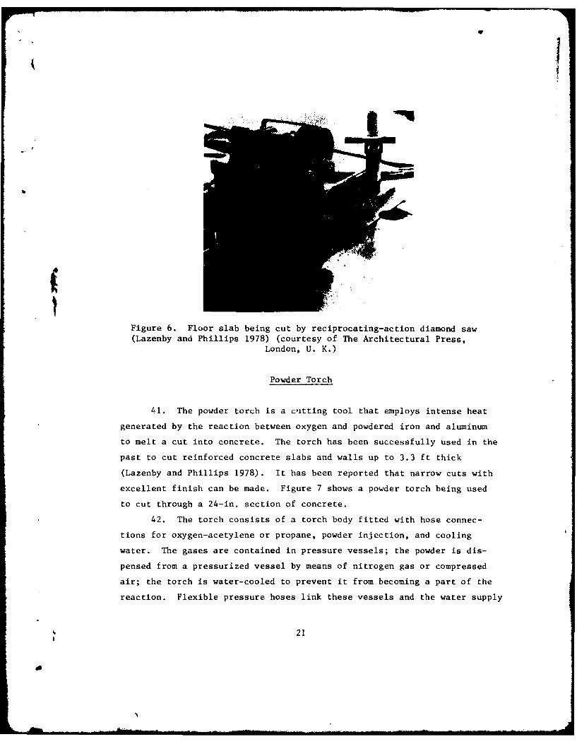
Figure 6. Floor slab being cut by reciprocating-action diamond saw(Lazenby and Phillips 1978) (courtesy of The Architectural Press,
London, U. K.)
Powder Torch
41. The powder torch is a cutting tool that employs intense heat
generated by the reaction between oxygen and powdered iron and aluminum
to melt a cut into concrete. The torch has been successfully used in the
past to cut reinforced concrete slabs and walls up to 3.3 ft thick
(Lazenby and Phillips 1978). It has been reported that narrow cuts with
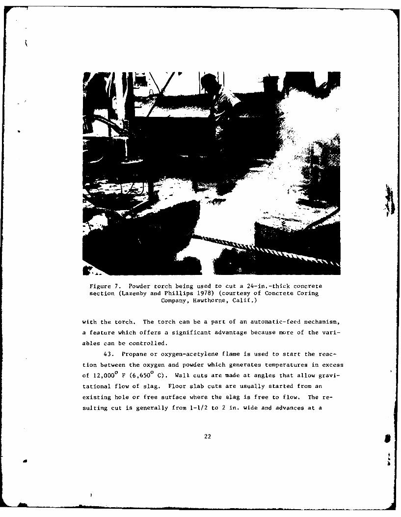
excellent finish can be made. Figure 7 shows a powder torch being used
to cut through a 24-in. section of concrete.
42. The torch consists of a torch body fitted with hose connec-
tions for oxygen-acetylene or propane, powder injection, and cooling
water. The gases are contained in pressure vessels; the powder is dis-
pensed from a pressurized vessel by means of nitrogen gas or compressed
air; the torch is water-cooled to prevent it from becoming a part of the
reaction. Flexible pressure hoses link these vessels and the water supply
21
a
1 *1
Figure 7. Powder torch being used to cut a 24-in.-thick concretesection (Lazenby and Phillips 1978) (courtesy of Concrete Coring
Company, Hawthorne, Calif.)
with the torch. The torch can be a part of an automatic-feed mechanism,
a feature which offers a significant advantage because more of the vari-
ables can be controlled.
43. Propane or oxygen-acetylene flame is used to start the reac-
tion between the oxygen and powder which generates temperatures in excess
of 12,000 F (6,6500 C). Wall cuts are made at angles that allow gravi-
tational flow of slag. Floor slab cuts are usually started from an
existing hole or free surface where the slag is free to flow. The re-
sulting cut is generally from 1-1/2 to 2 in. wide and advances at a
22 9
aI
cutting rate of approximately 20 in. 2/min. The more steel reinforcing
in the concrete, the faster the cutting rate.
44. The advantages of the powder torch are:
a. It is an effective means of cutting reinforced concreteup to 3.3 ft thick.
b. Irregular shapes can be cut.
c. Minimal noise, vibration, and dust are produced.
45. The disadvantages are:
a. The cutting operation is slow and costly.
b. Initial investment is high.
c. Torch operation is somewhat cumbersome due to the numberof different components used.
d. The torch is not suitable for cuts where slag flow isrestricted.
e. Smoke and fumes are produced.
f. Increased safety requirements are necessary due to thefire hazard presented by the combustible gases used and
the explosion hazard of the gases under pressure (seeEM 385-1-1).
. At present, no information can be found that documentsthe condition of the concrete that remains. (It is rea-sonable to assume that damage will occur; however, theextent of such is not known.)
Thermal Lance
46. The thermal lance is the simplest of the flame tools for cut-
ting concrete. It employs intense heat generated by the reaction be-
tween oxygen and mild steel rods to melt a cut into concrete. In the
past, the lance has been successfully used to cut openings in reinforced
concrete walls and floors reportedly as thick as 19.7 ft (Lazenby and
Phillips 1978). Figure 8 shows a thermal lance being used to cut through
a concrete wall by making a series of individual holes.
47. The lance system consists of an iron or steel pipe, a handle,
flexible pressure hose, an oxygen supply, and an acetylene or propane
supply system. The pipe is filled with mild steel rods and comes in
sections that are threaded and socketed for connection to the lance
23
A
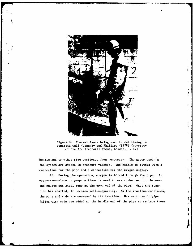
Figure 8. Thermal lance being used to cut through aconcrete wall (Lazenby and Phillips (1978) (courtesy
of the Architectural Press, London, U. K.)
handle and to other pipe sections, when necessary. The gases used in
the system are stored in pressure vessels. The handle is fitted with a
connection for the pipe and a connection for the oxygen supply.
48. During the operation, oxygen is forced through the pipe. An
oxygen-acetylene or propane flame is used to start the reaction between
the oxygen and steel rods at the open end of the pipe. Once the reac-
tion has started, it becomes self-supporting. As the reaction continues,
the pipe and rods are consumed by the reaction. New sections of pipe
filled with rods are added to the handle end of the pipe to replace those
24
- I
that are consumed. The resulting cut is around 1-1/2 to 2 in. wide and
advances at an approximate cutting rate of 20 in. 2/min. The more steel
reinforcement in the concrete, the faster the cutting rate.
49. The thermal lance works best when used for punching holes in
reinforced concrete at angles that allow gravity flow of slag. For
angles that restrict flow, the oxygen pressure has to be increased to
blow slag out of the cut. The effective cutting depth for a vertical
hole is between 24 and 30 in. (Lazenby and Phillips 1978). Deeper ver-tical cuts are possible if the cut is started• at a vertical face where
the slag is free to drain.
50. The advantages of the thermal lance are:
a. It is one of the most effective means of cutting rein-forced concrete.
b. It is the simplest of the flame tools.
c. Deep cuts can be made in areas where slag is free to flow.
4. Irregular shapes can be cut.
e. Minimal noise, vibration, and dust are produced.
51. The disadvantages are:
a. The cutting operation is slow and costly.
b. Initial investment is high.
c. The thermal lance is not suitable for cuts where slagflow is restricted.
d. Smoke and fumes are produced.
e. Increased safety requirements are necessary due to firehazard presented by the combustible gases used and theexplosion hazard of the gases under pressure (seeEM 385-1-1).
f. The operator must be protected against possible burns.
j. The extent of damage to concrete that remains is unknown.
Powder Lance
52. The powder lance is a manually operated tool for cutting con-
crete that combines some of the features of the powder torch and the
thermal lance. It employs intense heat generated by the reaction between
25
a
oxygen and powdered metals to melt a cut into concrete. In the past,
the lance has been successfully used to cut openings in reinforced con-
crete walls and floors, reportedly as thick as 12 ft (Lazenby and Phillips
1978).
53. The lance system consists of a black iron pipe, a handle,
flexible pressure hoses, an oxygen supply, an acetylene or propane sup-
ply, and a powdered metal supply system. The iron pipe comes in sections
that are threaded and socketed for connection to the lance handle and
other pipe sections. The gases used in the system are stored in pres-
sure vessels. The handle is fitted with three connections: one for the
iron pipe, one for the oxygen supply, and one for the powdered metal
supply. The metal powders used are iron and aluminum and are supplied
from a pressurized vessel by means of nitrogen or compressed-air gas.
54. During the operation, the powders are mixed with oxygen in the
handle and are ignited with an oxygen-acetylene or propane flame at the
open end of the iron pipe. Once the reaction has started, it becomes
self-supporting. As the reaction continues, the iron pipe is melted and
consumed by the cutting flame, and new sections of pipe are added to the
handle end of the pipe. The resulting cut is around 1-1/2 to 2 in. wide2
and advances at an approximate cutting rate of 20 in. /min. The more
steel reinforcing in the concrete, the faster the cutting rate.
55. The lance works best when used for punching holes in rein-
forced concrete at angles that allow gravity flow of slag. For angles
that restrict flow, the oxygen pressure has to be increased Lo blow slag
out of the cut. The effective cutting depth for a vertical hole is
around 30 in. Deeper vertical cuts are possible if the cut is started
at a vertical face where the slag is free to drain.
56. The advantages of the powder lance are:
a. It is one of the most effective means of cutting rein-forced concrete.
b. Deep cuts can be made in areas where slag is free to flow.
c.Irregular shapes can be cut.
d. Minimal noise, vibration, and dust are produced.
26
a U
e. The powder lance weighs much less than the thermal lance(since the pipe is empty for the powder lance and filledwith rods for the thermal lance).
57. The disadvantages are:
a. The cutting operation is slow and costly.
b. Initial investment is high.
c. The powder lance is not suitable for cuts where slag flowis restricted.
d. Smoke and fumes are produced.
e. Increased safety requirements are necessary due to thefire hazard presented by the combustible gases used andthe explosion hazard of the gases under pressure (seeEM 385-1-1).
f. The operator must be protected against possible burns.
j. The extent of damage to concrete that remains is unknown.
Electric-Arc Equipment
58. Electric-arc equipment (Goriainov and Antropov 1967) employs
a thermal device that was developed and tested in the USSR for cutting
openings and recesses in brick and reinforced concrete. Its operating
principle is based on fusion of concrete materials by electric arc at
temperatures ranging from 7,200 to 14,4000 F (4,000 to 8,0000 C).
Cutting depths up to 12 in. have been achieved in tests.
59. In general, the equipment consists of two graphite electrodes
with holders, a stand, and a welding transformer with supply cables.
The frame allows the electrodes a maximum movement of 19.7 in. in two
perpendicular directions in a plane parallel to the cutting surface.
The supply cables are rubber-insulated and are sheathed over with braided
asbestos for a distance of 6.6 ft from the equipment.
60. Before beginning operation, electrical ground connections and
cable insulation must be inspected to help ensure a safe operation. The
electric arc is initiated by plugging in the transformer, whereupon con-
tact is made with the electrodes and an ionized zone forms; the fused
slag is ejected from the fusion zone by the resultant electrodynamic
forces. During the operation, the closest distance to the electrodes at
27
L
which the operator can safely work is approximately 3 ft. The concrete
that remains after cutting is damaged to a depth of 0.4 to 0.6 in. from
the edge of the cut.
61. The advantages of the electric-arc equipment are:
a. It is an effective means of cutting irregular shapes inplain or reinforced concrete.
b. Minimal noise, vibration, and dust are produced.bf
62. The disadvantages are:
a. Electric-arc cutting is slow and costly. )b. Concrete that remains is damaged to a depth of 0.4 to
0.6 in. from the edge of the cut.
c. During operation, the operator cannot get closer than ap-proximately 3 ft from electrodes to make adjustments orrepairs.
d. The operator must be protected against burning slag.
e. Fumes are produced.
f. Increased safety requirements are necessary due to thedanger electrical shock (see EM 385-1-1).
j. The electric-arc equipment is not commercially available.
High-Pressure Water Jet
63. The high-pressure water jet is a cutting tool that employs a
small jet of water driven at high velocities to erode a cut into con-
crete. There are a number of different types of water jets that are
presently being used. The most promising of these appear to be the
ultrahigh-pressure jet and the cavitating jet. In the past, both types
have been used for grooving and cutting of concrete pavement for high-
ways. Figure 9 shows a reinforced concrete wall that was cut using a
water jet. Note that the reinforcing steel was not damaged by the ac-
tion of the jet.
64. In general, the water jet can be frame-mounted and automated,
or portable. The jet system basically consists of a motor, a hydraulic
oil system, an intensifier, a water system, and a control system. The
hydraulic oil system consists of a filter, a pump, hydraulic lines, and
a cooling system. The intensifier is a hydraulically driven reciprocating
28
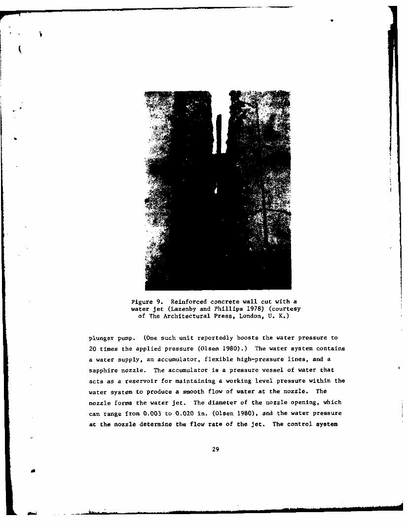
Figure 9. Reinforced concrete wall cut with awater jet (Lazenby and Phillips 1978) (courtesy
of The Architectural Press, London, U. K.)
plunger pump. (One such unit reportedly boosts the water pressure to
20 times the applied pressure (Olsen 1980).) The water system contains
a water supply, an accumulator, flexible high-pressure lines, and a
sapphire nozzle. The accumulator is a pressure vessel of water that
acts as a reservoir for maintaining a working level pressure within the
water system to produce a smooth flow of water at the nozzle. The
nozzle forms the water jet. The diameter of the nozzle opening, which
can range from 0.003 to 0.020 in. (Olsen 1980), and the water pressure
at the nozzle determine the flow rate of the jet. The control system
29
• V
regulates the flow of water by controlling the power transmitted to
the hydraulic oil pump.
65. In general, the water jet works like this: the motor pro-
vides power to the pump; the pump generates the oil pressure to drive the
intensifier; the intensifier boosts the pressure in the water system to
a working level; and the nozzle forms the jet for cutting the concrete.
During the cutting operation, the chief causes of failure of nozzles are
dirt particles in water or deposits formed by hard water near the orifice.
The depth of cut depends mainly on the number of repeated passes over
the cut. Large fragments of aggregate and other debris are sometimes
dislodged and ejected from the cut with considerable force. This hazard
requires the operator to wear adequate protection and the cutting area
to be kept clear of other personnel.
66. In a recent study of highway surface maintenance (Hilaris
1980), a cutting rate of approximately 140 in. 2/mn was achieved using
an ultrahigh-pressure jet. In a partial depth repair test for removing
surface-deteriorated concrete from a bridge deck, the same study showed
a volume removal rate of approximately 2.5 ft3/hr. The jet system for
this was operated at 40,000-psi pressure to produce a 4.5-gpm flow rate
through dual nozzles of 0.020-in. diameter.
67. In some systems, the ultrahigh-pressure water jet has been
designed to operate at stagnation pressures up to 60,000 psi (Olsen
1980). At this pressure, velocities around 3,000 ft/sec can be achieved
by using a nozzle diameter of 0.008 in. An abrasive water-jet system is
presently under development that will be more productive than the regular
ultrahigh-pressure jet yet will require significantly less pressure and
power to operate. This system will have another advantage: it will be
capable of cutting steel reinforcing. In the past, additives to the
water jet fluid have had the drawbacks of increasing cost and system
complexity.
68. The cavitating water jet controls water flow through its noz-
zle to produce cavitation at the concrete surface. This jet operates at
stagnation pressures of 12,000 to 15,000 psi, a range which is consider-
ably lower than that for the ultrahigh-pressure jets. As the cavitation
30
A
phenomenon occurs only within a limited range of standoff distances,
maintaining an optimal rate of removal depends on standoff distance more
for cavitating jets than for ultrahigh-pressure jets. Work is currently
being done for the U. S. Department of Transportation to develop a cavi-
tating water jet capable of removing concrete bridge deck surfaces at the
rate of 6 ft 3/hr.
69. Several low-pressure, high-flow cavitating water jets are
presently under development for cutting concrete. They operate at stag-
nation pressures around 10,000 psi and flow rates of 4 to 15 gpm, depend-
ing on the nozzle diameters and the horsepower of the pump used. The
high flow rates allow the same cutting penetration at lower stagnation
pressures. These jets use rotating dual nozzles to cut a wide slot into
concrete; the width of the slot is controlled by adjusting the angle of
one of the nozzles. When the nozzle is adjusted for the maximum size of
aggregate in the concrete, the water jet can more easily erode the cement
matrix from around the aggregate to remove the aggregate with minimal
energy spent on cutting the aggregate. The low-pressure, high-flow cavi-
tating water jet at its present stage of development is less efficient,
however, than either the ultrahigh-pressure or the higher pressure cavi-
tating jets.
70. The advantages of the water jet are:
a. Minimal damage is produced to the concrete that remains.
b. The cutting operation can be automated.
c. Irregular shapes can be cut.
d. No heat, vibration, or dust is produced by the cuttingaction.
e. In some cases, exposed steel that remains after removalcan be used in the resurfacing operation to transfer loadsbetween old and new concrete.
f. Water jets can be used to cut concrete under water withlittle loss of efficiency.
71. The disadvantages are:
a. The cutting operation is slow and costly.
b. Initial investment is high.
31
A
c. Systems that are presently available cannot cut reinforc-ing steel or extremely abrasion-resistant aggregate.
d. Some additional safety requirements and procedures arerequired due to the high pressures of the water-jet sys-tem (see EM 385-1-1).
32-I
11
III 32
PART IV: IMPACTING
72. Impacting methods have been used in the past to remove sur-
faces from mass concrete structures. Such methods involve the repeated
striking of a surface with a mass to fracture and spall it. The produc-
tivity for this group of impacting methods varies widely and is basically
a function of energy delivered per volume removed.
Hand-Held Breaker
73. The hand-held breaker is an impact tool that employs a rapid
succession of light blows and the wedging action of its breaking bit to
fracture and spall the concrete. It is normally used to aid other re-
moval methods when work involves removal of large volumes of concrete
from mass concrete surfaces.
74. A hand-held breaker such as the one shown in Figure 10 consists
of a backhead group, a cylinder group, and a fronthead group (U. S. Army
Engineer School 1967). The backhead group contains a handle for holding
the breaker, a power source or power connection, and operating controls.
The cylinder group drives the breaker attachment and consists of a cylin-
der, piston, and valve assembly. The fronthead group provides a socket
for holding the breaker bit or attachment. The breaker is operated from
one of four power sources: a compressed-air system, a hydraulic system,
a self-contained gasoline engine, or a self-contained electric motor.
75. The pneumatic breaker, operated by compressed air, is the
most common type of hand-held breaker. In general, the pneumatic breaker
requires less maintenance and is more rugged than the other types of
breakers. No special care is required during transportation or storage.
In extreme cold, it may be necessary to add antifreeze solution to the
air line to prevent the exhaust port from being iced shut.
76. The hand-held breaker is best suited for downward breaking ac-
tion for which breakers in the 50- to 90-lb class should be used. For
a heavy breaker with a moil point on nonreinforced concrete, a breaking
rate in the vicinity of 25 ft 3/hr (U. S. Army Engineer School 1967) has
33
Figure 10. Hand-held breaker
been achieved. For reinforced areas, this rate will be considerably
lower depending on the amount of reinforcement present. Lighter breakers
are required when breaking action is in a direction other than downward.
Both the size of the breaker and the working angle significantly influ-
ence the productivity of the operation.
77. Hand-held breakers can be operated by unskilled labor. How-
ever, the more experience and ability the operator has, the greater his/
her productivity. The choice of tool point and the age and strength of
the concrete also affect the productivity of the breaking operation.
During the breaking, the operator must wear hearing protection due to
the noise generated by the operation.
78. The advantages of the hand-held breaker are:
a. Capital costs are low.
b. The breaker can be operated by unskilled labor.
c. It can be used in areas of limited work space.
d. It is readily available commercially.
34
79. The disadvantages are:
a. Productivity is slow.
b. The breaker is generally limited to downward breakingaction.
c. Dust and vibrations are produced.
d. A high level of noise is produced.
Vehicle-Mounted Breaker
80. The vehicle-mounted breaker is an impact tool that employs a
relatively rapid succession of heavy blows and the wedging action of its
breaking bit to fracture and break concrete. The vehicle-mounted breaker
has been used for the removal of concrete from a variety of concrete
structures which includes pavements, bridges, and structural floor and
wall slabs and from mass concrete. These jobs usually involve removal
of large volumes of concrete within a limited time frame.
81. The breaker tool design is somewhat similar to that of the
hand-held breaker except that it is mechanically operated and consider-
ably more massive. The tool is normally attached to the hydraulically
operated arm of a digging machine as shown in Figure 11 and is operated
by compressed air or hydraulic pressure. The reach of the hydraulic arm
enables the tool to be used on walls at a considerable distance above
and below the level of the machine.
82. The productivity of the vehicle-mounted breaker is much
greater than that of the hand-held breaker due to its increased mass and
power. The performance of a breaker is directly proportional to the
blow energy it delivers; the maximum blow energy of most breakers ranges
between 200 and 20,000 ft-lb. Specific energy (Wayment and Grantmyer
1976) is sometimes used to evaluate breaking performance when such fac-
tors as concrete properties, fragmentation method, operator skill, and
tool design are considered. In these cases, specific energy is the mea-
sure of the blow energy delivered per unit volume removed.
83. The high cyclic impact energy delivered to a structure by a
vehicle-mounted breaker generates vibrations that may adversely affect
35
d
* | *
Figure 11. Vehicle-mounted breaker(courtesy of Joy Manufacturing Co.,
Denver, Colo.)
the integrity of the structure. To keep such vibrations at a safe level,
one Corps office has placed a 150-ft-lb limit on the blow energy allowed
for removal work at its locks and dams. Such action has eliminated the
use of most vehicle-mounted breakers at these projects.
84. The advantages of the vehicle-mounted breaker are:
a. It is an efficient tool for removing large volumes ofconcrete.
b. It is an efficient tool for removing concrete from wallsurfaces.
C. It is readily available commercially.
85. The disadvantages are:
a. High cyclic energy applied to a structure over a period oftime may have an adverse effect on the integrity of thestructure.
36
a
b. Concrete that remains may have significant damage due tohigh cyclic energy applied during breaking.
c. Use of the breaker is restricted in areas of limited work
space.
d. A high level of noise is produced.
e. Dust is produced.
Water Cannon
86. The water cannon is an impact device that uses a jet spurt
of liquid propelled at a very high velocity to impact and spall a con-
crete surface. The resulting debris is trapped by the protective shield
of the cannon and is coated with the impacting liquid, thereby minimizing
airborne particles and dust. Two versions of the water cannon were
tested and evaluated by the Pacific Northwest Laboratory for removal of
contaminated concrete in nuclear facilities (LaGuardia 1980).
87. One version of the water cannon tested was a .458 magnum
(11.63-mm) rifle. It was modified by replacing its standard barrel with
a shorter smooth-bored barrel, adding a jet nozzle and a funnel-shaped
shield to the open end of the barrel, and including a vacuum system con-
nected by a hose to the shield. The shield of the rifle is placed
against the concrete surface as illustrated in Figure 12. The gunpowder
is fired propelling a cylindrically shaped projectile of solidified
glycerine down the barrel and out the nozzle at a very high velocity.
The debris from the impact is removed by the vacuum system through the
hose connection in the shield.
88. The second version of the water cannon tested was a water jet
propelled by a compressed-air-driven piston. The cannon is added as a
bit to the tool end of the impactor of a vehicle-mounted breaker. As
the impactor is operated, the cannon fires a jet of water as illustrated
in Figure 13. The impact of the water spalls the concrete from the
surface.
89. Tests using both versions of the water cannon were conducted
on nuclear reactor-grade concrete. Results (LaGuardia 1980) showed that
37
do
GUN POWDER LYCERINE
CARTRIDGE CASESIEDWT
VACUUM PORT
Figure 12. Drawing illustrating the .458 magnum water cannon(LaGuardia 1980)
NOZZLE-
WATER-FILLED AREA
COMPRESSED
GAS
Figure 13. Drawing illustrating the piston-propelled water cannon(LaGuardia 1980)
38
a
a single shot by the modified .458 magnum rifle made an average spall of
3 to 4 in. in diameter and approximately 0.75 in. deep at the center. It2
required 5 to 6 min and 24 shots to remove I ft of surface. The piston-
propelled cannon fires up to five times a second and required 15 min to
remove 1 ft2 of surface. This represents removal rates of less than
I ft 3/hr for both the rifle and the piston-propelled cannons.
90. The advantages of the modified .458 magnum rifle as a water
canncn are:
a. It is relatively safe to operate.
b. It can be used on wall surfaces and in areas of limitedwork space.
c. Limited skills are required by the operator.
d. The rifle cannon is relatively lightweight.
e. Fly rock and dust are minimized.
f. The rifle cannon is more productive than the piston-propelled cannon.
91. The disadvantages of the rifle cannon are:
a. It is not an efficient or a productive means of removinglarge volumes of concrete.
b. Fumes from firing of gunpowder are produced.
c. Shot noise is excessive.
d. It is not commercially available.
92. The advantages of the piston-propelled water cannon are:
a. It can be used to remove concrete from wall surfaces.
b. Fly rock and dust are minimized.
93. The disadvantages of the piston-propelled cannon are:
a. It is not an efficient or a productive means of removinglarge volumes of concrete.
b. Excessive noise is produced.
C. It is not suited for use in areas of limited work space.
d. It is not commercially available.
39
d
PART V: PRESPLITTING
94. Presplitting methods employ wedge mechanisms in boreholes
drilled at points along a predetermined plane to propagate a crack plane
for removal of a distressed or deteriorated section of concrete. The
pattern and spacing of boreholes and the depth of the boreholes affect
the direction and extent of the crack planes that propagate. Secondary
methods of breakage are often required to complete the removal.
Concrete Splitter
95. The concrete splitter is a wedging device that is used at pre-
drilled boreholes to split concrete into sections. Splitters have been
used at Corps projects such as Hiram M. Chittenden Lock (Anonymous 1975a),
Seattle District, in the removal of an existing fish ladder structure
and Markland Dam (Anonymous 1975b), Louisville District, in the removal
of pairs of reinforced blocks atop downstream pier stems. Splitters
have been used on a variety of other types of structures such as bridges,
nuclear reactors, retaining walls, and concrete bank vault walls. Fig-
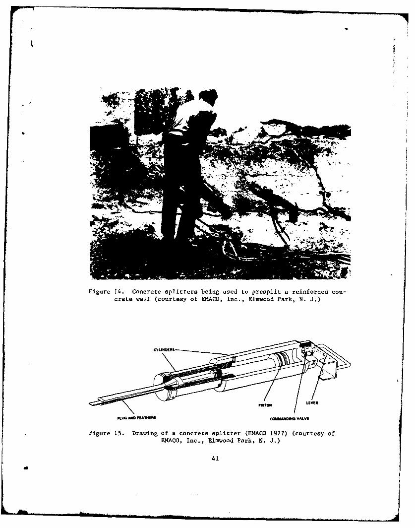
ure 14 shows splitters being used to presplit an 8-ft reinforced concrete
wall.96. In general, the concrete splitter system consists of a hydrau-
lic system and a splitter. The hydraulic system contains hydraulic hoses,
a hydraulic pump, and a power source which can be an air compressor,
gasoline engine, or electric motor. The splitter, as illustrated in Fig-
ure 15, contains a plug, feathers, cylinders, a piston, a commanding
valve, and a control lever. Several splitters can be operated using one
hydraulic system.
97. The drilling operation generates both noise and dust. Re-
quired hole diameters range from 1-3/16 to 1-3/4 in. (EMACO 1977) and
minimum hole depths from 12 to 26 in., depending on the model of splitter
used. The splitters may vary in weight from 39 to 78 lb (EMACO 1977)
and can develop maximum splitting forces of around 440,000 to 700,000 lbf.
40
a
79
Figure 14. Concrete splitters being used to presplit a reinforced con-crete wall (courtesy of EMACO, Inc., Elmwood Park, N. J.)
PgISTONLVE
PLUG AND FEATHERS COMMANDING VALVE
Figure 15. Drawing of a concrete splitter (EMACO 1977) (courtesy ofEMACO, Inc., Elmwood Park, N. J.)
41do
Y4
98. The control lever operates the commanding valve that directs
pressure to the piston for advancing or retracting the plug. As the
plug advances, the feathers are wedged against the sides of the borehole
generating a crack plane that propagates out from opposite sides of the
hole at the spaces between the feathers. The pattern, spacing, and depth
of holes; the orientation of the feathers; and the number of splitters
used affect the direction and extent of crack planes that propagate.
99. The advantages of the concrete splitter are:
a. It is safe to use.
b. It can be used to presplit and separate large sections of
concrete for removal.
c. It can be used on wall surfaces and in areas of limited
work space.
d. Limited skills are required by the operator.
e. No vibration, fly rock, or dust is produced other than
that yielded by drilling and secondary breaking operations.
100. The disadvantages are:
a. For removal of surfaces from mass concrete structures,
control of crack plane depth is somewhat limited.
b. For reinforced concrete structures, other means are re-
quired to cut reinforcing that links the split sectionwith the main body of the structure.
c. Secondary means of breakage are often required to separateand break sections to increase efficiency in handling andremoval work.
Expansive Agent
101. An expansive agent when correctly mixed will undergo a large
increase in volume over a period of time. By placement of the agent
slurry in boreholes that are located in a predetermined pattern within
a concrete structure, the concrete can be presplit in a controlled manner
for removal.
102. The agent comes in powder form and is mixed with water to form
a slurry. As the agent will irritate the skin and eyes, rubber gloves
and goggles are worn to protect the worker. Boreholes that contain water
42
d
are lined with plastic or other suitable material to prevent dilution
of the slurry. Boreholes that are suspected of containing large voids
should also be lined to prevent slurry from entering the voids. When
the slurry is poured into the holes, it solidifies and expands producing
tensile stress concentrations on the inner surface of the hole. The
tensile stress that develops will generally exceed the tensile strength
of the concrete within 10 to 20 hr (Onoda undated) after pouring. A
crack will begin to propagate out from the hole due to thn resulting
overstress and may continue for a couple of days before reaching optimum.
Secondary means of breakage are employed to complete separation and re-
moval of concrete. For reinforced concrete, a means of cutting rein-
forcement must also be employed.
103. In November 1980 at Emsworth Lock in the Pittsburgh District,
a pilot test program was implemented to evaluate removal techniques for
future work on the lock. One portion of the program involved evaluating
the use of an expansive agent for presplitting and ease of removal. Work
for this involved removing 1 ft of deteriorated concrete from a 6-ft-
wide and 26-ft-high area of lock face. For such, 2-in.-diam boreholes
were located I ft behind the lock face on 6-in. centers and vertically
drilled to a depth of 26 ft. Alternate holes were lined with plastic
and filled with slurry. The plastic liners were intended to prevent the
slurry from being diluted by water in the bottoms of holes but were
easily torn and punctured by the abrasive sides of the boreholes. Fig-
ure 16 shows the presplitting crack that propagated between boreholes
approximately 20 hr after the slurry was placed. Figure 17 shows the
resulting surface after removal of the presplit section of the lock face.
The removal was completed by using a crane to drop a large I-beam with
a fabricated chisel point into the presplit crack.
104. In December of 1980, the same expansive product was used for
the same type of repair and rehabilitation work at Dresden Island Lock
in the Rock Island District, and presplitting was less than desired.
The poor performance of the agent is believed to have been caused by the
adverse effects resulting from one or more of the following conditions:
43
a
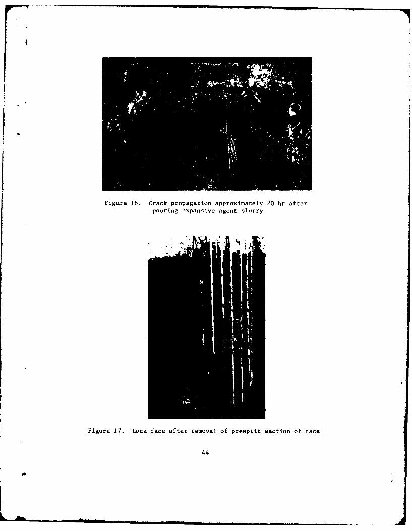
Figure 16. Crack propagation approximately 20 hr afterpouring expansive agent slurry
ML.
Figure 17. Lock face after removal of presplit section of face
44
d
a. Mixing water was heated too high, producing a slurrytemperature above recommended values for optimumperformance.
b. No liners were used in the boreholes; the slurry became
diluted by water already in the holes.
c,. Freezing temperatures partially froze the slurry.
d. Presplitting between the boreholes was difficult toachieve due to stress relief provided by the very weakmaterial that existed between the boreholes and the lockface.
105. The advantages of the expansive agent are:
a. Reasonably safe operation can be maintained.
b. It can be used to presplit large sections of concretefor removal.
c. It can be used to propagate vertical crack planes of sig-nificant depth for controlled presplitting within a massconcrete structure.
d. Limited skills are required by field personnel.
e. No noise, vibration, fly rock, or dust is produced otherthan that produced by drilling and secondary removalmethods.
106. The disadvantages are:
a. The agent is expensive.
b. The overall operation is somewhat costly when drillingand secondary removal expenses are included.
c. Control of crack plane depth is somewhat limited.
d. The agent may not be effective if the slurry is allowed
to freeze or overheat.
e. Secondary means are required to complete separation andremoval of the concrete section from the structure.
f. For reinforced concrete, a means of cutting the rein-
forcement must be employed.
j. A couple of days may be required before presplitting be-comes optimum.
h. Any large voids in a borehole are usually not detecteduntil an excessive amount of slurry has been used.
45
8I
PART VI: MECHANICAL SPALLING
107. Mechanical spalling methods employ tensile stressing devices
that pull small chunks of concrete from concrete surfaces. The devices
are hydraulically operated and require a borehole of a specified depth
for each chunk removed. This results in a lot of drilling and redrilling.
For removal of large volumes of concrete, these methods are slow and
costly.
Hydraulic Rock-Breaker
108. The hydraulic rock-breaker is a spalling device for breaking
concrete and rock. It operates on a concept similar to that of an anchor
being pulled from its place of embedment. Inserted into a predrilled
borehole, the device jacks against the bottom of the hole while gripping
the inner surface of the hole. This pushes the concrete between the
gripped inner surface and the top of the hole outward. The jacking con-
tinues until the concrete becomes overstressed and spalls.
109. The breaker is relatively light, weighing approximately 25 lb
(Cooley 1980). It is being developed and tested through funding pro-
vided by the National Science Foundation. Its development is a part of
an effort to provide environmentally acceptable demolition and excavation
tools for removing rock and concrete. Its operating system is composed
of a hydraulic pump, hydraulic hoses, and the breaker device. The break-
er device, which is detailed in Figure 18, basically contains a Jack
and a notching unit consisting of a sleeve and handle. The sleeve is
threaded at one end and has flexible fingers at the other. At the end
of each finger is a blade for notching and gripping the inner wall of a
borehole.
110. The breaker device with Jack piston retracted is inserted into
a 2.5-in.-diam borehole until the piston contacts the bottom of hole at a
depth of 12 to 17 in. (Cooley 1980). The device is pressed against the
bottom of the hole by the operator until the fingers of the notching unit )override the conical end of the jack. The notching handle is turned
46
L
r70-I-
~0~0
000100
o-
H
-4 W
4JO
414
01
47
clockwise until the fingers of the notching unit spread enough to lightly
set the notching blades into the inner face of the hole. Hydraulic pres-
sure is applied to the jack forcing the notching blades deeper into the
inner face and thereby creating a circumferential notch and line of weak-
ness in the hole face. As the hydraulic pressure is increased, the por-
tion of the hole between the notch and the top of the hole is pushed out-
ward until the concrete becomes overstressed and spalls.
111. The advantages of the hydraulic rock-breaker are:
a. Reasonably safe operation can be maintained.
b. The breaker can be used on wall surfaces and in areas oflimited work space.
c. Limited skills are required by the operator.
d. The breaker is relatively lightweight.
e. No vibration, fly rock, or dust is produced other thanthat produced by the drilling operation.
112. The disadvantages are:
a. Operation is slow for removal of large volumes of concrete.
b. Drilling cost may be high due to the number of holes re-quired for removal of large volumes of concrete and forremoval of concrete surfaces of significant thickness thatrequire redrilling of holes to complete removal.
C. The breaker is not commercially available; it is stillin the experimental and test stages of development.
Concrete Spaller
113. The concrete spaller is a spalling device developed and tested
by the Pacific Northwest Laboratory (Halter and Sullivan 1980) for remov-
ing thin layers of contaminated concrete surfaces in nuclear facilities.
The operation of the device combines the wedge concept with a concept
similar to that of an anchor being pulled from its place of embedment.
When the spaller is inserted into a predrilled borehole, the tapered
end of the spaller push rod is driven by hydraulic pressure through the
hollow bit toward the bottom of the hole wedging outward the feathers of
the bit against the inner face of the hole. As the bit contacts the
bottom of the hole, the tips of the bit feathers grip the inner surface
48
a
pushing the concrete between the gripped area and the top of the hole
outward. The hydraulic pressure is increased on ,. push rod until the
concrete becomes overstressed and spalls.
114. The concrete spaller system contains a hydraulic power sup-
ply system and the spaller device. The spaller device, as shown in Fig-
ure 19, basically consists of a hydraulic cylinder, a push rod, and a bit.
The push rod has a pressure plate at one end and a tapered point at the
other end. The bit is a piece of circular tubing that is slotted at one
end to make four equal feathers. At the tip of each feather is a spike
for gripping the inner surface of the wall.
115. The testing program (Halter and Sullivan 1980) indicated
that boreholes 1 in. in diameter and 2 in. in depth produced optimum
removal when located in a triangular pattern 8 in. apart. Test results
showed removal rates for such to be approximately 5 ft 3/hr. This in-
cluded both drilling and spalling operations and required two workers
and an automated air drill system. For additional surface removal,
holes can be redrilled and spalled again.
116. The advantages of the concrete spaller are:
a. It is safe to operate.
b. It can be used on wall surfaces and in areas of limitedwork space.
c. Limited skills are required by the operator.
d. The device is relatively lightweight.
e. No vibration, fly rock, or dust is produced other thanthat produced by the drilling operation.
117. The disadvantages are:
a. It is a slow and inefficient means of removing largevolumes of concrete.
b. Drilling cost may be high due to the number of holesrequired.
c. The spaller is not commercially available.
49
a
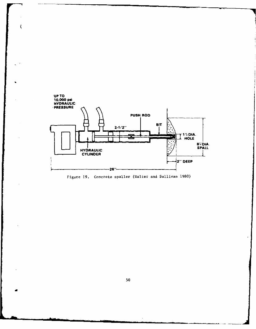
UP TO10.000 psiHYDRAULIC
- PRESSURE
V- .DIA.
u HOLE
-T- S8-DIA.
HYDRAULICSPLCYLINDER7
2" DEEP
26"
Figure 19. Concrete spaller (Halter and Sullivan 1980)
50
A
PART VII: BOREHOLE NOTCHING TECHNIQUE
118. Borehole notching is a crack control technique that has been
tested for use in tunnel blasting of rock for the U. S. Department of
Transportation (Thompson et al. 1979) and in blast removal of deteriorated
concrete surfaces at Lock and Dam 1 on the Mississippi River in the
St. Paul District. The general procedure for both projects was first to
predrill boreholes and later to come back and notch them. The notches
penetrate 1/4 in. into the inner face of the hole and are located on op-
posite sides along the length of the hole. They create lines of weak-
ness on the inner face of the hole and thereby reduce the amount of force
required to initiate and propagate a crack plane from the hole. As a
result, hole spacings can be increased without reducing the efficiency
of the removal method.
119. For both projects, notching of the boreholes allowed a reduc-
tion in the number of holes and the amount of explosive required. How-
ever, at Lock and Dam 1, borehole notching was not used for project work
after the pilot test program was complete because it offered no savings
in time. The time required to reenter and notch each of the predrilled
holes was about equal to the time required to drill the extra holes
saved by notching.
120. In concrete that is extremely deteriorated or that has other
weaknesses, random undesired crack planes may result due to the use of
blasting or an expansive agent. For such situations, borehole notching
may provide the desired crack control that could not otherwise be
achieved.
121. The notching bits used in these tests were specifically
fabricated for such and are not commercially available at present. Sev-
eral preliminary designs have been made of a single tool that combines
the drilling and notching operation into one. The development of this
tool has been halted until an interested sponsor can be found. Figure 20
details a bit recommended by Thompson et al. (1979) for notching predrilled
boreholes; figure 21 is a conceptual sketch of a single-pass combination
drilling and notching tool also mentioned by Thompson et al.
51
a
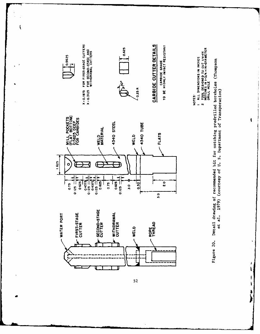
Inn w
I) W0
Wuy V 0-'.Uv
w 010
(n4W
4 L Coo D Z
Ow 0W4 0 W OZ
0 x W
0 00 000
4)
$14
i0 0
C0 4 $4 4o l W w co m 0
0 '-
0j 0 w 0 0 0 aJ
4 Jo w~ - w to -j0 c
0:
0
$4
44
52
f- 'Df
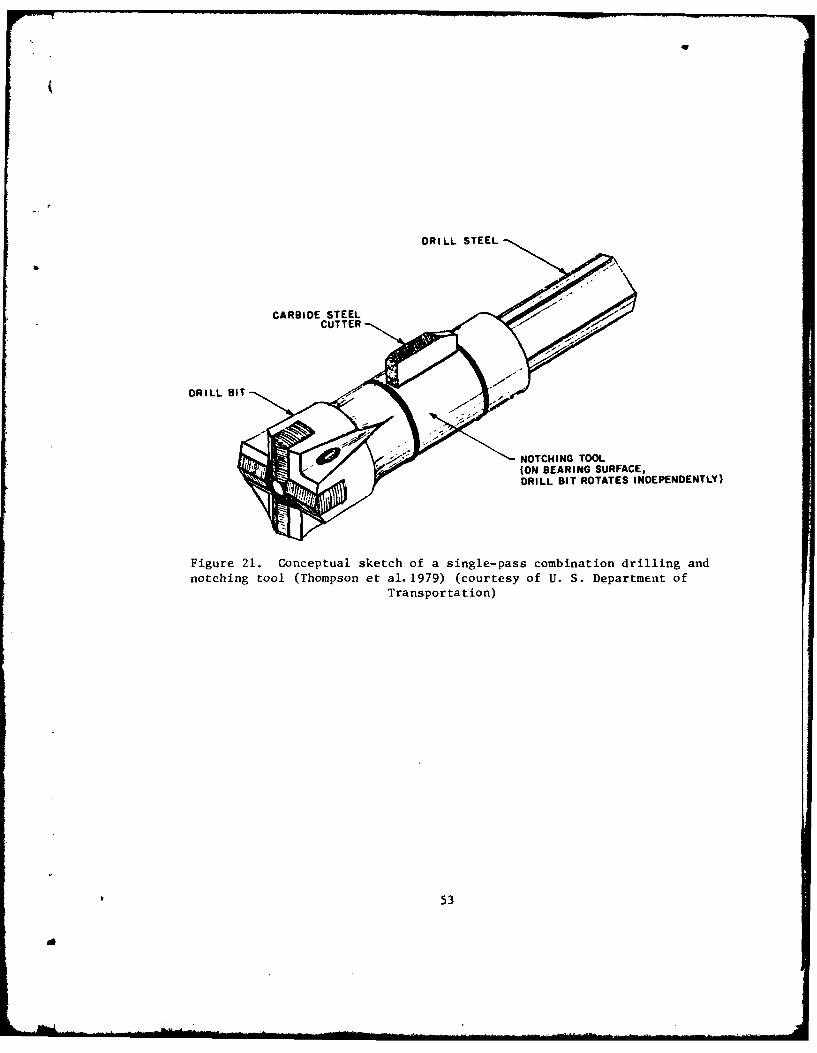
bq
DRILL STEEL
CARBIDE STEELCUTTER
NOTCHING TOOL(ON BEARING SURFACE,
DRILL SIT ROTATES INDEPENDENTLY)
Figure 21. Conceptual sketch of a single-pass combination drilling and
notching tool (Thompson et al. 1979) (courtesy of U. S. Department of
Transportation)
53
d
122. The advantages of the borehole notching technique are:
a. Better crack control is achieved in concrete that isdeteriorated or has other weaknesses that might causeundesired random cracking.
b. The amount of force required to achieve desired crackpropagation is reduced.
C. The number of holes that are required to be drilled isreduced.
d. The amount of expansive agent or explosive is reduced.
e. Reduction in blast effect occurs due to reduction in theamount of explosives used.
123. The disadvantages are:
a. Holes have to be reentered in order to be notched; thetime gained by drilling fewer holes is lost.
b. At present, the borehole notching tool is not commerciallyavailable.
54 1do
(g
PART VIII: DISCUSSION AND RECOMMENDATIONS
Discussion
124. Most repair and rehabilitation work at Corps projects in-
volves removal of large volumes of distressed or deteriorated concrete.
At present, the most cost-effective and expedient means for such removal
is explosive blasting. However, for areas where explosive blasting is
restricted or presents a hazard, other means of removal must be employed.
125. The high-pressure carbon dioxide blaster has been suggested
as an alternate to explosives (Pikrose undated). It is a less violent
but less powerful means of removal than explosives. The device is com-
mercially available in Europe but may be a little more difficult to get
in the United States. Its actual performance in removing concrete sur-
faces has not been established; however, it does appear to have poten-
tial in this area. Redrilling of holes that require more than one car-
tridge and the use of cartridges requiring holes larger than 2 in. in
diameter increase the drilling cost and may make the blaster too expen-
sive to use.
126. The acetylene-air rock-breaker is a blasting tool that is
under development and, therefore, cannot be considered for present re-
moval work. It does appear to have potential similar to that of the
high-pressure carbon dioxide blaster, but it will require a significant
amount of testing and documenting before it can be commercially marketed
for concrete removal.
127. Diamond saw cutting is slow and costly, and the saw has a
very limited cutting depth. It is therefore considered impractical in
most applications for surface removal from mass concrete structures.
However, a diamond saw can be used with other methods to improve crack
control and reduce overbreakage by making a cut through the area in
which a crack plane is to be propagated or where overbreakage is to be
limited.
128. Applicability of the powder torch, thermal lance, and powder
lance for removing surfaces from mass concrete structures will mainly
55
depend on the rate at which the resulting slag can flow from the cut.
For vertical cuts of significant depth and limited slag flow, these
cutting devices are not practical. However, the powder torch, thermallance, and powder lance may be used like the diamond saw to improve crack
control and reduce overbreaking. They are especially effective for
cutting reinforced concrete; however, in general, they are considered
somewhat slow and costly. I
129. The electric-arc cutting method developed in the USSR uses
an electric power source to melt the concrete. Like the other thermal
devices which melt concrete, its success in cutting concrete will mainly
depend on the rate at which the slag can flow from the cut. In Switzer-
land, an electrothermal lance (Lazenby and Phillips 1978) is being de-
veloped for cutting reinforced concrete. The lance has advantages and
disadvantages similar to those of the electric-arc, except that it is
capable of making deeper cuts more efficiently. Neither the electric-arc
nor the electrothermal lance is commercially available at present. If
available, these devices would be more effectively used in supporting
other methods of removal rather than as the primary means of surface re-
moval for mass concrete structures.
130. The productivity of the water jet has greatly improved over
the last decade, and it is now becoming competitive with some of the
other removal devices. Improvements that are under development should
make the water jet even more competitive. The water jet has the poten-
tial for being a primary means for removal when it is desired to preserve
the reinforcement within the removal area for reuse. However, at present,
the water jet, like other cutting devices, may be better used in support
of primary removal methods.
131. None of the impact methods mentioned appear to be suitable
as a primary method of removal. The hand-held breaker has a low produc-
tivity rate which makes it undesirable for expedient removal of large
volumes of concrete. The hand-held breaker is, however, suitable for
use in support of primary means of removal. The vehicle-mounted breaker
is a highly productive means of removing concrete; but because of the
dangers associated with the high energy and vibration it transmits through
56
the structure, it is not recommended for repair and rehabilitation work 4
at Corps locks and dams, except for projects where blow energy is to be
restricted to a proven safe level. The water cannon, because of its
low productivity and because it is not commercially available, is not
considered applicable for this type of work.
132. Presplitting methods have potential as primary means of
removing large volumes of material from mass concrete structures. For
both the concrete splitter and the expansive agent, secondary means of
separating and removing the concrete usually must be employed. This
adds to the cost of removal. The splitter is best suited for shallow
holes at any angle; the expansive agent is best suited for use in verti-
cal holes of significant depth. The high cost of the agent may make the
splitter more desirable when both methods are applicable.
133. Mechanical spalling methods have low productivity rates that
make them unattractive as primary means of removal. The hydraulic rock-
breaker is not commercially available at present, but appears to have
potential as a secondary means of removal. The mechanical spaller is
more applicable to shallow removal of limited volumes of concrete.
134. The borehole notching technique promises to enhance the
blasting and expansive agent methods by reducing the number of holes
needed and producing better control for crack plane propagations. In the
past, drilling and notching of the holes were separate operations. Sev-
eral preliminary designs have been made that combine these operations
into one. These designs are presently waiting for a sponsor to fund
their development.
13. To reiterate, explosive blasting is the most cost-effective
and expedient means of surface removal of large volumes of material from
mass concrete structures at Corps projects. In a situation where explo-
sive blasting cannot be used, an alternate means of removal must be se-
lected. Of those reviewed, the following appear to have potential as
alternate means of removal:
a. Acetylene-air rock-breaker.
b. Concrete splitter.
S. Expansive agent.
57
a
d. High-pressure carbon dioxide blaster.
e. High-pressure water jet (in situations where reinforce-ment is to be preserved for reuse).
Recommendations
136. To complete the update of Corps technology on removal of
distressed or deteriorated surfaces from mass concrete structures, it
is recommended that a field comparison study be made. Selection of re-
moval methods for such a study would be made from those reported to have
potential as primary means of removal. It is felt that some of those
having potential as secondary means of removal should also be evalu-
ated. The study would be included as a part of scheduled repair and re-
habilitation work at a Corps project. As many variables as possible
would be held constant to ensure meaningful comparisons. The principal
determinations to be made for comparison would be:
a. Cost.
b. Removal rates.
c. Extent of damage to concrete that remains.
d. Problem areas.
It is also recommended that the borehole notching technique be evaluated
as a part of this study.
58
a
REFERENCES
Anonymous. 1975a. "Rebuild Fish Ladder in Confined Quarters," Contrac-tors' and Engineers' Magazine, January Issue.
Anonymous. 1975b. "Concrete Comes Off Markland Dam Piers to StartConstruction of Ohio River Bridge," Construction Digest, December Issue.
Anonymous. 1981. "Defusing the Risk With Explosives," New Civil
Engineer, January Issue, p 28.
Bligh, T. P. 1974. "Principles of Breaking Rock Using High PressureGases," Advances in Rock Mechaaics, Proceedings of Third Congress ofInternational Society of Rock Mechanics, Denver, Colo.
Bligh, T. P. 1977. "Ultrahigh Pressure Gaseous Detonations Used ina Rock Fragmentation Device, 6th International Colloquium on Gasdynamicsof Explosions and Reactive Systems, Sweden.
Cooley, W. C. 1980. "Hydraulic Bursting of Concrete and Rock - PhaseII," prepared for National Science Foundation, Terraspace, Inc.,Rockville, Md.
E. I. Du Pont de Nemours and Company, Inc. 1977. Blasters' Handbook,175th Anniversary Edition. Wilmington, Del.
EMACO, Inc. 1977. "Hydraulic Rock and Concrete Splitter," ElmwoodPark, N. J.
Goriainov, K. E., and Antropov, V. 1. 1967. "Elektrodugovye UstanovkiDlia Vyzhiganiia Otverstii v Kirpichnykh i Zhelezobetonnykh Konstruksiiakh"(Electric-Arc Equipment for Burning Openings into Brick and ReinforcedConcrete Structures), Mekhanizatsiia Stroitel'stva, No. 2, pp 18-19.
Halter, J. M., and Sullivan, R. G. 1980. "Equipment for Removal of Con-taminated Concrete Surfaces," Proceedings of the Concrete DecontaminationWorkshop, Report No. PNL-SA-8855, Pacific Northwest Laboratory, Richland,Wash.
Hilaris, J. A. 1980. "Field Study of High Pressure Water Jet for High-way Surface Maintenance," prepared for National Science Foundation, IITResearch Institute, Chicago, Ill.
LaGuardia, T. S. 1980. "Concrete Decontamination and Demolition Meth-ods," Proceedings of the Concrete Decontamination Workshop, ReportNo. PNL-SA-8855, Pacific Northwest Laboratory, Richland, Wash.
Lazenby, David, and Phillips, Paul. 1978. Cutting for Construction,Halsted Press, John Wiley & Sons, Inc., New York, N. Y.
59
" a-i iI . . ..
Olsen, J. H. 1980. "Cutting By Waterjet," Flow Industries, Inc., Kent,Wash.
Onoda Cement Co., Ltd. Undated. "Bristar, Non-Explosive DemolitionAgent," Technical Note, Tokyo, Japan.
Palovchik, S. T. 1975, "Sawing Reinforced Concrete With Diamond Blades,"Annual Convention of the Concrete Sawing and Drilling Association, Tech-nical Paper, New Orleans, La.
Pikrose and Company, Limited. Undated. "Cardox, The Fast Efficient
Concrete/Rock Bursting Splitting Tool," Audenshaw, Manchester, UnitedKingdom.
Plump, John. 1980. "Selective Concrete Removal by Explosives," Concrete
Structures Repair and Rehabilitation, Vol C-80-2, pp 2-3, U. S. ArmyEngineer Waterways Experiment Station, CE, Vicksburg, Miss.
Siskind, D. E. et al. 1980. "Structure Response and Damage Produced byGround Vibration from Surface Mine Blasting," RI 8507, Bureau of Mines,
U. S. Department of the Interior, Washington, D. C.
Thompson, D. E. et al. 1979. "Field Evaluation of Fracture Control in JTunnel Blasting," prepared for U. S. Department of Transportation, Haleyand Aldrich, Inc., Cambridge, Mass.
U. S. Army Corps of Engineers. 1981. "Safety and Health RequirementsManual," EM 385-1-1, U. S. Government Printing Office, Washington, D. C.
U. S. Army Engineer School. 1967. "Air Compressor Pneumatic Tools andQuarrying Techniques," Fort Belvoir, Va. !Wayment, W. R. and Grantmyre, I. P. 1976. "Development of a High BlowEnergy Hydraulic Impactor," Joy Manufacturing Company, Denver, Colo.
I
60
d
In accordance with letter from DAEN-RDC, DAEN-AS1 dated
22 July 1977, Subject: Facsimile Catalog Cards for
Laboratory Technical Publications, a facsimile catalog
card in Library of Congress MARC format is reproduced
below.
Campbell, Roy L.A review of methods for concrete removal / by Roy
L. Campbell, Sr. (Structures Laboratory, U.S. Army
Engineer Waterways Experiment Station). -- Vicksburg,
Miss. : The Station ; Springfield, Va. : available from
NTIS, 1982.60 p. ; ill. ; 27 cm. -- (Technical report
; SL-82-3)
I Cover title."April 1982."Final report."Prepared for Office, Chief of Engineers, U.S.
Army
under CWIS 31S53."Bibliography: p. 59-60.
1. Concrete deterioration. 2. Concrete construction.
3. Concrete research. 4. Water-Jet. 1. United States.
Army. Corps of Engineers. Office of the Chief of
Engineers. II. U.S. Army Engineer Waterways Experiment
Campbell, Roy L.A review of methods for concrete removal
: ... 1982.(Card 2)
Station. Structures Laboratory. III. Title
IV. Series: Technical report (U.S. Army Engineer
Waterways Experiment Station) ; SL-82-3.
TA7.W34 no.SL-82-3
" k