Embed Size (px)
Citation preview
Director, Operational Test and Evaluation
FY 2005 Annual Report
December 2005
This report satisfies the provisions of Title 10, United States Code, Section 139. The report summarizes the operational test and evaluation activities (including live fire testing activities) of the Department of Defense during the preceding fiscal year.
David W. Duma

i
I N T R O D U C T I O N
The Director, Operational Test and Evaluation (DOT&E) activities for Fiscal Year 2005 (FY05) are characterized by three dominant themes: providing information for acquisition decision makers, providing direct support to our warfighters, and assessing the adequacy of Test and Evaluation (T&E) resources for future testing needs.
In support of acquisition, DOT&E published nine Beyond Low-Rate Initial Production Reports, including those for the highly visible and often controversial F-22 Raptor and V-22 Osprey. DOT&E monitored 279 Major Defense Acquisition Programs (MDAPs) and special interest programs. This included test adequacy reviews for 56 Test and Evaluation Master Plans (TEMPs), 10 Live Fire Test and Evaluation (LFT&E) strategies, and 50 individual Test and Evaluation Plans (TEPs) for specific test events.
In continuing support to our warfighters, the LFT&E staff monitored Service efforts to upgrade armor for tactical vehicles, as well as Service efforts to resolve personal body armor testing variances. DOT&E also provided T&E advice to the Office of the Secretary of Defense (OSD) Joint Rapid Acquisition Cell (JRAC) to help ensure performance is demonstrated before fielding. The results of DOT&E Information Assurance (IA) assessments of legacy systems received wide visibility within the Department of Defense (DoD), including OSD, the Joint Staff, and the Combatant Commanders (COCOMs). The DOT&E Joint Test and Evaluation (JT&E) program acted in direct response to COCOM requests via its re-engineered Quick Reaction Test (QRT) process.
In assessing future testing resource needs, DOT&E provides strategic planning inputs to the Defense Test Resource Management Center (DTRMC) to which several DOT&E responsibilities regarding T&E resources have been transferred. DOT&E also works with the individual Services to address future testing needs for air, land, and naval warfare.
Acquisition Support
ValuesDOT&E focuses on adhering to the principle upon which the office was founded—the adequacy of tests to determine operational effectiveness and suitability for combat. In making these determinations, DOT&E uses requirements and criteria generated by the Service sponsors including Key Performance Parameters (KPPs) and criteria validated by the Joint Requirements Oversight Council (JROC) to assess mission accomplishment. In other words, “To what degree can a unit equipped with these systems accomplish its missions and tasks?”
Acquisition ChangesThe Defense Acquisition Performance Assessment (DAPA) panel recently released the executive summary of its report. That summary proposes significant changes to the way in which the DoD acquires new military capabilities. Included in these proposals are changes to the operational T&E process, which are included under the ‘requirements’ category. One of the principles to achieve objective operational testing and reporting is to keep the operational test agencies independent of setting requirements, or establishing performance criteria.
The panel emphasized stability to control costs and to meet schedules and proposed shifting to ‘time-certain’ development procedures. Such changes will challenge DOT&E and operational test and evaluation agencies to ensure the new military capabilities thus acquired still demonstrate satisfactory performance in operationally realistic environments.
“Fly before Buy”The challenge is to determine operational effectiveness and suitability to support large procurement decisions before fielding for combat. DOT&E is a proponent of the principle of “fly before buy” to help ensure the DoD provides systems that work and are supportable in the field. The pressures on program managers to control costs and speed delivery in today’s environment of evolutionary acquisition and spiral development are driving them toward schedule-driven acquisition strategies in which significant procurement occurs before Full-Rate Production (FRP) decisions. Acquiring a significant percentage of an acquisition program prior to the FRP decision increases the risk that COCOMs will experience increased logistical support requirements and configuration management challenges.
Missile DefenseThe Missile Defense Agency (MDA) programs continue to mature. The Airborne Laser (ABL) technology program achieved first light early in FY05 and recently demonstrated full power operation of significant duration. The PATRIOT system had demonstrated multiple launch and the capability to intercept multiple targets. However, in tests of subsequent software upgrades, PATRIOT failed to destroy intended targets. The root cause determination is under investigation. The Terminal High-Altitude Area Defense (THAAD) program demonstrated a successful flight in its first developmental flight test. The Ballistic Missile Defense System (BMDS) Aegis program demonstrated continued maturation with several successful
ii
I N T R O D U C T I O N
launches culminating in a recent target intercept. The BMDS Ground-based Midcourse Defense (GMD) program had two successive failures during which interceptors failed to launch in FY05. Independent review teams confirmed quality assurance shortcomings and recommended significant actions that the MDA is implementing. Additional details regarding the MDA programs are provided in the BMDS section of this report.
Dedicated Operational TestingThe Global War on Terrorism (GWOT), with its demands on rotating forces into and out of theater, have made live forces dedicated to operational test events extremely scarce. Combined test teams—Contractor Testing (CT), Developmental Testing (DT) and Operational Testing (OT)—are the norm; so too are combined DT/OT test events. Wherever possible, the Service Operational Test Agencies (OTAs) combine operational testing with other exercises and training events to conserve resources. Combined test teams are generally effective, but too often test objectives are sacrificed in the interest of training objectives during combined test events. This has been particularly true in naval exercises. As a consequence, testing is not completed and timely performance information is not obtained. The result is an extended test program and delayed information to decision makers.
OT&E TrendsFrom the perspective of effective mission accomplishment, “To what degree can a unit equipped with these systems accomplish its missions or tasks?”, demonstrated performance has gotten better over the years. Sustained mission accomplishment depends upon being able to support the systems in the field. Suitability performance regarding the ability to keep those systems available for effective employment has gotten worse. This decreasing trend in suitability results noted during operational T&E is cause for concern. This declining trend may be evidence that the Department, in attempting to field MDAPs more rapidly, is tending to focus on effectiveness, and is treating suitability (reliability, availability, maintainability, logistics, etc.) as a second tier capability.
To specifically address this adverse trend, DOT&E developed a Guide to Achieving Reliability, Availability, and Maintainability. DOT&E based this guide on work done by the National Academy of Sciences (NAS). One of the significant aspects of the NAS work is the need to educate senior leaders on the dependency of long-term effectiveness on suitability. The Under Secretary of Defense for Acquisition, Technology, and Logistics (USD(AT&L)) and DOT&E approved the guide in August and it is available to assist program managers on the OSD Web site: http://www.acq.osd.mil/ds/se/ed/publications.htm
ComplexityThe complexity of our weapons systems is increasing. Not only are the technologies more complex today, the interdependency of the sensors, the command, control, and communications, and the munitions in joint operations drives both our war fighting capabilities and our war fighting challenges. Complexity costs money in design, development, and testing and in the need for contractor logistics support. This has a direct bearing on what the DAPA panel is focused on—controlling costs and meeting schedules.
Warfighter Support
Vehicle ArmorThe use of Improvised Explosive Devices (IEDs) in Operation Iraqi Freedom (OIF), and the rapid maturation of IED tactics, techniques, and procedures in theater challenged the Services to up-armor numerous tactical vehicles that had not been designed for front line combat. The DOT&E LFT&E staff worked closely with the Army Test Center (ATC), Aberdeen, Maryland, to ensure potential up-armor solutions were adequately tested before being implemented. The level of expertise resident at Aberdeen for testing armor makes it a center of excellence for this vital function. This expertise helped influence the design of armor ultimately developed, tested, and selected for up-armoring tactical vehicles.
DOT&E discovered some armor being made available to forces in theatre that had not gone through such formal testing. When subsequently tested, the Army found it to be ineffective. All potential armor solutions should go through the Army’s survivability testing to ensure consistent and comparable results, and to ensure ineffective armor does not reach the field.
Body ArmorThe development and procurement of personal body armor did not trip the fiscal threshold to be designated as a MDAP. Consequently the DOT&E LFT&E staff had not exercised T&E oversight of body armor. Upon learning that the Marine Corps recalled roughly 5,000 outer tactical vests (OTVs), I became concerned that acceptance testing may not have been adequate to preclude fielding of substandard body armor.
iii
I N T R O D U C T I O N
The LFT&E staff, working with the Army Soldier Command in Natick, Massachusetts, and both the Army T&E community and the Army Research Laboratory in Aberdeen, Maryland, determined that there were inconsistencies in the lot acceptance test methods used by various organizations. Review of records revealed some OTVs had been fielded despite not meeting acceptance criteria. This led to the Army recall of roughly 8,000 OTVs, and an additional recall of roughly 10,000 OTVs by the Marine Corps.
Work is in progress to develop a standard test process for body armor lot acceptance testing. Once determined, this process will become the DoD standard. DoD intends to make this process available to civilian law enforcement agencies and organizations for their use.
Rapid FieldingDOT&E advises the OSD JRAC to help ensure rapid fielding initiatives consider the adequacy of performance testing. JRAC projects do not meet criteria to be designated as MDAPs. Without adding T&E oversight to the JRAC bureaucracy, DOT&E focused on asking two critical questions, “Does the system work as intended?” and “How do you know it works?” This minimalist approach has neither delayed rapid fielding due to testing nor has it caused an administrative burden. It has benefited the Service OTAs by ensuring adequate funds and resources are made available to do appropriate testing.
Information Assurance (IA)The DOT&E initiative to assess IA for legacy systems is truly a success story. Directed as part of the FY03 National Defense Authorization Act (NDAA), DOT&E established a working relationship with the COCOMs and a formal program that directly aids the warfighters. At the request of COCOMs, DOT&E added IA assessments to selected pre-deployment exercises of units returning to Iraq.
The results of these legacy system IA assessments have been shared among the COCOMs and briefed to the Secretary of Defense and the Chairman, Joint Chiefs of Staff. The Chairman has released two messages to COCOMs regarding IA, based in part, upon the results of our assessments. Also, U.S. Strategic Command (USSTRATCOM) directed an IA stand-down for the entire DoD in November. Additional details regarding the IA assessment program are provided in the Information Assurance section of this report.
Joint Test and Evaluation (JT&E) ProgramWhen USD(AT&L) transferred the JT&E program to DOT&E, we began a re-engineering effort to make the JT&E program more responsive to the warfighters. The creation and implementation of Quick Reaction Tests (QRTs) is designed to respond directly to stated needs of the COCOMs, and to deliver useful products to the warfighters in a timely manner—months, not years. Products delivered have received the endorsement of COCOMs and the Joint Staff.
The rigor of the T&E process enables delivery of products that instill confidence in the user because the process is credible. Examples of products delivered using QRTs are the: • Joint Shipboard Ammunition and Ammunition Boards (JSAABR) refined the process to certify existing non-Naval weapon
systems for shipboard use• Joint Forward Operating Base (JFOB) Handbook - Force Protection Handbook for deployed forces• U. S. Special Operations Command Convoy Handbook - pocket-sized handbooks covering combat convoys and convoy
leaders training
Additional details regarding QRTs are provided in the Joint Test and Evaluation section of this report.
Test Resources
Defense Test Resources Management Center (DTRMC)The USD(AT&L) completed manning of the DTRMC with a permanent director, staff, and contractor support in FY05. Additionally, DOT&E transferred administration and management of the Central Test and Evaluation Investment Program (CTEIP) and the Test and Evaluation Science and Technology (T&E/S&T) program and oversight of the Major Range and Test Facilities Base (MRTFB) to the DTRMC in FY05.
The DTRMC published a strategic plan that continues to evolve and mature. The FY05 strategic plan is more comprehensive than previous plans, but remains focused on the MRTFB. I expect, as strategic planning matures, T&E resources such as the OTAs and the workforce, will be included. DOT&E has worked to establish a partnership with the DTRMC to ensure the DoD T&E investment strategy is adequate to meet future testing needs. This is an ongoing process.
Congressional direction called for the DoD to reverse the trend of increasing test costs to MRTFB customers with the objective of charging only for direct test costs. During FY05, the DoD changed its financial management regulations to
iv
I N T R O D U C T I O N
require the Services to comply with the new policy in the latest budget. As a result, roughly $580 Million has been realigned to the MRTFB institutional funding lines. While this is a significant change, some time will be needed to assess its efficacy.
Air WarfareDuring FY05, in response to DOT&E and USD(AT&L), the Defense Science Board (DSB) conducted a high-level review of aerial targets to assess DT/OT issues, current and future threat projections and trends, and Service target payloads and control systems. The study resulted in three key recommendations:• Proceed with a replacement of the QF-4 drone target with an existing aircraft platform, striving for an unmanned vehicle
while developing a new target to represent likely future threats• Proceed with aggressive efforts to develop and procure three types of supersonic anti-ship cruise missile targets (GQM-
163A, MA-31, Threat D)• Migrate to a common target control system and provide a centralized management and planning function to the aerial
targets community
In response to these recommendations, the Air Force adopted a replacement strategy that will drone existing F-16s. This strategy does not address concerns over the capability of a QF-16 to represent future threat aircraft. Also, plans to make the QF-16 manned-capable increases the cost due to personnel safety considerations.
Land WarfareLand warfare evaluations under realistic combat environments are limited by a lack of Real Time Casualty Assessment (RTCA) instrumentation. Such instrumentation enables participants to be removed from combat scenarios in response to attacks. RTCA instrumentation is needed to replace the aging and unwieldy MILES gear. It is also needed to adequately assess the effects of air-to-ground operations. The technology exists to miniaturize the next generation of RTCA instrumentation so it could be embedded into vehicles, and not unduly encumber individual soldiers. New RTCA instrumentation has the added benefit of being able to support the training community.
Naval WarfareDOT&E continues to emphasize realism and an enterprise approach to test defensive capabilities of shipboard combat systems against threat-representative anti-ship cruise missile targets. Key to the enterprise approach for realistic testing are the self defense test ship and a modeling and simulation test bed for estimating performance for variations in sea state, ship signature, and radar propagation. The enterprise approach promises significant cost savings and avoids disparate “point determinations” of capabilities for different ship classes. In a November 2005 memorandum to my office, the Deputy Chief of Naval Operations (N6/N7) stated, “Navy is committed to funding the Enterprise Anti-Air Warfare Ship Self Defense Test and Evaluation strategy to prove our warfighting systems perform to the requirement.”
Future Challenges
Software DominancePlatform focused acquisition is being overtaken by software intensive systems-of-systems and network-centric concepts. Platforms provide the space, weight, cooling, and power for significant software-driven mission capabilities. However, integrating software packages is proving to be a time consuming challenge for complex systems. Frequent demonstrations of integrated software performance early and throughout the development cycle is key to ensuring software-driven mission capabilities are both ready for OT&E and to be fielded.
DOT&E has observed that mission capabilities of MDAPs—Acquisition Category I (ACAT I) programs—may be driven significantly by software capabilities of smaller programs (i.e., ACAT III programs). There is a need to take a more holistic view of managing and developing mission capabilities that includes not only the platform but all of the systems, regardless of ACAT, that contribute to the mission capabilities. DOT&E recommended such an approach to the Defense Acquisition Executive.
Testing in a Joint EnvironmentThe DOT&E-led collaborative effort to develop a capability to test in a Joint mission environment continued throughout FY05. To create such a Joint mission environment, DOT&E developed a roadmap. The Deputy Secretary of Defense (DEPSECDEF) approved the roadmap early in FY05. The roadmap promotes:• Institutionalizing the need to test in realistic Joint operational environments• Defining capabilities in common, measurable, war fighting terms
v
I N T R O D U C T I O N
• Establishing persistent connectivity between Battle Labs, Hardware-in-the-Loop facilities, Software-in-the-Loop facilities, DT facilities, and live force instrumentation
• Using connectivity to build the environments for Joint experimentation, development, test, and training
One key goal in the roadmap is to achieve “persistence.” Millennium Challenge and more recent exercises have proven the technology works. The Multi-Service Distributed Event (MSDE) in August 2005 required about 300 people and 120 days to establish the network for the exercise. Just as we saw in Millennium Challenge, the lack of persistence resulted in users dismantling the MSDE network when the exercise was complete. We need an environment in which information exchange can be achieved simply by changing the address. The roadmap points the way to building such a Joint mission environment by linking existing single-Service assets when needed to create a DoD Joint asset.
DOT&E remains committed to establishing this capability for the Department. DOT&E sponsored a feasibility study as part of its JT&E program to determine appropriate Joint Test and Evaluation Methods (JTEM). This will include recommended policies and processes for conducting testing in a Joint mission environment. DOT&E worked to obtain funding for the Joint Mission Environment Test Capability (JMETC) infrastructure—linking existing facilities. DOT&E led the implementation planning effort throughout FY05 and the established partnerships, as reported in last year’s annual report, continue to grow and mature.
David W. Duma

vi
T A B L E O F C O N T E N T S
vii
DOT&E Activity and Oversight
Activity Summary ..........................................................................................................................................................................1
Program Oversight .........................................................................................................................................................................5
DoD Programs
Business Systems Modernization (BSM) ....................................................................................................................................11
Chemical Demilitarization Program – Assembled Chemical Weapons Alternatives (CHEM DEMIL-ACWA) ........................13
Composite Health Care System II (CHCS II) ..............................................................................................................................15
Defense Message System (DMS) ................................................................................................................................................17
Defense Travel System (DTS) .....................................................................................................................................................19
Global Command and Control System – Joint (GCCS-J) ...........................................................................................................21
Global Information Grid Bandwidth Expansion (GIG-BE) .........................................................................................................23
Joint Biological Agent Identification and Diagnostic System (JBAIDS) ....................................................................................25
Joint Chemical Agent Detector (JCAD) ......................................................................................................................................27
Joint Service Light Nuclear, Biological, and Chemical Reconnaissance System (JSLNBCRS) ................................................29
Joint Service Lightweight Standoff Chemical Agent Detector (JSLSCAD) ...............................................................................31
Joint Warning and Reporting Network (JWARN) .......................................................................................................................33
Teleport ........................................................................................................................................................................................35
Theater Medical Information Program (TMIP) ...........................................................................................................................37
Army Programs
Advanced Threat Infrared Countermeasures/Common Missile Warning System (ATIRCM/CMWS) .......................................39
All Source Analysis System (ASAS) ...........................................................................................................................................41
Armed Reconnaissance Helicopter (ARH) ..................................................................................................................................43
Army Battle Command System (ABCS) .....................................................................................................................................45
Black Hawk Upgrades (UH-60M) – Utility Helicopter Upgrade ................................................................................................47
CH-47F – Cargo Helicopter .........................................................................................................................................................49
Dismounted Battle Command System (DBCS) ...........................................................................................................................51
Extended Range/Multipurpose Unmanned Aerial Vehicle (ER/MP UAV) ..................................................................................53
Force XXI Battle Command Brigade and Below (FBCB2)/Blue Force Tracking (BFT) ...........................................................55
Future Combat Systems (FCS) Overview ....................................................................................................................................57
Future Combat Systems (FCS) Manned Ground Vehicles: Non-Line-of-Sight Cannon (NLOS-C) ..........................................61
Future Combat Systems (FCS) Unattended Munitions: Non-Line-of-Sight Launch System (NLOS-LS) ................................63
M30 Guided Multiple Launch Rocket System (GMLRS) – Dual Purpose Improved Conventional Munitions (DPICM) ........65
Guided Multiple Launch Rocket System (GMLRS) - Unitary ....................................................................................................67
High Mobility Artillery Rocket System (HIMARS) ....................................................................................................................69
Joint Tactical Radio System (JTRS) Cluster 1 .............................................................................................................................71
Joint Tactical Radio System (JTRS) Cluster 5 .............................................................................................................................73
Maneuver Control System (MCS) Army Tactical Command and Control System (MCS (ATCCS)) .........................................75
T A B L E O F C O N T E N T S
viii
PATRIOT/Medium Extended Air Defense System Combined Aggregate Program (PATRIOT/MEADS CAP) ........................77
Shadow Tactical Unmanned Aerial Vehicle (RQ-7 Shadow 200) ...............................................................................................79
Spider XM7 Network Command Munition .................................................................................................................................81
Stryker - Mobile Gun System (MGS) ..........................................................................................................................................83
Stryker - Mortar Carrier B ...........................................................................................................................................................85
Stryker - Nuclear, Biological, and Chemical (NBC) Reconnaissance Vehicle ............................................................................87
Suite of Integrated Radio Frequency Countermeasures (SIRFC) (AN/ALQ-211) ......................................................................89
Transportation Coordinators’ Automated Information for Movements System II (TC-AIMS II) ...............................................91
Warfighting Information Network-Tactical (WIN-T)/Joint Network Node (JNN) .....................................................................93
XM982 Excalibur Precision Engagement Projectiles ..................................................................................................................95
Navy Programs
Acoustic Rapid Commercial Off-the-Shelf (COTS) Insertion for SONAR AN/BQQ-10 (V) (A-RCI) ......................................97
Active Electronically Scanned Array (AESA) .............................................................................................................................99
Advanced Deployable System (ADS) .......................................................................................................................................101
Advanced SEAL Delivery System (ASDS) ...............................................................................................................................103
AIM-9X Air-to-Air Missile Upgrade .........................................................................................................................................105
AN/AAR-47 V2 Upgrade Missile/Laser Warning Receiver ......................................................................................................107
Cooperative Engagement Capability (CEC) ..............................................................................................................................109
CVN 21 - Next Generation Nuclear Aircraft Carrier .................................................................................................................111
DD(X) Future Surface Combatant including Long Range Land Attack Projectile ...................................................................113
DDG 51 Guided Missile Destroyer ............................................................................................................................................115
Deployable Joint Command and Control (DJC2) ......................................................................................................................117
E-2D Advanced Hawkeye (AHE) to include Radar Modernization Program (RMP) ...............................................................119
EA-6B Upgrades/Improved Capability (ICAP) III and Low Band Transmitter (LBT) ............................................................121
EA-18G Growler (Electronic Attack variant of F/A-18) ...........................................................................................................123
Evolved Sea Sparrow Missile (ESSM) ......................................................................................................................................125
Expeditionary Fighting Vehicle (EFV) ......................................................................................................................................127
F/A-18E/F Hornet Naval Strike Fighter (All Upgrades) ...........................................................................................................129
Global Command and Control System – Maritime (GCCS-M) ................................................................................................131
H-1 Upgrades – U.S. Marine Corps Upgrade to AH-1W Attack Helicopter and UH-1N Utility Helicopter ............................133
Integrated Defensive Electronic Countermeasure (IDECM) .....................................................................................................135
Joint Standoff Weapon (JSOW) Baseline Variant and Unitary Warhead Variant ......................................................................137
KC-130J Aerial Tanker/Airlift Aircraft ......................................................................................................................................139
LHA 6 (formerly LHA(R)) - New Amphibious Assault Ship ....................................................................................................141
Littoral Combat Ship (LCS) .......................................................................................................................................................143
LPD 17 Amphibious Transport Dock ........................................................................................................................................145
Mark XIIA Identification Friend or Foe (IFF) Mode 5 ..............................................................................................................147
MH-60R Multi-Mission Helicopter Upgrade ............................................................................................................................149
T A B L E O F C O N T E N T S
ix
MH-60S Fleet Combat Support Helicopter ...............................................................................................................................151
Mk 48 Advanced Capability (ADCAP) Torpedo Mods .............................................................................................................153
Multi-Functional Information Distribution System - Low Volume Terminal (LVT) and Joint Tactical
Radio System (JTRS) .................................................................................................................................................................155
Multi-Mission Maritime Aircraft (MMA) .................................................................................................................................157
Navy-Marine Corps Intranet (NMCI) ........................................................................................................................................159
Ship Self Defense System (SSDS) .............................................................................................................................................161
SSGN Ohio Class Conversion ...................................................................................................................................................163
SSN 774 Virginia Class Submarine ...........................................................................................................................................165
Submarine Exterior Communications System (SubECS) (Includes Common Submarine Radio Room (CSRR)) ...................167
Surface Electronic Warfare Improvement Program (SEWIP) ...................................................................................................169
T-AKE Lewis & Clark Class of Auxiliary Dry Cargo Ships .....................................................................................................171
V-22 Osprey Joint Advanced Vertical Lift Aircraft ....................................................................................................................173
Air Force Programs
Advanced Extremely High Frequency (AEHF) Satellite Communications System .................................................................175
Advanced Medium Range Air-to-Air Missile (AMRAAM) .....................................................................................................177
Air Operations Center – Weapons System (AOC-WS) .............................................................................................................179
ALR-69A Radar Warning Receiver (RWR) ...............................................................................................................................181
B-2 Radar Modernization Program (B-2 RMP) .........................................................................................................................183
C-5 Avionics Modernization Program (AMP) and Reliability Enhancement and Re-engining Program (RERP) ...................185
C-17 Globemaster III Advanced Cargo Aircraft ........................................................................................................................187
C-130 Avionics Modernization Program/Common Avionics Architecture for Penetration (C-130 AMP/CAAP) ....................189
C-130J Aircraft ...........................................................................................................................................................................191
Combat Search and Rescue Replacement Vehicle (CSAR-X) Personnel Recovery Vehicle (PRV) .........................................193
Combat Survivor Evader Locator (CSEL) and the PRC Family of Handheld Survivor Radios ...............................................195
Deliberate and Crisis Action Planning and Execution System (DCAPES) ...............................................................................197
E-3 Airborne Warning and Control System 40/45 .....................................................................................................................199
E-8 Joint Surveillance Target Attack Radar System (JSTARS) .................................................................................................201
Evolved Expendable Launch Vehicle (EELV) ...........................................................................................................................203
F-35 Joint Strike Fighter (JSF) ..................................................................................................................................................205
F/A-22 – Advanced Tactical Fighter ..........................................................................................................................................207
Global Broadcast Service (GBS) ...............................................................................................................................................209
Global Hawk High-Altitude Endurance Unmanned Aerial Vehicle, RQ-4A .............................................................................211
Integrated Strategic Planning and Analysis Network (ISPAN) .................................................................................................213
Joint Air-to-Surface Standoff Missile (JASSM) and JASSM Extended Range (ER) ................................................................215
Joint Direct Attack Munition (JDAM) .......................................................................................................................................217
Joint Mission Planning Systems (JMPS) ...................................................................................................................................219
KC-135 Block 40 Upgrade ........................................................................................................................................................221
T A B L E O F C O N T E N T S
x
Large Aircraft Infrared Countermeasures (LAIRCM) ...............................................................................................................223
Milstar - Satellite System ...........................................................................................................................................................225
Mobile User Objective System (MUOS) ...................................................................................................................................227
MQ-9 Predator B Armed Unmanned Aerial Vehicle (UAV) ......................................................................................................229
National Airspace System (NAS) ..............................................................................................................................................231
National Polar-Orbiting Operational Environmental Satellite System (NPOESS) ...................................................................233
NAVSTAR Global Positioning System (GPS) ...........................................................................................................................235
Small Diameter Bomb ................................................................................................................................................................237
Space-Based Infrared System, High Component (SBIRS HIGH) .............................................................................................239
Theater Battle Management Core System (TBMCS) ................................................................................................................241
Wideband Gapfiller Satellite (WGS) .........................................................................................................................................243
BMDS
Overview ....................................................................................................................................................................................245
Ballistic Missile Defense System (BMDS) ................................................................................................................................247
Aegis ..........................................................................................................................................................................................249
Airborne Laser (ABL) ................................................................................................................................................................251
Command, Control, Battle Management, and Communications System (C2BMC) ................................................................253
Forward-Based X-band Transportable-Radar (FBX-T) .............................................................................................................255
Ground-Based Midcourse Defense (GMD) ...............................................................................................................................257
Space Tracking and Surveillance System (STSS) .....................................................................................................................259
Terminal High-Altitude Area Defense (THAAD) .....................................................................................................................261
Live Fire Test and Evaluation Programs ...............................................................................................................................263
Joint Test and Evaluation Programs ......................................................................................................................................273
Information Assurance (IA) and Interoperability (IOP) Evaluations During Combatant Command and Service Exercises ......................................................................................................................................................................279
Annex - BLRIP Executive Summaries
Overview ....................................................................................................................................................................................285
CH-47F Improved Cargo Helicopter Executive Summary ........................................................................................................287
JSOW-C Executive Summary ....................................................................................................................................................289
DoD National Airspace System (NAS) Executive Summary ....................................................................................................291
Guided Multiple Launch Rocket System (GMLRS) Executive Summary ................................................................................293
High Mobility Artillery Rocket System (HIMARS) Executive Summary ................................................................................295
V-22 Osprey Program Executive Summary ...............................................................................................................................297
EA-6B Improved Capability Three (ICAP III) system ..............................................................................................................301
Index of Programs ....................................................................................................................................................................303

DOT&E Activityand Oversight

DOT&
E Ac
tivity
and
Over
sight
DOT&
E Ac
tivity
and
Over
sight
D O T & E A C T I V I T Y A N D O V E R S I G H T
DOT&E activity for FY05 involved oversight of 279 programs, including 38 major automated information systems. Oversight activity begins with the early acquisition milestones, continues through approval for full-rate production and, in some instances, during full production until deleted from the DOT&E oversight list.
Our review of test planning activities for FY05 included approval of 56 Test and Evaluation Master Plans (TEMPs)/Test and
Evaluation Strategies, as well as 50 Operational Test Plans. Live Fire Test and Evaluation (LFT&E) activity included the approval of 10 LFT&E Strategies and Test Plans for inclusion in the TEMPs. In FY05 through Deceber 31, 2005, DOT&E prepared nine reports for the Secretary of Defense and Congress.
DOT&E also prepared and submitted numerous reports to the Defense Acquisition Board (DAB) principals for consideration in DAB deliberations.
Advanced Field Artillery Tactical Data System (AFATDS) Advanced SEAL Delivery System (ASDS) Revision B AGM-154C Joint Standoff Weapon System Revision B Air and Missile Defense Planning and Control System (AMDPCS) Air and Space Operations Center Weapon System (AOC-WS) Block 10 Capstone AN/ALR-69A Radar Warning Receiver AN/SPY-1 Radar System Armed Reconnaissance Helicopter (ARH)
TEST AND EVALUATION MASTER PLANS / STRATEGIES APPROVED
Expeditionary Combat Support System (ECSS) Extended Range/Multipurpose (ER/MP) Unmanned Aerial Vehicle System (UAVS) Increment 1 F/A-18E/F Software Qualification Testing (SQT) Revision C F/A-22Global Broadcast Service (GBS)Global Combat Support System (GCSS) (Combatant Command/Joint Task Force) (CC/JTF) Phase 6Global Command and Control System - Joint (GCCS-J) Block IV AnnexGlobal Command and Control System - Maritime (GCCS-M)Guided Multiple Launch Rocket System (GMLRS) with Dual Purpose Improved Conventional Munitions (DPICM)High Mobility Artillery Rocket System (HIMARS) UpdateIntegrated Strategic Planning and Analysis Network (ISPAN)Integrated Strategic Planning and Analysis Network (ISPAN) Modernization (MOD) Program Integrated System Control System Version 4 (ISYSCON V4) software Version 6.4 Joint Land Attack Cruise Missile Defense Elevated Netted Sensor System (JLENS) Joint Surveillance Target and Attack Radar System (JSTARS) Key Management Infrastructure (KMI) Version 1.9Littoral Combat Ship (LCS)Maneuver Control System (MCS)
Activity Summary
Navy Advanced Extremely High Frequency (AEHF) Multi-Band Terminal (NMT)Shared Reconnaissance Pod (SHARP) F/A-18E/F Integration Small Diameter Bomb (SDB)
Business Systems Modernization (BSM)C-5 Reliability and Re-engining Program (RERP) Updated C-17C-130J Cooperative Engagement Capability (CEC) Revision 3 DD(X) Destroyer Program Revision B TEMPDefense Commissary Agency Commissary Advanced Resale Transaction System (CARTS) Defense Enterprise Accounting and Management System (DEAMS)Defense Travel System (DTS) Version 1.3 Deployable Joint Command and Control (DJC2) DoD Distributed Common Ground/Surface System (DCGS) Capstone E-2C Mission Computer Upgrade (MCU) Revision B Evolved Expendable Launch Vehicle (EELV)
Army General Fund Enterprise Business System (GFEBS) Ballistic Missile Defense System (BMDS) Integrated Master Test Plan (IMTP)Battle Command Sustainment Support System (BCS3)
Activity and Oversight 1
D O T & E A C T I V I T Y A N D O V E R S I G H T
Space-Based Infrared System (SBIRS)Spider XM155Standoff Land Attack Missile - Expanded Response (SLAM-ER) Revision EStryker Mobile Gun System (MGS)Stryker Nuclear, Biological, and Chemical Reconnaissance Vehicle (NBCRV) Revision 1Submarine Exterior Communications System (SubECS) Capstone
2 Activity and Oversight
Surface Electronic Warfare Improvement Program (SEWIP) Block 1A
OPERATIONAL TEST PLANS APPROVED
AAR-47(V)2 Missile Warning System Force Development EvaluationAcoustic Rapid Commercial Off-the-Shelf (COTS) Insertion (ARCI)-AN/BQQ-10(V) Sonar System OT-IIAAdvanced Electronically Scanned Array (AESA) Phase III Radar Upgrade (RUG) Operational Assessment (OT-C1 Phase 2)Advanced SEAL Delivery Vehicle (ASDS) OPEVAL (OT-IIIA)Amphibious Assault Ships Replacement (LHA(R)) Program Early Operational EvaluationAN/ALR-69A Radar Warning Receiver Operational Assessment AN/SPY-1D(V) Radar System OT-IIG1Army Battle Command Systems (ABCS) 6.4 Event Design Plan Business System Modernization IOT&EC-5 Avionics Modernization Program (AMP) Qualification Operational Test and Evaluation (QOT&E)C-130J (Stretch) Aircraft Event Design Plan version 2.0C-130J/J-30 Phase 2 Qualification Operational Test and Evaluation (QOT&E)Defense Travel System (DTS) Monroe 1.7 Release LUTDeployable Joint Command and Control (DJC2) MOT&EDoD Teleport System, Generation One IOC-2 FOT&EEvolved Sea Sparrow Missile (ESSM) OT-D1F/A-22 Increment 1 FOT&EF/A-22 Low Observable Stability Over Time Revision 1.2 Force Development EvaluationF/A-22 Operational Flight Program 3.1.3 Force Development Evaluation Test PlanF/A-22 TDS Mission Data Optimization, Annex B(05)
Global Command and Control System - Joint (GCCS-J) v4.0 Global Release OTP
Theater Battle Management Core System (TBMCS) Annex P, Spiral 1.1.3Torpedo Mk 49 ADCAP Rev 9UH-60M Black HawkXM982 Excalibur Precision Engagement Projectiles
F-15 Annex, JMPS IOT&EFuture Aircraft Carrier (CVN 21) Initial Operational Test and Evaluation (OT-B1)Global Broadcast Service (GBS) Space System MOT&E-1
Global Information Grid Bandwidth Expansion (GIG-BE) FOT&EJoint Air-to-Surface Standoff Missile (JASSM) FOT&E (3/2005)Joint Air-to-Surface Standoff Missile (JASSM) FOT&E (5/2005)Joint Biological Agent Identification and Diagnostic System (JBAIDS) MOT&EJoint Mission Planning System - Maritime (JMPS-M) OPEVAL OT-IIA, OT-IIBJoint Mission Planning System (JMPS)Joint Warning and Reporting Network Block II Operational Assessment 1 PlanKC-130J OT-IIIC(2)KC-135 Global Air Traffic Management (GATM) Block 40.2Large Aircraft Infrared Countermeasures (LAIRCM) System Phase II OALittoral Combat Ship (LCS) Program OT-IAMH-60R Multi-Mission Helicopter OPEVAL OT-IIBMk 48 ACOT-GCB Advanced Capability (ADCAP) Torpedo Follow-on Operational Test and Evaluation (OT-IIIG)Mobile Gun System Armor Coupon Combined Event Design Plan and Detailed Test PlanMV-22 OSPREY OT-IIGRQ-4A Global Hawk Operational AssessmentSerial COTF/0028Shared Reconnaissance Pod (SHARP) System OPEVAL (OT-IIB)Ship Self Defense System (SSDS) Mk 2 Mod 1 Program FOT&E OT-IIIB Phase 2Ship Self Defense System (SSDS) Mk 2 Mod 2 Program Follow-on Operational Test and Evaluation (OT-IIIC Phase 1)Suite of Integrated Radio Frequency Countermeasures AN/ALQ-211(V) Flight Test
D O T & E A C T I V I T Y A N D O V E R S I G H T
C-130J Engine Nacelle Fire Extinguishing Evaluation (ENFEE) Test PlanDD(X) Destroyer Live Fire Management PlanFuture Destroyer, DD(X) Live Fire Management PlanGround-Based Midcourse Defense Element Integrated Ground Test-3 Test Plan
Joint Air-to-Surface Standoff Missile (JASSM) Electronic Safe and Arm Fuze (ESAF) LFT&E StrategySmall Diameter Bomb (SDB) Flight Test SV-13a Test PlanSmall Diameter Bomb (SDB) Flight Test SV-8 Test PlanSmall Diameter Bomb (SDB) Static Destination Test PlanXM1022 Long Range Sniper Ammunition LFT&E Strategy
LIVE FIRE TEST AND EVALUATION STRATEGIES AND TEST PLANS
PROGRAM REPORT TYPE DATE
CH-47F Improved Cargo Helicopter - Block 1 Combined OT&E / LFT&E Report November 2004
Joint Standoff Weapon Unitary (JSOW-C) Combined OT&E / LFT&E Report December 2004
Department of Defense National Airspace System (DoD NAS) OT&E Report March 2005
F/A-22 Combined OT&E / LFT&E Report March 2005
Guided Multiple Launch Rocket System (GMLRS) - XM30 Rocket Combined OT&E / LFT&E Report May 2005
Large Aircraft Infrared Countermeasures (LAIRCM) System OT&E Report May 2005
High Mobility Artillery Rocket System (HIMARS) Combined OT&E / LFT&E Report June 2005
V-22 Osprey Program Combined OT&E / LFT&E Report September 2005
EA-6B Improved Capability Three (ICAP III) Weapons System OT&E Report October 2005
REPORTS TO CONGRESS
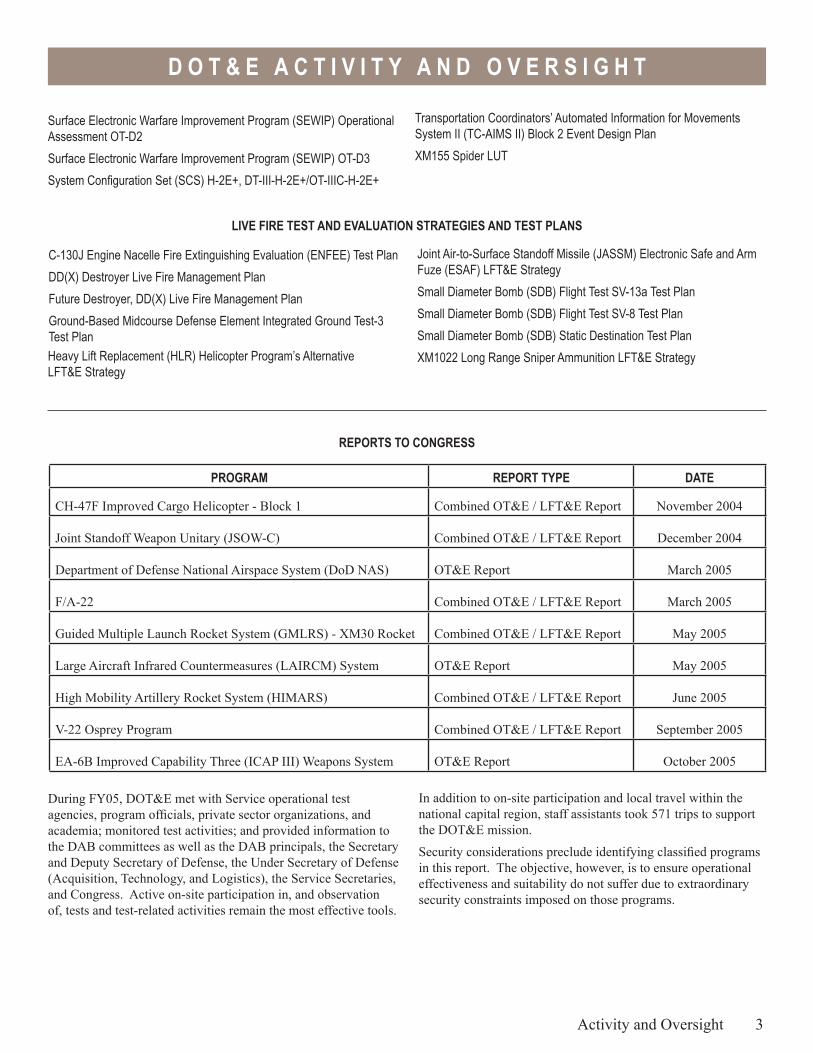
In addition to on-site participation and local travel within the national capital region, staff assistants took 571 trips to support the DOT&E mission.
Security considerations preclude identifying classified programs in this report. The objective, however, is to ensure operational effectiveness and suitability do not suffer due to extraordinary security constraints imposed on those programs.
During FY05, DOT&E met with Service operational test agencies, program officials, private sector organizations, and academia; monitored test activities; and provided information to the DAB committees as well as the DAB principals, the Secretary and Deputy Secretary of Defense, the Under Secretary of Defense (Acquisition, Technology, and Logistics), the Service Secretaries, and Congress. Active on-site participation in, and observation of, tests and test-related activities remain the most effective tools.
Surface Electronic Warfare Improvement Program (SEWIP) Operational Assessment OT-D2Surface Electronic Warfare Improvement Program (SEWIP) OT-D3System Configuration Set (SCS) H-2E+, DT-III-H-2E+/OT-IIIC-H-2E+
Transportation Coordinators’ Automated Information for Movements System II (TC-AIMS II) Block 2 Event Design PlanXM155 Spider LUT
Heavy Lift Replacement (HLR) Helicopter Program’s Alternative LFT&E Strategy
Activity and Oversight 3

4
D O T & E A C T I V I T Y A N D O V E R S I G H T
D O T & E A C T I V I T Y A N D O V E R S I G H T
DOT&E is responsible for approving the adequacy of plans for operational test and evaluation, and for reporting the operational test results for all major defense acquisition programs to the Secretary of Defense, Under Secretary of Defense (Acquisition, Technology, and Logistics), Service Secretaries, and Congress. For DOT&E oversight purposes, major defense acquisition programs were defined in the law to mean those programs meeting the criteria for reporting under section 2430, title 10, United States Code (Selected Acquisition Reports (SARs)). The law (sec.139(a)(2)(B)) also stipulates that DOT&E may designate any other programs for the purpose of oversight, review, and reporting. With the addition of such “non-major” programs, DOT&E was responsible for oversight of a total of 279 acquisition programs during FY05.
Non-major programs are selected for DOT&E oversight after careful consideration of the relative importance of the individual program. In determining non-SAR systems for oversight, consideration is given to one or more of the following essential elements: • Congress or OSD agencies have expressed a high level of
interest in the program. • Congress has directed that DOT&E assess or report on the
program as a condition for progress or production. • The program requires joint or multi-Service testing. The
law (sec. 139(b)(4)) requires DOT&E to coordinate “testing conducted jointly by more than one military department or defense agency.”
• The program exceeds or has the potential to exceed the dollar threshold definition of a major program according to DoD 5000.1, but does not appear on the current SAR list (e.g., highly classified systems).
• The program has a close relationship to or is a key component of a major program.
• The program is an existing system undergoing major modification.
• The program was previously a SAR program and operational testing is not yet complete.
This office is also responsible for the oversight of LFT&E programs, in accordance with 10 USC 139. DoD regulation uses the term “covered system” to include all categories of systems or programs identified in 10 USC 2366 as requiring Live Fire test and evaluation. In addition, systems or programs that do not have acquisition points referenced in 10 USC 2366, but otherwise meet the statutory criteria, are considered “covered systems” for the purpose of DOT&E oversight.
A covered system, for the purpose of oversight for LFT&E, has been determined by DOT&E to meet one or more of the following criteria:• A major system, within the meaning of that term in 10 USC
2302(5), that is:- User-occupied and designed to provide some degree of
protection to the system or its occupants in combat- A conventional munitions program or missile program
• A conventional munitions program for which more than 1,000,000 rounds are planned to be acquired
• A modification to a covered system that is likely to significantly affect the survivability or lethality of such a system
DOT&E was responsible for the oversight of 96 LFT&E acquisition programs during FY05.
Program Oversight
Activity and Oversight 5
D O T & E A C T I V I T Y A N D O V E R S I G H T
PROGRAMS UNDER DOT&E OVERSIGHT CALENDAR YEAR 2005
(As taken from the January 2005 Official T&E Oversight List)
ARMY PROGRAMS
Abrams Tank Upgrade
Advanced Field Artillery Tactical Data System (AFATDS)
Advanced Threat Infrared Countermeasures/Common Missile Warning System (ATIRCM/CMWS)
Aerial Common Sensor (ACS)
Air and Missile Defense Planning and Control System (AMDPCS)
All Source Analysis System (ASAS)
Armed Reconnaissance Helicopter (ARH) Program
Battle Command Sustainment Support System (BCS3)
Black Hawk Upgrades (UH-60M) – Utility Helicopter Upgrades
Bradley Upgrade – Bradley M2A3 Infantry/M3A3 Cavalry Fighting Vehicle
CH-47F – Cargo Helicopter (CH-47D Helicopter Upgrade Program)
Defense Support Program (DSP) Multi-Mission Mobile Processor (DM3P)
Distributed Common Ground System - Army (DCGS-A)
Excalibur (Family of Precision, 155 mm Projectiles)
• Armed Robotic Vehicle (ARV) Assault (ASLT)• Armed Robotic Vehicle (ARV) Assault Light (ASLT(L))• Armed Robotic Vehicle (ARV) Reconnaissance and
Surveillance Target and Acquisition (RSTA)• Multi-Function Utility/Logistics and Equipment Vehicle
(MULE) Countermine• Multi-Function Utility/Logistics and Equipment Vehicle
(MULE) Transport• Small Manpackable Unmanned Ground Vehicle (SUGV)• Unattended Ground Sensors (UGS) (Tactical and Urban UGS)• Non-Line-of-Sight Launch System (NLOS-LS) – to include
Precision Attack Munition (PAM) and Loitering Attack Munition (LAM)
• Intelligent Munitions System (IMS)• Mid-Range Munitions (MRM)
General Fund Enterprise Business System (GFEBS)
Global Combat Support System – Army (GCSS-A)
Global Command and Control System – Army (GCCS-A)
Guided Multiple Launch Rocket System (GMLRS) – Dual Purpose Improved Conventional Munitions (DPICM)
Guided Multiple Launch Rocket System (GMLRS) – Unitary
High Mobility Artillery Rocket System (HIMARS), including HIMARS Armored Cab
Integrated System Control (ISYSCON V4)
Javelin Anti-Tank Missile System – Medium
Joint Common Missile
Joint Land Attack Cruise Missile Defense Elevated Netted Sensors (JLENS)
Joint Mission Planning System (JMPS)
Joint Network Transport Capability-Spiral (JNTC–S)/Joint Network Node (JNN)
Joint Tactical Radio System (JTRS) Cluster 1 (JTRS Cluster 1)
Joint Tactical Radio System (JTRS) Cluster 5 (JTRS Cluster 5)
Joint Tactical Radio System Waveform (JTRS WAVEFORM)
Kiowa Warrior (OH-58D)
Land Warrior – Integrated Soldier Fighting System for Infantrymen
Light Utility Helicopter
Longbow Apache (AH-64D) Block II
6 Activity and Oversight
Extended Range/Multipurpose Unmanned Aerial Vehicle (ER/MP UAV)
Family of Medium Tactical Vehicles (FMTV)Force XXI Battle Command Brigade and Below (FBCB2) Program
Future Cargo Aircraft
Future Combat System (FCS) and all associated systems, including:• Network Battle Command• Infantry Carrier Vehicle (ICV)• Command and Control Vehicle (C2V)• Recon and Surveillance Vehicle (R&SV)• Mounted Combat System (MCS)• Non-Line-of-Sight Mortar (NLOS-M)• Non-Line-of-Sight Cannon (NLOS-C) • Medical Vehicle (MV) (Treatment and Evacuation Variant)• FCS Recovery Maintenance Vehicle (FRMV)• UAV Class I • UAV Class II • UAV Class III • UAV Class IV (Fire Scout)
D O T & E A C T I V I T Y A N D O V E R S I G H T
Longbow Apache (AH-64D) Block III
Hellfire Missile (Upgrades/Modifications), including Longbow (RF) and SAL
Maneuver Control System (MCS) Army Tactical Command and Control System (MCS (ATCCS))
Mobile Tactical High Energy Laser (MTHEL)
Objective Individual Combat Weapon (OICW) Increment I
Objective Individual Combat Weapon (OICW) Increment II
Objective Individual Combat Weapon (OICW) Increment III
PATRIOT/Medium Extended Air Defense System Combined Aggregate Program (PATRIOT/MEADS CAP)
Precision Guided Mortar Munitions (PGMM)
Shadow Unmanned Aerial Vehicle (Shadow UAV)
Single Channel Anti-Jam Man-Portable (SCAMP) (MILSTAR, Block II)
Single Channel Anti-Jam Man-Portable (SCAMP) System Enhancement Program (SEP)
Small Unmanned Aerial Vehicle (Small UAV)
Spider XM7 Network Command Munition
Stryker – Armored Vehicle and all associated systems, including:• Stryker – Anti-Tank Guided Missile Vehicle• Stryker – Commander’s Vehicle• Stryker – Engineer Squad Vehicle• Stryker – Fire Support Vehicle• Stryker – Infantry Carrier Vehicle• Stryker – Medical Evacuation Vehicle• Stryker – Mortar Carrier• Stryker – Reconnaissance Vehicle• Stryker – Mobile Gun System• Stryker – Nuclear, Biological, and Chemical (NBC)
Reconnaissance Vehicle
Suite of Integrated Radio Frequency Countermeasures (SIRFC) (AN/ALQ-211)
Surface-Launched AMRAAM (SLAMRAAM)
Transportation Coordinators’ Automated Information for Movements System II (TC-AIMS II)
Warfighter Information Network-Tactical (WIN-T)
XM307 Advanced Crew Served Weapon System (ACSWS) (formerly the OCSWS)
NAVY PROGRAMS
21” Mission Reconfigurable Unmanned Undersea Vehicle (21” MRUUV)
Acoustic Rapid Commerical Off-the-Shelf (COTS) Insertion for SONAR
Active Electronically Scanned Array (AESA)
Advanced Deployable System (ADS)
Advanced SEAL Delivery System (ASDS)
AGM-88E Advanced Anti-Radiation Guided Missile (AARGM) Program
AIM-9X Air-to-Air Missile Upgrade
Airborne Mine Neutralization System (AMNS)
Air Early Warning (AEW)
AN/AAR-47 V2 Upgrade Missile/Laser Warning Receiver
AN/ALR-67 Advanced Special Receiver (ASR) V2 and V3
AN/APR-39A V2 Radar Warning Receiver
AN/SPY-1 B/D (All Versions)
AN/WSQ-11 Countermeasure Anti-Torpedo
Ballistic Missile Technical Collection (BMTC)
Broad Area Maritime Surveillance (BAMS)
CG(X) – Next Generation Cruiser
Cooperative Engagement Capability (CEC)
Cobra Judy Replacement (CJR) - Ship-based Radar System
CVN 21 – Next Generation Nuclear Aircraft Carrier
CVN 68 – Nimitz Class Nuclear Powered Aircraft Carriers
DDG 51 Guided Missile Destroyer
DD(X) Future Surface Combatant including Long Range Land Attack Projectile
Defense Integrated Military Human Resources System (DIMHRS)
Deployable Joint Command and Control (DJC2)
ARMY PROGRAMS (continued)
E-2C Advanced Hawkeye (E2C Radar Modernization Program (RMP))
E-2D Reproduction Hawkeye Carrier-based Early Warning Aircraft
Activity and Oversight 7
D O T & E A C T I V I T Y A N D O V E R S I G H T
NAVY PROGRAMS (continued)
EA-6B Improved Capabilities (ICAP) III and Multiple Upgrades (Low Band Transmitter, Band 7-8 Transmitter, USQ-113 Communications Jammer)
EA-18G (Electronic Attack variant of F/A-18)
Expeditionary Fighting Vehicle (EFV)
Evolved Sea Sparrow Missile (ESSM)
Extended Range Munition (ERM)
F/A-18 E/F Hornet Naval Strike Fighter (All Upgrades)
Fixed Distributed System (FDS)
Global Command and Control System – Maritime (GCCS-M)
Global Combat Support System – Marine Corps (GCSS-MC)
H-1 Upgrades (4BW/4BN) – U.S. Marine Corps Upgrade to AH-1W Attack Helicopter and UH-1N Utility Helicopter
Heavy Lift Replacement (HLR) Helicopter (CH-53X Upgrade to U.S. Marine Corps H-53 Program)
Identification Friend or Foe Mark XIIA Mode 5
Integrated Defensive Electronic Countermeasure (IDECM)
Joint High Speed Vessel (JHSV)
Joint Mission Planning System (JMPS)
Joint Standoff Weapon (JSOW) Baseline Variant and Unitary Warhead Variant
KC-130J Aircraft
LHA(R) – New Amphibious Assault Ship
LHD 1 Amphibious Assault Ship
LHD 8 Amphibious Assault Ship
Littoral Combat Ship (LCS)
LPD 17 Amphibious Transport Dock (Includes 30 mm ammunition)
Maritime Prepositioning Force (Future) (MPF (F))
MH-60R Multi-Mission Helicopter Upgrade
MH-60S Helicopter (Utility helicopter)
Mk 48 Torpedo Mods
Multi-Functional Information Distribution System – Low Volume Terminal (MIDS-LVT)
Multi-Mission Maritime Aircraft (MMA)
Naval Integrated Fire Control-Counter Air (NIFC-CA)
AIR FORCE PROGRAMS
Advanced Extremely High Frequency (AEHF) Program
Advanced Medium Range Air-to-Air Missile (AMRAAM)
Advanced Polar System (APS)
Air Operations Center – Weapons System (AOC-WS)
8 Activity and Oversight
Navy Advanced EHF Multi-Band Terminal (NMT)
Navy Enterprise Resource Planning (ERP) (includes Navy Enterprise Maintenance Automated Information System (NEMAIS)Navy-Marine Corps Intranet (NMCI)
Rapid Airborne Mine Clearance System (RAMICS)
Rolling Airframe Missile (RAM)
Ship Self Defense System (SSDS)
SSGN Ohio Class Conversion
SSN 21 Seawolf /AN/BSY-2
SSN 774 Virginia Class Submarine
Standard Missile 2 (SM-2) Block IIIB
Standard Missile 2 (SM-2) Block IV
Standard Missile 6 (SM-6)
Submarine Exterior Communications System (SubECS) (Includes Common Submarine Radio Room (CSRR))
Surface Electronic Warfare Improvement Program (SEWIP)
T-45TS – Undergraduate Jet Pilot Training System
T-AKE Lewis & Clark Class of Auxiliary Dry Cargo Ships
T-AOE(X) Fast Combatant Support Ship
Tactical Control System (TCS)
Tactical Tomahawk Missile
Tactical Tomahawk Mission Planning System/Tomahawk Command and Control System (MPS/TCCS)
Trident II Missile
V-22 Osprey Joint Advanced Vertical Lift Aircraft
Vertical Take-Off Unmanned Aerial Vehicle (VTUAV)
VH-71 Presidential Helicopter Fleet Replacement Program (formerly the VXX program)
D O T & E A C T I V I T Y A N D O V E R S I G H T
Airborne Warning and Control System (AWACS (E-3)) Upgrades
ALR-56M Radar Warning Receiver
ALR-69A Radar Warning Receiver
B-2 SPIRIT Advanced Extremely High Frequency SatCom Capability (B-2 EHF)
B-2 Radar Modernization Program (B-2 RMP)
B-52 Re-engining Program
B-52 Standoff Jammer (SOJ)
Battle Control System – Mobile (BCS-M) (formerly the Tactical Air Control System (TACS))
C-5 Avionics Modernization Program (AMP)
C-5 Reliability and Re-engining Program (RERP)
C-17A – Globemaster III Advance Cargo Aircraft
C-130 Avionics Modernization Program (C-130 AMP)
C-130J Hercules Cargo Aircraft (All Variants)
Combatant Commanders Integrated Command and Control System (CCIC2S)
Combat Information Transport System Combatant (CITS)
Combat Survivor Evader Locator (CSEL) and the PRC Family of Handheld Survivor Radios
Defense Enterprise Accounting Management System (DEAMS)
Global Positioning System III (GPS III)
Global Transportation Network-21 (GTN-21)
Integrated Strategic Planning and Analysis Network (ISPAN)
Joint Air-to-Surface Standoff Missile (JASSM) and JASSM Expanded Response (ER)
Joint Direct Attack Munition (JDAM)
Joint Helmet Mounted Cueing System (JHMCS)
Joint Precision Approach and Landing System (JPALS)
Joint Primary Aircraft Training System (JPATS)
Joint Tactical Radio System (JTRS) Airborne/Maritime/Fixed Station (AMF)
Joint Unmanned Combat Air System (JOINT UCAS) (Includes Air Force and Navy UAV programs)
KC-135 Global Air Traffic Management (GATM) Upgrade
KC-135 Tanker Replacement Program (KC-135 Replacement)
Large Aircraft Infrared Countermeasures (LAIRCM)
Milstar – Satellite Low/Med-Data Rate Communications
Minuteman III Guidance Replacement Program (GRP)
Minuteman III Propulsion Replacement Program (PRP)
Mission Planning System (MPS) including the Joint Mission Planning System (JMPS)
Mobile User Objective System (MUOS)
Multi-Platform Radar Technology Insertion Program (MP RTIP)
Multiple Platform – Common Data Link (MP-CDL)
National Airspace System (NAS)
National Polar-Orbiting Operational Environment Satellite System (NPOESS)
NAVSTAR Global Positioning System (GPS)
Navy Extremely High Frequency (NESP) Satellite Communications (SATCOM) Program
Orbital Deep Space Imager (ODSI)
Personnel Recovery Vehicle (PRV)
Predator Unmanned Aerial Vehicle (UAV) RQ/MQ-1
Predator B Armed Unmanned Aerial Vehicle (UAV) MQ 9
Space-Based Infrared System Program, High Component (SBIRS HIGH)
Space-Based Radar (SBR)
Small Diameter Bomb (SDB)
Secure Mobile Anti-Jam Reliable Tactical Terminal (SMART-T)
AIR FORCE PROGRAMS (continued)
Deliberate and Crisis Action Planning and Execution Segments (DCAPES)Distributed Common Ground System – Air Force (DCGS-AF) (including Block 10)
E-4B Modernization Program
E-8 Joint Surveillance Target Attack Radar System (JSTARS)
E-10A Multi-Sensor Command and Control Aircraft (MC2A) Program
Evolved Expendable Launch Vehicle (EELV)
Expeditionary Combat Support Systems (ECSS)
F-15 Tactical Electronic Warfare Suite (TEWS) (AN/ALQ-135 Band 1.5 Fiber-Optic Towed Decoy)
F/A-22 – Advanced Tactical Fighter
F-35 Joint Strike Fighter (JSF)
F-117 Infrared Acquisition and Designation System (IRADS)
Family of Beyond Line-of-Sight Terminals (FAB-T)
Global Broadcast Service (GBS)
Global Command and Control System – Air Force (GCCS-AF)
Global Hawk High-Altitude Endurance Unmanned Aerial Vehicle
Activity and Oversight 9
D O T & E A C T I V I T Y A N D O V E R S I G H T
OTHER DoD PROGRAMS
Ballistic Missile Defense Program• Aegis Ballistic Missile Defense (BMD) and SM-3 BLOCK I• Ground-Based Midcourse Defense Segment (Includes
Ground-Based Interceptor [GBI], Ground-Based Radar [GBR], and Battle Management C3 [BMC3])
• Space Tracking and Surveillance System (STSS) • Terminal High-Altitude Area Defense (THAAD) • YAL-1 Airborne Laser (ABL)
Artemis (Chemical Agent Standoff Detection System)
Business System Modernization (BSM)
Chemical Demilitarization Program – Assembled Chemical Weapons Alternatives (CHEM DEMIL-ACWA)
Chemical Demilitarization Program – Chemical Materials Agency (CHEM DEMIL-CMA)
Chemical Demilitarization Program – Chemical Materials Agency Newport (CHEM DEMIL-CMA NEWPORT)
Composite Health Care System II (CHCS II)
Consolidated Advanced Resale Transaction System (CARTS)
Defense Message System (DMS)
Defense Travel System (DTS)
Global Combat Support System COCOM/JTF (GCSS (CC/JTF))
Global Command and Control System – Joint (GCCS J)
Global Electromagnetic Spectrum Information System (GEMSIS)
Global Information Grid Bandwidth Expansion (GIG-BE)
High Performance Computing Modernization (HPCM)
Internet Protocol version 6 (IPv6)
10 Activity and Oversight
Joint Biological Agent Identification and Diagnostic System (JBAIDS)
Joint Biological Point Detection System (JBPDS)
Joint Biological Standoff Detection System (JBSDS)
Joint Chemical Agent Detector (JCAD)
Joint Command and Control (JC2)
Joint Service Light Nuclear, Biological, and Chemical (NBC) Reconnaissance System (JSLNBCRS)
Joint Service Lightweight Standoff Chemical Agent Detector (JSLSCAD)Joint Service Sensitive Equipment Decontamination (JSSED)
Joint Warning and Reporting Network (JWARN)
Key Management Infrastructure (KMI)
Net-Centric Enterprise Services (NCES)
Public Key Infrastructure (PKI)
Single Integrated Air Picture (SIAP)
Teleport
Theater Medical Information Program (TMIP)
AIR FORCE PROGRAMS (continued)
Theater Battle Management Core System (TBMCS)
Transformational SATCOM System (TSAT)
Ultra High Frequency (UHF) Follow-on Satellite
Wideband Gapfiller

DoD Programs

DoD
Prog
ram
s
D O D P R O G R A M S
Executive Summary• The Joint Interoperability Test Command completed the initial
operational testing of Business Systems Modernization (BSM) in November 2004.
• Test results showed that the system is operationally effective and operationally suitable, but had some suitability deficiencies.
• As the fielding of the system continues, the program manager must pay particular attention to potential adverse impacts to performance measures as new and inexperienced users are added to the system.
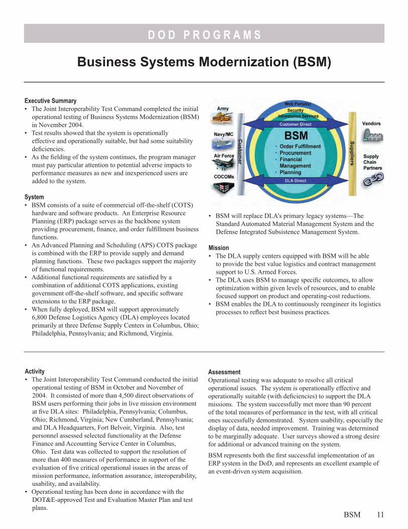
System• BSM consists of a suite of commercial off-the-shelf (COTS)
hardware and software products. An Enterprise Resource Planning (ERP) package serves as the backbone system providing procurement, finance, and order fulfillment business functions.
• An Advanced Planning and Scheduling (APS) COTS package is combined with the ERP to provide supply and demand planning functions. These two packages support the majority of functional requirements.
• Additional functional requirements are satisfied by a combination of additional COTS applications, existing government off-the-shelf software, and specific software extensions to the ERP package.
• When fully deployed, BSM will support approximately 6,800 Defense Logistics Agency (DLA) employees located primarily at three Defense Supply Centers in Columbus, Ohio; Philadelphia, Pennsylvania; and Richmond, Virginia.
• BSM will replace DLA’s primary legacy systems—The Standard Automated Material Management System and the Defense Integrated Subsistence Management System.
Mission• The DLA supply centers equipped with BSM will be able
to provide the best value logistics and contract management support to U.S. Armed Forces.
• The DLA uses BSM to manage specific outcomes, to allow optimization within given levels of resources, and to enable focused support on product and operating-cost reductions.
• BSM enables the DLA to continuously reengineer its logistics processes to reflect best business practices.
AssessmentOperational testing was adequate to resolve all critical operational issues. The system is operationally effective and operationally suitable (with deficiencies) to support the DLA missions. The system successfully met more than 90 percent of the total measures of performance in the test, with all critical ones successfully demonstrated. System usability, especially the display of data, needed improvement. Training was determined to be marginally adequate. User surveys showed a strong desire for additional or advanced training on the system.
BSM represents both the first successful implementation of an ERP system in the DoD, and represents an excellent example of an event-driven system acquisition.
Activity• The Joint Interoperability Test Command conducted the initial
operational testing of BSM in October and November of 2004. It consisted of more than 4,500 direct observations of BSM users performing their jobs in live mission environment at five DLA sites: Philadelphia, Pennsylvania; Columbus, Ohio; Richmond, Virginia; New Cumberland, Pennsylvania; and DLA Headquarters, Fort Belvoir, Virginia. Also, test personnel assessed selected functionality at the Defense Finance and Accounting Service Center in Columbus, Ohio. Test data was collected to support the resolution of more than 400 measures of performance in support of the evaluation of five critical operational issues in the areas of mission performance, information assurance, interoperability, usability, and availability.
• Operational testing has been done in accordance with the DOT&E-approved Test and Evaluation Master Plan and test plans.
Business Systems Modernization (BSM)
BSM 11

D O D P R O G R A M S
Recommendations1. The program manager must pay attention to adverse impacts to
operational performance measures as new and inexperienced users are added to the system.
2. The program manager should investigate ways to improve training and enhance data presentation to the user’s computer screens to improve system usability.
12 BSM
D O D P R O G R A M S
Executive Summary• U.S. Army testing of stockpile and nonstockpile systems in
the Chemical Demilitarization Program has been adequate to ensure the safe and efficient disposal of chemical warfare material.
• All Operational Testing (OT) was conducted in accordance with DOT&E-approved test plans.
• Successful testing was conducted at Anniston, Alabama; Umatilla, Oregon; Pine Bluff, Arkansas; Aberdeen, Maryland; and Newport, Indiana, stockpile facilities.
• Successful testing of nonstockpile programs was conducted for two Explosive Destruction Systems (EDS), and also for the Munitions Assessment and Processing System (MAPS).
• Agent destruction operations began at Pine Bluff, Aberdeen, and Newport facilities.
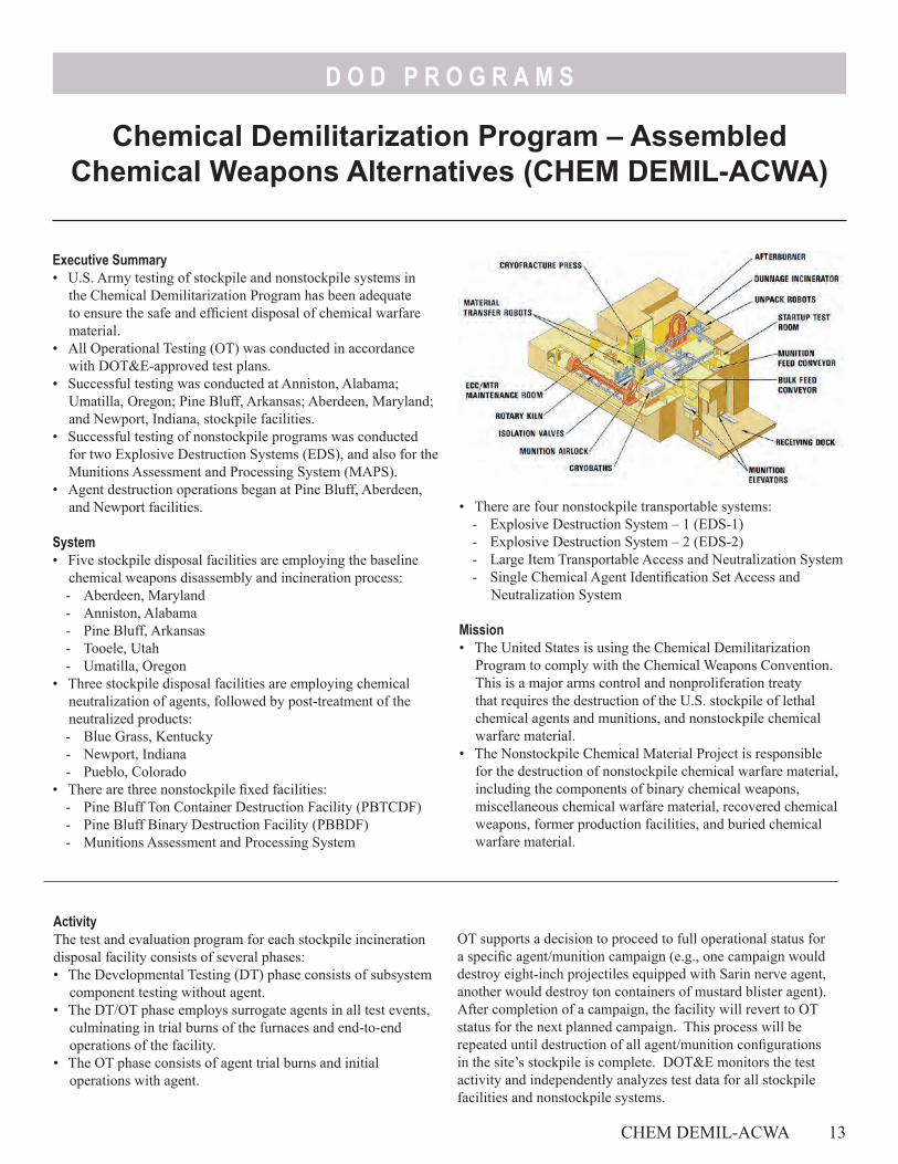
System• Five stockpile disposal facilities are employing the baseline
chemical weapons disassembly and incineration process:- Aberdeen, Maryland - Anniston, Alabama- Pine Bluff, Arkansas- Tooele, Utah- Umatilla, Oregon
• Three stockpile disposal facilities are employing chemical neutralization of agents, followed by post-treatment of the neutralized products:- Blue Grass, Kentucky- Newport, Indiana- Pueblo, Colorado
• There are three nonstockpile fixed facilities:- Pine Bluff Ton Container Destruction Facility (PBTCDF)- Pine Bluff Binary Destruction Facility (PBBDF)- Munitions Assessment and Processing System
• There are four nonstockpile transportable systems:- Explosive Destruction System – 1 (EDS-1)- Explosive Destruction System – 2 (EDS-2)- Large Item Transportable Access and Neutralization System- Single Chemical Agent Identification Set Access and
Neutralization System
Mission• The United States is using the Chemical Demilitarization
Program to comply with the Chemical Weapons Convention. This is a major arms control and nonproliferation treaty that requires the destruction of the U.S. stockpile of lethal chemical agents and munitions, and nonstockpile chemical warfare material.
• The Nonstockpile Chemical Material Project is responsible for the destruction of nonstockpile chemical warfare material, including the components of binary chemical weapons, miscellaneous chemical warfare material, recovered chemical weapons, former production facilities, and buried chemical warfare material.
Chemical Demilitarization Program – Assembled Chemical Weapons Alternatives (CHEM DEMIL-ACWA)
ActivityThe test and evaluation program for each stockpile incineration disposal facility consists of several phases:• The Developmental Testing (DT) phase consists of subsystem
component testing without agent. • The DT/OT phase employs surrogate agents in all test events,
culminating in trial burns of the furnaces and end-to-end operations of the facility.
• The OT phase consists of agent trial burns and initial operations with agent.
OT supports a decision to proceed to full operational status for a specific agent/munition campaign (e.g., one campaign would destroy eight-inch projectiles equipped with Sarin nerve agent, another would destroy ton containers of mustard blister agent). After completion of a campaign, the facility will revert to OT status for the next planned campaign. This process will be repeated until destruction of all agent/munition configurations in the site’s stockpile is complete. DOT&E monitors the test activity and independently analyzes test data for all stockpile facilities and nonstockpile systems.
CHEM DEMIL-ACWA 13
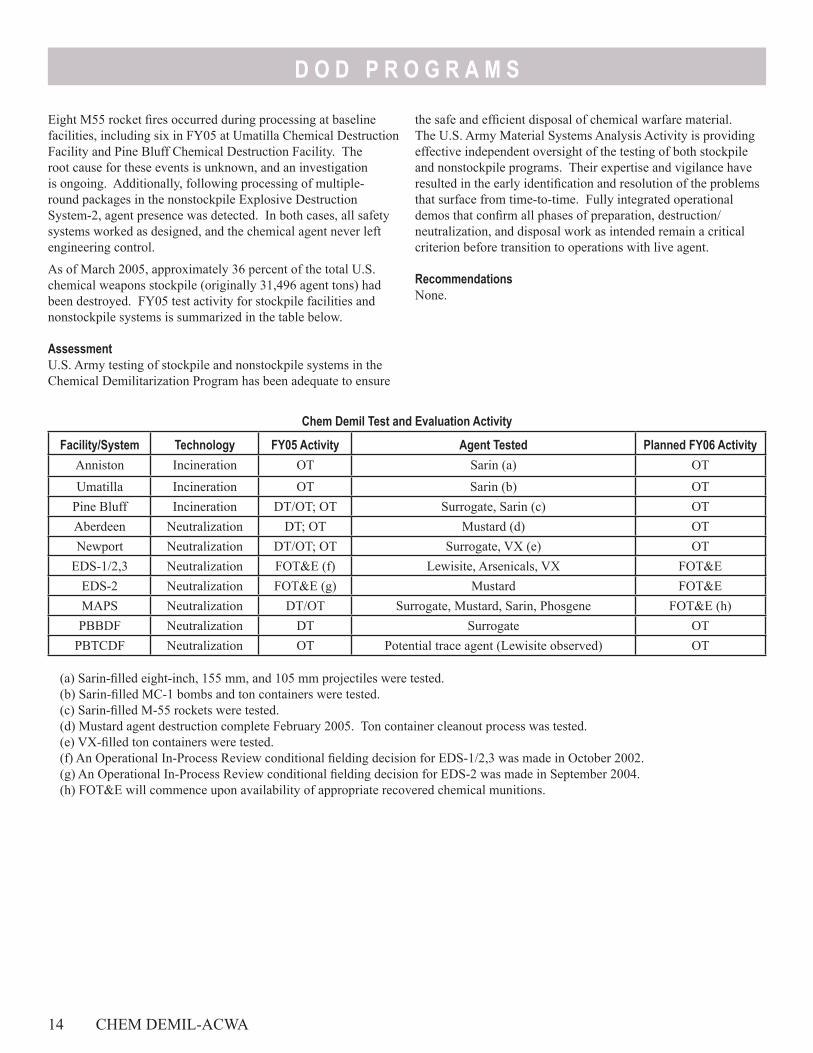
D O D P R O G R A M S
Eight M55 rocket fires occurred during processing at baseline facilities, including six in FY05 at Umatilla Chemical Destruction Facility and Pine Bluff Chemical Destruction Facility. The root cause for these events is unknown, and an investigation is ongoing. Additionally, following processing of multiple-round packages in the nonstockpile Explosive Destruction System-2, agent presence was detected. In both cases, all safety systems worked as designed, and the chemical agent never left engineering control.
As of March 2005, approximately 36 percent of the total U.S. chemical weapons stockpile (originally 31,496 agent tons) had been destroyed. FY05 test activity for stockpile facilities and nonstockpile systems is summarized in the table below.
AssessmentU.S. Army testing of stockpile and nonstockpile systems in the Chemical Demilitarization Program has been adequate to ensure
Chem Demil Test and Evaluation Activity
Facility/System Technology FY05 Activity Agent Tested Planned FY06 ActivityAnniston Incineration OT Sarin (a) OTUmatilla Incineration OT Sarin (b) OT
Pine Bluff Incineration DT/OT; OT Surrogate, Sarin (c) OTAberdeen Neutralization DT; OT Mustard (d) OTNewport Neutralization DT/OT; OT Surrogate, VX (e) OT
EDS-1/2,3 Neutralization FOT&E (f) Lewisite, Arsenicals, VX FOT&E EDS-2 Neutralization FOT&E (g) Mustard FOT&EMAPS Neutralization DT/OT Surrogate, Mustard, Sarin, Phosgene FOT&E (h)PBBDF Neutralization DT Surrogate OT
PBTCDF Neutralization OT Potential trace agent (Lewisite observed) OT
(a) Sarin-filled eight-inch, 155 mm, and 105 mm projectiles were tested.(b) Sarin-filled MC-1 bombs and ton containers were tested.(c) Sarin-filled M-55 rockets were tested.(d) Mustard agent destruction complete February 2005. Ton container cleanout process was tested.(e) VX-filled ton containers were tested.(f) An Operational In-Process Review conditional fielding decision for EDS-1/2,3 was made in October 2002.(g) An Operational In-Process Review conditional fielding decision for EDS-2 was made in September 2004.(h) FOT&E will commence upon availability of appropriate recovered chemical munitions.
14 CHEM DEMIL-ACWA
the safe and efficient disposal of chemical warfare material. The U.S. Army Material Systems Analysis Activity is providing effective independent oversight of the testing of both stockpile and nonstockpile programs. Their expertise and vigilance have resulted in the early identification and resolution of the problems that surface from time-to-time. Fully integrated operational demos that confirm all phases of preparation, destruction/neutralization, and disposal work as intended remain a critical criterion before transition to operations with live agent.
RecommendationsNone.
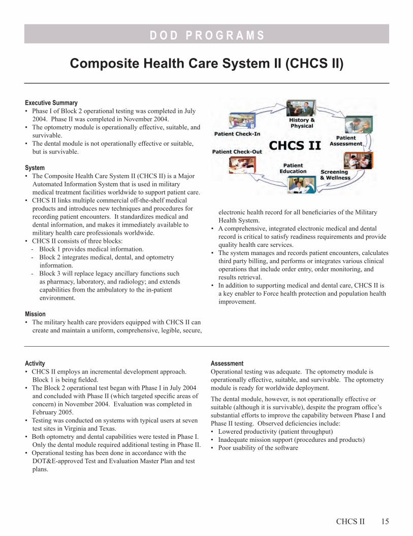
D O D P R O G R A M S
Composite Health Care System II (CHCS II)
electronic health record for all beneficiaries of the Military Health System.
• A comprehensive, integrated electronic medical and dental record is critical to satisfy readiness requirements and provide quality health care services.
• The system manages and records patient encounters, calculates third party billing, and performs or integrates various clinical operations that include order entry, order monitoring, and results retrieval.
• In addition to supporting medical and dental care, CHCS II is a key enabler to Force health protection and population health improvement.
Executive Summary• Phase I of Block 2 operational testing was completed in July
2004. Phase II was completed in November 2004.• The optometry module is operationally effective, suitable, and
survivable.• The dental module is not operationally effective or suitable,
but is survivable.
System• The Composite Health Care System II (CHCS II) is a Major
Automated Information System that is used in military medical treatment facilities worldwide to support patient care.
• CHCS II links multiple commercial off-the-shelf medical products and introduces new techniques and procedures for recording patient encounters. It standardizes medical and dental information, and makes it immediately available to military health care professionals worldwide.
• CHCS II consists of three blocks:- Block 1 provides medical information. - Block 2 integrates medical, dental, and optometry
information. - Block 3 will replace legacy ancillary functions such
as pharmacy, laboratory, and radiology; and extends capabilities from the ambulatory to the in-patient environment.
Mission• The military health care providers equipped with CHCS II can
create and maintain a uniform, comprehensive, legible, secure,
AssessmentOperational testing was adequate. The optometry module is operationally effective, suitable, and survivable. The optometry module is ready for worldwide deployment.
The dental module, however, is not operationally effective or suitable (although it is survivable), despite the program office’s substantial efforts to improve the capability between Phase I and Phase II testing. Observed deficiencies include:• Lowered productivity (patient throughput)• Inadequate mission support (procedures and products)• Poor usability of the software
Activity• CHCS II employs an incremental development approach.
Block 1 is being fielded.• The Block 2 operational test began with Phase I in July 2004
and concluded with Phase II (which targeted specific areas of concern) in November 2004. Evaluation was completed in February 2005.
• Testing was conducted on systems with typical users at seven test sites in Virginia and Texas.
• Both optometry and dental capabilities were tested in Phase I. Only the dental module required additional testing in Phase II.
• Operational testing has been done in accordance with the DOT&E-approved Test and Evaluation Master Plan and test plans.
CHCS II 15
D O D P R O G R A M S
The dental module slowed operations to an unacceptable pace and required dentists to follow a frustrating and sometimes illogical set of procedures. Despite these deficiencies, the system offers benefits overall, including a legible, accurate, and electronically transferable health record.
Recommendations1. The dental module is not ready for deployment until correction
and verification of software deficiencies.
16 CHCS II
2. The correction to the deficiencies should focus on the following:- Using more logical procedures that mirror the processes
military dentists are trained to follow- Providing a patient record that can be easily read and
understood in all dental treatment facilities3. Conduct follow-on test and evaluation on the dental module
after the deficiencies have been corrected and verified during developmental testing.
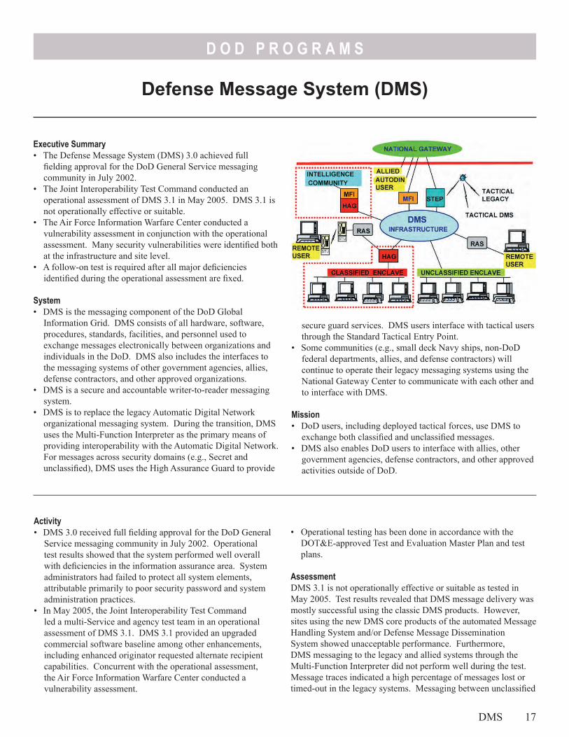
D O D P R O G R A M S
Defense Message System (DMS)
Executive Summary• The Defense Message System (DMS) 3.0 achieved full
fielding approval for the DoD General Service messaging community in July 2002.
• The Joint Interoperability Test Command conducted an operational assessment of DMS 3.1 in May 2005. DMS 3.1 is not operationally effective or suitable.
• The Air Force Information Warfare Center conducted a vulnerability assessment in conjunction with the operational assessment. Many security vulnerabilities were identified both at the infrastructure and site level.
• A follow-on test is required after all major deficiencies identified during the operational assessment are fixed.
System• DMS is the messaging component of the DoD Global
Information Grid. DMS consists of all hardware, software, procedures, standards, facilities, and personnel used to exchange messages electronically between organizations and individuals in the DoD. DMS also includes the interfaces to the messaging systems of other government agencies, allies, defense contractors, and other approved organizations.
• DMS is a secure and accountable writer-to-reader messaging system.
• DMS is to replace the legacy Automatic Digital Network organizational messaging system. During the transition, DMS uses the Multi-Function Interpreter as the primary means of providing interoperability with the Automatic Digital Network. For messages across security domains (e.g., Secret and unclassified), DMS uses the High Assurance Guard to provide
secure guard services. DMS users interface with tactical users through the Standard Tactical Entry Point.
• Some communities (e.g., small deck Navy ships, non-DoD federal departments, allies, and defense contractors) will continue to operate their legacy messaging systems using the National Gateway Center to communicate with each other and to interface with DMS.
Mission• DoD users, including deployed tactical forces, use DMS to
exchange both classified and unclassified messages.• DMS also enables DoD users to interface with allies, other
government agencies, defense contractors, and other approved activities outside of DoD.
• Operational testing has been done in accordance with the DOT&E-approved Test and Evaluation Master Plan and test plans.
AssessmentDMS 3.1 is not operationally effective or suitable as tested in May 2005. Test results revealed that DMS message delivery was mostly successful using the classic DMS products. However, sites using the new DMS core products of the automated Message Handling System and/or Defense Message Dissemination System showed unacceptable performance. Furthermore, DMS messaging to the legacy and allied systems through the Multi-Function Interpreter did not perform well during the test. Message traces indicated a high percentage of messages lost or timed-out in the legacy systems. Messaging between unclassified
Activity• DMS 3.0 received full fielding approval for the DoD General
Service messaging community in July 2002. Operational test results showed that the system performed well overall with deficiencies in the information assurance area. System administrators had failed to protect all system elements, attributable primarily to poor security password and system administration practices.
• In May 2005, the Joint Interoperability Test Command led a multi-Service and agency test team in an operational assessment of DMS 3.1. DMS 3.1 provided an upgraded commercial software baseline among other enhancements, including enhanced originator requested alternate recipient capabilities. Concurrent with the operational assessment, the Air Force Information Warfare Center conducted a vulnerability assessment.
DMS 17
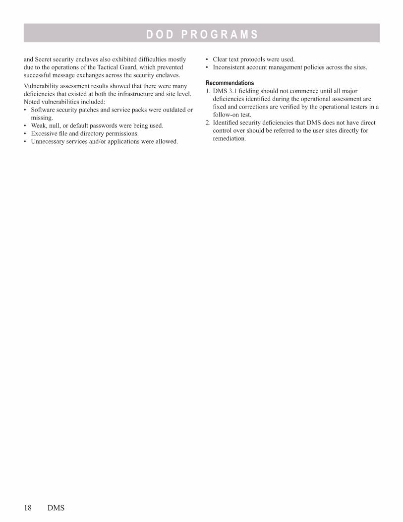
D O D P R O G R A M S
and Secret security enclaves also exhibited difficulties mostly due to the operations of the Tactical Guard, which prevented successful message exchanges across the security enclaves.
Vulnerability assessment results showed that there were many deficiencies that existed at both the infrastructure and site level. Noted vulnerabilities included:• Software security patches and service packs were outdated or
missing.• Weak, null, or default passwords were being used.• Excessive file and directory permissions.• Unnecessary services and/or applications were allowed.
18 DMS
• Clear text protocols were used.• Inconsistent account management policies across the sites.
Recommendations1. DMS 3.1 fielding should not commence until all major
deficiencies identified during the operational assessment are fixed and corrections are verified by the operational testers in a follow-on test.
2. Identified security deficiencies that DMS does not have direct control over should be referred to the user sites directly for remediation.
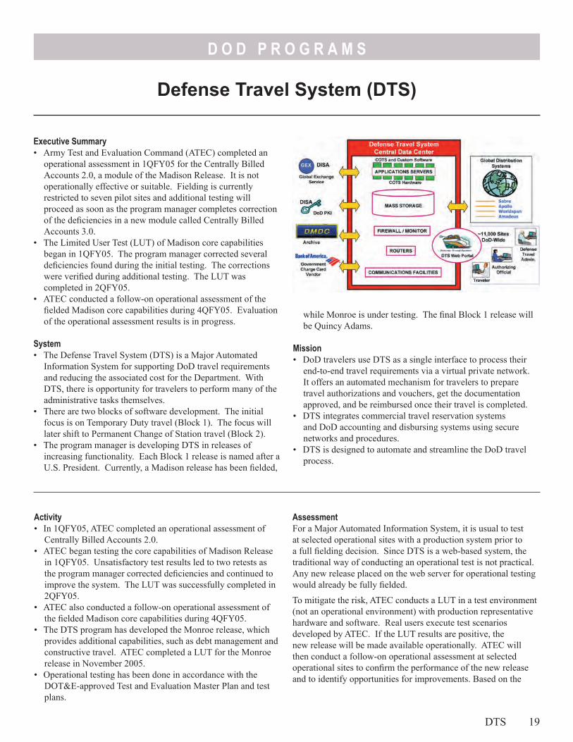
D O D P R O G R A M S
Defense Travel System (DTS)
Executive Summary• Army Test and Evaluation Command (ATEC) completed an
operational assessment in 1QFY05 for the Centrally Billed Accounts 2.0, a module of the Madison Release. It is not operationally effective or suitable. Fielding is currently restricted to seven pilot sites and additional testing will proceed as soon as the program manager completes correction of the deficiencies in a new module called Centrally Billed Accounts 3.0.
• The Limited User Test (LUT) of Madison core capabilities began in 1QFY05. The program manager corrected several deficiencies found during the initial testing. The corrections were verified during additional testing. The LUT was completed in 2QFY05.
• ATEC conducted a follow-on operational assessment of the fielded Madison core capabilities during 4QFY05. Evaluation of the operational assessment results is in progress.
System• The Defense Travel System (DTS) is a Major Automated
Information System for supporting DoD travel requirements and reducing the associated cost for the Department. With DTS, there is opportunity for travelers to perform many of the administrative tasks themselves.
• There are two blocks of software development. The initial focus is on Temporary Duty travel (Block 1). The focus will later shift to Permanent Change of Station travel (Block 2).
• The program manager is developing DTS in releases of increasing functionality. Each Block 1 release is named after a U.S. President. Currently, a Madison release has been fielded,
while Monroe is under testing. The final Block 1 release will be Quincy Adams.
Mission• DoD travelers use DTS as a single interface to process their
end-to-end travel requirements via a virtual private network. It offers an automated mechanism for travelers to prepare travel authorizations and vouchers, get the documentation approved, and be reimbursed once their travel is completed.
• DTS integrates commercial travel reservation systems and DoD accounting and disbursing systems using secure networks and procedures.
• DTS is designed to automate and streamline the DoD travel process.
AssessmentFor a Major Automated Information System, it is usual to test at selected operational sites with a production system prior to a full fielding decision. Since DTS is a web-based system, the traditional way of conducting an operational test is not practical. Any new release placed on the web server for operational testing would already be fully fielded.
To mitigate the risk, ATEC conducts a LUT in a test environment (not an operational environment) with production representative hardware and software. Real users execute test scenarios developed by ATEC. If the LUT results are positive, the new release will be made available operationally. ATEC will then conduct a follow-on operational assessment at selected operational sites to confirm the performance of the new release and to identify opportunities for improvements. Based on the
Activity• In 1QFY05, ATEC completed an operational assessment of
Centrally Billed Accounts 2.0.• ATEC began testing the core capabilities of Madison Release
in 1QFY05. Unsatisfactory test results led to two retests as the program manager corrected deficiencies and continued to improve the system. The LUT was successfully completed in 2QFY05.
• ATEC also conducted a follow-on operational assessment of the fielded Madison core capabilities during 4QFY05.
• The DTS program has developed the Monroe release, which provides additional capabilities, such as debt management and constructive travel. ATEC completed a LUT for the Monroe release in November 2005.
• Operational testing has been done in accordance with the DOT&E-approved Test and Evaluation Master Plan and test plans.
DTS 19
D O D P R O G R A M S
Madison LUT results, ATEC considered the release operationally effective, suitable, and survivable, but with deficiencies noted. We agreed to the installation of the new Madison release for an in-field operational assessment. The operational assessment data collection was completed, but data analysis is still ongoing.
Although DTS worked satisfactorily with most of its many interfacing accounting and disbursing systems, there was an anomaly with the legacy Washington Headquarters Services Allotment Accounting Systems, which caused delay in processing some of the DTS transactions. Although this problem was subsequently fixed by the maintenance staff of the legacy accounting systems, these systems were not available to process FY06 transactions for the first two weeks of the new fiscal year. Any problem such as this requires implementing workarounds and confuses those travelers that have to use DTS interfacing with these legacy systems.
The Centrally Billed Accounts 2.0 module of Madison is neither operationally effective nor suitable. The credit card reconciliation process is not prompt and there are certain interoperability and business process deficiencies, such as
occasional non-receipt of charge card vendor invoices and cumbersome manual reconciliation processes.
The Monroe release is not operationally effective or suitable, but is survivable. There are many faulty cost computations on obligations, vouchers, debt resolutions, cost entitlements, remittances, waivers, and payroll deductions, which led to many data exchange rejections by interfacing systems.
Recommendations1. The Centrally Billed Accounts 2.0 module should not be
fielded past the pilot sites until the program manager corrects the deficiencies and the fixes are verified by ATEC.
2. The Monroe release should not be fielded until the program manager corrects the deficiencies and ATEC retests the release.
2. The Monroe release operational assessment should include the legacy accounting system to avoid problems that were experienced in the past.
3. Fix or replace the legacy Washington Headquarters Services Allotment Accounting System. This responsibility is with the owner of this legacy system versus the DTS program manager.
20 DTS
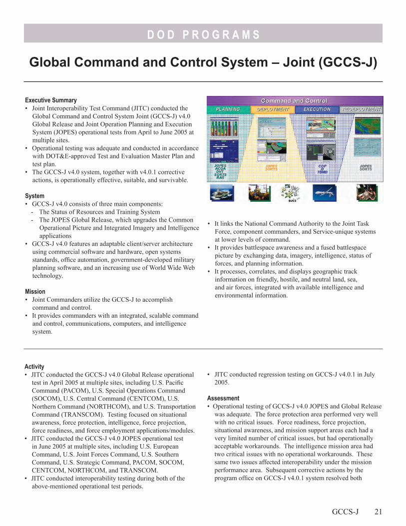
D O D P R O G R A M S
Executive Summary• Joint Interoperability Test Command (JITC) conducted the
Global Command and Control System Joint (GCCS-J) v4.0 Global Release and Joint Operation Planning and Execution System (JOPES) operational tests from April to June 2005 at multiple sites.
• Operational testing was adequate and conducted in accordance with DOT&E-approved Test and Evaluation Master Plan and test plan.
• The GCCS-J v4.0 system, together with v4.0.1 corrective actions, is operationally effective, suitable, and survivable.
System• GCCS-J v4.0 consists of three main components:
- The Status of Resources and Training System - The JOPES Global Release, which upgrades the Common
Operational Picture and Integrated Imagery and Intelligence applications
• GCCS-J v4.0 features an adaptable client/server architecture using commercial software and hardware, open systems standards, office automation, government-developed military planning software, and an increasing use of World Wide Web technology.
Mission• Joint Commanders utilize the GCCS-J to accomplish
command and control. • It provides commanders with an integrated, scalable command
and control, communications, computers, and intelligence system.
• It links the National Command Authority to the Joint Task Force, component commanders, and Service-unique systems at lower levels of command.
• It provides battlespace awareness and a fused battlespace picture by exchanging data, imagery, intelligence, status of forces, and planning information.
• It processes, correlates, and displays geographic track information on friendly, hostile, and neutral land, sea, and air forces, integrated with available intelligence and environmental information.
• JITC conducted regression testing on GCCS-J v4.0.1 in July 2005.
Assessment• Operational testing of GCCS-J v4.0 JOPES and Global Release
was adequate. The force protection area performed very well with no critical issues. Force readiness, force projection, situational awareness, and mission support areas each had a very limited number of critical issues, but had operationally acceptable workarounds. The intelligence mission area had two critical issues with no operational workarounds. These same two issues affected interoperability under the mission performance area. Subsequent corrective actions by the program office on GCCS-J v4.0.1 system resolved both
Activity• JITC conducted the GCCS-J v4.0 Global Release operational
test in April 2005 at multiple sites, including U.S. Pacific Command (PACOM), U.S. Special Operations Command (SOCOM), U.S. Central Command (CENTCOM), U.S. Northern Command (NORTHCOM), and U.S. Transportation Command (TRANSCOM). Testing focused on situational awareness, force protection, intelligence, force projection, force readiness, and force employment applications/modules.
• JITC conducted the GCCS-J v4.0 JOPES operational test in June 2005 at multiple sites, including U.S. European Command, U.S. Joint Forces Command, U.S. Southern Command, U.S. Strategic Command, PACOM, SOCOM, CENTCOM, NORTHCOM, and TRANSCOM.
• JITC conducted interoperability testing during both of the above-mentioned operational test periods.
Global Command and Control System – Joint (GCCS-J)
GCCS-J 21
D O D P R O G R A M S
of the critical issues affecting the intelligence and mission performance areas.
• Testing of JOPES v4.0 revealed marked improvement over test results from 2004. Interoperability criteria were not fully met, but were likewise corrected. Regression testing of corrective actions was adequate.
• JITC adequately tested all critical interfaces with GCCS-J v4.0. Regression testing of corrective actions was adequate and implemented. All critical interfaces performed satisfactorily.
• The National Security Agency conducted an information assurance evaluation of GCCS-J v4.0 together with v4.0.1
22 GCCS-J
corrective actions. The designated approving authority granted the Authority to Operate.
• GCCS-J v4.0 system, together with v4.0.1 corrective actions, is operationally effective, suitable, and survivable. The Milestone Decision Authority recommended fielding.
Recommendation1. The GCCS-J program should continue improving controls on
data updating to preclude data synchronization and accuracy problems in the JOPES database.
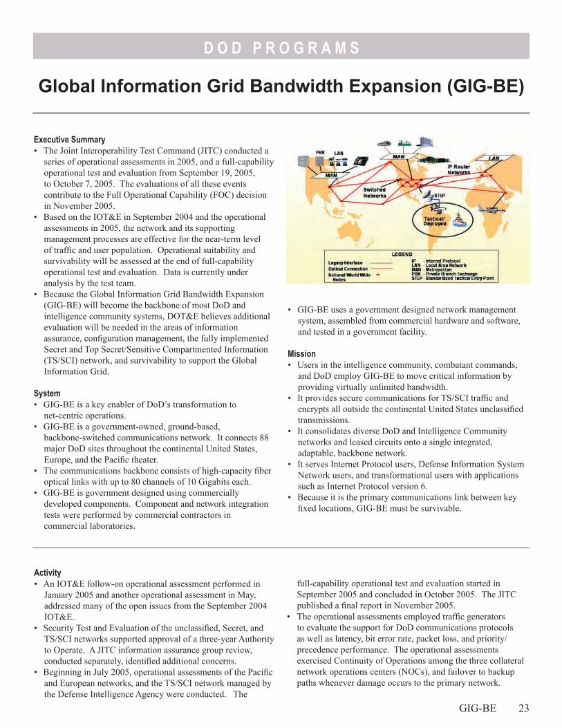
D O D P R O G R A M S
Executive Summary• The Joint Interoperability Test Command (JITC) conducted a
series of operational assessments in 2005, and a full-capability operational test and evaluation from September 19, 2005, to October 7, 2005. The evaluations of all these events contribute to the Full Operational Capability (FOC) decision in November 2005.
• Based on the IOT&E in September 2004 and the operational assessments in 2005, the network and its supporting management processes are effective for the near-term level of traffic and user population. Operational suitability and survivability will be assessed at the end of full-capability operational test and evaluation. Data is currently under analysis by the test team.
• Because the Global Information Grid Bandwidth Expansion (GIG-BE) will become the backbone of most DoD and intelligence community systems, DOT&E believes additional evaluation will be needed in the areas of information assurance, configuration management, the fully implemented Secret and Top Secret/Sensitive Compartmented Information (TS/SCI) network, and survivability to support the Global Information Grid.
System• GIG-BE is a key enabler of DoD’s transformation to
net-centric operations.• GIG-BE is a government-owned, ground-based,
backbone-switched communications network. It connects 88 major DoD sites throughout the continental United States, Europe, and the Pacific theater.
• The communications backbone consists of high-capacity fiber optical links with up to 80 channels of 10 Gigabits each.
• GIG-BE is government designed using commercially developed components. Component and network integration tests were performed by commercial contractors in commercial laboratories.
• GIG-BE uses a government designed network management system, assembled from commercial hardware and software, and tested in a government facility.
Mission• Users in the intelligence community, combatant commands,
and DoD employ GIG-BE to move critical information by providing virtually unlimited bandwidth.
• It provides secure communications for TS/SCI traffic and encrypts all outside the continental United States unclassified transmissions.
• It consolidates diverse DoD and Intelligence Community networks and leased circuits onto a single integrated, adaptable, backbone network.
• It serves Internet Protocol users, Defense Information System Network users, and transformational users with applications such as Internet Protocol version 6.
• Because it is the primary communications link between key fixed locations, GIG-BE must be survivable.
full-capability operational test and evaluation started in September 2005 and concluded in October 2005. The JITC published a final report in November 2005.
• The operational assessments employed traffic generators to evaluate the support for DoD communications protocols as well as latency, bit error rate, packet loss, and priority/precedence performance. The operational assessments exercised Continuity of Operations among the three collateral network operations centers (NOCs), and failover to backup paths whenever damage occurs to the primary network.
Activity• An IOT&E follow-on operational assessment performed in
January 2005 and another operational assessment in May, addressed many of the open issues from the September 2004 IOT&E.
• Security Test and Evaluation of the unclassified, Secret, and TS/SCI networks supported approval of a three-year Authority to Operate. A JITC information assurance group review, conducted separately, identified additional concerns.
• Beginning in July 2005, operational assessments of the Pacific and European networks, and the TS/SCI network managed by the Defense Intelligence Agency were conducted. The
Global Information Grid Bandwidth Expansion (GIG-BE)
GIG-BE 23
D O D P R O G R A M S
• The full-capability operational test and evaluation evaluates network management at the collateral and intelligence community NOCs, as well as live communication services with live user traffic at 20 of the 55 operational sites on the collateral network and simulated traffic on the intelligence community TS/SCI network.
• Operational testing has been done in accordance with the DOT&E approved Test and Evaluation Master Plan and test plans.
Assessment• GIG-BE is operationally effective in that it supports all
approved DoD protocols; meets latency, packet loss, bit error rate, and priority/precedence standards; and carries all required types of operational traffic.
• GIG-BE is operationally suitable to support a limited number of users. Although progress continues to be made, some processes still must mature to support the full user population. These include the European NOC completing its ramp up to a full complement of operators, obtaining the full set of required spare parts, and replacing the interim configuration process currently being done manually by the automated Integrated Configuration Tracking System. None are high risk to a positive assessment.
• Through the operational assessment testing, GIG-BE was judged to be survivable because it has sufficient route diversity and successfully demonstrated Continuity of Operations in all three theaters, as well as on the optical and Internet
24 GIG-BE
Protocol layers. Questions remain as to whether this level of survivability is sufficient as other key DoD networks transition onto the GIG-BE.
• More testing is needed for the TS/SCI network. The network and processes are mature in some areas and less mature in others. There was no final configuration of the network, management processes, or security fully represented in the test. The network remains to be integrated into the intelligence community methods for information assurance defense and configuration management, due to the necessary completion of an alternate NOC and successful demonstration of Continuity of Operations operations.
• The post-FOC transition consolidates many of DoD’s legacy networks onto GIG-BE, making GIG-BE a more lucrative target than individual systems. As such, it warrants intensive follow-on information assurance evaluation.
Recommendations1. Develop follow-on evaluations for information assurance
security and survivability, and mature TS/SCI operations to include Continuity of Operations actions with the TS/SCI network’s alternate NOC.
2. Ensure that the Integrated Configuration Tracking System continues development and is fielded in a timely manner to ensure integration and configuration management tools are available to support effective scale up of operational traffic.

D O D P R O G R A M S
Executive Summary• Emerging results from IOT&E indicate Joint Biological
Agent Identification and Diagnostic System (JBAIDS) meets sensitivity and specificity performance requirements.
• The system provides for timely information to medical and operational elements.
• JBAIDS is not operationally effective or suitable for shipboard use.
System• The Services intend the JBAIDS to be a reusable, portable,
biological agent identification and diagnostic system capable of identification of multiple biological agents simultaneously.
• JBAIDS is intended to satisfy a need to rapidly identify biological threat agents in clinical specimens and environmental samples, and interface with computer warning systems.
• It consists of an analytical device, sample preparation kits, reagent kits, laptop computer, and other support equipment.
• The total system with supporting equipment weighs approximately 1,500 pounds and measures 227 cubic feet.
• JBAIDS will be developed in three blocks: - Block I-modified commercial off-the-shelf (COTS) device
intended to identify 10 biological warfare agents in 40 minutes.
- Block II- adds capability to identify toxins.- Block III-reduced footprint and hand-held system. It is
intended to receive Food and Drug Agency clearance as a diagnostic tool.
Mission• Units equipped with JBAIDS can identify biological agents
to support a commander’s force protection decisions by providing timely information for determining appropriate treatment, effective preventive measures, prophylaxis, and operational decisions.
• JBAIDS is intended to be employed in units such as:- Army Medical Laboratory- Navy Environmental Preventive Medical Units, and aboard
CVNs, LHDs, amphibious assault ships, and LCCs- Marine Corps Preventive Medicine units- Forward-Deployed or Forward-Positioned Biological
Augmentation Team• It provides enhanced capabilities to the warfighter against both
conventional infectious organisms that occur naturally in the environment and biological weapons threats.
• It provides Services with confirmatory identification capability.
Assessment• Emerging results indicate JBAIDS can identify biological
warfare agents in samples received from the Joint Biological Point Detection System or dry filter units, and for most clinical samples.
• Joint Task Force Commander indicated that rapid sample preparation and analyses using JBAIDS did provide for timely decisions regarding medical treatment and countermeasure decision-making.
• JBAIDS has suitability shortfalls:- The centrifuge is not suitable for shipboard use.- Reagent packaging is wasteful, inefficient, and costly. - Completion of information assurance testing for laptop
computers is required.
Activity• The Air Force Operational Test and Evaluation Center,
supported by the Army Test and Evaluation Command and Marine Corps Operational Test and Evaluation Activity, conducted the IOT&E at Brooks City Base, Texas, during May 2005. Sixteen matrices were spiked with 10 inactivated biological warfare agents. The Commander, Operational Test and Evaluation Force conducted an operational evaluation on USS Blue Ridge in Western Pacific Operation Area during May and June 2005.
• Developmental testing for live agent and inactivated agent sensitivity and specificity was conducted in FY05. Shelf life testing is ongoing.
• Testing was done in accordance with DOT&E-approved test plans.
Joint Biological Agent Identification and Diagnostic System (JBAIDS)
JBAIDS 25
D O D P R O G R A M S
- JBAIDS system will provide capability to identify 10 Block I agents, but safety issues such as requirement for Biological Safety Level II and III facilities for analyses of some agents may preclude use by some forward-deployed laboratories.
Recommendations1. JBAIDS footprint needs to be reduced. Extraction kit protocol
utilizing large centrifuge needs to be revised to accommodate shipboard size and safety concerns.
2. Reagent kits need to be repackaged for greater efficiency and reduction in waste and cost.
3. Reagent kits should be optimized to improve limit of detection of JBAIDS instrument.
26 JBAIDS
4. Provide process and inhibition controls to the JBAIDS Block 1 system to reduce incidence of false negative and false positive reporting.
5. Training should include guidance on preparation of samples using alternative protocols and to evaluate invalid machine calls.
6. Corrective actions from multi-Service operational test and evaluation and operational testing of revised sample preparation kits will require follow-on operational test and evaluation.
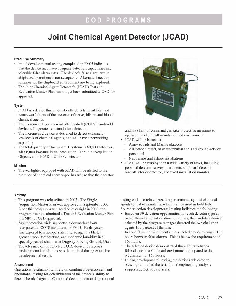
D O D P R O G R A M S
Executive Summary• Initial developmental testing completed in FY05 indicates
that the device may have adequate detection capabilities and tolerable false alarm rates. The device’s false alarm rate in shipboard operations is not acceptable. Alternate detection schemes for the shipboard environment are being explored.
• The Joint Chemical Agent Detector’s (JCAD) Test and Evaluation Master Plan has not yet been submitted to OSD for approval.
System• JCAD is a device that automatically detects, identifies, and
warns warfighters of the presence of nerve, blister, and blood chemical agents.
• The Increment 1 commercial off-the-shelf (COTS) hand-held device will operate as a stand-alone detector.
• The Increment 2 device is designed to detect extremely low levels of chemical agents, and will have a networking capability.
• The total quantity of Increment 1 systems is 60,000 detectors, with 6,000 low-rate initial production. The Joint Acquisition Objective for JCAD is 274,887 detectors.
Mission• The warfighter equipped with JCAD will be alerted to the
presence of chemical agent vapor hazards so that the operator
and his chain of command can take protective measures to operate in a chemically-contaminated environment.
• JCAD will be issued to: - Army squads and Marine platoons- Air Force aircraft, base reconnaissance, and ground-service
personnel- Navy ships and ashore installations
• JCAD will be employed in a wide variety of tasks, including personal detector, survey instrument, shipboard detector, aircraft interior detector, and fixed installation monitor.
Joint Chemical Agent Detector (JCAD)
testing will also relate detection performance against chemical agents to that of simulants, which will be used in field tests. Source selection developmental testing indicates the following:• Based on 30 detection opportunities for each detector type at
two different ambient relative humidities, the candidate device selected by the program manager detected the two challenge agents 100 percent of the time.
• In six different environments, the selected device averaged 105 hours between false alarms. This is below the requirement of 168 hours.
• The selected device demonstrated three hours between false alarms in a shipboard environment compared to the requirement of 168 hours.
• During developmental testing, the devices subjected to blowing rain failed the test. Initial engineering analysis suggests defective case seals.
Activity• This program was rebaselined in 2003. The Single
Acquisition Master Plan was approved in September 2005. Since this program was placed on oversight in 2000, the program has not submitted a Test and Evaluation Master Plan (TEMP) for OSD approval.
• Agent detection trials supported a downselect from four potential COTS candidates in FY05. Each system was exposed to a non-persistent nerve agent, a blister agent at room temperature, and moderate humidity in a specially-sealed chamber at Dugway Proving Ground, Utah.
• The tolerance of the selected COTS device to rigorous environmental conditions was determined during extensive developmental testing.
AssessmentOperational evaluation will rely on combined development and operational testing for determination of the device’s ability to detect chemical agents. Combined development and operational
JCAD 27

D O D P R O G R A M S
Recommendations1. JCAD testing should use weapons-grade, rather than
chemically-pure, agents. 2. Investigate whether JCAD’s detection capability degrades
over time, as well as whether there is variability of detection performance among detectors.
28 JCAD
3. Develop appropriate chemical agent simulants and correlate specific properties of these simulants to those of actual agents.
4. Use these simulants in field testing of the device to evaluate the response of the JCAD, its operators, and the operators’ associated units to simulated chemical agent challenges.
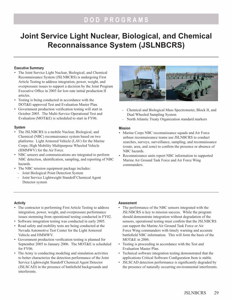
D O D P R O G R A M S
Executive Summary• The Joint Service Light Nuclear, Biological, and Chemical
Reconnaissance System (JSLNBCRS) is undergoing First Article Testing to address integration, power, weight, and overpressure issues to support a decision by the Joint Program Executive Office in 2005 for low-rate initial production II articles.
• Testing is being conducted in accordance with the DOT&E-approved Test and Evaluation Master Plan.
• Government production verification testing will start in October 2005. The Multi-Service Operational Test and Evaluation (MOT&E) is scheduled to start in FY06.
System• The JSLNBCRS is a mobile Nuclear, Biological, and
Chemical (NBC) reconnaissance system based on two platforms: Light Armored Vehicle (LAV) for the Marine Corps; High Mobility Multipurpose Wheeled Vehicle (HMMWV) for the Air Force.
• NBC sensors and communications are integrated to perform NBC detection, identification, sampling, and reporting of NBC hazards.
• The NBC mission equipment package includes:- Joint Biological Point Detection System- Joint Service Lightweight Standoff Chemical Agent
Detector system
- Chemical and Biological Mass Spectrometer, Block II, and Dual Wheeled Sampling System
- North Atlantic Treaty Organization standard markers
Mission• Marine Corps NBC reconnaissance squads and Air Force
airbase reconnaissance teams use JSLNBCRS to conduct searches, surveys, surveillance, sampling, and reconnaissance (route, area, and zone) to confirm the presence or absence of NBC hazards.
• Reconnaissance units report NBC information to supported Marine Air Ground Task Force and Air Force Wing commanders.
Activity• The contractor is performing First Article Testing to address
integration, power, weight, and overpressure performance issues stemming from operational testing conducted in FY02.
• Software integration testing was conducted in early 2005.• Road safety and mobility tests are being conducted at the
Nevada Automotive Test Center for the Light Armored Vehicle and HMMWV.
• Government production verification testing is planned for September 2005 to January 2006. The MOT&E is scheduled for FY06.
• The Army is conducting modeling and simulation activities to better characterize the detection performance of the Joint Service Lightweight Standoff Chemical Agent Detector (JSLSCAD) in the presence of battlefield backgrounds and interferents.
Assessment• The performance of the NBC sensors integrated with the
JSLNBCRS is key to mission success. While the program should demonstrate integration without degradation of the sensors, operational testing must confirm that the JSLNBCRS can support the Marine Air Ground Task Force or Air Force Wing commanders with timely warning and accurate battlefield NBC information. This will form the basis of the MOT&E in 2006.
• Testing is proceeding in accordance with the Test and Evaluation Master Plan.
• Technical software integration testing demonstrated that the applications Critical Software Configuration Item is stable.
• JSLSCAD detection performance is significantly degraded by the presence of naturally occurring environmental interferents.
JSLNBCRS 29
Joint Service Light Nuclear, Biological, and Chemical Reconnaissance System (JSLNBCRS)

D O D P R O G R A M S
Even if it meets revised operational requirements for detection and range performance, its critical detection information will not provide the battlefield commander with a beneficial standoff detection capability. This conclusion is derived from the fact that the system completes a search pattern in 90 seconds, and can cover almost 1,500 meters in 90 seconds. If
30 JSLNBCRS
the detector can only detect out to 500 meters, the platform will have entered the cloud before it will alarm.
RecommendationsNone.
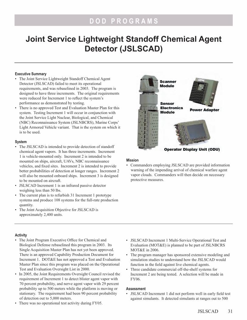
D O D P R O G R A M S
Joint Service Lightweight Standoff Chemical Agent Detector (JSLSCAD)
Mission• Commanders employing JSLSCAD are provided information
warning of the impending arrival of chemical warfare agent vapor clouds. Commanders will then decide on necessary protective measures.
Executive Summary• The Joint Service Lightweight Standoff Chemical Agent
Detector (JSLSCAD) failed to meet its operational requirements, and was rebaselined in 2003. The program is designed to have three increments. The original requirements were reduced for Increment 1 to reflect the system’s performance as demonstrated by testing.
• There is no approved Test and Evaluation Master Plan for this system. Testing Increment 1 will occur in conjunction with the Joint Service Light Nuclear, Biological, and Chemical (NBC) Reconnaissance System (JSLNBCRS), Marine Corps’ Light Armored Vehicle variant. That is the system on which it is to be used.
System• The JSLSCAD is intended to provide detection of standoff
chemical agent vapors. It has three increments. Increment 1 is vehicle-mounted only. Increment 2 is intended to be mounted on ships, aircraft, UAVs, NBC reconnaissance vehicles, and fixed sites. Increment 2 is intended to provide better probabilities of detection at longer ranges. Increment 2 will also be mounted onboard ships. Increment 3 is designed to be mounted on aircraft.
• JSLSCAD Increment 1 is an infrared passive detector weighing less than 50 lbs.
• The current plan is to refurbish 31 Increment 1 prototype systems and produce 108 systems for the full-rate production quantity.
• The Joint Acquisition Objective for JSLSCAD is approximately 2,400 units.
Activity• The Joint Program Executive Office for Chemical and
Biological Defense rebaselined this program in 2003. Its Single Acquisition Master Plan has not yet been approved. There is an approved Capability Production Document for Increment 1. DOT&E has not approved a Test and Evaluation Master Plan since this program was placed on the Operational Test and Evaluation Oversight List in 2000.
• In 2005, the Joint Requirements Oversight Council revised the requirement of Increment 1 to detect blister agent vapor with 70 percent probability, and nerve agent vapor with 29 percent probability up to 500 meters while the platform is moving or stationary. The requirement had been 90 percent probability of detection out to 5,000 meters.
• There was no operational test activity during FY05.
• JSLSCAD Increment 1 Multi-Service Operational Test and Evaluation (MOT&E) is planned to be part of JSLNBCRS MOT&E in 2006.
• The program manager has sponsored extensive modeling and simulation studies to understand how the JSLSCAD would function in the field against live chemical agents.
• Three candidate commercial off-the-shelf systems for Increment 2 are being tested. A selection will be made in FY06.
Assessment• JSLSCAD Increment 1 did not perform well in early field test
against simulants. It detected simulants at ranges out to 500
JSLSCAD 31
D O D P R O G R A M S
meters instead of the intended 5,000 meters. It has had a high false alarm rate.
• When used in a vehicle-mounted configuration at full speed of 56 kilometers per hour (about 35 miles/hour), the JSLSCAD may provide no warning before entering or passing through the vapor cloud because of its limited detection range. This conclusion is derived from the fact that the system completes a search pattern in 90 seconds, and the vehicle can cover almost 1,500 meters in 90 seconds. If the detector can only detect out to 500 meters, the vehicle will have entered the cloud before it will alarm.
• Modeling and simulation indicate that water vapor and ozone can be significant natural interferents for the JSLSCAD Increment 1. This may hamper operational use of this system.
Recommendations1. DOT&E will continue to follow the performance of
Increment 1 in preparation for the JSLNBCRS MOT&E, but approval of test plan is contingent on an approved Single Acquisition Master Plan and Test and Evaluation Master Plan.
2. Continue to pursue resolution of modeling and simulation work to understand how test simulants relate to actual agent clouds in Increment 1’s processing and reporting.
32 JSLSCAD
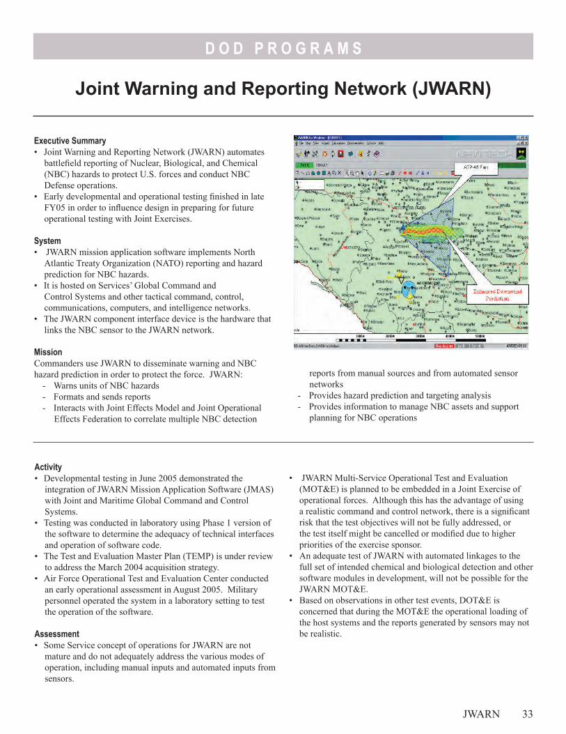
D O D P R O G R A M S
reports from manual sources and from automated sensor networks
- Provides hazard prediction and targeting analysis- Provides information to manage NBC assets and support
planning for NBC operations
Executive Summary• Joint Warning and Reporting Network (JWARN) automates
battlefield reporting of Nuclear, Biological, and Chemical (NBC) hazards to protect U.S. forces and conduct NBC Defense operations.
• Early developmental and operational testing finished in late FY05 in order to influence design in preparing for future operational testing with Joint Exercises.
System• JWARN mission application software implements North
Atlantic Treaty Organization (NATO) reporting and hazard prediction for NBC hazards.
• It is hosted on Services’ Global Command and Control Systems and other tactical command, control, communications, computers, and intelligence networks.
• The JWARN component interface device is the hardware that links the NBC sensor to the JWARN network.
MissionCommanders use JWARN to disseminate warning and NBC hazard prediction in order to protect the force. JWARN:
- Warns units of NBC hazards- Formats and sends reports- Interacts with Joint Effects Model and Joint Operational
Effects Federation to correlate multiple NBC detection
Activity• Developmental testing in June 2005 demonstrated the
integration of JWARN Mission Application Software (JMAS) with Joint and Maritime Global Command and Control Systems.
• Testing was conducted in laboratory using Phase 1 version of the software to determine the adequacy of technical interfaces and operation of software code.
• The Test and Evaluation Master Plan (TEMP) is under review to address the March 2004 acquisition strategy.
• Air Force Operational Test and Evaluation Center conducted an early operational assessment in August 2005. Military personnel operated the system in a laboratory setting to test the operation of the software.
Assessment• Some Service concept of operations for JWARN are not
mature and do not adequately address the various modes of operation, including manual inputs and automated inputs from sensors.
JWARN 33
Joint Warning and Reporting Network (JWARN)
• JWARN Multi-Service Operational Test and Evaluation (MOT&E) is planned to be embedded in a Joint Exercise of operational forces. Although this has the advantage of using a realistic command and control network, there is a significant risk that the test objectives will not be fully addressed, or the test itself might be cancelled or modified due to higher priorities of the exercise sponsor.
• An adequate test of JWARN with automated linkages to the full set of intended chemical and biological detection and other software modules in development, will not be possible for the JWARN MOT&E.
• Based on observations in other test events, DOT&E is concerned that during the MOT&E the operational loading of the host systems and the reports generated by sensors may not be realistic.

D O D P R O G R A M S
Recommendations1. Prepare a backup plan and resources to conduct independent
operational testing if the planned Joint Exercise fails to sponsor the operational test.
34 JWARN
2. As Phase 1 testing was conducted in a laboratory, further test planning efforts are needed so test objectives are fully embedded into operational exercises.

D O D P R O G R A M S
and commercial SATCOM services to support all phases of conflict, globally distributed from six core teleport facilities. The facilities are located at: - Chesapeake, Virginia- Ramstein and Landstuhl, Germany- Lago Patria, Italy- Fort Buckner, Japan- Wahiawa, Hawaii- Camp Roberts, California
• Teleport provides deployed forces with pre-positioned interfaces from anywhere in the world for all six DISN services:- Secret Internet Protocol Router Network (SIPRNET)- Unclassified-But-Sensitive Internet Protocol Router
Network (NIPRNET)- Defense Red Switch Network (DRSN)- Defense Switched Network (DSN)- Video Teleconferences (VTC)- Joint Worldwide Intelligence Communications System
(JWICS)• Teleport will expand Standard Tactical Entry Point (tactical
systems) concept to supply warfighters with pre-positioned standardized gateways into DISN services.
Teleport
Executive Summary• Installation of new capabilities to the six Teleport sites
continued to follow a spiral acquisition strategy.• The Follow-on Testing and Evaluation (FOT&E) tested
increased C, X, and Ku band capability, new Ultra High Frequency (UHF) band, new intermediate base-band management and mission control capability, and resolution of open items from previous operational tests.
• Due to UHF radio transmitter technical problems (constant lockup), FOT&E was terminated. The FOT&E is postponed until the radio transmitters can support the UHF operational requirements.
• All C, X, and Ku band installation deficiencies and safety issues previously noted were re-examined and found corrected during FOT&E.
System• The DoD Teleport sites consist of four segments:
- Earth terminals- Base-band segment- Network services- Management and mission control
• Teleport earth terminals are Satellite Communications (SATCOM) terminals that operate in X, C, Ku, UHF, Extremely High Frequency, and Ka frequency bands.
• Base-band segment includes all encryption, switching, multiplexing, and routing functions for connecting data streams or packeted data to the Defense Information System Network services (DISN).
• Network services provide connectivity to the DISN long-haul networks and other interworking functions necessary to meet the warfighter’s requirements.
• Management and mission control provides integrated and automated control and monitoring of Teleport base-band hardware, earth terminal hardware, electronic matrix switch, transmission security, and test equipment.
• The terminals provide the radio frequency links between the Teleport site, the satellite, and the deployed warfighter SATCOM terminal via commercial or military satellites.
Mission• Services, combatant commanders, and deployed forces
will use the Teleport system to gain worldwide military
• During FOT&E, the Joint Interoperability Test Command tested increased C, X, and Ku band capability; new UHF band; new intermediate base-band management; and mission control
Activity• In June 2005, the Joint Interoperability Test Command
conducted a Teleport FOT&E at the Northwest Teleport site in Chesapeake, Virginia.
Teleport 35
D O D P R O G R A M S
capability. The test also re-examined the previous deficiencies to identify if corrective action was taken.
• In August 2005, the Joint Interoperability Test Command conducted an operational assessment at Camp Roberts, California, to assess the feasibility of conversion to Internet Protocol modems.
Assessment• The Teleport FOT&E was done in accordance with a
DOT&E-approved Test and Evaluation Master Plan and test plan.
• All C, X, and Ku band criteria for installation deficiencies and safety issues previously noted were re-examined and found corrected during FOT&E.
• The FOT&E is postponed. A UHF test network was configured, but due to UHF radio technical problems (constant
lockup), the test was terminated. FOT&E will resume when the radio transmitters can support the UHF operational requirements.
• Multiplexer Integration and Defense Communications Satellite Subsystem Automation System and Teleport Management and Control System, Build 1, were observed during the regression testing and they meet the initial system requirements. These two systems are valuable tools for Teleport operation and they improve the site’s capabilities to respond to warfighter needs.
Recommendation1. DOT&E recommends the use of System Verification
Operational Tests and other test venues as a means to consolidate testing, thus reducing the number of test events.
36 Teleport
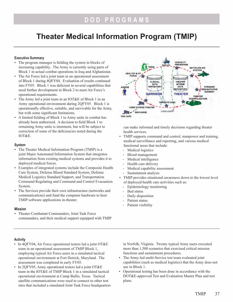
D O D P R O G R A M S
Theater Medical Information Program (TMIP)
Executive Summary• The program manager is fielding the system in blocks of
increasing capability. The Army is currently using parts of Block 1 in actual combat operations in Iraq and Afghanistan.
• The Air Force led a joint team in an operational assessment of Block 1 during 4QFY04. Evaluation of results continued into FY05. Block 1 was deficient in several capabilities that need further development in Block 2 to meet Air Force’s operational requirements.
• The Army led a joint team in an IOT&E of Block 1 in an Army operational environment during 2QFY05. Block 1 is operationally effective, suitable, and survivable for the Army, but with some significant limitations.
• A limited fielding of Block 1 to Army units in combat has already been authorized. A decision to field Block 1 to remaining Army units is imminent, but will be subject to correction of some of the deficiencies noted during the IOT&E.
System• The Theater Medical Information Program (TMIP) is a
joint Major Automated Information System that integrates information from existing medical systems and provides it to deployed medical forces.
• Examples of integrated systems include the Composite Health Care System, Defense Blood Standard System, Defense Medical Logistics Standard Support, and Transportation Command Regulating and Command and Control Evacuation System.
• The Services provide their own infrastructure (networks and communications) and fund the computer hardware to host TMIP software applications in-theater.
Mission• Theater Combatant Commanders, Joint Task Force
commanders, and their medical support equipped with TMIP
can make informed and timely decisions regarding theater health services.
• TMIP supports command and control, manpower and training, medical surveillance and reporting, and various medical functional areas that include:- Medical logistics- Blood management- Medical intelligence- Health care delivery- Medical capability assessment- Sustainment analysis
• TMIP provides situational awareness down to the lowest level of deployed health care activities such as:- Epidemiology monitoring- Bed status- Daily disposition- Patient status- Patient visibility
Activity• In 4QFY04, Air Force operational testers led a joint OT&E
team in an operational assessment of TMIP Block 1, employing typical Air Force users in a simulated tactical operational environment at Fort Detrick, Maryland. The assessment was completed in early FY05.
• In 2QFY05, Army operational testers led a joint OT&E team in the IOT&E of TMIP Block 1 in a simulated tactical operational environment at Camp Bullis, Texas. Tactical satellite communications were used to connect to other test sites that included a simulated Joint Task Force headquarters
in Norfolk, Virginia. Twenty typical Army users executed more than 1,500 scenarios that exercised critical mission functions and sustainment procedures.
• The Army-led multi-Service test team evaluated joint capabilities (such as medical logistics) that the Army does not use in Block 1.
• Operational testing has been done in accordance with the DOT&E-approved Test and Evaluation Master Plan and test plans.
TMIP 37
D O D P R O G R A M S
• The Assistant Secretary of Defense for Networks and Information Integration granted limited deployment of TMIP Block 1 in response to an urgent request from the Army Deputy Surgeon General to support combat operations in Iraq and Afghanistan.
AssessmentThe Air Force operational assessment showed that TMIP required further enhancements before it could fully meet that Service’s operational requirements. There were numerous operational suitability deficiencies that included:• Lack of accuracy and reliability of medical command and
control reporting• Immature system administration processes and procedures• Inadequate integrated logistics support planning and training
support package• Human systems integration (not sufficiently user friendly)• Immature medical concepts of operations• Various software problems
The Army IOT&E reflected a high functional success rate (over 99 percent) and user survey responses were generally favorable. There were no major security or information assurance deficiencies identified. However, the testing uncovered some significant operational limitations:• Patient encounter data were sometimes lost in transmission to
higher headquarters• Immunization module produced erroneous next-due
immunization dates• Inoperable joint medical logistics functions• User friendliness and human-systems integration shortfalls
TMIP shows promise for tactical medical operations. It is steadily progressing toward a goal of making all medical records
electronic. The most serious limitation is the lack of mature Service concepts of operations for using the system.
Recommendations1. The Army should be authorized to complete its TMIP Block 1
fielding, subject to the incorporation of a message regenerator tool to remedy the problem of occasional patient encounter data lost. The Army must develop adequate operational procedures for using the tool.
2. The Army has no plans for using the immunization module, and should not be authorized to use it without providing the TMIP Program Manager the necessary information to update the immunization algorithm. Similarly, the Army has no plans to use the medical logistics functions, and should not be authorized to do so until multi-Service concepts of operations are developed and the capability is successfully operationally tested.
3. No Service should be authorized to field Block 1 without successful IOT&E or special authorization to meet wartime necessities.
4. The program manager should correct all of the problems found in Block 1 and work the solutions into Block 2. Since Block 2 reportedly is needed immediately for wartime operations, the independent operational test agencies should conduct a joint IOT&E of Block 2 for any Service(s) prepared to field it as soon as the software is ready. A second phase of Block 2 IOT&E should be conducted for the other Services when they are ready. However, before the fielding of Block 2 is considered by any of the Services, each must develop a mature concept of operations for using TMIP. Immature concepts of operations pose the greatest risk to the success of TMIP.
38 TMIP
Army Program
s
Arm
y Pro
gram
s
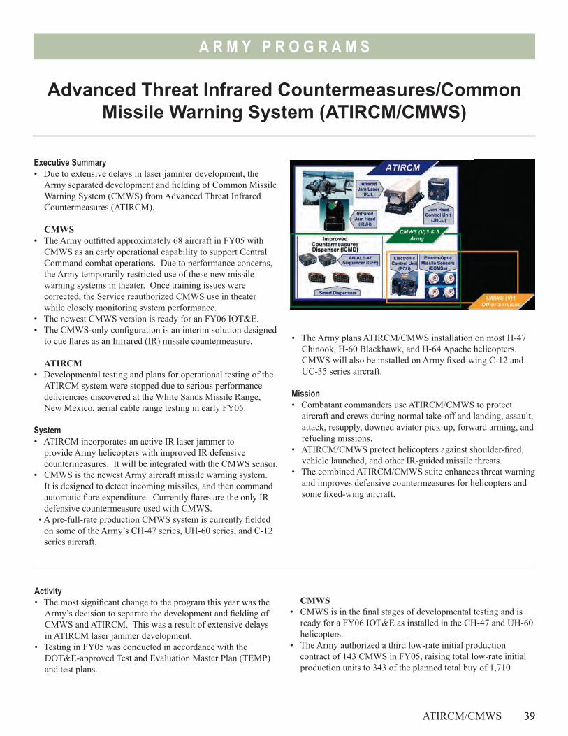
39
A R M Y P R O G R A M S
Advanced Threat Infrared Countermeasures/Common Missile Warning System (ATIRCM/CMWS)
Executive Summary• Due to extensive delays in laser jammer development, the
Army separated development and fielding of Common Missile Warning System (CMWS) from Advanced Threat Infrared Countermeasures (ATIRCM).
CMWS• The Army outfitted approximately 68 aircraft in FY05 with
CMWS as an early operational capability to support Central Command combat operations. Due to performance concerns, the Army temporarily restricted use of these new missile warning systems in theater. Once training issues were corrected, the Service reauthorized CMWS use in theater while closely monitoring system performance.
• The newest CMWS version is ready for an FY06 IOT&E. • The CMWS-only configuration is an interim solution designed
to cue flares as an Infrared (IR) missile countermeasure.
ATIRCM• Developmental testing and plans for operational testing of the
ATIRCM system were stopped due to serious performance deficiencies discovered at the White Sands Missile Range, New Mexico, aerial cable range testing in early FY05.
System• ATIRCM incorporates an active IR laser jammer to
provide Army helicopters with improved IR defensive countermeasures. It will be integrated with the CMWS sensor.
• CMWS is the newest Army aircraft missile warning system. It is designed to detect incoming missiles, and then command automatic flare expenditure. Currently flares are the only IR defensive countermeasure used with CMWS.
• A pre-full-rate production CMWS system is currently fielded on some of the Army’s CH-47 series, UH-60 series, and C-12 series aircraft.
Activity• The most significant change to the program this year was the
Army’s decision to separate the development and fielding of CMWS and ATIRCM. This was a result of extensive delays in ATIRCM laser jammer development.
• Testing in FY05 was conducted in accordance with the DOT&E-approved Test and Evaluation Master Plan (TEMP) and test plans.
CMWS• CMWS is in the final stages of developmental testing and is
ready for a FY06 IOT&E as installed in the CH-47 and UH-60 helicopters.
• The Army authorized a third low-rate initial production contract of 143 CMWS in FY05, raising total low-rate initial production units to 343 of the planned total buy of 1,710
ATIRCM/CMWS 39
• The Army plans ATIRCM/CMWS installation on most H-47 Chinook, H-60 Blackhawk, and H-64 Apache helicopters. CMWS will also be installed on Army fixed-wing C-12 and UC-35 series aircraft.
Mission• Combatant commanders use ATIRCM/CMWS to protect
aircraft and crews during normal take-off and landing, assault, attack, resupply, downed aviator pick-up, forward arming, and refueling missions.
• ATIRCM/CMWS protect helicopters against shoulder-fired, vehicle launched, and other IR-guided missile threats.
• The combined ATIRCM/CMWS suite enhances threat warning and improves defensive countermeasures for helicopters and some fixed-wing aircraft.
40
A R M Y P R O G R A M S
CMWS and ATIRCM systems. Developmental tests using live missile firings against CMWS were conducted at the White Sands Missile Range, New Mexico, aerial cable range in October 2004. This test assessed the missile warning sensor’s ability to detect live IR surface-to-air missiles in-flight, and provide timely cueing to the countermeasures dispenser. This test supported the January 2005 early fielding for combat operations and the planned April 2005 IOT&E.
• The Army conducted an early fielding of 13 H-47, 50 H-60, and five C-12 CMWS configured series aircraft in FY05 to the Central Command area of operations. Due to concerns about the observed high false alarm rate of CMWS, the Army terminated its use. Once additional training on CMWS operational training was incorporated, the service reauthorized CMWS use in theater, while instituting close performance monitoring. The Army and contractor began accelerated development of a software upgrade to address the false alarm issue.
• The Army delayed IOT&E until early FY06 because of system modifications resulting from operational experience.
• From May-August 2005, the Army assessed modifications to improve false alarm performance, which also led to the Army adopting a tailored software load designed for current deployed operations.
• The Army revised the ATIRCM/CMWS TEMP to reflect the separation of the CMWS from ATIRCM laser IR jammer program. DOT&E approved the TEMP and IOT&E test plan in October 2005.
ATIRCM• Developmental testing and plans for operational testing of the
ATIRCM system were stopped because of serious performance deficiencies discovered during the aerial cable range testing in early FY05.
• The Army has purchased a total of 37 ATIRCM low-rate initial production units.
• The Army formed an independent team of Infrared Countermeasures program and subject matter experts to assess
the system’s design maturity, and potential to support the operational requirement.
AssessmentCMWS
• The new missile sensor hardware is mature, the software is improving, and the system is ready for IOT&E.
• The most recent CMWS software modifications are designed to support effective performance against a reduced threat list prioritized for current combat operations. The Army’s plan to upgrade the missile warning sensor to be effective against the full threat list is expected to be tested when the system is integrated with ATIRCM in FY07.
• The Army has not accredited their end-to-end CMWS simulation model, which would have reduced the flight test requirements for the FY06 CMWS-only IOT&E.
ATIRCM • The independent team that assessed ATIRCM design maturity
to meet the operational requirements found that although the overarching system architecture is adequate, the system has several limitations and requires hardware and manufacturing design changes. The DOT&E assessment is that there are challenging technical problems that require resolution before the system is ready for IOT&E.
Recommendations1. The Army should closely monitor the progress of ATIRCM
design maturity and development tests. The Army Test and Evaluation Command should report whether the program will meet the full system IOT&E schedule objective in FY07.
2. The Army should continue the verification, validation, and accreditation process for the end-to-end model in order to support the ATIRCM/CMWS developmental and operational testing leading up to the full system IOT&E.
40 ATIRCM/CMWS
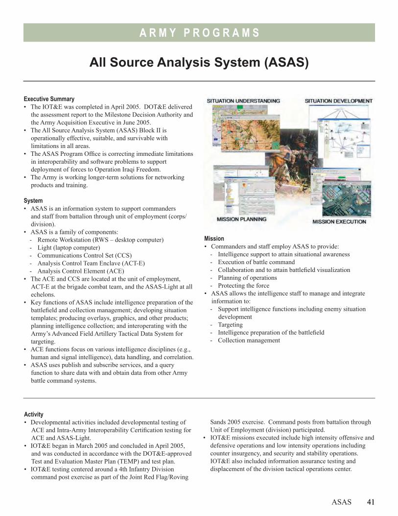
41
A R M Y P R O G R A M S
All Source Analysis System (ASAS)
ASAS 41
Executive Summary• The IOT&E was completed in April 2005. DOT&E delivered
the assessment report to the Milestone Decision Authority and the Army Acquisition Executive in June 2005.
• The All Source Analysis System (ASAS) Block II is operationally effective, suitable, and survivable with limitations in all areas.
• The ASAS Program Office is correcting immediate limitations in interoperability and software problems to support deployment of forces to Operation Iraqi Freedom.
• The Army is working longer-term solutions for networking products and training.
System• ASAS is an information system to support commanders
and staff from battalion through unit of employment (corps/division).
• ASAS is a family of components: - Remote Workstation (RWS – desktop computer)- Light (laptop computer)- Communications Control Set (CCS)- Analysis Control Team Enclave (ACT-E)- Analysis Control Element (ACE)
• The ACE and CCS are located at the unit of employment, ACT-E at the brigade combat team, and the ASAS-Light at all echelons.
• Key functions of ASAS include intelligence preparation of the battlefield and collection management; developing situation templates; producing overlays, graphics, and other products; planning intelligence collection; and interoperating with the Army’s Advanced Field Artillery Tactical Data System for targeting.
• ACE functions focus on various intelligence disciplines (e.g., human and signal intelligence), data handling, and correlation.
• ASAS uses publish and subscribe services, and a query function to share data with and obtain data from other Army battle command systems.
Mission• Commanders and staff employ ASAS to provide:
- Intelligence support to attain situational awareness- Execution of battle command- Collaboration and to attain battlefield visualization- Planning of operations- Protecting the force
• ASAS allows the intelligence staff to manage and integrate information to:- Support intelligence functions including enemy situation
development- Targeting- Intelligence preparation of the battlefield- Collection management
Activity• Developmental activities included developmental testing of
ACE and Intra-Army Interoperability Certification testing for ACE and ASAS-Light.
• IOT&E began in March 2005 and concluded in April 2005, and was conducted in accordance with the DOT&E-approved Test and Evaluation Master Plan (TEMP) and test plan.
• IOT&E testing centered around a 4th Infantry Division command post exercise as part of the Joint Red Flag/Roving
Sands 2005 exercise. Command posts from battalion through Unit of Employment (division) participated.
• IOT&E missions executed include high intensity offensive and defensive operations and low intensity operations including counter insurgency, and security and stability operations. IOT&E also included information assurance testing and displacement of the division tactical operations center.
42
A R M Y P R O G R A M S
Assessment• Operational testing was adequate. Interoperability and
information assurance require additional testing to confirm corrections.
• ASAS is operationally effective, suitable, and survivable with limitations. The system performed its critical missions to include:- Supporting the battle staff in managing the available
information to develop the enemy situation, answer priority intelligence requirements, and requests for information
- Identifying targets using automated alert functions, and then nominating them
• The ASAS system gathered and disseminated information horizontally and vertically across the family of Army Battle Command Systems. However, limitations still exist: - The network management and information distribution
tools need improvement. Establishing the networks and information flows presented significant challenges that affected exchange of information and thus the ability of the ASAS to provide an accurate and consistent picture, be interoperable, and react to unit task reorganizations.
- The processing speed of the workstations needs improvement. Operators expressed frustration with database updates and dissemination.
- Interoperability shortfalls affected distribution of database updates within the ASAS and exchange of the enemy situation with the Maneuver Control System. In addition, ASAS does not currently have the proper Joint certifications to operate with other Service systems.
- The training program did not prepare the unit to employ the ASAS as an integrated intelligence support element within the Army Battle Command System. Record test was suspended after three days to allow additional training on system operations, staff functions, and collective tasks.
- There are system-of-systems issues that impact ASAS capabilities. These include the need for a flexible networking schema and products, and sufficient collective training focused on the integrated Army Battle Command System.
Recommendations1. Demonstrate that all high priority software problems are
corrected.2. Obtain Intra-Army Interoperability Certification to ensure
ASAS products integrate with the other Army Battle Command Systems.
3. Correct information assurance deficiencies and validate in an appropriate venue.
4. Complete Joint interoperability certification.5. Improve the analyst tools and the process for disseminating
database information between ASAS workstations to increase responsiveness to the unit’s needs.
6. Resolve system-of-system shortfalls in networking products and create improved collective and sustainment training programs to increase utility to the warfighter.
42 ASAS
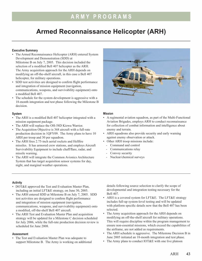
43
A R M Y P R O G R A M S
Armed Reconnaissance Helicopter (ARH)
ARH 43
Executive Summary• The Armed Reconnaissance Helicopter (ARH) entered System
Development and Demonstration (SDD) at Milestone B on July 7, 2005. This decision included the selection of a modified Bell 407 helicopter as the ARH. The Army acquisition approach for the ARH depends on modifying an off-the-shelf aircraft, in this case a Bell 407 helicopter, for military operations.
• SDD test activities are designed to confirm flight performance and integration of mission equipment (navigation, communications, weapons, and survivability equipment) onto a modified Bell 407.
• The schedule for the system development is aggressive with a 18-month integration and test phase following the Milestone B decision.
System• The ARH is a modified Bell 407 helicopter integrated with a
mission equipment package.• The ARH will replace the OH-58D Kiowa Warrior.• The Acquisition Objective is 368 aircraft with a full-rate
production decision in 1QFY09. The Army plans to have 10 ARH per troop and 30 per squadron.
• The ARH fires 2.75-inch aerial rockets and Hellfire missiles. It has armored crew stations, and employs Aircraft Survivability Equipment to include chaff/flare, radar, and missile warning.
• The ARH will integrate the Common Avionics Architecture System that has target acquisition sensor systems for day, night, and marginal weather operations.
Activity• DOT&E approved the Test and Evaluation Master Plan,
including an initial LFT&E strategy, on June 30, 2005. • The ARH entered SDD at Milestone B on July 7, 2005. SDD
test activities are designed to confirm flight performance and integration of mission equipment (navigation, communications, weapons, and survivability equipment) onto a modified, off-the-shelf Bell 407 aircraft.
• The ARH Test and Evaluation Master Plan and acquisition strategy will be updated for a Milestone C decision scheduled for July 2006, while the full-rate production decision review is scheduled for June 2008.
Assessment• The Test and Evaluation Master Plan was adequate to
support Milestone B. The Army is working on additional
Mission• A regimental aviation squadron, as part of the Multi-Functional
Aviation Brigades, employs ARH to conduct reconnaissance for collection of combat information and intelligence about enemy and terrain.
• ARH squadrons also provide security and early warning against enemy observation or attack.
• Other ARH troop missions include:- Command and control- Communications relay- Convoy security- Nuclear/chemical surveys
details following source selection to clarify the scope of developmental and integration testing necessary for the Bell 407.
• ARH is a covered system for LFT&E. The LFT&E strategy includes full-up system-level testing and will be updated with platform specific details now that the Bell 407 has been selected.
• The Army acquisition approach for the ARH depends on modifying an off-the-shelf aircraft for military operations. This will require discipline within the program management to ensure non-essential missions, which exceed the capabilities of the airframe, are not added as requirements.
• The ARH schedule is aggressive. The Milestone Decision B in June 2005 initiated an 18-month integration and test phase.
• The Army plans to conduct IOT&E with one live platoon
44
A R M Y P R O G R A M S
44 ARH
(four to five aircraft) and one simulated platoon (four to five aircraft). This approach is dependent upon successful simulation of ARH troop-level missions.
RecommendationsThe Army should:1. Begin integration testing for mission equipment as early as
possible with SDD aircraft to conduct simultaneous testing of performance, avionics, armament, and survivability equipment.
2. Validate modeling and simulation of an ARH platoon during a Limited User Test to produce troop-level reconnaissance products and operational realism. If not able to validate the modeling and simulation, the Army must require realistic troop level mission testing with 10 production representative aircraft for the IOT&E.
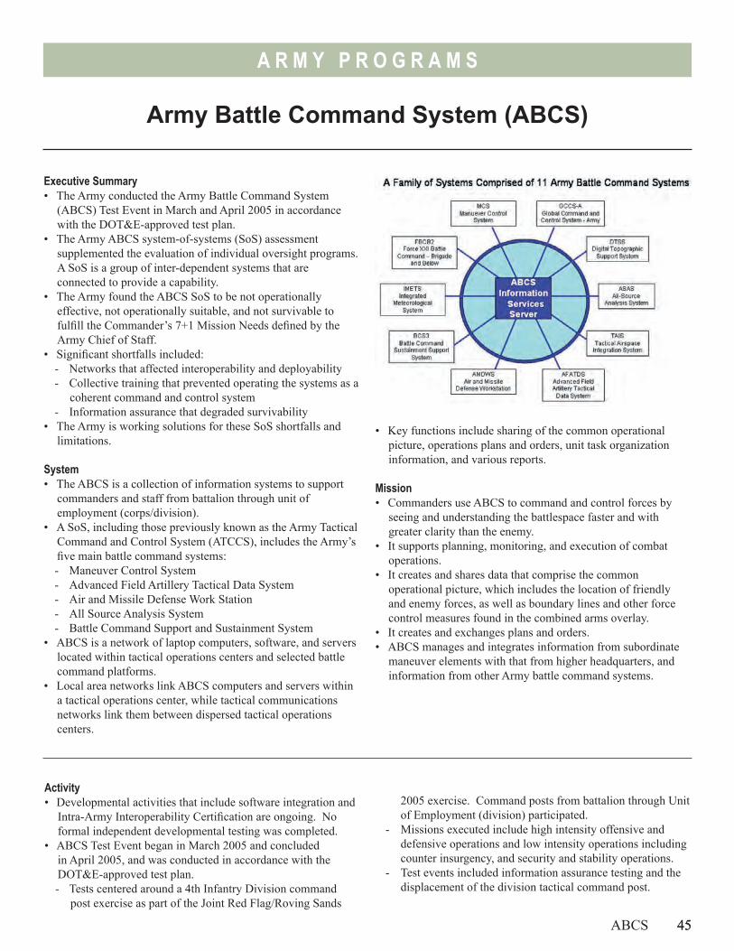
45
A R M Y P R O G R A M S
Army Battle Command System (ABCS)
ABCS 45
Executive Summary• The Army conducted the Army Battle Command System
(ABCS) Test Event in March and April 2005 in accordance with the DOT&E-approved test plan.
• The Army ABCS system-of-systems (SoS) assessment supplemented the evaluation of individual oversight programs. A SoS is a group of inter-dependent systems that are connected to provide a capability.
• The Army found the ABCS SoS to be not operationally effective, not operationally suitable, and not survivable to fulfill the Commander’s 7+1 Mission Needs defined by the Army Chief of Staff.
• Significant shortfalls included: - Networks that affected interoperability and deployability- Collective training that prevented operating the systems as a
coherent command and control system- Information assurance that degraded survivability
• The Army is working solutions for these SoS shortfalls and limitations.
System• The ABCS is a collection of information systems to support
commanders and staff from battalion through unit of employment (corps/division).
• A SoS, including those previously known as the Army Tactical Command and Control System (ATCCS), includes the Army’s five main battle command systems: - Maneuver Control System - Advanced Field Artillery Tactical Data System- Air and Missile Defense Work Station- All Source Analysis System- Battle Command Support and Sustainment System
• ABCS is a network of laptop computers, software, and servers located within tactical operations centers and selected battle command platforms.
• Local area networks link ABCS computers and servers within a tactical operations center, while tactical communications networks link them between dispersed tactical operations centers.
• Key functions include sharing of the common operational picture, operations plans and orders, unit task organization information, and various reports.
Mission• Commanders use ABCS to command and control forces by
seeing and understanding the battlespace faster and with greater clarity than the enemy.
• It supports planning, monitoring, and execution of combat operations.
• It creates and shares data that comprise the common operational picture, which includes the location of friendly and enemy forces, as well as boundary lines and other force control measures found in the combined arms overlay.
• It creates and exchanges plans and orders.• ABCS manages and integrates information from subordinate
maneuver elements with that from higher headquarters, and information from other Army battle command systems.
Activity• Developmental activities that include software integration and
Intra-Army Interoperability Certification are ongoing. No formal independent developmental testing was completed.
• ABCS Test Event began in March 2005 and concluded in April 2005, and was conducted in accordance with the DOT&E-approved test plan.- Tests centered around a 4th Infantry Division command
post exercise as part of the Joint Red Flag/Roving Sands
2005 exercise. Command posts from battalion through Unit of Employment (division) participated.
- Missions executed include high intensity offensive and defensive operations and low intensity operations including counter insurgency, and security and stability operations.
- Test events included information assurance testing and the displacement of the division tactical command post.
46
A R M Y P R O G R A M S
• Follow-on testing occurred in August and September 2005 in conjunction with other 4th Infantry Division training events at Fort Hood, Texas, and the National Training Center in California.
Assessment• This was the first attempt to test and assess the operational
effectiveness, suitability, and survivability of a SoS or Family of Systems (FoS). The component systems within ABCS were developed separately and up to this point were considered a FoS (i.e., they operated independently within their own battlefield functional areas). Information provided by each component was integrated by the operations staff within the command elements. However, with the horizontal integration of these systems at the command level, they are now viewed as a SoS. A SoS is a group of independent systems that are connected to provide a capability. The loss of any part of that SoS degrades the capability provided by the integrated whole (i.e., the whole is now greater than the sum of the parts).
• There is no formal ABCS capabilities document to guide the assessment. Instead, the assessment looked at the ability of ABCS to satisfy the Commander’s 7+1 Mission Needs.
• These mission needs were reported to the Chief of Staff of the Army from commanders in the field. They include friendly locations, current enemy situation, running estimate, graphics and overlays, plans and orders, commander’s situation report, fire support coordination measures/overlays, and Joint and coalition interoperability.
• The ABCS test event was also an IOT&E for the Maneuver Control System and All Source Analysis System Block II systems. The test provided data to support software material release decisions for the Air and Missile Defense Work Station, the Advanced Field Artillery Tactical Data System, and the Battle Command Support and Sustainment System.
• The assessment determined that the ABCS SoS was not operationally effective, suitable, or survivable. Significant observations contributing to the conclusions include:- Inflexible networking products complicate, and often
prevent, altering the ABCS architecture to match the unit’s operational architecture. The products themselves are inflexible and the process to create the products is too complicated and time consuming to respond to dynamic operations.
- The training program does not prepare the unit to employ the ABCS as an integrated and comprehensive command and control system; this includes how systems integrate with one another to support battle staff operations. Sustainment training did not maintain operator proficiency nor provide opportunity to train new soldiers arriving in the unit between new equipment training and conduct of the test event.
- Interoperability challenges include time to process overlays and database updates, incompatible graphics types and formats, and the reliability of the ABCS Information Services server.
- Information assurance vulnerabilities were identified and exploited.
These ABCS SoS issues affect multiple systems. The performance of each individual system in the ABCS is inextricably tied to the performance of the SoS network that defines the information flows and links the systems to one another. Correction of these issues is beyond the scope of the individual acquisition programs, but is required for the individual systems and overall ABCS to provide its required capability.
The ABCS SoS assessment contributed valuable insights to the evaluations of the individual acquisition programs. By taking a more holistic approach, the assessment identified significant issues beyond the scope of a single program manager’s responsibility. This assessment and subsequent recommendations were briefed to the Chief of Staff of the Army.
These cross-cutting issues are as important to warfighting effectiveness as specific deficiencies associated with the individual programs.
Recommendations1. Develop improved networking products to support dynamic
and flexible operations.2. Demonstrate corrections to information assurance deficiencies.3. Create and fund improved collective and sustainment training
programs to increase utility to the warfighter.
46 ABCS

47
A R M Y P R O G R A M S
Black Hawk Upgrades (UH-60M) – Utility Helicopter Upgrade
Executive Summary• The Defense Acquisition Executive approved the
Milestone C low-rate initial production decision to purchase up to 40 UH-60M aircraft on March 31, 2005.
• The Army has flown nearly 500 of the planned 650 developmental test hours.
• Technical risks include system-level integration, digital interoperability, and reliability. The UH-60M Test and Evaluation Master Plan is adequate to evaluate these technical issues and determine the operational effectiveness and suitability of the UH-60M Blackhawk.
System• The UH-60M is a recapitalized and upgraded UH-60 A or
L model Black Hawk medium-lift helicopter.• The program projects upgrade for 1,235 UH-60M Black
Hawks. • The Assault Helicopter Battalion is organized as three
companies of 10 aircraft each.• The UH-60M upgrades include:
- A Common Avionics Architecture System for improved situational awareness
- Power and Airframe improvements with monolithic machined parts, for increased lift and range over the A/L model Black Hawk
- Enhanced laser warning and infrared suppression for anti-missile defense, and crashworthy fuel system to increase survivability
Mission• Assault Aviation and General Support Aviation Battalions will
use this aircraft to conduct the following missions:
- Resupply the force through internal transport, and internal and external cargo lift capability
- Air Assault 11 combat soldiers or light vehicles and equipment less than 4,500 pounds
- Conduct aero medical evacuation- Execute command and control
• The increased lift capability of the UH-60M enhances mission accomplishment by massing more combat assets with greater situational awareness than the UH-60 A and L models.
Activity• The Army conducted a Limited User Test in August 2004 to
assess the integration of advanced avionics and software build C, which is designed to reduce pilot workload and increase pilot situational awareness. The Limited User Test results supported the Milestone C decision in March 2005 for a low-rate production of 40 aircraft.
• A combined contractor and government test team continued developmental flight and ground testing on three prototype aircraft. These tests included nearly 500 of the planned 650 developmental test hours and focused on the integration of advanced avionics, such as the Automated Flight Control System and Flight Management System. Ground
testing included Electromagnetic Compatibility testing and qualification, initial integration testing of the Volcano mission equipment package, crashworthy external fuel system integration, and icing testing.
• The LFT&E strategy approved by DOT&E in May 2000 includes a waiver from full-up system-level testing. An alternate strategy combines efforts with the Navy’s MH-60R and MH-60S programs, as well as DOT&E’s Joint Live Fire Program. Joint Live Fire testing of the crashworthy external fuel system was completed in FY05, with testing of the onboard oxygen generation system and the new wide chord blades remaining under the Army Live Fire program. Related
Black Hawk UH-60M 47
A R M Y P R O G R A M S
testing of the UH-60 engine compartments and the improved gear box is ongoing under the Joint Live Fire program.
Assessment• The UH-60M met three of four Milestone C entrance criteria.
The UH-60M met or exceeded the entrance criteria for troop lift, external lift, and digitization. The UH-60M did not meet the reliability entrance criterion, and by the Army’s current reliability growth model estimates, the reliability threshold for essential maintenance actions will not be met until 2010, three years after the full-rate production decision review.
• The UH-60M provides improved handling qualities over the UH-60 A/L aircraft, with digital cockpit enhancements and reduction of pilot workload.
• LFT&E results to date indicate improved survivability over the UH-60A/L aircraft.
• The UH-60M line-of-sight based communications system is not compatible with the current Army digital architecture. As with other platforms, it will be difficult for this program to provide the digital communications capabilities necessary to achieve required interoperability.
• Technical risks include digital interoperability and reliability.
RecommendationsThe Army should:1. Integrate a satellite-based communication system that is
compatible with the current Army digital architecture into the UH-60M to achieve the required interoperability.
2. Address reliability shortfalls.
48 Black Hawk UH-60M
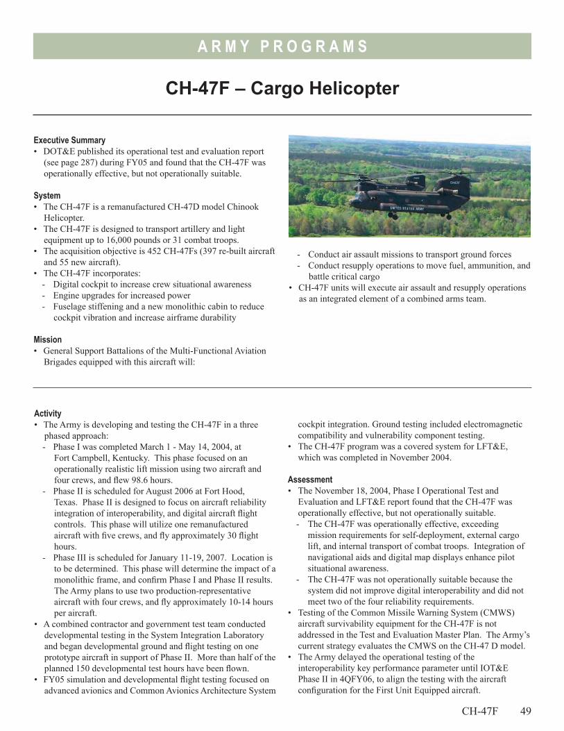
A R M Y P R O G R A M S
CH-47F – Cargo Helicopter
Executive Summary• DOT&E published its operational test and evaluation report
(see page 287) during FY05 and found that the CH-47F was operationally effective, but not operationally suitable.
System• The CH-47F is a remanufactured CH-47D model Chinook
Helicopter.• The CH-47F is designed to transport artillery and light
equipment up to 16,000 pounds or 31 combat troops.• The acquisition objective is 452 CH-47Fs (397 re-built aircraft
and 55 new aircraft). • The CH-47F incorporates:
- Digital cockpit to increase crew situational awareness - Engine upgrades for increased power- Fuselage stiffening and a new monolithic cabin to reduce
cockpit vibration and increase airframe durability
Mission• General Support Battalions of the Multi-Functional Aviation
Brigades equipped with this aircraft will:
- Conduct air assault missions to transport ground forces- Conduct resupply operations to move fuel, ammunition, and
battle critical cargo• CH-47F units will execute air assault and resupply operations
as an integrated element of a combined arms team.
Activity• The Army is developing and testing the CH-47F in a three
phased approach: - Phase I was completed March 1 - May 14, 2004, at
Fort Campbell, Kentucky. This phase focused on an operationally realistic lift mission using two aircraft and four crews, and flew 98.6 hours.
- Phase II is scheduled for August 2006 at Fort Hood, Texas. Phase II is designed to focus on aircraft reliability integration of interoperability, and digital aircraft flight controls. This phase will utilize one remanufactured aircraft with five crews, and fly approximately 30 flight hours.
- Phase III is scheduled for January 11-19, 2007. Location is to be determined. This phase will determine the impact of a monolithic frame, and confirm Phase I and Phase II results. The Army plans to use two production-representative aircraft with four crews, and fly approximately 10-14 hours per aircraft.
• A combined contractor and government test team conducted developmental testing in the System Integration Laboratory and began developmental ground and flight testing on one prototype aircraft in support of Phase II. More than half of the planned 150 developmental test hours have been flown.
• FY05 simulation and developmental flight testing focused on advanced avionics and Common Avionics Architecture System
cockpit integration. Ground testing included electromagnetic compatibility and vulnerability component testing.
• The CH-47F program was a covered system for LFT&E, which was completed in November 2004.
Assessment• The November 18, 2004, Phase I Operational Test and
Evaluation and LFT&E report found that the CH-47F was operationally effective, but not operationally suitable. - The CH-47F was operationally effective, exceeding
mission requirements for self-deployment, external cargo lift, and internal transport of combat troops. Integration of navigational aids and digital map displays enhance pilot situational awareness.
- The CH-47F was not operationally suitable because the system did not improve digital interoperability and did not meet two of the four reliability requirements.
• Testing of the Common Missile Warning System (CMWS) aircraft survivability equipment for the CH-47F is not addressed in the Test and Evaluation Master Plan. The Army’s current strategy evaluates the CMWS on the CH-47 D model.
• The Army delayed the operational testing of the interoperability key performance parameter until IOT&E Phase II in 4QFY06, to align the testing with the aircraft configuration for the First Unit Equipped aircraft.
CH-47F 49
50
A R M Y P R O G R A M S
• Preliminary developmental testing results and test pilot feedback indicate that advanced avionics and the Common Avionics Architecture System cockpit enhancements including integration of navigational aids with digital moving map and flight plan, greatly improve handling and situational awareness.
• Technical risks include system-level integration, digital interoperability, reliability, and monolithic airframe integration.
Recommendations1. The Army should conduct operational testing to evaluate
anticipated changes to the CH-47F before fielding in 2007, and
50 CH-47F
to demonstrate that the aircraft can meet interoperability and reliability requirements.
2. To adequately test aircraft survivability equipment effectiveness on the CH-47F, the Army should expand the CMWS initial operational test of the CH-47D to include the CH-47F. CH-47F CMWS is not currently scheduled to be tested, and the impact of enhancements such as the Common Avionics Architecture System and monolithic airframe remains unknown.
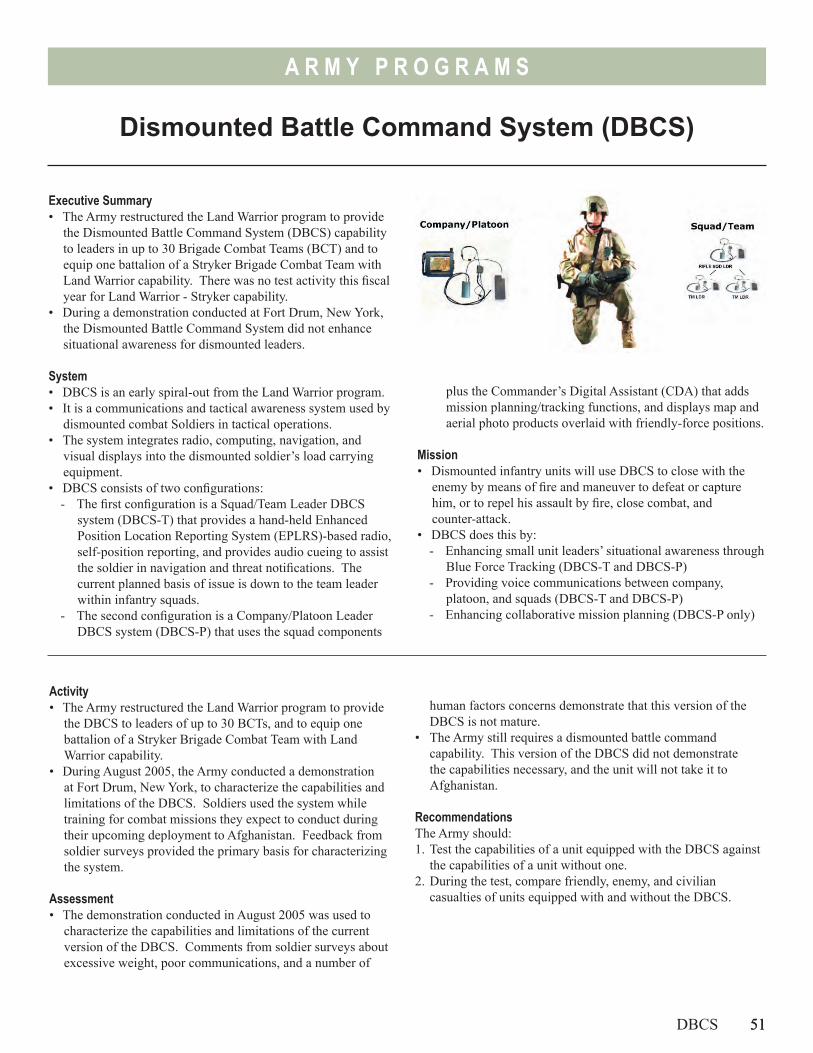
51
A R M Y P R O G R A M S
Dismounted Battle Command System (DBCS)
Executive Summary• The Army restructured the Land Warrior program to provide
the Dismounted Battle Command System (DBCS) capability to leaders in up to 30 Brigade Combat Teams (BCT) and to equip one battalion of a Stryker Brigade Combat Team with Land Warrior capability. There was no test activity this fiscal year for Land Warrior - Stryker capability.
• During a demonstration conducted at Fort Drum, New York, the Dismounted Battle Command System did not enhance situational awareness for dismounted leaders.
System• DBCS is an early spiral-out from the Land Warrior program.• It is a communications and tactical awareness system used by
dismounted combat Soldiers in tactical operations.• The system integrates radio, computing, navigation, and
visual displays into the dismounted soldier’s load carrying equipment.
• DBCS consists of two configurations:- The first configuration is a Squad/Team Leader DBCS
system (DBCS-T) that provides a hand-held Enhanced Position Location Reporting System (EPLRS)-based radio, self-position reporting, and provides audio cueing to assist the soldier in navigation and threat notifications. The current planned basis of issue is down to the team leader within infantry squads.
- The second configuration is a Company/Platoon Leader DBCS system (DBCS-P) that uses the squad components
plus the Commander’s Digital Assistant (CDA) that adds mission planning/tracking functions, and displays map and aerial photo products overlaid with friendly-force positions.
Mission• Dismounted infantry units will use DBCS to close with the
enemy by means of fire and maneuver to defeat or capture him, or to repel his assault by fire, close combat, and counter-attack.
• DBCS does this by:- Enhancing small unit leaders’ situational awareness through
Blue Force Tracking (DBCS-T and DBCS-P)- Providing voice communications between company,
platoon, and squads (DBCS-T and DBCS-P)- Enhancing collaborative mission planning (DBCS-P only)
Activity• The Army restructured the Land Warrior program to provide
the DBCS to leaders of up to 30 BCTs, and to equip one battalion of a Stryker Brigade Combat Team with Land Warrior capability.
• During August 2005, the Army conducted a demonstration at Fort Drum, New York, to characterize the capabilities and limitations of the DBCS. Soldiers used the system while training for combat missions they expect to conduct during their upcoming deployment to Afghanistan. Feedback from soldier surveys provided the primary basis for characterizing the system.
Assessment• The demonstration conducted in August 2005 was used to
characterize the capabilities and limitations of the current version of the DBCS. Comments from soldier surveys about excessive weight, poor communications, and a number of
human factors concerns demonstrate that this version of the DBCS is not mature.
• The Army still requires a dismounted battle command capability. This version of the DBCS did not demonstrate the capabilities necessary, and the unit will not take it to Afghanistan.
RecommendationsThe Army should:1. Test the capabilities of a unit equipped with the DBCS against
the capabilities of a unit without one.2. During the test, compare friendly, enemy, and civilian
casualties of units equipped with and without the DBCS.
DBCS 51

52
A R M Y P R O G R A M S
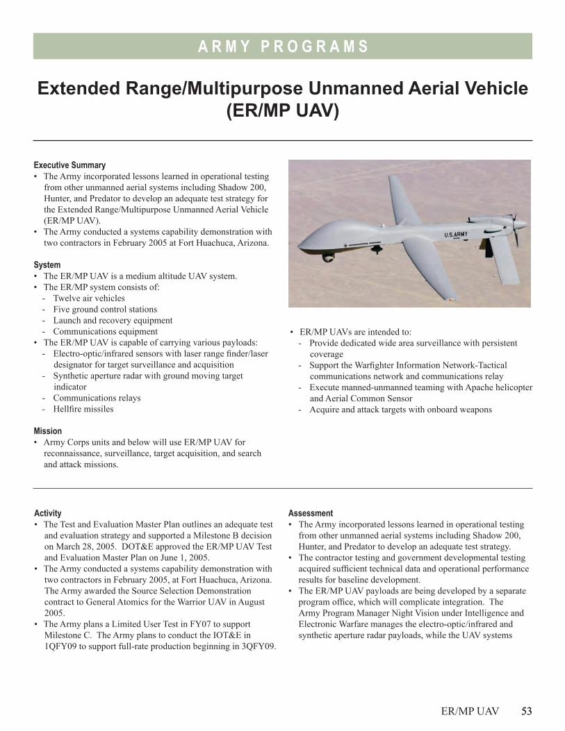
53
A R M Y P R O G R A M S
Extended Range/Multipurpose Unmanned Aerial Vehicle (ER/MP UAV)
Executive Summary• The Army incorporated lessons learned in operational testing
from other unmanned aerial systems including Shadow 200, Hunter, and Predator to develop an adequate test strategy for the Extended Range/Multipurpose Unmanned Aerial Vehicle (ER/MP UAV).
• The Army conducted a systems capability demonstration with two contractors in February 2005 at Fort Huachuca, Arizona.
System• The ER/MP UAV is a medium altitude UAV system.• The ER/MP system consists of:
- Twelve air vehicles- Five ground control stations- Launch and recovery equipment- Communications equipment
• The ER/MP UAV is capable of carrying various payloads: - Electro-optic/infrared sensors with laser range finder/laser
designator for target surveillance and acquisition- Synthetic aperture radar with ground moving target
indicator- Communications relays- Hellfire missiles
Mission• Army Corps units and below will use ER/MP UAV for
reconnaissance, surveillance, target acquisition, and search and attack missions.
• ER/MP UAVs are intended to:- Provide dedicated wide area surveillance with persistent
coverage- Support the Warfighter Information Network-Tactical
communications network and communications relay- Execute manned-unmanned teaming with Apache helicopter
and Aerial Common Sensor- Acquire and attack targets with onboard weapons
Activity• The Test and Evaluation Master Plan outlines an adequate test
and evaluation strategy and supported a Milestone B decision on March 28, 2005. DOT&E approved the ER/MP UAV Test and Evaluation Master Plan on June 1, 2005.
• The Army conducted a systems capability demonstration with two contractors in February 2005, at Fort Huachuca, Arizona. The Army awarded the Source Selection Demonstration contract to General Atomics for the Warrior UAV in August 2005.
• The Army plans a Limited User Test in FY07 to support Milestone C. The Army plans to conduct the IOT&E in 1QFY09 to support full-rate production beginning in 3QFY09.
ER/MP UAV 53
Assessment• The Army incorporated lessons learned in operational testing
from other unmanned aerial systems including Shadow 200, Hunter, and Predator to develop an adequate test strategy.
• The contractor testing and government developmental testing acquired sufficient technical data and operational performance results for baseline development.
• The ER/MP UAV payloads are being developed by a separate program office, which will complicate integration. The Army Program Manager Night Vision under Intelligence and Electronic Warfare manages the electro-optic/infrared and synthetic aperture radar payloads, while the UAV systems
54
A R M Y P R O G R A M S
program manager under Army aviation manages the ER/MP program executive office.
• The developmental testing schedule is ambitious. Environmental, transportability, interoperability, and airworthiness/safety tests are planned prior to the FY07 Limited User Test.
Recommendations1. ER/MP UAV payloads are under separate programs. The
Army should require close coordination to ensure adequate test integration and mission performance.
2. In order to develop adequate testing, the Army should update and complete fielding plans and tactics development thus defining reconnaissance and surveillance missions.
54 ER/MP UAV
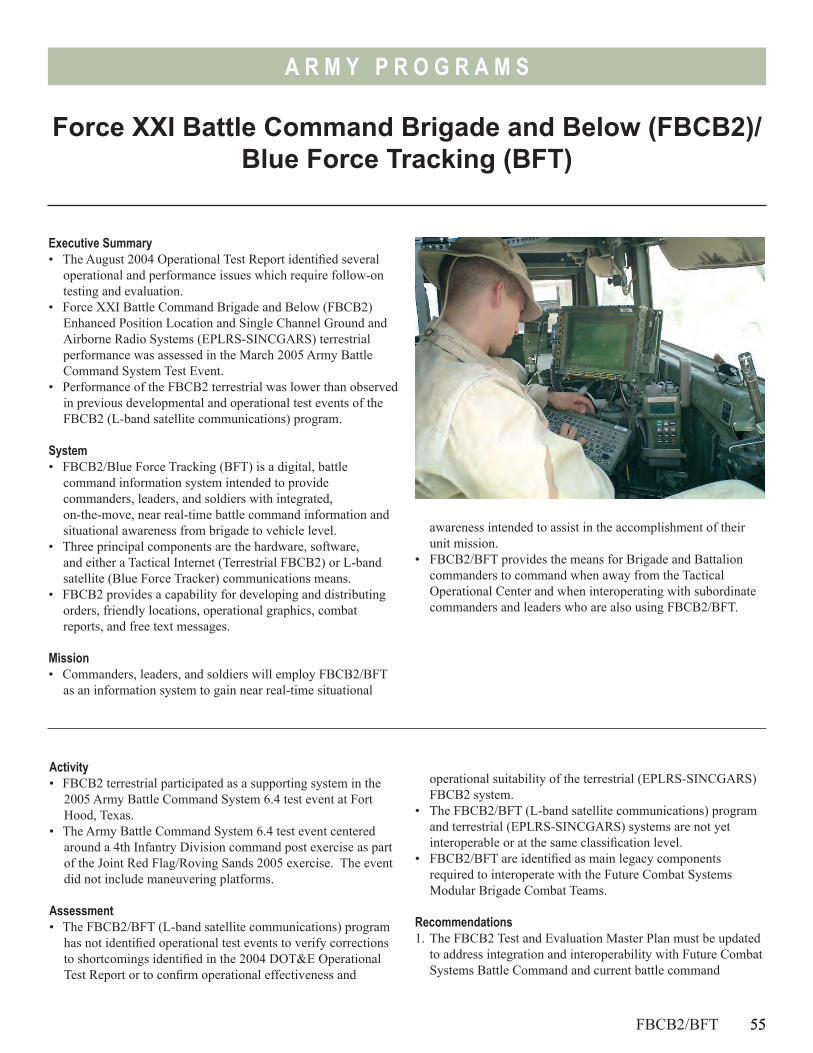
55
A R M Y P R O G R A M S
Force XXI Battle Command Brigade and Below (FBCB2)/ Blue Force Tracking (BFT)
Executive Summary• The August 2004 Operational Test Report identified several
operational and performance issues which require follow-on testing and evaluation.
• Force XXI Battle Command Brigade and Below (FBCB2) Enhanced Position Location and Single Channel Ground and Airborne Radio Systems (EPLRS-SINCGARS) terrestrial performance was assessed in the March 2005 Army Battle Command System Test Event.
• Performance of the FBCB2 terrestrial was lower than observed in previous developmental and operational test events of the FBCB2 (L-band satellite communications) program.
System• FBCB2/Blue Force Tracking (BFT) is a digital, battle
command information system intended to provide commanders, leaders, and soldiers with integrated, on-the-move, near real-time battle command information and situational awareness from brigade to vehicle level.
• Three principal components are the hardware, software, and either a Tactical Internet (Terrestrial FBCB2) or L-band satellite (Blue Force Tracker) communications means.
• FBCB2 provides a capability for developing and distributing orders, friendly locations, operational graphics, combat reports, and free text messages.
Mission• Commanders, leaders, and soldiers will employ FBCB2/BFT
as an information system to gain near real-time situational
Activity• FBCB2 terrestrial participated as a supporting system in the
2005 Army Battle Command System 6.4 test event at Fort Hood, Texas.
• The Army Battle Command System 6.4 test event centered around a 4th Infantry Division command post exercise as part of the Joint Red Flag/Roving Sands 2005 exercise. The event did not include maneuvering platforms.
Assessment• The FBCB2/BFT (L-band satellite communications) program
has not identified operational test events to verify corrections to shortcomings identified in the 2004 DOT&E Operational Test Report or to confirm operational effectiveness and
FBCB2/BFT 55
awareness intended to assist in the accomplishment of their unit mission.
• FBCB2/BFT provides the means for Brigade and Battalion commanders to command when away from the Tactical Operational Center and when interoperating with subordinate commanders and leaders who are also using FBCB2/BFT.
operational suitability of the terrestrial (EPLRS-SINCGARS) FBCB2 system.
• The FBCB2/BFT (L-band satellite communications) program and terrestrial (EPLRS-SINCGARS) systems are not yet interoperable or at the same classification level.
• FBCB2/BFT are identified as main legacy components required to interoperate with the Future Combat Systems Modular Brigade Combat Teams.
Recommendations 1. The FBCB2 Test and Evaluation Master Plan must be updated
to address integration and interoperability with Future Combat Systems Battle Command and current battle command
A R M Y P R O G R A M S
networks. It should include a strategy to test information assurance and security functionality.
2. Conduct focused event to test interoperability between the FBCB2 (L-band satellite communications) program, the
56 FBCB2/BFT
FBCB2 (EPLRS-SINCGARS) terrestrial, and current battle command components.
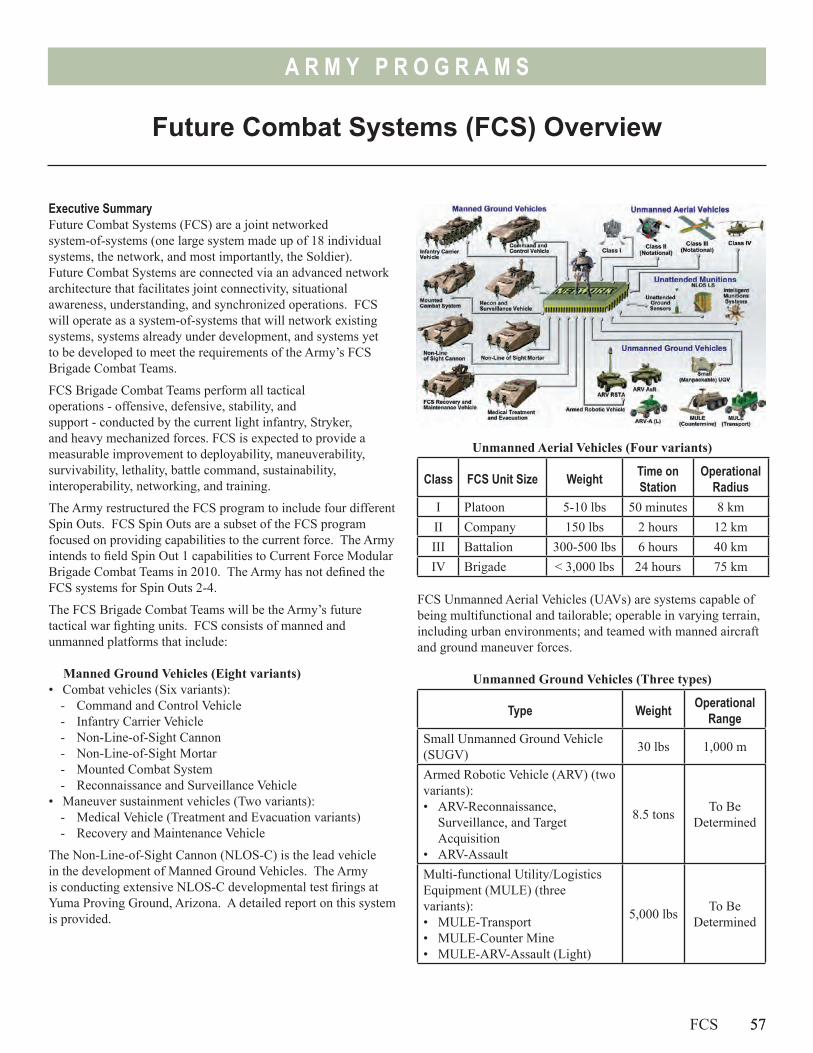
57
A R M Y P R O G R A M S
Future Combat Systems (FCS) Overview
Executive SummaryFuture Combat Systems (FCS) are a joint networked system-of-systems (one large system made up of 18 individual systems, the network, and most importantly, the Soldier). Future Combat Systems are connected via an advanced network architecture that facilitates joint connectivity, situational awareness, understanding, and synchronized operations. FCS will operate as a system-of-systems that will network existing systems, systems already under development, and systems yet to be developed to meet the requirements of the Army’s FCS Brigade Combat Teams.
FCS Brigade Combat Teams perform all tactical operations - offensive, defensive, stability, and support - conducted by the current light infantry, Stryker, and heavy mechanized forces. FCS is expected to provide a measurable improvement to deployability, maneuverability, survivability, lethality, battle command, sustainability, interoperability, networking, and training.
The Army restructured the FCS program to include four different Spin Outs. FCS Spin Outs are a subset of the FCS program focused on providing capabilities to the current force. The Army intends to field Spin Out 1 capabilities to Current Force Modular Brigade Combat Teams in 2010. The Army has not defined the FCS systems for Spin Outs 2-4.
The FCS Brigade Combat Teams will be the Army’s future tactical war fighting units. FCS consists of manned and unmanned platforms that include:
Manned Ground Vehicles (Eight variants)• Combat vehicles (Six variants):
- Command and Control Vehicle- Infantry Carrier Vehicle- Non-Line-of-Sight Cannon- Non-Line-of-Sight Mortar- Mounted Combat System- Reconnaissance and Surveillance Vehicle
• Maneuver sustainment vehicles (Two variants):- Medical Vehicle (Treatment and Evacuation variants)- Recovery and Maintenance Vehicle
The Non-Line-of-Sight Cannon (NLOS-C) is the lead vehicle in the development of Manned Ground Vehicles. The Army is conducting extensive NLOS-C developmental test firings at Yuma Proving Ground, Arizona. A detailed report on this system is provided.
Unmanned Aerial Vehicles (Four variants)
Class FCS Unit Size Weight Time on Station
Operational Radius
I Platoon 5-10 lbs 50 minutes 8 kmII Company 150 lbs 2 hours 12 kmIII Battalion 300-500 lbs 6 hours 40 kmIV Brigade < 3,000 lbs 24 hours 75 km
FCS Unmanned Aerial Vehicles (UAVs) are systems capable of being multifunctional and tailorable; operable in varying terrain, including urban environments; and teamed with manned aircraft and ground maneuver forces.
Unmanned Ground Vehicles (Three types)
Type Weight Operational Range
Small Unmanned Ground Vehicle (SUGV) 30 lbs 1,000 m
Armed Robotic Vehicle (ARV) (two variants):• ARV-Reconnaissance,
Surveillance, and Target Acquisition
• ARV-Assault
8.5 tons To Be Determined
Multi-functional Utility/Logistics Equipment (MULE) (three variants):• MULE-Transport• MULE-Counter Mine• MULE-ARV-Assault (Light)
5,000 lbs To Be Determined
FCS 57
58
A R M Y P R O G R A M S
The Autonomous Navigation System provides the capability to operate all UGVs in a tele-operated mode, semi-autonomous mode, and/or semi-autonomous route following mode.
Unattended Munitions (Two types)Both of these systems are part of Spin Out 1. • The Non-Line-of-Sight Launch System (NLOS-LS) consists
of a family of missiles and a deployable, platform-independent Container Launch Unit with self-contained tactical fire control electronics and software for remote and unmanned operations. A detailed report on this system is provided.
• The Intelligent Munitions System is a system of lethal and non-lethal munitions integrated with command and control features, communications devices, a sensor, and seekers. The Army plans for IMS to meet the requirements of the 2004 National Landmine Policy, and to be a component of FCS. The program completed concept and technology development and plans to transition IMS to System Development and Demonstration in December 2005.
Unattended Ground Sensor (2 types)FCS Unattended Ground Sensors (UGS) are an array of networked sensors capable of target detection, location, tracking, and classification. The Army intends the UGSs to be small, low cost, robust sensors capable of operating in the field for extended periods of time.
The FCS UGS program is developing two major sensor subgroups:• Tactical-UGS (two variants):
- Intelligence, Surveillance, and Reconnaissance-UGS- Chemical, Biological, Radiological, and Nuclear-UGS
• Urban-UGS is an array of small, lightweight sensors emplaced in buildings.
Early versions will be hand emplaced. Later versions plan to have these sensors emplaced from FCS Unmanned Ground Vehicles. Both Unattended Ground Sensor subgroups are part of Spin Out 1.
Battle Command NetworkThe Battle Command Network is critical to FCS. It enables soldiers of a FCS Brigade Combat Team to conduct Network Centric Warfare. The network will support the FCS Brigade Combat Team by providing advance functionalities such as integrated network management, information assurance, and information dissemination to ensure dissemination of critical information among sensors, processors, and warfighters within and external to the FCS Brigade Combat Team.
The Battle Command Network consists of:• Communications payloads (radios, cabling, and antennas) for
every soldier installed on FCS ground and air platform• Network management software distributed on platform
computers• Communications payloads on unmanned aerial vehicles
The FCS Battle Command Network is the primary means in which FCS Brigade Combat Teams will move information and data.
Activity• The Army restructured the FCS program to include four
different Spin Outs. FCS Spin Outs are a subset of the FCS program focused on providing technologies/capabilities to the Current Force to address specific capability gaps.
• The major focus for 2005 was revising the FCS Test and Evaluation Master Plan and tailoring the test program to the restructured FCS Spin Out strategy.
Assessment• DOT&E is concerned about the Army’s commitment to
provide adequate resources to the U.S. Army Test and Evaluation Command (ATEC) to conduct 13 FCS operational test events between the years 2008 and 2016. This will be the most complex series of operational tests events ever conducted by the Army. Funding, civilian personnel, and military personnel test and evaluation authorizations continue to be cut by the Army. Additional pending cuts by the Army will severely impact ATEC’s ability to accomplish its mission
• Combat experience in Afghanistan and Iraq has demonstrated the utility of small Unmanned Ground Vehicles for tunnel surveillance and explosive device detection/destruction.
• The Army plans to have an approved FCS Test and Evaluation Master Plan in 2006. Major DOT&E focus areas for the updated Test and Evaluation Master Plan are:- Developing operational and live fire testing on individual
systems in addition to system-of-system level testing.- Testing a fully equipped Brigade Combat Team during the
IOT&E, to include an operational deployment of a portion of the FCS Brigade Combat Team via Air Force cargo aircraft.
- Ensuring adequate numbers and types of units, equipped with production representative prototypes, are available for operational and LFT&E.
- Monitoring critical technologies associated with the Battle Command Network. The Army has identified 13 critical technologies; nine of these critical technologies are network related.
- Ensuring the program conducts a separate Battle Command Network test.
- Ensuring that the more than 140 complementary programs, of which 52 are essential in meeting key performance parameters, are integrated.
58 FCS
A R M Y P R O G R A M S
- Understanding the role of modeling and simulation in operational test events.
• Additionally, in accordance with the 2005 Base Realignment and Closure Commission’s report to Congress, ATEC is scheduled to relocate in the midst of these operational test events. Experience has shown that approximately 80 percent of the workforce does not want to move when an organization relocates. Losing key and essential test and evaluation personnel during this critical period in the FCS program is high risk.
Recommendations1. The Army is planning to conduct the FCS IOT&E as a
system-of-systems test. The Army should conduct FCS operational tests at the system-level first in order to evaluate the operational capabilities of each system before conducting the overall FCS system-of-systems test.
2. Review the relevance of key requirements, particularly C-130 transportability of manned ground vehicles. Design trades necessary to meet this requirement are significant and have consequences in terms of operational effectiveness, lethality, survivability, tactical mobility, and sustainability.
3. The FCS program is highly dependent on the following non-FCS programs:- Joint Tactical Radio System- Joint Network Node- Warfighter Information Network-Tactical- Distributed Common Ground System-Army- Ground Soldier System
4. Several of these programs are high risk in that they are not synchronized with the FCS program. The Department should consider a risk management alternative and understand the cost and performance implications of that alternative.
FCS 59

60
A R M Y P R O G R A M S
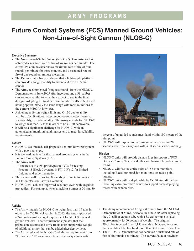
61
A R M Y P R O G R A M S
percent of unguided rounds must land within 110 meters of the aim point.
• NLOS-C will respond to fire mission requests within 20 seconds when stationary and within 30 seconds when moving.
Mission• NLOS-C units will provide cannon fires in support of FCS
Brigade Combat Teams and other mechanized brigade combat teams.
• NLOS-C will fire the entire suite of 155 mm munitions, including Excalibur precision munitions, to attack point targets.
• NLOS-C units will be deployable by C-130 aircraft (before installing extra protective armor) to support early deploying forces with cannon fires.
Future Combat Systems (FCS) Manned Ground Vehicles: Non-Line-of-Sight Cannon (NLOS-C)
FCS: NLOS-C 61
Executive Summary• The Non-Line-of-Sight Cannon (NLOS-C) Demonstrator has
achieved a sustained rate of fire of six rounds per minute. The current Paladin howitzer has a maximum rate of fire of four rounds per minute for three minutes, and a sustained rate of fire of one round per minute thereafter.
• The Demonstrator has also shown that a lightweight platform can provide enough stability to mount and fire a 155 mm cannon.
• The Army recommenced firing test rounds from the NLOS-C Demonstrator in June 2005 after incorporating a 38-caliber cannon tube similar to what they expect to use in the final design. Adopting a 38-caliber cannon tube results in NLOS-C having approximately the same range with most munitions as the current M109A6 howitzer.
• Achieving a 19-ton weight limit and C-130 deployability will be difficult without affecting operational effectiveness, survivability, or sustainability. The Army intends for NLOS-C to weigh less than 19 tons in order to be C-130 deployable.
• It will be a significant challenge for NLOS-C, with an automated ammunition handling system, to meet its reliability requirements.
System• NLOS-C is a tracked, self-propelled 155 mm howitzer system
with a two-man crew.• It is the lead vehicle for the manned ground systems in the
Future Combat Systems (FCS).• The Army will:
- Procure six to eight prototypes in FY08 for testing- Procure 18 Block 0 systems in FY10-FY12 for limited
fielding and experimentation• The cannon will fire six to 10 rounds per minute to ranges of
30+ kilometers (km) (with Excalibur).• NLOS-C will achieve improved accuracy, even with unguided
projectiles. For example, when attacking a target at 20 km, 50
Activity• The Army intends for NLOS-C to weigh less than 19 tons in
order to be C-130 deployable. In 2005, the Army approved a 24-ton design-to-weight requirement for all FCS manned ground vehicles. That requirement stipulates that the propulsion systems and drive trains must support the weight of additional armor that can be added after deployment.
• The Army reduced the NLOS-C reliability requirement from 741 hours to 512 hours mean time between system aborts.
• The Army recommenced firing test rounds from the NLOS-C Demonstrator at Yuma, Arizona, in June 2005 after replacing the 39-caliber cannon tube with a 38-caliber tube to save approximately 1,400 pounds of weight. The original 39-caliber tube had fired 1,193 rounds in NLOS-C tests and the 38-caliber tube has fired more than 300 rounds since June.
• The NLOS-C Demonstrator has achieved a sustained rate of fire of six rounds per minute. The current Paladin howitzer
62
A R M Y P R O G R A M S
has a maximum rate of fire of four rounds per minute for three minutes, and a sustained rate of fire of one round per minute thereafter.
• It has also demonstrated firing stability with a 155 mm cannon on a lightweight chassis, stable suspension on a band track, integration of power electronics and in-hull drive motors, and integration of a hybrid electric drive with a diesel propulsion system.
• The Army is revising the FCS Milestone B Test and Evaluation Master Plan (TEMP) in response to program restructuring. That TEMP will include a separate appendix for the NLOS-C.
Assessment• Achieving a 19-ton weight limit and C-130 deployability
will be difficult without affecting operational effectiveness, survivability, or sustainability. Modifying the design parameters to a 24-ton design-to-weight requirement has significant deployment and operational implications.
• Adopting a 38-caliber cannon tube reduces the range of most munitions by 3-5 km when compared to the 39-caliber tube previously tested. As a result, NLOS-C will have approximately the same range with most munitions as the current M109A6 howitzer.
• It will be a challenge for a two-man crew to conduct continuous 24-hour operations while performing operational missions, maintenance, resupply, and security associated with combat operations.
• The reliability requirement of 512 hours mean time between system aborts is more than an eight-fold increase over the reliability requirement for the Crusader system that
was cancelled in 2002. Likewise, it is over eight times the 62-hour requirement that the current Paladin howitzer was required to achieve at its operational testing in 1992. It will be a significant challenge for NLOS-C, with an automated ammunition handling system, to meet its 512-hour requirement.
• Drafts of the FCS TEMP have not yet adequately integrated NLOS-C Live Fire exercises into future operational testing. Likewise, drafts have not contained an adequate test and evaluation strategy to support fielding of NLOS-C Block 0 production howitzers.
• To assess the effectiveness of NLOS-C, within the FCS system-of-systems, it will require a sophisticated real-time casualty assessment system that can accurately determine the relative impact that indirect fires have upon the outcome of operations.
RecommendationsThe Army should:1. Ensure that FCS operational tests include adequate
NLOS-C Live Fire exercises. Supported maneuver units will need opportunities to demonstrate that they can plan and coordinate fires, and the NLOS units will need to demonstrate they can sustain operations while delivering accurate and timely fires.
2. Develop a real-time casualty assessment system for indirect fires that can accurately assess the effectiveness of NLOS-C fires in system-of-system exercises.
3. Develop a test and evaluation strategy to support the fielding of NLOS-C Block 0 production howitzers, beginning in FY10.
62 FCS: NLOS-C
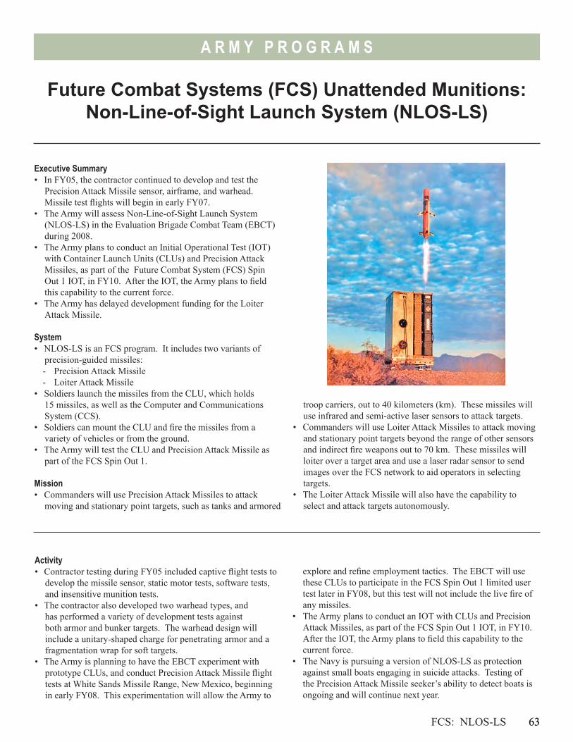
63
A R M Y P R O G R A M S
Future Combat Systems (FCS) Unattended Munitions: Non-Line-of-Sight Launch System (NLOS-LS)
FCS: NLOS-LS 63
Executive Summary• In FY05, the contractor continued to develop and test the
Precision Attack Missile sensor, airframe, and warhead. Missile test flights will begin in early FY07.
• The Army will assess Non-Line-of-Sight Launch System (NLOS-LS) in the Evaluation Brigade Combat Team (EBCT) during 2008.
• The Army plans to conduct an Initial Operational Test (IOT) with Container Launch Units (CLUs) and Precision Attack Missiles, as part of the Future Combat System (FCS) Spin Out 1 IOT, in FY10. After the IOT, the Army plans to field this capability to the current force.
• The Army has delayed development funding for the Loiter Attack Missile.
System• NLOS-LS is an FCS program. It includes two variants of
precision-guided missiles: - Precision Attack Missile- Loiter Attack Missile
• Soldiers launch the missiles from the CLU, which holds 15 missiles, as well as the Computer and Communications System (CCS).
• Soldiers can mount the CLU and fire the missiles from a variety of vehicles or from the ground.
• The Army will test the CLU and Precision Attack Missile as part of the FCS Spin Out 1.
Mission• Commanders will use Precision Attack Missiles to attack
moving and stationary point targets, such as tanks and armored
troop carriers, out to 40 kilometers (km). These missiles will use infrared and semi-active laser sensors to attack targets.
• Commanders will use Loiter Attack Missiles to attack moving and stationary point targets beyond the range of other sensors and indirect fire weapons out to 70 km. These missiles will loiter over a target area and use a laser radar sensor to send images over the FCS network to aid operators in selecting targets.
• The Loiter Attack Missile will also have the capability to select and attack targets autonomously.
Activity• Contractor testing during FY05 included captive flight tests to
develop the missile sensor, static motor tests, software tests, and insensitive munition tests.
• The contractor also developed two warhead types, and has performed a variety of development tests against both armor and bunker targets. The warhead design will include a unitary-shaped charge for penetrating armor and a fragmentation wrap for soft targets.
• The Army is planning to have the EBCT experiment with prototype CLUs, and conduct Precision Attack Missile flight tests at White Sands Missile Range, New Mexico, beginning in early FY08. This experimentation will allow the Army to
explore and refine employment tactics. The EBCT will use these CLUs to participate in the FCS Spin Out 1 limited user test later in FY08, but this test will not include the live fire of any missiles.
• The Army plans to conduct an IOT with CLUs and Precision Attack Missiles, as part of the FCS Spin Out 1 IOT, in FY10. After the IOT, the Army plans to field this capability to the current force.
• The Navy is pursuing a version of NLOS-LS as protection against small boats engaging in suicide attacks. Testing of the Precision Attack Missile seeker’s ability to detect boats is ongoing and will continue next year.
64
A R M Y P R O G R A M S
• The NLOS-LS Program Office is developing its Test and Evaluation Master Plan, including the LFT&E strategy, as an annex to the FCS Test and Evaluation Master Plan.
• The NLOS-LS LFT&E strategy will leverage developmental and operational testing, as well as modeling and simulation, to evaluate the lethality of the Precision Attack Missile. DOT&E expects that the Army will also evaluate the vulnerability associated with the combat-loaded NLOS CLU.
Assessment• Early component and sensor developmental tests indicate
that available technology is sufficiently mature to meet user requirements.
• These capabilities will be demonstrated more completely as flight tests begin in early FY07 and continue through FY09.
• Warhead development is on a tight schedule, but is benefiting from a unitary design concept originally developed for the Joint Common Missile.
• The Army is making progress in developing the tactics and procedures needed to employ NLOS-LS within the current force. The Army may begin experimentation with a user unit employing a prototype CLU (without missiles) as early as next year. This will aid in the planned fielding to the EBCT in 2008.
Recommendation1. The Army should continue early user involvement in program
development to reduce program risk and enhance the likelihood of a successful IOT.
64 FCS: NLOS-LS
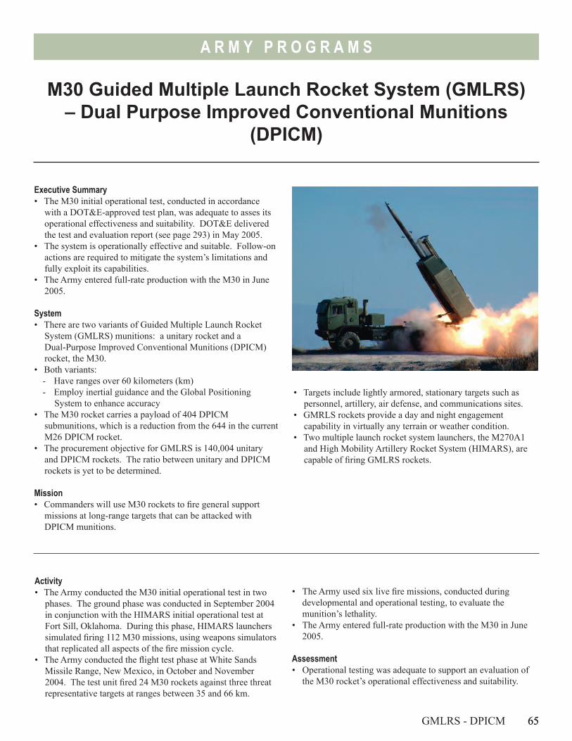
65
A R M Y P R O G R A M S
M30 Guided Multiple Launch Rocket System (GMLRS) – Dual Purpose Improved Conventional Munitions
(DPICM)
Executive Summary• The M30 initial operational test, conducted in accordance
with a DOT&E-approved test plan, was adequate to asses its operational effectiveness and suitability. DOT&E delivered the test and evaluation report (see page 293) in May 2005.
• The system is operationally effective and suitable. Follow-on actions are required to mitigate the system’s limitations and fully exploit its capabilities.
• The Army entered full-rate production with the M30 in June 2005.
System• There are two variants of Guided Multiple Launch Rocket
System (GMLRS) munitions: a unitary rocket and a Dual-Purpose Improved Conventional Munitions (DPICM) rocket, the M30.
• Both variants:- Have ranges over 60 kilometers (km)- Employ inertial guidance and the Global Positioning
System to enhance accuracy• The M30 rocket carries a payload of 404 DPICM
submunitions, which is a reduction from the 644 in the current M26 DPICM rocket.
• The procurement objective for GMLRS is 140,004 unitary and DPICM rockets. The ratio between unitary and DPICM rockets is yet to be determined.
Mission• Commanders will use M30 rockets to fire general support
missions at long-range targets that can be attacked with DPICM munitions.
• Targets include lightly armored, stationary targets such as personnel, artillery, air defense, and communications sites.
• GMRLS rockets provide a day and night engagement capability in virtually any terrain or weather condition.
• Two multiple launch rocket system launchers, the M270A1 and High Mobility Artillery Rocket System (HIMARS), are capable of firing GMLRS rockets.
Activity• The Army conducted the M30 initial operational test in two
phases. The ground phase was conducted in September 2004 in conjunction with the HIMARS initial operational test at Fort Sill, Oklahoma. During this phase, HIMARS launchers simulated firing 112 M30 missions, using weapons simulators that replicated all aspects of the fire mission cycle.
• The Army conducted the flight test phase at White Sands Missile Range, New Mexico, in October and November 2004. The test unit fired 24 M30 rockets against three threat representative targets at ranges between 35 and 66 km.
GMLRS - DPICM 65
• The Army used six live fire missions, conducted during developmental and operational testing, to evaluate the munition’s lethality.
• The Army entered full-rate production with the M30 in June 2005.
Assessment• Operational testing was adequate to support an evaluation of
the M30 rocket’s operational effectiveness and suitability.
66
A R M Y P R O G R A M S
• The GMLRS M30 rocket is operationally effective. The M30: - Is more accurate and can achieve greater ranges than the
current M26 or M26A2 DPICM munitions. - Is lethal against its intended target sets.- Is not degraded by Global Positional System jamming.- Is dependent on the availability of accurate, long-range
sensors to provide timely targeting information. Currently, there are few target acquisition capabilities that meet these requirements. As a result, the effectiveness of the munition will be less than it could be until long-range sensors become more accurate and the target acquisition and execution process is timelier.
• The GMLRS M30 rocket is operationally suitable. The M30: - Is reliable as it comes off the production line. However,
follow-on testing conducted by the Army indicates that the M30 has durability issues and potential long-term storage problems caused by moisture leaks.
- Has a submunition dud rate that is significantly lower than current DPICM rockets at all ranges. It does not meet the DoD standard for submunition dud rates of less than 1 percent. It also does not meet the standard for dud rates, as amended by the Joint Requirements Oversight Council (JROC) for this munition, of less than 4 percent at ranges less than 20 km. It does meet the JROC-amended standards for dud rates at ranges beyond 20 km.
- Is supportable within the Army’s current maintenance, logistics, training, and manpower structures.
- Has a rocket motor and warhead that are not compliant with DoD insensitive munition requirements. The JROC waived this requirement for approximately 4,600 M30 rockets to be procured through FY06.
RecommendationsThe Army should:1. Continue efforts to make the M30 fully compliant with
insensitive munitions standards. The Army is currently developing a rocket motor and submunitions that are compliant with these standards. As an interim solution, the Army should review and adjust procedures for tactical operations, commercial and military transportation, resupply, storage, and security to mitigate these risks.
2. Continue efforts to meet DoD policy requirements for submunition dud rates of less than 1 percent at all ranges. The Army is pursuing a self-destruct fuze to reduce the dud rate.
3. Continue lifecycle testing to validate that environmental or storage conditions do not adversely affect munition reliability.
4. Review procedures for targeting and command and control to exploit the enhanced accuracy and range capabilities of GMLRS munitions. The Army should consider sponsoring a Joint operational exercise to determine if the current sensor and targeting architecture is sufficient to exploit the capabilities of GMLRS and other long-range munitions.
66 GMLRS - DPICM

67
A R M Y P R O G R A M S
Executive Summary• Testing to support interim fielding to forces in Iraq indicates
the rockets are accurate and capable of killing their intended targets while limiting collateral damage.
• Initial testing indicated a 68 percent reliability rating as opposed to the 92 percent requirement. These results are typical for a system at this point of development.
• The Army continues to test the interim rockets while further developing and testing the production version. The final version is intended to be insensitive to enemy fire and will add a proximity fuze mode.
System• There are two variants of Guided Multiple Launch Rocket
System munitions (GMLRS): a unitary rocket and a Dual-Purpose Improved Conventional Munitions (DPICM) rocket.
• Both variants:- Have ranges over 60 kilometers (km)- Employ inertial guidance and the Global Positioning
System to enhance accuracy• The unitary version carries a single, high-explosive warhead.• The Army plans to begin full-rate production of
GMLRS-Unitary in FY08, but is currently deploying a limited number of early-production rockets to coalition forces in Iraq.
• The procurement objective for GMLRS is 140,004 unitary and DPICM rockets. The ratio between unitary and DPICM rockets is yet to be determined.
Mission• Commanders will use GMLRS-Unitary rockets against targets
that require precise, individual aim points with high explosive warheads.
• GMLRS-Unitary will have three fuze settings to attack different target types at extended ranges. - Proximity fuze for use against personnel in the open- Delay fuze for lightly fortified bunkers and structures- Point detonating fuze for single, lightly armored targets
• The Army expects GMLRS-Unitary to limit collateral damage, particularly in urban environments.
• Two multiple launch rocket system launchers, the M270A1 and High Mobility Artillery Rocket System (HIMARS), are capable of firing GMLRS rockets.
Activity• The Army began fielding an interim version of
GMLRS-Unitary rockets in June 2005 to the Multi-National Corps – Iraq. These rockets have only point-detonating and delay fuze modes, and use a rocket motor that does not meet insensitive munition standards. The Army plans to field 486 of these rockets in Iraq by the end of 2005.
• To support this early fielding, the Army conducted test flights with 13 Unitary rockets during FY05. The Army used a number of different targets in these missions, including personnel targets, trucks, towed howitzers, and bunkers.
• The Army also conducted a command and control exercise to develop and validate the procedures needed to employ GMLRS-Unitary in Iraq. The exercise focused on procedures to reduce collateral damage.
GMLRS - Unitary 67
Guided Multiple Launch Rocket System (GMLRS) - Unitary
• The Army continues to test the GMLRS-Unitary rocket to validate the production line making rockets for forces in Iraq and to develop the production version of the rocket.
Assessment• The effectiveness of the GMRLS-Unitary rocket at extended
ranges is dependent upon long-range sensors that are both accurate and available to provide targeting information to MLRS firing units. Currently, there are few target acquisition capabilities that meet these requirements. As a result, the long-range effectiveness of the munition will be less than it could be until long-range sensors become more accurate and the target acquisition and execution process is timelier.
Before After
68
A R M Y P R O G R A M S
• Testing to date indicates the GMLRS-Unitary rockets are accurate and are capable of killing their intended target sets, given the targets can be found with sufficient accuracy and attacked in a timely fashion. They are also capable of limiting collateral damage.
• Initial results indicate that GMLRS-Unitary rockets do not yet meet reliability requirements. Rockets tested through May 2005 demonstrated a 68 percent reliability rating. Testers detected many of the faults during pre-launch checks. These results are typical for a system at this point of development.
• GMLRS-Unitary is not compliant with insensitive munitions requirements. While the warhead complies with insensitive
68 GMLRS - Unitary
munition standards, the rocket motor does not. The Joint Requirements Oversight Council waived this requirement for the interim version the Army is fielding to coalition forces in Iraq. The Army plans to begin flight tests with an insensitive munition compliant rocket motor in 3QFY06.
Recommendations1. The Army should continue to pursue the planned design
changes to make the rocket motor insensitive to enemy fire.2. The Army should continue conducting lifecycle testing to
validate that expected environmental or tactical conditions do not degrade munition reliability.
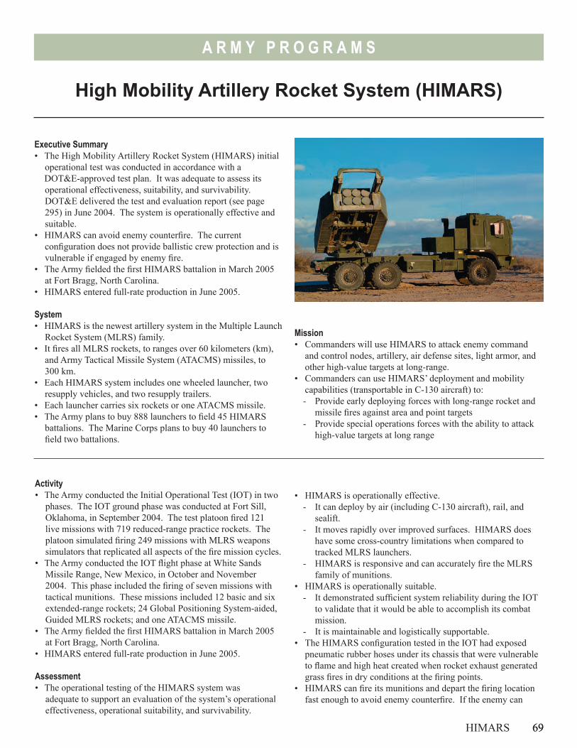
69
A R M Y P R O G R A M S
High Mobility Artillery Rocket System (HIMARS)
Executive Summary• The High Mobility Artillery Rocket System (HIMARS) initial
operational test was conducted in accordance with a DOT&E-approved test plan. It was adequate to assess its
operational effectiveness, suitability, and survivability. DOT&E delivered the test and evaluation report (see page 295) in June 2004. The system is operationally effective and suitable.
• HIMARS can avoid enemy counterfire. The current configuration does not provide ballistic crew protection and is vulnerable if engaged by enemy fire.
• The Army fielded the first HIMARS battalion in March 2005 at Fort Bragg, North Carolina.
• HIMARS entered full-rate production in June 2005.
System• HIMARS is the newest artillery system in the Multiple Launch
Rocket System (MLRS) family.• It fires all MLRS rockets, to ranges over 60 kilometers (km),
and Army Tactical Missile System (ATACMS) missiles, to 300 km.
• Each HIMARS system includes one wheeled launcher, two resupply vehicles, and two resupply trailers.
• Each launcher carries six rockets or one ATACMS missile.• The Army plans to buy 888 launchers to field 45 HIMARS
battalions. The Marine Corps plans to buy 40 launchers to field two battalions.
Activity• The Army conducted the Initial Operational Test (IOT) in two
phases. The IOT ground phase was conducted at Fort Sill, Oklahoma, in September 2004. The test platoon fired 121 live missions with 719 reduced-range practice rockets. The platoon simulated firing 249 missions with MLRS weapons simulators that replicated all aspects of the fire mission cycles.
• The Army conducted the IOT flight phase at White Sands Missile Range, New Mexico, in October and November 2004. This phase included the firing of seven missions with tactical munitions. These missions included 12 basic and six extended-range rockets; 24 Global Positioning System-aided, Guided MLRS rockets; and one ATACMS missile.
• The Army fielded the first HIMARS battalion in March 2005 at Fort Bragg, North Carolina.
• HIMARS entered full-rate production in June 2005.
Assessment• The operational testing of the HIMARS system was
adequate to support an evaluation of the system’s operational effectiveness, operational suitability, and survivability.
HIMARS 69
Mission• Commanders will use HIMARS to attack enemy command
and control nodes, artillery, air defense sites, light armor, and other high-value targets at long-range.
• Commanders can use HIMARS’ deployment and mobility capabilities (transportable in C-130 aircraft) to:- Provide early deploying forces with long-range rocket and
missile fires against area and point targets- Provide special operations forces with the ability to attack
high-value targets at long range
• HIMARS is operationally effective. - It can deploy by air (including C-130 aircraft), rail, and
sealift. - It moves rapidly over improved surfaces. HIMARS does
have some cross-country limitations when compared to tracked MLRS launchers.
- HIMARS is responsive and can accurately fire the MLRS family of munitions.
• HIMARS is operationally suitable. - It demonstrated sufficient system reliability during the IOT
to validate that it would be able to accomplish its combat mission.
- It is maintainable and logistically supportable.• The HIMARS configuration tested in the IOT had exposed
pneumatic rubber hoses under its chassis that were vulnerable to flame and high heat created when rocket exhaust generated grass fires in dry conditions at the firing points.
• HIMARS can fire its munitions and depart the firing location fast enough to avoid enemy counterfire. If the enemy can
70
A R M Y P R O G R A M S
target and engage HIMARS, the current configuration is vulnerable to artillery and mortar fragmentation, improvised explosive devices, rocket-propelled grenades, and small arms fire.
• HIMARS achieved satisfactory results during tests involving electromagnetic radiation threats, near strike lightning, and direct strike lightning.
• Current MLRS munitions are not compliant with DoD insensitive munition requirements against ballistic threats and may explode if exposed to enemy fire such as improvised explosive devices, rocket-propelled grenades, small arms fire, or mortar/artillery fragments.
RecommendationsThe Army should:1. Proceed with the planned armored cab upgrade of the
HIMARS to enhance crew protection and system survivability as a LFT&E covered program.
2. Include an assessment of the ability of the crew and maintenance personnel to repair the system after battle damage.
3. Mitigate the safety risks posed by MLRS munitions’ non-compliance with insensitive munitions standards.
This effort should include reviewing and adjusting tactics, techniques, and procedures dealing with tactical operations, commercial and military transportation, resupply, storage, and security to mitigate those risks.
4. Conduct additional testing to assess the impact of additional weight associated with the armored cab upgrade upon operational effectiveness and suitability.
5. Install and test the interim air line protection kits on all currently procured launchers and install a permanent air line protection kit on all future production launchers. (The Army has installed an interim air line protection kit on its low-rate initial production launchers that are fielded to the first HIMARS battalion at Fort Bragg, North Carolina.) The Army should also examine whether the family of medium tactical vehicles requires similar air line protection kits.
6. Develop a methodology that will facilitate survivability training and testing by providing effective feedback to crews that they are close to simulated incoming artillery.
70 HIMARS
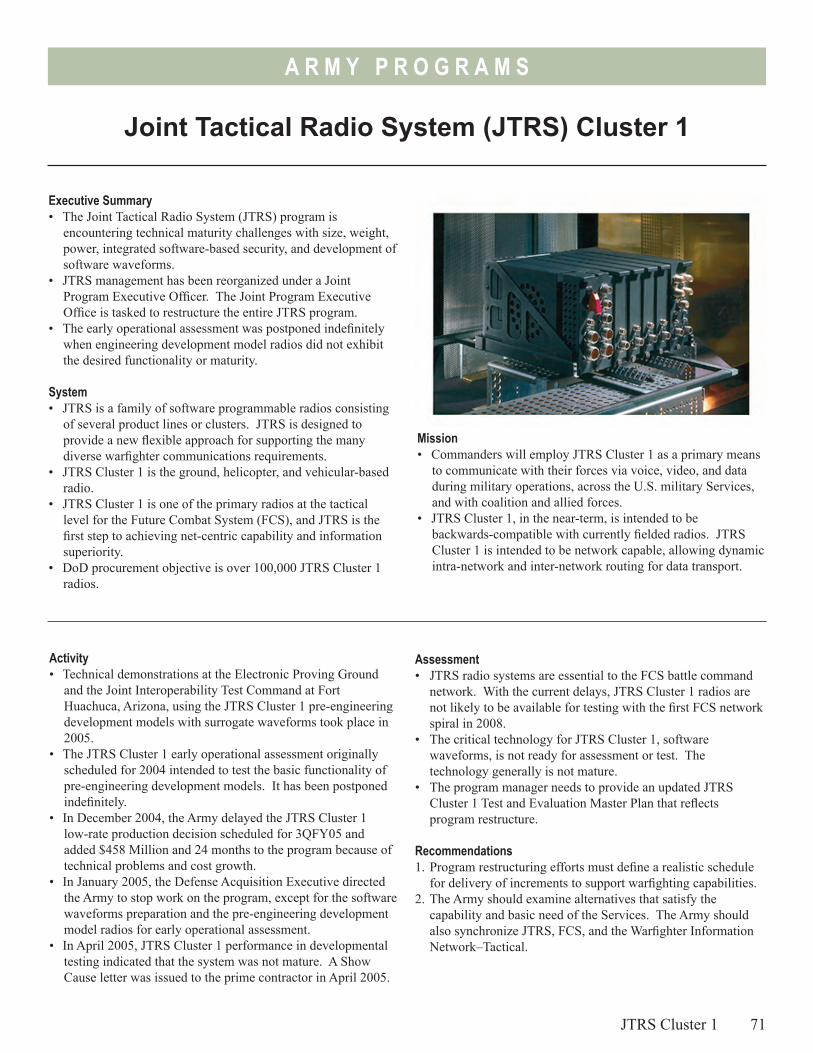
A R M Y P R O G R A M S
Joint Tactical Radio System (JTRS) Cluster 1
Executive Summary• The Joint Tactical Radio System (JTRS) program is
encountering technical maturity challenges with size, weight, power, integrated software-based security, and development of software waveforms.
• JTRS management has been reorganized under a Joint Program Executive Officer. The Joint Program Executive Office is tasked to restructure the entire JTRS program.
• The early operational assessment was postponed indefinitely when engineering development model radios did not exhibit the desired functionality or maturity.
System• JTRS is a family of software programmable radios consisting
of several product lines or clusters. JTRS is designed to provide a new flexible approach for supporting the many diverse warfighter communications requirements.
• JTRS Cluster 1 is the ground, helicopter, and vehicular-based radio.
• JTRS Cluster 1 is one of the primary radios at the tactical level for the Future Combat System (FCS), and JTRS is the first step to achieving net-centric capability and information superiority.
• DoD procurement objective is over 100,000 JTRS Cluster 1 radios.
Mission• Commanders will employ JTRS Cluster 1 as a primary means
to communicate with their forces via voice, video, and data during military operations, across the U.S. military Services, and with coalition and allied forces.
• JTRS Cluster 1, in the near-term, is intended to be backwards-compatible with currently fielded radios. JTRS Cluster 1 is intended to be network capable, allowing dynamic intra-network and inter-network routing for data transport.
Activity• Technical demonstrations at the Electronic Proving Ground
and the Joint Interoperability Test Command at Fort Huachuca, Arizona, using the JTRS Cluster 1 pre-engineering development models with surrogate waveforms took place in 2005.
• The JTRS Cluster 1 early operational assessment originally scheduled for 2004 intended to test the basic functionality of pre-engineering development models. It has been postponed indefinitely.
• In December 2004, the Army delayed the JTRS Cluster 1 low-rate production decision scheduled for 3QFY05 and added $458 Million and 24 months to the program because of technical problems and cost growth.
• In January 2005, the Defense Acquisition Executive directed the Army to stop work on the program, except for the software waveforms preparation and the pre-engineering development model radios for early operational assessment.
• In April 2005, JTRS Cluster 1 performance in developmental testing indicated that the system was not mature. A Show Cause letter was issued to the prime contractor in April 2005.
Assessment• JTRS radio systems are essential to the FCS battle command
network. With the current delays, JTRS Cluster 1 radios are not likely to be available for testing with the first FCS network spiral in 2008.
• The critical technology for JTRS Cluster 1, software waveforms, is not ready for assessment or test. The technology generally is not mature.
• The program manager needs to provide an updated JTRS Cluster 1 Test and Evaluation Master Plan that reflects program restructure.
Recommendations1. Program restructuring efforts must define a realistic schedule
for delivery of increments to support warfighting capabilities.2. The Army should examine alternatives that satisfy the
capability and basic need of the Services. The Army should also synchronize JTRS, FCS, and the Warfighter Information Network–Tactical.
JTRS Cluster 1 71

72
A R M Y P R O G R A M S
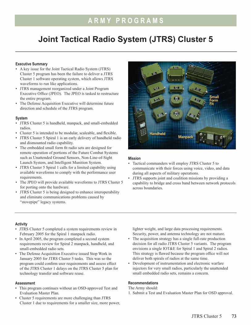
73
A R M Y P R O G R A M S
Joint Tactical Radio System (JTRS) Cluster 5
Executive Summary• A key issue for the Joint Tactical Radio System (JTRS)
Cluster 5 program has been the failure to deliver a JTRS Cluster 1 software operating system, which allows JTRS waveforms to run like applications.
• JTRS management reorganized under a Joint Program Executive Office (JPEO). The JPEO is tasked to restructure the entire program.
• The Defense Acquisition Executive will determine future direction and schedule of the JTRS program.
System• JTRS Cluster 5 is handheld, manpack, and small-embedded
radios.• Cluster 5 is intended to be modular, scaleable, and flexible.• JTRS Cluster 5 Spiral 1 is an early delivery of handheld radio
and dismounted radio capability.• The embedded small form fit radio sets are designed for
remote operation of portions of the Future Combat Systems such as Unattended Ground Sensors, Non-Line-of-Sight Launch System, and Intelligent Munition System.
• JTRS Cluster 5 Spiral 1 calls for a limited capability using available waveforms to comply with the performance user requirements.
• The JPEO will provide available waveforms to JTRS Cluster 5 for porting onto the hardware.
• JTRS Cluster 5 is being designed to enhance interoperability and eliminate communications problems caused by “stovepipe” legacy systems.
Activity• JTRS Cluster 5 completed a system requirements review in
February 2005 for the Spiral 1 manpack radio.• In April 2005, the program completed a second system
requirements review for Spiral 2 manpack, handheld, and small-embedded radio sets.
• The Defense Acquisition Executive issued Stop Work in January 2005 for JTRS Cluster 5 tasks. This was so the program could confirm user requirements and assess effect of the JTRS Cluster 1 delays on the JTRS Cluster 5 plan for technology transfer and software reuse.
Assessment• This program continues without an OSD-approved Test and
Evaluation Master Plan.• Cluster 5 requirements are more challenging than JTRS
Cluster 1 due to requirements for a smaller size, more power,
JTRS Cluster 5 73
Mission• Tactical commanders will employ JTRS Cluster 5 to
communicate with their forces using voice, video, and data during all aspects of military operations.
• JTRS supports joint and coalition missions by providing a capability to bridge and cross band between network protocols across boundaries.
lighter weight, and large data processing requirements. Security, power, and antenna technology are not mature.
• The acquisition strategy has a single full-rate production decision for all radio JTRS Cluster 5 variants. The program envisions a single IOT&E for Spiral 1 and Spiral 2 radios. This strategy is flawed because the program office will not deliver both spirals of radios at the same time.
• Development of instrumentation and electronic warfare injectors for very small radios, particularly the unattended small embedded radio sets, remains a concern.
RecommendationsThe Army should:1. Submit a Test and Evaluation Master Plan for OSD approval.
74
A R M Y P R O G R A M S
2. Synchronize the program schedule with Future Combat Systems and Warfighter Information Network-Tactical programs to optimize required integration and testing efforts.
3. Develop a test and evaluation strategy that supports an evaluation of network maturity as part of FCS Spiral production.
74 JTRS Cluster 5
4. Demonstrate the wideband networking and soldier radio waveform capabilities over JTRS prototype radios.
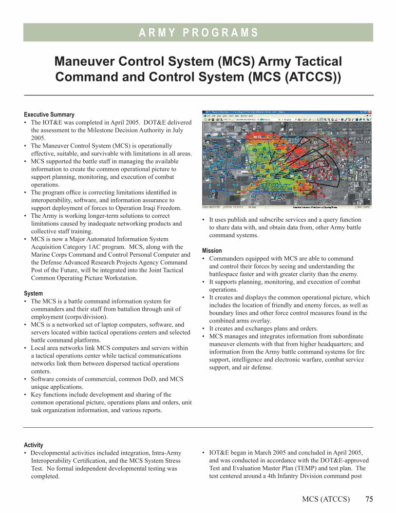
75
A R M Y P R O G R A M S
Maneuver Control System (MCS) Army Tactical Command and Control System (MCS (ATCCS))
Executive Summary• The IOT&E was completed in April 2005. DOT&E delivered
the assessment to the Milestone Decision Authority in July 2005.
• The Maneuver Control System (MCS) is operationally effective, suitable, and survivable with limitations in all areas.
• MCS supported the battle staff in managing the available information to create the common operational picture to support planning, monitoring, and execution of combat operations.
• The program office is correcting limitations identified in interoperability, software, and information assurance to support deployment of forces to Operation Iraqi Freedom.
• The Army is working longer-term solutions to correct limitations caused by inadequate networking products and collective staff training.
• MCS is now a Major Automated Information System Acquisition Category 1AC program. MCS, along with the Marine Corps Command and Control Personal Computer and the Defense Advanced Research Projects Agency Command Post of the Future, will be integrated into the Joint Tactical Common Operating Picture Workstation.
System• The MCS is a battle command information system for
commanders and their staff from battalion through unit of employment (corps/division).
• MCS is a networked set of laptop computers, software, and servers located within tactical operations centers and selected battle command platforms.
• Local area networks link MCS computers and servers within a tactical operations center while tactical communications networks link them between dispersed tactical operations centers.
• Software consists of commercial, common DoD, and MCS unique applications.
• Key functions include development and sharing of the common operational picture, operations plans and orders, unit task organization information, and various reports.
Activity• Developmental activities included integration, Intra-Army
Interoperability Certification, and the MCS System Stress Test. No formal independent developmental testing was completed.
MCS (ATCCS) 75
• It uses publish and subscribe services and a query function to share data with, and obtain data from, other Army battle command systems.
Mission• Commanders equipped with MCS are able to command
and control their forces by seeing and understanding the battlespace faster and with greater clarity than the enemy.
• It supports planning, monitoring, and execution of combat operations.
• It creates and displays the common operational picture, which includes the location of friendly and enemy forces, as well as boundary lines and other force control measures found in the combined arms overlay.
• It creates and exchanges plans and orders.• MCS manages and integrates information from subordinate
maneuver elements with that from higher headquarters; and information from the Army battle command systems for fire support, intelligence and electronic warfare, combat service support, and air defense.
• IOT&E began in March 2005 and concluded in April 2005, and was conducted in accordance with the DOT&E-approved Test and Evaluation Master Plan (TEMP) and test plan. The test centered around a 4th Infantry Division command post
76
A R M Y P R O G R A M S
exercise as part of the Joint Red Flag/Roving Sands 2005 exercise. Command posts from battalion through Unit of Employment (division) participated. Missions executed include high intensity offensive and defensive operations, and low intensity operations including counter insurgency, and security and stability operations. Test events included information assurance testing and displacement of the division tactical command post.
• Follow-on testing occurred in August and September 2005 in conjunction with other 4th Infantry Division training events at both Fort Hood, Texas, and the National Training Center in California.
• In July 2005, MCS was designated an Acquisition Category 1AC program. MCS is responsible for transitioning MCS and the Marine Corps Command and Control Personal Computer into the Joint Tactical Common Operating Picture Workstation, and integrating the Command Post of the Future visualization technologies.
AssessmentOperational testing was adequate, but we recommended additional testing to confirm fixes for shortfalls in interoperability and information assurance. Testing in August 2005 successfully demonstrated the information assurance fixes and the unit was more alert to electronic attacks. Loading Information Assurance Vulnerability Alert patches onto each MCS computer remains a challenge as these software patches are frequent and there is no automated means to download patches onto each computer from a central location/server.
The MCS is operationally effective, suitable, and survivable with limitations. The system was able to perform its critical missions to include:
• Support to the battle staff in managing the available information that creates the Common Operational Picture including friendly situation, enemy situation, and the combined arms overlay to support planning, monitoring, and execution of combat operations
• Creation and dissemination of operations orders and plans primarily using the unit’s internal Microsoft Exchange server and tactical web servers
For the first time, the MCS system gathered and disseminated information horizontally and vertically across the Army Battle Command Systems. However, important problems remain for the Army to correct:• Network management and information distribution tools
require improvement. Establishing the networks and information flows presented significant challenges that affected exchange of information and thus the ability of the MCS to provide an accurate and consistent picture, interoperability, and unit task reorganizations.
• Increased processing power of the MCS laptops is needed to support users desire to display multiple overlays simultaneously.
• A training program is needed to better prepare a unit to employ the MCS as a coherent command and control system within the Army Battle Command Systems. Record test was suspended after three days to allow additional training on system operations, staff functions, and collective tasks.
• System-of-systems issues affecting MCS performance must be addressed by the Army if MCS is going to reach its full capability. These include developing a flexible networking schema and products that limited flexibility and interoperability during the test, and sufficient collective training that integrates the Army Battle Command Systems into a coherent command and control system.
Recommendations1. Demonstrate, in an operational venue, that all high priority
software problems are corrected.2. Obtain Intra-Army Interoperability Certification to optimize
exchange of overlays and other critical data between the MCS and the family of Army Battle Command Systems.
3. Complete Joint interoperability certification to ensure MCS can share critical command and control information with the Marine Corps.
4. Resolve system-of-system shortfalls in networking products and improve and fund collective and sustainment training programs.
76 MCS (ATCCS)
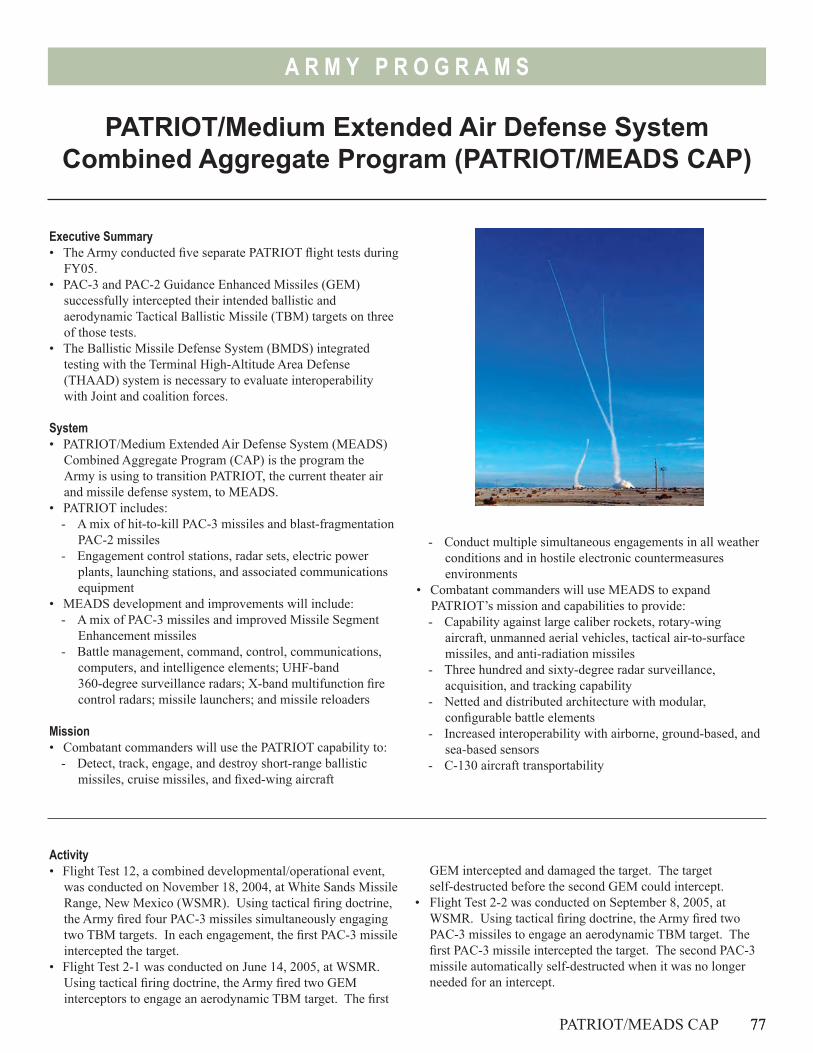
77
A R M Y P R O G R A M S
PATRIOT/Medium Extended Air Defense System Combined Aggregate Program (PATRIOT/MEADS CAP)
Executive Summary• The Army conducted five separate PATRIOT flight tests during
FY05.• PAC-3 and PAC-2 Guidance Enhanced Missiles (GEM)
successfully intercepted their intended ballistic and aerodynamic Tactical Ballistic Missile (TBM) targets on three of those tests.
• The Ballistic Missile Defense System (BMDS) integrated testing with the Terminal High-Altitude Area Defense (THAAD) system is necessary to evaluate interoperability with Joint and coalition forces.
System• PATRIOT/Medium Extended Air Defense System (MEADS)
Combined Aggregate Program (CAP) is the program the Army is using to transition PATRIOT, the current theater air and missile defense system, to MEADS.
• PATRIOT includes:- A mix of hit-to-kill PAC-3 missiles and blast-fragmentation
PAC-2 missiles- Engagement control stations, radar sets, electric power
plants, launching stations, and associated communications equipment
• MEADS development and improvements will include:- A mix of PAC-3 missiles and improved Missile Segment
Enhancement missiles- Battle management, command, control, communications,
computers, and intelligence elements; UHF-band 360-degree surveillance radars; X-band multifunction fire control radars; missile launchers; and missile reloaders
Mission• Combatant commanders will use the PATRIOT capability to:
- Detect, track, engage, and destroy short-range ballistic missiles, cruise missiles, and fixed-wing aircraft
- Conduct multiple simultaneous engagements in all weather conditions and in hostile electronic countermeasures environments
• Combatant commanders will use MEADS to expand PATRIOT’s mission and capabilities to provide:- Capability against large caliber rockets, rotary-wing
aircraft, unmanned aerial vehicles, tactical air-to-surface missiles, and anti-radiation missiles
- Three hundred and sixty-degree radar surveillance, acquisition, and tracking capability
- Netted and distributed architecture with modular, configurable battle elements
- Increased interoperability with airborne, ground-based, and sea-based sensors
- C-130 aircraft transportability
Activity• Flight Test 12, a combined developmental/operational event,
was conducted on November 18, 2004, at White Sands Missile Range, New Mexico (WSMR). Using tactical firing doctrine, the Army fired four PAC-3 missiles simultaneously engaging two TBM targets. In each engagement, the first PAC-3 missile intercepted the target.
• Flight Test 2-1 was conducted on June 14, 2005, at WSMR. Using tactical firing doctrine, the Army fired two GEM interceptors to engage an aerodynamic TBM target. The first
PATRIOT/MEADS CAP 77
GEM intercepted and damaged the target. The target self-destructed before the second GEM could intercept.
• Flight Test 2-2 was conducted on September 8, 2005, at WSMR. Using tactical firing doctrine, the Army fired two PAC-3 missiles to engage an aerodynamic TBM target. The first PAC-3 missile intercepted the target. The second PAC-3 missile automatically self-destructed when it was no longer needed for an intercept.
78
A R M Y P R O G R A M S
• Flight Test 2-3 was conducted on November 11, 2005, at WSMR. Test objectives of this mission included demonstrating the performance of PAC-3 missile software changes and associated ground system software improvements to detect, track, engage, and intercept a short-range aerodynamic target with two PAC-3 missiles. The Fire Unit detected, tracked, and engaged the target with the two PAC-3 missiles, but fired a third missile after receiving a false launch failure indication. All three missiles, each launched from separate launching stations, failed to intercept the target. The Army is currently analyzing the flight test data to determine the root cause of the failures.
• Flight Test ATM-46 was conducted on November 17, 2005, at WSMR. The test objectives of this mission included demonstrating integration of the Missile Defense Agency Block 04 Command, Control, Battle Management, and Communication (C2BMC) with PATRIOT during the execution of a TBM engagement using Post Deployment Build 6 software and a GEM interceptor. The Fire Unit detected, tracked, and engaged the target and shared this data with the C2BMC via Link-16. However, the GEM interceptor failed to intercept the target. The Army is currently analyzing the flight test data to determine the root cause of failure.
• The Army conducted these tests in accordance with the DOT&E-approved Test and Evaluation Master Plan.
Assessment• During 2004 and 2005, PATRIOT demonstrated the capability
to intercept multiple TBMs simultaneously. Details of these tests are discussed in the classified FY05 BMDS annual report.
• Evaluation of PATRIOT performance at the battalion level requires the use of flight mission simulator hardware-in-the-loop systems to stress load the PATRIOT system with tactically representative types and numbers of targets - including friendly aircraft. These simulators will also be useful for training, verifying fixes, and minimizing the probability of undiscovered problems.
• Additionally, BMDS integrated testing with the THAAD system is necessary to evaluate interoperability with Joint and coalition forces and to evaluate information assurance.
Recommendations1. Field one or two additional flight mission simulator
hardware-in-the-loop systems as soon as possible. 2. Conduct PATRIOT air and missile defense testing during
Joint and coalition exercises that include large numbers of different aircraft types, sensors, battle management elements, and weapon systems. Conduct Red Team penetration testing during these exercises to test PATRIOT information assurance.
3. Participate in THAAD flight tests to demonstrate PATRIOT-to-THAAD interoperability and the capability for PATRIOT to intercept TBM targets that are not intercepted by THAAD.
78 PATRIOT/MEADS CAP
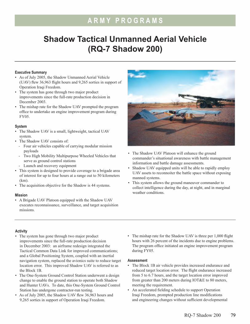
79
A R M Y P R O G R A M S
Shadow Tactical Unmanned Aerial Vehicle (RQ-7 Shadow 200)
Executive Summary• As of July 2005, the Shadow Unmanned Aerial Vehicle
(UAV) flew 36,963 flight hours and 9,265 sorties in support of Operation Iraqi Freedom.
• The system has gone through two major product improvements since the full-rate production decision in December 2003.
• The mishap rate for the Shadow UAV prompted the program office to undertake an engine improvement program during FY05.
System• The Shadow UAV is a small, lightweight, tactical UAV
system.• The Shadow UAV consists of:
- Four air vehicles capable of carrying modular mission payloads
- Two High Mobility Multipurpose Wheeled Vehicles that serve as ground control stations
- Launch and recovery equipment• This system is designed to provide coverage to a brigade area
of interest for up to four hours at a range out to 50 kilometers (km).
• The acquisition objective for the Shadow is 44 systems.
Mission• A Brigade UAV Platoon equipped with the Shadow UAV
executes reconnaissance, surveillance, and target acquisition missions.
• The Shadow UAV Platoon will enhance the ground commander’s situational awareness with battle management information and battle damage assessments.
• Shadow UAV equipped units will be able to rapidly employ UAV assets to reconnoiter the battle space without exposing manned systems.
• This system allows the ground maneuver commander to collect intelligence during the day, at night, and in marginal weather conditions.
Activity• The system has gone through two major product
improvements since the full-rate production decision in December 2003: an airframe redesign integrated the Tactical Common Data Link for improved communications; and a Global Positioning System, coupled with an inertial navigation system, replaced the avionics suite to reduce target location error. This improved Shadow UAV is referred to as the Block 1B.
• The One-System Ground Control Station underwent a design change to enable the ground station to operate both Shadow and Hunter UAVs. To date, this One-System Ground Control Station has undergone contractor-run testing.
• As of July 2005, the Shadow UAV flew 36,963 hours and 9,265 sorties in support of Operation Iraqi Freedom.
RQ-7 Shadow 200 79
• The mishap rate for the Shadow UAV is three per 1,000 flight hours with 26 percent of the incidents due to engine problems. The program office initiated an engine improvement program during FY05.
Assessment• The Block 1B air vehicle provides increased endurance and
reduced target location error. The flight endurance increased from 5 to 6.7 hours, and the target location error improved from greater than 200 meters during IOT&E to 80 meters, meeting the requirement.
• An accelerated fielding schedule to support Operation Iraqi Freedom, prompted production line modifications and engineering changes without sufficient developmental
80
A R M Y P R O G R A M S
and operational testing for the Shadow UAV Block 1B and the One-System Ground Control Station. The engineering changes delayed delivery of equipment to the Army, causing reduced collective training time and prevented a deploying unit from participating in the capstone certification exercise.
• Reliability issues with the air vehicle engine have persisted since the IOT&E conducted in April and May 2002.
80 RQ-7 Shadow 200
Recommendations1. The Army should conduct government developmental and
operational testing for significant engineering upgrades for the UAV.
2. The Army should complete an engine improvement program with adequate testing to reduce the mishap rate.
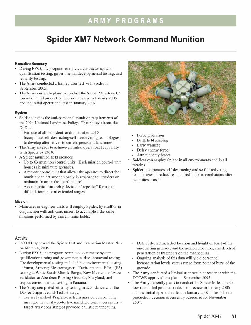
81
A R M Y P R O G R A M S
Spider XM7 Network Command Munition
Executive Summary• During FY05, the program completed contractor system
qualification testing, governmental developmental testing, and lethality testing.
• The Army conducted a limited user test with Spider in September 2005.
• The Army currently plans to conduct the Spider Milestone C/ low-rate initial production decision review in January 2006 and the initial operational test in January 2007.
System• Spider satisfies the anti-personnel munition requirements of
the 2004 National Landmine Policy. That policy directs the DoD to:- End use of all persistent landmines after 2010- Incorporate self-destructing/self-deactivating technologies
to develop alternatives to current persistent landmines• The Army intends to achieve an initial operational capability
with Spider by 2010.• A Spider munition field includes:
- Up to 63 munition control units. Each mission control unit houses six miniature grenades.
- A remote control unit that allows the operator to direct the munitions to act autonomously in response to intruders or maintain “man-in-the-loop” control.
- A communications relay device or “repeater” for use in difficult terrain or at extended ranges.
Mission• Maneuver or engineer units will employ Spider, by itself or in
conjunction with anti-tank mines, to accomplish the same missions performed by current mine fields:
Activity• DOT&E approved the Spider Test and Evaluation Master Plan
on March 4, 2005.• During FY05, the program completed contractor system
qualification testing and governmental developmental testing. The developmental testing included hot environmental testing at Yuma, Arizona; Electromagnetic Environmental Effect (E3) testing at White Sands Missile Range, New Mexico; software validation at Aberdeen Proving Grounds, Maryland; and tropics environmental testing in Panama.
• The Army completed lethality testing in accordance with the DOT&E-approved LFT&E strategy. - Testers launched 48 grenades from mission control units
arranged in a hasty-protective minefield formation against a target array consisting of plywood ballistic mannequins.
Spider XM7 81
- Force protection- Battlefield shaping- Early warning- Delay enemy forces- Attrite enemy forces
• Soldiers can employ Spider in all environments and in all terrains.
• Spider incorporates self-destructing and self-deactivating technologies to reduce residual risks to non-combatants after hostilities cease.
- Data collected included location and height of burst of the air-bursting grenade, and the number, location, and depth of penetration of fragments on the mannequins.
- Ongoing analysis of this data will yield personnel incapacitation levels versus range from point of burst of the grenade.
• The Army conducted a limited user test in accordance with the DOT&E-approved test plan in September 2005.
• The Army currently plans to conduct the Spider Milestone C/ low-rate initial production decision review in January 2006 and the initial operational test in January 2007. The full-rate production decision is currently scheduled for November 2007.
A R M Y P R O G R A M S
Assessment• The contractor testing and government developmental testing
demonstrated that Spider performance was sufficient to enter operational testing.
• The limited user test conducted in September 2005 demonstrated that Spider requires some hardware and software modification prior to further operational testing.
RecommendationsThe Army should:1. Analyze the results of developmental testing, lethality testing,
and the limited user test prior to conducting the Milestone C decision review.
2. Ensure Spider meets all relevant criteria for entrance into the initial operational testing, to include validation of all hardware and software changes made since the limited user test.
82 Spider XM7
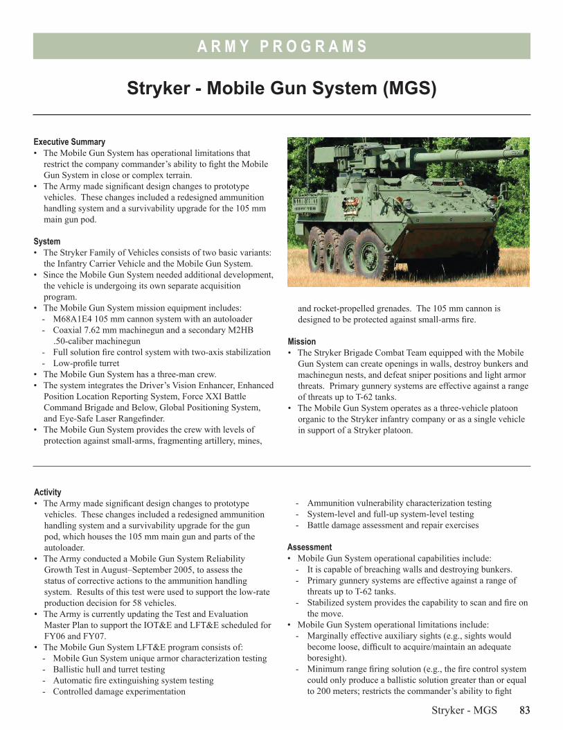
83
A R M Y P R O G R A M S
Stryker - Mobile Gun System (MGS)
Executive Summary• The Mobile Gun System has operational limitations that
restrict the company commander’s ability to fight the Mobile Gun System in close or complex terrain.
• The Army made significant design changes to prototype vehicles. These changes included a redesigned ammunition handling system and a survivability upgrade for the 105 mm main gun pod.
System• The Stryker Family of Vehicles consists of two basic variants:
the Infantry Carrier Vehicle and the Mobile Gun System.• Since the Mobile Gun System needed additional development,
the vehicle is undergoing its own separate acquisition program.
• The Mobile Gun System mission equipment includes:- M68A1E4 105 mm cannon system with an autoloader - Coaxial 7.62 mm machinegun and a secondary M2HB
.50-caliber machinegun- Full solution fire control system with two-axis stabilization- Low-profile turret
• The Mobile Gun System has a three-man crew. • The system integrates the Driver’s Vision Enhancer, Enhanced
Position Location Reporting System, Force XXI Battle Command Brigade and Below, Global Positioning System, and Eye-Safe Laser Rangefinder.
• The Mobile Gun System provides the crew with levels of protection against small-arms, fragmenting artillery, mines,
and rocket-propelled grenades. The 105 mm cannon is designed to be protected against small-arms fire.
Mission• The Stryker Brigade Combat Team equipped with the Mobile
Gun System can create openings in walls, destroy bunkers and machinegun nests, and defeat sniper positions and light armor threats. Primary gunnery systems are effective against a range of threats up to T-62 tanks.
• The Mobile Gun System operates as a three-vehicle platoon organic to the Stryker infantry company or as a single vehicle in support of a Stryker platoon.
Activity• The Army made significant design changes to prototype
vehicles. These changes included a redesigned ammunition handling system and a survivability upgrade for the gun pod, which houses the 105 mm main gun and parts of the autoloader.
• The Army conducted a Mobile Gun System Reliability Growth Test in August–September 2005, to assess the status of corrective actions to the ammunition handling system. Results of this test were used to support the low-rate production decision for 58 vehicles.
• The Army is currently updating the Test and Evaluation Master Plan to support the IOT&E and LFT&E scheduled for FY06 and FY07.
• The Mobile Gun System LFT&E program consists of: - Mobile Gun System unique armor characterization testing- Ballistic hull and turret testing- Automatic fire extinguishing system testing- Controlled damage experimentation
Stryker - MGS 83
- Ammunition vulnerability characterization testing- System-level and full-up system-level testing- Battle damage assessment and repair exercises
Assessment• Mobile Gun System operational capabilities include:
- It is capable of breaching walls and destroying bunkers.- Primary gunnery systems are effective against a range of
threats up to T-62 tanks.- Stabilized system provides the capability to scan and fire on
the move.• Mobile Gun System operational limitations include:
- Marginally effective auxiliary sights (e.g., sights would become loose, difficult to acquire/maintain an adequate boresight).
- Minimum range firing solution (e.g., the fire control system could only produce a ballistic solution greater than or equal to 200 meters; restricts the commander’s ability to fight
84
A R M Y P R O G R A M S
the Mobile Gun System in an urban environment). This limitation does not apply to the anti-personnel round.
- Dead space around the vehicle for observation and defensive fires limits the crew’s ability to engage close targets.
- Concerns about C-130 transportability and reconfiguration issues.
- Capability to integrate existing and planned C4ISR systems.• Demonstrated results from the Reliability Growth Test showed
that the Mobile Gun System achieved 57 mean rounds between system aborts, versus a growth expectation of 49 mean rounds between system aborts.
• The Reliability Growth Test assessment was made using developmental vehicles, not fully integrated production representative systems. The Reliability Growth Test highlighted essential function failures that maintainers will have to fix. The Reliability Growth Test did not include use of the coaxial machinegun, and did not address operational effectiveness issues noted in previous Limited User Tests (e.g., marginally effective auxiliary sighting system, ability to meet target identification and engagement requirements, and the ability to effectively engage minimum range targets).
• Mobile Gun System survivability has not been assessed to date. The Mobile Gun System survivability assessment is scheduled for FY06 and FY07. The Army added armor to the gun pod, but this solution has not been tested or evaluated in full-up system Live Fire tests. The Army also adopted a slat armor vice reactive armor survivability solution against rocket-propelled grenades. The effectiveness of this solution has not been tested.
• DOT&E is concerned that the Army plans to field the Mobile Gun System to two Stryker Brigades and deploy Mobile Gun System-equipped units into combat before demonstrating performance in planned developmental, live fire, and required operational testing.
Recommendation1. The Army should continue planned Mobile Gun System
developmental, live fire, and initial operational testing and evaluation before deploying Mobile Gun System-equipped Stryker Brigades into combat.
84 Stryker - MGS
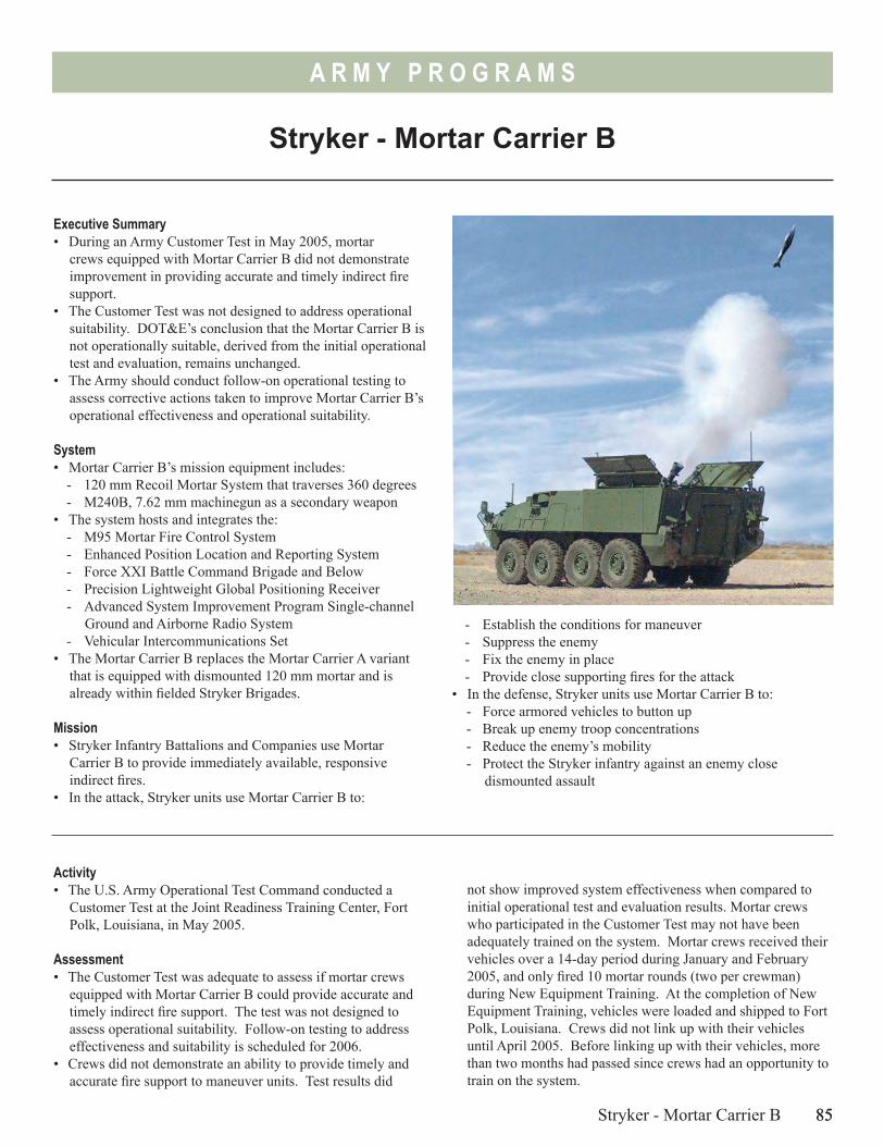
85
A R M Y P R O G R A M S
Stryker - Mortar Carrier B
Executive Summary• During an Army Customer Test in May 2005, mortar
crews equipped with Mortar Carrier B did not demonstrate improvement in providing accurate and timely indirect fire support.
• The Customer Test was not designed to address operational suitability. DOT&E’s conclusion that the Mortar Carrier B is not operationally suitable, derived from the initial operational test and evaluation, remains unchanged.
• The Army should conduct follow-on operational testing to assess corrective actions taken to improve Mortar Carrier B’s operational effectiveness and operational suitability.
System• Mortar Carrier B’s mission equipment includes:
- 120 mm Recoil Mortar System that traverses 360 degrees- M240B, 7.62 mm machinegun as a secondary weapon
• The system hosts and integrates the:- M95 Mortar Fire Control System- Enhanced Position Location and Reporting System - Force XXI Battle Command Brigade and Below- Precision Lightweight Global Positioning Receiver - Advanced System Improvement Program Single-channel
Ground and Airborne Radio System- Vehicular Intercommunications Set
• The Mortar Carrier B replaces the Mortar Carrier A variant that is equipped with dismounted 120 mm mortar and is already within fielded Stryker Brigades.
Mission• Stryker Infantry Battalions and Companies use Mortar
Carrier B to provide immediately available, responsive indirect fires.
• In the attack, Stryker units use Mortar Carrier B to:
Activity• The U.S. Army Operational Test Command conducted a
Customer Test at the Joint Readiness Training Center, Fort Polk, Louisiana, in May 2005.
Assessment• The Customer Test was adequate to assess if mortar crews
equipped with Mortar Carrier B could provide accurate and timely indirect fire support. The test was not designed to assess operational suitability. Follow-on testing to address effectiveness and suitability is scheduled for 2006.
• Crews did not demonstrate an ability to provide timely and accurate fire support to maneuver units. Test results did
Stryker - Mortar Carrier B 85
- Establish the conditions for maneuver- Suppress the enemy- Fix the enemy in place- Provide close supporting fires for the attack
• In the defense, Stryker units use Mortar Carrier B to:- Force armored vehicles to button up- Break up enemy troop concentrations- Reduce the enemy’s mobility- Protect the Stryker infantry against an enemy close
dismounted assault
not show improved system effectiveness when compared to initial operational test and evaluation results. Mortar crews who participated in the Customer Test may not have been adequately trained on the system. Mortar crews received their vehicles over a 14-day period during January and February 2005, and only fired 10 mortar rounds (two per crewman) during New Equipment Training. At the completion of New Equipment Training, vehicles were loaded and shipped to Fort Polk, Louisiana. Crews did not link up with their vehicles until April 2005. Before linking up with their vehicles, more than two months had passed since crews had an opportunity to train on the system.
86
A R M Y P R O G R A M S
• The Customer Test confirmed that the Army has taken corrective action on 12 of 27 DOT&E beyond low-rate initial production recommendations addressing safety and human factors issues.
RecommendationsThe Army should:1. Conduct operational testing to demonstrate the ability of
mortar crews to provide timely and accurate indirect fire support.
86 Stryker - Mortar Carrier B
2. Implement critical safety and human factors corrective actions before the next operational test in FY06.
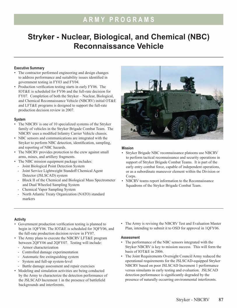
87
A R M Y P R O G R A M S
Mission• Stryker Brigade NBC reconnaissance platoons use NBCRV
to perform tactical reconnaissance and security operations in support of Stryker Brigade Combat Teams. It is part of the early entry combat force, capable of independent operations, or as a subordinate maneuver element within the Division or Corps.
• NBCRV teams report information to the Reconnaissance Squadrons of the Stryker Brigade Combat Team.
Stryker - Nuclear, Biological, and Chemical (NBC) Reconnaissance Vehicle
Executive Summary• The contractor performed engineering and design changes
to address performance and suitability issues identified in government testing in FY03 and FY04.
• Production verification testing starts in early FY06. The IOT&E is scheduled for FY06 and the full-rate decision for FY07. Completion of both the Stryker – Nuclear, Biological, and Chemical Reconnaissance Vehicle (NBCRV) initial OT&E and LFT&E programs is designed to support the full-rate production decision review in 2007.
System• The NBCRV is one of 10 specialized systems of the Stryker
family of vehicles in the Stryker Brigade Combat Team. The NBCRV uses a modified Infantry Carrier Vehicle chassis.
• NBC sensors and communications are integrated with the Stryker to perform NBC detection, identification, sampling, and reporting of NBC hazards.
• The NBCRV provides protection to the crew against small arms, mines, and artillery fragments.
• The NBC mission equipment package includes:- Joint Biological Point Detection System- Joint Service Lightweight Standoff Chemical Agent
Detector (JSLSCAD) system- Block II of the Chemical and Biological Mass Spectrometer
and Dual Wheeled Sampling System- Chemical Vapor Sampling System- North Atlantic Treaty Organization (NATO) standard
markers
Activity• Government production verification testing is planned to
begin in 1QFY06. The IOT&E is scheduled for 3QFY06, and the full-rate production decision review in FY07.
• The Army plans to execute the NBCRV LFT&E program between 2QFY06 and 2QFY07. Testing will include: - Armor characterization - Controlled damage experimentation - Automatic fire extinguishing system - System and full-up system-level- Battle damage assessment and repair exercises
• Modeling and simulation activities are being conducted by the Army to characterize the detection performance of the JSLSCAD Increment 1 in the presence of battlefield backgrounds and interferents.
Stryker - NBCRV 87
• The Army is revising the NBCRV Test and Evaluation Master Plan, intending to submit it to OSD for approval in 1QFY06.
Assessment• The performance of the NBC sensors integrated with the
Stryker NBCRV is key to mission success. This will form the basis of IOT&E in 2006.
• The Joint Requirements Oversight Council/Army reduced the operational requirements for the JSLSCAD-equipped Stryker NBCRV based on poor JSLSCAD Increment 1 performance versus simulants in early testing and evaluation. JSLSCAD detection performance is significantly degraded by the presence of naturally occurring environmental interferents.
88
A R M Y P R O G R A M S
Even if it meets revised operational requirements for detection and range performance, its critical detection information will not provide the battlefield commander with a beneficial standoff detection capability. This conclusion is derived from the fact that the system completes a search pattern in 90 seconds, and can cover almost 1,500 meters in 90 seconds. If the detector can detect out to 500 meters, the platform will have entered the cloud before it will alarm.
• The mission equipment package is provided to this system as government furnished equipment by the Joint Program Executive Office for Chemical and Biological Defense. It is
not sufficient for the NBCRV program to demonstrate mere integration without degradation of the sensors; operational testing must confirm that the NBCRV can support the brigade commander with timely warning and accurate battlefield NBC information.
Recommendation1. Conduct operational testing to confirm that the NBCRV can
support the brigade commander.
88 Stryker - NBCRV
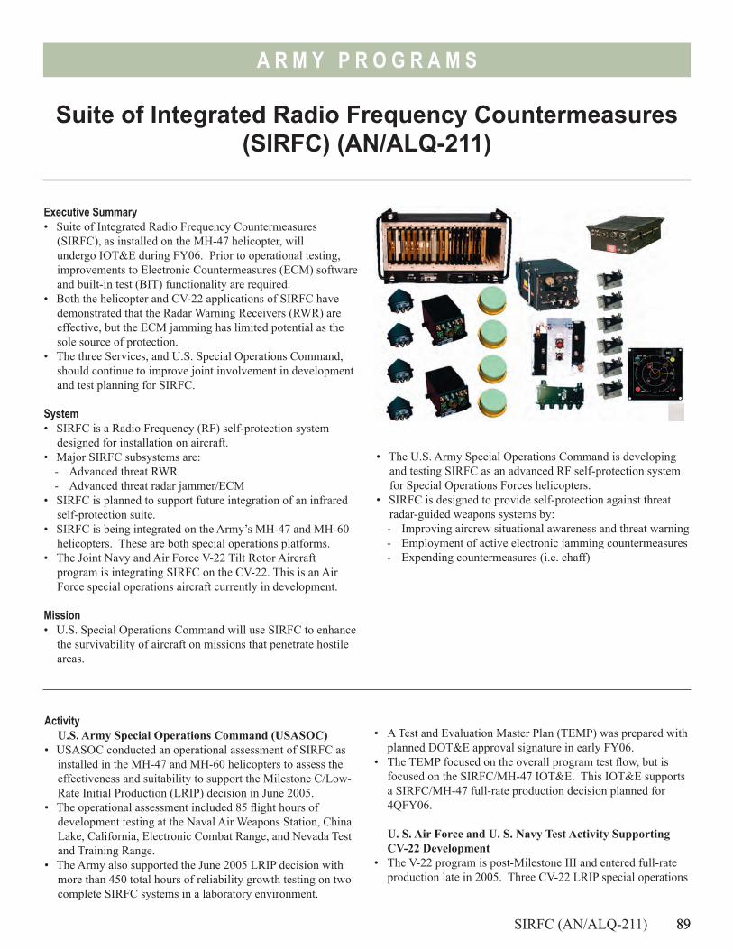
89
A R M Y P R O G R A M S
Suite of Integrated Radio Frequency Countermeasures (SIRFC) (AN/ALQ-211)
Executive Summary• Suite of Integrated Radio Frequency Countermeasures
(SIRFC), as installed on the MH-47 helicopter, will undergo IOT&E during FY06. Prior to operational testing, improvements to Electronic Countermeasures (ECM) software and built-in test (BIT) functionality are required.
• Both the helicopter and CV-22 applications of SIRFC have demonstrated that the Radar Warning Receivers (RWR) are effective, but the ECM jamming has limited potential as the sole source of protection.
• The three Services, and U.S. Special Operations Command, should continue to improve joint involvement in development and test planning for SIRFC.
System• SIRFC is a Radio Frequency (RF) self-protection system
designed for installation on aircraft. • Major SIRFC subsystems are:
- Advanced threat RWR- Advanced threat radar jammer/ECM
• SIRFC is planned to support future integration of an infrared self-protection suite.
• SIRFC is being integrated on the Army’s MH-47 and MH-60 helicopters. These are both special operations platforms.
• The Joint Navy and Air Force V-22 Tilt Rotor Aircraft program is integrating SIRFC on the CV-22. This is an Air Force special operations aircraft currently in development.
Mission• U.S. Special Operations Command will use SIRFC to enhance
the survivability of aircraft on missions that penetrate hostile areas.
• The U.S. Army Special Operations Command is developing and testing SIRFC as an advanced RF self-protection system for Special Operations Forces helicopters.
• SIRFC is designed to provide self-protection against threat radar-guided weapons systems by:- Improving aircrew situational awareness and threat warning- Employment of active electronic jamming countermeasures - Expending countermeasures (i.e. chaff)
ActivityU.S. Army Special Operations Command (USASOC)
• USASOC conducted an operational assessment of SIRFC as installed in the MH-47 and MH-60 helicopters to assess the effectiveness and suitability to support the Milestone C/Low-Rate Initial Production (LRIP) decision in June 2005.
• The operational assessment included 85 flight hours of development testing at the Naval Air Weapons Station, China Lake, California, Electronic Combat Range, and Nevada Test and Training Range.
• The Army also supported the June 2005 LRIP decision with more than 450 total hours of reliability growth testing on two complete SIRFC systems in a laboratory environment.
SIRFC (AN/ALQ-211) 89
• A Test and Evaluation Master Plan (TEMP) was prepared with planned DOT&E approval signature in early FY06.
• The TEMP focused on the overall program test flow, but is focused on the SIRFC/MH-47 IOT&E. This IOT&E supports a SIRFC/MH-47 full-rate production decision planned for 4QFY06.
U. S. Air Force and U. S. Navy Test Activity Supporting CV-22 Development
• The V-22 program is post-Milestone III and entered full-rate production late in 2005. Three CV-22 LRIP special operations
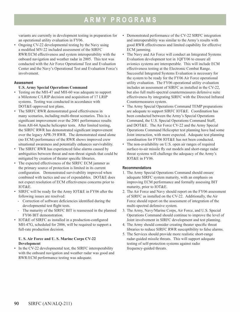
90
A R M Y P R O G R A M S
variants are currently in development testing in preparation for an operational utility evaluation in FY06.
• Ongoing CV-22 developmental testing by the Navy using a modified MV-22 included assessment of the SIRFC RWR/ECM effectiveness and system interoperability with the onboard navigation and weather radar in 2005. This test was conducted with the Air Force Operational Test and Evaluation Center and the Navy’s Operational Test and Evaluation Force’s involvement.
Assessment
U.S. Army Special Operations Command • Testing on the MH-47 and MH-60 was adequate to support
a Milestone C/LRIP decision and acquisition of 17 LRIP systems. Testing was conducted in accordance with DOT&E-approved test plans.
• The SIRFC RWR demonstrated good effectiveness in many scenarios, including multi-threat scenarios. This is a significant improvement over the 2001 performance results from AH-64 Apache helicopter tests. After limited testing, the SIRFC RWR has demonstrated significant improvement over the legacy APR-39 RWR. The demonstrated stand alone (no ECM) performance of the RWR shows improved crew situational awareness and potentially enhances survivability.
• The SIRFC RWR has experienced false alarms caused by ambiguities between threat and non-threat signals that could be mitigated by creation of theater specific libraries.
• The expected effectiveness of the SIRFC ECM jammer as the primary source of protection is limited in its current configuration. Demonstrated survivability improved when combined with tactics and use of expendables. DOT&E does not expect resolution of ECM effectiveness concerns prior to IOT&E.
• SIRFC will be ready for the Army IOT&E in FY06 after the following issues are resolved:- Correction of software deficiencies identified during the
developmental test flight tests. - The maturity of the SIRFC BIT is reassessed in the planned
FY06 BIT demonstration. • IOT&E of SIRFC as installed in a production-configured
MH-47G, scheduled for 2006, will be required to support a full-rate production decision.
U. S. Air Force and U. S. Marine Corps CV-22 Development
• In the CV-22 developmental test, the SIRFC interoperability with the onboard navigation and weather radar was good and RWR/ECM performance testing was adequate.
• Demonstrated performance of the CV-22 SIRFC integration and interoperability was similar to the Army’s results with good RWR effectiveness and limited capability for effective ECM jamming.
• The Navy and Air Force will conduct an Integrated Systems Evaluation development test in 1QFY06 to ensure all avionics systems are interoperable. This will include ECM effectiveness testing at the Electronic Combat Range. Successful Integrated Systems Evaluation is necessary for the system to be ready for the FY06 Air Force operational utility evaluation. The FY06 operational utility evaluation includes an assessment of SIRFC as installed in the CV-22, but also full multi-spectral countermeasures defensive suite effectiveness by integrating SIRFC with the Directed Infrared Countermeasures system.
• The Army Special Operations Command TEMP preparations are adequate to support SIRFC IOT&E. Coordination has been conducted between the Army’s Special Operations Command, the U.S. Special Operations Command Staff, and DOT&E. The Air Force CV-22 and the Army Special Operations Command Helicopter test planning have had some Joint interaction, with more expected. Adequate test planning coordination for FY06 IOT&E has not been conducted.
• The non-availability on U.S. open air ranges of required surface-to-air missile fly out models and short-range radar threat systems will challenge the adequacy of the Army’s IOT&E in FY06.
Recommendations1. The Army Special Operations Command should ensure
adequate SIRFC system maturity, with an emphasis on improving ECM performance and formally assessing BIT maturity, prior to IOT&E.
2. The Air Force and Navy should report on the FY06 assessment of SIRFC as installed on the CV-22. Additionally, the Air Force should report on the assessment of integration of the multi-spectral defensive system.
3. The Army, Navy/Marine Corps, Air Force, and U.S. Special Operations Command should continue to improve the level of Joint involvement in SIRFC development and test planning.
4. The Army should consider creating theater specific threat libraries to reduce SIRFC RWR susceptibility to false alarms.
5. The Services should provide more realistic short-range radar-guided missile threats. This will support adequate testing of self-protection systems against radio frequency-guided threats.
90 SIRFC (AN/ALQ-211)
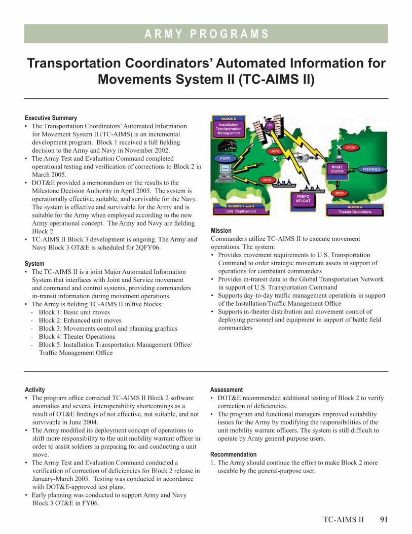
91
A R M Y P R O G R A M S
Transportation Coordinators’ Automated Information for Movements System II (TC-AIMS II)
Executive Summary• The Transportation Coordinators’ Automated Information
for Movement System II (TC-AIMS) is an incremental development program. Block 1 received a full fielding decision to the Army and Navy in November 2002.
• The Army Test and Evaluation Command completed operational testing and verification of corrections to Block 2 in March 2005.
• DOT&E provided a memorandum on the results to the Milestone Decision Authority in April 2005. The system is operationally effective, suitable, and survivable for the Navy. The system is effective and survivable for the Army and is suitable for the Army when employed according to the new Army operational concept. The Army and Navy are fielding Block 2.
• TC-AIMS II Block 3 development is ongoing. The Army and Navy Block 3 OT&E is scheduled for 2QFY06.
System• The TC-AIMS II is a joint Major Automated Information
System that interfaces with Joint and Service movement and command and control systems, providing commanders in-transit information during movement operations.
• The Army is fielding TC-AIMS II in five blocks:- Block 1: Basic unit moves- Block 2: Enhanced unit moves- Block 3: Movements control and planning graphics- Block 4: Theater Operations- Block 5: Installation Transportation Management Office/
Traffic Management Office
MissionCommanders utilize TC-AIMS II to execute movement operations. The system: • Provides movement requirements to U.S. Transportation
Command to order strategic movement assets in support of operations for combatant commanders
• Provides in-transit data to the Global Transportation Network in support of U.S. Transportation Command
• Supports day-to-day traffic management operations in support of the Installation/Traffic Management Office
• Supports in-theater distribution and movement control of deploying personnel and equipment in support of battle field commanders
Activity• The program office corrected TC-AIMS II Block 2 software
anomalies and several interoperability shortcomings as a result of OT&E findings of not effective, not suitable, and not survivable in June 2004.
• The Army modified its deployment concept of operations to shift more responsibility to the unit mobility warrant officer in order to assist soldiers in preparing for and conducting a unit move.
• The Army Test and Evaluation Command conducted a verification of correction of deficiencies for Block 2 release in January-March 2005. Testing was conducted in accordance with DOT&E-approved test plans.
• Early planning was conducted to support Army and Navy Block 3 OT&E in FY06.
TC-AIMS II 91
Assessment• DOT&E recommended additional testing of Block 2 to verify
correction of deficiencies. • The program and functional managers improved suitability
issues for the Army by modifying the responsibilities of the unit mobility warrant officers. The system is still difficult to operate by Army general-purpose users.
Recommendation1. The Army should continue the effort to make Block 2 more
useable by the general-purpose user.

92
A R M Y P R O G R A M S
93
A R M Y P R O G R A M S
Warfighting Information Network-Tactical (WIN-T)/ Joint Network Node (JNN)
WIN-T/JNN 93
Executive Summary• DOT&E is concerned that numerous Warfighter Information
Network-Tactical (WIN-T) components lack the maturity normally demonstrated at Milestone C.
• Joint Network Node (JNN) is not a program of record and does not comply with “fly-before-buy.” The Army is procuring and fielding JNN to seven to 10 Army Divisions before conducting OT&E.
• The Army has been directed to initiate a program of record and describe the required test and evaluation, which will support the transition from JNN to WIN-T.
• Current JNN performance in Iraq is reportedly not satisfactory.
SystemWIN-T
• The WIN-T is designed to be the Army’s tactical intranet and intends to provide reliable, secure, and seamless video, data, imagery, and voice services. WIN-T is a high-speed and high capacity backbone communications network intended to support communications from the sustaining base down to the Future Combat Systems (FCS) Brigade Combat Team.
• Key components of ground layer are the Joint Tactical Radio System (JTRS) Cluster 1, a personal communications device, and a secure wireless local area network.
• Airborne layer consists of unmanned aerial vehicles or tethered air vehicles in the WIN-T airborne communications node to provide beyond line-of-sight communications.
• Space layer includes commercial and military satellites such as the Wideband Gapfiller or Advanced Extremely High Frequency satellites to provide reach-back via the Global Information Grid.
JNN• JNN is an interim communication system supporting Army
tactical requirements for exchange of voice, data, and video from division to battalion. Components include commercial off-the-shelf shelters, trailers, antennas, transit cases, switches, and other equipment to access satellite communications and provide Secret Internet Protocol Router Network (SIPRNET)/
Activity• The Defense Acquisition Executive (DAE) approved
combining the two competing contractor teams for WIN-T to permit a single architecture a year earlier than originally planned.
Unclassified-But-Sensitive Internet Protocol Router Network (NIPRNET) connectivity.
• JNN is intended to provide communications at the quick halt. JNN replaces capability provided by the Mobile Subscriber Equipment and is currently deployed with forces in Iraq.
Mission• The Army intends for WIN-T to support Mobile Battle
Command by integrating capabilities into maneuver platforms, and support dispersed operations over increased distances beyond line-of-sight.
• WIN-T will provide commanders at all echelons the ability to operate on the move and at remote locations. WIN-T will be the single communications network integrating the current force and the FCS.
• WIN-T integrates terrestrial, airborne, and military satellite-based transport capabilities into a network infrastructure to provide connectivity across an extended non-linear battlespace.
• WIN-T is designed to provide commercial satellite access and commercial off-the-shelf systems to satisfy bandwidth and network services demands.
• WIN-T completed system design review, preliminary design review, and critical design review in 2005.
• WIN-T conducted three contractor demonstrations of equipment and selected capabilities.
94
A R M Y P R O G R A M S
• WIN-T developmental and operational testing is scheduled for November 2005 to support a low-rate production decision in March 2006.
• The Army continues to procure JNN as an interim satellite capability without conducting OT&E.
• JNN was fielded to Army units deploying to Iraq in Operation Iraqi Freedom 3 and 4, with additional fielding planned.
Assessment• Based on contractor demonstrations, the program believes
that WIN-T is ready to enter combined developmental and operational testing to support the low-rate production decision review in 2006. The WIN-T Test and Evaluation Master Plan must be updated for Milestone C.
• The contractor event held in December 2005 was a technical demonstration of the system capabilities.
• The demonstration was executed with a limited number of WIN-T components providing very basic insight to its capabilies.
• The operators, a mixture of soldiers and contractors, completed the scripted test vignettes to exercise the network.
• The maturity and integration of the hardware and software into the platforms was consistent with the early prototype designation.
• DOT&E is concerned that numerous WIN-T components lack the maturity normally demonstrated at Milestone C. The
WIN-T program will develop and integrate 80-90 software programs with 60 percent commercial off-the-shelf and 40 percent government off-the-shelf. WIN-T airborne platforms were not identified or fully funded at Milestone B. WIN-T is developing a unique command, control, computer, intelligence, surveillance, and reconnaissance (C4ISR) radio and waveforms to meet FCS throughput requirements. Current and near term satellite communications capacity will be exceeded without an unmanned aerial vehicle/airborne tier.
• The Army has been directed to initiate program of record and describe the required test and evaluation, which will support the transition from JNN to WIN-T.
• JNN performance in Iraq has problems.• Capabilities documents and a Test and Evaluation Master Plan
for JNN do not currently exist.• The Army has followed neither program of record nor rapid
acquisition guidelines to justify JNN procurement authority.
Recommendations1. Synchronize WIN-T, FCS, and the Joint Tactical Radio System
acquisition and test and evaluation strategies. Identify test opportunities for WIN-T during FCS Spin Outs.
2. JNN is fragile but provides some long haul capability. The Army is required to report to DoD how they plan to satisfy the test requirement prior to Milestone C.
94 WIN-T/JNN
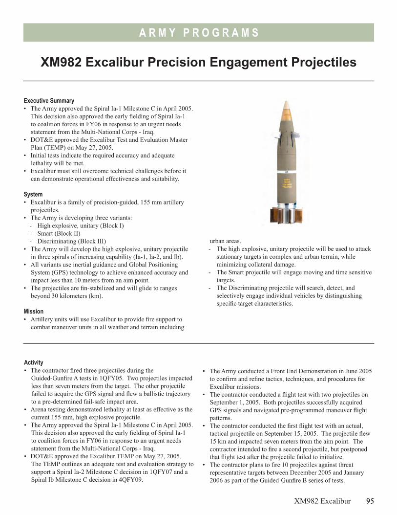
95
A R M Y P R O G R A M S
XM982 Excalibur Precision Engagement Projectiles
Executive Summary• The Army approved the Spiral Ia-1 Milestone C in April 2005.
This decision also approved the early fielding of Spiral Ia-1 to coalition forces in FY06 in response to an urgent needs statement from the Multi-National Corps - Iraq.
• DOT&E approved the Excalibur Test and Evaluation Master Plan (TEMP) on May 27, 2005.
• Initial tests indicate the required accuracy and adequate lethality will be met.
• Excalibur must still overcome technical challenges before it can demonstrate operational effectiveness and suitability.
System• Excalibur is a family of precision-guided, 155 mm artillery
projectiles.• The Army is developing three variants:
- High explosive, unitary (Block I)- Smart (Block II)- Discriminating (Block III)
• The Army will develop the high explosive, unitary projectile in three spirals of increasing capability (Ia-1, Ia-2, and Ib).
• All variants use inertial guidance and Global Positioning System (GPS) technology to achieve enhanced accuracy and impact less than 10 meters from an aim point.
• The projectiles are fin-stabilized and will glide to ranges beyond 30 kilometers (km).
Mission• Artillery units will use Excalibur to provide fire support to
combat maneuver units in all weather and terrain including
Activity• The contractor fired three projectiles during the
Guided-Gunfire A tests in 1QFY05. Two projectiles impacted less than seven meters from the target. The other projectile failed to acquire the GPS signal and flew a ballistic trajectory to a pre-determined fail-safe impact area.
• Arena testing demonstrated lethality at least as effective as the current 155 mm, high explosive projectile.
• The Army approved the Spiral Ia-1 Milestone C in April 2005. This decision also approved the early fielding of Spiral Ia-1 to coalition forces in FY06 in response to an urgent needs statement from the Multi-National Corps - Iraq.
• DOT&E approved the Excalibur TEMP on May 27, 2005. The TEMP outlines an adequate test and evaluation strategy to support a Spiral Ia-2 Milestone C decision in 1QFY07 and a Spiral Ib Milestone C decision in 4QFY09.
• The Army conducted a Front End Demonstration in June 2005 to confirm and refine tactics, techniques, and procedures for Excalibur missions.
• The contractor conducted a flight test with two projectiles on September 1, 2005. Both projectiles successfully acquired GPS signals and navigated pre-programmed maneuver flight patterns.
• The contractor conducted the first flight test with an actual, tactical projectile on September 15, 2005. The projectile flew 15 km and impacted seven meters from the aim point. The contractor intended to fire a second projectile, but postponed that flight test after the projectile failed to initialize.
• The contractor plans to fire 10 projectiles against threat representative targets between December 2005 and January 2006 as part of the Guided-Gunfire B series of tests.
XM982 Excalibur 95
urban areas.- The high explosive, unitary projectile will be used to attack
stationary targets in complex and urban terrain, while minimizing collateral damage.
- The Smart projectile will engage moving and time sensitive targets.
- The Discriminating projectile will search, detect, and selectively engage individual vehicles by distinguishing specific target characteristics.
96
A R M Y P R O G R A M S
Assessment• Initial Excalibur testing has demonstrated required accuracy
and lethality. • Excalibur must still overcome many technical challenges.
Those challenges include:- Reducing initialization time to meet autoloader
requirements- Achieving reliable fin and canard deployment- Improving airframe maneuverability- Integrating an inductive fuze setter- Hardening the inertial measurement unit- Enhancing GPS acquisition- Integrating base bleed technologies to achieve extended
ranges• The schedule for the development and testing of Spiral Ia-1 is
ambitious, with little time to fix problems. • Significant effort is required to mitigate GPS jamming. • The smart and discriminating projectiles, which are scheduled
for Milestone C decisions in FY13, incorporate target
96 XM982 Excalibur
discrimination capabilities. Previous efforts to field smart projectiles have been successful against benign targets, but have been less successful against targets that employ active and passive countermeasures.
Recommendations1. The testing of Spiral Ia-1 should remain event-driven. Failure
to meet specific Army entrance and exit criteria specified in the TEMP prior to progressing to the next stage of testing will add program risk.
2. Due to the ambitious schedule for Spiral Ia-1, the Army should incorporate operational realism into the developmental testing whenever possible to reduce program risk. This includes using soldiers as forward observers, fire direction personnel, and gun crews.
Navy Programs
Navy
Pro
gram
s
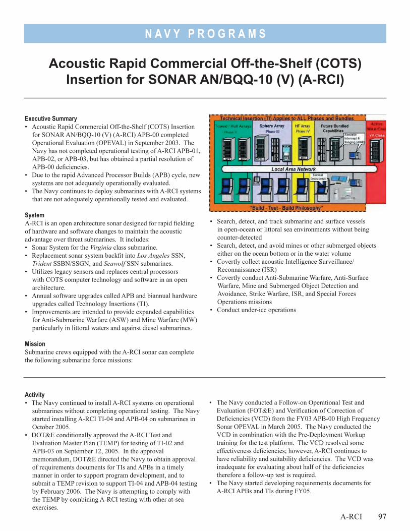
97
N A V Y P R O G R A M S
• Search, detect, and track submarine and surface vessels in open-ocean or littoral sea environments without being counter-detected
• Search, detect, and avoid mines or other submerged objects either on the ocean bottom or in the water volume
• Covertly collect acoustic Intelligence Surveillance/Reconnaissance (ISR)
• Covertly conduct Anti-Submarine Warfare, Anti-Surface Warfare, Mine and Submerged Object Detection and Avoidance, Strike Warfare, ISR, and Special Forces Operations missions
• Conduct under-ice operations
Executive Summary• Acoustic Rapid Commercial Off-the-Shelf (COTS) Insertion
for SONAR AN/BQQ-10 (V) (A-RCI) APB-00 completed Operational Evaluation (OPEVAL) in September 2003. The Navy has not completed operational testing of A-RCI APB-01, APB-02, or APB-03, but has obtained a partial resolution of APB-00 deficiencies.
• Due to the rapid Advanced Processor Builds (APB) cycle, new systems are not adequately operationally evaluated.
• The Navy continues to deploy submarines with A-RCI systems that are not adequately operationally tested and evaluated.
SystemA-RCI is an open architecture sonar designed for rapid fielding of hardware and software changes to maintain the acoustic advantage over threat submarines. It includes:• Sonar System for the Virginia class submarine.• Replacement sonar system backfit into Los Angeles SSN,
Trident SSBN/SSGN, and Seawolf SSN submarines.• Utilizes legacy sensors and replaces central processors
with COTS computer technology and software in an open architecture.
• Annual software upgrades called APB and biannual hardware upgrades called Technology Insertions (TI).
• Improvements are intended to provide expanded capabilities for Anti-Submarine Warfare (ASW) and Mine Warfare (MW) particularly in littoral waters and against diesel submarines.
MissionSubmarine crews equipped with the A-RCI sonar can complete the following submarine force missions:
Activity• The Navy continued to install A-RCI systems on operational
submarines without completing operational testing. The Navy started installing A-RCI TI-04 and APB-04 on submarines in October 2005.
• DOT&E conditionally approved the A-RCI Test and Evaluation Master Plan (TEMP) for testing of TI-02 and APB-03 on September 12, 2005. In the approval memorandum, DOT&E directed the Navy to obtain approval of requirements documents for TIs and APBs in a timely manner in order to support program development, and to submit a TEMP revision to support TI-04 and APB-04 testing by February 2006. The Navy is attempting to comply with the TEMP by combining A-RCI testing with other at-sea exercises.
• The Navy conducted a Follow-on Operational Test and Evaluation (FOT&E) and Verification of Correction of Deficiencies (VCD) from the FY03 APB-00 High Frequency Sonar OPEVAL in March 2005. The Navy conducted the VCD in combination with the Pre-Deployment Workup training for the test platform. The VCD resolved some effectiveness deficiencies; however, A-RCI continues to have reliability and suitability deficiencies. The VCD was inadequate for evaluating about half of the deficiencies therefore a follow-up test is required.
• The Navy started developing requirements documents for A-RCI APBs and TIs during FY05.
A-RCI 97
Acoustic Rapid Commercial Off-the-Shelf (COTS) Insertion for SONAR AN/BQQ-10 (V) (A-RCI)
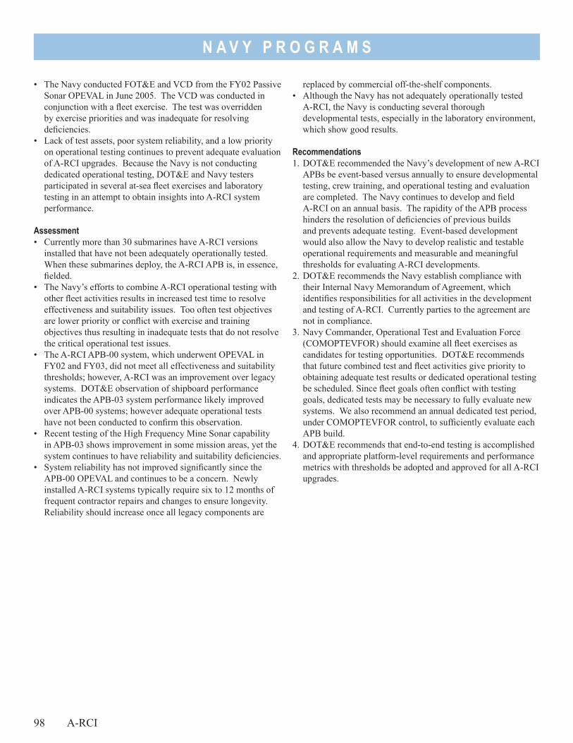
N A V Y P R O G R A M S
98 A-RCI
• The Navy conducted FOT&E and VCD from the FY02 Passive Sonar OPEVAL in June 2005. The VCD was conducted in conjunction with a fleet exercise. The test was overridden by exercise priorities and was inadequate for resolving deficiencies.
• Lack of test assets, poor system reliability, and a low priority on operational testing continues to prevent adequate evaluation of A-RCI upgrades. Because the Navy is not conducting dedicated operational testing, DOT&E and Navy testers participated in several at-sea fleet exercises and laboratory testing in an attempt to obtain insights into A-RCI system performance.
Assessment• Currently more than 30 submarines have A-RCI versions
installed that have not been adequately operationally tested. When these submarines deploy, the A-RCI APB is, in essence, fielded.
• The Navy’s efforts to combine A-RCI operational testing with other fleet activities results in increased test time to resolve effectiveness and suitability issues. Too often test objectives are lower priority or conflict with exercise and training objectives thus resulting in inadequate tests that do not resolve the critical operational test issues.
• The A-RCI APB-00 system, which underwent OPEVAL in FY02 and FY03, did not meet all effectiveness and suitability thresholds; however, A-RCI was an improvement over legacy systems. DOT&E observation of shipboard performance indicates the APB-03 system performance likely improved over APB-00 systems; however adequate operational tests have not been conducted to confirm this observation.
• Recent testing of the High Frequency Mine Sonar capability in APB-03 shows improvement in some mission areas, yet the system continues to have reliability and suitability deficiencies.
• System reliability has not improved significantly since the APB-00 OPEVAL and continues to be a concern. Newly installed A-RCI systems typically require six to 12 months of frequent contractor repairs and changes to ensure longevity. Reliability should increase once all legacy components are
replaced by commercial off-the-shelf components.• Although the Navy has not adequately operationally tested
A-RCI, the Navy is conducting several thorough developmental tests, especially in the laboratory environment, which show good results.
Recommendations1. DOT&E recommended the Navy’s development of new A-RCI
APBs be event-based versus annually to ensure developmental testing, crew training, and operational testing and evaluation are completed. The Navy continues to develop and field A-RCI on an annual basis. The rapidity of the APB process hinders the resolution of deficiencies of previous builds and prevents adequate testing. Event-based development would also allow the Navy to develop realistic and testable operational requirements and measurable and meaningful thresholds for evaluating A-RCI developments.
2. DOT&E recommends the Navy establish compliance with their Internal Navy Memorandum of Agreement, which identifies responsibilities for all activities in the development and testing of A-RCI. Currently parties to the agreement are not in compliance.
3. Navy Commander, Operational Test and Evaluation Force (COMOPTEVFOR) should examine all fleet exercises as candidates for testing opportunities. DOT&E recommends that future combined test and fleet activities give priority to obtaining adequate test results or dedicated operational testing be scheduled. Since fleet goals often conflict with testing goals, dedicated tests may be necessary to fully evaluate new systems. We also recommend an annual dedicated test period, under COMOPTEVFOR control, to sufficiently evaluate each APB build.
4. DOT&E recommends that end-to-end testing is accomplished and appropriate platform-level requirements and performance metrics with thresholds be adopted and approved for all A-RCI upgrades.
N A V Y P R O G R A M S
Active Electronically Scanned Array (AESA)
Executive Summary• Active Electronically Scanned Array (AESA) software
development is behind schedule due to software instability.• In order to conduct the operational evaluation of AESA in the
spring of 2006 and support the first AESA equipped squadron transition schedule, the Navy has deferred some functionality from the initial software build to the second software build.
• When the software is stable AESA radar performance is as good as or better than modeling and engineering predictions.
System• The APG-79 AESA Radar System is an upgrade to the
F/A-18E/F Super Hornet and replaces the APG-73 mechanically scanned array.
• The antenna is a fixed array of transmit/receive modules and does not rotate back and forth like a conventional radar antenna. The beam is “steered” electronically through the aircraft mission computers. Because the antenna has no moving parts, reliability is significantly better than older radars.
• There are hundreds of transmit/receive modules in the antenna array so total radiated power is much greater than a conventional radar and failure of several modules does not significantly degrade overall system performance.
planned to incorporate in the first fleet-release version of the radar software tape (H3E System Configuration Set (SCS)). This radar software tape will now be used for training only. The deferred functionality will be in the second fleet-release software tape (SCS H4E). The second tape will be used for the first AESA equipped squadron’s first deployment, currently scheduled for the end of FY07.
• The Test and Evaluation Master Plan (TEMP) was approved in September 2004 and is adequate to complete OT-C1 Phase 2. The Navy is revising the TEMP to support integrated testing and operational evaluation in the spring of 2006.
AssessmentAESA development has been slowed by software immaturity. Radar performance with the developmental software loads to date can best be characterized as inconsistent. On one flight it will dazzle the aircrew with its target detection range and resolution, and on the next it will frustrate them with multiple shutdowns and re-starts. When the radar is operating consistently, its performance is as good as or better than modeling and engineering predictions. Based on performance to date the development team’s plan to fix software stability prior to
Activity• The Navy completed the third operational assessment of
AESA, Operational Test (OT) - C1 Phase 1, in October 2004. During this test, the system flew 11 flights for a total of 19.9 hours. Synthetic aperture radar mapping performance was rated as mature and ready for operational test. Reliability and air-to-air performance were poor and the test team recommended continued development.
• The Navy conducted OT-C1 Phase 2 in September–November 2005. Due to inconsistent performance that was a result of software instability, this assessment period was delayed from the summer of 2005. Results of the fourth operational assessment of AESA are pending.
• Developmental and operational test aircrew flew approximately 330 AESA flight hours with Engineering and Manufacturing Development and low-rate initial production hardware this year. Each time the development team introduced new radar functionality and software they experienced multiple radar shutdowns that necessitated airborne radar re-starts. The development team has aggressively pursued solutions to these software instabilities. Software instability has forced delays in testing and deferral of some radar functionality that the Navy had originally
AESA 99
Mission• The operational commander whose force uses the F/A-18E/F
fitted with AESA will detect and track enemy air and ground targets at longer ranges than current systems, increasing effectiveness and survivability.
• The radar simultaneously tracks targets and provides data link information to missiles in flight.
• Allows near simultaneous air-to-air and air-to-ground target tracking and engagement. Current radars can only do one mission at a time.
N A V Y P R O G R A M S
100 AESA
Operational Evaluation (OPEVAL) is optimistic, but if successful will result in a stable configuration for OPEVAL in the spring of 2006.
Recommendations1. OPEVAL should not start until the AESA program
demonstrates stable software performance.
2. As the Navy revises the TEMP, it should ensure that the revision supports both the OPEVAL period and the follow-on operational test and evaluation period that incorporates deferred functionality.
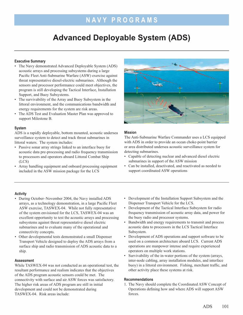
N A V Y P R O G R A M S
Executive Summary• The Navy demonstrated Advanced Deployable System (ADS)
acoustic arrays and processing subsystems during a large Pacific Fleet Anti-Submarine Warfare (ASW) exercise against threat representative diesel-electric submarines. Although the sensors and processor performance could meet objectives, the program is still developing the Tactical Interface, Installation Support, and Buoy Subsystems.
• The survivability of the Array and Buoy Subsystem in the littoral environment, and the communications bandwidth and energy requirements for the system are risk areas.
• The ADS Test and Evaluation Master Plan was approved to support Milestone B.
SystemADS is a rapidly deployable, bottom mounted, acoustic undersea surveillance system to detect and track threat submarines in littoral waters. The system includes:• Passive sonar array strings linked to an interface buoy for
acoustic data pre-processing and radio frequency transmission to processors and operators aboard Littoral Combat Ship (LCS)
• Array handling equipment and onboard processing equipment included in the ASW mission package for the LCS
Advanced Deployable System (ADS)
MissionThe Anti-Submarine Warfare Commander uses a LCS equipped with ADS in order to provide an ocean choke-point barrier or area distributed undersea acoustic surveillance system for detecting submarines.• Capable of detecting nuclear and advanced diesel electric
submarines in support of the ASW mission• Can be installed, deactivated, and reactivated as needed to
support coordinated ASW operations
• Development of the Installation Support Subsystem and the Dispenser Transport Vehicle for the LCS.
• Development of the Tactical Interface Subsystem for radio frequency transmission of acoustic array data, and power for the buoy radio and processor systems.
• Bandwidth and energy requirements to transmit and process acoustic data to processors in the LCS Tactical Interface Subsystem.
• Development of ADS operations and support software to be used on a common architecture aboard LCS. Current ADS operations are manpower intense and require experienced operators on multiple work stations.
• Survivability of the in-water portions of the system (arrays, inter-node cabling, array installation modules, and interface buoy) in a littoral environment. Fishing, merchant traffic, and other activity place these systems at risk.
Recommendations1. The Navy should complete the Coordinated ASW Concept of
Operations defining how and where ADS will support ASW forces.
Activity• During October–November 2004, the Navy installed ADS
arrays, as a technology demonstration, in a large Pacific Fleet ASW exercise, TASWEX-04. While not fully representative of the system envisioned for the LCS, TASWEX-04 was an excellent opportunity to test the acoustic arrays and processing subsystems against threat representative diesel electric submarines and to evaluate many of the operational and connectivity concepts.
• Other developmental tests demonstrated a small Dispenser Transport Vehicle designed to deploy the ADS arrays from a surface ship and radio transmission of ADS acoustic data to a ship.
AssessmentWhile TASWEX-04 was not conducted as an operational test, the resultant performance and realism indicates that the objectives of the ADS program acoustic sensors could be met. The connectivity with surface and air ASW forces was satisfactory. The higher risk areas of ADS program are still in initial development and could not be demonstrated during TASWEX-04. Risk areas include:
ADS 101
N A V Y P R O G R A M S
102 ADS
2. The following steps are designed to maximize the probability of a successful ADS operational test with the LCS ASW mission package, and should be observed by operational testers:- Complete realistic testing of the Tactical Interface,
Installation Support, and Buoy subsystems.
- Conduct early interoperability tests of the LCS Tactical Interface Subsystem.
- The LCS and ADS program offices should give high priority to the resolution of any ADS/LCS interface issues.
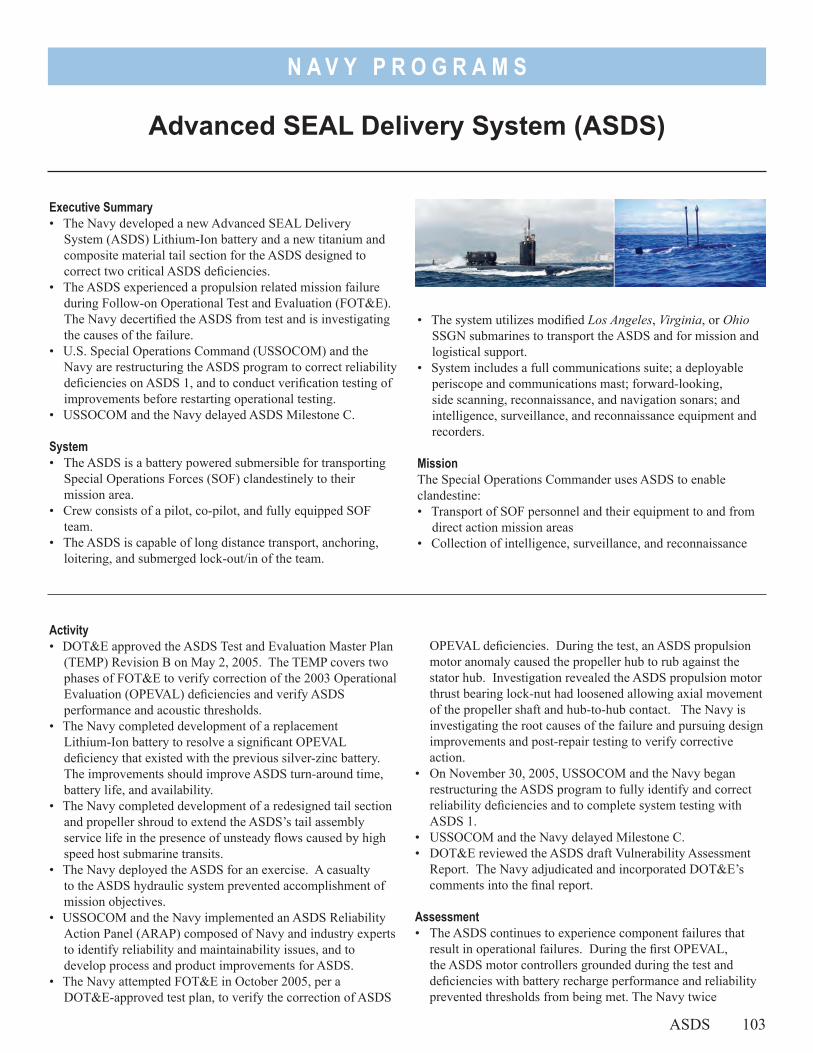
N A V Y P R O G R A M S
Executive Summary• The Navy developed a new Advanced SEAL Delivery
System (ASDS) Lithium-Ion battery and a new titanium and composite material tail section for the ASDS designed to correct two critical ASDS deficiencies.
• The ASDS experienced a propulsion related mission failure during Follow-on Operational Test and Evaluation (FOT&E). The Navy decertified the ASDS from test and is investigating the causes of the failure.
• U.S. Special Operations Command (USSOCOM) and the Navy are restructuring the ASDS program to correct reliability deficiencies on ASDS 1, and to conduct verification testing of improvements before restarting operational testing.
• USSOCOM and the Navy delayed ASDS Milestone C.
System• The ASDS is a battery powered submersible for transporting
Special Operations Forces (SOF) clandestinely to their mission area.
• Crew consists of a pilot, co-pilot, and fully equipped SOF team.
• The ASDS is capable of long distance transport, anchoring, loitering, and submerged lock-out/in of the team.
Advanced SEAL Delivery System (ASDS)
• The system utilizes modified Los Angeles, Virginia, or Ohio SSGN submarines to transport the ASDS and for mission and logistical support.
• System includes a full communications suite; a deployable periscope and communications mast; forward-looking, side scanning, reconnaissance, and navigation sonars; and intelligence, surveillance, and reconnaissance equipment and recorders.
MissionThe Special Operations Commander uses ASDS to enable clandestine:• Transport of SOF personnel and their equipment to and from
direct action mission areas• Collection of intelligence, surveillance, and reconnaissance
OPEVAL deficiencies. During the test, an ASDS propulsion motor anomaly caused the propeller hub to rub against the stator hub. Investigation revealed the ASDS propulsion motor thrust bearing lock-nut had loosened allowing axial movement of the propeller shaft and hub-to-hub contact. The Navy is investigating the root causes of the failure and pursuing design improvements and post-repair testing to verify corrective action.
• On November 30, 2005, USSOCOM and the Navy began restructuring the ASDS program to fully identify and correct reliability deficiencies and to complete system testing with ASDS 1.
• USSOCOM and the Navy delayed Milestone C.• DOT&E reviewed the ASDS draft Vulnerability Assessment
Report. The Navy adjudicated and incorporated DOT&E’s comments into the final report.
Assessment• The ASDS continues to experience component failures that
result in operational failures. During the first OPEVAL, the ASDS motor controllers grounded during the test and deficiencies with battery recharge performance and reliability prevented thresholds from being met. The Navy twice
Activity• DOT&E approved the ASDS Test and Evaluation Master Plan
(TEMP) Revision B on May 2, 2005. The TEMP covers two phases of FOT&E to verify correction of the 2003 Operational Evaluation (OPEVAL) deficiencies and verify ASDS performance and acoustic thresholds.
• The Navy completed development of a replacement Lithium-Ion battery to resolve a significant OPEVAL deficiency that existed with the previous silver-zinc battery. The improvements should improve ASDS turn-around time, battery life, and availability.
• The Navy completed development of a redesigned tail section and propeller shroud to extend the ASDS’s tail assembly service life in the presence of unsteady flows caused by high speed host submarine transits.
• The Navy deployed the ASDS for an exercise. A casualty to the ASDS hydraulic system prevented accomplishment of mission objectives.
• USSOCOM and the Navy implemented an ASDS Reliability Action Panel (ARAP) composed of Navy and industry experts to identify reliability and maintainability issues, and to develop process and product improvements for ASDS.
• The Navy attempted FOT&E in October 2005, per a DOT&E-approved test plan, to verify the correction of ASDS
ASDS 103
N A V Y P R O G R A M S
104 ASDS
deployed the ASDS and twice experienced operational failures. Another mission related failure occurred during FOT&E with the propeller hub rubbing on the stator hub. Failure investigations identified assembly problems, improperly manufactured components, unsteady flow at the aft end of the ASDS that caused vibration and premature component cracking failures, recurring failures of critical system components, and commercial off-the-shelf (COTS) equipment with low reliability performance and insufficient factory testing.
• The Navy completed redesign and replacement of the ASDS main battery and the tail section to correct two significant OPEVAL deficiencies. Other deficiencies from OPEVAL have been addressed with component redesigns or improved maintenance procedures. However, due to funding constraints, correction of problems with the ASDS hydraulic system, periscope system, environmental control systems, etc., were delayed. Often these systems were COTS technology that did not meet the required performance, acoustic, or reliability expectations.
• Some components on the ASDS are one-of-a-kind or no longer commercially available. Also some critical ASDS systems
(hydraulics, environmental control, etc.) required redesigned components to meet ASDS noise, performance, or reliability specifications.
• Survivability of the ASDS relies on its inherent stealth. Testing to date indicates detecting and attacking ASDS is a significant challenge; however, if ASDS is attacked, results of modeling indicate there are problems with hull mounted components and crew protection.
RecommendationsThe Navy should:1. Identify systems and components that are critical to mission
success. Deficient components and systems should be repaired and have design improvements incorporated and performance verified before recertifying the ASDS for FOT&E.
2. Evaluate the selection and test processes for COTS systems for applications in submergence systems. ASDS components are exposed to environmental conditions and have performance requirements different than most commercial systems. The number of ASDS component redesigns or repairs indicates the selection and developmental test process for COTS systems requires improvement.
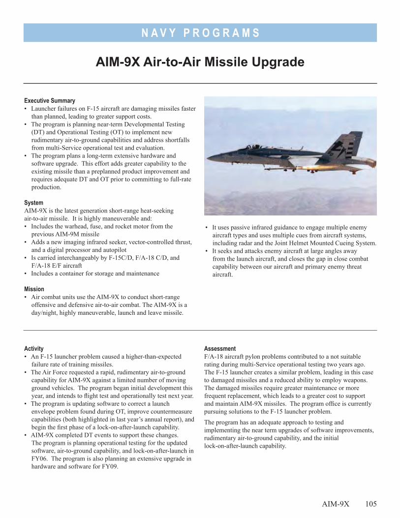
N A V Y P R O G R A M S
Executive Summary• Launcher failures on F-15 aircraft are damaging missiles faster
than planned, leading to greater support costs. • The program is planning near-term Developmental Testing
(DT) and Operational Testing (OT) to implement new rudimentary air-to-ground capabilities and address shortfalls from multi-Service operational test and evaluation.
• The program plans a long-term extensive hardware and software upgrade. This effort adds greater capability to the existing missile than a preplanned product improvement and requires adequate DT and OT prior to committing to full-rate production.
SystemAIM-9X is the latest generation short-range heat-seeking air-to-air missile. It is highly maneuverable and:• Includes the warhead, fuse, and rocket motor from the
previous AIM-9M missile• Adds a new imaging infrared seeker, vector-controlled thrust,
and a digital processor and autopilot• Is carried interchangeably by F-15C/D, F/A-18 C/D, and
F/A-18 E/F aircraft• Includes a container for storage and maintenance
Mission• Air combat units use the AIM-9X to conduct short-range
offensive and defensive air-to-air combat. The AIM-9X is a day/night, highly maneuverable, launch and leave missile.
AIM-9X Air-to-Air Missile Upgrade
• It uses passive infrared guidance to engage multiple enemy aircraft types and uses multiple cues from aircraft systems, including radar and the Joint Helmet Mounted Cueing System.
• It seeks and attacks enemy aircraft at large angles away from the launch aircraft, and closes the gap in close combat capability between our aircraft and primary enemy threat aircraft.
AssessmentF/A-18 aircraft pylon problems contributed to a not suitable rating during multi-Service operational testing two years ago. The F-15 launcher creates a similar problem, leading in this case to damaged missiles and a reduced ability to employ weapons. The damaged missiles require greater maintenance or more frequent replacement, which leads to a greater cost to support and maintain AIM-9X missiles. The program office is currently pursuing solutions to the F-15 launcher problem.
The program has an adequate approach to testing and implementing the near term upgrades of software improvements, rudimentary air-to-ground capability, and the initial lock-on-after-launch capability.
Activity• An F-15 launcher problem caused a higher-than-expected
failure rate of training missiles.• The Air Force requested a rapid, rudimentary air-to-ground
capability for AIM-9X against a limited number of moving ground vehicles. The program began initial development this year, and intends to flight test and operationally test next year.
• The program is updating software to correct a launch envelope problem found during OT, improve countermeasure capabilities (both highlighted in last year’s annual report), and begin the first phase of a lock-on-after-launch capability.
• AIM-9X completed DT events to support these changes. The program is planning operational testing for the updated software, air-to-ground capability, and lock-on-after-launch in FY06. The program is also planning an extensive upgrade in hardware and software for FY09.
AIM-9X 10⁵
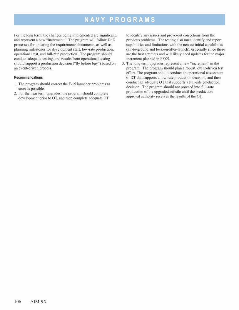
N A V Y P R O G R A M S
106 AIM-9X
For the long term, the changes being implemented are significant, and represent a new “increment.” The program will follow DoD processes for updating the requirements documents, as well as planning milestones for development start, low-rate production, operational test, and full-rate production. The program should conduct adequate testing, and results from operational testing should support a production decision (“fly before buy”) based on an event-driven process.
Recommendations1. The program should correct the F-15 launcher problems as
soon as possible. 2. For the near term upgrades, the program should complete
development prior to OT, and then complete adequate OT
to identify any issues and prove-out corrections from the previous problems. The testing also must identify and report capabilities and limitations with the newest initial capabilities (air-to-ground and lock-on-after-launch), especially since these are the first attempts and will likely need updates for the major increment planned in FY09.
3. The long term upgrades represent a new “increment” in the program. The program should plan a robust, event-driven test effort. The program should conduct an operational assessment of DT that supports a low-rate production decision, and then conduct an adequate OT that supports a full-rate production decision. The program should not proceed into full-rate production of the upgraded missile until the production approval authority receives the results of the OT.
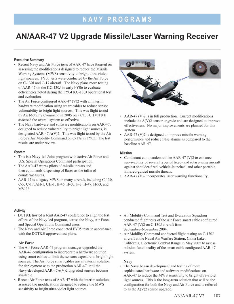
N A V Y P R O G R A M S
• AAR-47 (V)2 is in full production. Current modifications include the A(V)2 sensor upgrade and are designed to improve effectiveness. No major improvements are planned for this system.
• AAR-47 (V)2 is designed to improve missile warning performance and reduce false alarms as compared to the baseline AAR-47.
Mission• Combatant commanders utilize AAR-47 (V)2 to enhance
survivability of several types of fixed- and rotary-wing aircraft against shoulder-fired, vehicle-launched, and other portable infrared-guided missile threats.
• AAR-47 (V)2 incorporates laser warning functionality.
AN/AAR-47 V2 Upgrade Missile/Laser Warning Receiver
Executive Summary• Recent Navy and Air Force tests of AAR-47 have focused on
assessing the modifications designed to reduce the Missile Warning Systems (MWS) sensitivity to bright ultra-violet light sources. FY05 tests were conducted by the Air Force on C-130J and C-17 aircraft. The Navy plans more testing of AAR-47 on the KC-130J in early FY06 to evaluate deficiencies noted during the FY04 KC-130J operational test and evaluation.
• The Air Force configured AAR-47 (V)2 with an interim hardware modification using smart cables to reduce sensor vulnerability to bright light sources. This was flight tested by Air Mobility Command in 2005 on a C130J. DOT&E assessed the overall system as effective.
• The Navy hardware and software modifications on AAR-47, designed to reduce vulnerability to bright light sources, is designated AAR-47 A(V)2. This was flight tested by the Air Force’s Air Mobility Command on C-17s in FY05. The test results are under review.
System• This is a Navy-led Joint program with active Air Force and
U.S. Special Operations Command participation.• The AAR-47 warns pilots of missile threats and
then commands dispensing of flares as the infrared countermeasures.
• AAR-47 is a legacy MWS on many aircraft, including C-130, C-5, C-17, AH-1, UH-1, H-46, H-60, P-3, H-47, H-53, and MV-22.
Activity• DOT&E hosted a Joint AAR-47 conference to align the test
efforts of the Navy led program, across the Navy, Air Force, and Special Operations Command users.
• The Navy and Air Force conducted FY05 tests in accordance with the DOT&E-approved test plans.
Air Force • The Air Force AAR-47 program manager upgraded the
AAR-47 configuration to incorporate a hardware solution using smart cables to limit the sensors exposure to bright light sources. The Air Force smart cables are an interim solution for deployment with the production AAR-47 until the Navy-developed AAR-47A(V)2 upgraded sensors become available.
• Recent Air Force tests of AAR-47 with the interim solution assessed the modifications designed to reduce the MWS sensitivity to bright ultra-violet light sources.
• Air Mobility Command Test and Evaluation Squadron conducted flight tests of the Air Force smart cable configured AAR-47 (V)2 on C-130J aircraft from September–November 2004.
• Air Mobility Command conducted flight testing on C-130J aircraft at the Naval Air Warfare Station, China Lake, California, Electronic Combat Range in May 2005 to assess mission functionality of the smart cable configured AAR-47 system.
Navy • The Navy began development and testing of more
sophisticated hardware and software modifications on AAR-47 to reduce the MWS sensitivity to bright ultra-violet light sources. This is the long-term solution that will be the configuration for both the Navy and Air Force and is referred to as the A(V)2 sensor upgrade.
AN/AAR-47 V2 107
N A V Y P R O G R A M S
108 AN/AAR-47 V2
• The Navy conducted AN/AAR-47 A(V)2 sensor baseline and upgrade testing on the KC-130J in the first and second quarters of FY05.
• The Air Force Air Mobility Command also conducted flight tests at Electronic Combat Range in June 2005 to assess mission effectiveness of the Navy’s AAR-47 A(V)2 configuration on Air Force C-17 aircraft. These tests supported the Navy’s sensor development efforts.
• The Navy configured 10 operational U.S. Marine Corps KC-130Js with the Air Force AAR-47 (V)2 smart cable (interim) configuration.
• The Navy finalized plans for KC-130J AN/AAR-47 A(V)2 mission effectiveness testing in 1QFY06 to evaluate deficiencies noted during the FY04 KC-130J operational test and evaluation.
• Operational Test and Evaluation Force, the Navy’s Operational Test Agency, ensured this test is an operationally representative test, while initiating closer oversight of ground-based missile plume simulator procedures.
• The Navy modifications on AAR-47 to reduce sensor vulnerability to bright light sources were tested by the Air Force’s Air Mobility Command on C-17s in FY05. The test results are under review.
AssessmentThe sharing of test plans, resources, and system performance lessons resulting from the Joint conference, improved Navy and Air Force AAR-47 test efficiency.
Air Force • DOT&E assessed the Air Force’s AAR-47 smart cable
configuration MWS as effective on the C130-J. This was based on the Air Mobility Command flight tests conducted in 2005.
Navy• The Navy’s operational testing in 3QFY04 was not adequate
to assess AAR-47 (V)2 system effectiveness due to lack of onboard data instrumentation for verifying the ground-based threat missile simulations. As a result, the Navy planned a follow-on test of AAR-47 A(V)2 installed on the KC-130J for 1QFY06 to adequately assess system effectiveness. Preliminary review of the recent test results indicate that testing was adequate to assess AAR-47 A(V)2 system effectiveness as installed on the KC-130J.
• The Navy’s execution of ground-based missile simulator procedures and shortage of calibration equipment led to inconsistent threat simulation presentations for AAR-47 tests in 2004 and 2005, which challenged test adequacy.
Recommendations1. The Navy and Air Force should continue to improve the Joint
interaction and testing of the AAR-47 MWS. 2. The Navy should strive to standardize ground-based missile
simulator procedures and equipment across the Joint test environment to maximize test efficiency.
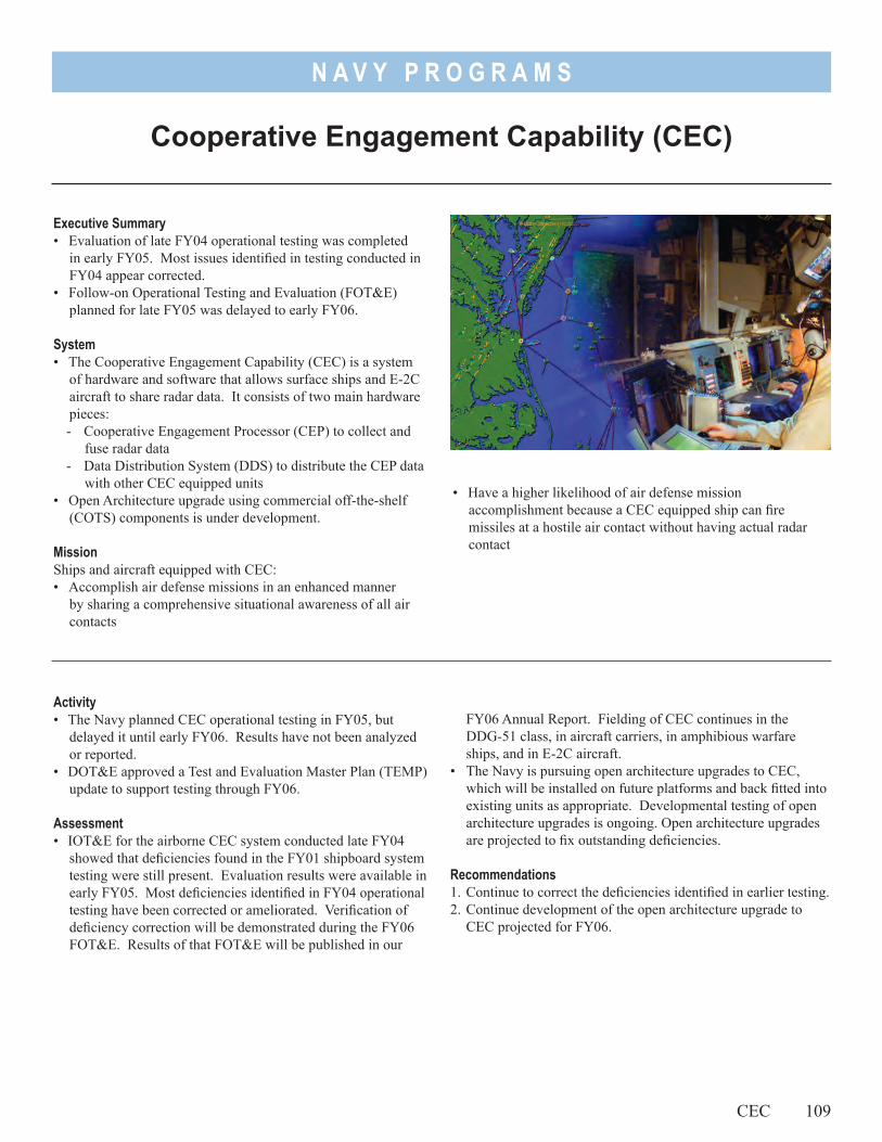
N A V Y P R O G R A M S
Executive Summary• Evaluation of late FY04 operational testing was completed
in early FY05. Most issues identified in testing conducted in FY04 appear corrected.
• Follow-on Operational Testing and Evaluation (FOT&E) planned for late FY05 was delayed to early FY06.
System• The Cooperative Engagement Capability (CEC) is a system
of hardware and software that allows surface ships and E-2C aircraft to share radar data. It consists of two main hardware pieces:- Cooperative Engagement Processor (CEP) to collect and
fuse radar data- Data Distribution System (DDS) to distribute the CEP data
with other CEC equipped units• Open Architecture upgrade using commercial off-the-shelf
(COTS) components is under development.
MissionShips and aircraft equipped with CEC: • Accomplish air defense missions in an enhanced manner
by sharing a comprehensive situational awareness of all air contacts
• Have a higher likelihood of air defense mission accomplishment because a CEC equipped ship can fire missiles at a hostile air contact without having actual radar contact
FY06 Annual Report. Fielding of CEC continues in the DDG-51 class, in aircraft carriers, in amphibious warfare ships, and in E-2C aircraft.
• The Navy is pursuing open architecture upgrades to CEC, which will be installed on future platforms and back fitted into existing units as appropriate. Developmental testing of open architecture upgrades is ongoing. Open architecture upgrades are projected to fix outstanding deficiencies.
Recommendations1. Continue to correct the deficiencies identified in earlier testing. 2. Continue development of the open architecture upgrade to
CEC projected for FY06.
Activity• The Navy planned CEC operational testing in FY05, but
delayed it until early FY06. Results have not been analyzed or reported.
• DOT&E approved a Test and Evaluation Master Plan (TEMP) update to support testing through FY06.
Assessment• IOT&E for the airborne CEC system conducted late FY04
showed that deficiencies found in the FY01 shipboard system testing were still present. Evaluation results were available in early FY05. Most deficiencies identified in FY04 operational testing have been corrected or ameliorated. Verification of deficiency correction will be demonstrated during the FY06 FOT&E. Results of that FOT&E will be published in our
Cooperative Engagement Capability (CEC)
CEC 109

N A V Y P R O G R A M S
110
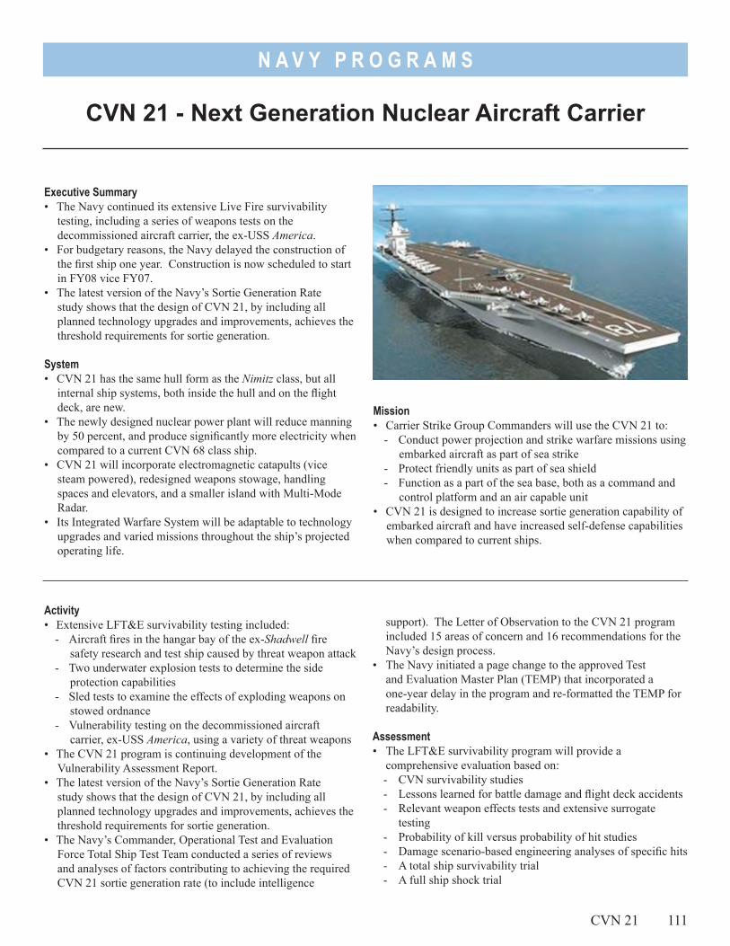
N A V Y P R O G R A M S
Executive Summary• The Navy continued its extensive Live Fire survivability
testing, including a series of weapons tests on the decommissioned aircraft carrier, the ex-USS America.
• For budgetary reasons, the Navy delayed the construction of the first ship one year. Construction is now scheduled to start in FY08 vice FY07.
• The latest version of the Navy’s Sortie Generation Rate study shows that the design of CVN 21, by including all planned technology upgrades and improvements, achieves the threshold requirements for sortie generation.
System• CVN 21 has the same hull form as the Nimitz class, but all
internal ship systems, both inside the hull and on the flight deck, are new.
• The newly designed nuclear power plant will reduce manning by 50 percent, and produce significantly more electricity when compared to a current CVN 68 class ship.
• CVN 21 will incorporate electromagnetic catapults (vice steam powered), redesigned weapons stowage, handling spaces and elevators, and a smaller island with Multi-Mode Radar.
• Its Integrated Warfare System will be adaptable to technology upgrades and varied missions throughout the ship’s projected operating life.
CVN 21 - Next Generation Nuclear Aircraft Carrier
Mission• Carrier Strike Group Commanders will use the CVN 21 to:
- Conduct power projection and strike warfare missions using embarked aircraft as part of sea strike
- Protect friendly units as part of sea shield- Function as a part of the sea base, both as a command and
control platform and an air capable unit• CVN 21 is designed to increase sortie generation capability of
embarked aircraft and have increased self-defense capabilities when compared to current ships.
support). The Letter of Observation to the CVN 21 program included 15 areas of concern and 16 recommendations for the Navy’s design process.
• The Navy initiated a page change to the approved Test and Evaluation Master Plan (TEMP) that incorporated a one-year delay in the program and re-formatted the TEMP for readability.
Assessment• The LFT&E survivability program will provide a
comprehensive evaluation based on: - CVN survivability studies- Lessons learned for battle damage and flight deck accidents- Relevant weapon effects tests and extensive surrogate
testing- Probability of kill versus probability of hit studies- Damage scenario-based engineering analyses of specific hits- A total ship survivability trial- A full ship shock trial
Activity• Extensive LFT&E survivability testing included:
- Aircraft fires in the hangar bay of the ex-Shadwell fire safety research and test ship caused by threat weapon attack
- Two underwater explosion tests to determine the side protection capabilities
- Sled tests to examine the effects of exploding weapons on stowed ordnance
- Vulnerability testing on the decommissioned aircraft carrier, ex-USS America, using a variety of threat weapons
• The CVN 21 program is continuing development of the Vulnerability Assessment Report.
• The latest version of the Navy’s Sortie Generation Rate study shows that the design of CVN 21, by including all planned technology upgrades and improvements, achieves the threshold requirements for sortie generation.
• The Navy’s Commander, Operational Test and Evaluation Force Total Ship Test Team conducted a series of reviews and analyses of factors contributing to achieving the required CVN 21 sortie generation rate (to include intelligence
CVN 21 111
N A V Y P R O G R A M S
112 CVN 21
• DOT&E approved both the LFT&E Management Plan and the TEMP in March 2004. DOT&E expects to approve the TEMP page change in December 2005. We expect both the TEMP and LFT&E Management Plan to be revised during 2006 to support a FY07 Defense Acquisition Board program review.
Recommendation1. The CVN 21 design program should thoroughly evaluate the
recommendations in the Operational Test and Evaluation Force Letter of Observation in the design process.
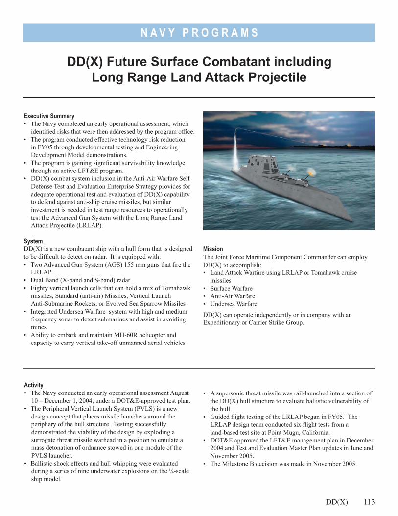
N A V Y P R O G R A M S
Executive Summary• The Navy completed an early operational assessment, which
identified risks that were then addressed by the program office.• The program conducted effective technology risk reduction
in FY05 through developmental testing and Engineering Development Model demonstrations.
• The program is gaining significant survivability knowledge through an active LFT&E program.
• DD(X) combat system inclusion in the Anti-Air Warfare Self Defense Test and Evaluation Enterprise Strategy provides for adequate operational test and evaluation of DD(X) capability to defend against anti-ship cruise missiles, but similar investment is needed in test range resources to operationally test the Advanced Gun System with the Long Range Land Attack Projectile (LRLAP).
SystemDD(X) is a new combatant ship with a hull form that is designed to be difficult to detect on radar. It is equipped with:• Two Advanced Gun System (AGS) 155 mm guns that fire the
LRLAP• Dual Band (X-band and S-band) radar• Eighty vertical launch cells that can hold a mix of Tomahawk
missiles, Standard (anti-air) Missiles, Vertical Launch Anti-Submarine Rockets, or Evolved Sea Sparrow Missiles
• Integrated Undersea Warfare system with high and medium frequency sonar to detect submarines and assist in avoiding mines
• Ability to embark and maintain MH-60R helicopter and capacity to carry vertical take-off unmanned aerial vehicles
• A supersonic threat missile was rail-launched into a section of the DD(X) hull structure to evaluate ballistic vulnerability of the hull.
• Guided flight testing of the LRLAP began in FY05. The LRLAP design team conducted six flight tests from a land-based test site at Point Mugu, California.
• DOT&E approved the LFT&E management plan in December 2004 and Test and Evaluation Master Plan updates in June and November 2005.
• The Milestone B decision was made in November 2005.
Activity• The Navy conducted an early operational assessment August
10 – December 1, 2004, under a DOT&E-approved test plan.• The Peripheral Vertical Launch System (PVLS) is a new
design concept that places missile launchers around the periphery of the hull structure. Testing successfully demonstrated the viability of the design by exploding a surrogate threat missile warhead in a position to emulate a mass detonation of ordnance stowed in one module of the PVLS launcher.
• Ballistic shock effects and hull whipping were evaluated during a series of nine underwater explosions on the ¼-scale ship model.
DD(X) Future Surface Combatant including Long Range Land Attack Projectile
DD(X) 113
MissionThe Joint Force Maritime Component Commander can employ DD(X) to accomplish:• Land Attack Warfare using LRLAP or Tomahawk cruise
missiles• Surface Warfare• Anti-Air Warfare• Undersea Warfare
DD(X) can operate independently or in company with an Expeditionary or Carrier Strike Group.
N A V Y P R O G R A M S
114 DD(X)
Assessment• Developmental, operational, and LFT&E to date have been
very successful for risk reduction and technology readiness improvement. Technology readiness levels are at or beyond the minimum required for Milestone B. The comprehensive early operational assessment report highlighted several effectiveness and suitability risks. Many of the highest technology risk issues have been addressed and mitigated through Engineering Development Model testing and demonstration. Some issues, such as whether the AGS will operate properly in a constant motion environment, will not be resolved before the first ship goes to sea. The DD(X) has a robust LFT&E vulnerability program planned that is designed to provide a comprehensive survivability evaluation of the technologies employed by this new generation destroyer. The DD(X) LFT&E Lethality Integrated Process Team has developed a comprehensive strategy for the lethality evaluation of the LRLAP.
• The program office is proactive in giving the Navy Operational Testing Agency (OTA) full access to every developmental test event. This open dialogue has helped to give the OTA full understanding of systems and will permit better integration of future testing opportunities.
• The Navy has not identified adequate facilities for measuring and calibrating magnetic, acoustic, and radar signatures, though these will not be needed until approximately 2013. This will be an issue sooner for other ship classes including LCS and LPD 17. The Navy has not identified an appropriate range for conducting operational end-to-end testing of the AGS with LRLAP against realistic targets.
• PVLS testing demonstrated that the design would limit damage to individual cells and prevent chain reaction explosions in adjacent cells.
• DD(X) will have a crew of 142. This is small compared to a DDG 51 crew of more than 300. Current shore support
infrastructure and Navy manpower management policies are not fully suited for the unique requirements DD(X) will have. DD(X) will lack onboard administrative and maintenance personnel and facilities traditionally assigned to ships. The Navy has not specified how shore-side logistics, administrative, and maintenance support will work, or how training and assignment strategies will ensure all personnel arrive ready to operate systems and equipment. Several Navy initiatives and pilot programs are in progress that may prove to be suitable to address these challenges for DD(X).
• The Navy proposed an acceptable approach for operational testing of self defense capability against anti-ship cruise missiles. That approach uses the Self Defense Test Ship, complemented by modeling and simulation using the Probability of Raid Annihilation Test-Bed. The approach is being aligned with the Navy Anti-Air Warfare Self Defense Test and Evaluation Enterprise Strategy for future ship classes. This will provide results that will address operational test issues with the next ship class (CVN 21) using the DD(X)-like combat system.
RecommendationsThe Navy should:1. Ensure manpower and other human capital policies are aligned
to support DD(X) afloat and ashore when the ship arrives in the fleet.
2. Invest in appropriate testing and calibration facilities in order to understand and properly preserve low DD(X) acoustic, magnetic, and radar signatures.
3. Continue test program alignment with the Enterprise Strategy for future ship classes.
4. Identify and invest in a test range and required resources soon to enable operational end-to-end testing of the AGS with LRLAP against realistic targets.
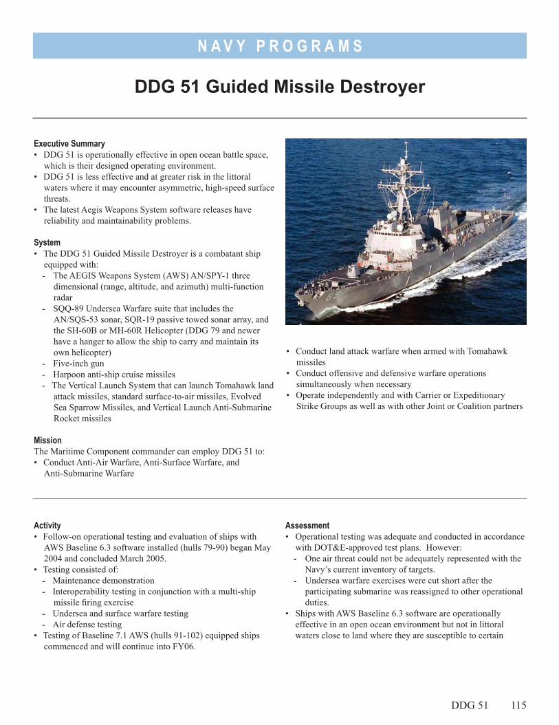
N A V Y P R O G R A M S
• Conduct land attack warfare when armed with Tomahawk missiles
• Conduct offensive and defensive warfare operations simultaneously when necessary
• Operate independently and with Carrier or Expeditionary Strike Groups as well as with other Joint or Coalition partners
Executive Summary• DDG 51 is operationally effective in open ocean battle space,
which is their designed operating environment.• DDG 51 is less effective and at greater risk in the littoral
waters where it may encounter asymmetric, high-speed surface threats.
• The latest Aegis Weapons System software releases have reliability and maintainability problems.
System• The DDG 51 Guided Missile Destroyer is a combatant ship
equipped with:- The AEGIS Weapons System (AWS) AN/SPY-1 three
dimensional (range, altitude, and azimuth) multi-function radar
- SQQ-89 Undersea Warfare suite that includes the AN/SQS-53 sonar, SQR-19 passive towed sonar array, and the SH-60B or MH-60R Helicopter (DDG 79 and newer have a hanger to allow the ship to carry and maintain its own helicopter)
- Five-inch gun- Harpoon anti-ship cruise missiles- The Vertical Launch System that can launch Tomahawk land
attack missiles, standard surface-to-air missiles, Evolved Sea Sparrow Missiles, and Vertical Launch Anti-Submarine Rocket missiles
MissionThe Maritime Component commander can employ DDG 51 to:• Conduct Anti-Air Warfare, Anti-Surface Warfare, and
Anti-Submarine Warfare
DDG 51 Guided Missile Destroyer
Activity• Follow-on operational testing and evaluation of ships with
AWS Baseline 6.3 software installed (hulls 79-90) began May 2004 and concluded March 2005.
• Testing consisted of:- Maintenance demonstration- Interoperability testing in conjunction with a multi-ship
missile firing exercise- Undersea and surface warfare testing- Air defense testing
• Testing of Baseline 7.1 AWS (hulls 91-102) equipped ships commenced and will continue into FY06.
DDG 51 115
Assessment• Operational testing was adequate and conducted in accordance
with DOT&E-approved test plans. However:- One air threat could not be adequately represented with the
Navy’s current inventory of targets.- Undersea warfare exercises were cut short after the
participating submarine was reassigned to other operational duties.
• Ships with AWS Baseline 6.3 software are operationally effective in an open ocean environment but not in littoral waters close to land where they are susceptible to certain
N A V Y P R O G R A M S
surface threats. This was also noted for ships with Baseline 5.3.8 software.
• Ships with AWS Baseline 6.3 software are not operationally suitable due to several software reliability and maintainability problems. These included a very short time between rebooting, poor technical documentation, and numerous workarounds that proved distracting to operators.
• Baseline 7.1 testing started with more high priority software anomalies on record than the number on record at the start of baseline 6.3 testing. None specifically cause safety hazards or interfere with the operation of the AWS. However, collectively these anomalies cause operators to be less efficient and to apply workarounds. Future software baselines (7.1R and 7.1OA for cruisers) are in development with a high level of program office attention to issues that might affect readiness for fleet release.
• The currently approved Test and Evaluation Master Plan (TEMP) does not include details or funding to assess upcoming baselines that will modify AWS system performance and operation.
RecommendationsThe Navy should:1. Complete testing of the Baseline 7.1 ships. Ensure suitability
issues with Baseline 6.3 software are resolved through follow-on testing.
2. Update the DDG 51 TEMP to provide funding for testing of future Baselines (7.1R, 7.1OA).
3. Consider consolidating DDG 51/AWS with SPY-1(D)V and SQQ-89(V)15 programs under a single TEMP. All of these programs are dependent on DDG 51. Consolidation will maximize developmental and testing efficiencies. These systems may be good candidates for later inclusion in the Navy’s proposed Anti-Air Warfare Self Defense Enterprise Strategy.
4. Consider including CG 52 class cruisers with the DDG 51, perhaps as a broader program. AWS Baselines installed are very similar for the cruisers and destroyers. Should the Navy fund a cruiser modification program that significantly enhances capability, it could realize development and testing efficiencies.
116 DDG 51
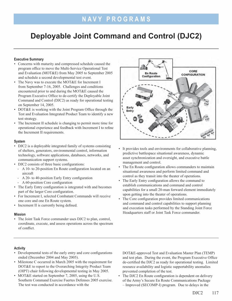
N A V Y P R O G R A M S
Executive Summary• Concerns with maturity and compressed schedule caused the
program office to move the Multi-Service Operational Test and Evaluation (MOT&E) from May 2005 to September 2005 and schedule a second developmental test event.
• The Navy was to execute the MOT&E for Increment I from September 7-16, 2005. Challenges and conditions encountered prior to and during the MOT&E caused the Program Executive Office to de-certify the Deployable Joint Command and Control (DJC2) as ready for operational testing on September 14, 2005.
• DOT&E is working with the Joint Program Office through the Test and Evaluation Integrated Product Team to identify a new test strategy.
• The Increment II schedule is changing to permit more time for operational experience and feedback with Increment I to refine the Increment II requirements.
System• DJC2 is a deployable integrated family of systems consisting
of shelters, generators, environmental control, information technology, software applications, databases, networks, and communication support systems.
• DJC2 consists of three basic configurations: - A 10- to 20-position En Route configuration located on an
aircraft- A 20- to 40-position Early Entry configuration- A 60-position Core configuration
• The Early Entry configuration is integrated with and becomes part of the larger Core configuration.
• For Increment I, selected Combatant Commands will receive one core and one En Route system.
• Increment II is currently being defined.
Mission• The Joint Task Force commander uses DJC2 to plan, control,
coordinate, execute, and assess operations across the spectrum of conflict.
• It provides tools and environments for collaborative planning, predictive battlespace situational awareness, dynamic asset synchronization and oversight, and executive battle management and control.
• The En Route configuration allows commanders to maintain situational awareness and perform limited command and control as they transit into the theater of operations.
• The Early Entry configuration allows the command to establish communications and command and control capabilities for a small 20-man forward element immediately upon getting into the theater of operations.
• The Core configuration provides limited communications and command and control capabilities to support planning and execution tasks performed by the Standing Joint Force Headquarters staff or Joint Task Force commander.
Deployable Joint Command and Control (DJC2)
DOT&E-approved Test and Evaluation Master Plan (TEMP) and test plan. During the event, the Program Executive Office de-certified the DJC2 as ready for operational testing. Limited resource availability and logistic supportability anomalies prevented completion of the test.
• The DJC2 En Route configuration is dependent on delivery of the Army’s Secure En Route Communications Package – Improved (SECOMP-I) program. Due to delays in the
Activity• Developmental tests of the early entry and core configurations
ended (December 2004 and May 2005).• Milestone C occurred in March 2005 with the requirement for
DOT&E to report to the Overarching Integrity Product Team (OIPT) chair following developmental testing in May 2005.
• MOT&E started on September 7, 2005, using the U.S. Southern Command Exercise Fuertes Defenses 2005 exercise. The test was conducted in accordance with the
DJC2 117
N A V Y P R O G R A M S
SECOMP-I program, the DJC2 Program Office moved test and delivery of the En Route configuration to a later spiral in Increment I.
• The Joint Program Office with support from the Joint Forces Command is planning a revised schedule for Increment II to permit time for feedback from operational experience with Increment I systems into the capabilities definition process. Consequently, DOT&E expects the Increment II Milestone B decision to move into FY07.
Assessment• Based on findings from the December 2004 developmental
testing, DOT&E and the Joint Program Office assessed the system design and documentation as not mature enough to enter the MOT&E in May 2005. As a result, the MOT&E moved from May 2005 to September 2005 to mature the system design, complete documentation, and demonstrate essential functionality before operational testing. A second developmental test in May 2005 occurred to confirm progress.
• DOT&E reported to the OIPT chair in June 2005 that the concerns identified in December 2004 were demonstrated to our satisfaction and posed a low risk to the MOT&E. The report concluded that the DJC2 had made considerable
progress in systems integration, maturity of the design, and testing of essential functionality.
• The MOT&E for the early entry and core configurations began on September 7, 2005. Issues encountered during the MOT&E contributed to the decision to de-certify the system as ready for test. The test identified challenges with the training program and logistics supportability, resulting in an inability to effectively set up the DJC2 system. Due to Hurricane Katrina priorities, insufficient bandwidth was available to support operations during the test, thus the exercise scenario did not contain the robust use of DJC2 capabilities as originally expected.
• DOT&E is working with the Test and Evaluation Integrated Product Team to define an appropriate test strategy to support upcoming acquisition decisions.
Recommendation1. The Joint Program Office, with support from the Joint Forces
Command and the Combatant Commands, should identify appropriate test venues for the MOT&E, and operational testing of the En Route configuration and remaining spirals of Increment 1.
118 DJC2
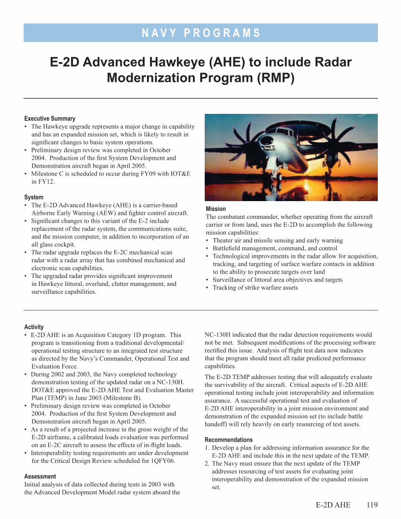
N A V Y P R O G R A M S
Executive Summary• The Hawkeye upgrade represents a major change in capability
and has an expanded mission set, which is likely to result in significant changes to basic system operations.
• Preliminary design review was completed in October 2004. Production of the first System Development and Demonstration aircraft began in April 2005.
• Milestone C is scheduled to occur during FY09 with IOT&E in FY12.
System• The E-2D Advanced Hawkeye (AHE) is a carrier-based
Airborne Early Warning (AEW) and fighter control aircraft.• Significant changes to this variant of the E-2 include
replacement of the radar system, the communications suite, and the mission computer, in addition to incorporation of an all glass cockpit.
• The radar upgrade replaces the E-2C mechanical scan radar with a radar array that has combined mechanical and electronic scan capabilities.
• The upgraded radar provides significant improvement in Hawkeye littoral, overland, clutter management, and surveillance capabilities.
E-2D Advanced Hawkeye (AHE) to include Radar Modernization Program (RMP)
MissionThe combatant commander, whether operating from the aircraft carrier or from land, uses the E-2D to accomplish the following mission capabilities:• Theater air and missile sensing and early warning• Battlefield management, command, and control• Technological improvements in the radar allow for acquisition,
tracking, and targeting of surface warfare contacts in addition to the ability to prosecute targets over land
• Surveillance of littoral area objectives and targets• Tracking of strike warfare assets
NC-130H indicated that the radar detection requirements would not be met. Subsequent modifications of the processing software rectified this issue. Analysis of flight test data now indicates that the program should meet all radar predicted performance capabilities.
The E-2D TEMP addresses testing that will adequately evaluate the survivability of the aircraft. Critical aspects of E-2D AHE operational testing include joint interoperability and information assurance. A successful operational test and evaluation of E-2D AHE interoperability in a joint mission environment and demonstration of the expanded mission set (to include battle handoff) will rely heavily on early resourcing of test assets.
Recommendations1. Develop a plan for addressing information assurance for the
E-2D AHE and include this in the next update of the TEMP.2. The Navy must ensure that the next update of the TEMP
addresses resourcing of test assets for evaluating joint interoperability and demonstration of the expanded mission set.
Activity• E-2D AHE is an Acquisition Category 1D program. This
program is transitioning from a traditional developmental/operational testing structure to an integrated test structure as directed by the Navy’s Commander, Operational Test and Evaluation Force.
• During 2002 and 2003, the Navy completed technology demonstration testing of the updated radar on a NC-130H. DOT&E approved the E-2D AHE Test and Evaluation Master Plan (TEMP) in June 2003 (Milestone B).
• Preliminary design review was completed in October 2004. Production of the first System Development and Demonstration aircraft began in April 2005.
• As a result of a projected increase in the gross weight of the E-2D airframe, a calibrated loads evaluation was performed on an E-2C aircraft to assess the effects of in-flight loads.
• Interoperability testing requirements are under development for the Critical Design Review scheduled for 1QFY06.
AssessmentInitial analysis of data collected during tests in 2003 with the Advanced Development Model radar system aboard the
E-2D AHE 119
N A V Y P R O G R A M S
3. The program manager must address interoperability shortfalls and integrated test content in the next update of the TEMP.
120 E-2D AHE
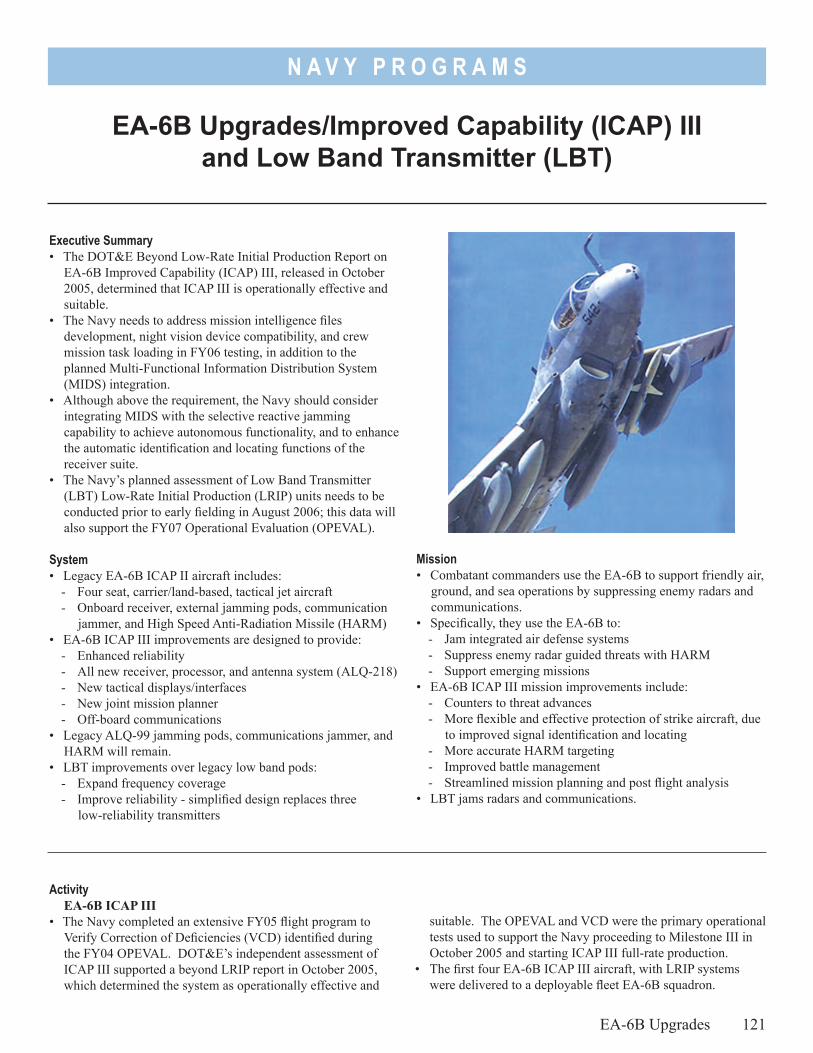
N A V Y P R O G R A M S
Executive Summary• The DOT&E Beyond Low-Rate Initial Production Report on
EA-6B Improved Capability (ICAP) III, released in October 2005, determined that ICAP III is operationally effective and suitable.
• The Navy needs to address mission intelligence files development, night vision device compatibility, and crew mission task loading in FY06 testing, in addition to the planned Multi-Functional Information Distribution System (MIDS) integration.
• Although above the requirement, the Navy should consider integrating MIDS with the selective reactive jamming capability to achieve autonomous functionality, and to enhance the automatic identification and locating functions of the receiver suite.
• The Navy’s planned assessment of Low Band Transmitter (LBT) Low-Rate Initial Production (LRIP) units needs to be conducted prior to early fielding in August 2006; this data will also support the FY07 Operational Evaluation (OPEVAL).
System• Legacy EA-6B ICAP II aircraft includes:
- Four seat, carrier/land-based, tactical jet aircraft- Onboard receiver, external jamming pods, communication
jammer, and High Speed Anti-Radiation Missile (HARM)• EA-6B ICAP III improvements are designed to provide:
- Enhanced reliability- All new receiver, processor, and antenna system (ALQ-218)- New tactical displays/interfaces- New joint mission planner - Off-board communications
• Legacy ALQ-99 jamming pods, communications jammer, and HARM will remain.
• LBT improvements over legacy low band pods:- Expand frequency coverage- Improve reliability - simplified design replaces three
low-reliability transmitters
Mission• Combatant commanders use the EA-6B to support friendly air,
ground, and sea operations by suppressing enemy radars and communications.
• Specifically, they use the EA-6B to:- Jam integrated air defense systems - Suppress enemy radar guided threats with HARM- Support emerging missions
• EA-6B ICAP III mission improvements include:- Counters to threat advances- More flexible and effective protection of strike aircraft, due
to improved signal identification and locating - More accurate HARM targeting- Improved battle management- Streamlined mission planning and post flight analysis
• LBT jams radars and communications.
suitable. The OPEVAL and VCD were the primary operational tests used to support the Navy proceeding to Milestone III in October 2005 and starting ICAP III full-rate production.
• The first four EA-6B ICAP III aircraft, with LRIP systems were delivered to a deployable fleet EA-6B squadron.
ActivityEA-6B ICAP III
• The Navy completed an extensive FY05 flight program to Verify Correction of Deficiencies (VCD) identified during the FY04 OPEVAL. DOT&E’s independent assessment of ICAP III supported a beyond LRIP report in October 2005, which determined the system as operationally effective and
EA-6B Upgrades/Improved Capability (ICAP) III and Low Band Transmitter (LBT)
EA-6B Upgrades 121
N A V Y P R O G R A M S
• Partial assessment of the integration of the MIDS on EA-6B ICAP III aircraft was conducted in FY05. Full operational testing of MIDS is planned for follow-on testing in FY06. MIDS is a digital link that allows EA-6Bs to automatically receive and transmit information with other ground and air assets.
Low Band Transmitter (LBT)• Limited developmental flight testing at the Nevada Test
and Training Range, using an Engineering Manufacturing Development low band transmitter pod, assessed the effectiveness of LBT in a limited threat environment to support early fielding for combat operations.
• The Navy purchased 17 LRIP LBTs in FY05. The first 10 will support early fielding in August 2006. The Navy expects a LBT full-rate production decision in FY07.
AssessmentEA-6B ICAP III
• The Navy’s FY05 VCD verified that the major deficiencies in the FY04 OPEVAL had been corrected. Commander, Operational Test and Evaluation Force, the Navy’s operational test agency, and DOT&E reported this new weapons system to be operationally effective and suitable, supporting the Navy’s full-rate production decision on ICAP III.
• The ICAP III weapons system combines better crew situational awareness with improved speed and accuracy of electronic threat detection, identification, and locating functions, to enhance the suppression of enemy radar-guided threats compared to the legacy system.
• The deficiencies that should be addressed in follow-on test and evaluation are related to development of mission intelligence files, night vision device compatibility concerns with the readability of cockpit displays, and new crew task lists to support improved cockpit functionality.
• Testing of ICAP III revealed that if the Navy integrates the automatic selective reactive jamming capability with MIDS, it could benefit the warfighters. This will provide the operators more timely fusion of accurate threat emitter information and supported striker positioning. Additionally, enhancement of the automatic receiver identification and locating functionality should reduce the operator work load.
• An early version of the mission planner was assessed under EA-6B testing. A more complete version will be tested under the Navy’s Joint Mission Planning System architecture. This is planned for FY06.
• The validation of procedures for standardized intelligence files development should include an assessment of the Navy’s Advanced Multiple Emitter Environment Simulators capability to support future intelligence file development for EA-6B ICAP III future testing and combat operations. Advanced Multiple Emitter Environment Simulators III is a laboratory threat signal simulator that is the critical tool in developing the geo-location considerations for intelligence file development.
• FY05 testing was conducted in accordance with the DOT&E-approved Test and Evaluation Master Plan.
Low Band Transmitter (LBT) • Testing of Engineering Manufacturing Development pods in
2004 provided insight into performance of LBT production representative pods, but the demonstrated reliability was poor. The Navy did learn from this testing and modified LRIP pods to improve reliability, which will be evaluated in the Navy’s planned assessment in FY06.
• The limited development testing for early fielding showed LBT to be operationally effective for the specific intended mission set. The early fielding plan to support combat operations is a priority for the Navy and Marine Corps. Follow-on testing of the complete mission set is still required.
RecommendationsEA-6B ICAP III
1. The Navy should address, in FY06 testing, the deficiencies found in the mission intelligence files development, night vision device compatibility, and crew mission task loading.
2. Although not a requirement, the Navy should consider upgrading the integration of MIDS with the automatic selective reactive jamming capability of the ICAP III EA-6B, along with improved automatic receiver suite functionality.
Low Band Transmitter (LBT)1. The Navy must conduct the planned assessment of LBT
LRIP units prior to the early fielding in 4QFY06, which will provide the Navy a preliminary assessment of the effectiveness and suitability of the low band transmitter LRIP units. Additionally, this assessment will help the Navy prepare for the OPEVAL in FY07.
2. An update of the Test and Evaluation Master Plan must be accomplished in FY06 to support the program changes, due to the early fielding of LBT and anticipated delays of OPEVAL.
122 EA-6B Upgrades
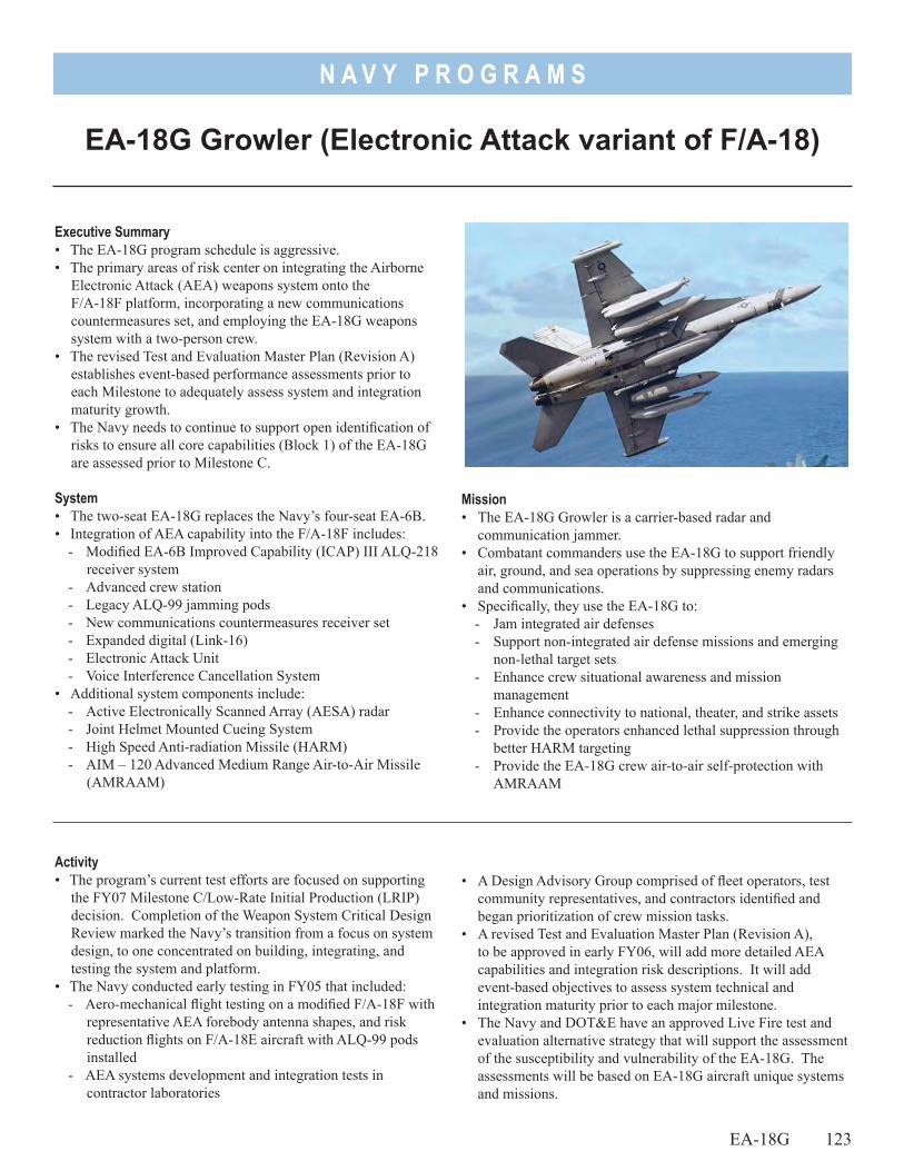
N A V Y P R O G R A M S
Executive Summary• The EA-18G program schedule is aggressive.• The primary areas of risk center on integrating the Airborne
Electronic Attack (AEA) weapons system onto the F/A-18F platform, incorporating a new communications countermeasures set, and employing the EA-18G weapons system with a two-person crew.
• The revised Test and Evaluation Master Plan (Revision A) establishes event-based performance assessments prior to each Milestone to adequately assess system and integration maturity growth.
• The Navy needs to continue to support open identification of risks to ensure all core capabilities (Block 1) of the EA-18G are assessed prior to Milestone C.
System• The two-seat EA-18G replaces the Navy’s four-seat EA-6B.• Integration of AEA capability into the F/A-18F includes:
- Modified EA-6B Improved Capability (ICAP) III ALQ-218 receiver system
- Advanced crew station- Legacy ALQ-99 jamming pods- New communications countermeasures receiver set- Expanded digital (Link-16)- Electronic Attack Unit- Voice Interference Cancellation System
• Additional system components include:- Active Electronically Scanned Array (AESA) radar- Joint Helmet Mounted Cueing System- High Speed Anti-radiation Missile (HARM) - AIM – 120 Advanced Medium Range Air-to-Air Missile
(AMRAAM)
EA-18G Growler (Electronic Attack variant of F/A-18)
• A Design Advisory Group comprised of fleet operators, test community representatives, and contractors identified and began prioritization of crew mission tasks.
• A revised Test and Evaluation Master Plan (Revision A), to be approved in early FY06, will add more detailed AEA capabilities and integration risk descriptions. It will add
event-based objectives to assess system technical and integration maturity prior to each major milestone.
• The Navy and DOT&E have an approved Live Fire test and evaluation alternative strategy that will support the assessment of the susceptibility and vulnerability of the EA-18G. The assessments will be based on EA-18G aircraft unique systems and missions.
Activity• The program’s current test efforts are focused on supporting
the FY07 Milestone C/Low-Rate Initial Production (LRIP) decision. Completion of the Weapon System Critical Design Review marked the Navy’s transition from a focus on system design, to one concentrated on building, integrating, and testing the system and platform.
• The Navy conducted early testing in FY05 that included:- Aero-mechanical flight testing on a modified F/A-18F with
representative AEA forebody antenna shapes, and risk reduction flights on F/A-18E aircraft with ALQ-99 pods installed
- AEA systems development and integration tests in contractor laboratories
EA-18G 123
Mission• The EA-18G Growler is a carrier-based radar and
communication jammer. • Combatant commanders use the EA-18G to support friendly
air, ground, and sea operations by suppressing enemy radars and communications.
• Specifically, they use the EA-18G to:- Jam integrated air defenses - Support non-integrated air defense missions and emerging
non-lethal target sets - Enhance crew situational awareness and mission
management- Enhance connectivity to national, theater, and strike assets- Provide the operators enhanced lethal suppression through
better HARM targeting- Provide the EA-18G crew air-to-air self-protection with
AMRAAM
N A V Y P R O G R A M S
124 EA-18G
Assessment• The schedule for this program is aggressive because the
Navy plans to take delivery of the first System Development and Demonstration EA-18G in FY06, and achieve initial operational capability in FY09.
• The EA-18G presents challenging risks associated with integrating the AEA weapons system onto the F/A-18F platform. Primary integration risks for the EA-18G are:- Effective operation of the ALQ-99 external jammer
pods and ALQ-218 wingtip pods and antenna in the high vibration F/A-18F under-wing and wing tip environments
- Modified F/A-18E/F mission planning system- New communications countermeasures set- Revised ALQ-218 receiver (digital auxiliary receiver)
design and component modifications to form and fit - Operator work load in electronic attack and electronic
support operations as performed by the four-person EA-6B- Aggressive software development schedule
• The new ALQ-218 receiver, improved connectivity, and linked displays are the primary design features implemented to reduce the operator workload in support of the two-man crew composition.
• The impact of the integration risks can be mitigated if the Navy continues its aggressive identification and resolution of
concerns, while maintaining the early involvement of the test community.
• The first Operational Assessment (OA) designed to support Milestone C will assess the key areas of integration risk, but will not provide assessment of the full EA-18G software functionality. The second OA, scheduled to support the second LRIP, is planned to assess full software functionality of the EA-18G. The second OA will ensure an adequate and timely assessment of the more mature ALQ-218 receiver and ALQ-99 external jamming pod capabilities in the challenging aerodynamic environment early in the acquisition process.
• FY05 testing was conducted in accordance with the DOT&E-approved Test and Evaluation Master Plan.
Recommendations1. The Navy should make the second LRIP, scheduled for FY08,
a formal decision point.2. The Navy should include in-flight assessment of the EA-18G’s
baseline receiver and jamming capabilities prior to the first LRIP.
3. Continue early evaluation of electronic attack crew tasks and tactics modifications for the two-person EA-18G platform.
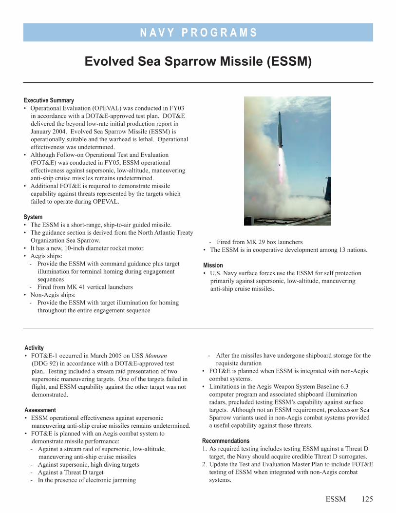
N A V Y P R O G R A M S
Executive Summary• Operational Evaluation (OPEVAL) was conducted in FY03
in accordance with a DOT&E-approved test plan. DOT&E delivered the beyond low-rate initial production report in January 2004. Evolved Sea Sparrow Missile (ESSM) is operationally suitable and the warhead is lethal. Operational effectiveness was undetermined.
• Although Follow-on Operational Test and Evaluation (FOT&E) was conducted in FY05, ESSM operational effectiveness against supersonic, low-altitude, maneuvering anti-ship cruise missiles remains undetermined.
• Additional FOT&E is required to demonstrate missile capability against threats represented by the targets which failed to operate during OPEVAL.
System• The ESSM is a short-range, ship-to-air guided missile.• The guidance section is derived from the North Atlantic Treaty
Organization Sea Sparrow.• It has a new, 10-inch diameter rocket motor.• Aegis ships:
- Provide the ESSM with command guidance plus target illumination for terminal homing during engagement sequences
- Fired from MK 41 vertical launchers• Non-Aegis ships:
- Provide the ESSM with target illumination for homing throughout the entire engagement sequence
Evolved Sea Sparrow Missile (ESSM)
- Fired from MK 29 box launchers• The ESSM is in cooperative development among 13 nations.
Mission• U.S. Navy surface forces use the ESSM for self protection
primarily against supersonic, low-altitude, maneuvering anti-ship cruise missiles.
- After the missiles have undergone shipboard storage for the requisite duration
• FOT&E is planned when ESSM is integrated with non-Aegis combat systems.
• Limitations in the Aegis Weapon System Baseline 6.3 computer program and associated shipboard illumination radars, precluded testing ESSM’s capability against surface targets. Although not an ESSM requirement, predecessor Sea Sparrow variants used in non-Aegis combat systems provided a useful capability against those threats.
Recommendations 1. As required testing includes testing ESSM against a Threat D
target, the Navy should acquire credible Threat D surrogates.2. Update the Test and Evaluation Master Plan to include FOT&E
testing of ESSM when integrated with non-Aegis combat systems.
Activity• FOT&E-1 occurred in March 2005 on USS Momsen
(DDG 92) in accordance with a DOT&E-approved test plan. Testing included a stream raid presentation of two supersonic maneuvering targets. One of the targets failed in flight, and ESSM capability against the other target was not demonstrated.
Assessment• ESSM operational effectiveness against supersonic
maneuvering anti-ship cruise missiles remains undetermined.• FOT&E is planned with an Aegis combat system to
demonstrate missile performance:- Against a stream raid of supersonic, low-altitude,
maneuvering anti-ship cruise missiles- Against supersonic, high diving targets- Against a Threat D target- In the presence of electronic jamming
ESSM 125

N A V Y P R O G R A M S
126
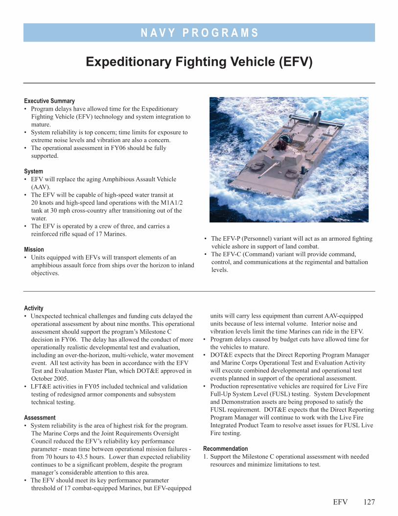
N A V Y P R O G R A M S
• The EFV-P (Personnel) variant will act as an armored fighting vehicle ashore in support of land combat.
• The EFV-C (Command) variant will provide command, control, and communications at the regimental and battalion levels.
Executive Summary• Program delays have allowed time for the Expeditionary
Fighting Vehicle (EFV) technology and system integration to mature.
• System reliability is top concern; time limits for exposure to extreme noise levels and vibration are also a concern.
• The operational assessment in FY06 should be fully supported.
System• EFV will replace the aging Amphibious Assault Vehicle
(AAV).• The EFV will be capable of high-speed water transit at
20 knots and high-speed land operations with the M1A1/2 tank at 30 mph cross-country after transitioning out of the water.
• The EFV is operated by a crew of three, and carries a reinforced rifle squad of 17 Marines.
Mission• Units equipped with EFVs will transport elements of an
amphibious assault force from ships over the horizon to inland objectives.
Expeditionary Fighting Vehicle (EFV)
units will carry less equipment than current AAV-equipped units because of less internal volume. Interior noise and vibration levels limit the time Marines can ride in the EFV.
• Program delays caused by budget cuts have allowed time for the vehicles to mature.
• DOT&E expects that the Direct Reporting Program Manager and Marine Corps Operational Test and Evaluation Activity will execute combined developmental and operational test events planned in support of the operational assessment.
• Production representative vehicles are required for Live Fire Full-Up System Level (FUSL) testing. System Development and Demonstration assets are being proposed to satisfy the FUSL requirement. DOT&E expects that the Direct Reporting Program Manager will continue to work with the Live Fire Integrated Product Team to resolve asset issues for FUSL Live Fire testing.
Recommendation1. Support the Milestone C operational assessment with needed
resources and minimize limitations to test.
Activity• Unexpected technical challenges and funding cuts delayed the
operational assessment by about nine months. This operational assessment should support the program’s Milestone C decision in FY06. The delay has allowed the conduct of more operationally realistic developmental test and evaluation, including an over-the-horizon, multi-vehicle, water movement event. All test activity has been in accordance with the EFV Test and Evaluation Master Plan, which DOT&E approved in October 2005.
• LFT&E activities in FY05 included technical and validation testing of redesigned armor components and subsystem technical testing.
Assessment• System reliability is the area of highest risk for the program.
The Marine Corps and the Joint Requirements Oversight Council reduced the EFV’s reliability key performance parameter - mean time between operational mission failures - from 70 hours to 43.5 hours. Lower than expected reliability continues to be a significant problem, despite the program manager’s considerable attention to this area.
• The EFV should meet its key performance parameter threshold of 17 combat-equipped Marines, but EFV-equipped
EFV 127

N A V Y P R O G R A M S
128
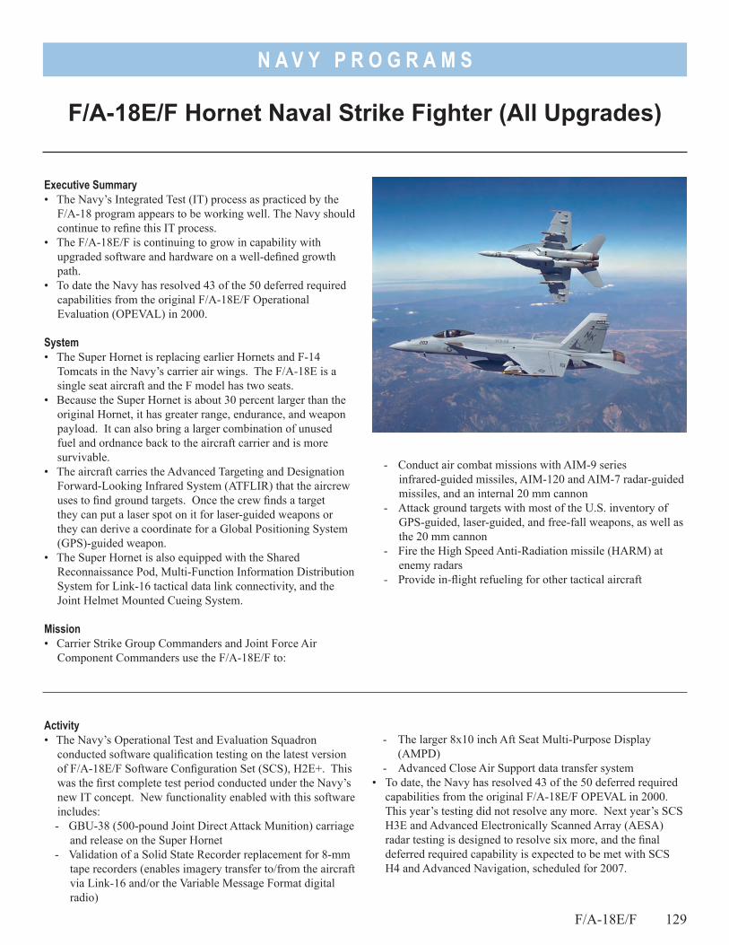
N A V Y P R O G R A M S
- Conduct air combat missions with AIM-9 series infrared-guided missiles, AIM-120 and AIM-7 radar-guided missiles, and an internal 20 mm cannon
- Attack ground targets with most of the U.S. inventory of GPS-guided, laser-guided, and free-fall weapons, as well as the 20 mm cannon
- Fire the High Speed Anti-Radiation missile (HARM) at enemy radars
- Provide in-flight refueling for other tactical aircraft
F/A-18E/F Hornet Naval Strike Fighter (All Upgrades)
Executive Summary• The Navy’s Integrated Test (IT) process as practiced by the
F/A-18 program appears to be working well. The Navy should continue to refine this IT process.
• The F/A-18E/F is continuing to grow in capability with upgraded software and hardware on a well-defined growth path.
• To date the Navy has resolved 43 of the 50 deferred required capabilities from the original F/A-18E/F Operational Evaluation (OPEVAL) in 2000.
System• The Super Hornet is replacing earlier Hornets and F-14
Tomcats in the Navy’s carrier air wings. The F/A-18E is a single seat aircraft and the F model has two seats.
• Because the Super Hornet is about 30 percent larger than the original Hornet, it has greater range, endurance, and weapon payload. It can also bring a larger combination of unused fuel and ordnance back to the aircraft carrier and is more survivable.
• The aircraft carries the Advanced Targeting and Designation Forward-Looking Infrared System (ATFLIR) that the aircrew uses to find ground targets. Once the crew finds a target they can put a laser spot on it for laser-guided weapons or they can derive a coordinate for a Global Positioning System (GPS)-guided weapon.
• The Super Hornet is also equipped with the Shared Reconnaissance Pod, Multi-Function Information Distribution System for Link-16 tactical data link connectivity, and the Joint Helmet Mounted Cueing System.
Mission• Carrier Strike Group Commanders and Joint Force Air
Component Commanders use the F/A-18E/F to:
Activity• The Navy’s Operational Test and Evaluation Squadron
conducted software qualification testing on the latest version of F/A-18E/F Software Configuration Set (SCS), H2E+. This was the first complete test period conducted under the Navy’s new IT concept. New functionality enabled with this software includes:- GBU-38 (500-pound Joint Direct Attack Munition) carriage
and release on the Super Hornet- Validation of a Solid State Recorder replacement for 8-mm
tape recorders (enables imagery transfer to/from the aircraft via Link-16 and/or the Variable Message Format digital radio)
- The larger 8x10 inch Aft Seat Multi-Purpose Display (AMPD)
- Advanced Close Air Support data transfer system• To date, the Navy has resolved 43 of the 50 deferred required
capabilities from the original F/A-18E/F OPEVAL in 2000. This year’s testing did not resolve any more. Next year’s SCS H3E and Advanced Electronically Scanned Array (AESA) radar testing is designed to resolve six more, and the final deferred required capability is expected to be met with SCS H4 and Advanced Navigation, scheduled for 2007.
F/A-18E/F 129
N A V Y P R O G R A M S
• The Super Hornet program continued developmental testing of Block 2 aircraft that primarily incorporates the AESA radar. AESA radar is reported on separately in this annual report.
Assessment• Operational testing for SCS H2E+ was adequate. • The Navy’s Integrated Test concept as practiced by the F/A-18
program, using DOT&E-approved Test and Evaluation Master Plans and operational test plans as an integral part, appears to reduce redundant testing. However, IT is not yet codified for use by all Navy programs. In using the IT process, the Navy’s developmental and operational test squadrons at China Lake, California, have been able to work around manpower
130 F/A-18E/F
shortages and occasional poor aircraft availability through the synergy of sharing both people and assets on an “as needed” basis.
RecommendationsThe Navy should:1. Continue to refine and codify the IT process until it has an
approved framework that other Navy programs can use in future testing.
2. Strengthen efforts to relieve the shortages of trained personnel at the test squadrons at China Lake, California.
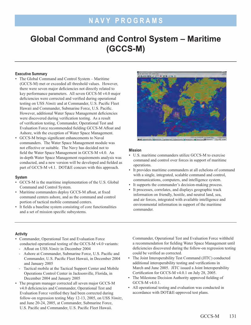
N A V Y P R O G R A M S
Mission• U.S. maritime commanders utilize GCCS-M to exercise
command and control over forces in support of maritime operations.
• It provides maritime commanders at all echelons of command with a single, integrated, scalable command and control, communications, computers, and intelligence system.
• It supports the commander’s decision-making process.• It processes, correlates, and displays geographic track
information on friendly, hostile, and neutral land, sea, and air forces, integrated with available intelligence and environmental information in support of the maritime commander.
Global Command and Control System – Maritime (GCCS-M)
Executive Summary• The Global Command and Control System – Maritime
(GCCS-M) met or exceeded all threshold values. However, there were seven major deficiencies not directly related to key performance parameters. All seven GCCS-M v4.0 major deficiencies were corrected and verified during operational testing on USS Nimitz and at Commander, U.S. Pacific Fleet Hawaii and Commander, Submarine Force, U.S. Pacific. However, additional Water Space Management deficiencies were discovered during verification testing. As a result of verification testing, Commander, Operational Test and Evaluation Force recommended fielding GCCS-M Afloat and Ashore, with the exception of Water Space Management.
• GCCS-M brings significant enhancements to Naval commanders. The Water Space Management module was not effective or suitable. The Navy has decided not to field the Water Space Management in GCCS-M v4.0. An in-depth Water Space Management requirements analysis was conducted, and a new version will be developed and fielded as part of GCCS-M v4.1. DOT&E concurs with this approach.
System• GCCS-M is the maritime implementation of the U.S. Global
Command and Control System. • Maritime commanders deploy GCCS-M afloat, at fixed
command centers ashore, and as the command and control portion of tactical mobile command centers.
• It fields a baseline system consisting of core functionalities and a set of mission specific subsystems.
Commander, Operational Test and Evaluation Force withheld a recommendation for fielding Water Space Management until deficiencies discovered during the follow-on regression testing could be verified as corrected.
• The Joint Interoperability Test Command (JITC) conducted additional interoperability testing and verifications in March and June 2005. JITC issued a Joint Interoperability Certification for GCCS-M v4.0.1 on July 28, 2005.
• The Milestone Decision Authority approved fielding of GCCS-M v4.0.1.
• All operational testing and evaluation was conducted in accordance with DOT&E-approved test plans.
Activity• Commander, Operational Test and Evaluation Force
conducted operational testing of the GCCS-M v4.0 variants:- Afloat on USS Nimitz in December 2004- Ashore at Commander, Submarine Force, U.S. Pacific and
Commander, U.S. Pacific Fleet Hawaii, in December 2004 and January 2005
- Tactical mobile at the Tactical Support Center and Mobile Operations Control Center in Jacksonville, Florida, in December 2004 and January 2005
• The program manager corrected all seven major GCCS-M v4.0 deficiencies and Commander, Operational Test and Evaluation Force verified they had been corrected during follow-on regression testing May 12-13, 2005, on USS Nimitz, and June 20-24, 2005, at Commander, Submarine Force, U.S. Pacific and Commander, U.S. Pacific Fleet Hawaii.
GCCS-M 131
N A V Y P R O G R A M S
AssessmentThe operational test of GCCS-M v4.0 was adequate, with minor exceptions: • Afloat platforms:
- While formal training was adequate and well received, the test did not include the Expeditionary Decision Support System, a system normally used on amphibious platforms. The Navy will test the Expeditionary Decision Support System in the latter part of 2006.
• For command and control centers ashore:- The Water Space Management module used in controlling
submarine operations was not ready for test at Commander, Submarine Force, U.S. Pacific. The program office is continuing to improve training and to make corrections to this module.
• For Tactical Mobile:- GCCS-M functionality worked well for the Tactical
Support Center/Mobile Operations Control Center. Testing was adequate, and included assessment of the two modules where USS Nimitz users lacked training. A Joint Mobile Ashore Support Terminal unit was not available to participate in the GCCS-M v4.0 operational test and evaluation. A Joint Mobile Ashore Support Terminal test with GCCS-M v4.0.1 is planned for 3QFY06.
• During the operational test, the U.S. Navy Fleet Information Warfare Center assessed information assurance vulnerabilities
of GCCS-M v4.0. The Fleet Information Warfare Center was unable to successfully attack and exploit any vulnerability; however, all sites were deficient in auditing, backup, and security lockdown procedures. This is a training issue.
• GCCS-M v4.0.1 met its threshold interoperability key performance parameter, and JITC certified it for Joint use.- The afloat variant of GCCS-M v4.0.1 is operationally
effective and suitable.- The ashore variant of GCCS-M v4.0.1 is effective and
suitable with the exception of the Water Space Management module. Naval forces will continue using the previous version of Water Space Management until a new version is tested and fielded as part of GCCS-M v4.1.
- The tactical/mobile variant of GCCS-M v4.0.1 is effective and suitable.
RecommendationsThe Navy should:1. Monitor corrections and retest the Water Space Management
module to satisfy maritime commander’s requirements.2. Conduct more training on information assurance and
adherence to DoD security guidelines.
132 GCCS-M
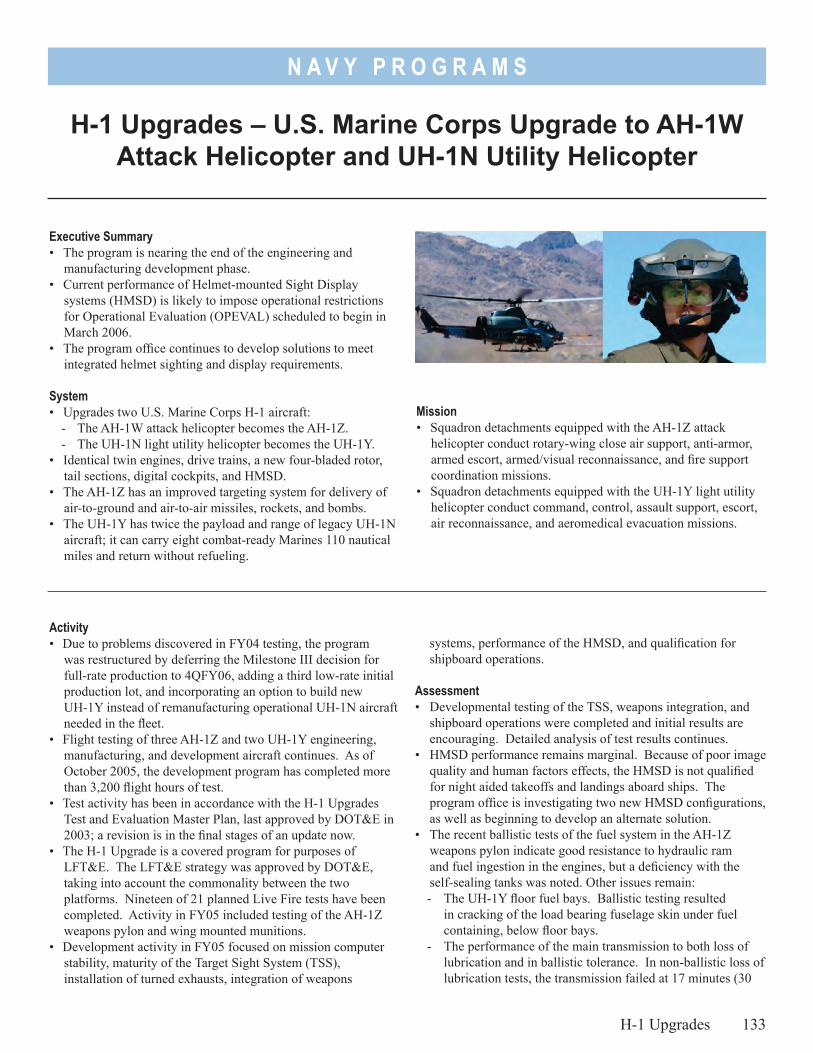
N A V Y P R O G R A M S
Mission• Squadron detachments equipped with the AH-1Z attack
helicopter conduct rotary-wing close air support, anti-armor, armed escort, armed/visual reconnaissance, and fire support coordination missions.
• Squadron detachments equipped with the UH-1Y light utility helicopter conduct command, control, assault support, escort, air reconnaissance, and aeromedical evacuation missions.
H-1 Upgrades – U.S. Marine Corps Upgrade to AH-1W Attack Helicopter and UH-1N Utility Helicopter
Executive Summary• The program is nearing the end of the engineering and
manufacturing development phase.• Current performance of Helmet-mounted Sight Display
systems (HMSD) is likely to impose operational restrictions for Operational Evaluation (OPEVAL) scheduled to begin in March 2006.
• The program office continues to develop solutions to meet integrated helmet sighting and display requirements.
System• Upgrades two U.S. Marine Corps H-1 aircraft:
- The AH-1W attack helicopter becomes the AH-1Z. - The UH-1N light utility helicopter becomes the UH-1Y.
• Identical twin engines, drive trains, a new four-bladed rotor, tail sections, digital cockpits, and HMSD.
• The AH-1Z has an improved targeting system for delivery of air-to-ground and air-to-air missiles, rockets, and bombs.
• The UH-1Y has twice the payload and range of legacy UH-1N aircraft; it can carry eight combat-ready Marines 110 nautical miles and return without refueling.
Activity• Due to problems discovered in FY04 testing, the program
was restructured by deferring the Milestone III decision for full-rate production to 4QFY06, adding a third low-rate initial production lot, and incorporating an option to build new UH-1Y instead of remanufacturing operational UH-1N aircraft needed in the fleet.
• Flight testing of three AH-1Z and two UH-1Y engineering, manufacturing, and development aircraft continues. As of October 2005, the development program has completed more than 3,200 flight hours of test.
• Test activity has been in accordance with the H-1 Upgrades Test and Evaluation Master Plan, last approved by DOT&E in 2003; a revision is in the final stages of an update now.
• The H-1 Upgrade is a covered program for purposes of LFT&E. The LFT&E strategy was approved by DOT&E, taking into account the commonality between the two platforms. Nineteen of 21 planned Live Fire tests have been completed. Activity in FY05 included testing of the AH-1Z weapons pylon and wing mounted munitions.
• Development activity in FY05 focused on mission computer stability, maturity of the Target Sight System (TSS), installation of turned exhausts, integration of weapons
systems, performance of the HMSD, and qualification for shipboard operations.
Assessment• Developmental testing of the TSS, weapons integration, and
shipboard operations were completed and initial results are encouraging. Detailed analysis of test results continues.
• HMSD performance remains marginal. Because of poor image quality and human factors effects, the HMSD is not qualified for night aided takeoffs and landings aboard ships. The program office is investigating two new HMSD configurations, as well as beginning to develop an alternate solution.
• The recent ballistic tests of the fuel system in the AH-1Z weapons pylon indicate good resistance to hydraulic ram and fuel ingestion in the engines, but a deficiency with the self-sealing tanks was noted. Other issues remain:- The UH-1Y floor fuel bays. Ballistic testing resulted
in cracking of the load bearing fuselage skin under fuel containing, below floor bays.
- The performance of the main transmission to both loss of lubrication and in ballistic tolerance. In non-ballistic loss of lubrication tests, the transmission failed at 17 minutes (30
H-1 Upgrades 133
N A V Y P R O G R A M S
minutes required). Against ballistic threats, results indicate the transmission is quite fragile, with severe case cracking and rapid loss of lubrication.
- The canopy mounted AH-1Z armor. The control stick on the AH-1Z was moved to a new side location, necessitating relocating cockpit armor to the canopy doors. Potential ballistic issues with canopy-mounted armor will remain unaddressed until full-up system-level testing in 2QFY06.
• OPEVAL is scheduled to begin in March 2006 with operational restrictions likely stemming from HMSD deficiencies. These
134 H-1 Upgrades
restrictions include low-light operations aided by night vision devices onboard L-class amphibious ships.
RecommendationsThe program:1. Should continue its vigorous pursuit to fix HMSD deficiencies.2. Should continue its developmental testing of survivability
through the additional testing of infrared signature, radar cross section, and aircraft survivability equipment.
3. Must have appropriate publications available for OPEVAL.
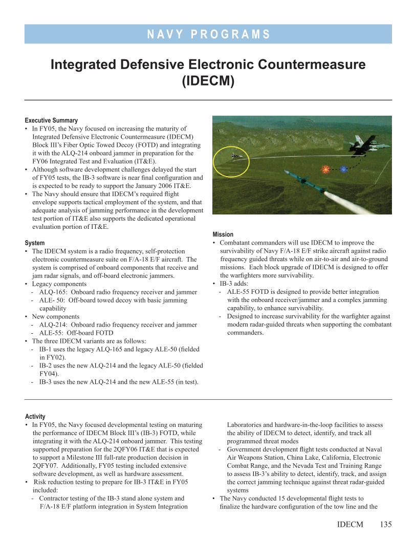
N A V Y P R O G R A M S
Mission• Combatant commanders will use IDECM to improve the
survivability of Navy F/A-18 E/F strike aircraft against radio frequency guided threats while on air-to-air and air-to-ground missions. Each block upgrade of IDECM is designed to offer the warfighters more survivability.
• IB-3 adds: - ALE-55 FOTD is designed to provide better integration
with the onboard receiver/jammer and a complex jamming capability, to enhance survivability.
- Designed to increase survivability for the warfighter against modern radar-guided threats when supporting the combatant commanders.
Integrated Defensive Electronic Countermeasure (IDECM)
Executive Summary• In FY05, the Navy focused on increasing the maturity of
Integrated Defensive Electronic Countermeasure (IDECM) Block III’s Fiber Optic Towed Decoy (FOTD) and integrating it with the ALQ-214 onboard jammer in preparation for the FY06 Integrated Test and Evaluation (IT&E).
• Although software development challenges delayed the start of FY05 tests, the IB-3 software is near final configuration and is expected to be ready to support the January 2006 IT&E.
• The Navy should ensure that IDECM’s required flight envelope supports tactical employment of the system, and that adequate analysis of jamming performance in the development test portion of IT&E also supports the dedicated operational evaluation portion of IT&E.
System• The IDECM system is a radio frequency, self-protection
electronic countermeasure suite on F/A-18 E/F aircraft. The system is comprised of onboard components that receive and jam radar signals, and off-board electronic jammers.
• Legacy components- ALQ-165: Onboard radio frequency receiver and jammer- ALE- 50: Off-board towed decoy with basic jamming
capability• New components
- ALQ-214: Onboard radio frequency receiver and jammer- ALE-55: Off-board FOTD
• The three IDECM variants are as follows:- IB-1 uses the legacy ALQ-165 and legacy ALE-50 (fielded
in FY02).- IB-2 uses the new ALQ-214 and the legacy ALE-50 (fielded
FY04).- IB-3 uses the new ALQ-214 and the new ALE-55 (in test).
Activity• In FY05, the Navy focused developmental testing on maturing
the performance of IDECM Block III’s (IB-3) FOTD, while integrating it with the ALQ-214 onboard jammer. This testing supported preparation for the 2QFY06 IT&E that is expected to support a Milestone III full-rate production decision in 2QFY07. Additionally, FY05 testing included extensive software development, as well as hardware assessment.
• Risk reduction testing to prepare for IB-3 IT&E in FY05 included: - Contractor testing of the IB-3 stand alone system and
F/A-18 E/F platform integration in System Integration
Laboratories and hardware-in-the-loop facilities to assess the ability of IDECM to detect, identify, and track all programmed threat modes
- Government development flight tests conducted at Naval Air Weapons Station, China Lake, California, Electronic Combat Range, and the Nevada Test and Training Range to assess IB-3’s ability to detect, identify, track, and assign the correct jamming technique against threat radar-guided systems
• The Navy conducted 15 developmental flight tests to finalize the hardware configuration of the tow line and the
IDECM 135
N A V Y P R O G R A M S
136 IDECM
FOTD. This testing at the Naval Air Station, Patuxent River, Maryland, also assessed IB-3 across its required flight envelope.
• A Joint test resource development verification and validation effort by the Navy and Air Force focused on the creation of a modern radar threat using a complex guidance system for IDECM testing. Since this resource will not be available for IT&E in early FY06, the Navy plans to use a science and technology system called the Airborne Seeker Test Bed.
• The Navy prepared a revised Test and Evaluation Master Plan, planned for approval in early FY06, to support the IB-3 final development testing and operational evaluation that make up the IT&E.
Assessment• The IB-3 hardware configuration is mature and near its final
configuration for the FY06 IT&E. • The software is approaching a final configuration demonstrated
by a significant reduction in the number of new software problems identified.
• The FY05 government flight tests to date indicate that IB-3 is progressing towards clearance for the entire required flight envelope.
• Although only 53 percent of key threats are available for high quality testing due to test resource availability on open air ranges and in hardware-in-the-loop, the four main categories of threats are all adequately represented.
• The primary test resource limitation is the lack of a modern threat using a complex guidance system. This is needed to
support full quantitative assessment of the primary IB-3 key performance parameter. The Navy’s alternate resource plan, utilizing the Airborne Seeker Test Bed, is adequate to assess if the IB-3 works against this modern system, but how well it works will need to be assessed qualitatively. Test resources for threats using more traditional guidance systems are available and will be utilized in the IT&E.
• The draft Test and Evaluation Master Plan includes a critical operational test readiness review prior to the start of IT&E, required joint interoperability testing, and is adequate to support IB-3 operational testing and evaluation.
Recommendations1. The Navy should provide adequate analysis of the system’s
jamming performance during the development test portion of the IT&E to support the dedicated operational evaluation portion.
2. The Navy should ensure joint interoperability testing supports assessment of the IB-3 reaction to and impact on friendly radar-guided surface-to-air and air-to-air systems, as well as command and control systems.
3. The Services should continue to improve the level of threat system fidelity needed to quantitatively assess the end-to-end (i.e. detect to jam) effectiveness of self-protection suites against all radar threat system categories.
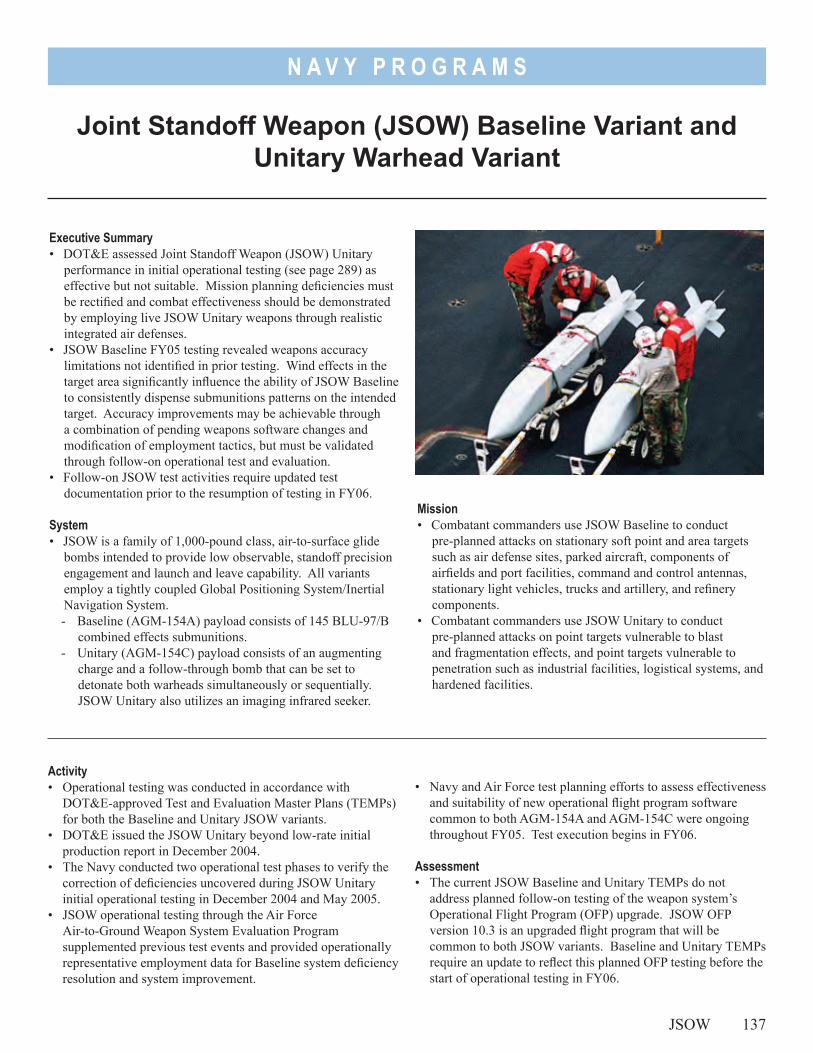
N A V Y P R O G R A M S
Mission• Combatant commanders use JSOW Baseline to conduct
pre-planned attacks on stationary soft point and area targets such as air defense sites, parked aircraft, components of airfields and port facilities, command and control antennas, stationary light vehicles, trucks and artillery, and refinery components.
• Combatant commanders use JSOW Unitary to conduct pre-planned attacks on point targets vulnerable to blast and fragmentation effects, and point targets vulnerable to penetration such as industrial facilities, logistical systems, and hardened facilities.
Executive Summary• DOT&E assessed Joint Standoff Weapon (JSOW) Unitary
performance in initial operational testing (see page 289) as effective but not suitable. Mission planning deficiencies must be rectified and combat effectiveness should be demonstrated by employing live JSOW Unitary weapons through realistic integrated air defenses.
• JSOW Baseline FY05 testing revealed weapons accuracy limitations not identified in prior testing. Wind effects in the target area significantly influence the ability of JSOW Baseline to consistently dispense submunitions patterns on the intended target. Accuracy improvements may be achievable through a combination of pending weapons software changes and modification of employment tactics, but must be validated through follow-on operational test and evaluation.
• Follow-on JSOW test activities require updated test documentation prior to the resumption of testing in FY06.
System• JSOW is a family of 1,000-pound class, air-to-surface glide
bombs intended to provide low observable, standoff precision engagement and launch and leave capability. All variants employ a tightly coupled Global Positioning System/Inertial Navigation System.- Baseline (AGM-154A) payload consists of 145 BLU-97/B
combined effects submunitions.- Unitary (AGM-154C) payload consists of an augmenting
charge and a follow-through bomb that can be set to detonate both warheads simultaneously or sequentially. JSOW Unitary also utilizes an imaging infrared seeker.
• Navy and Air Force test planning efforts to assess effectiveness and suitability of new operational flight program software common to both AGM-154A and AGM-154C were ongoing throughout FY05. Test execution begins in FY06.
Assessment• The current JSOW Baseline and Unitary TEMPs do not
address planned follow-on testing of the weapon system’s Operational Flight Program (OFP) upgrade. JSOW OFP version 10.3 is an upgraded flight program that will be common to both JSOW variants. Baseline and Unitary TEMPs require an update to reflect this planned OFP testing before the start of operational testing in FY06.
JSOW 137
Joint Standoff Weapon (JSOW) Baseline Variant and Unitary Warhead Variant
Activity• Operational testing was conducted in accordance with
DOT&E-approved Test and Evaluation Master Plans (TEMPs) for both the Baseline and Unitary JSOW variants.
• DOT&E issued the JSOW Unitary beyond low-rate initial production report in December 2004.
• The Navy conducted two operational test phases to verify the correction of deficiencies uncovered during JSOW Unitary initial operational testing in December 2004 and May 2005.
• JSOW operational testing through the Air Force Air-to-Ground Weapon System Evaluation Program supplemented previous test events and provided operationally representative employment data for Baseline system deficiency resolution and system improvement.
N A V Y P R O G R A M S
JSOW Baseline:• AGM-154A testing revealed that the weapon does not achieve
consistent payload placement on the desired target in the presence of winds in the target area. Modeling and simulation suggest that pending OFP software changes and employment of multiple weapons from different axes may offer improved capabilities, but this has not been validated by operational testing.
• JSOW Baseline employment from F-16 BRU-57 smart rack carriage has yet to be accomplished in support of TEMP and Joint Operational Requirements Document specifications.
JSOW Unitary:• DOT&E’s JSOW Unitary beyond low-rate initial production
report found that the system is effective but not suitable.• JSOW Unitary’s mission planning system does not
consistently complete the computational process nor allow the user to plan weapon impact parameters. Furthermore, target images cannot be transferred into the system during land-based operations, and JSOW Unitary cannot accept the mission planning-developed fuze delay setting from the aircraft data transfer device.
• Improvements were observed in JSOW Unitary mission planning processes within the limited scope of subsequent testing, but a definitive assessment remains to be verified in planned FY06 testing.
• JSOW Unitary survivability models have not been validated by actual weapons delivery in the appropriate threat environment.
Recommendations1. Update the JSOW TEMPs and provide a new or revised test
plan prior to the resumption of JSOW FY06 operational testing.
2. Conduct follow-on operational testing of JSOW Baseline to characterize the weapon’s ability to consistently place the payload on a target in the presence of winds. Testing should evaluate pending software change capabilities and employment tactics, techniques, and procedures that may lead to improved weapons effectiveness.
3. Conduct follow-on operational testing of JSOW Baseline weapons released from a BRU-57 smart rack on an F-16 aircraft to confirm Baseline weapon system capability with the new F-16 weapon carriage.
4. For JSOW Unitary to be fully effective and suitable the Navy should:- Improve mission planning to: enable the mission planning
system to complete mission planning more reliably, quickly, and easily; permit impact parameter planning across the spectrum of JSOW-C targets; and ensure availability of imagery with accurate coordinates for automated planning activities
- Characterize lethality by determining precise velocity decay of the follow-through bomb upon penetration of a hardened target exterior, identify correct fuze settings for moderately hardened targets, and enable fuze setting transfer to the F/A-18 aircraft
- Confirm combat effectiveness, suitability, and survivability through operational testing of live JSOW Unitary weapons flown through realistic integrated air defenses
138 JSOW
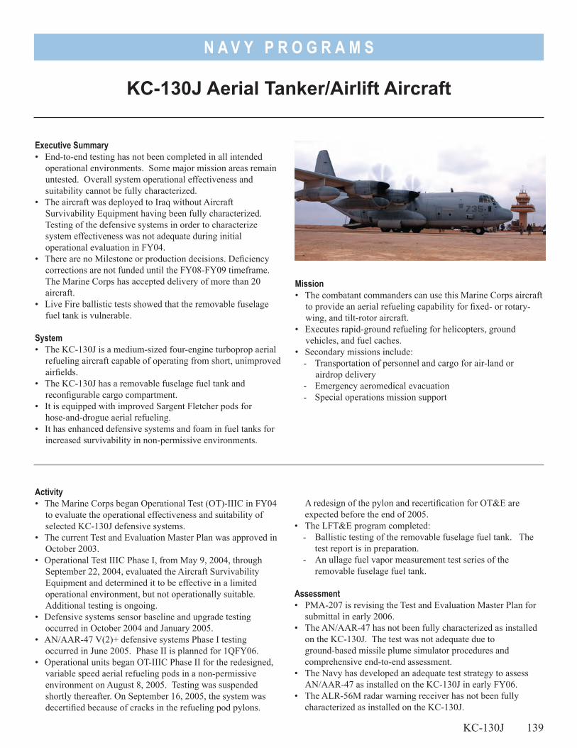
N A V Y P R O G R A M S
Mission• The combatant commanders can use this Marine Corps aircraft
to provide an aerial refueling capability for fixed- or rotary-wing, and tilt-rotor aircraft.
• Executes rapid-ground refueling for helicopters, ground vehicles, and fuel caches.
• Secondary missions include:- Transportation of personnel and cargo for air-land or
airdrop delivery- Emergency aeromedical evacuation- Special operations mission support
KC-130J Aerial Tanker/Airlift Aircraft
Executive Summary• End-to-end testing has not been completed in all intended
operational environments. Some major mission areas remain untested. Overall system operational effectiveness and suitability cannot be fully characterized.
• The aircraft was deployed to Iraq without Aircraft Survivability Equipment having been fully characterized. Testing of the defensive systems in order to characterize system effectiveness was not adequate during initial operational evaluation in FY04.
• There are no Milestone or production decisions. Deficiency corrections are not funded until the FY08-FY09 timeframe. The Marine Corps has accepted delivery of more than 20 aircraft.
• Live Fire ballistic tests showed that the removable fuselage fuel tank is vulnerable.
System• The KC-130J is a medium-sized four-engine turboprop aerial
refueling aircraft capable of operating from short, unimproved airfields.
• The KC-130J has a removable fuselage fuel tank and reconfigurable cargo compartment.
• It is equipped with improved Sargent Fletcher pods for hose-and-drogue aerial refueling.
• It has enhanced defensive systems and foam in fuel tanks for increased survivability in non-permissive environments.
Activity• The Marine Corps began Operational Test (OT)-IIIC in FY04
to evaluate the operational effectiveness and suitability of selected KC-130J defensive systems.
• The current Test and Evaluation Master Plan was approved in October 2003.
• Operational Test IIIC Phase I, from May 9, 2004, through September 22, 2004, evaluated the Aircraft Survivability Equipment and determined it to be effective in a limited operational environment, but not operationally suitable. Additional testing is ongoing.
• Defensive systems sensor baseline and upgrade testing occurred in October 2004 and January 2005.
• AN/AAR-47 V(2)+ defensive systems Phase I testing occurred in June 2005. Phase II is planned for 1QFY06.
• Operational units began OT-IIIC Phase II for the redesigned, variable speed aerial refueling pods in a non-permissive environment on August 8, 2005. Testing was suspended shortly thereafter. On September 16, 2005, the system was decertified because of cracks in the refueling pod pylons.
A redesign of the pylon and recertification for OT&E are expected before the end of 2005.
• The LFT&E program completed:- Ballistic testing of the removable fuselage fuel tank. The
test report is in preparation.- An ullage fuel vapor measurement test series of the
removable fuselage fuel tank.
Assessment• PMA-207 is revising the Test and Evaluation Master Plan for
submittal in early 2006.• The AN/AAR-47 has not been fully characterized as installed
on the KC-130J. The test was not adequate due to ground-based missile plume simulator procedures and
comprehensive end-to-end assessment.• The Navy has developed an adequate test strategy to assess
AN/AAR-47 as installed on the KC-130J in early FY06.• The ALR-56M radar warning receiver has not been fully
characterized as installed on the KC-130J.
KC-130J 139
N A V Y P R O G R A M S
• The KC-130J is not suitable due to deficiencies in documentation, training, and false alarm indications within the built-in test system. These deficiencies will be re-evaluated in the next phase of operational test.
• Live Fire testing demonstrated that the removable fuselage fuel tank is vulnerable to ballistic threats.
Recommendations1. The Navy should include funding and physical resources for
test events throughout FY06 and FY07 on its next revision of the Test and Evaluation Master Plan.
140 KC-130J
2. Sufficient developmental testing and evaluation should be conducted on the re-designed refueling pod pylons before the system is re-certified to begin OT-IIIC Phase II.
3. The Navy must execute the AN/AAR-47 testing as planned in early FY06, and develop plans for testing of the ALR-56M in an operationally realistic environment.
4. The Navy should consider ullage inerting or ballistic foam to reduce or eliminate the ballistic vulnerability of the removable fuselage fuel tank.
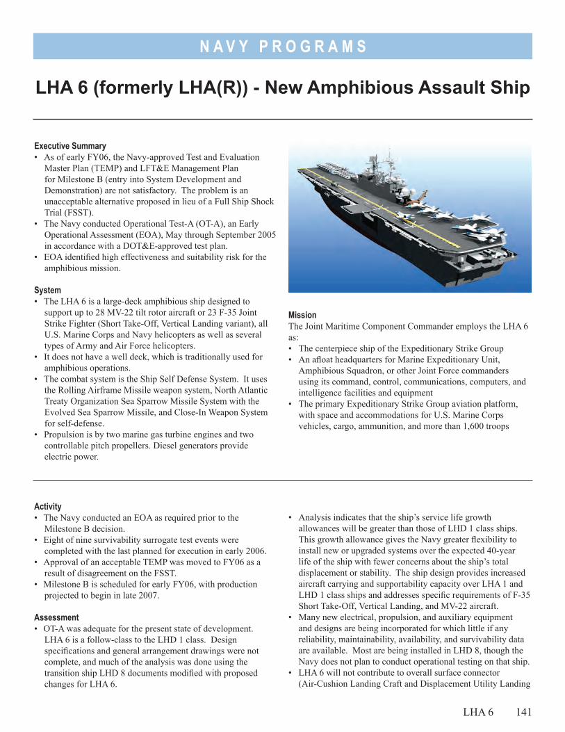
N A V Y P R O G R A M S
LHA 6 (formerly LHA(R)) - New Amphibious Assault Ship
Executive Summary• As of early FY06, the Navy-approved Test and Evaluation
Master Plan (TEMP) and LFT&E Management Plan for Milestone B (entry into System Development and Demonstration) are not satisfactory. The problem is an unacceptable alternative proposed in lieu of a Full Ship Shock Trial (FSST).
• The Navy conducted Operational Test-A (OT-A), an Early Operational Assessment (EOA), May through September 2005 in accordance with a DOT&E-approved test plan.
• EOA identified high effectiveness and suitability risk for the amphibious mission.
System• The LHA 6 is a large-deck amphibious ship designed to
support up to 28 MV-22 tilt rotor aircraft or 23 F-35 Joint Strike Fighter (Short Take-Off, Vertical Landing variant), all U.S. Marine Corps and Navy helicopters as well as several types of Army and Air Force helicopters.
• It does not have a well deck, which is traditionally used for amphibious operations.
• The combat system is the Ship Self Defense System. It uses the Rolling Airframe Missile weapon system, North Atlantic Treaty Organization Sea Sparrow Missile System with the Evolved Sea Sparrow Missile, and Close-In Weapon System for self-defense.
• Propulsion is by two marine gas turbine engines and two controllable pitch propellers. Diesel generators provide electric power.
Activity• The Navy conducted an EOA as required prior to the
Milestone B decision.• Eight of nine survivability surrogate test events were
completed with the last planned for execution in early 2006.• Approval of an acceptable TEMP was moved to FY06 as a
result of disagreement on the FSST.• Milestone B is scheduled for early FY06, with production
projected to begin in late 2007.
Assessment• OT-A was adequate for the present state of development.
LHA 6 is a follow-class to the LHD 1 class. Design specifications and general arrangement drawings were not complete, and much of the analysis was done using the transition ship LHD 8 documents modified with proposed changes for LHA 6.
LHA 6 141
MissionThe Joint Maritime Component Commander employs the LHA 6 as:• The centerpiece ship of the Expeditionary Strike Group• An afloat headquarters for Marine Expeditionary Unit,
Amphibious Squadron, or other Joint Force commanders using its command, control, communications, computers, and intelligence facilities and equipment
• The primary Expeditionary Strike Group aviation platform, with space and accommodations for U.S. Marine Corps vehicles, cargo, ammunition, and more than 1,600 troops
• Analysis indicates that the ship’s service life growth allowances will be greater than those of LHD 1 class ships. This growth allowance gives the Navy greater flexibility to install new or upgraded systems over the expected 40-year life of the ship with fewer concerns about the ship’s total displacement or stability. The ship design provides increased aircraft carrying and supportability capacity over LHA 1 and LHD 1 class ships and addresses specific requirements of F-35 Short Take-Off, Vertical Landing, and MV-22 aircraft.
• Many new electrical, propulsion, and auxiliary equipment and designs are being incorporated for which little if any reliability, maintainability, availability, and survivability data are available. Most are being installed in LHD 8, though the Navy does not plan to conduct operational testing on that ship.
• LHA 6 will not contribute to overall surface connector (Air-Cushion Landing Craft and Displacement Utility Landing
N A V Y P R O G R A M S
Craft) capability of a three-ship Expeditionary Strike Group like the LHA 1 and LHD 1 class ships. Neither the Navy nor the Marine Corps has presented documented analysis to show how an Expeditionary Strike Group built around LHA 6 will carry out the primary mission of amphibious warfare without an additional well deck.
• As a modification of a legacy ship design, crew and troop habitability features do not compare favorably to other new ship designs and do not comply with current Navy habitability standards.
• The design does not display comparable potential in the context of expeditionary unit level (tactical level) of operations. The principle concern is that during unit level expeditionary operations that exceed the complexity and duration of an “amphibious raid,” LHA(R) is at risk of not being capable of supporting troops ashore. This risk is caused by the reduction of square footage for stowage of major end items including equipment (to include combat and service support vehicles) and supplies, and the limited ability to transport these items ashore. No formal analysis of throughput of major end items from LHA(R) to shore was available to support the OT-A. Specifically, the design studies presented did not adequately consider the “end-to-end” embarkation, debarkation, and back loading process required for LHA(R) to support its Amphibious Warfare mission.
• Analysis by the Navy using a low fidelity modeling and simulation tool (G-SHOCK) alone is not of sufficient fidelity to support foregoing a FSST. Because survivability was elevated to a key performance parameter in a recent change to the Capabilities Development Document, proving LHA 6 can meet Level II (moderate) survivability standards will require more rigorous testing and analysis than has been proposed in lieu of FSST.
• The TEMP includes estimates for the cost of anti-air warfare self defense testing (as directed by DOT&E), but actual funding is tied to the Anti-Air Warfare Self-Defense Test and Evaluation Enterprise Strategy document that is not yet approved by the Navy or DOT&E. The Navy presented separate correspondence expressing commitment to funding the enterprise-wide testing intent. DOT&E supports the Navy’s proposal. Until the enterprise-wide document is approved, operational testing of LHA 6 Anti-Air Warfare self-defense capability is not fully funded.
RecommendationsThe Navy should:1. Ensure adequate OT&E to assess how the amphibious warfare
mission will be conducted from LHA 6. Consider revising current doctrinal publications to account for the unique capabilities and limitations of this design.
2. Conduct detailed analyses of studies that include modeling and simulation efforts to better understand what design adjustments or doctrinal changes should be made to LHA 6 to appropriately accommodate Marine Expeditionary Unit-level amphibious operations. These analyses should also be applied to more clearly define cargo, vehicle, and passenger flow routes throughout the ship to support troop embarkation, debarkation, backload, and weapons safety.
3. Maximize observations of LHD 8 to collect suitability data on new electrical, propulsion, and auxiliary equipment that will be common to LHA 6.
4. Change the TEMP and/or LFT&E management plan to provide a technically sound alternative to the FSST or retain the funded FSST option in the event analysis does not produce an acceptable option.
142 LHA 6
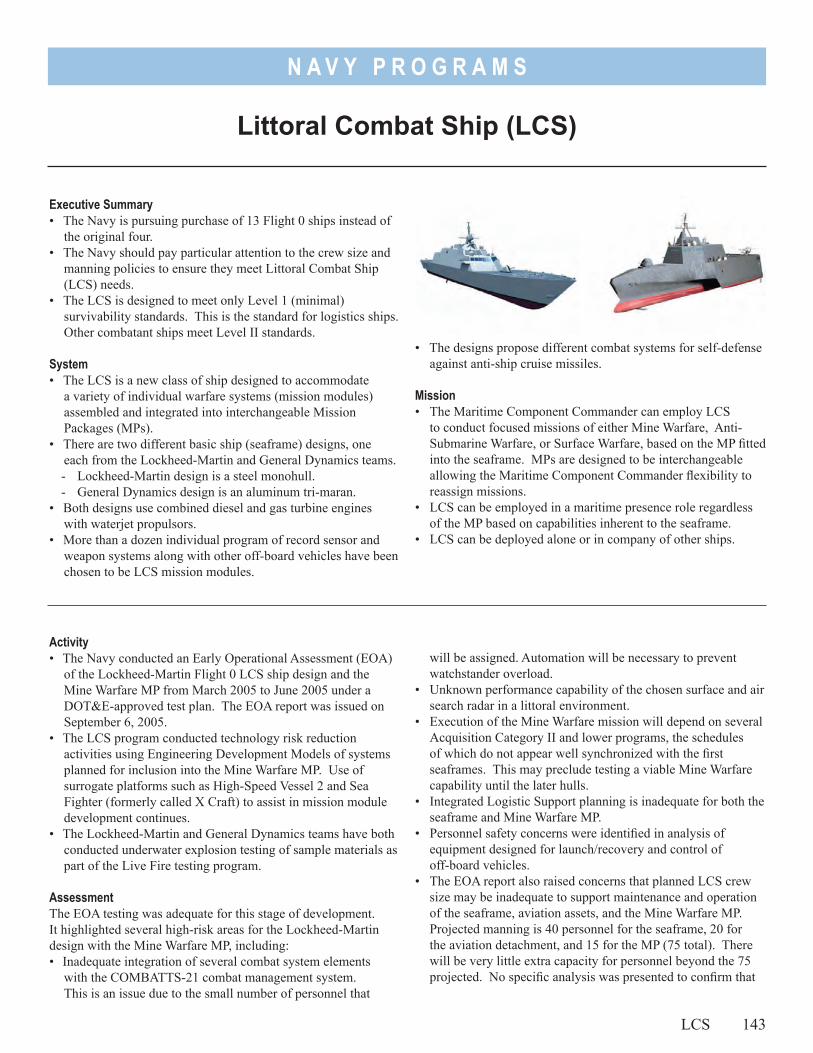
N A V Y P R O G R A M S
Littoral Combat Ship (LCS)
Executive Summary• The Navy is pursuing purchase of 13 Flight 0 ships instead of
the original four.• The Navy should pay particular attention to the crew size and
manning policies to ensure they meet Littoral Combat Ship (LCS) needs.
• The LCS is designed to meet only Level 1 (minimal) survivability standards. This is the standard for logistics ships. Other combatant ships meet Level II standards.
System• The LCS is a new class of ship designed to accommodate
a variety of individual warfare systems (mission modules) assembled and integrated into interchangeable Mission Packages (MPs).
• There are two different basic ship (seaframe) designs, one each from the Lockheed-Martin and General Dynamics teams.- Lockheed-Martin design is a steel monohull.- General Dynamics design is an aluminum tri-maran.
• Both designs use combined diesel and gas turbine engines with waterjet propulsors.
• More than a dozen individual program of record sensor and weapon systems along with other off-board vehicles have been chosen to be LCS mission modules.
Activity• The Navy conducted an Early Operational Assessment (EOA)
of the Lockheed-Martin Flight 0 LCS ship design and the Mine Warfare MP from March 2005 to June 2005 under a DOT&E-approved test plan. The EOA report was issued on September 6, 2005.
• The LCS program conducted technology risk reduction activities using Engineering Development Models of systems planned for inclusion into the Mine Warfare MP. Use of surrogate platforms such as High-Speed Vessel 2 and Sea Fighter (formerly called X Craft) to assist in mission module development continues.
• The Lockheed-Martin and General Dynamics teams have both conducted underwater explosion testing of sample materials as part of the Live Fire testing program.
AssessmentThe EOA testing was adequate for this stage of development. It highlighted several high-risk areas for the Lockheed-Martin design with the Mine Warfare MP, including:• Inadequate integration of several combat system elements
with the COMBATTS-21 combat management system. This is an issue due to the small number of personnel that
LCS 143
• The designs propose different combat systems for self-defense against anti-ship cruise missiles.
Mission• The Maritime Component Commander can employ LCS
to conduct focused missions of either Mine Warfare, Anti-Submarine Warfare, or Surface Warfare, based on the MP fitted into the seaframe. MPs are designed to be interchangeable allowing the Maritime Component Commander flexibility to reassign missions.
• LCS can be employed in a maritime presence role regardless of the MP based on capabilities inherent to the seaframe.
• LCS can be deployed alone or in company of other ships.
will be assigned. Automation will be necessary to prevent watchstander overload.
• Unknown performance capability of the chosen surface and air search radar in a littoral environment.
• Execution of the Mine Warfare mission will depend on several Acquisition Category II and lower programs, the schedules of which do not appear well synchronized with the first seaframes. This may preclude testing a viable Mine Warfare capability until the later hulls.
• Integrated Logistic Support planning is inadequate for both the seaframe and Mine Warfare MP.
• Personnel safety concerns were identified in analysis of equipment designed for launch/recovery and control of off-board vehicles.
• The EOA report also raised concerns that planned LCS crew size may be inadequate to support maintenance and operation of the seaframe, aviation assets, and the Mine Warfare MP. Projected manning is 40 personnel for the seaframe, 20 for the aviation detachment, and 15 for the MP (75 total). There will be very little extra capacity for personnel beyond the 75 projected. No specific analysis was presented to confirm that
N A V Y P R O G R A M S
75 is the right number of personnel rather than the desired number.
The Navy is considering design trade-off studies to assess options that preserve or increase survivability while remaining at or below the planned unit cost of $220 Million. LCS is currently designed to have only Level 1 (minimal) survivability. This is the standard for logistics ships. Other combatant ships meet Level II standards.
DOT&E approved a Test and Evaluation Strategy document for LCS based on a planned procurement of four (two Lockheed-Martin and two General Dynamics) Flight 0 ships. The Navy is now planning to buy as many as 13 Flight 0 ships. This change in acquisition strategy requires reevaluation of OT&E and LFT&E plans.
The Navy has not identified all of the necessary instrumented shallow water testing ranges and facilities needed to evaluate LCS and support training.
RecommendationsThe Navy should:1. Reassess the level of combat system integration to be sure
missions can be accomplished with a small number of
watchstanders. Closely evaluate personnel training and assignment policies to be sure they will support keeping appropriately trained people available for LCS. Conduct appropriate analysis to ensure 75 is in fact the appropriate number of personnel necessary to accomplish LCS missions.
2. Examine ashore support infrastructure to ensure its consonance with LCS manning policies; of particular concern is proper maintenance support.
3. Assess the risks to be sure Level 1 survivability is sufficient for a 13-ship class of small combatants.
4. Perform analysis to determine the minimum number of the various Mine Warfare mission module program of records that will be sufficient to provide genuine Mine Warfare capability.
5. Identify and resource all necessary instrumented shallow water testing ranges and facilities.
144 LCS
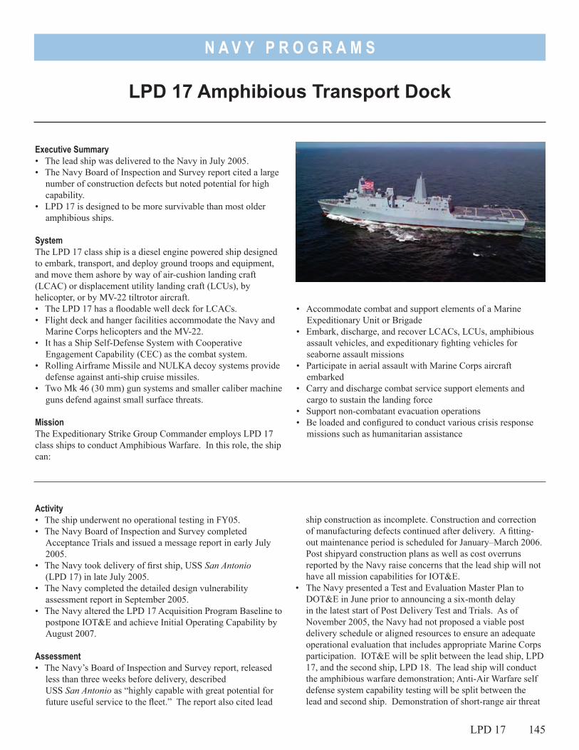
N A V Y P R O G R A M S
LPD 17 Amphibious Transport Dock
Executive Summary• The lead ship was delivered to the Navy in July 2005.• The Navy Board of Inspection and Survey report cited a large
number of construction defects but noted potential for high capability.
• LPD 17 is designed to be more survivable than most older amphibious ships.
SystemThe LPD 17 class ship is a diesel engine powered ship designed to embark, transport, and deploy ground troops and equipment, and move them ashore by way of air-cushion landing craft (LCAC) or displacement utility landing craft (LCUs), by helicopter, or by MV-22 tiltrotor aircraft.• The LPD 17 has a floodable well deck for LCACs.• Flight deck and hanger facilities accommodate the Navy and
Marine Corps helicopters and the MV-22.• It has a Ship Self-Defense System with Cooperative
Engagement Capability (CEC) as the combat system.• Rolling Airframe Missile and NULKA decoy systems provide
defense against anti-ship cruise missiles. • Two Mk 46 (30 mm) gun systems and smaller caliber machine
guns defend against small surface threats.
MissionThe Expeditionary Strike Group Commander employs LPD 17 class ships to conduct Amphibious Warfare. In this role, the ship can:
• Accommodate combat and support elements of a Marine Expeditionary Unit or Brigade
• Embark, discharge, and recover LCACs, LCUs, amphibious assault vehicles, and expeditionary fighting vehicles for seaborne assault missions
• Participate in aerial assault with Marine Corps aircraft embarked
• Carry and discharge combat service support elements and cargo to sustain the landing force
• Support non-combatant evacuation operations• Be loaded and configured to conduct various crisis response
missions such as humanitarian assistance
Activity• The ship underwent no operational testing in FY05.• The Navy Board of Inspection and Survey completed
Acceptance Trials and issued a message report in early July 2005.
• The Navy took delivery of first ship, USS San Antonio (LPD 17) in late July 2005.
• The Navy completed the detailed design vulnerability assessment report in September 2005.
• The Navy altered the LPD 17 Acquisition Program Baseline to postpone IOT&E and achieve Initial Operating Capability by August 2007.
Assessment• The Navy’s Board of Inspection and Survey report, released
less than three weeks before delivery, described USS San Antonio as “highly capable with great potential for future useful service to the fleet.” The report also cited lead
LPD 17 145
ship construction as incomplete. Construction and correction of manufacturing defects continued after delivery. A fitting-out maintenance period is scheduled for January–March 2006. Post shipyard construction plans as well as cost overruns reported by the Navy raise concerns that the lead ship will not have all mission capabilities for IOT&E.
• The Navy presented a Test and Evaluation Master Plan to DOT&E in June prior to announcing a six-month delay in the latest start of Post Delivery Test and Trials. As of November 2005, the Navy had not proposed a viable post delivery schedule or aligned resources to ensure an adequate operational evaluation that includes appropriate Marine Corps participation. IOT&E will be split between the lead ship, LPD 17, and the second ship, LPD 18. The lead ship will conduct the amphibious warfare demonstration; Anti-Air Warfare self defense system capability testing will be split between the lead and second ship. Demonstration of short-range air threat
N A V Y P R O G R A M S
defense systems will be done using the Navy’s Self Defense Test Ship.
• In the vulnerability assessment report a variety of vulnerability models are exercised to determine the vulnerability of the San Antonio class ships to seven threat engagements including a terrorist threat scenario. The testing community for LPD 17 is actively planning for the total ship survivability trial on LPD 17 in FY06 and the full ship shock trial on LPD 19 in FY07. The survivability of the San Antonio class ships are designed to be improved over the 1970’s-era amphibious ships they will replace, primarily due to:
- Reduced radar cross section signature design features - Strengthened hull girder design- Improved bulkhead connections - Improved fragmentation protection - Addition of fire insulation at fire zone boundaries - Maximum use of redundancy and separation for vital
systems
RecommendationsNone.
146 LPD 17
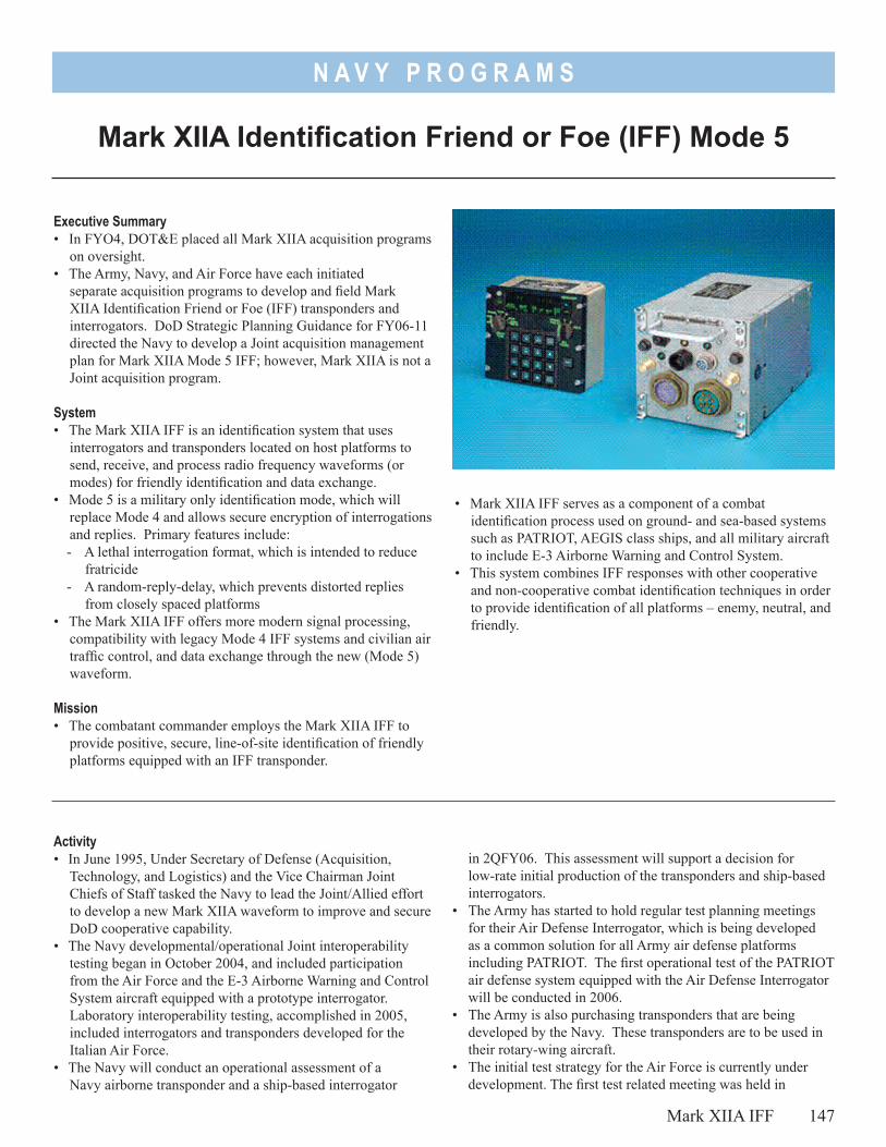
N A V Y P R O G R A M S
• Mark XIIA IFF serves as a component of a combat identification process used on ground- and sea-based systems such as PATRIOT, AEGIS class ships, and all military aircraft to include E-3 Airborne Warning and Control System.
• This system combines IFF responses with other cooperative and non-cooperative combat identification techniques in order to provide identification of all platforms – enemy, neutral, and friendly.
Mark XIIA Identification Friend or Foe (IFF) Mode 5
Executive Summary• In FYO4, DOT&E placed all Mark XIIA acquisition programs
on oversight. • The Army, Navy, and Air Force have each initiated
separate acquisition programs to develop and field Mark XIIA Identification Friend or Foe (IFF) transponders and interrogators. DoD Strategic Planning Guidance for FY06-11 directed the Navy to develop a Joint acquisition management plan for Mark XIIA Mode 5 IFF; however, Mark XIIA is not a Joint acquisition program.
System• The Mark XIIA IFF is an identification system that uses
interrogators and transponders located on host platforms to send, receive, and process radio frequency waveforms (or modes) for friendly identification and data exchange.
• Mode 5 is a military only identification mode, which will replace Mode 4 and allows secure encryption of interrogations and replies. Primary features include:- A lethal interrogation format, which is intended to reduce
fratricide- A random-reply-delay, which prevents distorted replies
from closely spaced platforms• The Mark XIIA IFF offers more modern signal processing,
compatibility with legacy Mode 4 IFF systems and civilian air traffic control, and data exchange through the new (Mode 5) waveform.
Mission• The combatant commander employs the Mark XIIA IFF to
provide positive, secure, line-of-site identification of friendly platforms equipped with an IFF transponder.
Activity • In June 1995, Under Secretary of Defense (Acquisition,
Technology, and Logistics) and the Vice Chairman Joint Chiefs of Staff tasked the Navy to lead the Joint/Allied effort to develop a new Mark XIIA waveform to improve and secure DoD cooperative capability.
• The Navy developmental/operational Joint interoperability testing began in October 2004, and included participation from the Air Force and the E-3 Airborne Warning and Control System aircraft equipped with a prototype interrogator. Laboratory interoperability testing, accomplished in 2005, included interrogators and transponders developed for the Italian Air Force.
• The Navy will conduct an operational assessment of a Navy airborne transponder and a ship-based interrogator
in 2QFY06. This assessment will support a decision for low-rate initial production of the transponders and ship-based interrogators.
• The Army has started to hold regular test planning meetings for their Air Defense Interrogator, which is being developed as a common solution for all Army air defense platforms including PATRIOT. The first operational test of the PATRIOT air defense system equipped with the Air Defense Interrogator will be conducted in 2006.
• The Army is also purchasing transponders that are being developed by the Navy. These transponders are to be used in their rotary-wing aircraft.
• The initial test strategy for the Air Force is currently under development. The first test related meeting was held in
Mark XIIA IFF 147
N A V Y P R O G R A M S
September 2005. An early operational assessment will be conducted in FY06.
Assessment• Prior to the Navy program being placed on oversight by
DOT&E, the Service approved its Test and Evaluation Master Plan for Mark XIIA IFF in November 2003. Although the Navy leads the way in scheduled Joint interoperability test events, the Army and Air Force have yet to establish a clear schedule, but are continuing to pursue test opportunities.
• Host platforms critical for testing the Mark XIIA IFF mission will be coming online at various times. Testing will be complicated by the fact that each Service plans to field interrogators and transponders over a period of many years.
• The certification of cryptographic computers by the National Security Agency has been delayed because the basic Mode 5 reply was considered vulnerable to spoofing. There is a National Security Agency/North Atlantic Treaty Organization-approved solution that is being implemented but has not been tested.
• The Navy developmental/operational testing exposed problems with false target generation in the current implementation of Mark XIIA IFF. The solution to this problem is still being addressed.
• Substantial collaboration between the Services toward sharing test assets, results, and the coordination of efforts is taking place.
• The Army and Air Force do not have traditionally structured acquisition programs.
Recommendations1. The Services’ Program Managers must integrate their
test schedules and look for opportunities to test in a Joint environment. This will ensure interoperability between all interrogators, transponders, and dual interrogator transponders.
2. Service Program Managers must ensure that all systems being developed interoperate properly as follows: - Coordinate testing between each of the Services’ operational
test agencies - Develop a capstone Test and Evaluation Master Plan
between all of the Services for Mark XIIA IFF
148 Mark XIIA IFF
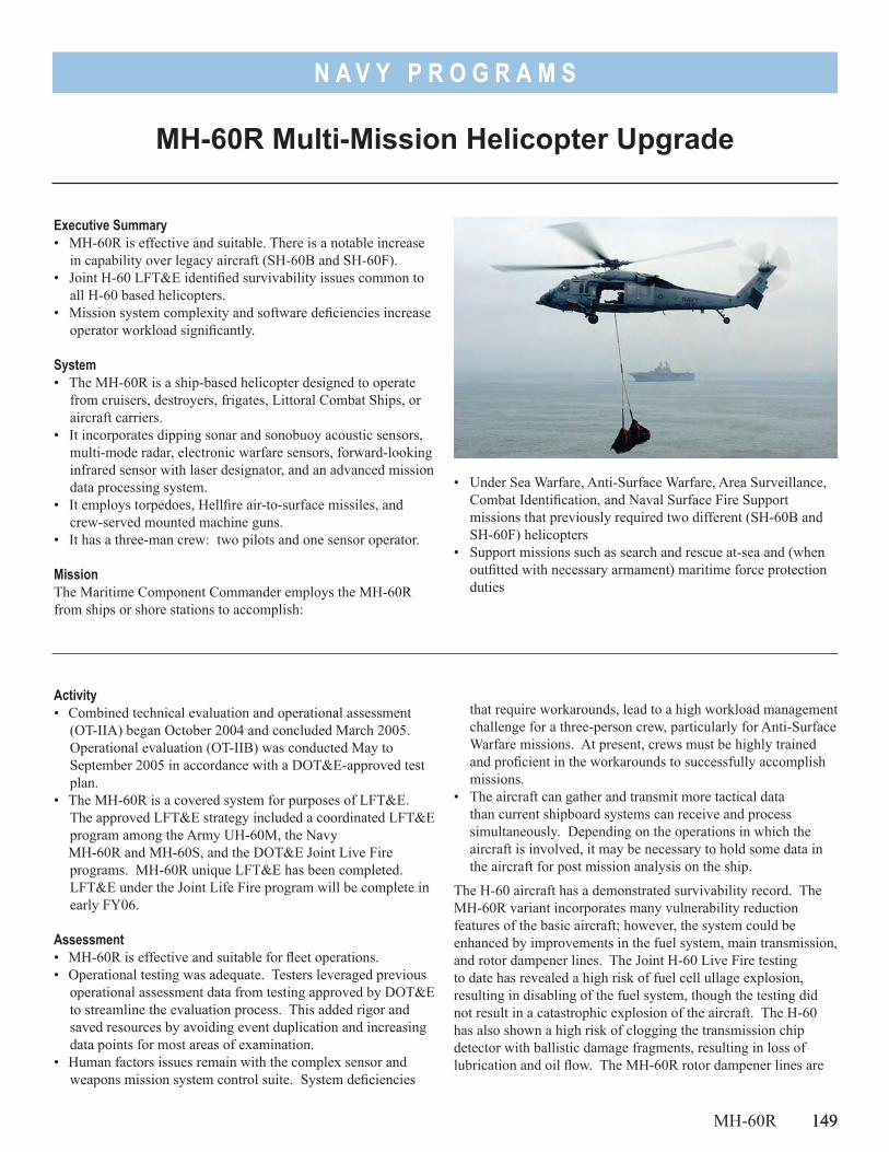
149
N A V Y P R O G R A M S
Executive Summary• MH-60R is effective and suitable. There is a notable increase
in capability over legacy aircraft (SH-60B and SH-60F).• Joint H-60 LFT&E identified survivability issues common to
all H-60 based helicopters.• Mission system complexity and software deficiencies increase
operator workload significantly.
System• The MH-60R is a ship-based helicopter designed to operate
from cruisers, destroyers, frigates, Littoral Combat Ships, or aircraft carriers.
• It incorporates dipping sonar and sonobuoy acoustic sensors, multi-mode radar, electronic warfare sensors, forward-looking infrared sensor with laser designator, and an advanced mission data processing system.
• It employs torpedoes, Hellfire air-to-surface missiles, and crew-served mounted machine guns.
• It has a three-man crew: two pilots and one sensor operator.
MissionThe Maritime Component Commander employs the MH-60R from ships or shore stations to accomplish:
Activity• Combined technical evaluation and operational assessment
(OT-IIA) began October 2004 and concluded March 2005. Operational evaluation (OT-IIB) was conducted May to September 2005 in accordance with a DOT&E-approved test plan.
• The MH-60R is a covered system for purposes of LFT&E. The approved LFT&E strategy included a coordinated LFT&E program among the Army UH-60M, the Navy
MH-60R and MH-60S, and the DOT&E Joint Live Fire programs. MH-60R unique LFT&E has been completed. LFT&E under the Joint Life Fire program will be complete in early FY06.
Assessment• MH-60R is effective and suitable for fleet operations. • Operational testing was adequate. Testers leveraged previous
operational assessment data from testing approved by DOT&E to streamline the evaluation process. This added rigor and saved resources by avoiding event duplication and increasing data points for most areas of examination.
• Human factors issues remain with the complex sensor and weapons mission system control suite. System deficiencies
that require workarounds, lead to a high workload management challenge for a three-person crew, particularly for Anti-Surface Warfare missions. At present, crews must be highly trained and proficient in the workarounds to successfully accomplish missions.
• The aircraft can gather and transmit more tactical data than current shipboard systems can receive and process simultaneously. Depending on the operations in which the aircraft is involved, it may be necessary to hold some data in the aircraft for post mission analysis on the ship.
The H-60 aircraft has a demonstrated survivability record. The MH-60R variant incorporates many vulnerability reduction features of the basic aircraft; however, the system could be enhanced by improvements in the fuel system, main transmission, and rotor dampener lines. The Joint H-60 Live Fire testing to date has revealed a high risk of fuel cell ullage explosion, resulting in disabling of the fuel system, though the testing did not result in a catastrophic explosion of the aircraft. The H-60 has also shown a high risk of clogging the transmission chip detector with ballistic damage fragments, resulting in loss of lubrication and oil flow. The MH-60R rotor dampener lines are
MH-60R Multi-Mission Helicopter Upgrade
MH-60R 149
• Under Sea Warfare, Anti-Surface Warfare, Area Surveillance, Combat Identification, and Naval Surface Fire Support missions that previously required two different (SH-60B and SH-60F) helicopters
• Support missions such as search and rescue at-sea and (when outfitted with necessary armament) maritime force protection duties
150
N A V Y P R O G R A M S
150 MH-60R
relatively soft and easily penetrated, which increases the risk of severe ground resonance problems on landing.
RecommendationsThe Navy should:1. Continue working to correct software deficiencies and
reduce the complexity in the mission systems that necessitate workarounds.
2. Ensure training curricula and documentation support the high level of crew proficiency required to operate the MH-60R mission systems.
3. Investigate improvements to existing shipboard data link systems to make use of the large amount of tactical information MH-60R can gather and transmit.
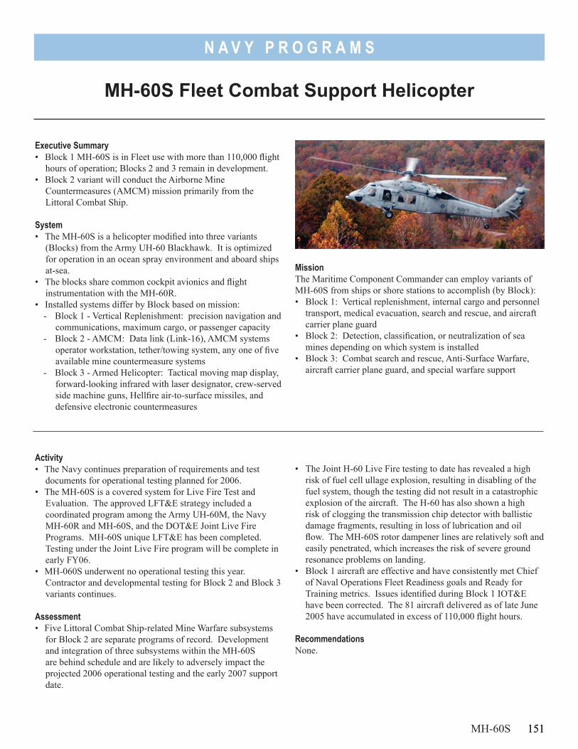
151
N A V Y P R O G R A M S
Executive Summary• Block 1 MH-60S is in Fleet use with more than 110,000 flight
hours of operation; Blocks 2 and 3 remain in development. • Block 2 variant will conduct the Airborne Mine
Countermeasures (AMCM) mission primarily from the Littoral Combat Ship.
System• The MH-60S is a helicopter modified into three variants
(Blocks) from the Army UH-60 Blackhawk. It is optimized for operation in an ocean spray environment and aboard ships at-sea.
• The blocks share common cockpit avionics and flight instrumentation with the MH-60R.
• Installed systems differ by Block based on mission:- Block 1 - Vertical Replenishment: precision navigation and
communications, maximum cargo, or passenger capacity- Block 2 - AMCM: Data link (Link-16), AMCM systems
operator workstation, tether/towing system, any one of five available mine countermeasure systems
- Block 3 - Armed Helicopter: Tactical moving map display, forward-looking infrared with laser designator, crew-served side machine guns, Hellfire air-to-surface missiles, and defensive electronic countermeasures
Activity• The Navy continues preparation of requirements and test
documents for operational testing planned for 2006.• The MH-60S is a covered system for Live Fire Test and
Evaluation. The approved LFT&E strategy included a coordinated program among the Army UH-60M, the Navy MH-60R and MH-60S, and the DOT&E Joint Live Fire Programs. MH-60S unique LFT&E has been completed. Testing under the Joint Live Fire program will be complete in early FY06.
• MH-060S underwent no operational testing this year. Contractor and developmental testing for Block 2 and Block 3 variants continues.
Assessment• Five Littoral Combat Ship-related Mine Warfare subsystems
for Block 2 are separate programs of record. Development and integration of three subsystems within the MH-60S are behind schedule and are likely to adversely impact the projected 2006 operational testing and the early 2007 support date.
• The Joint H-60 Live Fire testing to date has revealed a high risk of fuel cell ullage explosion, resulting in disabling of the fuel system, though the testing did not result in a catastrophic explosion of the aircraft. The H-60 has also shown a high risk of clogging the transmission chip detector with ballistic damage fragments, resulting in loss of lubrication and oil flow. The MH-60S rotor dampener lines are relatively soft and easily penetrated, which increases the risk of severe ground resonance problems on landing.
• Block 1 aircraft are effective and have consistently met Chief of Naval Operations Fleet Readiness goals and Ready for Training metrics. Issues identified during Block 1 IOT&E have been corrected. The 81 aircraft delivered as of late June 2005 have accumulated in excess of 110,000 flight hours.
RecommendationsNone.
MH-60S Fleet Combat Support Helicopter
MH-60S 151
MissionThe Maritime Component Commander can employ variants of MH-60S from ships or shore stations to accomplish (by Block):• Block 1: Vertical replenishment, internal cargo and personnel
transport, medical evacuation, search and rescue, and aircraft carrier plane guard
• Block 2: Detection, classification, or neutralization of sea mines depending on which system is installed
• Block 3: Combat search and rescue, Anti-Surface Warfare, aircraft carrier plane guard, and special warfare support

152
N A V Y P R O G R A M S
152
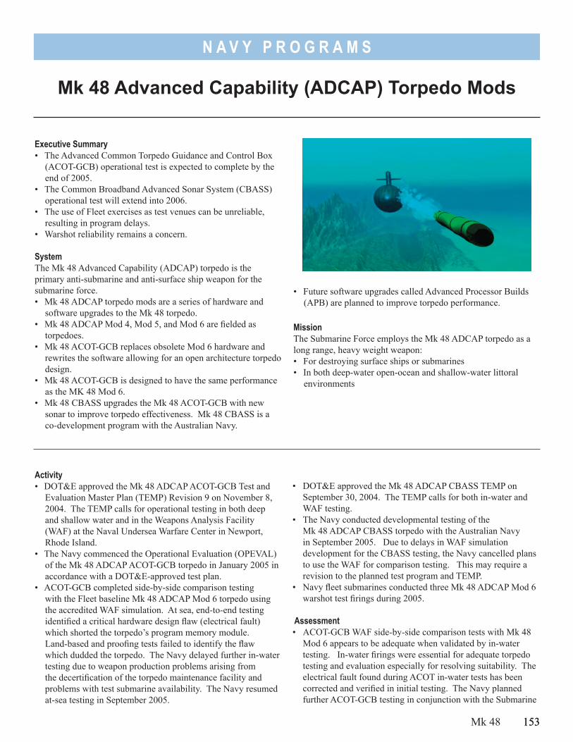
153
N A V Y P R O G R A M S
• Future software upgrades called Advanced Processor Builds (APB) are planned to improve torpedo performance.
MissionThe Submarine Force employs the Mk 48 ADCAP torpedo as a long range, heavy weight weapon:• For destroying surface ships or submarines • In both deep-water open-ocean and shallow-water littoral
environments
Executive Summary• The Advanced Common Torpedo Guidance and Control Box
(ACOT-GCB) operational test is expected to complete by the end of 2005.
• The Common Broadband Advanced Sonar System (CBASS) operational test will extend into 2006.
• The use of Fleet exercises as test venues can be unreliable, resulting in program delays.
• Warshot reliability remains a concern.
SystemThe Mk 48 Advanced Capability (ADCAP) torpedo is the primary anti-submarine and anti-surface ship weapon for the submarine force. • Mk 48 ADCAP torpedo mods are a series of hardware and
software upgrades to the Mk 48 torpedo.• Mk 48 ADCAP Mod 4, Mod 5, and Mod 6 are fielded as
torpedoes.• Mk 48 ACOT-GCB replaces obsolete Mod 6 hardware and
rewrites the software allowing for an open architecture torpedo design.
• Mk 48 ACOT-GCB is designed to have the same performance as the MK 48 Mod 6.
• Mk 48 CBASS upgrades the Mk 48 ACOT-GCB with new sonar to improve torpedo effectiveness. Mk 48 CBASS is a co-development program with the Australian Navy.
Activity• DOT&E approved the Mk 48 ADCAP ACOT-GCB Test and
Evaluation Master Plan (TEMP) Revision 9 on November 8, 2004. The TEMP calls for operational testing in both deep and shallow water and in the Weapons Analysis Facility (WAF) at the Naval Undersea Warfare Center in Newport, Rhode Island.
• The Navy commenced the Operational Evaluation (OPEVAL) of the Mk 48 ADCAP ACOT-GCB torpedo in January 2005 in accordance with a DOT&E-approved test plan.
• ACOT-GCB completed side-by-side comparison testing with the Fleet baseline Mk 48 ADCAP Mod 6 torpedo using the accredited WAF simulation. At sea, end-to-end testing identified a critical hardware design flaw (electrical fault) which shorted the torpedo’s program memory module. Land-based and proofing tests failed to identify the flaw which dudded the torpedo. The Navy delayed further in-water testing due to weapon production problems arising from the decertification of the torpedo maintenance facility and problems with test submarine availability. The Navy resumed at-sea testing in September 2005.
• DOT&E approved the Mk 48 ADCAP CBASS TEMP on September 30, 2004. The TEMP calls for both in-water and WAF testing.
• The Navy conducted developmental testing of the Mk 48 ADCAP CBASS torpedo with the Australian Navy in September 2005. Due to delays in WAF simulation development for the CBASS testing, the Navy cancelled plans to use the WAF for comparison testing. This may require a revision to the planned test program and TEMP.
• Navy fleet submarines conducted three Mk 48 ADCAP Mod 6 warshot test firings during 2005.
Assessment• ACOT-GCB WAF side-by-side comparison tests with Mk 48
Mod 6 appears to be adequate when validated by in-water testing. In-water firings were essential for adequate torpedo testing and evaluation especially for resolving suitability. The electrical fault found during ACOT in-water tests has been corrected and verified in initial testing. The Navy planned further ACOT-GCB testing in conjunction with the Submarine
Mk 48 Advanced Capability (ADCAP) Torpedo Mods
Mk 48 153
154
N A V Y P R O G R A M S
Command Course training in November 2005 and should complete ACOT operational testing by the end of 2005.
• CBASS testing with the Australian Navy will be conducted as combined developmental and operational testing beginning in December 2005. Due to CBASS development delays, the Navy added a new dedicated operational test exercise in early 2006. Without the WAF, the planned in-water test program may not be adequate to address all performance issues. The WAF allows comparisons to baseline performance. These comparisons will be difficult to conduct with a limited number of planned in-water torpedo shots.
• In response to two Mk 48 Mod 6 failures during a 2003 Ship Sink Exercise, the Navy convened a flag level Reliability Action Panel designed to focus on torpedo
154 Mk 48
production, maintenance, and reliability issues. One of the recommendations included increasing warshot test firings. Three torpedoes were successfully fired in 2005. This program needs to continue to verify the inventory of torpedoes.
Recommendations1. Testing of torpedoes is often delayed while test assets are
identified. Given the concerns over weapon reliability, the Navy should work to arrange more dedicated operational test and Ship-Sink-Exercise opportunities.
2. The WAF simulation must be upgraded to support realistic shallow water modeling for future CBASS development and assessment.
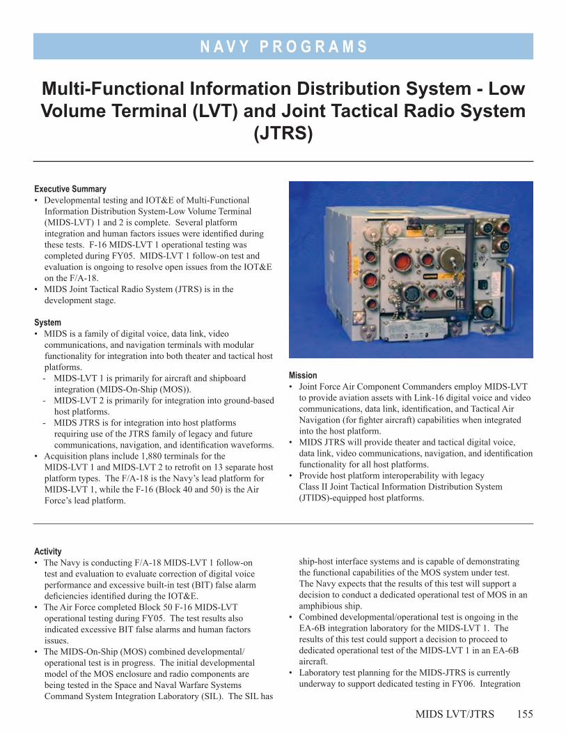
N A V Y P R O G R A M S
Executive Summary• Developmental testing and IOT&E of Multi-Functional
Information Distribution System-Low Volume Terminal (MIDS-LVT) 1 and 2 is complete. Several platform integration and human factors issues were identified during these tests. F-16 MIDS-LVT 1 operational testing was completed during FY05. MIDS-LVT 1 follow-on test and evaluation is ongoing to resolve open issues from the IOT&E on the F/A-18.
• MIDS Joint Tactical Radio System (JTRS) is in the development stage.
System• MIDS is a family of digital voice, data link, video
communications, and navigation terminals with modular functionality for integration into both theater and tactical host platforms.- MIDS-LVT 1 is primarily for aircraft and shipboard
integration (MIDS-On-Ship (MOS)).- MIDS-LVT 2 is primarily for integration into ground-based
host platforms.- MIDS JTRS is for integration into host platforms
requiring use of the JTRS family of legacy and future communications, navigation, and identification waveforms.
• Acquisition plans include 1,880 terminals for the MIDS-LVT 1 and MIDS-LVT 2 to retrofit on 13 separate host platform types. The F/A-18 is the Navy’s lead platform for MIDS-LVT 1, while the F-16 (Block 40 and 50) is the Air Force’s lead platform.
Multi-Functional Information Distribution System - Low Volume Terminal (LVT) and Joint Tactical Radio System
(JTRS)
Activity• The Navy is conducting F/A-18 MIDS-LVT 1 follow-on
test and evaluation to evaluate correction of digital voice performance and excessive built-in test (BIT) false alarm deficiencies identified during the IOT&E.
• The Air Force completed Block 50 F-16 MIDS-LVT operational testing during FY05. The test results also indicated excessive BIT false alarms and human factors issues.
• The MIDS-On-Ship (MOS) combined developmental/operational test is in progress. The initial developmental model of the MOS enclosure and radio components are being tested in the Space and Naval Warfare Systems Command System Integration Laboratory (SIL). The SIL has
ship-host interface systems and is capable of demonstrating the functional capabilities of the MOS system under test. The Navy expects that the results of this test will support a decision to conduct a dedicated operational test of MOS in an amphibious ship.
• Combined developmental/operational test is ongoing in the EA-6B integration laboratory for the MIDS-LVT 1. The results of this test could support a decision to proceed to dedicated operational test of the MIDS-LVT 1 in an EA-6B aircraft.
• Laboratory test planning for the MIDS-JTRS is currently underway to support dedicated testing in FY06. Integration
MIDS LVT/JTRS 155
Mission • Joint Force Air Component Commanders employ MIDS-LVT
to provide aviation assets with Link-16 digital voice and video communications, data link, identification, and Tactical Air Navigation (for fighter aircraft) capabilities when integrated into the host platform.
• MIDS JTRS will provide theater and tactical digital voice, data link, video communications, navigation, and identification functionality for all host platforms.
• Provide host platform interoperability with legacy Class II Joint Tactical Information Distribution System (JTIDS)-equipped host platforms.
156
N A V Y P R O G R A M S
test planning for MIDS-JTRS into the F/A-18E/F, B-1B bomber, and A-10 attack aircraft has been initiated.
Assessment• MIDS-LVT developmental testing reduced risk by identifying
design, performance, and reliability deficiencies early in the development process. Each of these deficiencies is currently being addressed by the program manager. These deficiencies include the following: - Tactical air navigation system errors- Human factors (poor visual cueing, improper
implementation of message types)- Operational maintainability (access to the terminal once
installed) • During the final months of FY05, the MIDS Development
Program Manager and host platform Integration Program Managers successfully shared lessons learned regarding the integration of this complex terminal. This sharing of data should result in a more realistic platform integration and test schedule.
• Terminal and host platform changes are needed to accommodate unique integration and user requirements. Consequently, some MIDS terminals are not interchangeable unless modified.
156 MIDS LVT/JTRS
• All operational testing was conducted in accordance with DOT&E-approved test plans.
Recommendations1. As design, performance, and reliability deficiencies are
identified, the program manager must correct or mitigate them. Additionally, the program manager must ensure that a strategy is developed for ultimately meeting the operational requirement.
2. Continue strong operational test participation in MIDS combined developmental/operational test in order to ensure the benefits of information sharing between Services and platforms. The sharing of lessons from MIDS terminal integration among other radio developers and host platforms should continue.
3. The program manager must plan to ensure that adequate Service and joint communications interoperability resources are available to support MIDS operational testing.
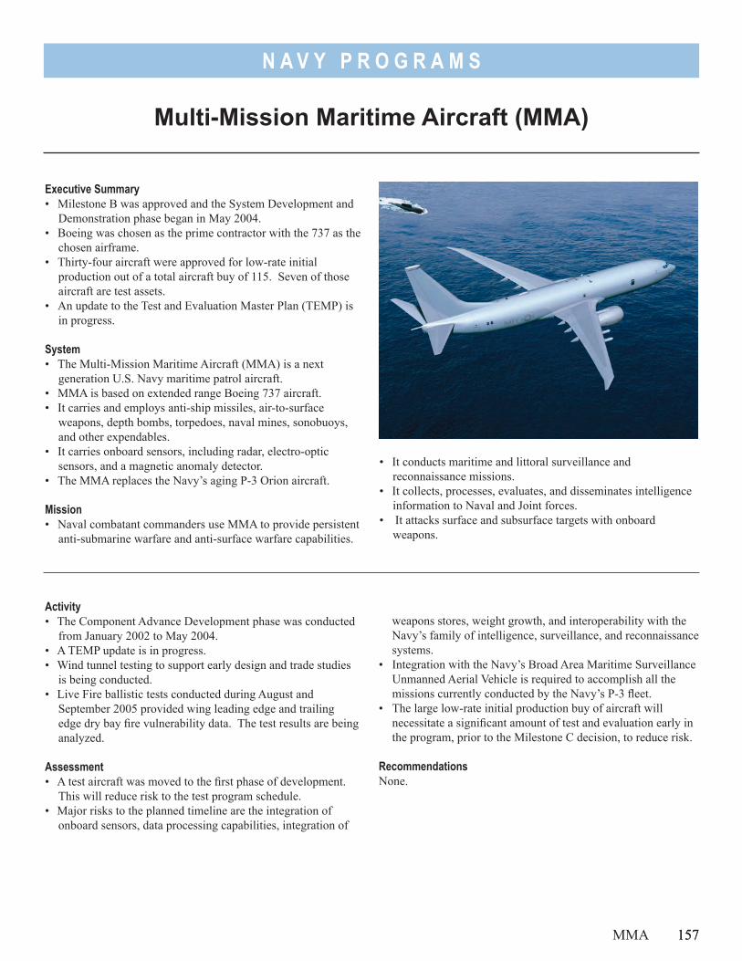
157
N A V Y P R O G R A M S
• It conducts maritime and littoral surveillance and reconnaissance missions.
• It collects, processes, evaluates, and disseminates intelligence information to Naval and Joint forces.
• It attacks surface and subsurface targets with onboard weapons.
Executive Summary• Milestone B was approved and the System Development and
Demonstration phase began in May 2004.• Boeing was chosen as the prime contractor with the 737 as the
chosen airframe.• Thirty-four aircraft were approved for low-rate initial
production out of a total aircraft buy of 115. Seven of those aircraft are test assets.
• An update to the Test and Evaluation Master Plan (TEMP) is in progress.
System• The Multi-Mission Maritime Aircraft (MMA) is a next
generation U.S. Navy maritime patrol aircraft.• MMA is based on extended range Boeing 737 aircraft.• It carries and employs anti-ship missiles, air-to-surface
weapons, depth bombs, torpedoes, naval mines, sonobuoys, and other expendables.
• It carries onboard sensors, including radar, electro-optic sensors, and a magnetic anomaly detector.
• The MMA replaces the Navy’s aging P-3 Orion aircraft.
Mission• Naval combatant commanders use MMA to provide persistent
anti-submarine warfare and anti-surface warfare capabilities.
Multi-Mission Maritime Aircraft (MMA)
Activity• The Component Advance Development phase was conducted
from January 2002 to May 2004.• A TEMP update is in progress.• Wind tunnel testing to support early design and trade studies
is being conducted.• Live Fire ballistic tests conducted during August and
September 2005 provided wing leading edge and trailing edge dry bay fire vulnerability data. The test results are being analyzed.
Assessment• A test aircraft was moved to the first phase of development.
This will reduce risk to the test program schedule.• Major risks to the planned timeline are the integration of
onboard sensors, data processing capabilities, integration of
weapons stores, weight growth, and interoperability with the Navy’s family of intelligence, surveillance, and reconnaissance systems.
• Integration with the Navy’s Broad Area Maritime Surveillance Unmanned Aerial Vehicle is required to accomplish all the missions currently conducted by the Navy’s P-3 fleet.
• The large low-rate initial production buy of aircraft will necessitate a significant amount of test and evaluation early in the program, prior to the Milestone C decision, to reduce risk.
RecommendationsNone.
MMA 157

158
N A V Y P R O G R A M S
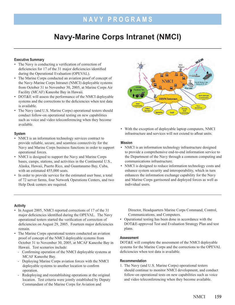
159
N A V Y P R O G R A M S
• With the exception of deployable laptop computers, NMCI infrastructure and services will not extend to afloat units.
Mission• NMCI is an information technology infrastructure designed
to provide a comprehensive end-to-end information service to the Department of the Navy through a common computing and communications infrastructure.
• NMCI is designed to reduce information technology costs and enhance system security and interoperability, which in turn enhances the information exchange capability for the Navy and Marine Corps garrisoned and deployed forces as well as individual users.
Executive Summary• The Navy is conducting a verification of correction of
deficiencies for 17 of the 31 major deficiencies identified during the Operational Evaluation (OPEVAL).
• The Marine Corps conducted an aviation proof of concept of the Navy-Marine Corps Intranet (NMCI) deployable systems from October 31 to November 30, 2005, at Marine Corps Air Facility (MCAF) Kaneohe Bay in Hawaii.
• DOT&E will assess the performance of the NMCI deployable systems and the corrections to the deficiencies when test data is available.
• The Navy (and U.S. Marine Corps) operational testers should conduct follow-on operational testing on new capabilities such as voice and video teleconferencing when they become available.
System• NMCI is an information technology services contract to
provide reliable, secure, and seamless connectivity for the Navy and Marine Corps business functions in order to support operational forces.
• NMCI is designed to support the Navy and Marine Corps bases, camps, stations, and activities in the Continental U.S., Alaska, Hawaii, Puerto Rico, and Guantanamo Bay, Cuba, with an estimated 455,000 seats.
• In order to provide service for the estimated user base, a total of 72 server farms, four Network Operations Centers, and two Help Desk centers are required.
Navy-Marine Corps Intranet (NMCI)
Activity• In August 2005, NMCI reported corrections of 17 of the 31
major deficiencies identified during the OPEVAL. The Navy operational testers started the verification of correction of deficiencies on August 29, 2005. Fourteen major deficiencies remain.
• The Marine Corps operational testers conducted an aviation proof of concept of the NMCI deployable systems from October 31 to November 30, 2005, at MCAF Kaneohe Bay in Hawaii. Test scenarios include: - Confirming operation of the NMCI deployable systems at
MCAF Kaneohe Bay.- Deploying Marine Corps aviation forces with the NMCI
deployable systems to another location to confirm operation.
- Redeploying and reestablishing operations at the original location. Test criteria were jointly established by Deputy Commandant of the Marine Corps for Aviation and
Director, Headquarters Marine Corps Command, Control, Communications, and Computers.
• Operational testing has been done in accordance with the DOT&E-approved Test and Evaluation Strategy Plan and test plans.
AssessmentDOT&E will complete the assessment of the NMCI deployable systems for the Marine Corps and the corrections to the OPEVAL deficiencies when test data is available.
Recommendation1. The Navy (and U.S. Marine Corps) operational testers
should continue to monitor NMCI development, and conduct follow-on operational tests on new capabilities such as voice and video teleconferencing when they become available.
NMCI 159

160
N A V Y P R O G R A M S
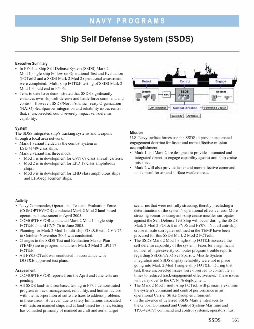
161
N A V Y P R O G R A M S
MissionU.S. Navy surface forces use the SSDS to provide automated engagement doctrine for faster and more effective mission accomplishment.• Mark 1 and Mark 2 are designed to provide automated and
integrated detect-to-engage capability against anti-ship cruise missiles .
• Mark 2 will also provide faster and more effective command and control for air and surface warfare areas.
Executive Summary• In FY05, a Ship Self Defense System (SSDS) Mark 2
Mod 1 single-ship Follow-on Operational Test and Evaluation (FOT&E) and a SSDS Mark 2 Mod 2 operational assessment were completed. Multi-ship FOT&E testing of SSDS Mark 2 Mod 1 should end in FY06.
• Tests to date have demonstrated that SSDS significantly enhances own-ship self defense and battle force command and control. However, SSDS/North Atlantic Treaty Organization (NATO) Sea Sparrow integration and reliability issues remain that, if uncorrected, could severely impact self-defense capability.
SystemThe SDSS integrates ship’s tracking systems and weapons through a local area network.• Mark 1 variant fielded as the combat system in
LSD 41/49-class ships.• Mark 2 variant has three mods:
- Mod 1 is in development for CVN 68 class aircraft carriers.- Mod 2 is in development for LPD 17 class amphibious
ships.- Mod 3 is in development for LHD class amphibious ships
and LHA-replacement ships.
Ship Self Defense System (SSDS)
scenarios that were not fully stressing, thereby precluding a determination of the system’s operational effectiveness. More stressing scenarios using anti-ship cruise missiles surrogates against the Self Defense Test Ship will occur during the SSDS Mark 2 Mod 2 FOT&E in FY06 and FY07. Not all anti-ship cruise missile surrogates outlined in the TEMP have been procured for this SSDS Mark 2 Mod 2 FOT&E.
• The SSDS Mark 2 Mod 1 single ship FOT&E assessed the self defense capability of the system. Fixes for a significant number of high-severity computer program trouble reports regarding SSDS/NATO Sea Sparrow Missile System integration and SSDS display reliability were not in place going into Mark 2 Mod 1 single-ship FOT&E. During that test, these uncorrected issues were observed to contribute at times to reduced track/engagement effectiveness. These issues will carry over to the CVN 76 deployment.
• The Mark 2 Mod 1 multi-ship FOT&E will primarily examine the system’s command and control performance in an operational Carrier Strike Group environment.
• In the absence of deferred SSDS Mark 2 interfaces to the Global Command and Control System-Maritime and TPX-42A(V) command and control systems, operators must
Activity• Navy Commander, Operational Test and Evaluation Force
(COMOPTEVFOR) conducted Mark 2 Mod 2 land-based operational assessment in April 2005.
• COMOPTEVFOR conducted Mark 2 Mod 1 single-ship FOT&E aboard CVN 76 in June 2005.
• Planning for Mark 2 Mod 1 multi-ship FOT&E with CVN 76 in October–November 2005 was conducted.
• Changes to the SSDS Test and Evaluation Master Plan (TEMP) are in progress to address Mark 2 Mod 2 LPD 17 FOT&E.
• All FY05 OT&E was conducted in accordance with DOT&E-approved test plans.
Assessment• COMOPTEVFOR reports from the April and June tests are
pending. • All SSDS land- and sea-based testing in FY05 demonstrated
progress in track management, reliability, and human factors with the incorporation of software fixes to address problems in these areas. However, due to safety limitations associated with tests on manned ships and at land-based test sites, testing has consisted primarily of manned aircraft and aerial target
SSDS 161
162
N A V Y P R O G R A M S
manually fuse the air and surface pictures displayed on the SSDS console with the blue force pictures on the consoles thereby increasing the likelihood of blue-on-blue engagements.
RecommendationsThe Navy should:1. Address the outstanding computer program trouble reports for
future CV/CVN deployments.
162 SSDS
2. Procure all required anti-ship surrogates as outlined in the TEMP for the SSDS Mark 2 Mod 2 FOT&E in FY06-07.
3. Update the TEMP to address FOT&E of Evolved Sea Sparrow Missile integration with SSDS Mark 2 Mod 1 in addition to SSDS Mark 2 Mods in LHD 8, CVN 68, and LHA 6.
4. Initiate efforts to fund deferred SSDS Mark 2 interfaces to the Global Command and Control System-Maritime and TPX-42A(V) command and control systems.
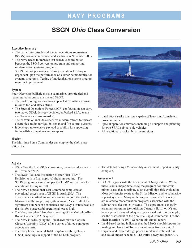
163
N A V Y P R O G R A M S
SSGN Ohio Class Conversion
Executive Summary• The first cruise missile and special operations submarines
(SSGN) conversion commenced sea trials in November 2005.• The Navy needs to improve test schedule coordination
between the SSGN conversion program and supporting modernization systems programs.
• SSGN mission performance during operational testing is dependent upon the performance of submarine modernization systems programs. Testing of modernization system program requires improvement.
SystemFour Ohio class ballistic missile submarines are refueled and reconfigured as cruise missile and SSGN.• The Strike configuration carries up to 154 Tomahawk cruise
missiles for land attack strike.• The Special Operations Forces (SOF) configuration can carry
two mated SEAL delivery vehicles, embarked SEAL teams, and Tomahawk cruise missiles.
• The conversion includes extensive modernizations to forward electronics, radio, navigation, sonar, and fire control systems.
• It develops an extensive payload capability for supporting future off-board systems and weapons.
MissionThe Maritime Force Commander can employ the Ohio class SSGN for:
• Land attack strike mission, capable of launching Tomahawk cruise missiles
• Special operations missions including all support and planning for two SEAL submersible vehicles
• All traditional attack submarine missions
Activity• USS Ohio, the first SSGN conversion, commenced sea trials
in November 2005.• The SSGN Test and Evaluation Master Plan (TEMP)
Revision A is in final approval signature routing. The SSGN program is executing per the TEMP and on track for operational testing in FY07.
• The Navy’s Operational Test Command completed an operational assessment of SSGN in April 2005. The assessment identified minor deficiencies in both the Strike Mission and the supporting system areas. As a result of the significant numbers of deficiencies, the Navy’s testers evaluate the risk for a successful operational test as high.
• The Navy completed land-based testing of the Multiple All-up Round Canister (MAC) system.
• The Navy is redesigning the Tomahawk missile Capsule Closure Assembly (CCA) after a series of failed contractor acceptance tests.
• The Navy hosted several Total Ship Survivability Trials (TSST) meetings in support of the LFT&E program.
SSGN Ohio 163
• The detailed design Vulnerability Assessment Report is nearly complete.
Assessment• DOT&E agrees with the assessment of Navy testers. While
there is not a major deficiency, the program has numerous minor issues that contribute to an overall high-risk evaluation. Most deficiencies relate to the Strike Mission and to submarine support systems. Many of the support system deficiencies are related to modernization programs associated with the submarine’s electronics systems. These programs generally are minor programs (Acquisition Category II, III, or IV) and have a poor history of adequate operational test. For example, see the assessment of the Acoustic Rapid Commercial Off-the-Shelf Insertion (A-RCI) Sonar in this annual report.
• Land-based testing indicates that the MACs should support the loading and launch of Tomahawk missiles from an SSGN.
• Capsule and CCA redesign poses a moderate technical risk and could impact schedule. The initial newly designed CCA
164
N A V Y P R O G R A M S
failed contractor tests. The redesigned CCA has started contractor testing but is behind schedule. The Navy plans to operationally test the new CCA design from an attack submarine in 2006.
• The integration of the SSGN conversion test plans and the test schedule for modernization systems, such as the sonar, combat systems, and radio room is a concern. The performance of the modernization system can significantly affect the ability of the SSGN to demonstrate satisfactory performance in the new SSGN mission areas. Deficiencies in modernization program performance risk delaying the SSGN operational test or degrading SSGN mission performance.
• The Navy’s goal is to maintain the level of survivability in the converted SSGN without introducing any survivability deficiencies into the platform. DOT&E is concerned about the new threats to the SSGN as a result of changes in the submarine’s operational profile from an open ocean strategic mission to a littoral mission.
• The Navy’s SSGN Program Office has started to coordinate the schedules of the conversion and modernization programs; however, the time allocated for testing, repairing, and retesting of some modernization system programs is often shorter than previously demonstrated.
Recommendations1. The Navy must improve coordination between the SSGN
conversion program and submarine modernization programs. Also, the Navy’s operational testing of submarine modernization programs (Acquisition Category II, III, and IV) requires improvement. Navy operational testing of submarine modernization programs is often inadequate, behind schedule, or not accomplished. The operational test of the SSGN, in each mission area, is designed to be an end-to-end test. SSGN mission area performance is dependent upon the performance of submarine modernization systems contributing to the mission area.
2. The Navy’s SSGN Test and Evaluation Integrated Process Team should meet on a regular basis to complete planning for operational evaluation. These meetings are important for discussing completed test results and for adjusting future test plans and schedules.
3. The Navy should complete development of the SSGN Concept of Operations.
164 SSGN Ohio
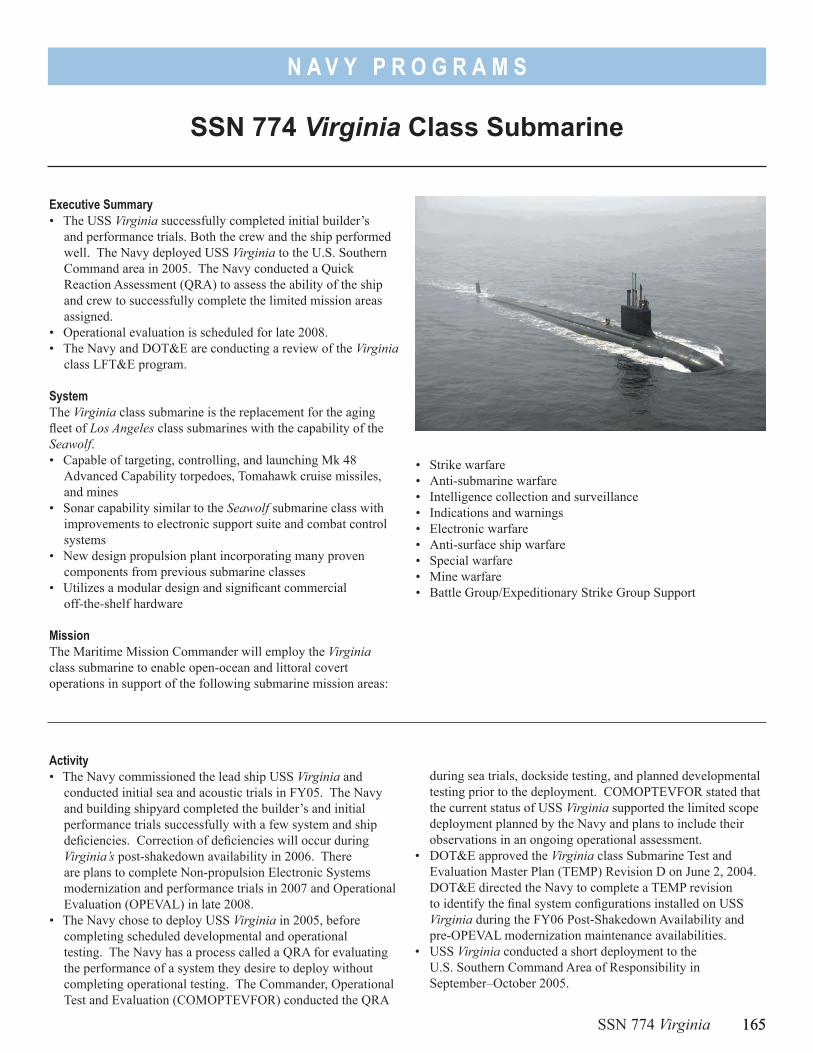
165
N A V Y P R O G R A M S
SSN 774 Virginia Class Submarine
Executive Summary• The USS Virginia successfully completed initial builder’s
and performance trials. Both the crew and the ship performed well. The Navy deployed USS Virginia to the U.S. Southern Command area in 2005. The Navy conducted a Quick Reaction Assessment (QRA) to assess the ability of the ship and crew to successfully complete the limited mission areas assigned.
• Operational evaluation is scheduled for late 2008.• The Navy and DOT&E are conducting a review of the Virginia
class LFT&E program.
SystemThe Virginia class submarine is the replacement for the aging fleet of Los Angeles class submarines with the capability of the Seawolf.• Capable of targeting, controlling, and launching Mk 48
Advanced Capability torpedoes, Tomahawk cruise missiles, and mines
• Sonar capability similar to the Seawolf submarine class with improvements to electronic support suite and combat control systems
• New design propulsion plant incorporating many proven components from previous submarine classes
• Utilizes a modular design and significant commercial off-the-shelf hardware
MissionThe Maritime Mission Commander will employ the Virginia class submarine to enable open-ocean and littoral covert operations in support of the following submarine mission areas:
• Strike warfare• Anti-submarine warfare• Intelligence collection and surveillance• Indications and warnings• Electronic warfare• Anti-surface ship warfare• Special warfare• Mine warfare• Battle Group/Expeditionary Strike Group Support
Activity• The Navy commissioned the lead ship USS Virginia and
conducted initial sea and acoustic trials in FY05. The Navy and building shipyard completed the builder’s and initial performance trials successfully with a few system and ship deficiencies. Correction of deficiencies will occur during Virginia’s post-shakedown availability in 2006. There are plans to complete Non-propulsion Electronic Systems modernization and performance trials in 2007 and Operational Evaluation (OPEVAL) in late 2008.
• The Navy chose to deploy USS Virginia in 2005, before completing scheduled developmental and operational testing. The Navy has a process called a QRA for evaluating the performance of a system they desire to deploy without completing operational testing. The Commander, Operational Test and Evaluation (COMOPTEVFOR) conducted the QRA
SSN 774 Virginia 165
during sea trials, dockside testing, and planned developmental testing prior to the deployment. COMOPTEVFOR stated that the current status of USS Virginia supported the limited scope deployment planned by the Navy and plans to include their observations in an ongoing operational assessment.
• DOT&E approved the Virginia class Submarine Test and Evaluation Master Plan (TEMP) Revision D on June 2, 2004. DOT&E directed the Navy to complete a TEMP revision to identify the final system configurations installed on USS Virginia during the FY06 Post-Shakedown Availability and pre-OPEVAL modernization maintenance availabilities.
• USS Virginia conducted a short deployment to the U.S. Southern Command Area of Responsibility in September–October 2005.
166
N A V Y P R O G R A M S
• The Navy conducted extensive testing, analysis, and modeling and simulation to support a recommendation to delete the full ship shock trial from the approved LFT&E program. After considerable review of the Navy’s work, OSD concurred with the recommendation to delete the USS Virginia full ship shock trial provided the Navy:- Complete the verification, validation, and accreditation of
the Transient Shock Analysis Process- Conduct a bottoms-up review of the Virginia class LFT&E
program to identify data voids and additional testing and/or analysis that may be needed to better understand the survivability of the Virginia class submarine
Assessment• USS Virginia completed initial trials on schedule with few
deficiencies. Virginia’s Non-propulsion Electronic Systems adequately supported at-sea trials. This is a credit to the extensive testing at the shipbuilder and the land-based test site over the last three years.
• The Navy plans to upgrade many of these systems in 2007; however, some systems such as Acoustic Rapid Commercial off-the-shelf Insertion (A-RCI) sonar will not be upgraded. By the time Virginia undergoes OPEVAL, the installed sonar system will be one of the oldest and least capable installed on U.S. submarines. Performance in all mission areas is dependent on A-RCI system performance; this increases the risk that Virginia will perform poorly in operational testing in some mission areas. The A-RCI sonar modernization program has a history of inadequate testing.
• Virginia’s early deployment forced a unique and rapid evaluation period that the Navy considers a precedent for
integrated testing. The Navy’s instructions state that the QRA does not satisfy or alter plans or need for full operational testing. COMOPTEVFOR did not resolve any critical operational issues during the QRA. DOT&E considers the scope of this type of testing inadequate for operational evaluations.
• Acquisition decisions, cost, and the rapid pace of technology change forces the Navy to complete the building of submarines during post-shakedown availability and modernization availabilities after delivery from the shipyard. Currently the schedule has more than four years between delivery and the completion of OPEVAL. Most of the schedule time is for completing the building, modernization, testing, and certification of the ship.
• DOT&E anticipates a comprehensive survivability evaluation will result from a successful completion of the bottoms-up review of the Virginia class LFT&E program.
Recommendations1. The Navy should complete all developmental and operational
testing before scheduling or conducting further deployments. 2. Navy operational testers should ride all ship underway periods
to ensure familiarity with Virginia systems and to support the rapid completion of OPEVAL.
3. The Navy should consider installing upgraded supporting program systems, such as the A-RCI sonar before OPEVAL. These upgrades will ensure USS Virginia has the same or better systems than the current systems in the fleet. Separately the Navy should take measures to ensure the modernization programs such as the A-RCI sonar program completes adequate operational testing.
166 SSN 774 Virginia
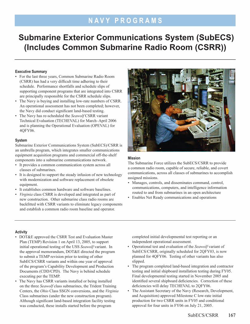
167
N A V Y P R O G R A M S
Submarine Exterior Communications System (SubECS) (Includes Common Submarine Radio Room (CSRR))
Executive Summary• For the last three years, Common Submarine Radio Room
(CSRR) has had a very difficult time adhering to their schedule. Performance shortfalls and schedule slips of supporting component programs that are integrated into CSRR are principally responsible for the CSRR schedule slips.
• The Navy is buying and installing low-rate numbers of CSRR. An operational assessment has not been completed; however, the Navy did conduct significant land-based testing.
• The Navy has re-scheduled the Seawolf CSRR variant Technical Evaluation (TECHEVAL) for March–April 2006 and is planning the Operational Evaluation (OPEVAL) for 4QFY06.
SystemSubmarine Exterior Communications System (SubECS)/CSRR is an umbrella program, which integrates smaller communications equipment acquisition programs and commercial off-the-shelf components into a submarine communications network.• It provides a common communication system across all
classes of submarines.• It is designed to support the steady infusion of new technology
with modernization and software replacement of obsolete equipment.
• It establishes common hardware and software baselines.• Virginia class CSRR is developed and integrated as part of
new construction. Other submarine class radio rooms are backfitted with CSRR variants to eliminate legacy components and establish a common radio room baseline and operator.
MissionThe Submarine Force utilizes the SubECS/CSRR to provide a common radio room, capable of secure, reliable, and covert communications, across all classes of submarines to accomplish assigned missions.• Manages, controls, and disseminates command, control,
communications, computers, and intelligence information routed to and from submarines in an open architecture
• Enables Net Ready communications and operations
Activity• DOT&E approved the CSRR Test and Evaluation Master
Plan (TEMP) Revision 1 on April 13, 2005, to support initial operational testing of the USS Seawolf variant. In the approval memorandum, DOT&E directed the program to submit a TEMP revision prior to testing of other SubECS/CSRR variants and within one year of approval of the program’s Capability Development and Production Documents (CDD/CPD). The Navy is behind schedule executing per the TEMP.
• The Navy has CSRR variants installed or being installed on the three Seawolf class submarines, the Trident Training Centers, the Ohio Class SSGN conversions, and the Virginia Class submarines (under the new construction program). Although significant land-based integration facility testing was conducted, these installs started before the program
SubECS/CSRR 167
completed initial developmental test reporting or an independent operational assessment.
• Operational test and evaluation of the Seawolf variant of SubECS/CSRR, originally scheduled for 2QFY03, is now planned for 4QFY06. Testing of other variants has also slipped.
• The program completed land-based integration and contractor testing and initial shipboard installation testing during FY05. Final developmental testing started in November 2005 and identified several shipboard deficiencies. Correction of these deficiencies will delay TECHEVAL to 2QFY06.
• The Assistant Secretary of the Navy (Research, Development, and Acquisition) approved Milestone C low-rate initial production for two CSRR units in FY05 and conditional approval for four units in FY06 on July 21, 2005.
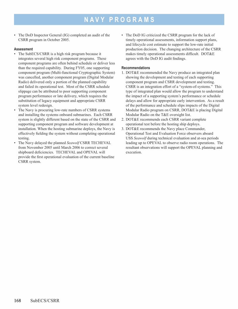
168
N A V Y P R O G R A M S
• The DoD Inspector General (IG) completed an audit of the CSRR program in October 2005.
Assessment• The SubECS/CSRR is a high risk program because it
integrates several high risk component programs. These component programs are often behind schedule or deliver less than the required capability. During FY05, one supporting component program (Multi-functional Cryptographic System) was cancelled, another component program (Digital Modular Radio) delivered only a portion of the planned capability and failed its operational test. Most of the CSRR schedule slippage can be attributed to poor supporting component program performance or late delivery, which requires the substitution of legacy equipment and appropriate CSRR system level redesign.
• The Navy is procuring low-rate numbers of CSRR systems and installing the systems onboard submarines. Each CSRR system is slightly different based on the state of the CSRR and supporting component program and software development at installation. When the hosting submarine deploys, the Navy is effectively fielding the system without completing operational testing.
• The Navy delayed the planned Seawolf CSRR TECHEVAL from November 2005 until March 2006 to correct several shipboard deficiencies. TECHEVAL and OPEVAL will provide the first operational evaluation of the current baseline CSRR system.
• The DoD IG criticized the CSRR program for the lack of timely operational assessments, information support plans, and lifecycle cost estimate to support the low-rate initial production decision. The changing architecture of the CSRR makes timely operational assessments difficult. DOT&E agrees with the DoD IG audit findings.
Recommendations1. DOT&E recommended the Navy produce an integrated plan
showing the development and testing of each supporting component program and CSRR development and testing. CSRR is an integration effort of a “system-of-systems.” This type of integrated plan would allow the program to understand the impact of a supporting system’s performance or schedule delays and allow for appropriate early intervention. As a result of the performance and schedule slips impacts of the Digital Modular Radio program on CSRR, DOT&E is placing Digital Modular Radio on the T&E oversight list.
2. DOT&E recommends each CSRR variant complete operational test before the hosting ship deploys.
3. DOT&E recommends the Navy place Commander, Operational Test and Evaluation Force observers aboard USS Seawolf during technical evaluation and at-sea periods leading up to OPEVAL to observe radio room operations. The resultant observations will support the OPEVAL planning and execution.
168 SubECS/CSRR
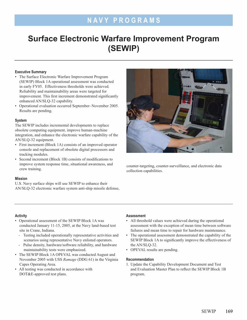
169
N A V Y P R O G R A M S
Surface Electronic Warfare Improvement Program (SEWIP)
Executive Summary• The Surface Electronic Warfare Improvement Program
(SEWIP) Block 1A operational assessment was conducted in early FY05. Effectiveness thresholds were achieved. Reliability and maintainability areas were targeted for improvement. This first increment demonstrated significantly enhanced AN/SLQ-32 capability.
• Operational evaluation occurred September–November 2005. Results are pending.
SystemThe SEWIP includes incremental developments to replace obsolete computing equipment, improve human-machine integration, and enhance the electronic warfare capability of the AN/SLQ-32 equipment.• First increment (Block 1A) consists of an improved operator
console and replacement of obsolete digital processors and tracking modules.
• Second increment (Block 1B) consists of modifications to improve system response time, situational awareness, and crew training.
MissionU.S. Navy surface ships will use SEWIP to enhance their AN/SLQ-32 electronic warfare system anti-ship missile defense,
counter-targeting, counter-surveillance, and electronic data collection capabilities.
Activity• Operational assessment of the SEWIP Block 1A was
conducted January 11-15, 2005, at the Navy land-based test site in Crane, Indiana.- Testing included operationally representative activities and
scenarios using representative Navy enlisted operators.- Pulse density, hardware/software reliability, and hardware
maintainability tests were emphasized.• The SEWIP Block 1A OPEVAL was conducted August and
November 2005 with USS Ramage (DDG 61) in the Virginia Capes Operating Area.
• All testing was conducted in accordance with DOT&E-approved test plans.
SEWIP 169
Assessment• All threshold values were achieved during the operational
assessment with the exception of mean time between software failures and mean time to repair for hardware maintenance.
• The operational assessment demonstrated the capability of the SEWIP Block 1A to significantly improve the effectiveness of the AN/SLQ-32.
• OPEVAL results are pending.
Recommendation1. Update the Capability Development Document and Test
and Evaluation Master Plan to reflect the SEWIP Block 1B program.

170
N A V Y P R O G R A M S
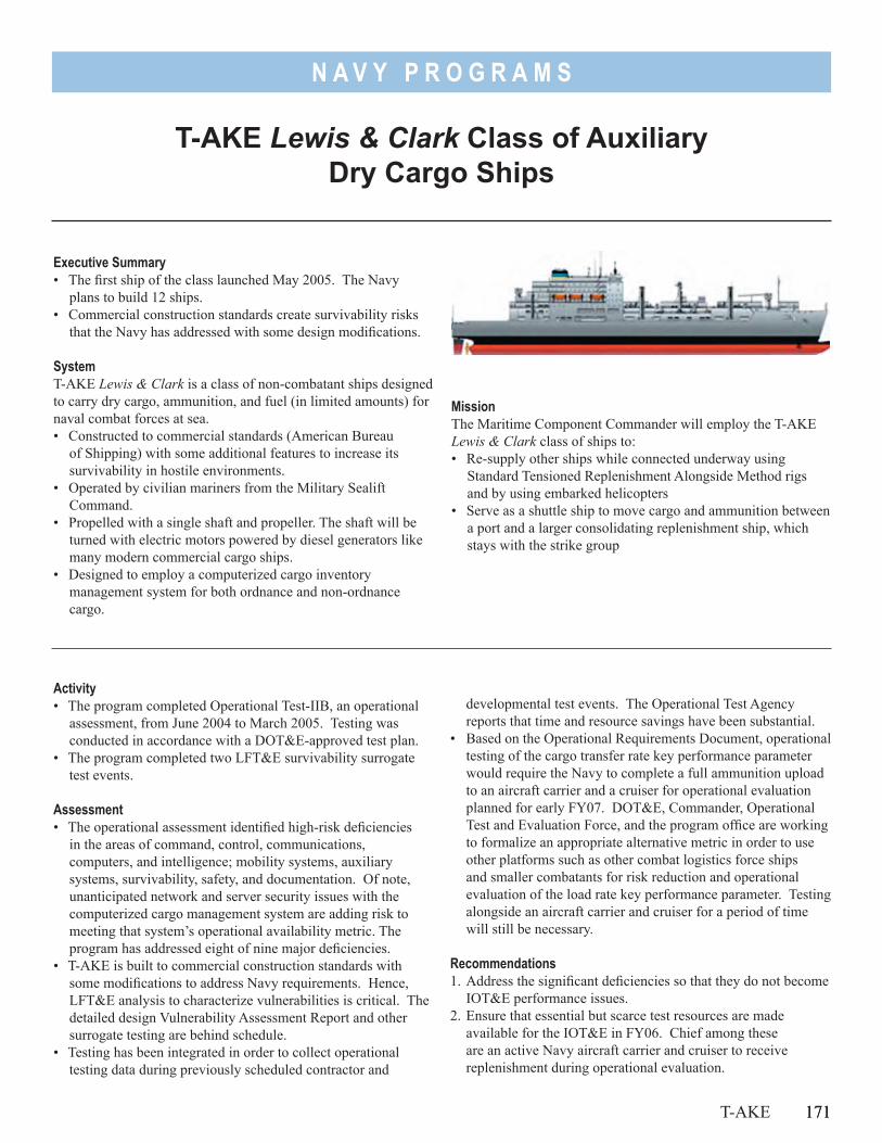
171
N A V Y P R O G R A M S
T-AKE Lewis & Clark Class of Auxiliary Dry Cargo Ships
Executive Summary• The first ship of the class launched May 2005. The Navy
plans to build 12 ships.• Commercial construction standards create survivability risks
that the Navy has addressed with some design modifications.
SystemT-AKE Lewis & Clark is a class of non-combatant ships designed to carry dry cargo, ammunition, and fuel (in limited amounts) for naval combat forces at sea. • Constructed to commercial standards (American Bureau
of Shipping) with some additional features to increase its survivability in hostile environments.
• Operated by civilian mariners from the Military Sealift Command.
• Propelled with a single shaft and propeller. The shaft will be turned with electric motors powered by diesel generators like many modern commercial cargo ships.
• Designed to employ a computerized cargo inventory management system for both ordnance and non-ordnance cargo.
MissionThe Maritime Component Commander will employ the T-AKE Lewis & Clark class of ships to:• Re-supply other ships while connected underway using
Standard Tensioned Replenishment Alongside Method rigs and by using embarked helicopters
• Serve as a shuttle ship to move cargo and ammunition between a port and a larger consolidating replenishment ship, which stays with the strike group
Activity• The program completed Operational Test-IIB, an operational
assessment, from June 2004 to March 2005. Testing was conducted in accordance with a DOT&E-approved test plan.
• The program completed two LFT&E survivability surrogate test events.
Assessment• The operational assessment identified high-risk deficiencies
in the areas of command, control, communications, computers, and intelligence; mobility systems, auxiliary systems, survivability, safety, and documentation. Of note, unanticipated network and server security issues with the computerized cargo management system are adding risk to meeting that system’s operational availability metric. The program has addressed eight of nine major deficiencies.
• T-AKE is built to commercial construction standards with some modifications to address Navy requirements. Hence, LFT&E analysis to characterize vulnerabilities is critical. The detailed design Vulnerability Assessment Report and other surrogate testing are behind schedule.
• Testing has been integrated in order to collect operational testing data during previously scheduled contractor and
T-AKE 171
developmental test events. The Operational Test Agency reports that time and resource savings have been substantial.
• Based on the Operational Requirements Document, operational testing of the cargo transfer rate key performance parameter would require the Navy to complete a full ammunition upload to an aircraft carrier and a cruiser for operational evaluation planned for early FY07. DOT&E, Commander, Operational Test and Evaluation Force, and the program office are working to formalize an appropriate alternative metric in order to use other platforms such as other combat logistics force ships and smaller combatants for risk reduction and operational evaluation of the load rate key performance parameter. Testing alongside an aircraft carrier and cruiser for a period of time will still be necessary.
Recommendations1. Address the significant deficiencies so that they do not become
IOT&E performance issues.2. Ensure that essential but scarce test resources are made
available for the IOT&E in FY06. Chief among these are an active Navy aircraft carrier and cruiser to receive replenishment during operational evaluation.

N A V Y P R O G R A M S
172
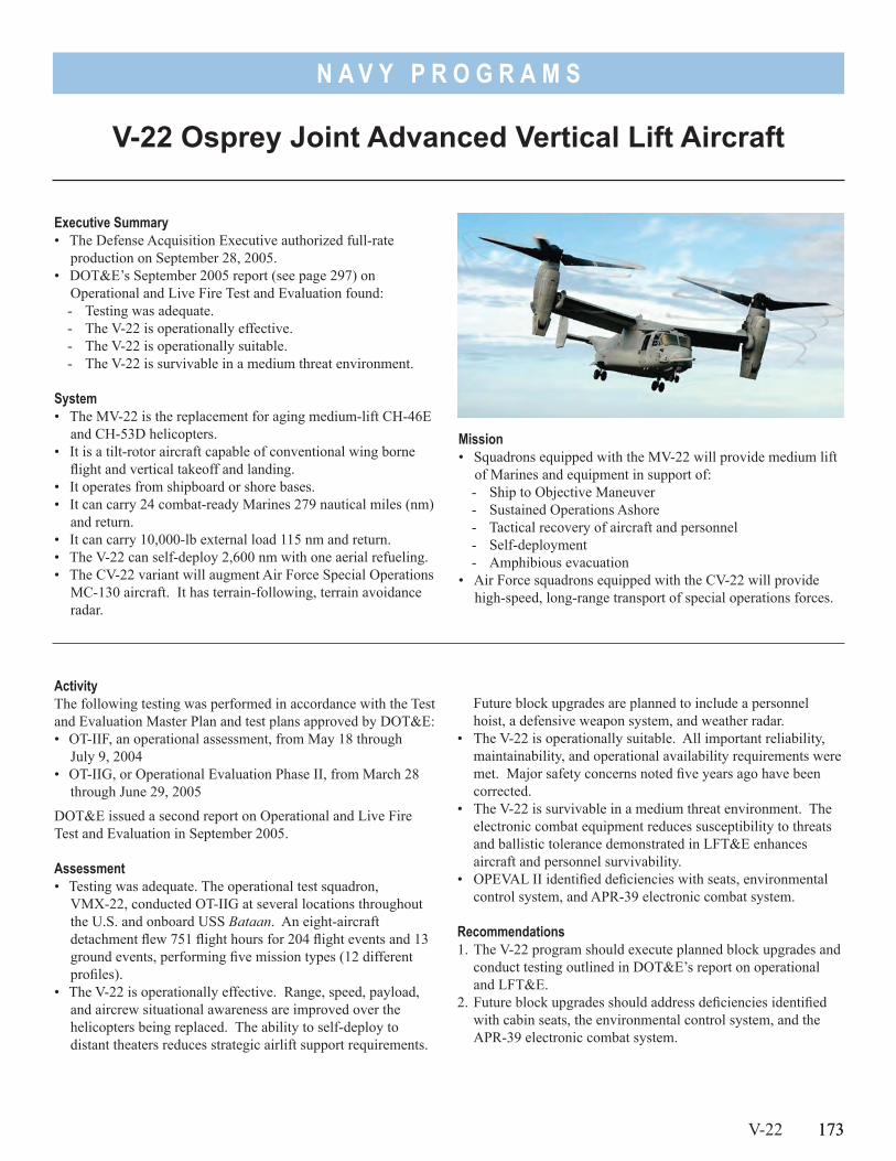
173
N A V Y P R O G R A M S
V-22 Osprey Joint Advanced Vertical Lift Aircraft
Executive Summary• The Defense Acquisition Executive authorized full-rate
production on September 28, 2005.• DOT&E’s September 2005 report (see page 297) on
Operational and Live Fire Test and Evaluation found:- Testing was adequate.- The V-22 is operationally effective.- The V-22 is operationally suitable.- The V-22 is survivable in a medium threat environment.
System• The MV-22 is the replacement for aging medium-lift CH-46E
and CH-53D helicopters.• It is a tilt-rotor aircraft capable of conventional wing borne
flight and vertical takeoff and landing.• It operates from shipboard or shore bases. • It can carry 24 combat-ready Marines 279 nautical miles (nm)
and return.• It can carry 10,000-lb external load 115 nm and return.• The V-22 can self-deploy 2,600 nm with one aerial refueling.• The CV-22 variant will augment Air Force Special Operations
MC-130 aircraft. It has terrain-following, terrain avoidance radar.
Mission• Squadrons equipped with the MV-22 will provide medium lift
of Marines and equipment in support of:- Ship to Objective Maneuver- Sustained Operations Ashore- Tactical recovery of aircraft and personnel- Self-deployment- Amphibious evacuation
• Air Force squadrons equipped with the CV-22 will provide high-speed, long-range transport of special operations forces.
ActivityThe following testing was performed in accordance with the Test and Evaluation Master Plan and test plans approved by DOT&E:• OT-IIF, an operational assessment, from May 18 through
July 9, 2004• OT-IIG, or Operational Evaluation Phase II, from March 28
through June 29, 2005
DOT&E issued a second report on Operational and Live Fire Test and Evaluation in September 2005.
Assessment• Testing was adequate. The operational test squadron,
VMX-22, conducted OT-IIG at several locations throughout the U.S. and onboard USS Bataan. An eight-aircraft detachment flew 751 flight hours for 204 flight events and 13 ground events, performing five mission types (12 different profiles).
• The V-22 is operationally effective. Range, speed, payload, and aircrew situational awareness are improved over the helicopters being replaced. The ability to self-deploy to distant theaters reduces strategic airlift support requirements.
V-22 173
Future block upgrades are planned to include a personnel hoist, a defensive weapon system, and weather radar.
• The V-22 is operationally suitable. All important reliability, maintainability, and operational availability requirements were met. Major safety concerns noted five years ago have been corrected.
• The V-22 is survivable in a medium threat environment. The electronic combat equipment reduces susceptibility to threats and ballistic tolerance demonstrated in LFT&E enhances aircraft and personnel survivability.
• OPEVAL II identified deficiencies with seats, environmental control system, and APR-39 electronic combat system.
Recommendations1. The V-22 program should execute planned block upgrades and
conduct testing outlined in DOT&E’s report on operational and LFT&E.
2. Future block upgrades should address deficiencies identified with cabin seats, the environmental control system, and the APR-39 electronic combat system.

174
Air Force Programs
Air F
orce
Pro
gram
s
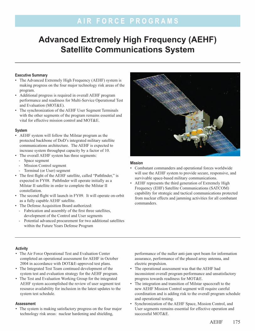
A I R F O R C E P R O G R A M S
Advanced Extremely High Frequency (AEHF) Satellite Communications System
AEHF 175
Activity• The Air Force Operational Test and Evaluation Center
completed an operational assessment for AEHF in October 2004 in accordance with DOT&E-approved test plans.
• The Integrated Test Team continued development of the system test and evaluation strategy for the AEHF program.
• The Test and Evaluation Working Group for the integrated AEHF system accomplished the review of user segment test resource availability for inclusion in the latest updates to the system test schedule.
Assessment• The system is making satisfactory progress on the four major
technology risk areas: nuclear hardening and shielding,
performance of the nuller anti-jam spot beam for information assurance, performance of the phased array antenna, and electric propulsion.
• The operational assessment was that the AEHF had inconsistent overall program performance and unsatisfactory progress towards readiness for MOT&E.
• The integration and transition of Milstar spacecraft to the new AEHF Mission Control segment will require careful coordination and is adding risk to the overall program schedule and operational testing.
• Synchronization of the AEHF Space, Mission Control, and User segments remains essential for effective operation and successful MOT&E.
Executive Summary• The Advanced Extremely High Frequency (AEHF) system is
making progress on the four major technology risk areas of the program.
• Additional progress is required in overall AEHF program performance and readiness for Multi-Service Operational Test and Evaluation (MOT&E).
• The synchronization of the AEHF User Segment Terminals with the other segments of the program remains essential and vital for effective mission control and MOT&E.
System• AEHF system will follow the Milstar program as the
protected backbone of DoD’s integrated military satellite communications architecture. The AEHF is expected to increase system throughput capacity by a factor of 10.
• The overall AEHF system has three segments: - Space segment- Mission Control segment- Terminal (or User) segment
• The first flight of the AEHF satellite, called “Pathfinder,” is expected in FY08. Pathfinder will operate initially as a Milstar II satellite in order to complete the Milstar II constellation.
• The second flight will launch in FY09. It will operate on-orbit as a fully capable AEHF satellite.
• The Defense Acquisition Board authorized: - Fabrication and assembly of the first three satellites,
development of the Control and User segments- Potential advanced procurement for two additional satellites
within the Future Years Defense Program
Mission• Combatant commanders and operational forces worldwide
will use the AEHF system to provide secure, responsive, and survivable space-based military communications.
• AEHF represents the third generation of Extremely High Frequency (EHF) Satellite Communications (SATCOM) capability for strategic and tactical communications protected from nuclear effects and jamming activities for all combatant commanders.
A I R F O R C E P R O G R A M S
176 AEHF
• The system contractor will need a more robust validation effort using test data to reduce the information assurance risks associated with using current program modeling data. The contractor also needs to expand the direct evaluation of system features such as anti-jam nuller operational performance.
• The User segment terminals are experiencing increased difficulty in retaining standardized and consistent configurations with the operational system baseline. If unresolved, the new AEHF terminals risk a lack of compatibility with both the spacecraft payload and with each other.
Recommendations1. The Air Force should use the second operational assessment in
FY07 to reassess the readiness of the AEHF Mission Control Segment to meet the demands of Milstar satellite transition and readiness for MOT&E.
2. The next operational assessment should be used by the Operational Test Agencies to evaluate the results of the developmental/operational test performed on the Pathfinder
satellite payload, and verify its full capability to provide adequate operational bandwidth and function as a Milstar II low-data rate/medium-data rate satellite.
3. The Air Force should monitor the fidelity of the AEHF Universal System Test Terminal simulator, the payload simulator, and integrated payload test equipment to ensure system and terminal synchronization for both operational testing and operations.
4. Specialized modeling and simulation validation should be accomplished by the Air Force in conjunction with direct AEHF operational testing to assess the information assurance features of nuller anti-jam spot beam performance in a variety of robust single and multiple jammer scenarios.
5. The integrated Air Force testing of AEHF should exercise: - Increased satellite-to-satellite payload cross-links- Theater-to-theater communications- Network control interoperability- Spacecraft system control- User segment terminal configuration compatibility
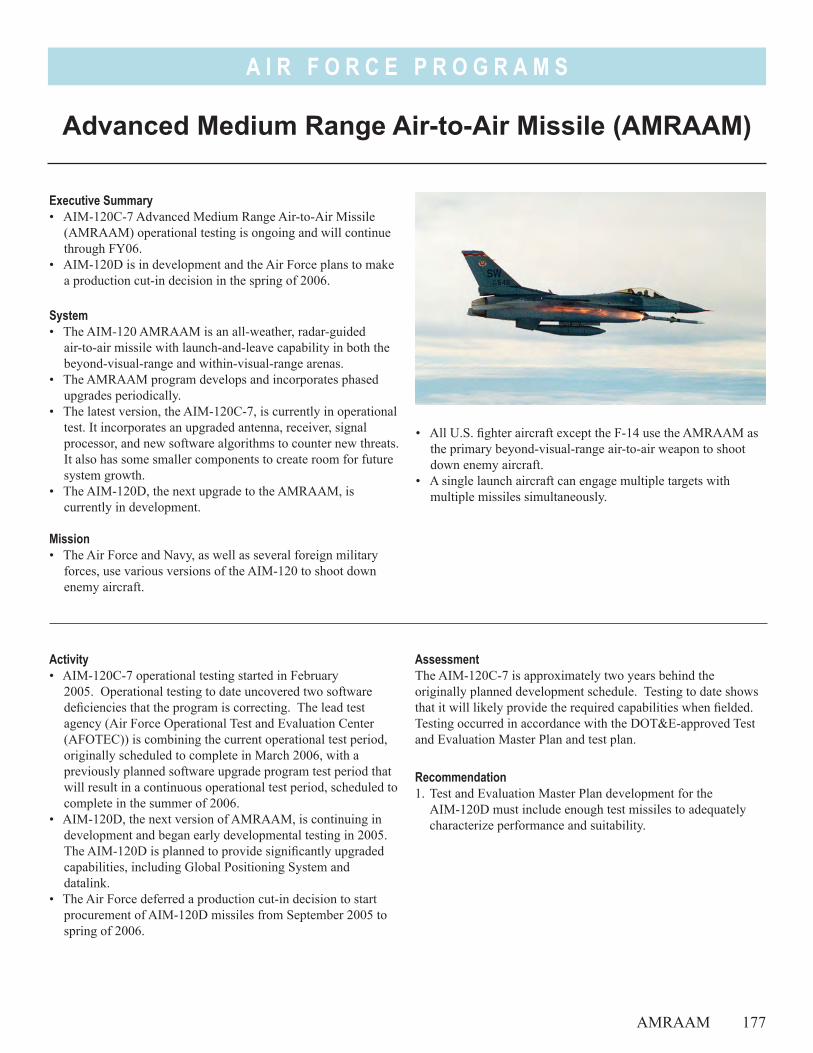
A I R F O R C E P R O G R A M S
• All U.S. fighter aircraft except the F-14 use the AMRAAM as the primary beyond-visual-range air-to-air weapon to shoot down enemy aircraft.
• A single launch aircraft can engage multiple targets with multiple missiles simultaneously.
Executive Summary• AIM-120C-7 Advanced Medium Range Air-to-Air Missile
(AMRAAM) operational testing is ongoing and will continue through FY06.
• AIM-120D is in development and the Air Force plans to make a production cut-in decision in the spring of 2006.
System• The AIM-120 AMRAAM is an all-weather, radar-guided
air-to-air missile with launch-and-leave capability in both the beyond-visual-range and within-visual-range arenas.
• The AMRAAM program develops and incorporates phased upgrades periodically.
• The latest version, the AIM-120C-7, is currently in operational test. It incorporates an upgraded antenna, receiver, signal processor, and new software algorithms to counter new threats. It also has some smaller components to create room for future system growth.
• The AIM-120D, the next upgrade to the AMRAAM, is currently in development.
Mission• The Air Force and Navy, as well as several foreign military
forces, use various versions of the AIM-120 to shoot down enemy aircraft.
Advanced Medium Range Air-to-Air Missile (AMRAAM)
AMRAAM 177
Activity• AIM-120C-7 operational testing started in February
2005. Operational testing to date uncovered two software deficiencies that the program is correcting. The lead test agency (Air Force Operational Test and Evaluation Center (AFOTEC)) is combining the current operational test period, originally scheduled to complete in March 2006, with a previously planned software upgrade program test period that will result in a continuous operational test period, scheduled to complete in the summer of 2006.
• AIM-120D, the next version of AMRAAM, is continuing in development and began early developmental testing in 2005. The AIM-120D is planned to provide significantly upgraded capabilities, including Global Positioning System and datalink.
• The Air Force deferred a production cut-in decision to start procurement of AIM-120D missiles from September 2005 to spring of 2006.
AssessmentThe AIM-120C-7 is approximately two years behind the originally planned development schedule. Testing to date shows that it will likely provide the required capabilities when fielded. Testing occurred in accordance with the DOT&E-approved Test and Evaluation Master Plan and test plan.
Recommendation1. Test and Evaluation Master Plan development for the
AIM-120D must include enough test missiles to adequately characterize performance and suitability.

A I R F O R C E P R O G R A M S
178
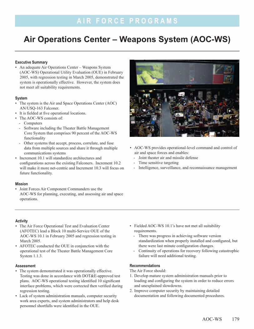
A I R F O R C E P R O G R A M S
• AOC-WS provides operational-level command and control of air and space forces and enables: - Joint theater air and missile defense- Time sensitive targeting- Intelligence, surveillance, and reconnaissance management
Air Operations Center – Weapons System (AOC-WS)
AOC-WS 179
Executive Summary• An adequate Air Operations Center – Weapons System
(AOC-WS) Operational Utility Evaluation (OUE) in February 2005, with regression testing in March 2005, demonstrated the system is operationally effective. However, the system does not meet all suitability requirements.
System• The system is the Air and Space Operations Center (AOC)
AN/USQ-163 Falconer.• It is fielded at five operational locations.• The AOC-WS consists of:
- Computers- Software including the Theater Battle Management
Core System that comprises 90 percent of the AOC-WS functionality
- Other systems that accept, process, correlate, and fuse data from multiple sources and share it through multiple communications systems
• Increment 10.1 will standardize architectures and configurations across the existing Falconers. Increment 10.2 will make it more net-centric and Increment 10.3 will focus on future functionality.
Mission• Joint Forces Air Component Commanders use the
AOC-WS for planning, executing, and assessing air and space operations.
Activity• The Air Force Operational Test and Evaluation Center
(AFOTEC) lead a Block 10 multi-Service OUE of the AOC-WS 10.1 in February 2005 and regression testing in March 2005.
• AFOTEC conducted the OUE in conjunction with the operational test of the Theater Battle Management Core System 1.1.3.
Assessment• The system demonstrated it was operationally effective.
Testing was done in accordance with DOT&E-approved test plans. AOC-WS operational testing identified 10 significant interface problems, which were corrected then verified during regression testing.
• Lack of system administration manuals, computer security work area experts, and system administrators and help desk personnel shortfalls were identified in the OUE.
• Fielded AOC-WS 10.1’s have not met all suitability requirements.- There was progress in achieving software version
standardization when properly installed and configured, but there were last minute configuration changes.
- Continuity of operations for recovery following catastrophic failure will need additional testing.
RecommendationsThe Air Force should:1. Develop mature system administration manuals prior to
loading and configuring the system in order to reduce errors and unexplained slowdowns.
2. Improve computer security by maintaining detailed documentation and following documented procedures.
A I R F O R C E P R O G R A M S
180 AOC-WS
3. Each AOC-WS operational work area needs a minimum number of experts to ensure all members correctly follow established processes.
4. System administrators and help desk personnel must attain a very high level of proficiency for time sensitive operations.
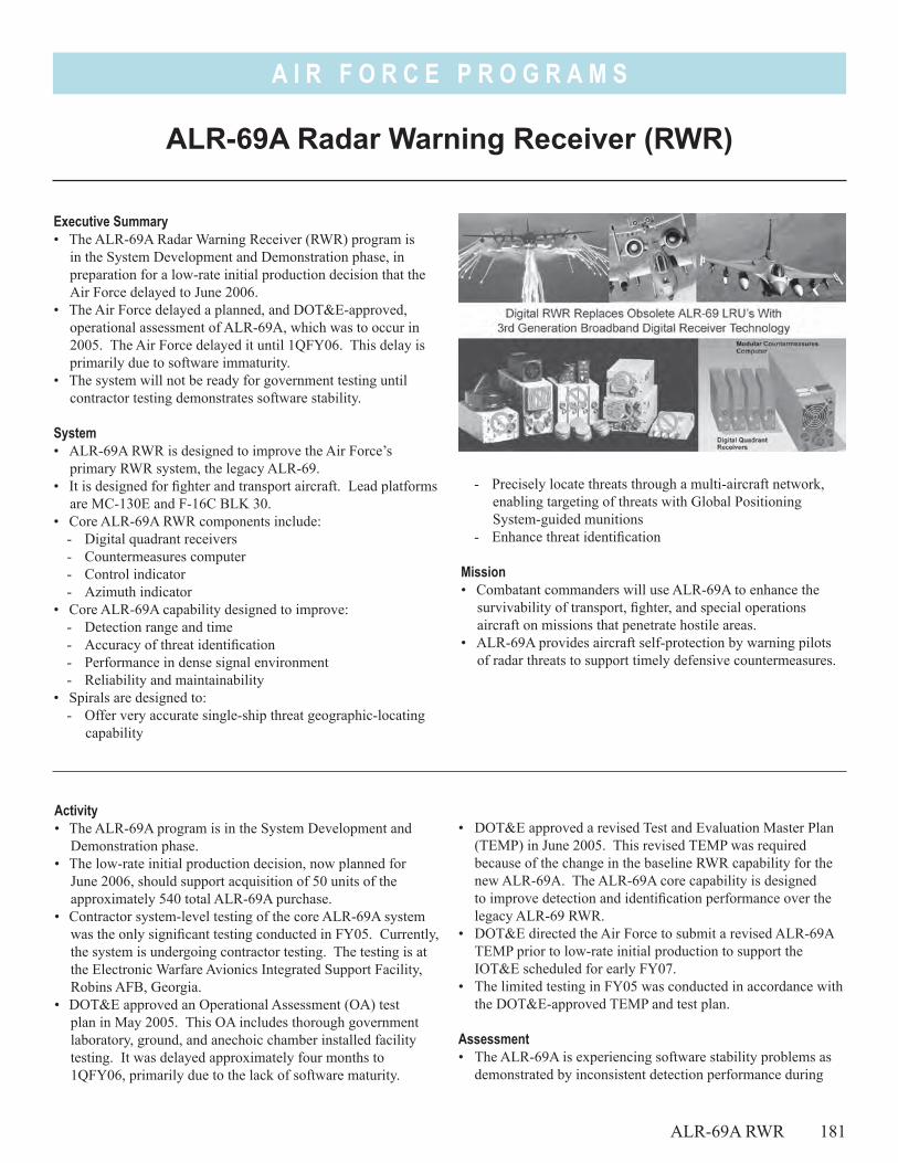
A I R F O R C E P R O G R A M S
- Precisely locate threats through a multi-aircraft network, enabling targeting of threats with Global Positioning System-guided munitions
- Enhance threat identification
Mission• Combatant commanders will use ALR-69A to enhance the
survivability of transport, fighter, and special operations aircraft on missions that penetrate hostile areas.
• ALR-69A provides aircraft self-protection by warning pilots of radar threats to support timely defensive countermeasures.
ALR-69A Radar Warning Receiver (RWR)
Executive Summary• The ALR-69A Radar Warning Receiver (RWR) program is
in the System Development and Demonstration phase, in preparation for a low-rate initial production decision that the Air Force delayed to June 2006.
• The Air Force delayed a planned, and DOT&E-approved, operational assessment of ALR-69A, which was to occur in 2005. The Air Force delayed it until 1QFY06. This delay is primarily due to software immaturity.
• The system will not be ready for government testing until contractor testing demonstrates software stability.
System• ALR-69A RWR is designed to improve the Air Force’s
primary RWR system, the legacy ALR-69. • It is designed for fighter and transport aircraft. Lead platforms
are MC-130E and F-16C BLK 30. • Core ALR-69A RWR components include:
- Digital quadrant receivers- Countermeasures computer- Control indicator- Azimuth indicator
• Core ALR-69A capability designed to improve:- Detection range and time - Accuracy of threat identification- Performance in dense signal environment- Reliability and maintainability
• Spirals are designed to: - Offer very accurate single-ship threat geographic-locating
capability
• DOT&E approved a revised Test and Evaluation Master Plan (TEMP) in June 2005. This revised TEMP was required because of the change in the baseline RWR capability for the new ALR-69A. The ALR-69A core capability is designed to improve detection and identification performance over the legacy ALR-69 RWR.
• DOT&E directed the Air Force to submit a revised ALR-69A TEMP prior to low-rate initial production to support the IOT&E scheduled for early FY07.
• The limited testing in FY05 was conducted in accordance with the DOT&E-approved TEMP and test plan.
Assessment • The ALR-69A is experiencing software stability problems as
demonstrated by inconsistent detection performance during
Activity • The ALR-69A program is in the System Development and
Demonstration phase.• The low-rate initial production decision, now planned for
June 2006, should support acquisition of 50 units of the approximately 540 total ALR-69A purchase.
• Contractor system-level testing of the core ALR-69A system was the only significant testing conducted in FY05. Currently, the system is undergoing contractor testing. The testing is at the Electronic Warfare Avionics Integrated Support Facility, Robins AFB, Georgia.
• DOT&E approved an Operational Assessment (OA) test plan in May 2005. This OA includes thorough government laboratory, ground, and anechoic chamber installed facility testing. It was delayed approximately four months to 1QFY06, primarily due to the lack of software maturity.
ALR-69A RWR 181
A I R F O R C E P R O G R A M S
182 ALR-69A RWR
contractor testing at its System Integration Laboratory and the Electronic Warfare Avionics Integrated Support Facility. The system will not be ready for government testing until contractor testing demonstrates software stability.
• The system hardware is stable as evidenced by the government’s acceptance of the system design.
• An accurate assessment of the ALR-69A system’s maturity, required to support the FY06 low-rate initial production and
FY07 full-rate production milestones, will not be available until the system is assessed in government testing.
RecommendationsNone.
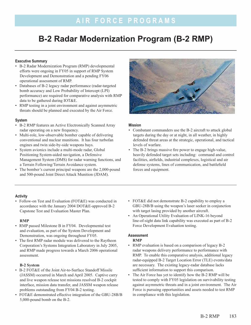
A I R F O R C E P R O G R A M S
Mission• Combatant commanders use the B-2 aircraft to attack global
targets during the day or at night, in all weather, in highly defended threat areas at the strategic, operational, and tactical levels of warfare.
• The B-2 brings massive fire power to engage high-value, heavily defended target sets including: command and control facilities, airfields, industrial complexes, logistical and air defense systems, lines of communication, and battlefield forces and equipment.
B-2 Radar Modernization Program (B-2 RMP)
Executive Summary• B-2 Radar Modernization Program (RMP) developmental
efforts were ongoing in FY05 in support of RMP System Development and Demonstration and a pending FY06 operational assessment of RMP.
• Databases of B-2 legacy radar performance (radar-targeted bomb accuracy and Low Probability of Intercept (LPI) performance) are required for comparative analysis with RMP data to be gathered during IOT&E.
• RMP testing in a joint environment and against asymmetric threats should be planned and executed by the Air Force.
System• B-2 RMP features an Active Electronically Scanned Array
radar operating on a new frequency.• Multi-role, low-observable bomber capable of delivering
conventional and nuclear munitions. It has four turbofan engines and twin side-by-side weapons bays.
• System avionics include a multi-mode radar, Global Positioning System-aided navigation, a Defensive Management System (DMS) for radar warning functions, and a Terrain Following/Terrain Avoidance system.
• The bomber’s current principal weapons are the 2,000-pound and 500-pound Joint Direct Attack Munition (JDAM).
Activity• Follow-on Test and Evaluation (FOT&E) was conducted in
accordance with the January 2004 DOT&E-approved B-2 Capstone Test and Evaluation Master Plan.
RMP• RMP passed Milestone B in FY04. Developmental test
and evaluation, as part of the System Development and Demonstration, was ongoing throughout FY05.
• The first RMP radar module was delivered to the Raytheon Corporation’s Systems Integration Laboratory in July 2005, and RMP made progress towards a March 2006 operational assessment.
B-2 System• B-2 FOT&E of the Joint Air-to-Surface Standoff Missile
(JASSM) occurred in March and April 2005. Captive carry and live weapon release test missions resolved B-2 cockpit interface, mission data transfer, and JASSM weapon release problems outstanding from FY04 B-2 testing.
• FOT&E demonstrated effective integration of the GBU-28B/B 5,000-pound bomb on the B-2.
• FOT&E did not demonstrate B-2 capability to employ a GBU-28B/B using the weapon’s laser seeker in conjunction with target lasing provided by another aircraft.
• An Operational Utility Evaluation of LINK-16 beyond line-of-sight data link capability was executed as part of B-2 Force Development Evaluation testing.
AssessmentRMP
• RMP evaluation is based on a comparison of legacy B-2 radar weapons delivery performance to performance with RMP. To enable this comparative analysis, additional legacy radar-equipped B-2 Target Location Error (TLE) events/data are necessary. The existing legacy-radar database lacks sufficient information to support this comparison.
• The Air Force has yet to identify how the B-2 RMP will be tested to comply with FY05 legislation on survivability testing against asymmetric threats and in a joint environment. The Air Force is pursuing opportunities and assets needed to test RMP in compliance with this legislation.
B-2 RMP 183
A I R F O R C E P R O G R A M S
• In order to compare B-2 RMP LPI performance to legacy B-2 radar LPI capability, legacy radar LPI flight testing is required. Existing legacy radar LPI data is insufficient to provide a basis for comparison to RMP LPI performance. The Air Force is refining test planning efforts to capture additional legacy radar LPI data.
• B-2 DMS threat system updates are provided through updates to the DMS Mission Region Sets. Outdated laboratory software and equipment, coupled with multiple co-existing B-2 aircraft operational flight program software configurations in the field, adversely impacted the Air Force ability to produce and validate Mission Region Sets software to meet operational needs. IOT&E requires updated DMS data to ensure RMP survivability testing is accomplished with the most current operational threat data.
B-2 System• FOT&E verified corrections to problems with JASSM cockpit
interface, mission data transfer, and weapon release problems.• In FYO6, FOT&E will assess:
- GBU-28B/B employment using target lasing from another aircraft
184 B-2 RMP
- Link-16 beyond line-of-sight capability in a stressed data link network environment
RecommendationsThe Air Force should:
RMP1. Develop a database of TLE measurements from legacy radar
delivered weapons to allow a comparison with similar TLE measurements to be made with the RMP radar system during IOT&E.
2. Identify a test regimen prior to Milestone C to confirm any B-2 vulnerability to an asymmetric threat when utilizing the modernized radar. Ensure a joint test and evaluation venue for B-2 RMP testing.
3. Conduct additional low probability of intercept flight testing with the B-2 legacy system to quantify B-2 LPI legacy system performance for comparison to RMP capabilities.
B-2 System1. Update Defense Management System Mission Region Set data
before conducting RMP IOT&E.
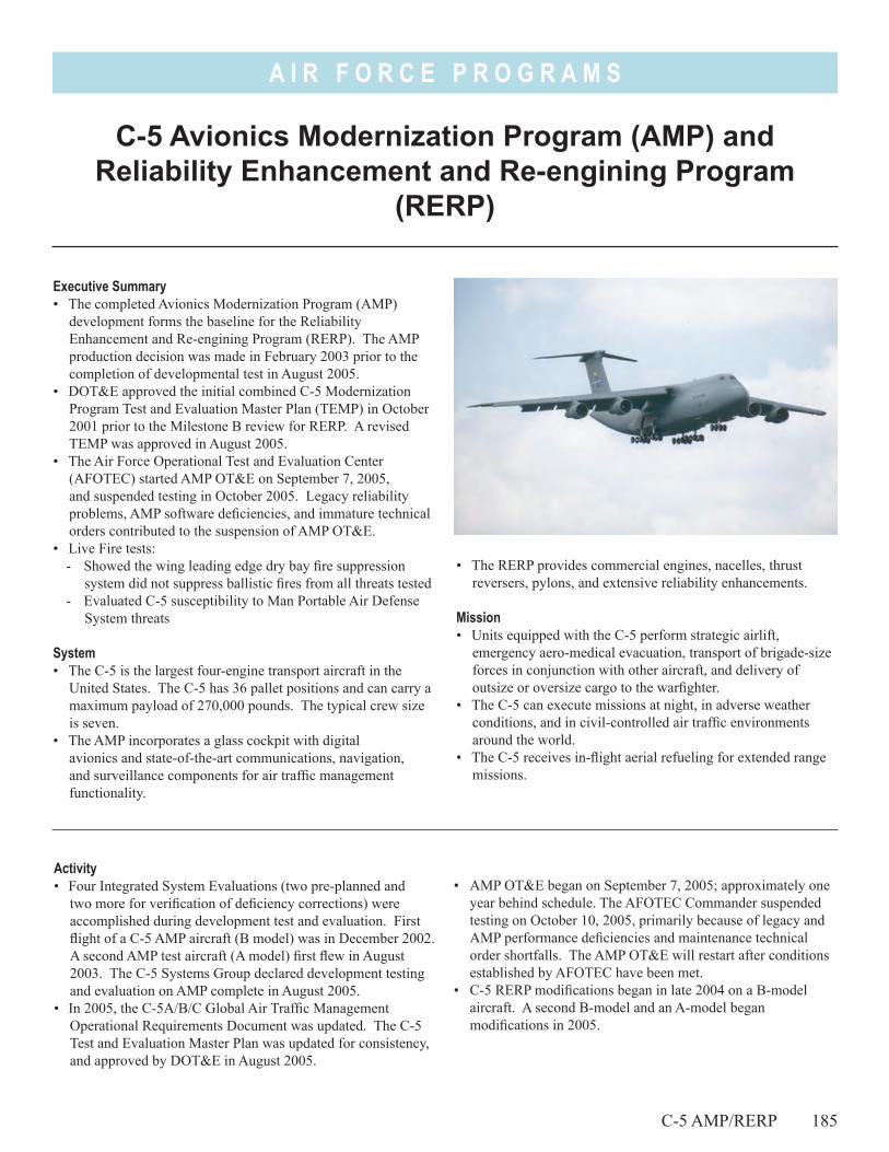
A I R F O R C E P R O G R A M S
• The RERP provides commercial engines, nacelles, thrust reversers, pylons, and extensive reliability enhancements.
Mission• Units equipped with the C-5 perform strategic airlift,
emergency aero-medical evacuation, transport of brigade-size forces in conjunction with other aircraft, and delivery of outsize or oversize cargo to the warfighter.
• The C-5 can execute missions at night, in adverse weather conditions, and in civil-controlled air traffic environments around the world.
• The C-5 receives in-flight aerial refueling for extended range missions.
C-5 Avionics Modernization Program (AMP) and Reliability Enhancement and Re-engining Program
(RERP)
Executive Summary• The completed Avionics Modernization Program (AMP)
development forms the baseline for the Reliability Enhancement and Re-engining Program (RERP). The AMP production decision was made in February 2003 prior to the completion of developmental test in August 2005.
• DOT&E approved the initial combined C-5 Modernization Program Test and Evaluation Master Plan (TEMP) in October 2001 prior to the Milestone B review for RERP. A revised TEMP was approved in August 2005.
• The Air Force Operational Test and Evaluation Center (AFOTEC) started AMP OT&E on September 7, 2005, and suspended testing in October 2005. Legacy reliability problems, AMP software deficiencies, and immature technical orders contributed to the suspension of AMP OT&E.
• Live Fire tests:- Showed the wing leading edge dry bay fire suppression
system did not suppress ballistic fires from all threats tested- Evaluated C-5 susceptibility to Man Portable Air Defense
System threats
System• The C-5 is the largest four-engine transport aircraft in the
United States. The C-5 has 36 pallet positions and can carry a maximum payload of 270,000 pounds. The typical crew size is seven.
• The AMP incorporates a glass cockpit with digital avionics and state-of-the-art communications, navigation, and surveillance components for air traffic management functionality.
• AMP OT&E began on September 7, 2005; approximately one year behind schedule. The AFOTEC Commander suspended testing on October 10, 2005, primarily because of legacy and AMP performance deficiencies and maintenance technical order shortfalls. The AMP OT&E will restart after conditions established by AFOTEC have been met.
• C-5 RERP modifications began in late 2004 on a B-model aircraft. A second B-model and an A-model began modifications in 2005.
Activity• Four Integrated System Evaluations (two pre-planned and
two more for verification of deficiency corrections) were accomplished during development test and evaluation. First flight of a C-5 AMP aircraft (B model) was in December 2002. A second AMP test aircraft (A model) first flew in August 2003. The C-5 Systems Group declared development testing and evaluation on AMP complete in August 2005.
• In 2005, the C-5A/B/C Global Air Traffic Management Operational Requirements Document was updated. The C-5 Test and Evaluation Master Plan was updated for consistency, and approved by DOT&E in August 2005.
C-5 AMP/RERP 185
A I R F O R C E P R O G R A M S
186 C-5 AMP/RERP
• Live Fire hardware-in-the-loop testing evaluated C-5M susceptibility to Man Portable Air Defense System threats during FY05.
• Live Fire ballistic tests provided data to evaluate the effectiveness of wing leading edge dry bay fire suppression systems.
Assessment• C-5 AMP software development and integration as well as
technical order development (flight manuals and maintenance manuals) were incomplete at the start of OT&E.
• Air Mobility Command personnel and equipment resources are strained by operational commitments resulting in limited support for AMP OT&E.
• The C-5 AMP operational test plan includes real-world airlift missions, maintenance demonstrations, and information assurance evaluations. Real-world operational missions for OT&E are intended to provide opportunities to evaluate the aircraft in typical environments.
• AMP development has experienced unrealistic schedules, unstable software systems, and immature systems integration. Resolution of AMP deficiencies, extension of the AMP OT&E schedule, and the RERP development timeline are affected.
• Wing leading and trailing edge dry bays are vulnerable to threat induced fires. The fire suppression system is not effective against all expected threats.
• The C-5 RERP is nine months behind schedule.
Recommendations1. An updated executable acquisition strategy is necessary for
program success. 2. Continuity among the current AMP and the future RERP test
teams should be maintained to the maximum extent possible. 3. Consider development of improved dry bay fire suppression
systems in the wing leading edge and evaluate them against expected ballistic threats.
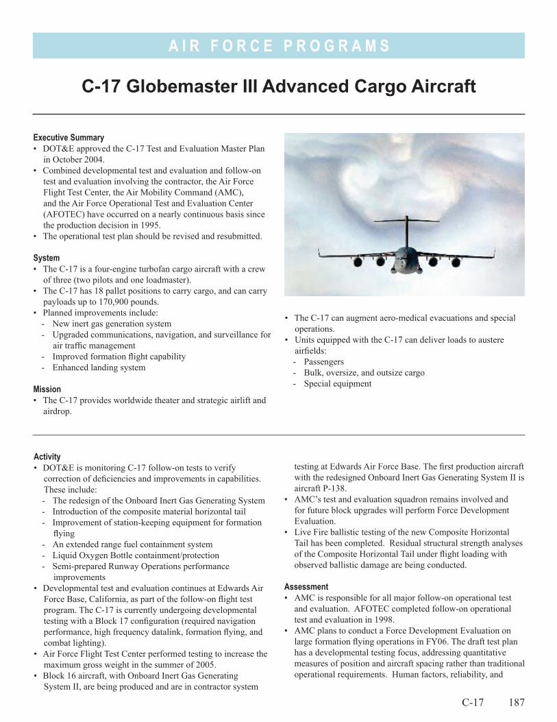
A I R F O R C E P R O G R A M S
• The C-17 can augment aero-medical evacuations and special operations.
• Units equipped with the C-17 can deliver loads to austere airfields:- Passengers - Bulk, oversize, and outsize cargo- Special equipment
C-17 Globemaster III Advanced Cargo Aircraft
C-17 187
Executive Summary• DOT&E approved the C-17 Test and Evaluation Master Plan
in October 2004.• Combined developmental test and evaluation and follow-on
test and evaluation involving the contractor, the Air Force Flight Test Center, the Air Mobility Command (AMC), and the Air Force Operational Test and Evaluation Center (AFOTEC) have occurred on a nearly continuous basis since the production decision in 1995.
• The operational test plan should be revised and resubmitted.
System• The C-17 is a four-engine turbofan cargo aircraft with a crew
of three (two pilots and one loadmaster).• The C-17 has 18 pallet positions to carry cargo, and can carry
payloads up to 170,900 pounds.• Planned improvements include:
- New inert gas generation system- Upgraded communications, navigation, and surveillance for
air traffic management- Improved formation flight capability- Enhanced landing system
Mission• The C-17 provides worldwide theater and strategic airlift and
airdrop.
Activity• DOT&E is monitoring C-17 follow-on tests to verify
correction of deficiencies and improvements in capabilities. These include:- The redesign of the Onboard Inert Gas Generating System- Introduction of the composite material horizontal tail- Improvement of station-keeping equipment for formation
flying- An extended range fuel containment system- Liquid Oxygen Bottle containment/protection- Semi-prepared Runway Operations performance
improvements• Developmental test and evaluation continues at Edwards Air
Force Base, California, as part of the follow-on flight test program. The C-17 is currently undergoing developmental testing with a Block 17 configuration (required navigation performance, high frequency datalink, formation flying, and combat lighting).
• Air Force Flight Test Center performed testing to increase the maximum gross weight in the summer of 2005.
• Block 16 aircraft, with Onboard Inert Gas Generating System II, are being produced and are in contractor system
testing at Edwards Air Force Base. The first production aircraft with the redesigned Onboard Inert Gas Generating System II is aircraft P-138.
• AMC’s test and evaluation squadron remains involved and for future block upgrades will perform Force Development Evaluation.
• Live Fire ballistic testing of the new Composite Horizontal Tail has been completed. Residual structural strength analyses of the Composite Horizontal Tail under flight loading with observed ballistic damage are being conducted.
Assessment• AMC is responsible for all major follow-on operational test
and evaluation. AFOTEC completed follow-on operational test and evaluation in 1998.
• AMC plans to conduct a Force Development Evaluation on large formation flying operations in FY06. The draft test plan has a developmental testing focus, addressing quantitative measures of position and aircraft spacing rather than traditional operational requirements. Human factors, reliability, and
A I R F O R C E P R O G R A M S
operational effectiveness were to be minimally tested. AMC should submit a revised plan.
• AMC plans follow-on operational testing with Onboard Inert Gas Generating System II and Block 17 in late 2006.
188 C-17
Recommendation1. AMC should submit plans for follow-on test of formation
flight operations and the onboard inert gas generating system.
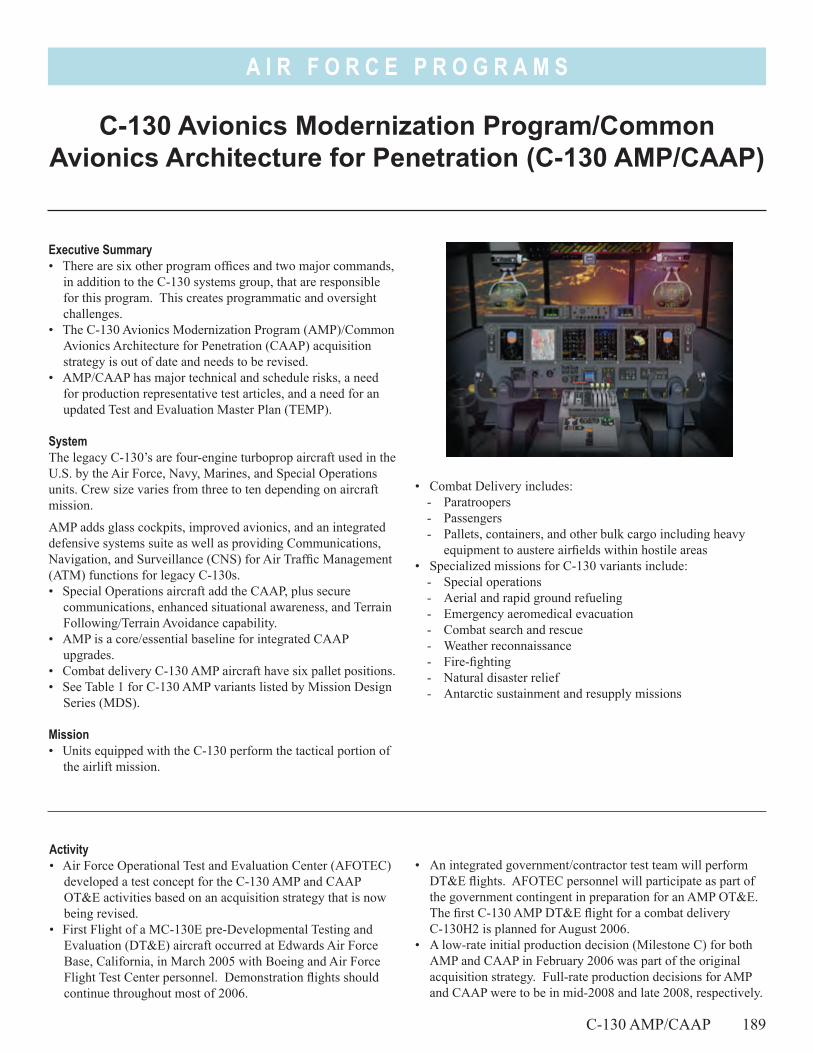
A I R F O R C E P R O G R A M S
C-130 Avionics Modernization Program/Common Avionics Architecture for Penetration (C-130 AMP/CAAP)
Executive Summary• There are six other program offices and two major commands,
in addition to the C-130 systems group, that are responsible for this program. This creates programmatic and oversight challenges.
• The C-130 Avionics Modernization Program (AMP)/Common Avionics Architecture for Penetration (CAAP) acquisition strategy is out of date and needs to be revised.
• AMP/CAAP has major technical and schedule risks, a need for production representative test articles, and a need for an updated Test and Evaluation Master Plan (TEMP).
SystemThe legacy C-130’s are four-engine turboprop aircraft used in the U.S. by the Air Force, Navy, Marines, and Special Operations units. Crew size varies from three to ten depending on aircraft mission.
AMP adds glass cockpits, improved avionics, and an integrated defensive systems suite as well as providing Communications, Navigation, and Surveillance (CNS) for Air Traffic Management (ATM) functions for legacy C-130s.• Special Operations aircraft add the CAAP, plus secure
communications, enhanced situational awareness, and Terrain Following/Terrain Avoidance capability.
• AMP is a core/essential baseline for integrated CAAP upgrades.
• Combat delivery C-130 AMP aircraft have six pallet positions.• See Table 1 for C-130 AMP variants listed by Mission Design
Series (MDS).
Mission• Units equipped with the C-130 perform the tactical portion of
the airlift mission.
• Combat Delivery includes:- Paratroopers- Passengers- Pallets, containers, and other bulk cargo including heavy
equipment to austere airfields within hostile areas• Specialized missions for C-130 variants include:
- Special operations- Aerial and rapid ground refueling- Emergency aeromedical evacuation- Combat search and rescue- Weather reconnaissance- Fire-fighting- Natural disaster relief- Antarctic sustainment and resupply missions
Activity• Air Force Operational Test and Evaluation Center (AFOTEC)
developed a test concept for the C-130 AMP and CAAP OT&E activities based on an acquisition strategy that is now being revised.
• First Flight of a MC-130E pre-Developmental Testing and Evaluation (DT&E) aircraft occurred at Edwards Air Force Base, California, in March 2005 with Boeing and Air Force Flight Test Center personnel. Demonstration flights should continue throughout most of 2006.
• An integrated government/contractor test team will perform DT&E flights. AFOTEC personnel will participate as part of the government contingent in preparation for an AMP OT&E. The first C-130 AMP DT&E flight for a combat delivery C-130H2 is planned for August 2006.
• A low-rate initial production decision (Milestone C) for both AMP and CAAP in February 2006 was part of the original acquisition strategy. Full-rate production decisions for AMP and CAAP were to be in mid-2008 and late 2008, respectively.
C-130 AMP/CAAP 189
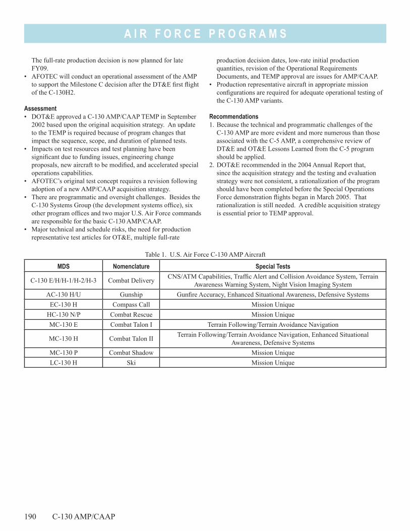
A I R F O R C E P R O G R A M S
The full-rate production decision is now planned for late FY09.
• AFOTEC will conduct an operational assessment of the AMP to support the Milestone C decision after the DT&E first flight of the C-130H2.
Assessment• DOT&E approved a C-130 AMP/CAAP TEMP in September
2002 based upon the original acquisition strategy. An update to the TEMP is required because of program changes that impact the sequence, scope, and duration of planned tests.
• Impacts on test resources and test planning have been significant due to funding issues, engineering change proposals, new aircraft to be modified, and accelerated special operations capabilities.
• AFOTEC’s original test concept requires a revision following adoption of a new AMP/CAAP acquisition strategy.
• There are programmatic and oversight challenges. Besides the C-130 Systems Group (the development systems office), six other program offices and two major U.S. Air Force commands are responsible for the basic C-130 AMP/CAAP.
• Major technical and schedule risks, the need for production representative test articles for OT&E, multiple full-rate
production decision dates, low-rate initial production quantities, revision of the Operational Requirements Documents, and TEMP approval are issues for AMP/CAAP.
• Production representative aircraft in appropriate mission configurations are required for adequate operational testing of the C-130 AMP variants.
Recommendations1. Because the technical and programmatic challenges of the
C-130 AMP are more evident and more numerous than those associated with the C-5 AMP, a comprehensive review of DT&E and OT&E Lessons Learned from the C-5 program should be applied.
2. DOT&E recommended in the 2004 Annual Report that, since the acquisition strategy and the testing and evaluation strategy were not consistent, a rationalization of the program should have been completed before the Special Operations Force demonstration flights began in March 2005. That rationalization is still needed. A credible acquisition strategy is essential prior to TEMP approval.
Table 1. U.S. Air Force C-130 AMP Aircraft
MDS Nomenclature Special Tests
C-130 E/H/H-1/H-2/H-3 Combat Delivery CNS/ATM Capabilities, Traffic Alert and Collision Avoidance System, Terrain Awareness Warning System, Night Vision Imaging System
AC-130 H/U Gunship Gunfire Accuracy, Enhanced Situational Awareness, Defensive SystemsEC-130 H Compass Call Mission Unique
HC-130 N/P Combat Rescue Mission UniqueMC-130 E Combat Talon I Terrain Following/Terrain Avoidance Navigation
MC-130 H Combat Talon II Terrain Following/Terrain Avoidance Navigation, Enhanced Situational Awareness, Defensive Systems
MC-130 P Combat Shadow Mission UniqueLC-130 H Ski Mission Unique
190 C-130 AMP/CAAP
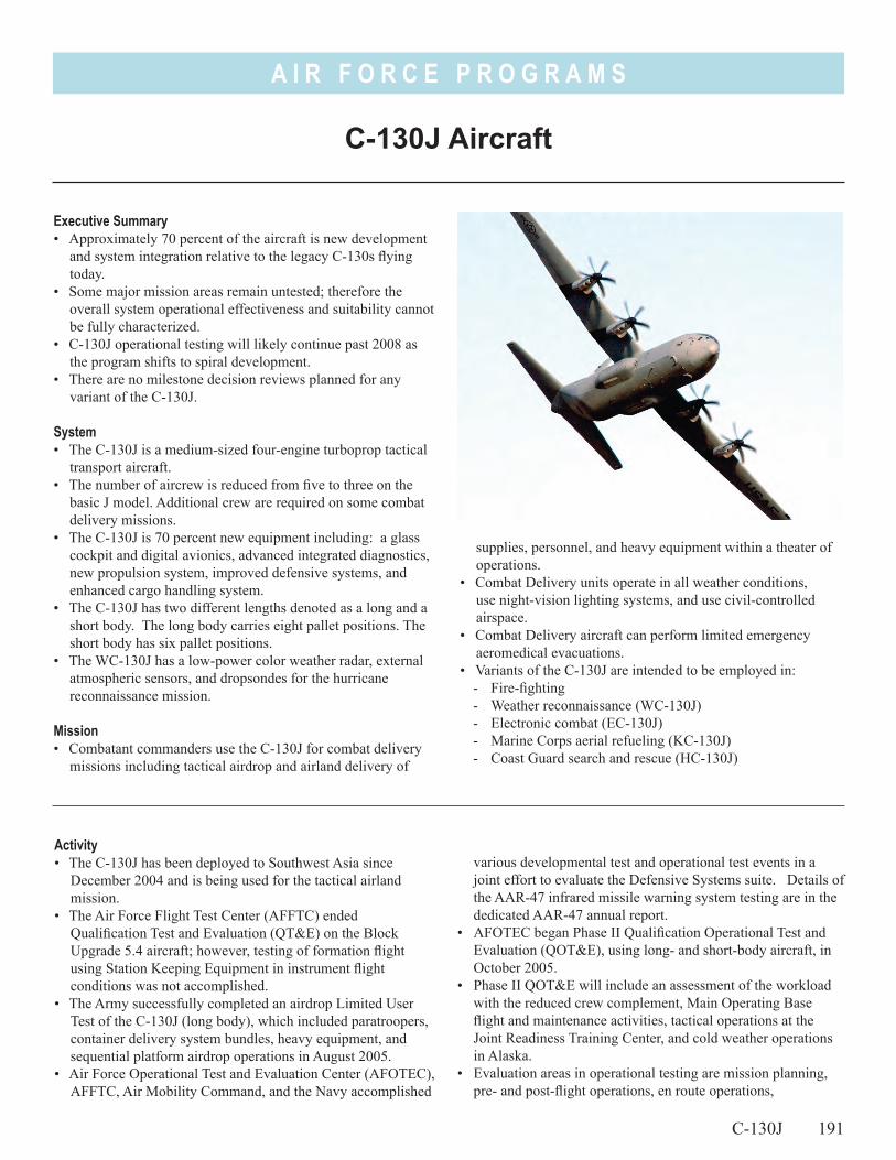
A I R F O R C E P R O G R A M S
Executive Summary• Approximately 70 percent of the aircraft is new development
and system integration relative to the legacy C-130s flying today.
• Some major mission areas remain untested; therefore the overall system operational effectiveness and suitability cannot be fully characterized.
• C-130J operational testing will likely continue past 2008 as the program shifts to spiral development.
• There are no milestone decision reviews planned for any variant of the C-130J.
System• The C-130J is a medium-sized four-engine turboprop tactical
transport aircraft.• The number of aircrew is reduced from five to three on the
basic J model. Additional crew are required on some combat delivery missions.
• The C-130J is 70 percent new equipment including: a glass cockpit and digital avionics, advanced integrated diagnostics, new propulsion system, improved defensive systems, and enhanced cargo handling system.
• The C-130J has two different lengths denoted as a long and a short body. The long body carries eight pallet positions. The short body has six pallet positions.
• The WC-130J has a low-power color weather radar, external atmospheric sensors, and dropsondes for the hurricane reconnaissance mission.
Mission• Combatant commanders use the C-130J for combat delivery
missions including tactical airdrop and airland delivery of
supplies, personnel, and heavy equipment within a theater of operations.
• Combat Delivery units operate in all weather conditions, use night-vision lighting systems, and use civil-controlled airspace.
• Combat Delivery aircraft can perform limited emergency aeromedical evacuations.
• Variants of the C-130J are intended to be employed in:- Fire-fighting- Weather reconnaissance (WC-130J)- Electronic combat (EC-130J)- Marine Corps aerial refueling (KC-130J)- Coast Guard search and rescue (HC-130J)
Activity• The C-130J has been deployed to Southwest Asia since
December 2004 and is being used for the tactical airland mission.
• The Air Force Flight Test Center (AFFTC) ended Qualification Test and Evaluation (QT&E) on the Block Upgrade 5.4 aircraft; however, testing of formation flight using Station Keeping Equipment in instrument flight conditions was not accomplished.
• The Army successfully completed an airdrop Limited User Test of the C-130J (long body), which included paratroopers, container delivery system bundles, heavy equipment, and sequential platform airdrop operations in August 2005.
• Air Force Operational Test and Evaluation Center (AFOTEC), AFFTC, Air Mobility Command, and the Navy accomplished
various developmental test and operational test events in a joint effort to evaluate the Defensive Systems suite. Details of the AAR-47 infrared missile warning system testing are in the dedicated AAR-47 annual report.
• AFOTEC began Phase II Qualification Operational Test and Evaluation (QOT&E), using long- and short-body aircraft, in October 2005.
• Phase II QOT&E will include an assessment of the workload with the reduced crew complement, Main Operating Base flight and maintenance activities, tactical operations at the Joint Readiness Training Center, and cold weather operations in Alaska.
• Evaluation areas in operational testing are mission planning, pre- and post-flight operations, en route operations,
C-130J 191
C-130J Aircraft
A I R F O R C E P R O G R A M S
192 C-130J
airland, airdrop, formation operations, sustainment, sortie generation, and self-deployment to representative operational environments.
Assessment• The following were not adequately characterized prior to entry
into Phase II QOT&E: - Correction of some deficiencies - Establishment of new procedures- Full characterization of defensive systems - Formation flight in adverse weather
Evaluations of these are not included in Phase II QOT&E.• Developmental test results by AFFTC and the Army’s Limited
User Test indicate that the C-130J will be operationally effective in single ship airdrop under specific scenarios and conditions.
• This evaluation is waiting for the analysis of Phase II QOT&E data. The reliability, maintainability, and availability performance of the C-130J have not been evaluated relative to
operational requirements. Reports from Air National Guard and Air Force Reserve units, from deployments in Southwest Asia, as well as from QT&E, will be utilized.
• C-130J Engine Nacelle Fire Suppression System Testing is on hold awaiting resolution of environmental concerns raised by SAF/AQR regarding the use and atmospheric release of Halon 1211.
Recommendations1. Follow-on operational test and evaluation will be required to
evaluate formation flight using Station Keeping Equipment in instrument flight conditions and improved defensive systems, as well as future block upgrades.
2. The U.S. Air Force needs to fully assess the defensive systems (AAR-47 and ALR-56M) as installed on the C-130J.
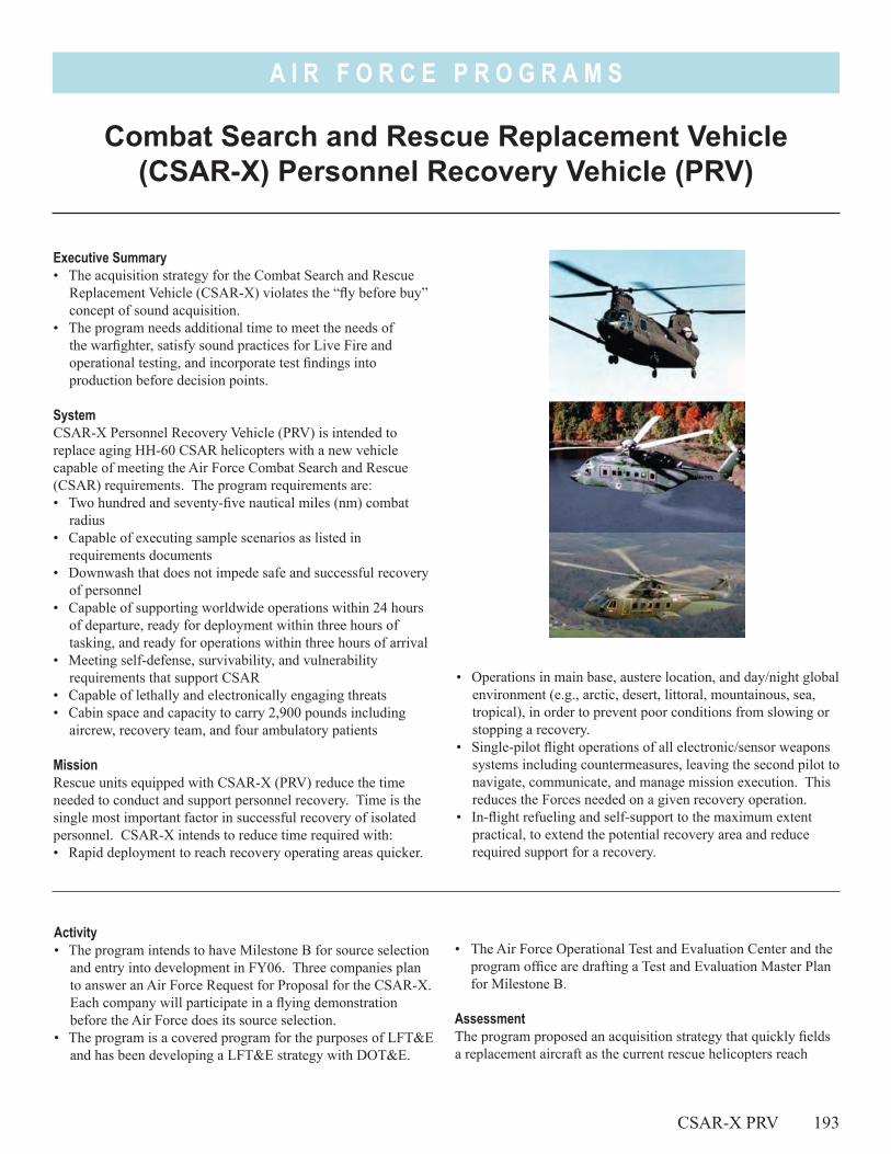
A I R F O R C E P R O G R A M S
• Operations in main base, austere location, and day/night global environment (e.g., arctic, desert, littoral, mountainous, sea, tropical), in order to prevent poor conditions from slowing or stopping a recovery.
• Single-pilot flight operations of all electronic/sensor weapons systems including countermeasures, leaving the second pilot to navigate, communicate, and manage mission execution. This reduces the Forces needed on a given recovery operation.
• In-flight refueling and self-support to the maximum extent practical, to extend the potential recovery area and reduce required support for a recovery.
Executive Summary• The acquisition strategy for the Combat Search and Rescue
Replacement Vehicle (CSAR-X) violates the “fly before buy” concept of sound acquisition.
• The program needs additional time to meet the needs of the warfighter, satisfy sound practices for Live Fire and operational testing, and incorporate test findings into production before decision points.
SystemCSAR-X Personnel Recovery Vehicle (PRV) is intended to replace aging HH-60 CSAR helicopters with a new vehicle capable of meeting the Air Force Combat Search and Rescue (CSAR) requirements. The program requirements are:• Two hundred and seventy-five nautical miles (nm) combat
radius• Capable of executing sample scenarios as listed in
requirements documents• Downwash that does not impede safe and successful recovery
of personnel• Capable of supporting worldwide operations within 24 hours
of departure, ready for deployment within three hours of tasking, and ready for operations within three hours of arrival
• Meeting self-defense, survivability, and vulnerability requirements that support CSAR
• Capable of lethally and electronically engaging threats• Cabin space and capacity to carry 2,900 pounds including
aircrew, recovery team, and four ambulatory patients
MissionRescue units equipped with CSAR-X (PRV) reduce the time needed to conduct and support personnel recovery. Time is the single most important factor in successful recovery of isolated personnel. CSAR-X intends to reduce time required with:• Rapid deployment to reach recovery operating areas quicker.
Combat Search and Rescue Replacement Vehicle (CSAR-X) Personnel Recovery Vehicle (PRV)
Activity• The program intends to have Milestone B for source selection
and entry into development in FY06. Three companies plan to answer an Air Force Request for Proposal for the CSAR-X. Each company will participate in a flying demonstration before the Air Force does its source selection.
• The program is a covered program for the purposes of LFT&E and has been developing a LFT&E strategy with DOT&E.
• The Air Force Operational Test and Evaluation Center and the program office are drafting a Test and Evaluation Master Plan for Milestone B.
AssessmentThe program proposed an acquisition strategy that quickly fields a replacement aircraft as the current rescue helicopters reach
CSAR-X PRV 193
A I R F O R C E P R O G R A M S
194 CSAR-X PRV
retirement. This strategy uses previously-developed aircraft, and proposes modifying them to meet rescue requirements. The program intends development to be only 18 months, including Live Fire testing and initial developmental testing. It will support a low-rate initial production decision with an operational assessment. The program then proposed to modify or retrofit the developmental aircraft before starting initial operational testing.
DOT&E is concerned that the acquisition strategy will not incorporate corrections into production before Operational Testing (OT). The strategy violates the “fly before buy” concept because it: • Begins low-rate production before the developer can
incorporate findings from Live Fire testing into design
• Carries developmental aircraft not production aircraft into OT• Commits to full-rate production before the developer can
incorporate findings from OT into production
Recommendations1. While we recognize the Service’s need for a replacement
helicopter, the test program should adopt an event-driven strategy instead of a schedule driven one.
2. The strategy should complete Live Fire development before producing aircraft. The program should adopt a test-fix-fly approach to development and initial production.
3. The program should use production-representative aircraft for operational testing.
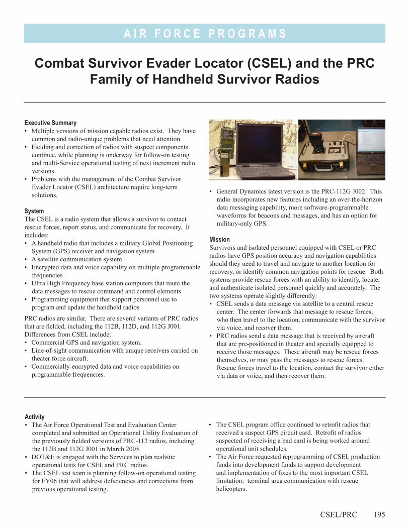
A I R F O R C E P R O G R A M S
Combat Survivor Evader Locator (CSEL) and the PRC Family of Handheld Survivor Radios
Executive Summary• Multiple versions of mission capable radios exist. They have
common and radio-unique problems that need attention.• Fielding and correction of radios with suspect components
continue, while planning is underway for follow-on testing and multi-Service operational testing of next increment radio versions.
• Problems with the management of the Combat Survivor Evader Locator (CSEL) architecture require long-term solutions.
SystemThe CSEL is a radio system that allows a survivor to contact rescue forces, report status, and communicate for recovery. It includes:• A handheld radio that includes a military Global Positioning
System (GPS) receiver and navigation system • A satellite communication system• Encrypted data and voice capability on multiple programmable
frequencies• Ultra High Frequency base station computers that route the
data messages to rescue command and control elements• Programming equipment that support personnel use to
program and update the handheld radios
PRC radios are similar. There are several variants of PRC radios that are fielded, including the 112B, 112D, and 112G J001. Differences from CSEL include:• Commercial GPS and navigation system.• Line-of-sight communication with unique receivers carried on
theater force aircraft.• Commercially-encrypted data and voice capabilities on
programmable frequencies.
• General Dynamics latest version is the PRC-112G J002. This radio incorporates new features including an over-the-horizon data messaging capability, more software-programmable waveforms for beacons and messages, and has an option for military-only GPS.
MissionSurvivors and isolated personnel equipped with CSEL or PRC radios have GPS position accuracy and navigation capabilities should they need to travel and navigate to another location for recovery, or identify common navigation points for rescue. Both systems provide rescue forces with an ability to identify, locate, and authenticate isolated personnel quickly and accurately. The two systems operate slightly differently:• CSEL sends a data message via satellite to a central rescue
center. The center forwards that message to rescue forces, who then travel to the location, communicate with the survivor via voice, and recover them.
• PRC radios send a data message that is received by aircraft that are pre-positioned in theater and specially equipped to receive those messages. These aircraft may be rescue forces themselves, or may pass the messages to rescue forces. Rescue forces travel to the location, contact the survivor either via data or voice, and then recover them.
Activity• The Air Force Operational Test and Evaluation Center
completed and submitted an Operational Utility Evaluation of the previously fielded versions of PRC-112 radios, including the 112B and 112G J001 in March 2005.
• DOT&E is engaged with the Services to plan realistic operational tests for CSEL and PRC radios.
• The CSEL test team is planning follow-on operational testing for FY06 that will address deficiencies and corrections from previous operational testing.
• The CSEL program office continued to retrofit radios that received a suspect GPS circuit card. Retrofit of radios suspected of receiving a bad card is being worked around operational unit schedules.
• The Air Force requested reprogramming of CSEL production funds into development funds to support development and implementation of fixes to the most important CSEL limitation: terminal area communication with rescue helicopters.
CSEL/PRC 195
A I R F O R C E P R O G R A M S
196 CSEL/PRC
• PRC-112G J002 has not yet been operationally tested, but planning is underway.
• Air Force Special Operations Command (AFSOC) purchased 1,402 PRC-112G J002 radios.
• Shortly after AFSOC purchased their radios, General Dynamics announced that they are recalling all 112G J002 radios for defective printed circuit boards. Impact to AFSOC radios is not yet known.
Assessment• Reprogramming production funds into research, development,
test, and evaluation will support development of terminal area communication for CSEL. Lack of this feature was highlighted as the most serious shortcoming of CSEL during multi-Service operational testing.
• Bad CSEL and PRC circuit cards impact operational units in that they must return radios to the developer for retrofit. This reduces the number of radios operationally available.
• The CSEL developer corrected the initial batch of suspect cards before any radios were operationally deployed and found some flawed cards. The list of suspect cards expanded later in FY05, and the developer continued to replace cards but found no other flawed cards.
• The Operational Utility Evaluation of PRC radios identified a number of issues that should be corrected as soon as possible. Some were similar to CSEL test results, such as inadequate training and a lack of well-defined operations concepts. Others are unique to PRC radios and may not be easily fixed, such as non-accredited encryption for secure communication, and batteries that discharge and expel toxic gas when in contact with salt water.
• Operational units assume undetermined risks when they purchase products without adequate and realistic operational
testing. Previous versions of PRC radios have been tested and employed operationally, and the latest version is similar but has new capabilities. Operational units are relying on manufacturer information about capabilities instead of adequate operational test data. Rapid acquisition does not equate to rapid capability. Purchasing radios directly provides the radio and immediate support equipment, but does not provide all parts of the system or the training needed to use the newly purchased radios.
• The recall of suspect printed circuits for direct-purchase 112G J002 radios highlights another risk for operational units. Operational units incur additional burdens because they must assign and task manpower to identify, package, and return affected radios, accurately track the radios they have, and introduce corrected radios back into the field.
Recommendations1. The Air Force Operational Test and Evaluation Center should
plan and conduct CSEL follow-on operational testing in FY06. AFOTEC should lead the other services in multi-Service operational testing in FY07 that tests an upgraded CSEL system (with terminal area communication) and the latest generation PRC radio (with over-the-horizon communication) in similar environments and scenarios.
2. The Air Force has not determined an operational agency to supervise and manage CSEL architecture, as recommended by DOT&E in our FY04 report. DOT&E also recommended that the Services develop a strategy for updating and replacing the oldest survivor radios with newer advanced radios. At this time, we have not seen this strategy. Operational units continue to procure radios directly. While the need is understandable, this approach sidesteps Service efforts to develop and support a survivor radio system for the long term.
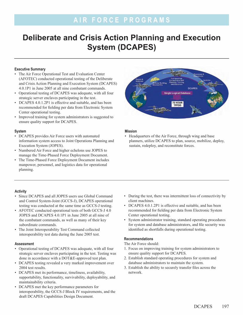
A I R F O R C E P R O G R A M S
Mission• Headquarters of the Air Force, through wing and base
planners, utilize DCAPES to plan, source, mobilize, deploy, sustain, redeploy, and reconstitute forces.
Deliberate and Crisis Action Planning and Execution System (DCAPES)
DCAPES 197
Executive Summary• The Air Force Operational Test and Evaluation Center
(AFOTEC) conducted operational testing of the Deliberate and Crisis Action Planning and Execution System (DCAPES) 4.0.1P1 in June 2005 at all nine combatant commands.
• Operational testing of DCAPES was adequate, with all four strategic server enclaves participating in the test.
• DCAPES 4.0.1.2P1 is effective and suitable, and has been recommended for fielding per data from Electronic System Center operational testing.
• Improved training for system administrators is suggested to ensure quality support for DCAPES.
System• DCAPES provides Air Force users with automated
information system access to Joint Operations Planning and Execution System (JOPES).
• Numbered Air Force and higher echelons use JOPES to manage the Time-Phased Force Deployment Document.
• The Time-Phased Force Deployment Document includes manpower, personnel, and logistics data for operational planning.
Activity• Since DCAPES and all JOPES users use Global Command
and Control System-Joint (GCCS-J), DCAPES operational testing was conducted at the same time as GCCS-J testing.
• AFOTEC conducted operational tests of both GCCS-J 4.0 JOPES and DCAPES 4.0.1P1 in June 2005 at all nine of the combatant commands, as well as many of their key subordinate commands.
• The Joint Interoperability Test Command collected interoperability test data during the June 2005 test.
Assessment• Operational testing of DCAPES was adequate, with all four
strategic server enclaves participating in the test. Testing was done in accordance with a DOT&E-approved test plan.
• DCAPES testing revealed a very marked improvement over 2004 test results.
• DCAPES met its performance, timeliness, availability, supportability, functionality, survivability, deployability, and maintainability criteria.
• DCAPES met the key performance parameters for interoperability, the GCCS-J Block IV requirements, and the draft DCAPES Capabilities Design Document.
• During the test, there was intermittent loss of connectivity by client machines.
• DCAPES 4.0.1.2P1 is effective and suitable, and has been recommended for fielding per data from Electronic System Center operational testing.
• System administrator training, standard operating procedures for system and database administrators, and file security was identified as shortfalls during operational testing.
RecommendationsThe Air Force should:1. Focus on improving training for system administrators to
ensure quality support for DCAPES.2. Establish standard operating procedures for system and
database administrators to maintain the system.3. Establish the ability to securely transfer files across the
network.

198
A I R F O R C E P R O G R A M S
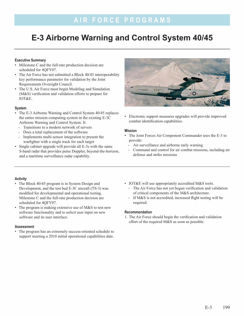
A I R F O R C E P R O G R A M S
E-3 Airborne Warning and Control System 40/45
E-3 199
Executive Summary• Milestone C and the full-rate production decision are
scheduled for 4QFY07.• The Air Force has not submitted a Block 40/45 interoperability
key performance parameter for validation by the Joint Requirements Oversight Council.
• The U.S. Air Force must begin Modeling and Simulation (M&S) verification and validation efforts to prepare for IOT&E.
System• The E-3 Airborne Warning and Control System 40/45 replaces
the entire mission computing system in the existing E-3C Airborne Warning and Control System. It:- Transitions to a modern network of servers- Does a total replacement of the software- Implements multi-sensor integration to present the
warfighter with a single track for each target• Single cabinet upgrade will provide all E-3s with the same
S-band radar that provides pulse Doppler, beyond-the-horizon, and a maritime surveillance radar capability.
• Electronic support measures upgrades will provide improved combat identification capabilities.
Mission• The Joint Forces Air Component Commander uses the E-3 to
provide:- Air surveillance and airborne early warning- Command and control for air combat missions, including air
defense and strike missions
Activity• The Block 40/45 program is in System Design and
Development, and the test bed E-3C aircraft (TS-3) was modified for developmental and operational testing. Milestone C and the full-rate production decision are scheduled for 4QFY07.
• The program is making extensive use of M&S to test new software functionality and to solicit user input on new software and its user interface.
Assessment• The program has an extremely success-oriented schedule to
support meeting a 2010 initial operational capabilities date.
• IOT&E will use appropriately accredited M&S tools.- The Air Force has not yet begun verification and validation
of critical components of the M&S architecture. - If M&S is not accredited, increased flight testing will be
required.
Recommendation1. The Air Force should begin the verification and validation
effort of the required M&S as soon as possible.

200
A I R F O R C E P R O G R A M S
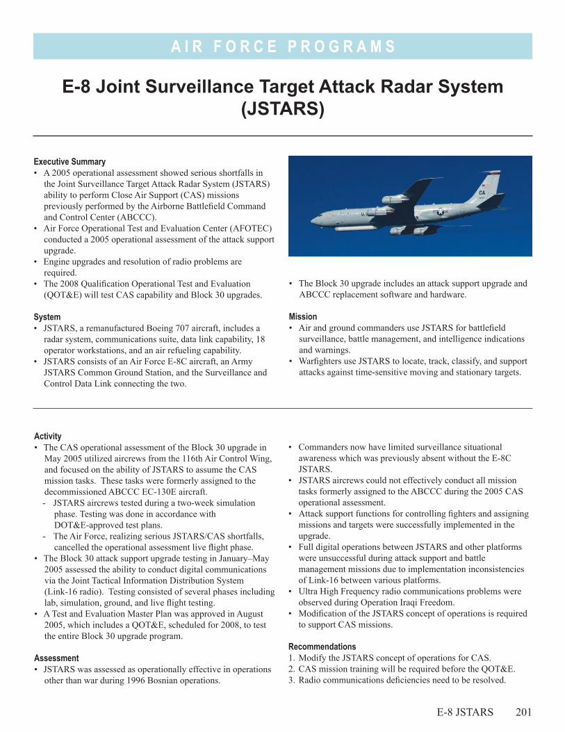
A I R F O R C E P R O G R A M S
• The Block 30 upgrade includes an attack support upgrade and ABCCC replacement software and hardware.
Mission• Air and ground commanders use JSTARS for battlefield
surveillance, battle management, and intelligence indications and warnings.
• Warfighters use JSTARS to locate, track, classify, and support attacks against time-sensitive moving and stationary targets.
E-8 Joint Surveillance Target Attack Radar System (JSTARS)
E-8 JSTARS 201
Executive Summary• A 2005 operational assessment showed serious shortfalls in
the Joint Surveillance Target Attack Radar System (JSTARS) ability to perform Close Air Support (CAS) missions previously performed by the Airborne Battlefield Command and Control Center (ABCCC).
• Air Force Operational Test and Evaluation Center (AFOTEC) conducted a 2005 operational assessment of the attack support upgrade.
• Engine upgrades and resolution of radio problems are required.
• The 2008 Qualification Operational Test and Evaluation (QOT&E) will test CAS capability and Block 30 upgrades.
System• JSTARS, a remanufactured Boeing 707 aircraft, includes a
radar system, communications suite, data link capability, 18 operator workstations, and an air refueling capability.
• JSTARS consists of an Air Force E-8C aircraft, an Army JSTARS Common Ground Station, and the Surveillance and Control Data Link connecting the two.
Activity• The CAS operational assessment of the Block 30 upgrade in
May 2005 utilized aircrews from the 116th Air Control Wing, and focused on the ability of JSTARS to assume the CAS mission tasks. These tasks were formerly assigned to the decommissioned ABCCC EC-130E aircraft.- JSTARS aircrews tested during a two-week simulation
phase. Testing was done in accordance with DOT&E-approved test plans.
- The Air Force, realizing serious JSTARS/CAS shortfalls, cancelled the operational assessment live flight phase.
• The Block 30 attack support upgrade testing in January–May 2005 assessed the ability to conduct digital communications via the Joint Tactical Information Distribution System (Link-16 radio). Testing consisted of several phases including lab, simulation, ground, and live flight testing.
• A Test and Evaluation Master Plan was approved in August 2005, which includes a QOT&E, scheduled for 2008, to test the entire Block 30 upgrade program.
Assessment• JSTARS was assessed as operationally effective in operations
other than war during 1996 Bosnian operations.
• Commanders now have limited surveillance situational awareness which was previously absent without the E-8C JSTARS.
• JSTARS aircrews could not effectively conduct all mission tasks formerly assigned to the ABCCC during the 2005 CAS operational assessment.
• Attack support functions for controlling fighters and assigning missions and targets were successfully implemented in the upgrade.
• Full digital operations between JSTARS and other platforms were unsuccessful during attack support and battle management missions due to implementation inconsistencies of Link-16 between various platforms.
• Ultra High Frequency radio communications problems were observed during Operation Iraqi Freedom.
• Modification of the JSTARS concept of operations is required to support CAS missions.
Recommendations1. Modify the JSTARS concept of operations for CAS. 2. CAS mission training will be required before the QOT&E.3. Radio communications deficiencies need to be resolved.
A I R F O R C E P R O G R A M S
4. Engine upgrades are required to improve mission reliability rates and increase operating altitudes.
5. Air Combat Command should conduct further operational test and evaluation with JSTARS, fighter aircraft, and ground
202 E-8 JSTARS
elements in order to resolve the issues identified during attack support upgrade testing.
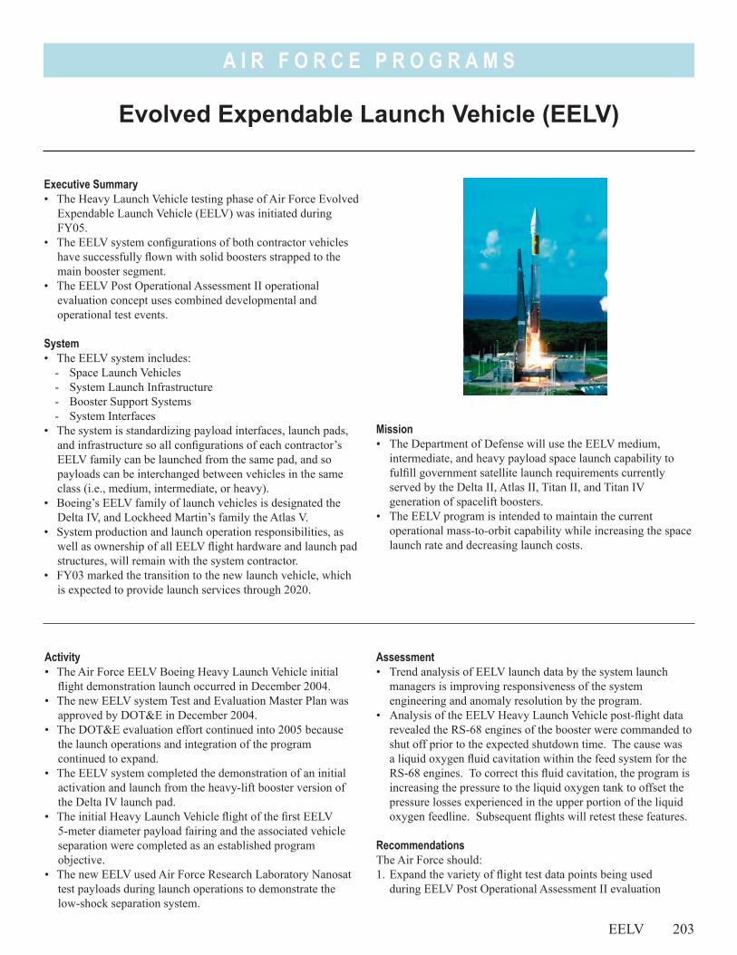
A I R F O R C E P R O G R A M S
Evolved Expendable Launch Vehicle (EELV)
EELV 203
Executive Summary• The Heavy Launch Vehicle testing phase of Air Force Evolved
Expendable Launch Vehicle (EELV) was initiated during FY05.
• The EELV system configurations of both contractor vehicles have successfully flown with solid boosters strapped to the main booster segment.
• The EELV Post Operational Assessment II operational evaluation concept uses combined developmental and operational test events.
System• The EELV system includes:
- Space Launch Vehicles- System Launch Infrastructure- Booster Support Systems- System Interfaces
• The system is standardizing payload interfaces, launch pads, and infrastructure so all configurations of each contractor’s EELV family can be launched from the same pad, and so payloads can be interchanged between vehicles in the same class (i.e., medium, intermediate, or heavy).
• Boeing’s EELV family of launch vehicles is designated the Delta IV, and Lockheed Martin’s family the Atlas V.
• System production and launch operation responsibilities, as well as ownership of all EELV flight hardware and launch pad structures, will remain with the system contractor.
• FY03 marked the transition to the new launch vehicle, which is expected to provide launch services through 2020.
Activity• The Air Force EELV Boeing Heavy Launch Vehicle initial
flight demonstration launch occurred in December 2004.• The new EELV system Test and Evaluation Master Plan was
approved by DOT&E in December 2004.• The DOT&E evaluation effort continued into 2005 because
the launch operations and integration of the program continued to expand.
• The EELV system completed the demonstration of an initial activation and launch from the heavy-lift booster version of the Delta IV launch pad.
• The initial Heavy Launch Vehicle flight of the first EELV 5-meter diameter payload fairing and the associated vehicle separation were completed as an established program objective.
• The new EELV used Air Force Research Laboratory Nanosat test payloads during launch operations to demonstrate the low-shock separation system.
Assessment• Trend analysis of EELV launch data by the system launch
managers is improving responsiveness of the system engineering and anomaly resolution by the program.
• Analysis of the EELV Heavy Launch Vehicle post-flight data revealed the RS-68 engines of the booster were commanded to shut off prior to the expected shutdown time. The cause was a liquid oxygen fluid cavitation within the feed system for the RS-68 engines. To correct this fluid cavitation, the program is increasing the pressure to the liquid oxygen tank to offset the pressure losses experienced in the upper portion of the liquid oxygen feedline. Subsequent flights will retest these features.
RecommendationsThe Air Force should:1. Expand the variety of flight test data points being used
during EELV Post Operational Assessment II evaluation
Mission• The Department of Defense will use the EELV medium,
intermediate, and heavy payload space launch capability to fulfill government satellite launch requirements currently served by the Delta II, Atlas II, Titan II, and Titan IV generation of spacelift boosters.
• The EELV program is intended to maintain the current operational mass-to-orbit capability while increasing the space launch rate and decreasing launch costs.
A I R F O R C E P R O G R A M S
activities to thoroughly characterize integrated booster system performance.
2. Track the EELV resolution and retest actions associated with the engine cavitation events of the Heavy Launch Vehicle demonstration flight.
3. Expand the integrated review and analysis of EELV launch data points in areas such as avionics, flight mechanics, loads and dynamics, and environments.
204 EELV
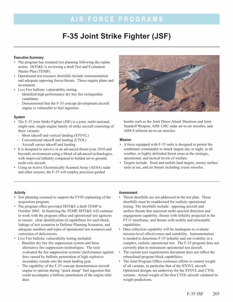
A I R F O R C E P R O G R A M S
bombs such as the Joint Direct Attack Munition and Joint Standoff Weapon, AIM-120C radar air-to-air missiles, and AIM-9 infrared air-to-air missiles.
Mission• A force equipped with F-35 units is designed to permit the
combatant commander to attack targets day or night, in all weather, in highly-defended threat areas at the strategic, operational, and tactical levels of warfare.
• Targets include: fixed and mobile land targets, enemy surface units at sea, and air threats including cruise missiles.
Executive Summary• The program has resumed test planning following the replan
action. DOT&E is reviewing a draft Test and Evaluation Master Plan (TEMP).
• Operational test resource shortfalls include instrumentation and adequate opposing forces/threats. These require plans and investment.
• Live Fire ballistic vulnerability testing:- Identified high performance dry bay fire extinguisher
candidates - Demonstrated that the F-35 concept development aircraft
engine is vulnerable to fuel ingestion
System• The F-35 Joint Strike Fighter (JSF) is a joint, multi-national,
single-seat, single-engine family of strike aircraft consisting of three variants:- Short takeoff and vertical landing (STOVL)- Conventional takeoff and landing (CTOL)- Aircraft carrier takeoff and landing
• It is designed to survive in an advanced threat (year 2010 and beyond) environment using a blend of advanced technologies, with improved lethality compared to fielded air-to-ground, multi-role aircraft.
• Using an Active Electronically Scanned Array (AESA) radar and other sensors, the F-35 will employ precision guided
Activity• Test planning resumed to support the FY05 replanning of the
acquisition program. • The program office provided DOT&E a draft TEMP in
October 2005. In finalizing the TEMP, DOT&E will continue to work with the program office and operational test agencies to ensure: clear identification of capabilities for each block, linkage of test scenarios to Defense Planning Scenarios, and adequate numbers and types of operational test scenarios and correction of deficiencies.
• Live Fire ballistic vulnerability testing included:- Baseline dry bay fire suppression system and three
alternative fire suppression technologies. The tests evaluated the fire suppression systems’ performance against fires caused by ballistic penetration of high explosive incendiary rounds into the main landing gear.
- The capability of the F-35 concept demonstration aircraft engine to operate during “quick dump” fuel ingestion that could accompany a ballistic penetration of the engine inlet duct.
Assessment• Threat shortfalls are not addressed in the test plan. These
shortfalls must be readdressed for realistic operational testing. The shortfalls include: opposing aircraft and surface threats that represent multi-spectral detection and engagement capability, threats with lethality projected in the FY11 timeframe, and threats with mobile and relocatable capabilities.
• Data collection capability will be inadequate to evaluate mission-level effectiveness and suitability. Instrumentation is needed to determine F-35 lethality and survivability in a complex, realistic operational test. The F-35 program does not currently plan to instrument operational test aircraft.
• The current user requirements document does not reflect the rebaselined program block capabilities.
• The Joint Program Office continues efforts to control weight of all variants, in particular that of the STOVL aircraft. Optimized designs are underway for the STOVL and CTOL variants. Actual weight of the first CTOL aircraft validated its weight predictions.
F-35 Joint Strike Fighter (JSF)
F-35 JSF 205
A I R F O R C E P R O G R A M S
• Live Fire testing:- Identified a candidate fire suppressor that successfully
demonstrated dry bay fire suppression in the main landing gear bay using less agent and longer time delays than the original design. This more robust design allows for the placement of redundant fire suppressors that could extinguish fires even if a single suppressor is destroyed by fragments from a ballistic threat.
- Results from the “quick dump” fuel ingestion test showed significant damage to the concept demonstration aircraft engine. A new concept demonstration aircraft engine may be required to continue Live Fire testing. The program is disassembling the damaged engine to determine what components failed, and to evaluate whether the production configured engine could fail in a similar way due to fuel ingestion.
Recommendations1. Develop an F-35 data collection and range interface capability
that enables precise mission replay and data capture to evaluate mission-level effectiveness and suitability.
2. Identify all test resource shortfalls in opposing force/threats and present a solution that mitigates these.
3. Align the requirements for each block with the replanned program.
4. Develop a predictive model to determine how test data on engine performance following “quick dump” fuel ingestion at the sea level test site could be extrapolated to predictions for higher operating altitudes.
5. Reduce the fuel ingestion vulnerability. This could be done, for example, by improving the fuel bladders around the inlet ducts or improving the engine design to be more tolerant to “quick dump” fuel ingestion.
206 F-35 JSF
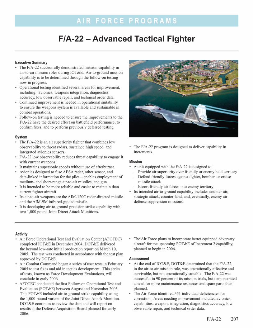
A I R F O R C E P R O G R A M S
• The F/A-22 program is designed to deliver capability in increments.
Mission• A unit equipped with the F/A-22 is designed to:
- Provide air superiority over friendly or enemy held territory- Defend friendly forces against fighter, bomber, or cruise
missile attack- Escort friendly air forces into enemy territory
• Its intended air-to-ground capability includes counter-air, strategic attack, counter-land, and, eventually, enemy air defense suppression missions.
F/A-22 – Advanced Tactical Fighter
F/A-22 207
Executive Summary• The F/A-22 successfully demonstrated mission capability in
air-to-air mission roles during IOT&E. Air-to-ground mission capability is to be determined through the follow-on testing now in progress.
• Operational testing identified several areas for improvement, including: avionics, weapons integration, diagnostics accuracy, low observable repair, and technical order data.
• Continued improvement is needed in operational suitability to ensure the weapons system is available and sustainable in combat operations.
• Follow-on testing is needed to ensure the improvements to the F/A-22 have the desired effect on battlefield performance, to confirm fixes, and to perform previously deferred testing.
System• The F/A-22 is an air superiority fighter that combines low
observability to threat radars, sustained high speed, and integrated avionics sensors.
• F/A-22 low observability reduces threat capability to engage it with current weapons.
• It maintains supersonic speeds without use of afterburner.• Avionics designed to fuse AESA radar, other sensor, and
data-linked information for the pilot—enables employment of medium- and short-range air-to-air missiles, and gun.
• It is intended to be more reliable and easier to maintain than current fighter aircraft.
• Its air-to-air weapons are the AIM-120C radar-directed missile and the AIM-9M infrared-guided missile.
• It is developing air-to-ground precision strike capability with two 1,000 pound Joint Direct Attack Munitions.
Activity• Air Force Operational Test and Evaluation Center (AFOTEC)
completed IOT&E in December 2004; DOT&E delivered the beyond low-rate initial production report on March 10, 2005. The test was conducted in accordance with the test plan approved by DOT&E.
• Air Combat Command began a series of user tests in February 2005 to test fixes and aid in tactics development. This series of tests, known as Force Development Evaluations, will conclude in early 2006.
• AFOTEC conducted the first Follow-on Operational Test and Evaluation (FOT&E) between August and November 2005. This FOT&E included air-to-ground strike capability using the 1,000-pound variant of the Joint Direct Attack Munition. DOT&E continues to review the data and will report on results at the Defense Acquisition Board planned for early 2006.
• The Air Force plans to incorporate better equipped adversary aircraft for the upcoming FOT&E of Increment 2 capability, planned to begin in 2006.
Assessment• At the end of IOT&E, DOT&E determined that the F/A-22,
in the air-to-air mission role, was operationally effective and survivable, but not operationally suitable. The F/A-22 was successful in 90 percent of its mission trials, but demonstrated a need for more maintenance resources and spare parts than planned.
• The Air Force identified 351 individual deficiencies for correction. Areas needing improvement included avionics capabilities, weapons integration, diagnostics accuracy, low observable repair, and technical order data.
A I R F O R C E P R O G R A M S
208 F/A-22
Recommendation1. The Air Force should address IOT&E test limitations and
test the F/A-22 against adversary aircraft and other threat systems that are representative of the intended operational environment.
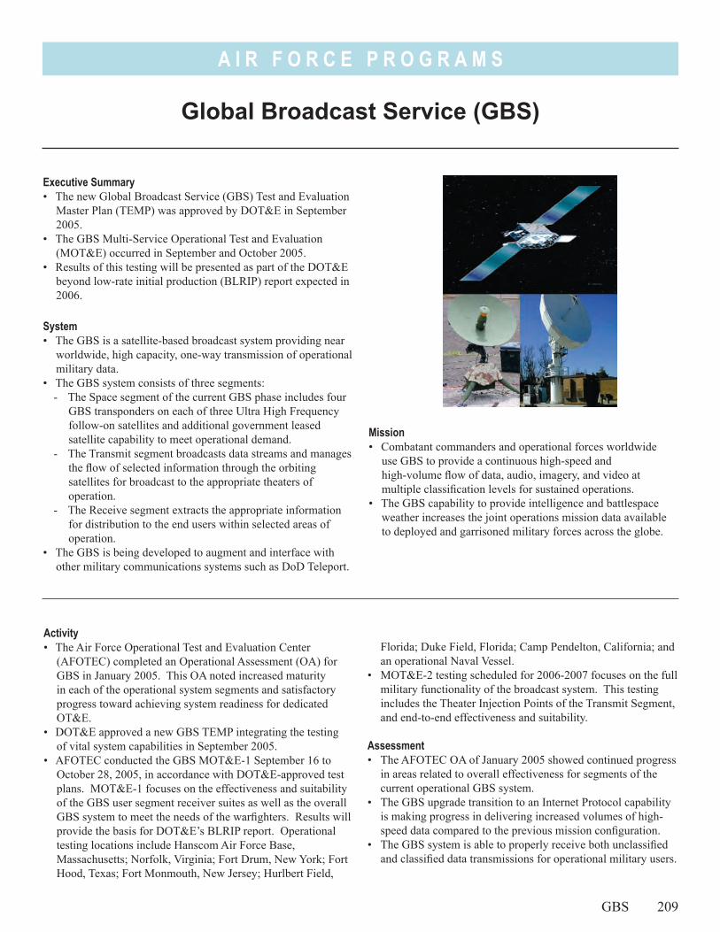
A I R F O R C E P R O G R A M S
Mission• Combatant commanders and operational forces worldwide
use GBS to provide a continuous high-speed and high-volume flow of data, audio, imagery, and video at multiple classification levels for sustained operations.
• The GBS capability to provide intelligence and battlespace weather increases the joint operations mission data available to deployed and garrisoned military forces across the globe.
Global Broadcast Service (GBS)
GBS 209
Executive Summary• The new Global Broadcast Service (GBS) Test and Evaluation
Master Plan (TEMP) was approved by DOT&E in September 2005.
• The GBS Multi-Service Operational Test and Evaluation (MOT&E) occurred in September and October 2005.
• Results of this testing will be presented as part of the DOT&E beyond low-rate initial production (BLRIP) report expected in 2006.
System• The GBS is a satellite-based broadcast system providing near
worldwide, high capacity, one-way transmission of operational military data.
• The GBS system consists of three segments: - The Space segment of the current GBS phase includes four
GBS transponders on each of three Ultra High Frequency follow-on satellites and additional government leased satellite capability to meet operational demand.
- The Transmit segment broadcasts data streams and manages the flow of selected information through the orbiting satellites for broadcast to the appropriate theaters of operation.
- The Receive segment extracts the appropriate information for distribution to the end users within selected areas of operation.
• The GBS is being developed to augment and interface with other military communications systems such as DoD Teleport.
Activity• The Air Force Operational Test and Evaluation Center
(AFOTEC) completed an Operational Assessment (OA) for GBS in January 2005. This OA noted increased maturity in each of the operational system segments and satisfactory progress toward achieving system readiness for dedicated OT&E.
• DOT&E approved a new GBS TEMP integrating the testing of vital system capabilities in September 2005.
• AFOTEC conducted the GBS MOT&E-1 September 16 to October 28, 2005, in accordance with DOT&E-approved test plans. MOT&E-1 focuses on the effectiveness and suitability of the GBS user segment receiver suites as well as the overall GBS system to meet the needs of the warfighters. Results will provide the basis for DOT&E’s BLRIP report. Operational testing locations include Hanscom Air Force Base, Massachusetts; Norfolk, Virginia; Fort Drum, New York; Fort Hood, Texas; Fort Monmouth, New Jersey; Hurlbert Field,
Florida; Duke Field, Florida; Camp Pendelton, California; and an operational Naval Vessel.
• MOT&E-2 testing scheduled for 2006-2007 focuses on the full military functionality of the broadcast system. This testing includes the Theater Injection Points of the Transmit Segment, and end-to-end effectiveness and suitability.
Assessment • The AFOTEC OA of January 2005 showed continued progress
in areas related to overall effectiveness for segments of the current operational GBS system.
• The GBS upgrade transition to an Internet Protocol capability is making progress in delivering increased volumes of high-speed data compared to the previous mission configuration.
• The GBS system is able to properly receive both unclassified and classified data transmissions for operational military users.
A I R F O R C E P R O G R A M S
• The GBS MOT&E-2 test strategy may require updates to meet the needs of the system users. MOT&E-2 Phase II testing is also applicable to the Wideband Gapfiller Satellite (WGS) contribution to GBS levels of service. The MOT&E-2 Phase II will include the WGS portion of service after the launch of the first WGS satellite in 2007.
• The GBS Theater Injection Points of the Transmit Segment will need to examine baseline configurations that more directly address the needs of joint military forces.
210 GBS
Recommendations1. The Air Force should determine if the GBS MOT&E-2 test
strategy requires updating to meet the current user expectations for an Initial Operational Capability declaration.
2. The GBS Theater Injection Points should be configured and tested consistent with the implementation configurations identified by U.S. Joint Forces Command and U.S. Strategic Command.
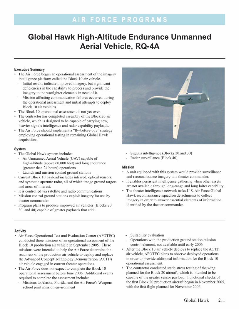
A I R F O R C E P R O G R A M S
- Signals intelligence (Blocks 20 and 30)- Radar surveillance (Block 40)
Mission• A unit equipped with this system would provide surveillance
and reconnaissance imagery to a theater commander. • It enables persistent intelligence gathering when other assets
are not available through long-range and long loiter capability. • The theater intelligence network tasks U.S. Air Force Global
Hawk reconnaissance squadron detachments to collect imagery in order to answer essential elements of information identified by the theater commander.
Global Hawk High-Altitude Endurance Unmanned Aerial Vehicle, RQ-4A
Executive Summary• The Air Force began an operational assessment of the imagery
intelligence platform called the Block 10 air vehicle. - Initial results indicate improved imagery, but significant
deficiencies in the capability to process and provide the imagery to the warfighter elements in need of it.
- Mission affecting communication failures occurred during the operational assessment and initial attempts to deploy Block 10 air vehicles.
• The Block 10 operational assessment is not yet over. • The contractor has completed assembly of the Block 20 air
vehicle, which is designed to be capable of carrying new, heavier signals intelligence and radar capability payloads.
• The Air Force should implement a “fly-before-buy” strategy employing operational testing in remaining Global Hawk acquisitions.
System• The Global Hawk system includes:
- An Unmanned Aerial Vehicle (UAV) capable of high-altitude (above 60,000 feet) and long endurance (greater than 24 hours) operations
- Launch and mission control ground stations• Current Block 10 payload includes infrared, optical sensors,
and synthetic aperture radar, all of which image ground targets and areas of interest.
• It is controlled via satellite and radio communications.• Mission control ground stations exploit imagery for use by
theater commander. • Program plans to produce improved air vehicles (Blocks 20,
30, and 40) capable of greater payloads that add:
Activity• Air Force Operational Test and Evaluation Center (AFOTEC)
conducted three missions of an operational assessment of the Block 10 production air vehicle in September 2005. These missions were intended to help the Air Force determine the readiness of the production air vehicle to deploy and replace the Advanced Concept Technology Demonstration (ACTD) air vehicle engaged in current theater operations.
• The Air Force does not expect to complete the Block 10 operational assessment before June 2006. Additional events required to complete the assessment include:- Missions to Alaska, Florida, and the Air Force’s Weapons
school joint mission environment
- Suitability evaluation- Operations with the production ground station mission
control element, not available until early 2006• After the Block 10 air vehicle deploys to replace the ACTD
air vehicle, AFOTEC plans to observe deployed operations in order to provide additional information for the Block 10 operational assessment.
• The contractor conducted static stress testing of the wing planned for the Block 20 aircraft, which is intended to be capable of the greater sensor payload. Functional checks of the first Block 20 production aircraft began in November 2005, with the first flight planned for November 2006.
Global Hawk 211
A I R F O R C E P R O G R A M S
Assessment• The Block 10 air vehicle demonstrated performance similar
to that of the ACTD air vehicle already in service. It has improved spot image quality. However, image processing, timeliness, communications, mission planning, and interoperability with the ground segments used to provide the imagery in usable form to the warfighter require significant improvement. Communications failures delayed the initial deployment attempts in October 2005 and continue to occur in Block 10 developmental test missions.
• In-flight shutdowns of the air vehicle engines occurred during Block 10 testing and ACTD operational missions. The program discovered deficiencies in late production versions of the engine that resulted in reduced surge margin at high-altitude (i.e., greater than 60,000 feet). The same engine is planned for use in the heavier, larger Blocks 20, 30, and 40 aircraft.
• The Air Force plans to conduct an IOT&E with a Block 20 (imagery intelligence only) system capable of meeting Increment 1 performance criteria in early 2009—24 months later than the current program baseline established in 2002,
and five years later than the original 2001 program baseline. The November 2005 DAB directed the development of revised acquisition and test strategies to include determination of an appropriate number of low-rate initial production quantities.
Recommendations1. The remaining test events in the Block 10 operational
assessment test plan should be completed. This includes the evaluation in the joint mission environment and evaluation of the Block 10 mission control element ground segment. These events provide the opportunity to evaluate the Global Hawk in other than desert environments.
2. Conduct a review and correct deficiencies in the intelligence, surveillance, and reconnaissance network in which Global Hawk operates—imagery processing and dissemination need attention and improvement, as highlighted in the Block 10 operational assessment missions performed in August 2005.
3. Low-rate initial production quantities should not be increased until after an adequate IOT&E of the Block 20 air vehicle and ground segments.
212 Global Hawk
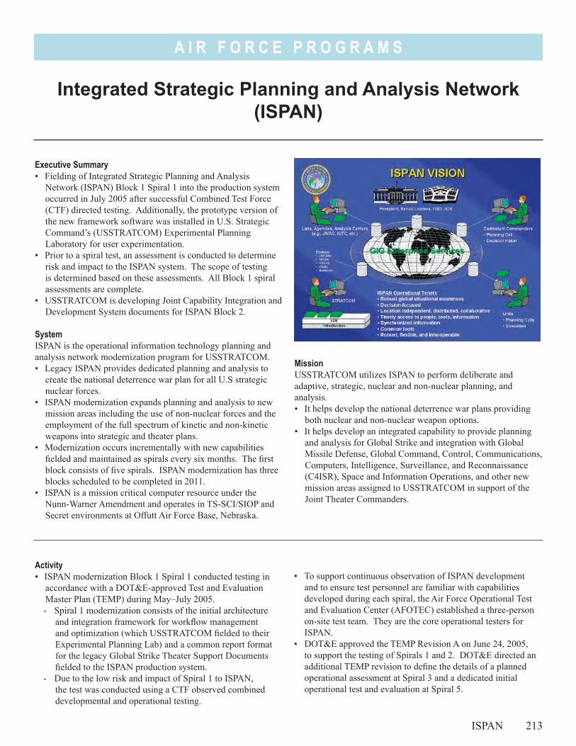
A I R F O R C E P R O G R A M S
MissionUSSTRATCOM utilizes ISPAN to perform deliberate and adaptive, strategic, nuclear and non-nuclear planning, and analysis.• It helps develop the national deterrence war plans providing
both nuclear and non-nuclear weapon options.• It helps develop an integrated capability to provide planning
and analysis for Global Strike and integration with Global Missile Defense, Global Command, Control, Communications, Computers, Intelligence, Surveillance, and Reconnaissance (C4ISR), Space and Information Operations, and other new mission areas assigned to USSTRATCOM in support of the Joint Theater Commanders.
Integrated Strategic Planning and Analysis Network (ISPAN)
ISPAN 213
Executive Summary• Fielding of Integrated Strategic Planning and Analysis
Network (ISPAN) Block 1 Spiral 1 into the production system occurred in July 2005 after successful Combined Test Force (CTF) directed testing. Additionally, the prototype version of the new framework software was installed in U.S. Strategic Command’s (USSTRATCOM) Experimental Planning Laboratory for user experimentation.
• Prior to a spiral test, an assessment is conducted to determine risk and impact to the ISPAN system. The scope of testing is determined based on these assessments. All Block 1 spiral assessments are complete.
• USSTRATCOM is developing Joint Capability Integration and Development System documents for ISPAN Block 2.
SystemISPAN is the operational information technology planning and analysis network modernization program for USSTRATCOM.• Legacy ISPAN provides dedicated planning and analysis to
create the national deterrence war plan for all U.S strategic nuclear forces.
• ISPAN modernization expands planning and analysis to new mission areas including the use of non-nuclear forces and the employment of the full spectrum of kinetic and non-kinetic weapons into strategic and theater plans.
• Modernization occurs incrementally with new capabilities fielded and maintained as spirals every six months. The first block consists of five spirals. ISPAN modernization has three blocks scheduled to be completed in 2011.
• ISPAN is a mission critical computer resource under the Nunn-Warner Amendment and operates in TS-SCI/SIOP and Secret environments at Offutt Air Force Base, Nebraska.
• To support continuous observation of ISPAN development and to ensure test personnel are familiar with capabilities developed during each spiral, the Air Force Operational Test and Evaluation Center (AFOTEC) established a three-person on-site test team. They are the core operational testers for ISPAN.
• DOT&E approved the TEMP Revision A on June 24, 2005, to support the testing of Spirals 1 and 2. DOT&E directed an additional TEMP revision to define the details of a planned operational assessment at Spiral 3 and a dedicated initial operational test and evaluation at Spiral 5.
Activity• ISPAN modernization Block 1 Spiral 1 conducted testing in
accordance with a DOT&E-approved Test and Evaluation Master Plan (TEMP) during May–July 2005. - Spiral 1 modernization consists of the initial architecture
and integration framework for workflow management and optimization (which USSTRATCOM fielded to their Experimental Planning Lab) and a common report format for the legacy Global Strike Theater Support Documents fielded to the ISPAN production system.
- Due to the low risk and impact of Spiral 1 to ISPAN, the test was conducted using a CTF observed combined developmental and operational testing.
A I R F O R C E P R O G R A M S
• USSTRATCOM is developing new requirements documents for ISPAN Block 2. The program is completing Spiral 2 development and the CTF started combined developmental and operational testing in 1QFY06. Spiral 2 is low risk. It comprises:- Converting from the legacy SYBASE to an ORACLE
database management system - Automating the process of integrating select conventional
weapons into the planning and analysis process- Enhancing the production of Theater/Global Strike Support
Documents
Assessment• Prior to each spiral test, DOT&E, AFOTEC, USSTRATCOM,
and the program office representatives conduct a risk assessment based on the modernization content of the spiral, the risk, and the impact to the production ISPAN system. The results of the assessments allow the test organizations to scope the spiral test and plan an adequate test.
• The AFOTEC memo was adequate to support a Spiral 1 fielding decision. A completed CTF report is required prior to fielding Spiral 2.
• The ISPAN Operational Requirements Document (ORD) does not adequately define the modernization requirements,
capabilities, or performance measures for each of the ISPAN blocks. USSTRATCOM is writing a Capability Development Document for each of the remaining ISPAN blocks.
• The ISPAN Program Office has yet to meet Acquisition Decision Memorandum directed timelines for TEMP revisions. With adequate requirements documents, this should improve with Block 2.
Recommendations1. USSTRATCOM should complete requirements documents
for Block 2 to define the capabilities to be developed in Block 2. It should include appropriate key performance parameters, critical operational issues, measures, and thresholds.
2. The program should complete a revision to the TEMP. ISPAN Spiral 3 testing will not begin without an approved TEMP revision.
3. The on-site AFOTEC test team should continually collect effectiveness and suitability data on fielded spirals on a non-interference basis. The analysis of this data should be included in subsequent spiral test reports.
214 ISPAN
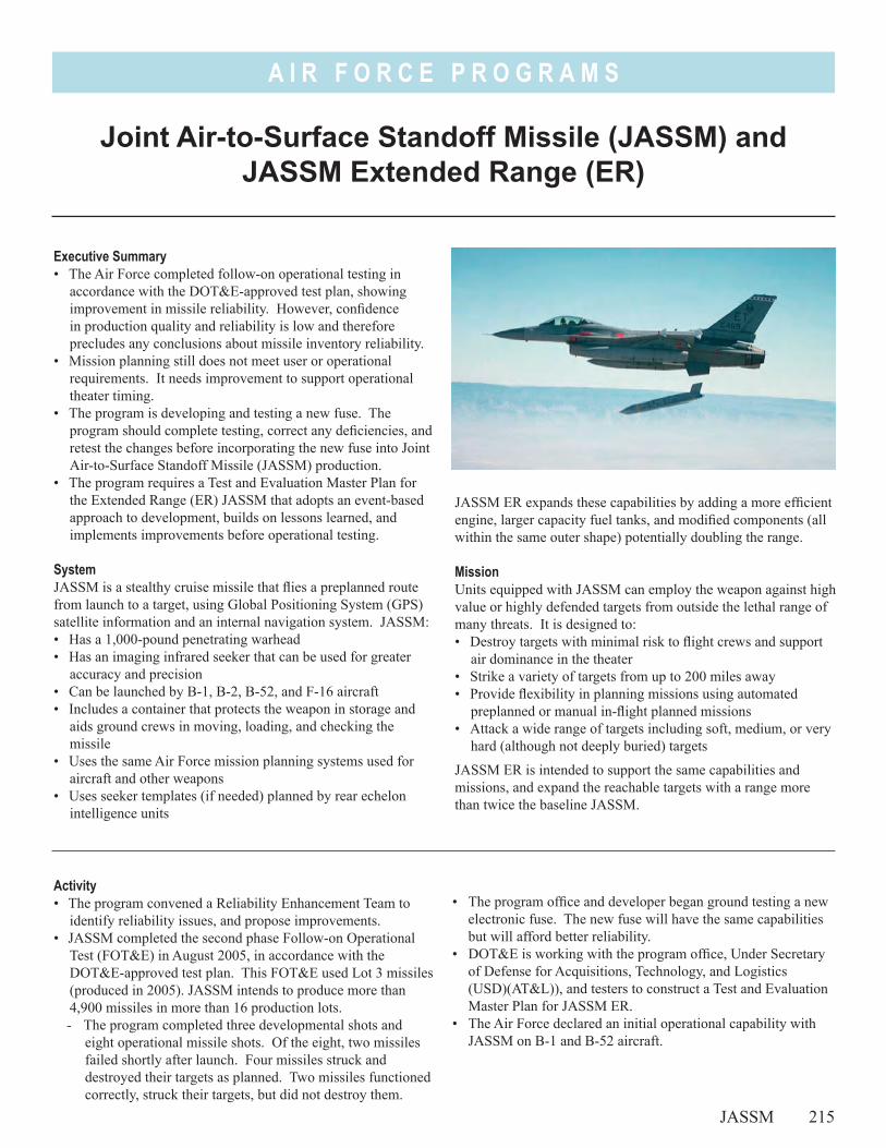
A I R F O R C E P R O G R A M S
Joint Air-to-Surface Standoff Missile (JASSM) and JASSM Extended Range (ER)
Executive Summary• The Air Force completed follow-on operational testing in
accordance with the DOT&E-approved test plan, showing improvement in missile reliability. However, confidence in production quality and reliability is low and therefore precludes any conclusions about missile inventory reliability.
• Mission planning still does not meet user or operational requirements. It needs improvement to support operational theater timing.
• The program is developing and testing a new fuse. The program should complete testing, correct any deficiencies, and retest the changes before incorporating the new fuse into Joint Air-to-Surface Standoff Missile (JASSM) production.
• The program requires a Test and Evaluation Master Plan for the Extended Range (ER) JASSM that adopts an event-based approach to development, builds on lessons learned, and implements improvements before operational testing.
SystemJASSM is a stealthy cruise missile that flies a preplanned route from launch to a target, using Global Positioning System (GPS) satellite information and an internal navigation system. JASSM: • Has a 1,000-pound penetrating warhead • Has an imaging infrared seeker that can be used for greater
accuracy and precision• Can be launched by B-1, B-2, B-52, and F-16 aircraft• Includes a container that protects the weapon in storage and
aids ground crews in moving, loading, and checking the missile
• Uses the same Air Force mission planning systems used for aircraft and other weapons
• Uses seeker templates (if needed) planned by rear echelon intelligence units
JASSM ER expands these capabilities by adding a more efficient engine, larger capacity fuel tanks, and modified components (all within the same outer shape) potentially doubling the range.
MissionUnits equipped with JASSM can employ the weapon against high value or highly defended targets from outside the lethal range of many threats. It is designed to: • Destroy targets with minimal risk to flight crews and support
air dominance in the theater• Strike a variety of targets from up to 200 miles away• Provide flexibility in planning missions using automated
preplanned or manual in-flight planned missions• Attack a wide range of targets including soft, medium, or very
hard (although not deeply buried) targets
JASSM ER is intended to support the same capabilities and missions, and expand the reachable targets with a range more than twice the baseline JASSM.
Activity• The program convened a Reliability Enhancement Team to
identify reliability issues, and propose improvements.• JASSM completed the second phase Follow-on Operational
Test (FOT&E) in August 2005, in accordance with the DOT&E-approved test plan. This FOT&E used Lot 3 missiles (produced in 2005). JASSM intends to produce more than 4,900 missiles in more than 16 production lots. - The program completed three developmental shots and
eight operational missile shots. Of the eight, two missiles failed shortly after launch. Four missiles struck and destroyed their targets as planned. Two missiles functioned correctly, struck their targets, but did not destroy them.
• The program office and developer began ground testing a new electronic fuse. The new fuse will have the same capabilities but will afford better reliability.
• DOT&E is working with the program office, Under Secretary of Defense for Acquisitions, Technology, and Logistics (USD)(AT&L)), and testers to construct a Test and Evaluation Master Plan for JASSM ER.
• The Air Force declared an initial operational capability with JASSM on B-1 and B-52 aircraft.
JASSM 215
A I R F O R C E P R O G R A M S
AssessmentThe developer is placing greater attention on supplier testing and review. The program office is constructing a ground test facility to test basic functions of a missile under a controlled environment, at a lower cost than a flight test. The Reliability Enhancement Team recommended both improvements.
The eight JASSM follow-on testing flights showed missile reliability improvement, but also identified new problems. Four missions flew successfully and destroyed their targets as planned. On two missions, the wings did not correctly open and the missiles crashed shortly after launch, for two different reasons. A poor wing actuator connection, identified during development but not corrected, failed on the first mission. After the Operational Test (OT) failure, the developer corrected all inventory missiles. A wing retention bolt that holds the wings closed and releases during launch failed on the second mission. The developer has not identified why this bolt failed. On two missions, the missiles flew successfully but failed to destroy their planned targets (a cave opening and a cave overhang). Both missiles struck away from the optimal impact points, causing little damage. Target location error, planning error, and target difficulty combined to cause the failures.
Some missiles experienced problems that reduce confidence in reliability and production consistency. On three missions (and on two developmental missions), the missile climbed much slower than planned and slower than on previous missions. On two missions, the missile experienced periodic loss of GPS guidance throughout the mission. The developer has not yet identified the sources of these problems. While reviewing the wing deployment problems, the developer identified a Lot 3 production change error that caused wings to bind when they open. This was due to incorrect assembly and the developer corrected it using a redesigned assembly process. This solved the problem, but the developer had to go back and fix all previously-produced missiles.
Previous operational testing identified production quality as an issue, and one purpose of this FOT&E was to demonstrate improvement. All FOT&E missiles were Lot 3 missiles and
Lot 3 production changes triggered several of the failures and problems. One development flight used a Lot 1 missile to assess the reliability of fielded missiles. However, the program office replaced the Lot 1 fuze with a new one before the flight. Developmental testing found the actuator connection problem before OT but the developer did not correct it until after the OT failure. These problems reduce confidence in missile production quality and reliability.
Automated mission planning does not meet timing requirements and is difficult to complete. User requirements and typical theater operations require a JASSM mission plan to be complete in less than 10 minutes (average). This is in order to complete more than 100 missile missions in a typical air tasking order (ATO) cycle (24 hours). Previous test results showed it takes 15 - 25 minutes (average). Exercises this past year show these times did not improve. Aircrews must use in-flight manual planning to complete some of their missions and strike all required targets in an ATO cycle. Manual in-flight planning is easier but less effective for some missile missions since it cannot take full advantage of the missile’s stealthiness and range, and it is more susceptible to mistakes. F-16 follow-on testing found a critical error that prevents crews from being able to manually plan missions in-flight.
Recommendations1. The program should adopt an event-driven approach to
development that completes robust testing, identifies problem areas, and corrects them before proceeding into OT.
2. The program should speed up mission planning to match the ATO cycle time.
3. The program should complete planned fuse testing, identify and correct deficiencies in fuse performance, and retest the corrections before incorporating the new fuse in JASSM production.
4. The Air Force should repeat the missions against the cave targets.
216 JASSM
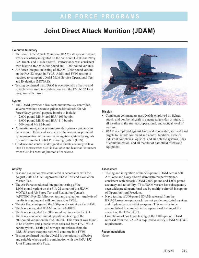
A I R F O R C E P R O G R A M S
Joint Direct Attack Munition (JDAM)
Executive Summary• The Joint Direct Attack Munition (JDAM) 500-pound variant
was successfully integrated on the Air Force F-15E and Navy F/A-18C/D and F-14D aircraft. Performance was consistent with historic JDAM 2,000-pound and 1,000-pound variants.
• Air Force integration testing of JDAM 1,000-pound variant on the F/A-22 began in FY05. Additional FY06 testing is required to complete JDAM Multi-Service Operational Test and Evaluation (MOT&E).
• Testing confirmed that JDAM is operationally effective and suitable when used in combination with the FMU-152 Joint Programmable Fuze.
System• The JDAM provides a low cost, autonomously controlled,
adverse weather, accurate guidance kit tailored for Air Force/Navy general purpose bombs to include:- 2,000-pound Mk 84 and BLU-109 bombs- 1,000-pound Mk 83 and BLU-110 bombs- 500-pound Mk 82 bomb
• An inertial navigation system provides primary guidance to the weapon. Enhanced accuracy of the weapon is provided by augmentation of the inertial navigation system by signals received from the Global Positioning System (GPS).
• Guidance and control is designed to enable accuracy of less than 13 meters when GPS is available and less than 30 meters when GPS is absent or jammed after release.
Mission• Combatant commanders use JDAMs employed by fighter,
attack, and bomber aircraft to engage targets day or night, in all weather at the strategic, operational, and tactical level of warfare.
• JDAM is employed against fixed and relocatable, soft and hard targets to include command and control facilities, airfields, industrial complexes, logistical and air defense systems, lines of communication, and all manner of battlefield forces and equipment.
Activity• Test and evaluation was conducted in accordance with the
August 2004 DOT&E-approved JDAM Test and Evaluation Master Plan.
• The Air Force conducted integration testing of the 1,000-pound variant on the F/A-22 as part of the JDAM MOT&E and Air Force Test and Evaluation Center’s (AFOTEC) F/A-22 follow-on test and evaluation. Analysis of results is ongoing and will continue into FY06.
• The Air Force integrated the 500-pound variant on the F-15E.• The Navy integrated JDAM on the F/A-18E/F.• The Navy integrated the 500-pound variant on the F-14D.• The Navy conducted initial operational testing of the
500-pound variant on the F/A-18C/D. This variant was found to be effective and suitable when released from F/A-18C/D parent pylons. Testing of carriage and release from the BRU-55 smart weapons rack will continue into FY06.
• Testing confirmed that the JDAM is operationally effective and suitable when used in combination with the FMU-152 Joint Programmable Fuze.
Assessment• Testing and integration of the 500-pound JDAM across both
Air Force and Navy aircraft demonstrated performance consistent with historic JDAM 2,000-pound and 1,000-pound accuracy and reliability. This JDAM variant has subsequently seen widespread operational use by multiple aircraft in support of Operation Iraqi Freedom.
• Navy testing of 500-pound JDAMs released from the BRU-55 smart weapons rack has not yet demonstrated carriage and ripple release of eight weapons. This remains to be accomplished to complete initial operational testing of this variant on the F/A-18C/D.
• Completion of Air Force testing of the 1,000-pound JDAM released from the F/A-22 is required to satisfy JDAM MOT&E requirements.
RecommendationsNone.
JDAM 217

A I R F O R C E P R O G R A M S
218
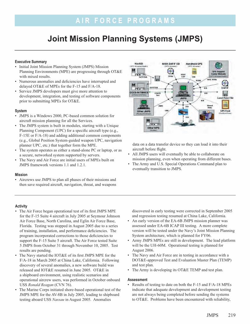
A I R F O R C E P R O G R A M S
data on a data transfer device so they can load it into their aircraft before flight.
• All JMPS users will eventually be able to collaborate on mission planning, even when operating from different bases.
• The Army and U.S. Special Operations Command plan to eventually transition to JMPS.
Executive Summary• Initial Joint Mission Planning System (JMPS) Mission
Planning Environments (MPE) are progressing through OT&E with mixed results.
• Numerous anomalies and deficiencies have interrupted and delayed OT&E of MPEs for the F-15 and F/A-18.
• Service JMPS developers must give more attention to development, integration, and testing of software components prior to submitting MPEs for OT&E.
System• JMPS is a Windows 2000, PC-based common solution for
aircraft mission planning for all the Services.• The JMPS system is built in modules, starting with a Unique
Planning Component (UPC) for a specific aircraft type (e.g., F-15E or F/A-18) and adding additional common components (e.g., Global Position System-guided weapon UPC, navigation planner UPC, etc.) that together form the MPE.
• The system operates as either a stand-alone PC or laptop, or as a secure, networked system supported by servers.
• The Navy and Air Force are initial users of MPEs built on JMPS framework versions 1.1 and 1.2.1.
Mission• Aircrews use JMPS to plan all phases of their missions and
then save required aircraft, navigation, threat, and weapons
Joint Mission Planning Systems (JMPS)
JMPS 219
Activity• The Air Force began operational test of its first JMPS MPE
for the F-15 Suite 4 aircraft in July 2005 at Seymour Johnson Air Force Base, North Carolina, and Eglin Air Force Base, Florida. Testing was stopped in August 2005 due to a series of training, installation, and performance deficiencies. The program incorporated corrections to those deficiencies to support the F-15 Suite 5 aircraft. The Air Force tested Suite 5 JMPS from October 31 through November 10, 2005. Test results are pending.
• The Navy started the IOT&E of its first JMPS MPE for the F/A-18 in March 2005 at China Lake, California. Following discovery of several anomalies, a new software build was released and IOT&E resumed in June 2005. OT&E in a shipboard environment, using realistic scenarios and operational aircrew users, was performed in October onboard USS Ronald Reagan (CVN 76).
• The Marine Corps initiated shore-based operational test of the JMPS MPE for the AV-8B in July 2005, leading to shipboard testing aboard USS Nassau in August 2005. Anomalies
discovered in early testing were corrected in September 2005 and regression testing resumed at China Lake, California.
• An early version of the EA-6B JMPS mission planner was assessed under EA-6B ICAP III testing. A more complete version will be tested under the Navy’s Joint Mission Planning System architecture, which is planned for FY06.
• Army JMPS MPEs are still in development. The lead platform will be the UH-60M. Operational testing is planned for August 2006.
• The Navy and Air Force are in testing in accordance with a DOT&E-approved Test and Evaluation Master Plan (TEMP) and test plan.
• The Army is developing its OT&E TEMP and test plan.
Assessment• Results of testing to date on both the F-15 and F/A-18 MPEs
indicate that adequate development and development testing are not always being completed before sending the systems to OT&E. Problems have been encountered with reliability,
A I R F O R C E P R O G R A M S
stability, consistency of performance, interoperability, and errors in calculating aircraft and weapon flight data. The result is that key performance parameters are not met. Evidence points to poor integration among the framework and UPCs, and incomplete development of installation procedures, training materials, and security settings. Critical anomalies and deficiencies found in OT&E have caused delays and stoppage of tests as well as additional efforts to deliver revised software.
• Operational testing of the AV-8B MPE was adequate. Indications are the AV-8B MPE will meet operational requirements.
• DOT&E found the overall EA-6B ICAP III system, including the early version of the EA-6B JMPS MPE, to be operationally effective and suitable. A complete operational test of the EA-6B JMPS MPE is planned for the ICAP III, Block 2 MPE in FY06.
• Operational Test Agencies have to resist pressure from various JMPS programs to “rush to test” and then change approved test plans and/or processes.
Recommendations1. Operational Test Agencies should not accept JMPS MPEs
for OT&E prior to confirmation in development testing that the development program has been adequate and complete, and that critical deficiencies have been eliminated. MPEs have been rushed to OT&E with incomplete integration and interoperability among components and with numerous uncorrected deficiencies affecting performance and suitability.
2. JMPS developers need to pay more attention to installation and operating instructions, training, system administration, and security settings.
3. The Services should conduct risk assessments for follow-on JMPS MPEs to help define the amount of operational testing necessary to mitigate these risks.
220 JMPS
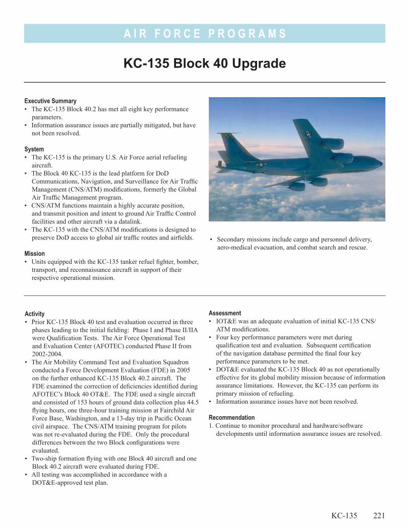
A I R F O R C E P R O G R A M S
• Secondary missions include cargo and personnel delivery, aero-medical evacuation, and combat search and rescue.
KC-135 Block 40 Upgrade
Executive Summary• The KC-135 Block 40.2 has met all eight key performance
parameters.• Information assurance issues are partially mitigated, but have
not been resolved.
System• The KC-135 is the primary U.S. Air Force aerial refueling
aircraft.• The Block 40 KC-135 is the lead platform for DoD
Communications, Navigation, and Surveillance for Air Traffic Management (CNS/ATM) modifications, formerly the Global Air Traffic Management program.
• CNS/ATM functions maintain a highly accurate position, and transmit position and intent to ground Air Traffic Control facilities and other aircraft via a datalink.
• The KC-135 with the CNS/ATM modifications is designed to preserve DoD access to global air traffic routes and airfields.
Mission• Units equipped with the KC-135 tanker refuel fighter, bomber,
transport, and reconnaissance aircraft in support of their respective operational mission.
Activity• Prior KC-135 Block 40 test and evaluation occurred in three
phases leading to the initial fielding: Phase I and Phase II/IIA were Qualification Tests. The Air Force Operational Test and Evaluation Center (AFOTEC) conducted Phase II from 2002-2004.
• The Air Mobility Command Test and Evaluation Squadron conducted a Force Development Evaluation (FDE) in 2005 on the further enhanced KC-135 Block 40.2 aircraft. The FDE examined the correction of deficiencies identified during AFOTEC’s Block 40 OT&E. The FDE used a single aircraft and consisted of 153 hours of ground data collection plus 44.5 flying hours, one three-hour training mission at Fairchild Air Force Base, Washington, and a 13-day trip in Pacific Ocean civil airspace. The CNS/ATM training program for pilots was not re-evaluated during the FDE. Only the procedural differences between the two Block configurations were evaluated.
• Two-ship formation flying with one Block 40 aircraft and one Block 40.2 aircraft were evaluated during FDE.
• All testing was accomplished in accordance with a DOT&E-approved test plan.
Assessment• IOT&E was an adequate evaluation of initial KC-135 CNS/
ATM modifications.• Four key performance parameters were met during
qualification test and evaluation. Subsequent certification of the navigation database permitted the final four key performance parameters to be met.
• DOT&E evaluated the KC-135 Block 40 as not operationally effective for its global mobility mission because of information assurance limitations. However, the KC-135 can perform its primary mission of refueling.
• Information assurance issues have not been resolved. Recommendation1. Continue to monitor procedural and hardware/software
developments until information assurance issues are resolved.
KC-135 221

A I R F O R C E P R O G R A M S
222
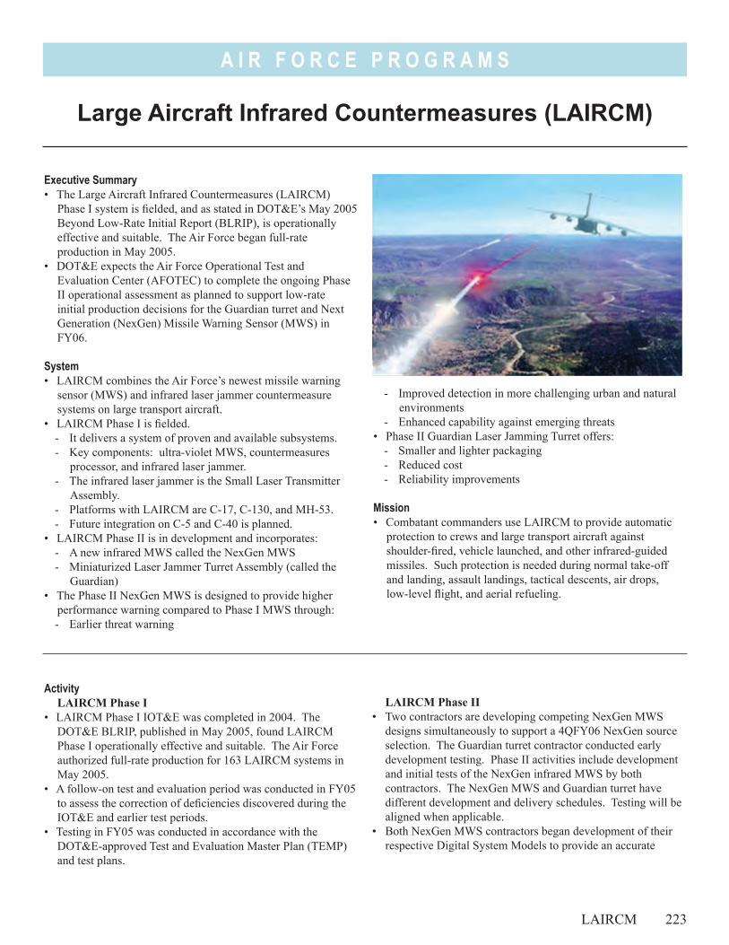
A I R F O R C E P R O G R A M S
- Improved detection in more challenging urban and natural environments
- Enhanced capability against emerging threats• Phase II Guardian Laser Jamming Turret offers:
- Smaller and lighter packaging- Reduced cost- Reliability improvements
Mission• Combatant commanders use LAIRCM to provide automatic
protection to crews and large transport aircraft against shoulder-fired, vehicle launched, and other infrared-guided missiles. Such protection is needed during normal take-off and landing, assault landings, tactical descents, air drops, low-level flight, and aerial refueling.
Executive Summary• The Large Aircraft Infrared Countermeasures (LAIRCM)
Phase I system is fielded, and as stated in DOT&E’s May 2005 Beyond Low-Rate Initial Report (BLRIP), is operationally effective and suitable. The Air Force began full-rate production in May 2005.
• DOT&E expects the Air Force Operational Test and Evaluation Center (AFOTEC) to complete the ongoing Phase II operational assessment as planned to support low-rate initial production decisions for the Guardian turret and Next Generation (NexGen) Missile Warning Sensor (MWS) in FY06.
System• LAIRCM combines the Air Force’s newest missile warning
sensor (MWS) and infrared laser jammer countermeasure systems on large transport aircraft.
• LAIRCM Phase I is fielded. - It delivers a system of proven and available subsystems.- Key components: ultra-violet MWS, countermeasures
processor, and infrared laser jammer.- The infrared laser jammer is the Small Laser Transmitter
Assembly.- Platforms with LAIRCM are C-17, C-130, and MH-53.- Future integration on C-5 and C-40 is planned.
• LAIRCM Phase II is in development and incorporates: - A new infrared MWS called the NexGen MWS - Miniaturized Laser Jammer Turret Assembly (called the
Guardian)• The Phase II NexGen MWS is designed to provide higher
performance warning compared to Phase I MWS through: - Earlier threat warning
Large Aircraft Infrared Countermeasures (LAIRCM)
LAIRCM Phase II• Two contractors are developing competing NexGen MWS
designs simultaneously to support a 4QFY06 NexGen source selection. The Guardian turret contractor conducted early development testing. Phase II activities include development and initial tests of the NexGen infrared MWS by both contractors. The NexGen MWS and Guardian turret have different development and delivery schedules. Testing will be aligned when applicable.
• Both NexGen MWS contractors began development of their respective Digital System Models to provide an accurate
ActivityLAIRCM Phase I
• LAIRCM Phase I IOT&E was completed in 2004. The DOT&E BLRIP, published in May 2005, found LAIRCM Phase I operationally effective and suitable. The Air Force authorized full-rate production for 163 LAIRCM systems in May 2005.
• A follow-on test and evaluation period was conducted in FY05 to assess the correction of deficiencies discovered during the IOT&E and earlier test periods.
• Testing in FY05 was conducted in accordance with the DOT&E-approved Test and Evaluation Master Plan (TEMP) and test plans.
LAIRCM 223
A I R F O R C E P R O G R A M S
224 LAIRCM
assessment of MWS detection performance against various threats and in multiple environments.
• The advanced design of the NexGen MWS requires the development of new test resource capabilities. The Joint Mobile Infrared Countermeasures Test System is being developed under the OSD sponsored Central Test and Evaluation Investment Program. It is a new ground-based missile threat simulator. Additionally, OSD and AFOTEC are developing a Towed Airborne Plume Simulator to support future LAIRCM testing.
• An Operational Assessment (OA) Test Plan was approved by DOT&E to support designated 2005 activities. This plan includes AFOTEC oversight of live missile firing and ground and flight testing in FY05 and FY06. This is the first operational look at Phase II in preparation for the separate Guardian and NexGen MWS IOT&Es, and subsequent full-rate production decisions in FY07. The LAIRCM Program Office revised the TEMP to support LAIRCM Phase II. This is in final service coordination and DOT&E expects to sign it in 1QFY06.
• Testing in FY05 was conducted in accordance with the DOT&E-approved TEMP and test plans.
AssessmentLAIRCM Phase I
• The LAIRCM Phase I system is fielded and is operationally effective at enhancing aircraft survivability. It demonstrated effectiveness in detecting, tracking, and jamming the representative infrared missile threats, yet can degrade under certain conditions.
• The Air Force recently reported on follow-on testing conducted to confirm successful correction of the one effectiveness limitation. DOT&E is currently analyzing this follow-on test. There has been no formal assessment of the suitability concerns identified in the DOT&E BLRIP.
LAIRCM Phase II• DOT&E expects AFOTEC to complete the ongoing Phase II
operational assessment as planned to support low-rate initial production decisions for the Guardian turret and NexGen MWS in FY06.
• The OSD sponsored development of Joint Mobile Infrared Countermeasures Test System is progressing, and should be available to support required LAIRCM tests in FY06 and FY07.
Recommendations1. LAIRCM Phase I: The Air Force should formally report on the results of
all corrections made to Phase I system deficiencies as recommended in the DOT&E BLRIP.
2. LAIRCM Phase II: As Phase II development and testing continues, the Air
Force should ensure that the verification, validation, and accreditation of the contractor generated Digital System Models are adequate to contribute to the overall NexGen MWS effectiveness assessment.
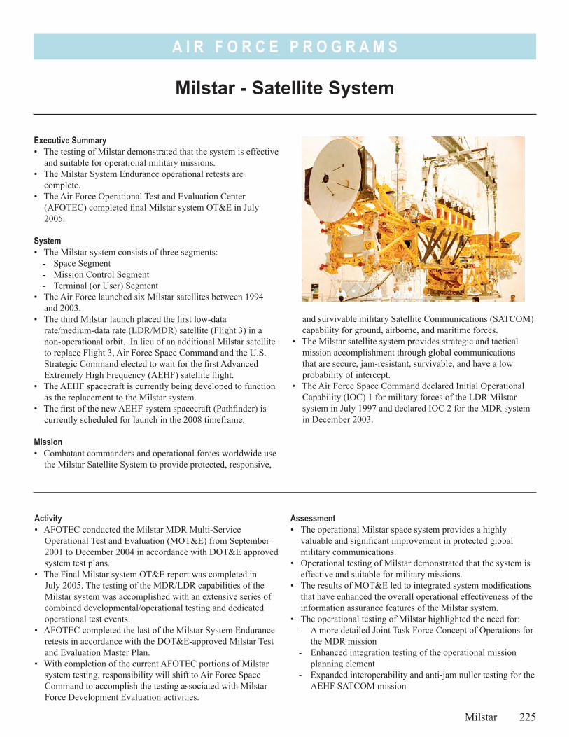
A I R F O R C E P R O G R A M S
and survivable military Satellite Communications (SATCOM) capability for ground, airborne, and maritime forces.
• The Milstar satellite system provides strategic and tactical mission accomplishment through global communications that are secure, jam-resistant, survivable, and have a low probability of intercept.
• The Air Force Space Command declared Initial Operational Capability (IOC) 1 for military forces of the LDR Milstar system in July 1997 and declared IOC 2 for the MDR system in December 2003.
Milstar - Satellite System
Milstar 225
Executive Summary• The testing of Milstar demonstrated that the system is effective
and suitable for operational military missions.• The Milstar System Endurance operational retests are
complete.• The Air Force Operational Test and Evaluation Center
(AFOTEC) completed final Milstar system OT&E in July 2005.
System• The Milstar system consists of three segments:
- Space Segment- Mission Control Segment- Terminal (or User) Segment
• The Air Force launched six Milstar satellites between 1994 and 2003.
• The third Milstar launch placed the first low-data rate/medium-data rate (LDR/MDR) satellite (Flight 3) in a non-operational orbit. In lieu of an additional Milstar satellite to replace Flight 3, Air Force Space Command and the U.S. Strategic Command elected to wait for the first Advanced Extremely High Frequency (AEHF) satellite flight.
• The AEHF spacecraft is currently being developed to function as the replacement to the Milstar system.
• The first of the new AEHF system spacecraft (Pathfinder) is currently scheduled for launch in the 2008 timeframe.
Mission• Combatant commanders and operational forces worldwide use
the Milstar Satellite System to provide protected, responsive,
Activity• AFOTEC conducted the Milstar MDR Multi-Service
Operational Test and Evaluation (MOT&E) from September 2001 to December 2004 in accordance with DOT&E approved system test plans.
• The Final Milstar system OT&E report was completed in July 2005. The testing of the MDR/LDR capabilities of the Milstar system was accomplished with an extensive series of combined developmental/operational testing and dedicated operational test events.
• AFOTEC completed the last of the Milstar System Endurance retests in accordance with the DOT&E-approved Milstar Test and Evaluation Master Plan.
• With completion of the current AFOTEC portions of Milstar system testing, responsibility will shift to Air Force Space Command to accomplish the testing associated with Milstar Force Development Evaluation activities.
Assessment• The operational Milstar space system provides a highly
valuable and significant improvement in protected global military communications.
• Operational testing of Milstar demonstrated that the system is effective and suitable for military missions.
• The results of MOT&E led to integrated system modifications that have enhanced the overall operational effectiveness of the information assurance features of the Milstar system.
• The operational testing of Milstar highlighted the need for:- A more detailed Joint Task Force Concept of Operations for
the MDR mission- Enhanced integration testing of the operational mission
planning element- Expanded interoperability and anti-jam nuller testing for the
AEHF SATCOM mission
A I R F O R C E P R O G R A M S
Recommendations1. Air Force testing of the remaining system features and
enhancements for Milstar (i.e., realistic anti-jam nuller and mission planning element) should be fully integrated into the structure of the operational testing currently being developed for the AEHF SATCOM program.
226 Milstar
2. The Air Force should continue to refine the Joint Task Force Concept of Operations for the Milstar system.
3. The Air Force should apply the information gained from system interoperability tests to both current Milstar operations and AEHF development.
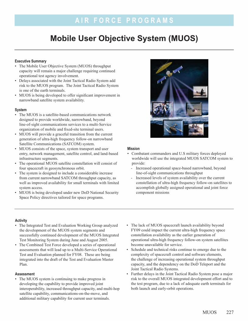
A I R F O R C E P R O G R A M S
Mission• Combatant commanders and U.S military forces deployed
worldwide will use the integrated MUOS SATCOM system to provide: - Increased operational space-based narrowband, beyond
line-of-sight communications throughput - Increased levels of system availability over the current
constellation of ultra-high frequency follow-on satellites to accomplish globally assigned operational and joint force component missions
Mobile User Objective System (MUOS)
MUOS 227
Executive Summary• The Mobile User Objective System (MUOS) throughput
capacity will remain a major challenge requiring continued operational test agency involvement.
• Delays associated with the Joint Tactical Radio System add risk to the MUOS program. The Joint Tactical Radio System is one of the earth terminals.
• MUOS is being developed to offer significant improvement in narrowband satellite system availability.
System• The MUOS is a satellite-based communications network
designed to provide worldwide, narrowband, beyond line-of-sight communications services to a multi-Service organization of mobile and fixed-site terminal users.
• MUOS will provide a graceful transition from the current generation of ultra-high frequency follow-on narrowband Satellite Communications (SATCOM) system.
• MUOS consists of the space, system transport and user entry, network management, satellite control, and land-based infrastructure segments.
• The operational MUOS satellite constellation will consist of four spacecraft in geosynchronous orbit.
• The system is designed to include a considerable increase from current narrowband SATCOM throughput capacity, as well as improved availability for small terminals with limited system access.
• MUOS is being developed under new DoD National Security Space Policy directives tailored for space programs.
Activity• The Integrated Test and Evaluation Working Group analyzed
the development of the MUOS system segments and successfully continued development of the MUOS Integrated Test Monitoring System during June and August 2005.
• The Combined Test Force developed a series of operational assessments that will lead up to a Multi-Service Operational Test and Evaluation planned for FY08. These are being integrated into the draft of the Test and Evaluation Master Plan.
Assessment• The MUOS system is continuing to make progress in
developing the capability to provide improved joint interoperability, increased throughput capacity, and multi-hop satellite capability, communications-on-the-move, and additional military capability for current user terminals.
• The lack of MUOS spacecraft launch availability beyond FY09 could impact the current ultra-high frequency space constellation availability as the earlier generation of operational ultra-high frequency follow-on system satellites become unavailable for service.
• Schedule and technical risks continue to emerge due to the complexity of spacecraft control and software elements, the challenge of increasing operational system throughput capacity, and the dependency on the DoD Teleport and the Joint Tactical Radio Systems.
• Further delays in the Joint Tactical Radio System pose a major risk to the overall MUOS integrated development effort and to the test program, due to a lack of adequate earth terminals for both launch and early-orbit operations.
A I R F O R C E P R O G R A M S
Recommendations1. The adequate and timely assessment of MUOS system
throughput capacity merits the focused attention of participating operational test agencies. The operational test agencies involved in capacity assessments should participate in the modeling and simulation efforts to guide and understand the system capacity verification modeling process.
228 MUOS
2. The Navy modeling and simulation effort should explore an appropriate means to tailor tools for use in operational testing.
3. The MUOS program should develop an alternate strategy to assure there will be adequate earth terminals available to accomplish system testing and early-orbit operations.
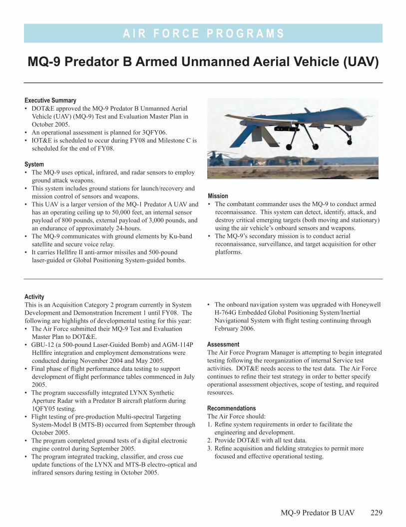
A I R F O R C E P R O G R A M S
Mission• The combatant commander uses the MQ-9 to conduct armed
reconnaissance. This system can detect, identify, attack, and destroy critical emerging targets (both moving and stationary) using the air vehicle’s onboard sensors and weapons.
• The MQ-9’s secondary mission is to conduct aerial reconnaissance, surveillance, and target acquisition for other platforms.
Executive Summary• DOT&E approved the MQ-9 Predator B Unmanned Aerial
Vehicle (UAV) (MQ-9) Test and Evaluation Master Plan in October 2005.
• An operational assessment is planned for 3QFY06.• IOT&E is scheduled to occur during FY08 and Milestone C is
scheduled for the end of FY08.
System• The MQ-9 uses optical, infrared, and radar sensors to employ
ground attack weapons.• This system includes ground stations for launch/recovery and
mission control of sensors and weapons.• This UAV is a larger version of the MQ-1 Predator A UAV and
has an operating ceiling up to 50,000 feet, an internal sensor payload of 800 pounds, external payload of 3,000 pounds, and an endurance of approximately 24-hours.
• The MQ-9 communicates with ground elements by Ku-band satellite and secure voice relay.
• It carries Hellfire II anti-armor missiles and 500-pound laser-guided or Global Positioning System-guided bombs.
ActivityThis is an Acquisition Category 2 program currently in System Development and Demonstration Increment 1 until FY08. The following are highlights of developmental testing for this year:• The Air Force submitted their MQ-9 Test and Evaluation
Master Plan to DOT&E.• GBU-12 (a 500-pound Laser-Guided Bomb) and AGM-114P
Hellfire integration and employment demonstrations were conducted during November 2004 and May 2005.
• Final phase of flight performance data testing to support development of flight performance tables commenced in July 2005.
• The program successfully integrated LYNX Synthetic Aperture Radar with a Predator B aircraft platform during 1QFY05 testing.
• Flight testing of pre-production Multi-spectral Targeting System-Model B (MTS-B) occurred from September through October 2005.
• The program completed ground tests of a digital electronic engine control during September 2005.
• The program integrated tracking, classifier, and cross cue update functions of the LYNX and MTS-B electro-optical and infrared sensors during testing in October 2005.
• The onboard navigation system was upgraded with Honeywell H-764G Embedded Global Positioning System/Inertial Navigational System with flight testing continuing through February 2006.
AssessmentThe Air Force Program Manager is attempting to begin integrated testing following the reorganization of internal Service test activities. DOT&E needs access to the test data. The Air Force continues to refine their test strategy in order to better specify operational assessment objectives, scope of testing, and required resources.
RecommendationsThe Air Force should:1. Refine system requirements in order to facilitate the
engineering and development. 2. Provide DOT&E with all test data.3. Refine acquisition and fielding strategies to permit more
focused and effective operational testing.
MQ-9 Predator B UAV 229
MQ-9 Predator B Armed Unmanned Aerial Vehicle (UAV)

A I R F O R C E P R O G R A M S
230
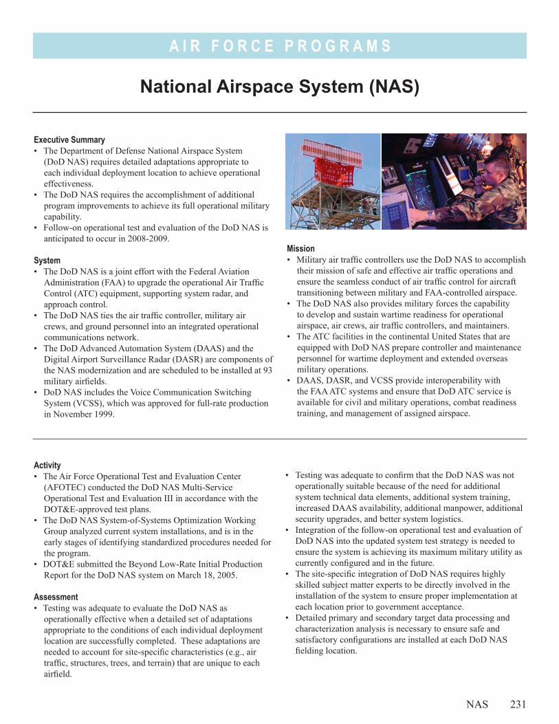
A I R F O R C E P R O G R A M S
Mission• Military air traffic controllers use the DoD NAS to accomplish
their mission of safe and effective air traffic operations and ensure the seamless conduct of air traffic control for aircraft transitioning between military and FAA-controlled airspace.
• The DoD NAS also provides military forces the capability to develop and sustain wartime readiness for operational airspace, air crews, air traffic controllers, and maintainers.
• The ATC facilities in the continental United States that are equipped with DoD NAS prepare controller and maintenance personnel for wartime deployment and extended overseas military operations.
• DAAS, DASR, and VCSS provide interoperability with the FAA ATC systems and ensure that DoD ATC service is available for civil and military operations, combat readiness training, and management of assigned airspace.
National Airspace System (NAS)
NAS 231
Executive Summary• The Department of Defense National Airspace System
(DoD NAS) requires detailed adaptations appropriate to each individual deployment location to achieve operational effectiveness.
• The DoD NAS requires the accomplishment of additional program improvements to achieve its full operational military capability.
• Follow-on operational test and evaluation of the DoD NAS is anticipated to occur in 2008-2009.
System• The DoD NAS is a joint effort with the Federal Aviation
Administration (FAA) to upgrade the operational Air Traffic Control (ATC) equipment, supporting system radar, and approach control.
• The DoD NAS ties the air traffic controller, military air crews, and ground personnel into an integrated operational communications network.
• The DoD Advanced Automation System (DAAS) and the Digital Airport Surveillance Radar (DASR) are components of the NAS modernization and are scheduled to be installed at 93 military airfields.
• DoD NAS includes the Voice Communication Switching System (VCSS), which was approved for full-rate production in November 1999.
Activity• The Air Force Operational Test and Evaluation Center
(AFOTEC) conducted the DoD NAS Multi-Service Operational Test and Evaluation III in accordance with the DOT&E-approved test plans.
• The DoD NAS System-of-Systems Optimization Working Group analyzed current system installations, and is in the early stages of identifying standardized procedures needed for the program.
• DOT&E submitted the Beyond Low-Rate Initial Production Report for the DoD NAS system on March 18, 2005.
Assessment• Testing was adequate to evaluate the DoD NAS as
operationally effective when a detailed set of adaptations appropriate to the conditions of each individual deployment location are successfully completed. These adaptations are needed to account for site-specific characteristics (e.g., air traffic, structures, trees, and terrain) that are unique to each airfield.
• Testing was adequate to confirm that the DoD NAS was not operationally suitable because of the need for additional system technical data elements, additional system training, increased DAAS availability, additional manpower, additional security upgrades, and better system logistics.
• Integration of the follow-on operational test and evaluation of DoD NAS into the updated system test strategy is needed to ensure the system is achieving its maximum military utility as currently configured and in the future.
• The site-specific integration of DoD NAS requires highly skilled subject matter experts to be directly involved in the installation of the system to ensure proper implementation at each location prior to government acceptance.
• Detailed primary and secondary target data processing and characterization analysis is necessary to ensure safe and satisfactory configurations are installed at each DoD NAS fielding location.
A I R F O R C E P R O G R A M S
• DoD NAS effectiveness deficiencies were also noted during system test in the areas of conflict alerts and Minimum Safe Altitude Warnings, radar clutter limitations, and processor capacity.
Recommendations1. The Air Force should prepare an integrated follow-on
operational test and evaluation program that addresses:- Conflict alerts- Minimum Safe Altitude Warnings- Radar clutter limitations- Processor capacity
- DOT&E beyond low-rate initial production recommendations
- Emerging features of the DoD NAS2. The Air Force should implement a full-rate production
system-of-systems optimization directive that ensures formal implementation and developmental contractor compliance.
3. The Air Force should accomplish detailed primary and secondary target data processing and characterization analysis to ensure safe and satisfactory configurations are installed at each DoD NAS fielding location.
232 NAS

A I R F O R C E P R O G R A M S
• NPOESS is being developed to integrate and upgrade the capabilities of the current generation of operational military and civilian polar orbiting weather satellite systems.
• The operational missions using NPOESS will include aviation and space forecasts, ocean surface and internal structure forecasts for ship movements, search and rescue, and tropical storm reconnaissance and warnings.
• NPOESS provides data to a multitude of environmental prediction systems that generate mission critical terrestrial and space weather products for operational users.
National Polar-Orbiting Operational Environmental Satellite System (NPOESS)
NPOESS 233
Executive Summary• The National Polar-Orbiting Operational Environmental
Satellite System (NPOESS) is being developed to provide, for a period of at least 10 years, a national remote sensing capability to acquire and disseminate global and regional battlespace environment data.
• The Air Force Operational Test and Evaluation Center (AFOTEC) conducted the operational assessment for the NPOESS program in accordance with the Test and Evaluation Master Plan approved by DOT&E.
• System technical difficulties delayed the launch of the NPOESS Preparatory Project risk reduction spacecraft.
SystemNPOESS consists of:• Three operational satellites in the space segment provide
sun-synchronous, near polar orbits with multiple advanced environmental sensors.
• The Command, Control, and Communications (C3) segment provides routing of mission data and spacecraft telemetry to Mission Management Centers.
• The Interface Data Processing Segment converts spacecraft sensor data into measurement formats for operational environmental products.
• The fixed and mobile field terminals of the NPOESS user segment are designed to receive and process data directly from satellites for operational system users.
MissionCombatant commanders, U.S. military forces, and federal partnership agencies will use NPOESS to provide timely characterization of environmental data.
Activity• AFOTEC completed the NPOESS operational assessment in
January 2005.• The NPOESS Integrated Test Team reviewed the current
system test strategy and refined the system test plan during November 2004 and June 2005 to better integrate the testing of NPOESS system segments in development.
• The integrated NPOESS Senior User Advisory Group analyzed the NPOESS Preparatory Project risk reduction development effort during March 2005 for application to the later operational spacecraft of program.
Assessment• The AFOTEC operational assessment identified continued
progress in areas related to operational effectiveness and unsatisfactory progress in areas related to system readiness for OT&E. The system does continue to make progress, but key concerns remain to be resolved in NPOESS system design, integration, threshold definitions for low-rate data user terminals, and user field terminal development for testing prior to launch.
• The NPOESS sensors, their integration, algorithm development, electromagnetic environmental effects, and
A I R F O R C E P R O G R A M S
information assurance testing remain on a tight schedule and continue to face technical challenges including the launch of the NPOESS risk reduction satellite.
• The emerging differences between NPOESS system specification and the Integrated Operational Requirements Document II have not yet been synchronized to ensure developmental and operational testing criteria are consistent. Examples include the initial lack of space environment sensors on the first spacecraft and the potential lack of NPOESS satellite compatibility with the Air Force Satellite Control Network.
Recommendations1. The risk reduction testing of NPOESS field terminals for
individual agencies should take place before launch. During that testing, user terminals should interface with realistic NPOESS data sources in a controlled setting.
234 NPOESS
2. The NPOESS program should provide increased user community assistance in developing threshold definitions for low-data rate versions of the field terminals to allow for adequate and integrated testing on this portion of the user segment.
3. The NPOESS test strategy and test plan should be updated to incorporate testing information assurance, electromagnetic environmental effects, and the Air Force Satellite Control Network.
4. The NPOESS program should place special emphasis on the requirements of Operational Requirements Document II and the national security space responsibilities established for the system in the NPOESS charter.
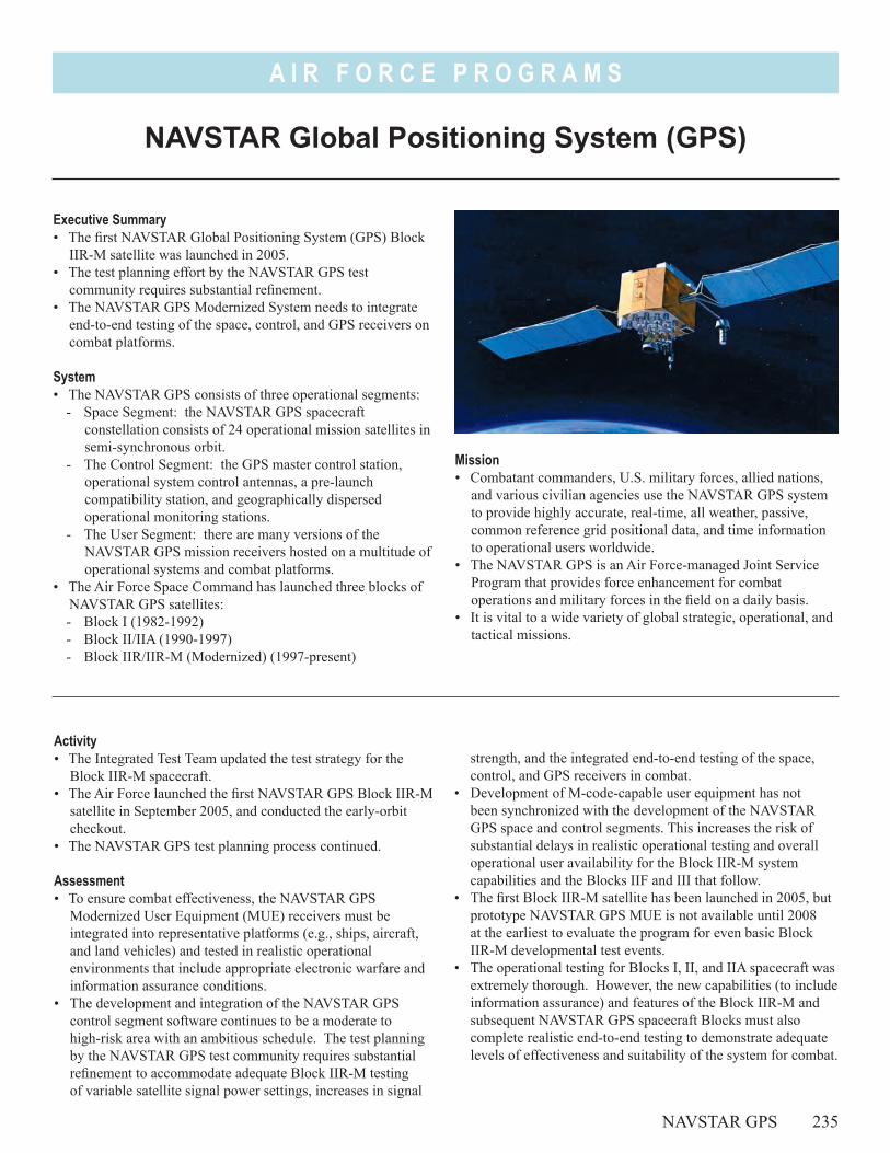
A I R F O R C E P R O G R A M S
Mission• Combatant commanders, U.S. military forces, allied nations,
and various civilian agencies use the NAVSTAR GPS system to provide highly accurate, real-time, all weather, passive, common reference grid positional data, and time information to operational users worldwide.
• The NAVSTAR GPS is an Air Force-managed Joint Service Program that provides force enhancement for combat operations and military forces in the field on a daily basis.
• It is vital to a wide variety of global strategic, operational, and tactical missions.
NAVSTAR Global Positioning System (GPS)
NAVSTAR GPS 235
Executive Summary• The first NAVSTAR Global Positioning System (GPS) Block
IIR-M satellite was launched in 2005. • The test planning effort by the NAVSTAR GPS test
community requires substantial refinement. • The NAVSTAR GPS Modernized System needs to integrate
end-to-end testing of the space, control, and GPS receivers on combat platforms.
System• The NAVSTAR GPS consists of three operational segments:
- Space Segment: the NAVSTAR GPS spacecraft constellation consists of 24 operational mission satellites in semi-synchronous orbit.
- The Control Segment: the GPS master control station, operational system control antennas, a pre-launch compatibility station, and geographically dispersed operational monitoring stations.
- The User Segment: there are many versions of the NAVSTAR GPS mission receivers hosted on a multitude of operational systems and combat platforms.
• The Air Force Space Command has launched three blocks of NAVSTAR GPS satellites:- Block I (1982-1992)- Block II/IIA (1990-1997)- Block IIR/IIR-M (Modernized) (1997-present)
Activity• The Integrated Test Team updated the test strategy for the
Block IIR-M spacecraft.• The Air Force launched the first NAVSTAR GPS Block IIR-M
satellite in September 2005, and conducted the early-orbit checkout.
• The NAVSTAR GPS test planning process continued.
Assessment• To ensure combat effectiveness, the NAVSTAR GPS
Modernized User Equipment (MUE) receivers must be integrated into representative platforms (e.g., ships, aircraft, and land vehicles) and tested in realistic operational environments that include appropriate electronic warfare and information assurance conditions.
• The development and integration of the NAVSTAR GPS control segment software continues to be a moderate to high-risk area with an ambitious schedule. The test planning by the NAVSTAR GPS test community requires substantial refinement to accommodate adequate Block IIR-M testing of variable satellite signal power settings, increases in signal
strength, and the integrated end-to-end testing of the space, control, and GPS receivers in combat.
• Development of M-code-capable user equipment has not been synchronized with the development of the NAVSTAR GPS space and control segments. This increases the risk of substantial delays in realistic operational testing and overall operational user availability for the Block IIR-M system capabilities and the Blocks IIF and III that follow.
• The first Block IIR-M satellite has been launched in 2005, but prototype NAVSTAR GPS MUE is not available until 2008 at the earliest to evaluate the program for even basic Block IIR-M developmental test events.
• The operational testing for Blocks I, II, and IIA spacecraft was extremely thorough. However, the new capabilities (to include information assurance) and features of the Block IIR-M and subsequent NAVSTAR GPS spacecraft Blocks must also complete realistic end-to-end testing to demonstrate adequate levels of effectiveness and suitability of the system for combat.
A I R F O R C E P R O G R A M S
RecommendationsThe Air Force should:1. Synchronize development of the three NAVSTAR GPS
segments and integrate production representative MUE onto operational platforms for OT&E.
2. Refine and integrate the NAVSTAR GPS system test strategy to include more rigorous end-to-end testing of the space, control, and MUE user segments with operationally representative platforms, and then update the Test and Evaluation Master Plan.
3. Integrate appropriate electronic warfare environments into testing of NAVSTAR GPS to ensure M-code capabilities are demonstrated under realistic combat conditions.
4. Evaluate information assurance in realistic testing. 5. DOT&E continues to advocate the operational testing of new
and legacy NAVSTAR GPS receivers as early in the program as possible to ensure that maximum capability is consistently provided to operational users.
236 NAVSTAR GPS
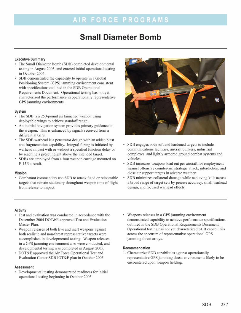
A I R F O R C E P R O G R A M S
• SDB engages both soft and hardened targets to include communications facilities, aircraft bunkers, industrial complexes, and lightly armored ground combat systems and vehicles.
• SDB increases weapons load out per aircraft for employment against offensive counter-air, strategic attack, interdiction, and close air support targets in adverse weather.
• SDB minimizes collateral damage while achieving kills across a broad range of target sets by precise accuracy, small warhead design, and focused warhead effects.
Executive Summary• The Small Diameter Bomb (SDB) completed developmental
testing in August 2005, and entered initial operational testing in October 2005.
• SDB demonstrated the capability to operate in a Global Positioning System (GPS) jamming environment consistent with specifications outlined in the SDB Operational Requirements Document. Operational testing has not yet characterized the performance in operationally representative GPS jamming environments.
System• The SDB is a 250-pound air launched weapon using
deployable wings to achieve standoff range.• An inertial navigation system provides primary guidance to
the weapon. This is enhanced by signals received from a differential GPS.
• The SDB warhead is a penetrator design with an added blast and fragmentation capability. Integral fuzing is initiated by warhead impact with or without a specified function delay or by reaching a preset height above the intended target.
• SDBs are employed from a four weapon carriage mounted on F-15E aircraft.
Mission• Combatant commanders use SDB to attack fixed or relocatable
targets that remain stationary throughout weapon time of flight from release to impact.
• Weapons releases in a GPS jamming environment demonstrated capability to achieve performance specifications outlined in the SDB Operational Requirements Document. Operational testing has not yet characterized SDB capabilities across the spectrum of representative operational GPS jamming threat arrays.
Recommendation1. Characterize SDB capabilities against operationally
representative GPS jamming threat environments likely to be encountered upon weapon fielding.
Small Diameter Bomb
Activity• Test and evaluation was conducted in accordance with the
December 2004 DOT&E-approved Test and Evaluation Master Plan.
• Weapon releases of both live and inert weapons against both realistic and non-threat representative targets were accomplished in developmental testing. Weapon releases in a GPS jamming environment also were conducted, and developmental testing was completed in August 2005.
• DOT&E approved the Air Force Operational Test and Evaluation Center SDB IOT&E plan in October 2005.
Assessment• Developmental testing demonstrated readiness for initial
operational testing beginning in October 2005.
SDB 237

A I R F O R C E P R O G R A M S
238
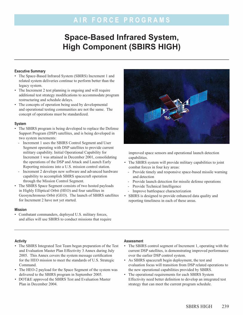
A I R F O R C E P R O G R A M S
improved space sensors and operational launch detection capabilities.
• The SBIRS system will provide military capabilities to joint combat forces in four key areas:- Provide timely and responsive space-based missile warning
and detection- Provide launch detection for missile defense operations- Provide Technical Intelligence- Improve battlespace characterization
• SBIRS is designed to provide enhanced data quality and reporting timeliness in each of these areas.
Space-Based Infrared System, High Component (SBIRS HIGH)
SBIRS HIGH 239
Executive Summary• The Space-Based Infrared System (SBIRS) Increment 1 and
related system deliveries continue to perform better than the legacy system.
• The Increment 2 test planning is ongoing and will require additional test strategy modifications to accommodate program restructuring and schedule delays.
• The concepts of operation being used by developmental and operational testing communities are not the same. The concept of operations must be standardized.
System• The SBIRS program is being developed to replace the Defense
Support Program (DSP) satellites, and is being developed in two system increments: - Increment 1 uses the SBIRS Control Segment and User
Segment operating with DSP satellites to provide current military capability. Initial Operational Capability for Increment 1 was attained in December 2001, consolidating the operations of the DSP and Attack and Launch Early Reporting missions into a U.S. mission control station.
- Increment 2 develops new software and advanced hardware capability to accomplish SBIRS spacecraft operation through the Mission Control Segment.
• The SBIRS Space Segment consists of two hosted payloads in Highly Elliptical Orbit (HEO) and four satellites in Geosynchronous Orbit (GEO). The launch of SBIRS satellites for Increment 2 have not yet started.
Mission• Combatant commanders, deployed U.S. military forces,
and allies will use SBIRS to conduct missions that require
Activity• The SBIRS Integrated Test Team began preparation of the Test
and Evaluation Master Plan Effectivity 3 Annex during July 2005. This Annex covers the system message certification for the HEO mission to meet the standards of U.S. Strategic Command.
• The HEO-2 payload for the Space Segment of the system was delivered to the SBIRS program in September 2005.
• DOT&E approved the SBIRS Test and Evaluation Master Plan in December 2004.
Assessment• The SBIRS control segment of Increment 1, operating with the
current DSP satellites, is demonstrating improved performance over the earlier DSP control system.
• As SBIRS spacecraft begin deployment, the test and evaluation focus will transition from DSP related operations to the new operational capabilities provided by SBIRS.
• The operational requirements for each SBIRS System Effectivity need better definition to develop an integrated test strategy that can meet the current program schedule.
A I R F O R C E P R O G R A M S
• Lack of accredited models and the delayed development of SBIRS test scenarios and simulations, increases the program risk for exceeding the program timelines associated with scheduled test events.
• There are emerging differences between the concepts of operation being used during the developmental and operational phases of testing. This reduces synchronization in the structure of the overall test program.
Recommendations1. The Air Force should adequately specify the operational
requirements for each SBIRS Effectivity to achieve the timely development of the corresponding Test and Evaluation Master Plan Annexes.
2. The Air Force should resolve delays associated with developing accredited system models for critical SBIRS testing, and identify timely delivery dates to meet the needs of the operational test schedule.
3. The Air Force should resolve the differences in the concept of operations being employed for the different phases of SBIRS testing in order to meet the integrated needs of the test program.
4. The Air Force should conduct integrated operational testing of SBIRS HEO message certification for the System Effectivity 3/11 to meet the needs of certification and operational acceptance by U.S. Strategic Command.
240 SBIRS HIGH
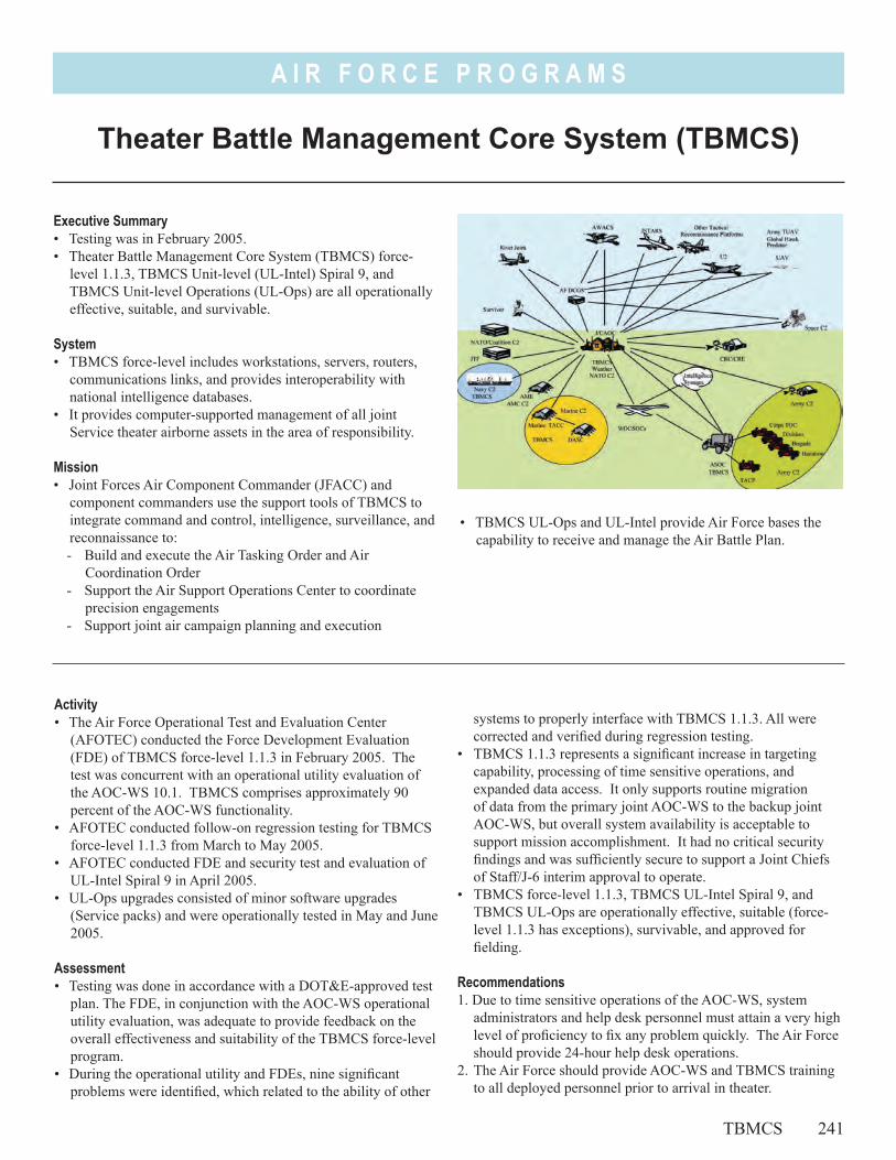
A I R F O R C E P R O G R A M S
• TBMCS UL-Ops and UL-Intel provide Air Force bases the capability to receive and manage the Air Battle Plan.
Theater Battle Management Core System (TBMCS)
TBMCS 241
Executive Summary• Testing was in February 2005.• Theater Battle Management Core System (TBMCS) force-
level 1.1.3, TBMCS Unit-level (UL-Intel) Spiral 9, and TBMCS Unit-level Operations (UL-Ops) are all operationally effective, suitable, and survivable.
System• TBMCS force-level includes workstations, servers, routers,
communications links, and provides interoperability with national intelligence databases.
• It provides computer-supported management of all joint Service theater airborne assets in the area of responsibility.
Mission• Joint Forces Air Component Commander (JFACC) and
component commanders use the support tools of TBMCS to integrate command and control, intelligence, surveillance, and reconnaissance to:- Build and execute the Air Tasking Order and Air
Coordination Order- Support the Air Support Operations Center to coordinate
precision engagements- Support joint air campaign planning and execution
Activity• The Air Force Operational Test and Evaluation Center
(AFOTEC) conducted the Force Development Evaluation (FDE) of TBMCS force-level 1.1.3 in February 2005. The test was concurrent with an operational utility evaluation of the AOC-WS 10.1. TBMCS comprises approximately 90 percent of the AOC-WS functionality.
• AFOTEC conducted follow-on regression testing for TBMCS force-level 1.1.3 from March to May 2005.
• AFOTEC conducted FDE and security test and evaluation of UL-Intel Spiral 9 in April 2005.
• UL-Ops upgrades consisted of minor software upgrades (Service packs) and were operationally tested in May and June 2005.
Assessment• Testing was done in accordance with a DOT&E-approved test
plan. The FDE, in conjunction with the AOC-WS operational utility evaluation, was adequate to provide feedback on the overall effectiveness and suitability of the TBMCS force-level program.
• During the operational utility and FDEs, nine significant problems were identified, which related to the ability of other
systems to properly interface with TBMCS 1.1.3. All were corrected and verified during regression testing.
• TBMCS 1.1.3 represents a significant increase in targeting capability, processing of time sensitive operations, and expanded data access. It only supports routine migration of data from the primary joint AOC-WS to the backup joint AOC-WS, but overall system availability is acceptable to support mission accomplishment. It had no critical security findings and was sufficiently secure to support a Joint Chiefs of Staff/J-6 interim approval to operate.
• TBMCS force-level 1.1.3, TBMCS UL-Intel Spiral 9, and TBMCS UL-Ops are operationally effective, suitable (force-level 1.1.3 has exceptions), survivable, and approved for fielding.
Recommendations1. Due to time sensitive operations of the AOC-WS, system
administrators and help desk personnel must attain a very high level of proficiency to fix any problem quickly. The Air Force should provide 24-hour help desk operations.
2. The Air Force should provide AOC-WS and TBMCS training to all deployed personnel prior to arrival in theater.

242
A I R F O R C E P R O G R A M S
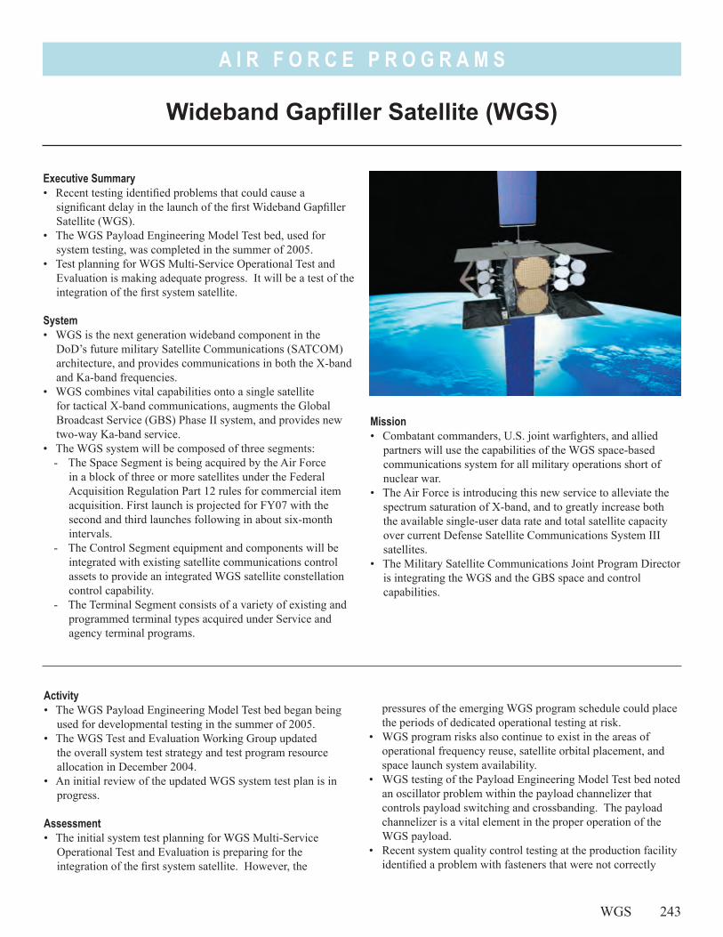
A I R F O R C E P R O G R A M S
Mission• Combatant commanders, U.S. joint warfighters, and allied
partners will use the capabilities of the WGS space-based communications system for all military operations short of nuclear war.
• The Air Force is introducing this new service to alleviate the spectrum saturation of X-band, and to greatly increase both the available single-user data rate and total satellite capacity over current Defense Satellite Communications System III satellites.
• The Military Satellite Communications Joint Program Director is integrating the WGS and the GBS space and control capabilities.
Wideband Gapfiller Satellite (WGS)
WGS 243
Executive Summary• Recent testing identified problems that could cause a
significant delay in the launch of the first Wideband Gapfiller Satellite (WGS).
• The WGS Payload Engineering Model Test bed, used for system testing, was completed in the summer of 2005.
• Test planning for WGS Multi-Service Operational Test and Evaluation is making adequate progress. It will be a test of the integration of the first system satellite.
System• WGS is the next generation wideband component in the
DoD’s future military Satellite Communications (SATCOM) architecture, and provides communications in both the X-band and Ka-band frequencies.
• WGS combines vital capabilities onto a single satellite for tactical X-band communications, augments the Global Broadcast Service (GBS) Phase II system, and provides new two-way Ka-band service.
• The WGS system will be composed of three segments: - The Space Segment is being acquired by the Air Force
in a block of three or more satellites under the Federal Acquisition Regulation Part 12 rules for commercial item acquisition. First launch is projected for FY07 with the second and third launches following in about six-month intervals.
- The Control Segment equipment and components will be integrated with existing satellite communications control assets to provide an integrated WGS satellite constellation control capability.
- The Terminal Segment consists of a variety of existing and programmed terminal types acquired under Service and agency terminal programs.
Activity• The WGS Payload Engineering Model Test bed began being
used for developmental testing in the summer of 2005.• The WGS Test and Evaluation Working Group updated
the overall system test strategy and test program resource allocation in December 2004.
• An initial review of the updated WGS system test plan is in progress.
Assessment• The initial system test planning for WGS Multi-Service
Operational Test and Evaluation is preparing for the integration of the first system satellite. However, the
pressures of the emerging WGS program schedule could place the periods of dedicated operational testing at risk.
• WGS program risks also continue to exist in the areas of operational frequency reuse, satellite orbital placement, and space launch system availability.
• WGS testing of the Payload Engineering Model Test bed noted an oscillator problem within the payload channelizer that controls payload switching and crossbanding. The payload channelizer is a vital element in the proper operation of the WGS payload.
• Recent system quality control testing at the production facility identified a problem with fasteners that were not correctly
A I R F O R C E P R O G R A M S
installed in the assembly of WGS Satellite 1. A WGS programmatic delay of at least 12 months is expected in order to replace the fasteners. Inspection of Satellites 2 and 3 will likely be required to verify that those fasteners were properly installed.
• The WGS Multi-Service Operational Test and Evaluation will need to integrate with the testing of the final mission capability requirements of the GBS Phase II and related system programs. The interoperability features of these systems will need to be evaluated.
Recommendations1. The Air Force and the Combined Test Force should maximize
the application of combined developmental and operational
testing for WGS, but preserve the previously scheduled periods needed for dedicated operational testing.
2. The Air Force should continue to carefully control WGS program risks associated with frequency reuse, satellite orbital placement, and launch system availability.
3. The Air Force should integrate the WGS related operating capabilities of the GBS Phase II system into the WGS Multi-Service Test and Evaluation Strategy.
244 WGS

Ballistic MissileDefense System

Ballis
tic M
issile
Defe
nse S
yste
m
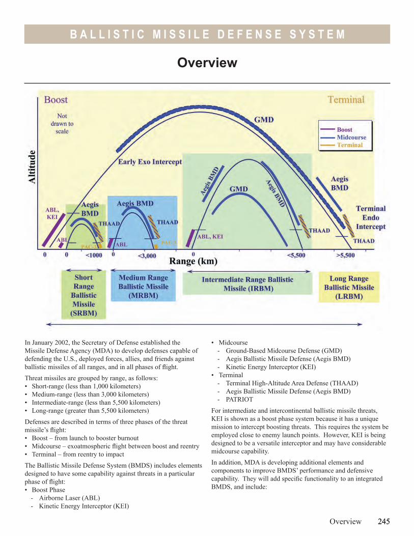
245
B A L L I S T I C M I S S I L E D E F E N S E S Y S T E M
• Midcourse- Ground-Based Midcourse Defense (GMD)- Aegis Ballistic Missile Defense (Aegis BMD)- Kinetic Energy Interceptor (KEI)
• Terminal- Terminal High-Altitude Area Defense (THAAD)- Aegis Ballistic Missile Defense (Aegis BMD)- PATRIOT
For intermediate and intercontinental ballistic missile threats, KEI is shown as a boost phase system because it has a unique mission to intercept boosting threats. This requires the system be employed close to enemy launch points. However, KEI is being designed to be a versatile interceptor and may have considerable midcourse capability.
In addition, MDA is developing additional elements and components to improve BMDS’ performance and defensive capability. They will add specific functionality to an integrated BMDS, and include:
In January 2002, the Secretary of Defense established the Missile Defense Agency (MDA) to develop defenses capable of defending the U.S., deployed forces, allies, and friends against ballistic missiles of all ranges, and in all phases of flight.
Threat missiles are grouped by range, as follows:• Short-range (less than 1,000 kilometers)• Medium-range (less than 3,000 kilometers)• Intermediate-range (less than 5,500 kilometers) • Long-range (greater than 5,500 kilometers)
Defenses are described in terms of three phases of the threat missile’s flight: • Boost – from launch to booster burnout• Midcourse – exoatmospheric flight between boost and reentry• Terminal – from reentry to impact
The Ballistic Missile Defense System (BMDS) includes elements designed to have some capability against threats in a particular phase of flight:• Boost Phase
- Airborne Laser (ABL)- Kinetic Energy Interceptor (KEI)
Overview 245
Overview
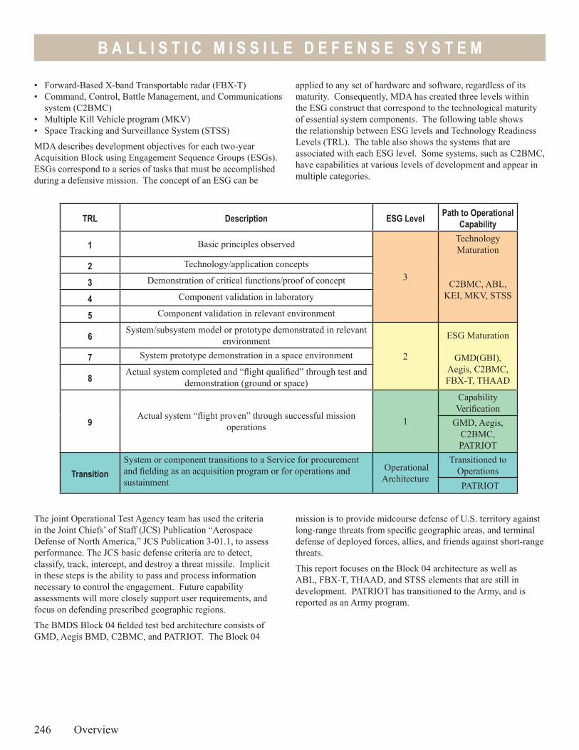
B A L L I S T I C M I S S I L E D E F E N S E S Y S T E M
The joint Operational Test Agency team has used the criteria in the Joint Chiefs’ of Staff (JCS) Publication “Aerospace Defense of North America,” JCS Publication 3-01.1, to assess performance. The JCS basic defense criteria are to detect, classify, track, intercept, and destroy a threat missile. Implicit in these steps is the ability to pass and process information necessary to control the engagement. Future capability assessments will more closely support user requirements, and focus on defending prescribed geographic regions.
The BMDS Block 04 fielded test bed architecture consists of GMD, Aegis BMD, C2BMC, and PATRIOT. The Block 04
246 Overview
TRL Description ESG Level Path to Operational Capability
1 Basic principles observed
3
Technology Maturation
2 Technology/application concepts
C2BMC, ABL, KEI, MKV, STSS
3 Demonstration of critical functions/proof of concept
4 Component validation in laboratory
5 Component validation in relevant environment
6System/subsystem model or prototype demonstrated in relevant
environment2
ESG Maturation
7 System prototype demonstration in a space environment GMD(GBI), Aegis, C2BMC, FBX-T, THAAD 8
Actual system completed and “flight qualified” through test and demonstration (ground or space)
9Actual system “flight proven” through successful mission
operations 1
Capability Verification
GMD, Aegis, C2BMC, PATRIOT
TransitionSystem or component transitions to a Service for procurement and fielding as an acquisition program or for operations and sustainment
Operational Architecture
Transitioned to Operations PATRIOT
mission is to provide midcourse defense of U.S. territory against long-range threats from specific geographic areas, and terminal defense of deployed forces, allies, and friends against short-range threats.
This report focuses on the Block 04 architecture as well as ABL, FBX-T, THAAD, and STSS elements that are still in development. PATRIOT has transitioned to the Army, and is reported as an Army program.
• Forward-Based X-band Transportable radar (FBX-T)• Command, Control, Battle Management, and Communications
system (C2BMC)• Multiple Kill Vehicle program (MKV)• Space Tracking and Surveillance System (STSS)
MDA describes development objectives for each two-year Acquisition Block using Engagement Sequence Groups (ESGs). ESGs correspond to a series of tasks that must be accomplished during a defensive mission. The concept of an ESG can be
applied to any set of hardware and software, regardless of its maturity. Consequently, MDA has created three levels within the ESG construct that correspond to the technological maturity of essential system components. The following table shows the relationship between ESG levels and Technology Readiness Levels (TRL). The table also shows the systems that are associated with each ESG level. Some systems, such as C2BMC, have capabilities at various levels of development and appear in multiple categories.
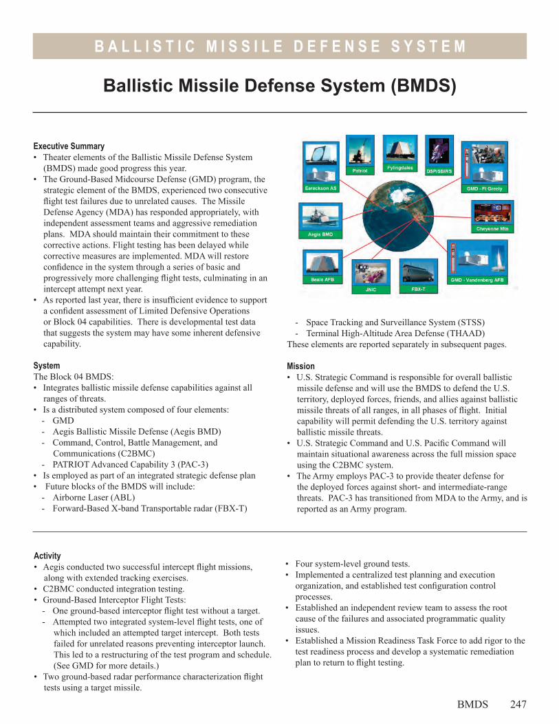
B A L L I S T I C M I S S I L E D E F E N S E S Y S T E M
- Space Tracking and Surveillance System (STSS)- Terminal High-Altitude Area Defense (THAAD)
These elements are reported separately in subsequent pages.
Mission• U.S. Strategic Command is responsible for overall ballistic
missile defense and will use the BMDS to defend the U.S. territory, deployed forces, friends, and allies against ballistic missile threats of all ranges, in all phases of flight. Initial capability will permit defending the U.S. territory against ballistic missile threats.
• U.S. Strategic Command and U.S. Pacific Command will maintain situational awareness across the full mission space using the C2BMC system.
• The Army employs PAC-3 to provide theater defense for the deployed forces against short- and intermediate-range threats. PAC-3 has transitioned from MDA to the Army, and is reported as an Army program.
Ballistic Missile Defense System (BMDS)
Executive Summary• Theater elements of the Ballistic Missile Defense System
(BMDS) made good progress this year. • The Ground-Based Midcourse Defense (GMD) program, the
strategic element of the BMDS, experienced two consecutive flight test failures due to unrelated causes. The Missile Defense Agency (MDA) has responded appropriately, with independent assessment teams and aggressive remediation plans. MDA should maintain their commitment to these corrective actions. Flight testing has been delayed while corrective measures are implemented. MDA will restore confidence in the system through a series of basic and progressively more challenging flight tests, culminating in an intercept attempt next year.
• As reported last year, there is insufficient evidence to support a confident assessment of Limited Defensive Operations or Block 04 capabilities. There is developmental test data that suggests the system may have some inherent defensive capability.
SystemThe Block 04 BMDS: • Integrates ballistic missile defense capabilities against all
ranges of threats.• Is a distributed system composed of four elements:
- GMD- Aegis Ballistic Missile Defense (Aegis BMD)- Command, Control, Battle Management, and
Communications (C2BMC)- PATRIOT Advanced Capability 3 (PAC-3)
• Is employed as part of an integrated strategic defense plan • Future blocks of the BMDS will include:
- Airborne Laser (ABL)- Forward-Based X-band Transportable radar (FBX-T)
Activity• Aegis conducted two successful intercept flight missions,
along with extended tracking exercises. • C2BMC conducted integration testing. • Ground-Based Interceptor Flight Tests:
- One ground-based interceptor flight test without a target. - Attempted two integrated system-level flight tests, one of
which included an attempted target intercept. Both tests failed for unrelated reasons preventing interceptor launch. This led to a restructuring of the test program and schedule. (See GMD for more details.)
• Two ground-based radar performance characterization flight tests using a target missile.
• Four system-level ground tests.• Implemented a centralized test planning and execution
organization, and established test configuration control processes.
• Established an independent review team to assess the root cause of the failures and associated programmatic quality issues.
• Established a Mission Readiness Task Force to add rigor to the test readiness process and develop a systematic remediation plan to return to flight testing.
BMDS 247
B A L L I S T I C M I S S I L E D E F E N S E S Y S T E M
• MDA added six interceptors to the test bed at Fort Greely, Alaska, bringing the total deployed inventory to 10 missiles at Fort Greely, Alaska, and two at Vandenburg Air Force Base, California.
Assessment• As reported last year, there is insufficient evidence to support
a confident assessment of Limited Defensive Operations or Block 04 capabilities. There is developmental test data that suggests the system may have some inherent defensive capability.
• C2BMC continues to make progress, but has not yet demonstrated engagement control.
• Two independent review teams, chartered by MDA to review the development and test programs, found that quality, workmanship, and inadequate ground testing contributed to flight test failures.
• The Mission Readiness Task Force recommended that MDA execute a deliberate series of tests that gradually increase in complexity in order to return to a stable flight test program. This is a prudent plan that focuses first on component-level testing and flight readiness, then demonstrates interceptor performance, integration of the launch equipment, a flight mission with a target missile, and finally an intercept flight mission.
• MDA is gradually adding operational realism to the BMDS test program by including both developmental and operational test objectives in all system-level test events.
• The majority of progress over the past year has been in the component-level test programs.
The BMDS is designed to provide a new capability against an important set of ballistic missile threats. To fully assess its operational capabilities, the following must occur:
• Robust system-level testing as the deployed components mature
• Models and simulations must be accredited in time to support system-level ground tests
• Flight tests must achieve operational realism as components mature
• Future testing must demonstrate capabilities against challenging threat scenarios
Recommendations1. Maintain the current emphasis on the Mission Readiness Task
Force test program.2. Conduct interceptor flight tests utilizing the operational ground
systems, midcourse sensors, and warfighter crews.3. Conduct operationally realistic intercept tests against a realistic
target suite to demonstrate capability and validate models. 4. Conduct robust distributed ground tests that employ
operational communications. 5. Exploit the deployed architecture of the test bed to gather
reliability, availability, and maintainability data. 6. Implement the recommendation of the independent review
teams to develop and test components of the BMDS in accordance with disciplined product assurance and test processes.
7. Establish procedures or architectural changes to support combined operations and robust testing.
8. Enforce the newly established test configuration control process.
248 BMDS
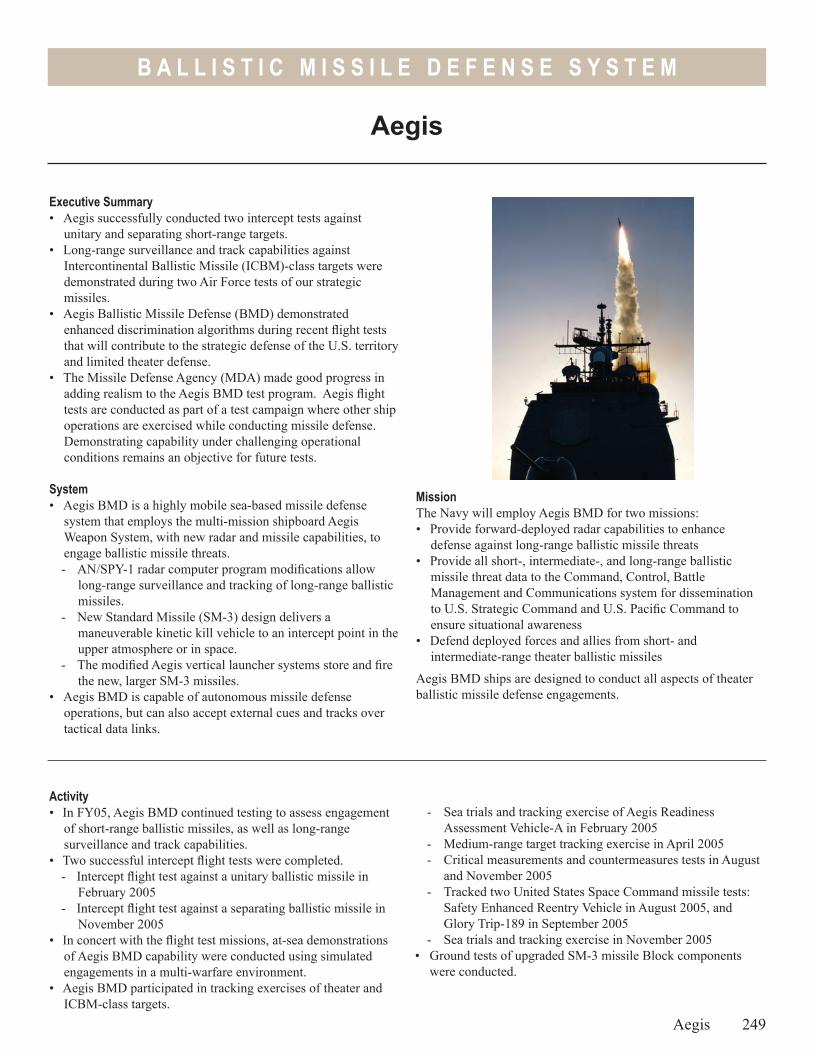
B A L L I S T I C M I S S I L E D E F E N S E S Y S T E M
MissionThe Navy will employ Aegis BMD for two missions:• Provide forward-deployed radar capabilities to enhance
defense against long-range ballistic missile threats• Provide all short-, intermediate-, and long-range ballistic
missile threat data to the Command, Control, Battle Management and Communications system for dissemination to U.S. Strategic Command and U.S. Pacific Command to ensure situational awareness
• Defend deployed forces and allies from short- and intermediate-range theater ballistic missiles
Aegis BMD ships are designed to conduct all aspects of theater ballistic missile defense engagements.
Aegis
Executive Summary• Aegis successfully conducted two intercept tests against
unitary and separating short-range targets.• Long-range surveillance and track capabilities against
Intercontinental Ballistic Missile (ICBM)-class targets were demonstrated during two Air Force tests of our strategic missiles.
• Aegis Ballistic Missile Defense (BMD) demonstrated enhanced discrimination algorithms during recent flight tests that will contribute to the strategic defense of the U.S. territory and limited theater defense.
• The Missile Defense Agency (MDA) made good progress in adding realism to the Aegis BMD test program. Aegis flight tests are conducted as part of a test campaign where other ship operations are exercised while conducting missile defense. Demonstrating capability under challenging operational conditions remains an objective for future tests.
System• Aegis BMD is a highly mobile sea-based missile defense
system that employs the multi-mission shipboard Aegis Weapon System, with new radar and missile capabilities, to engage ballistic missile threats. - AN/SPY-1 radar computer program modifications allow
long-range surveillance and tracking of long-range ballistic missiles.
- New Standard Missile (SM-3) design delivers a maneuverable kinetic kill vehicle to an intercept point in the upper atmosphere or in space.
- The modified Aegis vertical launcher systems store and fire the new, larger SM-3 missiles.
• Aegis BMD is capable of autonomous missile defense operations, but can also accept external cues and tracks over tactical data links.
Activity• In FY05, Aegis BMD continued testing to assess engagement
of short-range ballistic missiles, as well as long-range surveillance and track capabilities.
• Two successful intercept flight tests were completed.- Intercept flight test against a unitary ballistic missile in
February 2005 - Intercept flight test against a separating ballistic missile in
November 2005• In concert with the flight test missions, at-sea demonstrations
of Aegis BMD capability were conducted using simulated engagements in a multi-warfare environment.
• Aegis BMD participated in tracking exercises of theater and ICBM-class targets.
- Sea trials and tracking exercise of Aegis Readiness Assessment Vehicle-A in February 2005
- Medium-range target tracking exercise in April 2005- Critical measurements and countermeasures tests in August
and November 2005- Tracked two United States Space Command missile tests:
Safety Enhanced Reentry Vehicle in August 2005, and Glory Trip-189 in September 2005
- Sea trials and tracking exercise in November 2005• Ground tests of upgraded SM-3 missile Block components
were conducted.
Aegis 249
B A L L I S T I C M I S S I L E D E F E N S E S Y S T E M
Assessment• Aegis BMD demonstrated a capability to engage short- to
medium-range ballistic missiles. In five out of six attempts to date, Aegis BMD successfully intercepted a short-range, unitary ballistic missile target. Test events were conducted under increasingly operationally realistic conditions with the involvement of the Navy Operational Test Agency.
• The Aegis ships modified for BMD are currently limited to ballistic missile defense missions; ship cruise missile defense is not possible with the current software. Future versions of the system will include both capabilities.
• Testing to date of Aegis BMD tracking performance has been primarily focused on short- and medium-range targets. Aegis BMD recently collected data on an ICBM-class target with the Limited Defensive Operations configuration. Data from these tests are currently under analysis to assess Aegis BMD long-range surveillance and track capability to support the Ground-Based Midcourse Defense mission.
• Flight tests have demonstrated good Aegis BMD performance for the engagement space tested to date. However, some issues remain open. Recent ground tests of the SM-3 third-stage rocket motor surfaced problems with thrust performance for certain fly-out scenarios. Also during ground tests of the redesigned kinetic warhead maneuvering system, the highest pulsed thrust mode failed to consistently perform to specification. This maneuvering system was redesigned in FY05 in an attempt to address past problems with thrust response. These thrust anomalies could lead to additional design changes.
• The Navy is making good progress toward incorporating operational realism into their flight tests. Operational crews execute the intercept flight missions without advanced notice of launch time. In early testing, ship position with respect to the target trajectory is still controlled to increase the probability of intercept. Other testing constraints such as sea states, time of day, weather, and target dynamics are necessary for safety, and to baseline system performance and concept of operations. The influence of these operational parameters must be accounted for in models and simulations used to extrapolate flight test performance to expected mission performance.
Recommendations1. Finalize design and flight test configurations of the third-stage
rocket motor and the kinetic warhead divert system. - Future flight tests should exercise the various multi-pulse
modes of the third-stage rocket motor and the kinetic warhead divert system against separating targets.
2. Increase operational realism for the long-range surveillance and tracking exercises of ICBM-class targets. Specific examples include:- Use Aegis BMD as a real-time contributor to Ground-Based
Midcourse Defense weapon task plan development during an Integrated Flight Test.
- Use ship positions and search sectors developed by the Aegis BMD tactical Mission Planner versus pre-scripted locations and search sectors.
250 Aegis
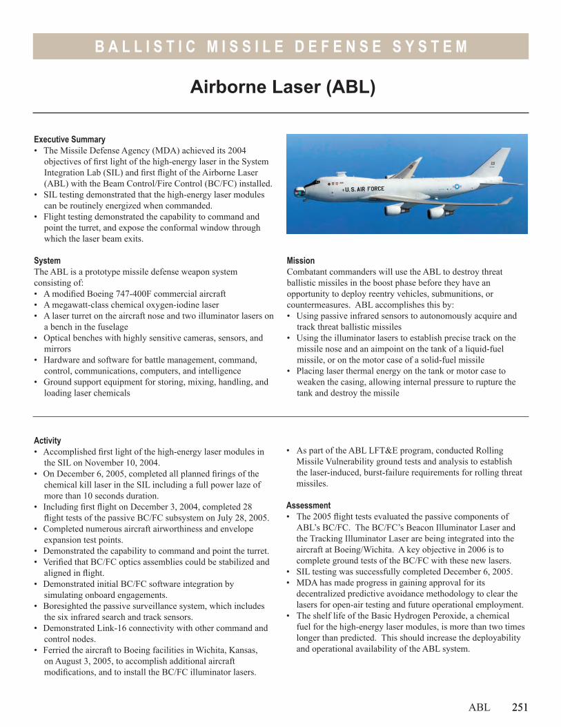
251
B A L L I S T I C M I S S I L E D E F E N S E S Y S T E M
MissionCombatant commanders will use the ABL to destroy threat ballistic missiles in the boost phase before they have an opportunity to deploy reentry vehicles, submunitions, or countermeasures. ABL accomplishes this by:• Using passive infrared sensors to autonomously acquire and
track threat ballistic missiles• Using the illuminator lasers to establish precise track on the
missile nose and an aimpoint on the tank of a liquid-fuel missile, or on the motor case of a solid-fuel missile
• Placing laser thermal energy on the tank or motor case to weaken the casing, allowing internal pressure to rupture the tank and destroy the missile
Executive Summary• The Missile Defense Agency (MDA) achieved its 2004
objectives of first light of the high-energy laser in the System Integration Lab (SIL) and first flight of the Airborne Laser (ABL) with the Beam Control/Fire Control (BC/FC) installed.
• SIL testing demonstrated that the high-energy laser modules can be routinely energized when commanded.
• Flight testing demonstrated the capability to command and point the turret, and expose the conformal window through which the laser beam exits.
SystemThe ABL is a prototype missile defense weapon system consisting of: • A modified Boeing 747-400F commercial aircraft• A megawatt-class chemical oxygen-iodine laser• A laser turret on the aircraft nose and two illuminator lasers on
a bench in the fuselage• Optical benches with highly sensitive cameras, sensors, and
mirrors• Hardware and software for battle management, command,
control, communications, computers, and intelligence• Ground support equipment for storing, mixing, handling, and
loading laser chemicals
Activity• Accomplished first light of the high-energy laser modules in
the SIL on November 10, 2004.• On December 6, 2005, completed all planned firings of the
chemical kill laser in the SIL including a full power laze of more than 10 seconds duration.
• Including first flight on December 3, 2004, completed 28 flight tests of the passive BC/FC subsystem on July 28, 2005.
• Completed numerous aircraft airworthiness and envelope expansion test points.
• Demonstrated the capability to command and point the turret. • Verified that BC/FC optics assemblies could be stabilized and
aligned in flight. • Demonstrated initial BC/FC software integration by
simulating onboard engagements.• Boresighted the passive surveillance system, which includes
the six infrared search and track sensors.• Demonstrated Link-16 connectivity with other command and
control nodes.• Ferried the aircraft to Boeing facilities in Wichita, Kansas,
on August 3, 2005, to accomplish additional aircraft modifications, and to install the BC/FC illuminator lasers.
• As part of the ABL LFT&E program, conducted Rolling Missile Vulnerability ground tests and analysis to establish the laser-induced, burst-failure requirements for rolling threat missiles.
Assessment• The 2005 flight tests evaluated the passive components of
ABL’s BC/FC. The BC/FC’s Beacon Illuminator Laser and the Tracking Illuminator Laser are being integrated into the aircraft at Boeing/Wichita. A key objective in 2006 is to complete ground tests of the BC/FC with these new lasers.
• SIL testing was successfully completed December 6, 2005.• MDA has made progress in gaining approval for its
decentralized predictive avoidance methodology to clear the lasers for open-air testing and future operational employment.
• The shelf life of the Basic Hydrogen Peroxide, a chemical fuel for the high-energy laser modules, is more than two times longer than predicted. This should increase the deployability and operational availability of the ABL system.
ABL 251
Airborne Laser (ABL)
B A L L I S T I C M I S S I L E D E F E N S E S Y S T E M
252 ABL
Recommendation1. Laser lethality investigations must continue. Additional data
is needed to establish laser engagement parameters for both testing and operational employment.
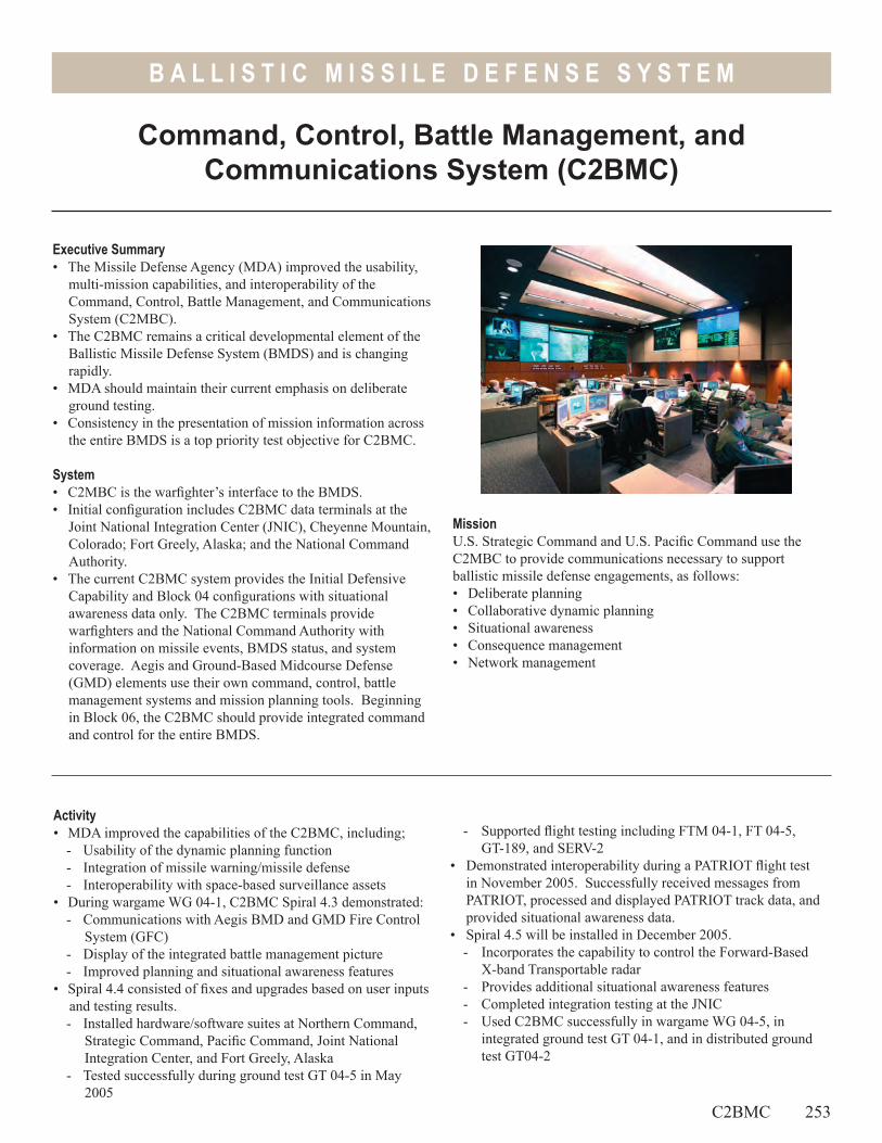
B A L L I S T I C M I S S I L E D E F E N S E S Y S T E M
Command, Control, Battle Management, and Communications System (C2BMC)
Executive Summary• The Missile Defense Agency (MDA) improved the usability,
multi-mission capabilities, and interoperability of the Command, Control, Battle Management, and Communications System (C2MBC).
• The C2BMC remains a critical developmental element of the Ballistic Missile Defense System (BMDS) and is changing rapidly.
• MDA should maintain their current emphasis on deliberate ground testing.
• Consistency in the presentation of mission information across the entire BMDS is a top priority test objective for C2BMC.
System• C2MBC is the warfighter’s interface to the BMDS. • Initial configuration includes C2BMC data terminals at the
Joint National Integration Center (JNIC), Cheyenne Mountain, Colorado; Fort Greely, Alaska; and the National Command Authority.
• The current C2BMC system provides the Initial Defensive Capability and Block 04 configurations with situational awareness data only. The C2BMC terminals provide warfighters and the National Command Authority with information on missile events, BMDS status, and system coverage. Aegis and Ground-Based Midcourse Defense (GMD) elements use their own command, control, battle management systems and mission planning tools. Beginning in Block 06, the C2BMC should provide integrated command and control for the entire BMDS.
MissionU.S. Strategic Command and U.S. Pacific Command use the C2MBC to provide communications necessary to support ballistic missile defense engagements, as follows:• Deliberate planning• Collaborative dynamic planning• Situational awareness• Consequence management • Network management
Activity• MDA improved the capabilities of the C2BMC, including;
- Usability of the dynamic planning function- Integration of missile warning/missile defense- Interoperability with space-based surveillance assets
• During wargame WG 04-1, C2BMC Spiral 4.3 demonstrated:- Communications with Aegis BMD and GMD Fire Control
System (GFC)- Display of the integrated battle management picture- Improved planning and situational awareness features
• Spiral 4.4 consisted of fixes and upgrades based on user inputs and testing results. - Installed hardware/software suites at Northern Command,
Strategic Command, Pacific Command, Joint National Integration Center, and Fort Greely, Alaska
- Tested successfully during ground test GT 04-5 in May 2005
- Supported flight testing including FTM 04-1, FT 04-5, GT-189, and SERV-2
• Demonstrated interoperability during a PATRIOT flight test in November 2005. Successfully received messages from PATRIOT, processed and displayed PATRIOT track data, and provided situational awareness data.
• Spiral 4.5 will be installed in December 2005. - Incorporates the capability to control the Forward-Based
X-band Transportable radar- Provides additional situational awareness features - Completed integration testing at the JNIC- Used C2BMC successfully in wargame WG 04-5, in
integrated ground test GT 04-1, and in distributed ground test GT04-2
C2BMC 253
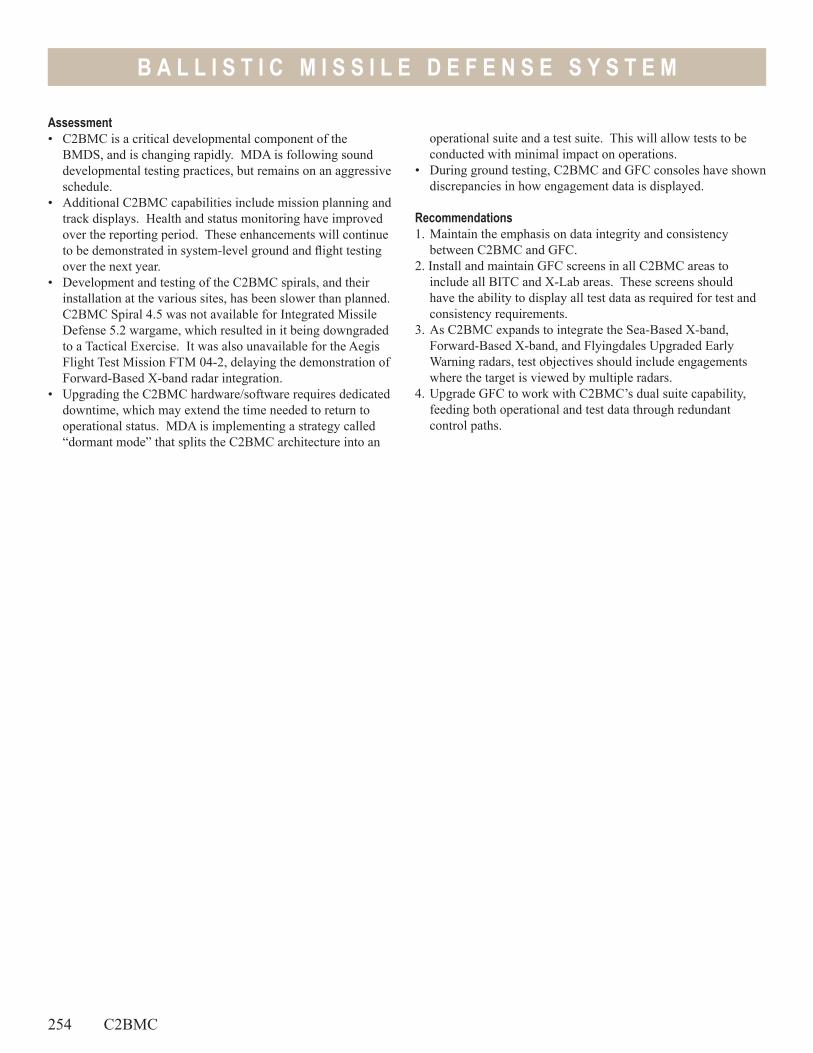
B A L L I S T I C M I S S I L E D E F E N S E S Y S T E M
Assessment• C2BMC is a critical developmental component of the
BMDS, and is changing rapidly. MDA is following sound developmental testing practices, but remains on an aggressive schedule.
• Additional C2BMC capabilities include mission planning and track displays. Health and status monitoring have improved over the reporting period. These enhancements will continue to be demonstrated in system-level ground and flight testing over the next year.
• Development and testing of the C2BMC spirals, and their installation at the various sites, has been slower than planned. C2BMC Spiral 4.5 was not available for Integrated Missile Defense 5.2 wargame, which resulted in it being downgraded to a Tactical Exercise. It was also unavailable for the Aegis Flight Test Mission FTM 04-2, delaying the demonstration of Forward-Based X-band radar integration.
• Upgrading the C2BMC hardware/software requires dedicated downtime, which may extend the time needed to return to operational status. MDA is implementing a strategy called “dormant mode” that splits the C2BMC architecture into an
operational suite and a test suite. This will allow tests to be conducted with minimal impact on operations.
• During ground testing, C2BMC and GFC consoles have shown discrepancies in how engagement data is displayed.
Recommendations1. Maintain the emphasis on data integrity and consistency
between C2BMC and GFC. 2. Install and maintain GFC screens in all C2BMC areas to
include all BITC and X-Lab areas. These screens should have the ability to display all test data as required for test and consistency requirements.
3. As C2BMC expands to integrate the Sea-Based X-band, Forward-Based X-band, and Flyingdales Upgraded Early Warning radars, test objectives should include engagements where the target is viewed by multiple radars.
4. Upgrade GFC to work with C2BMC’s dual suite capability, feeding both operational and test data through redundant control paths.
254 C2BMC
B A L L I S T I C M I S S I L E D E F E N S E S Y S T E M
Forward-Based X-band Transportable-Radar (FBX-T)
Executive Summary• The first Forward-Based X-band Transportable-radar (FBX-T)
unit is on schedule to make an initial deployment in early 2006.
• FBX-T has not yet demonstrated its ability to act as the primary engagement sensor during a flight test intercept.
• To reduce performance risk, the Missile Defense Agency (MDA) has maximized the ground test opportunities to assess FBX-T capability prior to deployment.
SystemFBX-T consists of:• A Terminal High-Altitude Area Defense (THAAD) radar with
modified software• Associated power and cooling equipment• An interface for communication with the Ballistic Missile
Defense System (BMDS)
MissionU.S. Strategic Command will use the FBX-T, an air transportable X-band radar to:
• Search, detect, track, and assess threat ballistic missiles in their boost and midcourse phases of flight
• Enhance battle space awareness and engagement options for the BMDS
• Provide combatant commanders with additional theater radar surveillance
Activity• The first FBX-T unit was delivered from Raytheon in Kansas,
to Vandenberg Air Force Base, California, for integration and testing in 1QFY05.
• Initial Capability Release software (CR 0) went through basic integration and test activities. CR 1, the first deployable software, is currently being tested and integrated with the Command, Control, Battle Management, and Communications (C2BMC) system. Verification of CR 1 requirements was completed in October 2005.
• The FBX-T unit at Vandenberg Air Force Base, California, observed four Targets of Opportunity from July to September 2005: SERV-1, SERV-2, and Glory Trip-187 were elemental-level tests, and Glory Trip-189 was a system test with other BMDS elements. FBX-T data is being used for post-flight playback to evaluate FBX-T/C2BMC messaging and simulated performance of the Ground-Based Midcourse Defense (GMD) element based on FBX-T data. During SERV-1, tracks were forwarded by FBX-T and received by the TPS-X radar in Hawaii.
• To prepare for possible deployment in early 2006, MDA plans to use the first FBX-T unit in two BMDS-level hardware-in-the-loop exercises in 1QFY06. The FBX-T hardware-in-the-loop facility in Woburn, Massachusetts, has been used to prepare the inputs for the exercises. This facility has identical hardware to FBX-T, but does not have an
operationally realistic connection to the C2BMC. As a result, one of these exercises may interface directly with the FBX-T at Vandenberg Air Force Base, California.
• FBX-T participated in the BMDS-level wargame IMD 5.4 in 1QFY06.
• CR 2 software is in development. MDA plans to deploy it by FY07. Key portions of CR 2 capability are in developmental testing using the TPS-X, an early version of the THAAD radar, at the Pacific Missile Range Facility. These elements were exercised in July and August 2005 during the MDA flight test FT04-2 and SERV-1.
• Developed, integrated, and tested a deployable C2BMC shelter suite to support FBX-T.
• Nine months of FBX-T data and a year of THAAD radar operations supports a potential early deployment.
Assessment• MDA plans to deploy the first FBX-T in early 2006. Prior to
deployment, MDA will not accomplish any flight testing to directly verify the operational concept of the GMD element engaging a threat based on FBX-T data.
• MDA plans to demonstrate this concept with a flight test in 2007.
• MDA’s rapid deployment of FBX-T allows little time for integration with C2BMC in operational configurations.
FBX-T 255
B A L L I S T I C M I S S I L E D E F E N S E S Y S T E M
Rapid deployment also precludes rigorous ground qualification testing of the radar, including environmental and electromagnetic environmental effects testing.
Recommendations1. MDA should place priority on conducting the dedicated flight
test for FBX-T, C2BMC, and GMD, as soon as possible.
256 FBX-T
2. Once FBX-T is in the deployed location, MDA should conduct further hardware-in-the-loop testing using the fielded FBX-T unit to assess latency.
3. MDA should examine ways to leverage combined ground testing and data collection in light of the similarities between FBX-T and the THAAD radar.
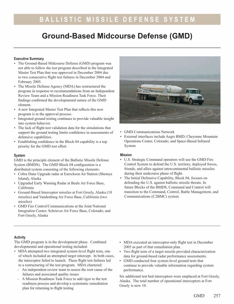
B A L L I S T I C M I S S I L E D E F E N S E S Y S T E M
• GMD Communications Network• External interfaces include Aegis BMD; Cheyenne Mountain
Operations Center, Colorado; and Space-Based Infrared System
Mission• U.S. Strategic Command operators will use the GMD Fire
Control System to defend the U.S. territory, deployed forces, friends, and allies against intercontinental ballistic missiles during their midcourse phase of flight.
• The Initial Defensive Capability, Block 04, focuses on defending the U.S. against ballistic missile threats. In future Blocks of the BMDS, Command and Control will transition to the Command, Control, Battle Management, and Communications (C2BMC) system.
Ground-Based Midcourse Defense (GMD)
Executive Summary• The Ground-Based Midcourse Defense (GMD) program was
not able to follow the test program described in the Integrated Master Test Plan that was approved in December 2004 due to two consecutive flight test failures in December 2004 and February 2005.
• The Missile Defense Agency (MDA) has restructured the program in response to recommendations from an Independent Review Team and a Mission Readiness Task Force. Their findings confirmed the developmental nature of the GMD element.
• A new Integrated Master Test Plan that reflects this new program is in the approval process.
• Integrated ground testing continues to provide valuable insight into system behavior.
• The lack of flight test validation data for the simulations that support the ground testing limits confidence in assessments of defensive capabilities.
• Establishing confidence in the Block 04 capability is a top priority for the GMD test effort.
SystemGMD is the principle element of the Ballistic Missile Defense System (BMDS). The GMD Block 04 configuration is a distributed system consisting of the following elements:• Cobra Dane Upgrade radar at Eareckson Air Station (Shemya
Island), Alaska• Upgraded Early Warning Radar at Beale Air Force Base,
California• Ground-Based Interceptor missiles at Fort Greely, Alaska (10
missiles) and Vandenburg Air Force Base, California (two missiles)
• GMD Fire Control/Communications at the Joint National Integration Center; Schriever Air Force Base, Colorado; and Fort Greely, Alaska
ActivityThe GMD program is in the development phase. Combined developmental and operational testing included:• MDA attempted two integrated system-level flight tests, one
of which included an attempted target intercept. In both cases, the interceptor failed to launch. These flight test failures led to a restructuring of the test program. MDA chartered:- An independent review team to assess the root cause of the
failures and associated quality issues- A Mission Readiness Task Force to add rigor to the test
readiness process and develop a systematic remediation plan for returning to flight testing
• MDA executed an interceptor-only flight test in December 2005 as part of that remediation plan.
• Two flight tests of a target missile provided characterization data for ground-based radar performance assessments.
• GMD conducted four system-level ground tests that continue to provide valuable information regarding system performance.
Six additional test bed interceptors were emplaced at Fort Greely, Alaska. The total number of operational interceptors at Fort Greely is now 10.
GMD 257
B A L L I S T I C M I S S I L E D E F E N S E S Y S T E M
Assessment• In Integrated Flight Tests (IFT) 13C and 14, the operational
ground-based interceptors failed to launch. The IFT-13 failure was a software design error in an automated diagnostic check run prior to launch. The IFT-14 failure was due to the missile’s lateral support stabilizer’s (inside the silo) failure to retract properly. In both cases, the system responded to these indications by correctly aborting the launch.
• Quality, workmanship, and inadequate ground testing have been cited as contributing factors to the flight test failures.
• MDA responded to these findings by appropriately restructuring their test program objectives to emphasize fundamentals and gradually increasing complexity over the next year.
• Future testing objectives stress reliable and repeatable performance.
• Robust testing is limited by the immaturity of some components.
• Ground and flight testing is essential to provide adequate data for validating and accrediting models and simulations.
• Flight tests still lack operational realism. This will remain the case over the next year as MDA implements the findings of the Mission Readiness Task Force and Independent Review Team.
• Test schedules continue to slip. Development of an Integrated Master Test Plan and the creation of the Test Configuration Control Board are both important steps in efforts to control the test program. However, optimistic estimates for the development and integration of a GMD capability result in frequent “fact-of-life” changes to the test schedules.
• Challenging integrated system demonstrations remain an important objective for future testing.
• Developmental testing to date indicates that the GMD system may have some inherent defensive capability against a limited missile attack.
Recommendations1. Maintain the current commitment to the Mission Readiness
Task Force recommendations. 2. Establish an evaluation-driven testing program where the need
for data (both developmental and operational) drives the test design.
3. Exploit the deployed architecture of the test bed to maximize data collection to determine the GMD systems operational reliability, availability, and maintainability.
4. Follow the recommendations of the Independent Review Team and Mission Readiness Task Force to:- Conduct ground-system tests, built-in-tests, and other
tests on both the test bed and sibling components to verify adequate quality, workmanship, and performance
- Conduct component and subsystem tests according to a disciplined product assurance and test process
- Conduct extended distributed ground tests that employ operational communications and components.
5. Develop component and system test plans that support model and simulation validation and accreditation.
6. Maximize use of operational hardware, software, and warfighters in system-level testing.
7. Maintain and enforce the newly established test configuration control process.
258 GMD
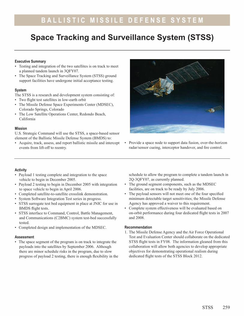
B A L L I S T I C M I S S I L E D E F E N S E S Y S T E M
Space Tracking and Surveillance System (STSS)
Executive Summary• Testing and integration of the two satellites is on track to meet
a planned tandem launch in 3QFY07. • The Space Tracking and Surveillance System (STSS) ground
support facilities have undergone initial acceptance testing.
SystemThe STSS is a research and development system consisting of:• Two flight test satellites in low-earth orbit• The Missile Defense Space Experiments Center (MDSEC),
Colorado Springs, Colorado• The Low Satellite Operations Center, Redondo Beach,
California
MissionU.S. Strategic Command will use the STSS, a space-based sensor element of the Ballistic Missile Defense System (BMDS) to:• Acquire, track, assess, and report ballistic missile and intercept
events from lift-off to reentry.
Activity• Payload 1 testing complete and integration to the space
vehicle to begin in December 2005.• Payload 2 testing to begin in December 2005 with integration
to space vehicle to begin in April 2006.• Completed satellite-to-satellite crosslink demonstration.• System Software Integration Test series in progress.• STSS surrogate test bed equipment in place at JNIC for use in
BMDS flight tests.• STSS interface to Command, Control, Battle Management,
and Communications (C2BMC) system test-bed successfully tested.
• Completed design and implementation of the MDSEC.
Assessment• The space segment of the program is on track to integrate the
payloads into the satellites by September 2006. Although there are minor schedule risks in the program, due to slow progress of payload 2 testing, there is enough flexibility in the
schedule to allow the program to complete a tandem launch in 2Q-3QFY07, as currently planned.
• The ground segment components, such as the MDSEC facilities, are on track to be ready by July 2006.
• The payload sensors will not meet one of the four specified minimum detectable target sensitivities; the Missile Defense Agency has approved a waiver to this requirement.
• Complete system effectiveness will be evaluated based on on-orbit performance during four dedicated flight tests in 2007 and 2008.
Recommendation1. The Missile Defense Agency and the Air Force Operational
Test and Evaluation Center should collaborate on the dedicated STSS flight tests in FY08. The information gleaned from this collaboration will allow both agencies to develop appropriate objectives for demonstrating operational realism during dedicated flight tests of the STSS Block 2012.
STSS 259
• Provide a space node to support data fusion, over-the-horizon radar/sensor cueing, interceptor handover, and fire control.
260
B A L L I S T I C M I S S I L E D E F E N S E S Y S T E M
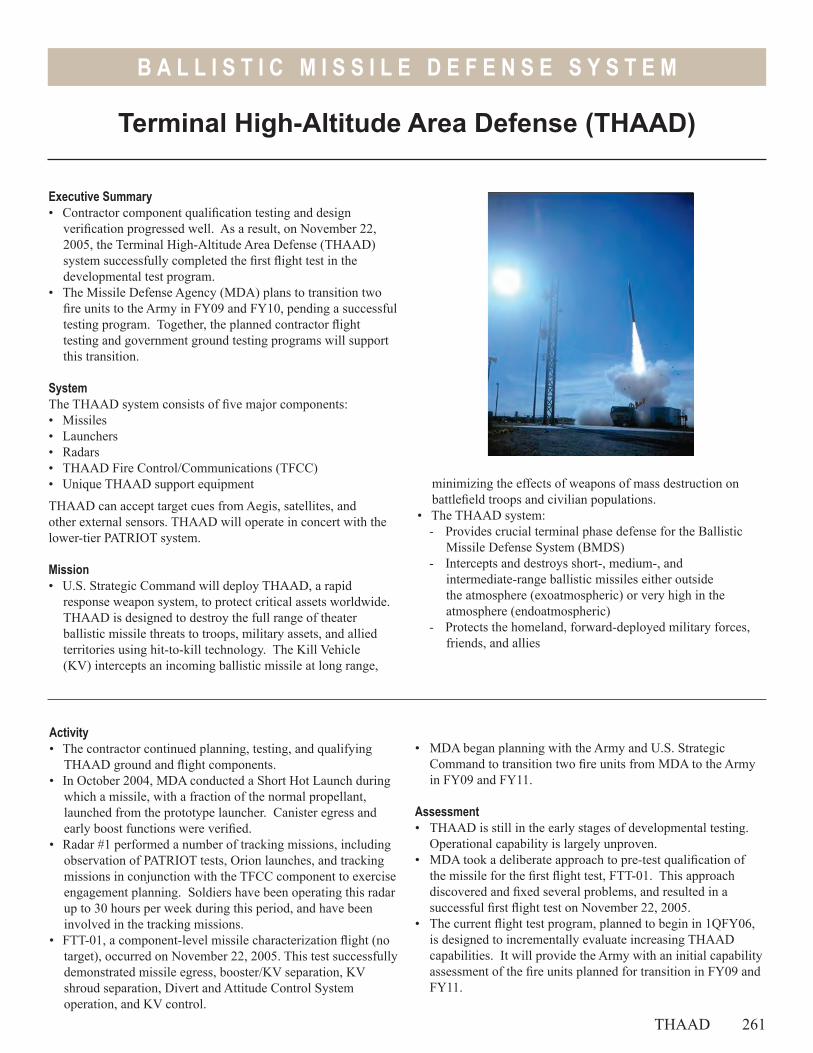
B A L L I S T I C M I S S I L E D E F E N S E S Y S T E M
Terminal High-Altitude Area Defense (THAAD)
Executive Summary• Contractor component qualification testing and design
verification progressed well. As a result, on November 22, 2005, the Terminal High-Altitude Area Defense (THAAD) system successfully completed the first flight test in the developmental test program.
• The Missile Defense Agency (MDA) plans to transition two fire units to the Army in FY09 and FY10, pending a successful testing program. Together, the planned contractor flight testing and government ground testing programs will support this transition.
SystemThe THAAD system consists of five major components:• Missiles• Launchers • Radars• THAAD Fire Control/Communications (TFCC)• Unique THAAD support equipment
THAAD can accept target cues from Aegis, satellites, and other external sensors. THAAD will operate in concert with the lower-tier PATRIOT system.
Mission• U.S. Strategic Command will deploy THAAD, a rapid
response weapon system, to protect critical assets worldwide. THAAD is designed to destroy the full range of theater ballistic missile threats to troops, military assets, and allied territories using hit-to-kill technology. The Kill Vehicle (KV) intercepts an incoming ballistic missile at long range,
Activity• The contractor continued planning, testing, and qualifying
THAAD ground and flight components.• In October 2004, MDA conducted a Short Hot Launch during
which a missile, with a fraction of the normal propellant, launched from the prototype launcher. Canister egress and early boost functions were verified.
• Radar #1 performed a number of tracking missions, including observation of PATRIOT tests, Orion launches, and tracking missions in conjunction with the TFCC component to exercise engagement planning. Soldiers have been operating this radar up to 30 hours per week during this period, and have been involved in the tracking missions.
• FTT-01, a component-level missile characterization flight (no target), occurred on November 22, 2005. This test successfully demonstrated missile egress, booster/KV separation, KV shroud separation, Divert and Attitude Control System operation, and KV control.
• MDA began planning with the Army and U.S. Strategic Command to transition two fire units from MDA to the Army in FY09 and FY11.
Assessment• THAAD is still in the early stages of developmental testing.
Operational capability is largely unproven.• MDA took a deliberate approach to pre-test qualification of
the missile for the first flight test, FTT-01. This approach discovered and fixed several problems, and resulted in a successful first flight test on November 22, 2005.
• The current flight test program, planned to begin in 1QFY06, is designed to incrementally evaluate increasing THAAD capabilities. It will provide the Army with an initial capability assessment of the fire units planned for transition in FY09 and FY11.
minimizing the effects of weapons of mass destruction on battlefield troops and civilian populations.
• The THAAD system: - Provides crucial terminal phase defense for the Ballistic
Missile Defense System (BMDS)- Intercepts and destroys short-, medium-, and
intermediate-range ballistic missiles either outside the atmosphere (exoatmospheric) or very high in the atmosphere (endoatmospheric)
- Protects the homeland, forward-deployed military forces, friends, and allies
THAAD 261
B A L L I S T I C M I S S I L E D E F E N S E S Y S T E M
• Government ground testing planned from FY07 through FY11 is on schedule.
• MDA, DOT&E, the Army, and the Army’s Operational Test Agency are involved in a review of the ground and flight test program. This review will ensure critical testing is completed before these fire units enter a Force Development Exercise/Limited User Test to support releasing this equipment to the Army.
RecommendationsNone.
262 THAAD

Live Fire Test& Evaluation
Live
Fire
Test
& Ev
aluat
ion
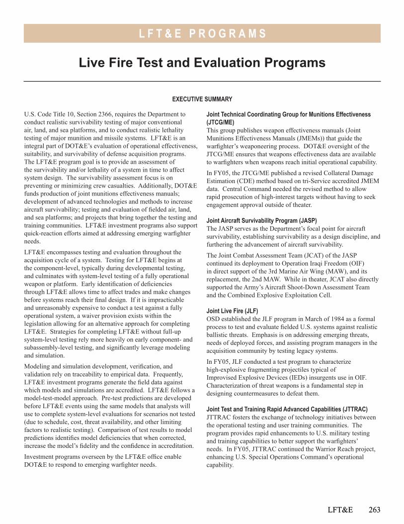
L F T & E P R O G R A M S
LFT&E 263
Live Fire Test and Evaluation Programs
U.S. Code Title 10, Section 2366, requires the Department to conduct realistic survivability testing of major conventional air, land, and sea platforms, and to conduct realistic lethality testing of major munition and missile systems. LFT&E is an integral part of DOT&E’s evaluation of operational effectiveness, suitability, and survivability of defense acquisition programs. The LFT&E program goal is to provide an assessment of the survivability and/or lethality of a system in time to affect system design. The survivability assessment focus is on preventing or minimizing crew casualties. Additionally, DOT&E funds production of joint munitions effectiveness manuals; development of advanced technologies and methods to increase aircraft survivability; testing and evaluation of fielded air, land, and sea platforms; and projects that bring together the testing and training communities. LFT&E investment programs also support quick-reaction efforts aimed at addressing emerging warfighter needs.
LFT&E encompasses testing and evaluation throughout the acquisition cycle of a system. Testing for LFT&E begins at the component-level, typically during developmental testing, and culminates with system-level testing of a fully operational weapon or platform. Early identification of deficiencies through LFT&E allows time to affect trades and make changes before systems reach their final design. If it is impracticable and unreasonably expensive to conduct a test against a fully operational system, a waiver provision exists within the legislation allowing for an alternative approach for completing LFT&E. Strategies for completing LFT&E without full-up system-level testing rely more heavily on early component- and subassembly-level testing, and significantly leverage modeling and simulation.
Modeling and simulation development, verification, and validation rely on traceability to empirical data. Frequently, LFT&E investment programs generate the field data against which models and simulations are accredited. LFT&E follows a model-test-model approach. Pre-test predictions are developed before LFT&E events using the same models that analysts will use to complete system-level evaluations for scenarios not tested (due to schedule, cost, threat availability, and other limiting factors to realistic testing). Comparison of test results to model predictions identifies model deficiencies that when corrected, increase the model’s fidelity and the confidence in accreditation.
Investment programs overseen by the LFT&E office enable DOT&E to respond to emerging warfighter needs.
Joint Technical Coordinating Group for Munitions Effectiveness (JTCG/ME)This group publishes weapon effectiveness manuals (Joint Munitions Effectiveness Manuals (JMEMs)) that guide the warfighter’s weaponeering process. DOT&E oversight of the JTCG/ME ensures that weapons effectiveness data are available to warfighters when weapons reach initial operational capability.
In FY05, the JTCG/ME published a revised Collateral Damage Estimation (CDE) method based on tri-Service accredited JMEM data. Central Command needed the revised method to allow rapid prosecution of high-interest targets without having to seek engagement approval outside of theater.
Joint Aircraft Survivability Program (JASP)The JASP serves as the Department’s focal point for aircraft survivability, establishing survivability as a design discipline, and furthering the advancement of aircraft survivability.
The Joint Combat Assessment Team (JCAT) of the JASP continued its deployment to Operation Iraqi Freedom (OIF) in direct support of the 3rd Marine Air Wing (MAW), and its replacement, the 2nd MAW. While in theater, JCAT also directly supported the Army’s Aircraft Shoot-Down Assessment Team and the Combined Explosive Exploitation Cell.
Joint Live Fire (JLF)OSD established the JLF program in March of 1984 as a formal process to test and evaluate fielded U.S. systems against realistic ballistic threats. Emphasis is on addressing emerging threats, needs of deployed forces, and assisting program managers in the acquisition community by testing legacy systems.
In FY05, JLF conducted a test program to characterize high-explosive fragmenting projectiles typical of Improvised Explosive Devices (IEDs) insurgents use in OIF. Characterization of threat weapons is a fundamental step in designing countermeasures to defeat them.
Joint Test and Training Rapid Advanced Capabilities (JTTRAC)JTTRAC fosters the exchange of technology initiatives between the operational testing and user training communities. The program provides rapid enhancements to U.S. military testing and training capabilities to better support the warfighters’ needs. In FY05, JTTRAC continued the Warrior Reach project, enhancing U.S. Special Operations Command’s operational capability.
LFT&E 263
EXECUTIVE SUMMARY
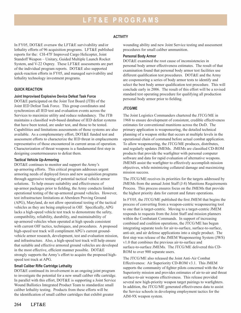
264 LFT&E
L F T & E P R O G R A M S
In FY05, DOT&E oversaw the LFT&E survivability and/or lethality efforts of 96 acquisition programs. LFT&E published reports for the: CH-47F Improved Cargo Helicopter, Joint Standoff Weapon – Unitary, Guided Multiple Launch Rocket System, and V-22 Osprey. These LFT&E assessments are part of the individual program reports. DOT&E also supported quick-reaction efforts in FY05, and managed survivability and lethality technology investment programs.
QUICK REACTION
Joint Improvised Explosive Device Defeat Task ForceDOT&E participated on the Joint Test Board (JTB) of the Joint IED Defeat Task Force. This group coordinates and synchronizes all IED test and evaluation events across the Services to maximize utility and reduce redundancy. The JTB maintains a classified web-based database of IED defeat systems that have been tested, are under test, and those to be tested. Capabilities and limitations assessments of those systems are also available. As a complementary effort, DOT&E funded test and assessment efforts to characterize the IED threat in emplacements representative of those encountered in current areas of operation. Characterization of threat weapons is a fundamental first step in designing countermeasures to defeat them.
Tactical Vehicle Up-ArmoringDOT&E continues to monitor and support the Army’s up-armoring efforts. This critical program addresses urgent armoring needs of deployed forces and new acquisition programs through aggressive testing of potential tactical vehicle armor solutions. To help ensure suitability and effectiveness of up-armor packages prior to fielding, the Army conducts limited operational testing of the up-armored ground vehicles. However, test infrastructure limitations at Aberdeen Proving Ground (APG), Maryland, do not allow operational testing of the tactical vehicles as they are being employed in OIF. Specifically, APG lacks a high-speed vehicle test track to demonstrate the safety, compatibility, reliability, durability, and maintainability of up-armored vehicles when operated at high speeds consistent with current OIF tactics, techniques, and procedures. A proposed high-speed test track will compliment APG’s current ground-vehicle armor research, development, test and evaluation mission, and infrastructure. Also, a high-speed test track will help ensure that suitable and effective armored ground vehicles are developed in the most effective, efficient manner possible. DOT&E strongly supports the Army’s effort to acquire the proposed high-speed test track at APG.
Small Caliber Rifle Cartridge LethalityDOT&E continued its involvement in an ongoing joint program to investigate the potential for a new small caliber rifle cartridge. In parallel with this effort, DOT&E is supporting a Joint Service Wound Ballistics Integrated Product Team to standardize small caliber lethality testing. Products from these efforts will be the identification of small caliber cartridges that exhibit greater
264 LFT&E
ACTIVITY
wounding ability and new Joint Service testing and assessment procedures for small caliber ammunition.
Personal Body ArmorDOT&E examined the root cause of inconsistencies in personal body armor effectiveness estimates. The result of that examination found that personal body armor test facilities use different qualification test procedures. DOT&E and the Army are cosponsoring a series of body armor tests to identify and select the best body armor qualification test procedure. This will conclude early in 2006. The result of this effort will be a revised standard test operating procedure for qualifying all production personal body armor prior to fielding.
JTCG/ME
The Joint Logistics Commanders chartered the JTCG/ME in 1968 to ensure development of consistent, credible effectiveness estimates for conventional munitions across the DoD. The primary application is weaponeering, the detailed technical planning of a weapon strike that occurs at multiple levels in the operational chain of command before actual combat application. To allow weaponeering, the JTCG/ME produces, distributes, and regularly updates JMEMs. JMEMs are classified CD-ROM products that provide the warfighter with personal computer software and data for rapid evaluation of alternative weapons. JMEMS assist the warfighter to effectively accomplish mission objectives, while minimizing collateral damage and maximizing mission success.
The JTCG/ME receives its priorities for the targets addressed by JMEMs from the annual Joint Staff (J-8) Munitions Requirements Process. This process ensures focus on the JMEMs that provide the highest priority data for current and future operations.
In FY05, the JTCG/ME published the first JMEM that begins the process of converting from a weapon-centric weaponeering tool to one that is target-centric. Moving to a target-centric JMEM responds to requests from the Joint Staff and mission planners within the Combatant Commands. In support of increasing combined and coalition operations, the JTCG/ME has begun integrating separate tools for air-to-surface, surface-to-surface, anti-air, and air defense applications into a single product. The first step was release of the JMEM Weaponeering System (JWS) v1.0 that combines the previous air-to-surface and surface-to-surface JMEMs. The JTCG/ME delivered this CD-ROM to over 900 separate users.
The JTCG/ME also released the Joint Anti-Air Combat Effectiveness: Air Superiority CD-ROM v3.1. This JMEM supports the community of fighter pilots concerned with the Air Superiority mission and provides estimates of air-to-air and threat surface-to-air weapons effectiveness. This release provided several new high-priority weapon target pairings to warfighters. In addition, the JTCG/ME generated effectiveness data to assist the Service schools in developing employment tactics for the AIM-9X weapon system.
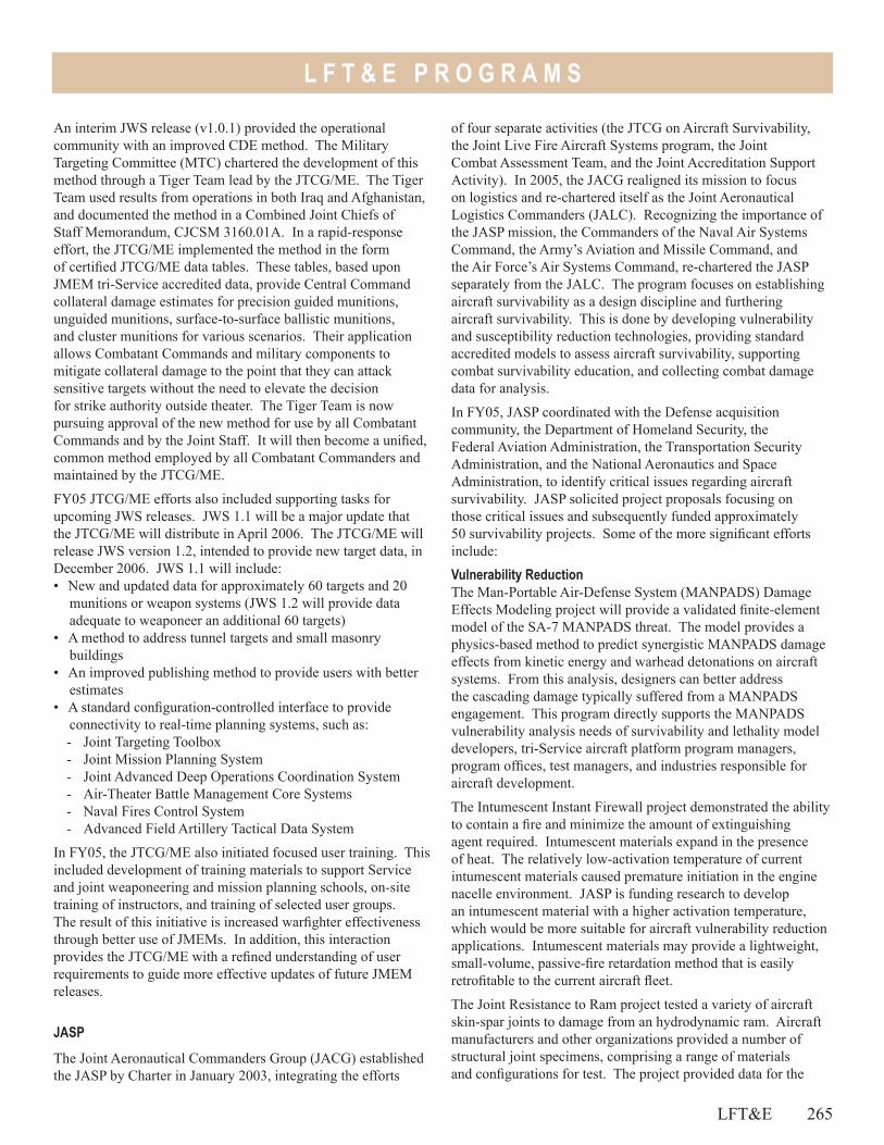
L F T & E P R O G R A M S
LFT&E 265
An interim JWS release (v1.0.1) provided the operational community with an improved CDE method. The Military Targeting Committee (MTC) chartered the development of this method through a Tiger Team lead by the JTCG/ME. The Tiger Team used results from operations in both Iraq and Afghanistan, and documented the method in a Combined Joint Chiefs of Staff Memorandum, CJCSM 3160.01A. In a rapid-response effort, the JTCG/ME implemented the method in the form of certified JTCG/ME data tables. These tables, based upon JMEM tri-Service accredited data, provide Central Command collateral damage estimates for precision guided munitions, unguided munitions, surface-to-surface ballistic munitions, and cluster munitions for various scenarios. Their application allows Combatant Commands and military components to mitigate collateral damage to the point that they can attack sensitive targets without the need to elevate the decision for strike authority outside theater. The Tiger Team is now pursuing approval of the new method for use by all Combatant Commands and by the Joint Staff. It will then become a unified, common method employed by all Combatant Commanders and maintained by the JTCG/ME.
FY05 JTCG/ME efforts also included supporting tasks for upcoming JWS releases. JWS 1.1 will be a major update that the JTCG/ME will distribute in April 2006. The JTCG/ME will release JWS version 1.2, intended to provide new target data, in December 2006. JWS 1.1 will include:• New and updated data for approximately 60 targets and 20
munitions or weapon systems (JWS 1.2 will provide data adequate to weaponeer an additional 60 targets)
• A method to address tunnel targets and small masonry buildings
• An improved publishing method to provide users with better estimates
• A standard configuration-controlled interface to provide connectivity to real-time planning systems, such as:- Joint Targeting Toolbox- Joint Mission Planning System- Joint Advanced Deep Operations Coordination System- Air-Theater Battle Management Core Systems- Naval Fires Control System- Advanced Field Artillery Tactical Data System
In FY05, the JTCG/ME also initiated focused user training. This included development of training materials to support Service and joint weaponeering and mission planning schools, on-site training of instructors, and training of selected user groups. The result of this initiative is increased warfighter effectiveness through better use of JMEMs. In addition, this interaction provides the JTCG/ME with a refined understanding of user requirements to guide more effective updates of future JMEM releases.
JASP
The Joint Aeronautical Commanders Group (JACG) established the JASP by Charter in January 2003, integrating the efforts
of four separate activities (the JTCG on Aircraft Survivability, the Joint Live Fire Aircraft Systems program, the Joint Combat Assessment Team, and the Joint Accreditation Support Activity). In 2005, the JACG realigned its mission to focus on logistics and re-chartered itself as the Joint Aeronautical Logistics Commanders (JALC). Recognizing the importance of the JASP mission, the Commanders of the Naval Air Systems Command, the Army’s Aviation and Missile Command, and the Air Force’s Air Systems Command, re-chartered the JASP separately from the JALC. The program focuses on establishing aircraft survivability as a design discipline and furthering aircraft survivability. This is done by developing vulnerability and susceptibility reduction technologies, providing standard accredited models to assess aircraft survivability, supporting combat survivability education, and collecting combat damage data for analysis.
In FY05, JASP coordinated with the Defense acquisition community, the Department of Homeland Security, the Federal Aviation Administration, the Transportation Security Administration, and the National Aeronautics and Space Administration, to identify critical issues regarding aircraft survivability. JASP solicited project proposals focusing on those critical issues and subsequently funded approximately 50 survivability projects. Some of the more significant efforts include:
Vulnerability ReductionThe Man-Portable Air-Defense System (MANPADS) Damage Effects Modeling project will provide a validated finite-element model of the SA-7 MANPADS threat. The model provides a physics-based method to predict synergistic MANPADS damage effects from kinetic energy and warhead detonations on aircraft systems. From this analysis, designers can better address the cascading damage typically suffered from a MANPADS engagement. This program directly supports the MANPADS vulnerability analysis needs of survivability and lethality model developers, tri-Service aircraft platform program managers, program offices, test managers, and industries responsible for aircraft development.
The Intumescent Instant Firewall project demonstrated the ability to contain a fire and minimize the amount of extinguishing agent required. Intumescent materials expand in the presence of heat. The relatively low-activation temperature of current intumescent materials caused premature initiation in the engine nacelle environment. JASP is funding research to develop an intumescent material with a higher activation temperature, which would be more suitable for aircraft vulnerability reduction applications. Intumescent materials may provide a lightweight, small-volume, passive-fire retardation method that is easily retrofitable to the current aircraft fleet.
The Joint Resistance to Ram project tested a variety of aircraft skin-spar joints to damage from an hydrodynamic ram. Aircraft manufacturers and other organizations provided a number of structural joint specimens, comprising a range of materials and configurations for test. The project provided data for the
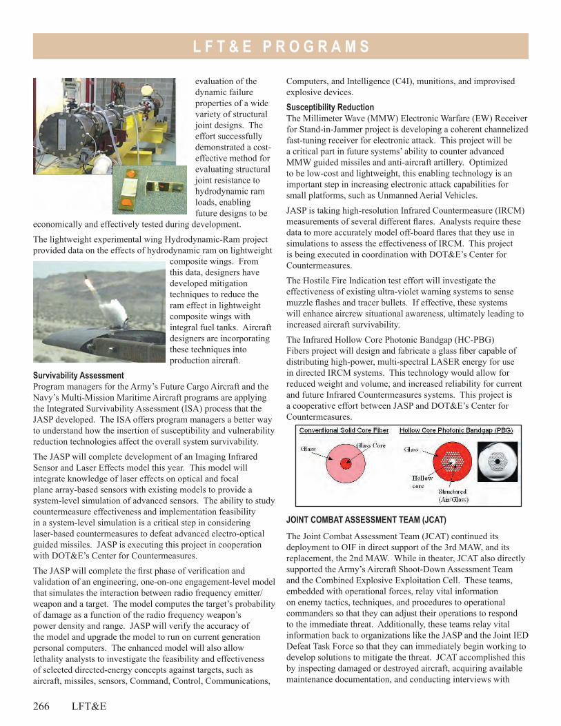
266 LFT&E
L F T & E P R O G R A M S
Computers, and Intelligence (C4I), munitions, and improvised explosive devices.
Susceptibility ReductionThe Millimeter Wave (MMW) Electronic Warfare (EW) Receiver for Stand-in-Jammer project is developing a coherent channelized fast-tuning receiver for electronic attack. This project will be a critical part in future systems’ ability to counter advanced MMW guided missiles and anti-aircraft artillery. Optimized to be low-cost and lightweight, this enabling technology is an important step in increasing electronic attack capabilities for small platforms, such as Unmanned Aerial Vehicles.
JASP is taking high-resolution Infrared Countermeasure (IRCM) measurements of several different flares. Analysts require these data to more accurately model off-board flares that they use in simulations to assess the effectiveness of IRCM. This project is being executed in coordination with DOT&E’s Center for Countermeasures.
The Hostile Fire Indication test effort will investigate the effectiveness of existing ultra-violet warning systems to sense muzzle flashes and tracer bullets. If effective, these systems will enhance aircrew situational awareness, ultimately leading to increased aircraft survivability.
The Infrared Hollow Core Photonic Bandgap (HC-PBG) Fibers project will design and fabricate a glass fiber capable of distributing high-power, multi-spectral LASER energy for use in directed IRCM systems. This technology would allow for reduced weight and volume, and increased reliability for current and future Infrared Countermeasures systems. This project is a cooperative effort between JASP and DOT&E’s Center for Countermeasures.
JOINT COMBAT ASSESSMENT TEAM (JCAT)
The Joint Combat Assessment Team (JCAT) continued its deployment to OIF in direct support of the 3rd MAW, and its replacement, the 2nd MAW. While in theater, JCAT also directly supported the Army’s Aircraft Shoot-Down Assessment Team and the Combined Explosive Exploitation Cell. These teams, embedded with operational forces, relay vital information on enemy tactics, techniques, and procedures to operational commanders so that they can adjust their operations to respond to the immediate threat. Additionally, these teams relay vital information back to organizations like the JASP and the Joint IED Defeat Task Force so that they can immediately begin working to develop solutions to mitigate the threat. JCAT accomplished this by inspecting damaged or destroyed aircraft, acquiring available maintenance documentation, and conducting interviews with
evaluation of the dynamic failure properties of a wide variety of structural joint designs. The effort successfully demonstrated a cost-effective method for evaluating structural joint resistance to hydrodynamic ram loads, enabling future designs to be
economically and effectively tested during development.
The lightweight experimental wing Hydrodynamic-Ram project provided data on the effects of hydrodynamic ram on lightweight
composite wings. From this data, designers have developed mitigation techniques to reduce the ram effect in lightweight composite wings with integral fuel tanks. Aircraft designers are incorporating these techniques into production aircraft.
Survivability AssessmentProgram managers for the Army’s Future Cargo Aircraft and the Navy’s Multi-Mission Maritime Aircraft programs are applying the Integrated Survivability Assessment (ISA) process that the JASP developed. The ISA offers program managers a better way to understand how the insertion of susceptibility and vulnerability reduction technologies affect the overall system survivability.
The JASP will complete development of an Imaging Infrared Sensor and Laser Effects model this year. This model will integrate knowledge of laser effects on optical and focal plane array-based sensors with existing models to provide a system-level simulation of advanced sensors. The ability to study countermeasure effectiveness and implementation feasibility in a system-level simulation is a critical step in considering laser-based countermeasures to defeat advanced electro-optical guided missiles. JASP is executing this project in cooperation with DOT&E’s Center for Countermeasures.
The JASP will complete the first phase of verification and validation of an engineering, one-on-one engagement-level model that simulates the interaction between radio frequency emitter/weapon and a target. The model computes the target’s probability of damage as a function of the radio frequency weapon’s power density and range. JASP will verify the accuracy of the model and upgrade the model to run on current generation personal computers. The enhanced model will also allow lethality analysts to investigate the feasibility and effectiveness of selected directed-energy concepts against targets, such as aircraft, missiles, sensors, Command, Control, Communications,
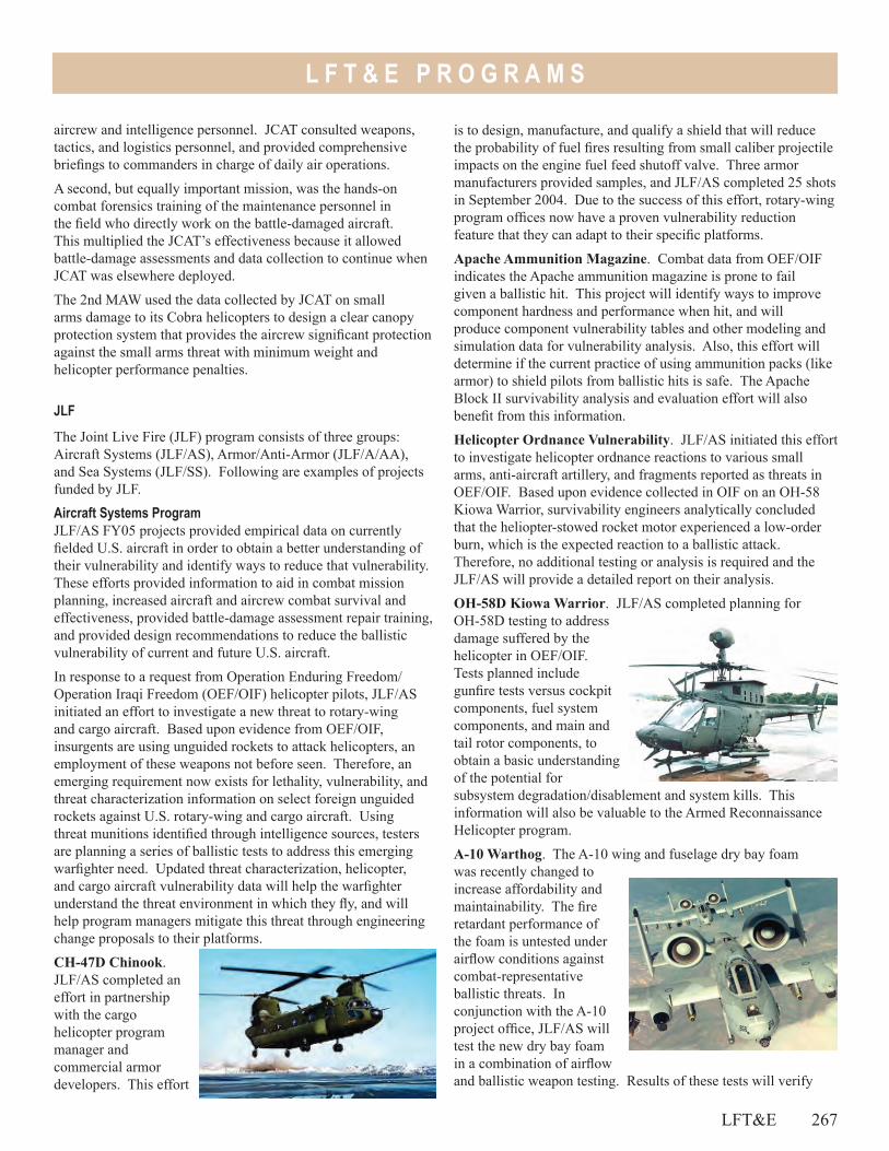
L F T & E P R O G R A M S
LFT&E 267
is to design, manufacture, and qualify a shield that will reduce the probability of fuel fires resulting from small caliber projectile impacts on the engine fuel feed shutoff valve. Three armor manufacturers provided samples, and JLF/AS completed 25 shots in September 2004. Due to the success of this effort, rotary-wing program offices now have a proven vulnerability reduction feature that they can adapt to their specific platforms.
Apache Ammunition Magazine. Combat data from OEF/OIF indicates the Apache ammunition magazine is prone to fail given a ballistic hit. This project will identify ways to improve component hardness and performance when hit, and will produce component vulnerability tables and other modeling and simulation data for vulnerability analysis. Also, this effort will determine if the current practice of using ammunition packs (like armor) to shield pilots from ballistic hits is safe. The Apache Block II survivability analysis and evaluation effort will also benefit from this information.
Helicopter Ordnance Vulnerability. JLF/AS initiated this effort to investigate helicopter ordnance reactions to various small arms, anti-aircraft artillery, and fragments reported as threats in OEF/OIF. Based upon evidence collected in OIF on an OH-58 Kiowa Warrior, survivability engineers analytically concluded that the heliopter-stowed rocket motor experienced a low-order burn, which is the expected reaction to a ballistic attack. Therefore, no additional testing or analysis is required and the JLF/AS will provide a detailed report on their analysis.
OH-58D Kiowa Warrior. JLF/AS completed planning for OH-58D testing to address damage suffered by the helicopter in OEF/OIF. Tests planned include gunfire tests versus cockpit components, fuel system components, and main and tail rotor components, to obtain a basic understanding of the potential for subsystem degradation/disablement and system kills. This information will also be valuable to the Armed Reconnaissance Helicopter program.
A-10 Warthog. The A-10 wing and fuselage dry bay foam was recently changed to increase affordability and maintainability. The fire retardant performance of the foam is untested under airflow conditions against combat-representative ballistic threats. In conjunction with the A-10 project office, JLF/AS will test the new dry bay foam in a combination of airflow and ballistic weapon testing. Results of these tests will verify
aircrew and intelligence personnel. JCAT consulted weapons, tactics, and logistics personnel, and provided comprehensive briefings to commanders in charge of daily air operations.
A second, but equally important mission, was the hands-on combat forensics training of the maintenance personnel in the field who directly work on the battle-damaged aircraft. This multiplied the JCAT’s effectiveness because it allowed battle-damage assessments and data collection to continue when JCAT was elsewhere deployed.
The 2nd MAW used the data collected by JCAT on small arms damage to its Cobra helicopters to design a clear canopy protection system that provides the aircrew significant protection against the small arms threat with minimum weight and helicopter performance penalties.
JLF
The Joint Live Fire (JLF) program consists of three groups: Aircraft Systems (JLF/AS), Armor/Anti-Armor (JLF/A/AA), and Sea Systems (JLF/SS). Following are examples of projects funded by JLF.
Aircraft Systems ProgramJLF/AS FY05 projects provided empirical data on currently fielded U.S. aircraft in order to obtain a better understanding of their vulnerability and identify ways to reduce that vulnerability. These efforts provided information to aid in combat mission planning, increased aircraft and aircrew combat survival and effectiveness, provided battle-damage assessment repair training, and provided design recommendations to reduce the ballistic vulnerability of current and future U.S. aircraft.
In response to a request from Operation Enduring Freedom/Operation Iraqi Freedom (OEF/OIF) helicopter pilots, JLF/AS initiated an effort to investigate a new threat to rotary-wing and cargo aircraft. Based upon evidence from OEF/OIF, insurgents are using unguided rockets to attack helicopters, an employment of these weapons not before seen. Therefore, an emerging requirement now exists for lethality, vulnerability, and threat characterization information on select foreign unguided rockets against U.S. rotary-wing and cargo aircraft. Using threat munitions identified through intelligence sources, testers are planning a series of ballistic tests to address this emerging warfighter need. Updated threat characterization, helicopter, and cargo aircraft vulnerability data will help the warfighter understand the threat environment in which they fly, and will help program managers mitigate this threat through engineering change proposals to their platforms.
CH-47D Chinook. JLF/AS completed an effort in partnership with the cargo helicopter program manager and commercial armor developers. This effort
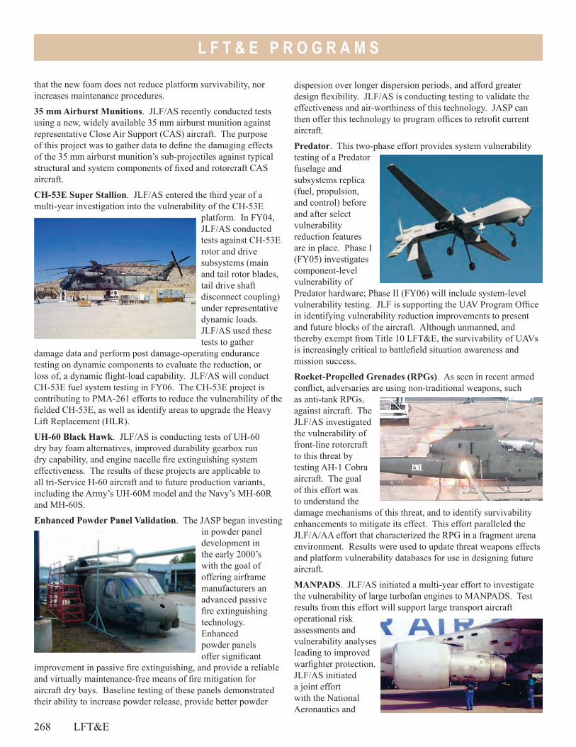
268 LFT&E
L F T & E P R O G R A M S
that the new foam does not reduce platform survivability, nor increases maintenance procedures.
35 mm Airburst Munitions. JLF/AS recently conducted tests using a new, widely available 35 mm airburst munition against representative Close Air Support (CAS) aircraft. The purpose of this project was to gather data to define the damaging effects of the 35 mm airburst munition’s sub-projectiles against typical structural and system components of fixed and rotorcraft CAS aircraft.
CH-53E Super Stallion. JLF/AS entered the third year of a multi-year investigation into the vulnerability of the CH-53E
platform. In FY04, JLF/AS conducted tests against CH-53E rotor and drive subsystems (main and tail rotor blades, tail drive shaft disconnect coupling) under representative dynamic loads. JLF/AS used these tests to gather
damage data and perform post damage-operating endurance testing on dynamic components to evaluate the reduction, or loss of, a dynamic flight-load capability. JLF/AS will conduct CH-53E fuel system testing in FY06. The CH-53E project is contributing to PMA-261 efforts to reduce the vulnerability of the fielded CH-53E, as well as identify areas to upgrade the Heavy Lift Replacement (HLR).
UH-60 Black Hawk. JLF/AS is conducting tests of UH-60 dry bay foam alternatives, improved durability gearbox run dry capability, and engine nacelle fire extinguishing system effectiveness. The results of these projects are applicable to all tri-Service H-60 aircraft and to future production variants, including the Army’s UH-60M model and the Navy’s MH-60R and MH-60S.
Enhanced Powder Panel Validation. The JASP began investing in powder panel development in the early 2000’s with the goal of offering airframe manufacturers an advanced passive fire extinguishing technology. Enhanced powder panels offer significant
improvement in passive fire extinguishing, and provide a reliable and virtually maintenance-free means of fire mitigation for aircraft dry bays. Baseline testing of these panels demonstrated their ability to increase powder release, provide better powder
dispersion over longer dispersion periods, and afford greater design flexibility. JLF/AS is conducting testing to validate the effectiveness and air-worthiness of this technology. JASP can then offer this technology to program offices to retrofit current aircraft.
Predator. This two-phase effort provides system vulnerability testing of a Predator fuselage and subsystems replica (fuel, propulsion, and control) before and after select vulnerability reduction features are in place. Phase I (FY05) investigates component-level vulnerability of Predator hardware; Phase II (FY06) will include system-level vulnerability testing. JLF is supporting the UAV Program Office in identifying vulnerability reduction improvements to present and future blocks of the aircraft. Although unmanned, and thereby exempt from Title 10 LFT&E, the survivability of UAVs is increasingly critical to battlefield situation awareness and mission success.
Rocket-Propelled Grenades (RPGs). As seen in recent armed conflict, adversaries are using non-traditional weapons, such as anti-tank RPGs, against aircraft. The JLF/AS investigated the vulnerability of front-line rotorcraft to this threat by testing AH-1 Cobra aircraft. The goal of this effort was to understand the damage mechanisms of this threat, and to identify survivability enhancements to mitigate its effect. This effort paralleled the JLF/A/AA effort that characterized the RPG in a fragment arena environment. Results were used to update threat weapons effects and platform vulnerability databases for use in designing future aircraft.
MANPADS. JLF/AS initiated a multi-year effort to investigate the vulnerability of large turbofan engines to MANPADS. Test results from this effort will support large transport aircraft operational risk assessments and vulnerability analyses leading to improved warfighter protection. JLF/AS initiated a joint effort with the National Aeronautics and
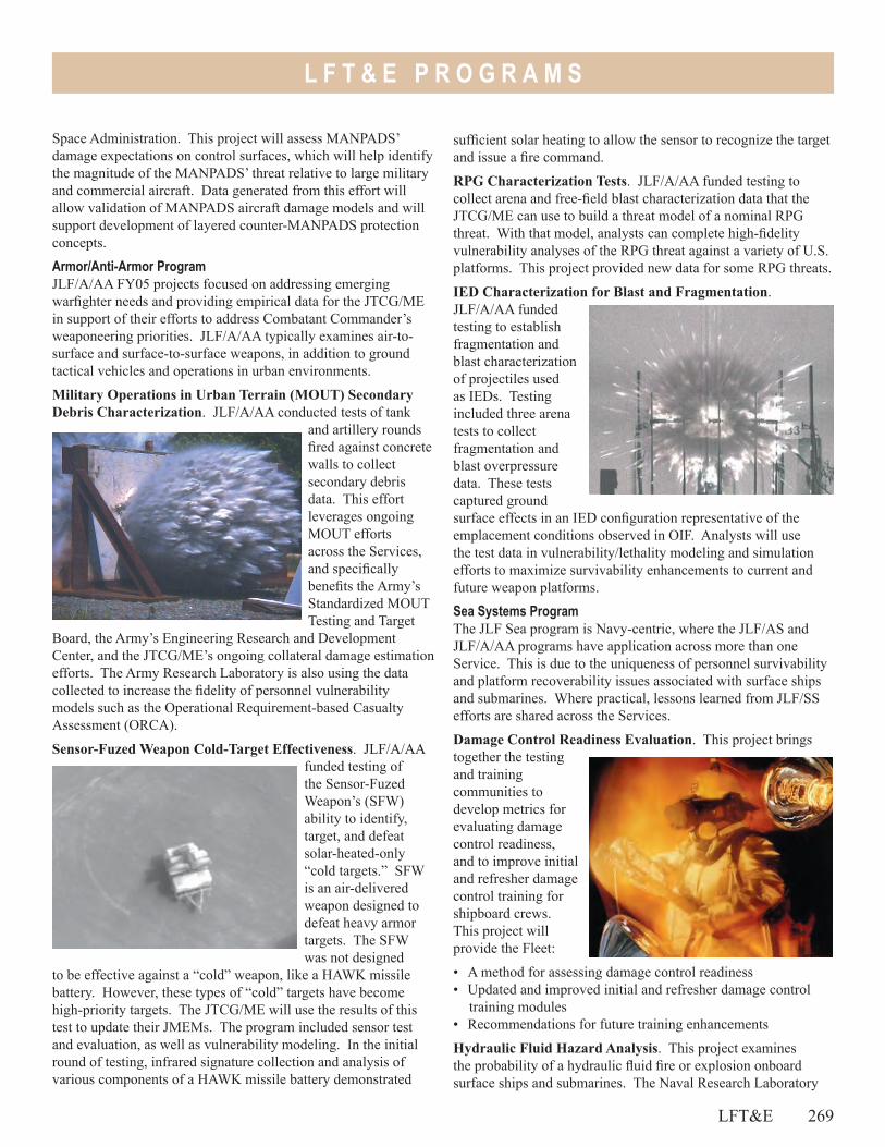
L F T & E P R O G R A M S
LFT&E 269
sufficient solar heating to allow the sensor to recognize the target and issue a fire command.
RPG Characterization Tests. JLF/A/AA funded testing to collect arena and free-field blast characterization data that the JTCG/ME can use to build a threat model of a nominal RPG threat. With that model, analysts can complete high-fidelity vulnerability analyses of the RPG threat against a variety of U.S. platforms. This project provided new data for some RPG threats.
IED Characterization for Blast and Fragmentation. JLF/A/AA funded testing to establish fragmentation and blast characterization of projectiles used as IEDs. Testing included three arena tests to collect fragmentation and blast overpressure data. These tests captured ground surface effects in an IED configuration representative of the emplacement conditions observed in OIF. Analysts will use the test data in vulnerability/lethality modeling and simulation efforts to maximize survivability enhancements to current and future weapon platforms.
Sea Systems ProgramThe JLF Sea program is Navy-centric, where the JLF/AS and JLF/A/AA programs have application across more than one Service. This is due to the uniqueness of personnel survivability and platform recoverability issues associated with surface ships and submarines. Where practical, lessons learned from JLF/SS efforts are shared across the Services.
Damage Control Readiness Evaluation. This project brings together the testing and training communities to develop metrics for evaluating damage control readiness, and to improve initial and refresher damage control training for shipboard crews. This project will provide the Fleet:
• A method for assessing damage control readiness• Updated and improved initial and refresher damage control
training modules• Recommendations for future training enhancements
Hydraulic Fluid Hazard Analysis. This project examines the probability of a hydraulic fluid fire or explosion onboard surface ships and submarines. The Naval Research Laboratory
Space Administration. This project will assess MANPADS’ damage expectations on control surfaces, which will help identify the magnitude of the MANPADS’ threat relative to large military and commercial aircraft. Data generated from this effort will allow validation of MANPADS aircraft damage models and will support development of layered counter-MANPADS protection concepts.
Armor/Anti-Armor ProgramJLF/A/AA FY05 projects focused on addressing emerging warfighter needs and providing empirical data for the JTCG/ME in support of their efforts to address Combatant Commander’s weaponeering priorities. JLF/A/AA typically examines air-to-surface and surface-to-surface weapons, in addition to ground tactical vehicles and operations in urban environments.
Military Operations in Urban Terrain (MOUT) Secondary Debris Characterization. JLF/A/AA conducted tests of tank
and artillery rounds fired against concrete walls to collect secondary debris data. This effort leverages ongoing MOUT efforts across the Services, and specifically benefits the Army’s Standardized MOUT Testing and Target
Board, the Army’s Engineering Research and Development Center, and the JTCG/ME’s ongoing collateral damage estimation efforts. The Army Research Laboratory is also using the data collected to increase the fidelity of personnel vulnerability models such as the Operational Requirement-based Casualty Assessment (ORCA).
Sensor-Fuzed Weapon Cold-Target Effectiveness. JLF/A/AA funded testing of the Sensor-Fuzed Weapon’s (SFW) ability to identify, target, and defeat solar-heated-only “cold targets.” SFW is an air-delivered weapon designed to defeat heavy armor targets. The SFW was not designed
to be effective against a “cold” weapon, like a HAWK missile battery. However, these types of “cold” targets have become high-priority targets. The JTCG/ME will use the results of this test to update their JMEMs. The program included sensor test and evaluation, as well as vulnerability modeling. In the initial round of testing, infrared signature collection and analysis of various components of a HAWK missile battery demonstrated
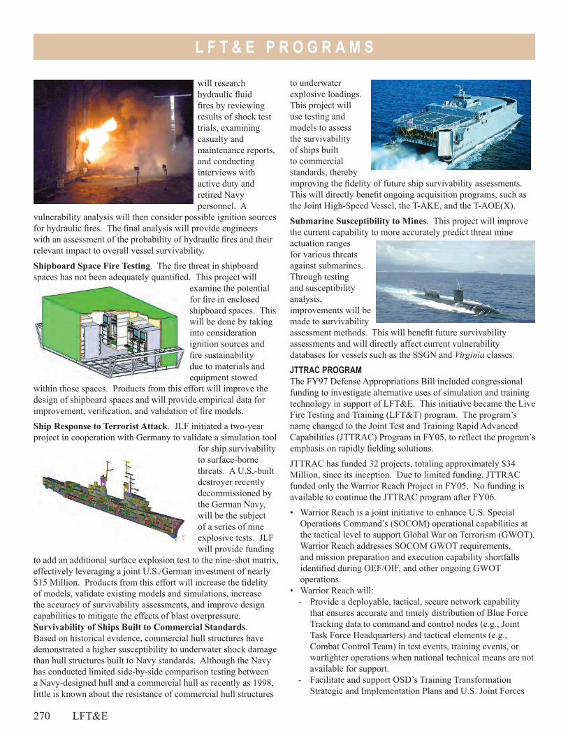
270 LFT&E
L F T & E P R O G R A M S
to underwater explosive loadings. This project will use testing and models to assess the survivability of ships built to commercial standards, thereby improving the fidelity of future ship survivability assessments. This will directly benefit ongoing acquisition programs, such as the Joint High-Speed Vessel, the T-AKE, and the T-AOE(X).
Submarine Susceptibility to Mines. This project will improve the current capability to more accurately predict threat mine actuation ranges for various threats against submarines. Through testing and susceptibility analysis, improvements will be made to survivability assessment methods. This will benefit future survivability assessments and will directly affect current vulnerability databases for vessels such as the SSGN and Virginia classes.
JTTRAC PROGRAMThe FY97 Defense Appropriations Bill included congressional funding to investigate alternative uses of simulation and training technology in support of LFT&E. This initiative became the Live Fire Testing and Training (LFT&T) program. The program’s name changed to the Joint Test and Training Rapid Advanced Capabilities (JTTRAC) Program in FY05, to reflect the program’s emphasis on rapidly fielding solutions.
JTTRAC has funded 32 projects, totaling approximately $34 Million, since its inception. Due to limited funding, JTTRAC funded only the Warrior Reach Project in FY05. No funding is available to continue the JTTRAC program after FY06.
• Warrior Reach is a joint initiative to enhance U.S. Special Operations Command’s (SOCOM) operational capabilities at the tactical level to support Global War on Terrorism (GWOT). Warrior Reach addresses SOCOM GWOT requirements, and mission preparation and execution capability shortfalls identified during OEF/OIF, and other ongoing GWOT operations.
• Warrior Reach will:- Provide a deployable, tactical, secure network capability
that ensures accurate and timely distribution of Blue Force Tracking data to command and control nodes (e.g., Joint Task Force Headquarters) and tactical elements (e.g., Combat Control Team) in test events, training events, or warfighter operations when national technical means are not available for support.
- Facilitate and support OSD’s Training Transformation Strategic and Implementation Plans and U.S. Joint Forces
will research hydraulic fluid fires by reviewing results of shock test trials, examining casualty and maintenance reports, and conducting interviews with active duty and retired Navy personnel. A
vulnerability analysis will then consider possible ignition sources for hydraulic fires. The final analysis will provide engineers with an assessment of the probability of hydraulic fires and their relevant impact to overall vessel survivability.
Shipboard Space Fire Testing. The fire threat in shipboard spaces has not been adequately quantified. This project will
examine the potential for fire in enclosed shipboard spaces. This will be done by taking into consideration ignition sources and fire sustainability due to materials and equipment stowed
within those spaces. Products from this effort will improve the design of shipboard spaces and will provide empirical data for improvement, verification, and validation of fire models.
Ship Response to Terrorist Attack. JLF initiated a two-year project in cooperation with Germany to validate a simulation tool
for ship survivability to surface-borne threats. A U.S.-built destroyer recently decommissioned by the German Navy, will be the subject of a series of nine explosive tests. JLF will provide funding
to add an additional surface explosion test to the nine-shot matrix, effectively leveraging a joint U.S./German investment of nearly $15 Million. Products from this effort will increase the fidelity of models, validate existing models and simulations, increase the accuracy of survivability assessments, and improve design capabilities to mitigate the effects of blast overpressure.Survivability of Ships Built to Commercial Standards. Based on historical evidence, commercial hull structures have demonstrated a higher susceptibility to underwater shock damage than hull structures built to Navy standards. Although the Navy has conducted limited side-by-side comparison testing between a Navy-designed hull and a commercial hull as recently as 1998, little is known about the resistance of commercial hull structures
L F T & E P R O G R A M S
LFT&E 271
Command’s Joint National Training Capability initiative by providing a deployable, live-force tracking capability for the Joint Mission Preparation, Rehearsal, and Operational Network.
- Support Special Operations Forces/Conventional Forces Concept of Operations and Tactics, Techniques, and Procedures development.
- Once fully developed, Warrior Reach will be available as an instrumentation tool for training exercises and operational test and evaluation.

272
Joint Test& Evaluation
Join
t Tes
t&
Evalu
atio
n
J T & E P R O G R A M S
The Joint Test and Evaluation (JT&E) program provides information on joint military capabilities and potential solutions for increasing military effectiveness of fielded systems. JT&E products help develop joint or multi-Service Tactics, Techniques, and Procedures (TTP); joint and individual Service training programs; operational and scientific testing methods; joint or multi-Service data bases; test and training range procedures; and joint and multi-Service models and simulations.
To be more responsive to the warfighters, the JT&E program modified its processes to include a Quick Reaction Test (QRT) capability. A QRT responds to emergent warfighter issues identified by a Combatant Commander (COCOM), Service, or National Agency sponsor. Three QRTs were directed this year: • Joint Low Altitude Aircraft Survivability (JLAAS)• Joint Forward Operations Base (JFOB) Force Protection• Joint Shipboard Ammunition and Ammunition Boards
(JSAABR)
Nominations for Joint Test and Evaluation projects and QRTs are now being submitted by COCOMs, the Joint Staff, and the four Services. This year’s nominations included first-time sponsors from U.S. Northern Command, Joint Staff J-4, and the U.S. Marine Corps. Joint feasibility studies include:• Global Combat Support System (GCSS) Family of Systems
(FoS) • Joint Command and Control for War on Terror Precursor
Operations (JC2WPO)
• Joint Integrated Command and Control for Maritime Homeland Defense Operations (JICM)
• Joint Mobile Network Operations (JMNO)• Joint Test And Evaluation Methodology (JTEM)
We have five ongoing JT&E projects, most of which address requirements of Joint Vision 2020, and all of which focus on meeting the emergent needs of today’s warfighter. Five projects have completed testing this year with products that have benefited the warfighter in important ways. Active projects are:• Joint Datalink Information Combat Execution (JDICE)• Joint Fires Coordination Measures (JFCM)• Joint Integration and Interoperability of Special Operations
(JIISO)• Joint Logistics Planning Enhancements (JLOG/PE)• Joint Space Control Operations - Negation (JSCO-N)
Completed projects are:• Joint Command and Control, Intelligence, Surveillance, and
Reconnaissance (JC2ISR)• Joint Cruise Missile Defense (JCMD)• Joint Methodology to Assess C4ISR Architecture (JMACA)• Joint Unmanned Aerial Vehicle in Time-Sensitive Operations
(JUAV-TSO)• Joint Shipboard Weapons and Ordnance (JSWORD) Quick
Reaction Test (QRT)
Simulation (M&S) Validation, Verification, and Accreditation (VV&A) of the engagement and missile fly-out models, analyzed field test data, and is performing final M&S analysis for the C-130H and UH-60L TTP for Balad airfield in Iraq.
Benefits to the Warfighter JLAAS quantified and documented departure and arrival TTP in support of airfield operations and recommended changes to Service, multi-Service, and joint doctrine and training. JLAAS validated a TTP assessment process with a guide for using selected engagement and missile flyout models to perform TTP assessments.
JOINT LOW ALTITUDE AIRCRAFT SURVIVABILITY (JLAAS)
Test DescriptionThe Joint Low Altitude Aircraft Survivability (JLASS) QRT was directed in September 2004 and sponsored by the U.S. Air Force to employ multi-Service and DoD Agency support to produce TTP. This was done to enhance aircraft survivability and reduce U.S. casualty rates in Iraq. The JLAAS QRT has been tasked with assessing the effectiveness of selected arrival and departure TTP for one fixed-wing and one rotary-wing aircraft against the SA-16 MANPADS, and developing and documenting a process to quantify TTP effectiveness.
Test ActivityJLAAS completed it’s field test at Yuma Marine Core Air Station (MCAS), Arizona, in FY05, finished the Modeling and
JT&E 273
Joint Test and Evaluation Programs
QUICK REACTION TESTS
J T & E P R O G R A M S
JOINT FORWARD OPERATIONS BASE (JFOB)
Test DescriptionThe Joint Forward Operations Base (JFOB) QRT is a one-year project sponsored by the Army. JFOB was directed in February 2005 to develop a Force Protection Handbook for current U.S. operations in Iraq. Test data is being collected from the Army’s Base Camp Survivability Program, the passive defense tests in the Counter Rockets, Artillery, and Mortars program, and other DoD sources, including best practices in the theater of operations. Initial analysis of leveraged test data focused the mitigation efforts on selection of a defensible site; perimeter security; access control; full-height sidewall protection, overhead cover, and compartmentalization of high-occupancy facilities; compartmentalization; and dispersion to reduce effectiveness of attacks.
Test ActivityBased on best practices of units in theater and inputs from the JFOB Subject Matter Expert (SME) working group, JFOB published an initial draft in July 2005, and distributed it to the SME working group for evaluation.
Benefits to the WarfighterJFOB delivered a handbook of TTP for defense against rockets, artillery, mortars and vehicle-borne improvised explosive devises in Iraq, and recommended changes to joint publications for JFOB defense. JFOB also published a final report that identifies the gaps and seams in expeditionary base defenses. The Army requested and received release approval from ATEC for 400 copies of the draft handbook to assist in training two deploying divisions for the next rotation, and another 2,000 copies are in production for use by deployed forces.
JOINT SHIPBOARD AMMUNITION AND AMMUNITION BOARDS (JSAABR)
Test DescriptionThe Joint Shipboard Ammunition and Ammunition Boards (JSAABR) Quick Reaction Test (QRT) is an 18-month QRT sponsored by U.S. Special Operations Command (USSOCOM). Directed in late August 2005, this QRT will evaluate and make recommendations on how the Services and USSOCOM can safely use non-naval weapons when deploying from U.S. Navy ships. JSAABR will provide the Services and USSOCOM with recommendations to improve shipboard safety procedures when using non-naval weapons, and show the Services how they can make their weapon systems more compatible with the shipboard environment. Test ActivityJSAABR is standing up their test team and preparing program and detailed test plans to execute the test.
Benefits to the WarfighterJSAABR will provide safer and more realistic joint training, as well as a seamless execution of sea basing operations for non-naval weapons. This QRT will modify current procedures by assessing munitions that may be approved for shipboard use without completing a full System Safety Risk Analysis, and identify munitions that need additional testing. JSAABR will identify and develop detailed subprocesses for these two critical areas and determine how the newly formed Joint Weapons Safety Technical Advisory Panel may facilitate certification of non-Navy material for shipboard use.
274 JT&E
GLOBAL COMBAT SUPPORT SYSTEM (GCSS) FAMILY OF SYSTEMS (FOS)
Global Combat Support System (GCSS) Family of Systems (FOS) Joint Feasibility Study (JFS) was directed in July 2005 to determine the feasibility of a JT&E project. This was done to establish a baseline evaluation and validation of the effectiveness of the GCSS FoS programs to deliver access to respective logistics data sources to meet the COCOM 129 requirements. If chartered, GCSS will capture and analyze the interoperability and interrelational flow of information between each of the family member’s logistics systems and the operational user community at the COCOM, Joint Task Force (JTF), and component levels. In addition to recommending improvements, GCSS will facilitate documentation and training recommendations that delineate and define utilization measures for staff members to fully integrate into the GCSS system, and enhance the desired effects for the COCOM. GCSS’s lead agency is the Joint Staff, J-4.
JOINT COMMAND AND CONTROL FOR WAR ON TERROR PRECURSOR OPERATIONS (JC2WPO)
The Joint Command and Control for War on Terror Precursor Operations (JC2WPO) JFS was directed in July 2005 to test and evaluate new joint- and multi-Service tactics, techniques, and procedures (J/MTTP) designed to provide an effective means for the Joint Task Force (JTF) Commander to plan and execute missions to support the Global War on Terror from clandestine forward-deployed platforms. Specifically, JC2WPO will improve Command, Control (C2) processes supporting the “find” and “fix” portions of the assigned GWOT mission, and develop J/MTTPs that support this critical mission area. JC2WPO’s lead Service is the U.S. Navy.
JOINT FEASIBILITY STUDIES
J T & E P R O G R A M S
JOINT INTEGRATED COMMAND AND CONTROL FOR MARITIME HOMELAND DEFENSE OPERATIONS (JICM)
The Joint Integrated Command and Control for Maritime Homeland Defense Operations (JICM) JFS was directed in July 2005 and proposes to test and evaluate U.S. Northern Command (USNORTHCOM) C2 capabilities. This will be done to deter, defend, and defeat potential adversaries’ abilities to exploit the maritime domain and strike the continental United States. JICM will develop recommendations to improve DoD and interagency C2 systems interoperability, USNORTHCOM maritime defense Concepts of Operations (CONOPS), Joint Tactics, Techniques, and Procedures (JTTP), joint and interagency doctrine, and inputs to improve C2 systems being developed to support Maritime Homeland Defense. JICM’s lead COCOM is USNORTHCOM.
JOINT MOBILE NETWORK OPERATIONS (JMNO)
Joint Mobile Network Operations (JMNO) JFS was directed in July 2005, and is developing its test concept and gaining Service buy-in to develop JTTP for warfighters using mobile Internet Protocol (IP) networks. JMNO will determine feasibility to identify, test, validate, and recommend network
operations procedures that enhance interoperability of IP-based mobile networks employed in joint, interagency, and coalition operations. JMNO will develop JTTP as “Net-Centric Warfare” standard procedures that provide interoperability regardless of the Services’ material solution. Results will improve combat efficiency and effectiveness with joint mobile IP networks and seamless joint battle space situational awareness. JMNO’s lead Service is the U.S. Marine Corps.
JOINT TEST AND EVALUATION METHODOLOGY (JTEM)
The Joint Test and Evaluation Methodology (JTEM) JFS was directed in January 2005, and proposes to test and evaluate a methodology for defining and using a distributed Live, Virtual, and Constructive (LVC) joint test environment to evaluate system performance and joint mission effectiveness. This will include those processes necessary to institutionalize testing (and training) in a joint mission environment. JTEM seeks to demonstrate viability of the methodology and processes to support operational, developmental, and joint test and evaluation requirements in realistic joint mission environments. JTEM’s lead Service is the U.S. Air Force.
JOINT DATALINK INFORMATION COMBAT EXECUTION (JDICE)
Test DescriptionThe Joint Datalink Information Combat Execution (JDICE) project was chartered in April 2003 to develop, evaluate, and validate Joint Tactics, Techniques, and Procedures (JTTP) and associated Link-16 network architecture modifications to provide actionable data to tactical shooters. The JTTP are designed to improve tactical-level offensive/defensive deconfliction and targeting by providing filtered Link-16 information via a man-in-the-loop to shooter platforms. The JDICE test concept is to execute three sequential mini-tests focused at different C2 nodes, and to conduct a final culminating field test that incorporates and validates all three mini-tests’ JTTP. The lead Service is the U.S. Air Force.
Test ActivityJDICE completed one of its planned mini-tests, Mini-Test B, during Talisman Saber 2005. The final field test is planned for February 2006 during a Red Flag event. JDICE is scheduled to complete on October 31, 2006.
Benefits to the WarfighterJDICE provides rapid feedback from each mini-test to the warfighter community via quick-look reports, briefings, and test reporting. JDICE has made important strides in improving the warfighter’s capability to provide actionable targeting and blue force tracking data to warfighters using Link-16. JDICE also:
• Identified significant flight software anomalies in several airborne platforms that applicable System Program Offices (SPOs) are correcting
• Produced JTTP and trained deploying forces• Engaged U.S. Joint Forces Command (USJFCOM) to provide
Doctrine, Organization, Training, Material, Leadership, Personnel, and Facility (DOTMLPF) inputs to support a DOTMLPF Change Recommendation to the Joint Staff
JOINT FIRES COORDINATION MEASURES (JFCM)
Test DescriptionThe Joint Datalink Information Combat Execution project was chartered in April 2003 to develop, evaluate, and validate JTTP, and associated Link-16 network architecture modifications to provide actionable data to tactical shooters. The JTTP are designed to improve tactical-level offensive/defensive deconfliction and targeting by providing actionable information via Link-16 to shooter platforms. The JDICE test concept is to execute three sequential mini-tests focused at different C2 nodes, and to conduct a final culminating field test that incorporates and validates all three mini-tests’ JTTP. The lead Service is the U.S. Air Force.
ACTIVE JOINT TEST AND EVALUATION PROJECTS
JT&E 275

J T & E P R O G R A M S
Test ActivityDuring FY05, JFCM conducted one risk-reduction event, and began detailed test planning for its first test event (Mini-Test 1) scheduled for January 2006. JFCM is scheduled to complete on March 31, 2008. Benefits to the WarfighterJFCM will determine and recommend new JTTP that standardize knowledge bases as a fire support coordination measure and associated C4 systems to more fully integrate fires with maneuver.
JOINT INTEGRATION AND INTEROPERABILITY OF SPECIAL OPERATIONS (JIISO)
Test DescriptionThe Joint Integration and Interoperability of Special Operations (JIISO) was chartered in February 2004 to investigate, evaluate, and make recommendations to improve and streamline the Joint Force Commander’s Integration and Interoperability (I&I) of Special Operations Forces (SOF) and Conventional Forces (CF), specifically during planning and execution of maneuver and fire support coordination to generate more timely actions and increased opportunities with less potential for fratricide. JIISO will test and evaluate the I&I of SOF and CF during tactical operations with a focus on TTP and supporting system-of-systems (SoS). JIISO will develop test products to support joint operational, training, and acquisition communities and recommend improvements to DOTMLPF. The lead COCOM is USSOCOM.
Test ActivityJIISO successfully completed a risk-reduction exercise in May 2005 in preparation for Field Test 1 (FT-1). Results of FT-1 are being reviewed and analyzed, and JIISO will publish a test report prior to January 2006. JIISO is scheduled to complete on March 31, 2007.
Benefits to the WarfighterJIISO provides reduced fratricide potential and greater situational awareness for SOF and CF. JIISO introduced the Effects Management Tool which shares the conventional fires picture between the SOF and CF. This tool allows SOF to input their own fire control measures and check fires between the Advanced Field Artillery Tactical Data System (CF) and the Command and Control Personal Computer (SOF). Additionally, JIISO has produced three handbooks that are in various stages of publication. These include: • Conventional Forces and Special Operations Forces
Integration and Interoperability Handbook • Tactical Situation Awareness Systems Guide • Procedures for Deconfliction of Tomahawk Land Attack
Missile with CF and SOF Aircraft
JOINT LOGISTICS PLANNING ENHANCEMENTS (JLOG/PE)
Test DescriptionJoint Logistics Planning Enhancements (JLOG/PE) improve joint operational capabilities through enhancements in logistics sustainment information and processes. JLOG/PE was chartered in October 2002 to coordinate with COCOMs and their logistics staffs to develop and test a variety of methods to enhance joint logistics. The test program focuses on improvements to logistics operations for Class III items (petroleum products) and Class V items (munitions). The lead Service is the U.S. Army.
Test ActivityDuring Terminal Fury 05 (TF05), JLOG/PE provided test products to the Theater Logistics Operations Cell (TLOC) pertaining to fuels and munitions. JLOG also deployed a test team to Taegu, Korea, to participate in the U.S. Forces Korea Reception, Staging, Onward Movement, and Integration (RSO&I) exercise in March 2005. The team went to Ulchi Focus Lens (UFL) 05 to collect data to formulate DoD Architecture Framework architectures for fuel and munitions, map processes for fuels, munitions, and future product enhancements. JLOG/PE is scheduled to complete on March 31, 2006.
Benefits to the WarfighterJLOG/PE provides test products that improve integrated logistics sustainment planning and management system performance. These products include:• The Rolling Brief, a web-based briefing that continually scrolls
across a projection screen in the logistics operations center providing real-time situational awareness of selected classes of supply
• The Joint Logistics Training Package (Munitions), a self-paced educational package, focused on Joint Force J4 staff officers responsible for managing joint theater-level logistics operations
• Modifications to the National Level Ammunition Capability (NLAC), to create joint munitions decision support tools and methodologies for using real-world reporting systems in an exercise environment
JOINT SPACE CONTROL OPERATIONS - NEGATION (JSCO-N)
Test Description and MissionThe Joint Space Control Operations – Negation (JSCO-N) project was chartered in February 2004 to evaluate improvements to C2 processes and JTTP associated with Space Control Negation (SC-N). It primarily focuses on integrating the SC-N functions into the Joint Targeting Cycle at the COCOM level. Specifically, JSCO-N is evaluating the planning and assessment capabilities used at the COCOM to support the SC-N function. The lead Service is the U.S. Air Force.
276 JT&E
J T & E P R O G R A M S
Test and Evaluation ActivityJSCO-N conducted its first Field Test (FT-1) during the U.S. Pacific Command’s (USPACOM) exercise Terminal Fury 2005 (TF05). FT-1 provided baseline information that documented SC-N mission processes. JSCO-N analysis of FT-1 resulted in recommended alternative processes, which will be evaluated in exercise Terminal Fury 2006 (TF06) during JSCO-N’s Field Test 2 (FT-2). JSCO-N is scheduled to complete on March 31, 2007.
Benefits to the WarfighterJSCO-N is:• Providing inputs to USSTRATCOM’s Joint Functional
Component Command (JFCC) Space and Global Strike
(S&GS) on Strategic Directives (SD 504-3), CONOPS, and Exercise Directives with respect to the SC-N mission area
• Drafting SC-N exercise planning guidance for USSTRATCOM, U.S. Pacific Command, and U.S. European Command to assist exercise developers in this mission area
• Assisting U.S. Joint Forces Command (USJFCOM) and USSTRATCOM with a joint Limited Objective Experiment (LOE) on collaborative processes that will use SC-N as a practical example in examining collaboration of C2 issues in general
• Providing inputs to update Joint Publication 3-14 (Space Operations)
JOINT COMMAND AND CONTROL, INTELLIGENCE, SURVEILLANCE, AND RECONNAISSANCE (JC2ISR)
Test DescriptionJC2ISR was chartered in FY00 to investigate, evaluate, and recommend improvements to the operational effectiveness of the Joint Task Force (JTF) and components’ ability to dynamically task and re-task ISR collection platforms and sensors, and their ability to process, exploit, and disseminate combat information to support Time-sensitive Targeting (TST). JC2ISR baselined the processes used to prosecute time-sensitive targets; identified ISR platform and sensor tasking, processing, exploitation, and dissemination deficiencies; and identified opportunities for improvement. JC2ISR was completed in June 2005.
Benefits to the WarfighterJC2ISR developed and produced JC2ISR test products that provide warfighters with a baseline effectiveness evaluation of current C2ISR capabilities and limitations, and quantify the effects of specific C2ISR enhancements to improve TST. Test products include:• The Intelligence, Surveillance, and Reconnaissance
Assessment Tool, which effectively evaluates JC2ISR improvements in TST prosecution
• The JC2ISR Methodology that, for the first time, integrates the rigors of joint testing and training of personnel in a Joint National Training Capability event
JOINT CRUISE MISSILE DEFENSE (JCMD)
Test DescriptionJoint Cruise Missile Defense (JCMD) was chartered to evaluate the operational effectiveness of joint operations against Land Attack Cruise Missiles (LACMs). JCMD quantified the effects of procedural and hardware enhancements to Joint Integrated Air Defense System (JIADS) in a cruise missile defense role. JCMD provided warfighters with an evaluation of current JIADS capabilities, and reported the effects of concept of operations
and TTP changes on command and control, sensor, and shooter system enhancements. JCMD completed in June 2005.
Benefits to the WarfighterJCMD enhanced the capability of U.S. JIADS to defeat a cruise missile attack. JCMD provided crucial information on near-term LACM defense capabilities and recommendations for future architectures, technologies, and operational concepts. JCMD introduced a manned, BD-5 mini-jet, surrogate cruise missile to enhance real-world joint training.
JOINT METHODOLOGY TO ASSESS C4ISR ARCHITECTURE (JMACA)
Test DescriptionJoint Methodology to Assess C4ISR Architecture (JMACA) was chartered in October 2001 to test, evaluate, and enhance a set of tools and procedures to assess joint C4ISR architectures. The JMACA methodology consists of a set of analytical tools and procedures designed to rapidly identify deficiencies in the C4ISR architecture and identify appropriate solutions. JMACA focused on the JTF commander’s need to rapidly assess the interoperability of an integrated joint C4ISR architecture prior to employment. JMACA completed in September 2005.
Benefits to the WarfighterJMACA JT&E made critical improvements to joint interoperability through an architecture-based assessment methodology that:• Provided a systematic means of focusing interoperability
assessments to potential deficiencies, which includes mapping assigned combat units to JTF operational facilities; providing automated collection of combat unit-related C4ISR systems;
JOINT TEST AND EVALUATION PROGRAMS COMPLETED IN FISCAL YEAR 2005
JT&E 277
J T & E P R O G R A M S
generating communication paths supporting mission-required information flow; and focusing planners on interoperability risks and C4ISR performance in an operational context
• Established a joint C4ISR architecture assessment team at the JT&E facility in Suffolk, Virginia, to conduct future joint DoD C4ISR assessment requirements
• Established an assessment team at USJFCOM Joint Battle Management Command and Control (JBMC2) J89 directorate in Norfolk, Virginia, to support engineering-level systems assessment with C4ISR architecture data access, architecture development, and system interoperability evaluation
JOINT UNMANNED AERIAL VEHICLE IN TIME-SENSITIVE OPERATIONS (JUAV-TSO)
Test DescriptionJUAV-TSO was chartered in August 2001 to develop and document JTTP for current and proposed tactical Unmanned
Aerial Vehicles (UAV) and to expand UAV tactical employment during dynamic, time-sensitive, joint operations. JUAV-TSO evaluated the ability of tactical leaders to effectively and efficiently utilize UAVs in a tactical role using three C2 architectures and an operational UAV. These C2 architectures established weapon engagement decisions at various C2 nodes throughout JUAV planned test events. The JUAV-TSO JT&E completed in April 2005.
Benefits to the WarfighterJUAV-TSO developed joint, platform-independent TTPs to improve UAV employment in time-sensitive joint operations, with emphasis on air interdiction, fire support, and personnel recovery missions. They produced the JUAV-TSO Handbook, which includes a UAV guide, UAV integration checklist, JTTP, and C2 communications architectures.
JOINT SHIPBOARD WEAPONS AND ORDNANCE (JSWORD)
Test DescriptionJoint Shipboard Weapons and Ordnance (JSWORD) developed a process to certify existing non-naval weapons systems for shipboard use. JSWORD established, documented, and published a standard joint procedure for tube loading the 2.75-inch Folding Fin Aerial Rocket (2.75” FFAR) on U.S. Army and USSOCOM helicopters with engines running and blades turning. JSWORD’s tests were developed in conjunction with a System Safety Risk Assessment conducted by government organizations throughout
all the Services. JSWORD was directed in May 2004, conducted both land-based and shipboard tests during FY05, and completed in March 2005.
Benefits to the WarfighterJSWORD provided procedures to mitigate the risks associated with the transportation, storage, handling, loading and unloading of the 2.75” FFAR during joint shipboard operations.
QUICK REACTION TESTS COMPLETED IN FISCAL YEAR 2005
278 JT&E
Information
Assurance
Info
rmat
ion
Assu
ranc
e
I N F O R M A T I O N A S S U R A N C E
Summary• DoD is improving its Information Assurance (IA) and
Interoperability (IOP) postures, but the information operations threat continues to increase in capability and in ability to rapidly exploit new vulnerabilities.
• Operational assessments of IA/IOP during Combatant Command (COCOM) and Service exercises promote identification and resolution of problems that could impact warfighter mission accomplishment.
• A full assessment cycle of Blue, Green, and Red teaming provides the most comprehensive assessments and the greatest opportunity to improve IA and IOP postures.
• Many of the vulnerabilities found to date are basic problems with readily available solutions; however, some will require more extensive enterprise solutions.
• Exercise authorities appreciate and desire more OT&E expertise during their exercise planning, execution, and assessment phases. There has been more senior-leadership emphasis on IA during selected exercises this fiscal year, resulting in improved IA performance.
• Assessments and remediation efforts in support of units deploying to Iraq and Afghanistan were tailored and conducted during four exercises this fiscal year; three such assessments are planned for FY06.
• Assessment methodology and metrics continue to mature and be tailored to the exercise environment and the needs of supporting organizations across DoD.
BackgroundThe FY03 Appropriations bill directed that the COCOMs and Services conduct operationally realistic IA and IOP evaluations during major exercises. The bill directed the Service Operational Test Agencies (OTAs), the Service Information Warfare Centers, and the National Security Agency (NSA) to assist in the planning, conduct, and evaluations of these exercises. DOT&E oversees these efforts and provides annual updates on DoD’s progress based on results of the exercise evaluations and acquisition OT&E.
The bulk of the FY05 IA/IOP funds were distributed to the OTAs, who in turn assembled teams with the proper expertise to perform IA and IOP assessments before and during exercises. These teams plan, execute, collect data, analyze, and report the results of all activities associated with IA and IOP assessments. Primary execution elements include:• Blue Teams -- Perform network scans and surveys of network
personnel and policy• Green Teams -- Assist the exercise authority in understanding
the nature, priority, and remedial activities needed for identified vulnerabilities; provide remediation support and training, where appropriate
• Red Teams -- Design a comprehensive Red Team scenario overlaid on an exercise scenario to examine the performance of operational networks and operators when subjected to information operations attacks
The following improvements were made this fiscal year to the planning, assessment, and reporting methodology: • Plan Red Team events that provide multi-echelon stress with
multi-level threats to enhance the warfighter’s appreciation for the rapidly evolving threat, and solidify their training and abilities in all aspects of the “protect, detect, react, and restore” missions.
• Design IOP assessment plans in coordination with the Joint Interoperability Test Command (JITC).
• Conduct an administrative Blue Team vulnerability assessment approximately six months prior to the exercise, providing feedback to the exercise authority for remedial actions in advance of the exercise. Interoperability certification reviews may also occur during the Blue Team phase.
• Provide Green Team assistance after both Blue and Red Team events.
• Coordinate external support for solutions beyond the organic capabilities of the exercise authority and assist in the identification of sources for any needed training.
FY05 Assessment ActivitiesIn this fiscal year, the OTA teams have grown significantly, as have the relationships with COCOMs and other critical partner organizations such as the NSA, the Service Information Warfare Centers, the Defense Intelligence Agency (DIA), and the Defense Information Systems Agency (DISA). Accomplishments by the OT&E community and our partners include the following:• Performed full Blue/Green/Red Team assessments for 15
exercises (see Table 1).• Performed Blue/Green Team assessments for eight additional
exercises.• Observed and assisted in exercises that have future assessment
opportunity.• Performed four assessments for units preparing to deploy to
Iraq and Afghanistan.• Developed IA and IOP metrics that are observable in the
exercise environment, meaningful to the warfighter, and suitable for performing baseline assessments and trend analyses.
• Developed an evaluation plan template and an exercise planning checklist to bring appropriate levels of analytical rigor to exercises.
IA 279
Information Assurance (IA) and Interoperability (IOP) Evaluations During Combatant Command and Service Exercises
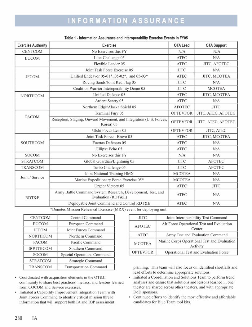
280
I N F O R M A T I O N A S S U R A N C E
• Coordinated with acquisition elements in the OT&E community to share best practices, metrics, and lessons learned from COCOM and Service exercises.
• Initiated a Capability Improvement Integration Team with Joint Forces Command to identify critical mission thread information that will support both IA and IOP assessment
planning. This team will also focus on identified shortfalls and lead efforts to determine appropriate solutions.
• Initiated a Coordination and Solutions Team to perform trend analyses and ensure that solutions and lessons learned in one theater are shared across other theaters, and with appropriate DoD sponsors.
• Continued efforts to identify the most effective and affordable candidates for Blue Team tool kits.
280 IA
Table 1 - Information Assurance and Interoperability Exercise Events in FY05
Exercise Authority Exercise OTA Lead OTA SupportCENTCOM No Exercises this FY N/A N/A
EUCOM
Lion Challenge 05 ATEC N/AFlexible Leader 05 ATEC JITC, AFOTEC
JFCOM
Joint Task Force Exercise 05 JITC N/AUnified Endeavor 05-01*, 05-02*, and 05-03* ATEC JITC, MCOTEA
Roving Sands/Joint Red Flag 05 JITC N/ACoalition Warrior Interoperability Demo 05 JITC MCOTEA
NORTHCOM
Unified Defense 05 ATEC JITC, MCOTEAArdent Sentry 05 ATEC N/A
Northern Edge/Alaska Shield 05 AFOTEC JITC
PACOM
Terminal Fury 05 OPTEVFOR JITC, ATEC, AFOTECReception, Staging, Onward Movement, and Integration (U.S. Forces,
Korea) 05 OPTEVFOR JITC, ATEC, AFOTEC
Ulchi Focus Lens 05 OPTEVFOR JITC, ATEC
SOUTHCOMJoint Task Force - Bravo 05 ATEC JITC, MCOTEA
Fuertas Defensas 05 ATEC N/AEllipse Echo 05 ATEC N/A
SOCOM No Exercises this FY N/A N/ASTRATCOM Global Guardian/Lightning 05 JITC AFOTECTRANSCOM Turbo Challenge 05 JITC AFOTEC
Joint / Service
Joint National Training HMX MCOTEA N/AMarine Expeditionary Force Exercise 05* MCOTEA N/A
Urgent Victory 05 ATEC JITC
RDT&E Army Battle Command System Research, Development, Test, and
Evaluation (RDT&E) ATEC N/A
Deployable Joint Command and Control RDT&E ATEC N/A*Denotes Mission Rehearsal Exercise (MRX) event for deploying unit
CENTCOM Central CommandEUCOM European CommandJFCOM Joint Forces Command
NORTHCOM Northern CommandPACOM Pacific Command
SOUTHCOM Southern CommandSOCOM Special Operations Command
STRATCOM Strategic CommandTRANSCOM Transportation Command
JITC Joint Interoperability Test Command
AFOTEC Air Force Operational Test and Evaluation Center
ATEC Army Test and Evaluation Command
MCOTEA Marine Corps Operational Test and Evaluation Activity
OPTEVFOR Operational Test and Evaluation Force
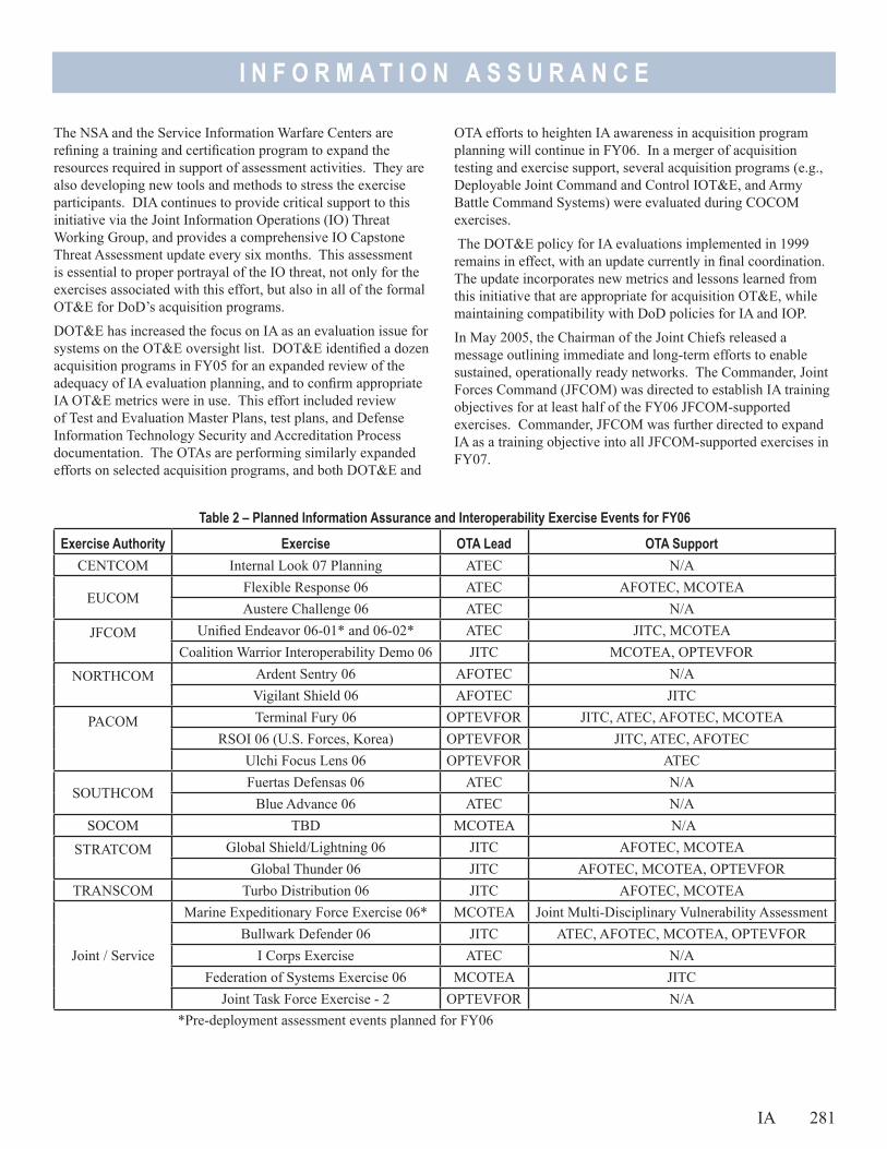
I N F O R M A T I O N A S S U R A N C E
The NSA and the Service Information Warfare Centers are refining a training and certification program to expand the resources required in support of assessment activities. They are also developing new tools and methods to stress the exercise participants. DIA continues to provide critical support to this initiative via the Joint Information Operations (IO) Threat Working Group, and provides a comprehensive IO Capstone Threat Assessment update every six months. This assessment is essential to proper portrayal of the IO threat, not only for the exercises associated with this effort, but also in all of the formal OT&E for DoD’s acquisition programs.
DOT&E has increased the focus on IA as an evaluation issue for systems on the OT&E oversight list. DOT&E identified a dozen acquisition programs in FY05 for an expanded review of the adequacy of IA evaluation planning, and to confirm appropriate IA OT&E metrics were in use. This effort included review of Test and Evaluation Master Plans, test plans, and Defense Information Technology Security and Accreditation Process documentation. The OTAs are performing similarly expanded efforts on selected acquisition programs, and both DOT&E and
OTA efforts to heighten IA awareness in acquisition program planning will continue in FY06. In a merger of acquisition testing and exercise support, several acquisition programs (e.g., Deployable Joint Command and Control IOT&E, and Army Battle Command Systems) were evaluated during COCOM exercises.
The DOT&E policy for IA evaluations implemented in 1999 remains in effect, with an update currently in final coordination. The update incorporates new metrics and lessons learned from this initiative that are appropriate for acquisition OT&E, while maintaining compatibility with DoD policies for IA and IOP.
In May 2005, the Chairman of the Joint Chiefs released a message outlining immediate and long-term efforts to enable sustained, operationally ready networks. The Commander, Joint Forces Command (JFCOM) was directed to establish IA training objectives for at least half of the FY06 JFCOM-supported exercises. Commander, JFCOM was further directed to expand IA as a training objective into all JFCOM-supported exercises in FY07.
Table 2 – Planned Information Assurance and Interoperability Exercise Events for FY06
Exercise Authority Exercise OTA Lead OTA SupportCENTCOM Internal Look 07 Planning ATEC N/A
EUCOMFlexible Response 06 ATEC AFOTEC, MCOTEAAustere Challenge 06 ATEC N/A
JFCOM
Unified Endeavor 06-01* and 06-02* ATEC JITC, MCOTEACoalition Warrior Interoperability Demo 06 JITC MCOTEA, OPTEVFOR
NORTHCOM
Ardent Sentry 06 AFOTEC N/AVigilant Shield 06 AFOTEC JITC
PACOM
Terminal Fury 06 OPTEVFOR JITC, ATEC, AFOTEC, MCOTEARSOI 06 (U.S. Forces, Korea) OPTEVFOR JITC, ATEC, AFOTEC
Ulchi Focus Lens 06 OPTEVFOR ATEC
SOUTHCOMFuertas Defensas 06 ATEC N/A
Blue Advance 06 ATEC N/ASOCOM TBD MCOTEA N/A
STRATCOM
Global Shield/Lightning 06 JITC AFOTEC, MCOTEAGlobal Thunder 06 JITC AFOTEC, MCOTEA, OPTEVFOR
TRANSCOM Turbo Distribution 06 JITC AFOTEC, MCOTEA
Joint / Service
Marine Expeditionary Force Exercise 06* MCOTEA Joint Multi-Disciplinary Vulnerability AssessmentBullwark Defender 06 JITC ATEC, AFOTEC, MCOTEA, OPTEVFOR
I Corps Exercise ATEC N/AFederation of Systems Exercise 06 MCOTEA JITC
Joint Task Force Exercise - 2 OPTEVFOR N/A*Pre-deployment assessment events planned for FY06
IA 281
I N F O R M A T I O N A S S U R A N C E
FY06 Goals and Planned Assessment ActivitiesAssessment plans for FY06 include 15 exercises with active Blue, Green, and Red Teams (full assessment support), and six additional exercises with lesser efforts (see Table 2). Based on current projections and planned levels of effort, funding appears adequate for FY06. However, the response from COCOM and Service exercise authorities continues to be very positive, and additional resources may be required to provide the full assessment support to more than 15 exercises. In particular, assessment and remediation support to units preparing to deploy to Iraq/Afghanistan has been very well received, and three of these assessment events are planned for FY06 (these events are designated with an asterick in Table 2).
Interoperability problems will usually be observed during exercises via failures to achieve critical mission requirements. The assessment team will seldom have instrumentation in place to capture system performance data so the exact cause of a problem may not be known. In FY06, we plan to develop a process with JFCOM and JITC for follow-up events to identify specific causes of interoperability problems identified during exercises.
Acquisition program support will continue to expand during FY06, and will include planning for an IA assessment during an upcoming Missile Defense Agency (MDA) wargame covering several MDA acquisition programs. We are optimistic that many training and test objectives can be simultaneously satisfied during combined events, and believe that the efficiencies and cost savings to the Department will be significant.
AssessmentHigh-level trends across FY05 events include the following:• Vulnerabilities have been found by every Blue and Red Team
associated with this initiative.• Most problems found are basic (e.g., unprotected servers
and open ports, Intrusion Detection Systems not installed or improperly configured, etc.) and easily remedied by trained system administrators.
• There is unfounded trust that certain networks are inherently secure and remote monitoring is always effective. These reduce vigilance by local operators, and set the stage for penetrations to go undetected.
• Corrective-action management is sometimes lacking; some identified problems are not being fixed, and some that have been fixed get reintroduced when backup or update disks are loaded.
• Tactics, techniques, and procedures for detect, react, and restore missions are generally immature and/or not well understood by operators.
• Responsiveness to solving problems found in networks during operational exercises, or when focused follow-up is provided, is excellent.
Specific trends in more detailed assessment areas include the following:• Personnel and Training - A common standard for network
manning, reflecting the complexity or operational criticality of the networks, does not exist. Many personnel working IA tasks are not designated as IA personnel, and as a result do not receive necessary training or achieve skill standards appropriate for their duties. DoD is revising IA training standards to address many of these issues.
• Configuration Management – Standards are inconsistently followed, and often too complex for local personnel to achieve. Poor configuration management results in undesirable network variance, making the detection of unauthorized modifications or access difficult. DoD has programmed additional development to an enterprise network scanning and remediation suite to address these shortfalls.
• Continuity of Operations Plans (COOP) or Recovery Plans – Many commands lack effective incident response guidelines, and seldom exercise COOP plans. Existing response and continuity plans are being rapidly overtaken by new technology options, such as Voice-over-Internet Protocol (IP), online IP-based chat, and intercom channels. These and other technologies provide popular services that leave few alternative options in their absence. The Joint Task Force for Global Network Operations is developing a template for these plans.
• Firewalls and Intrusion Detection Systems (IDS) - Many units have no firewalls and no IDS in place, particularly on classified networks. Where firewalls and IDS are employed, host-based and internal firewalls and IDS capabilities are more effective than those provided at only enterprise boundaries or by higher echelon.
• Information Assurance Vulnerability Advisory (IAVA) Compliance - Many systems are not compliant with IAVAs, and some cannot be brought into compliance due to incompatibility with recommended patches. Units have little or no control over Program of Record software, which must be patched by the program manager. Within the U.S. Army Battle Command System, steps have been taken to more rapidly test and field new patches and protections. Additionally, DoD has purchased enterprise licenses for certain software tools to identify and remediate IAVA shortfalls locally.
• Organizational Roles and Responsibilities - Many organizations rely on higher echelons to perform critical network management tasks. The lack of local responsibility causes reduced awareness of and attention to critical IA practices. It also results in reduced ability to locally protect networks from attack and perform proper detection, reaction, and restoration actions in the face of an attack.
282 IA
I N F O R M A T I O N A S S U R A N C E
• Physical Security - Exercise opposition forces routinely demonstrate the ability to penetrate badging and gate/door security. Sensitive information that facilitates both physical and electronic penetration is often found in unguarded trash. Additionally, computer screen locks and time outs are inconsistently applied, allowing intruders access to logged-on systems.
These results have been shared both with the exercise authorities and with our initiative partners in the Joint Staff and the Defense IA program in the office of the Assistant Secretary of Defense (Network Information and Integration). Our partners are becoming more closely aligned with this initiative and exploring new ways to use the available results and influence focus areas for future events. The Coordination and Solutions Team (CST) at DOT&E has established a method for harvesting information concerning critical vulnerabilities and shortfalls. It is intended that COCOM-specific vulnerabilities and shortfalls will be reviewed by the COCOM at least bi-monthly, supported by the CST efforts to obtain outside agency assistance. The CST has additionally provided briefings and other information via the Joint Staff to the senior leadership on interoperability issues, with the intent of establishing a “clearing house” for remediation similar to that which exists via the Enterprise Solutions Steering Group for IA vulnerabilities.
Exercise authorities have demonstrated strong interest in applying remedies for identified vulnerabilities. We have observed significant improvements in IA posture between Blue and Red Team events for those exercises that have agreed to incorporate the full assessment cycle. We attribute this in part to the increased IA awareness among exercise participants that a full assessment brings to the exercise planning, but also to the increased command emphasis that is generally associated with the decision to have a full assessment. We also believe the focused Green Team and the synergy across all of the teams improves the likelihood that identified problems will be fixed, and repeat observations of the same problem will be reduced.
The U.S. Strategic Command subordinate command, the Joint Information Operations Command (JIOC), and the Marine Corps collaborated on the conduct of the first Joint Multi-Disciplinary Vulnerability Assessment. This effort expands the assessment previously planned for 1st Marine Expeditionary Force to include other elements, such as radio frequency and telephone monitoring. DOT&E, in partnership with NSA and other DoD entities, will continue to work closely with the JIOC to help shape this initiative in a fashion that will not duplicate or obviate other efforts that are already executing successfully.
Although a variety of methods for managing vulnerabilities and shortfalls exists within DoD, DOT&E has instituted the use of
IA 283
a Vulnerability and Shortfall Matrix. This matrix identifies the vulnerability or interoperability shortfall, proposes a remedy, and includes a statement of the operational impact if remedies are not applied. The matrix is updated following every Blue, Green, or Red Team assessment to reflect the current state of observed vulnerabilities and shortfalls. This tool is used to monitor correction of vulnerabilities and shortfalls, support trend analyses across theaters, and assist in the identification of issues to be reviewed or validated in subsequent events. Several COCOMs have chosen to employ this matrix as their own tracking tool.
Conclusion and RecommendationThere are many ongoing activities focused on improving DoD’s IA and IOP posture, and in the aggregate they are having a positive effect. The efforts described in the preceding pages have already assisted in integrating and finding synergy among these efforts, resulting in improved IA postures and awareness wherever the full cycle of Blue-Green-Red Teaming is performed. The assessments enable rapid identification of vulnerabilities and interoperability/training shortfalls, and frequently result in immediate correction of identified problems. DoD has refocused and charged several senior review groups to receive assessment information produced by this initiative, prioritize issues for correction, and identify appropriate agencies to address those solutions for all of DoD.
The Department should continue to synchronize its many activities and leverage the results of the operational evaluations provided by this assessment initiative. In last year’s report, we recommended that IA should become an exercise objective (i.e., realistic Red Teaming should be present) wherever information is critical to mission accomplishment. The Chairman of the Joint Chiefs’ message in May 2005, to the Commander, Joint Forces Command is a step in the right direction, but should be expanded to include all COCOMs. In recognition of the continued success by Red Teams, we believe that every major exercise should have IA as a critical operational training objective. Consistent with other training objectives, Red Teams should be permitted to conduct threat representative activities, and exercise participants should have mature continuity of operations plans and be prepated to execute them.
Finally, we should accept that threat penetrations may occur when and where we least expect them; as such, more effort must be placed in preparing to detect, react, and restore critical services in the face of a successful attack. As previously discussed, this initiative is prepared to assess the ability of exercise participants in each of these domains.

284
I N F O R M A T I O N A S S U R A N C E

BLRIP ExecutiveSum
maries

BLRI
PEx
ecut
iveSu
mm
aries
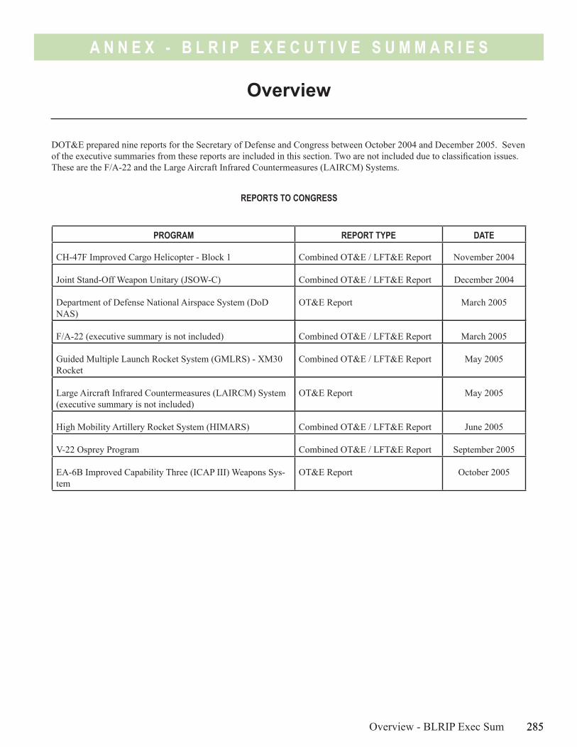
285
A N N E X - B L R I P E X E C U T I V E S U M M A R I E S
Overview - BLRIP Exec Sum 285
Overview
DOT&E prepared nine reports for the Secretary of Defense and Congress between October 2004 and December 2005. Seven of the executive summaries from these reports are included in this section. Two are not included due to classification issues. These are the F/A-22 and the Large Aircraft Infrared Countermeasures (LAIRCM) Systems.
PROGRAM REPORT TYPE DATE
CH-47F Improved Cargo Helicopter - Block 1 Combined OT&E / LFT&E Report November 2004
Joint Stand-Off Weapon Unitary (JSOW-C) Combined OT&E / LFT&E Report December 2004
Department of Defense National Airspace System (DoD NAS)
OT&E Report March 2005
F/A-22 (executive summary is not included) Combined OT&E / LFT&E Report March 2005
Guided Multiple Launch Rocket System (GMLRS) - XM30 Rocket
Combined OT&E / LFT&E Report May 2005
Large Aircraft Infrared Countermeasures (LAIRCM) System (executive summary is not included)
OT&E Report May 2005
High Mobility Artillery Rocket System (HIMARS) Combined OT&E / LFT&E Report June 2005
V-22 Osprey Program Combined OT&E / LFT&E Report September 2005
EA-6B Improved Capability Three (ICAP III) Weapons Sys-tem
OT&E Report October 2005
REPORTS TO CONGRESS

286
A N N E X - B L R I P E X E C U T I V E S U M M A R I E S
A N N E X - B L R I P E X E C U T I V E S U M M A R I E S
CH-47F Improved Cargo Helicopter Executive Summary
This combined Operational Test and Evaluation and Live Fire Test and Evaluation report provides my evaluation of the CH-47F Improved Cargo Helicopter. Submission of this report fulfills the provisions of Title 10, United States Code, Sections 2399 and 2366. It assesses the adequacy of the operational and live fire test, and the overall operational effectiveness, suitability, and survivability of the Block 1 modifications to the CH-47F Improved Cargo Helicopter.
System OverviewThe CH-47F helicopter is a service-life extension and selected component upgrade program for the current CH-47D helicopter fleet. The Army plans for this program to increase performance and extend the aircraft’s service life another 20 years. The CH-47F is a twin-turbine tandem rotor heavy lift helicopter designed for combat support, combat service support, and combat assault missions.
The Army developed an evolutionary acquisition/two-block approach for meeting requirements. The Army plans to test and evaluate this two-block approach in three phases of operational test and evaluation.
Block 1 modifications include digital cockpit displays, improved navigation avionics, limited digital messaging, airframe rebuild and stiffening to reduce cockpit vibrations, and modifications to provide for easy removal of the aft pylon for enhanced air transportability. Phase 1 of Initial Operational Test and Evaluation (IOT&E), which this report covers, tested these capabilities.
Block 2 modifications will include all Block 1 capabilities, additional interoperability with digital messaging networks, and the integration of Global Air Traffic Management capability. In addition, the Army plans to install new monolithic machined frames in the cabin, floor, and aft sections of the aircraft; complete the restoration of dynamic components to like-new condition; and integrate the Common Avionics Architecture System cockpit, the Common Missile Warning System, and Blue Force Tracker for increased situational awareness. Phases 2 and 3 of IOT&E will evaluate the addition of these Block 2 capabilities in FY06 and FY07, respectively.
Between now and FY07, production and fielding will focus on the MH-47G Special Operations variant of the aircraft, which is produced on the same production line and is a separate acquisition program. The Army plans to field 452 CH-47F aircraft with Block 2 capabilities starting in FY07.
Test Adequacy Operational testing and live fire testing were adequate and conducted in accordance with the Director, Operational Test & Evaluation (DOT&E)-approved Test and Evaluation Master Plan, the Phase 1 IOT&E Test Plan, and the Alternative Live Fire Test & Evaluation (LFT&E) Strategy.
Members of the DOT&E staff monitored these tests, reviewed test data, and analyzed test results. This report summarizes the results of the independent evaluation of the CH-47F Block 1 aircraft.
Operational EffectivenessThe CH-47F is operationally effective. During testing, the system demonstrated a high overall degree of mission accomplishment when employed by representative personnel in an environment planned or expected for operational employment. The CH-47F’s demonstrated performance exceeded the mission requirements for self-deployment, external cargo lift, and internal transport of combat troops. The integration of navigation aids with the digital moving map and flight plan enhanced pilot situational awareness and reduced pilot workload.
Operational SuitabilityThe CH-47F Block 1 aircraft is not operationally suitable. The system did not demonstrate program goals to integrate communications systems with the new digital cockpit, improve digital interoperability, or increase system reliability. Additionally, there are unresolved electrical concerns with the CH-47F, which result in battery power drainage. Inadequate integration of communications systems resulted in reduced communications clarity for the crew. High frequency radio operational capability did not occur during testing and the system demonstrated an immature digital messaging capability. The demonstrated CH-47F communications capability is less suitable than the existing CH-47D capabilities, and the CH-47F
CH-47F BLRIP Exec Sum 287
A N N E X - B L R I P E X E C U T I V E S U M M A R I E S
did not meet the Interoperability Key Performance Parameter to demonstrate all Information Exchange Requirements for the Block 1 system. In addition to not meeting two of the four reliability requirements during IOT&E, other test data reveals that airframe cracks due to metal fatigue continue to affect the aft sections of the aircraft. Reliability failures in the CH-47F are common to legacy CH-47D aircraft and suggest that restoration of major dynamic components to a “like-new” condition is required to meet reliability goals in the future. The Army is planning to implement this component recapitalization effort, as well as addressing the vibration/metal fatigue issues by adding monolithic machined metal formers to the airframe, for Block 2 aircraft.
SurvivabilityThe overall survivability of the CH-47F is comparable to that of the CH-47D aircraft. The effectiveness of the aircraft survivability equipment integrated onto the CH-47F was not demonstrated during testing.
The CH-47F vulnerability to projected ballistic threats is similar to that of the CH-47D. In some cases, the test results indicate the CH-47F is more survivable than the original design indicated. Combat threats considered in the 1960’s CH-47 basic design were not as lethal as the threats used in this evaluation. The vulnerability assessment against ballistic threats indicates that the probability of kill against the CH-47D and CH-47F are essentially the same. The Army considers the Man-Portable Air Defense Systems (MANPADS) threat an overmatch (i.e., almost certain to kill the aircraft). They intended to evaluate the vulnerability to MANPADS by analysis, but model development is not complete.
RecommendationsThe Army should consider the following recommendations to improve the operational effectiveness and operational suitability of the CH-47F Cargo Helicopter:• Improve the communications system to reduce electromagnetic interference, eliminate bleed over and headset static, and
make communications controls more accessible to pilots.• Replace and strengthen airframes throughout the aircraft to eliminate stress cracking and metal fatigue.• Improve the reliability of baseline and new aircraft components. The restoration of dynamic components to a “like-new”
condition should help.• Conduct additional operational testing to evaluate anticipated changes to the CH-47F before fielding in 2007 and to
demonstrate that the aircraft can meet interoperability and reliability requirements.
The Army should consider the following recommendations to improve survivability to expected threats: • Conduct additional testing to confirm the integration of aircraft survivability equipment onto the CH-47F aircraft.• Complete the three planned, but not conducted, dynamic live fire tests. These tests should demonstrate the CH 47F’s
ability to withstand damage while under dynamic load, as well as the capability to continue its mission or safely return to base after a ballistic impact.
• Continue development of tools for assessment of CH-47F survivability to MANPADS. • Review and update Battle Damage Assessment and Repair (BDAR) manuals to reflect the available repair capability.
288 CH-47F BLRIP Exec Sum
A N N E X - B L R I P E X E C U T I V E S U M M A R I E S
JSOW-C Executive Summary
This report on the Joint Standoff Weapon System (JSOW-C) fulfills the provisions of Title 10, United States Code, Sections 2399 and 2366. It assesses the adequacy of testing and the operational effectiveness, suitability, survivability, and lethality of the JSOW-C when delivered from F/A-18 aircraft.
Testing was adequate to evaluate the system as effective, when successfully delivered, against light-surface materiel targets and deployed combat systems. Against moderately hardened structure targets, JSOW-C requires information about fuze delay settings that is not currently available. We conclude that JSOW-C testing has not confirmed its effectiveness against moderately hardened targets.
JSOW-C has the same airframe as JSOW-A, so modeling predicts no change to in-flight survivability. However, testing has not confirmed the survivability of either variant. Testing confirmed the JSOW-C is not suitable for combat because personnel with experience planning JSOW-C attacks, who would not necessarily be available in combat, are required to facilitate planning. The mission planning system is also unable to complete the computational mission planning process; the average mission planning time is lengthy (57 minutes, compared to 16 minutes for the Joint Air-to-Surface Standoff Missile), and training and documentation do not enable less experienced personnel to complete a mission plan. In addition, no predictive lethality capability exists to guide mission-planning selection of weapon impact parameters or warhead fuze delay.
To have a fully effective and suitable system, the Navy should:• Improve training and documentation for JSOW-C mission planning.• Improve the Tactical Automated Mission Planning System (TAMPS) so that it completes the planning more reliably, more
quickly, and more easily.• Develop a capability for mission planners to define weapon impact parameters across the entire spectrum of JSOW-C
operational targets.• Determine correct fuze settings against moderately hardened targets, and enable transfer of those to the F/A-18.• Ensure imagery with accurate coordinates is available for mission planning.
The correction of deficiencies and inadequacies discovered during this operational evaluation require additional operational testing That testing should confirm effectiveness and suitability for combat by including live JSOW-C weapons, flown through a realistic integrated air defense, against realistic targets. Once the JSOW-C module of the Joint Mission Planning System is available, this same operational testing should be completed.
JSOW-C BLRIP Exec Sum 289

290
A N N E X - B L R I P E X E C U T I V E S U M M A R I E S
A N N E X - B L R I P E X E C U T I V E S U M M A R I E S
The DoD National Airspace System will be employed to accomplish military air traffic operations and will ensure the seamless conduct of air traffic control for aircraft transitioning between military and Federal Aviation Administration-controlled airspace.
Testing was adequate to evaluate the DoD National Airspace System as operationally effective when a detailed set of performance adaptations appropriate to each individual deployment location are successfully completed. Site-specific integration requires highly skilled subject matter experts to be directly involved in the installation of DoD National Airspace System at each location prior to government acceptance. Without such involvement, potential safety of flight hazards could be introduced into the system. Effectiveness deficiencies are present in the areas of conflict alerts and minimum safe altitude warnings, radar clutter limitations, and processor capacity.
Testing was adequate to confirm the DoD National Airspace System is not operationally suitable. This is because of non-current technical data, incomplete system training, unacceptable DoD Advanced Automation System availability, additional skilled maintenance manpower requirements, additional security upgrades, and system logistics shortfalls. In addition to these corrections, an effectiveness and suitability enhancement program needs to be developed to increase the integrated performance of the full-rate production system.
To have a fully effective and suitable system, the Air Force should:• Implement a full-rate production system-of-systems optimization directive. The Electronic System Center will function as
the cognizant government authority for implementation and formal contractor compliance.• Accomplish detailed target data processing and characterization analysis to ensure safe and satisfactory configurations are
installed at each DoD Advanced Automation System fielding location.• Use the Federal Aviation Administration’s implementation capabilities as appropriate to enhance cross-agency utilization
and fielding functions.• Initiate, implement, and operationally test the advanced signal data processor capability.• Initiate and implement an improved Digital Airport Surveillance Radar to DoD Advanced Automation System interface
analysis capability.• Initiate a program to resolve the existing deficiencies and potential new deficiencies created by DoD National Airspace
System full-rate production.
The correction of deficiencies and inadequacies discovered during this operational evaluation require additional rigorous, thorough, and integrated operational testing. That testing should confirm the current and emerging full-rate production operational effectiveness and suitability of DoD NAS performance for operations under realistic military airspace conditions.
DoD National Airspace System (NAS) Executive Summary
DoD NAS BLRIP Exec Sum 291

292
A N N E X - B L R I P E X E C U T I V E S U M M A R I E S
A N N E X - B L R I P E X E C U T I V E S U M M A R I E S
The Army’s testing of the Guided Multiple Launch Rocket System (GMLRS) XM30 rocket was adequate. The GMLRS XM30 rocket is operationally effective and suitable.
System OverviewThe GMLRS is a system of munitions. There are two versions, the dual-purpose improved conventional munitions (DPICM) rocket and a unitary rocket. This report covers the DPICM version of the GMLRS rocket – the XM30.
The XM30 system consists of the rocket and the launch pod container. This guided rocket is capable of reaching ranges over 60 kilometers. Commanders will use XM30 rockets primarily in a general support role to attack lightly armored, stationary targets such as personnel, artillery, air defense, and communications sites.
Test AdequacyTesting was adequate to support an evaluation of the rocket’s operational effectiveness and suitability. This evaluation is based on data derived from both developmental and operational testing of XM30 rockets.
Operational EffectivenessThe GMLRS XM30 rocket is operationally effective. Developmental and operational testing demonstrated that:• XM30 rockets are more accurate and can achieve greater ranges than the current M26 or M26A2 DPICM munitions.
Because of the XM30 guidance capabilities, depending upon the range, it generally requires three to five times fewer XM30 rockets than M26 rockets to attack a target with equivalent effects. XM30 rockets are lethal against their intended target sets.
• MLRS units can execute XM30 missions quickly enough to be responsive to field commanders’ tactical requirements. However, the effectiveness of the XM30 at extended ranges is dependent upon long-range sensors that are both accurate and available to provide timely targeting information to MLRS units. Currently, there are few target acquisition assets that meet these requirements.
• GPS jamming does not degrade the overall effectiveness of the XM30 rockets. • Follow-on testing conducted after the IOT demonstrated that camouflage nets erected over the targets do not have an
operationally significant impact on the functioning of the M101 submunitions.
Operational SuitabilityThe GMLRS XM30 rocket is operationally suitable. Developmental and operational testing demonstrated that:• The XM30 rockets are reliable as they come off the production line. However, follow-on testing conducted by the Army
indicates that the XM30 has durability issues and potential long-term storage problems caused by moisture leaks. • The XM30’s submunition dud rate is significantly lower than current DPICM rockets at all ranges, which results in
significantly less unexploded ordnance to impair friendly maneuver and cause casualties to non-combatants. • The XM30 does not meet the DoD standard for submunition dud rate of less than 1 percent. It also does not meet the Joint
Requirements Oversight Council-amended requirement of less than 4 percent at ranges less than 20 km. It does meet the amended requirements of less than 2 percent at ranges between 20-60 km, and less then four percent at ranges beyond 60 km.
• The XM30 rocket is supportable within the Army’s current maintenance, logistics, training, and manpower structures. • XM30 rockets are safe and suitable for use in an electromagnetic environment and can be decontaminated if exposed to
nuclear, biological, or chemical contaminants.• The XM30 rocket motor and warhead are not compliant with DoD insensitive munition requirements. Like other existing
rockets and missiles, the XM30 places soldiers and other equipment at risk and makes them vulnerable if exposed to enemy fire, including improvised explosive devices, rocket propelled grenades, small arms fire, or mortar/artillery fragments. Crews and equipment are also at risk due to the XM30’s vulnerability to detonation from onboard system fires or burning munitions.
Guided Multiple Launch Rocket System (GMLRS) Executive Summary
GMLRS BLRIP Exec Sum 293
A N N E X - B L R I P E X E C U T I V E S U M M A R I E S
RecommendationsThe Army should:• Continue efforts to make the XM30 fully compliant with insensitive munitions standards. This effort should include
retrofitting or deactivating the munitions initially fielded that will not meet these standards. As an interim fix, the Army should implement solutions to mitigate the risks posed by the XM30’s non-compliance with insensitive munitions standards. This effort should include reviewing all tactics, techniques, and procedures dealing with tactical operations, commercial and military transportation, resupply, storage, and security.
• Continue efforts to meet DoD policy requirements for submunition dud rates of less than one percent at all ranges. As an interim step, the Army should continue efforts to achieve and validate a dud rate of less than 4 percent at ranges less than 20 km, as per the amended requirement approved by the Joint Requirements Oversight Council.
• Continue to conduct rigorous life cycle testing to validate that extreme environmental or storage conditions do not adversely affect munition reliability. In particular, the Army must solve a problem with moisture leaks that can cause long-term storage issues.
• Review Joint tactics, techniques, and procedures for targeting and command and control to exploit the enhanced accuracy and range capabilities that GMLRS munitions provide. The Army should consider sponsoring a joint operational test to determine if current sensors and the targeting architecture are sufficient to exploit the capabilities of GMLRS and other long-range munitions.
• Conduct additional developmental testing to determine whether camouflage nets of non-U.S. design impact the lethality and dud rate of the XM30’s M101 submunitions.
• Conduct follow-on developmental and operational testing to confirm that planned upgrades to the XM30 do not adversely affect operational effectiveness and suitability.
294 GMLRS BLRIP Exec Sum
A N N E X - B L R I P E X E C U T I V E S U M M A R I E S
HIMARS is operationally effective and suitable. It is also survivable against enemy counterfire because it can avoid engagement by that threat. In its current configuration, HIMARS does not provide ballistic crew protection and is vulnerable if engaged by enemy fire.
System OverviewHIMARS is an artillery system that fires the family of Multiple Launch Rocket System (MLRS) rockets and Army Tactical Missile System (ATACMS) missiles. It is the newest weapons system within the MLRS family that includes the M270 and M270A1 tracked launchers. HIMARS units will attack high priority targets such as major command and control nodes; air defense systems; logistics storage facilities; helicopter operating bases; surface-to-surface missile systems; multiple rocket launchers; and major troop assembly areas. The Army designed HIMARS to be C-130-deployable to support Joint contingency and forced entry forces.
The Army currently plans to buy 888 HIMARS launchers to field 45 battalions. The Marine Corps also intends to buy 40 launchers and field two HIMARS battalions. Each HIMARS system consists of a launcher, two resupply vehicles, and two resupply trailers. Each HIMARS battalion will contain three firing batteries, each equipped with six launchers and their associated resupply vehicles and trailers.
Test AdequacyThe operational testing of the HIMARS system, supplemented by data collected during developmental testing, was adequate to support an evaluation of the system’s operational effectiveness, operational suitability, and its survivability with regard to its ability to avoid enemy counterfire.
Operational EffectivenessHIMARS is operationally effective.• HIMARS is deployable by air (including C-130 aircraft), rail, and sealift. The C-130 deployment capability provides
additional options for operational planners to provide long-range rocket and missile fires to early deploying and special operations forces.
• HIMARS units can sustain a realistic tempo to support friendly maneuver forces. They can sustain rapid movements over improved surfaces, but have some cross-country limitations when compared to tracked MLRS launchers.
• HIMARS operates effectively with the Advanced Field Artillery Tactical Data System.• HIMARS units can responsively and accurately deliver the MLRS family of munitions to attack the types of long-range
targets envisioned for HIMARS.• HIMARS units carry half the munitions that tracked MLRS units carry.
Operational SuitabilityHIMARS is operationally suitable.• HIMARS demonstrated sufficient system reliability during the initial operational test (IOT) to validate that it would be
able to accomplish its combat mission.• HIMARS is maintainable and logistically supportable.• The HIMARS configuration tested in the IOT had exposed components under its chassis that were vulnerable to flame and
high heat, creating a risk to the system and crew. The Army has subsequently installed an interim air line protection kit on its low-rate initial production launchers that are being fielded to the first HIMARS battalion at Fort Bragg, North Carolina.
Survivability• HIMARS can fire its munitions and depart the firing location fast enough to avoid enemy counterfire. Once a mission is
fired, HIMARS can depart the firing point as quickly as the M270A1 and faster than the M270. For these “shoot-and-scoot” tactics to work, the launcher crews must follow established MLRS procedures and avoid returning to locations from which they recently fired.
• If the enemy can target and engage HIMARS, the current configuration is vulnerable to a number of ballistic threats, including artillery and mortar fragmentation, improvised explosive devices, rocket-propelled grenades, and small arms fire.
High Mobility Artillery Rocket System (HIMARS) Executive Summary
HIMARS BLRIP Exec Sum 295
A N N E X - B L R I P E X E C U T I V E S U M M A R I E S
• The Army recognizes these risks and is pursuing a product improvement to develop and field an armored cab to enhance crew protection and system survivability. The armored cab version of HIMARS is a LFT&E covered program.
• The current munitions in the MLRS family of munitions are not compliant with DoD insensitive munition requirements. This non-compliance poses both safety and survivability risks to the HIMARS launchers, resupply vehicles, and crews.
RecommendationsThe Army should:• Proceed with the armored cab upgrade of the HIMARS to enhance crew protection and system survivability.• Complete LFT&E testing and include an assessment of system repairability to determine the ability of the crew and
maintenance personnel to repair the system and continue the mission once HIMARS is damaged by enemy fire.• Mitigate the safety and survivability risks posed by the MLRS family of munitions noncompliance with insensitive
munitions standards. This effort should include developing insensitive munitions, and reviewing all tactics, techniques, and procedures dealing with tactical operations, commercial and military transportation, resupply, storage, and security.
• Conduct additional follow-on developmental/operational testing to assess the impact of additional weight associated with the armored cab upgrade upon operational effectiveness and suitability.
• Install and test the interim air line protection kits on all currently procured launchers and install a permanent air line protection kit on all future production launchers (per the product manager’s plan). The Army should also consider whether the family of medium tactical vehicles requires similar air line protection kits.
• Develop a methodology that will facilitate survivability training and testing by providing effective feedback to vehicle crews that they are in close proximity to simulated incoming artillery.
296 HIMARS BLRIP Exec Sum
A N N E X - B L R I P E X E C U T I V E S U M M A R I E S
This is the second DOT&E combined operational and live fire test and evaluation report on the V-22 Osprey. Following two crashes in 2000, the Navy restructured the V-22 program. New, improved aircraft capabilities were to incorporate changes in block upgrades. The Block A aircraft is intended for use in a training unit; this configuration incorporates modifications to address recommendations from the two mishap investigations and DOT&E’s earlier report. Some capabilities were re-designated as threshold requirements for future MV-22 Block B aircraft. MV-22 Block B will be the first configuration procured for deployment and will undergo additional testing.
Similar aircraft performance is expected of the MV-22 Block B and CV-22 airframe. The CV-22 will have additional equipment for special operations missions and will be evaluated in future CV-22 operational testing scheduled for 2006 and 2008.
Test AdequacyOperational testing was adequate to determine the effectiveness, suitability, survivability, and safety of the V-22. Previous live fire test and evaluation adequately addressed vulnerabilities to ballistic threats; no additional live fire testing was conducted in this test phase. Operational testing occurred in multiple locations using MV-22 Block A production aircraft. Commander, Operational Test and Evaluation Force, using a dedicated tiltrotor operational test squadron, conducted the V-22 OPEVAL Phase II called OT-IIG. VMX-22, the Marine Corps’ V-22 test squadron, accomplished the operational testing with an eight-aircraft detachment with representative military and contractor manning equivalent to two thirds of a typical flight squadron. VMX-22 conducted the operational test in accordance with the DOT&E-approved V-22 Test and Evaluation Master Plan and the OT-IIG Test Plan.
Operational EffectivenessOT-IIG demonstrated that the MV-22 Block A is operationally effective in low and medium threat environments.1 The MV-22 Block A aircraft satisfied all key performance parameters as VMX-22 flew scenarios for the following mission areas:• Ship-to-objective maneuver.• Sustained operations ashore.• Tactical recovery of aircraft and personnel.• Self-deployment.• Amphibious evacuation.
Performance of the Block A aircraft will be the baseline for future effectiveness evaluations of follow-on V-22 variants.
Enhancing Features. During operational testing, the V-22 system demonstrated significant mission advantages when compared to the medium-lift helicopters that it will replace. The V-22 advantages include:• Extended range with high speeds and larger payloads for greater operational reach and reduced response times.• Self-deployment capability for reduced strategic lift requirements.• Advanced mission management systems and situational awareness equipment for precision navigation, increased
battlefield situational awareness, and reduced aircrew workload providing greater tactical flexibility for commanders.
Follow-On Test Requirements. Some system performance shortfalls remain. Follow-on system upgrades and testing should include:• Personnel hoist.• Defensive weapons system.• Weather radar.
Resolved Areas of Concern from Previous Operational Testing. The program resolved four areas of concern that DOT&E reported from the first operational test phase, including the safety problems associated with the two crashes in 2000: 1. Vortex Ring State. The Vortex Ring State (VRS) envelope for the V-22 is now well defined and avoidable. During
OT-IIG, VMX-22 aircrews accomplished all operational missions while remaining outside the VRS-susceptible envelope and pilots are trained regarding its dangers.
2. Flight Control Software Reliability. Comprehensive evaluation in simulation laboratories verified the integrity of the flight control hardware and software prior to the MV-22 returning to flight in May 2002.
V-22 Osprey Program Executive Summary
V-22 BLRIP Exec Sum 297
A N N E X - B L R I P E X E C U T I V E S U M M A R I E S
3. Hydraulic Line Routing. The V-22 program conducted a thorough review, redesign, and re-routing of hydraulic lines. Over 5,000 flight hours with the new design provide confidence that the current hydraulic system is safe to operate.
4. Impact of Downwash on Operations. Flight and ground operations demonstrated that revised tactics, techniques, and procedures allow safe operations in downwash. VMX-22 routinely operated in remote terrain and unprepared areas. There was limited testing at night in severe brownout conditions. Air and ground crews demonstrated satisfactory external load hookup and transporting operations.
Operational SuitabilityOT-IIG demonstrated that the MV-22 Block A is operationally suitable. The aircraft demonstrated improvement in the suitability metrics and satisfied thresholds for:• Mean flight hours between aborts (25 hrs. vs. >17 hrs. required).• Mean flight hours between failures (1.4 hrs. vs. >0.9 hrs. required).• Maintenance man-hours per flight hour (7.2 hrs. vs. <20 hrs. required).• Mission capable rate (78-88 percent vs. 82 percent required at 60,000 hrs. total fleet time).
The MV-22 did not meet the threshold for mean repair time for aborts, but this deficiency did not impact the overall operational suitability of the aircraft, as abort-causing failures accounted for only 5 percent of the overall maintenance workload.
Shipboard testing on USS Bataan (LHD 5) verified improvements in the aircraft’s operating envelope and the blade-fold wing-stow system. The MV-22 is compatible with flight and hangar deck operations. Deck heating and shipboard power compatibility deficiencies were discovered during operational testing.
The MV-22 satisfied its top-level information exchange requirements. During mission-representative flights, VMX-22 pilots were able to plan and re-create missions before and after flight, maintain in-flight situational awareness and communications with other service platforms and data links, and use navigation aids and required Identification, Friend-or-Foe transponder modes. Planned corrections to the avionics system for the Single Channel Ground and Airborne Radio System (SINCGARS) will be evaluated in follow-on testing.
The following human factors and safety items remain:• The congested cabin and cumbersome seat belts may increase the debarkation time for the 24 combat-loaded Marines, and
pose a safety risk during combat or emergency evacuations. The Navy plans to install and test new seats and restraints as part of the Block B upgrade.
• The restricted field of view to the left from the cabin limits the ability of the crew chief to keep a safe lookout.• The environmental control system does not cool the cabin adequately in hot weather.• Emergency landing after the sudden failure of both engines in the Conversion/Vertical Take-Off and Landing modes below
1,600 feet altitude are not likely to be survivable. The likelihood of sudden, dual-engine failure is remote, but possible. The V-22 cannot autorotate to a safe landing.
SurvivabilityLive fire test and evaluation results, and Phase I and II operational testing indicate that the MV-22 Block A is a survivable aircraft in low and medium threat environments. The basic design and speed, range, and altitude performance of the V-22 reduce its overall susceptibility as compared to legacy transport helicopters. Ballistic vulnerability testing demonstrated that the V-22 is capable of withstanding impacts by expected threat projectiles. Live fire test results led directly to several vulnerability reduction improvements.
The integrated defensive electronic countermeasures system provides an adequate capability for detecting radio frequency and laser energy directed at the aircraft. There are major deficiencies in spatial coverage and threat displays that should be addressed. The quantity and placement of the countermeasure expendables are not sufficient for multiple threat encounters on long missions.
The MV-22 Block A aircraft does not have a defensive weapon. This is a Block B requirement.
During the susceptibility testing versus ground threats, pilots noted that the current flight restrictions on aircraft maneuvering in airplane mode (roll and pitch attitude) restricted the aircraft’s ability while performing defensive maneuvers. While developing tactics, current bank angle and pitch attitude limitations may prove insufficient to counter threat systems. The maneuvering envelope of the aircraft should be expanded as necessary through follow-on developmental testing.
Analysis of the aircraft design and infrared emission sources indicates that the V-22 exhibits a decreased susceptibility to man portable air defense systems compared to legacy transport conventional helicopters. This decrease in susceptibility comes
298 V-22 BLRIP Exec Sum
A N N E X - B L R I P E X E C U T I V E S U M M A R I E S
from the design feature that places most of the infrared emission at the end of the nacelles, which are displaced from both the engines and fuselage.
RecommendationsOperational Effectiveness• Assess V-22 survivability in realistic tactical approaches to landing zones in high-threat areas during follow-on testing and
tactics development. • Training, which is critical for this hybrid aircraft, should emphasize:
- Aerial refueling at night and in turbulence.- Landing techniques in severe brownout conditions.- High-tempo operations, particularly aboard ship.
• Resolve remaining deficiencies in Joint Mission Planning System (JMPS) version 5.2.• Pursue a radar altimeter that allows the V-22 to carry dual-hook external loads at night.• Pursue flight testing to define V-22 performance in extreme environmental conditions.• Install and test an effective personnel hoist.• Consider installing a weather radar in the MV-22.
Operational Suitability• Implement planned upgrades to seats and harnesses.• Implement logistics support plans to support deploying MV-22 squadrons.
Survivability • Develop appropriate tactics for coordination with helicopter and fixed-wing fire support aircraft.• Equip the flare and chaff dispensing system with sufficient capacity for multiple threat encounters on long missions.• Install and test a defensive weapon (planned for Block B aircraft).• Correct the deficiencies in the defensive electronics countermeasures system.• Consider adding active fire suppression systems to the wheel well and under floor dry bays. • Determine the effectiveness of the engine bay fire extinguishing system against actual threat-induced fires.• Devise/improve cabin wall battle damage repair methods and procedures. Damage to this wall can make the aircraft
unavailable for an extensive period.
-------------------------------------------------------------------------------------------------------------------------------------------------------
1 Low threat includes sporadic small arms fire from random locations (maximum caliber 7.62 mm/.30 cal), and automatic weapons (assault rifles). Medium threat includes those threats, plus larger caliber weapons (.50 cal/12.5 mm and 23 mm, but not AAA) adapted for anti-aircraft fire, more sophisticated aiming devices, and legacy MANPADS (SA-7 and variants).
V-22 BLRIP Exec Sum 299

300
A N N E X - B L R I P E X E C U T I V E S U M M A R I E S
A N N E X - B L R I P E X E C U T I V E S U M M A R I E S
The EA-6B Improved Capability Three (ICAP III) system provides the aircrew with more situational awareness and more accurate threat emitter and location information. This results in a measurable increase in the efficacy of jamming. Data are presented in this report in approximate values to remain at the unclassified level. The ICAP III system incorporates:• ALQ-218 receiver/antenna suite.• Cockpit displays.• Communication interfaces.
AdequacyTesting was adequate to evaluate operational effectiveness and suitability. The system required significant modifications to correct deficiencies identified during the operational evaluation (OPEVAL) in 2004. An additional post-OPEVAL test phase, called the verification of correction of deficiencies (VCD), was conducted during May–July 2005. The VCD consisted of 122 flight hours and was augmented with more than 400 hours of additional reliability, availability, and maintainability data from four low-rate initial production systems. Operational testing was in accordance with the DOT&E-approved Test and Evaluation Master Plan.
Operational EffectivenessThe EA-6B ICAP III is operationally effective for combat. The system demonstrated improvements in the following areas:• Identification and location of threats in jamming and non-jamming environments.• Crew situational awareness and mission coordination.• Cueing and management of external jamming pods.
Operational SuitabilityThe ICAP III system is operationally suitable for combat. The ICAP III system met all availability and maintainability requirements. Although the system did not meet reliability requirements during the VCD test, its reliability growth allowed ICAP III to meet therequirements during post-test fleet training. The post-test fleet data shows that the system meets reliability requirements of 17 hours or greater between operational mission failures.
Reliability, joint interoperability, mission planning, human factors, and documentation are areas of concern that need to be addressed in follow-on testing.
An early release of the new EA-6B mission planner under the Joint Mission Planning System (JMPS) was used in the VCD. The mission planner will be operationally tested in FY06. Initial assessment of the new mission planner demonstrated it is more useful than the legacy planner.
RecommendationsThe Navy should:• Standardize procedures and controls necessary to develop intelligence files. • Establish crew procedures in order to maximize cockpit efficiency and eliminate duplicate tasks.• Explore procedures or hardware modifications to enable aircrew wearing night vision devices to be able to set brightness
levels on their displays sufficient for readability without the adverse affects of canopy glare.
The Navy should evaluate the merits of additional improvements which are not validated requirements:• Integrating selective reactive jamming with the Multifunctional Information Distribution System (MIDS) to achieve
autonomous functionality.• There is no stated requirement to reduce the dependence on the operator with ICAP 111. However, upgrading the receiver
suite to improve automatic receiver system functionality would provide a reduction in operator task loading. The Navy should consider improving autonomous capability of the identification and location functions of the receiver suite.
EA-6B Improved Capability Three (ICAP III) System
EA-6B BLRIP Exec Sum 301

302

Index

Inde
x
I N D E X O F P R O G R A M S
303
Acoustic Rapid Commercial Off-the-Shelf (COTS) Insertion for SONAR AN/BQQ-10 (V) (A-RCI) ......................................97
Active Electronically Scanned Array (AESA) .............................................................................................................................99
Advanced Deployable System (ADS) .......................................................................................................................................101
Advanced Extremely High Frequency (AEHF) Satellite Communications System .................................................................175
Advanced Medium Range Air-to-Air Missile (AMRAAM) .....................................................................................................177
Advanced SEAL Delivery System (ASDS) ...............................................................................................................................103
Advanced Threat Infrared Countermeasures/Common Missile Warning System (ATIRCM/CMWS) .......................................39
Aegis ..........................................................................................................................................................................................249
AIM-9X Air-to-Air Missile Upgrade .........................................................................................................................................105
Airborne Laser (ABL) ................................................................................................................................................................251
Air Operations Center – Weapons System (AOC-WS) .............................................................................................................179
All Source Analysis System (ASAS) ...........................................................................................................................................41
ALR-69A Radar Warning Receiver (RWR) ...............................................................................................................................181
AN/AAR-47 V2 Upgrade Missile/Laser Warning Receiver ......................................................................................................107
Annex - BLRIP Executive Summaries ......................................................................................................................................285
Armed Reconnaissance Helicopter (ARH) ..................................................................................................................................43
Army Battle Command System (ABCS) .....................................................................................................................................45
B-2 Radar Modernization Program (B-2 RMP) .........................................................................................................................183
Ballistic Missile Defense System (BMDS) ................................................................................................................................247
Black Hawk Upgrades (UH-60M) – Utility Helicopter Upgrade ................................................................................................47
BMDS Overview .......................................................................................................................................................................245
Business Systems Modernization (BSM) ....................................................................................................................................11
C-5 Avionics Modernization Program (AMP) and Reliability Enhancement and Re-engining Program (RERP) ...................185
C-17 Globemaster III Advanced Cargo Aircraft ........................................................................................................................187
C-130 Avionics Modernization Program/Common Avionics Architecture for Penetration (C-130 AMP/CAAP) ....................189
C-130J Aircraft ...........................................................................................................................................................................191
CH-47F – Cargo Helicopter .................................................................................................................................................49, 287
Chemical Demilitarization Program – Assembled Chemical Weapons Alternatives (CHEM DEMIL-ACWA) ........................13
Combat Search and Rescue Replacement Vehicle (CSAR-X) Personnel Recovery Vehicle (PRV) .........................................193
Combat Survivor Evader Locator (CSEL) and the PRC Family of Handheld Survivor Radios ...............................................195
Command, Control, Battle Management, and Communications System (C2BMC) ................................................................253
Composite Health Care System II (CHCS II) ..............................................................................................................................15
Cooperative Engagement Capability (CEC) ..............................................................................................................................109
CVN 21 - Next Generation Nuclear Aircraft Carrier .................................................................................................................111
DD(X) Future Surface Combatant including Long Range Land Attack Projectile ...................................................................113
DDG 51 Guided Missile Destroyer ............................................................................................................................................115
Defense Message System (DMS) ................................................................................................................................................17
Defense Travel System (DTS) .....................................................................................................................................................19
304
I N D E X O F P R O G R A M S
Deliberate and Crisis Action Planning and Execution System (DCAPES) ...............................................................................197
Deployable Joint Command and Control (DJC2) ......................................................................................................................117
Dismounted Battle Command System (DBCS) ...........................................................................................................................51
E-2D Advanced Hawkeye (AHE) to include Radar Modernization Program (RMP) ...............................................................119
E-3 Airborne Warning and Control System 40/45 .....................................................................................................................199
E-8 Joint Surveillance Target Attack Radar System (JSTARS) .................................................................................................201
EA-18G Growler (Electronic Attack variant of F/A-18) ...........................................................................................................123
EA-6B Upgrades/Improved Capability (ICAP) III and Low Band Transmitter (LBT) ....................................................121, 301
Evolved Expendable Launch Vehicle (EELV) ...........................................................................................................................203
Evolved Sea Sparrow Missile (ESSM) ......................................................................................................................................125
Expeditionary Fighting Vehicle (EFV) ......................................................................................................................................127
Extended Range/Multipurpose Unmanned Aerial Vehicle (ER/MP UAV) ..................................................................................53
F-35 Joint Strike Fighter (JSF) ..................................................................................................................................................205
F/A-18E/F Hornet Naval Strike Fighter (All Upgrades) ...........................................................................................................129
F/A-22 – Advanced Tactical Fighter ..........................................................................................................................................207
Force XXI Battle Command Brigade and Below (FBCB2)/Blue Force Tracking (BFT) ...........................................................55
Forward-Based X-band Transportable-Radar (FBX-T) .............................................................................................................255
Future Combat Systems (FCS) Manned Ground Vehicles: Non-Line-of-Sight Cannon (NLOS-C) ..........................................61
Future Combat Systems (FCS) Overview ....................................................................................................................................57
Future Combat Systems (FCS) Unattended Munitions: Non-Line-of-Sight Launch System (NLOS-LS) ................................63
Global Broadcast Service (GBS) ...............................................................................................................................................209
Global Command and Control System – Joint (GCCS-J) ...........................................................................................................21
Global Command and Control System – Maritime (GCCS-M) ................................................................................................131
Global Hawk High-Altitude Endurance Unmanned Aerial Vehicle, RQ-4A .............................................................................211
Global Information Grid Bandwidth Expansion (GIG-BE) .........................................................................................................23
Ground-Based Midcourse Defense (GMD) ...............................................................................................................................257
Guided Multiple Launch Rocket System (GMLRS) - Unitary ....................................................................................................67
H-1 Upgrades – U.S. Marine Corps Upgrade to AH-1W Attack Helicopter and UH-1N Utility Helicopter ............................133
High Mobility Artillery Rocket System (HIMARS) ............................................................................................................69, 295
Information Assurance (IA) and Interoperability (IOP) Evaluations During Combatant Command and
Service Exercises .......................................................................................................................................................................279
Integrated Defensive Electronic Countermeasure (IDECM) .....................................................................................................135
Integrated Strategic Planning and Analysis Network (ISPAN) .................................................................................................213
Joint Air-to-Surface Standoff Missile (JASSM) and JASSM Extended Range (ER) ................................................................215
Joint Biological Agent Identification and Diagnostic System (JBAIDS) ....................................................................................25
Joint Chemical Agent Detector (JCAD) ......................................................................................................................................27
Joint Direct Attack Munition (JDAM) .......................................................................................................................................217
Joint Mission Planning Systems (JMPS) ...................................................................................................................................219
I N D E X O F P R O G R A M S
305
Joint Service Lightweight Standoff Chemical Agent Detector (JSLSCAD) ...............................................................................31
Joint Service Light Nuclear, Biological, and Chemical Reconnaissance System (JSLNBCRS) ................................................29
Joint Standoff Weapon (JSOW) Baseline Variant and Unitary Warhead Variant ..............................................................137, 289
Joint Tactical Radio System (JTRS) Cluster 1 .............................................................................................................................71
Joint Tactical Radio System (JTRS) Cluster 5 .............................................................................................................................73
Joint Tactical Radio System (JTRS) - Multi-Functional Information Distribution System - Low Volume Terminal (LVT) ....155
Joint Test and Evaluation Programs ...........................................................................................................................................273
Joint Warning and Reporting Network (JWARN) .......................................................................................................................33
KC-130J Aerial Tanker/Airlift Aircraft ......................................................................................................................................139
KC-135 Block 40 Upgrade ........................................................................................................................................................221
Large Aircraft Infrared Countermeasures (LAIRCM) ...............................................................................................................223
LHA 6 (formerly LHA(R)) - New Amphibious Assault Ship ....................................................................................................141
Littoral Combat Ship (LCS) .......................................................................................................................................................143
Live Fire Test and Evaluation Programs ....................................................................................................................................263
LPD 17 Amphibious Transport Dock ........................................................................................................................................145
M30 Guided Multiple Launch Rocket System (GMLRS) – Dual Purpose Improved Conventional Munitions (DPICM) ............................................................................................................................................................65, 293
Maneuver Control System (MCS) Army Tactical Command and Control System (MCS (ATCCS)) .........................................75
Mark XIIA Identification Friend or Foe (IFF) Mode 5 ..............................................................................................................147
MH-60R Multi-Mission Helicopter Upgrade ............................................................................................................................149
MH-60S Fleet Combat Support Helicopter ...............................................................................................................................151
Milstar - Satellite System ...........................................................................................................................................................225
Mk 48 Advanced Capability (ADCAP) Torpedo Mods .............................................................................................................153
Mobile User Objective System (MUOS) ...................................................................................................................................227
MQ-9 Predator B Armed Unmanned Aerial Vehicle (UAV) ......................................................................................................229
Multi-Functional Information Distribution System - Low Volume Terminal (LVT) and Joint Tactical Radio System (JTRS) .................................................................................................................................................................155
Multi-Mission Maritime Aircraft (MMA) .................................................................................................................................157
National Airspace System (NAS) ......................................................................................................................................231, 291
National Polar-Orbiting Operational Environmental Satellite System (NPOESS) ...................................................................233
NAVSTAR Global Positioning System (GPS) ...........................................................................................................................235
Navy-Marine Corps Intranet (NMCI) ........................................................................................................................................159
PATRIOT/Medium Extended Air Defense System Combined Aggregate Program (PATRIOT/MEADS CAP) ........................77
Shadow Tactical Unmanned Aerial Vehicle (RQ-7 Shadow 200) ...............................................................................................79
Ship Self Defense System (SSDS) .............................................................................................................................................161
Small Diameter Bomb ................................................................................................................................................................237
Space-Based Infrared System, High Component (SBIRS HIGH) .............................................................................................239
Space Tracking and Surveillance System (STSS) .....................................................................................................................259
Spider XM7 Network Command Munition .................................................................................................................................81
306
I N D E X O F P R O G R A M S
SSGN Ohio Class Conversion ...................................................................................................................................................163
SSN 774 Virginia Class Submarine ...........................................................................................................................................165
Stryker - Mobile Gun System (MGS) ..........................................................................................................................................83
Stryker - Mortar Carrier B ...........................................................................................................................................................85
Stryker - Nuclear, Biological, and Chemical (NBC) Reconnaissance Vehicle ............................................................................87
Submarine Exterior Communications System (SubECS) (Includes Common Submarine Radio Room (CSRR)) ...................167
Suite of Integrated Radio Frequency Countermeasures (SIRFC) (AN/ALQ-211) ......................................................................89
Surface Electronic Warfare Improvement Program (SEWIP) ...................................................................................................169
T-AKE Lewis & Clark Class of Auxiliary Dry Cargo Ships .....................................................................................................171
Teleport ........................................................................................................................................................................................35
Terminal High-Altitude Area Defense (THAAD) .....................................................................................................................261
Theater Battle Management Core System (TBMCS) ................................................................................................................241
Theater Medical Information Program (TMIP) ...........................................................................................................................37
Transportation Coordinators’ Automated Information for Movements System II (TC-AIMS II) ...............................................91
V-22 Osprey Joint Advanced Vertical Lift Aircraft ............................................................................................................173, 297
Warfighting Information Network-Tactical (WIN-T)/Joint Network Node (JNN) .....................................................................93
Wideband Gapfiller Satellite (WGS) .........................................................................................................................................243
XM982 Excalibur Precision Engagement Projectiles ..................................................................................................................95

www.dote.osd.mil
DOT&E Activityand Oversight
DoD Programs
Army Programs
Navy Programs
Air Force Programs
Live Fire Test and Evaluation
Joint Test & Evaluation
Index
Information Assurance
BLRIP Executive Summaries
Ballistic Missile Defense Systems