Embed Size (px)
Citation preview
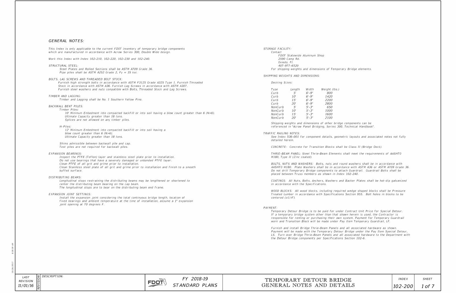
GENERAL NOTES:
NonCurb
NonCurb
NonCurb
NonCurb
Curb
Curb
Curb
Curb
20'
15'
10'
5'
20'
15'
10'
5'
5'-3"
5'-3"
5'-3"
5'-3"
6'-9"
6'-9"
6'-9"
6'-9"
2100
1600
1000
650
2800
2200
1420
800
the Detour Bridge components per Specifications Section 102-6.
LS. Turn over Bridge Thrie-Beam Panels and all associated hardware to the Department with
Payment will be made with the Temporary Detour Bridge under the Pay Item Special Detour,
Furnish and install Bridge Thrie-Beam Panels and all associated hardware as shown.
work and Transition Block will be made under Pay Item Temporary Guardrail, LF.
responsible for renting or purchasing their own system. Payment for Temporary Guardrail
If a temporary bridge system other than that shown herein is used, the Contractor is
Temporary Detour Bridge is to be paid for under Contract Unit Price for Special Detour.
PAYMENT:
centered (±1/4”).
Treated Lumber in accordance with Specifications Section 955. Bolt holes in blocks to be
WOOD BLOCKS: All wood blocks, including required wedge shaped blocks shall be Pressure
in accordance with the Specifications.
COATINGS: All Nuts, Bolts, Anchors, Washers and Backer Plates shall be hot-dip galvanized
placed between Truss members as shown in Index 102-240.
Do not drill Temporary Bridge components to attach Guardrail. Guardrail Bolts shall be
AASHTO M180. Plate Washers shall be in accordance with ASTM A36 or ASTM A709 Grade 36.
BOLTS, NUTS AND WASHERS: Bolts, nuts and round washers shall be in accordance with
M180, Type II (Zinc coated).
THRIE-BEAM PANEL: Steel Thrie-Beam Elements shall meet the requirements of AASHTO
CONCRETE: Concrete for Transition Blocks shall be Class II (Bridge Deck).
detailed herein.
See Index 536-001 for component details, geometric layouts and associated notes not fully
TRAFFIC RAILING NOTES:
referenced in "Acrow Panel Bridging, Series 300, Technical Handbook".
Shipping weights and dimensions of other bridge components can be
Weight (lbs.)WidthLengthType
Decking Sizes:
SHIPPING WEIGHTS AND DIMENSIONS:
For shipping weights and dimensions of Temporary Bridge elements.
407-977-6520
Oviedo, Fl.
2590 Camp Rd.
FDOT Statewide Aluminum Shop
Contact
STORAGE FACILITY:
joint opening at 70 degrees F.
fixed bearings and ambient temperature at the time of installation, assume a 1" expansion
Install the expansion joint considering the total continuous bridge length, location of
EXPANSION JOINT SETTINGS:
The longitudinal stops are to bear on the distributing beam end frame.
center the distributing beam bearing on the cap beam.
Longitudinal stops restraining the distributing beams may be lengthened or shortened to
DISTRIBUTING BEAMS:
buffed surface.
Clean Stainless steel plate of all grit and grime prior to installation and finish to a smooth
Clean PTFE of all grit and grime prior to installation.
Do not use bearings that have a severely damaged or unbonded PTFE layer.
Inspect the PTFE (Teflon) layer and stainless steel plate prior to installation.
EXPANSION BEARINGS:
Test piles are not required for backwall piles.
Shims admissible between backwall pile and cap.
Ultimate Capacity greater than 18 tons.
blow count greater than 6 (N>6).
12' Minimum Embedment into compacted backfill or into soil having a
H-Piles:
Splices are not allowed on any timber piles.
Ultimate Capacity greater than 18 tons.
10' Minimum Embedment into compacted backfill or into soil having a blow count greater than 6 (N>6).
Timber Piles:
BACKWALL BENT PILES:
Timber and Lagging shall be No. 1 Southern Yellow Pine.
TIMBER AND LAGGING:
Furnish steel washers and nuts compatible with Bolts, Threaded Stock and Lag Screws.
Stock in accordance with ASTM A36. Furnish Lag Screws in accordance with ASTM A307.
Furnish high strength bolts in accordance with ASTM F3125 Grade A325 Type 1. Furnish Threaded
BOLTS, LAG SCREWS AND THREADED BOLT STOCK:
Pipe piles shall be ASTM A252 Grade 2, Fy = 35 ksi.
Steel Plates and Rolled Sections shall be ASTM A709 Grade 36.
STRUCTURAL STEEL:
Work this Index with Index 102-210, 102-220, 102-230 and 102-240.
which are manufactured in accordance with Acrow Series 300, Double Wide design.
This Index is only applicable to the current FDOT inventory of temporary bridge components
10/26/2017
8:3
8:3
9
AM
RE
VISIO
N DESCRIPTION:
REVISION
LAST
ofSTANDARD PLANS
FY 2018-19 SHEETINDEX
GENERAL NOTES AND DETAILS 1 7 102-200
TEMPORARY DETOUR BRIDGE
11/01/16

~
~
~
AB306 Transom DW (Typ.)
1'-6"25'-6"
24'-0" Clear Roadway Width
1'-6"
AB1 Truss Panels (Typ.)
AB3 Bracing Frame (Typ.)
Toe of Fill Slope
1 :
1ƀ *
1 : 1ƀ *
Edge of Berm
1 : 1ƀ *
Grade Beam
Approach Roadway
5'-0" Approach Span
5'-0"
Ramp Span
AB13 Swaybrace Standard (Typ.)
Shoulder Line (see Plans for width requirements, Typ.)
Retainer Angles (Typ.)
1 : 1ƀ *
AB5 or AB6 End Post (Typ.)
1 : 1ƀ *
1 :
1ƀ *
� End Bent
� Backwall Bent
� Detour Bridge
TYPICAL PLAN VIEW OF DETOUR BRIDGE
(TIMBER PILES SHOWN, STEEL H PILES AND STEEL PIPE PILES SIMILAR)
4" x 10" Timber Lagging
with Filter Fabric
Begin or End
Detour Bridge
* or Flatter
1 :
1ƀ *
1 :
1ƀ *
AB7 & AB8 Bearings
(Expansion Bearing
Shown Fixed
Bearing Similar)
(Typ.)
(Thrie-Beam Panel not shown for clarity, See Index 102-240)
10/26/2017
8:3
8:4
2
AM
RE
VISIO
N DESCRIPTION:
REVISION
LAST
ofSTANDARD PLANS
FY 2018-19 SHEETINDEX TEMPORARY DETOUR BRIDGE
GENERAL NOTES AND DETAILS 2 7 102-20007/01/15
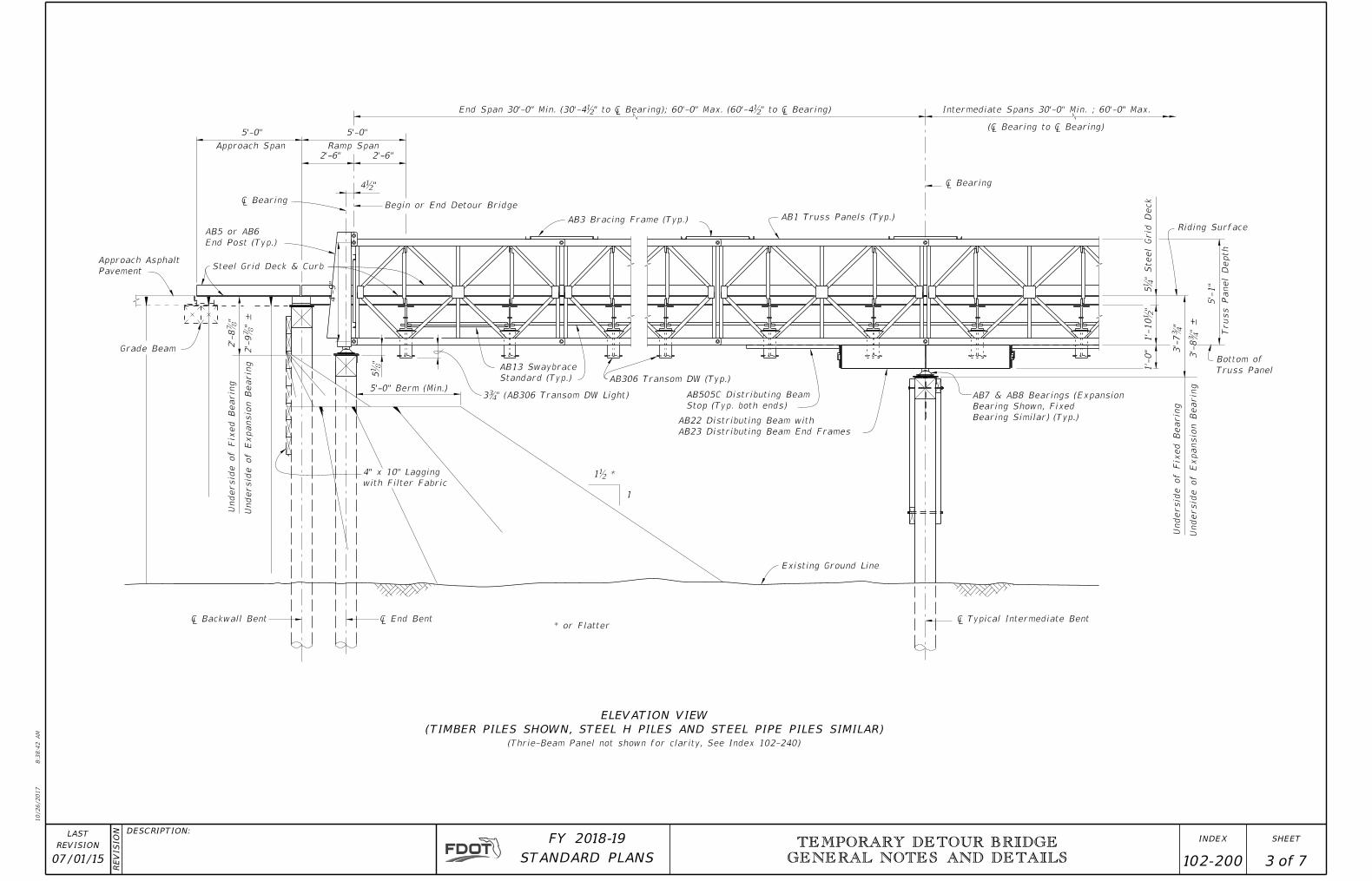
Existing Ground Line
1
� End Bent
4" x 10" Lagging
with Filter Fabric
Undersid
e of E
xpansio
n Bearin
g
Undersid
e of Fix
ed Bearin
g
5'-0" Berm (Min.)
AB13 Swaybrace
Standard (Typ.) AB306 Transom DW (Typ.)
AB505C Distributing Beam
Stop (Typ. both ends)
AB22 Distributing Beam with
AB23 Distributing Beam End Frames
Undersid
e of Fix
ed Bearin
g
Undersid
e of E
xpansio
n Bearin
g
Bottom of
Truss Panel1'-
0"
Riding Surface
Truss Panel
Depth
5'-
1"
Intermediate Spans 30'-0" Min. ; 60'-0" Max.
AB1 Truss Panels (Typ.)AB3 Bracing Frame (Typ.)
Begin or End Detour Bridge
2'-6"
Ramp Span
2'-6"
5'-0"5'-0"
Approach Span
AB5 or AB6
End Post (Typ.)
Steel Grid Deck & CurbApproach Asphalt
Pavement
Grade Beam
2'-
8Ɔ
"
2'-
9Ɔ
" ±
� Backwall Bent
5ƃ"
� Typical Intermediate Bent
1'-
10ƀ"
3'-
7Ƃ"
3'-
8Ƃ"
±
5Ɓ"
Steel
Grid
Deck
(� Bearing to � Bearing)
� Bearing
End Span 30'-0" Min. (30'-4ƀ" to � Bearing); 60'-0" Max. (60'-4ƀ" to � Bearing)
4ƀ"
� Bearing
ELEVATION VIEW
(TIMBER PILES SHOWN, STEEL H PILES AND STEEL PIPE PILES SIMILAR)
* or Flatter
1ƀ *
AB7 & AB8 Bearings (Expansion
Bearing Shown, Fixed
Bearing Similar) (Typ.)
4'-
9"
3Ƃ" (AB306 Transom DW Light)
(Thrie-Beam Panel not shown for clarity, See Index 102-240)
10/26/2017
8:3
8:4
2
AM
RE
VISIO
N DESCRIPTION:
REVISION
LAST
ofSTANDARD PLANS
FY 2018-19 SHEETINDEX TEMPORARY DETOUR BRIDGE
GENERAL NOTES AND DETAILS 3 7 102-20007/01/15
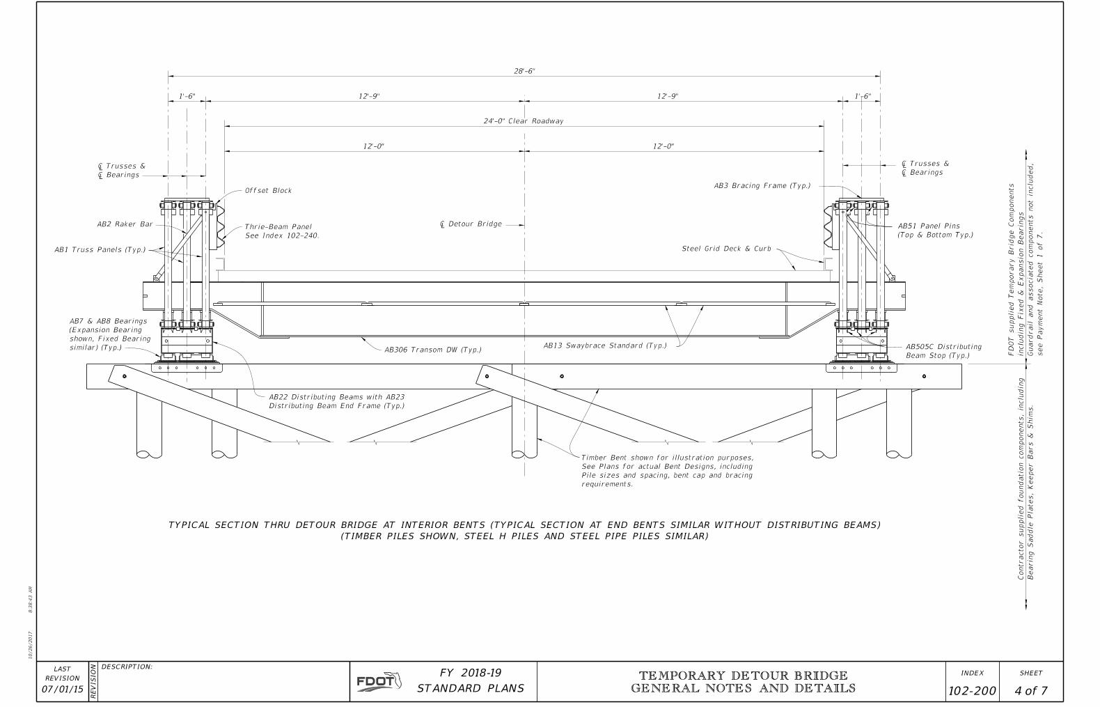
Timber Bent shown for illustration purposes,
See Plans for actual Bent Designs, including
Pile sizes and spacing, bent cap and bracing
requirements.
AB22 Distributing Beams with AB23
Distributing Beam End Frame (Typ.)
AB306 Transom DW (Typ.)AB13 Swaybrace Standard (Typ.) AB505C Distributing
Beam Stop (Typ.)
Contractor supplied foundatio
n co
mponents, in
clu
din
g
Bearin
g Saddle Plates,
Keeper Bars
& S
him
s.
AB51 Panel Pins
(Top & Bottom Typ.)
AB3 Bracing Frame (Typ.)
Steel Grid Deck & Curb
1'-6"12'-9"
12'-0"
24'-0" Clear Roadway
28'-6"
12'-0"
12'-9"1'-6"
AB2 Raker Bar
AB1 Truss Panels (Typ.)
� Trusses &
� Bearings
� Detour Bridge
� Trusses &
� Bearings
Offset Block
TYPICAL SECTION THRU DETOUR BRIDGE AT INTERIOR BENTS (TYPICAL SECTION AT END BENTS SIMILAR WITHOUT DISTRIBUTING BEAMS)
(TIMBER PILES SHOWN, STEEL H PILES AND STEEL PIPE PILES SIMILAR)
FD
OT supplied Te
mporary Brid
ge Co
mponents
inclu
din
g Fix
ed
& E
xpansio
n Bearin
gs
Guardrail and associated co
mponents not in
clu
ded,
see Pay
ment
Note,
Sheet 1 of 7.
AB7 & AB8 Bearings
(Expansion Bearing
shown, Fixed Bearing
similar) (Typ.)
Thrie-Beam Panel
See Index 102-240.
10/26/2017
8:3
8:4
3
AM
RE
VISIO
N DESCRIPTION:
REVISION
LAST
ofSTANDARD PLANS
FY 2018-19 SHEETINDEX TEMPORARY DETOUR BRIDGE
GENERAL NOTES AND DETAILS
4 7 07/01/15 102-200
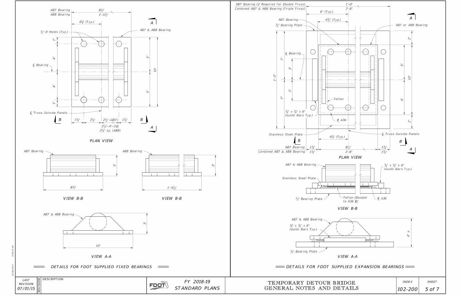
10"
3"
AB7 Bearing
"218
3"
1"
4"
5"
10"
5"
4"
1"
1Ƃ"2ƀ"1Ƃ"
� Bearing
Ɔ" Ø Holes (Typ.)
8ƀ"
4"
±
Ƃ" x Ƃ" x 6"
(Guide Bars Typ.)
Stainless Steel Plate
℅ A36Teflon (Bonded
to A36 ℅)
Ƃ" x Ƃ" x 6"
(Guide Bars Typ.)
Stainless Steel Plate
2"
5"
10"
Teflon
5"
2"
1'-0"
7"
3"
1'-
2"
3"
7"
1Ƃ" 8ƀ" 1Ƃ"
℅ A36
� Bearing
DETAILS FOR FDOT SUPPLIED EXPANSION BEARINGS
VIEW A-A
VIEW B-B
PLAN VIEW
B B
A
A
A
B
A
B
PLAN VIEW
VIEW B-B
VIEW A-A
Ƃ" x Ƃ" x 6"
(Guide Bars Typ.)
DETAILS FOR FDOT SUPPLIED FIXED BEARINGS
ƀ" Bearing Plate
ƀ" Bearing Plate
ƀ" Bearing Plate
AB7 & AB8 Bearing
AB8 Bearing
3"
VIEW B-B
AB7 & AB8 Bearing
AB7 Bearing
AB8 Bearing
AB7 & AB8 Bearing
1Ƃ"1Ƃ" 2'-6"
AB7 Bearing
AB7 or AB8 Bearing
2'-6"
1'-5ƀ"
1'-5ƀ"
4Ɓ" (Typ.)
Combined AB7 & AB8 Bearing
AB7 & AB8 Bearing
� Truss Outside Panels
4Ƅ" (Typ.)
6" (Typ.)
AB7 Bearing (2 Required for Double Truss)
Combined AB7 & AB8 Bearing (Triple Truss)
AB7 Bearing
� Truss Outside Panels
2ƀ" (AB7)
4Ɓ" (Typ.)
2ƀ"~4"~2@
2ƀ" sp. (AB8)
10/26/2017
8:3
8:4
3
AM
RE
VISIO
N DESCRIPTION:
REVISION
LAST
ofSTANDARD PLANS
FY 2018-19 SHEETINDEX TEMPORARY DETOUR BRIDGE
GENERAL NOTES AND DETAILS
5 7 07/01/15 102-200
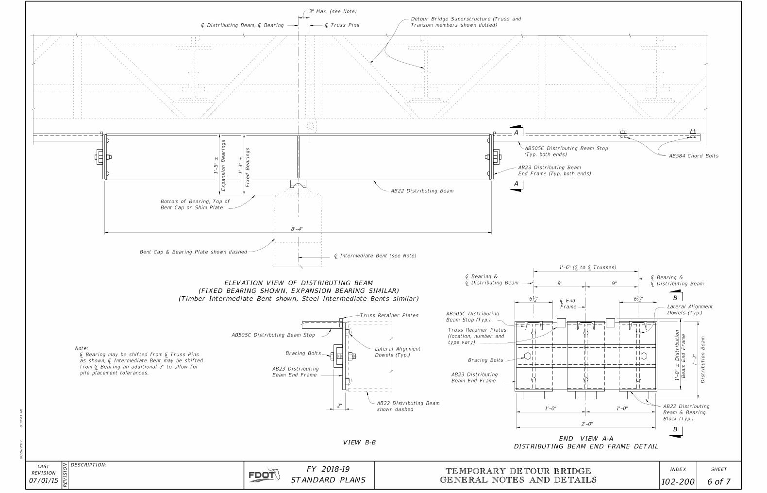
AB22 Distributing
Beam & Bearing
Block (Typ.)
1'-0"
2'-0"
1'-0"
AB23 Distributing
Beam End Frame
Bracing Bolts
Truss Retainer Plates
(location, number and
type vary)
AB505C Distributing
Beam Stop (Typ.)
9" 9"
Lateral Alignment
Dowels (Typ.)
1'-
0"
±
Distrib
utio
n
Bea
m E
nd Fra
me
1'-
2"
Distrib
utio
n Bea
m
� Bearing &
� Distributing Beam
6ƀ" � End
Frame
1'-6" (� to � Trusses)
� Bearing &
� Distributing Beam
"ƀ6
AB22 Distributing Beam
shown dashed2"
AB23 Distributing
Beam End Frame
Bracing Bolts
AB505C Distributing Beam Stop
Truss Retainer Plates
Lateral Alignment
Dowels (Typ.)
Note:
� Bearing may be shifted from � Truss Pins
as shown, � Intermediate Bent may be shifted
from � Bearing an additional 3" to allow for
pile placement tolerances.
¡ Intermediate Bent (see Note)
8'-4"
Bent Cap & Bearing Plate shown dashed
Bottom of Bearing, Top of
Bent Cap or Shim Plate
1'-
5"
±
Expansio
n Bearin
gs
1'-
4"
±
Fix
ed Bearin
gs
AB22 Distributing Beam
AB23 Distributing Beam
End Frame (Typ. both ends)
AB505C Distributing Beam Stop
(Typ. both ends)
Detour Bridge Superstructure (Truss and
Transom members shown dotted)
3" Max. (see Note)
� Distributing Beam, � Bearing � Truss Pins
END VIEW A-A
DISTRIBUTING BEAM END FRAME DETAILVIEW B-B
B
B
A
A
ELEVATION VIEW OF DISTRIBUTING BEAM
(FIXED BEARING SHOWN, EXPANSION BEARING SIMILAR)
(Timber Intermediate Bent shown, Steel Intermediate Bents similar)
AB584 Chord Bolts
10/26/2017
8:3
8:4
3
AM
RE
VISIO
N DESCRIPTION:
REVISION
LAST
ofSTANDARD PLANS
FY 2018-19 SHEETINDEX TEMPORARY DETOUR BRIDGE
GENERAL NOTES AND DETAILS
6 7 07/01/15 102-200

~~
~
~ ~
3"
10" x 10" (Nominal)
Grade Beam Timbers
ƀ" Anchor Plate(see Detail)
ƅ" Ø Threaded Bar placed @ Strap locations,
Torque to 25 Lb.-Ft.
2"
Steel Grid Deck Unit
(shown dashed)
Ɓ
Typ. both
ends �
� 3 x 2 x ƀ x 10"
(placed against Grid Deck)
� 5 x 5 x ƀ x 12'-3"
Steel Grid Deck Unit
(shown dashed)
* 1" @ 70° F
Approach Asphalt
Pavement
3"
3"
10" x 10" (Nominal)
Grade Beam Timbers
* See General Notes for setting
widths other than 70° F.
1ƀ" Ƃ"
ƃ" x 4" x 2'-10" ± Strap ℅, field
bend to shape (center ƌ" Ø
holes for Lag Screws in strap)
ƅ" Ø x 6" Lag Screws (Typ.)
ƀ" Ø x 5" Lag Screws (Typ.)
3ƀ"
ƀ" x 1'-7" x 12'-9" Cap ℅
ƀ" x 1ƀ" x 4" Deck Hold Down Tabs
Ƅ
Ƅ2ƀ"3ƀ"� 5 x 5 x ƀ x 12'-3"
4"
4"
ƀ" ℅
ƌ" Ø Hole
(Centered)
Strap Spacing1'-0"
10" x 10" (Nominal)
Grade Beam Timbers
5'-0"5'-0"2'-0"1'-0"1'-0"2'-0"5'-0"
Grade Beam Straps (Typ.)
5'-0"1'-0"
See Detail "B"
Deck Hold Down Tabs (Typ.)
1'-6" 1'-11" 1'-11"
12'-3"
2'-9" 3'-1" 1'-1" 1'-1" 3'-1" 2'-9"
12'-3"
1'-11" 1'-11" 1'-6" Spacing Deck Hold Down Tabs
� Lengths
� 3 x 2 x ƀ x 10" (Typ.)�'s 5 x 5 x ƀ x 12'-3"
1'-
7"
10" x 10" (Nominal)
Grade Beam Timbers
1'-3"
9 sp. @ 1'-3" = 11'-3"
12'-9"
16'-0"
25'-6"
9 sp. @ 1'-3" = 11'-3"
12'-9"
12'-0"
Cap Plate Lengths
1'-3"
Front Grade Beam Lengths
10"
Deck Hold Down Tabs (Typ.)
Rear Grade Beam Lengths16'-0"
14'-0"
28'-0"
14'-0"
12'-0"
Grade Beam Straps (Typ.)� 3 x 2 x ƀ x 10" (Typ.)
9ƀ"
9ƀ"
10ƀ"
� Detour Bridge
7ƀ"
2 ~ ƀ" x 1'-7" x 12'-9" Cap ℅
�'s 5 x 5 x ƀ x 12'-3"
Ƌ" Ø Holes(Typ.)
10ƀ" Spacing Ƌ" Ø Holes for ƀ" Ø Lag Screws
7ƀ"
OPTIONAL THROUGH BOLT DETAIL
(MAY BE USED IN LIEU OF STRAPS)
GRADE BEAM DETAILS
DETAIL "B"
ANCHOR PLATE DETAIL
SECTION A-A
ELEVATION VIEW
A
A
PLAN VIEW
Cap ℅
10/26/2017
8:3
8:4
4
AM
RE
VISIO
N DESCRIPTION:
REVISION
LAST
ofSTANDARD PLANS
FY 2018-19 SHEETINDEX TEMPORARY DETOUR BRIDGE
GENERAL NOTES AND DETAILS
7 7 07/01/06 102-200